Tested. Trusted. Guaranteed. INSTALLER: These instructions must be given to the consumer. CONSUMER: Retain these instructions for further use. Save this manual for future reference. READ ALL INSTRUCTIONS CAREFULLY BEFORE INSTALLING OR USING THIS COVER. Actual parts may vary from those shown in this booklet. BY: Installation Manual ROLTEC ® ELECTRIC TARP CONVERSION WITH REAR SPRING BOX RETURN FOR SIDE LOCKING TARPS

Welcome message from author
This document is posted to help you gain knowledge. Please leave a comment to let me know what you think about it! Share it to your friends and learn new things together.
Transcript
Tested. Trusted. Guaranteed.
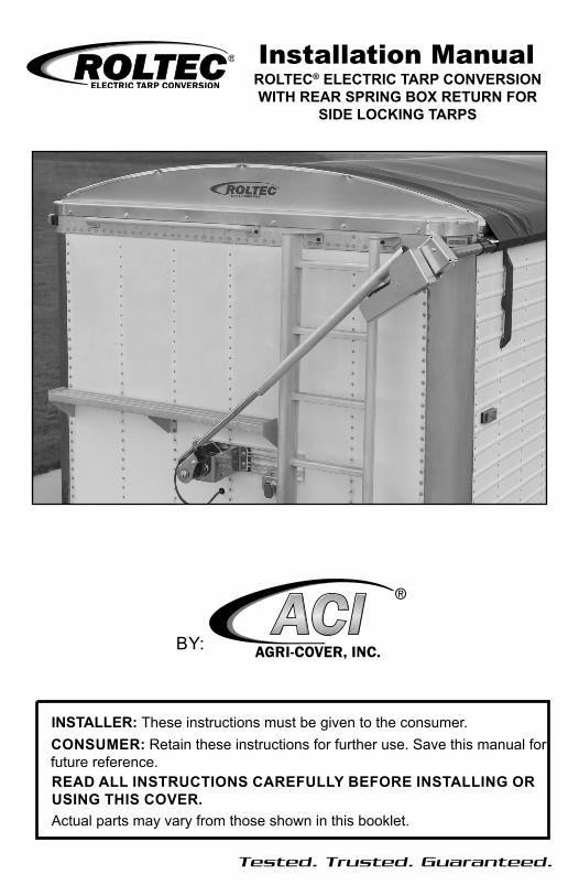
INSTALLER: These instructions must be given to the consumer.CONSUMER: Retain these instructions for further use. Save this manual for future reference.READ ALL INSTRUCTIONS CAREFULLY BEFORE INSTALLING OR USING THIS COVER.Actual parts may vary from those shown in this booklet.
BY:
Installation ManualROLTEC® ELECTRIC TARP CONVERSION WITH REAR SPRING BOX RETURN FOR
SIDE LOCKING TARPS
Safety .......................................................................................... Page 2-3Operating Instructions ................................................................. Page 3Inspection and Maintenance........................................................ Page 4Tools for Installation ..................................................................... Page 5Part Numbers and Diagrams ....................................................... Page 6-9Installing Roltec Conversion ........................................................ Page 10-18 Installing Electrical Parts ............................................................. Page 18-22Edge Trim and Enabling Manual Override................................... Page 23Warranty ...................................................................................... Back Page
Table of Contents
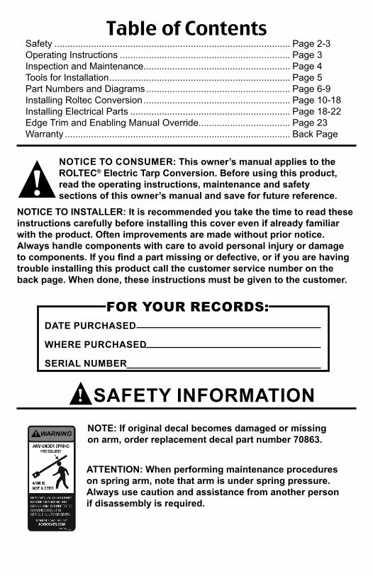
NOTE: If original decal becomes damaged or missing on arm, order replacement decal part number 70863.
ATTENTION: When performing maintenance procedures on spring arm, note that arm is under spring pressure. Always use caution and assistance from another person if disassembly is required.
NOTICE TO CONSUMER: This owner’s manual applies to the ROLTEC® Electric Tarp Conversion. Before using this product, read the operating instructions, maintenance and safety sections of this owner’s manual and save for future reference.
NOTICE TO INSTALLER: It is recommended you take the time to read these instructions carefully before installing this cover even if already familiar with the product. Often improvements are made without prior notice. Always handle components with care to avoid personal injury or damage to components. If you find a part missing or defective, or if you are having trouble installing this product call the customer service number on the back page. When done, these instructions must be given to the customer.
!
FOR YOUR RECORDS:DATE PURCHASED
WHERE PURCHASED
SERIAL NUMBER
SAFETY INFORMATION!

ELECTRIC MOTOROPERATING INSTRUCTIONS
1: CLOSING TARP FROM OPEN POSITIONPush switch to the CLOSED position and hold. Visually view tarp position and release switch when tarp is fully closed. Fully closed is when tarp roll tube is tight up under latch plate.
2: OPENING TARP FROM CLOSED POSITIONPush switch to the OPEN position and hold. Visually view tarp position and release switch when tarp is fully open. Fully open is when tarp roll touches tarp stops. TOO TIGHT in open position could cause damage to tarp stops, tubes and tarp.
NOTE: For kits with a tarp control box, refer to the tarp control box manual for operating instructions.
IMPORTANT: Electric tarp system is equipped with a modified reset circuit breaker. Holding switch until circuit breaker trips is too long. When this occurs, breaker will trip and reset if the breaker is overloaded by the motor. To reduce unnecessary strain on components, always release switch before breaker trips. If breaker trips and does not reset, it may have detected a continuous short and will not reset until the short is repaired.
• Always use adequate caution when operating tarp.• Make sure tarp is open before unloading or loading.• Make sure nobody is on or near tarping system before and during operation.• Do not operate tarp with box hoisted in an elevated position.• If tarp is covered with snow, its removal is important before operating.• End caps must be free from grain that may be piled on them. Grain should not be heaped higher than end caps.• Do not operate this vehicle at highway speeds, while tarp system is in the “open” position• Instruct everyone who will operate this tarp the proper procedures, or have them read this entire manual.• Do not directly spray the electric motor and electrical connections with a pressure washer.
SAFETY INFORMATION (Continued)!
4
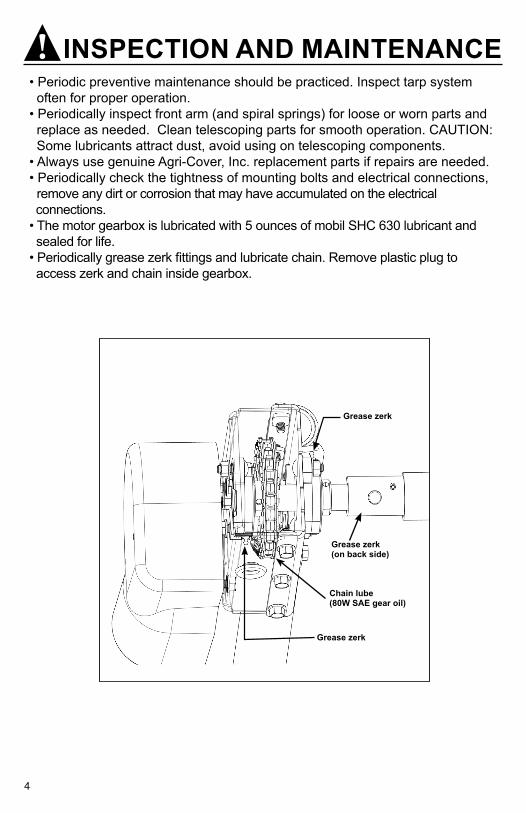
Chain lube (80W SAE gear oil)
Grease zerk
Grease zerk
Grease zerk(on back side)
• Periodic preventive maintenance should be practiced. Inspect tarp system often for proper operation.• Periodically inspect front arm (and spiral springs) for loose or worn parts and replace as needed. Clean telescoping parts for smooth operation. CAUTION: Some lubricants attract dust, avoid using on telescoping components.• Always use genuine Agri-Cover, Inc. replacement parts if repairs are needed.• Periodically check the tightness of mounting bolts and electrical connections, remove any dirt or corrosion that may have accumulated on the electrical connections.• The motor gearbox is lubricated with 5 ounces of mobil SHC 630 lubricant and sealed for life.• Periodically grease zerk fittings and lubricate chain. Remove plastic plug to access zerk and chain inside gearbox.
INSPECTION AND MAINTENANCE!
5
• Protective eyewear • Tape measure• Marking pencil• 3/8” electric drill• #2, and #3 Phillips driver bit • 5/16” drill bit• Center punch• Impact wrench• 9/16” socket
• 9/16”, 1/2”, 7/16” and 3/8” combination wrench • Metal hack saw• Heat gun• Wire cutter and crimper• Welder • Grinder• Hammer
PREPARATIONTOOLS & EQUIPMENTMost installations will require use of all these items
IMPORTANT NOTES:
The truck or trailer on which installation is being done must be parked on a level surface. This prevents box from twisting, which can cause a poor installation.
Box must be square and straight, center must not be pulled together or spread apart. Make adjustments prior to installation.
Inspect box for sharp edges or points that make contact with tarp and/or cables, remove or grind smooth.
It may be necessary to remove or reposition ladders or other devices that may interfere with system. If any modifications to box are needed, consult box manufacturer.
If you have an extension on top of your box, make sure it is secure by bolting in place.
Most fasteners used in this installation are 3/8” x 1” self threading bolts. A 5/16” hole must be drilled to obtain correct tap drill hole size. Attach these bolts only to secure structures on box. In some cases it will be necessary to use washer and nuts or other types of fasteners (NOT FURNISHED) to ensure a solid anchor.

6
Part Numbers and Descriptions (Item numbers are used to reference parts in diagrams throughout this manual)
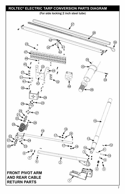
NOTE: Some components are pre-assembled at the factory prior to shipping. The exploded diagram at right is for reference purposes and does not display parts in pre-assembled form. Always keep electric conversion parts in proper operating condition. In the event replacement parts are needed, use only genuine Agri-Cover, Inc. replacement parts.
Item Part # Description
80120ROLTEC Electric Tarp Conversion (for Side Locking Tarp Systems w/ 2" Steel Tube)
1 70670 Gearbox Asm2 90447 Upper Front Arm Asm
3 60583 Bolt, Hex, Serrated Flange, 5/16-18 x 3/4", Gr-5, Zinc Pl, w/ Vibratite
4 90428 Plug, Grommet, 2"5 40664 Grommet, Rubber 7/16"
6 70996 Screw, Phillips Head 10-32 x 1/4", Zinc Pl, w/ Vibratite
7 90479 Washer, Pivot Arm8 90410 Wear Tube, Pivot Arm9 70575 Cotter Pin10 70554 Clevis Pin11 4000189 Cotter Pin
12 10915 Screw, Self Drilling Phillips #12 x 3/4"
13 70993 Protective Sleeve14 70908 Grease Zerk15 70745 Adaptor, Motor 2" Steel Tube16 90375 Bearing, 3/8" x 1/4"17 90313 Bearing Clip18 90378 Bearing Shaft19 90394 Lower Pivot Arm Asm20 70696 1-1/4" Retaining Ring21 70724 Washer, Pivot, SST22 70971 Wear Bushing, Clip-in
23 70401 Nut, Hex Nylock Flange, 3/8"-16, Gr-5, Zinc Pl
24 80113 Bushing , Spacer
25 70626 Spring, Spiral Torsion (4 req'd)
26 70594 Bolt, Carriage, 3/8"-16 x 3-3/4", Gr-5, Zinc Pl
27 60254 Bolt, Carriage, 3/8"-16 x 1", Gr-5, Zinc Pl
28 70584 Bracket, Slant
29 70646 Plate Wmt, Pivot30 10901 Bolt, 3/8" x 1" Gr-5, Zinc Pl31 10185 Flat Washer, 3/8"
32 50670 Bolt, Carriage, 3/8" x 1-1/2" Gr-5, Zinc Pl
33 70618 Collar, Tube34 10914 Screw, Self Drilling Phillips #14 x 1"35 70952 Cable Retainer36 30610 Spline37 70961 Cable Return Wear Channel38 70947 Spring (without pulleys)39 70985 Synthetic Cable w/ pulley
70795 Steel Pulley 1" Dia. (not shown)
40 70955 Center Mounting Bracket41 10903 Lock Washer, 3/8" Zinc Pl42 10186 Nut, 3/8" Hex, Zinc Pl43 4000232 Pivot Mount Wmt44 90616 Pivot Mount Bracket (small half)45 60642 Bolt, Hex, 3/8" x 1-3/4" Gr-5, Zinc Pl46 10172 Nut, Square 3/8", Zinc Pl
47 90803 Pivot Mount Support Plate
48 90607 Dual Pole Mount Kit
90395 Tarp Motor Wire Asm (not shown)
Item Part # Description
7
FRONT PIVOT ARM AND REAR CABLE RETURN PARTS
2
15
1322
21
20
8
76
1
910
11
1618
5
1412
4
17
17 16
25
2021
22
26
27
28
29 23
41
48
32
27
24
23
3
45
19
36
34
33
35
39
38
37
30
42
40
41
(For side locking 2 inch steel tube)ROLTEC® ELECTRIC TARP CONVERSION PARTS DIAGRAM
30
31
46
47
23
43
2344
8
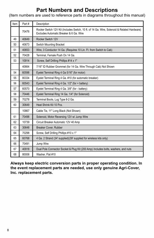
Part Numbers and Descriptions (Item numbers are used to reference parts in diagrams throughout this manual)
Always keep electric conversion parts in proper operating condition. In the event replacement parts are needed, use only genuine Agri-Cover, Inc. replacement parts.
Item Part # Description
70476 Rocker Switch 12V Kit (Includes Switch, 10 ft. of 14 Ga. Wire, Solenoid & Related Hardware) Excludes Automatic Breaker & 6 Ga. Wire
49 40649 Rocker Switch 12V 50 40673 Switch Mounting Bracket51 40653 Wire, 3 Conductor 14 Ga. (Requires 10 Lin. Ft. from Switch to Cab)52 70428 Terminal, Female Push On 14 Ga.53 10914 Screw, Self Drilling Phillips #14 x 1"
40664 7/16" ID Rubber Grommet (for 14 Ga. Wire Through Cab) Not Shown
54 60598 Eyelet Terminal Ring 4 Ga 5/16" (for motor)55 80334 Eyelet Terminal Ring 4 Ga. #10 (for automatic breaker)56 60543 Eyelet Terminal Ring 4 Ga. 1/2" (for + battery)57 60570 Eyelet Terminal Ring 4 Ga. 3/8" (for - battery)58 70446 Eyelet Terminal Ring 14 Ga. 1/4" (for Solenoid)59 70278 Terminal Boots, Lug Type 8-2 Ga.60 30649 Heat Shrink Kit 10 Pcs.
10867 Cable Tie, 11" Long Black (Not Shown)
61 70498 Solenoid, Motor Reversing 12V w/ Jump Wire62 10739 Circuit Breaker Automatic 12V 40 Amp63 30648 Breaker Cover, Rubber64 70298 Screw, Self Drilling Phillips #10 x 1"65 60768 4 Ga. 2 Strand (34' supplied)(39' supplied for wireless kits only)66 70491 Jump Wire67 40918 Dual Pole Connector Socket & Plug Kit (200 Amp) Includes bolts, washers, and nuts68 80006 Washer, Flat #10
9
49
51
53
63
55
57
62
54
60
56
5954
58
66
64
68
61
67
65
50
52
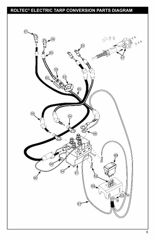
ROLTEC® ELECTRIC TARP CONVERSION PARTS DIAGRAM
10
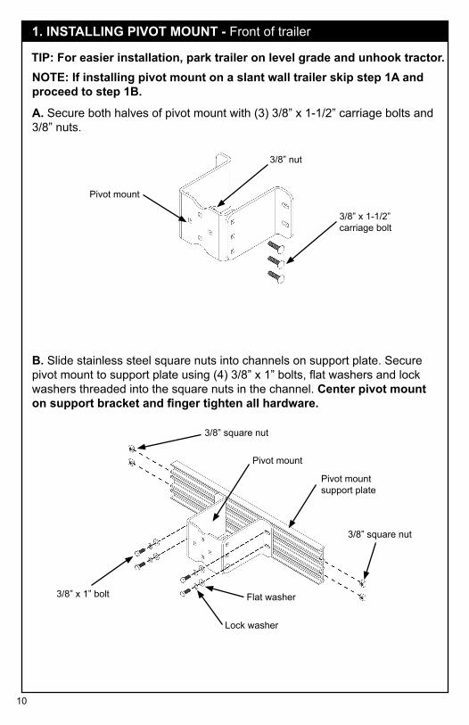
TIP: For easier installation, park trailer on level grade and unhook tractor.
1. INSTALLING PIVOT MOUNT - Front of trailer
A. Secure both halves of pivot mount with (3) 3/8” x 1-1/2” carriage bolts and 3/8” nuts.
3/8” nut
3/8” x 1-1/2” carriage bolt
Pivot mount
NOTE: If installing pivot mount on a slant wall trailer skip step 1A and proceed to step 1B.
B. Slide stainless steel square nuts into channels on support plate. Secure pivot mount to support plate using (4) 3/8” x 1” bolts, flat washers and lock washers threaded into the square nuts in the channel. Center pivot mount on support bracket and finger tighten all hardware.
3/8” square nut
3/8” square nut
Pivot mount support plate
Pivot mount
3/8” x 1” bolt
Lock washer
Flat washer
11
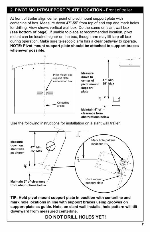
2. PIVOT MOUNT/SUPPORT PLATE LOCATION - Front of trailer
CL
CL
Measure down to center of pivot mount support plate
47” Min55” Max
DO NOT DRILL HOLES YET!
Maintain 5” of clearance from obstructions below
CL
CL
Mark hole pattern locations
Maintain 5” of clearance from obstructions below
Measure down on slant wall as shown
TIP: Hold pivot mount support plate in position with centerline and mark hole locations in line with support braces using grooves on support plate as guide. Note, on slant wall installs, hole pattern will tilt downward from measured centerline.
47” Min55” Max
Centerline of box
Pivot mount support plate
At front of trailer align center point of pivot mount support plate with centerline of box. Measure down 47”-55” from top of end cap and mark holes for drilling. View shows vertical wall box. Do the same on slant wall box (see bottom of page). If unable to place at recommended location, pivot mount can be located higher on the box, though arm may lift tarp off box during operation. Make sure telescopic arm has a clear pathway to operate. NOTE: Pivot mount support plate should be attached to support braces whenever possible.
Pivot mount and support plate centered on box
Use the following instructions for installation on a slant wall trailer.
12
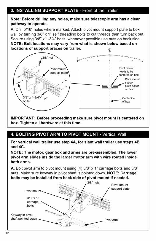
3. INSTALLING SUPPORT PLATE - Front of the Trailer
Keyway in pivot shaft pointed down
Pivot mount support plate
Pivot mount
3/8” x 1” carriage bolts
3/8” nuts
For vertical wall trailer use step 4A, for slant wall trailer use steps 4B and 4C.
Pivot arm
NOTE: The motor, gear box and arms are pre-assembled. The lower pivot arm slides inside the larger motor arm with wire routed inside both arms.
4. BOLTING PIVOT ARM TO PIVOT MOUNT - Vertical Wall
CL
3/8” x 1-3/4” bolts
A. Drill 5/16” holes where marked. Attach pivot mount support plate to box wall by turning 3/8” x 1” self threading bolts to cut threads then turn back out. Secure using 3/8” x 1-3/4” bolts, whenever possible use nuts on back side. NOTE: Bolt locations may vary from what is shown below based on locations of support braces on trailer.
Note: Before drilling any holes, make sure telescopic arm has a clear pathway to operate.
Centerline of box
3/8” nut
Pivot mount support plate
Pivot mount needs to be centered on box
Pivot mount support plate bolted on box
IMPORTANT: Before proceeding make sure pivot mount is centered on box. Tighten all hardware at this time.
A. Bolt pivot arm to pivot mount using (4) 3/8” x 1” carriage bolts and 3/8” nuts. Make sure keyway in pivot shaft is pointed down. NOTE: Carriage bolts may be installed from back side of pivot mount if needed.
13
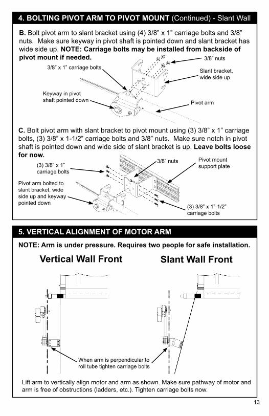
4. BOLTING PIVOT ARM TO PIVOT MOUNT (Continued) - Slant Wall
Keyway in pivot shaft pointed down
Slant bracket, wide side up
3/8” x 1” carriage bolts3/8” nuts
C. Bolt pivot arm with slant bracket to pivot mount using (3) 3/8” x 1” carriage bolts, (3) 3/8” x 1-1/2” carriage bolts and 3/8” nuts. Make sure notch in pivot shaft is pointed down and wide side of slant bracket is up. Leave bolts loose for now.
Pivot arm
Pivot mount support plate
Pivot arm bolted to slant bracket, wide side up and keyway pointed down
3/8” nuts(3) 3/8” x 1” carriage bolts
(3) 3/8” x 1”-1/2” carriage bolts
Vertical Wall Front Slant Wall Front
Lift arm to vertically align motor and arm as shown. Make sure pathway of motor and arm is free of obstructions (ladders, etc.). Tighten carriage bolts now.
5. VERTICAL ALIGNMENT OF MOTOR ARMNOTE: Arm is under pressure. Requires two people for safe installation.
When arm is perpendicular to roll tube tighten carriage bolts
B. Bolt pivot arm to slant bracket using (4) 3/8” x 1” carriage bolts and 3/8” nuts. Make sure keyway in pivot shaft is pointed down and slant bracket has wide side up. NOTE: Carriage bolts may be installed from backside of pivot mount if needed.
14
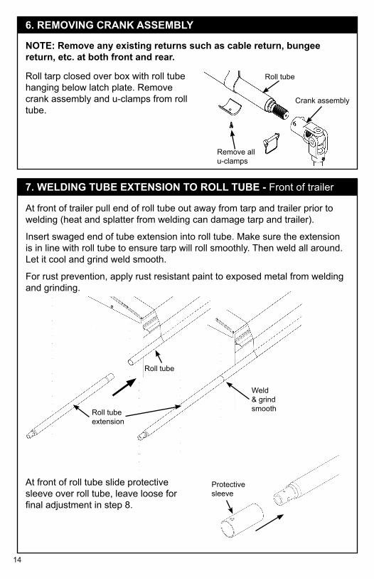
Roll tube extension
Roll tube
Weld & grind smooth
At front of trailer pull end of roll tube out away from tarp and trailer prior to welding (heat and splatter from welding can damage tarp and trailer).
Insert swaged end of tube extension into roll tube. Make sure the extension is in line with roll tube to ensure tarp will roll smoothly. Then weld all around. Let it cool and grind weld smooth.
For rust prevention, apply rust resistant paint to exposed metal from welding and grinding.
At front of roll tube slide protective sleeve over roll tube, leave loose for final adjustment in step 8.
Crank assembly
Remove all u-clamps
Roll tubeRoll tarp closed over box with roll tube hanging below latch plate. Remove crank assembly and u-clamps from roll tube.
NOTE: Remove any existing returns such as cable return, bungee return, etc. at both front and rear.
6. REMOVING CRANK ASSEMBLY
7. WELDING TUBE EXTENSION TO ROLL TUBE - Front of trailer
Protective sleeve
15
90º
Telescopic armInsert motor shaft and drive roll pin first.
Insert motor shaft and drive roll pin first.
End cap wind deflector
SleeveFront Vertical Wall Trailer
90º
End cap wind deflectorFront Slant Wall Trailer
Telescopic arm
9
11
12
10
11
12
10
Sleeve
9
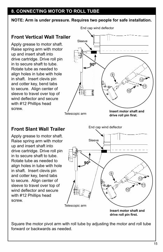
8. CONNECTING MOTOR TO ROLL TUBE
NOTE: Arm is under pressure. Requires two people for safe installation.
Square the motor pivot arm with roll tube by adjusting the motor and roll tube forward or backwards as needed.
Apply grease to motor shaft. Raise spring arm with motor up and insert shaft into drive cartridge. Drive roll pin in to secure shaft to tube. Rotate tube as needed to align holes in tube with hole in shaft. Insert clevis pin and cotter key, bend tabs to secure. Align center of sleeve to travel over top of wind deflector and secure with #12 Phillips head screw.
Apply grease to motor shaft. Raise spring arm with motor up and insert shaft into drive cartridge. Drive roll pin in to secure shaft to tube. Rotate tube as needed to align holes in tube with hole in shaft. Insert clevis pin and cotter key, bend tabs to secure. Align center of sleeve to travel over top of wind deflector and secure with #12 Phillips head screw.

16
3”- 5”3”- 5”
Rear Vertical Wall Trailer Rear Slant Wall Trailer
Weld around in short welds. Let cool and finish weld
36
End cap End cap
Roll TubeRoll Tube
At rear, insert spline into rear of tube. Hold straight and weld all around. Use care to avoid weld splatter and keep heat away from tarp and trailer.
TIP: Weld several short beads, let cool and finish with fill weld between them. Let cool and grind weld smooth.
For rust prevention, apply rust resistant paint to exposed metal surfaces from welding and grinding.
10. WELDING NEW SPLINE
Measure 3-5” back from end cap as shown and make a mark. Cut off excess roll tube at mark.
9. TRIMMING ROLL TUBE
17
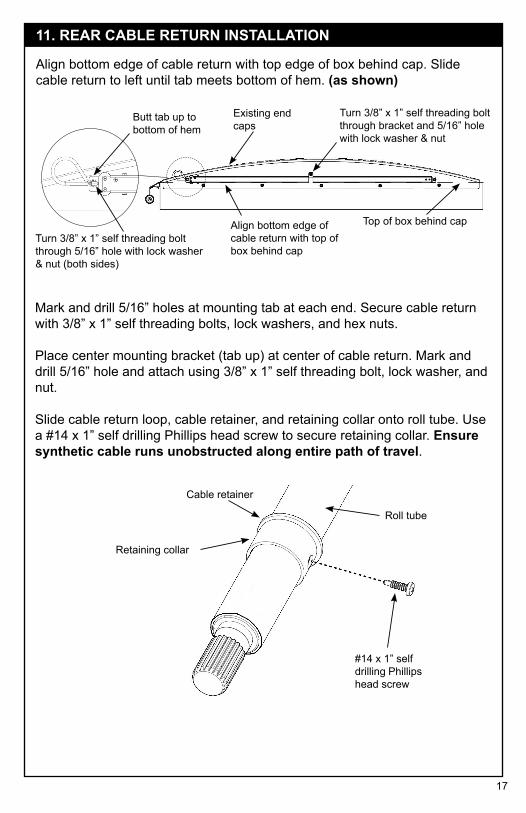
Align bottom edge of cable return with top edge of box behind cap. Slide cable return to left until tab meets bottom of hem. (as shown)
Turn 3/8” x 1” self threading bolt through 5/16” hole with lock washer & nut (both sides)
Butt tab up to bottom of hem
Existing end caps
Turn 3/8” x 1” self threading bolt through bracket and 5/16” hole with lock washer & nut
Align bottom edge of cable return with top of box behind cap
Top of box behind cap
Mark and drill 5/16” holes at mounting tab at each end. Secure cable return with 3/8” x 1” self threading bolts, lock washers, and hex nuts.
Place center mounting bracket (tab up) at center of cable return. Mark and drill 5/16” hole and attach using 3/8” x 1” self threading bolt, lock washer, and nut.
Slide cable return loop, cable retainer, and retaining collar onto roll tube. Use a #14 x 1” self drilling Phillips head screw to secure retaining collar. Ensure synthetic cable runs unobstructed along entire path of travel.
Cable retainer
Retaining collar
Roll tube
#14 x 1” self drilling Phillips head screw
11. REAR CABLE RETURN INSTALLATION

18
Reattach tarp to roll tube using existing U-clamps and screws (screws most likely will not align with old holes). Check all bolts and nuts on front and rear arm systems and tighten if needed.
12. REATTACH TARP
13. WIRING DUAL POLE PLUGTIP: Dielectric silicone is provided for electric wire connections. Use as needed.
Connector socket
A. Bolt connector socket to dual pole mount bracket using 5/16” x 1” bolts, flat washers, lock washers and nuts.
B. Before cutting wire, form a loop on arm that allows room for movement and mark where to cut at socket connector at location on dual pole mount bracket. Cut wire, strip only enough insulation off to attach ring terminals and heat shrink tube. Attach wires to socket terminals.
Dual pole mount bracket
Flat washer
Lock washerNut
C. Slide (2) square nuts into channel on pivot mount. Place protective fabric between dual pole mounting bracket and pivot mount and secure dual pole mounting bracket with 3/8 x 3/4” bolts and lock washers.
5/16” x 1” bolt
Square nut (2x)
3/8” x 3/4” bolt
Lock washer
Protective fabric
Dual pole mounting bracket
Heat shrink
Eyelet
Stripped wire end

19
Remote control box (wireless kits only)
Circuit Breaker
Heavy gauge wire
Rocker switch inside cab
14 gauge wire
Solenoid
ATTENTION: If installing this kit on an existing tarp system, it is recommended both end tarp stops are located 5” in from each end of tarp. When needed and if possible, relocate existing end tarp stops.
NOTE: If installing an optional tarp control box, skip steps 14-15. Use instructions supplied with the tarp control box.
NOTE: Some wiring will come pre-assembled.
14. WIRING ELECTRIC CONVERSION
A. WIRE ROUTING - HEAVY GAUGESelect best routing of wire from battery to solenoid usually along frame with other wire harness along cab and up to pole connectors.
For wireless units only - 5’ length of wire (included in
kit) from remote control box to dual pole plug

20
Connect wires as shown:Black to open
Green to center
White to close
Front of bracket
(2) #14 x 1” self drilling Phillips head screw
15. WIRING SWITCH
B. SWITCH LOCATION AND INSTALLATIONSelect convenient location in cab to mount switch bracket with two #14 x 1” self drilling Phillips screws through slots in back of bracket.
Route 14 ga. wire from switch to location of solenoid near battery. Rubber grommet is supplied for area where wire enters cab, 11/16” hole is needed for grommet.
At switch, strip 14 ga. wire ends about 3/8” back and attach push-on connectors and crimp. Pull wires through mount bracket and attach to switch. Snap switch into mount bracket.
C. SOLENOIDMount solenoid in protected area near battery using #2 x 1” self drilling Phillips screws. Then follow wiring connections on page 21. For reference see wiring schematic on page 22.
D. LIGHT GAUGE WIRESPrepare end of black and white light gauge wires from switch with push on connectors for solenoid terminals. Connect white wire to close terminal. Con-nect black wire to open terminal. Prepare end of light gauge green wire from switch with 1/4” ring terminal. For reference see wiring schematic on page 22.
21
15. WIRING SWITCH (Continued)
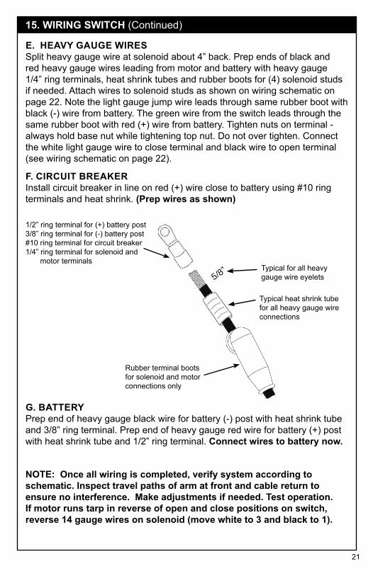
F. CIRCUIT BREAKERInstall circuit breaker in line on red (+) wire close to battery using #10 ring terminals and heat shrink. (Prep wires as shown)
E. HEAVY GAUGE WIRESSplit heavy gauge wire at solenoid about 4” back. Prep ends of black and red heavy gauge wires leading from motor and battery with heavy gauge 1/4” ring terminals, heat shrink tubes and rubber boots for (4) solenoid studs if needed. Attach wires to solenoid studs as shown on wiring schematic on page 22. Note the light gauge jump wire leads through same rubber boot with black (-) wire from battery. The green wire from the switch leads through the same rubber boot with red (+) wire from battery. Tighten nuts on terminal - always hold base nut while tightening top nut. Do not over tighten. Connect the white light gauge wire to close terminal and black wire to open terminal (see wiring schematic on page 22).
G. BATTERYPrep end of heavy gauge black wire for battery (-) post with heat shrink tube and 3/8” ring terminal. Prep end of heavy gauge red wire for battery (+) post with heat shrink tube and 1/2” ring terminal. Connect wires to battery now.
Rubber terminal boots for solenoid and motor connections only
Typical heat shrink tube for all heavy gauge wire connections
Typical for all heavy gauge wire eyelets
1/2” ring terminal for (+) battery post3/8” ring terminal for (-) battery post#10 ring terminal for circuit breaker1/4” ring terminal for solenoid and motor terminals
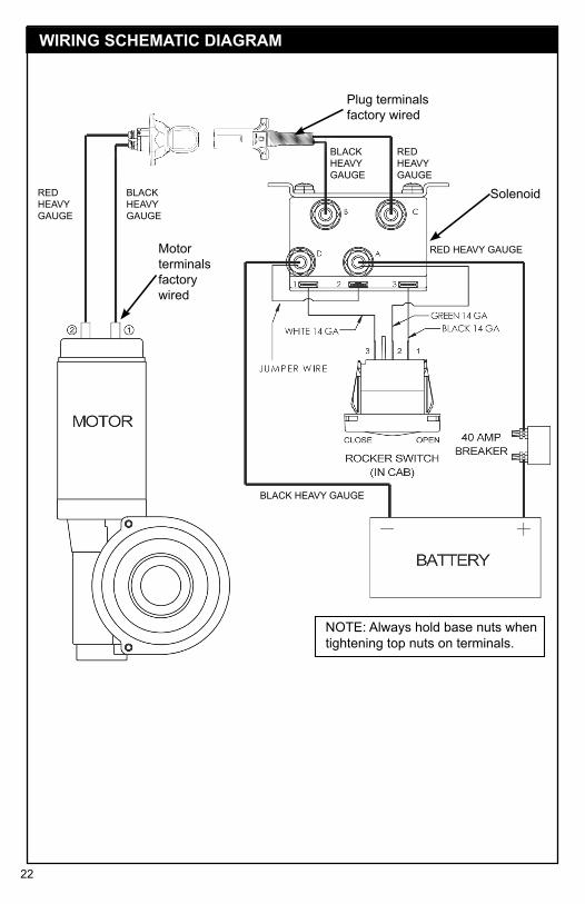
NOTE: Once all wiring is completed, verify system according to schematic. Inspect travel paths of arm at front and cable return to ensure no interference. Make adjustments if needed. Test operation. If motor runs tarp in reverse of open and close positions on switch, reverse 14 gauge wires on solenoid (move white to 3 and black to 1).
22
BLACK HEAVY GAUGE
BLACK HEAVY GAUGE
RED HEAVY GAUGE
RED HEAVY GAUGE
Solenoid
Motor terminals factory wired
NOTE: Always hold base nuts when tightening top nuts on terminals.
Plug terminals factory wired
RED HEAVY GAUGE
BLACK HEAVY GAUGE
WIRING SCHEMATIC DIAGRAM
23
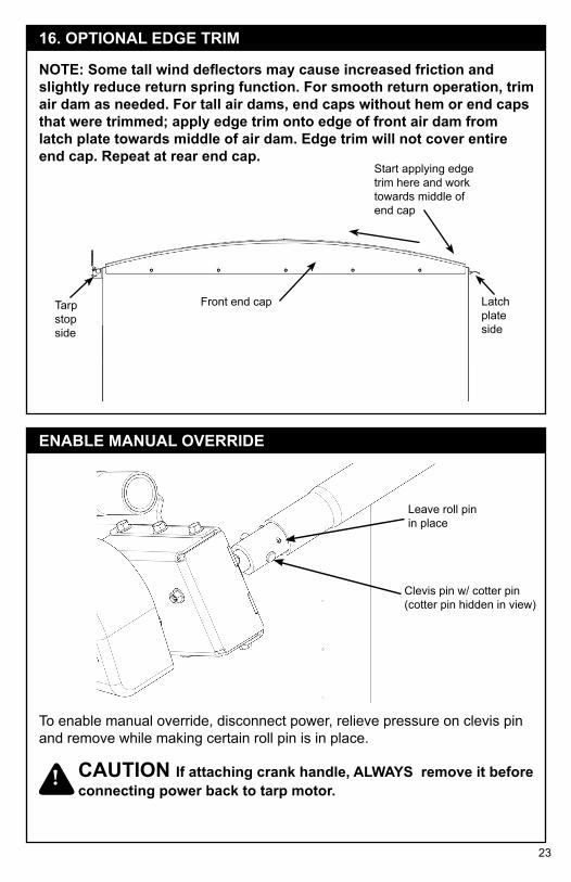
Clevis pin w/ cotter pin (cotter pin hidden in view)
Leave roll pin in place
!
ENABLE MANUAL OVERRIDE
Latch plate side
Front end capTarp stop side
Start applying edge trim here and work towards middle of end cap
NOTE: Some tall wind deflectors may cause increased friction and slightly reduce return spring function. For smooth return operation, trim air dam as needed. For tall air dams, end caps without hem or end caps that were trimmed; apply edge trim onto edge of front air dam from latch plate towards middle of air dam. Edge trim will not cover entire end cap. Repeat at rear end cap.
16. OPTIONAL EDGE TRIM
CAUTION If attaching crank handle, ALWAYS remove it beforeconnecting power back to tarp motor.
To enable manual override, disconnect power, relieve pressure on clevis pin and remove while making certain roll pin is in place.

Agri-Cover, Inc. extends the following limited warranty on its ROLTEC® Electric Tarp Conversion to the original retail purchaser:
Agri-Cover, Inc. warrants its ROLTEC® Electric Tarp Conversion to be free from defects in material and workmanship under normal use for one (1) year from date of manufacture unless accompanied by proof of purchase.
ANY IMPLIED WARRANTY APPLICABLE TO THE ROLTEC® ELECTRIC TARP CONVERSION IS LIMITED IN DURATION TO ONE YEAR FROM THE DATE OF MANUFACTURE UNLESS ACCOMPANIED BY PROOF OF PURCHASE. Agri-Cover, Inc.’s sole obligation under this warranty or any implied warranty is limited to the repair or replacement at its option, of defective parts only. No labor or service allowance is given or implied. IN NO EVENT SHALL AGRI-COVER, INC. BE LIABLE FOR INCIDENTAL, CONSEQUENTIAL, OR SPECIAL DAMAGES. Some states do not allow limitations on how long an implied warranty lasts or exclusions of incidental or consequential damages, so the above limitations and exclusions may not apply to you.
For warranty call our Customer Service Department at 800-233-4655 to determine if only a replacement part is needed or if the cover needs to be returned for inspection and repair. Goods to be returned must have a pre-authorized RA# (Returned Authorization Number) – obtained by calling the number above. Mark the number on the package and ship it freight prepaid to address below. Agri-Cover will pay freight to return goods to sender.
This warranty does not cover any failure due to abuse, misuse, alteration, neglect, improper assembly or installation, or improper maintenance.
This warranty gives you specific legal rights and you may have other rights which vary from state to state.
MANUFACTURER’S LIMITED WARRANTY
051517 80478_K
Agri-Cover, Inc.Customer Service Dept
PO Box 508 | 3000 Hwy 281 SEJamestown, ND 58402Phone: 800-233-4655
© 2017 AGRI-COVER, INC. ALL RIGHTS RESERVED.Product subject to change without notice. Patents: agricover.com/patents.
Hours: 8:00 am - 5:00 pm CST Monday through Friday, except HolidaysROLTEC® is a registered United States trademark of AGRI-COVER, INC.
Related Documents