Wynn Marine Ltd 2-4 Merse Road, North Moons Moat, Redditch, Worcestershire B98 9HL, United Kingdom Tel: +44 (0) 1527 61243, Fax: +44 (0) 1527 66836 Email: [email protected], website www.b-hepworth.com These manuals have been page checked for completeness, the soft copy and hard copy are identical in every respect and these manuals are Fit For Purpose and appropriate to the equipment fitted on the Khareef Class Ships. WARNING: A suitably qualified person should perform all installation and maintenance. All electrical wiring should be carried out in accordance with relevant regulations. Ensure all products are correctly earthed and all connections are made in accordance with the wiring diagram. Non-compliance may result in damage, malfunction or personal injury. Before commencing any installation or maintenance work, ensure that the electrical supply is disconnected. Installation & Maintenance Manual Type C350 Clear View Screen

Welcome message from author
This document is posted to help you gain knowledge. Please leave a comment to let me know what you think about it! Share it to your friends and learn new things together.
Transcript

Wynn Marine Ltd
2-4 Merse Road, North Moons Moat, Redditch, Worcestershire B98 9HL, United Kingdom
Tel: +44 (0) 1527 61243, Fax: +44 (0) 1527 66836
Email: [email protected], website www.b-hepworth.com
These manuals have been page checked for completeness, the soft copy and hard copy are identical in every respect and these manuals are Fit For Purpose and appropriate to the equipment fitted on the Khareef Class Ships.
WARNING: A suitably qualified person should perform all installation and maintenance. All electrical wiring should be carried out in accordance with relevant regulations. Ensure all products are correctly earthed and all connections are made in accordance with the wiring diagram. Non-compliance may result in damage, malfunction or personal injury. Before commencing any installation or maintenance work, ensure that the electrical supply is disconnected.
Installation & Maintenance ManualType C350 Clear View Screen

IndexWiper Description 1
Wiper Installation 2
C350 Installation Drawing 4
Wiper Operation 6
Wiper Fault Finding 7
Wiper Maintenance 8
Wiper Spares List 9
Wiper Spares Drawing 10
Documentation 11

1
TYPE C350 GENERAL SYSTEM DESCRIPTION This C350 Clear View Screen is suitable for mounting on all vessels provided the window dimensions are above the minimum requirement of 510mm wide and 533mm high, and the windscreen between 10 and 32 mm thick. The Wynn C350 is designed to meet or to exceed ISO 3904:1990(E) (BS7470:1991) standards. The centrifugal force created by the spinning disc of the Clear View Screen throws off all rain, spray, snow or ice giving instant clear vision. In accordance with ISO 3904, the Wynn C350 is defined as: ISO 3904-C-350-AL-vf, where vf is voltage and frequency identification number. Toughened glass is used both for the fixed and the rotating screens. The rotating screen is balanced such that little vibration or noise is generated. This also allows high rotation speeds to be used making it particularly effective in heavy weather / sea spray conditions. The motors are fan cooled, constant speed Induction motors, with a 100°C thermal cut-out (self resetting) fitted for added safety. 4-pole motors are used on 60 Hz, 2-pole on 50 Hz. Optional metal sheathed, ceramic filled heaters are used of the same voltage as the screen motor. For rapid ice and misting clearance, power consumption is approximately 250W. In addition, air from the motor fan cooling is directed onto the inner screen to aid heating. A connection box is incorporated within the C350 in order that the CVS controller may be connected to the C350 Motor and Heater. The Clear View Screen must be mounted with the control box at the bottom. Note: This product is not recommended for sloping glass beyond 10° forward or backwards, or for windows likely to be struck by waves. Seawater is likely to be retained within the space between the two screens.
Nominal
Supply
Voltage
Freq Ident Nr:
ISO 3904–C-350-AL-
Motor
Run
Current
A
Motor
Fuse
A
Nominal
Rotation
Speed
Heater
Current
Heater
Fuse
Compass
Safe
Distance
M
115 50 11 1.0 2 2800 2.2 3.15 0.3
115 60 12 0.6 2 1700 2.2 3.15 0.3
230 50 13 0.5 2 2800 1.3 1.6 0.3
230 60 14 0.3 1 1700 1.3 1.6 0.3
Fuse type ‘F’ fast blow.
The compass safe distances are estimated values based on similar certifications. The values quoted are the maximum figure (i.e. not ‘reduced’ figure) for ‘Magnet-Regelkompass’ as defined by BSH (Germany). Certification from this Authority will become available - contact WYNN.

2
TYPE C350 INSTALLATION These instructions assume that the required mounting hole is already available in the windscreen. It should be checked for compliance with the 390 - 392mm diameter limits, and the glass thickness should be checked against the Certificate of Conformity, supplied with the product. In the case of the need to remove or replace the rotating screen, a tool is supplied with the product. 1. The wiper must be installed with the control box at the bottom of the wiper. 2. Clean the area on both sides around the hole in the window. 3. Open the Control Box and disconnect the heater wires from the terminals. HL1, HL2 and E. 4. Remove the 12 cap screws from the clamp ring and carefully remove the clamping ring
pulling the heater power & earth wires through the cable hole out of the control box. 5. Insert the Clear View Screen, complete with the Control Box attached, through the hole from
the outside of the windscreen. 6. Refit the Clamp Ring carefully feeding the 3 wires from the heater through the hole in the
clamp ring. CAUTION: Insert the cap screws and tighten carefully until an even pressure on the rubber gaskets is achieved without distorting them and causing them to extrude outside of the outer rim or clamp ring. Do NOT over- tighten.
7. Carefully feed the heater power and earth wires through the slot in the back of the Control
Box and connect the wires as per sleeve marking to terminals marked HL1, HL2 and E. 8. The motor wires are supplied connected to ensure the correct direction of running. The
correct direction of rotation is clockwise viewed from inside the window.
9. Switch both the screen and the heater, if fitted, OFF. 10. Check that the rotating screen is free to rotate freely and without any sound - make sure no
packing materials are trapped in the labyrinth seals. See Fault Finding Guide if there are difficulties.
WARNING: ISOLATE the supply and then connect the supply cabling to the incoming terminals as shown on the wiring diagram.
11. Switch on the supply. 12. Switch on the screen switch and check that the rotating screen is running in the correct
direction as stated above. See Fault Finding guide if there are difficulties. 13. Switch on the heater (if fitted). The outer rims of the wiper should become warm within 5
minutes. 14. Switch off the screen and heater. Clean the glass of the screens and any other dirty areas.

3
Water Seal Test 1. Spray water at right angles to the screen and directly at the centre of the screen whilst
rotating. 2. In the case of water ingress, stop the rotating screen and allow water to drain out. 3. Turn on the heater and wait a few minutes for the screen to de-fog.
4
TYPE C350 SCREEN LOCATION

5
TYPE C350 CLAMP RING AND HEATER ROUTING

6
TYPE C350 OPERATING INSTRUCTIONS
CAUTION: If operating in freezing weather always switch on the heater first allowing 10 minutes for any ice attached to the rotating screen or sealing area to melt before switching on the C350.
If the ice has not cleared sufficiently the screen WILL NOT start up. If the ice has not started to melt after 10 minutes the heater is not functioning.
Note: In the stalled condition the motor will heat up until a thermal cut-out will disconnect power to the motor to prevent damage at an internal temperature of 100 C. The cut-out will reset when the motor temperature has fallen around 10 C.
1. If vision through the C350 is obscured by condensation, switch on the heater and screen together. It may take up to 20 minutes for the screen to clear completely.
2. Switch on the C350. It will take up to two minutes to accelerate to normal operating speed. 3. Should the wiper fail to operate when first switched on - follow the fault finding procedure
below. 4. Switch off the heater when not needed: Leaving the heater on continuously in high
temperature conditions will reduce its life.
Note: The CVS consists of two circular glass screens, one of which rotates. When the temperature of the outside and inside of the glass is different, the fixed glass screen can collect moisture according to the weather conditions.
7
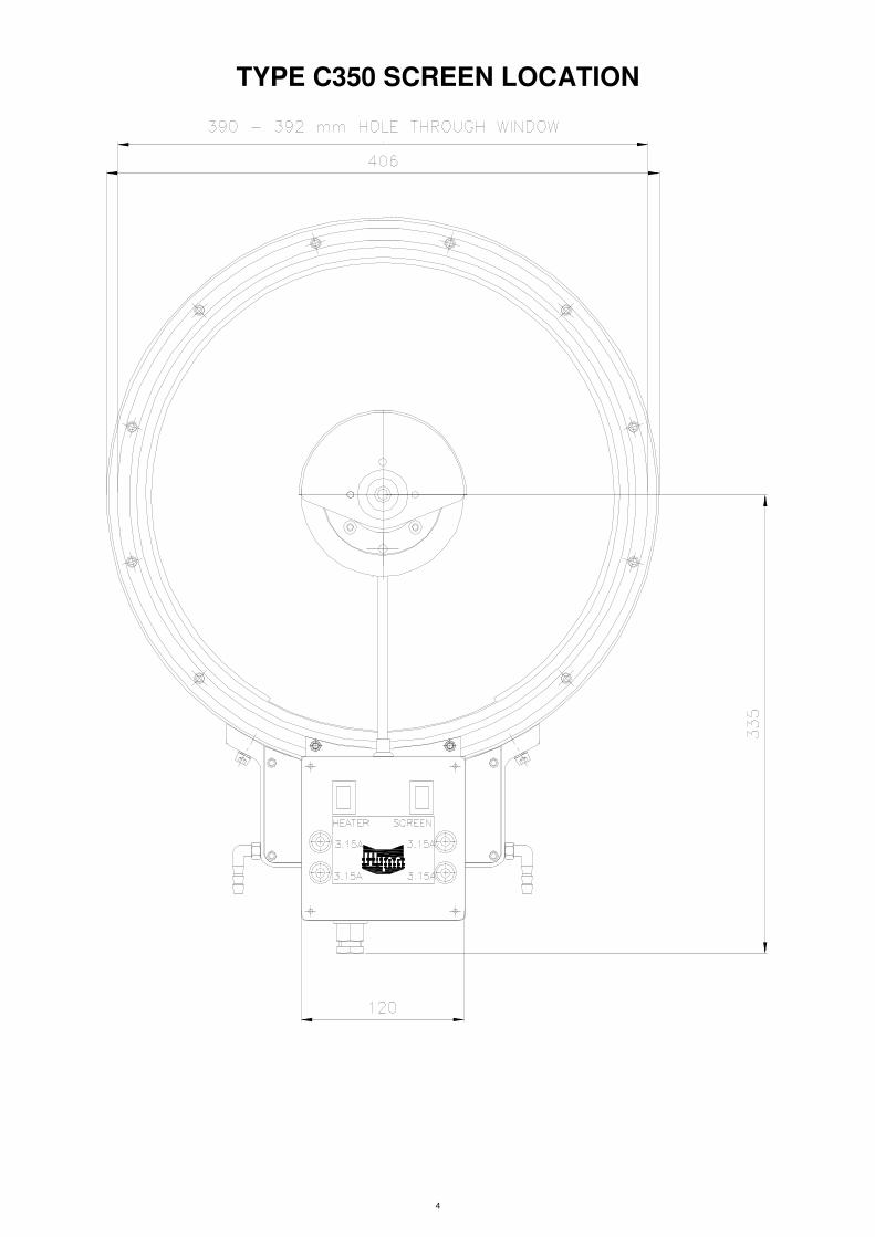
CLEAR VIEW SCREEN FAULT FINDING GUIDE NOTE: This fault finding guide assumes a reasonable level of technical ability and should be carried out by a suitably qualified person.
Problem: Screen does not rotate when switched on & the motor remains cold
Possible Cause Solution
No power to system Check supply / switches / fusing / isolating circuitry (where fitted) Check supply voltage at control box terminals
Screen motor fuses failed Investigate reasons for failure & repair. Replace fuses and retry.
Supply voltage too low Check supply voltage level against data on label off Clear View Screen.
Problem: Screen does not rotate when switched on & the motor becomes hot.
Possible Cause Solution
Wiper iced up Switch off screen. Switch on heater and retry after 10 minutes.
Wiper jammed Switch off screen. Clear obstruction, check for free rotation
Motor connections incorrect Switch off screen. Check connections accordingly to wiring diagram, correct if necessary.
Problem: Screen rotates O.K. but motor hot.
Possible Cause Solutions
Normal motor temperature will reach 35 C above ambient (i.e. more than hand hot)
N/A
Wiper not running freely Clear obstruction, Check for free rotation
Problem: Heater switched on, but wiper does not heat up.
Possible Cause Solution
No power to heater system Check supply / switches / fusing / isolating circuitry (where fitted)
Wiring / connections incorrect Check supply / switches / fusing / isolating circuitry (where fitted)
Ships Earth leakage circuit breaker tripped (this is not a Wynn supplied part)
It is common for earth leakage to rise if the heater has not been used for a while. If possible allow heater to be powered up to dry out. The heaters water seal or wiring may be damaged allowing ingress of water – check and replace heater if necessary.

8
TYPE C350 MAINTENANCE. It is recommended that the Clear View Screen is inspected annually or after 5,000 hours use whichever is the sooner. Dirt build up on the inner side of the rotating screen and on the outer side of the fixed screen requires removal of the rotating screen.
Rotating screen To remove the rotating screen for cleaning or inspection: 1. Unscrew the cone nut using the spanner supplied with the tool box whilst holding the rim of
the rotating screen 2. Using the other end of the spanner, unscrew the clamp nut and remove, allowing screen to
be lifted off. 3. Clean the glasses as necessary and clear any build up of salt or dirt encrustation in the rim
labyrinths. 4. Check drain holes at the bottom of the wiper are clear
Note: Refit the rotating screen by reversing the procedure above but observing the following additional important points.
5. Ensure that the mating faces of the hub and of the rotating screen are completely clean and then apply a very light smear of clean grease to aid refitting.
6. Ensure that the threading of the clamp nut and the hub is clean. 7. Clean the face of the clamp nut and the mating face of the cone nut. Apply a light coat of
Duralac compound or a waterproof grease to the mating faces. IMPORTANT! This is part of the Gas tight sealing.
8. Remove any surplus compound or grease from the screen once the cone nut has been re-
tightened 9. Re-apply power to the system and test the operation of the unit as above.
9
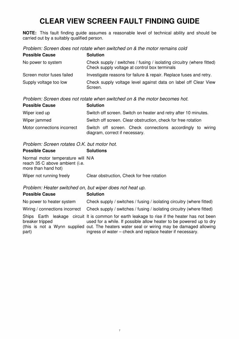
TYPE C350 SPARES LIST NB: The main installation screws lengths are dependent upon window glass thickness. This should be quoted when ordering spares. The spares available for this wiper are shown in the spares drawing at the end of the manual.
Ident Description Part Number
1 Rotating Screen C350-144
2 Control Panel Local C350-425-A
3 Control Panel Remote C350-425-B
4 Heater Assembly and Clip C350-031-***SA
5 Clamp Ring C350-012-B
6 Clamp Ring Screws #A0005-0**S
7 Cone Nut C350-109-A
8 C350 GASKET SET OF 2 SPC350-022V2
9 Clamp Nut C350-104-B
NI Motor Shroud C350-165
10 Motor 230V AC 50Hz 1 Phase 2 pole C350PARV-230-1
Motor 230V AC 60 Hz 1 Phase 4 pole C350PARV-230-1L
Motor 115V AC 50Hz 1 Phase 2 pole C350PARV-115-1
Motor 115V AC 60Hz 1 Phase 4 pole C350PARV-115-1L
11 Nylon Washer C350-078
*** specific to installation configuration – contact sales.

10
TYPE C350 SPARE PARTS DRAWING For Illustration Purposes Only
11
DOCUMENTATION Whilst every effort is made to provide accurate information in good faith, no responsibility can be accepted by Wynn for inaccuracies and Wynn reserves the right to alter and amend specifications and designs without prior notice in line with our policy of continued improvement.
Spares Parts To enable technical troubleshooting and ordering of spare parts, this manual should be kept in a safe place on board. It is also advisable to keep one set of spare parts on board for emergency use. Please contact Wynn directly or your local distributor / service centre for all order requirements.
Maintenance Schedules Plan your maintenance work according to the schedule in this manual.
Our Commitment We are committed to a 10 year product support programme. This ensures that any spare part will be available for any wiper at least 10 years after its purchase. It is strongly recommended that only genuine replacement parts manufactured by WYNN be used. This will guarantee that only suitable materials have been used and will ensure interchangeability of parts.
Quality and Testing We are committed to the principles of Total Quality Management, ISO 9000. We manufacture our range of marine products to the highest standard and quality. We therefore maintain an ongoing schedule of product improvement and testing. To help us sustain such standards we maintain a salt-water test rig on which our products are taken, at random from the production line, and subjected to 3,000 hour continuous testing. We are sure you will receive many years trouble-free service from your Wynn product and hope you find this information pack comprehensive.
Guarantee All Wynn equipment is tested before despatch from our works. The Windscreen Wiper System supplied has a 1 year warranty period provided the installation of the system and the subsequent maintenance is in accordance with the installation/maintenance instructions. We cannot accept any responsibility for the installation of equipment, or damage to the equipment during installation, or normal wear and tear. The guarantee is negated if the equipment is not installed strictly observing the instructions set out in this manual, or not maintained as specified. The Wiper System is very reliable but to ensure its continued smooth running we recommend that the following guidelines are adhered to:-
Monthly • Check for wear on all parts subject to friction
• Visual inspection should be made of the blades to ensure that they are still in good condition and replace as soon as there are signs of wear or damage
Annually • It is recommended that the blades are changed every 12 months After the Wiper System has been operating in severe weather conditions it is advisable to thoroughly check the unit for signs of wear or damage.

12
This warranty excludes the wiper blades which are a consumable item and any replacements that are detailed in the manual as part of any regular maintenance requirement. This guarantee is expressly in lieu of all other guarantees expressed or implied and of all other obligations of liabilities on our part, and we neither assume nor authorise any other person to assume for us any other liability in connection with the sale of our equipment. Faulty equipment must be returned, carriage paid, to our works for examination. Any legal action must be settled in the English courts under English law.

THIS PAGE INTENTIONALLY LEFT BLANK

A worldwide network of agents supports Wynn’s Marine product range. For details of the nearest Wynn agent please contact our Head Office. Wynn Agents operate in the following countries.
Argentina, Australia, Brazil, Canada, Chile, China, Croatia, Denmark, Egypt, Finland, France, Germany, Greece, Hong Kong, Iceland, India, Israel, Italy, Japan, Korea, Netherlands, New Zealand, Norway, Oman, Peru, Poland, Portugal, Russia, Singapore, South Africa, Spain, Sweden, Taiwan, Turkey, Ukraine, U.S.A.
Wynn Marine Ltd
2-4 Merse Road, North Moons Moat, Redditch, Worcestershire B98 9HL
Tel: +44 (0) 1527 61243, Fax: +44 (0) 1527 66836
Email: [email protected], website www.b-hepworth.com
Related Documents