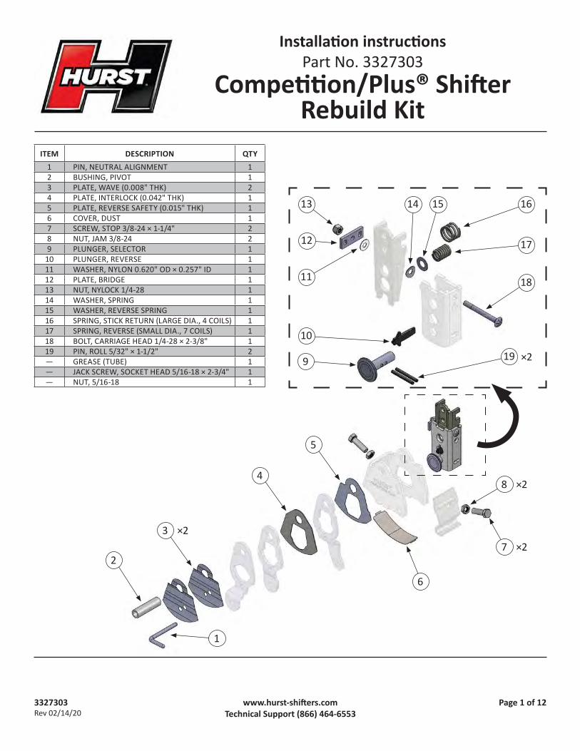
3327303 Rev 02/14/20 Page 1 of 12 www.hurst-shiſters.com Technical Support (866) 464-6553 Installaon instrucons Part No. 3327303 Compeon/Plus® Shiſter Rebuild Kit 13 12 11 14 15 16 17 18 ×2 19 10 9 5 4 2 1 6 ×2 8 ×2 7 3 ×2 ITEM DESCRIPTION QTY 1 PIN, NEUTRAL ALIGNMENT 1 2 BUSHING, PIVOT 1 3 PLATE, WAVE (0.008" THK) 2 4 PLATE, INTERLOCK (0.042" THK) 1 5 PLATE, REVERSE SAFETY (0.015" THK) 1 6 COVER, DUST 1 7 SCREW, STOP 3/8-24 × 1-1/4" 2 8 NUT, JAM 3/8-24 2 9 PLUNGER, SELECTOR 1 10 PLUNGER, REVERSE 1 11 WASHER, NYLON 0.620" OD × 0.257" ID 1 12 PLATE, BRIDGE 1 13 NUT, NYLOCK 1/4-28 1 14 WASHER, SPRING 1 15 WASHER, REVERSE SPRING 1 16 SPRING, STICK RETURN (LARGE DIA., 4 COILS) 1 17 SPRING, REVERSE (SMALL DIA., 7 COILS) 1 18 BOLT, CARRIAGE HEAD 1/4-28 × 2-3/8" 1 19 PIN, ROLL 5/32" × 1-1/2" 2 — GREASE (TUBE) 1 — JACK SCREW, SOCKET HEAD 5/16-18 × 2-3/4" 1 — NUT, 5/16-18 1

Welcome message from author
This document is posted to help you gain knowledge. Please leave a comment to let me know what you think about it! Share it to your friends and learn new things together.
Transcript
3327303Rev 02/14/20
Page 1 of 12www.hurst-shifters.comTechnical Support (866) 464-6553
Installation instructionsPart No. 3327303
Competition/Plus® Shifter Rebuild Kit
13
12
11
14 15 16
17
18
×219
10
9
5
4
2
1
6
×28
×273 ×2
ITEM DESCRIPTION QTY1 PIN, NEUTRAL ALIGNMENT 12 BUSHING, PIVOT 13 PLATE, WAVE (0.008" THK) 24 PLATE, INTERLOCK (0.042" THK) 15 PLATE, REVERSE SAFETY (0.015" THK) 16 COVER, DUST 17 SCREW, STOP 3/8-24 × 1-1/4" 28 NUT, JAM 3/8-24 29 PLUNGER, SELECTOR 1
10 PLUNGER, REVERSE 111 WASHER, NYLON 0.620" OD × 0.257" ID 112 PLATE, BRIDGE 113 NUT, NYLOCK 1/4-28 114 WASHER, SPRING 115 WASHER, REVERSE SPRING 116 SPRING, STICK RETURN (LARGE DIA., 4 COILS) 117 SPRING, REVERSE (SMALL DIA., 7 COILS) 118 BOLT, CARRIAGE HEAD 1/4-28 × 2-3/8" 119 PIN, ROLL 5/32" × 1-1/2" 2— GREASE (TUBE) 1— JACK SCREW, SOCKET HEAD 5/16-18 × 2-3/4" 1— NUT, 5/16-18 1

3327303Rev 02/14/20
Page 2 of 12www.hurst-shifters.comTechnical Support (866) 464-6553
INTRODUCTIONThis kit contains all the wear parts needed to rebuild your 1966 or newer Hurst Competition/Plus shifter.
Before starting, please take the time to read and understand these instructions.
Also, use the parts list to verify your kit’s contents. In the unlikely event that any parts are missing, please contact Hurst Technical Support for replacements.
NOTES• Installation requires better-than-average mechanical knowl-
edge and skills. If this job is beyond your abilities, seek the services of a qualified technician.
• If you do not understand any part of these instructions, please call Hurst Technical Support at (866) 464-6553 for assistance.
SAFETY WARNINGS• AVOID SERIOUS INJURY OR DEATH BY CRUSHING! If you
have to raise the vehicle to work under it, securely support it on a lift or jack stands. NEVER work under a vehicle that is supported only by jacks!
• AVOID EYE INJURY! When removing or installing shifter springs, WEAR SAFETY GLASSES to protect your eyes from an unexpectedly-released spring.
DISASSEMBLY
1. Remove the shifter from the vehicle. Different models of the Competition/Plus shifter have different shift levers. Make note or take a photo of the location and orientation of your shifter's levers for reference during reassembly.
2. Remove the stop screws from the shifter housing.
3. Remove the locknut, bridge plate, and nylon washer.
4. Remove the pivot bushing.
LOCKNUT & BRIDGE PLATE
NYLON WASHER
1-2REVERSE
3-4
3327303Rev 02/14/20
Page 3 of 12www.hurst-shifters.comTechnical Support (866) 464-6553
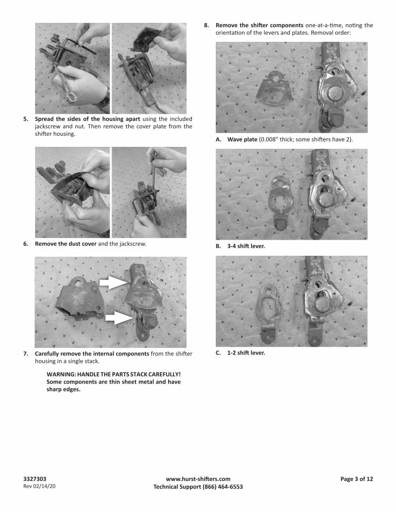
5. Spread the sides of the housing apart using the included jackscrew and nut. Then remove the cover plate from the shifter housing.
6. Remove the dust cover and the jackscrew.
7. Carefully remove the internal components from the shifter housing in a single stack.
WARNING: HANDLE THE PARTS STACK CAREFULLY! Some components are thin sheet metal and have sharp edges.
8. Remove the shifter components one-at-a-time, noting the orientation of the levers and plates. Removal order:
A. Wave plate (0.008" thick; some shifters have 2).
B. 3-4 shift lever.
C. 1-2 shift lever.
3327303Rev 02/14/20
Page 4 of 12www.hurst-shifters.comTechnical Support (866) 464-6553
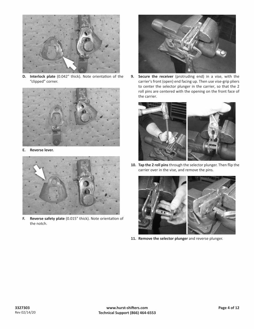
D. Interlock plate (0.042" thick). Note orientation of the “clipped” corner.
E. Reverse lever.
F. Reverse safety plate (0.015" thick). Note orientation of the notch.
9. Secure the receiver (protruding end) in a vise, with the carrier's front (open) end facing up. Then use vise-grip pliers to center the selector plunger in the carrier, so that the 2 roll pins are centered with the opening on the front face of the carrier.
10. Tap the 2 roll pins through the selector plunger. Then flip the carrier over in the vise, and remove the pins.
11. Remove the selector plunger and reverse plunger.

3327303Rev 02/14/20
Page 5 of 12www.hurst-shifters.comTechnical Support (866) 464-6553
12. Tap the carriage bolt out of the carrier, and remove it and the spring washer between the receiver and carrier.
13. CAREFULLY disassemble the receiver and carrier as follows:
WARNING: The reverse plunger and stick return springs are under compression. WEAR SAFETY GLASSES, and cover the carrier with a rag or your hand to prevent the springs from shooting loose.
A. Place the carrier assembly on a workbench driver-side up (with the open side of the receiver face down).
B. Use a screwdriver to CAREFULLY pivot the receiver out of the carrier, tip first.
C. Remove the (smaller) reverse spring and its washer first, followed by the (larger) stick return spring.
CLEANING AND INSPECTION14. Thoroughly clean the following reusable parts of all dirt
and corrosion:A. Shifter housingB. Cover plateC. Three shift levers (1-2; 3-4; and Reverse)D. CarrierE. Receiver
15. Inspect the parts for cracks.
CAUTION: Cracked or damaged shifter components must be replaced. Call Hurst Technical Support for assistance.
16. Inspect the parts for any rough spots, dings, etc. that may interfere with proper fit and operation. File or stone any such damage flat.
3327303Rev 02/14/20
Page 6 of 12www.hurst-shifters.comTechnical Support (866) 464-6553
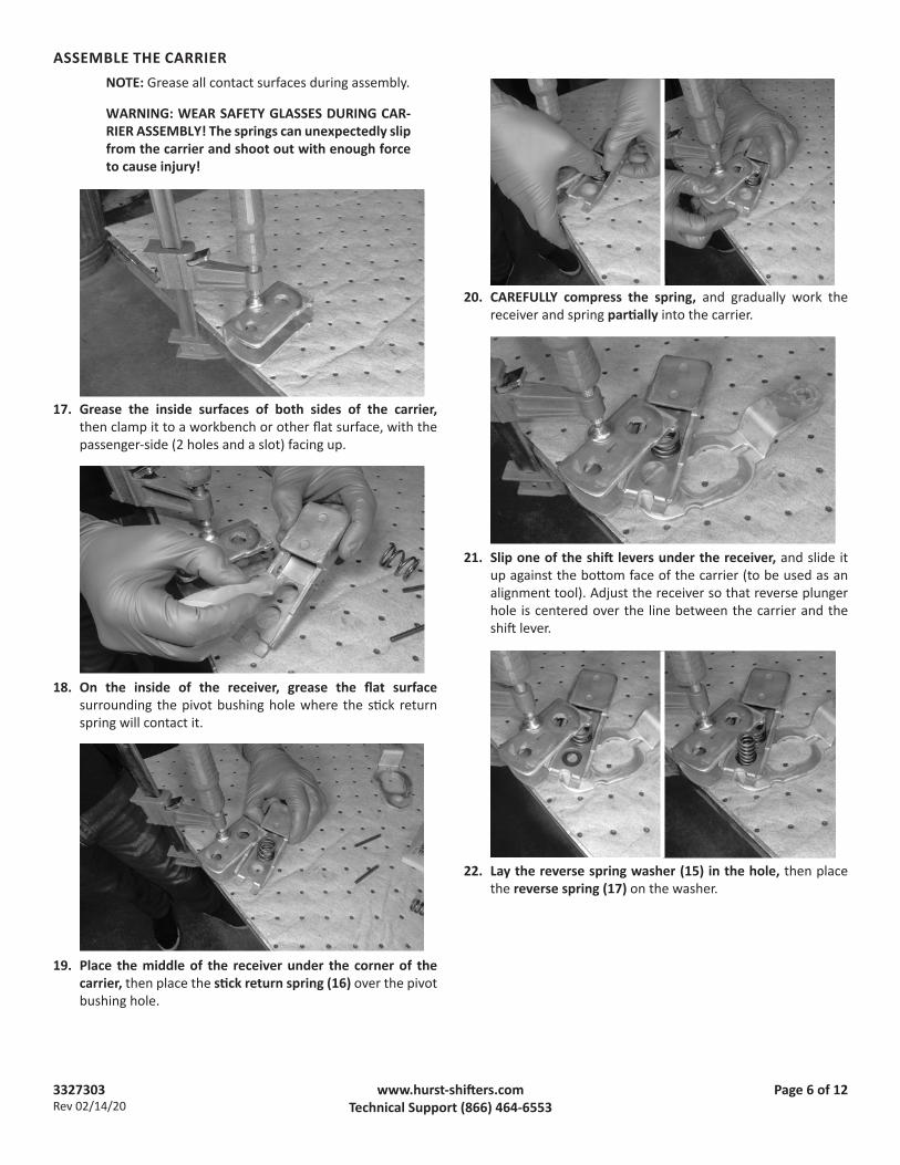
ASSEMBLE THE CARRIERNOTE: Grease all contact surfaces during assembly.
WARNING: WEAR SAFETY GLASSES DURING CAR-RIER ASSEMBLY! The springs can unexpectedly slip from the carrier and shoot out with enough force to cause injury!
17. Grease the inside surfaces of both sides of the carrier, then clamp it to a workbench or other flat surface, with the passenger-side (2 holes and a slot) facing up.
18. On the inside of the receiver, grease the flat surface surrounding the pivot bushing hole where the stick return spring will contact it.
19. Place the middle of the receiver under the corner of the carrier, then place the stick return spring (16) over the pivot bushing hole.
20. CAREFULLY compress the spring, and gradually work the receiver and spring partially into the carrier.
21. Slip one of the shift levers under the receiver, and slide it up against the bottom face of the carrier (to be used as an alignment tool). Adjust the receiver so that reverse plunger hole is centered over the line between the carrier and the shift lever.
22. Lay the reverse spring washer (15) in the hole, then place the reverse spring (17) on the washer.

3327303Rev 02/14/20
Page 7 of 12www.hurst-shifters.comTechnical Support (866) 464-6553
23. CAREFULLY compress the spring, and gradually work the receiver, spring, and washer into the carrier.
NOTE: Use a flat-tipped screwdriver or a putty knife to keep the washer in its hole in the receiver while working them both into the carrier.
24. Align the washer and springs with their respective holes using a punch or screwdriver.
25. Grease the selector plunger (9) and insert it through the carrier, with the roll pin holes oriented crosswise with the carrier.
26. Secure the protruding end of the receiver in a vise, with the carrier's front (open) end facing up. Then insert a small screwdriver between the receiver and carrier to center the tip of the receiver between the selector plunger's roll pin holes.
27. Install the 2 roll pins (19) in the selector plunger by orienting their seams away from the receiver tip, then tapping it into its hole until the pin is centered in the plunger.

3327303Rev 02/14/20
Page 8 of 12www.hurst-shifters.comTechnical Support (866) 464-6553
28. Install the reverse plunger (10) in its hole by first inserting it “sideways” (aligned side-to-side), then turning it 90 de-grees, so that its tip (bottom) and 2 tabs (top) fit into their respective slots.
NOTE: It may be necessary to re-center the washer and spring with a punch or screwdriver to allow the plunger to seat fully.
29. Insert the spring washer (14) between the carrier and the receiver (at the carriage bolt hole), with its center bend down (touching the receiver).
30. Use a flat-tipped screwdriver between the carrier and receiver to align the carriage bolt holes.
31. Insert the carriage bolt (18) fully. Be sure to align the bolt's square neck with the square hole in the carrier, so that the head seats fully in the carrier. Check selector plunger and receiver for free movement back and forth in the carrier.
ASSEMBLE THE SHIFTERNOTE: Grease the contact surfaces of all plates and levers during assembly.
32. Grease the selector plunger, and both sides of the carrier. Then place the assembly on the bench with the selector plunger face up.
33. Assemble the new plates and used shift levers on the carrier in the order shown. Orient the shift levers to match their orientation at removal. Grease each component before assembly.

3327303Rev 02/14/20
Page 9 of 12www.hurst-shifters.comTechnical Support (866) 464-6553
A. Reverse safety plate (5) (0.015" thick).
CAUTION: Notch faces left (vehicle front).
B. Reverse lever.
C. Interlock plate (4) (0.042" thick).
CAUTION: “Clipped” corner faces right (ve-hicle rear).
D. 1-2 shift lever.
E. 3-4 shift lever.
F. Wave plate (3). Install 1 or 2 wave plates, based on the number removed at disassembly.
CAUTION: To ensure that the wave plate presses against its adjacent parts as intended, orient it with the upper hole toward the right (vehicle rear).
3327303Rev 02/14/20
Page 10 of 12www.hurst-shifters.comTechnical Support (866) 464-6553
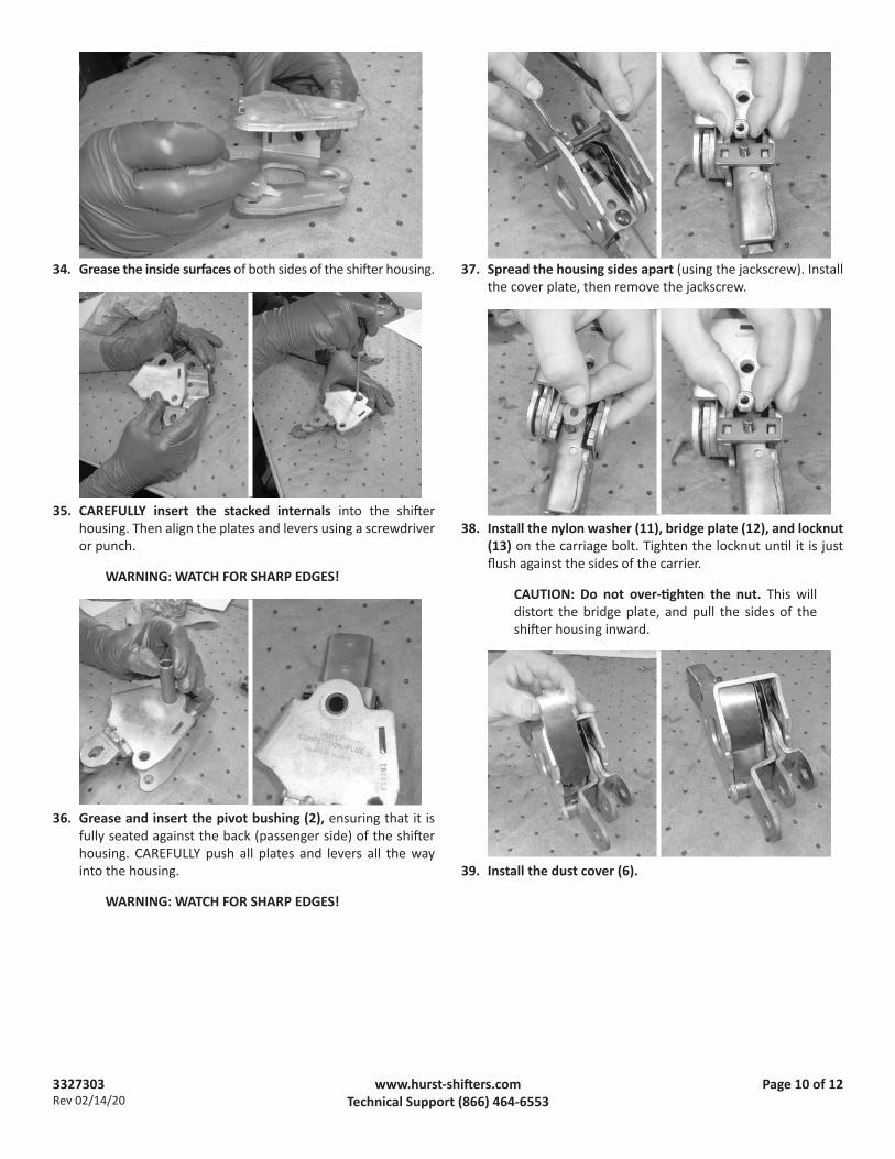
34. Grease the inside surfaces of both sides of the shifter housing.
35. CAREFULLY insert the stacked internals into the shifter housing. Then align the plates and levers using a screwdriver or punch.
WARNING: WATCH FOR SHARP EDGES!
36. Grease and insert the pivot bushing (2), ensuring that it is fully seated against the back (passenger side) of the shifter housing. CAREFULLY push all plates and levers all the way into the housing.
WARNING: WATCH FOR SHARP EDGES!
37. Spread the housing sides apart (using the jackscrew). Install the cover plate, then remove the jackscrew.
38. Install the nylon washer (11), bridge plate (12), and locknut (13) on the carriage bolt. Tighten the locknut until it is just flush against the sides of the carrier.
CAUTION: Do not over-tighten the nut. This will distort the bridge plate, and pull the sides of the shifter housing inward.
39. Install the dust cover (6).

3327303Rev 02/14/20
Page 11 of 12www.hurst-shifters.comTechnical Support (866) 464-6553
40. Assemble 2 jam nuts (8) and 2 stop screws (7), then thread the screws 3-5 turns into the shifter housing. (The stop screws will be adjusted after the shifter is installed on the transmission.)
Your Hurst Competition/Plus shifter is now rebuilt and ready to install.
INSTALLATION TIPS
1. Detailed installation instructions are provided with the Hurst installation kit for your shifter-transmission application. Installation kit instructions are also available for download at www.hurst-shifters.com.
CAUTION: To avoid transmission damage, shift rod length must be properly adjusted as described in the installation kit instructions. A neutral alignment pin (1) is included with this kit to ensure proper shift rod adjustment.
2. If you're installing your rebuilt shifter with an existing (used) installation kit, we recommend that you replace the used shift rod bushings with new nylon or steel bushings, available as Competition/Plus Shifter Bushing Pit Packs from your Hurst dealer.

3327303Rev 02/14/20
Page 12 of 12www.hurst-shifters.comTechnical Support (866) 464-6553
STOP SCREW ADJUSTMENT
1. Push the stick firmly forward into 3rd gear and hold it.
2. On the rear of the shifter housing, turn the 3rd gear stop screw in until contact is made. Then back the screw out one turn, and tighten the locknut while holding the screw stationary.
3. Pull the stick firmly back into 4th gear and hold it.
4. On the front of the shifter housing, turn the 4th gear stop screw in until contact is made. Then back the screw out one turn, and tighten the locknut while holding the screw stationary.
KEEP THESE INSTRUCTIONS FOR FUTURE REFERENCEHurst maintains a highly-trained technical service department to answer your technical questions, provide additional product information and offer various recommendations.
HURST TECHNICAL SUPPORT: (866) 464-6553
Hurst Performance Products
Related Documents