INSTALLATION INSTRUCTIONS LFH200 Cable This guide describes how to use the National Instruments LFH200 cable to connect the NI PXI-2569/2570/2571/2575 or SCXI-1169/1175 switch module to your system. The LFH200 cable is available in three configurations: • SH200LFH-4xDB50F-C—Recommended for use with the PXI-2569/2570/2571 or SCXI-1169. • SH200LFH-4xDB50F-S—Recommended for use with the PXI-2575 or SCXI-1175. • SH200LFH-BARE WIRE—Recommended for termination other than 50-pin female D-SUB. Caution The LFH200 cable has a maximum voltage rating of 60 VDC. When using the LFH200 cable with switch modules, do not exceed 60 VDC. Contents Conventions .............................................................................................................................. 2 Getting Started .......................................................................................................................... 2 Connecting the LFH200 Cable ................................................................................................. 2 Connectors ........................................................................................................................ 4 Cable Configurations ................................................................................................................ 5 SH200LFH-4xDB50F-C Cable ........................................................................................ 5 SH200LFH-4xDB50F-S Cable......................................................................................... 15 SH200LFH-BARE WIRE Cable ...................................................................................... 24 Accessories ............................................................................................................................... 33 Specifications............................................................................................................................ 34

Welcome message from author
This document is posted to help you gain knowledge. Please leave a comment to let me know what you think about it! Share it to your friends and learn new things together.
Transcript

INSTALLATION INSTRUCTIONS
LFH200 Cable
This guide describes how to use the National Instruments LFH200 cable to connect the NI PXI-2569/2570/2571/2575 or SCXI-1169/1175 switch module to your system.
The LFH200 cable is available in three configurations:
• SH200LFH-4xDB50F-C—Recommended for use with the PXI-2569/2570/2571 or SCXI-1169.
• SH200LFH-4xDB50F-S—Recommended for use with the PXI-2575 or SCXI-1175.
• SH200LFH-BARE WIRE—Recommended for termination other than 50-pin female D-SUB.
Caution The LFH200 cable has a maximum voltage rating of 60 VDC. When using the LFH200 cable with switch modules, do not exceed 60 VDC.
ContentsConventions .............................................................................................................................. 2Getting Started.......................................................................................................................... 2Connecting the LFH200 Cable ................................................................................................. 2
Connectors ........................................................................................................................ 4Cable Configurations ................................................................................................................ 5
SH200LFH-4xDB50F-C Cable ........................................................................................ 5SH200LFH-4xDB50F-S Cable......................................................................................... 15SH200LFH-BARE WIRE Cable ...................................................................................... 24
Accessories ............................................................................................................................... 33Specifications............................................................................................................................ 34

LFH200 Cable Installation Instructions 2 ni.com
ConventionsThe following conventions are used in this guide:
» The » symbol leads you through nested menu items and dialog box options to a final action. The sequence Options»Settings»General directs you to pull down the Options menu, select the Settings item, and select General from the last dialog box.
This icon denotes a note, which alerts you to important information.
This icon denotes a caution, which advises you of precautions to take to avoid injury, data loss, or a system crash.
bold Bold text denotes items that you must select or click in the software, such as menu items and dialog box options. Bold text also denotes parameter names.
italic Italic text denotes variables, emphasis, a cross-reference, or an introduction to a key concept. Italic text also denotes text that is a placeholder for a word or value that you must supply.
monospace Text in this font denotes text or characters that you should enter from the keyboard, sections of code, programming examples, and syntax examples. This font is also used for the proper names of disk drives, paths, directories, programs, subprograms, subroutines, device names, functions, operations, variables, filenames, and extensions.
Getting StartedThe following items are necessary for connecting the LFH200 cable:
❑ LFH200 cable
❑ NI PXI-2569/2570/2571/2575 or SCXI-1169/1175 switch module and documentation
Connecting the LFH200 CableComplete the following steps to connect the LFH200 cable to your switch module and application. Refer to Figures 1 and 2 for illustrations of the LFH200 cable.
1. Connect the LFH200 connector to the connector on the switch module.
2. Tighten the thumbscrews.
3. Complete either of the following steps, and refer to Tables 1 through 16 to determine how to connect your signals.
• Connect the D-SUB connectors to your application.
• Connect the unterminated wires to your application.

© National Instruments Corporation 3 LFH200 Cable Installation Instructions
Figure 1. SH200LFH-4xDB50F-C or SH200LFH-4xDB50F-S Cable
Figure 2. SH200LFH-BARE WIRE Cable
1 LFH200 Connector2 Thumbscrews
3 Cable Leg Label4 50-Pin Female D-SUB Connectors
1 LFH200 Connector2 Thumbscrews
3 Cable Leg Label4 25 Unterminated, Tinned, and Stripped Wires
4
1 2
3
1 2 43

LFH200 Cable Installation Instructions 4 ni.com
ConnectorsThe cable in this kit connects an LFH200 connector to four, 50-pin female D-SUB connectors marked P1–P4, or eight bundles, leg J0–J7, of unterminated, tinned, and stripped wires. The LFH200 connector provides connection to the switch module. The 50-pin female D-SUB connectors and unterminated wires provide connection to your application. Figures 3 and 4 show the pinouts for these connectors.
Figure 3. LFH200 Connector
Figure 4. 50-Pin Female D-SUB Connector
Pin 100
Pin 1
Pin 50
Pin 51
Pin 101
Pin 200
Pin 150
Pin 151
Pin 1
Pin 34
Pin 17
Pin 50
Pin 18Pin 33

© National Instruments Corporation 5 LFH200 Cable Installation Instructions
Cable ConfigurationsThe LFH200 cable is available in three configurations:
• SH200LFH-4xDB50F-C
• SH200LFH-4xDB50F-S
• SH200LFH-BARE WIRE
The following sections describe each of the LFH200 cable configurations.
SH200LFH-4xDB50F-C CableThe SH200LFH-4xDB50F-C cable is recommended for connecting the PXI-2569/2570/2571 or SCXI-1169 to your system. One end of the cable terminates with an LFH200 connector which connects to the switch module. The other end of the cable terminates with four 50-pin female D-SUB connectors.
When using the SH200LFH-4xDB50F-C cable with the PXI-2569 or SCXI-1169, each Channel and its corresponding Common form a twisted pair. For example, CH0 is paired with COM0, and CH1 is paired with COM1. Figure 5 illustrates how this pairing relates to the pins on the PXI-2569 or SCXI-1169.
Figure 5. Twisted Pair Groupings for the PXI-2569 or SCXI-1169
When using the SH200LFH-4xDB50F-C cable with the PXI-2570, each Channel and its corresponding NO (Normally Open) connection form a twisted pair. The NC (Normally Closed) connection is twisted with NO CONNECT wires. For example, COM0 is twisted with NO0, and NC0 is twisted with a NO CONNECT wire. Figure 6 illustrates how this pairing relates to the pins on the PXI-2570.
COM0
COM2
COM4
COM6
COM8
150151149152148153147154146155
51505249534854475546
CH0
CH2
CH4
CH6
CH8
CH1
CH3
CH5
CH7
CH9
COM1
COM3
COM5
COM7
COM9

LFH200 Cable Installation Instructions 6 ni.com
Figure 6. Twisted Pair Groupings for the PXI-2570
When using the SH200LFH-4xDB50F-C cable with the PXI-2571 the twisted pairs vary depending on the channel. For the first 50 Channels, each COM and its corresponding NO connection form a twisted pair. However, for the remaining 16 channels, the three components (NC, COM, and NO) are each twisted with a NC component from the first 50 Channels. For example, COM0 is twisted with NO0, and NC0 is twisted with NC50. COM1 is twisted with NO1, and NC1 is twisted with COM50. COM2 is twisted with NO2, and NC2 is twisted with NO50. Figure 7 illustrates how this pairing relates to the pins on the PXI-2571.
Figure 7. Twisted Pair Groupings for the PXI-2571
Refer to the NI Switches Help for a complete listing of channel names and pinouts.
The following tables list the pin assignments for the SH200LFH-4xDB50F-C cable.
NC0
NC1NO CONNECT
NC2
NC3
NC4
150151149152148153147154146155
51505249534854475546
COM0
COM1
COM2
COM3
COM4
NO0
NO1
NO2
NO3
NO4
NO CONNECT
NO CONNECT
NO CONNECT
NO CONNECT
NC0
NC1
NC2
NC3
NC4
150151149152148153147154146155
51505249534854475546
NC50
COM50
NO50
NC51
COM51
COM0
COM1
COM2
COM3
COM4
NO0
NO1
NO2
NO3
NO4

© National Instruments Corporation 7 LFH200 Cable Installation Instructions
Table 1. Pin Assignment for SH200LFH-4xDB50F-C P1
50-Pin D-SUB P1
CablePXI-2569, SCXI-1169
ChannelPXI-2570Channel
PXI-2571ChannelLFH Pin
50-Pin D-SUB Pin
26 50 COM49 NO24 NO24
27 48 COM47 NO23 NO23
28 46 COM45 NO22 NO22
29 44 COM43 NO21 NO21
30 42 COM41 NO20 NO20
31 40 COM39 NO19 NO19
32 38 COM37 NO18 NO18
33 36 COM35 NO17 NO17
34 34 COM33 NO16 NO16
35 19 COM31 NO15 NO15
36 21 COM29 NO14 NO14
37 23 COM27 NO13 NO13
38 25 COM25 NO12 NO12
39 27 COM23 NO11 NO11
40 29 COM21 NO10 NO10
41 31 COM19 NO9 NO9
42 33 COM17 NO8 NO8
43 16 COM15 NO7 NO7
44 14 COM13 NO6 NO6
45 12 COM11 NO5 NO5
46 10 COM9 NO4 NO4
47 8 COM7 NO3 NO3
48 6 COM5 NO2 NO2
49 4 COM3 NO1 NO1
50 2 COM1 NO0 NO0

LFH200 Cable Installation Instructions 8 ni.com
51 1 CH1 COM0 COM0
52 3 CH3 COM1 COM1
53 5 CH5 COM2 COM2
54 7 CH7 COM3 COM3
55 9 CH9 COM4 COM4
56 11 CH11 COM5 COM5
57 13 CH13 COM6 COM6
58 15 CH15 COM7 COM7
59 17 CH17 COM8 COM8
60 32 CH19 COM9 COM9
61 30 CH21 COM10 COM10
62 28 CH23 COM11 COM11
63 26 CH25 COM12 COM12
64 24 CH27 COM13 COM13
65 22 CH29 COM14 COM14
66 20 CH31 COM15 COM15
67 18 CH33 COM16 COM16
68 35 CH35 COM17 COM17
69 37 CH37 COM18 COM18
70 39 CH39 COM19 COM19
71 41 CH41 COM20 COM20
72 43 CH43 COM21 COM21
73 45 CH45 COM22 COM22
74 47 CH47 COM23 COM23
75 49 CH49 COM24 COM24
Table 1. Pin Assignment for SH200LFH-4xDB50F-C P1 (Continued)
50-Pin D-SUB P1
CablePXI-2569, SCXI-1169
ChannelPXI-2570Channel
PXI-2571ChannelLFH Pin
50-Pin D-SUB Pin

© National Instruments Corporation 9 LFH200 Cable Installation Instructions
Table 2. Pin Assignment for SH200LFH-4xDB50F-C P2
50-Pin D-SUB P2
CablePXI-2569, SCXI-1169
ChannelPXI-2570Channel
PXI-2571ChannelLFH Pin
50-Pin D-SUB Pin
126 50 COM48 NC24 NC24
127 48 COM46 NC23 NC23
128 46 COM44 NC22 NC22
129 44 COM42 NC21 NC21
130 42 COM40 NC20 NC20
131 40 COM38 NC19 NC19
132 38 COM36 NC18 NC18
133 36 COM34 NC17 NC17
134 34 COM32 NC16 NC16
135 19 COM30 NC15 NC15
136 21 COM28 NC14 NC14
137 23 COM26 NC13 NC13
138 25 COM24 NC12 NC12
139 27 COM22 NC11 NC11
140 29 COM20 NC10 NC10
141 31 COM18 NC9 NC9
142 33 COM16 NC8 NC8
143 16 COM14 NC7 NC7
144 14 COM12 NC6 NC6
145 12 COM10 NC5 NC5
146 10 COM8 NC4 NC4
147 8 COM6 NC3 NC3
148 6 COM4 NC2 NC2
149 4 COM2 NC1 NC1
150 2 COM0 NC0 NC0
151 1 CH0 — NC50
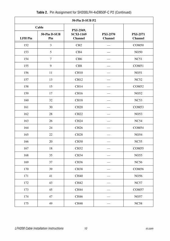
LFH200 Cable Installation Instructions 10 ni.com
152 3 CH2 — COM50
153 5 CH4 — NO50
154 7 CH6 — NC51
155 9 CH8 — COM51
156 11 CH10 — NO51
157 13 CH12 — NC52
158 15 CH14 — COM52
159 17 CH16 — NO52
160 32 CH18 — NC53
161 30 CH20 — COM53
162 28 CH22 — NO53
163 26 CH24 — NC54
164 24 CH26 — COM54
165 22 CH28 — NO54
166 20 CH30 — NC55
167 18 CH32 — COM55
168 35 CH34 — NO55
169 37 CH36 — NC56
170 39 CH38 — COM56
171 41 CH40 — NO56
172 43 CH42 — NC57
173 45 CH44 — COM57
174 47 CH46 — NO57
175 49 CH48 — NC58
Table 2. Pin Assignment for SH200LFH-4xDB50F-C P2 (Continued)
50-Pin D-SUB P2
CablePXI-2569, SCXI-1169
ChannelPXI-2570Channel
PXI-2571ChannelLFH Pin
50-Pin D-SUB Pin

© National Instruments Corporation 11 LFH200 Cable Installation Instructions
Table 3. Pin Assignment for SH200LFH-4xDB50F-C P3
50-Pin D-SUB P3
CablePXI-2569, SCXI-1169
ChannelPXI-2570Channel
PXI-2571ChannelLFH Pin
50-Pin D-SUB Pin
101 50 COM98 — NC49
102 48 COM96 — NC48
103 46 COM94 — NC47
104 44 COM92 — NC46
105 42 COM90 — NC45
106 40 COM88 — NC44
107 38 COM86 — NC43
108 36 COM84 — NC42
109 34 COM82 — NC41
110 19 COM80 — NC40
111 21 COM78 NC39 NC39
112 23 COM76 NC38 NC38
113 25 COM74 NC37 NC37
114 27 COM72 NC36 NC36
115 29 COM70 NC35 NC35
116 31 COM68 NC34 NC34
117 33 COM66 NC33 NC33
118 16 COM64 NC32 NC32
119 14 COM62 NC31 NC31
120 12 COM60 NC30 NC30
121 10 COM58 NC29 NC29
122 8 COM56 NC28 NC28
123 6 COM54 NC27 NC27
124 4 COM52 NC26 NC26
125 2 COM50 NC25 NC25
176 1 CH50 — COM58

LFH200 Cable Installation Instructions 12 ni.com
177 3 CH52 — NO58
178 5 CH54 — NC59
179 7 CH56 — COM59
180 9 CH58 — NO59
181 11 CH60 — NC60
182 13 CH62 — COM60
183 15 CH64 — NO60
184 17 CH66 — NC61
185 32 CH68 — COM61
186 30 CH70 — NO61
187 28 CH72 — NC62
188 26 CH74 — COM62
189 24 CH76 — NO62
190 22 CH78 — NC63
191 20 CH80 — COM63
192 18 CH82 — NO63
193 35 CH84 — NC64
194 37 CH86 — COM64
195 39 CH88 — NO64
196 41 CH90 — NC65
197 43 CH92 — COM65
198 45 CH94 — NO65
199 47 CH96 — —
200 49 CH98 — —
Table 3. Pin Assignment for SH200LFH-4xDB50F-C P3 (Continued)
50-Pin D-SUB P3
CablePXI-2569, SCXI-1169
ChannelPXI-2570Channel
PXI-2571ChannelLFH Pin
50-Pin D-SUB Pin

© National Instruments Corporation 13 LFH200 Cable Installation Instructions
Table 4. Pin Assignment for SH200LFH-4xDB50F-C P4
50-Pin D-SUB P4
CablePXI-2569, SCXI-1169
ChannelPXI-2570Channel
PXI-2571ChannelLFH Pin
50-Pin D-SUB Pin
1 50 COM99 — NO49
2 48 COM97 — NO48
3 46 COM95 — NO47
4 44 COM93 — NO46
5 42 COM91 — NO45
6 40 COM89 — NO44
7 38 COM87 — NO43
8 36 COM85 — NO42
9 34 COM83 — NO41
10 19 COM81 — NO40
11 21 COM79 NO39 NO39
12 23 COM77 NO38 NO38
13 25 COM75 NO37 NO37
14 27 COM73 NO36 NO36
15 29 COM71 NO35 NO35
16 31 COM69 NO34 NO34
17 33 COM67 NO33 NO33
18 16 COM65 NO32 NO32
19 14 COM63 NO31 NO31
20 12 COM61 NO30 NO30
21 10 COM59 NO29 NO29
22 8 COM57 NO28 NO28
23 6 COM55 NO27 NO27
24 4 COM53 NO26 NO26
25 2 COM51 NO25 NO25
76 1 CH51 COM25 COM25

LFH200 Cable Installation Instructions 14 ni.com
77 3 CH53 COM26 COM26
78 5 CH55 COM27 COM27
79 7 CH57 COM28 COM28
80 9 CH59 COM29 COM29
81 11 CH61 COM30 COM30
82 13 CH63 COM31 COM31
83 15 CH65 COM32 COM32
84 17 CH67 COM33 COM33
85 32 CH69 COM34 COM34
86 30 CH71 COM35 COM35
87 28 CH73 COM36 COM36
88 26 CH75 COM37 COM37
89 24 CH77 COM38 COM38
90 22 CH79 COM39 COM39
91 20 CH81 — COM40
92 18 CH83 — COM41
93 35 CH85 — COM42
94 37 CH87 — COM43
95 39 CH89 — COM44
96 41 CH91 — COM45
97 43 CH93 — COM46
98 45 CH95 — COM47
99 47 CH97 — COM48
100 49 CH99 — COM49
Table 4. Pin Assignment for SH200LFH-4xDB50F-C P4 (Continued)
50-Pin D-SUB P4
CablePXI-2569, SCXI-1169
ChannelPXI-2570Channel
PXI-2571ChannelLFH Pin
50-Pin D-SUB Pin
© National Instruments Corporation 15 LFH200 Cable Installation Instructions
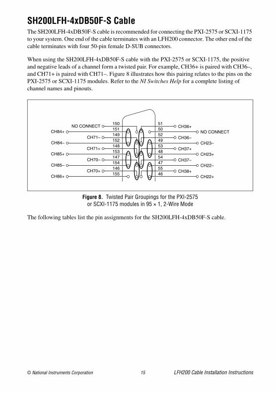
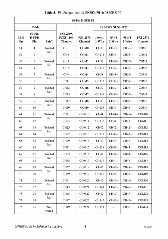
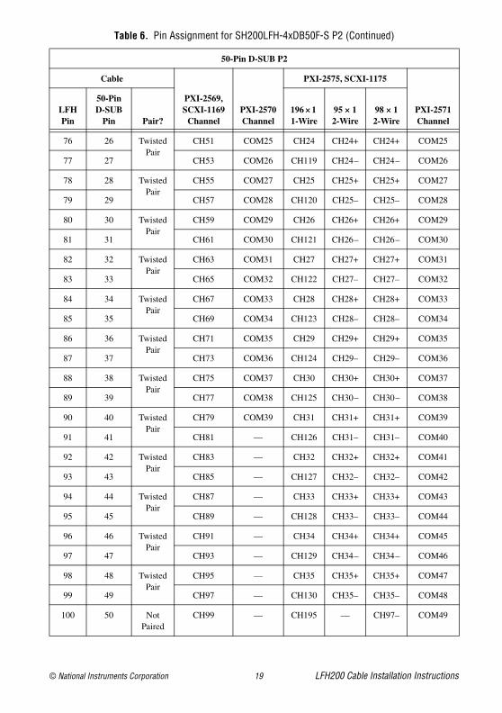
SH200LFH-4xDB50F-S CableThe SH200LFH-4xDB50F-S cable is recommended for connecting the PXI-2575 or SCXI-1175 to your system. One end of the cable terminates with an LFH200 connector. The other end of the cable terminates with four 50-pin female D-SUB connectors.
When using the SH200LFH-4xDB50F-S cable with the PXI-2575 or SCXI-1175, the positive and negative leads of a channel form a twisted pair. For example, CH36+ is paired with CH36–, and CH71+ is paired with CH71–. Figure 8 illustrates how this pairing relates to the pins on the PXI-2575 or SCXI-1175 modules. Refer to the NI Switches Help for a complete listing of channel names and pinouts.
Figure 8. Twisted Pair Groupings for the PXI-2575 or SCXI-1175 modules in 95 × 1, 2-Wire Mode
The following tables list the pin assignments for the SH200LFH-4xDB50F-S cable.
NO CONNECT
CH71–
CH71+
CH70–
CH70+
150151149152148153147154146155
51505249534854475546
CH84+
CH84–
CH85+
CH85–
CH86+
CH36+
CH36–
CH37+
CH37–
CH38+
NO CONNECT
CH23–
CH23+
CH22–
CH22+

LFH200 Cable Installation Instructions 16 ni.com
Table 5. Pin Assignment for SH200LFH-4xDB50F-S P1
50-Pin D-SUB P1
Cable
PXI-2569, SCXI-1169
ChannelPXI-2570Channel
PXI-2575, SCXI-1175
PXI-2571Channel
LFH Pin
50-Pin D-SUB
Pin Pair?196 × 1 1-Wire
95 × 1 2-Wire
98 × 1 2-Wire
1 1 Twisted Pair
COM99 — CH0 CH0+ CH0+ NO49
2 2 COM97 — CH95 CH0– CH0– NO48
3 3 Twisted Pair
COM95 — CH1 CH1+ CH1+ NO47
4 4 COM93 — CH96 CH1– CH1– NO46
5 5 Twisted Pair
COM91 — CH2 CH2+ CH2+ NO45
6 6 COM89 — CH97 CH2– CH2– NO44
7 7 Twisted Pair
COM87 — CH3 CH3+ CH3+ NO43
8 8 COM85 — CH98 CH3– CH3– NO42
9 9 Twisted Pair
COM83 — CH4 CH4+ CH4+ NO41
10 10 COM81 — CH99 CH4– CH4– NO40
11 11 Twisted Pair
COM79 NO39 CH5 CH5+ CH5+ NO39
12 12 COM77 NO38 CH100 CH5– CH5– NO38
13 13 Twisted Pair
COM75 NO37 CH6 CH6+ CH6+ NO37
14 14 COM73 NO36 CH101 CH6– CH6– NO36
15 15 Twisted Pair
COM71 NO35 CH7 CH7+ CH7+ NO35
16 16 COM69 NO34 CH102 CH7– CH7– NO34
17 17 Twisted Pair
COM67 NO33 CH8 CH8+ CH8+ NO33
18 18 COM65 NO32 CH103 CH8– CH8– NO32
19 19 Twisted Pair
COM63 NO31 CH9 CH9+ CH9+ NO31
20 20 COM61 NO30 CH104 CH9– CH9– NO30
21 21 Twisted Pair
COM59 NO29 CH10 CH10+ CH10+ NO29
22 22 COM57 NO28 CH105 CH10– CH10– NO28
23 23 Twisted Pair
COM55 NO27 CH11 CH11+ CH11+ NO27
24 24 COM53 NO26 CH106 CH11– CH11– NO26
25 25 Not Paired
COM51 NO25 CH194 — CH96– NO25

© National Instruments Corporation 17 LFH200 Cable Installation Instructions
26 26 Twisted Pair
COM49 NO24 CH12 CH12+ CH12+ NO24
27 27 COM47 NO23 CH107 CH12– CH12– NO23
28 28 Twisted Pair
COM45 NO22 CH13 CH13+ CH13+ NO22
29 29 COM43 NO21 CH108 CH13– CH13– NO21
30 30 Twisted Pair
COM41 NO20 CH14 CH14+ CH14+ NO20
31 31 COM39 NO19 CH109 CH14– CH14– NO19
32 32 Twisted Pair
COM37 NO18 CH15 CH15+ CH15+ NO18
33 33 COM35 NO17 CH110 CH15– CH15– NO17
34 34 Twisted Pair
COM33 NO16 CH16 CH16+ CH16+ NO16
35 35 COM31 NO15 CH111 CH16– CH16– NO15
36 36 Twisted Pair
COM29 NO14 CH17 CH17+ CH17+ NO14
37 37 COM27 NO13 CH112 CH17– CH17– NO13
38 38 Twisted Pair
COM25 NO12 CH18 CH18+ CH18+ NO12
39 39 COM23 NO11 CH113 CH18– CH18– NO11
40 40 Twisted Pair
COM21 NO10 CH19 CH19+ CH19+ NO10
41 41 COM19 NO9 CH114 CH19– CH19– NO9
42 42 Twisted Pair
COM17 NO8 CH20 CH20+ CH20+ NO8
43 43 COM15 NO7 CH115 CH20– CH20– NO7
44 44 Twisted Pair
COM13 NO6 CH21 CH21+ CH21+ NO6
45 45 COM11 NO5 CH116 CH21– CH21– NO5
46 46 Twisted Pair
COM9 NO4 CH22 CH22+ CH22+ NO4
47 47 COM7 NO3 CH117 CH22– CH22– NO3
48 48 Twisted Pair
COM5 NO2 CH23 CH23+ CH23+ NO2
49 49 COM3 NO1 CH118 CH23– CH23– NO1
50 50 Not Paired
COM1 NO0 — — — NO0
Table 5. Pin Assignment for SH200LFH-4xDB50F-S P1 (Continued)
50-Pin D-SUB P1
Cable
PXI-2569, SCXI-1169
ChannelPXI-2570Channel
PXI-2575, SCXI-1175
PXI-2571Channel
LFH Pin
50-Pin D-SUB
Pin Pair?196 × 1 1-Wire
95 × 1 2-Wire
98 × 1 2-Wire
LFH200 Cable Installation Instructions 18 ni.com
Table 6. Pin Assignment for SH200LFH-4xDB50F-S P2
50-Pin D-SUB P2
Cable
PXI-2569, SCXI-1169
ChannelPXI-2570Channel
PXI-2575, SCXI-1175
PXI-2571Channel
LFH Pin
50-Pin D-SUB
Pin Pair?196 × 1 1-Wire
95 × 1 2-Wire
98 × 1 2-Wire
51 1 Twisted Pair
CH1 COM0 CH36 CH36+ CH36+ COM0
52 2 CH3 COM1 CH131 CH36– CH36– COM1
53 3 Twisted Pair
CH5 COM2 CH37 CH37+ CH37+ COM2
54 4 CH7 COM3 CH132 CH37– CH37– COM3
55 5 Twisted Pair
CH9 COM4 CH38 CH38+ CH38+ COM4
56 6 CH11 COM5 CH133 CH38– CH38– COM5
57 7 Twisted Pair
CH13 COM6 CH39 CH39+ CH39+ COM6
58 8 CH15 COM7 CH134 CH39– CH39– COM7
59 9 Twisted Pair
CH17 COM8 CH40 CH40+ CH40+ COM8
60 10 CH19 COM9 CH135 CH40– CH40– COM9
61 11 Twisted Pair
CH21 COM10 CH41 CH41+ CH41+ COM10
62 12 CH23 COM11 CH136 CH41– CH41– COM11
63 13 Twisted Pair
CH25 COM12 CH42 CH42+ CH42+ COM12
64 14 CH27 COM13 CH137 CH42– CH42– COM13
65 15 Twisted Pair
CH29 COM14 CH43 CH43+ CH43+ COM14
66 16 CH31 COM15 CH138 CH43– CH43– COM15
67 17 Twisted Pair
CH33 COM16 CH44 CH44+ CH44+ COM16
68 18 CH35 COM17 CH139 CH44– CH44– COM17
69 19 Twisted Pair
CH37 COM18 CH45 CH45+ CH45+ COM18
70 20 CH39 COM19 CH140 CH45– CH45– COM19
71 21 Twisted Pair
CH41 COM20 CH46 CH46+ CH46+ COM20
72 22 CH43 COM21 CH141 CH46– CH46– COM21
73 23 Twisted Pair
CH45 COM22 CH47 CH47+ CH47+ COM22
74 24 CH47 COM23 CH142 CH47– CH47– COM23
75 25 Not Paired
CH49 COM24 CH191 — CH96+ COM24
© National Instruments Corporation 19 LFH200 Cable Installation Instructions
76 26 Twisted Pair
CH51 COM25 CH24 CH24+ CH24+ COM25
77 27 CH53 COM26 CH119 CH24– CH24– COM26
78 28 Twisted Pair
CH55 COM27 CH25 CH25+ CH25+ COM27
79 29 CH57 COM28 CH120 CH25– CH25– COM28
80 30 Twisted Pair
CH59 COM29 CH26 CH26+ CH26+ COM29
81 31 CH61 COM30 CH121 CH26– CH26– COM30
82 32 Twisted Pair
CH63 COM31 CH27 CH27+ CH27+ COM31
83 33 CH65 COM32 CH122 CH27– CH27– COM32
84 34 Twisted Pair
CH67 COM33 CH28 CH28+ CH28+ COM33
85 35 CH69 COM34 CH123 CH28– CH28– COM34
86 36 Twisted Pair
CH71 COM35 CH29 CH29+ CH29+ COM35
87 37 CH73 COM36 CH124 CH29– CH29– COM36
88 38 Twisted Pair
CH75 COM37 CH30 CH30+ CH30+ COM37
89 39 CH77 COM38 CH125 CH30– CH30– COM38
90 40 Twisted Pair
CH79 COM39 CH31 CH31+ CH31+ COM39
91 41 CH81 — CH126 CH31– CH31– COM40
92 42 Twisted Pair
CH83 — CH32 CH32+ CH32+ COM41
93 43 CH85 — CH127 CH32– CH32– COM42
94 44 Twisted Pair
CH87 — CH33 CH33+ CH33+ COM43
95 45 CH89 — CH128 CH33– CH33– COM44
96 46 Twisted Pair
CH91 — CH34 CH34+ CH34+ COM45
97 47 CH93 — CH129 CH34– CH34– COM46
98 48 Twisted Pair
CH95 — CH35 CH35+ CH35+ COM47
99 49 CH97 — CH130 CH35– CH35– COM48
100 50 Not Paired
CH99 — CH195 — CH97– COM49
Table 6. Pin Assignment for SH200LFH-4xDB50F-S P2 (Continued)
50-Pin D-SUB P2
Cable
PXI-2569, SCXI-1169
ChannelPXI-2570Channel
PXI-2575, SCXI-1175
PXI-2571Channel
LFH Pin
50-Pin D-SUB
Pin Pair?196 × 1 1-Wire
95 × 1 2-Wire
98 × 1 2-Wire

LFH200 Cable Installation Instructions 20 ni.com
Table 7. Pin Assignment for SH200LFH-4xDB50F-S P3
50-Pin D-SUB P3
Cable
PXI-2569, SCXI-1169
ChannelPXI-2570Channel
PXI-2575, SCXI-1175
PXI-2571Channel
LFH Pin
50-Pin D-SUB
Pin Pair?196 × 1 1-Wire
95 × 1 2-Wire
98 × 1 2-Wire
101 1 Twisted Pair
COM98 — CH48 CH48+ CH48+ NC49
102 2 COM96 — CH143 CH48– CH48– NC48
103 3 Twisted Pair
COM94 — CH49 CH49+ CH49+ NC47
104 4 COM92 — CH144 CH49– CH49– NC46
105 5 Twisted Pair
COM90 — CH50 CH50+ CH50+ NC45
106 6 COM88 — CH145 CH50– CH50– NC44
107 7 Twisted Pair
COM86 — CH51 CH51+ CH51+ NC43
108 8 COM84 — CH146 CH51– CH51– NC42
109 9 Twisted Pair
COM82 — CH52 CH52+ CH52+ NC41
110 10 COM80 — CH147 CH52– CH52– NC40
111 11 Twisted Pair
COM78 NC39 CH53 CH53+ CH53+ NC39
112 12 COM76 NC38 CH148 CH53– CH53– NC38
113 13 Twisted Pair
COM74 NC37 CH54 CH54+ CH54+ NC37
114 14 COM72 NC36 CH149 CH54– CH54– NC36
115 15 Twisted Pair
COM70 NC35 CH55 CH55+ CH55+ NC35
116 16 COM68 NC34 CH150 CH55– CH55– NC34
117 17 Twisted Pair
COM66 NC33 CH56 CH56+ CH56+ NC33
118 18 COM64 NC32 CH151 CH56– CH56– NC32
119 19 Twisted Pair
COM62 NC31 CH57 CH57+ CH57+ NC31
120 20 COM60 NC30 CH152 CH57– CH57– NC30
121 21 Twisted Pair
COM58 NC29 CH58 CH58+ CH58+ NC29
122 22 COM56 NC28 CH153 CH58– CH58– NC28
123 23 Twisted Pair
COM54 NC27 CH59 CH59+ CH59+ NC27
124 24 COM52 NC26 CH154 CH59– CH59– NC26
125 25 Not Paired
COM50 NC25 CH193 — CH95– NC25

© National Instruments Corporation 21 LFH200 Cable Installation Instructions
126 26 Twisted Pair
COM48 NC24 CH60 CH60+ CH60+ NC24
127 27 COM46 NC23 CH155 CH60– CH60– NC23
128 28 Twisted Pair
COM44 NC22 CH61 CH61+ CH61+ NC22
129 29 COM42 NC21 CH156 CH61– CH61– NC21
130 30 Twisted Pair
COM40 NC20 CH62 CH62+ CH62+ NC20
131 31 COM38 NC19 CH157 CH62– CH62– NC19
132 32 Twisted Pair
COM36 NC18 CH63 CH63+ CH63+ NC18
133 33 COM34 NC17 CH158 CH63– CH63– NC17
134 34 Twisted Pair
COM32 NC16 CH64 CH64+ CH64+ NC16
135 35 COM30 NC15 CH159 CH64– CH64– NC15
136 36 Twisted Pair
COM28 NC14 CH65 CH65+ CH65+ NC14
137 37 COM26 NC13 CH160 CH65– CH65– NC13
138 38 Twisted Pair
COM24 NC12 CH66 CH66+ CH66+ NC12
139 39 COM22 NC11 CH161 CH66– CH66– NC11
140 40 Twisted Pair
COM20 NC10 CH67 CH67+ CH67+ NC10
141 41 COM18 NC9 CH162 CH67– CH67– NC9
142 42 Twisted Pair
COM16 NC8 CH68 CH68+ CH68+ NC8
143 43 COM14 NC7 CH163 CH68– CH68– NC7
144 44 Twisted Pair
COM12 NC6 CH69 CH69+ CH69+ NC6
145 45 COM10 NC5 CH164 CH69– CH69– NC5
146 46 Twisted Pair
COM8 NC4 CH70 CH70+ CH70+ NC4
147 47 COM6 NC3 CH165 CH70– CH70– NC3
148 48 Twisted Pair
COM4 NC2 CH71 CH71+ CH71+ NC2
149 49 COM2 NC1 CH166 CH71– CH71– NC1
150 50 Not Paired
COM0 NC0 — — — NC0
Table 7. Pin Assignment for SH200LFH-4xDB50F-S P3 (Continued)
50-Pin D-SUB P3
Cable
PXI-2569, SCXI-1169
ChannelPXI-2570Channel
PXI-2575, SCXI-1175
PXI-2571Channel
LFH Pin
50-Pin D-SUB
Pin Pair?196 × 1 1-Wire
95 × 1 2-Wire
98 × 1 2-Wire
LFH200 Cable Installation Instructions 22 ni.com
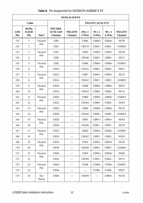
Table 8. Pin Assignment for SH200LFH-4xDB50F-S P4
50-Pin D-SUB P4
Cable
PXI-2569, SCXI-1169
ChannelPXI-2570Channel
PXI-2575, SCXI-1175
PXI-2571Channel
LFH Pin
50-Pin D-SUB
Pin Pair?196 × 1 1-Wire
95 × 1 2-Wire
98 × 1 2-Wire
151 1 Twisted Pair
CH0 — CH84 CH84+ CH84+ NC50
152 2 CH2 — CH179 CH84– CH84– COM50
153 3 Twisted Pair
CH4 — CH85 CH85+ CH85+ NO50
154 4 CH6 — CH180 CH85– CH85– NC51
155 5 Twisted Pair
CH8 — CH86 CH86+ CH86+ COM51
156 6 CH10 — CH181 CH86– CH86– NO51
157 7 Twisted Pair
CH12 — CH87 CH87+ CH87+ NC52
158 8 CH14 — CH182 CH87– CH87– COM52
159 9 Twisted Pair
CH16 — CH88 CH88+ CH88+ NO52
160 10 CH18 — CH183 CH88– CH88– NC53
161 11 Twisted Pair
CH20 — CH89 CH89+ CH89+ COM53
162 12 CH22 — CH184 CH89– CH89– NO53
163 13 Twisted Pair
CH24 — CH90 CH90+ CH90+ NC54
164 14 CH26 — CH185 CH90– CH90– COM54
165 15 Twisted Pair
CH28 — CH91 CH91+ CH91+ NO54
166 16 CH30 — CH186 CH91– CH91– NC55
167 17 Twisted Pair
CH32 — CH92 CH92+ CH92+ COM55
168 18 CH34 — CH187 CH92– CH92– NO55
169 19 Twisted Pair
CH36 — CH93 CH93+ CH93+ NC56
170 20 CH38 — CH188 CH93– CH93– COM56
171 21 Twisted Pair
CH40 — CH94 CH94+ CH94+ NO56
172 22 CH42 — CH189 CH94– CH94– NC57
173 23 Twisted Pair
CH44 — COM COM+ COM+ COM57
174 24 CH46 — — COM– COM– NO57
175 25 Not Paired
CH48 — CH190 — CH95+ NC58

© National Instruments Corporation 23 LFH200 Cable Installation Instructions
176 26 Twisted Pair
CH50 — CH72 CH72+ CH72+ COM58
177 27 CH52 — CH167 CH72– CH72– NO58
178 28 Twisted Pair
CH54 — CH73 CH73+ CH73+ NC59
179 29 CH56 — CH168 CH73– CH73– COM59
180 30 Twisted Pair
CH58 — CH74 CH74+ CH74+ NO59
181 31 CH60 — CH169 CH74– CH74– NC60
182 32 Twisted Pair
CH62 — CH75 CH75+ CH75+ COM60
183 33 CH64 — CH170 CH75– CH75– NO60
184 34 Twisted Pair
CH66 — CH76 CH76+ CH76+ NC61
185 35 CH68 — CH171 CH76– CH76– COM61
186 36 Twisted Pair
CH70 — CH77 CH77+ CH77+ NO61
187 37 CH72 — CH172 CH77– CH77– NC62
188 38 Twisted Pair
CH74 — CH78 CH78+ CH78+ COM62
189 39 CH76 — CH173 CH78– CH78– NO62
190 40 Twisted Pair
CH78 — CH79 CH79+ CH79+ NC63
191 41 CH80 — CH174 CH79– CH79– COM63
192 42 Twisted Pair
CH82 — CH80 CH80+ CH80+ NO63
193 43 CH84 — CH175 CH80– CH80– NC64
194 44 Twisted Pair
CH86 — CH81 CH81+ CH81+ COM64
195 45 CH88 — CH176 CH81– CH81– NO64
196 46 Twisted Pair
CH90 — CH82 CH82+ CH82+ NC65
197 47 CH92 — CH177 CH82– CH82– COM65
198 48 Twisted Pair
CH94 — CH83 CH83+ CH83+ NO65
199 49 CH96 — CH178 CH83– CH83– —
200 50 Not Paired
CH98 — CH192 — CH97+ —
Table 8. Pin Assignment for SH200LFH-4xDB50F-S P4 (Continued)
50-Pin D-SUB P4
Cable
PXI-2569, SCXI-1169
ChannelPXI-2570Channel
PXI-2575, SCXI-1175
PXI-2571Channel
LFH Pin
50-Pin D-SUB
Pin Pair?196 × 1 1-Wire
95 × 1 2-Wire
98 × 1 2-Wire

LFH200 Cable Installation Instructions 24 ni.com
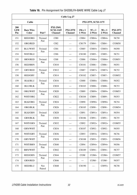
SH200LFH-BARE WIRE CableThe SH200LFH-BARE WIRE cable is recommended for connecting the switch module to your system if termination other than 50-pin female D-SUB is required. One end of the cable terminates with an LFH200 connector. The other end of the cable has eight bundles of unterminated, tinned, and stripped wires.
The following tables list the pin assignments for the SH200LFH-BARE WIRE cable.
Note The first color listed in the Bare Wire Color column of Tables 9 through 16 is the primary color of the wire. The second color listed is the stripe color.
Note Each of the eight bundles consists of 13 twisted pairs of wires. Only 25 of the wires are used. Therefore, the 26th blue/red wire remains unused and unmentioned in Tables 9 through 16.

© National Instruments Corporation 25 LFH200 Cable Installation Instructions
Table 9. Pin Assignment for SH200LFH-BARE WIRE Cable Leg J0
Cable Leg J0
Cable
PXI-2569, SCXI-1169
ChannelPXI-2570Channel
PXI-2575, SCXI-1175
PXI-2571Channel
200 LFH Pin
Bare Wire Color Pair?
196 × 1 1-Wire
95 × 1 2-Wire
98 × 1 2-Wire
1 RED/ORG Twisted Pair
COM99 — CH0 CH0+ CH0+ NO49
2 ORG/RED COM97 — CH95 CH0– CH0– NO48
3 BLU/WHT Twisted Pair
COM95 — CH1 CH1+ CH1+ NO47
4 WHT/BLU COM93 — CH96 CH1– CH1– NO46
5 BRN/RED Twisted Pair
COM91 — CH2 CH2+ CH2+ NO45
6 RED/BRN COM89 — CH97 CH2– CH2– NO44
7 GRY/RED Twisted Pair
COM87 — CH3 CH3+ CH3+ NO43
8 RED/GRY COM85 — CH98 CH3– CH3– NO42
9 BLK/BLU Twisted Pair
COM83 — CH4 CH4+ CH4+ NO41
10 BLU/BLK COM81 — CH99 CH4– CH4– NO40
11 ORG/WHT Twisted Pair
COM79 NO39 CH5 CH5+ CH5+ NO39
12 WHT/ORG COM77 NO38 CH100 CH5– CH5– NO38
13 BLK/ORG Twisted Pair
COM75 NO37 CH6 CH6+ CH6+ NO37
14 ORG/BLK COM73 NO36 CH101 CH6– CH6– NO36
15 BLK/GRN Twisted Pair
COM71 NO35 CH7 CH7+ CH7+ NO35
16 GRN/BLK COM69 NO34 CH102 CH7– CH7– NO34
17 WHT/GRN Twisted Pair
COM67 NO33 CH8 CH8+ CH8+ NO33
18 GRN/WHT COM65 NO32 CH103 CH8– CH8– NO32
19 WHT/GRY Twisted Pair
COM63 NO31 CH9 CH9+ CH9+ NO31
20 GRY/WHT COM61 NO30 CH104 CH9– CH9– NO30
21 WHT/BRN Twisted Pair
COM59 NO29 CH10 CH10+ CH10+ NO29
22 BRN/WHT COM57 NO28 CH105 CH10– CH10– NO28
23 RED/GRN Twisted Pair
COM55 NO27 CH11 CH11+ CH11+ NO27
24 GRN/RED COM53 NO26 CH106 CH11– CH11– NO26
25 RED/BLU Not Paired
COM51 NO25 CH194 — CH96– NO25

LFH200 Cable Installation Instructions 26 ni.com
Table 10. Pin Assignment for SH200LFH-BARE WIRE Cable Leg J1
Cable Leg J1
Cable
PXI-2569, SCXI-1169
ChannelPXI-2570Channel
PXI-2575, SCXI-1175
PXI-2571Channel
200 LFH Pin
Bare Wire Color Pair?
196 × 1 1-Wire
95 × 1 2-Wire
98 × 1 2-Wire
26 RED/ORG Twisted Pair
COM49 NO24 CH12 CH12+ CH12+ NO24
27 ORG/RED COM47 NO23 CH107 CH12– CH12– NO23
28 BLU/WHT Twisted Pair
COM45 NO22 CH13 CH13+ CH13+ NO22
29 WHT/BLU COM43 NO21 CH108 CH13– CH13– NO21
30 BRN/RED Twisted Pair
COM41 NO20 CH14 CH14+ CH14+ NO20
31 RED/BRN COM39 NO19 CH109 CH14– CH14– NO19
32 GRY/RED Twisted Pair
COM37 NO18 CH15 CH15+ CH15+ NO18
33 RED/GRY COM35 NO17 CH110 CH15– CH15– NO17
34 BLK/BLU Twisted Pair
COM33 NO16 CH16 CH16+ CH16+ NO16
35 BLU/BLK COM31 NO15 CH111 CH16– CH16– NO15
36 ORG/WHT Twisted Pair
COM29 NO14 CH17 CH17+ CH17+ NO14
37 WHT/ORG COM27 NO13 CH112 CH17– CH17– NO13
38 BLK/ORG Twisted Pair
COM25 NO12 CH18 CH18+ CH18+ NO12
39 ORG/BLK COM23 NO11 CH113 CH18– CH18– NO11
40 BLK/GRN Twisted Pair
COM21 NO10 CH19 CH19+ CH19+ NO10
41 GRN/BLK COM19 NO9 CH114 CH19– CH19– NO9
42 WHT/GRN Twisted Pair
COM17 NO8 CH20 CH20+ CH20+ NO8
43 GRN/WHT COM15 NO7 CH115 CH20– CH20– NO7
44 WHT/GRY Twisted Pair
COM13 NO6 CH21 CH21+ CH21+ NO6
45 GRY/WHT COM11 NO5 CH116 CH21– CH21– NO5
46 WHT/BRN Twisted Pair
COM9 NO4 CH22 CH22+ CH22+ NO4
47 BRN/WHT COM7 NO3 CH117 CH22– CH22– NO3
48 RED/GRN Twisted Pair
COM5 NO2 CH23 CH23+ CH23+ NO2
49 GRN/RED COM3 NO1 CH118 CH23– CH23– NO1
50 RED/BLU Not Paired
COM1 NO0 — — — NO0

© National Instruments Corporation 27 LFH200 Cable Installation Instructions
Table 11. Pin Assignment for SH200LFH-BARE WIRE Cable Leg J2
Cable Leg J2
Cable
PXI-2569, SCXI-1169
ChannelPXI-2570Channel
PXI-2575, SCXI-1175
PXI-2571Channel
200 LFH Pin
Bare Wire Color Pair?
196 × 1 1-Wire
95 × 1 2-Wire
98 × 1 2-Wire
76 RED/ORG Twisted Pair
CH51 COM25 CH24 CH24+ CH24+ COM25
77 ORG/RED CH53 COM26 CH119 CH24– CH24– COM26
78 BLU/WHT Twisted Pair
CH55 COM27 CH25 CH25+ CH25+ COM27
79 WHT/BLU CH57 COM28 CH120 CH25– CH25– COM28
80 BRN/RED Twisted Pair
CH59 COM29 CH26 CH26+ CH26+ COM29
81 RED/BRN CH61 COM30 CH121 CH26– CH26– COM30
82 GRY/RED Twisted Pair
CH63 COM31 CH27 CH27+ CH27+ COM31
83 RED/GRY CH65 COM32 CH122 CH27– CH27– COM32
84 BLK/BLU Twisted Pair
CH67 COM33 CH28 CH28+ CH28+ COM33
85 BLU/BLK CH69 COM34 CH123 CH28– CH28– COM34
86 ORG/WHT Twisted Pair
CH71 COM35 CH29 CH29+ CH29+ COM35
87 WHT/ORG CH73 COM36 CH124 CH29– CH29– COM36
88 BLK/ORG Twisted Pair
CH75 COM37 CH30 CH30+ CH30+ COM37
89 ORG/BLK CH77 COM38 CH125 CH30– CH30– COM38
90 BLK/GRN Twisted Pair
CH79 COM39 CH31 CH31+ CH31+ COM39
91 GRN/BLK CH81 — CH126 CH31– CH31– COM40
92 WHT/GRN Twisted Pair
CH83 — CH32 CH32+ CH32+ COM41
93 GRN/WHT CH85 — CH127 CH32– CH32– COM42
94 WHT/GRY Twisted Pair
CH87 — CH33 CH33+ CH33+ COM43
95 GRY/WHT CH89 — CH128 CH33– CH33– COM44
96 WHT/BRN Twisted Pair
CH91 — CH34 CH34+ CH34+ COM45
97 BRN/WHT CH93 — CH129 CH34– CH34– COM46
98 RED/GRN Twisted Pair
CH95 — CH35 CH35+ CH35+ COM47
99 GRN/RED CH97 — CH130 CH35– CH35– COM48
100 RED/BLU Not Paired
CH99 — CH195 — CH97– COM49

LFH200 Cable Installation Instructions 28 ni.com
Table 12. Pin Assignment for SH200LFH-BARE WIRE Cable Leg J3
Cable Leg J3
Cable
PXI-2569, SCXI-1169
ChannelPXI-2570Channel
PXI-2575, SCXI-1175
PXI-2571Channel
200 LFH Pin
Bare Wire Color Pair?
196 × 1 1-Wire
95 × 1 2-Wire
98 × 1 2-Wire
51 RED/ORG Twisted Pair
CH1 COM0 CH36 CH36+ CH36+ COM0
52 ORG/RED CH3 COM1 CH131 CH36– CH36– COM1
53 BLU/WHT Twisted Pair
CH5 COM2 CH37 CH37+ CH37+ COM2
54 WHT/BLU CH7 COM3 CH132 CH37– CH37– COM3
55 BRN/RED Twisted Pair
CH9 COM4 CH38 CH38+ CH38+ COM4
56 RED/BRN CH11 COM5 CH133 CH38– CH38– COM5
57 GRY/RED Twisted Pair
CH13 COM6 CH39 CH39+ CH39+ COM6
58 RED/GRY CH15 COM7 CH134 CH39– CH39– COM7
59 BLK/BLU Twisted Pair
CH17 COM8 CH40 CH40+ CH40+ COM8
60 BLU/BLK CH19 COM9 CH135 CH40– CH40– COM9
61 ORG/WHT Twisted Pair
CH21 COM10 CH41 CH41+ CH41+ COM10
62 WHT/ORG CH23 COM11 CH136 CH41– CH41– COM11
63 BLK/ORG Twisted Pair
CH25 COM12 CH42 CH42+ CH42+ COM12
64 ORG/BLK CH27 COM13 CH137 CH42– CH42– COM13
65 BLK/GRN Twisted Pair
CH29 COM14 CH43 CH43+ CH43+ COM14
66 GRN/BLK CH31 COM15 CH138 CH43– CH43– COM15
67 WHT/GRN Twisted Pair
CH33 COM16 CH44 CH44+ CH44+ COM16
68 GRN/WHT CH35 COM17 CH139 CH44– CH44– COM17
69 WHT/GRY Twisted Pair
CH37 COM18 CH45 CH45+ CH45+ COM18
70 GRY/WHT CH39 COM19 CH140 CH45– CH45– COM19
71 WHT/BRN Twisted Pair
CH41 COM20 CH46 CH46+ CH46+ COM20
72 BRN/WHT CH43 COM21 CH141 CH46– CH46– COM21
73 RED/GRN Twisted Pair
CH45 COM22 CH47 CH47+ CH47+ COM22
74 GRN/RED CH47 COM23 CH142 CH47– CH47– COM23
75 RED/BLU Not Paired
CH49 COM24 CH191 — CH96+ COM24

© National Instruments Corporation 29 LFH200 Cable Installation Instructions
Table 13. Pin Assignment for SH200LFH-BARE WIRE Cable Leg J4
Cable Leg J4
Cable
PXI-2569, SCXI-1169
ChannelPXI-2570Channel
PXI-2575, SCXI-1175
PXI-2571Channel
200 LFH Pin
Bare Wire Color Pair?
196 × 1 1-Wire
95 × 1 2-Wire
98 × 1 2-Wire
101 RED/ORG Twisted Pair
COM98 — CH48 CH48+ CH48+ NC49
102 ORG/RED COM96 — CH143 CH48– CH48– NC48
103 BLU/WHT Twisted Pair
COM94 — CH49 CH49+ CH49+ NC47
104 WHT/BLU COM92 — CH144 CH49– CH49– NC46
105 BRN/RED Twisted Pair
COM90 — CH50 CH50+ CH50+ NC45
106 RED/BRN COM88 — CH145 CH50– CH50– NC44
107 GRY/RED Twisted Pair
COM86 — CH51 CH51+ CH51+ NC43
108 RED/GRY COM84 — CH146 CH51– CH51– NC42
109 BLK/BLU Twisted Pair
COM82 — CH52 CH52+ CH52+ NC41
110 BLU/BLK COM80 — CH147 CH52– CH52– NC40
111 ORG/WHT Twisted Pair
COM78 NC39 CH53 CH53+ CH53+ NC39
112 WHT/ORG COM76 NC38 CH148 CH53– CH53– NC38
113 BLK/ORG Twisted Pair
COM74 NC37 CH54 CH54+ CH54+ NC37
114 ORG/BLK COM72 NC36 CH149 CH54– CH54– NC36
115 BLK/GRN Twisted Pair
COM70 NC35 CH55 CH55+ CH55+ NC35
116 GRN/BLK COM68 NC34 CH150 CH55– CH55– NC34
117 WHT/GRN Twisted Pair
COM66 NC33 CH56 CH56+ CH56+ NC33
118 GRN/WHT COM64 NC32 CH151 CH56– CH56– NC32
119 WHT/GRY Twisted Pair
COM62 NC31 CH57 CH57+ CH57+ NC31
120 GRY/WHT COM60 NC30 CH152 CH57– CH57– NC30
121 WHT/BRN Twisted Pair
COM58 NC29 CH58 CH58+ CH58+ NC29
122 BRN/WHT COM56 NC28 CH153 CH58– CH58– NC28
123 RED/GRN Twisted Pair
COM54 NC27 CH59 CH59+ CH59+ NC27
124 GRN/RED COM52 NC26 CH154 CH59– CH59– NC26
125 RED/BLU Not Paired
COM50 NC25 CH193 — CH95– NC25

LFH200 Cable Installation Instructions 30 ni.com
Table 14. Pin Assignment for SH200LFH-BARE WIRE Cable Leg J5
Cable Leg J5
Cable
PXI-2569, SCXI-1169
ChannelPXI-2570Channel
PXI-2575, SCXI-1175
PXI-2571
Channel
200 LFH Pin
Bare Wire Color Pair?
196 × 1 1-Wire
95 × 1 2-Wire
98 × 1 2-Wire
126 RED/ORG Twisted Pair
COM48 NC24 CH60 CH60+ CH60+ NC24
127 ORG/RED COM46 NC23 CH155 CH60– CH60– NC23
128 BLU/WHT Twisted Pair
COM44 NC22 CH61 CH61+ CH61+ NC22
129 WHT/BLU COM42 NC21 CH156 CH61– CH61– NC21
130 BRN/RED Twisted Pair
COM40 NC20 CH62 CH62+ CH62+ NC20
131 RED/BRN COM38 NC19 CH157 CH62– CH62– NC19
132 GRY/RED Twisted Pair
COM36 NC18 CH63 CH63+ CH63+ NC18
133 RED/GRY COM34 NC17 CH158 CH63– CH63– NC17
134 BLK/BLU Twisted Pair
COM32 NC16 CH64 CH64+ CH64+ NC16
135 BLU/BLK COM30 NC15 CH159 CH64– CH64– NC15
136 ORG/WHT Twisted Pair
COM28 NC14 CH65 CH65+ CH65+ NC14
137 WHT/ORG COM26 NC13 CH160 CH65– CH65– NC13
138 BLK/ORG Twisted Pair
COM24 NC12 CH66 CH66+ CH66+ NC12
139 ORG/BLK COM22 NC11 CH161 CH66– CH66– NC11
140 BLK/GRN Twisted Pair
COM20 NC10 CH67 CH67+ CH67+ NC10
141 GRN/BLK COM18 NC9 CH162 CH67– CH67– NC9
142 WHT/GRN Twisted Pair
COM16 NC8 CH68 CH68+ CH68+ NC8
143 GRN/WHT COM14 NC7 CH163 CH68– CH68– NC7
144 WHT/GRY Twisted Pair
COM12 NC6 CH69 CH69+ CH69+ NC6
145 GRY/WHT COM10 NC5 CH164 CH69– CH69– NC5
146 WHT/BRN Twisted Pair
COM8 NC4 CH70 CH70+ CH70+ NC4
147 BRN/WHT COM6 NC3 CH165 CH70– CH70– NC3
148 RED/GRN Twisted Pair
COM4 NC2 CH71 CH71+ CH71+ NC2
149 GRN/RED COM2 NC1 CH166 CH71– CH71– NC1
150 RED/BLU Not Paired
COM0 NC0 — — — NC0

© National Instruments Corporation 31 LFH200 Cable Installation Instructions
Table 15. Pin Assignment for SH200LFH-BARE WIRE Cable Leg J6
Cable Leg J6
Cable
PXI-2569, SCXI-1169
ChannelPXI-2570Channel
PXI-2575, SCXI-1175
PXI-2571Channel
200 LFH Pin
Bare Wire Color Pair?
196 × 1 1-Wire
95 × 1 2-Wire
98 × 1 2-Wire
176 RED/ORG Twisted Pair
CH50 — CH72 CH72+ CH72+ COM58
177 ORG/RED CH52 — CH167 CH72– CH72– NO58
178 BLU/WHT Twisted Pair
CH54 — CH73 CH73+ CH73+ NC59
179 WHT/BLU CH56 — CH168 CH73– CH73– COM59
180 BRN/RED Twisted Pair
CH58 — CH74 CH74+ CH74+ NO59
181 RED/BRN CH60 — CH169 CH74– CH74– NC60
182 GRY/RED Twisted Pair
CH62 — CH75 CH75+ CH75+ COM60
183 RED/GRY CH64 — CH170 CH75– CH75– NO60
184 BLK/BLU Twisted Pair
CH66 — CH76 CH76+ CH76+ NC61
185 BLU/BLK CH68 — CH171 CH76– CH76– COM61
186 ORG/WHT Twisted Pair
CH70 — CH77 CH77+ CH77+ NO61
187 WHT/ORG CH72 — CH172 CH77– CH77– NC62
188 BLK/ORG Twisted Pair
CH74 — CH78 CH78+ CH78+ COM62
189 ORG/BLK CH76 — CH173 CH78– CH78– NO62
190 BLK/GRN Twisted Pair
CH78 — CH79 CH79+ CH79+ NC63
191 GRN/BLK CH80 — CH174 CH79– CH79– COM63
192 WHT/GRN Twisted Pair
CH82 — CH80 CH80+ CH80+ NO63
193 GRN/WHT CH84 — CH175 CH80– CH80– NC64
194 WHT/GRY Twisted Pair
CH86 — CH81 CH81+ CH81+ COM64
195 GRY/WHT CH88 — CH176 CH81– CH81– NO64
196 WHT/BRN Twisted Pair
CH90 — CH82 CH82+ CH82+ NC65
197 BRN/WHT CH92 — CH177 CH82– CH82– COM65
198 RED/GRN Twisted Pair
CH94 — CH83 CH83+ CH83+ NO65
199 GRN/RED CH96 — CH178 CH83– CH83– —
200 RED/BLU Not Paired
CH98 — CH192 — CH97+ —
LFH200 Cable Installation Instructions 32 ni.com
Table 16. Pin Assignment for SH200LFH-BARE WIRE Cable Leg J7
Cable Leg J7
Cable
PXI-2569, SCXI-1169
ChannelPXI-2570Channel
PXI-2575, SCXI-1175
PXI-2571Channel
200 LFH Pin
Bare Wire Color Pair?
196 × 1 1-Wire
95 × 1 2-Wire
98 × 1 2-Wire
151 RED/ORG Twisted Pair
CH0 — CH84 CH84+ CH84+ NC50
152 ORG/RED CH2 — CH179 CH84– CH84– COM50
153 BLU/WHT Twisted Pair
CH4 — CH85 CH85+ CH85+ NO50
154 WHT/BLU CH6 — CH180 CH85– CH85– NC51
155 BRN/RED Twisted Pair
CH8 — CH86 CH86+ CH86+ COM51
156 RED/BRN CH10 — CH181 CH86– CH86– NO51
157 GRY/RED Twisted Pair
CH12 — CH87 CH87+ CH87+ NC52
158 RED/GRY CH14 — CH182 CH87– CH87– COM52
159 BLK/BLU Twisted Pair
CH16 — CH88 CH88+ CH88+ NO52
160 BLU/BLK CH18 — CH183 CH88– CH88– NC53
161 ORG/WHT Twisted Pair
CH20 — CH89 CH89+ CH89+ COM53
162 WHT/ORG CH22 — CH184 CH89– CH89– NO53
163 BLK/ORG Twisted Pair
CH24 — CH90 CH90+ CH90+ NC54
164 ORG/BLK CH26 — CH185 CH90– CH90– COM54
165 BLK/GRN Twisted Pair
CH28 — CH91 CH91+ CH91+ NO54
166 GRN/BLK CH30 — CH186 CH91– CH91– NC55
167 WHT/GRN Twisted Pair
CH32 — CH92 CH92+ CH92+ COM55
168 GRN/WHT CH34 — CH187 CH92– CH92– NO55
169 WHT/GRY Twisted Pair
CH36 — CH93 CH93+ CH93+ NC56
170 GRY/WHT CH38 — CH188 CH93– CH93– COM56
171 WHT/BRN Twisted Pair
CH40 — CH94 CH94+ CH94+ NO56
172 BRN/WHT CH42 — CH189 CH94– CH94– NC57
173 RED/GRN Twisted Pair
CH44 — COM COM+ COM+ COM57
174 GRN/RED CH46 — — COM– COM– NO57
175 RED/BLU Not Paired
CH48 — CH190 — CH95+ NC58
© National Instruments Corporation 33 LFH200 Cable Installation Instructions
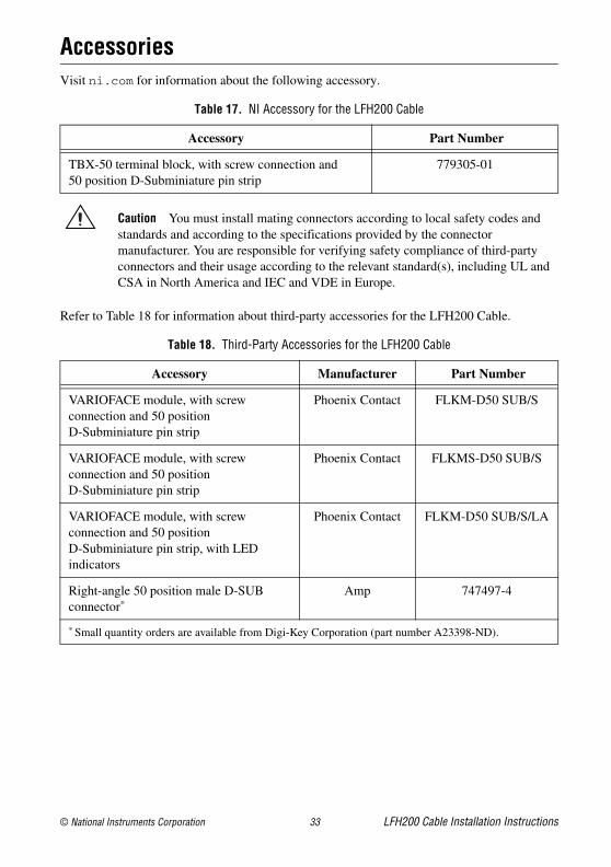
AccessoriesVisit ni.com for information about the following accessory.
Caution You must install mating connectors according to local safety codes and standards and according to the specifications provided by the connector manufacturer. You are responsible for verifying safety compliance of third-party connectors and their usage according to the relevant standard(s), including UL and CSA in North America and IEC and VDE in Europe.
Refer to Table 18 for information about third-party accessories for the LFH200 Cable.
Table 17. NI Accessory for the LFH200 Cable
Accessory Part Number
TBX-50 terminal block, with screw connection and 50 position D-Subminiature pin strip
779305-01
Table 18. Third-Party Accessories for the LFH200 Cable
Accessory Manufacturer Part Number
VARIOFACE module, with screw connection and 50 position D-Subminiature pin strip
Phoenix Contact FLKM-D50 SUB/S
VARIOFACE module, with screw connection and 50 position D-Subminiature pin strip
Phoenix Contact FLKMS-D50 SUB/S
VARIOFACE module, with screw connection and 50 position D-Subminiature pin strip, with LED indicators
Phoenix Contact FLKM-D50 SUB/S/LA
Right-angle 50 position male D-SUB connector*
Amp 747497-4
* Small quantity orders are available from Digi-Key Corporation (part number A23398-ND).
LFH200 Cable Installation Instructions 34 ni.com
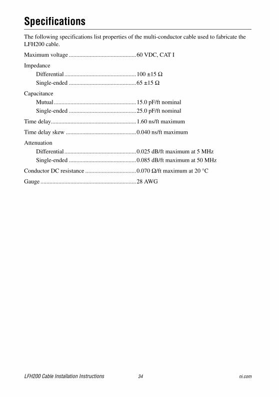
SpecificationsThe following specifications list properties of the multi-conductor cable used to fabricate the LFH200 cable.
Maximum voltage .............................................60 VDC, CAT I
Impedance
Differential ................................................100 ±15 ΩSingle-ended .............................................65 ±15 Ω
Capacitance
Mutual .......................................................15.0 pF/ft nominal
Single-ended .............................................25.0 pF/ft nominal
Time delay.........................................................1.60 ns/ft maximum
Time delay skew ...............................................0.040 ns/ft maximum
Attenuation
Differential ................................................0.025 dB/ft maximum at 5 MHz
Single-ended .............................................0.085 dB/ft maximum at 50 MHz
Conductor DC resistance ..................................0.070 Ω/ft maximum at 20 °C
Gauge ................................................................28 AWG

© 2004–2011 National Instruments Corporation. All rights reserved.
373848F Oct11
LabVIEW, National Instruments, NI, ni.com, the National Instruments corporate logo, and the Eagle logo are trademarks of National Instruments Corporation. Refer to the Trademark Information at ni.com/trademarks for other National Instruments trademarks. Other product and company names mentioned herein are trademarks or trade names of their respective companies. For patents covering National Instruments products/technology, refer to the appropriate location: Help»Patents in your software, the patents.txt file on your media, or the National Instruments Patents Notice at ni.com/patents. Refer to the Export Compliance Information at ni.com/legal/export-compliance for the National Instruments global trade compliance policy and how to obtain relevant HTS codes, ECCNs, and other import/export data.
Related Documents