General INFORMATION: The EMG B136rE is a Push-Pull Switch (DPDT) combined with a 25K Pot onto a split shaft control. The Push-Pull switch provides a convenient way to choose either Single-Coil or Dual-Coil sounds from Active EMG-TW Style Pickups. The 25K Pot can be used as a Volume or Tone Control for the pickup, or it can be used as a Master Volume or Master Tone Control for the instrument. The B136 uses EMG’s standard solderless installation system. The B136 version described in this data sheet is thE “E” Version that allows daisy-chaining of volume controls without any extra connnectors. PICKUP INPUT OUTPUT DPDT S1 J1 J2 J3 Dimensions: B136rE Push-Pull Pot 1.800 .850 1.060 .813 .400 B136E SCHEMATIC 0230-0269A © 2012 Copyright EMG INC. All Rights Reserved. PO BOX 4394 SANTA ROSA, CA 95402 USA P (707) 525-9941 F (707) 575-7046 EMGPICKUPS.COM The B136 has 2 Sections. Section 1) Push-Pull Switch: This is the single in-line 6 pin header. This header is for the pickup input. Section 2) 25K Audio Taper pot: The dual-header labeled H1 thru H6 directs how the pot functions. The Pot can be used in 4 different ways: 1) Volume Control for the pickup only 2) Tone Control for the pickup only 3) Master Volume Control for the entire instrument 4) Master Tone Control for the entire instrument Using the B136 with EMG-X Series Pickups: The Tone Control for the B136 is passive. It is not suitable for EMG-X Series Pickups. If you are using the B136 with EMG X-Series Pickups it should be used as a Volume Control only, either for the Pickup or as a Master Volume. 1 2 3 4 5 6 1 2 3 4 5 6 1 2 3 4 5 6 8mm Dia. P.75 C1 104 1 2 3 25K VR1 1 2 3 4 5 6 INSTALLATION INFORMATION EMG MODEL:B136RE PUSH-PULL POT FOR EMG-89 AND ACTIVE EMG-TW PICKUPS

Welcome message from author
This document is posted to help you gain knowledge. Please leave a comment to let me know what you think about it! Share it to your friends and learn new things together.
Transcript
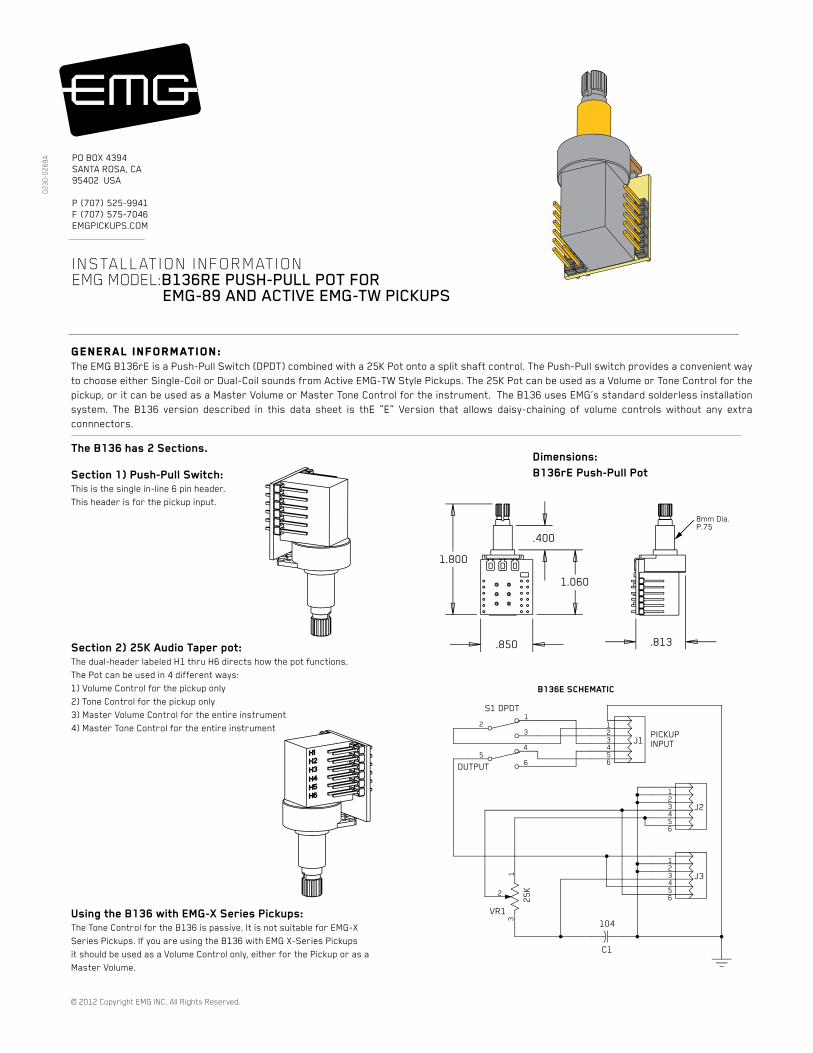
General INFORMATION:The EMG B136rE is a Push-Pull Switch (DPDT) combined with a 25K Pot onto a split shaft control. The Push-Pull switch provides a convenient way
to choose either Single-Coil or Dual-Coil sounds from Active EMG-TW Style Pickups. The 25K Pot can be used as a Volume or Tone Control for the
pickup, or it can be used as a Master Volume or Master Tone Control for the instrument. The B136 uses EMG’s standard solderless installation
system. The B136 version described in this data sheet is thE “E” Version that allows daisy-chaining of volume controls without any extra
connnectors.
PICKUPINPUT
OUTPUT
DPDTS1
J1
J2
J3
Dimensions:
B136rE Push-Pull Pot
1.800
.850
1.060
.813
.400
B136E SCHEMATIC
02
30
-02
69
A
© 2012 Copyright EMG INC. All Rights Reserved.
PO BOX 4394
SANTA ROSA, CA
95402 USA
P (707) 525-9941
F (707) 575-7046
EMGPICKUPS.COM
The B136 has 2 Sections.
Section 1) Push-Pull Switch:
This is the single in-line 6 pin header.
This header is for the pickup input.
Section 2) 25K Audio Taper pot:
The dual-header labeled H1 thru H6 directs how the pot functions.
The Pot can be used in 4 different ways:
1) Volume Control for the pickup only
2) Tone Control for the pickup only
3) Master Volume Control for the entire instrument
4) Master Tone Control for the entire instrument
Using the B136 with EMG-X Series Pickups:
The Tone Control for the B136 is passive. It is not suitable for EMG-X
Series Pickups. If you are using the B136 with EMG X-Series Pickups
it should be used as a Volume Control only, either for the Pickup or as a
Master Volume.
123456
123456
123456
8mm Dia.P.75
C1
104
1
2
3
25
K
VR1
12
3
45
6
INSTALLATION INFORMATION EMG MODEL:B136RE PUSH-PULL POT FOR EMG-89 AND ACTIVE EMG-TW PICKUPS
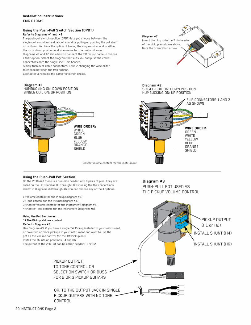
Diagram #7
Insert the plug onto the 7 pin header
of the pickup as shown above.
Note the orientation arrow.
Installation Instructions:
EMG B136rE
89 INSTRUCTIONS Page 2
Using the Push-Pull Pot SectionOn the PC Board there is a dual-line header with 6 pairs of pins. They are
listed on the PC Board as H1 through H6. By using the the connections
shown in Diagrams #3 through #6, you can choose any of the 4 options.
1) Volume control for the Pickup (diagram #3)
2) Tone control for the Pickup(diagram #4)
3) Master Volume control for the instrument(diagram #5)
4) Master Tone control for the instrument (diagram #6)
Using the Push-Pull Switch Section (DPDT)Refer to Diagrams #1 and #2
The push-pull switch section (DPDT) lets you choose between the
single-coil sound and a dual-coil sound by pulling or pushing the pot shaft
up or down. You have the option of having the single-coil sound in either
the up or down position and vice-versa for the dual-coil sound.
Diagrams #1 and #2 show how to connect the TW Pickup cable to choose
either option. Select the diagram that suits you and push the cable
connectors onto the single line 6-pin header.
Simply turn over cable connectors 1 and 2 changing the wire order
to choose between the two options.
Connector 3 remains the same for either choice.
Using the Pot Section as:
1) The Pickup Volume control.
Refer to Diagram #3
Use Diagram #3 if you have a single TW Pickup installed in your instrument,
or have two or more pickups in your instrument and want to use the
pot as the Volume control for the TW Pickup only.
Install the shunts on positions H4 and H6.
The output of the 25K Pot can be either header H1 or H2.
PICKUP OUTPUT
(H1 or H2)
Diagram #1HUMBUCKING ON: DOWN POSITIONSINGLE COIL ON: UP POSITION
Diagram #2SINGLE-COIL ON: DOWN POSITIONHUMBUCKING ON: UP POSITION
FLIP CONNECTORS 1 AND 2AS SHOWN
WIRE ORDER:WHITEGREENBLUEYELLOWORANGESHIELD
WIRE ORDER:GREENWHITEYELLOWBLUEORANGESHIELD
INSTALL SHUNT (H6)
INSTALL SHUNT (H4)
Diagram #3
PUSH-PULL POT USED AS
THE PICKUP VOLUME CONTROL
OR; TO THE OUTPUT JACK IN SINGLE
PICKUP GUITARS WITH NO TONE
CONTROL
PICKUP OUTPUT:
TO TONE CONTROL OR
SELECTION SWITCH OR BUSS
FOR 2 OR 3 PICKUP GUITARS
1
2
3
1
2
3
Master Volume control for the instrument
89 INSTRUCTIONS Page 3
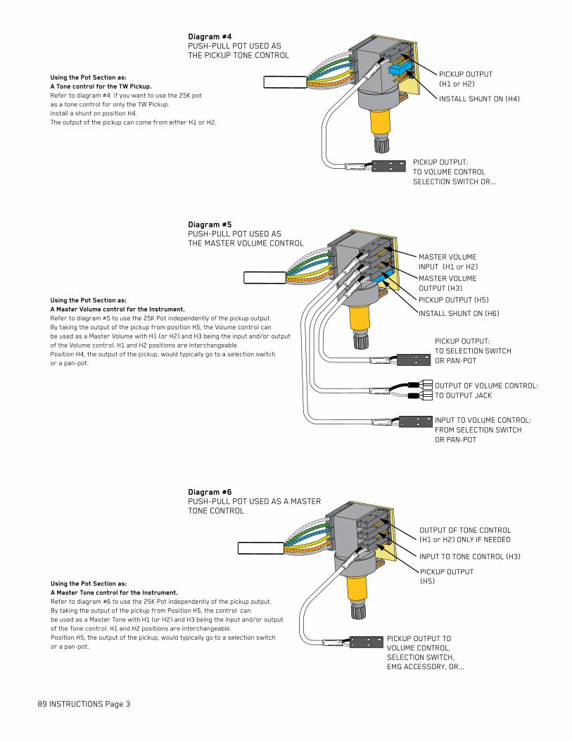
Using the Pot Section as:
A Master Volume control for the Instrument.
Refer to diagram #5 to use the 25K Pot independently of the pickup output.
By taking the output of the pickup from position H5, the Volume control can
be used as a Master Volume with H1 (or H2) and H3 being the input and/or output
of the Volume control. H1 and H2 positions are interchangeable.
Position H4, the output of the pickup, would typically go to a selection switch
or a pan-pot.
PICKUP OUTPUT:
TO VOLUME CONTROL
SELECTION SWITCH OR...
MASTER VOLUME
INPUT (H1 or H2)
INSTALL SHUNT ON (H6)
MASTER VOLUME
OUTPUT (H3)
PICKUP OUTPUT
(H1 or H2)
INSTALL SHUNT ON (H4)
OUTPUT OF TONE CONTROL
(H1 or H2) ONLY IF NEEDED
INPUT TO TONE CONTROL (H3)
PICKUP OUTPUT
(H5)
Diagram #6
PUSH-PULL POT USED AS A MASTER
TONE CONTROL
PICKUP OUTPUT TO
VOLUME CONTROL,
SELECTION SWITCH,
EMG ACCESSORY, OR...
Diagram #4
PUSH-PULL POT USED AS
THE PICKUP TONE CONTROL
INPUT TO VOLUME CONTROL:
FROM SELECTION SWITCH
OR PAN-POT
OUTPUT OF VOLUME CONTROL:
TO OUTPUT JACK
PICKUP OUTPUT:
TO SELECTION SWITCH
OR PAN-POT
Diagram #5
PUSH-PULL POT USED AS
THE MASTER VOLUME CONTROL
PICKUP OUTPUT (H5)
Using the Pot Section as:
A Tone control for the TW Pickup.
Refer to diagram #4 if you want to use the 25K pot
as a tone control for only the TW Pickup.
Install a shunt on position H4.
The output of the pickup can come from either H1 or H2.
Using the Pot Section as:
A Master Tone control for the Instrument.
Refer to diagram #6 to use the 25K Pot independently of the pickup output.
By taking the output of the pickup from Position H5, the control can
be used as a Master Tone with H1 (or H2) and H3 being the input and/or output
of the Tone control. H1 and H2 positions are interchangeable.
Position H5, the output of the pickup, would typically go to a selection switch
or a pan-pot.
B124rH
TONE
B124rH
TONE
B124rH
TONE
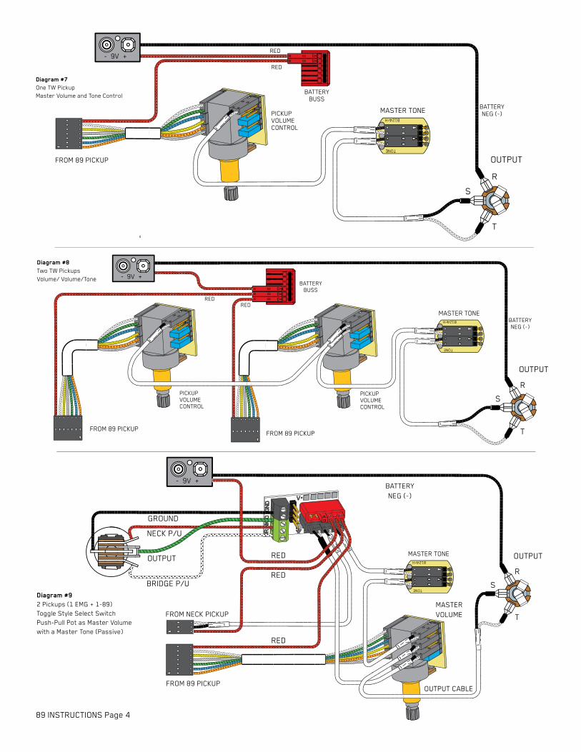
Diagram #7
One TW Pickup
Master Volume and Tone Control
Diagram #8
Two TW Pickups
Volume/ Volume/Tone
89 INSTRUCTIONS Page 4
OUTPUT
T
R
S
BATTERY
NEG (-)
RED
RED
BATTERY
BUSS
PICKUP
VOLUME
CONTROL
OUTPUT
T
R
S
BATTERY
NEG (-)
REDRED
BATTERY
BUSS
PICKUP
VOLUME
CONTROL
MASTER TONE
PICKUP
VOLUME
CONTROL
MASTER TONE
MASTER TONE
- 9V +
Diagram #9
2 Pickups (1 EMG + 1-89)
Toggle Style Select Switch
Push-Pull Pot as Master Volume
with a Master Tone (Passive)
FROM NECK PICKUP
FROM 89 PICKUP
BATTERY
NEG (-)
- 9V +
OUTPUT
T
R
S
OUTPUT CABLE
RED
RED
RED
GROUND
BRIDGE P/U
NECK P/U
OUTPUT
MASTER
VOLUME
- 9V +
FROM 89 PICKUP
FROM 89 PICKUP FROM 89 PICKUP
Related Documents