1999 American Honda Motor Co., Inc. – All Rights Reserved Y0505-B2 8000X-S04-KC99A 1 of 16 INSTALLATION INSTRUCTIONS Accessory Application Publications No. Issue Date AIR CONDITIONER CIVIC 2/3/4-DOOR FEB 1999 AII 19789-20321 What’s changed for ’99? The kits have been revised for 1999. The evaporator unit, the condenser assembly, and the A/C switch button are all new. The procedure for installing the evaporator has changed to prevent damage to the air mix door. A new label and hang tag have also been added. Be sure you have the correct kit for the model you are working on: • 1999 HX A/C Kit P/N 80000-S04-A03 . . . . . . . . . • 1999 CX & DX A/C Kit P/N 80000- S04- A12 . . . TOOLS AND SUPPLIES REQUIRED Clip remover Open-end wrench set Screwdrivers Socket wrench set Torque wrench Tension gauge 1/2″ Drive breaker bar Refrigerant oil (R12 mineral oil or R134a PAG oil) Fender covers, floor mats, and seat covers to protect the vehicle HFC-134a recovery/recycling/charging station Gloves and safety goggles or a face shield to protect your hands and eyes from liquid refrigerant Electronic leak detector NOTICE S Use only HFC-134a in this system; do not use CFC 12 (Freon); do not install parts designed for use in a CFC system. S Use a charging station. A/C charging stations and refrigerant recovery/recycling units minimize the release of CFCs and HFCs to the atmosphere. Use them for all A/C charging and service work according to their manufacturers’ instructions. S Do not overcharge. This system requires only the amount of HFC-134a refrigerant shown below. If you overcharge the system, the engine and the A/C will malfunction. 600 to 650 grams 0.60 to 0.65 kilograms 1.3 to 1.4 pounds 21.2 to 22.9 ounces INSTALLATION Before You Begin: S Write down the customer’s radio station presets; the radio memory will be erased when you disconnect the battery. S Make sure you install the right part. Use the illustration on page 2 as a guide to check the parts before you install them. S Don’t remove plugs and caps from fittings until the parts are ready to connect. This will keep out moisture and dirt which could cause wear and damage. S Before you connect any line or hose, check and lube its O-ring. Make sure the O-ring is there (inside the fitting), put a few drops of refrigerant oil on it and on the threads, then connect the fitting. S You may use either type of refrigerant oil to lubricate O-rings and fittings. S If you add or replace refrigerant oil to the system, use only this PAG oil: SP-10, P/N 38899-P13-A01. S Route and secure the lines and hoses properly; maintain clearance between them and surrounding parts. S Use two wrenches to tighten or loosen fittings; hold one fitting in place while you tighten the other one against it. CAUTION: Don’t overtighten; you could damage the fittings. If in doubt, check the torque listed for them. If leaks are caused by faulty O-rings, overtightening won’t help. S Before you connect each connector, check its terminals. Make sure they aren’t bent or out of place.

Welcome message from author
This document is posted to help you gain knowledge. Please leave a comment to let me know what you think about it! Share it to your friends and learn new things together.
Transcript

1999 American Honda Motor Co., Inc. – All Rights Reserved Y0505-B2 8000X-S04-KC99A 1 of 16
INSTALLATIONINSTRUCTIONS
Accessory Application Publications No.
Issue DateAIR CONDITIONER CIVIC2/3/4-DOOR
FEB 1999
AII 19789-20321
What’s changed for ’99?
The kits have been revised for 1999. Theevaporator unit, the condenser assembly, and theA/C switch button are all new. The procedure forinstalling the evaporator has changed to preventdamage to the air mix door. A new label and hangtag have also been added. Be sure you have thecorrect kit for the model you are working on:
• 1999 HX A/C Kit P/N 80000-S04-A03. . . . . . . . .
• 1999 CX & DX A/C Kit P/N 80000-S04-A12. . .
TOOLS AND SUPPLIES REQUIRED
Clip removerOpen-end wrench setScrewdriversSocket wrench setTorque wrenchTension gauge1/2″ Drive breaker barRefrigerant oil (R12 mineral oil or R134a PAG oil)Fender covers, floor mats, and seat covers toprotect the vehicleHFC-134a recovery/recycling/charging stationGloves and safety goggles or a face shield toprotect your hands and eyes from liquid refrigerantElectronic leak detector
NOTICE
� Use only HFC-134a in this system; do not useCFC 12 (Freon); do not install parts designed foruse in a CFC system.
� Use a charging station. A/C charging stationsand refrigerant recovery/recycling units minimizethe release of CFCs and HFCs to the atmosphere.Use them for all A/C charging and service workaccording to their manufacturers’ instructions.
� Do not overcharge. This system requires onlythe amount of HFC-134a refrigerant shownbelow. If you overcharge the system, the engineand the A/C will malfunction.
600 to 650 grams
0.60 to 0.65 kilograms
1.3 to 1.4 pounds
21.2 to 22.9 ounces
INSTALLATION
Before You Begin:� Write down the customer’s radio station
presets; the radio memory will be erased whenyou disconnect the battery.
� Make sure you install the right part. Use theillustration on page 2 as a guide to check theparts before you install them.
� Don’t remove plugs and caps from fittingsuntil the parts are ready to connect. This willkeep out moisture and dirt which could causewear and damage.
� Before you connect any line or hose, checkand lube its O-ring. Make sure the O-ring isthere (inside the fitting), put a few drops ofrefrigerant oil on it and on the threads, thenconnect the fitting.
� You may use either type of refrigerant oil tolubricate O-rings and fittings.
� If you add or replace refrigerant oil to thesystem, use only this PAG oil: SP-10, P/N38899-P13-A01.
� Route and secure the lines and hosesproperly; maintain clearance between themand surrounding parts.
� Use two wrenches to tighten or loosenfittings; hold one fitting in place while youtighten the other one against it.
CAUTION: Don’t overtighten; you coulddamage the fittings. If in doubt, check thetorque listed for them. If leaks are caused byfaulty O-rings, overtightening won’t help.
� Before you connect each connector, checkits terminals. Make sure they aren’t bent or outof place.
Trevor Allen
http://www.HandA-Accessories.com

1999 American Honda Motor Co., Inc – All Rights Reserved2 of 16
�������
�������
������
�������������
�������� ���
38940-P2A-000

��������������������������
������� ��
������������
�����������
�������
�������
������������� ��������� ��� ��
�����������
����������
�������� ��
������������
�����������
�����������
�����������
��������� ��
��������� ��� �
�������������������������
����������
���������
�������� ��
���������� �� ����������� ��
1999 American Honda Motor Co., Inc – All Rights Reserved 3 of 16
�� �����
����������
����� � �� ��� � ��
����� !�" !
�!�#$%& '(
�!�#$%& '(%)! **("
���� !�" !%)! **("
�(+,�"���#$)%'-!(.'
/�'&(!%0 +"%1�%2%��%**3
/�'&(!%$4"%1�%**3
�5%'.#"-&%04"" $
�������������
���������� ��
�������6�����
�������������
�����������
�����������
�����7����
���������8��
�
�
�
�
�
�
�
�
�
�
�
�
�
�
�
�
�5 *�!('' !%�''9
5 *�!('' !%�''9
5 *�!('' !%0(+"
6+�$)(%0 +"'%1�%2%���%**3
�:+(!%�4++(9%�''(*0+9
6+�$)(%0 +"'%1�%2%��%**3
��������� ��
�������6� ��
������ ���
�����������
������ ����
�������������
�
;;
�
�
�
;;
�
�
�
�
�5 $:($'(!%4��(!%0!�-<("'
5 $:($'(!%�''9
�4-"# $%+#$(%=
5 $:($'(!%+#$(
�(-(#�(!%+#$(%
�(-(#�(!%+#$(%=
�(-(#�(!%+#$(%5
�(-(#�(!�:!9(!
�5%.#!(%&�!$(''
�(-(#�(!%+#$(%-+#�'
6+�$)(%0 +"'%1�%2%��%**3
/�'&(!%0 +"%1�%2%��%**3
/�'&(!%0 +"'%1�%2%��%**3
�! 4$:%0 +"%1�%2%��%**3
�������������
���������� ��
��������� ��
�������� ��
��������� ��
��������� ��
�������� ��
��������� ��
�������������
������>�� ��
�������������
�����������
�����������
����������
�
�
�
�
�
�
�
�
�
�
�% ,%�
�
�
�
�
�
�
�
�
�
�
�
�
�% ,%�
�
�
��4-"# $%& '(
�#'-&�!)(%& '(
�4-"# $%+#$(%
�4-"# $%& '(%-+�*�
�4-"# $%& '(%0!�-<("
�4-"# $%+#$(%0!�-<("
�4-"# $%+#$(%-+�*�
�# :(
� .(!%!(+�9'
�4-"# $%+#$(%-+#�
5 $:($'(!%!400(!%* 4$"
5 $:($'(!%* 4$"%'+((�(
/�'&(!%0 +"'%1�%2%��%**3
/�'&(!%0 +"%1�%2%��%**3
6+�$)(%$4"%1�%**3
��������� ��� �
��������� ��� ��
��������� ��
������������
�����������
������������
�������� ��
����������
������� ��
���������
�����������
����������
�����������
������������
�������� ��
�
�
�
�
�
�
�
�
�
�
�
�
% ,%�
�
�
�
�
�
�
�
�
�
�
�
�
�
�
% ,%�
�
�
� �5%+�0(+
�65����%+�0(+
��$)%"�)
�5%�''(*0+9%���%+�0(+
�������������
�������������
��������� ��
��������� �� ��
�
�
�
�
�
�
�
�

1999 American Honda Motor Co., Inc – All Rights Reserved4 of 16
��������������� �
� ����������������������������
Turn the ignition switch ON (II),then turn the temperature controlknob all the way to “HOT.” Waitapproximately 10 seconds, thenturn the ignition switch off.
Remove and discard the A/Cswitch hole cover. If necessary,use a flat-tip screwdriver tocarefully pry the cover out.
Press the A/Cswitch buttononto the switch.
3
1
2
� �����������������
Loosen this nut, and removethe hold-down bracket and rods.
Disconnect the cables(negative first, then positive).
Remove the tray.
Removethesebolts.
Remove thecover, battery,and tray liner.
Release thiswire harness clip.
� ������������������������������
Pry the two harness clipsout of the heater duct.
Remove anddiscard thesescrews.
Remove and discardthe heater duct.
Unlatch andremove theglove box.
Remove thesescrews.
GLOVE BOXFRAME
Removethesebolts, andremovethe glovebox frame.
Remove this screw,then pull off theside trim panel(3 clips).Pull the panel away from the
dashboard, and hold it therewhile you remove this bolt.
Clip
SIDE TRIMPANEL
Removethis screwand thesebolts.
=

1999 American Honda Motor Co., Inc – All Rights Reserved 5 of 16
Install the grommet for the evaporator pipeswith the small side toward the engine.
Push out anddiscard thesehole plugs.
Remove these 3 pieces of pre-cutinsulation from the bulkhead.
ENGINE
Note thegrommet direction.
From the engine compartment,move the small canister filter asideand push the drain hose throughthe hole in the bulkhead. Makesure the grommet is seated in thehole, then return the canisterfilter to its original position.
FR
DRAINHOSEGROMMET
Slide the grommet about95 mm onto the drain hose.
95 mm
��������������������
Install the hose all theway onto the evaporator.Do not apply any oil orgrease to the hose.
Secure the vehicle harness tothe evaporator.
Untape the thermostatconnector from the vehicleharness.
Plug the connectorinto the thermostat.
Install the 6 mm nut (90321-SV4-003).Tighten the nut to 10.0 N.m (7 lb-ft).
Install the four self-tapping screws(90155-SE0-003).
Hold the evaporator inposition, and install this6 x 24 mm washer bolt(90156-SH3-000).Tighten the bolt to 10 N.m(7 lb-ft).

1999 American Honda Motor Co., Inc – All Rights Reserved6 of 16
! �������������������"#���$���������������������������%����������������&�'() *
+ ������������������%��$������$�����������������
RESONATOR
Pull the air intake duct outof the air cleaner housing.
Lift out theresonator andair intake ducttogether.
Remove these bolts.
VTEC ENGINE
Remove these bolts.
AIR CLEANERHOUSING
Disconnect this connector andbreather tube, then lift out the aircleaner housing.
Loosen thesehose clamps.
NON-VTEC ENGINE
, �������������������������������������-��������������������-���������%��
Lift up the coolantreservoir, and set itout of the way.
Remove this bolt andthe radiator mount bracket.
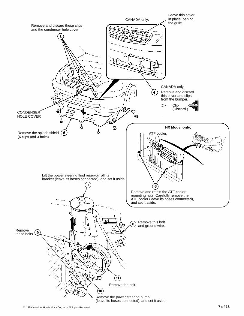
1999 American Honda Motor Co., Inc – All Rights Reserved 7 of 16
Remove and retain the ATF coolermounting nuts. Carefully remove theATF cooler (leave its hoses connected),and set it aside.
CANADA only:
CANADA only:Leave this coverin place, behindthe grille.
= Clip(Discard.)
Remove and discardthis cover and clipsfrom the bumper.
Remove the splash shield(6 clips and 3 bolts).
CONDENSERHOLE COVER
Remove and discard these clipsand the condenser hole cover.
Lift the power steering fluid reservoir off itsbracket (leave its hoses connected), and set it aside.
Remove the power steering pump(leave its hoses connected), and set it aside.
Remove the belt.
Removethese bolts.
Remove this boltand ground wire.
ATF cooler.
HX Model only:

1999 American Honda Motor Co., Inc – All Rights Reserved8 of 16
��������������. �
/ ��������������������
Hang the compressor belton the damper shaft.
Reinstall these bolts andtighten them to 44 N.m(33 lb-ft).
Removethese bolts.
ENGINEDAMPER
Remove this nutand washer, thenremove theengine damper.
Reinstall the engine damper,washer, and nut. Be sure theflats in the washer line upwith the flats on the dampershaft, then torque the nut to60 N.m (43 lb-ft).
IDLER PULLEYASSEMBLY(38940-P2A-000)
Install the idler pulley assemblyonto the compressor bracket withthese 8 x 29 mm flange bolts(9570-08020-08); tighten themto 25 N.m (18 lb-ft).
Attach the compressor to thebracket with these 8 x 10 mmflange bolts (90023-P01-000);tighten them to 25 N.m (18 lb-ft).

1999 American Honda Motor Co., Inc – All Rights Reserved 9 of 16
0 �$1����������������������������
Turn this bolt, and keepchecking the gauge untilthe belt tension is correct.
Fit the compressorbelt onto thecrankshaft pulley,the idler pulley, andthe compressorpulley.
Tighten this nut to47 N.m (35 lb-ft),and then recheckthe belt tension.
Do not overtighten!
Do not use any gaugeother than this one.
Fit this belt tension gauge(07JGG-001010A) onto the belt.
Specified Tension:690-835N (70-85 kgf)
�2 �������������������������������
Move the breaker bar to obtain theapproximate belt tension . . .
Insert a 1/2″ drivebreaker bar intothe socket on thepower steeringpump.
Fit this tension gauge(07JGG-001010A)onto the belt.Do not use anygauge other thanthis one.
Reinstall thepowersteeringpump, buttightenthese boltsonly finger-tight.
Reinstall thepump belt.
When the belttension is correct;tighten these boltsto 25 N.m (18 lb-ft).
. . . then tightenthis bolt and checkthe tension gauge.Repeat as needed toobtain the specifiedtension: 340-490N(35-50 kgf).Do not overtighten!

Install two receiver lineclips on receiver line B,then snap the clips intothe square holes shown.
Apply refrigerant oil to this fitting,then connect the fitting toreceiver line C, and tighten it to14 N.m (10 lb-ft). Be sure to usea second wrench to hold theother fitting.
Attach the receiver-dryerwith a 6 x 12 mm washerbolt, and tighten the bolt to10 N.m (7 lb-ft).
WINDSHIELDWASHER TANK
Apply refrigerant oil to its fitting, thenconnect receiver line A to thereceiver-dryer with a 6 x 25 mmflange bolt (95701-06025-08). Tightenthe bolt to 10 N.m (7 lb-ft).
Install areceiver lineclip here onreceiver line A,then snap theclip into thesquare hole.
Apply refrigerant oil to the fitting,then connect receiver line A toline B, and tighten the fitting to14 N.m (10 lb-ft). Be sure to use asecond wrench to hold the other fitting.
SUCTION LINE BRECEIVER LINE C
Route receiver line C underthe wire harness. Apply a fewdrops of refrigerant oil to thefitting, and then connect it to theevaporator with a 6 x 25 mmflange bolt (95701-06025-08).Tighten the bolt to 10 N.m(7 lb-ft).
NOTE: Make sure thiswire harness is routedabove the A/C lines.
Apply refrigerant oil to its fitting, thenconnect suction line B to the evaporatorwith a 6 x 25 mm flange bolt(95701-06025-08). Tighten the bolt to10 N.m (7 lb-ft).
1999 American Honda Motor Co., Inc – All Rights Reserved10 of 16
��������������� �
�� ���������������������

Connect the compressor connector tothe A/C wire harness, then snap theconnector onto the fan shroud tab.
Connect this connectorto the pressure switchon the receiver-dryer.
Press this wireinto the white clipon the vehicleharness.
Connect this A/Cwire harnessconnector to thecondenser fan.
Install the condenser onthe condenser mounts.
Connect the vehicleharness connector to theA/C harness connector.
Snap this wire harnessclip in to the fan shroud.
Attach the A/C harness groundwire here with the ground bolt(90153-SE0-003). Tighten thebolt to10 N.m (7 lb-ft).
Snap this wire harnessclip into the body.
Pry out this wireharness clip.
VEHICLEHARNESS
Snap this A/Charness connectoronto the fanshroud tab.
Snap these clips intothe fan shroud tab.
Disconnect and discardthis white cap.
Apply refrigerant oil to both fittings, then connect thecondenser line to the receiver/dryer and the condenserwith two 6 x 25 mm flange bolts (95701-06025-08).Tighten the bolts to 10 N.m (7 lb-ft).
CONDENSERLINE
1999 American Honda Motor Co., Inc – All Rights Reserved 11 of 16
�� ��������������$�����#���$���������������������������������

1999 American Honda Motor Co., Inc – All Rights Reserved12 of 16
Install thecondenserupperbracketon the condensermounts.
Secure the condenser with thetwo 6 x 12 mm washer bolts.Tighten the bolts 10 N.m (7 lb-ft).
CONDENSER
��������������)
�� ������������������������
Snap thesuction line cliponto the suctionline bracket.
Attach the suctionline bracket to thebumper with the6 mm flange nut(90308-SD2-A00).Tighten the nut to10 N.m (7 lb-ft).
Secureline A withthe clampyou justinstalled.
� ���������������������
MANUAL TRANSMISSION AUTOMATIC TRANSMISSION
Apply refrigerant oil to its fitting, then connectsuction line A to line B, and tighten the fitting to32 N.m (24 lb-ft). Be sure to use a secondwrench to hold the other fitting.
Route suction line A under theradiator lower hose and up into place.
Apply refrigerant oil to its fitting, then connectsuction line A to line B, and tighten the fittingto 32 N.m (24 lb-ft). Be sure to use a secondwrench to hold the other fitting.
Route suction line A under theradiator lower hose and up into place.
Secure line A with the clampyou just installed.
SUCTION LINE A
SUCTIONLINE B
SUCTIONLINE B

Secure receiver line Cand suction line B withthe suction line clampand a 6 x 12 mm washerbolt (93403-06012-08).Tighten the bolt to10 N.m (7 lb-ft).
RECEIVER LINE C
SUCTIONLINE B
Apply refrigerant oil toits fitting, then connectthe discharge hose tothe compressor with a6 x 25 mm flange bolt(95701-06025-08).Tighten the bolt to10 N.m (7 lb-ft).
Apply refrigerant oil to its fitting, thenconnect the suction hose to thecompressor with a 6 x 25 mm flangebolt (95701-06025-08). Tighten the boltto 10 N.m (7 lb-ft).
Remove anddiscard this boltand cap.
Remove and discardthis bolt and cap.
Apply refrigerant oil to its fitting, then connect the discharge hoseto the condenser with a 6 x 25 mm flange bolt (95701-06025-08).Tighten the bolt to 10 N.m (7 lb-ft).
Attach the suctionhose bracket to thecondenser fan shroudwith a 6 x 12 mmwasher bolt(93403-06012-08).Tighten the bolt to10 N.m (7 lb-ft).
Apply refrigerant oil to the suctionhose fitting, then connect and tighten thefitting to 32 N.m (24 lb-ft). Be sure to use asecond wrench to hold the other fitting.
Install the suction hose clamp overthe suction hose, and attach theclamp with a 6 x 12 mm washerbolt (93403-06012-08). Tightenthe bolt to 10 N.m (7 lb-ft).
Install the rubber mountand then the metal sleeveon the suction hose clamp,and attach the clamp to thesuction hose bracket with a6 x 25 mm washer bolt(93405-06025-08). Tightenthe bolt to 10 N.m (7 lb-ft).
1999 American Honda Motor Co., Inc – All Rights Reserved 13 of 16
�! �������������������$�������

(USA) (Others)
UNDER-HOOD EMISSIONSCONTROL LABEL
1999 American Honda Motor Co., Inc – All Rights Reserved14 of 16
�+ ��������������������������$�$�$�
Plug in the diode here.
Plug in the twopower relays here.
Remove the fusebox lid.
��������������3 �
�, ������������������������������������

1999 American Honda Motor Co., Inc – All Rights Reserved 15 of 16
�/ ����������������������������
Fuse box lid
Engine ground wire and bolt; tighten thebolt to 10 N.m (7 lb-ft)
Power steering fluid reservoir
Splash shield
ATF cooler; tighten the nuts to 10 N.m(7 lb-ft)
Radiator upper mount bracket; tighten thebolt to 10 N.m (7 lb-ft)
Coolant reservoir
Air cleaner housing (and air intake duct);tighten the bolts to 10 N.m (7 lb-ft)
Glove box
Battery
�0 3������������������
HFC-134a and compressor oil used in thisA/C system are highly moisture absorbent.After installing the system, be sure toevacuate it for at least 15 minutes.
NOTE:
� If low pressure does not reach more than700 mm Hg (27 in-Hg) in 15 minutes, thereis probably a leak in the system. Partiallycharge the system and check for leaks(see Step 21 Test for leaks).
� If the system is left open, the desiccant inthe receiver tank will become saturated withmoisture, requiring longer evacuation time.
HIGH-PRESSURESIDE
LOW-PRESSURESIDE
�2 ����������������
� This system requires only the amount ofHFC-134a refrigerant shown below. If youovercharge the system, the engine and theA/C will malfunction. Do not overcharge!
600 to 650 grams
0.60 to 0.65 kilograms
1.3 to 1.4 pounds
21.2 to 22.9 ounces
� Do not add oil to the compressor; a newcompressor already contains enough oil forthe entire A/C system. If you are replacingcompressor oil that has leaked out of thesystem, use only Sanden SP-10 oil.
� Using the wrong oil, or mixing different typesof oil, will result in abnormal compressor noiseor seizure, or shortened compressor servicelife. These conditions are not covered bywarranty policy.
�� 4����-�����%�
When testing for leaks, follow theseguidelines:
� Be sure to use a leak detector designed forA/C systems that use HFC-134a.
� Because HFC-134a is heavier than air,always check 360° around all fittings.
� To avoid false readings, do not use a testerdesigned to detect Freon (CFC-12).
� If you lose or damage an O-ring during A/Cinstallation, make sure you order the correctreplacement as listed here:
PART NAME PART NUMBER APPLICATION
O-ring, 8 mm 80873-ST7-000 Condenser lineReceiver lines
O-ring, 5/8″ 80871-ST7-000 Suction hose& line
O-ring, 1/2″ 80872-ST7-000 Discharge hose& line
�� ���-��������������������������
Refer to Service Bulletin 96-012 for the A/Cperformance test procedures.

1999 American Honda Motor Co., Inc – All Rights Reserved16 of 16
�� 5���������������
After you have completed the installation of theA/C kit and confirmed that it is operating properly,place the hang tag “CLIMATE CONTROL USAGETO DEFOG WINDOW” (89100-S01-A00) in thelocation shown.
Place DEFOGtag here ...
... or here, if cassetteplayer or CD playeris installed.
Related Documents


![Removal and installation of fuel injector assembly · 7. Disconnect fuel return hose (14). [*3] 8. Disconnect fuel return hose (15). 9. Disconnect bracket (16). [*4] 10. Remove fuel](https://static.cupdf.com/doc/110x72/608b24e2c7459a383b5c110f/removal-and-installation-of-fuel-injector-assembly-7-disconnect-fuel-return-hose.jpg)

