MIXER SP-100A, SP-200A, SP-30HA, SP-40HA, SP-60HA, SP-A80HI, SP-B80HI 4025016, 4025025, 4025036, 4025041, 4025047, 4025050 5.7.2019 Installation and Operation Manual

Welcome message from author
This document is posted to help you gain knowledge. Please leave a comment to let me know what you think about it! Share it to your friends and learn new things together.
Transcript
MIXERSP-100A, SP-200A, SP-30HA, SP-40HA, SP-60HA, SP-A80HI, SP-B80HI
4025016, 4025025, 4025036, 4025041, 4025047, 4025050
5.7.2019
Installation and Operation Manual

CONTENTS
OVERALL VIEW OF THE MIXER ..............................................................................................................................5INSTALLATION INSTRUCTIONS ............................................................................................................................6OPERATING INSTRUCTIONS .................................................................................................................................7CLEANING INSTRUCTIONS .................................................................................................................................14MAINTENANCE .....................................................................................................................................................15LIMITED WARRANTY ............................................................................................................................................15TROUBLESHOOTING ............................................................................................................................................16CAPACITY CHART TABLE ......................................................................................................................................17MIXER AGITATOR/APPLICATION .........................................................................................................................18WIRING SCHEMATICS ..........................................................................................................................................19DECLARATION OF CONFORMITY ........................................................................................................................33

CAUTIO
N Read before you operate the machine
It is important to read this manual and following the instructions before operate the machines.
This mixer is designed as a safe and efficient food processing product as long as the machine is used in
accordance with the instructions in this manual and is properly maintained.
User has taken following precautions in order to operate the mixer safely.
⚫ All operators should be at least 18 years old and are adequately trained and supervised.
Also, have fully read and understood this manual.
⚫ Owner should not let customer, visitor or other unauthorized people come in contact with this
machine.
⚫ Do not wear loose clothes or ring while operating, and keep hands, hair and clothing away the
moving parts.
⚫ NEVER use an extension cord to connect electrical power.
⚫ Make sure the safety guard is closed and bowl is lifted to right position before operating.
⚫ NEVER reach into the bowl when the mixer is running.
⚫ NEVER place your hand or any kitchen utensil in the bowl whilst the mixer is in operation.
⚫ When mixing product always follow the recommends agitator and speed setting according to the
capacity chart.
⚫ STOP the mixer before changing speed.
⚫ STOP the mixer before removing or installing attachments into the hub.
⚫ NEVER put your hand and finger into the feed chute when using any mixer’s attachments, include
VH-12 Meat Mincer and V99S Vegetable Slicer. Always use the pusher plate with attachment.
⚫ Always UNPLUG before cleaning or doing any maintenances.
⚫ DO NOT hose down or pressure wash any part of mixer.
⚫ NEVER bypass, alter or modify this machine. Doing so may create hazard and will void warranty.
⚫ Avoid exposing to vibration environment
If you have any questions, please contact any local representative or SPAR directly.
1

Overall View of the Mixer
A) Bowl
B) Removable Bowl Guard
C) Planetary Shaft
D) Attachment Hub*
E) Control Panel
F) Gear Lever
G) Additions Chute
H) Bowl Lift Handle
(Wheel)
I) Bowl Cradle
NOTE: Attachment Hub is optional.
Control Panel
A) Emergency StopB) StartC) Timer**
NOTE: Timer is optional on Model SP-100A, SP-100A/nh, SP-200A and SP-200A/nh.
D) Bowl Raise Button
E) Bowl Lower Button
(Available for SP-A80HI and
SP-A80I Only)
NOTE: Oil Meter Indicator is only available for SP-A80HI, SP-A80I,
SP-B80HI and SP-B80I.
Installation Instructions
Model SP-60HA
2

INSTALLATION
- The machine is supplied factory lubricated and ready to run. It should be positioned on any solid,level and non-skid work surface that is nonflammable. Install in work area with adequate light andspace.
- For Smaller Capacity Model, you may place the mixer on bench which is capable of supporting aload of mixer’s weight. For safety, the mixer should be BOLTED in position using all four holeslocated in the legs.
- DO NOT attempt to lift the mixer alone.- Clean the mixer before use. It is normal for the factory to apply a
generous amount of grease in and on the machine before initial use.- During the transportation or fitting, please do not lean over 35 degree
to avoid the gear oil leaking from the gear oil container.- Please use forklift to transporting. Please refer to Figure 1.
ELECTRICAL CONNECTION
CAUTION: NEVER USE EXTENSION CORD. Low amp supply could damage the mixer or cause a fire. CAUTION: The user should install an over-current protection device (e.g. fuse or NFB) or Residual Current Device (GFCI) in the machine incoming site power lines to prevent a fault current risk. CAUTION: The machine is designed for TN power system.
Before connecting this machine to the electrical supply, check that the details on the rating plate (located on the rear of the machine) correspond to the details of your electrical connection.
The mixer is supplied with a trailing lead fitted with a molded plug. If the style of plug is unsuitable for the socket you plan to use, the plug must be cut off and replaced with an appropriate plug.
Machines are fitted with a color coded three core cable as follows: (1) Brown: Live(2) Blue: Neutral(3) Green/Yellow: Earth
As the color of the wires may not correspond to the colored markings identifying the terminals in your plug, you should proceed as follows:
- The wire which is colored blue must be connected to the terminal which is marked with the letterN or colored black.
- The wire which is colored brown must be connected to the terminal which is marked with theletter L or colored red.
- The wire which is colored green/yellow must be connected to the terminal which is marked withthe letter E or colored green.
NOTE: In terms of the 3-phase, when the mixer is located and connected with the plug, please make sure that the shaft goes clockwise. (Same direction as the arrow sticker that located on the front of the machine) If the shaft goes counterclockwise, please replace the wires: R.S.T. (USA) L1, L2, L3, (Europe). To replace the wires each other until the shaft goes clockwise.
The mixer should be plugged into a switched socket which isolates all poles and has a minimum contact clearance of 3mm and located close to the mixer for use in an emergency and to facilitate servicing.
The machine must be incorporated into a potential equalization system. The leakage current for this appliance is no greater than 1 mA/KW. If the electrical supply cable to the machine becomes damaged, it must be replaced by a specification
or higher and suitable for the Mixer’s motor load. The ground wire is fixed to the machine and this connection must be kept intact. CAUTION: The mixer MUST be grounded.
Figure 1
3

- The minimum requirement for all electrical equipment is correct operation between air temperatureof +5℃ and +40℃.
- Electrical equipment is capable of operating correctly when the relative humidity does not exceeding 95% ata maximum temperature of +40℃.
- Electrical equipment is capable of operating correctly at altitude up to 1000m.- Electrical equipment is designed to withstand to protected against the effects of transportation, and
storage temperature within a range of -25℃ to +55℃ and for short periods not exceeding 24h at upto +70℃.
Operating Instructions
BEFORE USING THE MIXER
Before using the mixer, ensure that all users are familiar with the correct operation of the machine. In particular, care should be taken to ensure that the bowl and mixing tools are correctly fitted and that the bowl guard is in position prior to starting the machine.
SAFETY AT WORK
- NEVER place your hand or any kitchen utensil in the bowl whilst the mixer is in operation.- Keep hands, hair and clothing away from moving parts.- Isolate the machine from the electrical supply by removing the plug from the socket before
cleaning, servicing or adjusting any parts or attachments.- Do not use the machine with any cover or guard removed.- Certain operator notice advising about the safe use of this mixer is attached to the machine.
OFFICE, SHOPS AND RAILWAY PREMISES ACT, 1963
The above Act requires that this machine and attachments shall be operated only by a properly instructed person or by an employee who is under the supervision of a properly instructed person. The instruction shall include indication of the possible dangers arising and the precautions to be observed. The Act also requires that no person under the age of 18 shall clean a machine if this exposes him to risk of injury from a moving part of that machine or any adjacent machine.
CORRECT USE OF THE MIXER
- It is the responsibility of the operators to use the mixer correctly within the recommendedlimitations. Always follow the instructions on the side of the machine when changing gear. If themotor labors, please stop the machine and reduce the size of the mix immediately. Damageresulting from improper use is will void the warranty.
- For operator safety, the machine is fitted with a bowl guard which is electrically interlocker toensure that the mixer cannot operate unless the guard is correctly positioned and the bowl is raised.Excessive force used to open and close the bowl guard may damage the electrically interlocker, andwill void the warranty.
- For additional safety, the mixer has a no volt release feature which means that in the event of apower failure, the machine will only restart after the control button has been pressed again. Thisarrangement ensures that when the supply is restored, the machine cannot restart on its own.
- Careful handling of bagged products by minimizing the height above the bowl base from which theyare poured.
- Careful slitting of bags in the lower part of the bowl to allow dust free discharge of flour as flour aspossible.
- Use temporary bowl covers to minimize openings through which flour many escape.
Installation Instructions
4
-
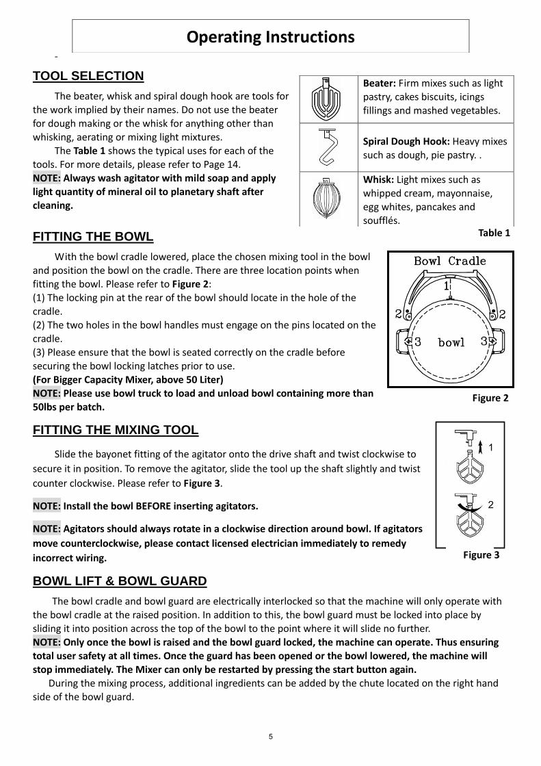
TOOL SELECTION
The beater, whisk and spiral dough hook are tools for the work implied by their names. Do not use the beater
for dough making or the whisk for anything other than whisking, aerating or mixing light mixtures.
The Table 1 shows the typical uses for each of the tools. For more details, please refer to Page 14. NOTE: Always wash agitator with mild soap and apply light quantity of mineral oil to planetary shaft after cleaning.
FITTING THE BOWL
With the bowl cradle lowered, place the chosen mixing tool in the bowl and position the bowl on the cradle. There are three location points when fitting the bowl. Please refer to Figure 2: (1) The locking pin at the rear of the bowl should locate in the hole of thecradle.(2) The two holes in the bowl handles must engage on the pins located on thecradle.(3) Please ensure that the bowl is seated correctly on the cradle beforesecuring the bowl locking latches prior to use.
(For Bigger Capacity Mixer, above 50 Liter)NOTE: Please use bowl truck to load and unload bowl containing more than50lbs per batch.
FITTING THE MIXING TOOL
Slide the bayonet fitting of the agitator onto the drive shaft and twist clockwise to
secure it in position. To remove the agitator, slide the tool up the shaft slightly and twist
counter clockwise. Please refer to Figure 3.
NOTE: Install the bowl BEFORE inserting agitators.
NOTE: Agitators should always rotate in a clockwise direction around bowl. If agitators
move counterclockwise, please contact licensed electrician immediately to remedy
incorrect wiring.
BOWL LIFT & BOWL GUARD
The bowl cradle and bowl guard are electrically interlocked so that the machine will only operate with the bowl cradle at the raised position. In addition to this, the bowl guard must be locked into place by sliding it into position across the top of the bowl to the point where it will slide no further.
NOTE: Only once the bowl is raised and the bowl guard locked, the machine can operate. Thus ensuring total user safety at all times. Once the guard has been opened or the bowl lowered, the machine will stop immediately. The Mixer can only be restarted by pressing the start button again.
During the mixing process, additional ingredients can be added by the chute located on the right hand side of the bowl guard.
Operating Instructions
Beater: Firm mixes such as light pastry, cakes biscuits, icings fillings and mashed vegetables.
Spiral Dough Hook: Heavy mixes such as dough, pie pastry. .
Whisk: Light mixes such as whipped cream, mayonnaise, egg whites, pancakes and soufflés.
Table 1
Figure 2
Figure 3
5
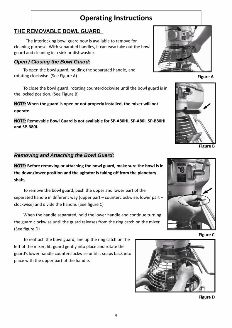
Figure A
THE REMOVABLE BOWL GUARD
The interlocking bowl guard now is available to remove for cleaning purpose. With separated handles, it can easy take out the bowl guard and cleaning in a sink or dishwasher.
Open / Closing the Bowl Guard:
To open the bowl guard, holding the separated handle, and rotating clockwise. (See Figure A)
To close the bowl guard, rotating counterclockwise until the bowl guard is in the locked position. (See Figure B)
NOTE: When the guard is open or not properly installed, the mixer will not
operate.
NOTE: Removable Bowl Guard is not available for SP-A80HI, SP-A80I, SP-B80HI and SP-B80I.
Removing and Attaching the Bowl Guard:
NOTE: Before removing or attaching the bowl guard, make sure the bowl is in
the down/lower position and the agitator is taking off from the planetary
shaft.
To remove the bowl guard, push the upper and lower part of the
separated handle in different way (upper part – counterclockwise, lower part –
clockwise) and divide the handle. (See figure C)
When the handle separated, hold the lower handle and continue turning
the guard clockwise until the guard releases from the ring catch on the mixer.
(See figure D)
To reattach the bowl guard, line up the ring catch on the
left of the mixer; lift guard gently into place and rotate the
guard’s lower handle counterclockwise until it snaps back into
place with the upper part of the handle.
Operating Instructions
Figure B
Figure C
Figure D
6
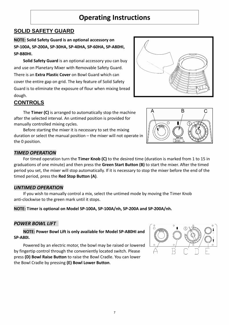
SOLID SAFETY GUARD
NOTE: Solid Safety Guard is an optional accessory on
SP-100A, SP-200A, SP-30HA, SP-40HA, SP-60HA, SP-A80HI,
SP-B80HI.
Solid Safety Guard is an optional accessory you can buy
and use on Planetary Mixer with Removable Safety Guard.
There is an Extra Plastic Cover on Bowl Guard which can
cover the entire gap on grid. The key feature of Solid Safety
Guard is to eliminate the exposure of flour when mixing bread
dough.
CONTROLS
The Timer (C) is arranged to automatically stop the machine after the selected interval. An untimed position is provided for manually controlled mixing cycles.
Before starting the mixer it is necessary to set the mixing duration or select the manual position – the mixer will not operate in the 0 position.
TIMED OPERATION For timed operation turn the Timer Knob (C) to the desired time (duration is marked from 1 to 15 in
graduations of one minute) and then press the Green Start Button (B) to start the mixer. After the timed period you set, the mixer will stop automatically. If it is necessary to stop the mixer before the end of the timed period, press the Red Stop Button (A).
UNTIMED OPERATION If you wish to manually control a mix, select the untimed mode by moving the Timer Knob
anti-clockwise to the green mark until it stops.
NOTE: Timer is optional on Model SP-100A, SP-100A/nh, SP-200A and SP-200A/nh.
POWER BOWL LIFT
NOTE: Power Bowl Lift is only available for Model SP-A80HI and SP-A80I.
Powered by an electric motor, the bowl may be raised or lowered by fingertip control through the conveniently located switch. Please press (D) Bowl Raise Button to raise the Bowl Cradle. You can lower the Bowl Cradle by pressing (E) Bowl Lower Button.
Operating Instructions
7
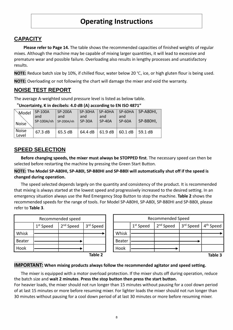
Table 2 Table 3
Noise
CAPACITY
Please refer to Page 14. The table shows the recommended capacities of finished weights of regular
mixes. Although the machine may be capable of mixing larger quantities, it will lead to excessive and premature wear and possible failure. Overloading also results in lengthy processes and unsatisfactory results.
NOTE: Reduce batch size by 10%, if chilled flour, water below 20 ℃, ice, or high gluten flour is being used.
NOTE: Overloading or not following the chart will damage the mixer and void the warranty.
NOISE TEST REPORT
The average A-weighted sound pressure level is listed as below table.
“Uncertainty, K in decibels: 4.0 dB (A) according to EN ISO 4871”
Model SP-100A and SP-100A/nh
SP-200A and SP-200A/nh
SP-30HA and SP-30A
SP-40HA and SP-40A
SP-60HA and SP-60A
SP-A80HI,
SP-B80HI,
Noise Level
67.3 dB 65.5 dB 64.4 dB 61.9 dB 60.1 dB 59.1 dB
SPEED SELECTION
Before changing speeds, the mixer must always be STOPPED first. The necessary speed can then be
selected before restarting the machine by pressing the Green Start Button.
NOTE: The Model SP-A80HI, SP-A80I, SP-B80HI and SP-B80I will automatically shut off if the speed is changed during operation.
The speed selected depends largely on the quantity and consistency of the product. It is recommended that mixing is always started at the lowest speed and progressively increased to the desired setting. In an emergency situation always use the Red Emergency Stop Button to stop the machine. Table 2 shows the
recommended speeds for the range of tools. For Model SP-A80HI, SP-A80I, SP-B80HI and SP-B80I, please refer to Table 3.
IMPORTANT: When mixing products always follow the recommended agitator and speed setting.
The mixer is equipped with a motor overload protection. If the mixer shuts off during operation, reduce the batch size and wait 2 minutes. Press the stop button then press the start button. For heavier loads, the mixer should not run longer than 15 minutes without pausing for a cool down period of at last 15 minutes or more before resuming mixer. For lighter loads the mixer should not run longer than 30 minutes without pausing for a cool down period of at last 30 minutes or more before resuming mixer.
Operating Instructions
Recommended speed
1st Speed 2nd Speed 3rd Speed
Whisk
Beater
Hook
Recommended Speed
1st Speed 2nd Speed 3rd Speed 4th Speed
Whisk
Beater
Hook
8

BOWL SCRAPER
NOTE: Bowl Scraper is an optional accessory. Please consult the local dealer for ordering.
The Bowl Scraper is used in conjunction with the Beater or Wire Whip agitator. The Bowl Scraper is easily attached to the mounted bracket when needed. While the agitator is mixing the product, the scraper is continuously scraping the entire inside of the mixing bowl.
BENEFITS/SOLUTIONS Reduces Labor: Eliminates the task of stopping mid batch to laboriously scrape
product from inside of bowl.Reduces Recipe Time: No more stopping during mixing time. Most recipes can
have multiple steps reduced by use of the Bowl Scraper. In most cases, reducestime required for initial incorporation of ingredients.
Increased Productivity: With reduced labor time and recipe time, more timecan be scheduled for additional batches and other assignments.
Provides Product Consistency: Continuous scraping provides more consistentproduct results, batch after batch.
IDEAL RECIPES FOR USE WITH THE BOWL SCRAPER Scratch Mashed PotatoesInstant Mashed PotatoesPancake and Waffle BattersCake BattersSugar CookiesIcingsMayonnaiseBiscuit BatterCheesecakesCreaming ShorteningsCreaming Eggs/Sugar
Operating Instructions
9

ATTACHMENTS
NOTE: Attachment Hub is optional.
The ranges of attachments that can be operated from the Attachment Hub are listed below. When using an attachment, lubricate the Drive Stud (D) using a food quality grease or oil. To fix to the mixer refer to Figure 4.Release the Thumbscrew (G) and slide the shaft of the attachment into thehub ensuring that the Drive Stud (D) engages in the socket within the hub.Rotate the attachment to line up the Location Peg (E) with its mating hole inthe hub and push firmly home. Tighten thumbscrew to secure.
CAUTION: Only fit attachments when the mixer is stationary and never when it is operating. Do not use attachments when mixing.
The recommended speed range for some of the attachments available is shown in table below.
Recommended speed
1st gear 2nd gear 3rd gear
V99S Veg. Prep.
VH-12 Mincer
V99S Vegetable Preparation With a range of 8 plates to slice, grate or shred all types of vegetable and fruit from nuts and cabbage to carrots and cheese.
VH-12 Mincer A no.12 mincing attachment which works wonders with meat, fish and vegetables alike.
NOTE: Make sure the bowl is up and the bowl guard is closed, otherwise the mixer will not function.
NOTE: If you still don’t understand or have any doubt of operation, please don’t use the machine and
contact the local representative.
Operating Instructions
Figure 4
10
Cleaning Instructions
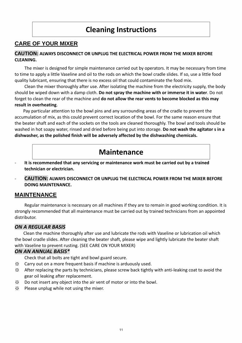
CARE OF YOUR MIXER
CAUTION: ALWAYS DISCONNECT OR UNPLUG THE ELECTRICAL POWER FROM THE MIXER BEFORE
CLEANING.
The mixer is designed for simple maintenance carried out by operators. It may be necessary from time to time to apply a little Vaseline and oil to the rods on which the bowl cradle slides. If so, use a little food quality lubricant, ensuring that there is no excess oil that could contaminate the food mix.
Clean the mixer thoroughly after use. After isolating the machine from the electricity supply, the body should be wiped down with a damp cloth. Do not spray the machine with or immerse it in water. Do not forget to clean the rear of the machine and do not allow the rear vents to become blocked as this may result in overheating.
Pay particular attention to the bowl pins and any surrounding areas of the cradle to prevent the accumulation of mix, as this could prevent correct location of the bowl. For the same reason ensure that the beater shaft and each of the sockets on the tools are cleaned thoroughly. The bowl and tools should be washed in hot soapy water, rinsed and dried before being put into storage. Do not wash the agitator s in a dishwasher, as the polished finish will be adversely affected by the dishwashing chemicals.
Maintenance - It is recommended that any servicing or maintenance work must be carried out by a trained
technician or electrician.
- CAUTION: ALWAYS DISCONNECT OR UNPLUG THE ELECTRICAL POWER FROM THE MIXER BEFOREDOING MAINTENANCE.
MAINTENANCE
Regular maintenance is necessary on all machines if they are to remain in good working condition. It is strongly recommended that all maintenance must be carried out by trained technicians from an appointed distributor.
ON A REGULAR BASIS Clean the machine thoroughly after use and lubricate the rods with Vaseline or lubrication oil which
the bowl cradle slides. After cleaning the beater shaft, please wipe and lightly lubricate the beater shaft with Vaseline to prevent rusting. (SEE CARE ON YOUR MIXER) ON AN ANNUAL BASIS*
Check that all bolts are tight and bowl guard secure. ※ Carry out on a more frequent basis if machine is arduously used.※ After replacing the parts by technicians, please screw back tightly with anti-leaking coat to avoid the
gear oil leaking after replacement.※ Do not insert any object into the air vent of motor or into the bowl.
※ Please unplug while not using the mixer.
11
Maintenance
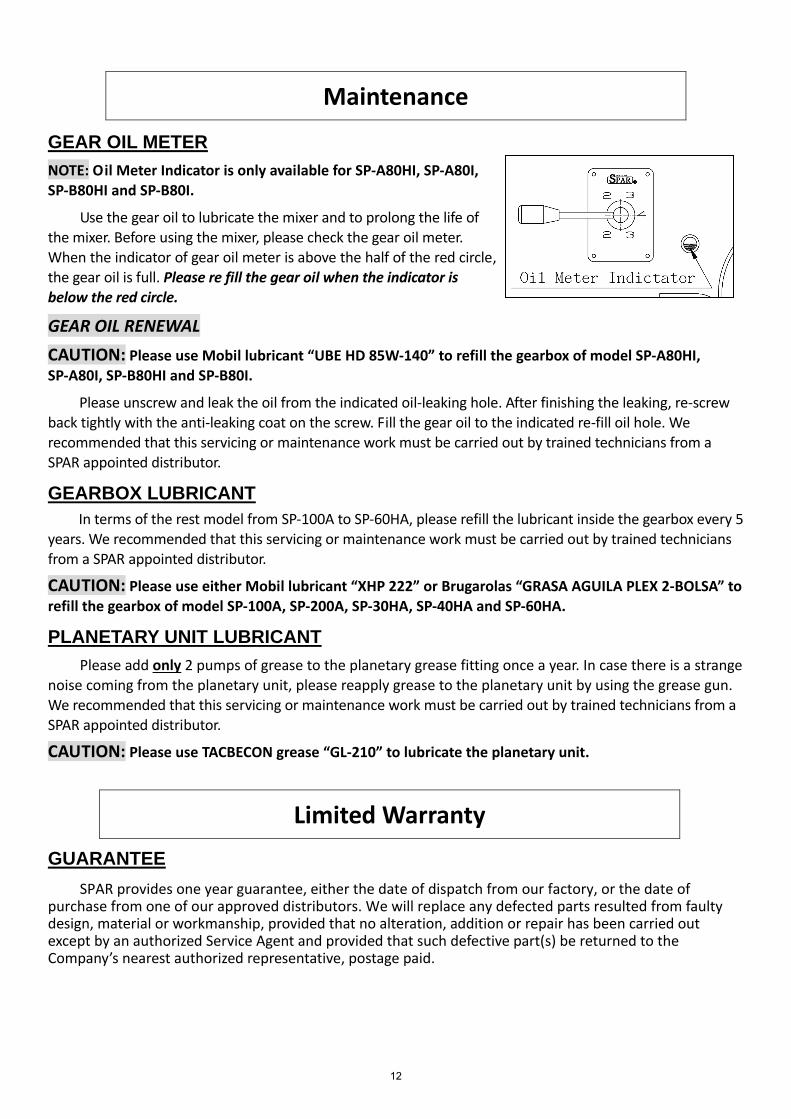
GEAR OIL METER
NOTE: Oil Meter Indicator is only available for SP-A80HI, SP-A80I,
SP-B80HI and SP-B80I.
Use the gear oil to lubricate the mixer and to prolong the life of the mixer. Before using the mixer, please check the gear oil meter. When the indicator of gear oil meter is above the half of the red circle, the gear oil is full. Please re fill the gear oil when the indicator is below the red circle.
GEAR OIL RENEWAL
CAUTION: Please use Mobil lubricant “UBE HD 85W-140” to refill the gearbox of model SP-A80HI, SP-A80I, SP-B80HI and SP-B80I.
Please unscrew and leak the oil from the indicated oil-leaking hole. After finishing the leaking, re-screw back tightly with the anti-leaking coat on the screw. Fill the gear oil to the indicated re-fill oil hole. We recommended that this servicing or maintenance work must be carried out by trained technicians from a SPAR appointed distributor.
GEARBOX LUBRICANT
In terms of the rest model from SP-100A to SP-60HA, please refill the lubricant inside the gearbox every 5 years. We recommended that this servicing or maintenance work must be carried out by trained technicians
from a SPAR appointed distributor.
CAUTION: Please use either Mobil lubricant “XHP 222” or Brugarolas “GRASA AGUILA PLEX 2-BOLSA” to refill the gearbox of model SP-100A, SP-200A, SP-30HA, SP-40HA and SP-60HA.
PLANETARY UNIT LUBRICANT
Please add only 2 pumps of grease to the planetary grease fitting once a year. In case there is a strange noise coming from the planetary unit, please reapply grease to the planetary unit by using the grease gun. We recommended that this servicing or maintenance work must be carried out by trained technicians from a SPAR appointed distributor.
CAUTION: Please use TACBECON grease “GL-210” to lubricate the planetary unit.
Limited Warranty
GUARANTEE
SPAR provides one year guarantee, either the date of dispatch from our factory, or the date of purchase from one of our approved distributors. We will replace any defected parts resulted from faulty design, material or workmanship, provided that no alteration, addition or repair has been carried out except by an authorized Service Agent and provided that such defective part(s) be returned to the Company’s nearest authorized representative, postage paid.
12
Troubleshooting
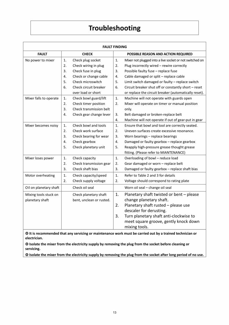
FAULT FINDING
FAULT CHECK POSSIBLE REASON AND ACTION REQUIRED
No power to mixer 1. Check plug socket
2. Check wiring in plug
3. Check fuse in plug
4. Check or change cable
5. Check microswitch
6. Check circuit breaker
over load or short
1. Mixer not plugged into a live socket or not switched on
2. Plug incorrectly wired – rewire correctly
3. Possible faulty fuse – replace fuse
4. Cable damaged or split – replace cable
5. Limit switch damaged or faulty – replace switch
6. Circuit breaker shut off or constantly short – reset
or replace the circuit breaker (automatically reset).
Mixer falls to operate 1. Check bowl guard/lift
2. Check timer position
3. Check transmission belt
4. Check gear change lever
1. Machine will not operate with guards open
2. Mixer will operate on timer or manual position
only.
3. Belt damaged or broken-replace belt
4. Machine will not operate if out of gear-put in gear
Mixer becomes noisy 1. Check bowl and tools
2. Check work surface
3. Check bearing for wear
4. Check gearbox
5. Check planetary unit
1. Ensure that bowl and tool are correctly seated.
2. Uneven surfaces create excessive resonance.
3. Worn bearings – replace bearings
4. Damaged or faulty gearbox – replace gearbox
5. Reapply high-pressure grease thought grease
fitting. (Please refer to MIANTENANCE)
Mixer loses power 1. Check capacity
2. Check transmission gear
3. Check shaft bias
1. Overloading of bowl – reduce load
2. Gear damaged or worn – replace belt
3. Damaged or faulty gearbox – replace shaft bias
Motor overheating 1. Check capacity/speed
2. Check supply voltage
1. Refer to Table 2 and 3 for details
2. Voltage should correspond to rating plate
Oil on planetary shaft Check oil seal Worn oil seal – change oil seal
Mixing tools stuck on
planetary shaft
Check planetary shaft
bent, unclean or rusted.
1. Planetary shaft twisted or bent – pleasechange planetary shaft.
2. Planetary shaft rusted – please usedescaler for derusting.
3. Turn planetary shaft anti-clockwise tomeet square groove, gently knock downmixing tools.
◎ It is recommended that any servicing or maintenance work must be carried out by a trained technician orelectrician.
◎ Isolate the mixer from the electricity supply by removing the plug from the socket before cleaning orservicing.
◎ Isolate the mixer from the electricity supply by removing the plug from the socket after long period of no use.
13

Capacity Chart Table
Product Agitator /
Speed SP-100A SP-200A SP-30HA SP-40HA SP-60HA
SP-A80HI &
SP-B80HI
Bowl Capacity Bowl 10 LITER 20 LITER 30 LITER 40 LITER 60 LITER 80 LITER
Waffle or Hot Cake Batter Beater 4.7L 7.6L 11.4L 15.1L 22.7L 28.4L
Whipped Cream Whip 1.9L 3.8L 5.7L 8.5L 11.4L 15.1L
Mashed Potatoes Beater 3.6KG 6.8KG 10.4KG 13.6KG 18.1KG 22.7KG
Egg Whites Whip 0.47L 0.95L 1.4L 1.7L 1.9L 2.8L
Meringue Whip 0.35L 0.71L 1.9L 2.4L 2.9L 3.8L
(Qty of Water)
Raised Donut Dough Hook 2KG 4.1KG 6.8KG 11.3KG 27.2KG 32.3KG
(65% AR) *◆ 1st & 2nd
Heavy Bread Dough Hook 3.4KG 6.8KG 13.6KG 18.1KG 31.8KG 32.3KG
(55% AR) *․◆ 1st only
Bread and Roll Dough Hook 5.7KG 11.3KG 20.4KG 27.2KG 36.3KG 40.8KG
(60% AR) *․◆ 1st only
Pizza Dough, Thin Hook 2.3KG 4.1KG 7.3KG 13.6KG 18.1KG 22.7KG
(40% AR) *․Δ◆□ 1st only
Pizza Dough, Medium Hook 2.3KG 4.5KG 11.3KG 18.1KG 31.8KG 40.8KG
(50% AR) *․◆□ 1st only
Pizza Dough, Thick Hook 4.5KG 9.1KG 18.1KG 22.7KG 31.8KG 45.4KG
(60% AR) *․◆ 1st only
Fondant Icing Beater 2.7KG 5.4KG 8.2KG 11.3KG 16.3KG 27.2KG
Cake Beater 4.5KG 9.1KG 13.6KG 18.1KG 27.2KG 40.8KG
Pie Dough Beater 4.5KG 8.2KG 12.2KG 15.9KG 22.7KG 31.8KG
Pasta, Basic Egg Noodle Hook 1.4KG 2.3KG 3.6KG 7.7KG 15.9KG 22.7KG
NOTE: *The mixer capacity depends on the moisture content of the dough. When mixing dough (pizza, bread,
or bagels) check your AR%! %AR (% Absorption Ration) = Water weight divided by flour weight. The capacities
listed above are based on flour at room temperature and 70°F water temperature. (1 gallon water weights 8.33
lbs.)
Δ Maximum Mixing Time- 7 Minutes
․ If high gluten flour is used, reduce the batch size by 10%.
◆ If using chilled flour, water below 20 ℃, or ice, reduce batch size by 10%.
□ 2nd speed should never be used on 50% AR or lower with the exception of Model SP-60HA. The SP-60HA
requires a 50% reduction in batch size to mix in speed 2 with 50% AR dough.
14
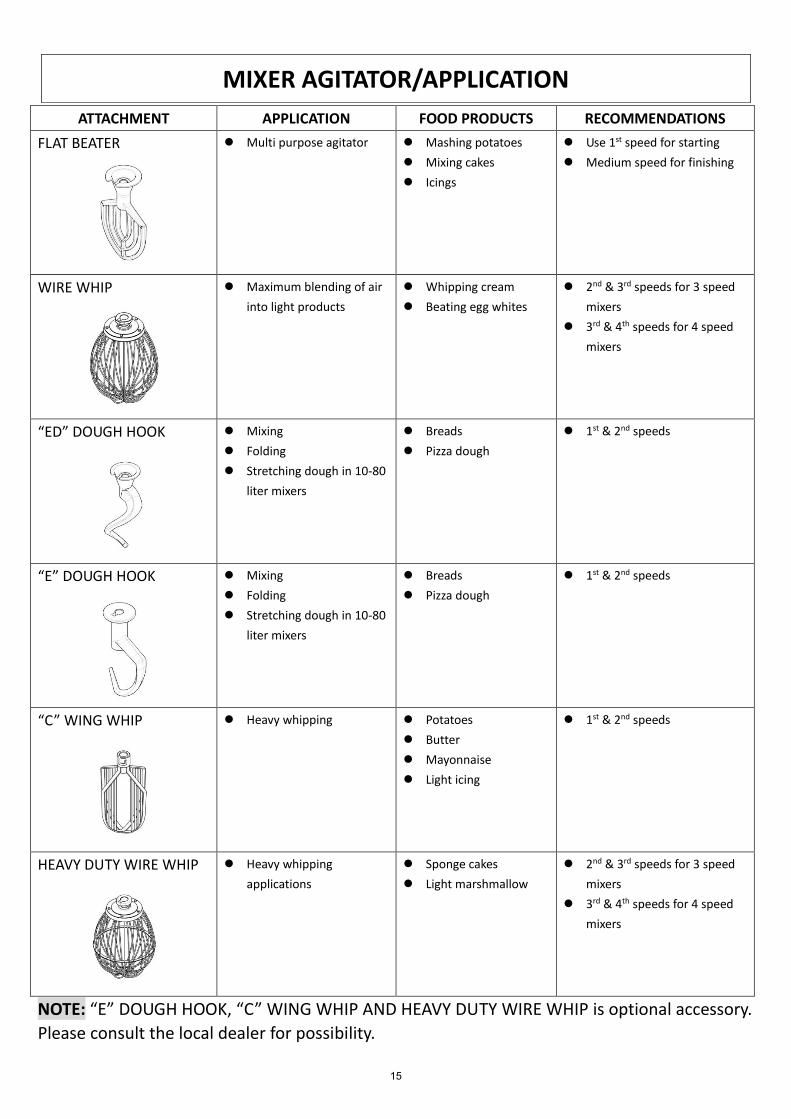
NOTE: “E” DOUGH HOOK, “C” WING WHIP AND HEAVY DUTY WIRE WHIP is optional accessory.
Please consult the local dealer for possibility.
ATTACHMENT APPLICATION FOOD PRODUCTS RECOMMENDATIONS
FLAT BEATER ⚫ Multi purpose agitator ⚫ Mashing potatoes
⚫ Mixing cakes
⚫ Icings
⚫ Use 1st speed for starting
⚫ Medium speed for finishing
WIRE WHIP ⚫ Maximum blending of air
into light products
⚫ Whipping cream
⚫ Beating egg whites
⚫ 2nd & 3rd speeds for 3 speed
mixers
⚫ 3rd & 4th speeds for 4 speed
mixers
“ED” DOUGH HOOK ⚫ Mixing
⚫ Folding
⚫ Stretching dough in 10-80
liter mixers
⚫ Breads
⚫ Pizza dough
⚫ 1st & 2nd speeds
“E” DOUGH HOOK ⚫ Mixing
⚫ Folding
⚫ Stretching dough in 10-80
liter mixers
⚫ Breads
⚫ Pizza dough
⚫ 1st & 2nd speeds
“C” WING WHIP ⚫ Heavy whipping ⚫ Potatoes
⚫ Butter
⚫ Mayonnaise
⚫ Light icing
⚫ 1st & 2nd speeds
HEAVY DUTY WIRE WHIP ⚫ Heavy whipping
applications
⚫ Sponge cakes
⚫ Light marshmallow
⚫ 2nd & 3rd speeds for 3 speed
mixers
⚫ 3rd & 4th speeds for 4 speed
mixers
MIXER AGITATOR/APPLICATION
15

12
34
ABCD
43
21
D C B A
7T2
T11
T21
7T1
1L1
3L2
5L3
13N
OA
2
2T1
4T2
6T3
FUSE
(1A
)
553 3
0V15V
6 6
14N
O
6T3
4T2
2T1
95 96 97 980V44
0V
T3 T3
4 4
L2
RR2 2
L2L1M
OTO
R
24V
MIC
ROSW
ITCH
HEI
GH
T A
DJU
STER
MIC
ROSW
ITCH
SAFT
Y C
OV
ER
PE
400V
L2L1L1
L1 L1L3L3
L3 L399
8 8
A1
L3
LAM
P
ON
SW
ITCH
OFF
SW
ITCH
TIM
ER
SP
-30H
I & S
P-3
0HA
WIR
ING
DIA
GR
AM
- 40
0V-5
0HZ-
3PH
AS
E
16

12
34
ABCD
43
21
D C B A
7T2
T11
T21
7T1
1L1
3L2
5L3
13N
OA
2
2T1
4T2
6T3
FUSE
(1A
)
553 3
0V15V
6 6
14N
O
6T3
4T2
2T1
95 96 97 980V48
0V
T3 T3
4 4
L2
RR2 2
L2L1M
OTO
R
24V
MIC
ROSW
ITCH
HEI
GH
T A
DJU
STER
MIC
ROSW
ITCH
SAFT
Y C
OV
ER
PE
440V
L2L1L1
L1 L1L3L3
L3 L399
8 8
A1
L3
LAM
P
ON
SW
ITCH
OFF
SW
ITCH
TIM
ER
SP
-30H
I & S
P-3
0HA
WIR
ING
DIA
GR
AM
- 48
0V-6
0HZ-
3PH
AS
E
17

ABCDD C B A
7T2
T11
T21
7T1
1L1
3L2
5L3
13N
OA
2
2T1
4T2
6T3
FUSE
(1A
)
553 3
0V15V
6 6
14N
O
6T3
4T2
2T1
95 96 97 980V38
0V
T3 T3
4 4
L2
RR2 2
L2L1M
OTO
R
24V
MIC
ROSW
ITCH
HEI
GH
T A
DJU
STER
MIC
ROSW
ITCH
SAFT
Y C
OV
ER
PE
230V
L2L1L1
L1 L1L3L3
L3 L399
8 8
A1
L3
LAM
P
ON
SW
ITCH
OFF
SW
ITCH
TIM
ER
SP
-30H
I & S
P-3
0HA
WIR
ING
DIA
GR
AM
- 23
0V-5
0HZ-
3PH
AS
E
18
12
34
ABCD
43
21
D C B A
7T2
T11
T21
7T1
1L1
3L2
5L3
13N
OA
2
2T1
4T2
6T3
FUSE
(1A
)
553 3
0V15V
6 6
14N
O
6T3
4T2
2T1
95 96 97 980V44
0V
T3 T3
4 4
L2
RR2 2
L2L1M
OTO
R
24V
MIC
ROSW
ITCH
HEI
GH
T A
DJU
STER
MIC
ROSW
ITCH
SAFT
Y C
OV
ER
PE
400V
L2L1L1
L1 L1L3L3
L3 L399
8 8
A1
L3
LAM
P
ON
SW
ITCH
OFF
SW
ITCH
TIM
ER
SP
-30H
I & S
P-3
0HA
WIR
ING
DIA
GR
AM
- 44
0V-6
0HZ-
3PH
AS
E
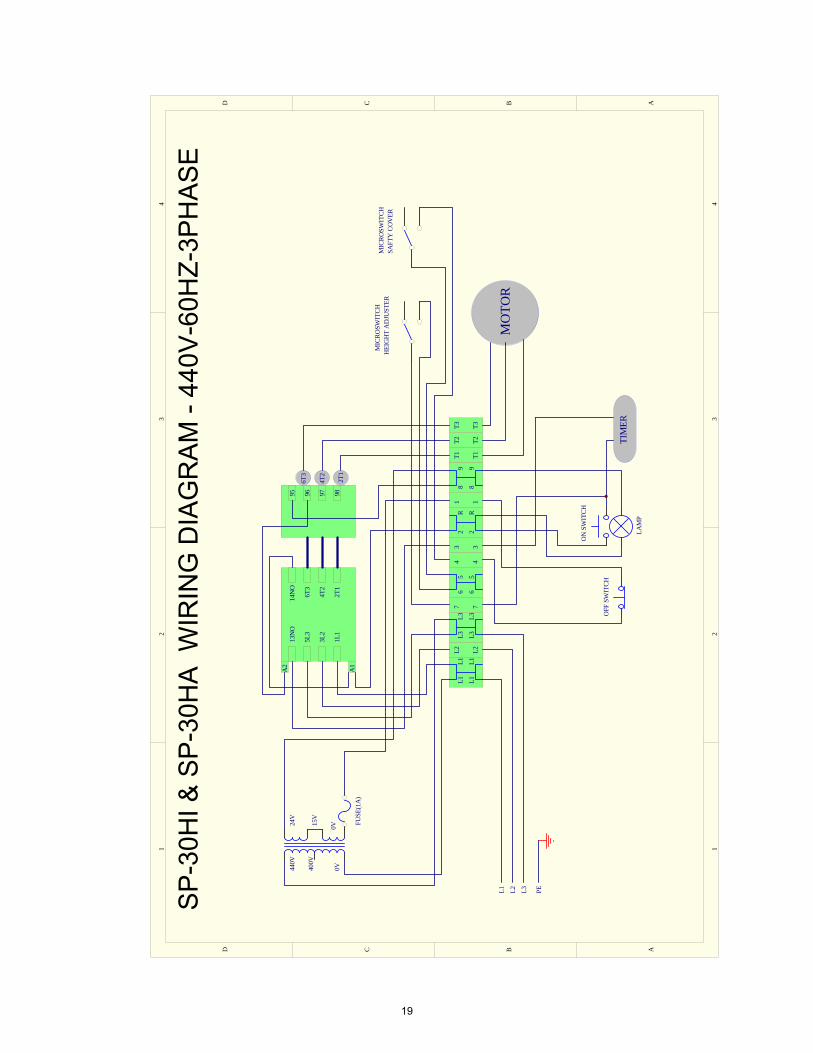
19

12
34
ABCD
43
21
D C B A
7T2
T11
T21
7T1
1L1
3L2
5L3
13N
OA
2
2T1
4T2
6T3
FUSE
(1A
)
553 3
0V15V
6 6
14N
O
6T3
4T2
2T1
95 96 97 980V38
0V
T3 T3
4 4
L2
RR2 2
L2L1M
OTO
R
24V
MIC
ROSW
ITCH
HEI
GH
T A
DJU
STER
MIC
ROSW
ITCH
SAFT
Y C
OV
ER
PE
230V
L2L1L1
L1 L1L3L3
L3 L399
8 8
A1
L3
LAM
P
ON
SW
ITCH
OFF
SW
ITCH
TIM
ER
SP
-40H
I & S
P-4
0HA
WIR
ING
DIA
GR
AM
- 23
0V-5
0HZ-
3PH
AS
E
20

12
34
ABCD
43
21
D C B A
7T2
T11
T21
7T1
1L1
3L2
5L3
13N
OA
2
2T1
4T2
6T3
FUSE
(1A
)
553 3
0V15V
6 6
14N
O
6T3
4T2
2T1
95 96 97 980V44
0V
T3 T3
4 4
L2
RR2 2
L2L1M
OTO
R
24V
MIC
ROSW
ITCH
HEI
GH
T A
DJU
STER
MIC
ROSW
ITCH
SAFT
Y C
OV
ER
PE
400V
L2L1L1
L1 L1L3L3
L3 L399
8 8
A1
L3
LAM
P
ON
SW
ITCH
OFF
SW
ITCH
TIM
ER
SP
-40H
I & S
P-4
0HA
WIR
ING
DIA
GR
AM
- 40
0V-5
0HZ-
3PH
AS
E
21

12
34
ABCD
43
21
D C B A
7T2
T11
T21
7T1
1L1
3L2
5L3
13N
OA
2
2T1
4T2
6T3
FUSE
(1A
)
553 3
0V15V
6 6
14N
O
6T3
4T2
2T1
95 96 97 980V44
0V
T3 T3
4 4
L2
RR2 2
L2L1M
OTO
R
24V
MIC
ROSW
ITCH
HEI
GH
T A
DJU
STER
MIC
ROSW
ITCH
SAFT
Y C
OV
ER
PE
400V
L2L1L1
L1 L1L3L3
L3 L399
8 8
A1
L3
LAM
P
ON
SW
ITCH
OFF
SW
ITCH
TIM
ER
SP
-40H
I & S
P-4
0HA
WIR
ING
DIA
GR
AM
- 44
0V-6
0HZ-
3PH
AS
E
22
12
34
ABCD
43
21
D C B A
7T2
T11
T21
7T1
1L1
3L2
5L3
13N
OA
2
2T1
4T2
6T3
FUSE
(1A
)
553 3
0V15V
6 6
14N
O
6T3
4T2
2T1
95 96 97 980V48
0V
T3 T3
4 4
L2
RR2 2
L2L1M
OTO
R
24V
MIC
ROSW
ITCH
HEI
GH
T A
DJU
STER
MIC
ROSW
ITCH
SAFT
Y C
OV
ER
PE
440V
L2L1L1
L1 L1L3L3
L3 L399
8 8
A1
L3
LAM
P
ON
SW
ITCH
OFF
SW
ITCH
TIM
ER
SP
-40H
I & S
P-4
0HA
WIR
ING
DIA
GR
AM
- 48
0V-6
0HZ-
3PH
AS
E
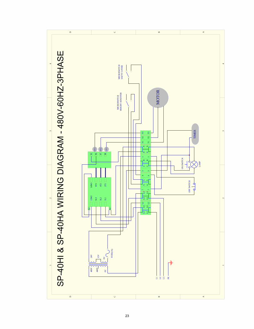
23
12
34
ABCD
43
21
D C B A
7T2
T11
T21
7T1
1L1
3L2
5L3
13N
OA
2
2T1
4T2
6T3
FUSE
(1A
)
553 3
0V15V
6 6
14N
O
6T3
4T2
2T1
95 96 97 980V38
0V
T3 T3
4 4
L2
RR2 2
L2L1M
OTO
R
24V
MIC
ROSW
ITCH
HEI
GH
T A
DJU
STER
MIC
ROSW
ITCH
SAFT
Y C
OV
ER
PE
230V
L2L1L1
L1 L1L3L3
L3 L399
8 8
A1
L3
LAM
P
ON
SW
ITCH
OFF
SW
ITCH
TIM
ER
SP
-60H
I & S
P-6
0HA
WIR
ING
DIA
GR
AM
- 2
30V
-50H
Z-3P
HA
SE
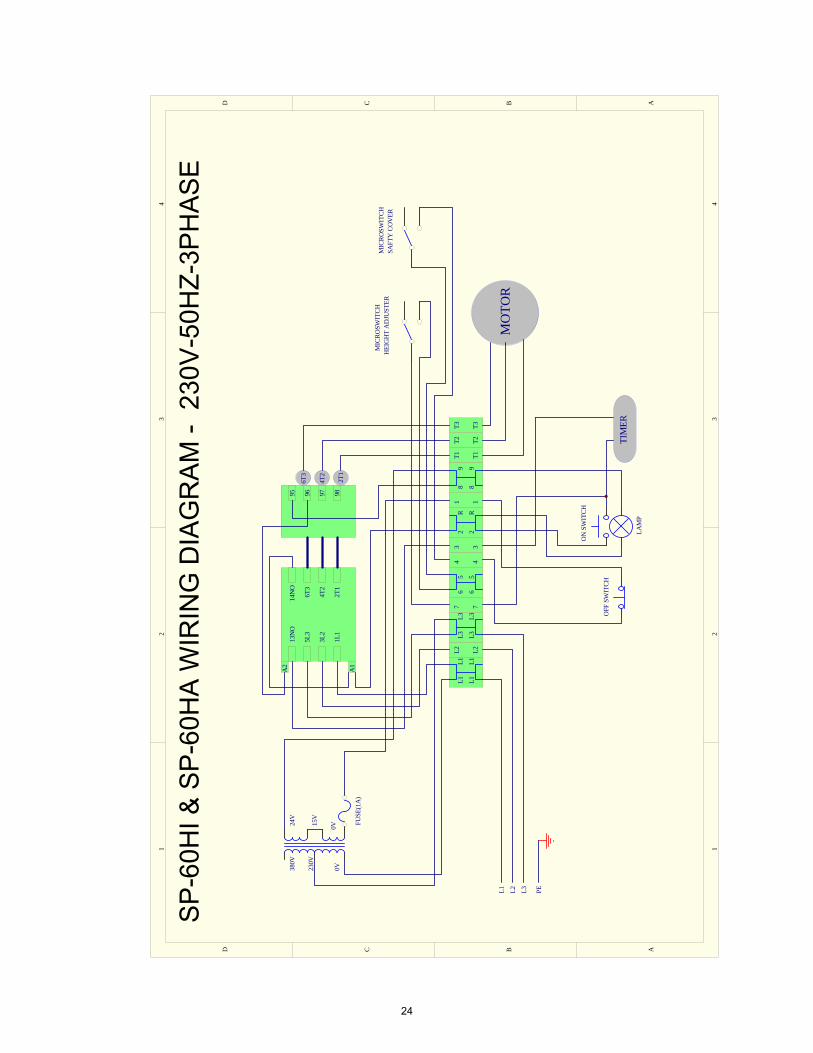
24

12
34
ABCD
43
21
D C B A
7T2
T11
T21
7T1
1L1
3L2
5L3
13N
OA
2
2T1
4T2
6T3
FUSE
(1A
)
553 3
0V15V
6 6
14N
O
6T3
4T2
2T1
95 96 97 980V48
0V
T3 T3
4 4
L2
RR2 2
L2L1M
OTO
R
24V
MIC
ROSW
ITCH
HEI
GH
T A
DJU
STER
MIC
ROSW
ITCH
SAFT
Y C
OV
ER
PE
440V
L2L1L1
L1 L1L3L3
L3 L399
8 8
A1
L3
LAM
P
ON
SW
ITCH
OFF
SW
ITCH
TIM
ER
SP
-60H
I & S
P-6
0HA
WIR
ING
DIA
GR
AM
- 4
80V
-60H
Z-3P
HA
SE
25
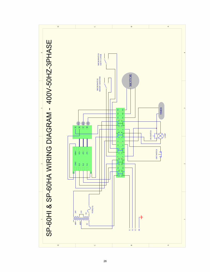
12
34
ABCD
43
21
D C B A
7T2
T11
T21
7T1
1L1
3L2
5L3
13N
OA
2
2T1
4T2
6T3
FUSE
(1A
)
553 3
0V15V
6 6
14N
O
6T3
4T2
2T1
95 96 97 980V44
0V
T3 T3
4 4
L2
RR2 2
L2L1M
OTO
R
24V
MIC
ROSW
ITCH
HEI
GH
T A
DJU
STER
MIC
ROSW
ITCH
SAFT
Y C
OV
ER
PE
400V
L2L1L1
L1 L1L3L3
L3 L399
8 8
A1
L3
LAM
P
ON
SW
ITCH
OFF
SW
ITCH
TIM
ER
SP
-60H
I & S
P-6
0HA
WIR
ING
DIA
GR
AM
- 4
00V
-50H
Z-3P
HA
SE
26
ABCDD C B A
1L1
3L2
5L3
13N
O
A1
A2
2T1
4T2
6T3
FUSE
(1A
)
0V24V
14N
O
6T3
4T2
2T1
95 96 97 98
0V230V
240V
1234
4P C
ON
NEC
TOR-
FEM
ALE
123456
6P C
ON
NEC
TOR-
FEM
ALE
123456
6P C
ON
NEC
TOR-
MA
LE
M
L1 L2 PE
HEI
GH
T A
DJU
STER
SAFT
Y C
OV
ER
12344P
CO
NN
ECTO
R-M
ALE
ON
SW
TICH
OFF
_SW
TICH
TIM
ER
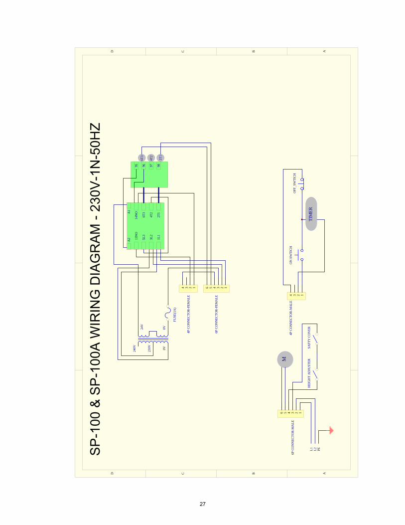
SP
-100
& S
P-1
00A
WIR
ING
DIA
GR
AM
- 23
0V-1
N-5
0HZ
27

ABCDD C B A
1L1
3L2
5L3
13N
O
A1
A2
2T1
4T2
6T3
FUSE
(1A
)
0V24V
14N
O
6T3
4T2
2T1
95 96 97 98
0V230V
240V
1234
4P C
ON
NEC
TOR-
FEM
ALE
123456
6P C
ON
NEC
TOR-
FEM
ALE
123456
6P C
ON
NEC
TOR-
MA
LE
M
L1 L2 PE
HEI
GH
T A
DJU
STER
SAFT
Y C
OV
ER
12344P
CO
NN
ECTO
R-M
ALE
ON
SW
TICH
OFF
_SW
TICH
TIM
ER
SP
-100
& S
P-1
00A
WIR
ING
DIA
GR
AM
- 23
0V-1
PE
-60H
Z
28

ABCDD C B A
1L1
3L2
5L3
13N
O
A1
A2
2T1
4T2
6T3
FUSE
(1A
)
SP-2
00 &
SP-
200A
WIR
ING
DIA
GR
AM
- 23
0V-5
0HZ-
SIN
GLE
PH
ASE
0V24V
14N
O
6T3
4T2
2T1
95 96 97 98
0V230V
240V
1234
4P C
ON
NEC
TOR-
FEM
ALE
123456
6P C
ON
NEC
TOR-
FEM
ALE
123456
6P C
ON
NEC
TOR-
MA
LE
M
L1 L2 PE
HEI
GH
T A
DJU
STER
SAFT
Y C
OV
ER
12344P
CO
NN
ECTO
R-M
ALE
ON
SW
TICH
OFF
_SW
TICH
TIM
ER
29
ABCDD C B A
1L1
3L2
5L3
13N
O
A1
A2
2T1
4T2
6T3
FUSE
(1A
)
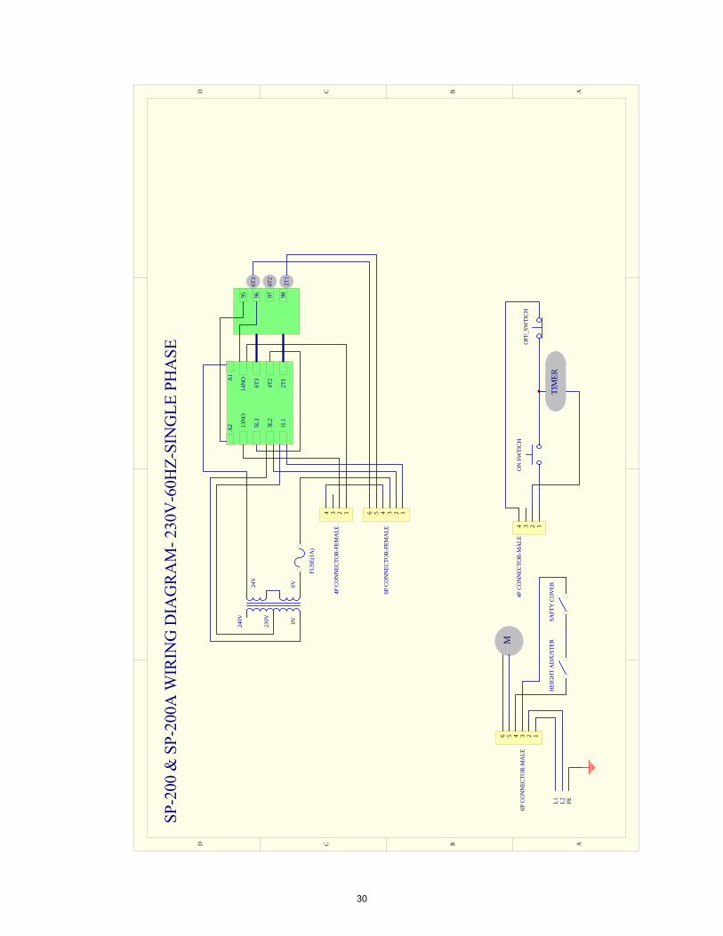
SP-2
00 &
SP-
200A
WIR
ING
DIA
GR
AM
- 230
V-6
0HZ-
SIN
GLE
PH
ASE
0V24V
14N
O
6T3
4T2
2T1
95 96 97 98
0V230V
240V
1234
4P C
ON
NEC
TOR-
FEM
ALE
123456
6P C
ON
NEC
TOR-
FEM
ALE
123456
6P C
ON
NEC
TOR-
MA
LE
M
L1 L2 PE
HEI
GH
T A
DJU
STER
SAFT
Y C
OV
ER
12344P
CO
NN
ECTO
R-M
ALE
ON
SW
TICH
OFF
_SW
TICH
TIM
ER
30
ABCDD C B A
1L1
3L2
5L3
13N
O
A1
A2
2T1
4T2
6T3
FUSE
(1A
)
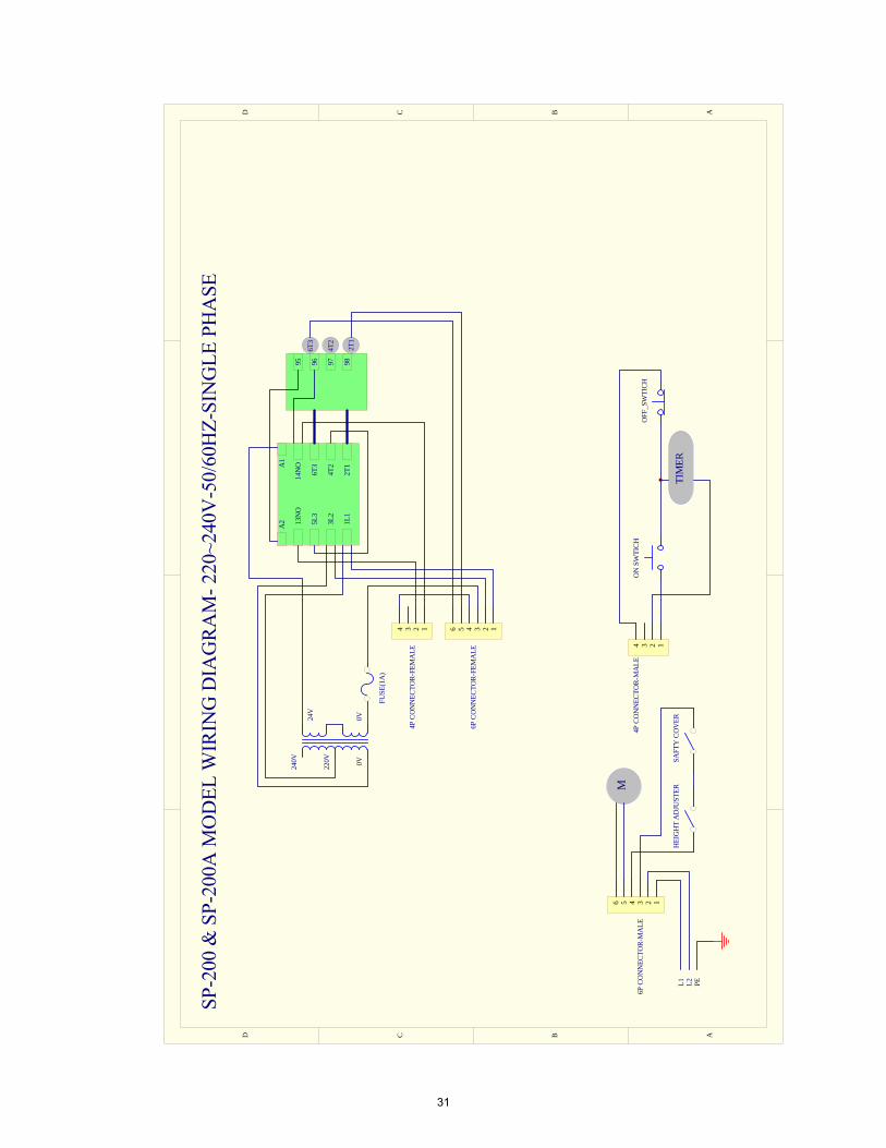
SP-2
00 &
SP-
200A
MO
DEL
WIR
ING
DIA
GR
AM
- 220
~240
V-5
0/60
HZ-
SIN
GLE
PH
ASE
0V24V
14N
O
6T3
4T2
2T1
95 96 97 98
0V220V
240V
1234
4P C
ON
NEC
TOR-
FEM
ALE
123456
6P C
ON
NEC
TOR-
FEM
ALE
123456
6P C
ON
NEC
TOR-
MA
LE
M
L1 L2 PE
HEI
GH
T A
DJU
STER
SAFT
Y C
OV
ER
12344P
CO
NN
ECTO
R-M
ALE
ON
SW
TICH
OFF
_SW
TICH
TIM
ER
31
ABCDD C B A
16
54
64
15
1L1
3L2
5L3
13N
OA
2
2T1
4T2
6T3 3 3
0V15V
14N
O
6T3
4T2
2T1
95 96 97 980V44
0V
7 7
2 2
8
L2L1
MO
TOR
24V
MIC
ROSW
ITCH
HEI
GH
T A
DJU
STER
MIC
ROSW
ITCH
SAFT
Y C
OV
ER
PE
400V
8
A1
L3
LAM
P
ON
SW
ITCH
OFF
SW
ITCH
TIM
ER
F1F2
F3
MIC
ROSW
ITCH
TRA
NSM
ISSI
ON
GEA
R
1 2 3 4 5 6
6P C
ON
NEC
TOR-
FEM
ALE
1 2 3 4 5 6
6P C
ON
NEC
TOR-
MA
LE
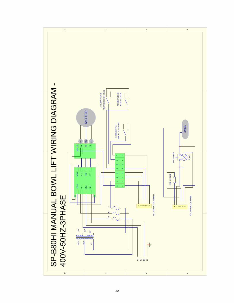
SP
-B80
HI M
AN
UA
L B
OW
L LI
FT W
IRIN
G D
IAG
RA
M -
400V
-50H
Z-3P
HA
SE
32

SPAR
(Internal ref.lid)
VAATIMUSTENMUKAISUUSVAKUUTUS FORSAKRAN OM OVERENSSTAMMELSE DECLARATION OF CONFORMITY
Vatmistajan nimi / Tillverkarens namn / Manufacturer's name
SPAR FOOD MACHINERY MFG. CO., LTD. Osaile/ Adress / Adress
No.145, 11th Industry Rd, Dali Dist., Taichung City, 412 Taiwan R.O.C.
Vakuuttaa, etta seuraava tuote / Forsakrar att foljande produkt / Declare that the following product
Nimi, tyyppi tai malli I Namn, typ eller model!/ Name, type or model
Mixer, Model: SP-800A, SP-100A, SP-200A, SP-30HA, SP-40HA, SP-60HA, SP-880HI, SP-A80HI
on seuraavien direktiivien asiaankuuluvien saannosten mukainen I overensstammer med tillampliga bestammelser i foljande direktiv / is in conformity with the relevant provisions of the following directives
Electromagnetic Compatibility Directives 2014/30/EU. Low-Voltage Directives 2014/35/EU. Machinery Directives 2006/42/EC.
ja lisaksi vakuuttaa, etta seuraavia yhdenmukaistettuja standardeja (tai niiden osia/kohtia) on sovellettu I och forsakrar dessutom att foljande harmoniserade standarder ( ell er delar/paragrafer) har anvants / and furthermore declares that the following harmonised standards (or parts/clauses) have been used
Standard: EN 61000-6-3: 2007/A 1: 2011, EN 61000-6-1: 2007.
Standard: EN 60204-1: 2006 + A1: 2009 + AC: 2010.
Standard: Annex I of Machinery Directive 2006/42/EC, EN 60204-1: 2006 + A1: 2009 + AC: 2010, EN 454: 2014, EN 1672-1: 2014, EN 1672-2: 2005 + A 1: 2009.
ja lisaksi vakuuttaa, etta seuraavia muita standardeja (tai niiden osia/kohtia) on sovellettu / och forsakrar dessutom att f0ljande andra standarder ( eller delar/paragrafer) har anvants / and furthermore we declare that the following other standards (or parts/clauses) have been used
ISO 9001 :2015
Tuotteen suunnitelmatarkastustodistus ja laatujarjestelmM valvova ilmoitettu laitos (vain painelaitteet) Produktens konstruktionskontrollcertifikat och anmalt organ, som overvakar kvalitetssystemet (endast tryckkarl) Product design examination certificate and the notified body supervising the quality system (only pressure vessels)
Alla mainittu henkil0 on valtuutettu kokoamaan teknisen tiedoston I Nedan namda person ar bemyndigad att sammanstalla den tekniska dokumentfilen / The person mentioned below is authorized to compile the technical file
Vincent Huang
Antopaikka ja p�Hva / Utfardad pcl art och datum/ Place and date of issue
Taiwan, June.18.2019
Valtuutetun henkilan nimi ja asema / Bemyndigad persons namn och befattning / Name and title of authorized person
33

Metos Oy Abwww.metos.com
Related Documents