Form #44201040 April 2010 April 2010 April 2010 April 2010 Rev B Rev B Rev B Rev B INSTALLATION AND OPERATION INSTRUCTIONS INFRARED RADIANT IP55 POULTRY TUBE HEATER Single Stage Pull Through System (Negative Pressure) Models: SRLP (30, 35, 40, 45) IP55 FOR YOUR SAFETY: FOR YOUR SAFETY: FOR YOUR SAFETY: FOR YOUR SAFETY: Exhaust fans MUST MUST MUST MUST be operating on an appropriate cycle when heaters are operating to avoid a high concentration of carbon monoxide. When used without fresh air, this heater may give off carbon monoxide, an odorless and poisonous gas. CARBON MONOXIDE POISONING MAY LEAD TO DEATH CARBON MONOXIDE POISONING MAY LEAD TO DEATH CARBON MONOXIDE POISONING MAY LEAD TO DEATH CARBON MONOXIDE POISONING MAY LEAD TO DEATH. Early signs of carbon monoxide poisoning resemble the flue with headaches, dizziness and nausea. If you experience these signs, GET FRESH AIR IMMEDIATELY! GET FRESH AIR IMMEDIATELY! GET FRESH AIR IMMEDIATELY! GET FRESH AIR IMMEDIATELY! Have the heaters serviced as soon as possible and check the ventilation in the house. These heaters are designed for agricultural applications and may operate with the use of either Natural Gas or Liquid Propane (LP) Gas. Check the heater’s nameplate to determine the correct gas type before proceeding with installation. !INSTALLER: This manual is the property of the owner. Please present this manual to the owner when you leave the job site. IF YOU SMELL GAS: FOR YOUR SAFETY FOR YOUR SAFETY FOR YOUR SAFETY FOR YOUR SAFETY ! DO NOT DO NOT DO NOT DO NOT try to light any appliance. ! DO NOT DO NOT DO NOT DO NOT touch any electrical switch; DO DO DO DO NOT NOT NOT NOT use any telephone in your building. ! IMMEDIATELY IMMEDIATELY IMMEDIATELY IMMEDIATELY call your gas supplier from a neighbor's telephone. Follow the gas supplier's instructions. If you cannot reach your gas supplier, call the fire department. DO NOT DO NOT DO NOT DO NOT store or use gasoline or other store or use gasoline or other store or use gasoline or other store or use gasoline or other flamm flamm flamm flammable vapors and liquids in the vicinity of able vapors and liquids in the vicinity of able vapors and liquids in the vicinity of able vapors and liquids in the vicinity of this or any other appliance. this or any other appliance. this or any other appliance. this or any other appliance. !IMPORTANT: !IMPORTANT: !IMPORTANT: !IMPORTANT: SAVE THIS MANUAL FOR FUTURE REFERENCE. SAVE THIS MANUAL FOR FUTURE REFERENCE. SAVE THIS MANUAL FOR FUTURE REFERENCE. SAVE THIS MANUAL FOR FUTURE REFERENCE. Gas Fired Products (UK) Ltd. Gas Fired Products (UK) Ltd. Gas Fired Products (UK) Ltd. Gas Fired Products (UK) Ltd. Chapel Lane, Claydon, Ipswich, Suffolk IP6 0JL, England Phone 01473 830551 Fax: 01473 832055 E-mail: [email protected] www.spaceray.com.uk OWNER / INSTALLER: For your safety this manual must be carefully and thoroughly read and understood before installing, operating or servicing this heater. This heater is intended for use with either Natural Gas or Propane Gas. It must be installed by a qualified service person or a licensed contractor in accordance with state and local codes. ▲WARNING: Improper installation, adjustment, alteration, service, or maintenance can cause property damage, injury or death. Read the installation, operation and maintenance instructions thoroughly before installing or servicing this equipment. For assistance or additional information, consult a qualified installer, service agency or the gas supplier. INSPECT INSPECT INSPECT INSPECT all combustion air openings into the building and, if necessary, clear as they become blocked by litter, dust, feathers or other matter.

Welcome message from author
This document is posted to help you gain knowledge. Please leave a comment to let me know what you think about it! Share it to your friends and learn new things together.
Transcript

Form #44201040 April 2010April 2010April 2010April 2010 Rev BRev BRev BRev B
INSTALLATION AND OPERATION INSTRUCTIONS INFRARED RADIANT IP55 POULTRY TUBE HEATER
Single Stage Pull Through System (Negative Pressure) Models: SRLP (30, 35, 40, 45) IP55
0086
FOR YOUR SAFETY:FOR YOUR SAFETY:FOR YOUR SAFETY:FOR YOUR SAFETY: Exhaust fans MUSTMUSTMUSTMUST be operating on an appropriate cycle when heaters are operating to avoid a high concentration of carbon monoxide. When used without fresh air, this heater may give off carbon monoxide, an odorless and poisonous gas. CARBON MONOXIDE POISONING MAY LEAD TO DEATHCARBON MONOXIDE POISONING MAY LEAD TO DEATHCARBON MONOXIDE POISONING MAY LEAD TO DEATHCARBON MONOXIDE POISONING MAY LEAD TO DEATH. Early signs of carbon monoxide poisoning resemble the flue with headaches, dizziness and nausea. If you experience these signs, GET FRESH AIR IMMEDIATELY!GET FRESH AIR IMMEDIATELY!GET FRESH AIR IMMEDIATELY!GET FRESH AIR IMMEDIATELY! Have the heaters serviced as soon as possible and check the ventilation in the house.
These heaters are designed for agricultural applications and may operate with the use of either Natural Gas or Liquid Propane (LP) Gas. Check the heater’s nameplate to determine the correct gas type before proceeding with installation.
!INSTALLER: This manual is the property of the owner. Please present this manual to the owner when you leave the job site.
IF YOU SMELL GAS: FOR YOUR SAFETYFOR YOUR SAFETYFOR YOUR SAFETYFOR YOUR SAFETY
!!!! DO NOTDO NOTDO NOTDO NOT try to light any appliance.
!!!! DO NOTDO NOTDO NOTDO NOT touch any electrical switch; DODODODO NOTNOTNOTNOT use any telephone in your building.
!!!! IMMEDIATELYIMMEDIATELYIMMEDIATELYIMMEDIATELY call your gas supplier from a neighbor's telephone. Follow the gas supplier's instructions. If you cannot reach your gas supplier, call the fire department.
DO NOT DO NOT DO NOT DO NOT store or use gasoline or other store or use gasoline or other store or use gasoline or other store or use gasoline or other flammflammflammflammable vapors and liquids in the vicinity of able vapors and liquids in the vicinity of able vapors and liquids in the vicinity of able vapors and liquids in the vicinity of this or any other appliance.this or any other appliance.this or any other appliance.this or any other appliance.
!IMPORTANT:!IMPORTANT:!IMPORTANT:!IMPORTANT: SAVE THIS MANUAL FOR FUTURE REFERENCE.SAVE THIS MANUAL FOR FUTURE REFERENCE.SAVE THIS MANUAL FOR FUTURE REFERENCE.SAVE THIS MANUAL FOR FUTURE REFERENCE.
Gas Fired Products (UK) Ltd.Gas Fired Products (UK) Ltd.Gas Fired Products (UK) Ltd.Gas Fired Products (UK) Ltd. Chapel Lane, Claydon, Ipswich, Suffolk IP6 0JL, England
Phone 01473 830551 Fax: 01473 832055 E-mail: [email protected] www.spaceray.com.uk
OWNER / INSTALLER: For your safety this manual must be carefully and thoroughly read and understood before installing, operating or servicing this heater. This heater is intended for use with either Natural Gas or Propane Gas. It must be installed by a qualified service person or a licensed contractor in accordance with state and local codes.
▲WARNING: Improper installation, adjustment, alteration, service, or maintenance can cause property damage, injury or death. Read the installation, operation and maintenance instructions thoroughly before installing or servicing this equipment. For assistance or additional information, consult a qualified installer, service agency or the gas supplier.
INSPECTINSPECTINSPECTINSPECT all combustion air openings into the building and, if necessary, clear as they become blocked by litter, dust, feathers or other matter.

Form #44201040 April 2010 Rev B -1-
TABLE OF CONTENTS
SECTION DESCRIPTION PAGE
1.0) Safety ................................................................................................................................................... 2 2.0) Installer Responsibility ...................................................................................................................... 2 3.0) General Information .......................................................................................................................... 2 4.0) Minimum Clearances to Combustibles........................................................................................... 4 5.0) Specifications ..................................................................................................................................... 5 6.0) Packing List – SRLP (30, 35, 40, 45) – IP55 ................................................................................ 5 6.1) Accessory Packages .......................................................................................................................... 7 7.0) Typical Assembly Layouts ................................................................................................................. 8 8.0) Dimensions – Straight Configuration .............................................................................................. 9 8.1) Heater Assembly - Overview ........................................................................................................... 10 9.0) Typical Suspension Methods .......................................................................................................... 11 10.0) Assembly of Tube Sections ............................................................................................................. 12 10.1) Assembly of Extension Sections .................................................................................................... 13 10.2) Adding Reflectors ............................................................................................................................. 15 11.0) Attaching Control Box Assembly .................................................................................................... 15 12.0) Attaching Fan Assembly ................................................................................................................. 17 13.0) Gas Connections and Regulations................................................................................................. 17 14.0) Instructions for Pressure Test Gauge Connection ....................................................................... 19 15.0) Electrical Connections ..................................................................................................................... 21 16.0) Venting and Fresh Air for Combustion .......................................................................................... 23 17.0) Lighting and Shutdown Instructions.............................................................................................. 28 18.0) Commissioning ................................................................................................................................. 29 19.0) Cleaning and Annual Maintenance ............................................................................................... 30 20.0) Troubleshooting Guide .................................................................................................................... 32 21.0) Replacing Parts ................................................................................................................................ 34 21.1) Removal of Electrodes .................................................................................................................... 34 21.2) Removing Main Burner.................................................................................................................... 35 21.3) Removing Injector ............................................................................................................................ 35 21.4) Removing Ignition Control .............................................................................................................. 36 21.5) Removing Air Switch ........................................................................................................................ 36 21.6) Removing Gas Valve and Manifold Assembly ............................................................................. 37 21.7) Removing Neon Indicator ............................................................................................................... 37 21.8) Removing Air Inlet Plate ................................................................................................................. 38 21.9) Removing the Fan ............................................................................................................................ 38 22.0) Conversion Instructions ................................................................................................................... 39 23.0) Installation Data ............................................................................................................................... 39 24.0) Replacement Parts Guide ............................................................................................................... 40
Form #44201040 -2- April 2010 Rev B
1.0) SAFETY
This heater is a self-contained infrared radiant tube heater designed for use in poultry applications. Safety information required during installation and operation of this heater is provided in this manual and the labels on the product. The installation, service and maintenance of this heater must be performed by a contractor qualified in the installation and service of gas fired heating equipment.
All personnel in contact with the heater must read and understand all safety information, instructions and labels before operation. The following symbols will be used in this manual to indicate important safety information.
WarningWarningWarningWarning instructions must be followed to prevent or avoid hazards which may cause serious injury, property damage or death.
CaCaCaCautionutionutionution instructions must be followed to prevent incorrect operation or installation of the heater which may cause minor injury or property damage.
2.0) INSTALLER RESPONSIBILITY
The installer is responsible for the following:
•••• The heater and venting, as well as electrical and gas supplies must be installed in accordance with these installation instructions and any applicable codes and regulations.
•••• Every heater shall be located with respect to building construction and other equipment so as to permit access to the heater.
•••• Each installer must follow the clearances to combustible materials for the heaters.
•••• Install the heater so that the supports and hangers are correctly spaced in accordance with these instructions. The heater must be supported by materials having a working load limit of at least 52kg.
•••• Supply the owner with a copy of these Installation and Operation Instructions.
•••• Never use the heater as a support for a ladder or other access equipment. Do not hang anything from the heater.
•••• Supply all installation materials necessary that are not included with the heater.
•••• Check the nameplate to make sure that the burner is correct for the gas type in the building and the installation altitude.
•••• Apply silicone sealant to the joint of the fresh air intake to prevent the introduction of moisture into the system.
3.0) GENERAL INFORMATION
This heater is a self-contained infrared radiant tube heater designed for use in poultry houses where flammable gases or vapors are not generally present. This heater has been approved for enclosure rating of IP55. This means it is electrically safe after washdown with a maximum of 12.5l/min at 80kPa.
Installation of this heater must be in accordance with all applicable codes shown in the instructions and/or the local codes and authorities having jurisdiction. Clearances to combustibles as outlined in the manual should always be observed. In areas used for storage of combustible materials where they may be stacked below the heater, the installer must post signs that will “specify the maximum permissible stacking height to maintain the required clearances from the heater to combustibles.”
Inspect all openings regularly and clean as necessary. This is necessary because litter, dust feathers and other matter can become airborne and clog openings and adversely affect heater operation and performance.
Every heater shall be located with respect to building construction and other equipment so as to permit access
to the control housing. Each installer shall use skillful and reliable installation practices when locating the heaters and must give consideration to service accessibility.
This heater is for INDOOR INSTALLATION ONLYINDOOR INSTALLATION ONLYINDOOR INSTALLATION ONLYINDOOR INSTALLATION ONLY and is used in VENTED or UNVENTEDVENTED or UNVENTEDVENTED or UNVENTEDVENTED or UNVENTED mode. The term Unvented actually means Indirect Vented. While the products of combustion are expelled into the building, national codes require ventilation in the building to dilute these products of combustion. This ventilation must be provided by gravity or mechanical means. Ventilation requirements are addressed further in these instructions.
Although these heaters may be used in many applications other than space heating (e.g., process heating), Space-Ray will not recognize the warranty for any use other than space heating.
Form #44201040 April 2010 Rev B -3-
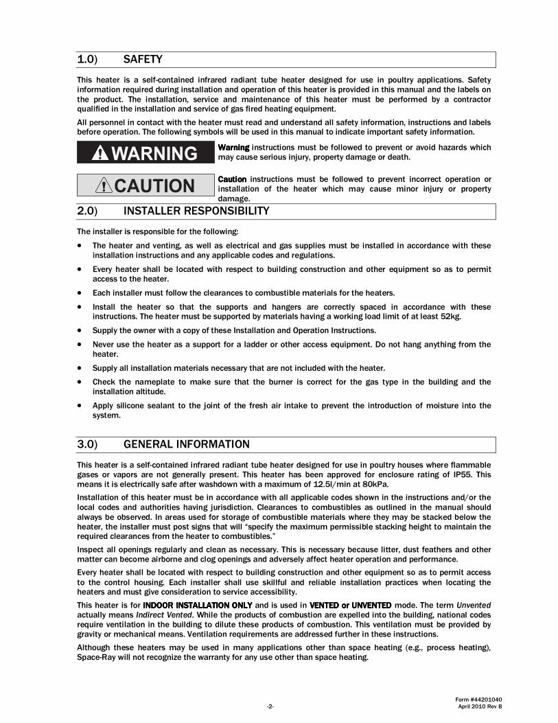
This heater is not an explosion proof heater.This heater is not an explosion proof heater.This heater is not an explosion proof heater.This heater is not an explosion proof heater. Where the possibility of exposure to volatile and low flash point materials exists, it could result in property damage or death. This heater must not be installed in a spray booth where the heater can operate during the spraying process. Consult your local fire marshal or insurance company.
StraightStraightStraightStraight Configuration Configuration Configuration Configuration Series Only:Series Only:Series Only:Series Only: Since straight Since straight Since straight Since straight configuration configuration configuration configuration tube heaters are always hotter at the control end tube heaters are always hotter at the control end tube heaters are always hotter at the control end tube heaters are always hotter at the control end than at the flue terminal end, always observe the minimum recommended mounting heights shown on the than at the flue terminal end, always observe the minimum recommended mounting heights shown on the than at the flue terminal end, always observe the minimum recommended mounting heights shown on the than at the flue terminal end, always observe the minimum recommended mounting heights shown on the specification sheetsspecification sheetsspecification sheetsspecification sheets in Section 5.0) of this manual.
WARM
HOTWARM
Fig. Fig. Fig. Fig. 1111
Form #44201040 -4- April 2010 Rev B
4.0) MINIMUM CLEARANCES TO COMBUSTIBLES
Failure to do so may result in death, serious injury orproperty damage.
Combustible material must be located outside theclearance dimensions listed.
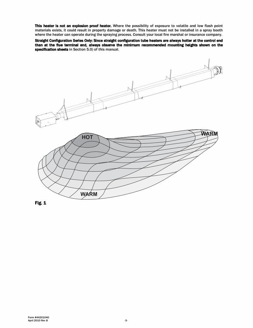
Minimum clearances to combustibles shall be measured from the outer surfaces as shown in the following diagram:
END END
ABOVE (CEILING) ABOVE (CEILING)
BELOWBELOW
SIDE SIDEFRONT
REAR
Fig. Fig. Fig. Fig. 2222
MINIMUM CLEARANCES TO COMBUSTIBLESMINIMUM CLEARANCES TO COMBUSTIBLESMINIMUM CLEARANCES TO COMBUSTIBLESMINIMUM CLEARANCES TO COMBUSTIBLES
SideSideSideSide AboveAboveAboveAbove BelowBelowBelowBelow EndEndEndEnd FrontFrontFrontFront RearRearRearRear
SRLP30 IP55 760mm 457mm 2285mm 610mm 760mm 380mm SRLP35 IP55 760mm 457mm 2285mm 610mm 760mm 380mm
SRLP40 IP55 760mm 457mm 2285mm 610mm 760mm 380mm
SRLP45 IP55 760mm 457mm 2285mm 610mm 760mm 380mm
▲WARNING:▲WARNING:▲WARNING:▲WARNING: Certain materials or objects, when stored under the heater, will be subjected to radiant heat and Certain materials or objects, when stored under the heater, will be subjected to radiant heat and Certain materials or objects, when stored under the heater, will be subjected to radiant heat and Certain materials or objects, when stored under the heater, will be subjected to radiant heat and could be seriously damaged.could be seriously damaged.could be seriously damaged.could be seriously damaged. Observe the Minimum Clearances to Combustibles listed in the manual and on the Observe the Minimum Clearances to Combustibles listed in the manual and on the Observe the Minimum Clearances to Combustibles listed in the manual and on the Observe the Minimum Clearances to Combustibles listed in the manual and on the heater at all timeheater at all timeheater at all timeheater at all times.s.s.s.
NOTE:NOTE:NOTE:NOTE:
1. 1. 1. 1. The clearances specified above must be maintained to combustibles and other materials that may be The clearances specified above must be maintained to combustibles and other materials that may be The clearances specified above must be maintained to combustibles and other materials that may be The clearances specified above must be maintained to combustibles and other materials that may be damaged by temperatures damaged by temperatures damaged by temperatures damaged by temperatures 32323232ººººCCCC above ambient temperature.above ambient temperature.above ambient temperature.above ambient temperature. Clearances to combustibles are posted on the Clearances to combustibles are posted on the Clearances to combustibles are posted on the Clearances to combustibles are posted on the control box.control box.control box.control box. In areas used for storage of comIn areas used for storage of comIn areas used for storage of comIn areas used for storage of combustible materials where they may be stacked below the heater, bustible materials where they may be stacked below the heater, bustible materials where they may be stacked below the heater, bustible materials where they may be stacked below the heater, NFPA54 requires that the installer must post signs that will “specify the maximum permissible stacking height NFPA54 requires that the installer must post signs that will “specify the maximum permissible stacking height NFPA54 requires that the installer must post signs that will “specify the maximum permissible stacking height NFPA54 requires that the installer must post signs that will “specify the maximum permissible stacking height to maintain the required clearances from the heater to combustibles.”to maintain the required clearances from the heater to combustibles.”to maintain the required clearances from the heater to combustibles.”to maintain the required clearances from the heater to combustibles.” SpaceSpaceSpaceSpace----RayRayRayRay recrecrecrecommends posting these ommends posting these ommends posting these ommends posting these signs adjacent to the heater thermostat or other suitable location that will provide enhanced visibility.signs adjacent to the heater thermostat or other suitable location that will provide enhanced visibility.signs adjacent to the heater thermostat or other suitable location that will provide enhanced visibility.signs adjacent to the heater thermostat or other suitable location that will provide enhanced visibility.
2. The stated clearance to combustibles represents a surface temperature of 322. The stated clearance to combustibles represents a surface temperature of 322. The stated clearance to combustibles represents a surface temperature of 322. The stated clearance to combustibles represents a surface temperature of 32 ºC above room temperature. ºC above room temperature. ºC above room temperature. ºC above room temperature. Building materials witBuilding materials witBuilding materials witBuilding materials with a low heat tolerance (such as plastics, vinyle siding, canvas, trih a low heat tolerance (such as plastics, vinyle siding, canvas, trih a low heat tolerance (such as plastics, vinyle siding, canvas, trih a low heat tolerance (such as plastics, vinyle siding, canvas, tri----ply, etc.) may be subject ply, etc.) may be subject ply, etc.) may be subject ply, etc.) may be subject to degradation at lower temperatures. It is the installer’s responsibility to assure that adjacent materials are to degradation at lower temperatures. It is the installer’s responsibility to assure that adjacent materials are to degradation at lower temperatures. It is the installer’s responsibility to assure that adjacent materials are to degradation at lower temperatures. It is the installer’s responsibility to assure that adjacent materials are protected from degradation.protected from degradation.protected from degradation.protected from degradation.
Form #44201040 April 2010 Rev B -5-
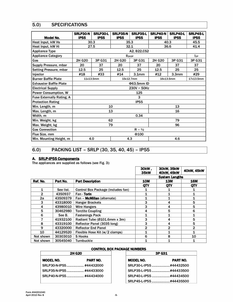
5.0) SPECIFICATIONS
ModeModeModeModel No.l No.l No.l No. SRLP30SRLP30SRLP30SRLP30----N N N N
IP55IP55IP55IP55 SRLP30SRLP30SRLP30SRLP30----L L L L
IP55IP55IP55IP55 SRLP35SRLP35SRLP35SRLP35----N N N N
IP55IP55IP55IP55 SRLP35SRLP35SRLP35SRLP35----L L L L
IP55IP55IP55IP55 SRLP40SRLP40SRLP40SRLP40----N N N N
IP55IP55IP55IP55 SRLP40SRLP40SRLP40SRLP40----L L L L
IP55IP55IP55IP55 SRLP45SRLP45SRLP45SRLP45----L L L L
IP55IP55IP55IP55
Heat Input, kW Hs 30.3 35.3 40.3 45.5
Heat Input, kW Hi 27.5 32.1 36.6 41.4
Appliance Type A2, B22,C52
Appliance Category II2H3P I3P
Gas 2H G20 3P G31 2H G20 3P G31 2H G20 3P G31 3P G31
Supply Pressure, mbar 20 37 20 37 20 37 37
Setting Pressure, mbar 12.5 25 12.5 25 12.5 25 25
Injector #18 #33 #14 3.1mm #12 3.3mm #29
Burner Baffle Plate 11x13.5mm 15x12.7mm 16x13.5mm 17x13.5mm
Exhauster Baffle Plate Φ63.5mm ID
Electrical Supply 230V ~ 50Hz
Power Consumption, W 125
Fuse Externally Rating, A 3
Protection Rating IP55
Min. Length, m 10 13
Max. Length, m 13 16
Width, m 0.34
Min. Weight, kg 62 79
Max. Weight, kg 79 96
Gas Connection R – ½
Flue Size, mm Φ100
Min. Mounting Height, m 4.0 4.3 4.6
6.0) PACKING LIST – SRLP (30, 35, 40, 45) – IP55
A.A.A.A. SRLPSRLPSRLPSRLP----IP55 IP55 IP55 IP55 ComponentsComponentsComponentsComponents The appliances are supplied as follows (see Fig. 3):
30kW30kW30kW30kW , , , , 35kW35kW35kW35kW
30kW30kW30kW30kW, , , , 35kW35kW35kW35kW 40kW40kW40kW40kW, , , , 45kW45kW45kW45kW
40kW40kW40kW40kW, , , , 45kW45kW45kW45kW
SystSystSystSystem Lengthsem Lengthsem Lengthsem Lengths
Ref. No.Ref. No.Ref. No.Ref. No. Part No.Part No.Part No.Part No. Part DescriptionPart DescriptionPart DescriptionPart Description 10101010MMMM 11113333MMMM 16161616MMMM
QTYQTYQTYQTY QTYQTYQTYQTY QTYQTYQTYQTY
1 See list. Control Box Package (includes fan) 1 1 1
2 4350937 Fan - TorinTorinTorinTorin 1 1 1
2a 43509379 Fan – McMillanMcMillanMcMillanMcMillan (alternate) 1 1 1
3 43318000 Hanger Brackets 3 4 5
4 43980010 Wire Hangers 3 4 5
5 30462980 Torctite Coupling 4 5 6
6 See B. Fastenings Pack 1 1 1
7 41932100 Radiant Tube (Ø101.6mm x 3m) 3 4 5
8 43319100 Reflector Panel (3035 long) 3 4 5
9 43320000 Reflector End Panel 2 2 2
10 44129520 Flexible Hose Kit (w/2 clamps) 1 1 1
Not shown 30303010 S Hooks 6 8 10
Not shown 30545040 Turnbuckle 1 1 1
CONTROL BOX CONTROL BOX CONTROL BOX CONTROL BOX PACKAGE NUMBERSPACKAGE NUMBERSPACKAGE NUMBERSPACKAGE NUMBERS
2H G202H G202H G202H G20 3P G313P G313P G313P G31
MODEL NO. MODEL NO. MODEL NO. MODEL NO. PART NO.PART NO.PART NO.PART NO. MODEL NO. MODEL NO. MODEL NO. MODEL NO. PART NO.PART NO.PART NO.PART NO.
SRLP30-N-IP55 .................... #44432000 SRLP30-L-IP55 ..................... #44432500
SRLP35-N-IP55 .................... #44433000 SRLP35-L-IP55 ..................... #44433500
SRLP40-N-IP55 .................... #44434000 SRLP40-L-IP55 ..................... #44434500
SRLP45-L-IP55 ..................... #44435500
Form #44201040 -6- April 2010 Rev B
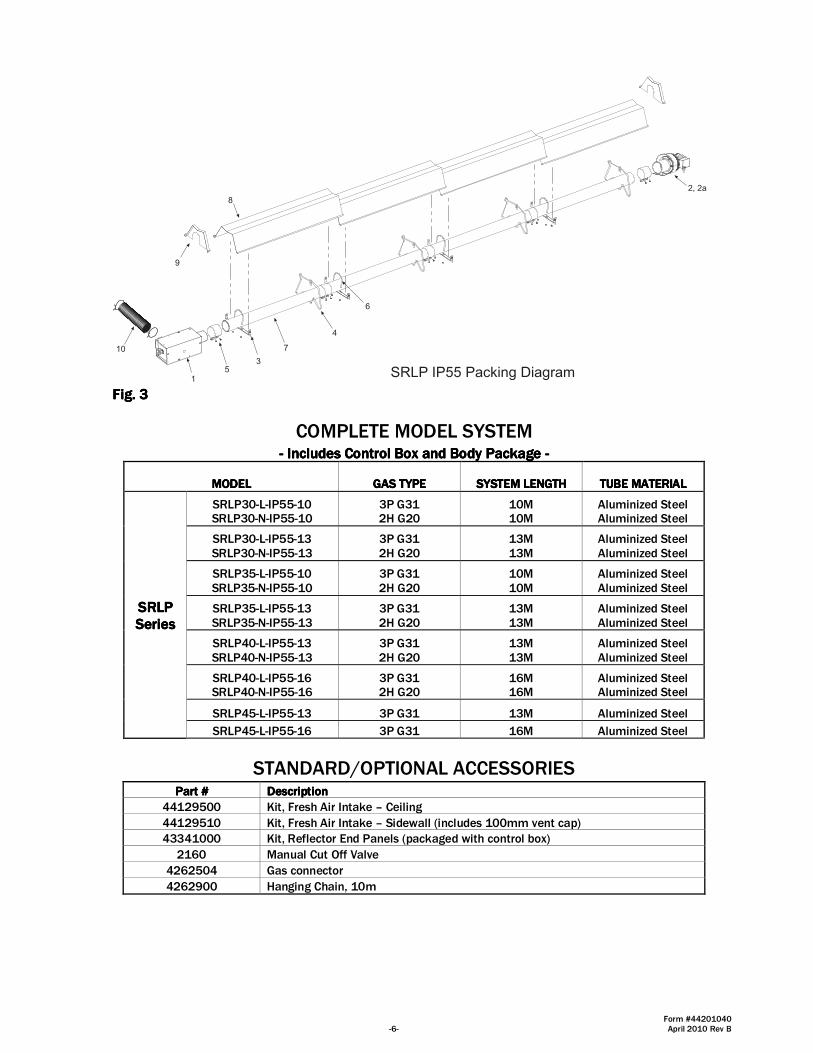
7
6
SRLP IP55 Packing Diagram1
5
9
10
2, 2a
8
3
4
Fig. Fig. Fig. Fig. 3333
COMPLETE MODEL SYSTEM
---- Includes Includes Includes Includes Control BoxControl BoxControl BoxControl Box and Body Packagand Body Packagand Body Packagand Body Packageeee ----
MODELMODELMODELMODEL GAS TYPEGAS TYPEGAS TYPEGAS TYPE SYSTEM LENGTHSYSTEM LENGTHSYSTEM LENGTHSYSTEM LENGTH TUBE MATERIALTUBE MATERIALTUBE MATERIALTUBE MATERIAL
SRLPSRLPSRLPSRLP SeriesSeriesSeriesSeries
SRLP30-L-IP55-10 SRLP30-N-IP55-10
3P G31 2H G20
10M 10M
Aluminized Steel Aluminized Steel
SRLP30-L-IP55-13 SRLP30-N-IP55-13
3P G31 2H G20
13M 13M
Aluminized Steel Aluminized Steel
SRLP35-L-IP55-10 SRLP35-N-IP55-10
3P G31 2H G20
10M 10M
Aluminized Steel Aluminized Steel
SRLP35-L-IP55-13 SRLP35-N-IP55-13
3P G31 2H G20
13M 13M
Aluminized Steel Aluminized Steel
SRLP40-L-IP55-13 SRLP40-N-IP55-13
3P G31 2H G20
13M 13M
Aluminized Steel Aluminized Steel
SRLP40-L-IP55-16 SRLP40-N-IP55-16
3P G31 2H G20
16M 16M
Aluminized Steel Aluminized Steel
SRLP45-L-IP55-13 3P G31 13M Aluminized Steel
SRLP45-L-IP55-16 3P G31 16M Aluminized Steel
STANDARD/OPTIONAL ACCESSORIES
Part #Part #Part #Part # DescriptionDescriptionDescriptionDescription
44129500 Kit, Fresh Air Intake – Ceiling
44129510 Kit, Fresh Air Intake – Sidewall (includes 100mm vent cap)
43341000 Kit, Reflector End Panels (packaged with control box)
2160 Manual Cut Off Valve
4262504 Gas connector
4262900 Hanging Chain, 10m

Form #44201040 April 2010 Rev B -7-
B.B.B.B. SRLPSRLPSRLPSRLP----IP55IP55IP55IP55 ((((Aluminized Aluminized Aluminized Aluminized Steel System) Steel System) Steel System) Steel System) Body Package DescriptionsBody Package DescriptionsBody Package DescriptionsBody Package Descriptions (Package Part Number is indicated on the outside of each corresponding carton.)
SystemSystemSystemSystemssss 10M10M10M10M SystemSystemSystemSystem 13M13M13M13MSystemSystemSystemSystem 16M 16M 16M 16M SystemSystemSystemSystem
SRLP Body Packages SRLP Body Packages SRLP Body Packages SRLP Body Packages –––– AluminizedAluminizedAluminizedAluminized 10M10M10M10M pkgpkgpkgpkg
44055310440553104405531044055310 13M13M13M13M pkg pkg pkg pkg
44055410440554104405541044055410 16M16M16M16M pkgpkgpkgpkg
44055510440555104405551044055510
Part #Part #Part #Part # Each Body Package Includes:Each Body Package Includes:Each Body Package Includes:Each Body Package Includes: Qty.Qty.Qty.Qty. Qty.Qty.Qty.Qty. Qty.Qty.Qty.Qty.
41932100 Tube less Flange – 3048mm (Aluminized) 3 4 5
43319100 Reflector - 3035mm 3 4 5
30462980 Tube Coupling 2 3 4 43318000 Tube Hanger/Support Bracket - 330mm 3 4 5 43980010 Wire Hanger 3 4 5
30303010 “S” Hooks 6 8 10
30545040 Turnbuckle 1 1 1
Body FastenerBody FastenerBody FastenerBody Fastener Kit (included in body packages)Kit (included in body packages)Kit (included in body packages)Kit (included in body packages) 42907429074290742907300300300300 42907429074290742907333310101010 42907429074290742907333320202020 42873000 U-Bolt 3 4 5
02127110 Hex Nut, 5/16-18 7 9 11
02189020 HWHSM Screw, #10-16 x ½” TEKS 16 20 24
6.1) ACCESSORY PACKAGES
A.A.A.A. End Reflector Accessory Package, Part #433410End Reflector Accessory Package, Part #433410End Reflector Accessory Package, Part #433410End Reflector Accessory Package, Part #43341000000000 (1 pkg. per Straight Configuration Series)
Contains: End Reflector, #43320000……QTY–2 Speed Clips, #02266010……QTY–8
150mm
300mm
END REFLECTOR
B.B.B.B. Fresh Air Inlet (Through Ceiling)Fresh Air Inlet (Through Ceiling)Fresh Air Inlet (Through Ceiling)Fresh Air Inlet (Through Ceiling) Package, Part Package, Part Package, Part Package, Part #4#4#4#44129500412950041295004129500
Contains: a) 101.6mm Air Intake Assembly, #44129000……QTY–1 b) 101.6mm x 610mm Flexible Hose, #30675020 QTY-1 c) 101.6mm Spring Tension Clamp, #30676040 QTY-2 d) #12 x ¾” Sheet Metal Screws, #02240010……QTY–4
A
B
C
C.C.C.C. Fresh Air Inlet (Through Sidewall) Fresh Air Inlet (Through Sidewall) Fresh Air Inlet (Through Sidewall) Fresh Air Inlet (Through Sidewall) Package, Part Package, Part Package, Part Package, Part #4#4#4#44129510412951041295104129510 Contains: a) 101.6mm Vent Cap, #41000020……QTY–1 b) 101.6mm x 610mm Flexible Hose, #30675020 QTY-1 c) 101.6mm Spring Tension Clamp, #30676040 QTY-2
A
B
C
Form #44201040 -8- April 2010 Rev B
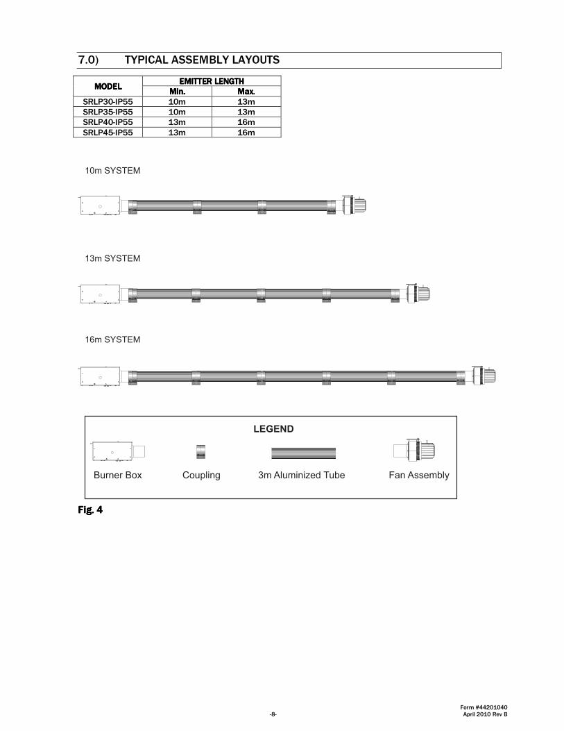
7.0) TYPICAL ASSEMBLY LAYOUTS
MODELMODELMODELMODEL EMITTER LENGTHEMITTER LENGTHEMITTER LENGTHEMITTER LENGTH
Min.Min.Min.Min. Max.Max.Max.Max.
SRLP30-IP55 10m 13m
SRLP35-IP55 10m 13m
SRLP40-IP55 13m 16m
SRLP45-IP55 13m 16m
16m SYSTEM
10m SYSTEM
13m SYSTEM
LEGEND
3m Aluminized TubeBurner Box Fan AssemblyCoupling
Fig. Fig. Fig. Fig. 4444
Form #44201040 April 2010 Rev B -9-
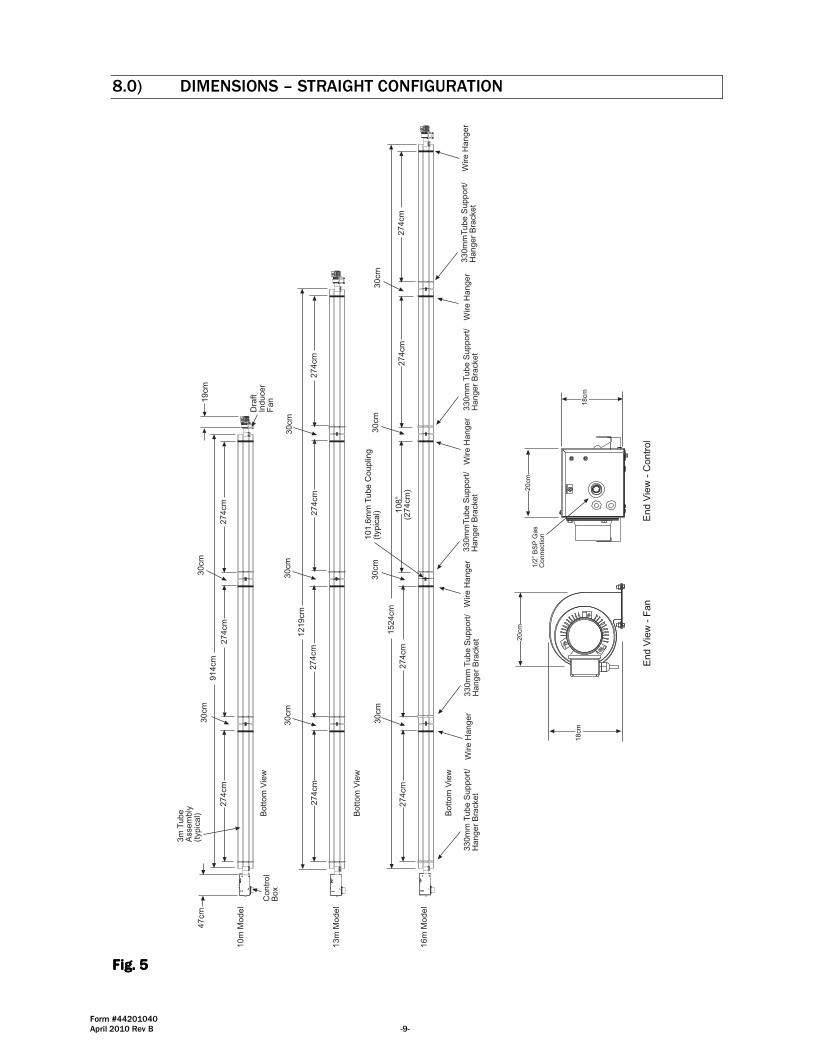
8.0) DIMENSIONS – STRAIGHT CONFIGURATION
20cm
20
cm
18
cm
1/2
� B
SP
Gas
Connection
En
d V
iew
- C
on
tro
l
10m
Model
914cm
274cm
30cm
30cm
274cm
274cm
101.6
mm
Tube C
ouplin
g(t
ypic
al)
47cm
Contr
ol
Box
Dra
ftIn
ducer
Fan
3m
Tube
Assem
bly
(typic
al) B
ottom
Vie
w
Wire H
anger
Wire H
anger
330m
m T
ube S
upport
/H
anger
Bra
cket
330m
mT
ube S
upport
/H
anger
Bra
cket
274cm
1524cm
274cm
108�
(274cm
)274cm
274cm
30cm
30cm
30cm
30cm
Wire H
anger
Wire H
anger
330m
m T
ube S
upport
/H
anger
Bra
cket
330m
mT
ube S
upport
/H
anger
Bra
cket
Wire H
anger
30cm
274cm
1219cm
274cm
30cm
274cm
274cm
30cm
330m
m T
ube S
upport
/H
anger
Bra
cket
13m
Model
16m
Model
Bottom
Vie
w
En
d V
iew
- F
an
18
cm
19cm
Bottom
Vie
w
Fig. Fig. Fig. Fig. 5555

Form #44201040 -10- April 2010 Rev B
8.1) HEATER ASSEMBLY - OVERVIEW
The minimum and maximum heater lengths for each input are shown in Section The minimum and maximum heater lengths for each input are shown in Section The minimum and maximum heater lengths for each input are shown in Section The minimum and maximum heater lengths for each input are shown in Section 5.0)5.0)5.0)5.0). Insure that all reflector . Insure that all reflector . Insure that all reflector . Insure that all reflector screws andscrews andscrews andscrews and clips are in place to prevent the reflectors from clips are in place to prevent the reflectors from clips are in place to prevent the reflectors from clips are in place to prevent the reflectors from separatingseparatingseparatingseparating during expansion and contraction of during expansion and contraction of during expansion and contraction of during expansion and contraction of the heater.the heater.the heater.the heater. The heater should be suspended to provide a slope of 0.25 degree up to the fan.The heater should be suspended to provide a slope of 0.25 degree up to the fan.The heater should be suspended to provide a slope of 0.25 degree up to the fan.The heater should be suspended to provide a slope of 0.25 degree up to the fan.
Ra
dia
nt T
ub
e(1
01
.6m
m d
ia.
x 3
m lo
ng
)T
yp
ica
l
Tube S
upport
Bra
cket
U-B
olt C
lam
p &
He
x N
uts
Wire
Ha
ng
er
Typic
al A
ssem
bly
Overv
iew
(SR
LP
13m
Show
n)
Co
ntr
ol B
ox
5 h
an
gin
g p
oin
ts t
o b
e u
se
d f
or
su
sp
en
sio
n. T
he
rem
ust
be
tw
o h
an
gin
g p
oin
ts o
n t
he
first
tub
e a
nd
on
eo
n e
ach
of
the
oth
er
tub
es
Ma
xim
um
26
0m
m d
ista
nce
fro
m c
on
tro
l b
ox t
o t
he
tub
e s
up
po
rt/h
an
ge
rb
racke
t.
2.4
to
2.8
m
2.4
to
3m
2.4
to
3m
NO
T L
ES
S T
HA
N2
54
mm
#10 S
elf-D
rill
Scre
ws
(Typic
al all
tube
support
sand t
ube c
ouplin
gs.)
Typ
ica
lO
ve
rla
p
To
rctite
Co
up
ling
Re
fle
cto
rE
nd
Pa
ne
l
Fre
sh
Air I
nta
ke
Fa
n A
sse
mb
ly(T
orin
fa
n s
ho
wn
)To
rctite
Co
up
ling
(To
rin
fa
n o
nly
)
Slo
pe u
p to
Fan b
y 0
.25
de
gre
e
Ho
rizo
nta
l L
ine
Fig. Fig. Fig. Fig. 6666

Form #44201040 April 2010 Rev B -11-
9.0) TYPICAL SUSPENSION METHODS
Not withstanding their limited scope, the appliance should be installed in accordance with the relevant provisions of any National Gas Safety (Installation and Use) Regulations. Due account should also be taken of any obligations arising from any National Heath and Safety at Work Regulations, National and Local Building Regulations and National Electrical Wiring Regulations. The appliance must be installed, and where necessary, converted for use on other gases, by a qualified installer.
Burner must be secured to the mounting flange with nuts.
All materials used to suspend the heater must have a minimum working loadof 52kg.All �S� Hooks must be crimped closed.
Never use the heater to support a ladder or other access equipment.
Failure to do so may result in death, serious injury or property damage.
SUSPENSION HAZARD
Various means of suspending the heater can be used. See the following drawings for typical examples.
1. Use only noncombustible materials for suspending hangers and brackets.
2. Linear Tube Heaters should be suspended to provide a slope of 0.25 degree upupupup to the fan. The appliance should be located with respect to building construction and other equipment to permit access to the appliance for servicing etc.
3. Turnbuckles can be used with chains to allow leveling of the heater. All “S” hooks and eye bolts must be manually crimped closed by the installer.
4. For suspending the appliance it is recommended that suitable protected welded chain (Ø3mm x 65 links per m) or Ø8mm min mild steel drop rods and suitable brackets are used. Attach the chains or drop rods to the hanger brackets where shown (see Section 8.1). Providing at least Ø5mm closed link hooks are used chains may be attached directly to the hanger brackets.
5. Heaters subject to vibration must be provided with vibration isolating hangers.
6. Heaters must not be supported by gas or electric supply lines and must be suspended from a permanent structure with adequate load capacity.
7. The appliance may be mounted horizontally or at a recommended angle of 300 maximum to the horizontal.
Space-Ray recommends that the body sections be suspended using chains with turnbuckles. This will allow slight adjustments after assembly and heater expansion/ contraction during operation.
If a “trapeze” method is used for tube support/hanger brackets (shown below), the minimum chain length for the two connecting chains is 914 mm to minimize any vibration that might be generated by the draft inducer assembly. If these chains must be less than 914 mm, then do not use the trapeze method and, instead, use individual chains on each tube support/hanger bracket.
WireHanger
910 m
m M
inim
um
910m
m M
inim
um
Single Chain(trapeze method)
Dual Chain Single Chain
Tube Support/Hanger BracketTube Support/
Hanger Bracket
Burner SupportChain
Burner SupportChain
Fig. Fig. Fig. Fig. 7777
Form #44201040 -12- April 2010 Rev B
10.0) ASSEMBLY OF TUBE SECTIONS
Sheet metal parts, particularly reflectors and vent have sharpedges. Always use gloves when handling.
Failure to do so may result in death, serious injury or propertydamage.
CUT HAZARD
During field assembly of the heater body sections, the recommended procedure is as follows:
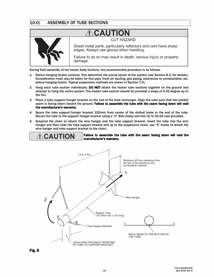
1. Before hanging heater sections, first determine the actual layout of the system (see Section 8.1) for details). Consideration must also be taken for flue pipe, fresh air ducting, gas piping, clearances to combustibles, etc. before hanging heater. Typical suspension methods are shown in Section 7.0).
2. Hang each tube section individually. DO NOTDO NOTDO NOTDO NOT attach the heater tube sections together on the ground and attempt to hang the entire system. The heater tube section should be provided a slope of 0.25 degree up to the fan.
3. Place a tube support/hanger bracket on the end of the heat exchanger. Align the tube such that the welded seam is facing down toward the ground. FFFFailure to assemble the tube with the seam facing down will void ailure to assemble the tube with the seam facing down will void ailure to assemble the tube with the seam facing down will void ailure to assemble the tube with the seam facing down will void the manufacturer’s warranty. the manufacturer’s warranty. the manufacturer’s warranty. the manufacturer’s warranty.
4. Space the tube support/hanger bracket 152mm from center of the slotted holes to the end of the tube. Secure the tube to the support/hanger bracket using a “U” Bolt clamp and two (2) 5/16-18 nuts provided.
5. Suspend the chain to attach the wire hanger and the tube support bracket. Insert the tube into the wire hanger and then raise the tube support bracket end up to the suspension chain, use “S” hooks to attach the wire hanger and tube support bracket to the chain.
Failure to assemble the tube with the seam facing down will voiFailure to assemble the tube with the seam facing down will voiFailure to assemble the tube with the seam facing down will voiFailure to assemble the tube with the seam facing down will void the d the d the d the manufacturer’s warranty.manufacturer’s warranty.manufacturer’s warranty.manufacturer’s warranty.
Radiant Tube(101.6mm dia. x 3m long)
1
2
Minimum 457mm clearance fromthe top of the relector to anycombustible material
2.4 to 2.8m
152mm MAX DISTANCE FROM ENDOF TUBE TO SUPPORT BRACKET
WELD SEAM TO THE BOTTOM OFTHE TUBE.
Tube Support Bracket
Wire Hanger
Fig. Fig. Fig. Fig. 8888
Form #44201040 April 2010 Rev B -13-
10.1) ASSEMBLY OF EXTENSION SECTIONS
U-Bolt Clamp& 5/16� Hex Nuts
Tube Support/Hanger Bracket
3
152mm approx.
MIN 2.4m MAX 3m BETWEEN HANGERS
1
2
Tube Support Bracket
Wire Hanger
Coupling
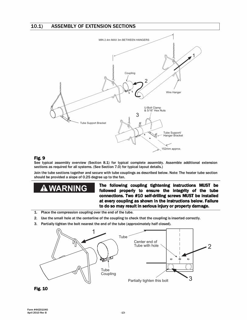
Fig. Fig. Fig. Fig. 9999 See typical assembly overview (Section 8.1) for typical complete assembly. Assemble additional extension sections as required for all systems. (See Section 7.0) for typical layout details.)
Join the tube sections together and secure with tube couplings as described below. Note: The heater tube section should be provided a slope of 0.25 degree up to the fan.
TTTThe followinghe followinghe followinghe following couplingcouplingcouplingcoupling tightening instructions MUSTtightening instructions MUSTtightening instructions MUSTtightening instructions MUST be be be be followed properly to ensure the integrity of the tube followed properly to ensure the integrity of the tube followed properly to ensure the integrity of the tube followed properly to ensure the integrity of the tube connections. Two #10 selfconnections. Two #10 selfconnections. Two #10 selfconnections. Two #10 self----drilling screws drilling screws drilling screws drilling screws MUSTMUSTMUSTMUST be installed be installed be installed be installed at every coupling as shown in the instructions beloat every coupling as shown in the instructions beloat every coupling as shown in the instructions beloat every coupling as shown in the instructions below. Failure w. Failure w. Failure w. Failure to do so may result in serious injury or property damage.to do so may result in serious injury or property damage.to do so may result in serious injury or property damage.to do so may result in serious injury or property damage.
1. Place the compression coupling over the end of the tube.
2. Use the small hole at the centerline of the coupling to check that the coupling is inserted correctly.
3. Partially tighten the bolt nearest the end of the tube (approximately half closed).
TubeCoupling
1
Center end ofTube with hole
Partially tighten this bolt
Tube
2
3
Fig. Fig. Fig. Fig. 10101010

Form #44201040 -14- April 2010 Rev B
4. Slide the next tube into the coupling.
5. Make sure both tube ends are butted together.
6. Finish tightening both bolts to 54-80 N�m torque to ensure a complete seal.
7. Use the two self-drilling screws through the pre-punched holes to secure the tubes in the coupling.
TubeCoupling
Center bothtubes with hole
#10 Self-DrillingScrews(QTY 2)
45
7
6
Fig. Fig. Fig. Fig. 11111111
8. Check to ensure that the hardware is completely closed and the band is seated on the reaction block and interference pins as illustrated above.
9. Once all the heater body sections are attached, make sure that the heater system is level. If it is not, slight adjustments can be made using the turnbuckles. (See Section 7.0)
INCORRECTINSTALLATION
CORRECTINSTALLATION
ForceBars
ReactionBlock
InterferencePins
Bolt
Band
Fig. Fig. Fig. Fig. 12121212
Important: Important: Important: Important: NEVER NEVER NEVER NEVER reuse a couplingreuse a couplingreuse a couplingreuse a coupling.... Always install a new coupling only and Always install a new coupling only and Always install a new coupling only and Always install a new coupling only and torque as per instructions above and the diagrams above.torque as per instructions above and the diagrams above.torque as per instructions above and the diagrams above.torque as per instructions above and the diagrams above.
Form #44201040 April 2010 Rev B -15-
10.2) ADDING REFLECTORS
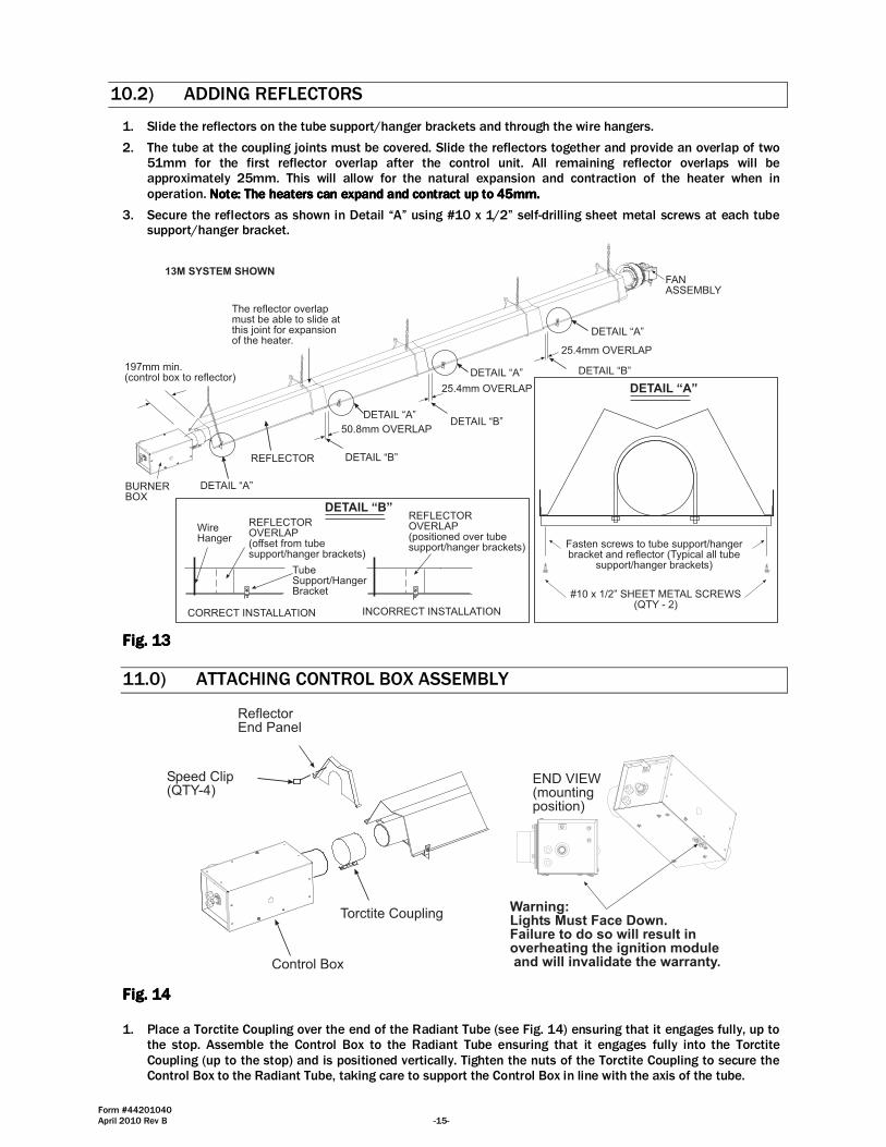
1. Slide the reflectors on the tube support/hanger brackets and through the wire hangers.
2. The tube at the coupling joints must be covered. Slide the reflectors together and provide an overlap of two 51mm for the first reflector overlap after the control unit. All remaining reflector overlaps will be approximately 25mm. This will allow for the natural expansion and contraction of the heater when in operation. Note: The heaters can expand and Note: The heaters can expand and Note: The heaters can expand and Note: The heaters can expand and contract up to contract up to contract up to contract up to 45mm45mm45mm45mm....
3. Secure the reflectors as shown in Detail “A” using #10 x 1/2” self-drilling sheet metal screws at each tube support/hanger bracket.
50.8mm OVERLAP
25.4mm OVERLAP
25.4mm OVERLAP
DETAIL �A�
REFLECTOR
13M SYSTEM SHOWN
197mm min.(control box to reflector)
FANASSEMBLY
BURNERBOX
REFLECTOROVERLAP(offset from tubesupport/hanger brackets)
CORRECT INSTALLATION
WireHanger
TubeSupport/HangerBracket
REFLECTOROVERLAP(positioned over tubesupport/hanger brackets)
INCORRECT INSTALLATION
DETAIL �B�
DETAIL �B�
The reflector overlapmust be able to slide atthis joint for expansionof the heater.
Fasten screws to tube support/hangerbracket and reflector (Typical all tube
support/hanger brackets)
#10 x 1/2� SHEET METAL SCREWS(QTY - 2)
DETAIL �A�
DETAIL �A�
DETAIL �A�
DETAIL �A�
DETAIL �B�
DETAIL �B�
FiFiFiFig. g. g. g. 13131313
11.0) ATTACHING CONTROL BOX ASSEMBLY
Control Box
Torctite Coupling
ReflectorEnd Panel
END VIEW(mountingposition)
Warning:Lights Must Face Down.Failure to do so will result inoverheating the ignition module and will invalidate the warranty.
Speed Clip(QTY-4)
Fig. Fig. Fig. Fig. 14141414 1. Place a Torctite Coupling over the end of the Radiant Tube (see Fig. 14) ensuring that it engages fully, up to
the stop. Assemble the Control Box to the Radiant Tube ensuring that it engages fully into the Torctite Coupling (up to the stop) and is positioned vertically. Tighten the nuts of the Torctite Coupling to secure the Control Box to the Radiant Tube, taking care to support the Control Box in line with the axis of the tube.
Form #44201040 -16- April 2010 Rev B
NOTE: Tighten the Torctite Coupling screws alternately while continually checking for slackness of the joint.
2. Assemble the end reflector flush with the end of the main body reflector. Secure by sliding speed clips onto the reflector edges. Evenly space the speed clips on the sides (one each side) and top (two required) of the reflectors to provide a snug fit. Leave a 197mm space between the end reflector and the control box assembly.
Repeat the procedure to attach the second Reflector End Panel to the opposite end of the Reflector.
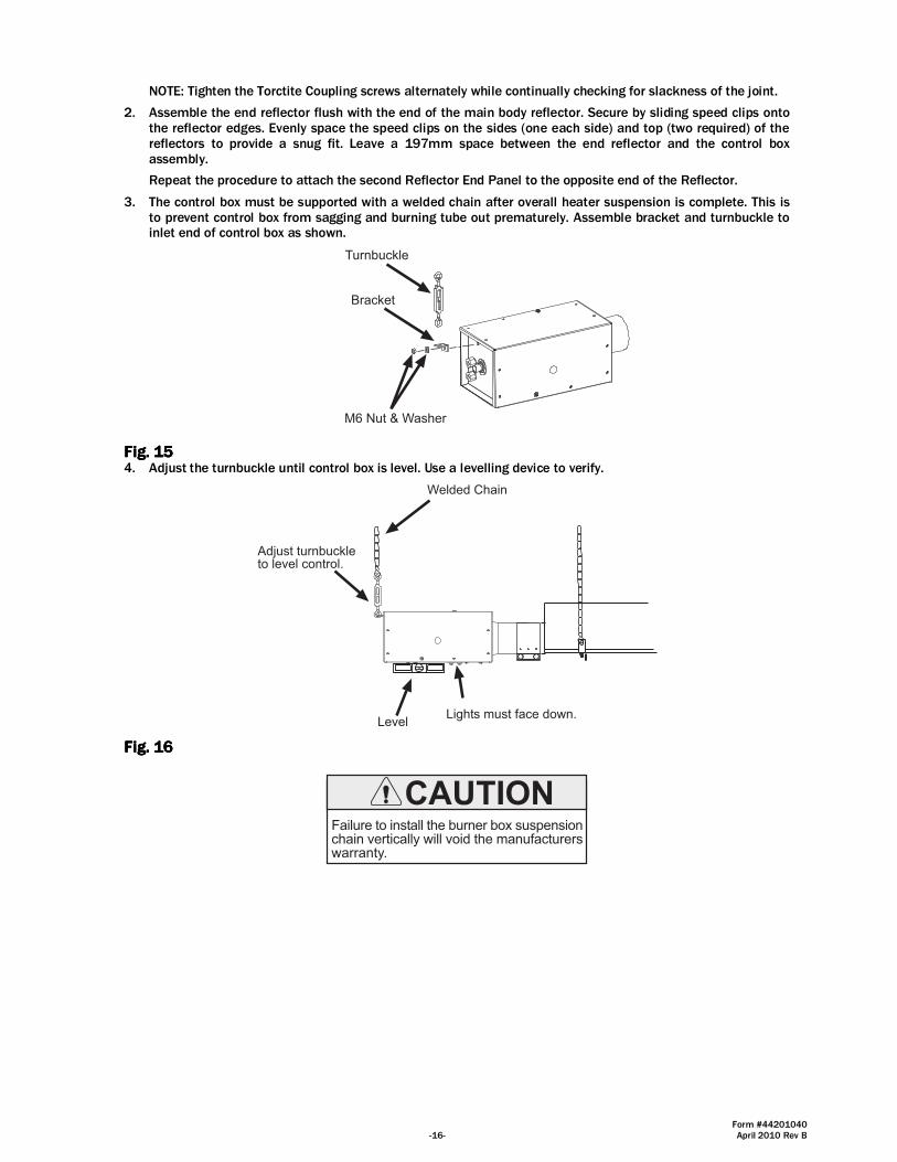
3. The control box must be supported with a welded chain after overall heater suspension is complete. This is to prevent control box from sagging and burning tube out prematurely. Assemble bracket and turnbuckle to inlet end of control box as shown.
Turnbuckle
Bracket
M6 Nut & Washer
Fig. Fig. Fig. Fig. 15151515 4. Adjust the turnbuckle until control box is level. Use a levelling device to verify.
Adjust turnbuckleto level control.
Level
Welded Chain
Lights must face down.
Fig. Fig. Fig. Fig. 16161616
Failure to install the burner box suspensionchain vertically will void the manufacturerswarranty.
Form #44201040 April 2010 Rev B -17-
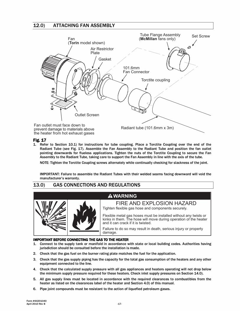
12.0) ATTACHING FAN ASSEMBLY
Fan outlet must face down toprevent damage to materials abovethe heater from hot exhaust gases
Fan(Torin model shown)
Torctite coupling
Radiant tube (101.6mm x 3m)
Air RestrictorPlate
Gasket
101.6mmFan Connector
Outlet Screen
Tube Flange Assembly(McMillan fans only)
Set Screw
Fig. Fig. Fig. Fig. 17171717 1. Refer to Section 10.1) for instructions for tube coupling. Place a Torctite Coupling over the end of the
Radiant Tube (see Fig. 17). Assemble the Fan Assembly to the Radiant Tube and position the fan outlet pointing downwards for flueless applications. Tighten the nuts of the Torctite Coupling to secure the Fan Assembly to the Radiant Tube, taking care to support the Fan Assembly in line with the axis of the tube.
NOTE: Tighten the Torctite Coupling screws alternately while continually checking for slackness of the joint.
IMPORTANT: Failure to assemble the Radiant Tubes with their welded seams facing downward will void the manufacturer’s warranty.
13.0) GAS CONNECTIONS AND REGULATIONS
Tighten flexible gas hose and components securely.
Flexible metal gas hoses must be installed without any twists orkinks in them. The hose will move during operation of the heaterand it can crack if it is twisted.
Failure to do so may result in death, serious injury or propertydamage.
IMPORTANT BEFORE CONNECTING THE GAS TO THE HEATERIMPORTANT BEFORE CONNECTING THE GAS TO THE HEATERIMPORTANT BEFORE CONNECTING THE GAS TO THE HEATERIMPORTANT BEFORE CONNECTING THE GAS TO THE HEATER 1. Connect to the supply tank or manifold in accordance with state or local building codes. Authorities having
jurisdiction should be consulted before the installation is made.
2. Check that the gas fuel on the burner rating plate matches the fuel for the application.
3. Check that the gas supply piping has the capacity for the total gas consumption of the heaters and any other equipment connected to the line.
4. Check that the calculated supply pressure with all gas appliances and heaters operating will not drop below the minimum supply pressure required for these heaters. Check inlet supply pressures on Section 14.0).
5. All gas supply lines must be located in accordance with the required clearances to combustibles from the heater as listed on the clearances label of the heater and Section 4.0) of this manual.
6. Pipe joint compounds must be resistant to the action of liquefied petroleum gases.
Form #44201040 -18- April 2010 Rev B
7. Tube heaters will expand/contract during operation. Use an approved flexible connector for connections between the rigid piping and the heater. A union should be installed before the control box inlet. An approved shut off valve should be installed within 1.8m of the union.
8. The gas pipe, flexible hose and connections must be self supporting. The gas pipe work must not bear any of the weight of the heater or any other suspended assembly.
9. This appliance is equipped with a step-opening, combination gas valve. The maximum supply pressure toThe maximum supply pressure toThe maximum supply pressure toThe maximum supply pressure to the the the the appliance is appliance is appliance is appliance is 60 mbar60 mbar60 mbar60 mbar.... If the line pressure is more than the maximum supply pressure, then a second stage regulator which corresponds to the supply pressure must be used.
10. After all gas connections have been made, make sure the heater and all gas outlets are turned off before the main gas supply is turned on slowly. Turn the gas supply pressure on and check for leaks.
11. If a 2nd stage regulator is used, the ball valve down stream in the supply line must be closed when purging the gas lines to prevent gas seeping through it. If initial gas pressure is higher than 60 mbar the redundant
combination gas valve is designed to lock out. Pressure build-up in the supply lines prior to the heater must be released before proper heater operation.
Do not use an open Do not use an open Do not use an open Do not use an open flame of any kind to test for leaks.flame of any kind to test for leaks.flame of any kind to test for leaks.flame of any kind to test for leaks.
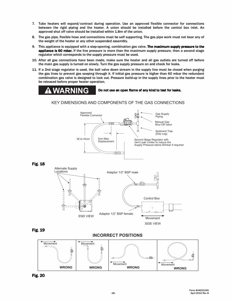
KEY DIMENSIONS AND COMPONENTS OF THE GAS CONNECTIONS
36 to 43cm
ApprovedFlexible Connector
Second Stage Regulator withVent Leak Limiter to reduce theSupply Pressure below 60mbar if required
Gas SupplyPiping
Sediment Trap(Drip Leg)
Manual GasShut Off Valve
5cm Max.Displacement
Fig. Fig. Fig. Fig. 18181818
SIDE VIEW
Control Box
END VIEWMovement
Alternate SupplyLocations Adaptor 1/2� BSP male
Adaptor 1/2� BSP female
Fig. Fig. Fig. Fig. 19191919
INCORRECT POSITIONS
Movement
WRONG
Movement
WRONGMovement
WRONG
Movement
WRONG
Fig. Fig. Fig. Fig. 20202020
Form #44201040 April 2010 Rev B -19-
Radiant tube heaters will expand and contract during operation. Therefore it is essential to provide a flexible hose, which must conform, to national or Local Regulations, to connect the appliance to the gas supply. Minimum size to be 12.7mm bore.
The gas pipe, flexible hose and connections must be self supporting. The gas pipe work must not bear any of the weight of the heater or any other suspended assembly.
12. Natural Gas - G20 at 20mbar nominal supply pressure (appliance cat 2H).
Maximum supply pressure (Pmax) 25mbar Minimum supply pressure (Pmin) 17mbar Setting pressure 12.5mbar Gas connection R - ½ 13. Check that the gas fuel on the burner data plate matches the fuel for the application.
14. LPG - G31 at 37mbar nominal supply pressure (appliance cat. 3P).
Maximum supply pressure (Pmax): G31 - 45mbar
Minimum supply pressure (Pmin): G31 - 25mbar
Setting pressure 25mbar Gas connections: R - ½
15. The complete installation MUST be tested for soundness in accordance with National or Local Regulations.
Do not use an open flame of any kind to test for leaks.Do not use an open flame of any kind to test for leaks.Do not use an open flame of any kind to test for leaks.Do not use an open flame of any kind to test for leaks.
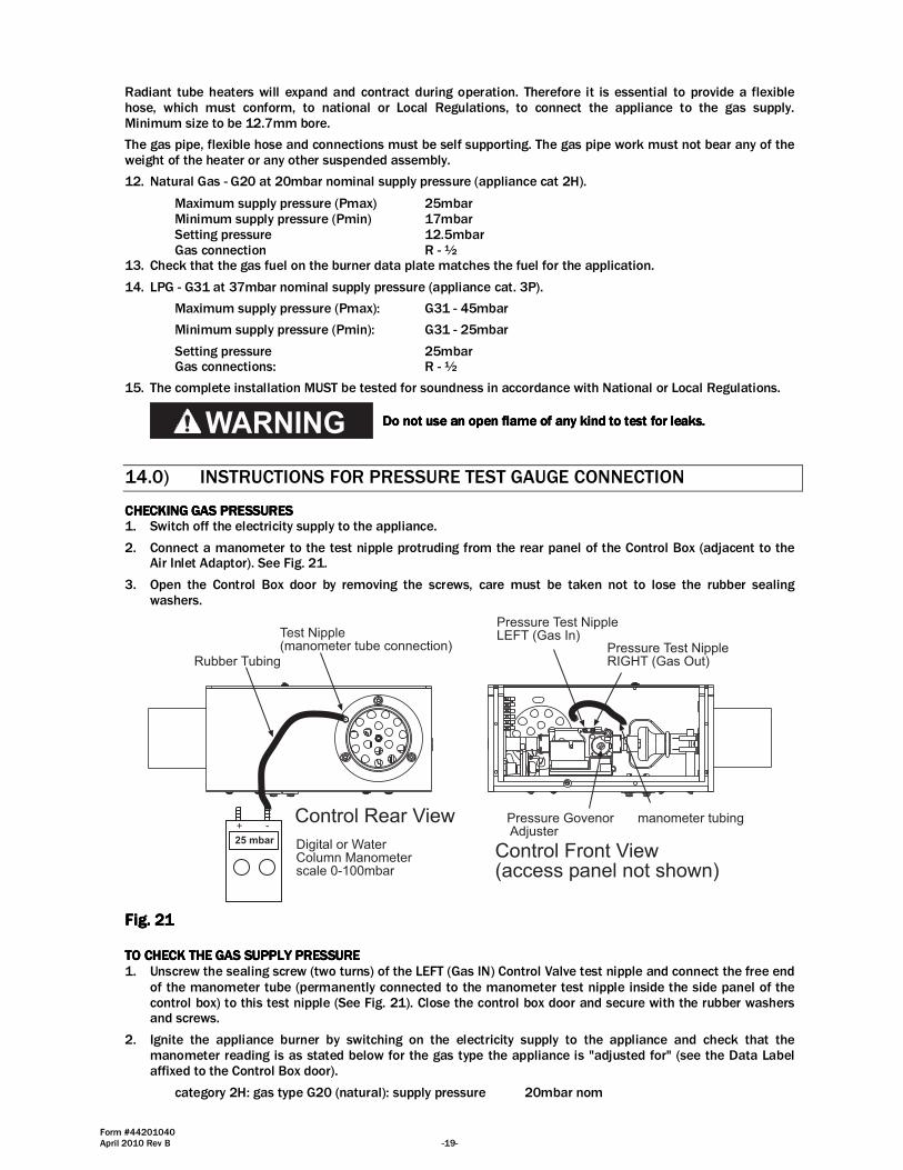
14.0) INSTRUCTIONS FOR PRESSURE TEST GAUGE CONNECTION
CHECKCHECKCHECKCHECKIIIINGNGNGNG GAS PRESSURESGAS PRESSURESGAS PRESSURESGAS PRESSURES 1. Switch off the electricity supply to the appliance.
2. Connect a manometer to the test nipple protruding from the rear panel of the Control Box (adjacent to the Air Inlet Adaptor). See Fig. 21.
3. Open the Control Box door by removing the screws, care must be taken not to lose the rubber sealing washers.
Test Nipple(manometer tube connection)
Control Rear View
Control Front View(access panel not shown)
Pressure Govenor Adjuster
Pressure Test NippleRIGHT (Gas Out)
Pressure Test NippleLEFT (Gas In)
Digital or WaterColumn Manometerscale 0-100mbar
25 mbar
+ -
Rubber Tubing
manometer tubing
Fig. Fig. Fig. Fig. 21212121 TO CHECK THE GAS SUPPLY PRESSURETO CHECK THE GAS SUPPLY PRESSURETO CHECK THE GAS SUPPLY PRESSURETO CHECK THE GAS SUPPLY PRESSURE 1. Unscrew the sealing screw (two turns) of the LEFT (Gas IN) Control Valve test nipple and connect the free end
of the manometer tube (permanently connected to the manometer test nipple inside the side panel of the control box) to this test nipple (See Fig. 21). Close the control box door and secure with the rubber washers and screws.
2. Ignite the appliance burner by switching on the electricity supply to the appliance and check that the manometer reading is as stated below for the gas type the appliance is "adjusted for" (see the Data Label affixed to the Control Box door).
category 2H: gas type G20 (natural): supply pressure 20mbar nom
Form #44201040 -20- April 2010 Rev B
17mbar min
25mbar max
category 3P: gas type G31 (propane): supply pressure 37mbar nom
25mbar min
45mbar max
3. Switch off the electricity supply to the appliance open the control box door and remove the manometer tube from the LEFT (Gas IN) control valve test nipple. Screw in the test nipple sealing screw.
TO CHECK THE BURNER SETTING PRESSURETO CHECK THE BURNER SETTING PRESSURETO CHECK THE BURNER SETTING PRESSURETO CHECK THE BURNER SETTING PRESSURE 1. Unscrew the sealing screw (two turns) of the RIGHT (Gas OUT) Control Valve test nipple and connect the free
end of the manometer tube (permanently connected to the manometer test nipple inside the side panel of the control box) to this test nipple (See Fig. 21). Close the control box door and secure with the rubber washers and screws.
2. Ignite the appliance burner by switching on the electricity supply to the appliance and check that the manometer reading is as stated below for the gas type the appliance is adjusted for (see the Data Label affixed to the control box door).
Category 2H: gas type G20 (natural): setting pressure 12.5mbar
Category 3P: gas type G31 (propane): setting pressure 25mbar
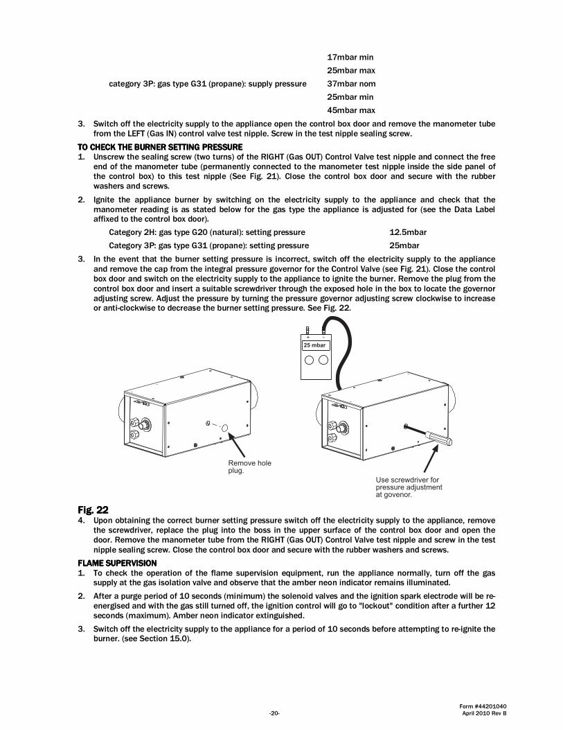
3. In the event that the burner setting pressure is incorrect, switch off the electricity supply to the appliance and remove the cap from the integral pressure governor for the Control Valve (see Fig. 21). Close the control box door and switch on the electricity supply to the appliance to ignite the burner. Remove the plug from the control box door and insert a suitable screwdriver through the exposed hole in the box to locate the governor adjusting screw. Adjust the pressure by turning the pressure governor adjusting screw clockwise to increase or anti-clockwise to decrease the burner setting pressure. See Fig. 22.
Remove holeplug.
Use screwdriver forpressure adjustmentat govenor.
25 mbar
+ -
Fig. Fig. Fig. Fig. 22222222 4. Upon obtaining the correct burner setting pressure switch off the electricity supply to the appliance, remove
the screwdriver, replace the plug into the boss in the upper surface of the control box door and open the door. Remove the manometer tube from the RIGHT (Gas OUT) Control Valve test nipple and screw in the test nipple sealing screw. Close the control box door and secure with the rubber washers and screws.
FLAME SUPERVISIONFLAME SUPERVISIONFLAME SUPERVISIONFLAME SUPERVISION 1. To check the operation of the flame supervision equipment, run the appliance normally, turn off the gas
supply at the gas isolation valve and observe that the amber neon indicator remains illuminated.
2. After a purge period of 10 seconds (minimum) the solenoid valves and the ignition spark electrode will be re-energised and with the gas still turned off, the ignition control will go to "lockout" condition after a further 12 seconds (maximum). Amber neon indicator extinguished.
3. Switch off the electricity supply to the appliance for a period of 10 seconds before attempting to re-ignite the burner. (see Section 15.0).
Form #44201040 April 2010 Rev B -21-
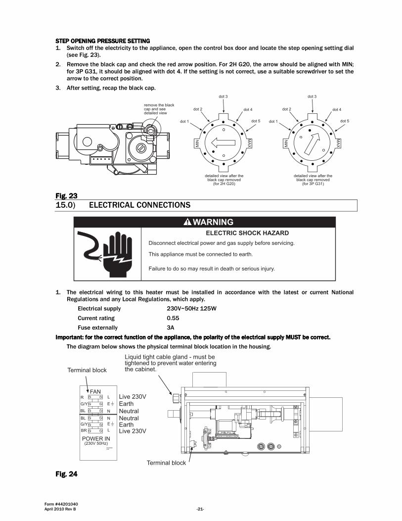
STEP OPENING PRESSURE SETTINGSTEP OPENING PRESSURE SETTINGSTEP OPENING PRESSURE SETTINGSTEP OPENING PRESSURE SETTING 1. Switch off the electricity to the appliance, open the control box door and locate the step opening setting dial
(see Fig. 23).
2. Remove the black cap and check the red arrow position. For 2H G20, the arrow should be aligned with MIN; for 3P G31, it should be aligned with dot 4. If the setting is not correct, use a suitable screwdriver to set the arrow to the correct position.
3. After setting, recap the black cap.
MIN
MA
X
dot 1
dot 2
dot 3
dot 4
dot 5
remove the blackcap and seedetailed view
detailed view after theblack cap removed
(for 2H G20)
MIN
MA
X
dot 1
dot 2
dot 3
dot 4
dot 5
detailed view after theblack cap removed
(for 3P G31)
Fig. Fig. Fig. Fig. 23232323
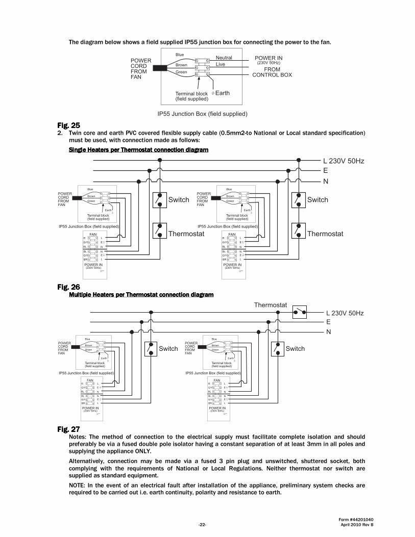
15.0) ELECTRICAL CONNECTIONS
Failure to do so may result in death or serious injury.
This appliance must be connected to earth.
Disconnect electrical power and gas supply before servicing.
ELECTRIC SHOCK HAZARD
1. The electrical wiring to this heater must be installed in accordance with the latest or current National Regulations and any Local Regulations, which apply.
Electrical supply 230V~50Hz 125W
Current rating 0.55
Fuse externally 3A
Important: for the correct function of the appliance, the polarity of the electrical supply Important: for the correct function of the appliance, the polarity of the electrical supply Important: for the correct function of the appliance, the polarity of the electrical supply Important: for the correct function of the appliance, the polarity of the electrical supply MUSTMUSTMUSTMUST be correct.be correct.be correct.be correct.
The diagram below shows the physical terminal block location in the housing.
FAN
POWER IN(230V 50Hz)
L
N
N
L
E
E
R
G/Y
BL
BL
G/Y
BR
432690807/08
Terminal block
Liquid tight cable gland - must betightened to prevent water enteringthe cabinet.Terminal block
Live 230VEarth
Neutral
Live 230VEarthNeutral
Fig. Fig. Fig. Fig. 24242424
Form #44201040 -22- April 2010 Rev B
The diagram below shows a field supplied IP55 junction box for connecting the power to the fan.
POWERCORDFROMFAN
POWER IN(230V 50Hz)
Blue
Terminal block(field supplied)
Live
Neutral
Earth
IP55 Junction Box (field supplied)
Brown
GreenFROM
CONTROL BOX
Fig. Fig. Fig. Fig. 25252525 2. Twin core and earth PVC covered flexible supply cable (0.5mm2-to National or Local standard specification)
must be used, with connection made as follows:
Single Heaters per Thermostat connection diagramSingle Heaters per Thermostat connection diagramSingle Heaters per Thermostat connection diagramSingle Heaters per Thermostat connection diagram
FAN
POWER IN(230V 50Hz)
L
N
N
L
E
E
R
G/Y
BL
BL
G/Y
BR
432690807/08
Switch
ThermostatFAN
POWER IN(230V 50Hz)
L
N
N
L
E
E
R
G/Y
BL
BL
G/Y
BR
432690807/08
Switch
Thermostat
L 230V 50Hz
E
N
Earth
POWERCORDFROMFAN
Blue
Terminal block(field supplied)
IP55 Junction Box (field supplied)
Brown
Green
Earth
POWERCORDFROMFAN
Blue
Terminal block(field supplied)
IP55 Junction Box (field supplied)
Brown
Green
Fig. Fig. Fig. Fig. 26262626 Multiple Heaters per Thermostat connection diagramMultiple Heaters per Thermostat connection diagramMultiple Heaters per Thermostat connection diagramMultiple Heaters per Thermostat connection diagram
FAN
POWER IN(230V 50Hz)
L
N
N
L
E
E
R
G/Y
BL
BL
G/Y
BR
432690807/08
Switch
FAN
POWER IN(230V 50Hz)
L
N
N
L
E
E
R
G/Y
BL
BL
G/Y
BR
432690807/08
Switch
L 230V 50Hz
E
N
Earth
POWERCORDFROMFAN
Blue
Terminal block(field supplied)
IP55 Junction Box (field supplied)
Brown
Green
Earth
POWERCORDFROMFAN
Blue
Terminal block(field supplied)
IP55 Junction Box (field supplied)
Brown
Green
Thermostat
Fig. Fig. Fig. Fig. 27272727 Notes: The method of connection to the electrical supply must facilitate complete isolation and should preferably be via a fused double pole isolator having a constant separation of at least 3mm in all poles and supplying the appliance ONLY.
Alternatively, connection may be made via a fused 3 pin plug and unswitched, shuttered socket, both complying with the requirements of National or Local Regulations. Neither thermostat nor switch are supplied as standard equipment.
NOTE: In the event of an electrical fault after installation of the appliance, preliminary system checks are required to be carried out i.e. earth continuity, polarity and resistance to earth.
Form #44201040 April 2010 Rev B -23-
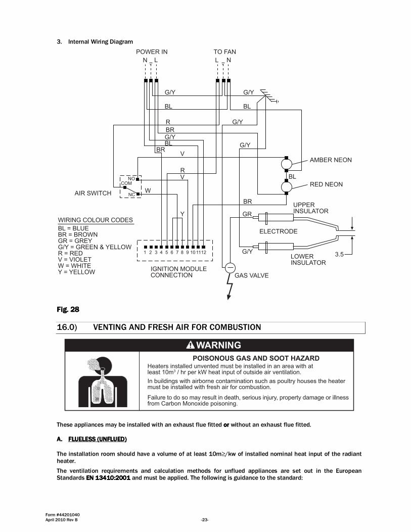
3. Internal Wiring Diagram
TO FANPOWER IN
AIR SWITCH
IGNITION MODULECONNECTION
ELECTRODE
G/Y
R
BR
1 2 3 4 5 6 7 8 9 101112
LN NL
BL
G/YBL
BRV
RV
G/Y
BL
BR
G/Y
GR
3.5
RED NEON
AMBER NEON
NC
COMNO
W
Y
BL
WIRING COLOUR CODES
BL = BLUEBR = BROWNGR = GREYG/Y = GREEN & YELLOWR = REDV = VIOLETW = WHITEY = YELLOW
GAS VALVE
G/Y
UPPERINSULATOR
LOWERINSULATOR
G/Y
Fig. Fig. Fig. Fig. 28282828
16.0) VENTING AND FRESH AIR FOR COMBUSTION
Failure to do so may result in death, serious injury, property damage or illnessfrom Carbon Monoxide poisoning.
In buildings with airborne contamination such as poultry houses the heatermust be installed with fresh air for combustion.
Heaters installed unvented must be installed in an area with atleast 10m3 / hr per kW heat input of outside air ventilation.
POISONOUS GAS AND SOOT HAZARD
These appliances may be installed with an exhaust flue fitted orororor without an exhaust flue fitted. A.A.A.A. FLUELESS (UNFLUED)FLUELESS (UNFLUED)FLUELESS (UNFLUED)FLUELESS (UNFLUED)
The installation room should have a volume of at least 10m≥/kw of installed nominal heat input of the radiant heater.
The ventilation requirements and calculation methods for unflued appliances are set out in the European Standards EN 13410:2001EN 13410:2001EN 13410:2001EN 13410:2001 and must be applied. The following is guidance to the standard:
Form #44201040 -24- April 2010 Rev B
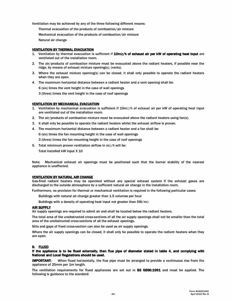
Ventilation may be achieved by any of the three following different means:
Thermal evacuation of the products of combustion/air mixture
Mechanical evacuation of the products of combustion/air mixture
Natural air change
VENTILATION BY THERMAL EVACUATIONVENTILATION BY THERMAL EVACUATIONVENTILATION BY THERMAL EVACUATIONVENTILATION BY THERMAL EVACUATION 1. Ventilation by thermal evacuation is sufficient if 10m10m10m10m≥≥≥≥////h of exhaust air per kW of operating heat inputh of exhaust air per kW of operating heat inputh of exhaust air per kW of operating heat inputh of exhaust air per kW of operating heat input are
ventilated out of the installation room.
2. The air/products of combustion mixture must be evacuated above the radiant heaters, if possible near the ridge, by means of exhaust mixture opening(s), (vents).
3. Where the exhaust mixture opening(s) can be closed, it shall only possible to operate the radiant heaters when they are open.
4. The maximum horizontal distance between a radiant heater and a vent opening shall be:
6 (six) times the vent height in the case of wall openings
3 (three) times the vent height in the case of roof openings
VENTILATION BY MECHANICAL EVACUATIONVENTILATION BY MECHANICAL EVACUATIONVENTILATION BY MECHANICAL EVACUATIONVENTILATION BY MECHANICAL EVACUATION 1. Ventilation by mechanical evacuation is sufficient if 10m≥/h of exhaust air per kW of operating heat input
are ventilated out of the installation room.
2. The air/products of combustion mixture must be evacuated above the radiant heaters using fan(s).
3. It shall only be possible to operate the radiant heaters whilst the exhaust airflow is proven.
4. The maximum horizontal distance between a radiant heater and a fan shall be:
6 (six) times the fan mounting height in the case of wall openings
3 (three) times the fan mounting height in the case of roof openings
5. Total minimum proven ventilation airflow in m≥/h will be:
Total installed kW input X 10
Note: Mechanical exhaust air openings must be positioned such that the burner stability of the nearest appliance is unaffected.
VENTILATION BY NATURAL AIR CHANGEVENTILATION BY NATURAL AIR CHANGEVENTILATION BY NATURAL AIR CHANGEVENTILATION BY NATURAL AIR CHANGE Gas-fired radiant heaters may be operated without any special exhaust system if the exhaust gases are discharged to the outside atmosphere by a sufficient natural air change in the installation room.
Furthermore, no provision for thermal or mechanical ventilation is required in the following particular cases:
Buildings with natural air change greater than 1.5 volumes per hour
Buildings with a density of operating heat input not greater than 5W/m≥
AIR SUPPLYAIR SUPPLYAIR SUPPLYAIR SUPPLY Air supply openings are required to admit air and shall be located below the radiant heaters.
The total area of the unobstructed cross-sections of all the air supply openings shall not be smaller than the total area of the unobstructed cross-sections of all the exhaust openings.
Slits and gaps of fixed cross-section can also be used as air supply openings.
Where the air supply openings can be closed, it shall only be possible to operate the radiant heaters when they are open.
B.B.B.B. FLUEDFLUEDFLUEDFLUED If the appliance is to be flued externally, then flue pipe of diameter stated in table 4, and complying with If the appliance is to be flued externally, then flue pipe of diameter stated in table 4, and complying with If the appliance is to be flued externally, then flue pipe of diameter stated in table 4, and complying with If the appliance is to be flued externally, then flue pipe of diameter stated in table 4, and complying with National and Local Regulations should be used.National and Local Regulations should be used.National and Local Regulations should be used.National and Local Regulations should be used.
IMPORTANT:IMPORTANT:IMPORTANT:IMPORTANT: When flued horizontally, the flue pipe must be arranged to provide a continuous rise from the appliance of 25mm per 1m length.
The ventilation requirements for flued appliances are set out in BS 6896:1991BS 6896:1991BS 6896:1991BS 6896:1991 and must be applied. The following is guidance to the standard:

Form #44201040 April 2010 Rev B -25-
NATURAL VENTILATIONNATURAL VENTILATIONNATURAL VENTILATIONNATURAL VENTILATION Low level ventilation shall be provided in all cases below the level of the heater(s).
Up to and including 60kW: 4.5cm2/kW
Over 60kW: 270cm2 + 2.25cm2 /kW in excess of 60kW total rated heat input.
Where the air supply openings can be closed, it shall only be possible to operate the radiant heaters when they are open.
MECHANICAL VENTILATIONMECHANICAL VENTILATIONMECHANICAL VENTILATIONMECHANICAL VENTILATION Ventilation shall be provided in all cases at or below the level of the heaters.
Minimum proven air flow: 2.35m3/h/kW of total rated heat input.
It shall only be possible to operate the radiant heaters whilst the ventilation airflow is proven.
C.C.C.C. FLUE AND COMBUSTION AIR CONFIGURATIONSFLUE AND COMBUSTION AIR CONFIGURATIONSFLUE AND COMBUSTION AIR CONFIGURATIONSFLUE AND COMBUSTION AIR CONFIGURATIONS The heaters can be installed with different flue and combustion air configurations please review the diagrams on the following page for the overview of the permitted installations. The permissible maximum lengths associated with these options are listed in the table below.
ModelModelModelModel FFFFlue lue lue lue TTTTypeypeypeype Max Combustion Max Combustion Max Combustion Max Combustion
AAAAir ir ir ir LLLLengthengthengthength, m, m, m, m ((((Ø100mmØ100mmØ100mmØ100mm))))
Max Flue LengthMax Flue LengthMax Flue LengthMax Flue Length, , , , m (m (m (m (Ø100mmØ100mmØ100mmØ100mm))))
Max Max Max Max LLLLenenenength gth gth gth CCCCombined ombined ombined ombined
CCCCombustion ombustion ombustion ombustion AAAAir ir ir ir and and and and FFFFlue,lue,lue,lue, m m m m ((((Ø100mmØ100mmØ100mmØ100mm))))
Reduce length for Reduce length for Reduce length for Reduce length for 90° bends90° bends90° bends90° bends, m , m , m , m
((((Ø100mmØ100mmØ100mmØ100mm))))
SRLP30IP55
A2 8 n/a n/a -1.7m
B22 8 8 16 -1.7m
C52 8 8 16 -1.7m
SRLP35IP55
A2 8 n/a n/a -1.7m
B22 8 8 16 -1.7m
C52 8 8 16 -1.7m
SRLP40IP55
A2 8 n/a n/a -1.7m
B22 8 8 16 -1.7m
C52 8 8 16 -1.7m
SRLP45IP55
A2 8 n/a n/a -1.7m
B22 8 8 16 -1.7m
C52 8 8 16 -1.7m
A2 - Fresh air horizontal A2 - Fresh air vertical
B22 - Fresh air and flue verticalC52 - Fresh air vertical & Flue horizontal in differentpressure zones
C52 - Fresh air horizontal & Flue vertical in differentpressure zones
Fig. Fig. Fig. Fig. 29292929
Form #44201040 -26- April 2010 Rev B
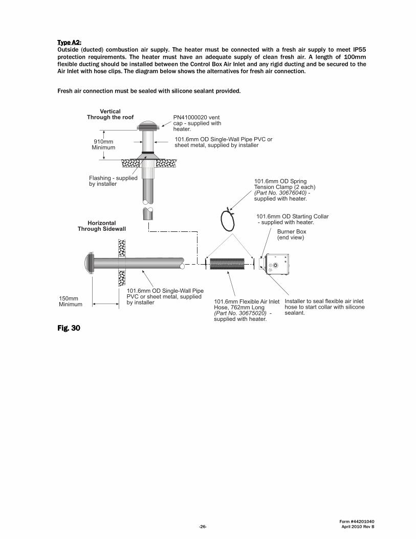
Type A2:Type A2:Type A2:Type A2: Outside (ducted) combustion air supply. The heater must be connected with a fresh air supply to meet IP55 protection requirements. The heater must have an adequate supply of clean fresh air. A length of 100mm flexible ducting should be installed between the Control Box Air Inlet and any rigid ducting and be secured to the Air Inlet with hose clips. The diagram below shows the alternatives for fresh air connection.
Fresh air connection must be sealed with silicone sealant provided.
101.6mm OD Single-Wall Pipe PVC orsheet metal, supplied by installer
Flashing - suppliedby installer
HorizontalThrough Sidewall
150mmMinimum
101.6mm OD Starting Collar - supplied with heater.
Burner Box(end view)
910mmMinimum
101.6mm Flexible Air InletHose, 762mm Long(Part No. 30675020) -supplied with heater.
101.6mm OD SpringTension Clamp (2 each)(Part No. 30676040) -supplied with heater.
VerticalThrough the roof PN41000020 vent
cap - supplied withheater.
101.6mm OD Single-Wall PipePVC or sheet metal, suppliedby installer Installer to seal flexible air inlet
hose to start collar with siliconesealant.
Fig. Fig. Fig. Fig. 30303030
Form #44201040 April 2010 Rev B -27-
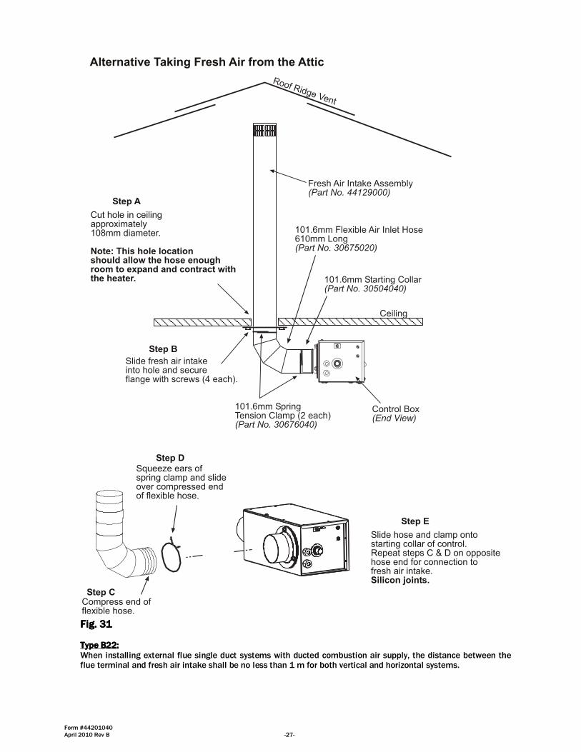
Fresh Air Intake Assembly(Part No. 44129000)
Slide fresh air intakeinto hole and secureflange with screws (4 each).
101.6mm Flexible Air Inlet Hose610mm Long(Part No. 30675020)
101.6mm Starting Collar(Part No. 30504040)
Control Box(End View)
Ceiling
101.6mm SpringTension Clamp (2 each)(Part No. 30676040)
Roof Ridge Vent
Cut hole in ceilingapproximately108mm diameter.
Note: This hole locationshould allow the hose enoughroom to expand and contract withthe heater.
Step A
Step B
Compress end offlexible hose.
Squeeze ears ofspring clamp and slideover compressed endof flexible hose.
Step C
Step D
Slide hose and clamp ontostarting collar of control.Repeat steps C & D on oppositehose end for connection tofresh air intake.Silicon joints.
Step E
Alternative Taking Fresh Air from the Attic
Fig. Fig. Fig. Fig. 31313131 Type B22:Type B22:Type B22:Type B22: When installing external flue single duct systems with ducted combustion air supply, the distance between the flue terminal and fresh air intake shall be no less than 1 m for both vertical and horizontal systems.
Form #44201040 -28- April 2010 Rev B
Type C52:Type C52:Type C52:Type C52: When fresh air for combustion and the flue outlet are from different pressures zones as shown in Fig. 29, the flue outlet and the fresh air intake must not be on surfaces that are 180 degrees apart. The acceptable configurations are those shown in Fig. 29 in combination with the maximum lengths listed on table above.
The flexible air inlet hose should be connected so that flexibility is provided for the expansion and contractionof the heater.
Failure to follow these instructions may result in property damage and invalidate warranties.
Property Damage
17.0) LIGHTING AND SHUTDOWN INSTRUCTIONS
1. Ensure that the Control Box lid is closed. The heater will not operate with the door open.
2. Turn on the gas supply to the appliance.
3. Set any time switches or thermostats to demand heat.
4. Switch on the electricity supply to the appliance. The red neon indicator and amber neon indicator will be illuminated.
5. The burner should ignite within 20 seconds. Both red and amber neon indicators will remain illuminated.
6. Failure to ignite will result in the ignition controller going to "lockout" condition. The red neon indicator will remain illuminated. The amber neon indicator will be extinguished.
7. If lockout occurs, switch off the electricity supply to the appliance; wait for 10 seconds before switching on the electricity supply to the appliance to repeat the ignition sequence.
8. If the appliance fails to ignite after a second sequence switch off the electrical supply to the appliance and call the service engineer.
9. If gas failure occurs after successful ignition the appliance will attempt one re-ignition before going to lockout condition.
10. To shut down the appliance for short periods of time, switch off the electricity supply to the appliance.
11. To shut down the appliance for longer periods of time, switch of the electricity supply to the appliance and turn off the gas supply at the gas isolation valve.
NOTE: NOTE: NOTE: NOTE: TTTThe lighting and shutdown instructions are also shown on the permanent nameplate label attached to the he lighting and shutdown instructions are also shown on the permanent nameplate label attached to the he lighting and shutdown instructions are also shown on the permanent nameplate label attached to the he lighting and shutdown instructions are also shown on the permanent nameplate label attached to the heater control box.heater control box.heater control box.heater control box.

Form #44201040 April 2010 Rev B -29-
18.0) COMMISSIONING
The chart below shows the sequence of operation for the normal operating cycle.
T0 T1 T2 T3 T4
Call for heat, Thermostat on
Thermostat
Blower
Amber neon indicator
Ignition
Air switch
Gas valve
Flame sensing
Function ON Function OFF
Red neon indicator
20 secs pre-purge
10 secs trial for ignition
Normal operation flame sensing
Thermostat off, Heater OFF
T5
Fig. Fig. Fig. Fig. 32323232 If the flame is not sensed during sequence T3 then the heater will go to lockout.
It is essential that all new pipework installations are purged and tested for soundness with a suitable leak detection fluid prior to attempting to ignite any appliance. This work should be carried out in accordance with National or Local regulations.
NOTE: DO NOT TEST FOR SOUNDNESS BY USE OF NAKED FLAMES.
IGNITIONIGNITIONIGNITIONIGNITION 1. Close and secure the Control Box door. The appliance will not operate unless the door is secured.
2. Turn on the gas supply to the appliance.
3. Set the system time clock and thermostat to demand heat.
4. Switch on the electricity supply to the appliance. The appliance red neon indicator will be illuminated, the system fan will commence rotating and the air proving switch will sense an adequate air flow condition. The amber neon indicator will be illuminated.
5. After a purge period of 20 seconds minimum, the solenoid valves and ignition spark electrode will be energised simultaneously.
6. Upon successful ignition, the flame sensor will detect the flame, and the ignition spark electrode will be de-energised.
7. Should the flame fail to permanently establish during the 10 second ignition period the solenoid valves and ignition spark electrode will be de-energised, the amber neon indicator extinguished, the fan stop rotating, and the appliance ignition control go to "lockout" condition.
8. To repeat the ignition sequence it will be necessary to switch off the electricity supply to the appliance for a period of 10 seconds to reset the ignition control. If a first reset is not successful, wait at least 15 seconds before repeating the procedure. After reset, an extended waiting time will occur.
9. If the burner fails to ignite following a second ignition sequence, switch off the electricity supply to the appliance, turn off the gas supply at the gas isolation valve and investigate the fault.
10. If gas failure occurs after successful ignition, the appliance ignition control will attempt one re-ignition before going to "lockout" condition.
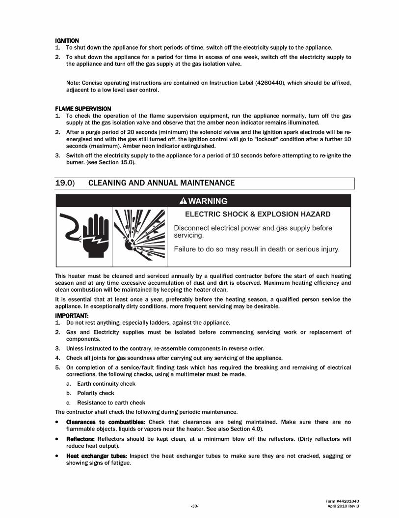
Form #44201040 -30- April 2010 Rev B
IGNITIONIGNITIONIGNITIONIGNITION 1. To shut down the appliance for short periods of time, switch off the electricity supply to the appliance.
2. To shut down the appliance for a period for time in excess of one week, switch off the electricity supply to the appliance and turn off the gas supply at the gas isolation valve.
Note: Concise operating instructions are contained on Instruction Label (4260440), which should be affixed, adjacent to a low level user control.
FLAME SUPERVISIONFLAME SUPERVISIONFLAME SUPERVISIONFLAME SUPERVISION 1. To check the operation of the flame supervision equipment, run the appliance normally, turn off the gas
supply at the gas isolation valve and observe that the amber neon indicator remains illuminated.
2. After a purge period of 20 seconds (minimum) the solenoid valves and the ignition spark electrode will be re-energised and with the gas still turned off, the ignition control will go to "lockout" condition after a further 10 seconds (maximum). Amber neon indicator extinguished.
3. Switch off the electricity supply to the appliance for a period of 10 seconds before attempting to re-ignite the burner. (see Section 15.0).
19.0) CLEANING AND ANNUAL MAINTENANCE
ELECTRIC SHOCK & EXPLOSION HAZARD
Disconnect electrical power and gas supply beforeservicing.
Failure to do so may result in death or serious injury.
This heater must be cleaned and serviced annually by a qualified contractor before the start of each heating season and at any time excessive accumulation of dust and dirt is observed. Maximum heating efficiency and clean combustion will be maintained by keeping the heater clean.
It is essential that at least once a year, preferably before the heating season, a qualified person service the appliance. In exceptionally dirty conditions, more frequent servicing may be desirable.
IMPORTANT:IMPORTANT:IMPORTANT:IMPORTANT: 1. Do not rest anything, especially ladders, against the appliance.
2. Gas and Electricity supplies must be isolated before commencing servicing work or replacement of components.
3. Unless instructed to the contrary, re-assemble components in reverse order.
4. Check all joints for gas soundness after carrying out any servicing of the appliance.
5. On completion of a service/fault finding task which has required the breaking and remaking of electrical corrections, the following checks, using a multimeter must be made.
a. Earth continuity check
b. Polarity check
c. Resistance to earth check
The contractor shall check the following during periodic maintenance.
•••• Clearances to combustibles:Clearances to combustibles:Clearances to combustibles:Clearances to combustibles: Check that clearances are being maintained. Make sure there are no flammable objects, liquids or vapors near the heater. See also Section 4.0).
•••• Reflectors:Reflectors:Reflectors:Reflectors: Reflectors should be kept clean, at a minimum blow off the reflectors. (Dirty reflectors will reduce heat output).
•••• Heat exchanger tubes:Heat exchanger tubes:Heat exchanger tubes:Heat exchanger tubes: Inspect the heat exchanger tubes to make sure they are not cracked, sagging or showing signs of fatigue.

Form #44201040 April 2010 Rev B -31-
•••• Combustion air intake:Combustion air intake:Combustion air intake:Combustion air intake: Disconnect combustion air intake from the control box and inspect internally using a
flashlight to make sure no foreign material has collected in the tubes and that there is no obstruction around the air intake openings. Clean any foreign materials. Inspect any joints to make sure they are completely sealed. See also Section 16.0).
•••• Venting System:Venting System:Venting System:Venting System: Disconnect vent pipe and inspect internally using a flashlight to make sure no foreign material has collected in the pipes. Check the external vent cap and make sure that there is no obstruction around the exhaust openings. Clean any foreign materials. Inspect any joints to make sure they are completely sealed. See also Section 16.0).
•••• Gas lines:Gas lines:Gas lines:Gas lines: Make sure that the gas lines are not leaking. Check the gas connection to the heater for any signs of damage, fatigue or corrosion. If there are any signs of damage to the gas connection or leaks found in the gas piping, immediately stop using the heater until the gas pipe and connections have been repaired or replaced. Check that the gas lines are not bearing the weight of the heater. See also Section 13.0).
•••• ControlControlControlControl Box:Box:Box:Box: In order to extend the longevity of the heater, the heat exchanger tube and the burner must be level. Check that the control box is level; use the turnbuckle on the burner suspension eyebolt to adjust the level of the burner. See also Section 11.0).
•••• Blower wheel and housing:Blower wheel and housing:Blower wheel and housing:Blower wheel and housing: Check that the blower wheel spins freely, blow out any dust or dirt with compressed air. See Section 0 for blower location.
•••• Electrode condition:Electrode condition:Electrode condition:Electrode condition: Visually check that the electrode gap is maintained at 3.5mm and that the tips of the flame sensor and spark electrode are free from deposits. Clean off any deposits. Check that the electrode ceramic is free from cracks. See Section 21.1).
•••• SuspSuspSuspSuspension system:ension system:ension system:ension system: Check that the suspension system is holding the heater level. Make sure that the heater
is hanging securely, look for any evidence where the heater may have been hit accidentally and tighten any loose hanging points. Check that S hooks are closed. Check that there is no evidence of wear on the chain at the connection to the heater and at the ceiling.
•••• Main Burner and Orifice:Main Burner and Orifice:Main Burner and Orifice:Main Burner and Orifice: Check the Main burner and orifice; remove any dirt or debris including spider webs. See Sections 21.2) and 21.3) .
•••• Electrical Wiring: Electrical Wiring: Electrical Wiring: Electrical Wiring: Check that all the electrical connections are sound and that the wiring is undamaged. Replace damaged wires as necessary.
•••• AAAAir Inlet / Baffle Plateir Inlet / Baffle Plateir Inlet / Baffle Plateir Inlet / Baffle Plate:::: Check that the air inlet holes in the Baffle Plate, which is clamped between the Control Box side panel and the Air Inlet flange, are clear from obstructions. Check also, that the wire mesh panel of the Air Inlet is clean. Clean as necessary using a soft brush. In the case of an appliance having a
ducted air supply, it will be necessary to disconnect the flexible ducting from the Air Inlet by first releasing the hose clip. If it is necessary to remove the Air Inlet to adequately clean the Baffle Plate it will be necessary to replace the gasket seal (see Section 21.8).
•••• Door Seal: Door Seal: Door Seal: Door Seal: Check the condition of the seal around the Control Box door and replace as necessary.
IMPORTANT:IMPORTANT:IMPORTANT:IMPORTANT: The appliance will not function unless the seal around the control box door is sound and the door secured with the M4 screws and rubber washers.
•••• Flue Pipes: Flue Pipes: Flue Pipes: Flue Pipes: For flued appliances it is important that periodic sweeping of the flue is carried out according to the National or Local regulations in force.
•••• Auxiliary Controls: Auxiliary Controls: Auxiliary Controls: Auxiliary Controls: Room thermostats, time switches, frost thermostats etc should be checked to ensure correct functioning, and are set to the user requirements.
•••• RRRReeee----assemble and Commissionassemble and Commissionassemble and Commissionassemble and Commission:::: Re-assemble the appliance in reverse order and commission in accordance with the instructions contained in Section 18.0).
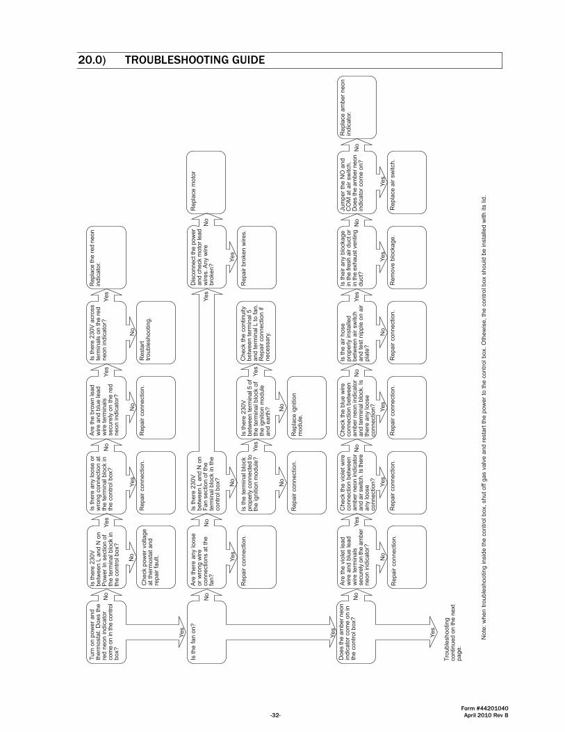
Form #44201040 -32- April 2010 Rev B
20.0) TROUBLESHOOTING GUIDE
Tu
rn o
n p
ow
er
an
dth
erm
osta
t. D
oe
s t
he
red
ne
on
in
dic
ato
rcom
e o
n in
the c
ontr
ol
bo
x?
Ye
s
No
Is t
he
re 2
30
Vb
etw
ee
n L
an
d N
on
Po
we
r In
se
ctio
n o
fth
e t
erm
ina
l b
lock in
the
co
ntr
ol b
ox?
Ye
s
No
Are
th
e b
row
n le
ad
wire
an
d b
lue
le
ad
wire
te
rmin
als
se
cu
rely
on
th
e r
ed
ne
on
in
dic
ato
r?
No
Ye
s
Repla
ce the r
ed n
eon
ind
ica
tor.
Re
pa
ir c
on
ne
ctio
n.
Check p
ow
er
voltage
at
the
rmo
sta
t a
nd
repa
ir f
au
lt.
Is t
he
fa
n o
n?
Ye
s
No
Are
th
ere
an
y lo
ose
or
wro
ng
wire
co
nn
ectio
ns a
t th
efa
n?
Ye
s
No
Re
pa
ir c
on
ne
ctio
n.
Is t
he
re 2
30
Vb
etw
ee
n L
an
d N
on
Fa
n s
ectio
n o
f th
ete
rmin
al b
lock in
th
eco
ntr
ol b
ox?
Does the a
mber
neon
ind
ica
tor
co
me
on
in
the
co
ntr
ol b
ox?
Ye
s
No
Tro
ub
lesh
oo
tin
gcontinued o
n the n
ext
pa
ge
.
No
Ye
s
Is t
he
te
rmin
al b
lock
pro
perly c
onnecte
d to
the
ig
nitio
n m
od
ule
?
Dis
connect th
e p
ow
er
and c
heck m
oto
r le
ad
wire
s. A
ny w
ire
bro
ke
n?
Ye
s
No
Re
pa
ir b
roke
n w
ire
s.
Re
pla
ce
mo
tor
Is t
he
re a
ny lo
ose
or
wro
ng
co
nn
ectio
n a
tth
e t
erm
ina
l b
lock in
the
co
ntr
ol b
ox?
Ye
s
No
Re
pa
ir c
on
ne
ctio
n.
Is t
he
re 2
30
V a
cro
ss
term
ina
ls o
n t
he
re
dn
eo
n in
dic
ato
r?
No
Ye
s
Re
sta
rttr
ou
ble
sh
oo
tin
g.
No
Ye
s
Re
pa
ir c
on
ne
ctio
n.
Is t
he
re 2
30
Vbetw
een term
inal 5
of
the
te
rmin
al b
lock o
fth
e ig
nitio
n m
od
ule
an
d e
art
h? N
o
Ye
s
Re
pla
ce
ig
nitio
nm
od
ule
.
Ch
eck t
he
co
ntin
uity
be
twe
en
te
rmin
al 5
and term
inal L to fan.
Re
pa
ir c
on
ne
ctio
n if
ne
ce
ssa
ry.
Are
th
e v
iole
t le
ad
wire
an
d b
lue
le
ad
wire
te
rmin
als
secure
ly o
n the a
mber
ne
on
in
dic
ato
r?
No
Ye
s
Re
pa
ir c
on
ne
ctio
n.
Ch
eck t
he
blu
e w
ire
co
nn
ectio
n b
etw
ee
nam
ber
neon indic
ato
rand term
inal blo
ck. Is
the
re a
ny lo
ose
co
nn
ectio
n?
Ch
eck t
he
vio
let
wire
co
nn
ectio
n b
etw
ee
nam
ber
neon indic
ato
rand a
ir s
witc
h. Is
there
an
y lo
ose
co
nn
ectio
n?
Ye
s
No
Re
pa
ir c
on
ne
ctio
n.
No
te:
wh
en
tro
ub
lesh
oo
tin
g in
sid
e t
he
co
ntr
ol b
ox,
sh
ut
off g
as v
alv
e a
nd
re
sta
rt t
he
po
we
r to
th
e c
on
tro
l b
ox.
Oth
ew
ise
, th
e c
on
tro
l b
ox s
ho
uld
be
in
sta
lled
with
its
lid
.
Ye
s
No
Re
pa
ir c
on
ne
ctio
n.
Is t
he
air h
ose
pro
pe
rly in
sta
lled
be
twe
en
air s
witch
an
d t
est
nip
ple
on
air
pla
te?
No
Ye
s
Re
pa
ir c
on
ne
ctio
n.
Is t
he
ir a
ny b
locka
ge
in the fre
sh a
ir d
uct or
in the e
xhaust ventin
gd
uct?
Ye
s
No
Re
mo
ve
blo
cka
ge
.
Ju
mp
er
the
NO
an
dC
OM
at
air s
witch
.D
oes the a
mber
neon
ind
ica
tor
co
me
on
?
Ye
s
No
Re
pla
ce
air s
witch
.
Re
pla
ce
am
be
r n
eo
nin
dic
ato
r.
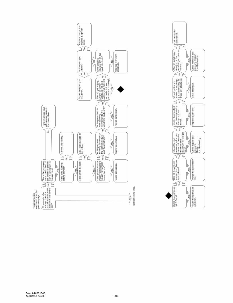
Form #44201040 April 2010 Rev B -33-
30 s
econds a
fter
sta
rtup, does the
am
ber
neon indic
ato
rsta
y o
n in the c
ontr
ol
box?
Yes
No
Is the ignitio
n m
odule
pro
perly c
onnecte
d to
the g
as v
alv
e insid
eth
e c
ontr
ol box?
Turn
on a
ll gas s
hut
off v
alv
es u
pstr
eam
the c
ontr
ol box.
Repair c
onnection.
Is the g
rey w
ire
secure
ly c
onnecte
d to
the ignitio
n m
odule
and the e
lectr
ode?
Shut off g
as s
upply
,ju
mper
air s
witch
CO
M a
nd N
O, and
call
for
heat. A
fter
20
seconds, is
there
continuous s
park
ing?
Yes
Check the g
as s
upply
to the c
ontr
ol box. Is
gas p
ressure
gre
ate
rth
an the m
inim
um
for
the g
as type?
Yes
No
Is the o
rifice b
locked?
No
Yes
Cle
ar
the b
lockage a
tth
e o
rifice.
No
Is the c
era
mic
insula
tor
OK
on the
spark
ele
ctr
ode?
No
Yes
Repla
ce the s
park
ele
ctr
ode.
Is the s
park
gap
3.5
mm
?
No
Yes
Adju
st th
e s
park
gap
to 3
.5m
m.
Repla
ce the ignitio
nm
odule
& ignitio
ncable
.
Tro
uble
shooting
continued fro
m the
pre
vio
us p
age.
Repair c
onnection.
Yes
No
Is the g
reen/y
ello
ww
ire s
ecure
lyconnecte
d to the
ele
ctr
ode a
nd e
art
h?
Yes
No
Repair c
onnection.
No
Yes
Tro
uble
shootin
g e
nds.
Check the s
park
gap.
Is it 3.5
mm
?
No
Yes
Adju
st th
e s
park
gap
to 3
.5m
m.
Has a
ll th
e a
ir b
een
purg
ed fro
m the g
as
supply
lin
es?
No
Yes
Purg
e the g
as s
upply
line.
Check the inle
tpre
ssure
to the g
as
valv
e. Is
it betw
een
min
imum
and
maxim
um
for
the g
as
type?
No
Yes
Adju
st supply
gas
pre
ssure
.R
esta
rttr
ouble
shooting.
Check the m
anifold
gas p
ressure
during
sta
rtup. Is
it zero
inches?
Yes
No
Repla
ce g
as v
alv
e.
After
an initia
l ste
popenin
g, is
the
manifo
ld g
as p
ressure
corr
ect?
No
Yes
Adju
st m
anifold
gas
pre
ssure
. R
esta
rttr
ouble
shooting.
Call
facto
ry for
assis
tance.
Check o
rifice a
nd
hold
er
for
blo
ckage
(i.e
. spid
er
web).
Is
there
any b
lockage?
Yes
No
Cle
ar
blo
ckage.
Is the s
tep o
penin
gsettin
g c
orr
ect?
Yes
No
Corr
ect th
e s
ettin
g.
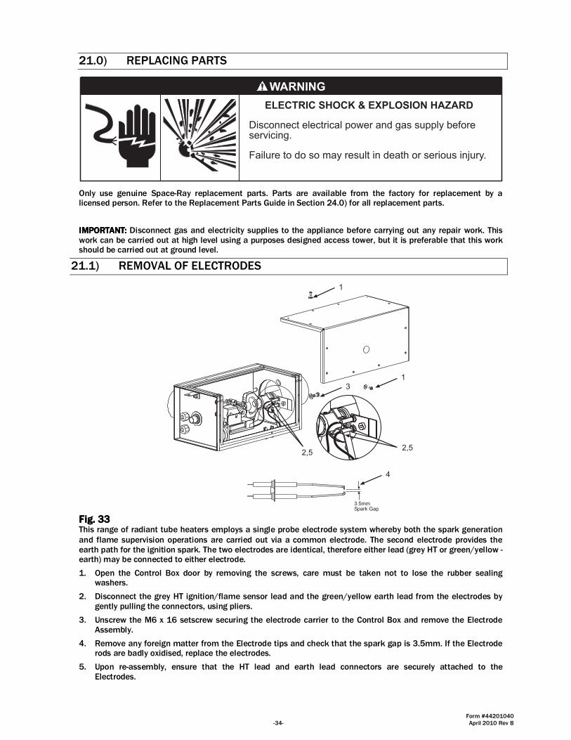
Form #44201040 -34- April 2010 Rev B
21.0) REPLACING PARTS
ELECTRIC SHOCK & EXPLOSION HAZARD
Disconnect electrical power and gas supply beforeservicing.
Failure to do so may result in death or serious injury.
Only use genuine Space-Ray replacement parts. Parts are available from the factory for replacement by a licensed person. Refer to the Replacement Parts Guide in Section 24.0) for all replacement parts.
IMPORTANT:IMPORTANT:IMPORTANT:IMPORTANT: Disconnect gas and electricity supplies to the appliance before carrying out any repair work. This work can be carried out at high level using a purposes designed access tower, but it is preferable that this work should be carried out at ground level.
21.1) REMOVAL OF ELECTRODES
3.5mmSpark Gap
1
2,52,5
13
4
Fig. Fig. Fig. Fig. 33333333 This range of radiant tube heaters employs a single probe electrode system whereby both the spark generation
and flame supervision operations are carried out via a common electrode. The second electrode provides the earth path for the ignition spark. The two electrodes are identical, therefore either lead (grey HT or green/yellow - earth) may be connected to either electrode.
1. Open the Control Box door by removing the screws, care must be taken not to lose the rubber sealing washers.
2. Disconnect the grey HT ignition/flame sensor lead and the green/yellow earth lead from the electrodes by gently pulling the connectors, using pliers.
3. Unscrew the M6 x 16 setscrew securing the electrode carrier to the Control Box and remove the Electrode Assembly.
4. Remove any foreign matter from the Electrode tips and check that the spark gap is 3.5mm. If the Electrode rods are badly oxidised, replace the electrodes.
5. Upon re-assembly, ensure that the HT lead and earth lead connectors are securely attached to the Electrodes.
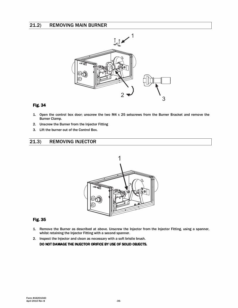
Form #44201040 April 2010 Rev B -35-
21.2) REMOVING MAIN BURNER
1
23
Fig. Fig. Fig. Fig. 34343434 1. Open the control box door; unscrew the two M4 x 25 setscrews from the Burner Bracket and remove the
Burner Clamp.
2. Unscrew the Burner from the Injector Fitting
3. Lift the burner out of the Control Box.
21.3) REMOVING INJECTOR
1
Fig. Fig. Fig. Fig. 35353535 1. Remove the Burner as described at above. Unscrew the Injector from the Injector Fitting, using a spanner,
whilst retaining the Injector Fitting with a second spanner.
2. Inspect the Injector and clean as necessary with a soft bristle brush.
DO NOT DAMAGE THE INJECTOR ORIFICE BY USE OF SOLID OBJECTS.DO NOT DAMAGE THE INJECTOR ORIFICE BY USE OF SOLID OBJECTS.DO NOT DAMAGE THE INJECTOR ORIFICE BY USE OF SOLID OBJECTS.DO NOT DAMAGE THE INJECTOR ORIFICE BY USE OF SOLID OBJECTS.

Form #44201040 -36- April 2010 Rev B
21.4) REMOVING IGNITION CONTROL
3
1 2 1
Fig.Fig.Fig.Fig. 36363636
1. Disconnect the 12 way Molex electrical connector and the grey HT ignition spark/flame sensor lead from the Ignition Control.
2. Unscrew the M3 screw securing the Ignition Control to the Control Valve.
3. Slide out the Ignition Control.
21.5) REMOVING AIR SWITCH
1
3
4
2
Fig. Fig. Fig. Fig. 37373737 1. After opening the control box door, remove the Air Tube Assembly from the Air Switch pressure connection
marked 'H'.
2. Disconnect the three electrical leads from the Air Switch by gently pulling the connectors, using pliers.
3. Unscrew the two No. 8 x 12 self tapping screws securing the Air Proving Switch to the floor of the Control box and lift out with the electrical leads attached.
4. Remove the Air Switch, and remove the restrictor from the Air Switch connection marked 'L'.
When installing a replacement Air Switch, take care to connect the electrical leads in accordance with the wiring diagram shown in Section 15.0) - Fig. 28 and replace the restrictor on the pressure connection marked L. The appliance will not function unless this restrictor is in place.

Form #44201040 April 2010 Rev B -37-
21.6) REMOVING GAS VALVE AND MANIFOLD ASSEMBLY
5
4
4
67
7
1 2
3
Fig. Fig. Fig. Fig. 38383838 1. After opening the control box door, disconnect the 12 way Molex electrical connector.
2. Disconnect the grey HT ignition spark/flame sensor lead from the ignition module.
3. Disconnect the green/yellow wire from the grounding tab of gas valve.
4. Unscrew the two M4x25 setscrews from the burner bracket and remove the burner clamp.
5. Unscrew the burner and slide it away from the valve.
6. Unscrew the M4 screw securing the valve bracket to the control valve and remove the grommet.
7. Slide out the complete assembly of gas valve, ignition module and manifold.
After replacing the Control Valve, check the gas pressures in accordance with Section 14.0) of this manual.
IMPORTANT:IMPORTANT:IMPORTANT:IMPORTANT: TEST FOR GAS SOUNDNESS USING A SUITABLE LEAK DETECTION FLUID.TEST FOR GAS SOUNDNESS USING A SUITABLE LEAK DETECTION FLUID.TEST FOR GAS SOUNDNESS USING A SUITABLE LEAK DETECTION FLUID.TEST FOR GAS SOUNDNESS USING A SUITABLE LEAK DETECTION FLUID.
21.7) REMOVING NEON INDICATOR
1
2
3
Fig. Fig. Fig. Fig. 39393939 1. Disconnect the electrical leads from the Neon Indicators by gently pulling the connectors, using pliers.
2. Remove the star washers.
3. Press the neon indicator out through the mounting hole in the floor of the control box.
When replacing a Neon Indicator, connect the electrical leads in accordance with the wiring diagram shown in Section 15.0) - Fig. 28.

Form #44201040 -38- April 2010 Rev B
21.8) REMOVING AIR INLET PLATE
1
2
Front View(access panel removed)
Rear View
3
Hex Nuts &Washers(3 each)
Air InletAssembly
Gasket
Gasket
Baffle Plate
PressureTest Fitting
Air SwitchPressureFitting
Fig. Fig. Fig. Fig. 40404040 1. After opening the control box door, disconnect tubing from both brass pressure test fittings.
2. Remove brass nut from pressure test fitting.
3. Disassemble components from the control box.
21.9) REMOVING THE FAN
Fan(Torin fan shown)
Tube Flange Assembly(McMillan fans only)
Set Screw
Air Restrictor Plate
Gasket
Outlet Screen
Fan Connector
M5 Nut &Washer(3 each)
M5 Screw, Nutand Washer(3 each)
1
24
5
6
Torctite coupling
Radiant tube (101.6mm x 3m)
3
Fig. Fig. Fig. Fig. 41414141 1. Disconnect the electrical wires from the fan (see Section 15.0) for connection details.
2. If a flued installation, disconnect the flue from the Fan.
3. Loosen the nuts of the Torctite Coupling securing the Fan Connector to the Radiant Tube and draw the Fan Assembly off the Radiant Tube.
(McMillan fans only) (McMillan fans only) (McMillan fans only) (McMillan fans only) Loosen set screw from Tube Flange Assembly. Draw the Fan Assembly off the Radiant Tube.
4. Unscrew the three M5 nuts and washers securing the Connector and Air Restrictor Plate to the fan.
5. Inspect the main impeller and secondary cooling impeller and remove any dust by brushing with a soft brush. Check that the impeller rotates freely and that there is no excessive play in the bearings. The bearings are pre-lubricated and require no attention.
6. When re-assembling the Air Restrictor Plate and Connector a new Gasket must be fitted between the Fan case and Orifice Plate (see Fig. 41).

Form #44201040 April 2010 Rev B -39-
22.0) CONVERSION INSTRUCTIONS
CONVERSION FROM CAT. 2H (CONVERSION FROM CAT. 2H (CONVERSION FROM CAT. 2H (CONVERSION FROM CAT. 2H (G20G20G20G20) TO CAT. 3P () TO CAT. 3P () TO CAT. 3P () TO CAT. 3P (G31G31G31G31)))) 1. Remove the Injector from the Injector Fitting (see Section 21.3) and replace it with the alternative Injector
supplied (fastenings pack). Check that the size reference marked on the Injector agrees with that listed in the Specifications table (Section 5.0) for the appliance model in question.
2. Remove the pressure governor cap from the integral pressure governor of the Control Valve and screw the adjuster clockwise to increase the gas pressure, check supply and manifold pressure in accordance with Section 14.0). Replace the pressure governor cap.
3. Affix the gas adjustment label (3P G31, 37mbar) supplied (fastenings pack) onto the Data Label, adjacent to the headings "Adjusted For" and "Setting Pressure", to cover the original gas adjustment label (2H, G20, 20mbar).
4. Carry out checks in accordance with Section 14.0) of this manual to ensure correct supply pressure relative to the gas type being used (G31 - Propane).
5. Remove the step-opening adjustment cap on the valve; turn clockwise the arrow to dot 4; recap the step-opening adjustment cap. (see Fig. 42)
CONVERSION FROM CAT. 3P (CONVERSION FROM CAT. 3P (CONVERSION FROM CAT. 3P (CONVERSION FROM CAT. 3P (G31G31G31G31)))) TO TO TO TO CAT. CAT. CAT. CAT. 2H (2H (2H (2H (G20G20G20G20)))) 1. Remove the Injector from the Injector Fitting (see Section 21.3) and replace it with the alternative Injector
supplied (fastenings pack). Check that the size reference marked on the Injector agrees with that listed in the Technical Data table (Section 5.0) for the appliance model in question.
2. Remove the pressure governor cap from the integral pressure governor of the Control Valve and unscrew the adjuster counter clockwise to increase the gas pressure, check supply and manifold pressure in accordance with Section 14.0). Replace the pressure governor cap.
3. Affix the gas adjustment label (2H, G20, 20mbar) supplied (fastenings pack) onto the Data Label adjacent to the headings, "Adjusted For" and "Setting Pressure" to cover the original gas adjustment label (3P G31, 37mbar).
4. Carry out checks in accordance with Section 14.0) of this manual to ensure correct supply pressure and setting pressure, relative to the gas type being used (G20 - Natural Gas).
5. Remove the step-opening adjustment cap on the valve; turn counterclockwise the arrow to min; recap the step-opening adjustment cap. (see Fig. 42)
MIN
MA
X
dot 1
dot 2
dot 3
dot 4
dot 5
remove the blackcap and seedetailed view
detailed view after theblack cap removed
(for 2H G20)
MIN
MA
X
dot 1
dot 2
dot 3
dot 4
dot 5
detailed view after theblack cap removed
(for 3P G31)
Fig. Fig. Fig. Fig. 42424242
23.0) INSTALLATION DATA
Date of Installation:
# of Heaters in System:
Serial No.
Model: SRLPSRLPSRLPSRLP N = Natural Gas L = Propane Gas
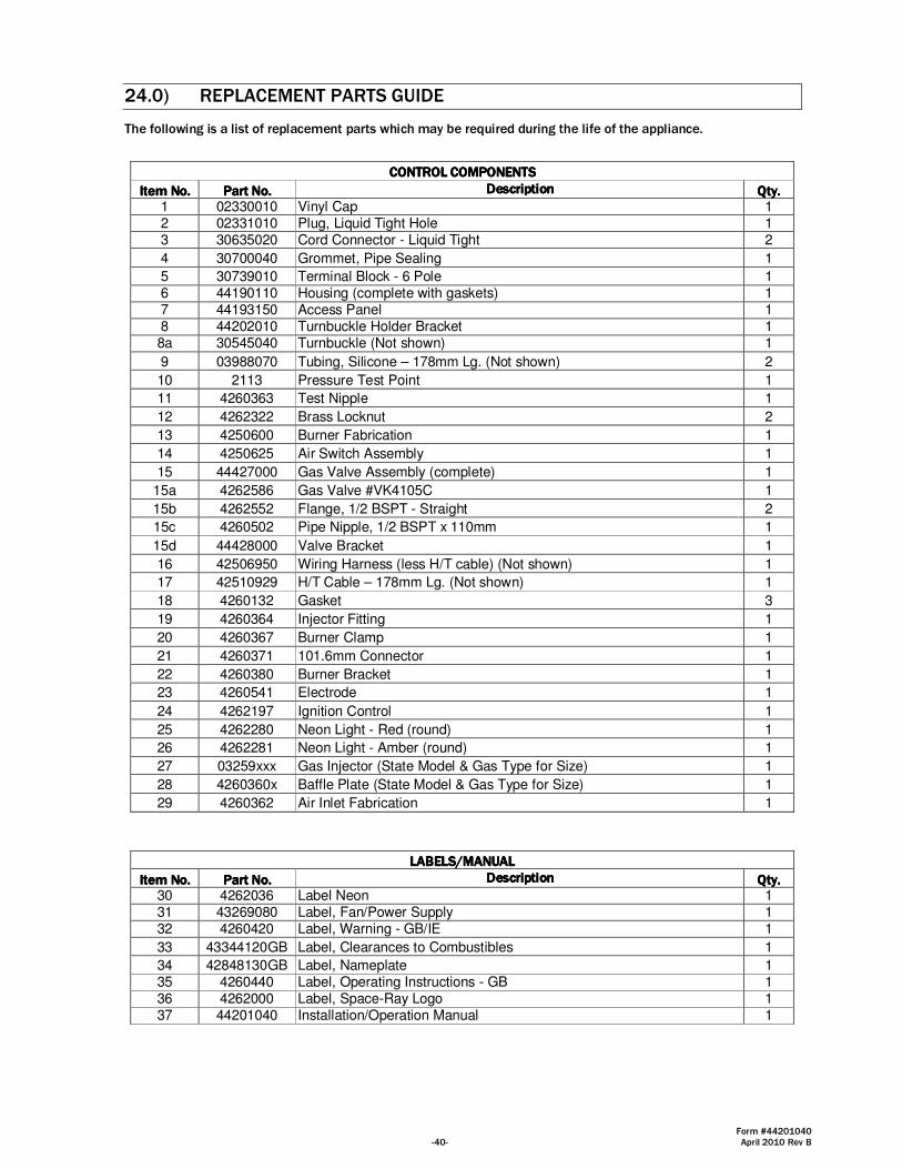
Form #44201040 -40- April 2010 Rev B
24.0) REPLACEMENT PARTS GUIDE
The following is a list of replacement parts which may be required during the life of the appliance.
CONTROL COMPONENTSCONTROL COMPONENTSCONTROL COMPONENTSCONTROL COMPONENTS
Item No.Item No.Item No.Item No. Part No.Part No.Part No.Part No. DescriptionDescriptionDescriptionDescription Qty.Qty.Qty.Qty. 1 02330010 Vinyl Cap 1 2 02331010 Plug, Liquid Tight Hole 1 3 30635020 Cord Connector - Liquid Tight 2
4 30700040 Grommet, Pipe Sealing 1
5 30739010 Terminal Block - 6 Pole 1 6 44190110 Housing (complete with gaskets) 1 7 44193150 Access Panel 1 8 44202010 Turnbuckle Holder Bracket 1 8a 30545040 Turnbuckle (Not shown) 1
9 03988070 Tubing, Silicone – 178mm Lg. (Not shown) 2
10 2113 Pressure Test Point 1
11 4260363 Test Nipple 1
12 4262322 Brass Locknut 2
13 4250600 Burner Fabrication 1
14 4250625 Air Switch Assembly 1
15 44427000 Gas Valve Assembly (complete) 1
15a 4262586 Gas Valve #VK4105C 1
15b 4262552 Flange, 1/2 BSPT - Straight 2
15c 4260502 Pipe Nipple, 1/2 BSPT x 110mm 1
15d 44428000 Valve Bracket 1
16 42506950 Wiring Harness (less H/T cable) (Not shown) 1
17 42510929 H/T Cable – 178mm Lg. (Not shown) 1
18 4260132 Gasket 3
19 4260364 Injector Fitting 1
20 4260367 Burner Clamp 1
21 4260371 101.6mm Connector 1
22 4260380 Burner Bracket 1
23 4260541 Electrode 1
24 4262197 Ignition Control 1
25 4262280 Neon Light - Red (round) 1
26 4262281 Neon Light - Amber (round) 1
27 03259xxx Gas Injector (State Model & Gas Type for Size) 1
28 4260360x Baffle Plate (State Model & Gas Type for Size) 1
29 4260362 Air Inlet Fabrication 1
LABELS/MANUALLABELS/MANUALLABELS/MANUALLABELS/MANUAL
Item No.Item No.Item No.Item No. Part No.Part No.Part No.Part No. DescriptionDescriptionDescriptionDescription Qty.Qty.Qty.Qty. 30 4262036 Label Neon 1 31 43269080 Label, Fan/Power Supply 1 32 4260420 Label, Warning - GB/IE 1
33 43344120GB Label, Clearances to Combustibles 1
34 42848130GB Label, Nameplate 1 35 4260440 Label, Operating Instructions - GB 1 36 4262000 Label, Space-Ray Logo 1 37 44201040 Installation/Operation Manual 1

Form #44201040 April 2010 Rev B -41-
1. TURN ON GAS SUPPLY.2. SET TIME SWITCHES OR THERMOSTATS TO DEMAND HEAT.3. SWITCH ON ELECTRICITY SUPPLY. RED & AMBER NEON INDICATORS �ON�.4. BURNER SHOULD IGNITE WITHIN 15 SECONDS. AMBER NEON INDICATOR �ON�.5. IF IGNITION IS NOT ACHIEVED DURING 12 SECOND IGNITION PERIOD, LOCKOUT OCCURS. THIS IS INDICATED BY THE AMBER NEON �OFF�. INTERRUPT ELECTICITY SUPPLY TO APPLIANCE FOR 10 SECONDST TO RESET IGNITION CONTROL. IF A FIRST RESET IS NOT SUCCESSFUL, WAIT AT LEAST 15 SECONDS BEFORE REPEATING PROCEDURE. AFTER RESET, AN EXTENDED WAITING TIME WILL OCCUR.6. IF THE FLAME IS LOST DURING NORMAL RUNNING, THE AUTOMATIC IGNITION CONTROL WILL REPEAT START PROCEDURE AS AT 4 ABOVE.7. IF THE APPLIANCE FAILS TO IGNITE AFTER SECOND START SEQUENCE, SWITCH OFF ELECTRICITY SUPPLY TO APPLIANCE AND CALL SERVICE ENGINEER.8. TO SHUT DOWN APPLIANCE, TURN OFF GAS AND ELECTRICITY SUPPLIES.
AFFIX THIS LABEL ADJACENT TO LOW LEVEL USER CONTROL.
OVERHEAT RADIANT TUBE HEATEROPERATING INSTRUCTIONS
1 11,12
18
1829
28
10,11
3
8
46
5
14
2526
23
2218
21
15,15a
19 27
20
13
24
15c
15d
7
215b
30
FAN
POWER IN(230V 50Hz)
L
N
N
L
E
E
R
G/Y
BL
BL
G/Y
BR
432690807/08
31
Minimum Clearances to Combustibles
3332
34 35
42848130GB Rev. A 9/08
SUPPLY :
FUSE EXTERNALLY:
HEAT INPUT:MODEL NO: SERIAL NO:
NOx CLASS:
FLUE TYPE:
CODE DATE:
Gas Fired Products (UK) Ltd, Claydon, Ipswic, Suffolk, IP6 0JL, England
Tel: (01473) 830551 e-mail [email protected]
COUNTRY:
APPLIANCE CATEGORY:
ELECTRICAL RATING
INSULATION CODE:
ADJUSTED FOR GAS TYPE& PRESSURE (mbar)
This appliance must be installed in accordance with therules in force, and used only in a sufficiently ventilatedspace. Consult instructions before installation and use ofthis appliance.
MANIFOLD:
PIN 87BT240087
36
WARNING
THIS APPLIANCE MUST BE INSTALLED IN ACCORDANCEWITH THE RULES IN FORCE AND USED ONLY IN ASUFFICIENTLY VENTILATED SPACE.
CONSULT INSTRUCTIONS BEFORE INSTALLATION ANDUSE OF THIS APPLIANCE.
ISOLATED GAS SUPPLY BEFORE CARRINGOUT ANY SERVICING OPERATION.
A
BC
D
EF
MODEL: A B C D E F
CBU09-15 45 45 45 122 58 31SRL09-15 45 45 45 122 58 31SRU/L25 51 51 45 122 61 31ERU25 51 51 45 122 61 31SRU/L30-45 61 76 61 229 76 38
D
C
B
A
Failure to follow the stated clearances to combustibles mayresult in death, serious injury or property damage.
All dimensions in centimetres
43344120GB Rev. - 09/08
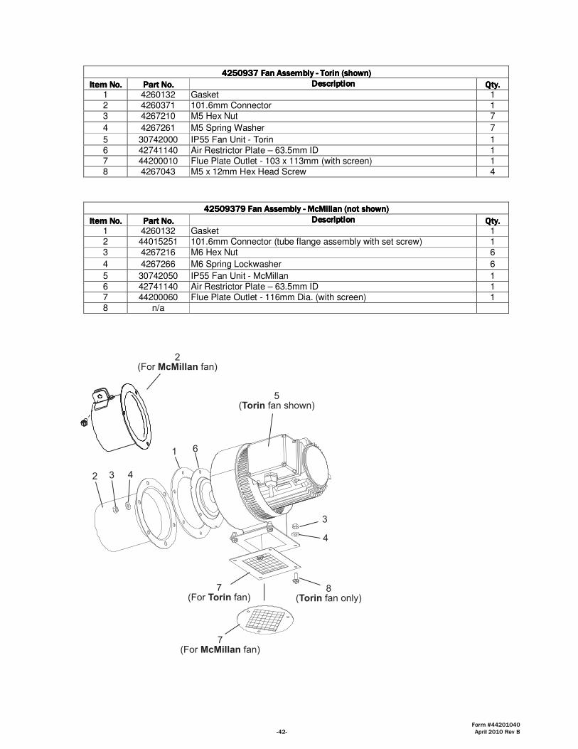
Form #44201040 -42- April 2010 Rev B
4444250937 Fan Assembly 250937 Fan Assembly 250937 Fan Assembly 250937 Fan Assembly ---- Torin (shown)Torin (shown)Torin (shown)Torin (shown)
Item No.Item No.Item No.Item No. Part No.Part No.Part No.Part No. DescriptionDescriptionDescriptionDescription Qty.Qty.Qty.Qty. 1 4260132 Gasket 1 2 4260371 101.6mm Connector 1 3 4267210 M5 Hex Nut 7
4 4267261 M5 Spring Washer 7
5 30742000 IP55 Fan Unit - Torin 1 6 42741140 Air Restrictor Plate – 63.5mm ID 1 7 44200010 Flue Plate Outlet - 103 x 113mm (with screen) 1 8 4267043 M5 x 12mm Hex Head Screw 4
42509379 Fan Assembly 42509379 Fan Assembly 42509379 Fan Assembly 42509379 Fan Assembly ---- McMillan (not shown)McMillan (not shown)McMillan (not shown)McMillan (not shown)
Item No.Item No.Item No.Item No. Part No.Part No.Part No.Part No. DescriptionDescriptionDescriptionDescription Qty.Qty.Qty.Qty. 1 4260132 Gasket 1 2 44015251 101.6mm Connector (tube flange assembly with set screw) 1 3 4267216 M6 Hex Nut 6
4 4267266 M6 Spring Lockwasher 6
5 30742050 IP55 Fan Unit - McMillan 1 6 42741140 Air Restrictor Plate – 63.5mm ID 1 7 44200060 Flue Plate Outlet - 116mm Dia. (with screen) 1 8 n/a
2 3 4
1 6
5(Torin fan shown)
3
4
8(Torin fan only)
7(For Torin fan)
7(For McMillan fan)
2(For McMillan fan)
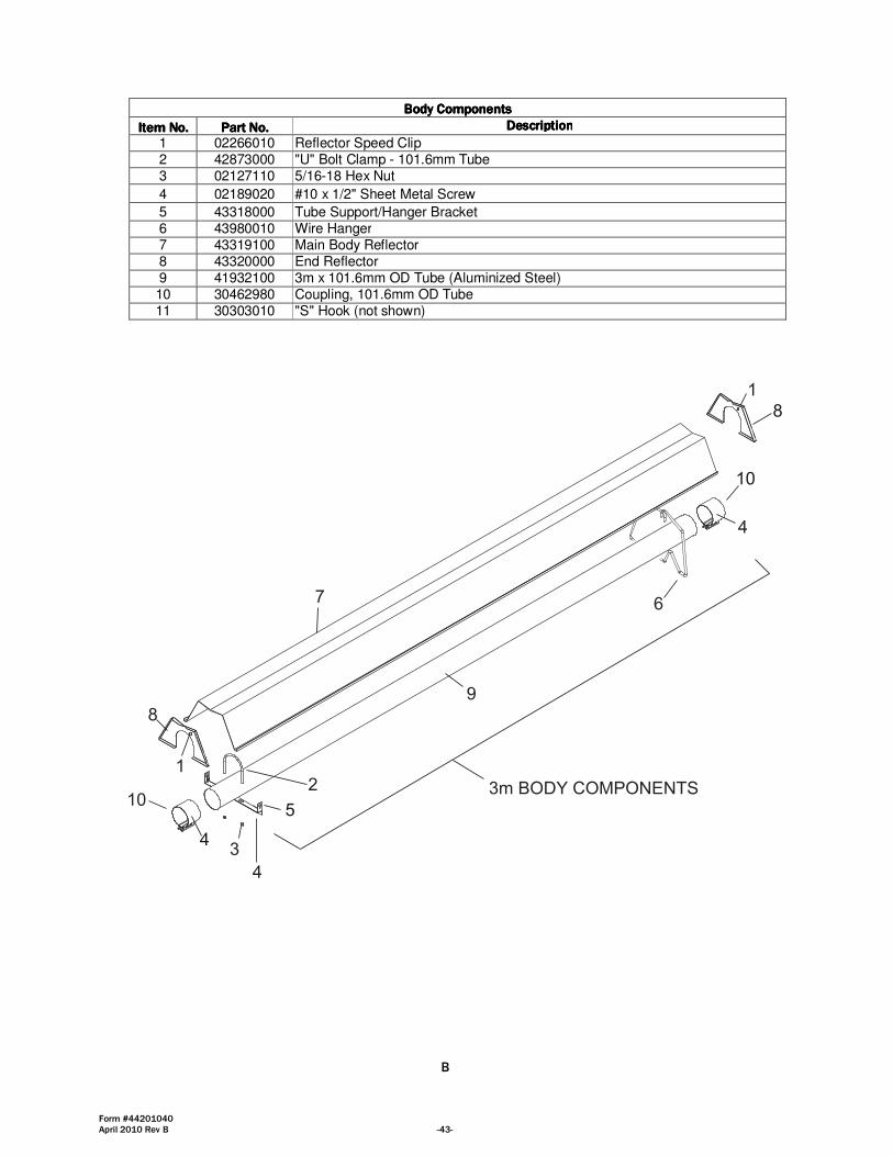
Form #44201040 April 2010 Rev B -43-
Body CompoBody CompoBody CompoBody Componentsnentsnentsnents
Item No.Item No.Item No.Item No. Part No.Part No.Part No.Part No. DescriptionDescriptionDescriptionDescription
1 02266010 Reflector Speed Clip 2 42873000 "U" Bolt Clamp - 101.6mm Tube 3 02127110 5/16-18 Hex Nut
4 02189020 #10 x 1/2" Sheet Metal Screw
5 43318000 Tube Support/Hanger Bracket 6 43980010 Wire Hanger 7 43319100 Main Body Reflector 8 43320000 End Reflector 9 41932100 3m x 101.6mm OD Tube (Aluminized Steel) 10 30462980 Coupling, 101.6mm OD Tube 11 30303010 "S" Hook (not shown)
7
8
10
6
2
3
4
9
3m BODY COMPONENTS
4
1
1
8
4
5
10
B
Related Documents