Dell™ Inspiron™ XPS Service Manual Before You Begin System Components Optical Drive Hard Drive Memory Module Modem Mini PCI Card Internal Card With Bluetooth ® Wireless Technology Center Control Cover Keyboard Display Palm Rest Speakers Subwoofer USB Port Board System Fans Microprocessor Thermal - Cooling Assembly Microprocessor Module Video Card/Thermal Cooling Assembly MCH Heat Sink PC Card Reader Cage System Board Battery Latch Assembly Customizable LEDs Flashing the BIOS Pin Assignments for I/O Connectors Notes, Notices, and Cautions Abbreviations and Acronyms For a complete list of abbreviations and acronyms, see the Dell Inspiron Help file. To access the help file, click the Start button, click Help and Support, click User and system guides, click User's guides, and click Dell Inspiron Help. If you purchased a Dell™ n Series computer, any references in this document to Microsoft® Windows® operating systems are not applicable. Information in this document is subject to change without notice. © 2005 Dell Inc. All rights reserved. Reproduction in any manner whatsoever without the written permission of Dell Inc. is strictly forbidden. Trademarks used in this text: Dell, the DELL logo, and Inspiron are trademarks of Dell Inc.; Microsoft and Windows are registered trademarks of Microsoft Corporation; Bluetooth is a trademark owned by Bluetooth SIG, Inc. and is used by Dell Inc. under license. Other trademarks and trade names may be used in this document to refer to either the entities claiming the marks and names or their products. Dell Inc. disclaims any proprietary interest in trademarks and trade names other than its own. Model PP14L February 2005 Rev. A00 NOTE: A NOTE indicates important information that helps you make better use of your computer. CAUTION: A CAUTION indicates a potential for property damage, personal injury, or death.

Welcome message from author
This document is posted to help you gain knowledge. Please leave a comment to let me know what you think about it! Share it to your friends and learn new things together.
Transcript
Dell™ Inspiron™ XPS Service Manual Before You Begin
System Components
Optical Drive
Hard Drive
Memory Module
Modem
Mini PCI Card
Internal Card With Bluetooth® Wireless Technology
Center Control Cover
Keyboard
Display
Palm Rest
Speakers
Subwoofer
USB Port Board
System Fans
Microprocessor Thermal-Cooling Assembly
Microprocessor Module
Video Card/Thermal Cooling Assembly
MCH Heat Sink
PC Card Reader Cage
System Board
Battery Latch Assembly
Customizable LEDs
Flashing the BIOS
Pin Assignments for I/O Connectors
Notes, Notices, and Cautions
Abbreviations and Acronyms
For a complete list of abbreviations and acronyms, see the Dell Inspiron Help file. To access the help file, click the Start button, click Help and Support, click User and system guides, click User's guides, and click Dell Inspiron Help.
If you purchased a Dell™ n Series computer, any references in this document to Microsoft® Windows® operating systems are not applicable.
Information in this document is subject to change without notice. © 2005 Dell Inc. All rights reserved.
Reproduction in any manner whatsoever without the written permission of Dell Inc. is strictly forbidden.
Trademarks used in this text: Dell, the DELL logo, and Inspiron are trademarks of Dell Inc.; Microsoft and Windows are registered trademarks of Microsoft Corporation; Bluetooth is a trademark owned by Bluetooth SIG, Inc. and is used by Dell Inc. under license.
Other trademarks and trade names may be used in this document to refer to either the entities claiming the marks and names or their products. Dell Inc. disclaims any proprietary interest in trademarks and trade names other than its own.
Model PP14L
February 2005 Rev. A00
NOTE: A NOTE indicates important information that helps you make better use of your computer.
CAUTION: A CAUTION indicates a potential for property damage, personal injury, or death.
Back to Contents Page
Battery Latch Assembly Dell™ Inspiron™ XPS Service Manual
Removing the Battery Latch Assembly
Replacing the Battery Latch Assembly
Removing the Battery Latch Assembly
1. Follow the instructions in "Before Working Inside Your Computer."
2. Remove the center control cover.
3. Remove the keyboard.
4. Remove the display assembly.
5. Remove the palm rest.
6. Remove the system board.
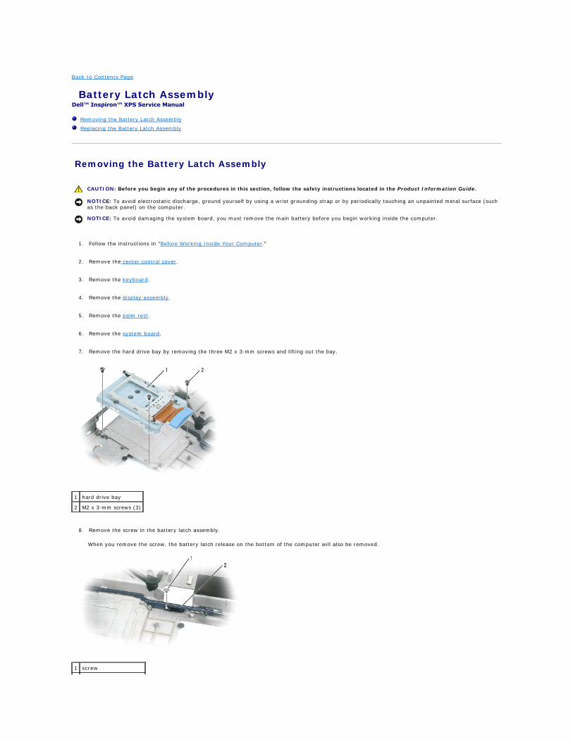
7. Remove the hard drive bay by removing the three M2 x 3-mm screws and lifting out the bay.
8. Remove the screw in the battery latch assembly.
When you remove the screw, the battery latch release on the bottom of the computer will also be removed.
CAUTION: Before you begin any of the procedures in this section, follow the safety instructions located in the Product Information Guide.
NOTICE: To avoid electrostatic discharge, ground yourself by using a wrist grounding strap or by periodically touching an unpainted metal surface (such as the back panel) on the computer.
NOTICE: To avoid damaging the system board, you must remove the main battery before you begin working inside the computer.
1 hard drive bay
2 M2 x 3-mm screws (3)
1 screw
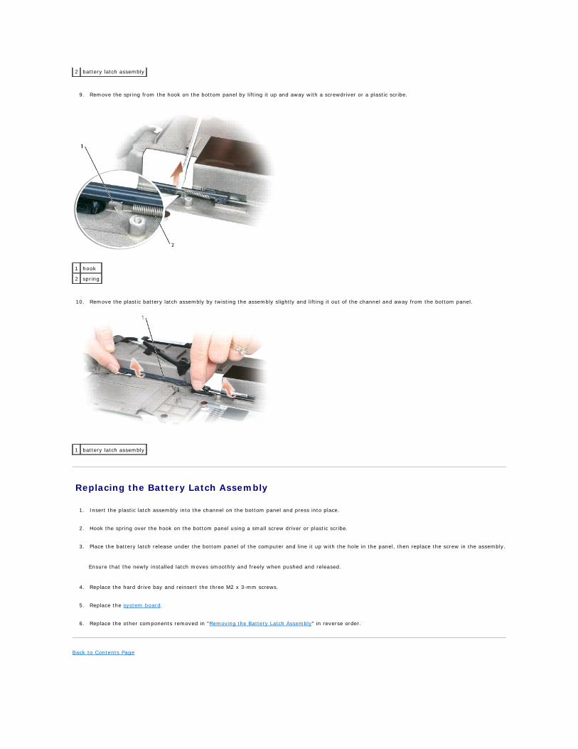
9. Remove the spring from the hook on the bottom panel by lifting it up and away with a screwdriver or a plastic scribe.
10. Remove the plastic battery latch assembly by twisting the assembly slightly and lifting it out of the channel and away from the bottom panel.
Replacing the Battery Latch Assembly
1. Insert the plastic latch assembly into the channel on the bottom panel and press into place.
2. Hook the spring over the hook on the bottom panel using a small screw driver or plastic scribe.
3. Place the battery latch release under the bottom panel of the computer and line it up with the hole in the panel, then replace the screw in the assembly.
Ensure that the newly installed latch moves smoothly and freely when pushed and released.
4. Replace the hard drive bay and reinsert the three M2 x 3-mm screws.
5. Replace the system board.
6. Replace the other components removed in "Removing the Battery Latch Assembly" in reverse order.
Back to Contents Page
2 battery latch assembly
1 hook
2 spring
1 battery latch assembly
Back to Contents Page
Before You Begin Dell™ Inspiron™ XPS Service Manual
Recommended Tools
Turning Off Your Computer
Before Working Inside Your Computer
Computer Orientation
Screw Identification
This section provides procedures for removing and installing the components in your computer. Unless otherwise noted, each procedure assumes that the following conditions exist:
l You have performed the steps in "Turning Off Your Computer" and "Before Working Inside Your Computer."
l You have read the safety information in the Dell™ Product Information Guide.
l A component can be replaced or—if purchased separately—installed by performing the removal procedure in reverse order.
Recommended Tools
The procedures in this document may require the following tools:
l Small flat-blade screwdriver
l Phillips screwdriver
l Small plastic scribe
l Flash BIOS update program CD
Turning Off Your Computer
1. Shut down the operating system:
a. Save and close any open files, exit any open programs, click the Start button, and then click Turn Off Computer.
b. In the Turn off computer window, click Turn off.
The computer turns off after the operating system shutdown process finishes.
2. Ensure that the computer and any attached devices are turned off. If your computer and attached devices did not automatically turn off when you shut
down your operating system, press and hold the power button for 4 seconds.
Before Working Inside Your Computer
Use the following safety guidelines to help protect your computer from potential damage and to help ensure your own personal safety.
1. Ensure that the work surface is flat and clean to prevent the computer cover from being scratched.
2. Turn off your computer.
NOTICE: To avoid losing data, save and close any open files and exit any open programs before you turn off your computer.
CAUTION: Before you begin any of the procedures in this section, follow the safety instructions in the Product Information Guide.
NOTICE: Handle components and cards with care. Do not touch the components or contacts on a card. Hold a card by its edges or by its metal mounting bracket. Hold a component such as a processor by its edges, not by its pins.
NOTICE: Only a certified service technician should perform repairs on your computer. Damage due to servicing that is not authorized by Dell is not covered by your warranty.
NOTICE: When you disconnect a cable, pull on its connector or on its strain-relief loop, not on the cable itself. Some cables have a connector with locking tabs; if you are disconnecting this type of cable, press in on the locking tabs before you disconnect the cable. As you pull connectors apart, keep them evenly aligned to avoid bending any connector pins. Also, before you connect a cable, ensure that both connectors are correctly oriented and aligned.
NOTICE: To avoid damaging the computer, perform the following steps before you begin working inside the computer.
NOTICE: To disconnect a network cable, first unplug the cable from your computer and then unplug it from the network device.
3. Disconnect any telephone or network cables from the computer.
4. Disconnect your computer and all attached devices from their electrical outlets.
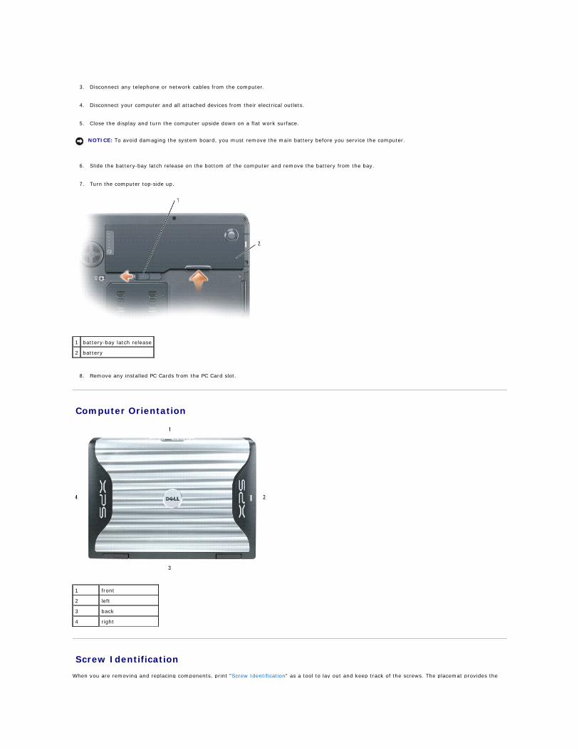
5. Close the display and turn the computer upside down on a flat work surface.
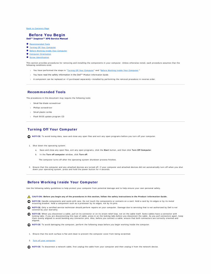
6. Slide the battery-bay latch release on the bottom of the computer and remove the battery from the bay.
7. Turn the computer top-side up.
8. Remove any installed PC Cards from the PC Card slot.
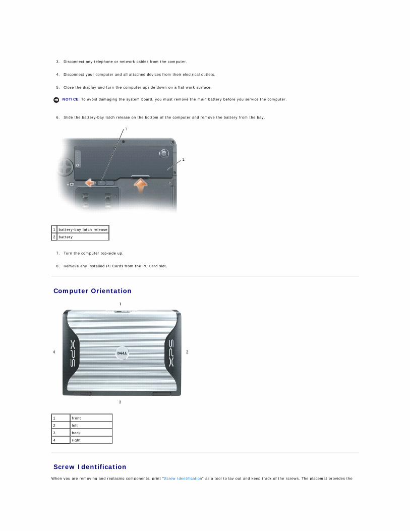
Computer Orientation
Screw Identification
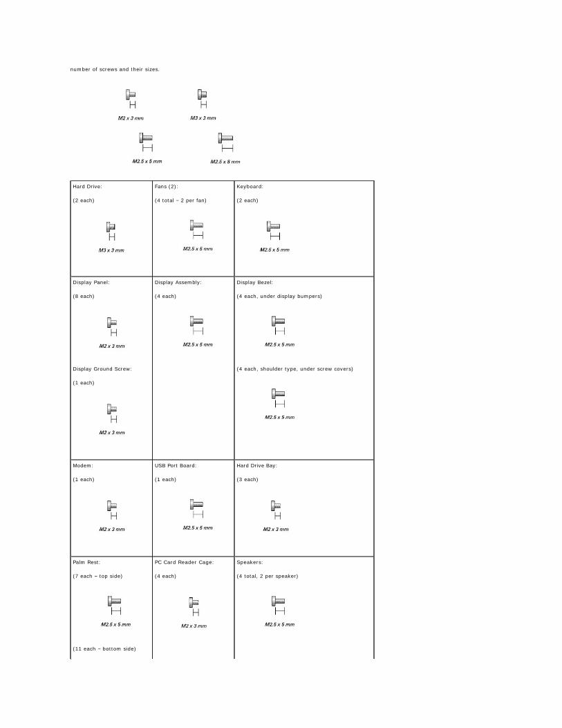
When you are removing and replacing components, print "Screw Identification" as a tool to lay out and keep track of the screws. The placemat provides the
NOTICE: To avoid damaging the system board, you must remove the main battery before you service the computer.
1 battery-bay latch release
2 battery
1 front
2 left
3 back
4 right

number of screws and their sizes.
Hard Drive:
(2 each)
Fans (2):
(4 total – 2 per fan)
Keyboard:
(2 each)
Display Panel:
(8 each)
Display Ground Screw:
(1 each)
Display Assembly:
(4 each)
Display Bezel:
(4 each, under display bumpers)
(4 each, shoulder type, under screw covers)
Modem:
(1 each)
USB Port Board:
(1 each)
Hard Drive Bay:
(3 each)
Palm Rest:
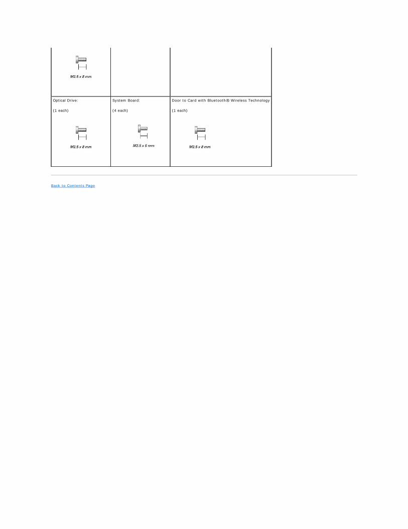
(7 each – top side)
(11 each – bottom side)
PC Card Reader Cage:
(4 each)
Speakers:
(4 total, 2 per speaker)
Back to Contents Page
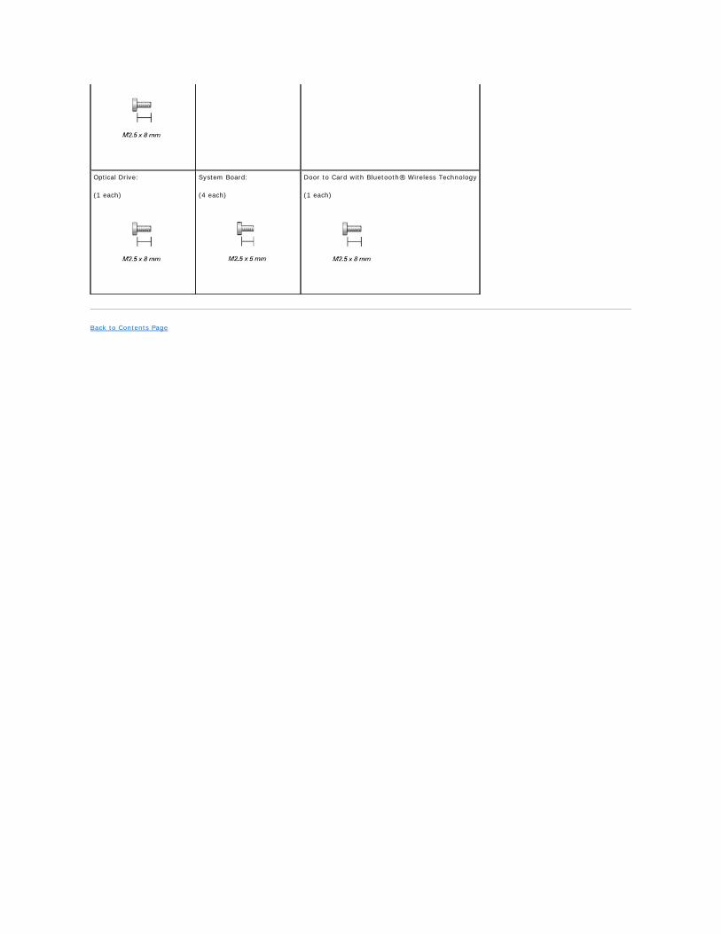
Optical Drive:
(1 each)
System Board:
(4 each)
Door to Card with Bluetooth® Wireless Technology
(1 each)

Back to Contents Page
Flashing the BIOS Dell™ Inspiron™ XPS Service Manual
1. Ensure that the AC adapter is plugged in and that the main battery is installed properly.
2. Insert the BIOS update program CD, and turn on the computer.
Follow the instructions that appear on the screen. The computer continues to boot and updates the new BIOS. When the flash update is complete, the computer will automatically reboot.
3. Press <F2> during POST to enter the system setup program.
4. Press <Alt> and <f> to reset the computer defaults.
5. Press <Esc>, select Save/Exit, and press <Enter> to save configuration changes.
6. Remove the flash BIOS update program CD from the drive and restart the computer.
Back to Contents Page
NOTICE: Plug the AC adapter into a known good power source to prevent a loss of power. Failure to do so may cause system damage.
NOTE: If you use a BIOS update program CD to flash the BIOS, set up the computer to boot from a CD before inserting the CD.
NOTICE: Do not interrupt this process once it begins. Doing so may cause system damage.
Back to Contents Page
Internal Card With Bluetooth® Wireless Technology Dell™ Inspiron™ XPS Service Manual
Removing the Card
Replacing the Card
Removing the Card
1. Follow the instructions in "Before Working Inside Your Computer."
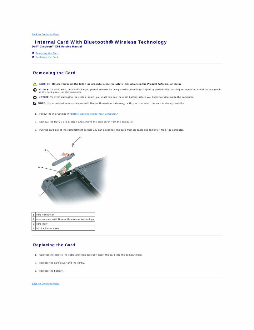
2. Remove the M2.5 x 8-mm screw and remove the card cover from the computer.
3. Pull the card out of the compartment so that you can disconnect the card from its cable and remove it from the computer.
Replacing the Card
1. Connect the card to the cable and then carefully insert the card into the compartment.
2. Replace the card cover and the screw.
3. Replace the battery.
Back to Contents Page
CAUTION: Before you begin the following procedure, see the safety instructions in the Product Information Guide.
NOTICE: To avoid electrostatic discharge, ground yourself by using a wrist grounding strap or by periodically touching an unpainted metal surface (such as the back panel) on the computer.
NOTICE: To avoid damaging the system board, you must remove the main battery before you begin working inside the computer.
NOTE: If you ordered an internal card with Bluetooth wireless technology with your computer, the card is already installed.
1 card connector
2 internal card with Bluetooth wireless technology
3 card door
4 M2.5 x 8-mm screw

Back to Contents Page
Coin-Cell Battery Dell™ Inspiron™ XPS Service Manual
Removing the Coin-Cell Battery
Replacing the Coin-Cell battery
Removing the Coin-Cell Battery
1. Follow the instructions in "Before Working Inside Your Computer."
2. Remove the center control cover.
3. Remove the keyboard.
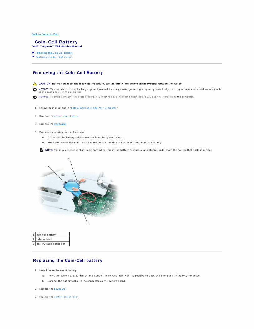
4. Remove the existing coin-cell battery:
a. Disconnect the battery cable connector from the system board.
b. Press the release latch on the side of the coin-cell battery compartment, and lift up the battery.
Replacing the Coin-Cell battery
1. Install the replacement battery:
a. Insert the battery at a 30-degree angle under the release latch with the positive side up, and then push the battery into place.
b. Connect the battery cable to the connector on the system board.
2. Replace the keyboard.
3. Replace the center control cover.
CAUTION: Before you begin the following procedure, see the safety instructions in the Product Information Guide.
NOTICE: To avoid electrostatic discharge, ground yourself by using a wrist grounding strap or by periodically touching an unpainted metal surface (such as the back panel) on the computer.
NOTICE: To avoid damaging the system board, you must remove the main battery before you begin working inside the computer.
NOTE: You may experience slight resistance when you lift the battery because of an adhesive underneath the battery that holds it in place.
1 coin-cell battery
2 release latch
3 battery cable connector


Back to Contents Page
Microprocessor Module Dell™ Inspiron™ XPS Service Manual
Removing the Microprocessor Module
Replacing the Microprocessor Module
Removing the Microprocessor Module
1. Follow the instructions in "Before Working Inside Your Computer."
2. Remove the center control cover.
3. Remove the keyboard.
4. Remove the display assembly.
5. Remove the palm rest.
6. Remove the microprocessor thermal-cooling assembly.
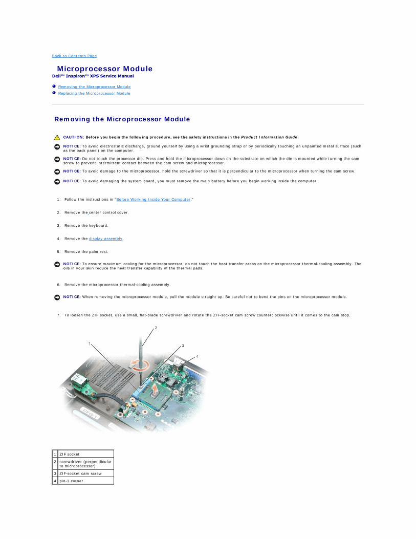
7. To loosen the ZIF socket, use a small, flat-blade screwdriver and rotate the ZIF-socket cam screw counterclockwise until it comes to the cam stop.
CAUTION: Before you begin the following procedure, see the safety instructions in the Product Information Guide.
NOTICE: To avoid electrostatic discharge, ground yourself by using a wrist grounding strap or by periodically touching an unpainted metal surface (such as the back panel) on the computer.
NOTICE: Do not touch the processor die. Press and hold the microprocessor down on the substrate on which the die is mounted while turning the cam screw to prevent intermittent contact between the cam screw and microprocessor.
NOTICE: To avoid damage to the microprocessor, hold the screwdriver so that it is perpendicular to the microprocessor when turning the cam screw.
NOTICE: To avoid damaging the system board, you must remove the main battery before you begin working inside the computer.
NOTICE: To ensure maximum cooling for the microprocessor, do not touch the heat transfer areas on the microprocessor thermal-cooling assembly. The oils in your skin reduce the heat transfer capability of the thermal pads.
NOTICE: When removing the microprocessor module, pull the module straight up. Be careful not to bend the pins on the microprocessor module.
1 ZIF socket
2 screwdriver (perpendicular to microprocessor)
3 ZIF-socket cam screw
4 pin-1 corner

8. Lift the microprocessor module from the ZIF socket.
Replacing the Microprocessor Module
1. Align the pin-1 corner of the microprocessor module with the pin-1 corner of the ZIF socket, and insert the microprocessor module.
When the microprocessor module is correctly seated, all four corners are aligned at the same height. If one or more corners of the module are higher than the others, the module is not seated correctly.
2. Tighten the ZIF socket by turning the cam screw clockwise to secure the microprocessor module to the system board.
3. Perform the steps in "Removing the Microprocessor Module" in reverse order, beginning with step 6.
Back to Contents Page
NOTE: The ZIF-socket cam screw secures the microprocessor to the system board. Take note of the arrow on the ZIF-socket cam screw, which indicates the direction to turn the cam screw.
NOTICE: Ensure that the cam lock is in the fully open position before seating the microprocessor module. Seating the microprocessor module properly in the ZIF socket does not require force.
NOTICE: A microprocessor module that is not properly seated can result in an intermittent connection or permanent damage to the microprocessor and ZIF socket.
NOTE: The pin-1 corner of the microprocessor module has a triangle that aligns with the triangle on the pin-1 corner of the ZIF socket.
NOTICE: You must position the microprocessor module correctly in the ZIF socket to avoid permanent damage to the module and the socket.

Back to Contents Page
Display Dell™ Inspiron™ XPS Service Manual
Display Assembly
Display Bezel
Display Panel
Display Latch
Display Assembly
Removing the Display Assembly
1. Follow the instructions in "Before Working Inside Your Computer."
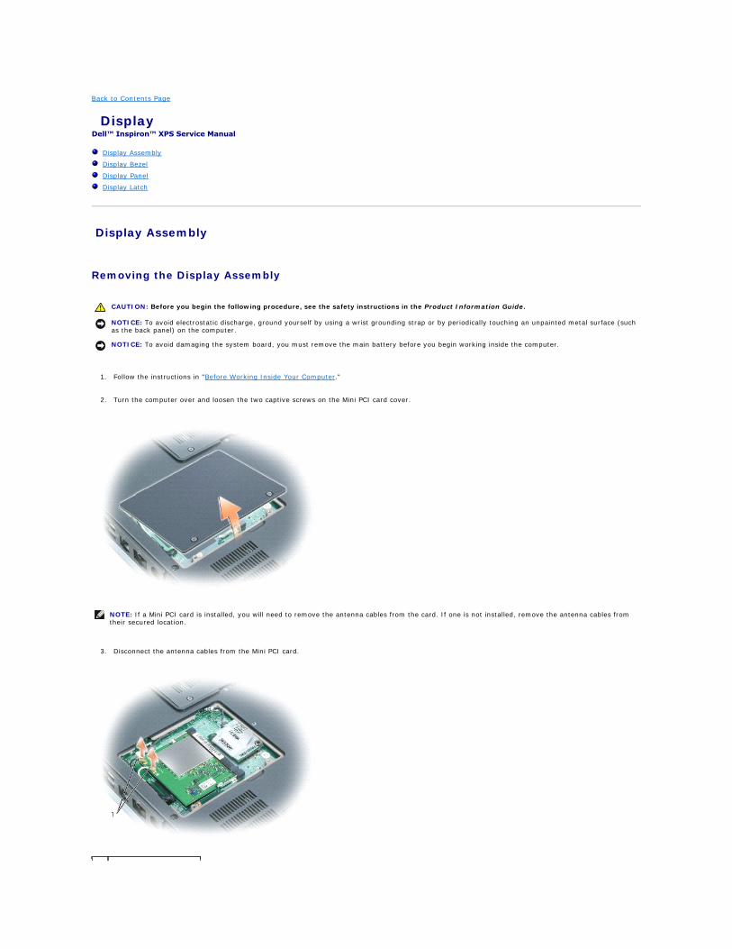
2. Turn the computer over and loosen the two captive screws on the Mini PCI card cover.
3. Disconnect the antenna cables from the Mini PCI card.
CAUTION: Before you begin the following procedure, see the safety instructions in the Product Information Guide.
NOTICE: To avoid electrostatic discharge, ground yourself by using a wrist grounding strap or by periodically touching an unpainted metal surface (such as the back panel) on the computer.
NOTICE: To avoid damaging the system board, you must remove the main battery before you begin working inside the computer.
NOTE: If a Mini PCI card is installed, you will need to remove the antenna cables from the card. If one is not installed, remove the antenna cables from their secured location.

4. Turn the computer top-side up.
5. Remove the center control cover.
6. Open the display all the way (180 degrees) so that it lies flat against the work surface.
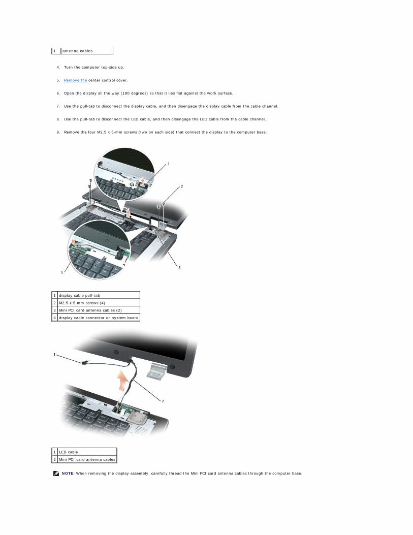
7. Use the pull-tab to disconnect the display cable, and then disengage the display cable from the cable channel.
8. Use the pull-tab to disconnect the LED cable, and then disengage the LED cable from the cable channel.
9. Remove the four M2.5 x 5-mm screws (two on each side) that connect the display to the computer base.
1 antenna cables
1 display cable pull-tab
2 M2.5 x 5-mm screws (4)
3 Mini PCI card antenna cables (2)
4 display cable connector on system board
1 LED cable
2 Mini PCI card antenna cables
NOTE: When removing the display assembly, carefully thread the Mini PCI card antenna cables through the computer base.
10. Lift the display assembly away from the computer.
Replacing the Display Assembly
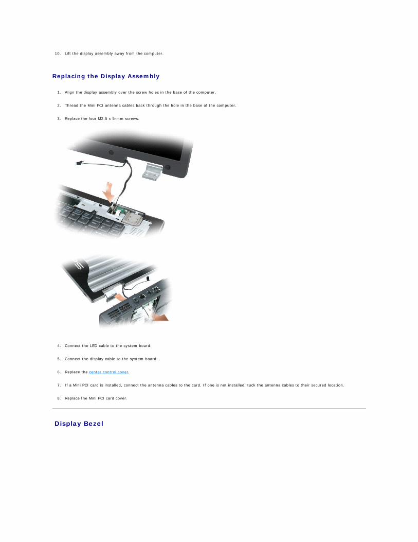
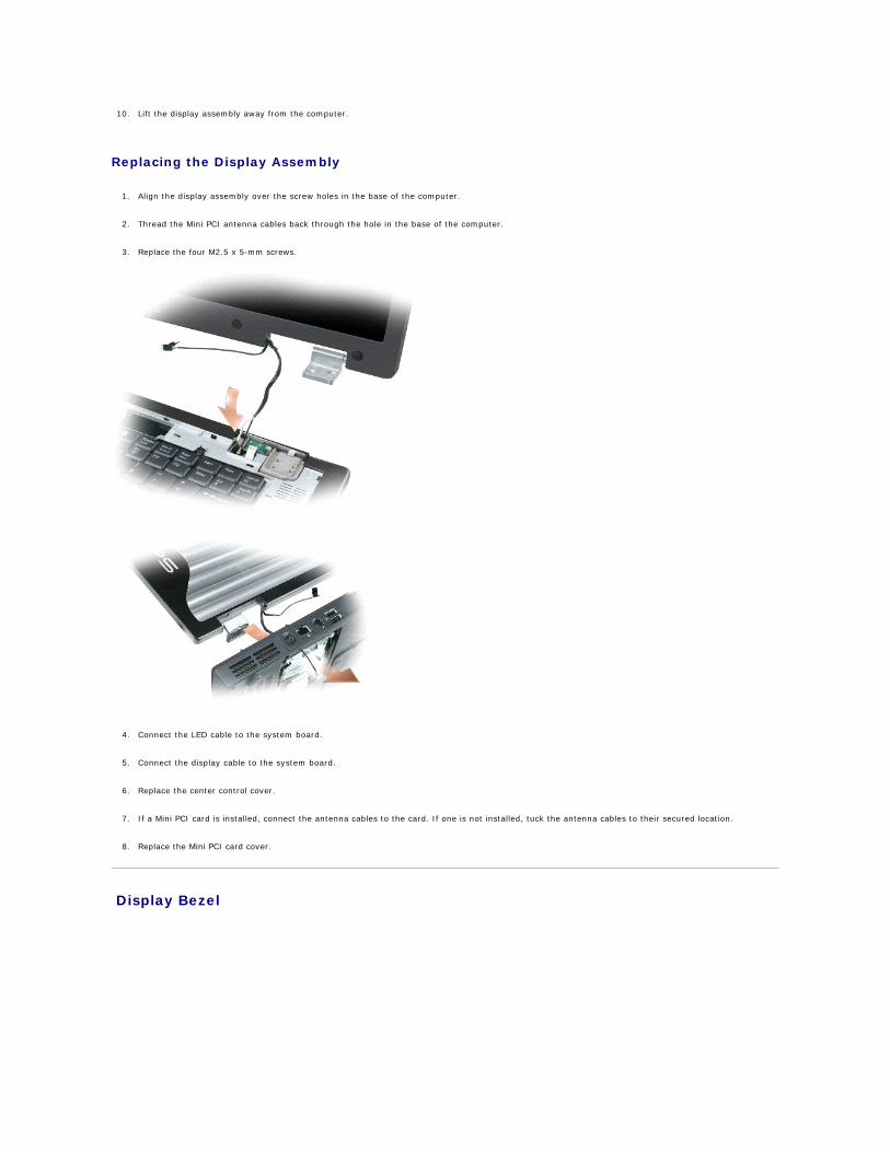
1. Align the display assembly over the screw holes in the base of the computer.
2. Thread the Mini PCI antenna cables back through the hole in the base of the computer.
3. Replace the four M2.5 x 5-mm screws.
4. Connect the LED cable to the system board.
5. Connect the display cable to the system board.
6. Replace the center control cover.
7. If a Mini PCI card is installed, connect the antenna cables to the card. If one is not installed, tuck the antenna cables to their secured location.
8. Replace the Mini PCI card cover.
Display Bezel

Removing the Display Bezel
1. Follow the instructions in "Before Working Inside Your Computer."
2. Remove the display assembly.
3. Remove the six screw-cover/rubber display bumpers.
4. Remove the two screw covers and the four shoulder screws.
5. Remove the four M2.5 x 5-mm screws at the corners of the display.
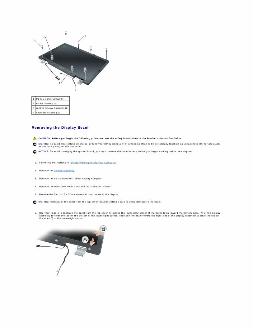
6. Use your fingers to separate the bezel from the top cover by pulling the lower-right corner of the bezel down toward the bottom edge (A) of the display
assembly to clear the tab on the bottom of the lower-right corner. Then pull the bezel toward the right side of the display assembly to clear the tab on the side (B) of the lower-right corner.
1 M2.5 x 5-mm screws (4)
2 screw covers (2)
3 rubber display bumpers (6)
4 shoulder screws (2)
CAUTION: Before you begin the following procedure, see the safety instructions in the Product Information Guide.
NOTICE: To avoid electrostatic discharge, ground yourself by using a wrist grounding strap or by periodically touching an unpainted metal surface (such as the back panel) on the computer.
NOTICE: To avoid damaging the system board, you must remove the main battery before you begin working inside the computer.
NOTICE: Removal of the bezel from the top cover requires extreme care to avoid damage to the bezel.

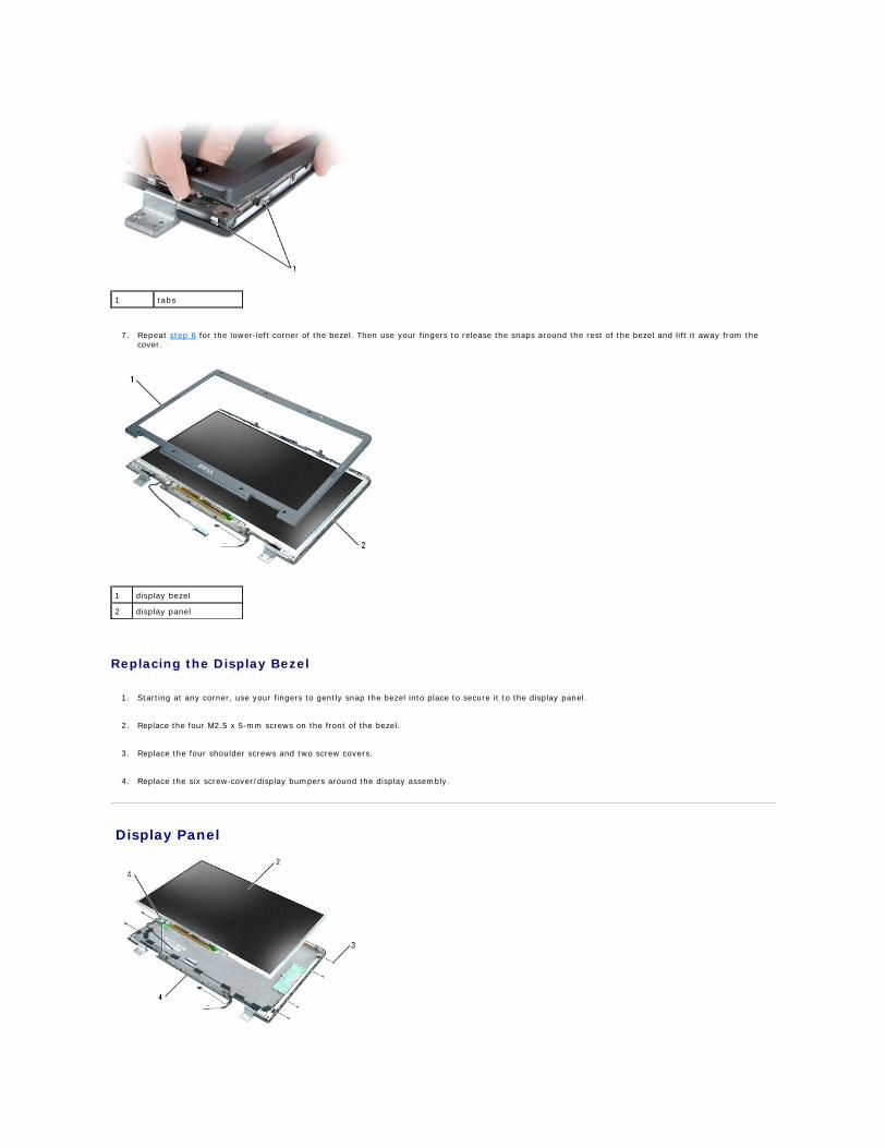
7. Repeat step 6 for the lower-left corner of the bezel. Then use your fingers to release the snaps around the rest of the bezel and lift it away from the
cover.
Replacing the Display Bezel
1. Starting at any corner, use your fingers to gently snap the bezel into place to secure it to the display panel.
2. Replace the four M2.5 x 5-mm screws on the front of the bezel.
3. Replace the four shoulder screws and two screw covers.
4. Replace the six screw-cover/display bumpers around the display assembly.
Display Panel
1 tabs
1 display bezel
2 display panel
Removing the Display Panel
1. Follow the instructions in "Before Working Inside Your Computer."
2. Remove the display assembly.
3. Remove the display bezel.
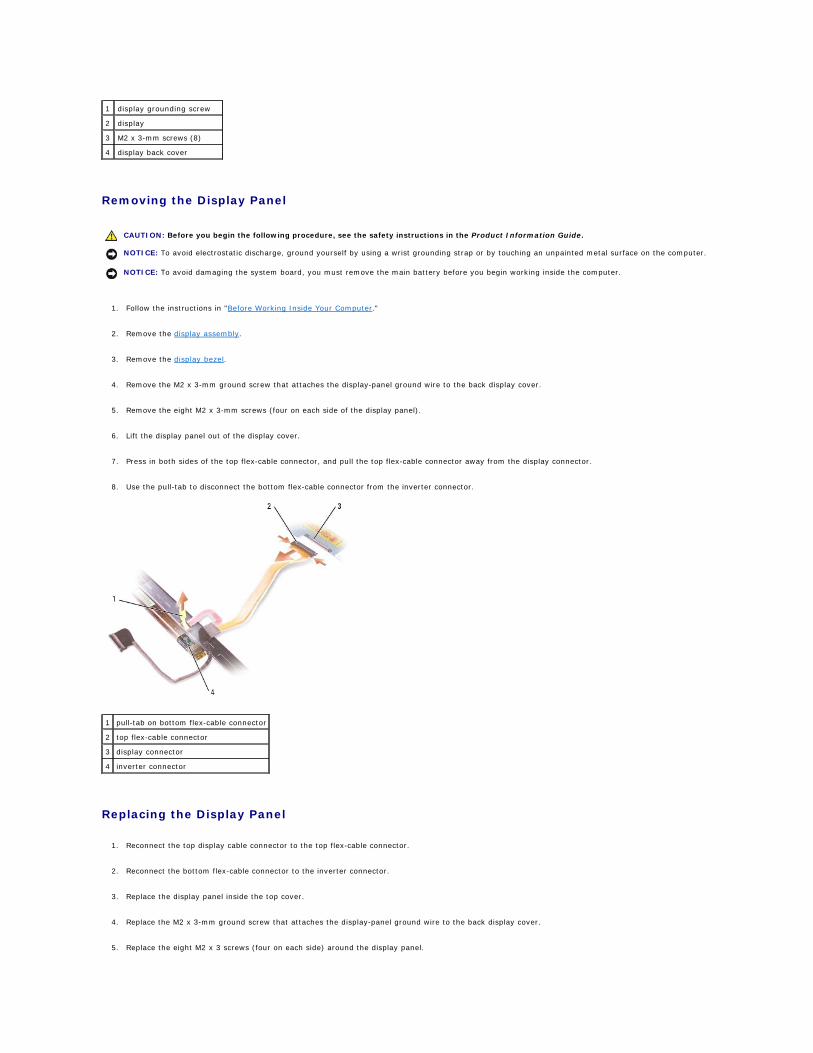
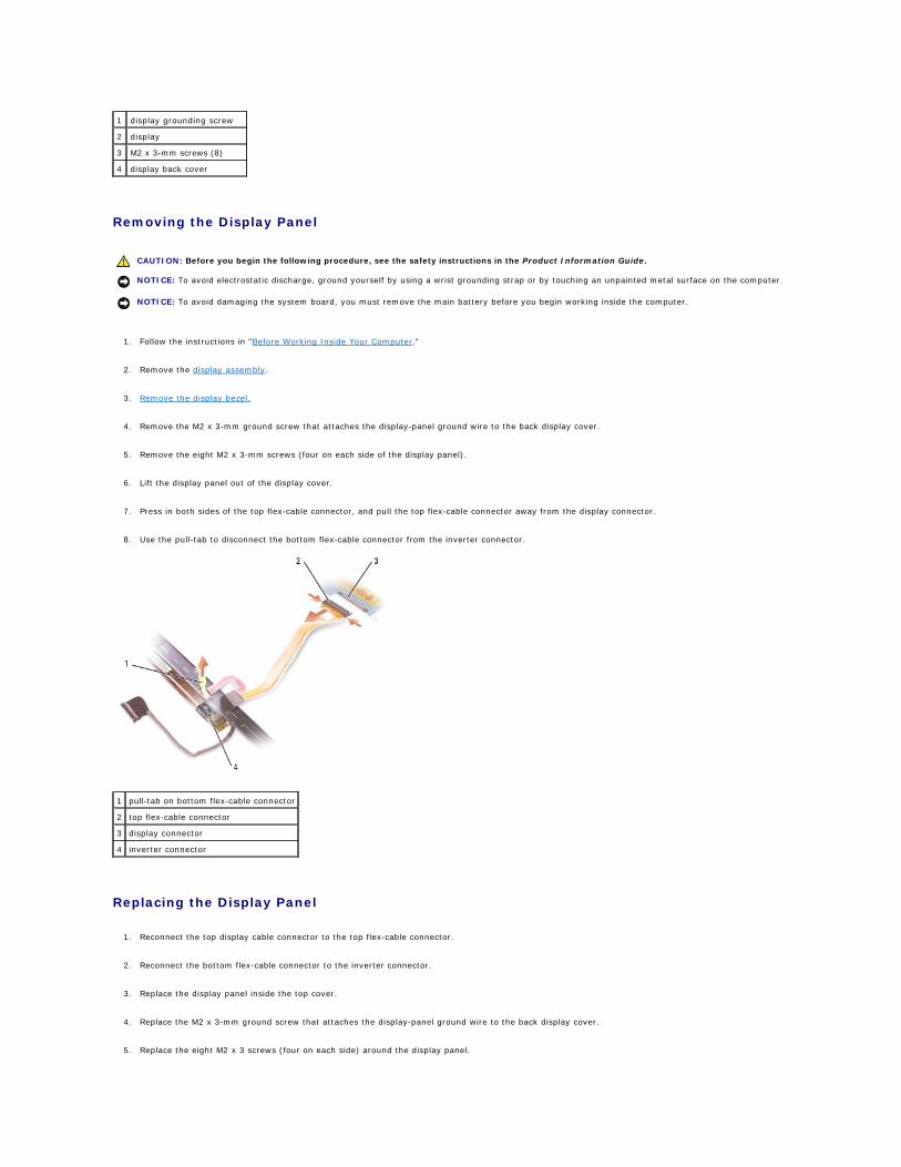
4. Remove the M2 x 3-mm ground screw that attaches the display-panel ground wire to the back display cover.
5. Remove the eight M2 x 3-mm screws (four on each side of the display panel).
6. Lift the display panel out of the display cover.
7. Press in both sides of the top flex-cable connector, and pull the top flex-cable connector away from the display connector.
8. Use the pull-tab to disconnect the bottom flex-cable connector from the inverter connector.
Replacing the Display Panel
1. Reconnect the top display cable connector to the top flex-cable connector.
2. Reconnect the bottom flex-cable connector to the inverter connector.
3. Replace the display panel inside the top cover.
4. Replace the M2 x 3-mm ground screw that attaches the display-panel ground wire to the back display cover.
5. Replace the eight M2 x 3 screws (four on each side) around the display panel.
1 display grounding screw
2 display
3 M2 x 3-mm screws (8)
4 display back cover
CAUTION: Before you begin the following procedure, see the safety instructions in the Product Information Guide.
NOTICE: To avoid electrostatic discharge, ground yourself by using a wrist grounding strap or by touching an unpainted metal surface on the computer.
NOTICE: To avoid damaging the system board, you must remove the main battery before you begin working inside the computer.
1 pull-tab on bottom flex-cable connector
2 top flex-cable connector
3 display connector
4 inverter connector
6. Replace the display bezel.
Display Latch
Removing the Display Latch
1. Follow the instructions in "Before Working Inside Your Computer."
2. Remove the display.
3. Remove the display bezel.
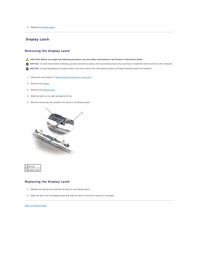
4. Slide the latch to the right and gently lift up.
5. Remove the spring that attaches the latch to the display panel.
Replacing the Display Latch
1. Replace the spring that attaches the latch to the display panel.
2. Align the latch with the display panel and slide the latch to the left to secure it into place.
Back to Contents Page
CAUTION: Before you begin the following procedure, see the safety instructions in the Product Information Guide.
NOTICE: To avoid electrostatic discharge, ground yourself by using a wrist grounding strap or by touching an unpainted metal surface on the computer.
NOTICE: To avoid damaging the system board, you must remove the main battery before you begin working inside the computer.
1 spring
2 display latch
Back to Contents Page
System Fans Dell™ Inspiron™ XPS Service Manual
Removing the System Fans
Replacing the System Fans
Removing the System Fans
1. Follow the instructions in "Before Working Inside Your Computer."
2. Remove the center control cover.
3. Remove the keyboard.
4. Remove the display assembly.
5. Remove the palm rest.
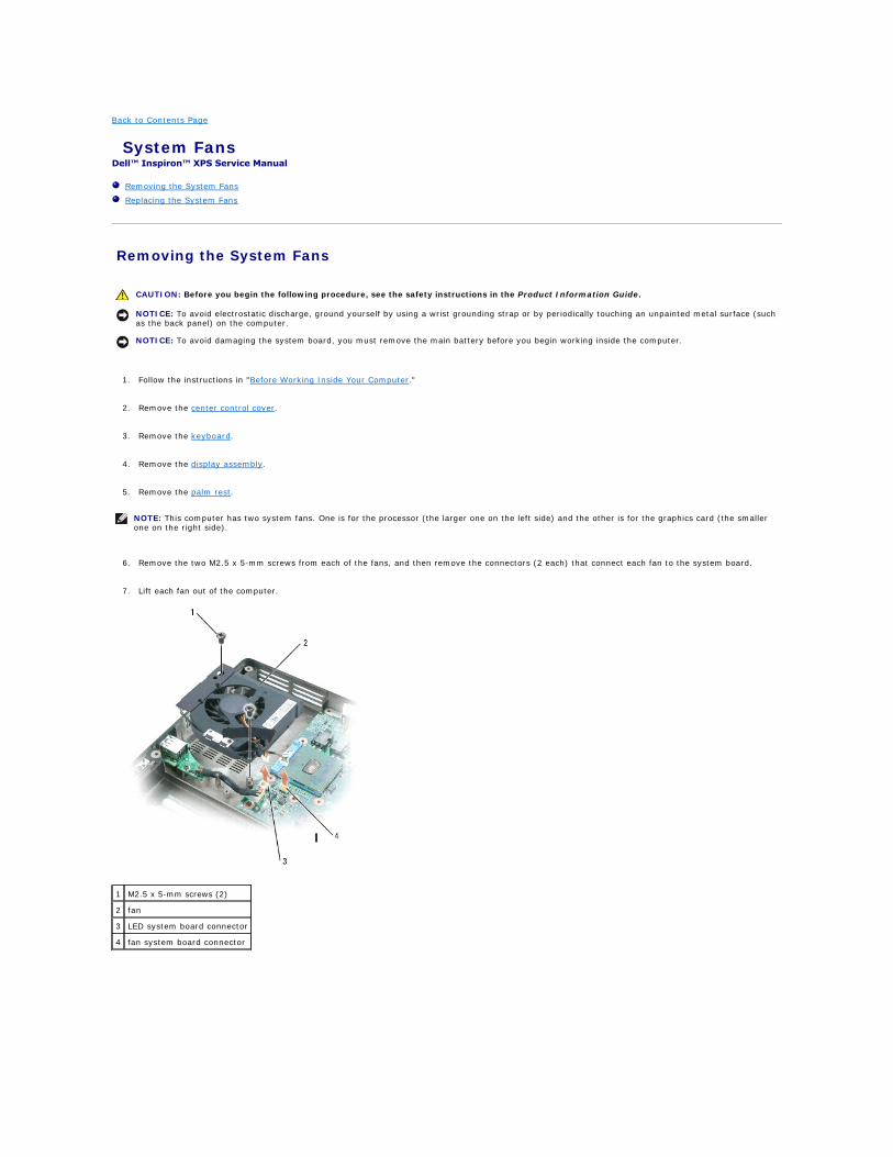
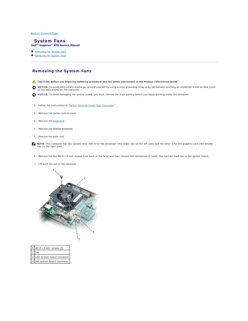
6. Remove the two M2.5 x 5-mm screws from each of the fans, and then remove the connectors (2 each) that connect each fan to the system board.
7. Lift each fan out of the computer.
CAUTION: Before you begin the following procedure, see the safety instructions in the Product Information Guide.
NOTICE: To avoid electrostatic discharge, ground yourself by using a wrist grounding strap or by periodically touching an unpainted metal surface (such as the back panel) on the computer.
NOTICE: To avoid damaging the system board, you must remove the main battery before you begin working inside the computer.
NOTE: This computer has two system fans. One is for the processor (the larger one on the left side) and the other is for the graphics card (the smaller one on the right side).
1 M2.5 x 5-mm screws (2)
2 fan
3 LED system board connector
4 fan system board connector

Replacing the System Fans
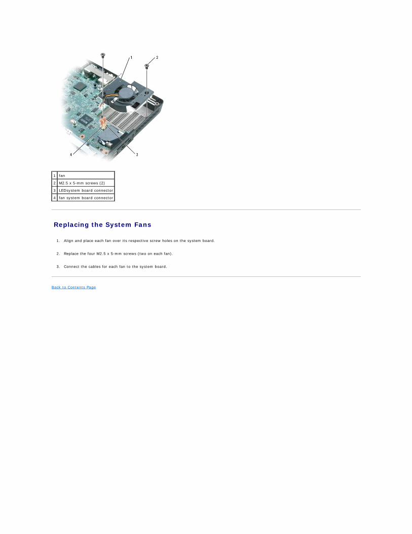
1. Align and place each fan over its respective screw holes on the system board.
2. Replace the four M2.5 x 5-mm screws (two on each fan).
3. Connect the cables for each fan to the system board.
Back to Contents Page
1 fan
2 M2.5 x 5-mm screws (2)
3 LED system board connector
4 fan system board connector
Back to Contents Page
Battery Latch Assembly Dell™ Inspiron™ XPS Service Manual
Removing the Battery Latch Assembly
Replacing the Battery Latch Assembly
Removing the Battery Latch Assembly
1. Follow the instructions in "Before Working Inside Your Computer."
2. Remove the center control cover.
3. Remove the keyboard.
4. Remove the display assembly.
5. Remove the palm rest.
6. Remove the system board.
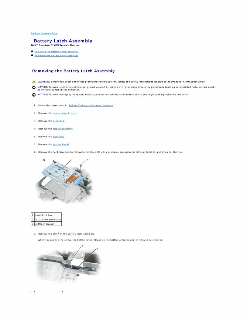
7. Remove the hard drive bay by removing the three M2 x 3-mm screws, removing the stiffener bracket, and lifting out the bay.
8. Remove the screw in the battery latch assembly.
When you remove the screw, the battery latch release on the bottom of the computer will also be removed.
CAUTION: Before you begin any of the procedures in this section, follow the safety instructions located in the Product Information Guide.
NOTICE: To avoid electrostatic discharge, ground yourself by using a wrist grounding strap or by periodically touching an unpainted metal surface (such as the back panel) on the computer.
NOTICE: To avoid damaging the system board, you must remove the main battery before you begin working inside the computer.
1 hard drive bay
2 M2 x 3-mm screws (3)
3 stiffener bracket
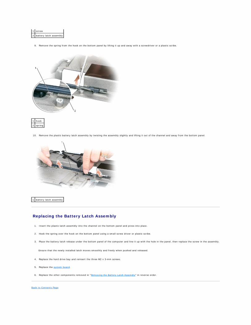
9. Remove the spring from the hook on the bottom panel by lifting it up and away with a screwdriver or a plastic scribe.
10. Remove the plastic battery latch assembly by twisting the assembly slightly and lifting it out of the channel and away from the bottom panel.
Replacing the Battery Latch Assembly
1. Insert the plastic latch assembly into the channel on the bottom panel and press into place.
2. Hook the spring over the hook on the bottom panel using a small screw driver or plastic scribe.
3. Place the battery latch release under the bottom panel of the computer and line it up with the hole in the panel, then replace the screw in the assembly.
Ensure that the newly installed latch moves smoothly and freely when pushed and released.
4. Replace the hard drive bay and reinsert the three M2 x 3-mm screws.
5. Replace the system board.
6. Replace the other components removed in "Removing the Battery Latch Assembly" in reverse order.
Back to Contents Page
1 screw
2 battery latch assembly
1 hook
2 spring
1 battery latch assembly


Back to Contents Page
Before You Begin Dell™ Inspiron™ XPS Service Manual
Recommended Tools
Turning Off Your Computer
Before Working Inside Your Computer
Computer Orientation
Screw Identification
This section provides procedures for removing and installing the components in your computer. Unless otherwise noted, each procedure assumes that the following conditions exist:
l You have performed the steps in "Turning Off Your Computer" and "Before Working Inside Your Computer."
l You have read the safety information in the Dell™ Product Information Guide.
l A component can be replaced or—if purchased separately—installed by performing the removal procedure in reverse order.
Recommended Tools
The procedures in this document may require the following tools:
l Small flat-blade screwdriver
l Phillips screwdriver
l Small plastic scribe
l Flash BIOS update program CD
Turning Off Your Computer
1. Shut down the operating system:
a. Save and close any open files, exit any open programs, click the Start button, and then click Turn Off Computer.
b. In the Turn off computer window, click Turn off.
The computer turns off after the operating system shutdown process finishes.
2. Ensure that the computer and any attached devices are turned off. If your computer and attached devices did not automatically turn off when you shut
down your operating system, press and hold the power button for 4 seconds.
Before Working Inside Your Computer
Use the following safety guidelines to help protect your computer from potential damage and to help ensure your own personal safety.
1. Ensure that the work surface is flat and clean to prevent the computer cover from being scratched.
2. Turn off your computer.
NOTICE: To avoid losing data, save and close any open files and exit any open programs before you turn off your computer.
CAUTION: Before you begin any of the procedures in this section, follow the safety instructions in the Product Information Guide.
NOTICE: Handle components and cards with care. Do not touch the components or contacts on a card. Hold a card by its edges or by its metal mounting bracket. Hold a component such as a processor by its edges, not by its pins.
NOTICE: Only a certified service technician should perform repairs on your computer. Damage due to servicing that is not authorized by Dell is not covered by your warranty.
NOTICE: When you disconnect a cable, pull on its connector or on its strain-relief loop, not on the cable itself. Some cables have a connector with locking tabs; if you are disconnecting this type of cable, press in on the locking tabs before you disconnect the cable. As you pull connectors apart, keep them evenly aligned to avoid bending any connector pins. Also, before you connect a cable, ensure that both connectors are correctly oriented and aligned.
NOTICE: To avoid damaging the computer, perform the following steps before you begin working inside the computer.
NOTICE: To disconnect a network cable, first unplug the cable from your computer and then unplug it from the network device.
3. Disconnect any telephone or network cables from the computer.
4. Disconnect your computer and all attached devices from their electrical outlets.
5. Close the display and turn the computer upside down on a flat work surface.
6. Slide the battery-bay latch release on the bottom of the computer and remove the battery from the bay.
7. Turn the computer top-side up.
8. Remove any installed PC Cards from the PC Card slot.
Computer Orientation
Screw Identification
When you are removing and replacing components, print "Screw Identification" as a tool to lay out and keep track of the screws. The placemat provides the
NOTICE: To avoid damaging the system board, you must remove the main battery before you service the computer.
1 battery-bay latch release
2 battery
1 front
2 left
3 back
4 right
number of screws and their sizes.
Hard Drive:
(2 each)
Fans (2):
(4 total – 2 per fan)
Keyboard:
(2 each)
Display Panel:
(8 each)
Display Ground Screw:
(1 each)
Display Assembly:
(4 each)
Display Bezel:
(4 each, under display bumpers)
(4 each, shoulder type, under screw covers)
Modem:
(1 each)
USB Port Board:
(1 each)
Hard Drive Bay:
(3 each)
Palm Rest:
(7 each – top side)
(11 each – bottom side)
PC Card Reader Cage:
(4 each)
Speakers:
(4 total, 2 per speaker)
Back to Contents Page
Optical Drive:
(1 each)
System Board:
(4 each)
Door to Card with Bluetooth® Wireless Technology
(1 each)
Back to Contents Page
Flashing the BIOS Dell™ Inspiron™ XPS Service Manual
1. Ensure that the AC adapter is plugged in and that the main battery is installed properly.
2. Insert the BIOS update program CD, and turn on the computer.
Follow the instructions that appear on the screen. The computer continues to boot and updates the new BIOS. When the flash update is complete, the computer will automatically reboot.
3. Press <F2> during POST to enter the system setup program.
4. Press <Alt> and <f> to reset the computer defaults.
5. Press <Esc>, select Save/Exit, and press <Enter> to save configuration changes.
6. Remove the flash BIOS update program CD from the drive and restart the computer.
Back to Contents Page
NOTICE: Plug the AC adapter into a known good power source to prevent a loss of power. Failure to do so may cause system damage.
NOTE: If you use a BIOS update program CD to flash the BIOS, set up the computer to boot from a CD before inserting the CD.
NOTICE: Do not interrupt this process once it begins. Doing so may cause system damage.

Back to Contents Page
Internal Card With Bluetooth® Wireless Technology Dell™ Inspiron™ XPS Service Manual
Removing the Card
Replacing the Card
Removing the Card
1. Follow the instructions in "Before Working Inside Your Computer."
2. Remove the M2.5 x 8-mm screw and remove the card cover from the computer.
3. Pull the card out of the compartment so that you can disconnect the card from its cable and remove it from the computer.
Replacing the Card
1. Connect the card to the cable and then carefully insert the card into the compartment.
2. Replace the card cover and the screw.
3. Replace the battery.
Back to Contents Page
CAUTION: Before you begin the following procedure, see the safety instructions in the Product Information Guide.
NOTICE: To avoid electrostatic discharge, ground yourself by using a wrist grounding strap or by periodically touching an unpainted metal surface (such as the back panel) on the computer.
NOTICE: To avoid damaging the system board, you must remove the main battery before you begin working inside the computer.
NOTE: If you ordered an internal card with Bluetooth wireless technology with your computer, the card is already installed.
1 card connector
2 internal card with Bluetooth wireless technology
3 card door
3 M2.5 x 8-mm screw
Back to Contents Page
Coin-Cell Battery Dell™ Inspiron™ XPS Service Manual
Removing the Coin-Cell Battery
Replacing the Coin-Cell battery
Removing the Coin-Cell Battery
1. Follow the instructions in "Before Working Inside Your Computer."
2. Remove the center control cover.
3. Remove the keyboard.
4. Remove the existing coin-cell battery:
a. Disconnect the battery cable connector from the system board.
b. Press the release latch on the side of the coin-cell battery compartment, and lift up the battery.
Replacing the Coin-Cell battery
1. Install the replacement battery:
a. Insert the battery at a 30-degree angle under the release latch with the positive side up, and then push the battery into place.
b. Connect the battery cable to the connector on the system board.
2. Replace the keyboard.
3. Replace the center control cover.
CAUTION: Before you begin the following procedure, see the safety instructions in the Product Information Guide.
NOTICE: To avoid electrostatic discharge, ground yourself by using a wrist grounding strap or by periodically touching an unpainted metal surface (such as the back panel) on the computer.
NOTICE: To avoid damaging the system board, you must remove the main battery before you begin working inside the computer.
NOTE: You may experience slight resistance when you lift the battery because of an adhesive underneath the battery that holds it in place.
1 coin-cell battery
2 release latch
3 battery cable connector

Back to Contents Page
Microprocessor Module Dell™ Inspiron™ XPS Service Manual
Removing the Microprocessor Module
Replacing the Microprocessor Module
Removing the Microprocessor Module
1. Follow the instructions in "Before Working Inside Your Computer."
2. Remove the center control cover.
3. Remove the keyboard.
4. Remove the display assembly.
5. Remove the palm rest.
6. Remove the microprocessor thermal-cooling assembly.
7. To loosen the ZIF socket, use a small, flat-blade screwdriver and rotate the ZIF-socket cam screw counterclockwise until it comes to the cam stop.
CAUTION: Before you begin the following procedure, see the safety instructions in the Product Information Guide.
NOTICE: To avoid electrostatic discharge, ground yourself by using a wrist grounding strap or by periodically touching an unpainted metal surface (such as the back panel) on the computer.
NOTICE: Do not touch the processor die. Press and hold the microprocessor down on the substrate on which the die is mounted while turning the cam screw to prevent intermittent contact between the cam screw and microprocessor.
NOTICE: To avoid damage to the microprocessor, hold the screwdriver so that it is perpendicular to the microprocessor when turning the cam screw.
NOTICE: To avoid damaging the system board, you must remove the main battery before you begin working inside the computer.
NOTICE: To ensure maximum cooling for the microprocessor, do not touch the heat transfer areas on the microprocessor thermal-cooling assembly. The oils in your skin reduce the heat transfer capability of the thermal pads.
NOTICE: When removing the microprocessor module, pull the module straight up. Be careful not to bend the pins on the microprocessor module.
1 ZIF socket
2 screwdriver (perpendicular to microprocessor)
3 ZIF-socket cam screw
4 pin-1 corner

8. Lift the microprocessor module from the ZIF socket.
Replacing the Microprocessor Module
1. Align the pin-1 corner of the microprocessor module with the pin-1 corner of the ZIF socket, and insert the microprocessor module.
When the microprocessor module is correctly seated, all four corners are aligned at the same height. If one or more corners of the module are higher than the others, the module is not seated correctly.
2. Tighten the ZIF socket by turning the cam screw clockwise to secure the microprocessor module to the system board.
3. Perform the steps in "Removing the Microprocessor Module" in reverse order, beginning with step 6.
Back to Contents Page
NOTE: The ZIF-socket cam screw secures the microprocessor to the system board. Take note of the arrow on the ZIF-socket cam screw, which indicates the direction to turn the cam screw.
NOTICE: Ensure that the cam lock is in the fully open position before seating the microprocessor module. Seating the microprocessor module properly in the ZIF socket does not require force.
NOTICE: A microprocessor module that is not properly seated can result in an intermittent connection or permanent damage to the microprocessor and ZIF socket.
NOTE: The pin-1 corner of the microprocessor module has a triangle that aligns with the triangle on the pin-1 corner of the ZIF socket.
NOTICE: You must position the microprocessor module correctly in the ZIF socket to avoid permanent damage to the module and the socket.
Back to Contents Page
Display Dell™ Inspiron™ XPS Service Manual
Display Assembly
Display Bezel
Display Panel
Display Latch
Display Assembly
Removing the Display Assembly
1. Follow the instructions in "Before Working Inside Your Computer."
2. Turn the computer over and loosen the two captive screws on the Mini PCI card cover.
3. Disconnect the antenna cables from the Mini PCI card.
CAUTION: Before you begin the following procedure, see the safety instructions in the Product Information Guide.
NOTICE: To avoid electrostatic discharge, ground yourself by using a wrist grounding strap or by periodically touching an unpainted metal surface (such as the back panel) on the computer.
NOTICE: To avoid damaging the system board, you must remove the main battery before you begin working inside the computer.
NOTE: If a Mini PCI card is installed, you will need to remove the antenna cables from the card. If one is not installed, remove the antenna cables from their secured location.
4. Turn the computer top-side up.
5. Remove the center control cover.
6. Open the display all the way (180 degrees) so that it lies flat against the work surface.
7. Use the pull-tab to disconnect the display cable, and then disengage the display cable from the cable channel.
8. Use the pull-tab to disconnect the LED cable, and then disengage the LED cable from the cable channel.
9. Remove the four M2.5 x 5-mm screws (two on each side) that connect the display to the computer base.
1 antenna cables
1 display cable pull-tab
2 M2.5 x 5-mm screws (4)
3 Mini PCI card antenna cables (2)
4 display cable connector on system board
1 LED cable
2 Mini PCI card antenna cables
NOTE: When removing the display assembly, carefully thread the Mini PCI card antenna cables through the computer base.
10. Lift the display assembly away from the computer.
Replacing the Display Assembly
1. Align the display assembly over the screw holes in the base of the computer.
2. Thread the Mini PCI antenna cables back through the hole in the base of the computer.
3. Replace the four M2.5 x 5-mm screws.
4. Connect the LED cable to the system board.
5. Connect the display cable to the system board.
6. Replace the center control cover.
7. If a Mini PCI card is installed, connect the antenna cables to the card. If one is not installed, tuck the antenna cables to their secured location.
8. Replace the Mini PCI card cover.
Display Bezel
Removing the Display Bezel
1. Follow the instructions in "Before Working Inside Your Computer."
2. Remove the display assembly.
3. Remove the six screw-cover/rubber display bumpers.
4. Remove the two screw covers and the four shoulder screws.
5. Remove the four M2.5 x 5-mm screws at the corners of the display.
6. Use your fingers to separate the bezel from the top cover by pulling the lower-right corner of the bezel down toward the bottom edge (A) of the display
assembly to clear the tab on the bottom of the lower-right corner. Then pull the bezel toward the right side of the display assembly to clear the tab on the side (B) of the lower-right corner.
1 M2.5 x 5-mm screws (4)
2 screw covers (2)
3 rubber display bumpers (6)
4 shoulder screws (2)
CAUTION: Before you begin the following procedure, see the safety instructions in the Product Information Guide.
NOTICE: To avoid electrostatic discharge, ground yourself by using a wrist grounding strap or by periodically touching an unpainted metal surface (such as the back panel) on the computer.
NOTICE: To avoid damaging the system board, you must remove the main battery before you begin working inside the computer.
NOTICE: Removal of the bezel from the top cover requires extreme care to avoid damage to the bezel.
7. Repeat step 6 for the lower-left corner of the bezel. Then use your fingers to release the snaps around the rest of the bezel and lift it away from the
cover.
Replacing the Display Bezel
1. Starting at any corner, use your fingers to gently snap the bezel into place to secure it to the display panel.
2. Replace the four M2.5 x 5-mm screws on the front of the bezel.
3. Replace the four shoulder screws and two screw covers.
4. Replace the six screw-cover/display bumpers around the display assembly.
Display Panel
1 tabs
1 display bezel
2 display panel
Removing the Display Panel
1. Follow the instructions in "Before Working Inside Your Computer."
2. Remove the display assembly.
3. Remove the display bezel.
4. Remove the M2 x 3-mm ground screw that attaches the display-panel ground wire to the back display cover.
5. Remove the eight M2 x 3-mm screws (four on each side of the display panel).
6. Lift the display panel out of the display cover.
7. Press in both sides of the top flex-cable connector, and pull the top flex-cable connector away from the display connector.
8. Use the pull-tab to disconnect the bottom flex-cable connector from the inverter connector.
Replacing the Display Panel
1. Reconnect the top display cable connector to the top flex-cable connector.
2. Reconnect the bottom flex-cable connector to the inverter connector.
3. Replace the display panel inside the top cover.
4. Replace the M2 x 3-mm ground screw that attaches the display-panel ground wire to the back display cover.
5. Replace the eight M2 x 3 screws (four on each side) around the display panel.
1 display grounding screw
2 display
3 M2 x 3-mm screws (8)
4 display back cover
CAUTION: Before you begin the following procedure, see the safety instructions in the Product Information Guide.
NOTICE: To avoid electrostatic discharge, ground yourself by using a wrist grounding strap or by touching an unpainted metal surface on the computer.
NOTICE: To avoid damaging the system board, you must remove the main battery before you begin working inside the computer.
1 pull-tab on bottom flex-cable connector
2 top flex-cable connector
3 display connector
4 inverter connector

6. Replace the display bezel.
Display Latch
Removing the Display Latch
1. Follow the instructions in "Before Working Inside Your Computer."
2. Remove the display.
3. Remove the display bezel.
4. Slide the latch to the right and gently lift up.
5. Remove the spring that attaches the latch to the display panel.
Replacing the Display Latch
1. Replace the spring that attaches the latch to the display panel.
2. Align the latch with the display panel and slide the latch to the left to secure it into place.
Back to Contents Page
CAUTION: Before you begin the following procedure, see the safety instructions in the Product Information Guide.
NOTICE: To avoid electrostatic discharge, ground yourself by using a wrist grounding strap or by touching an unpainted metal surface on the computer.
NOTICE: To avoid damaging the system board, you must remove the main battery before you begin working inside the computer.
1 spring
2 display latch
Back to Contents Page
System Fans Dell™ Inspiron™ XPS Service Manual
Removing the System Fans
Replacing the System Fans
Removing the System Fans
1. Follow the instructions in "Before Working Inside Your Computer."
2. Remove the center control cover.
3. Remove the keyboard.
4. Remove the display assembly.
5. Remove the palm rest.
6. Remove the two M2.5 x 5-mm screws from each of the fans, and then remove the connectors (2 each) that connect each fan to the system board.
7. Lift each fan out of the computer.
CAUTION: Before you begin the following procedure, see the safety instructions in the Product Information Guide.
NOTICE: To avoid electrostatic discharge, ground yourself by using a wrist grounding strap or by periodically touching an unpainted metal surface (such as the back panel) on the computer.
NOTICE: To avoid damaging the system board, you must remove the main battery before you begin working inside the computer.
NOTE: This computer has two system fans. One is for the processor (the larger one on the left side) and the other is for the graphics card (the smaller one on the right side).
1 M2.5 x 5-mm screws (2)
2 fan
3 LED system board connector
4 fan system board connector
Replacing the System Fans
1. Align and place each fan over its respective screw holes on the system board.
2. Replace the four M2.5 x 5-mm screws (two on each fan).
3. Connect the cables for each fan to the system board.
Back to Contents Page
1 fan
2 M2.5 x 5-mm screws (2)
3 LEDsystem board connector
4 fan system board connector

Back to Contents Page
Hard Drive Dell™ Inspiron™ XPS Service Manual
Removing the Hard Drive
Replacing the Hard Drive
Returning a Hard Drive to Dell
Removing the Hard Drive
1. Follow the instructions in "Before Working Inside Your Computer."
2. Turn over the computer and remove the two M3 x 3-mm screws.
3. Slide the hard drive out of the computer.
Replacing the Hard Drive
1. Slide the drive into the bay until it is fully seated.
2. Replace and tighten the screws.
3. Reinstall the Microsoft® Windows® operating system.
4. Reinstall drivers. For instructions, see "Reinstalling Drivers" in your Owner's Manual.
CAUTION: If you remove the hard drive from the computer when the drive is hot, do not touch the metal housing of the hard drive.
CAUTION: Before you begin the following procedure, see the safety instructions in the Product Information Guide.
NOTICE: To avoid damaging the system board, you must remove the main battery before you begin working inside the computer.
NOTICE: To prevent data loss, turn off your computer before removing the hard drive. Do not remove the hard drive while the computer is on, in standby mode, or in hibernate mode.
NOTICE: Hard drives are extremely fragile; even a slight bump can damage the drive.
NOTE: Dell does not guarantee compatibility or provide support for hard drives from sources other than Dell.
1 M3 x 3-mm screws (2)
2 hard drive
NOTICE: When the hard drive is not in the computer, store it in protective antistatic packaging. See "Protecting Against Electrostatic Discharge" in your Product Information Guide.
NOTICE: Use firm and even pressure to slide the drive into place. If you use excessive force, you may damage the connector.

Returning a Hard Drive to Dell
Return your old hard drive to Dell in its original or comparable foam packaging. Otherwise, the hard drive may be damaged in transit.
Back to Contents Page
1 hard drive
2 foam packaging
Back to Contents Page
Center Control Cover Dell™ Inspiron™ XPS Service Manual
Removing the Center Control Cover
Replacing the Center Control Cover
Removing the Center Control Cover
1. Follow the instructions in "Before Working Inside Your Computer."
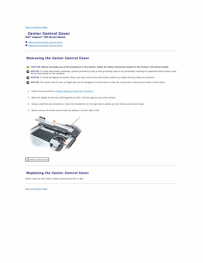
2. Open the display all the way (180 degrees) so that it lies flat against your work surface.
3. Using a small flat end screwdriver, insert the screwdriver on the right side to gently pry the center control cover loose.
4. Gently remove the center control cover by pulling it up from right to left.
Replacing the Center Control Cover
Gently snap the cover back in place starting from left to right.
Back to Contents Page
CAUTION: Before you begin any of the procedures in this section, follow the safety instructions located in the Product Information Guide.
NOTICE: To avoid electrostatic discharge, ground yourself by using a wrist grounding strap or by periodically touching an unpainted metal surface (such as the back panel) on the computer.
NOTICE: To avoid damaging the system board, you must remove the main battery before you begin working inside the computer.
NOTICE: The center control cover is fragile and can be damaged if extreme force is used. Be careful when removing the center control cover.
1 center control cover
Back to Contents Page
Keyboard Dell™ Inspiron™ XPS Service Manual
Removing the Keyboard
Replacing the Keyboard
Removing the Keyboard
1. Follow the instructions in "Before Working Inside Your Computer."
2. Open the display.
3. Remove the center control cover.
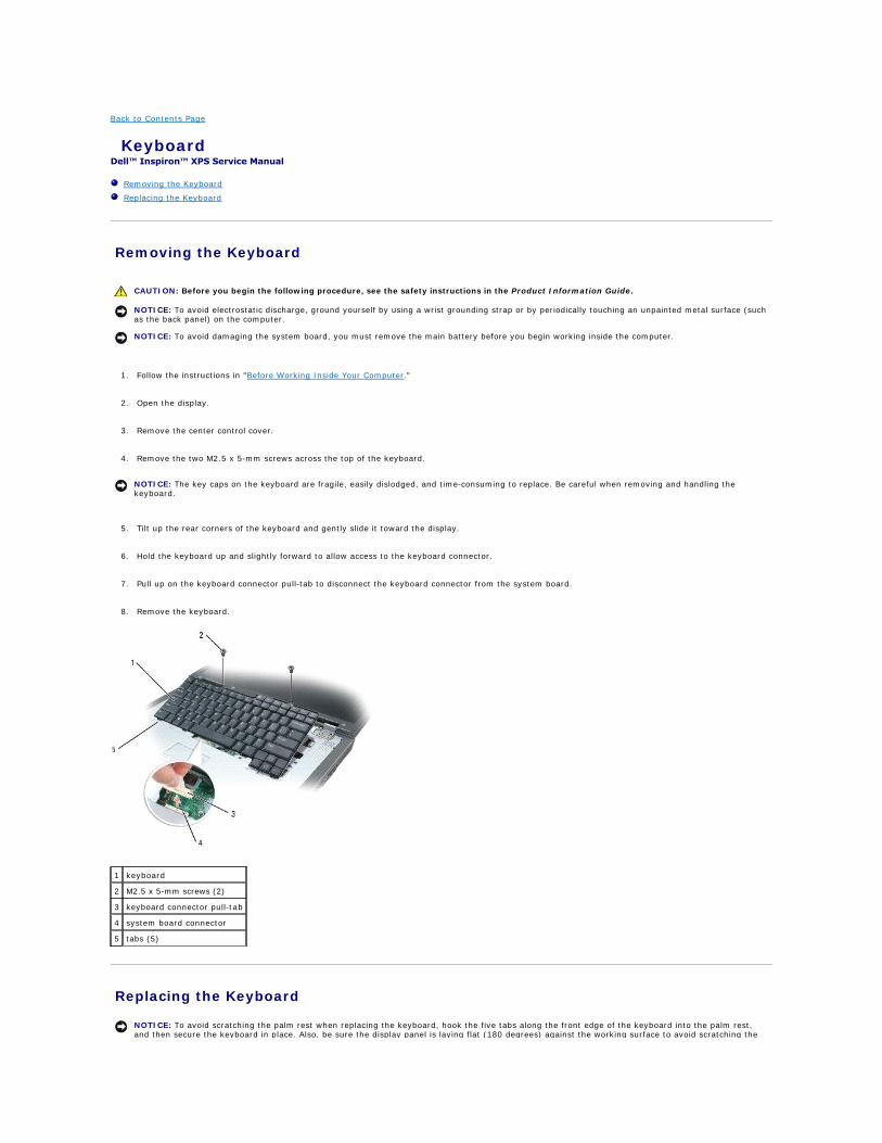
4. Remove the two M2.5 x 5-mm screws across the top of the keyboard.
5. Tilt up the rear corners of the keyboard and gently slide it toward the display.
6. Hold the keyboard up and slightly forward to allow access to the keyboard connector.
7. Pull up on the keyboard connector pull-tab to disconnect the keyboard connector from the system board.
8. Remove the keyboard.
Replacing the Keyboard
CAUTION: Before you begin the following procedure, see the safety instructions in the Product Information Guide.
NOTICE: To avoid electrostatic discharge, ground yourself by using a wrist grounding strap or by periodically touching an unpainted metal surface (such as the back panel) on the computer.
NOTICE: To avoid damaging the system board, you must remove the main battery before you begin working inside the computer.
NOTICE: The key caps on the keyboard are fragile, easily dislodged, and time-consuming to replace. Be careful when removing and handling the keyboard.
1 keyboard
2 M2.5 x 5-mm screws (2)
3 keyboard connector pull-tab
4 system board connector
5 tabs (5)
NOTICE: To avoid scratching the palm rest when replacing the keyboard, hook the five tabs along the front edge of the keyboard into the palm rest, and then secure the keyboard in place. Also, be sure the display panel is laying flat (180 degrees) against the working surface to avoid scratching the

1. Reconnect the keyboard to the system board connector.
2. Slide the bottom of the keyboard into the computer base.
3. Replace the two M2.5 x 5-mm screws across the top of the keyboard.
4. Replace the center control cover.
Back to Contents Page
display panel.
NOTE: You may need to push the bottom of the keyboard down slightly to seat the keyboard into the computer base.
Back to Contents Page
Customizable LEDs Dell™ Inspiron™ XPS Service Manual
Replacing the Customizable LEDs
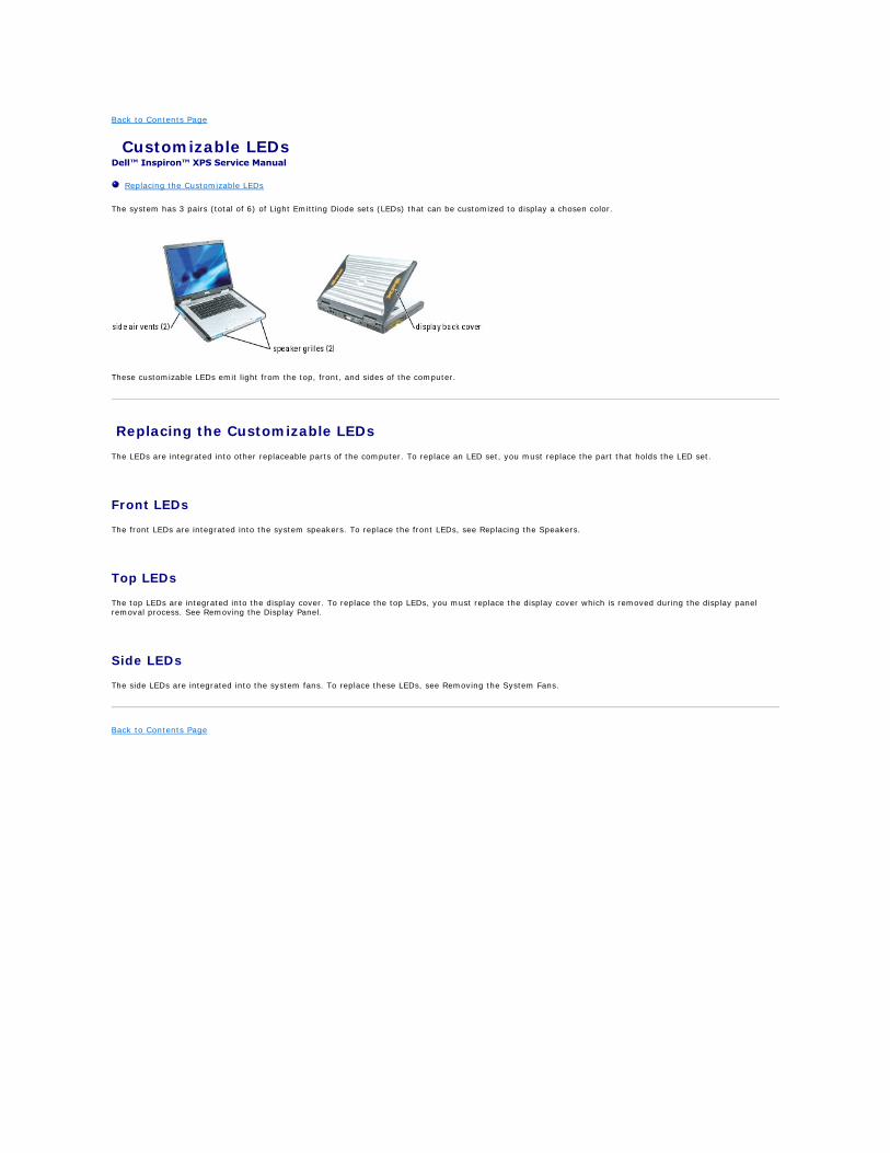
The system has 3 pairs (total of 6) of Light Emitting Diode sets (LEDs) that can be customized to display a chosen color.
These customizable LEDs emit light from the top, front, and sides of the computer.
Replacing the Customizable LEDs
The LEDs are integrated into other replaceable parts of the computer. To replace an LED set, you must replace the part that holds the LED set.
Front LEDs
The front LEDs are integrated into the system speakers. To replace the front LEDs, see Replacing the Speakers.
Top LEDs
The top LEDs are integrated into the display cover. To replace the top LEDs, you must replace the display cover which is removed during the display panel removal process. See Removing the Display Panel.
Side LEDs
The side LEDs are integrated into the system fans. To replace these LEDs, see Removing the System Fans.
Back to Contents Page
Back to Contents Page
MCH Heat Sink Dell™ Inspiron™ XPS Service Manual
Removing the MCH Heat Sink
Replacing the MCH Heat Sink
Removing the MCH Heat Sink
1. Follow the instructions in "Before Working Inside Your Computer."
2. Remove the Mini PCI card (if applicable) and the optical drive.
3. Remove the hard drive.
4. Remove the center control cover.
5. Remove the keyboard.
6. Remove the display assembly.
7. Remove the palm rest.
8. Remove the video card/thermal cooling assembly (if applicable).
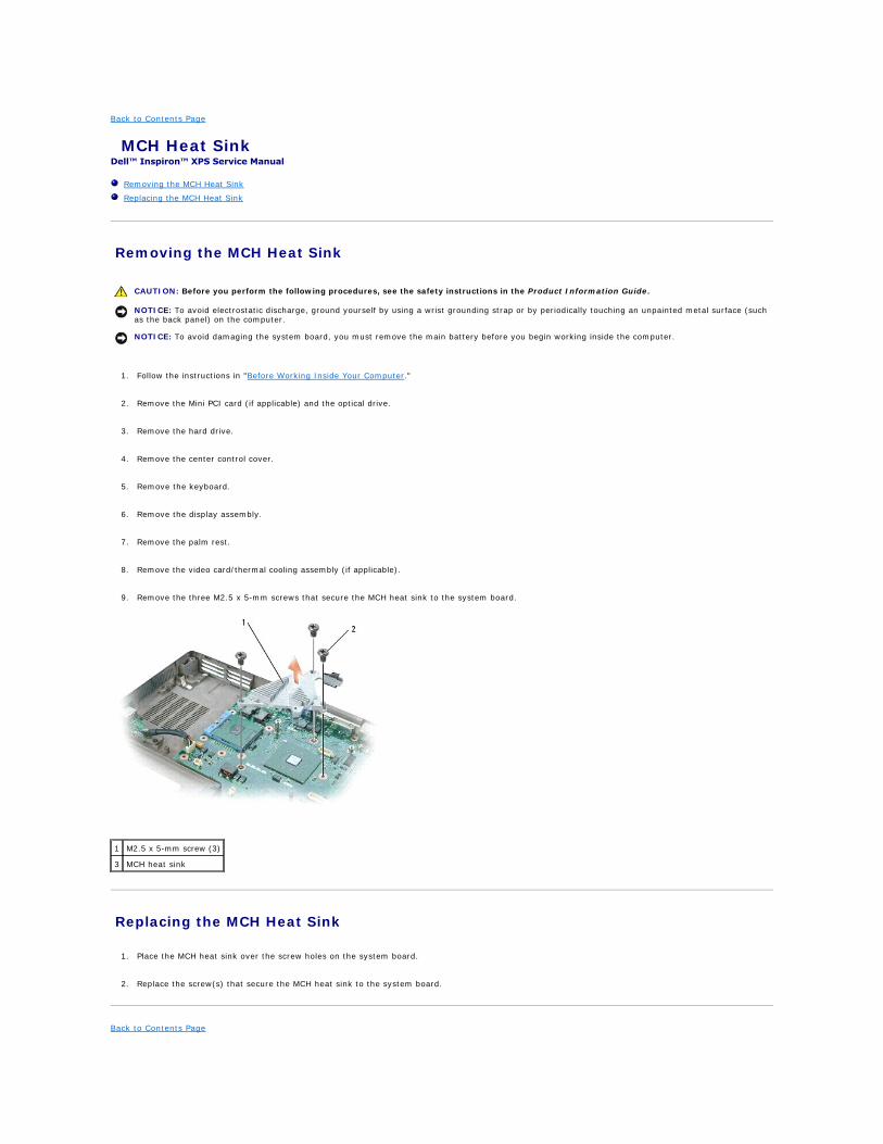
9. Remove the three M2.5 x 5-mm screws that secure the MCH heat sink to the system board.
Replacing the MCH Heat Sink
1. Place the MCH heat sink over the screw holes on the system board.
2. Replace the screw(s) that secure the MCH heat sink to the system board.
Back to Contents Page
CAUTION: Before you perform the following procedures, see the safety instructions in the Product Information Guide.
NOTICE: To avoid electrostatic discharge, ground yourself by using a wrist grounding strap or by periodically touching an unpainted metal surface (such as the back panel) on the computer.
NOTICE: To avoid damaging the system board, you must remove the main battery before you begin working inside the computer.
1 M2.5 x 5-mm screw (3)
3 MCH heat sink


Back to Contents Page
Memory Module Dell™ Inspiron™ XPS Service Manual
Removing the Memory Module
Replacing the Memory Module
Removing the Memory Module
1. Follow the instructions in "Before Working Inside Your Computer."
2. Turn the computer over, loosen the two captive screws from the memory module cover, and remove the cover.
a. Use your fingertips to carefully spread apart the securing clips on each end of the memory module connector until the module pops up.
b. Remove the module from the connector at a 45-degree angle.
CAUTION: Before you begin the following procedure, see the safety instructions in the Product Information Guide.
NOTICE: To prevent static damage to components inside your computer, discharge static electricity from your body before you touch any of your computer's electronic components. You can do so by touching an unpainted metal surface.
NOTE: Memory modules purchased from Dell are covered under your computer warranty.
NOTE: To get maximum performance/dual-channel memory bandwidth capability, both memory module connectors must contain memory modules and the modules must be of the same size and configuration.
NOTICE: To prevent damage to the memory module connector, do not use tools to spread the securing clips that secure the memory module.
NOTICE: Handle memory modules by their edges, and do not touch the components on a module.
1 memory module
2 securing clip (2)

Replacing the Memory Module
1. Ground yourself and install the new memory module:
a. Align the notch in the module edge connector with the tab in the connector slot.
b. Slide the module firmly into the slot at a 45-degree angle, and rotate the module down until it clicks into place. If you do not feel the click, remove
the module and reinstall it.
2. Replace the memory cover and tighten the captive screws.
3. Insert the battery into the battery bay, or connect the AC adapter to your computer and an electrical outlet.
4. Turn on the computer.
As the computer boots, it detects the additional memory and automatically updates the system configuration information.
Back to Contents Page
NOTE: To get maximum performance/dual-channel memory bandwidth capability, both memory module connectors must contain memory modules and the modules must be of the same size and configuration.
NOTE: If a memory module is not installed properly, the computer will not boot.
NOTICE: If the memory module cover is difficult to close, remove the module and reinstall it. Forcing the cover to close may damage your computer.
Back to Contents Page
Mini PCI Card Dell™ Inspiron™ XPS Service Manual
Removing the Mini PCI Card
Replacing the Mini PCI Card
Removing the Mini PCI Card
1. Follow the instructions in "Before Working Inside Your Computer."
2. Turn the computer over and loosen the two captive screws from the cover.
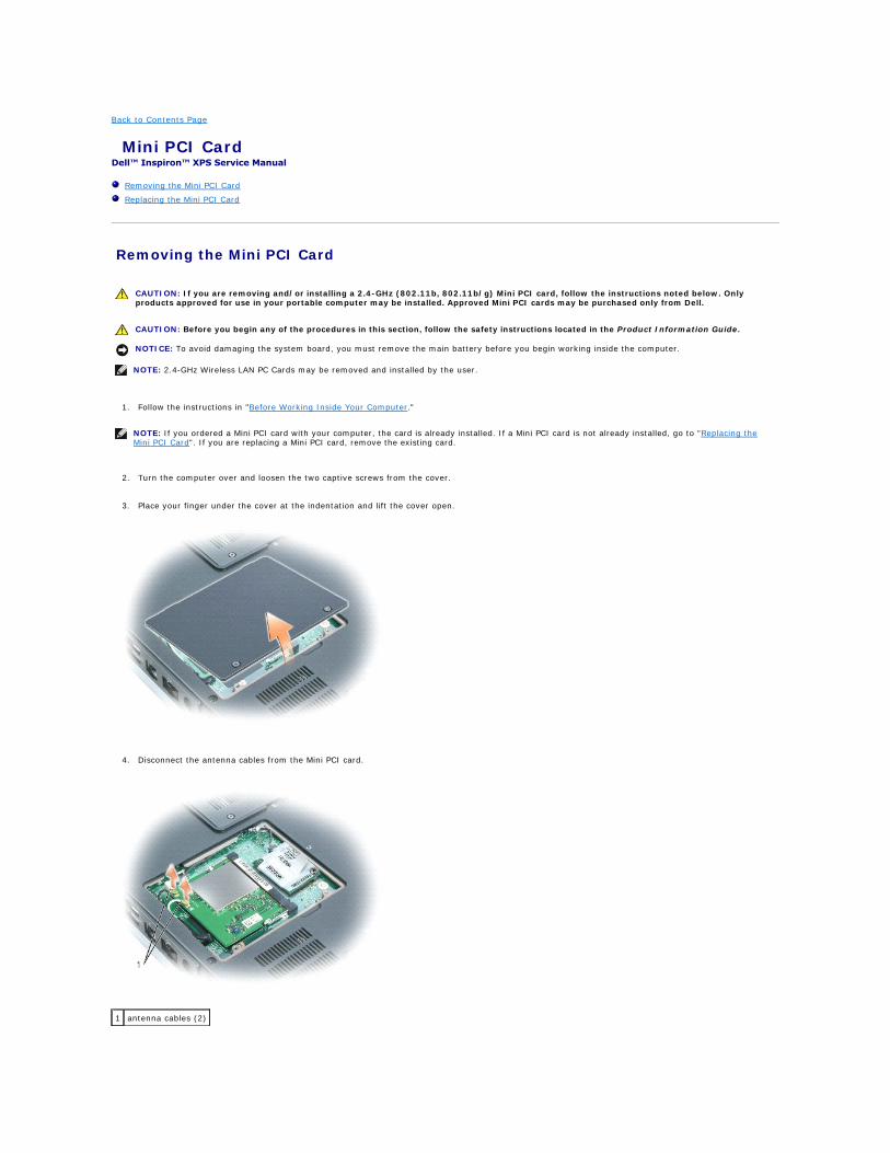
3. Place your finger under the cover at the indentation and lift the cover open.
4. Disconnect the antenna cables from the Mini PCI card.
CAUTION: If you are removing and/or installing a 2.4-GHz (802.11b, 802.11b/g) Mini PCI card, follow the instructions noted below. Only products approved for use in your portable computer may be installed. Approved Mini PCI cards may be purchased only from Dell.
CAUTION: Before you begin any of the procedures in this section, follow the safety instructions located in the Product Information Guide.
NOTICE: To avoid damaging the system board, you must remove the main battery before you begin working inside the computer.
NOTE: 2.4-GHz Wireless LAN PC Cards may be removed and installed by the user.
NOTE: If you ordered a Mini PCI card with your computer, the card is already installed. If a Mini PCI card is not already installed, go to "Replacing the Mini PCI Card". If you are replacing a Mini PCI card, remove the existing card.
1 antenna cables (2)

5. Release the Mini PCI card by spreading the metal securing tabs until the card pops up slightly.
6. Remove the Mini PCI card from the connector at a 45-degree angle.
Replacing the Mini PCI Card
1. Align the Mini PCI card with the connector at a 45-degree angle, and press the Mini PCI card into the connector until it clicks.
2. Connect the antenna cables to the Mini PCI card.
NOTICE: To prevent damage to the Mini PCI card connector, do not use tools to spread the securing clips that secure the card.
1 Mini PCI card
2 metal securing tabs (2)
NOTICE: To avoid damaging the antenna cables or the Mini PCI card, never place the cables under the card.
NOTICE: The connectors are keyed to ensure correct insertion. If you feel resistance, check the connectors and realign the card.
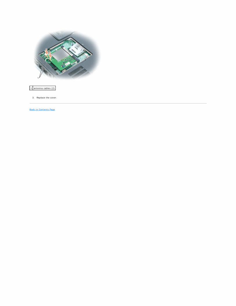
3. Replace the cover.
Back to Contents Page
1 antenna cables (2)
Back to Contents Page
Modem Dell™ Inspiron™ XPS Service Manual
Removing the Modem
Replacing the Modem
Removing the Modem
1. Follow the instructions in "Before Working Inside Your Computer."
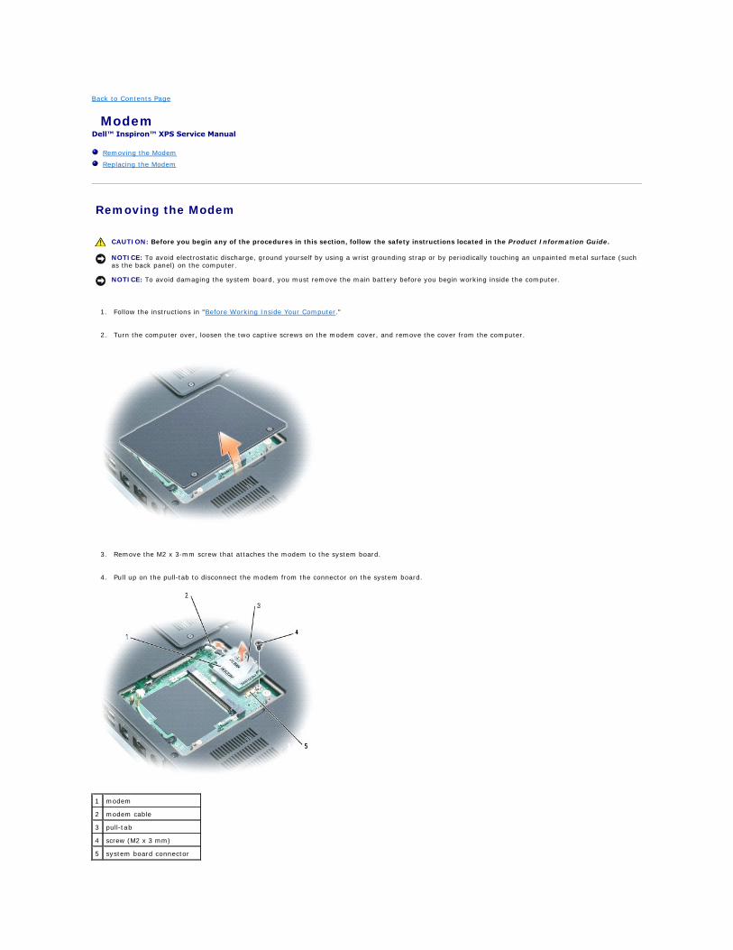
2. Turn the computer over, loosen the two captive screws on the modem cover, and remove the cover from the computer.
3. Remove the M2 x 3-mm screw that attaches the modem to the system board.
4. Pull up on the pull-tab to disconnect the modem from the connector on the system board.
CAUTION: Before you begin any of the procedures in this section, follow the safety instructions located in the Product Information Guide.
NOTICE: To avoid electrostatic discharge, ground yourself by using a wrist grounding strap or by periodically touching an unpainted metal surface (such as the back panel) on the computer.
NOTICE: To avoid damaging the system board, you must remove the main battery before you begin working inside the computer.
1 modem
2 modem cable
3 pull-tab
4 screw (M2 x 3 mm)
5 system board connector

5. Disconnect the modem cable from the modem.
Replacing the Modem
1. Connect the modem cable to the modem.
2. Connect the modem to the system board.
Align the connector on the bottom of the modem with the modem connector on the system board, and press down on the right side of the modem.
3. Replace the M2 x 3-mm screw.
Back to Contents Page
NOTICE: Do not disconnect the modem cable from the system board.
NOTICE: Ensure that the modem cable is routed correctly when you replace the modem.

Back to Contents Page
Optical Drive Dell™ Inspiron™ XPS Service Manual
Removing the Optical Drive
Replacing the Optical Drive
Your computer ships with a fixed optical drive installed.
Removing the Optical Drive
1. Follow the instructions in "Before Working Inside Your Computer."
2. Turn over the computer and remove the M2.5 x 8-mm security screw labeled with a lock icon ( ).
3. Insert a screwdriver into the indentation, and push the notch on the metal tab to release the drive from the bay.
4. Pull the device out of the drive bay.
Replacing the Optical Drive
1. Slide the optical drive into the drive bay and snap it into place.
2. Replace the M2.5 x 8-mm screw that secures the drive in place.
Back to Contents Page
NOTICE: To prevent damage to drives, store them in a safe, dry place when they are not installed in the computer. Avoid pressing down on them or placing heavy objects on top of them.
1 optical drive
2 optical-drive security screw (M2.5 x 8 mm)
3 notch
Back to Contents Page
Palm Rest Dell™ Inspiron™ XPS Service Manual
Removing the Palm Rest
Replacing the Palm Rest
Removing the Palm Rest
1. Follow the instructions in "Before Working Inside Your Computer."
2. Remove the optical drive.
3. Remove the center control cover.
4. Remove the keyboard.
5. Remove the display assembly.
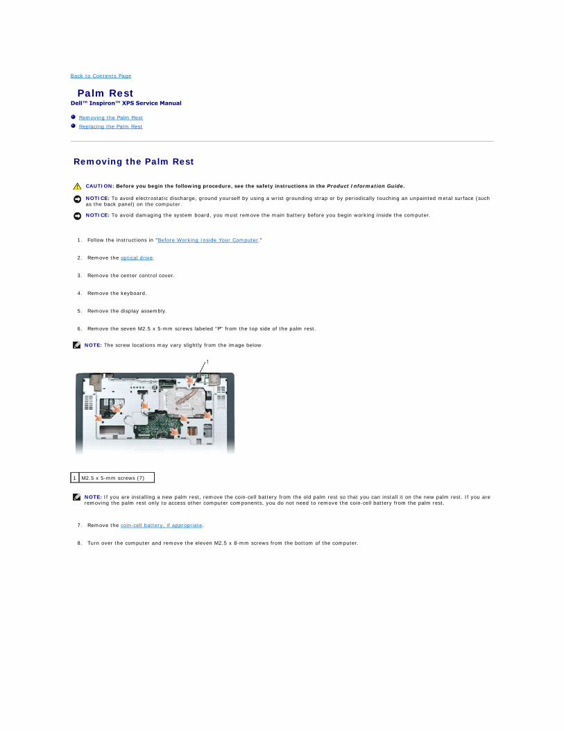
6. Remove the seven M2.5 x 5-mm screws labeled "P" from the top side of the palm rest.
7. Remove the coin-cell battery, if appropriate.
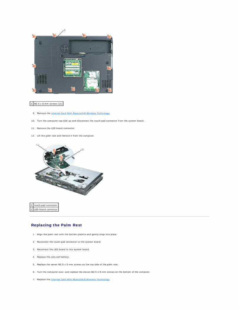
8. Turn over the computer and remove the eleven M2.5 x 8-mm screws from the bottom of the computer.
CAUTION: Before you begin the following procedure, see the safety instructions in the Product Information Guide.
NOTICE: To avoid electrostatic discharge, ground yourself by using a wrist grounding strap or by periodically touching an unpainted metal surface (such as the back panel) on the computer.
NOTICE: To avoid damaging the system board, you must remove the main battery before you begin working inside the computer.
NOTE: The screw locations may vary slightly from the image below.
1 M2.5 x 5-mm screws (7)
NOTE: If you are installing a new palm rest, remove the coin-cell battery from the old palm rest so that you can install it on the new palm rest. If you are removing the palm rest only to access other computer components, you do not need to remove the coin-cell battery from the palm rest.
9. Remove the Internal Card With Bluetooth® Wireless Technology.
10. Turn the computer top-side up and disconnect the touch-pad connector from the system board.
11. Remove the LED board connector.
12. Lift the palm rest and remove it from the computer.
Replacing the Palm Rest
1. Align the palm rest with the bottom plastics and gently snap into place.
2. Reconnect the touch-pad connector to the system board.
3. Reconnect the LED board to the system board.
4. Replace the coin-cell battery.
5. Replace the seven M2.5 x 5-mm screws on the top side of the palm rest.
6. Turn the computer over, and replace the eleven M2.5 x 8-mm screws on the bottom of the computer.
7. Replace the Internal Card With Bluetooth® Wireless Technology.
1 M2.5 x 8-mm screws (11)
1 touch-pad connector
2 LED board connector

8. Replace the display assembly.
9. Replace the keyboard.
10. Replace the center control cover.
Back to Contents Page

Back to Contents Page
PC Card Reader Cage Dell™ Inspiron™ XPS Service Manual
Removing the PC Card Reader cage
Removing the PC Card Reader cage
1. Follow the instructions in "Before Working Inside Your Computer."
2. Remove the hard drive.
3. Remove the optical drive.
4. Remove the center control cover.
5. Remove the keyboard.
6. Remove the display assembly.
7. Remove the palm rest.
8. Disconnect the PC Card connector from the system board.
9. Remove the four M2 x 3-mm screws that attach the PC Card reader cage to the top of the hard drive bay.
Back to Contents Page
CAUTION: Before you begin the following procedure, see the safety instructions in the Product Information Guide.
NOTICE: To avoid electrostatic discharge, ground yourself by using a wrist grounding strap or by periodically touching an unpainted metal surface (such as the back panel) on the computer.
NOTICE: To avoid damaging the system board, you must remove the main battery before you begin working inside the computer.
1 PC Card reader cage
2 M2 x 3-mm screws (4)
2 PC Card reader connector
Back to Contents Page
Pin Assignments for I/O Connectors Dell™ Inspiron™ XPS Service Manual
USB Connector
Video Connector
S-Video TV-Out Connector
IEEE 1394 Connector
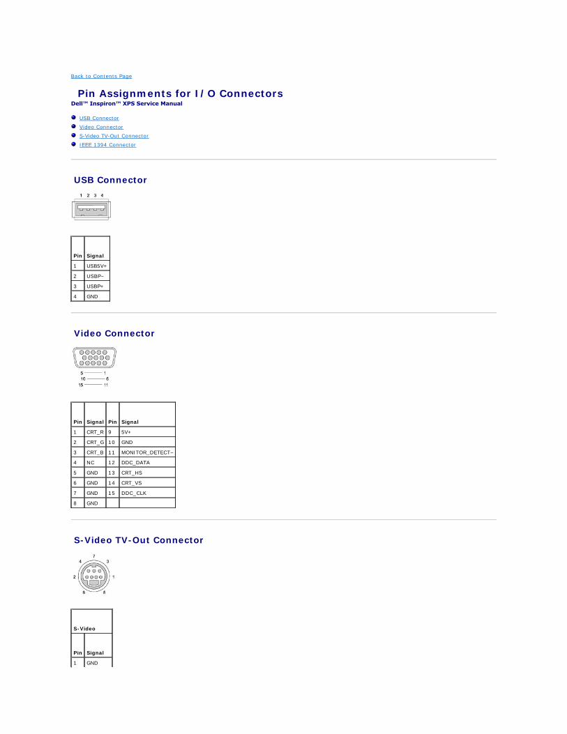
USB Connector
Video Connector
S-Video TV-Out Connector
Pin
Signal
1 USB5V+
2 USBP–
3 USBP+
4 GND
Pin
Signal
Pin
Signal
1 CRT_R 9 5V+
2 CRT_G 10 GND
3 CRT_B 11 MONITOR_DETECT–
4 NC 12 DDC_DATA
5 GND 13 CRT_HS
6 GND 14 CRT_VS
7 GND 15 DDC_CLK
8 GND
S-Video
Pin
Signal
1 GND

IEEE 1394 Connector
Back to Contents Page
2 GND
3 DLUMA-L
4 DCRMA-L
Composite Video
Pin
Signal
5 NC
6 DCMPS-L
7 GND
Pin
Signal
1 TPB–
2 TPB+
3 TPA–
4 TPA+
Back to Contents Page
System Board Dell™ Inspiron™ XPS Service Manual
Removing the System Board
Replacing the System Board
Removing the System Board
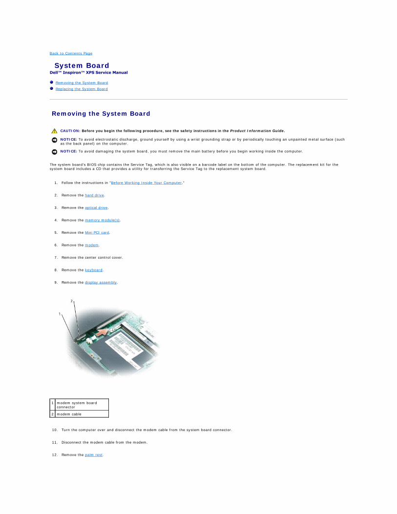
The system board's BIOS chip contains the Service Tag, which is also visible on a barcode label on the bottom of the computer. The replacement kit for the system board includes a CD that provides a utility for transferring the Service Tag to the replacement system board.
1. Follow the instructions in "Before Working Inside Your Computer."
2. Remove the hard drive.
3. Remove the optical drive.
4. Remove the memory module(s).
5. Remove the Mini PCI card.
6. Remove the modem.
7. Remove the center control cover.
8. Remove the keyboard.
9. Remove the display assembly.
10. Turn the computer over and disconnect the modem cable from the system board connector.
11. Disconnect the modem cable from the modem.
12. Remove the palm rest.
CAUTION: Before you begin the following procedure, see the safety instructions in the Product Information Guide.
NOTICE: To avoid electrostatic discharge, ground yourself by using a wrist grounding strap or by periodically touching an unpainted metal surface (such as the back panel) on the computer.
NOTICE: To avoid damaging the system board, you must remove the main battery before you begin working inside the computer.
1 modem system board connector
2 modem cable
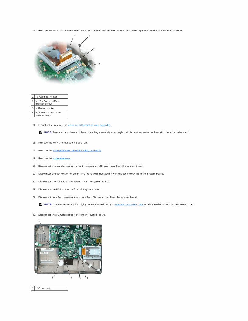
13. Remove the M2 x 3-mm screw that holds the stiffener bracket next to the hard drive cage and remove the stiffener bracket.
14. If applicable, remove the video card/thermal cooling assembly.
15. Remove the MCH thermal-cooling solution.
16. Remove the microprocessor thermal-cooling assembly.
17. Remove the microprocessor.
18. Disconnect the speaker connector and the speaker LED connector from the system board.
19. Disconnect the connector for the internal card with Bluetooth™ wireless technology from the system board.
20. Disconnect the subwoofer connector from the system board
21. Disconnect the USB connector from the system board.
22. Disconnect both fan connectors and both fan LED connectors from the system board.
23. Disconnect the PC Card connector from the system board.
1 PC Card connector
2 M2.5 x 5-mm stiffener bracket screw
3 stiffener bracket
4 PC Card connector on system board
NOTE: Remove the video card/thermal cooling assembly as a single unit. Do not separate the heat sink from the video card.
NOTE: It is not necessary but highly recommended that you remove the system fans to allow easier access to the system board.
1 USB connector
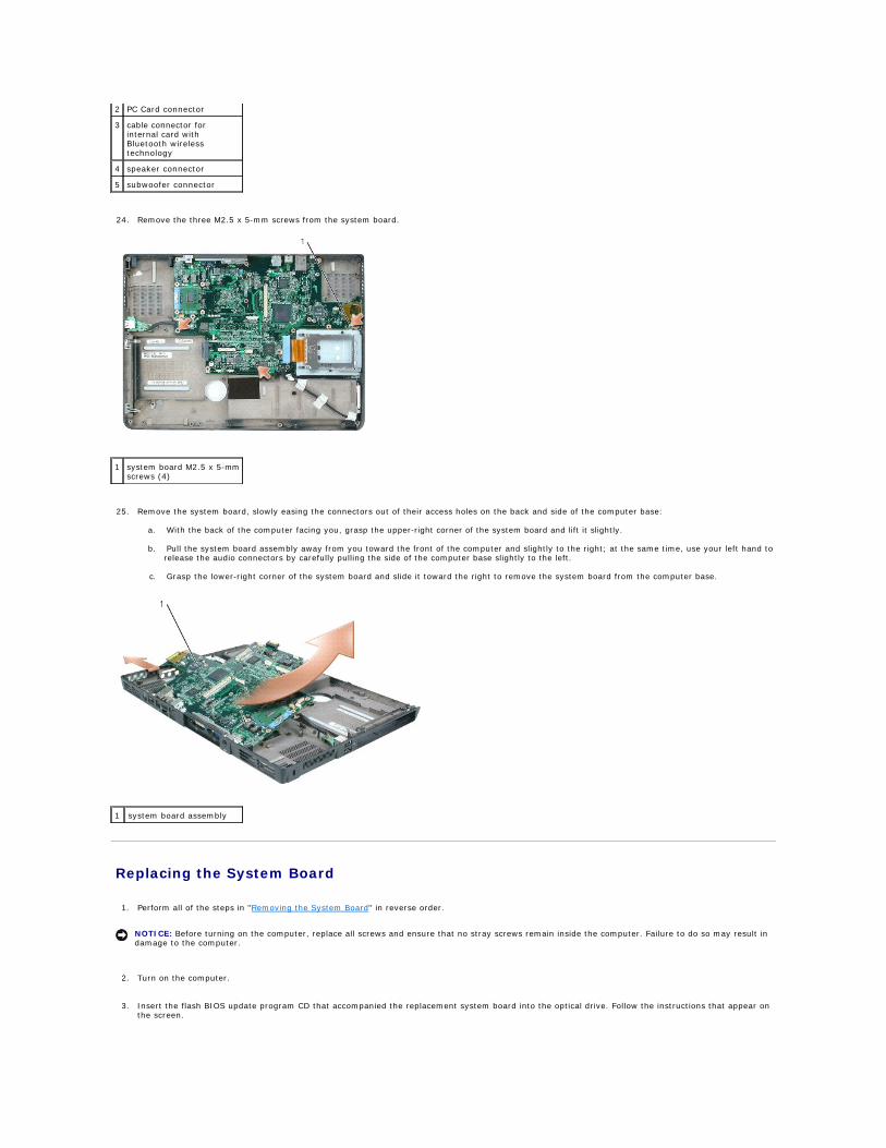
24. Remove the three M2.5 x 5-mm screws from the system board.
25. Remove the system board, slowly easing the connectors out of their access holes on the back and side of the computer base:
a. With the back of the computer facing you, grasp the upper-right corner of the system board and lift it slightly.
b. Pull the system board assembly away from you toward the front of the computer and slightly to the right; at the same time, use your left hand to
release the audio connectors by carefully pulling the side of the computer base slightly to the left.
c. Grasp the lower-right corner of the system board and slide it toward the right to remove the system board from the computer base.
Replacing the System Board
1. Perform all of the steps in "Removing the System Board" in reverse order.
2. Turn on the computer.
3. Insert the flash BIOS update program CD that accompanied the replacement system board into the optical drive. Follow the instructions that appear on the screen.
2 PC Card connector
3 cable connector for internal card with Bluetooth wireless technology
4 speaker connector
5 subwoofer connector
1 system board M2.5 x 5-mm screws (4)
1 system board assembly
NOTICE: Before turning on the computer, replace all screws and ensure that no stray screws remain inside the computer. Failure to do so may result in damage to the computer.

4. Enter the system setup program to update the BIOS on the new system board with the computer Service Tag sequence.
Back to Contents Page
Back to Contents Page
Speakers Dell™ Inspiron™ XPS Service Manual
Removing the Speakers
Replacing the Speakers
Removing the Speakers
1. Follow the instructions in "Before Working Inside Your Computer."
2. Remove the center control cover.
3. Remove the keyboard.
4. Remove the display assembly.
5. Remove the palm rest.
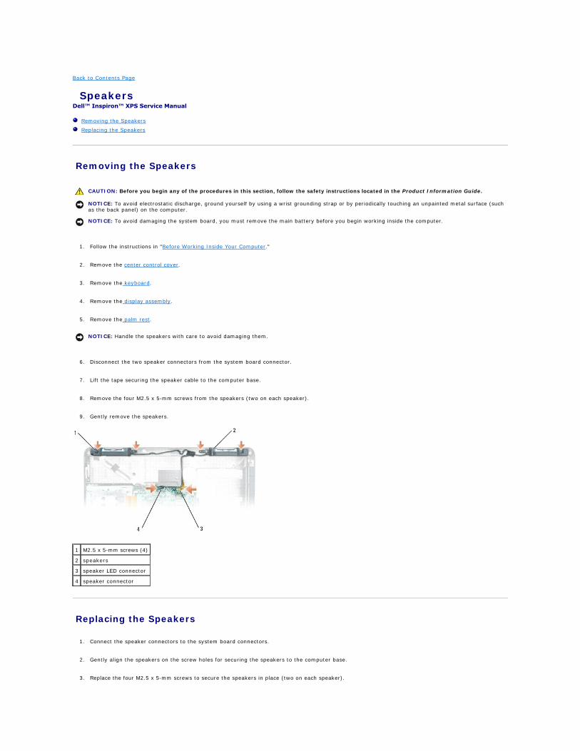
6. Disconnect the two speaker connectors from the system board connector.
7. Lift the tape securing the speaker cable to the computer base.
8. Remove the four M2.5 x 5-mm screws from the speakers (two on each speaker).
9. Gently remove the speakers.
Replacing the Speakers
1. Connect the speaker connectors to the system board connectors.
2. Gently align the speakers on the screw holes for securing the speakers to the computer base.
3. Replace the four M2.5 x 5-mm screws to secure the speakers in place (two on each speaker).
CAUTION: Before you begin any of the procedures in this section, follow the safety instructions located in the Product Information Guide.
NOTICE: To avoid electrostatic discharge, ground yourself by using a wrist grounding strap or by periodically touching an unpainted metal surface (such as the back panel) on the computer.
NOTICE: To avoid damaging the system board, you must remove the main battery before you begin working inside the computer.
NOTICE: Handle the speakers with care to avoid damaging them.
1 M2.5 x 5-mm screws (4)
2 speakers
3 speaker LED connector
4 speaker connector

4. Re-route the speaker cables into the cable guides and re-adhere the tape to secure the speaker cables in place on the computer base.
Back to Contents Page
Back to Contents Page
System Components Dell™ Inspiron™ XPS Service Manual
Back to Contents Page
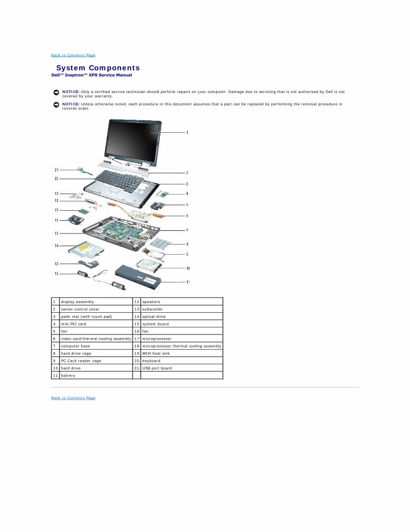
NOTICE: Only a certified service technician should perform repairs on your computer. Damage due to servicing that is not authorized by Dell is not covered by your warranty.
NOTICE: Unless otherwise noted, each procedure in this document assumes that a part can be replaced by performing the removal procedure in reverse order.
1 display assembly 12 speakers
2 center control cover 13 subwoofer
3 palm rest (with touch pad) 14 optical drive
4 mini PCI card 15 system board
5 fan 16 fan
6 video card/thermal cooling assembly 17 microprocessor
7 computer base 18 microprocessor thermal cooling assembly
8 hard drive cage 19 MCH heat sink
9 PC Card reader cage 20 keyboard
10 hard drive 21 USB port board
11 battery
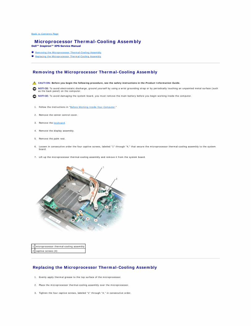
Back to Contents Page
Microprocessor Thermal-Cooling Assembly Dell™ Inspiron™ XPS Service Manual
Removing the Microprocessor Thermal-Cooling Assembly
Replacing the Microprocessor Thermal-Cooling Assembly
Removing the Microprocessor Thermal-Cooling Assembly
1. Follow the instructions in "Before Working Inside Your Computer."
2. Remove the center control cover.
3. Remove the keyboard.
4. Remove the display assembly.
5. Remove the palm rest.
6. Loosen in consecutive order the four captive screws, labeled "1" through "4," that secure the microprocessor thermal-cooling assembly to the system board.
7. Lift up the microprocessor thermal-cooling assembly and remove it from the system board.
Replacing the Microprocessor Thermal-Cooling Assembly
1. Evenly apply thermal grease to the top surface of the microprocessor.
2. Place the microprocessor thermal-cooling assembly over the microprocessor.
3. Tighten the four captive screws, labeled "1" through "4," in consecutive order.
CAUTION: Before you begin the following procedure, see the safety instructions in the Product Information Guide.
NOTICE: To avoid electrostatic discharge, ground yourself by using a wrist grounding strap or by periodically touching an unpainted metal surface (such as the back panel) on the computer.
NOTICE: To avoid damaging the system board, you must remove the main battery before you begin working inside the computer.
1 microprocessor thermal-cooling assembly
2 captive screws (4)

Back to Contents Page
Dell™ Inspiron™ XPS Service Manual
For a complete list of abbreviations and acronyms, see the Dell Inspiron Help file. To access the help file, click the Start button, click Help and Support, click User and system guides, click User's guides, and click Dell Inspiron Help.
If you purchased a Dell™ n Series computer, any references in this document to Microsoft® Windows® operating systems are not applicable.
Model PP14L
February 2005 Rev. A00
Back to Contents Page
NOTE: A NOTE indicates important information that helps you make better use of your computer.
NOTICE: A NOTICE indicates either potential damage to hardware or loss of data and tells you how to avoid the problem.
CAUTION: A CAUTION indicates a potential for property damage, personal injury, or death.
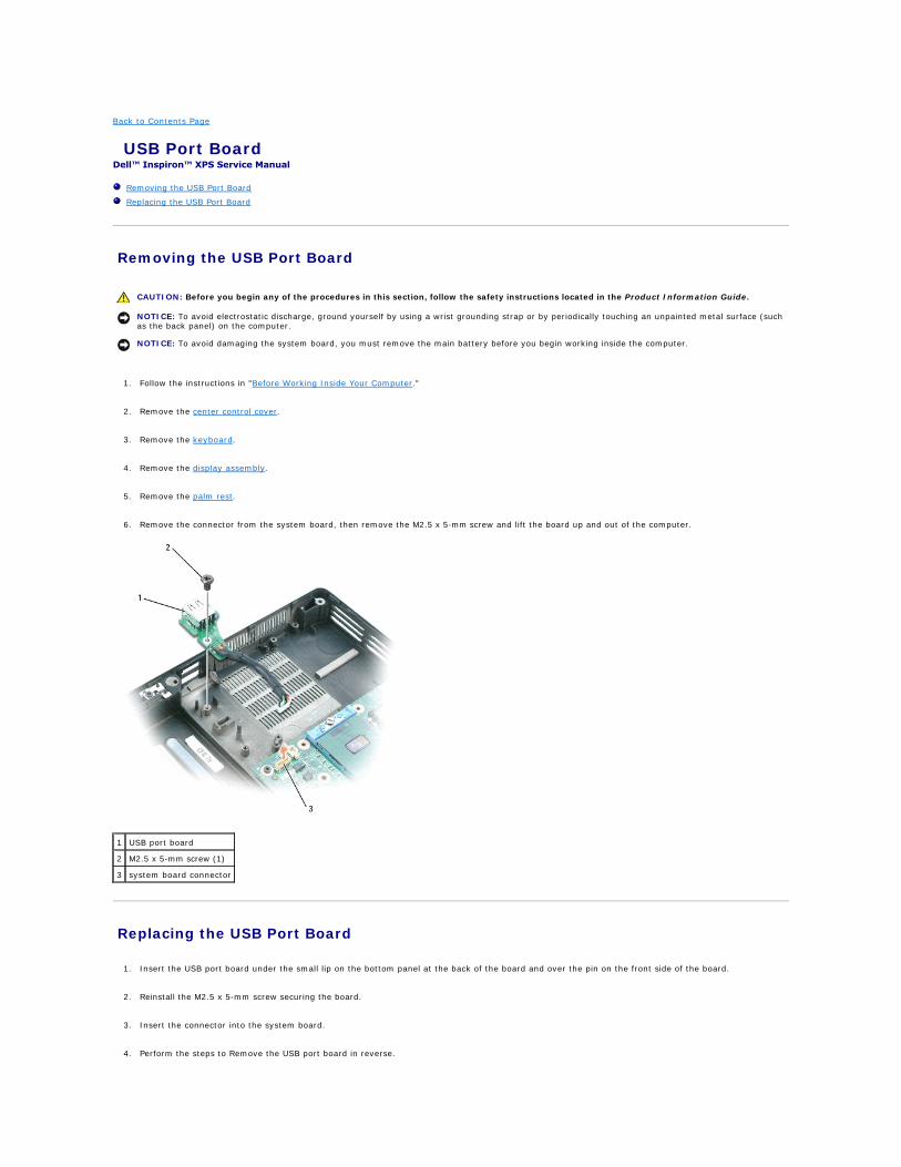
Back to Contents Page
USB Port Board Dell™ Inspiron™ XPS Service Manual
Removing the USB Port Board
Replacing the USB Port Board
Removing the USB Port Board
1. Follow the instructions in "Before Working Inside Your Computer."
2. Remove the center control cover.
3. Remove the keyboard.
4. Remove the display assembly.
5. Remove the palm rest.
6. Remove the connector from the system board, then remove the M2.5 x 5-mm screw and lift the board up and out of the computer.
Replacing the USB Port Board
1. Insert the USB port board under the small lip on the bottom panel at the back of the board and over the pin on the front side of the board.
2. Reinstall the M2.5 x 5-mm screw securing the board.
3. Insert the connector into the system board.
4. Perform the steps to Remove the USB port board in reverse.
CAUTION: Before you begin any of the procedures in this section, follow the safety instructions located in the Product Information Guide.
NOTICE: To avoid electrostatic discharge, ground yourself by using a wrist grounding strap or by periodically touching an unpainted metal surface (such as the back panel) on the computer.
NOTICE: To avoid damaging the system board, you must remove the main battery before you begin working inside the computer.
1 USB port board
2 M2.5 x 5-mm screw (1)
3 system board connector

5. Replace the palm rest.
6. Replace the display assembly.
7. Replace the keyboard.
8. Replace the center control cover.
9. Replace the battery and other items removed in "Before Working Inside Your Computer."
Back to Contents Page
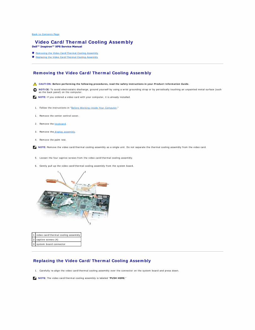
Back to Contents Page
Video Card/Thermal Cooling Assembly Dell™ Inspiron™ XPS Service Manual
Removing the Video Card/Thermal Cooling Assembly
Replacing the Video Card/Thermal Cooling Assembly
Removing the Video Card/Thermal Cooling Assembly
1. Follow the instructions in "Before Working Inside Your Computer."
1. Remove the center control cover.
2. Remove the keyboard.
3. Remove the display assembly.
4. Remove the palm rest.
5. Loosen the four captive screws from the video card/thermal cooling assembly.
6. Gently pull up the video card/thermal cooling assembly from the system board.
Replacing the Video Card/Thermal Cooling Assembly
1. Carefully re-align the video card/thermal cooling assembly over the connector on the system board and press down.
CAUTION: Before performing the following procedures, read the safety instructions in your Product Information Guide.
NOTICE: To avoid electrostatic discharge, ground yourself by using a wrist grounding strap or by periodically touching an unpainted metal surface (such as the back panel) on the computer.
NOTE: If you ordered a video card with your computer, it is already installed.
NOTE: Remove the video card/thermal cooling assembly as a single unit. Do not separate the thermal cooling assembly from the video card.
1 video card/thermal cooling assembly
2 captive screws (4)
3 system board connector
NOTE: The video card/thermal cooling assembly is labeled "PUSH HERE."

2. Tighten the four captive screws on the video card/thermal cooling assembly.
Back to Contents Page

Back to Contents Page
Subwoofer Dell™ Inspiron™ XPS Service Manual
Removing the Subwoofer
Replacing the Subwoofer
Removing the Subwoofer
If you ordered a subwoofer with your computer, it is already installed. To remove and replace a subwoofer:
1. Follow the instructions in "Before Working Inside Your Computer."
2. Remove the optical drive.
3. Remove the center control cover.
4. Remove the keyboard.
5. Remove the display assembly.
6. Remove the palm rest.
7. Loosen the two captive screws that secure the subwoofer in place.
8. Remove the subwoofer cable connector from the system board.
Replacing the Subwoofer
1. Reconnect the subwoofer cable to the system board.
2. Place the subwoofer onto the system board.
3. Tighten the two captive screws that secure the subwoofer in place.
CAUTION: Before performing the following procedures, read the safety instructions in your Product Information Guide.
NOTICE: To avoid electrostatic discharge, ground yourself by using a wrist grounding strap or by periodically touching an unpainted metal surface (such as the back panel) on the computer.
1 subwoofer
2 subwoofer cable connector
3 system board connector

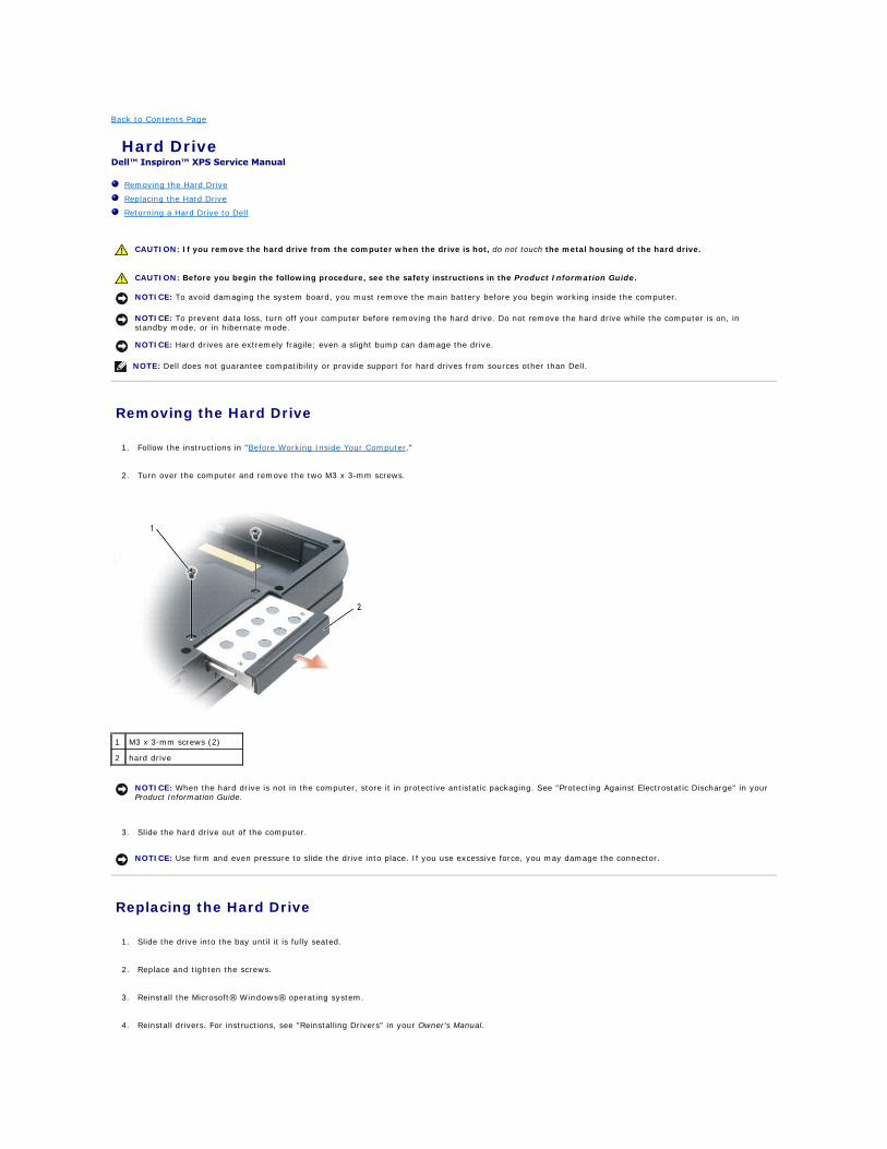
Back to Contents Page
Hard Drive Dell™ Inspiron™ XPS Service Manual
Removing the Hard Drive
Replacing the Hard Drive
Returning a Hard Drive to Dell
Removing the Hard Drive
1. Follow the instructions in "Before Working Inside Your Computer."
2. Turn over the computer and remove the two M3 x 3-mm screws.
3. Slide the hard drive out of the computer.
Replacing the Hard Drive
1. Slide the drive into the bay until it is fully seated.
2. Replace and tighten the screws.
3. Reinstall the Microsoft® Windows® operating system.
4. Reinstall drivers. For instructions, see "Reinstalling Drivers" in your Owner's Manual.
CAUTION: If you remove the hard drive from the computer when the drive is hot, do not touch the metal housing of the hard drive.
CAUTION: Before you begin the following procedure, see the safety instructions in the Product Information Guide.
NOTICE: To avoid damaging the system board, you must remove the main battery before you begin working inside the computer.
NOTICE: To prevent data loss, turn off your computer before removing the hard drive. Do not remove the hard drive while the computer is on, in standby mode, or in hibernate mode.
NOTICE: Hard drives are extremely fragile; even a slight bump can damage the drive.
NOTE: Dell does not guarantee compatibility or provide support for hard drives from sources other than Dell.
1 M3 x 3-mm screws (2)
2 hard drive
NOTICE: When the hard drive is not in the computer, store it in protective antistatic packaging. See "Protecting Against Electrostatic Discharge" in your Product Information Guide.
NOTICE: Use firm and even pressure to slide the drive into place. If you use excessive force, you may damage the connector.
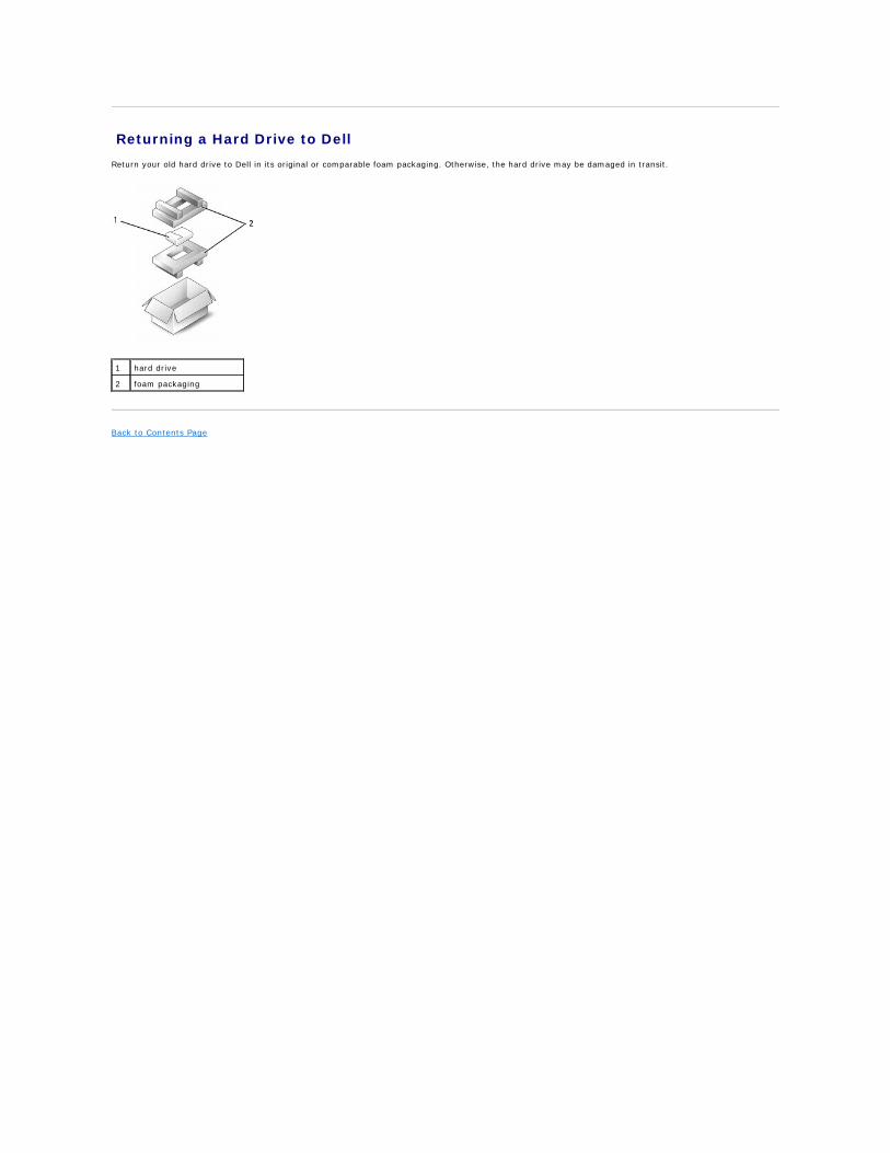
Returning a Hard Drive to Dell
Return your old hard drive to Dell in its original or comparable foam packaging. Otherwise, the hard drive may be damaged in transit.
Back to Contents Page
1 hard drive
2 foam packaging

Back to Contents Page
Center Control Cover Dell™ Inspiron™ XPS Service Manual
Removing the Center Control Cover
Replacing the Center Control Cover
Removing the Center Control Cover
1. Follow the instructions in "Before Working Inside Your Computer."
2. Open the display all the way (180 degrees) so that it lies flat against your work surface.
3. Using a small flat end screwdriver, insert the screwdriver on the right side to gently pry the center control cover loose.
4. Gently remove the center control cover by pulling it up from right to left.
Replacing the Center Control Cover
Gently snap the cover back in place starting from left to right.
Back to Contents Page
CAUTION: Before you begin any of the procedures in this section, follow the safety instructions located in the Product Information Guide.
NOTICE: To avoid electrostatic discharge, ground yourself by using a wrist grounding strap or by periodically touching an unpainted metal surface (such as the back panel) on the computer.
NOTICE: To avoid damaging the system board, you must remove the main battery before you begin working inside the computer.
NOTICE: The center control cover is fragile and can be damaged if extreme force is used. Be careful when removing the center control cover.
1 center control cover
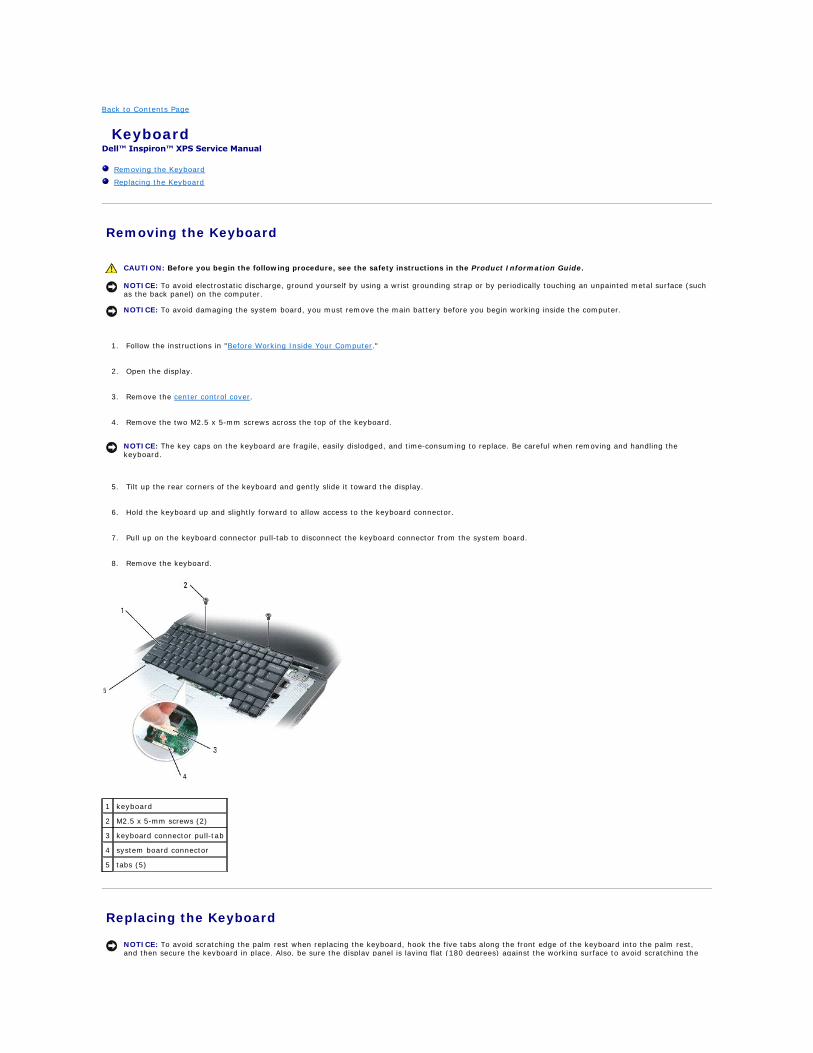
Back to Contents Page
Keyboard Dell™ Inspiron™ XPS Service Manual
Removing the Keyboard
Replacing the Keyboard
Removing the Keyboard
1. Follow the instructions in "Before Working Inside Your Computer."
2. Open the display.
3. Remove the center control cover.
4. Remove the two M2.5 x 5-mm screws across the top of the keyboard.
5. Tilt up the rear corners of the keyboard and gently slide it toward the display.
6. Hold the keyboard up and slightly forward to allow access to the keyboard connector.
7. Pull up on the keyboard connector pull-tab to disconnect the keyboard connector from the system board.
8. Remove the keyboard.
Replacing the Keyboard
CAUTION: Before you begin the following procedure, see the safety instructions in the Product Information Guide.
NOTICE: To avoid electrostatic discharge, ground yourself by using a wrist grounding strap or by periodically touching an unpainted metal surface (such as the back panel) on the computer.
NOTICE: To avoid damaging the system board, you must remove the main battery before you begin working inside the computer.
NOTICE: The key caps on the keyboard are fragile, easily dislodged, and time-consuming to replace. Be careful when removing and handling the keyboard.
1 keyboard
2 M2.5 x 5-mm screws (2)
3 keyboard connector pull-tab
4 system board connector
5 tabs (5)
NOTICE: To avoid scratching the palm rest when replacing the keyboard, hook the five tabs along the front edge of the keyboard into the palm rest, and then secure the keyboard in place. Also, be sure the display panel is laying flat (180 degrees) against the working surface to avoid scratching the

1. Reconnect the keyboard to the system board connector.
2. Slide the bottom of the keyboard into the computer base.
3. Replace the two M2.5 x 5-mm screws across the top of the keyboard.
4. Replace the center control cover.
Back to Contents Page
display panel.
NOTE: You may need to push the bottom of the keyboard down slightly to seat the keyboard into the computer base.
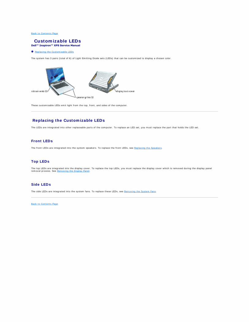
Back to Contents Page
Customizable LEDs Dell™ Inspiron™ XPS Service Manual
Replacing the Customizable LEDs
The system has 3 pairs (total of 6) of Light Emitting Diode sets (LEDs) that can be customized to display a chosen color.
These customizable LEDs emit light from the top, front, and sides of the computer.
Replacing the Customizable LEDs
The LEDs are integrated into other replaceable parts of the computer. To replace an LED set, you must replace the part that holds the LED set.
Front LEDs
The front LEDs are integrated into the system speakers. To replace the front LEDs, see Replacing the Speakers.
Top LEDs
The top LEDs are integrated into the display cover. To replace the top LEDs, you must replace the display cover which is removed during the display panel removal process. See Removing the Display Panel.
Side LEDs
The side LEDs are integrated into the system fans. To replace these LEDs, see Removing the System Fans.
Back to Contents Page
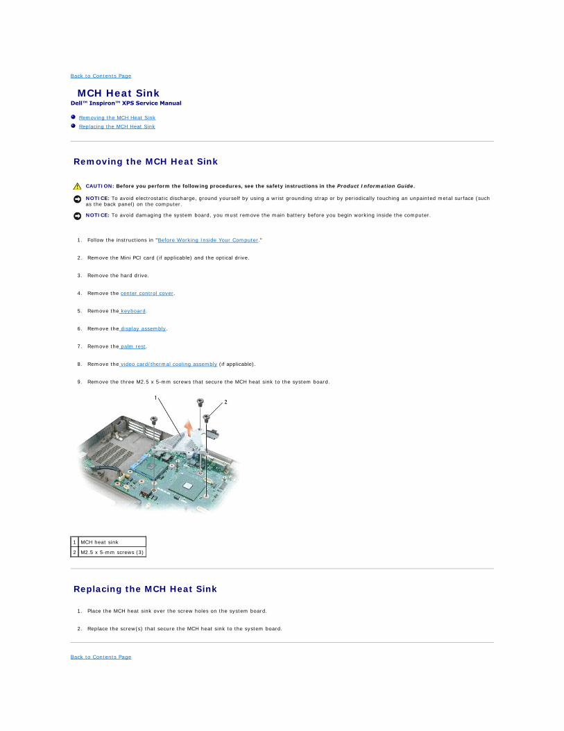
Back to Contents Page
MCH Heat Sink Dell™ Inspiron™ XPS Service Manual
Removing the MCH Heat Sink
Replacing the MCH Heat Sink
Removing the MCH Heat Sink
1. Follow the instructions in "Before Working Inside Your Computer."
2. Remove the Mini PCI card (if applicable) and the optical drive.
3. Remove the hard drive.
4. Remove the center control cover.
5. Remove the keyboard.
6. Remove the display assembly.
7. Remove the palm rest.
8. Remove the video card/thermal cooling assembly (if applicable).
9. Remove the three M2.5 x 5-mm screws that secure the MCH heat sink to the system board.
Replacing the MCH Heat Sink
1. Place the MCH heat sink over the screw holes on the system board.
2. Replace the screw(s) that secure the MCH heat sink to the system board.
Back to Contents Page
CAUTION: Before you perform the following procedures, see the safety instructions in the Product Information Guide.
NOTICE: To avoid electrostatic discharge, ground yourself by using a wrist grounding strap or by periodically touching an unpainted metal surface (such as the back panel) on the computer.
NOTICE: To avoid damaging the system board, you must remove the main battery before you begin working inside the computer.
1 MCH heat sink
2 M2.5 x 5-mm screws (3)

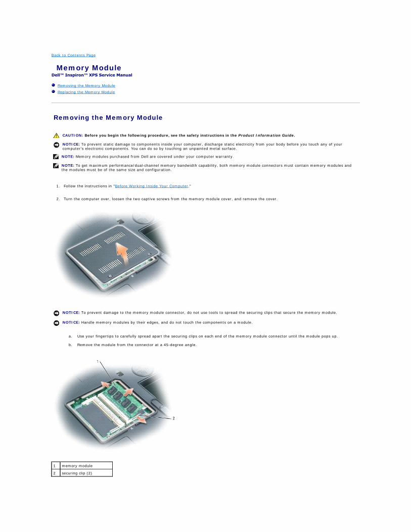
Back to Contents Page
Memory Module Dell™ Inspiron™ XPS Service Manual
Removing the Memory Module
Replacing the Memory Module
Removing the Memory Module
1. Follow the instructions in "Before Working Inside Your Computer."
2. Turn the computer over, loosen the two captive screws from the memory module cover, and remove the cover.
a. Use your fingertips to carefully spread apart the securing clips on each end of the memory module connector until the module pops up.
b. Remove the module from the connector at a 45-degree angle.
CAUTION: Before you begin the following procedure, see the safety instructions in the Product Information Guide.
NOTICE: To prevent static damage to components inside your computer, discharge static electricity from your body before you touch any of your computer's electronic components. You can do so by touching an unpainted metal surface.
NOTE: Memory modules purchased from Dell are covered under your computer warranty.
NOTE: To get maximum performance/dual-channel memory bandwidth capability, both memory module connectors must contain memory modules and the modules must be of the same size and configuration.
NOTICE: To prevent damage to the memory module connector, do not use tools to spread the securing clips that secure the memory module.
NOTICE: Handle memory modules by their edges, and do not touch the components on a module.
1 memory module
2 securing clip (2)
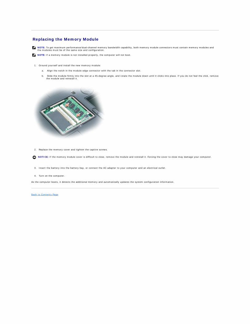
Replacing the Memory Module
1. Ground yourself and install the new memory module:
a. Align the notch in the module edge connector with the tab in the connector slot.
b. Slide the module firmly into the slot at a 45-degree angle, and rotate the module down until it clicks into place. If you do not feel the click, remove
the module and reinstall it.
2. Replace the memory cover and tighten the captive screws.
3. Insert the battery into the battery bay, or connect the AC adapter to your computer and an electrical outlet.
4. Turn on the computer.
As the computer boots, it detects the additional memory and automatically updates the system configuration information.
Back to Contents Page
NOTE: To get maximum performance/dual-channel memory bandwidth capability, both memory module connectors must contain memory modules and the modules must be of the same size and configuration.
NOTE: If a memory module is not installed properly, the computer will not boot.
NOTICE: If the memory module cover is difficult to close, remove the module and reinstall it. Forcing the cover to close may damage your computer.

Back to Contents Page
Mini PCI Card Dell™ Inspiron™ XPS Service Manual
Removing the Mini PCI Card
Replacing the Mini PCI Card
Removing the Mini PCI Card
1. Follow the instructions in "Before Working Inside Your Computer."
2. Turn the computer over and loosen the two captive screws from the cover.
3. Place your finger under the cover at the indentation and lift the cover open.
4. Disconnect the antenna cables from the Mini PCI card.
CAUTION: If you are removing and/or installing a 2.4-GHz (802.11b, 802.11b/g) Mini PCI card, follow the instructions noted below. Only products approved for use in your portable computer may be installed. Approved Mini PCI cards may be purchased only from Dell.
CAUTION: Before you begin any of the procedures in this section, follow the safety instructions located in the Product Information Guide.
NOTICE: To avoid damaging the system board, you must remove the main battery before you begin working inside the computer.
NOTE: 2.4-GHz Wireless LAN PC Cards may be removed and installed by the user.
NOTE: If you ordered a Mini PCI card with your computer, the card is already installed. If a Mini PCI card is not already installed, go to "Replacing the Mini PCI Card". If you are replacing a Mini PCI card, remove the existing card.
1 antenna cables (2)
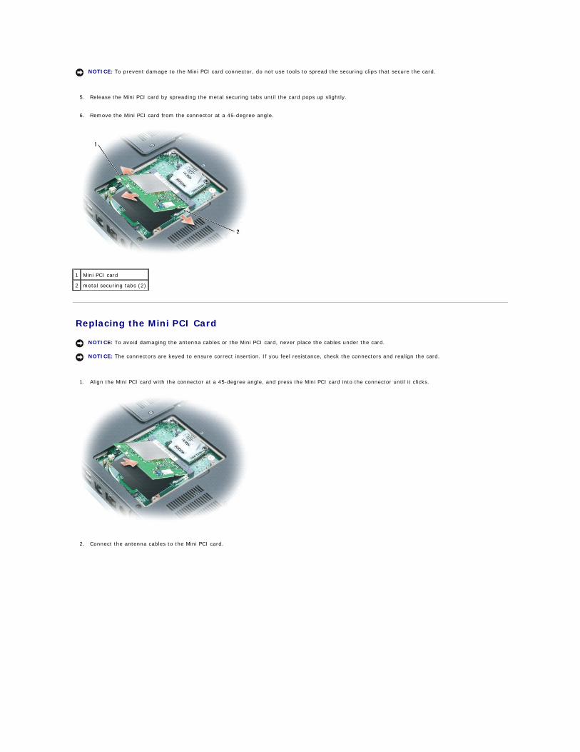
5. Release the Mini PCI card by spreading the metal securing tabs until the card pops up slightly.
6. Remove the Mini PCI card from the connector at a 45-degree angle.
Replacing the Mini PCI Card
1. Align the Mini PCI card with the connector at a 45-degree angle, and press the Mini PCI card into the connector until it clicks.
2. Connect the antenna cables to the Mini PCI card.
NOTICE: To prevent damage to the Mini PCI card connector, do not use tools to spread the securing clips that secure the card.
1 Mini PCI card
2 metal securing tabs (2)
NOTICE: To avoid damaging the antenna cables or the Mini PCI card, never place the cables under the card.
NOTICE: The connectors are keyed to ensure correct insertion. If you feel resistance, check the connectors and realign the card.

3. Replace the cover.
Back to Contents Page
1 antenna cables (2)

Back to Contents Page
Modem Dell™ Inspiron™ XPS Service Manual
Removing the Modem
Replacing the Modem
Removing the Modem
1. Follow the instructions in "Before Working Inside Your Computer."
2. Turn the computer over, loosen the two captive screws on the modem cover, and remove the cover from the computer.
3. Remove the M2 x 3-mm screw that attaches the modem to the system board.
4. Pull up on the pull-tab to disconnect the modem from the connector on the system board.
CAUTION: Before you begin any of the procedures in this section, follow the safety instructions located in the Product Information Guide.
NOTICE: To avoid electrostatic discharge, ground yourself by using a wrist grounding strap or by periodically touching an unpainted metal surface (such as the back panel) on the computer.
NOTICE: To avoid damaging the system board, you must remove the main battery before you begin working inside the computer.
1 modem
2 modem cable
3 pull-tab
4 screw (M2 x 3 mm)
5 system board connector
5. Disconnect the modem cable from the modem.
Replacing the Modem
1. Connect the modem cable to the modem.
2. Connect the modem to the system board.
Align the connector on the bottom of the modem with the modem connector on the system board, and press down on the right side of the modem.
3. Replace the M2 x 3-mm screw.
Back to Contents Page
NOTICE: Do not disconnect the modem cable from the system board.
NOTICE: Ensure that the modem cable is routed correctly when you replace the modem.
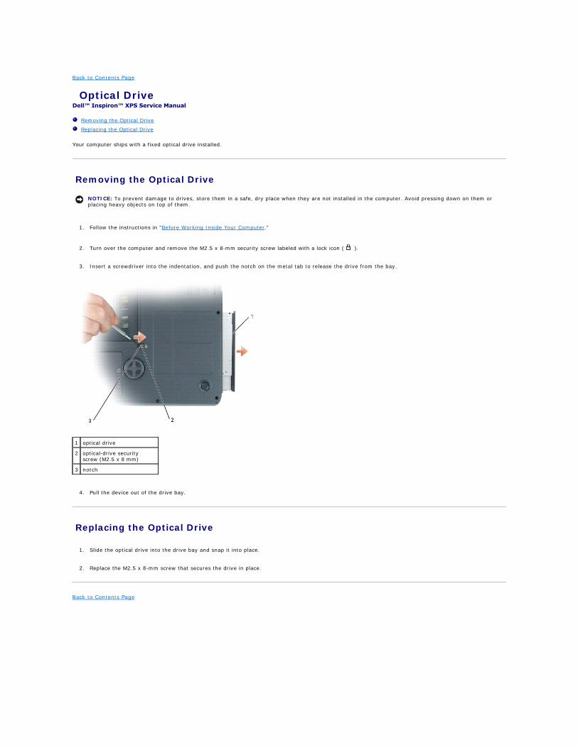
Back to Contents Page
Optical Drive Dell™ Inspiron™ XPS Service Manual
Removing the Optical Drive
Replacing the Optical Drive
Your computer ships with a fixed optical drive installed.
Removing the Optical Drive
1. Follow the instructions in "Before Working Inside Your Computer."
2. Turn over the computer and remove the M2.5 x 8-mm security screw labeled with a lock icon ( ).
3. Insert a screwdriver into the indentation, and push the notch on the metal tab to release the drive from the bay.
4. Pull the device out of the drive bay.
Replacing the Optical Drive
1. Slide the optical drive into the drive bay and snap it into place.
2. Replace the M2.5 x 8-mm screw that secures the drive in place.
Back to Contents Page
NOTICE: To prevent damage to drives, store them in a safe, dry place when they are not installed in the computer. Avoid pressing down on them or placing heavy objects on top of them.
1 optical drive
2 optical-drive security screw (M2.5 x 8 mm)
3 notch
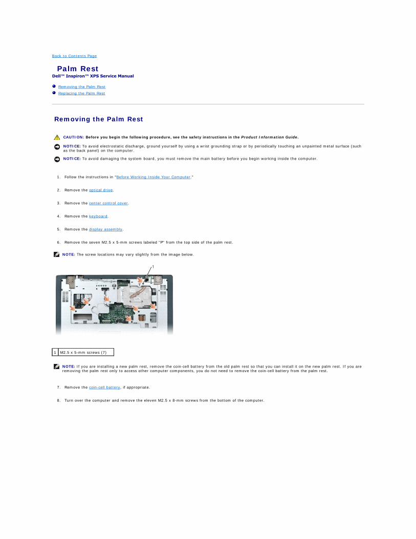
Back to Contents Page
Palm Rest Dell™ Inspiron™ XPS Service Manual
Removing the Palm Rest
Replacing the Palm Rest
Removing the Palm Rest
1. Follow the instructions in "Before Working Inside Your Computer."
2. Remove the optical drive.
3. Remove the center control cover.
4. Remove the keyboard.
5. Remove the display assembly.
6. Remove the seven M2.5 x 5-mm screws labeled "P" from the top side of the palm rest.
7. Remove the coin-cell battery, if appropriate.
8. Turn over the computer and remove the eleven M2.5 x 8-mm screws from the bottom of the computer.
CAUTION: Before you begin the following procedure, see the safety instructions in the Product Information Guide.
NOTICE: To avoid electrostatic discharge, ground yourself by using a wrist grounding strap or by periodically touching an unpainted metal surface (such as the back panel) on the computer.
NOTICE: To avoid damaging the system board, you must remove the main battery before you begin working inside the computer.
NOTE: The screw locations may vary slightly from the image below.
1 M2.5 x 5-mm screws (7)
NOTE: If you are installing a new palm rest, remove the coin-cell battery from the old palm rest so that you can install it on the new palm rest. If you are removing the palm rest only to access other computer components, you do not need to remove the coin-cell battery from the palm rest.

9. Remove the Internal Card With Bluetooth® Wireless Technology.
10. Turn the computer top-side up and disconnect the touch-pad connector from the system board.
11. Remove the LED board connector.
12. Lift the palm rest and remove it from the computer.
Replacing the Palm Rest
1. Align the palm rest with the bottom plastics and gently snap into place.
2. Reconnect the touch-pad connector to the system board.
3. Reconnect the LED board to the system board.
4. Replace the coin-cell battery.
5. Replace the seven M2.5 x 5-mm screws on the top side of the palm rest.
6. Turn the computer over, and replace the eleven M2.5 x 8-mm screws on the bottom of the computer.
7. Replace the Internal Card With Bluetooth® Wireless Technology.
1 M2.5 x 8-mm screws (11)
1 touch-pad connector
2 LED board connector

8. Replace the display assembly.
9. Replace the keyboard.
10. Replace the center control cover.
Back to Contents Page
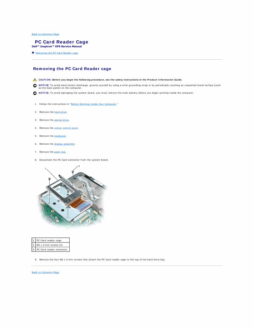
Back to Contents Page
PC Card Reader Cage Dell™ Inspiron™ XPS Service Manual
Removing the PC Card Reader cage
Removing the PC Card Reader cage
1. Follow the instructions in "Before Working Inside Your Computer."
2. Remove the hard drive.
3. Remove the optical drive.
4. Remove the center control cover.
5. Remove the keyboard.
6. Remove the display assembly.
7. Remove the palm rest.
8. Disconnect the PC Card connector from the system board.
9. Remove the four M2 x 3-mm screws that attach the PC Card reader cage to the top of the hard drive bay.
Back to Contents Page
CAUTION: Before you begin the following procedure, see the safety instructions in the Product Information Guide.
NOTICE: To avoid electrostatic discharge, ground yourself by using a wrist grounding strap or by periodically touching an unpainted metal surface (such as the back panel) on the computer.
NOTICE: To avoid damaging the system board, you must remove the main battery before you begin working inside the computer.
1 PC Card reader cage
2 M2 x 3-mm screws (4)
3 PC Card reader connector

Back to Contents Page
Pin Assignments for I/O Connectors Dell™ Inspiron™ XPS Service Manual
USB Connector
Video Connector
S-Video TV-Out Connector
IEEE 1394 Connector
USB Connector
Video Connector
S-Video TV-Out Connector
Pin
Signal
1 USB5V+
2 USBP–
3 USBP+
4 GND
Pin
Signal
Pin
Signal
1 CRT_R 9 5V+
2 CRT_G 10 GND
3 CRT_B 11 MONITOR_DETECT–
4 NC 12 DDC_DATA
5 GND 13 CRT_HS
6 GND 14 CRT_VS
7 GND 15 DDC_CLK
8 GND
S-Video
Pin
Signal
1 GND
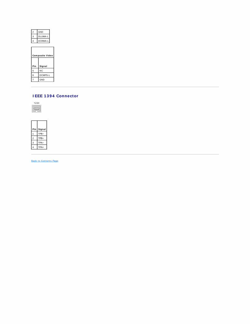
IEEE 1394 Connector
Back to Contents Page
2 GND
3 DLUMA-L
4 DCRMA-L
Composite Video
Pin
Signal
5 NC
6 DCMPS-L
7 GND
Pin
Signal
1 TPB–
2 TPB+
3 TPA–
4 TPA+

Back to Contents Page
Speakers Dell™ Inspiron™ XPS Service Manual
Removing the Speakers
Replacing the Speakers
Removing the Speakers
1. Follow the instructions in "Before Working Inside Your Computer."
2. Remove the center control cover.
3. Remove the keyboard.
4. Remove the display assembly.
5. Remove the palm rest.
6. Disconnect the two speaker connectors from the system board connector.
7. Lift the tape securing the speaker cable to the computer base.
8. Remove the four M2.5 x 5-mm screws from the speakers (two on each speaker).
9. Gently remove the speakers.
Replacing the Speakers
1. Connect the speaker connectors to the system board connectors.
2. Gently align the speakers on the screw holes for securing the speakers to the computer base.
3. Replace the four M2.5 x 5-mm screws to secure the speakers in place (two on each speaker).
CAUTION: Before you begin any of the procedures in this section, follow the safety instructions located in the Product Information Guide.
NOTICE: To avoid electrostatic discharge, ground yourself by using a wrist grounding strap or by periodically touching an unpainted metal surface (such as the back panel) on the computer.
NOTICE: To avoid damaging the system board, you must remove the main battery before you begin working inside the computer.
NOTICE: Handle the speakers with care to avoid damaging them.
1 M2.5 x 5-mm screws (4)
2 speakers
3 speaker LED connector
4 speaker connector

4. Re-route the speaker cables into the cable guides and re-adhere the tape to secure the speaker cables in place on the computer base.
Back to Contents Page
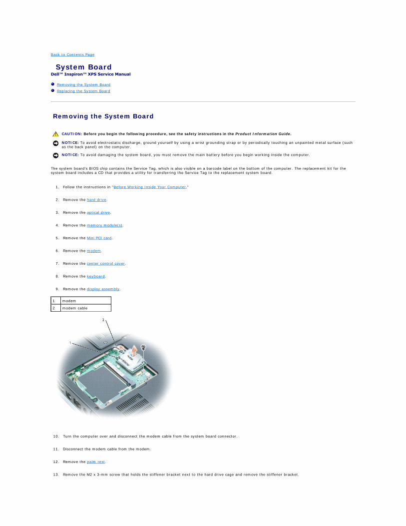
Back to Contents Page
System Board Dell™ Inspiron™ XPS Service Manual
Removing the System Board
Replacing the System Board
Removing the System Board
The system board's BIOS chip contains the Service Tag, which is also visible on a barcode label on the bottom of the computer. The replacement kit for the system board includes a CD that provides a utility for transferring the Service Tag to the replacement system board.
1. Follow the instructions in "Before Working Inside Your Computer."
2. Remove the hard drive.
3. Remove the optical drive.
4. Remove the memory module(s).
5. Remove the Mini PCI card.
6. Remove the modem.
7. Remove the center control cover.
8. Remove the keyboard.
9. Remove the display assembly.
10. Turn the computer over and disconnect the modem cable from the system board connector.
11. Disconnect the modem cable from the modem.
12. Remove the palm rest.
13. Remove the M2 x 3-mm screw that holds the stiffener bracket next to the hard drive cage and remove the stiffener bracket.
CAUTION: Before you begin the following procedure, see the safety instructions in the Product Information Guide.
NOTICE: To avoid electrostatic discharge, ground yourself by using a wrist grounding strap or by periodically touching an unpainted metal surface (such as the back panel) on the computer.
NOTICE: To avoid damaging the system board, you must remove the main battery before you begin working inside the computer.
1 modem
2 modem cable
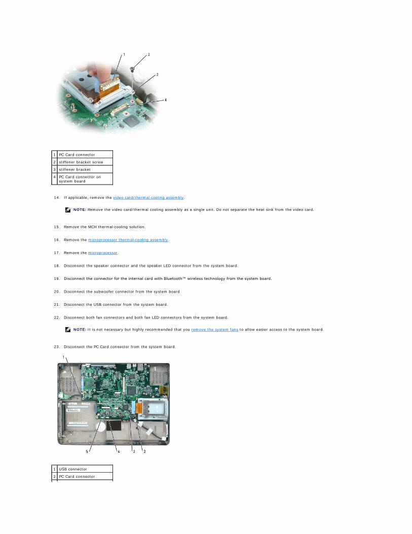
14. If applicable, remove the video card/thermal cooling assembly.
15. Remove the MCH thermal-cooling solution.
16. Remove the microprocessor thermal-cooling assembly.
17. Remove the microprocessor.
18. Disconnect the speaker connector and the speaker LED connector from the system board.
19. Disconnect the connector for the internal card with Bluetooth™ wireless technology from the system board.
20. Disconnect the subwoofer connector from the system board
21. Disconnect the USB connector from the system board.
22. Disconnect both fan connectors and both fan LED connectors from the system board.
23. Disconnect the PC Card connector from the system board.
1 PC Card connector
2 stiffener bracket screw
3 stiffener bracket
4 PC Card connector on system board
NOTE: Remove the video card/thermal cooling assembly as a single unit. Do not separate the heat sink from the video card.
NOTE: It is not necessary but highly recommended that you remove the system fans to allow easier access to the system board.
1 USB connector
2 PC Card connector
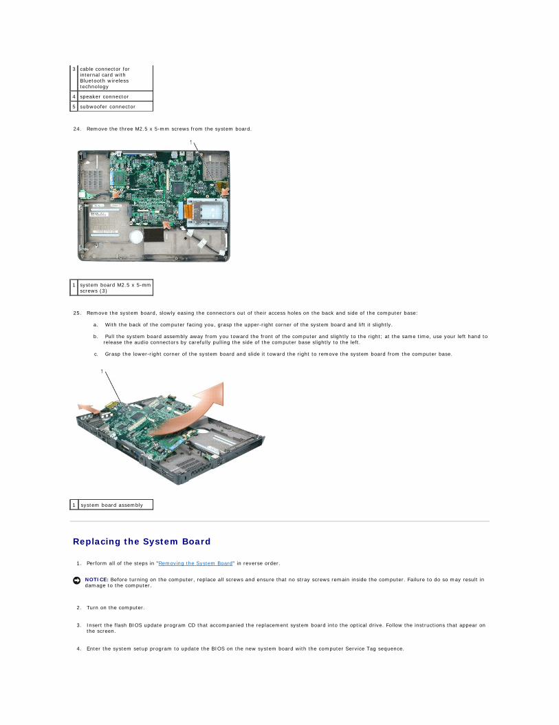
24. Remove the three M2.5 x 5-mm screws from the system board.
25. Remove the system board, slowly easing the connectors out of their access holes on the back and side of the computer base:
a. With the back of the computer facing you, grasp the upper-right corner of the system board and lift it slightly.
b. Pull the system board assembly away from you toward the front of the computer and slightly to the right; at the same time, use your left hand to
release the audio connectors by carefully pulling the side of the computer base slightly to the left.
c. Grasp the lower-right corner of the system board and slide it toward the right to remove the system board from the computer base.
Replacing the System Board
1. Perform all of the steps in "Removing the System Board" in reverse order.
2. Turn on the computer.
3. Insert the flash BIOS update program CD that accompanied the replacement system board into the optical drive. Follow the instructions that appear on the screen.
4. Enter the system setup program to update the BIOS on the new system board with the computer Service Tag sequence.
3 cable connector for internal card with Bluetooth wireless technology
4 speaker connector
5 subwoofer connector
1 system board M2.5 x 5-mm screws (3)
1 system board assembly
NOTICE: Before turning on the computer, replace all screws and ensure that no stray screws remain inside the computer. Failure to do so may result in damage to the computer.


Back to Contents Page
System Components Dell™ Inspiron™ XPS Service Manual
Back to Contents Page
NOTICE: Only a certified service technician should perform repairs on your computer. Damage due to servicing that is not authorized by Dell is not covered by your warranty.
NOTICE: Unless otherwise noted, each procedure in this document assumes that a part can be replaced by performing the removal procedure in reverse order.
1 display assembly 12 speakers
2 center control cover 13 subwoofer
3 palm rest (with touch pad) 14 optical drive
4 mini PCI card 15 system board
5 fan 16 fan
6 video card/thermal cooling assembly 17 microprocessor
7 computer base 18 microprocessor thermal cooling assembly
8 hard drive cage 19 MCH heat sink
9 PC Card reader cage 20 keyboard
10 hard drive 21 USB port board
11 battery
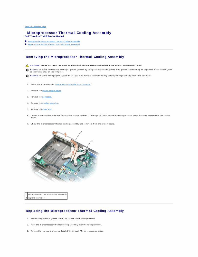
Back to Contents Page
Microprocessor Thermal-Cooling Assembly Dell™ Inspiron™ XPS Service Manual
Removing the Microprocessor Thermal-Cooling Assembly
Replacing the Microprocessor Thermal-Cooling Assembly
Removing the Microprocessor Thermal-Cooling Assembly
1. Follow the instructions in "Before Working Inside Your Computer."
2. Remove the center control cover.
3. Remove the keyboard.
4. Remove the display assembly.
5. Remove the palm rest.
6. Loosen in consecutive order the four captive screws, labeled "1" through "4," that secure the microprocessor thermal-cooling assembly to the system board.
7. Lift up the microprocessor thermal-cooling assembly and remove it from the system board.
Replacing the Microprocessor Thermal-Cooling Assembly
1. Evenly apply thermal grease to the top surface of the microprocessor.
2. Place the microprocessor thermal-cooling assembly over the microprocessor.
3. Tighten the four captive screws, labeled "1" through "4," in consecutive order.
CAUTION: Before you begin the following procedure, see the safety instructions in the Product Information Guide.
NOTICE: To avoid electrostatic discharge, ground yourself by using a wrist grounding strap or by periodically touching an unpainted metal surface (such as the back panel) on the computer.
NOTICE: To avoid damaging the system board, you must remove the main battery before you begin working inside the computer.
1 microprocessor thermal-cooling assembly
2 captive screws (4)


Back to Contents Page
Dell™ Inspiron™ XPS Service Manual
For a complete list of abbreviations and acronyms, see the Dell Inspiron Help file. To access the help file, click the Start button, click Help and Support, click User and system guides, click User's guides, and click Dell Inspiron Help.
If you purchased a Dell™ n Series computer, any references in this document to Microsoft® Windows® operating systems are not applicable.
Information in this document is subject to change without notice. © 2005 Dell Inc. All rights reserved.
Reproduction in any manner whatsoever without the written permission of Dell Inc. is strictly forbidden.
Trademarks used in this text: Dell, the DELL logo, and Inspiron are trademarks of Dell Inc.; Microsoft and Windows are registered trademarks of Microsoft Corporation; Bluetooth is a trademark owned by Bluetooth SIG, Inc. and is used by Dell Inc. under license.
Other trademarks and trade names may be used in this document to refer to either the entities claiming the marks and names or their products. Dell Inc. disclaims any proprietary interest in trademarks and trade names other than its own.
Model PP14L
February 2005 Rev. A00
Back to Contents Page
NOTE: A NOTE indicates important information that helps you make better use of your computer.
NOTICE: A NOTICE indicates either potential damage to hardware or loss of data and tells you how to avoid the problem.
CAUTION: A CAUTION indicates a potential for property damage, personal injury, or death.

Back to Contents Page
USB Port Board Dell™ Inspiron™ XPS Service Manual
Removing the USB Port Board
Replacing the USB Port Board
Removing the USB Port Board
1. Follow the instructions in "Before Working Inside Your Computer."
2. Remove the center control cover.
3. Remove the keyboard.
4. Remove the display assembly.
5. Remove the palm rest.
6. Remove the connector from the system board, then remove the M2.5 x 5-mm screw and lift the board up and out of the computer.
Replacing the USB Port Board
1. Insert the USB port board under the small lip on the bottom panel at the back of the board and over the pin on the front side of the board.
2. Reinstall the M2.5 x 5-mm screw securing the board.
3. Insert the connector into the system board.
4. Perform the steps to Remove the USB port board in reverse.
CAUTION: Before you begin any of the procedures in this section, follow the safety instructions located in the Product Information Guide.
NOTICE: To avoid electrostatic discharge, ground yourself by using a wrist grounding strap or by periodically touching an unpainted metal surface (such as the back panel) on the computer.
NOTICE: To avoid damaging the system board, you must remove the main battery before you begin working inside the computer.
1 USB port board
2 M2.5 x 5-mm screw (1)
3 system board connector

5. Replace the palm rest.
6. Replace the display assembly.
7. Replace the keyboard.
8. Replace the center control cover.
9. Replace the battery and other items removed in "Before Working Inside Your Computer."
Back to Contents Page
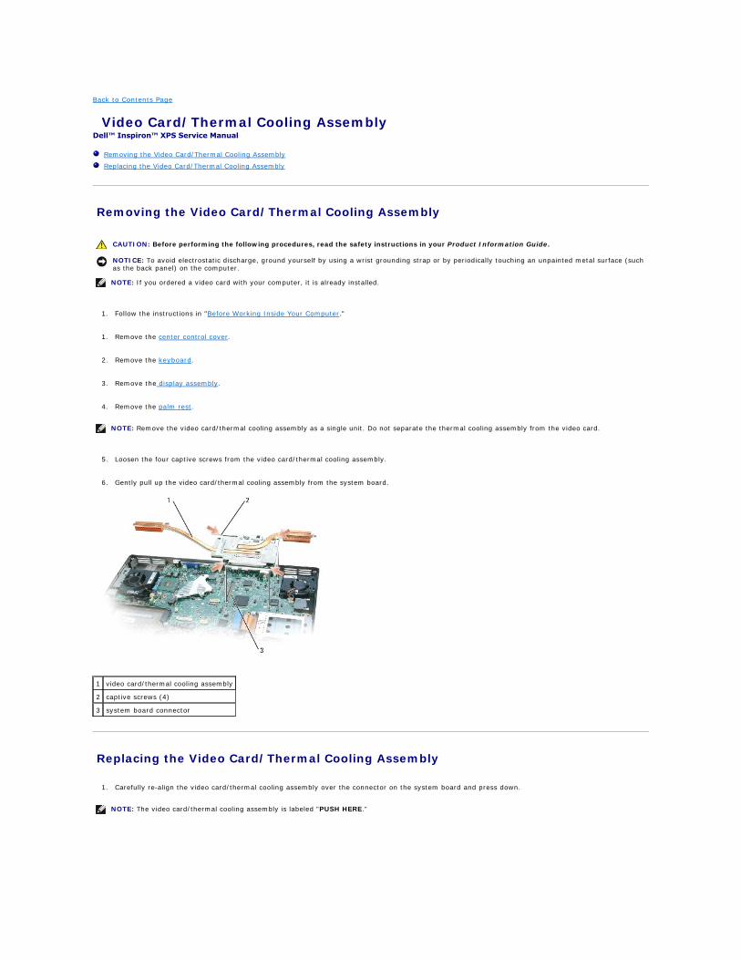
Back to Contents Page
Video Card/Thermal Cooling Assembly Dell™ Inspiron™ XPS Service Manual
Removing the Video Card/Thermal Cooling Assembly
Replacing the Video Card/Thermal Cooling Assembly
Removing the Video Card/Thermal Cooling Assembly
1. Follow the instructions in "Before Working Inside Your Computer."
1. Remove the center control cover.
2. Remove the keyboard.
3. Remove the display assembly.
4. Remove the palm rest.
5. Loosen the four captive screws from the video card/thermal cooling assembly.
6. Gently pull up the video card/thermal cooling assembly from the system board.
Replacing the Video Card/Thermal Cooling Assembly
1. Carefully re-align the video card/thermal cooling assembly over the connector on the system board and press down.
CAUTION: Before performing the following procedures, read the safety instructions in your Product Information Guide.
NOTICE: To avoid electrostatic discharge, ground yourself by using a wrist grounding strap or by periodically touching an unpainted metal surface (such as the back panel) on the computer.
NOTE: If you ordered a video card with your computer, it is already installed.
NOTE: Remove the video card/thermal cooling assembly as a single unit. Do not separate the thermal cooling assembly from the video card.
1 video card/thermal cooling assembly
2 captive screws (4)
3 system board connector
NOTE: The video card/thermal cooling assembly is labeled "PUSH HERE."
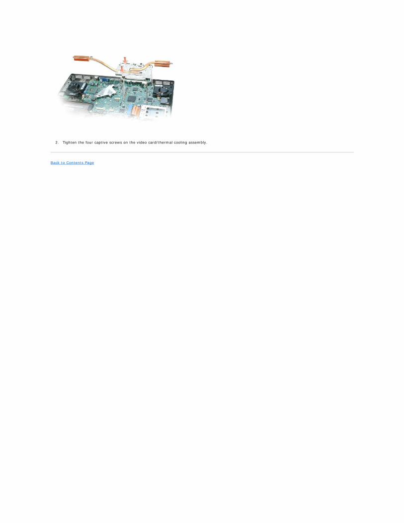
2. Tighten the four captive screws on the video card/thermal cooling assembly.
Back to Contents Page
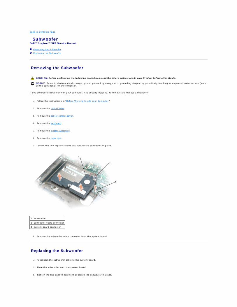
Back to Contents Page
Subwoofer Dell™ Inspiron™ XPS Service Manual
Removing the Subwoofer
Replacing the Subwoofer
Removing the Subwoofer
If you ordered a subwoofer with your computer, it is already installed. To remove and replace a subwoofer:
1. Follow the instructions in "Before Working Inside Your Computer."
2. Remove the optical drive.
3. Remove the center control cover.
4. Remove the keyboard.
5. Remove the display assembly.
6. Remove the palm rest.
7. Loosen the two captive screws that secure the subwoofer in place.
8. Remove the subwoofer cable connector from the system board.
Replacing the Subwoofer
1. Reconnect the subwoofer cable to the system board.
2. Place the subwoofer onto the system board.
3. Tighten the two captive screws that secure the subwoofer in place.
CAUTION: Before performing the following procedures, read the safety instructions in your Product Information Guide.
NOTICE: To avoid electrostatic discharge, ground yourself by using a wrist grounding strap or by periodically touching an unpainted metal surface (such as the back panel) on the computer.
1 subwoofer
2 subwoofer cable connector
3 system board connector

Related Documents