XPS-MCWIN Configuration Software for XPS-MC16 and XPS-MC32, for MS-Windows

Welcome message from author
This document is posted to help you gain knowledge. Please leave a comment to let me know what you think about it! Share it to your friends and learn new things together.
Transcript
XPS-MCWIN
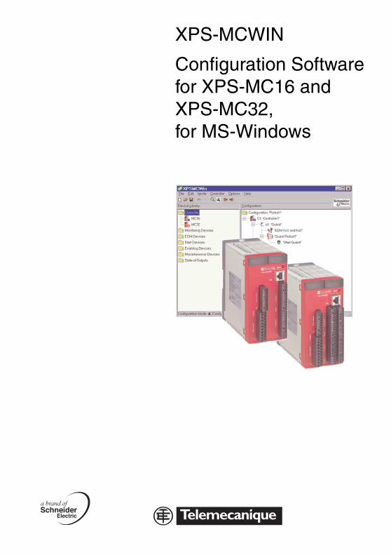
Configuration Softwarefor XPS-MC16 andXPS-MC32,for MS-Windows

© All rights reserved, in particular the rights of reproduction and translation. Copying or reproduction in any form requires prior written permission from copyright owner.Changes due to technical improvement may be made.
Telemecanique - XPS-MCWIN
07/2004 Contents 1
EN
GLI
SH
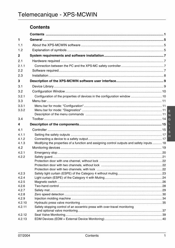
ContentsContents ............................................................................................................................... 1
1 General .................................................................................................................................. 5
1.1 About the XPS-MCWIN software ......................................................................................... 5
1.2 Explanation of symbols ........................................................................................................ 5
2 System requirements and software installation................................................................ 7
2.1 Hardware required ............................................................................................................... 7
2.1.1 Connection between the PC and the XPS-MC safety controller ................................................. 7
2.2 Software required................................................................................................................. 7
2.3 Installation............................................................................................................................ 8
3 Description of the XPS-MCWIN software user interface................................................... 9
3.1 Device Library ...................................................................................................................... 9
3.2 Configuration Window........................................................................................................ 10
3.2.1 Configuration of the properties of devices in the configuration window .................................... 10
3.3 Menu bar ............................................................................................................................ 11
3.3.1 Menu bar for mode: "Configuration".......................................................................................... 113.3.2 Menu bar for mode: "Diagnostics" ............................................................................................ 11
Description of the menu commands ........................................................................................ 11
3.4 Toolbar ............................................................................................................................... 14
4 Description of the components......................................................................................... 15
4.1 Controller ........................................................................................................................... 15
4.1.1 Setting the safety outputs ......................................................................................................... 174.1.2 Connecting a device to a safety output..................................................................................... 174.1.3 Modifying the properties of a function and assigning control outputs and safety inputs ........... 18
4.2 Monitoring devices ............................................................................................................. 19
4.2.1 Emergency stop ........................................................................................................................ 204.2.2 Safety guard.............................................................................................................................. 21
Protection door with one channel, without lock ........................................................................ 22Protection door with two channels, without lock ...................................................................... 22Protection door with two channels, with lock ........................................................................... 22
4.2.3 Safety light curtain (ESPE) of the Category 4 without muting................................................... 234.2.4 Light curtain (ESPE) of the Category 4 with Muting.................................................................. 244.2.5 Magnetic switch ........................................................................................................................ 264.2.6 Two-hand control ...................................................................................................................... 284.2.7 Safety mat................................................................................................................................. 294.2.8 Zero speed detection ................................................................................................................ 304.2.9 Injection molding machine ........................................................................................................ 344.2.10 Hydraulic press valve monitoring .............................................................................................. 354.2.11 Safety stopping control of an eccentric press with over-travel monitoring
and optional valve monitoring................................................................................................. 374.2.12 Seat Valve Monitoring............................................................................................................... 394.2.13 EDM Devices (EDM = External Device Monitoring).................................................................. 40
Telemecanique - XPS-MCWIN
2 Contents 07/2004
EN
GLI
SH
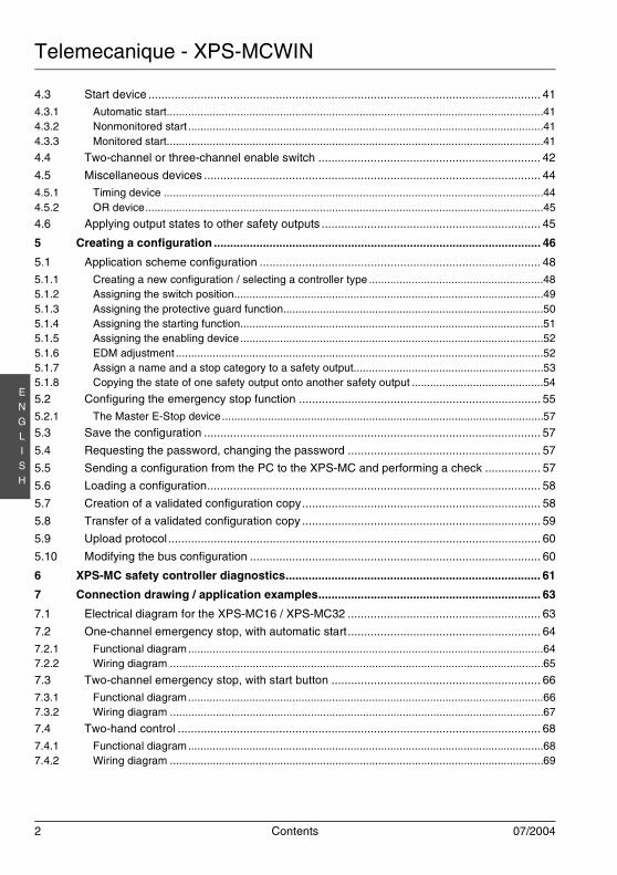
4.3 Start device ........................................................................................................................ 41
4.3.1 Automatic start...........................................................................................................................414.3.2 Nonmonitored start ....................................................................................................................414.3.3 Monitored start...........................................................................................................................41
4.4 Two-channel or three-channel enable switch .................................................................... 42
4.5 Miscellaneous devices ....................................................................................................... 44
4.5.1 Timing device ............................................................................................................................444.5.2 OR device..................................................................................................................................45
4.6 Applying output states to other safety outputs ................................................................... 45
5 Creating a configuration .................................................................................................... 46
5.1 Application scheme configuration ...................................................................................... 48
5.1.1 Creating a new configuration / selecting a controller type .........................................................485.1.2 Assigning the switch position.....................................................................................................495.1.3 Assigning the protective guard function.....................................................................................505.1.4 Assigning the starting function...................................................................................................515.1.5 Assigning the enabling device ...................................................................................................525.1.6 EDM adjustment ........................................................................................................................525.1.7 Assign a name and a stop category to a safety output..............................................................535.1.8 Copying the state of one safety output onto another safety output ...........................................54
5.2 Configuring the emergency stop function .......................................................................... 55
5.2.1 The Master E-Stop device .........................................................................................................57
5.3 Save the configuration ....................................................................................................... 57
5.4 Requesting the password, changing the password ........................................................... 57
5.5 Sending a configuration from the PC to the XPS-MC and performing a check ................. 57
5.6 Loading a configuration...................................................................................................... 58
5.7 Creation of a validated configuration copy......................................................................... 58
5.8 Transfer of a validated configuration copy ......................................................................... 59
5.9 Upload protocol.................................................................................................................. 60
5.10 Modifying the bus configuration ......................................................................................... 60
6 XPS-MC safety controller diagnostics.............................................................................. 61
7 Connection drawing / application examples.................................................................... 63
7.1 Electrical diagram for the XPS-MC16 / XPS-MC32 ........................................................... 63
7.2 One-channel emergency stop, with automatic start........................................................... 64
7.2.1 Functional diagram....................................................................................................................647.2.2 Wiring diagram ..........................................................................................................................65
7.3 Two-channel emergency stop, with start button ................................................................ 66
7.3.1 Functional diagram....................................................................................................................667.3.2 Wiring diagram ..........................................................................................................................67
7.4 Two-hand control ............................................................................................................... 68
7.4.1 Functional diagram....................................................................................................................687.4.2 Wiring diagram ..........................................................................................................................69
Telemecanique - XPS-MCWIN
07/2004 Contents 3
EN
GLI
SH
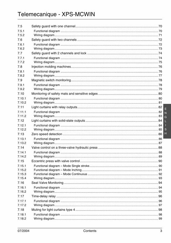
7.5 Safety guard with one channel........................................................................................... 70
7.5.1 Functional diagram ................................................................................................................... 707.5.2 Wiring diagram.......................................................................................................................... 71
7.6 Safety guard with two channels ......................................................................................... 72
7.6.1 Functional diagram ................................................................................................................... 727.6.2 Wiring diagram.......................................................................................................................... 73
7.7 Safety guard with 2 channels and lock .............................................................................. 74
7.7.1 Functional diagram ................................................................................................................... 747.7.2 Wiring diagram.......................................................................................................................... 75
7.8 Injection molding machines................................................................................................ 76
7.8.1 Functional diagram ................................................................................................................... 767.8.2 Wiring diagram.......................................................................................................................... 77
7.9 Magnetic switch monitoring................................................................................................ 78
7.9.1 Functional diagram ................................................................................................................... 787.9.2 Wiring diagram.......................................................................................................................... 79
7.10 Monitoring of safety mats and sensitive edges .................................................................. 80
7.10.1 Functional diagram ................................................................................................................... 807.10.2 Wiring diagram.......................................................................................................................... 81
7.11 Light curtains with relay outputs......................................................................................... 82
7.11.1 Functional diagram ................................................................................................................... 827.11.2 Wiring diagram.......................................................................................................................... 83
7.12 Light curtains with solid-state outputs ................................................................................ 84
7.12.1 Functional diagram ................................................................................................................... 847.12.2 Wiring diagram.......................................................................................................................... 85
7.13 Zero speed detection ......................................................................................................... 86
7.13.1 Functional diagram ................................................................................................................... 867.13.2 Wiring diagram.......................................................................................................................... 87
7.14 Valve control on a three-valve hydraulic press .................................................................. 88
7.14.1 Functional diagram ................................................................................................................... 887.14.2 Wiring diagram.......................................................................................................................... 89
7.15 Eccentric press with valve control ...................................................................................... 90
7.15.1 Functional diagram – Mode Single stroke................................................................................. 907.15.2 Functional diagram – Mode Inching.......................................................................................... 917.15.3 Functional diagram – Mode Continuous ................................................................................... 927.15.4 Wiring diagram.......................................................................................................................... 93
7.16 Seat Valve Monitoring ........................................................................................................ 94
7.16.1 Functional diagram ................................................................................................................... 947.16.2 Wiring diagram.......................................................................................................................... 95
7.17 Time-delay relay ................................................................................................................ 96
7.17.1 Functional diagram ................................................................................................................... 967.17.2 Wiring diagram.......................................................................................................................... 97
7.18 Muting for light curtains type 4 ........................................................................................... 98
7.18.1 Functional diagram ................................................................................................................... 987.18.2 Wiring diagram.......................................................................................................................... 99
Telemecanique - XPS-MCWIN
4 Contents 07/2004
EN
GLI
SH
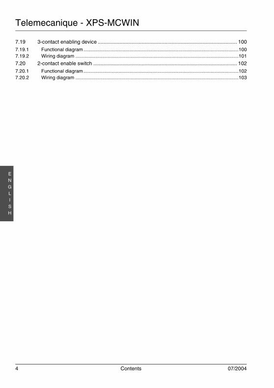
7.19 3-contact enabling device ................................................................................................ 100
7.19.1 Functional diagram..................................................................................................................1007.19.2 Wiring diagram ........................................................................................................................101
7.20 2-contact enable switch ................................................................................................... 102
7.20.1 Functional diagram..................................................................................................................1027.20.2 Wiring diagram ........................................................................................................................103
Telemecanique - XPS-MCWIN
07/2004 General 5
EN
GLI
SH
1 General
1.1 About the XPS-MCWIN software
This program lets you start, set up and diagnose the XPS-MC safety controller from a PC.
The simple user interface lets you set up the XPS-MC for a multitude of applications for the protectionof hazardous areas near mechanical machines.
The XPS-MCWIN software is used for the installation, documentation and fault diagnostics of yoursafety application.
This version of the XPS-MCWIN software was designed to be used with Microsoft® Windows 95/98/ME/NT/2000/XP® operating systems.
1.2 Explanation of symbols
The explanation of the symbols used in this instruction manual is given below.
Attention!This symbol is included in front of paragraphs which must be strictly complied with. If notcomplied with, injuries or equipment damage may result.
Notice !This symbol marks passages containing important information.
Telemecanique - XPS-MCWIN
6 General 07/2004
EN
GLI
SH
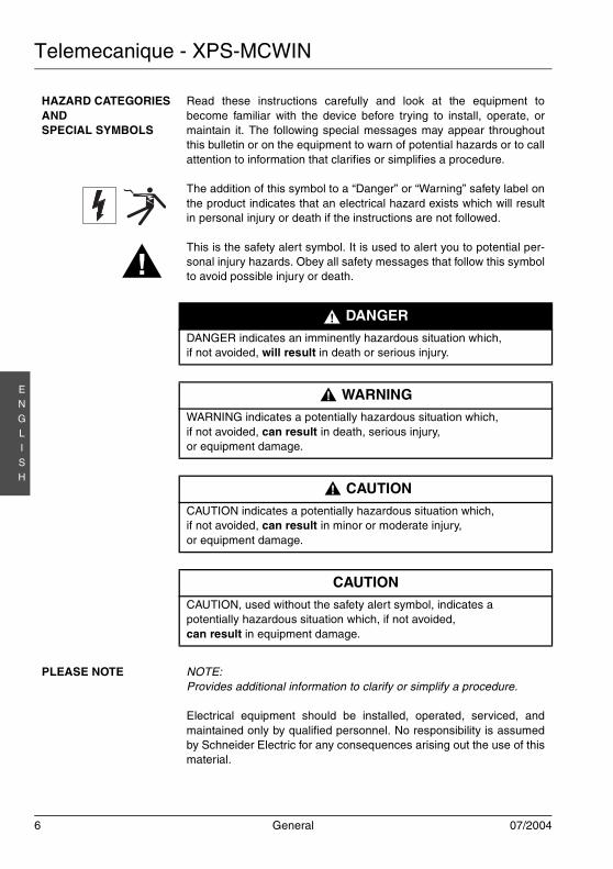
HAZARD CATEGORIESANDSPECIAL SYMBOLS
Read these instructions carefully and look at the equipment tobecome familiar with the device before trying to install, operate, ormaintain it. The following special messages may appear throughoutthis bulletin or on the equipment to warn of potential hazards or to callattention to information that clarifies or simplifies a procedure.
The addition of this symbol to a “Danger” or “Warning” safety label onthe product indicates that an electrical hazard exists which will resultin personal injury or death if the instructions are not followed.
This is the safety alert symbol. It is used to alert you to potential per-sonal injury hazards. Obey all safety messages that follow this symbolto avoid possible injury or death.
DANGERDANGER indicates an imminently hazardous situation which,if not avoided, will result in death or serious injury.
WARNINGWARNING indicates a potentially hazardous situation which,if not avoided, can result in death, serious injury,or equipment damage.
CAUTIONCAUTION indicates a potentially hazardous situation which,if not avoided, can result in minor or moderate injury,or equipment damage.
CAUTIONCAUTION, used without the safety alert symbol, indicates apotentially hazardous situation which, if not avoided,can result in equipment damage.
PLEASE NOTE NOTE:Provides additional information to clarify or simplify a procedure.
Electrical equipment should be installed, operated, serviced, andmaintained only by qualified personnel. No responsibility is assumedby Schneider Electric for any consequences arising out the use of thismaterial.
!
!
!!
!!
Telemecanique - XPS-MCWIN
07/2004 System requirements and software installation 7
EN
GLI
SH
2 System requirements and software installation
2.1 Hardware required
The following is required to set up / diagnose faults affecting the safety controller on a PC:
• an XPS-MC16 or XPS-MC32 safety controller,• the TSXPCX1031 interface cable and the XPSMCCPC adaptor cable (not included) for connecting
the safety controller to the PC,• an IBM compatible PC with the following capabilities at least:
• a Pentium® processor, or equivalent,• a CD-ROM drive (or a floppy disk drive) for the installation,• a mouse or an equivalent device,• a free RS232 serial port with a 9-pin subD connector,• at least 12 MB free hard disk space,• at least 8 MB RAM recommended.
• Display: 800 x 600, 256 colors (1024 x 768 recommended)
2.1.1 Connection between the PC and the XPS-MC safety controller
To set up and diagnose faults affecting the XPS-MC using the XPS-MCWIN software, connect a serialport of your PC to the TER connector of the XPS-MC safety controller by means of the TSXPCX1031serial interface cable and the XPSMCCPC adaptor (not included).
2.2 Software required
The XPS-MCWIN software requires the following system:
• Operating system: Microsoft® Windows 95/98/ME/NT/2000/XP®
• Adobe® Reader® 5 must be installed to read the PDF Files of the instructions sheets.
WARNINGIMPROPER CONFIGURATION FROM PC
Exclusively use the TSXPCX1031 interface cable and XPSMCCPC adapter for connection to theXPS-MC when configuring from a PC.
Failure to follow this instruction can result in equipment damage or serious injury.
Note!Under Windows-XP, transmission sometimes may not be fully completed.Solution: quit and restart XPS-MCWIN.
!
Telemecanique - XPS-MCWIN
8 System requirements and software installation 07/2004
EN
GLI
SH
2.3 Installation
To install the XPS-MCWIN software, you need the installation CD-ROM included. If your PC does nothave a CD-ROM drive, you can also copy the installation data on floppy disks and perform the instal-lation in this way.
After inserting the CD into the drive, run the “setup.exe” file in the CD-ROM default directory, for ex-ample:D:\setup.exe (if D: is the letter corresponding to your CD-ROM drive).
After the installation, the program is ready to be started for the first time.
Telemecanique - XPS-MCWIN
07/2004 Description of the XPS-MCWIN software user interface 9
EN
GLI
SH
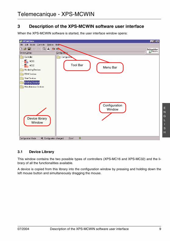
3 Description of the XPS-MCWIN software user interfaceWhen the XPS-MCWIN software is started, the user interface window opens:
3.1 Device Library
This window contains the two possible types of controllers (XPS-MC16 and XPS-MC32) and the li-brary of all the functionalities available.
A device is copied from this library into the configuration window by pressing and holding down theleft mouse button and simultaneously dragging the mouse.
Tool Bar
Device libraryWindow
Menu Bar
ConfigurationWindow
Telemecanique - XPS-MCWIN
10 Description of the XPS-MCWIN software user interface 07/2004
EN
GLI
SH
3.2 Configuration Window
This is the working window in XPS-MCWIN. The configuration is defined and modified in this window.
3.2.1 Configuration of the properties of devices in the configuration window
All the devices of the configuration window are configured by following the same procedure.
If a device is moved in the configuration window, a window appears in which the parameters of thisdevice are selected. On the subject of these parameters, reference should also be made to chapter 4"Description of the components".
Note: If this window does not open automatically, this means that this device is not active in the“options editor” menu option. In this case, open the window by clicking with the right mousebutton on the symbol and selecting the “Properties” option.
The following commands can also be called by clicking the right mouse button on the symbol in theconfiguration window:
Copy
Using this command, a device can be copied with the properties assigned to it and pasted else-where in the configuration tree.
Cut
Using this command, a device can be cut with the properties assigned to it and pasted elsewherein the configuration tree.
Paste
This command pastes a copied or cut device into the selected location.
Delete
Deletes the selected object.
Tree
Minimises the configuration tree of this controller for better visibility. The tree is conserved and canbe reopened at any time.
Telemecanique - XPS-MCWIN
07/2004 Description of the XPS-MCWIN software user interface 11
EN
GLI
SH
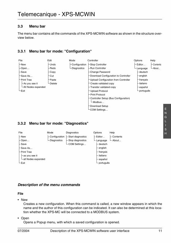
3.3 Menu bar
The menu bar contains all the commands of the XPS-MCWIN software as shown in the structure over-view below.
3.3.1 Menu bar for mode: "Configuration"
3.3.2 Menu bar for mode: "Diagnostics"
Description of the menu commands
File
• NewCreates a new configuration. When this command is called, a new window appears in which thename and the author of this configuration can be indicated. It can also be determined at this loca-tion whether the XPS-MC will be connected to a MODBUS system.
• OpenOpens a Popup menu, with which a saved configuration is opened.
File
New
Open…
Save
Save As…
Print Tree
Undo
Redo
Copy
Cut
Paste
Delete
Configuration
Diagnostics
Stop Controller
Run Controller
Change Password
Download Configuration to Controller
Upload Configuration from Controller
Create validated copy
Editor…
Edit ControllerMode Options Help
Transfer validated copy
Download Setup
As you see itAll Nodes expanded
Exit
Controller Setup (Bus Configuration)
Modbus…
COM Settings…
deutsch
english
français
Language
italiano
español
português
Contents
About...
Upload Protocol
Print Protocol
File
New
Open…
Save
Save As…
Print Tree
Help
as you see itall Nodes expanded
Exit
Contents
About...
Configuration
Diagnostics
Mode
Start diagnostics
Stop diagnostics
COM Settings…
Diagnostics
Editor…
Options
deutsch
english
français
Language
italiano
español
português
Telemecanique - XPS-MCWIN
12 Description of the XPS-MCWIN software user interface 07/2004
EN
GLI
SH
• SaveSaves the current configuration under the current name.
• Save as…Saves the current configuration under a new name.
• Print tree• As you see it
Print the configuration tree as you see it
• All the nodes expandedPrint the configuration tree with all the nodes expanded
• ExitQuits the XPS-MCWIN software.
Edit
• UndoCancels the last action.
• RedoRestores a cancelled action.
• CopyCopies the selected item into the buffer memory.
• CutCuts the selected item and copies it into the buffer memory.
• PastePastes an item from the buffer memory into the selected location.
• DeleteDeletes the selected item.
Mode
• ConfigurationThe configuration mode is the software’s working mode. All the commands can be executed inthis mode. In the configuration mode, a configuration is created, modified, and sent to and reload-ed from XPS-MC. When the program is started, this is the default mode of the software.
• DiagnosticsThe diagnostic mode is used exclusively for fault diagnosing the XPS-MC connected to the PC.The configuration can not be modified. In the fault diagnostic mode, the software working windowsare grey in colour.In this mode, the connected XPS-MC safety controller continues to operate without being affected.
Telemecanique - XPS-MCWIN
07/2004 Description of the XPS-MCWIN software user interface 13
EN
GLI
SH
Controller
• Stop ControllerThis command shuts down the XPS-MC. Its safety outputs are de-activated in accordance withtheir stop category, (either immediately or with a delay). The password must be entered.
• Run ControllerSwitches the XPS-MC to the Run mode.
• Change PasswordOpens a window to change the password.
• Download Configuration to ControllerSends the current configuration to the selected controller. The controller cannot be in RUN mode.The password must be entered.
• Upload Configuration from ControllerLoads into the PC and displays the current configuration of the connected XPS-MC. The XPS-MCcan continue to operate at the same time.
• Create validated copyCreates a file as safety copy of a validated configuration.
• Transfer validated copyTransfers a validated configuration from a file into a controller.
• Upload the protocolUpload the protocol of the present configuration of the connected XPS-MC and represents it as atext file. The password must be entered.
• Print the protocolPrints the protocol generated in the configuration. This protocol is used as proof for the XPS-MCstatutory configuration.For statutory use, the user checks, signs and keeps this protocol.
• Controller Setup (Bus Configuration)• Modbus…
Opens a window for adjusting the settings required for the operation of all the XPS-MCs (upto 8) of this configuration with a MODBUS system. Operation with different MODBUS sys-tems is also possible. By clicking on the “Download” button, the “send the settings to thecontroller” command is executed.
• Download SetupSends the parameters set (for MODBUS) to the selected controller of this configuration. TheXPS-MC must also be shut down. The password must be entered.This command only sends the bus parameters and not the configuration!
• COM Settings…Selects the COM port of the PC to which the XPS-MC is connected.

Telemecanique - XPS-MCWIN
14 Description of the XPS-MCWIN software user interface 07/2004
EN
GLI
SH
Options
• Editor…Setting possibilities to cause the “properties” dialogue window to be displayed automatically dur-ing item “Drag&Drop” and to save it automatically.
• Language• Selects the XPS-MCWIN software language.• A list of available languages is shown
Help
• ContentsOverview of the online help
• AboutInformation about the present version of the software
Diagnostics
• Start diagnosticsThe transmission of the diagnostics datas from the XPS-MC to the PC will be started.
• Stop diagnosticsThe transmission of the diagnostics datas from the XPS-MC to the PC will be stopped.
• COM Settings…Selection of the COM port of the PC, where the XPS-MC has to be connected.
After the change over in the mode diagnostics with menu command "Mode - Diagnostics", the menubar will be modified like described in the chapter 3.3.2 "Menu bar for mode: "Diagnostics"".
3.4 Toolbar
The toolbar contains a number of often-used instructions in the form of icons.
Telemecanique - XPS-MCWIN
07/2004 Description of the components 15
EN
GLI
SH
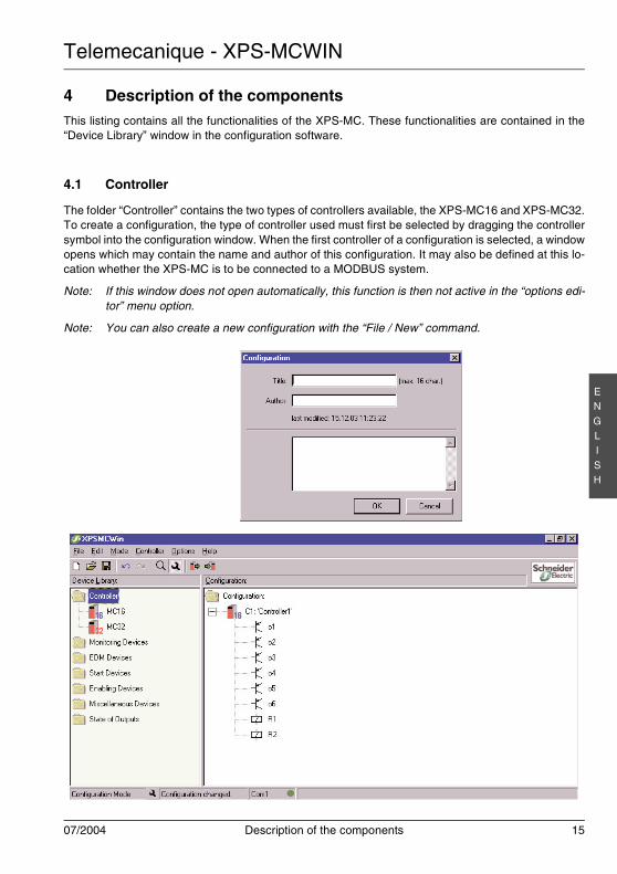
4 Description of the componentsThis listing contains all the functionalities of the XPS-MC. These functionalities are contained in the“Device Library” window in the configuration software.
4.1 Controller
The folder “Controller” contains the two types of controllers available, the XPS-MC16 and XPS-MC32.To create a configuration, the type of controller used must first be selected by dragging the controllersymbol into the configuration window. When the first controller of a configuration is selected, a windowopens which may contain the name and author of this configuration. It may also be defined at this lo-cation whether the XPS-MC is to be connected to a MODBUS system.
Note: If this window does not open automatically, this function is then not active in the “options edi-tor” menu option.
Note: You can also create a new configuration with the “File / New” command.
Telemecanique - XPS-MCWIN
16 Description of the components 07/2004
EN
GLI
SH
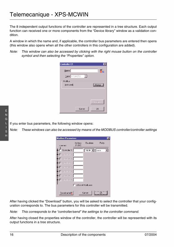
The 8 independent output functions of the controller are represented in a tree structure. Each outputfunction can received one or more components from the “Device library” window as a validation con-dition.
A window in which the name and, if applicable, the controller bus parameters are entered then opens(this window also opens when all the other controllers in this configuration are added).
Note: This window can also be accessed by clicking with the right mouse button on the controllersymbol and then selecting the “Properties” option.
.
If you enter bus parameters, the following window opens:
Note: These windows can also be accessed by means of the MODBUS controller/controller settings
After having clicked the “Download” button, you will be asked to select the controller that your config-uration corresponds to. The bus parameters for this controller will be transmitted.
Note: This corresponds to the “controller/send” the settings to the controller command.
After having closed the properties window of the controller, the controller will be represented with itsoutput functions in a tree structure.
Telemecanique - XPS-MCWIN
07/2004 Description of the components 17
EN
GLI
SH
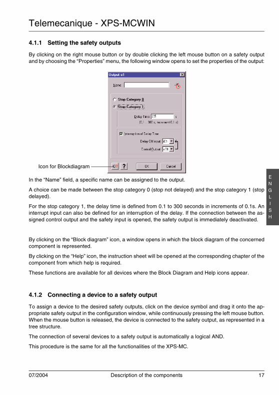
4.1.1 Setting the safety outputs
By clicking on the right mouse button or by double clicking the left mouse button on a safety outputand by choosing the “Properties” menu, the following window opens to set the properties of the output:
In the “Name” field, a specific name can be assigned to the output.
A choice can be made between the stop category 0 (stop not delayed) and the stop category 1 (stopdelayed).
For the stop category 1, the delay time is defined from 0.1 to 300 seconds in increments of 0.1s. Aninterrupt input can also be defined for an interruption of the delay. If the connection between the as-signed control output and the safety input is opened, the safety output is immediately deactivated.
By clicking on the “Block diagram” icon, a window opens in which the block diagram of the concernedcomponent is represented.
By clicking on the “Help” icon, the instruction sheet will be opened at the corresponding chapter of thecomponent from which help is required.
These functions are available for all devices where the Block Diagram and Help icons appear.
4.1.2 Connecting a device to a safety output
To assign a device to the desired safety outputs, click on the device symbol and drag it onto the ap-propriate safety output in the configuration window, while continuously pressing the left mouse button.When the mouse button is released, the device is connected to the safety output, as represented in atree structure.
The connection of several devices to a safety output is automatically a logical AND.
This procedure is the same for all the functionalities of the XPS-MC.
Icon for Blockdiagram

Telemecanique - XPS-MCWIN
18 Description of the components 07/2004
EN
GLI
SH
4.1.3 Modifying the properties of a function and assigning control outputs andsafety inputs
By dropping a component onto an output, the properties window of this component will be automati-cally opened. This function can be activated or deactivated in the menu Options - Editor.
Additional modifications of the properties can be done by clicking the right mouse button and choosingthe properties menu, or by double clicking on the symbol of the component in the configuration win-dow.
Note: If this window does not open automatically, this means that this function is not active in the“options editor” menu option. In this case, open the window by clicking with the right mousebutton on the symbol and selecting the “Properties” menu option.
In this window, the adjustable parameters of this function can be modified. Lower down in this window,you must indicate the switching item of this function (for example, the emergency stop button, the limitswitch, etc.), the control outputs and the safety inputs with which it is connected to the XPS-MC.
Note: If a safety input is occupied, it no longer appears in the list of safety inputs currently available.An incorrect double occupation is therefore eliminated.
Note: The already used control outputs can not be used in the properties window of the device“safety mats”.
This procedure is the same for all the functionalities of the XPS-MC.
Finally, confirm the defined inputs with “OK” or cancel with “Cancel”.
WARNINGLOSS OF SAFETY INPUT CROSS-CONNECTION DETECTION
Ensure that no more than one critical safety input is connected to each of the control outputs.
Failure to follow this instruction can result in equipment damage or serious injury.
Attention!If a control output c1...c8 has been used, a “*” follows the name, for example “c2*”, appearswhen this output is selected.The user must guarantee that no dangerous fault can occur when this control output is usedmore then once, as a dangerous short-circuit, for example, is no longer detected.
!
Telemecanique - XPS-MCWIN
07/2004 Description of the components 19
EN
GLI
SH
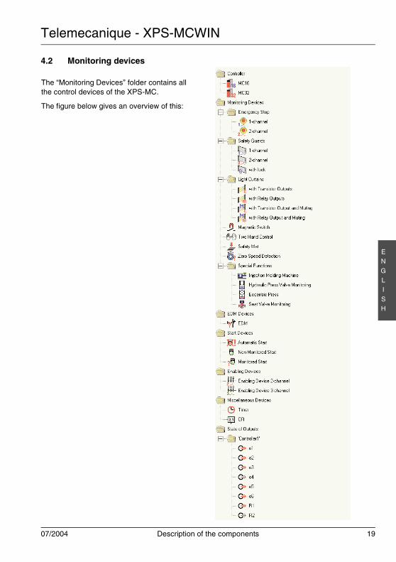
4.2 Monitoring devices
The “Monitoring Devices” folder contains allthe control devices of the XPS-MC.
The figure below gives an overview of this:
Telemecanique - XPS-MCWIN
20 Description of the components 07/2004
EN
GLI
SH
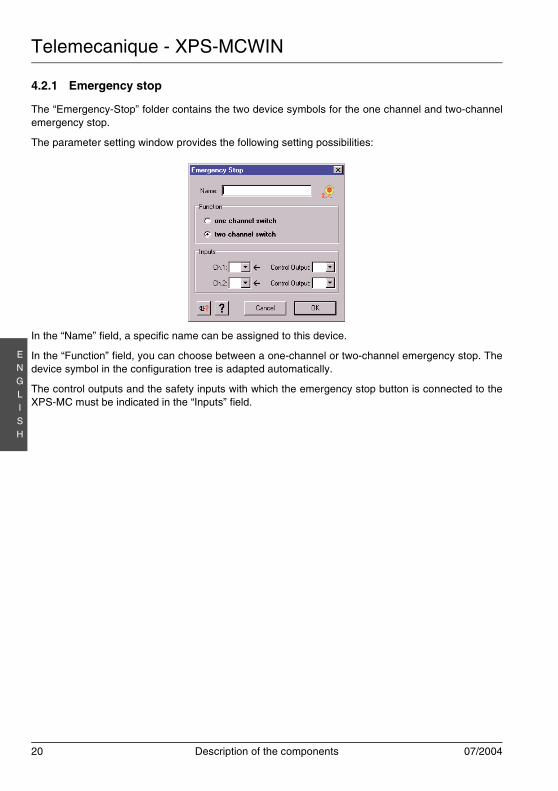
4.2.1 Emergency stop
The “Emergency-Stop” folder contains the two device symbols for the one channel and two-channelemergency stop.
The parameter setting window provides the following setting possibilities:
In the “Name” field, a specific name can be assigned to this device.
In the “Function” field, you can choose between a one-channel or two-channel emergency stop. Thedevice symbol in the configuration tree is adapted automatically.
The control outputs and the safety inputs with which the emergency stop button is connected to theXPS-MC must be indicated in the “Inputs” field.
Telemecanique - XPS-MCWIN
07/2004 Description of the components 21
EN
GLI
SH
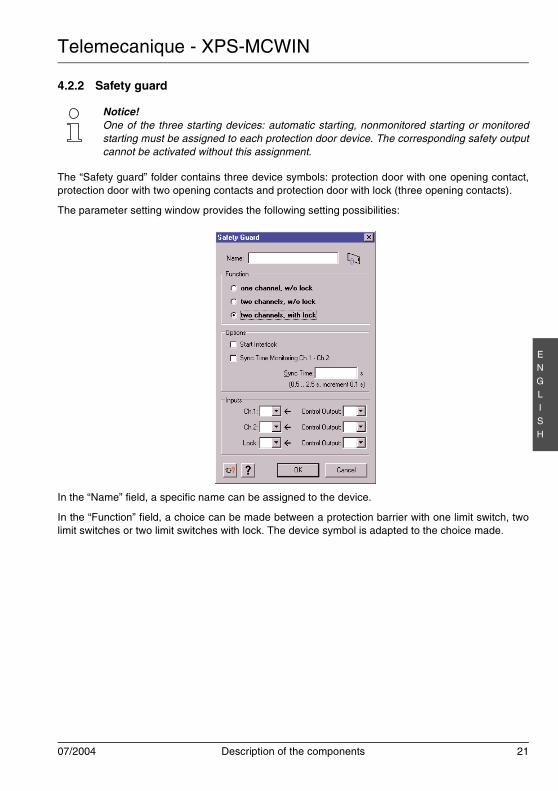
4.2.2 Safety guard
The “Safety guard” folder contains three device symbols: protection door with one opening contact,protection door with two opening contacts and protection door with lock (three opening contacts).
The parameter setting window provides the following setting possibilities:
In the “Name” field, a specific name can be assigned to the device.
In the “Function” field, a choice can be made between a protection barrier with one limit switch, twolimit switches or two limit switches with lock. The device symbol is adapted to the choice made.
Notice!One of the three starting devices: automatic starting, nonmonitored starting or monitoredstarting must be assigned to each protection door device. The corresponding safety outputcannot be activated without this assignment.
Telemecanique - XPS-MCWIN
22 Description of the components 07/2004
EN
GLI
SH
Protection door with one channel, without lock
In the “Options” field, you can define whether a startup test is to be carried out. During the startup test,the protection door must be opened once before the machine is started and then closed again, to guar-antee that the connected contact ch.1 also operates.
In the “Input” field, the control output and the safety input to which ch.1 is connected must be indicated.
Protection door with two channels, without lock
In the “Options” field, you can define whether a startup test is to be carried out. During the startup test,the protection door must be opened once before the machine is started and then closed again, to guar-antee that the connected contacts ch.1 and ch.2 also operate. A synchronisation time, during whichcontacts ch.1 and ch.2 must close, can also be entered. If this time is exceeded, the assigned safetyoutputs are not activated. This time can be defined from 0.5s to 2.5s, in increments of 0.1s.
The control outputs and the safety inputs used must be indicated in the “Inputs” field.
Protection door with two channels, with lock
In the “Options” field, you can define whether a startup test is to be carried out. During the startup test,the protection door must be opened once before the machine is started and then closed again, to guar-antee that the connected contacts ch.1, ch.2 and lock also operate. A synchronisation time, duringwhich contacts ch.1 and ch.2 must close, can also be entered. If this time is exceeded, the assignedsafety outputs are not activated. This time can be defined from 0.5s to 2.5s, in increments of 0.1s.
The control outputs and the safety inputs used must be indicated in the “Inputs” field.
Telemecanique - XPS-MCWIN
07/2004 Description of the components 23
EN
GLI
SH
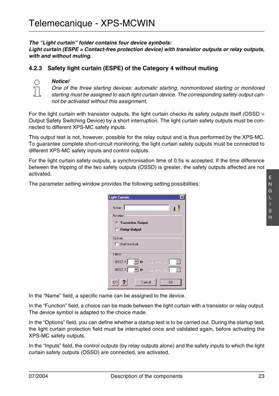
The “Light curtain” folder contains four device symbols:Light curtain (ESPE = Contact-free protection device) with transistor outputs or relay outputs,with and without muting.
4.2.3 Safety light curtain (ESPE) of the Category 4 without muting
For the light curtain with transistor outputs, the light curtain checks its safety outputs itself (OSSD =Output Safety Switching Device) by a short interruption. The light curtain safety outputs must be con-nected to different XPS-MC safety inputs.
This output test is not, however, possible for the relay output and is thus performed by the XPS-MC.To guarantee complete short-circuit monitoring, the light curtain safety outputs must be connected todifferent XPS-MC safety inputs and control outputs.
For the light curtain safety outputs, a synchronisation time of 0.5s is accepted. If the time differencebetween the tripping of the two safety outputs (OSSD) is greater, the safety outputs affected are notactivated.
The parameter setting window provides the following setting possibilities:
In the “Name” field, a specific name can be assigned to the device.
In the “Function” field, a choice can be made between the light curtain with a transistor or relay output.The device symbol is adapted to the choice made.
In the “Options” field, you can define whether a startup test is to be carried out. During the startup test,the light curtain protection field must be interrupted once and validated again, before activating theXPS-MC safety outputs.
In the “Inputs” field, the control outputs (by relay outputs alone) and the safety inputs to which the lightcurtain safety outputs (OSSD) are connected, are activated.
Notice!One of the three starting devices: automatic starting, nonmonitored starting or monitoredstarting must be assigned to each light curtain device. The corresponding safety output can-not be activated without this assignment.
Telemecanique - XPS-MCWIN
24 Description of the components 07/2004
EN
GLI
SH
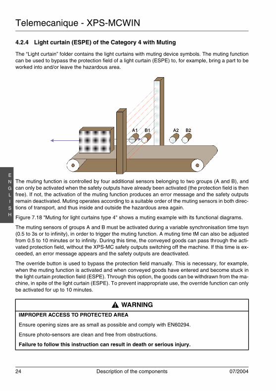
4.2.4 Light curtain (ESPE) of the Category 4 with Muting
The “Light curtain” folder contains the light curtains with muting device symbols. The muting functioncan be used to bypass the protection field of a light curtain (ESPE) to, for example, bring a part to beworked into and/or leave the hazardous area.
The muting function is controlled by four additional sensors belonging to two groups (A and B), andcan only be activated when the safety outputs have already been activated (the protection field is thenfree). If not, the activation of the muting function produces an error message and the safety outputsremain deactivated. Muting operates according to a suitable order of the muting sensors in both direc-tions of transport, and thus inside and outside the hazardous area again.
Figure 7.18 "Muting for light curtains type 4" shows a muting example with its functional diagrams.
The muting sensors of groups A and B must be activated during a variable synchronisation time tsyn(0.5 to 3s or to infinity), in order to trigger the muting function. A muting time tM can also be adjustedfrom 0.5 to 10 minutes or to infinity. During this time, the conveyed goods can pass through the acti-vated protection field, without the XPS-MC safety outputs switching off the machine. If this time is ex-ceeded, an error message appears and the safety outputs are deactivated.
The override button is used to bypass the protection field manually. This is necessary, for example,when the muting function is activated and when conveyed goods have entered and become stuck inthe light curtain protection field (ESPE). Through this option, the goods can be withdrawn from the ma-chine, in spite of the light curtain (ESPE). To prevent inappropriate use, the override function can onlybe activated for up to 10 minutes.
WARNINGIMPROPER ACCESS TO PROTECTED AREA
Ensure opening sizes are as small as possible and comply with EN60294.
Ensure photo-sensors are clean and free from obstructions.
Failure to follow this instruction can result in death or serious injury.
!

Telemecanique - XPS-MCWIN
07/2004 Description of the components 25
EN
GLI
SH
To create the muting signal, sensors with relais output, or mechanical limit switches are suitable formaking sure that a distinction is made between individuals and goods. At the same time, all easy de-feating must be prevented (stickers or photoelectric sensors for example).
On entering the hazardous area, light signal is recommended to announce the muting status for mut-ing operation; this signal must be connected between terminal H1 and the XPS-MC supply voltage(terminal A1). If a fault occurs at the level of this light signal (short-circuit, interruption), the mutingfunction is immediately de-activated and an error message appears. The safety outputs are then de-activated.
Sources of white light with an illumination surface of 1 cm² and a brightness of at least 200 lm/m² areused as a light signal. The intensity value of this light source must vary from 20mA to 350mA.
The light signal always comes on when the muting signals are generated correctly and announces thebypassing of the light curtain protection function (ESPE).
• A new cycle is only initiated with the starting control when no muting signal is required and whenthe protection field is free.
• During the time a muting signal is produced correctly, no one must be allowed to enter the hazard-ous area.
• A guide less means of transport must create the muting signal before it enters the protection field,and may only leave this field when it no longer interrupts the light curtains beams of the protectionfield.
The muting function meets the requirements of category 4 according to EN 954-1. To ensure the cor-rect monitoring of the muting lamp, a minimum duration of 500 ms for muting is necessary.
Photoelectric muting sensors must operate in dark switching mode, in order to produce the output sig-nal when a light ray is interrupted.
The parameter setting window provides the following setting possibilities:
WARNINGDETECTOR INTERFERENCE HAZARD WITH THRU-BEAM SENSORS
Reciprocal mount transmitters and receivers.
Mount adjacent receivers at distance greater than minimum separation distance.
Failure to follow this instruction can result in death or serious injury.
!
Telemecanique - XPS-MCWIN
26 Description of the components 07/2004
EN
GLI
SH
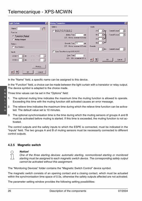
In the “Name” field, a specific name can be assigned to this device.
In the “Function” field, a choice can be made between the light curtain with a transistor or relay output.The device symbol is adapted to the choice made.
Three time values can be set in the “Options” field:
1. The optional muting time indicates the maximum time the muting function is allowed to operate.Exceeding this time with the muting function still activated causes an error message.
2. The relieve time indicates the maximum time during which the relieve time function can be activa-ted. The default value set is 10 minutes.
3. The optional synchronisation time is the time during which the muting sensors of groups A and Bmust be activated before muting is started. If this time is exceeded, the muting function is not ac-tivated.
The control outputs and the safety inputs to which the ESPE is connected, must be indicated in the“Inputs” field. The two groups A and B of muting sensors must be necessarily connected to differentcontrol outputs.
4.2.5 Magnetic switch
The “Monitoring Devices” folder contains the “Magnetic Switch Control” device symbol.
The magnetic switch consists of an opening contact and a closing contact, which must be actuatedwithin the synchronisation time space of 0.5s, otherwise the safety outputs affected are not activated.
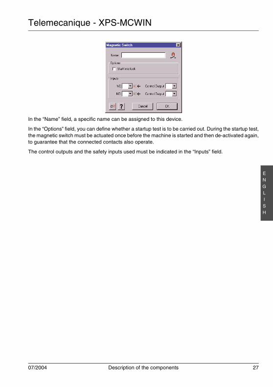
The parameter setting window provides the following setting possibilities:
Notice!One of the three starting devices: automatic starting, nonmonitored starting or monitoredstarting must be assigned to each magnetic switch device. The corresponding safety outputcannot be activated without this assignment.
Telemecanique - XPS-MCWIN
07/2004 Description of the components 27
EN
GLI
SH
In the “Name” field, a specific name can be assigned to this device.
In the “Options” field, you can define whether a startup test is to be carried out. During the startup test,the magnetic switch must be actuated once before the machine is started and then de-activated again,to guarantee that the connected contacts also operate.
The control outputs and the safety inputs used must be indicated in the “Inputs” field.
Telemecanique - XPS-MCWIN
28 Description of the components 07/2004
EN
GLI
SH
4.2.6 Two-hand control
The “Monitoring Devices” folder contains the “Two Hand Control” device symbol.
The control panel of the two-hand control consists of two buttons each having an opening contact anda closing contact. These buttons must be actuated within the synchronisation time space of 0.5s, toobtain switching of the safety outputs. If this time is exceeded, the assigned safety outputs are notactivated.
To ensure complete short-circuit monitoring, the two buttons must be connected to different controloutputs. If a button produces an unexpected signal, such as a short-circuit for example, the safety out-puts affected are deactivated or are not activated and an error message appears.
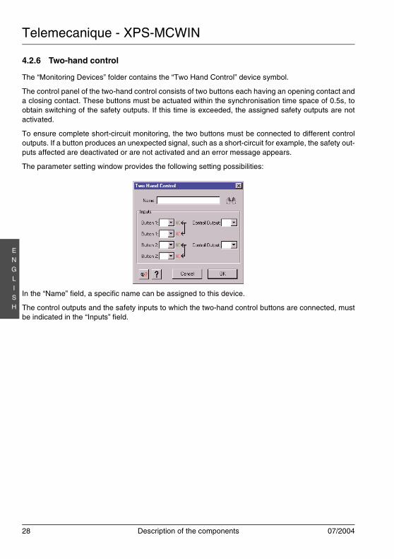
The parameter setting window provides the following setting possibilities:
In the “Name” field, a specific name can be assigned to this device.
The control outputs and the safety inputs to which the two-hand control buttons are connected, mustbe indicated in the “Inputs” field.
Telemecanique - XPS-MCWIN
07/2004 Description of the components 29
EN
GLI
SH
4.2.7 Safety mat
The “Monitoring Devices” folder contains the “Safety Mat” function symbol.
The switching mat consists of two pairs of metal leads that are short-circuited when the mat is walkedon. The XPS-MC safety outputs are then immediately deactivated. To be able to detect this shortcir-cuit, the four connection leads must be connected to different safety inputs and control outputs.
Types: see Technical Specifications, Hardware Presentation
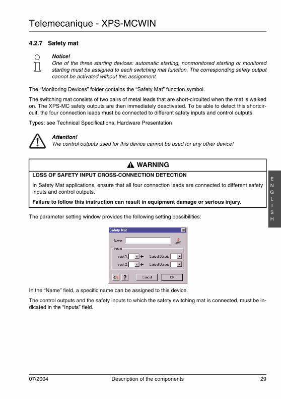
The parameter setting window provides the following setting possibilities:
In the “Name” field, a specific name can be assigned to this device.
The control outputs and the safety inputs to which the safety switching mat is connected, must be in-dicated in the “Inputs” field.
Notice!One of the three starting devices: automatic starting, nonmonitored starting or monitoredstarting must be assigned to each switching mat function. The corresponding safety outputcannot be activated without this assignment.
Attention!The control outputs used for this device cannot be used for any other device!
WARNINGLOSS OF SAFETY INPUT CROSS-CONNECTION DETECTION
In Safety Mat applications, ensure that all four connection leads are connected to different safetyinputs and control outputs.
Failure to follow this instruction can result in equipment damage or serious injury.
!
Telemecanique - XPS-MCWIN
30 Description of the components 07/2004
EN
GLI
SH
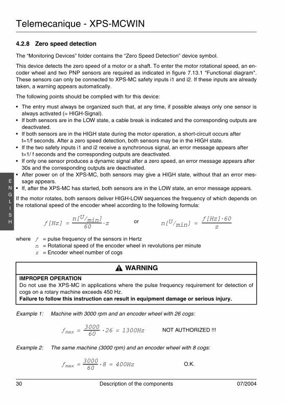
4.2.8 Zero speed detection
The “Monitoring Devices” folder contains the “Zero Speed Detection” device symbol.
This device detects the zero speed of a motor or a shaft. To enter the motor rotational speed, an en-coder wheel and two PNP sensors are required as indicated in figure 7.13.1 "Functional diagram".These sensors can only be connected to XPS-MC safety inputs i1 and i2. If these inputs are alreadytaken, a warning appears automatically.
The following points should be complied with for this device:
• The entry must always be organized such that, at any time, if possible always only one sensor isalways activated (= HIGH-Signal).
• If both sensors are in the LOW state, a cable break is indicated and the corresponding outputs aredeactivated.
• If both sensors are in the HIGH state during the motor operation, a short-circuit occurs aftert=1/f seconds. After a zero speed detection, both sensors may be in the HIGH state.
• If the two safety inputs i1 and i2 receive a synchronous signal, an error message appears aftert=1/ f seconds and the corresponding outputs are deactivated.
• If only one sensor produces a dynamic signal after a zero speed, an error message appears after30s and the corresponding outputs are deactivated.
• After power on of the XPS-MC, both sensors may give a HIGH state, without that an error mes-sage appears.
• If, after the XPS-MC has started, both sensors are in the LOW state, an error message appears.
If the motor rotates, both sensors deliver HIGH-LOW sequences the frequency of which depends onthe rotational speed of the encoder wheel according to the following formula:
where ƒ = pulse frequency of the sensors in Hertzn = Rotational speed of the encoder wheel in revolutions per minutez = Encoder wheel number of cogs
Example 1: Machine with 3000 rpm and an encoder wheel with 26 cogs:
Example 2: The same machine (3000 rpm) and an encoder wheel with 8 cogs:
or
WARNINGIMPROPER OPERATIONDo not use the XPS-MC in applications where the pulse frequency requirement for detection ofcogs on a rotary machine exceeds 450 Hz.Failure to follow this instruction can result in equipment damage or serious injury.
NOT AUTHORIZED !!!
O.K.
ƒ[Hz] = ·z60n[U/min] ƒ[Hz]·60
zn[U/min] =
!
300060ƒmax = ·26 = 1300Hz
300060ƒmax = ·8 = 400Hz
Telemecanique - XPS-MCWIN
07/2004 Description of the components 31
EN
GLI
SH
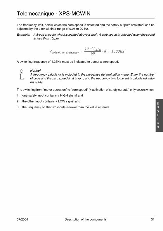
The frequency limit, below which the zero speed is detected and the safety outputs activated, can beadjusted by the user within a range of 0.05 to 20 Hz.
Example: A 8-cog encoder wheel is located above a shaft. A zero speed is detected when the speedis less than 10rpm.
A switching frequency of 1.33Hz must be indicated to detect a zero speed.
The switching from “motor operation” to “zero speed” (= activation of safety outputs) only occurs when:
1. one safety input contains a HIGH signal and
2. the other input contains a LOW signal and
3. the frequency on the two inputs is lower than the value entered.
Notice!A frequency calculator is included in the properties determination menu. Enter the numberof cogs and the zero speed limit in rpm, and the frequency limit to be set is calculated auto-matically.
·8 = 1,33Hz6010 U/minƒSwitching frequency =
Telemecanique - XPS-MCWIN
32 Description of the components 07/2004
EN
GLI
SH
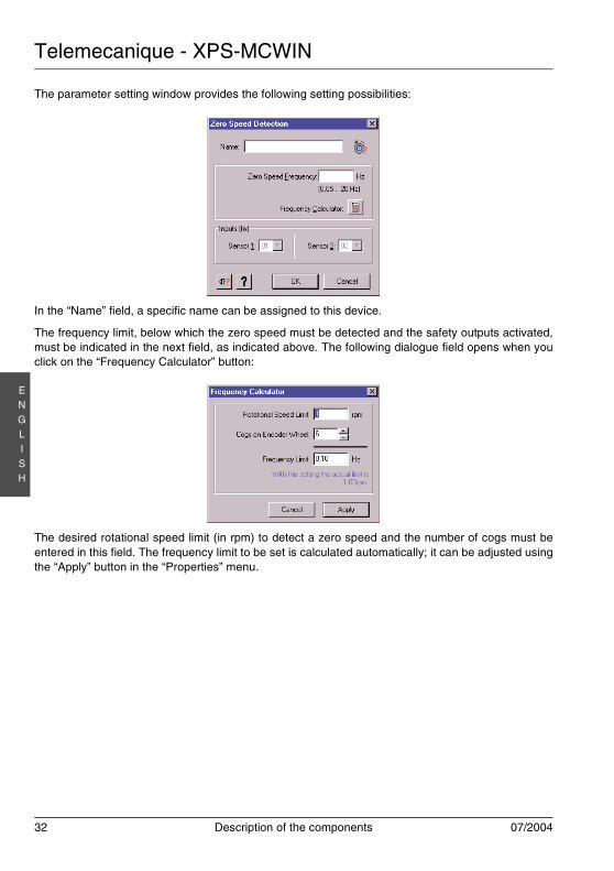
The parameter setting window provides the following setting possibilities:
In the “Name” field, a specific name can be assigned to this device.
The frequency limit, below which the zero speed must be detected and the safety outputs activated,must be indicated in the next field, as indicated above. The following dialogue field opens when youclick on the “Frequency Calculator” button:
The desired rotational speed limit (in rpm) to detect a zero speed and the number of cogs must beentered in this field. The frequency limit to be set is calculated automatically; it can be adjusted usingthe “Apply” button in the “Properties” menu.
Telemecanique - XPS-MCWIN
07/2004 Description of the components 33
EN
GLI
SH
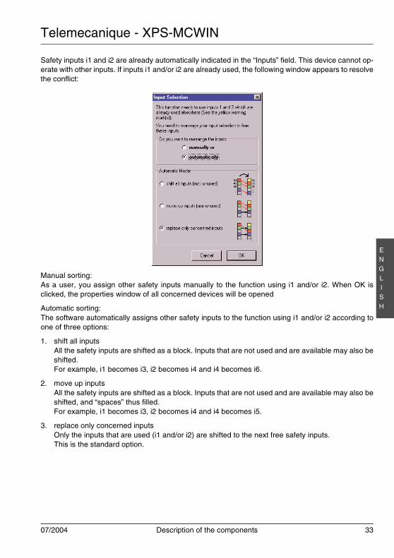
Safety inputs i1 and i2 are already automatically indicated in the “Inputs” field. This device cannot op-erate with other inputs. If inputs i1 and/or i2 are already used, the following window appears to resolvethe conflict:
Manual sorting:As a user, you assign other safety inputs manually to the function using i1 and/or i2. When OK isclicked, the properties window of all concerned devices will be opened
Automatic sorting:The software automatically assigns other safety inputs to the function using i1 and/or i2 according toone of three options:
1. shift all inputsAll the safety inputs are shifted as a block. Inputs that are not used and are available may also beshifted.For example, i1 becomes i3, i2 becomes i4 and i4 becomes i6.
2. move up inputsAll the safety inputs are shifted as a block. Inputs that are not used and are available may also beshifted, and “spaces” thus filled.For example, i1 becomes i3, i2 becomes i4 and i4 becomes i5.
3. replace only concerned inputsOnly the inputs that are used (i1 and/or i2) are shifted to the next free safety inputs.This is the standard option.
Telemecanique - XPS-MCWIN
34 Description of the components 07/2004
EN
GLI
SH
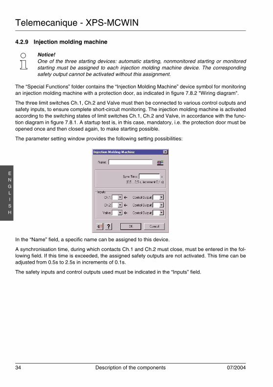
4.2.9 Injection molding machine
The “Special Functions” folder contains the “Injection Molding Machine” device symbol for monitoringan injection molding machine with a protection door, as indicated in figure 7.8.2 "Wiring diagram".
The three limit switches Ch.1, Ch.2 and Valve must then be connected to various control outputs andsafety inputs, to ensure complete short-circuit monitoring. The injection molding machine is activatedaccording to the switching states of limit switches Ch.1, Ch.2 and Valve, in accordance with the func-tion diagram in figure 7.8.1. A startup test is, in this case, mandatory, i.e. the protection door must beopened once and then closed again, to make starting possible.
The parameter setting window provides the following setting possibilities:
In the “Name” field, a specific name can be assigned to this device.
A synchronisation time, during which contacts Ch.1 and Ch.2 must close, must be entered in the fol-lowing field. If this time is exceeded, the assigned safety outputs are not activated. This time can beadjusted from 0.5s to 2.5s in increments of 0.1s.
The safety inputs and control outputs used must be indicated in the “Inputs” field.
Notice!One of the three starting devices: automatic starting, nonmonitored starting or monitoredstarting must be assigned to each injection molding machine device. The correspondingsafety output cannot be activated without this assignment.
Telemecanique - XPS-MCWIN
07/2004 Description of the components 35
EN
GLI
SH
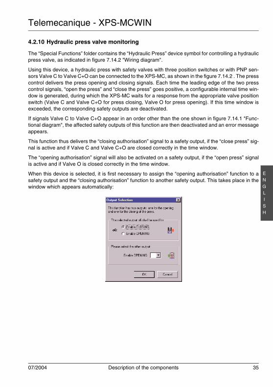
4.2.10 Hydraulic press valve monitoring
The “Special Functions” folder contains the “Hydraulic Press” device symbol for controlling a hydraulicpress valve, as indicated in figure 7.14.2 "Wiring diagram".
Using this device, a hydraulic press with safety valves with three position switches or with PNP sen-sors Valve C to Valve C+O can be connected to the XPS-MC, as shown in the figure 7.14.2 . The presscontrol delivers the press opening and closing signals. Each time the leading edge of the two presscontrol signals, “open the press” and “close the press” goes positive, a configurable internal time win-dow is generated, during which the XPS-MC waits for a response from the appropriate valve positionswitch (Valve C and Valve C+O for press closing, Valve O for press opening). If this time window isexceeded, the corresponding safety outputs are deactivated.
If signals Valve C to Valve C+O appear in an order other than the one shown in figure 7.14.1 "Func-tional diagram", the affected safety outputs of this function are then deactivated and an error messageappears.
This function thus delivers the “closing authorisation” signal to a safety output, if the “close press” sig-nal is active and if Valve C and Valve C+O are closed correctly in the time window.
The “opening authorisation” signal will also be activated on a safety output, if the “open press” signalis active and if Valve O is closed correctly in the time window.
When this device is selected, it is first necessary to assign the “opening authorisation” function to asafety output and the “closing authorisation” function to another safety output. This takes place in thewindow which appears automatically:
Telemecanique - XPS-MCWIN
36 Description of the components 07/2004
EN
GLI
SH
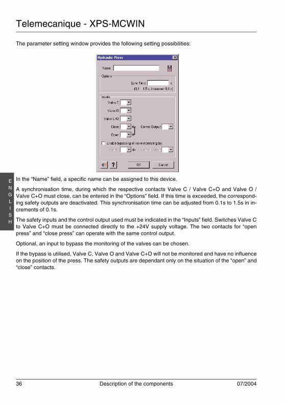
The parameter setting window provides the following setting possibilities:
In the “Name” field, a specific name can be assigned to this device.
A synchronisation time, during which the respective contacts Valve C / Valve C+O and Valve O /Valve C+O must close, can be entered in the “Options” field. If this time is exceeded, the correspond-ing safety outputs are deactivated. This synchronisation time can be adjusted from 0.1s to 1.5s in in-crements of 0.1s.
The safety inputs and the control output used must be indicated in the “Inputs” field. Switches Valve Cto Valve C+O must be connected directly to the +24V supply voltage. The two contacts for “openpress” and “close press” can operate with the same control output.
Optional, an input to bypass the monitoring of the valves can be chosen.
If the bypass is utilised, Valve C, Valve O and Valve C+O will not be monitored and have no influenceon the position of the press. The safety outputs are dependant only on the situation of the “open” and“close” contacts.
Telemecanique - XPS-MCWIN
07/2004 Description of the components 37
EN
GLI
SH
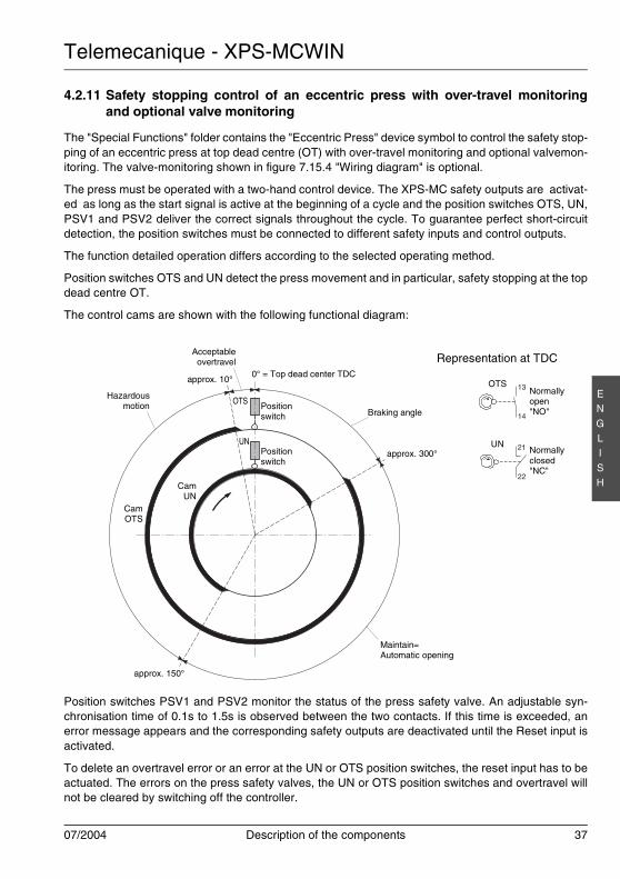
4.2.11 Safety stopping control of an eccentric press with over-travel monitoringand optional valve monitoring
The "Special Functions" folder contains the "Eccentric Press" device symbol to control the safety stop-ping of an eccentric press at top dead centre (OT) with over-travel monitoring and optional valvemon-itoring. The valve-monitoring shown in figure 7.15.4 "Wiring diagram" is optional.
The press must be operated with a two-hand control device. The XPS-MC safety outputs are activat-ed as long as the start signal is active at the beginning of a cycle and the position switches OTS, UN,PSV1 and PSV2 deliver the correct signals throughout the cycle. To guarantee perfect short-circuitdetection, the position switches must be connected to different safety inputs and control outputs.
The function detailed operation differs according to the selected operating method.
Position switches OTS and UN detect the press movement and in particular, safety stopping at the topdead centre OT.
The control cams are shown with the following functional diagram:
Position switches PSV1 and PSV2 monitor the status of the press safety valve. An adjustable syn-chronisation time of 0.1s to 1.5s is observed between the two contacts. If this time is exceeded, anerror message appears and the corresponding safety outputs are deactivated until the Reset input isactivated.
To delete an overtravel error or an error at the UN or OTS position switches, the reset input has to beactuated. The errors on the press safety valves, the UN or OTS position switches and overtravel willnot be cleared by switching off the controller.
13
14
21
22
OTS
UN
Hazardousmotion
Braking angle
CamOTS
CamUN
approx. 150°
approx. 300°
approx. 10°
OTS
UN
Positionswitch
Positionswitch
Maintain=Automatic opening
Acceptableovertravel
0° = Top dead center TDC
Representation at TDC
Normallyopen"NO"
Normallyclosed"NC"
Telemecanique - XPS-MCWIN
38 Description of the components 07/2004
EN
GLI
SH
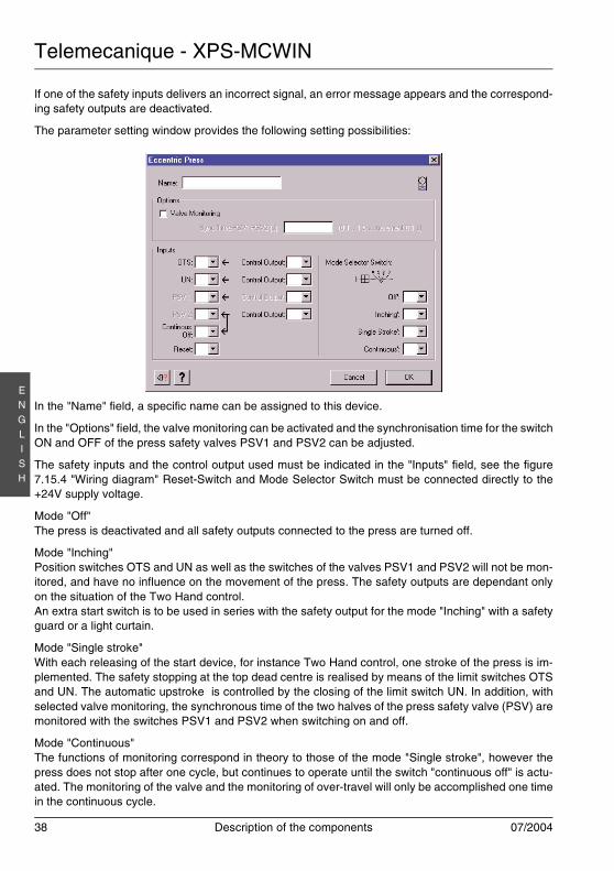
If one of the safety inputs delivers an incorrect signal, an error message appears and the correspond-ing safety outputs are deactivated.
The parameter setting window provides the following setting possibilities:
In the "Name" field, a specific name can be assigned to this device.
In the "Options" field, the valve monitoring can be activated and the synchronisation time for the switchON and OFF of the press safety valves PSV1 and PSV2 can be adjusted.
The safety inputs and the control output used must be indicated in the "Inputs" field, see the figure7.15.4 "Wiring diagram" Reset-Switch and Mode Selector Switch must be connected directly to the+24V supply voltage.
Mode "Off"The press is deactivated and all safety outputs connected to the press are turned off.
Mode "Inching"Position switches OTS and UN as well as the switches of the valves PSV1 and PSV2 will not be mon-itored, and have no influence on the movement of the press. The safety outputs are dependant onlyon the situation of the Two Hand control.An extra start switch is to be used in series with the safety output for the mode "Inching" with a safetyguard or a light curtain.
Mode "Single stroke"With each releasing of the start device, for instance Two Hand control, one stroke of the press is im-plemented. The safety stopping at the top dead centre is realised by means of the limit switches OTSand UN. The automatic upstroke is controlled by the closing of the limit switch UN. In addition, withselected valve monitoring, the synchronous time of the two halves of the press safety valve (PSV) aremonitored with the switches PSV1 and PSV2 when switching on and off.
Mode "Continuous"The functions of monitoring correspond in theory to those of the mode "Single stroke", however thepress does not stop after one cycle, but continues to operate until the switch "continuous off" is actu-ated. The monitoring of the valve and the monitoring of over-travel will only be accomplished one timein the continuous cycle.
Telemecanique - XPS-MCWIN
07/2004 Description of the components 39
EN
GLI
SH
The mode « continuous » needs the use of sure tools, or additional protection measures have to betaken.
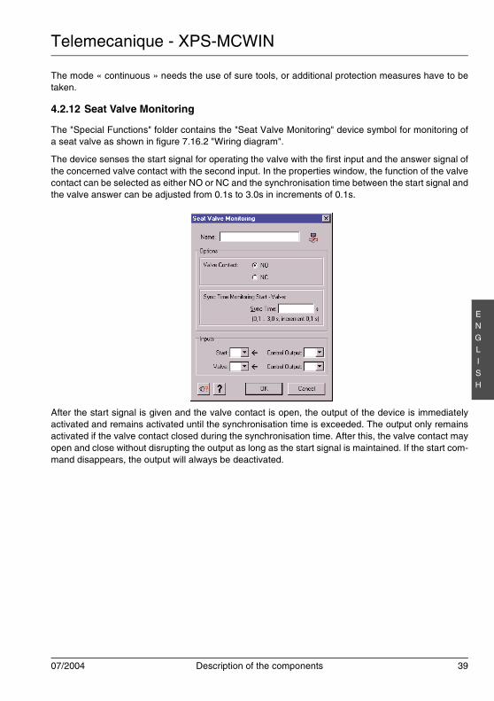
4.2.12 Seat Valve Monitoring
The "Special Functions" folder contains the "Seat Valve Monitoring" device symbol for monitoring ofa seat valve as shown in figure 7.16.2 "Wiring diagram".
The device senses the start signal for operating the valve with the first input and the answer signal ofthe concerned valve contact with the second input. In the properties window, the function of the valvecontact can be selected as either NO or NC and the synchronisation time between the start signal andthe valve answer can be adjusted from 0.1s to 3.0s in increments of 0.1s.
After the start signal is given and the valve contact is open, the output of the device is immediatelyactivated and remains activated until the synchronisation time is exceeded. The output only remainsactivated if the valve contact closed during the synchronisation time. After this, the valve contact mayopen and close without disrupting the output as long as the start signal is maintained. If the start com-mand disappears, the output will always be deactivated.
Telemecanique - XPS-MCWIN
40 Description of the components 07/2004
EN
GLI
SH
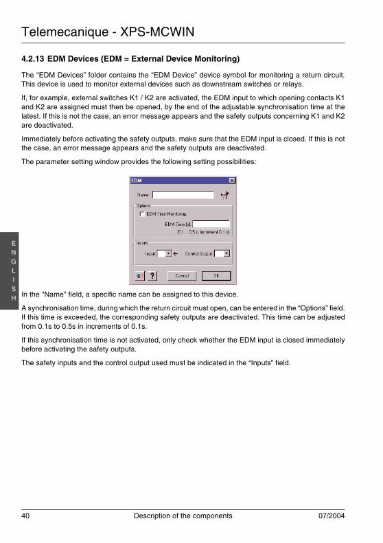
4.2.13 EDM Devices (EDM = External Device Monitoring)
The “EDM Devices” folder contains the “EDM Device” device symbol for monitoring a return circuit.This device is used to monitor external devices such as downstream switches or relays.
If, for example, external switches K1 / K2 are activated, the EDM input to which opening contacts K1and K2 are assigned must then be opened, by the end of the adjustable synchronisation time at thelatest. If this is not the case, an error message appears and the safety outputs concerning K1 and K2are deactivated.
Immediately before activating the safety outputs, make sure that the EDM input is closed. If this is notthe case, an error message appears and the safety outputs are deactivated.
The parameter setting window provides the following setting possibilities:
In the "Name" field, a specific name can be assigned to this device.
A synchronisation time, during which the return circuit must open, can be entered in the “Options” field.If this time is exceeded, the corresponding safety outputs are deactivated. This time can be adjustedfrom 0.1s to 0.5s in increments of 0.1s.
If this synchronisation time is not activated, only check whether the EDM input is closed immediatelybefore activating the safety outputs.
The safety inputs and the control output used must be indicated in the “Inputs” field.
Telemecanique - XPS-MCWIN
07/2004 Description of the components 41
EN
GLI
SH
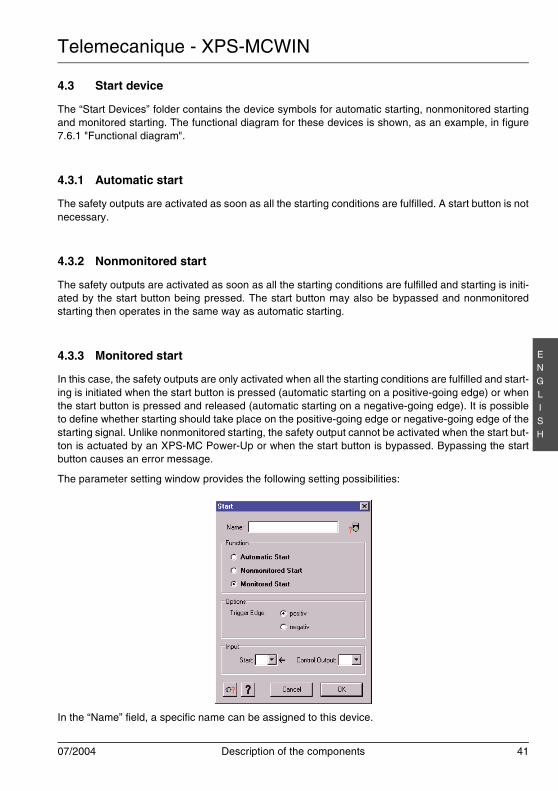
4.3 Start device
The “Start Devices” folder contains the device symbols for automatic starting, nonmonitored startingand monitored starting. The functional diagram for these devices is shown, as an example, in figure7.6.1 "Functional diagram".
4.3.1 Automatic start
The safety outputs are activated as soon as all the starting conditions are fulfilled. A start button is notnecessary.
4.3.2 Nonmonitored start
The safety outputs are activated as soon as all the starting conditions are fulfilled and starting is initi-ated by the start button being pressed. The start button may also be bypassed and nonmonitoredstarting then operates in the same way as automatic starting.
4.3.3 Monitored start
In this case, the safety outputs are only activated when all the starting conditions are fulfilled and start-ing is initiated when the start button is pressed (automatic starting on a positive-going edge) or whenthe start button is pressed and released (automatic starting on a negative-going edge). It is possibleto define whether starting should take place on the positive-going edge or negative-going edge of thestarting signal. Unlike nonmonitored starting, the safety output cannot be activated when the start but-ton is actuated by an XPS-MC Power-Up or when the start button is bypassed. Bypassing the startbutton causes an error message.
The parameter setting window provides the following setting possibilities:
In the “Name” field, a specific name can be assigned to this device.
Telemecanique - XPS-MCWIN
42 Description of the components 07/2004
EN
GLI
SH
You can then select one of the starting devices again in the “Function” field. The device symbol in theconfiguration tree is adapted automatically.
During monitored starting, a selection can be made in the “Options” field between starting on the pos-itive-going edge (= starting when the start button is pressed) or starting on the negative-going edge(= starting when the start button is released).
The safety input and the control output used must be indicated in the “Input” field.
4.4 Two-channel or three-channel enable switch
The “Enabling Devices” folder contains the device symbols for the enable switch. This device can beused alone on a safety output, or with a safety guard.
Note: To do it, the enable switch function symbol must be dragged onto the symbol of the safetyguard.For the changeover between the safety guard and the enable switch, an external positionswitch must be used.
With an enable switch, a safety guard can be bypassed and a hazardous movement can consequentlybe started, even with a protection door open, during the fitting out of a machine for example. The en-able switch does not activate the dangerous movement but gives a validation for the dangerous move-ment to be actuated.
This function works with a two or three channel enable switch with the switching diagram which ap-pears in figure 7.20.2 "Wiring diagram" or figure 7.19.2 "Wiring diagram". Category 4 is only achievedwhen using the 3 position enable switch. For the types of enable switches that can be used, see theTechnical data chapter of the Hardware instruction manual.
To produce the confirmation signal, the enable switch must first be set to position 0 and then to posi-tion 1. The authorisation is thus activated, as are the XPS-MC safety outputs. If the enable switchreaches position 2, the safety outputs are again deactivated. When the enable switch is set back toposition 0, no further enabling is authorized, even if the switch is returned to position 1.
Telemecanique - XPS-MCWIN
07/2004 Description of the components 43
EN
GLI
SH
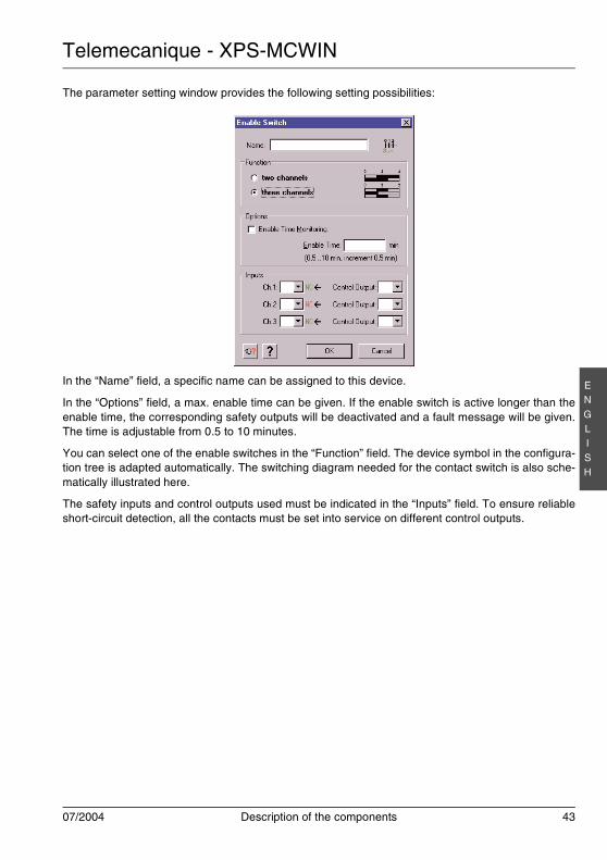
The parameter setting window provides the following setting possibilities:
In the “Name” field, a specific name can be assigned to this device.
In the “Options” field, a max. enable time can be given. If the enable switch is active longer than theenable time, the corresponding safety outputs will be deactivated and a fault message will be given.The time is adjustable from 0.5 to 10 minutes.
You can select one of the enable switches in the “Function” field. The device symbol in the configura-tion tree is adapted automatically. The switching diagram needed for the contact switch is also sche-matically illustrated here.
The safety inputs and control outputs used must be indicated in the “Inputs” field. To ensure reliableshort-circuit detection, all the contacts must be set into service on different control outputs.
Telemecanique - XPS-MCWIN
44 Description of the components 07/2004
EN
GLI
SH
4.5 Miscellaneous devices
The “Miscellaneous devices” folder contains all the logic devices.
4.5.1 Timing device
The “Timing Devices” folder contains the Timer device symbol. figure 7.17.1 indicates the correspond-ing functional diagrams.
This device enables the safety output(s) as the timer function of a control signal. Four possibilities areprovided:
1. Switch on delay. The safety output is activated when the control signal delayed by an adjustabletime is activated. It lasts for as long as the control signal is active.
2. Switch off delay. The safety output is stopped when the control signal delayed by an adjustabletime is stopped. The safety output is activated at the same time as the control signal is activated.
3. Switch on pulse. The safety output is activated at the same time as the control signal is activated,but only lasts for an adjustable time.
4. Switch off pulse. The safety output is activated at the same time as the control signal is stopped,but only lasts for an adjustable time.
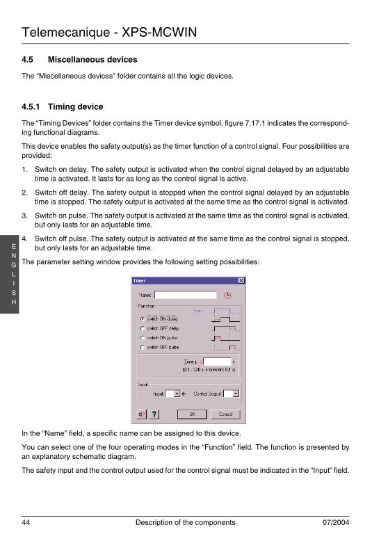
The parameter setting window provides the following setting possibilities:
In the “Name” field, a specific name can be assigned to this device.
You can select one of the four operating modes in the “Function” field. The function is presented byan explanatory schematic diagram.
The safety input and the control output used for the control signal must be indicated in the “Input” field.
Telemecanique - XPS-MCWIN
07/2004 Description of the components 45
EN
GLI
SH
4.5.2 OR device
The “Miscellaneous devices” folder contains the symbol of the OR device for a logical OR connectionbetween devices.
With this device, the validation of an output is the result of an OR connection between several devices.
The OR component has no properties window.
The OR component can not be used with several E-Stop devices.
4.6 Applying output states to other safety outputs
The “Output states” folder contains the symbol of the safety outputs for each controller.
By moving the output “X” symbol on the output “Y” in the configuration window, the safety output “Y”will have the same behaviour as the safety output “X”. Other components can be assigned to the out-put “Y”.
The same result will be achieved by moving the output “X” symbol with the left mouse button onto theoutput “Y”.
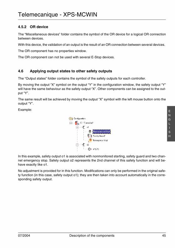
Example:
In this example, safety output o1 is associated with nonmonitored starting, safety guard and two chan-nel emergency stop. Safety output o2 represents the 2nd channel of this safety function and will be-have exactly like o1.
No adjustment is provided for in this function. Modifications can only be performed in the original safe-ty function (in this case, safety output o1); they are then taken into account automatically in the corre-sponding safety output.
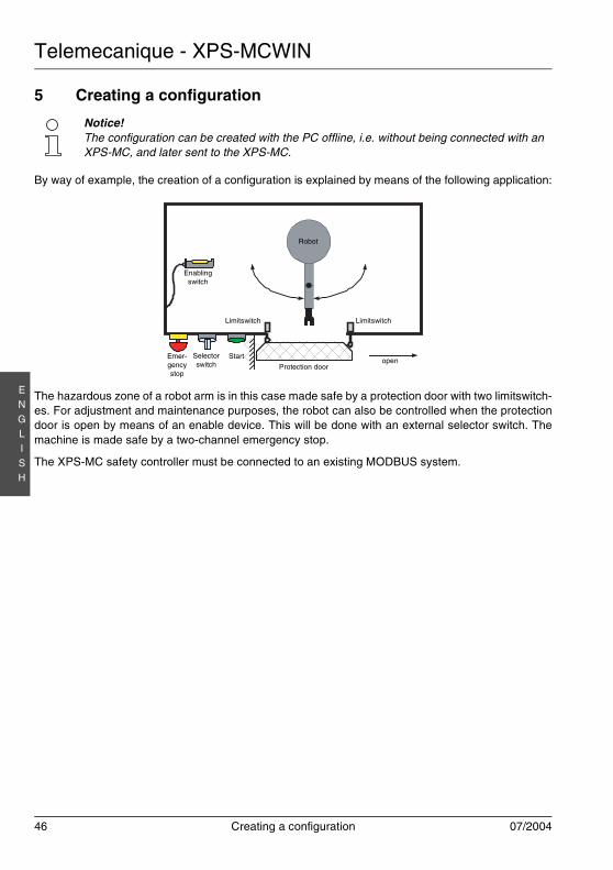
Telemecanique - XPS-MCWIN
46 Creating a configuration 07/2004
EN
GLI
SH
5 Creating a configuration
By way of example, the creation of a configuration is explained by means of the following application:
The hazardous zone of a robot arm is in this case made safe by a protection door with two limitswitch-es. For adjustment and maintenance purposes, the robot can also be controlled when the protectiondoor is open by means of an enable device. This will be done with an external selector switch. Themachine is made safe by a two-channel emergency stop.
The XPS-MC safety controller must be connected to an existing MODBUS system.
Notice!The configuration can be created with the PC offline, i.e. without being connected with anXPS-MC, and later sent to the XPS-MC.
Robot
openProtection door
Limitswitch Limitswitch
Enablingswitch
StartEmer-gencystop
Selectorswitch
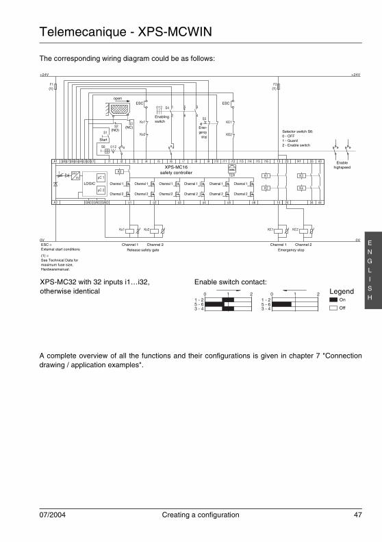
Telemecanique - XPS-MCWIN
07/2004 Creating a configuration 47
EN
GLI
SH
The corresponding wiring diagram could be as follows:
A complete overview of all the functions and their configurations is given in chapter 7 "Connectiondrawing / application examples".
K0
A1 c8 c7 c6 c5 c3c4 c2 c1 i1 i2 i3 i4 i5 i6 i7 i8 i9 i10 i11 i12 i13 i14 i15 i16 13 23 H1 33 43
A2 44342414o6o5o4o3o2o1GNDGNDGND
µC 1
µC 2
K1
K2
K3
K4
KE1 KE2Ko1 Ko2
F1
+24V
0V 0V
+24V
S1
S4
S5KE1
KE2
Ko1
Ko2
S2S3
1 5 3
2 6 4
012
F2
TER24V5V
T
0 12S6
0
3 - 45 - 61 - 2
1 2 0
3 - 45 - 61 - 2
1 2
Enable switch contact:Legend
On
Off
XPS-MC32 with 32 inputs i1…i32,otherwise identical
LOGIC Channal 1
Channal 2
XPS-MC16safety controller
Channel 1
Release safety gate
ESC =External start conditions
(1) =See Technical Data formaximum fuse size,Hardwaremanual.
Emer-gency
stop
open
Enablingswitch
Start
(NC)(NO)
(1)(1)
Channel 2 Channel 1
Emergency stop
Channel 2
Channal 1
Channal 2
Channal 1
Channal 2
Channal 1
Channal 2
Channal 1
Channal 2
Channal 1
Channal 2
Enablehighspeed
Selector switch S6:0 - OFF1 - Guard2 - Enable switch
ESC ESC
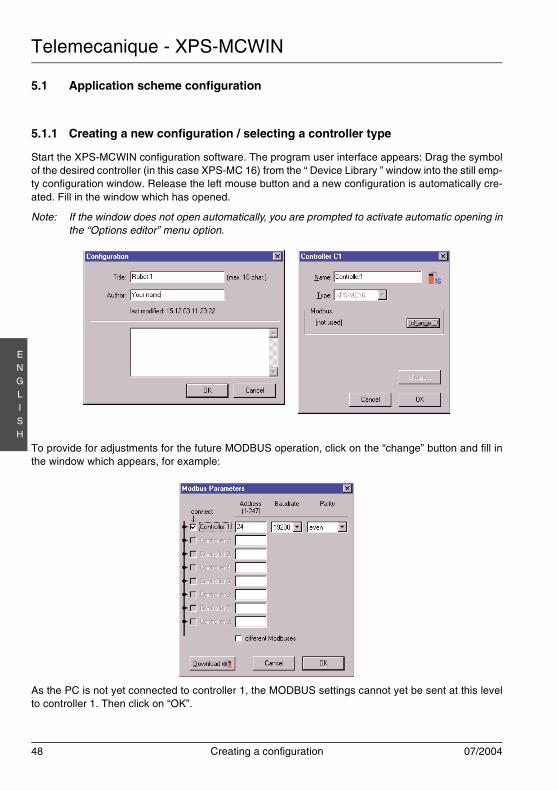
Telemecanique - XPS-MCWIN
48 Creating a configuration 07/2004
EN
GLI
SH
5.1 Application scheme configuration
5.1.1 Creating a new configuration / selecting a controller type
Start the XPS-MCWIN configuration software. The program user interface appears: Drag the symbolof the desired controller (in this case XPS-MC 16) from the “ Device Library ” window into the still emp-ty configuration window. Release the left mouse button and a new configuration is automatically cre-ated. Fill in the window which has opened.
Note: If the window does not open automatically, you are prompted to activate automatic opening inthe “Options editor” menu option.
To provide for adjustments for the future MODBUS operation, click on the “change” button and fill inthe window which appears, for example:
As the PC is not yet connected to controller 1, the MODBUS settings cannot yet be sent at this levelto controller 1. Then click on “OK”.
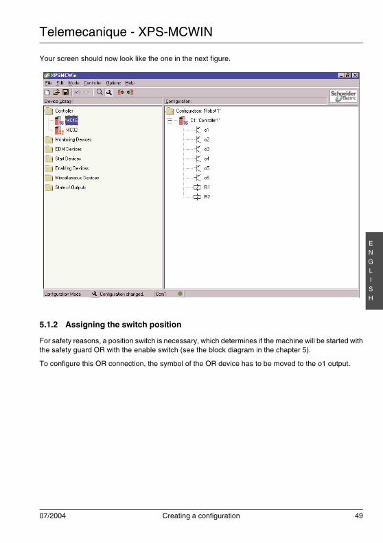
Telemecanique - XPS-MCWIN
07/2004 Creating a configuration 49
EN
GLI
SH
Your screen should now look like the one in the next figure.
5.1.2 Assigning the switch position
For safety reasons, a position switch is necessary, which determines if the machine will be started withthe safety guard OR with the enable switch (see the block diagram in the chapter 5).
To configure this OR connection, the symbol of the OR device has to be moved to the o1 output.
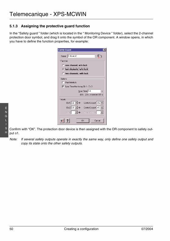
Telemecanique - XPS-MCWIN
50 Creating a configuration 07/2004
EN
GLI
SH
5.1.3 Assigning the protective guard function
In the “Safety guard ” folder (which is located in the “ Monitoring Device ” folder), select the 2-channelprotection door symbol, and drag it onto the symbol of the OR component. A window opens, in whichyou have to define the function properties, for example:
Confirm with “OK”. The protection door device is then assigned with the OR component to safety out-put o1.
Note: If several safety outputs operate in exactly the same way, only define one safety output andcopy its state onto the other safety outputs.
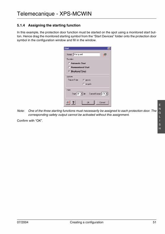
Telemecanique - XPS-MCWIN
07/2004 Creating a configuration 51
EN
GLI
SH
5.1.4 Assigning the starting function
In this example, the protection door function must be started on the spot using a monitored start but-ton. Hence drag the monitored starting symbol from the “Start Devices” folder onto the protection doorsymbol in the configuration window and fill in the window.
Note: One of the three starting functions must necessarily be assigned to each protection door. Thecorresponding safety output cannot be activated without this assignment.
Confirm with “OK”.
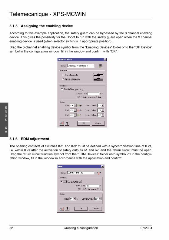
Telemecanique - XPS-MCWIN
52 Creating a configuration 07/2004
EN
GLI
SH
5.1.5 Assigning the enabling device
According to this example application, the safety guard can be bypassed by the 3 channel enablingdevice. This gives the possibility for the Robot to run with the safety guard open when the 3 channelenabling device is used (when selector switch is in appropriate position).
Drag the 3-channel enabling device symbol from the “Enabling Devices” folder onto the “OR Device”symbol in the configuration window, fill in the window and confirm with “OK”:
5.1.6 EDM adjustment
The opening contacts of switches Ko1 and Ko2 must be defined with a synchronisation time of 0.2s,i.e. within 0.2s after the activation of safety outputs o1 and o2, and the return circuit must be open.Drag the return circuit function symbol from the “EDM Devices” folder onto symbol o1 in the configu-ration window, fill in the window in accordance with the application and confirm:
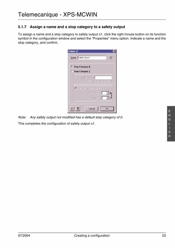
Telemecanique - XPS-MCWIN
07/2004 Creating a configuration 53
EN
GLI
SH
5.1.7 Assign a name and a stop category to a safety output
To assign a name and a stop category to safety output o1, click the right mouse button on its functionsymbol in the configuration window and select the “Properties” menu option. Indicate a name and thestop category, and confirm.
Note: Any safety output not modified has a default stop category of 0.
This completes the configuration of safety output o1.
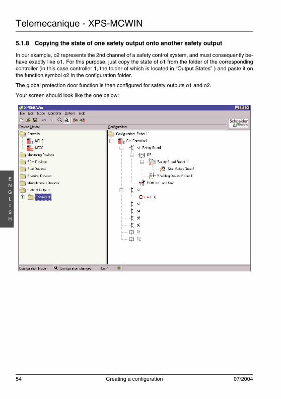
Telemecanique - XPS-MCWIN
54 Creating a configuration 07/2004
EN
GLI
SH
5.1.8 Copying the state of one safety output onto another safety output
In our example, o2 represents the 2nd channel of a safety control system, and must consequently be-have exactly like o1. For this purpose, just copy the state of o1 from the folder of the correspondingcontroller (in this case controller 1, the folder of which is located in “Output States” ) and paste it onthe function symbol o2 in the configuration folder.
The global protection door function is then configured for safety outputs o1 and o2.
Your screen should look like the one below:
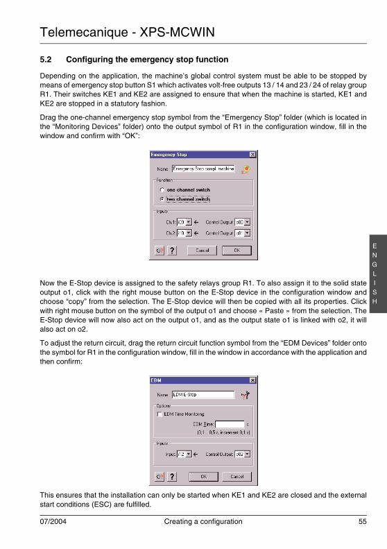
Telemecanique - XPS-MCWIN
07/2004 Creating a configuration 55
EN
GLI
SH
5.2 Configuring the emergency stop function
Depending on the application, the machine’s global control system must be able to be stopped bymeans of emergency stop button S1 which activates volt-free outputs 13 / 14 and 23 / 24 of relay groupR1. Their switches KE1 and KE2 are assigned to ensure that when the machine is started, KE1 andKE2 are stopped in a statutory fashion.
Drag the one-channel emergency stop symbol from the “Emergency Stop” folder (which is located inthe “Monitoring Devices” folder) onto the output symbol of R1 in the configuration window, fill in thewindow and confirm with “OK”:
Now the E-Stop device is assigned to the safety relays group R1. To also assign it to the solid stateoutput o1, click with the right mouse button on the E-Stop device in the configuration window andchoose “copy” from the selection. The E-Stop device will then be copied with all its properties. Clickwith right mouse button on the symbol of the output o1 and choose « Paste » from the selection. TheE-Stop device will now also act on the output o1, and as the output state o1 is linked with o2, it willalso act on o2.
To adjust the return circuit, drag the return circuit function symbol from the “EDM Devices” folder ontothe symbol for R1 in the configuration window, fill in the window in accordance with the application andthen confirm:
This ensures that the installation can only be started when KE1 and KE2 are closed and the externalstart conditions (ESC) are fulfilled.
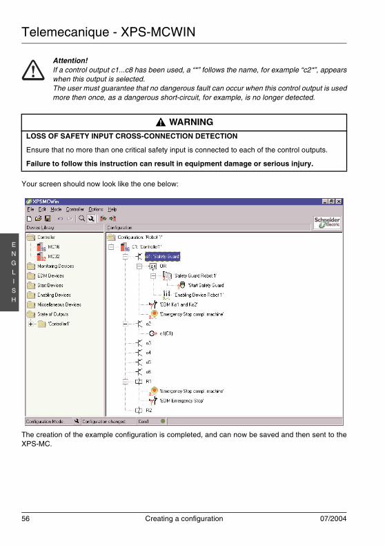
Telemecanique - XPS-MCWIN
56 Creating a configuration 07/2004
EN
GLI
SH
Your screen should now look like the one below:
The creation of the example configuration is completed, and can now be saved and then sent to theXPS-MC.
Attention!If a control output c1...c8 has been used, a “*” follows the name, for example “c2*”, appearswhen this output is selected.The user must guarantee that no dangerous fault can occur when this control output is usedmore then once, as a dangerous short-circuit, for example, is no longer detected.
WARNINGLOSS OF SAFETY INPUT CROSS-CONNECTION DETECTION
Ensure that no more than one critical safety input is connected to each of the control outputs.
Failure to follow this instruction can result in equipment damage or serious injury.
!
Telemecanique - XPS-MCWIN
07/2004 Creating a configuration 57
EN
GLI
SH
5.2.1 The Master E-Stop device
A E-Stop device acts as a Master E-Stop on all the other devices of the output. The other devices willbe deactivated when the Master E-Stop is pressed. When this occurs, the start of this output is notpossible until the start conditions of all the other devices are met.
This is also available for all the copies of the E-Stop devices.
5.3 Save the configuration
The configuration can be saved by opening the “File/Save” menu option (or by clicking on the floppydisk symbol button ) under the current name or by opening the “File/Save As...” option and assign-ing a new path/name.
5.4 Requesting the password, changing the password
Each XPS-MC command involving quitting the RUN mode (setting up the XPS-MC for example) mustbe confirmed with a password. If such a command is performed, a dialogue window opens in whichthe password must be entered.The default password is “safety”; as a safety measure, it must be changed to an individual password.The password must contain between 4 and 12 symbols. Any combination of letters and numbers maybe used.The password can be modified with command “Controller - change password”.
5.5 Sending a configuration from the PC to the XPS-MC and performing a check
To send a completed configuration from the PC to the safety controller, follow this procedure:
Note: The settings indicated are also sent to the bus system and retrieved by the XPS-MC with theconfiguration data.
Setting the initial configuration / Modifying a current configuration
1. Apply the 24V DC supply voltage to terminals A1-A2 of the XPS-MC. An automatic check lastingabout 2 seconds takes place during which all the LEDs are lit.
2. At the end of the automatic test, all the LEDs except the “Power” LED go off. If the XPS-MC is notyet configured, the yellow “CNF” LED flashes.
3. Connect your PC to the XPS-MC safety controller.
4. Start the XPS-MCWIN software. To set the configuration, the software must be in the configurati-on mode (default setting).
Attention!An output state does not transfer a master E-Stop command on other devices. Only the sta-tus itself is transferred.
Notice!The password is case sensitive. “Security” and “security” are thus two different passwords.
Telemecanique - XPS-MCWIN
58 Creating a configuration 07/2004
EN
GLI
SH
5. Load and create the configuration to be sent with the XPS-MCWIN software.
6. Begin by saving the configuration again by means of the command “Controller - Download Confi-guration to Controller” or by clicking on the button . The configuration is sent with comments.If the controller is in RUN mode, the password must be entered.
7. The data transmission begins, and the “CNF” and “COM” LEDs are lit to announce that the confi-guration data are now being sent.
8. After the download of the configuration to the XPSMC controller, the configuration protocol will beautomatically uploaded by the XPS-MCWIN software and displayed in a separate window.
9. In order for the configuration to become effective, it must be validated.
To do this, click on the "Validate" button, in the new window , give your name and fix the optionsfor the copie of the validated configuration. Then, in the new window give the password of the con-troller.
The configuration will be again downloaded and the protocol will then be displayed with the date,the hour, your name and the validation counter stored in the controller (VDC), as well as the run-ning time (OPC) of this configuration, which is saved in the controller.
This protocol serves as proof of the configuration, and must be carefully analysed, printed,signed and kept.
10. The controller can then be put into RUN mode.
5.6 Loading a configuration
The configuration of a controller can be uploaded at any time, even with the controller not in STOPmode.
1. Connect your PC to the XPS-MC safety controller.
2. Choose the command from the “Controller - Upload Configuration from Controller” menu or clickon the button in the toolbar. The configuration is loaded from the XPS-MC and then represen-ted in the usual tree structure.
5.7 Creation of a validated configuration copy
As a condition to create a copy of a validated configuration, the "Enable copying of validated configu-ration from controller" option must be selected during the validation of the configuration. Under thiscondition the user is able to make a copy of the validated configuration from the XPS-MC into a binaryfile at any time. In addition, the "Create a copy of the validated configuration now" option can be se-lected in order to immediately create such a copy during the validation.
Included with the configuration itself, the following data of the original controller is taken:
1. Validation counter (VDC)
2. Password
3. Validation data (name, date)
Telemecanique - XPS-MCWIN
07/2004 Creating a configuration 59
EN
GLI
SH
4. Device parameters (Modbus parameters, controller number)
This file can be used as a safety copy to transfer the validated configuration to another controller with-out the need of a new validation.
Saving a validated configuration to a file
To save a validated configuration to a file, follow this procedure:
1. Connect the PC to the controller containing the validated configuration which is free for copy.
2. Choose the command « Controller - Create validated copy ».The configuration will be read out of the controller.
3. Enter the save location and file name in the window which appears.The copy will be saved as this file.
5.8 Transfer of a validated configuration copy
When a file with a copy of a validated configuration has been made (see chapter 5.7 "Creation of avalidated configuration copy") for a certain controller, it is easy to transfer the configuration into anoth-er controller, especially for replacement of a XPS-MC unit for service or for installation of controllersin identical machines.
Transferring a validated configuration to a controller
To transfer a validated configuration from a file into a controller, follow this procedure:
1. Connect the PC to the controller in which the validated configuration is to be transferred.
2. Set the controller with the command « Controller - Stop Controller » in the Stop Modus.(If the password is unknown, the controller must be started with the pressed reset button. After-wards the Controller behave as with the first start-up and the old configuration can no more bestarted).
3. Choose the command « Controller - Transfer validated copy ».
4. Indicate in the appearing window the memory place and the name of the file as the copy of theconfiguration.The validated configuration is picked out from the file and transferred into the connected Control-ler.
The new controller now has the validated configuration, including the validation counter (VDC), thepassword, the validation data (name, date) and the device parameters (Modbus parameters, control-ler number).It can be used like the original controller from which the copy was made from, except that the runningtime (OPC) of the configuration is set to zero.
In order to put the controller in the RUN mode after the download, the supply voltage must be stoppedand restored.
Telemecanique - XPS-MCWIN
60 Creating a configuration 07/2004
EN
GLI
SH
5.9 Upload protocol
1. The controller has to be put in STOP mode with the menu « Controller - Stop Controller » andentering the password.
2. Choose the menu « Controller - Upload protocol ». The protocol will be displayed in a separatewindow and can be printed.
5.10 Modifying the bus configuration
To modify the bus configuration of an XPS-MC, follow this procedure:
1. If not already done, connect your PC to the XPS-MC safety controller as per the description inchapter 5.5 concerning the equipment.
2. Stop the controller with the command “Controller - Stop Controller”. The safety outputs are thendeactivated.
3. Load the configuration data corresponding to this controller, or load the saved configuration of theXPS-MC on the PC see chapter 5.5 "Sending a configuration from the PC to the XPS-MC and per-forming a check".
4. Choose MODBUS from the “Controller - Controller setup” menu.
5. In the window which appears, indicate the bus system values for all the controllers of this configu-ration. A controller with the same configuration can also be set into service for different MODBUSsystems.
6. Click on the button . The configuration is sent with comments.
7. Use the XPS-MC in the RUN mode with the command “Controller - Run Controller”.
Notice!This print is just a work tool.The only proof of the correctness of the configuration is the validated and signed protocol.(see chapter 5.5 "Sending a configuration from the PC to the XPS-MC and performing acheck")
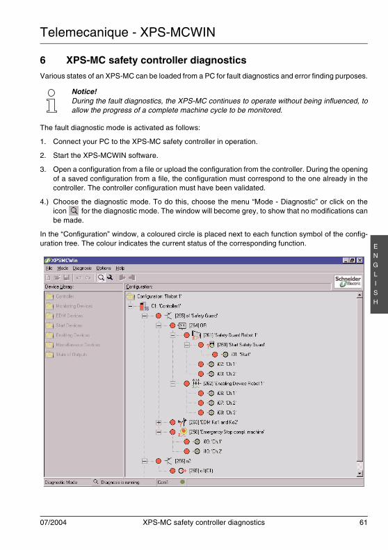
Telemecanique - XPS-MCWIN
07/2004 XPS-MC safety controller diagnostics 61
EN
GLI
SH
6 XPS-MC safety controller diagnosticsVarious states of an XPS-MC can be loaded from a PC for fault diagnostics and error finding purposes.
The fault diagnostic mode is activated as follows:
1. Connect your PC to the XPS-MC safety controller in operation.
2. Start the XPS-MCWIN software.
3. Open a configuration from a file or upload the configuration from the controller. During the openingof a saved configuration from a file, the configuration must correspond to the one already in thecontroller. The controller configuration must have been validated.
4.) Choose the diagnostic mode. To do this, choose the menu “Mode - Diagnostic” or click on theicon for the diagnostic mode. The window will become grey, to show that no modifications canbe made.
In the “Configuration” window, a coloured circle is placed next to each function symbol of the config-uration tree. The colour indicates the current status of the corresponding function.
Notice!During the fault diagnostics, the XPS-MC continues to operate without being influenced, toallow the progress of a complete machine cycle to be monitored.

Telemecanique - XPS-MCWIN
62 XPS-MC safety controller diagnostics 07/2004
EN
GLI
SH
A red point means:the safety output concerned is deactivated, or this device has not been validated (for example, pro-tection door open, emergency stop not initiated, etc.), or the concerned input is opened.
A red point with a yellow flash means:An error exists for this device (input/output). The error message will then be shown by clicking on thedevice.
A green point means:the safety output concerned is activated, or this device has been validated (for example, protectiondoor closed, emergency stop initiated, etc.), or the concerned input is closed.
A green point with a hourglass means:This output has a category 1 stop.The commutation conditions are no longer fulfilled, but the time delay is not yet finished.
A yellow point means:this component or this outputs are enabled (i.e. the starting conditions are fulfilled), but not yet started.
A grey point means:the safety output concerned is not used, or the PC has not yet received the fault diagnostics data fromthe XPS-MC (all the points are then greyed).
The state of the inputs of the different devices will be shown in the same way by clicking on the symbolof the device.
A special menu will appear by clicking the right mouse button within the diagnostic window.
When “Overview” is selected from the menu, a new window appears displaying the diagnostics of allthe inputs and outputs of the controller.
The “Stop diagnostic” in the menu selection stops the diagnostics. The diagnostic window is then fro-zen.
The “Run diagnostic” in the menu selection begins the diagnostics.
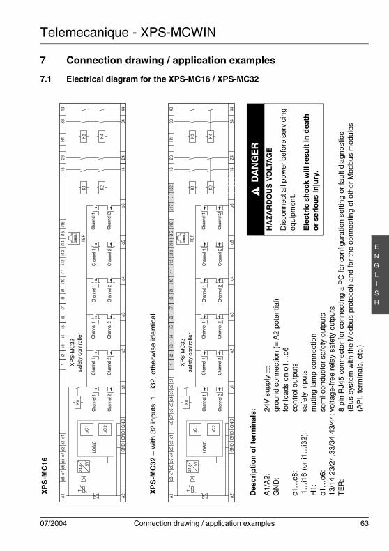
Telemecanique - XPS-MCWIN
07/2004 Connection drawing / application examples 63
EN
GLI
SH
7 Connection drawing / application examples
7.1 Electrical diagram for the XPS-MC16 / XPS-MC32
c8A1 A2
c7c6
c5c3
c4c2
c1i1
i2i3
i4i5
i6i7
i8i9
i10
i11
i12
i13
i14
i15
i16
1323
H1
3343 44
3424
14o6
o5o4
o3o2
o1G
ND
GN
DG
ND
µC 1
µC 2
K0K1 K2
K3 K4
i17
…i3
2c8
c7c6
c5c3
c4c2
c1
c8A1 A2
c7c6
c5c3
c4c2
c1i1
i2i3
i4i5
i6i7
i8i9
i10
i11
i12
i13
i14
i15
i16
1323
H1
3343 44
3424
14o6
o5o4
o3o2
o1G
ND
GN
DG
ND
µC 1
µC 2
K0K1 K2
K3 K4
TER
TER
24V 5V
T
24V 5V
TXP
S-M
C16
XP
S-M
C32
– w
ith 3
2 in
puts
i1…
i32,
oth
erw
ise
iden
tical
Des
crip
tio
n o
f te
rmin
als:
A1/
A2:
24V
sup
ply c
GN
D:
grou
nd c
onne
ctio
n (=
A2
pote
ntia
l)fo
r lo
ads
on o
1…o6
c1…
c8:
cont
rol o
utpu
tsi1
…i1
6 (o
r i1
…i3
2):
safe
ty in
puts
H1:
mut
ing
lam
p co
nnec
tion
o1…
o6:
sem
i-con
duct
or s
afet
y ou
tput
s13
/14,
23/2
4,33
/34,
43/4
4:vo
ltage
-fre
e re
lay
safe
ty o
utpu
tsT
ER
:8
pin
RJ4
5 co
nnec
tor
for
conn
ectin
g a
PC
for
conf
igur
atio
n se
tting
or
faul
t dia
gnos
tics
(Bus
sys
tem
with
the
Mod
bus
prot
ocol
) an
d fo
r th
e co
nnec
ting
of o
ther
Mod
bus
mod
ules
(AP
I, te
rmin
als,
etc
.)
LOG
ICC
hann
el 1
Cha
nnel
2
Cha
nnel
1
Cha
nnel
2
Cha
nnel
1
Cha
nnel
2
Cha
nnel
1
Cha
nnel
2
Cha
nnel
1
Cha
nnel
2
Cha
nnel
1
Cha
nnel
2
XP
S-M
C32
safe
ty c
ontr
olle
r
LOG
ICC
hann
el 1
Cha
nnel
2
Cha
nnel
1
Cha
nnel
2
Cha
nnel
1
Cha
nnel
2
Cha
nnel
1
Cha
nnel
2
Cha
nnel
1
Cha
nnel
2
Cha
nnel
1
Cha
nnel
2
XP
S-M
C32
safe
ty c
ontr
olle
r
DA
NG
ER
HA
ZA
RD
OU
S V
OLT
AG
E
Dis
conn
ect a
ll po
wer
bef
ore
serv
icin
geq
uipm
ent.
Ele
ctri
c sh
ock
will
res
ult
in d
eath
or
seri
ou
s in
jury
.
!
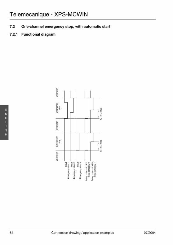
Telemecanique - XPS-MCWIN
64 Connection drawing / application examples 07/2004
EN
GLI
SH
7.2 One-channel emergency stop, with automatic start
7.2.1 Functional diagram
Ope
ratio
nE
me
rgen
cyst
opO
pera
tion
Em
erge
ncy
stop
Ope
ratio
n
Inpu
tE
mer
genc
y st
op 1
Inpu
tE
mer
genc
y st
op 2
Inpu
tE
mer
genc
y st
op 3
Rel
ay
outp
uts
K1/
K2
Sto
p ca
tego
ry 0
Rel
ay
outp
uts
K3/
K4
Sto
p ca
tego
ry 1
tv =
0…
300s
tv =
0…
300s
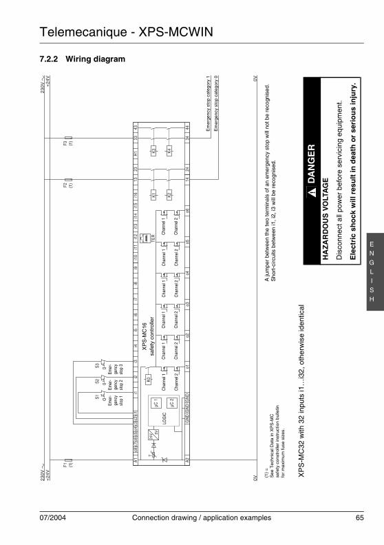
Telemecanique - XPS-MCWIN
07/2004 Connection drawing / application examples 65
EN
GLI
SH
7.2.2 Wiring diagram
K0
A1c8
c7c6
c5c3
c4c2
c1i1
i2i3
i4i5
i6i7
i8i9
i10
i11
i12
i13
i14
i15
i16
1323
H1
3343
A244
3424
14o6
o5o4
o3o2
o1G
ND
GN
DG
ND
µC 1
µC 2
K1 K2
K3 K4
TER
+24
V+
24V 0V
0V
F1F3
F2
S1S2
S3
24V 5V
T
XP
S-M
C32
with
32
inpu
ts i1
…i3
2, o
ther
wis
e id
entic
al
LOG
ICC
hann
el 1
Cha
nnel
2
Cha
nnel
1
Cha
nnel
2
Cha
nnel
1
Cha
nnel
2
Cha
nnel
1
Cha
nnel
2
Cha
nnel
1
Cha
nnel
2
Cha
nnel
1
Cha
nnel
2
XP
S-M
C16
safe
ty c
ontr
olle
r
Em
erge
ncy
stop
cat
egor
y 1
A ju
mpe
r be
twee
n th
e tw
o te
rmin
als
of a
n em
erge
ncy
stop
will
not
be
reco
gnis
ed.
Sho
rt-c
ircui
ts b
etw
een
i1, i
2, i3
will
be
reco
gnis
ed.
Emer
-ge
ncy
stop
1
(1)
Emer
-ge
ncy
stop
3
Emer
-ge
ncy
stop
2
(1)
Em
erge
ncy
stop
cat
egor
y 0
(1)
(1)
=S
ee T
ech
nica
l Dat
a in
XP
S-M
Csa
fety
con
stro
ller
inst
ruct
ion
bul
letin
for
max
imum
fuse
siz
es.
DA
NG
ER
HA
ZA
RD
OU
S V
OLT
AG
E
Dis
conn
ect a
ll po
wer
bef
ore
serv
icin
g eq
uipm
ent.
Ele
ctri
c sh
ock
will
res
ult
in d
eath
or
seri
ou
s in
jury
.
!
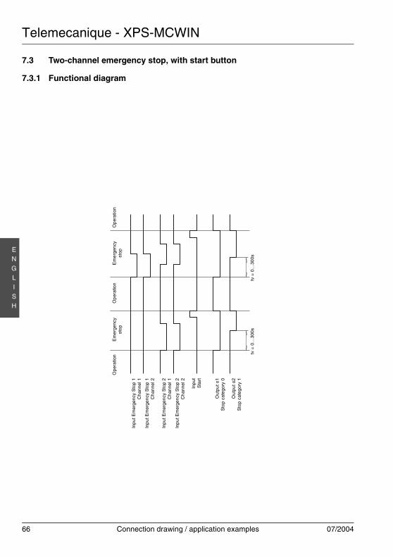
Telemecanique - XPS-MCWIN
66 Connection drawing / application examples 07/2004
EN
GLI
SH
7.3 Two-channel emergency stop, with start button
7.3.1 Functional diagram
Ope
ratio
nE
mer
genc
yst
op
Op
erat
ion
Em
erge
ncy
sto
pO
pera
tion
Inp
ut E
mer
gen
cy S
top
1C
han
nel 1
Inp
ut E
mer
gen
cy S
top
1C
han
nel 2
Inp
ut E
mer
gen
cy S
top
2C
han
nel 1
Inp
ut E
mer
gen
cy S
top
2C
han
nel 2
Inpu
tS
tart
Out
put o
1S
top
cate
gory
0
Out
put o
2S
top
cate
gory
1
tv =
0…
300s
tv =
0…
300s
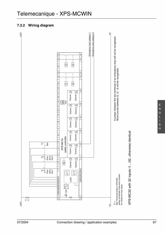
Telemecanique - XPS-MCWIN
07/2004 Connection drawing / application examples 67
EN
GLI
SH
7.3.2 Wiring diagram
K0
A1c8
c7c6
c5c3
c4c2
c1i1
i2i3
i4i5
i6i7
i8i9
i10
i11
i12
i13
i14
i15
i16
1323
H1
3343
A244
3424
14o6
o5o4
o3o2
o1G
ND
GN
DG
ND
µC 1
µC 2
K1 K2
K3 K4
TER
+24
V
F1
+24
V 0V0V
S3S1
S2
24V 5V
T
XP
S-M
C32
with
32
inpu
ts i1
…i3
2, o
ther
wis
e id
entic
al
LOG
ICC
hann
el 1
Cha
nnel
2
Cha
nnel
1
Cha
nnel
2
Cha
nnel
1
Cha
nnel
2
Cha
nnel
1
Cha
nnel
2
Cha
nnel
1
Cha
nnel
2
Cha
nnel
1
Cha
nnel
2
XP
S-M
C16
safe
ty c
ontr
olle
r
Em
erge
ncy
stop
cat
egor
y 1
A ju
mpe
r be
twee
n th
e tw
o te
rmin
als
of a
n em
erge
ncy
stop
will
not
be
reco
gnis
ed.
Sho
rt-c
ircui
ts b
etw
een
i2, i
3…i5
will
be
reco
gnis
ed.
Star
tEm
er-
genc
yst
op 2
Emer
-ge
ncy
stop
1
Em
erge
ncy
stop
cat
egor
y 0
(1)
(1)
=S
ee T
ech
nica
l Dat
a in
XP
S-M
Csa
fety
con
stro
ller
inst
ruct
ion
bul
letin
for
max
imum
fuse
siz
es.
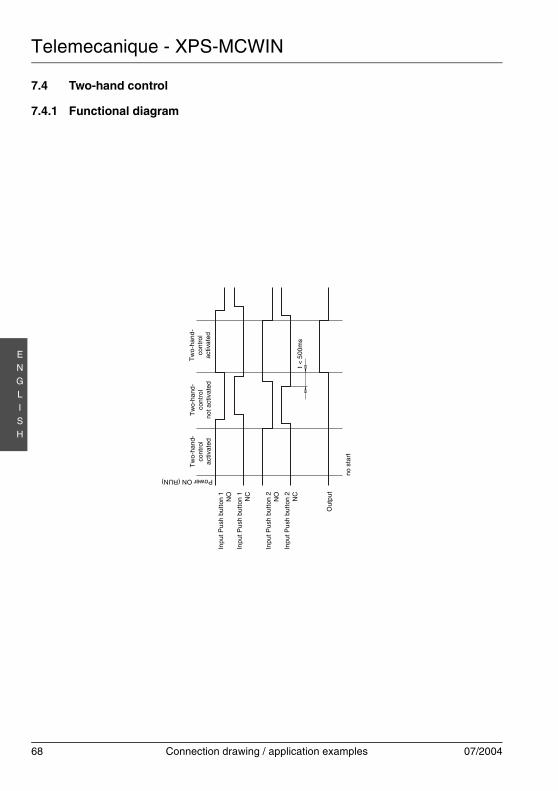
Telemecanique - XPS-MCWIN
68 Connection drawing / application examples 07/2004
EN
GLI
SH
7.4 Two-hand control
7.4.1 Functional diagram
Tw
o-ha
nd-
cont
rol
activ
ate
d
Tw
o-ha
nd-
cont
rol
not a
ctiv
ated
Tw
o-ha
nd-
cont
rol
activ
ated
Inpu
t Pus
h bu
tton
1N
O
Inpu
t Pus
h bu
tton
1N
C
Inpu
t Pus
h bu
tton
2N
O
Inpu
t Pus
h bu
tton
2N
C
Out
put
no s
tart
t <
500
ms
Power ON (RUN)
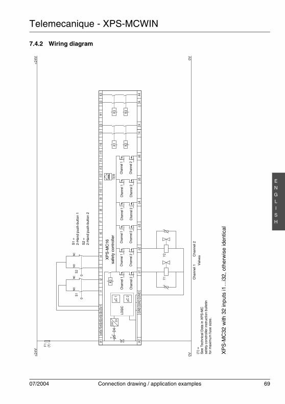
Telemecanique - XPS-MCWIN
07/2004 Connection drawing / application examples 69
EN
GLI
SH
7.4.2 Wiring diagram
K0
A1c8
c7c6
c5c3
c4c2
c1i1
i2i3
i4i5
i6i7
i8i9
i10
i11
i12
i13
i14
i15
i16
1323
H1
3343
A244
3424
14o6
o5o4
o3o2
o1G
ND
GN
DG
ND
µC 1
µC 2
K1 K2
K3 K4
TER
+24
V
0V
F1
+24
V
0V
S1S2
Y1Y2
24V 5V
T
LOG
ICC
hann
el 1
Cha
nnel
2
Cha
nnel
1
Cha
nnel
2
Cha
nnel
1
Cha
nnel
2
Cha
nnel
1
Cha
nnel
2
Cha
nnel
1
Cha
nnel
2
Cha
nnel
1
Cha
nnel
2
XP
S-M
C16
safe
ty c
ontr
olle
r
S1
=2-
Han
d pu
sh-b
utto
n 1
S2
=2-
Han
d pu
sh-b
utto
n 2
XP
S-M
C32
with
32
inpu
ts i1
…i3
2, o
ther
wis
e id
entic
al
Cha
nnel
1C
han
nel 2
Val
ves
(1)
NON
CNO
NC
(1)
=S
ee T
ech
nica
l Dat
a in
XP
S-M
Csa
fety
con
stro
ller
inst
ruct
ion
bul
letin
for
max
imum
fuse
siz
es.
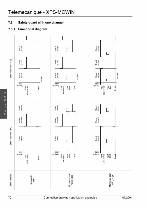
Telemecanique - XPS-MCWIN
70 Connection drawing / application examples 07/2004
EN
GLI
SH
7.5 Safety guard with one channel
7.5.1 Functional diagram
Sta
rt fu
nctio
n
Inpu
tLi
mit
switc
h
Aut
omat
icst
art
Mon
itore
d st
art
risin
g ed
ge
Mon
itore
d st
art
falli
ng e
dge
Sta
rt In
terlo
ck =
NO
Sta
rt In
terlo
ck =
YE
S
Ou
tput
Inpu
tLi
mit
switc
h
Inpu
tS
tart
Out
put
Inpu
tLi
mit
switc
h
Inpu
tS
tart
Ou
tput
Inpu
tLi
mit
switc
h
Out
put
Inpu
tLi
mit
switc
h
Inpu
tS
tart
Ou
tput
Inpu
tLi
mit
switc
h
Inpu
tS
tart
Out
put
Power On(RUN)
Gua
rdcl
osed
Gua
rdo
pene
dG
uard
clos
ed
Gua
rdcl
osed
Gua
rdop
ene
dG
uard
clos
ed
no s
tart
Power On(RUN)
Power On(RUN)
Gua
rdcl
osed
Gua
rdop
ened
Gua
rdcl
osed
Gua
rdcl
osed
Gua
rdop
ene
dG
uard
clos
ed
Power On(RUN)
Gua
rdcl
osed
Gua
rdop
ene
dG
uard
clos
ed
Power On(RUN)
no s
tart
no
star
t
Power On(RUN)
Gua
rdcl
osed
Gua
rdo
pene
dG
uard
clos
ed
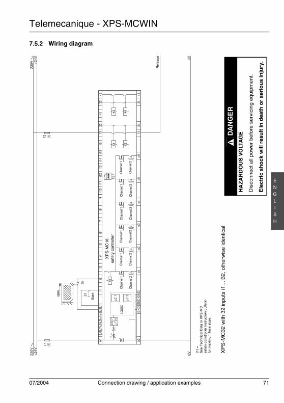
Telemecanique - XPS-MCWIN
07/2004 Connection drawing / application examples 71
EN
GLI
SH
7.5.2 Wiring diagram
K0
A1c8
c7c6
c5c3
c4c2
c1i1
i2i3
i4i5
i6i7
i8i9
i10
i11
i12
i13
i14
i15
i16
1323
H1
3343
A244
3424
14o6
o5o4
o3o2
o1G
ND
GN
DG
ND
µC 1
µC 2
K1 K2
K3 K4
TER
S1S2
+24
V+
24V 0V
0V
F1F2
24V 5V
T
LOG
ICC
hann
el 1
Cha
nnel
2
Cha
nnel
1
Cha
nnel
2
Cha
nnel
1
Cha
nnel
2
Cha
nnel
1
Cha
nnel
2
Cha
nnel
1
Cha
nnel
2
Cha
nnel
1
Cha
nnel
2
XP
S-M
C16
safe
ty c
ontr
olle
r
XP
S-M
C32
with
32
inpu
ts i1
…i3
2, o
ther
wis
e id
entic
al
open
(1)
Sta
rt
Rel
ease
(1)
(1)
=S
ee T
ech
nica
l Dat
a in
XP
S-M
Csa
fety
con
stro
ller
inst
ruct
ion
bul
letin
for
max
imum
fuse
siz
es.
DA
NG
ER
HA
ZA
RD
OU
S V
OLT
AG
E
Dis
conn
ect a
ll po
wer
bef
ore
serv
icin
g eq
uipm
ent.
Ele
ctri
c sh
ock
will
res
ult
in d
eath
or
seri
ou
s in
jury
.
!
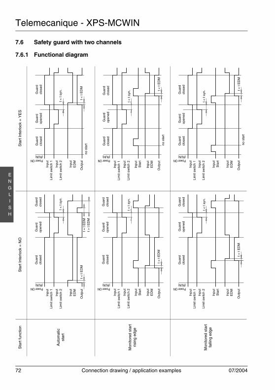
Telemecanique - XPS-MCWIN
72 Connection drawing / application examples 07/2004
EN
GLI
SH
7.6 Safety guard with two channels
7.6.1 Functional diagramIn
put
Lim
it sw
itch
1
Out
put
Inpu
tLi
mit
switc
h 1
Inpu
tLi
mit
switc
h 2
Out
put
Power ON(RUN)
Gua
rdcl
osed
Gua
rdop
ened
Gua
rdcl
ose
d
Gua
rdcl
osed
Gua
rdop
ene
dG
uar
dcl
osed
no s
tart
Power ON(RUN)
Power ON(RUN)
Gua
rdcl
osed
Gu
ard
open
edG
uar
dcl
osed
Gua
rdcl
osed
Gua
rdop
ene
dG
uard
clos
ed
Power ON(RUN)
Gua
rdcl
osed
Gua
rdop
ene
dG
uard
clos
ed
Power ON(RUN) n
o st
art
Power ON(RUN)
Gua
rdcl
ose
dG
uard
open
ed
Gua
rdcl
osed
Inpu
tLi
mit
switc
h 2
Inpu
tE
DM
Inpu
tLi
mit
switc
h 1
Out
put
Inpu
tS
tart
Inpu
tLi
mit
switc
h 2
Inpu
tE
DM
Inpu
tS
tart
Inpu
tE
DM
Inpu
tLi
mit
switc
h 1
Inpu
tLi
mit
switc
h 2
Ou
tput
Inpu
tS
tart
Inpu
tE
DM
Inpu
tLi
mit
switc
h 1
Out
put
Inpu
tS
tart
Inpu
tLi
mit
switc
h 2
Inpu
tE
DM
Inpu
tLi
mit
switc
h 1
Out
put
Inpu
tLi
mit
switc
h 2
Inpu
tE
DM
t < t
ED
M
t < t
syn.
t < t
ED
M
t < t
syn. t <
t E
DM
no s
tart
t < t
syn.
t < t
syn.
t = t
ED
Mt >
t E
DM
t <
t E
DM
t <
t sy
n.
t < t
ED
M
t <
t sy
n.
t < t
ED
M
Sta
rt fu
nctio
n
Aut
omat
icst
art
Mon
itore
d st
art
risin
g ed
ge
Mon
itore
d st
art
falli
ng e
dge
Sta
rt In
terlo
ck =
NO
Sta
rt In
terlo
ck =
YE
S
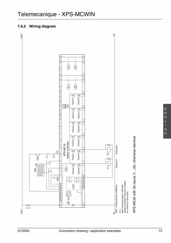
Telemecanique - XPS-MCWIN
07/2004 Connection drawing / application examples 73
EN
GLI
SH
7.6.2 Wiring diagram
K0
A1c8
c7c6
c5c3
c4c2
c1i1
i2i3
i4i5
i6i7
i8i9
i10
i11
i12
i13
i14
i15
i16
1323
H1
3343
A244
3424
14o6
o5o4
o3o2
o1G
ND
GN
DG
ND
µC 1
µC 2
K1 K2
K3 K4
TER
+24
V+
24V
F1
0V0V
S2S3
S1
Ko1
Ko2
24V 5V
T
Ko1
Ko2
LOG
ICC
hann
el 1
Cha
nnel
2
Cha
nnel
1
Cha
nnel
2
Cha
nnel
1
Cha
nnel
2
Cha
nnel
1
Cha
nnel
2
Cha
nnel
1
Cha
nnel
2
Cha
nnel
1
Cha
nnel
2
XP
S-M
C16
safe
ty c
ontr
olle
r
XP
S-M
C32
with
32
inpu
ts i1
…i3
2, o
ther
wis
e id
entic
al
open
Sta
rt
Cha
nnel
1C
han
nel 2
(1)
EDM
ES
C =
Ext
ern
al s
tart
con
ditio
ns
(1)
=S
ee T
ech
nica
l Dat
a in
XP
S-M
Csa
fety
con
stro
ller
inst
ruct
ion
bul
letin
for
max
imum
fuse
siz
es.
ES
C
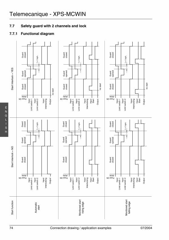
Telemecanique - XPS-MCWIN
74 Connection drawing / application examples 07/2004
EN
GLI
SH
7.7 Safety guard with 2 channels and lock
7.7.1 Functional diagramIn
put
Lim
it sw
itch
1
Out
put
Inpu
tLi
mit
switc
h 1
Inpu
tLi
mit
switc
h 2
Out
put
Power ON(RUN)
Gua
rdcl
osed
Gua
rdop
ened
Gua
rdcl
ose
d
Gua
rdcl
osed
Gua
rdop
ene
dG
uar
dcl
osed
no s
tart
Power ON(RUN)
Power ON(RUN)
Gua
rdcl
osed
Gua
rdo
pene
dG
uar
dcl
osed
Gua
rdcl
osed
Gua
rdop
ened
Gua
rdcl
osed
Power ON(RUN)
Gua
rdcl
osed
Gu
ard
ope
ned
Gua
rdcl
osed
Power ON(RUN) n
o st
art
Power ON(RUN)
Gua
rdcl
ose
dG
uard
open
edG
uard
clos
ed
Inpu
tLi
mit
switc
h 2
Inpu
tIn
terlo
ckin
g
Inpu
tLi
mit
switc
h 1
Out
put
Inpu
tLi
mit
switc
h 2
Inpu
tS
tart
Inpu
tIn
terlo
ckin
g
Inpu
tS
tart
Inpu
tLi
mit
switc
h 1
Inpu
tLi
mit
switc
h 2
Ou
tput
Inpu
tIn
terlo
ckin
g
Inpu
tS
tart
Inpu
tLi
mit
switc
h 1
Out
put
Inpu
tLi
mit
switc
h 2
Inpu
tS
tart
Inpu
tLi
mit
switc
h 1
Out
put
Inpu
tLi
mit
switc
h 2
Inpu
tIn
terlo
ckin
g
t < t
syn.
t < t
syn.
no s
tart
t < t
syn.
t < t
syn.
t <
t sy
n.
t <
t sy
n.
Inpu
tIn
terlo
ckin
gIn
put
Inte
rlock
ing
Sta
rt fu
nctio
n
Aut
omat
icst
art
Mon
itore
d st
art
risin
g ed
ge
Mon
itore
d st
art
falli
ng e
dge
Sta
rt In
terlo
ck =
NO
Sta
rt In
terlo
ck =
YE
S

Telemecanique - XPS-MCWIN
07/2004 Connection drawing / application examples 75
EN
GLI
SH
7.7.2 Wiring diagram
K0
A1c8
c7c6
c5c3
c4c2
c1i1
i2i3
i4i5
i6i7
i8i9
i10
i11
i12
i13
i14
i15
i16
1323
H1
3343
A244
3424
14o6
o5o4
o3o2
o1G
ND
GN
DG
ND
µC 1
µC 2
K1 K2
K3 K4
TER
+24
V
0V
F1
0V
+24
V
S1
S2S3
S4
Ko1
Ko2
Ko2
Ko1
24V 5V
T
LOG
ICC
hann
el 1
Cha
nnel
2
Cha
nnel
1
Cha
nnel
2
Cha
nnel
1
Cha
nnel
2
Cha
nnel
1
Cha
nnel
2
Cha
nnel
1
Cha
nnel
2
Cha
nnel
1
Cha
nnel
2
XP
S-M
C16
safe
ty c
ontr
olle
r
XP
S-M
C32
with
32
inpu
ts i1
…i3
2, o
ther
wis
e id
entic
al
open Sta
rt
Cha
nnel
1C
han
nel 2
(1)
EDM
ES
C
ES
C =
Ext
ern
al s
tart
con
ditio
ns
(1)
=S
ee T
ech
nica
l Dat
a in
XP
S-M
Csa
fety
con
stro
ller
inst
ruct
ion
bul
letin
for
max
imum
fuse
siz
es.
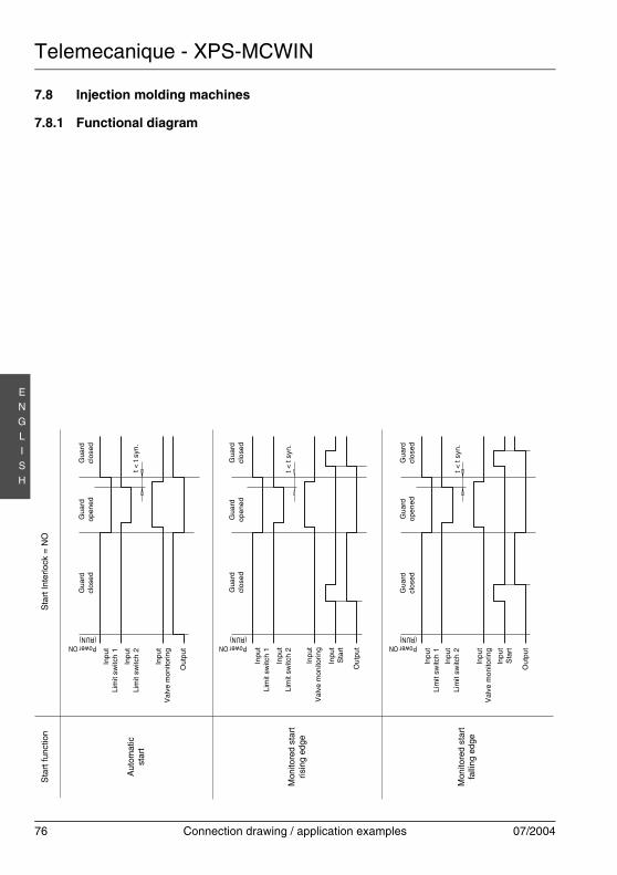
Telemecanique - XPS-MCWIN
76 Connection drawing / application examples 07/2004
EN
GLI
SH
7.8 Injection molding machines
7.8.1 Functional diagram
Power ON(RUN)
Gua
rdcl
osed
Gua
rdop
ened
Gua
rdcl
ose
d
Power ON(RUN)
Gua
rdcl
osed
Gua
rdop
ened
Gu
ard
clos
ed
Power ON(RUN)
Gua
rdcl
ose
dG
uar
dop
ened
Gua
rdcl
osed
Inpu
tLi
mit
switc
h 1
Inpu
tLi
mit
switc
h 2
Ou
tput
Inpu
tV
alve
mo
nito
ring
Inpu
tS
tart
Inpu
tLi
mit
switc
h 1
Out
put
Inpu
tLi
mit
switc
h 2
Inpu
tS
tart
Inpu
tLi
mit
switc
h 1
Out
put
Inpu
tLi
mit
switc
h 2
Inpu
tV
alve
mon
itorin
g
t < t
syn.
t <
t sy
n.
t <
t sy
n.
Inpu
tV
alve
mon
itorin
g
Sta
rt fu
nctio
n
Aut
omat
icst
art
Mon
itore
d st
art
risin
g ed
ge
Mon
itore
d st
art
falli
ng e
dge
Sta
rt In
terlo
ck =
NO
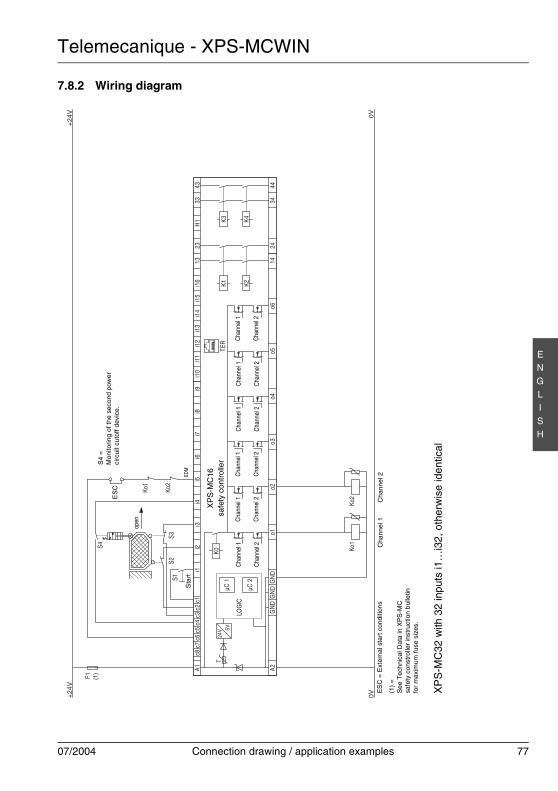
Telemecanique - XPS-MCWIN
07/2004 Connection drawing / application examples 77
EN
GLI
SH
7.8.2 Wiring diagram
K0
A1c8
c7c6
c5c3
c4c2
c1i1
i2i3
i4i5
i6i7
i8i9
i10
i11
i12
i13
i14
i15
i16
1323
H1
3343
A244
3424
14o6
o5o4
o3o2
o1G
ND
GN
DG
ND
µC 1
µC 2
K1 K2
K3 K4
TER
+24
V
F1
0V0V
+24
V
Ko1
Ko2
Ko1
Ko2
S1S2
S3
S4
24V 5V
T
LOG
ICC
hann
el 1
Cha
nnel
2
Cha
nnel
1
Cha
nnel
2
Cha
nnel
1
Cha
nnel
2
Cha
nnel
1
Cha
nnel
2
Cha
nnel
1
Cha
nnel
2
Cha
nnel
1
Cha
nnel
2
XP
S-M
C16
safe
ty c
ontr
olle
r
XP
S-M
C32
with
32
inpu
ts i1
…i3
2, o
ther
wis
e id
entic
al
open
Cha
nnel
1C
han
nel 2
Sta
rt
S4
=M
onito
ring
of th
e se
con
d po
we
rci
rcui
t cut
off d
evic
e.
(1)
EDM
ES
C =
Ext
ern
al s
tart
con
ditio
ns
(1)
=S
ee T
ech
nica
l Dat
a in
XP
S-M
Csa
fety
con
stro
ller
inst
ruct
ion
bul
letin
for
max
imum
fuse
siz
es.
ES
C
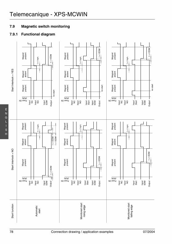
Telemecanique - XPS-MCWIN
78 Connection drawing / application examples 07/2004
EN
GLI
SH
7.9 Magnetic switch monitoring
7.9.1 Functional diagramIn
put
NC
Out
put
Inpu
tN
C
Inpu
tN
O
Out
put
Power ON(RUN)
Mag
net
pre
sen
tM
agne
tab
sent
Mag
net
pres
ent
Mag
net
pres
ent
Mag
net
abse
ntM
agne
tp
rese
nt
no s
tart
Power ON(RUN)
Power ON(RUN)
Mag
net
pres
ent
Mag
net
abse
ntM
agn
etpr
ese
nt
Mag
net
pre
sen
tM
agne
tab
sen
tM
agn
etpr
esen
t
Power ON(RUN)
Mag
net
pre
sen
tM
agne
tab
sen
tM
agne
tpr
esen
t
Power ON(RUN) n
o st
art
Power ON(RUN)
Mag
net
pres
ent
Mag
net
abs
ent
Mag
net
pres
ent
Inpu
tN
O
Inpu
tE
DM
Inpu
tN
C
Out
put
Inpu
tN
O
Inpu
tE
DM
Inpu
tS
tart
Inpu
tE
DM
Inpu
tN
C
Inpu
tN
O
Inpu
tS
tart
Inpu
tN
C
Out
put
Inpu
tN
O
Inpu
tE
DM
Inpu
tN
C
Out
put
Inpu
tN
O
Inpu
tE
DM
t < t
syn.
t < t
syn.
no s
tart
t < t
syn.
t < t
syn.
t <
t sy
n.
t <
t sy
n.
Inpu
tS
tart
Inpu
tS
tart
t =
t E
DM
t >
t E
DM
t <
t E
DM
t < t
ED
M
t < t
ED
Mt <
t E
DM
Out
put
Inpu
tE
DM
t < t
ED
Mt
< t
ED
M
Sta
rt fu
nctio
n
Aut
omat
icst
art
Mon
itore
d st
art
risin
g ed
ge
Mon
itore
d st
art
falli
ng e
dge
Sta
rt In
terlo
ck =
NO
Sta
rt In
terlo
ck =
YE
S
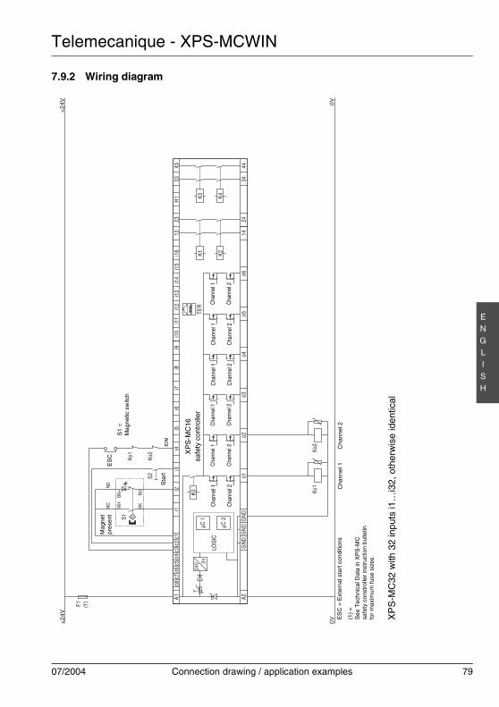
Telemecanique - XPS-MCWIN
07/2004 Connection drawing / application examples 79
EN
GLI
SH
7.9.2 Wiring diagram
K0
A1c8
c7c6
c5c3
c4c2
c1i1
i2i3
i4i5
i6i7
i8i9
i10
i11
i12
i13
i14
i15
i16
1323
H1
3343
A244
3424
14o6
o5o4
o3o2
o1G
ND
GN
DG
ND
µC 1
µC 2
K1 K2
K3 K4
TER
+24
V+
24V
F1
0V0V
Ko1
Ko2
S2
S1W
H
BK
BN+
BU Ko1
Ko2
24V 5V
T
LOG
ICC
hann
el 1
Cha
nnel
2
Cha
nnel
1
Cha
nnel
2
Cha
nnel
1
Cha
nnel
2
Cha
nnel
1
Cha
nnel
2
Cha
nnel
1
Cha
nnel
2
Cha
nnel
1
Cha
nnel
2
XP
S-M
C16
safe
ty c
ontr
olle
r
XP
S-M
C32
with
32
inpu
ts i1
…i3
2, o
ther
wis
e id
entic
al
Cha
nnel
1C
han
nel 2
Sta
rt
S1
=M
agne
tic s
witc
h
(1)
EDM
NC
NOM
agne
tpr
esen
t
ES
C =
Ext
ern
al s
tart
con
ditio
ns
(1)
=S
ee T
ech
nica
l Dat
a in
XP
S-M
Csa
fety
con
stro
ller
inst
ruct
ion
bul
letin
for
max
imum
fuse
siz
es.
ES
C
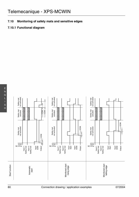
Telemecanique - XPS-MCWIN
80 Connection drawing / application examples 07/2004
EN
GLI
SH
7.10 Monitoring of safety mats and sensitive edges
7.10.1 Functional diagram
Power ON(RUN)
Saf
ety
ma
tno
t act
ivat
ed
Saf
ety
mat
act
uate
dS
afet
y m
atno
t act
ivat
ed
Power ON(RUN)
Saf
ety
mat
not a
ctiv
ated
Saf
ety
ma
tac
tuat
edS
afet
y m
at
not a
ctiv
ate
d
Power ON(RUN)
Saf
ety
mat
not a
ctiv
ated
Sa
fety
mat
actu
ated
Sa
fety
mat
not
activ
ated
Inp
ut 1
Saf
ety
mat
Inp
ut 2
Saf
ety
mat
Inpu
tS
tart
Inpu
t 1S
afet
y m
at
Out
put
Inpu
t 2S
afet
y m
at
Inpu
tE
DM
Inpu
t 1
Saf
ety
mat
Out
put
Inpu
t 2
Saf
ety
mat
Inpu
tE
DM
Inpu
tS
tart
t =
t E
DM
t >
t E
DM
t <
t E
DM
t < t
ED
M
Out
put
Inpu
tE
DM
t < t
ED
M
Sta
rt fu
nctio
n
Aut
omat
icst
art
Mon
itore
d st
art
risin
g ed
ge
Mon
itore
d st
art
falli
ng e
dge

Telemecanique - XPS-MCWIN
07/2004 Connection drawing / application examples 81
EN
GLI
SH
7.10.2 Wiring diagram
K0
A1c8
c7c6
c5c3
c4c2
c1i1
i2i3
i4i5
i6i7
i8i9
i10
i11
i12
i13
i14
i15
i16
1323
H1
3343
A244
3424
14o6
o5o4
o3o2
o1G
ND
GN
DG
ND
µC 1
µC 2
K1 K2
K3 K4
TER
+24
V
F1
0V0V
+24
V
Ko1
Ko2
Ko1
Ko2
S1
S2
24V 5V
T
LOG
ICC
hann
el 1
Cha
nnel
2
Cha
nnel
1
Cha
nnel
2
Cha
nnel
1
Cha
nnel
2
Cha
nnel
1
Cha
nnel
2
Cha
nnel
1
Cha
nnel
2
Cha
nnel
1
Cha
nnel
2
XP
S-M
C16
safe
ty c
ontr
olle
r
XP
S-M
C32
with
32
inpu
ts i1
…i3
2, o
ther
wis
e id
entic
al
Cha
nnel
1C
han
nel 2
Sta
rt
Con
trol
out
puts
whi
ch a
re c
onne
cted
to a
safe
ty m
at c
anno
t be
used
for
othe
r ite
ms.
Safe
tym
at
(1)
EDM
ES
C =
Ext
ern
al s
tart
con
ditio
ns
(1)
=S
ee T
ech
nica
l Dat
a in
XP
S-M
Csa
fety
con
stro
ller
inst
ruct
ion
bul
letin
for
max
imum
fuse
siz
es.
ES
C

Telemecanique - XPS-MCWIN
82 Connection drawing / application examples 07/2004
EN
GLI
SH
7.11 Light curtains with relay outputs
7.11.1 Functional diagramIn
put
OS
SD
1
Out
put
Inpu
tO
SS
D 1
Inpu
tO
SS
D 2
Out
put
Rising edge(RUN)
Ligh
t cur
tain
free
Ligh
t cur
tain
inte
rrup
ted
Ligh
t cur
tain
free
Lig
ht c
urta
infr
eeLi
ght
curt
ain
inte
rru
pted
Ligh
t cur
tain
fre
e
no s
tart
Rising edge(RUN)
Rising edge(RUN)
Ligh
t cur
tain
free
Ligh
t cur
tain
inte
rrup
ted
Ligh
t cur
tain
fre
e
Ligh
t cur
tain
fre
eLi
ght c
urta
inin
terr
upte
dLi
ght c
urt
ain
free
Rising edge(RUN)
Ligh
t cur
tain
fre
eLi
ght c
urta
inin
terr
upte
dLi
ght
curt
ain
free
Rising edge(RUN) n
o st
art
Rising edge(RUN)
Lig
ht c
urta
infr
eeLi
ght
curt
ain
inte
rru
pted
Lig
ht c
urta
infr
ee
Inpu
tO
SS
D 2
Inpu
tE
DM
Inpu
tO
SS
D 1
Out
put
Inpu
tO
SS
D 2
Inpu
tE
DM
Inpu
tS
tart
Inpu
tE
DM
Inpu
tO
SS
D 1
Inpu
tO
SS
D 2
Inpu
tS
tart
Inpu
tO
SS
D 1
Out
put
Inpu
tO
SS
D 2
Inpu
tE
DM
Inpu
tO
SS
D 1
Out
put
Inpu
tO
SS
D 2
Inpu
tE
DM
t < t
syn.
t < t
syn.
no
star
t
t < t
syn.
t < t
syn.
t <
t sy
n.
t <
t sy
n.
Inpu
tS
tart
Inpu
tS
tart
t =
t E
DM
t >
t E
DM
t <
t E
DM
t < t
ED
M
t < t
ED
Mt <
t E
DM
Out
put
Inpu
tE
DM
t < t
ED
Mt
< t
ED
M
Sta
rt fu
nctio
n
Aut
omat
icst
art
Mon
itore
d st
art
risin
g ed
ge
Mon
itore
d st
art
falli
ng e
dge
Sta
rt In
terlo
ck =
NO
Sta
rt In
terlo
ck =
YE
S

Telemecanique - XPS-MCWIN
07/2004 Connection drawing / application examples 83
EN
GLI
SH
7.11.2 Wiring diagram
K0
A1c8
c7c6
c5c3
c4c2
c1i1
i2i3
i4i5
i6i7
i8i9
i10
i11
i12
i13
i14
i15
i16
1323
H1
3343
A244
3424
14o6
o5o4
o3o2
o1G
ND
GN
DG
ND
µC 1
µC 2
K1 K2
K3 K4
TER
(1)
(2)
(1)
OSS
D1O
SSD2
(2)
+24
V+
24V
F1
0V0V
Ko1
Ko2
Ko1
Ko2
S1
24V 5V
T
LOG
ICC
hann
el 1
Cha
nnel
2
Cha
nnel
1
Cha
nnel
2
Cha
nnel
1
Cha
nnel
2
Cha
nnel
1
Cha
nnel
2
Cha
nnel
1
Cha
nnel
2
Cha
nnel
1
Cha
nnel
2
XP
S-M
C16
safe
ty c
ontr
olle
r
XP
S-M
C32
with
32
inpu
ts i1
…i3
2, o
ther
wis
e id
entic
al
Cha
nnel
1C
han
nel 2
Sta
rt
ES
PE
=E
SP
E o
utpu
t
(1)
ESPE
EDM
ES
C =
Ext
ern
al s
tart
con
ditio
ns
(1)
=S
ee T
ech
nica
l Dat
a in
XP
S-M
Csa
fety
con
stro
ller
inst
ruct
ion
bul
letin
for
max
imum
fuse
siz
es.
ES
C

Telemecanique - XPS-MCWIN
84 Connection drawing / application examples 07/2004
EN
GLI
SH
7.12 Light curtains with solid-state outputs
7.12.1 Functional diagramIn
put
OS
SD
1
Out
put
Inpu
tO
SS
D 1
Inpu
tO
SS
D 2
Out
put
Rising edge(RUN)
Ligh
t cur
tain
free
Ligh
t cur
tain
inte
rrup
ted
Ligh
t cur
tain
free
Lig
ht c
urta
infr
eeLi
ght
curt
ain
inte
rru
pted
Ligh
t cur
tain
fre
e
no s
tart
Rising edge(RUN)
Rising edge(RUN)
Ligh
t cur
tain
free
Ligh
t cur
tain
inte
rrup
ted
Ligh
t cur
tain
fre
e
Ligh
t cur
tain
fre
eLi
ght c
urta
inin
terr
upte
dLi
ght c
urt
ain
free
Rising edge(RUN)
Ligh
t cur
tain
fre
eLi
ght c
urta
inin
terr
upte
dLi
ght
curt
ain
free
Rising edge(RUN) n
o st
art
Rising edge(RUN)
Lig
ht c
urta
infr
eeLi
ght
curt
ain
inte
rru
pted
Lig
ht c
urta
infr
ee
Inpu
tO
SS
D 2
Inpu
tE
DM
Inpu
tO
SS
D 1
Out
put
Inpu
tO
SS
D 2
Inpu
tE
DM
Inpu
tS
tart
Inpu
tE
DM
Inpu
tO
SS
D 1
Inpu
tO
SS
D 2
Inpu
tS
tart
Inpu
tO
SS
D 1
Out
put
Inpu
tO
SS
D 2
Inpu
tE
DM
Inpu
tO
SS
D 1
Out
put
Inpu
tO
SS
D 2
Inpu
tE
DM
t < t
syn.
t < t
syn.
no
star
t
t < t
syn.
t < t
syn.
t <
t sy
n.
t <
t sy
n.
Inpu
tS
tart
Inpu
tS
tart
t =
t E
DM
t >
t E
DM
t <
t E
DM
t < t
ED
M
t < t
ED
Mt <
t E
DM
Out
put
Inpu
tE
DM
t < t
ED
Mt
< t
ED
M
Sta
rt fu
nctio
n
Aut
omat
icst
art
Mon
itore
d st
art
risin
g ed
ge
Mon
itore
d st
art
falli
ng e
dge
Sta
rt In
terlo
ck =
NO
Sta
rt In
terlo
ck =
YE
S
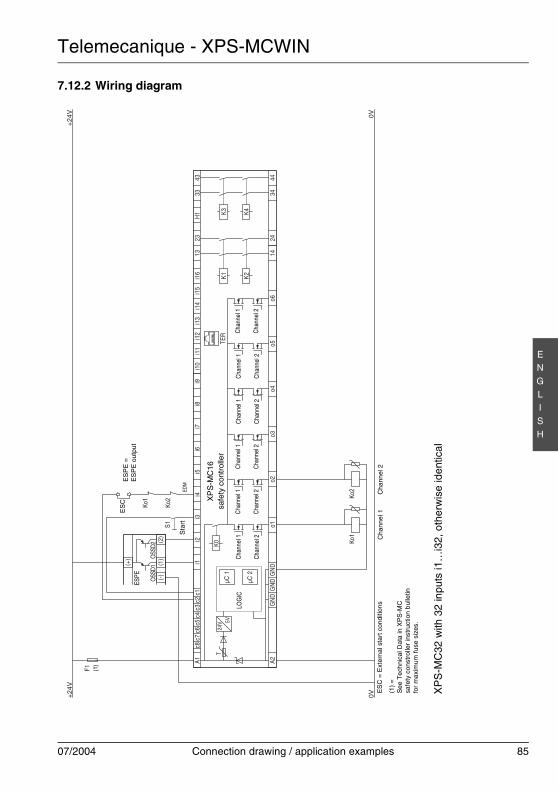
Telemecanique - XPS-MCWIN
07/2004 Connection drawing / application examples 85
EN
GLI
SH
7.12.2 Wiring diagram
K0
A1c8
c7c6
c5c3
c4c2
c1i1
i2i3
i4i5
i6i7
i8i9
i10
i11
i12
i13
i14
i15
i16
1323
H1
3343
A244
3424
14o6
o5o4
o3o2
o1G
ND
GN
DG
ND
µC 1
µC 2
K1 K2
K3 K4
TER
(1)
(2)
(-)
(+)
OSS
D1O
SSD2
+24
V 0V0V+
24V
F1
Ko1
Ko2
S1
Ko1
Ko2
24V 5V
T
LOG
ICC
hann
el 1
Cha
nnel
2
Cha
nnel
1
Cha
nnel
2
Cha
nnel
1
Cha
nnel
2
Cha
nnel
1
Cha
nnel
2
Cha
nnel
1
Cha
nnel
2
Cha
nnel
1
Cha
nnel
2
XP
S-M
C16
safe
ty c
ontr
olle
r
XP
S-M
C32
with
32
inpu
ts i1
…i3
2, o
ther
wis
e id
entic
al
Cha
nne
l 1C
hann
el 2
Sta
rt
ES
PE
=E
SP
E o
utpu
t
(1)
ESPE
EDM
ES
C =
Ext
ern
al s
tart
con
ditio
ns
(1)
=S
ee T
ech
nica
l Dat
a in
XP
S-M
Csa
fety
con
stro
ller
inst
ruct
ion
bul
letin
for
max
imum
fuse
siz
es.
ES
C
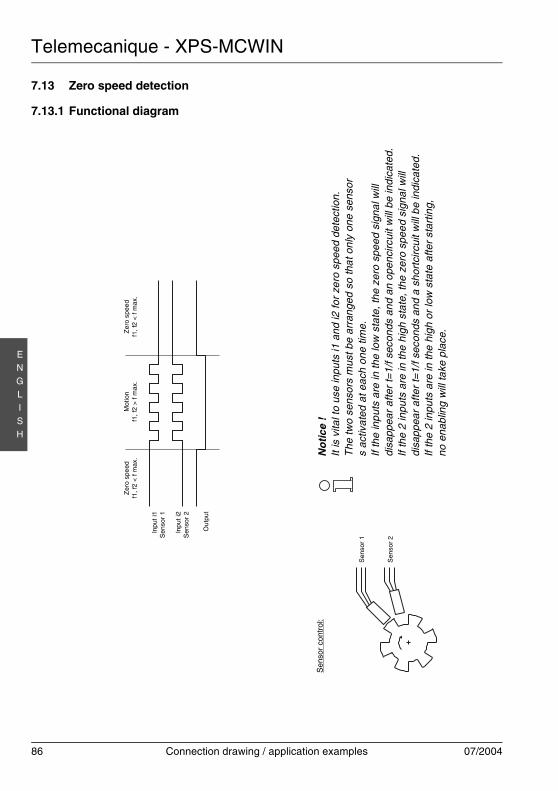
Telemecanique - XPS-MCWIN
86 Connection drawing / application examples 07/2004
EN
GLI
SH
7.13 Zero speed detection
7.13.1 Functional diagramZ
ero
spee
df1
, f2
< f
max
.Z
ero
spe
edf1
, f2
< f
max
.M
otio
nf1
, f2
> f
max
.
Sen
sor
1
Inpu
t i1
Sen
sor
1
Inpu
t i2
Sen
sor
2
Ou
tput
Sen
sor
2
Sen
sor
cont
rol:
No
tice
!It
is v
ital t
o us
e in
puts
i1 a
nd i2
for
zero
spe
ed d
etec
tion.
The
two
sens
ors
mus
t be
arra
nged
so
that
onl
y on
e se
nsor
s
activ
ated
at e
ach
one
time.
If th
e in
puts
are
in th
e lo
w s
tate
, the
zer
o sp
eed
sign
al w
ill
disa
ppea
r af
ter
t=1/
f sec
onds
and
an
open
circ
uit w
ill b
e in
dica
ted.
If th
e 2
inpu
ts a
re in
the
high
sta
te, t
he z
ero
spee
d si
gnal
will
disa
ppea
r af
ter
t=1/
f sec
onds
and
a s
hort
circ
uit w
ill b
e in
dica
ted.
If th
e 2
inpu
ts a
re in
the
high
or
low
sta
te a
fter
star
ting,
no e
nabl
ing
will
take
pla
ce.

Telemecanique - XPS-MCWIN
07/2004 Connection drawing / application examples 87
EN
GLI
SH
7.13.2 Wiring diagram
K0
A1c8
c7c6
c5c3
c4c2
c1i1
i2i3
i4i5
i6i7
i8i9
i10
i11
i12
i13
i14
i15
i16
1323
H1
3343
A244
3424
14o6
o5o4
o3o2
o1G
ND
GN
DG
ND
µC 1
µC 2
K1 K2
K3 K4
TER
+24
V 0V0V+
24V
F1
Ko1
Ko2
++ AA ––
24V 5V
T
LOG
ICC
hann
el 1
Cha
nnel
2
Cha
nnel
1
Cha
nnel
2
Cha
nnel
1
Cha
nnel
2
Cha
nnel
1
Cha
nnel
2
Cha
nnel
1
Cha
nnel
2
Cha
nnel
1
Cha
nnel
2
XP
S-M
C16
safe
ty c
ontr
olle
r
XP
S-M
C32
with
32
inpu
ts i1
…i3
2, o
ther
wis
e id
entic
al
Cha
nne
l 1C
hann
el 2
(1)
Sens
or 2
Sens
or 1
(1)
=S
ee T
ech
nica
l Dat
a in
XP
S-M
Csa
fety
con
stro
ller
inst
ruct
ion
bul
letin
for
max
imum
fuse
siz
es.
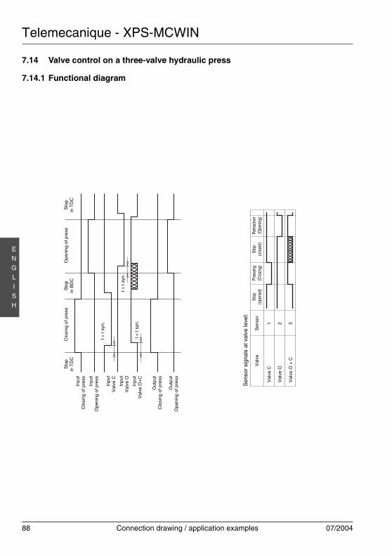
Telemecanique - XPS-MCWIN
88 Connection drawing / application examples 07/2004
EN
GLI
SH
7.14 Valve control on a three-valve hydraulic press
7.14.1 Functional diagram
Sto
pin
TD
CO
peni
ng
of p
ress
Sto
pin
BD
CC
losi
ng o
f pre
ssS
top
in T
DC
Inpu
tC
losi
ng o
f pre
ss
Inpu
tO
peni
ng o
f pre
ss
Inpu
tV
alve
O+
C
Out
put
Clo
sing
of p
ress
Out
put
Ope
ning
of p
ress
t < t
syn.
t < t
syn.
t < t
syn
.
Inpu
tV
alve
C
Inpu
tV
alve
O
Sen
sor
sign
als
at v
alve
leve
l:
Val
veSt
op(o
pene
d)Pr
essi
ng(C
losi
ng)
Stop
(clo
sed)
Ret
ract
ion
(Ope
ning
)
Val
ve C
Val
ve O
Val
ve O
+ C
Sen
sor
1 2 3
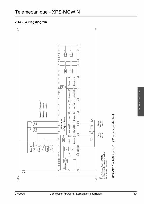
Telemecanique - XPS-MCWIN
07/2004 Connection drawing / application examples 89
EN
GLI
SH
7.14.2 Wiring diagram
K0
A1c8
c7c6
c5c3
c4c2
c1i1
i2i3
i4i5
i6i7
i8i9
i10
i11
i12
i13
i14
i15
i16
1323
H1
3343
A244
3424
14o6
o5o4
o3o2
o1G
ND
GN
DG
ND
µC 1
µC 2
K1 K2
K3 K4
TER
+24
V
F1
0V0V
+24
V
Ko1
Ko2
S5S4
+++ AAA –––
24V 5V
T
LOG
ICC
hann
el 1
Cha
nnel
2
Cha
nnel
1
Cha
nnel
2
Cha
nnel
1
Cha
nnel
2
Cha
nnel
1
Cha
nnel
2
Cha
nnel
1
Cha
nnel
2
Cha
nnel
1
Cha
nnel
2
XP
S-M
C16
safe
ty c
ontr
olle
r
XP
S-M
C32
with
32
inpu
ts i1
…i3
2, o
ther
wis
e id
entic
al
Pre
sscl
osin
gen
able
Pre
ssop
enin
ge
nabl
e
Pres
scl
osed
Pres
sop
en
(1)
Sens
or 3
Sens
or 2
Sens
or 1
Sen
sor
3 -
Val
ve O
+ C
Sen
sor
2 -
Val
ve O
Sen
sor
1 -
Val
ve C
(1)
=S
ee T
ech
nica
l Dat
a in
XP
S-M
Csa
fety
con
stro
ller
inst
ruct
ion
bul
letin
for
max
imum
fuse
siz
es.
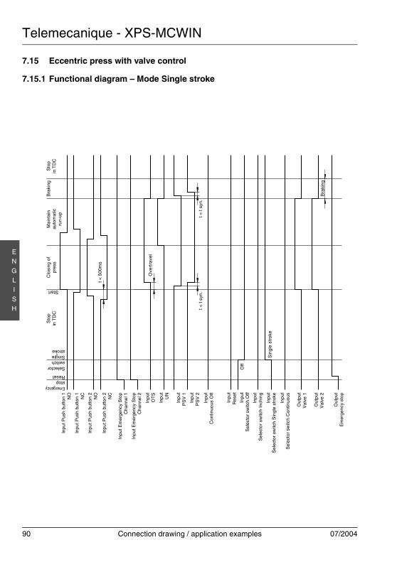
Telemecanique - XPS-MCWIN
90 Connection drawing / application examples 07/2004
EN
GLI
SH
7.15 Eccentric press with valve control
7.15.1 Functional diagram – Mode Single stroke
Inpu
t E
mer
genc
y S
top
Ch
anne
l 1
Inpu
t E
mer
genc
y S
top
Ch
anne
l 2
t < 5
00m
s
Sin
gle
str
oke
Start
Inpu
tO
TS
Inp
utU
N
Inpu
tC
ontin
uous
Off
Inpu
tS
ele
ctor
sw
itch
Inch
ing
Inpu
tS
elec
tor
switc
h S
ingl
e st
roke
Inpu
tS
elec
tor
switc
h C
ontin
uous
Out
put
Val
ve 2
Out
put
Em
erge
ncy
stop
Off
Ove
rtra
vel
t < t
syn.
Bra
king
Inpu
tR
eset
Inpu
t Pus
h bu
tton
1N
O
Inpu
t Pus
h bu
tton
2N
O
Inpu
t Pus
h bu
tton
1N
C
Inpu
t Pus
h bu
tton
2N
C
Inp
utP
SV
1
Inp
utP
SV
2
Inpu
tS
elec
tor
switc
h O
ff
Out
put
Val
ve 1
Bra
king
EmergencystopReset
SelectorswitchSinglestroke
Mai
ntai
nau
tom
atic
run-
up
Clo
sing
of
pres
sS
top
in T
DC
Sto
pin
TD
C
t < t
syn
.
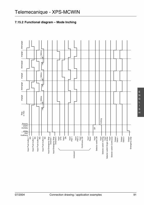
Telemecanique - XPS-MCWIN
07/2004 Connection drawing / application examples 91
EN
GLI
SH
7.15.2 Functional diagram – Mode Inchingdi
seng
age
t < 5
00m
s
Inch
ing
EmergencystopReset
OffSelector
switchInching
eng
age
enga
gee
ngag
edi
seng
age
dise
nga
ge
t < 5
00m
st <
500
ms
Inpu
t Em
erge
ncy
Sto
pC
hann
el 1
Inpu
t Em
erge
ncy
Sto
pC
hann
el 2
Inpu
tO
TS
Inpu
tU
N
Inpu
tC
ontin
uous
Off
Inpu
tS
elec
tor
switc
h In
chin
gIn
put
Sel
ecto
r sw
itch
Sin
gle
str
oke
Inpu
tS
elec
tor
switc
h C
ontin
uou
s
Out
put
Val
ve 2
Out
put
Em
erge
ncy
sto
p
Inpu
tR
eset
Inpu
t Pus
h bu
tton
1N
O
Inpu
t Pus
h bu
tton
2N
O
Inpu
t Pus
h bu
tton
1N
C
Inpu
t Pus
h bu
tton
2N
C
Inpu
tP
SV
1
Inpu
tP
SV
2
Inpu
tS
elec
tor
switc
h O
ff
Out
put
Val
ve 1
irrel
eva
nt
Sto
pin
TD
C
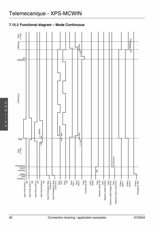
Telemecanique - XPS-MCWIN
92 Connection drawing / application examples 07/2004
EN
GLI
SH
7.15.3 Functional diagram – Mode Continuous
t < 5
00m
s
Con
tinuo
us
EmergencystopReset
Off
Ove
rtra
vel
SelectorswitchContinuous
Con
tinuo
usS
top
in T
DC
Bra
king
t < t
syn.
Bra
king
Sto
pin
TD
C
Start
Continuousoff
Inp
ut E
mer
gen
cy S
top
Cha
nnel
1
Inp
ut E
mer
gen
cy S
top
Cha
nnel
2
Inp
utO
TS
Inpu
tU
N
Inpu
tC
ontin
uous
Off
Inp
utS
elec
tor
switc
h In
chin
g
Inp
utS
elec
tor
switc
h S
ingl
e st
roke
Inp
utS
ele
ctor
sw
itch
Con
tinuo
us
Out
put
Val
ve 2
Out
put
Em
erge
ncy
stop
Inpu
tR
eset
Inp
ut P
ush
but
ton
1N
O
Inp
ut P
ush
but
ton
2N
O
Inp
ut P
ush
but
ton
1N
C
Inp
ut P
ush
but
ton
2N
C
Inpu
tP
SV
1
Inpu
tP
SV
2
Inpu
tS
elec
tor
switc
h O
ff
Out
put
Val
ve 1
t < t
syn.
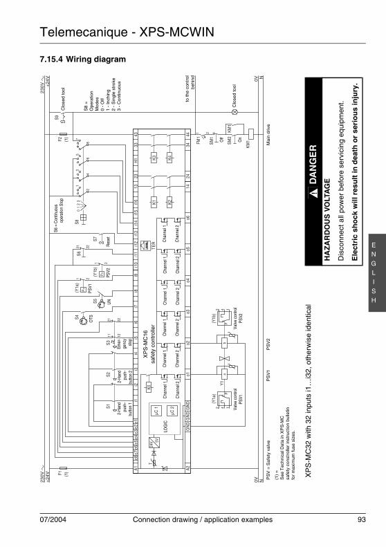
Telemecanique - XPS-MCWIN
07/2004 Connection drawing / application examples 93
EN
GLI
SH
7.15.4 Wiring diagram
K0
A1c8
c7c6
c5c3
c4c2
c1i1
i2i3
i4i5
i6i7
i8i9
i10
i11
i12
i13
i14
i15
i16
1323
H1
3343
A244
3424
14o6
o5o4
o3o2
o1G
ND
GN
DG
ND
µC 1
µC 2
K1 K2
K3 K4
TER
+24
V F1
0V0V
+24
V
S1S2
S3
(Y1a
)(Y
1b)
Y1142
P142
Pb
a
S4
S5
(Y1a
)S6
S80
12
31
2
3
4
5
6
7
8
S7
1 2
21 22P>
(Y1b
)1 2
P>
24V 5V
T
F2
21 22
11 12
KM1
KM1
NN
FM1
SM1
SM2
1 2
S9
LOG
ICC
hann
el 1
Cha
nnel
2
Cha
nnel
1
Cha
nnel
2
Cha
nnel
1
Cha
nnel
2
Cha
nnel
1
Cha
nnel
2
Cha
nnel
1
Cha
nnel
2
Cha
nnel
1
Cha
nnel
2
XP
S-M
C16
safe
ty c
ontr
olle
r
S8
=O
pera
tion
Mod
es
0 -
Off
1 -
Inch
ing
2 -
Sin
gle
stro
ke3
- C
ontin
uous
2-H
and
push
-bu
tton
2
2-H
and
push
-bu
tton
1
(1)
PS
V =
Saf
ety
valv
e
(1)
=S
ee T
echn
ical
Dat
a in
XP
S-M
Csa
fety
con
stro
ller
inst
ruct
ion
bulle
tinfo
r m
axim
um fu
se s
izes
.
XP
S-M
C32
with
32
inpu
ts i1
…i3
2, o
ther
wis
e id
entic
al
PS
V1
PS
V2
OTS
Valv
e co
ntro
lPS
V1Va
lve
cont
rol
PSV2
UN
PSV2
PSV1
S6 =
Con
tinuo
usop
erat
ion
Stop
Mai
n dr
ive
Emer
-ge
ncy
stop
Res
et
to th
e co
ntro
lbe
hin
d
(1)
Off
On
Clo
sed
tool
Clo
sed
too
l
DA
NG
ER
HA
ZA
RD
OU
S V
OLT
AG
E
Dis
conn
ect a
ll po
wer
bef
ore
serv
icin
g eq
uipm
ent.
Ele
ctri
c sh
ock
will
res
ult
in d
eath
or
seri
ou
s in
jury
.
!
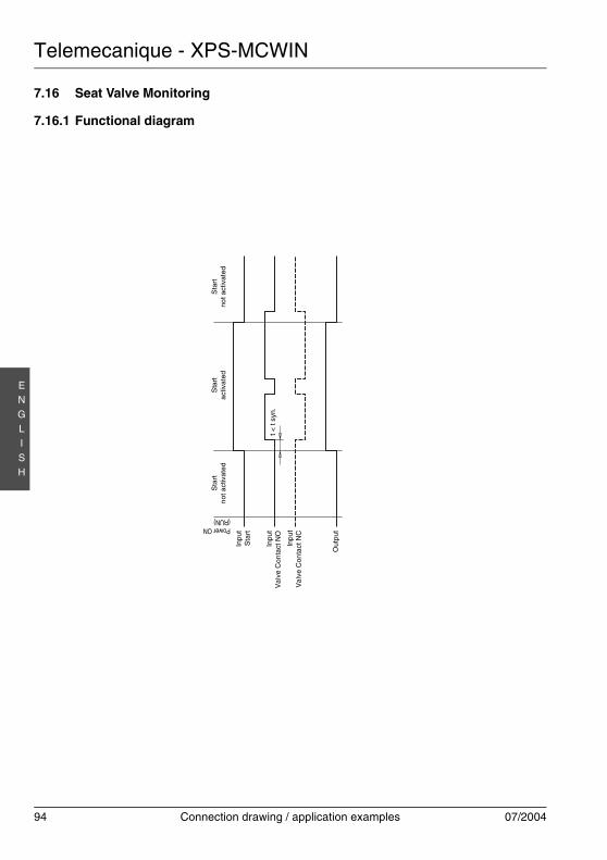
Telemecanique - XPS-MCWIN
94 Connection drawing / application examples 07/2004
EN
GLI
SH
7.16 Seat Valve Monitoring
7.16.1 Functional diagram
Power ON(RUN)
Sta
rtn
ot a
ctiv
ated
Sta
rta
ctiv
ated
Sta
rtno
t act
ivat
ed
Inpu
tS
tart
Out
put
Inpu
tV
alv
e C
onta
ct N
Ot <
t s
yn.
Inp
utV
alv
e C
onta
ct N
C

Telemecanique - XPS-MCWIN
07/2004 Connection drawing / application examples 95
EN
GLI
SH
7.16.2 Wiring diagram
K0
A1c8
c7c6
c5c3
c4c2
c1i1
i2i3
i4i5
i6i7
i8i9
i10
i11
i12
i13
i14
i15
i16
1323
H1
3343
A244
3424
14o6
o5o4
o3o2
o1G
ND
GN
DG
ND
µC 1
µC 2
K1 K2
K3 K4
TER
+24
V
0V
F1
+24
V
0V
S1S2
24V 5V
T
Y1
XP
S-M
C32
with
32
inpu
ts i1
…i3
2, o
ther
wis
e id
entic
al
Sea
t Val
veValv
em
onito
ring
Seat
Valv
eop
erat
ing
(1)
LOG
ICC
hann
el 1
Cha
nnel
2
Cha
nnel
1
Cha
nnel
2
Cha
nnel
1
Cha
nnel
2
Cha
nnel
1
Cha
nnel
2
Cha
nnel
1
Cha
nnel
2
Cha
nnel
1
Cha
nnel
2
XP
S-M
C16
safe
ty c
ontr
olle
r
(1)
=S
ee T
ech
nica
l Dat
a in
XP
S-M
Csa
fety
con
stro
ller
inst
ruct
ion
bul
letin
for
max
imum
fuse
siz
es.
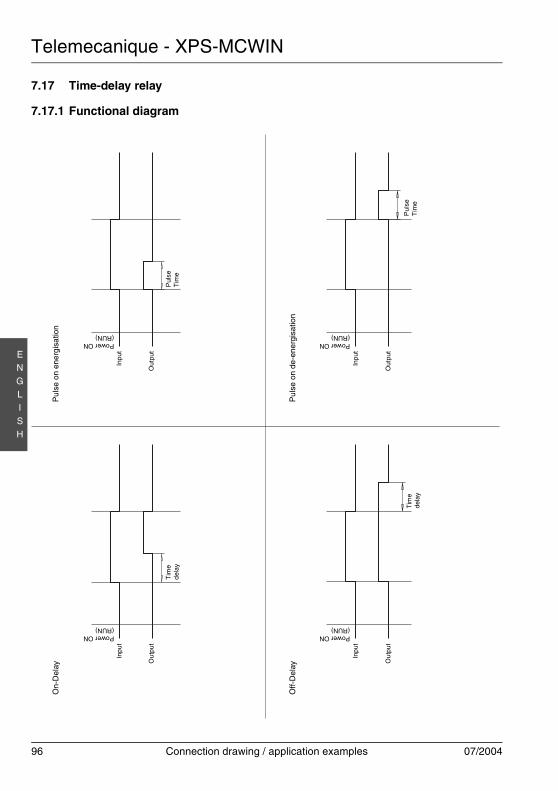
Telemecanique - XPS-MCWIN
96 Connection drawing / application examples 07/2004
EN
GLI
SH
7.17 Time-delay relay
7.17.1 Functional diagram
On-
Del
ay
Power ON(RUN)
Tim
ed
elay
Inpu
t
Ou
tput
Off-
Del
ay
Power ON(RUN)
Tim
ede
lay
Inpu
t
Ou
tput
Pul
se o
n en
ergi
satio
n
Power ON(RUN)
Pul
seT
ime
Inpu
t
Out
put
Pul
se o
n de
-ene
rgis
atio
n
Power ON(RUN)
Pul
seT
ime
Inpu
t
Out
put
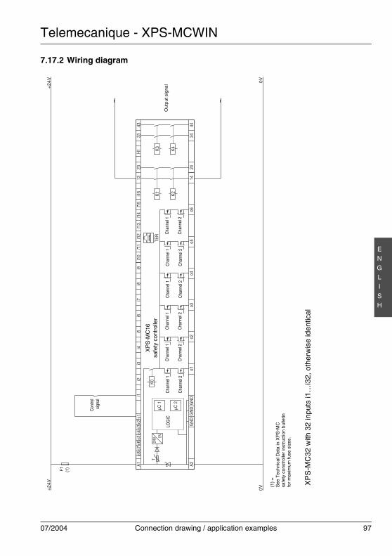
Telemecanique - XPS-MCWIN
07/2004 Connection drawing / application examples 97
EN
GLI
SH
7.17.2 Wiring diagram
K0
A1c8
c7c6
c5c3
c4c2
c1i1
i2i3
i4i5
i6i7
i8i9
i10
i11
i12
i13
i14
i15
i16
1323
H1
3343
A244
3424
14o6
o5o4
o3o2
o1G
ND
GN
DG
ND
µC 1
µC 2
K1 K2
K3 K4
TER
+24
V
0V
F1
0V
+24
V
24V 5V
T
LOG
ICC
hann
el 1
Cha
nnel
2
Cha
nnel
1
Cha
nnel
2
Cha
nnel
1
Cha
nnel
2
Cha
nnel
1
Cha
nnel
2
Cha
nnel
1
Cha
nnel
2
Cha
nnel
1
Cha
nnel
2
XP
S-M
C16
safe
ty c
ontr
olle
r
XP
S-M
C32
with
32
inpu
ts i1
…i3
2, o
ther
wis
e id
entic
al
Con
trol
sign
al
Out
put s
igna
l
(1)
(1)
=S
ee T
ech
nica
l Dat
a in
XP
S-M
Csa
fety
con
stro
ller
inst
ruct
ion
bul
letin
for
max
imum
fuse
siz
es.
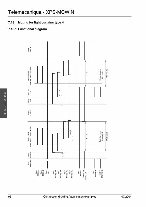
Telemecanique - XPS-MCWIN
98 Connection drawing / application examples 07/2004
EN
GLI
SH
7.18 Muting for light curtains type 4
7.18.1 Functional diagramS
tart
requ
ired
Inpu
tS
tart
Inp
utM
utin
g A
1
Inp
utM
utin
g B
1
Inp
utM
utin
g A
2
Inp
utM
utin
g B
2
Inp
utR
elie
ve
Out
put H
1M
utin
g La
mp
Out
put
Cha
nnel
1
Out
put
Cha
nnel
2
Mut
ing
(M)
t > t
syn.
ES
PE
p
rote
cts
Mut
ing
activ
Det
ect
ion
zone
by-
pas
sed
ES
PE
prot
ects
Mut
ing
faul
tO
utpu
tsO
ffR
elie
ve a
ctiv
Det
ectio
n zo
ne b
y-pa
ssed
ES
PE
prot
ects
t < t
Mt < t
syn.
t < t
syn.
Det
ectio
n zo
nein
terr
upte
d
t < t
F
Inpu
tO
SS
D 1
Inpu
tO
SS
D 2
Rel
ieve
(F
)
Det
ectio
n zo
nein
terr
upte
d
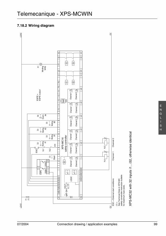
Telemecanique - XPS-MCWIN
07/2004 Connection drawing / application examples 99
EN
GLI
SH
7.18.2 Wiring diagram
K0
A1c8
c7c6
c5c3
c4c2
c1i1
i2i3
i4i5
i6i7
i8i9
i10
i11
i12
i13
i14
i15
i16
1323
H1
3343
A244
3424
14o6
o5o4
o3o2
o1G
ND
GN
DG
ND
µC 1
µC 2
K1 K2
K3 K4
TER
(1)
(2)
(-)
(+)
OSS
D1O
SSD2
+24
V
F1
0V0V
+24
V
Ko1
Ko2
H1
S5S3
S4S2
S1Ko
2
Ko1
24V 5V
T
S6
LOG
ICC
hann
el 1
Cha
nnel
2
Cha
nnel
1
Cha
nnel
2
Cha
nnel
1
Cha
nnel
2
Cha
nnel
1
Cha
nnel
2
Cha
nnel
1
Cha
nnel
2
Cha
nnel
1
Cha
nnel
2
XP
S-M
C16
safe
ty c
ontr
olle
r
ES
C =
Ext
erna
l sta
rt c
ondi
tions
(1)
=S
ee T
echn
ical
Dat
a in
XP
S-M
Csa
fety
con
stro
ller
inst
ruct
ion
bulle
tinfo
r m
axim
um fu
se s
izes
.
XP
S-M
C32
with
32
inpu
ts i1
…i3
2, o
ther
wis
e id
entic
al
Cha
nnel
1C
hann
el 2
Sta
rt
Mut
ing A1
Mut
ing B1
Mut
ing A2
Mut
ing B2
Mu
ting
lam
p
ES
PE
=E
SP
E o
utpu
t
(1)
ESPE
Ove
rri-
de
EDM
ES
C
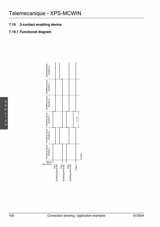
Telemecanique - XPS-MCWIN
100 Connection drawing / application examples 07/2004
EN
GLI
SH
7.19 3-contact enabling device
7.19.1 Functional diagram
Ena
blin
g de
vice
Pos
itio
n 1
Inp
utE
nab
ling
dev
ice
NO
Out
put
no s
tart
Inpu
tE
nabl
ing
devi
ce N
O
Inp
utE
nabl
ing
dev
ice
NC
Power ON(RUN)
t < t
Z
Ena
blin
g de
vice
Pos
ition
1E
nab
ling
devi
ceP
ositi
on 0
Ena
blin
g de
vice
Pos
ition
2E
nabl
ing
dev
ice
Pos
ition
1E
nabl
ing
devi
ceP
ositi
on 0
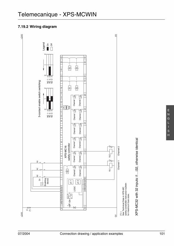
Telemecanique - XPS-MCWIN
07/2004 Connection drawing / application examples 101
EN
GLI
SH
7.19.2 Wiring diagram
K0
A1c8
c7c6
c5c3
c4c2
c1i1
i2i3
i4i5
i6i7
i8i9
i10
i11
i12
i13
i14
i15
i16
1323
H1
3343
A244
3424
14o6
o5o4
o3o2
o1G
ND
GN
DG
ND
µC 1
µC 2
K1 K2
K3 K4
TER
+24
V 0V0V+
24V
F1
Ko1
Ko2
24V 5V
T
S40
12
1 2
5 6
3 4
LOG
ICC
hann
el 1
Cha
nnel
2
Cha
nnel
1
Cha
nnel
2
Cha
nnel
1
Cha
nnel
2
Cha
nnel
1
Cha
nnel
2
Cha
nnel
1
Cha
nnel
2
Cha
nnel
1
Cha
nnel
2
XP
S-M
C16
safe
ty c
ontr
olle
r
XP
S-M
C32
with
32
inpu
ts i1
…i3
2, o
ther
wis
e id
entic
al
Ch
anne
l 1C
hann
el 2
En
ablin
gde
vice
(1)
NON
CNO
0
3 -
45
- 6
1 -
21
20
3 -
45
- 6
1 -
21
2
3-co
ntac
t ena
ble
switc
h sw
itchi
ng:
Lege
nd On
Off
NO NC
NO
NO NC
NO
(1)
=S
ee T
ech
nica
l Dat
a in
XP
S-M
Csa
fety
con
stro
ller
inst
ruct
ion
bul
letin
for
max
imum
fuse
siz
es.

Telemecanique - XPS-MCWIN
102 Connection drawing / application examples 07/2004
EN
GLI
SH
7.20 2-contact enable switch
7.20.1 Functional diagram
Ena
blin
g d
evic
eP
ositi
on 1
Out
put
Ena
blin
g de
vice
Pos
ition
0
Inpu
tE
nabl
ing
devi
ce N
O
Inpu
tE
nabl
ing
devi
ce N
C
Power ON(RUN)
t < t
Z
Ena
blin
g d
evic
eP
ositi
on 1
En
ablin
g d
evic
eP
ositi
on 1
Ena
blin
g de
vice
Po
sitio
n 0
Ena
blin
g de
vice
Pos
ition
2
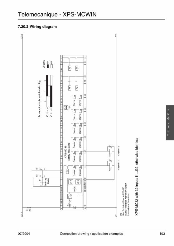
Telemecanique - XPS-MCWIN
07/2004 Connection drawing / application examples 103
EN
GLI
SH
7.20.2 Wiring diagram
K0
A1c8
c7c6
c5c3
c4c2
c1i1
i2i3
i4i5
i6i7
i8i9
i10
i11
i12
i13
i14
i15
i16
1323
H1
3343
A244
3424
14o6
o5o4
o3o2
o1G
ND
GN
DG
ND
µC 1
µC 2
K1 K2
K3 K4
TER
+24
V
F1
0V0V
+24
V
Ko1
Ko2
24V 5V
T
S40
12
1413
2221
LOG
ICC
hann
el 1
Cha
nnel
2
Cha
nnel
1
Cha
nnel
2
Cha
nnel
1
Cha
nnel
2
Cha
nnel
1
Cha
nnel
2
Cha
nnel
1
Cha
nnel
2
Cha
nnel
1
Cha
nnel
2
XP
S-M
C16
safe
ty c
ontr
olle
r
XP
S-M
C32
with
32
inpu
ts i1
…i3
2, o
ther
wis
e id
entic
al
Ch
anne
l 1C
hann
el 2
Ena
blin
gde
vice
2-co
ntac
t ena
ble
switc
h sw
itchi
ng:
Lege
nd On
Off
0
21 -
22
13 -
14
12
(1)
NCN
O
NO NC
(1)
=S
ee T
ech
nica
l Dat
a in
XP
S-M
Csa
fety
con
stro
ller
inst
ruct
ion
bul
letin
for
max
imum
fuse
siz
es.
Telemecanique - XPS-MCWIN
104 Connection drawing / application examples 07/2004
EN
GLI
SH


XPS-MCWIN 9597 95471 26-GB07/2004 2GB/157/01
Related Documents