INSIDE BRICSCAD ® A Quick Tour Through BricsCAD Navigating the BricsCAD Interface Setting Up A New Drawing Creating Your First Drawing Adding Details to Drawings Making Changes to Drawings Adding Notes and Dimensions Bills of Material Working with 2D Regions & Booleans Direct 3D Modeling & Editing Dimensional & Geometric Constraints Updated for V18

Welcome message from author
This document is posted to help you gain knowledge. Please leave a comment to let me know what you think about it! Share it to your friends and learn new things together.
Transcript

INSIDE BRICSCAD®
A Quick Tour Through BricsCADNavigating the BricsCAD InterfaceSetting Up A New DrawingCreating Your First DrawingAdding Details to DrawingsMaking Changes to DrawingsAdding Notes and DimensionsBills of MaterialWorking with 2D Regions & BooleansDirect 3D Modeling & EditingDimensional & Geometric Constraints
Updated for V18

Payment InformationThis book is covered by copyright. As the owner of the copyright, upFront.eZine Publishing, Ltd. gives you permission to
make one print copy. You may not make any electronic copies, and you may not claim authorship or ownership of the text
or figures herein.
By Email
Acrobat PDF format: $20.00
Allow for a 17MB download
PayPal Check or Money Order To pay by PayPal, send payment to the account We can accept checks from the following
of [email protected] at www.paypal.com. regions of the world:
• US funds drawn on a bank with address in the USA
PayPal accepts funds in US, Euro, Yen, • Canadian funds drawn on a bank with a Canadian
Canadian, and 100+ other currencies. address (includes GST).
Make cheque payable to ‘upFront.eZine Publishing’
Please mail your payment to:
“Inside BricsCAD V18”
upFront.eZine Publishing, Ltd.
34486 Donlyn Avenue
Abbotsford BC
V2S 4W7 Canada
Visit the Inside BricsCAD Web site at www.upfrontezine.com/ib8. At this Web page, editions of this book are available for
BricsCAD V8 through V18.
Purchasing an ebook published by upFront.eZine Publishing, Ltd. entitles you to receive the upFront.eZine newsletter
weekly. To subscribe to our “The Business of CAD” newsletter separately, send an email to [email protected].
Copyright InformationCopyright © 2017 by upFront.eZine Publishing, Ltd.
All rights reserved worldwide.
This 9th edition is based on BricsCAD V18
21 December 2017
Technical Writer Ralph Grabowski
Technical Editor BricsysStaff
Copy editor Herbert Grabowski
All brand names and product names mentioned in this book
are trademarks or service marks of their respective compa-
nies. Any omission or misuse (of any kind) of service marks
or trademarks should not be regarded as intent to infringe
on the property of others. The publisher recognizes and
respects all marks used by companies, manufacturers, and
developers as a means to distinguish their products.
This book is sold as is, without warranty of any kind,
either express or implied, respecting the contents of this
book and any disks or programs that may accompany it,
including but not limited to implied warranties for the
book’s quality, performance, merchantability, or fitness
for any particular purpose. Neither the publisher, authors,
staff, or distributors shall be liable to the purchaser or any
other person or entity with respect to any liability, loss, or
damage caused or alleged to have been caused directly or
indirectly by this book.
1. A Quick Tour Through BricsCAD ......................................1
How to Start BricsCAD V18 ...................................................................3Starting BricsCAD on Windows ......................................................................................................... 3
Windows Vista and 7 ........................................................................................................................................ 3
Windows 8 ........................................................................................................................................................... 4
Windows 10......................................................................................................................................................... 4
Starting BricsCAD on Linux ................................................................................................................ 5Starting BricsCAD on Mac MacOS .................................................................................................... 5BricsCAD V18 User Interface ............................................................................................................ 6
Getting Started .....................................................................................8The BricsCAD Window......................................................................................................................... 9A Basic Tour of the User Interface .................................................................................................10
Crosshair and Arrow Cursors ....................................................................................................................... 10
Command Bar ......................................................................................................................................11All About Command Prompts...................................................................................................................... 12
Undoing What You’ve Done: U .................................................................................................................... 14
Seeing What You Did Before: Command History ...................................................................................15
Typing Less: Aliases and AutoComplete ....................................................................................................16
UCS Icon ................................................................................................................................................18Online Help ..........................................................................................................................................19
SUPPORTED GRAPHICS BOARDS ................................................................................................................20
Exiting BricsCAD .................................................................................20
Table of Contents
Table of Contents viv Inside BricsCAD V18
What’s New in BricsCAD V18 ...............................................................21What’s New in the User Interface .................................................................................................21
New Clean Screen Interface ......................................................................................................................... 22
Updated Content Browser Panel ............................................................................................................... 24
New Drawing Compare .................................................................................................................................. 25
New Manipulator Widget .............................................................................................................................. 27
New Walk and Fly Navigation ......................................................................................................................29
New View Transitions ..................................................................................................................................... 31
What’s Changed in Quad Cursor and Rollover Tooltips ......................................................................32
Other Changes to the User Interface .........................................................................................................33
What’s New in Layers ..................................................................................................................................... 34
What’s New in Text ........................................................................................................................................ 35
What’s New in Dimensions ........................................................................................................................... 38
What’s New in 3D Modeling ............................................................................................................39What’s New in Layouts ................................................................................................................................... 41
What’s New in Generated Drawings ...........................................................................................................42
What’s New in the BIM Module ......................................................................................................43What’s New in the SHEET METAL Module ...................................................................................45What’s New in the Communicator Module .................................................................................47
What’s New in PDFs and Printing ...................................................................................................47New in PDF Exporting .................................................................................................................................... 47
New in Printing ................................................................................................................................................ 48
What’s New in Files ......................................................................................................................................... 48
What’s New in Chapoo (Now 24/7) ...............................................................................................49
What’s New in APIs ............................................................................................................................49Miscellany .......................................................................................................................................................... 50
License Requirements ........................................................................................................................52Release note Updates ........................................................................................................................52
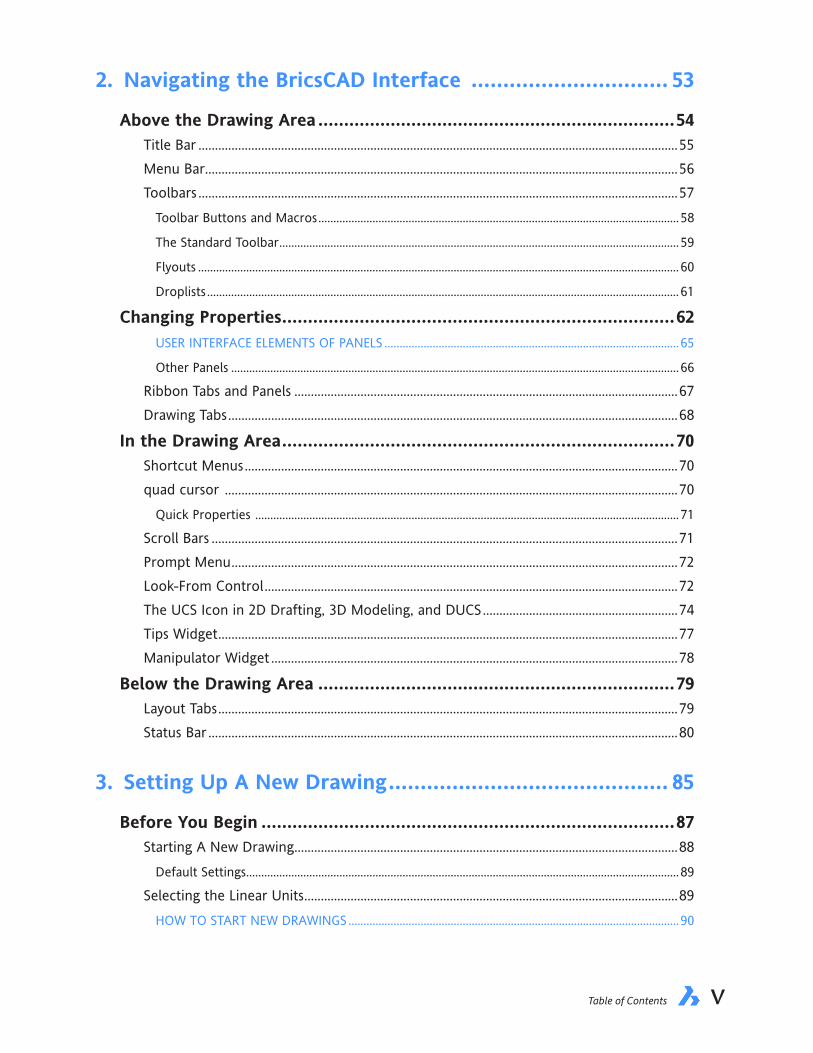
Table of Contents viv Inside BricsCAD V18
2. Navigating the BricsCAD Interface ............................... 53
Above the Drawing Area .....................................................................54Title Bar .................................................................................................................................................55Menu Bar ...............................................................................................................................................56Toolbars .................................................................................................................................................57
Toolbar Buttons and Macros ........................................................................................................................ 58
The Standard Toolbar ..................................................................................................................................... 59
Flyouts ................................................................................................................................................................ 60
Droplists ............................................................................................................................................................. 61
Changing Properties ............................................................................62USER INTERFACE ELEMENTS OF PANELS ..................................................................................................65
Other Panels ..................................................................................................................................................... 66
Ribbon Tabs and Panels ....................................................................................................................67Drawing Tabs ........................................................................................................................................68
In the Drawing Area ............................................................................70Shortcut Menus ...................................................................................................................................70quad cursor .........................................................................................................................................70
Quick Properties ............................................................................................................................................. 71
Scroll Bars .............................................................................................................................................71Prompt Menu .......................................................................................................................................72Look-From Control .............................................................................................................................72The UCS Icon in 2D Drafting, 3D Modeling, and DUCS ...........................................................74Tips Widget ...........................................................................................................................................77Manipulator Widget ...........................................................................................................................78
Below the Drawing Area .....................................................................79Layout Tabs ...........................................................................................................................................79Status Bar ..............................................................................................................................................80
3. Setting Up A New Drawing ............................................ 85
Before You Begin ................................................................................87Starting A New Drawing ....................................................................................................................88
Default Settings ................................................................................................................................................ 89
Selecting the Linear Units .................................................................................................................89HOW TO START NEW DRAWINGS ..............................................................................................................90

Table of Contents viivi Inside BricsCAD V18
Selecting the Angle Style ..................................................................................................................93Choosing the Plot Style .....................................................................................................................94Setting Entity Properties ...................................................................................................................94Finishing the Wizard ...........................................................................................................................95
Additional Important Settings .............................................................96Setting Drawing Limits .......................................................................................................................96Accessing and Changing Variables .................................................................................................98Changing the Snap and Grid Spacing ..........................................................................................100
QUICK SUMMARY OF LAYERS ....................................................................................................................102
Creating Layers ................................................................................. 104Naming Layers ...................................................................................................................................104
QUICK SUMMARY OF THE SAVEAS COMMAND ..................................................................................107
QUICK SUMMARY OF ALTERNATIVE SAVE FORMATS .........................................................................108
Saving Drawings ................................................................................ 109Making Backups Automatic ...........................................................................................................110
4. Creating Your First Drawing ........................................ 113
Reopening Drawings ......................................................................... 115Drawing the Lot’s Boundary .............................................................. 116Planning the Next Steps .................................................................... 118
Changing Layers ................................................................................................................................119
Drawing the House Outline ............................................................... 120QUICK SUMMARY OF THE PLINE COMMAND ......................................................................................121
QUICK SUMMARY OF ENTITY SNAP MODES .........................................................................................123
Direct Distance Entry .......................................................................................................................124Dynamic Input ...................................................................................................................................124
Moving the House into Position ........................................................ 127Starting on the Driveway .................................................................. 128
Finishing the Driveway ....................................................................................................................129Mirroring Entities .........................................................................................................................................130
Putting Drawings to Paper ................................................................ 132Solving Printing Problems ...............................................................................................................135
QUICK SUMMARY OF PRINT PREVIEW ....................................................................................................135
Generating PDFs of Drawings ........................................................................................................137Specifying PDF Output Options .................................................................................................................138

Table of Contents viivi Inside BricsCAD V18
5. Adding Details to Drawings ......................................... 141
Dividing the Lot ................................................................................ 143Smoothing Polylines .........................................................................................................................146
Grips Editing ..................................................................................... 147QUICK SUMMARY OF THE PEDIT COMMAND ......................................................................................148
QUICK SUMMARY OF EDITING WITH GRIPS..........................................................................................150
Editing by Double-clicking ..........................................................................................................................152
Hatching the Lawn ..........................................................................................................................153
Creating Symbols (Blocks) ................................................................ 157Drawing Circles ..................................................................................................................................157
Zooming in Real Time ..................................................................................................................................157
QUICK SUMMARY OF DRAWING CIRCLES .............................................................................................158
Creating Arrays ..................................................................................................................................159
Making Blocks ................................................................................... 162Adding Many More Trees (Insert) ................................................................................................163
Drawing the Pond ............................................................................. 164QUICK SUMMARY OF DRAWING ELLIPSES .............................................................................................166
Array Paths ..........................................................................................................................................167QUICK SUMMARY OF SPLINE ....................................................................................................................168
Drawing Splines..............................................................................................................................................168
Zooming to Objects ......................................................................................................................................169
Paving Stones from Polygons .....................................................................................................................170
Arraying Along a Path ..................................................................................................................................171
QUICK SUMMARY OF POLYGON ..............................................................................................................171
QUICK SUMMARY OF ARRAYPATH...........................................................................................................172
6. Making Changes to Drawings ...................................... 175
Changing the Look of Lines ............................................................... 177Loading Linetypes .............................................................................................................................177Changing Properties .........................................................................................................................179
QUICK SUMMARY OF PROPERTIES PANEL .............................................................................................180
Changing the Linetype Scale ..........................................................................................................182Selecting Entities by Other Methods ...........................................................................................183
Selecting Entities by Their Properties ......................................................................................................183
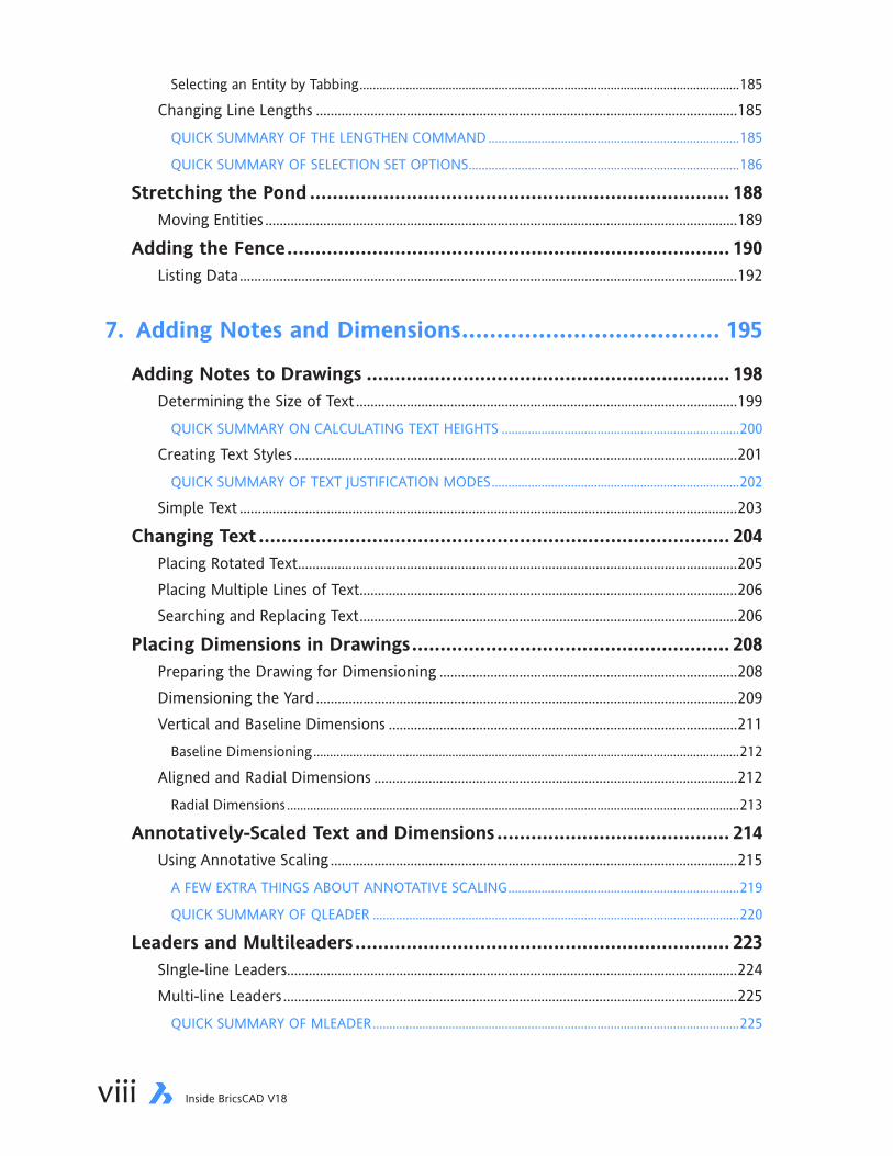
Table of Contents ixviii Inside BricsCAD V18
Selecting an Entity by Tabbing ...................................................................................................................185
Changing Line Lengths ....................................................................................................................185QUICK SUMMARY OF THE LENGTHEN COMMAND ............................................................................185
QUICK SUMMARY OF SELECTION SET OPTIONS ..................................................................................186
Stretching the Pond .......................................................................... 188Moving Entities ..................................................................................................................................189
Adding the Fence .............................................................................. 190Listing Data .........................................................................................................................................192
7. Adding Notes and Dimensions ..................................... 195
Adding Notes to Drawings ................................................................ 198Determining the Size of Text .........................................................................................................199
QUICK SUMMARY ON CALCULATING TEXT HEIGHTS ........................................................................200
Creating Text Styles ..........................................................................................................................201QUICK SUMMARY OF TEXT JUSTIFICATION MODES ...........................................................................202
Simple Text .........................................................................................................................................203
Changing Text ................................................................................... 204Placing Rotated Text .........................................................................................................................205Placing Multiple Lines of Text ........................................................................................................206Searching and Replacing Text ........................................................................................................206
Placing Dimensions in Drawings ........................................................ 208Preparing the Drawing for Dimensioning ..................................................................................208Dimensioning the Yard ....................................................................................................................209Vertical and Baseline Dimensions ................................................................................................211
Baseline Dimensioning .................................................................................................................................212
Aligned and Radial Dimensions ....................................................................................................212Radial Dimensions .........................................................................................................................................213
Annotatively-Scaled Text and Dimensions ......................................... 214Using Annotative Scaling ................................................................................................................215
A FEW EXTRA THINGS ABOUT ANNOTATIVE SCALING ......................................................................219
QUICK SUMMARY OF QLEADER ...............................................................................................................220
Leaders and Multileaders .................................................................. 223SIngle-line Leaders............................................................................................................................224Multi-line Leaders .............................................................................................................................225
QUICK SUMMARY OF MLEADER ...............................................................................................................225

Table of Contents ixviii Inside BricsCAD V18
8. Bills of Material .......................................................... 229
About Attribute Data ........................................................................ 231Creating Blocks with Attributes ........................................................ 232
Drawing Blocks ..................................................................................................................................234Defining Attributes ...........................................................................................................................234Adding More Attributes ..................................................................................................................236Combining Entities and Attributes into Blocks .........................................................................237
Inserting Blocks with Attributes ........................................................ 239Alternatives to the Insert Command ...........................................................................................240
Exporting Data from Drawings .......................................................... 241Data Extraction .................................................................................................................................241Importing Data Files into Spreadsheets ......................................................................................247
Placing Data in Drawings as Tables ................................................... 249Automatic BOMs from 3D Components ............................................. 251
Exploding Assemblies.......................................................................................................................251QUICK SUMMARY OF BMEXPLODE ..........................................................................................................252
Generating BOMs ..............................................................................................................................253QUICK SUMMARY OF BMBOM .................................................................................................................253
Attaching Balloons ............................................................................................................................254QUICK SUMMARY OF BMBALLOON ........................................................................................................255
9. Working with 2D Regions & Booleans .......................... 257
About Regions .................................................................................. 259How to create Regions ....................................................................................................................259Tutorial: Creating Boundaries ........................................................................................................260
QUICK SUMMARY OF BOUNDARY OPTIONS ........................................................................................261
Boolean Operations .......................................................................... 265QUICK SUMMARY OF BOOLEAN OPERATIONS ...................................................................................266
Tutorial: Creating a Waffle Shape .................................................................................................267
Measuring Regions ............................................................................ 273About Mass Properties ....................................................................................................................274
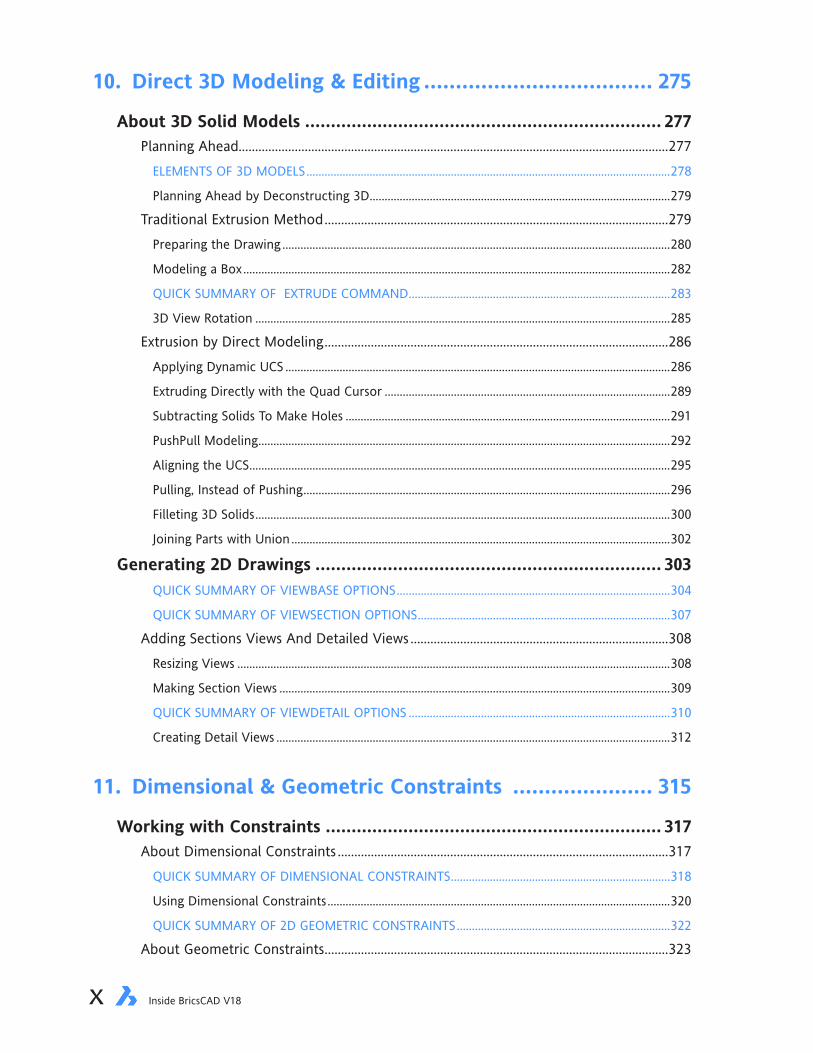
Table of Contents xix Inside BricsCAD V18
10. Direct 3D Modeling & Editing .................................... 275
About 3D Solid Models ..................................................................... 277Planning Ahead..................................................................................................................................277
ELEMENTS OF 3D MODELS .........................................................................................................................278
Planning Ahead by Deconstructing 3D ....................................................................................................279
Traditional Extrusion Method ........................................................................................................279Preparing the Drawing .................................................................................................................................280
Modeling a Box ..............................................................................................................................................282
QUICK SUMMARY OF EXTRUDE COMMAND .......................................................................................283
3D View Rotation ..........................................................................................................................................285
Extrusion by Direct Modeling ........................................................................................................286Applying Dynamic UCS ................................................................................................................................286
Extruding Directly with the Quad Cursor ...............................................................................................289
Subtracting Solids To Make Holes ............................................................................................................291
PushPull Modeling .........................................................................................................................................292
Aligning the UCS ............................................................................................................................................295
Pulling, Instead of Pushing ..........................................................................................................................296
Filleting 3D Solids ..........................................................................................................................................300
Joining Parts with Union ..............................................................................................................................302
Generating 2D Drawings ................................................................... 303QUICK SUMMARY OF VIEWBASE OPTIONS ...........................................................................................304
QUICK SUMMARY OF VIEWSECTION OPTIONS ....................................................................................307
Adding Sections Views And Detailed Views ..............................................................................308Resizing Views ................................................................................................................................................308
Making Section Views ..................................................................................................................................309
QUICK SUMMARY OF VIEWDETAIL OPTIONS .......................................................................................310
Creating Detail Views ...................................................................................................................................312
11. Dimensional & Geometric Constraints ...................... 315
Working with Constraints ................................................................. 317About Dimensional Constraints ....................................................................................................317
QUICK SUMMARY OF DIMENSIONAL CONSTRAINTS .........................................................................318
Using Dimensional Constraints ..................................................................................................................320
QUICK SUMMARY OF 2D GEOMETRIC CONSTRAINTS .......................................................................322
About Geometric Constraints ........................................................................................................323
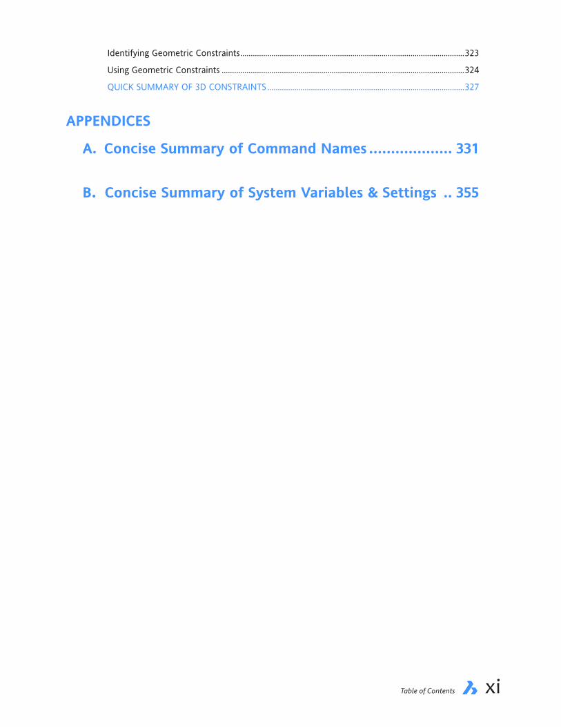
Table of Contents xix Inside BricsCAD V18
Identifying Geometric Constraints ............................................................................................................323
Using Geometric Constraints .....................................................................................................................324
QUICK SUMMARY OF 3D CONSTRAINTS ...............................................................................................327
APPENDICES
A. Concise Summary of Command Names ................... 331
B. Concise Summary of System Variables & Settings .. 355

Table of Contents PBxii Inside BricsCAD V18

CHAPTER 1
A Quick Tour Through BricsCAD
Welcome to BricsCAD V18!
You want to know how to create drawings with BricsCAD, and this book shows you how to — in as little as a day! But before doing any kind of drafting, you really should take a tour of the user interface to learn your way around BricsCAD. Even if you know other CAD programs, it may be useful for you to skim this chapter to take note of the areas in which BricsCAD operates differently from what you already know.
In this chapter, you learn how to start this popular 2D/3D CAD program, take a tour through its user inter-face, and then get your feet wet by drawing a few lines.
IN THIS CHAPTER
• Starting BricsCAD V18
• Becoming familiar with parts of the user interface
• Understanding the crosshair cursor, command bar, auto-complete, and UCS icon
• Drawing lines
• Reversing errors
• Accessing online help

2 Inside BricsCAD V18
KEY TERMS IN THIS CHAPTER
Button — executes associated command when clicked
Cursor — provides feedback from the operating system and from BricsCAD
Flipscreen — switches between the drawing window and text window
Flyout — shows a secondary toolbar when clicked
Icon — represents commands pictorially
Layout — defines how drawings are plotted
Pickbox — specifies the points being picked (selected)
Right-click — involves pressing the right mouse button to display context-sensitive (shortcut) menus
Toolbar — collects buttons into a single, useful strip
USEFUL ABBREVIATIONS
Alt Alternate key on PCs
Cmd Command key on Macs
Ctrl Control key on PCs
F Function key
U Undoes the last command or option
UCS User-defined coordinate system
NEW COMMANDS
Command Shortcut* Menu Selection** Ribbon
Help ? or F1 Help | Help Home | Help | Help Line L Draw | Line Draw | Draw | Line Quit Alt+F4 File | Exit ... TextScr F2 View | Prompt History Window ... Undo Ctrl+Z Edit | Undo ... UcsIcon ... ... ...
* F1 means function key F1
Alt+F4 means hold down the Alt key, and then press function key F4.
** The vertical bar separates menu selections. Draw | Line means: from the Draw menu, select the Line item.

chapter 1 A Tour Through BricsCAD 3
How to Start BricsCAD V18
If BricsCAD is not yet set up on your computer, do so. To run BricsCAD, your computer must be operating recent releases of Windows, just about any recent dialect of Linux, or MacOS on Macs.
To start BricsCAD, double-click the BricsCAD icon found on the computer desktop.
Depending on the speed of your computer, it can take from 10 to 30 seconds to load BricsCAD. During this time, a “splash screen” appears and disappears as BricsCAD starts up.
STARTING BRICSCAD ON WINDOWSBricsCAD V18 works with Windows Vista and newer.
Windows Vista and 7In Windows Vista and 7, you can start the program from the task bar using the following steps:
1. Click the task bar’s Start icon.
2. Choose All Programs.
3. Select Bricsys, followed by the BricsCAD V18 folder, and then click on BricsCAD V18.
The exact name you see depends on the language version you downloaded. For example, “Brics-CAD V18 (x64) en_US” is the name of the 64-bit program for English speakers in the US dialect.

4 Inside BricsCAD V18
Windows 8In Windows 8.x, you make these moves:
1. If necessary, switch to the Start screen.
2. In the Start screen, tap on the BricsCAD V18 icon.
Windows 10Under Windows 10 starting BricsCAD reverts more to like it started with Windows 7:
1. Tap the Start button.
2. Choose All Apps.
3. In the B menu, tap Bricsys folder, and then tap the BricsCAD V18 item.
If the item is not visible in the menu, then follow these steps:
1. Tap the Start button.
2. Start typing “bricscad”
3. When you see Bricsys V18, tap it.

chapter 1 A Tour Through BricsCAD 5
Instructions in this book specific to Linux and Mac are shown in gray text. No matter the operating system, BricsCAD looks pretty much the same in each one, as illustrated on the following pages.
STARTING BRICSCAD ON LINUXBricsCAD works with just about any recent release of Linux, but is specifically supported on Fe-dora, OpenSuse, and Ubuntu. To start the program, follow these steps:
1. Click the task bar’s Main Menu button.
2. Choose Graphics.
3. Click on BricsCAD.
STARTING BRICSCAD ON MAC MACOSBricsCAD works with recent releases of MacOS on Mac computers, 10.8 or higher. (MacOS is the new name for OS X.) On the dock, click the BricsCAD V18 icon:
If you do not see the icon there, then follow these steps:
1. In the dock, open the Application folder.

6 Inside BricsCAD V18
BRICSCAD V18 USER INTERFACE Illustrated is BricsCAD running on Windows 10.
Crosshair cursor
Pickbox
Menu bar Title bar
Properties panel
Drawing area
Drawing origin (0,0)UCS icon
Command panel Status bar optionsX, y coordinate and elevation (z)
Resize window
Status bar
Layout tabs
Look From widget
RibbonDocument bar
Mechanical Browser panel

chapter 1 A Tour Through BricsCAD 7
Crosshair cursor
Pickbox
Menu bar Title bar
Properties panel
Drawing area
Drawing origin (0,0)UCS icon
Command panel Status bar optionsX, y coordinate and elevation (z)
Resize window
Status bar
Layout tabs
Look From widget
RibbonDocument bar
Mechanical Browser panel
8 Inside BricsCAD V18
2. Find the BricsCAD V18 icon, and then click it.
To keep the icon in the dock, follow these steps
1. Right-click the BricsCAD icon.
2. From the shortcut menu, choose Options, and then choose Keep in Doc.
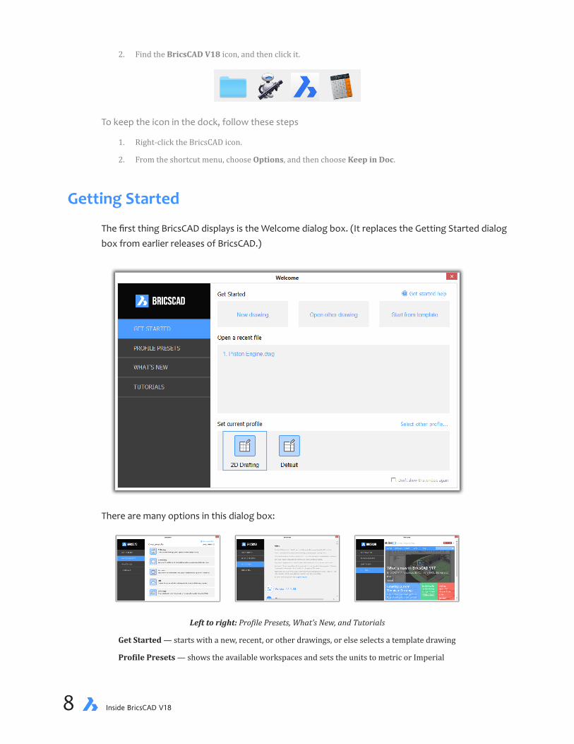
Getting Started
The first thing BricsCAD displays is the Welcome dialog box. (It replaces the Getting Started dialog box from earlier releases of BricsCAD.)
There are many options in this dialog box:
Left to right: Profile Presets, What’s New, and Tutorials
Get Started — starts with a new, recent, or other drawings, or else selects a template drawing
Profile Presets — shows the available workspaces and sets the units to metric or Imperial

chapter 1 A Tour Through BricsCAD 9
What’s New — reproduces “Release Notes” from https://www.bricsys.com/common/releasenotes.jsp
Tutorials — accesses the video tutorials hosted by Bricsys TV at https://www.bricsys.com/tv
For now click New Drawing to enter BricsCAD.
THE BRICSCAD WINDOWTake a look at the details of the BricsCAD window by checking out the figure spread across the earlier two pages.
BricsCAD’s central area consists of a large graphical drawing region. Here you can see the red-green cursor with its pickbox, and the red-green UCS icon with its x,y axes. The drawing region is surrounded by several panels of information — toolbars or ribbon, status bar, and so on.
Along the very top of the BricsCAD window, you see the title bar. Below it is the menu bar, below them the fat ribbon, and then the thin row of ribbon tabs. (Depending on how BricsCAD is config-ured, you might see toolbars.)
Along the bottom of BricsCAD are the layout tabs, the command prompt area, and then at the very bottom is the status bar.

10 Inside BricsCAD V18
A BASIC TOUR OF THE USER INTERFACEThe user interfaces of CAD programs have many elements, and so it can be daunting to learn all of it at once. In this chapter, you look at just a few UI elements, some of the more important ones:
Ð Crosshair and arrow cursors
Ð Command bar
Ð UCS icon
Chapter 2 provides you with a detailed tour of BricsCAD and its UI (short for “user interface”).
Crosshair and Arrow CursorsThe cursor gives you feedback from BricsCAD, Windows, and other software. When the cursor is in the BricsCAD drawing area, it looks like a crosshair that shows you where “you” are in the draw-ing, precisely.
Y axis
X axisPick box
Try moving the cursor now around the BricsCAD window: move your mouse.
Notice that the crosshair cursor has colors. These help you orient yourself, particularly in 3D (three dimensional) drafting. Here’s what the cursor looks like in 3D, and what the colors mean:
• Red line represents the x axis
• Green line represents the y axis
• Blue line represents the z axis; it is hidden when your draw in 2D mode
• Black square is the pick box, for selecting entities
The black square at the center of the crosshairs is called the “pickbox.” It shows you exactly where you are picking entities to edit them. Entities outside the pickbox will not be picked. You use the pickbox during Chapter 5, “Adding Details to Drawings.”
You can change the colors and the size of the cross hairs, as well as the size of the pick box, with the Settings command; see the tip coming up soon.
When you move the crosshair out of the drawing area, the cursor changes it shape to an arrow — one that you probably are familiar with from other software. You use the arrow cursor to make menu selections, pick buttons on the toolbar or ribbon, and so on. The cursor can change to other shapes. For example, when the cursor becomes a double-ended cursor, you can resize windows and palettes.
Left: Arrow cursor outside the drawing area, used to select UI elements; right: Double-headed cursor used to change size of UI elements
chapter 1 A Tour Through BricsCAD 11
Many user interface options are changed in BricsCAD with the Settings command. It provides you with over 600 settings that let you control how BricsCAD works and looks. The best way to find a specific setting quickly is to enter its name in its search field, as shown below. Changing the Pickbox Size. To change the size of the pickbox, enter “pickbox.” The default size that you see on the BricsCAD screen is 3 pixels wide, but you can change the size from 0 (gone) to 50 pixels (huge); I suggest you change it to 5 to make it just a bit bigger. Changing the Crosshair Cursor Size. Should you find the crosshair cursor too small or too large, you change its size also through the Settings command: search for “crosshair.” The de-fault value is 5, which means the length of the cross hairs is 5% of the screen’s size. When set to 100, the cross hairs stretch across the entire drawing area.
COMMAND BARCommands CommandLine, CommandLineHide
Ribbon ...
Shortcuts Ctrl+9, Shift+F2
Alias ...
The command bar is near the bottom of the BricsCAD window. This is one place where you can enter the names of commands and their options. If you are a touch typist like me, then you’ll find that you probably prefer specifying commands by typing them — instead of hunting through a menu or the ribbon. The command bar is also the place where BricsCAD prompts you for any ad-ditional information it needs to complete a command.
While you can turn off the Command bar with the CommandLineHide command, I don’t recom-mend doing this; there is no good reason to do so! These are the important parts of the command bar:
Command historyClick to closecommand bar
Drag to movecommand bar
Enter yourresponse here
Prompts fromBricsCAD
Scroll through earliercommand history
Let’s take a look at how the command bar works.
12 Inside BricsCAD V18
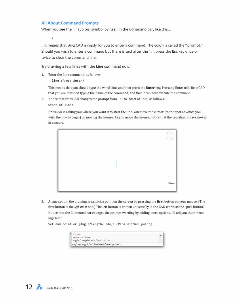
All About Command PromptsWhen you see the ‘ : ’ (colon) symbol by itself in the Command bar, like this...
:
...it means that BricsCAD is ready for you to enter a command. The colon is called the “prompt.” Should you wish to enter a command but there is text after the ‘ : ’, press the Esc key once or twice to clear the command line.
Try drawing a few lines with the Line command now:
1. Enter the Line command, as follows:
: line (Press Enter)
This means that you should type the word line, and then press the Enter key. Pressing Enter tells BricsCAD that you are finished typing the name of the command, and that it can now execute the command.
2. Notice that BricsCAD changes the prompt from ‘ : ’ to ‘ Start of line: ’ as follows:
Start of line:
BricsCAD is asking you where you want it to start the line. You move the cursor (to the spot at which you wish the line to begin) by moving the mouse. As you move the mouse, notice that the crosshair cursor moves in concert.
3. At any spot in the drawing area, pick a point on the screen by pressing the first button on your mouse. (The first button is the left-most one.) The left button is known universally in the CAD world as the “pick button.”
Notice that the Command bar changes the prompt wording by adding more options. I’ll tell you their mean-ings later.
Set end point or [Angle/Length/Undo]: (Pick another point)
chapter 1 A Tour Through BricsCAD 13
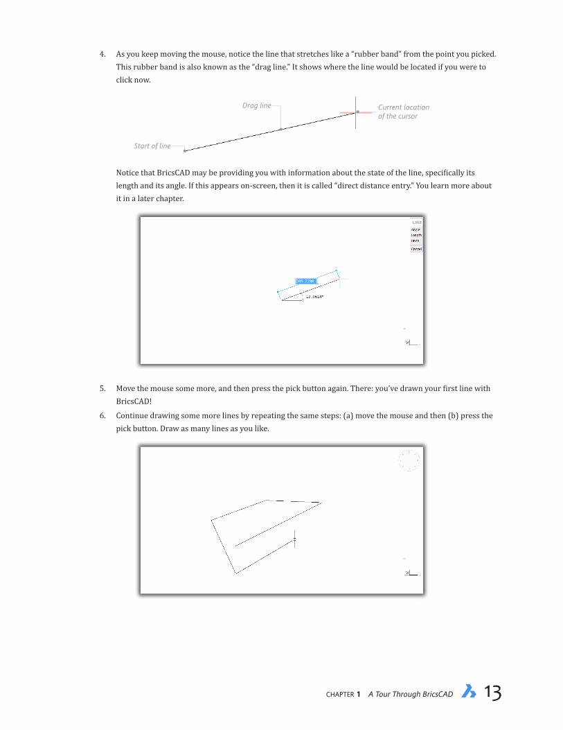
4. As you keep moving the mouse, notice the line that stretches like a “rubber band” from the point you picked. This rubber band is also known as the “drag line.” It shows where the line would be located if you were to click now.
Start of line
Drag line Current locationof the cursor
Notice that BricsCAD may be providing you with information about the state of the line, specifically its length and its angle. If this appears on-screen, then it is called “direct distance entry.” You learn more about it in a later chapter.
5. Move the mouse some more, and then press the pick button again. There: you’ve drawn your first line with BricsCAD!
6. Continue drawing some more lines by repeating the same steps: (a) move the mouse and then (b) press the pick button. Draw as many lines as you like.
14 Inside BricsCAD V18
7. To end the Line command, press the Esc key. Pressing Esc stops just about any command, although in some commands you may need to press the key two or three times.
Set end point or [Angle/Length/Follow/Close/Undo]: (Press esc)
I want to point out that the prompt text you see — ‘Angle/Length/Follow/Close/Undo/<End point>’ — has subtle aspects that are not immediately obvious. For instance, you can specify an option by typing just the letters displayed in uppercase, such typing ‘a’ to start the Angle option.
The other aspect to notice is that the default option (or value) is always shown angle brackets, such as <End Point>. “Default” means that this is what BricsCAD will do when you just press En-ter, without picking an option. This becomes a pretty fast way of working.
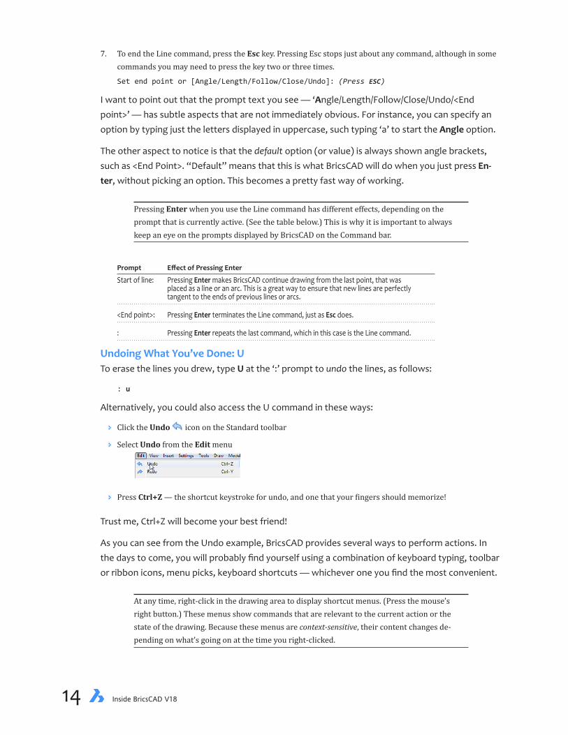
Pressing Enter when you use the Line command has different effects, depending on the prompt that is currently active. (See the table below.) This is why it is important to always keep an eye on the prompts displayed by BricsCAD on the Command bar.
Prompt EffectofPressingEnter
Start of line: Pressing Enter makes BricsCAD continue drawing from the last point, that was placed as a line or an arc. This is a great way to ensure that new lines are perfectly tangent to the ends of previous lines or arcs.
<End point>: Pressing Enter terminates the Line command, just as Esc does.
: Pressing Enter repeats the last command, which in this case is the Line command.
Undoing What You’ve Done: UTo erase the lines you drew, type U at the ‘:’ prompt to undo the lines, as follows:
: u
Alternatively, you could also access the U command in these ways:
Ð Click the Undo icon on the Standard toolbar
Ð Select Undo from the Edit menu
Ð Press Ctrl+Z — the shortcut keystroke for undo, and one that your fingers should memorize!
Trust me, Ctrl+Z will become your best friend!
As you can see from the Undo example, BricsCAD provides several ways to perform actions. In the days to come, you will probably find yourself using a combination of keyboard typing, toolbar or ribbon icons, menu picks, keyboard shortcuts — whichever one you find the most convenient.
At any time, right-click in the drawing area to display shortcut menus. (Press the mouse’s right button.) These menus show commands that are relevant to the current action or the state of the drawing. Because these menus are context-sensitive, their content changes de-pending on what’s going on at the time you right-clicked.

chapter 1 A Tour Through BricsCAD 15
SeeingWhatYouDidBefore:CommandHistoryThe command bar typically displays three or four lines of history, which is the text of previ-ously displayed prompts. When you need to see more lines of history, then you have a couple of choices:
Ð Drag the command bar’s top border to stretch it taller or shorter. For the exact point at which to do this, see the location of the double-ended arrow cursor in the figure below.
Ð Drag the bar away from its docked position, and then resize it, as shown below.
Ð Press F2 to see the prompt window. BricsCAD display a second window on the computer screen. You can reposition it anywhere, such as on a second screen.

16 Inside BricsCAD V18
The Prompt History window displays the most recent 400 lines of command text. You can scroll back to earlier prompts and other text by clicking on the vertical scroll bar along the right edge of the window. You can leave the window up, or else dismiss it by again pressing F2.
To keep a copy of the history, enter the LogfileOn command. Everything types in the command bar is recorded to a .log file with the same name as the drawing in this folder: C:\Users\userid\App-Data\Local\Bricsys\BricsCAD\V18x64\en_US\. Use the LogFilePath variable to specify a more conve-nient folder, and the LogFileOff command to turn off command logging.
Alternatively, you can copy the text to the clipboard: select the text, then press Ctrl+C. Once copied, you can paste the text in any word processor or text editor. (This is process we use to get command prompts and path names into this book!) Right-click the text window for more options in the shortcut menu.
Typing Less: Aliases and AutoCompleteThere are two ways to spend less time entering command names: by entering aliases and by tak-ing advantage of the auto-complete function. I use both.
Ð “Aliases” are command abbreviations, such as ‘c’ for the Circle command
Ð “Auto-complete” lists the names of all commands that begin with the same letters as you are typing
Aliases are described later in this book. Here is how auto-complete works with the Line command:
1. At the command prompt, type L. Notice that a box pops with listing the names of all commands and system variables that start with ‘l’. To see them all, scroll down the list, all the way to where it ends with “lwunits.”
2. Now type i, the second letter of the Line command. Notice that the suggestion list shortens to just the names that begin with ‘li.’
chapter 1 A Tour Through BricsCAD 17
a. You can keep typing letter of the command name to further reduce the suggestion list.
Notice that the last letter (‘E’) is highlighted in blue. This means that if you now press Enter, the entire command shown (‘LINE’) will be executed.
b. Or you can use the cursor to select a name from the list. It’s your choice.
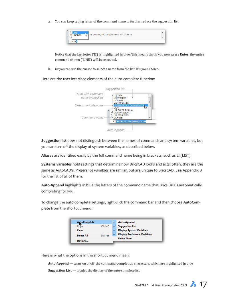
Here are the user interface elements of the auto-complete function:
Suggestion list
Auto-Append
Alias with commandname in brackets
System variable name
Command name
Suggestion list does not distinguish between the names of commands and system variables, but you can turn off the display of system variables, as described below.
Aliases are identified easily by the full command name being in brackets, such as LI (LIST).
Systems variables hold settings that determine how BricsCAD looks and acts; often, they are the same as AutoCAD’s. Preference variables are similar, but are unique to BricsCAD. See Appendix B for the list of all of them.
Auto-Append highlights in blue the letters of the command name that BricsCAD is automatically completing for you.
To change the auto-complete settings, right-click the command bar and then choose AutoCom-plete from the shortcut menu.
Here is what the options in the shortcut menu mean:
Auto-Append — turns on of off the command-completion characters, which are highlighted in blue
Suggestion List — toggles the display of the auto-complete list
18 Inside BricsCAD V18
Display System Variables — toggles the display of system variable names in the list
Display Preference Variables — toggles the display of preference variable names in the list
Delay Time — determines how long BricsCAD waits before displaying the auto-complete list
To change other things like the font or color used by the command line, right-click and then choose Options from the shortcut menu.
UCS ICONCommand UcsIcon
Menu ...
Alias ...
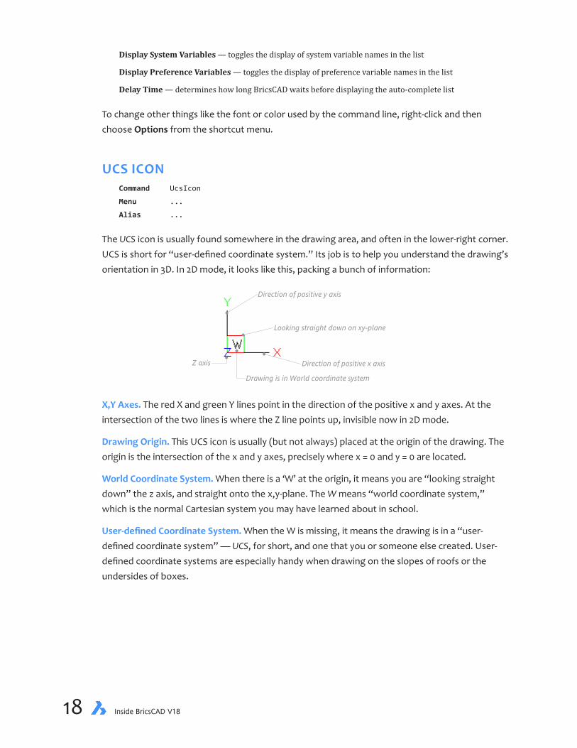
The UCS icon is usually found somewhere in the drawing area, and often in the lower-right corner. UCS is short for “user-defined coordinate system.” Its job is to help you understand the drawing’s orientation in 3D. In 2D mode, it looks like this, packing a bunch of information:
Direction of positive y axis
Direction of positive x axis
Looking straight down on xy-plane
Z axis
Drawing is in World coordinate system
X,Y Axes. The red X and green Y lines point in the direction of the positive x and y axes. At the intersection of the two lines is where the Z line points up, invisible now in 2D mode.
Drawing Origin. This UCS icon is usually (but not always) placed at the origin of the drawing. The origin is the intersection of the x and y axes, precisely where x = 0 and y = 0 are located.
World Coordinate System. When there is a ‘W’ at the origin, it means you are “looking straight down” the z axis, and straight onto the x,y-plane. The W means “world coordinate system,” which is the normal Cartesian system you may have learned about in school.
User-definedCoordinateSystem.When the W is missing, it means the drawing is in a “user-defined coordinate system” — UCS, for short, and one that you or someone else created. User-defined coordinate systems are especially handy when drawing on the slopes of roofs or the undersides of boxes.

chapter 1 A Tour Through BricsCAD 19
I find the UCS icon gets in the way of 2D drafting, and so I recommend that you turn it off, as fol-lows:
1. Type the UcsIcon command at the ‘:’ prompt in the command bar, as follows:
: ucsicon (Press Enter)
Press Enter to execute the command.
2. Notice the next prompt displayed by BricsCAD:
[ucs icon ON/ucs icon OFf/display in All views/display at ORigin/display in Corner]
<ON>: off (Press Enter)
3. Type ‘Off,’ and then press Enter. Notice that the UCS icon disappears from the drawing area.
You’ll get to try out the UCS icon later during the 3D modeling portion of this book.
ONLINE HELPCommand Help
Ribbon Home | Help | Help
Menu Bar Help | Help
Shortcut F1
Alias ?
To peruse help during a command, press F1 and BricsCAD displays a separate Help window, such as the one illustrated below for the Line command.
Icons indicate whether the command operates in each of the supported operating systems, Windows, MacOS, or Linux. Most commands do. Other icons indicate which edition the command works with, such as Pro, Platinum, or Sheet Metal. For the complete list of commands, see Ap-pendix A.
In addition, there is an online version of help information that you access through a Web browser. Enter the following URL: https://www.bricsys.com/bricscad/help/en_US/V18/UsrGui/index.html.

20 Inside BricsCAD V18
Exiting BricsCADCommand Quit
Menu Bar File | Exit
Shortcuts Ctrl+Q, Alt+F4
To exit BricsCAD, use the Quit command. When BricsCAD asks if you want to save the drawing, click No.
Alternatively, press Ctrl+Q, or else select Exit from the File menu.
SUPPORTED GRAPHICS BOARDS
BricsCAD works with whatever graphics board is built into your computer. When it comes to non-wire-frame renderings, however, BricsCAD employs RedSDK GPU-acceleration technology provided by Red-way3D. (GPUs are the processing chips on graphics boards.) Download the latest drivers from http://www.redway3d.com/supported-gpu-tables-for-redsdk/list-of-the-available-drivers/.
WINDOWS
On Windows, Redsdk hardware acceleration supports graphics boards made by AMD, Intel, and nVidia. See http://www.redway3d.com/downloads/public/documentation/bk_ba_gpu_chipset_reference.html; for the comprehensive list.
MAC
Apple does not allow developers to have full access to the graphics hardware inside Mac computers, and so there are no third-party drivers available to speed up the display of CAD programs.
LINUX
On Linux, RedSDK support graphics chip sets for 3D graphics hardware acceleration from AMD and nVidia. Intel is not supported in Linux, nor are laptops with discrete graphics systems. You are advised to down-load the latest recommended drivers from NVIDIA and AMD.

chapter 1 A Tour Through BricsCAD 21
What’s New in BricsCAD V18
This list of BricsCAD’s new and changed functions was compiled from version 18.1.08. Changes are highlighted throughout this book, but be aware that information on theses pages is not comprehensive, because Bricsys continually updates this software. For information on functions added since this book was published, please see http://www.bricsys.com/common/releasenotes.jsp.
New command and variable names are shown in boldface blue, updated ones are in boldface black. The new and changed functions are listed in roughly alphabetical order, sorted into the following sections:
Ð User interface
Ð Layers
Ð Text
Ð Dimensioning
Ð 3D modeling
Ð Layouts
Ð Generated views
Ð BIM module
Ð Sheet metal module
Ð Communicator module
Ð PDFs and printing
Ð Files
Ð Chapoo (renamed 24/7)
Ð APIs
BricsCAD V18 installs and runs independently from previous BricsCAD versions.
WHAT’S NEW IN THE USER INTERFACE BricsCAD V18 improves the display performance in the following areas:
Ð Redraw is 2x faster for drawings containing many tiny entities, such as dashes in hatch patterns.
Ð Isolines of 3D models are displayed faster
Ð Selection preview is cleared when the cursor leaves the view area
Ð Zooming into partial circles and arcs is smoother
Ð Changing the BkgColor and Perspective variables is faster when many drawings are loaded, as only the ac-tive drawing is updated; the regeneration of others is delayed
Ð Rollover performance is improved for large selection sets
Ð Explorer is faster in folder view at switching between sections of the same drawing, such as between layers and linetypes, by no longer reloading the database
22 Inside BricsCAD V18
Ð Print and save performance was improved by a factor 20 for drawings containing layers with many viewport overrides
Ð Thumbnail raster images generated for render materials and blocks are now cached, allowing instant switching in the Content Browser between drawings containing even thousands of blocks
Ð Drawing compare uses a cache to operate orders of magnitude faster than competitors
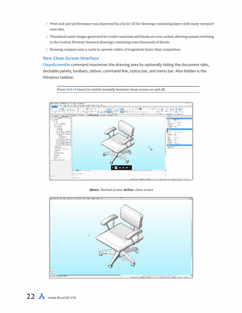
NewCleanScreenInterfaceCleanScreenOn command maximizes the drawing area by optionally hiding the document tabs, dockable panels, toolbars, ribbon, command line, status bar, and menu bar. Also hidden is the Windows taskbar.
Press Ctrl+0 (zero) to switch instantly between clean screen on and off.
Above: Normal screen; below: clean screen

chapter 1 A Tour Through BricsCAD 23
CleanScreenOff command unhides hidden user-interface items.
CleanScreenOptions variable determines which user interface elements should remain visible in clean screen mode; default = 15:
CleanScreenOptions Meaning
0 Hide no elements 1 Hide document (drawing) tabs 2 Hide dockable panels (palettes) 4 Hide toolbars 8 Hide ribbon 16 Hide command line panel (bar) 32 Hide status bar 64 Hide menu bar
As a useful alternative to the CleanScreenOptions variable’s command-line prompt, open the Settings dialog box and then search for “clean”:
CleanScreenState variable (read-only) reports whether clean screen mode is on or off:
CleanScreenState Meaning
0 Off (default) 1 On
Command Bar. Previously, when the command bar was turned off, command text appeared only in the status bar. As of V18, the last four lines of command text appear in the drawing area. After about five seconds, the text fades away. When you next enter a command or pick an option, the on-screen text reappears. This applies when the command bar is off, and works whether clean screen is on or off.
24 Inside BricsCAD V18
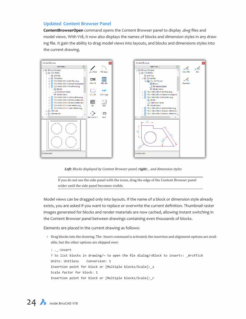
Updated Content Browser PanelContentBrowserOpen command opens the Content Browser panel to display .dwg files and model views. WIth V18, it now also displays the names of blocks and dimension styles in any draw-ing file. It gain the ability to drag model views into layouts, and blocks and dimensions styles into the current drawing.
Left: Blocks displayed by Content Browser panel; right:... and dimension styles
If you do not see the side panel with the icons, drag the edge of the Content Browser panel wider until the side panel becomes visible.
Model views can be dragged only into layouts. If the name of a block or dimension style already exists, you are asked if you want to replace or overwrite the current definition. Thumbnail raster images generated for blocks and render materials are now cached, allowing instant switching in the Content Browser panel between drawings containing even thousands of blocks.
Elements are placed in the current drawing as follows:
Ð Drag blocks into the drawing. The -Insert command is activated; the insertion and alignment options are avail-able, but the other options are skipped over:
: ._-insert
? to list blocks in drawing/~ to open the file dialog/<Block to insert>: _ArchTick
Units: Unitless Conversion: 1
Insertion point for block or [Multiple blocks/Scale]:_s
Scale factor for block: 1
Insertion point for block or [Multiple blocks/Scale]:_r
chapter 1 A Tour Through BricsCAD 25
Rotation angle for block: 0
Insertion point for block or [Multiple blocks/Scale]:\
When the block definition already exists, the following warning appears:
Ð Right-click a dimension style name, and then choose Add Dimstyle(s); when the dimstyle already exists, the following warning appears:
Ð Switch to a layout, and then double-click a model view; it is placed in the current layout using the PlaceView command.
ContentBrowserClose command closes the Content browser.
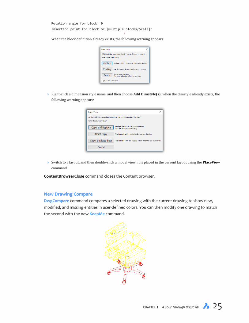
New Drawing CompareDwgCompare command compares a selected drawing with the current drawing to show new, modified, and missing entities in user-defined colors. You can then modify one drawing to match the second with the new KeepMe command.

26 Inside BricsCAD V18
: 3dcompare
CMPDIFFLIMIT = 1000. Select the file to compare with or [Limit]:(Press Enter to display
the Open a File dialog box.)
Choose a DWG or DXF file, and then click Open. A drawing appears that shows the differences between the two drawings. Green indicates added entities, while red reports removed ones.
3 differences were found.
While the DwgCompare session is active, the following actions are available:
Ð Select an entity to see the new DiffType property (read-only) displayed in the Properties panel and by Rollover tooltips
Left: Diff type property in the Properties panel; right: ...and in the rollover tooltip
Ð The Structure panel (opened by the new StructurePanel command) displays all differences. Bricsys notes that the default.cst configuration file should be used to display the results correctly. (CST files format the display of data in the Structure panel.)
Ð KeepMe command visually merges the two drawings being compared with Drawing Compare. It keeps selected entities and discards the matching variants. When no more differences are listed in the Structure panel, the merge is complete.
Ð EndCompare command exits the comparison session. You have to use this command to exit DwgCompare.
Dimensions are not compared. Blocks can be compared and merged.
The new Compare toolbar controls the drawing comparison process. From left to right, the but-tons activate the DwgCompare, KeepMe, and EndCompare commands.
chapter 1 A Tour Through BricsCAD 27
The following variables can be used to control the comparison results:
Ð CmpClrMiss variable specifies the color of missing entities; default = red.
Ð CmpClrMode1 variable specifies the color of modified entities in drawing #1; default = 253 (gray).
Ð CmpClrMode2 variable specifies the color of modified entities in drawing #2; default = yellow.
Ð CmlClrNew variable specifies the color of new entities; default = green.
Ð CmdDiffLimit variable specifies the maximum number of entities to compare:
CmdDiffLimit Meaning
1 Minimum number 1000 Default 10000000 Maximum number (ten million)
Here are the variables displayed in the Settings dialog box:
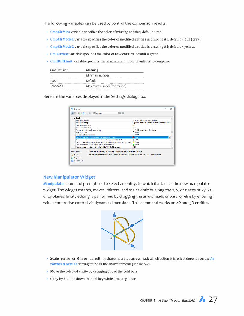
New Manipulator WidgetManipulate command prompts us to select an entity, to which it attaches the new manipulator widget. The widget rotates, moves, mirrors, and scales entities along the x, y, or z axes or xy, xz, or zy planes. Entity editing is performed by dragging the arrowheads or bars, or else by entering values for precise control via dynamic dimensions. This command works on 2D and 3D entities.
Ð Scale (resize) or Mirror (default) by dragging a blue arrowhead; which action is in effect depends on the Ar-rowhead Acts As setting found in the shortcut menu (see below)
Ð Move the selected entity by dragging one of the gold bars
Ð Copy by holding down the Ctrl key while dragging a bar
28 Inside BricsCAD V18
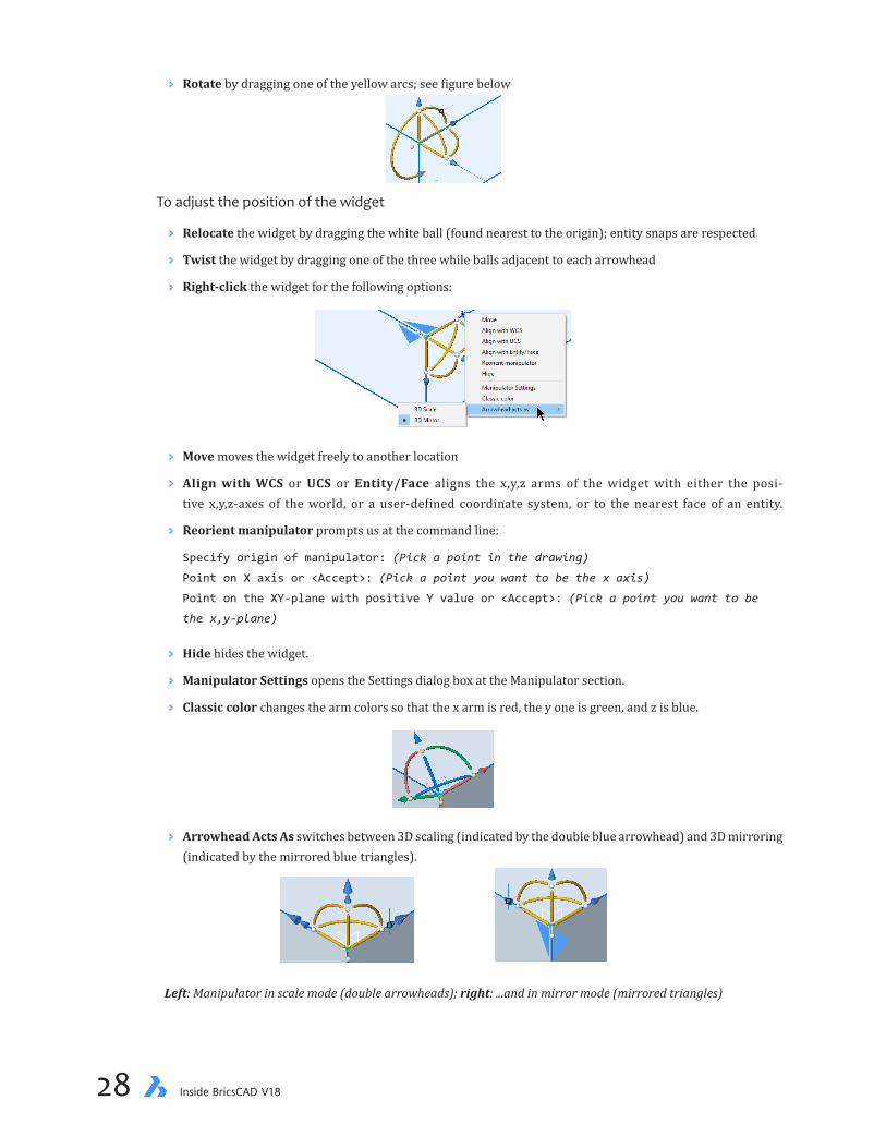
Ð Rotate by dragging one of the yellow arcs; see figure below
To adjust the position of the widget
Ð Relocate the widget by dragging the white ball (found nearest to the origin); entity snaps are respected
Ð Twist the widget by dragging one of the three while balls adjacent to each arrowhead
Ð Right-click the widget for the following options:
Ð Move moves the widget freely to another location
Ð Align with WCS or UCS or Entity/Face aligns the x,y,z arms of the widget with either the posi-tive x,y,z-axes of the world, or a user-defined coordinate system, or to the nearest face of an entity.
Ð Reorient manipulator prompts us at the command line:
Specify origin of manipulator: (Pick a point in the drawing)
Point on X axis or <Accept>: (Pick a point you want to be the x axis)
Point on the XY-plane with positive Y value or <Accept>: (Pick a point you want to be
the x,y-plane)
Ð Hide hides the widget.
Ð Manipulator Settings opens the Settings dialog box at the Manipulator section.
Ð Classic color changes the arm colors so that the x arm is red, the y one is green, and z is blue.
Ð Arrowhead Acts As switches between 3D scaling (indicated by the double blue arrowhead) and 3D mirroring (indicated by the mirrored blue triangles).
Left: Manipulator in scale mode (double arrowheads); right: ...and in mirror mode (mirrored triangles)

chapter 1 A Tour Through BricsCAD 29
Ð Manipulator variable determines when the manipulator widget is available:
Manipulator Meaning
0 Not displayed (default) 1 Display manipulator when entities are selected 2 Display manipulator when left mouse button is pressed longer than the time specified by ManipulatorDuration variable
Ð ManipulatorDuration variable determines how long the left mouse button must be pressed before the ma-nipulator widget appears; default = 250 milliseconds.
Ð ManipulatorSize variable specifies the size of the manipulator widget relative to the default size; range is 0.5 - 2; default = 1.
Ð M_ArrowheadLengthCoeff variable specifies the length of the manipulator’s arrowheads:
M_ArrowheadLengthCoeff Meaning
1 Minimum value 3.5 Default value
Ð M_ArrowheadRadiusCoeff variable specifies the radius (size) of the arrowheads:
M_ArrowheadRadiusCoeff Meaning
1 Minimum value 2.2 Default value
Ð M_AxisDiameter variable specifies the diameter (thickness) of the manipulator’s axes (arms):
M_AxisDiameter Meaning
1 Minimum value 6 Default value 16 Maximum value
Ð M_TotalAxisLength variable specifies the length of the axes (arms):
M_TotalAxisLength Meaning
1 Minimum value 130 Default value 200 Maximum value
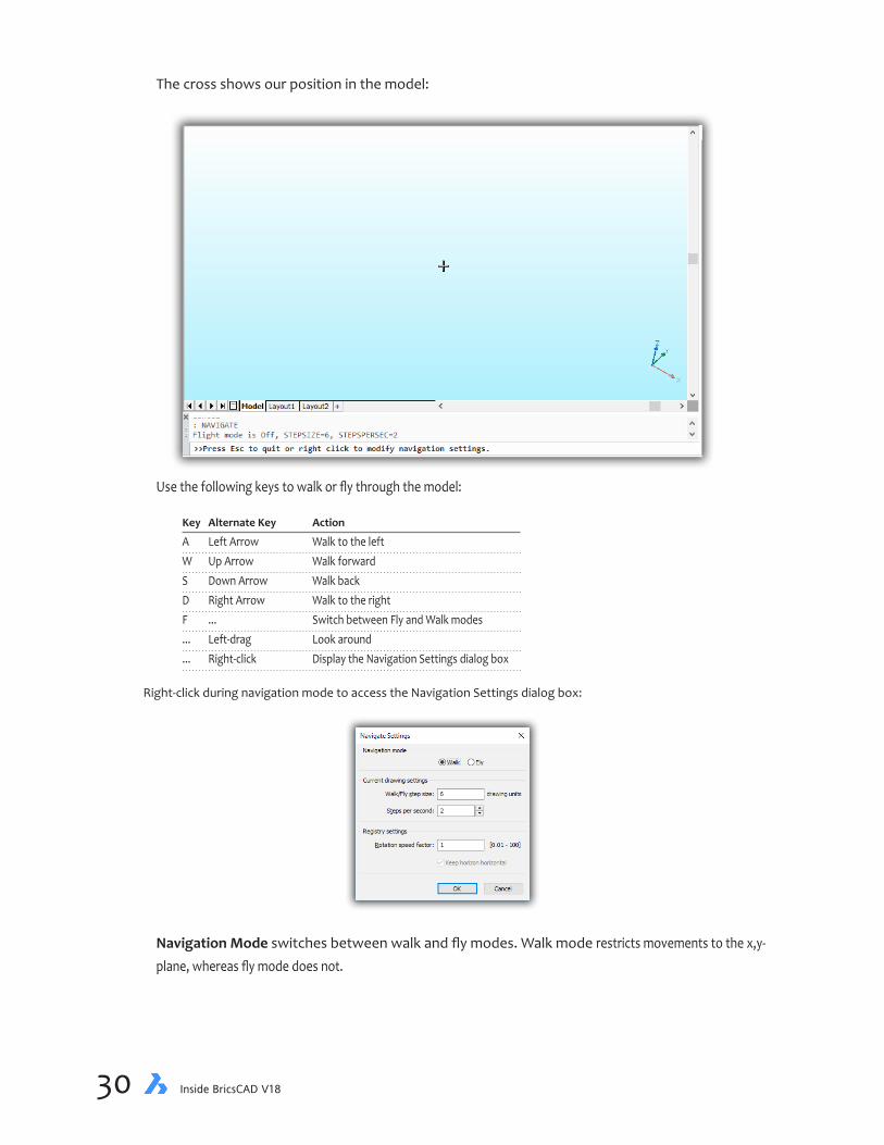
New Walk and Fly NavigationNavigate command walks or flies through 3D models:
: navigate
Flight mode is Off, STEPSIZE=4, STEPSPERSEC=24
>>Press Esc to quit or right click to modify navigation settings.
30 Inside BricsCAD V18
The cross shows our position in the model:
Use the following keys to walk or fly through the model:
Key Alternate Key Action
A Left Arrow Walk to the left W Up Arrow Walk forward S Down Arrow Walk back D Right Arrow Walk to the right F ... Switch between Fly and Walk modes ... Left-drag Look around ... Right-click Display the Navigation Settings dialog box
Right-click during navigation mode to access the Navigation Settings dialog box:
Navigation Mode switches between walk and fly modes. Walk mode restricts movements to the x,y-plane, whereas fly mode does not.

chapter 1 A Tour Through BricsCAD 31
Current Drawing Settings sets values for the following variables:
Ð StepsPerSec variable specifies the speed in steps per second when navigating through 3D models with the new Navigate command, as well as the and RtWalk command activated by holding down Alt+left mouse button:
StepsPerSecond Meaning
1 Slowest speed 2 Default 30 Fastest speed (typical for videos)
Ð StepSize variable specifies the size of steps in drawing units when navigating through 3D models; this variable replaces RTWalkSpeedFactor.
StepSize Meaning
1E-6 Shortest step 6 Default 1E+6 Longest step (one million drawing units)
Ð RTWalkSpeedFactor is variable obsolete and is replaced by the StepSize variable.
Registry Settings specifies the rotation speed in frames per second.
New View TransitionsView transitions are now animated, so that zooms, pans, and view rotations appear to move.
Turning on view transitions may make it easier to keep your bearings as the view changes, but I find that slows down my CAD work, waiting for the zoom to finish. So I leave it turned off.
Ð VtDuration variable specifies the duration of view transition animations in milliseconds; default = 0.75 seconds.
VtDuration Meaning
0 Disabled 750 Default, in milliseconds 5000 Maximum (5 seconds)
Ð VtEnable variable determines when view transitions occur; default = 3:
VtEnable Meaning
0 Disabled 1 Enabled for zooms and pans (default) 2 Enabled for view rotation (default) 4 Enabled during scripts and so on

32 Inside BricsCAD V18
Ð VtFps variable determines the minimum frame rate required to allow view animation to operate; default = 7. When your computer and its graphics board do not have sufficient horsepower to generate the animated transition, then the effect is unavailable. The FPS (frames per second) rate is divided into 1 second: 1.0 divided by 7fps = 0.143 seconds/frame.
VtFps Meaning
0 Disabled 7 Default 30 Maximum
What’s Changed in Quad Cursor and Rollover Tooltips When the Quad and Rollover are both on, clicking the Quad’s title bar now toggles the display between Quad mode (tool buttons) and Rollovers (properties).
Ð QuadDisplay variable adds 4, the Suppress Quad on Hover When Entities are Selected option.
Ð QuadiconSize variable now supports 64x64-pixel size icons, useful for very-high resolution displays. This variable also affects the size of the rollover tooltip.
Left to right: 16x16 small icons, 32x32 medium icons, and 64x64 large icons
Ð QuadMostRecentItems variable specifies the number of most-recent items listed by the Quad. The default is 2.
Ð _QuadTabFlags variable determines style of Quad. This variable appears to be a temporary one for use during a transition to a new Quad layout: _QuadTabFlags Meaning
1 Fixed with tabs 2 Center tab labels 4 Tab borders (on by default) 8 Double tab height (on by default) 16 Show 3D mass properties
The property values in the Rollover tooltips are can now be edited. In the figure below, the color of the line is being changed with the Rollover tooltip.
Rollover properties performance is improved for large selection sets.
Ð RolloverOpacity variable determines the translucency of rollover tooltips; range is from 10 (mostly transpar-ent) to 100, opaque (default)

chapter 1 A Tour Through BricsCAD 33
Ð RolloverSelectionSet variable determines how rollover tooltips display properties of a selection set: RolloverSelectionSet Meaning
0 No properties displayed of the selection set 1 General properties displayed (default) 2 Properties common to all entities displayed
Ð RolloverTips variable toggles the display of rollover tooltips.
OtherChangestotheUserInterface Ð CrossHairDrawMode variable determines how the cursor is drawn in the drawing area during 3D visualiza-
tion. RedSDK is faster at the job, but may be incompatible with some systems.
CrossHairDrawMode Meaning
0 Use Windows rendering 1 Undefined at this time 2 Use RedSDK rendering
Ð DocTabPosition, ShowDocTabs, and WndlTabs variables are no longer read-only.
Dynamic dimensions are now enabled during the following drawing commands: Arc, Circle, El-lipse, HelixPLine, Polysolid, Ray, Spline, and Xline. Also, they are enabled during the following ed-iting commands: ArrayEditExt, Change, Lengthen, PEditExt, Stretch, and Ucs commands. Dyndims now also work when grip-editing entities.
Left Dynamic dimensions displayed during the Arc command; right: ...and the Stretch command.
Ð DynDimAperture variable specifies the search radius, in pixels, around the cursor; works only when the DynMode variable is on. Default value is 20; largest value is 21474836347
Home key rotates the view to become horizontal.
Ð LockUi variable locks the location and size of toolbars and dockable panels. To temporarily override the lock to move items, hold down the Ctrl key.
LockUi Meaning
0 Disabled (default) 1 Docked toolbars and panels locked 2 Docked and anchored windows locked 4 Floating toolbars and panels locked

34 Inside BricsCAD V18
The LockUi toggle button is added to the status bar.
Properties command now saves the grid column splitter position between sessions.
Ð RubberbandColor variable specifies the rubber band color; default = 40 (gold). The rubber band shows in real time the distance that entities are moved during commands like Move and Copy.
Ð RubberbandStyle variable toggles the look of the rubber band between solid lines and dashed ones (default).
Temporary Tracking Mode. To activate temporary tracking mode, we used to enter TK in the command bar, or else choose ‘Temporary Tracking Points’ from the Snap toolbar. With V18, we can now click the middle mouse button to activate temporary tracking points.
Temporary snap tracking points now leave colored trails. In the figure below, the current tracking line is orange, while the placed one is blue.
Tracking can be used in any direction, and is no longer restricted to the xy-plane. Dynamic dimen-sions are displayed during tracking, as shown above
What’s New in LayersVpLayer command gains the following options to modify viewports in current layout.The new Color, Ltype, LWeight, and TRansparency options set the color, etc. respectively in the current viewport. The new eXcept current option can be used during the selection of viewports.
: vplayer
[List frozen layers/Color/LineType/LineWeight/TRansparency/Freeze layers/Thaw layers/Re-
set layers/New frozen layers/Default visibility setting]:
Ð InterfereLayer variable specifies the layer on which interference solids are placed.
Ð LayerFilterExcess variables deletes layer filters when the number exceeds this value, upon opening the Lay-ers dialog box; default = 250.
Ð SaveLayerSnapshot variable saves layer settings with newly created views.

chapter 1 A Tour Through BricsCAD 35
The new Isolate Selected Layers option is added to the shortcut menus of Layers dockable panel and the Layer Explorer.
What’s New in Text BricsCAD V18 improves the display of highlighted SHX text in wireframe mode.
Ð AnnoAutoScale variable determines what happens to annotative scales when a new one is introduced:
AnnoAutoScale Meaning
0 New annotative scale is not added to existing entities 1 New annotation scale is added, except to those on off, frozen, locked, and VpFreeze layers 2 New annotation scale is added, except to those on off, frozen, and VpFreeze layers (excludes locked layers) 3 New annotation scale is added, except for those on locked layers 4 New annotation scale is added to all annotative objects
Fields. BricsCAD V18 adds the Layout Name property and the NamedObject field category to the Field dialog box.

36 Inside BricsCAD V18
Find and Replace. The Ignore hidden items option is added to the options of the Find and Re-place Options dialog box. The Zoom To option is improved to support switching between lay-outs. When the zoomed entity is on a frozen or off layer, an alert message is reported.
Find command now reports a count of found and replaced text.
Hyperlinks. Double-clicking the Hyperlink value in the Properties Panel or the Rollover tips now opens the link.
MText command now supports the following format options:
Ð Numbered lists
Ð Bulleted lists
Ð Strikeout text
Ð Paragraph alignment (left, right, center, justify and distribute)

chapter 1 A Tour Through BricsCAD 37
Ð MTextDetectSpace variable determines if lists are formatted automatically:
MTextDetectSpace Meaning
Off Lists are not formatted automatically On (default) Lists are formatted upon pressing the spacebar
Table command gains new functions. The minimum row height of tables now adjusts automati-cally, and is based on the actual height of the cell’s content, instead of the height specified by the table’s style.
TInsert command inserts blocks into table cells, as a cell can now contain one or more blocks and text:
: tinsert
Pick table cell: (Choose a cell in a table; BricsCAD displays the Insert Block in Cell
dialog box.)
Alternatively, right-click a cell, chooseInsertBlockReference, and then choose a block definition.
Left: Accessing the block insertion dialog box; right: .. and choosing the block to insert into the cell
Blocks are sized to automatically fit the area of the cell. A cell can hold more than one block; to add additional blocks, repeat the steps listed above.
To add text to a cell that already contains a block, click on the cell and then start typing. The text is placed below the block, by default. To control how the text and the block are positioned rela-tive to one other, access the new Manage Cell Content dialog box by right-clicking the cell. This dialog box manages each cell independently, so each cell can have a different arrangement.
Left: Table with cells containing text and two blocks, text with block, and only blocks; right: adjusting content of cell
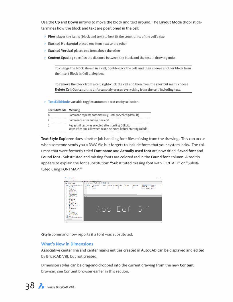
38 Inside BricsCAD V18
Use the Up and Down arrows to move the block and text around. The Layout Mode droplist de-termines how the block and text are positioned in the cell:
Ð Flow places the items (block and text) to best fit the constraints of the cell’s size
Ð Stacked Horizontal placed one item next to the other
Ð Stacked Vertical places one item above the other
Ð Content Spacing specifies the distance between the block and the text in drawing units
To change the block shown in a cell, double-click the cell, and then choose another block from the Insert Block in Cell dialog box. To remove the block from a cell, right-click the cell and then from the shortcut menu choose Delete Cell Content; this unfortunately erases everything from the cell, including text.
Ð TextEditMode variable toggles automatic text entity selection:
TextEditMode Meaning
0 Command repeats automatically, until cancelled (default) 1 Commands after ending one edit 2 Repeats if text was selected after starting DdEdit; stops after one edit when text is selected before starting DdEdit
Text Style Explorer does a better job handling font files missing from the drawing. This can occur when someone sends you a DWG file but forgets to include fonts that your system lacks. The col-umns that were formerly titled Font name andActuallyusedfont are now titled Savedfont and Foundfont . Substituted and missing fonts are colored red in the Foundfont column. A tooltip appears to explain the font substitution: “Substituted missing font with FONTALT” or “Substi-tuted using FONTMAP.”
-Style command now reports if a font was substituted.
What’s New in DimensionsAssociative center line and center marks entities created in AutoCAD can be displayed and edited by BricsCAD V18, but not created.
Dimension styles can be drag-and-dropped into the current drawing from the new Content browser; see Content browser earlier in this section.

chapter 1 A Tour Through BricsCAD 39
DimBaseline and DimContinue commands get the Undo option, so that we can back up when we place too many chain dimensions are placed, or placed them in the an incorrect position.
: dimbaseline
Baseline: Origin of next extension line or [Select starting dimension/Undo] <Select
starting dimension>:
Multi-line leaders now support associativity. When an entity is moved, the arrowhead and leader move with it.
WHAT’S NEW IN 3D MODELINGSee also what’s new in layouts, generated drawings, BIM, and Sheetmetal.
bmBrowser command is removed, as the Mechanical browser is separated into a Standard Parts panel and a Report panel. As a result, new commands open and close the panels:
Commands Purpose
MechanicalBrowserOpen MechanicalBrowserClose Replace the bmBrowser command ReportPanelOpen ReportPanelClose Opens and closes the Reports panel StandardPartsPanelOpen StandardPartsPanelClose Opens and closes the Standard Parts panel
Ð ReportPanel variable reports the status of the Mechanical Browser panel.
Ð bmUpdateMode variable specifies how to load external assemblies.
Expressions (formulas) can also be assigned to nested entities using the Mechanical browser, the Property panel’s array properties, or through the new Link to parameter option of the -bmParam-eters command.
Extrude command is now faster at extruding splines, and creates 3D solids (instead of surfaces) when extruding polylines located at large coordinates.

40 Inside BricsCAD V18
Interfere command gains several enhancements. Interference checking is performed orders of magnitude faster by using a cached form of DWG data. Solids showing the interferences are placed on their own layer, as specified by the new InterferenceLayer variable, which has its own color. Interference checking can be interrupted by pressing the Esc key.
The new Settings option displays a dialog box that configures interference settings, which are stored in new variables:
: interfere
Select first set of entities or [Nested selection/Settings] <Nested selection>:
Ð InterfereLayer variable specifies the layer on which interference solids are placed; default = Interference.
Left: Intersecting solids; right: Intersected solid colored red and placed on layer ‘Intersection’
3D constraints can now be applied to the origin, axes, planes of the WCS in model space, as well as coordinate systems associated with blocks and arrays. The constraints are applied between them and entities using the new World and Block options while creating constraints:
: dmConcentric3d
Select first subentity [World/Block]: w
Select reference coordinate system subentity [Origin/X axis/Y axis/Z axis/XY plane/YZ
plane/ZX plane]: o
Select first subentity [World/Block]:
ArrayEdit command now supports both 2D and 3D associative arrays with parametric expres-sions. Expression can be set in the Properties panel: click the new Fx button and then enter an expression. This allows the construction of entities with variable numbers of repeating elements
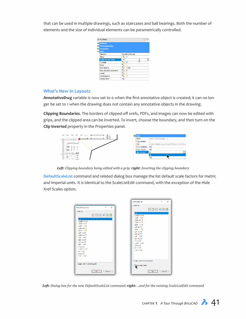
chapter 1 A Tour Through BricsCAD 41
that can be used in multiple drawings, such as staircases and ball bearings. Both the number of elements and the size of individual elements can be parametrically controlled.
What’s New in LayoutsAnnotativeDwg variable is now set to 0 when the first annotative object is created; it can no lon-ger be set to 1 when the drawing does not contain any annotative objects in the drawing.
Clipping Boundaries. The borders of clipped-off xrefs, PDFs, and images can now be edited with grips, and the clipped area can be inverted. To invert, choose the boundary, and then turn on the Clip Inverted property in the Properties panel.
Left: Clipping boundary being edited with a grip; right: Inverting the clipping boundary
DefaultScaleList command and related dialog box manage the list default scale factors for metric and Imperial units. It is identical to the ScaleListEdit command, with the exception of the Hide Xref Scales option.
Left: Dialog box for the new DefaultScaleList command; right: ...and for the existing ScaleListEdit command

42 Inside BricsCAD V18
Layout switching is now instant, through the caching of display objects for all layouts, if sufficient memory is available.
LayoutManager command adds, deletes, activates, finds, and rearranges layouts. To set a layout as current, double-click a row label or cell; the layout tab is scrolled into sight, if needed.
The toolbar provides the following functions:
Ð New Layout adds another layout to the list with the generic name Layoutn.
Ð Delete removes one or more layouts, without a warning message
Ð Up and Down changes the order of layouts
Ð Clear Selection removes the highlight from selected layout(s)
A new button to the left of the Model tab opens the Layout manager.
What’s New in Generated DrawingsbmBalloon command places associative balloon entities on assembly components and related generated views. Balloons contain component numbers extracted from associated BOM (bills of material) tables created by bmBOM command; the GenerateAssocViews variable should be On.
bmExplode command creates exploded representations of assemblies by moving all top- and bottom-level components to make them visible; the exploded representation is stored as a new block that is inserted in model space. Table-style and Manual modes are offered in command options. Drawing views can be generated from exploded representations of assemblies with the option to add BOM balloons to them.

chapter 1 A Tour Through BricsCAD 43
Ð HpMaxAreas variable determines how sparse hatches are filled.
ViewBase and ViewEdit commands gain the Select option for selecting solids nested in compo-nents. Press the Tab key to iterate through the entities on different nesting levels.
ViewSection command gains the Sectionable property for mechanical components; when off, components appear non-sectioned on section views. The property is supported for Full section type. Clipped property of section views can now be set on a per-viewport basis. Clipped views can be dragged from the new Content Browser and then dropped onto layout sheets as a new way to document details. Section views can be printed in their clipped state, including lids and hatches.
ViewUpdate command now preserves the rotation angle of generated drawing views following view updates.
WHAT’S NEW IN THE BIM MODULEBIM is an optional extra-cost add-on (bim is the prefix for building information modeling commands)
BricsCAD BIM V18 is certified for IFC import and export.
Rooms now detect their 3D boundaries and can be displayed as 3D solids in the model. The room volume is listed in the Properties panel.
Room stamps are based on a template drawing, which allows BIM to customize their appearance; room stamps can be moved using grips.
Parametrics is a new feature in arrays to control the number of elements in the array. This allows BIM to create parametric stairs, curtain walls, and so on.
Xrefs are now supported as BIM objects. They can be classified and have a spatial location. The structure tree has an option to display the exploded contents of xrefs.
bimAddEccentricity command controls relative positions of the axes in linear solids.
bimApplyProfile command applies profiles to linear entities; also replaces profiles of linear solids. Profiles are elongated solids that consist of a constant cross section over a linear extrusion path. The command recognizes clippings and openings. Permitted linear entities include lines, polylines, circles, arcs, ellipses, elliptical arcs, and open and closed non-self-intersecting splines with default tangents. This command is typically used to create elements such as these:
Ð Columns
Ð Beams
Ð Railings
Ð Pipes
Ð Ducts
bimAttachSpatialLocation command gains the option to automatically detect, create, and assign buildings and stories.

44 Inside BricsCAD V18
bimClassify command gains more types, as well as a dialog box to select the classification type. Classification types are grouped into the following categories:
Ð Core
Ð Architectural
Ð Structural
Ð Building services
bimConnect command now works with linear solids (profiles), connecting them with smooth or planar cuts:
Ð Smooth cut - one solid is fully extended to connect to all the other solid’s faces
Ð Planar cut - solids are cut with straight planar cuts
bimDrag command now places multiple solids in copy mode, and has a repeat option like the Copy command. The command works with linear solids, moving or copying all side faces of the extrusion on the entire solid; on start and end faces, the command executes a push-pull opera-tion.
bimIfy command classifies and spatial locates automatically the entire model.
bimLinearSolid command draws linear solids, like the Line command; axis lines of linear solids can be displayed.
bimMultiSelect command select all linear solids with coplanar/parallel axis with the selected lin-ear solid. If the selction is the face of the solid, then the result is the faces on the same side of the linear solids with coplanar/parallel axes. The Ctrl-widget offers the following options:
Ð All coplanar axes
Ð Axes that are coplanar and parallel
Ð All parallel axes
Ð bimOsMode variable controls geometric snapping to axes of linear solids.
bimProfiles command opens the library of profiles included with the installation.
bimProperties now assigns custom properties to building elements, and adds a properties dialog to create, edit, and delete property definitions, and organize properties in property sets. A set of IFC2x3 properties is included.
bimSection gains the option to create interior elevations. Input is a room; outputs are a volume state bimsection entity for each wall segment and one for the floor plan. The bimsection entities have new types ‘Interior Elevation’ and ‘Interior Floor Plan’ and as such their callouts can be fully customized separately from other section types. Color of intersection hatch is set to ByLayer in default bimsection settings.

chapter 1 A Tour Through BricsCAD 45
bimSectionUpdate command now accepts rooms as input. In case interior elevations are at-tached to it, they are generated into a single file. The file is named by room name and room number.
bimSuggest command selects two solids, analyzes their connection, and then presents similar situations in the model where the same connection can be applied. You can toggle suggestions between different types. The following connections are supported:
Ð Wall-wall
Ð Wall-slab
Ð Wall-beam
Ð Column-slab
bimWindowCreate command creates fully parametric windows based on closed contours, such as polylines.
DataExtraction command now supports ply quantities and materials. A room now has a property ‘Interior Elevations’, values can be On or Off, to control visibility of the corresponding interior elevation bimsection entities.
Ð DefaultBSysLibImperial variable points to the Imperial bsyslib library folder.
Ð DefaultBSysLibMetric variable points to metric bsyslib library folder.
Ð UseBIM variable specifies the BIM license level:
UseBIM Meaning
0 BIM add-on not present 1 Trial version of BIM running 2 Licensed version of BIM running
IfcImport command supports many more IFC types; windows in imported IFC files are now parametric and associative; custom properties can be imported. IFC import is certified by Build-ingSmart for Coordination View 2.0 exchange.
WHAT’S NEW IN THE SHEET METAL MODULEThe Sheet Metal module is an optional extra-cost add-on (sm is the prefix for sheet metal com-mands)
smAssemblyExport command batch processes assemblies with sheet metal parts by traversing the assembly structure. For every component that it recognizes as an encapsulated sheet metal design, it saves it as an unfolded version to a .dxf file, and then generates an HTML summary report on the assembly.
smBendCreate command gains the option to not change existing reliefs, provided they are suf-ficient to create the required bend.
46 Inside BricsCAD V18
smConvert command is better at distinguishing flanges and bends versus form features. It now arranges flange faces so that external dimensions are preserved when the thickness is changed. Recognition of small-radius bends (including zero-radius ones, which have an internal hard edge) is done in a smarter way, respecting the design intent of their external radius.
smExportOsm command now translates form features to .osm files.
smExtrude command extrudes sheet metal parts from polylines:
Ð Linear segments converted to flanges
Ð Arcs to bends
Ð Hard edges in flanges to bends automatically
smFlangeEdge command now handles near-zero radius and aligned junction cases better. Miters are automatically created when several flanges are pulled together, and it supports no-relief cases as design intent.
smFlangeSplit command now ensures that miters automatically maintain their gaps. Bend splits intelligently convert part of the bend adjacent to corner into a junction. This command gains the option to convert miter design with coincident faces to a valid miter feature. And it supports more inputs:
Ð Polyline
Ð Two points
Ð Single point as input
smJunctionCreate command gains the option to recognize junction designs with coincident faces and then convert them to regular junction features.
smParametrize command creates rigid sets of constraints on holes to improve the ability to change parameters for such parts. It generates overall distance constraints and supports Entire Model as an input.
smReliefCreate command now supports wrong-direction and zero-radius bends.
smRepair command now keeps corner/bends reliefs, junctions, miter features. It preserves exist-ing reference faces of the model. In healing zero-radius wrong bends, it selects minimally possible internal radius. Form features incorrectly placed on an unfolding are healed.
smRibCreate command creates associative rib features on sheet metal parts from 2D profiles, which are updated automatically when defining profiles are changed.
Settings command now contains per-drawing values to initialize sheet metal contexts on cre-ation. Template .dwt files can now contain our preferred values, such as default thickness, bend radius, and relief parameters. A new setting controls the color of the reference side of flange features that are to remain fixed during changes to thickness.

chapter 1 A Tour Through BricsCAD 47
WHAT’S NEW IN THE COMMUNICATOR MODULECommunicator is an optional, extra-cost translator add-on
BricsCAD V18 is not compatible with Communicator V17, and so an upgrade to Communicator V18 is required.
CommunicatorInfo command replaces the CommDiag command, checking whether the Commu-nicator add-on is correctly installed; an error diagnostic is printed when it is not.
CommDiag command is replaced by the CommunicatorInfo command
Export command (when Communicator is installed) now supports product structure in XCGM and CATProduct formats.
Import command (when Communicator is installed) now imports PMI (product and manufactur-ing information) annotations as graphical elements grouped in blocks. PMI data is imported from the following file formats:
Ð ACIS
Ð CATIA V5
Ð NX
Ð Pro/E and Creo
Ð SolidWorks
Ð XCGM
PMI data in the following formats can now be imported in V18:
PMI Meaning
0 Do not import PMI 1 Import PMI as graphical information (default) 2 Import PMI as semantic information 3 Import PMI both as graphical and semantic information
Communicator now checks for fatal ACIS errors when the “Repair model on import” setting in Communicator’s settings is turned off.
WHAT’S NEW IN PDFs AND PRINTINGNew in PDF ExportingPDF files are now generated 10 to 15% faster.
PdfExport and PrintAsPdf commands now report ‘Cannot export file: filepath\name.pdf (File is currently open in another program. Please close the file and try again.)’ instead of ‘Can’t open file filepath\name.pdf’.

48 Inside BricsCAD V18
PrintAsPdf command now prints selected entities as an option. Missing paper sizes that previ-ously were used are now added automatically as a custom size upon printing or previewing. This command’s performance is improved for drawings containing many viewports and gradient hatches.
BricsCAD used to output duplicate searchable text, confusing some OCR applications. In V18, PDF searchable text is more efficient. When text is exported as
AsText searchable text is not exported, because the visible text already is searchable
AsGeometry searchable text is exported transparently, together with the geometric representation of the text
PDF image (such as with the modeling visual style) then text is exported transparently on top of the image
Ð PdfPRCCompression variable determines the PRC compression level; PRC is the 3D PDF container format.
Ð PdfPRCExport variable determines how PRC data is exported:
PdfPRCExport Meaning
0 3D models are not exported 1 3D models are exported at B-Reps 2 3D models are exported as meshes
Ð PdfPRCSingleViewMode variable toggles single view for PRC data; default is on.
Ð PdfVectorResolution variable specifies the resolution of vector data; default is 2400 dpi.
New in PrintingPreview command’s generation performance is improved; drawings that may have taken a minute to display are now down to a few of seconds. Previously only wireframe previews were generated; now the current visual style is used.
Print command offers increased precision when handling custom paper size dimensions stored in .pc3 files, resulting in better paper size matching when switching between printers.
Publish command tries to find missing and renamed layouts first by name, then by handle from sheetset (.dst) files. When a layout is not found, the sheet is omitted from the published sheets.
Ð PlotOutputPath variable now does a better job handling the location of the print output directory on startup: if the value of the variable is empty (“”), then it is initialized with the user’s Documents folder for print and publish operations; if the folder name specified by PlotOutputPath is unavailable or write-protected, then this variable also employs the user’s Documents folder.
What’s New in FilesNetwork read/write performance is improved for DWG and DXF files accessed over a network.
AcisIn command now checks the incoming model for fatal errors and then prints warning mes-sages that list the errors found.
Ð MyDocumentsPrefix variable (read-only) holds the path to the user’s Documents folder.

chapter 1 A Tour Through BricsCAD 49
Ð RegExpand variable determines how paths are stored in the Windows registry:
RegExpand Meaning
0 Store paths in absolute format 1 Store paths in a portable format, using environment variables
Ð SkpStich variable toggles if SketchUp surfaces are stitched upon import; default is 1.
WHAT’SNEWINCHAPOO(NOW24/7)Chapoo is renamed 24/7. The prefix of related commands is renamed from Chapoo to Cloud:
Previous Command Name New Command Name
ChapooAccount CloudAccount ChapooDownload CloudDownload ChapooLogOff CloudLogOff ChapooLogOn CloudLogOn ChapooOpen CloudOpen ChapooProject CloudProject ChapooUpload CloudUpload ChapooWeb CloudWeb
The Includedatafilesfor3Donlineviewing and Removeafterupload options were removed, because they are no longer needed, as these data files are now generated on the 24/7 server.
WHAT’S NEW IN APIsBricsCAD V18 supports the DWG 2018 format.
Teigha API is updated to version 4.3.0.
ACIS modeler is upgraded to version 2018 1.0.
CIVIL 3D enabler loads, saves, and displays drawings made with AutoCAD CIVIL 3D, and snaps to entities in the drawings.
FlySDK library for PDF underlays is updated to v11.0.3.1
BricsCAD V18 is compiled with Visual Studio 2013 (platform toolset = v120). To be compatible, C++ extension dlls need to be compiled with the same platform toolset.

50 Inside BricsCAD V18
MiscellanyBRX implemented AcDbSpatialFilter::queryBounds(). Jig input flag AcEdJig::kDisableDirectDistanceInput is now supported. The quality of drawing thumbnail image displayed by acdbDisplayPre-viewFromDwg() has been improved. Implemented AcDbSurface::createInterferenceObjects(). Implemented AcDb3dSolid::getSubentMaterial() member function. Implemented AcDbSubDMesh::getSubDividedFaceArray(), AcDbSubDMesh::getSubDividedVertices(), AcDbSubDMesh::computeSurfaceArea() and AcDbSubDMesh::computeVolume() . Implemented missing functions for AcDbUnderlayReference.
COM. Startup registration changed to register per-user (HKCU instead of HKLM) so that side-by-side installations work without requiring elevated privileges.
CUI. V18 added CUI icon mappings for acad IDs ML_EDIT_ADD, ML_EDIT_DELETE, LAYSTATE, and added support for PNG raster images in resource-only DLLs.
Customize. Added ‘Copy tool’ option to the right-click menu in the ‘Available tools’ tree.
LISP. getxx: ? is now considered as a valid shortcut character for the prompt menu. Double precision numbers smaller than 1.0e-13 are now printed as “0.0” (for output to commandline or file; binary value of variables is not changed). Added (dos_command filename) and (dos_fileex filename [mode]) functions for all platforms (compatible with DOSLib). Improved (findfile) and (load) performance, when file is specified with a fully qualified path. Added COM enums ‘ac2018_dwg’(64) ‘ac2018_dxf’(65) and ‘ac2018_Template’(66) to complete COM support of the new dwg 2018 format. Added ExpressTools API function (acet-appid-delete). Added BIM API functions for rooms:
Ð (bim:get-allrooms)
Ð (bim:get-room name)
Ð (bim:get-roomisvalid EnameOrVlaObject)
Ð (bim:get-roomident roomObject)
Ð (bim:get-roomname roomObject)
Ð (bim:get-roomarea roomObject)
Ð (bim:get-roomdescription roomObject)
Ð (bim:get-roomdepartment roomObject)
Ð (bim:set-roomname roomObject name)
Ð (bim:set-roomdescription roomObject description)
Ð (bim:set-roomdepartment roomObject department)
Ð (bim:create-room EnameOrVlaObject name)
Ð (bim:create-associativeroom refPoint planeNormal name)

chapter 1 A Tour Through BricsCAD 51
Ð (bim:get-roomassignedstory roomObject|EnameOrVlaObject)
Ð (bim:get-roomassignedbuilding roomObject|EnameOrVlaObject)
Ð (bim:set-roomassignedstory roomObject|EnameOrVlaObject building story)
Ð (bim:set-roomassignedbuilding roomObject|EnameOrVlaObject building)
Ð (bim:set-roomunassignedlocation roomObject|EnameOrVlaObject)
MENU. A menu macro ending with ^P now suppresses adding to command history. Inline ^P in a menu macro no longer affects the value of MenuEcho. Setting a new toolbar button image from within a lisp reactor could cause the toolbar to be hidden. The following commands were added to the menus:
Ð ArrayClassic
Ð ChSpace
Ð DimReassociate
Ð DimDiassociate
Ð ExportLayout
Ð HatchGenerateBoundary
Ð InsertAligned
Ð OverKill
Ð PdfAdjust
Ð TxtExp
Ð WsSave
.NET. V18 added Transparency constant to the LayerStateMasks enum. Database.AttachXref and Database.OverlayXref now load the xref immediately. Implemented support for using Entity.In-tersectWith() to get intersections with a DBPoint entity. Added missing methods to the Bricscad.PlottingServices.PlotProgressDialog class.
ProfileInitialization.V18 added a default profile named “Default” for the situation when no initial profile is present at initial bricscad.exe startup using a script file
Sample applications installed with BricsCAD are updated to demonstrate these new APIs, such as under the C:\Program Files\Bricsys\BricsCAD V18 en_US\API folder.
52 Inside BricsCAD V18
LICENSE REQUIREMENTSA Pro or Platinum license is required for the following functions:
Ð Rendering
Ð Most kinds of 3D modeling
Ð Drawing views (generated views)
Ð All APIs
A Platinum license is required for these additional functions:
Ð 3D constraints
Ð Mechanical assemblies
Ð Deformable (mesh) modeling
The Communicator translation add-on requires a separate license that works with Pro or Plati-num.
The BIM and Sheet Metal add-ons require separate licenses each, on top of a Platinum license.
RELEASE NOTE UPDATESFor the latest information about what’s new in V18, including bug fixes, see https://www.bricsys.com/common/releasenotes.jsp.
Check out the appendices at the back of this book for alphabetical listings of new commands, system variables, and shortcuts.
———
This has been your introduction to seeing and using BricsCAD. Next, you get into greater depth using the user interface. But first... a summary of what’s new in the V18 release of BricsCAD.

CHAPTER 2
Navigating the BricsCAD Interface
Inthischapter,wecontinuethetourofBricsCAD’suserinterface(UI),lookingatitingreaterdetail.We will work our way from the top of the screen to the bottom — from the title bar down to the status bar. In subsequent lessons, you’ll learn about some nuances to the UI, such as entering aliases and working with relative coordinates.
IN THIS CHAPTER
• Working with the upper half of BricsCAD: title bar, menu bar, toolbars, and ribbon
• Trying out some user interface elements of the drawing area: Quad, LookFrom widget, and UCS icon
• Finding out about the lower half of BricsCAD: layout tabs, scroll bar, command bar, and status bar
• Understanding panels (palettes)

chapter 2 Navigating the BricsCAD Interface 5554 Inside BricsCAD V18
Above the Drawing Area
The figure above explodes the top part of BricsCAD’s interface into horizontal bars. Let’s take a look at them, from top to bottom:
Title bar — reports the name of the program and current drawing file, as in “BricsCAD - [Drawing1.dwg]”
Menu bar — contains pull-down menus for accessing commands logically
Toolbars — collects buttons labeled with icons (miniature pictures) into bars of the same type of com-mands
Ribbon — collects tabs and panels with icons that execute commands
Drawing tabs — switches between open drawings quickly
Let’s take a look at each one to better understand their function in BricsCAD.
Title bar: program name and name of the current drawing, with program window controls at the far right
Menu bar: commands arranged in logical order
Toolbar: buttons in toolbars, with flyouts and droplists
Ribbon: tabs with panels with buttons, flyouts, and droplists to access commands
Drawing tabs: quick access to all open drawings
chapter 2 Navigating the BricsCAD Interface 5554 Inside BricsCAD V18
TITLE BARThe title bar displays the name of the BricsCAD program, its edition (such as “Platinum”), and the drawing you are working with, such as...
[Office Fixtures.dwg]
If the drawing is read-only (cannot be saved by the same name to its original file location), then a note is added to the file name that looks like this:
[Office Fixtures.dwg (Read-Only)]
The title bar has a couple of hidden tricks: To quickly maximize the BricsCAD window, double-click the title bar. To restore the window, double-click the title bar a second time. To quickly open a drawing, drag it from the file manager to BricsCAD’s title bar.
chapter 2 Navigating the BricsCAD Interface 5756 Inside BricsCAD V18
Both end of the title bar feature buttons and menus to control the size of the window. At the left end, the rarely used menu performs many of the same functions as the trio of buttons at the right end: to minimize, maximize or restore the BricsCAD window, or else exit BricsCAD.
Left: Control menu at left end of title bar; right: equivalent control buttons at right end of title bar.
MENU BARBricsCAD has a menu bar that operates identically to other programs running on Windows, Ma-cOS, and Linux. If you do not see the menu in BricsCAD, enter the MenuBar variable, as follows:
: menubar (and then press the Enter key to execute the command)
Enter on to turn on the menu bar.
New current value for MENUBAR [1 for on(ON))/ 0 for off(OF) <0 for Off>: on
To access a menu, click a word on the menu bar, such as View, to reveal the dropdown menus, such as this one:
Some notes on what you see in the menus:
Ð The > marker indicates submenus, which group together command options. Submenus can also have sub-submenus!
Ð To the right of command names are sometimes keystroke shortcuts . For example, to the right of the Command Bar is Shift+F2. Instead of selecting items from menus, you can also do it by pressing function keys — Shift+F2, in this case. Here’s how shortcut keystrokes work: (a) Hold down the Shift key, and then press F2.

chapter 2 Navigating the BricsCAD Interface 5756 Inside BricsCAD V18
Ð The check mark in front of a command means it is a toggle. “Toggle” means to turn on and off. The presence of check mark means the item is turned on; the lack of a check mark means it is turned off.
Ð The ... after a command name means clicking it will open a dialog box.
The check mark and the keystroke shortcuts are examples of the symbols used by menus to indi-cate special meanings. They indicate the status of commands, as shown by the table below:
Menu Symbol Example Meaning
... (ellipsis) Named Views... Indicates command displays a dialog box (arrowhead) Zoom Indicates the presence of a submenu (check mark) Clean Screen Indicates that the command is turned on + (plus) Shift+F2 Uses the Shift key for command shortcuts _ (underline) Command Bar Uses the Alt key to access menu items
If you pick a menu item accidentally, you can “unselect” it by picking it a second time.
Some users find pressing keys on the keyboard faster than selecting items from the menu or rib-bon.
You can access the menu bar without a mouse! Here’s how to do it:
1. On the menu bar, notice that each word has a letter underlined. Hold down the Alt key, and then press the v key to drop the View menu.
(Alternatively, use the left and right cursor keys to move the blue highlight to the menu name.)
2. With the View menu displayed, press a key to execute a command, such as c key for Command Bar. (Again, you can manoeuvre there with the up and down cursor keys.)
Advanced users may be interested in customizing menus and other parts of BricsCAD with the Customize command; see the Customizing BricsCAD ebook, which is available to download as a PDF file from https://www.bricsys.com/en-intl/documentation/.
TOOLBARSBelow the menu bar might be several toolbars. Toolbars are collections of similar functions — a bar of tools. For instance, the “Draw 2D” toolbar has commands for drawing 2D entities, such as lines, arcs, and rectangles; the “3D Constraints” toolbar contains commands for connecting and sizing entities automatically with 3D geometric and dimensional constraints.
Left: Toolbar for drawing 2D entities; right: toolbar for connecting entities with 3D constraints

chapter 2 Navigating the BricsCAD Interface 5958 Inside BricsCAD V18
Each toolbar consists of a row of buttons and/or list boxes — these are known as “controls.” Click a button or select an item from a list box to execute the related command. The figure shows examples of of controls you can expect to find on toolbars.
Droplist(click to display list)
Dragbar Open Layer dialog box
On/OffUnfreeze/Freeze
Unlocked/Locked
Set layer by entity
Print/No printColor sample
Layer name
Move entity to current layer
Access additional layer-related commands
Toolbars have several visual elements for controlling them:
Droplist indicatorButtonDrag bar Flyout indicator
Ð Drag bar at the left end of a docked toolbar lets you move the toolbar around the screen. To drag a floating toolbar, grab it by its title bar.
Ð Flyout (small black triangle) displays an embedded toolbar; hold down on the button to see the flyout
Ð Droplist (a.k.a. list box) lists items; click the arrow at the right end of the box to access the list.
BricsCAD has more than thirty toolbars, but you see only a few of them now. The visible ones are placed along the top and side edges of the drawing area. To see the complete list of toolbar names, right-click any toolbar or the ribbon, and then choose BRICSCAD.
The shortcut menu that appears lists the names of all the toolbars; see the figure on the side. Those names prefixed with a check mark are cur-rently displayed. You can toggle (switch on or off) the display of a toolbar by selecting its name from the list.
BricsCAD lets you change the look of the icons displayed by all toolbars, the function of the icons, and even the shape of the toolbar. These opera-tions are described in the Customizing BricsCAD ebook.
Toolbar Buttons and MacrosToolbar buttons have small pictures called “icons.” Icons are pictorial representations of commands. Because icons are pictures, their meaning is not always clear. For example, one button on a toolbar shows the icon, which represents... Well, what does it represent? The three sheets of paper are the symbol for layers, but the blue star (or is it a snowflake?) is not as clear.

chapter 2 Navigating the BricsCAD Interface 5958 Inside BricsCAD V18
For this reason, BricsCAD also displays word descriptions. Pass the cursor over an icon, and then wait for a second. A small tag, called a “tooltip,” appears; below, the tooltip tells you that the button executes “Set Layer by Entity” (LayMCur command).
Keep the cursor over the icon, and look down at the status line at the very bottom of the Brics-CAD window. It displays a one-sentence description of the button’s meaning.
In other words, when you click the button, BricsCAD prompts you to choose an entity in the draw-ing, and then changes the working layer to that belonging to the entity.
The Standard ToolbarOf all the toolbars, the most important one contains buttons with which you are probably already familiar from other Windows or Linux applications. It is called the “Standard” toolbar, because it is standard to most Windows and Linux applications. It’s important enough that I point out the meaning of all its buttons.
QSave
CutClipCopyClip
PasteClip
URedo
Help
PreviewQPrint
Erase
ExplorerSettings
Properties
MatchProp
Sheet Sets
Clean Screen
Add SelectedSelect Similar
From left to right, the icons have the following meaning:
QNew creates new drawing files; Q is short for “quick.”
Open opens existing drawing files.
Save (QSave command) saves the current drawing.
Print Preview (Preview command) shows what the drawing will look before it is printed or plotted.
Print (QPrint command) immediately prints the drawing to the default printer; no dialog box is displayed.
Publish prints collections of drawings.
Cut (CutClip command) copies entities to the clipboard, erases them from the drawing; “clip” is short for clipboard.
Copy (CopyClip command) copies entities to the clipboard.
Paste (PasteClip command) pastes graphical or text data from the clipboard into the drawing.
Match Properties (MatchProp command) copies properties from an entity and applies them to other enti-ties.
Add Selected (AddSelected command) adds additional entities to the selection set.
Select Similar (SelectSimilar command) selects additional entities similar to the first one selected.

chapter 2 Navigating the BricsCAD Interface 6160 Inside BricsCAD V18
Erase deletes the selected entities.
Undo (U command) undoes the last command(s).
Redo redoes the last undo.
Drawing Explorer (Explorer command) opens the Drawing Explorer for controlling named entities, such as linetypes and blocks.
Sheet Sets (SheetSet command) opens the Drawing Explorer for creating and modifying sets of sheets.
Settings opens the Settings dialog box for adjusting the values of all system variables.
Properties opens the Properties pane; reports and edits the properties of selected entities.
(new to v18) Clean Screen (ClearScreenOn command) maximizes the drawing area by hidding most user interface elements
Help displays the help window.
FlyoutsSome toolbar buttons contain flyouts, which are sub-toolbars containing two or more additional buttons “hidden” underneath. When you take a close look at the View toolbar...
...notice that in the lower-right corner of the Zoom Extents button is a tiny triangle:
The triangle indicates that the button contains the flyout, a sub-toolbar with additional but-tons. To see how a flyout works, move the cursor over the Zoom Extents button:
1. Move the cursor down to the button you want, keeping the left mouse button depressed.
2. Let go of the mouse button.
Notice that the command is executed; the button you selected now appears on the toolbar. It can be a bit tricky accessing a flyout the first few times, so practice this procedure until it works.
Left: Holding down on the button displays the flyout; right: Selecting a button from the flyout

chapter 2 Navigating the BricsCAD Interface 6160 Inside BricsCAD V18
Toolbars can be dragged around BricsCAD. Toolbars can stick to any side of the drawing area or float anywhere on the desktop. If your computer has two monitors, you may want to drag the toolbars to the second one to create a larger drawing area. BricsCAD remembers toolbar placement. You can make the icons larger and smaller. Right-click any toolbar, select Toolbar Size, and then choose Small icons, Large icons, and Extra-large icons. Each icon size is twice as large: Small = 16x16 pixels Large = 32x32 pixels Extra-large = 64x64 pixels The extra-large icons are meant for very high-resolution computer screens, such as 4K. The size affects toolbar buttons only, and no other user interface element such as the ribbon.
DroplistsDroplists in ribbons and toolbars provide instant access to useful lists, such as the names of layers, colors, and linetypes.
From left to right: Droplists access layer names and properties; colors; linetypes (patterns); and line weights (entity widths)
Droplists operate the same, whether they are found in a toolbar, ribbon panel, or Properties panel. (There are no droplists in menus.) See the description of the Properties panel later in this chapter. The exception is, however, the layers droplist. It is found in the Entity Properties toolbar and the Home > Layers panel. (You learn more about layers in Chapter 3.)
If the toolbars are turned off, such as in a ribbon-only environment, then use the Properties panel to view and change the properties of entities.
Here is what the Layers droplist looks like in a toolbar. (The ribbon version is similar.)
Layer button labeled with an icon(click to access Layers dialog box)
Droplist(click to display list)
Status iconsreport the state of each layer
chapter 2 Navigating the BricsCAD Interface 6362 Inside BricsCAD V18
To change the status of a layer, open the droplist and then click one of the symbols next to a layer name. The symbols have the following meanings:
Top: Layer settings turned on; bottom: settings turned off
Light bulb — turns the layer on and off
Sun or Snowflake — thaws and freezes the layer in all viewports
Sun on page — thaws and freezes the layer in the current viewport only; this symbol appears only when the drawing is in paper space
Padlock — unlocks and locks the layer
Printer — prints or doesn’t print the layer
Square — specifies the color assigned to the layer (black in the figure above); click the color square to ac-cess the Colors dialog box, which lets you change the layer’s color.
Name —specifies the name of the layer (“0” in the figure)
Changing Properties
The two big jobs in CAD are making and editing drawings, but following closely behind in third place is viewing and changing properties. Properties are things like the color and location of entities. The Properties panel provides immediate feedback of the properties of the entities with which you are working. It parks on the edge of the drawing area, so it is always handy while not taking up too much space.
If the Properties panel is not visible, you turn it on with the Properties command. Look for it at the right edge of the drawing area. In the figure below, I show a blue polyline with a dashed line pattern.
Here is how to use the Properties panel to view and change properties of the polyline:
When no entities are selected, then the Properties panel reports the current (active) property names, such as the name of the current layer, color, lineweight, and linetype. For instance, the default color is usually “ByLayer,” meaning that the current layer defines the default color. See the Property panel in the figure above.

chapter 2 Navigating the BricsCAD Interface 6362 Inside BricsCAD V18
When an entity is selected, the Properties panel reports the properties associated with the entity. For example, when you select the blue dashed polyline, the Properties panel reports the color (Blue) and linetype, Dashed. See figure below.
While an entity is selected, you can choose a different property from the Properties panel. The entity takes on the new property. For instance, select “Red” from the Color droplist, and the polyline turns red.
In the same way, you change other properties of the selected entity — elevation (distance in the z direction), transparency (level of see-through-ness), and even the coordinates of its position in the drawing.
Some droplists in the Properties panel contain extra functions that are kind of hidden from view. Here is how to access them:
Adding Colors. Initially the Color droplist shows just nine colors. If you want more colors on the list, follow these steps:
1. Go to the end of the Color droplist, and click then Select Color... .

chapter 2 Navigating the BricsCAD Interface 6564 Inside BricsCAD V18
2. Notice the Select Color dialog box, Choose a color from one of 255 “index” colors (standard colors among BricsCAD and AutoCAD uses) or 17.6 million “true” colors (standard in the broader world of graphics).
3. Click OK. Each color you choose from this dialog box is added to the droplist, so that you can reuse them in the future.
Adding Linetypes. You use the Linetypes droplist to change the linetype of selected entities, such as dashed or dotted. But in new drawings it shows only three linetypes — Continuous, ByLayer, and ByBlock. The steps to add linetypes are similar to that of colors:
1. Go to the end of the Linetypes droplist, and then click Other...
2. Notice the Load Linetypes dialog box. Choose one or more linetypes from the dialog box. To choose more than one at a time, hold down the Ctrl key.
3. Click OK. Their names of the linetypes you picked are added to the end of the droplist.
To remove unwanted linetypes, use the Purge command. Unwanted colors cannot be removed from drawings, as colors are fixed.

chapter 2 Navigating the BricsCAD Interface 6564 Inside BricsCAD V18
USER INTERFACE ELEMENTS OF PANELS
Panels or “palettes” are so important to BricsCAD that I am going to give you this quick tour of their user interface features. (Prior to V17 many of them were called “bars.”) Once you learn these for the Properties panel, you can use them with other panels, as well. (See Chapter 6 for how to use the Properties panel.)
Close the panel
Drag to resize the bar
Name of selected object
Click - to collapse section(click to + expand)
Property name
Toggles panel between Propertiesand Quick Select modes
Property value
Drag the title bar to relocate the panel on the screen
Click the x button to close the panel
Click the droplist to access other entities (if any)
Click the + node to expand a section
Click the - node to collapse a section
Click on a property value to modify it
Drag the edge of the panel to change its size, smaller or larger
SHORTCUT KEYSTROKES FOR PANELS
Several panels and bars can be opened and closed using shortcut keystrokes. Here is a summary of them:
Action Command Shortcut Keystroke
Open or close Properties panel Properties Ctrl+1 Open the Drawing Explorer Explorer Ctrl+2 Open or close Command bar CommandLine Ctrl+9
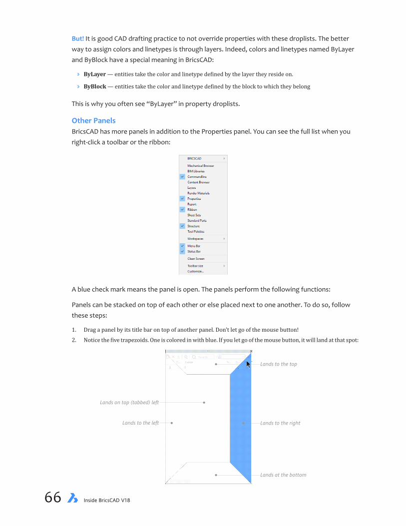
chapter 2 Navigating the BricsCAD Interface 6766 Inside BricsCAD V18
But! It is good CAD drafting practice to not override properties with these droplists. The better way to assign colors and linetypes is through layers. Indeed, colors and linetypes named ByLayer and ByBlock have a special meaning in BricsCAD:
Ð ByLayer — entities take the color and linetype defined by the layer they reside on.
Ð ByBlock — entities take the color and linetype defined by the block to which they belong
This is why you often see “ByLayer” in property droplists.
Other PanelsBricsCAD has more panels in addition to the Properties panel. You can see the full list when you right-click a toolbar or the ribbon:
A blue check mark means the panel is open. The panels perform the following functions:
Panels can be stacked on top of each other or else placed next to one another. To do so, follow these steps:
1. Drag a panel by its title bar on top of another panel. Don’t let go of the mouse button!
2. Notice the five trapezoids. One is colored in with blue. If you let go of the mouse button, it will land at that spot:
Lands to the right
Lands to the top
Lands at the bottom
Lands to the left
Lands on top (tabbed) left

chapter 2 Navigating the BricsCAD Interface 6766 Inside BricsCAD V18
Here is what two panels look like when one panel lands above another (shown at left) or the panel is stacked on top of another (shown at right):
Ð When above or beside each other, a drag bar appears between them that lets you change their size
Ð When on stacked, tabs appear that let you switch between them
To unstick panels, grab one by its title bar and then drag it away from the others. To close a panel, click the x in its upper right corner.
These panels can be docked: Command Bar, BIM Compositions, Content Browser, Layers, Me-chanical Browser, Properties, Render Materials, Ribbon, Sheet Sets, Structure, and Tool Palettes.
RIBBON TABS AND PANELSThe ribbon dominates the upper part of the user interface. It’s kind of like a series of overlap-ping toolbars, where of tabs segregate the “toolbars” into groups of functions. Each tab has is further segregated by a series of panels, and each panel contains a group of buttons, flyouts, and droplists — just like toolbars.
If you do not see the ribbon, enter the Ribbon command:
: ribbon
Shown below is the ribbon’s standard Home tab.

chapter 2 Navigating the BricsCAD Interface 6968 Inside BricsCAD V18
Each tab shows a different group of panels. Click the name of a tab to switch to it. Here is the View tab.
Because Bricsys wrote its own version of the ribbon interface, it is equally available on the Win-dows, Mac, and Linux versions, unlike all other CAD systems. You customize the ribbon through the Customize command.
DRAWING TABSDrawing tabs let you switch quickly between open drawings, and provides a shortcut to file-relat-ed commands, such as Open and Close. BricsCAD calls it “Document Tab.”
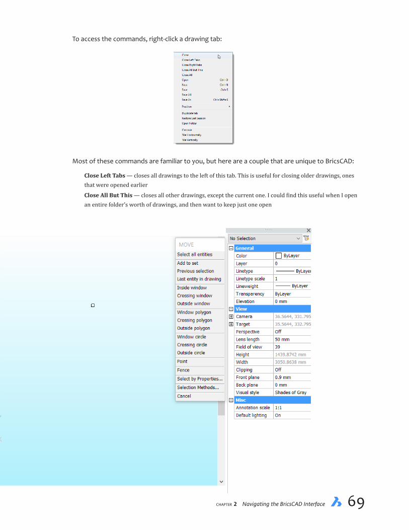
chapter 2 Navigating the BricsCAD Interface 6968 Inside BricsCAD V18
To access the commands, right-click a drawing tab:
Most of these commands are familiar to you, but here are a couple that are unique to BricsCAD:
Close Left Tabs — closes all drawings to the left of this tab. This is useful for closing older drawings, ones that were opened earlier
Close All But This — closes all other drawings, except the current one. I could find this useful when I open an entire folder’s worth of drawings, and then want to keep just one open

chapter 2 Navigating the BricsCAD Interface 7170 Inside BricsCAD V18
Save All — saves all drawings at once
Duplicate Tab — makes a copy of the current drawing, naming it Copy_name.dwg
Open Folder — opens the folder from which the drawing was opened
There are two variables that control drawing tabs. DocTabPosition places the tab at the top, bottom,left, or right of the drawing area. ShowDocTabs turns the tab row on and off.
In the Drawing Area
The drawing area is in the center of the BricsCAD window, as shown above. Here I will tell you
about some of the user interface elements you find in the drawing area.
SHORTCUT MENUSScattered all about BricsCAD are accesses to shortcut menus. Nearly any place you right-click, a menu will pop up with a list of commands. The commands usually are relevant to the spot you right-click. Holding down the Shift or Ctrl keys sometimes displays other shortcut menus. In later lessons, I’ll point out shortcut menus that are useful to the work at hand. I don’t detail them all here, because there are so many. The figure shows what happens when you hold down the Ctrl key and click the right mouse button: you access the entity snap modes, as describe later in this book.
QUAD CURSOR Status bar QUAD
Shortcut F12
The Quad is unique to BricsCAD in the way that it incorporates drawing and editing commands. This multifunction cursor takes its cue from the “heads-up” style of computer interface design, placing in the drawing area many useful commands.
The Quad is normally not visible; most of the time, you see the standard tri-color crosshair cursor or arrowhead cursor. When you pass the cursor over an entity, however, the quad cursor ap-pears, first as a single button; see figure below.
(If it does not appear, then turn it on by clicking QUAD on status bar or pressing function key F12.)

chapter 2 Navigating the BricsCAD Interface 7170 Inside BricsCAD V18
When you move the arrow cursor onto the sole button, the quad cursor expands to show addi-tional buttons, usually for commands most commonly used with the nearest entity.
In addition, there are blue boxes for groups of additional buttons. Some groups are for common operations, while others are specific to the entity. To access the additional buttons, pass the cur-sor over a blue box. Click a button to execute its command.
The Quad changes its content, depending on the nearby entity and the workspace. BricsCAD comes with sets of predefined Quads for the various workspaces.
To customize the Quad, right-click it to access the following shortcut menu:
Quick Properties When Quick Properties are turned on, the properties of an entity are displayed by the Quad. To turn this in, click RP on the taskbar. (RP is short for “rollover properties” — I know, the name keeps changing. Sigh.)
Hover the cursor over an entity, and the Quad displays some of the properties of it.
If you want the Quad to display other properties, then use the Customize command’s Properties tab to specify the properties for every entity.
SCROLL BARSA scroll bar rests at the right edge of the drawing area. It lets you pan the drawing up and down. A second one is along the bottom of the drawing area; it pans left and right. Normally, they are turned off, but I find them handy. To turn on scroll bars, enter the ScrollBar command.

chapter 2 Navigating the BricsCAD Interface 7372 Inside BricsCAD V18
Scroll bars are limited to panning left-right and up-down.
Drag to pan drawing interactively
Click here to pan drawingby 10% of screen width
Click buttons to pan drawingby 1% of screen width
As a more flexible alternative, hold down the middle button (or the roller wheel in the middle of the mouse), and then drag the mouse around. This action pans the drawing in any direction dur-ing any command.
PROMPT MENUThe Prompt menu shows the prompts available for the current command. This menu appears in the upper right corner (usually) of the drawing areas. It is useful when the Command bar is turned off, because then you see what options are available for each command.
To select an option, just pick it from the list shown. When the command ends, the Prompt menu disappears.
LOOK-FROMCONTROLBricsCAD has a LookFrom widget in the upper right corner of the drawing area. When you pass the cursor over the widget, small triangles appear, as does the the preview of a chair. Pausing the cursor over a triangle shows what the 3D view will look like:
Left: LookFrom control with no cursor interaction...; right: ...and when the cursor is over one of the small triangles

chapter 2 Navigating the BricsCAD Interface 7372 Inside BricsCAD V18
Clicking the triangle changes the 3D viewpoint.
The green dot indicates the cursor position, kind of like a laser pointer:
To see the bottom view, hold down the Ctrl (or Cmd in Mac) key. Click the center of the LookFrom control to return the view to its home view. This is particu-larly helpful in Twist mode. (new to V18) Press the Home button on the keyboard to return the view to its normal posi-tion.
There are two ways you can change the way the LookFrom control operates. The easier one is right-click the control, and then choose an option from the shortcut menu.
Most of the options in the shortcut menu are straight-forward, but I do want to explain the differ-ence between Isometric and Twist modes:
Ð Isometric mode is like using the Viewpoint or View commands
Ð Twist mode is like using the RtRotF (real time view rotation) command
Left: LookFrom in isometric mode; right: And in twist mode

chapter 2 Navigating the BricsCAD Interface 7574 Inside BricsCAD V18
The other method is to enter the LookFrom command, from which you can turn off (and on) the control and access its settings:
: lookfrom
LookFrom [ON/OFF/Settings] <ON>:
The Settings option opens the Settings dialog box at the LookFrom section. Here you can adjust the properties of the widget, such as its translucency and position. Of particular interest is the number of isometric viewpoints it can display, which is set through “Direction Mode” or the Look-FromDirectionMode variable. The following table shows you the options:
LookFromDirectionMode NumberofViews
0 6 orthogonal views 1 14 views; no flat views of corners 2 18 views; top down corners 3 26 views; eight top down corners
THE UCS ICON IN 2D DRAFTING, 3D MODELING, AND DUCSI described the function of the UCS (user-defined coordinate system) icon in the last chapter. Here I want to talk a bit about how the UCS is used — rarely in 2D drafting, but a lot in 3D model-ing. In short, a UCS lets us locate twist the x,y,z axes in any direction in space. This makes it easier to draw and edit at unusual angles and on slanted surfaces.
StaticUCSsfor2D. In 2D drafting, for example, when we draw things at an angle, such as the angled wing of a building, then we use a USC. Changing the coordinate system to match the angle of the building rotates everything else as well. In the figure below, I rotated the UCS icon to match the angled walls; notice that the crosshair cursor has matched the angle.

chapter 2 Navigating the BricsCAD Interface 7574 Inside BricsCAD V18
To change the angle of the UCS icon, you tell the UCS command three things:
1. The new origin point (0,0)
2. The new direction of the x axis (determines the angle)
3. The new direction of the y axis (determines the orientation)
From these three, BricsCAD figures out the direction of the z axes using the right-hand rule. Here is how to use the UCS command in 2D drawings:
1. Pick new origin usingINTersection esnap
3. Pick new y axis usingENDpoint esnap
2. Pick new x axis usingENDpoint esnap
: ucs
Specify origin of UCS or [Face/NAmed/Entity/Previous/View/X/Y/Z/Z Axis/Move/World]
<World>: (Pick a point like the intersection of two lines; BricsCAD turns on INTersec-
tion entity snap automatically)
Point on X-axis/<Accept>: (Pick a point along the new x axis; BricsCAD turns on ENDpoint
entity snap automatically)
Point on the XY-plane with positive Y value/<Accept>: (Pick a point along the new y
axis; BricsCAD turns on ENDpoint entity snap automatically)
If you use the same UCS often, then you can give it a name. This lets you switch back to it quickly. Named UCSes can be managed through the ExpUcs command, which displays the Coordinate Systems section of the Drawing Explorer.

chapter 2 Navigating the BricsCAD Interface 7776 Inside BricsCAD V18
DynamicUCSsfor3D. The same system works for manually changing the UCS in 3D modeling. Why would you want to change the UCS in 3D? Because CAD is still fundamentally 2D, even when in 3D. To draw on a face, the UCS needs to match the orientation in space of the face. BricsCAD, fortunately, can do this automatically through dynamic UCS. Here is a brief example. In the figure below, the UCS icon is in the “world” position:
To, say, write some text on the bottom of the piston, the UCS needs to relocate to the flat face. To do so, first turn on DUCS (dynamic UCS) mode by clicking the DUCS button on the status bar (so that it looks black). Then start the Text command:
: text
Text: Style/Align/Fit/Center/Middle/Right/Justify/<Start point>: (Pick a face on which
to write)
Now move the cursor around faces of the piston. Notice how the UCS jumps to match the orien-tation of the face. I show two of these in the figures below.
Left: UCS dynamically placed on one face...; right: ...and on another face

chapter 2 Navigating the BricsCAD Interface 7776 Inside BricsCAD V18
UCSs in Layout Mode. In paper space of layout modes, the UCS icon turns into something that looks like a sheet of paper.
It serves no purpose. In the early days when layout mode was first introduced, the CAD interface was such that it could be difficult for users to determine if they were in model or paper space. So the UCS icon switched to a triangle in some CAD programs, and a piece of paper in BricsCAD. Today, however, the user interface makes layout mode quite clear, and so the paper icon remains primarily for sentimental reasons.
TIPS WIDGET“Tips” are interactive tooltips that report options that might otherwise be unknown to users. For example, the following Tips widget appears during the Polysolid command.
Notice that it shows several icons. The Ctrl “button” is a reminder that by holding down the Ctrl key during the command, you can change the justification of polysolids between left, centered, and right. To get a brief description of the purpose, pause the cursor over the Tip.
To dismiss the Tip, click the small x at the right end. (The Ctrl button itself does nothing; neither does the i icon.) The display of the Tips widget is toggled through the TIPS button on the status bar. Right-click the button for options.
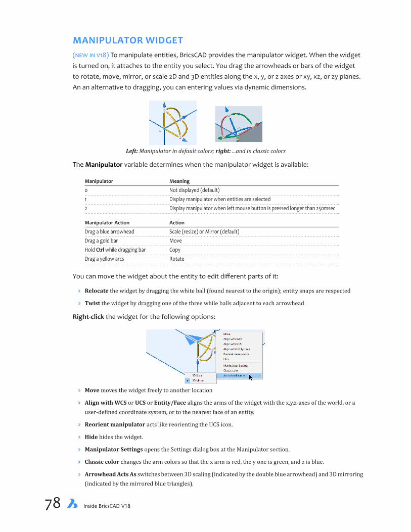
chapter 2 Navigating the BricsCAD Interface 7978 Inside BricsCAD V18
MANIPULATOR WIDGET(new in v18) To manipulate entities, BricsCAD provides the manipulator widget. When the widget is turned on, it attaches to the entity you select. You drag the arrowheads or bars of the widget to rotate, move, mirror, or scale 2D and 3D entities along the x, y, or z axes or xy, xz, or zy planes. An an alternative to dragging, you can entering values via dynamic dimensions.
Left: Manipulator in default colors; right: ...and in classic colors
The Manipulator variable determines when the manipulator widget is available:
Manipulator Meaning
0 Not displayed (default) 1 Display manipulator when entities are selected 2 Display manipulator when left mouse button is pressed longer than 250msec
Manipulator Action Action
Drag a blue arrowhead Scale (resize) or Mirror (default) Drag a gold bar Move Hold Ctrl while dragging bar Copy Drag a yellow arcs Rotate
You can move the widget about the entity to edit different parts of it:
Ð Relocate the widget by dragging the white ball (found nearest to the origin); entity snaps are respected
Ð Twist the widget by dragging one of the three while balls adjacent to each arrowhead
Right-click the widget for the following options:
Ð Move moves the widget freely to another location
Ð Align with WCS or UCS or Entity/Face aligns the arms of the widget with the x,y,z-axes of the world, or a user-defined coordinate system, or to the nearest face of an entity.
Ð Reorient manipulator acts like reorienting the UCS icon.
Ð Hide hides the widget.
Ð Manipulator Settings opens the Settings dialog box at the Manipulator section.
Ð Classic color changes the arm colors so that the x arm is red, the y one is green, and z is blue.
Ð Arrowhead Acts As switches between 3D scaling (indicated by the double blue arrowhead) and 3D mirroring (indicated by the mirrored blue triangles).

chapter 2 Navigating the BricsCAD Interface 7978 Inside BricsCAD V18
Below the Drawing Area
At the bottom of BricsCAD are several more areas of information:
Layout tabs — switch between model space and layouts quickly
Command bar — accepts typed input and displays prompts; see Chapter 1 for details
Status bar — reports on the status of the drawing and provides on-off toggles
Let’s examine the function of each area.
LAYOUT TABSUnder the drawing area are three tabs labeled Model, Layout1, and Layout2. You may have seen similar tabs in other Windows or Linux software, such as the sheet tabs in LibreOffice Calc or Excel.
Click to move through tabs Model tab Layout tabs Add a layout
Layout Manager
In BricsCAD, these tabs switch the drawing view among layouts. Layouts allow you to define how the drawing will look as it is plotted. They let you position its location on the paper, adding draw-ing borders, specific views, and/or specifying shades of gray instead of colors.
Click the + plus sign to add more tabs.
The arrow buttons let you see more of them there are too many tabs to fit along the bottom of BricsCAD.
(new to v18) Click the Layout Manager button to display the Layout Manager dialog box, which lets you create, name, and organize more than layout at a time.
To access a shortcut menu of layout options, right-click any layout tab. The options let you create more layouts,rename them, or specify settings specific to a variety of plotter models.
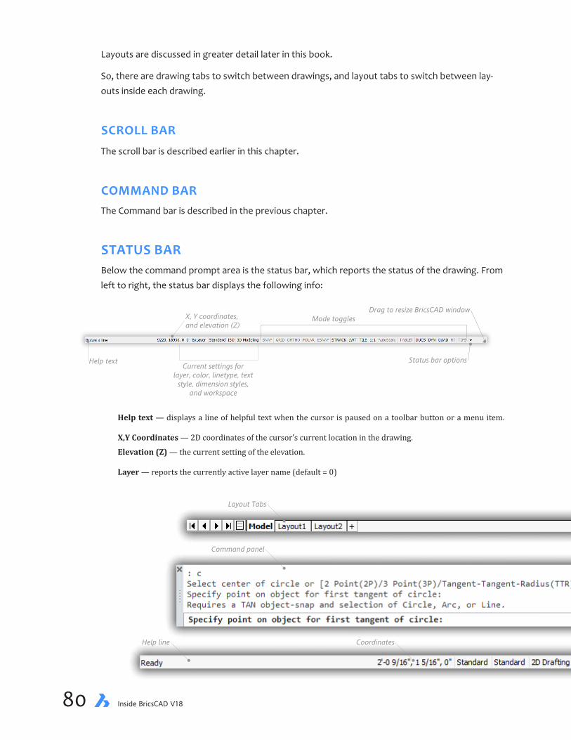
chapter 2 Navigating the BricsCAD Interface 8180 Inside BricsCAD V18
Layouts are discussed in greater detail later in this book.
So, there are drawing tabs to switch between drawings, and layout tabs to switch between lay-outs inside each drawing.
SCROLL BARThe scroll bar is described earlier in this chapter.
COMMAND BARThe Command bar is described in the previous chapter.
STATUS BARBelow the command prompt area is the status bar, which reports the status of the drawing. From left to right, the status bar displays the following info:
Help text
X, Y coordinates,and elevation (Z)
Current settings forlayer, color, linetype, text
style, dimension styles,and workspace
Mode toggles
Status bar options
Drag to resize BricsCAD window
Help text — displays a line of helpful text when the cursor is paused on a toolbar button or a menu item.
X,Y Coordinates — 2D coordinates of the cursor’s current location in the drawing.
Elevation (Z) — the current setting of the elevation.
Layer — reports the currently active layer name (default = 0)
Layout Tabs
Command panel
Help line Coordinates Status Bar
Scroll Bar

chapter 2 Navigating the BricsCAD Interface 8180 Inside BricsCAD V18
Color — reports the current color (default = 0; black)
Linestyle — reports the current line type (ByLayer)
Style — reports the current text style (Standard)
Dimension style — reports the current dimension style (ISO-25)
Workspace — reports the current workspace (2D Drafting).
Drawing Settings — reports the status of drawing settings. Each word is an on/off button called a “toggle:”
Ð Gray text — the toggle is turned off, as for SNAP in the figure above.
Ð Black text — the toggle is turned on, as for POLAR.
Click a button to turn the mode on and off.
SNAP — toggles the distance snap
GRID — toggles the display of grid lines
ORTHO — toggles orthographic drawing mode to draw at right angles
POLAR — toggles snapping at common polar angles, such as 15 degrees
ESNAP — toggles all entity snaps (a.k.a. object snaps)
STRACK — toggles snap tracking
LWT — toggles lineweight display
TILE / P:Layout — switches between paper and model modes
Annotation Scale — specifies the current scale factor for annotative entities
AutoScale — toggles wether annotation scales are added automatically
Tablet — toggles tablet mode on and off
DDUCS — toggles dynamic UCS mode for drawing on the faces of 3D entities
DYN — toggles dynamic dimensions mode
QUAD — toggles the cursor between crosshair and quad modes
RT — toggles the display of rollover tooltips
TIPS — toggles the tips widget
None — selects a GIS coordinate system
Layout Tabs
Command panel
Help line Coordinates Status Bar
Scroll Bar

chapter 2 Navigating the BricsCAD Interface 8382 Inside BricsCAD V18
When you right-click any of status bar button, BricsCAD displays a shortcut menu. Many have the same set of options: On, Off, and Settings,
Settings is a shortcut to the dialog box that regulates the mode. For example, to change the settings for the grid, right-click the GRID button and then select Settings; BricsCAD displays the Snap/Grid section of the Settings dialog box.
When you right-click a few buttons, they present a longer list of options so that you can, for ex-ample, choose an entity snap.
Click the tiny black triangle near the right end of the status bar to display a shortcut menu listing all possible toggles.
This lefts you turn on and off toggles that you want (or don’t want) to see.

chapter 2 Navigating the BricsCAD Interface 8382 Inside BricsCAD V18
- ———
You have learned all about BricsCAD’s user interface, from the title bar at the top to the status bar along the bottom, and nearly everything in between
Next, you begin to start working with BricsCAD, beginning with starting a new drawing.

chapter 2 Navigating the BricsCAD Interface PB84 Inside BricsCAD V18
Notes
CHAPTER 3
Setting Up A New Drawing
YounowpreparetheCADenvironmentforcreatingnewdrawings.BeforecreatinganydrawingwithBricsCAD, you must prepare it. Here we have the tutorials that show you how to do this:
Step 1: Start new, blank drawings
Step 2: Name the drawing file
Step 3: Specify the units of measurement
Step 4: Set the snap and grid spacings
Step 5: Indicate the drawing limits
Step 6: Create layers
Step 7: Save the drawing
In this chapter, you learn how to set up new drawings, save your work to disk, and how to exit BricsCAD.
IN THIS CHAPTER
• Preparing a drawing for first-time use with a wizard
• Specifying units, angle formats, and drawing settings
• Understanding how layers organize the drawing
• Saving the drawing
• Recognizing the importance of automatic backups
chapter 3 Setting Up a New Drawing 8786 Inside BricsCAD V18
KEY TERMS IN THIS CHAPTER
Default — value of a setting defined by the program and unchanged by the user
File name — uniquely identifies drawing files and other documents
Grid — displays a grid of lines or array of dots as visual guides
Layers — organize drawings by segregating common elements
Limit — specifies the nominal limits of drawings, and constrains the range of grid marks
Scratch — brand-new drawing with no preset parameters
Snap — constrains cursor movement to discrete distances
Template — a drawing file read by BricsCAD that sets default parameters for new drawings
Unit — specifies units of measurement, such as metric, architectural, and engineering
Wizard — series of dialog box that step users through a procedure
Working set — set of one of more drawings that were previously open in BricsCAD or were saved for future use
Workspace — predefined user interface specific to tasks, such as 2D drafting or 3D modeling
Zoom — enlarges and reduces the visual size of drawings
USEFUL ABBREVIATIONS
' or ft Feet
" or in Inches (12 inches per foot)
ANSI American National Standards Institute
BAK Backups of BricsCAD drawing files
DWT Portion of file names that identify them as template files
DWG Portion of file names that identify them as BricsCAD drawings
mm Millimeters (1000mm per meter)
m Meters
NEW COMMANDS
Command Alias Menu Bar Ribbon Tab
Layer la Settings | Layers Home | Layers | Layers Limits ... Settings | Drawing Limits ... NewWiz ddnew File | New Wizard ... Settings rm Settings | Settings Settings | Settings | Settings SaveAs ... File | Save As ...

chapter 3 Setting Up a New Drawing 8786 Inside BricsCAD V18
BeforeYouBegin
To learn how to draw with BricsCAD, you will work on a landscape plan, creating and modifying the drawing of a yard around a house. By the end of chapter 7, the drawing will look like this one:
House
Pond
Donly
n A
ven
ue
4486 Donlyn AvenueAnytown BC
35.00
23.0012.00
5.00
6.00
13.0015.00
24.00
15.00
R1.00
Before beginning this series of tutorial, you may want to measure your yard and locate major features, such as the house, driveway, and garden areas. If you’d rather not measure your yard or you don’t have access to one, then follow along with the following sketch, which is the drawing used by the next several lessons.
The tutorial in this book will be done in metric units, 7but for North American readers I’ll include imperial units (feet and inches). The completed Yard.dwg file can be downloaded from https://www.dropbox.com/s/ft6gzw3r408ndgd/Inside-BricsCAD-Tutorial-Files.zip. If you draw with imperial units, then use Imp-Yard.dwg. The .zip file also holds the drawing as it appears at the end of each chapter.

chapter 3 Setting Up a New Drawing 8988 Inside BricsCAD V18
STARTING A NEW DRAWINGCommand NewWiz
Menu File | New Wizard
When you start a new drawing in BricsCAD, you can start in several different ways:
Ð From scratch with a blank drawing
Ð Or, with a template file that presets certain aspects of new drawings
Ð Or, enlist the services of a software wizard — this how you will start the first tutorial
In this chapter, you create the new drawing with the assistance of a wizard. The wizard is a series of dialog boxes that take you through the steps needed to set up a new drawing. It prompts you to select the units, grid, and so on, and is meant to help you get through the first few steps of preparing a new drawing, which can be confusing to new users.
1. If BricsCAD is not running, start it now by double-clicking its icon on the desktop
2. Notice the Welcome dialog box. Click New Drawing.
3. Start the wizard by taking one of the following steps:
Ð In the ribbon’s Home tab, click New and then New Wizard
Ð Or, from the menu bar, choose File, and then New Wizard
Ð Or, at the command line, enter the NewWiz command
: newwiz
Notice the Create New Drawing dialog box:
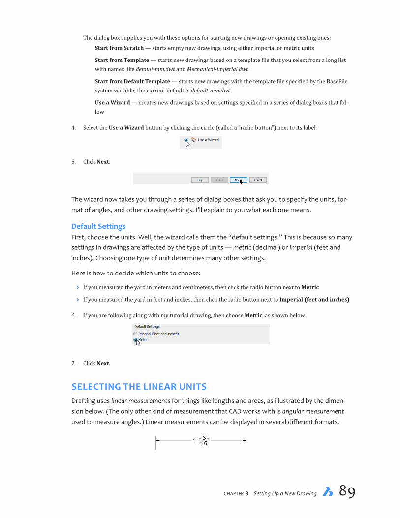
chapter 3 Setting Up a New Drawing 8988 Inside BricsCAD V18
The dialog box supplies you with these options for starting new drawings or opening existing ones:
Start from Scratch — starts empty new drawings, using either imperial or metric units
Start from Template — starts new drawings based on a template file that you select from a long list with names like default-mm.dwt and Mechanical-imperial.dwt
Start from Default Template — starts new drawings with the template file specified by the BaseFile system variable; the current default is default-mm.dwt
Use a Wizard — creates new drawings based on settings specified in a series of dialog boxes that fol-low
4. Select the Use a Wizard button by clicking the circle (called a “radio button”) next to its label.
5. Click Next.
The wizard now takes you through a series of dialog boxes that ask you to specify the units, for-mat of angles, and other drawing settings. I’ll explain to you what each one means.
DefaultSettingsFirst, choose the units. Well, the wizard calls them the “default settings.” This is because so many settings in drawings are affected by the type of units — metric (decimal) or Imperial (feet and inches). Choosing one type of unit determines many other settings.
Here is how to decide which units to choose:
Ð If you measured the yard in meters and centimeters, then click the radio button next to Metric
Ð If you measured the yard in feet and inches, then click the radio button next to Imperial (feet and inches)
6. If you are following along with my tutorial drawing, then choose Metric, as shown below.
7. Click Next.
SELECTING THE LINEAR UNITSDrafting uses linear measurements for things like lengths and areas, as illustrated by the dimen-sion below. (The only other kind of measurement that CAD works with is angular measurement used to measure angles.) Linear measurements can be displayed in several different formats.

chapter 3 Setting Up a New Drawing 9190 Inside BricsCAD V18
HOW TO START NEW DRAWINGS
OPENING WORKING SETS
A “working set” is a list of previously-opened drawings, or a saved sets of drawing file names. To save and open sets of drawings, use the Workset command.
OPENING MORE THAN ONE DRAWING
To select one than one drawing at once, hold down the following keys as you pick them in the Open dialog box:
Shift — select a contiguous range of .dwg files
Ctrl (Cmd on Macs) — to select non-contiguous files, as shown below
STARTING FROM SCRATCH
New “empty” drawings employ default settings for all variables, which are read from the following DWT template files:
default-mm.dwt — for drawings with metric units or unitless (millimeters)
default-imperial.dwt — for drawings with Imperial or British units (inches)

chapter 3 Setting Up a New Drawing 9190 Inside BricsCAD V18
STARTING FROM TEMPLATES
New drawings are begun with a DWT template file that you select from the following list:
You can create your own templates: edit the current drawing, and then use the SaveAs command. Choose “Drawing Template (*.dwt)” from the Save As Type droplist.
STARTING FROM THE DEFAULT TEMPLATE
Start new drawings with the template file specified by the BaseFile system variable, usually default-mm.dwt if none other is specified. This option is useful when you usually want to start with the same template, such as one specified by your firm or a client.
To change the value of BaseFile, enter the Settings command, search for “basefile,” and then click the button in the Template field. From the Choose a File dialog box, select the .dwt file you wish to employ as the new default template.
USING A WIZARD
Creates new drawings based on settings specified in a series of dialog boxes. See the tutorial in this chap-ter.

chapter 3 Setting Up a New Drawing 9392 Inside BricsCAD V18
Look closely at the example measurements shown in the table below to understand how Brics-CAD displays each one. Note that a dash (-) separates feet from inches, while a space separates inches from fractional inches.
Unit Name Measures In Example
Architectural Feet, inches, fractional inches 4'-6 1/16" Engineering Feet, inches, decimal inches 4'-6.0625" Fractional Inches, fractional inches 54 1/6" Decimal Units and decimal units 2128.4449 Scientific Units, decimal units, and exponents 2.1284E+03
The default is called “Decimal,” which is often used for metric measurements, such as millimeters. BricsCAD displays metric measurement as unitless decimals, such as 1.2345; the “mm” for millime-ter is not displayed.
Once you select a style of unit, BricsCAD displays all measurements in that format. But don’t wor-ry! You can always switch the measurement format to something else with the Units command.
(The reason you can switch between units is because internally BricsCAD ignores the type of units.It keeps track of measurements with unitless real numbers accurate to 14 decimal places. For the sake of us humans, however, BricsCAD displays distances and angles in the units we want; the software converts them on-the-fly.)
8. For this drawing tutorial, measurements were made in centimeters. Under Unit of Measurement, ensure “Decimal” is selected.
9. This drawing is measured in meters, to the nearest centimeter (0.01m). Centimeters are represented by two decimal places. To set the number of decimal places, follow these steps: Next to Precision, click the down arrow and then select 0.00.
(For imperial drawings, measurements made in feet to the nearest 1/4-inch — accurate enough for this project. Select Architectural units, and then from the Precision droplist choose 0'-0 1/4".)

chapter 3 Setting Up a New Drawing 9392 Inside BricsCAD V18
10. Click Next. As we see next, BricsCAD displays the set of options for measuring and displaying angles.
You are free to enter distances more accurate than a centimeter, because BricsCAD remem-bers distances to full accuracy. When BricsCAD displays coordinates, however, it will round them off to the nearest 0.01 units, because we told it to in step 9.
SELECTING THE ANGLE STYLEBefore we choose the angle measurement system, I must mention some facts about angles:
Ð In CAD, angles are usually measured starting at the x-axis, which is 0 degrees; see figure below
Ð Angles are usually measured counter-clockwise from the positive x axis
Ð 90 degrees is at the positive y axis
Ð BricsCAD shows the x axis in red, and the y axis in green
Positive Y axisat 90 degrees
Positive X axisat 0 degrees
180 degrees
270 degreesor -90 degrees
Positive angle are measured counter clockwise
The elements of axes and angles
The Angle dialog box is for choosing the formats of angular units that BricsCAD should display. The options available are listed below:
Angle Name Measures In Example
Decimal degrees Degrees and decimals 12.3456 Degrees/Minutes/Seconds (d ' ") Degrees, minutes, seconds, and decimal seconds 12d34'56" Grads (g) Grads and decimals 123.45g Radians (r) Radians and decimals 1.23r Surveyor’s Units (N d ' " E) North/South degrees towards East/West N12d34'56"E
Note that there are 400 grads (used in Germany) and are 2*pi radians in a 360-degree circle.
If we were real land surveyors, we would use Surveyor format. But we’re not, and so we’re sticking with the more familiar decimal degrees. (Again, you can choose the change the angular format at anytime with the Units command without affecting the drawing.)

chapter 3 Setting Up a New Drawing 9594 Inside BricsCAD V18
11. Ensure that the default, Decimal Degrees, is selected for the angle of measurement.
12. Change the default Precision to 0 degrees, as we are measuring angles to the nearest degree.
13. Click Next.
CHOOSING THE PLOT STYLEWhen it comes time to printing drawings, they can be formatted by BricsCAD using one of two methods. One method is known as a color table (a.k.a. “color dependent” styles or CTB), while the other method is through a style table (a.k.a. “named” styles or STB). They are, unhappily, mu-tually exclusive, meaning that you have to choose only one to be active at a time.
14. Right now, all you need to know is that neither color tables nor style tables really matter when plotting reg-ular 2D drawings on monochrome printers. So, ensure that the Color Dependent (CTB) option is selected.
15. Click Next.
SETTING ENTITY PROPERTIESYou come to the final dialog box of the wizard. Here, you set the defaults of some entity prop-erties (a.k.a. “objects”). By default, all entities are drawn with a color named “ByLayer” and a linetype of the same name.
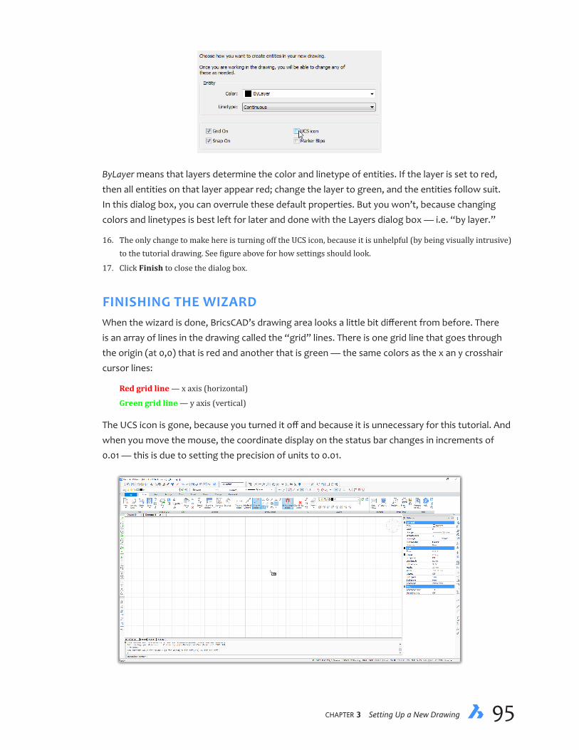
chapter 3 Setting Up a New Drawing 9594 Inside BricsCAD V18
ByLayer means that layers determine the color and linetype of entities. If the layer is set to red, then all entities on that layer appear red; change the layer to green, and the entities follow suit. In this dialog box, you can overrule these default properties. But you won’t, because changing colors and linetypes is best left for later and done with the Layers dialog box — i.e. “by layer.”
16. The only change to make here is turning off the UCS icon, because it is unhelpful (by being visually intrusive) to the tutorial drawing. See figure above for how settings should look.
17. Click Finish to close the dialog box.
FINISHING THE WIZARDWhen the wizard is done, BricsCAD’s drawing area looks a little bit different from before. There is an array of lines in the drawing called the “grid” lines. There is one grid line that goes through the origin (at 0,0) that is red and another that is green — the same colors as the x an y crosshair cursor lines:
Red grid line — x axis (horizontal)
Green grid line — y axis (vertical)
The UCS icon is gone, because you turned it off and because it is unnecessary for this tutorial. And when you move the mouse, the coordinate display on the status bar changes in increments of 0.01 — this is due to setting the precision of units to 0.01.
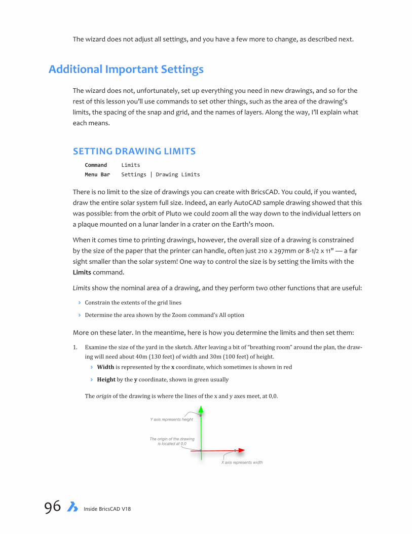
chapter 3 Setting Up a New Drawing 9796 Inside BricsCAD V18
The wizard does not adjust all settings, and you have a few more to change, as described next.
Additional Important Settings
The wizard does not, unfortunately, set up everything you need in new drawings, and so for the rest of this lesson you’ll use commands to set other things, such as the area of the drawing’s limits, the spacing of the snap and grid, and the names of layers. Along the way, I’ll explain what each means.
SETTING DRAWING LIMITSCommand Limits
Menu Bar Settings | Drawing Limits
There is no limit to the size of drawings you can create with BricsCAD. You could, if you wanted, draw the entire solar system full size. Indeed, an early AutoCAD sample drawing showed that this was possible: from the orbit of Pluto we could zoom all the way down to the individual letters on a plaque mounted on a lunar lander in a crater on the Earth’s moon.
When it comes time to printing drawings, however, the overall size of a drawing is constrained by the size of the paper that the printer can handle, often just 210 x 297mm or 8-1/2 x 11" — a far sight smaller than the solar system! One way to control the size is by setting the limits with the Limits command.
Limits show the nominal area of a drawing, and they perform two other functions that are useful:
Ð Constrain the extents of the grid lines
Ð Determine the area shown by the Zoom command’s All option
More on these later. In the meantime, here is how you determine the limits and then set them:
1. Examine the size of the yard in the sketch. After leaving a bit of “breathing room” around the plan, the draw-ing will need about 40m (130 feet) of width and 30m (100 feet) of height.
Ð Width is represented by the x coordinate, which sometimes is shown in red
Ð Height by the y coordinate, shown in green usually
The origin of the drawing is where the lines of the x and y axes meet, at 0,0.
Y axis represents height
X axis represents width
The origin of the drawingis located at 0,0

chapter 3 Setting Up a New Drawing 9796 Inside BricsCAD V18
2. At the ‘ : ’ prompt, enter the Limits command, as follows:
: limits (Press Enter to execute the command)
3. Notice that BricsCAD reports that the limits are turned off. Turn them on:
Limits are off: Set lower left corner or [turn limits ON] <0,0>: on
4. Restart the Limits command by pressing the spacebar. This is a shortcut to repeating the last-used com-mand:
: (press the spacebar)
: LIMITS
Notice that BricsCAD reports the name of the command it is repeating, so you are sure it is the correct one.
5. Now specify the x,y coordinates of the lower left corner. The default value of 0,0 is good for this drawing, so just press Enter to leave the value as is:
Limits are on: Set lower left corner or [turn limits ON] <0,0>: (Press Enter to accept
the default value of 0,0)
6. When BricsCAD asks for coordinates of the upper right corner, enter 40 and 30 (meters), as follows:
Upper right corner <12,9>: 40,30
Lower left corner is at the origin 0,0
Upper right corner is at 40,30 meters
Drawing limits
Warning! If you work with imperial units, it is important that you include the apostrophe ( ' ) when you enter measurements as feet, like 130'. When you leave out the apostrophe of 130, BricsCAD assumes you mean 130 inches, which it translates to 10'-10.
7. I find it handy to restrict the grid’s lines to the extent of the Limits. To do so, I change the value of the Grid-Display system variable to 2 like this:
: griddisplay
New current value for GRIDDISPLAY (0 to 15) <3>: 2
8. Finally, use the Zoom All command to see all of the drawing. Enter the Zoom command, and then enter ‘a’ for the All option:
: zoom
Zoom [zoom In/zoom Out/All/Center/Dynamic/Extents/Left/Previous/Right/Scale (nx/nxp)/
Window/OBject] <Scale (nX/nXP)>:a
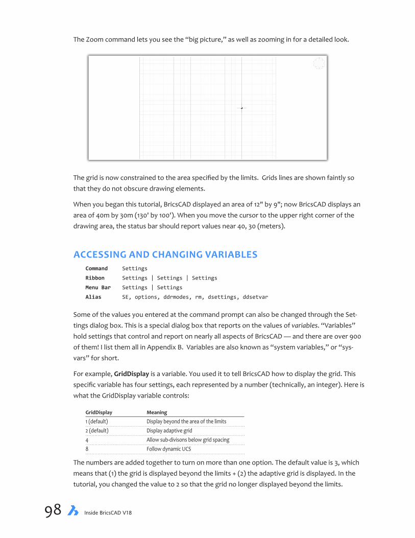
chapter 3 Setting Up a New Drawing 9998 Inside BricsCAD V18
The Zoom command lets you see the “big picture,” as well as zooming in for a detailed look.
The grid is now constrained to the area specified by the limits. Grids lines are shown faintly so that they do not obscure drawing elements.
When you began this tutorial, BricsCAD displayed an area of 12" by 9"; now BricsCAD displays an area of 40m by 30m (130' by 100'). When you move the cursor to the upper right corner of the drawing area, the status bar should report values near 40, 30 (meters).
ACCESSING AND CHANGING VARIABLESCommand Settings
Ribbon Settings | Settings | Settings
Menu Bar Settings | Settings
Alias SE, options, ddrmodes, rm, dsettings, ddsetvar
Some of the values you entered at the command prompt can also be changed through the Set-tings dialog box. This is a special dialog box that reports on the values of variables. “Variables” hold settings that control and report on nearly all aspects of BricsCAD — and there are over 900 of them! I list them all in Appendix B. Variables are also known as “system variables,” or “sys-vars” for short.
For example, GridDisplay is a variable. You used it to tell BricsCAD how to display the grid. This specific variable has four settings, each represented by a number (technically, an integer). Here is what the GridDisplay variable controls:
GridDisplay Meaning
1 (default) Display beyond the area of the limits 2 (default) Display adaptive grid 4 Allow sub-divisons below grid spacing 8 Follow dynamic UCS
The numbers are added together to turn on more than one option. The default value is 3, which means that (1) the grid is displayed beyond the limits + (2) the adaptive grid is displayed. In the tutorial, you changed the value to 2 so that the grid no longer displayed beyond the limits.

chapter 3 Setting Up a New Drawing 9998 Inside BricsCAD V18
(Adaptive grid means that as you zoom out, the grid shows fewer lines so that the drawing area is not overwhelmed with too many closely-spaced lines. Allow subdivisions means that additional lines are displayed between the specified grid spacing. Follow DUCS means that the grid rotates to match the x,y-plane specified by the current UCS.)
Here is another example: When you used the Limits command, for example, BricsCAD stored the values you entered in two system variables, LimMin and LimMax:
LimMin — stores the x, y coordinates of the lower left corner.
LimMax — stores coordinates of the upper right corner.
These two system variables can be accessed directly at the command bar by entering their names, just like they were commands:
: limmin
New value for LIMMIN <0,0>: (Press Enter to keep values as they are)
: limmax
New value for LIMMAX <40,30>: (Press Enter)
A problem lies in remembering the names of hundreds of system variables. And so the other method is to use the Settings dialog box, as follows:
1. Enter the Settings command:
: settings
Notice the Settings dialog box.
Enter text to search for Click to close dialog box
Click + to open section
Click - to close section
Descriptive name ofvariable
Actual name of variable
Description of variable
Value of variable

chapter 3 Setting Up a New Drawing 101100 Inside BricsCAD V18
2. This dialog box contains hundreds of settings, and so the best way to access one of them is to use the Find feature, as follows:
a. Enter “limits” in the Find field.
b. Press Enter.
The Settings dialog box goes to the first setting with “limits” in its name. Click the Find Next arrow until you arrive at the Limits Minimum and Limits Maximum settings:
3. There is no “Close” or “OK” button to dismiss the dialog box. When you are done, just click the red X.
When the Find field turns orange, it means that there is no setting by that name. This occurs when you misspell the name, or when a variable of that name does not exist in BricsCAD.
CHANGING THE SNAP AND GRID SPACINGOne great advantage to drawing with CAD is that software permits you to create very accurate drawings. BricsCAD has several functions that help you draw with pretty much perfect accuracy.
One such feature you already met, the grid. It helps you visualize distances.
Another such function is known as “snap mode.” Snap can be thought of as setting the mouse resolution. It determines the distance the cursor moves in the drawing. For instance, by setting the snap distance to 0.5, the cursor moves at precise, 0.5-unit distances during drawing and edit-ing commands. (You learn about other accuracy aids in later lessons of this book.)
During the wizard, you turned on snap mode, but the spacing of 0.5 meters is too wide. Follow these steps to change the snap and grid spacing to 0.1 meters:
1. (If you are not in the Settings dialog box, then enter the Settings command.)
In the Find field, enter “snap mode” and then press Enter.
2. Notice that the listing in the dialog box jumps to the Snap Unit field. It specifies the distance that the cursor moves.

chapter 3 Setting Up a New Drawing 101100 Inside BricsCAD V18
3. Change the X and Y values of Snap Unit to 0.1, 0.1 to represent 1 decimeter (or 1",1" in imperial units). Leave other snap settings at their default values, such as Snap Angle = 0.
4. Earlier, the wizard had turned on the grid as a visual guide. The grid is meant to guide you; the default spac-ing of 10 units is perhaps to far apart. (BricsCAD will in fact not display the grid when its lines or dots are too closely spaced.) Change the spacing to 1 meter by changing the value of Grid Unit to 1,1.
5. Finally, change the type of grid from lines to dots. Grid lines are useful in 3D modeling, but tend to cover up lines in 2D drafting. Here is how to do this:
a. Click the node next to Grid Style .
b. Turn on the Dotted Grid is 2D Model Space option.
6. To close the dialog box, click the X at the top right end.

chapter 3 Setting Up a New Drawing 103102 Inside BricsCAD V18
QUICK SUMMARY OF LAYERS
BricsCAD provides great control over layers through the Drawing Explorer. It lists the names of all layers and their properties. The names of properties are indicated by the names on the header bar.
(To sort layers alphabetically, click a header such as Name or Linetype. Click a second time to sort in reverse order, Z to A.)
Current — • indicates the current layer.
Layer Name — specifies the name up to 255 characters long. You can use numbers, letters, and the follow-ing punctuation marks: dollar sign ( $ ), hyphen ( - ), underline ( _ ), and spaces. Two layers cannot have the same name in the same drawing. There is no limit to the number of layers in a drawing.
Description — describes the purpose or content of the layer; optional.
On/Off (obsolete) — when on, displays entities; when off, entities cannot be seen nor are they plotted.
Freeze — freezes entities so that they cannot be seen, edited, or plotted. Also, frozen layers are not included when BricsCAD performs drawing regenerations and hidden-line operations. When thawed, the layers behave normally. (To thaw layers means to turn off their frozen status.) It is better to freeze layers than turn them off.
Locked — locks layers, which means entities are seen but cannot be edited. Unlock layers to make entities available for editing.
Color — specifies the color of entities on the layer. Entities drawn on the layer are displayed in this color, but the entity color can be overridden with the Color command. The default color is 7, which is displayed as white or black, depending on the background color.
Linetype — specifies the line type by which entities are displayed. The default linetype is Continuous (solid line). Before any other linetype can be used, its definition must be loaded into the drawing; can be overrid-den by the Linetype command.
Lineweight — specifies the line widths for entities on the layer. The default is 0.00mm; the maximum is 2.11mm (about 0.08", or 6 points wide); can be overridden by the Lineweight command.
Plot Style — specifies the plot style with which entities plotted. Named plot styles defines colors, widths, and percentages of black during plotting. This option is not available for drawings created with color-dependent plot styles.
Plot — specifies whether the layer is plotted; when off, the layer is not plotted.
If some of the drawing does not plot, check the setting of the Plot property.
Transparency — specifies the translucency of the layer; the default of 0 means all entities are displayed opaque.
New VP — specifies whether the status of new viewports, visible or frozen.
Material — specifies the material used during renderings.
...continued

chapter 3 Setting Up a New Drawing 103102 Inside BricsCAD V18
A grid distance of 0 has a special meaning in BricsCAD. It means that the grid spacing matches the snap spacing, 1" in our case.
Notice that the drawing area is covered by a grid of dots.
Sometimes the snap function can get in the way of your drafting. You can turn the snap on and off at any time by pressing function key F9. Similarly, the grid can be toggled with F7. For many options in BricsCAD’s commands, you need only type the first letter of the option. For example, type “a” as the abbreviation for the All option. When two options begin with the same letter, you need to type the first two characters of the option. When entering text and numbers in a dialog box, pressing the Tab key is a quicker way to get to the next field. Fields are buttons, text entry boxes, list boxes, and other dialog box elements that you can change. To return to previous fields, press Shift+Tab (hold down the Shift key, and then press Tab). When you change values in the Settings dialog box, they are shown in boldface text. And, the changes take effect immediately.
...continued
LAYOUT MODE PROPERTIES
When drawings are in layout mode, this dialog box displays more columns. (VP is short for “viewport.”)
VP Freeze — freezes the layers in new viewports created in paper space
VP Color, VP Linetype, VP Lineweight, VP Transparency, and VP Plot Style — specifies the color, linetype, lineweight, transparency, and plot style for the layer in paper space viewports
chapter 3 Setting Up a New Drawing 105104 Inside BricsCAD V18
Creating LayersCommands Layer, layerpanelon
Ribbon Home | Layers | Layers
Menu Bar Settings | Layers
Alias LA
If you ever worked with overlay drafting, then you would be familiar with the concept of layers. In overlay drafting, drafters draw the base plan on one clear sheet of Mylar, a common form of drawing media made from plastic. The electrical plan would be drawn on another sheet, the structural on a third. Since the Mylar is transparent, drafters would overlay the two or all three of the drawings to create a single blueprint —depending on how much detail needed to be shown.
In CAD, layers operate in a similar manner. We draw different parts of drawings on different lay-ers. The base on one layer, electrical on another, and so on. Then we turn layers off and on to display the drawing in different ways.
For example, the electrical contractor would be interested in seeing only the base plan layer with the electrical layer. While it is possible to create hundreds and thousands of layers in drawings, it is more common to work with a few dozen layers; in this book, we work with a mere half-dozen. Layers in this tutorial segregate text, yard, roads, and so on.
A further advantage to CAD layers is that they apply global properties to entities. For example, when a layer is green, then all entities assigned to they layer called are colored green. Changing the color of the layer, such as to brown, instantly changes the color of all entities assigned to that layer.
Assigning entities to layers is this simple: (a) set the name of a layer as current, and then (b) start drawing! The most common way to set a name as current through the Layer droplist. As well, BricsCAD has commands that let you move entities to other layers, should that be necessary.
NAMING LAYERSLayers are specified by name. BricsCAD lets you give layers names up to 255 characters long. Start setting up new layers with the Layer command, which displays a dialog box. Layers can also be displayed in a panel, which stays always open, with the LayersPanelOpen command.
1. Enter the Layer command:
: layer
Notice the Drawing Explorer dialog box. This dialog box lets you control almost every aspect of layers in drawings.

chapter 3 Setting Up a New Drawing 105104 Inside BricsCAD V18
The drawing already has one layer: 0. Every new BricsCAD drawing has one layer, called “0”, which you can never erase. Layer 0 has special properties that affect the creation of blocks, as discussed in greater detail later in this book.
Step 1: Click to create a new layer Step 2: Rename the generic name Step 3: Set the properties
Step 4: Set the layer as current
2. Following the steps illustrated below, create a layer:
a. Click the New Layer button. Notice that BricsCAD creates a new layer called “NewLayer1.”
b. Change the name by clicking “NewLayer1.”
c. Type Lot , and then press Enter.
Step 1: Click New button Step 2: Click new layer name Step 3: Enter name and press Enter
3. Assigning a color to each layer makes it easier to determine which lines belong to which layers. Change the color of the Lot layer to blue, as follows:
a. Click the black square under the Color column across from the layer name Lot.
b. The Select Color dialog box appears, displaying 255 colors. Which one to choose?
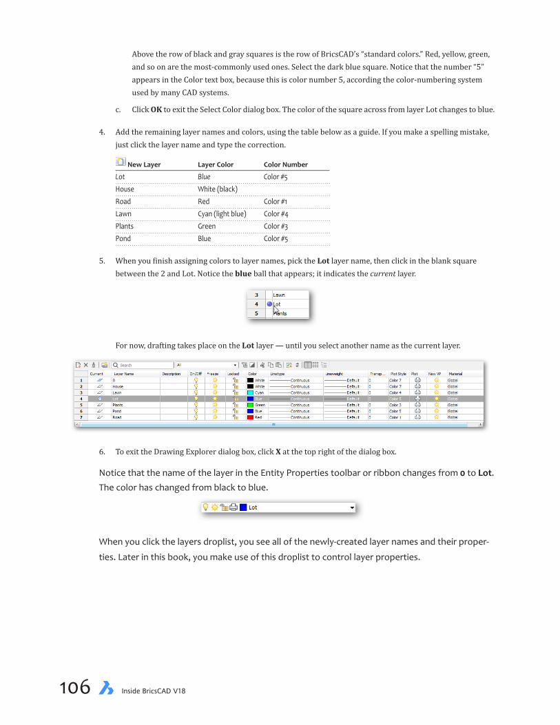
chapter 3 Setting Up a New Drawing 107106 Inside BricsCAD V18
Above the row of black and gray squares is the row of BricsCAD’s “standard colors.” Red, yellow, green, and so on are the most-commonly used ones. Select the dark blue square. Notice that the number “5” appears in the Color text box, because this is color number 5, according the color-numbering system used by many CAD systems.
c. Click OK to exit the Select Color dialog box. The color of the square across from layer Lot changes to blue.
4. Add the remaining layer names and colors, using the table below as a guide. If you make a spelling mistake, just click the layer name and type the correction.
New Layer Layer Color Color Number
Lot Blue Color #5 House White (black) Road Red Color #1 Lawn Cyan (light blue) Color #4 Plants Green Color #3 Pond Blue Color #5
5. When you finish assigning colors to layer names, pick the Lot layer name, then click in the blank square between the 2 and Lot. Notice the blue ball that appears; it indicates the current layer.
For now, drafting takes place on the Lot layer — until you select another name as the current layer.
6. To exit the Drawing Explorer dialog box, click X at the top right of the dialog box.
Notice that the name of the layer in the Entity Properties toolbar or ribbon changes from 0 to Lot. The color has changed from black to blue.
When you click the layers droplist, you see all of the newly-created layer names and their proper-
ties. Later in this book, you make use of this droplist to control layer properties.
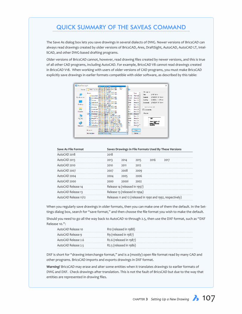
chapter 3 Setting Up a New Drawing 107106 Inside BricsCAD V18
QUICK SUMMARY OF THE SAVEAS COMMAND
The Save As dialog box lets you save drawings in several dialects of DWG. Newer versions of BricsCAD can always read drawings created by older versions of BricsCAD, Ares, DraftSight, AutoCAD, AutoCAD LT, Intel-liCAD, and other DWG-based drafting programs.
Older versions of BricsCAD cannot, however, read drawing files created by newer versions, and this is true of all other CAD programs, including AutoCAD. For example, BricsCAD V8 cannot read drawings created in BricsCAD V18. When working with users of older versions of CAD programs, you must make BricsCAD explicitly save drawings in earlier formats compatible with older software, as described by this table:
Save As File Format Saves Drawings in File Formats Used By These Versions
AutoCAD 2018 2018 AutoCAD 2013 2013 2014 2015 2016 2017 AutoCAD 2010 2010 2011 2012 AutoCAD 2007 2007 2008 2009 AutoCAD 2004 2004 2005 2006 AutoCAD 2000 2000 2000i 2002 AutoCAD Release 14 Release 14 (released in 1997) AutoCAD Release 13 Release 13 (released in 1994) AutoCAD Release 11/12 Releases 11 and 12 (released in 1990 and 1992, respectively)
When you regularly save drawings in older formats, then you can make one of them the default. In the Set-tings dialog box, search for “save format,” and then choose the file format you wish to make the default.
Should you need to go all the way back to AutoCAD 10 through 2.5, then use the DXF format, such as “DXF Release 10.”:
AutoCAD Release 10 R10 (released in 1988) AutoCAD Release 9 R9 (released in 1987) AutoCAD Release 2.6 R2.6 (released in 1987) AutoCAD Release 2.5 R2.5 (released in 1986)
DXF is short for “drawing interchange format,” and is a (mostly) open file format read by many CAD and other programs. BricsCAD imports and exports drawings in DXF format.
Warning! BricsCAD may erase and alter some entities when it translates drawings to earlier formats of DWG and DXF. Check drawings after translation. This is not the fault of BricsCAD but due to the way that entities are represented in drawing files.

chapter 3 Setting Up a New Drawing 109108 Inside BricsCAD V18
QUICK SUMMARY OF ALTERNATIVE SAVE FORMATS
In addition to saving drawings in AutoCAD’s .dwg file format, BricsCAD Classic, Pro, and Platinum can export drawings with the File | Export command in the following formats:
Ð ASCII and binary DXF (*.dxf)7
Ð Template (*.dwt)
Ð Adobe Portable Document Format (*.pdf)
Ð Scalable Vector Graphics (*.svg)
Ð Windows Bitmap (*.bmp), Metaformat (*.wmf), and Enhanced Metaformat (*.emf)
Ð And many versions of DWF, such as 2D, 3D, binary, ASCII, and compressed ASCII
COMMUNICATOR TRANSLATOR
When you need to translate drawings to and from other formats, then you may want enlist Communicator. This is an optional, extra-cost add-on for BricscAD Pro and Platinum that translates files in additional formats.
...continued

chapter 3 Setting Up a New Drawing 109108 Inside BricsCAD V18
There can be some confusion over the color “white” — or is it black? BricsCAD switches white and black depending on the background color of the drawing area. When the background is black, BricsCAD displays white lines; when white, BricsCAD displays black lines. So, white can be black — at least in the world of CAD. To set the background color in BricsCAD, from the Settings menu, select Settings. In the Find field, enter “background color,” and then press Enter. Select the color.
Saving DrawingsCommand Save
Ribbon Home | File | Save
Menu Bar File | Save
Shortcut Ctrl+S (Cmd+S on Macs)
As the most important activity, save your work with the Save command, as follows.
1. In the ribbon’s Home tab, click the Save button in the File panel.
On the toolbar, click the icon that looks like a diskette (tooltip: Save).\
2. Because new drawings have a generic name of “Drawing1.Dwg,” BricsCAD automatically displays the Save Drawing As dialog box to give you a chance to give it a better name. Type the name “Yard” in the File name text entry box.
...continued
You access the additional formats with the Import and Export commands, after the software in installed on your computer.

chapter 3 Setting Up a New Drawing 111110 Inside BricsCAD V18
Step 1: Choose drive andfolder in to save the file
Step 2: Name the drawing file Step 3: Click Save
3. Click the Save button. BricsCAD saves the drawing with the name yard.dwg. From now on, you and BricsCAD refer to this drawing as “Yard.”
MAKING BACKUPS AUTOMATICFor speed, BricsCAD keeps parts of the drawing in the computer’s memory (RAM). The drawback is that when the operating system crashes or when the power is cut to the computer, you may lose some or all of your work. Because crashes are common in older versions of Windows espe-cially, it is an excellent idea to save drawings every few minutes.
BricsCAD does this automatically, but also lets you specify the interval in which the drawings are saved — without you needing to repeatedly use the Save command. The default setting is 60 minutes, which is far too long.
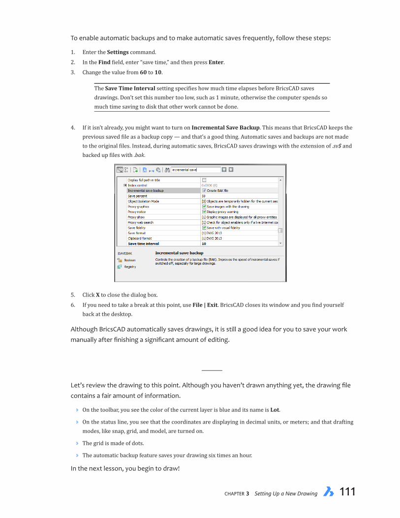
chapter 3 Setting Up a New Drawing 111110 Inside BricsCAD V18
To enable automatic backups and to make automatic saves frequently, follow these steps:
1. Enter the Settings command.
2. In the Find field, enter “save time,” and then press Enter.
3. Change the value from 60 to 10.
The Save Time Interval setting specifies how much time elapses before BricsCAD saves drawings. Don’t set this number too low, such as 1 minute, otherwise the computer spends so much time saving to disk that other work cannot be done.
4. If it isn’t already, you might want to turn on Incremental Save Backup. This means that BricsCAD keeps the previous saved file as a backup copy — and that’s a good thing. Automatic saves and backups are not made to the original files. Instead, during automatic saves, BricsCAD saves drawings with the extension of .sv$ and backed up files with .bak.
5. Click X to close the dialog box.
6. If you need to take a break at this point, use File | Exit. BricsCAD closes its window and you find yourself back at the desktop.
Although BricsCAD automatically saves drawings, it is still a good idea for you to save your work manually after finishing a significant amount of editing.
———
Let’s review the drawing to this point. Although you haven’t drawn anything yet, the drawing file contains a fair amount of information.
Ð On the toolbar, you see the color of the current layer is blue and its name is Lot.
Ð On the status line, you see that the coordinates are displaying in decimal units, or meters; and that drafting modes, like snap, grid, and model, are turned on.
Ð The grid is made of dots.
Ð The automatic backup feature saves your drawing six times an hour.
In the next lesson, you begin to draw!

chapter 3 Setting Up a New Drawing PB112 Inside BricsCAD V18
Notes
CHAPTER 4
Creating Your First Drawing
Thepointto2DCADistodraftdrawingsefficiently,andthenprintthem—eitheronpaperorelectroni-cally.
In this chapter, you learn how to draw lines, accurately, how to make changes to them, and then produce a copy of your first drawing on a printer.
IN THIS CHAPTER
• Drawing with lines and polylines
• Understanding absolute and relative distances
• Using polar coordinates
• Modifying entities
• Plotting (printing) drawings
• Exporting drawings in PDF format
chapter 4 Creating Your First Drawing 115114 Inside BricsCAD V18
KEY TERMS IN THIS CHAPTER
Absolute coordinate — refers to measurements made relative to the drawing’s origin
Aperture — refers to the area around the cursor in which BricsCAD searches for entities to snap to
Direct distance entry — specifies points by moving the mouse in a direction, then entering the distance
Extent — refers to the invisible rectangle that encompasses all entities in drawings
Fillet — rounds corners
Mirror — mirrors copies of entities
Entity(entity)snap — snaps the cursor to geometric features, such as to the ends of lines
Origin — refers to the location of x=0, y=0, usually at the lower-left corner of drawings
Ortho — constrains cursor movement to the vertical and horizontal; short for “orthographic”
Pick cursor — refers to the square cursor in which BricsCAD searches for entities to select
Polar coordinate — describes measurements specified by distances and angles
Relative coordinate — describes measurements made relative to the last point
USEFUL ABBREVIATIONS
@ At symbol specifies relative coordinates, such as @2,3
# Pound sign specifies absolute coordinates, such as #4,5
< Angle bracket specifies angles, such as 10<45
- Dash forces BricsCAD to use the command-line version of a command, such as -layer
[option] Square brackets indicate command options, such as [Undo]
<value> Angle brackets indicate the default (current) value, such as <LOT>
x x specifies the X coordinate along the horizontal axis
y y specifies the Y coordinate along the vertical axis
NEW COMMANDS
Command Aliases Menu Selection Ribbon Tab
Cancel Esc ...1 ... Fillet f or fi Modify | Fillet Change | Modify | Fillet Mirror mi Modify | 2D Mirror Change | Arrange | 2D Mirror Move m Modify | Move Change | Arrange | Move Open op or Ctrl+O File | Open Home | File | Open OSnap os or F3 Settings | Settings Settings | Settings PLine pl Draw | Polyline Draw | Draw | Polyline Plot Ctrl+P File | Print Home | Print/Plot | Print QSave Ctrl+S File | Save Home | File | Save Zoom z View | Zoom View | Zoom | Zoom
1 The ellipsis (...) indicates no menu selection is available.

chapter 4 Creating Your First Drawing 115114 Inside BricsCAD V18
Reopening DrawingsCommand Open
Ribbon Home | File | Open
Menu Bar File | Open
Shortcut Ctrl+O
If you exited BricsCAD at the end of the last lesson, then you need to start the program again, and then load the Yard drawing.
The Recent Drawings item of the File menu always holds the names of the last ten drawings you opened with BricsCAD. Here’s how to do this: 1. Click File on the menu bar. 2. Slide your cursor down to Recent Drawings, and then click on yard.dwg. See figure below.
THIS CHAPTER’S DRAWING
By the end of this lesson, your drawing should look like this one:
Tutorial-04 drawing file

chapter 4 Creating Your First Drawing 117116 Inside BricsCAD V18
Notice that when the Yard drawing opens in BricsCAD, it looks exactly the same as when you last saw it — that is to say blank, except for the grid lines.
Drawing the Lot’s BoundaryCommand Line
Ribbon Draw | Draw | Line
Menu Bar Draw | Line
Alias L
Let’s get some lines on the screen! To orient yourself, the first thing to do is to draw the boundary of the yard. That helps you see the extents of the drawing.
The lines making up the lot boundary are drawn with the Line command. You begin drawing the lot lines at the lower-left corner, the origin (0,0), then work counterclockwise around the lot boundary, as shown by the illustration below.
1. First, ensure DYN is turned off on the status bar; the word should look gray. This turns off dynamic input, so that all prompts appear in the Command bar.
2. Enter the Line command, as follows:
: line
3. Respond to the ‘Specify first point:’ prompt by typing the coordinates of the origin:
Start of line or [Follow] <Last point>: 0,0
@23<180
Angle of line: 216.88Length of line: 15
C (close)35,0
Start at 0,0(the origin)
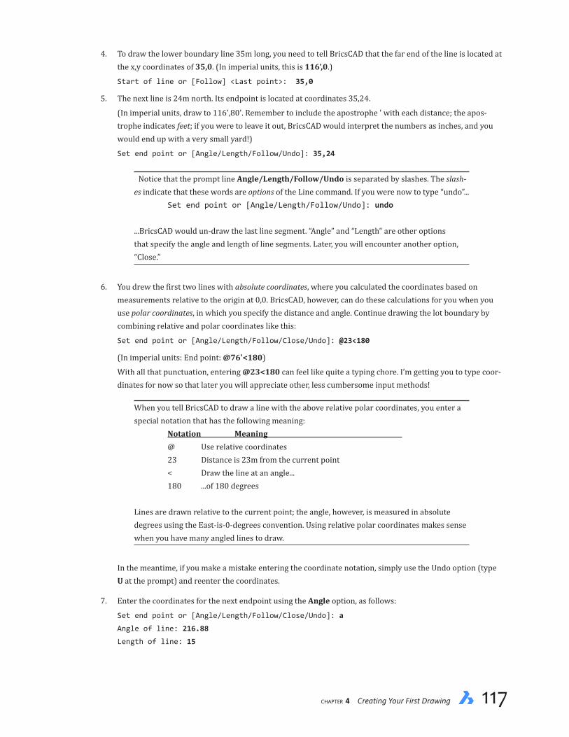
chapter 4 Creating Your First Drawing 117116 Inside BricsCAD V18
4. To draw the lower boundary line 35m long, you need to tell BricsCAD that the far end of the line is located at the x,y coordinates of 35,0. (In imperial units, this is 116’,0.)
Start of line or [Follow] <Last point>: 35,0
5. The next line is 24m north. Its endpoint is located at coordinates 35,24.
(In imperial units, draw to 116',80'. Remember to include the apostrophe ' with each distance; the apos-trophe indicates feet; if you were to leave it out, BricsCAD would interpret the numbers as inches, and you would end up with a very small yard!)
Set end point or [Angle/Length/Follow/Undo]: 35,24
Notice that the prompt line Angle/Length/Follow/Undo is separated by slashes. The slash-es indicate that these words are options of the Line command. If you were now to type “undo”... Set end point or [Angle/Length/Follow/Undo]: undo ...BricsCAD would un-draw the last line segment. “Angle” and “Length” are other options that specify the angle and length of line segments. Later, you will encounter another option, “Close.”
6. You drew the first two lines with absolute coordinates, where you calculated the coordinates based on measurements relative to the origin at 0,0. BricsCAD, however, can do these calculations for you when you use polar coordinates, in which you specify the distance and angle. Continue drawing the lot boundary by combining relative and polar coordinates like this:
Set end point or [Angle/Length/Follow/Close/Undo]: @23<180
(In imperial units: End point: @76'<180)
With all that punctuation, entering @23<180 can feel like quite a typing chore. I’m getting you to type coor-dinates for now so that later you will appreciate other, less cumbersome input methods!
When you tell BricsCAD to draw a line with the above relative polar coordinates, you enter a special notation that has the following meaning: Notation Meaning @ Use relative coordinates 23 Distance is 23m from the current point < Draw the line at an angle... 180 ...of 180 degrees Lines are drawn relative to the current point; the angle, however, is measured in absolute degrees using the East-is-0-degrees convention. Using relative polar coordinates makes sense when you have many angled lines to draw.
In the meantime, if you make a mistake entering the coordinate notation, simply use the Undo option (type U at the prompt) and reenter the coordinates.
7. Enter the coordinates for the next endpoint using the Angle option, as follows:
Set end point or [Angle/Length/Follow/Close/Undo]: a
Angle of line: 216.88
Length of line: 15

chapter 4 Creating Your First Drawing 119118 Inside BricsCAD V18
(In imperial units, Length of line: 50'.) Notice that the Angle option removes the need to use the @ and < characters.
The Length option works the same way, but prompts first for the length, then the angle.
8. To finish the lot boundary, you use a shortcut. Type c (short for “Close”) to close the boundary — instead of typing the final coordinates (0,0):
Set end point or [Angle/Length/Follow/Close/Undo]: c
BricsCAD automatically draws a line from the current endpoint to the beginning of the first line.
As I mentioned earlier, slashes separate options names. The options for the Line command are Angle/Length/Follow/Close/Undo:
Angle — asks you to enter the angle of the next line segment, followed by length
Length — asks you to enter the length of the next line segment, followed by angle
Follow — asked you to show the angle with the mouse, and then enter the length
Close — BricsCAD closes the polygon formed by the lines
Undo — BricsCAD undoes the drawing of the last line segment
9. To add space around the drawing, use the Zoom command to make the drawing 10% smaller, as follows:
: zoom
Zoom [zoom In/zoom Out/All/Center/Dynamic/Extents/Left/Previous/Right/Scale (nx/nxp)/
Window/OBject] <Scale (nX/nXP)>: 0.9x
This zooms the drawing 90% as large as it was before.
Instead of drafting on paper, you have created your first digital drawing! More importantly, you have drawn it full size — even if it looks small on your computer screen. This is one of the most powerful aspects of CAD: everything is drawn full size. There is no need for a scale ruler or to divide distances by a scale factor as in manual drafting.
Planning the Next Steps
The next step is to draw the outline of the house. The lower-right corner of the house is located 3m up and 6m in from the lot corner.

chapter 4 Creating Your First Drawing 119118 Inside BricsCAD V18
There are several ways in BricsCAD to locate one entity relative to another, in this case the corner of the house relative to the property line. You could...
Ð Calculate the coordinates of the house’s corner, or
Ð Use the XLine command to draw a pair of construction lines, then start drawing from their intersection, or
Ð Use the From option to start drawing from an offset from the lot corner, or
Ð Use tracking to offset the starting point (described in a later lesson),or
Ð Draw the house in the corner of the lot, then move the house into position
Please don’t feel overwhelmed by this long list of options. I show them to you purely to make the point that in CAD there are many ways to skin a cat.
In this tutorial, you use the last method in the list: Draw, and move. It demonstrates two of Brics-CAD’s most powerful commands, PLine and Move. But first, make a layer change.
CHANGING LAYERSCommand -Layer
Before you draw the house, you need to change the layer to “House.” Continuing with the theme of many approaches to solving drafting problems, a significant number of BricsCAD’s commands can be carried out in more than one way. Here you learn an alterative way to control layers.
In the previous chapter, you used the Drawing Explorer dialog box to create and color new layers and to set “Lot” as the current (or working) layer. Another method is to change the layer through a droplist on the ribbon, status bar, toolbar, or use the Layers panel. And then there is another method:
In this part of the tutorial, you change layers by typing the command and its options at the key-board by entering the -Layer command. The hyphen ( - ) in front of Layer forces the command to display its prompts in the command bar.
1. To set the House layer with the -Layer command, enter the following:
: -layer
2. The -Layer command has more than a dozen options, most of which you ignore for now:
Layer [? to list/New layer/Make new current layer/Set layer as current/Color/Linetype/
LineWeight/TRansparency/MATerial/Plot/stAte/turn layer ON/turn layer OFf/Freeze/Thaw/
LOck/Unlock]: s
Enter s, and BricsCAD invokes the Set option. It sets another layer as active, whose name you specify.
3. BricsCAD prompts you to enter the name of the layer to make active. To change the working layer to House, type “house” and then press Enter.
Layer to set as current: house (Press Enter)

chapter 4 Creating Your First Drawing 121120 Inside BricsCAD V18
4. The House layer is now current.
The -Layer command repeats its many-optioned prompt. Press Esc to cancel the command and return to the ‘ : ’ prompt.
Layer [? to list/New layer/Make new current layer/Set layer as current/Color/Linetype/
LineWeight/TRansparency/MATerial/Plot/stAte/turn layer ON/turn layer OFf/Freeze/Thaw/
LOck/Unlock]: (Press Esc)
You can cancel commands at any time by pressing Esc. Sometimes, however, you may need to press Esc two or even three times in commands that have large numbers of sub-options, such as the PEdit command.
5. Look at the ribbon, status bar, or toolbar to confirm that BricsCAD has changed the working layer from layer Lot to layer House.
For all command options, BricsCAD capitalizes one (or more) letters of each option. To select an option, you need type only its capitalized character, such as S for the Set option.
When two (or more) options begin with the same first letter — such as LType and LWeight — then you need to enter the first two characters, as specified by the capitalization — LT and LW in this case. There are a few times when the character that’s capitalized is in the middle of the option name, such as A for the stAte option. This is because the all the other letters in stAte were already taken up by other option abbreviations. By capitalizing them, BricsCAD shows you the fewest characters you need to enter for it to know what you’re talking about. So you could enter SE for the Set option or LTY for LType.
Drawing the House OutlineStatus Bar ORTHO
Ribbon Settings | Settings | Draw Orthogonal
Menu Settings | Draw Orthogonal
Shortcuts Ctrl+L, F8
Command Pline
Ribbon Draw | Draw | Polyline
Menu Bar Draw | Polyline
Alias PL

chapter 4 Creating Your First Drawing 121120 Inside BricsCAD V18
Earlier, you drew the lot boundary as a polygon with the Line command. It looks like a continuous line that was made of several segments and vertices (corners). Each segment, however, is inde-pendent; they only look connected. This disconnected group of lines can be difficult to deal with when it comes to selecting something like the entire lot boundary at once.
To remedy this, BricsCAD offers a special kind of line called the “polyline.” Polylines are lines made of many features, as suggested by the prefix poly (from the Greek word polloi for “many”). They can be made of lines and arcs, or of snaky-looking spline-like shapes; plines can have widths (which lines cannot), and even varying widths — all connected together as a single entity, as il-lustrated below.
VertexSegmentArc(aka polyarc)
Start point
End point
Length
Width
QUICK SUMMARY OF THE PLINE COMMAND
A polyline consists of numerous lines and/or arcs connected together as a single entity. Polylines are drawn with the PLine command, and edited with the PEdit command. The PLine command has the following op-tions for drawing polylines:
: pline
Start of polyline:
Set next point or [draw Arcs/Close/Distance/Follow/Halfwidth/Width/Undo]:
Next point — specifies the location of the polyline’s next vertex
draw Arcs — draws polyarcs; you can switch between lines and arcs when drawing polylines
Close — joins the last endpoint with the starting point
Distance — specifies the length and angle of the next segment
Follow — draws a specific distance, in the direction of the cursor’s angle
Halfwidth — specifies the width of polylines by the distance from their center line to their outside edge
Width — specifies the width of polyline segments; allows independent starting and ending widths for tapered polylines
Undo — undoes the last polyline drawing operation
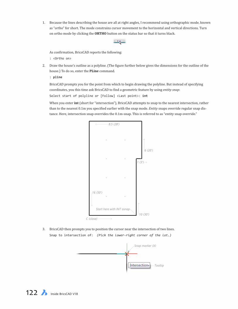
chapter 4 Creating Your First Drawing 123122 Inside BricsCAD V18
1. Because the lines describing the house are all at right angles, I recommend using orthographic mode, known as “ortho” for short. The mode constrains cursor movement to the horizontal and vertical directions. Turn on ortho mode by clicking the ORTHO button on the status bar so that it turns black.
As confirmation, BricsCAD reports the following:
: <Ortho on>
2. Draw the house’s outline as a polyline. (The figure further below gives the dimensions for the outline of the house.) To do so, enter the PLine command.
: pline
BricsCAD prompts you for the point from which to begin drawing the polyline. But instead of specifying coordinates, you this time ask BricsCAD to find a geometric feature by using entity snap:
Select start of polyline or [Follow] <Last point>: int
When you enter int (short for “intersection”), BricsCAD attempts to snap to the nearest intersection, rather than to the nearest 0.1m you specified earlier with the snap mode. Entity snaps override regular snap dis-tance. Here, intersection snap overrides the 0.1m-snap. This is referred to as “entity snap override.”
8.5 (28')
16 (50')
6 (20')
1 (3')
10 (30')C (close)
Start here with INT osnap
3. BricsCAD then prompts you to position the cursor near the intersection of two lines.
Snap to intersection of: (Pick the lower-right corner of the lot.)
Tooltip
Snap marker (X)
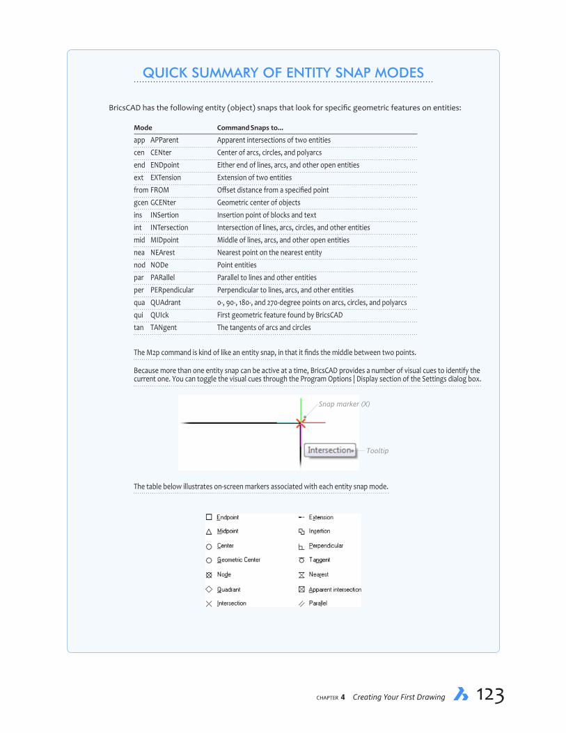
chapter 4 Creating Your First Drawing 123122 Inside BricsCAD V18
QUICK SUMMARY OF ENTITY SNAP MODES
BricsCAD has the following entity (object) snaps that look for specific geometric features on entities:
Mode Command Snaps to...
app APParent Apparent intersections of two entities cen CENter Center of arcs, circles, and polyarcs end ENDpoint Either end of lines, arcs, and other open entities ext EXTension Extension of two entities from FROM Offset distance from a specified point gcen GCENter Geometric center of objects ins INSertion Insertion point of blocks and text int INTersection Intersection of lines, arcs, circles, and other entities mid MIDpoint Middle of lines, arcs, and other open entities nea NEArest Nearest point on the nearest entity nod NODe Point entities par PARallel Parallel to lines and other entities per PERpendicular Perpendicular to lines, arcs, and other entities qua QUAdrant 0-, 90-, 180-, and 270-degree points on arcs, circles, and polyarcs qui QUIck First geometric feature found by BricsCAD tan TANgent The tangents of arcs and circles
The M2p command is kind of like an entity snap, in that it finds the middle between two points.
Because more than one entity snap can be active at a time, BricsCAD provides a number of visual cues to identify the current one. You can toggle the visual cues through the Program Options | Display section of the Settings dialog box.
Tooltip
Snap marker (X)
The table below illustrates on-screen markers associated with each entity snap mode.

chapter 4 Creating Your First Drawing 125124 Inside BricsCAD V18
a. Move the cursor until the aperture is over the lower-right corner of the lot boundary. The tooltip re-ports the entity snap found by BricsCAD.
b. Click — press the left mouse button. BricsCAD “captures” the intersection as the starting point for the polyline.
DIRECT DISTANCE ENTRYAs CAD systems improve, they develop easier way to specify distances and angles. Let’s now look at a shortcut called “direct distance entry” (DDE). It combines cursor movement with keyboard entry — you directly show BricsCAD the angle, and then type in the distance. It’s a lot quicker than typing values of angles — and more intuitive, too.
Carrying on with the tutorial, here is how to use DDE:
4. The second line of the prompt displays many options, but don’t let them intimidate you; for now, you ignore all of them, except for the default, ‘Next point.’
Set next point or [draw Arcs/Distance/Follow/Halfwidth/Width]: (Move cursor up)
Here is how to do direct distance entry:
a. First, move the cursor up towards the top of the drawing. The distance does not matter, only the direc-tion. (Other ways of saying “move the cursor up” include “in the positive y direction,” or “to the North,” or “at 90 degrees”).
b. Then, on the keyboard, type 10 and press Enter. (In imperial units, 30')
Notice that the line is drawn upwards, 10m long. Direct distance entry is like another form of rela-tive coordinates: BricsCAD measures the 10m relative to the last entered point.
DYNAMIC INPUTLet’s now move to another way of using direct distance entry, one that is even more interactive with the drawing area. It is known as “dynamic input,” because it displays distances and angles dynamically — right at the cursor in the drawing. Let’s see how it works:
5. To use dynamic input for the next segment, the 1m line, follow these steps:
a. On the status bar, ensure DYN is turned on. When black (instead of gray) then dynamic input is on.
Notice that a couple of “dimensions” immediately appear in the drawing area:
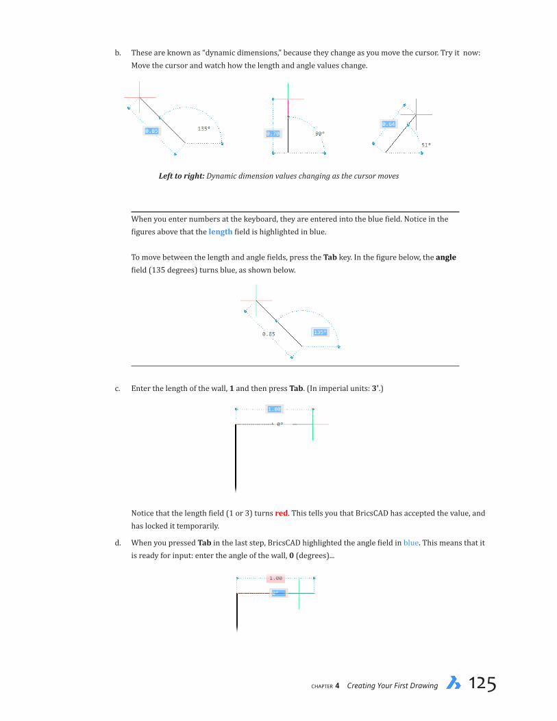
chapter 4 Creating Your First Drawing 125124 Inside BricsCAD V18
b. These are known as “dynamic dimensions,” because they change as you move the cursor. Try it now: Move the cursor and watch how the length and angle values change.
Left to right: Dynamic dimension values changing as the cursor moves
When you enter numbers at the keyboard, they are entered into the blue field. Notice in the figures above that the length field is highlighted in blue. To move between the length and angle fields, press the Tab key. In the figure below, the angle field (135 degrees) turns blue, as shown below.
c. Enter the length of the wall, 1 and then press Tab. (In imperial units: 3'.)
Notice that the length field (1 or 3) turns red. This tells you that BricsCAD has accepted the value, and has locked it temporarily.
d. When you pressed Tab in the last step, BricsCAD highlighted the angle field in blue. This means that it is ready for input: enter the angle of the wall, 0 (degrees)...

chapter 4 Creating Your First Drawing 127126 Inside BricsCAD V18
...and then press Tab again to lock the value. (To change the length and/or angle, press Tab to switch between the two fields.)
e. Accept the length and angle values by pressing Enter.
6. Draw the remainder of the house outline by moving the cursor in the appropriate direction, and then enter-ing the distances:
Cursor Direction Metric Distance Imperial Distance
East 1 3' North 6 20' West 8.5 28' South 16 50'
7. Complete the polyline with the C option, as you did with the Line command.
8.5 (28')
16 (50')
6 (20')
1 (3')
10 (30')C (close)
Start here with INT osnap
When Lot was the working layer, the lines you drew showed up in blue. You changed the layer to House, and so BricsCAD automatically drew the lines in black instead. This shows that lines take on the color specified by their layer. (You can, if you need to, change colors on-the-fly with the Color command.)

chapter 4 Creating Your First Drawing 127126 Inside BricsCAD V18
Moving the House into PositionCommand Move
Ribbon Change | Arrange | Move
Menu Bar Modify | Move
Alias M
Now that you’ve drawn the outline of the house, you need to move it into position. Entities are moved with the Move command.
1. Enter Move the ‘Command:’ prompt:
: move
2. Notice that BricsCAD asks what you want to move:
Select entities to move:
(“Entities” is an older word that means the same as objects.)
At the same time, BricsCAD changes the crosshair cursor into a small square cursor, called the pick cursor.
3. Move the cursor to any part of the house’s polyline, and then press the pick button.
Select entities to move: (Pick the outline of the house)
The entire house outline is highlighted. The highlighting shows as a dotted line, which is how BricsCAD lets you know it found the entity you picked.
Selected polylineis highlighted
Select polyline with pick cursor
4. BricsCAD reports the number of entity selected, and then lets you make additional selections, if need be. The prompt repeats:
Select entities to move: (Press Enter to exit entity selection)
Because you are moving just one polyline, press Enter to end the entity selection process.
5. Just as when drawing lines, the Move command needs to know a from-point and a to-point. But here the from-point is named the “base point,” as follows:
Enter base point [Displacement] <Displacement>: 0,0
(If you were to press Enter at the ‘Enter base point <Displacement>’ prompt, BricsCAD would ask for the displacement vector, which consists of a move in the x,y, and z directions.)

chapter 4 Creating Your First Drawing 129128 Inside BricsCAD V18
6. Now BricsCAD wants to know where you want to move the selected entities:
Enter second point <Use base point as displacement>: -6,3
Base point
X = -6 (-20')Y = -3 (-10')Displacement point
The coordinates -6,3 (in imperial units: -20',10') tell BricsCAD to move the house left by 6m (x direction = –6 meters) and up by 3m (y direction = 3). BricsCAD instantly relocates the house much faster than a house mover. The Move command shows you a powerful aspect of CAD: no eraser dust!
7. It’s a good idea to regularly save your work. Press Ctrl+S, and BricsCAD silently saves the drawing to disk. The only indication is that “: _qsave” appears on the command line.
Alternatively, you can click the diskette icon on the toolbar, enter the QSave command, or select Save from the File menu.
Starting on the Driveway
The final drafting for this project is to add the driveway and the street. Before drawing them, change the layer to Road using the technique described below. Once the layer is set correctly, you will draw the driveway and street outlines using a shortcut. Once the upper roadwork is drawn, you duplicate it with a single command to create the lower roadworks.
1. On the toolbar, status bar, or ribbon, click on the House layer name.
2. When the list box appears, select Road. BricsCAD changes the layer name from House to Road and the work-ing color from black to red. Below, I show the toolbar version of the Layers droplist.

chapter 4 Creating Your First Drawing 129128 Inside BricsCAD V18
3. Ensure that ortho mode is still on by glancing at the status bar. The ORTHO button should be in black text.
4. Start the Line command:
: line
...and then draw the upper driveway and street line using direct distance entry, as follows:
Start of line or [Follow] <Last point>: int
Snap to intersection of: (Pick upper-right corner of house)
Set end point or [Angle/Length/Undo]: 8.5
Set end point or [Angle/Length/Undo]: 12
Set end point or [Angle/Length/Follow/Close/Undo]: (Press Enter to end the command)
From point: INT
8.5 (28')
12 (40')
Recall that you can “back up” to undraw incorrect lines with u (short for “Undo”), as follows:
Set end point or [Angle/Length/Follow/Close/Undo]: 21
Set end point or [Angle/Length/Follow/Close/Undo]: u
Set end point or [Angle/Length/Follow/Close/Undo]: 12
FINISHING THE DRIVEWAYCommand Fillet
Ribbon Change | Modify | Fillet
Menu Bar Modify | Fillet
Alias F
To add the curb return — the arc joining the driveway and street — use BricsCAD’s Fillet com-mand. It draws arcs between intersecting lines. The lines don’t have to physically meet; BricsCAD takes care of extending (or trimming) the lines so that the arc is drawn between them.
You use the Fillet command by specifying the radius of the arc and then applying the fillet.
1. To start the command, enter the Fillet command, or else do as I do: just type f at the ‘ : ’ prompt.
: f
2. Notice that BricsCAD reports the current fillet radius. To change it, enter the hidden r option:
Fillet (radius=0.5): Select first entity or [Settings/Polyline/Radius/Trim/Undo/Multiple]: r
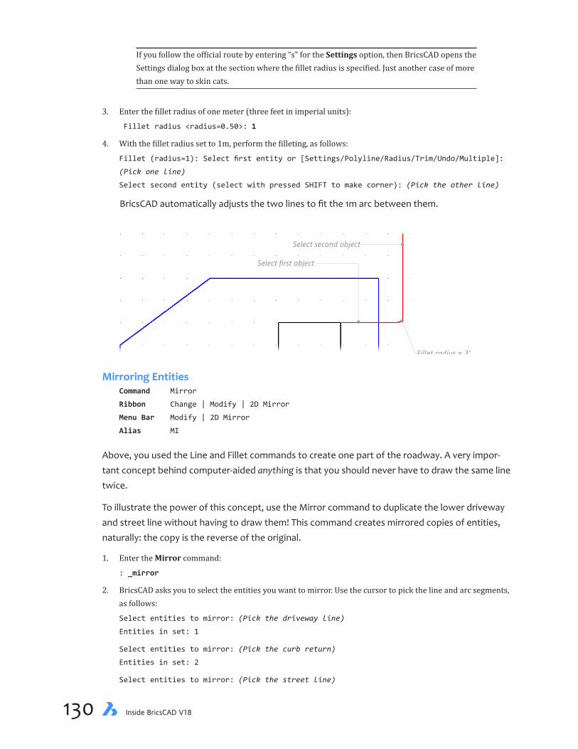
chapter 4 Creating Your First Drawing 131130 Inside BricsCAD V18
If you follow the official route by entering “s” for the Settings option, then BricsCAD opens the Settings dialog box at the section where the fillet radius is specified. Just another case of more than one way to skin cats.
3. Enter the fillet radius of one meter (three feet in imperial units):
Fillet radius <radius=0.50>: 1
4. With the fillet radius set to 1m, perform the filleting, as follows:
Fillet (radius=1): Select first entity or [Settings/Polyline/Radius/Trim/Undo/Multiple]:
(Pick one line)
Select second entity (select with pressed SHIFT to make corner): (Pick the other line)
BricsCAD automatically adjusts the two lines to fit the 1m arc between them.
Select first object
Select second object
Fillet radius = 3'
Mirroring Entities Command Mirror
Ribbon Change | Modify | 2D Mirror
Menu Bar Modify | 2D Mirror
Alias MI
Above, you used the Line and Fillet commands to create one part of the roadway. A very impor-tant concept behind computer-aided anything is that you should never have to draw the same line twice.
To illustrate the power of this concept, use the Mirror command to duplicate the lower driveway and street line without having to draw them! This command creates mirrored copies of entities, naturally: the copy is the reverse of the original.
1. Enter the Mirror command:
: _mirror
2. BricsCAD asks you to select the entities you want to mirror. Use the cursor to pick the line and arc segments, as follows:
Select entities to mirror: (Pick the driveway line)
Entities in set: 1
Select entities to mirror: (Pick the curb return)
Entities in set: 2
Select entities to mirror: (Pick the street line)

chapter 4 Creating Your First Drawing 131130 Inside BricsCAD V18
Entities in set: 3
Select entities to mirror: (Press Enter to end entity selection)
3. BricsCAD needs you to specify the mirror line, an imaginary line about which it mirrors the entities you just picked. Use Midpoint and Perpendicular entity snaps to help you:
Start of mirror line: mid
Snap to midpoint of: (Pick center of garage entrance)
End of mirror line: per
Snap to perpendicular of: (Pick right-hand lot boundary)

chapter 4 Creating Your First Drawing 133132 Inside BricsCAD V18
The length of the mirror line is not important, but its angle is crucial. For this reason, you used two new entity snap modes: mid to find the midpoint of the garage entrance and per to ensure the mirror line is perpendicular to the lot boundary.
4. At this point, BricsCAD gives you the option of erasing the old entities — the two lines and arc you picked. In most cases, as in this case, you don’t want them erased:
Delete the original entities? [Yes-delete entities/No-keep entities] <No-Keep entities>:
n
BricsCAD draws the lower driveway and street outline as a perfect mirror image of the upper set.
You have now drawn the outline of the lot, house, and driveway. The work you have done is valu-able and it is important that you save the drawing to disk. Use the QSave command to store the drawing on disk.
Putting Drawings to PaperCommand Print
Ribbon Home | Print/Plot | Print
Menu Bar File | Print
Shortcut Ctrl+P
While it is efficient (and environmentally aware) to create and store drawings on computers and share them electronically via email or Web sites, you may want to print copies on paper. That lets you mark up the drawing with notes or show off your progress to friends and family!
The Print command sends the drawing to printers, plotters (oversize printers), and files. It is also known as the print command. Traditionally, “plotters” used motors to move the pen over the paper, while “printers” are what we mostly use today – laser printers and inkjet printers.
The following series of dialog boxes assumes you have a printer compatible with Windows or Linux attached to your computer. (The method for printing with Macs is roughly similar, but shows different dialog boxes.)
1. Press Ctrl+P or enter the Print command. Notice that BricsCAD displays the Plot [Model] dialog box.
(Old timers might enter the command as “plot,” but this makes the command’s options appear in the Com-mand bar, instead of in the dialog box.)
2. The dialog box has many options. Fortunately you can ignore most options, except for these:
Printer/Plotter Configuration selects the printer you want to use:
Select a printer from the Name droplist. BricsCAD supports local and networked printers.

chapter 4 Creating Your First Drawing 133132 Inside BricsCAD V18
Drawing orientation: Landscape
Choose a printer
Choose Extents
Choose Fitprint area tosize of page
Plot offset: Center on Page
Click Preview
Plot Area determines which part of the drawing is printed:
Select Extents. This option ensures everything in your drawing is plotted on the paper.
Plot Scale determines how large the drawing is printed on the paper:
Check that Fit Print Area to Size of Page is selected. This ensures the entire drawing will be plotted, and that it won’t be too large or too small.

chapter 4 Creating Your First Drawing 135134 Inside BricsCAD V18
Page Orientation turns the drawing by 90 degrees on the paper:
If the orientation of the paper doesn’t match that of the drawing, then you need to change it. The paper is tall but the drawing is wide. To change the orientation of the paper, select Landscape.
Plot Offset moves the drawing to one side of the paper or the other:
Turn on the Center on Page option to have the drawing nicely centered on the paper.
3. To check that the drawing fits the paper, click the Preview button. The drawing appears simulated on a sheet of paper.
4. If the drawing looks alright to you, then click Print to print the drawing.
(If, however, the preview shows a problem, click Close to exit, and return to the Print dialog box to adjust settings.)
BricsCAD sends the drawing to the printer, and it should appear a few seconds later looking exactly like the preview.
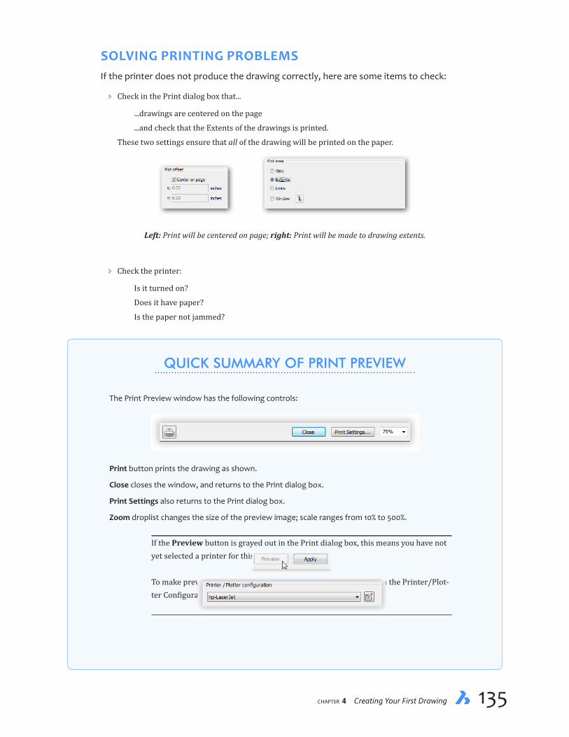
chapter 4 Creating Your First Drawing 135134 Inside BricsCAD V18
SOLVING PRINTING PROBLEMSIf the printer does not produce the drawing correctly, here are some items to check:
Ð Check in the Print dialog box that...
...drawings are centered on the page
...and check that the Extents of the drawings is printed.
These two settings ensure that all of the drawing will be printed on the paper.
Left: Print will be centered on page; right: Print will be made to drawing extents.
Ð Check the printer:
Is it turned on?
Does it have paper?
Is the paper not jammed?
QUICK SUMMARY OF PRINT PREVIEW
The Print Preview window has the following controls:
Print button prints the drawing as shown.
Close closes the window, and returns to the Print dialog box.
Print Settings also returns to the Print dialog box.
Zoom droplist changes the size of the preview image; scale ranges from 10% to 500%.
If the Preview button is grayed out in the Print dialog box, this means you have not yet selected a printer for this drawing. To make preview available, select a printer — any printer! — from the Printer/Plot-ter Configuration droplist:

chapter 4 Creating Your First Drawing 137136 Inside BricsCAD V18
Are the toner or ink cartridges not low”
Are there any warning messages or lights?
Left and right: Warning lights from various printers.
Ð Check that the BricsCAD is printing to the correct printer. The operating system sometimes mistakenly lists names of printers that are not necessarily accessible by the computer.
Ð In some cases, the spooler acts up in Windows. The spooler is software that feeds data to the printer, allowing you to continue working with BricsCAD while the printer works in the background. Sometimes, the spooler plugs up, preventing the printer from receiving the data.
To fix the problem, follow these steps:
1. Click Start, and then Devices and Printers in Windows 7. (In Windows 8.x and 10, click the Start but-ton, and then type “printers.” Choose Devices and Printers.)
2. In the window, click Add a Printer. Install the same printer as the one that is giving you problems.
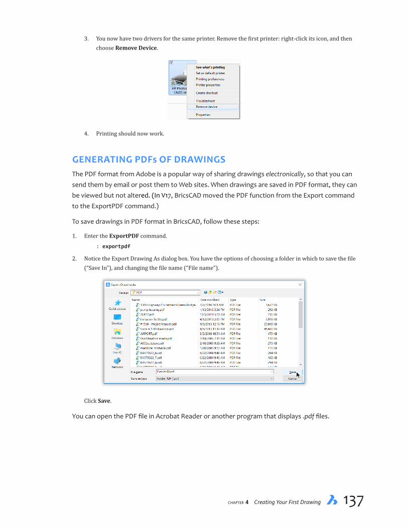
chapter 4 Creating Your First Drawing 137136 Inside BricsCAD V18
3. You now have two drivers for the same printer. Remove the first printer: right-click its icon, and then choose Remove Device.
4. Printing should now work.
GENERATING PDFs OF DRAWINGSThe PDF format from Adobe is a popular way of sharing drawings electronically, so that you can send them by email or post them to Web sites. When drawings are saved in PDF format, they can be viewed but not altered. (In V17, BricsCAD moved the PDF function from the Export command to the ExportPDF command.)
To save drawings in PDF format in BricsCAD, follow these steps:
1. Enter the ExportPDF command.
: exportpdf
2. Notice the Export Drawing As dialog box. You have the options of choosing a folder in which to save the file (“Save In”), and changing the file name (“File name”).
Click Save.
You can open the PDF file in Acrobat Reader or another program that displays .pdf files.

chapter 4 Creating Your First Drawing 139138 Inside BricsCAD V18
SpecifyingPDFOutputOptionsYou control aspects of the PDF files produced by BricsCAD through the Settings dialog box. The quick way to access options specific to PDF files is with the PdfOptions command, which then opens the Settings dialog box at the section for PDF Export options, conveniently enough
Here is an explanation of the settings available, along with the default values in parentheses:
PDF Embed Fonts (on) embeds TTF font files in the PDF file:
Ð PDF TTF Text as Geometry (off) converts text made with TTF fonts into geometry (lines and arcs)
Ð PDF SHX Text as Geometry (off) converts text made with SHX fonts into geometry
PDF Simple Geometry Optimization (on) reduces the file size by combining individual line segments into polylines, and uses Bezier control points to define splines. This option does not affect the drawing, only the resulting PDF file.
PDF Zoom to Extents Mode (on) exports the drawing unscaled, so that its extends fit the page
PDF Merge Control (0) determines the look of overlapping lines:
Ð 0 Overwrite; the topmost line obscures lines underneath it
Ð 1 Merge; overlapping lines are semi-transparent
PDF Layer Support (1) determines whether layers are included:
Ð 0 Exclude layers; export entities with no layer information (this is a form of security)
Ð 1 Export layers, except those turned off (default setting)
Ð 2 Export all layers, including those turned off
PDF Layouts to Export (1) specifies which layouts should be included in the PDF file:
Ð 0 Only the current “active” layout; this is like plotting a single layout (default setting)
Ð 1 All layouts; the PDF file becomes a multi-page PDF, with each layout on its own page
PDF Papersize Override — determines whether the PDF page should be of a custom size:
Ð PDF Overridden Paper Width (210) specifies the width of the PDF page in millimeters
Ð PDF Overridden Paper Height (297) specifies the height in millimeters
PDF Use Plotstyles (on) determines whether the drawing is exported to PDF format using named plot styles; named plot styles must exist in the drawing

chapter 4 Creating Your First Drawing 139138 Inside BricsCAD V18
Image Anti-Aliasing (on) applies anti-aliasing (smoothing) to images requiring upscaling for export to PDF format
Image Compression (JPEG) specifies whether to compress raster images in drawings; 0 = off.
Vector Resolution (2400) specifies the resolution of vector graphics.
(new to V18) PRC Export Mode (0) determines if a 3D model is exported as a BREP (boundary representa-tion), mesh, or not at all.
(new to V18) PRC Single-View Mode (1) determines whether the 3D model is exported as a single view.
(new to V18) PRC Compression (0) specifies whether the PRC file is exported with medium, high, or no compression.
———
Congratulations! You’ve drafted your very first drawing using a computer. You can save the draw-ing as a memento of your introduction to computer-aided drafting.
In the next lesson, you learn how to add details to drawings, such as hatching and symbols (blocks).

chapter 4 Creating Your First Drawing PB140 Inside BricsCAD V18
Notes

CHAPTER 5
Adding Details to Drawings
Sofar,you’velearnedhowtodrawlinesthatrepresenttheoutlinesofthelot,house,anddriveway. Now it’s time to add details, like the lawn, some trees, and a pond.
In this chapter, you learn to use BricsCAD’s intermediate commands, such as those that create ellipses, place hatch patterns, makes arrays, and draw offsets.
IN THIS CHAPTER
• Drawing circles and ellipses
• Editing with grips
• Applying hatch patterns to areas
• Arraying entities
• Making parallel offsets of entities
• Creating symbols (blocks)
• Performing real-time zooming and panning
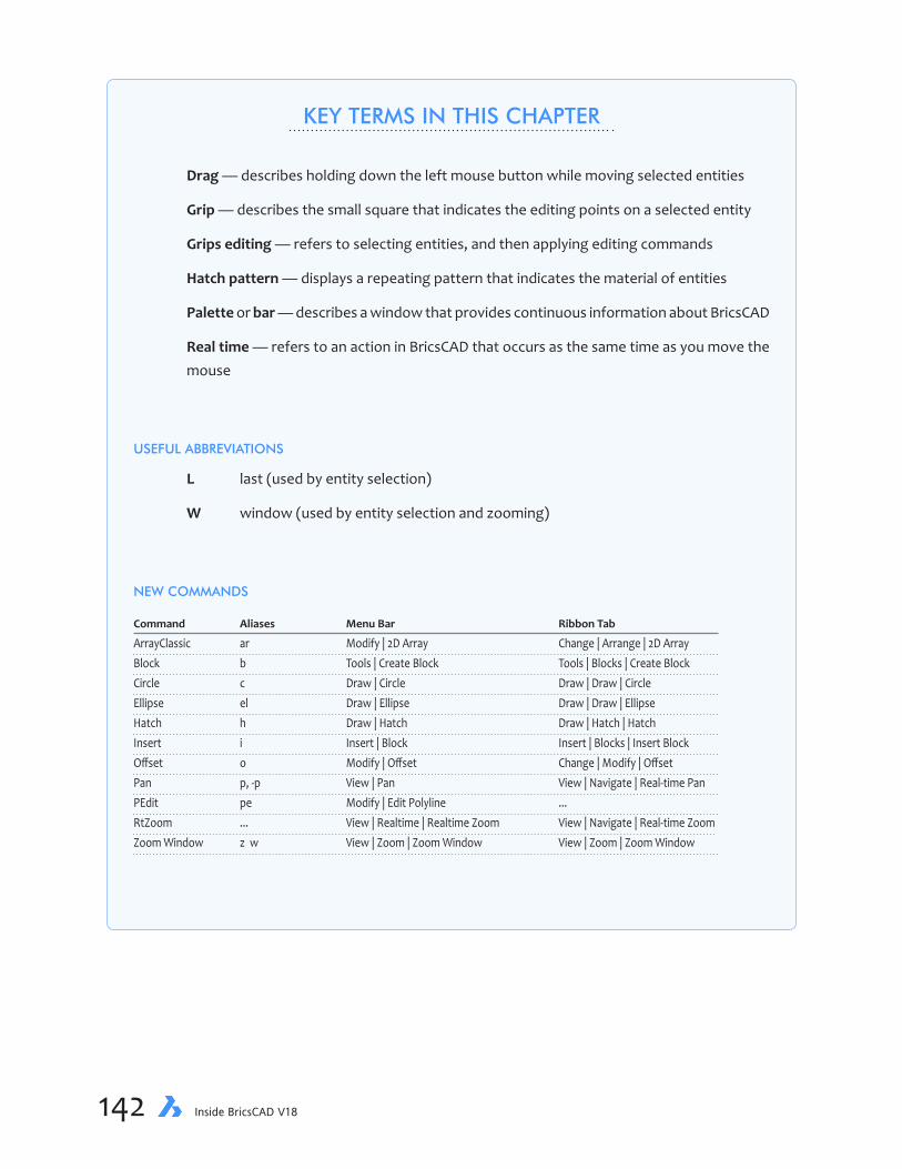
chapter 6 Adding Details to Drawings 143142 Inside BricsCAD V18
KEY TERMS IN THIS CHAPTER
Drag — describes holding down the left mouse button while moving selected entities
Grip — describes the small square that indicates the editing points on a selected entity
Grips editing — refers to selecting entities, and then applying editing commands
Hatch pattern — displays a repeating pattern that indicates the material of entities
Palette or bar — describes a window that provides continuous information about BricsCAD
Real time — refers to an action in BricsCAD that occurs as the same time as you move the mouse
USEFUL ABBREVIATIONS
L last (used by entity selection)
W window (used by entity selection and zooming)
NEW COMMANDS
Command Aliases Menu Bar Ribbon Tab
ArrayClassic ar Modify | 2D Array Change | Arrange | 2D Array Block b Tools | Create Block Tools | Blocks | Create Block Circle c Draw | Circle Draw | Draw | Circle Ellipse el Draw | Ellipse Draw | Draw | Ellipse Hatch h Draw | Hatch Draw | Hatch | Hatch Insert i Insert | Block Insert | Blocks | Insert Block Offset o Modify | Offset Change | Modify | Offset Pan p, -p View | Pan View | Navigate | Real-time Pan PEdit pe Modify | Edit Polyline ... RtZoom ... View | Realtime | Realtime Zoom View | Navigate | Real-time ZoomZoom Window z w View | Zoom | Zoom Window View | Zoom | Zoom Window

chapter 6 Adding Details to Drawings 143142 Inside BricsCAD V18
Dividing the Lot
The back of the yard has lawn and garden areas. For this tutorial, you draw the boundary between the two areas with a polyline using the PLine command, and then smooth it with the PEdit (poly-line edit) command.
If BricsCAD is not running, start it now. If you did not complete the previous lesson, open the tuto-rial-04.dwg file. (If you’re doing the tutorials in imperial units, open Imp-tutorial-04.dwg.) You can download them from my public Dropbox folder at https://www.dropbox.com/s/ft6gzw3r408ndgd/Inside-BricsCAD-Tutorial-Files.zip?dl=0.
Before starting to draw, though, take these steps:
1. You won’t be drawing at right angles, so turn off ortho mode by clicking the ORTHO button on the status bar. It should look gray to indicate it is turned off.
2. Change the working layer to Lawn; its color should be cyan (light blue). There are several different ways to do this:
Ð In the toolbar or ribbon interfaces, choose “Lawn” from the Layers droplist (as shown below).
THIS CHAPTER’S DRAWING
By the end of this lesson, your drawing should look similar to this one:
Tutorial-05 drawing file

chapter 6 Adding Details to Drawings 145144 Inside BricsCAD V18
Ð Or, from the Properties panel, choose “Lawn” from the Layers droplist
Ð Or in the status bar, right-click the current layer field...
... and then choose “Lawn” from the list
If the Current Layer button is not visible on the status bar, then you can add the button like this: 1. Click the black arrow at the end of the status bar 2. From the shortcut menu, choose Current Layer.
Ð Or at the command prompt, you can enter the CLayer system variable. (Clayer is short for “current layer,” and is a quick way to change layers at the keyboard. In fact, this is the same variable used by the Current Layer field in the status bar.)
: clayer
New current value for CLAYER <"0">: lawn
Now the drawing is ready for you to draw the lawn-garden boundary.

chapter 6 Adding Details to Drawings 145144 Inside BricsCAD V18
3. To draw the polyline, start the PLine command.
: pline
4. To determine the polyline’s starting point, you use an entity snap mode. But this time, you will access entity snap modes differently than in last chapter’s method:
a. Hold down the Shift key on the keyboard.
b. Press the right mouse button, and then let go of the Shift key. Notice the new menu that pops up on the screen. This is called a “shortcut menu.” The menu lists all of BricsCAD’s entity snap modes.
c. Move the cursor down to Snap to Midpoint, and then click. On the command line, notice that BricsCAD reports that MIDpoint esnap is activated:
Start of polyline: _midpoint
5. Move the cursor to any point on the diagonal portion of the lot line, and then select the line.
Snap to midpoint of: (Pick diagonal lot line)
Polyline snaps to themidpoint of the segment
The MIDpoint esnap forces to BricsCAD snap to the precise midpoint of the lot’s diagonal line.
6. Moving your way down toward the bottom of the yard line, pick a few more points at roughly 3m to 6m intervals. (In imperial units: 10' to 20' intervals.)
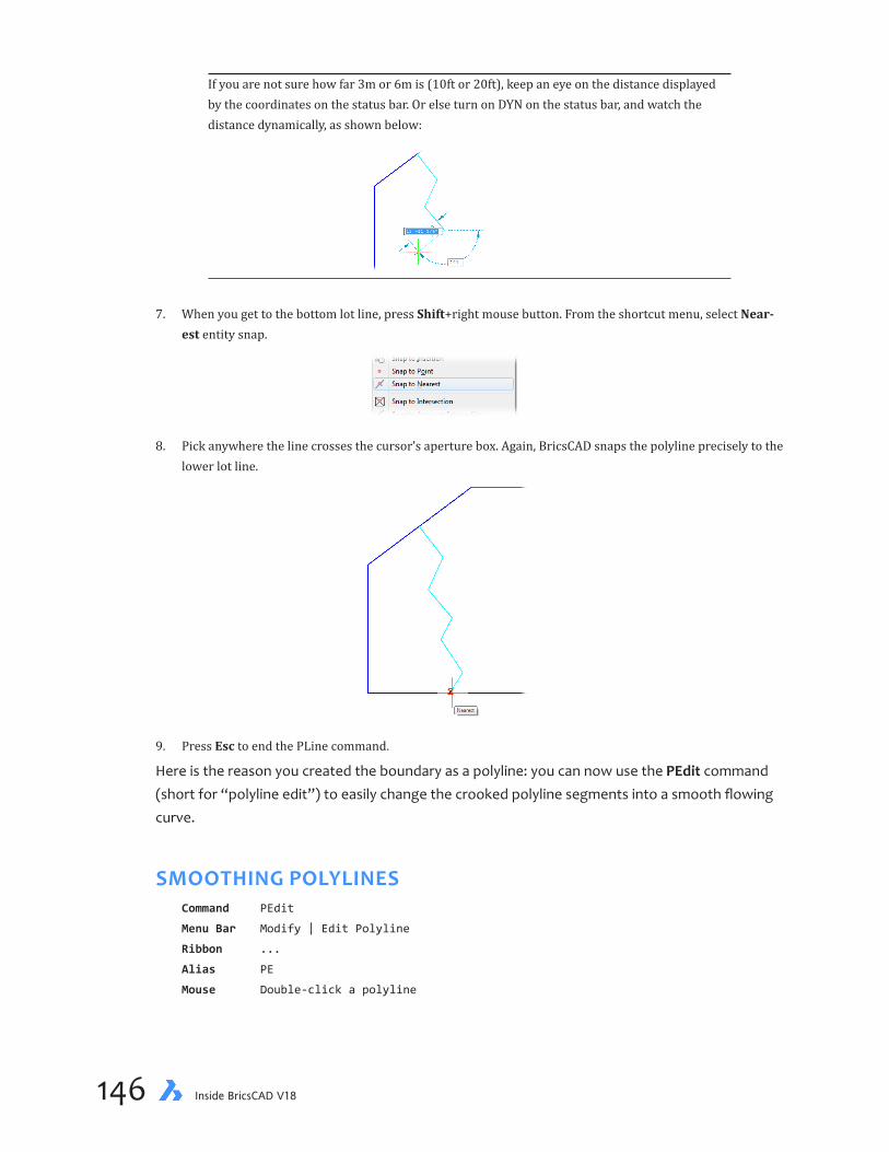
chapter 6 Adding Details to Drawings 147146 Inside BricsCAD V18
If you are not sure how far 3m or 6m is (10ft or 20ft), keep an eye on the distance displayed by the coordinates on the status bar. Or else turn on DYN on the status bar, and watch the distance dynamically, as shown below:
7. When you get to the bottom lot line, press Shift+right mouse button. From the shortcut menu, select Near-est entity snap.
8. Pick anywhere the line crosses the cursor’s aperture box. Again, BricsCAD snaps the polyline precisely to the lower lot line.
9. Press Esc to end the PLine command.
Here is the reason you created the boundary as a polyline: you can now use the PEdit command (short for “polyline edit”) to easily change the crooked polyline segments into a smooth flowing curve.
SMOOTHING POLYLINESCommand PEdit
Menu Bar Modify | Edit Polyline
Ribbon ...
Alias PE
Mouse Double-click a polyline

chapter 6 Adding Details to Drawings 147146 Inside BricsCAD V18
The PEdit command’s purpose is to change the look of polylines. It has many, many options; don’t worry, you’ll use just one of them.
1. To edit the polyline, begin the PEdit command:
: pedit
2. Pick the polyline.
Select polyline to edit [Multiple]: (Pick the polyline, or type L to choose the last-drawn entity)
Original polyline(“frame”)
Splined polyline(cubic Bezier curve)
3. Use the Spline option to smooth the straight lines into a flowing curve, as follows:
Edit polyline [Edit vertices/Close/Decurve/Fit/Join/Linetype mode/Reverse direction/
Spline/Taper/Width/Undo] <eXit>: s
The straight lines disappear and are replaced by a smooth curve. (Technically, BricsCAD redrew the line seg-ments as a cubic Bezier curve based on the polyline frame.)
4. Exit the PEdit command by pressing Enter:
Edit polyline [Edit vertices/Close/Decurve/Fit/Join/Linetype mode/Reverse direction/
Spline/Taper/Width/Undo] <eXit>: (Enter Enter)
Grips Editing
To edit the polyline, you started the PEdit command, then selected the polyline to edit. BricsCAD can do this in reverse: select an entity, and then edit it.
There are two ways to do this. One is called “grips editing,” the other is double-click editing.
Grips editing is a faster and more direct way to edit entities in CAD drawings, sometimes. I say “sometimes,” because not all editing commands lend themselves to it. In this case, however, it does.
Here you use grips editing to change the shape of the splined polyline separating the garden from the lawn.
If you cannot see the entity you want to edit, hold down the roller button on the mouse and then move it to pan the drawing. Alternatively, use the Pan command or a scroll bar to move the entity into view.
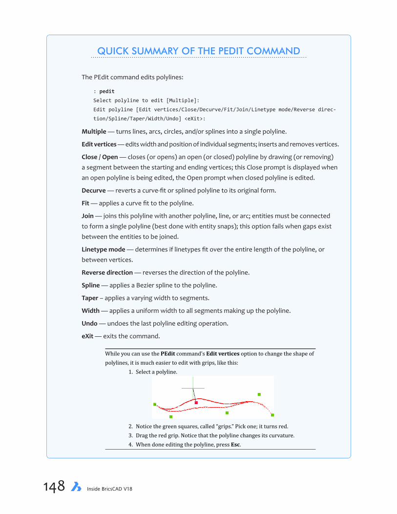
chapter 6 Adding Details to Drawings 149148 Inside BricsCAD V18
QUICK SUMMARY OF THE PEDIT COMMAND
The PEdit command edits polylines:
: pedit
Select polyline to edit [Multiple]:
Edit polyline [Edit vertices/Close/Decurve/Fit/Join/Linetype mode/Reverse direc-
tion/Spline/Taper/Width/Undo] <eXit>:
Multiple — turns lines, arcs, circles, and/or splines into a single polyline.
Edit vertices — edits width and position of individual segments; inserts and removes vertices.
Close/Open — closes (or opens) an open (or closed) polyline by drawing (or removing) a segment between the starting and ending vertices; this Close prompt is displayed when an open polyline is being edited, the Open prompt when closed polyline is edited.
Decurve — reverts a curve-fit or splined polyline to its original form.
Fit — applies a curve fit to the polyline.
Join — joins this polyline with another polyline, line, or arc; entities must be connected to form a single polyline (best done with entity snaps); this option fails when gaps exist between the entities to be joined.
Linetype mode — determines if linetypes fit over the entire length of the polyline, or between vertices.
Reverse direction — reverses the direction of the polyline.
Spline — applies a Bezier spline to the polyline.
Taper – applies a varying width to segments.
Width — applies a uniform width to all segments making up the polyline.
Undo — undoes the last polyline editing operation.
eXit — exits the command.
While you can use the PEdit command’s Edit vertices option to change the shape of polylines, it is much easier to edit with grips, like this: 1. Select a polyline. 2. Notice the green squares, called “grips.” Pick one; it turns red. 3. Drag the red grip. Notice that the polyline changes its curvature. 4. When done editing the polyline, press Esc.
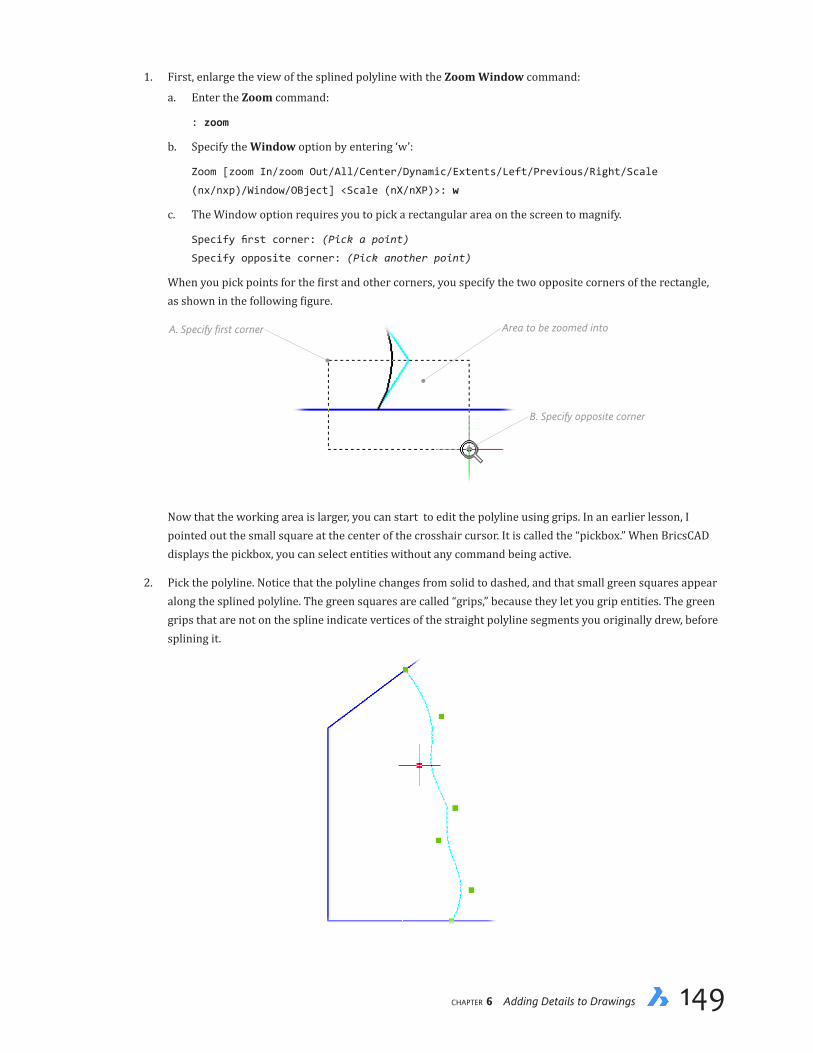
chapter 6 Adding Details to Drawings 149148 Inside BricsCAD V18
1. First, enlarge the view of the splined polyline with the Zoom Window command:
a. Enter the Zoom command:
: zoom
b. Specify the Window option by entering ‘w’:
Zoom [zoom In/zoom Out/All/Center/Dynamic/Extents/Left/Previous/Right/Scale
(nx/nxp)/Window/OBject] <Scale (nX/nXP)>: w
c. The Window option requires you to pick a rectangular area on the screen to magnify.
Specify first corner: (Pick a point)
Specify opposite corner: (Pick another point)
When you pick points for the first and other corners, you specify the two opposite corners of the rectangle, as shown in the following figure.
B. Specify opposite corner
A. Specify first corner Area to be zoomed into
Now that the working area is larger, you can start to edit the polyline using grips. In an earlier lesson, I pointed out the small square at the center of the crosshair cursor. It is called the “pickbox.” When BricsCAD displays the pickbox, you can select entities without any command being active.
2. Pick the polyline. Notice that the polyline changes from solid to dashed, and that small green squares appear along the splined polyline. The green squares are called “grips,” because they let you grip entities. The green grips that are not on the spline indicate vertices of the straight polyline segments you originally drew, before splining it.

chapter 6 Adding Details to Drawings 151150 Inside BricsCAD V18
QUICK SUMMARY OF EDITING WITH GRIPS
Grips editing is interactive: you select an entity (green grips appear), select one of the grips (grip turns red), and then manipulate the red grip to modify the entity.
Unselected object Select object;notice green grips
Select a grip;notice it turns red
Most grips look the same (squares), and so it can be hard to determine their function — until you start to drag one of them. Typically, an interior grip moves an entity, while grips on the periphery stretch or scale the entity.
Periphery gripsstretch (or scale)
objects
Center gripsmove objects
Some entities sport triangular entities, such as polylines: this grip moves the segment.
(new to V18) When DYN is turned on, then dynamic dimensions appear during grips editing:
...continued

chapter 6 Adding Details to Drawings 151150 Inside BricsCAD V18
...continued
GRIPS EDITING COMMANDS
During grips editing, BricsCAD makes available these editing commands: Stretch, Move, Rotate, Scale, Mirror, and Copy. (The six operate identically to their non-grips equiva-lents.) To see the commands, you need to right-click for a shortcut menu, or eles press the Spacebar repeatedly.
Each time you press the Spacebar, BricsCAD displays another set of prompts:
** STRETCH **
<Stretch to point>/Base point/Copy/Undo/eXit:
** MOVE **
<Move to point>/Base point/Copy/Undo/eXit:
** ROTATE **
<Rotation angle>/Base point/Copy/Undo/Reference/eXit:
** SCALE **
<Scale factor>/Base point/Copy/Undo/Reference/eXit:
** MIRROR **
<Second point>/Base point/Copy/Undo/eXit:
After ** MIRROR **, BricsCAD repeats the cycle. The other editing options are:
Base point — specifies a base point other than the hot grip.
Copy — copies the entity, using the current grip as the base point.
Reference — changes the reference point from the current hot grip.
Undo — undoes the last editing operation.
eXit — exits non-modal editing mode (or press ESC).

chapter 6 Adding Details to Drawings 153152 Inside BricsCAD V18
3. Pick the green grip at the very bottom end of the polyline. BricsCAD prompts:
New location for control point: nea
Hot grip Drag grip to relocate end point
4. Enter the NEAr entity snap mode, and then move the cursor. As you do, the last segment of the polyline curves and arcs to follow you. (The NEAr entity snap ensures the polyline ends precisely at the lot line.)
5. Click along the lot line where you want the end of the polyline to move to. If you wish, feel free to interac-tively reshape the rest of the polyline, segment by segment.
6. When you are finished reshaping the polyline, press Esc twice to exit grips editing.
7. Enter the Zoom Previous command to see the entire drawing again.
When you move the cursor over a polyline, the Tips widget appears. It gives you the option to edit the entire polyline or just the segment over which the cursor is currently hovering — using grips editing. Press the Ctrl key to switch the editing type.
Of all 2D entities, the polyline is the only one for which the Tips widget appears.
Editing by Double-clickingBricsCAD lets you edit entities by double-clicking them. This is a very fast way to do it, because you don’t need to enter a command — or even remember the correct command name!
The table below lists the entities that react to double-clicking with a specific command. For all other entities, BricsCAD opens the Properties panel when you double-click them. You can use the Customize command to change how double-clicking works with entities. See Customizing Brics-CAD.

chapter 6 Adding Details to Drawings 153152 Inside BricsCAD V18
Entity Command Executed Notes by Double-clicking
Array ArrayEdit Edits associative arrays Attribute Definition DdEdit Attribute Block EAttEdit Block RefEdit Dimension DdEdit Edits text of dimensions Hatch HatchEdit Image ImageAdjust Adjusts brightness, contrast, fadePolyline PEdit Multileader DdEdit Edits text of mleaders Section ClipDisplay Adjusts clipping planes Spline SplinEdit Text DdEdit XRef RefEdit
HATCHING THE LAWN Command Hatch
Ribbon Draw | Hatch | Hatch
Menu Bar Draw | Hatch
Alias H, BH, BHATCH
You created the boundary between the lawn and garden, but how do you show the difference between them? One way is to add a repeating pattern that identifies areas; the repeating pattern is called hatching or a hatch pattern. It is a shorthand used by drafters to indicate the materials, just like linetype identify the purpose of lines.
In BricsCAD, hatching is done with the Hatch command. In this tutorial you hatch the lawn with the drafting symbol for grass.
1. First, turn off the grid, since its lines can interfere with seeing the hatch pattern. On the status bar, click GRID so that the word turns gray.
2. Enter the Hatch command to start the Hatch command:
: hatch
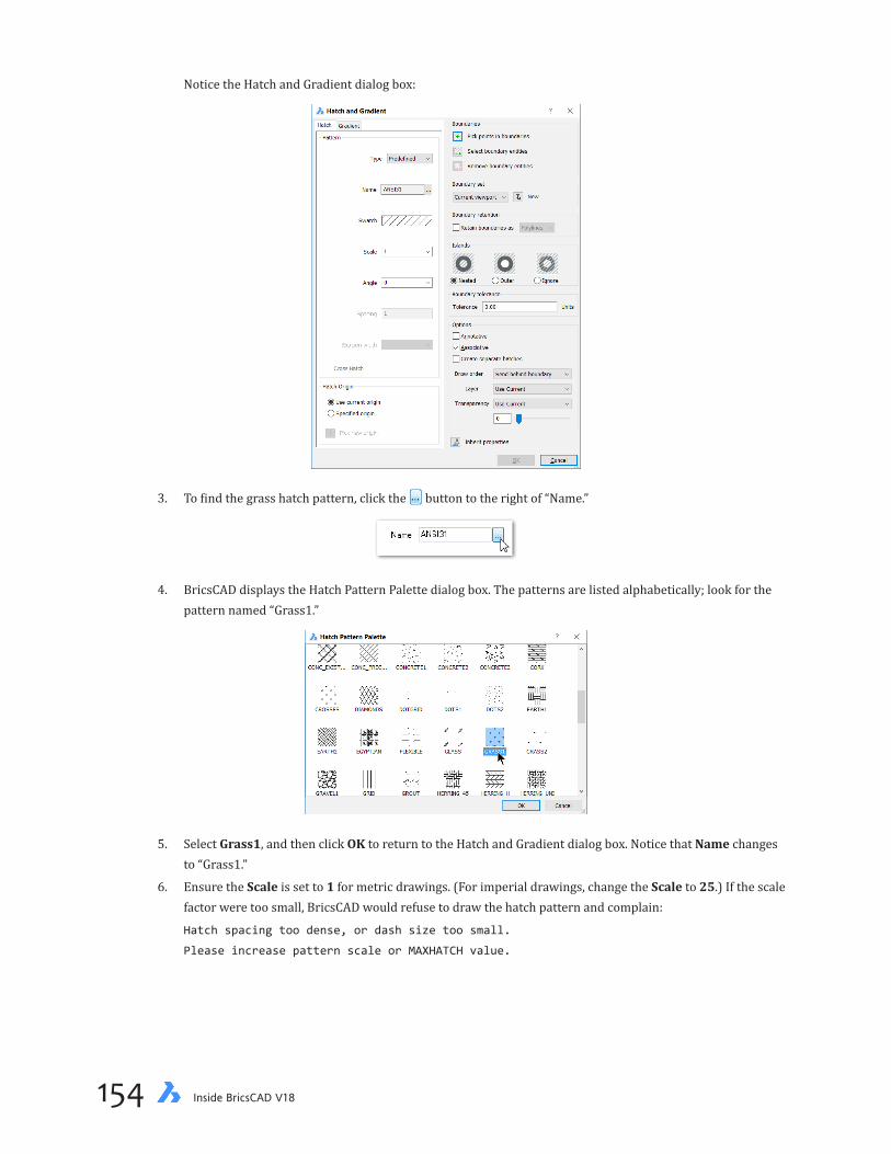
chapter 6 Adding Details to Drawings 155154 Inside BricsCAD V18
Notice the Hatch and Gradient dialog box:
3. To find the grass hatch pattern, click the button to the right of “Name.”
4. BricsCAD displays the Hatch Pattern Palette dialog box. The patterns are listed alphabetically; look for the pattern named “Grass1.”
5. Select Grass1, and then click OK to return to the Hatch and Gradient dialog box. Notice that Name changes to “Grass1.”
6. Ensure the Scale is set to 1 for metric drawings. (For imperial drawings, change the Scale to 25.) If the scale factor were too small, BricsCAD would refuse to draw the hatch pattern and complain:
Hatch spacing too dense, or dash size too small.
Please increase pattern scale or MAXHATCH value.

chapter 6 Adding Details to Drawings 155154 Inside BricsCAD V18
7. BricsCAD has a useful feature that searches a contiguous area, no matter how many different borders the area has. To employ this feature, click the Pick points in Boundaries button.
8. The dialog box disappears and BricsCAD prompts you to pick a point. Do so anywhere in the lawn area.
Select a point to define a boundary or hatch area: (Pick a point inside the lawn area)
Notice that BricsCAD immediately previews the hatch pattern for you. It shows that the scale factor is good enough. Note how precisely the hatch pattern is applied, and how it is automatically clipped along boundaries. Try doing a hatch pattern that neatly and that quickly by hand!
The hatch preview lets you check for two important things, and so gives you a change to correct errors:
Ð A pattern that floods incorrect areas — look out for patterns that leak into unwanted areas, or don’t ap-pear at all
Ð A pattern that is applied at the wrong scale factor — lLook for one that are too large or too tightly spaced
Hatch leaked intoadjacent area
Pattern scaletoo small
Boundaries

chapter 6 Adding Details to Drawings 157156 Inside BricsCAD V18
When the scale is much too large, the hatch may seem invisible. When too small, the hatch pattern looks like a solid and can take a very time to display. There is also a -Hatch command that operates at the command line. It is meant for use by macros and programming routines.
9. Press Enter to return to the Hatch and Gradient dialog box:
Select a point to define a boundary or hatch area: (Press Enter)
10. After you press Enter, the Hatch and Gradient dialog box reappears. Click OK to exit it. Notice that the hatch-ing is applied in the color of the layer.
With all this hard work on your drawing, it’s a good idea to save the drawing to the computer’s hard disk with the Save command... right now!
Once hatch patterns are in place, they are not cast in stone. You can change them in several ways:
Ð You can move entities that make up the boundary of the pattern, and the hatching automatically updates itself.
Ð You can move, copy and erase the hatch pattern, as it acts like a block; it does not need to stay in one place.
Ð You can click the hatch entity to bring up the Properties palette, as illustrated below. You can use it to change the color, pattern, scale factor, rotation angle, and so on.
Ð You can double-click the hatch pattern to bring up the Hatch Edit dialog box. It looks identical to the Hatch and Gradient dialog box, except that it displays all the settings of the current hatch pattern.

chapter 6 Adding Details to Drawings 157156 Inside BricsCAD V18
CreatingSymbols(Blocks)
You’ve given the lawn area its grass. Now it’s time to add trees and shrubs to the garden area. Instead of drawing complex things like trees, landscape architects typically draw simple represen-tations of them, such as a circle with radiating lines.
And instead of drawing lines and circles over and over again, designers draw just one set, and then repeatedly makes copies of them. While you could use the Copy command, the most effi-cient method is to use the Block and Insert commands. Block creates a stencil-like object of which you place multiple copies with the Insert command.
DRAWING CIRCLESCommand Circle
Ribbon Draw | Draw | Circle
Menu Bar Draw | Circle
Alias C
In this tutorial, you learn how to draw trees as simplified symbols, and then turn them into blocks.
1. Before starting to draw first tree, make sure the working layer is set to Plants. From a Layer droplist, select layer “Plants.”
2. Next, draw a 0.15-meter radius circle. Enter the Circle command, and then specify a radius of 0.15 units (in imperial units, 6"):
: circle
Select center of circle or [2Point/3Point/TTR/Arc/Multiple]: (Pick a point anywhere in
garden area.)
Set Radius or [Diameter]: 0.15
When the radius is 0.15, the diameter is 0.3, so don’t be surprised when BricsCAD draws the circle larger than you expect. (Recall that the radius is half the diameter.)
Zooming in Real TimeCommand RtZoom
Shortcut scroll the mouse wheel
Ribbon View | Navigate | Real-time Zoom
Menu Bar View | Realtime | Realtime Zoom
Command Regen
Menu Bar View | Regen
The program lets you zoom in and out without needing to specify a zoom size or ratio. This is done with the mouse and the RtZoom command:
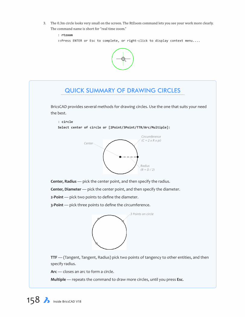
chapter 6 Adding Details to Drawings 159158 Inside BricsCAD V18
3. The 0.3m circle looks very small on the screen. The RtZoom command lets you see your work more clearly. The command name is short for “real time zoom.”
: rtzoom
>>Press ENTER or Esc to complete, or right-click to display context menu....
QUICK SUMMARY OF DRAWING CIRCLES
BricsCAD provides several methods for drawing circles. Use the one that suits your need the best.
: circle
Select center of circle or [2Point/3Point/TTR/Arc/Multiple]:
Center
Circumference(C = 2 x R x pi)
Radius(R = D / 2)
Center, Radius — pick the center point, and then specify the radius.
Center, Diameter — pick the center point, and then specify the diameter.
2-Point — pick two points to define the diameter.
3-Point — pick three points to define the circumference.
3 Points on circle
TTF — (Tangent, Tangent, Radius) pick two points of tangency to other entities, and then specify radius.
Arc — closes an arc to form a circle.
Multiple — repeats the command to draw more circles, until you press Esc.

chapter 6 Adding Details to Drawings 159158 Inside BricsCAD V18
a. The cursor changes to a magnifying glass. Drag the cursor over the circle.
b. As you move the mouse forward and backward, BricsCAD dynamically increases and decreases the zoom. (As an alternative, if you have a mouse with a wheel, roll the wheel forward to zoom in.)
To drag means to (a) hold down the left mouse button, (b) move the mouse, and then (c) let go of the mouse button.
4. If you find the tree going off the edge of the screen, right-click the drawing, and then choose Realtime Pan from the shortcut menu. This pans (shifts) the drawing in real time: as you drag the cursor, the tree-circle is moved back to the center of the drawing area.
5. When the tree-circle is at a satisfactory size, press Esc to get out of real-time pan-and-zoom mode:
>>Press ENTER or Esc to complete, or right-click to display context menu....(Press ESC.)
If the circle looks like an octagon or diamond, select View | Regen to clean it up, as follows:
: _regen
Now that the circle looks rounder and larger, it is easier to work with.
CREATING ARRAYSCommand ArrayClassic
Ribbon Change | Arrange | 2D Array
Menu Bar Modify | 2D Array
Alias AR
With the circle in place representing the trunk, the tree branches can be added by an array of lines.
To create the array, use the ArrayClassic command to create the radiating lines. This command creates several types of arrays: linear, rectangular, and polar (circular). They are illustrated below.
Left to right: Linear, rectangular, and polar arrays.
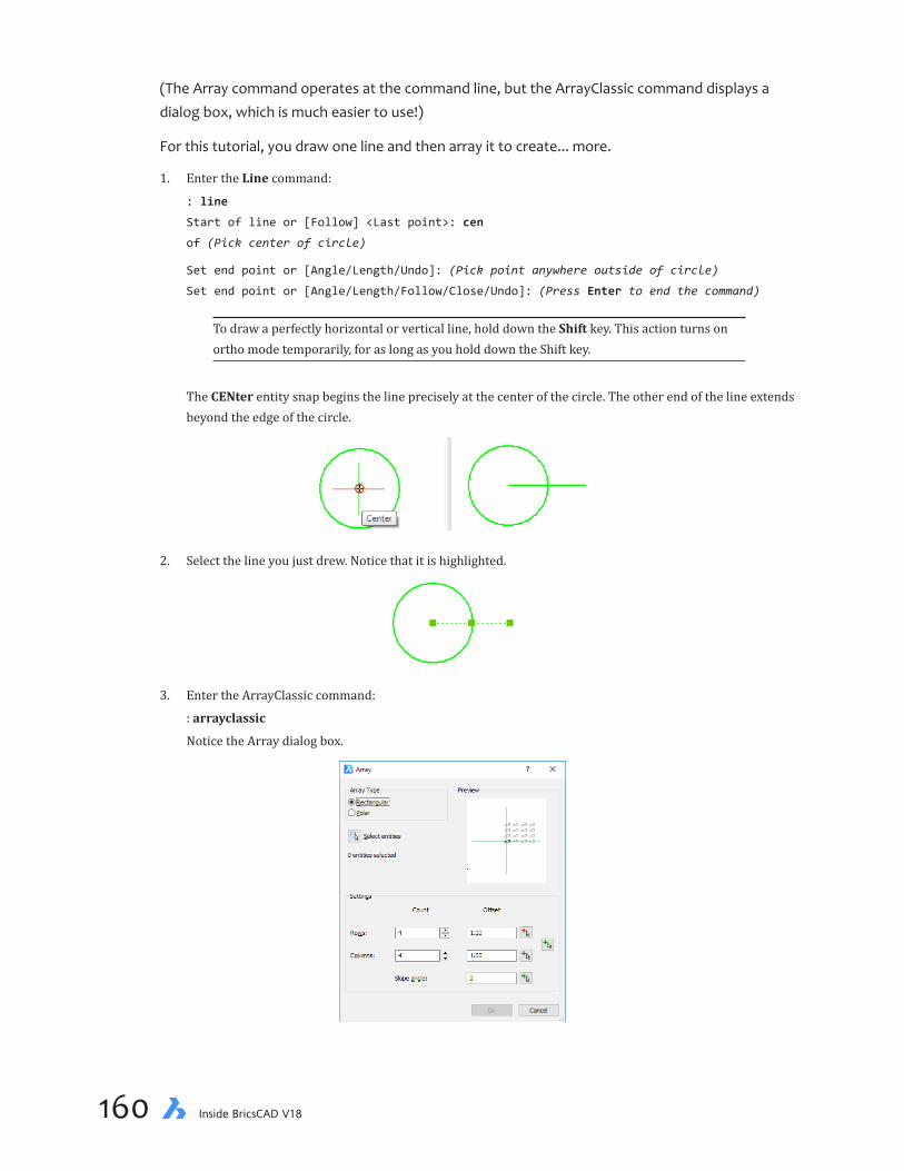
chapter 6 Adding Details to Drawings 161160 Inside BricsCAD V18
(The Array command operates at the command line, but the ArrayClassic command displays a dialog box, which is much easier to use!)
For this tutorial, you draw one line and then array it to create... more.
1. Enter the Line command:
: line
Start of line or [Follow] <Last point>: cen
of (Pick center of circle)
Set end point or [Angle/Length/Undo]: (Pick point anywhere outside of circle)
Set end point or [Angle/Length/Follow/Close/Undo]: (Press Enter to end the command)
To draw a perfectly horizontal or vertical line, hold down the Shift key. This action turns on ortho mode temporarily, for as long as you hold down the Shift key.
The CENter entity snap begins the line precisely at the center of the circle. The other end of the line extends beyond the edge of the circle.
2. Select the line you just drew. Notice that it is highlighted.
3. Enter the ArrayClassic command:
: arrayclassic
Notice the Array dialog box.

chapter 6 Adding Details to Drawings 161160 Inside BricsCAD V18
4. Entering array parameters in this dialog box is like filling out a form:
Array Parameter Value
Array Type Polar Select Entities Click Select Entities, and then choose the line Center Click Pick Center Point, and then choose the center of the circle like this:
Base/Center of polar array: cen
Snap to center of: (Choose the circle)
Number of items 15 Rotate items as copied Yes
5. Ignore the other settings (leave them at their default values); see figure above. Click OK.
Later in this chapter, you turn this symbol into a block. But first, a detour to interactive arrays.

chapter 6 Adding Details to Drawings 163162 Inside BricsCAD V18
Making BlocksCommand Block
Ribbon Insert | Blocks | Create Block
Menu Bar Tools | Create Block
Alias B
CAD draws symbols more quickly and accurately than you can by hand. The key is to turn symbols into blocks, and then insert the blocks into drawings. In this section, you do this by adding tree blocks to the garden area.
1. To turn the tree symbol into a block, use the Block command:
: block
Notice that BricsCAD displays the Block Definition dialog box.
2. Enter the following parameters:
Block Option Value Notes
Name Tree You can give the block any name you like, up to 255 characters longBase point Click Pick Point button, and then choose the center of the circle Entities Click Select Entities, and then choose all 16 Convert to block On Converts the entities to a block when you click OK Scale uniformly On Forces the circle to remain round
a. The base point is used later by the Insert command; this point is also called the “insertion point” — the point where the block is inserted in the drawing. The center of the tree symbol is a logical spot base point, so use CENter entity snap:
Insertion point for new block: cen
Snap to centerpoint of: (Pick the circle)
b. You need to tell BricsCAD which entities to turn into a block. BricsCAD lets you select entities by several different ways. So far, you have picked them one at a time with your mouse or with the L (last) option.
Just as you windowed the zoomed-in view, you can window the entities you want to select with the W option (short for “Window”).
Select entities for block: w
c. You pick the two corners of a rectangle that encompasses the circle and lines making up the tree symbol:
First corner of crossing window: (Pick point 1, shown in figure below)

chapter 6 Adding Details to Drawings 163162 Inside BricsCAD V18
Opposite Corner: (Pick point 2, shown in figure)
Entities in set: 30
Select entities for block: (Press Enter to end entity selection)
#1: First corner ofcrossing window
Base point
#2: Opposite corner
3. Click OK. BricsCAD records the tree symbol as a block in the drawing file. In the next section, you place many trees as blocks.
4. Use the Zoom Extents command to see the entire yard.
ADDINGMANYMORETREES(INSERT)Command Insert
Ribbon Insert | Blocks | Insert Block
Menu Bar Insert | Block
Alias I
With the bigger view in place, insert tree blocks in the drawing.
1. Start the Insert command:
: insert
Notice that BricsCAD displays the Insert dialog box.
2. The Tree block name should be shown in the Name field.
You can ignore most of the dialog box, other than to ensure that the options are set as follows:
Insert Options Value
Insertion Point SpecifyOn-screen (on) Scale SpecifyOn-screen (on) Rotation SpecifyOn-screen (off)
Angle: 0

chapter 6 Adding Details to Drawings 165164 Inside BricsCAD V18
3. Click OK. BricsCAD now prompts you in the command bar, because of the Specify On-Screen options that were turned on in the dialog box.
The first item of business is to pick a spot for the block, a suitable spot in the garden area.
Insertion point for block: (Pick a point anywhere in the garden area)
4. The other item is the scale, which draws the block larger or smaller than the symbol original size:
Corner/XYZ/X scale factor <1.000000>: 2
The x scale factor of 2 draws the block twice as large as the original. Because you drew the original symbol one meter in diameter, the newly inserted tree has a diameter of two meters. If you had entered a scale fac-tor smaller than 1, such as 0.5, then the block would have been drawn half-size.
From this exercise, you can see that it makes sense to draw a symbol to unit size (to the nearest meter or foot), because that makes it easy to scale the block during insertion.
Left: Two trees inserted at different scale factors
Right: Many more tree blocks inserted into the drawing
5. Try a different way of repeating the Insert command. This time, right-click the drawing. Notice that the Insert command repeats, again displays the dialog box and prompts of the Insert command.
6. Add several more trees around the garden area using the Insert command and different scale factors, such as 2, 1.2, 0.6, and 0.4 (or 6.0, 4.0, 2.0, and 1.5 in imperial units).
Use the Mirror command to double the number of trees.
Drawing the PondCommand Ellipse
Ribbon Draw | Draw | Ellipse
Menu Bar Draw | Ellipse
Alias EL
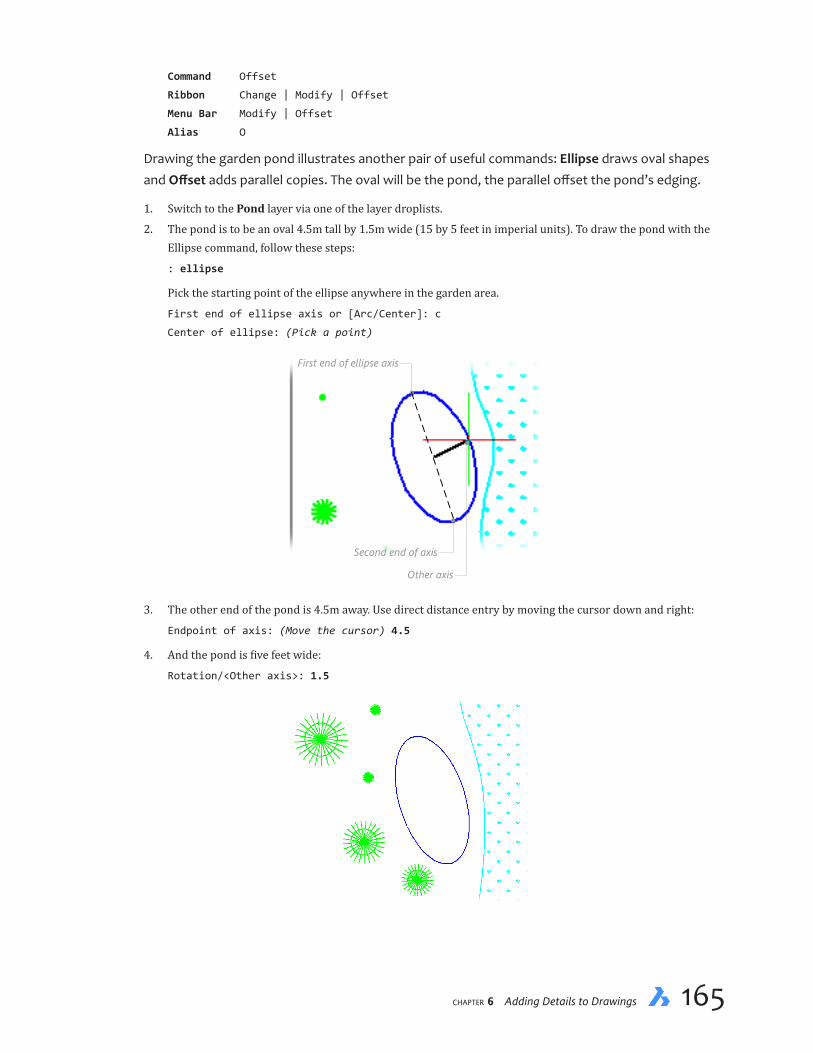
chapter 6 Adding Details to Drawings 165164 Inside BricsCAD V18
Command Offset
Ribbon Change | Modify | Offset
Menu Bar Modify | Offset
Alias O
Drawing the garden pond illustrates another pair of useful commands: Ellipse draws oval shapes and Offsetadds parallel copies. The oval will be the pond, the parallel offset the pond’s edging.
1. Switch to the Pond layer via one of the layer droplists.
2. The pond is to be an oval 4.5m tall by 1.5m wide (15 by 5 feet in imperial units). To draw the pond with the Ellipse command, follow these steps:
: ellipse
Pick the starting point of the ellipse anywhere in the garden area.
First end of ellipse axis or [Arc/Center]: c
Center of ellipse: (Pick a point)
First end of ellipse axis
Second end of axis
Other axis
3. The other end of the pond is 4.5m away. Use direct distance entry by moving the cursor down and right:
Endpoint of axis: (Move the cursor) 4.5
4. And the pond is five feet wide:
Rotation/<Other axis>: 1.5

chapter 6 Adding Details to Drawings 167166 Inside BricsCAD V18
5. The pond is edged with rock. You could draw the edging of by repeating this command to draw a second, larger ellipse. The easier alternative is to use the Offset command, which creates parallel copies, precisely. Here, you use it to create a concentric ellipse:
a. The offset distance is 0.3m (or one foot in imperial units):
: offset
Enter offset distance or [Through point/Erase/Layer] 0.3
b. Choose the ellipse; notice that only one entity can be offset at a time:
Select entity/subentity or [Exit] <Exit>: (Pick the ellipse)
c. Place the offset copy on the outside of the ellipse:
Select side for parallel copy or [Both sides/Multiple]: (Pick outside ellipse)
QUICK SUMMARY OF DRAWING ELLIPSES
BricsCAD provides three methods for drawing ellipses (ovals):
: ellipse
First end of ellipse axis or [Arc/Center]:
Point 1: CenterPoint 2: Other end ofmajor axis
Point 3: Other end ofminor axis
Center — specifies the ellipse’s center point, and then the endpoints of the major and
minor axes.
Axis, End — specifies the endpoints of the ellipse’s major axis, and then the minor one.
Center
Major (long) axis
Minor (short) axis
Arc — draws elliptical arcs.
This command also draws isocircles, which are isometric circles. This option is available only when isometric drawing mode is turned on through the Snap or Settings commands.

chapter 6 Adding Details to Drawings 167166 Inside BricsCAD V18
d. The command repeats itself to offset other entities. But to exit the command, press Enter.
Select entity/subentity or [Undo/Exit] <Exit>: (Press Enter to exit)
The Offset command also creates parallel lines, parallel polylines, and concentric circles and arcs.
If you wish, add the Gravel hatch pattern to the pond edging.
ARRAY PATHSAnother type of array can place objects along a path. This is called a “path array,” appropriately enough. In the figure below, the path is in green while the arrayed entities are the black circles.
You use this construction technique to lay a path of paving stones from the house, across the lawn, and to near the pond. But an path array needs a guide path, an entity along which to place the arrayed entities. And so in this part of the tutorial, you draw the guide path with a spline (Spline command), then array (ArrayPath command) the paving stones made of polygons (Poly-gon command).

chapter 6 Adding Details to Drawings 169168 Inside BricsCAD V18
Drawing Splines
Command Spline
Ribbon Draw | Polylines | Spline
Menu Bar Draw | Spline
Alias spl
Splines were first used in ship building for making hulls from smooth flowing strips of wood. To draw a spline with the Spline command, follow along with these steps:
1. First, change the layer to “Road” using one of the methods you learned earlier. (My preferences is to use the “clayer road” shortcut shown below.) This means the paving stones are placed on the same layer as the driveway.
: clayer
New current value for CLAYER: road
QUICK SUMMARY OF SPLINE
: spline
First point for spline:
Second point:
Set next point or [Close/Fit tolerance]:
Select starting tangent point:
Enter tangent for ending point:
Starting tangency
Vertex
Ending tangencySpline
Fit tolerance
Firstpointforspline — specifies the start of the spline’s tangency
Second point — locates the first vertex of the spline
Close — closes the spline, joining the start and points
Fit — specifies how closely the spline matches its vertices (also known as “fit points”); a value of 0 forces the spline to pass through the points you pick, and then the higher the number the further the spline is from those points.
Select starting tangent point — locates a tangency for the starting point; press Enter to ignore the option
Entertangentforendingpoint — locates a tangency for the ending point; press Enter to ignore the option

chapter 6 Adding Details to Drawings 169168 Inside BricsCAD V18
2. Draw the guide path using a spline. If you ignore the command’s many options, then drawing a spline is as just about as easy as drawing a line:
: spline
First point for spline: (Pick a point on the house outline, as show below.)
Second point (Pick a point along the lawn)
Set next point or [Close/Fit tolerance]: (Pick another point along the lawn)
Set next point or [Close/Fit tolerance]: (Pick a point at the edge of the lawn near the
pond, as shown below)
3. To end the command, press Enter three times, once for each prompt:
Set next point or [Close/Fit tolerance]: (Press Enter)
Starting point tangent point: (Press Enter)
Enter tangent for ending point: (Press Enter)
Another way to draw splines is with polylines. Use the PLine command to draw the polyline, and then use the PEdit command’s Spline command to convert it to a spline. This can be an easier approach than using the Spine command directly.
Zooming to ObjectsThe Zoom command has a handy option that lets you zoom into a single entity. Here is how it works:
4. To zoom into the spline, use the OBject option of the Zoom command, as follows:
: zoom
Zoom [zoom In/zoom Out/All/Center/Dynamic/Extents/Left/Previous/Right/Scale (nx/nxp)/
Window/OBject] <Scale (nX/nXP)>: ob
Select an entity: l
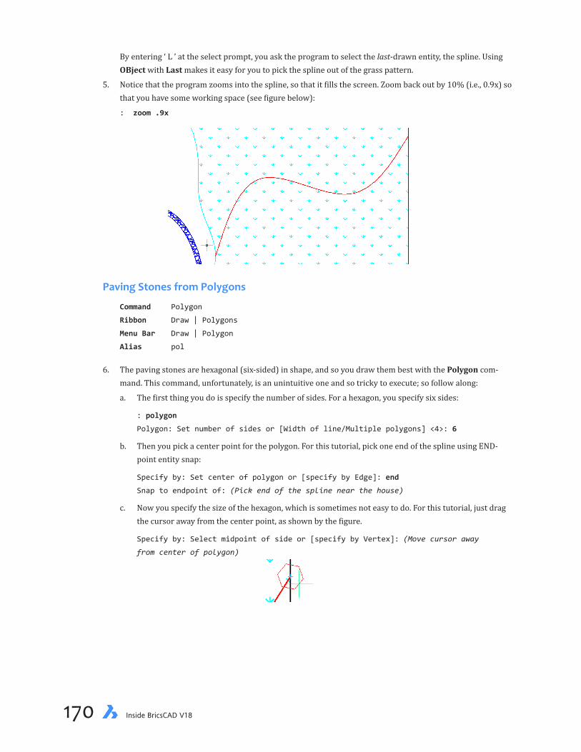
chapter 6 Adding Details to Drawings 171170 Inside BricsCAD V18
By entering ‘ L ’ at the select prompt, you ask the program to select the last-drawn entity, the spline. Using OBject with Last makes it easy for you to pick the spline out of the grass pattern.
5. Notice that the program zooms into the spline, so that it fills the screen. Zoom back out by 10% (i.e., 0.9x) so that you have some working space (see figure below):
: zoom .9x
PavingStonesfromPolygons
Command Polygon
Ribbon Draw | Polygons
Menu Bar Draw | Polygon
Alias pol
6. The paving stones are hexagonal (six-sided) in shape, and so you draw them best with the Polygon com-mand. This command, unfortunately, is an unintuitive one and so tricky to execute; so follow along:
a. The first thing you do is specify the number of sides. For a hexagon, you specify six sides:
: polygon
Polygon: Set number of sides or [Width of line/Multiple polygons] <4>: 6
b. Then you pick a center point for the polygon. For this tutorial, pick one end of the spline using END-point entity snap:
Specify by: Set center of polygon or [specify by Edge]: end
Snap to endpoint of: (Pick end of the spline near the house)
c. Now you specify the size of the hexagon, which is sometimes not easy to do. For this tutorial, just drag the cursor away from the center point, as shown by the figure.
Specify by: Select midpoint of side or [specify by Vertex]: (Move cursor away
from center of polygon)

chapter 6 Adding Details to Drawings 171170 Inside BricsCAD V18
Arraying Along a PathCommand ArrayPath
Ribbon Change | Array | Path Array
Menu Bar Modify | Array | Path Array
Alias ...
With one paving stone (polygon) in place, you use the ArrayPath command to add all of the oth-ers along the path (spline). But first, a word of explanation.
ArrayPath is one of a trio of commands that create associative arrays; the other two are Array-Rect (for associative rectangular arrays) and ArrayPolar for polar ones. Associative means that all the elements of the array act as a single entity, yet can be individually edited — like an associative dimension (see chapter 7). When you change the path, the array changes to suit.
QUICK SUMMARY OF POLYGON
This command draws regular polygons, which means that every side has the same length. (To draw irregular ones, use another command such as Rectang or PLine.) The minimum and maximum sides is 3 and 1024.
: polygon
Polygon: Set number of sides or [Width of line/Multiple polygons] <4>:
Specify by: Set center of polygon or [specify by Edge]:
Specify by: Select midpoint of side or [specify by Vertex]:
2: Center
1: Number of sides
3. Midpoint of side
Vertex
Edge
Setnumberofsides— specifies the number of sides between 3 and 1024
Multiple polygons — repeats the command to draw additional polygons
Widthofline — specifies the width of the lines, because polygons are made of polylines
Specifybyedge — specifies the length of one side
Setcenterofpolygon — specifies the center point of the polygon
Specifybyvertex — specifies the location of a vertex (corner of the polygon)
Selectmidpointofside — specifies the midpoint of one of the sides

chapter 6 Adding Details to Drawings 173172 Inside BricsCAD V18
1. Start the ArrayPath command, and then select the polygon, as follows:
: arraypath
Select entities to array: (Pick the polygon)
2. Press Enter to exit the selection process, and then pick the spline:
Entities in set: 1
Select entities to array: (Press Enter)
Type = Path, Associative = Yes
Select the path curve: (Pick the spline)
QUICK SUMMARY OF ARRAYPATH
: arraypath
Select entities to array:
Select path curve:
[ASsociative/Method/Base point/Tangent direction/Items/Rows/Levels/Align items/
Z direction/eXit]<eXit>:
Select path curve — you can use any linear (open) entity for the path, such as a line, poly-line, arc, circle, ellipse, elliptical arc, spline, helix, or 3D polyline.
ASsociative — toggles the array between associative and non-associative
Method — determines how the entity is arrayed along the path:Measure Places entities at a specified distance apartDivide Places a specified number of entities along the path
Base point — specifies a new base point from which the entity is arrayed; useful for when you don’t want the array on top of the path
Tangent direction — determines how the entity is aligned along the path in 3D, tangent or normal.
Items — specifies the (Measure mode) distance between items, or (Divide mode) num-ber of items to place along the path; a maximum number of items can be specified to make the array shorter than the path.
Rows — specifies the number of rows for stacked arrays
Levels — specifies the number of levels and their spacing for 3D arrays
Align items — determines whether the entity is aligned along the path
Z direction — toggles the z orientation between upright or banked along path
eXit — ends the command

chapter 6 Adding Details to Drawings 173172 Inside BricsCAD V18
3. Now you see many paving stones along the path.
Press Enter to exit the command.
4. Use the Erase command to remove the spline from the drawing.
To count the number of paving stones you need to order from the lumber store, select the array and then look at the Items field in the Properties pane: 19. Your number may differ, depending on how you drew the spline and the polygon stepping stones.
To see the progress you are making in learning BricsCAD, plot your drawing with the Print com-mand. At this point, your drawing should look similar to the following:
Remember to save your work with the Save command.

chapter 6 Adding Details to Drawings PB174 Inside BricsCAD V18
———
You’ve added a number of details to the drawing. In the next lesson, you learn how to make changes to them — how to edit entities.

CHAPTER 6
Making Changes to Drawings
Previously,youaddeddetailstothedrawing,suchasthelawn,trees,andapond.ButCADsoftware shows itself to be most powerful at effortlessly making changes, and flushing out the data held by draw-ings.
In this chapter, you learn how to change parts of the drawing and how to extract information.
IN THIS CHAPTER
• Modifying properties of entities
• Applying linetypes
• Changing the length of open and closed entities
• Finding information about entities in drawings

chapter 6 Making Changes to Drawings 177176 Inside BricsCAD V18
KEY TERMS IN THIS CHAPTER
Extend — extends open entities to boundaries that are defined by other entities
Filter — creates specified subsets of entities based on their properties
Linetype — displays line patterns made of dashes, dots, gaps, and symbols
Properties — lists all the characteristics of an entity
Trim — cuts entities at cutting edges that are defined by other entities
USEFUL ABBREVIATIONS
ISO International Organization for Standardization
.lin Linetype definition file
NEW COMMANDS
Command Aliases Menu Selection Ribbon Tab
Dist di Tools | Inquiry | Distance Tools | Inquiry | Distance Lengthen len Modify | Lengthen ... Linetype lt Settings | Linetypes ... List li Tools | Inquiry | List Entity Info Tools | Inquiry | List Properties pr Modify | Properties ... Stretch s Modify | Stretch Change | Modify | Stretch
THIS CHAPTER’S DRAWING
By the end of this lesson, your drawing will look like this one:
HouseText
MText in aboundingbox
Tutorial-06 drawing file

chapter 6 Making Changes to Drawings 177176 Inside BricsCAD V18
ChangingtheLookofLines
When you drew the lot lines in an earlier chapter, they were solid lines. Lot lines are, however, usually shown by a dashed pattern. Just as BricsCAD comes with several hatch patterns, it also includes a number of line patterns made of dashes, dots, and other patterns. They are called “linetypes,” and some of them look like this:
To change a line from solid (called “Continuous” by BricsCAD) to dashed, you load the linetype definition into the drawing, and then change lines to the new look.
LOADING LINETYPESCommand Linetype
Menu Bar Tools | Linetypes
Status Bar Linetype
Alias LT
Start BricsCAD, and then open your copy of yard.dwg. (If necessary, open the tutorial-05.dwg file or Imp-tutorial-05.dwg in imperial units. You can access them from my Dropbox folder: https://www.dropbox.com/s/ft6gzw3r408ndgd/Inside-BricsCAD-Tutorial-Files.zip.)
1. If necessary, use the Zoom command’s All option so that you see the entire drawing on the screen”
: zoom
Zoom [zoom In/zoom Out/All/Center/Dynamic/Extents/Left/Previous/Right/Scale (nx/nxp)/
Window/OBject] <Scale (nX/nXP)>: all
Follow this by an 80% zoom that adds breathing space around the drawing (80% is the same as 0.8x):
: zoom
Zoom [zoom In/zoom Out/All/Center/Dynamic/Extents/Left/Previous/Right/Scale (nx/nxp)/
Window/OBject] <Scale (nX/nXP)>: 0.8x
2. Before you can apply linetypes, you must load their definitions from a file into the drawing. Linetype defini-tions are stored in files separately from BricsCAD and drawings. You recognize the file by the .lin found at the end of its name. Here is how to load linetypes into the drawing.
Enter the linetype command:
: linetype
Notice that BricsCAD displays the Drawing Explorer:

chapter 6 Making Changes to Drawings 179178 Inside BricsCAD V18
All new drawings initially contain some linetypes. Here is what their names mean:
Ð ByLayer — entities take the linetype assigned by the layer. If a layer is assigned the Dashed linetype,then all entities on that layer are displayed with dashed linetypes.
Ð ByBlock — entities take the linetype of their block
Ð Continuous — lines are solid, with no gaps
Ð DYN_DIM — lines with dashes; meant for use by dynamic dimensions
Although BricsCAD uses terms like linetypes and line weights, these apply to nearly any kind of entity, such as circles and arcs — not just lines. Linetypes and lineweights are not, however, applied to text or 3D entities, because linetypes assign meaning to lines, which are not needed by text and 3D entities.
3. To add a linetype to this drawing, click the New button. BricsCAD doesn’t actually create new linetypes, as the name of this button suggests. Instead, this button leads you to the dialog box in which you load pre-defined linetypes.
Notice the Load Linetypes dialog box.
The dialog box lists in alphabetical order the names of all linetype definitions available to you. (They are stored in the default.lin file.) Scroll through the list to see what is available. The names of some linetypes use a code to identify them:
Ð Linetype names postfixed with X2 are double scale
Ð Linetype names postfixed with 2 or 4 or 8 are half or quarter or eighth-size (0.5x, 0.25x, 0.125x scale)
Ð Linetype names prefixed with ISO match the ISO (International Standards Organization) standard
4. Load the Border linetype like this:
a. Select BORDER.
b. Click OK to close the dialog box.

chapter 6 Making Changes to Drawings 179178 Inside BricsCAD V18
5. You are back in the Drawing Explorer dialog box. Set the Border linetype as current. “Current” means that it is the working linetype: if you were to draw a line, it would take on the Border linetype. Existing lines are not affected.
a. Click BORDER to select it.
b. Under the Current column, click the blank square so that the blue dot appears.
c. Click X to dismiss the dialog box.
If the Properties panel or Entity Properties toolbar are open, notice that the default linetype changes to Border.
CHANGING PROPERTIESCommand Properties
Menu Bar Modify | Properties
Ribbon ...
Alias PR
Right-click Properties
The Properties panel (or bar or palette) is handy for changing several properties of one or more entities. It provides three kinds of information:
Ð When No Entities are Selected — The Properties panel reports the current default color, layer, linetype, and so on. The next entity you draw will take on these properties. For instance, the figure below shows that enti-ties will be drawn with color ByLayer (red), on layer “Road,” and so on.

chapter 6 Making Changes to Drawings 181180 Inside BricsCAD V18
Ð One Entity is Selected — The Properties panel describes the properties of the entity that you selected. The General section is common to all entities; the Geometry section changes depending on the type of entity selected. In the figure below (at left), you see that a line is selected and that the Properties panel shows the properties of the line.
Left: Properties panel when one line is selected; right: More than one line selected
Ð Two or More Entities Selected — When two or more entities are selected, the Properties panel reports only those properties that the entities have in common. When properties are different between entities, the panel reports “*Varies*”, as shown above at right.
QUICK SUMMARY OF PROPERTIES PANEL
Properties describe the look and position of entities, such as color, linetype, starting and ending coordi-nates, and thickness. When two or more entities are selected, then the Properties panel (bar or palette) can displays a subset of entities. Click the droplist, and then choose a subset, such as “Arc (2).”
The Properties palette does more than display properties; it also lets you to change values of properties — usually. Properties marked *Varies* can also be changed; in this case, all selected entities take on the same property. If you do this by accident, use the U command to undo the change.
There are three ways to change property values:
Ð Enter new values by typing them in
Ð Select preset values from droplists (when available)
Ð Click buttons (when available) to select values from drawings or dialog boxes

chapter 6 Making Changes to Drawings 181180 Inside BricsCAD V18
Use the Properties panel to change the lot lines from ‘Continuous’ to ‘Border’, like this:
1. If the Properties panel is not displayed, enter the Properties command to open it now:
: properties
Notice that the Properties panel appears.
2. In the drawing, pick the five blue lot lines directly. As you pick them, notice that BricsCAD highlights them: they are shown as dashed lines, with green grip squares appearing on each line.
At the top of the Properties panel, notice that the list box reports Line (5). This confirms that you selected five lines. The properties that you see listed belong to the five, such as layer “Lot” and linetype “Border.” Because more than one line is selected, many properties are reported as *Varies*, because these properties, such as the x and y coordinates, differ for each line.
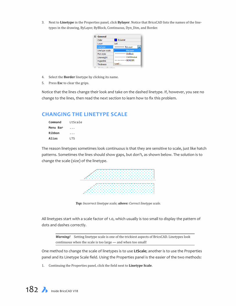
chapter 6 Making Changes to Drawings 183182 Inside BricsCAD V18
3. Next to Linetype in the Properties panel, click Bylayer. Notice that BricsCAD lists the names of the line-types in the drawing, ByLayer, ByBlock, Continuous, Dyn_Dim, and Border.
4. Select the Border linetype by clicking its name.
5. Press Esc to clear the grips.
Notice that the lines change their look and take on the dashed linetype. If, however, you see no change to the lines, then read the next section to learn how to fix this problem.
CHANGING THE LINETYPE SCALECommand LtScale
Menu Bar ...
Ribbon ...
Alias LTS
The reason linetypes sometimes look continuous is that they are sensitive to scale, just like hatch patterns. Sometimes the lines should show gaps, but don’t, as shown below. The solution is to change the scale (size) of the linetype.
Top: Incorrect linetype scale; above: Correct linetype scale.
All linetypes start with a scale factor of 1.0, which usually is too small to display the pattern of dots and dashes correctly.
Warning! Setting linetype scale is one of the trickiest aspects of BricsCAD. Linetypes look continuous when the scale is too large — and when too small!
One method to change the scale of linetypes is to use LtScale; another is to use the Properties panel and its Linetype Scale field. Using the Properties panel is the easier of the two methods:
1. Continuing the Properties panel, click the field next to Linetype Scale.

chapter 6 Making Changes to Drawings 183182 Inside BricsCAD V18
2. Change 1.0 to something like 10.
3. Check whether the linetype pattern becomes visible. If not, try another scale value, such as 0.01.
4. It may be necessary for you to use the Regen command to fix the display, following a change in linetype scale.
SELECTING ENTITIES BY OTHER METHODSI find that it can be tricky trying to select entities in crowded drawings. No matter how tiny the pick box, sometimes I repeatedly pick the wrong entity. The program provides two workarounds that are useful to know.
Selecting Entities by Their PropertiesIn the previous tutorial I had you pick the five lot lines one by one. I did that on purpose so that I could show you easier ways! You can select entities by their properties. For this, BricsCAD offers the Quick Select mode, which isn’t so much about selecting things quickly as selecting them by their properties.
When using Quick Select mode, you modify filters that apply to the current selection set. The current selection set starts off as all entities in the drawing. A filter reduces the selection set. For instance, when you select “Red” as the Color, you filter out all entities that are not red. When you select “Lot” as the Layer, you remove all entities that are not on layer Lot.

chapter 6 Making Changes to Drawings 185184 Inside BricsCAD V18
1. Press Esc to ensure no entities are selected.
2. In the Properties pane, click the Quick Select button. Notice that the panel changes its look to Quick Select mode:
Notice the following about the new look:
Ð All entities are selected, as shown by “All (25)”
Ð Thee buttons populate the toolbar
Ð Basic properties show ‘ * ’ (asterisk), which means that all properties are selected.
Toggle betweenProperties andQuick Select
All entities selectedin drawing
Start a new selection set
Add to to selection set
Remove from selection set Apply filters to current selection set
3. In the Layer droplist, choose “Lot.”
4. Click the Add to Selection Set button. Notice that only the lot lines are highlighted. You can now change the properties of just the lot lines, such as the linetype or color.
The * is not the only wildcard used by Quick Select. To see the full list, click the asterisk to un-cover this shortcut menu. (That’s left click, not right click.) These let you, for example, select all lines that have a Length property of less than 10m.
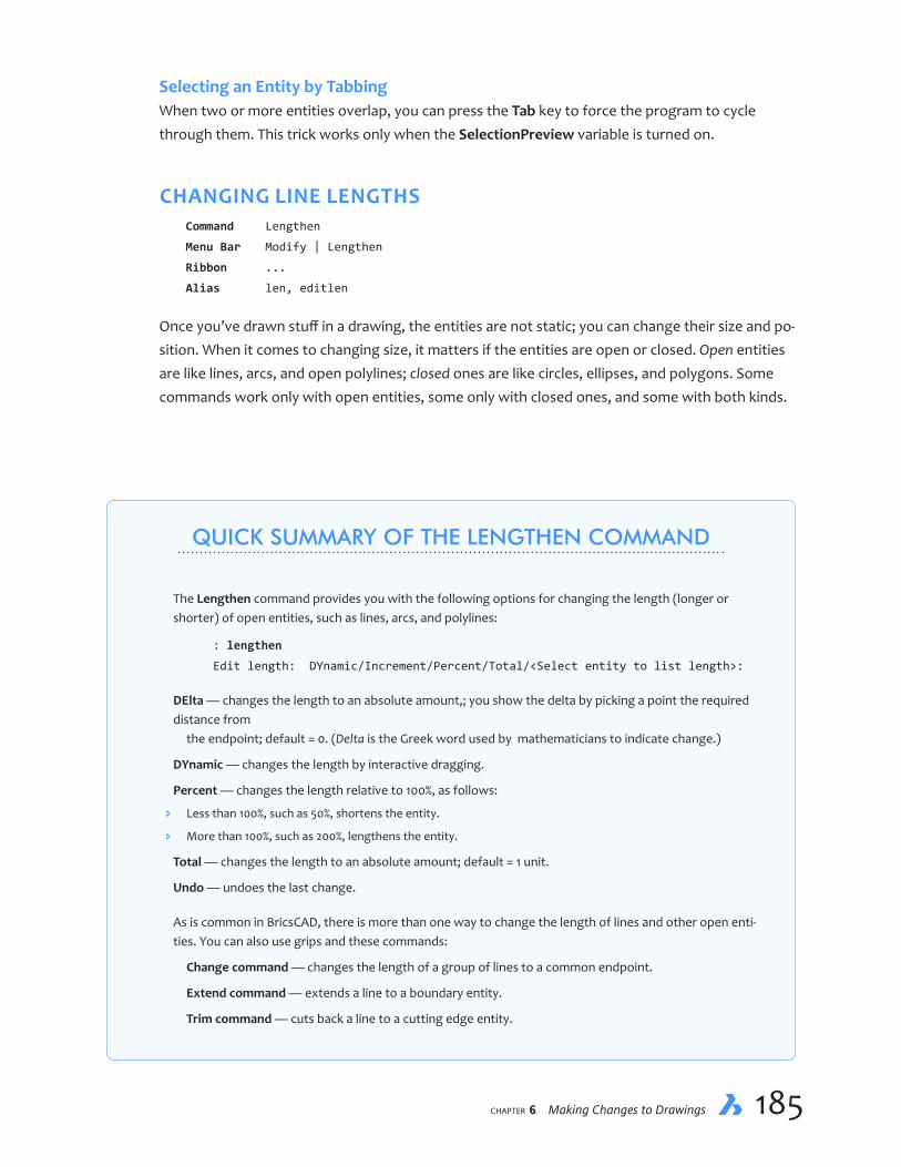
chapter 6 Making Changes to Drawings 185184 Inside BricsCAD V18
Selecting an Entity by TabbingWhen two or more entities overlap, you can press the Tab key to force the program to cycle through them. This trick works only when the SelectionPreview variable is turned on.
CHANGING LINE LENGTHSCommand Lengthen
Menu Bar Modify | Lengthen
Ribbon ...
Alias len, editlen
Once you’ve drawn stuff in a drawing, the entities are not static; you can change their size and po-sition. When it comes to changing size, it matters if the entities are open or closed. Open entities are like lines, arcs, and open polylines; closed ones are like circles, ellipses, and polygons. Some commands work only with open entities, some only with closed ones, and some with both kinds.
QUICK SUMMARY OF THE LENGTHEN COMMAND
The Lengthen command provides you with the following options for changing the length (longer or shorter) of open entities, such as lines, arcs, and polylines:
: lengthen
Edit length: DYnamic/Increment/Percent/Total/<Select entity to list length>:
DElta — changes the length to an absolute amount,; you show the delta by picking a point the required distance from the endpoint; default = 0. (Delta is the Greek word used by mathematicians to indicate change.)
DYnamic — changes the length by interactive dragging.
Percent — changes the length relative to 100%, as follows:
Ð Less than 100%, such as 50%, shortens the entity.
Ð More than 100%, such as 200%, lengthens the entity.
Total — changes the length to an absolute amount; default = 1 unit.
Undo — undoes the last change.
As is common in BricsCAD, there is more than one way to change the length of lines and other open enti-ties. You can also use grips and these commands:
Change command — changes the length of a group of lines to a common endpoint.
Extend command — extends a line to a boundary entity.
Trim command — cuts back a line to a cutting edge entity.

chapter 6 Making Changes to Drawings 187186 Inside BricsCAD V18
QUICK SUMMARY OF SELECTION SET OPTIONS
Selection has many options for selecting entities, as shown in the following table. I find that I typically use just some of them, such as pick, W, C, L, P and Enter. To see the full list in BricsCAD, enter the Select com-mand, and then press ?, like this:
: select
Select entities to include in set: ?
Select entities: ALL/Add/+/Remove/-/Previous/Last/Window/Crossing/Outside/WPoly-
gon/CPolygon/OPolygon/WCircle/CCircle/OCircle/Box/POint/Fence/AUto/Multiple/
Single/PROperties/Dialog/Undo:
Mode Abbreviation Selects
Entity [pick] A single entity All ALL All non-frozen entities; can also press Ctrl+A Previous P Most recently selected entity Last L Most-recently created entity visible on the screen Window W All entities inside a rectangular window Crossing C All entities crossing and within a rectangular window Outside O All entities outside the rectangular window Window Polygon WP All entities within a polygonal window Crossing Polygon CP All entities crossing and within a polygon Outside Polygon OP All entities outside a polygonal window Window Circle WC All entities inside a circular window Crossing Circle CC All entities crossing and inside a circular window Outside Circle OC All entities outside a circular window Box B All entities depending on how direction selection window is drawn: • Right to left: selects by Crossing mode • Left to right: selects by Window mode Fence F All entities along a fence polyline Auto AU Single pick selects one entity; otherwise acts like Box option Single S Selects the first entity encountered, and ends the command
SELECTION MODIFICATIONS
Add or + A or + Enters add-entities mode Remove or - R or - Enters remove-entities mode Multiple M Select entities without highlighting; faster in complex drawings Undo U Removes most recent selection group Dialog D Displays the Entity Selection section of the Settings dialog box End press [Enter] Ends entity selection Cancel press [Esc] Cancels entity selection Location LO Switches back to original select prompt \
...continued

chapter 6 Making Changes to Drawings 187186 Inside BricsCAD V18
One way to change lengths is using grips, as described earlier. A more precise method is with the Lengthen command. To see how it works, in this tutorial you extend the edge of the street line to the bottom of the screen. If necessary, first zoom in on the area around the pond with the Zoom Window command.
1. Start the Lengthen command:
: lengthen
2. At the ‘Select entity to list length’ prompt, pick the lower road line:
Edit length: DYnamic/Increment/Percent/Total/<Select entity to list length>: (Pick
the line.)
Notice that BricsCAD reports its length in the command bar:
Current length: 11.00
This means that the line is 11m long (about 37', imperial units).
3. Lengthen the road to 12m by specify the Total option, and then entering 12 as the new length, as follows:
Edit length: DYnamic/Increment/Percent/Total/<Select entity to list length>: t
Angle/<Enter total length (11.00)>: 12
4. Curiously, BricsCAD asks you a second time to select the entity; for some reason, it does not automatically change the length of the line you choose first:
Mode/<Select entity to change>: (Pick the same line)
5. Notice that the line lengthens. Press Enter to end the command.
Mode/Undo/<Select entity to change>: (Press ENTER)
...continued
SELECTION BY PROPERTIES
The PROperties option selects entities by common properties:
Properties Abbreviation Selects
Color C All entities of the same color name or number such as “red” or “122” Layer LA All entities with the same layer name Ltype LT All entities of the same linetype Name N All entities of the same name Thickness TH All entities of the same thickness Type TY All entities of the same entity type, such as “circle” Value V All entities of the specified handle Width W All entities of the specified width
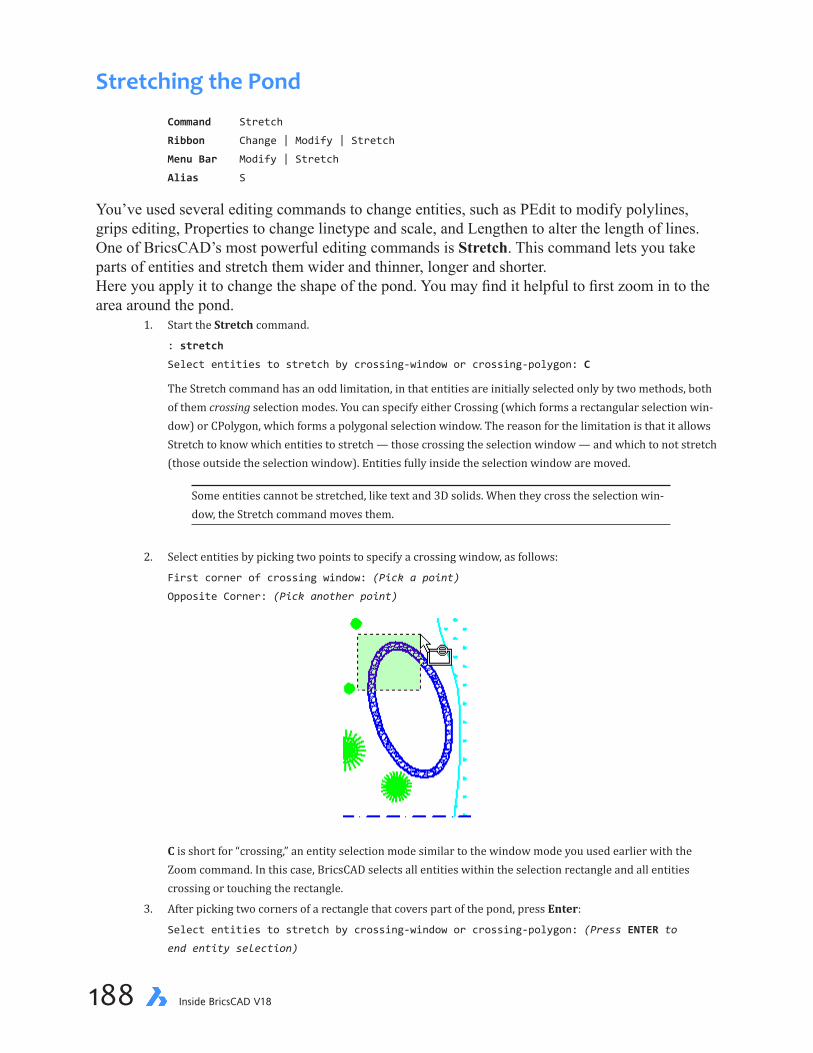
chapter 6 Making Changes to Drawings 189188 Inside BricsCAD V18
Stretching the PondCommand Stretch
Ribbon Change | Modify | Stretch
Menu Bar Modify | Stretch
Alias S
You’ve used several editing commands to change entities, such as PEdit to modify polylines, grips editing, Properties to change linetype and scale, and Lengthen to alter the length of lines.One of BricsCAD’s most powerful editing commands is Stretch. This command lets you take parts of entities and stretch them wider and thinner, longer and shorter. Here you apply it to change the shape of the pond. You may find it helpful to first zoom in to the area around the pond.
1. Start the Stretch command.
: stretch
Select entities to stretch by crossing-window or crossing-polygon: C
The Stretch command has an odd limitation, in that entities are initially selected only by two methods, both of them crossing selection modes. You can specify either Crossing (which forms a rectangular selection win-dow) or CPolygon, which forms a polygonal selection window. The reason for the limitation is that it allows Stretch to know which entities to stretch — those crossing the selection window — and which to not stretch (those outside the selection window). Entities fully inside the selection window are moved.
Some entities cannot be stretched, like text and 3D solids. When they cross the selection win-dow, the Stretch command moves them.
2. Select entities by picking two points to specify a crossing window, as follows:
First corner of crossing window: (Pick a point)
Opposite Corner: (Pick another point)
C is short for “crossing,” an entity selection mode similar to the window mode you used earlier with the
Zoom command. In this case, BricsCAD selects all entities within the selection rectangle and all entities crossing or touching the rectangle.
3. After picking two corners of a rectangle that covers part of the pond, press Enter:
Select entities to stretch by crossing-window or crossing-polygon: (Press ENTER to
end entity selection)

chapter 6 Making Changes to Drawings 189188 Inside BricsCAD V18
If the pond were entirely inside the entity selection rectangle, the Stretch command would move the pond, not stretch it. If you accidentally select entities other than the pond, type the R option (short for “remove from selection set”), and then select the entities to remove.
4. To tell BricsCAD how much you want the pond stretched, pick two points that indicate the distance:
Base point of displacement: (Pick a point near the pond)
Second point of displacement: (Pick a point away from the pond)
You have now created a whole new look to your pond! (Your pond will probably look different from the one illustrated in this book.) Note that you cannot create this effect using grips editing.
5. If you don’t like it, you can undo the stretch with the U command, as follows:
: u
U: STRETCH
... and try stretching the pond again.
MOVING ENTITIESCommand Move
Ribbon Change | Modify | Move
Menu Bar Modify | Move
Alias M
If the pond isn’t exactly where you want it, you can relocate it with the Move command.
1. Start the Move command by entering the letter ‘m’, as follows:
: m
Here you used another of BricsCAD’s shortcuts. M is the alias (abbreviation) for the Move command.
2. Continue the Move command by specifying Crossing selection mode to capture all three parts of the pond: two ellipses and hatch pattern.
Select entities to move: c
First corner of crossing window: (Pick a point near the pond)
Opposite Corner: (Pick another point to encompass the pond)
Select entities: (Press ENTER to end entity selection)
chapter 6 Making Changes to Drawings 191190 Inside BricsCAD V18
3. Just as with the Stretch command, you need to specify two points. They indicate the direction and distance to move the entities:
Vector/<Base point>: (Pick edge of pond.)
Displacement point: (Pick new location for pond.)
4. Notice that the pond has moved. If necessary, clean up the screen with the Redraw command, using its alias, as follows:
: r
5. Save your work.
BricsCAD lets you specify commands by typing just one or two letters at the ‘ : ’ prompt. Shortcut keystrokes are listed at the start of each chapter. The complete list of command name abbreviations (called “aliases”) is stored in the default.pgp.
Adding the Fence
Say you’ve decided to add a fence to the backyard. You can use BricsCAD to help plan the materi-als needed: after drawing the fence (as a polyline), you can find out from the drawing the length of the fence.
The fence is drawn as a polyline, 0.1m-wide (4”-wide). Along the way, you’ll use a variety of entity snap modes and tracking mode.
1. First, switch the working layer to House by selecting its name from the toolbar.
Use the Zoom Previous command to see the full drawing.
2. If you turned off the INTersection entity snap, turn it back on using this method: at the command prompt, enter Intersection like a command.
: intersection
3. Begin by entering the PLine command:
: pline
4. Start the polyline at the middle of the upper house line. This point is shown as #1 in the figure below). Use the MIDdle entity snap to precisely locate the polyline’s starting point at the middle of the house line. “Mid” is the abbreviation for MIDdle entity snap.
: _pline
Start of polyline: mid
Snap to midpoint of: (Pick upper house line.)
Current line-width is 0

chapter 6 Making Changes to Drawings 191190 Inside BricsCAD V18
5. To change the width of the polyline from zero to 10cm (4"), use the PLine command’s w (Width) option, as follows:
Set next point or [draw Arcs/Distance/Follow/Halfwidth/Width]: w
Starting width <0>: 0.1
Ending width <0.1>: (Press Enter to accept the new default)
#1(MIDpoint)
#2(PERpendicular)
#3(INTesection)
#4(INTesection)
#5(INTesection)
#6(.X filter, MIDpoint)
#7(PERpendicular)
Note that you can specify different starting and ending widths, which would produce tapered polylines.
6. Now that the starting point and width are set, continue drawing the fence. Follow the path shown by num-bers 2 through 5 in the figure above.
7. Pause the picking action at point #5. When you get to the bottom of the house, you get into a bit of tricky ge-ometry. You want the fence to end at the same relative location as its starting point. You’re not sure of the x coordinate, which is located somewhere along the bottom line of the lot. Fortunately, you can find that point with point filters.
Normally, when you pick a point, you are providing BricsCAD with the x and y coordinate. Point filters cap-ture a single coordinate, such as just the x or the y.
a. Here is how to get just the x coordinate:
Set next point or [draw Arcs/Distance/Follow/Halfwidth/Width]: .x
b. BricsCAD asks you to pick a point (‘Select X of’ prompt), from which it obtains that x coordinate. Tell it that you want the middleof the line:
Select X of: mid
Snap to midpoint of: (Pick the lower line of the house at #6)
Notice that you can combine point filters and entity snaps to get very specific coordinates!
c. And then BricsCAD asks you for the y coordinate. When it asks ‘Still need YX,’ BricsCAD is asking for the y and z coordinates. Well, the z you don’t care about, but here is how to get the y with the perpendicular entity snap:
Still need YZ of: per
Snap to perpendicular of: (Pick the property line at #7)

chapter 6 Making Changes to Drawings 193192 Inside BricsCAD V18
You completed the fence by drawing the last polyline segment using PERpendicular entity snap at #7.
8. Exit the PLine command:
Set next point or [draw Arcs/Distance/Follow/Halfwidth/Width]: (Press ENTER to exit
the command)
LISTING DATACommand List
Ribbon Tools | Inquiry | List
Menu Bar Tools | Inquiry | List Entity Info
Alias LI
Command Dist
Ribbon Tools | Inquiry | Distance
Menu Bar Tools | Inquiry | Distance
Alias DI
Now that you’ve drawn the fence, you can use the List command to tell you its length.
1. Enter the List command:
: list
SOrt/Tracking/<Select entities to list>: (Pick the fence’s polyline)
SOrt/Tracking/<Select entities to list>: (Press Enter to end entity selection)
BricsCAD flips to the Prompt History and lists lines of information. The List command tells you every piece of information about the polyline (technically known as a “lwpolyline”) that BricsCAD has stored in its data-base. Most of the information is about its vertices (“at point”).
The total length of the polyline is shown in the middle of the listing:
Perimeter 77.0
So, 77 meters (roughly 260 feet). Now you know how much fencing you would need.

chapter 6 Making Changes to Drawings 193192 Inside BricsCAD V18
2. Press function key F2 to flip back to the graphics window. The Properties panel also reports area and length information:
3. You can measure distances directly on the drawing with the Dist command (short for “distance”). To find the shortest distance from the house to the pond with the Dist command, from the Tools menu bar, select Inquiry | Distance:
: _dist
Starting point for distance: nea
Snap to nearest of: (Pick inside edge of pond.)
End point: per
Snap to perpendicular of: (Pick house wall.)
The beeline distance from house to pond is 13m (around 43 feet). The value on your drawing may differ, depending on where you located the pond.
———
You’ve done a lot of editing, so remember to save the work you have done on the drawing. You may also want to plot out the drawing.
Next, you learn how to add text and dimensions to the drawing.

chapter 6 Making Changes to Drawings PB194 Inside BricsCAD V18
Notes

CHAPTER 7
Adding Notes and Dimensions
Withtheyardplannearlyfinished,nowisthetimetoaddcallouts(ortext)todescribethe parts of the yard. In this chapter, you learn how to add these finishing touches to the drawing.
IN THIS CHAPTER
• Learning about drawing scales
• Placing text in drawings
• Defining styles and justification modes for text
• Understanding annotative scaling
• Editing text
• Attaching dimensions to entities
• Placing leaders and multileaders

chapter 7 Adding Notes and Dimensions 197196 Inside BricsCAD V18
KEY TERMS IN THIS CHAPTER
Anotative — refers to entities that scale themselves to match the layout’s scale factor
Associative — refers to entities, such as dimensions and hatches, that update automatically when associ-ated entities are updated
Bounding box — describes the invisible rectangle that determines the word wrap of paragraph text
Callouts — describes the text attached to lines that describe significant parts of drawings
Dimension — indicates a measured distance, usually consisting of lines, arrowheads, and text
Justification — determines the relative positioning of text, such as right, left, and centered
Layout — presents editable print previews
USEFUL ABBREVIATIONS
dims Dimensions
dimvars Dimension variables
dimstyle Dimension style
NEW COMMANDS
Command Shortcuts Menu Bar Ribbon Tab
DdEdit ed ... Draw | Dimensions | Edit DimAligned dal, dimali Dimension | Aligned Draw | Dimensions | Aligned DimBaseline dba, dimbase Dimension | Baseline Draw | Dimensions | Baseline DimContinue dco, dimcont Dimension | Continue Draw | Dimensions | Continue DimEdit ded, dimed Modify | Edit Dimension Text ... DimLinear dli, dimlin Dimension | Linear Draw | Dimensions | Linear DimRadius dra, dimrad Dimension | Radius Draw | Dimensions | Circle MText t Draw | Multiline Text Draw | Text | Multiline Text QText qt … ... Rotate ro Modify | Rotate Change | Arrange | 2D Rotate Style st Settings | Text Style Home | Drawing Explorer Text tx Draw | Text Draw | Text | Text

chapter 7 Adding Notes and Dimensions 197196 Inside BricsCAD V18
Before starting this exercise, take the following steps:
1. Start BricsCAD, and then open the yard.dwg file.
If you were unable to complete the exercises of previous lessons, open the tutorial-06.dwg file; for imperial units, open the Imp-tutorial-06.dwg file. You can access them from my Dropbox folder: https://www.dropbox.com/s/ft6gzw3r408ndgd/Inside-BricsCAD-Tutorial-Files.zip.
2. Do a Zoom All to make the full drawing visible.
3. With the Layer command, create a new layer, and then name it Text.
4. Assign color “White” to the layer, and then make the layer current by clicking in the Current column, so that the blue dot appears next to the name, “Text.”
You are now ready to tackle text in drawings.
THIS CHAPTER’S DRAWING
By the end of this lesson, your drawing will look like this one:
House
Pond
Donly
n A
ven
ue
4486 Donlyn AvenueAnytown BC
35.00
23.0012.00
5.00
6.00
13.0015.00
24.00
15.00
R1.00

chapter 7 Adding Notes and Dimensions 199198 Inside BricsCAD V18
Adding Notes to DrawingsCommand MText
Ribbon Draw | Text | Multiline Text
Menu Bar Draw | Multiline Text
Alias T
You add callouts with the MText command, short for “multiple-line text” and also known as para-graph text.
Mtext constrains text by the top and two sides of paragraphs of a rectangle. As you add text, it flows down. You can, however, drag the sides to make the block wider and narrower (see figure below); this is handy for ensuring the text fits a particular spot, such as in title blocks. You can move the block of mtext to any location in the drawing.
Drag to makethis sidewider andnarrower
Bottom changesautomatically as text is
added or removed
Top of text block (fixed)
Side oftext block
(fixed)
You can format individual words and letters of the text with a variety of fonts and colors, as well as apply effects such as boldfacing and italics. Special symbols can be included, such as the center line symbol and the degree symbols. You can define how far margins are indented and where tabs are set. All these features make the MText command very flexible, but more complex than the simpler but less capable Text command you learn about later.
Place some mtext in the drawing now:
1. Start the MTtext command:
: mtext
2. The first thing BricsCAD wants is a starting point from you; pick it inside the house, as shown below:
Multiline Text: First corner for block of text: (Pick a point within the house outline)
a. Specify first corner:b. Specify opposite corner:
Text begins here
Bounding box

chapter 7 Adding Notes and Dimensions 199198 Inside BricsCAD V18
3. Drag the cursor, and as you do notice that a rectangle is being formed. Pick a second point to define the width of the text:
Select Opposite corner for block of text or [Justification/Rotation angle/text Style/text
Height/Direction/Width]: (Pick a second point)
The rectangle forms a boundary box that constrains the text. The box is visible only when the MText command is active; otherwise, it is neither displayed nor printed.
BricsCAD will start the first line of text at the top of the box. The right edge of the box determines where the text wraps — flows onto the following lines. (For right-to-left text like Hebraic, the left edge determines the word wrap location.) This is just like setting margins with word processing software.
The bottom of the boundary is ignored. When there is too much text for the box, BricsCAD auto-matically extends it downwards. The bottom line is used only when the direction of the text flows upwards.
DETERMINING THE SIZE OF TEXTNow you need to pause to do some multiplication and division, because you have to work out the height of the text. The drawing standard for text height is 10mm (or 3/8" in imperial units). But if text were placed at that size, it would be nearly invisible; after all, a few millimeters is tiny next to a 15-meter house! You need the text to be big enough to be legible, and so it has to be larger, much larger.
To figure out how tall to make the text, read the text box on the next page, Quick Summary on Calculating Text Heights. Based on the size of this drawing, the text height needs to of 400mm tall (or 18" in imperial units). Continue with the MText command to specify the text height and other font parameters:
4. After picking the second point, BricsCAD displays the Text Formatting dialog box, in which you specify font settings and enter the text. First, change the height, as follows:
a. In the Font droplist, ensure “Arial” is specified.
b. In the Height droplist, highlight 0.2, and then enter 0.4.
c. Press Enter.

chapter 7 Adding Notes and Dimensions 201200 Inside BricsCAD V18
QUICK SUMMARY ON CALCULATING TEXT HEIGHTS
Here are the steps to calculating the height of text appropriate for any size of drawing.
IN METRIC UNITS
Step 1: Work out the related drawing and paper widths, which will specify the scale factor:
Width of drawing 40m———————————————— = ——————Width of paper 0.297m
Step 2: Determine the scale factor by dividing the two values:
40————— = 1340.297
The scale factor is 134. That means text in the drawing should be about 140 times taller to plot big enough to be legible on the page. The standard for text heights in drawing is 3mm (0.003m), and for title text is 10mm.
Step 3: Multiply the standard text size by the scale factor:
0.003m x 132 = 0.4m
In BricsCAD’s MText and Text commands, specify a text height of 0.4m.
IN IMPERIAL UNITS
Step 1: Work out the related drawing and paper widths, which will specify the scale factor:
Width of drawing 130 ft.———————————————— = ———————Width of paper 11 in.
Step 2: To make the units consistent, convert the feet to inches:
130 ft x 12 in/ft 1,560 in.————————————————— = ————————— 11 in. 11 in.
Step 3: Determine the scale factor by dividing:
1,560 in.————————— = 142 11 in.
The scale factor is 142. That means text in the drawing should be about 140 times taller to plot big enough to be legible on the page. The standard for text heights in drawing is 1/8" (0.125"), and for title text 3/8" (0.375").
Step4: Multiply the standard text size by the scale factor:
0.125" x 142 = 18"
In BricsCAD’s MText and Text commands, specify a text height of 18".
———
The reason for the difference between the metric scale factor of 134 and the imperial scale factor of 142 is that metric A4 paper is 18mm (0.7") wider than imperial A-size paper. See http://www.papersizes.org/a-paper-sizes.htm.

chapter 7 Adding Notes and Dimensions 201200 Inside BricsCAD V18
5. Type House, and then press Enter. Notice that the text appears in the drawing.
6. Click OK to exit the MText command.
You change the width of the mtext boundary box using grips. Here is how to do this: 1. Select the text. Notice the two handles (green grips) , one at each corner of the top of the boundary box. 2. Select a grip; notice it turns red. 3. Drag a grip wider and narrower. Notice that the word wrap (paragraph lengths) change.
CREATING TEXT STYLESCommand Style
Ribbon Home | Drawing Explorer | Text Styles
Menu Bar Settings | Text Styles
Alias ST
You can change the font used with text, but in CAD this is done indirectly with styles. “Styles” de-termine the look of the text, including which font should be used — just like in a word processor. The difference is that in CAD, styles must be used, where as in word processors they are optional.
Just as linetypes must be loaded into BricsCAD drawings, text fonts must be loaded before they can be assigned to styles. This is done through the Style command.
1. Enter the Style command. Notice that the Drawing Explorer dialog box appears on the screen.
: style
2. Make the following changes to the Standard style:
Property Old Value New Value
Font Name Arial Times New Roman Height 0 .75
(For imperial drawings, enter 26 as the height.) Ignore the other settings, as you don’t need the text to be backwards, upside-down, or vertical — at least for now.

chapter 7 Adding Notes and Dimensions 203202 Inside BricsCAD V18
The height of 0 has a special meaning: it means that the text height is not predefined and so must be specified during the Text command. Text insertion point
Textheight
QUICK SUMMARY OF TEXT JUSTIFICATION MODES
BricsCAD can specify justification (alignment) for text in many different ways:
Baseline Left (BL)also, Start Point
Top Left (TL)
Middle Left (ML)
Baseline Right (BR)also, Right
Baseline Center (BC)also, Center
Middle Center (MC)also, Middle
Alig
n an
d Fit
(fitt
edbe
twee
ntw
opo
ints
)
Justification Meaning
Start point Baseline leftAlign Fitted between two pointsFit Fitted with constant text heightCenter Baseline centerMiddle Exact center of textRight Baseline rightTL Top leftTC Top centerTR Top rightML Middle leftMC Middle center (equivalent to Middle)MR Middle rightBL Baseline left (equivalent to Start point)BC Baseline center (equivalent to Center)BR Baseline right (equivalent to Right)
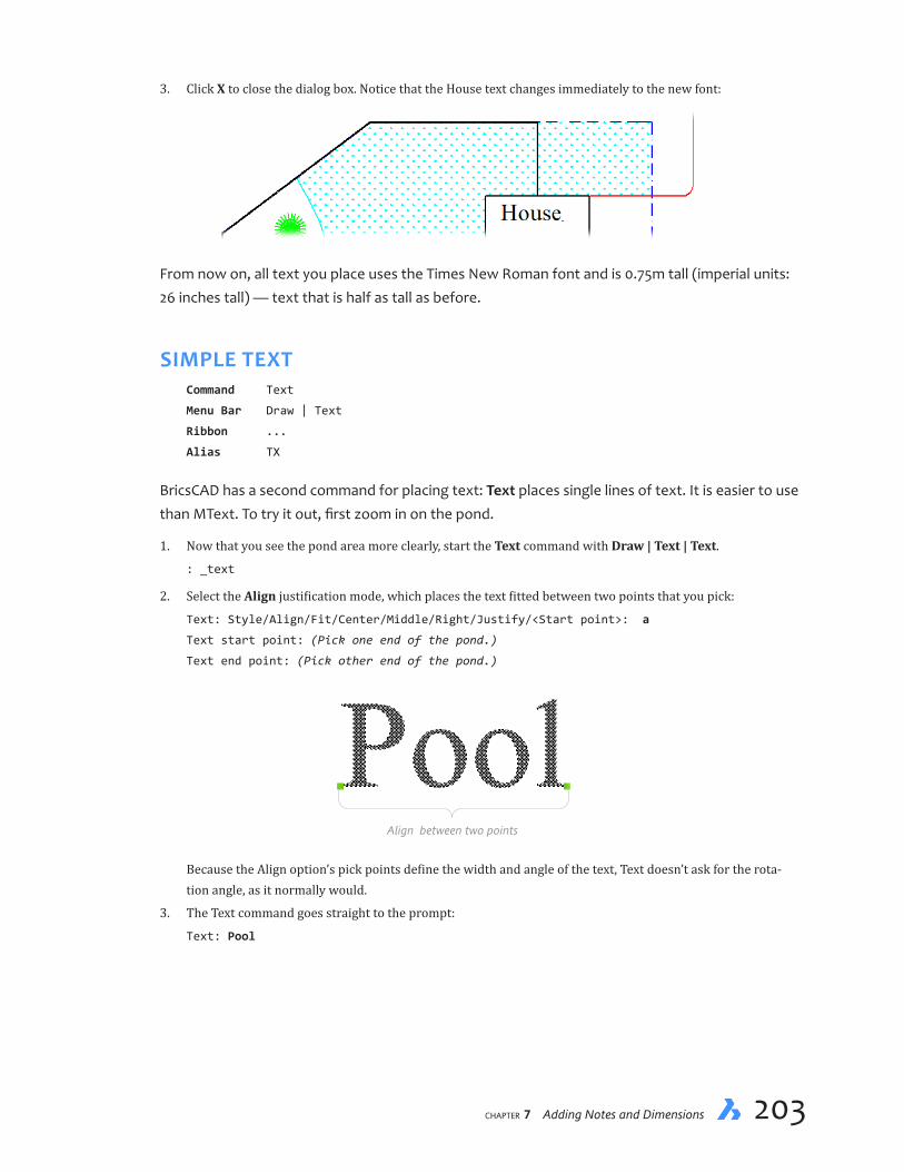
chapter 7 Adding Notes and Dimensions 203202 Inside BricsCAD V18
3. Click X to close the dialog box. Notice that the House text changes immediately to the new font:
From now on, all text you place uses the Times New Roman font and is 0.75m tall (imperial units: 26 inches tall) — text that is half as tall as before.
SIMPLE TEXTCommand Text
Menu Bar Draw | Text
Ribbon ...
Alias TX
BricsCAD has a second command for placing text: Text places single lines of text. It is easier to use than MText. To try it out, first zoom in on the pond.
1. Now that you see the pond area more clearly, start the Text command with Draw | Text | Text.
: _text
2. Select the Align justification mode, which places the text fitted between two points that you pick:
Text: Style/Align/Fit/Center/Middle/Right/Justify/<Start point>: a
Text start point: (Pick one end of the pond.)
Text end point: (Pick other end of the pond.)
Align between two points
Because the Align option’s pick points define the width and angle of the text, Text doesn’t ask for the rota-tion angle, as it normally would.
3. The Text command goes straight to the prompt:
Text: Pool

chapter 7 Adding Notes and Dimensions 205204 Inside BricsCAD V18
Notice that the word “Pool” is drawn with the Times New Roman text font specified by the Standard style.
4. Press Enter at the ‘Text:’ prompt to exit the command.
Text: (Press ENTER)
Changing TextCommand DdEdit
Shortcut double-click text
Alias ED
Oops! “Pool” should read “Pond.”
To change the wording, use the DdEdit command. You could enter the command name at the : prompt, but there is another way:
1. Double-click the word Pool. This action activates the DdEdit command (short for “dynamic dialog editor”). Notice the Edit Text dialog box.
2. Replace Pool with Pond.
3. Click OK. Notice that the word is corrected in the drawing.

chapter 7 Adding Notes and Dimensions 205204 Inside BricsCAD V18
PLACING ROTATED TEXTNow we’ll add some more text. This time you place the text sideways to see that BricsCAD can place rotated text. First, though, perform a Zoom All to see the entire drawing.
Restart the Text command, and then follow these steps:
1. Enter Text:
: text
Text: Style/Align/Fit/Center/Middle/Right/Justify/<Start point>: (Pick a point on
street)
2. Specify a rotation angle of 90 degrees, and then enter the text:
Rotation angle of text <0>: 90
Text: Donlyn Avenue
Text: (Press Enter)
By specifying a rotation angle of 90 degrees, BricsCAD draws the text sideways. You can, of course, place text at any angle — from 0 degrees to 359 degrees.
3. If you picked the wrong rotation angle, you can rotate the text after the fact. Use the Zoom OBject command to take a closer look.
4. Pick the text...
: (Pick text)
..and then right-click the text. From the shortcut menu, choose Properties.
5. In the Properties palette:
a. Look for Rotation in the Text section.
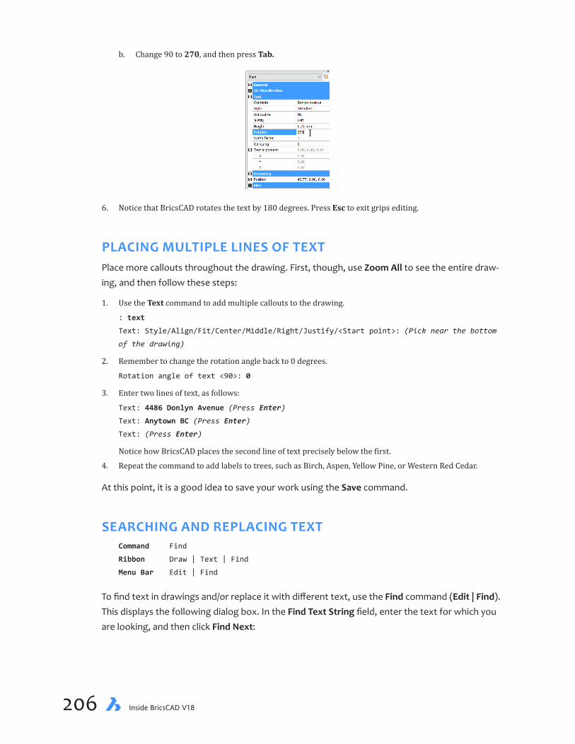
chapter 7 Adding Notes and Dimensions 207206 Inside BricsCAD V18
b. Change 90 to 270, and then press Tab.
6. Notice that BricsCAD rotates the text by 180 degrees. Press Esc to exit grips editing.
PLACING MULTIPLE LINES OF TEXTPlace more callouts throughout the drawing. First, though, use Zoom All to see the entire draw-ing, and then follow these steps:
1. Use the Text command to add multiple callouts to the drawing.
: text
Text: Style/Align/Fit/Center/Middle/Right/Justify/<Start point>: (Pick near the bottom
of the drawing)
2. Remember to change the rotation angle back to 0 degrees.
Rotation angle of text <90>: 0
3. Enter two lines of text, as follows:
Text: 4486 Donlyn Avenue (Press Enter)
Text: Anytown BC (Press Enter)
Text: (Press Enter)
Notice how BricsCAD places the second line of text precisely below the first.
4. Repeat the command to add labels to trees, such as Birch, Aspen, Yellow Pine, or Western Red Cedar.
At this point, it is a good idea to save your work using the Save command.
SEARCHING AND REPLACING TEXTCommand Find
Ribbon Draw | Text | Find
Menu Bar Edit | Find
To find text in drawings and/or replace it with different text, use the Find command (Edit | Find). This displays the following dialog box. In the Find Text String field, enter the text for which you are looking, and then click Find Next:

chapter 7 Adding Notes and Dimensions 207206 Inside BricsCAD V18
By clicking the Options button, you can narrow the search by BricsCAD to certain kinds of text:
Ð Block Attribute Value — attribute text found in blocks
Ð Dimension Annotation Text — text in dimensions, including leaders
Ð Text (MText, DText, Text) — all other kinds of text, including field text
Ð Table Text — text found in the cells of tables
Ð Hyperlink — text in URLs (links)
Ð Hyperlink Description — text found in the descriptions of hyperlinks
And then there are these additional options for narrowing down the search further:
Ð Match Case — text must match the pattern of upper and lower case
Ð Whole Words — text must have spaces or punctuation on either side, and so not be part of a larger word
Ð Use Wildcard — text contains characters wildcards, such as * (any number of characters) and ? (any single character)
Ð Search Blocks — searches for text inside of blocks
Ð (new to v18) Ignore Hidden Items — does not search for text on hidden and frozen layers
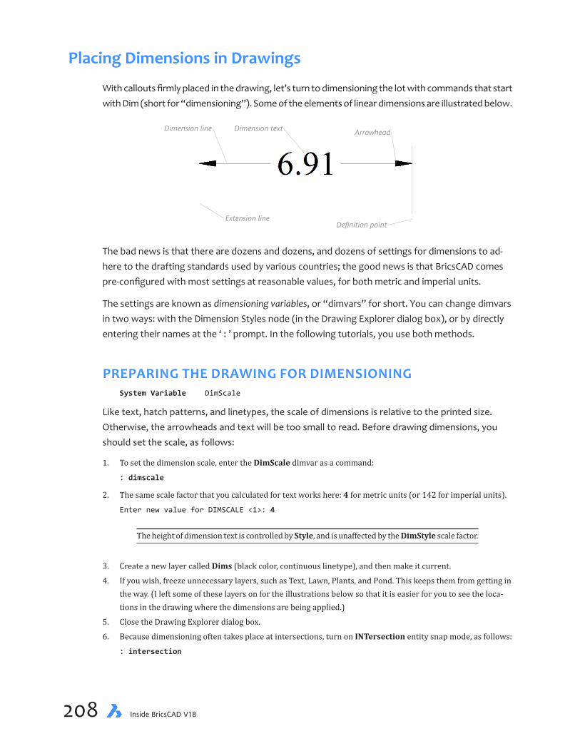
chapter 7 Adding Notes and Dimensions 209208 Inside BricsCAD V18
Placing Dimensions in Drawings
With callouts firmly placed in the drawing, let’s turn to dimensioning the lot with commands that start with Dim (short for “dimensioning”). Some of the elements of linear dimensions are illustrated below.
Dimension textDimension line Arrowhead
Definition pointExtension line
The bad news is that there are dozens and dozens, and dozens of settings for dimensions to ad-here to the drafting standards used by various countries; the good news is that BricsCAD comes pre-configured with most settings at reasonable values, for both metric and imperial units.
The settings are known as dimensioning variables, or “dimvars” for short. You can change dimvars in two ways: with the Dimension Styles node (in the Drawing Explorer dialog box), or by directly entering their names at the ‘ : ’ prompt. In the following tutorials, you use both methods.
PREPARING THE DRAWING FOR DIMENSIONINGSystem Variable DimScale
Like text, hatch patterns, and linetypes, the scale of dimensions is relative to the printed size. Otherwise, the arrowheads and text will be too small to read. Before drawing dimensions, you should set the scale, as follows:
1. To set the dimension scale, enter the DimScale dimvar as a command:
: dimscale
2. The same scale factor that you calculated for text works here: 4 for metric units (or 142 for imperial units).
Enter new value for DIMSCALE <1>: 4
The height of dimension text is controlled by Style, and is unaffected by the DimStyle scale factor.
3. Create a new layer called Dims (black color, continuous linetype), and then make it current.
4. If you wish, freeze unnecessary layers, such as Text, Lawn, Plants, and Pond. This keeps them from getting in the way. (I left some of these layers on for the illustrations below so that it is easier for you to see the loca-tions in the drawing where the dimensions are being applied.)
5. Close the Drawing Explorer dialog box.
6. Because dimensioning often takes place at intersections, turn on INTersection entity snap mode, as follows:
: intersection

chapter 7 Adding Notes and Dimensions 209208 Inside BricsCAD V18
DIMENSIONING THE YARDCommand DimLinear
Ribbon Draw | Dimensions | Linear
Menu Bar Dimension | Linear
Alias dimlin
Command DimContinue
Ribbon Draw | Dimensions | Continuous
Menu Bar Dimension | Continuous
Alias dimcont
Begin dimensioning with the most used dimensioning command, DimLinear. It draws horizontal, vertical, and rotated linear dimensions — depending on how you move the cursor. By tradition, most dimensions are either horizontal or vertical. In rare cases they are placed at an angle (“ro-tated”). BricsCAD determines how to construct the dimension from the relative positions of your pick points in the drawing.
Ð For horizontal dimensions — pick two points roughly horizontal, and BricsCAD draws the dimension per-fectly horizontal
Ð For vertical dimensions — pick two points roughly vertical, and BricsCAD draws the dimension exactly vertical.
Ð For rotated dimensions — at the prompt, enter R to force the dimension to be placed at an angle. BricsCAD prompts you to specify the angle. A more useful command, however, is DimAligned, which determines the angle automatically.
1. To begin, select Linear from the Dimensions menu.
: _dimlinear
2. Dimension the lower lot line horizontally, as follows:
ENTER to select entity/<Origin of first extension line>: (Pick intersection near #1)
Origin of second extension line: (Pick other intersection at #2)
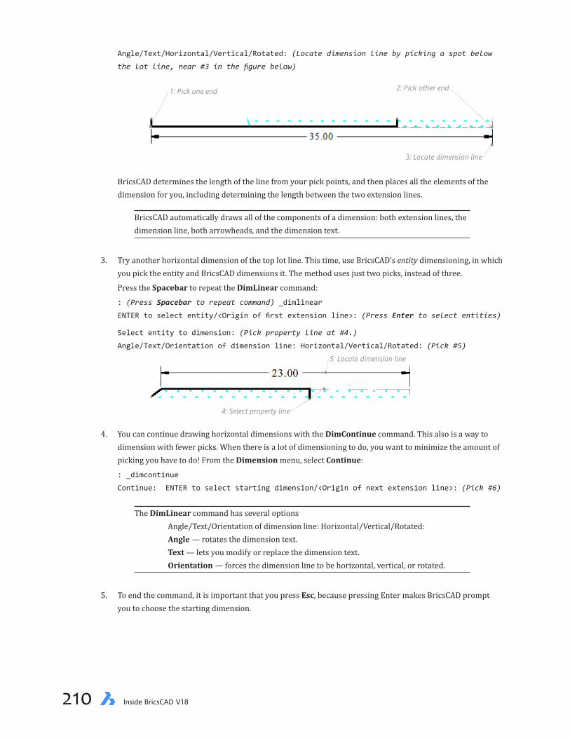
chapter 7 Adding Notes and Dimensions 211210 Inside BricsCAD V18
Angle/Text/Horizontal/Vertical/Rotated: (Locate dimension line by picking a spot below
the lot line, near #3 in the figure below)
2: Pick other end1: Pick one end
3: Locate dimension line
BricsCAD determines the length of the line from your pick points, and then places all the elements of the dimension for you, including determining the length between the two extension lines.
BricsCAD automatically draws all of the components of a dimension: both extension lines, the dimension line, both arrowheads, and the dimension text.
3. Try another horizontal dimension of the top lot line. This time, use BricsCAD’s entity dimensioning, in which you pick the entity and BricsCAD dimensions it. The method uses just two picks, instead of three.
Press the Spacebar to repeat the DimLinear command:
: (Press Spacebar to repeat command) _dimlinear
ENTER to select entity/<Origin of first extension line>: (Press Enter to select entities)
Select entity to dimension: (Pick property line at #4.)
Angle/Text/Orientation of dimension line: Horizontal/Vertical/Rotated: (Pick #5)
4: Select property line
5: Locate dimension line
4. You can continue drawing horizontal dimensions with the DimContinue command. This also is a way to dimension with fewer picks. When there is a lot of dimensioning to do, you want to minimize the amount of picking you have to do! From the Dimension menu, select Continue:
: _dimcontinue
Continue: ENTER to select starting dimension/<Origin of next extension line>: (Pick #6)
The DimLinear command has several options Angle/Text/Orientation of dimension line: Horizontal/Vertical/Rotated: Angle — rotates the dimension text. Text — lets you modify or replace the dimension text. Orientation — forces the dimension line to be horizontal, vertical, or rotated.
5. To end the command, it is important that you press Esc, because pressing Enter makes BricsCAD prompt you to choose the starting dimension.

chapter 7 Adding Notes and Dimensions 211210 Inside BricsCAD V18
Continue: ENTER to select starting dimension/<Origin of next extension line>: (Press ESC
to end the command)
Because BricsCAD knows where the last extension line was, all it now needs to know the location of the next extension line to draw in the second dimension.
VERTICAL AND BASELINE DIMENSIONSAs noted earlier, the DimLinear command draws vertical dimensions in addition to horizontal di-mensions. When you move the cursor in a vertical direction, BricsCAD knows to draw the dimen-sion vertically.
1. To draw vertical dimensions, select Dimension | Linear, and then follow the numbered pick point from the illustration below.
: _dimlinear
ENTER to select entity/<Origin of first extension line>: (Pick #7)
Origin of second extension line: (Pick #8)
Angle/Text/Orientation of dimension line: Horizontal/Vertical/Rotated: (Pick #9)
#7
#8
#10
#11
#9
2. Use DimContinue to continue the vertical dimensions along the right side of the lot at points 10 and 11.
: dimcont
Continue: ENTER to select starting dimension/<Origin of next extension line>: (Pick #10)
Continue: ENTER to select starting dimension/<Origin of next extension line>: (Pick #11)
Continue: ENTER to select starting dimension/<Origin of next extension line>: (Press
Esc)

chapter 7 Adding Notes and Dimensions 213212 Inside BricsCAD V18
Baseline DimensioningCommand DimBaseline
Ribbon Draw | Dimensions | Baseline
Menu Bar Dimensions | Baseline
Alias dimbase
A variation on the DimContinue command is DimBaseline. Rather than continuing a dimension from the previous extension line, DimBaseline dimensions from the original extension line (a.k.a. “the base line”). To see how it works, first place a vertical dimension:
3. With the DimLinear command, place the first extension line at #12. Place the second extension line at #13, and then the dimension line at #14.
4. Now try out the DimBaseline command. From the Dimension menu, select Baseline.
: _dimbaseline
Baseline: ENTER to select starting dimension/<Origin of next extension line>: (Pick #15)
Baseline: ENTER to select starting dimension/<Origin of next extension line>: (Press Esc)
Pressing Esc exits the command.
#13
#14
#15
#12
The DimBaseline and DimContinue commands also work with other linear and angular dimen-sions.
ALIGNED AND RADIAL DIMENSIONSCommand DimAligned
Ribbon Draw | Dimensions | Aligned
Menu Bar Dimensions | Aligned
Alias dimali
So far, you have dimensioned the straight and angled portions of the lot line with horizontal and vertical dimension commands. To dimension an angled line, you use the DimAligned command.

chapter 7 Adding Notes and Dimensions 213212 Inside BricsCAD V18
1. Enter the DimAligned command:
: dimaligned
ENTER to select entity/<Origin of first extension line>: (Pick #16.)
Origin of second extension line: (Pick #17.)
Angle/Text/<Location of dimension line>: (Pick #18.)
#16
#17
#18
The dimension you draw may look different, depending on how the angled line was drawn.
Radial DimensionsCommand DimRadius
Ribbon Draw | Dimensions | Radius
Menu Bar Dimensions | Radius
Alias dimrad
So far, all dimensioning commands have presented pretty much the same prompts. Now try one that’s a bit different. The DimRadius command dimensions arcs and circles. The related DimDiam-eter command places dimensions across diameters of circular entities.
2. (Zoom in for a closer look, if necessary.) Enter the DimRadius command, and then follow the prompts:
: dimradius
Select arc or circle: (Pick #19)
Dimension text = 1
Angle/Text/<Location of dimension line>: (Pick #20)
The DimRadius command gives you some flexibility as to where you want to place the dimension text. As you move the cursor, BricsCAD ghosts in the leader and text.
#19
#20
3. Save your work, and then print out a copy.
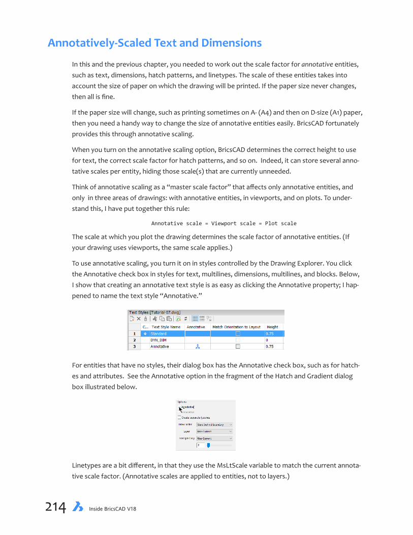
chapter 7 Adding Notes and Dimensions 215214 Inside BricsCAD V18
Annotatively-Scaled Text and Dimensions
In this and the previous chapter, you needed to work out the scale factor for annotative entities, such as text, dimensions, hatch patterns, and linetypes. The scale of these entities takes into account the size of paper on which the drawing will be printed. If the paper size never changes, then all is fine.
If the paper size will change, such as printing sometimes on A- (A4) and then on D-size (A1) paper, then you need a handy way to change the size of annotative entities easily. BricsCAD fortunately provides this through annotative scaling.
When you turn on the annotative scaling option, BricsCAD determines the correct height to use for text, the correct scale factor for hatch patterns, and so on. Indeed, it can store several anno-tative scales per entity, hiding those scale(s) that are currently unneeded.
Think of annotative scaling as a “master scale factor” that affects only annotative entities, and only in three areas of drawings: with annotative entities, in viewports, and on plots. To under-stand this, I have put together this rule:
Annotative scale = Viewport scale = Plot scale
The scale at which you plot the drawing determines the scale factor of annotative entities. (If your drawing uses viewports, the same scale applies.)
To use annotative scaling, you turn it on in styles controlled by the Drawing Explorer. You click the Annotative check box in styles for text, multilines, dimensions, multilines, and blocks. Below, I show that creating an annotative text style is as easy as clicking the Annotative property; I hap-pened to name the text style “Annotative.”
For entities that have no styles, their dialog box has the Annotative check box, such as for hatch-es and attributes. See the Annotative option in the fragment of the Hatch and Gradient dialog box illustrated below.
Linetypes are a bit different, in that they use the MsLtScale variable to match the current annota-tive scale factor. (Annotative scales are applied to entities, not to layers.)

chapter 7 Adding Notes and Dimensions 215214 Inside BricsCAD V18
You can’t just type one in any annotative scale factor; you are limited to the ones provided by BricsCAD. You can, however, edit the list with the ScaleListEdit command to add and remove scale factors.
USING ANNOTATIVE SCALINGSo far, I’ve been doing a lot of talking. Let’s see how annotative scaling works for real. I’ll have you switch back and forth between model and layout modes. Layout mode shows you what the drawing looks like on the paper you’ll be printing it on; it is like an interactive print preview mode. (I’ve frozen the Dims layer so that the dimensions do not clutter the drawing.)
You find tabs for switching between the model and layout modes at the bottom of the drawing area.
1. Open the Imp-Tutorial-06.dwg file.
2. Switch to layout mode by clicking the Layout1 tab.

chapter 7 Adding Notes and Dimensions 217216 Inside BricsCAD V18
In the figure below:
Ð White area represents the paper
Ð Black rectangle is the viewport, in which you see the model; the viewport has green grips and dashed lines, because I have selected it
Ð Dashed rectangle is the margin, the area at the edge of the paper on which the printer cannot print
3. When the drawing is first opened in a viewport, it is most likely displayed at a non-standard scale. Bric-sCAD fits the model’s extents inside the area of the viewport, and so this drawing has an initial scale of 0.00462733 (or 1:216.1073, expressed as a scale factor). To see the model’s scale, select the viewport border, and then check the Custom Scale value in the Properties panel.
Because 1:216.1073 is a non-standard scale factor, you have to change it to meet these two criteria:
Ð The entire drawing must fit the viewport (usually somewhat smaller than the viewport)
Ð The drawing must be at a standard scale
To convert the scale into the scale factor, divide 1 by the scale. In this case 0.00462733 = 1 / 0.00462733 = 1:216.1073
4. You change the oddball scale to a standard one through a button on the status bar or the Properties panel. On the status bar, the annotative scale button appears near the right end next to DUCS, and probably looks like 1:1 right now.
(If you do not see it, click the arrow at the right end of the status bar, and then turn on the Annotative Scale button.)
The annotation scale button does double-duty of setting the scale for the viewport and for annotative ob-jects.

chapter 7 Adding Notes and Dimensions 217216 Inside BricsCAD V18
5. Enter the model area by double-clicking inside the viewport border (the black rectangle), because annota-tive scaling works only in model space.
6. Use the Zoom Extents command to ensure that the drawing fits the viewport snugly. This gives you the larg-est scale permissible.
7. For the scale factor, pick the next largest whole number to 1:216.1073, because standard scale factors are always whole numbers, such as 1:250. Choosing the next largest number makes the drawing slightly smaller in the viewport. You don’t want some of the drawing hidden by the edge of the viewport! (If the scale factor were something like 1:7.25, then pick 1:8.)
There is, however, no scale factor listed at 1:250, so you need to add it with the ScaleListEdit command, as follows:
a. Enter the ScaleListEdit command. Notice the Edit Scale List dialog box.
: scalelistedit
b. In the Edit Scale List dialog box, click Add.
c. For the ‘Name appearing in scale list’ you can type anything. For this tutorial, enter 1:250.
d. For ‘Drawing Units’ enter 250. Leave the Paper Units set to 1.
e. Click OK.

chapter 7 Adding Notes and Dimensions 219218 Inside BricsCAD V18
8. To pick the annotative scale factor, right-click the Annotation Scale button (1:1), and then select 1:250.
You know that you have picked the correct scale when the drawing becomes slightly smaller, but not too much smaller. (See figure below.) Notice also that the reported scale matches the annotation factor you selected. From now on, the viewport scale is locked to the annotation scale. This means that any change you make to the annotation scale changes the viewport scale automatically.
If the drawing does not change its size in the viewport automatically, you will need to make the change manually. In the Properties panel, change the value of Viewport Scale to match Annotation Scale, or 1:4 for this tutorial.
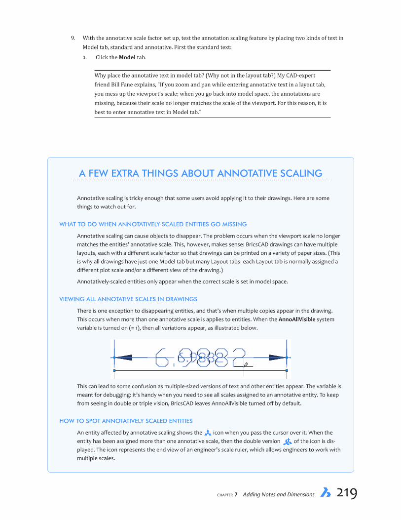
chapter 7 Adding Notes and Dimensions 219218 Inside BricsCAD V18
A FEW EXTRA THINGS ABOUT ANNOTATIVE SCALING
Annotative scaling is tricky enough that some users avoid applying it to their drawings. Here are some things to watch out for.
WHAT TO DO WHEN ANNOTATIVELY-SCALED ENTITIES GO MISSING
Annotative scaling can cause objects to disappear. The problem occurs when the viewport scale no longer matches the entities’ annotative scale. This, however, makes sense: BricsCAD drawings can have multiple layouts, each with a different scale factor so that drawings can be printed on a variety of paper sizes. (This is why all drawings have just one Model tab but many Layout tabs: each Layout tab is normally assigned a different plot scale and/or a different view of the drawing.)
Annotatively-scaled entities only appear when the correct scale is set in model space.
VIEWING ALL ANNOTATIVE SCALES IN DRAWINGS
There is one exception to disappearing entities, and that’s when multiple copies appear in the drawing. This occurs when more than one annotative scale is applies to entities. When the AnnoAllVisible system variable is turned on (= 1), then all variations appear, as illustrated below.
This can lead to some confusion as multiple-sized versions of text and other entities appear. The variable is meant for debugging: it’s handy when you need to see all scales assigned to an annotative entity. To keep from seeing in double or triple vision, BricsCAD leaves AnnoAllVisible turned off by default.
HOW TO SPOT ANNOTATIVELY SCALED ENTITIES
An entity affected by annotative scaling shows the icon when you pass the cursor over it. When the entity has been assigned more than one annotative scale, then the double version of the icon is dis-played. The icon represents the end view of an engineer’s scale ruler, which allows engineers to work with multiple scales.
9. With the annotative scale factor set up, test the annotation scaling feature by placing two kinds of text in Model tab, standard and annotative. First the standard text:
a. Click the Model tab.
Why place the annotative text in model tab? (Why not in the layout tab?) My CAD-expert friend Bill Fane explains, “If you zoom and pan while entering annotative text in a layout tab, you mess up the viewport’s scale; when you go back into model space, the annotations are missing, because their scale no longer matches the scale of the viewport. For this reason, it is best to enter annotative text in Model tab.”

chapter 7 Adding Notes and Dimensions 221220 Inside BricsCAD V18
QUICK SUMMARY OF QLEADER
: qleader
Start of leader <Settings>:
Next point:
To point: <Undo>:
First line of annotation text:
Next line of annotation text:
Startofleader — starts drawing the leader line at the arrowhead end
Settings — displays the Settings dialog box
Next point — draws knee of the leader line, where it bends
To point — continues drawing the leader line with a knee at each pick point, until you press Enter
Undo — reverses the drawing of the last leader line
Firstlineofannotationtext — enter text for the leader
Nextlineofannotationtext — enters additional lines of text until you press Enter
SETTINGS DIALOG BOX
Annotation — specifies the type of annotation to add: mtext (default), an entity from the drawing, a toler-ance specification, a block, or no annotation at all.
Reuse — determines if the annotation used for the previous leader should be reused.
Leader — draws the leader as straight segments or as a spline
...continued

chapter 7 Adding Notes and Dimensions 221220 Inside BricsCAD V18
b. Enter the Text command to place regular text with the “Standard” style (which is non-annotative) at a height of 1/8" (0.125"):
: text
Text: Style/Align/Fit/Center/Middle/Right/Justify/<Start point>: (Pick a point)
Height of text <0.2000>: 0.125
Rotation angle of text <0>: (Press Enter)
Text: Driveway
Text: (Press Enter)
Notice that the text looks very tiny. It is so tiny that I needed to highlight it with a blue selection rect-angle; look for the short dash in the center. It is so tiny because it is placed at the size we normally use for text in drawings, 1/8". Recall from earlier in the chapter that we would normally scale it up by 250x and so draw it 31.25" high!
10. Now place the annotative text:
a. Restart the Text command, and then use the Style option to change the text style to an annotative one.
: text
Text: Style/Align/Fit/Center/Middle/Right/Justify/<Start point>: s
Text style to use (or ‘?’): Annotative
Text: Style/Align/Fit/Center/Middle/Right/Justify/<Start point>: (Pick a point)
...continued
Arrowhead — specifies the arrowhead style
Multi-line Text — toggles options for placing annotations as multiline text
Attachment location — locates the mtext relative to the leader line
Maximumnumberofpoints — specifies the maximum number of knee points before command switches to annotation mode
Angle Constraints — specifies the angle for the first and second knees: Any Angle, Horizontal, 90°, 45°, 30°, or 15°

chapter 7 Adding Notes and Dimensions 223222 Inside BricsCAD V18
b. Again place text with a height of 1/8".
Height of text <0.2000>: 0.125
Rotation angle of text <0>: (Press Enter)
Text: Driveway
Text: (Press Enter)
Notice that the text looks a reasonable size. BricsCAD did the scale calculation for us and deter-mined that the text should be 31.25" tall.
11. Any text you place now in Model tab will be scaled appropriately for the viewport and the scale factor. To see that the text appears at the correct size in the viewport, switch to Layout1. The text placed with the Standard style is effectively invisible, but the annotative text “Driveway” is correctly visible.
If the drawing does not contain an annotative text style, then you can create one like this: 1. Enter the Style command. 2. Make a copy of an existing style by clicking the New button. 3. Click the Annotative option. It’s that simple!
4. Give the style a clever name, such as “Annotative,” and then exit the Drawing Explorer.
12. Select the annotative text, and notice that the Properties panel reports two scales:
Ð Paper text height 1/4"
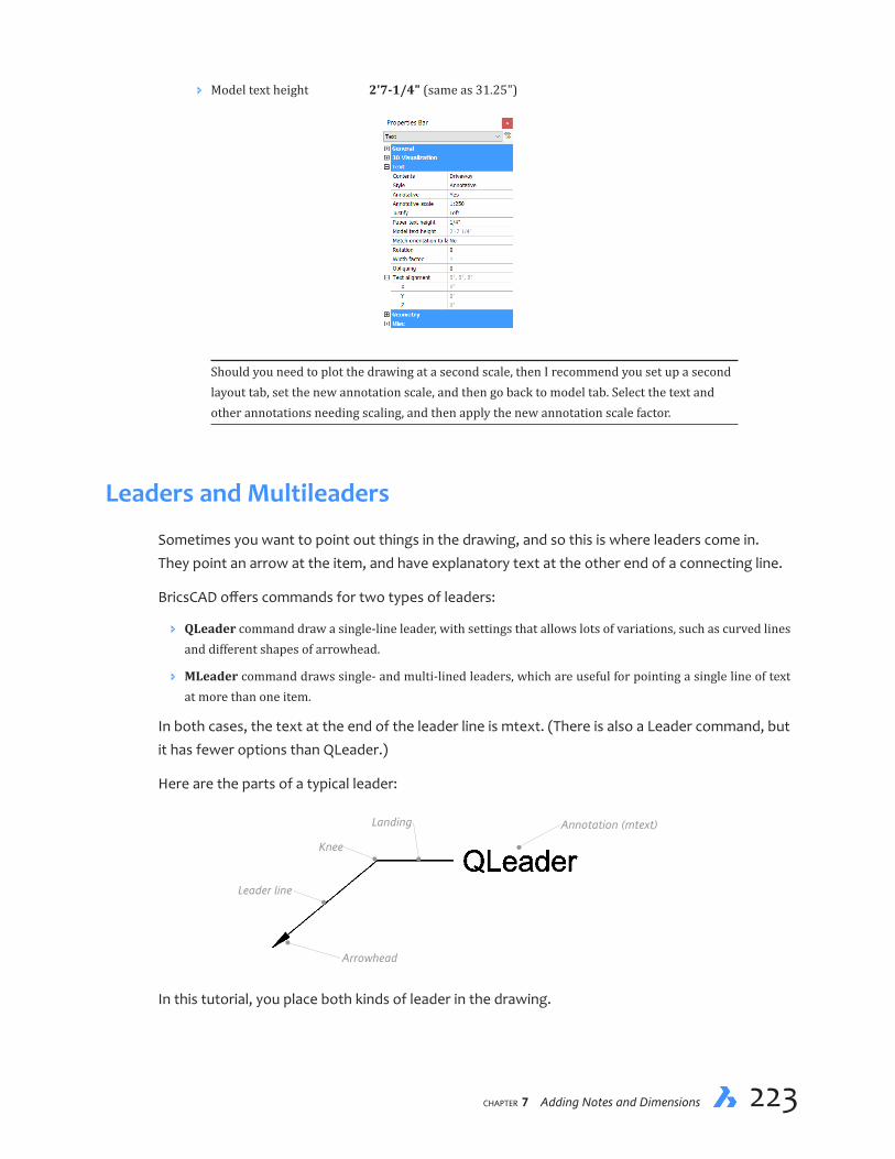
chapter 7 Adding Notes and Dimensions 223222 Inside BricsCAD V18
Ð Model text height 2'7-1/4" (same as 31.25")
Should you need to plot the drawing at a second scale, then I recommend you set up a second layout tab, set the new annotation scale, and then go back to model tab. Select the text and other annotations needing scaling, and then apply the new annotation scale factor.
Leaders and Multileaders
Sometimes you want to point out things in the drawing, and so this is where leaders come in. They point an arrow at the item, and have explanatory text at the other end of a connecting line.
BricsCAD offers commands for two types of leaders:
Ð QLeader command draw a single-line leader, with settings that allows lots of variations, such as curved lines and different shapes of arrowhead.
Ð MLeader command draws single- and multi-lined leaders, which are useful for pointing a single line of text at more than one item.
In both cases, the text at the end of the leader line is mtext. (There is also a Leader command, but it has fewer options than QLeader.)
Here are the parts of a typical leader:
Annotation (mtext)
Knee
Landing
Arrowhead
Leader line
In this tutorial, you place both kinds of leader in the drawing.
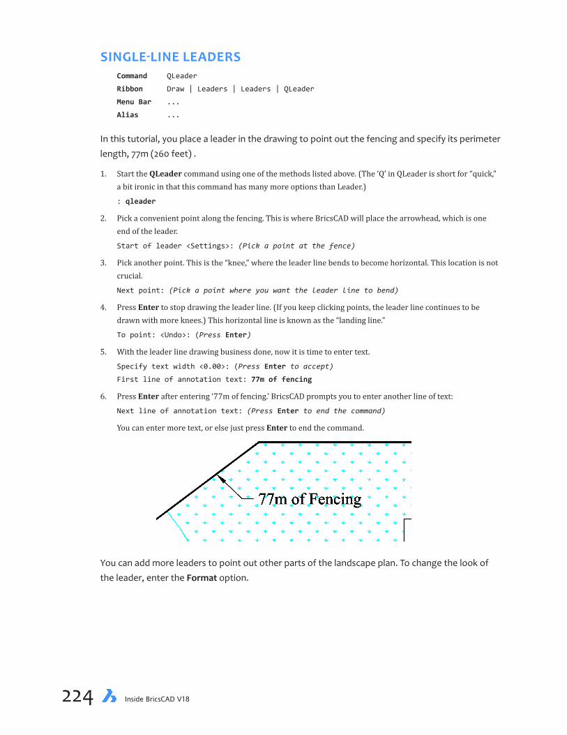
chapter 7 Adding Notes and Dimensions 225224 Inside BricsCAD V18
SINGLE-LINELEADERSCommand QLeader
Ribbon Draw | Leaders | Leaders | QLeader
Menu Bar ...
Alias ...
In this tutorial, you place a leader in the drawing to point out the fencing and specify its perimeter length, 77m (260 feet) .
1. Start the QLeader command using one of the methods listed above. (The ‘Q’ in QLeader is short for “quick,” a bit ironic in that this command has many more options than Leader.)
: qleader
2. Pick a convenient point along the fencing. This is where BricsCAD will place the arrowhead, which is one end of the leader.
Start of leader <Settings>: (Pick a point at the fence)
3. Pick another point. This is the “knee,” where the leader line bends to become horizontal. This location is not crucial.
Next point: (Pick a point where you want the leader line to bend)
4. Press Enter to stop drawing the leader line. (If you keep clicking points, the leader line continues to be drawn with more knees.) This horizontal line is known as the “landing line.”
To point: <Undo>: (Press Enter)
5. With the leader line drawing business done, now it is time to enter text.
Specify text width <0.00>: (Press Enter to accept)
First line of annotation text: 77m of fencing
6. Press Enter after entering ‘77m of fencing.’ BricsCAD prompts you to enter another line of text:
Next line of annotation text: (Press Enter to end the command)
You can enter more text, or else just press Enter to end the command.
You can add more leaders to point out other parts of the landscape plan. To change the look of the leader, enter the Format option.
chapter 7 Adding Notes and Dimensions 225224 Inside BricsCAD V18
MULTI-LINELEADERSCommand DimRadius
Ribbon Draw | Leaders | Leaders | Multileader
Menu Bar Dimension | Multileader
Alias ...
In this tutorial, you place a leader in the drawing to point out the stepping stones. First, you place one leader, and then you add a second one to the same annotation.
QUICK SUMMARY OF MLEADER
: mleader
Specify leader arrowhead location or [leader Landing first/Content first/Options]
<Options>:
Specifyleaderarrowheadlocation — starts drawing the leader line at the arrowhead end
leaderLandingfirst — starts drawing the leader line in reverse, from the landing
Contentfirst — start the leader by placing first the annotation
Options — continues drawing the leader line with a knee at each pick point, until you press Enter
OPTIONS OPTIONS
Enter an option [Leader type/leader lAnding/Content type/Maxpoints/First angle/
Second angle/eXit options] <eXit options>:
Leader type — specifies the leader type, straight, spline or none
Leader landing — toggles the leader landing
Content type — select the annotation types, multiline text, block or none
Maxpoints — specifies the maximum leader line nodes; default = 2
First and second angle — specifies the multiple* angle for the first leader segment; default = 0 degrees
Exit options — exits the options part of this command
* The angle specified here is used as a multiple for the actual angle. For instance, enter 15 to place the line at increments of 15 degrees, such as 15, 30 ,and 45.
ADDITIONAL MLEADER COMMANDS
MLeaderEdit adds and removes leader lines from multileaders.
MLeaderEditExt adds and removes leader lines and vertices from multileaders.
MLeaderStyle creates, edits, and deletes multileader styles (operates in Drawing Explorer).
aiMLeaderEditAdd adds multi-legged leaders.
aiMLeaderEditRemove removes leader lines.
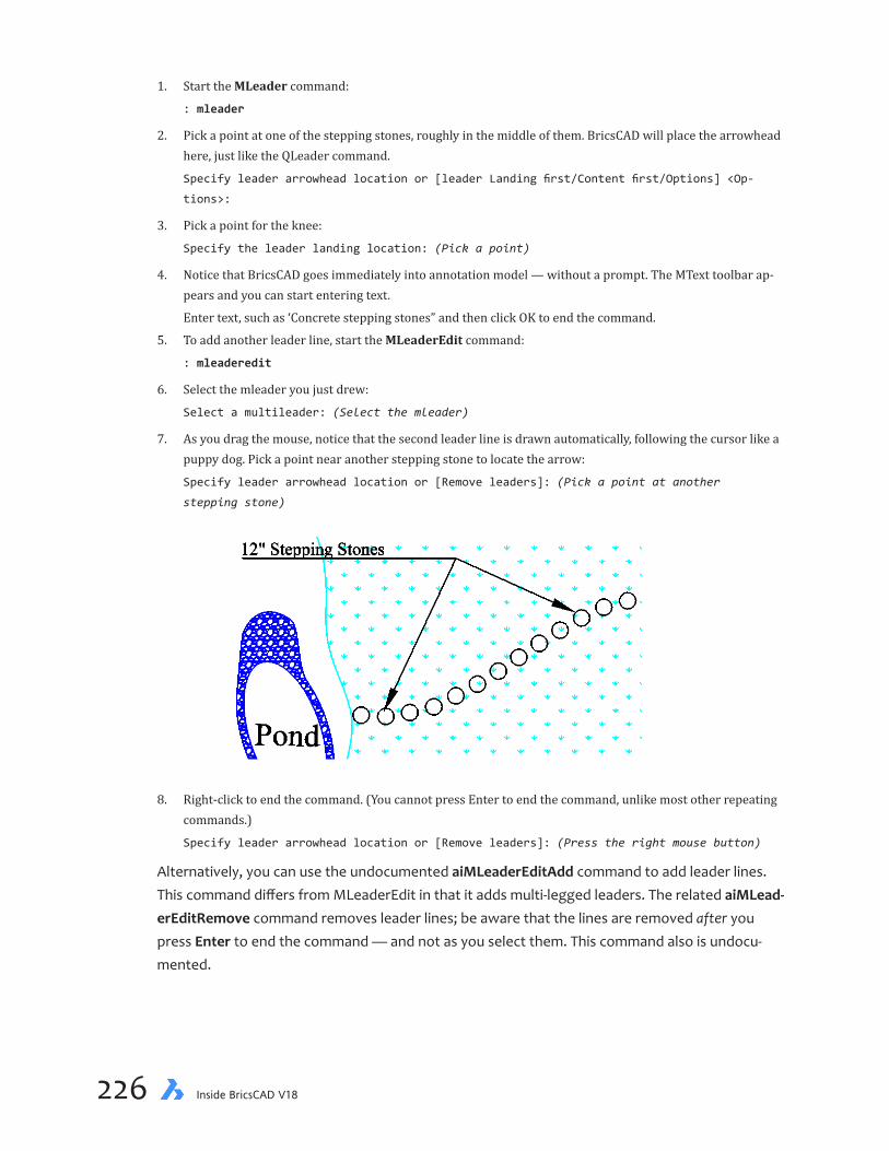
chapter 7 Adding Notes and Dimensions 227226 Inside BricsCAD V18
1. Start the MLeader command:
: mleader
2. Pick a point at one of the stepping stones, roughly in the middle of them. BricsCAD will place the arrowhead here, just like the QLeader command.
Specify leader arrowhead location or [leader Landing first/Content first/Options] <Op-
tions>:
3. Pick a point for the knee:
Specify the leader landing location: (Pick a point)
4. Notice that BricsCAD goes immediately into annotation model — without a prompt. The MText toolbar ap-pears and you can start entering text.
Enter text, such as ‘Concrete stepping stones” and then click OK to end the command.
5. To add another leader line, start the MLeaderEdit command:
: mleaderedit
6. Select the mleader you just drew:
Select a multileader: (Select the mleader)
7. As you drag the mouse, notice that the second leader line is drawn automatically, following the cursor like a puppy dog. Pick a point near another stepping stone to locate the arrow:
Specify leader arrowhead location or [Remove leaders]: (Pick a point at another
stepping stone)
8. Right-click to end the command. (You cannot press Enter to end the command, unlike most other repeating commands.)
Specify leader arrowhead location or [Remove leaders]: (Press the right mouse button)
Alternatively, you can use the undocumented aiMLeaderEditAdd command to add leader lines. This command differs from MLeaderEdit in that it adds multi-legged leaders. The related aiMLead-erEditRemove command removes leader lines; be aware that the lines are removed after you press Enter to end the command — and not as you select them. This command also is undocu-mented.

chapter 7 Adding Notes and Dimensions 227226 Inside BricsCAD V18
———
This lesson showed how to add text and dimensions to drawings.
This tutorial is now complete. The following lessons describe other 2D CAD topics in greater de-tail, such as working with attribute data,and constructing 2D regions.

chapter 7 Adding Notes and Dimensions PB228 Inside BricsCAD V18
Notes

CHAPTER 8
Bills of Material
OneofthemostpowerfulaspectofCADisitsabilitytogenerateinformationfromdrawings. You saw a hint of this when in an earlier lesson you used the Dist and List commands to find distances, lengths, areas, and totals.
In this chapter, you learn how to extract information stored in the drawing, and then how to create a bill of materials (BOM) in BricsCAD drawings and externally in spreadsheets.
IN THIS CHAPTER
• Defining attributes (custom data)
• Attaching attributes to blocks
• Exporting attributes and block data from drawings, then importing data into spreadsheets for analysis
• Importing spreadsheets into drawings as tables
• Automatic bills of materials from 3D component drawings

chapter 8 Bills of Material 231230 Inside BricsCAD V18
KEY TERMS IN THIS CHAPTER
Attribute — consists of text data attached to blocks
Attribute extraction — describes a process that exports attribute and block data to files
Block — describes BricsCAD’s term for a symbol. (Other CAD software packages call blocks “compo-nents,” “cells,” “shapes,” “symbols,” or “parts.”)
Block
Attributes
Insertion point
Donut — consists of a solid-filled circle
Insertion point — specifies the place at which blocks are inserted in drawings
Prompt — refers to the text displayed by BricsCAD during block insertions
Tag — identifies attributes by name
Templatefile — defines the format of data in export files
Value — specifies the default values of attribute data
USEFUL ABBREVIATIONS
CDF Comma-delimited format
DXF Drawing interchange format
ODF Open Document file
SDF Space-delimited format
TXT Extension for an ASCII text file
XLS Excel spreadsheet file
NEW COMMANDS
Command Aliases Menu Bar Ribbon Tab
AttDef at Tools | Attributes | Define Attributes Insert | Block | Define Attribute AttDisp ad Tools | Attributes | Attribute Display Insert | Block | Attribute Display AttExt ax Tools | Attributes | Extract Attributes Insert | Block | Extract Attributes Donut do, doughnut Draw | Donut Draw | Draw | Polygons | Donut Table ... Draw | Table Draw | Tables | Table

chapter 8 Bills of Material 231230 Inside BricsCAD V18
About Attribute Data
CAD can be used for many different kinds of drawings, such as floor plans, building construction, mechanical design, and electrical layouts. Drawings are usually made from standard parts, such as desks, windows, bolts, and switches. When the parts contain attribute data, then the drawings become truly useful.
In this chapter, you create the schematic drawing for an automobile electrical system. The draw-ing contains numerous components, such as a battery, fuse, several kinds of light bulbs, and quite a few ground and solder connections. You could count these components by hand, but I’d wager that you would miss a few and end up with a wrong total. (Well, you might not miscount, but I know I would.)
It’s faster and 100% accurate to let software do the counting. Part of the counting process is called “attribute extraction,” because BricsCAD extracts attribute data from the drawing and then stores it in a data file. The data file can be imported into a spreadsheet to count the components, determine component costs, and so on. The parts count can be placed in drawings as tables.
This is very powerful stuff, and is known in many disciplines as BOM (short for “bill of materials”) or in architecture as FM (short for “facilities management”).
THIS CHAPTER’S DRAWING
During this lesson, you work with the following drawing file, electric.dwg.
chapter 8 Bills of Material 233232 Inside BricsCAD V18
The attribute extraction process progresses through these steps:
Step 1: Template — define an attribute extraction template file
Step 2: Extract — use the AttExt command to extract attributes to a data file
Step 3: Import — import the data file into a spreadsheet program
AttExt is the name of the command that extracts attributes from drawings. It is a very old com-mand, one that goes back to 1985 in some CAD packages — which explains why it is somewhat ornery. Over the decades it has remained essentially unchanged, except for the addition of the dialog box front-end. While other programs may boast “coaches” and “wizards” to step you through complicated procedures, BricsCAD does not assist you in this area. And so this lesson ex-ists to guide you.
In the first tutorial, you create a headlamp block, and then attach attribute data to it. In the fol-lowing tutorials, you open a copy of the completed electric.dwg file, and then extract the attri-bute data from it. Later, you open the attribute data file in a spreadsheet program to count the parts, and finally you bring that data back into BricsCAD as a table.
Download the files for this chapter from https://www.dropbox.com/s/ft6gzw3r408ndgd/Inside-BricsCAD-Tutorial-Files.zip?dl=0.
Creating Blocks with Attributes
The example drawing for this lesson is part of the electrical schematic of an antique automobile. See the previous page. (Wondering which auto? It’s adapted from the electrical system of my first car, a 1965 Volkswagen Beetle.) If you have repair manuals or other schematic drawings lay-ing around, you can use them to produce your own schematic with BricsCAD. If not, then follow along with the schematic sketch I provide with this book.
To begin, you create one block and then attach attributes to it. Working with attributes is kind of tedious, which is why I won’t get you create all of the blocks. I’ve got them all in a drawing file that you can download.
1. Start BricsCAD with a new drawing using the 2D Drawing workspace (in metric units) or the Default-cm.dwt template file.
2. Because you will be drawing the block to an accuracy of 0.1 unit, it makes sense to change the snap spacing to this value, as well as to turn on the grid. Follow these steps:
a. On the status bar, right-click SNAP, and then choose Settings from the shortcut menu.
b. In the Settings dialog box, make these changes:
Grid Mode Grid on
Grid Unit 0.1,0.1
Grid Major 1
Grid Display Turn off Display beyond LIMITS area
Snap Mode Snap on
Snap Unit 0.1,0.1

chapter 8 Bills of Material 233232 Inside BricsCAD V18
The result should be like the bold-faced entries in the Settings dialog box illustrated below.
c. Click X when done to close the dialog box. Notice that the screen fills with a fine grid of lines. (Recall that the the extents of the grid display are determined by the limits.)
3. A couple more steps, and you will be ready to draw:
a. There is no need for the UCS icon, so turn it off with the UcsIcon command:
: ucsicon
[ucs icon ON/ucs icon OFf/display in All views/display at ORigin/display in Corner]
<ON>: off
b. Perform a Zoom All to center the drawing on the screen.
Notice that there are some light gray grid lines and some that are dark gray. The dark gray lines are called “major grid lines” and are spaced 100 units apart; the light gray ones are called “minor grid lines” and are spaced 10 units apart.
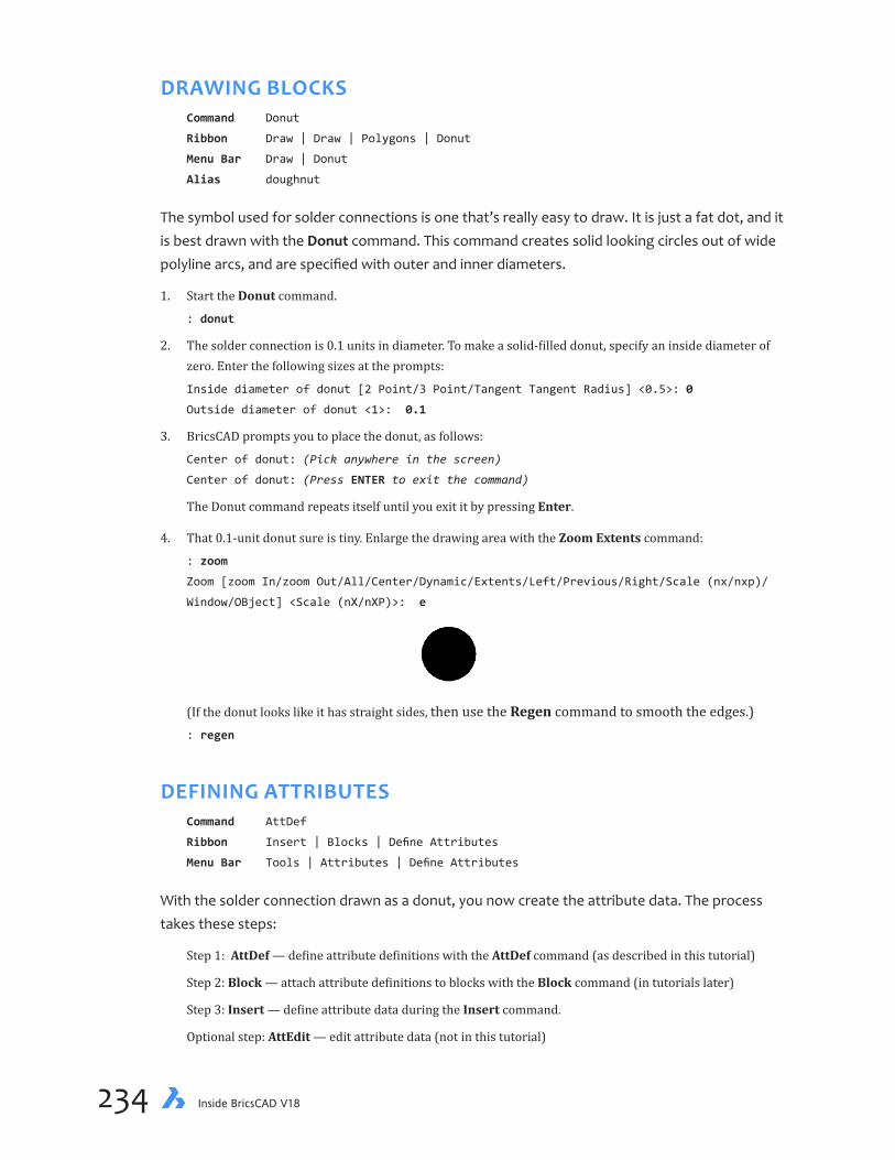
chapter 8 Bills of Material 235234 Inside BricsCAD V18
DRAWING BLOCKSCommand Donut
Ribbon Draw | Draw | Polygons | Donut
Menu Bar Draw | Donut
Alias doughnut
The symbol used for solder connections is one that’s really easy to draw. It is just a fat dot, and it is best drawn with the Donut command. This command creates solid looking circles out of wide polyline arcs, and are specified with outer and inner diameters.
1. Start the Donut command.
: donut
2. The solder connection is 0.1 units in diameter. To make a solid-filled donut, specify an inside diameter of zero. Enter the following sizes at the prompts:
Inside diameter of donut [2 Point/3 Point/Tangent Tangent Radius] <0.5>: 0
Outside diameter of donut <1>: 0.1
3. BricsCAD prompts you to place the donut, as follows:
Center of donut: (Pick anywhere in the screen)
Center of donut: (Press ENTER to exit the command)
The Donut command repeats itself until you exit it by pressing Enter.
4. That 0.1-unit donut sure is tiny. Enlarge the drawing area with the Zoom Extents command:
: zoom
Zoom [zoom In/zoom Out/All/Center/Dynamic/Extents/Left/Previous/Right/Scale (nx/nxp)/
Window/OBject] <Scale (nX/nXP)>: e
(If the donut looks like it has straight sides, then use the Regen command to smooth the edges.): regen
DEFINING ATTRIBUTESCommand AttDef
Ribbon Insert | Blocks | Define Attributes
Menu Bar Tools | Attributes | Define Attributes
With the solder connection drawn as a donut, you now create the attribute data. The process takes these steps:
Step 1: AttDef — define attribute definitions with the AttDef command (as described in this tutorial)
Step 2: Block — attach attribute definitions to blocks with the Block command (in tutorials later)
Step 3: Insert — define attribute data during the Insert command.
Optional step: AttEdit — edit attribute data (not in this tutorial)

chapter 8 Bills of Material 235234 Inside BricsCAD V18
Attributes are customized data that store information, such as part numbers and prices. Drawings are useful to showing you how to assemble the electrical system, but the bill of materials (derived from the attributes) tells you how many parts are needed for the assembly.
Attributes attach only to blocks. It is possible to add data to other kinds of entities, but the process is more technical, because it involves xdata (short for “extended entity data”). Nev-ertheless, BricsCAD can export all data (such as properties) from all entities to CSV files for further processing.
A single block can contain one or more attributes. Just as blocks are graphical descriptions, at-tributes are textual descriptions. Think of attributes as custom data, or user-defined properties. And only text or numbers can be used; graphical data, such as images and other entities, cannot be included in attributes.
Attributes can describe the block’s part number, manufacturer, price, and any other text-based information you want to include. These attributes can have descriptive labels, such as “Product name,” “Manufacturer,” “Model number,” “Stock number,” “Serial number,” and “Material.”
You could include “Price” as an attribute field; but since prices tend to change, it is better to deal with the price in the spreadsheet program. Instead, I suggest that if you need prices in attributes that you use a price code instead, such as AA, which is substituted later with the latest price.
Attributes are created with the AttDefcommand (short for “attribute definition”).
1. Start the AttDef command. Notice the Define Attribute dialog box.
: attdef
2. In the Attribute section, enter the following text:
Attribute Field Value
Tag Product Prompt Product Default Solder Connection
3. In the Text section of the dialog box, set the Height (of the text) to a tiny, unobtrusive value, such as 0.01. You don’t actually want to see attributes in drawings, and so you work with them only through dialog boxes.

chapter 8 Bills of Material 237236 Inside BricsCAD V18
4. The Insert Coordinates section defines the point in the drawing at which the attribute text starts. A logical location would be on or near the block. To obtain the value of the Insert Coordinates, follow these steps:
a. In the Insert Coordinates section, click the button. The dialog box disappears temporarily.
b. In the command bar, notice that BricsCAD prompts you for the location of the insertion point.
Specify insertion point: (Pick a point to the right of the donut)
c. Pick a point to the right of the connection block:
As soon as you do, the dialog box returns. Its fields should now be filled out with values that look simi-lar to the following:
5. Click OK. Notice that BricsCAD shows the tag next to the donut.
Although blocks can contain multiple attributes, the AttDef command creates just one at-tribute at a time. You have to repeat the command to define additional attributes, up to a maximum of 245.
ADDING MORE ATTRIBUTESFor the Stock Number, add it as a second attribute directly below the first:
1. Press the spacebar to repeat the AttDef command:
: (Press spacebar)
_attdef
And the Define Attribute dialog box reappears.
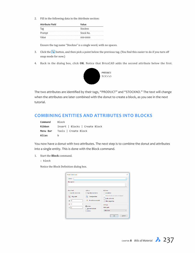
chapter 8 Bills of Material 237236 Inside BricsCAD V18
2. Fill in the following data in the Attribute section:
Attribute Field Value
Tag Stockno Prompt Stock No. Value 000-0000
Ensure the tag name “Stockno” is a single word, with no spaces.
3. Click the button, and then pick a point below the previous tag. (You find this easier to do if you turn off snap mode for now.)
4. Back in the dialog box, click OK. Notice that BricsCAD adds the second attribute below the first.
The two attributes are identified by their tags, “PRODUCT” and “STOCKNO.” The text will change when the attributes are later combined with the donut to create a block, as you see in the next tutorial.
COMBINING ENTITIES AND ATTRIBUTES INTO BLOCKSCommand Block
Ribbon Insert | Blocks | Create Block
Menu Bar Tools | Create Block
Alias b
You now have a donut with two attributes. The next step is to combine the donut and attributes into a single entity. This is done with the Block command.
1. Start the Block command.
: block
Notice the Block Definition dialog box.

chapter 8 Bills of Material 239238 Inside BricsCAD V18
2. The first thing to do is enter a name for the block. In this case, enter “Connect” in the Name field:
Name: Connect
You can ignore the Description field.
3. The most important aspect to blocks is their base point. The base point is the spot where the block will be inserted in drawings — either with coordinates or a cursor pick. The default is at the origin of the drawing at 0,0,0. However, other points might be more convenient, as described in the boxed text on the next page.
For this block, change the base point to the center of the donut:
a. In the Base Point section, click the Pick Point button. The dialog box disappears temporarily.
b. In the command bar, notice that BricsCAD prompts you for the location of the insertion point. Pick a point to the right of the connection block.
Insertion point for new block: (Pick the center of the donut)
As soon as you pick the point, the dialog box returns.
4. BricsCAD needs to know which entities will be part of the block:
a. In the Entities section, click the Select Entities button. The dialog box disappears temporarily.
b. In the command bar, notice that BricsCAD prompts you to select the entities that you want to be part of the block. Select the donut and the text.
Select entities for block: (Select donut and two attribute entities)
You can press Ctrl+A (or Cmd+A on Macs) to select all entities in the drawing, or else use windowing, like I did in the figure above.
c. Press Enter to end entity selection and then return to the dialog box.
Select entities for block: (Press ENTER)
5. Choose the Retain option. This determines what happens to the entities after you click OK.
Option Meaning
Retain Retains the entities after defining them as a block Convert to Block Creates a block from the entities, and then inserts them in the drawing; this option combines two steps: erases the entities and inserts the block Delete Erases the entities after defining them as a block; this option saves using the Erase command to later remove the entities
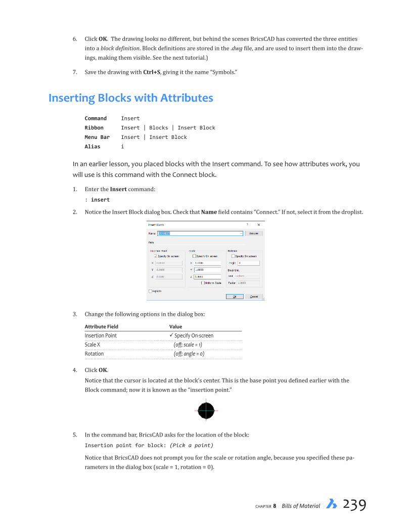
chapter 8 Bills of Material 239238 Inside BricsCAD V18
6. Click OK. The drawing looks no different, but behind the scenes BricsCAD has converted the three entities into a block definition. Block definitions are stored in the .dwg file, and are used to insert them into the draw-ings, making them visible. See the next tutorial.)
7. Save the drawing with Ctrl+S, giving it the name “Symbols.”
Inserting Blocks with AttributesCommand Insert
Ribbon Insert | Blocks | Insert Block
Menu Bar Insert | Insert Block
Alias i
In an earlier lesson, you placed blocks with the Insert command. To see how attributes work, you will use is this command with the Connect block.
1. Enter the Insert command:
: insert
2. Notice the Insert Block dialog box. Check that Name field contains “Connect.” If not, select it from the droplist.
3. Change the following options in the dialog box:
Attribute Field Value
Insertion Point Specify On-screen Scale X (off; scale = 1) Rotation (off; angle = 0)
4. Click OK.
Notice that the cursor is located at the block’s center. This is the base point you defined earlier with the Block command; now it is known as the “insertion point.”
5. In the command bar, BricsCAD asks for the location of the block:
Insertion point for block: (Pick a point)
Notice that BricsCAD does not prompt you for the scale or rotation angle, because you specified these pa-rameters in the dialog box (scale = 1, rotation = 0).

chapter 8 Bills of Material 241240 Inside BricsCAD V18
6. BricsCAD does, however, prompt you to enter the attribute values. You can press Enter to accept the de-faults:
Product <Solder Connection>: (Press Enter)
Stock No. <000-0000>: (Press Enter)
Notice that the attribute values appear next to the connection block in exactly the same location where you placed the tags.
ALTERNATIVES TO THE INSERT COMMANDIn addition to the Insert command, BricsCAD has several other methods for placing blocks in drawings:
Ð Drawing Explorer accesses blocks stored in other drawings and inserts them into drawings
Ð -Insert command displays insertion options in the command bar, and is meant for use in scripts and macros
Ð Drag’n drop to drag .dwg files from the operating system’s file manager right into the drawing
When you use drag’n to drop .dwg files from the file manager into the drawing, BricsCAD reacts differently depending on which mouse button you hold down during the action:
Ð Hold down the left mouse button — file opened as a drawing, like using the Open command
Ð Hold down the right mouse button — BricsCAD gives you options through this shortcut menu:
The functions of these options are as follows:
Default by File Extension — places known file types with appropriate commands:
File Extension Command Activated Result
Drawing .dwg Open command Inserted as a block Raster images ImageAttach command Attached as a raster image Unknown file types InsertObj command Inserted as an OLE entity (Windows only)
Insert Here — places the file as a block through the -Insert command
Open — opens the file as a drawing in a new window through the Open command
Create XRef Attachment — places the file as an externally-referenced drawing through the -XRef Attach command

chapter 8 Bills of Material 241240 Inside BricsCAD V18
Create XRef Overlay — places the file as an overlain xref through the -XRef Overlay command
Create Hyperlink Here — prompts you to select one or more entities, and then attaches a URL to them that points to the file through the -HyperLink command
Cancel — cancels the operation
ExportingDatafromDrawings
Adding attributes to blocks is tedious work, and so to save you time and trouble, I have prepared for you the drawing used by the next set of tutorials. It already contains all the needed blocks and attributes. Get your copy of the electric.dwg file from my Dropbox folder: https://www.dropbox.com/s/ft6gzw3r408ndgd/Inside-BricsCAD-Tutorial-Files.zip?dl=0.
DATA EXTRACTION Command DataExtraction
Ribbon ...
Menu Bar Tools | Attributes | Extract Data
To export data from drawings, you use the DataExtraction command. It saves the data in a CSV file, short for “comma delimited values,” which can then be read into spreadsheet and database programs for further processing. (This command is a more convenient replacement to the AttExt command, because it does not need template files.)
To extract the attribute data from the drawing, follow these steps:
1. Launch BricsCAD, and then open the electric.dwg file.
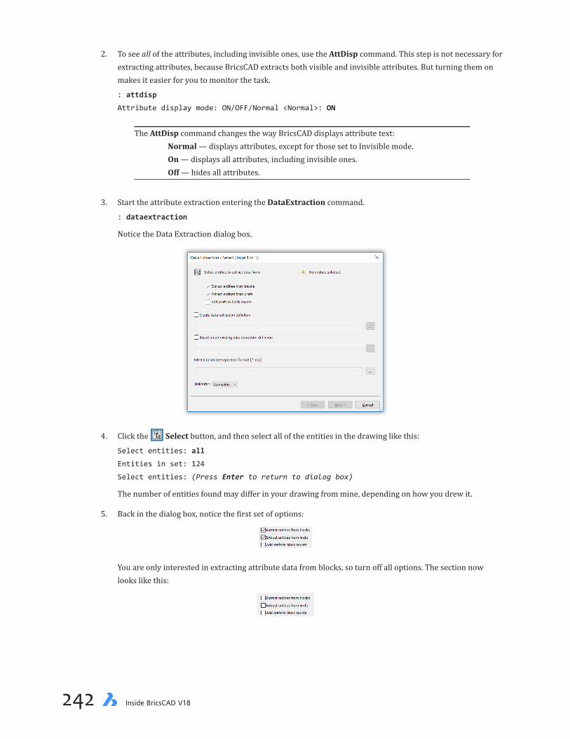
chapter 8 Bills of Material 243242 Inside BricsCAD V18
2. To see all of the attributes, including invisible ones, use the AttDisp command. This step is not necessary for extracting attributes, because BricsCAD extracts both visible and invisible attributes. But turning them on makes it easier for you to monitor the task.
: attdisp
Attribute display mode: ON/OFF/Normal <Normal>: ON
The AttDisp command changes the way BricsCAD displays attribute text: Normal — displays attributes, except for those set to Invisible mode. On — displays all attributes, including invisible ones. Off — hides all attributes.
3. Start the attribute extraction entering the DataExtraction command.
: dataextraction
Notice the Data Extraction dialog box.
4. Click the Select button, and then select all of the entities in the drawing like this:
Select entities: all
Entities in set: 124
Select entities: (Press Enter to return to dialog box)
The number of entities found may differ in your drawing from mine, depending on how you drew it.
5. Back in the dialog box, notice the first set of options:
You are only interested in extracting attribute data from blocks, so turn off all options. The section now looks like this:

chapter 8 Bills of Material 243242 Inside BricsCAD V18
6. The second set of options specify files that are needed. Let’s go through them one by one:
Create Data Extraction Definition — I recommend turning this option on.
When this option is on, BricsCAD saves the options you chose to a DXD file (short for “data extraction definition”). The next time you run this data extraction command, you use the following option (“Based on an existing data extraction definition”) to reuse the options, saving you from setting things up all over again. You see the benefit of this when you get to the next dialog box!
Based on an Existing Data Extraction Definition — Reuse the DXD file from a previous session; this option does not apply the first time you run this command.
Extract Delimiter-separated Format — Specify the file name and folder location for the extracted data. Data is saved in CSV format, which separates data values with commas: one record per row, with fields separated by commas. You have to fill out this option, as BricsCAD prevents you from moving further without it by keeping the Next button deactivated.
For ease of reference, specify the following names for each file:
Create Data Extraction Definition electric.dxd
Based on an Existing Data Extraction Definition (ignore this time around)
Extract Delimiter-separated Format electric.csv
For two of the options, click the Browse button, and then choose a convenient folder location. Specify the ‘electric’ file names.
7. Click the Delimited droplist, and change it to ‘Comma.” A delimiter is punctuation that separates data values in the CSV file. It can be a semi-colon, a comma, a space, or a tab. I recommend using the comma.
When you are done, the dialog box should look something like this.

chapter 8 Bills of Material 245244 Inside BricsCAD V18
8. Click Next. Notice that the Page 2 dialog box lists the blocks and line entities. You want data about all of them extracted, so leave everything as it is. Even the line entities, from which you can get the length of each; the total length tells you the amount of wiring needed. Here is the meaning of the options:
Ð Check boxes — to exclude an item, click the check box
Ð Select all — selects all items in the list (turns on all check boxes)
Ð Select blocks — selects just blocks, and avoids non-block entities (like the lines)
9. Click Next to carry on. When the Page 3 dialog box appears, it looks scarey as it lists every property of every entity, as well as attributes.

chapter 8 Bills of Material 245244 Inside BricsCAD V18
The options in this dialog box have the following meaning:
Ð Checkbox — selects an item to be exported to the CSV file
Ð Select Attributes — selects only attributes in the list, and excludes other items
Ð Show Checked Only — shows only the items that are selected, and hides the rest from the list
Ð Show All — shows all items, checked and unchecked
Ð Move Selected Up / Down — moves the selected item(s) up and down the list; this affects the order in which items appear in the CSV file
To turn off (or on) all properties at once, select the first property in the list, hold down the Shift key, select the last property, and then click the checkbox. To sort the columns alphabetically, click the header of each one. When you click the invisible header of the checkboxes column, it sorts by which boxes are and are not checked.
Your big job now is to turn off all properties, except for the following ones:
Length
Product
StockNo
To do this, follow these steps:
a. Click the Select Attributes button. This highlights the attributes in the list.
b. Click one of the checkboxes in front of an attribute name. This action selects both of them.
c. Click the Property header. This sorts the items alphabetically by property name.
d. Go through the list until you find Length, and then click its checkbox.

chapter 8 Bills of Material 247246 Inside BricsCAD V18
e. Click Show Checked Only to ensure that you have the correct ones.
10. The dialog box has a column labeled Additional Format column. Its purpose is for specifying different for-mats for values. You don’t want too much formatting, because that might confuse the spreadsheet program. Nevertheless, here is how to use it:
a. Next to “Length,” click the blank area under Additional Format. Notice the dialog box.
The Length field shows you what the format looks like, either the default or else after you make chang-es. In the figure shown, I changed the “Format” to Decimal and the “Precision” to 0.0. I was tempted to specify mm for “Suffix,” but then I realized that would make the spreadsheet unhappy — it would think the number was text.
b. The Product and StockNo attributes are text, and I changed the “Format” to First capital.
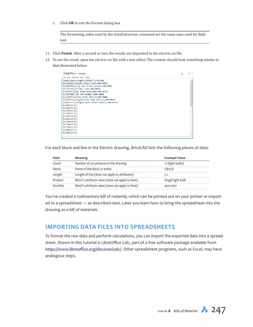
chapter 8 Bills of Material 247246 Inside BricsCAD V18
c. Click OK to exit the Format dialog box.
The formatting codes used by the DataExtraction command are the same ones used for field text.
11. Click Finish. After a second or two, the results are deposited in the electric.csv file.
12. To see the result, open the electric.csv file with a text editor. The content should look something similar to that illustrated below.
For each block and line in the Electric drawing, BricsCAD lists the following pieces of data:
Field Meaning Example Value
Count Number of occurrences in the drawing 12 (light bulbs) Name Name of the block or entity LBULB Length Length of line (does not apply to attributes) 5.1 Product Block’s attribute value (does not apply to lines) Single light bulb StockNo Block’s attribute value (does not apply to lines) 400-0001
You’ve created a rudimentary bill of material, which can be printed out on your printer or import-ed to a spreadsheet — as described next. Later you learn how to bring the spreadsheet into the drawing as a bill of materials.
IMPORTING DATA FILES INTO SPREADSHEETSTo format the raw data and perform calculations, you can import the exported data into a spread-sheet. Shown in this tutorial is LibreOffice Calc, part of a free software package available from https://www.libreoffice.org/discover/calc/. Other spreadsheet programs, such as Excel, may have analogous steps.

chapter 8 Bills of Material 249248 Inside BricsCAD V18
1. Launch the spreadsheet program.
2. To open the data file correctly, please follow these steps:
a. From the spreadsheet’s File menu, select Open to display the Open dialog box.
b. Navigate to the folder holding the electric.csv file.
c. Select the electric.csv file, and then click Open.
3. Notice that LibreOffice displays the Text Import dialog box, which allows you to specify the format of files being imported.
All the default options are sufficient, but make sure the following ones are set:
Import
From row: 1
Separator Options
Separated by: Tab Comma Semicolon

chapter 8 Bills of Material 249248 Inside BricsCAD V18
4. Click OK. Notice that Excel loads the electric.csv file, and then displays each field in its own column.
If it is necessary to adjust the column widths, select the four columns, then choose from the menu bar For-mat | Column | Optimal Width.
5. If you wish, add price and extension fields, a totals row, and format the text for lovely output. For example, I used the SUM() function to find the total length of wires (lines).
6. Remember to save the spreadsheet file.
Placing Data in Drawings as TablesCommand Table
Ribbon Draw | Tables | Table
Menu Bar Draw | Table
Data that you export as CSV files can be placed in drawings as tables. This creates a bill of materi-als right in the drawing. BricsCAD’s Table command imports data in two formats, CSV and XML.

chapter 8 Bills of Material 251250 Inside BricsCAD V18
Ð CSV — output from BircsCAD DataExtraction command, as well as other programs
Ð XML — non-product specific spreadsheet format using XML codes (extended markup language), and can be exported by LibreOffice Calc and Excel. (Don’t confuse XML with XLS, the latter being Excel’s native format.)
You place files, such as CSV and XLS, in drawings with the Table command.
1. Start the Table command. Notice the Insert Table dialog box.
2. In the Table Options section, choose the From Data option.
3. Click the Browse button to access the electric.csv file. In the Open dialog box, navigate to the folder in which the CSV file is stored. Choose it, and then click Open.
4. If necessary, change the Separator field to Command or which ever character is used to separate fields in the file. If you specify the wrong separator character, BricsCAD will later complain “Invalid format.”
5. Click OK. Notice that BricsCAD prompts you to pick the insertion point:
Specify insertion point or [Style/Width/Height]: (Pick a point)
6. The table is placed in the drawing, and BricsCAD immediately goes into formatting mode, should you wish to further change the look of the table.
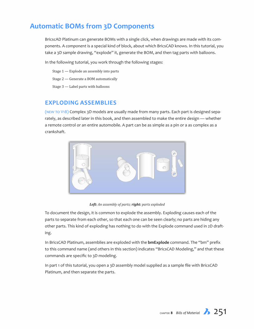
chapter 8 Bills of Material 251250 Inside BricsCAD V18
AutomaticBOMsfrom3DComponents
BricscAD Platinum can generate BOMs with a single click, when drawings are made with its com-ponents. A component is a special kind of block, about which BricsCAD knows. In this tutorial, you take a 3D sample drawing, “explode” it, generate the BOM, and then tag parts with balloons.
In the following tutorial, you work through the following stages:
Stage 1 — Explode an assembly into parts
Stage 2 — Generate a BOM automatically
Stage 3 — Label parts with balloons
EXPLODING ASSEMBLIES(new to V18) Complex 3D models are usually made from many parts. Each part is designed sepa-rately, as described later in this book, and then assembled to make the entire design — whether a remote control or an entire automobile. A part can be as simple as a pin or a as complex as a crankshaft.
Left: An assembly of parts; right: parts exploded
To document the design, it is common to explode the assembly. Exploding causes each of the parts to separate from each other, so that each one can be seen clearly; no parts are hiding any other parts. This kind of exploding has nothing to do with the Explode command used in 2D draft-ing.
In BricsCAD Platinum, assemblies are exploded with the bmExplode command. The “bm” prefix to this command name (and others in this section) indicates “BricsCAD Modeling,” and that these commands are specific to 3D modeling.
In part 1 of this tutorial, you open a 3D assembly model supplied as a sample file with BricsCAD Platinum, and then separate the parts.

chapter 8 Bills of Material 253252 Inside BricsCAD V18
1. Start BricsCAD Platinum, and then open the 3D model piston-pin.dwg. This drawing contains two compo-nents in an assembly.
2. Enter the bmExplode command.
: bmexplode
Select explosion algorithm [Table by Level/Table by Types/Manual/Settings] <Manual>: TL
Left: An assembly of two parts; right: parts exploded
QUICK SUMMARY OF bmEXPLODE
: bmexplode
Select explosion algorithm [Table by Level/Table by Types/Manual/Settings]
<Manual>:
Select a position of the exploded representation:
TablebyLevel(TL)— places components according to their level in the assembly tree in the same row
TablebyTypes(TT)— places components of the same type together in the same row”
Manual — places components to be moved apart manually
Settings — determines how assembly is exploded:
Ð Top — explodes only top level components to suppress minor components
Ð Bottom — explodes components
Ð Name — assigns a name to the settings so that they can be used for future explosions

chapter 8 Bills of Material 253252 Inside BricsCAD V18
3. Notice the BricsCAD turns the exploded parts into a single block. This makes it easier to place many parts at once. Pick a point in the drawing to place the exploded components.
Select a position of the exploded representation: (Pick a point in the drawing away from
the source components)
GENERATING BOMsBricsCAD automatically generates a bill of material from any drawing made with components with the bmBom command. Bills of material are listed in table form.
All you have to do is specify the BOM table’s location in the drawing. The command creates a table listing an identification number for each component, such as 1, 2, 3; the name of the com-ponents; and quantity of each. The table is a regular BricsCAD table that you can edit anyway you see fit. It is subject to the properties of the TableStyle command.
For the bmBom command to work, it needs at least one component. The components do not need to be assembled, nor does the assembly need to be exploded; the drawing needs to contain just one component.
QUICK SUMMARY OF bmBOM
: bmbom
Insertion point [Name/Top level/Bottom level/Configure]:
Insertion point — places the table in the drawing by its upper-left corner
Name — adds a name to the title, such as “Lift Parts.”
Top level — makes the BOM table from the top level components only; this is useful for suppressing many minor components.
Bottom level — makes the BOM table from all components.
Configure— specifies which columns are included in the table: Description, Density, Volume, Mass, Mate-rial, Thickness (only for sheet metal parts), and Parameters.

chapter 8 Bills of Material 255254 Inside BricsCAD V18
In part 2 of this tutorial, you generate a bill of material from the parts.
1. Continue with the model from the previous tutorial.
2. Enter the bmBom command:
: bmbom
Insertion point [Name/Top level/Bottom level/Configure]: (Pick a point in the drawing to
place the table)
That’s it, you’re done! BricsCAD does all the work creating the table for you. If you want to change the look, then use the TableStyle command; to change the content of the table, use the bmBom command’s Configure option, which lets you choose among these columns: Description, Density, Volume, Mass, Material, Thickness, and Parameters.
ATTACHING BALLOONS(new to V18) BricsCAD semi-automatically attaches balloons to components using the bmBalloon command. Balloons are used to identify components, making a visual link between the geometry and the text in the BOM table.

chapter 8 Bills of Material 255254 Inside BricsCAD V18
QUICK SUMMARY OF bmBALLOON
: bmballoon
Select a component insert [select other Table/choose balloon Frame]:
Pick point to place balloon:
Insert — places the arrowhead end of the balloon, preferably on the component
select other Table — chooses the BOM table to use, should more than one exist in the drawing
choose balloon Frame — choose the balloon style: circle, rectangle, triangle, or hexagon.
Pick point — places the balloon end; hold down the Shift key to align balloons
During the bmBalloon command, you pick the component and then specify the location of the balloon. The command identifies the component and assigns the ID number, which it gets from the BOM table. Balloons can be attached only after the BOM is generated. This command can be used only in model space.
BricsCAD constructs balloons from multileaders, and so they are subject to the properties of the MLeaderStyle command. You can edit the balloons like multileaders, such as pointing multiple leaders to multiple, identical components. Traditionally, balloons are lined up to make it easier to read and find them, and so BricsCAD accommodates this: hold down the Shift key while placing them. This lines up the balloons, vertically or horizontally.
In part 3 of this tutorial, you attach reference balloons to the parts.
1. Start the bmBalloon command:
: bmballoon
2. Pick one of the components. Notice that the arrowhead end of the balloon attaches itself to the component.
Select a component insert [select other Table/choose balloon Frame]: (Pick a component)
3. Place the rest of the balloons at a convenient location in the drawing, away from the other components:
Pick a point to place balloon: (Pick a point)

chapter 8 Bills of Material PB256 Inside BricsCAD V18
4. Repeat the bmBalloon command to place a balloon for the other component. At the ‘Pick point to place bal-loon’ prompt, hold down the Shift key so that the second balloon lines up with the first one.
———
You learned how to export attribute data to spreadsheets, and then bring formatted spreadsheet data back into BricsCAD. You also learned about creating, populating, and editing tables. At the end of the chapter, you learned how to explode a 3D assembly, have BricsCAD generate a BOM automatically from components, and then place identifying balloons. You learn more about 3D in later chapters.
Next, you learn about a more sophisticated 2D entity known as the region.

CHAPTER 9
Working with 2D Regions &
Booleans
HereyoulearnhowtoincreaseyourCADefficiencybyworkingwithregionsandapplyingBoolean operations. These are two BricsCAD features for constructing complex 2D shapes, and then analyzing them. BricsCAD does this far faster than if you were to perform the calculations by hand.
In this chapter you learn to use the similar Boundary and Region commands, and commands related to boolean operations. (The Region command is available only in the Pro and Platinum editions of BricsCAD.)
IN THIS CHAPTER
• Converting entities into regions
• Applying Boolean operations to regions
• Finding the mass properties of regions

258 Inside BricsCAD V18
KEY TERMS IN THIS CHAPTER
Boolean — refers to logical operations, such as AND, OR, and NOT
Mass property — reports the properties of a mass, such as its area, centroid, and radius of gyration
Pointfilter— returns a single coordinate
Region — consists of a closed 2D area
NEW COMMANDS
Command Shortcut Menu Bar Ribbon
DelObj … … ...Intersect in Modify | Solid Editing| Intersect Solid | Edit | IntersectMassProp ... Tools | Inquiry | Region/Mass Properties Tools | Inquiry | Mass PropertiesRegion reg Draw | Region ...Subtract su Modify | Solid Editing | Subtract Solid | Edit | SubtractUnion uni Modify | Solid Editing| Union Solid | Edit | Union
THIS CHAPTER’S DRAWING
By the end of this lesson, your drawing will look like this one:
RegionTutorial drawing

chapter 9 Working with 2D Regions & Booleans 259
About Regions
BricsCAD works with regions. These are closed 2D areas of almost any shape. Regions are inter-esting, because two or more can be combined using Boolean operations. These operations join, intersect, and subtract one region from the other. This lets you create a single entity with holes in it, and then analyze its physical properties.
Technically, regions are ACIS entities, the same technology used for 3D solid models. The outer boundary of the region goes by the name of a “loop.” The holes inside of regions are called “is-lands.” The loops and islands can have any kind of shape, from a simple triangle to flowing curves.
Loop (outer boundary)
Island (inner boundary)
Region
HOW TO CREATE REGIONSIn a curious twist of fate, BricsCAD cannot create regions from scratch, such as using the PLine command to directly draw polylines. Rather, BricsCAD converts existing closed entities into regions. To do this, BricsCAD provides you with two commands, Boundary and Region. They are subtly different:
Ð Boundary command displays a dialog box, then prompts you to pick a point inside a closed area. It finds the boundary, and makes a region or a polyline; along it. (It is a subset of the Hatch command.)
Ð Region command prompts you to select entities and/or boundaries that make up a closed area, and then generates a region entity; it operates at the command line
Either way, both create a region entity out of a closed area (made of one or more entities). So, it takes two steps to create a region:
Step 1: Draw the shape using drawing commands such as PLine, Arc, and Circle. To create a region success-fully, the shape must be closed. Self-intersecting curves are made into multiple regions. See figure below for examples. Left to right, you end up with one region, no region, and three regions.
Left: Closed non-self-intersecting shape; center: Not-closed shape cannot become a region;
right: Self-intersecting curve becomes multiple regions

260 Inside BricsCAD V18
Step 2: Convert the shape into a region with the Boundary or Region commands. The results of the com-mands differs for the shapes shown in the figure below:
Command ClosedEntity OpenEntity Self-intersecting Entity
Boundary: 1 region o or 1 regions * 1 region per pick Region: 1 region 0 regions 3 regions with 1 pick
* The Boundary command can make a region from an open area if the gap is smaller than the tolerance.
The two commands aren’t able to combine non-overlapping entities into one. For instance, select three circles, each an inch apart, and they become three regions. (This behavior may change in a future release of the software.)
Both commands leave the source entities in place. Change the DelObj (short for “delete objects”) variable to -2 or 2 to change this behavior in the Region command. (This variable has no effect on the Boundary command.) Set it to -2 or 2 to have Region erase the source entities automatically:
DelObj Meaning
-2 Prompts if source entities should be erased with Region -1 Prompts if source entities should be erased during commands like Extrude, Revolve, and Sweep 0 Leaves source entities in place 1 (default) Erases source entities only during commands like Extrude, Revolve, and Sweep 2 Erases source entities with Region
The U command can be used to change region entities back to their original components. Regions are always closed; there are no open regions.
After entities are converted to regions, they look no different, but they do have different proper-ties, of which you learn about later. In the following tutorials, you first use the Boundary com-mand and then the Region command to see how they work. Later, you apply boolean operations.
TUTORIAL: CREATING BOUNDARIESAvailable in all versions of BricsCAD
Command Boundary
Ribbon Draw | hatch | Boundary
Menu Bar Draw | Boundary Polyline
Alias BO
The Boundary command draws a boundary around the inside of selected areas and/or entities. It draws them as polylines or as regions — your choice, although in this tutorial you want regions.

chapter 9 Working with 2D Regions & Booleans 261
QUICK SUMMARY OF BOUNDARY OPTIONS
The Boundary dialog box contains options that control how boundaries are created.
BOUNDARIES
The Pick Points button dismisses the dialog box temporarily, and the prompts you to pick a point in the drawing: ‘Select a point to define a boundary or hatch area.’ You can pick inside more than one boundary.
BOUNDARY SET
Boundary Set section determines where BricsCAD should look for entities from which to create boundaries.
The default is the entire current viewport, but you can change this with the New button to smaller areas, such as the existing selection set or the current viewport. For instance, after you click the New button and choose a number of entities, the boundary seeking algorithm limits its work to the entities you selected.
BOUNDARY RETENTION
The Boundary Retention option makes the boundary from a polyline or region.
ISLANDS
When entities contains other entities (a.k.a. “islands”), then you can tell the boundary-seeking algorithm to include or ignore them.
The circles shown below illustrate the difference between the Nested, Outer, and Ignore options. Notice the location of the cursor, and that the pick point is the same in each case.
Entities created by Boundary can look invisible, because they are created on the cur-rent layer. To see them, create a new layer with a different color.
Continued...
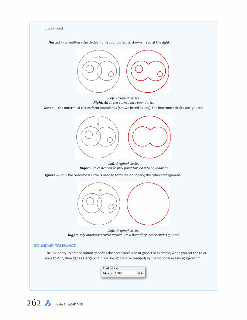
262 Inside BricsCAD V18
...continued.
Nested — all entities (the circles) form boundaries, as shown in red at the right.
Left: Original circles Right: All circles turned into boundaries
Outer — the outermost circles form boundaries (shown in red below); the innermost circles are ignored.
Left: Original circles Right: Circles nearest to pick point turned into boundaries
Ignore — only the outermost circle is used to form the boundary; the others are ignored.
Left: Original circles Right: Only outermost circle turned into a boundary; other circles ignored
BOUNDARY TOLERANCE
The Boundary Tolerance option specifies the acceptable size of gaps. For example, when you set the toler-ance to 0.1", then gaps as large as 0.1" will be ignored (or bridged) by the boundary-seeking algorithm.

chapter 9 Working with 2D Regions & Booleans 263
(This command is a subset of the Hatch command. To place hatch patterns correctly, the Hatch command first draws invisible boundaries around the areas to be hatched; the hatching is applied inside the boundary, and then the boundary is optionally erased. The Boundary command draws the same outline, but keeps it.)
The Boundary command displays a dialog box that looks like a simplified version of the Hatch and Gradient dialog box, but the hatch components are missing.
To create boundaries as regions, follow these steps:
1. Start BricsCAD with a new drawing. The workspace or template does not matter.
2. Use the Circle command to draw two overlapping circles, as illustrated below. The size does not matter.
3. Start the Boundary command. Notice the Boundary dialog box; the boxed text on a nearby page explains its functions.
4. Click the Pick Points in Boundaries button. It lets you pick a point inside the circles. Based on your pick point, BricsCAD determines the boundary(ies) automatically.
5. Notice that the dialog box disappears (temporarily), and that you are prompted at the command bar.
Pick a point to define a boundary or hatch area or [Select entities/Undo]: (Pick inside
one of the circles)

264 Inside BricsCAD V18
Pick a point inside one of the circles, as illustrated below. It doesn’t matter which one, just don’t select a circle itself.
6. Press Enter to return to the dialog box:
Pick a point to define a boundary or hatch area or [Select entities/Undo]: (Press Enter)
7. In the Boundary Retention area, change the boundary type from Polyline to “Regions”:
8. And then click OK to exit the dialog box.
9. The circles look no different, yet BricsCAD has drawn an entity inside one of them. To see it, drag it away from the circles, like this:
a. Click the circle that surrounds your pick point made during the Boundary command. Notice that when BricsCAD highlights it, the highlight looks like a crescent moon. This moon is the region entity.
b. Drag the region away from the two circles. Notice that it is an independent entity; the two original circles remain in place.
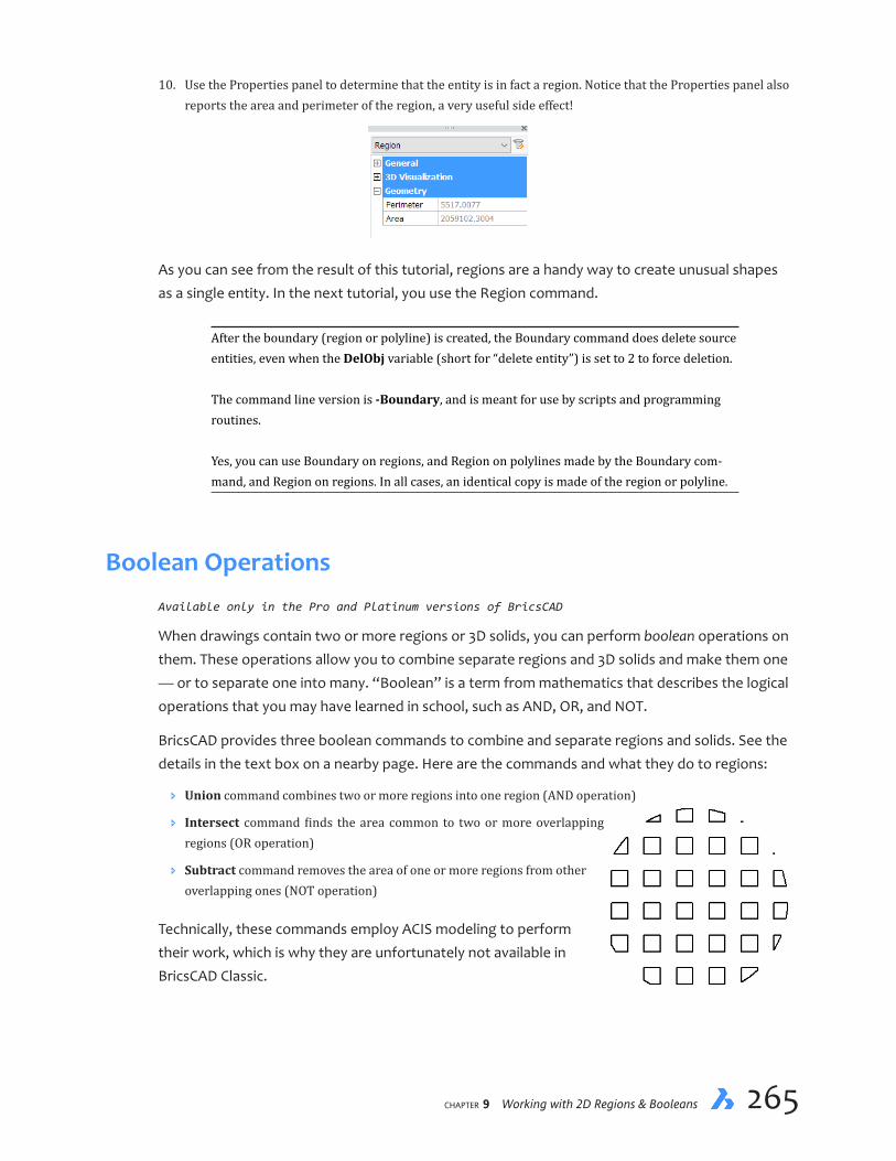
chapter 9 Working with 2D Regions & Booleans 265
10. Use the Properties panel to determine that the entity is in fact a region. Notice that the Properties panel also reports the area and perimeter of the region, a very useful side effect!
As you can see from the result of this tutorial, regions are a handy way to create unusual shapes as a single entity. In the next tutorial, you use the Region command.
After the boundary (region or polyline) is created, the Boundary command does delete source entities, even when the DelObj variable (short for “delete entity”) is set to 2 to force deletion. The command line version is -Boundary, and is meant for use by scripts and programming routines. Yes, you can use Boundary on regions, and Region on polylines made by the Boundary com-mand, and Region on regions. In all cases, an identical copy is made of the region or polyline.
Boolean OperationsAvailable only in the Pro and Platinum versions of BricsCAD
When drawings contain two or more regions or 3D solids, you can perform boolean operations on them. These operations allow you to combine separate regions and 3D solids and make them one — or to separate one into many. “Boolean” is a term from mathematics that describes the logical operations that you may have learned in school, such as AND, OR, and NOT.
BricsCAD provides three boolean commands to combine and separate regions and solids. See the details in the text box on a nearby page. Here are the commands and what they do to regions:
Ð Union command combines two or more regions into one region (AND operation)
Ð Intersect command finds the area common to two or more overlapping regions (OR operation)
Ð Subtract command removes the area of one or more regions from other overlapping ones (NOT operation)
Technically, these commands employ ACIS modeling to perform their work, which is why they are unfortunately not available in BricsCAD Classic.

266 Inside BricsCAD V18
QUICK SUMMARY OF BOOLEAN OPERATIONS
UNION COMMAND
Union joins two or more regions into one. This allows you to create complex entities from simple ones.
Left: Original objects (two regions); right: square unioned with circle as a single object
In boolean terms, the union operation returns everything in region #1 OR in #2.
INTERSECT COMMAND
Intersect removes all but the overlapping portions of two or more regions. This allows you to find the areas in common between entities.
Left: Original objects (two regions); right: circle intersected with square
In boolean terms, the intersection operation returns everything that’s in region #1 AND in region #2.
SUBTRACT COMMAND
Subtract subtracts one set of regions from another. This allows you to remove parts of entities.
There are two outcomes possible from subtraction. The outcome depends on the order in which you select the regions, as shown by the figure below. In the center result, the circle was removed from the square; in the right result, the opposite occurred: the square was removed from the circle. (Selection order does not matter for the union and intersect operations.)
Left: Original objects (two regions); center: circle subtracted from square; right: square subtracted from circle
In boolean terms, the subtraction operation returns everything that’s in region #1 but NOT in region #2.

chapter 9 Working with 2D Regions & Booleans 267
Together with Boundary and Regions commands, boolean commands are employed to construct complex shapes with BricsCAD. Indeed, boolean operations work only with region entities and 3D solids. They do not work with regular 2D and 3D entities like lines and 3D polymeshes; you need to first convert regular entities into regions or 3D solids.
The trickiest of the boolean operations is subtraction, which is why you get to employ it in the following tutorial.
TUTORIAL: CREATING A WAFFLE SHAPECommands Array and -Array
Ribbon Change | Array
Menu Bar Modify | 2D Array
Aliases AR and -AR
Command Region
Ribbon Model | Solids | Region
Menu Bar Draw | Region
Alias REG
Command Subtract
Ribbon Model | Solid Editing | Subtract
Menu Bar Model | 3D Solids Editing| Subtract
Alias SU
In this tutorial, you create a waffle shape as illustrated below. After drawing some intersecting rectangles, you will apply the Subtract command to form the waffle shape. To determine the net area, you find the mass properties of the shape; this would be very difficult to do without regions.
1. Start BricsCAD with a new drawing.
2. Using the Circle command, draw a circle with a radius of 2.875 units at the origin (0,0), as follows:
: circle
Select center of circle or [2Point/3Point/TTR/Arc/Multiple]: 0,0
Set Radius or [Diameter]: 2.875
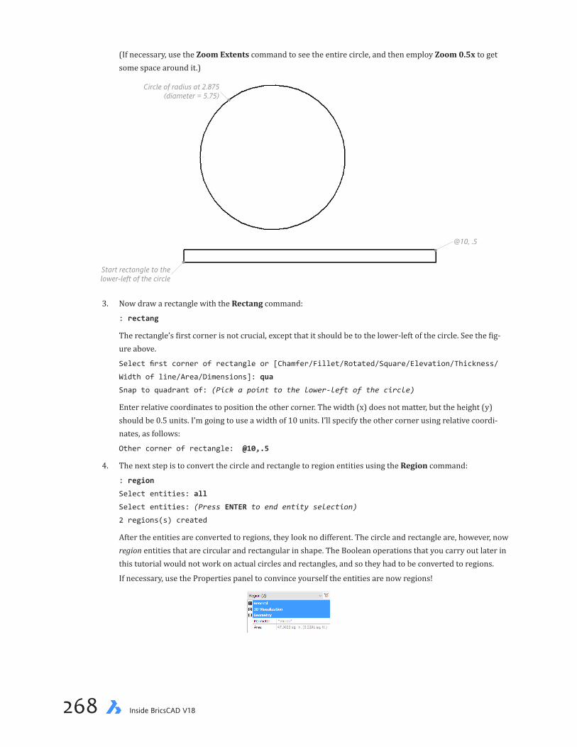
268 Inside BricsCAD V18
(If necessary, use the Zoom Extents command to see the entire circle, and then employ Zoom 0.5x to get some space around it.)
Circle of radius at 2.875(diameter = 5.75)
Start rectangle to thelower-left of the circle
@10, .5
3. Now draw a rectangle with the Rectang command:
: rectang
The rectangle’s first corner is not crucial, except that it should be to the lower-left of the circle. See the fig-ure above.
Select first corner of rectangle or [Chamfer/Fillet/Rotated/Square/Elevation/Thickness/
Width of line/Area/Dimensions]: qua
Snap to quadrant of: (Pick a point to the lower-left of the circle)
Enter relative coordinates to position the other corner. The width (x) does not matter, but the height (y) should be 0.5 units. I’m going to use a width of 10 units. I’ll specify the other corner using relative coordi-nates, as follows:
Other corner of rectangle: @10,.5
4. The next step is to convert the circle and rectangle to region entities using the Region command:
: region
Select entities: all
Select entities: (Press ENTER to end entity selection)
2 regions(s) created
After the entities are converted to regions, they look no different. The circle and rectangle are, however, now region entities that are circular and rectangular in shape. The Boolean operations that you carry out later in this tutorial would not work on actual circles and rectangles, and so they had to be converted to regions.
If necessary, use the Properties panel to convince yourself the entities are now regions!

chapter 9 Working with 2D Regions & Booleans 269
5. Create copies of the rectangle region to cover the circle.
Now, you could use the Copy command for this task, but it is much faster to deploy the -Array command. In this tutorial, you array the rectangle twice. The first time you array the rectangle vertically; the second time, you rotate one by 90 degrees (with the Mirror command) and then array it horizontally.
To start the -Array command, enter the -ar alias:
: -ar
6. Choose the rectangle:
Select entities to array: (Pick the rectangle)
Select entities to array: (Press Enter to end entity selection)
This command can make arrays that are polar (circular) or rectangular, but you want rectangular:
Type of array [Polar/Rectangular] <Rectangular>: (Press Enter to accept Rectangular)
The number of rows in the first array is somewhat arbitrary, because you want to cover the entire circle with rectangles. If there are too many, you can just erase the extras; if too few, then it’s a pain to restart the Array command, so draw too many in the first place!
Number of rows in the array <1>: 10
Number of columns <1>: (Press Enter to accept default, 1)
The distance between rows is 1 unit:
Vertical distance between rows, or spacing rectangle: 1
Notice that BricsCAD instantly creates ten copies of the rectangle.
Number of rows = 10
Entity to array
Verticaldistancebetween
rows = 1.0
(The reason I use command-line oriented -Array command instead of the dialog box-toting Array is because it can be faster to enter values at the command line than hunting through a dialog box.)
7. Use the Erase command to remove superfluous rows, in other words, those that don’t cover the circle.

270 Inside BricsCAD V18
8. Now you want a second set of rectangles at 90 degrees. Create the first one by mirroring an existing rect-angle with the Mirror command:
: mirror
Select the lowest rectangle, like this:
Select entities to mirror: (Pick the rectangle, indicated by the figure below)
Select entities to mirror: (Press ENTER to end entity selection)
BricsCAD needs an imaginary line called the “mirror line” about which to mirror the rectangle. The place-ment of the mirror line is not crucial, as long as it is at 45 degrees to the rectangle. The easy way to do this is to employ the following relative polar coordinates: @1<45 as the mirror line’s end point:
Start of mirror line: 0,0
End of mirror line: @1<45
Delete the original entities? [Yes-delete entities/No-keep entities] <No-Keep entities>:
(Press ENTER to accept default, N)
9. With the vertical rectangle in place, start the Array command. This is the dialog box version of the com-mand.
a. For Array Type, ensure Rectangular is chosen:
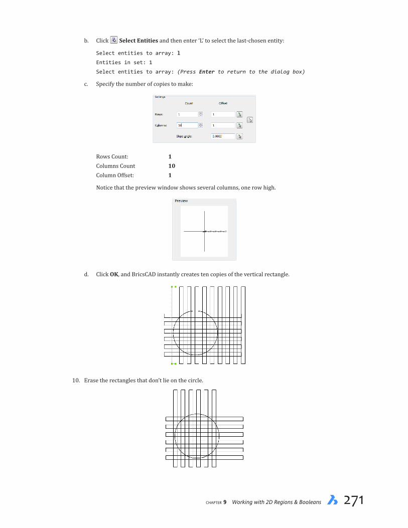
chapter 9 Working with 2D Regions & Booleans 271
b. Click Select Entities and then enter ‘L’ to select the last-chosen entity:
Select entities to array: l
Entities in set: 1
Select entities to array: (Press Enter to return to the dialog box)
c. Specify the number of copies to make:
Rows Count: 1 Columns Count 10 Column Offset: 1
Notice that the preview window shows several columns, one row high.
d. Click OK, and BricsCAD instantly creates ten copies of the vertical rectangle.
10. Erase the rectangles that don’t lie on the circle.
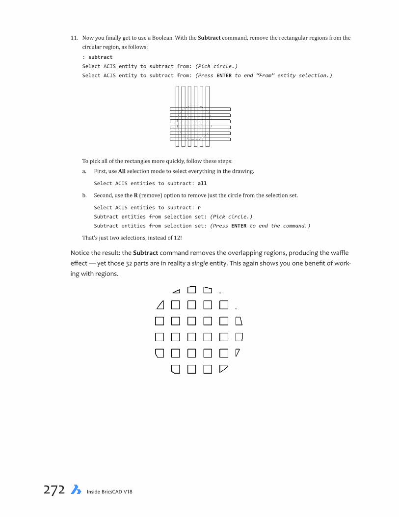
272 Inside BricsCAD V18
11. Now you finally get to use a Boolean. With the Subtract command, remove the rectangular regions from the circular region, as follows:
: subtract
Select ACIS entity to subtract from: (Pick circle.)
Select ACIS entity to subtract from: (Press ENTER to end “From” entity selection.)
To pick all of the rectangles more quickly, follow these steps:
a. First, use All selection mode to select everything in the drawing.
Select ACIS entities to subtract: all
b. Second, use the R (remove) option to remove just the circle from the selection set.
Select ACIS entities to subtract: r
Subtract entities from selection set: (Pick circle.)
Subtract entities from selection set: (Press ENTER to end the command.)
That’s just two selections, instead of 12!
Notice the result: the Subtract command removes the overlapping regions, producing the waffle effect — yet those 32 parts are in reality a single entity. This again shows you one benefit of work-ing with regions.
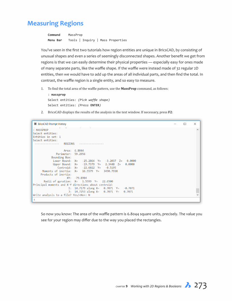
chapter 9 Working with 2D Regions & Booleans 273
Measuring RegionsCommand MassProp
Menu Bar Tools | Inquiry | Mass Properties
You’ve seen in the first two tutorials how region entities are unique in BricsCAD, by consisting of unusual shapes and even a series of seemingly disconnected shapes. Another benefit we get from regions is that we can easily determine their physical properties — especially easy for ones made of many separate parts, like the waffle shape. If the waffle were instead made of 32 regular 2D entities, then we would have to add up the areas of all individual parts, and then find the total. In contrast, the waffle region is a single entity, and so easy to measure.
1. To find the total area of the waffle pattern, use the MassProp command, as follows:
: massprop
Select entities: (Pick waffle shape)
Select entities: (Press ENTER)
2. BricsCAD displays the results of the analysis in the text window. If necessary, press F2:
So now you know: The area of the waffle pattern is 6.8044 square units, precisely. The value you see for your region may differ due to the way you placed the rectangles.

274 Inside BricsCAD V18
ABOUT MASS PROPERTIESThe MassProp command uses terms that have the following meaning:
Bounding box
Cendroid
Area
Perimeter
Ð Area — cumulative area of all 24 waffles.
Ð Perimeter — cumulate perimeters of all 24 waffles.
Ð Bounding Box: Lower Bound and Upper Bound — rectangular limits of the region; the coordinates describe the lower-left and upper-right corners of the corners of an imaginary rectangle that tightly encloses the region.
Ð Centroid — center of mass of the region’s 24 waffles, excluding the open areas.
Ð Moments of inertia — measure of the region’s resistance to angular acceleration.
Ð Product of Inertia: XY — measures the region’s resistance to change in rotation.
Ð Radius of Gyration — distance from the axis that the entire region can be concentrated to obtain the same mass moment of inertia.
Ð Principle moments and X-Y directions about centroid — equivalent to torque.
———
This lesson introduced you to regions and Boolean operations. These concepts extend to working with 3D models in BricsCAD Professional and other 3D software packages.
CHAPTER 10
Direct 3D Modeling & Editing
Here, you learn how to create 3D models using traditional and modern editing techniques. Traditional techniques use commands to create and manipulate 3D models; the modern technique is to manipulate 2D and 3D entities directly.
In this chapter, you learn how to create 3D models by directly manipulating elements, without necessar-ily using a command. (Direct modeling and editing are available only in the Pro and Platinum editions of BricsCAD.)
IN THIS CHAPTER
• Learning about 3D solid models
• Extruding profiles (2D entities) into bodies
• Rotating 3D viewpoints
• Subtracting 3D entities from one another
• Modeling with direct editing
• Aligning UCSes
• Adding fillets to 3D edges

chapter 10 Direct 3D Modeling & Editing 277276 Inside BricsCAD V18
KEY TERMS IN THIS CHAPTER
Direct modeling and editing — creates and edits 3D parts directly, without entering commands
Profiles — describes 2D entities that define 3D parts.
Quad — multi-tiled cursor with common commands
Shell — refers to a hollowed out 3D solid model
Sub entities — describes entities that make up 3D solid models, such as faces and edges
Union — joins two or more solid models into a single body
USEFUL ABBREVIATIONS
QUAD Quad cursor
SUB Sub-entity selection
NEW COMMANDS
Command Shortcut Menu Bar Ribbon Tab
DelObj ... ... ... Extrude Ext Model | 3D Solids | Extrude Solid | Create QuadDisplay F12 ... ... SolidEdit ... Model | 3D Solid Editing | Shell Solid | Edit UCS ... ... ...
THIS CHAPTER’S MODEL
By the end of this lesson, your 3D model will look like this:
Focus-bracket drawing 3d-part.dwg

chapter 10 Direct 3D Modeling & Editing 277276 Inside BricsCAD V18
About 3D Solid Models
BricsCAD Pro and Platinum allow you to create 3D models from solids. Solids are 3D entities that are solid on the inside, which distinguishes them from other 3D entities that are not solid, such as surfaces and polyface meshes. Being solid through and through is important, because they accurately mimic real world entities. For instance, using third-party tools like FEA (finite element analysis) and CFD (computational fluid dynamic), they can be tested on the computer to ensure they work properly once manufactured.
BricsCAD has several methods for creating 3D models from solids, and here you learn about two of them, both traditional commands and direct modeling. In these tutorials, you model the focus ring mount for a webcam. The 2D plans are illustrated below and finished 3D model is shown on the facing page. The dimensioned 2D drawings illustrate a further benefit to 3D: it is easier for non-experts to visualize products in 3D than in 2D.
The 2D drawing is Tutorial-10-2D.dwg and the completed 3D model is 3d-part.dwg, and both are available through my Dropbox folder: https://www.dropbox.com/s/ft6gzw3r408ndgd/Inside-BricsCAD-Tutorial-Files.zip?dl=0.
PLANNING AHEADThere are differences between 2D drafting and 3D modeling. One is that 3D has a limited number of ways to create parts that make up models, whereas there are many way in 2D. For instance, to create a box shape in 3D, you use the Box command or extrude a rectangle; that’s pretty much it; in 2D, by contrast, you can draw a rectangle with lines, polylines, traces, with Rectangle, Polygon commands, and so on.
Another difference is that you plan ahead to construct 3D models; this differs from 2D, where you simply start drawing. There is a Catch-22 here: you only become effective in planning ahead after
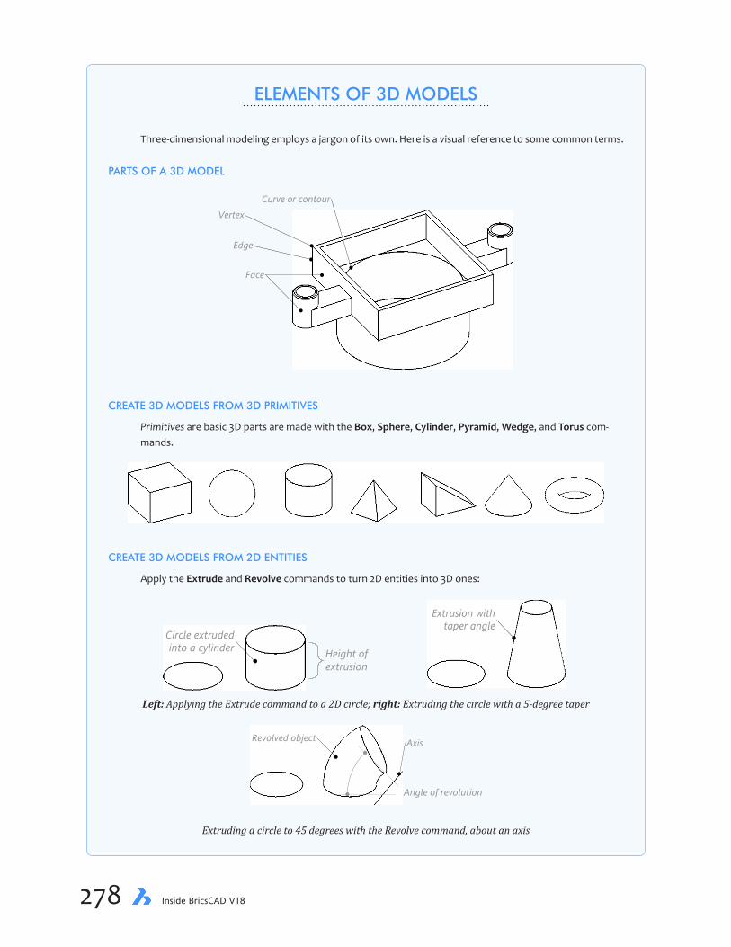
chapter 10 Direct 3D Modeling & Editing 279278 Inside BricsCAD V18
ELEMENTS OF 3D MODELS
Three-dimensional modeling employs a jargon of its own. Here is a visual reference to some common terms.
PARTS OF A 3D MODEL
Face
Edge
VertexCurve or contour
CREATE 3D MODELS FROM 3D PRIMITIVES
Primitives are basic 3D parts are made with the Box, Sphere, Cylinder, Pyramid, Wedge, and Torus com-mands.
CREATE 3D MODELS FROM 2D ENTITIES
Apply the Extrude and Revolve commands to turn 2D entities into 3D ones:
Height ofextrusion
Circle extrudedinto a cylinder
Extrusion withtaper angle
Left: Applying the Extrude command to a 2D circle; right: Extruding the circle with a 5-degree taper
Revolved object Axis
Angle of revolution
Extruding a circle to 45 degrees with the Revolve command, about an axis

chapter 10 Direct 3D Modeling & Editing 279278 Inside BricsCAD V18
you gain experience with 3D modeling, so this chapter shows you tricks to putting together 3D models.
Planning Ahead by Deconstructing 3DThe way to plan ahead is to deconstruct the model. Here are some tips:
Ð Look to see what kinds of sub-parts exist. “Sub-parts” are portions of the model that look like boxes and cylinders.
Ð Holes are formed from cylinders.
Ð Figure out which common operations can be applied. For instance, parts can be repeated (made once then copied), mirrored (made once then copy-mirrored), or made uniquely (made once).
Ð Rounded edges are added with the Fillet command.
Ð 2D drawings determine the dimensions of the part.
Examine the photograph (right) and identify sub-parts (a.k.a “primitives”) that could be mod-eled first. Notice that there are some are square ones and some round ones. How would these be modeled? (Hint: with the Box and Cylinder commands.)
TRADITIONAL EXTRUSION METHODBecause the sides are parallel, much of this part can be constructed from extrusions. An “extru-sion” takes a 2D outline and then makes it taller to make it 3D.
To create the extrusion, you draw the outline of the part in 2D (on the x,y-plane), and then use the Extrude command to thicken it in the z-direction. See the figure below for how this works. Extrusions have either straight or slanted sides. (If you want a part to have curved sides, then revolve the 2D entity with the Revolve command.)
2D object definesbase shape
Extrusion thickens the 2Dobject to make it a 3D
model with straight sides
Extrusionheight
Left: 2D circle defining the diameter of the cylinder; right: Circle extruded to become a 3D cylinder

chapter 10 Direct 3D Modeling & Editing 281280 Inside BricsCAD V18
In this set of tutorials, you use variations on commands to 7model this webcam focus ring holder. In the first tutorial you use the traditional Extrude command, which in CAD dates back to the late 1980s; in a later tutorial, you get to use a newer approach to do the same thing known as “direct modeling.”
Preparing the DrawingHere are the steps you need to take to prepare the drawing for 3D modeling.
1. Start BricsCAD.
2. Notice the Welcome dialog box. Click Profile Presets.
3. Change the Units to “Metric.”
4. Click 3D Modeling.
5. When the Create/Reinitialize Profile dialog box appears, click OK.

chapter 10 Direct 3D Modeling & Editing 281280 Inside BricsCAD V18
6. Notice that BricsCAD opens in the 3D Modeling workspace. On the ribbon, click the Model tab.
7. Prepare this drawing by changing the following settings in the status bar:
Setting Toggle Comments
SNAP Off You use entity snaps and dynamic dimensions in place of snap spacing GRID Off The grid is not useful for this project ESNAP On Turn on INTersection snap; turn off all others
To turn on Intersection entity snap, right-click ESNAP on the status bar, as shown below. Ensure all other ensaps are turned off.
8. Use the Units command to change the display precision of decimal places (linear units) to 1mm. You will be working with dimensions to the nearest 0.5mm.

chapter 10 Direct 3D Modeling & Editing 283282 Inside BricsCAD V18
9. Close the Settings dialog box by clicking the X.
10. Change the visual style to “Shades of Gray,” which I like the best for 3D modeling. You do this through the Properties panel.
a. If the panel is not open, then enter the Properties command.
b. In the View section, click the Visual Style droplist
c. Choose “Shades of Gray.” (By the way, there are 256 shades of gray, not just 50.)
11. Finally, change the value of DelObj to 0. Recall from a previous lesson that this system variable determines what happens to 2D entities after you convert them to 3D models. (When set to 1 or 2, the program erases them; I find it useful to keep them around.)
Modeling a BoxCommand Extrude
Ribbon Solid | Create | Extrude
Menu Models | 3D Solids | Extrude
Alias EXT
Command SolidEdit
Ribbon Solid | Edit | Shell
Menu Model | 3D Solid Editing | Shell
Alias ...
The top of the part is a square open box. It is shown in gray by the figure below.

chapter 10 Direct 3D Modeling & Editing 283282 Inside BricsCAD V18
To make it, you’ll work through three commands, in this order:
a. Rectangle command defines the size and base of the square
b. Extrude command changes the 2D square into a solid 3D box
c. SolidEdit command hollows the 3D box by shelling it
1. First, use the Rectangle command’s Dimension option to draw a 2D square sized 13x13mm:
: rectangle
Choose first corner of rectangle or [Chamfer/Elevation/Fillet/Rotated/Square/Thickness/
Width/Area/Dimensions]: d
Length to use for rectangles <13.0>: 13
Width to use for rectangles <13.0>: 13
Select first corner of rectangle or [Chamfer/Elevation/Fillet/Rotated/Square/Thickness/
Width/Area/Dimensions]: 0,0
Other corner of rectangle: (Pick a point; it’s not crucial where you pick it)
2. If necessary, use the Zoom Extents to see it better.
QUICK SUMMARY OF EXTRUDE COMMAND
Extrude commands thickens 2D entities into 3D solids or surfaces (included in BricsCAD Pro and Platinum).
: extrude
Select entities/subentities to extrude or set [MOde]:
Specify height of extrusion or [Direction/Path/Taper angle]:
Entities/subentities — selects 2D closed entities or faces of 3D solids
MOde — specifies the result of the extrusion, solid or surface
Height — specifies the height of the extruded entities; positive values extrude in the positive z direction, negative values go “downwards”
Direction — controls the direction of the extrusion, up or down along the z axis
Path — allows curved extrusions by specifying an entity that determines the path
Taper angle — gives sloping sides to the extrusion; positive angle slope inwards, negative angles outwards
chapter 10 Direct 3D Modeling & Editing 285284 Inside BricsCAD V18
3. Now use the Extrude command to convert the square into a short 3D box. Specify a height of 3.5mm, as follows:
: extrude
Select entities/subentities to extrude or set [MOde]: (Pick the square)
Select entities/subentities to extrude or set [MOde]: (Press ENTER to end selection)
Specify height of extrusion or [Direction/Path/Taper angle]: 3.5
4. “Shell” is an option of the SolidEdit command that turns solid entities into “walls” — it uniformly removes the insides. Follow these steps to make the box hollow:
a. Because the SolidEdit command has many options, it is faster to get to the Shell option via the ribbon. From the ribbon’s Model tab, look in the Solid Editing panel, and then click Shell. (It’s a bit hard to find it, but Shell is the last icon in the middle row.)
: _solidedit
Enter a solids editing option Face/Edge/Body/Undo/eXit: _body
Enter a body editing option Imprint/seParate/Shell/cLean/Check/Undo/eXit: _shell
b. As prompted, select the extruded box:
Select 3d solid: (Pick the box)
c. Pick the top face to remove it entirely. It is shown in blue in the figure below. BricsCAD does not give any indication when you choose the face, and so you work somewhat blindly here.
Select face to remove or [Add/Undo/ALL]: (Pick the face on top of the box)
Select face to remove or [Add/Undo/ALL]: (Press Enter to exit entity selection)
d. Specify the thickness of the walls, 0.5mm, for the remaining sides:
Enter the shell offset distance: .5

chapter 10 Direct 3D Modeling & Editing 285284 Inside BricsCAD V18
e. And finally press Enter twice to exit the command:
Enter a body editing option Imprint/seParate/Shell/cLean/Check/Undo/eXit: (Press Enter)
Enter a solids editing option Face/Edge/Body/Undo/eXit: (Press Enter)
Notice that the result is a hollow box with no top.
3D View RotationThe next step is to add the round part underneath the box, shown in gray below.
But to do this, you need to spin the model so that you can see the bottom of it. There are several methods you could employ, but the easiest is the most direct way: real-time rotation. Here’s how:
1. Position the cursor in the center of the box. The location of the cursor determines the center point about which the model will rotate. This means it is important for you to locate the cursor at roughly the right point.
2. Hold down the Shift key. (If you don’t hold down Shift, then the model will pan instead of rotate.)
3. Hold down the middle mouse button, and then move the mouse. Notice the real-time rotation cursor.
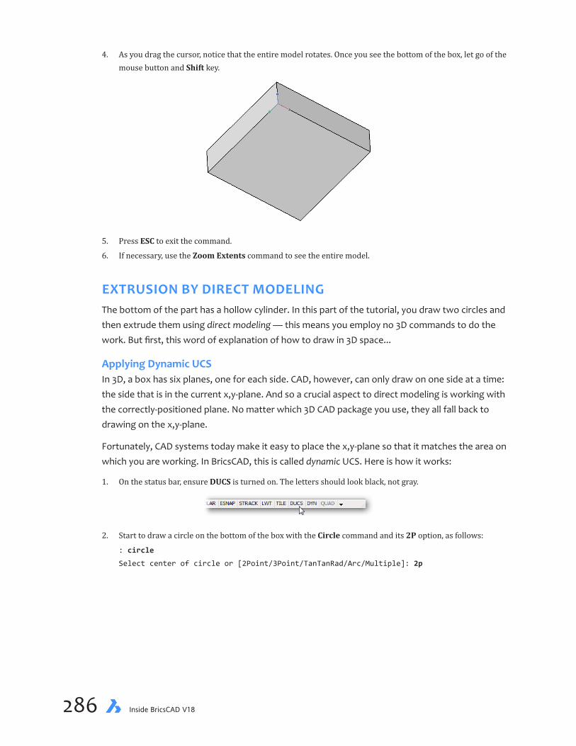
chapter 10 Direct 3D Modeling & Editing 287286 Inside BricsCAD V18
4. As you drag the cursor, notice that the entire model rotates. Once you see the bottom of the box, let go of the mouse button and Shift key.
5. Press ESC to exit the command.
6. If necessary, use the Zoom Extents command to see the entire model.
EXTRUSION BY DIRECT MODELINGThe bottom of the part has a hollow cylinder. In this part of the tutorial, you draw two circles and then extrude them using direct modeling — this means you employ no 3D commands to do the work. But first, this word of explanation of how to draw in 3D space...
Applying Dynamic UCSIn 3D, a box has six planes, one for each side. CAD, however, can only draw on one side at a time: the side that is in the current x,y-plane. And so a crucial aspect to direct modeling is working with the correctly-positioned plane. No matter which 3D CAD package you use, they all fall back to drawing on the x,y-plane.
Fortunately, CAD systems today make it easy to place the x,y-plane so that it matches the area on which you are working. In BricsCAD, this is called dynamic UCS. Here is how it works:
1. On the status bar, ensure DUCS is turned on. The letters should look black, not gray.
2. Start to draw a circle on the bottom of the box with the Circle command and its 2P option, as follows:
: circle
Select center of circle or [2Point/3Point/TanTanRad/Arc/Multiple]: 2p

chapter 10 Direct 3D Modeling & Editing 287286 Inside BricsCAD V18
3. Now you get to see the effect of dynamic UCS: move the cursor around the visible faces of the box. Notice that two things are happening: the face turns blue, and the UCS icon jumps to a corner of the face. This is dynamic UCS at work: BricsCAD is automatically relocating the x,y drawing plane to the face that you pick.
Left to right: As cursor passes over face, they turn blue and the UCS icon is reelocated (tri-color icon)
In summary: As the cursor passes over a face during DUCS, the face turns blue to tell you that it is the current, temporary x,y drawing plane. The UCS icon is positioned at the current, temporary origin (0,0,0). DUCS is available only during drawing and editing commands, because most of them operate only on an x,y plane.
DUCS works only during drawing and editing commands. If you want to see a more dramatic effect of dynamic UCS at work, turn on the grid display. (Click GRID on the status bar.) As you move the cursor from face to face, the grid jumps to match the face.
4. To locate the circle, pick two points on the edges of the box, right at the middle of two facing edges. Use the MIDpoint ensap to assist you.
a. Position the cursor over the bottom face of the box. Notice that it turns blue.
b. Move the cursor close to the edge illustrated below, but do not go beyond the edge! (Were you to go be-yond the edge, then the DUCS would jump to the adjacent face, telling BricsCAD that you want to draw the circle on a different face.)
c. Enter the MIDpoint entity snap mode:
First point on diameter: mid
chapter 10 Direct 3D Modeling & Editing 289288 Inside BricsCAD V18
d. Pick a point near the edge:
Snap to midpoint of: (Pick near point 1)
e. Repeat the MID ensap mode, and pick a point near the opposite edge:
Second point on diameter: mid
Snap to midpoint of: (Pick near point 2)
Pick point #2 near themidpoint of the opposite edge
Pick point #1 near themidpoint of this edge
5. A second circle is needed to define the thickness of the 0.5mm wall. Instead of drawing it, you will make a copy using the Offset command. The offset distance of 0.5mm.
Offset this circle...
...by 0.5mm to the inside
: offset
Enter offset distance or [Through point/Erase/Layer] <Through point>: .5
Select entity/subentity or [Exit] <Exit>: (Select the black circle)
Select side for parallel copy or [Both sides/Multiple]: (Pick a point inside the circle)
Select entity/subentity or [Exit] <Exit>: (Press Enter to end the command)

chapter 10 Direct 3D Modeling & Editing 289288 Inside BricsCAD V18
Extruding Directly with the Quad CursorWith the pair of 2D circles in place, you extrude them to create a 5mm-tall hollow cylinder. This time, you use the Quad to extrude. The Quad is unique to BricsCAD, and gives you fast access to commands right at the cursor. In many cases, commands suitable to the highlighted element are presented to you. (See the boxed text for more on using the Quad.)
Cylinders are extruded from circles. Making a hollow cylinder takes these steps:
a. Extrude the inside circle into a cylinder that is more than 5mm in height
b. Extrude the outside circle by exactly 5mm
c. Subtract the taller cylinder from the shorter to make the hole.
You extrude the inside circle by a distance longer than 5mm, because its height does not matter; indeed, in a later step, you “erase” it to create a hole. Follow these steps:
1. On the status bar, ensure that QUAD is turned on.
2. Move the cursor over the smaller circle. Notice that it turns blue, and that a second cursor appears. This is the Quad cursor, sporting a single icon (for now).
3. The icon on the cursor indicates the Extrude command. To confirm, pass the cursor over the icon. No-tice that the Quad cursor expands to show more commands; after a moment the tooltip appears explaining the name and purpose of the button.
4. Click the Extrude button, and then move the cursor. As you do, notice that the circle extrudes into a cylinder (i.e., thickens in 3D). The direction you move the cursor determines the direction the circle ex-trudes, upwards or down.

chapter 10 Direct 3D Modeling & Editing 291290 Inside BricsCAD V18
5. Notice the dynamic dimension next to the cylinder: a pair of arrowheads and text with blue background. It allows you to enter precise distances; in this case, however, you don’t care about the precise height of this cylinder, because its only purpose is to be cut out of the larger one to form a hole. But it is useful to ensure the cylinder ends up longer than 5mm.
Watching the dynamic dimension, drag the extrusion so that it is longer than 5mm — like 7 or 8mm.
6. Then click. The cylinder is formed — without entering commands.
7. Repeat the direct modeling procedure for the larger circle. This time, however, enter 5 in the direct dimen-sion.
Left: Extruding the outer circle into a 5mm cylinder; right: Two cylinders in place
8. Save your work with Ctrl+S, naming it “Focus-Bracket.dwg.”

chapter 10 Direct 3D Modeling & Editing 291290 Inside BricsCAD V18
Subtracting Solids To Make HolesCommand: Subtract
Ribbon: Solid | Edit | Subtract
Menu: Model | 3D Solids Editing | Subtract
Alias: SU
You learned about Boolean operations in a previous lesson, where it was applied to 2D regions. The same operations can be applied to 3D solids: union, subtract, and intersect. In this tutorial, you create a hole by subtracting one cylinder from another.
The Subtract command is sensitive to the order in which entities are selected. Make sure you pick the correct ones in the correct order: first the one that stays, and then the one that will be removed (subtracted).
1. With the two cylinders looking somewhat like a wedding cake, it is time to subtract the smaller one from the larger one. Start the Subtract command, and then choose the cylinders in correct order:
: subtract
Select ACIS entity to subtract from: (Select the fatter, shorter cylinder)
Select ACIS entity to subtract from: (Press Enter to end entity selection)
1. Select the outercylinder first...
2. Select the innercylinder last...
2. Now pick the cylinder to be removed (erased):
Select ACIS entities to subtract: (Select the smaller, longer cylinder)
Select ACIS entities to subtract: (Press Enter to end the command)
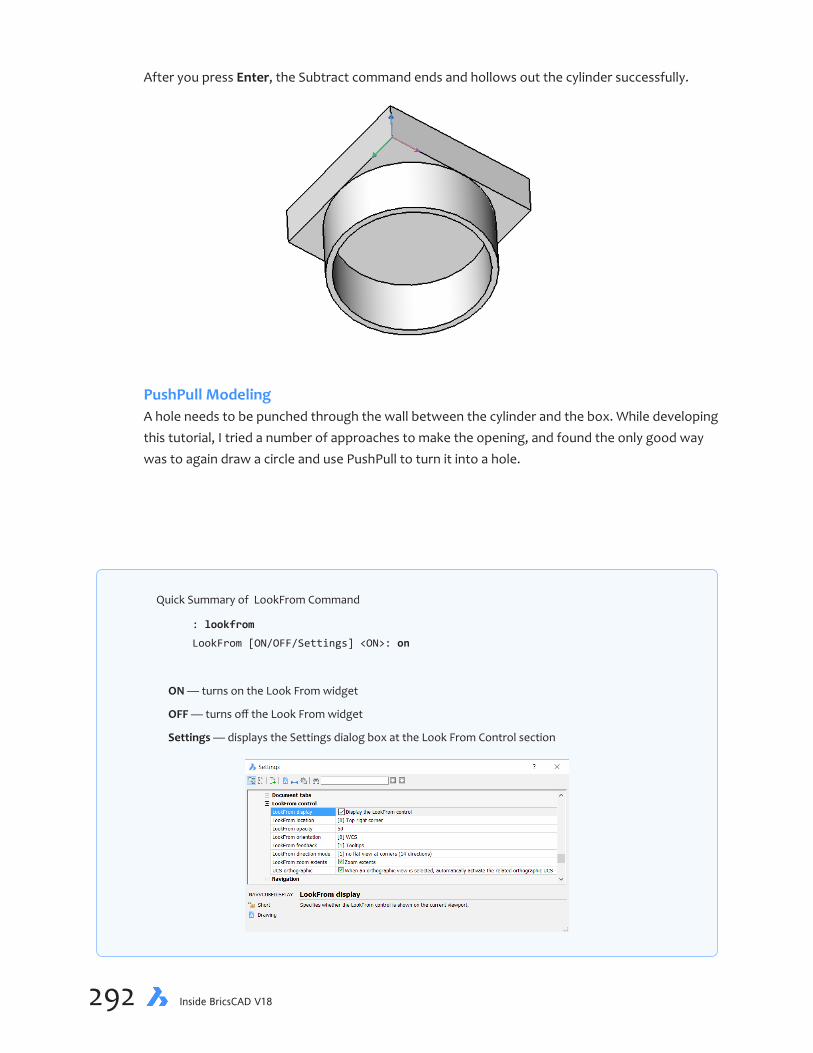
chapter 10 Direct 3D Modeling & Editing 293292 Inside BricsCAD V18
After you press Enter, the Subtract command ends and hollows out the cylinder successfully.
PushPull ModelingA hole needs to be punched through the wall between the cylinder and the box. While developing this tutorial, I tried a number of approaches to make the opening, and found the only good way was to again draw a circle and use PushPull to turn it into a hole.
Quick Summary of LookFrom Command
: lookfrom
LookFrom [ON/OFF/Settings] <ON>: on
ON — turns on the Look From widget
OFF — turns off the Look From widget
Settings — displays the Settings dialog box at the Look From Control section

chapter 10 Direct 3D Modeling & Editing 293292 Inside BricsCAD V18
1. The easiest way to draw a circle (and other 2D entities) is in plan view. The quick way to switch between static viewpoints — such as the plan and isometric viewpoints — is to use the Look From widget. To use it, follow these steps:
a. Locate the Look From widget. Usually, it is in the upper right corner of the drawing area.
If the Look From widget is turned off, you can turn it on with the LookFrom command: : lookfrom LookFrom [ON/OFF/Settings] <ON>: on
b. Move the cursor into the center of the widget. Notice that the icon changes to show the top view of a chair.
c. Click in the center of the widget. Notice that the viewpoint changes.
d. You may need to do a Zoom Extents to see the entire model.
2. To draw the circle, use the same technique as before: employ the Circle command with the 2P option and MIDpoint esnaps:
: c
Select center of circle or [2 Point(2P)/3 Point(3P)/Tangent-Tangent-Radius(TTR)/
Turn arc into circle(A)/Multiple circles]: 2p
First point on diameter: mid
Snap to midpoint of: (Pick one edge)
Second point on diameter: mid
Snap to midpoint of: (Pick the opposite edge)
3. Using the Quad cursor, punch out the circle using direct modeling. You may find it easier to control the ex-trusion by clicking the Top Front Left position on the Look From widget.

chapter 10 Direct 3D Modeling & Editing 295294 Inside BricsCAD V18
a. Pass the cursor over the newly added circle. Notice that it turns blue.
b. Move the crosshair cursor into the Quad cursor. Notice that it expands to show more commands. Choose the PushPull button.
c. Drag the cursor down so that a hole appears. The distance you drag does not matter; all you need is for the hole to appear.

chapter 10 Direct 3D Modeling & Editing 295294 Inside BricsCAD V18
d. Click to finish the hole. This was quicker and easier than using the Extrude command!
Aligning the UCSCommand UCS Face
Alias ...
The next step is to draw the rectangle needed for the arms that hold the two screw holes, one of which is shown in gray in the figure below. This time you use PushPull to create an entity, instead of a hole.
In this case, the 2D entity is a rectangle. Before drawing the rectangle, however, you align the UCS on the face by another method: align UCS. This permanently reorients the UCS plane to a face — permanent until you change it again. This is different from the temporary, dynamic UCS alignment you used in the earlier part of this tutorial.
1. Ensure QUAD is turned on in the status bar, and then move the crosshair cursor over a rectangular face. Notice that it is highlighted in blue, and that the Quad cursor appears.
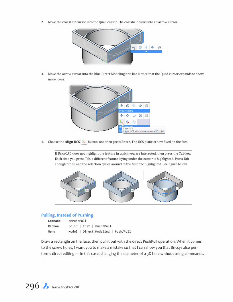
chapter 10 Direct 3D Modeling & Editing 297296 Inside BricsCAD V18
2. Move the crosshair cursor into the Quad cursor. The crosshair turns into an arrow cursor.
3. Move the arrow cursor into the blue Direct Modeling title bar. Notice that the Quad cursor expands to show more icons.
4. Choose the Align UCS button, and then press Enter. The UCS plane is now fixed on the face.
If BricsCAD does not highlight the feature in which you are interested, then press the Tab key. Each time you press Tab, a different feature laying under the cursor is highlighted. Press Tab enough times, and the selection cycles around to the first one highlighted. See figure below.
Pulling,InsteadofPushingCommand dmPushPull
Ribbon Solid | Edit | Push/Pull
Menu Model | Direct Modeling | Push/Pull
Draw a rectangle on the face, then pull it out with the direct PushPull operation. When it comes to the screw holes, I want you to make a mistake so that I can show you that Bricsys also per-forms direct editing — in this case, changing the diameter of a 3D hole without using commands.
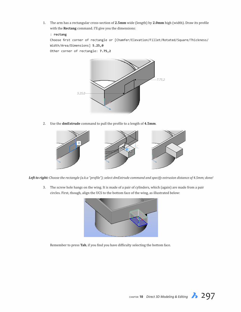
chapter 10 Direct 3D Modeling & Editing 297296 Inside BricsCAD V18
1. The arm has a rectangular cross-section of 2.5mm wide (length) by 2.0mm high (width). Draw its profile with the Rectang command. I’ll give you the dimensions:
: rectang
Choose first corner of rectangle or [Chamfer/Elevation/Fillet/Rotated/Square/Thickness/
Width/Area/Dimensions] 5.25,0
Other corner of rectangle: 7.75,2
5.25,0
7.75,2
2. Use the dmExtrude command to pull the profile to a length of 4.5mm.
Left to right: Choose the rectangle (a.k.a “profile”); select dmExtrude command and specify extrusion distance of 4.5mm; done!
3. The screw hole hangs on the wing. It is made of a pair of cylinders, which (again) are made from a pair circles. First, though, align the UCS to the bottom face of the wing, as illustrated below:
Remember to press Tab, if you find you have difficulty selecting the bottom face.

chapter 10 Direct 3D Modeling & Editing 299298 Inside BricsCAD V18
4. Drawing 2D entities in 3D can be tricky when the viewpoint is the plan view. By default, Bricsys will snap to the nearest geometric feature; in 3D, this can too easily be the one you don’t want. To solve the problem, turn on the OsnapZ system variable:
: osnapz
New current value for OSNAPZ (Off or On) <Off>: on
When on, all entity snaps set z = 0, so that the snapping takes place on the x,y-plane — and not at some other higher or lower location.
OsnapZ Meaning
Off Snaps to the nearest z coordinate On Snaps to the elevation setting (usually 0; z = elevation)
5. Using the Isometric Views toolbar, change the viewpoint to the top (or plan) view.
6. Use the Circle command to draw the round profile:
: circle
Select center of circle or [2 Point(2P)/3 Point(3P)/Tangent-Tangent-Radius(TTR)/Turn arc
into circle(A)/Multiple circles]: mid
Snap to midpoint of: (Pick the midpoint of the edge.)
Set Diameter or [Radius] <1.3>: end
Snap to endpoint of: (Pick the end of the edge)
1. MIDpoint of edge 2. ENDpoint of edge
When you rotate the view back to isometric, you see the circle placed on the bottom face, thanks to OsnapZ.
7. Use the Offset command to place a second circle, offset by 0.75mm. (This value is deliberately incorrect, and you correct it later with direct editing.)
Source circle
Offset circle(offset by 0.75mm)
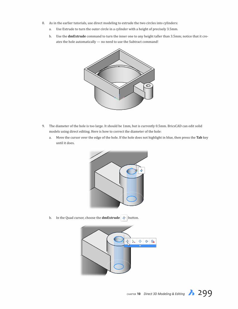
chapter 10 Direct 3D Modeling & Editing 299298 Inside BricsCAD V18
8. As in the earlier tutorials, use direct modeling to extrude the two circles into cylinders:
a. Use Extrude to turn the outer circle in a cylinder with a height of precisely 3.5mm.
b. Use the dmExtrude command to turn the inner one to any height taller than 3.5mm; notice that it cre-ates the hole automatically — no need to use the Subtract command!
9. The diameter of the hole is too large. It should be 1mm, but is currently 0.5mm. BricsCAD can edit solid models using direct editing. Here is how to correct the diameter of the hole:
a. Move the cursor over the edge of the hole. If the hole does not highlight in blue, then press the Tab key until it does.
b. In the Quad cursor, choose the dmExtrude button.
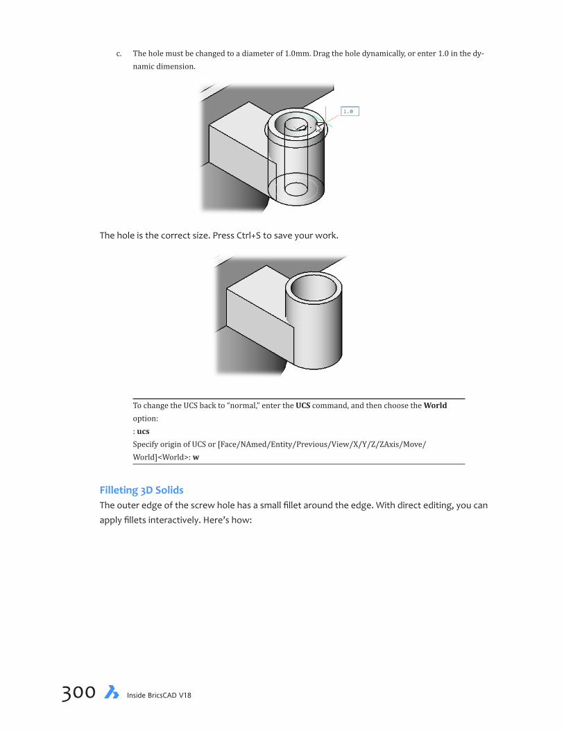
chapter 10 Direct 3D Modeling & Editing 301300 Inside BricsCAD V18
c. The hole must be changed to a diameter of 1.0mm. Drag the hole dynamically, or enter 1.0 in the dy-namic dimension.
The hole is the correct size. Press Ctrl+S to save your work.
To change the UCS back to “normal,” enter the UCS command, and then choose the World option: : ucs Specify origin of UCS or [Face/NAmed/Entity/Previous/View/X/Y/Z/ZAxis/Move/World]<World>: w
Filleting 3D SolidsThe outer edge of the screw hole has a small fillet around the edge. With direct editing, you can apply fillets interactively. Here’s how:
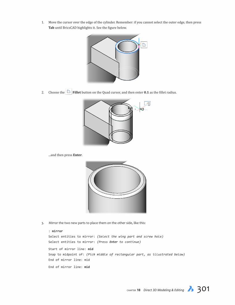
chapter 10 Direct 3D Modeling & Editing 301300 Inside BricsCAD V18
1. Move the cursor over the edge of the cylinder. Remember: if you cannot select the outer edge, then press Tab until BricsCAD highlights it. See the figure below.
2. Choose the Fillet button on the Quad cursor, and then enter 0.1 as the fillet radius.
...and then press Enter.
3. Mirror the two new parts to place them on the other side, like this:
: mirror
Select entities to mirror: (Select the wing part and screw hole)
Select entities to mirror: (Press Enter to continue)
Start of mirror line: mid
Snap to midpoint of: (Pick middle of rectangular part, as illustrated below)
End of mirror line: mid
End of mirror line: mid

chapter 10 Direct 3D Modeling & Editing 303302 Inside BricsCAD V18
Snap to midpoint of: (Pick a point on the other side)
Delete the original entities? [Yes-delete entities/No-keep entities] <No-Keep entities>: n
Joining Parts with UnionThe 3D model consists of six solids. You can leave them as individuals, or join them into a single body with the Union command.
1. Use the Union command to merge all solids into one:
: union
Select ACIS entities to union: all
Select ACIS entities to union: (Press Enter to end the command)
You can continue to directly edit the model, even after all its parts are joined by the Union command.
2. Now that the model is one unified part, you can apply commands like MassProp and Properties to find out the properties of this focusing bracket.
: massprop
Select entities: all
Select entities: (Press Enter to continue)
Write analysis to a file? Yes/<No>: y

chapter 10 Direct 3D Modeling & Editing 303302 Inside BricsCAD V18
The report you see in the text window can be saved to a .mpr (mass properties report) file.
3. Save the drawing.
Generating 2D DrawingsCommand ViewBase
Ribbon Annotation | Views | Base Views
Menu Model | Drawing Views | Generate Drawing Views
With the 3D model completed, it is time to generate engineering drawings from it. These are 2D plans that are used to check dimensions and give instructions to the manufacturer. BricsCAD gen-erates these drawings semi-automatically. Let’s see how it works.
1. Switch your focus to the Drawing Views panel of the ribbon’s Annotation tab. It contains the commands you need for this tutorial.
Click the Base Views button. (It runs the ViewBase command). This command semi-automatically gen-erates 2D views of the 3D model — front, side, top, isometric — in a new layout; all you need to do is pick the points where you want the views placed.

chapter 10 Direct 3D Modeling & Editing 305304 Inside BricsCAD V18
QUICK SUMMARY OF VIEWBASE OPTIONS
: viewbase
Select objects or [Entire model/preseTs] <Entire model>:
Enter new or existing layout name to make current <LayoutName>:
Select position for base view [Scale/Tangent edges/Orientation/Projection type/
Isometric style]<Cancel>:
Select position for projected view <Done>:
PRESETS OPTION
Displays the Drawing View Presets dialog box:
Preset droplist offers these options:
Ð None
Ð Architectural Views — generates Front, Right, Back, Left (elevations) and Top views; three section views (two horizontal section plans); and one vertical section.
Ð Mechanical Views — generates standard Front, Top and Left (first-angle projection) or Right (third-angle pro-jection) views. The projection type: first or third angle. The projection type held by the ProjectionType variable.
View Scale droplist offers automatic scaling or one of the scales presided over by the ScaleListEdit com-mand.
SCALE OPTION
Sets the scale of all views to fit the following arrangements:
Ð fit4views — adjusts scale to fit four orthographic views: Front, Top, Left, and Right. The Front view (base view) is defined by the Orientation option.
Ð 9 views — adjusts scale to fit five orthographic views and four isometric views.
Ð 5 views — adjusts scale to fit five orthographic views: Front (*), Top, Left, Right, and Back.
Ð 10 views — adjusts scale to fit six orthographic views and four isometric views.
Ð Standard scales — displays the scales lorded over by the ScaleListEdit command.
Ð Custom — prompts for any scale factor.
TANGENT EDGES OPTION
Determines whether tangent edges between tangent faces are displayed or not; tangent edges are always displayed in isometric views:
HIDDEN LINES OPTION
Determines whether hidden lines are shown.
Continued...
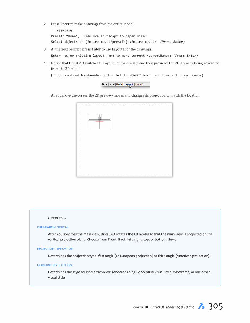
chapter 10 Direct 3D Modeling & Editing 305304 Inside BricsCAD V18
2. Press Enter to make drawings from the entire model:
: _viewbase
Preset: “None”, View scale: “Adapt to paper size”
Select objects or [Entire model/preseTs] <Entire model>: (Press Enter)
3. At the next prompt, press Enter to use Layout1 for the drawings:
Enter new or existing layout name to make current <LayoutName>: (Press Enter)
4. Notice that BricsCAD switches to Layout1 automatically, and then previews the 2D drawing being generated from the 3D model.
(If it does not switch automatically, then click the Layout1 tab at the bottom of the drawing area.)
As you move the cursor, the 2D preview moves and changes its projection to match the location.
Continued...
ORIENTATION OPTION
After you specifies the main view, BricsCAD rotates the 3D model so that the main view is projected on the vertical projection plane. Choose from Front, Back, left, right, top, or bottom views.
PROJECTION TYPE OPTION
Determines the projection type: first angle (or European projection) or third angle (American projection).
ISOMETRIC STYLE OPTION
Determines the style for isometric views: rendered using Conceptual visual style, wireframe, or any other visual style.

chapter 10 Direct 3D Modeling & Editing 307306 Inside BricsCAD V18
In this step of the the tutorial, position the cursor in the upper left quadrant, and then click.
Select position for base view [Scale/Hidden lines/Tangent edges/Orientation/Projection
type/Isometric style/sElect] <Cancel>: (Move the cursor to upper left, and then click)
The quadrant of the layout in which you click determines the viewpoint generated by BricsCAD:
Quadrant 2D View Generated
Upper left Top view Upper right Side view
Lower left Front view Lower right Isometric view
5. The command repeats its prompt. Repeat the process: move the cursor to a quadrant of the layout, and then click to position the view.
Select position for projected view [Done] <Done> (Move the cursor to lower left
quadrant, and then click to place the front view)
Select position for projected view [Done] <Done> (Move the cursor to upper right
quadrant, and then click to place the side view)
Select position for projected view [Done] <Done> (Move cursor to lower right quadrant,
and then click to place the isometric view)
The result should look like the figure below. BricsCAD automatically adjust the scale factor so that the resulting viewports nicely fit the page.
chapter 10 Direct 3D Modeling & Editing 307306 Inside BricsCAD V18
QUICK SUMMARY OF VIEWSECTION OPTIONS
: viewsection
Select drawing view:
Specify start point of section line or select type [Full/Half/Offset/Aligned] <Full>:
Specify next point of section line [Done] <Done>:
Select position for section view:
Select option [Scale/Hidden lines/Tangent lines/anChor/Geometry/Annotation/
Depth/Projection] <Cancel>:
TYPE OPTION
Ð Full — draws a section of the entire viewport
Ð Half — draws a section of half the viewport
Ð Offset — draws a section specified by points that you pick
Ð Aligned — draws a section per perpendicular to the section line
SCALE OPTION
Sets the scale of the section view; choose from the standard scale factors,specify a custom scale, or inher-ent the scale of the parent view:
GEOMETRY OPTION
Defines the visual style for the section view: conceptual 3D view or 2dWireframe visual style; alternately, select a visual style from the Properties panel. (Hidden Line option is moved to the ViewBase command.)
TANGENT LINES OPTION
Toggles display of tangent lines, on or off.
ANCHOR OPTION
Determines what happens to the section view when it is updated after the 3D model changes:
Ð Yes — anchors the center of the viewport so that the viewport grows and shrinks around that point.
Ð No — fixes the position of the geometry; the AutoVpFitting variable specifies whether the viewport size is adjusted to fit the extents of the 3D model automatically (default = on).
ISOMETRIC STYLE OPTION
Determines style for isometric views: rendered using Conceptual visual style, wireframe, or other one.
ANNOTATION OPTION
Prompts you to override that automatic annotations of section view: .
Ð Identifier — specifies the view identifier, such as A.
Ð Label — toggles the display of the view label.
DEPTH OPTION
Specifies clipping of the section view, full or limited. You can define the depth with your mouse.
PROJECTION OPTION
Toggles between normal and orthographic projection of the view.
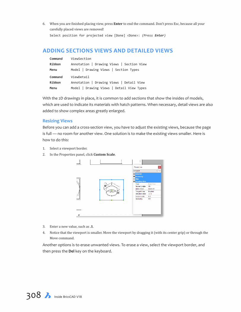
chapter 10 Direct 3D Modeling & Editing 309308 Inside BricsCAD V18
6. When you are finished placing view, press Enter to end the command. Don’t press Esc, because all your carefully placed views are removed!
Select position for projected view [Done] <Done>: (Press Enter)
ADDING SECTIONS VIEWS AND DETAILED VIEWSCommand ViewSection
Ribbon Annotation | Drawing Views | Section View
Menu Model | Drawing Views | Section Types
Command ViewDetail
Ribbon Annotation | Drawing Views | Detail View
Menu Model | Drawing Views | Detail View Types
With the 2D drawings in place, it is common to add sections that show the insides of models, which are used to indicate its materials with hatch patterns. When necessary, detail views are also added to show complex areas greatly enlarged.
Resizing ViewsBefore you can add a cross-section view, you have to adjust the existing views, because the page is full — no room for another view. One solution is to make the existing views smaller. Here is how to do this:
1. Select a viewport border.
2. In the Properties panel, click Custom Scale.
3. Enter a new value, such as .1.
4. Notice that the viewport is smaller. Move the viewport by dragging it (with its center grip) or through the Move command.
Another options is to erase unwanted views. To erase a view, select the viewport border, and then press the Del key on the keyboard.

chapter 10 Direct 3D Modeling & Editing 309308 Inside BricsCAD V18
Making Section ViewsOkay, with space freed up, you can go ahead to make the section view:
1. From the ribbon’s Model > Drawing Views panel, click the Section View button (or else enter the ViewSection command).
2. BricsCAD prompts you to choose a drawing view. The section view will be generated from the view you pick, so choose carefully! For this tutorial, move the cursor to the upper left quadrant, and then click inside the view (side view).
: _viewsection
Select drawing view: (Pick inside a viewport)
Notice that BricsCAD highlights the selected viewport with dashed lines.
When selecting the view, don’t select the viewport’s rectangle, as BricsCAD will just repeat the prompt. Click inside the viewport, as shown by the crosshair cursor above.
3. With the drawing view selected, it’s time to show BricsCAD through which part of the drawing that you want the section to cut. At the next prompt, pick two points outside the viewport, shown by the arrowheads in the figure below:
Specify start point of section line or select type [Full/Half/Offset/Aligned] <Full>:
(Pick a point outside the viewport)
Specify next point of section line [Done] <Done>: (Pick a second point on the other
side of the viewport)
I recommend holding down the Shift key to enforce ortho mode. This results in a section line that’s precisely horizontal.

chapter 10 Direct 3D Modeling & Editing 311310 Inside BricsCAD V18
QUICK SUMMARY OF VIEWDETAIL OPTIONS
: viewdetail
Select drawing view:
Specify detail center or select boundary type [Circular/Rectangular] <Circular>:
Select radius of detail view:
Select position for detail view [Scale] <Cancel>:
Select option [Scale/Hidden lines/Tangent lines/anChor/Annotation/Boundary/model
Edge] <Cancel>:
CIRCULAR OPTION
Creates a circular boundary, prompting you for the radius.
RECTANGULAR OPTION
Creates a rectangular boundary. You can still change the boundary type with the Boundary option in the last prompt of this command.
SCALE OPTION
Sets the scale of the detail view; choose from the standard scale factors,specify a custom scale, or inherent the scale of the parent view:
HIDDEN LINES OPTION
Toggles hidden line display of the detail view on and off, or inherited from the parent view.
TANGENT LINES OPTION
Toggles display of tangent lines, on or off.
ANCHOR OPTION
Determines what happens to the detail view when it is updated after the 3D model changes:
Ð Yes — anchors the center of the viewport so that the viewport grows and shrinks around that point.
Ð No — fixes the position of the geometry; the AutoVpFitting variable specifies whether the viewport size is adjusted to fit the extents of the 3D model automatically (default = on).
ANNOTATION OPTION
Prompts you to override automatic annotations of detail views:
Ð Identifier — specifies the view identifier, such as A.
Ð Label — toggles the display of the view label.
BOUNDARY OPTION
Determines if the boundary of the detail view is a circle or a rectangule.
MODEL EDGE OPTION
Specifies how the connection line is drawn between the two views (detail and in the parent view), smooth with the border or with the connection line.

chapter 10 Direct 3D Modeling & Editing 311310 Inside BricsCAD V18
4. The final step is to position the section view:
Select position for section view: (Pick a point in the drawing)
BricsCAD automatically labels the section using the standard method of “A-A.” Engineers use the A-A to see what is referenced elsewhere in the drawing. It indicates the scale factor of the sec-tion, 1:5 — also automatically determined. Hatching is applied automatically to the cross section.
Hatching is used by drafters to describe two types of information:
Ð The presence of hatching shows that areas of the are solid; areas without hatching are empty air.
Ð The style of hatching indicates the type of material; “ANSI31” hatching is the default pattern, and represents iron.
Here is the meaning of the ANSI hatch patterns included with BricsCAD:
Pattern Name Example Pattern Meaning
ANSI31 Iron, general purpose hatch
ANSI32 Steel
ANSI33 Bronze, brass, copper, composites
ANSI34 Rubber, plastic, electrical insulation
ANSI35 Defined by the legend
ANSI36 Defined by the legend
ANSI37 White metal, zinc, lead, babbit, and alloys of them
ANSI38 Magnesium, aluminum, and alloys of them

chapter 10 Direct 3D Modeling & Editing 313312 Inside BricsCAD V18
Creating Detail ViewsA detail view is an enlargement of one part of a drawing. It makes it easier to see what is going on with complex parts. Details are placed a larger scale factor by the ViewDetail command. Here you make a detail of one of the small round parts:
1. Enter the enter the ViewDetail command:
: viewdetail
2. BricsCAD prompts you to choose a drawing view. This is the drawing view from which the detail will be taken. For this tutorial, click inside the lower left quadrant’s viewport.
Select drawing view: (Pick inside a viewport)
3. Pick the center of the detail, as BricsCAD will use a circle as the view’s boundary:
Specify detail center or select boundary type [Circular/Rectangular] <Circular>:(Pick
the center of what will be detailed)
4. Now size the circle to indicate the extent of the detail. You can see the circle in the figure above, it has the “B” reference attached.
Select radius of detail view: (Drag the circle to size the detail area)
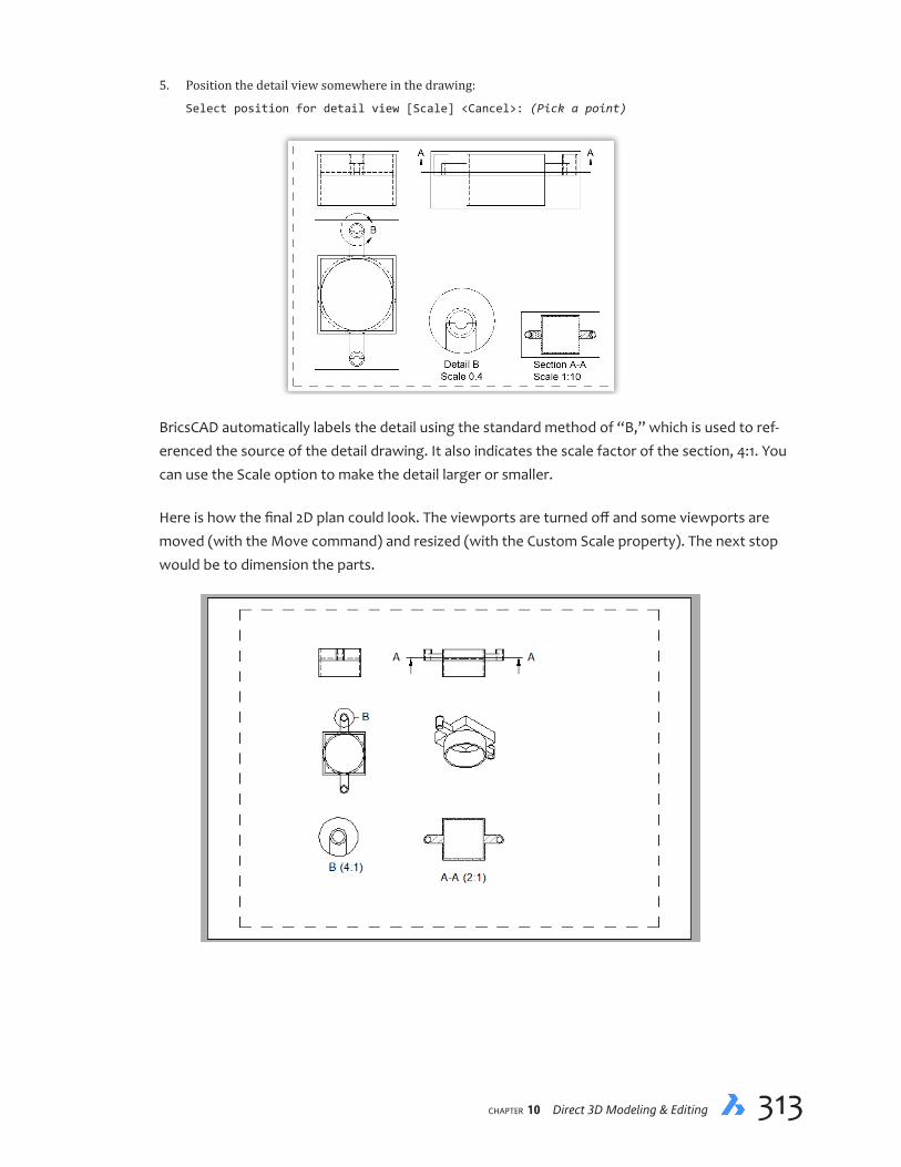
chapter 10 Direct 3D Modeling & Editing 313312 Inside BricsCAD V18
5. Position the detail view somewhere in the drawing:
Select position for detail view [Scale] <Cancel>: (Pick a point)
BricsCAD automatically labels the detail using the standard method of “B,” which is used to ref-erenced the source of the detail drawing. It also indicates the scale factor of the section, 4:1. You can use the Scale option to make the detail larger or smaller.
Here is how the final 2D plan could look. The viewports are turned off and some viewports are moved (with the Move command) and resized (with the Custom Scale property). The next stop would be to dimension the parts.

chapter 10 Direct 3D Modeling & Editing PB314 Inside BricsCAD V18
You can make sections of details, and details of sections, and details of details... To hide the rectangles that make up the viewports, freeze the “Drafting Viewports” layer. You can use the Layer command (shown below) or the Layers droplist in the Properties panel.
———
You learned how to construct 3D models using traditional and modern commands for creating and editing bodies. You also saw how to generate 2D drawings from the model, semi-automatically.
Next, you learn how to control the size and positioning of entities through constraints and param-eters.
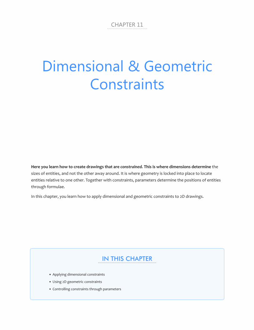
CHAPTER 11
Dimensional & Geometric Constraints
Here you learn how to create drawings that are constrained. This is where dimensions determine the sizes of entities, and not the other away around. It is where geometry is locked into place to locate entities relative to one other. Together with constraints, parameters determine the positions of entities through formulae.
In this chapter, you learn how to apply dimensional and geometric constraints to 2D drawings.
IN THIS CHAPTER
• Applying dimensional constraints
• Using 2D geometric constraints
• Controlling constraints through parameters

chapter 11 Dimensional & Geometric Constraints 317316 Inside BricsCAD V18
KEY TERMS IN THIS CHAPTER
Constraint bar — describes the small tooltips that report the constraints applied to entities
Dimensional constraint — specifies the size of entities in a dimension-like manner
Geometric constraint — determines the geometric relationship between entities, much like a semi-permanent entity snap
Parameter — specifies a formula that determines relationships between constraints
NEW COMMANDS
Command Menu Bar Ribbon
MaterialBrowserOpen Parametric | Mechanical Browser ... ConstraintBar Parametric | 2D Constraints Bar 2D Constraints Bar DimConstraint Parametric | 2D Constraints 2D Constraints panel GeomConstraint Parametric | 2D Constraints 2D Constraints panel
THIS CHAPTER’S MODEL
By the end of this lesson, your parametric drawing will look like this one:
Drawing file begun as bracket-ragged.dwg and ended as bracket-constrainted.dwg
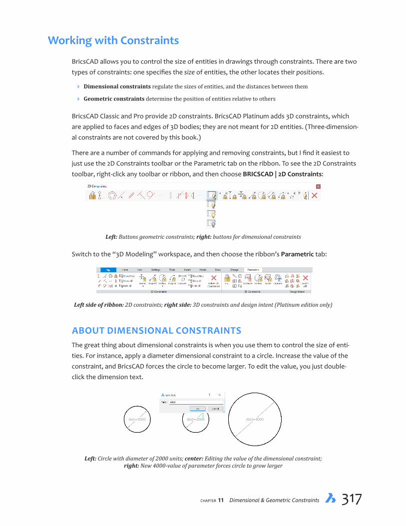
chapter 11 Dimensional & Geometric Constraints 317316 Inside BricsCAD V18
Working with Constraints
BricsCAD allows you to control the size of entities in drawings through constraints. There are two types of constraints: one specifies the size of entities, the other locates their positions.
Ð Dimensional constraints regulate the sizes of entities, and the distances between them
Ð Geometric constraints determine the position of entities relative to others
BricsCAD Classic and Pro provide 2D constraints. BricsCAD Platinum adds 3D constraints, which are applied to faces and edges of 3D bodies; they are not meant for 2D entities. (Three-dimension-al constraints are not covered by this book.)
There are a number of commands for applying and removing constraints, but I find it easiest to just use the 2D Constraints toolbar or the Parametric tab on the ribbon. To see the 2D Constraints toolbar, right-click any toolbar or ribbon, and then choose BRICSCAD | 2D Constraints:
Left: Buttons geometric constraints; right: buttons for dimensional constraints
Switch to the “3D Modeling” workspace, and then choose the ribbon’s Parametric tab:
Left side of ribbon: 2D constraints; right side: 3D constraints and design intent (Platinum edition only)
ABOUT DIMENSIONAL CONSTRAINTSThe great thing about dimensional constraints is when you use them to control the size of enti-ties. For instance, apply a diameter dimensional constraint to a circle. Increase the value of the constraint, and BricsCAD forces the circle to become larger. To edit the value, you just double-click the dimension text.
Left: Circle with diameter of 2000 units; center: Editing the value of the dimensional constraint; right: New 4000-value of parameter forces circle to grow larger

chapter 11 Dimensional & Geometric Constraints 319318 Inside BricsCAD V18
QUICK SUMMARY OF DIMENSIONAL CONSTRAINTS
There are two sets of commands for applying constraints. One is the all-purpose DimConstraint command, which is useful for seeing a list of all modes, The other set consists of the individual commands, one for each dimensional constraint:
DIMCONSTRAINT COMMAND
: dimconstraint
Select associative dimension to convert or [LInear/Horizontal/Vertical/Aligned/
ANgular/Radial/Diameter] <LInear>: (Enter an option.)
Above: 2D constraints on right half of the toolbar; below: 2D constraints on ribbon
DIMENSIONAL CONSTRAINT COMMANDS
The other set of commands consists of ones specific to each constraint mode, as listed in the table below. Notice that the command names all begin with ‘dc’, short for dimensional constraint.
Typeof Icon Constraint Command Constraining Action
LInear dcLinear Horizontal or vertical distance Horizontal dcHorizontal Horizontal (X) distance between two points Vertical dcVertical Vertical (Y) distance between two points Aligned dcAligned Distance between two points at any angle ANgular dcAngular Angle between two lines or linear polyline segments; or
angle of an arc or polyline arc; or angle between three points on an entity
Radial dcRadius Radius of a circle, arc, or polyline arc Diameter dcDiameter Diameter of a circle, arc, or polyline arc ... DimConvert Converts associative dimensions to dim constraints
Dimensional constraints are applied in the current UCS. Icons for dimensional constraints are found at the right end of the 2D Constraints toolbar or ribbon tab:
CONVERTING DIMENSIONS TO CONSTRAINTS7
Dimensional constraints are very much like associative dimensions and, in fact, existing associative dimen-sions can be converted to constraints with the DimConstraint command’s Select Associative Dimension to Convert option — or the DimConvert command.
The command converts like to like. For instance, linear dimensions become linear constraints, radial dimen-sions become radial constraints, and so on.

chapter 11 Dimensional & Geometric Constraints 319318 Inside BricsCAD V18
To control how far apart entities are, you place linear dimensional constraints between them. De-crease the value of the constraint, and BricsCAD moves the entities closer together; increase the value, and they are moved further apart. To edit the value, just double-click the dimension text.
Left: Two circles separated by 5000 units; center: Distance being edited; right: Circles now separated by 2500 units
Better yet, the values of constraints can be determined by other constraints, and even by formu-las. For instance, you can make the diameter of a circle equal to the linear distance between it and another entity. When you change one dimension, the linked ones follow suit.
For example, the figure below shows that I made the value of dia1 (diameter of one circle) equal to d1 (distance between circles) using a simple formula, dia1=d1.
To change the values of dimensional constraints, open the Mechanical Browser with the Mechani-calBrowserOpen command. (You can also edit values with the Properties panel.) As I change the value of d1 (the distance between the two circles), the diameter of the big circle changes.
To remove a dimensional constraint, simply select it and then press Del (or else use the Erase command). A concise reference to all dimensional constraints is found in the boxed text on the facing page.

chapter 11 Dimensional & Geometric Constraints 321320 Inside BricsCAD V18
Using Dimensional ConstraintsUsing dimensional constraints in drawings is very much like placing regular dimensions. Except for the text, they look exactly like one another; you even can apply dimension styles to them. The only visual difference between the two is the ‘d1=’ text that prefixes the constraint value; this is how you identify dimensions that are constraints.
Left: Associative dimension (top) and dimensional constraint (bottom) applied to the same line; right: Editing options for
dimensional constraints are the same as for associative dimensions
The difference between the two types of dimensions is this: whereas associative dimensions are controlled by the entity, dimensional constraints do the controlling. They specify the sizes of enti-ties, overruling what ever you may have drawn. Here is a tutorial to illustrate the differences.
1. Start BricsCAD with a new drawing.
2. Draw a line with the Line command. The length is not critical.
3. Dimension the line with the DimLinear command.
4. Use the dcLinear command to apply a dimensional constraint to the same line. (‘dc’ is short for dimensional constraint.)
: dclinear
Specify first constraint point or [Entity] <Entity>: (Press Enter)
Select an entity: (Choose the line.)
Specify dimension line location: (Move the cursor, and then click)
Dimension text <3730>: (Press Enter)
In the figure above, the two linear dimensions look identical — other than the ‘d1=’ name. The ‘d’ is short for “distance,” and the ‘1’ indicates this is the first distance constraint placed in the draw-ing. You can change this name through the Properties panel.

chapter 11 Dimensional & Geometric Constraints 321320 Inside BricsCAD V18
Continuing with the tutorial, you now edit the line and the dimensions to see how one affects the other.
5. Edit the line by stretching one of its end grips; see figure below. Notice that you cannot. This is because the length of the line is “locked” by the dimensional constraint.
6. You can, however, use the center grip to move the line and its dimension as a unit. As well, you can stretch the line vertically and it will change its angle, because the position and the height are not locked — only the horizontal length is locked by dcLinear.
7. Now change the value of the constraint to see what happens to the line:
a. Enter the DdEdit command, and then select the constraint value.
b. Enter a new value, such as 2500, and then twice press Enter to exit the dialog box.

chapter 11 Dimensional & Geometric Constraints 323322 Inside BricsCAD V18
QUICK SUMMARY OF 2D GEOMETRIC CONSTRAINTS
As with dimensional constraints, there are two sets of commands for applying geometric ones. One is the all-purpose GeomConstraint command, which is useful for seeing a list of all modes:
: geomconstraint
Enter constraint type [Horizontal/Vertical/Perpendicular/PArallel/Tangent/
SMooth/Coincident/CONcentric/COLlinear/Symmetric/Equal/Fix] <CONcentric>:
The other set of commands consists of ones specific to each constraint mode, as listed in the table below. The names of geometric constraint commands all begin with ‘gc’.
Typeof Icon Constraint Command Constraining Action
Horizontal gcHorizontal Keeps entities horizontal (parallel to the x-axis)
Vertical gcVertical Keeps entities vertical (parallel to the y-axis)
Perpendicular gcPerpendicular Keeps entities perpendicular to one other
PArallel gcParallel Keeps entities parallel to one another
Tangent gcTangent Keeps circular and straight entities tangent
SMooth gcSmooth Keep splines smooth with splines, lines, arcs, polylines
Coincident gcCoincident Keeps end points attached, such as of two lines
CONcentric gcConcentric Keeps circles, arcs, ellipses, and elliptical arcs centered
COLlinear gcCollinear Makes linear entities to lie in the same line
Symmetric gcSymmetric Keeps entities or points symmetric about mirror lines
Equal gcEqual Gives curved entities the same radius; open entities the same length
Fix gcFix Keeps entities fixed in-place in the drawing
ACCEPTABLE GEOMETRY
Constraints apply to lines, segments of polylines, circles, arcs, ellipses, elliptical arcs, and splines.
Entity Constraint Points
Arcs Endpoints, center points, and midpoints Arrays Parameters Block insertions Insertion point Circles Center points Ellipses Center points Elliptical arcs Endpoints, center points, and midpoints Lines Endpoints and midpoints Polyline line and arc segments Endpoints, midpoints, center points of arc segments Splines Endpoints Tables Insertion point Text, mtext, and attributes Insertion point Xref attachments Insertion point
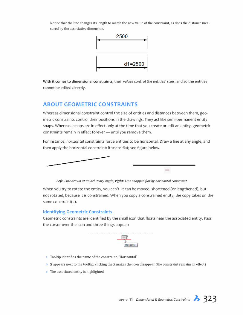
chapter 11 Dimensional & Geometric Constraints 323322 Inside BricsCAD V18
Notice that the line changes its length to match the new value of the constraint, as does the distance mea-sured by the associative dimension.
With it comes to dimensional constraints, their values control the entities’ sizes, and so the entities
cannot be edited directly.
ABOUT GEOMETRIC CONSTRAINTSWhereas dimensional constraint control the size of entities and distances between them, geo-metric constraints control their positions in the drawings. They act like semi-permanent entity snaps. Whereas esnaps are in effect only at the time that you create or edit an entity, geometric constraints remain in effect forever — until you remove them.
For instance, horizontal constraints force entities to be horizontal. Draw a line at any angle, and then apply the horizontal constraint: it snaps flat; see figure below.
Left: Line drawn at an arbitrary angle; right: Line snapped flat by horizontal constraint
When you try to rotate the entity, you can’t. It can be moved, shortened (or lengthened), but not rotated, because it is constrained. When you copy a constrained entity, the copy takes on the same constraint(s).
IdentifyingGeometricConstraintsGeometric constraints are identified by the small icon that floats near the associated entity. Pass the cursor over the icon and three things appear:
Ð Tooltip identifies the name of the constraint, “Horizontal”
Ð X appears next to the tooltip; clicking the X makes the icon disappear (the constraint remains in effect)
Ð The associated entity is highlighted

chapter 11 Dimensional & Geometric Constraints 325324 Inside BricsCAD V18
Here is another for-instance: concentric constraints force circles to be concentric. Move one, and the other moves with it.
Left: Two circles placed arbitrarily in the drawing; right: Larger circle made concentric to the first one
The gcConcentric command is order-dependent: the first entity you select is the master, meaning that the second entity you select follows it. (Unlike dimensional constraints, geometric con-strains do not take formulae.)
To remove a geometric constraint, you have to use the DelConstraint command; you cannot sim-ply “erase” geometric constraints.
All the kinds of dimensional constraints found in BricsCAD are listed in the boxed text on the fac-ing page.
Using Geometric ConstraintsThe easiest way to understand geometric constraints is to work through a tutorial. Below, I drew a rough sketch of a bracket. I drew it badly deliberately to show off the beneficial effect of constraints. You can access the bracket-ragged.dwg file from my public Dropbox folder: https://dl.dropboxusercontent.com/u/28941239/Inside-BricsCAD-Tutorial-Files.zip.)
1. Start BricsCAD with a new drawing.
2. Draw a shape similar to the one illustrated above with the Line, Arc, and Circle commands. The exact size and exact placement of entities is not critical.

chapter 11 Dimensional & Geometric Constraints 325324 Inside BricsCAD V18
3. The 2D Constraints toolbar assists you in assigning geometric constraints to entities. Open it, as follows:
a. Right-click any toolbar.
b. From the shortcut menu, choose BRICSCAD, and then choose 2D Constraints.
4. The first step, usually, is to connect all lines with the gcCoincident command. This particular constraint mode forces the endpoints of lines and arcs to stick together. The good news is that you don’t need to pick entities individually:
a. From the 2D Constraints toolbar, choose the Coincident button.
: _gccoincident
b. Use the command’s Autoconstrain option to connect all lines in one fell swoop:
Select first point or [Entity/Autoconstrain] <Entity>: a
Select entities: all
c. Press Enter to end the command:
Select entities: (Press Enter)
5. Notice that tooltip-like tags appear all over the drawing. They are known as “constraint bars,” and report the types of geometric constraints applied to entities. In this case, the tags are all the same, because of the coincident constraint.
6. Me, I find these bars annoying, because they clutter the drawing, and so I close them. You can, too:
Ð To turn off bars individually, click the x that appears in the upper right corner of each bar
Ð To turn them off all at the same time, use the ConstraintBar command’s Hide option, as follows:
: constraintbar
Select entities: all
Select entities: (Press Enter to continue)
Select option to [Show/Hide/Reset] constraints: h

chapter 11 Dimensional & Geometric Constraints 327326 Inside BricsCAD V18
7. To see the effect of the Coincident constraint, drag a line. Notice the other lines that are connected to it. This shows that Coincident is like a sticky bit of glue, making lines act like polylines.
8. Enter the U command to return the drawing as it was before.
9. To straighten out lines that are supposed to be horizontal, use the gcHorizontal command on the nearly horizontal ones, as follows:
a. In the 2D Constraints toolbar, click the Horizontal button, and then follow the prompts in the command bar:
: _gchorizontal
b. Select a nearly-horizontal line:
Select an entity or [2Points] <2Points>: (Choose a line)
Notice that it immediately goes precisely horizontal. The line changes its length as needed, so that it remains attached to its neighbors.

chapter 11 Dimensional & Geometric Constraints 327326 Inside BricsCAD V18
QUICK SUMMARY OF 3D CONSTRAINTS
The Platinum Edition of BricsCAD provides dimensional and geometric constraints work in three dimen-sions, as illustrated by the 3D Constraints toolbar and the 3D Parametric ribbon tab:
Above: 3D Constraints toolbar; below: 3D Constraints on the ribbon
The 3D constraints are applied with the dmConstraint3d command. (‘dm’ is short for direct modeling.)
: dmconstraint3d
Select type of 3D constraint [Fix/Coincident/CONcentric/Parallel/PErpendicular/
Tangent/RIgidSet/Distance/Radius/Angle]:
Icon Geometric Constraint Command Constraining Action
Fix dmFix3d Fixes solids, or edges or faces of solids
Coincident dmCoincident3d Fixes edges, faces, or edge and face of different solids
Concentric dmConcentric3d Fixes two cylindrical, spherical or conical surfaces
Parallel dmParallel3d Fixes two faces of a solid, or of different solids
Perpendicular dmPerpendicular3d Fixes two faces of a solid, or of different solids
Tangent dmTangent3d Fixes a face and a curved surface of different solids
Rigid Set dmRigidSet3d Define a set of entities or sub-entities as a rigid body
Icon Dimensional Constraint Command Constraining Action
Distance dmDistance3d Distance between two sub-entities
Radius dmRadius3d Radius of cylindrical surfaces or circular edges Angle dmAngle3d Angle between the faces of a solid or of different solids
c. Repeat the command to make other lines horizontal.

chapter 11 Dimensional & Geometric Constraints 329328 Inside BricsCAD V18
Now you need to straighten out the vertical lines. Here you have some options. You could apply any of these constraints:
Ð Two vertical constraints to make all the near-vertical lines truly vertical
Ð Two perpendicular constraints to make vertical lines perpendicular to the horizontal ones
Ð One perpendicular and one parallel constraint to make one vertical line perpendicular to one horizontal one, and then to make the remaining vertical one parallel to the first
Which approach you choose depends on your intent for the design: how do you want the lines to relate to each other?
10. I consider approach #2 is best, because I want vertical lines to all be perpendicular to the horizontals. Here is how to do this:
a. Click the Perpendicular button to start the gcPerpendicular command.
: _gcperpendicular
b. For this type of constraint, the selection order matters. Essentially, the second entity selected is made perpendicular to the first one. (The first is the master, the second is the slave.) Select a horizontal line:
Select first entity: (Choose a horizontal line)
c. And then select an attached nearly-vertical one:
Select second entity: (Choose the vertical one)
Notice that the vertical line straightens out, because it is forced to be perpendicular to the horizontal one.
11. Repeat for the other nearly-vertical lines. The result should look similar to the figure below.

chapter 11 Dimensional & Geometric Constraints 329328 Inside BricsCAD V18
12. The circle needs a geometric constraint to fix its location. Use gcConcentric to match the center point of the circle to that of the arc, as follows:
: _gcconcentric
Select first entity: (Pick the circle)
Select second entity: (Pick the arc)
Normally, selection order matters with Concentric constraint: the second entity shifts its position to be con-centric with the first one selected. In this particular case, however, selection order did not matter, because the arc is fixed in place (through the earlier Coincident constraint), and so BricsCAD forced the circle to move.
13. Notice that the connection between the arc and the two tangent lines is not smooth. To force the arc’s two ends smoothly meet the lines, use the gcTangent constraint, as follows:
: _gctangent
Select first entity: (Pick the arc)
Select second entity: (Pick a line)
Repeat for the second arc-line connection.
In the figure below, I overlapped the constrained drawing (shown in black) with the original rough sketch (shown in gray). It is easy to see how constraints fixed it up!
Original sketch
Drawing cleaned up with constraints
14. If you wish to see all the constraint bars again, turn them on like this:
: constraintbar
Select option to [Show/Hide/Reset] constraints: S
Select entities or ENTER to select all: (Press Enter)

chapter 11 Dimensional & Geometric Constraints PB330 Inside BricsCAD V18
15. With all the geometry fixed in place relative to one another, you can use dimensional constraints to size the bracket. The drawing illustrated below provides the values of the dimensions.
As you enter the values, notice that parts stretch their sizes to accommodate.
Ð Use dcHorizontal for horizontal dimensional constraints
: _dchorizontal
Specify first constraint point or [Entity] <Entity>: (Press Enter)
Select an entity: (Pick a line)
Specify dimension line location: (Pick a point)
Dimension text <17.993713>: 19
Ð Use dcVertical for vertical dimensional constraints
Ð Use dcDiameter for diameter dimensional constraints
———
This concludes the tutorials on using constraints with BricsCAD. You learned how constraints can be used to clean up drawings, as well as to quickly change the sizes of them.
APPENDIX A
Concise Summary of
Command Names
IN THIS APPENDIX, YOU CAN REFERENCE THE NAMES OF OVER 900 COMMANDS IN BRICSCAD V18. They are listed alphabetically by name, as well as in groupings of common commands, as follows:
ai- commands
bim- (building information modeling) commands
bm- (BricsCAD mechanical) Commands
Cloud commands (ex-Chapoo)
Dim- (dimension) commands
dc- (dimensional constraint) commands
dm- (direct modeling) commands
gc- (geometric constraint) commands
Layer Commands
sm- (sheet metal) Commands
VBA (Visual Basic for Applications) commands
ViewBase commands
“Bim-” BIM and “Sm-” sheet metal commands are available through optional extra-cost add-on modules.
When a command has a hyphen prefix, such as -Color, the command runs at the command prompt.
Command names new in V18 are shown in blue. Command names specific to the Pro and Platinum ver-sions are shown in boldface; these commands are not available in the Standard version.
B Concise Summary of Command Names 333332 Inside BricsCAD V18
A Commands
About displays information about the program.
AcisIn imports 3D solids in SAT format (SAT is short for “save as text”).
AcisOut exports 3D solids and surface entities in SAT format.
AddInMan displays the VBA COM Add-In Manager dialog box (windows only).
AddSelected creates a new entity of the same type as an existing entity.
Align aligns entities with other entities in 2D and 3D space.
AlignSpace adjusts viewport angle, zoom factor, and pan position based on alignment points specified in model space and paper space; operates in paper space only.
AniPath makes movies from views generated by a camera moving through 3D scenes.
AnnReset resets all scale representations to the entity’s original positions
AnnUpdate updates annotative scale factors to match updates made with Style and DimStyle commands.
Aperture sets selection area for snapping to entities.
Apparent toggles Apparent intersection entity snap; snaps to the intersections of entities, even when they only appear to intersect in 3D space.
AppLoad loads DRX, LISP, and SDS applications to run inside BricsCAD; Mac and Linux load only LISP and SDS.
Arc draws arcs.
Area determines the area and perimeter of closed 2D objects; the area and length of open polylines and splines as if they were closed; the lengths only of lines, sketches, arcs, and elliptical arcs; and the areas of faces of 3D objects.
Array and -Array creates dynamic polar, path, and rectangular arrays of entities.
ArrayClassic runs the dialog box-based version of the Array command.
ArrayClose and -ArrayClose end the array editing session.
ArrayEdit edits entities and source entities of arrays.
ArrayEditExt edits entities in arrays.
ArrayPath distributes entity copies evenly along a path into multiple rows and levels.
ArrayPolar distributes entity copies evenly in a circular pattern about a center point or axis of rotation, using multiple rows and levels.
ArrayRect distributes entity copies into any number of rows, columns, and levels.
AttDef and -AttDef defines attributes for blocks.
AttDisp toggles the display of attributes through all, none, or those normally visible.
AttEdit edits the values and properties of attributes.
AttExt and -AttExt exports data from attributes to text files.
AttRedef redefines blocks and updates associated attributes.
AttSync synchronizes attribute definitions in all references to a specified block definition.
Audit repairs open drawings in case of data corruption.
AutoComplete sets the options for autocomplete mode on the command line.
B Concise Summary of Command Names 333332 Inside BricsCAD V18
Ai Commands
Ai_Box draws 3D boxes as mesh surfaces.
Ai_CircTan draws a circle tangent to three entities.
Ai_Cone draws 3D cones as mesh surfaces.
Ai_Cylinder draws 3D cylinders as mesh surfaces.
Ai_DeSelect unselects all selected entities.
Ai_Dish draws 3D dishes as mesh surfaces.
Ai_Dome draws 3D domes (half-spheres) as mesh surfaces.
Ai_DrawOrder changes the display order of overlapping entities.
Ai_Fms switches to the first layout tab and enters model space of the first viewport.
Ai_Molc makes the layer current of the selected entity (short for “make object layer current”).
Ai_MSpace switches to model tab.
Ai_PSpace switches to the first layout tab.
Ai_Pyramid draws 3D pyramids as mesh surfaces.
Ai_SelAll selects all non-frozen entities in the current space, like Ctrl+A.
Ai_Sphere draws 3D spheres as mesh surfaces.
Ai_TileMode1 sets TileMode variable to 1 and then switches to model tab.
Ai_Torus draws 3D tori as mesh surfaces.
Ai_Wedge draws 3D wedges as mesh surfaces.
AiMleaderEditAdd adds leader lines to multi-leaders.
AiMleaderEditRemove removes leader lines from multi-leaders.
B Commands
Base changes the drawing’s insertion point when when it is inserted into other drawings.
BAttMan manages the attributes of block definitions (short for Block Attribute Manager).
BHatch and -BHatch fills closed areas with repeating patterns, solid colors, or gradients.
BlipMode enables and disables display of marker blips.
Block and -Block groups entities into blocks (symbols).
BmpOut exports the current viewport as a BMP (bitmap) file.
Boundary and -Boundary draws a polyline that forms a boundary around the inside closed areas.
Box draws three-dimensional solid boxes.
Break removes portions of entities.
Browser opens the default Web browser.

B Concise Summary of Command Names 335334 Inside BricsCAD V18
BIM Commands
(Available as an add-on to the Platinum edition only; bim = building information modeling)
bimAddEccentricity controls relative positions of the axes in linear solids.
bimApplyProfile applies profiles to linear entities and linear solids.
bimAttachComposition attaches BIM compositions to solids.
bimAttachSpatialLocation locates the drawing in mapping references.
bimCheck checks the validity of the BIM model.
bimClassify classifies an entity as a building element with a name and an internal ‘guid’ (globally unique identifier).
bimConnect creates L-connections between faces of two solids.
bimDrag drags faces of solids; when dragging major faces, it preserves connections with minor faces; when dragging minor faces, it optionally connects minor faces to major faces of other solids.
bimExport exports the current BIM model to an IFC file.
bimFlip flips the starting face from which the layers of a composition are set out.
bimGetStatisticalData reports statistics data of BIM objects in the current drawing.
bimIfcImport imports IFC files; IFC is short for “industry foundation classes.”
bimIfy automatically classifies and spatial locates the entire bim model.
bimInsert and -bimInsert insert windows and doors in solids.
bimLinearSolid creates chains of linear solids.
bimList list names and properties of BIM entities in the current drawing.
bimMultiSelect selects one or more linear solids with coplanar and/or parallel axes based on the initial solid or face selected.
bimPatch reserves an of a BIM model for editing with the RefEdit command.
bimProfiles displays the Profiles dialog box for creating and editing profiles.
bimProjectInfo displays the BIM Project Info dialog box for specifying project library databases.
bimProperties displays the BIM Properties dialog box for specifying and editing properties of bim projects.
bimReposition repositions inserts in face of solids.
bimRoom defines room areas with markers.
bimSection creates BIM section entities.
bimSectionOpen opens the drawing file related to a BIM section entity; or the 3D BIM model related to a BIM section drawing.
bimSectionUpdate updates and exports BIM sections.
bimSplit splits segmented solids into separated solids automatically; splits solids using cutting faces.
bimSuggest analyzes the selected connection between a pair of solids, then finds and suggest similar connections elsewhere in the mode.
bimTag tags BIM sections.
bimUpdateRoom updates data about the selected room.
bimUpdateThickness re-applies the overall thickness of a composition to the solid.
bimWindowCreate replaces closed entities with parametric window entities; displays the choose window style dialog box.
bimWindowPrint prints a specified area of the BIM model.

B Concise Summary of Command Names 335334 Inside BricsCAD V18
bimWindowUpdate updates openings made by windows or doors in solids in case the opening did not updated correctly automatically.
ClipDisplay toggles the clipped display property of a section plane or a BIM section entity.
BricsCAD Mechanical Commands
(Available in Platinum edition only; bm = BricsCAD mechanical)
BmBalloon associates balloon with assembly components in Model space and in generated views in layouts.
bmBom inserts bill of material (BOM) tables in the current drawing.
bmBrowser toggles the visibility of the Mechanical Browser window.
bmDependencies lists all files, containing component definitions inserted in the assembly, in the command window.
bmDissolve dissolves a mechanical component inserted in the current drawing.
BmExplode creates a block of an exploded representation of an assembly.
bmExternalize converts local components to external components.
bmForm creates a new mechanical component and inserts it into the current drawing; if necessary, run bmMech to initialize the mechanical structure in the current drawing.
bmHardware and -bmHardware insert standard hardware parts as a mechanical component in the current drawing.
bmHide hides the visibility of mechanical components; hidden inserts are taken into account by commands such as bmBom and bmMassProp.
bmInsert and -bmInsert insert an existing mechanical component as a virtual component into the current drawing.
bmLocalize converts external components to local components.
bmMassProp computes mass properties for the current model using densities assigned to the components (defined by the Density property of the components and subcomponents).
bmMech converts the current drawing into a mechanical component.
bmNew creates a mechanical component as a new drawing file.
bmOpen opens the source drawing of external mechanical components.
bmOpenCopy opens a copy of a component insert as a new drawing.
-bmParameters lists and edits parameters of inserted components.
bmRecover recovers broken mechanical structures.
bmReplace replaces a component insert.
bmShow shows previously hidden mechanical components.
bmUnmech converts the current mechanical component into a plain drawing.
bmUpdate reloads all referenced components from external files and updates BOM tables.
bmVStyle applies visual styles to mechanical component inserts.
bmXConvert converts X-Hardware solids in the current drawing to mechanical components.

B Concise Summary of Command Names 337336 Inside BricsCAD V18
C Commands
Cal displays the operating system’s Calculator program.
Callout places callouts; can be used only from the SheetSet panel.
Camera changes the viewpoint to perspective.
Center toggles Center entity snap; snaps to the center of circles, arcs, and other circular entities.
Chamfer bevels entities.
Change changes the position and properties of entities: endpoint, color, elevation, layer, linetype, linetype scale, lineweight, and thickness.
ChProp changes just the properties of entities.
ChSpace moves entities from paper space to model space and vice versa.
Circle draws circles.
CleanScreenOn hides most user interface elements to maximize the drawing area.
CleanScreenOff restores the user interface to its default configuration.
CleanUnsedVariables clears unused variables from memory.
Close exits the current drawing, but not the program.
Color and -Color specifies the color for entities.
CommandLine and CommandLineHide open and close the command bar.
Commands reports the names of all commands supported by the program.
Cone draws three-dimensional solid cones.
ContentBrowserClose and ContentBrowserOpen close and open the Content Browser panel.
ConvertCtb converts older CBT (color-based plot tables) files to newer STB (style-based plot tables) files.
ConvertOldLights converts old light definitions to the current format.
ConvertOldMaterials converts old material definitions to the current format.
ConvertPoly converts lightweight polylines to classic polylines (2D polylines) and vice versa.
ConvertPStyles converts drawings to from CTB (color-based plotting) to STB (plot styles).
Copy duplicates entities.
CopyBase copies entities with a specified reference point to the Clipboard.
CopyClip copies entities to the Clipboard.
CopyEData Copies extended entity data from one entity to others.
CopyHist copies the command history to the Clipboard.
CPageSetup edits the page setup of the current layout or model space.
CuiLoad and CuiUnload load and undload CUI and CUIX (user interface customization), MNU (menu), MNS (LISP code), and ICM (IntelliCAD menu) files.
Customize customizes user interface elements, such as menus, toolbars, and shortcuts.
CutClip copies entities to the Clipboard and deletes the entities.
Cylinder draws three-dimensional solid cylinders.
B Concise Summary of Command Names 337336 Inside BricsCAD V18
Cloud(24/7,ex-Chapoo)Commands
All Chapoo- commands are renamed Cloud- in V18
CloudAccount reports the status of the 24/7 account at the command bar.
CloudDownload downloads drawings from the 24/7 project to a local folder.
CloudLogoff logs off from the 24/7 project.
CloudLogon logs on to 24/7.
CloudOpen opens a drawing after downloading it from 24/7.
CloudProject opens the 24/7 project in the default browser.
CloudUpload uploads the current drawing to 24/7.
CloudWeb connects to the 24/7 website at https://www.bricsys.com/en-intl/247/.
D Commands
DataExtraction exports entity properties, block attributes and drawing information to CSV (comma separated values) file.
DbList lists information about all entities in the drawing (short for “database listing”).
DdAttE edits the values of attributes through a dialog box (short for “dynamic dialog attribute editor”).
DdEdit edits single-line text, multi-line text, attribute definitions, and attribute text (short for “dynamic dialog editor”).
DdEModes sets default values for creating entities (short for “dynamic dialog entity modes”).
DdFilter creates a selection set of the entities selected.
DdGrips specifies the properties of grips through the Settings dialog box.
DdPType specifies the look and size of point entities, through the Settings dialog box (short for “dynamic dialog point type”).
DdSelect specifies the properties for selecting entities, through the Settings dialog box.
DdSetVar displays the Settings dialog box to change the values of variables.
DdSTrack Sets the properties for snap tracking, through the Settings dialog box (short for “snap tracking”).
DdVPoint sets 3D viewpoints or plan view.
DefaultScaleList displays the Scale List Edit dialog box to edit the default scale factors
DesignTable creates new design tables for the Mechanical Browser.
-DesignTableEdit configures, replaces, exports, and deletes design tables at the command line.
Delay delays execution of the next command; for use with scripts only.
DelEData deletes extended entity data from the selected entity (short for “delete entity data”).
Dish draws dishes (bottom half-sphere) from polygon meshes.
Dist reports the distance and angle between two points.
Distantlight places distant lights.
Divide places points or blocks along entities.
Dome draws domes (top half-sphere) from polygon meshes.
Donut draws circular polylines with width.
DragMode controls the appearance of objects while being dragged.
DrawOrder changes the display order of overlapping entities.
B Concise Summary of Command Names 339338 Inside BricsCAD V18
DrawOrderByLayer controls the draw order of overlapping objects through layer names.
DSettings displays the Settings dialog box for drafting settings (short for “drafting settings”).
DView changes the 3D viewpoint interactively, and turns on perspective mode (short for “dynamic view”).
DwgCodePage changes the code page for text in drawings.
DwgCompare compares differences between two drawings, and visually merges drawings.d
DwgProps opens the Drawing Properties dialog box, showing the general information and user defined properties stored with a drawing.
DxfIn and DxfOut imports DXF files (short for “drawing exchange format”) and exports drawings in ASCII or binary DXF format.
Dimension Commands
(Dim = dimension)
Ai_Dim_TextAbove moves text above the dimension line.
Ai_Dim_TextCenter centers text on the dimension line.
Ai_Dim_TextHome moves text to its home position, as defined by the dimension style.
AiDimFlipArrow mirrors arrowheads on dimension lines.
AiDimPrec changes the precision of dimension text.
Dim places and edits dimensions at the ‘Dimensioning command:’ prompt.
Dim1 executes a single dimension command at the ‘Dimensioning command:’ prompt.
DimAligned draws dimensions parallel to (aligned with) selected entities; works with lines, polylines, arcs, and circles.
DimAngular dimensions angles.
DimArc places arc length dimensions.
DimBaseline places multiple linear or angular dimensions starting at the same base point; command can only be used when at least one other dimension is already in the drawing.
DimCenter places center marks at the center points of circles and arcs.
DimContinue continues linear and angular dimensions from the endpoint of the previous dimension.
DimDiameter dimensions the diameter of circles and arcs, and places a center mark.
DimDisassociate removes associativity from selected dimension entities.
DimEdit changes wording and angle of dimension text; changes the angle of extension lines.
DimLeader draws leaders.
DimLinear places linear dimensions horizontally, vertically, or rotated.
DimOrdinate measures x and y ordinate distances from a common origin, specified by the current UCS origin.
DimOverride overrides the values of the current dimension style.
DimRadius dimensions the radii of arcs and circles.
DimReassociate reassociates or associates dimensions to entities or points on entities.
DimRegen updates associative dimensions (short for “dimension regeneration”).
DimStyle and -DimStyle creates and modifies dimension styles through the Drawing Explorer.
DimStyleSet reports the current dimension style in the command bar.
DimTEdit changes the position of dimension text.

B Concise Summary of Command Names 339338 Inside BricsCAD V18
Dimensional Constraint Commands
(dc = dimensional constraint)
CleanUnusedVariables purges variables not used by constraint expressions and not linked to dimensions.
dcAligned constrains the distance between two defining points on entities.
dcAngular constrains the angle between three constraint points on entities; or between two lines; or between two polyline seg-ments; or constrains the angles of arcs or polyline arcs.
dcConvert converts an associative dimension to a dimensional constraint.
dcDiameter constrains the diameters of circles, arc, or polyline arcs.
dcDisplay shows and hides dimensional constraints.
dcHorizontal constrains the horizontal distance between two defining points on entities.
dcLinear constrains horizontal or vertical distance between two defining points on entities.
dcRadial constrains the radius of circles, arcs, or polyline arcs.
dcVertical constrains the vertical distance between two defining points on entities.
DelConstraint removes all dimensional (and geometrical) constraints from an entity.
DimConstraint applies a dimensional constraint to an entity or between constraint points on entities; converts associative dimensions to dynamic dimensions.
Direct Modeling Commands
(Available for Pro or Platinum editions only; dm = direct modeling)
dmAngle3D applies angle constraints between the faces of a solid or of different solids.
dmAudit checks and fixes 3D models.
dmChamfer creates an equal distance chamfer between adjacent faces.
dmCoincident3D applies coincident constraints between two edges, two faces, or an edge and a face of two different solids.
dmConcentric3D applies concentric constraints between two cylindrical, spherical, or conical surfaces.
dmConstraint3D applies geometric relationships and dimensional constraints between sub-entities (such as faces, surfaces, and edges) of 3D entities.
dmCopyFaces copies features like holes and ribs to the same or other 3D solids
dmDeformCurve deforms one or more connected faces of a 3D solid/surface by replacing their edges with given curves.
dmDeformMove deforms one or more connected faces of a 3D solid/surface by moving and rotating their edges.
dmDeformPoint deforms as smoothly as possible (using G1 or G2 continuity) a region, one or more connected faces of a 3D solid or a surface by moving a point lying on one of them in arbitrary 3D direction.
dmDelete deletes faces and solids.
dmDistance3D applies a distance constraint between two sub-entities of a solid or of different solids.
dmExtrude creates 3D solids by extruding closed 2D entities, regions or closed boundaries.
dmFillet creates a smooth fillet between adjacent faces sharing a sharp edge.
dmFix3D applies a fixed constraint to a solid or to an edge or a face of a solid.
dmGroup creates new groups, edits them, and dissolves groups.
dmMove moves the selected solids, or faces or edges of a solid using a vector.

B Concise Summary of Command Names 341340 Inside BricsCAD V18
dmParallel3D applies a parallel constraint between two faces of a solid or of different solids.
dmPerpendicular3D applies a perpendicular constraint between two faces of a solid or of different solids.
dmPushPull adds or removes volume from a solid by moving a face.
dmRadius3D applies a radius constraint to cylindrical surfaces or circular edges.
dmRepair fixes inconsistencies in 3D geometry supported by ACIS kernel (3D solids, surfaces).
dmRevolve creates 3D solids by revolution of closed 2D entities or regions about an axis.
dmRigidSet3D defines a set of entities or sub-entities as a rigid body.
dmRotate rotates faces of a solid around an axis.
dmSelect selects edges and faces of 3D solids or surfaces based on their geometric properties.
dmSelectEdges selects faces and edges of 3D solids.
dmSimplify simplifies the geometry and topology of 3D solid entities by removing unnecessary edges and vertices, merges seam edges, and replaces the geometry of faces and edges by analytic surfaces and curves, if possible within the user-specified tolerance. Run this command on imported 3D solid geometry.
dmStitch converts a set of region and surface entities that bound a watertight area to a 3D solid.
dmTangent3D applies a tangent constraint between a face and a curved surface of different solids.
dmThicken creates 3D solids by thickening (i.e. adding thickness to) surfaces, their faces, and faces of 3D solids.
dmTwist twists 3D solids, surfaces, and regions by an angle.
dmUpdate forces 3D constraints to update.
E Commands
EAttEdit edits the value and most properties of attributes (short for “enhanced attribute editor”).
EdgeSurf creates a 3D Coons mesh surface patch between four lines, forming a closed shape (short for “edge surface”).
EditEData creates and edits extended entity data (short for “edit entity data”).
Elev changes the default elevation and thickness.
Ellipse draws ellipses and elliptical arcs.
EndCompare ends the drawing compare session
Endpoint toggles endpoint entity snap; snaps to the ends of open entities, such as line, arcs, and open polylines.
Erase erases selected entities from drawings; alternatively, press the Del key.
eTransmit creates a package of a drawing file and all its dependencies, such as external references, images, font files, plot configu-ration files, plot style tables and font map files.
ExpBlocks opens the Blocks section of the Drawing Explorer dialog box (short for “explorer blocks”).
ExpFolders opens the Drawing Explorer on the Folders tab.
Explode breaks complex objects into their component entities.
Explorer opens the Drawing Explorer dialog box, which controls Layers, Layer States, Linetypes, Multiline Styles, Multileader Styles, Text Styles, Dimension Styles, Table Styles, Coordinate Systems, Views, Visual Styles, Lights, Materials, Render Presets, Blocks, External References, Images, PDF Underlays, Dependencies, Page Setups, and Section Planes.
Export saves entities in other file formats.
ExportLayout exports visible objects from the current layout to model space of new drawings.
B Concise Summary of Command Names 341340 Inside BricsCAD V18
ExportPDF exports the current layout to a PDF file.
ExpUcs creates, modifies, and deletes named UCSes through the Drawing Explorer (short for “explore user-defined coordinate systems”).
Extend extends entities to bounding edges defined by other entities.
Extension toggles extension entity snap, which snaps to the point where a line extended would intersect another entity.
Extrude extrudes closed entities as 3D solids and open ones as 3D surfaces.
F Commands
Field inserts text that is updated automatically when system variables change.
FileOpen opens drawing (DWG), template (DWT), and interchange (DXF) files from the command line.
Files opens the operating system’s file manager, such as Windows Explorer or Finder.
Fill fills areas with a solid color or color gradient
Fillet rounds entities.
Find finds and replaces text in notes, annotations, and dimension text.
Flatshot creates a hidden line representation of all 3D solids in model space as a block or a new drawing.
Flatten flattens 2D objects with thickness and allows to convert splines to polylines.
G Commands
GCE snaps the the geometric center of entities.
GenerateBoundary creates closed polylines from faces of 3D solids, as well as from boundaries detected when the Enable Boundary Detection of SelectionModes is activated.
GeographicLocation sets the geographic location of the drawing.
Gradient fills closed areas with gradient fills of one or two colors.
GradientBkgOff and GradientBkgOn turn off and on the gradient displayed in the working area.
GraphScr switches from the text windows to the graphics windows (short for “graphics screen”).
Grid turns the grid display on or off and sets other grid options.
Group and -Group creates and modifies named groups of entities.
Geometric Constraint Commands
(For 3D constraints, see Direct Modeling Commands section; gc = geometric constraints)
ConstraintBar shows, hides, and resets the display of geometric constraint icons.
DelConstraint removes all geometrical (and dimensional) constraints from an entity.
gcCenter snaps to the centroid of closed entities.
gcCoincident constrains points on entities coincidently; or constrains a point on an entity to another entity.
gcCollinear constrains lines collinearly.
gcConcentric constrains the center points of arcs, circles, ellipses, and/or elliptical arcs to be coincident.

B Concise Summary of Command Names 343342 Inside BricsCAD V18
gcEqual constrains lines to have the same length, or arcs and circles to have the same radius.
gcFix constrains points on entities to fixed positions.
gcHorizontal constrains lines or linear polyline segments, or pairs of points on entities to be parallel to the x axis in the current coordinate system.
gcParallel constrains two lines or linear polyLine segments to be parallel to each other.
gcPerpendicular constrains two lines or linear polyline segments to be perpendicular to each other.
gcSmooth constrains a spline to be fluidly continuous to another spline, or arc, or line, or polyline.
gcSymmetric constrains two entities, or two points on entities, to be symmetric about a line of symmetry.
gcTangent constrains one entity tangent to another.
gcVertical constrains lines or linear polyline segments, or pairs of points on entities to be parallel to the y axis in the current coordinate system.
GeomConstraint acts as a universal command that applies all available geometric constraint points.
H Commands
Hatch and -Hatch fills a selected boundary with a pattern.
HatchEdit and -HatchEdit edits hatch patterns and gradient fills.
HatchGenerateBoundary generates a boundary around a hatch or gradient fill.
HatchToBack sets the draw order of all hatch entities in the drawing to display behind all other entities.
Helix draws 2D spirals or 3D helixes.
Help displays online help.
HelpSearch prompts for searching through the help files at the command prompt.
Hide removes hidden lines from 3D entities until the UnisolateObjects command is used.
HideObjects temporarily hides selected entities.
Hyperlink and -Hyperlink adds hyperlinks to entities or modifies existing hyperlinks.
HyperlinkOptions controls the display of the hyperlink cursor, shortcut menu, and tooltips.
I Commands
Id reports the x,y,z coordinates of a picked point.
Image inserts raster images in drawings through the Drawing Explorer.
ImageAdjust adjusts the properties of images through the Properties palette.
ImageAttach and -ImageAttach attache raster images to the drawing like xrefs.
ImageClip clips images.
ImageFrame toggles the frame around images.
ImageQuality determines the display quality of images attached to the drawing.
Import displays a dialog box for importing files into the drawing: DWG, DXF, DWT, and DAE (Collada) files. Platinum edition also imports IFC and SKP (SketchUp) files. Additional formats can be imported when the optional Communicator modules is purchased.

B Concise Summary of Command Names 343342 Inside BricsCAD V18
Imprint imprints 2D entities onto planar faces of 3D solids and surfaces; allows to create additional edges on planar faces.
Insert and -Insert inserts blocks or another drawing into the current drawing.
InsertAligned inserts blocks repeatedly, and inserts mirrored blocks.
Insertion toggles Insertion entity snap; snaps to the insertion point of text and blocks.
InsertObj displays data from other programs in drawings, such as text documents, spreadsheets, and images (windows only).
Interfere checks interferences between solid models.
Intersect creates regions or 3D solids from the intersection of regions or 3D solids.
Intersection Toggles Intersection entity snap; snaps to the intersections of entities.
IsolateObjects hides all other entities from view.
Isoplane controls the isometric plane (left, right, or top) when isometric snap is used.
J Command
Join joins lines, lwpolylines, 2D polylines, 3D polylines, circular arcs, elliptical arcs, splines and helixes at common endpoints.
K Command
KeepMe visually merges drawings during the DrawingCompare command
L Commands
Layer: see Layer Commands below.
Layout creates, copies, renames, and deletes layouts.
LayoutManager displays the Layout Manager dialog box for creating, naming, and reordering sets of layouts
Leader draws leader lines that connect annotations to drawing entities.
Lengthen changes the length of open objects, such as lines and arcs.
LicenseManager provides access to all Bricsys software licenses, as shown below.
LicEnterKey enters the license key number (short for “licence enter key”).
LicProperties reports the BricsCAD license information; modifies and deactivates single user and volume license keys.
LicPropertiesCommunicator reports license information for the optional extra-cost Communicator add-on.
Light places lights in drawings.
LightList displays the lighting palette.
Limits sets the extents of the drawing and the grid.
Line draws straight line segments.
LineType and -LineType creates, loads, and sets linestyles.
List lists the properties of selected entities at the command line.
LiveSection toggles the Live Section property of a section plane.

B Concise Summary of Command Names 345344 Inside BricsCAD V18
Load loads compiled SHX shape files into the drawing.
Loft creates 3D solids passing through two or more cross sections.
LogFileOff and LogFileOn turn off and on log file recording.
LWeight sets lineweight options.
Layer Commands
LayCur moves the selected entities to the current layer.
Layer and -Layer controls layers and layer properties.
LayerP undoes previously applied changes to layer settings when LayerPMode is on (short for “layer previous”).
LayerPMode controls the tracking of changes made to layer settings.
LayersPanelClose and LayersPanelOpen closes and open the Layers panel.
LayerState saves and restores the properties of layers.
LayFrz and LayThw freeze and thaw the layers associated with entities selected in the drawing.
LayIso and LayUnIso isolate and restore layers associated with entities selected in the drawing; locks or turns off all other layers (short for “layer isolate”).
LayLck and LayUlk lock and unlock the layers of selected entities.
LayMCur changes the working layer to that of a selected entity (short for “layer make current”).
LayOff and LayOn turn off and on layers associated with entities selected in the drawing; off layers cannot be seen.
M Commands
Mail attaches the current drawing to a new message with your computer’s default email client.
Manipulate launches the widget for rotating, copying, moving, mirroring, and scaling entities.
MapConnect sets up a connection with a Web Map Service, after the GeographicLocation command defines the geographic location in the drawing.
MassProp reports the area, perimeter, and other mathematical properties of 3D solids and 2D regions (short for “mass properties”).
MatBrowserClose and MatBrowserOpen close and open the materials browser.
MatchPerspective changes the viewpoint in perspective mode to match a background image.
MatchProp assigns the properties of one entity to one or more other entities (short for “match properties”).
MaterialMap maps material definitions onto the surfaces of objects, with presets for boxes, planes, spheres, and cylinders.
Materials creates materials and edits their properties through the Drawing Explorer.
MatLib displays the Rendering Materials panel.
Measure places points or blocks along entities.
MechanicalBrowserClose closes the Mechanical Browser panel.
MechanicalBrowserOpen displays the Mechanical Browser panel.
Menu loads menu files to modify the user interface.
MenuLoad and MenuUnload load and unload CUIX and CUI (user interface customization), MNU (menu), MNS (LISP code), and ICM (IntelliCAD menu) files.

B Concise Summary of Command Names 345344 Inside BricsCAD V18
Midpoint toggles Midpoint entity snap; snaps to the middle of lines, arcs, and other open entities.
MInsert inserts a block as a rectangular array; combines the -Insert and Array commands (short for “multiple insertion”).
Mirror draws mirror image copies of entities.
Mirror3D draws mirror images of entities about a plane in 3D space.
MLeader creates multileader entities using the current multileader style.
MLeaderEdit adds leader lines to and removes leader lines from a multileader entity.
MLeaderEditExt adds and removes leader lines, adds and removes vertices from a multileader entity.
MLeaderStyle creates and manages multileader styles through the Drawing Explorer.
MLine draws multilines.
MLStyle creates and edits multiline styles.
ModelerProperties and -ModelerProperties controls the various settings of the ACIS modeler through the Settings dialog box.
Move displaces entities a specified distance in a specified direction.
MoveEData moves extended entity data from one entity to another.
MSlide makes SLD (slide) files from the current view.
MSpace switches to model space inside a viewport of layout tab.
MText and -MText opens the multi-line text editor interface for placing paragraph text.
Multiple command prefix forces commands to repeat themselves automatically.
MView creates viewports in layout tab.
MvSetup prepares sets of paper space viewports; superseded by the ViewBase command.
MTP snaps to the midpoint between two points.
N Commands
Navigate walks and flys through 3D models.
Nearest toggles Nearest entity snap mode; snaps to the nearest geometry on entities.
NetLoad loads .NET applications.
New starts new drawing files.
NewSheetSet creates a new sheet set.
NewWiz starts new drawings with the New Drawing Wizard.
Node toggles Node entity snap mode; snaps to point entities.
None turns off all entity snap modes.
O Commands
ObjectScale and -ObjectScale adds or removes supported scales for annotative entities.
Offset offsets linear entities in parallel orientation.
OleLinks adjusts links of OLE entities embedded in or linked to drawings (short for “object linking and embedding”). (windows only).
OleOpen opens OLE objects for modification (windows only).
B Concise Summary of Command Names 347346 Inside BricsCAD V18
OnWeb opens the Bricsys home page in your computer’s default Web browser.
Oops un-erases the last erased entity, including those erased by the Block command.
Open opens an existing drawing file.
OpenSheetSet and -OpenSheetSet open an existing sheet set.
Options configures program operating parameters.
Orthogonal constrains the pointer so it moves parallel to the axes of the current coordinate system.
OSnap and -OSnap sets entity snaps through the Settings dialog box or the command line (short for “object snap”).
Overkill and -Overkill deletes duplicate entities and overlapping lines, arcs or polylines and unifies partly overlapping or contigu-ous ones.
P Commands
PageSetup creates and edits page setups for plotting drawings in the Drawing Explorer.
Pan and -Pan moves the drawing display in the active view tile.
Parallel turns on parallel entity snap.
-Parameters create and edit constraint expressions and values.
PasteBlock inserts data from the Clipboard as block.
PasteClip inserts data from the Clipboard.
PasteOrig pastes entities from the clipboard at the coordinates from the source drawing.
PasteSpec pastes entities from the clipboard, after the user specifies the format.
PdfAdjust adjust the fade, contrast and monochrome settings of PDF underlays.
Pdfattach and -PdfAttach attaches PDF files as underlays into the drawing.
PdfClip clips PDF underlays.
PdfLayers controls the display of layers in PDF underlays.
PdfOptions controls the exporting of drawings in PDF format through the Settings dialog box.
PEdit edits polylines, 3D polylines, and 3D meshes (short for “polyline edit”).
PEditExt edits vertices and segments of a polyline.
Perpendicular toggles perpendicular entity snap mode.
PFace draws 3D multi-sided meshes; meant for use by programs (short for “polyface mesh”).
Plan sets plan view to construction plane.
PLine draws polyline lines, arcs, and splines with optional width (short for “polyline”).
Plot and -Plot both execute the plot command at the command line.
PlotStyle sets the current plot style; works only when plot styles are enabled in drawings.
PlotterManager creates customized parameter PC3 files for printers and other output devices; executes the PlotConfig.exe utility program.
Point draws point entities.
PointLight places point lights in drawings.
Polygon draws eqi-sided polygons from polylines of 3 to 1,024 sides.
PolySolid creates 3D wall-like solids.
B Concise Summary of Command Names 347346 Inside BricsCAD V18
Preview shows a preview before printing the drawing.
Print plots the drawing to a plotter, printer, or file.
ProfileManager sets current, create, copy, delete, import and export user profiles.
ProjectGeometry projects geometry like curves, and edges onto regions, surfaces, and 3D solids.
Properties displays the Properties palette to change drawing entity properties.
PropertiesClose closes the Properties palette.
PSetupIn and -PSetupIn imports page setup definitions from another drawing.
PSpace switches from model to paper space (short for “paper space”).
Publish and -Publish prints sheet lists of model space or paper space layouts; saves a sheet list to a file.
Purge and -Purge remove unused named entities from drawings, such as unused layers and linetypes.
Pyramid draws three-dimensional solid pyramids.
Q Commands
QLeader draws leaders; specifies properties through a dialog box.
QNew opens new drawings in BricsCAD (short for “quick new”).
QPrint prints the drawing with the default plot configuration, without displaying the Print dialog box (short for “quick print”).
QSave saves the drawing without displaying the Save dialog box (short for “quick save”).
QSelect composes a selection set using filters.
QText toggles the display of text as rectangles (short for “quick text”).
Quadrant toggles snaps to quadrant points of circles, arcs, and polyarcs.
Quick toggles snaps to the first entity geometry found; used together with at least one other entity snap mode.
Quit ends BricsCAD; optionally saves unsaved drawings.
R Commands
Ray draws semi-infinite construction lines
ReAssocApp associates extended entity data with applications (short for “reassociate application”).
Recover repairs damaged drawings.
RecScript records keystrokes to an SCR file for playback with the Script command (short for “record script”).
Rectang draws a rectangular polyline.
Redefine restores built-in commands that have been undefined using the Undefine command.
Redo reverses the effects of a previous U command.
Redraw refreshes the display of the active view tile.
RedrawAll refreshes the display of all currently-open view tiles.
RedSdkInfo reports on rendering related hardware and driver specifications (short for “Red software development kit information”).
RefClose closes the in-situ block and xref editor.
RefEdit and -RefEdit edits blocks and externally-referenced drawings (short for “reference editor”).
RefSet adds and removes entities from the block or external reference being edited.
B Concise Summary of Command Names 349348 Inside BricsCAD V18
Regen regenerates the current viewport.
RegenAll regenerates all viewports.
RegenAuto determines when BricsCAD regenerates the drawing automatically.
Region converts an entity enclosing an area into a region.
ReInit reloads the PGP alias file (short for “re-initialize”).
Rename and -Rename changes the names of objects.
Render and -Render generates photorealistic renderings od 3D models using materials and lights.
RenderPresets creates and edits rendering presets, and to set the current render preset.
ReportPanelClose and ReportPanelOpen close and open the Report panel.
ResetBlock resets dynamic blocks to their default values.
Resume resumes an interrupted script.
RevCloud draws revision clouds commonly used for red-lining drawings.
Revolve draws 3D solids or surfaces by revolving 2D objects about an axis.
RevSurf creates 3D mesh surfaces by revolving open entities around a axis (usually a line).
Ribbon displays the ribbon user interface.
RibbonClose closes the ribbon.
Rotate rotates entities about a base point.
Rotate3D moves entities about a 3D axis.
RScript reruns the currently loaded SCR script file (short for “repeat script”).
RtLook moves the viewpoint through a 3D scene (short for “real time looking”).
RtPan pans the view in real time.
RtRot, RtRotCtr, or RtRotF rotate the viewpoint in real time.
RtRotX, RtRotY, or RtRotZ rotates the 3D viewpoint about the x, y, or z axis in real time.
RtUpDown tilts the viewpoint up, down, left, or right in real time.
RtWalk walk lefts, right, forward or backward through 3D scenes in real time.
RtZoom zooms into the drawing in real time.
RuleSurf draws ruled surfaces between two curves.
S Commands
Save saves the drawing under the current file name or a specified name.
SaveAll saves all open drawings.
SaveAs saves an unnamed drawing with a file name or renames the current drawing.
SaveAsR12 saves drawings in DWG R12 format.
Scale enlarges or reduces specified entities equally in the X, Y, and Z directions.
ScaleListEdit and -ScaleListEdit edits the list of scale factors used by annotative scaling, sheet scales, and plot scales.
Script loads and runs SCR script files.
Scrollbar toggles the display of the horizontal and vertical scroll bars.

B Concise Summary of Command Names 349348 Inside BricsCAD V18
Section creates a cross section based on the intersection of a plane and 3D solids.
SectionPlane creates a section entity that creates sections of 3D solids.
SectionPlaneSettings defines the properties of section plane entities in the Drawing Explorer.
SectionPlaneToBlock saves the selected section plane as a 2D cross section / elevation block or a 3D cutaway section block
Security determines whether VBA macros can run automatically; not available in the 64-bit version.
SecurityOptions sets a password to protect the drawing (windows only).
Select places selected entities in the ‘Previous’ selection set.
SelectAlignedFaces selects all faces in a model which are coplanar with a selected face.
SelectAlignedSolids Selects all solids in a model of which a face is coplanar with a selected face.
SelectConnectedFaces selects all faces in a model which are connected to a selected face.
SelectConnectedSolids selects all solids in a model which are connected to a selected face.
SelectSimilar selects entities of the same type and properties.
SelGrips prompts to selects entities and then displays grips.
Settings displays the Settings dialog box for changing the values of variables.
SettingsSearch opens the Settings dialog box at the specified category, variable name, or user preference.
SetUCS sets the UCS to a viewpoint specified through a dialog box.
SetVar displays and changes the values of system variables (short for “set variables”).
Sh and Shell open the Windows command prompt window; runs other applications (short for “shell”).
Shade shades the drawing mode.
ShadeMode sets the current visual style at the command line, such as Realistic, Conceptual, Edges, and X-ray.
-ShadeMode sets the old type of shade modes: 2D, 3D, Hidden, Flat, Flat with Edges, Gouraud, and Gouraud with edges.
Shape places shapes from SHX files in drawings.
SheetSet and SheetsetHide manage sheet sets, and closes the Sheet Set pane.
Singleton toggles whether multiple copies of BricsCAD can run at the same time.
Sketch draws freehand lines.
Slice slices 3D solids with a plane or surface.
Snap restricts pointer movements and pointing in the drawing to specified intervals.
Solid draws solid-filled 2D faces.
SolidEdit edits 3D solids and 2D regions.
SolProf creates hidden line representations of 3D solids in a layout viewport.
Spell checks the spelling of text in the drawing.
Sphere draws three-dimensional solid spheres.
Spline draws quadratic or cubic non-uniform rational Bezier spline (NURBS) curves.
SpotLight inserts spot lights into drawings.
Start runs operating system applications.
StatBar toggles the display of the status bar.
Status reports status of the drawing’s settings in the Text window.
B Concise Summary of Command Names 351350 Inside BricsCAD V18
StlOut export 3D models in STL format for 3D printing (short for “stereolithography”).
StopScript stops recording of scripts begun with the RunScript command.
Stretch moves or stretches entities.
StandardPartsPanelClose and StandardPartsPanelOpen close and open the Standard Parts panel.
StructurePanel and StructurePanelClose open and close the Structure panel displaying tree structure of the drawing content
Style and -Style creates and edits text styles through the Drawing Explorer.
StylesManager creates and attaches plot style files.
Subtract creates a composite region or a 3D solid by subtraction.
SunProperties edits sun properties through the Drawing Explorer.
SupportFolder opens the C:\Users\<login>\AppData\Roaming\Bricsys\BricsCAD\V18x64\en_US\Support folder.
SvgOptions controls the output as SVG files.
Sweep creates solid primitives or surfaces by sweeping two dimensional entities along a path.
SysWindows arranges windows.
Sheet Metal Commands
(Available for Platinum edition; requires an additional license; sm = sheet metal)
LicPropertiesSheetmetal reports the license state of the sheet metal module.
smBendCreate converts hard edges (sharp edges between flange faces) into bends.
smBendSwitch converts bends to lofted bends.
smConvert automatically recognizes flanges and bends in a 3D solid.
smDelete removes a bend or a junction by restoring the hard edge between two flanges; removes a flange with all the bends adjacent to it.
smDissolve removes sheet metal data from the selected features.
smExport2D exports unfolded representations of sheet metal bodies as 2D profiles in DXF or DWG files.
smExportOSM exports sheet metal solids to OSM files (short for “Open Sheet Metal”) used by CADMAN-B CAM systems.
smFlangeBase creates base (initial) flanges of sheet metal parts from closed 2D entities.
smFlangeBend bends existing flanges along a line, taking into account the k-factor.
smFlangeConnect closes gaps between two arbitrarily oriented flanges.
smFlangeEdge creates one or more flanges to a sheet metal part by pulling one or more edges of an existing flange.
smFlangeRotate rotates a selected flange of a sheet metal part with automatic selection of the rotation axis depending on the design intent.
smFlangeSplit splits a flange along a line drawn on its face.
smForm adds forms to sheet metal.
smJunctionCreate converts hard edges (sharp edges between flange faces) and bends into junctions.
smJunctionSwitch changes symmetrical junction features to overlapping faces.
smLoft creates sheet metal part with lofted bends and flanges from two non-coplanar curves.
smReliefCreate creates proper corner (three or more adjacent flanges) and bend reliefs (at the start and end of a flange edge).
smReliefSwitch converts corner reliefs a circular, rectangular or V-type relief. Allows to change the parameters of existing corner reliefs.

B Concise Summary of Command Names 351350 Inside BricsCAD V18
smRepair restores the 3D solid model of a sheet metal part by thickening one of its sides: all thickness faces become perpen-dicular to flange faces.
smReplace replacing form features with ones from libraries.
smRethicken restores the 3D solid model of a sheet metal part by thickening one of its sides (all thickness faces become per-pendicular to flange faces).
smSelectHardEdges selects all hard edges on sheet metal parts.
smUnfold generates unfolded 2D or 3D representations of sheet metal parts.
T Commands
Table and -Table draws tables in drawings.
Tabledit edits text in table cells.
TableExport exports the contents of a table entity to CSV (command separated values) files.
TableMod modifies the properties of table cells.
TableStyle creates and manages table styles through the Drawing Explorer.
Tablet configures and calibrates tablets, and toggles tablet mode (windows mode).
TabSurf draws tabulated surfaces from a path curve and a direction vector.
Tangent toggles tangent entity snap; snaps to the tangency of circles, arcs, ellipses and elliptical arcs.
TemplateFolder opens the C:\Users\<login>\AppData\Local\Bricsys\BricsCAD\V18x64\en_US\Templates folder.
Text and -Text places lines of text in the drawing.
TextScr displays the text window showing command history (short for “text screen”).
TextToFront sets the draw order of all texts and dimensions in the drawing to display in front of all other entities.
TfLoad and TfSave open and save handle, xsd, and strip data from DWT template files
Time reports on the time spent in the drawing.
TInsert inserts blocks in the cells of tables.
Tolerance draws tolerances (datum indicators and basic dimension notation).
Toolbar and -Toolbar displays and hides toolbars.
ToolPalettes opens the Tool Palettes bar.
ToolPalettesClose Closes the Tool Palettes bar.
-ToolPanel opens tool panels by name at the command bar.
Torus draws three-dimensional torrid solids.
TpNavigate opens tool palettes or group at the command bar.
Trace draws traces.
Transparency toggles the transparency of monotone images; has nothing do with the transparency property
Trim trims entities at a cutting edge defined by other entities.
TxtExp explodes text into polyline segments.

B Concise Summary of Command Names 353352 Inside BricsCAD V18
U Commands
U reverses the most recent command.
Ucs creates and displays named UCSes through the command bar (short for “user-defined coordinate system”).
UcsIcon toggles the display of the UCS icon.
Undefine disables built-in commands.
Undo restores deleted entities.
Union creates composite regions or solids by addition.
UnisolateObjects makes entities visible again following the IsolateObjects and HideObjects commands
Units and -Units sets coordinate and angle display formats and precision.
UpdateField forces the values of field text to update.
Url opens the default Web browser (short for “uniform resource locator”).
V Commands
View and -View saves, restores, and manages user-defined model and sheet views, and presets views.
ViewLabel adds labels to views; available through the Sheet Set manager only.
ViewRes sets the view resolution and toggles fast-zoom mode (short for “view resolution”).
VisualStyles and -VisualStyles creates and edits visual style definitions in the Drawing Explorer or at the command line.
VmlOut exports drawings in VML format embedded in Web pages (short for “vector markup language”).
VpClip clips viewports in layouts (short for “view port clipping”).
VpLayer changes the properties of layers in the current paper space viewport (short for “view port layer”).
VPoint Changes the 3D viewpoint through a dialog box.
VPorts and -VPorts create one or more viewports in model space (short for “viewports”).
VSlide displays images saved as SLD or WMF files (short for “view slide”).
Vba Commands
(Available in Pro and Platinum editions only; vba = Visual Basic for Applications)
VbaIde opens the VBA editing window; short for “integrated development environment” (windows only).
VbaLoad and -VbaLoad loads VBA projects (windows only).
VbaMan manages VBA projects; short for “manager” (windows only).
VbaRun and -VbaRun runs, creates, edits, and deletes VBA macros (windows only).
VbaSecurity sets the security level for running VBA macros.
VbaUnload unloads VBA projects (windows only).

B Concise Summary of Command Names 353352 Inside BricsCAD V18
ViewBase Commands
(Available in Pro and Platinum editions only)
ViewBase generates associative orthographic and standard isometric views of a 3D solid model in a paper space layout.
ViewDetail creates a detail view of a portion of a standard generated drawing at a larger scale.
ViewDetailStyle specifies the visual format of detail views and detail symbols.
ViewEdit changes the scale and hidden line visibility of drawing views; works in paper space only.
ViewExport exports the content of drawing views to Model space or to a new drawing; operates in paper space only.
ViewProj generates additional projected views from an existing drawing view.
ViewSection creates cross section views based on standard drawing views generated by the ViewBase command in a paper space layout.
ViewSectionStyle specifies the visual format of section views and section lines.
ViewUpdate updates drawing views.
W Commands
WBlock and -WBLock export blocks, selected entities, or the entire drawing as a DWG file.
WCascade, WClose, WCloseAll, WNext, and WPrev cascade the windows, close the current window, close all windows, and switch to the next or previous windows.
Weblight places Web lights.
Wedge draws three-dimensional solids with a sloped face tapering along the X axis.
WhoHas reports the ownership of a drawing file.
WhTile, WiArrange, and WvTile tiles windows horizontally, arranges tiled windows in an overlapping manner, or tiles them vertically.
WipeOut creates blank areas in drawings.
WmfOut exports the drawing in WMF (WIndows meta file), EMF (enhanced meta file), or SLD (slide) format.
WorkSets creates and loads named sets of drawing files.
Workspace sets the current workspace; creates, modifies, and saves workspaces.
WsSaves saves the current user interface by name.
WsSettings opens the Customize dialog box at the Workspace tab.
X Commands
XAttach attaches externally-referenced drawings.
XClip clips externally-referenced drawings.
XEdges extracts edges from 3D solids as lines.
XLine draws infinitely long lines.
XmlSave prompts for handles to save in an XML file.

B Concise Summary of Command Names PB354 Inside BricsCAD V18
XOpen opens externally-referenced drawings in a new window.
Xplode explodes entities, and provides control over the resulting entities.
XRef and -XRef attaches DWG files to the current drawing through the Drawing Explorer or the command line.
Z Commands
Zcenter toggles the 3D center entity snap; snaps to the center of planar or curved 3D faces.
Zknot toggles the 3D knot entity snap; snaps to a knot on a spline.
Zmidpoint toggles the 3D midpoint snap; snaps to the midpoint of a face edge.
Znearest toggles the 3D nearest entity snap; snaps to a point on the face of a 3D entity that is nearest to the cursor.
Znone disables all 3D snap modes.
Zoom increases or decreases the visible part of the drawing.
Zperpendicular toggles the 3D perpendicular entity snap; snaps to a point perpendicular to a face.
Zvertex toggles the 3D vertex entity snap; snaps to the closest vertex of a 3D entity.
# Commands
? displays the Help window.
2dIntersection toggles apparent intersection entity snap; snaps to the intersections of entities, even when they only appear to intersect in 3D space.
3D draws 3D polygon mesh objects: boxes, cones, cylinders, dishes, domes, pyramids, spheres, tori, wedges, or meshes.
3DArray constructs 3D rectangular arrays and rotated polar arrays.
3DCompare compares the 3D content of two drawing files.
3DConvert converts 3D solids to polyface meshes.
3DFace draws 3D 4-edged faces with optional invisible edges.
3DIntersection toggles Intersection entity snap; snaps to the intersections of entities.
3DMesh draws 3D surface meshes.
3DOsnap and -3DOsnap sets the entity snap modes for 3D entities through the Settings dialog box.
3DPoly draws 3D polylines.
APPENDIX B
Concise Summary of System Variables and Settings
BRICSCAD USES VARIABLES TO STORE AND REPORT SETTINGS AFFECTING THE PROGRAM and drawings. There are two types of variables: system variables that mimic the names and values from AutoCAD, and preference variables unique to BricsCAD. You access and change variables through a dialog box (Settings command) or directly on the command line (SetVar command).
This appendix lists over 800 variable names in alphabetical order.
UPPERCASE text indicates the name is also found in AutoCAD as a system variable
MixedCase text means the variable is a preference, and so is unique to BricsCAD
Blue text indicates that the variable is new in V18
StrikeThrough text indicates the variable was removed from BricsCAD
userid refers to your computer login name
When you see R/O (read-only), it means that you cannot change the variable's value. The Format column reports the format in which values are saved: Ð bool Boolean (true or false, yes or no, 1 or 0)
Ð int or short Integer number (a number without decimal point with a maximum value of 32768)
Ð long Long integer (integers larger than 32,768)
Ð pt2d 2D point (x,y)
Ð pt3d 3D point (x,y,z)
Ð real Real number (a number with decimal point)
Ð str String (text)

356 Inside BricsCAD V18
VariableName Format R/O DefaultValue
A VariablesACADLSPASDOC bool 0ACADPREFIX str read-only "C:\Users\userid\AppData\Roaming\Bricsys\BricsCAD\V18x64\en_US\Support\; C:\Program Files (x86)\Bricsys\BricsCAD V18x64\Support\,; C:\Program Files (x86)\Bricsys\BricsCAD V18x64\Fonts\; C:\Program Files (x86)\Bricsys\BricsCAD V18x64\Help\en_US\"ACADVER str read-only "20.0 BricsCAD"AcisHlrResolution real -1ACISOUTVER int 70AcisSaveAsMode int 0AFLAGS int 0AllowTabExternalMove bool 1AllowTabMove bool 1AllowTabSplit bool 1ANGBASE real 0ANGDIR bool 0ANNOALLVISIBLE int 1ANNOAUTOSCALE short -4AnnoSelected int read-only 0ANNOTATIVEDWG bool 0AntiAliasRender short 2AntiAliasScreen short 1APBOX bool 0APERTURE int 10AREA real read-only 0AREAPREC short -1AREAUNITS string "in ft mi µm mm cm m km"ARRAYASSOCIATIVITY bool 1ARRAYEDITSTATE bool read-only 0ATTDIA bool 0ATTMODE int 1AttractionDistance int 3ATTREQ bool 1AUDITCTL bool 0AuditErrorCount int read-only 0AUNITS int 0AUPREC int 0AUTOCOMPLETEDELAY real 0.3AUTOCOMPLETEMODE int 47AUTOMENULOAD bool 1AutoResetScales short 0AutosaveChecksOnlyFirstBitDBMOD bool 1AUTOSNAP int 119AutoTrackingVecColor int 171AutoVpFitting bool 1AXISMODE bool 0AXISUNIT pt3d X= 0 Y= 0 Z= 0
B VariablesBACKGROUNDPLOT int 2BACKZ real read-only 0BASEFILE str "Default-mm.dwt"BIMOSMODE rtshort 0

appendix A Concise Summary of System Variables and Settings 357
VariableName Format R/O DefaultValue
BINDTYPE bool 0BKGCOLOR int 7BKGCOLORPS int 7BLIPMODE bool 0BLOCKEDITLOCK bool 0BLOCKEDITOR bool 0BlocksPath str "C:\Users\userid\Documents\"bmAutoUpdate int 1bmForceUpdateMode int 0bmReportPanel bool 0BMUPDATEMODE rtshort 0 BndLimit long 1000BVMODE long 0
C VariablesCACHELAYOUT bool 1CAMERADISPLAY bool 0CAMERAHEIGHT real 0CANNOSCALE string "1:1"CANNOSCALEVALUE real read-only 1CDATE real read-only 20160211.15522CECOLOR str "ByLayer"CELTSCALE real 1CELTYPE str "ByLayer"CELWEIGHT int -1CETRANSPARECNY str "ByLayer"CGEOCS str read-only "" CHAMFERA real 0CHAMFERB real 0CHAMFERC real 0CHAMFERD real 0CHAMMODE int 0ChapooLog int 0ChapooLogVerbose boolean 0ChapooOnModified int 1ChapooServer str "https://my.chapoo.com/"ChapooTempFolder str "C:\Users\userid\AppData\Local\Temp\Chapoo\"ChapooUploadDependencies short 1ChapooWebsite str "http://www.chapoo.com/"CheckDwlPresence long 0CIRCLERAD real 0CLAYER str "0"CLEANSCREENOPTIONS rtshort 15CLEANSCREENSTATE rtshort read-only 0ClipBoardFormat int 1CLIPBOARDFORMATS long 127CLISTATE int read-only 1CloseChecksOnlyFirstBitDBMOD bool 0CMATERIAL str "ByLayer"CMDACTIVE int read-only 1CMDDIA bool 1CMDECHO bool 1CmdLineEditBgColor str "#fefefe"CmdLineEditFgColor str "#202020"

358 Inside BricsCAD V18
VariableName Format R/O DefaultValue
CmdLineFontName str "Consolas"CmdLineFontSize int 10CmdLineListBgColor str "#ecf1ff"CmdLineListFgColor str "#000000"CMDLNTEXT str ":"CMDNAMES str read-only "SETTINGS"CMLEADERSTYLE str "Standard"CMLJUST int 0CMLSCALE real 1CMLSTYLE str "Standard"CMPCLRMISS rtshort 1 CMPCLRMOD1 rtshort 253 CMPCLRMOD2 rtshort 2 CMPCLRNEW rtshort 3 CMPDIFFLIMIT rtlong 1000 COLORX int 11COLORY int 112COLORZ int 150COMAcadCompatibility bool 0COMPASS bool 0CONSTRAINTBARDISPLAY short 3 ContinuousMotion bool 0COORDS int 1COPYMODE int 0CPLOTSTYLE str "ByColor"CPROFILE str read-only "Default"CREATEVIEWPORTS bool 1CROSSINGAREACOLOR int 91CTAB str "Model"CTABLESTYLE str "Standard"Ctrl3DMouse short 1CTRLMOUSE int 1CURSORSIZE int 3CVPORT int 2
D VariablesDATE real read-only 2456335.6613464DBCSTATE bool read-only 0DBLCLKEDIT bool 1DBMOD int read-only 0DCTCUST str ""DCTMAIN str "en_US.dic"ddBetweenKnots int 2ddFastMode bool 0ddGridAspectRatio real 0ddMaxFacetEdgeLength real 0ddMaxNumGridLines long 10000ddNormalTol real 15ddPointsPerEdge long 0ddSurfaceTol real 0ddUseFacetRES bool 1DEFAULTLIGHTING bool 0DefaultLightShadowBlur short 8

appendix A Concise Summary of System Variables and Settings 359
VariableName Format R/O DefaultValue
DefaultNewSheetTemplate str ""DEFLPLSTYLE str "Normal"DEFPLSTYLE str "ByColor"DeleteTool bool 1DELOBJ int 1DEMANDLOAD int 3DGNFRAME int 2DGNOSNAP bool 1DIASTAT bool read-only 0DisplaySnapMarkerInAllViews bool 0DisplayTooltips bool 1DISPPAPERBKG bool 1DISPPAPERMARGINS bool 1DISPSILH bool 0DISTANCE real read-only 0DMAUTOUPDATE bool 1DmExtrudeMode short 0DMRECOGNIZE int 0DockPriority int 1DocTabPosition short 0DONUTID real 0.5DONUTOD real 1DRAGMODE int 2DragModeHide short 0DRAGMODEINTERRUPT short 1DRAGOPEN int 1DRAGP1 int 10DRAGP2 int 25DRAGSNAP bool 0DrawingPath str "C:\Users\userid\Documents\"DrawingViewPreset str "none"DrawingViewPresetScale str ""DRAWORDERCTL int 3DWFFRAME int 2DWFOSNAP bool 1DwfVersion int 2DWGCHECK int 0DWGCODEPAGE str read-only "ANSI_1252"DWGNAME str read-only "Drawing1.dwg"DWGPREFIX str read-only "C:\Program Files (x86)\Bricsys\BricsCAD V18x64\"DWGTITLED bool read-only 0DXEVAL int 12DxfTextAdjustAlignment bool 0DYNCONSTRAINTMODE bool 1DYNDIGRIP int 31DynDimColorHot int 142DynDimColorHover int 142DynDimDistance real 1DynDimLineType int 1DYNDIVIS int 1DynInputTransparency int 65DYNMODE int 3

360 Inside BricsCAD V18
VariableName Format R/O DefaultValue
Dimensions VariablesDIMADEC int 0DIMALT bool 0DIMALTD int 2DIMALTF real 25.4DIMALTRND real 0DIMALTTD int 2DIMALTTZ bool 0DIMALTU int 2DIMALTZ int 0DIMANNO bool read-only 0DIMAPOST str ""DIMARCSYM int 0DIMASO bool 1DIMASSOC int 2DIMASZ real 0.18DIMATFIT int 3DIMAUNIT int 0DIMAZIN int 0DIMBLK str ""DIMBLK1 str ""DIMBLK2 str ""DIMCEN real 0.09DIMCLRD int 0DIMCLRE int 0DIMCLRT int 0DIMDEC int 4DIMDLE real 0DIMDLI real 0.38DIMDSEP str "0"DIMEXE real 0.18DIMEXO real 0.0625DIMFIT int 3DIMFRAC int 0DIMFXL real 1DIMFXLON bool 0DIMGAP real 0.09DIMJOGANG real 0.7853981634DIMJUST int 0DIMLDRBLK str ""DIMLFAC real 1DIMLIM bool 0DIMLTEX1 str ""DIMLTEX2 str ""DIMLTYPE str ""DIMLUNIT int 2DIMLWD int -2DIMLWE int -2DIMPOST str ""DIMRND real 0DIMSAH bool 0DIMSCALE real 1DIMSD1 bool 0
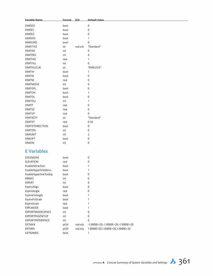
appendix A Concise Summary of System Variables and Settings 361
VariableName Format R/O DefaultValue
DIMSD2 bool 0DIMSE1 bool 0DIMSE2 bool 0DIMSHO bool 1DIMSOXD bool 0DIMSTYLE str read-only "Standard"DIMTAD int 0DIMTDEC int 4DIMTFAC real 1DIMTFILL int 0DIMTFILLCLR str "BYBLOCK"DIMTIH bool 1DIMTIX bool 0DIMTM real 0DIMTMOVE int 0DIMTOFL bool 0DIMTOH bool 1DIMTOL bool 0DIMTOLJ int 1DIMTP real 0DIMTSZ real 0DIMTVP real 0DIMTXSTY str "Standard"DIMTXT real 0.18DIMTXTDIRECTION bool 0DIMTZIN int 0DIMUNIT int 2DIMUPT bool 0DIMZIN int 0
E VariablesEDGEMODE bool 0ELEVATION real 0EnableAttraction bool 1EnableHyperlinkMenu bool 1EnableHyperlinkTooltip bool 0ERRNO int 0EXPERT int 0ExpInsAlign bool 0ExpInsAngle real 0ExpInsFixAngle bool 1ExpInsFixScale bool 1ExpInsScale real 1EXPLMODE bool 1EXPORTMODELSPACE int 0EXPORTPAGESETUP int 0EXPORTPAPERSPACE int 0EXTMAX pt3d read-only -1.0000E+20,-1.0000E+20,-1.0000E+20EXTMIN pt3d read-only 1.0000E+20,1.0000E+20,1.0000E+20EXTNAMES bool 1

362 Inside BricsCAD V18
VariableName Format R/O DefaultValue
F VariablesFACETRATIO int 0FACETRES real 0.5FEATURECOLORS bool 1FIELDDISPLAY bool 1FIELDEVAL int 31FILEDIA bool 1FILLETRAD real 0.5FILLMODE bool 1FLATLAND bool OffFONTALT str "simplex.shx"FONTMAP str "default.fmp"FRAME int 3FRAMESELECTION rtshort 0 FRONTZ real read-only 0FULLOPEN int read-only 1
G VariablesGDIOBJECTS long read-only 3768GENERATEASSOCVIEWS bool 0GEOLATLONGFORMAT int 1GEOMARKERVISIBILITY bool 1GetStarted bool 1GLSWAPMODE int 2GradientColorBottom str "#d2d2d2" GradientColorMiddle str "#fafafa"GradientColorTop str "#ffffff" GradientMode str "0"GRIDAXISCOLOR int 252GRIDDISPLAY int 3GRIDMAJOR int 5GRIDMAJORCOLOR int 253GRIDMINORCOLOR int 254GRIDMODE bool 0GRIDSTYLE int 0GRIDUNIT pt2d 1/2",1/2"GRIDXYZTINT int 1GRIPBLOCK bool 0GRIPCOLOR int 72GRIPDYNCOLOR int 140GRIPHOT int 240GRIPHOVER int 150GRIPOBJLIMIT int 100GRIPS bool 1GRIPSIZE int 4GRIPTIPS bool 1GsDeviceType int 0GsDeviceType2D 0GsDeviceType3D 1

appendix A Concise Summary of System Variables and Settings 363
VariableName Format R/O DefaultValue
H VariablesHALOGAP int 0HANDLES bool read-only 1HANDSEED str "64"HIDEPRECISION int 0HIDETEXT int 1HIDEXREFSCALES bool 1HIGHLIGHT bool 1HIGHLIGHTCOLOR int 142HIGHLIGHTEFFECT int 0HomeGradientColorButtom short 210,210,210HomeGradientColorMiddle short 250,250,250 HomeGradientColorTop short WhiteHomeGradientMode str "0"HorizonBkg_Enable bool 1HorizonBkg_GroundHorizon str "#878787"HorizonBkg_GroundOrigin str "#5F5F5F"HorizonBkg_SkyHigh str "#239BFF"HorizonBkg_SkyHorizon str "#FFFFFF"HorizonBkg_SkyLow str "#FAFAFF"HPANG real 0HPANNOTATIVE bool 0HPASSOC bool 1HPBOUND int 1HPBOUNDRETAIN short 0HPDOUBLE bool 0HPDRAWORDER int 3HPGAPTOL real 0HPLAYER str "."HPLINETYPE bool 0HPMAXAREAS rtshort 0 HPNAME str ""HPOBJWARNING long 10000HPORIGIN pt2d 0",0"HPSCALE real 1HPSEPARATE bool 0HPSPACE real 1HPSTYLE int 0HPTRANSPARENCY str "."HYPERLINKBASE str ""
I VariablesImageCacheFolder str "C:\Users\userid\AppData\Local\Temp\ImageCache\"ImageCacheMaxMemory short 160ImageDiskCache bool 1IMAGEFRAME int 1IMAGEHLT bool 0ImageNotify bool 0ImportCuiFileExists short 0IncludePlotStamp bool 1INDEXCTL int 0INETLOCATION str "http://www.bricsys.com"

364 Inside BricsCAD V18
VariableName Format R/O DefaultValue
INSBASE pt3d 0",0",0"INSNAME str ""INSUNITS int 1INSUNITSDEFSOURCE int 0INSUNITSDEFTARGET int 0INTERFERECOLOR str "BYLAYER"InterfereLayer str "Interference"INTERFEREOBJVS str ""INTERFEREVPVS str ""INTERSECTIONCOLOR int 257INTERSECTIONDISPLAY bool 0ISAVEBAK bool 1ISAVEPERCENT int 50ISOLINES int 4
L VariablesLASTANGLE real 0LASTPOINT pt3d 0",0",0"LASTPROMPT str read-only ": SETTINGS"LATITUDE real 37.795LayerFilterExcess rtlong 250 LAYERPMODE bool 1LAYLOCKFADECTL short 50LAYOUTREGENCTL int 2LENGTHUNITS stre ""LENSLENGTH real 50LicExpDays short 31LICFLAGS int 7LICKEY str read-only "7897-9999-0000-99999-0000" LightGlyphColor int 30LIGHTGLYPHDISPLAY bool 1LIGHTINGUNITS int 0LightWebGlyphColor int 1LIMCHECK bool 0LIMMAX pt2d 1',9"LIMMIN pt2d 0",0"LINEARBRIGHTNESS short 0LINEARCONTRAST short 0LISPINIT int 1LOCALE str "en_US"LocalRootFolder str "C:\Users\userid\AppData\Local\Bricsys\BricsCAD\V18x64\en_US\"LOCALROOTPREFIX str read-only "C:\Users\userid\AppData\Local\Bricsys\BricsCAD\V18x64\en_US\"LOCKUI rtshort 0LOFTANG1 real 1.5707963268LOFTANG2 real 1.5707963268LOFTMAG1 real 0LOFTMAG2 real 0LOFTNORMALS int 1LOFTPARAM int 7LOGFILEMODE bool 0LOGFILENAME str read-only ""LOGFILEPATH str read-only "C:\Users\userid\AppData\Local\Bricsys\BricsCAD\V18x64\en_US\"LOGINNAME str read-only "userid"LONGITUDE real -122.394

appendix A Concise Summary of System Variables and Settings 365
VariableName Format R/O DefaultValue
LookFromDirectionMode short 1LookFromFeedback short 1LookFromZoomExtents bool 1LTSCALE real 1LUNITS int 4LUPREC int 4LWDEFAULT int 25LWDISPLAY bool 0LWDISPSCALE real 0.55LWUNITS int 1
M VariablesMACROREC bool 0MACROTRACE bool 0MANIPULATOR rtshort 0MANIPULATORDURATION rtlong 250ManipulatorSize rtreal 1MassPropAccuracy real 0.01MASSUNITS str "oz lbs stone mg g kg tonne"MAXACTVP int 64MAXHATCH int 100000MAXSORT int 200MAXTHREADS int 0MBUTTONPAN int 1MEASUREINIT int 0MEASUREMENT int 0MENUBAR bool 1MENUCTL bool 1MENUECHO int 0MENUNAME str read-only "C:\Users\userid\AppData\Roaming\Bricsys\Bricscad\V18x64\en_US\Support\default.cui"MESHTYPE int 1MiddleClickClose bool 1MILLISECS long read-only 436750804MIRRTEXT bool 1MLEADERSCALE real 1MODEMACRO str ""MSLTSCALE short 1MSOLESCALE real 1MTEXTCOLUMN short 0MTEXTDETECTSPACE rtshort 1 MTEXTED str ""MTEXTFIXED int 2MTFLAGS int 0
N VariablesNAVVCUBEDISPLAY bool 3NAVVCUBELOCATION int 0NAVVCUBEOPACITY int 50NAVVCUBEORIENT int 1NavVCubeSize short 4NFILELIST int 10NOMUTT bool 0NORTHDIRECTION real 0
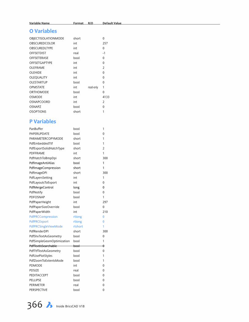
366 Inside BricsCAD V18
VariableName Format R/O DefaultValue
O VariablesOBJECTISOLATIONMODE short 0OBSCUREDCOLOR int 257OBSCUREDLTYPE int 0OFFSETDIST real -1OFFSETERASE bool 0OFFSETGAPTYPE int 0OLEFRAME int 2OLEHIDE int 0OLEQUALITY int 0OLESTARTUP bool 0OPMSTATE int read-only 1ORTHOMODE bool 0OSMODE int 4133OSNAPCOORD int 2OSNAPZ bool 0OSOPTIONS short 1
P VariablesPanBuffer bool 1PAPERUPDATE bool 0PARAMETERCOPYMODE short 1PdfEmbeddedTtf bool 1PdfExportSolidHatchType short 2PDFFRAME int 1PdfHatchToBmpDpi short 300PdfImageAntiAlias bool 1PdfImageCompression short 1PdfImageDPI short 300PdfLayersSetting int 1PdfLayoutsToExport int 0PdfMergeControl long 0PdfNotify bool 0PDFOSNAP bool 1PdfPaperHeight int 297PdfPaperSizeOverride bool 0PdfPaperWidth int 210PdfPRCCompression rtlong 0PdfPRCExport rtlong 0PdfPRCSingleViewMode rtshort 1PdfRenderDPI short 300PdfShxTextAsGeometry bool 0PdfSimpleGeomOptimization bool 1PdfTextIsSearchable bool 0PdfTtfTextAsGeometry bool 0PdfUsePlotStyles bool 1PdfZoomToExtentsMode bool 1PDMODE int 0PDSIZE real 0PEDITACCEPT bool 0PELLIPSE bool 0PERIMETER real 0PERSPECTIVE bool 0
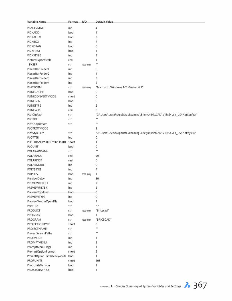
appendix A Concise Summary of System Variables and Settings 367
VariableName Format R/O DefaultValue
PFACEVMAX int 4PICKADD bool 1PICKAUTO bool 3PICKBOX int 4PICKDRAG bool 0PICKFIRST bool 1PICKSTYLE int 1PictureExportScale real 1_PKSER str read-only "" PlacesBarFolder1 int 0PlacesBarFolder2 int 1PlacesBarFolder3 int 3PlacesBarFolder4 int 5PLATFORM str read-only "Microsoft Windows NT Version 6.2"PLINECACHE bool 0PLINECONVERTMODE short 0PLINEGEN bool 0PLINETYPE int 2PLINEWID real 0PlotCfgPath str "C:\Users\userid\AppData\Roaming\Bricsys\BricsCAD\V18x64\en_US\PlotConfig\"PLOTID str ""PlotOutputPath str ""PLOTROTMODE 2PlotStylePath str "C:\Users\userid\AppData\Roaming\Bricsys\BricsCAD\V18x64\en_US\PlotStyles\"PLOTTER int 0PLOTTRANSPARENCYOVERRIDE short 1PLQUIET bool 0POLARADDANG str ""POLARANG real 90POLARDIST real 0POLARMODE int 0POLYSIDES int 4POPUPS bool read-only 1PreviewDelay int 30PREVIEWEFFECT int 2PREVIEWFILTER int 5PreviewTopdown bool 0PREVIEWTYPE int 0PreviewWndInOpenDlg bool 1PrintFile str "."PRODUCT str read-only "Bricscad"PROGBAR bool 1PROGRAM str read-only "BRICSCAD"PROJECTIONTYPE short 0PROJECTNAME str ""ProjectSearchPaths str ""PROJMODE int 1PROMPTMENU int 3PromptMenuFlags int 1PromptOptionFormat short 2PromptOptionTranslateKeywords bool 1PROPUNITS short 103PropUnitsVersion bool 1PROXYGRAPHICS bool 1

368 Inside BricsCAD V18
VariableName Format R/O DefaultValue
PROXYNOTICE bool 1PROXYSHOW int 1PROXYWEBSEARCH int 1PSLTSCALE int 1PSOLHEIGHT real 4PSOLWIDTH real 0.25PSTYLEMODE int read-only 1PSTYLEPOLICY int 1PSVPSCALE real 0PUBLISHALLSHEETS bool 1PUCSBASE str ""
Q VariablesQAFLAGS int 0QTEXTMODE bool 0QuadAperture short 20QuadCommandLaunch short 1QuadCommandSort short 0QuadDisplay bool 0QuadExpandDelay short 110QuadExpandTabDelay long 50QuadExpandGroup short 0QuadGoTransparent bool 0QuadHideDelay int 1000QuadHideMargin short 40QuadIconSize short 32QuadIconSpace short 1QuadMostRecentItems rtlong 2 QuadPopupCorner short 1QuadShowDelay short 150_QuadTabFlags short 12QuadToolipDelay short 1200QuadWarpPointer short 4QuadWidth short 5
R VariablesR12SaveAccuracy int 8R12SaveDeviation real 0RASTERPREVIEW bool 1RE_INIT int read-only 0RealTimeSpeedUp int 5REALWORLDSCALE bool 1RecentPath str "C:\Users\userid\Documents\"RedHiliteFull_Edge_Alpha int 100RedHiliteFull_Edge_Color str "#007AFF"RedHiliteFull_Edge_ShowHidden bool 0RedHiliteFull_Edge_Smoothing bool 1RedHiliteFull_Edge_Thickness real 2RedHiliteFull_Face_Alpha int 10RedHiliteFull_Face_Color str "#007AFF"RedHilitePartial_SelectedEdgeGlow_Alpha int 75RedHilitePartial_SelectedEdgeGlow_Color str "#FFFFFF"RedHilitePartial_SelectedEdgeGlow_Smoothing bool 1
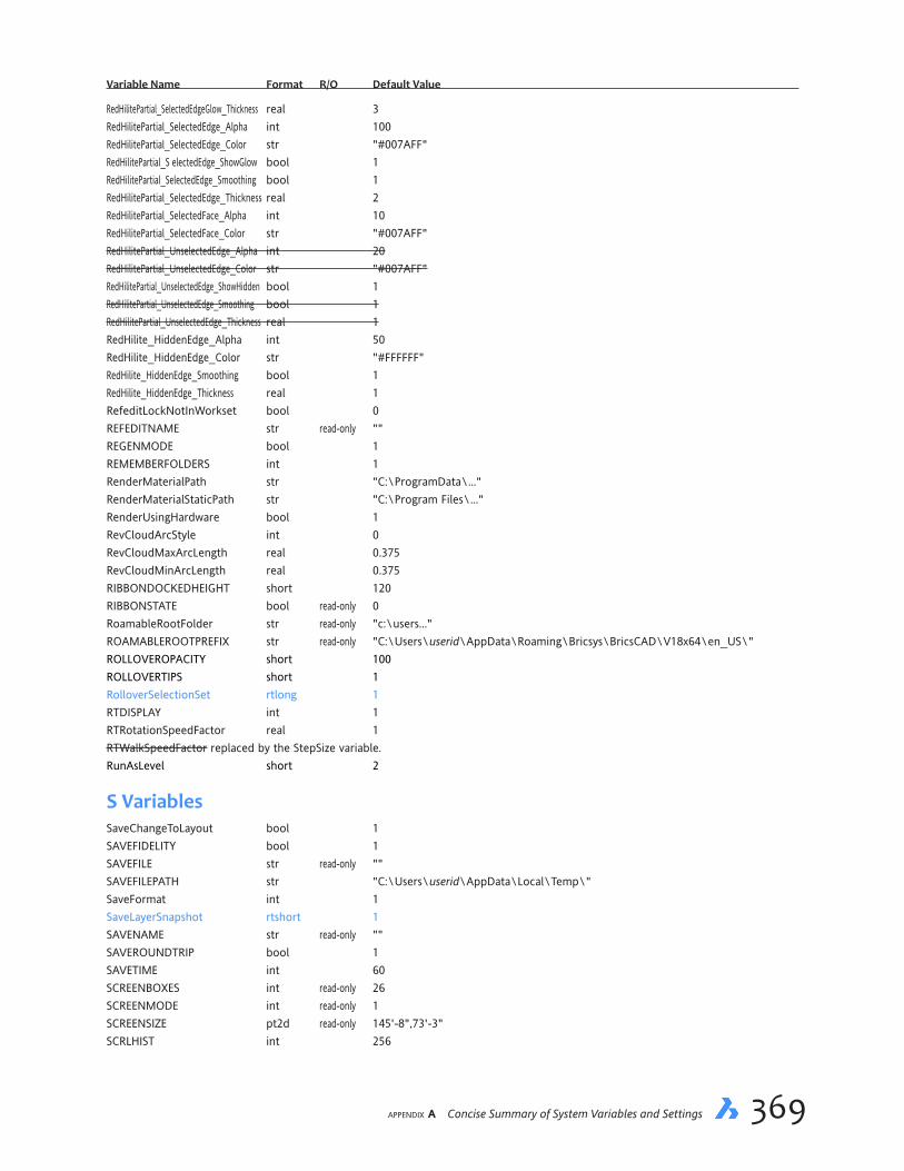
appendix A Concise Summary of System Variables and Settings 369
VariableName Format R/O DefaultValue
RedHilitePartial_SelectedEdgeGlow_Thickness real 3RedHilitePartial_SelectedEdge_Alpha int 100RedHilitePartial_SelectedEdge_Color str "#007AFF"RedHilitePartial_S electedEdge_ShowGlow bool 1RedHilitePartial_SelectedEdge_Smoothing bool 1RedHilitePartial_SelectedEdge_Thickness real 2RedHilitePartial_SelectedFace_Alpha int 10RedHilitePartial_SelectedFace_Color str "#007AFF"RedHilitePartial_UnselectedEdge_Alpha int 20RedHilitePartial_UnselectedEdge_Color str "#007AFF"RedHilitePartial_UnselectedEdge_ShowHidden bool 1RedHilitePartial_UnselectedEdge_Smoothing bool 1RedHilitePartial_UnselectedEdge_Thickness real 1RedHilite_HiddenEdge_Alpha int 50RedHilite_HiddenEdge_Color str "#FFFFFF"RedHilite_HiddenEdge_Smoothing bool 1RedHilite_HiddenEdge_Thickness real 1RefeditLockNotInWorkset bool 0REFEDITNAME str read-only ""REGENMODE bool 1REMEMBERFOLDERS int 1RenderMaterialPath str "C:\ProgramData\..."RenderMaterialStaticPath str "C:\Program Files\..."RenderUsingHardware bool 1RevCloudArcStyle int 0RevCloudMaxArcLength real 0.375RevCloudMinArcLength real 0.375RIBBONDOCKEDHEIGHT short 120RIBBONSTATE bool read-only 0RoamableRootFolder str read-only "c:\users..."ROAMABLEROOTPREFIX str read-only "C:\Users\userid\AppData\Roaming\Bricsys\BricsCAD\V18x64\en_US\"ROLLOVEROPACITY short 100ROLLOVERTIPS short 1RolloverSelectionSet rtlong 1 RTDISPLAY int 1RTRotationSpeedFactor real 1RTWalkSpeedFactor replaced by the StepSize variable.RunAsLevel short 2
S VariablesSaveChangeToLayout bool 1SAVEFIDELITY bool 1SAVEFILE str read-only ""SAVEFILEPATH str "C:\Users\userid\AppData\Local\Temp\"SaveFormat int 1SaveLayerSnapshot rtshort 1SAVENAME str read-only ""SAVEROUNDTRIP bool 1SAVETIME int 60SCREENBOXES int read-only 26SCREENMODE int read-only 1SCREENSIZE pt2d read-only 145'-8",73'-3"SCRLHIST int 256
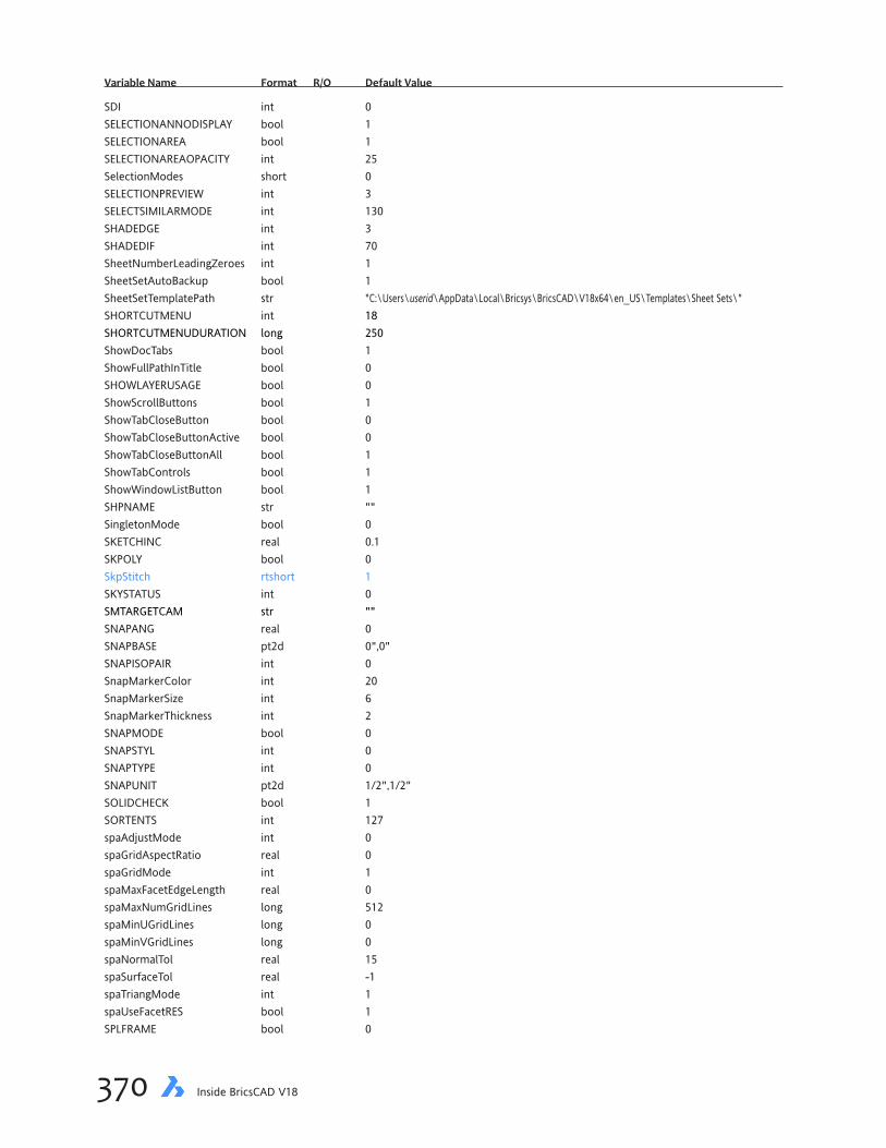
370 Inside BricsCAD V18
VariableName Format R/O DefaultValue
SDI int 0SELECTIONANNODISPLAY bool 1SELECTIONAREA bool 1SELECTIONAREAOPACITY int 25SelectionModes short 0SELECTIONPREVIEW int 3SELECTSIMILARMODE int 130SHADEDGE int 3SHADEDIF int 70SheetNumberLeadingZeroes int 1SheetSetAutoBackup bool 1SheetSetTemplatePath str "C:\Users\userid\AppData\Local\Bricsys\BricsCAD\V18x64\en_US\Templates\Sheet Sets\"SHORTCUTMENU int 18SHORTCUTMENUDURATION long 250ShowDocTabs bool 1ShowFullPathInTitle bool 0SHOWLAYERUSAGE bool 0ShowScrollButtons bool 1ShowTabCloseButton bool 0ShowTabCloseButtonActive bool 0ShowTabCloseButtonAll bool 1ShowTabControls bool 1ShowWindowListButton bool 1SHPNAME str ""SingletonMode bool 0SKETCHINC real 0.1SKPOLY bool 0SkpStitch rtshort 1SKYSTATUS int 0SMTARGETCAM str ""SNAPANG real 0SNAPBASE pt2d 0",0"SNAPISOPAIR int 0SnapMarkerColor int 20SnapMarkerSize int 6SnapMarkerThickness int 2SNAPMODE bool 0SNAPSTYL int 0SNAPTYPE int 0SNAPUNIT pt2d 1/2",1/2"SOLIDCHECK bool 1SORTENTS int 127spaAdjustMode int 0spaGridAspectRatio real 0spaGridMode int 1spaMaxFacetEdgeLength real 0spaMaxNumGridLines long 512spaMinUGridLines long 0spaMinVGridLines long 0spaNormalTol real 15spaSurfaceTol real -1spaTriangMode int 1spaUseFacetRES bool 1SPLFRAME bool 0

appendix A Concise Summary of System Variables and Settings 371
VariableName Format R/O DefaultValue
SPLINESEGS int 8SPLINETYPE int 6SRCHPATH str "C:\Users\userid\AppData\Roaming\Bricsys\BricsCAD\V18x64\en_US\Support\; C:\Program Files (x86)\Bricsys\BricsCAD V18x64\Support\; C:\Program Files (x86)\Bricsys\BricsCAD V18x64\Fonts\; C:\Program Files (x86)\Bricsys\BricsCAD V18x64\Help\en_US\"SSFOUND str ""SSLOCATE bool 1SSMAUTOOPEN bool 1SSMPOLLTIME short 15SSMSHEETSTATUS short 2SSMSTATE int 0StampFontSize real 0.2StampFontStyle str "Arial"StampFooter str ""StampHeader str ""StampUnits int 0STARTUP int 1STEPSIZE real 6STEPSPERSEC real 2StructureTreeConfig str "mechanical.cst"SURFTAB1 int 6SURFTAB2 int 6SURFTYPE int 6SURFU int 6SURFV int 6SvgBlendedGradients int 0SvgDefaultImageExtension str ".png"SvgGenericFontFamily int 0SvgHiddenLineRemoving int 0SvgImageBase str ""SvgImageUrl str ""SvgLineWeightScale real 1SvgOutputHeight int 768SvgOutputWidth int 1024SvgPrecision int 6SYSCODEPAGE str read-only "ANSI_1252"
T VariablesTabControlHeight int 25TABMODE bool 0TabsFixedWidth bool 0TARGET pt3d 0",0",0"TDCREATE real read-only 2456335.5399919TDINDWG real read-only 0.121354456TDUCREATE real read-only 2456335.8733252TDUPDATE real read-only 2456335.5399919TDUSRTIMER real read-only 0.121354456TDUUPDATE real read-only 2456335.8733252TemplatePath str "C:\Users\userid\AppData\Local\Bricsys\BricsCAD\V18x64\en_US\Templates\"TEMPPREFIX str ""TestFlags 0TEXTANGLE real 0TEXTEDITMODE rtshort 0

372 Inside BricsCAD V18
VariableName Format R/O DefaultValue
TEXTEVAL int 0TEXTFILL int 1TEXTQLTY int 50TEXTSIZE real 0.2TEXTSTYLE str "Standard"TextureMapPath str "C:\Program Files (x86)\Bricsys\BricsCAD V18x64\Textures\1\"THICKNESS real 0THUMBSIZE short 1TILEMODE int 1TILEMODELIGHTSYNCH bool 1TIMEZONE int -8000Tips short 1ToolbarIconSize short 16TOOLPALETTEPATH str "C:\Users\userid\AppData\Roaming\Bricsys\BricsCAD\V18x64\en_US\Support\ToolPalettes\"TOOLTIPS 1TPSTATE int read-only 0TRACEWID real 0.05TRACKPATH int 0TRANSPARENCYDISPLAY bool 1TREEDEPTH int 3020TREEMAX long 10000000TRIMMODE bool 1TSPACEFAC real 1TSPACETYPE int 1TSTACKALIGN int 1TSTACKSIZE int 70TTFASTEXT int 3
U VariablesUCSAXISANG int 90UCSBASE str ""UCSDETECT bool 0UCSFOLLOW bool 0UCSICON int 3UCSICONPOS int 0UCSNAME str read-only ""UCSORG pt3d read-only 0",0",0"UCSORTHO bool 1UCSVIEW bool 1UCSVP bool 1UCSXDIR pt3d read-only 1",0",0"UCSYDIR pt3d read-only 0",1",0"UNDOCTL int read-only 5UNDOMARKS int read-only 0UNITMODE bool 0USERI1 thru USERI5 int 0USERR1 thru USERR5 real 0USERS1 thru USERS5 str ""UseSheetMetal short 2UseStandardOpenFileDialog bool 0
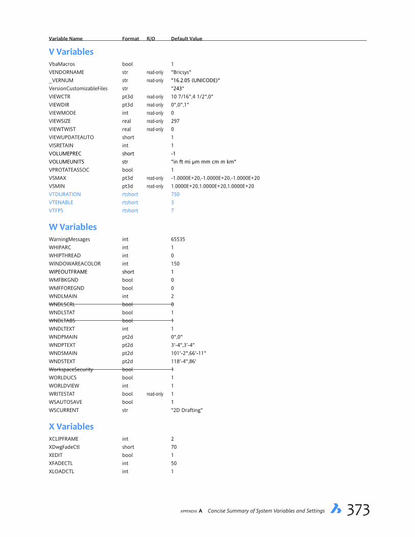
appendix A Concise Summary of System Variables and Settings 373
VariableName Format R/O DefaultValue
V VariablesVbaMacros bool 1VENDORNAME str read-only "Bricsys"_VERNUM str read-only "16.2.05 (UNICODE)"VersionCustomizableFiles str "243"VIEWCTR pt3d read-only 10 7/16",4 1/2",0"VIEWDIR pt3d read-only 0",0",1"VIEWMODE int read-only 0VIEWSIZE real read-only 297VIEWTWIST real read-only 0VIEWUPDATEAUTO short 1VISRETAIN int 1VOLUMEPREC short -1VOLUMEUNITS str "in ft mi µm mm cm m km"VPROTATEASSOC bool 1VSMAX pt3d read-only -1.0000E+20,-1.0000E+20,-1.0000E+20VSMIN pt3d read-only 1.0000E+20,1.0000E+20,1.0000E+20VTDURATION rtshort 750VTENABLE rtshort 3VTFPS rtshort 7
W VariablesWarningMessages int 65535WHIPARC int 1WHIPTHREAD int 0WINDOWAREACOLOR int 150WIPEOUTFRAME short 1WMFBKGND bool 0WMFFOREGND bool 0WNDLMAIN int 2WNDLSCRL bool 0WNDLSTAT bool 1WNDLTABS bool 1WNDLTEXT int 1WNDPMAIN pt2d 0",0"WNDPTEXT pt2d 3'-4",3’-4"WNDSMAIN pt2d 101'-2",66'-11"WNDSTEXT pt2d 118'-4",86'WorkspaceSecurity bool 1WORLDUCS bool 1WORLDVIEW int 1WRITESTAT bool read-only 1WSAUTOSAVE bool 1WSCURRENT str "2D Drafting"
X VariablesXCLIPFRAME int 2XDwgFadeCtl short 70XEDIT bool 1XFADECTL int 50XLOADCTL int 1

374 Inside BricsCAD V18
VariableName Format R/O DefaultValue
XLOADPATH str "C:\Users\userid\Documents\"XNotifyTime short 5XREFCTL bool 0XRefNotify bool 1XREFOVERRIDE bool 0
Z VariablesZOOMFACTOR int 60ZOOMWHEEL short 0
# Variables3DCOMPAREMODE short 33DOSMODE short 113dSnapMarkerColor short 5
Related Documents