INSERT WEAR FAILURE MODES TEC-TEAM: 1-800-832-8326 SECOTOOLS.COM/US/STEP 1. NORMAL FLANK WEAR Normal Flank Wear, since it is predictable and consistent, is the most desirable wear condition. Rapid flank wear looks the same, but happens much quicker than the target 15 minutes of time in cut. CAUSE Abrasive wear. Hard microscopic particles or work-hardened material in the workpiece cut into the insert, wearing away the cutting edge. WHAT TO LOOK FOR Q Relatively uniform abrasion along the cutting edge Q Occasionally, metal from the workpiece that is smeared over the cutting edge can exaggerate the apparent size of the wear scar WHEN TO EXPECT IT In all materials, an insert will fail due to normal wear if it doesn’t fail from something else first. CORRECTIVE ACTIONS (TO RAPID FLANK WEAR) Q Select a harder, more wear resistant grade. Q Apply coolant correctly Q Reduce the cutting speed (RPM or SFPM) 2. CRATERING CAUSE A combination of diffusion, decomposition and abrasive wear causes cratering. The heat from workpiece chips promotes decomposition of the tungsten carbide grains in the cutting tool, wearing a ‘crater’ on the top of the insert. The crater will eventually grow large enough to cause the insert flank to chip or deform. WHAT TO LOOK FOR Q Craters or pits on top of inserts Q Chipbreaking may improve after cratering starts WHEN TO EXPECT IT Q When machining iron (especially steel) or titanium-based alloys CORRECTIVE ACTIONS (TO RAPID FLANK WEAR) Q Use a coated grade – Coatings containing relatively thick layers of aluminum oxide are best – TiAlN is the most crater resistant PVD coating Q Apply coolant Q Use a freer cutting geometry to reduce heat Q Reduce the cutting speed (RPM or SFPM) Q Reduce feed rate Q Increasing the lead angle will have a small, but positive, effect CAUSE Material adhesion. BUE is a result of the workpiece material being pressure welded to the cutting edge. This occurs when there is chemical affinity, high pressure, and sufficient temperature in the cutting zone. Eventually, the built up edge breaks off and often takes a piece of the cutting edge with it, leading to chippage and rapid flank wear. WHAT TO LOOK FOR Q Shiny material on the top or flank of the insert edge Q Erratic changes in part size or finish WHEN TO EXPECT IT Q When machining gummy materials Q At low speeds Q When machining high temp alloys and stainless steel Q Threading operations Q Drilling Q When machining non-ferrous materials CORRECTIVE ACTIONS Q Increase the cutting speed (RPM or SFPM) Q Any coating, but especially a nitride coating, will reduce built-up edge Q Select an insert with a sharper, freer cutting edge geometry Q Apply coolant correctly. Increasing the concentration usually helps Q Use an insert with a smoother (polished) surface 3. BUILT UP EDGE 4. CHIPPING CAUSE Mechanical instability. Chipping of the insert edge is often a result of vibrations in the workpiece or spindle. Hard inclusions in the surface of the material being cut and interrupted cuts result in local stress concentrations that can cause chipping. WHAT TO LOOK FOR Q Chips along the edge of the insert WHEN TO EXPECT IT Q Non-rigid set-ups (bad bearings, worn spindles, etc.) Q Interrupted cuts Q Deflection in the tool or tool holder. Often seen in long drills or long boring bars Q Hard spots in work material Q Powdered Metal (PM) materials CORRECTIVE ACTIONS Q Ensure proper (rigid) machine tool setup Q Minimize deflection Q Select a stronger cutting edge geometry Q Select a tougher insert grade Q Reduce the feed rate (especially at the entrance or exit of the cut) Q See also corrective actions for built-up edge as built-up edge is a frequent cause of chipping f = V/(5 x WL) f = vibration frequency (cycles per second) V = cutting speed (feet per minute) WL = wave length of vibration (inches) SECO TECHNICAL EDUCATION PROGRAM

Welcome message from author
This document is posted to help you gain knowledge. Please leave a comment to let me know what you think about it! Share it to your friends and learn new things together.
Transcript

INSERT WEARFAILURE MODES
TEC-TEAM: 1-800-832-8326
SECOTOOLS.COM/US/STEP
1. NORMAL FLANK WEARNormal Flank Wear, since it is predictable and consistent, is the most desirable wear condition. Rapid flank wear looks the same, but happens much quicker than the target 15 minutes of time in cut.
CAUSEAbrasive wear. Hard microscopic particles or work-hardened material in the workpiece cut into the insert, wearing away the cutting edge.
WHAT TO LOOK FOR Q Relatively uniform abrasion along the cutting edge Q Occasionally, metal from the workpiece that is smeared over the
cutting edge can exaggerate the apparent size of the wear scar
WHEN TO EXPECT ITIn all materials, an insert will fail due to normal wear if it doesn’t fail from something else first.
CORRECTIVE ACTIONS (TO RAPID FLANK WEAR) Q Select a harder, more wear resistant grade. Q Apply coolant correctly Q Reduce the cutting speed (RPM or SFPM)
2. CRATERINGCAUSEA combination of diffusion, decomposition and abrasive wear causes cratering. The heat from workpiece chips promotes decomposition of the tungsten carbide grains in the cutting tool, wearing a ‘crater’ on the top of
the insert. The crater will eventually grow large enough to cause the insert flank to chip or deform.
WHAT TO LOOK FOR Q Craters or pits on top of inserts Q Chipbreaking may improve after cratering starts
WHEN TO EXPECT IT Q When machining iron (especially steel) or titanium-based alloys
CORRECTIVE ACTIONS (TO RAPID FLANK WEAR) Q Use a coated grade
– Coatings containing relatively thick layers of aluminum oxide are best – TiAlN is the most crater resistant PVD coating
Q Apply coolant Q Use a freer cutting geometry to reduce heat Q Reduce the cutting speed (RPM or SFPM) Q Reduce feed rate Q Increasing the lead angle will have a small, but positive, effect
CAUSEMaterial adhesion. BUE is a result of the workpiece material being pressure welded to the cutting edge. This occurs when there is chemical affinity, high pressure, and sufficient temperature in the cutting zone.
Eventually, the built up edge breaks off and often takes a piece of the cutting edge with it, leading to chippage and rapid flank wear.
WHAT TO LOOK FOR Q Shiny material on the top or flank of the insert edge Q Erratic changes in part size or finish
WHEN TO EXPECT IT Q When machining gummy materials Q At low speeds Q When machining high temp alloys and stainless steel Q Threading operations Q Drilling Q When machining non-ferrous materials
CORRECTIVE ACTIONS Q Increase the cutting speed (RPM or SFPM) Q Any coating, but especially a nitride coating, will reduce built-up edge Q Select an insert with a sharper, freer cutting edge geometry Q Apply coolant correctly. Increasing the concentration usually helps Q Use an insert with a smoother (polished) surface
3. BUILT UP EDGE 4. CHIPPINGCAUSEMechanical instability. Chipping of the insert edge is often a result of vibrations in the workpiece or spindle. Hard inclusions in the surface of the material being cut and interrupted cuts result in local stress
concentrations that can cause chipping.
WHAT TO LOOK FOR Q Chips along the edge of the insert
WHEN TO EXPECT IT Q Non-rigid set-ups (bad bearings, worn spindles, etc.) Q Interrupted cuts Q Deflection in the tool or tool holder. Often seen in long drills or long
boring bars Q Hard spots in work material Q Powdered Metal (PM) materials
CORRECTIVE ACTIONS Q Ensure proper (rigid) machine tool setup Q Minimize deflection Q Select a stronger cutting edge geometry Q Select a tougher insert grade Q Reduce the feed rate (especially at the entrance or exit of the cut) Q See also corrective actions for built-up edge as built-up edge is a
frequent cause of chipping
f = V/(5 x WL)f = vibration frequency (cycles per second)V = cutting speed (feet per minute)WL = wave length of vibration (inches)
SECO TECHNICAL EDUCATION PROGRAM
6. EDGE DEFORMATIONCAUSEExcessive heat. Excessive heat causes the carbide binder (cobalt) to soften. Mechanical Overloading. Pressure of the insert against the workpiece makes the insert deform or sag at the tip, eventually breaking off or
leading to rapid flank wear.
WHAT TO LOOK FOR Q Deformation at the cutting edge Q The dimensions of the workpiece may not be as expected
WHEN TO EXPECT IT Q High heat operations Q High speed Q Hard steels or work-hardened surfaces Q High temperature alloys Q High feed rates
CORRECTIVE ACTIONS Q Apply coolant correctly Q Use a harder, more wear resistant grade with a lower binder (cobalt)
content Q Using a freer cutting insert geometry will have a small but positive effect Q Reduce the cutting speed (RPM or SFPM) Q Reduce the feed rate Q Select an insert with a larger nose radius
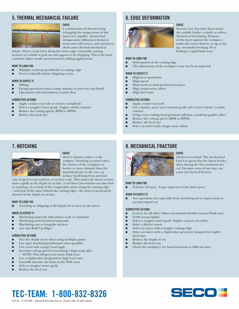
5. THERMAL MECHANICAL FAILURECAUSEA combination of thermal cycling (changing the temperature of the insert very rapidly), thermal load (temperature differences between warm and cold zones), and mechanical shock causes thermal mechanical
failure. Stress cracks form along the insert edge, eventually causing sections of carbide to pull out and appear to be chipping. This is the most common failure mode encountered in milling applications.
WHAT TO LOOK FOR Q Multiple cracks perpendicular to cutting edge Q Need to identify before chipping occurs
WHEN TO EXPECT IT Q Milling Q Facing operations when a large number of parts are machined Q Operations with intermittent coolant flow
CORRECTIVE ACTIONS Q Apply coolant correctly or remove completely Q Select a tougher insert grade (higher cobalt content) Q Reduce the cutting speed (RPM or SFPM) Q Reduce the feed rate
7. NOTCHINGCAUSEHard or abrasive surfaces on the workpiece. Notching is caused when the surface of the workpiece is harder or more abrasive than the material deeper in the cut, e.g. surface hardening from previous
cuts, forged or cast surfaces, or surface scale. This causes the insert to wear more rapidly at the depth of cut line. Local Stress Concentration can also lead to notching. As a result of the compressive stress along the cutting edge – and lack of the same behind the cutting edge – the insert is particularly stressed at the depth of cut line.
WHAT TO LOOK FOR Q Notching or chipping at the depth of cut area on the insert
WHEN TO EXPECT IT Q Machining materials with surface scale or oxidation Q Machining work hardened materials Q Machining cast or irregular surfaces Q (see also Built Up Edge)
CORRECTIVE ACTIONS Q Vary the depth of cut when using multiple passes Q Use taper machining techniques when possible Q Use a tool with a larger lead angle Q Increase cutting speed if machining a high temp alloy
– NOTE: This will generate more flank wear Q Use a chipbreaker designed for high feed rates Q Carefully increase the hone in the DOC area Q Select a tougher insert grade Q Reduce the feed rate
8. MECHANICAL FRACTURECAUSEMechanical overload. The mechanical load is so great that the insert breaks, often during the first moments of a cut. Excessive wear of any type can cause mechanical fracture.
WHAT TO LOOK FOR
Q Fracture of insert. Large segments of the insert gone.
WHEN TO EXPECT IT Q Any operation, but especially those involving severe impact such as
an interrupted cut
CORRECTIVE ACTIONS Q Correct for all other failure mechanisms besides normal flank wear Q Verify set-up rigidity Q Select a tougher insert grade (higher content of cobalt) Q Select a thicker insert Q Select an insert with a tougher cutting edge Q Select an insert with a chipbreaker geometry designed for higher
feed rates Q Reduce the depth of cut Q Reduce the feed rate Q Check the workpiece for hard inclusions or difficult entry
TEC-TEAM: 1-800-832-8326GT13-5xx P-1303-2000 Copyright © 2013 Seco Tools, Inc. Printed in USA. All rights reserved.
Related Documents