GA422337 INITIAL OPERATION OF THE DIVERTOR THOMSON SCATTERING DIAGNOSTIC ON DIII-D by T.N. CARLSTROM, C.L. HSIEH, R.E. STOCKDALE, D.G. NILSON, and D.N. HILL MAY 1996

Welcome message from author
This document is posted to help you gain knowledge. Please leave a comment to let me know what you think about it! Share it to your friends and learn new things together.
Transcript

GA422337
INITIAL OPERATION OF THE DIVERTOR THOMSON SCATTERING
DIAGNOSTIC ON DIII-D
by T.N. CARLSTROM, C.L. HSIEH, R.E. STOCKDALE,
D.G. NILSON, and D.N. HILL
MAY 1996
DISC LA1 M E R
This report was prepared as an account of work sponsored by an agency of the United States Government. Neither the United States Government nor any agency thereof, nor any of their employees, makes any warranty, express or implied, or assumes any legal liability or responsibility for the accuracy, completeness, or usefulness of any information, apparatus, product, or process disclosed, or represents that its use would not infringe privately owned rights. Reference herein to any specific commercial product, process, or service by trade name, trademark, manufacturer, or otherwise, does not necessarily constitute or imply its endorsement, recommendation, or favoring by the United States Government or any agency thereof. The views and opinions of authors expressed herein do not necessarily state or reflect those of the United States Government or any agency thereof.

Portions of this document may be illegible in electronic image products, linages are produced fnrm the best available original document.

G A-A22337
INITIAL OPERATION OF THE DIVERTOR THOMSON SCATTERING
DIAGNOSTIC ON DIII-D
by T.N. CARLSTROM, C.L. HSIEH, R.E. STOCKDALE,
D.G. NILSON,* and D.N. HILL*
This is a preprint of a paper to be presented at the 11 th Topical High Temperature Plasma Diagnostics Conference, May 12-16, 1996, in Monterey, California, and to be published in Rev. Sci. Instrum.
Lawrence Livermore National Laboratory, Livermore, California. *
Work supported by the U.S. Department of Energy
under Contract Nos. DE-AC03-89ER51114 and W-7405-ENG-48
GA PROJECT 3466 MAY 1996
T. N. Carlstrom, et al. INITIAL OPERATION OF THE DIVERTOR THOMSON SCATTERING
DIAGNOSTIC ON DIII-D
ABSTRACT
The first Thomson scattering measurements of ne and Te in the
divertor region of a tokamak are reported. These data are used as input to
boundary physics codes such as UEDGE and DEGAS and to benchmark
the predictive capabilities of these codes. These measurements have also
contributed to the characterization of tokamak disruptions. A Nd:YAG
laser (20 Hz, 1 J, 15 ns, 1064 nm) is directed vertically through the lower
divertor region of the DIII-D tokamak. A custom, aspherical collection
lens (f/6.8) images the laser beam from 1-21 cm above the target plates
into eight spatial channels with 1.5 cm vertical and 0.3 cm radial
resolution. 2D mapping of the divertor region is achieved by sweeping
the divertor X-point location radially through the fixed laser beam
location. Fiber optics carry the light to polychromators whose
interference filters have been optimized for low Te measurements. Silicon
avalanche photo diodes measure both the scattered and plasma
background light. Temperatures and densities are typically in the range of
5-200 eV and 1- 10x1019 m-3 respectively. Low temperatures, Te < 1 eV,
and high densities, ne > 8x10²⁰ m-3 have been observed in detached
plasmas. Background light levels have not been a significant problem.
Reduction of the laser stray light permits Rayleigh calibration. Because
of access difficulties, no in-vessel vacuum alignment target could be
used. Instead, an in situ laser alignment monitor provides alignment
information for each laser pulse. Results are compared with Langmuir
GENERAL ATOMICS REPORT GA-A22337 ... 111

iv
INITIAL OPERATION OF THE DIVERTOR THOMSON SCATTERING DIAGNOSTIC ON DIII-D T. N. Carlstrom, et al.
probe measurements where good agreement is found except for regions
of high and low Te as measured by Thomson scattering.
GENERAL ATOMICS REPORT GA-A22337
T. N. Carlstrom, et al. INITIAL OPERATION OF THE DIVERTOR THOMSON SCATIERING
DIAGNOSTIC ON DID-D
INTRODUCTION
In this paper we describe the commissioning (summer, 1995) of the
Divertor Thomson Scattering (DTS) System for the DIII-D tokamak,
which has been used to measure the complete two-dimensional density
and temperature profiles in the tokamak divertor plasma below the
X-point for the first time. This work is motivated by the need to reduce
the expected scrape-off layer energy and particle transport to the divertor
target plates by more than an order of magnitude in future high power
tokamaks such as the proposed ITER device. The most likely means for
achieving this will be to seed the divertor with impurities in order to
increase the local radiative losses. Our measurements are significant
because they document for the first time in these highly radiating plasmas
how n e and T , vary on magnetic flux surfaces in the divertor with
sufficient spatial resolution to allow comparison with theoretical
predictions of heat and particle transport.
In the remainder of this paper we discuss the design of the system,
important features unique to the low temperatures found in the divertor,
calibration, and test results. Finally, we show typical density and
temperature data from a divertor plasma in which deuterium gas injection
was used to raise the divertor neutral pressure and radiative losses to the
point where almost all the power flowing in the SOL is lost via atomic
processes such as radiation and charge exchange. In this case, we find
very low temperatures (below 2 eV) throughout the divertor region, a
GENERAL ATOMICS REPORT GA-A22337 1

mrna OPERATION OF THE DIVERTOR THOMSON SCATTERING DIAGNOSTIC ON DID-D T.N. Carlstrom, et al.
sharp drop in electron plasma pressure along flux surfaces, and a radial
shift in the peak of the density profile.
2 GENERAL ATOMICS REPORT GA-A22337

INITIAL OPERATION OF THE DIVERTOR THOMSON SCATTERING T.N. Carlstrom, et al. DIAGNOSTIC ON DJX-D
11. SYSTEM DESCRIPTION
This system is an extension of the pre-existing 8 laser, multipulse
Thomson scattering diagnostic previously reported. 1 A brief description
of the system is given here for completeness. Further details of the
divertor Thomson scattering system design are given in Ref. 2. One of
the 8, Nd:YAG lasers (20 Hz, 1 J, 15 ns, 1064 nm) is redirected from the
core plasma to the divertor plasma with mirrors on an optics table located
beneath the DIII-D vessel as shown in Fig. 1. The 5.6 m focal length lens
with a 20 mm aperture focuses the beam through a series of 12 light
baffles and produces a 3.5 mm diameter spot in the scattering region. A
3 mm radial clearance is maintained between the beam and the baffle
cones in the vertical entrance port. At the top of the vessel, the laser beam
passes through six large aperture baffles (39 mm dia.), an exit vacuum
window tilted at Brewster's angle, a beamsplitter for an alignment
camera, and finally a beam dump constructed of NG-4 glass. A Glan-
Laser polarizer is used to improve the polarization characteristics of the
laser beam and reduce the stray light reflecting from the exit window.
Additional techniques and methods used to reduce the stray light level are
given in a companion paper at this conference.3
A two-element f/6.8 collection lens images the 20 cm vertical
scattering region onto 12 rectangular fiber arrays (1.5 mm x 3.0 mm)
with a system demagnification of 0.29. The lens structure and fiber arrays
GENERAL ATOMICS REPORT GA-A22337 3

INITIAL OPERATION OF THE DIVERTOR THOMSON SCATTERING DIAGNOSTIC ON DIII-D
4 GENERAL ATOMICS REPORT GA-A22337
T.N. Carlstrom, et al.

T. N. Carlstrom, et al. INITIAL OPERATION OF THE! DIVERTOR THOMSON SCA?TERING
DIAGNOSTIC ON DIU-D
are mounted to a carriage which translates outward with the vessel as it
expands during high temperature baking. The collection optics view
through a 20 cm diameter bakeable vacuum window which is protected
from plasma heating and coating by a 1 cm thick quartz debris shield. A
thin clam-shell shutter covers both of these elements during boronization
and discharge cleaning of the vacuum vessel.
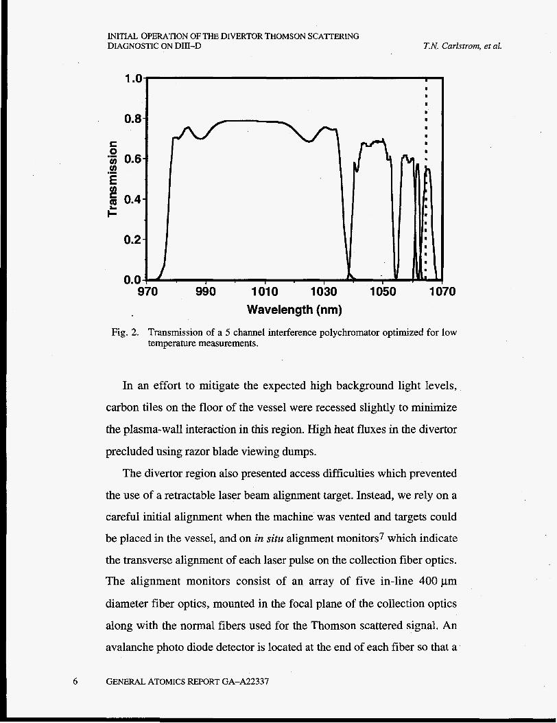
Eight of the 12 fiber optic bundles are selected to transport the light to
interference filter polychromators which have been optimized for low Te
measurements. Typical transmission characteristics of the 5 channel
polychromator are shown in Fig. 2. Further information about the
polychromator design can be found in Ref. 4. The critical feature of the
polychromator that permits low-temperature capability is the narrow
bandwidth (1.6 nm) interference filter close to the laser wavelength. This
filter is placed last in the polychromator cascade and a modified mount is
used so that incident light can strike it normally instead of at 4". This
helps to reduce the bandwidth and improves out-of-band rejection.
Rejection of the laser line (1064.3 nm) is about 10-4 for this filter and is >
10-5 for the filters further away from the laser line.
The detectors are silicon avalanche photo diodes (RCA C30956E)
with an internal gain of about 100. They are used in an electronic circuits
which provides a pulsed channel output where the background light is
subtracted with a delay line technique.6 This allows the full range of the
11-bit gated integrator (LeCroy 4300 FERA) to be utilized for the
Thomson scattered signal. A d.c.-coupled channel provides background
light measurements so that error bars based on photon statistics can be
~
estimated accurately. The d.c. channel also permits calibration using
standard d.c. light sources.
GENERAL ATOMICS REPORT GA-A22337 5 I
INITIAL OPERATION OF THE DIVERTOR THOMSON SCA'ITERING DIAGNOSTIC ON DIII-D T.N. Carlstrom, et al.
1 .o
0.8
S 0
tn 'z 0.6 .- E Q 0.4 c
0.2
0.0 970 990 1010 1030
Wavelength (nrn)
k I
1050
I I
I I I I I I
I I .
1070
Fig. 2. Transmission of a 5 channel interference polychromator optimized for low temperature measurements.
In an effort to mitigate the expected high background light levels,
carbon tiles on the floor of the vessel were recessed slightly to minimize
the plasma-wall interaction in this region. High heat fluxes in the divertor
precluded using razor blade viewing dumps.
The divertor region also presented access difficulties which prevented
the use of a retractable laser beam alignment target. Instead, we rely on a
careful initial alignment when the machine was vented and targets could
be placed in the vessel, and on in situ alignment monitors7 which indicate
the transverse alignment of each laser pulse on the collection fiber optics.
The alignment monitors consist of an array of five in-line 400 pm
diameter fiber optics, mounted in the focal plane of the collection optics
along with the normal fibers used for the Thomson scattered signal. An
avalanche photo diode detector is located at the end of each fiber so that a
6 GENERAL ATOMICS REPORT GA-A22337

T.N. Carlstrom, et al. INITIAL OPERATION OF THE DIVERTOR THOMSON SCATTERING
DIAGNOSTIC ON DIII-D
crude measurement of the laser beam profile is made. The position of the
peak of the profile relative to the central fiber optic is an indicator of the
alignment. Typical alignment data taken during a plasma discharge is
shown in Fig. 3.
1000 r 2 800 1 7 T I-
600 1 400 1,. 200
-1 .o
GENERAL ATOMICS REPORT GA-A22337 7
-0.5 0.0 0.5 POSITION (mm)
1 .o
Fig. 3. Signals from an in-situ alignment monitor which shows the image of the laser beam on a 5 channel fiber optic array. The central region corresponds to the area viewed by the fiber optic bundle used for the Thomson scattering measurements. The peak of the signal is well centered indicating good alignment. An alignment signal is recorded for each laser pulse.

INITIAL OPERATION OF THE DIVERTOR THOMSON SCATTERING DIAGNOSTIC ON DIII-D T.N. Carlstrom, et al.
8 GENERAL ATOMICS REPORT GA-A22337

i? N. Carlstrom, et al. INITIAL OPERATION OF THE DIVERTOR THOMSON SCATTERING
DIAGNOSTIC ON DID-D
I TESTING AND Cu L JBRATION
Each detector, together with its electronics, is individually calibrated
for gain and noise level in a separate test stand using both pulsed (10 ns)
and d.c. light from calibrated light emitting diodes at 1060 nm. Relative
channel- to-channel response of the polychromator is obtained using a
computer controlled monochromator to illuminate the fiber optic input of
each polychromator. The output of the monochromator is monitored with
a calibrated detector (EG&G 690) traceable to NBS standards. The
wavelength calibration of the monochromator is checked with an argon
lamp and light from the Nd:YAG laser. This insures accurate wavelength
calibration (0.1 nm) in the vicinity of the laser line which is important for
low T, measurements.
Absolute system gain was calibrated using Rayleigh scattering in
argon. A typical plot of signal versus pressure is shown in Fig. 4. In spite
of a sizable effort to reduce laser stray light,3 several channels which
view the divertor floor region near the laser entrance (channels 1 4 ) ,
suffered from high stray light levels. These high stray light levels caused
detector saturation which prevented Rayleigh calibration of these
channels. However, after normalizing the Rayleigh factors of the non-
saturated channels by the measured fiber optic and polychromator
transmission, as well as the detector gain, it was found that these
channels all had the same response. Rayleigh factors for the saturated
channels were calculated assuming this constant response. Further work
GENERAL ATOMICS REPORT GA-A22337 9

INITIAL OPERATION OF THE DIVERTOR THOMSON SCATTERING DIAGNOSTIC ON DIII-D T.N. Carlstrom, et al.
to reduce the stray light levels is on going. The option of using Raman
scattering in hydrogen to obtain an absolute calibration was dismissed
owing to the safety considerations associated with such a large volume of
hydrogen at substantial pressures (100 Torr).
6000
2000
0
-
Equvilen t Stray1 ight: 1.29 Torr Argon
-
€
I . . I . I I . I , I . 3 . I I , I . . I . I I .
0 2 4 Argon Pressure (Torr)
6
Fig. 4. Rayleigh scattering signal using argon for channel 6 at 13.8 cm above the divertor floor. The error bars represent the standard deviation of 200 laser pulses. The signal at 0 Torr represent the stray light level which, for this channel, corresponds to 1.29 Torr argon or an equivalent electron density of 1.8 x10¹⁹ m-3.
10 GENERAL ATOMICS REPORT GA-A22337

T.N. Caristrom, et ai. INITIAL OPERATION OF THE DIVERTOR TBOMSON SCATERING
DIAGNOSTIC ON DIU-D
111. ANALYSIS
The measured Thomson spectrum is fitted with a least-squares fitting
routine to the theoretical Thomson spectrum given by Selden,8 which
includes relativistic effects (important for Te > 1 keV) but not collective
effects (important when the scattering parameter a = @Ad 1 1, i.e. low
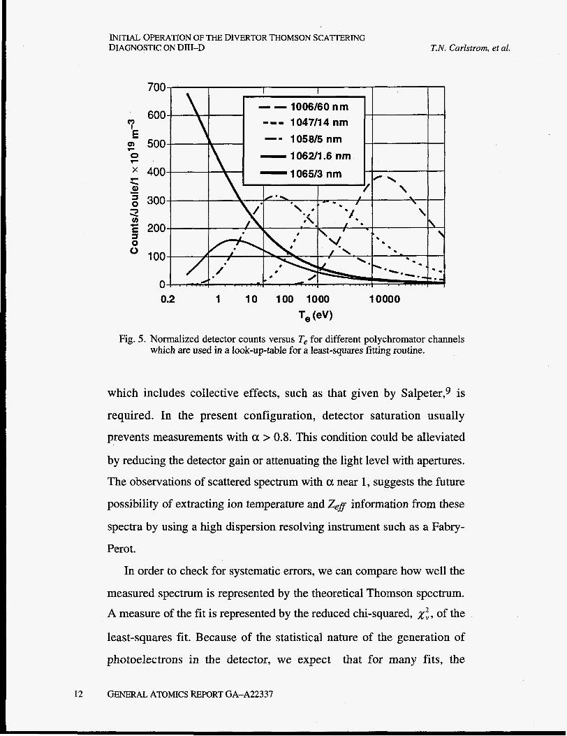
Te and high ne). Instead of calculating the theoretical spectrum for each
iteration in the fitting process, a look-up table of each wavelength
channel response as a function of Te is used. Fig. 5 graphically shows a
look-up table for a typical 5 channel polychromator. Temperatures as low
as 1 eV can be analyzed without using the laser channel which is often
polluted with stray light. When stray light levels are low enough that the
laser channel is not saturated, it can also be used in the analysis. After
accounting for the portion of the signal due to stray light, the laser
channel has been included for some shots and Te measurements c 1 eV
have been obtained with good fits and low error bars.
The low temperature capability of this system has made possible
measurements where the scattering parameter a = l/kA, is approaching 1,
and collective effects begin to appear in the scattered spectrum. The
highest a measured to date is about 0.5, corresponding to Te= 1 eV and
ne = 8xlO20m-3. Modeling of our system has shown that for a < 0.8,
only about a 20% error is made by neglecting collective effects when
fitting the data. For a > 0.8, a 2-dimensional minimum x2 fit to a model
GENERAL ATOMICS REPORT GA-A22337 1 1
INITIAL OPERATION OF THE DIVERTOR THOMSON SCATTERING DIAGNOSTIC ON DIII-D T.N. Carlstrom, et al.
I
600
I - - 1006/60 nm -== 1047/14 nm -I 1058/5 nm - 1062/1.6 nm - 1065/3 nm
0.2 1 10 100 1000 10000 Te (ev)
Fig. 5. Normalized detector counts versus T, for different polychromator channels which are used in a look-up-table for a least-squares fitting routine.
which includes collective effects, such as that given by Salpeter,g is
required. In the present configuration, detector saturation usually
prevents measurements with a > 0.8. This condition could be alleviated
by reducing the detector gain or attenuating the light level with apertures.
The observations of scattered spectrum with a near 1, suggests the future
possibility of extracting ion temperature and Zef information from these
spectra by using a high dispersion resolving instrument such as a Fabry-
Perot.
In order to check for systematic errors, we can compare how well the
measured spectrum is represented by the theoretical Thomson spectrum. A measure of the fit is represented by the reduced chi-squared, x:, of the
least-squares fit. Because of the statistical nature of the generation of
photoelectrons in the detector, we expect that for many fits, the
12 GENERAL ATOMICS REPORT GA-A22337
T. N. Carlstrom, et al. INITIAL OPERATION OF THE DIVERTOR THOMSON SCATTERING
DIAGNOSTIC ON Dm-D
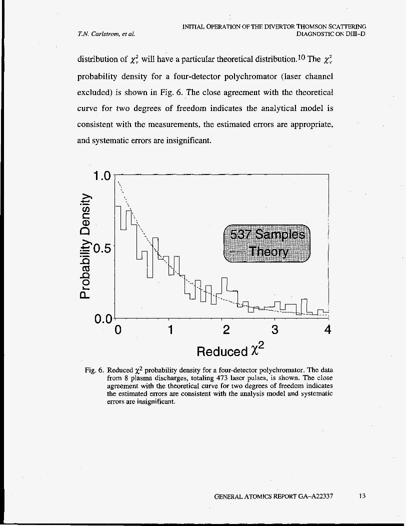
distribution of x- will have a particular theoretical distribution.10 The x; probability density for a four-detector polychromator (laser channel
excluded) is shown in Fig. 6. The close agreement with the theoretical
curve for two degrees of freedom indicates the analytical model is
consistent with the measurements, the estimated errors are appropriate,
and systematic errors are insignificant.
4-J .I cn t a,
0.0 0 1 2 3 4
Reduced x2 Fig. 6. Reduced x2 probability density for a four-detector polychromator. The data
from 8 plasma discharges, totaling 473 laser pulses, is shown. The close agreement with the theoretical curve for two degrees of freedom indicates the estimated errors are consistent with the analysis model and systematic errors are insignificant.
GENERAL ATOMICS REPORT GA-A22337 13
INITIAL OPERATION OF THE DIVERTOR THOMSON SCATTERING DIAGNOSTIC ON DIII-D T.N. Carlstrom. et al.
14 GENERAL ATOMICS REPORT GA-A22337

INITIAL OPERATION OF THE DIVERTOR THOMSON SCAlTERING DIAGNOSTIC ON DIII-D T.N. Carlstrom, et al.
IV. RESULTS
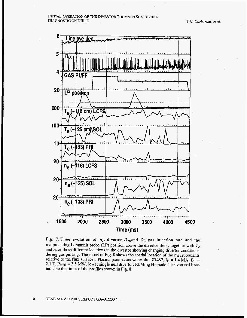
The time evolution of Te and ne at three different locations in the
divertor showing changing divertor conditions during gas puffing are
shown in Fig. 7. The measurement at z = -1 16 cm is located inside the
last-closed-flux-surface, LCFS, near the edge of the main plasma as
shown in the insert of Fig. 8. The measurement at z = -125 cm is in the
scrape-off-layer, SOL, near the X-point, and the measurement at z =
-133 cm in located in the private flux region. The reconstruction of the
magnetic equilibrium is done with the code EFIT,11 which typically
determines the LCFS position to k0.5 cm. However, near the X-point,
the accuracy is estimated to be a few cm. The determination of where the
outer divertor leg intersects the floor is estimated to be +1 cm.
When the gas puff is turned on, Te in the private flux region
decreases and ne increases. At about 2750 ms, there is a sharp increase in
ne in the SOL and private regions but not inside the LCFS. This is
indicative of plasma detachment and MARFE formation. Several of the
Te and ne spikes are associated with the occurance of an ELM during the
laser firing time.
Spatial profiles of divertor Te and ne taken along the laser path are
shown in Fig. 8 at three different times for the discharge shown in Fig. 7.
The high densities in the private flux region are accompanied by
temperatures in the 1 eV range. Normally, the main contribution to the
GENERAL ATOMICS REPORT GA-A22337 15
INITIAL. OPERATION OF THE DIVERTOR THOMSON SCATTERING DIAGNOSTIC ON DIII-D T.N. Carlstrorn, et al.
Y
4
2
20
10
1
2
J *
- ne (-125) SOL 20---1 ' '
9n- f V , I , 1 1 1 1 I , I I 1 I l l
V u - -" - ne(-133)PRI
\ I 1 ' I ' I ' ' " 1 ' 1 1 ~ ' ' " 1 " 1 " 1 1 " ' 1 " 1 1 ' 1 1 1 ' ~ ~ ' 1 ' ' " ' 1 1 1 1 1 1 " " " I ' 1
. 1500 2000 2500 3000 3500 4000 4500 Time (ms)
Fig. 7. Time evolution of fie, divertor D,,and D2 gas injection rate and the reciprocating Langmuir probe (LP) position above the divertor floor, together with Te and ne at three different locations in the divertor showing changing divertor conditions during gas puffing. The insert of Fig. 8 shows the spatial location of the measurements relative to the flux surfaces. Plasma parameters were: shot 87487, Ip = 1.4 MA, BT = 2.1 T, PNBI = 3.5 MW, lower single null divertor, ELMing H-mode. The vertical lines indicate the times of the profiles shown in Fig. 8.
16 GENERAL ATOMICS REPORT GA-A22337

T. N. Caristrom, et ai. INITIAL OPERATION OF THE DIVERTOR THOMSON SCATTERING
DIAGNOSTIC ON DIII-D
I 5- c
GENERAL ATOMICS REPORT GA-A22337 17
INITIAL OPERATION OF THE DIVERTOR THOMSON SCATERING DIAGNOSTIC ON DII-D T. N. Carlstrom, et al.
error bars, which represent the 1 CT statistical uncertainty in the
measurement, is predominately due to the effects of the plasma
background light. At sufficiently low temperatures, the Thomson signal
is present only in the 2 spectral channels near the laser line. Because
these channels have narrow bandwidths, the background light is not a
serious problem and the error bars are dominated by the photoelectron
statistics of the Thomson scattered signal. Typical background light
levels are in the range of (2-500) x 1010 photons/s/nm/nez/steradian,
which corresponds to 10-2000 counts. Digitizer saturation occurs at 2048
counts and saturated channels are excluded from the analysis.
Two-dimensional mapping of Te and ne in the divertor region can be
obtained by radially sweeping the X-point through the laser beam path
during a steady discharge. Plots of Te, ne, and Pe constructed in this way
, are shown in Fig. 9. Using this technique, a large portion of the divertor
region can be examined to study the structure of detached and radiative
divertor configurations. In the partially detached L-mode shown in Fig. 9,
high density is observed in the region from the floor to the X-point. This
high density region is not located at the separatrix but forms a few cm
just beyond it in the SOL. Low Te in the range of 1-3 eV accompany this
high density region with higher temperatures observed in the SOL
outside the X-point region. The electron pressure is highest near the
X-point and drops significantly toward the separatrix and the divertor
floor. These data can be used to compare the results of predictive
modeling codes such as UEDGE.12
18 GENERAL ATOMICS REPORT GA-A22337

INITIAL OPERATION OF THE DIVERTOR THOMSON SCAIITERING T.N. Carlstrom, et al. DIAGNOSTIC ON DIII-D
1.375 1 500 1.625 1.375 1.500 1.625 Ne
-1.125
-1.250
-1.375
Shot 86872 43 1 837 Ne-Te-torr R=3 Smooth Spherical 30x100 0.0 0.1 02 0.4 0.5
Fig. 9. 2D plot of the divertor Te,, ne,, and Pe constructed from 13 laser pulses as the X-point was swept radially through the laser beam path. The discharge conditions were: shot 86872, Ip = 1.0 MA, BT = 2.1 T, PNBI = 1.1 M W , lower single null divertor, partially detached L-mode. The left side of the figure shows the location of the measurements when mapped to flux coordinates. The right side of the figure shows the data smoothed so that a continuous picture is formed.
GENERAL ATOMICS REPORT GA-A22337 19
INITIAL OPERATION OF THE DIVERTOR THOMSON SCATTERING DIAGNOSTIC ON DII-D
7
0 0
0 0 0 CO 0 ' 0 7 0
0 (v
n
E
0 T-
0 '
0
0
n CCI W
n
SL
v (D T-
E 0-a> 'r
zs)
0 0
T.N. Carlstrom, et al.
20 GENERAL ATOMICS REPORT GA-A22337

T.N. Carlstrom, et al. INITIAL OPERATION OF THE DIVERTOR THOMSON SCATITRING
DIAGNOSTIC ON DID-D
A new reciprocating Langmuir probe has recently been added to the
divertor region on DIII-D.13 This probe measures ne and Te in the
divertor region at the same major radius as the DTS system but at a
different toroidal location. Two probe plunges were made at 1979 ms and
3182 ms for the discharge shown in Fig. 7. The effect of the probe plunge
on the DTS measurements can be seen by the reduction of Te(-125 cm)
at these times. Other DTS channels do not show a reduction in Te. It is
believed that the shadow of the probe only propagates to the DTS
location when the field lines are predominately toroidal. This condition
exists only near the X-point location.
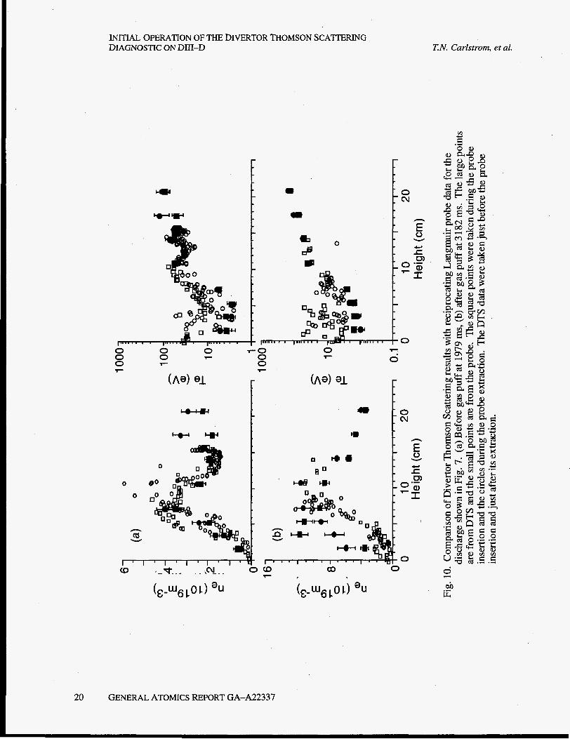
Comparisons of DTS results with Langmuir probe measurements are
shown in Fig. 10. At 1979 ms, before the D2 gas puff, there is generally
good agreement with DTS measured ne slightly higher and Te lower near
the divertor floor. The high spatial resolution of the probes shows
significant structure in the SOL region between the private flux region
and the separatrix. After the D2 gas puff at 3182 ms, there are significant
differences between the two measurements. DTS measures higher ne and
lower Te in the private flux region near the floor. Above this region the
agreement is somewhat better on average. Understanding the nature and
causes of these discrepancies is currently an area of active research.
GENERAL ATOMICS REPORT GA-A22337 21

22
INITIAL OPERATION OF THE DIVERTOR THOMSON SCATTERING DIAGNOSTIC ON DIIl-D
GENERAL ATOMICS REPORT GA-A22337
T.N. Carlstrom, et al.
T.N. Carlstrom, et al. INITIAL OPERATION OF THE DIVERTOR THOMSON SCA'ITERING
DIAGNOSTIC ON DIII-D
REFERENCES
1T.N. Carlstrom et al., Rev. Sci. Instrum. 63 4901 (1992).
2T.N. Carlstrom et al., Rev. Sci. Instrum. 66 493 (1994).
3D.G. Nilson et al, to be published in Rev. Sci. Instrum. (1996).
4T.N. Carlstrom et al., Rev. Sci. Instrum. 61 2858 (1990).
5C.L. Hsieh et al., Rev. Sci. Instrum. 61 2855 (1990).
6A. Bregni and L. Giudicotti, J. Phys. E 15, 1310 (1982).
7P.K. Trost et al., Rev. Sci. Instrum. 61 2864 (1990).
8A.C. Selden, Phys. Lett. A 79,6 (1980).
9E.E. Salpeter, Phys. Rev. 120 1528 (1960).
1oP.R. Bevington, Data Reduction and Error Analysis for the Physical
Sciences (McGraw-Hill, New York, 1969).
11L.L. Lao, et al., Nucl. Fusion 25, 161 1 (1985).
126. Porter, "Simulations of experimentally achieved detached plasmas using
the UEDGE code", to be published in Plasma Physics, 1996.
13J.G. Watkins et al, "A fast reciprocating Langmuir probe for the
DIII-D divertor", this conference.
GENERAL ATOMICS REPORT GA-A22337 23

24
INITIAL OPERATION OF THE DIVERTOR THOMSON SCATTERING DIAGNOSTIC ON DIII-D
GENERAL ATOMICS REPORT GA-A22337
T.N. Carlstrom, et al.

T.N. Carlstrom, et al. INITIAL OPERATION OF THE DIVERTOR THOMSON SCATERING
DIAGNOSTIC ON DIII-D
ACKNOWLEDGMENTS
We wish to thank C. Makariou for electronics design and
implementation, R. Ellis, D. Behne, G. Holtz, and G. Rolens for
technical support, and J.C. DeBoo, R.D. Stambaugh, and S.L. Allen for
program support. We also thank Jon Watkins of Sandia National
Laboratories for providing Langmuir probe data. This work was
supported by the U.S. Department of Energy under Contract No. DE-
AC03-89ER51114.
GENERAL ATOMICS REPORT GA-A22337 25
Related Documents