Design of Multi-Pulse Thomson Scattering Diagnostic for SST-1 Tokamak Ajai Kumar, C. Ramdas, Chhaya Chavada, Y.C. Saxena, R. Rajesh, B. R.Kumar, S. Sunil, A. Thaker, R. Singh, V. Aravind, & V. Chaudhari Institute For Plasma Research Bhat, Gandhinagar 382 428, India ABSTRACT This paper describes the design and subsystem testing of vertical, horizontal and divertor Thomson scattering systems for SST-1 tokamak. These Thomson scattering systems will use multiple 30 Hz Nd:YAG lasers to measure the electron temperature and density profile periodically throughout, the 1000 sec plasma discharge of SST-1. The system is designed for high spatial resolution (1.0 cm) and wide dynamic range (20ev –3 keV). The modular design of the vertical Thomson scattering diagnostic system on SST-1 has allowed simultaneous measurements in the main plasma and in the divertor region using same laser. Three different optical imaging lens systems, with magnification of 0.2, are designed to image scattering volume on to the linear array of optical fibers to provide spatial resolution of 1.0 cm. The scattered photons are dispersed by two different sets of five channel interference filter polychromators to cover the dynamic range of divertor, SOL, and main plasma. The scattered light will be detected by cooled Si-APD. Laser control and data acquisition will be performed in real time a by PXI based system throughout the plasma discharge. Initially data analysis will be done after the plasma shot, but later on it will be done in real time. Results of subsystem testing like, laser beam-clustering concept, laser beam transport, imaging parameters of filter polychromators, detector electronics are discussed. 1. INTRODUCTION SST-1 tokamak is a large aspect ratio tokamak with elongation of 1.7-1.9, triangularity of 0.4-0.7. It is designed for double null configuration. The machine is configured with super conducting magnets (both poloidal and toroidal) to achieve plasma of 1000 sec duration. The

Welcome message from author
This document is posted to help you gain knowledge. Please leave a comment to let me know what you think about it! Share it to your friends and learn new things together.
Transcript
Design of Multi-Pulse Thomson Scattering Diagnostic for SST-1 Tokamak
Ajai Kumar, C. Ramdas, Chhaya Chavada, Y.C. Saxena, R. Rajesh,B. R.Kumar, S. Sunil, A. Thaker, R. Singh, V. Aravind, & V. Chaudhari
Institute For Plasma ResearchBhat, Gandhinagar 382 428, India
ABSTRACT
This paper describes the design and subsystem testing of vertical, horizontal and divertor
Thomson scattering systems for SST-1 tokamak. These Thomson scattering systems will use
multiple 30 Hz Nd:YAG lasers to measure the electron temperature and density profile
periodically throughout, the 1000 sec plasma discharge of SST-1. The system is designed for
high spatial resolution (1.0 cm) and wide dynamic range (20ev –3 keV).
The modular design of the vertical Thomson scattering diagnostic system on SST-1 has
allowed simultaneous measurements in the main plasma and in the divertor region using
same laser. Three different optical imaging lens systems, with magnification of 0.2, are
designed to image scattering volume on to the linear array of optical fibers to provide spatial
resolution of 1.0 cm. The scattered photons are dispersed by two different sets of five channel
interference filter polychromators to cover the dynamic range of divertor, SOL, and main
plasma. The scattered light will be detected by cooled Si-APD.
Laser control and data acquisition will be performed in real time a by PXI based system
throughout the plasma discharge. Initially data analysis will be done after the plasma shot, but
later on it will be done in real time.
Results of subsystem testing like, laser beam-clustering concept, laser beam transport,
imaging parameters of filter polychromators, detector electronics are discussed.
1. INTRODUCTION
SST-1 tokamak is a large aspect ratio tokamak with elongation of 1.7-1.9, triangularity of
0.4-0.7. It is designed for double null configuration. The machine is configured with super
conducting magnets (both poloidal and toroidal) to achieve plasma of 1000 sec duration. The
major and minor radii of the machine are 1.1 m and 0.2 m respectively. Other details of SST-
1 tokamak are given in ref. [1].
Thomson scattering has long been a standard diagnostic for measuring the electron
temperature and density in tokamak [2-7]. For temporal evolution of the plasma, it is
important to understand the processes such as L-H transition, ELM’s, beta limits, disruption,
activity of other modes, and rapid density increase due to injection of pellets etc. To analyze
these plasma phenomena, a high time resolution is required. It is cost effective to use a multi-
pulse laser system to study all the events, when shot to shot reproducibility is difficult. Due to
dynamic behavior of the plasma, during the heat up phase, the nested magnetic flux surface
moves outwards to compensate for the increasing thermal pressure. Then the hot magnetic
plasma center moves out of the range of the vertical laser beam and hence will no longer be
covered by the measuring system, whose geometry remains fixed. It is not possible to send
laser beam through the central vertical plasma chord of SST-1. To analyze the entire plasma
cross-section, one has to enlarge the number of observation points.
For the temporal evolution of the electron temperature (Te) and density (ne) profiles over
1000 sec of SST-1 plasma duration, a multi-point, and multi-pulse 1. Vertical Thomson
scattering System (VTS), 2. Horizontal tangential Thomson scattering System (HTS) and 3.
Divertor Thomson scattering System (DTS) were designed. These systems together will cover
a parameter range of, ne ≥ 1 x 1012 cm-3 and Te: 20eV to 3.0 keV. Practical issues like space
availability, machine interface, accessibility, and simplicity of alignment, cost effectiveness,
long-term stability and reliability etc were important considerations for the design.
2. Laser Source And Beam Transport Line
2.1 Laser Source
As per signal estimation and analysis, for the measurements of low electron density, ~ 9J of
Nd:YAG laser energy is required. The present design uses multiple lasers. These laser beams
are combined into a common beam path. Low divergence lasers are required to minimize the
laser beam waist inside the plasma to maximize the signal to noise ratio. We have selected a
Nd:YAG laser ( 6 total, Continuum Model Powerlite 9030) which produces; 1.6 J, 10-ns, 30
Hz laser pulse with divergence of <500 µrad. The laser beams are packed together along a
common beam path. These beams will partially overlap in the far field in side SST-1 vacuum
vessel. Configuration of six Nd:YAG lasers permit the following mode of laser firing:
1. 1.6J per pulse at 180 Hz (Low energy high repetition rate mode)
2. 9.6J per pulse at 30 Hz (High energy low repetition rate mode)
3. 1.6J per pulse at ~3KHz triggered at given plasma event. (Burst mode)
For measuring the plasma events, laser-firing rate will be changed from 30Hz to 180 or 3 kHz
before the event occurs. After the event, laser firing rate will changed to 30 Hz rate. A PXI
based, in-house developed, time sequencing module will be used for this purpose.
For the safe operation of these lasers, against the EMI and RF fields of the SST-1 machine,
these lasers are kept in a separate laser diagnostics room. All the six lasers are placed on a
vibration free table.
2.2 Laser Beam Packing
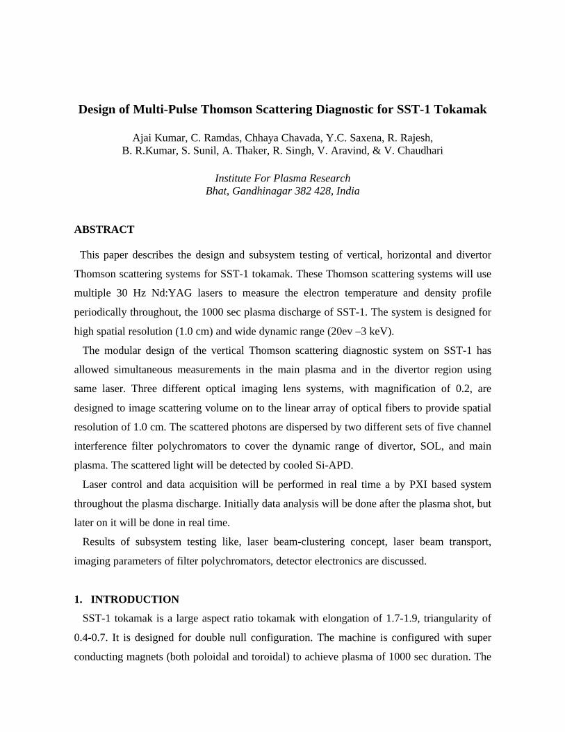
The laser beam-packing [8] scheme is shown schematically in fig. 1. In the present scheme,
a right-angle prism with high energetic dielectric mirror coating on their sides for packing
Fig. 1. Top inside view showing six-channel laser beam-packing scheme and its cross-section
at the end of laser table
laser beams are used. All the six lasers are arranged on a vibration free table such that each
pair of lasers will face each other and with a difference in height. The prisms are mounted on
precision tilt and rotation stages. The beams from each pair of lasers will be directed towards
the common path by the 45o surfaces of the prism such that the beam pack at the end of the
table will be a 2x3 matrix. The beam pack passes from the laser table and traverses
approximately 28 m to the focusing lens. To reduce the size of beam transport optics, top and
bottom pairs of beams are tilted such that these pairs of beams coincide with the middle pair
at the lens position. By overlapping the beams at focusing lens, the focus point of the
individual beams will be positioned behind each other. This way collection lens will see three
sets of overlapping beams. This arrangement also simplifies the alignment.
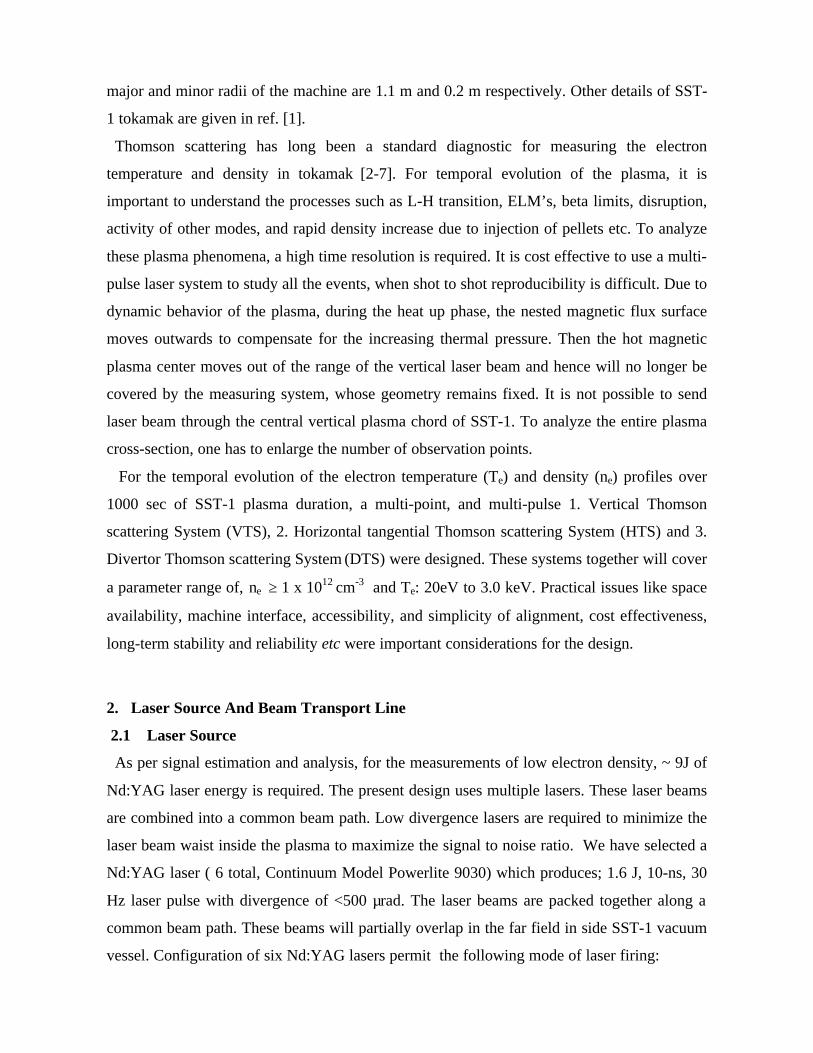
A proto-type experimental set (fig. 2) was assembled to test and develop the alignment
procedure for packing and transporting laser beams over 30 meter of distance. This set up
makes use of 4 He-Ne lasers of divergence 500 ìrad. The center-to-center distance of 10 mm
Fig. 2 : A proto-type experimental setup for the laser beam packing scheme
between all the 4 beams were maintained. At a distance of 30m, a 4m focal length lens was
mounted in the beam path to measure the beam position and their overlap at different distance
from lens position. These measurements were made by Spiricon beam profiler and visible on
paper.
2.3 Beam Transport Line
The beam transport line for all the three Thomson scattering system is common upto the
machine location. The beam pack from the laser table will enter the SST-1 hall through a
window, then the beam will be folded towards the machine with the help of beam folding
mirrors. These folding mirrors, along with their gymbal mount and translation stages are
mounted on sub-hertz vibration isolation platforms. To avoid human hazards and loss due to
scattering from water molecules and dust during the free air transportation, the beam passes
through a beam transportation line maintained at 10-2 Torr of pressure.
To test laser beam transport over 30m of distance with the use of 5 beam folding mirrors,
beam stability, beam profile, beam size at different locations in the focal plane of lens, loss of
beam energy upto 30 meter and to set up the alignment procedure for beam transport, a test
stand was designed and fabricated (fig. 3). The measurements were made by beam profiler,
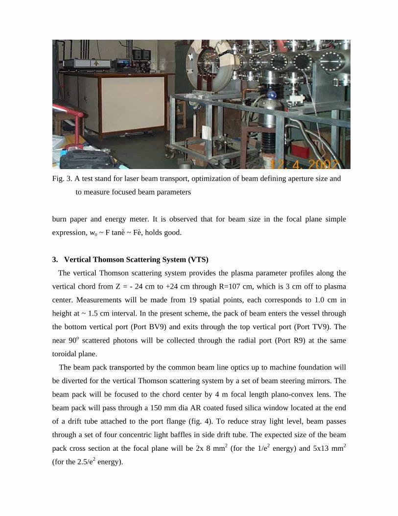
Fig. 3. A test stand for laser beam transport, optimization of beam defining aperture size and
to measure focused beam parameters
burn paper and energy meter. It is observed that for beam size in the focal plane simple
expression, wo ~ F tanè ~ Fè, holds good.
3. Vertical Thomson Scattering System (VTS)
The vertical Thomson scattering system provides the plasma parameter profiles along the
vertical chord from Z = - 24 cm to +24 cm through R=107 cm, which is 3 cm off to plasma
center. Measurements will be made from 19 spatial points, each corresponds to 1.0 cm in
height at ~ 1.5 cm interval. In the present scheme, the pack of beam enters the vessel through
the bottom vertical port (Port BV9) and exits through the top vertical port (Port TV9). The
near 90o scattered photons will be collected through the radial port (Port R9) at the same
toroidal plane.
The beam pack transported by the common beam line optics up to machine foundation will
be diverted for the vertical Thomson scattering system by a set of beam steering mirrors. The
beam pack will be focused to the chord center by 4 m focal length plano-convex lens. The
beam pack will pass through a 150 mm dia AR coated fused silica window located at the end
of a drift tube attached to the port flange (fig. 4). To reduce stray light level, beam passes
through a set of four concentric light baffles in side drift tube. The expected size of the beam
pack cross section at the focal plane will be 2x 8 mm2 (for the 1/e2 energy) and 5x13 mm2
(for the 2.5/e2 energy).
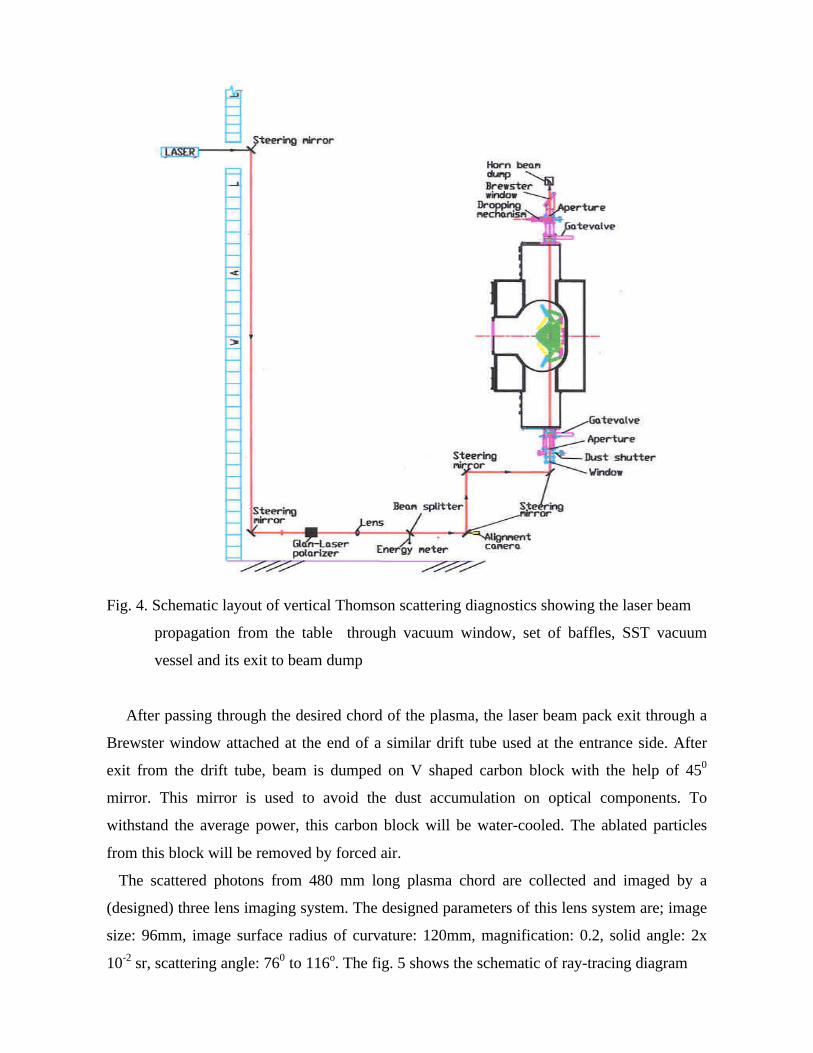
Fig. 4. Schematic layout of vertical Thomson scattering diagnostics showing the laser beam
propagation from the table through vacuum window, set of baffles, SST vacuum
vessel and its exit to beam dump
After passing through the desired chord of the plasma, the laser beam pack exit through a
Brewster window attached at the end of a similar drift tube used at the entrance side. After
exit from the drift tube, beam is dumped on V shaped carbon block with the help of 450
mirror. This mirror is used to avoid the dust accumulation on optical components. To
withstand the average power, this carbon block will be water-cooled. The ablated particles
from this block will be removed by forced air.
The scattered photons from 480 mm long plasma chord are collected and imaged by a
(designed) three lens imaging system. The designed parameters of this lens system are; image
size: 96mm, image surface radius of curvature: 120mm, magnification: 0.2, solid angle: 2x
10-2 sr, scattering angle: 760 to 116o. The fig. 5 shows the schematic of ray-tracing diagram
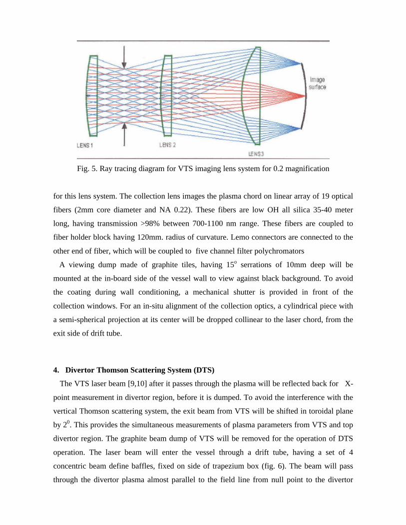
Fig. 5. Ray tracing diagram for VTS imaging lens system for 0.2 magnification
for this lens system. The collection lens images the plasma chord on linear array of 19 optical
fibers (2mm core diameter and NA 0.22). These fibers are low OH all silica 35-40 meter
long, having transmission >98% between 700-1100 nm range. These fibers are coupled to
fiber holder block having 120mm. radius of curvature. Lemo connectors are connected to the
other end of fiber, which will be coupled to five channel filter polychromators
A viewing dump made of graphite tiles, having 15o serrations of 10mm deep will be
mounted at the in-board side of the vessel wall to view against black background. To avoid
the coating during wall conditioning, a mechanical shutter is provided in front of the
collection windows. For an in-situ alignment of the collection optics, a cylindrical piece with
a semi-spherical projection at its center will be dropped collinear to the laser chord, from the
exit side of drift tube.
4. Divertor Thomson Scattering System (DTS)
The VTS laser beam [9,10] after it passes through the plasma will be reflected back for X-
point measurement in divertor region, before it is dumped. To avoid the interference with the
vertical Thomson scattering system, the exit beam from VTS will be shifted in toroidal plane
by 20. This provides the simultaneous measurements of plasma parameters from VTS and top
divertor region. The graphite beam dump of VTS will be removed for the operation of DTS
operation. The laser beam will enter the vessel through a drift tube, having a set of 4
concentric beam define baffles, fixed on side of trapezium box (fig. 6). The beam will pass
through the divertor plasma almost parallel to the field line from null point to the divertor
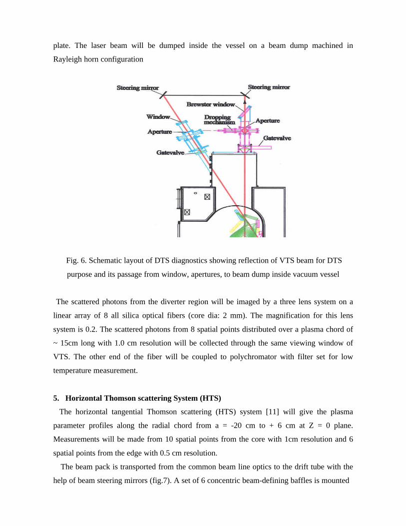
plate. The laser beam will be dumped inside the vessel on a beam dump machined in
Rayleigh horn configuration
Fig. 6. Schematic layout of DTS diagnostics showing reflection of VTS beam for DTS
purpose and its passage from window, apertures, to beam dump inside vacuum vessel
The scattered photons from the diverter region will be imaged by a three lens system on a
linear array of 8 all silica optical fibers (core dia: 2 mm). The magnification for this lens
system is 0.2. The scattered photons from 8 spatial points distributed over a plasma chord of
~ 15cm long with 1.0 cm resolution will be collected through the same viewing window of
VTS. The other end of the fiber will be coupled to polychromator with filter set for low
temperature measurement.
5. Horizontal Thomson scattering System (HTS)
The horizontal tangential Thomson scattering (HTS) system [11] will give the plasma
parameter profiles along the radial chord from a = -20 cm to + 6 cm at Z = 0 plane.
Measurements will be made from 10 spatial points from the core with 1cm resolution and 6
spatial points from the edge with 0.5 cm resolution.
The beam pack is transported from the common beam line optics to the drift tube with the
help of beam steering mirrors (fig.7). A set of 6 concentric beam-defining baffles is mounted
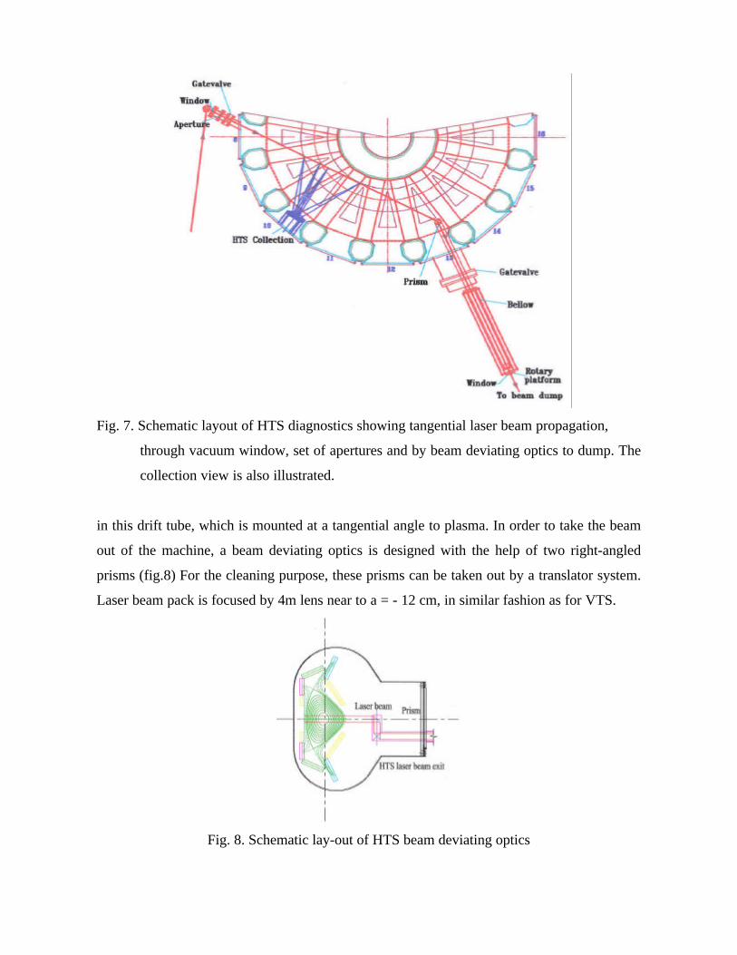
Fig. 7. Schematic layout of HTS diagnostics showing tangential laser beam propagation,
through vacuum window, set of apertures and by beam deviating optics to dump. The
collection view is also illustrated.
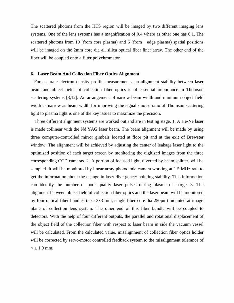
in this drift tube, which is mounted at a tangential angle to plasma. In order to take the beam
out of the machine, a beam deviating optics is designed with the help of two right-angled
prisms (fig.8) For the cleaning purpose, these prisms can be taken out by a translator system.
Laser beam pack is focused by 4m lens near to a = - 12 cm, in similar fashion as for VTS.
Fig. 8. Schematic lay-out of HTS beam deviating optics
The scattered photons from the HTS region will be imaged by two different imaging lens
systems. One of the lens systems has a magnification of 0.4 where as other one has 0.1. The
scattered photons from 10 (from core plasma) and 6 (from edge plasma) spatial positions
will be imaged on the 2mm core dia all silica optical fiber liner array. The other end of the
fiber will be coupled onto a filter polychromator.
6. Laser Beam And Collection Fiber Optics Alignment
For accurate electron density profile measurements, an alignment stability between laser
beam and object fields of collection fiber optics is of essential importance in Thomson
scattering systems [3,12]. An arrangement of narrow beam width and minimum object field
width as narrow as beam width for improving the signal / noise ratio of Thomson scattering
light to plasma light is one of the key issues to maximize the precision.
Three different alignment systems are worked out and are in testing stage. 1. A He-Ne laser
is made collinear with the Nd:YAG laser beam. The beam alignment will be made by using
three computer-controlled mirror gimbals located at floor pit and at the exit of Brewster
window. The alignment will be achieved by adjusting the center of leakage laser light to the
optimized position of each target screen by monitoring the digitized images from the three
corresponding CCD cameras. 2. A portion of focused light, diverted by beam splitter, will be
sampled. It will be monitored by linear array photodiode camera working at 1.5 MHz rate to
get the information about the change in laser divergence/ pointing stability. This information
can identify the number of poor quality laser pulses during plasma discharge. 3. The
alignment between object field of collection fiber optics and the laser beam will be monitored
by four optical fiber bundles (size 3x3 mm, single fiber core dia 250µm) mounted at image
plane of collection lens system. The other end of this fiber bundle will be coupled to
detectors. With the help of four different outputs, the parallel and rotational displacement of
the object field of the collection fiber with respect to laser beam in side the vacuum vessel
will be calculated. From the calculated value, misalignment of collection fiber optics holder
will be corrected by servo-motor controlled feedback system to the misalignment tolerance of
< ± 1.0 mm.
7. Filter Polychromators
The scattered light carried by the fibers is fed to a five channel interference filter
polychromators for the dispersion into different wavelength bands [2,5,13]. In the present
polychromators design, optimization is made between size and filter performance in terms of
angle of incidence and the cone angle of light. Stability of alignment, maintenance, optical
component size, good laser line rejection, and required spectral resolution are other important
design criteria
The scattered signal enters the polychromators via all silica optical fiber (2mm core dia,
NA: 0.22). The scattered light is imaged on interference filter by an aspheric input lens, by
placing fiber at the focal length. The focal length of this lens (35mm) is chosen such that the
beam dia at the fifth filter is less than the clear diameter (36 mm). The design has an angle of
incidence of 5 o and cone angle of 4 o at the filter. This permits the use of filter with required
lowest bandwidths 2.5nm.
As mentioned above, the temperature range to be studied is in the range of 20 eV to 3 keV
with the measurement error of < 5%. To select the filter set, which will cover this temperature
range, a code was developed. The reported values of collection lens efficiency, fiber optics,
filters transmission, detector quantum efficiency as a function of wavelength and estimated
values for laser energy, observation volume, total detector noise and optical transmission
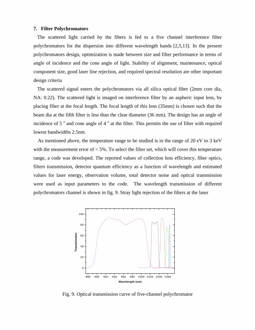
were used as input parameters to the code. The wavelength transmission of different
polychromators channel is shown in fig. 9. Stray light rejection of the filters at the laser
880 900 920 940 960 980 1000 1020 1040 1060
0
20
40
60
80
100
Wavelength (nm)
Tra
nsm
issi
on
Fig. 9. Optical transmission curve of five-channel polychromator
wavelength are > 105. The band pass for each filter is optimized to provide good temperature
resolution. A, 2.5nm wide filter at laser wavelength will be used for Rayleigh calibration.
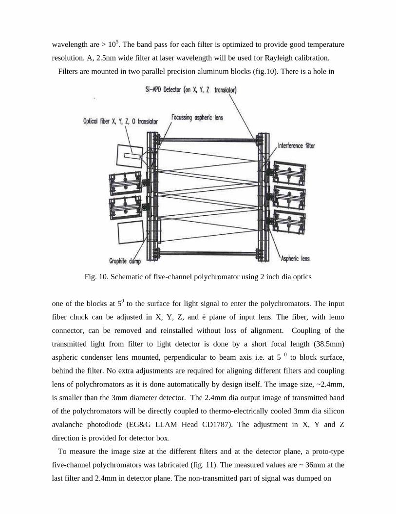
Filters are mounted in two parallel precision aluminum blocks (fig.10). There is a hole in
Fig. 10. Schematic of five-channel polychromator using 2 inch dia optics
one of the blocks at 50 to the surface for light signal to enter the polychromators. The input
fiber chuck can be adjusted in X, Y, Z, and è plane of input lens. The fiber, with lemo
connector, can be removed and reinstalled without loss of alignment. Coupling of the
transmitted light from filter to light detector is done by a short focal length (38.5mm)
aspheric condenser lens mounted, perpendicular to beam axis i.e. at 5 0 to block surface,
behind the filter. No extra adjustments are required for aligning different filters and coupling
lens of polychromators as it is done automatically by design itself. The image size, ~2.4mm,
is smaller than the 3mm diameter detector. The 2.4mm dia output image of transmitted band
of the polychromators will be directly coupled to thermo-electrically cooled 3mm dia silicon
avalanche photodiode (EG&G LLAM Head CD1787). The adjustment in X, Y and Z
direction is provided for detector box.
To measure the image size at the different filters and at the detector plane, a proto-type
five-channel polychromators was fabricated (fig. 11). The measured values are ~ 36mm at the
last filter and 2.4mm in detector plane. The non-transmitted part of signal was dumped on
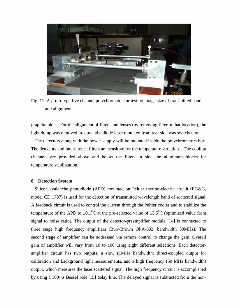
Fig. 11. A proto-type five channel polychromator for testing image size of transmitted band
and alignment
graphite block. For the alignment of filters and lenses (by removing filter at that location), the
light dump was removed in-situ and a diode laser mounted from rear side was switched on.
The detectors along with the power supply will be mounted inside the polychromators box.
The detectors and interference filters are sensitive for the temperature variation. . The cooling
channels are provided above and below the filters in side the aluminum blocks for
temperature stabilization.
8. Detection System
Silicon avalanche photodiode (APD) mounted on Peltier thermo-electric circuit (EG&G,
model CD 1787) is used for the detection of transmitted wavelength band of scattered signal.
A feedback circuit is used to control the current through the Peltier cooler and to stabilize the
temperature of the APD to ±0.10C at the pre-selected value of 13.50C (optimized value from
signal to noise ratio). The output of the detector-preamplifier module [14] is connected to
three stage high frequency amplifiers (Burr-Brown OPA-603, bandwidth 50MHz). The
second stage of amplifier can be addressed via remote control to change the gain. Overall
gain of amplifier will vary from 10 to 100 using eight different selections. Each detector-
amplifier circuit has two outputs; a slow (1MHz bandwidth) direct-coupled output for
calibration and background light measurements, and a high frequency (50 MHz bandwidth)
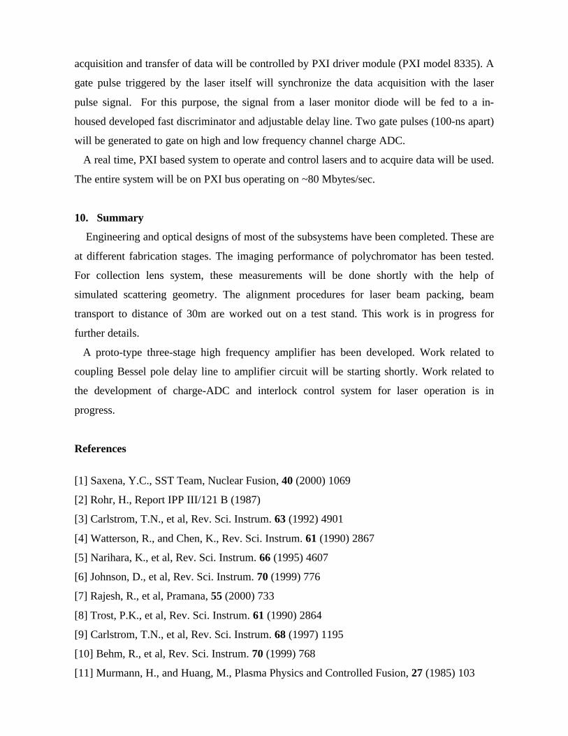
output, which measures the laser scattered signal. The high frequency circuit is accomplished
by using a 100-ns Bessel pole [15] delay line. The delayed signal is subtracted from the non-
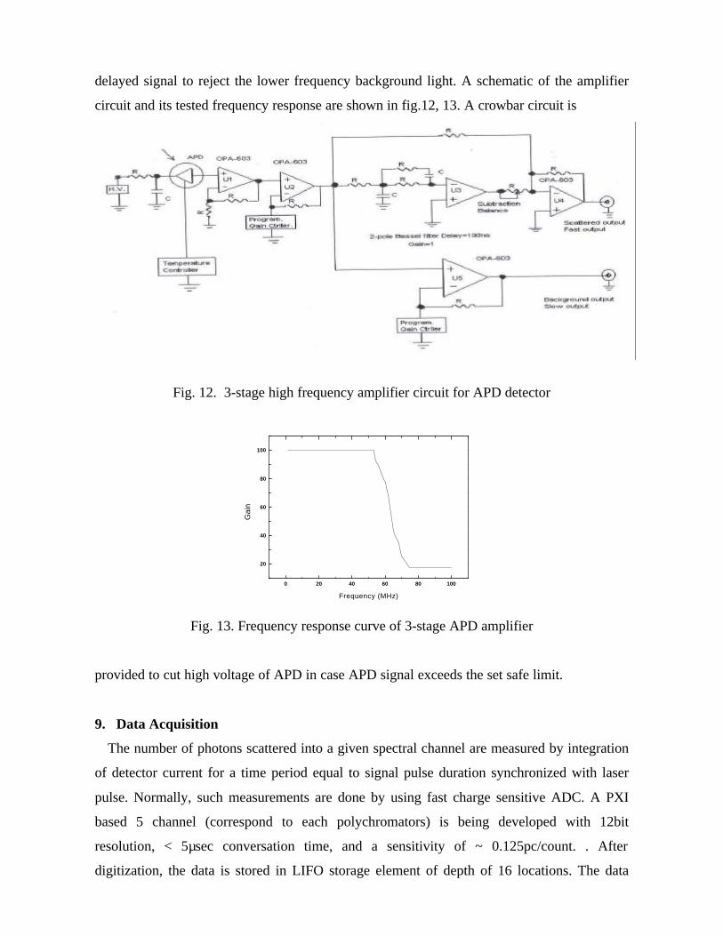
delayed signal to reject the lower frequency background light. A schematic of the amplifier
circuit and its tested frequency response are shown in fig.12, 13. A crowbar circuit is
Fig. 12. 3-stage high frequency amplifier circuit for APD detector
0 20 40 60 80 100
20
40
60
80
100
Gai
n
Frequency (MHz)
Fig. 13. Frequency response curve of 3-stage APD amplifier
provided to cut high voltage of APD in case APD signal exceeds the set safe limit.
9. Data Acquisition
The number of photons scattered into a given spectral channel are measured by integration
of detector current for a time period equal to signal pulse duration synchronized with laser
pulse. Normally, such measurements are done by using fast charge sensitive ADC. A PXI
based 5 channel (correspond to each polychromators) is being developed with 12bit
resolution, < 5µsec conversation time, and a sensitivity of ~ 0.125pc/count. . After
digitization, the data is stored in LIFO storage element of depth of 16 locations. The data
acquisition and transfer of data will be controlled by PXI driver module (PXI model 8335). A
gate pulse triggered by the laser itself will synchronize the data acquisition with the laser
pulse signal. For this purpose, the signal from a laser monitor diode will be fed to a in-
housed developed fast discriminator and adjustable delay line. Two gate pulses (100-ns apart)
will be generated to gate on high and low frequency channel charge ADC.
A real time, PXI based system to operate and control lasers and to acquire data will be used.
The entire system will be on PXI bus operating on ~80 Mbytes/sec.
10. Summary
Engineering and optical designs of most of the subsystems have been completed. These are
at different fabrication stages. The imaging performance of polychromator has been tested.
For collection lens system, these measurements will be done shortly with the help of
simulated scattering geometry. The alignment procedures for laser beam packing, beam
transport to distance of 30m are worked out on a test stand. This work is in progress for
further details.
A proto-type three-stage high frequency amplifier has been developed. Work related to
coupling Bessel pole delay line to amplifier circuit will be starting shortly. Work related to
the development of charge-ADC and interlock control system for laser operation is in
progress.
References
[1] Saxena, Y.C., SST Team, Nuclear Fusion, 40 (2000) 1069
[2] Rohr, H., Report IPP III/121 B (1987)
[3] Carlstrom, T.N., et al, Rev. Sci. Instrum. 63 (1992) 4901
[4] Watterson, R., and Chen, K., Rev. Sci. Instrum. 61 (1990) 2867
[5] Narihara, K., et al, Rev. Sci. Instrum. 66 (1995) 4607
[6] Johnson, D., et al, Rev. Sci. Instrum. 70 (1999) 776
[7] Rajesh, R., et al, Pramana, 55 (2000) 733
[8] Trost, P.K., et al, Rev. Sci. Instrum. 61 (1990) 2864
[9] Carlstrom, T.N., et al, Rev. Sci. Instrum. 68 (1997) 1195
[10] Behm, R., et al, Rev. Sci. Instrum. 70 (1999) 768
[11] Murmann, H., and Huang, M., Plasma Physics and Controlled Fusion, 27 (1985) 103

[12] Yoshida, H., et al, Rev. Sci. Instrum. 68 (1997) 1152
[13] Carlstrom, T.N., et al, Rev. Sci. Instrum. 61 (1990) 2858
[14] Hsieh, C.L., et al, Rev. Sci. Instrum. 61 (1990) 2855
[15] Johnson, D., et al, Rev. Sci. Instrum. 72 (2001) 1129
Related Documents


![A Dimensions: [mm] B Recommended land pattern: [mm] D ...2012-12-06 2012-10-24 2012-08-08 2012-06-28 2012-03-12 DATE SSt SSt SSt SSt SSt SSt BY SSt SSt BD BD SSt DDe CHECKED Würth](https://static.cupdf.com/doc/110x72/60f984e176666848374d15c0/a-dimensions-mm-b-recommended-land-pattern-mm-d-2012-12-06-2012-10-24.jpg)