White Paper The Effect of Pipe Expansion on Fusion Bonded Epoxy Coatings Energy Pipeline Industry Pipe Quality Action Plan November 5, 2010 The INGAA Foundation 2010

Welcome message from author
This document is posted to help you gain knowledge. Please leave a comment to let me know what you think about it! Share it to your friends and learn new things together.
Transcript
White Paper The Effect of Pipe Expansion on Fusion Bonded Epoxy Coatings
Energy Pipeline Industry Pipe Quality Action Plan
November 5, 2010
The INGAA Foundation 2010
White Paper – The Effect of Pipe Expansion on Fusion Bonded Epoxy Coatings November 5, 2010
This white paper is the product of work conducted by an ad‐hoc group formed to study and evaluate the effect of expansions that have been observed in line pipe on fusion bond epoxy coatings. This was one of eight work groups created to address a broader set of pipe quality issues. The members of the work group were: Jesus Soto, El Paso Corporation1 Neil Hruzek, CCSI2 Matt Dabiri, El Paso Corporation Blaine Metzger, El Paso Corporation David Sokol, Consulting Metallurgist Mark Hereth, P‐PIC Danny Castro, El Paso Corporation Joe Glassco, Akzo Nobel Kuru Varughese, DuPont Russell Hess, 3M Mike Adams, Valspar Steve Rapp, Spectra Energy Bob Worthingham, TransCanada 1 – Executive Champion 2 – Technical Lead

White Paper – The Effect of Pipe Expansion on Fusion Bonded Epoxy Coatings November 5, 2010
Purpose The purpose of Work Group 8 was to explore the impact that pipe expansion has on Fusion Bonded Epoxy Coatings. Upon organization, the work group decided to approach this along three work activities.
• Past industry papers and testing on the subject of coating expansion were researched and summarized in a white paper1. This included previously unpublished field data were collected on coating condition of pipeline segments, which permanently expanded during field hydrostatic tests.
• Pipe coated with plant applied Fusion Bond Epoxy underwent burst testing during which the coating was evaluated at incremental levels of strain.
• Additional samples of coated pipe underwent tensile and bend testing to demonstrate the strain levels at which the coating showed signs of strain and cracking.
Goals The goal of Work Group 8 was to demonstrate the level of strain that Fusion Bonded Epoxy can undergo before the coating becomes strained and ultimately reflects cracking. A second goal was to evaluate the effect of strain as manifested as stress marks and ultimately, cracking, on coating performance. Historical Testing The first activity of Work Group 8 took was to review and evaluation of Pipeline Research Council International (PRCI), the Gas Research Institute (GRI – predecessor of GTI), the Gas Technology Institute (GTI), NACE, and the International Pipeline Conference (IPC) publications and determine what historical work, if any, had been done on the performance of coatings on pipe subsequently expanded or strained. The white paper which discussed this research was written by Process Performance Improvement Consultants, LLC and entitled “Flexibility (Strain Limit) of Fusion Bonded Epoxy Coatings”1. Substantial work on coating flexibility has been done, however; to date little work has been completed on the effect of coating expansion on FBE coatings. However, both Spectra Energy and TransCanada have recently looked at how coatings perform once subjected to strain through expansion.
• The Spectra Energy report2 studied coating performance after being subjected to bending and how film thickness played a role in the flexibility of the coating. All of the strain levels in this report are expressed as permanent strain. The tests showed that, as expected, the coating remained intact at the 2.5°/PD (degrees per pipe diameter). Additional testing showed with the four‐point bend method that no cracking was seen in the coating when bent to 3°/PD in either tension or compression. There was some decrease in adhesion (observed through the knife adhesion test) observed on strained coating; however, this did not impact the results of cathodic disbondment testing or hot water soak testing. The report found that FBE, used in conjunction with Cathodic Protection Systems, still provides a corrosion barrier as long as the coating is intact.
1

White Paper – The Effect of Pipe Expansion on Fusion Bonded Epoxy Coatings November 5, 2010
• The TransCanada report3 looked at the percent strain a coating can undergo before signs of strain or cracking are observed. At film thicknesses of 14 to 20 mils FBE coating was subjected to a strain of 9% (total surface strain per ASTM A370‐09) before cracking was observed.
Current Testing The second work activity the group undertook was to develop a test series to demonstrate FBE coatings’ ability to handle a certain amount of strain. Three sets of tests were completed: these consisted of tensile testing, bend testing, and burst testing of fusion bond epoxy coated pipe samples. Description of test samples and conditions
• All samples were from coated pipe and the test specimens were longitudinal straps.
• The pipe coated for testing was 42 in. OD spiral welded pipe with a wall thickness of 0.541 in. (API Spec. 5L X70).
• The tensile straps were prepared per ASTM A370‐9a and were 14 x 2.25 x 1.5 in.
• The bend straps were prepared per NACE RP0394 and were 8 x 1 in. • The bend and tensile testing were carried out at ambient temperatures
between 65˚F and 72˚F • The presence of holidays was determined by the use of a wet sponge coating
holiday detector set at 67.5 volts. • Fusion Bonded Epoxies from two material manufactures were used: 3M
SK6233 and Valspar 2000. These were applied at thicknesses ranging between 14 and 26 mils.
• The FBE coating was applied and tested to El Paso Specification UC200. The FBE coatings used achieved CSAZ245‐20.02 certification which requires a 3°/PD bend be made at ‐30°C with no cracking of the coating. The 3°/PD bend equates to a strain level of 2.61% total strain (elastic plus permanent set).
Types of Strain Relevant to Data in this Paper4 The main topic of this paper is the amount of strain that an FBE coating can withstand before showing signs of damage. It is important to recognize that there are various ways to measure strain, and this paper includes strain data that from various sources using different methods to measure or calculate strain. In general, strain is either Total Strain or Permanent Strain. Differentiating between these two types of strain is important, as the level of Permanent Strain on the coating is more relevant to the strain seen in pipe expansion. Throughout this paper the strain seen in a bend strap is referred to in units of °/PD (degrees per pipe diameter), and the type of strain data (permanent or total) is indicated.
2

White Paper – The Effect of Pipe Expansion on Fusion Bonded Epoxy Coatings November 5, 2010
The definitions of Total Strain and Permanent Strain are given below and referenced to how this was calculated. The differences between the two types of strain and how they are calculated are shown in more detail in Appendix A. • Total Strain‐ The total amount of strain a coating is subjected to before the load is released and the steel substrate springs back. This includes both plastic and elastic deformation. • Permanent Strain‐ This is the plastic strain remaining after release of the force used in bending, hydrostatic testing, pipe expansion in the mill, or tensile testing. On coated straps, this is most easily measured by determining the bend radius of the strap after release of the bending force, and using an equation such as in NACE RP0394‐2002 Appendix H Section H4.3 or in Appendix A of this paper (which was actually the basis for the NACE test method). Bend severity is usually designated and measured in degrees per pipe diameter, because this was the traditional way for operators of field bending machines to measure the strain of their bends. This usage carried over into the standards for bending of coated straps. In order to further make the two numbers comparable (i.e. field bend severity and coated strap bend severity), both give the strain along the neutral axis of the pipe or strain. Appendix A of this paper explains this in more detail. Strain in °/PD is 1.146 times the strain in percent. The strain measured in tensile testing is always in percent, and is measured at the surface. When determining yield strength, the strain includes both elastic and plastic components. However, within this paper, the strain is measured after release of tensile force, and hence is only the permanent strain. Another way to look at this is via the stress‐strain curve for steel. As the tensile strap is pulled, the stress and strain increase along a straight line with a slope called the elastic modulus (also referred to as Young’s modulus). At some point, the graph deviates from linearity as the steel plastically deforms. If the test is stopped before breakage, and tensile load released, then the strap shrinks back along the slope of the elastic modulus. Thus the amount of permanent strain (after load release) is less than the total strain experienced under the maximum load. The amount of elastic strain reduction (referred to as “spring back” on bends) is significant, on the order of 0.5% (~ 0.6 °/PD). The strain of hydrostatic testing can be measured while the pipe is under pressure, and this would be total strain (both elastic and plastic components). But the hydrostatic test strain data in this paper were determined after pressure release, and thus represent permanent strain. Mandrel bending of coated straps, such as in specifications like NACE RP0394‐2002, Appendix H Section H4.2, or CSA Z245.20, section 12.11, represent total strain. These numbers are higher than the permanent strain values. . This method is easier for the coating applicator or manufacturer to meet a specification because the target strain is met BEFORE elastic spring back. However, total strain is not directly
3

White Paper – The Effect of Pipe Expansion on Fusion Bonded Epoxy Coatings November 5, 2010
comparable to the amount of strain that the coating must withstand in field cold bends, which is measured AFTER spring back. Based on tests done at Tennessee Gas Pipeline some years ago on X52 and X60 pipe, the amount of spring back is 0.4 to 0.6 °/PD. Higher‐strength pipe may have a greater amount of spring back, depending on the shape of the stress‐strain curves for the pipe steel. If the amount of elastic spring back is 0.6 °/PD, then a CSA mandrel bend of 2.5°/PD would be equivalent to only 1.9 °/PD permanent bend. Conversely, a 2.5 °/PD permanent strain such as determined by the Tennessee Gas (Tenneco) / NACE template method would require a mandrel bend to a total strain of 3.1 °/PD. The importance of permanent strain is reflected in NACE RP0394, Table 4, where the acceptance criterion for flexibility of straps from production test rings is specifically “permanent strain”. It would be beneficial to the pipeline industry if the various coating standards and customer specifications were more consistent in their treatment of strain requirements for coating. Tensile Test Summary The complete result tables for the tensile tests can be found in Appendix B. In summary, the tensile testing was conducted at two facilities in the following manner. The tensile test straps were prepared per ASTM A370-9a and placed in the tensile tester. Each strap was slowly elongated while watching for signs of strain on the coating. The elongation continued until cracking in the coating was observed. For the purpose of these tests stress marks are defined in the coating is defined as ‘small white lines appearing in the coating’ and a pictorial example are seen in Figure 1; The bend straps were placed in the test rig and the strain gauge was attached as seen in Figure 2 and elongated. As the straps were elongated measurements were taken at pre‐determined points of strain, Figure 3.
Figure 1
Figure 3Figure 2
4

White Paper – The Effect of Pipe Expansion on Fusion Bonded Epoxy Coatings November 5, 2010
The testing stopped when cracks were observed visually in the coating. Holidays in the coating were verified by a wet sponge jeep set at 67.5 volts. Examples of the types of cracking seen are shown in Figures 4 and 5.
The tensile testing showed that signs of stress in the coating are not observed until strains in excess of 10% are applied to the strap. Cracking or the creation of holidays does not begin until strain levels in excess of 14% are seen. It should be noted that the tensile straps were flattened prior to tensile testing, which could create strains on the coating before the tensile testing. Bend Test Summary The complete bend test results can be found in Appendix C. In summary, the bend tests were carried out using NACE RP0394 with a combination of the four‐point and mandrel bending methods. The severity of bend resulting in stress marks and cracking was first determined by using the four‐point bend method outlined in NACE RP0394‐2002. From this estimate the proper size mandrels were determined. To ensure reproducibility of the bend these mandrels were used for the remaining bends. The samples had an effective strap thickness, which was between 0.560 in and 0.580 in. We found that a four inch radius mandrel creates signs of stress in the coating, will generate permanent strain levels between 7.3˚/PD and 7.6˚/PD total strain depending on strap thickness (Figures 7 and 8).
Figure 4 Figure 5
5

White Paper – The Effect of Pipe Expansion on Fusion Bonded Epoxy Coatings November 5, 2010
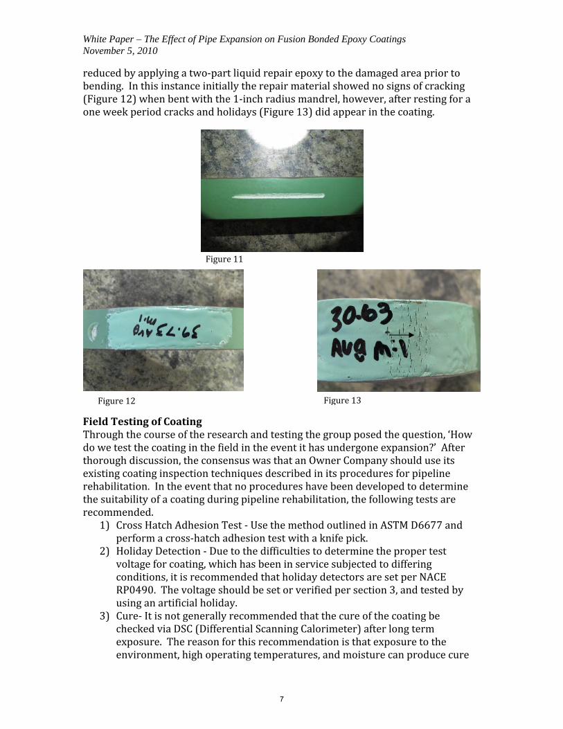
When attempting to create a crack in the coating using the four‐point bend method, the strap had to be bent almost 180˚ before cracking was observed. While creating this failure mode it, should be noted that the time it takes to complete the bend is important; too fast a bend rate can result in disbondment of the coating in the area of the bend. For this experiment, the bend was completed in a 20 to 30 second time frame. Due to the extreme degree of bend required to show cracking a mandrel was made from a piece of 1 in. radius bar stock (Figure 6). This resulted in permanent strain levels between 27.17˚/PD and 27.82˚/PD total deflection. A wet sponge holiday detector was used to determine the presence of holidays; refer to Figures 9 and 10. The coating elongation for two samples at each bend severity was determined by marking the straps at uniform intervals and measuring the distance along the arc between the marks both before and after the bend. The results of these measurements can be found in Appendix C1. It should be noted that all bend straps were taken in the longitudinal direction. Additional testing could be conducted to see if there are any changes in how the coating performs when circumferential straps are bent. While completing the bend tests, the impact of damage to the coating, such as a gouge (Figure 11), were also studied. It was found that a gouge in the coating, that did not penetrate through the coating, could create a stress riser for a coating crack to initiate and propagate when put under strain. This effect of the stress riser was
Figure 8Figure 7
Figure 9 Figure 10
6
White Paper – The Effect of Pipe Expansion on Fusion Bonded Epoxy Coatings November 5, 2010
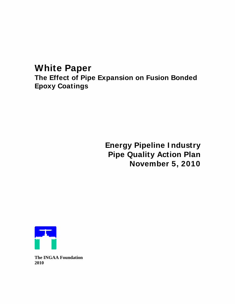
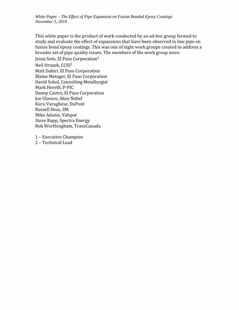
reduced by applying a two‐part liquid repair epoxy to the damaged area prior to bending. In this instance initially the repair material showed no signs of cracking (Figure 12) when bent with the 1‐inch radius mandrel, however, after resting for a one week period cracks and holidays (Figure 13) did appear in the coating.
Field Testing of Coating Through the course of the research and testing the group posed the question, ‘How do we test the coating in the field in the event it has undergone expansion?’ After thorough discussion, the consensus was that an Owner Company should use its existing coating inspection techniques described in its procedures for pipeline rehabilitation. In the event that no procedures have been developed to determine the suitability of a coating during pipeline rehabilitation, the following tests are recommended.
1) Cross Hatch Adhesion Test ‐ Use the method outlined in ASTM D6677 and perform a cross‐hatch adhesion test with a knife pick.
2) Holiday Detection ‐ Due to the difficulties to determine the proper test voltage for coating, which has been in service subjected to differing conditions, it is recommended that holiday detectors are set per NACE RP0490. The voltage should be set or verified per section 3, and tested by using an artificial holiday.
3) Cure‐ It is not generally recommended that the cure of the coating be checked via DSC (Differential Scanning Calorimeter) after long term exposure. The reason for this recommendation is that exposure to the environment, high operating temperatures, and moisture can produce cure
Figure 12 Figure 13
Figure 11
7

White Paper – The Effect of Pipe Expansion on Fusion Bonded Epoxy Coatings November 5, 2010
results, which are false or misleading. In the event that the cure of the material is in question, the Owner Company should work with the Material Supplier to develop a valid procedure for verifying the cure of the coating in question.
Burst Test Summary The purpose of the testing was to analyze the coating integrity during the burst testing. Burst testing was performed on six coated pipes submitted by two different pipe mills. Each mill submitted three coated pipes: each mill had applied a different FBE coating. Three pipes were coated with 3M SK6233 and the remaining three were coated with Valspar 2000. The pipe was welded together in strings of three pipes, each string being comprised of the same coating. The outer diameter of the pipe was then measured at pre‐determined locations to determine the baseline diameter. The pipe was then pressurized to 80%, 105%, and 110% of the specified minimum yield strength (SMYS), and depressurized at each increment to re‐measure the diameter. The FBE coating was inspected visually and with a coating holiday detector between pressurization intervals through the course of the hydro test. No loss of coating integrity was visually identified nor did the holiday detector show any areas of exposed bare metal between pressurization intervals on either pipe string prior to rupture. After reaching the 110% of SMYS, the sections were taken to burst pressure. Upon completion of the test, the outer diameter was measured. All these measurements can be found in Appendix D, followed by a pictorial summary of the pipe sections and rupture sites. Up to 110% of SMYS the coating showed no signs of strain or cracking; however, after the pipes were taken to burst, signs of strain could be seen through the length of the coating to various degrees. The observed strain marks ranged in size from 1/16 to ¾ inch in length throughout different areas of each pipe string, with the longest indications adjacent to the rupture origins. Figures 14 and 15, page 9, show the types of strain marks seen at areas marked Section T (2.63% expansion) and Q (3.2% expansion), respectively. (The raw data can be found in Appendix D2 Joint P3 and pictures of the burst test can be found in Appendix D3.) At the rupture sites, the coating was fractured in either a “puzzle piece” pattern or a “strip” pattern parallel with the direction of the stress marks (Appendix D3). The exact cause of the differences in how the coating failed at the rupture site can only be speculated about at this point. Holiday detection was performed after both burst tests on the entire OD surface of each pipe string. It should be noted that only the areas immediately surrounding the rupture site caused the coating to crack and/or disbond.
8

White Paper – The Effect of Pipe Expansion on Fusion Bonded Epoxy Coatings November 5, 2010
Field Observations Two operators who have recently excavated pipelines and observed expansions in the pipe have provided some initial feedback on their findings. It was found in both cases that visual signs of stress in the coating were present. Despite these stress marks seen in the coating, no loss of adhesion was observed. Excavation 1 Stress marks and cracking were observed over approximately half of a pipe joint at one location that measured 3.06% expansion (permanent strain), Figure 16. The coating showed good adhesion as reflected by a cross‐hatch test. Holidays were identified and after visual inspection, were verified as shovel dings and damage from probing made during initial excavation.
Figure 14 Figure 15
Figure 16
9

White Paper – The Effect of Pipe Expansion on Fusion Bonded Epoxy Coatings November 5, 2010
Excavation 2 Signs of initial stress (stress marks) Figure 17, in the coating were observed at two localized expansions on the pipe. A picture was taken at the location of largest expansion, which was 1.73% (permanent strain).
Figure 17
10

White Paper – The Effect of Pipe Expansion on Fusion Bonded Epoxy Coatings November 5, 2010
Conclusions The testing conducted by Work Group 8 on coated samples which were subjected to varying levels of strain by tensile, bend, and burst testing show that Fusion Bonded Epoxy coating does not begin to show signs of stress until strain levels reach levels that well exceed the minimum required to generate plastic deformation of the steel substrate. It was concluded that a correlation between the strain from tensile testing and strain from bend testing needs more data points which should include additional coating and steel thicknesses. To ensure reproducibility it is important that the bend and tensile testing be conducted at a temperature ranging from 65°F to 75°F. The temperature range of 65°F to 75°F was chosen to make results comparable to those seen in hydrostatic testing. From the testing conducted, it appears that dramatic deformation (greater than strain levels of 7%) in the steel substrate is required before visual defects were observed in the coating. Fusion Bonded Epoxy coatings are designed to handle certain levels of strain and tested for their abilities to do so. This is outlined in CSA Z245.02, which requires them to be bent to a 3°/PD bend at ‐30°C and pass Cathodic Disbondment Testing with the coating in strain. Additionally, historical experience shows that even in instances where adhesion of the coating may be compromised, the coating will still provide a level of protection when used in conjunction with a Cathodic Protection System. The group recommends to the pipeline industry that the various coating standards and customer specifications should be more consistent in their treatment of strain requirements for coating. The work group also recognizes that this study is not inclusive of all coatings currently used for pipelines. A more extensive study may be appropriate to learn the effects of expansion on;
1) other coatings such as abrasion resistant overlays, liquid coatings, and repair materials and
2) the effect of specific strain levels related to the following industry standard tests; Cathodic Disbondment, Moisture Permeation, and Adhesion.
3) Look at how coatings perform when strained at varying temperatures, mainly less than 40°F. The goal being to make testing comparable to lower temperature hydrostatic testing.
11

White Paper – The Effect of Pipe Expansion on Fusion Bonded Epoxy Coatings November 5, 2010
Appendix A
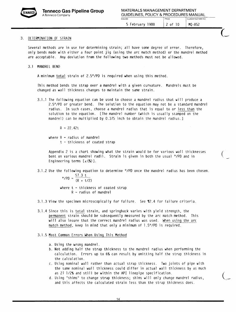
Tennessee Gas (Tenneco Gas) MQ-852 Coating Bend Tests
12

13
14

15

16

17

18

19

20

21

22

White Paper – The Effect of Pipe Expansion on Fusion Bonded Epoxy Coatings November 5, 2010
Appendix B
Valspar 2000 Sample No. 3 A : PIPE NO. A09004912 Tensile Strap ( Coating Thickness 17.5 – 19.7 mils )
% Strain Thickness, inch
Elongation Visual Remarks
0.00% 0.560 2.00 ok -- 1.90% 0.559 2.038 ok -- 1.95% 0.559 2.039 ok -- 2.10% 0.559 2.042 ok -- 3.70% 0.559 2.074 ok -- 6.15% 0.545 2.123 ok --
13.10% 0.537 2.262 Small fracture , No holiday -- 16.20% 0.525 2.324 Stress Crack, Holiday Failed
Valspar 2000 Sample No. 3 B : PIPE NO. A09004912
Tensile Strap ( Coating Thickness 17.5 – 19.7 mils ) % Strain Thickness,
inch Elongation Visual Remarks
0.00% 0.560 2.00 ok -- 1.40% 0.558 2.028 ok -- 3.25% 0.557 2.065 ok -- 2.75% 0.555 2.055 ok -- 3.85% 0.553 2.077 ok -- 6.70% 0.545 2.134 ok --
11.25% 0.537 2.225 ok -- 17.40% 0.530 2.348 Stress mark , No holiday -- 22.60% 0.511 2.452 Crack, Holiday Failed
23

White Paper – The Effect of Pipe Expansion on Fusion Bonded Epoxy Coatings November 5, 2010
Appendix B, cont.
3M SK6233 SAMPLE 1-A PIPE NUMBER 901830-H
Tensile Strap (coating thickness 24.1 to 25.1 mils) % Strain Thickness,
inch Elongation Visual Remarks
1.55% 0.567 2.031 OK -- 3.10% 0.554 2.062 OK -- 4.65% 0.543 2.093 OK -- 9.60% 0.531 2.192 OK --
12.80% 0.513 2.256 OK -- 16.00% 0.494 2.32 Stress mark , No holiday -- 19.20% 0.488 2.384 Stress mark , No holiday -- 21.85% 0.461 2.437 Crack Holiday
3M SK6233 SAMPLE 1-B PIPE NUMBER 901830-H
Tensile Strap (coating thickness 24.1 to 25.1 mils) % Strain Thickness,
inch Elongation Visual Remarks
0.00% 0.569 2 OK -- 0.75% 0.562 2.015 OK -- 1.55% 0.559 2.031 OK -- 3.10% 0.551 2.062 OK -- 6.25% 0.542 2.125 OK -- 7.80% 0.538 2.156 OK --
10.95% 0.521 2.219 Stress mark , No holiday -- 17.55% 0.49 2.351 Crack Holiday
24

White Paper – The Effect of Pipe Expansion on Fusion Bonded Epoxy Coatings November 5, 2010
Appendix C1
Elongation Measurement of Bend Straps
Sample No
Effective Strap
Thickness
Radius of
Mandrel Used
Start Finish Elongation *Percent Elongation
Total Strain ˚/PD
R1 .574 4 .352 .378 .025 7.10% 7.67 R2 .570 4 .350 .378 .028 8.00% 7.62 R3 .570 1 .341 .4825 .141 41.34% 25.42 R4 .568 1 .349 .5040 .155 44.41% 25.35
All measurements are in inches Strain in °/PD is calculated using the formulas found in NACE RP0394
Appendix C2
Bend Strap Evaluation
Sample No Coating Type
Effective Strap
Thickness
Coating Thickness
(Mil)
Radius of Bend
Permanent Strain ˚/PD
ε (%) Stress/ Crack
4-1 A09003306 Valspar .577 15 4.75 7.41 6.45 Stress 4-2 A09003306 Valspar .570 15 4.75 7.31 6.36 Stress 4-3 A09004575 Valspar .582 16 4.75 7.48 6.51 Stress 4-4 901830 3M .590 18 4.75 7.59 6.60 Stress 1-1 A09804912 Valspar .586 16 1.5 27.82 24.20 Crack 1-2 A09804912 Valspar .577 17 1.5 27.29 23.74 Crack 1-3 A09004575 Valspar .577 15 1.5 27.29 23.71 Crack 1-4 901830 3M .575 19 1.5 27.17 23.64 Crack All measurements are in inches Strain in °/PD is calculated using the formulas found in NACE RP0394 Engineering Strain ε(%) is calculating by using the formula found in Tennessee Gas Specification PIT 5-852 dated April 30, 1984 where a relationship between Strain in °/PD is related to Engineering Strain. The formula for this is listed below;
( ) ( )PDo×= 87.0%ε
25
White Paper – The Effect of Pipe Expansion on Fusion Bonded Epoxy Coatings November 5, 2010
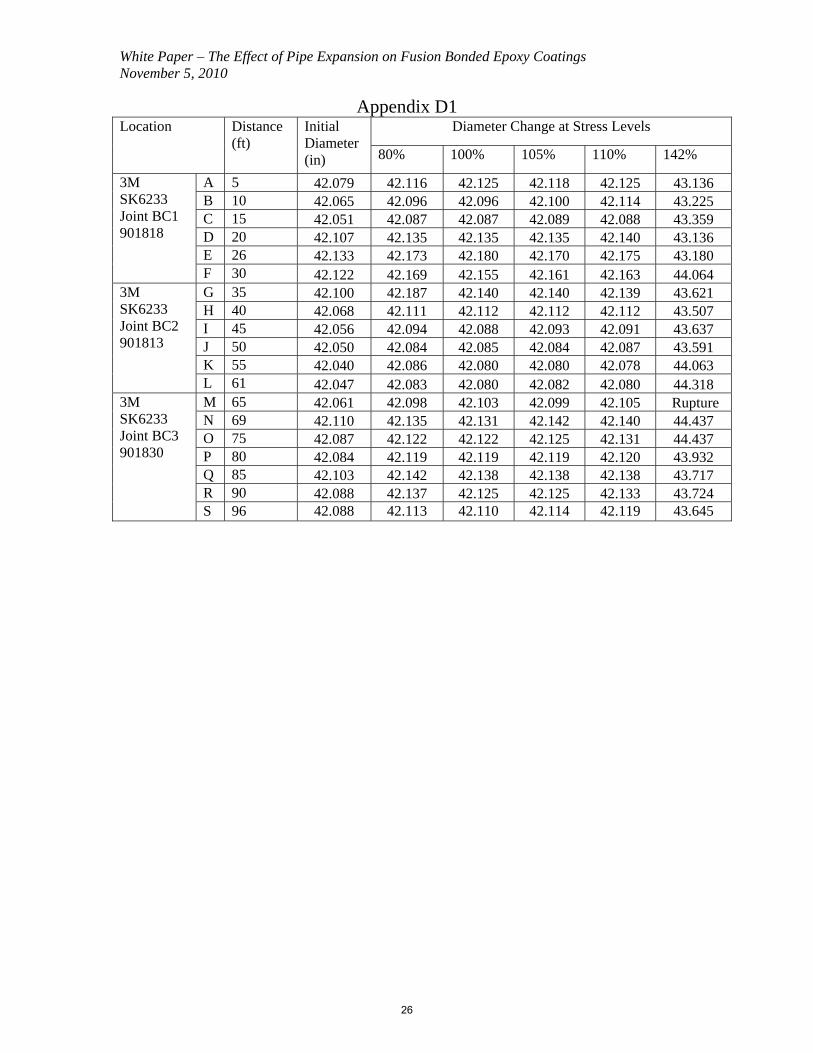
Appendix D1 Diameter Change at Stress Levels Location Distance
(ft) Initial Diameter (in) 80% 100% 105% 110% 142%
A 5 42.079 42.116 42.125 42.118 42.125 43.136 B 10 42.065 42.096 42.096 42.100 42.114 43.225 C 15 42.051 42.087 42.087 42.089 42.088 43.359 D 20 42.107 42.135 42.135 42.135 42.140 43.136 E 26 42.133 42.173 42.180 42.170 42.175 43.180
3M SK6233 Joint BC1 901818
F 30 42.122 42.169 42.155 42.161 42.163 44.064 G 35 42.100 42.187 42.140 42.140 42.139 43.621 H 40 42.068 42.111 42.112 42.112 42.112 43.507 I 45 42.056 42.094 42.088 42.093 42.091 43.637 J 50 42.050 42.084 42.085 42.084 42.087 43.591 K 55 42.040 42.086 42.080 42.080 42.078 44.063
3M SK6233 Joint BC2 901813
L 61 42.047 42.083 42.080 42.082 42.080 44.318 M 65 42.061 42.098 42.103 42.099 42.105 Rupture N 69 42.110 42.135 42.131 42.142 42.140 44.437 O 75 42.087 42.122 42.122 42.125 42.131 44.437 P 80 42.084 42.119 42.119 42.119 42.120 43.932 Q 85 42.103 42.142 42.138 42.138 42.138 43.717 R 90 42.088 42.137 42.125 42.125 42.133 43.724
3M SK6233 Joint BC3 901830
S 96 42.088 42.113 42.110 42.114 42.119 43.645
26

White Paper – The Effect of Pipe Expansion on Fusion Bonded Epoxy Coatings November 5, 2010
Appendix D2
Diameter Change at Stress Levels Location Distance (ft)
Initial Diameter (in) 80% 100% 105% 110% 138%
A 7 42.152 42.183 42.195 42.196 42.192 42.185 B 10 42.141 42.186 42.189 42.188 42.181 42.182 C 15 42.157 42.213 42.211 42.188 42.189 42.190 D 20 42.172 42.234 42.232 42.204 42.208 42.215 E 25 42.132 42.182 42.173 42.176 42.169 42.207 F 31 42.100 42.145 42.140 42.136 42.144 42.178
Valspar 2000 Joint P1 A09003306
G 35 42.051 42.066 42.065 42.078 42.085 42.270 H 39 42.138 42.186 42.176 42.173 42.175 42.900 I 45 42.120 42.165 42.161 42.165 42.170 42.628 J 50 42.136 42.206 42.183 42.190 42.190 42.530 K 55 42.119 42.166 42.172 42.162 42.162 42.469 L 60 42.137 42.184 42.168 42.175 42.175 42.510
Valspar 2000 Joint P2 A09004575
M 66 42.097 42.134 42.145 42.139 42.134 42.759 N 71 42.133 42.208 42.183 42.178 42.179 Rupture O 75 42.118 42.160 42.155 42.154 42.152 Rupture P 80 42.120 42.161 42.166 42.157 42.160 43.758 Q 85 42.111 42.177 42.164 42.160 42.155 43.484 R 90 42.106 42.158 42.146 42.145 42.142 43.170 S 95 42.103 42.148 42.141 42.144 42.134 43.091
Valspar 2000 Joint P3 A09004912
T 101 42.112 42.154 42.181 42.150 42.150 43.222
27

White Paper – The Effect of Pipe Expansion on Fusion Bonded Epoxy Coatings November 5, 2010
Appendix D3
Burst Test Pictures
28
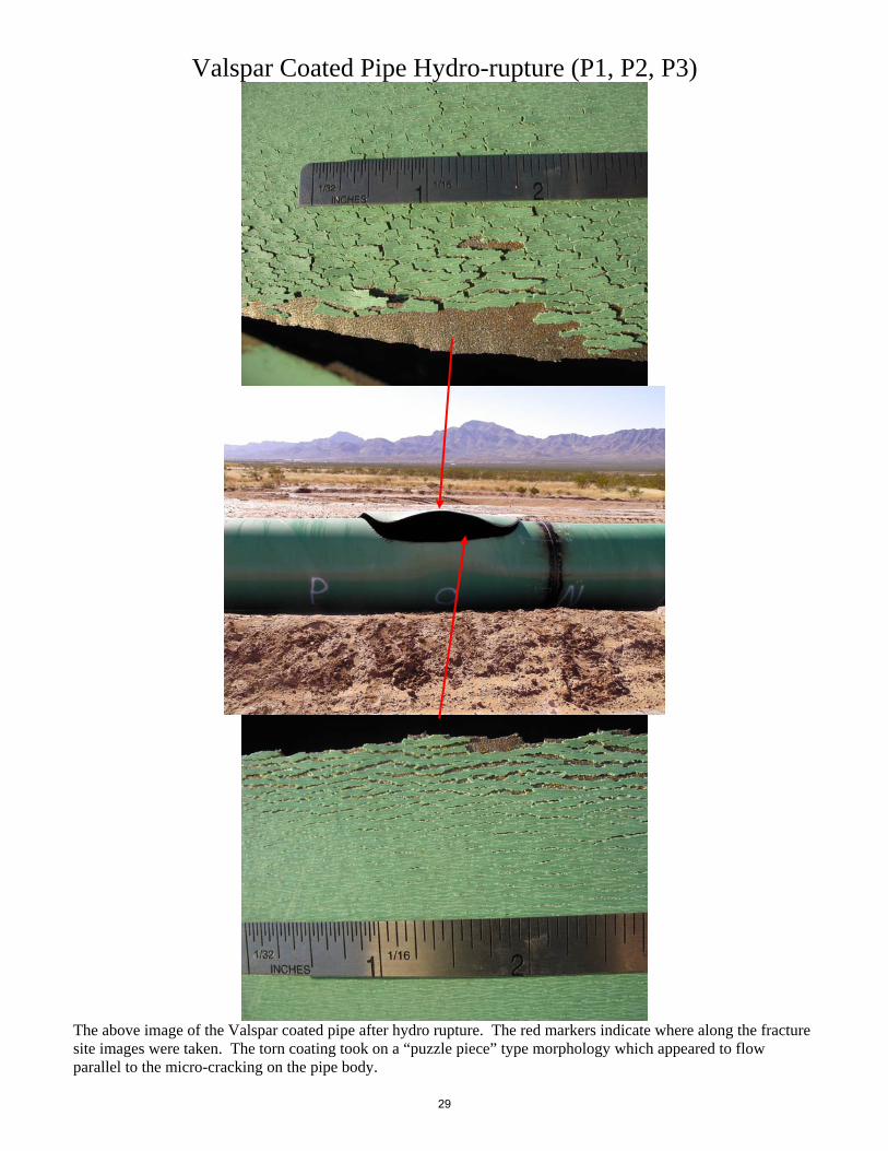
Valspar Coated Pipe Hydro-rupture (P1, P2, P3)
The above image of the Valspar coated pipe after hydro rupture. The red markers indicate where along the fracture site images were taken. The torn coating took on a “puzzle piece” type morphology which appeared to flow parallel to the micro-cracking on the pipe body.
29

The above images of the micro-cracks observed on the coating pipe body illustrated by the red and yellow markers. The micro-cracks extended approximately 40ft. upstream and downstream of the rupture site, after which undamaged pipe coating was visually observed.
30
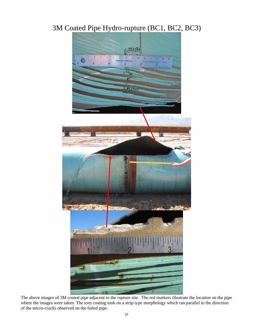
3M Coated Pipe Hydro-rupture (BC1, BC2, BC3)
The above images of 3M coated pipe adjacent to the rupture site. The red markers illustrate the location on the pipe where the images were taken. The torn coating took on a strip type morphology which ran parallel to the direction of the micro-cracks observed on the failed pipe.
31

The above images of the micro-cracks observed on the coated pipe body illustrated by the red markers. The 3M coated pipe displayed micro-cracks through the entire pipe body, the cracks ran axially along the pipe. Regions adjacent to the end cap girth welds did not display the observed micro-cracking due to the increase strength and thickness of the end caps.
32

White Paper – The Effect of Pipe Expansion on Fusion Bonded Epoxy Coatings November 5, 2010
References and Further Reading
1. Process Performance Improvement Consultants, LLC “Flexibility (Strain Limit) of Fusion Bonded Epoxy Coatings”, November 22, 2009, Mark Hereth and Keith Leewis, P‐PIC 1. Corinth Pipe for Spectra Energy “Evaluation of Bending Performance of High DFT Coatings” Dated January 3, 2008 Provided by: Stephen Rapp, Spectra Energy 2. RAE Engineering and Inspection Ltd. For TransCanada “Determination of Coatings Deformation Limit in Tensile Strain” Dated September 15, 2009 Provided by: Robert Worthingham, TransCanada 3. Explanation of Types of Strain Relevant to Data in this Paper Provided by: David Sokol, Consulting Metallurgist
Referenced Standards ASTM A370‐09a Standard Test Methods and Definitions for Mechanical Testing of Steel Products ASTM D6677‐07 Standard Test Method for Evaluating Adhesion by Knife El Paso Corporation UC200 Plant Applied External Fusion Bonded Epoxy Pipe Coating NACE RP‐0394 – 2002 Application, Performance, and Quality Control of Plant Applied Fusion‐Bonded Epoxy External Coating – Appendix H sets out the test requirements.
NACE RP‐0490‐2001 Standard Recommended Practice‐Holiday Detection of Fusion Bonded Epoxy External Pipeline Coatings of 25‐ to 760 um (10 to 30 mils)
Tennessee Gas (Tenneco Gas) Test Procedure MQ‐852 Coating Bend Tests
Dated April 30, 1984 Background information on the Engineering Strain Calculation Provided by: David Sokol, Consulting Metallurgist
Tensile and Burst Testing were coordinated and conducted by ElPaso. For additional information contact Matt Dabiri, ElPaso
33

White Paper – The Effect of Pipe Expansion on Fusion Bonded Epoxy Coatings November 5, 2010
Bend Testing was conducted at Commercial Coating Services International Ltd. For additional information contact Neil Hruzek, CCSI
34
Related Documents