Inductive Power System for Autonomous Underwater Vehicles Tim McGinnis University of Washington, Applied Physics Lab

Welcome message from author
This document is posted to help you gain knowledge. Please leave a comment to let me know what you think about it! Share it to your friends and learn new things together.
Transcript

Inductive Power System for
Autonomous Underwater VehiclesTim McGinnis
University of Washington, Applied Physics Lab
Inductive Power System for
Autonomous Underwater VehiclesTim McGinnis
University of Washington, Applied Physics Lab

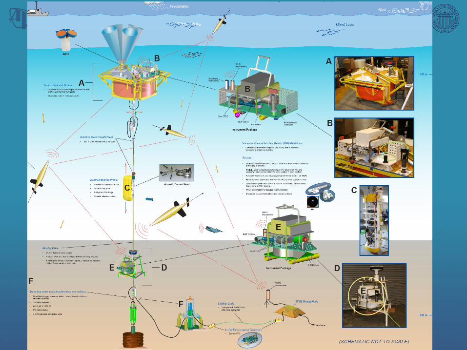
• Major Components– Seafloor Secondary Node with Sensors– Subsurface float at 200m depth with Secondary Node and Sensor Suite – Mooring profiler with sensor suite that can “dock” for inductive battery
charging– 1700m electro-optical seafloor extension cable with E-O Converters– 800m electro-optical mooring cable with E-O Converters
• Features– Cable connection provides high power and real-time communications– Mooring profiler uses inductive modem for continuous comms– MARS compatible ROV-mateable Science Connectors on Float & Seafloor
Nodes– ROV servicing and installation of sensors
• Deployments– 2007 in Puget Sound at Seahurst Observatory in 30m water depth– 2008 on MARS in 950m water depth
ALOHA-MARS Mooring Sensor Network

Inductive Power System Requirements
• Needed to transfer several hundred watts to profiler
• Could not generate enough mate/unmate force for connectors
• Preferred non-conductive technique due to conductive medium
• Decided to use inductive transfer

S&K Engineering
• Principals had worked in the Electric Vehicle (EV) industry
• Working with US Navy on underwater inductive power transfer technology

DC-HFAC Driver (in Float Pressure Housing)
HFAC-DC Rectifier (in Vehicle Pressure
Housing)
Vehicle Battery Housing
EMI Filter/Transient Protection
Input150-400Vdc
Primary SideUnderwater
Coupler
Resonant Converter
BoostRegulator
In-Rush Current
Limit
Secondary Side
UnderwaterCoupler
400Vac50kHz
Driver Side Controller
Active Rectifier
Secondary Side
Controller/Li-Ion
Battery Charger
16.4VdcLithium Battery
Pack
Loads
Voltage Regulator
12V
Block Diagram
• Powered from 375VDC from MARS Node
• Driver chops input at 50kHz
• AC signal transferred across couplers
• AC signal rectified & regulated to 16.4VDC
• Microcontroller manages Lithium-Ion charging profile


Maximum Output Power vs. Gap
Maximum Output Power at 14.6Vdc
0
50
100
150
200
250
300
350
0 1 2 3 4 5 6Physical Gap mm
Ou
tpu
t P
ow
er
Wa
tts
0.64
0.66
0.68
0.7
0.72
0.74
0.76
0.78
0.8
0 1 2 3 4 5 6
Physical Gap mm
Eff
icie
nc
y
14Vout 140 Vin
16Vout 140Vin
18Vout 140Vin
14Vout 240Vin
16Vout 240Vin
18Vout 240Vin
20Vout 240Vin
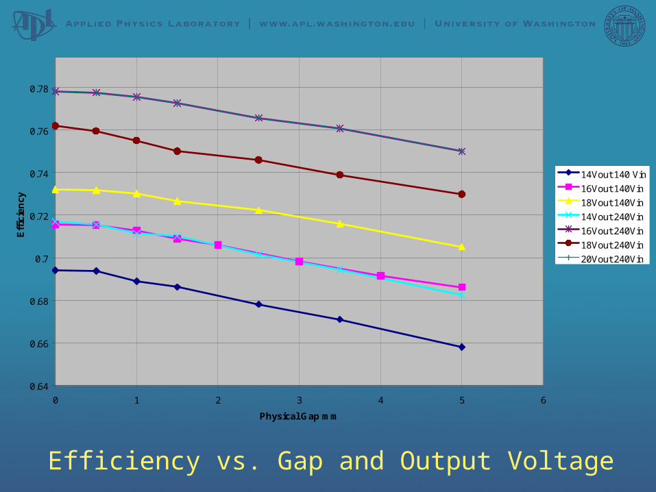
Efficiency vs. Gap and Output Voltage
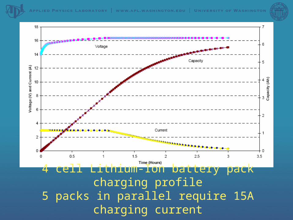
4 cell Lithium-Ion battery pack charging profile5 packs in parallel require 15A charging current

0
2
4
6
8
10
12
14
16
18
0:00
0:05
0:32
1:20
1:54
3:20
5:30
5:44
6:03
Elapsed Time
Vo
lts/
Am
ps Voltage
Current
Li-Ion Battery Charging Profile - constant current to 16.4V then constant voltage
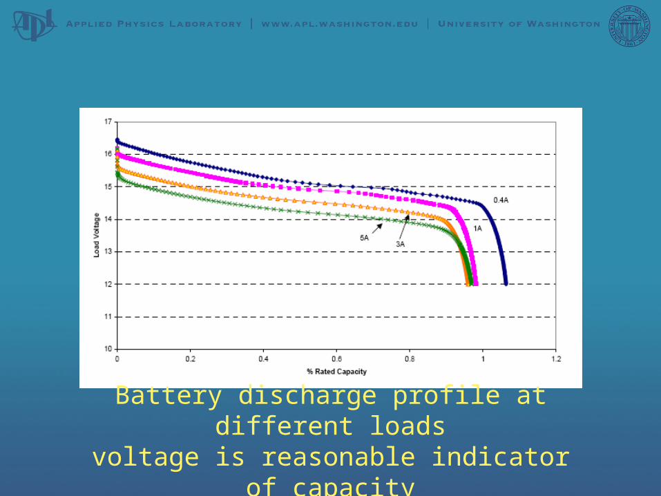
Battery discharge profile at different loadsvoltage is reasonable indicator of capacity

Vout(t)
VISEC(t)
Gate Drive
Active Rectifier
V1
ISEC
PICMicrocontrollerIout(t)
PWMLowPass Filter
+
Vout(t)
-
Iout(t)
+
--
+
Synchronous Ramp
Reference
Vout(t)
VISEC(t)
Gate Drive
Active Rectifier
V1
ISEC
PICMicrocontrollerIout(t)
PWMLowPass Filter
+
Vout(t)
-
Iout(t)
+
--
+
Synchronous Ramp
Reference

Limit switch to indicate profiler in dockSpring shock absorber

Preparing for deployment in Puget Sound

Profiler with inductive couplers (docked)
in the water

Operation
• Profiler is programmed with minimum voltage (15V) – allowing 25-30% battery capacity remaining
• When profiler detects voltage below minimum, it returns to charging dock
• IPS driver turns on every minute – if current is flowing it continues to operate, if no current it turns off
• Profiler is programmed with minimum current (3A)• When minimum current is reached, profiler
resumes profiling• IPS turns off at 1.5A to prevent over-charging if
profiler present

Results of 2 month Deployment
• Deployed June 26, 2007
• Driver FET Failure on Aug 27, 2007
• Completed 4984 profiles
• Charge interval was approximately 7-8 days
• Currently investigating reason for FET failure

Current Status
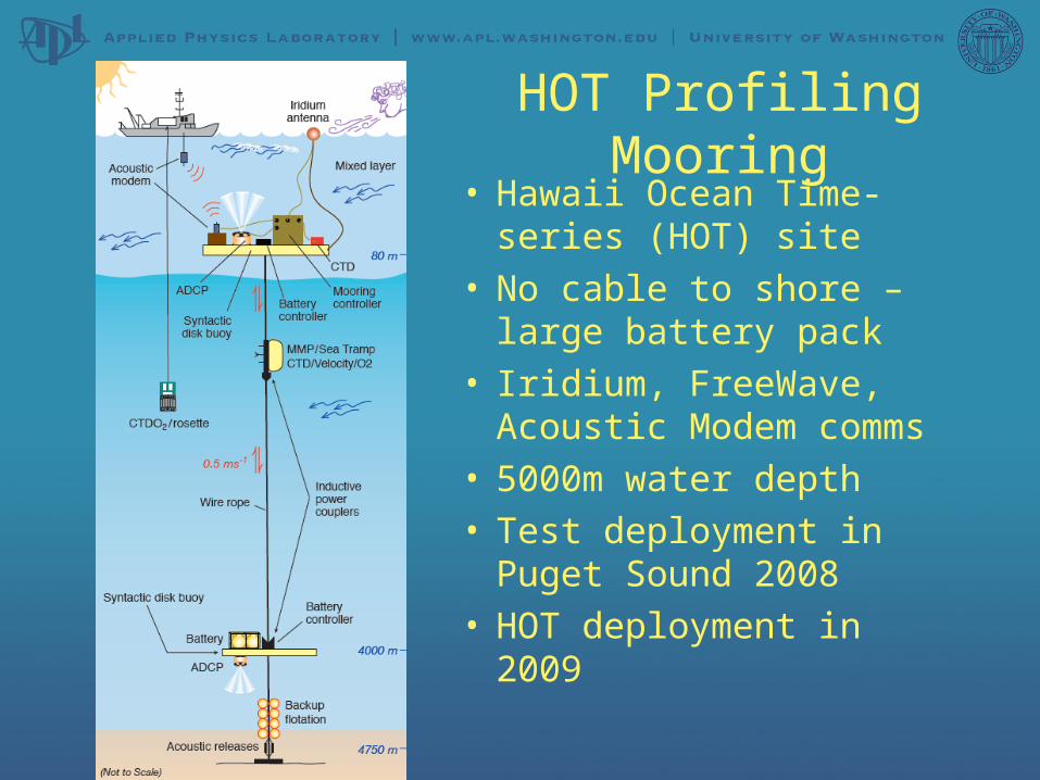
HOT Profiling Mooring• Hawaii Ocean Time-
series (HOT) site• No cable to shore –
large battery pack• Iridium, FreeWave,
Acoustic Modem comms• 5000m water depth• Test deployment in
Puget Sound 2008• HOT deployment in 2009
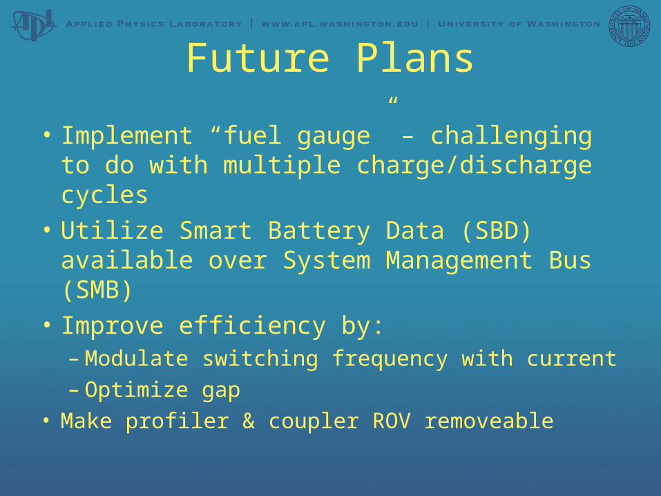
Future Plans
• Implement “fuel gauge” – challenging to do with multiple charge/discharge cycles
• Utilize Smart Battery Data (SBD) available over System Management Bus (SMB)
• Improve efficiency by:– Modulate switching frequency with current– Optimize gap
• Make profiler & coupler ROV removeable

Questions?
Related Documents


