©Service Competence Center Induction G0 Induction cooktop G0

Welcome message from author
This document is posted to help you gain knowledge. Please leave a comment to let me know what you think about it! Share it to your friends and learn new things together.
Transcript
©Service Competence Center
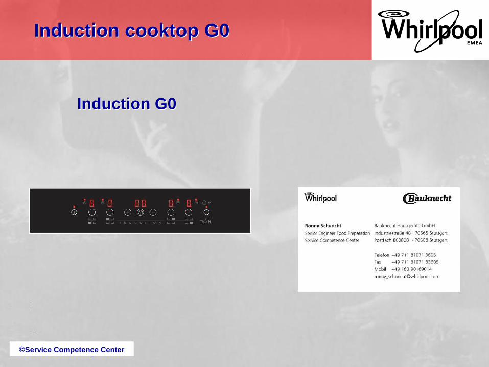
Induction G0
Induction cooktop G0

©Service Competence Center
Induction G0
Version 1.1
Table of Contents
Installation
Operation
Components
Repair guide line
Troubleshooting
Marketing information
Chapter List
Induction cooktop G0
©Service Competence Center
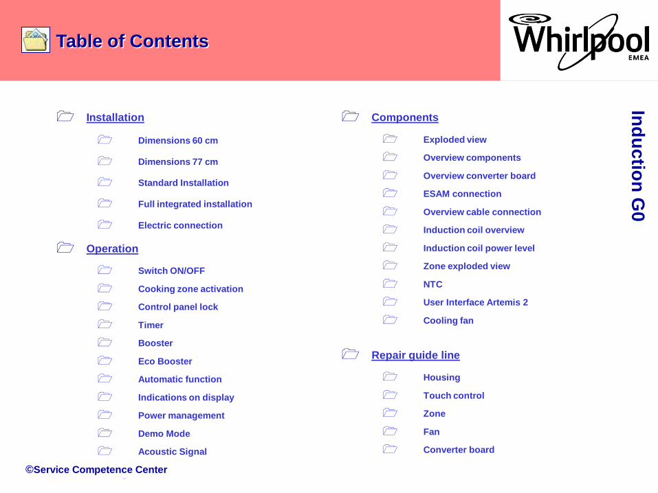
Table of ContentsIn
du
ctio
n G
0
Installation
Dimensions 60 cm
Dimensions 77 cm
Standard Installation
Full integrated installation
Electric connection
Operation
Switch ON/OFF
Cooking zone activation
Control panel lock
Timer
Booster
Eco Booster
Automatic function
Indications on display
Power management
Demo Mode
Acoustic Signal
Repair guide line
Housing
Touch control
Zone
Fan
Converter board
Components
Exploded view
Overview components
Overview converter board
ESAM connection
Overview cable connection
Induction coil overview
Induction coil power level
Zone exploded view
NTC
User Interface Artemis 2
Cooling fan

©Service Competence Center
Table of Contents
Marketing Information
Range overview
12NC breakdown
7 safety points
Accessories
Troubleshooting
Failure code type 1
Failure code type 2
Failure code type 3
Failure description
LED and buzzer check
Access main menu
Main menu
Configuration G0
Failure Show
Delete Failures
Test program rules
Configuration Codes
Wiring diagram
Ind
uctio
n G
0
©Service Competence Center
Installation
Dimensions 60 cm
Dimensions 77 cm
Standard Installation
Full integrated installation
Electrical connection
Ind
uctio
n G
0
©Service Competence Center
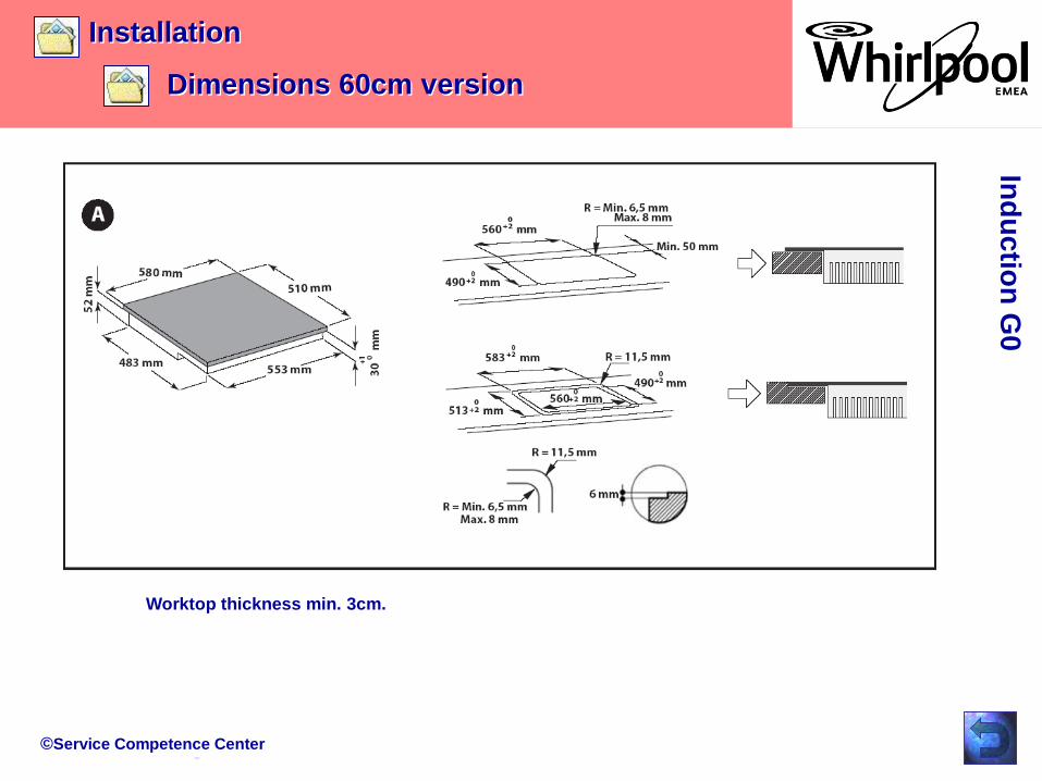
Installation
Dimensions 60cm version
Information in the IFU:
Ind
uctio
n G
0
Worktop thickness min. 3cm.
©Service Competence Center
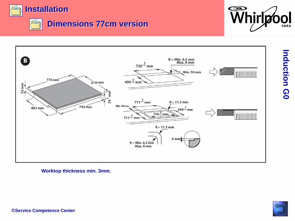
Installation
Dimensions 77cm version
Ind
uctio
n G
0
Worktop thickness min. 3mm.
©Service Competence Center
Installation
Installation
Ind
uctio
n G
0
©Service Competence Center
Installation
Installation
Ind
uctio
n G
0
©Service Competence Center
Installation
Installation
Ind
uctio
n G
0
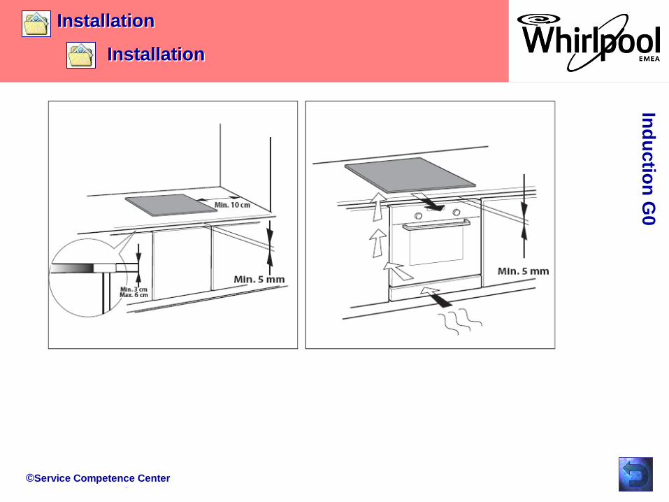
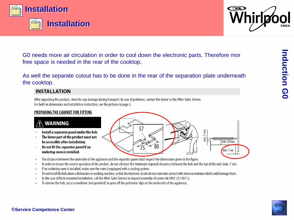
G0 needs more air circulation in order to cool down the electronic parts. Therefore mor
free space is needed in the rear of the cooktop.
As well the separate cutout has to be done in the rear of the separation plate underneath
the cooktop.
©Service Competence Center
Installation
Full integrated installation
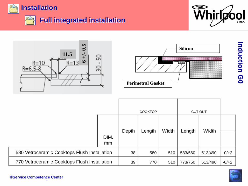
11.5
6 +
/-0
.5Perimetral Gasket
Silicon
COOKTOP CUT OUT
DIM.
mm
Depth Length Width Length Width
580 Vetroceramic Cooktops Flush Installation 38 580 510 583/560 513/490 -0/+2
770 Vetroceramic Cooktops Flush Installation 39 770 510 773/750 513/490 -0/+2
Ind
uctio
n G
0
©Service Competence Center
Installation
Full integrated installation
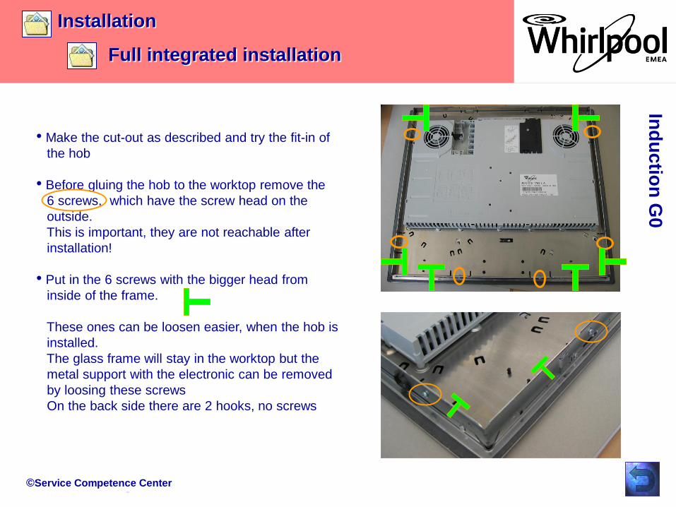
• Make the cut-out as described and try the fit-in of
the hob
• Before gluing the hob to the worktop remove the
6 screws, which have the screw head on the
outside.
This is important, they are not reachable after
installation!
• Put in the 6 screws with the bigger head from
inside of the frame.
These ones can be loosen easier, when the hob is
installed.
The glass frame will stay in the worktop but the
metal support with the electronic can be removed
by loosing these screws
On the back side there are 2 hooks, no screws
Ind
uctio
n G
0

©Service Competence Center
Installation
Electrical connection (hob)
The cover for the main power connection
is on the back side of the hob.
The cover is fixed with a screw (Torx 10).
Ind
uctio
n G
0
Bild vom Anschluß
©Service Competence Center
Installation
Electrical connection (hob)
Ind
uctio
n G
0
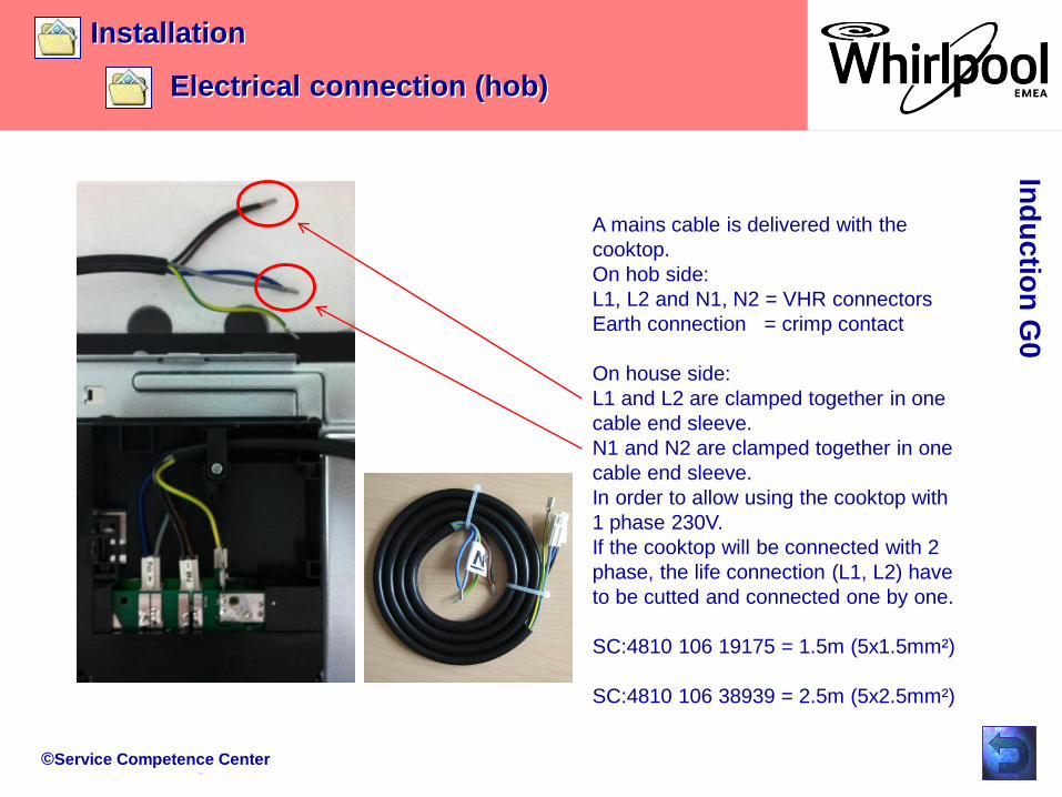
A mains cable is delivered with the
cooktop.
On hob side:
L1, L2 and N1, N2 = VHR connectors
Earth connection = crimp contact
On house side:
L1 and L2 are clamped together in one
cable end sleeve.
N1 and N2 are clamped together in one
cable end sleeve.
In order to allow using the cooktop with
1 phase 230V.
If the cooktop will be connected with 2
phase, the life connection (L1, L2) have
to be cutted and connected one by one.
SC:4810 106 19175 = 1.5m (5x1.5mm²)
SC:4810 106 38939 = 2.5m (5x2.5mm²)
©Service Competence Center
Installation
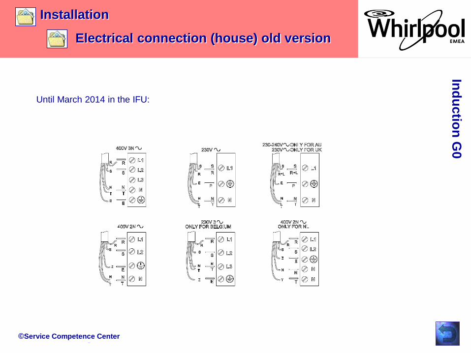
Electrical connection (house) old version
Ind
uctio
n G
0
Until March 2014 in the IFU:
©Service Competence Center
Installation
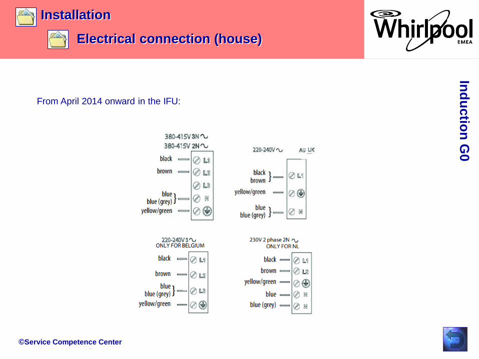
Electrical connection (house)
Ind
uctio
n G
0
From April 2014 onward in the IFU:
©Service Competence Center
Switch ON/OFF
Cooking zone activation
Control panel lock
Timer
Booster
Eco Booster
OperationIn
du
ctio
n G
0
Automatic function
Indications on display
Power management
Demo Mode
Acoustic Signal
©Service Competence Center
Operation
Switch ON/OFF
Ind
uctio
n G
0
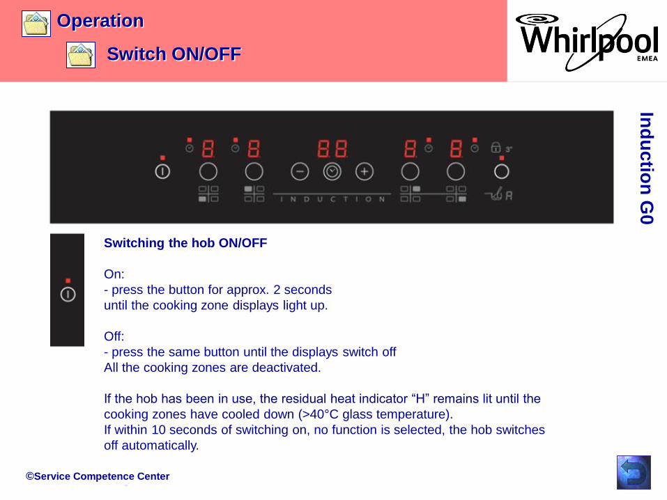
Switching the hob ON/OFF
On:
- press the button for approx. 2 seconds
until the cooking zone displays light up.
Off:
- press the same button until the displays switch off
All the cooking zones are deactivated.
If the hob has been in use, the residual heat indicator “H” remains lit until the
cooking zones have cooled down (>40°C glass temperature).
If within 10 seconds of switching on, no function is selected, the hob switches
off automatically.

©Service Competence Center
Operation
Cooking zone activation
Ind
uctio
n G
0
Switching on and adjusting cooking zones
Place the pot on the cooking zone
switch the hob on
activate the required cooking zone by pressing the corresponding circular button
“5” appears on the display.
With the Slider (if available) it is possible to select the required power level, from min. 0
to max. 9, or booster “P” if available. To increase the power level, slide your
finger on the slider from left to right several times; to decrease it, slide in the opposite
direction. Alternatively the “+” and “-” buttons can be used.
Deactivation of cooking zones
To switch off the cooking zone, press the corresponding button for more than 3 seconds.
The cooking zone switches off and, if still hot, the letter “H” appears on the zone display.
©Service Competence Center
Operation
Control panel lock
Ind
uctio
n G
0
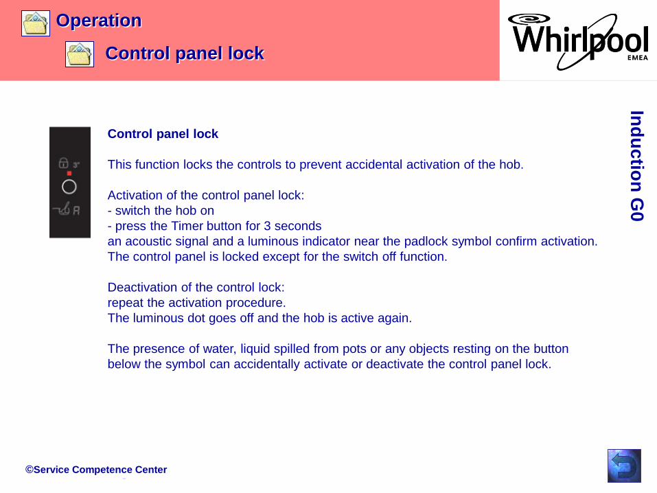
Control panel lock
This function locks the controls to prevent accidental activation of the hob.
Activation of the control panel lock:
- switch the hob on
- press the Timer button for 3 seconds
an acoustic signal and a luminous indicator near the padlock symbol confirm activation.
The control panel is locked except for the switch off function.
Deactivation of the control lock:
repeat the activation procedure.
The luminous dot goes off and the hob is active again.
The presence of water, liquid spilled from pots or any objects resting on the button
below the symbol can accidentally activate or deactivate the control panel lock.

©Service Competence Center
Operation
Timer
Ind
uctio
n G
0
Timer
The timer can be used to set the cooking time for a maximum of 99
minutes (1 hour and 39 minutes) for all the cooking zones separately.
- Select the cooking zone to be used with the timer.
- Press the timer and a beep signals the function.
The display shows “00” and the LED indication gets on.
- The timer value can be decreased and increased by keeping the
slider function “+” and “-” buttons pressed.
When the set time has elapsed, an acoustic signal sounds and the
cooking zone switches off automatically.
To deactivate the timer, keep the timer button pressed for at least 3
seconds.
To set the timer for another zone, repeat the above steps. The timer
display always shows the timer for the selected zone or the shortest
timer.
To modify or deactivate the timer, press the cooking zone selection
button for the timer in question.
©Service Competence Center
Operation
Booster
Ind
uctio
n G
0
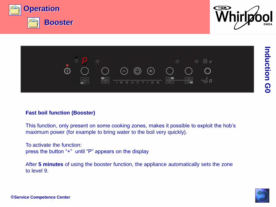
Fast boil function (Booster)
This function, only present on some cooking zones, makes it possible to exploit the hob’s
maximum power (for example to bring water to the boil very quickly).
To activate the function:
press the button “+” until “P” appears on the display
After 5 minutes of using the booster function, the appliance automatically sets the zone
to level 9.

©Service Competence Center
Operation
Booster
Ind
uctio
n G
0
Fast boil function (Booster)
In case that more than one Booster is available, there are the following restrictions:
- It can not be activated simultaneously on two zones managed from the same IPC.
If the user tries to do so, the last touched zone (therefore the active zone) gets the booster
level, while the previous zone set with booster is depowered to a lower power level.
Before this level reduction the “P” will flash 2 times and then go to the new level (to highlight
that a change has taken place).
©Service Competence Center
Operation
Eco Booster
Ind
uctio
n G
0
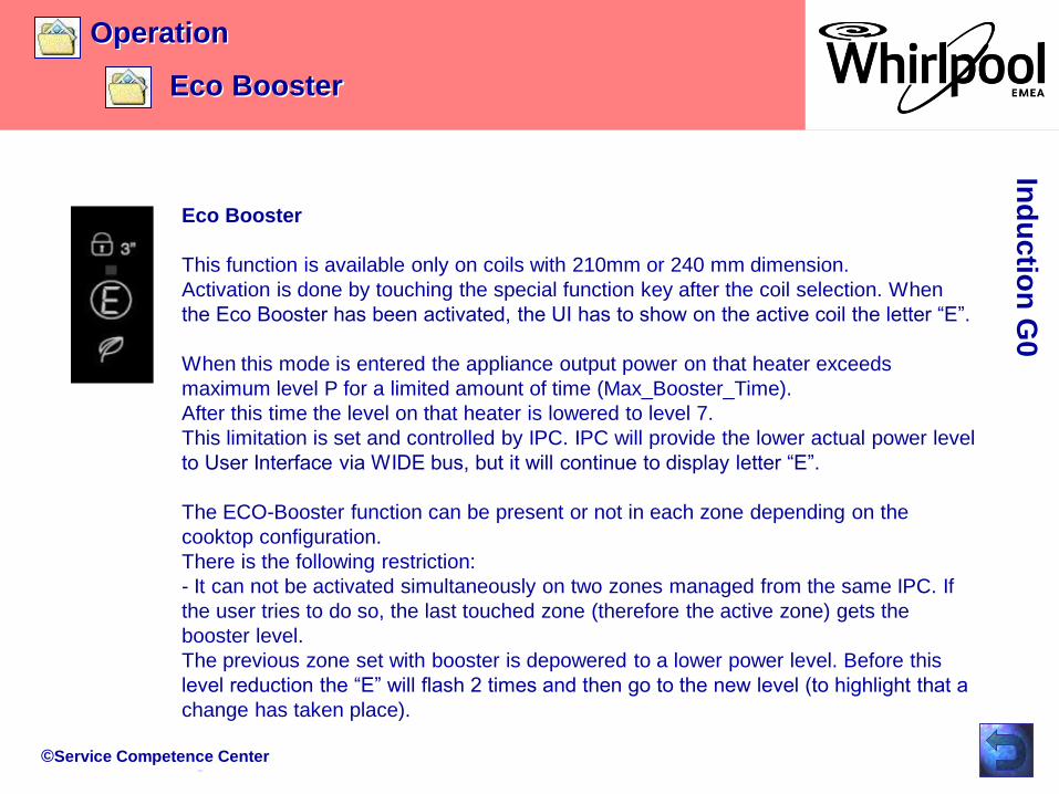
Eco Booster
This function is available only on coils with 210mm or 240 mm dimension.
Activation is done by touching the special function key after the coil selection. When
the Eco Booster has been activated, the UI has to show on the active coil the letter “E”.
When this mode is entered the appliance output power on that heater exceeds
maximum level P for a limited amount of time (Max_Booster_Time).
After this time the level on that heater is lowered to level 7.
This limitation is set and controlled by IPC. IPC will provide the lower actual power level
to User Interface via WIDE bus, but it will continue to display letter “E”.
The ECO-Booster function can be present or not in each zone depending on the
cooktop configuration.
There is the following restriction:
- It can not be activated simultaneously on two zones managed from the same IPC. If
the user tries to do so, the last touched zone (therefore the active zone) gets the
booster level.
The previous zone set with booster is depowered to a lower power level. Before this
level reduction the “E” will flash 2 times and then go to the new level (to highlight that a
change has taken place).
©Service Competence Center
Operation
Automatic function
Ind
uctio
n G
0
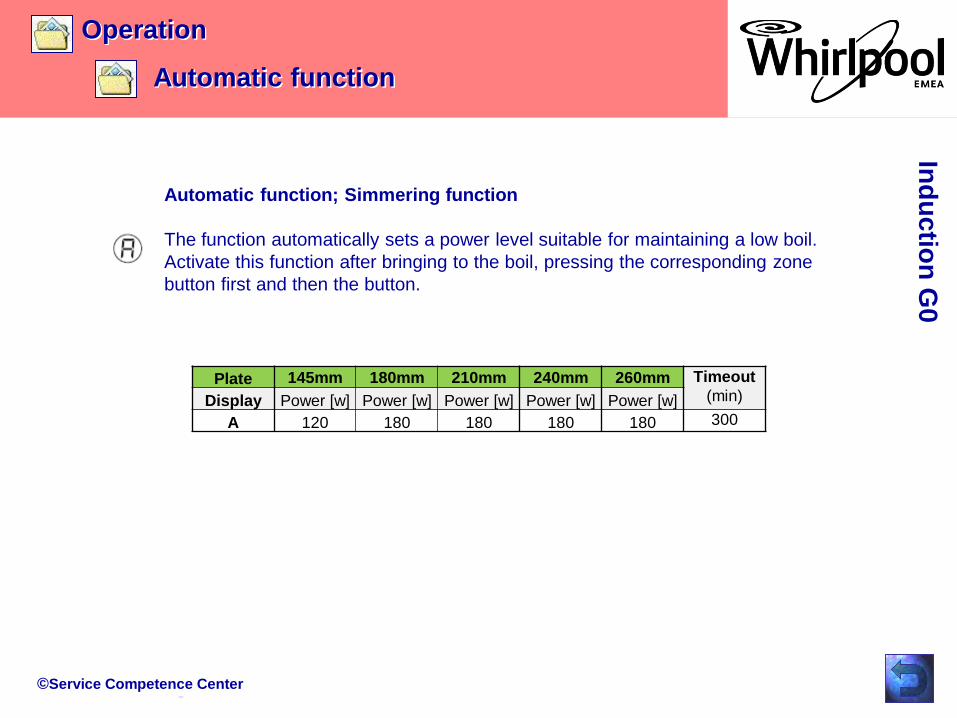
Automatic function; Simmering function
The function automatically sets a power level suitable for maintaining a low boil.
Activate this function after bringing to the boil, pressing the corresponding zone
button first and then the button.
Plate 145mm 180mm 210mm 240mm 260mm Timeout
(min)Display Power [w] Power [w] Power [w] Power [w] Power [w]
A 120 180 180 180 180 300

©Service Competence Center
Operation
Indications on display
Ind
uctio
n G
0
Residual heat indicator
The hob is fitted with a residual heat indicator for each cooking zone. These
indicators alert the user when cooking zones are still hot.
If the display shows , the cooking zone is still hot. If the residual heat indicator of a
given cooking zone is lit, that zone can be used, for example, to keep a
dish warm or to melt butter.
When the cooking zone cools down, the display goes off.
Switching temperature is:
Incorrect or missing pot indicator
If you are using a pot that is not suitable, not correctly positioned or not of the
correct dimensions for your induction hob, the message “no pot” will appear in the
display. In these situations it is recommended to put the pot until you find the
position of operation.
If no pot is detected within 60 seconds, the hob switches off.

©Service Competence Center
Operation
Power management
Ind
uctio
n G
0
“Power management” (Function where it is available)
Thanks to the “Power management” function, the user can set the maximum power the hob can
reach, as required.
This setting is possible at any time and is maintained until the next change.
By setting the required maximum power, the hob automatically adjusts distribution in the various
cooking zones, ensuring that this limit is never exceeded; with the advantage of also being able to
manage all the zones simultaneously, but without overload problems.
4 maximum power levels are available: 2.5 – 4.0 – 6.0 – 7.2 kW
At the time of purchase, the hob is set to maximum power! (4 zone hob = 7.2kw; 3 zone hob =
5.9kw)

©Service Competence Center
Operation
Power management
Ind
uctio
n G
0
“Power management” (Function where it is available)
In the first 60 seconds after connecting the cooktop to power, it is possible to set the required
power level by running the following points:

©Service Competence Center
Operation
Power management
Ind
uctio
n G
0
Hob with timer hob without timerIndication
active menu:
Power Limitation
selected:
Power limit
selectable
power limits (kw)
“Power management” (Function where it is available)
©Service Competence Center
Operation
Power management
Ind
uctio
n G
0
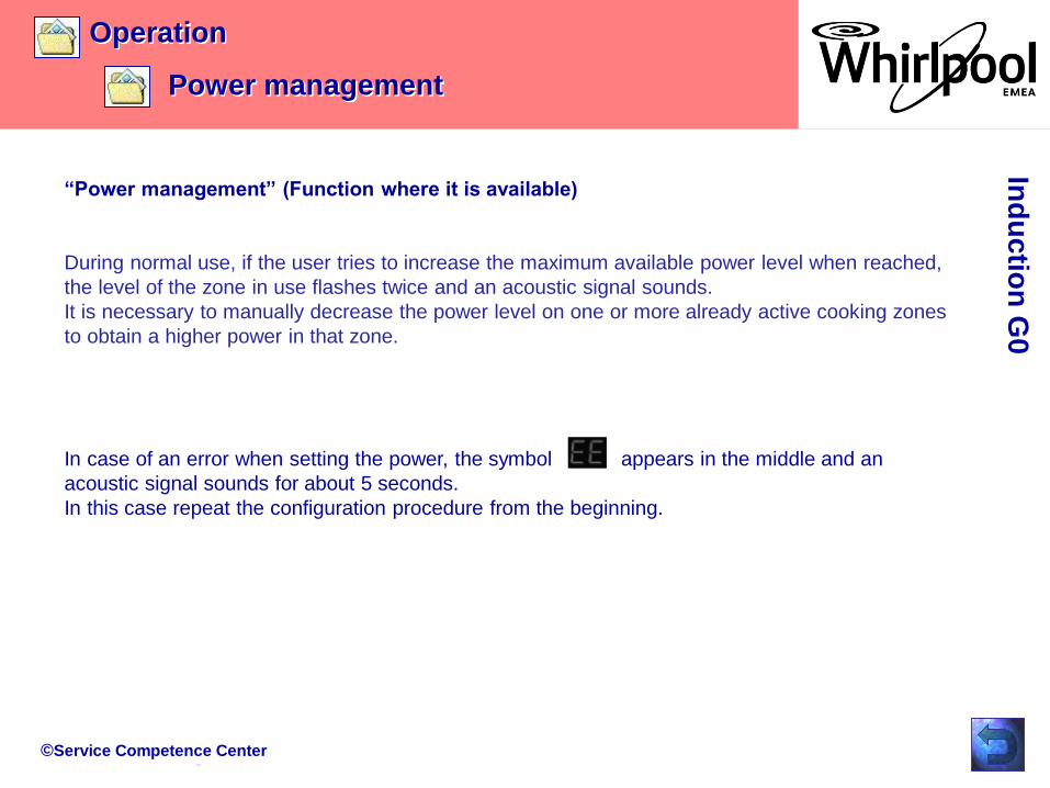
“Power management” (Function where it is available)
During normal use, if the user tries to increase the maximum available power level when reached,
the level of the zone in use flashes twice and an acoustic signal sounds.
It is necessary to manually decrease the power level on one or more already active cooking zones
to obtain a higher power in that zone.
In case of an error when setting the power, the symbol appears in the middle and an
acoustic signal sounds for about 5 seconds.
In this case repeat the configuration procedure from the beginning.
©Service Competence Center
OperationIn
du
ctio
n G
0
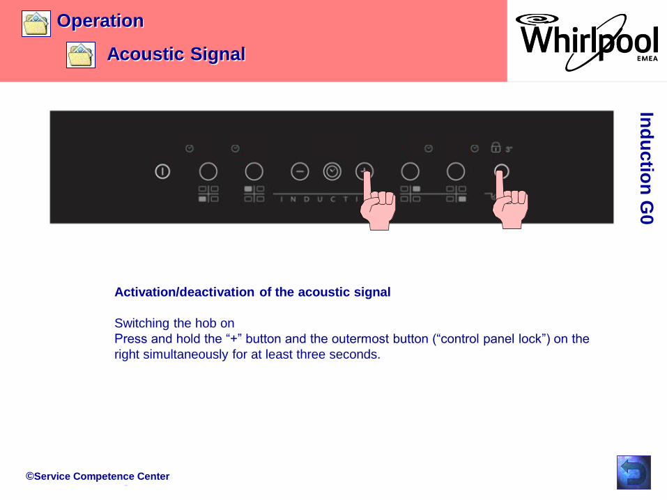
Activation/deactivation of the acoustic signal
Switching the hob on
Press and hold the “+” button and the outermost button (“control panel lock”) on the
right simultaneously for at least three seconds.
Acoustic Signal
©Service Competence Center
Operation
Demo Mode
Ind
uctio
n G
0
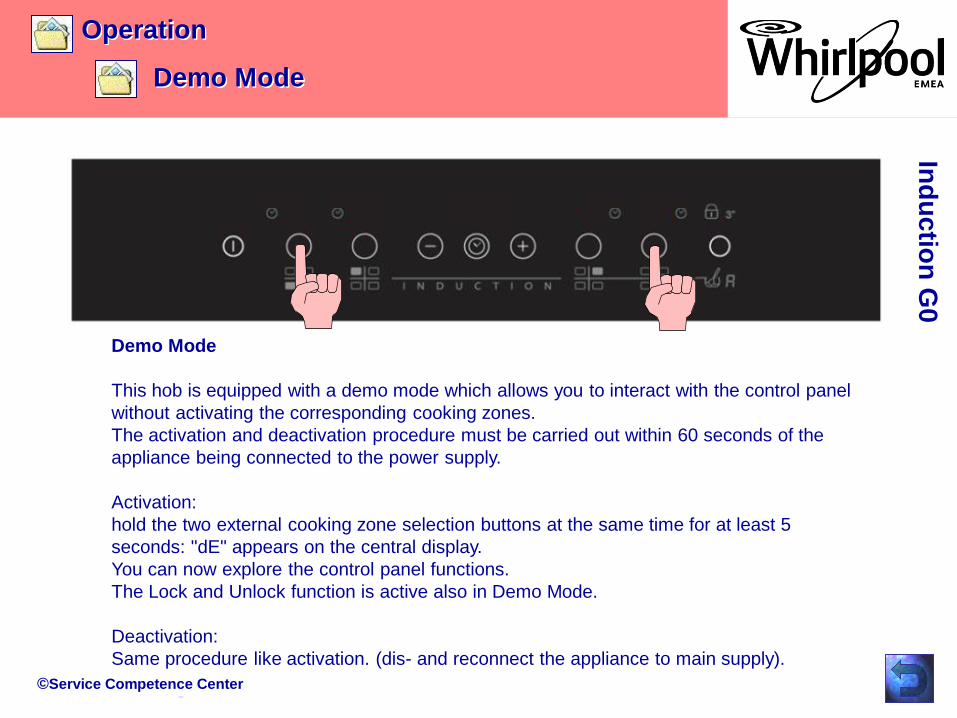
Demo Mode
This hob is equipped with a demo mode which allows you to interact with the control panel
without activating the corresponding cooking zones.
The activation and deactivation procedure must be carried out within 60 seconds of the
appliance being connected to the power supply.
Activation:
hold the two external cooking zone selection buttons at the same time for at least 5
seconds: "dE" appears on the central display.
You can now explore the control panel functions.
The Lock and Unlock function is active also in Demo Mode.
Deactivation:
Same procedure like activation. (dis- and reconnect the appliance to main supply).

©Service Competence Center
Components
Exploded view
Overview components
Overview converter board
ESAM connection
Overview cable connection
Induction coil overview
Induction coil power level
Zone exploded view
Ind
uctio
n G
0
NTC
User Interface Artemis 2
Cooling fan

©Service Competence Center
Components
exploded view
Ind
uctio
n G
0
IPC power board G0
incl. housing
Touch control Artemis 2
Induction zones
Hob glas surface
incl. frame
fan
Fixation clamps
Inox frame
Connection cable IPC - UI
©Service Competence Center
Components
overview components
Ind
uctio
n G
0

©Service Competence Center
Components
overview components
Ind
uctio
n G
0
©Service Competence Center
Components
overview converter board
Ind
uctio
n G
0
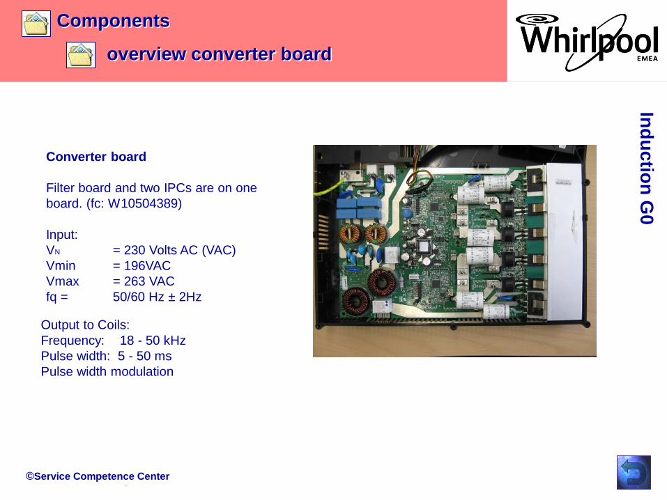
Converter board
Filter board and two IPCs are on one
board. (fc: W10504389)
Input:
VN = 230 Volts AC (VAC)
Vmin = 196VAC
Vmax = 263 VAC
fq = 50/60 Hz ± 2Hz
Output to Coils:
Frequency: 18 - 50 kHz
Pulse width: 5 - 50 ms
Pulse width modulation

©Service Competence Center
Components
overview converter board
Ind
uctio
n G
0
fan
IPC2
Filter board
IPC1

©Service Competence Center
Components
overview cable connections
Ind
uctio
n G
0
©Service Competence Center
Components
induction coil overview
Ind
uctio
n G
0
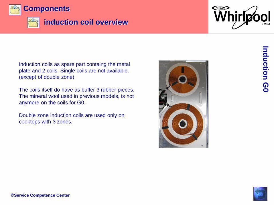
Induction coils as spare part containg the metal
plate and 2 coils. Single coils are not available.
(except of double zone)
The coils itself do have as buffer 3 rubber pieces.
The mineral wool used in previous models, is not
anymore on the coils for G0.
Double zone induction coils are used only on
cooktops with 3 zones.
©Service Competence Center
Components
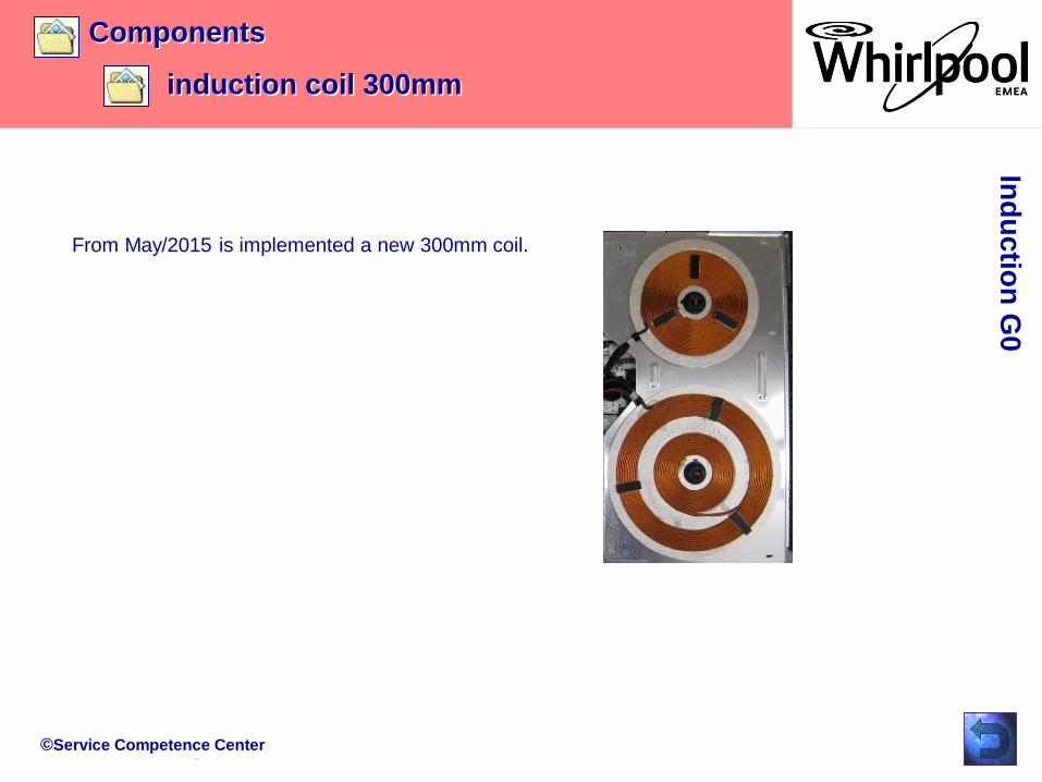
induction coil 300mm
Ind
uctio
n G
0
From May/2015 is implemented a new 300mm coil.
©Service Competence Center
Components
induction coil power levels
Ind
uctio
n G
0
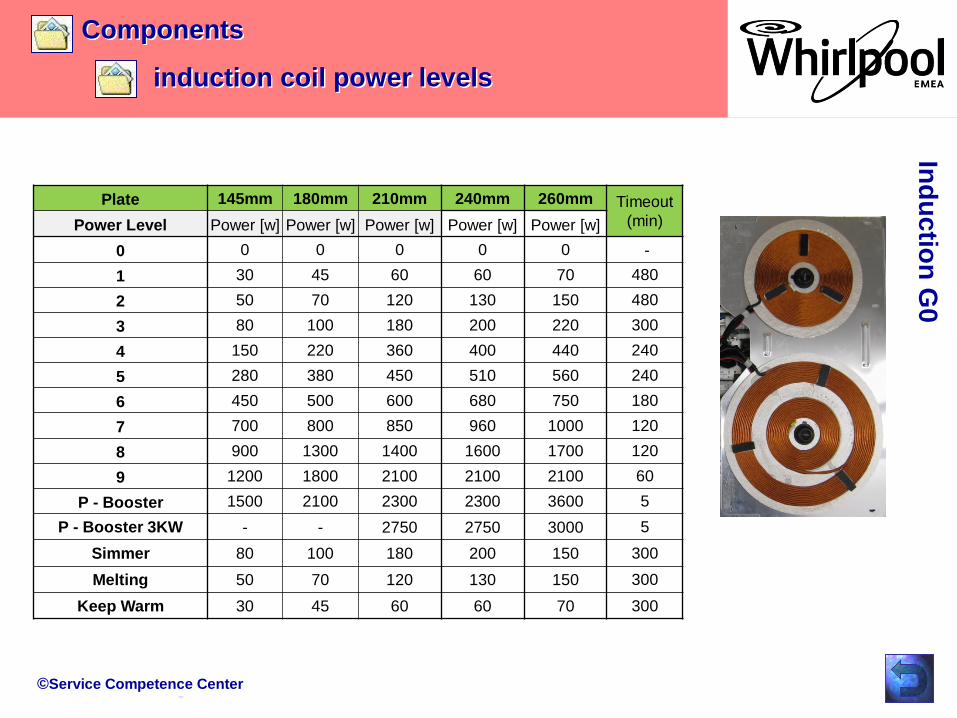
Plate 145mm 180mm 210mm 240mm 260mm Timeout
(min)Power Level Power [w] Power [w] Power [w] Power [w] Power [w]
0 0 0 0 0 0 -
1 30 45 60 60 70 480
2 50 70 120 130 150 480
3 80 100 180 200 220 300
4 150 220 360 400 440 240
5 280 380 450 510 560 240
6 450 500 600 680 750 180
7 700 800 850 960 1000 120
8 900 1300 1400 1600 1700 120
9 1200 1800 2100 2100 2100 60
P - Booster 1500 2100 2300 2300 3600 5
P - Booster 3KW - - 2750 2750 3000 5
Simmer 80 100 180 200 150 300
Melting 50 70 120 130 150 300
Keep Warm 30 45 60 60 70 300
©Service Competence Center
Components
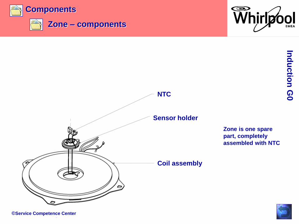
Zone – components
NTC
Sensor holder
Coil assembly
Zone is one spare
part, completely
assembled with NTC
Ind
uctio
n G
0

©Service Competence Center
Components
Zone – NTC
PTN - 312
Ind
uctio
n G
0

©Service Competence Center
Components
User Interface Artemis 2
Ind
uctio
n G
0
User Interface
The Interface between capacitive sensor
pads and the glass (that actually is the
point the user touches) is done through
conductive metallic springs.

©Service Competence Center
Components
User Interface Artemis 2
Ind
uctio
n G
0
The User Interface is supplied from the IPC board through its auxiliary,
galvanically insulated, output.
The ratings of this output are the following:
Platform Voutput (Vdc) Imax (mA)
G8_Minus/ G7 10,5 ± 5% 250
GiZero 12,5 ± 10% 350
©Service Competence Center
Components
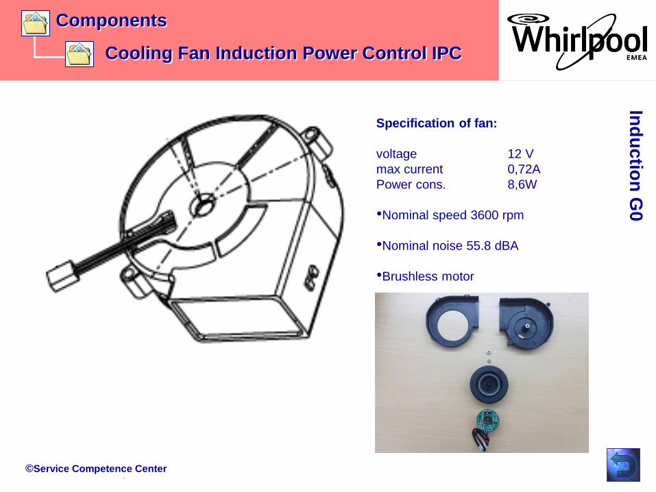
Cooling Fan Induction Power Control IPC
Ind
uctio
n G
0
Specification of fan:
voltage 12 V
max current 0,72A
Power cons. 8,6W
•Nominal speed 3600 rpm
•Nominal noise 55.8 dBA
•Brushless motor

©Service Competence Center
Components
Cooling Fan Induction Power Control IPC
Ind
uctio
n G
0
Single components of cooling fan
Coil with electronic circuit on the rear side of the printed circuit board
Permanent magnet
1 32
1
Single components from top down to left, bearing, spring, fanwheel and coil with driver
electronic
2
3 View to the printed circuit board and driver electronic

©Service Competence Center
Components
Cooling Fan Induction Power Control IPC
Ind
uctio
n G
0
Function of cooling fan:
The fan is a brushless driven. On the printed circuit board a electronic is generating a alternating
magnetic field via the coil. This coil is driving the permanent magnet which is glued in the fanwheel .
The speed is controlled via a hall sensor. The speed itself is variable and can be changed via the
main control electronic.
The fan itself has 3 wirings:
Black ground
Red power supply 12V
Blue speed control
For verifying the function a meter in the resistance setting can‘t be used !
The supply voltage can be measured on the plug.
Power supply (DC) speed active
6V 1900rpm 1 coil is in use (switched on and pot detected)
8V 2600rpm 2 coils are in use (switched on and pot detected)
10V 3100rpm 3 or 4 coils are in use (switched on and pot detecte
12V 3600rpm (max) 3 or 4 coils are in use AND the heatsink temperature
exceeds 55°C. Switching back to 10V at 50°C.
©Service Competence Center
Housing
Touch control
Zone
Fan
Converter board
Repair Guide LineIn
du
ctio
n G
0

©Service Competence Center
Repair guide line
Housing – disassembly
Remove 6
screws from the
frame.
Turn the hob to
have the glass
on top side.
Open the hob
only from top!
The back side of
the frame is fixed
with 2 hooks.
Ind
uctio
n G
0
©Service Competence Center
Repair guide line
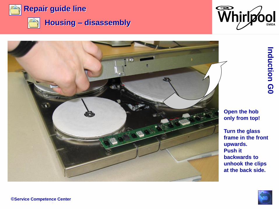
Housing – disassembly
Open the hob
only from top!
Turn the glass
frame in the front
upwards.
Push it
backwards to
unhook the clips
at the back side.
Ind
uctio
n G
0
©Service Competence Center
Repair guide line
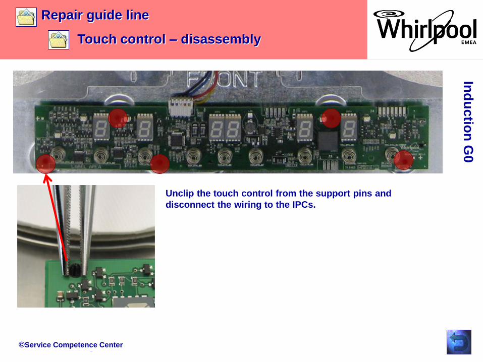
Touch control – disassembly
Unclip the touch control from the support pins and
disconnect the wiring to the IPCs.
Ind
uctio
n G
0
©Service Competence Center
Repair guide line
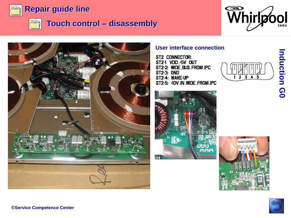
Touch control – disassembly
User interface connection Ind
uctio
n G
0

©Service Competence Center
Repair guide line
Fan – disassembly
Remove the 2 fixation screws and
unplug the cable from the IPC board
Ind
uctio
n G
0
©Service Competence Center
Repair guide line
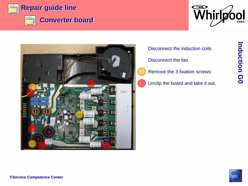
Converter board
Disconnect the induction coils
Disconnect the fan.
Remove the 3 fixation screws
Unclip the board and take it out.
Ind
uctio
n G
0
©Service Competence Center
Failure code type 1
Failure code type 2
Failure code type 3
Failure description
LED and buzzer check
Access main menu
Main menu
Configuration G0
TroubleshootingIn
du
ctio
n G
0
Failure Show
Delete Failures
Test program rules
Configuration Codes
Wiring Diagram
©Service Competence Center
Troubleshooting
Type of failure codes
Ind
uctio
n G
0
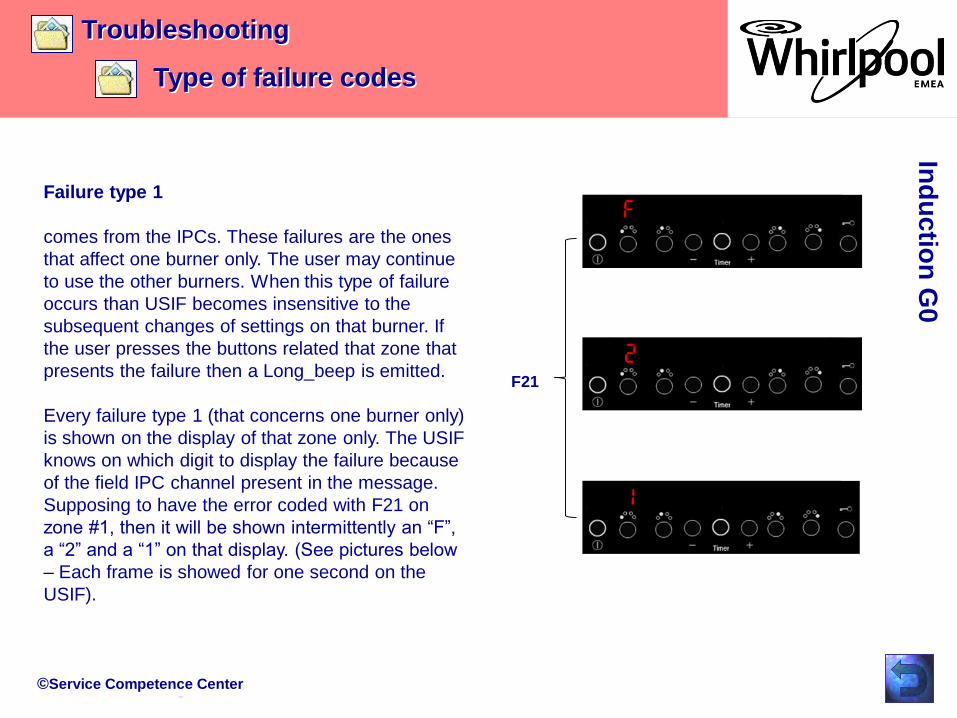
Failure type 1
comes from the IPCs. These failures are the ones
that affect one burner only. The user may continue
to use the other burners. When this type of failure
occurs than USIF becomes insensitive to the
subsequent changes of settings on that burner. If
the user presses the buttons related that zone that
presents the failure then a Long_beep is emitted.
Every failure type 1 (that concerns one burner only)
is shown on the display of that zone only. The USIF
knows on which digit to display the failure because
of the field IPC channel present in the message.
Supposing to have the error coded with F21 on
zone #1, then it will be shown intermittently an “F”,
a “2” and a “1” on that display. (See pictures below
– Each frame is showed for one second on the
USIF).
F21
©Service Competence Center
Troubleshooting
Type of failure codes
Ind
uctio
n G
0
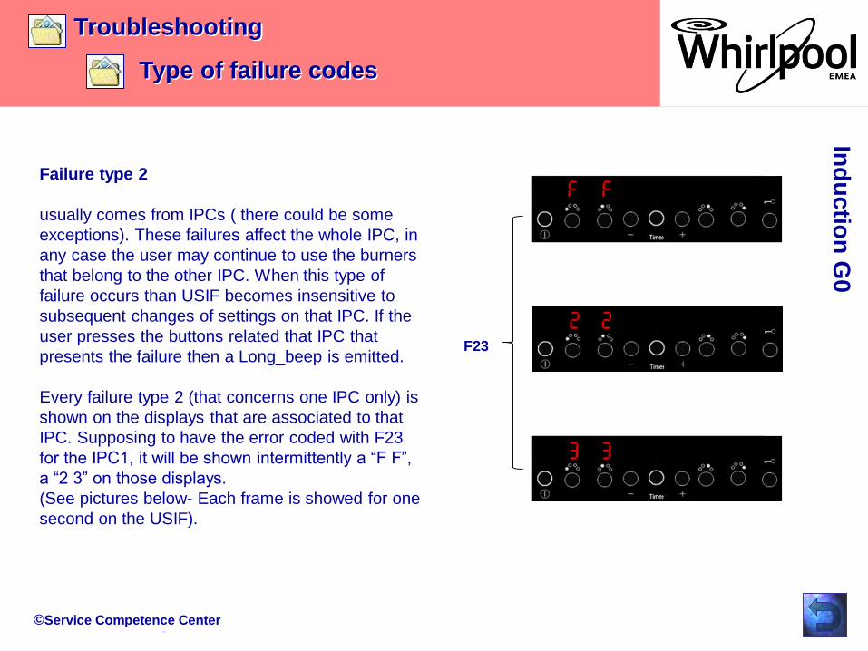
Failure type 2
usually comes from IPCs ( there could be some
exceptions). These failures affect the whole IPC, in
any case the user may continue to use the burners
that belong to the other IPC. When this type of
failure occurs than USIF becomes insensitive to
subsequent changes of settings on that IPC. If the
user presses the buttons related that IPC that
presents the failure then a Long_beep is emitted.
Every failure type 2 (that concerns one IPC only) is
shown on the displays that are associated to that
IPC. Supposing to have the error coded with F23
for the IPC1, it will be shown intermittently a “F F”,
a “2 3” on those displays.
(See pictures below- Each frame is showed for one
second on the USIF).
F23
©Service Competence Center
Troubleshooting
Type of failure codes
Ind
uctio
n G
0
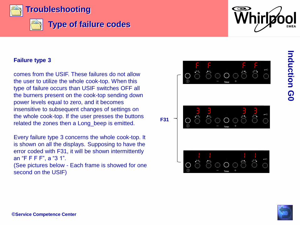
Failure type 3
comes from the USIF. These failures do not allow
the user to utilize the whole cook-top. When this
type of failure occurs than USIF switches OFF all
the burners present on the cook-top sending down
power levels equal to zero, and it becomes
insensitive to subsequent changes of settings on
the whole cook-top. If the user presses the buttons
related the zones then a Long_beep is emitted.
Every failure type 3 concerns the whole cook-top. It
is shown on all the displays. Supposing to have the
error coded with F31, it will be shown intermittently
an “F F F F”, a “3 1”.
(See pictures below - Each frame is showed for one
second on the USIF)
F31
©Service Competence Center
Ind
uctio
n G
0
Service
Code Type Repair suggestions:
shown on
display
Failure description of failure Points to check subsequently until the appliance starts to work properly again.
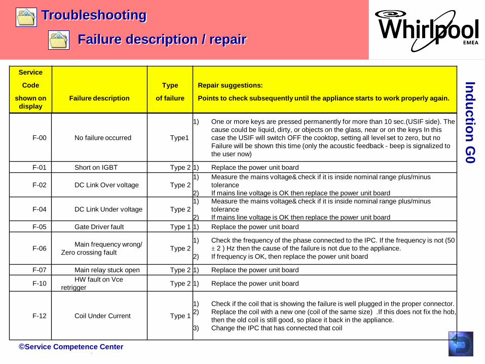
Troubleshooting
Failure description / repair
F-00 No failure occurred Type1
1) One or more keys are pressed permanently for more than 10 sec.(USIF side). The
cause could be liquid, dirty, or objects on the glass, near or on the keys In this
case the USIF will switch OFF the cooktop, setting all level set to zero, but no
Failure will be shown this time (only the acoustic feedback - beep is signalized to
the user now)
F-01 Short on IGBT Type 2 1) Replace the power unit board
F-02 DC Link Over voltage Type 2
1) Measure the mains voltage& check if it is inside nominal range plus/minus
tolerance
2) If mains line voltage is OK then replace the power unit board
F-04 DC Link Under voltage Type 2
1) Measure the mains voltage& check if it is inside nominal range plus/minus
tolerance
2) If mains line voltage is OK then replace the power unit board
F-05 Gate Driver fault Type 1 1) Replace the power unit board
F-06Main frequency wrong/
Zero crossing faultType 2
1) Check the frequency of the phase connected to the IPC. If the frequency is not (50 ± 2 ) Hz then the cause of the failure is not due to the appliance.
2) If frequency is OK, then replace the power unit board
F-07 Main relay stuck open Type 2 1) Replace the power unit board
F-10HW fault on Vce
retriggerType 2 1) Replace the power unit board
F-12 Coil Under Current Type 1
1) Check if the coil that is showing the failure is well plugged in the proper connector.
2) Replace the coil with a new one (coil of the same size) .If this does not fix the hob,
then the old coil is still good, so place it back in the appliance.
3) Change the IPC that has connected that coil

©Service Competence Center
Ind
uctio
n G
0
Service
Code Type Repair suggestions:
shown on
display
Failure description of failure Points to check subsequently until the appliance starts to work properly
again.
Failure description / repair
Troubleshooting
F-25 Fan Stuck on IPC # Type 3 1) Check Fan connection – if the connector is plugged in well or not.
2) Replace the Fan with a new one.
3) If replacing the fan with a new one did not fix the appliance, then the old fan is
still good. Put it back in the appliance. Change the IPC interested in the failure.
F-33 Heatsink NTC open Type 2 1) Replace the power unit board
F-34 Heatsink NTC shorted Type 2 1) Replace the power unit board
F-36 Coil # – temperature
sensor short-circuited
NTC temp value is out
of the spec range.
Type 1 1) Check if the NTC coil that is showing the failure is well plugged in the proper
connector.
2) Replace the interested Coil with a new one.
3) If replacing the Coil with a new one did not fix the appliance, then the old coil is
still good. Put it back in the appliance. Change the IPC interested in the failure
F-37 Coil # – temperature
sensor Open-circuited
NTC temp value is out
of the spec range.
Type 1 1) Check if the NTC coil that is showing the failure is well plugged in the proper
connector.
2) Replace the interested Coil with a new one.
3) If replacing the Coil with a new one did not fix the appliance, then the old coil is
still good. Put it back in the appliance. Change the IPC interested in the failure
F-46 IPC WIDE
communication error/ Time
Out UI/ TSM
Type 2 1) Check the wire between USIF and IPC
2) Replace the power unit board
F-47 E35 - After 3 seconds,
10,5 volts line from one IPC
is missing
Type 2 1) Check the wire between USIF and IPC
2) Replace the related IPC
3) If replacing the IPC with a new one did not fix the appliance, then check fuse on
filter boards. If interrupted replace fuse component.
4) If replacing the fuse with a new one did not fix the appliance change the Filter
board .

©Service Competence Center
Ind
uctio
n G
0
Service
Code Type Repair suggestions:
shown on
display
Failure description of failure Points to check subsequently until the appliance starts to work properly
again.
Failure description / repair
Troubleshooting
F-47 E39 - One IPC only is
not responding within a time
T_to_have_response_
from_IPC
when it is polled
Type 2 1) Check if the harness / wires ( WIDE cables) are well connected in the related
connectors.
2) If this does not fix the appliance then: Replace the related IPC
3) If replacing the IPC with a new one did not fix the appliance, then check fuse
on filter boards. If interrupted replace fuse component.
4) If replacing the fuse with a new one did not fix the appliance change the Filter
board .
F-47 E47 - WIDE
communication error.
Communication
between USIF and all the
IPCs is not working.
Type 3 1) Check if the harness / wires ( WIDE cables) are well connected in the related
connectors. If this does not fix the appliance then:
2) Replace the USIF
F-48 IPC WIDE
communication error / live
tag
Type 2 1) Check the wire between USIF and IPC
2) Replace the power unit board
F-49 IPC WIDE
communication error / CRC
error
Type 2 1) Check the wire between USIF and IPC
2) Replace the power unit board
F-56 E56 - Wrong or invalid
USIF configuration.
Type 3 1) Configure the USIF. If this does not fix the appliance then:
2) Replace the USIF with a new one
F-58 E58 - Wrong or invalid
IPC configuration.
Type 2 1) Configure the related IPC If this does not fix the appliance then:
2) Replace the related IPC with a new one

©Service Competence Center
Ind
uctio
n G
0
Service
Code Type Repair suggestions:
shown on
display
Failure description of failure Points to check subsequently until the appliance starts to work properly
again.
Failure description / repair
Troubleshooting
F-60 E53 - USIF I/O Button
error
Type 3 1) Replace the USIF
F-60 E57 - There is an access
E2PROM memory error The
memory is damaged.
Type 3 Replace the USIF
F-61 60730 Micro register
error
Type 2 1) Switch off and on the cooktop
2) Replace the power unit board
F-62 60730 Micro Ram error Type 2 1) Switch off and on the cooktop
2) Replace the power unit board
F-63 60730 Micro FLASH
error
Type 2 Switch off and on the cooktop
Replace the power unit board
F-72 CH1 / CH2 Io Port Error Type 2 1) Switch off and on the cooktop
2) Replace the power unit board
F-73 60730 Micro Program
Flow Error
Type 2 Switch off and on the cooktop
Replace the power unit board
F-77 Coil 1/2 NTC Stuck Type 2 1) Switch off and on the cooktop
2) Replace the power unit board
©Service Competence Center
Ind
uctio
n G
0
Service
Code Type Repair suggestions:
shown on
display
Failure description of failure Points to check subsequently until the appliance starts to work properly
again.
Failure description / repair
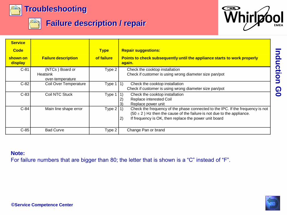
Troubleshooting
C-81 (NTCs ) Board or
Heatsink
over-temperature
Type 2 Check the cooktop installation
Check if customer is using wrong diameter size pan/pot
C-82 Coil Over Temperature Type 1 1) Check the cooktop installation
Check if customer is using wrong diameter size pan/pot
C-83 Coil NTC Stuck Type 1 1) Check the cooktop installation
2) Replace interested Coil
3) Replace power unit
C-84 Main line shape error Type 2 1) Check the frequency of the phase connected to the IPC. If the frequency is not (50 ± 2 ) Hz then the cause of the failure is not due to the appliance.
2) If frequency is OK, then replace the power unit board
C-85 Bad Curve Type 2 Change Pan or brand
Note:
For failure numbers that are bigger than 80; the letter that is shown is a “C” instead of “F”.
©Service Competence Center
Trouble Shooting
LED and buzzer check
Ind
uctio
n G
0
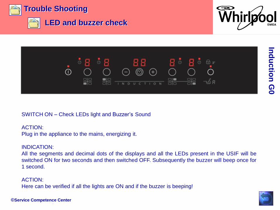
SWITCH ON – Check LEDs light and Buzzer’s Sound
ACTION:
Plug in the appliance to the mains, energizing it.
INDICATION:
All the segments and decimal dots of the displays and all the LEDs present in the USIF will be
switched ON for two seconds and then switched OFF. Subsequently the buzzer will beep once for
1 second.
ACTION:
Here can be verified if all the lights are ON and if the buzzer is beeping!
©Service Competence Center
Test Program
Access main menu G0
Ind
uctio
n G
0
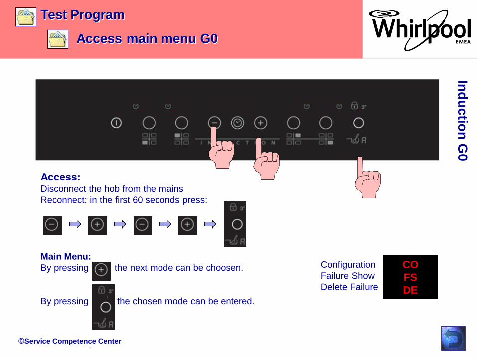
Access:Disconnect the hob from the mains
Reconnect: in the first 60 seconds press:
Main Menu:
By pressing the next mode can be choosen.
By pressing the chosen mode can be entered.
Configuration
Failure Show
Delete Failure
CO
FS
DE

©Service Competence Center
Trouble Shooting
Main menu
Ind
uctio
n G
0
Figure 11-3. Delete mode.
Configuration Mode
Failure Show
Delete Error

©Service Competence Center
Test Program
Configuration G0
Ind
uctio
n G
0After accessing the main menu the
first indication on display is the
configuration menu “CO”.
In order to enter the configuration
mode press the ‘Childlock’ key.
In the display is shown 00.
Possible configurations are between
00 and 65.
Sample: 64
Press the button for zone 1 and adjust
by pressing “+” or “-” the 6.
Press the button for zone 4 and adjust
by pressing “+” or “-” the 4.
When is necessary to change the main borad you have to do the configuration of the product. Every product
have his configuration code and you can find it in Service Net. Below the procedure to do the configuration.

©Service Competence Center
Trouble Shooting
Failure Show
Ind
uctio
n G
0
Failure ShowPress outer most button (child lock button)
Indication of sub menu 1:
User Interface Press outer most button (“child lock” button)
The present failure will be shown.Press outer most button (“child lock” button)
Indication of sub menu 2:
IPC 1Press outer most button (“child lock” button)
The present failure will be shown.Press outer most button (“child lock” button)
Indication of sub menu 3:
IPC 2Press outer most button (“child lock” button)
The present failure will be shown.Press outer most button (“child lock” button)

©Service Competence Center
Trouble Shooting
Delete Failures
Ind
uctio
n G
0
It will appear dE for the meaning of erasing the failure codes stored in the DATA FLASH.
Pressing ‘Childlock key’ the USIF will erase those locations.
Leaving this mode without erasing the current failure codes stored:
press ON/IDLE
Erasing the failures:
press the childlock key, it will show ‘0’ displays of zone 1 and 4.
©Service Competence Center
Trouble Shooting
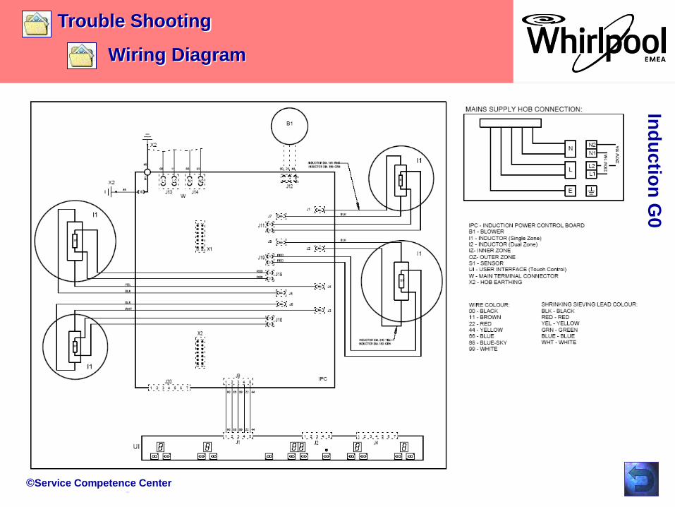
Wiring Diagram
Ind
uctio
n G
0
©Service Competence Center
Range overview
12NC breakdown
7 safety points
Marketing informationIn
du
ctio
n G
0

©Service Competence Center
Ind
uctio
n G
0Marketing
Range overview
©Service Competence Center
Ind
uctio
n G
0Marketing
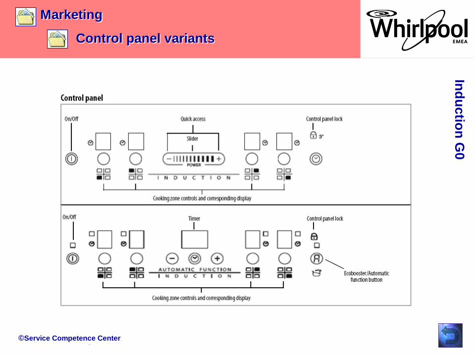
Control panel variants

©Service Competence Center
Ind
uctio
n G
0Marketing
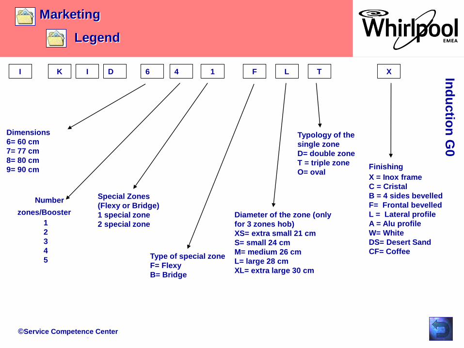
Legend
XK DI F L T6 4 1I
Channel
I = Channel 1
H = Channel 2
Brand
K= Hotpoint Ariston
T= Scholtès
V= Indesit
N= Ariston
C= HotpointTypology
I= Induction
R= Radiant
E= Mixed
User Interface
F= Premium slider
with Automatic Functions
U= Ulysse Direct Access
with Automatic Functions
D= Ulysse Direct Access
T= Artemis with Automatic Functions
S= Artemis Slider
A= Artemis
©Service Competence Center
Ind
uctio
n G
0Marketing
Legend
XK DI F L T6 4 1I
Dimensions
6= 60 cm
7= 77 cm
8= 80 cm
9= 90 cm
Number
zones/Booster
1
2
3
4
5
Special Zones
(Flexy or Bridge)
1 special zone
2 special zone
Type of special zone
F= Flexy
B= Bridge
Diameter of the zone (only
for 3 zones hob)
XS= extra small 21 cm
S= small 24 cm
M= medium 26 cm
L= large 28 cm
XL= extra large 30 cm
Typology of the
single zone
D= double zone
T = triple zone
O= ovalFinishing
X = Inox frame
C = Cristal
B = 4 sides bevelled
F= Frontal bevelled
L = Lateral profile
A = Alu profile
W= White
DS= Desert Sand
CF= Coffee

©Service Competence Center
Marketing
Safety points
Ind
uctio
n G
0
Induction hobs provide an absolute safety with 7 key safety points
CHILD LOCK - by a simple push on a specific knob, the hob is blocked1
RESIDUAL HEAT INDICATOR - a “H” is appearing as long as the T°C is above 60°C2
PAN DETECTION – the display flashes when there is no pan on the burner3
ANTI-SPILLAGE SYSTEM - cuts the power off in case of spillage on the control area4
OVERHEATING LOCK - When the T°C is too high5
VENTILATION - The hob protects the furniture by ventilated system6
AUTO-OFF SYSTEM - The power is off if the using time is too long7

©Service Competence Center
DocumentsIn
du
ctio
n G
0
• I.F.U.
Related Documents