51 IN SITU COAL GASIFICATION: AN EMERGING TECHNOLOGY 1 Kristin M. Brown 2 Abstract. A literature review was conducted on in situ coal gasification with particular attention to environmental effects, benefits and process controls of this emerging technology. In situ coal gasification also known as underground coal gasification (UCG) appears to be both technically and economically feasible and exhibits many potential advantages over the conventional mining methods. The resource for UCG is principally un-mined coal seams. The gasification process creates synthesis gas that can be used as fuel, or feedstock for further chemical processes such as NH 3 production or liquid fuels. An oxidant (usually air, oxygen, or steam) is injected into the coal seam and reacts with the coal and water present in the seam to produce syngas that is extracted through a production well. As the gasification process proceeds, the cavity grows radially outward and upward from the injection well. UCG has some environmental benefits relative to conventional mining including (1) no discharge of tailings, (2) reduced sulfur emissions (3) reduced discharge of ash, Hg and tar, and (4) the additional benefit of carbon capture and sequestration. Hydraulic control is the most important feature of UCG. It controls the gasification process and prevents groundwater contamination. Contaminants from the UCG process can affect water quality making sources for human and wildlife consumption unusable. Coal resources that are not suitable for conventional mining are ideally suited for UCG. Ultimately, UCG will compete in the marketplace with conventional and innovative gasification technologies to provide syngas for fuel and power applications, which will in turn compete against other fuels such as biodiesel and gasoline. In the coming years, these technologies will compete not just on an economic basis but on the costs and difficulties of managing CO 2 emissions. Additional Key Words: underground coal gasification, water, carbon dioxide, hydrology. _________________ 1 Paper was presented at the 2012 National Meeting of the American Society of Mining and Reclamation, Tupelo, MS. Sustainable Reclamation June 8 – 15, 2012 and accepted for the online in the Journal of The American Society of Mining and Reclamation, Volume 1, No. 1, R.I. Barnhisel (Ed.) Published by ASMR, 3134 Montavesta Rd., Lexington, KY 40502. 2 Kristin M. Brown, Hydrologist, U.S. Office of Surface Mining Reclamation and Enforcement, Multimedia, Training and Asset Management Branch, Denver, CO 80202 Proceedings America Society of Mining and Reclamation, 2012 pp 51-70 DOI: 10.21000/JASMR12010051

Welcome message from author
This document is posted to help you gain knowledge. Please leave a comment to let me know what you think about it! Share it to your friends and learn new things together.
Transcript
51
IN SITU COAL GASIFICATION: AN EMERGING TECHNOLOGY1
Kristin M. Brown2
Abstract. A literature review was conducted on in situ coal gasification with
particular attention to environmental effects, benefits and process controls of this
emerging technology. In situ coal gasification also known as underground coal
gasification (UCG) appears to be both technically and economically feasible and
exhibits many potential advantages over the conventional mining methods.
The resource for UCG is principally un-mined coal seams. The gasification
process creates synthesis gas that can be used as fuel, or feedstock for further
chemical processes such as NH3 production or liquid fuels. An oxidant (usually
air, oxygen, or steam) is injected into the coal seam and reacts with the coal and
water present in the seam to produce syngas that is extracted through a production
well. As the gasification process proceeds, the cavity grows radially outward and
upward from the injection well.
UCG has some environmental benefits relative to conventional mining including
(1) no discharge of tailings, (2) reduced sulfur emissions (3) reduced discharge of
ash, Hg and tar, and (4) the additional benefit of carbon capture and sequestration.
Hydraulic control is the most important feature of UCG. It controls the
gasification process and prevents groundwater contamination. Contaminants
from the UCG process can affect water quality making sources for human and
wildlife consumption unusable.
Coal resources that are not suitable for conventional mining are ideally suited for
UCG. Ultimately, UCG will compete in the marketplace with conventional and
innovative gasification technologies to provide syngas for fuel and power
applications, which will in turn compete against other fuels such as biodiesel and
gasoline. In the coming years, these technologies will compete not just on an
economic basis but on the costs and difficulties of managing CO2 emissions.
Additional Key Words: underground coal gasification, water, carbon dioxide, hydrology.
_________________ 1 Paper was presented at the 2012 National Meeting of the American Society of Mining and
Reclamation, Tupelo, MS. Sustainable Reclamation June 8 – 15, 2012 and accepted for the
online in the Journal of The American Society of Mining and Reclamation, Volume 1, No. 1,
R.I. Barnhisel (Ed.) Published by ASMR, 3134 Montavesta Rd., Lexington, KY 40502. 2 Kristin M. Brown, Hydrologist, U.S. Office of Surface Mining Reclamation and Enforcement,
Multimedia, Training and Asset Management Branch, Denver, CO 80202
Proceedings America Society of Mining and Reclamation, 2012 pp 51-70
DOI: 10.21000/JASMR12010051
rbarn
Typewritten Text
http://dx.doi.org/10.21000/JASMR12010051
52
Background
In 1868, Sir William Siemens was the first to suggest that coal could be gasified
underground. Around the same time in Russia, Dmitri Mendeleyev suggested the idea of
directing and controlling spontaneous underground coal fires by drilling injection and production
wells. In 1909, the first patent for underground coal gasification (UCG) was issued in Great
Britain to A.G. Betts, the American chemist, engineer, and inventor. Sir William Ramsey then
promoted and expanded on Bett’s idea culminating in plans for a first trial experiment.
However, the experiment was never completed due to Ramsey’s death and the start of World
War I (Burton et al., 2008; Klimenko, 2009). Synthesis gas (syngas) is the product of
gasification. It is primarily comprised of a mixture of CO and H (Bell et al., 2011).
In 1928, Joseph Stalin began the national Soviet UCG program. It was based on the potential
benefits of the technology for the socialist society, which saw a need to reduce hard mining labor
costs. Development of UCG continued for the next 50 years in the Soviet Union and included
successful commercial production at numerous sites. During this time, the Soviet Union
conducted roughly 200 field tests and several commercial projects producing over 15 million
tons of coal. Much of this was at the electric power plant in Angren, Uzbekistan that is still in
operation after 47 years (Fig. 1). Since 1991, China has conducted at least 16 tests, and has
several commercial UCG projects for chemical and fertilizer feed stocks. In the U.S., over 30
pilot tests have carried out between 1975 and 1996, testing bituminous, sub-bituminous, and
lignite coals. In 2000, Linc Energy’s Australian counterpart began a large pilot test called the
Chinchilla project (Friedmann et al., 2009). Chinchilla produced syngas for three years and
converted 35,000 tons of coal into syngas before a controlled shut-down and controlled restart
(Friedmann et al., 2009). This was done in order to demonstrate to the regulatory agency that
shut-down and restart of the process is controlled.
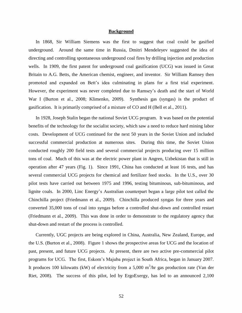
Currently, UGC projects are being explored in China, Australia, New Zealand, Europe, and
the U.S. (Burton et al., 2008). Figure 1 shows the prospective areas for UCG and the location of
past, present, and future UCG projects. At present, there are two active pre-commercial pilot
programs for UCG. The first, Eskom’s Majuba project in South Africa, began in January 2007.
It produces 100 kilowatts (kW) of electricity from a 5,000 m3/hr gas production rate (Van der
Riet, 2008). The success of this pilot, led by ErgoExergy, has led to an announced 2,100
53
megawatt (MW) new integrated gasification combined cycle (IGCC) plant to be run entirely on
UCG syngas at a 375,000 m3/hr production rate. Another pilot program, ENN Group’s UCG
project in Inner Mongolia, China, started in October 2007. Results from this program showed
sustained production of syngas in terms of rate and composition over five months (Friedmann
et al., 2009).
Figure 1: UCG Site Location Map (Friedman et al., 2009). Courtesy of Lawrence Livermore
National Laboratory.
Introduction
Coal extraction by the UCG process, also known as in-situ coal gasification, appears to be
both technically and economically feasible and exhibits many potential advantages over the
conventional mining methods (Kapusta and Stanczyk, 2011; Shuqin et al., 2007). The UCG
process occurs when un-mined coal seams are reacted underground to create syngas. An oxidant
(usually air, oxygen, or steam) is injected into the coal seam and reacts with the coal and water
present in the seam to produce syngas that is extracted through a production well (Bell et al.,
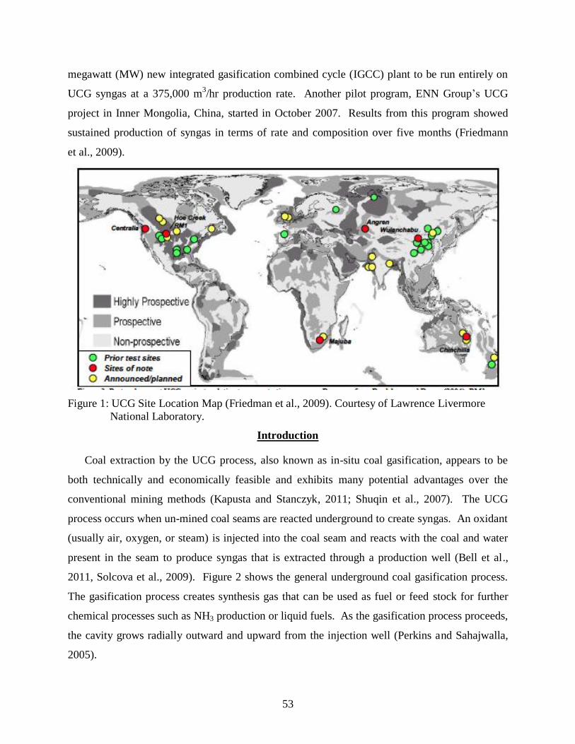
2011, Solcova et al., 2009). Figure 2 shows the general underground coal gasification process.
The gasification process creates synthesis gas that can be used as fuel or feed stock for further
chemical processes such as NH3 production or liquid fuels. As the gasification process proceeds,
the cavity grows radially outward and upward from the injection well (Perkins and Sahajwalla,
2005).
54
Contaminants can be introduced into the groundwater during the UCG process, at
termination, and after termination. The contamination mechanism involves simultaneous
diffusion and penetration of contaminants generated in the UCG process with the gas that
escaped to the surrounding underground formations (Kapusta and Stanczyk, 2011).
Contaminants from the UCG process can affect water quality making sources unfit for human
and wildlife consumption (Bell et al., 2011).
PH = Hydrostatic Pressure; PO = Operating Pressure in the gasification chamber.
Figure 2: General UCG Process. Courtesy of Susannah Strauss with www.UCG-GTL.com.
Hydrostatic Pressure and Chemical Reactions Governing UCG
There are several chemical processes involved in underground coal gasification. Evaporation
and pyrolysis are what create gas. The UCG cavity has permeable walls unlike a conventional
chemical reactor. The coal seam is saturated with water and is at hydrostatic pressure.
Hydrostatic pressure is defined as follows assuming the fluid is incompressible and z is
reasonably small compared to the radius of the Earth:
PH = rgz (1)
Where PH = Hydrostatic Pressure, r = Fluid Density, g = Gravitational Acceleration and z =
height of the liquid column (Gray, 2000)
55
A properly operated UCG chamber operates at slightly below hydrostatic pressure. The
gasification pressure is a function of hydrostatic pressure rather than an independent design
variable. Hydrostatic pressure increases with the depth of the coal seam. The gasification rate
increases with coal depth due to increasing gasification pressure (Bell et al., 2011).
There are several chemical processes involved in underground coal gasification. These
processes include volatiles oxidation, char oxidation, water evaporation, pyrolysis, gasification,
the Boudouard reaction, water gas shift, methanogenesis, and hydrogen gasification. The general
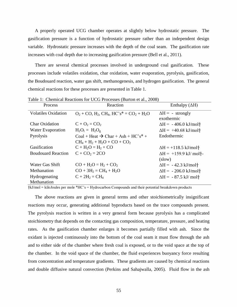
chemical reactions for these processes are presented in Table 1.
Table 1: Chemical Reactions for UCG Processes (Burton et al., 2008)
Process Reaction Enthalpy (ΔH)
Volatiles Oxidation O2 + CO, H2, CH4, HC’s* = CO2 + H2O ΔH = - strongly
exothermic
Char Oxidation C + O2 = CO2 ΔH = - 406.0 kJ/mol†
Water Evaporation H2Ol = H2Og ΔH = +40.68 kJ/mol†
Pyrolysis Coal + Heat Char + Ash + HC’s* +
CH4 + H2 + H2O + CO + CO2
Endothermic
Gasification C + H2O = H2 + CO ΔH = +118.5 kJ/mol†
Boudouard Reaction C + CO2 = 2CO ΔH = +159.9 kJ/ mol†-
(slow)
Water Gas Shift CO + H2O = H2 + CO2 ΔH = - 42.3 kJ/mol†
Methanation CO + 3H2 = CH4 + H2O ΔH = - 206.0 kJ/mol†
Hydrogenating
Methanation
C + 2H2 = CH4 ΔH = - 87.5 kJ/ mol†
†kJ/mol = kiloJoules per mole *HC’s = Hydrocarbon Compounds and their potential breakdown products
The above reactions are given in general terms and other stoichiometrically insignificant
reactions may occur, generating additional byproducts based on the trace compounds present.
The pyrolysis reaction is written in a very general form because pyrolysis has a complicated
stoichiometry that depends on the contacting gas composition, temperature, pressure, and heating
rates. As the gasification chamber enlarges it becomes partially filled with ash. Since the
oxidant is injected continuously into the bottom of the coal seam it must flow through the ash
and to either side of the chamber where fresh coal is exposed, or to the void space at the top of
the chamber. In the void space of the chamber, the fluid experiences buoyancy force resulting
from concentration and temperature gradients. These gradients are caused by chemical reactions
and double diffusive natural convection (Perkins and Sahajwalla, 2005). Fluid flow in the ash
56
bed is dominated by the permeability distribution. Void space fluid flow is determined by
double diffusive natural convection, but is dominated by a single buoyant force due to the
temperature gradients created from combustion of oxygen with CO produced from gasification at
the coal seam walls (Perkins and Sahajwalla, 2005).
At temperatures above 200o C, the dielectric constant of water becomes comparable to the
dielectric constant of acetone and methanol. At these temperatures liquid water becomes a
highly diffusive medium with good solubility for polar and non-polar organic solutes. The
solubility behavior of compounds in water at elevated temperatures changes significantly and
how this affects contaminant dispersion needs to be accounted for in transport modeling at UCG
sites (Burton et al., 2008).
According to Solcova et al., (2009) pressure increases influence the gas front in the porous
media more than do temperature increases. Similarly, the effect of pore size is relatively less
than the effect of pressure increase. The front of individual gas molecules will move in the order
of H2, NH3, CH4, H2S2, CO2, and CO. The rate of the H2 front will be approximately twice as
fast as the CO2, front (Solcova et al., 2009).
Site Characterization and Evaluation for UCG
One of the most import aspects to a successful UCG operation is adequate site
characterization. Several overburden characteristics are essential for successful UCG operations.
No high production aquifers should be within the expected vertical subsidence volume. Water
influx into the gasification cavity can substantially reduce gasification efficiency. The Soviets
published the effect of “gasification intensity,” which is the tons of coal gasified per hour versus
the water influx rate and the heat content of the produced gas. At low gasification intensities and
one-ton coal per hour, the heating value of the syngas drops from approximately 4657 kilojoules
per meter cubed (kJ/m3) with a low water intrusion rate of 15 gallons per minute (gpm), to only
about 932 kJ/m3at high water intrusion rates of 150 gpm. At higher gasification intensities (e.g.,
ten tons coal per hour) intrusion of water does not usually decrease syngas heating value. The
Soviet data shows that the heating value is always increased with increased gasification intensity
and reduced water intrusion. Ideally, the immediate overburden unit should be a thick vertical
section of an aquitard such as a claystone or shale. Low production water bearing units are also
acceptable (GasTech, 2007).
57
Coal seam thicknesses greater than 9 m (30’) are deemed to be adequate for UCG
development. The coal seam thickness impacts gasification efficiency and cost effectiveness, as
thicker coal seams are more efficient and economical to develop. Thicker coal seams have the
potential negative impact of greater subsidence. With the exception of one UCG test in West
Virginia, UCG experience in the U.S. has been in sub-bituminous coal seams greater than twenty
feet in thickness (GasTech, 2007).
Coal seam depths > 24 m (500’) and < 96 m (2,000’) are considered ideal candidates for
UCG development. Coal seams < 24 m are considered to be targets for conventional mining
methods. Non-coal partings and lenses within a coal seam are of secondary importance in
evaluating the geological resource for UCG potential. Thin partings and lenses low in the coal
seam can be beneficial in restricting the communication link between process wells that are low
in the seam. The communication link is an atmospheric connection between the injection and the
production wells. Process wells refer to both the injection and production wells since both types
of wells are needed in the process of UCG.
As UCG develops in coal above the link, it is important to keep the link near the bottom of
the coal seam. These partings should be < 12 m (20’) in thickness and in the lower third of the
coal seam to have a beneficial effect (GasTech, 2007).
Structural (faulting and folding) considerations are also important in UCG resource selection.
Faults and folds can cause problems with linking, cause excessive water influx, and promote
premature roof collapse. Areas of high faulting frequency should be avoided. UCG site
assessments should include geophysical and logging information to constrain any structural
overprints that could influence the integrity of the coal seam (Burton et al., 2008).
Well Completion and Linking.
A good drilling technique is necessary to connect the injection well and the production well.
The cavity between these two wells is the gasification reactor. Three methods that have been
developed for this purpose are as follows:
1. Air pressurization between two vertical holes: This method was used in the trials of
Chinchilla (Australia) and the former Soviet Union (FSU) sites. A recent pilot project
(1999-2003) at Chinchilla was successful and an international company now offers it as a
commercial process (Khadse et al., 2007).
58
2. Man-built galleries in the coal seam: This method was used in China to utilize remaining
coal after mining (Burton et al., 2008).
3. Directional drilling in the coal seam with controlled injection: This method is being used
in the U.S. and European field trials. Directional drilling is more costly to construct but
possesses the advantage that basic drilling and completion technology is available from
the traditional oil and gas industry. With this method it is possible to get sustainable
gasification over long inseam wells (> 200 m), branch drilling of borehole networks for
commercial scale operation, and control of a large gasification process using movable
injection in simultaneous channels known as Controlled Retractable Injection Procedure
(CRIP). These methods have been demonstrated in single channel configurations (Burton
et al., 2008). CRIP may be suitable due to the available robust technology and possibility
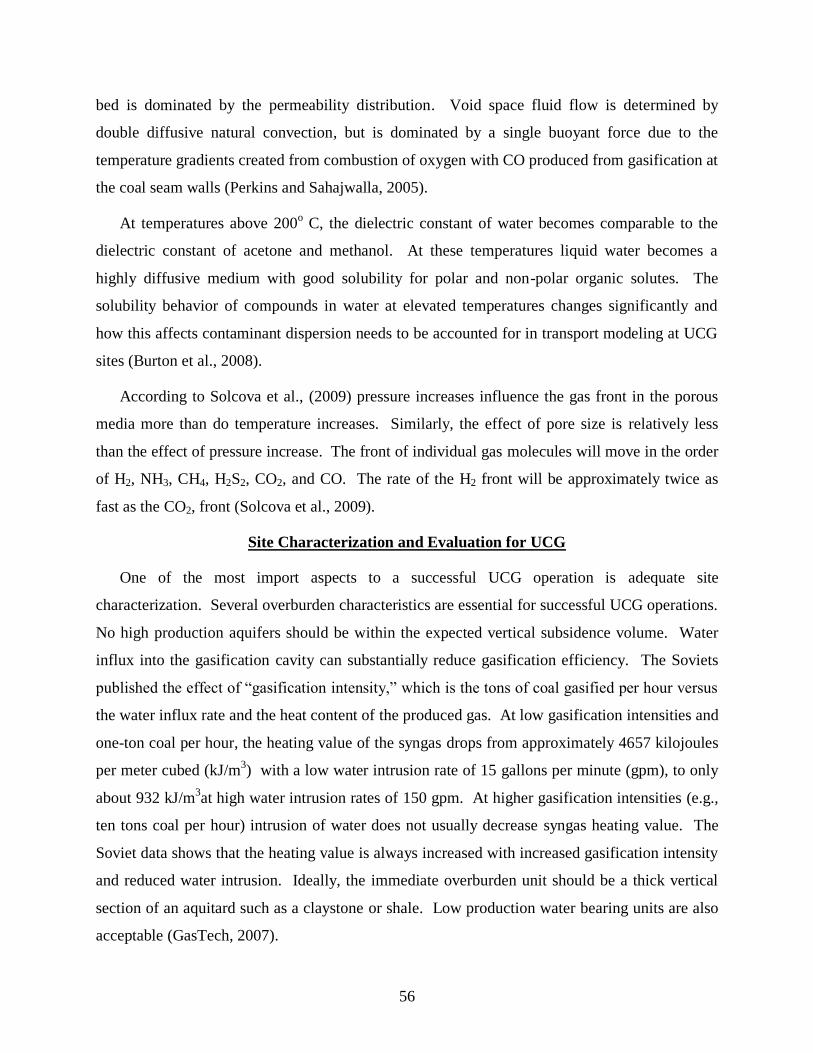
of exercising good control over the process (Khadse et al., 2007). Figures 3 and 4 show
the CRIP method.
Figure 3. CRIP Method (LLNL, 2011) Figure Courtesy of Burl Davis, Carbon Energy
59
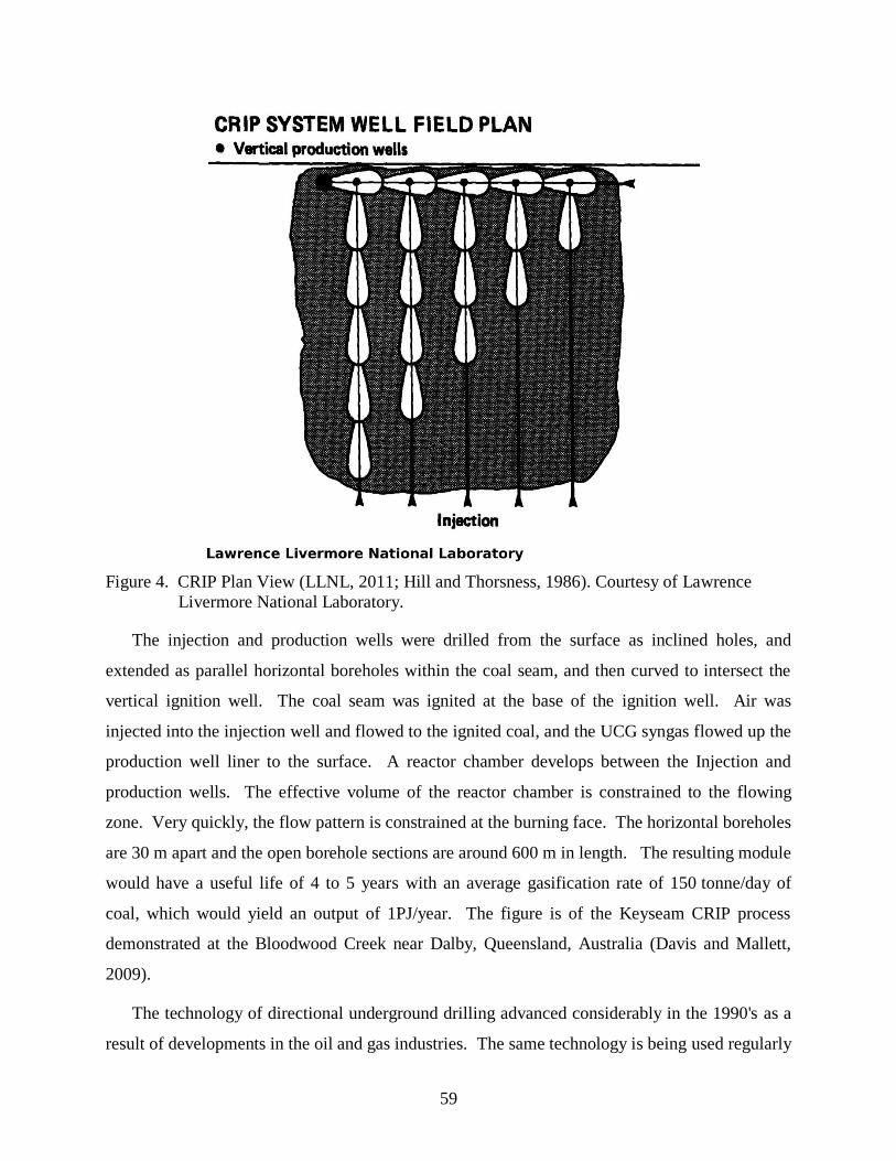
Figure 4. CRIP Plan View (LLNL, 2011; Hill and Thorsness, 1986). Courtesy of Lawrence
Livermore National Laboratory.
The injection and production wells were drilled from the surface as inclined holes, and
extended as parallel horizontal boreholes within the coal seam, and then curved to intersect the
vertical ignition well. The coal seam was ignited at the base of the ignition well. Air was
injected into the injection well and flowed to the ignited coal, and the UCG syngas flowed up the
production well liner to the surface. A reactor chamber develops between the Injection and
production wells. The effective volume of the reactor chamber is constrained to the flowing
zone. Very quickly, the flow pattern is constrained at the burning face. The horizontal boreholes
are 30 m apart and the open borehole sections are around 600 m in length. The resulting module
would have a useful life of 4 to 5 years with an average gasification rate of 150 tonne/day of
coal, which would yield an output of 1PJ/year. The figure is of the Keyseam CRIP process
demonstrated at the Bloodwood Creek near Dalby, Queensland, Australia (Davis and Mallett,
2009).
The technology of directional underground drilling advanced considerably in the 1990's as a
result of developments in the oil and gas industries. The same technology is being used regularly
60
for the degassing of coal seams in Australia, South Africa, and the United States. Consequently,
for the first time, in-seam coal wells can be constructed reliably and accurately, with much less
risk of failure. Furthermore, the option of constructing gasification wells in much deeper coal
seams, over 1000 m, has become possible. Access to deeper coal brings advantages in terms of
cavity growth, power output, and environmental benefits, and the possibility of maintaining
supercritical conditions for CO2 sequestration. Underground coal gasification operating
conditions require injection well construction and materials to withstand the extreme thermal and
mechanical stresses associated with UCG: high pressures and temperatures (up to 1500oC),
sulfidation and oxidation reactions, and subsidence of the cavity roof. Wells are usually cased
with carbon or high-strength stainless steel. Cementing of wells is done above the reaction zone
to facilitate the controlled introduction of air and to prevent loss through the wellbore of gases to
the surface or into overlying strata. If UCG infrastructure is subsequently used for carbon
capture and sequestration (CCS) operations, well materials must also withstand the corrosion
associated with carbon dioxide (Burton et al., 2008).
Environmental Effects
Underground coal gasification has some environmental benefits relative to conventional
mining including no discharge of tailings, reduced sulfur emissions; reduced discharge of ash,
Hg, and tar and the additional benefit of CCS (Shuqin et al., 2007). Atmospheric CO2 is a major
greenhouse gas of concern in fossil fuel processes. Due to global climate change, CCS is an
important technology that can be combined with UCG. Carbon capture and sequestration is the
process to remove and store “greenhouse gases” from resulting process streams to reduce
buildup of these gases in the atmosphere. However, in UCG operations, overburden material
participates in the gasification process. The overburden participation increases as the UCG
cavity matures and more overburden is exposed to the major underground processes. The major
concerns with the UCG process and overburden are excessive subsidence, groundwater influx,
mixing of aquifers (or water bearing strata), and groundwater contamination (GasTech, 2007).
Carbon Capture and Sequestration
Underground coal gasification may have more promise when used in combination with CCS.
First, there is a high degree of coincidence between coal resources and potential sequestration
sites. Second, preliminary engineering and economic assessments suggest that it would be
61
possible to fully or partially decarbonize many UCG product streams with CCS at costs at or
below their surface equivalents that presently are not using CCS technologies (Burton et al.,
2008).
Carbon capture and sequestration usually involves the process of extraction, separation,
collection, compression, transporting, and geologic storage. Storage in geologic formations can
be as adsorbed gases and liquefied gases. Carbon dioxide stored as liquid, must be at
supercritical conditions. This requires the depth to be > 790 m (2,600’). Abandoned oil and gas
reservoirs, coal seams, and brine formations are potential storage resources. Carbon capture and
sequestration may be synergistically applied for Enhanced Coal Bed Methane Recovery
(ECBMR) and Enhanced Oil Recovery (EOR) (Gas Tech, 2007).
The cavity created by UCG is as great as 80% of the volume of the gasified coal. The
“spent” cavity is estimated to have the capacity to store about 30% of the total CO2 produced
from the gasification of the coal. Advantages for carbon storage in UCG cavities include large
storage volumes, existing wells that may be used for CO2 injection, and self-sealing caused by
coal physical changes in the presence of CO2. Coal in the presence of CO2 swells and plasticizes
and may seal the natural fractures (cleats) in the coal seam. In addition, the coal surrounding the
spent cavity may be fused and have very low permeability, thus preventing escape of the stored
CO2 (Gas Tech, 2007, 2008).
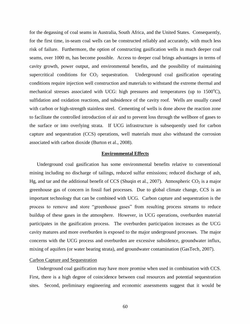
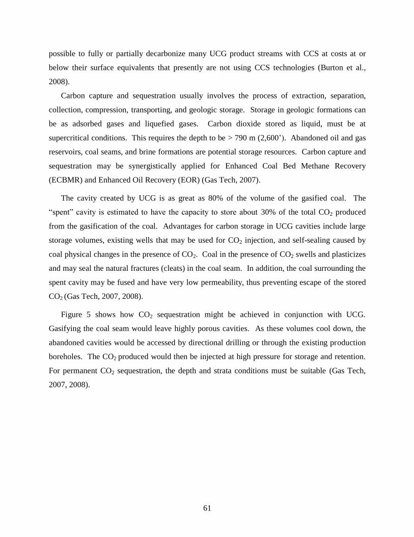
Figure 5 shows how CO2 sequestration might be achieved in conjunction with UCG.
Gasifying the coal seam would leave highly porous cavities. As these volumes cool down, the
abandoned cavities would be accessed by directional drilling or through the existing production
boreholes. The CO2 produced would then be injected at high pressure for storage and retention.
For permanent CO2 sequestration, the depth and strata conditions must be suitable (Gas Tech,
2007, 2008).
62
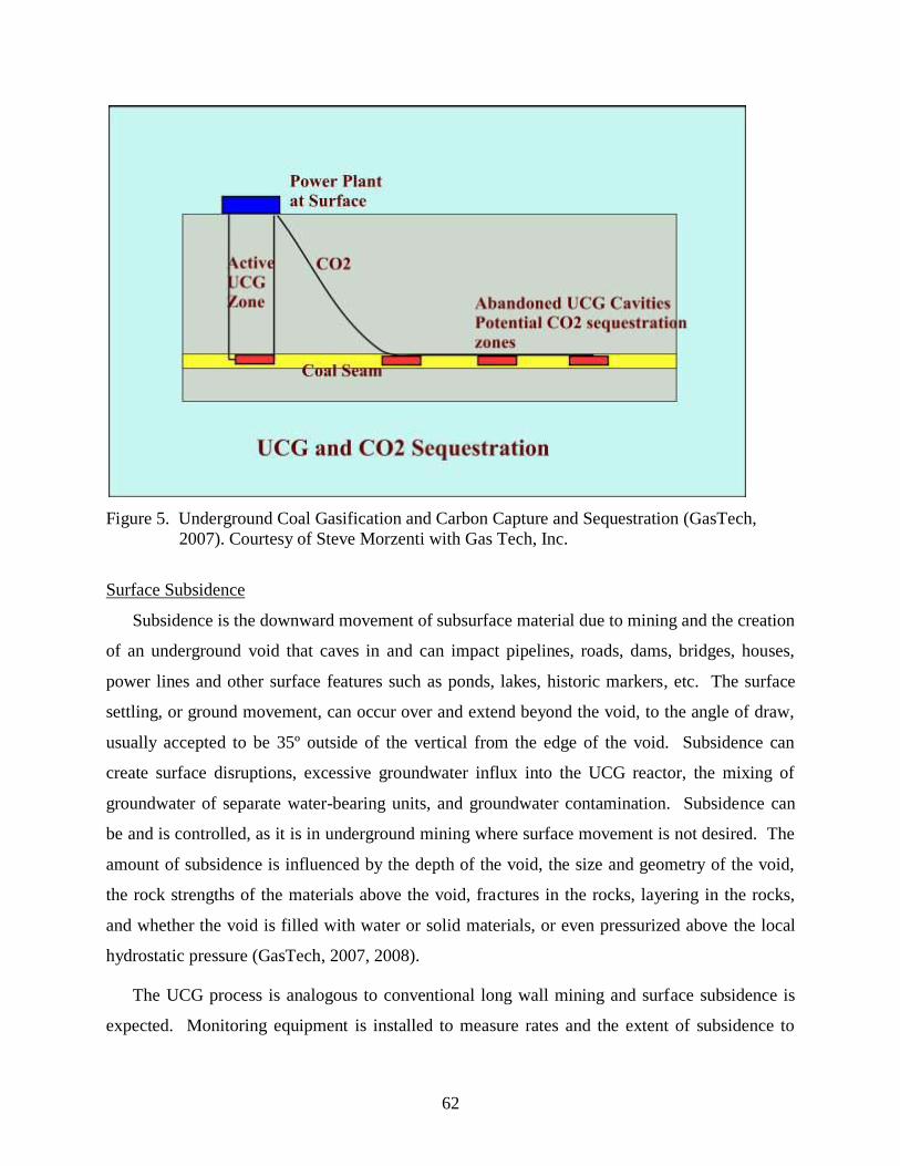
Figure 5. Underground Coal Gasification and Carbon Capture and Sequestration (GasTech,
2007). Courtesy of Steve Morzenti with Gas Tech, Inc.
Surface Subsidence
Subsidence is the downward movement of subsurface material due to mining and the creation
of an underground void that caves in and can impact pipelines, roads, dams, bridges, houses,
power lines and other surface features such as ponds, lakes, historic markers, etc. The surface
settling, or ground movement, can occur over and extend beyond the void, to the angle of draw,
usually accepted to be 35º outside of the vertical from the edge of the void. Subsidence can
create surface disruptions, excessive groundwater influx into the UCG reactor, the mixing of
groundwater of separate water-bearing units, and groundwater contamination. Subsidence can
be and is controlled, as it is in underground mining where surface movement is not desired. The
amount of subsidence is influenced by the depth of the void, the size and geometry of the void,
the rock strengths of the materials above the void, fractures in the rocks, layering in the rocks,
and whether the void is filled with water or solid materials, or even pressurized above the local
hydrostatic pressure (GasTech, 2007, 2008).
The UCG process is analogous to conventional long wall mining and surface subsidence is
expected. Monitoring equipment is installed to measure rates and the extent of subsidence to
63
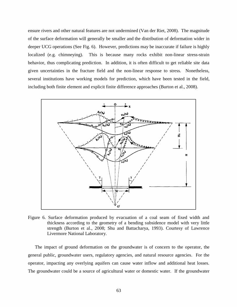
ensure rivers and other natural features are not undermined (Van der Riet, 2008). The magnitude
of the surface deformation will generally be smaller and the distribution of deformation wider in
deeper UCG operations (See Fig. 6). However, predictions may be inaccurate if failure is highly
localized (e.g. chimneying). This is because many rocks exhibit non-linear stress-strain
behavior, thus complicating prediction. In addition, it is often difficult to get reliable site data
given uncertainties in the fracture field and the non-linear response to stress. Nonetheless,
several institutions have working models for prediction, which have been tested in the field,
including both finite element and explicit finite difference approaches (Burton et al., 2008).
Figure 6. Surface deformation produced by evacuation of a coal seam of fixed width and
thickness according to the geometry of a bending subsidence model with very little
strength (Burton et al., 2008; Shu and Battacharya, 1993). Courtesy of Lawrence
Livermore National Laboratory.
The impact of ground deformation on the groundwater is of concern to the operator, the
general public, groundwater users, regulatory agencies, and natural resource agencies. For the
operator, impacting any overlying aquifers can cause water inflow and additional heat losses.
The groundwater could be a source of agricultural water or domestic water. If the groundwater
64
has over 10,000 ppm total dissolved solids (TDS) (total dissolved solids) the aquifer may be
exempt from EPA regulation. The groundwater may be essentially unaffected by the ground
motion accompanying UCG if the aquifer is separated from the caved and fractured zones that
develop above the coal seam. The caved and fractured zones together can extend up to 10 to 20
times the thickness of the extracted seam; so for a 30 m seam, with various char content, the cave
and fractured zones could be 150 to 550 m thick. Aquifers in this zone could be drained. Above
this thickness the strata will deform but not fracture, except for occasional slip along bedding and
along preexisting joints, and can act as an aquitard. This favors deeper coal beds in that the
shallower thick beds will result in caving to the surface thereby impacting overlying aquifers
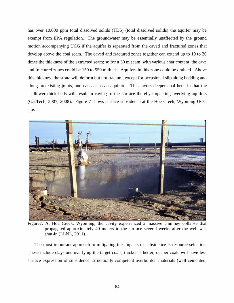
(GasTech, 2007, 2008). Figure 7 shows surface subsidence at the Hoe Creek, Wyoming UCG
site.
Figure7. At Hoe Creek, Wyoming, the cavity experienced a massive chimney collapse that
propagated approximately 40 meters to the surface several weeks after the well was
shut-in (LLNL, 2011).
The most important approach to mitigating the impacts of subsidence is resource selection.
These include claystone overlying the target coals, thicker is better; deeper coals will have less
surface expression of subsidence; structurally competent overburden materials (well cemented,
65
and rigid); absence of really consolidated sand units; and absence of thick water-bearing units
used for domestic consumption (GasTech, 2007, 2008).
Groundwater Contamination
Groundwater pollution is considered the most serious potential environmental risk related to
UCG. An intensive and broad investigation of the environmental aspects of UCG was carried
out during the field scale experiments in Hanna and Hoe Creek, Wyoming. Hoe Creek was the
most studied area; poor site characterization and operation led to cavity roof collapse and gas
loss into the local groundwater system (Friedman et al., 2009). Groundwater monitoring
activities included determination of the baseline before gasification trials as well as sampling
during and after the experiments.
The Lawrence Livermore National Laboratory (LLNL) conducted the Hoe Creek I
gasification experiment in a recharge area near Gillette, WY with general groundwater flow to
the southeast. The Felix II coal seam at the Hoe Creek I site is an aquifer 7.6 m thick and
approximately 22 m below the static water level. A 4.5 m thick section of claystone and
siltstone, with a vertical permeability of approximately 0.001 to 0.02 millidarcies, overlies the
Felix II coal seam (Campbell et al., 1979). Prior to gasification, LLNL installed six dewatering
wells radially and five monitoring wells downgradient of the proposed chamber. The six
dewatering wells were used as monitoring wells once gasification was complete. Groundwater
samples were collected from all the wells prior to, during, and after 3, 83, 182, and 280 days
following gasification (Campbell et al., 1979).
A wide range of hazardous species were identified in the underground environment next to
the selected gasification sites (Hoe Creek, WY; Fairfield, TX). The phenolic compounds were
identified as the major organic groundwater pollution followed by benzene and its derivatives,
polycyclic aromatic hydrocarbons (PAHs), N containing heterocycles, and minor species such as
carboxylic acids, aldehydes, ketones and amines (Kapusta and Stanczyk, 2011). Groundwater
samples were collected near an UCG site in Fairfield, Texas. Organics and NH3 are deposited in
surrounding strata by condensation from cooling gases during gasification (Humenick et al.,
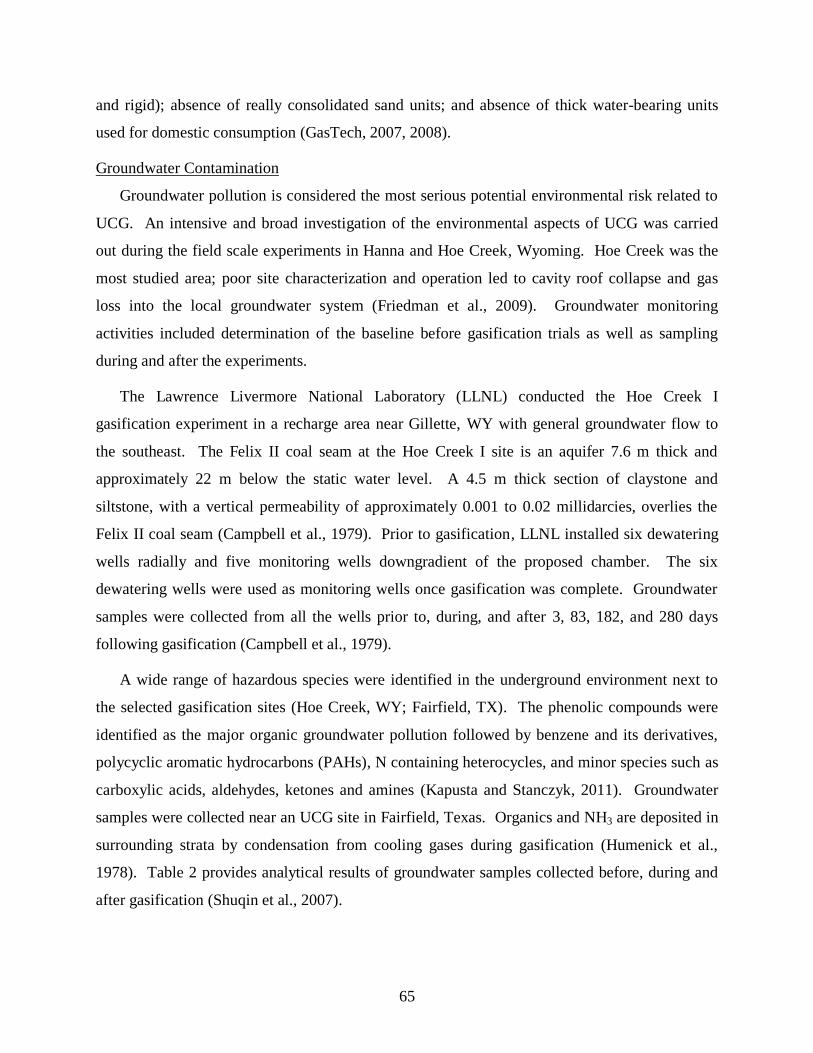
1978). Table 2 provides analytical results of groundwater samples collected before, during and
after gasification (Shuqin et al., 2007).
66
Table 2: Organic Parameter Analytical Results near Fairfield, Texas (Shuqin et al., 2007)
Component
Analytical Results (ug/L)†
Before Gasification Soon after
Gasification
One year after
Gasification
Total Phenolics 7 100000 20
Total Heterocyclics ND* 2200 ND*
Two Ring PAHs 2 105 9
Three Ring PAHs 1 22 5
Four Ring PAHs ND* 7 ND*
Five Ring PAHs ND* 3 ND*
Total Organics 10 103 34
*ND = Not Detected, †ug/L = micrograms per liter
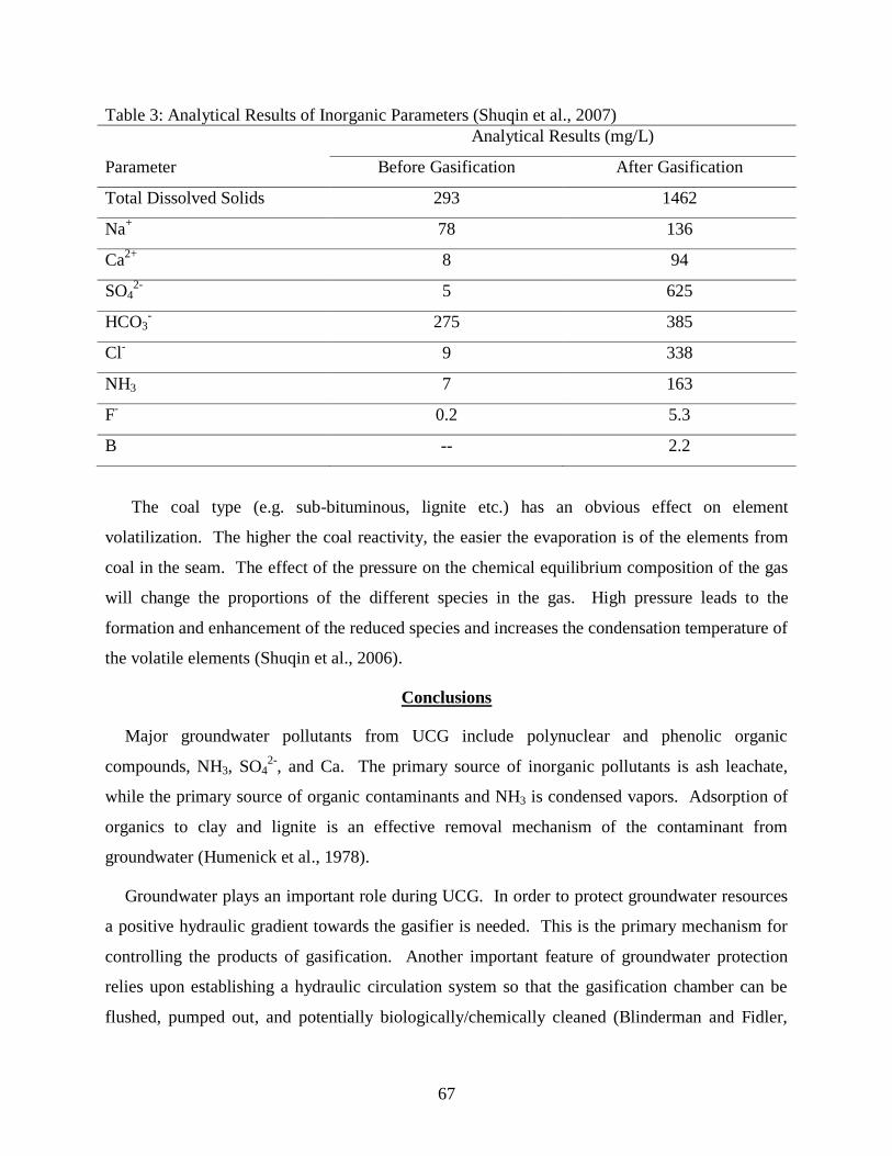
A wide array of ionic inorganic species was also identified in relation to the UCG process.
This array included mainly ammonium, sulphate, chloride, and other species present in smaller
quantities, mainly cations of B, Mn, Fe, Zn, Cd, Al, Cr, Co, Ni, Cu, Hg, Pb, and Be (Kapusta and
Stanczyk, 2011). Table 3 provides analytical results of inorganic parameters in groundwater
samples collected near Fairfield, Texas. At the Texas UCG site organics, NH3, SO42-
, and TDSs
were detected above drinking water quality standards. Most of the inorganic contaminants are
extracted by groundwater intrusion from the ash in the burn zone after gasification (Humenick
et. al., 1978).
Mercury, As and Se are trace elements well known for their high volatility in UCG that can
lead to environmental and technical problems during gas utilization. Shuqin et al., (2006)
investigated the volatilization of Hg, As, and Se from coal in a seam during the process of UCG
based on comparison of their volatility during the transformation of coal to char and the
conversion of char to ash. Three types of coal were involved in this study. The results indicate
that the volatility of Hg, As, and Se during UCG in the seam follows the sequence of Hg>Se>As.
Mercury and Se show volatility higher than 90% from coal to ash. The volatility of As is lower
than 60% as confirmed by As enrichment in UCG ash. Arsenic volatilization during UCG is
enhanced by increasing temperature, which is different from the result of As volatilization during
the combustion of crushed coal (Shuqin et al., 2006).
67
Table 3: Analytical Results of Inorganic Parameters (Shuqin et al., 2007)
Parameter
Analytical Results (mg/L)
Before Gasification After Gasification
Total Dissolved Solids 293 1462
Na+
78 136
Ca2+
8 94
SO42-
5 625
HCO3-
275 385
Cl-
9 338
NH3 7 163
F-
0.2 5.3
B -- 2.2
The coal type (e.g. sub-bituminous, lignite etc.) has an obvious effect on element
volatilization. The higher the coal reactivity, the easier the evaporation is of the elements from
coal in the seam. The effect of the pressure on the chemical equilibrium composition of the gas
will change the proportions of the different species in the gas. High pressure leads to the
formation and enhancement of the reduced species and increases the condensation temperature of
the volatile elements (Shuqin et al., 2006).
Conclusions
Major groundwater pollutants from UCG include polynuclear and phenolic organic
compounds, NH3, SO42-
, and Ca. The primary source of inorganic pollutants is ash leachate,
while the primary source of organic contaminants and NH3 is condensed vapors. Adsorption of
organics to clay and lignite is an effective removal mechanism of the contaminant from
groundwater (Humenick et al., 1978).
Groundwater plays an important role during UCG. In order to protect groundwater resources
a positive hydraulic gradient towards the gasifier is needed. This is the primary mechanism for
controlling the products of gasification. Another important feature of groundwater protection
relies upon establishing a hydraulic circulation system so that the gasification chamber can be
flushed, pumped out, and potentially biologically/chemically cleaned (Blinderman and Fidler,
68
2003). Hydraulic control is the most important feature of UCG. It controls the process and
prevents groundwater contamination.
In addition to hydraulic control, site characterization and proper well completion are of
utmost importance. Coal resources that are not suitable for conventional mining are ideally
suited for UCG (Van der Riet, 2008). Ultimately, UCG will compete in the marketplace with
conventional and innovative gasification technologies to provide syngas for fuel and power
applications, which will in turn compete against other fuels such as biodiesel and gasoline. In
the coming years, these technologies will likely be competitive in the market place not just on an
economic basis but also on the costs and difficulties of managing CO2 emissions to the
atmosphere (Friedmann et al., 2009).
Acknowledgements
I would like to thank Burl Davis with Carbon Energy, and Dr. Joshua White and the UCG
group at Lawrence Livermore National Laboratory for their technical advice and support.
Literature Cited
Bell, David A., Brian F. Towler and Maohong Fan. 2011. Coal gasification and its applications.
Elsevier, Burlington, MA.
Blinderman, M. S. and S. Fidler. 2003. Groundwater at the underground coal gasification site at
Chinchilla, Australia. P. 141-150. In Proc. Water in Mining Conference, Oct. 13-15, 2003.
Burton, E., J. Friedmann and A. Upadhye. 2008. Best practices in underground coal gasification
(draft). Lawrence Livermore National Laboratory, U.S. Department of Energy Contract W-
7405-7448.
Campbell J. H., F. T. Wang, S. W. Mead, and J. F. Busby 1979. Groundwater quality near an
underground coal gasification experiment. J. of Hydrology. 44: 241-266.
http://dx.doi.org/10.1016/0022-1694(79)90134-3.
Davis, Burl E. and Dr. Cliff Mallett. 2009. Rm-1 to Bloodwood Creek: A status report. 2009
International Coal Conference Proceedings. Pittsburgh, PA.
Friedmann, S. Julio, Ravi Upadhye, and Fund-Ming Kong. 2009. Prospects for underground coal
gasification in carbon-constrained world. Energy Procedia. 1: 4551-4557.
http://dx.doi.org/10.1016/j.egypro.2009.02.274.
69
GasTech, Inc. 2007. Viability of underground coal gasification in the “Deep Coals” of the
Powder River Basin, WY. Prepared for the Wyoming Business Council.
http://www.wyomingbusiness.org/program/ucg-viability-analysis-powder-river-/1169
accessed September 19, 2011.
GasTech, Inc. 2008. UCG in the “Deep Coals” of the Powder River Basin, WY Progress 2007-
2008. Prepared for Zeus Development Corp.
Gray, Donald D. 2000. A first course in fluid mechanics for civil engineers. Water Resources
Publications, LLC, Highlands Ranch, CO. http://www.ucg-gtl.com/australian-UCG-
underground-coal-gasification-process.html accessed October 4, 2011.
Humenick, Michael J., and C. Fletcher Mattox. 1978. Groundwater pollutants from underground
coal gasification. Water Research. 12: 463-469. http://dx.doi.org/10.1016/0043-
1354(78)90153-7.
Kapusta, Krzysztof, and Krzysztof Stanczyk, 2011. Pollution of water during underground coal
gasification of hard coal and lignite. Fuel. 90: 1927-1934.
http://dx.doi.org/10.1016/j.fuel.2010.11.02534.
Khadse, Anil, Mohammed Qayyumi, Sanjay Mahajani, and Preeti Aghalayam. 2007.
Underground coal gasification: A new clean coal utilization technique for India. Energy. 32:
2061-2071. http://dx.doi.org/10.1016/j.energy.2007.04.012.
Klimenko, Alexander Y. 2009 Early ideas in underground coal gasification and their evolution.
Energies. 2: 456-476. http://dx.doi.org/10.3390/en20200456-476.
Lawrence Livermore National Laboratory. 2011. Presentation on LLNL underground coal
gasification program to DOI, Office of Surface Mining. September 20, 2011.
Perkins, G., and V. Sahajwalla. 2005 A mathematical model for the chemical reaction of a semi-
infinite block of coal in underground coal gasification, Energy and Fuels. 19: 1679–92.
http://dx.doi.org/10.1021/ef04968082.
Shu, D.M., and A. K. Battacharya. 1993. Prediction of sub-surface subsidence movements due to
underground coal mining. Geotechnical and Geological Engineering. 11: 221-234
http://dx.doi.org/10.1007/BF00466365
70
Shuqin Liu, Li Jing-gang, Mei Mei, and Dong Dong-lin. 2007. Groundwater pollution from
underground coal gasification. J. of China Univ. of Mining and Technology. 17 (4) 467-472.
http://dx.doi.org/10.1016/S1006-1266(07)60127-8.
Shuqin Liu, Yongtao Wang, Li Yu, and John Oakey. 2006. Volatilization of mercury, arsenic
and selenium during underground coal gasification. Fuel. 85: 1550-1558.
http://dx.doi.org/10.1016/j.fuel.2005.12.01058.
Solcova, Olga, Karel Soukup, Jan Rogut, Krzysztof Stanczyk, and Petr Schneider. 2009. Gas
transport through porous strata from underground reaction source: The influence of the gas
kind, temperature and transport-pore size. Fuel Processing Technology. 90. (12) 1495-1501.
http://dx.doi.org/10.1016/j.fuproc.2009.07.015.
Van der Riet, Mark. 2008. Underground coal gasification. In Proceedings of the South African
Institute of Electrical Engineers Generation Conference. Midrand South Africa. Feb. 19,
2008.
Related Documents