Proceedings of the 7 h World Congress on Civil, Structural, and Environmental Engineering (CSEE'22) Lisbon, Portugal – April 10 – 12, 2022 Paper No. ICSECT 161 DOI: 10.11159/icsect22.161 ICSECT 161-1 Improving the Behavior of Steel Plate Shear Wall Using Double Infill Plates Ahmad Jabbar Hussain Alshimmeri 1 , Denise-Penelope N. Kontoni 2,3 1 Department of Civil Engineering, College of Engineering, University of Baghdad, Baghdad, Iraq [email protected] 2 Department of Civil Engineering, School of Engineering, University of the Peloponnese, GR-26334 Patras, Greece [email protected] 3 School of Science and Technology, Hellenic Open University, GR-26335 Patras, Greece [email protected] Abstract. Steel Plate Shear Wall (SPSW) has indicated suitable performance in numerical studies by researchers as well as in past earthquakes. Although this system has a considerable advantage, it requires huge columns to resist stress due to the infill plate, and this is one of the main dilemmas relating to this system. Also, increasing the infill plate made the system form plastic hinges in the columns instead of the infill plate and beam. To solve this problem, herein, an innovative model of SPSW is proposed as an alternative to the traditional type of steel shear wall, namely the use of Double Infill Plates for SPSW (DIP-SSW). The use of DIP-SSW as a resistance system against lateral loads, also results in space savings. The present numerical finite element investigation was performed by parametric study and consideration of the nonlinear behavior of this system. The results of the parametric study have been addressed. Also, the results showed that the DIP-SSW has an excellent ductility factor and capability of energy absorption under lateral loads. Keywords: steel shear wall; double infill plates; stiffness; ductility. 1. Introduction Steel Plate Shear Walls (SPSWs) relying on the infill plate, resist against lateral loadings. The high slenderness of the infill plate made it buckle at the elastic zone. The elastic bucking of the infill plate is not the ultimate load carrying of the system. By post-bucking, the main resistance of the system is occurred after bucking that is known as diagonal filed action [1]. This phenomenon was introduced by Wagner [2]. Then, researchers [3,4] used this theory to design girders and then was used to design of SPSWs based on the findings of researchers at the University of Alberta [5,6]. Experimental and numerical studies till now have demonstrated the capability of the SPSW system as a system with considerable ductility, high lateral stiffness, and lateral strength [7-14]. Thereafter, the SPSW design requirements were reported in FEMA450 [15], AISC 341 [16], and AISC Design Guide 20 [17]. Several researchers have attempted to prevent elastic buckling of the infill plate. They proposed to use of LYP steel [18-22], adding dampers [23], changing the mechanism of SPSW by stiffeners [24-26], covering the infill plate using concrete [27-30], separating the infill wall from the boundary frame [31,32], utilizing semi-supported SPSW [33,34], covering the infill plate by FRP [35], semi-disconnected SPSW [36]. Although the mentioned idea improves the behavior of SPSW, it imposes an additional cost on the structures. Therefore, in this study, an innovative idea of SPSW is presented to reduce the imposed additional cost to the structures. In this study, Double Infill Plates for Steel plate Shear Walls (DIP-SSW) are proposed to be used. The main feature of this system is that the shear stress of the column is reduced, and the post-buckling of the infill plates has governed the behavior of the system. It is also useful for the architect aspect because less space is occupied. The nonlinear behavior of the DIP-SSW is studied in many aspects.

Welcome message from author
This document is posted to help you gain knowledge. Please leave a comment to let me know what you think about it! Share it to your friends and learn new things together.
Transcript

Proceedings of the 7h World Congress on Civil, Structural, and Environmental Engineering (CSEE'22)
Lisbon, Portugal – April 10 – 12, 2022
Paper No. ICSECT 161
DOI: 10.11159/icsect22.161
ICSECT 161-1
Improving the Behavior of Steel Plate Shear Wall Using Double Infill Plates
Ahmad Jabbar Hussain Alshimmeri1, Denise-Penelope N. Kontoni2,3 1Department of Civil Engineering, College of Engineering, University of Baghdad,
Baghdad, Iraq
[email protected] 2Department of Civil Engineering, School of Engineering, University of the Peloponnese,
GR-26334 Patras, Greece
[email protected] 3School of Science and Technology, Hellenic Open University,
GR-26335 Patras, Greece
Abstract. Steel Plate Shear Wall (SPSW) has indicated suitable performance in numerical studies by researchers as well as in past
earthquakes. Although this system has a considerable advantage, it requires huge columns to resist stress due to the infill plate, and this
is one of the main dilemmas relating to this system. Also, increasing the infill plate made the system form plastic hinges in the columns
instead of the infill plate and beam. To solve this problem, herein, an innovative model of SPSW is proposed as an alternative to the
traditional type of steel shear wall, namely the use of Double Infill Plates for SPSW (DIP-SSW). The use of DIP-SSW as a resistance
system against lateral loads, also results in space savings. The present numerical finite element investigation was performed by parametric
study and consideration of the nonlinear behavior of this system. The results of the parametric study have been addressed. Also, the
results showed that the DIP-SSW has an excellent ductility factor and capability of energy absorption under lateral loads.
Keywords: steel shear wall; double infill plates; stiffness; ductility.
1. Introduction Steel Plate Shear Walls (SPSWs) relying on the infill plate, resist against lateral loadings. The high slenderness of the
infill plate made it buckle at the elastic zone. The elastic bucking of the infill plate is not the ultimate load carrying of the
system. By post-bucking, the main resistance of the system is occurred after bucking that is known as diagonal filed action
[1]. This phenomenon was introduced by Wagner [2]. Then, researchers [3,4] used this theory to design girders and then was
used to design of SPSWs based on the findings of researchers at the University of Alberta [5,6].
Experimental and numerical studies till now have demonstrated the capability of the SPSW system as a system with
considerable ductility, high lateral stiffness, and lateral strength [7-14]. Thereafter, the SPSW design requirements were
reported in FEMA450 [15], AISC 341 [16], and AISC Design Guide 20 [17]. Several researchers have attempted to prevent
elastic buckling of the infill plate. They proposed to use of LYP steel [18-22], adding dampers [23], changing the mechanism
of SPSW by stiffeners [24-26], covering the infill plate using concrete [27-30], separating the infill wall from the boundary
frame [31,32], utilizing semi-supported SPSW [33,34], covering the infill plate by FRP [35], semi-disconnected SPSW [36].
Although the mentioned idea improves the behavior of SPSW, it imposes an additional cost on the structures. Therefore,
in this study, an innovative idea of SPSW is presented to reduce the imposed additional cost to the structures.
In this study, Double Infill Plates for Steel plate Shear Walls (DIP-SSW) are proposed to be used. The main feature of
this system is that the shear stress of the column is reduced, and the post-buckling of the infill plates has governed the
behavior of the system. It is also useful for the architect aspect because less space is occupied. The nonlinear behavior of the
DIP-SSW is studied in many aspects.

ICSECT 161-2
2. Methodology 2.1. Numerical models
Rezai [37] showed that the strains developed in the top and bottom flanges of the story beams were relatively small.
Fig. 1 illustrates the SPSW model used for the parametric study. The ANSYS computer program was selected to simulate
the Finite Element (FE) analysis and modeling. All elements were simulated using the SHELL element.
The model consists of a single panel bounded by two rigid beams at the top and bottom. In this study and to start with,
a single-story single-bay SPSW having L = h = 2700 mm, 𝛽1 = 𝐿 ℎ⁄ = 1, and tp=3 mm (Model DB-t3), as illustrated in Fig.
1, was designed according to the AISC 341-05 [16] and the AISC Design Guide 20 [17] rules and provisions, where L and
h are the width and the height of the infill plate, respectively, and tp is the thickness of infill plate. After that, the L had
increased 1.5 times, and the tp had increased 1.5 and 2 times, while the column cross-section and the panel/column height
kept constant. The different models are listed in Table 1.
Fig. 1: A selected model for the parametric study.
Table 1: Numerical models.
Model tp (mm) h (mm) L (mm)
DB-t3 3 2700 2700
DB-t4.5 4.5 2700 2700
DB-t6 6 2700 2700
DB-t3-L1.5 3 2700 4050
DB-t4.5-L1.5 4.5 2700 4050
DB-t6-L1.5 6 2700 4050

ICSECT 161-3
2.2. Material properties and boundary conditions The ST37 steel was selected for the infill plate and columns materials with a yield stress of 240 MPa, modulus of
Elasticity of 200 GPa, and Poisson’s ratio of 0.3, respectively.
For the pushover analysis of the FE models, the displacement control method was used. It was considered equal to a
drift angle of 2.5% according to the ASCE 7-05 [38].
2.3. Model parameters In general, the parameters affecting the behavior and capacity of a system are classified into three categories: geometric
variables, deformational variables, and loading parameters. The parameters that govern the behavior and capacity of the
selected model of steel plate shear wall with rigid floor beams are defined below. Referring to Fig. 1, the geometric variables
were defined.
𝛽1 = 𝐿 ℎ⁄ (Aspect ratio)
𝛽2 =𝑡𝑤𝐿
2𝐴𝑐 (Ratio of axial stiffness of infill plate to that column)
𝛽3 = 𝛿 ℎ⁄ (Drift index)
𝛽4 = 𝑉 𝑉𝑦𝑖𝑒𝑙𝑑⁄ (Ratio of shear load to shear yield capacity or normalized base shear)
Using the Von Misses yield criterion, the 𝑉𝑦 can be obtained as follows:
𝑉𝑦𝑖𝑒𝑙𝑑 = 2𝑑. 𝑡𝑝(0.577𝐹𝑦) + 𝐿. 𝐹𝑦 (1)
In these relations, Ac is the cross-sectional area of the columns, δ is the drift of the wall, V is the lateral shear force,
𝑉𝑦𝑖𝑒𝑙𝑑 is the shear force corresponding to the yielding of whole cross section of the shear wall, and Fy is the yield strength of
materials.
Of the above parameters, the normalized base shear 𝛽4, is the loading parameter, while the drift index 𝛽3, is obtained as
an output. The remaining β–parameters define the Finite Element (FE) model (Table 2). In terms of limit states design, the
ultimate limit state is defined as the maximum value of 𝛽4, and the serviceability limit state can be described in terms of 𝛽3
which is the drift index.
Table 2: Model parameters.
Model Vy (kN) β1 β2
DB-t3 278 1 0.20
DB-t4.5 334 1 0.30
DB-t6 391 1 0.41
DB-t3-L1.5 334 1.5 0.30
DB-t4.5-L1.5 419 1.5 0.46
DB-t6-L1.5 503 1.5 0.61
Behbahanifard et al. [39] selected eight scale-independent and non-dimensional parameters that have the potential to
influence the predicted non-dimensional inelastic pushover curve of steel plate shear walls. It was found that only three of
the parameters (aspect ratio, column flexibility, and normalized gravity load) had a significant influence on the behavior and
also were relevant to the parametric study of the modified strip model. During the design process, it was found that the
normalized gravity load parameter did not vary much (between 0.01 and 0.03). Thus, to maintain a reasonably straightforward
design process, the normalized gravity load parameter was not considered in the study. The aspect ratio was varied by
changing the length L (distance between steel plate shear wall column centerlines), and keeping the story height h constant.
The column flexibility parameter (defined by the CAN/CSA S16-01 [40]) was varied by using different column cross-
sections while keeping the infill plate thickness and aspect ratio constant.

ICSECT 161-4
2.4. Verification of the FE results In order to validate the FE results, the FE results were compared with the experimental results reported in Ref. [35]. The
boundary condition, material properties, and other aspects of the SPSW were simulated as the same as the experimental
model of Ref. [35]. Fig. 2 shows a good agreement between the FE results and the experimental results.
(a) (b) Fig. 2. Steel plate shear wall system without crack: (a) test setup, (b) load–displacement response.
3. Discussion and results 3.1. Effect of aspect ratio-𝜷𝟏
The aspect ratio (𝛽1) is an important parameter since it is expected that it will strongly influence the inclination of the
tension field and the resulting general behavior of the steel plate shear wall. In a narrow and tall shear wall (small aspect
ratio), the tension field is close to vertical, which makes the tension field contribution to shear resistance small, and bending
becomes the governing factor. In a wide and short shear wall (large aspect ratio), the tension field is more inclined, which
results in shear deformations governing the behavior of the shear wall. Changing the aspect ratio in a steel plate shear wall
changes the relative stiffness of the columns to the infill plate, and this affects the stiffness and the capacity of the shear wall.
The effect of the infill plate aspect ratio on the behavior of the steel plate shear wall was investigated using four models
with aspect ratios of 1.0, 1.5, as shown in Fig. 3. The remaining non-dimensional parameters were kept constant for these
models. The other β–parameters were obtained in such a way that the combination of non-dimensional parameters results in
practical and reasonable dimensions for each model.
ICSECT 161-5
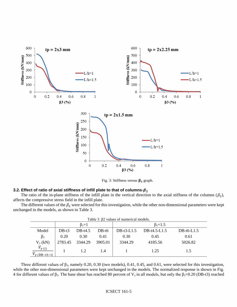
Fig. 3: Stiffness versus 𝛃𝟑 graph.
3.2. Effect of ratio of axial stiffness of infill plate to that of columns-𝜷𝟐
The ratio of the in-plane stiffness of the infill plate in the vertical direction to the axial stiffness of the columns (𝛽2),
affects the compressive stress field in the infill plate.
The different values of the 𝛽2 were selected for this investigation, while the other non-dimensional parameters were kept
unchanged in the models, as shown in Table 3.
Table 3: β2 values of numerical models.
β1=1 β1=1.5
Model DB-t3 DB-t4.5 DB-t6 DB-t3-L1.5 DB-t4.5-L1.5 DB-t6-L1.5
β2 0.20 0.30 0.41 0.30 0.45 0.61
Vy (kN) 2783.45 3344.29 3905.01 3344.29 4185.56 5026.82
𝑉𝑦 (𝑖)
𝑉𝑦 (DB−t3−i) 1 1.2 1.4 1 1.25 1.5
Three different values of β2, namely 0.20, 0.30 (two models), 0.41, 0.45, and 0.61, were selected for this investigation,
while the other non-dimensional parameters were kept unchanged in the models. The normalized response is shown in Fig.
4 for different values of β2. The base shear has reached 80 percent of Vy in all models, but only the β2=0.20 (DB-t3) reached

ICSECT 161-6
around 60 percent of Vy. For β1=1, by increasing the β2 from 0.20 to 0.41, the Vy is increased up 1.4 times, whereas for
β1=1.5, by increasing the β2 from 0.20 to 0.41, the Vy is increased up to 1.5 times.
Referring to Fig. 4, the axial stiffness ratio, β2, does not have a considerable effect on the lateral strength and stiffness
of the shear wall.
Fig. 4: β4 versus β3 graph.
The stiffness curves of DIP-SSWs with β1=1, 1.5 and various infill thicknesses are given in Fig. 5. As shown in Fig. 5,
after the drift angle of 0.7%, the infill plate thickness does not have a considerable effect on the stiffness. It should be noted
that by increasing the infill plate, the initial lateral stiffness is increased. Nevertheless, after the appearance of diagonal yield
zones, which incidentally occur at similar drift angles, the curves tend to converge towards each other.

ICSECT 161-7
Fig. 5: Stiffness versus β3.
3.3. Structural parameters 3.3.1 Energy absorption
In Fig. 6, the energy dissipation, Es, of the system is shown. The results indicate that that higher β1 values increase
energy absorption of the DIP-SSW system. Also, by increasing the tp of the infill plates, the energy absorption capacity of
the systems is improved.
Fig. 6: Energy absorption graph.
3.3.2 Overstrength and Ductility The overstrength, Ω, and the ductility, μ, of the FE models are listed in Table 4. Referring to the results of Table 4, both
β1 and β2 are effective on the mentioned parameters. But, they are more effective on the overstrength than ductility. Also, β1
is more effective than the β2 for both parameters.

ICSECT 161-8
Table 4: Structural parameters.
μ Ω
DB-t3 7.11 1.46
β1 DB-t4.5 8.44 1.60
DB-t6 8.44 1.61
DB-t3-L1.5 7.50 1.32
β2 DB-t4.5-L1.5 8.44 1.43
DB-t6-L1.5 8.44 1.54
3.3.3 Elastic stiffness and displacement corresponding to the yielding
In Table 5, the elastic stiffness, K, and displacement that correspond to the yielding, Δy, are listed to consider the effect
of the β1 and β2 on the mentioned parameters. As reported in Table 5, by increasing the thickness of the infill plate, the elastic
stiffness K is enhanced, but Δy is reduced. Also, increasing the β1 does not have an effect on the Δy, whereas by increasing
the β2, both K and Δy are improved.
Table 5: Elastic stiffness and displacement corresponding to the yielding β1=1 β1=1.5
Model DB-t3 DB-t4.5 DB-t6 DB-t3-L1.5 DB-t4.5-L1.5 DB-t6-L1.5
β2 0.20 0.30 0.41 0.30 0.45 0.61
Δy (mm) 9.50 8.00 8.00 9.00 8.00 8.00
K (kN/mm) 173.81 311.77 367.50 277.00 405.01 518.00
4. Conclusions Despite the good performance of steel shear walls, this system has not been used at civil projects widely (because of
some problems such as architect aspect requirement). In this article, an innovative model of steel shear wall was introduced,
which solves the conventional SPSW’s deficiency. Some of the conclusions of the numerical results can be ordered as
follows:
- The base shear has reached around 80 percent of Vy in all models, but only the β2=0.20 (DB-t3) reached around 60
percent of Vy.
- Increasing the aspect ratio (length to height) of the infill plate improves the behavior of the SPSW.
- After the occurrence of the first yield points in frame members and between the drift angles of 0.5% and 1%, the infills
become less effective, and all stiffness curves merge to the open frame curve.
- Higher β1 values increase energy absorption of the system. Also, by increasing the thickness of the infill plates, the
energy absorption is enhanced, too.
- Both β1 and β2 are effective on the elastic stiffness. So, the elastic stiffness K is increased by raising of the β1 and β2
parameters.
References [1] M. Shayanfar, V. Broujerdian and A. Ghamari, “Numerically and Parametrically Investigating the Cracked Steel Plate
Shear Walls (SPSWs)”, Iranian Journal of Science and Technology, Transactions of Civil Engineering, vol. 44, pp.
481-500, 2020. https://doi.org/10.1007/s40996-019-00250-6
[2] H. Wagner, “Flat sheet metal girders with very thin metal webs. Part I–General theories and assumptions”, National
Advisory Committee for Aeronautics (NACA), Technical Memo, no. 604, 1931.
[3] K. Basler, “Strength of plate girders in shear”, Trans. ASCE, vol. 128(2), pp. 683-719, 1963.

ICSECT 161-9
[4] D.M. Porter, K.C. Rockey and H.R. Evans, “The collapse behaviour of plate girders loaded in shear”, The Structural
Engineer, vol. 53, no. 8. pp. 313-325, 1975.
[5] L.J. Thorburn, G.L. Kulak and C.J. Montgomery, “Analysis of steel plate shear walls”, Structural Engineering Report
No. 107, Department of Civil Engineering, University of Alberta, Edmonton, Alberta, Canada, 1983.
[6] P.A. Timler and G.L. KuIak, “Experimental study of steel plate shear walls”, Structural Engineering Report No. 114,
Department of Civil Engineering, University of Alberta, Edmonton, Alberta, Canada, 1983.
[7] E.W. Tromposch and G.L. Kulak, “Cyclic and static behavior of thin panel steel plate shear walls”, Structural
Engineering Report No 145, Department of Civil Engineering, University of Alberta, Edmonton, Alberta, Canada, 1987.
[8] A. Khaloo, M. Foroutani and A. Ghamari, “Influence of diagonal stiffeners on the response of steel plate shear walls
(SPSWs) considering crack propagation”, Bulletin of Earthquake Engineering, vol. 17, pp. 5291-5312, 2019.
https://doi.org/10.1007/s10518-019-00685-2
[9] M. Shayanfar, V. Broujerdian and A. Ghamari, “Corner Crack Effect on the Seismic Behavior of Steel Plate Shear Wall
System”, Civil Engineering Infrastructures Journal, vol. 50, no. 2, 311-332, 2017.
https://doi.org/10.7508/ceij.2017.02.007
[10] A. Ghamari, A. Akbarpour and A. Ghanbari, “Improving behavior of semi-supported steel plate shear walls”, Journal
of Central South University, vol. 26, pp. 2891-2905, 2019. https://doi.org/10.1007/s11771-019-4222-4
[11] M. Shayanfar, V. Broujerdian and A. Ghamari, “Analysis of Coupled Steel Plate Shear Walls with Outrigger System
for Tall Buildings”, Iranian Journal of Science and Technology, Transactions of Civil Engineering, vol. 44, 151-163,
2020. https://doi.org/10.1007/s40996-019-00246-2 [12] J.W. Berman and M. Bruneau, “Experimental investigation of light-gauge steel plate shear walls”, Journal of Structural
Engineering - ASCE, vol. 131, no. 2, pp. 259-267, 2005.
[13] B. Qu, M. Bruneau, C.H. Lin and K.C. Tsai, “Testing of full-scale two-story steel plate shear wall with reduced beam
section connections and composite floors”, Journal of Structural Engineering - ASCE, vol. 134, no. 3, pp. 364-373,
2008.
[14] Canadian Standards Association (CSA), “Limit state design of steel structures – CSA-S16-2001”, Canadian Standards
Association, Toronto, Ontario, Canada, 2001.
[15] Building Seismic Safety Council, “2003 Edition NEHRP recommended provisions for seismic regulations for new
buildings and other structures (FEMA 450)”, Federal Emergency Management Agency, 2004.
[16] AISC, ANSI/AISC 341-05, “Seismic provisions for structural steel buildings”, American Institute of Steel Construction
(AISC), Chicago (IL), 2016.
[17] R. Sabelli and M. Bruneau, “Design Guide 20: Steel Plate Shear Walls”, Chicago (IL): American Institute of Steel
Construction (AISC), 2006.
[18] A. Ghamari and H. Haeri, “Improving the behavior of high performance steel plate shear walls using Low Yield Point
steel”, Case Studies in Construction Materials, vol. 14, e00511, pp. 1-12, 2021.
https://doi.org/10.1016/j.cscm.2021.e00511
[19] S.-J. Chen and C. Jhang, “Cyclic behavior of low yield point steel shear walls”, Thin-Walled Structures, vol. 44, no. 7,
pp. 730-738, 2006.
[20] S.-J. Chen and C.Z. Yen, “Application of LYP steel shear damper for seismic resistance”, Struct. Eng., vol. 15(1), pp.
3-21, 2000.
[21] S. Torii, T. Teramoto, H. Kihara and H. Kitamura, “The Response Control Design of High-Rise Building with Low
Yield Steel Wall”, in Proceedings of the 11th World Conference on Earthquake Engineering, Acapulco, Mexico, Paper
No. 97, 1996.
[22] T. Yamaguchi, T. Takeuchi, T. Nagao, T. Suzuki, Y. Nakata, T. Ikebe and A. Minami, “Seismic Control Devices Using
Low-Yield-Point Steel”, Nippon Steel Technical Report No. 77, Nippon Steel Corporation, Chiba, Japan, pp. 65-72,
1998.
[23] I. Shimoda, F. Ohsugi, T. Igarashi and J. Shiki, (1996), “Seismic retrofit system using the viscous shear wall damper
(Viscous Wall Damper)”, Lecture Summary, Architectural Institute of Japan, Kinki, Japan.

ICSECT 161-10
[24] M.M. Alinia and M. Dastfan, “Cyclic behaviour, deformability and rigidity of stiffened steel shear panels”, Journal of
Constructional Steel Research, vol. 63, no. 4, pp. 554–563, 2007.
[25] M.M. Alinia and R. Sarraf Shirazi, On the design of stiffeners in steel plate shear walls, Journal of Constructional Steel
Research, vol. 65, no. 10, pp. 2069-2077, 2009.
[26] H.R. Habashi, M.M. Alinia, “Characteristics of the wall-frame interaction in steel plate shear walls”, Journal of
Constructional Steel Research, vol. 66, no. 2, pp. 150-158, 2010.
[27] A. Astaneh-Asl, “Seismic studies of innovative and traditional composite shear walls”, Research project, Department
of Civil and Enviromental Engineering, University of California Berkeley, Berkeley, CA, USA, 1998-2000.
[28] C. Avci-Karatas and A. Ghamari, “Analysis approach for composite steel plate shear walls (CSPSW) reinforced with
CFRP”, in the 2021 International Conference on Steel and Composite Structures (ICSCS21) of ASEM21, Seoul, Korea,
2021.
[29] D. Dan, A. Fabian, and V. Stoian, “Theoretical and experimental study on composite steel-concrete shear walls with
vertical steel encased profiles”, Journal of Constructional Steel Research, vol. 67, no. 5, pp. 800-813, 2011.
[30] A. Arabzadeh, M. Soltani and A. Ayazi, “Experimental investigation of composite shear walls under shear loadings”,
Thin-Walled Structures, vol. 49, no. 7, pp. 842-854, 2011.
[31] A. Arabzade, H. Moharami and A. Ayazi, “Local elastic buckling coefficients of steel plates in composite steel plate
shear walls”, Scientia Iranica, vol. 18, no. 1, pp. 9-15, 2011.
[31] M. Xue and L.-W. Lu, “Influence of steel shear wall panels with surrounding frame members”, in Proc. SSRC Annual
Technical Session, pp. 339-354, 1994.
[32] R.G. Driver, G.Y. Grondin, M. Behbahanifard and M.A. Hussain, “Recent developments and future directions in steel
plate shear wall research”, in Proc. North American Steel Construction Conference, 2001.
[33] H. Moharrami, A. Habibnejad, A. Mazrouei and H. Alizadeh, “Semi-supported thin steel shear walls”, Research report
no. 1-4679, The Building and Housing Research Centre, 2006.
[34] A. Jahanpour, H. Moharrami and A. Aghakoochak, “Evaluation of ultimate capacity of semi-supported steel shear
walls”, Journal of Constructional Steel Research, vol. 67, no. 6, pp. 1022-1030, 2011.
[35] R. Driver, G. Kulak, D. Kennedy and A. Elwi, “Cyclic test of four-story steel plate shear wall”, Journal of Structural
Engineering, vol. 124, pp. 112-120, 1998.
[36] S.M. Salimi, S. Rahimi, M. Hoseinzadeh, D.-P.N. Kontoni, M. Ebadi-Jamkhaneh, “Numerical 3D Finite Element
Assessment of Bending Moment-Resisting Frame Equipped with Semi-Disconnected Steel Plate Shear Wall and
Yielding Plate Connection”, Metals, vol. 11, no. 4, article 604, pp. 1-19, 2021. https://doi.org/10.3390/met11040604
[37] M. Rezai, “Seismic Behaviour of Steel Plate Shear Walls by Shake Table Testing”, Ph.D. Dissertation, Department of
Civil Engineering, University of British Columbia, Vancouver, Canada, 1999.
[38] ASCE, ASCE/SEI 7-05, “Minimum Design Loads for Buildings and Other Structures”, Virginia (USA): American
Society of Civil Engineers, 2006.
[39] M. R. Behbahanifard, G.Y. Grondin and A. Elwi, “Experimental and Numerical study Investigation of Steel Plate Shear
Wall”, Structural Engineering Report No. 254, University of Alberta, 2003.
[40] CSA, CAN/CSA S16-01, Limit States Design of Steel Structures, Canadian Standards Association, Mississauga,
Ontario, Canada, 2001.
Related Documents