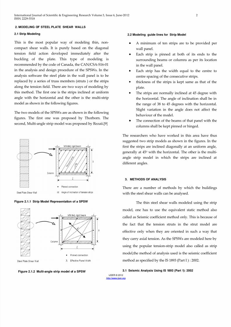
International Journal of Scientific & Engineering Research Volume 3, Issue 6, June-2 012 1 ISSN 2229-5518 IJSER © 2012 http://www.ijser.org Analysis and Design of steel framed buildings with and without Steel Plate Shear Walls Ms Deepika C. Hiwrale 1 , Prof. P.S. Pajgade 2 ABSTRACT The present paper describes the analysis and design of high-rise steel building frame with and without Steel plate shear wall (SPSW). For present work equivalent static analysis is carried out for steel moment resisting building frame having (G+6) storey situated in zone III. Modelling will be done by using strip modelling. The analysis of steel plate shear wall and the building are carried out using Software STAAD PRO V8i SELECT series II. The main parameters consider in this paper to compare the seismic performance of buildings are bending moment, shear force, deflection and axial force. The models are analyze by equivalent static analysis as per IS 1893:2002 and design will be carried out by using IS 800-2007. Keywords — Steel plate shear wall ( SPSW) , steel building, strip model, IS 800-2007 , IS 1893-2002, seismic coefficient method, tension field action, seismic design, boundary element. —————————— —————————— 1. 1 INTRODUCTION As compare to the Reinforced cement concrete (RCC) the steel has got some important physical properties like the high strength per unit weight and ductility [3]. The high yield and ultimate strength result in slender sections. Being ductile the steel structures give sufficient advance warning before failure by way of excessive deformations. These properties of steel are of very much vital in case of the seismic resistant design. Steel shear wall is a lateral load resisting system consisting of vertical steel plate infills connected to the surrounding beams and columns and installed in one or more bays along the full height of the structure to form a cantilever wall. Shear walls are vertical elements of the horizontal force resisting system. The main role of steel shear wall is to collect lateral forces of earthquake in a building and transfer those forces to the foundation. The web plates in steel shear walls are categorized according to their ability to resist buckling. ———————————————— 1 Final Year Student (M.E. Structure) , 2 Professor Department Of Civil Engineering Prof. Ram Meghe Institute of Technology & Research Badnera, Amravati-444701, Maharashtra, India Email ID: [email protected] Email ID: [email protected] The web plates can be sufficiently stiffened to preclude buckling and allow the full shear strength of the web to be reached. The steel plate shear walls are mainly used in multistoried building in the foreign countries such America, Japan, Canada etc. 1.2 PURPOSE OF SPSW Shear walls are not only designed to resist gravity / vertical loads (due to its self-weight and other living / moving loads), but they are also designed for lateral loads of earthquakes / wind. the walls are structurally integrated with roofs / floors (diaphragms) and other lateral walls running across at right angles, thereby giving the three dimensional stability for the building structures. Shear wall structural systems are more stable. Because, their supporting area (total cross-sectional area of all shear walls) with reference to total plans area of building, is comparatively more, unlike in the case of RCC framed structures. Walls have to resist the uplift forces caused by the pull of the wind. Walls have to resist the shear forces that try to push the walls over. Walls have to resist the lateral force of the wind that tries to push the walls in and pull them away from the building.

Welcome message from author
This document is posted to help you gain knowledge. Please leave a comment to let me know what you think about it! Share it to your friends and learn new things together.
Transcript

8/18/2019 Steel plate shear walls
http://slidepdf.com/reader/full/steel-plate-shear-walls 1/9
International Journal of Scientific & Engineering Research Volume 3, Issue 6, June-2012 1ISSN 2229-5518
IJSER © 2012
http://www.ijser.org
Analysis and Design of steel framed buildingswith and without Steel Plate Shear Walls
Ms Deepika C. Hiwrale 1, Prof. P.S. Pajgade 2
ABSTRACT
The present paper describes the analysis and design of high-rise steel building frame with and without Steel plate shear wall (SPSW).
For present work equivalent static analysis is carried out for steel moment resisting building frame having (G+6) storey situated in zone III.
Modelling will be done by using strip modelling. The analysis of steel plate shear wall and the building are carried out using Software STAAD
PRO V8i SELECT series II. The main parameters consider in this paper to compare the seismic performance of buildings are bending moment,
shear force, deflection and axial force. The models are analyze by equivalent static analysis as per IS 1893:2002 and design will be carried out
by using IS 800-2007.
Keywords — Steel plate shear wall ( SPSW) , steel building, strip model, IS 800-2007 , IS 1893-2002, seismic coefficient method, tension
field action, seismic design, boundary element.
—————————— ——————————
1. 1 INTRODUCTION
As compare to the Reinforced cement concrete (RCC)
the steel has got some important physical properties like the
high strength per unit weight and ductility [3]. The high
yield and ultimate strength result in slender sections. Being
ductile the steel structures give sufficient advance warning
before failure by way of excessive deformations. These
properties of steel are of very much vital in case of the
seismic resistant design. Steel shear wall is a lateral load
resisting system consisting of vertical steel plate infillsconnected to the surrounding beams and columns and
installed in one or more bays along the full height of the
structure to form a cantilever wall. Shear walls are vertical
elements of the horizontal force resisting system. The main
role of steel shear wall is to collect lateral forces of
earthquake in a building and transfer those forces to the
foundation. The web plates in steel shear walls are
categorized according to their ability to resist buckling.
————————————————
1 Final Year Student (M.E. Structure) , 2 Professor Department Of Civil Engineering
Prof. Ram Meghe Institute of Technology & Research
Badnera, Amravati-444701, Maharashtra, India
Email ID: [email protected]
Email ID: [email protected]
The web plates can be sufficiently stiffened to preclude
buckling and allow the full shear strength of the web to be
reached. The steel plate shear walls are mainly used in
multistoried building in the foreign countries such
America, Japan, Canada etc.
1.2 PURPOSE OF SPSW
Shear walls are not only designed to resist gravity
/ vertical loads (due to its self-weight and other living
moving loads), but they are also designed for lateral loads
of earthquakes / wind. the walls are structurally integrated
with roofs / floors (diaphragms) and other lateral walls
running across at right angles, thereby giving the three
dimensional stability for the building structures. Shear wal
structural systems are more stable. Because, their
supporting area (total cross-sectional area of all shear walls
with reference to total plans area of building, is
comparatively more, unlike in the case of RCC framed
structures.
Walls have to resist the uplift forces caused by thepull of the wind.
Walls have to resist the shear forces that try to
push the walls over.
Walls have to resist the lateral force of the wind
that tries to push the walls in and pull them away
from the building.
8/18/2019 Steel plate shear walls
http://slidepdf.com/reader/full/steel-plate-shear-walls 2/9

8/18/2019 Steel plate shear walls
http://slidepdf.com/reader/full/steel-plate-shear-walls 3/9
International Journal of Scientific & Engineering Research Volume 3, Issue 6, June-2012 3ISSN 2229-5518
IJSER © 2012
http://www.ijser.org
3.1.1 Static Analysis
Load factors
In the design of steel structure, following load
combinations as given in the IS 1893 (Part1): 2002 and IS
800-2007 are:
1.5 DL+1.5 LL+ 1.5RLL
1.2 DL+0.6 LL+1.2 EL
1.2 DL+0.6 LL-1.2 EL
1.5 DL+1.5 EL
1.5 DL-1.5 EL
0.9 DL+1.5 EL
0.9 DL-1.5 EL
4. DESIGN OF STEEL BUILDING WITH AND WITHOUT
STEEL PLATE SHEAR WALL
4.1 DESIGN OF STEEL BUILDING WITH STEELPLATE SHEAR WALL
Fig. 4.1 Idealized tension- field action in a typical SPW
4.1.1 Thickness of steel panel
t wi =
Where ,
i the i-th story
Vi is the storey shearL is the bay width
Fy is the material yield stress
4.1.2 Equation for the inclination angle of the
tension field, in a SPSW infill plate:
α = tan 1
Where,
t = Thickness of web plate
L = distance between VBE centerlineAc = cross- sectional area of a VBE
h = distance between HBE centerline
Ab = cross- sectional area of a HBE
Ic = moment of inertia of a VBE taken
perpendicular to the direction of the
web plate line
4.1.3 DESIGN OF VERTICAL BOUNDARY ELEMENT
For vertical boundary elements (VBE), it has been
recommende that the moment of inertia Ic should be suchthat [9 ] :
0.70 h ≤ 2.5
I c ≥
4.1.4 SHEAR STRENGTH OF STEEL PLATE PANEL
The shear panels are represented as a series of inclined
strip members, capable of transmitting tension forces only,and oriented in the same direction as the principal tensile
stresses in the panel. [10 ]
Design Strength of Tension member as per the IS 800-2007 cl. 6.2
[12]
T dg =
where,
f y = yield stress of material
Ag
= gross area of cross – secti Ƴmo = partial safety factor for failure in tension
By yielding
4.2 DESIGN OF STEEL BUILDING WITHOUT
STEEL PLATE SHEAR WALL
8/18/2019 Steel plate shear walls
http://slidepdf.com/reader/full/steel-plate-shear-walls 4/9
International Journal of Scientific & Engineering Research Volume 3, Issue 6, June-2012 4ISSN 2229-5518
IJSER © 2012
http://www.ijser.org
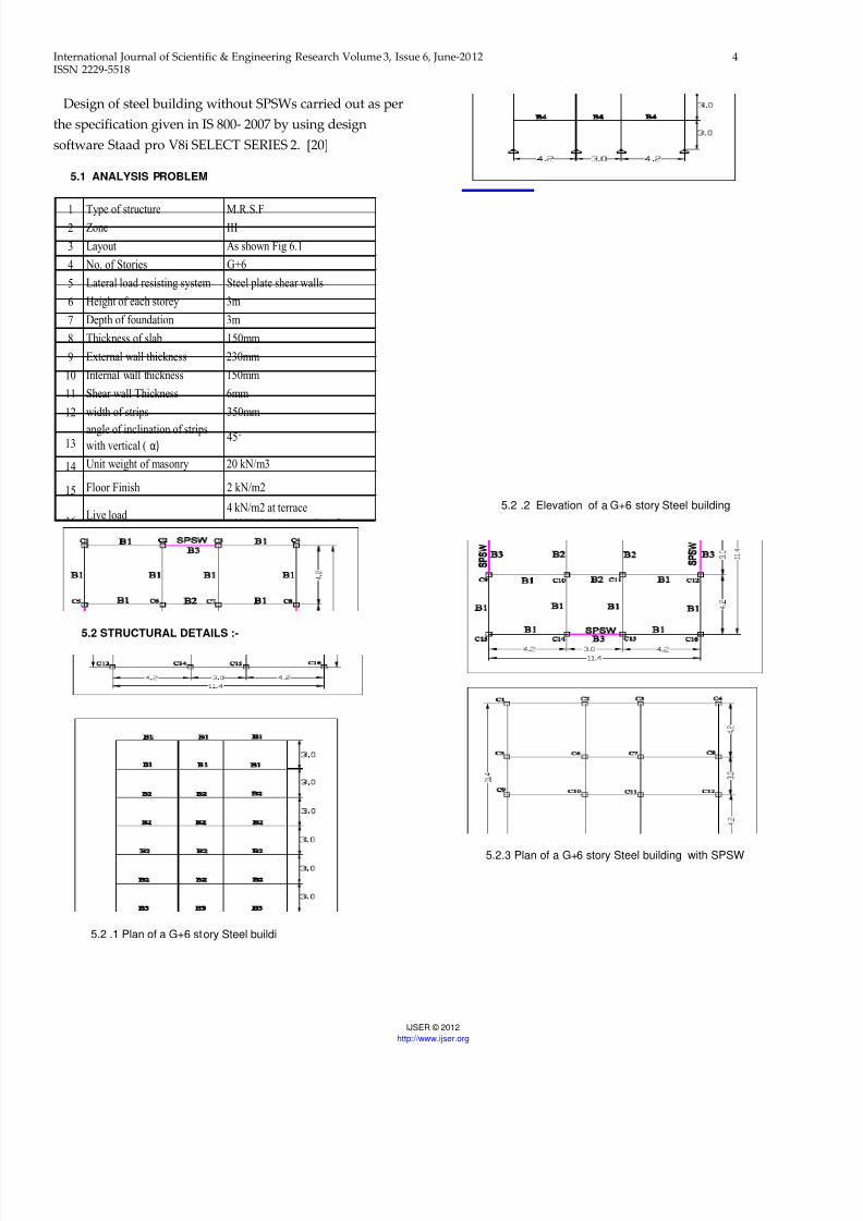
Design of steel building without SPSWs carried out as per
the specification given in IS 800- 2007 by using design
software Staad pro V8i SELECT SERIES 2. [20]
5.1 ANALYSIS PROBLEM
5.2 STRUCTURAL DETAILS :-
5.2 .1 Plan of a G+6 story Steel buildi
5.2 .2 Elevation of a G+6 story Steel building
5.2.3 Plan of a G+6 story Steel building with SPSW
1 Type of structure M.R.S.F2 Zone III
3 Layout As shown Fig 6.1
4 No. of Stories G+6
5 Lateral load resisting system Steel plate shear walls
6 Height of each storey 3m
7 Depth of foundation 3m
8 Thickness of slab 150mm
9 External wall thickness 230mm
10 Internal wall thickness 150mm
11 Shear wall Thickness 6mm
12 width of strips 350mm
13angle of inclination of stripswith vertical ( α)
45°
14 Unit weight of masonry 20 kN/m3
15 Floor Finish 2 kN/m2
16Live load
4 kN/m2 at terrace
4 kN/m2 at intermediate floor
17 Type of soil Medium
18Seismic Analysis
Seismic coefficient Method
(IS 1893-2002)
19Design of philosophy
Limit state method conforming to
IS 800-2007

8/18/2019 Steel plate shear walls
http://slidepdf.com/reader/full/steel-plate-shear-walls 5/9
International Journal of Scientific & Engineering Research Volume 3, Issue 6, June-2012 5ISSN 2229-5518
IJSER © 2012
http://www.ijser.org
5 .2.4 Elevation of a G+6 story Steel building with SPSW
5.3 Member Specification:
For Steel building :
Size of Beam :
B1 = ISHB 225
B2 = ISWB 350
B3 = ISHB 300H
B4 = ISHB 400Size of Column :
1 ) FOR C1 , C4 , C13 , C16
TUBE 330 X 330 X 8
TUBE 330 X 330 X 10
TUBE 330 X 330 X 16
2 ) FOR C2 , C3 , C5 , C9 , C8 ,
C12 , C14 , 15
TUBE 330 X 330 X 16
TUBE 330 X 330 X 12
TUBE 330 X 330 X 10
TUBE 330 X 330 X 8
3 ) FOR C6 , C7 , C10 , C11
TUBE 330 X 330 X 20
TUBE 330 X 330 X 16
TUBE 330 X 330 X 12
TUBE 330 X 330 X 10
TUBE 330 X 330 X 8
For SPSWs Building:
Size of Beam :
B1 = ISWB 300
B2 = ISHB 200
B3 = ISWB 150
Size of Column :
1 ) FOR C1 , C4 , C13 , C16
TUBE 270 X 270 X 6
TUBE 270 X 270 X 8
2 ) FOR C2 , C3 , C5 , C9 , C8 ,
C12 , C14 , 15
TUBE 270 X 270 X 8
TUBE 270 X 270 X 10
TUBE 270 X 270 X 12
3 ) FOR C6 , C7 , C10 , C11
TUBE 270 X 270 X 8
TUBE 270 X 270 X 10
The above mentioned both the frame has been
analysed and Design by using STAAD-PRO V8i SELECT
SERIES 2 software. For getting results some column has been selected and they are as column nos. 1 ,7 & 9. The
results found to be are shown with the help of graph for the
parameters.
1. Deflection
2. Shear force
3. Moment
4. Axial force
5. Ast
8/18/2019 Steel plate shear walls
http://slidepdf.com/reader/full/steel-plate-shear-walls 6/9
International Journal of Scientific & Engineering Research Volume 3, Issue 6, June-2012 6ISSN 2229-5518
IJSER © 2012
http://www.ijser.org
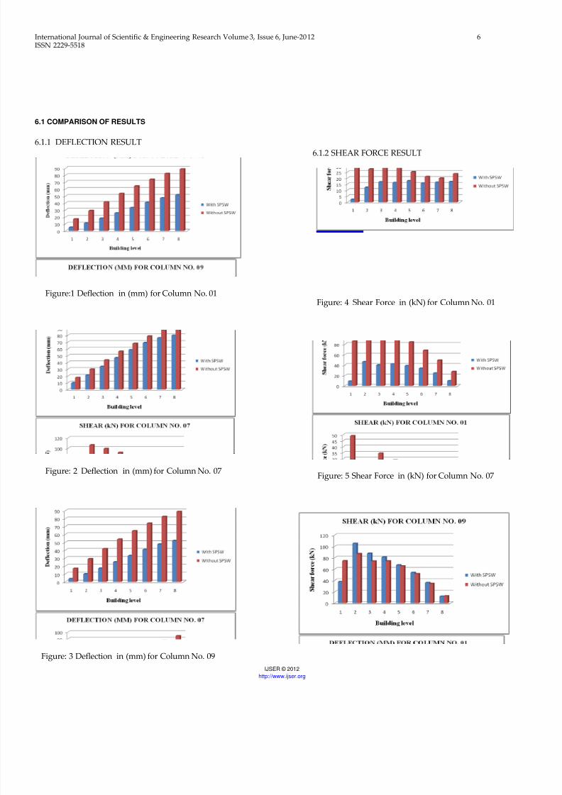
6.1 COMPARISON OF RESULTS
6.1.1 DEFLECTION RESULT
Figure:1 Deflection in (mm) for Column No. 01
Figure: 2 Deflection in (mm) for Column No. 07
Figure: 3 Deflection in (mm) for Column No. 09
6.1.2 SHEAR FORCE RESULT
Figure: 4 Shear Force in (kN) for Column No. 01
Figure: 5 Shear Force in (kN) for Column No. 07
8/18/2019 Steel plate shear walls
http://slidepdf.com/reader/full/steel-plate-shear-walls 7/9
International Journal of Scientific & Engineering Research Volume 3, Issue 6, June-2012 7ISSN 2229-5518
IJSER © 2012
http://www.ijser.org
Figure: 6 Shear Force in (kN) for Column No. 09
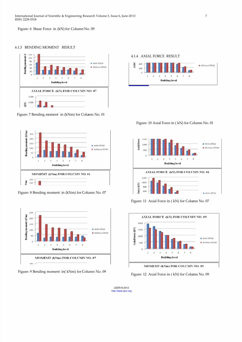
6.1.3 BENDING MOMENT RESULT
Figure: 7 Bending moment in (kNm) for Column No. 01
Figure: 8 Bending moment in (kNm) for Column No. 07
Figure: 9 Bending moment in( kNm) for Column No. 09
4.1.4 AXIAL FORCE RESULT
Figure: 10 Axial Force in ( kN) for Column No. 01
Figure: 11 Axial Force in ( kN) for Column No. 07
Figure: 12 Axial Force in ( kN) for Column No. 09

8/18/2019 Steel plate shear walls
http://slidepdf.com/reader/full/steel-plate-shear-walls 8/9
8/18/2019 Steel plate shear walls
http://slidepdf.com/reader/full/steel-plate-shear-walls 9/9
International Journal of Scientific & Engineering Research Volume 3, Issue 6, June-2012 9ISSN 2229-5518
IJSER © 2012
http://www.ijser.org
Related Documents


![FULL AND PERFORATED METAL PLATE SHEAR WALLS …ingegneriasismica.org/wp-content/uploads/2016/08/Formisano-finale.pdf · Steel Plate Shear Walls ... and perforated steel plates 0 2007],](https://static.cupdf.com/doc/110x72/5b1532617f8b9a4e2c8e0564/full-and-perforated-metal-plate-shear-walls-steel-plate-shear-walls-and.jpg)