TECHNISCHE UNIVERSIT ¨ AT M ¨ UNCHEN Lehrstuhl f¨ ur Robotik, K¨ unstliche Intelligenz und Echtzeitsysteme Improving Industrial Corrective Maintenance by Efficient Realization of Self-Diagnosis in Automated Production Systems Reusing Their Engineering Data Milan Vathoopan Kannan Vollst¨ andiger Abdruck der von der Fakult¨ at der Informatik der Technischen Universit¨ at M¨ unchen zur Erlangung des akademischen Grades eines Doktors der Naturwissenschaften (Dr. rer. nat.) genehmigten Dissertation. Vorsitzender: Prof. Dr.-Ing. Alin Albu-Sch¨ affer Pr¨ ufer der Dissertation: 1. Prof. Dr.-Ing. habil. Alois Knoll 2. Prof. Dr.-Ing. Alois Zoitl Die Dissertation wurde am 19.06.2020 bei der Technischen Universit¨ at M¨ unchen eingereicht und durch die Fakult¨ at f¨ ur Informatik am 09.11.2020 angenommen.

Welcome message from author
This document is posted to help you gain knowledge. Please leave a comment to let me know what you think about it! Share it to your friends and learn new things together.
Transcript
TECHNISCHE UNIVERSITAT MUNCHENLehrstuhl fur Robotik, Kunstliche Intelligenz und Echtzeitsysteme
Improving Industrial Corrective Maintenance byEfficient Realization of Self-Diagnosis in Automated
Production Systems Reusing Their Engineering Data
Milan Vathoopan Kannan
Vollstandiger Abdruck der von der Fakultat der Informatik der Technischen Universitat Munchen
zur Erlangung des akademischen Grades eines
Doktors der Naturwissenschaften (Dr. rer. nat.)
genehmigten Dissertation.
Vorsitzender: Prof. Dr.-Ing. Alin Albu-Schaffer
Prufer der Dissertation: 1. Prof. Dr.-Ing. habil. Alois Knoll
2. Prof. Dr.-Ing. Alois Zoitl
Die Dissertation wurde am 19.06.2020 bei der Technischen Universitat Munchen eingereicht und
durch die Fakultat fur Informatik am 09.11.2020 angenommen.

Copyright © 2020
Milan Vathoopan Kannan
All rights reserved. The author by no means claims the rights on the component images from
different vendors used in Figures 6.1 and 8.3.
Abstract
Maintenance refers to the set of activities required to keep the functional state of any
system. Maintenance is of different types and can take place with or without prior
knowledge of occurrence of faults in a system. The corrective maintenance refers
to the maintenance function that takes place with prior knowledge of occurrence of
faults in a system. Within the domain of industrial manufacturing, the state-of-the-
art corrective maintenance is human intensive. Hence, any human error or incapabil-
ity affects the industrial corrective maintenance negatively. Many researchers have
highlighted the importance of improving corrective maintenance for improving the
industrial production in the future. Consequently, this thesis examines means and
methodologies for improving the efficiency of humans in corrective maintenance, and
hence improving the industrial corrective maintenance in the future.
This thesis identifies enablement of visual assistive and self-diagnosis features in in-
dustrial automation systems, as a means to improve human efficiency in industrial
corrective maintenance. However, many researchers identify high effort and cost for
realization as the deterrents, for enabling self-diagnosis in industrial automation sys-
tems. Consequently, this thesis further focuses on approaches for cost and resource
efficient realization of self-diagnosis in future industrial automation systems. Fore-
seeing the future automation systems to be component based, this thesis proposes
effectively reusing the engineering data for realizing the self-diagnosis in automation
components and systems of the future. A visual model of the corrective maintenance
activity flawlessly integrates the self-diagnosis within it and assists the human for
performing industrial corrective maintenance.
It is crucial to note that, the proposed solution is evaluated with two application
examples. The first application example confirms the substantial improvement in
industrial corrective maintenance, by efficient realization of self-diagnosis in automa-
tion systems. The results from the second application example prove the scalability
of the solution to an industrial environment. By improving the industrial corrective
maintenance, this thesis establishes the foundation for improving the industrial pro-
duction in the future. Hence, by enhancing the solution a significant progress in the
domain of industrial manufacturing is foreseen.

Kurzfassung
Instandhaltung umfasst jene Aktivitaten, die erforderlich sind, um den funktionstuch-
tigen Zustand eines Systems aufrecht zu erhalten. Es gibt verschiedene Arten von
Instandhaltung, abhangig davon, ob vor der Durchfuhrung Kenntnis von Fehlern in
einem System vorliegt. Der Begriff der korrektiven Instandhaltung bezieht sich auf
Tatigkeiten, die unter Kenntnis bereits aufgetretener Fehler durchgefuhrt werden.
Nach dem aktuellen Stand der Technik werden im Bereich der industriellen Fertigung
Maßnahmen der korrektiven Instandhaltung von Menschen ausgefuhrt. Fehlerhafte
Ausfuhrung infolge menschlichen Versagens und Verzogerungen aufgrund fehlender
Informationen konnen erhebliche zusatzliche Kosten verursachen. Die Verbesserung
der korrektiven Instandhaltung, insbesondere in der industriellen Produktion, wur-
de bereits von vielen Forschern als relevantes Feld fur Verbesserungen identifiziert.
In dieser Dissertation werden daher Mittel und Methoden herausgearbeitet um die
korrektive Instandhaltung im Bereich der industriellen Fertigung zu verbessern.
Als geeignete Mittel, um den Ausfuhrenden bei der korrektiven Instandhaltung von
Maschinen und Anlagen in der industriellen Fertigung zu unterstutzen und seine Ef-
fizienz zu steigern, wurden in dieser Arbeit Selbstdiagnose sowie visuelle Werkzeuge
identifiziert. Selbstdiagnose in industriellen Automatisierungsanlagen ist zum aktu-
ellen Stand der Technik allerdings nur aufwandig und kostspielig realisierbar. Um
ihren Einsatz dennoch zu ermoglichen, werden in dieser Dissertation Methoden zur
kosten- und ressourceneffizienten Realisierung der Selbstdiagnose entwickelt. Es wird
angenommen, dass es sich bei zukunftigen Automatisierungssystemen um komponen-
tenbasierte Systeme handeln wird. Diese Dissertation schlagt daher die Wiederver-
wendung der Konstruktionsdaten von Komponenten und Systemen zur Realisierung
der Selbstdiagnose vor. Die zur Selbstdiagnose befahigten Komponenten und Syste-
me werden außerdem in ein visuelles Modell integriert, das den Anwender bei der
Durchfuhrung der korrektiven Instandhaltung unterstutzt.
Die vorgeschlagene Losung wird anhand von zwei Anwendungsbeispielen evaluiert.
Das erste Anwendungsbeispiel weist eine signifikante Verbesserung der industriellen
korrektiven Instandhaltung durch die effiziente Realisierung von Selbstdiagnose in
Automatisierungssystemen nach. Die Ergebnisse des zweiten Anwendungsbeispiels

bestatigen, dass die Losung fur eine industrielle Umgebung skaliert. Durch die Ver-
besserung der industriellen korrektiven Instandhaltung schafft diese Dissertation die
Grundlage fur die kunftige Verbesserung der industriellen Produktion.
Acknowledgements
My deepest gratitude goes first to Prof. Dr. Alois Knoll, for giving me the opportu-
nity to work on this challenging research topic. His immense knowledge and critical
thinking guided me in shaping this thesis by continuous improvement. I would also
like to thank Prof. Dr. Alois Zoitl, for accepting to support and evaluate my thesis
externally. My gratitude to him extends further, since he guided me to set this topic
and mentored me throughout the thesis with patience and motivation.
I would like to thank Benjamin Brandenbourger, Dr. Monika Wenger, Georg Neugsch-
wandtner, Hendrik Walzel, Waldemar Eisenmenger, Kiril Dorofeev, Jose Cabral, Ben
Schneider, Nisrine Bnouhanna, David Tiefenthaler, all other colleagues and students
at fortiss, who supported me during this thesis. My special thanks goes to Dr.
Monika Wenger for supporting me in the completion and review of this thesis. My
sincere thanks also goes to Dr. Dhiraj Gulati, for his constructive criticism and
valuable review of this thesis. I would like to appreciate, Dr. Vincent Aravantinos
for his timely and insightful guidance. I am grateful to Georg Neugschwandtner and
Benjamin Brandenbourger for the stimulating discussions. I am also thankful to
Prof. Rute Sofia for supporting me in managing the project work during the final
year of this thesis.
My hearty appreciation goes to Mathias Wiegand and Manuel Paul from Festo AG,
for helping with the development of technologies used in this thesis. I am also
thankful to the workshop team of the AutomationML consortium for supporting me
with constructive feedback throughout this work.
Finally, I would like to thank my parents Kunhikannan Thekkandathil and Chandara-
mathi Vathoopan, all other family members and friends for constantly supporting
and pushing me to finish this thesis. Finally yet importantly, I would like to thank
my wife Dr. Vidhya M Haridas for her love and moral support, especially during the
completion of this work. Without her motivation, I would never have been able to
complete this work.

Contents
1 Introduction 1
1.1 Background . . . . . . . . . . . . . . . . . . . . . . . . . . . . . . . . . . . . . . . 1
1.2 Problem Description . . . . . . . . . . . . . . . . . . . . . . . . . . . . . . . . . . 3
1.3 Motivation . . . . . . . . . . . . . . . . . . . . . . . . . . . . . . . . . . . . . . . 6
1.4 Research Objectives and Contributions . . . . . . . . . . . . . . . . . . . . . . . . 6
1.5 Thesis Structure . . . . . . . . . . . . . . . . . . . . . . . . . . . . . . . . . . . . 7
2 State-Of-The-Art Review of the Literature 9
2.1 Fundamentals of Factories of the Future . . . . . . . . . . . . . . . . . . . . . . . 9
2.1.1 Basic Characteristics of Factories of the Future . . . . . . . . . . . . . . . 10
2.1.2 Humans as the Strategic Decision Makers . . . . . . . . . . . . . . . . . . 13
2.1.3 Complexity as a Key Problem to be Addressed . . . . . . . . . . . . . . . 14
2.2 State-Of-The-Art Review of Plant Engineering and Operation . . . . . . . . . . . 14
2.2.1 Increasing Digitization and Data Generation in Engineering . . . . . . . . 15
2.2.2 State-Of-The-Art Methodologies of Plant Engineering . . . . . . . . . . . 16
2.2.3 Information Exchange and Communication within Plant Operation . . . . 18
2.3 State-Of-The-Art Review of Industrial Corrective Maintenance . . . . . . . . . . 20
2.3.1 Types of Industrial Maintenance . . . . . . . . . . . . . . . . . . . . . . . 20
2.3.2 Basics of Industrial Corrective Maintenance . . . . . . . . . . . . . . . . . 21
2.3.3 Important Facts and Figures of Industrial Corrective Maintenance . . . . 22
2.3.4 Management of Maintenance Activities in Industries . . . . . . . . . . . . 23
2.3.5 Importance of Improving Industrial Corrective Maintenance . . . . . . . . 23
2.4 Improving Industrial Corrective Maintenance by Applying Self-Diagnosis . . . . . 26
2.4.1 Fundamentals of Self-Diagnosis . . . . . . . . . . . . . . . . . . . . . . . . 26
2.4.2 Self-Diagnosis and Corrective Maintenance . . . . . . . . . . . . . . . . . 28
2.4.3 Importance of Applying Visual Assistive Models with Self-Diagnosis . . . 29
2.5 Scope of the Research and Questions Addressed . . . . . . . . . . . . . . . . . . . 29
vii
CONTENTS
3 Requirements for Enabling Self-Diagnosis in Future Corrective Maintenance 33
3.1 Requirements Engineering as a Means to Ensure Industrial Applicability of the
Research Results . . . . . . . . . . . . . . . . . . . . . . . . . . . . . . . . . . . . 33
3.2 Defining the Desired Practice of Requirements Engineering . . . . . . . . . . . . 34
3.3 Stakeholders and Stated Requirements of the Systems . . . . . . . . . . . . . . . 35
3.3.1 Identifying the Stakeholders . . . . . . . . . . . . . . . . . . . . . . . . . . 36
3.3.2 Stated Requirements . . . . . . . . . . . . . . . . . . . . . . . . . . . . . . 37
3.4 Use-case Analysis and Elicited Requirements . . . . . . . . . . . . . . . . . . . . 39
3.4.1 Use-cases of the Systems . . . . . . . . . . . . . . . . . . . . . . . . . . . . 39
3.4.2 Eliciting the Requirements . . . . . . . . . . . . . . . . . . . . . . . . . . 42
3.5 Conclusion . . . . . . . . . . . . . . . . . . . . . . . . . . . . . . . . . . . . . . . 43
4 Modelling Self-Diagnosis of Modular Industrial Automation Components 45
4.1 Prerequisites for Modelling Self-Diagnosis of Automation Components . . . . . . 45
4.1.1 Prerequisite Associated with the Skill Model of a Component . . . . . . . 46
4.1.2 Prerequisite Associated with the Behaviour Model of a Component . . . . 47
4.2 Implementing Self-Diagnosis of Automation Components Using Model of a Skill . 49
4.3 Identifying Plausible Faults for Diagnosing Skill of an Automation Component . 50
4.3.1 Software Related Faults . . . . . . . . . . . . . . . . . . . . . . . . . . . . 50
4.3.2 Hardware Related Faults . . . . . . . . . . . . . . . . . . . . . . . . . . . 51
4.4 Reusing Engineering Data for Modelling Self-Diagnosis of Automation Components 52
4.4.1 Handling Variants of Automation Components . . . . . . . . . . . . . . . 54
4.4.2 Diagnosing Software Faults of Automation Components . . . . . . . . . . 55
4.4.3 Diagnosing Hardware Faults of Automation Components . . . . . . . . . 55
4.5 Conclusion . . . . . . . . . . . . . . . . . . . . . . . . . . . . . . . . . . . . . . . 58
5 Modelling Self-Diagnosis of Component Based Automation Systems 61
5.1 Prerequisites for Modelling Self-Diagnosis of Future Automation Systems . . . . 61
5.2 Analysing Fault Tree for Reconfigurable Self-Diagnosis Models . . . . . . . . . . 63
5.3 Analysing Planning Models for Fault-Tree Based Reconfigurable Self-Diagnosis . 63
5.4 Generating Fault-Tree Based Self-Diagnosis Models from Planning Models . . . . 65
5.4.1 Deriving the Detection and Localization of Fault in an Automation System 66
5.4.2 Deriving the Diagnosis of Fault in an Automation System . . . . . . . . . 67
5.5 Conclusion . . . . . . . . . . . . . . . . . . . . . . . . . . . . . . . . . . . . . . . 67
6 Improving Self-Diagnosing Automation Systems’ Realization and Application 69
6.1 Application of Standards for Improving the Realization of Self-Diagnosis . . . . . 69
6.1.1 Importance of Applying Available Industrial Automation Standards . . . 70
viii

CONTENTS
6.1.2 Proposed Standards for Improving the Self-Diagnosis Models of Automa-
tion Components . . . . . . . . . . . . . . . . . . . . . . . . . . . . . . . . 71
6.1.3 Proposed Standards for Improved Generation of Self-Diagnosis Models of
Automation Systems . . . . . . . . . . . . . . . . . . . . . . . . . . . . . . 72
6.2 Deployment of Different Stakeholders in the System Development . . . . . . . . . 72
6.3 Self-Diagnosing Automation Systems and Corrective Maintenance . . . . . . . . 74
6.3.1 Taking Humans in the Loop with a Visual Interface . . . . . . . . . . . . 74
6.3.2 Leveraging Humans as the Strategic Decision Makers . . . . . . . . . . . . 76
6.4 Conclusion . . . . . . . . . . . . . . . . . . . . . . . . . . . . . . . . . . . . . . . 76
7 Realizing the Self-Diagnosing Automation Systems of Future 79
7.1 AutomationML for Modelling Self-Diagnosis by Reusing the Engineering Data . 79
7.1.1 Comparison of Existing Description Languages . . . . . . . . . . . . . . . 80
7.1.2 AutomationML and Its Features . . . . . . . . . . . . . . . . . . . . . . . 81
7.1.3 Modelling Automation Components’ Inter-model Relations, Connectors
and Skills in AutomationML . . . . . . . . . . . . . . . . . . . . . . . . . 83
7.1.4 AutomationML for Reusing Engineering Models for Self-Diagnosis . . . . 86
7.1.5 AutomationML for Deducing Fault Tree from Planning Model . . . . . . 88
7.2 SystemPlanner between Planning and Maintenance Phases of Automation Systems 89
7.3 Using Eclipse 4diac for IEC 61499 Based Distributed Self-Diagnosis Models . . . 91
7.3.1 Modelling Self-Diagnosis of Automation Components . . . . . . . . . . . . 92
7.3.2 Generating Self-Diagnosis of Automation Systems . . . . . . . . . . . . . 93
7.3.3 Using OPC UA for Interoperability among Models within Eclipse 4diac . 94
7.3.4 Node-RED for Developing the Visual Interface for Diagnosis Models . . . 95
7.4 Conclusion . . . . . . . . . . . . . . . . . . . . . . . . . . . . . . . . . . . . . . . 95
8 Evaluation and Discussion 97
8.1 Evaluating the Overall Approach with a Lab Scale Pick and Place Module . . . . 98
8.2 Modelling the Self-Diagnosis of Components of the Pick and Place Module . . . . 99
8.2.1 Modelling the Self-Diagnosis of CPPSDGSL-80 and 50 as Variants . . . . 100
8.2.2 Modelling the Self-Diagnosis of the CPPSVASB-15-1/8 . . . . . . . . . . 106
8.2.3 Analysis of the Effort Required for Developing Self-Diagnosis Models . . . 107
8.3 Using SystemPlanner for the Planning of Pick and Place Module . . . . . . . . . 108
8.4 Using Eclipse 4diac for the Self-Diagnosis Models of Pick and Place Module . . . 110
8.4.1 Realizing Self-Diagnosis with the AutomationML Importer Plugin . . . . 110
8.4.2 Analysis of the Effort Required for Realizing Self-Diagnosis . . . . . . . . 111
8.5 Corrective Maintenance of the Self-Diagnosing Pick and Place Module . . . . . . 112
8.5.1 Taking Humans in the Loop with a Visual Interface in Node-RED . . . . 112
ix
CONTENTS
8.5.2 Performance Analysis of Self-Diagnosis for Corrective Maintenance . . . . 113
8.6 Scalability Evaluation of the Approach with an Industrial Assembly Station . . . 115
8.6.1 Modelling the Self-Diagnosis of Components of the Station . . . . . . . . 117
8.6.2 Generating the Self-Diagnosis Model of the Station . . . . . . . . . . . . . 119
8.6.3 Analysis of the Scalability of the Approach . . . . . . . . . . . . . . . . . 120
8.7 Review of the Results and Discussion . . . . . . . . . . . . . . . . . . . . . . . . . 120
9 Conclusions and Outlook 123
9.1 Summary . . . . . . . . . . . . . . . . . . . . . . . . . . . . . . . . . . . . . . . . 123
9.2 Contributions . . . . . . . . . . . . . . . . . . . . . . . . . . . . . . . . . . . . . . 124
9.3 Outlook . . . . . . . . . . . . . . . . . . . . . . . . . . . . . . . . . . . . . . . . . 126
9.4 Concluding Remarks . . . . . . . . . . . . . . . . . . . . . . . . . . . . . . . . . . 126
Acronyms 129
List of Figures 131
List of Tables 135
References 137
x
Chapter 1
Introduction
1.1 Background
Industrial manufacturing is said to be one of the key pillars of the modern globalized economy.
The rise and development of economically leading nations in the world, such as the USA, Ger-
many, etc., have been triggered by industrialization [1, 2]. Industrial manufacturing has gone
through dramatic changes in the past 100 years, in response to economic and social challenges [3].
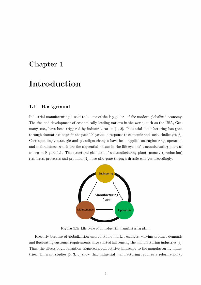
Correspondingly strategic and paradigm changes have been applied on engineering, operation
and maintenance; which are the sequential phases in the life cycle of a manufacturing plant as
shown in Figure 1.1. The structural elements of a manufacturing plant, namely (production)
resources, processes and products [4] have also gone through drastic changes accordingly.
OperationMaintenance
Engineering
ManufacturingPlant
Figure 1.1: Life cycle of an industrial manufacturing plant.
Recently because of globalization unpredictable market changes, varying product demands
and fluctuating customer requirements have started influencing the manufacturing industries [3].
Thus, the effects of globalization triggered a competitive landscape to the manufacturing indus-
tries. Different studies [5, 3, 6] show that industrial manufacturing requires a reformation to
1
1. INTRODUCTION
form so-called Factories of the Future (FoF) to strive whilst global competition and market
changes. Several studies, for instance [5, 7, 8, 6, 9] have been conducted, concerning the char-
acteristics, life cycle and structural elements of FoF. Consequently, the foundations of FoF have
already been established.
A strategic project named Industry 4.0 (I4.0) [5] initiated in Germany affirms flexibility,
human assistive nature and cognition as the fundamental characteristics of the FoF. With these
characteristics, manufacturing companies can timely respond to the customer requirements with-
out compromising on products’ quality and enact a market driven production. On achieving a
flexible, human assistive and cognitive manufacturing plant a fourth industrial revolution (I4.0)
is anticipated in the near future [5, 10, 11].
According to Monostori et.al [9] the FoF are envisaged as a result of applying the latest and
foreseeable further developments of Computer Science, Information and Communication Tech-
nologies (ICT), Manufacturing Science and Technology on the structural elements of current
manufacturing plants. They assert that the resources in the FoF take the form of automation
components or systems known as Cyber Physical Production Systems (CPPS). The CPPS
based production resources provide flexibility, modularity and information exchange capabili-
ties [12]. The products in the FoF take the form of smart products, having capabilities of data
storage, communication and self-awareness. CPPS along with smart products shape the future
manufacturing plants as smart factories [5]. The smart factories possess distributed and high
performance control features for their manufacturing process [12]. Smart factories also apply
further manufacturing technologies and ICT to integrate the stakeholders of the production in
horizontal and vertical directions. The smart factories implement a human centred design [13]
and hold flexible, human assistive and cognitive features [5].
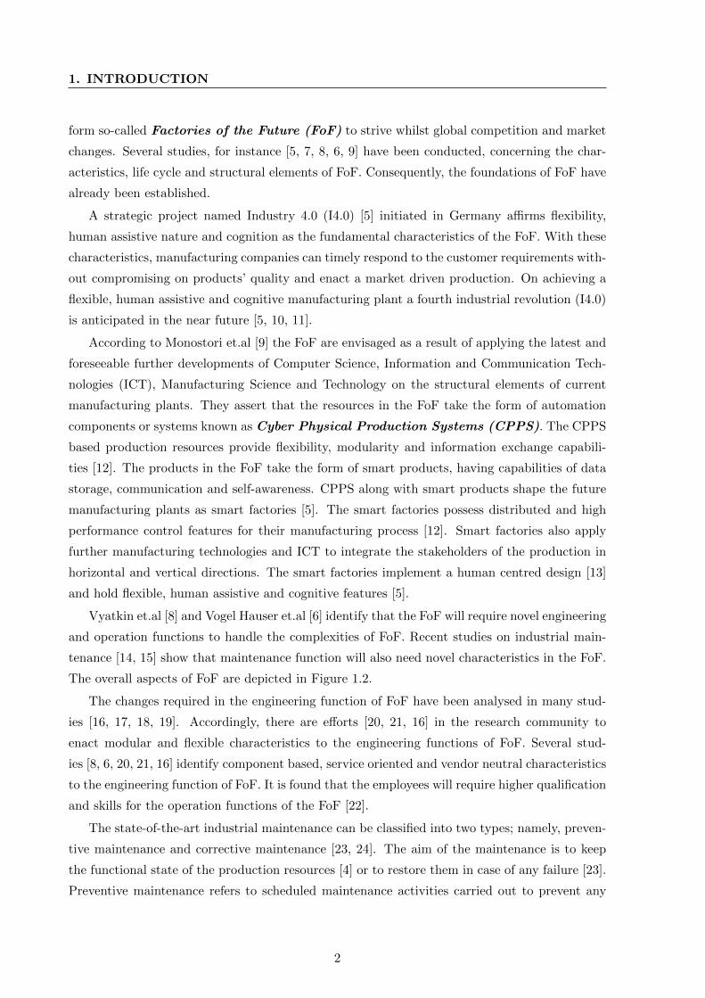
Vyatkin et.al [8] and Vogel Hauser et.al [6] identify that the FoF will require novel engineering
and operation functions to handle the complexities of FoF. Recent studies on industrial main-
tenance [14, 15] show that maintenance function will also need novel characteristics in the FoF.
The overall aspects of FoF are depicted in Figure 1.2.
The changes required in the engineering function of FoF have been analysed in many stud-
ies [16, 17, 18, 19]. Accordingly, there are efforts [20, 21, 16] in the research community to
enact modular and flexible characteristics to the engineering functions of FoF. Several stud-
ies [8, 6, 20, 21, 16] identify component based, service oriented and vendor neutral characteristics
to the engineering function of FoF. It is found that the employees will require higher qualification
and skills for the operation functions of the FoF [22].
The state-of-the-art industrial maintenance can be classified into two types; namely, preven-
tive maintenance and corrective maintenance [23, 24]. The aim of the maintenance is to keep
the functional state of the production resources [4] or to restore them in case of any failure [23].
Preventive maintenance refers to scheduled maintenance activities carried out to prevent any
2
1.2 Problem Description
Factories of the future
Flex
ible
Co
gnit
ive
Hu
man
Ass
isti
ve
Novel engineering, operation & maintenance functions
Smart Products
Information and
Communication Technologies
ManufacturingScience
and Technologies
Smart factories
Cyber physical production systems
Figure 1.2: Different aspects of factories of the future.
kind of failure of the production resources and thus to avoid any disruption in the manufac-
turing process. Corrective maintenance refers to the maintenance activities applied to restore
production resources under downtime back to their functional state. Hence, it aims to correct
the faults of a production resource with prior knowledge of their occurrence.
The recent studies on maintenance of FoF [14, 25] show that in the context of FoF, the
preventive maintenance will be replaced by prognostic and predictive approaches. By applying
prognostic and predictive approaches, any failure or performance degradation of a system can
be predicted. Therefore, this thesis foresees that corrective maintenance will be applicable in
three cases in the future as shown in Table 1.1. The first case occurs when a production system
breaks down, and the second case occurs when the predictive maintenance system predicts a
future failure. Third case is triggered when the predictive maintenance system finds performance
degradation of a system [18]. In case of a breakdown, the downtime is accidental and may lead
to an emergency. The corrective maintenance is carried out as an unscheduled activity and has
a critical nature in some cases of breakdown. In the other two cases, the down time is planned or
even no down time occurs and the corrective maintenance is carried out as a scheduled activity.
1.2 Problem Description
Summarizing the previous section, this thesis makes the assumption that the concept of FoF will
be materialized in the near future. Accordingly, this thesis presumes the following fundamental
aspects of FoF to be true:
3
1. INTRODUCTION
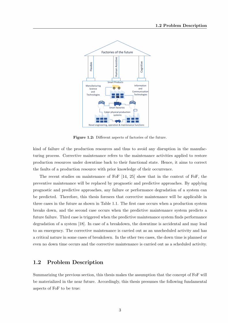
Table 1.1: Corrective maintenance: Application context and types in factories of the future.
Initiating Events Type of Downtime Type of Corrective Mainte-
nance
Breakdown Unplanned down time Unscheduled corrective mainte-
nance
Future failure prediction Planned down time Scheduled corrective maintenance
Performance degradation
prediction
Planned down time/ No
down time
Scheduled corrective maintenance
1. The future factories will have flexible, human assistive and cognitive characteristics.
2. The future production resources take the form of CPPS.
3. The engineering, operation and maintenance functions will have novel characteristics in
the context of FoF.
Efforts have been made to reform the maintenance function of the FoF, with prognostic and
predictive approaches [14, 26, 27]. However, studies show that though every effort is made to
keep a production resource as reliable as it can be with means of preventive or novel predictive
techniques, they do fail frequently [28, 29]. Failure of a production resource leads to a downtime
in the manufacturing process and hence makes production losses. Each time a production
resource fails, or the predictive maintenance system predicts an upcoming failure, or finds a
performance degradation, it triggers a downtime and subsequently a corrective maintenance
function. Thus, corrective maintenance can be inferred as an imminent activity even within the
context of FoF.
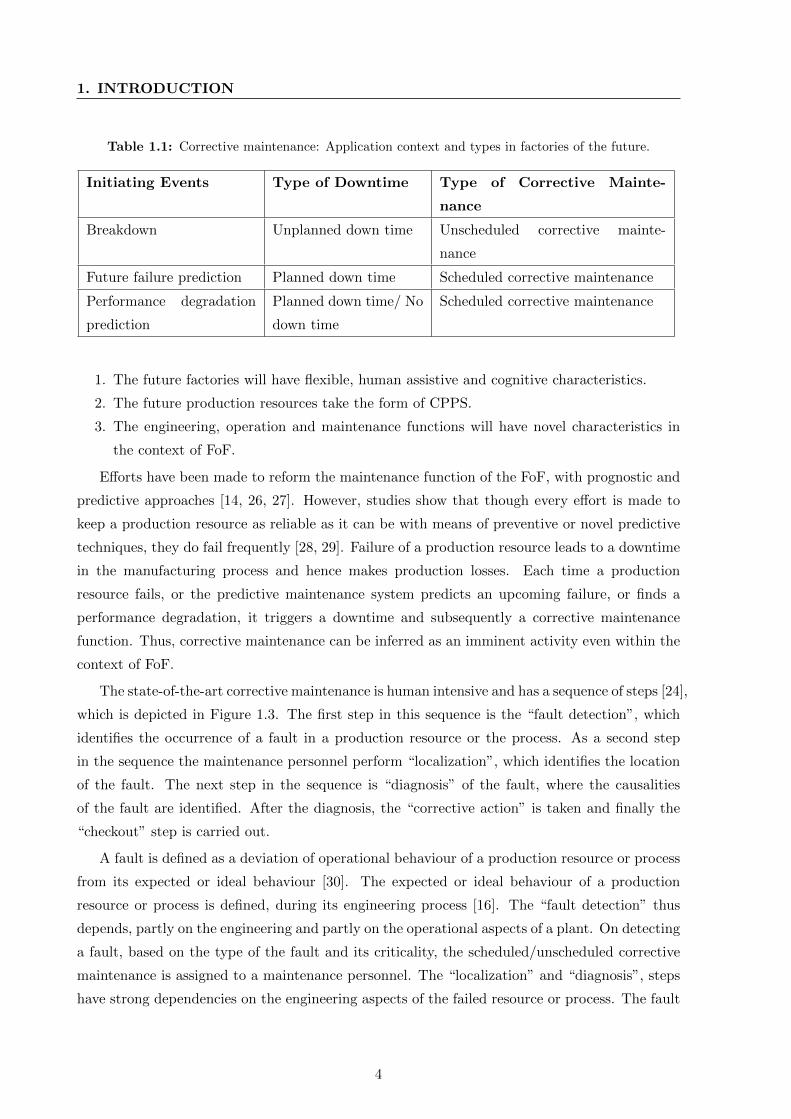
The state-of-the-art corrective maintenance is human intensive and has a sequence of steps [24],
which is depicted in Figure 1.3. The first step in this sequence is the “fault detection”, which
identifies the occurrence of a fault in a production resource or the process. As a second step
in the sequence the maintenance personnel perform “localization”, which identifies the location
of the fault. The next step in the sequence is “diagnosis” of the fault, where the causalities
of the fault are identified. After the diagnosis, the “corrective action” is taken and finally the
“checkout” step is carried out.
A fault is defined as a deviation of operational behaviour of a production resource or process
from its expected or ideal behaviour [30]. The expected or ideal behaviour of a production
resource or process is defined, during its engineering process [16]. The “fault detection” thus
depends, partly on the engineering and partly on the operational aspects of a plant. On detecting
a fault, based on the type of the fault and its criticality, the scheduled/unscheduled corrective
maintenance is assigned to a maintenance personnel. The “localization” and “diagnosis”, steps
have strong dependencies on the engineering aspects of the failed resource or process. The fault
4
1.2 Problem Description
Fault Detection Localization Diagnosis Corrective Action Checkout
Figure 1.3: Sequence of activity in a corrective maintenance function according to Dhillon [24].
localization identifies its origin within the resource or process, based on their engineering data.
The diagnosis step requires to derive the causalities of the fault, based on the engineering and
operational aspects of the resource or process. Further steps in the maintenance function, namely
the corrective action and the checkout step also depend on the engineering and operational
aspects of the plant.
The aforementioned paragraph clarifies the strong relation of corrective maintenance function
with the engineering and operational aspects of a plant [31, 32, 29]. Different studies clarify the
basic concepts for engineering and operating the FoF. These studies show that the engineering
and operation of the FoF will undergo a paradigm shift within the context of FoF [3, 6, 8, 16].
However, the corrective maintenance aspects are not yet upgraded accordingly.
Many researchers [24, 28] highlight human error as one of the key issues that makes industrial
corrective maintenance unreliable. Apart from that, many studies [6, 8, 28] identify complexity
as a big challenge to any human related activities within the FoF, including maintenance. They
establish that the complexity will affect the efficiency of human workers within the FoF. Vy-
atkin [8] and Vogel-Heuser [6] predict that the FoF will be software intensive in nature. They
point out the complex nature of software intensive systems and hence the software intensive
nature as a challenge within the FoF. Colombo et al. [33] illustrate that the CPPS combine
complex software and physical aspects together and they have a frequently reconfigured archi-
tecture. Thus, the source of complexity in the FoF may also arise from the CPPS nature of the
production systems. Gao et al. [34] state that the interconnected nature, multiple control loops,
varying loads, etc., of CPPS also induce complexity in future industrial systems.
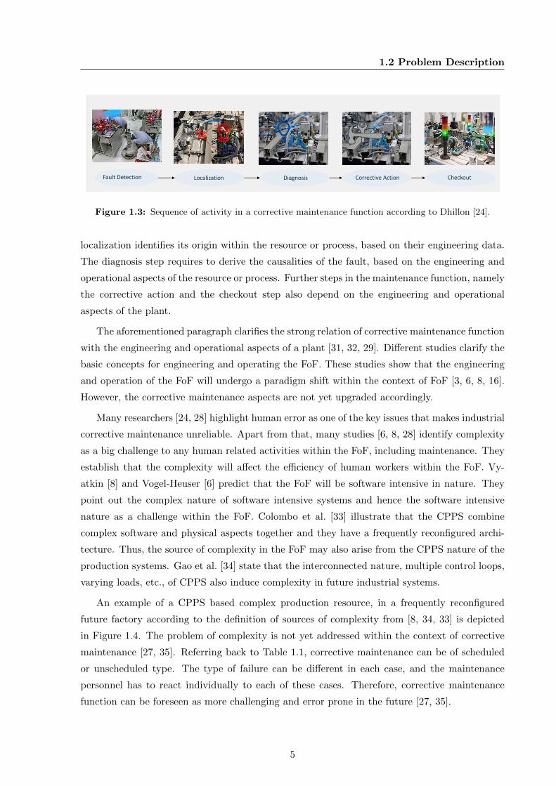
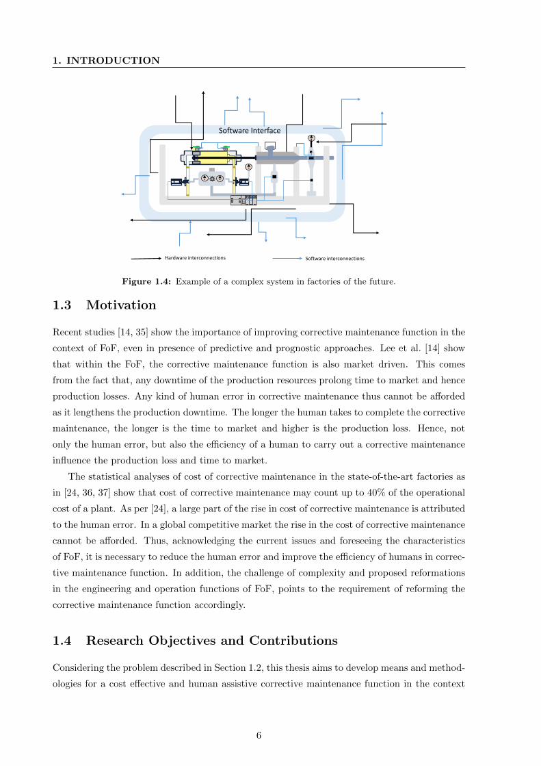
An example of a CPPS based complex production resource, in a frequently reconfigured
future factory according to the definition of sources of complexity from [8, 34, 33] is depicted
in Figure 1.4. The problem of complexity is not yet addressed within the context of corrective
maintenance [27, 35]. Referring back to Table 1.1, corrective maintenance can be of scheduled
or unscheduled type. The type of failure can be different in each case, and the maintenance
personnel has to react individually to each of these cases. Therefore, corrective maintenance
function can be foreseen as more challenging and error prone in the future [27, 35].
5
1. INTRODUCTION
Software Interface
Software interconnectionsHardware interconnections
Figure 1.4: Example of a complex system in factories of the future.
1.3 Motivation
Recent studies [14, 35] show the importance of improving corrective maintenance function in the
context of FoF, even in presence of predictive and prognostic approaches. Lee et al. [14] show
that within the FoF, the corrective maintenance function is also market driven. This comes
from the fact that, any downtime of the production resources prolong time to market and hence
production losses. Any kind of human error in corrective maintenance thus cannot be afforded
as it lengthens the production downtime. The longer the human takes to complete the corrective
maintenance, the longer is the time to market and higher is the production loss. Hence, not
only the human error, but also the efficiency of a human to carry out a corrective maintenance
influence the production loss and time to market.
The statistical analyses of cost of corrective maintenance in the state-of-the-art factories as
in [24, 36, 37] show that cost of corrective maintenance may count up to 40% of the operational
cost of a plant. As per [24], a large part of the rise in cost of corrective maintenance is attributed
to the human error. In a global competitive market the rise in the cost of corrective maintenance
cannot be afforded. Thus, acknowledging the current issues and foreseeing the characteristics
of FoF, it is necessary to reduce the human error and improve the efficiency of humans in correc-
tive maintenance function. In addition, the challenge of complexity and proposed reformations
in the engineering and operation functions of FoF, points to the requirement of reforming the
corrective maintenance function accordingly.
1.4 Research Objectives and Contributions
Considering the problem described in Section 1.2, this thesis aims to develop means and method-
ologies for a cost effective and human assistive corrective maintenance function in the context
6
1.5 Thesis Structure
of FoF. As a result, the length of production downtime can be reduced and the manufactur-
ing companies can respond to customer requirements timely without compromising on quality.
Accordingly, this study provides a framework for addressing the following objectives within the
context of the FoF in a cost efficient manner:
1. Minimize possibilities of erroneous activities and increase efficiency of the human involved
in corrective maintenance function.
2. Handle complexity whilst corrective maintenance function within the FoF.
3. Reform the corrective maintenance function for the FoF.
It is crucial to note that the proposed solution is evaluated with two application examples.
The first application example illustrates how the objectives are achieved with minimum resources
and cost. The second example evaluates the scalability of the proposed solution to an industrial
environment.
1.5 Thesis Structure
Chapter 2 presents the literature review, concerned with the problem described previously in
this chapter. The review of the literature identifies, enablement of self-diagnosis in production
resources as a potential solution for improving corrective maintenance within the FoF. Further,
it analyses the existing gap in enabling self-diagnosis within industrial systems and derives the
research questions. Chapter 3 lists the requirements for enabling self-diagnosis within the correc-
tive maintenance of future automated production resources. Further, it derives the methodology
for addressing the research questions.
From Chapter 4 onward, the research contributions of this thesis are elaborated. Chapter 4
details the methodology for modelling self-diagnosis in the automation components. It de-
rives the prerequisites and methodologies for creating reusable models for self-diagnosis within
automation components. Chapter 5 describes the methodology for realizing self-diagnosis in au-
tomation systems composing automation components. This chapter also addresses the challenge
of bringing flexibility and reconfiguration to the developed systems.
The aspects for improving the development and application of the self-diagnosis based cor-
rective maintenance in FoF are addressed in Chapter 6. Chapter 7 describes the overall im-
plementation of the system. An evaluation of the approach with two application examples is
elaborated in Chapter 8. Chapter 9 concludes the thesis with concepts for future work.
7

Chapter 2
State-Of-The-Art Review of the
Literature
The previous chapter clarifies that the characteristics and building elements of FoF will change
considerably with that of the state-of-the-art factories [6, 8, 38]. Many studies [6, 8, 38, 39, 18, 16]
assert that the maintenance of FoF requires changes accordingly. The inter-relation between
maintenance and other phases in the life cycle of a manufacturing plant, such as engineering
and operation were also clarified in the previous chapter. Based on this foundation, the state-
of-the-art review of literature of this thesis is divided into five sections.
Section 2.1 extensively reviews the building elements and fundamental characteristics of
the FoF. The important aspects concerning the engineering and operation of a manufacturing
plant, which influence its maintenance are reviewed in Section 2.2. Section 2.3 reviews the state-
of-the-art industrial maintenance and describes corrective maintenance in detail. Section 2.4
describes the self-diagnosis and methodologies for applying self-diagnosis within industrial cor-
rective maintenance. The research focus of this thesis and formulated research questions are
detailed in Section 2.5.
2.1 Fundamentals of Factories of the Future
The manufacturing industries have gone through dramatic changes in the past 200 years. Dif-
ferent manufacturing paradigms have been applied to address the social and economic scenarios
and corresponding requirements during this period [7]. The Industrial revolutions occurred as
a result of the changes in manufacturing paradigms applied during the past 200 years. The
first Industrial revolution occurred in the 1800’s as a result of steam-powered mechanization of
manufacturing industries, providing high production volume compared to manual labour [1, 40].
The second industrial revolution occurred in the last quarter of the 18th century because of
applying electricity and oil driven manufacturing. The second industrial revolution happened
9
2. STATE-OF-THE-ART REVIEW OF THE LITERATURE
in response to the requirement of cost effectiveness in mass production. The third industrial
revolution took place in the last quarter of the 19th century. The third industrial revolution
was a result of introduction of automation technologies, leading to further cost optimization and
starting of mass customization [1, 40].
From 1990’s onward, the effect of globalization has been influencing the social and economic
circumstances once again. With globalization the market turned volatile and on the provision
of freedom to choose their products from multiple providers, the customer demands started to
vary [7]. Nowadays the companies are forced to satisfy the varying requirements of customers
to survive whilst global competition. In order to facilitate the industries to face the social and
economical challenges of the modern world, the concept of FoF was put forward [3, 5, 8, 14].
One of the key projects on FoF, which attained global attention is the strategic initiative by the
German government named I4.0 [5]. The basic concepts of FoF presented in the initial study
on I4.0 [5] have been improved since then. The required characteristics of the FoF to address
the social and economic challenges of the future market have been instituted in many other
studies. An extensive study of the proposed characteristics and building elements of the FoF
are described in the following sections.
2.1.1 Basic Characteristics of Factories of the Future
One of the key problems faced in the state-of-the-art factories is that the production facilities are
not flexible and most of the manufacturing companies follow mass production paradigms [40, 41].
The mass production paradigm (American system of manufacturing) was introduced by Henry
Ford to produce large quantities of one kind of a product, employing automated manufacturing
facilities. The main characteristic of mass production is to reduce the cost by increasing the
volume of production. An example is the mass production of Ford motor model T, trusting
on its popularity and expecting mass requirements from the market at a lower price [42]. The
state-of-the-art manufacturing paradigm followed by most of the automotive companies are of
type mass customization [43]; means providing variety in mass, from which nearly everyone can
find what they can afford. However, once the production is started, no changes are expected or
allowed [42].
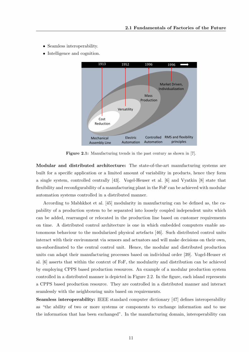
As shown in Figure 2.1, the fundamental characteristic of FoF is that manufacturing will be
market driven [3]. This means that the future manufacturing companies will have to offer high
individualization to their customers with high variability of products [42, 44]. Koren [3] states
that high individualization can be achieved, if the manufacturing plants possess flexibility and
reconfigurability.
Recent studies [6, 44, 38] show that the flexibility and reconfigurability of a plant can be
improved, if they hold the following characteristics:
• Modular and distributed architecture.
10
2.1 Fundamentals of Factories of the Future
• Seamless interoperability.
• Intelligence and cognition.
CostReduction
Versatility
Market Driven,Individualization
1913 1952 1996
Mechanical Assembly Line
Electric Automation
ControlledAutomation
Mass Production
RMS and flexibilityprinciples
1996
Figure 2.1: Manufacturing trends in the past century as shown in [7].
Modular and distributed architecture: The state-of-the-art manufacturing systems are
built for a specific application or a limited amount of variability in products, hence they form
a single system, controlled centrally [43]. Vogel-Heuser et al. [6] and Vyatkin [8] state that
flexibility and reconfigurability of a manufacturing plant in the FoF can be achieved with modular
automation systems controlled in a distributed manner.
According to Mabhkhot et al. [45] modularity in manufacturing can be defined as, the ca-
pability of a production system to be separated into loosely coupled independent units which
can be added, rearranged or relocated in the production line based on customer requirements
on time. A distributed control architecture is one in which embedded computers enable au-
tonomous behaviour to the modularized physical artefacts [46]. Such distributed control units
interact with their environment via sensors and actuators and will make decisions on their own,
un-subordinated to the central control unit. Hence, the modular and distributed production
units can adapt their manufacturing processes based on individual order [39]. Vogel-Heuser et
al. [6] asserts that within the context of FoF, the modularity and distribution can be achieved
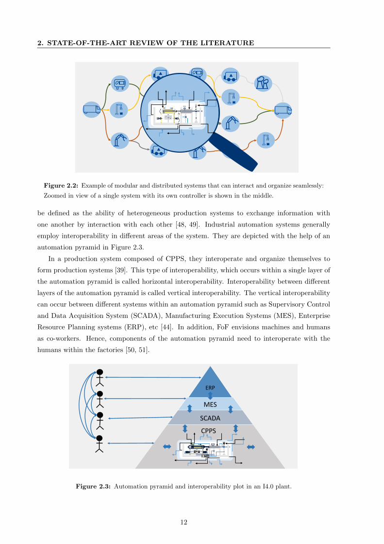
by employing CPPS based production resources. An example of a modular production system
controlled in a distributed manner is depicted in Figure 2.2. In the figure, each island represents
a CPPS based production resource. They are controlled in a distributed manner and interact
seamlessly with the neighbouring units based on requirements.
Seamless interoperability: IEEE standard computer dictionary [47] defines interoperability
as “the ability of two or more systems or components to exchange information and to use
the information that has been exchanged”. In the manufacturing domain, interoperability can
11
2. STATE-OF-THE-ART REVIEW OF THE LITERATURE
Figure 2.2: Example of modular and distributed systems that can interact and organize seamlessly:
Zoomed in view of a single system with its own controller is shown in the middle.
be defined as the ability of heterogeneous production systems to exchange information with
one another by interaction with each other [48, 49]. Industrial automation systems generally
employ interoperability in different areas of the system. They are depicted with the help of an
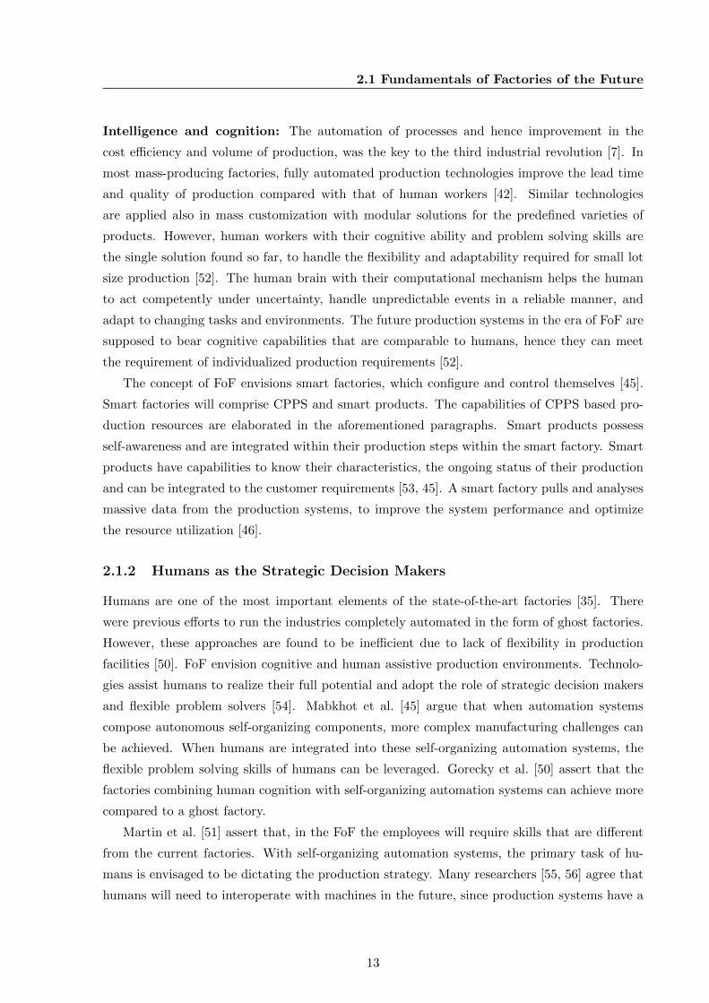
automation pyramid in Figure 2.3.
In a production system composed of CPPS, they interoperate and organize themselves to
form production systems [39]. This type of interoperability, which occurs within a single layer of
the automation pyramid is called horizontal interoperability. Interoperability between different
layers of the automation pyramid is called vertical interoperability. The vertical interoperability
can occur between different systems within an automation pyramid such as Supervisory Control
and Data Acquisition System (SCADA), Manufacturing Execution Systems (MES), Enterprise
Resource Planning systems (ERP), etc [44]. In addition, FoF envisions machines and humans
as co-workers. Hence, components of the automation pyramid need to interoperate with the
humans within the factories [50, 51].
ERP
MES
SCADA
CPPS
Figure 2.3: Automation pyramid and interoperability plot in an I4.0 plant.
12
2.1 Fundamentals of Factories of the Future
Intelligence and cognition: The automation of processes and hence improvement in the
cost efficiency and volume of production, was the key to the third industrial revolution [7]. In
most mass-producing factories, fully automated production technologies improve the lead time
and quality of production compared with that of human workers [42]. Similar technologies
are applied also in mass customization with modular solutions for the predefined varieties of
products. However, human workers with their cognitive ability and problem solving skills are
the single solution found so far, to handle the flexibility and adaptability required for small lot
size production [52]. The human brain with their computational mechanism helps the human
to act competently under uncertainty, handle unpredictable events in a reliable manner, and
adapt to changing tasks and environments. The future production systems in the era of FoF are
supposed to bear cognitive capabilities that are comparable to humans, hence they can meet
the requirement of individualized production requirements [52].
The concept of FoF envisions smart factories, which configure and control themselves [45].
Smart factories will comprise CPPS and smart products. The capabilities of CPPS based pro-
duction resources are elaborated in the aforementioned paragraphs. Smart products possess
self-awareness and are integrated within their production steps within the smart factory. Smart
products have capabilities to know their characteristics, the ongoing status of their production
and can be integrated to the customer requirements [53, 45]. A smart factory pulls and analyses
massive data from the production systems, to improve the system performance and optimize
the resource utilization [46].
2.1.2 Humans as the Strategic Decision Makers
Humans are one of the most important elements of the state-of-the-art factories [35]. There
were previous efforts to run the industries completely automated in the form of ghost factories.
However, these approaches are found to be inefficient due to lack of flexibility in production
facilities [50]. FoF envision cognitive and human assistive production environments. Technolo-
gies assist humans to realize their full potential and adopt the role of strategic decision makers
and flexible problem solvers [54]. Mabkhot et al. [45] argue that when automation systems
compose autonomous self-organizing components, more complex manufacturing challenges can
be achieved. When humans are integrated into these self-organizing automation systems, the
flexible problem solving skills of humans can be leveraged. Gorecky et al. [50] assert that the
factories combining human cognition with self-organizing automation systems can achieve more
compared to a ghost factory.
Martin et al. [51] assert that, in the FoF the employees will require skills that are different
from the current factories. With self-organizing automation systems, the primary task of hu-
mans is envisaged to be dictating the production strategy. Many researchers [55, 56] agree that
humans will need to interoperate with machines in the future, since production systems have a
13
2. STATE-OF-THE-ART REVIEW OF THE LITERATURE
human assistive nature. Foreseeing a human-machine collaborative environment, they recom-
mend application of visual human-machine interfacing technologies such as augmented reality
or virtual reality.
2.1.3 Complexity as a Key Problem to be Addressed
Complexity is found to be the intrinsic nature of FoF [6, 8, 9]. Monostroi et al. [9] found that
the complexity issue will have larger significance in the future. According to them, complexity
has to be handled mitigating the negative aspects while leveraging its positive ones. Elmaraghy
et al. [57] find that complexity of FoF begin right from the design phase, and stems from
the complexity of the emerging technologies applied. The US National Science Foundation
highlights the complexity of engineering the CPPS and identifies that it will lead to adverse
consequences [58]. They assert that the advanced methodologies of software systems engineering
are required to handle the complexity of engineering CPPS based manufacturing systems.
Vyatkin [8] mentions in his study that the software ratio in the machine building process
has increased from 20% to 40% in the last decade. He asserts that the software ratio in the
manufacturing process is going to increase further and the complex nature of software used
in automation systems will affect the engineering, operation and maintenance of manufacturing
systems in the future. According to him, FoF will require reusable component based architecture.
The designing, developing, and maintaining components for reuse is a very complex process.
Though complex software engineering uses formal methods, the knowledge of formal methods
is not common among automation and control engineers. Therefore, the education threshold
required for training of engineers in the future will be complex and difficult to execute.
Brandenbourger et al. [16] and Vathoopan et al. [18] show that the complexity of future
factories can also arise from the distributed control architecture employing CPPS. Each CPPS
integrates physical systems, actuators and sensors together and their control software. In an
overall application, several CPPS are organized into a distributed modular architecture as shown
in Figure 2.2 and thus forms a system of systems architecture. Vathoopan et al. [59] further
indicate that in a future factory, the CPPS interact seamlessly and group themselves to yield a
manufacturing process and corresponding product. The distributed CPPS are added, removed
or relocated themselves to satisfy the flexible nature of production required in FoF, which makes
engineering, operation and maintenance of these systems also complex.
2.2 State-Of-The-Art Review of Plant Engineering and Opera-
tion
This section reviews the state-of-the-art literature of plant engineering and operation, which
have association to the plant maintenance. As shown in the previous section, the FoF hold
14

2.2 State-Of-The-Art Review of Plant Engineering and Operation
complex and reconfigurable nature and compose distributed, modular CPPS based production
systems. Different studies [38, 8, 6, 18] show that these changes also affect the life cycle of the
manufacturing plant. Therefore, the different phases in the life cycle of manufacturing plants
namely engineering, operation and maintenance has to be revamped to satisfy the proposed
aspects of FoF [38, 6].
The first and foremost step in the life cycle of a manufacturing plant is its engineering.
Plant engineering is used as a collective term for all technical oriented services, and working
methods applied to conceptualize, implement and commission an industrial plant based on
customer specific requirements. This is applicable to different sectors of business such as chemical
processing, power generation, assembly, etc [60]. The operation of a plant comes as a next phase
within the life cycle of a manufacturing plant. Operation is a collective term for all the activities
applied whilst a manufacturing plant produces some product [22].
The Section 1.2 clarifies the strong relation of corrective maintenance function with the
engineering and operational aspect of a plant. The corrective maintenance is dependent on the
characteristics and methodologies of engineering of a plant. Further, it requires information
exchange with an operating plant. Hence, the following sections reviews the characteristics
and methodologies of state-of-the-art plant engineering. In addition, a review of the important
aspects of information exchange and communication within the operation of a plant is also
presented.
2.2.1 Increasing Digitization and Data Generation in Engineering
Every plant engineering process intends to develop a manufacturing plant capable of producing
a required product. The technical services and working methods involved in plant engineering
generate enormous data from various means. Within the context of FoF, the amount of generated
data is expected to increase further [14]. Some of the means of data generation and effort towards
more digitization within the context of FoF are elaborated below.
Integration of components, systems and stakeholders: Every plant engineering process
is unique and specific to the requirements of the customer (manufacturing company) and their
specific product [60]. Plant engineering is typically performed by a system integrating company
using components and systems from suppliers and contractors to deliver a plant that can man-
ufacture the required product by the customer (manufacturing company). Plant engineering
thus involves multiple stakeholders such as the system integrating company, the customer (man-
ufacturing company), suppliers of manufacturing system components, contracting companies
providing construction services, etc [39]. Each of these stakeholders, components and systems
hold their specific data within the plant engineering process. A typical plant engineering pro-
cess integrates different components, systems and different stakeholders to yield a manufacturing
plant and thus integrate the data from the stakeholders inherently.
15

2. STATE-OF-THE-ART REVIEW OF THE LITERATURE
Application of domain specific tools: The engineering process as a whole involves multiple
stakeholders and domains. In modern plant engineering, different stakeholders and domains
employ software tools specific to the stakeholders or the domain [61]. Advanced digitization
techniques are applied in different stages of the engineering process of manufacturing plants
in the form of software tools [8]. Each of these tools produces tool specific or domain specific
engineering data. The example of an engineering process and digitized tasks performed in its
each step are shown in Figure 2.4. In the process shown in the figure the tools are employed
in a sequential manner. Creating the plant and production hierarchy is performed in the first
(plant and process planning) phase with a software tool. This tool produces a domain specific
engineering data. In the next stage (mechanical engineering), the automation devices and their
characteristics are defined with a different software tool and so on [62].
1
2
3
4
5
ToolProcess Phase
Plant and Process Planning
Mechanical Engineering
Electrical Engineering
Communication Engineering
PLC Programming
Task carried out in the tool
Plant and production hierarchy
Automation devices and characteristics
Wiring of devices to PLC physical IOApplied physical address of PLC variables
Communication system wiring to PLCApplied communication address for PLC variables
Actual control code depending on the output of previous stages
Figure 2.4: A sequential plant engineering process employing different tools; modified from [43].
Electronic data exchange as a means for integrating tools and stakeholders: Con-
sidering the sequential nature of plant engineering, Luder et al. [62] and Drath et al. [63] find
interoperability among tools as one of the key challenge to be addressed to reduce the complex-
ity of engineering FoF. For example in Figure 2.4, tools applied from first phase to last phase
have sequential dependencies; each tool or task receives some data as input from the preceding
tool. In such cases, it is necessary that the tools should interoperate. Luder et al. [62] and
Drath et al. [63] propose a standard electronic data exchange known as Automation Mark-up
Language (AML) for enabling interoperability among tools in the plant engineering process.
Vathoopan et al. [39] identify that a universally acceptable electronic data exchange format
will facilitate integration of different stakeholders involved in the engineering process such as
component manufacturers, system integrator, and the customers, etc.
2.2.2 State-Of-The-Art Methodologies of Plant Engineering
Different studies [8, 6, 38] show that in order to achieve the key characteristics of future factories
such as flexibility, human assistive and cognitive nature, the state-of-the-art engineering process
16
2.2 State-Of-The-Art Review of Plant Engineering and Operation
has to be revamped. Many researchers [8, 11, 64] find complexity as the key challenge to be
addressed considering the engineering of FoF. Vyatkin [8] points out the continuing increase
of software ratio in manufacturing system. Hence, he suggests the use of software engineering
techniques such as component based development [8, 6], service orientation [65, 66] and model
driven engineering with code generation [67] in the design and engineering of FoF.
Mitigating Complexity with Automation Systems Engineering: In the modern con-
text plant engineering and automation engineering are used alternatively, as most of the plant
engineering is attributed to the automation engineering process [63, 16]. Inspired from [6, 8],
Brandenbourger et al. [16] proposed a methodology for engineering FoF by using CPPS based
automation components. They apply CPPS as the basic building units of future manufactur-
ing plants and assume a software component for each hardware counterpart. They propose that
standard software components can be created reflecting the hardware components and thus reuse
of both hardware and software components can be implied in a reconfigurable manufacturing
scenario.
Ovtcharova et al. [68], suggest the importance of developing a functional model. Since
product function remains the same for all, they propose a functional model to improve the
collaboration process and close the significant gap existing in cross-domain engineering. Based
on this concept, Vathoopan et al. [39, 69] proposes skills as a means for service orientation in
the domain of plant engineering. Here a skill represents a function offered by an automation
component and for any discipline or stakeholder involved in the process the function offered
by the component is its skill and remains the same throughout the engineering process. They
also propose automation components as the service (skill) provider and products as the service
(skill) consumer in a service oriented architecture. Such an architecture where components are
loosely coupled and integrated based on requested skills of products are shown in Figure 2.5. In
this method, each level in the physical system hierarchy offers an interface in the form of skills
and they can be coupled based on product requirements from the customer. By modularizing
product models based on features, each feature can be mapped on to a skill provided by a
physical component in a hierarchical architecture, and thus can support multiple variants of
products and their features.
Vathoopan et al. [39] also assert that on provision of universally acceptable models of au-
tomation components, a systems engineering process enabling integration of stakeholders and
tools is possible in the manufacturing domain. Vathoopan et al. [69] further developed the con-
cept presented in [39], to develop a model based automation systems engineering, using skills
and yielding a service oriented hierarchical architecture with code generation in various tools.
Facilitating Personalized Engineering for Personalized Production: The initial engi-
neering of a manufacturing plant can be treated as a green field process. A plant engineering
process typically involves design and construction of plants’ physical hardware and the software
17

2. STATE-OF-THE-ART REVIEW OF THE LITERATURE
Component 1
+ Provides: Skill 1..n
+ Supports: Product 1: feature 1
Component n
+ Provides: Skill 1..n
+ Supports: Product 1: feature n
SubSystem 1
+ Provides: SubSystem Skill 1..n
+ Supports: Product 1
SubSystem n
System
+ Provides: System Skill 1..n+ Supports: Products 1..n
+ Provides: SubSystem Skill 1..n
+ Supports: Product n
Figure 2.5: Architecture of a component oriented manufacturing plant (modified from [69]).
that controls the physical hardware. Thus, different disciplines such as mechanical, electrical,
design, software, etc., cooperate in the plant engineering process [64]. If the requirement of the
customer is for certain types of variants as in the mass production, the plant engineering takes
place only once and then it goes to the operational stage, producing these variants of products
in mass quantity expecting requirements from the market [42]. The state-of-the-art plant engi-
neering thus has a sequential nature [43] and once commissioned, it keeps operational for next
15-20 years producing the same fixed variants of products.
The future plant requires frequent evolution or reconfiguration such that they are slowly
moving towards personalized production in the future. Therefore, the life cycle of a future
manufacturing plant will be short and the engineering of such plants possess a sequential and
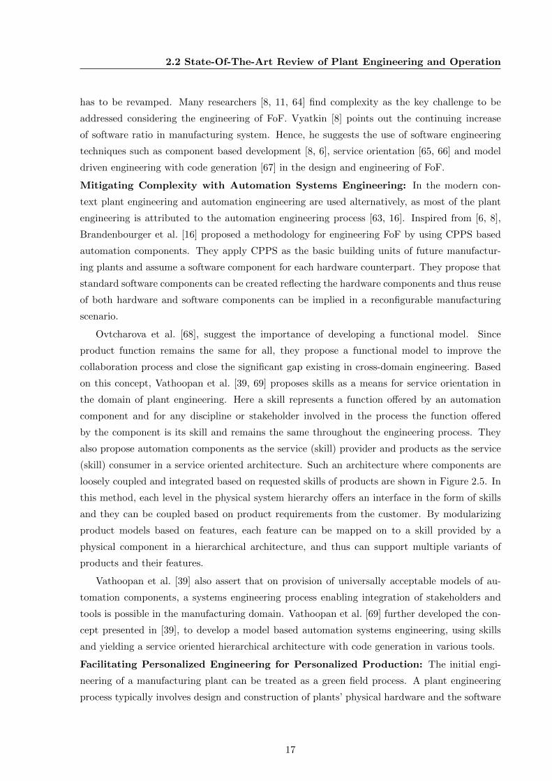
cyclic behaviour as depicted in Figure 2.6. Here it is assumed that a plant already exists and thus
the plant engineering can be treated as a brownfield engineering process [64]. In such a process,
the customer requirements need to be integrated within the engineering process [43]. The overall
plant engineering has a cyclic behaviour, since it is evolved and reconfigured frequently. Every
change in customer requirements will require changes in the engineering process as well. In this
regard, the engineering process of the FoF can be seen as personalized.
2.2.3 Information Exchange and Communication within Plant Operation
In the FoF, the systems are expected to be modular in nature and they can be rearranged and
reconnected to form new factory configurations as explained in the previous section. There
can be various types of systems covering various levels of the automation pyramid as shown
in Figure 2.3. There can be equipment from different vendors used in different levels. In this
18
2.2 State-Of-The-Art Review of Plant Engineering and Operation
Customer Requirements
Planning Implementation
Testing
CommissioningOperation
Analysis
Figure 2.6: Cyclic and sequential nature of plant engineering in a reconfigurable plant.
scenario, it is important that each of these systems can interoperate so that at any point of
time, they can exchange information among each other to enact the seamless operation of the
plant [48, 49, 44].
Profanter et al. [70] has made a comparison of existing technological solutions for interop-
erability within the industrial automation domain. Different standard interoperability solutions
used in industrial automation such as OPC UA, DDS, ROS, MQTT, etc., are compared. All
of these protocols address the problem of interoperability by providing a standardized, open
and manufacture independent protocol for communication by using an Ethernet based imple-
mentation. Thus, they can replace proprietary field bus protocols since Ethernet offers an open
and hardware independent solution without licensing fees. Their basic analysis showed that
considering the complex nature of industrial automation systems and multitude of domain spe-
cific models employed, MQTT and ROS can be neglected. OPC UA and DDS are compared
in detail. A detailed comparison of OPC UA and DDS with information modelling capability
modelling specific to industrial automation and also performance showed that OPC UA prevail
in the industrial automation domain with the counterpart.
The application of OPC UA has been evaluated in several use-cases within the operation
of a manufacturing plant. Schleipen et al. [49] evaluated the application of OPC UA for the
implementation and operation of a service based industrial automation system. Merkumians et
al. [71] show the use-case of employing OPC UA as a middleware between the control platforms
and value added services by using a standard data model for industries. The study from Flat
et al. [72] proves the capability of OPC UA to act as an interoperability medium between the
human interface devices and the production systems specific for the operation and maintenance
of the plant. Vyatkin [8] and Vogel-Heuser et al. [6] identify OPC UA as the interoperability
solution for I4.0. Relying on [71, 70, 49, 72, 8, 6] application of OPC UA can be seen as a means
for information exchange and communication within the operation of the FoF.
19
2. STATE-OF-THE-ART REVIEW OF THE LITERATURE
2.3 State-Of-The-Art Review of Industrial Corrective Mainte-
nance
The term maintenance is defined in a production environment as all actions necessary to retain
or restore a production item/part/equipment to a defined state [24]. This section reviews the
different types of maintenance in a production environment and the importance of improving
maintenance, foreseeing the FoF.
2.3.1 Types of Industrial Maintenance
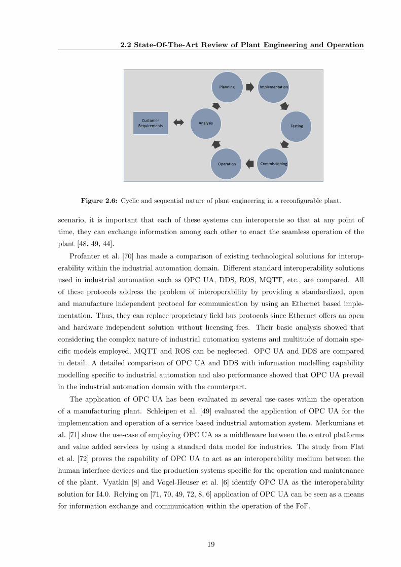
Maintenance in a production environment is mainly of three types in practice [73]. They are
elaborated in the following sections and illustrated in Figure 2.7.
00:05:52
12
6
39 24/7
Feb
07
Preventive maintenance Predictive maintenance Corrective maintenance
Figure 2.7: Types of maintenance in the manufacturing context.
Preventive maintenance: Preventive maintenance can be defined as all actions carried out
on a planned, periodic, and specific schedule to keep an item/equipment in a stated working
condition through the process of checking and reconditioning [23]. These actions are precau-
tionary steps undertaken to forestall or lower the probability of failures or an unacceptable level
of degradation in later service, rather than correcting them after they occur [24]. Preventive
maintenance tasks thus have mainly the following characteristics [74]:
• Tasks are predefined.
• Tasks are carried out in a predefined schedule.
• Tasks are human intensive.
Predictive maintenance: The use of modern measurement and signal processing methods
to accurately diagnose an item or equipment condition during operation is known as predictive
maintenance. In the context of FoF, predictive maintenance using big data and machine learn-
ing technologies is investigated exhaustively for prognostic health management of systems [14].
Predictive maintenance aims to conveniently schedule corrective maintenance, predicting the
condition/state of the system by analysing its performance [38]. Along with predictive main-
tenance technologies, automation technologies are also getting improved such that automated
process adjustment and plant reconfiguration technologies evolve. This refers to if a down-
time or performance degradation is predicted by the predictive maintenance system, the process
20

2.3 State-Of-The-Art Review of Industrial Corrective Maintenance
can be adjusted with novel automation architecture [44]. Predictive maintenance is normally
implemented with machine learning techniques that run 24x7 in the background of a manufac-
turing process making prognostic data analysis and predict the system health [38]. The tasks of
predictive maintenance have the following characteristics:
• Tasks are mostly automated, less human involvement.
• Tasks are predefined for an equipment/item condition.
• Tasks are carried out round the clock.
Corrective maintenance: Maintenance activities carried out by a maintenance personnel, to
return items/equipment to a defined state when deficiencies or failures are detected is known
as corrective maintenance [23]. Hence, corrective maintenance refers to all activities required
to identify and rectify the cause or reduce the severity, if an equipment/machine fails or a
potential failure is predicted by a predictive maintenance system. It focuses on bringing a failed
equipment back into production in the shortest possible time or other alternative that minimizes
production losses while the machine is not productive [75, 76]. The corrective maintenance is
carried out, either in a scheduled or unscheduled manner. A scheduled corrective maintenance
is a result of either a regular inspection or a prognostic health management system [74]. An
unscheduled corrective maintenance is required when an item/equipment breaks or fails during
operation. Thus, corrective maintenance is normally applied under a strict time deadline to
reduce production losses due to failure [18]. The tasks carried out in a corrective maintenance
function have mainly the following characteristics:
• Task cannot be predefined/predicted.
• Tasks are time bound.
• Tasks are scheduled or unscheduled in nature.
• Tasks are human intensive.
2.3.2 Basics of Industrial Corrective Maintenance
Industrial corrective maintenance is applied, after a failure has occurred/ potential failure has
identified in an industrial system. Because of the dynamic nature of industrial systems, correc-
tive maintenance occurs mostly as unscheduled. The corrective maintenance in the context of
industries includes emergency and breakdown corrective maintenance. A breakdown corrective
maintenance is carried out when an equipment fails to function as expected. An emergency
corrective maintenance is the one, carried out when an emergency arises from the failure of an
equipment with regards to safety or performance [74].
The Table 1.1 in the previous chapter shows, when and where a corrective maintenance is
required in industries. The corrective maintenance is normally performed by a maintenance
personnel and has a sequence of activity as shown in Figure 1.3 according to [24]. As per 1.3,
when a fault is detected, the maintenance personnel locate the fault, then diagnose the fault
21
2. STATE-OF-THE-ART REVIEW OF THE LITERATURE
and carry out the corrective action based on the diagnosis and then checkout.
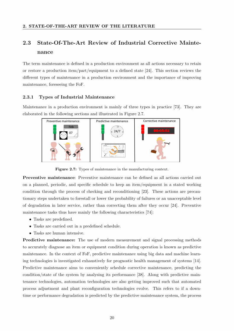
The corrective action in the state-of-the-art corrective maintenance is classified into five
major types [24] as shown in the Figure 2.8 and requires the involvement of a maintenance
personnel. They are Fail repair, Salvage, Rebuild, Servicing, Overhaul and Servicing. Fail repair
refers to remedial actions required to take a failed system to its operational state. Salvage refers
to the actions needed for taking disposed systems back to their defined operational behaviour.
Rebuild actions are applied to restore an item to a standard as close as possible to its original
state in performance. Overhaul takes a system back to its serviceable state as per maintenance
serviceability standard. Servicing results as a side effect of a corrective action performed. For
example, corrective action of a tank may lead to leakage in the crank.
Corrective Maintenance
Overhaul
Fail repair
RebuildServicing
Salvage
Figure 2.8: Types of corrective actions as shown in [24].
Even though predictive and prognostic techniques allow scheduling corrective maintenance
in some cases, the task required in a corrective maintenance function cannot be predicted
or pre-planned [35]. Each equipment or item under maintenance has a defined operational/
original/ serviceable state. Based on the type of the failure/breakdown, the maintenance
personnel completes the task/sequence required to take the component to the defined oper-
ational/original/serviceable state and then checkout. The time between the detection of the
fault and checkout of a fault in a system can be interpreted as Mean Time To Repair (MTTR).
MTTR is a process indicator in the modern production environment, concerning the relationship
between the breakdown and production loss [77].
2.3.3 Important Facts and Figures of Industrial Corrective Maintenance
A large part of the operating budget is constituted by maintenance spending in automated
industries [78]. A study from the United States shows that $300 billion is spent on maintenance
of a plant and operations by the US industry and of which 80% is for chronic failure of machines,
systems and people [36, 37]. A study by the British ministry shows that it requires around
£3000 million annually for maintenance in the UK industries for failure [24]. The average size of
a maintenance group in a manufacturing organization varies from 5-10 % of the total operating
22
2.3 State-Of-The-Art Review of Industrial Corrective Maintenance
force. The cost of maintenance can be up to the 25% of the total operating cost [24]. A study
from 1968 from the UK showed that better maintenance practices could save approximately
£300 million annually [78]. Vathoopan et al. [18] shows that human errors play an important
role in elongating a downtime. They state that, by providing proper support for the human,
the corrective maintenance can be improved. They also assert that in the context of FoF the
complexity of the systems increases and this will affect the human performing maintenance.
2.3.4 Management of Maintenance Activities in Industries
The maintenance activities are managed in two types namely: 1) Centralized maintenance
management 2) Decentralized maintenance management.
Centralized maintenance management: Centralized maintenance management is the one
in which a fixed number of maintenance personnel are assigned for handling the maintenance of
the overall plant. Centralized maintenance management is mainly applied in small and medium
scale enterprises as they have constraints related to human and financial resources. Centralized
maintenance management employs a minimum number of maintenance personnel and supporting
equipment for the management of maintenance activities. However, it assumes that the employed
personnel have expert knowledge of the overall production systems [24].
Decentralized maintenance management: Decentralized maintenance management uses
dedicated maintenance personnel for distributed areas. This kind of maintenance management
also reserves dedicated supporting equipment for the distributed fleet. Thus, it requires more
resources in general and is applied mainly in large-scale companies [24].
2.3.5 Importance of Improving Industrial Corrective Maintenance
In the modern context, the term preventive maintenance is slowly being archived in the produc-
tion environment [38]. Preventive maintenance is applied mainly to enhance capital equipment
life, reduce critical equipment breakdown, minimize production losses due to breakdown, and
increase safety of maintenance personnel. However, mostly the preventive maintenance pro-
grams end up in failure, since their cost is unjustifiable or they take significant time to show the
advantages [24]. In case of critical systems, the preventive maintenance is found to be making
more production losses than corrective maintenance performed during breakdown, as it exposes
equipment to possible damage. It also requires frequent access to equipment and requires access
to more resources [35].
The globalization and related market competition has forced the evolution of the manufac-
turing paradigm in the previous years [7]. According to Lee et al. [38], these changes in the
manufacturing paradigm have also effects on the business processes and other functions within
the manufacturing companies. The maintenance is also an area, facing challenges concerning
23
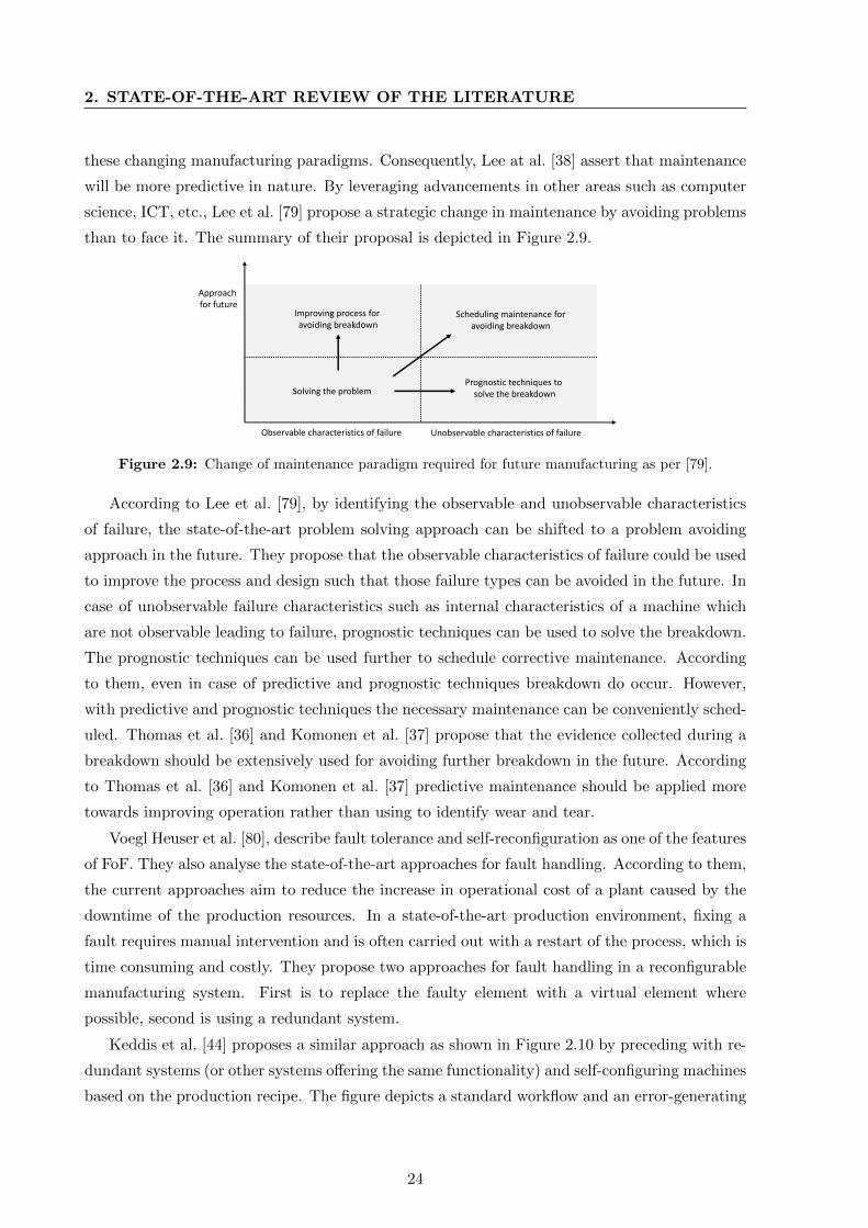
2. STATE-OF-THE-ART REVIEW OF THE LITERATURE
these changing manufacturing paradigms. Consequently, Lee at al. [38] assert that maintenance
will be more predictive in nature. By leveraging advancements in other areas such as computer
science, ICT, etc., Lee et al. [79] propose a strategic change in maintenance by avoiding problems
than to face it. The summary of their proposal is depicted in Figure 2.9.
Solving the problem
Improving process for avoiding breakdown
Scheduling maintenance foravoiding breakdown
Prognostic techniques tosolve the breakdown
Approach for future
Observable characteristics of failure Unobservable characteristics of failure
Figure 2.9: Change of maintenance paradigm required for future manufacturing as per [79].
According to Lee et al. [79], by identifying the observable and unobservable characteristics
of failure, the state-of-the-art problem solving approach can be shifted to a problem avoiding
approach in the future. They propose that the observable characteristics of failure could be used
to improve the process and design such that those failure types can be avoided in the future. In
case of unobservable failure characteristics such as internal characteristics of a machine which
are not observable leading to failure, prognostic techniques can be used to solve the breakdown.
The prognostic techniques can be used further to schedule corrective maintenance. According
to them, even in case of predictive and prognostic techniques breakdown do occur. However,
with predictive and prognostic techniques the necessary maintenance can be conveniently sched-
uled. Thomas et al. [36] and Komonen et al. [37] propose that the evidence collected during a
breakdown should be extensively used for avoiding further breakdown in the future. According
to Thomas et al. [36] and Komonen et al. [37] predictive maintenance should be applied more
towards improving operation rather than using to identify wear and tear.
Voegl Heuser et al. [80], describe fault tolerance and self-reconfiguration as one of the features
of FoF. They also analyse the state-of-the-art approaches for fault handling. According to them,
the current approaches aim to reduce the increase in operational cost of a plant caused by the
downtime of the production resources. In a state-of-the-art production environment, fixing a
fault requires manual intervention and is often carried out with a restart of the process, which is
time consuming and costly. They propose two approaches for fault handling in a reconfigurable
manufacturing system. First is to replace the faulty element with a virtual element where
possible, second is using a redundant system.
Keddis et al. [44] proposes a similar approach as shown in Figure 2.10 by preceding with re-
dundant systems (or other systems offering the same functionality) and self-configuring machines
based on the production recipe. The figure depicts a standard workflow and an error-generating
24
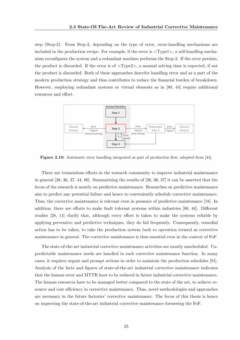
2.3 State-Of-The-Art Review of Industrial Corrective Maintenance
step (Step-2). From Step-2, depending on the type of error, error-handling mechanisms are
included in the production recipe. For example, if the error is <Type1>, a self-handling mecha-
nism reconfigures the system and a redundant machine performs the Step-2. If the error persists,
the product is discarded. If the error is of <Type2>, a manual solving time is expected, if not
the product is discarded. Both of these approaches describe handling error and as a part of the
modern production strategy and thus contributes to reduce the financial burden of breakdown.
However, employing redundant systems or virtual elements as in [80, 44] require additional
resources and effort.
Error<Type3>
Step-2Redundant
Step-2
Step-1
Step-3
Error
<Type1>(self solving)
DiscardProduct
Error
<Type1>
DiscardProduct
Error
<Type2>(manual solving)
Standard Workflow
Figure 2.10: Automatic error handling integrated as part of production flow; adopted from [44].
There are tremendous efforts in the research community to improve industrial maintenance
in general [38, 36, 37, 44, 80]. Summarizing the results of [38, 36, 37] it can be asserted that the
focus of the research is mostly on predictive maintenance. Researches on predictive maintenance
aim to predict any potential failure and hence to conveniently schedule corrective maintenance.
Thus, the corrective maintenance is relevant even in presence of predictive maintenance [18]. In
addition, there are efforts to make fault tolerant systems within industries [80, 44]. Different
studies [28, 14] clarify that, although every effort is taken to make the systems reliable by
applying preventive and predictive techniques, they do fail frequently. Consequently, remedial
action has to be taken, to take the production system back to operation termed as corrective
maintenance in general. The corrective maintenance is thus essential even in the context of FoF.
The state-of-the-art industrial corrective maintenance activities are mostly unscheduled. Un-
predictable maintenance needs are handled in each corrective maintenance function. In many
cases, it requires urgent and prompt actions in order to maintain the production schedules [81].
Analysis of the facts and figures of state-of-the-art industrial corrective maintenance indicates
that the human error and MTTR have to be reduced in future industrial corrective maintenance.
The human resources have to be managed better compared to the state of the art, to achieve re-
source and cost efficiency in corrective maintenance. Thus, novel methodologies and approaches
are necessary in the future factories’ corrective maintenance. The focus of this thesis is hence
on improving the state-of-the-art industrial corrective maintenance foreseeing the FoF.
25
2. STATE-OF-THE-ART REVIEW OF THE LITERATURE
2.4 Improving Industrial Corrective Maintenance by Applying
Self-Diagnosis
Based on the described problem in Section 1.2 of the previous chapter, this section reviews
methodologies which improve the industrial corrective maintenance in detail.
2.4.1 Fundamentals of Self-Diagnosis
Self-diagnosis is referred to as the capability of a system to observe its functionality and diagnose
any fault in it, without using an external mechanism [82]. The state-of-the-art self-diagnosis
methodologies combine fault detection, localisation and diagnosis of a system [30]. Self-diagnosis
is applied across different domains such as consumer electronics, industrial systems, automotive
systems, etc [82, 83, 84]. Consequently, there are several methods for creating self-diagnosis.
Iserman [30] conducted a survey of existing self-diagnosis methodologies to find their ap-
plicability in the automotive domain. He lists several methodologies for fault detection based
on models such as limit checking, signal model based, process model based, etc. He identifies
classification based methods and inference based methods for fault diagnosis. He asserts that
when prior knowledge on causalities of fault symptoms can be derived inference based diagnosis
can be applied, and when not different classification approaches like statistical, neural network
based, fuzzy clusters, etc., can be applied.
Isermann [30] shows examples of classification based diagnosis models for components such
as actuators used in the automotive domain. Even though the methods for creating fault detec-
tion models and diagnosis models are given in this work, the models are created manually and
require detailed knowledge, heuristics, resources and time for development. Classification based
approaches for self-diagnosis have been extensively evaluated further [85, 86], and shows accept-
able results. Statistical approaches were also evaluated later, showing competent results [26, 27].
However, the main drawback of these approaches [85, 86, 26, 27] is their high effort for develop-
ment. In addition, the solutions are problem specific and not reusable.
Iserman et al. [87] further describe inference based self-diagnosis models. According to him,
there are features specific to the equipment/item/part and their ideal states. Any violation
from this state is normally identified as a fault [30]. There are different methods for identifying
or detecting a fault. Normally a fault is detected with the help of a measured variable by
instruments and observed variables and states by maintenance personnel [30]. Since the fault
detection and diagnosis requires analytical methods, a knowledge base is created where ideal
models of features exist. The creation of the knowledge base is a manual process, the complexity
of which depends on the type of machines and their complexity.
Fault tree based self-diagnosis models are generally employed when prior knowledge on
causalities of fault symptoms are available. Collecting this prior-knowledge generally requires
26
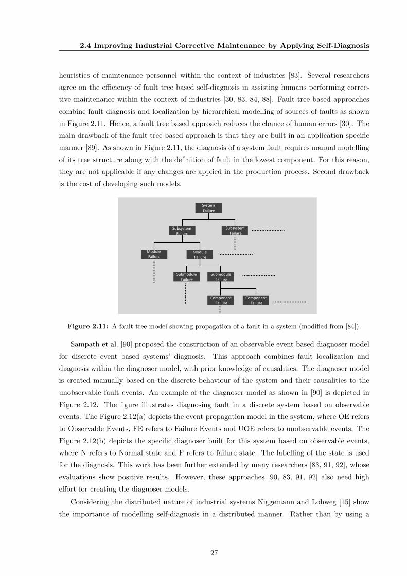
2.4 Improving Industrial Corrective Maintenance by Applying Self-Diagnosis
heuristics of maintenance personnel within the context of industries [83]. Several researchers
agree on the efficiency of fault tree based self-diagnosis in assisting humans performing correc-
tive maintenance within the context of industries [30, 83, 84, 88]. Fault tree based approaches
combine fault diagnosis and localization by hierarchical modelling of sources of faults as shown
in Figure 2.11. Hence, a fault tree based approach reduces the chance of human errors [30]. The
main drawback of the fault tree based approach is that they are built in an application specific
manner [89]. As shown in Figure 2.11, the diagnosis of a system fault requires manual modelling
of its tree structure along with the definition of fault in the lowest component. For this reason,
they are not applicable if any changes are applied in the production process. Second drawback
is the cost of developing such models.
System Failure
Subsystem Failure
Module Failure
Module Failure
Submodule Failure
Submodule Failure
Component Failure
Component Failure
Subsystem Failure
Figure 2.11: A fault tree model showing propagation of a fault in a system (modified from [84]).
Sampath et al. [90] proposed the construction of an observable event based diagnoser model
for discrete event based systems’ diagnosis. This approach combines fault localization and
diagnosis within the diagnoser model, with prior knowledge of causalities. The diagnoser model
is created manually based on the discrete behaviour of the system and their causalities to the
unobservable fault events. An example of the diagnoser model as shown in [90] is depicted in
Figure 2.12. The figure illustrates diagnosing fault in a discrete system based on observable
events. The Figure 2.12(a) depicts the event propagation model in the system, where OE refers
to Observable Events, FE refers to Failure Events and UOE refers to unobservable events. The
Figure 2.12(b) depicts the specific diagnoser built for this system based on observable events,
where N refers to Normal state and F refers to failure state. The labelling of the state is used
for the diagnosis. This work has been further extended by many researchers [83, 91, 92], whose
evaluations show positive results. However, these approaches [90, 83, 91, 92] also need high
effort for creating the diagnoser models.
Considering the distributed nature of industrial systems Niggemann and Lohweg [15] show
the importance of modelling self-diagnosis in a distributed manner. Rather than by using a
27

2. STATE-OF-THE-ART REVIEW OF THE LITERATURE
1
3
FE
2
5
7
6
9
11
10
13
15
4 8 12
16
17
14
OE1
OE1
UOE OE1 UOE OE2 UOE OE3
OE4 UOE
FEUOEOE3
OE3
FE
OE2
OE2
FE
OE4
FE FE FE
OE1
OE1
OE: Observable Events, UOE: Unobservable Events, FE: Failure Events
(a) System event propagation model.
IN
17F1
IN
3F3N5N
7F7N9N
11F111N13N
OE2
OE1
OE1
OE1
OE1
OE3
OE4
N: Normal state, F: Failure state
(b) System diagnosis model.
Figure 2.12: An example of diagnosis model as shown in [90] showing its application dependency.
central observer, in distributed self-diagnosing systems, each distributed unit has its own diag-
nosis model and access to the diagnosis relevant data [82]. Niggemann and Lohweg describe
the different methodologies of self-diagnosis applicable to distributed industrial systems. Their
approach show the importance of improvement in classification based self-diagnosis and clarify
the efficiency of inference based models within industries.
2.4.2 Self-Diagnosis and Corrective Maintenance
The Section 2.3.5, clarifies the importance of improving industrial corrective maintenance.
Dhillon [24] finds, improving the performance of humans and hence reducing the MTTR can
improve the corrective maintenance. As per definition [24], corrective maintenance involves five
sequential steps namely: fault identification; fault localization; fault diagnosis; corrective ac-
tion; and checkout. According to Dhillon [24] the first three steps in the corrective maintenance,
i.e., fault identification, fault localization, and fault diagnosis are the most time taking steps,
and the time required largely depends on the skill of the person performing maintenance. He
suggests that achieving efficiency in these three steps will reduce the MTTR and thus improve
maintenance effectiveness.
There were previous efforts [83, 93, 30, 92, 25] to improve the efficiency of maintenance
personnel in the production environment by implementing self-diagnosis within corrective main-
tenance. Self-diagnosis integrates the first three steps in the corrective maintenance function
namely fault detection, localization and diagnosis [18]. Self-diagnosis in any system is imple-
mented as a software module, which continuously monitors the operation of a resource, detects,
localizes and diagnoses any fault within that resource [87]. Self-diagnosis thus acts as a human
assistive feature for corrective maintenance in a production environment [83, 93, 15, 92].
28
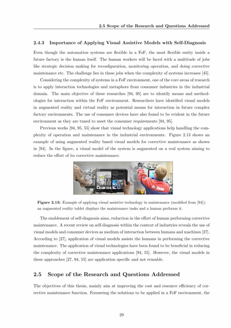
2.5 Scope of the Research and Questions Addressed
2.4.3 Importance of Applying Visual Assistive Models with Self-Diagnosis
Even though the automation systems are flexible in a FoF, the most flexible entity inside a
future factory is the human itself. The human workers will be faced with a multitude of jobs
like strategic decision making for reconfiguration, monitoring operation, and doing corrective
maintenance etc. The challenge lies in these jobs when the complexity of systems increases [45].
Considering the complexity of systems in a FoF environment, one of the core areas of research
is to apply interaction technologies and metaphors from consumer industries in the industrial
domain. The main objective of these researches [94, 95] are to identify means and method-
ologies for interaction within the FoF environment. Researchers have identified visual models
in augmented reality and virtual reality as potential means for interaction in future complex
factory environments. The use of consumer devices have also found to be evident in the future
environment as they are tuned to meet the consumer requirements [94, 95].
Previous works [94, 95, 55] show that visual technology applications help handling the com-
plexity of operation and maintenance in the industrial environments. Figure 2.13 shows an
example of using augmented reality based visual models for corrective maintenance as shown
in [94]. In the figure, a visual model of the system is augmented on a real system aiming to
reduce the effort of its corrective maintenance.
Figure 2.13: Example of applying visual assistive technology in maintenance (modified from [94]);
an augmented reality tablet displays the maintenance tasks and a human performs it.
The enablement of self-diagnosis aims, reduction in the effort of human performing corrective
maintenance. A recent review on self-diagnosis within the context of industries reveals the use of
visual models and consumer devices as medium of interaction between humans and machines [27].
According to [27], application of visual models assists the humans in performing the corrective
maintenance. The application of visual technologies have been found to be beneficial in reducing
the complexity of corrective maintenance applications [94, 55]. However, the visual models in
these approaches [27, 94, 55] are application specific and not reusable.
2.5 Scope of the Research and Questions Addressed
The objectives of this thesis, mainly aim at improving the cost and resource efficiency of cor-
rective maintenance function. Foreseeing the solutions to be applied in a FoF environment, the
29
2. STATE-OF-THE-ART REVIEW OF THE LITERATURE
fundamental characteristics and elements of the FoF are analysed. The review of the funda-
mentals of FoF reveals that the future systems will be flexible and reconfigurable in nature and
also possess human assistive features. The future factories should hold cognitive capabilities,
intelligence and seamless interoperability.
As it was found that, the maintenance of a production system has strong dependencies to
the engineering and operation of a production system, the state-of-the-art plant engineering and
operation influential to the corrective maintenance are also reviewed. The studies on engineer-
ing of FoF summarize that the future plant engineering features modularization, component
orientation and service (skill) orientation. The domain specific and stakeholder specific tools of
the future, interoperate and generate seamlessly exchangeable engineering data. As the com-
munication and information exchange between operation and maintenance platforms is relevant
for corrective maintenance, a review of information and communication exchange technologies
for FoF were also performed. This analysis revealed OPC UA as the choice for operational
information exchange and communication within the industrial manufacturing domain.
Further analysing the state of the art and research trend in corrective maintenance, it was
clear that the state-of-the-art industrial corrective maintenance has to be revamped for the FoF.
Though different studies reveal the advantages of self-diagnosis in improving corrective mainte-
nance by reducing MTTR and human errors, it was also clear that enabling self-diagnosis on
manufacturing systems requires a lot of resources and effort. The review of the applicability of
different diagnosis approaches shows that they are developed for specific problems using specific
technologies and mostly are not reusable.
By identifying the reduction in human error and MTTR as a must for revamping the future
corrective maintenance, this thesis aims enabling self-diagnosis in future factories in a cost
efficient and reusable manner. By acknowledging the benefits of visual assistive technologies in
the corrective maintenance, this thesis further investigates visual models for integrating reusable
self-diagnosis models within future corrective maintenance. This thesis also aims to accomplish
the proposed characteristics of FoF in their corrective maintenance function.
Within the scope of this thesis, the following research questions are addressed:
1. Is it possible to create reusable models for self-diagnosis in production systems?
What are the prerequisites for it?
Acknowledging the application specific behaviour of different self-diagnosis approaches,
this question focuses on methodologies for creating reusable models for self-diagnosis in
production systems and the prerequisites for it.
2. How to realize self-diagnosis of automated production systems in a cost efficient
manner? Is it possible to leverage their engineering and operational aspects
for achieving cost efficiency in self-diagnosis realization?
Literature analysis reveals the high cost and resource utilization for developing self-diagnosis
30
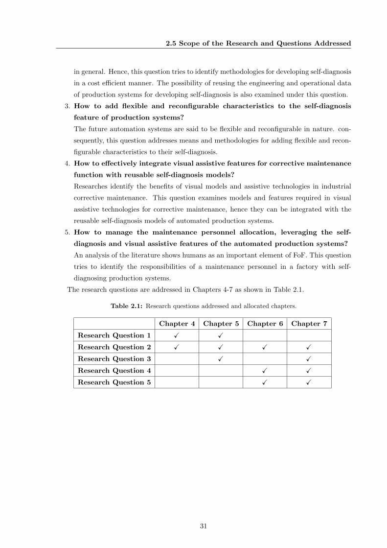
2.5 Scope of the Research and Questions Addressed
in general. Hence, this question tries to identify methodologies for developing self-diagnosis
in a cost efficient manner. The possibility of reusing the engineering and operational data
of production systems for developing self-diagnosis is also examined under this question.
3. How to add flexible and reconfigurable characteristics to the self-diagnosis
feature of production systems?
The future automation systems are said to be flexible and reconfigurable in nature. con-
sequently, this question addresses means and methodologies for adding flexible and recon-
figurable characteristics to their self-diagnosis.
4. How to effectively integrate visual assistive features for corrective maintenance
function with reusable self-diagnosis models?
Researches identify the benefits of visual models and assistive technologies in industrial
corrective maintenance. This question examines models and features required in visual
assistive technologies for corrective maintenance, hence they can be integrated with the
reusable self-diagnosis models of automated production systems.
5. How to manage the maintenance personnel allocation, leveraging the self-
diagnosis and visual assistive features of the automated production systems?
An analysis of the literature shows humans as an important element of FoF. This question
tries to identify the responsibilities of a maintenance personnel in a factory with self-
diagnosing production systems.
The research questions are addressed in Chapters 4-7 as shown in Table 2.1.
Table 2.1: Research questions addressed and allocated chapters.
Chapter 4 Chapter 5 Chapter 6 Chapter 7
Research Question 1 X X
Research Question 2 X X X X
Research Question 3 X X
Research Question 4 X X
Research Question 5 X X
31

Chapter 3
Requirements for Enabling
Self-Diagnosis in Future Corrective
Maintenance
This thesis hypothesizes that efficient realization of self-diagnosis along with visual assistive
features in production systems will improve the industrial corrective maintenance in the future.
This chapter identifies the requirements for achieving the same using the methodologies of
requirements engineering. The application of requirements engineering promises to derive the
users perspectives, functional specifications and technical characteristics of a system from its
elicited requirements [96, 97, 98]. Thus, the application of requirements engineering guarantees
that the system under consideration meets the needs and expectations of its users. This thesis
uses the elicited requirements to further refine the scope of the research and subsequently to
derive the research methodologies.
This chapter is divided in four sections. Section 3.1 describes the fundamentals of require-
ments engineering. The stakeholders and the stated requirements of the system are introduced
in Section 3.3. Section 3.4 describes the use-cases and the elicited requirements of the system.
Subsequently, Section 3.5 concludes this chapter.
3.1 Requirements Engineering as a Means to Ensure Industrial
Applicability of the Research Results
This thesis is partly developed within the scope of the research projects OPAK [99] and DE-
VEKOS [100], funded by the German Federal Ministry for Economic Affairs and Energy (BMWi).
These projects integrate academic and industrial partners, envisioning the industrial applicabil-
ity of the research results. Therefore, the results of this thesis are also foreseen to be transferable
33
3. REQUIREMENTS FOR ENABLING SELF-DIAGNOSIS IN FUTURECORRECTIVE MAINTENANCE
to the industries. Hence, methodologies of requirements engineering are used to formally elicit
the requirements of the system under consideration in this thesis. Requirements are used as a
means to convey the technical aspects and functionalities of the system among the stakeholders.
The requirements are traced through the further development of this thesis, foreseeing that the
results of this thesis meet the stakeholders’ needs.
Within the research projects OPAK and DEVEKOS, the production resources are assumed
as a composition of modular CPPS based automation components. The projects primarily ex-
amine the methodologies for engineering modular production resources of the future, consuming
the services of the automation components. These projects presume that the manufacturers
of CPPS based automation components can distribute the digitized engineering models of their
components along/prior to their delivery to the consumer. Consequently, the consumers can
leverage the digitized engineering models available from the manufacturers of the CPPS based
automation components, for the cost efficient engineering of their automation systems.
This thesis examines means and methods for cost and resource efficient realization of self-
diagnosis in industrial automation systems. The partners from the projects anticipate that
the concept for engineering automation systems applied in the projects is also applicable for
the realization of self-diagnosis. The component manufacturers can distribute the self-diagnosis
models of CPPS based automation components along/prior to their delivery to the consumer.
The consumer can make use of the self-diagnosis models of the components to reduce the cost,
and effort for realizing self-diagnosis and visual assistive features in their automation systems.
Thus, this thesis presumes two systems under consideration: 1) A CPPS based automation
component 2) An automation system composed of CPPS based automation components. The
technical specifications and functionalities of the self-diagnosis and visual assistive features of
these two systems have to be derived using the principles of requirements engineering.
3.2 Defining the Desired Practice of Requirements Engineering
Requirements engineering practice in the industrial environment varies from project to project
and company to company [96]. The requirements engineering commonly integrates several activi-
ties such as requirements elicitation, analysis, negotiation, specification and validation [101, 102].
The requirements elicitation itself include several stages such as stakeholder identification, un-
derstanding the customers’ needs, clarifying requirements, etc [96, 98]. In the initial analysis, it
was found that only some of the aspects of the industrial requirements engineering practice is
applicable in this thesis. The sequences of activities of requirements engineering applied in this
thesis are described below.
The process of requirements engineering applied in this thesis starts by, identifying the
stakeholders of the system under consideration. According to Westfall [97], the stakeholders of
34
3.3 Stakeholders and Stated Requirements of the Systems
a system are mainly categorized into three types. The first are the acquirers of the software
product or system; the second are the suppliers of the software product or system; and the third
one are the other stakeholders. The acquirers can be further divided into two major groups; the
customers who request, purchase and pay for the software product and the users who actually
use the product. The suppliers have further internal stakeholders such as developers, advisers,
project groups that are involved in developing the system, etc. The other stakeholders may
change depending on the type of the product and project. Examples of other stakeholders are
legal or contract management, upper management, government or regulatory agencies, etc [97].
The core activities of the requirements engineering starts by collecting expectations of the
acquirers of the system. The expectations of the acquirers are otherwise termed as stated
requirements [96]. The stated requirements can be of different types in a project namely, busi-
ness requirements, user requirements, product requirements, environmental requirements and
unknowable requirements [96, 98]. Business requirements are used to specify the customer’s
business goals and corresponding bounds. These are the initiating reasons for developing new
systems or software of any kind. When the system involves user interactions, user requirements
are used to derive the user’s needs for the system or software. Product requirements represent
the requirements of the products/services offered by the system. Environmental requirements
concern the physical setting, social and cultural conditions of the system and the setting in which
the system or software will be used. Unknowable requirements are those, which are not known
at the beginning of a system development, and are highlighted only as the system evolves [96].
The stated requirements are then analysed to derive the real requirements. There are differ-
ent techniques and means for requirements analysis, such as requirement workshops, high level
data flow diagrams, use-case diagrams, etc. Use-cases help to specify the requirements from a
users point of view and to elicit the hidden requirements from the stakeholders. In addition,
they can be used in the further development of a system [103]. Hence, this thesis employs use-
case diagrams to elicit the real requirements from the stated requirements. The elicited real
requirements are later used consistently throughout the development of this thesis.
The sequence of activities of requirements engineering applied in this thesis are as follows:
1. Identify the stakeholders and derive the stated requirements of the systems.
2. Elicit the real requirements of the systems by analysing the use-case scenarios.
3.3 Stakeholders and Stated Requirements of the Systems
The first step of requirements engineering is to identify the overall stakeholders of the system
under consideration [97]. Subsequently from the overall stakeholders, the acquirers have to be
identified and their needs and expectations have to be collected.
35
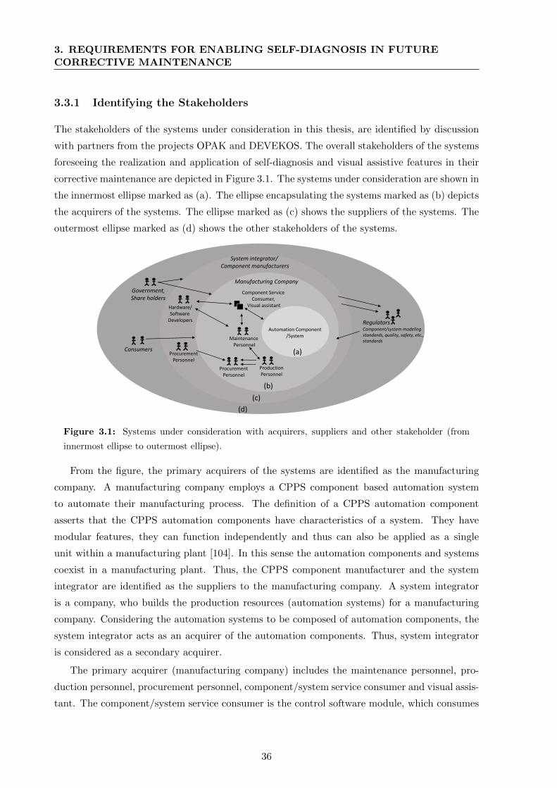
3. REQUIREMENTS FOR ENABLING SELF-DIAGNOSIS IN FUTURECORRECTIVE MAINTENANCE
3.3.1 Identifying the Stakeholders
The stakeholders of the systems under consideration in this thesis, are identified by discussion
with partners from the projects OPAK and DEVEKOS. The overall stakeholders of the systems
foreseeing the realization and application of self-diagnosis and visual assistive features in their
corrective maintenance are depicted in Figure 3.1. The systems under consideration are shown in
the innermost ellipse marked as (a). The ellipse encapsulating the systems marked as (b) depicts
the acquirers of the systems. The ellipse marked as (c) shows the suppliers of the systems. The
outermost ellipse marked as (d) shows the other stakeholders of the systems.
RegulatorsComponent/system modeling standards, quality, safety, etc., standards
Manufacturing Company
Hardware/Software
Developers
ProcurementPersonnel
Government, Share holders
Component Service Consumer,
Visual assistant
Automation Component/SystemMaintenance
Personnel
ProductionPersonnel
System integrator/Component manufacturers
ProcurementPersonnel
Consumers (a)
(b)
(c)
(d)
Figure 3.1: Systems under consideration with acquirers, suppliers and other stakeholder (from
innermost ellipse to outermost ellipse).
From the figure, the primary acquirers of the systems are identified as the manufacturing
company. A manufacturing company employs a CPPS component based automation system
to automate their manufacturing process. The definition of a CPPS automation component
asserts that the CPPS automation components have characteristics of a system. They have
modular features, they can function independently and thus can also be applied as a single
unit within a manufacturing plant [104]. In this sense the automation components and systems
coexist in a manufacturing plant. Thus, the CPPS component manufacturer and the system
integrator are identified as the suppliers to the manufacturing company. A system integrator
is a company, who builds the production resources (automation systems) for a manufacturing
company. Considering the automation systems to be composed of automation components, the
system integrator acts as an acquirer of the automation components. Thus, system integrator
is considered as a secondary acquirer.
The primary acquirer (manufacturing company) includes the maintenance personnel, pro-
duction personnel, procurement personnel, component/system service consumer and visual assis-
tant. The component/system service consumer is the control software module, which consumes
36
3.3 Stakeholders and Stated Requirements of the Systems
the services of the automation components. The visual assistant is a software module, which
assists the maintenance personnel with visual assistive feature for carrying out the corrective
maintenance function. The maintenance personnel are the indirect users of the systems through
the visual assistant. The maintenance personnel coordinate with the production personnel to
schedule and execute corrective maintenance functions. Thus, the production personnel are in-
direct and passive users of the systems. The procurement personnel are the customers of the
systems under consideration. The procurement personnel decide on the acquisition, based on
the review of the system by the production personnel and the maintenance personnel.
The supplier of the systems can be either the component manufacturer or the system inte-
grator. From the component manufacturer/system integrator, the stakeholders interacting with
the automation component/system are the hardware/software developers, and procurement per-
sonnel. The hardware/software developers from the component manufacturer/system integrator
interact with the maintenance personnel concerning their systems. The hardware/software de-
velopers from the component manufacturer/system integrator are the ones, who develop the
automation system/component hardware and the corresponding service consumer and visual
assistant software modules. The stakeholders within the system integrator also serve the addi-
tional role of secondary acquirer.
The other stakeholders such as the government, or shareholders might also influence the ac-
tivities in a manufacturing company affecting the procurement personnel in a negative manner.
The consumers of the products of the manufacturing company have a direct influence on the
automation systems and the manufacturing company. The regulators such as component mod-
elling standard, quality, safety, etc., standards used within the manufacturing company influence
the component manufactures and system integrator negatively.
3.3.2 Stated Requirements
The stated requirements of the systems are created by interviewing the partners within the
projects having the role of acquirers (manufacturing company and the system integrator).
Business Requirements: The initiation of the systems are triggered by the basic business
goals of the manufacturing company or the system integrator. The system integrator plans to
leverage the self-diagnosis feature of a CPPS based automation component to facilitate self-
diagnosis in a component based automation system. The manufacturing company intends to
employ the automation systems with self-diagnosis and visual assistive features for the corrective
maintenance of FoF. The business requirements are listed below:
1. The application of self-diagnosis and visual assistive features shall decrease the downtime
and the production loss in FoF.
2. The self-diagnosis and visual assistive features of the systems shall have re-configuration
and flexible characteristics, such that these can also be reconfigured according to produc-
37
3. REQUIREMENTS FOR ENABLING SELF-DIAGNOSIS IN FUTURECORRECTIVE MAINTENANCE
tion reconfiguration/s.
3. The self-diagnosis and visual assistive features shall reduce human involvement in correc-
tive maintenance. By reducing human involvement, human error can be reduced and also
human resources can be efficiently employed.
4. The facilitation of the self-diagnosis and visual assistive features shall have cost and time
efficiency. Hence, the cost efficiency of corrective maintenance can be achieved.
User Requirements: The expectations of the manufacturing company/system integrator on
the usage of the self-diagnosis feature within the corrective maintenance of future systems are
listed below:
1. Less effort shall be required in composing self-diagnosis feature of automation components
to facilitate self-diagnosis in automation systems.
2. The systems shall handle complexity, since the FoF is envisioned to be complex in nature.
3. The usage of self-diagnosis feature in automation components should be intuitive and
human assistive. Thus, the facilitation self-diagnosis in future automation systems should
reduce human effort in corrective maintenance.
4. The future corrective maintenance systems shall use existing/intuitive user interfaces.
Therefore, the learning curve required for any new interface/software can be reduced.
Product Requirements: Product requirements evolve from the characteristics of FoF elabo-
rated in Section 2.1 of the previous chapter. These are listed below:
1. The self-diagnosis aspects from the component manufacturer shall have interoperability
and exchangeability. Hence, they can interoperate and exchange information with the
component/system service consumer and the visual assistant module.
2. The self-diagnosis shall have loosely coupled and modular architecture, such that they
have flexibility and reconfigurability.
3. The self-diagnosis of the systems shall exchange information with the production mod-
ules or systems: The maintenance systems have dependencies on production systems and
information exchange will help improving production based on corrective maintenance.
4. The self-diagnosis of the automation system shall not induce any safety threat or perfor-
mance issues to the production systems.
Environmental Requirements: Environmental requirements are derived from the system
integrator and the manufacturing company and are listed below:
1. The automated production systems employed in the manufacturing company shall satisfy
the requirements of FoF.
2. The development shall be performed in the standard bounds recommended within the
industrial automation domain.
3. The humans shall act as strategic decision makers in the corrective maintenance function.
38
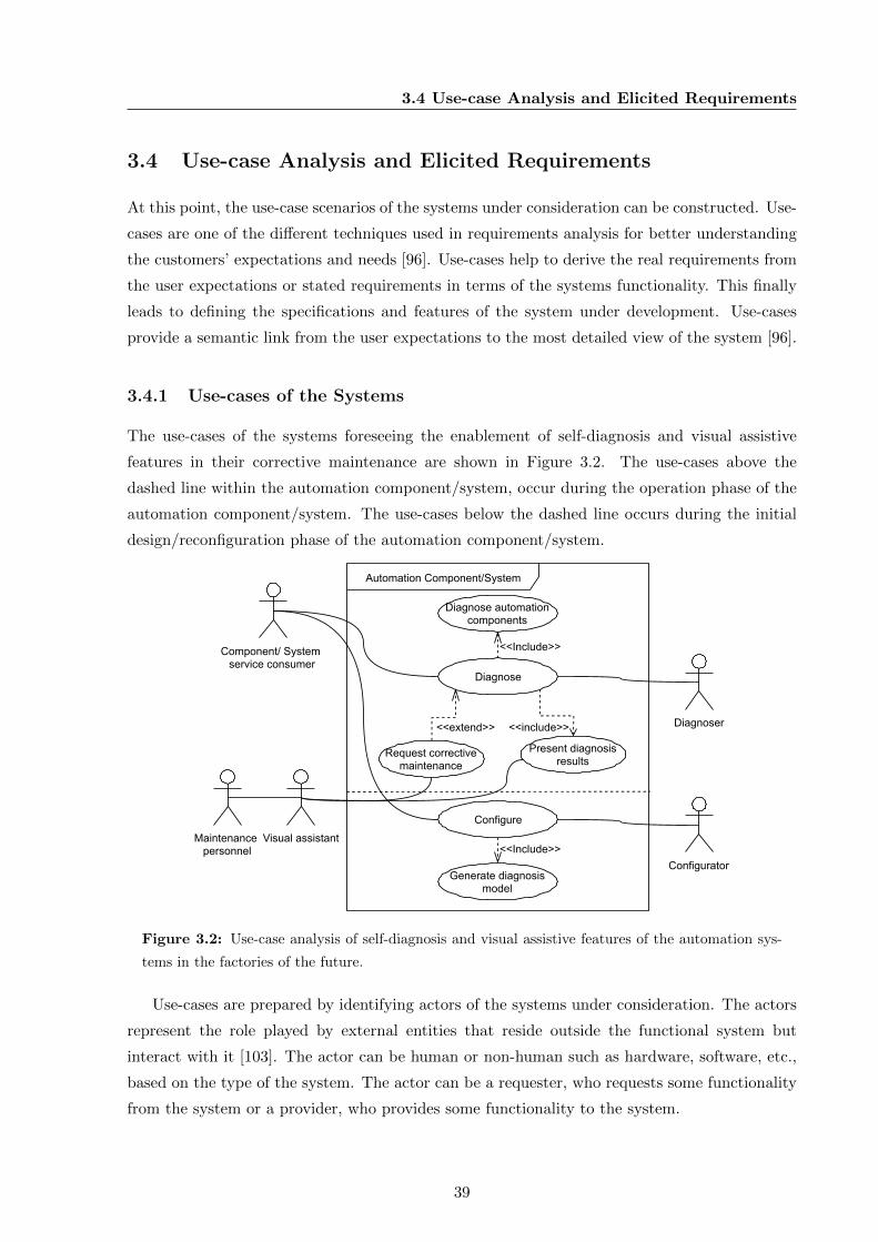
3.4 Use-case Analysis and Elicited Requirements
3.4 Use-case Analysis and Elicited Requirements
At this point, the use-case scenarios of the systems under consideration can be constructed. Use-
cases are one of the different techniques used in requirements analysis for better understanding
the customers’ expectations and needs [96]. Use-cases help to derive the real requirements from
the user expectations or stated requirements in terms of the systems functionality. This finally
leads to defining the specifications and features of the system under development. Use-cases
provide a semantic link from the user expectations to the most detailed view of the system [96].
3.4.1 Use-cases of the Systems
The use-cases of the systems foreseeing the enablement of self-diagnosis and visual assistive
features in their corrective maintenance are shown in Figure 3.2. The use-cases above the
dashed line within the automation component/system, occur during the operation phase of the
automation component/system. The use-cases below the dashed line occurs during the initial
design/reconfiguration phase of the automation component/system.
Diagnoser
Automation Component/System
Present diagnosisresults
Diagnose
Component/ System service consumer
Configure
ConfiguratorGenerate diagnosis
model
<<Include>>
<<include>>
Diagnose automationcomponents
<<Include>>
Request correctivemaintenance
<<extend>>
Visual assistantMaintenance personnel
Figure 3.2: Use-case analysis of self-diagnosis and visual assistive features of the automation sys-
tems in the factories of the future.
Use-cases are prepared by identifying actors of the systems under consideration. The actors
represent the role played by external entities that reside outside the functional system but
interact with it [103]. The actor can be human or non-human such as hardware, software, etc.,
based on the type of the system. The actor can be a requester, who requests some functionality
from the system or a provider, who provides some functionality to the system.
39
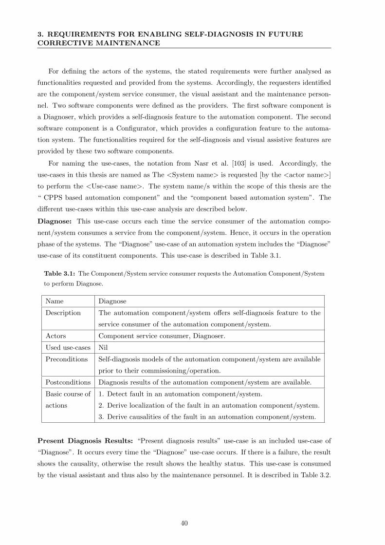
3. REQUIREMENTS FOR ENABLING SELF-DIAGNOSIS IN FUTURECORRECTIVE MAINTENANCE
For defining the actors of the systems, the stated requirements were further analysed as
functionalities requested and provided from the systems. Accordingly, the requesters identified
are the component/system service consumer, the visual assistant and the maintenance person-
nel. Two software components were defined as the providers. The first software component is
a Diagnoser, which provides a self-diagnosis feature to the automation component. The second
software component is a Configurator, which provides a configuration feature to the automa-
tion system. The functionalities required for the self-diagnosis and visual assistive features are
provided by these two software components.
For naming the use-cases, the notation from Nasr et al. [103] is used. Accordingly, the
use-cases in this thesis are named as The <System name> is requested [by the <actor name>]
to perform the <Use-case name>. The system name/s within the scope of this thesis are the
“ CPPS based automation component” and the “component based automation system”. The
different use-cases within this use-case analysis are described below.
Diagnose: This use-case occurs each time the service consumer of the automation compo-
nent/system consumes a service from the component/system. Hence, it occurs in the operation
phase of the systems. The “Diagnose” use-case of an automation system includes the “Diagnose”
use-case of its constituent components. This use-case is described in Table 3.1.
Table 3.1: The Component/System service consumer requests the Automation Component/System
to perform Diagnose.
Name Diagnose
Description The automation component/system offers self-diagnosis feature to the
service consumer of the automation component/system.
Actors Component service consumer, Diagnoser.
Used use-cases Nil
Preconditions Self-diagnosis models of the automation component/system are available
prior to their commissioning/operation.
Postconditions Diagnosis results of the automation component/system are available.
Basic course of
actions
1. Detect fault in an automation component/system.
2. Derive localization of the fault in an automation component/system.
3. Derive causalities of the fault in an automation component/system.
Present Diagnosis Results: “Present diagnosis results” use-case is an included use-case of
“Diagnose”. It occurs every time the “Diagnose” use-case occurs. If there is a failure, the result
shows the causality, otherwise the result shows the healthy status. This use-case is consumed
by the visual assistant and thus also by the maintenance personnel. It is described in Table 3.2.
40
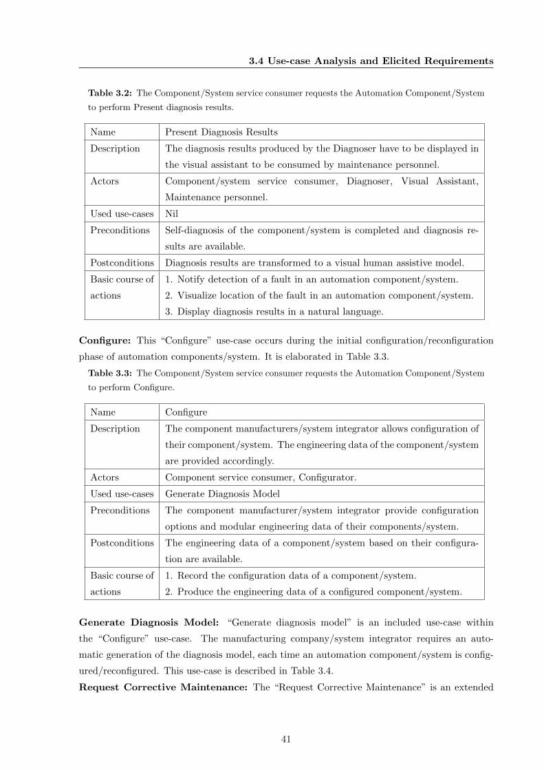
3.4 Use-case Analysis and Elicited Requirements
Table 3.2: The Component/System service consumer requests the Automation Component/System
to perform Present diagnosis results.
Name Present Diagnosis Results
Description The diagnosis results produced by the Diagnoser have to be displayed in
the visual assistant to be consumed by maintenance personnel.
Actors Component/system service consumer, Diagnoser, Visual Assistant,
Maintenance personnel.
Used use-cases Nil
Preconditions Self-diagnosis of the component/system is completed and diagnosis re-
sults are available.
Postconditions Diagnosis results are transformed to a visual human assistive model.
Basic course of
actions
1. Notify detection of a fault in an automation component/system.
2. Visualize location of the fault in an automation component/system.
3. Display diagnosis results in a natural language.
Configure: This “Configure” use-case occurs during the initial configuration/reconfiguration
phase of automation components/system. It is elaborated in Table 3.3.
Table 3.3: The Component/System service consumer requests the Automation Component/System
to perform Configure.
Name Configure
Description The component manufacturers/system integrator allows configuration of
their component/system. The engineering data of the component/system
are provided accordingly.
Actors Component service consumer, Configurator.
Used use-cases Generate Diagnosis Model
Preconditions The component manufacturer/system integrator provide configuration
options and modular engineering data of their components/system.
Postconditions The engineering data of a component/system based on their configura-
tion are available.
Basic course of
actions
1. Record the configuration data of a component/system.
2. Produce the engineering data of a configured component/system.
Generate Diagnosis Model: “Generate diagnosis model” is an included use-case within
the “Configure” use-case. The manufacturing company/system integrator requires an auto-
matic generation of the diagnosis model, each time an automation component/system is config-
ured/reconfigured. This use-case is described in Table 3.4.
Request Corrective Maintenance: The “Request Corrective Maintenance” is an extended
41
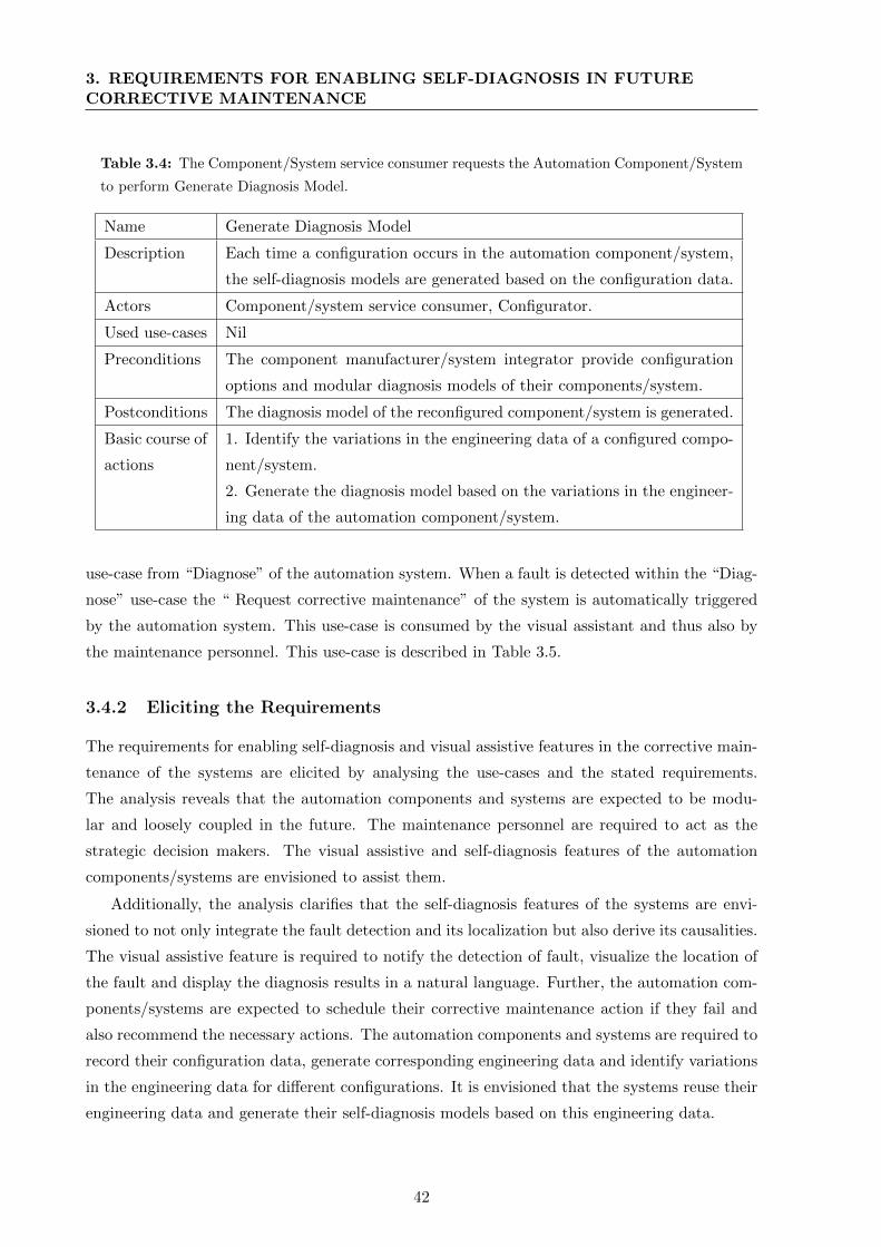
3. REQUIREMENTS FOR ENABLING SELF-DIAGNOSIS IN FUTURECORRECTIVE MAINTENANCE
Table 3.4: The Component/System service consumer requests the Automation Component/System
to perform Generate Diagnosis Model.
Name Generate Diagnosis Model
Description Each time a configuration occurs in the automation component/system,
the self-diagnosis models are generated based on the configuration data.
Actors Component/system service consumer, Configurator.
Used use-cases Nil
Preconditions The component manufacturer/system integrator provide configuration
options and modular diagnosis models of their components/system.
Postconditions The diagnosis model of the reconfigured component/system is generated.
Basic course of
actions
1. Identify the variations in the engineering data of a configured compo-
nent/system.
2. Generate the diagnosis model based on the variations in the engineer-
ing data of the automation component/system.
use-case from “Diagnose” of the automation system. When a fault is detected within the “Diag-
nose” use-case the “ Request corrective maintenance” of the system is automatically triggered
by the automation system. This use-case is consumed by the visual assistant and thus also by
the maintenance personnel. This use-case is described in Table 3.5.
3.4.2 Eliciting the Requirements
The requirements for enabling self-diagnosis and visual assistive features in the corrective main-
tenance of the systems are elicited by analysing the use-cases and the stated requirements.
The analysis reveals that the automation components and systems are expected to be modu-
lar and loosely coupled in the future. The maintenance personnel are required to act as the
strategic decision makers. The visual assistive and self-diagnosis features of the automation
components/systems are envisioned to assist them.
Additionally, the analysis clarifies that the self-diagnosis features of the systems are envi-
sioned to not only integrate the fault detection and its localization but also derive its causalities.
The visual assistive feature is required to notify the detection of fault, visualize the location of
the fault and display the diagnosis results in a natural language. Further, the automation com-
ponents/systems are expected to schedule their corrective maintenance action if they fail and
also recommend the necessary actions. The automation components and systems are required to
record their configuration data, generate corresponding engineering data and identify variations
in the engineering data for different configurations. It is envisioned that the systems reuse their
engineering data and generate their self-diagnosis models based on this engineering data.
42
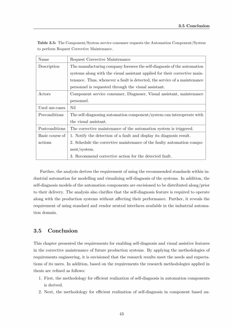
3.5 Conclusion
Table 3.5: The Component/System service consumer requests the Automation Component/System
to perform Request Corrective Maintenance.
Name Request Corrective Maintenance
Description The manufacturing company foresees the self-diagnosis of the automation
systems along with the visual assistant applied for their corrective main-
tenance. Thus, whenever a fault is detected, the service of a maintenance
personnel is requested through the visual assistant.
Actors Component service consumer, Diagnoser, Visual assistant, maintenance
personnel.
Used use-cases Nil
Preconditions The self-diagnosing automation component/system can interoperate with
the visual assistant.
Postconditions The corrective maintenance of the automation system is triggered.
Basic course of
actions
1. Notify the detection of a fault and display its diagnosis result.
2. Schedule the corrective maintenance of the faulty automation compo-
nent/system.
3. Recommend corrective action for the detected fault.
Further, the analysis derives the requirement of using the recommended standards within in-
dustrial automation for modelling and visualizing self-diagnosis of the systems. In addition, the
self-diagnosis models of the automation components are envisioned to be distributed along/prior
to their delivery. The analysis also clarifies that the self-diagnosis feature is required to operate
along with the production systems without affecting their performance. Further, it reveals the
requirement of using standard and vendor neutral interfaces available in the industrial automa-
tion domain.
3.5 Conclusion
This chapter presented the requirements for enabling self-diagnosis and visual assistive features
in the corrective maintenance of future production systems. By applying the methodologies of
requirements engineering, it is envisioned that the research results meet the needs and expecta-
tions of its users. In addition, based on the requirements the research methodologies applied in
thesis are refined as follows:
1. First, the methodology for efficient realization of self-diagnosis in automation components
is derived.
2. Next, the methodology for efficient realization of self-diagnosis in component based au-
43

3. REQUIREMENTS FOR ENABLING SELF-DIAGNOSIS IN FUTURECORRECTIVE MAINTENANCE
tomation systems is defined.
3. Finally, the methodology for improving the application of visual assistive and self-diagnosis
features in the corrective maintenance of a production system is addressed.
The requirements elaborated in Section 3.4.2 are traced in the further development of this thesis.
44
Chapter 4
Modelling Self-Diagnosis of Modular
Industrial Automation Components
Self-diagnosis is a key feature in many consumer devices, such as printers, washing machines,
etc., in and around our daily life. The self-diagnosis feature of these devices has been found to be
quite efficient in reducing the human effort for the corrective maintenance of such devices [90].
This thesis hypothesizes that, implementing self-diagnosis and visual assistive features in the
production resources will improve their corrective maintenance. Self-diagnosis feature has al-
ready been implemented in industrial automation systems. However, the previous experiences
show that self-diagnosis implementation in industrial automation systems are not efficient, con-
sidering the cost and effort required [36, 89, 24].
The previous chapter defines, a methodology for efficient realization of self-diagnosis in au-
tomation components as an initial requirement for deriving the overall methodology of this thesis.
Consequently, this chapter examines a methodology for cost efficient realization of self-diagnosis
in automation components. Thus, Section 4.1 of this chapter describes the prerequisites for
modelling self-diagnosis in automation components. The model of a skill, which acts as a facil-
itator for implementing self-diagnosis is introduced in Section 4.2. Later, Section 4.3 describes
the types of faults, which serve as the point of entry for modelling self-diagnosis in skill of an
automation component. Different aspects of reusing engineering data for realizing self-diagnosis
are elaborated in Section 4.4. Subsequently, Section 4.5 concludes this chapter.
4.1 Prerequisites for Modelling Self-Diagnosis of Automation
Components
Self-diagnosis has been applied in multiple domains, such as consumer electronics, industrial sys-
tems, automotive systems, etc. [90, 30, 89]. Sampath et al. [90] showed an example of modelling
45
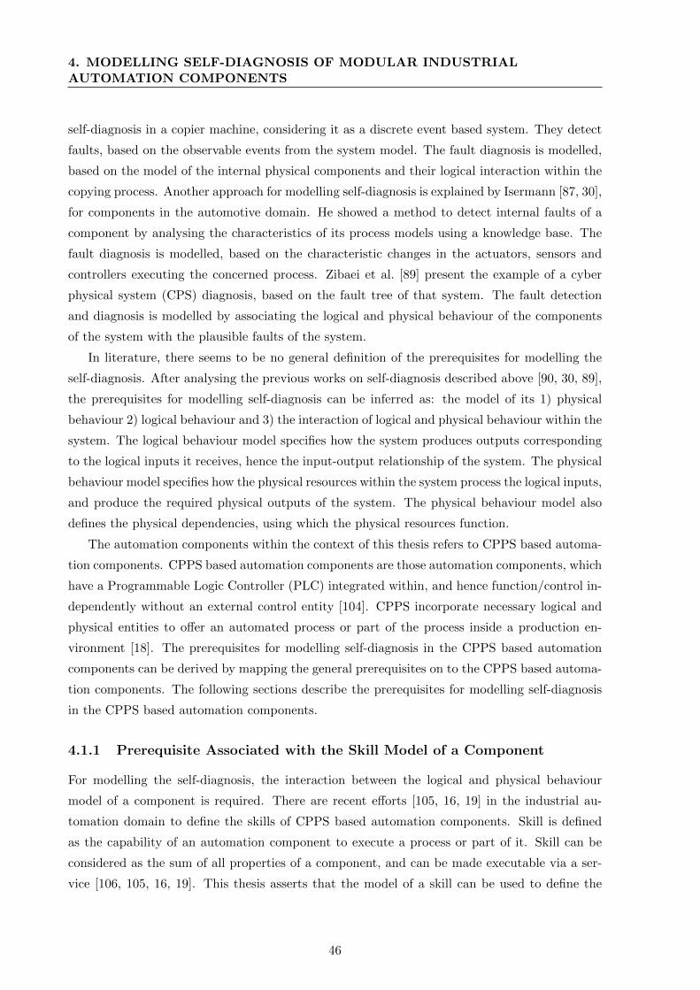
4. MODELLING SELF-DIAGNOSIS OF MODULAR INDUSTRIALAUTOMATION COMPONENTS
self-diagnosis in a copier machine, considering it as a discrete event based system. They detect
faults, based on the observable events from the system model. The fault diagnosis is modelled,
based on the model of the internal physical components and their logical interaction within the
copying process. Another approach for modelling self-diagnosis is explained by Isermann [87, 30],
for components in the automotive domain. He showed a method to detect internal faults of a
component by analysing the characteristics of its process models using a knowledge base. The
fault diagnosis is modelled, based on the characteristic changes in the actuators, sensors and
controllers executing the concerned process. Zibaei et al. [89] present the example of a cyber
physical system (CPS) diagnosis, based on the fault tree of that system. The fault detection
and diagnosis is modelled by associating the logical and physical behaviour of the components
of the system with the plausible faults of the system.
In literature, there seems to be no general definition of the prerequisites for modelling the
self-diagnosis. After analysing the previous works on self-diagnosis described above [90, 30, 89],
the prerequisites for modelling self-diagnosis can be inferred as: the model of its 1) physical
behaviour 2) logical behaviour and 3) the interaction of logical and physical behaviour within the
system. The logical behaviour model specifies how the system produces outputs corresponding
to the logical inputs it receives, hence the input-output relationship of the system. The physical
behaviour model specifies how the physical resources within the system process the logical inputs,
and produce the required physical outputs of the system. The physical behaviour model also
defines the physical dependencies, using which the physical resources function.
The automation components within the context of this thesis refers to CPPS based automa-
tion components. CPPS based automation components are those automation components, which
have a Programmable Logic Controller (PLC) integrated within, and hence function/control in-
dependently without an external control entity [104]. CPPS incorporate necessary logical and
physical entities to offer an automated process or part of the process inside a production en-
vironment [18]. The prerequisites for modelling self-diagnosis in the CPPS based automation
components can be derived by mapping the general prerequisites on to the CPPS based automa-
tion components. The following sections describe the prerequisites for modelling self-diagnosis
in the CPPS based automation components.
4.1.1 Prerequisite Associated with the Skill Model of a Component
For modelling the self-diagnosis, the interaction between the logical and physical behaviour
model of a component is required. There are recent efforts [105, 16, 19] in the industrial au-
tomation domain to define the skills of CPPS based automation components. Skill is defined
as the capability of an automation component to execute a process or part of it. Skill can be
considered as the sum of all properties of a component, and can be made executable via a ser-
vice [106, 105, 16, 19]. This thesis asserts that the model of a skill can be used to define the
46
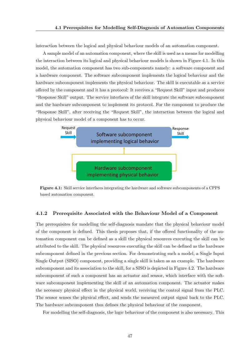
4.1 Prerequisites for Modelling Self-Diagnosis of Automation Components
interaction between the logical and physical behaviour models of an automation component.
A sample model of an automation component, where the skill is used as a means for modelling
the interaction between its logical and physical behaviour models is shown in Figure 4.1. In this
model, the automation component has two sub-components namely: a software component and
a hardware component. The software subcomponent implements the logical behaviour and the
hardware subcomponent implements the physical behaviour. The skill is executable as a service
offered by the component and it has a protocol: It receives a “Request Skill” input and produces
“Response Skill” output. The service interfaces of the skill integrate the software subcomponent
and the hardware subcomponent to implement its protocol. For the component to produce the
“Response Skill”, after receiving the “Request Skill”, the interaction between the logical and
physical behaviour model of a component has to occur.
RequestSkill
ResponseSkillSoftware subcomponent
implementing logical behavior
Hardware subcomponentimplementing physical behavior
Figure 4.1: Skill service interfaces integrating the hardware and software subcomponents of a CPPS
based automation component.
4.1.2 Prerequisite Associated with the Behaviour Model of a Component
The prerequisites for modelling the self-diagnosis mandate that the physical behaviour model
of the component is defined. This thesis proposes that, if the offered functionality of the au-
tomation component can be defined as a skill the physical resources executing the skill can be
attributed to the skill. The physical resources executing the skill can be defined as the hardware
subcomponent defined in the previous section. For demonstrating such a model, a Single Input
Single Output (SISO) component, providing a single skill is taken as an example. The hardware
subcomponent and its association to the skill, for a SISO is depicted in Figure 4.2. The hardware
subcomponent of such a component has an actuator and sensor, which interface with the soft-
ware subcomponent implementing the skill of an automation component. The actuator makes
the necessary physical effect in the physical world, receiving the control signal from the PLC.
The sensor senses the physical effect, and sends the measured output signal back to the PLC.
The hardware subcomponent thus defines the physical behaviour of the component.
For modelling the self-diagnosis, the logic behaviour of the component is also necessary. This
47
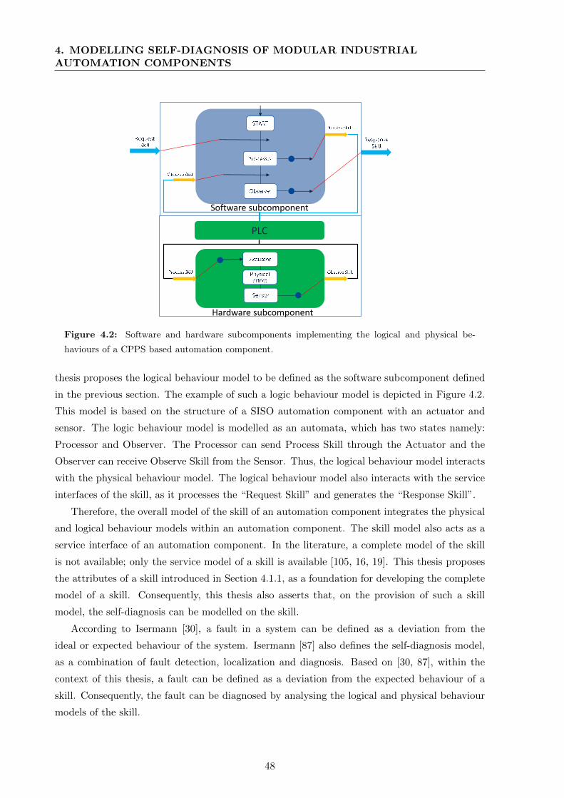
4. MODELLING SELF-DIAGNOSIS OF MODULAR INDUSTRIALAUTOMATION COMPONENTS
PLC
Software subcomponent
Hardware subcomponent
Figure 4.2: Software and hardware subcomponents implementing the logical and physical be-
haviours of a CPPS based automation component.
thesis proposes the logical behaviour model to be defined as the software subcomponent defined
in the previous section. The example of such a logic behaviour model is depicted in Figure 4.2.
This model is based on the structure of a SISO automation component with an actuator and
sensor. The logic behaviour model is modelled as an automata, which has two states namely:
Processor and Observer. The Processor can send Process Skill through the Actuator and the
Observer can receive Observe Skill from the Sensor. Thus, the logical behaviour model interacts
with the physical behaviour model. The logical behaviour model also interacts with the service
interfaces of the skill, as it processes the “Request Skill” and generates the “Response Skill”.
Therefore, the overall model of the skill of an automation component integrates the physical
and logical behaviour models within an automation component. The skill model also acts as a
service interface of an automation component. In the literature, a complete model of the skill
is not available; only the service model of a skill is available [105, 16, 19]. This thesis proposes
the attributes of a skill introduced in Section 4.1.1, as a foundation for developing the complete
model of a skill. Consequently, this thesis also asserts that, on the provision of such a skill
model, the self-diagnosis can be modelled on the skill.
According to Isermann [30], a fault in a system can be defined as a deviation from the
ideal or expected behaviour of the system. Isermann [87] also defines the self-diagnosis model,
as a combination of fault detection, localization and diagnosis. Based on [30, 87], within the
context of this thesis, a fault can be defined as a deviation from the expected behaviour of a
skill. Consequently, the fault can be diagnosed by analysing the logical and physical behaviour
models of the skill.
48
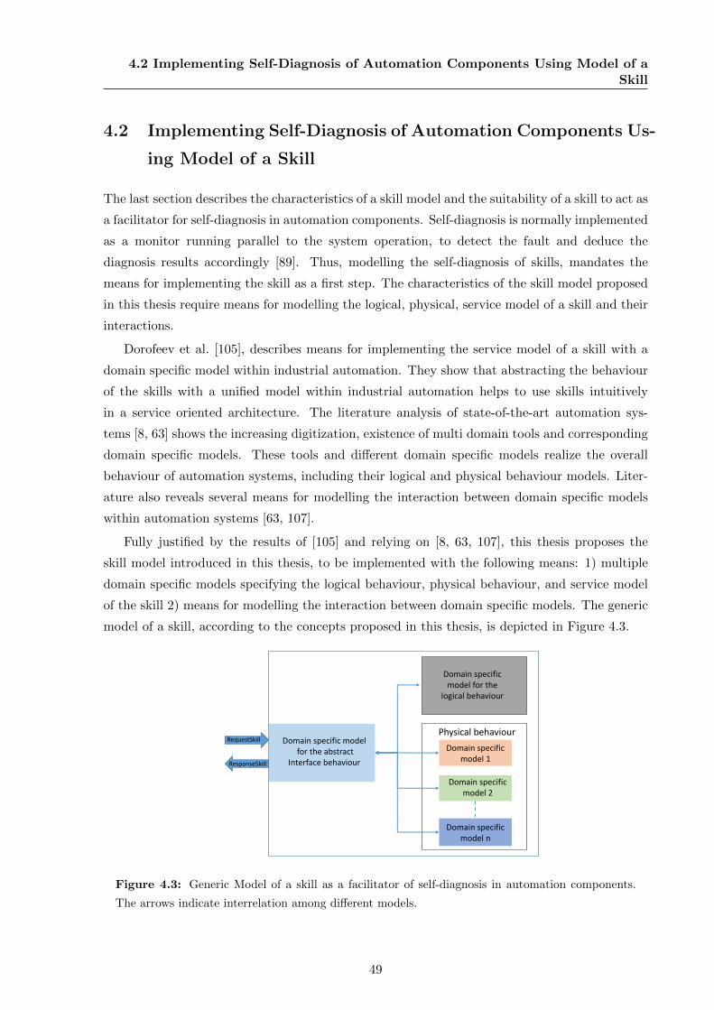
4.2 Implementing Self-Diagnosis of Automation Components Using Model of aSkill
4.2 Implementing Self-Diagnosis of Automation Components Us-
ing Model of a Skill
The last section describes the characteristics of a skill model and the suitability of a skill to act as
a facilitator for self-diagnosis in automation components. Self-diagnosis is normally implemented
as a monitor running parallel to the system operation, to detect the fault and deduce the
diagnosis results accordingly [89]. Thus, modelling the self-diagnosis of skills, mandates the
means for implementing the skill as a first step. The characteristics of the skill model proposed
in this thesis require means for modelling the logical, physical, service model of a skill and their
interactions.
Dorofeev et al. [105], describes means for implementing the service model of a skill with a
domain specific model within industrial automation. They show that abstracting the behaviour
of the skills with a unified model within industrial automation helps to use skills intuitively
in a service oriented architecture. The literature analysis of state-of-the-art automation sys-
tems [8, 63] shows the increasing digitization, existence of multi domain tools and corresponding
domain specific models. These tools and different domain specific models realize the overall
behaviour of automation systems, including their logical and physical behaviour models. Liter-
ature also reveals several means for modelling the interaction between domain specific models
within automation systems [63, 107].
Fully justified by the results of [105] and relying on [8, 63, 107], this thesis proposes the
skill model introduced in this thesis, to be implemented with the following means: 1) multiple
domain specific models specifying the logical behaviour, physical behaviour, and service model
of the skill 2) means for modelling the interaction between domain specific models. The generic
model of a skill, according to the concepts proposed in this thesis, is depicted in Figure 4.3.
Domain specificmodel 1
Domain specificmodel 2
Domain specific modelfor the abstract
Interface behaviour
Domain specific model for the
logical behaviour
Domain specificmodel n
Physical behaviourRequestSkill
ResponseSkill
Figure 4.3: Generic Model of a skill as a facilitator of self-diagnosis in automation components.
The arrows indicate interrelation among different models.
49
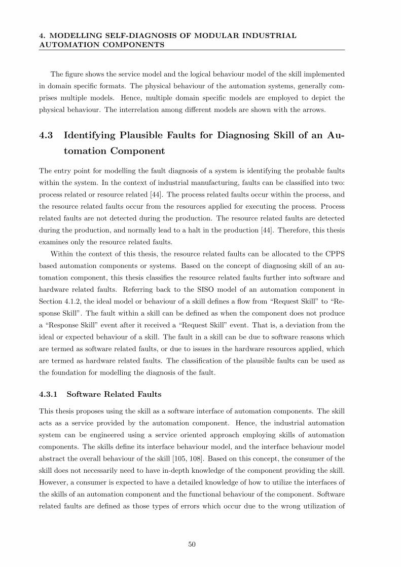
4. MODELLING SELF-DIAGNOSIS OF MODULAR INDUSTRIALAUTOMATION COMPONENTS
The figure shows the service model and the logical behaviour model of the skill implemented
in domain specific formats. The physical behaviour of the automation systems, generally com-
prises multiple models. Hence, multiple domain specific models are employed to depict the
physical behaviour. The interrelation among different models are shown with the arrows.
4.3 Identifying Plausible Faults for Diagnosing Skill of an Au-
tomation Component
The entry point for modelling the fault diagnosis of a system is identifying the probable faults
within the system. In the context of industrial manufacturing, faults can be classified into two:
process related or resource related [44]. The process related faults occur within the process, and
the resource related faults occur from the resources applied for executing the process. Process
related faults are not detected during the production. The resource related faults are detected
during the production, and normally lead to a halt in the production [44]. Therefore, this thesis
examines only the resource related faults.
Within the context of this thesis, the resource related faults can be allocated to the CPPS
based automation components or systems. Based on the concept of diagnosing skill of an au-
tomation component, this thesis classifies the resource related faults further into software and
hardware related faults. Referring back to the SISO model of an automation component in
Section 4.1.2, the ideal model or behaviour of a skill defines a flow from “Request Skill” to “Re-
sponse Skill”. The fault within a skill can be defined as when the component does not produce
a “Response Skill” event after it received a “Request Skill” event. That is, a deviation from the
ideal or expected behaviour of a skill. The fault in a skill can be due to software reasons which
are termed as software related faults, or due to issues in the hardware resources applied, which
are termed as hardware related faults. The classification of the plausible faults can be used as
the foundation for modelling the diagnosis of the fault.
4.3.1 Software Related Faults
This thesis proposes using the skill as a software interface of automation components. The skill
acts as a service provided by the automation component. Hence, the industrial automation
system can be engineered using a service oriented approach employing skills of automation
components. The skills define its interface behaviour model, and the interface behaviour model
abstract the overall behaviour of the skill [105, 108]. Based on this concept, the consumer of the
skill does not necessarily need to have in-depth knowledge of the component providing the skill.
However, a consumer is expected to have a detailed knowledge of how to utilize the interfaces of
the skills of an automation component and the functional behaviour of the component. Software
related faults are defined as those types of errors which occur due to the wrong utilization of
50
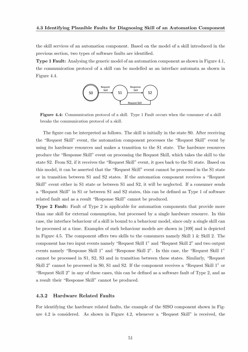
4.3 Identifying Plausible Faults for Diagnosing Skill of an Automation Component
the skill services of an automation component. Based on the model of a skill introduced in the
previous section, two types of software faults are identified.
Type 1 Fault: Analysing the generic model of an automation component as shown in Figure 4.1,
the communication protocol of a skill can be modelled as an interface automata as shown in
Figure 4.4.
S0 S1 S2
Request Skill
Response Skill
Request Skill
Figure 4.4: Communication protocol of a skill. Type 1 Fault occurs when the consumer of a skill
breaks the communication protocol of a skill.
The figure can be interpreted as follows. The skill is initially in the state S0. After receiving
the “Request Skill” event, the automation component processes the “Request Skill” event by
using its hardware resources and makes a transition to the S1 state. The hardware resources
produce the “Response Skill” event on processing the Request Skill, which takes the skill to the
state S2. From S2, if it receives the “Request Skill” event, it goes back to the S1 state. Based on
this model, it can be asserted that the “Request Skill” event cannot be processed in the S1 state
or in transition between S1 and S2 states. If the automation component receives a “Request
Skill” event either in S1 state or between S1 and S2, it will be neglected. If a consumer sends
a “Request Skill” in S1 or between S1 and S2 states, this can be defined as Type 1 of software
related fault and as a result “Response Skill” cannot be produced.
Type 2 Fault: Fault of Type 2 is applicable for automation components that provide more
than one skill for external consumption, but processed by a single hardware resource. In this
case, the interface behaviour of a skill is bound to a behaviour model, since only a single skill can
be processed at a time. Examples of such behaviour models are shown in [109] and is depicted
in Figure 4.5. The component offers two skills to the consumers namely Skill 1 & Skill 2. The
component has two input events namely “Request Skill 1” and “Request Skill 2” and two output
events namely “Response Skill 1” and “Response Skill 2”. In this case, the “Request Skill 1”
cannot be processed in S1, S2, S3 and in transition between these states. Similarly, “Request
Skill 2” cannot be processed in S0, S1 and S2. If the component receives a “Request Skill 1” or
“Request Skill 2” in any of these cases, this can be defined as a software fault of Type 2, and as
a result their “Response Skill” cannot be produced.
4.3.2 Hardware Related Faults
For identifying the hardware related faults, the example of the SISO component shown in Fig-
ure 4.2 is considered. As shown in Figure 4.2, whenever a “Request Skill” is received, the
51
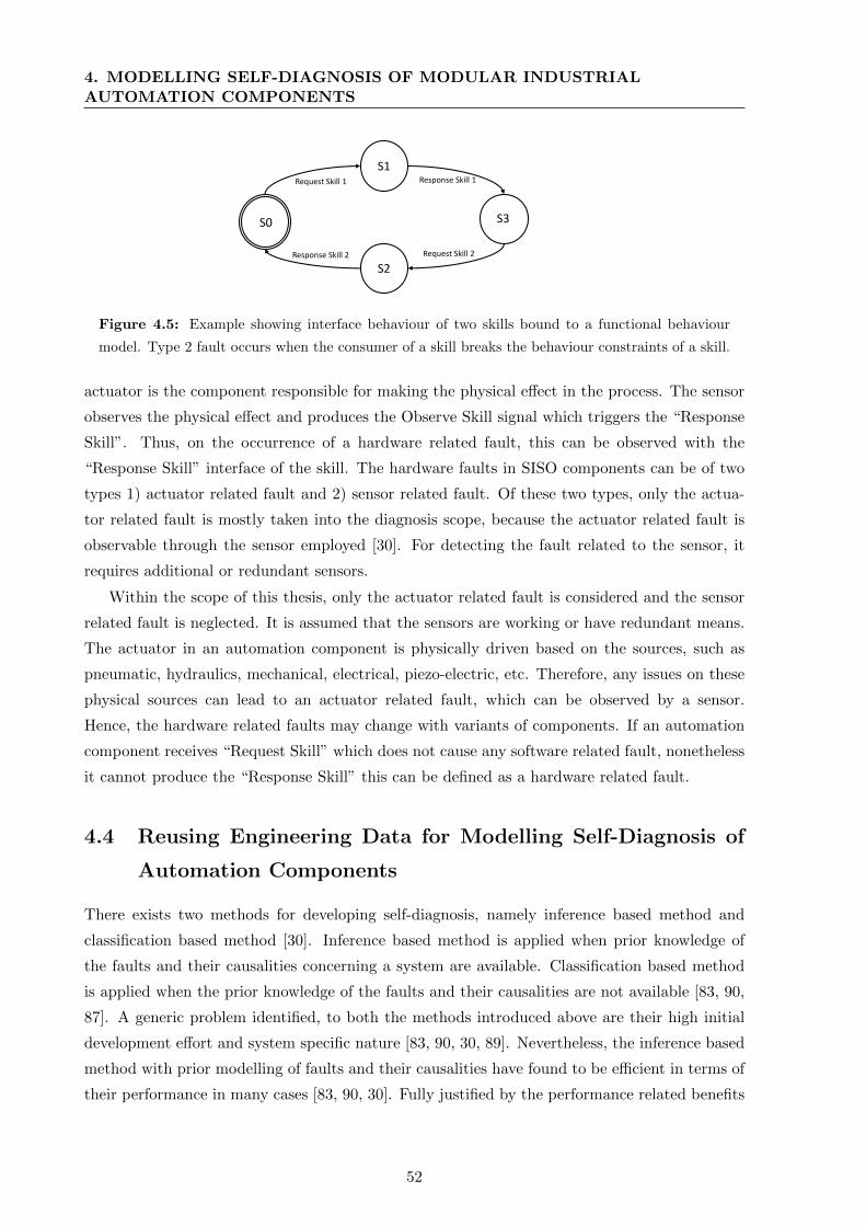
4. MODELLING SELF-DIAGNOSIS OF MODULAR INDUSTRIALAUTOMATION COMPONENTS
S0
S1
S3
Request Skill 1 Response Skill 1
Response Skill 2
S2Request Skill 2
Figure 4.5: Example showing interface behaviour of two skills bound to a functional behaviour
model. Type 2 fault occurs when the consumer of a skill breaks the behaviour constraints of a skill.
actuator is the component responsible for making the physical effect in the process. The sensor
observes the physical effect and produces the Observe Skill signal which triggers the “Response
Skill”. Thus, on the occurrence of a hardware related fault, this can be observed with the
“Response Skill” interface of the skill. The hardware faults in SISO components can be of two
types 1) actuator related fault and 2) sensor related fault. Of these two types, only the actua-
tor related fault is mostly taken into the diagnosis scope, because the actuator related fault is
observable through the sensor employed [30]. For detecting the fault related to the sensor, it
requires additional or redundant sensors.
Within the scope of this thesis, only the actuator related fault is considered and the sensor
related fault is neglected. It is assumed that the sensors are working or have redundant means.
The actuator in an automation component is physically driven based on the sources, such as
pneumatic, hydraulics, mechanical, electrical, piezo-electric, etc. Therefore, any issues on these
physical sources can lead to an actuator related fault, which can be observed by a sensor.
Hence, the hardware related faults may change with variants of components. If an automation
component receives “Request Skill” which does not cause any software related fault, nonetheless
it cannot produce the “Response Skill” this can be defined as a hardware related fault.
4.4 Reusing Engineering Data for Modelling Self-Diagnosis of
Automation Components
There exists two methods for developing self-diagnosis, namely inference based method and
classification based method [30]. Inference based method is applied when prior knowledge of
the faults and their causalities concerning a system are available. Classification based method
is applied when the prior knowledge of the faults and their causalities are not available [83, 90,
87]. A generic problem identified, to both the methods introduced above are their high initial
development effort and system specific nature [83, 90, 30, 89]. Nevertheless, the inference based
method with prior modelling of faults and their causalities have found to be efficient in terms of
their performance in many cases [83, 90, 30]. Fully justified by the performance related benefits
52

4.4 Reusing Engineering Data for Modelling Self-Diagnosis of AutomationComponents
of inference based method, this thesis proposes applying inference based approach for developing
self-diagnosis in automation components.
From [90, 87] it is clear that creating system specific diagnosis models is a challenge when it
requires cost efficiency. Zibaei et al. [89] and Feischmann [27] show that, for achieving efficiency in
terms of cost and effort on realizing self-diagnosis, it is necessary to handle variants of automation
systems, and create reusable and generic solutions.
In the industrial automation domain, there exist variants even in the level of CPPS based
components. This can be illustrated with the SISO automation component introduced before.
In a SISO component, there exists an actuator and a sensor. The SISO component can be
reconfigured to have several variants of it. For example, the actuator can be of pneumatic,
electric or mechanical or some other type. The sensor can be of different types such as optical,
pressure, proximity, etc. For each actuator or sensor, the physical behaviour of the component
can differ and hence may result in variation of its logical behaviour. An illustration of the
variants in case of a SISO component is shown in Figure 4.6
Software subcomponent
Hardware subcomponent
PLC 1,2,..n
Figure 4.6: Types of variants in a SISO generic automation component.
The figure depicts the actuators and sensors as type 1 to n. Correspondingly, the skill logical
behaviour (automata) changes. The processor and observer state in the logical behaviour can be
of type 1 to n (n variants). This clarifies that, the skill logical behaviour changes for every change
in the hardware. Apart from the actuator and sensor, the changes in the PLC may also lead
to changes in the skill logical behaviour, as vendors use different standards for implementing
the logic. As diagnosis models heavily depend on the logical and physical behaviour models
of the skills, this will lead to the requirement of separate diagnosis models for each variant.
53
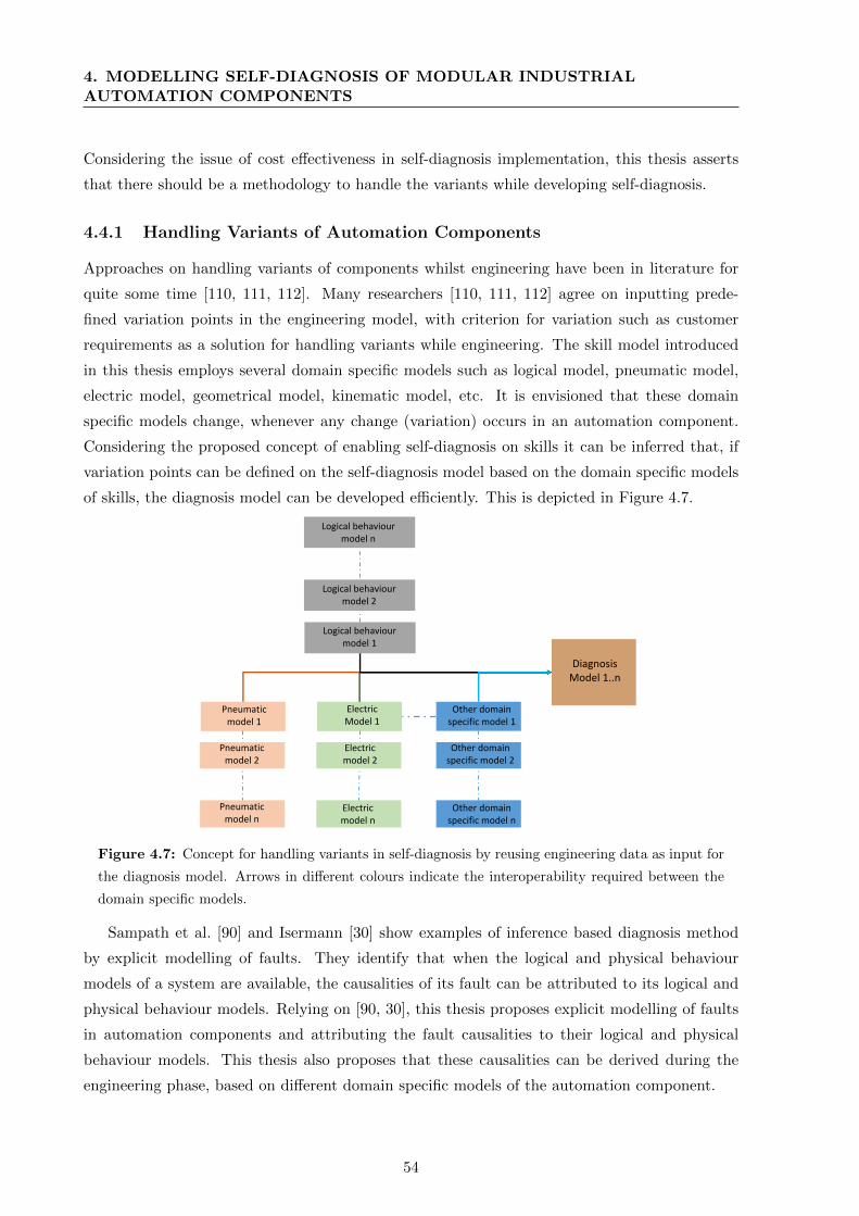
4. MODELLING SELF-DIAGNOSIS OF MODULAR INDUSTRIALAUTOMATION COMPONENTS
Considering the issue of cost effectiveness in self-diagnosis implementation, this thesis asserts
that there should be a methodology to handle the variants while developing self-diagnosis.
4.4.1 Handling Variants of Automation Components
Approaches on handling variants of components whilst engineering have been in literature for
quite some time [110, 111, 112]. Many researchers [110, 111, 112] agree on inputting prede-
fined variation points in the engineering model, with criterion for variation such as customer
requirements as a solution for handling variants while engineering. The skill model introduced
in this thesis employs several domain specific models such as logical model, pneumatic model,
electric model, geometrical model, kinematic model, etc. It is envisioned that these domain
specific models change, whenever any change (variation) occurs in an automation component.
Considering the proposed concept of enabling self-diagnosis on skills it can be inferred that, if
variation points can be defined on the self-diagnosis model based on the domain specific models
of skills, the diagnosis model can be developed efficiently. This is depicted in Figure 4.7.
Pneumaticmodel 1
ElectricModel 1
Other domain specific model 1
Logical behaviourmodel 1
DiagnosisModel 1..n
Electricmodel 2
Pneumaticmodel 2
Other domain specific model 2
Logical behaviourmodel 2
Logical behaviourmodel n
Electricmodel n
Pneumaticmodel n
Other domain specific model n
Figure 4.7: Concept for handling variants in self-diagnosis by reusing engineering data as input for
the diagnosis model. Arrows in different colours indicate the interoperability required between the
domain specific models.
Sampath et al. [90] and Isermann [30] show examples of inference based diagnosis method
by explicit modelling of faults. They identify that when the logical and physical behaviour
models of a system are available, the causalities of its fault can be attributed to its logical and
physical behaviour models. Relying on [90, 30], this thesis proposes explicit modelling of faults
in automation components and attributing the fault causalities to their logical and physical
behaviour models. This thesis also proposes that these causalities can be derived during the
engineering phase, based on different domain specific models of the automation component.
54
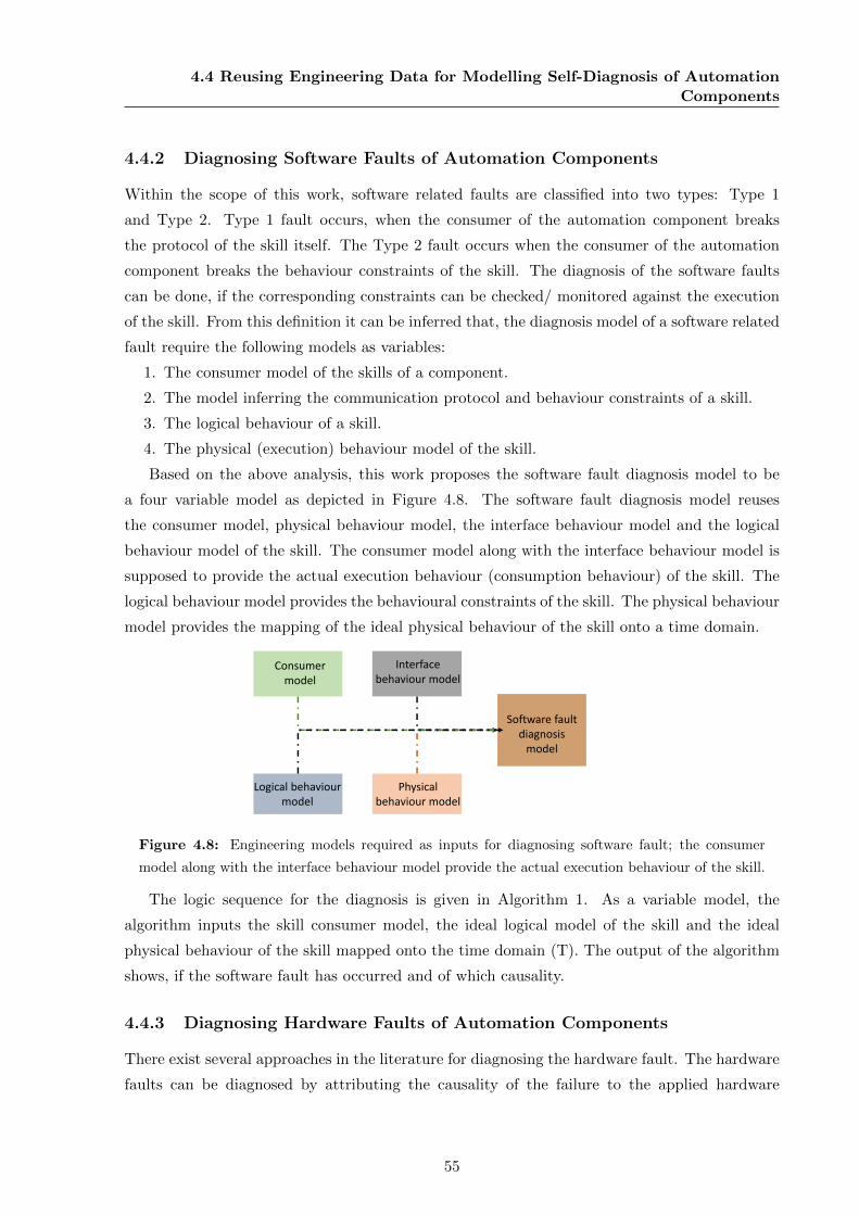
4.4 Reusing Engineering Data for Modelling Self-Diagnosis of AutomationComponents
4.4.2 Diagnosing Software Faults of Automation Components
Within the scope of this work, software related faults are classified into two types: Type 1
and Type 2. Type 1 fault occurs, when the consumer of the automation component breaks
the protocol of the skill itself. The Type 2 fault occurs when the consumer of the automation
component breaks the behaviour constraints of the skill. The diagnosis of the software faults
can be done, if the corresponding constraints can be checked/ monitored against the execution
of the skill. From this definition it can be inferred that, the diagnosis model of a software related
fault require the following models as variables:
1. The consumer model of the skills of a component.
2. The model inferring the communication protocol and behaviour constraints of a skill.
3. The logical behaviour of a skill.
4. The physical (execution) behaviour model of the skill.
Based on the above analysis, this work proposes the software fault diagnosis model to be
a four variable model as depicted in Figure 4.8. The software fault diagnosis model reuses
the consumer model, physical behaviour model, the interface behaviour model and the logical
behaviour model of the skill. The consumer model along with the interface behaviour model is
supposed to provide the actual execution behaviour (consumption behaviour) of the skill. The
logical behaviour model provides the behavioural constraints of the skill. The physical behaviour
model provides the mapping of the ideal physical behaviour of the skill onto a time domain.
Physical behaviour model
Interface behaviour model
Software faultdiagnosis
model
Consumermodel
Logical behaviour model
Figure 4.8: Engineering models required as inputs for diagnosing software fault; the consumer
model along with the interface behaviour model provide the actual execution behaviour of the skill.
The logic sequence for the diagnosis is given in Algorithm 1. As a variable model, the
algorithm inputs the skill consumer model, the ideal logical model of the skill and the ideal
physical behaviour of the skill mapped onto the time domain (T). The output of the algorithm
shows, if the software fault has occurred and of which causality.
4.4.3 Diagnosing Hardware Faults of Automation Components
There exist several approaches in the literature for diagnosing the hardware fault. The hardware
faults can be diagnosed by attributing the causality of the failure to the applied hardware
55

4. MODELLING SELF-DIAGNOSIS OF MODULAR INDUSTRIALAUTOMATION COMPONENTS
Algorithm 1: Algorithm for software fault diagnosis.
Input : Skill consumer model, ideal interface behaviour model of the skill, ideal
physical behaviour of the skill mapped onto the time domain (T)
Output: Software fault type 1 or 2
while Time==T do
Generate interface automata of the ideal behaviour of the skill (A);
Generate interface automata of the application model of the skill (B);
if (A-B == 0) && (AXB) == [RequestSkill, ResponseSkill] then
Return No Error;
else
if (A-B == 0) && (AXB) == [RequestSkill, NULL] then
“Request Skill” is called before “Response Skill” event;
end
if (A-B != 0) && (AXB) == [ResponseSkill] then
Hard fault;
else
Return null;
end
end
end
sources such as pneumatic, mechanical, etc [30, 89]. For diagnosing the hardware faults, different
approaches from literature, applicable to the automation components are proposed.
Limit checking: This approach employs limit checking of the dedicated sensors for diagnosis.
According to Isermann [30] this approach brings competitive results, as the physical constraints
are verified for the skill execution. This thesis proposes, reusing the physical constraints model
such as pneumatic model, electric model, etc., for the limit checking based diagnosis. The diag-
nosis model thus depends on the consumer model, the interface behaviour model and multiple
domain specific models defining physical constraints depending on the hardware employed. A
schematic representation of the approach is depicted in Figure 4.9 and the applicable algorithm
is given in Algorithm 2. The algorithm inputs the skill consumer model, physical constraints
from the domain specific models, sensor inputs, the ideal physical behaviour of the skill mapped
onto the time domain (T). It produces a variable output, based on the physical constraints from
the domain specific models and the sensor inputs.
Applying available observable signals: This approach does not employ dedicated sensors.
It leverages the observable signals [90, 92] from the system for creating system specific diagnosis
56
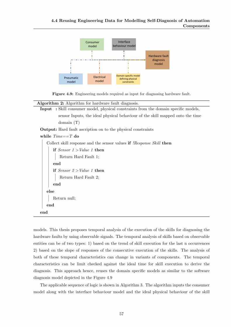
4.4 Reusing Engineering Data for Modelling Self-Diagnosis of AutomationComponents
Electricalmodel
Interface behaviour model
Hardware faultdiagnosis
model
Consumer model
Pneumatic model
Domain specific model defining physical
constraints
Figure 4.9: Engineering models required as input for diagnosing hardware fault.
Algorithm 2: Algorithm for hardware fault diagnosis.
Input : Skill consumer model, physical constraints from the domain specific models,
sensor Inputs, the ideal physical behaviour of the skill mapped onto the time
domain (T)
Output: Hard fault ascription on to the physical constraints
while Time==T do
Collect skill response and the sensor values if !Response Skill then
if Sensor 1 >Value 1 then
Return Hard Fault 1;
end
if Sensor 2 >Value 1 then
Return Hard Fault 2;
end
else
Return null;
end
end
models. This thesis proposes temporal analysis of the execution of the skills for diagnosing the
hardware faults by using observable signals. The temporal analysis of skills based on observable
entities can be of two types: 1) based on the trend of skill execution for the last n occurrences
2) based on the slope of responses of the consecutive execution of the skills. The analysis of
both of these temporal characteristics can change in variants of components. The temporal
characteristics can be limit checked against the ideal time for skill execution to derive the
diagnosis. This approach hence, reuses the domain specific models as similar to the software
diagnosis model depicted in the Figure 4.9
The applicable sequence of logic is shown in Algorithm 3. The algorithm inputs the consumer
model along with the interface behaviour model and the ideal physical behaviour of the skill
57
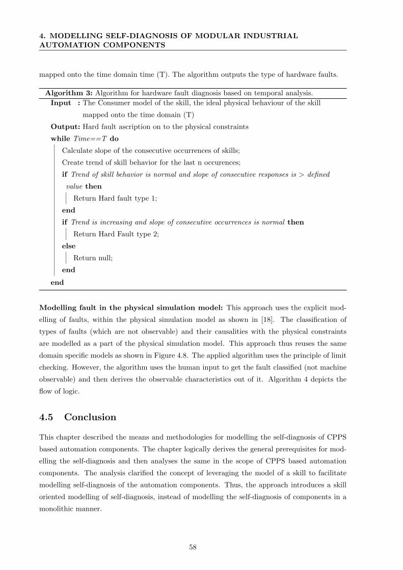
4. MODELLING SELF-DIAGNOSIS OF MODULAR INDUSTRIALAUTOMATION COMPONENTS
mapped onto the time domain time (T). The algorithm outputs the type of hardware faults.
Algorithm 3: Algorithm for hardware fault diagnosis based on temporal analysis.
Input : The Consumer model of the skill, the ideal physical behaviour of the skill
mapped onto the time domain (T)
Output: Hard fault ascription on to the physical constraints
while Time==T do
Calculate slope of the consecutive occurrences of skills;
Create trend of skill behavior for the last n occurences;
if Trend of skill behavior is normal and slope of consecutive responses is > defined
value then
Return Hard fault type 1;
end
if Trend is increasing and slope of consecutive occurrences is normal then
Return Hard Fault type 2;
else
Return null;
end
end
Modelling fault in the physical simulation model: This approach uses the explicit mod-
elling of faults, within the physical simulation model as shown in [18]. The classification of
types of faults (which are not observable) and their causalities with the physical constraints
are modelled as a part of the physical simulation model. This approach thus reuses the same
domain specific models as shown in Figure 4.8. The applied algorithm uses the principle of limit
checking. However, the algorithm uses the human input to get the fault classified (not machine
observable) and then derives the observable characteristics out of it. Algorithm 4 depicts the
flow of logic.
4.5 Conclusion
This chapter described the means and methodologies for modelling the self-diagnosis of CPPS
based automation components. The chapter logically derives the general prerequisites for mod-
elling the self-diagnosis and then analyses the same in the scope of CPPS based automation
components. The analysis clarified the concept of leveraging the model of a skill to facilitate
modelling self-diagnosis of the automation components. Thus, the approach introduces a skill
oriented modelling of self-diagnosis, instead of modelling the self-diagnosis of components in a
monolithic manner.
58
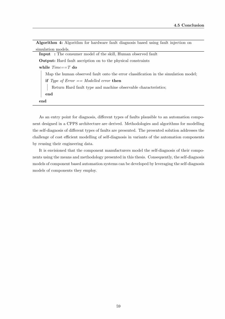
4.5 Conclusion
Algorithm 4: Algorithm for hardware fault diagnosis based using fault injection on
simulation models.Input : The consumer model of the skill, Human observed fault
Output: Hard fault ascription on to the physical constraints
while Time==T do
Map the human observed fault onto the error classification in the simulation model;
if Type of Error == Modelled error then
Return Hard fault type and machine observable characteristics;
end
end
As an entry point for diagnosis, different types of faults plausible to an automation compo-
nent designed in a CPPS architecture are derived. Methodologies and algorithms for modelling
the self-diagnosis of different types of faults are presented. The presented solution addresses the
challenge of cost efficient modelling of self-diagnosis in variants of the automation components
by reusing their engineering data.
It is envisioned that the component manufacturers model the self-diagnosis of their compo-
nents using the means and methodology presented in this thesis. Consequently, the self-diagnosis
models of component based automation systems can be developed by leveraging the self-diagnosis
models of components they employ.
59

Chapter 5
Modelling Self-Diagnosis of
Component Based Automation
Systems
This chapter examines the methodology for realizing self-diagnosis in a component based au-
tomation system, on the provision of self-diagnosis models of automation components. Hence,
this methodology is envisioned to be applied at the system integrator or the manufacturing com-
panies, as they realize the component based automation systems. Considering the challenge of
reducing the cost and effort for realizing self-diagnosis, as pointed out in Chapter 1, this chapter
is organized in five sections.
Section 5.1 identifies the prerequisites for realizing self-diagnosis in future automation sys-
tems, considering their reconfigurable and flexible architecture. Section 5.2 and Section 5.3
describe the aspects for facilitating the reconfigurable characteristics to the self-diagnosis mod-
els of future automation systems. Later, Section 5.4 explains the methodology for achieving cost
and resource efficiency in the realization of self-diagnosis feature of the automation systems.
Finally, Section 5.5 concludes this chapter.
5.1 Prerequisites for Modelling Self-Diagnosis of Future Au-
tomation Systems
The state-of-the-art self-diagnosis solutions of automated systems do not feature reconfigurabil-
ity; they require re-implementing the self-diagnosis each time a system is reconfigured [89, 27].
The development methodologies of current industrial self-diagnosis solutions apply heuristics of
maintenance personnel concerned with the deployed automation systems [24, 30]. Presuming
the FoF to be frequently reconfigured [3], it can be inferred that the development of future
61
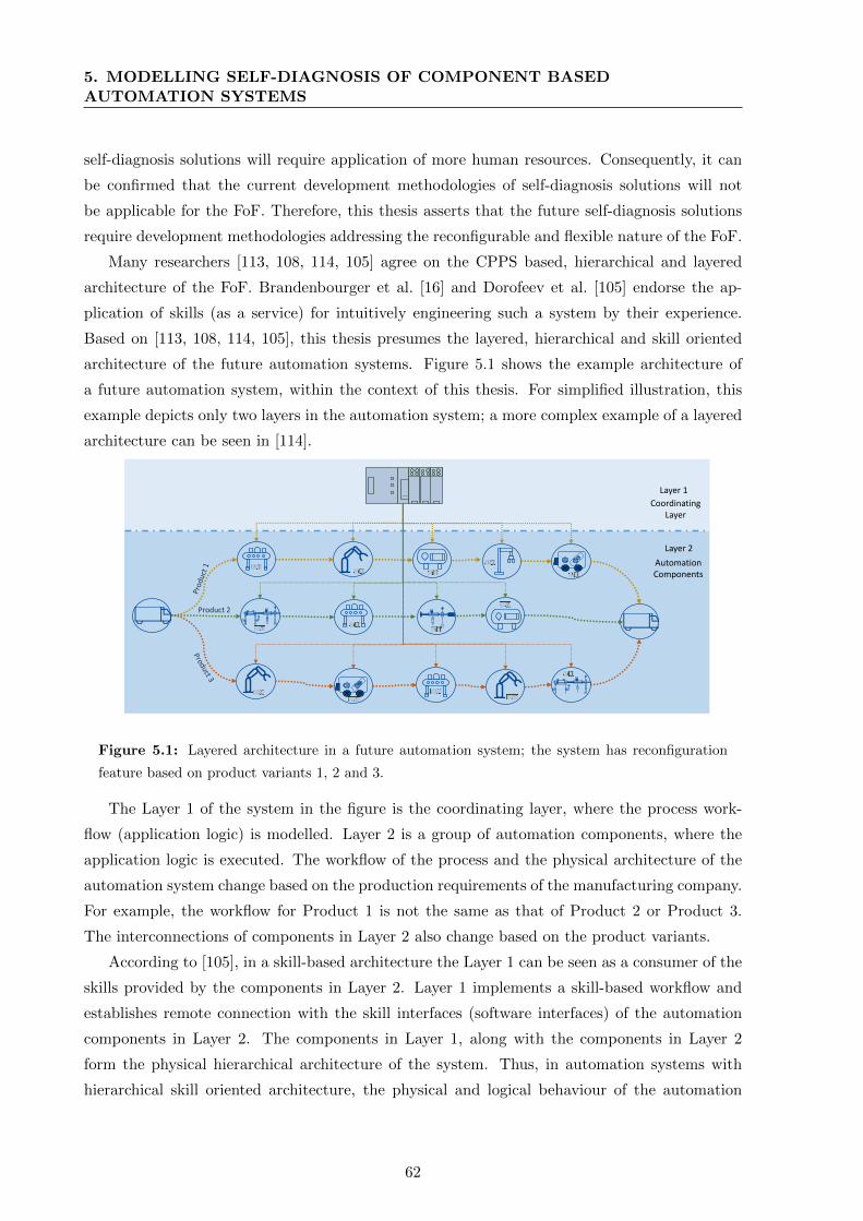
5. MODELLING SELF-DIAGNOSIS OF COMPONENT BASEDAUTOMATION SYSTEMS
self-diagnosis solutions will require application of more human resources. Consequently, it can
be confirmed that the current development methodologies of self-diagnosis solutions will not
be applicable for the FoF. Therefore, this thesis asserts that the future self-diagnosis solutions
require development methodologies addressing the reconfigurable and flexible nature of the FoF.
Many researchers [113, 108, 114, 105] agree on the CPPS based, hierarchical and layered
architecture of the FoF. Brandenbourger et al. [16] and Dorofeev et al. [105] endorse the ap-
plication of skills (as a service) for intuitively engineering such a system by their experience.
Based on [113, 108, 114, 105], this thesis presumes the layered, hierarchical and skill oriented
architecture of the future automation systems. Figure 5.1 shows the example architecture of
a future automation system, within the context of this thesis. For simplified illustration, this
example depicts only two layers in the automation system; a more complex example of a layered
architecture can be seen in [114].
Layer 1
Layer 2
Automation Components
CoordinatingLayer
Product 2
Figure 5.1: Layered architecture in a future automation system; the system has reconfiguration
feature based on product variants 1, 2 and 3.
The Layer 1 of the system in the figure is the coordinating layer, where the process work-
flow (application logic) is modelled. Layer 2 is a group of automation components, where the
application logic is executed. The workflow of the process and the physical architecture of the
automation system change based on the production requirements of the manufacturing company.
For example, the workflow for Product 1 is not the same as that of Product 2 or Product 3.
The interconnections of components in Layer 2 also change based on the product variants.
According to [105], in a skill-based architecture the Layer 1 can be seen as a consumer of the
skills provided by the components in Layer 2. Layer 1 implements a skill-based workflow and
establishes remote connection with the skill interfaces (software interfaces) of the automation
components in Layer 2. The components in Layer 1, along with the components in Layer 2
form the physical hierarchical architecture of the system. Thus, in automation systems with
hierarchical skill oriented architecture, the physical and logical behaviour of the automation
62
5.2 Analysing Fault Tree for Reconfigurable Self-Diagnosis Models
systems can be seen as dynamic in nature, depending on the production requirements.
The Section 4.1 from the last chapter clarifies the general prerequisites for modelling self-
diagnosis as the logical, physical behaviour models and the interaction between them in a system.
Accordingly, it can be inferred that, the realization of self-diagnosis in a layered, hierarchical
and skill oriented future automation system needs the following prerequisites:
1. The model of the skill-based workflow of the process, which defines the logical behaviour
of the system and its interaction with the hierarchical physical systems.
2. The layered physical architecture of the automation system, which processes the logical
behaviour of the system, and hence the physical behaviour of the system.
5.2 Analysing Fault Tree for Reconfigurable Self-Diagnosis Mod-
els
Realizing self-diagnosis on the automation system requires fault detection, localization and di-
agnosis enabled in the automation system as a whole. The self-diagnosis models as shown
in [83, 90, 30] apply monolithic approaches, and are not applicable to flexible and reconfig-
urable systems. Hence, these approaches [83, 90, 30] cannot be applied for the reconfigurable
automation systems presumed in the context of this thesis.
Zibaei et al. [89] show the possibility of creating a fault tree based diagnosis model for a
reconfigurable cyber physical system (CPS). Zibaei et al. [89] assume that the fault detection
is enabled until the last child element of the CPS. They model the CPS with a four variable
and reconfigurable model. They show that the fault propagation and thus the self-diagnosis can
be realized using a variable fault tree of the CPS. Their approach requires the hierarchy of the
system to be known, so that the causalities can be perceived and the overall fault propagation
can be implemented using a fault tree.
Relying on the findings of [89], this thesis proposes that a fault tree based approach can
also be applied to the FoF. Applying the concept of [89], the fault detection in an automation
system can be perceived as a propagation of fault detection from the employed components in the
automation system. The localization of fault corresponds to the components’ physical location
in the automation system’s hierarchy. The diagnosis result of the automation system can be as
a propagation of self-diagnosis results from the employed components in an automation system.
5.3 Analysing Planning Models for Fault-Tree Based Reconfig-
urable Self-Diagnosis
For gathering the prerequisites for realizing self-diagnosis in CPPS component based automa-
tion systems of the future, an analysis of the engineering of automation systems was conducted.
63
5. MODELLING SELF-DIAGNOSIS OF COMPONENT BASEDAUTOMATION SYSTEMS
Several works [115, 63, 116] agree on the sequential nature of the engineering process of au-
tomation systems. Estevez et al. [115] identify: planning; analysis; design & construction; and
programming as the phases in automation systems engineering. According to Drath et al. [63]
the automation systems engineering consists of 8 stages, namely: product design; plant and
process planning; mechanical engineering; electrical engineering; communication systems engi-
neering; PLC programming; virtual commissioning; and commissioning. Schmidt et al. [116]
describe the automation systems engineering to have five phases namely: analysis; basic en-
gineering; functional engineering; system integration; and then commissioning. An analysis
of [115, 63, 116] shows that the prerequisites for realizing self-diagnosis (workflow of the pro-
cess and the physical architecture of the automation system) are defined in the early phases of
engineering such as planning, analysis, and functional engineering.
Himmler [20] shows three main phases in a function based automation systems engineering
process namely: plant configuration; detailed engineering; and offer generation. He proposes
the workflow of the process flow and the physical architecture of the automation system to
be completed in the plant configuration phase, based on the requirements from the customer.
Vathoopan et al. [117] extend the results of [20], to define the phases in a skill-based automation
systems engineering. They endorse three phases in a skill-based automation system engineering,
namely: planning; model generation & construction; and commissioning [117]. In the planning
phase, the functional requirements of the automation system, the architecture of the resources
required and the workflow of the processes are defined. In the model generation & construction
phase, the different software models are generated and the physical construction is carried out.
In the commissioning phase, the constructed system is verified against the user requirements
and commissioned.
Within the scope of this thesis, a skill-based automation system composed of CPPS based
automation components is foreseen in the future. The planning model of a skill-based automa-
tion system, based on the results of [117] is depicted in Figure 5.2. The skill-based workflow
can be seen as a component of Layer 1, which is coordinating the skills executed by the com-
ponents in Layer 2. The planning model also includes the physical system hierarchy, with a
coordinating PLC in Layer 1 and the CPPS based automation components in Layer 2. The
skill-based workflow of the process changes from product to product. The applied automation
components change as the skills required by the process change. Thus, the prerequisites for
realizing self-diagnosis on the automation system can be elicited from the skill-based planning
model of the automation system.
The previous section introduced a fault tree as the means to realize self-diagnosis in a com-
ponent based and reconfigurable automation system. Consequently, this thesis proposes that
the fault tree of the automation system can be derived from the skill-based planning model of
the automation system shown in Figure 5.2. The self-diagnosis model of the automation system
64
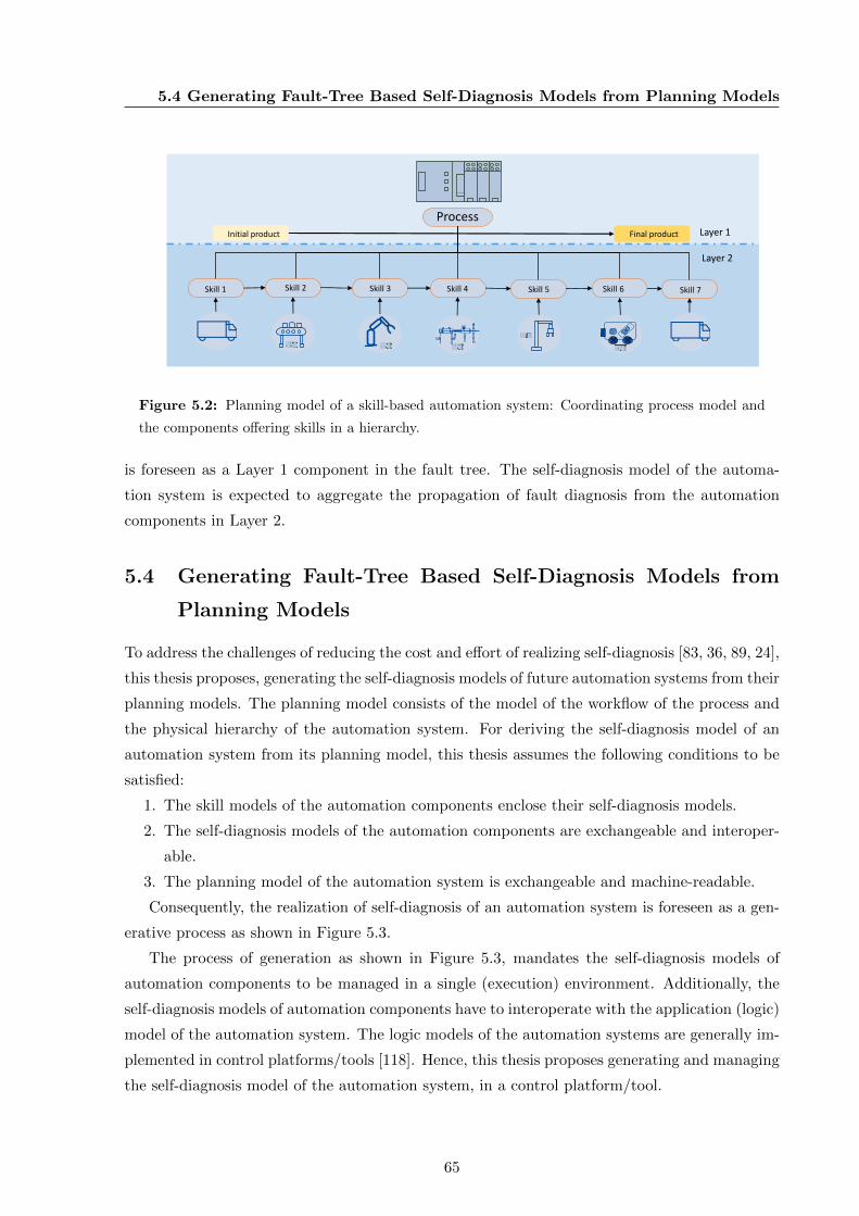
5.4 Generating Fault-Tree Based Self-Diagnosis Models from Planning Models
Skill 1 Skill 2 Skill 3 Skill 4 Skill 5 Skill 6
Final productInitial product
ProcessLayer 1
Layer 2
Skill 7
Figure 5.2: Planning model of a skill-based automation system: Coordinating process model and
the components offering skills in a hierarchy.
is foreseen as a Layer 1 component in the fault tree. The self-diagnosis model of the automa-
tion system is expected to aggregate the propagation of fault diagnosis from the automation
components in Layer 2.
5.4 Generating Fault-Tree Based Self-Diagnosis Models from
Planning Models
To address the challenges of reducing the cost and effort of realizing self-diagnosis [83, 36, 89, 24],
this thesis proposes, generating the self-diagnosis models of future automation systems from their
planning models. The planning model consists of the model of the workflow of the process and
the physical hierarchy of the automation system. For deriving the self-diagnosis model of an
automation system from its planning model, this thesis assumes the following conditions to be
satisfied:
1. The skill models of the automation components enclose their self-diagnosis models.
2. The self-diagnosis models of the automation components are exchangeable and interoper-
able.
3. The planning model of the automation system is exchangeable and machine-readable.
Consequently, the realization of self-diagnosis of an automation system is foreseen as a gen-
erative process as shown in Figure 5.3.
The process of generation as shown in Figure 5.3, mandates the self-diagnosis models of
automation components to be managed in a single (execution) environment. Additionally, the
self-diagnosis models of automation components have to interoperate with the application (logic)
model of the automation system. The logic models of the automation systems are generally im-
plemented in control platforms/tools [118]. Hence, this thesis proposes generating and managing
the self-diagnosis model of the automation system, in a control platform/tool.
65
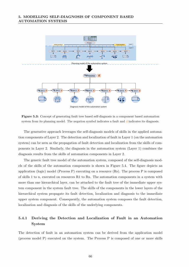
5. MODELLING SELF-DIAGNOSIS OF COMPONENT BASEDAUTOMATION SYSTEMS
Planning model of the automation system
Diagnosis model of the automation system
Skill 1 Skill 2 Skill 3 Skill 4 Skill 5 Skill 6
Process
Skill 7¬ ¬¬ ¬ ¬ ¬ ¬
¬ d
d d d d d d d
Skill 1 Skill 2 Skill 3 Skill 4 Skill 5 Skill 6
Final productInitial productProcess
Layer 1
Layer 2
Skill 7
Figure 5.3: Concept of generating fault tree based self-diagnosis in a component based automation
system from its planning model. The negation symbol indicates a fault and d indicates its diagnosis.
The generative approach leverages the self-diagnosis models of skills in the applied automa-
tion components of Layer 2. The detection and localization of fault in Layer 1 (on the automation
system) can be seen as the propagation of fault detection and localization from the skills of com-
ponents in Layer 2. Similarly, the diagnosis in the automation system (Layer 1) combines the
diagnosis results from the skills of automation components in Layer 2.
The generic fault tree model of the automation system, composed of the self-diagnosis mod-
els of the skills of the automation components is shown in Figure 5.4. The figure depicts an
application (logic) model (Process P) executing on a resource (Rs). The process P is composed
of skills 1 to n, executed on resources R1 to Rn. The automation components in a system with
more than one hierarchical layer, can be attached to the fault tree of the immediate upper sys-
tem component in the system fault tree. The skills of the components in the lower layers of the
hierarchical system propagate its fault detection, localization and diagnosis to the immediate
upper system component. Consequently, the automation system composes the fault detection,
localization and diagnosis of the skills of the underlying components.
5.4.1 Deriving the Detection and Localization of Fault in an Automation
System
The detection of fault in an automation system can be derived from the application model
(process model P) executed on the system. The Process P is composed of one or more skills
66
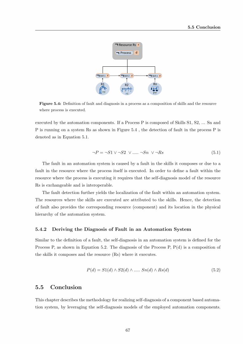
5.5 Conclusion
Resource Rs¬ d
Skill 1 Skill 2 Skill n¬ ¬ ¬d d d
Process d¬
R1 R2 Rn
Figure 5.4: Definition of fault and diagnosis in a process as a composition of skills and the resource
where process is executed.
executed by the automation components. If a Process P is composed of Skills S1, S2, ... Sn and
P is running on a system Rs as shown in Figure 5.4 , the detection of fault in the process P is
denoted as in Equation 5.1.
¬P = ¬S1 ∨ ¬S2 ∨ ..... ¬Sn ∨ ¬Rs (5.1)
The fault in an automation system is caused by a fault in the skills it composes or due to a
fault in the resource where the process itself is executed. In order to define a fault within the
resource where the process is executing it requires that the self-diagnosis model of the resource
Rs is exchangeable and is interoperable.
The fault detection further yields the localization of the fault within an automation system.
The resources where the skills are executed are attributed to the skills. Hence, the detection
of fault also provides the corresponding resource (component) and its location in the physical
hierarchy of the automation system.
5.4.2 Deriving the Diagnosis of Fault in an Automation System
Similar to the definition of a fault, the self-diagnosis in an automation system is defined for the
Process P, as shown in Equation 5.2. The diagnosis of the Process P, P(d) is a composition of
the skills it composes and the resource (Rs) where it executes.
P (d) = S1(d) ∧ S2(d) ∧ ..... Sn(d) ∧Rs(d) (5.2)
5.5 Conclusion
This chapter describes the methodology for realizing self-diagnosis of a component based automa-
tion system, by leveraging the self-diagnosis models of the employed automation components.
67
5. MODELLING SELF-DIAGNOSIS OF COMPONENT BASEDAUTOMATION SYSTEMS
Considering the future automation systems to be frequently reconfigurable in nature, a gener-
ative approach, using their planning model is proposed for realizing the self-diagnosis model of
an automation system. Thus, the proposed solution is envisioned to reduce cost and effort for
realizing the self-diagnosis model of a component based automation system.
This thesis proposes the application of this methodology, at a system integrator or a manu-
facturing company, who deploys a component based automation system. The proposed solution
presumes the planning model of an automation system to be exchangeable in nature. The
solution also assumes that each skill of automation components incorporates an exchangeable
and interoperable self-diagnosis model of that skill. Consequently, the self-diagnosis model of
the component based automation system can be generated in the control platform/tool of the
manufacturing company.
68
Chapter 6
Improving Self-Diagnosing
Automation Systems’ Realization
and Application
Integrating the concepts from Chapter 4 and Chapter 5, the methodology of realizing a self-
diagnosing automation system can be summarized as follows. The automation component man-
ufacturers model self-diagnosis on the skills of their components. The self-diagnosis models
of the components are made available in an exchangeable format to the end users, such as a
manufacturing company or a system integrator. The system integrator or the manufacturing
company derives the self-diagnosis model of their component based automation system, using
the planning model of their automation system.
This thesis proposes applying self-diagnosis for the corrective maintenance of future automa-
tion systems. Consequently, a reduction in MTTR, cost and utilization of resources are envi-
sioned within the corrective maintenance of future automation systems. This chapter introduces
methodologies for improving the realization and application of self-diagnosis within FoF. The
required standards within the realization of self-diagnosing automation systems are elaborated
in Section 6.1. Section 6.2 describes the involved stakeholders and their deployment within the
system development process. The aspects for applying self-diagnosis in the industrial corrective
maintenance are described in Section 6.3. Later, Section 6.4 concludes this chapter.
6.1 Application of Standards for Improving the Realization of
Self-Diagnosis
Standardization is reported as one of the fundamental requirements of the FoF [8, 6]. Standard-
ization describes a process of unification, especially in terminology, capabilities of personnel,
69
6. IMPROVING SELF-DIAGNOSING AUTOMATION SYSTEMS’REALIZATION AND APPLICATION
technology and organizational processes [119, 120]. According to Jiang et al. [121] standardiza-
tion acts as the key for innovation, since it trims the technology down and narrows the challenges
to a transparent and open path. Standardization triggers opportunities in a globalized economy,
as they enable transparency and comparability of the entities [122]. For example, when property
such as quality is transparent, products or services can be compared with one another.
For the providers of the products or services, the standards permit greater efficiency in
development and processing, as the capabilities and properties of their products or services are
unified. They can easily achieve growth, when quality can be reproduced over time and in
various locations. In a standardized work environment, the technical knowledge and innovations
can be distributed. For the customers, the standardized products or services are of low risk in
quality or investment, because they can be compared with one another. The customers get more
freedom to choose their products, with a foreknowledge of the properties such as quality of a
product or service [122, 123].
According to Reichwald [124], within the industrial or service sector, there exist different
aspects of standardization. They are service standardization, technical systems standardization
and process standardization. These have a high impact on the commercial success of the orga-
nization. Standardizing services helps to avoid unambiguous communication. Standardization
of technical systems allows exchange among actors in a specific service market. Standardization
of a process is required to avoid erroneous behaviour when services have to be composed.
6.1.1 Importance of Applying Available Industrial Automation Standards
The literature on the application of standards in industrial automation systems were further
analysed within the scope of this thesis. Several studies [6, 63, 43, 8] identify that, the custom
standards or models from manufacturers necessitates extra learning effort at the end users. They
also identify that the custom standards or models create deadlocks while developing automation
systems. According to the findings, the application of available standards or standardization of
existing entities within the industrial automation systems can solve this problem.
This thesis proposes leveraging the self-diagnosis models of automation components to com-
pose the self-diagnosis models in component based automation systems. The proposed solution
assumes that the component manufacturers provide the self-diagnosis models of their compo-
nents in an exchangeable format. Hence, it is necessary that the self-diagnosis models of automa-
tion components of different manufacturers are interpretable by their consumers. In addition,
it requires the interoperability of self-diagnosing automation components with the automation
system, such that the self-diagnosis continuously monitors the automation systems’ operation.
By relying on the findings of [8, 6, 63, 43], this work proposes the development of self-
diagnosis models of automation components in available exchangeable standards within the in-
dustrial automation domain. Consequently, the consumers of automation components (system
70
6.1 Application of Standards for Improving the Realization of Self-Diagnosis
integrator) can use the tools supporting the standards for generating the self-diagnosis models
of the automation system. If the planning models are also available in an available exchange-
able standard, the self-diagnosis model of the overall system can be managed in a single tool.
This work also proposes employing the available interoperability standards within the industrial
automation domain between the control model and the self-diagnosis model of the automation
system, so that diagnosis models can monitor the control model.
6.1.2 Proposed Standards for Improving the Self-Diagnosis Models of Au-
tomation Components
The approach for developing self-diagnosis models in automation components has been illus-
trated in Chapter 4. The approach leverages the model of skill of an automation component.
The plausible types of faults in the skill of an automation component are defined. Subsequently,
a methodology for realizing the self-diagnosis of the plausible fault types in the skills, reusing
the domain specific engineering models of an automation component is proposed.
Recently the naming conventions and granularity of skills of automation components/systems
are being standardized under German Association of Engineers (VDI) 2860 [125]. For example,
“Grip” and “Move” are lowest granularity skills. Additionally, the interface behaviour model of
a skill is getting standardized by German Association of Mechanical Engineers (VDMA) under
the Service Oriented Architectures and Realtime Control (SOArc) specification [126]. This
thesis proposes, applying both of these standards, as they unify the semantic interpretation and
interface behaviour of the skill. With unified semantics for the skills, the self-diagnosis models
can be defined for types of skills. Unified interface behaviour model facilitates reuse of the
diagnosis models for the fault types introduced in Section 4.3.
Within the context of this thesis, the interrelation between different domain specific mod-
els within the model of a skill is used for deriving its diagnosis model. This thesis proposes,
application of available standards for modelling the domain specific engineering models, hence
they can be interpreted in an unified manner by the consumer of the components. Addition-
ally, the interrelations among different models have to be defined in a standard manner. For
example, the interrelation between the self-diagnosis model and the logical behaviour model of
a skill. This thesis foresees standardised means for modelling the interrelations among different
domain specific models as the foundation for automatically deriving diagnosis models of variants
of components.
The generic model of the skill introduced in Section 4.1.1 facilitates the reuse of engineering
data for realizing the self-diagnosis models. Hence, it reduces the effort of modelling the self-
diagnosis of components and their variants. Therefore, to increase the efficiency of realizing the
self-diagnosis models, this thesis also proposes the standardization of generic model of the skill
introduced in this thesis.
71
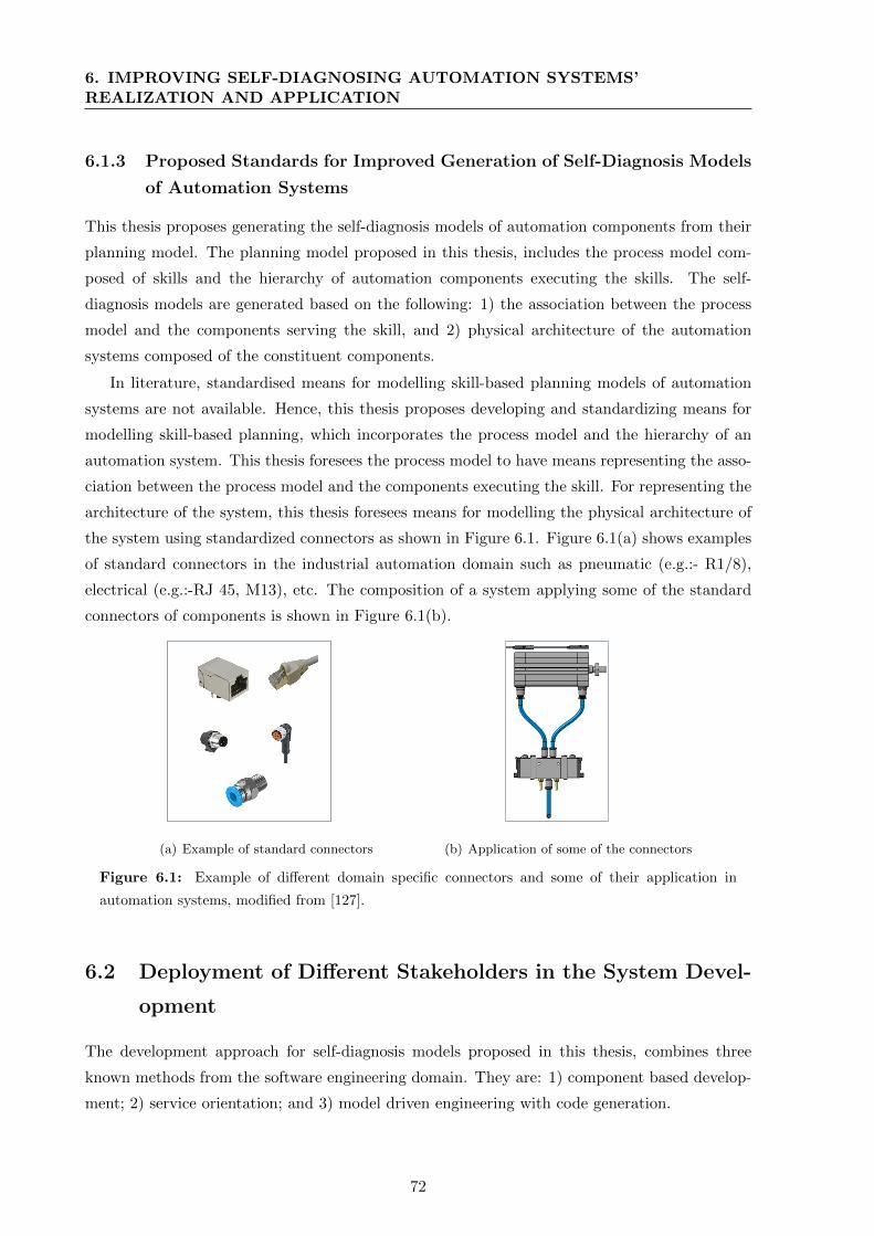
6. IMPROVING SELF-DIAGNOSING AUTOMATION SYSTEMS’REALIZATION AND APPLICATION
6.1.3 Proposed Standards for Improved Generation of Self-Diagnosis Models
of Automation Systems
This thesis proposes generating the self-diagnosis models of automation components from their
planning model. The planning model proposed in this thesis, includes the process model com-
posed of skills and the hierarchy of automation components executing the skills. The self-
diagnosis models are generated based on the following: 1) the association between the process
model and the components serving the skill, and 2) physical architecture of the automation
systems composed of the constituent components.
In literature, standardised means for modelling skill-based planning models of automation
systems are not available. Hence, this thesis proposes developing and standardizing means for
modelling skill-based planning, which incorporates the process model and the hierarchy of an
automation system. This thesis foresees the process model to have means representing the asso-
ciation between the process model and the components executing the skill. For representing the
architecture of the system, this thesis foresees means for modelling the physical architecture of
the system using standardized connectors as shown in Figure 6.1. Figure 6.1(a) shows examples
of standard connectors in the industrial automation domain such as pneumatic (e.g.:- R1/8),
electrical (e.g.:-RJ 45, M13), etc. The composition of a system applying some of the standard
connectors of components is shown in Figure 6.1(b).
M12 RJ45 Mini 7/8
M12 RJ45 Mini 7/8
(a) Example of standard connectors (b) Application of some of the connectors
Figure 6.1: Example of different domain specific connectors and some of their application in
automation systems, modified from [127].
6.2 Deployment of Different Stakeholders in the System Devel-
opment
The development approach for self-diagnosis models proposed in this thesis, combines three
known methods from the software engineering domain. They are: 1) component based develop-
ment; 2) service orientation; and 3) model driven engineering with code generation.
72
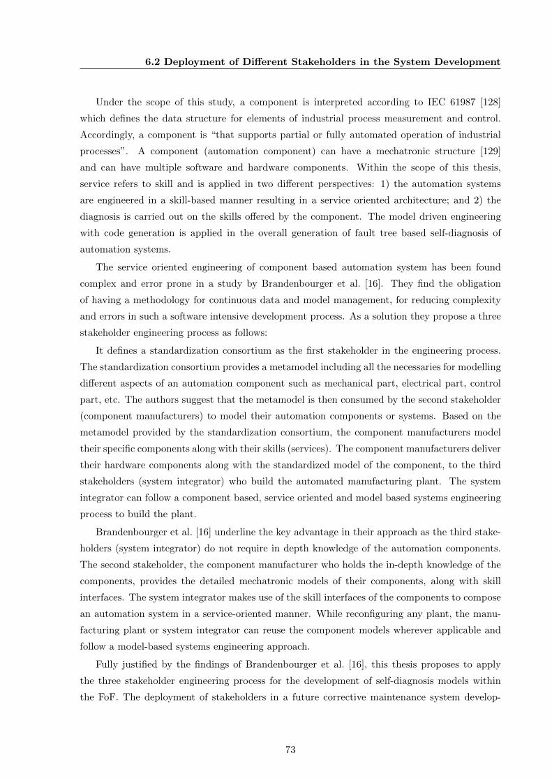
6.2 Deployment of Different Stakeholders in the System Development
Under the scope of this study, a component is interpreted according to IEC 61987 [128]
which defines the data structure for elements of industrial process measurement and control.
Accordingly, a component is “that supports partial or fully automated operation of industrial
processes”. A component (automation component) can have a mechatronic structure [129]
and can have multiple software and hardware components. Within the scope of this thesis,
service refers to skill and is applied in two different perspectives: 1) the automation systems
are engineered in a skill-based manner resulting in a service oriented architecture; and 2) the
diagnosis is carried out on the skills offered by the component. The model driven engineering
with code generation is applied in the overall generation of fault tree based self-diagnosis of
automation systems.
The service oriented engineering of component based automation system has been found
complex and error prone in a study by Brandenbourger et al. [16]. They find the obligation
of having a methodology for continuous data and model management, for reducing complexity
and errors in such a software intensive development process. As a solution they propose a three
stakeholder engineering process as follows:
It defines a standardization consortium as the first stakeholder in the engineering process.
The standardization consortium provides a metamodel including all the necessaries for modelling
different aspects of an automation component such as mechanical part, electrical part, control
part, etc. The authors suggest that the metamodel is then consumed by the second stakeholder
(component manufacturers) to model their automation components or systems. Based on the
metamodel provided by the standardization consortium, the component manufacturers model
their specific components along with their skills (services). The component manufacturers deliver
their hardware components along with the standardized model of the component, to the third
stakeholders (system integrator) who build the automated manufacturing plant. The system
integrator can follow a component based, service oriented and model based systems engineering
process to build the plant.
Brandenbourger et al. [16] underline the key advantage in their approach as the third stake-
holders (system integrator) do not require in depth knowledge of the automation components.
The second stakeholder, the component manufacturer who holds the in-depth knowledge of the
components, provides the detailed mechatronic models of their components, along with skill
interfaces. The system integrator makes use of the skill interfaces of the components to compose
an automation system in a service-oriented manner. While reconfiguring any plant, the manu-
facturing plant or system integrator can reuse the component models wherever applicable and
follow a model-based systems engineering approach.
Fully justified by the findings of Brandenbourger et al. [16], this thesis proposes to apply
the three stakeholder engineering process for the development of self-diagnosis models within
the FoF. The deployment of stakeholders in a future corrective maintenance system develop-
73
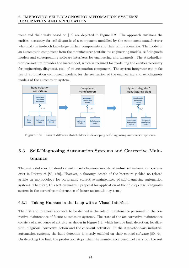
6. IMPROVING SELF-DIAGNOSING AUTOMATION SYSTEMS’REALIZATION AND APPLICATION
ment and their tasks based on [16] are depicted in Figure 6.2. The approach envisions the
entities necessary for self-diagnosis of a component modelled by the component manufacturer
who hold the in-depth knowledge of their components and their failure scenarios. The model of
an automation component from the manufacturer contains its engineering models, self-diagnosis
models and corresponding software interfaces for engineering and diagnosis. The standardiza-
tion consortium provides the metamodel, which is required for modelling the entities necessary
for engineering, diagnosis, etc., of an automation component. The system integrator can make
use of automation component models, for the realization of the engineering and self-diagnosis
models of the automation system.
Standardization consortium
Component manufacturers
System integrator/Manufacturing plant
Automationcomponentmetamodel
OtherModel
EngineeringModel
Self-diagnosisModel
Componentmanufacturer
model
EngineeringModel
Self-diagnosisModel
Manufacturingautomationsystemmodel
Componentmanufacturer
model
Componentmanufacturer
model
0..n0..n0..n
Figure 6.2: Tasks of different stakeholders in developing self-diagnosing automation systems.
6.3 Self-Diagnosing Automation Systems and Corrective Main-
tenance
The methodologies for development of self-diagnosis models of industrial automation systems
exist in Literature [83, 130]. However, a thorough search of the literature yielded no related
article on methodology for performing corrective maintenance of self-diagnosing automation
systems. Therefore, this section makes a proposal for application of the developed self-diagnosis
system in the corrective maintenance of future automation systems.
6.3.1 Taking Humans in the Loop with a Visual Interface
The first and foremost approach to be defined is the role of maintenance personnel in the cor-
rective maintenance of future automation systems. The state-of-the-art corrective maintenance
consists of a sequence of activity as shown in Figure 1.3, which include fault detection, localiza-
tion, diagnosis, corrective action and the checkout activities. In the state-of-the-art industrial
automation systems, the fault detection is mostly enabled on their control software [80, 44].
On detecting the fault the production stops, then the maintenance personnel carry out the rest
74
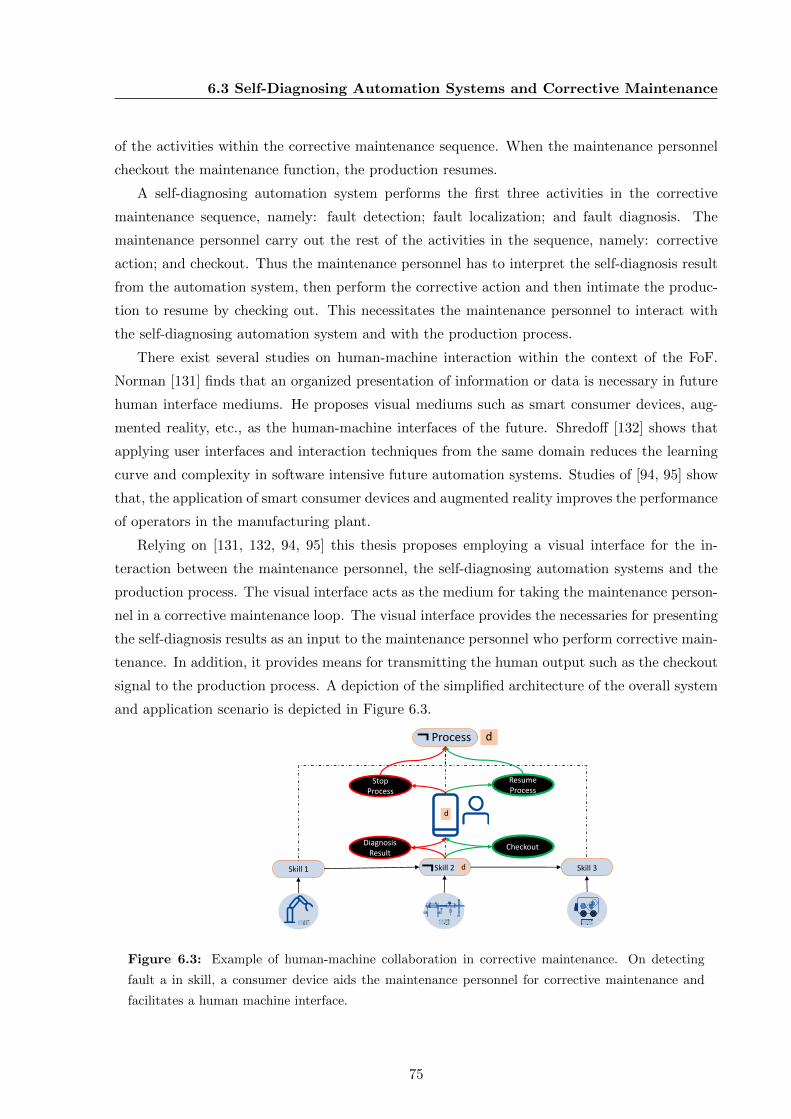
6.3 Self-Diagnosing Automation Systems and Corrective Maintenance
of the activities within the corrective maintenance sequence. When the maintenance personnel
checkout the maintenance function, the production resumes.
A self-diagnosing automation system performs the first three activities in the corrective
maintenance sequence, namely: fault detection; fault localization; and fault diagnosis. The
maintenance personnel carry out the rest of the activities in the sequence, namely: corrective
action; and checkout. Thus the maintenance personnel has to interpret the self-diagnosis result
from the automation system, then perform the corrective action and then intimate the produc-
tion to resume by checking out. This necessitates the maintenance personnel to interact with
the self-diagnosing automation system and with the production process.
There exist several studies on human-machine interaction within the context of the FoF.
Norman [131] finds that an organized presentation of information or data is necessary in future
human interface mediums. He proposes visual mediums such as smart consumer devices, aug-
mented reality, etc., as the human-machine interfaces of the future. Shredoff [132] shows that
applying user interfaces and interaction techniques from the same domain reduces the learning
curve and complexity in software intensive future automation systems. Studies of [94, 95] show
that, the application of smart consumer devices and augmented reality improves the performance
of operators in the manufacturing plant.
Relying on [131, 132, 94, 95] this thesis proposes employing a visual interface for the in-
teraction between the maintenance personnel, the self-diagnosing automation systems and the
production process. The visual interface acts as the medium for taking the maintenance person-
nel in a corrective maintenance loop. The visual interface provides the necessaries for presenting
the self-diagnosis results as an input to the maintenance personnel who perform corrective main-
tenance. In addition, it provides means for transmitting the human output such as the checkout
signal to the production process. A depiction of the simplified architecture of the overall system
and application scenario is depicted in Figure 6.3.
Skill 1 Skill 2 Skill 3
Process
¬
¬ d
d
Resume Process
StopProcess
CheckoutDiagnosisResult
d
Figure 6.3: Example of human-machine collaboration in corrective maintenance. On detecting
fault a in skill, a consumer device aids the maintenance personnel for corrective maintenance and
facilitates a human machine interface.
75
6. IMPROVING SELF-DIAGNOSING AUTOMATION SYSTEMS’REALIZATION AND APPLICATION
The figure shows a process composed of three skills 1, 2 and 3. On identification of a fault
in any of the skills for example in skill 2, based on the criticality, the production stops. The
user interface immediately presents the diagnosis result to the maintenance personnel. The
maintenance personnel carry out the corrective action for skill 2, and then signal checkout, on
which the production resumes. Thus, the human is treated as part of the corrective maintenance
system of the future automation systems.
6.3.2 Leveraging Humans as the Strategic Decision Makers
The literature analysis on corrective maintenance presented in Section 2.3 shows that, most
of the human effort in a corrective maintenance sequence is applied until the fault diagnosis
activity. Similarly, most of the human errors in a corrective maintenance sequence also occur
until the fault diagnosis activity. As soon as a fault is detected, a self-diagnosing automation
system produces the fault diagnosis result. Hence, it can be asserted that, the application of
self-diagnosing automation systems will result in the reduction of the human effort for corrective
maintenance. This thesis proposes the self-diagnosis and thus the corrective maintenance to be
carried out on the services (skills) of automation components/systems, rather than considering
the component/system as a whole. Consequently, this thesis foresees that the complexity and
hence the possibility of human error reduces in the corrective maintenance of FoF.
Many studies on the FoF [54, 5] identify humans as the strategic decision makers within
the FoF. Accordingly, this work proposes employing maintenance personnel as strategic decision
makers in the FoF. Different studies [24, 74] show that data collected from maintenance can
improve the production. The maintenance personnel in the FoF can identify potential data
(evidence), relevant for avoiding problems such as problems related to bad design, or program-
ming. These evidences and the cognitive skills of the maintenance personnel thus can be used for
improving production. In addition, on the provision of interoperability between the corrective
maintenance visual interface and the inventory tools, these evidences can also be utilized for
improving the inventory.
With plausible reduction in the skills required for corrective maintenance, this thesis proposes
employment of minimum number of maintenance personnel within the FoF. The maintenance
personnel should have the required skill set for performing corrective action and expertise in the
production process within the FoF.
6.4 Conclusion
By identifying lack of methodologies for developing and applying self-diagnosis in the industrial
automation domain, this chapter introduced potential methodologies applicable for developing
and applying self-diagnosis in future automation systems. As a first step, the available stan-
76
6.4 Conclusion
dards and the required extension of standards necessary for improving the development of the
self-diagnosis models are presented. Secondly, a three stakeholder sequential deployment of
stakeholders is proposed for maintaining consistency in the development and reducing errors.
As a final step, a methodology for applying self-diagnosis in the corrective maintenance of future
automation systems is proposed, by taking the human in the loop of corrective maintenance se-
quence. The approach also leverages humans as a strategic decision maker. Overall application
methodology not only reduces the complexity and human error but also improves MTTR and
resource utilization. The application methodology also proposes means for improving production
through corrective maintenance.
77

Chapter 7
Realizing the Self-Diagnosing
Automation Systems of Future
This chapter describes the implementation of the proposed solution using specific tools and tech-
nologies of the FoF. The selection of tools and technologies are made considering the following
methodologies proposed within the context of this thesis:
1. The self-diagnosis models of automation components reuse their engineering data.
2. The self-diagnosis models in component based automation systems can be generated au-
tomatically from their planning models.
3. The humans are integrated within the corrective maintenance of future self-diagnosing
automation systems with a visual interface.
Accordingly, this chapter is organized in four sections. Section 7.1 introduces the technology
that enables reuse of engineering data for realizing self-diagnosis. The tool that bridges the
planning phase of an automation system with the maintenance phase of an automation system
is elaborated in Section 7.2. Subsequently, Section 7.3 introduces other important tools and
technologies used within the context of this thesis. Section 7.4 concludes this chapter.
7.1 AutomationML for Modelling Self-Diagnosis by Reusing the
Engineering Data
Description languages have been in place for quite some time. One of the first application exam-
ples of description languages in the industrial automation domain was for field devices and their
configuration [133]. The state-of-the-art field devices have different communication interfaces
and their device specific configuration. The field device manufacturers describe their device con-
figuration with description languages such as Electronic Device Description Language (EDDL).
The device manufacturers supply the description along with the devices, such that the software
79

7. REALIZING THE SELF-DIAGNOSING AUTOMATION SYSTEMS OFFUTURE
tools who use the devices can interpret the specific configuration of the field devices [133, 134].
The concept of device description has been extended to several other phases in the industrial au-
tomation domain such as for systems engineering (SysML) [135], for product description (STEP
XML) [136], for engineering data exchange (AML) [63], etc.
The proposed development methodology within the context of this thesis raises the require-
ment of a description language under the following circumstances:
• The component manufacturers reuse different domain specific engineering models for mod-
elling the self-diagnosis.
• The component manufacturers deliver the self-diagnosis models to their consumers such
as system integrator.
• The system integrator can interpret the self-diagnosis models of the automation compo-
nents they employ.
• The system integrator generate the self-diagnosis model of their automation system using
the planning model of the automation system.
Accordingly, the following characteristics have been identified for a description language to
be used for the modelling purpose within the context of this thesis:
1. Machine-readable; hence, they can be exported and imported in different tools employed
at different stakeholders.
2. Neutral, manufacturer independent and unified format for exchange; therefore, they can
be employed seamlessly.
3. Capability to model skills and skill-based production planning.
4. Capability to model different disciplinary aspects such as geometry, kinematic, logical,
diagnosis, etc.
5. Support for existing standardized data exchange formats within the industrial automation
domain.
6. Means for modelling inter relations among different disciplinary models.
7. Means for modelling physical composition of component based automation systems.
8. Capability to model logical composition of processes out of skills.
9. Capability to model physical and logical interfaces of components.
10. Support of proper syntax and semantics; such that consistency can be maintained.
11. Text based format; such that versions can be controlled.
7.1.1 Comparison of Existing Description Languages
Based on the characteristics listed in the previous section, the technology solutions available
in the market such as AADL (Architecture Analysis and Description Language) [137], EDDL,
SysML (Systems Modelling Language) and AML have been compared. In the initial stages of
the comparison, it was found that, AADL and EDDL do not hold most of the characteristics
80
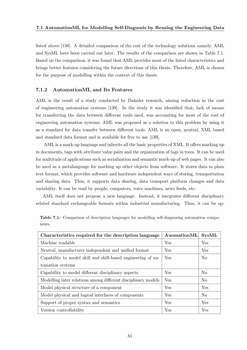
7.1 AutomationML for Modelling Self-Diagnosis by Reusing the Engineering Data
listed above [138]. A detailed comparison of the rest of the technology solutions namely, AML
and SysML have been carried out later. The results of the comparison are shown in Table 7.1.
Based on the comparison, it was found that AML provides most of the listed characteristics and
brings better features considering the future directions of this thesis. Therefore, AML is chosen
for the purpose of modelling within the context of this thesis.
7.1.2 AutomationML and Its Features
AML is the result of a study conducted by Daimler research, aiming reduction in the cost
of engineering automation systems [139]. In the study it was identified that, lack of means
for transferring the data between different tools used, was accounting for most of the cost of
engineering automation systems. AML was proposed as a solution to this problem by using it
as a standard for data transfer between different tools. AML is an open, neutral, XML based
and standard data format and is available for free to use [139].
AML is a mark-up language and inherits all the basic properties of XML. It offers marking up
in documents, tags with attribute value pairs and the organization of tags in trees. It can be used
for multitude of applications such as serialization and semantic mark-up of web pages. It can also
be used as a metalanguage for marking up other objects from software. It stores data in plain
text format, which provides software and hardware independent ways of storing, transportation
and sharing data. Thus, it supports data sharing, data transport platform changes and data
variability. It can be read by people, computers, voice machines, news feeds, etc.
AML itself does not propose a new language. Instead, it integrates different disciplinary
related standard exchangeable formats within industrial manufacturing. Thus, it can be ap-
Table 7.1: Comparison of description languages for modelling self-diagnosing automation compo-
nents.
Characteristics required for the description language AuomationML SysML
Machine readable Yes Yes
Neutral, manufacturer independent and unified format Yes Yes
Capability to model skill and skill-based engineering of au-
tomation systems
Yes No
Capability to model different disciplinary aspects Yes No
Modelling inter relations among different disciplinary models Yes No
Model physical structure of a component Yes Yes
Model physical and logical interfaces of components Yes No
Support of proper syntax and semantics Yes Yes
Version controllability Yes Yes
81
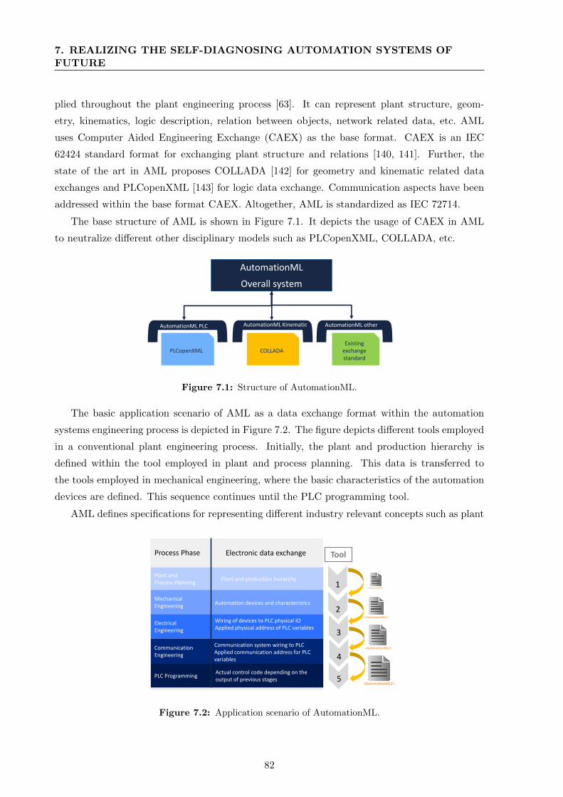
7. REALIZING THE SELF-DIAGNOSING AUTOMATION SYSTEMS OFFUTURE
plied throughout the plant engineering process [63]. It can represent plant structure, geom-
etry, kinematics, logic description, relation between objects, network related data, etc. AML
uses Computer Aided Engineering Exchange (CAEX) as the base format. CAEX is an IEC
62424 standard format for exchanging plant structure and relations [140, 141]. Further, the
state of the art in AML proposes COLLADA [142] for geometry and kinematic related data
exchanges and PLCopenXML [143] for logic data exchange. Communication aspects have been
addressed within the base format CAEX. Altogether, AML is standardized as IEC 72714.
The base structure of AML is shown in Figure 7.1. It depicts the usage of CAEX in AML
to neutralize different other disciplinary models such as PLCopenXML, COLLADA, etc.
AutomationML
Overall system
AutomationML PLC AutomationML AutomationML other
PLCopenXML COLLADA
AutomationML Kinematic
Existing exchange standard
Figure 7.1: Structure of AutomationML.
The basic application scenario of AML as a data exchange format within the automation
systems engineering process is depicted in Figure 7.2. The figure depicts different tools employed
in a conventional plant engineering process. Initially, the plant and production hierarchy is
defined within the tool employed in plant and process planning. This data is transferred to
the tools employed in mechanical engineering, where the basic characteristics of the automation
devices are defined. This sequence continues until the PLC programming tool.
AML defines specifications for representing different industry relevant concepts such as plant
1
2
3
4
5
ToolProcess Phase
Plant and Process Planning
Mechanical Engineering
Electrical Engineering
Communication Engineering
PLC Programming
Electronic data exchange
Plant and production hierarchy
Automation devices and characteristics
Wiring of devices to PLC physical IOApplied physical address of PLC variables
Communication system wiring to PLCApplied communication address for PLC variables
Actual control code depending on the output of previous stages
<AutomationML/>
<AutomationML/>
<AutomationML/>
<AutomationML/>
Figure 7.2: Application scenario of AutomationML.
82
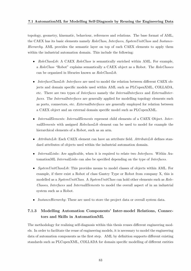
7.1 AutomationML for Modelling Self-Diagnosis by Reusing the Engineering Data
topology, geometry, kinematic, behaviour, references and relations. The base format of AML,
the CAEX has its basic elements namely RoleClass, Interfaces, SystemUnitClass and Instance-
Hierarchy. AML provides the semantic layer on top of each CAEX elements to apply them
within the industrial automation domain. This include the following:
• RoleClassLib: A CAEX RoleClass is semantically enriched within AML. For example,
a RoleClass “Robot” explains semantically a CAEX object as a Robot. The RoleClasses
can be organized in libraries known as RoleClassLib.
• InterfaceClassLib: Interfaces are used to model the relation between different CAEX ob-
jects and domain specific models used within AML such as PLCopenXML, COLLADA,
etc. There are two types of Interfaces namely the InternalInterfaces and ExternalInter-
faces. The InternalInterfaces are generally applied for modelling topology elements such
as ports, connectors, etc. ExternalInterfaces are generally employed for relation between
a CAEX object and an external domain specific model such as PLCopenXML.
• InternalElements: InternalElements represent child elements of a CAEX Object. Inter-
nalElements with assigned RoleclassLib element can be used to model for example the
hierarchical elements of a Robot, such as an arm.
• AttributeLib: Each CAEX element can have an attribute field. AttributeLib defines stan-
dard attributes of objects used within the industrial automation domain.
• InternalLinks: Are applicable, when it is required to relate two Interfaces. Within Au-
tomationML InternalLinks can also be specified depending on the type of Interfaces.
• SystemUnitClassLib: This provides means to model classes of objects within AML. For
example, if there exist a Robot of class Gantry Type or Robot from company X, this is
modelled as a SystemUnitClass. A SystemUnitClass can hold other elements such as Role-
Classes, Interfaces and InternalElements to model the overall aspect of in an industrial
system such as a Robot.
• InstanceHierarchy : These are used to store the project data or overall system data.
7.1.3 Modelling Automation Components’ Inter-model Relations, Connec-
tors and Skills in AutomationML
The methodology for realizing self-diagnosis within this thesis reuses different engineering mod-
els. In order to facilitate the reuse of engineering models, it is necessary to model the engineering
data of automation components as the first step. AML by definition supports different existing
standards such as PLCopenXML, COLLADA for domain specific modelling of different entities
83

7. REALIZING THE SELF-DIAGNOSING AUTOMATION SYSTEMS OFFUTURE
within an automation component. It also allows extending the standards to include more, where
necessary.
Hence, this thesis examines those engineering aspects of an automation system, which are
reusable for the development of its self-diagnosis models. This includes:
1. Modelling domain specific connectors of an automation component.
2. Modelling interrelations among different models within an automation component.
3. Modelling skills of automation components.
The important aspects of AML applied in the implementation of this thesis are described below.
Modelling different domain specific connectors of an automation component: For
modelling different domain specific connectors of an automation component, the concept of using
the RoleClass Connector is proposed. The Connector allows modelling of external interfaces
of automation components, which are required when connecting components with any other
entities within a production plant. The Connector acts as a high-level external interface for a
component and can have models within, where necessary.
A Connector connects the different internal domain specific models and represents the in-
terfacing aspects of the domain specific models. The concept of connectors can be applied to
different domain specific aspects like electric, pneumatic, mechanical, etc. For example, the
pneumatic inlet, electric input and the mechanical attachment point of a pneumatic linear actu-
ator can be modelled with a connector. Detailed models of different domain specific connectors
are out of scope of this thesis.
Modelling interrelations among models within an automation component: For mod-
elling the inter-dependencies of different domain specific models within an automation compo-
nent, the standardized aspects necessary for modelling interrelations is proposed. Two different
entities were identified for modelling of internal inter-dependencies. First aspect is, model-to-
model inter-dependency. For example in a pneumatic linear actuator, the pneumatic inlets are
piloted by an electrical signal and the electrical signals are triggered from a control program.
The second aspect is, the connection between the connectors and the models. In order to model
these aspects, the initial concept for standardizing InternalLinks within an automation compo-
nent based on the type (Model-to-Model or Connector-to-Model InternalLinks) is proposed.
Modelling skill of a component: The generic model of a skill is introduced in Chapter 4.
This include the following:
1. The logical behaviour of a skill.
2. Multiple domain specific models specifying the physical behaviour of a skill.
3. The abstract interface behaviour model of a skill so that they can be employed in a service
oriented architecture.
4. The interrelations between the logical behaviour model and the resources applied.
Figure 7.3 shows the class diagram of the skill model within AML applicable to an automation
84
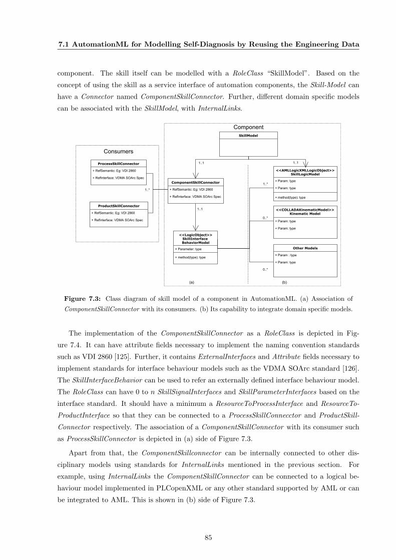
7.1 AutomationML for Modelling Self-Diagnosis by Reusing the Engineering Data
component. The skill itself can be modelled with a RoleClass “SkillModel”. Based on the
concept of using the skill as a service interface of automation components, the Skill-Model can
have a Connector named ComponentSkillConnector. Further, different domain specific models
can be associated with the SkillModel, with InternalLinks.
<<COLLADAKinematicModel>>Kinematic Model
+ Param: type
+ Param: type
<<LogicObject>>SkillInterface BehaviorModel
+ Parameter: type
+ method(type): type
ComponentSkillConnector
+ RefSemantic: Eg: VDI 2860
+ RefInterface: VDMA SOArc Spec
1..1
(a) (b)
ProcessSkillConnector
+ RefSemantic: Eg: VDI 2860
+ RefInterface: VDMA SOArc Spec
ProductSkillConnector
+ RefSemantic: Eg: VDI 2860
+ RefInterface: VDMA SOArc Spec
1..*
<<AMLLogicXMLLogicObject>>SkillLogicModel
+ Param: type
+ Param: type
+ method(type): type
0..*
Other Models
+ Param : type
+ Param: type
1..1
0..*
SkillModel
1..1
1..*
Component
Consumers
Figure 7.3: Class diagram of skill model of a component in AutomationML. (a) Association of
ComponentSkillConnector with its consumers. (b) Its capability to integrate domain specific models.
The implementation of the ComponentSkillConnector as a RoleClass is depicted in Fig-
ure 7.4. It can have attribute fields necessary to implement the naming convention standards
such as VDI 2860 [125]. Further, it contains ExternalInterfaces and Attribute fields necessary to
implement standards for interface behaviour models such as the VDMA SOArc standard [126].
The SkillInterfaceBehavior can be used to refer an externally defined interface behaviour model.
The RoleClass can have 0 to n SkillSignalInterfaces and SkillParameterInterfaces based on the
interface standard. It should have a minimum a ResourceToProcessInterface and ResourceTo-
ProductInterface so that they can be connected to a ProcessSkillConnecctor and ProductSkill-
Connector respectively. The association of a ComponentSkillConnector with its consumer such
as ProcessSkillConnector is depicted in (a) side of Figure 7.3.
Apart from that, the ComponentSkillconnector can be internally connected to other dis-
ciplinary models using standards for InternalLinks mentioned in the previous section. For
example, using InternalLinks the ComponentSkillConnector can be connected to a logical be-
haviour model implemented in PLCopenXML or any other standard supported by AML or can
be integrated to AML. This is shown in (b) side of Figure 7.3.
85
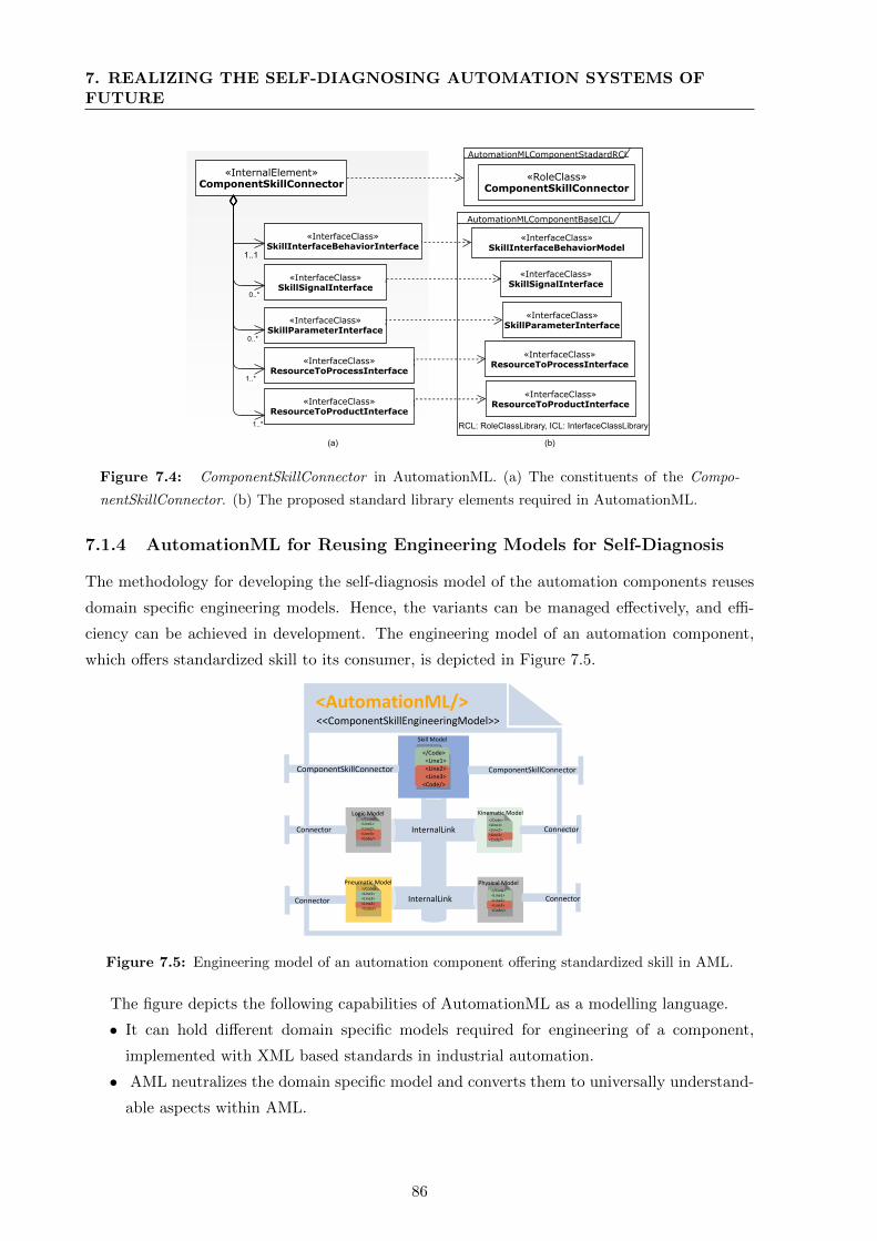
7. REALIZING THE SELF-DIAGNOSING AUTOMATION SYSTEMS OFFUTURE
AutomationMLComponentStadardRCL
«RoleClass»ComponentSkillConnector
AutomationMLComponentBaseICL
«InterfaceClass»SkillInterfaceBehaviorModel
«InterfaceClass»SkillSignalInterface
«InterfaceClass»SkillParameterInterface
«InterfaceClass»ResourceToProcessInterface
«InterfaceClass»ResourceToProductInterface
«InternalElement»ComponentSkillConnector
«InterfaceClass»SkillInterfaceBehaviorInterface
«InterfaceClass»SkillSignalInterface
«InterfaceClass»SkillParameterInterface
«InterfaceClass»ResourceToProcessInterface
«InterfaceClass»ResourceToProductInterface
0..*
0..*
1..*
1..*
1..1
RCL: RoleClassLibrary, ICL: InterfaceClassLibrary
(a) (b)
Figure 7.4: ComponentSkillConnector in AutomationML. (a) The constituents of the Compo-
nentSkillConnector. (b) The proposed standard library elements required in AutomationML.
7.1.4 AutomationML for Reusing Engineering Models for Self-Diagnosis
The methodology for developing the self-diagnosis model of the automation components reuses
domain specific engineering models. Hence, the variants can be managed effectively, and effi-
ciency can be achieved in development. The engineering model of an automation component,
which offers standardized skill to its consumer, is depicted in Figure 7.5.
Logic Model</Code><Line1><Line2><Line3><Code/>
Pneumatic Model</Code><Line1><Line2><Line3><Code/>
Physical Model</Code><Line1><Line2><Line3><Code/>
Kinematic Model</Code><Line1><Line2><Line3><Code/>
Skill Model
</Code><Line1><Line2><Line3>
<Code/>
<AutomationML/><<ComponentSkillEngineeringModel>>
ComponentSkillConnectorComponentSkillConnector
Connector
Connector
Connector
Connector
InternalLink
InternalLink
Figure 7.5: Engineering model of an automation component offering standardized skill in AML.
The figure depicts the following capabilities of AutomationML as a modelling language.
• It can hold different domain specific models required for engineering of a component,
implemented with XML based standards in industrial automation.
• AML neutralizes the domain specific model and converts them to universally understand-
able aspects within AML.
86
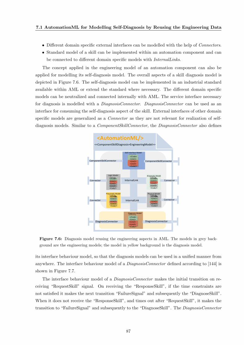
7.1 AutomationML for Modelling Self-Diagnosis by Reusing the Engineering Data
• Different domain specific external interfaces can be modelled with the help of Connectors.
• Standard model of a skill can be implemented within an automation component and can
be connected to different domain specific models with InternalLinks.
The concept applied in the engineering model of an automation component can also be
applied for modelling its self-diagnosis model. The overall aspects of a skill diagnosis model is
depicted in Figure 7.6. The self-diagnosis model can be implemented in an industrial standard
available within AML or extend the standard where necessary. The different domain specific
models can be neutralized and connected internally with AML. The service interface necessary
for diagnosis is modelled with a DiagnosisConnector. DiagnosisConnector can be used as an
interface for consuming the self-diagnosis aspect of the skill. External interfaces of other domain
specific models are generalized as a Connector as they are not relevant for realization of self-
diagnosis models. Similar to a ComponentSkillConnector, the DiagnosisConnector also defines
Logic Model
</Code><Line1><Line2><Line3><Code/>
Pneumatic Model
</Code><Line1><Line2><Line3><Code/>
Physical Model</Code><Line1><Line2><Line3><Code/>
Kinematic Model</Code><Line1><Line2><Line3><Code/>
Skill Interface Model
</Code><Line1><Line2><Line3><Code/>
<AutomationML/><<ComponentSkillDiagnosis+EngineeringModel>>
ComponentSkillConnectorComponentSkillConnector
Connector
Connector
Connector
Connector
InternalLink
InternalLink
Diagnosis Model
</Code><Line1><Line2><Line3><Code/>
DiagnosisConnector DiagnosisConnector
Figure 7.6: Diagnosis model reusing the engineering aspects in AML. The models in grey back-
ground are the engineering models; the model in yellow background is the diagnosis model.
its interface behaviour model, so that the diagnosis models can be used in a unified manner from
anywhere. The interface behaviour model of a DiagnosisConnector defined according to [144] is
shown in Figure 7.7.
The interface behaviour model of a DiagnosisConnector makes the initial transition on re-
ceiving “RequestSkill” signal. On receiving the “ResponseSkill”, if the time constraints are
not satisfied it makes the next transition “FailureSignal” and subsequently the “DiagnoseSkill”.
When it does not receive the “ResponseSkill”, and times out after “RequestSkill”, it makes the
transition to “FailureSignal” and subsequently to the “DiagnoseSkill”. The DiagnosisConnector
87
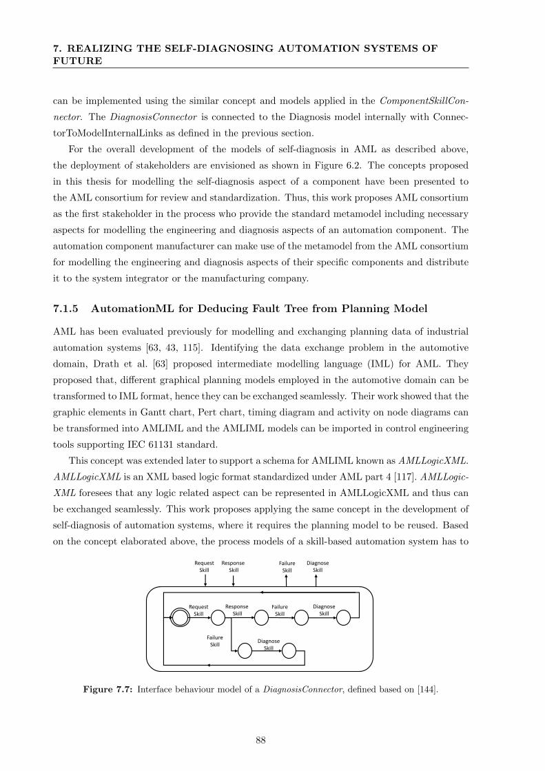
7. REALIZING THE SELF-DIAGNOSING AUTOMATION SYSTEMS OFFUTURE
can be implemented using the similar concept and models applied in the ComponentSkillCon-
nector. The DiagnosisConnector is connected to the Diagnosis model internally with Connec-
torToModelInternalLinks as defined in the previous section.
For the overall development of the models of self-diagnosis in AML as described above,
the deployment of stakeholders are envisioned as shown in Figure 6.2. The concepts proposed
in this thesis for modelling the self-diagnosis aspect of a component have been presented to
the AML consortium for review and standardization. Thus, this work proposes AML consortium
as the first stakeholder in the process who provide the standard metamodel including necessary
aspects for modelling the engineering and diagnosis aspects of an automation component. The
automation component manufacturer can make use of the metamodel from the AML consortium
for modelling the engineering and diagnosis aspects of their specific components and distribute
it to the system integrator or the manufacturing company.
7.1.5 AutomationML for Deducing Fault Tree from Planning Model
AML has been evaluated previously for modelling and exchanging planning data of industrial
automation systems [63, 43, 115]. Identifying the data exchange problem in the automotive
domain, Drath et al. [63] proposed intermediate modelling language (IML) for AML. They
proposed that, different graphical planning models employed in the automotive domain can be
transformed to IML format, hence they can be exchanged seamlessly. Their work showed that the
graphic elements in Gantt chart, Pert chart, timing diagram and activity on node diagrams can
be transformed into AMLIML and the AMLIML models can be imported in control engineering
tools supporting IEC 61131 standard.
This concept was extended later to support a schema for AMLIML known as AMLLogicXML.
AMLLogicXML is an XML based logic format standardized under AML part 4 [117]. AMLLogic-
XML foresees that any logic related aspect can be represented in AMLLogicXML and thus can
be exchanged seamlessly. This work proposes applying the same concept in the development of
self-diagnosis of automation systems, where it requires the planning model to be reused. Based
on the concept elaborated above, the process models of a skill-based automation system has to
Request Skill
FailureSkill
Response Skill
DiagnoseSkill
FailureSkill
DiagnoseSkill
Request Skill
Response Skill
FailureSkill
DiagnoseSkill
Figure 7.7: Interface behaviour model of a DiagnosisConnector, defined based on [144].
88

7.2 SystemPlanner between Planning and Maintenance Phases of AutomationSystems
be represented in AMLLogicXML and the physical hierarchy within AML.
7.2 SystemPlanner between Planning and Maintenance Phases
of Automation Systems
SystemPlanner is a prototype implemented for the planning of a skill-based automation system.
The tool was developed, by analysing the literature and state of the art in industrial automation,
which revealed lack of a tool for skill-based planning of an automation system [117]. The
basic aspects of planning of a skill-based automation system is introduced in Chapter 5. These
include process planning based on skills and physical composition of automation systems by using
the connectors of automation components. The SystemPlanner employs the AML component
models as shown in Figure 7.6 for planning of the automation system.
An illustration of the PPR based [19] planning methodology applied in the SystemPlanner,
with two reusable components is shown in Figure 7.8. The planning starts with the product
modelling. The initial product is first converted to the mid product, and then to the final
product with the help of processes. The processes are provided by the skills of the components.
With a common understanding of the semantics of the skills, the planning of a system can be
performed by ordering the skills required for the product transformation and mapping these
skills on to the provided components. By employing CPPS based automation components, each
skill in the process plan can find a physical counterpart, on which the skill can be executed.
Control sequence of the system
coordinating required skills of components
Component
State1
Component
State2
Prov.Skill2
Prov.Skill1
Component 1
Initial
Product (P)
Component
State1Component
State2
Prov.Skill2
Prov.Skill1
Component 2
Final
Product (P)
Resource (R)Resource (R)
Initial
product
Require
Skill 2
(Comp.2)
Require
Skill 2
(Comp.1)
Process (P)
Mid
product
Final
product
Figure 7.8: The methodology of planning applied in the SystemPlanner (modified from [117]). The
elements in the light blue background depict a skill-based automation system. The elements in the
grey background indicate the basics of the PPR concept.
The current implementation of the SystemPlanner does not include provision for modelling
the products. It provides only process and resource aspects of the PPR concept [19]. Fig-
ure 7.9 shows the screen shot of the current implementation of the tool. SystemPlanner employs
89
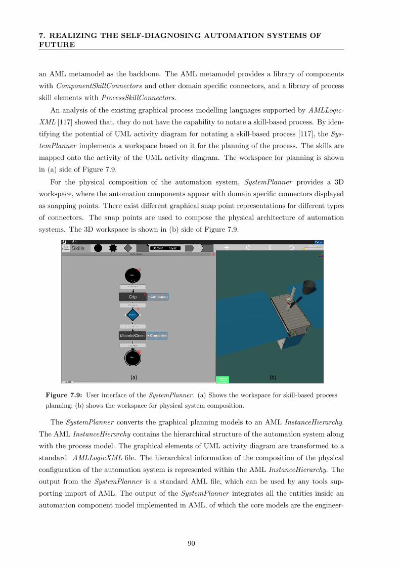
7. REALIZING THE SELF-DIAGNOSING AUTOMATION SYSTEMS OFFUTURE
an AML metamodel as the backbone. The AML metamodel provides a library of components
with ComponentSkillConnectors and other domain specific connectors, and a library of process
skill elements with ProcessSkillConnectors.
An analysis of the existing graphical process modelling languages supported by AMLLogic-
XML [117] showed that, they do not have the capability to notate a skill-based process. By iden-
tifying the potential of UML activity diagram for notating a skill-based process [117], the Sys-
temPlanner implements a workspace based on it for the planning of the process. The skills are
mapped onto the activity of the UML activity diagram. The workspace for planning is shown
in (a) side of Figure 7.9.
For the physical composition of the automation system, SystemPlanner provides a 3D
workspace, where the automation components appear with domain specific connectors displayed
as snapping points. There exist different graphical snap point representations for different types
of connectors. The snap points are used to compose the physical architecture of automation
systems. The 3D workspace is shown in (b) side of Figure 7.9.
(a) (b)
Figure 7.9: User interface of the SystemPlanner. (a) Shows the workspace for skill-based process
planning; (b) shows the workspace for physical system composition.
The SystemPlanner converts the graphical planning models to an AML InstanceHierarchy.
The AML InstanceHierarchy contains the hierarchical structure of the automation system along
with the process model. The graphical elements of UML activity diagram are transformed to a
standard AMLLogicXML file. The hierarchical information of the composition of the physical
configuration of the automation system is represented within the AML InstanceHierarchy. The
output from the SystemPlanner is a standard AML file, which can be used by any tools sup-
porting import of AML. The output of the SystemPlanner integrates all the entities inside an
automation component model implemented in AML, of which the core models are the engineer-
90
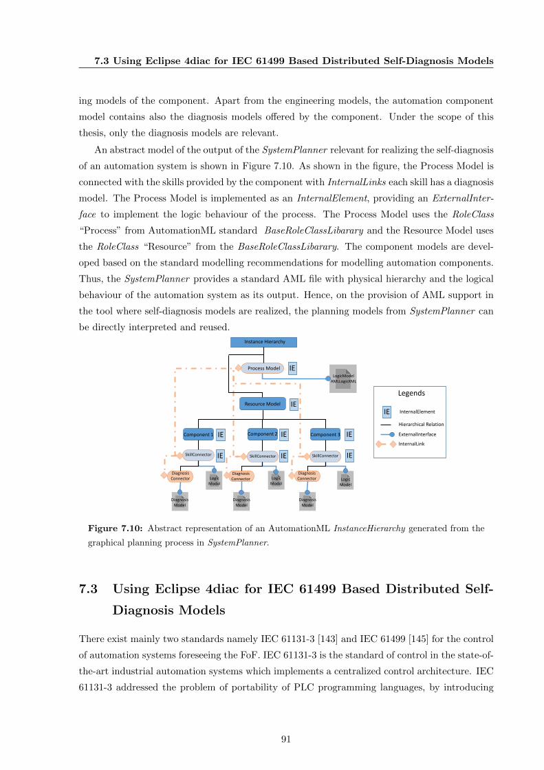
7.3 Using Eclipse 4diac for IEC 61499 Based Distributed Self-Diagnosis Models
ing models of the component. Apart from the engineering models, the automation component
model contains also the diagnosis models offered by the component. Under the scope of this
thesis, only the diagnosis models are relevant.
An abstract model of the output of the SystemPlanner relevant for realizing the self-diagnosis
of an automation system is shown in Figure 7.10. As shown in the figure, the Process Model is
connected with the skills provided by the component with InternalLinks each skill has a diagnosis
model. The Process Model is implemented as an InternalElement, providing an ExternalInter-
face to implement the logic behaviour of the process. The Process Model uses the RoleClass
“Process” from AutomationML standard BaseRoleClassLibarary and the Resource Model uses
the RoleClass “Resource” from the BaseRoleClassLibarary. The component models are devel-
oped based on the standard modelling recommendations for modelling automation components.
Thus, the SystemPlanner provides a standard AML file with physical hierarchy and the logical
behaviour of the automation system as its output. Hence, on the provision of AML support in
the tool where self-diagnosis models are realized, the planning models from SystemPlanner can
be directly interpreted and reused.
Process Model
Resource Model
IE
IE
IE
IE
IE
IEIE
IE
Instance Hierarchy
LogicModelAMLLogicXML
LogicModel
LogicModel
LogicModel
DiagnosisModel
DiagnosisModel
DiagnosisModel
Component 1 Component 2 Component 3
SkillConnector SkillConnector SkillConnector
DiagnosisConnector
DiagnosisConnector
DiagnosisConnector
IE
Legends
InternalElement
Hierarchical Relation
ExternalInterface
InternalLink
Figure 7.10: Abstract representation of an AutomationML InstanceHierarchy generated from the
graphical planning process in SystemPlanner.
7.3 Using Eclipse 4diac for IEC 61499 Based Distributed Self-
Diagnosis Models
There exist mainly two standards namely IEC 61131-3 [143] and IEC 61499 [145] for the control
of automation systems foreseeing the FoF. IEC 61131-3 is the standard of control in the state-of-
the-art industrial automation systems which implements a centralized control architecture. IEC
61131-3 addressed the problem of portability of PLC programming languages, by introducing
91

7. REALIZING THE SELF-DIAGNOSING AUTOMATION SYSTEMS OFFUTURE
the concept of unified and standard programming languages across vendors. However, as it
implements a centralized and tightly coupled control architecture based on a central PLC, the
configuration of PLCs are not portable across vendors [146].
IEC 61499 was introduced intending to bring portability, interoperability, configurability,
reconfiguration, and distribution within industrial automation systems [146]. IEC 61499 al-
lows using the programming languages of IEC 61131-3 for implementing the control algorithms
and follows an event driven control architecture. IEC 61499 specifies a reference architecture
model for distributed modular automation systems with a management interface foreseeing a
component based distributed architecture.
The characteristics of the self-diagnosis models, proposed in this thesis can be summarized
as follows. The CPPS automation components are enabled with their self-diagnosis models.
The diagnosis algorithm of a component is triggered on identifying a fault event within the
component. The self-diagnosis model of the automation system is proposed to be implemented
as a fault tree composing the self-diagnosing automation components. The fault tree based self-
diagnosis of the automation system is triggered by the fault events and diagnosis events from the
applied components. Thus, the self-diagnosis models have characteristics of a distributed, event-
based system. Additionally, this thesis proposes the self-diagnosis models to be implemented in
an existing standard in the industrial automation domain. The interoperability of the executing
control program of the automation systems, and the human interface systems with the self-
diagnosis models are also foreseen.
This thesis proposes the self-diagnosis models to be implemented in the standard IEC 61499,
since it provides the characteristics required for self-diagnosis models. The capability of IEC
61499 to coexist with the most predominant existing standard IEC 61131-3 [146] is also con-
sidered. The open source implementation of IEC 61499 standard Eclipse 4diac is applied for
the realization of self-diagnosis models within the scope of this thesis. Eclipse 4diac provides a
development environment based on the Eclipse modelling platform called 4diac IDE and a C++
based run-time environment named 4diac run-time environment (forte) [146].
7.3.1 Modelling Self-Diagnosis of Automation Components
The models for diagnosis proposed in this thesis (described in Chapter 4), use different ap-
proaches such as limit checking, matching of automata, temporal analysis, etc. IEC 61499
provides BasicFBType (Basic Function Block Type) which allows implementing custom algo-
rithms in a standardized and exchangeable format. The proposed algorithms of this thesis can
be implemented using the BasicFBType of IEC 61499.
The proposed approach of modelling self-diagnosing algorithms reuses engineering models.
The IEC 61499 BasicFBType has different data types as input. The solution proposes these in-
put data types to be fed from domain specific models within the AML component model. Hence,
92
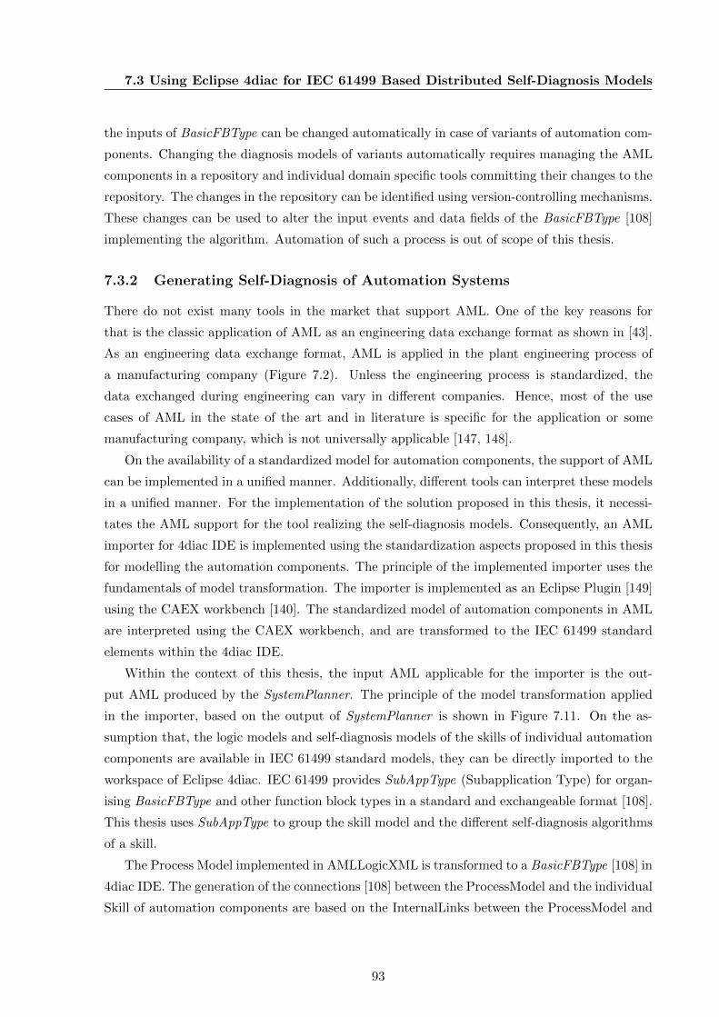
7.3 Using Eclipse 4diac for IEC 61499 Based Distributed Self-Diagnosis Models
the inputs of BasicFBType can be changed automatically in case of variants of automation com-
ponents. Changing the diagnosis models of variants automatically requires managing the AML
components in a repository and individual domain specific tools committing their changes to the
repository. The changes in the repository can be identified using version-controlling mechanisms.
These changes can be used to alter the input events and data fields of the BasicFBType [108]
implementing the algorithm. Automation of such a process is out of scope of this thesis.
7.3.2 Generating Self-Diagnosis of Automation Systems
There do not exist many tools in the market that support AML. One of the key reasons for
that is the classic application of AML as an engineering data exchange format as shown in [43].
As an engineering data exchange format, AML is applied in the plant engineering process of
a manufacturing company (Figure 7.2). Unless the engineering process is standardized, the
data exchanged during engineering can vary in different companies. Hence, most of the use
cases of AML in the state of the art and in literature is specific for the application or some
manufacturing company, which is not universally applicable [147, 148].
On the availability of a standardized model for automation components, the support of AML
can be implemented in a unified manner. Additionally, different tools can interpret these models
in a unified manner. For the implementation of the solution proposed in this thesis, it necessi-
tates the AML support for the tool realizing the self-diagnosis models. Consequently, an AML
importer for 4diac IDE is implemented using the standardization aspects proposed in this thesis
for modelling the automation components. The principle of the implemented importer uses the
fundamentals of model transformation. The importer is implemented as an Eclipse Plugin [149]
using the CAEX workbench [140]. The standardized model of automation components in AML
are interpreted using the CAEX workbench, and are transformed to the IEC 61499 standard
elements within the 4diac IDE.
Within the context of this thesis, the input AML applicable for the importer is the out-
put AML produced by the SystemPlanner. The principle of the model transformation applied
in the importer, based on the output of SystemPlanner is shown in Figure 7.11. On the as-
sumption that, the logic models and self-diagnosis models of the skills of individual automation
components are available in IEC 61499 standard models, they can be directly imported to the
workspace of Eclipse 4diac. IEC 61499 provides SubAppType (Subapplication Type) for organ-
ising BasicFBType and other function block types in a standard and exchangeable format [108].
This thesis uses SubAppType to group the skill model and the different self-diagnosis algorithms
of a skill.
The Process Model implemented in AMLLogicXML is transformed to a BasicFBType [108] in
4diac IDE. The generation of the connections [108] between the ProcessModel and the individual
Skill of automation components are based on the InternalLinks between the ProcessModel and
93
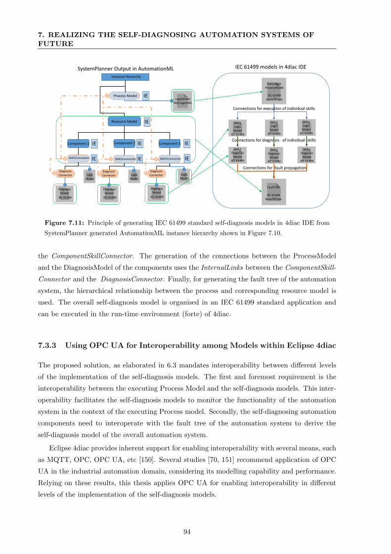
7. REALIZING THE SELF-DIAGNOSING AUTOMATION SYSTEMS OFFUTURE
DiagnosisModel
IEC 61499
DiagnosisModel
IEC 61499
Process Model
Resource Model
IE
IE
IE
IE
IE
IEIE
IE
Instance Hierarchy
LogicModelAMLLogicXML
LogicModel
LogicModel
LogicModel
DiagnosisModel
Component 1 Component 2 Component 3
Skill1Connector Skill2Connector SkillnConnector
DiagnosisConnector
DiagnosisConnector
DiagnosisConnector
IEC 61499
ExecutableProcessModel
IEC 61499BasicFBType
FaultTree
IEC 61499BasicFBType
Skill 1Diagnosis
ModelIEC 61499
Skill 2Diagnosis
ModelIEC 61499
Skill nDiagnosis
ModelIEC 61499
Connections for diagnosis of individual skills
Connections for fault propagation
IEC 61499 models in 4diac IDE
Skill 1Logic
ModelIEC 61499
Skill 2Logic
ModelIEC 61499
Skill nLogic
ModelIEC 61499
Connections for execution of individual skills
SystemPlanner Output in AutomationML
Figure 7.11: Principle of generating IEC 61499 standard self-diagnosis models in 4diac IDE from
SystemPlanner generated AutomationML instance hierarchy shown in Figure 7.10.
the ComponentSkillConnector. The generation of the connections between the ProcessModel
and the DiagnosisModel of the components uses the InternalLinks between the ComponentSkill-
Connector and the DiagnosisConnector. Finally, for generating the fault tree of the automation
system, the hierarchical relationship between the process and corresponding resource model is
used. The overall self-diagnosis model is organised in an IEC 61499 standard application and
can be executed in the run-time environment (forte) of 4diac.
7.3.3 Using OPC UA for Interoperability among Models within Eclipse 4diac
The proposed solution, as elaborated in 6.3 mandates interoperability between different levels
of the implementation of the self-diagnosis models. The first and foremost requirement is the
interoperability between the executing Process Model and the self-diagnosis models. This inter-
operability facilitates the self-diagnosis models to monitor the functionality of the automation
system in the context of the executing Process model. Secondly, the self-diagnosing automation
components need to interoperate with the fault tree of the automation system to derive the
self-diagnosis model of the overall automation system.
Eclipse 4diac provides inherent support for enabling interoperability with several means, such
as MQTT, OPC, OPC UA, etc [150]. Several studies [70, 151] recommend application of OPC
UA in the industrial automation domain, considering its modelling capability and performance.
Relying on these results, this thesis applies OPC UA for enabling interoperability in different
levels of the implementation of the self-diagnosis models.
94

7.4 Conclusion
7.3.4 Node-RED for Developing the Visual Interface for Diagnosis Models
This thesis proposes consumer devices as the interface between the maintenance personnel and
the self-diagnosing future automation systems. Eclipse 4diac, does not inherently support in-
tegration of visual interfaces for such purposes. Since the self-diagnosis models are realized in
Eclipse 4diac, it requires technology solutions which can interface the 4diac IDE easily with a
consumer device based visual interface. Thus, the development environment should hold capa-
bilities for enabling interoperability between the 4diac IDE and consumer devices. Additionally,
it should also provide means for implementing the user interfaces and interaction techniques
from the industrial automation domain.
Consequently, this thesis applies Node-RED [152] for the implementation of consumer device
based visual interface for the corrective maintenance. Node-RED is a web-based tool for con-
necting distributed hardware by providing a flow based programming environment. It provides
a browser based flow-editing environment implemented in JavaScript using Node.js. frame-
work [152]. The selection of Node-RED for implementing the visual interface for corrective
maintenance application is made based on the following characteristics Node-Red:
1. It provides an event based execution environment and portability to many platforms.
2. It has a distributed component based architecture.
3. It allows configuration and management of other interoperable hardware systems, within
the development environment.
4. It provides a library of graphic elements for user interfaces common in industries.
7.4 Conclusion
This chapter elaborated implementation of the proposed solution using specific tools and tech-
nologies. This thesis envisions the application of these tools in a sequence as shown in Figure 7.12
by a system integrator or a manufacturing company. Whenever the system integrator or a man-
ufacturing company configure/reconfigure their automation system, the tools are applied in this
sequence.
SystemPlanner
Skill-based planning of production
systems
<AML/> <AML/>
component modelsInclusive self
diagnosis models
Planning modelof the manufacturing
plant
Eclipse 4diac IDE
IEC 61499
AutomationML
Importer Plugin
Node-Red
Flow based
visual interface
developmentOverall diagnosismodel of the
production plant
Reconfiguration
Diagnosis Model
IEC 61499
Service model/ for corrective maintenance
Planning Realize ServiceUser interface
elements inconsumer
device
Figure 7.12: Sequence of tools applied and model transformation involved in the implementation.
95
7. REALIZING THE SELF-DIAGNOSING AUTOMATION SYSTEMS OFFUTURE
The AML component models (including their self-diagnosis models) from the component
manufacturers are consumed by the SystemPlanner, which is used for the planning of the au-
tomation system. Initially, the SystemPlanner transforms the AML component models to visual
elements within the SystemPlanner workspace. Subsequently, the visual planning models from
the SystemPlanner are transformed to an AML InstanceHierarchy. This AML model is con-
sumed by the AML importer of Eclipse 4diac IDE, which realizes the self-diagnosis model.
The AML importer transforms the AML output of the SystemPlanner to an IEC 61499 stan-
dard diagnosis model within the 4diac IDE. The self-diagnosis models realized in the Eclipse
4diac IDE are further transformed to visual elements within Node-RED for their service phase.
Based on this sequence, the self-diagnosis model of the automation system is generated
automatically with the Eclipse 4diac IDE. Hence, the self-diagnosis models can be seen as a
by-product of the configuration/reconfiguration of the automation system.
96
Chapter 8
Evaluation and Discussion
Identifying the perpetual increase in cost and resource consumption for the corrective main-
tenance of industrial automation systems, this thesis proposes integrating self-diagnosis in the
corrective maintenance of future automation systems. The future automation systems are as-
sumed as a composition of CPPS based automation components. Based on this assumption, a
methodology for cost efficient realization of self-diagnosis in CPPS component based automation
systems, by reusing their engineering data is proposed. Foreseeing the future automation systems
as frequently reconfigurable in nature, a methodology for enabling flexible and reconfigurable
characteristics to the self-diagnosis feature is also proposed.
With a visual human-machine interface for self-diagnosing automation systems, a human-
machine collaborative environment is proposed for the corrective maintenance of FoF. Conse-
quently, it is envisioned that the future automation systems can be maintained with minimum
resources and cost. Thus, this thesis contributes to the improvement of corrective maintenance
within the context of FoF.
This chapter evaluates the proposed solution, with two application examples and discusses
the results. The first application example, a lab scale pick and place module, is used to evaluate
the overall concept of self-diagnosis based corrective maintenance introduced in this thesis.
The second application example, an industrial assembly demonstrator, is used to evaluate the
scalability of the approach to an industrial environment.
Thus, this chapter is organized in seven sections. The pick and place module is introduced
in Section 8.1. Section 8.2 describes the self-diagnosis models of the components of the pick
and place module. Section 8.3 elaborates the planning process of the pick and place module.
The realization and execution of self-diagnosis in the pick and place module in explained in
Section 8.4. Subsequently, the evaluation of corrective maintenance of the pick and place mod-
ule with self-diagnosis is described in Section 8.5. Later, Section 8.6 evaluates the industrial
scalability of the approach. Finally, Section 8.7 discusses the results.
97
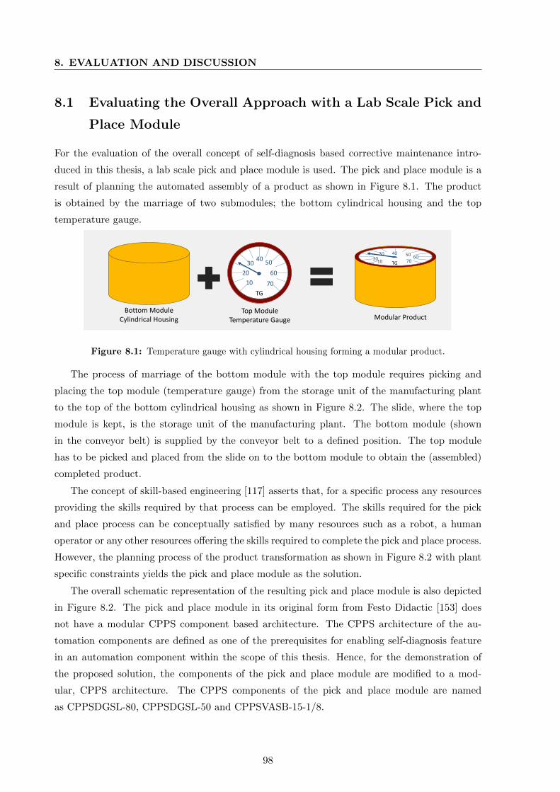
8. EVALUATION AND DISCUSSION
8.1 Evaluating the Overall Approach with a Lab Scale Pick and
Place Module
For the evaluation of the overall concept of self-diagnosis based corrective maintenance intro-
duced in this thesis, a lab scale pick and place module is used. The pick and place module is a
result of planning the automated assembly of a product as shown in Figure 8.1. The product
is obtained by the marriage of two submodules; the bottom cylindrical housing and the top
temperature gauge.
10
20
3040
50
60
70
TG
1020
30 40 50 6070TG
Bottom ModuleCylindrical Housing
Top ModuleTemperature Gauge Modular Product
Figure 8.1: Temperature gauge with cylindrical housing forming a modular product.
The process of marriage of the bottom module with the top module requires picking and
placing the top module (temperature gauge) from the storage unit of the manufacturing plant
to the top of the bottom cylindrical housing as shown in Figure 8.2. The slide, where the top
module is kept, is the storage unit of the manufacturing plant. The bottom module (shown
in the conveyor belt) is supplied by the conveyor belt to a defined position. The top module
has to be picked and placed from the slide on to the bottom module to obtain the (assembled)
completed product.
The concept of skill-based engineering [117] asserts that, for a specific process any resources
providing the skills required by that process can be employed. The skills required for the pick
and place process can be conceptually satisfied by many resources such as a robot, a human
operator or any other resources offering the skills required to complete the pick and place process.
However, the planning process of the product transformation as shown in Figure 8.2 with plant
specific constraints yields the pick and place module as the solution.
The overall schematic representation of the resulting pick and place module is also depicted
in Figure 8.2. The pick and place module in its original form from Festo Didactic [153] does
not have a modular CPPS component based architecture. The CPPS architecture of the au-
tomation components are defined as one of the prerequisites for enabling self-diagnosis feature
in an automation component within the scope of this thesis. Hence, for the demonstration of
the proposed solution, the components of the pick and place module are modified to a mod-
ular, CPPS architecture. The CPPS components of the pick and place module are named
as CPPSDGSL-80, CPPSDGSL-50 and CPPSVASB-15-1/8.
98
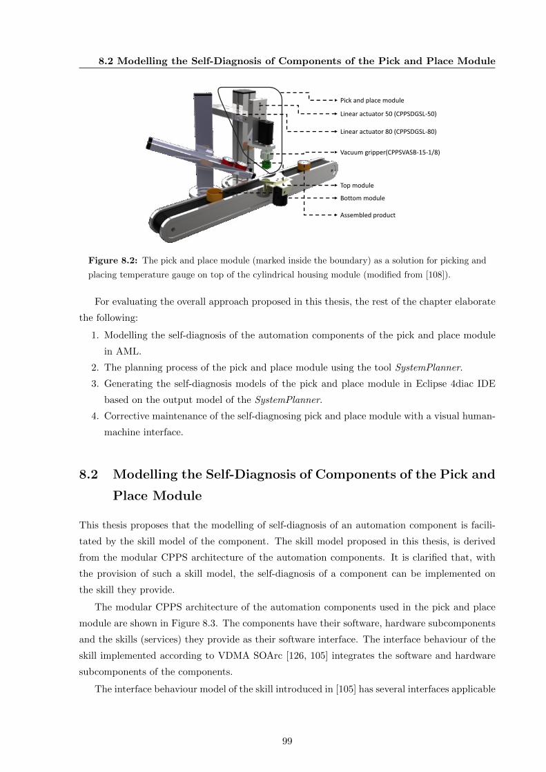
8.2 Modelling the Self-Diagnosis of Components of the Pick and Place Module
Linear actuator 80 (CPPSDGSL-80)
Linear actuator 50 (CPPSDGSL-50)
Vacuum gripper(CPPSVASB-15-1/8)
Top module
Bottom module
Assembled product
Pick and place module
Figure 8.2: The pick and place module (marked inside the boundary) as a solution for picking and
placing temperature gauge on top of the cylindrical housing module (modified from [108]).
For evaluating the overall approach proposed in this thesis, the rest of the chapter elaborate
the following:
1. Modelling the self-diagnosis of the automation components of the pick and place module
in AML.
2. The planning process of the pick and place module using the tool SystemPlanner.
3. Generating the self-diagnosis models of the pick and place module in Eclipse 4diac IDE
based on the output model of the SystemPlanner.
4. Corrective maintenance of the self-diagnosing pick and place module with a visual human-
machine interface.
8.2 Modelling the Self-Diagnosis of Components of the Pick and
Place Module
This thesis proposes that the modelling of self-diagnosis of an automation component is facili-
tated by the skill model of the component. The skill model proposed in this thesis, is derived
from the modular CPPS architecture of the automation components. It is clarified that, with
the provision of such a skill model, the self-diagnosis of a component can be implemented on
the skill they provide.
The modular CPPS architecture of the automation components used in the pick and place
module are shown in Figure 8.3. The components have their software, hardware subcomponents
and the skills (services) they provide as their software interface. The interface behaviour of the
skill implemented according to VDMA SOArc [126, 105] integrates the software and hardware
subcomponents of the components.
The interface behaviour model of the skill introduced in [105] has several interfaces applicable
99

8. EVALUATION AND DISCUSSION
ResponseMoveIn/
Out
START
Processor 80
Observer 80
RequestMoveIn/
Out
Observe MoveIn/
Out
ProcessMoveIn
Out
Hardware subcomponent
Software subcomponent
START
Processor 50
Observer 50
RequestMoveIn/
OutObserve MoveIn/
Out
ProcessMoveIn/
OutResponseMoveIn/
Out
Hardware subcomponent
Software subcomponent
CPPSDGSL-80 CPPSDGSL-50
START
Processor
Observer
RequestGrip/
ReleaseObserve
Grip/Release
Process Grip/
Release ResponseGrip/
Release
Hardware subcomponent
Software subcomponent
CPPSVASB-15-1/8
Figure 8.3: CPPS based automation components of the pick and place module.
for the control of a component, which are not relevant under the scope of this thesis. An analysis
of this model showed that “Start Skill” and “Idle State” of this model is equivalent to “Request
Skill” and “Response Skill” of this thesis as proposed in Section 4.3. Hence, the interfaces of the
skills are represented with “Request Skill” and “Response Skill” within the scope of this thesis.
8.2.1 Modelling the Self-Diagnosis of CPPSDGSL-80 and 50 as Variants
The CPPSDGSL-80 and CPPSDGSL-50 have identical functionality of moving a payload lin-
early. Hence, they are modelled as variants of the linear actuator series CPPSDGSL. The CPPS-
DGSL-80/50 provide two skills “MoveIn” and “MoveOut” whose interface behaviour models
integrate the hardware and software subcomponents of the component. The CPPSDGSL-80/50
have an integrated PLC Festo CECC-LK [154], on which the skills are executed.
The key differing characteristic of CPPSDGSL80/50 as variants is their stroke length. CPPS-
DGSL80 has a stroke length of 80 mm and CPPSDGSL-50 has a stroke length of 50 mm. For
processing the skills with a stroke length of 80 mm, CPPSDGSL-80 has a solenoid valve with
two coils. It has a load bearing capacity of 185 g and two proximity sensors for observing the
execution of the skills. For processing the skills with a stroke length of 50 mm, CPPSDGSL-
50 employs a solenoid valve with a single coil. It has a load bearing capacity of 152 g and a
single proximity sensor for observing the execution of the skills. The software subcomponent of
the CPPSDGSL-80/50 has changes based on the differences in their hardware subcomponent.
The skills “MoveIn” and “MoveOut” of the CPPSDGSL-80/50 are processed by the same
hardware components and they differ only in their functional behaviour. A “RequestMoveIn”
makes a linear movement inwards and a “RequestMoveOut” makes a linear movement out-
wards. Hence, the implementation of these skills in AML are depicted as a common model
as shown in Figure 8.4. The model employs the interface behaviour model of the skills based
on VDMA SOArc and VDI 2860 standards as introduced in Section 7.1. The interface behaviour
100
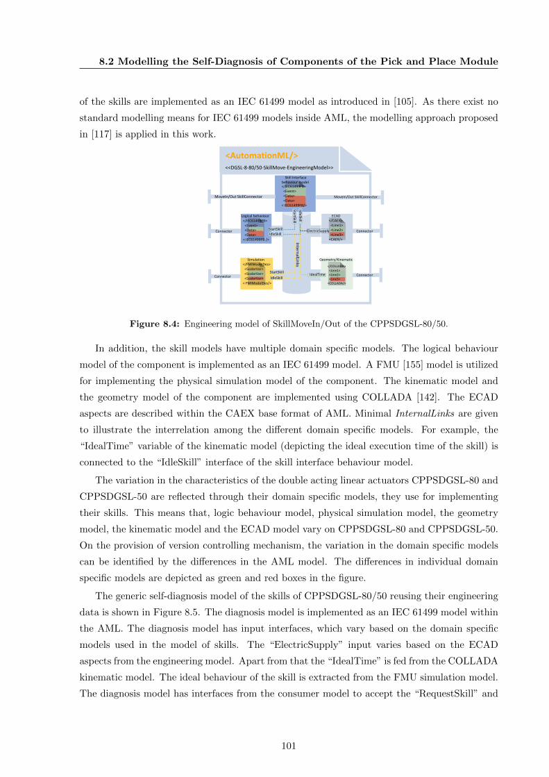
8.2 Modelling the Self-Diagnosis of Components of the Pick and Place Module
of the skills are implemented as an IEC 61499 model as introduced in [105]. As there exist no
standard modelling means for IEC 61499 models inside AML, the modelling approach proposed
in [117] is applied in this work.
Logical behaviour
Simulation Geometry/Kinematic
ECAD
Skill Interfacebehaviour model
<AutomationML/><<DGSL-8-80/50-SkillMove-EngineeringModel>>
MoveIn/Out SkillConnectorMoveIn/Out SkillConnector
Connector
Connector
Connector
Connector
</CAEX><Line1><Line2><Line3>
<CAEX/>
</COLLADA><Line1><Line2><Line3>
<COLLADA/>
</IEC61499FB><Event><Data><Data>
< IEC61499FB />
</FMIModelDes><ScalarVar><ScalarVar><ScalarVar>
< FMIModelDes/>
</IEC61499FB><Event><Data><Data>
< IEC61499FB/>
StartSkill
IdleSkill
StartSkill
StartSkill
IdleSkill
IdleSkillIdealTime
ElectricSupply
Intern
alLinks
Figure 8.4: Engineering model of SkillMoveIn/Out of the CPPSDGSL-80/50.
In addition, the skill models have multiple domain specific models. The logical behaviour
model of the component is implemented as an IEC 61499 model. A FMU [155] model is utilized
for implementing the physical simulation model of the component. The kinematic model and
the geometry model of the component are implemented using COLLADA [142]. The ECAD
aspects are described within the CAEX base format of AML. Minimal InternalLinks are given
to illustrate the interrelation among the different domain specific models. For example, the
“IdealTime” variable of the kinematic model (depicting the ideal execution time of the skill) is
connected to the “IdleSkill” interface of the skill interface behaviour model.
The variation in the characteristics of the double acting linear actuators CPPSDGSL-80 and
CPPSDGSL-50 are reflected through their domain specific models, they use for implementing
their skills. This means that, logic behaviour model, physical simulation model, the geometry
model, the kinematic model and the ECAD model vary on CPPSDGSL-80 and CPPSDGSL-50.
On the provision of version controlling mechanism, the variation in the domain specific models
can be identified by the differences in the AML model. The differences in individual domain
specific models are depicted as green and red boxes in the figure.
The generic self-diagnosis model of the skills of CPPSDGSL-80/50 reusing their engineering
data is shown in Figure 8.5. The diagnosis model is implemented as an IEC 61499 model within
the AML. The diagnosis model has input interfaces, which vary based on the domain specific
models used in the model of skills. The “ElectricSupply” input varies based on the ECAD
aspects from the engineering model. Apart from that the “IdealTime” is fed from the COLLADA
kinematic model. The ideal behaviour of the skill is extracted from the FMU simulation model.
The diagnosis model has interfaces from the consumer model to accept the “RequestSkill” and
101
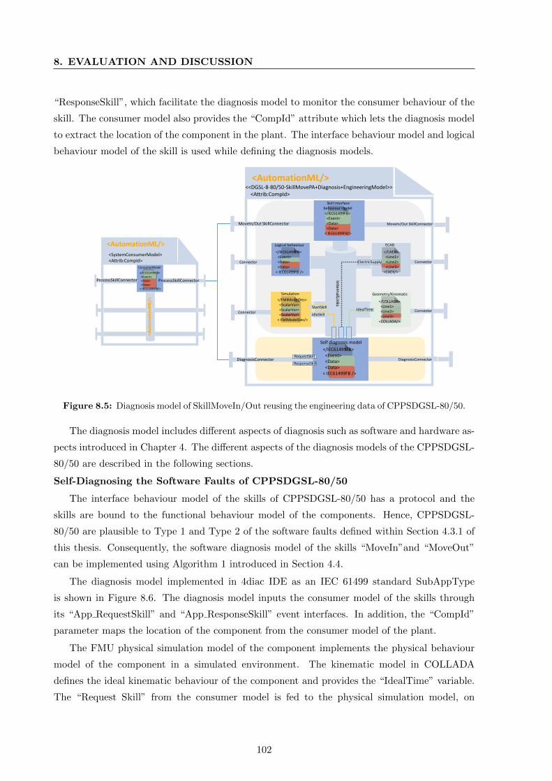
8. EVALUATION AND DISCUSSION
“ResponseSkill”, which facilitate the diagnosis model to monitor the consumer behaviour of the
skill. The consumer model also provides the “CompId” attribute which lets the diagnosis model
to extract the location of the component in the plant. The interface behaviour model and logical
behaviour model of the skill is used while defining the diagnosis models.
ConsumerModel
<AutomationML/>
<AutomationML/>
<SystemConsumerModel><Attrib:CompId>
ProcessSkillConnector ProcessSkillConnector
Logical behaviour
Simulation Geometry/Kinematic
ECAD
<AutomationML/><<DGSL-8-80/50-SkillMovePA+Diagnosis+EngineeringModel>>
<Attrib:CompId>
MoveIn/Out SkillConnectorMoveIn/Out SkillConnector
Connector
Connector
Connector
Connector
</CAEX><Line1><Line2><Line3>
<CAEX/>
</COLLADA><Line1><Line2><Line3>
<COLLADA/>
</IEC61499FB><Event><Data><Data>
< IEC61499FB />
</FMIModelDes><ScalarVar><ScalarVar><ScalarVar>
< FMIModelDes/>
Self diagnosis model
</IEC61499FB><Event><Data><Data>
< IEC61499FB />
DiagnosisConnector DiagnosisConnector
Intern
alLinks
IdealTime
ElectricSupply
RequestSkill
ResponseSkill
Skill Interfacebehaviour model
</IEC61499FB><Event><Data><Data>
< IEC61499FB/>
</IEC61499FB><Event><Data><Data>
< IEC61499FB/>
StartSkill
idleSkill
Figure 8.5: Diagnosis model of SkillMoveIn/Out reusing the engineering data of CPPSDGSL-80/50.
The diagnosis model includes different aspects of diagnosis such as software and hardware as-
pects introduced in Chapter 4. The different aspects of the diagnosis models of the CPPSDGSL-
80/50 are described in the following sections.
Self-Diagnosing the Software Faults of CPPSDGSL-80/50
The interface behaviour model of the skills of CPPSDGSL-80/50 has a protocol and the
skills are bound to the functional behaviour model of the components. Hence, CPPSDGSL-
80/50 are plausible to Type 1 and Type 2 of the software faults defined within Section 4.3.1 of
this thesis. Consequently, the software diagnosis model of the skills “MoveIn”and “MoveOut”
can be implemented using Algorithm 1 introduced in Section 4.4.
The diagnosis model implemented in 4diac IDE as an IEC 61499 standard SubAppType
is shown in Figure 8.6. The diagnosis model inputs the consumer model of the skills through
its “App RequestSkill” and “App ResponseSkill” event interfaces. In addition, the “CompId”
parameter maps the location of the component from the consumer model of the plant.
The FMU physical simulation model of the component implements the physical behaviour
model of the component in a simulated environment. The kinematic model in COLLADA
defines the ideal kinematic behaviour of the component and provides the “IdealTime” variable.
The “Request Skill” from the consumer model is fed to the physical simulation model, on
102
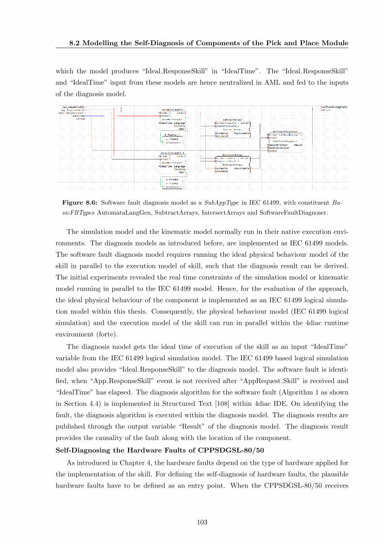
8.2 Modelling the Self-Diagnosis of Components of the Pick and Place Module
which the model produces “Ideal ResponseSkill” in “IdealTime”. The “Ideal ResponseSkill”
and “IdealTime” input from these models are hence neutralized in AML and fed to the inputs
of the diagnosis model.
Figure 8.6: Software fault diagnosis model as a SubAppType in IEC 61499, with constituent Ba-
sicFBTypes AutomataLangGen, SubtractArrays, IntersectArrays and SoftwareFaultDiagnoser.
The simulation model and the kinematic model normally run in their native execution envi-
ronments. The diagnosis models as introduced before, are implemented as IEC 61499 models.
The software fault diagnosis model requires running the ideal physical behaviour model of the
skill in parallel to the execution model of skill, such that the diagnosis result can be derived.
The initial experiments revealed the real time constraints of the simulation model or kinematic
model running in parallel to the IEC 61499 model. Hence, for the evaluation of the approach,
the ideal physical behaviour of the component is implemented as an IEC 61499 logical simula-
tion model within this thesis. Consequently, the physical behaviour model (IEC 61499 logical
simulation) and the execution model of the skill can run in parallel within the 4diac runtime
environment (forte).
The diagnosis model gets the ideal time of execution of the skill as an input “IdealTime”
variable from the IEC 61499 logical simulation model. The IEC 61499 based logical simulation
model also provides “Ideal ResponseSkill” to the diagnosis model. The software fault is identi-
fied, when “App ResponseSkill” event is not received after “AppRequest Skill” is received and
“IdealTime” has elapsed. The diagnosis algorithm for the software fault (Algorithm 1 as shown
in Section 4.4) is implemented in Structured Text [108] within 4diac IDE. On identifying the
fault, the diagnosis algorithm is executed within the diagnosis model. The diagnosis results are
published through the output variable “Result” of the diagnosis model. The diagnosis result
provides the causality of the fault along with the location of the component.
Self-Diagnosing the Hardware Faults of CPPSDGSL-80/50
As introduced in Chapter 4, the hardware faults depend on the type of hardware applied for
the implementation of the skill. For defining the self-diagnosis of hardware faults, the plausible
hardware faults have to be defined as an entry point. When the CPPSDGSL-80/50 receives
103
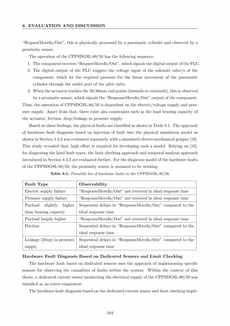
8. EVALUATION AND DISCUSSION
“RequestMoveIn/Out”, this is physically processed by a pneumatic cylinder and observed by a
proximity sensor.
The operation of the CPPSDGSL-80/50 has the following sequence:
1. The component receives “RequestMoveIn/Out”, which signals the digital output of the PLC.
2. The digital output of the PLC triggers the voltage input of the solenoid valve/s of the
component, which let the required pressure for the linear movement of the pneumatic
cylinder through the outlet port of the pilot valve.
3. When the actuator reaches the 50/80mm end points (inwards or outwards), this is observed
by a proximity sensor, which signals the “ResponseMoveIn/Out” output of the component.
Thus, the operation of CPPSDGSL-80/50 is dependent on the electric/voltage supply and pres-
sure supply. Apart from that, there exist also constraints such as the load bearing capacity of
the actuator, friction, drop/leakage in pressure supply.
Based on these findings, the physical faults are classified as shown in Table 8.1. The approach
of hardware fault diagnosis based on injection of fault into the physical simulation model as
shown in Section 4.4.3 was evaluated separately with a simulated electro-mechanical gripper [18].
This study revealed that, high effort is required for developing such a model. Relying on [18],
for diagnosing the hard fault types, the limit checking approach and temporal analysis approach
introduced in Section 4.4.3 are evaluated further. For the diagnosis model of the hardware faults
of the CPPSDGSL-80/50, the proximity sensor is assumed to be working.
Table 8.1: Plausible list of hardware faults in the CPPSDGSL-80/50.
Fault Type Observability
Electric supply failure “ResponseMoveIn/Out” not received in ideal response time
Pressure supply failure “ResponseMoveIn/Out” not received in ideal response time
Payload slightly higher
than bearing capacity
Sequential delays in “ResponseMoveIn/Out” compared to the
ideal response time
Payload largely higher “ResponseMoveIn/Out” not received in ideal response time
Friction Sequential delays in “ResponseMoveIn/Out” compared to the
ideal response time
Leakage (Drop) in pressure
supply
Sequential delays in “ResponseMoveIn/Out” compared to the
ideal response time
Hardware Fault Diagnosis Based on Dedicated Sensors and Limit Checking
The hardware fault based on dedicated sensors uses the approach of implementing specific
sensors for observing the causalities of faults within the system. Within the context of this
thesis, a dedicated current sensor monitoring the electrical supply of the CPPSDGSL-80/50 was
installed as an extra component.
The hardware fault diagnosis based on the dedicated current sensor and limit checking imple-
104
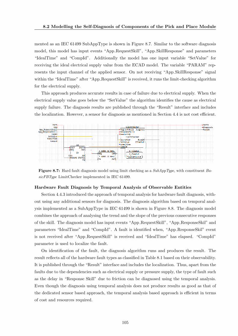
8.2 Modelling the Self-Diagnosis of Components of the Pick and Place Module
mented as an IEC 61499 SubAppType is shown in Figure 8.7. Similar to the software diagnosis
model, this model has input events “App RequestSkill”, “App SkillResponse” and parameters
“IdealTime” and “CompId”. Additionally the model has one input variable “SetValue” for
receiving the ideal electrical supply value from the ECAD model. The variable “PARAM” rep-
resents the input channel of the applied sensor. On not receiving “App SkillResponse” signal
within the “IdealTime” after “App RequestSkill” is received, it runs the limit-checking algorithm
for the electrical supply.
This approach produces accurate results in case of failure due to electrical supply. When the
electrical supply value goes below the “SetValue” the algorithm identifies the cause as electrical
supply failure. The diagnosis results are published through the “Result” interface and includes
the localization. However, a sensor for diagnosis as mentioned in Section 4.4 is not cost efficient.
Figure 8.7: Hard fault diagnosis model using limit checking as a SubAppType, with constituent Ba-
sicFBType LimitChecker implemented in IEC 61499.
Hardware Fault Diagnosis by Temporal Analysis of Observable Entities
Section 4.4.3 introduced the approach of temporal analysis for hardware fault diagnosis, with-
out using any additional sensors for diagnosis. The diagnosis algorithm based on temporal anal-
ysis implemented as a SubAppType in IEC 61499 is shown in Figure 8.8. The diagnosis model
combines the approach of analysing the trend and the slope of the previous consecutive responses
of the skill. The diagnosis model has input events “App RequestSkill”, “App ResponseSkil” and
parameters “IdealTime” and “CompId”. A fault is identified when, “App ResponseSkil” event
is not received after “App RequestSkill” is received and “IdealTime” has elapsed. “CompId”
parameter is used to localize the fault.
On identification of the fault, the diagnosis algorithm runs and produces the result. The
result reflects all of the hardware fault types as classified in Table 8.1 based on their observability.
It is published through the “Result” interface and includes the localization. Thus, apart from the
faults due to the dependencies such as electrical supply or pressure supply, the type of fault such
as the delay in “Response Skill” due to friction can be diagnosed using the temporal analysis.
Even though the diagnosis using temporal analysis does not produce results as good as that of
the dedicated sensor based approach, the temporal analysis based approach is efficient in terms
of cost and resources required.
105
8. EVALUATION AND DISCUSSION
Figure 8.8: Hard fault diagnosis model based on temporal analysis implemented as a SubAppType
in IEC 61499. SlopeTracer Time BasicFBType, DataCollector Time and TrendAnalyser Time are
the constituent BasicFbTypes.
8.2.2 Modelling the Self-Diagnosis of the CPPSVASB-15-1/8
The CPPSVASB-15-1/8 functions using the generated vacuum to grip a payload. The CPPS-
VASB-15-1/8 is embedded with its own PLC from RevolutionPi [156]. The CPPSVASB-15-1/8
offers skills “Grip” and “Release” to its consumers. The interface behaviour model of the skills
integrate the software subcomponents and hardware subcomponents of the CPPSVASB-15-1/8.
The skills of the CPPSVASB-15-1/8 are processed by a solenoid, which generates the vacuum
and observed by a vacuum sensor. The CPPSVASB-15-1/8, as shown in Figure 8.3 integrate all
those supporting components, which makes the independent functionality of a vacuum gripper
possible. The software subcomponent is assumed to be similar to that of the generic model of
a SISO automation component.
The generic implementation model of the skills “Grip” and “Release” of the CPPSVASB-
15-1/8 in AML is similar to the implementation model of the skills of the CPPSDGSL-80/50 as
shown in Figure 8.4. The model defines the logical and physical behaviour model of the skill it
offers within AML, similar to the model shown for the CPPSDGSL-80/50. The skill interface
behaviour model, based on standard VDMA SOArc and VDI 2856 act as the interoperating
medium for all the discipline specific aspects of a skill model as shown in Figure 8.4. Hence,
the generic diagnosis model of the CPPSVASB-15-1/8 in AML can be seen similar to that of
the CPPSDGSL-80/50 shown in Figure 8.5.
Diagnosing the Software Faults of CPPSVASB-15-1/8
Since the interface behaviour model of every component is the same according to VDMA SOArc,
the diagnosis model for software fault types (Type 1 & 2) as introduced in Section 4.4 can be
seen similar to that of the CPPSDGSL-80/50. The model is implemented as a SubAppType in
IEC 61499 similar to the CPPSDGSL-80/50 and the only difference, that appears is the value
of “IdealTime” variable as the temporal behaviour of the skills “Grip/Release” differ from that
of skills “MoveIn/Out”.
106
8.2 Modelling the Self-Diagnosis of Components of the Pick and Place Module
Diagnosing the Hardware Faults of CPPSVASB-15-1/8
When the CPPSVASB-15-1/8 receives a “RequestGrip/Release”, this is processed by a suc-
tion cup operating with the help of generated vacuum. The sequence of operation of the CPPSVASB-
15-1/8 is as follows:
1. The component receives a “RequestGrip/Release”, this signals the digital output of the PLC.
2. The digital output of the PLC triggers the voltage input required for the operation of the
solenoid valve, which generates the vacuum required to grab the object.
3. The gripping process is observed by the vacuum sensor, which signals the “ResponseG-
rip/Release” of the skill.
Thus, the operation of the vacuum gripper has similar dependencies as that of the CPPS-
DGSL-80/50. However, the gripper does not have a constraint on friction, but only con-
straint on the pressure and the area of the payload. Hence, the hardware diagnosis models
of the CPPSVASB-15-1/8, except the temporal analysis based model look similar to that of
the CPPSDGSL-80/50. In the temporal analysis model, the constraints are defined only for
payload area and the drop in pressure, in comparison to the CPPSDGSL-80/50. The results of
the hardware fault diagnosis reflect only these constraints as shown in Table 8.2. The diagnosis
model looks similar to that of CPPSDGSL-80/50 in all other aspects.
Table 8.2: Plausible list of faults in the CPPSVASB-15-1/8.
Fault Type Observability
Electric supply failure “ResponseGrip/Release” not received in ideal response time
Pressure supply fail-
ure/Drop
“ResponseGrip/Release” not received in ideal response time
Payload area smaller than
the suction cup
“ResponseGrip/Release” not received in ideal response time
Leakage (Drop) in pressure
supply
“ResponseGrip/Release” not received or Delay in “ResponseG-
rip/Release” compared to the ideal response time
8.2.3 Analysis of the Effort Required for Developing Self-Diagnosis Models
The application example of pick and place module clarifies that, self-diagnosis models of skills
of the components can be prepared without much effort. Most of the proposed algorithms can
be reused for different types and variants of the components and their skills.
The example of double acting linear actuators as variants shows the handling of variants
by using the different domain specific engineering models as variable inputs for the diagnosing
algorithm. The similarity of diagnosis model of the vacuum gripper CPPSVASB-15-1/8 with
that of the CPPSDGSL-80/50 show that, in presence of standard model of a skill, most of the
algorithm can be generalized for different components and their skills.
107
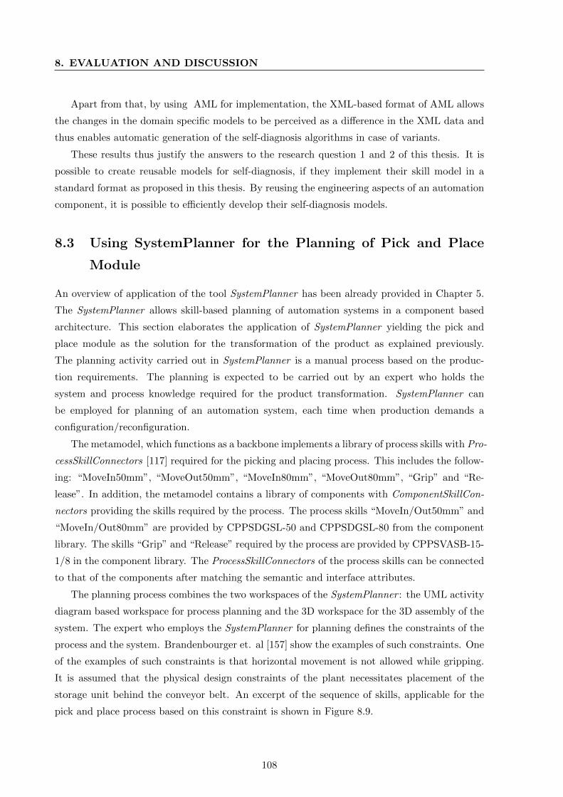
8. EVALUATION AND DISCUSSION
Apart from that, by using AML for implementation, the XML-based format of AML allows
the changes in the domain specific models to be perceived as a difference in the XML data and
thus enables automatic generation of the self-diagnosis algorithms in case of variants.
These results thus justify the answers to the research question 1 and 2 of this thesis. It is
possible to create reusable models for self-diagnosis, if they implement their skill model in a
standard format as proposed in this thesis. By reusing the engineering aspects of an automation
component, it is possible to efficiently develop their self-diagnosis models.
8.3 Using SystemPlanner for the Planning of Pick and Place
Module
An overview of application of the tool SystemPlanner has been already provided in Chapter 5.
The SystemPlanner allows skill-based planning of automation systems in a component based
architecture. This section elaborates the application of SystemPlanner yielding the pick and
place module as the solution for the transformation of the product as explained previously.
The planning activity carried out in SystemPlanner is a manual process based on the produc-
tion requirements. The planning is expected to be carried out by an expert who holds the
system and process knowledge required for the product transformation. SystemPlanner can
be employed for planning of an automation system, each time when production demands a
configuration/reconfiguration.
The metamodel, which functions as a backbone implements a library of process skills with Pro-
cessSkillConnectors [117] required for the picking and placing process. This includes the follow-
ing: “MoveIn50mm”, “MoveOut50mm”, “MoveIn80mm”, “MoveOut80mm”, “Grip” and “Re-
lease”. In addition, the metamodel contains a library of components with ComponentSkillCon-
nectors providing the skills required by the process. The process skills “MoveIn/Out50mm” and
“MoveIn/Out80mm” are provided by CPPSDGSL-50 and CPPSDGSL-80 from the component
library. The skills “Grip” and “Release” required by the process are provided by CPPSVASB-15-
1/8 in the component library. The ProcessSkillConnectors of the process skills can be connected
to that of the components after matching the semantic and interface attributes.
The planning process combines the two workspaces of the SystemPlanner : the UML activity
diagram based workspace for process planning and the 3D workspace for the 3D assembly of the
system. The expert who employs the SystemPlanner for planning defines the constraints of the
process and the system. Brandenbourger et. al [157] show the examples of such constraints. One
of the examples of such constraints is that horizontal movement is not allowed while gripping.
It is assumed that the physical design constraints of the plant necessitates placement of the
storage unit behind the conveyor belt. An excerpt of the sequence of skills, applicable for the
pick and place process based on this constraint is shown in Figure 8.9.
108
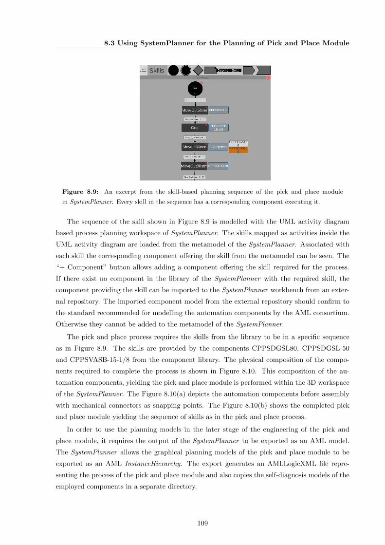
8.3 Using SystemPlanner for the Planning of Pick and Place Module
Figure 8.9: An excerpt from the skill-based planning sequence of the pick and place module
in SystemPlanner. Every skill in the sequence has a corresponding component executing it.
The sequence of the skill shown in Figure 8.9 is modelled with the UML activity diagram
based process planning workspace of SystemPlanner. The skills mapped as activities inside the
UML activity diagram are loaded from the metamodel of the SystemPlanner. Associated with
each skill the corresponding component offering the skill from the metamodel can be seen. The
“+ Component” button allows adding a component offering the skill required for the process.
If there exist no component in the library of the SystemPlanner with the required skill, the
component providing the skill can be imported to the SystemPlanner workbench from an exter-
nal repository. The imported component model from the external repository should confirm to
the standard recommended for modelling the automation components by the AML consortium.
Otherwise they cannot be added to the metamodel of the SystemPlanner.
The pick and place process requires the skills from the library to be in a specific sequence
as in Figure 8.9. The skills are provided by the components CPPSDGSL80, CPPSDGSL-50
and CPPSVASB-15-1/8 from the component library. The physical composition of the compo-
nents required to complete the process is shown in Figure 8.10. This composition of the au-
tomation components, yielding the pick and place module is performed within the 3D workspace
of the SystemPlanner. The Figure 8.10(a) depicts the automation components before assembly
with mechanical connectors as snapping points. The Figure 8.10(b) shows the completed pick
and place module yielding the sequence of skills as in the pick and place process.
In order to use the planning models in the later stage of the engineering of the pick and
place module, it requires the output of the SystemPlanner to be exported as an AML model.
The SystemPlanner allows the graphical planning models of the pick and place module to be
exported as an AML InstanceHierarchy. The export generates an AMLLogicXML file repre-
senting the process of the pick and place module and also copies the self-diagnosis models of the
employed components in a separate directory.
109
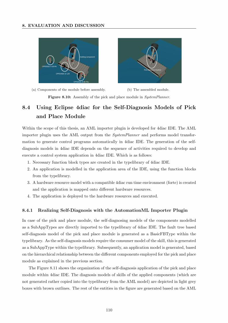
8. EVALUATION AND DISCUSSION
CPPSDGSL-5-50-PA
CPPSVASB-15-1/8
CPPSDGSL-8-80-PAc
Holding component
(a) Components of the module before assembly.
Pick and place module
(b) The assembled module.
Figure 8.10: Assembly of the pick and place module in SystemPlanner.
8.4 Using Eclipse 4diac for the Self-Diagnosis Models of Pick
and Place Module
Within the scope of this thesis, an AML importer plugin is developed for 4diac IDE. The AML
importer plugin uses the AML output from the SystemPlanner and performs model transfor-
mation to generate control programs automatically in 4diac IDE. The generation of the self-
diagnosis models in 4diac IDE depends on the sequence of activities required to develop and
execute a control system application in 4diac IDE. Which is as follows:
1. Necessary function block types are created in the typelibrary of 4diac IDE.
2. An application is modelled in the application area of the IDE, using the function blocks
from the typelibrary.
3. A hardware resource model with a compatible 4diac run time environment (forte) is created
and the application is mapped onto different hardware resources.
4. The application is deployed to the hardware resources and executed.
8.4.1 Realizing Self-Diagnosis with the AutomationML Importer Plugin
In case of the pick and place module, the self-diagnosing models of the components modelled
as a SubAppTypes are directly imported to the typelibrary of 4diac IDE. The fault tree based
self-diagnosis model of the pick and place module is generated as a BasicFBType within the
typelibrary. As the self-diagnosis models require the consumer model of the skill, this is generated
as a SubAppType within the typelibrary. Subsequently, an application model is generated, based
on the hierarchical relationship between the different components employed for the pick and place
module as explained in the previous section.
The Figure 8.11 shows the organization of the self-diagnosis application of the pick and place
module within 4diac IDE. The diagnosis models of skills of the applied components (which are
not generated rather copied into the typelibrary from the AML model) are depicted in light grey
boxes with brown outlines. The rest of the entities in the figure are generated based on the AML
110
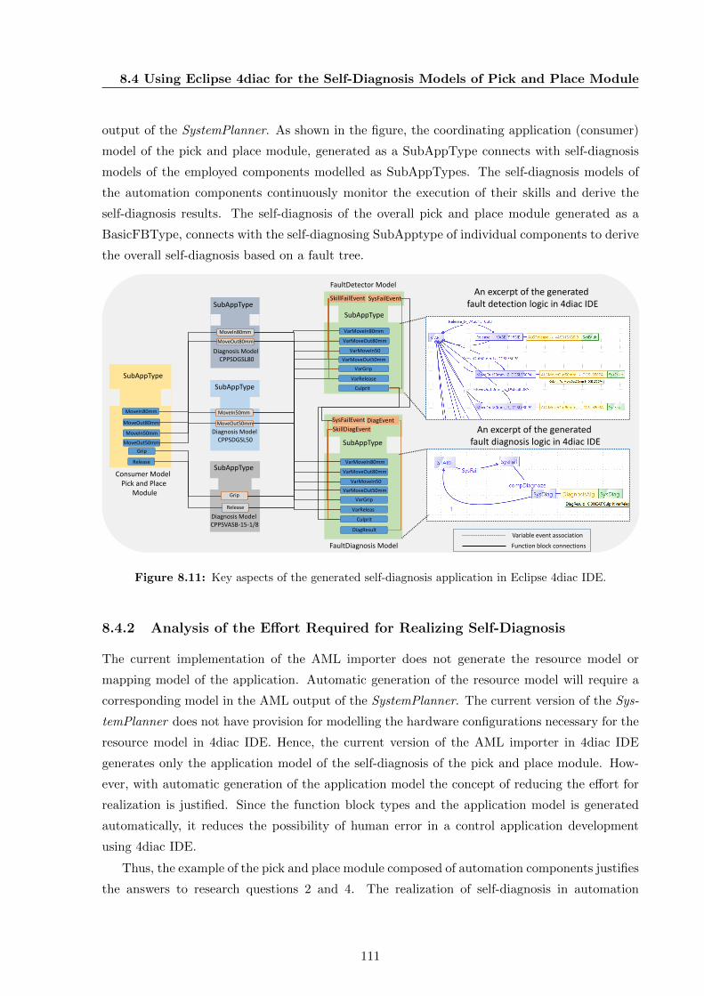
8.4 Using Eclipse 4diac for the Self-Diagnosis Models of Pick and Place Module
output of the SystemPlanner. As shown in the figure, the coordinating application (consumer)
model of the pick and place module, generated as a SubAppType connects with self-diagnosis
models of the employed components modelled as SubAppTypes. The self-diagnosis models of
the automation components continuously monitor the execution of their skills and derive the
self-diagnosis results. The self-diagnosis of the overall pick and place module generated as a
BasicFBType, connects with the self-diagnosing SubApptype of individual components to derive
the overall self-diagnosis based on a fault tree.
Diagnosis Model CPPSDGSL80
SubAppType
Diagnosis Model CPPSVASB-15-1/8
FaultDetector Model
Diagnosis Model CPPSDGSL50
SubAppType
SubAppTypeConsumer Model
Pick and PlaceModule
SubAppType
Grip
MoveIn80mm
MoveOut80mm
MoveIn50mm
MoveOut50mm
Release
MoveIn80mm
MoveOut80mm
MoveIn50mm
MoveOut50mm
Grip
Release
VarMoveIn80mm
VarMoveOut80mm
VarMoveIn50mmVarMoveOut50mm
VarGrip
VarRelease
SubAppType
FaultDiagnosis Model
VarMoveIn80mm
VarMoveOut80mm
VarMoveIn50mmVarMoveOut50mm
VarGrip
VarRelease
SubAppType
SkillFailEvent
SysFailEvent
SysFailEvent
SkillDiagEvent
Culprit
DiagResult
DiagEvent
Culprit
FaultDiagnosis Model
An excerpt of the generated fault detection logic in 4diac IDE
An excerpt of the generated fault diagnosis logic in 4diac IDE
Function block connections
Variable event association
Figure 8.11: Key aspects of the generated self-diagnosis application in Eclipse 4diac IDE.
8.4.2 Analysis of the Effort Required for Realizing Self-Diagnosis
The current implementation of the AML importer does not generate the resource model or
mapping model of the application. Automatic generation of the resource model will require a
corresponding model in the AML output of the SystemPlanner. The current version of the Sys-
temPlanner does not have provision for modelling the hardware configurations necessary for the
resource model in 4diac IDE. Hence, the current version of the AML importer in 4diac IDE
generates only the application model of the self-diagnosis of the pick and place module. How-
ever, with automatic generation of the application model the concept of reducing the effort for
realization is justified. Since the function block types and the application model is generated
automatically, it reduces the possibility of human error in a control application development
using 4diac IDE.
Thus, the example of the pick and place module composed of automation components justifies
the answers to research questions 2 and 4. The realization of self-diagnosis in automation
111
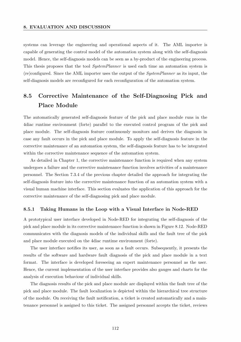
8. EVALUATION AND DISCUSSION
systems can leverage the engineering and operational aspects of it. The AML importer is
capable of generating the control model of the automation system along with the self-diagnosis
model. Hence, the self-diagnosis models can be seen as a by-product of the engineering process.
This thesis proposes that the tool SystemPlanner is used each time an automation system is
(re)configured. Since the AML importer uses the output of the SystemPlanner as its input, the
self-diagnosis models are reconfigured for each reconfiguration of the automation system.
8.5 Corrective Maintenance of the Self-Diagnosing Pick and
Place Module
The automatically generated self-diagnosis feature of the pick and place module runs in the
4diac runtime environment (forte) parallel to the executed control program of the pick and
place module. The self-diagnosis feature continuously monitors and derives the diagnosis in
case any fault occurs in the pick and place module. To apply the self-diagnosis feature in the
corrective maintenance of an automation system, the self-diagnosis feature has to be integrated
within the corrective maintenance sequence of the automation system.
As detailed in Chapter 1, the corrective maintenance function is required when any system
undergoes a failure and the corrective maintenance function involves activities of a maintenance
personnel. The Section 7.3.4 of the previous chapter detailed the approach for integrating the
self-diagnosis feature into the corrective maintenance function of an automation system with a
visual human machine interface. This section evaluates the application of this approach for the
corrective maintenance of the self-diagnosing pick and place module.
8.5.1 Taking Humans in the Loop with a Visual Interface in Node-RED
A prototypical user interface developed in Node-RED for integrating the self-diagnosis of the
pick and place module in its corrective maintenance function is shown in Figure 8.12. Node-RED
communicates with the diagnosis models of the individual skills and the fault tree of the pick
and place module executed on the 4diac runtime environment (forte).
The user interface notifies its user, as soon as a fault occurs. Subsequently, it presents the
results of the software and hardware fault diagnosis of the pick and place module in a text
format. The interface is developed foreseeing an expert maintenance personnel as the user.
Hence, the current implementation of the user interface provides also gauges and charts for the
analysis of execution behaviour of individual skills.
The diagnosis results of the pick and place module are displayed within the fault tree of the
pick and place module. The fault localization is depicted within the hierarchical tree structure
of the module. On receiving the fault notification, a ticket is created automatically and a main-
tenance personnel is assigned to this ticket. The assigned personnel accepts the ticket, reviews
112
8.5 Corrective Maintenance of the Self-Diagnosing Pick and Place Module
Figure 8.12: Screenshot of the prototypical corrective maintenance user interface of the pick and
place module developed in Node-RED.
the self-diagnosis results and performs the corrective action. After performing the corrective
action, checking out the ticket terminates the corrective maintenance. Thus, the solution takes
the human as an element within the overall architecture of the system through the visual model
of the corrective maintenance.
8.5.2 Performance Analysis of Self-Diagnosis for Corrective Maintenance
For evaluating the performance of the self-diagnosis feature of the pick and place module, some
faults were injected into the pick and place module.
(1) Type 1 and 2 software faults
Software faults of Type 1 and 2 as shown in Section 4.3.1 were injected to all of the applied
components by using the feature of monitoring in 4diac IDE [108]. By enabling monitoring on
the application model of the pick and place module, the skill requests were triggered before
their responses were received (Type 1 of software fault). In addition, in each component the
requests of skills bound the behaviour model were triggered while the component is processing
other skills; for example, the “Grip” was triggered while the component is processing “Release”
(Type 2 of software fault). Injecting these software faults, produced the diagnosis result of:
“Check the application software breaking the communication protocol or behaviour constraint
of <SkillType>” message in the Node-RED visual interface.
(2) Hardware fault; disrupting electrical supply
This fault was diagnosed with two proposed approaches. First was with a dedicated current
sensor for monitoring the electrical supply as a dependent factor for the physical execution of
the skill in the actuator. By limit checking the value of the dedicated current sensor, whenever
113

8. EVALUATION AND DISCUSSION
the electrical supply is disrupted the diagnosis result immediately reflects the same. The limit
checking approach with the dedicated sensor is depicted in Figure 8.13. Accordingly, in case the
monitored value of the current in the component changes, this is immediately detected using a
dedicated sensor. The user interface presents the result of “Hardware fault: Broken electrical
supply” to the human user.
Set Value
Current value
Time
Figure 8.13: Limit checking the value of current for diagnosing failure in electrical supply.
The second approach was using the temporal analysis. In this case, the result was produced
by the slope of the time responses of the consecutive skills as the disrupted supply makes a
sharp change in the consecutive response of a skill. This is identified by, limit checking the slope
to the ideal value. This is depicted in Figure 8.14(a). The user interface prints the message:
“Hardware fault please check for a broken electrical supply, pressure supply or broken part” in
the user interface, as the same response is produced for a broken pressure supply or a broken
component.
(3) Hardware fault; applying friction on the component
A frictional force was manually introduced on the linear actuators for evaluating the perfor-
mance of the hardware diagnosis feature of the linear actuator against friction. The introduction
of frictional force caused subsequent delay in the time of responses of the skills. The diagnosis of
this issue was identified with the temporal analysis of the response time of the skills. A depiction
of the trend of the response time of the skill is shown in Figure 8.14(b). The slope of the trend
is analysed for n occurrences and a diagnosis leading to friction as the cause is produced on
increasing slope value. The result prints the message “Hardware fault, please check friction or
excess payload or drop in pressure” as the same behaviour is observed in increase of payload or
drop in pressure in linear actuators.
Ideal time
Time of responses of skill
Res
po
nse
Tim
e
(a) Slope of the consecutive responses.
Res
po
nse
Tim
e
Ideal time
Trend lineTime of responses of skill
(b) Trend of the responses.
Figure 8.14: Trace of event “Response Skill” for the hardware diagnosis based on temporal analysis.
114
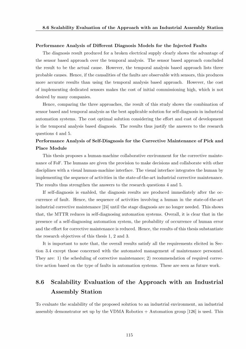
8.6 Scalability Evaluation of the Approach with an Industrial Assembly Station
Performance Analysis of Different Diagnosis Models for the Injected Faults
The diagnosis result produced for a broken electrical supply clearly shows the advantage of
the sensor based approach over the temporal analysis. The sensor based approach concluded
the result to be the actual cause. However, the temporal analysis based approach lists three
probable causes. Hence, if the causalities of the faults are observable with sensors, this produces
more accurate results than using the temporal analysis based approach. However, the cost
of implementing dedicated sensors makes the cost of initial commissioning high, which is not
desired by many companies.
Hence, comparing the three approaches, the result of this study shows the combination of
sensor based and temporal analysis as the best applicable solution for self-diagnosis in industrial
automation systems. The cost optimal solution considering the effort and cost of development
is the temporal analysis based diagnosis. The results thus justify the answers to the research
questions 4 and 5.
Performance Analysis of Self-Diagnosis for the Corrective Maintenance of Pick and
Place Module
This thesis proposes a human-machine collaborative environment for the corrective mainte-
nance of FoF. The humans are given the provision to make decisions and collaborate with other
disciplines with a visual human-machine interface. The visual interface integrates the human by
implementing the sequence of activities in the state-of-the-art industrial corrective maintenance.
The results thus strengthen the answers to the research questions 4 and 5.
If self-diagnosis is enabled, the diagnosis results are produced immediately after the oc-
currence of fault. Hence, the sequence of activities involving a human in the state-of-the-art
industrial corrective maintenance [24] until the stage diagnosis are no longer needed. This shows
that, the MTTR reduces in self-diagnosing automation systems. Overall, it is clear that in the
presence of a self-diagnosing automation system, the probability of occurrence of human error
and the effort for corrective maintenance is reduced. Hence, the results of this thesis substantiate
the research objectives of this thesis 1, 2 and 3.
It is important to note that, the overall results satisfy all the requirements elicited in Sec-
tion 3.4 except those concerned with the automated management of maintenance personnel.
They are: 1) the scheduling of corrective maintenance; 2) recommendation of required correc-
tive action based on the type of faults in automation systems. These are seen as future work.
8.6 Scalability Evaluation of the Approach with an Industrial
Assembly Station
To evaluate the scalability of the proposed solution to an industrial environment, an industrial
assembly demonstrator set up by the VDMA Robotics + Automation group [126] is used. This
115
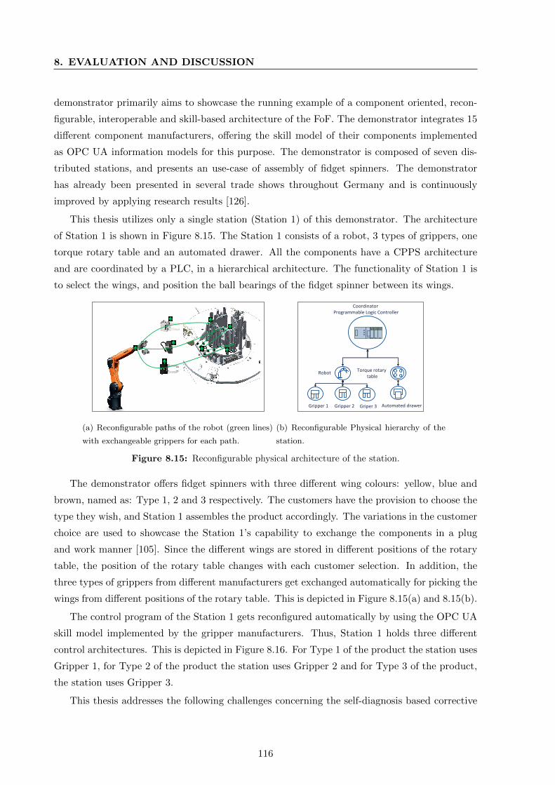
8. EVALUATION AND DISCUSSION
demonstrator primarily aims to showcase the running example of a component oriented, recon-
figurable, interoperable and skill-based architecture of the FoF. The demonstrator integrates 15
different component manufacturers, offering the skill model of their components implemented
as OPC UA information models for this purpose. The demonstrator is composed of seven dis-
tributed stations, and presents an use-case of assembly of fidget spinners. The demonstrator
has already been presented in several trade shows throughout Germany and is continuously
improved by applying research results [126].
This thesis utilizes only a single station (Station 1) of this demonstrator. The architecture
of Station 1 is shown in Figure 8.15. The Station 1 consists of a robot, 3 types of grippers, one
torque rotary table and an automated drawer. All the components have a CPPS architecture
and are coordinated by a PLC, in a hierarchical architecture. The functionality of Station 1 is
to select the wings, and position the ball bearings of the fidget spinner between its wings.
(a) Reconfigurable paths of the robot (green lines)
with exchangeable grippers for each path.
Griper 3Gripper 1 Gripper 2
RobotTorque rotary
table
Automated drawer
Coordinator Programmable Logic Controller
(b) Reconfigurable Physical hierarchy of the
station.
Figure 8.15: Reconfigurable physical architecture of the station.
The demonstrator offers fidget spinners with three different wing colours: yellow, blue and
brown, named as: Type 1, 2 and 3 respectively. The customers have the provision to choose the
type they wish, and Station 1 assembles the product accordingly. The variations in the customer
choice are used to showcase the Station 1’s capability to exchange the components in a plug
and work manner [105]. Since the different wings are stored in different positions of the rotary
table, the position of the rotary table changes with each customer selection. In addition, the
three types of grippers from different manufacturers get exchanged automatically for picking the
wings from different positions of the rotary table. This is depicted in Figure 8.15(a) and 8.15(b).
The control program of the Station 1 gets reconfigured automatically by using the OPC UA
skill model implemented by the gripper manufacturers. Thus, Station 1 holds three different
control architectures. This is depicted in Figure 8.16. For Type 1 of the product the station uses
Gripper 1, for Type 2 of the product the station uses Gripper 2 and for Type 3 of the product,
the station uses Gripper 3.
This thesis addresses the following challenges concerning the self-diagnosis based corrective
116
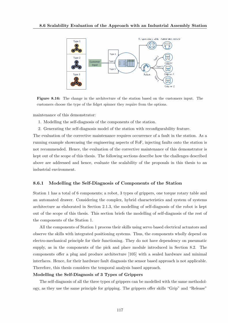
8.6 Scalability Evaluation of the Approach with an Industrial Assembly Station
Type 2 Customer Input
Type 3
Type 1
Type 2
Type 1
Type 2
Type 3
Figure 8.16: The change in the architecture of the station based on the customers input. The
customers choose the type of the fidget spinner they require from the options.
maintenance of this demonstrator:
1. Modelling the self-diagnosis of the components of the station.
2. Generating the self-diagnosis model of the station with reconfigurability feature.
The evaluation of the corrective maintenance requires occurrence of a fault in the station. As a
running example showcasing the engineering aspects of FoF, injecting faults onto the station is
not recommended. Hence, the evaluation of the corrective maintenance of this demonstrator is
kept out of the scope of this thesis. The following sections describe how the challenges described
above are addressed and hence, evaluate the scalability of the proposals in this thesis to an
industrial environment.
8.6.1 Modelling the Self-Diagnosis of Components of the Station
Station 1 has a total of 6 components; a robot, 3 types of grippers, one torque rotary table and
an automated drawer. Considering the complex, hybrid characteristics and system of systems
architecture as elaborated in Section 2.1.3, the modelling of self-diagnosis of the robot is kept
out of the scope of this thesis. This section briefs the modelling of self-diagnosis of the rest of
the components of the Station 1.
All the components of Station 1 process their skills using servo based electrical actuators and
observe the skills with integrated positioning systems. Thus, the components wholly depend on
electro-mechanical principle for their functioning. They do not have dependency on pneumatic
supply, as in the components of the pick and place module introduced in Section 8.2. The
components offer a plug and produce architecture [105] with a sealed hardware and minimal
interfaces. Hence, for their hardware fault diagnosis the sensor based approach is not applicable.
Therefore, this thesis considers the temporal analysis based approach.
Modelling the Self-Diagnosis of 3 Types of Grippers
The self-diagnosis of all the three types of grippers can be modelled with the same methodol-
ogy, as they use the same principle for gripping. The grippers offer skills “Grip” and “Release”
117

8. EVALUATION AND DISCUSSION
as their software interfaces and integrate the physical and logical behaviour of the gripper. The
generic implementation of the model of the skills in AML can be seen similar to that of the skills
“MoveIn/Out” of the CPPSDGSL-50/80 as shown in Figure 8.4.
The grippers provide their skills “Grip” and “Release” with their interface behaviour im-
plemented according to VDMA SOArc. Both the skills are processed by the same hardware
resource. Hence, both the Type 1 and Type 2 of software faults introduced in Section 4.3.1 are
applicable to the grippers. These can be diagnosed using Algorithm 1 introduced in Section 4.4.
Three types of hardware faults were identified, which are diagnosable using the temporal
analysis based approach. They are electrical supply failure, fault due to excess payload weight
and error due to plausible friction. The temporal characteristics of the gripper can be obtained
from the kinematic model and the simulation model of the component. The variation point of the
diagnosis algorithm is similar to that of the “Grip/Release” of CPPSVASB-15-1/8 introduced
in Section 8.2: the “IdealTime” variable from the kinematic model.
Modelling the Self-Diagnosis of Torque Rotary Table
The torque rotary table provides the skill “Rotate” with an option for parameter specifying
the rate of change of an angle. The angle values are mapped onto positions 1, 2, 3 respectively.
The positions are observed with the integrated position sensor. The implementation of the model
of “Rotate” in AML can be seen similar to that of the “ MoveIn/Out” of the CPPSDGSL-50/80.
The torque rotary table provides only a single skill to the external consumers. Hence, only
the Type 1 of software fault is plausible to the torque rotary table. The software fault Type 1,
can be diagnosed using Algorithm 1 introduced in Section 4.4.
The electrical supply failure, payload weight greater than bearing capacity and error due to
friction were identified as hardware faults diagnosable with temporal analysis. The temporal
analysis based diagnosis is applied by analysing the temporal behaviour of the torque rotary table
in each position. The algorithm for the torque rotary table differs with the other components.
It requires different analysis for each position of the torque rotary table, as each position has
different temporal characteristics.
Modelling the Self-Diagnosis of Automated Drawer
The automated drawer offers skills “Extend” and “Retract” to its consumers. Similar to the
other components, these skills are processed by a servo motor and observed by an integrated
position sensor. The software faults of the drawer can be diagnosed using Algorithm 1 introduced
in Section 4.4. The hardware faults diagnosable with temporal analysis were found to be the
same as that of the grippers. Hence, the diagnosis algorithm can be of the same type as that of
the grippers, with change in the “IdealTime”.
118
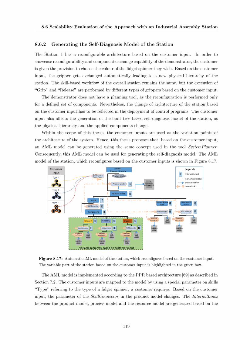
8.6 Scalability Evaluation of the Approach with an Industrial Assembly Station
8.6.2 Generating the Self-Diagnosis Model of the Station
The Station 1 has a reconfigurable architecture based on the customer input. In order to
showcase reconfigurability and component exchange capability of the demonstrator, the customer
is given the provision to choose the colour of the fidget spinner they wish. Based on the customer
input, the gripper gets exchanged automatically leading to a new physical hierarchy of the
station. The skill-based workflow of the overall station remains the same, but the execution of
“Grip” and “Release” are performed by different types of grippers based on the customer input.
The demonstrator does not have a planning tool, as the reconfiguration is performed only
for a defined set of components. Nevertheless, the change of architecture of the station based
on the customer input has to be reflected in the deployment of control programs. The customer
input also affects the generation of the fault tree based self-diagnosis model of the station, as
the physical hierarchy and the applied components change.
Within the scope of this thesis, the customer inputs are used as the variation points of
the architecture of the system. Hence, this thesis proposes that, based on the customer input,
an AML model can be generated using the same concept used in the tool SystemPlanner.
Consequently, this AML model can be used for generating the self-diagnosis model. The AML
model of the station, which reconfigures based on the customer inputs is shown in Figure 8.17.
Process Model
Resource Model
IE
IE
IE
IE
IE
IE
IE
IE
Station1 Instance Hierarchy
LogicModelAMLLogicXML
LogicModel
LogicModel
DiagnosisModel
DiagnosisModel
RobotTorque Rotary
tableAutomated
drawerSkillConnector
SkillConnector SkillConnector
DiagnosisConnector
DiagnosisConnector
IE
Legends
InternalElement
Hierarchical Relation
ExternalInterface
InternalLink
Components
IE
LogicModel
DiagnosisModel
SkillConnector
DiagnosisConnector
IE
LogicModel
DiagnosisModel
SkillConnector
DiagnosisConnector
IE
LogicModel
DiagnosisModel
SkillConnector
DiagnosisConnector
Type 1
Type 2
Type 3
IE
IE IE IEGripper 1 Gripper 3
CustomerInput
Variable hierarchy based on customer input
Product Model
Gripper 2
SkillConnectorParam: Type
Figure 8.17: AutomationML model of the station, which reconfigures based on the customer input.
The variable part of the station based on the customer input is highlighted in the green box.
The AML model is implemented according to the PPR based architecture [69] as described in
Section 7.2. The customer inputs are mapped to the model by using a special parameter on skills
“Type” referring to the type of a fidget spinner, a customer requires. Based on the customer
input, the parameter of the SkillConnector in the product model changes. The InternalLinks
between the product model, process model and the resource model are generated based on the
119
8. EVALUATION AND DISCUSSION
customer inputs. Consequently, the changes are reflected in the process model and the hierarchy
of the station. The AML model can be used to generate the diagnosis model in the 4diac IDE
based on the transformation rules as shown in 7.11.
8.6.3 Analysis of the Scalability of the Approach
The self-diagnosis models of the components of Station 1 clarify that most of the self-diagnosis
models proposed in this thesis is also applicable for the industrial components. Nevertheless, the
granularity of the models are limited. For example, the servo motor internal errors, the errors
on the circuit and communication related errors could not be identified and diagnosed based on
the proposed models. This makes the applicability of self-diagnosis models proposed in thesis
limited, as the complexity of the component increases. Hence, this points to the requirement of
developing more diagnosis models addressing the granularity requirements by reusing engineering
aspects as proposed in this thesis.
The results of this application example show that, the generation of the diagnosis models
based on the AML model is irrespective of the size of the automation system. The self-diagnosis
model of the station reconfigures with each reconfiguration of the station. The application of
self-diagnosis feature in the corrective maintenance of the station has to be evaluated further,
based on the occurrence of faults in the station. Nevertheless, the scalability of the key aspect
of this thesis “the resource efficient realization of self-diagnosis model” is justified with this
application example.
8.7 Review of the Results and Discussion
This thesis aimed at improving the corrective maintenance within the context of FoF. The basic
analysis of the literature on FoF [5, 3, 6] showed that complexity is a key challenge and com-
plexity will negatively affect the human efficiency in the FoF. Further analysis of the state of
the art and literature in corrective maintenance [24, 36, 37] revealed that, currently the correc-
tive maintenance is human intensive. The human error and inefficiency contribute highly to the
increase in the cost of corrective maintenance. Later a hypothesis was made by reviewing the lit-
erature on self-diagnosis of industrial systems [90, 30, 87] that, “Implementing self-diagnosis will
improve the corrective maintenance of industrial systems in the context of FoF”. Subsequently
methodologies for self-diagnosis based corrective maintenance for the FoF were proposed.
For the overall evaluation of the approach, the proposed self-diagnosis based corrective main-
tenance was implemented in a pick and place module. The corrective maintenance of the self-
diagnosing pick and place module was simulated by injecting certain faults manually on to the
pick and place module. The results clarify that, by implementing self-diagnosis on the skills
of automation components, the complexity of corrective maintenance and probability of human
120
8.7 Review of the Results and Discussion
error reduces. A human-machine collaborative corrective maintenance with a visual human-
machine interface, reduces the human effort for maintenance and reduces the MTTR. Thus, it
can be concluded that the methodologies proposed in this thesis improve the corrective mainte-
nance within the context of FoF.
A detailed analysis of the self-diagnosis models revealed the high effort and cost is required for
the development of self-diagnosis models [90, 36, 89, 24]. Hence, for applying self-diagnosis in in-
dustrial automation, it required development methodologies that yield cost and resource efficient
solutions. Consequently, this thesis proposed the application of components with standardized
skills in the automation systems of the future, which have self-diagnosis enabled. For enabling
self-diagnosis on the skills of automation components, a methodology reusing the engineering
data of the automation components is proposed. The evaluation of the methodology on differ-
ent components and their variants shows that, standardized and reusable self-diagnosis models
applicable for different types and variants of components can be developed. The previous ap-
proaches of developing self-diagnosis models [89, 90, 30] employ, system specific self-diagnosing
models and application specific development approaches. Hence, the proposed methodology
shows substantial improvement in comparison to the previous approaches [89, 90, 30].
For the realization self-diagnosis models in component based automation systems, a three-
stakeholder, skill-based engineering process is proposed. The three-stakeholder engineering pro-
cess has justified its capability, in reducing the human error and preserving the consistency in
complex engineering processes [114]. Different studies show the characteristics of future automa-
tion systems to be flexible and reconfigurable in nature, such that they can dynamically respond
to the varying customer requirements [5, 3, 6]. In order to reduce the realization effort of the
self-diagnosis models of reconfigurable automation systems, a generative approach is proposed
for the self-diagnosis models of the automation system. As the generative process is based on
planning models of automation systems, it can be inferred that the proposed solution meets the
flexible and reconfigurable characteristics of the FoF.
The reconfigurability of the self-diagnosis models corresponding to the automation systems’
reconfiguration is justified with a second application example, an industrial assembly demon-
strator. The second application example also proves the scalability of the proposed solution to
a modular, service oriented and reconfigurable industrial environment. Thus, as a whole with
its service based modular and reconfigurable architecture, the proposed solution satisfies the
fundamental characteristics of FoF [45, 8, 105, 3, 6].
Several literature on FoF [45, 50] assert that the future automation systems are intelligent
and cognitive in nature. Hence, they define the role of humans as the strategic decision makers
within FoF. The proposed solution in this study, takes the human in the loop for the future au-
tomation systems corrective maintenance, where the automation systems are self-diagnosing in
nature. For the future automation systems’ corrective maintenance, the role of human (mainte-
121

8. EVALUATION AND DISCUSSION
nance personnel) is defined as a strategic decision maker, who verifies the results of self-diagnosis
of the system and performs corrective action based on that. In addition, it is also proposed that
the maintenance personnel interact with other disciplinary teams such as the production team,
inventory team, etc., to improve production based on the data collected from maintenance. Thus,
the system foresees a human-machine collaborative environment which improves the corrective
maintenance function and thus production in the FoF.
122

Chapter 9
Conclusions and Outlook
9.1 Summary
This thesis was initiated by identifying the necessity of reforming corrective maintenance whilst
the reformation of the state-of-the-art industries to so called the FoF. Considering high human
effort and human errors as the key issues of state-of-the-art corrective maintenance, this thesis
hypothesizes that “enabling self-diagnosis and visual assistive features in the automation systems
will improve the corrective maintenance”. Finding high effort and cost for realizing self-diagnosis,
this thesis further focuses on the efficient realization of self-diagnosis in automation systems.
This thesis proposes re-usage of engineering data to efficiently realize self-diagnosis in au-
tomation systems. In addition, a visual model encapsulating the corrective maintenance func-
tion, which integrates the self-diagnosis feature of an automation system is introduced. This
visual model is proposed as a means to improve the efficiency of a human, performing the cor-
rective maintenance of an automation system. The proposed concepts are implemented as a
combination of state-of-the-art industrial standards and their extensions.
IEC 62714 standard AML facilitates the reuse of engineering data for realizing self-diagnosis.
An AML based prototypical automation system planning tool named SystemPlanner produces
self-diagnosis models integrated in its output model. From the output of SystemPlanner, the
executable self-diagnosis models are generated in IEC 61499 standard tool Eclipse 4diac. Within
the scope of this thesis, an AML importer plugin for Eclipse 4diac is developed for this purpose.
The visual model that assists the human in performing the corrective maintenance of a self-
diagnosing automation system is implemented as a web-based interface using Node-Red. The
usage of standards facilitates seamless application of the proposed solution within the industrial
manufacturing domain.
The proposed solution was evaluated with two application examples. The first application
example (a lab scale pick and place module) justifies the enhancement in realizing self-diagnosis
by reusing engineering data. It also confirms the improvement in corrective maintenance func-
123
9. CONCLUSIONS AND OUTLOOK
tion, by applying self-diagnosis and visual assistive features. The second application example
(an industrial assembly station) demonstrates the scalability of the solution to a complex and
reconfigurable industrial environment. The results from the two application examples, thus
justify the hypothesis and objectives 1, 2 and 3 of this thesis.
Additionally, an in-depth analysis of the pick and place module clarifies the strength and
weaknesses of different self-diagnosis models introduced within the context of this thesis. Among
the constructed models, the sensor based approach produces the most accurate results. However,
the use of dedicated sensors for diagnosis leads to a high initial commissioning cost, which
is not desired by many companies. Although the temporal analysis based approach is cost
effective, it requires further enhancements for accurate results. Thus, a combination of sensor
based and temporal analysis based approach is identified as the best applicable solution. The
second application example of an assembly station shows the limitation of the diagnosis models
considering an industrial environment. Nonetheless, both the demonstrators shows reusability of
the models on variants of components from different manufacturers and hence the improvement
in self-diagnosis realization.
It is important to note that, some of the implementation aspects related to AML proposed
in this thesis are reviewed by members of the AML consortium. The rest of the aspects are
under review. Consequently, it is envisioned that the AML related models and implementation
approaches will be adopted by the industries in the future. This thesis devises the foundation
for implementing diagnosis libraries within IEC 61499 standard. In addition, the fundamental
aspects necessary for supporting AML models within IEC 61499 standard tools are also proposed.
9.2 Contributions
This thesis makes remarkable research contributions based on five research questions. This sec-
tion describes the research contributions of this thesis.
Perceiving the system specific nature of current self-diagnosis models, Research Ques-
tion 1 addresses the possibility to create reusable models for self-diagnosis in pro-
duction systems. Additionally it examines the prerequisites for the same. The answer
to the first question leverages the concept of skill of an automation component. Skills represent
standardized functionalities of automation components and act as their standardized software
interfaces. This thesis devised a methodology for modelling the self-diagnosis of standardized
skills of automation components. Hence, the self-diagnosis models can be reused for different
types and variants of automation components. A model of the skill, integrating its logical and
physical behaviour and their interactions is identified as the prerequisite for the same.
124
9.2 Contributions
Research Question 2 investigates the methodology for realizing the self-diagnosis
models in a cost efficient manner. In addition, it examines the possibility of leverag-
ing the engineering and operational aspects of an automation system for the same.
For answering the second question, an analysis of the state-of-the-art plant engineering and op-
eration was performed. This analysis revealed generation of digitized and interoperable domain
specific engineering data from the plant engineering process. Accordingly, a novel methodology
for deriving the key aspects of the diagnosis model, reusing the domain specific engineering data
is provided. Consequently, the diagnosis models are able to handle types and variants of au-
tomation components, and are cost efficient. Further, a methodology for seamless deployment of
self-diagnosing automation systems, leveraging the operational information exchange standards
in the industrial automation domain is devised.
Considering the reconfigurable and flexible characteristics of the FoF, Research Ques-
tion 3 set out to add flexible and reconfigurable characteristics to the self-diagnosis
feature of the production systems. To address this question, the state-of-the-art plant
engineering and its phases were analysed individually. This analysis clarified that, the reconfig-
uration of a plant affects all the phases of its engineering and is initiated in the planning phase
of an automation system. Based on this analysis, a novel framework for generating the self-
diagnosis models of automation systems, based on the planning model of the automation system
is introduced. The framework yields the reconfigurable self-diagnosis models as a by-product of
the plant engineering process and avoids manual development effort for self-diagnosis models.
Research Question 4 set out to examine the methodology for effectively integrat-
ing visual assistive features for corrective maintenance with reusable self-diagnosis
models. For answering this question, the corrective maintenance function was analysed in de-
tail, which revealed the sequence of activities in it. The first activity is the fault detection, the
second activity is the localization and the third activity is the diagnosis. Then comes corrective
action and checkout activities. Accordingly, a visual assistive tool integrating the detection, the
localization and the diagnosis of the fault is introduced. In addition, the assistive tool includes
the provision for the maintenance personnel to communicate with the production system/team.
Research Question 5 seeks to manage the maintenance personnel allocation,
leveraging the self-diagnosis and visual assistive features of the automated produc-
tion systems. Analysing the corrective maintenance function in detail and also the literature,
a corrective maintenance solution, where the maintenance personnel act as strategic decision
makers is devised. With self-diagnosis integrated in the corrective maintenance, the solution
reduces the effort of maintenance personnel to carry out corrective maintenance. The solution
also facilitates the maintenance personnel to collect information from corrective maintenance
for improving the production.
125

9. CONCLUSIONS AND OUTLOOK
9.3 Outlook
The solutions proposed in this work, raise further research challenges leading to the improvement
of the FoF. Some of the important challenges to be addressed in the future are listed below:
• This thesis presented open text based diagnosis models with high level of granularity.
Since more detailed diagnosis models require protecting the intellectual properties of the
companies, more detailed diagnosis models are not addressed. The following challenge has
to be addressed in future: How to develop diagnosis models with lowest granularity of
complex components protecting the intellectual properties of the companies?
• This thesis provides the foundation for facilitating interoperability and information ex-
change between maintenance and other disciplines within a manufacturing environment.
Consequently, it raises the following challenge, which is still unsolved: How to improve
the management of human and other resources for corrective maintenance, leveraging the
interoperability and information exchange possibilities within the context of FoF.
• Similarly, is it possible to improve the life cycle of industrial production resources within
the context of FoF, leveraging the information exchange from corrective maintenance?
• The proposed solution does not support the legacy systems. Hence, how to realize self-
diagnosis in large legacy systems in a cost efficient manner? Is it possible to reuse the
engineering data for the realization of self-diagnosis in legacy systems?
• Using the data collected from maintenance for improving the production is a recent area
of research. Thus, the following question has to be addressed in the future: What kind of
data from corrective maintenance are relevant for improving the production and how to
use the data effectively for improving the production?
• The visual tool presented in this thesis, is developed manually based on the application
example. The concept of reusing engineering data might be also applicable for the vi-
sual development tools. Hence, the following challenges: How to develop a visual model
for the self-diagnosis of automation components? How to generate visual assistive tool
automatically for the component based automation system reusing the engineering data?
9.4 Concluding Remarks
This thesis investigated means and methodologies for cost effective improvement of corrective
maintenance function in the context of FoF. The results of this thesis proves that, self-diagnosis
and visual assistive features facilitate a human-machine collaborative environment for the cor-
rective maintenance of automation systems. Consequently, the human performance improves
and hence corrective maintenance. The efficiency in cost is achieved by realizing self-diagnosis
by reusing engineering data.
126

9.4 Concluding Remarks
This thesis raises the following key challenge foreseeing the materialization of the FoF in
the near future: 1) How to improve the production by improving corrective maintenance within
the context of FoF? Thus, by enhancing the solution a substantial enhancement in industrial
manufacturing is foreseen. Application of existing standards facilitate, creation of reusable
and cost efficient self-diagnosis models in this thesis. Hence, for extension of the solution or
integration of the legacy or non-modular automation systems in the proposed solution, the
applied standards in this thesis are recommended.
127

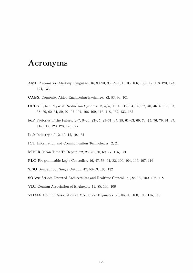
Acronyms
AML Automation Mark-up Language. 16, 80–93, 96, 99–101, 103, 106, 108–112, 118–120, 123,
124, 133
CAEX Computer Aided Engineering Exchange. 82, 83, 93, 101
CPPS Cyber Physical Production Systems. 2, 4, 5, 11–15, 17, 34, 36, 37, 40, 46–48, 50, 53,
58, 59, 62–64, 89, 92, 97–104, 106–109, 116, 118, 132, 133, 135
FoF Factories of the Future. 2–7, 9–20, 23–25, 29–31, 37, 38, 61–63, 69, 73, 75, 76, 79, 91, 97,
115–117, 120–123, 125–127
I4.0 Industry 4.0. 2, 10, 12, 19, 131
ICT Information and Communication Technologies. 2, 24
MTTR Mean Time To Repair. 22, 25, 28, 30, 69, 77, 115, 121
PLC Programmable Logic Controller. 46, 47, 53, 64, 82, 100, 104, 106, 107, 116
SISO Single Input Single Output. 47, 50–53, 106, 132
SOArc Service Oriented Architectures and Realtime Control. 71, 85, 99, 100, 106, 118
VDI German Association of Engineers. 71, 85, 100, 106
VDMA German Association of Mechanical Engineers. 71, 85, 99, 100, 106, 115, 118
129

List of Figures
1.1 Life cycle of an industrial manufacturing plant. . . . . . . . . . . . . . . . . . . . 1
1.2 Different aspects of factories of the future. . . . . . . . . . . . . . . . . . . . . . . 3
1.3 Sequence of activity in a corrective maintenance function according to Dhillon [24]. 5
1.4 Example of a complex system in factories of the future. . . . . . . . . . . . . . . 6
2.1 Manufacturing trends in the past century as shown in [7]. . . . . . . . . . . . . . 11
2.2 Example of modular and distributed systems that can interact and organize seam-
lessly: Zoomed in view of a single system with its own controller is shown in the
middle. . . . . . . . . . . . . . . . . . . . . . . . . . . . . . . . . . . . . . . . . . 12
2.3 Automation pyramid and interoperability plot in an I4.0 plant. . . . . . . . . . . 12
2.4 A sequential plant engineering process employing different tools; modified from [43]. 16
2.5 Architecture of a component oriented manufacturing plant (modified from [69]). . 18
2.6 Cyclic and sequential nature of plant engineering in a reconfigurable plant. . . . 19
2.7 Types of maintenance in the manufacturing context. . . . . . . . . . . . . . . . . 20
2.8 Types of corrective actions as shown in [24]. . . . . . . . . . . . . . . . . . . . . . 22
2.9 Change of maintenance paradigm required for future manufacturing as per [79]. . 24
2.10 Automatic error handling integrated as part of production flow; adopted from [44]. 25
2.11 A fault tree model showing propagation of a fault in a system (modified from [84]). 27
2.12 An example of diagnosis model as shown in [90] showing its application dependency. 28
2.13 Example of applying visual assistive technology in maintenance (modified from [94]);
an augmented reality tablet displays the maintenance tasks and a human performs
it. . . . . . . . . . . . . . . . . . . . . . . . . . . . . . . . . . . . . . . . . . . . . 29
3.1 Systems under consideration with acquirers, suppliers and other stakeholder (from
innermost ellipse to outermost ellipse). . . . . . . . . . . . . . . . . . . . . . . . . 36
3.2 Use-case analysis of self-diagnosis and visual assistive features of the automation
systems in the factories of the future. . . . . . . . . . . . . . . . . . . . . . . . . . 39
131

LIST OF FIGURES
4.1 Skill service interfaces integrating the hardware and software subcomponents of
a CPPS based automation component. . . . . . . . . . . . . . . . . . . . . . . . . 47
4.2 Software and hardware subcomponents implementing the logical and physical
behaviours of a CPPS based automation component. . . . . . . . . . . . . . . . . 48
4.3 Generic Model of a skill as a facilitator of self-diagnosis in automation compo-
nents. The arrows indicate interrelation among different models. . . . . . . . . . 49
4.4 Communication protocol of a skill. Type 1 Fault occurs when the consumer of a
skill breaks the communication protocol of a skill. . . . . . . . . . . . . . . . . . . 51
4.5 Example showing interface behaviour of two skills bound to a functional behaviour
model. Type 2 fault occurs when the consumer of a skill breaks the behaviour
constraints of a skill. . . . . . . . . . . . . . . . . . . . . . . . . . . . . . . . . . . 52
4.6 Types of variants in a SISO generic automation component. . . . . . . . . . . . . 53
4.7 Concept for handling variants in self-diagnosis by reusing engineering data as
input for the diagnosis model. Arrows in different colours indicate the interoper-
ability required between the domain specific models. . . . . . . . . . . . . . . . . 54
4.8 Engineering models required as inputs for diagnosing software fault; the consumer
model along with the interface behaviour model provide the actual execution
behaviour of the skill. . . . . . . . . . . . . . . . . . . . . . . . . . . . . . . . . . 55
4.9 Engineering models required as input for diagnosing hardware fault. . . . . . . . 57
5.1 Layered architecture in a future automation system; the system has reconfigura-
tion feature based on product variants 1, 2 and 3. . . . . . . . . . . . . . . . . . . 62
5.2 Planning model of a skill-based automation system: Coordinating process model
and the components offering skills in a hierarchy. . . . . . . . . . . . . . . . . . . 65
5.3 Concept of generating fault tree based self-diagnosis in a component based au-
tomation system from its planning model. The negation symbol indicates a fault
and d indicates its diagnosis. . . . . . . . . . . . . . . . . . . . . . . . . . . . . . 66
5.4 Definition of fault and diagnosis in a process as a composition of skills and the
resource where process is executed. . . . . . . . . . . . . . . . . . . . . . . . . . . 67
6.1 Example of different domain specific connectors and some of their application in
automation systems, modified from [127]. . . . . . . . . . . . . . . . . . . . . . . 72
6.2 Tasks of different stakeholders in developing self-diagnosing automation systems. 74
6.3 Example of human-machine collaboration in corrective maintenance. On detect-
ing fault a in skill, a consumer device aids the maintenance personnel for corrective
maintenance and facilitates a human machine interface. . . . . . . . . . . . . . . 75
7.1 Structure of AutomationML. . . . . . . . . . . . . . . . . . . . . . . . . . . . . . 82
132
LIST OF FIGURES
7.2 Application scenario of AutomationML. . . . . . . . . . . . . . . . . . . . . . . . 82
7.3 Class diagram of skill model of a component in AutomationML. (a) Association
of ComponentSkillConnector with its consumers. (b) Its capability to integrate
domain specific models. . . . . . . . . . . . . . . . . . . . . . . . . . . . . . . . . 85
7.4 ComponentSkillConnector in AutomationML. (a) The constituents of the Com-
ponentSkillConnector. (b) The proposed standard library elements required in
AutomationML. . . . . . . . . . . . . . . . . . . . . . . . . . . . . . . . . . . . . . 86
7.5 Engineering model of an automation component offering standardized skill in AML. 86
7.6 Diagnosis model reusing the engineering aspects in AML. The models in grey
background are the engineering models; the model in yellow background is the
diagnosis model. . . . . . . . . . . . . . . . . . . . . . . . . . . . . . . . . . . . . 87
7.7 Interface behaviour model of a DiagnosisConnector, defined based on [144]. . . . 88
7.8 The methodology of planning applied in the SystemPlanner (modified from [117]).
The elements in the light blue background depict a skill-based automation system.
The elements in the grey background indicate the basics of the PPR concept. . . 89
7.9 User interface of the SystemPlanner. (a) Shows the workspace for skill-based
process planning; (b) shows the workspace for physical system composition. . . . 90
7.10 Abstract representation of an AutomationML InstanceHierarchy generated from
the graphical planning process in SystemPlanner. . . . . . . . . . . . . . . . . . . 91
7.11 Principle of generating IEC 61499 standard self-diagnosis models in 4diac IDE
from SystemPlanner generated AutomationML instance hierarchy shown in Fig-
ure 7.10. . . . . . . . . . . . . . . . . . . . . . . . . . . . . . . . . . . . . . . . . . 94
7.12 Sequence of tools applied and model transformation involved in the implementation. 95
8.1 Temperature gauge with cylindrical housing forming a modular product. . . . . . 98
8.2 The pick and place module (marked inside the boundary) as a solution for picking
and placing temperature gauge on top of the cylindrical housing module (modified
from [108]). . . . . . . . . . . . . . . . . . . . . . . . . . . . . . . . . . . . . . . . 99
8.3 CPPS based automation components of the pick and place module. . . . . . . . . 100
8.4 Engineering model of SkillMoveIn/Out of the CPPSDGSL-80/50. . . . . . . . . . 101
8.5 Diagnosis model of SkillMoveIn/Out reusing the engineering data of CPPSDGSL-
80/50. . . . . . . . . . . . . . . . . . . . . . . . . . . . . . . . . . . . . . . . . . . 102
8.6 Software fault diagnosis model as a SubAppType in IEC 61499, with constituent Ba-
sicFBTypes AutomataLangGen, SubtractArrays, IntersectArrays and Software-
FaultDiagnoser. . . . . . . . . . . . . . . . . . . . . . . . . . . . . . . . . . . . . . 103
8.7 Hard fault diagnosis model using limit checking as a SubAppType, with con-
stituent BasicFBType LimitChecker implemented in IEC 61499. . . . . . . . . . . 105
133
LIST OF FIGURES
8.8 Hard fault diagnosis model based on temporal analysis implemented as a Sub-
AppType in IEC 61499. SlopeTracer Time BasicFBType, DataCollector Time
and TrendAnalyser Time are the constituent BasicFbTypes. . . . . . . . . . . . . 106
8.9 An excerpt from the skill-based planning sequence of the pick and place module
in SystemPlanner. Every skill in the sequence has a corresponding component
executing it. . . . . . . . . . . . . . . . . . . . . . . . . . . . . . . . . . . . . . . . 109
8.10 Assembly of the pick and place module in SystemPlanner. . . . . . . . . . . . . . 110
8.11 Key aspects of the generated self-diagnosis application in Eclipse 4diac IDE. . . . 111
8.12 Screenshot of the prototypical corrective maintenance user interface of the pick
and place module developed in Node-RED. . . . . . . . . . . . . . . . . . . . . . 113
8.13 Limit checking the value of current for diagnosing failure in electrical supply. . . 114
8.14 Trace of event “Response Skill” for the hardware diagnosis based on temporal
analysis. . . . . . . . . . . . . . . . . . . . . . . . . . . . . . . . . . . . . . . . . . 114
8.15 Reconfigurable physical architecture of the station. . . . . . . . . . . . . . . . . . 116
8.16 The change in the architecture of the station based on the customers input. The
customers choose the type of the fidget spinner they require from the options. . . 117
8.17 AutomationML model of the station, which reconfigures based on the customer
input. The variable part of the station based on the customer input is highlighted
in the green box. . . . . . . . . . . . . . . . . . . . . . . . . . . . . . . . . . . . . 119
134

List of Tables
1.1 Corrective maintenance: Application context and types in factories of the future. 4
2.1 Research questions addressed and allocated chapters. . . . . . . . . . . . . . . . . 31
3.1 The Component/System service consumer requests the Automation Component/System
to perform Diagnose. . . . . . . . . . . . . . . . . . . . . . . . . . . . . . . . . . . 40
3.2 The Component/System service consumer requests the Automation Component/System
to perform Present diagnosis results. . . . . . . . . . . . . . . . . . . . . . . . . . 41
3.3 The Component/System service consumer requests the Automation Component/System
to perform Configure. . . . . . . . . . . . . . . . . . . . . . . . . . . . . . . . . . 41
3.4 The Component/System service consumer requests the Automation Component/System
to perform Generate Diagnosis Model. . . . . . . . . . . . . . . . . . . . . . . . . 42
3.5 The Component/System service consumer requests the Automation Component/System
to perform Request Corrective Maintenance. . . . . . . . . . . . . . . . . . . . . . 43
7.1 Comparison of description languages for modelling self-diagnosing automation
components. . . . . . . . . . . . . . . . . . . . . . . . . . . . . . . . . . . . . . . . 81
8.1 Plausible list of hardware faults in the CPPSDGSL-80/50. . . . . . . . . . . . . . 104
8.2 Plausible list of faults in the CPPSVASB-15-1/8. . . . . . . . . . . . . . . . . . . 107
135

References
[1] Charles Jones. Was the Industrial Revolution Inevitable? NBER Working Paper, 1, 2015.
1, 9, 10
[2] Jack A. Goldstone. Efflorescences and Economic Growth in World History: Rethink-
ing the ”Rise of the West” and the Industrial Revolution. Journal of World History,
13(2):323–389, 2002. 1
[3] Yoram Koren. The rapid responsiveness of RMS. International Journal of Production
Research, 51(23-24):6817–6827, 2013. 1, 5, 10, 61, 120, 121
[4] AutomationML Consortium. Whitepaper AutomationML Part 1 : Architecture and
General Requirements. Technical Report November, 2018. 1, 2
[5] Wolfgang Wahlster, Johannes Helbig, Ariane Hellinger, M A Veronika Stumpf,
Joaquın Blasco, Helen Galloway, and Heilmeyerundsernau Gestaltung. Recommen-
dations for implementing the strategic initiative Industrie 4.0. Technical Report April,
2013. 1, 2, 10, 76, 120, 121
[6] Birgit Vogel-Heuser, Christian Diedrich, Alexander Fay, Sabine Jeschke, Stefan
Kowalewski, Martin Wollschlaeger, and Peter Gohner. Challenges for Software
Engineering in Automation. Journal of Software Engineering and Applications, 07(05):440–
451, 2014. 1, 2, 5, 9, 10, 11, 14, 15, 16, 17, 19, 69, 70, 120, 121
[7] Yoram Koren, Xi Gu, and Weihong Guo. Reconfigurable manufacturing systems:
Principles, design, and future trends. Frontiers of Mechanical Engineering, 13(2):121–136,
2018. 2, 9, 10, 11, 13, 23, 131
[8] Valeriy Vyatkin. Software engineering in industrial automation: State-of-the-art re-
view. IEEE Transactions on Industrial Informatics, 9(3):1234–1249, 2013. 2, 5, 9, 10, 11, 14, 15,
16, 17, 19, 49, 69, 70, 121
[9] L. Monostori, B. Kadar, T. Bauernhansl, S. Kondoh, S. Kumara, G. Reinhart,
O. Sauer, G. Schuh, W. Sihn, and K. Ueda. Cyber-physical systems in manufacturing.
CIRP Annals, 65(2):621–641, 2016. 2, 14
[10] Stephan Weyer, Mathias Schmitt, Moritz Ohmer, and Dominic Gorecky. Towards
Industry 4.0 - Standardization as the crucial challenge for highly modular, multi-
vendor production systems. IFAC-PapersOnLine, 48(3):579–584, 2015. 2
[11] Birgit Vogel-Heuser and Dieter Hess. Guest Editorial Industry 4.0–Prerequisites and
Visions. IEEE Transactions on Automation Science and Engineering, 13(2):411–413, 2016. 2, 17
137
REFERENCES
[12] Laszlo Monostori. Cyber-physical production systems: Roots, expectations and R&D
challenges. Procedia Cirp, 17:9–13, 2014. 2
[13] Jochen Nelles, Sinem Kuz, Alexander Mertens, and Christopher M. Schlick.
Human-centered design of assistance systems for production planning and control:
The role of the human in Industry 4.0. Proceedings of the IEEE International Conference on
Industrial Technology, 2016-May:2099–2104, 2016. 2
[14] Jay Lee, Hossein Davari Ardakani, Shanhu Yang, and Behrad Bagheri. Industrial
Big Data Analytics and Cyber-physical Systems for Future Maintenance & Service
Innovation. Procedia CIRP, 38:3–7, 2015. 2, 3, 4, 6, 10, 15, 20, 25
[15] Oliver Niggemann and Volker Lohweg. On the diagnosis of cyber-physical production
systems. In Twenty-Ninth AAAI Conference on Artificial Intelligence, 2015. 2, 27, 28
[16] Benjamin Brandenbourger, Milan Vathoopan, and Alois Zoitl. Engineering of Au-
tomation Systems using a Metamodel implemented in AutomationML. In 2016 IEEE
14th International Conference on Industrial Informatics (INDIN), pages 363–370. IEEE, 2016. 2,
4, 5, 9, 14, 17, 46, 48, 62, 73, 74
[17] Benjamin Brandenbourger, Milan Vathoopan, and Alois Zoitl. Generating
metamodel-based descriptions of automation components in AutomationML. Proceed-
ings of the IEEE International Conference on Industrial Technology, pages 1159–1164, 2017. 2
[18] Milan Vathoopan, Maria Johny, Alois Zoitl, and Alois Knoll. Modular Fault Ascrip-
tion and Corrective Maintenance Using a Digital Twin. IFAC-PapersOnLine, 51(11):1041–
1046, 2018. 2, 3, 9, 14, 15, 21, 23, 25, 28, 46, 58, 104
[19] Julius Pfrommer, Miriam Schleipen, and Jurgen Beyerer. PPRS: Production skills
and their relation to product, process, and resource. In 2013 IEEE 18th Conference on
Emerging Technologies & Factory Automation (ETFA), pages 1–4. IEEE, 2013. 2, 46, 48, 89
[20] Florian Himmler. Function Based Engineering with AutomationML-Towards better
standardization and seamless process integration in plant engineering. In Wirtschaftsin-
formatik, pages 16–30, 2015. 2, 64
[21] Georg Hackenberg, Christoph Richter, and Michael F. Zaeh. From Conception to
Refinement in Mechatronics Systems Engineering. International Journal of Materials, Me-
chanics and Manufacturing, 4(1):66–73, 2015. 2
[22] Fabian Hecklau, Mila Galeitzke, Sebastian Flachs, and Holger Kohl. Holistic Ap-
proach for Human Resource Management in Industry 4.0. Procedia CIRP, 54:1–6, 2016.
2, 15
[23] DIN EN 13306- 2018-02 European standard for maintenance. https://www.beuth.de/
en/standard/din-en-13306/270274780. Accessed: 2020-03-02. 2, 20, 21
[24] Balbir S Dhillon. Engineering maintenance: a modern approach. cRc press, 2002. 2, 4, 5, 6,
20, 21, 22, 23, 28, 45, 61, 65, 76, 115, 120, 121, 131
[25] Jay Lee and Behrad Bagheri. Cyber-physical systems in future maintenance. In 9th
WCEAM Research Papers, pages 299–305. Springer, 2015. 3, 28
138
REFERENCES
[26] Stefan Windmann and Oliver Niggemann. Efficient fault detection for industrial au-
tomation processes with observable process variables. In 2015 IEEE 13th International
Conference on Industrial Informatics (INDIN), pages 121–126. IEEE, 2015. 4, 26
[27] Hans Feischmann. Modellbasierte Zustands-und Prozessuberwachung auf Basis sozio-
cyber-physischer Systeme. 4, 5, 26, 29, 53, 61
[28] John Moubray. Reliability-centered maintenance. Industrial Press Inc., 2001. 4, 5, 25
[29] Ali Rastegari and Mohammadsadegh Mobin. Maintenance decision making, supported
by computerized maintenance management system. In 2016 annual reliability and main-
tainability symposium (RAMS), pages 1–8. IEEE, 2016. 4, 5
[30] Rolf Isermann. Combustion engine diagnosis. Springer, 2017. 4, 26, 27, 28, 45, 46, 48, 52, 54,
56, 61, 63, 120, 121
[31] Rolf Isermann. Fault-diagnosis systems: an introduction from fault detection to fault tolerance.
Springer Science & Business Media, 2006. 5
[32] Hassan Noura, Didier Theilliol, Jean-Christophe Ponsart, and Abbas Chamseddine.
Fault-tolerant control systems: Design and practical applications. Springer Science & Business
Media, 2009. 5
[33] Armando W Colombo, Stamatis Karnouskos, Okyay Kaynak, Yang Shi, and Shen Yin.
Industrial cyberphysical systems: A backbone of the fourth industrial revolution. IEEE
Industrial Electronics Magazine, 11(1):6–16, 2017. 5
[34] Zhiwei Gao, Sing Kiong Nguang, and De-Xing Kong. Advances in Modelling, moni-
toring, and control for complex industrial systems. Complexity, 2019, 2019. 5
[35] Milan Vathoopan, Benjamin Brandenbourger, and Alois Zoitl. A human in the loop
corrective maintenance methodology using cross domain engineering data of mecha-
tronic systems. In 2016 IEEE 21st International Conference on Emerging Technologies and
Factory Automation (ETFA), pages 1–4. IEEE, 2016. 5, 6, 13, 22, 23
[36] Douglas S Thomas. Advanced Maintenance in Manufacturing : Costs and Benefits.
(October):1–12, 2018. 6, 22, 24, 25, 45, 65, 120, 121
[37] Kari Komonen. A cost model of industrial maintenance for profitability analysis and
benchmarking. International Journal of Production Economics, 79(1):15–31, 2002. 6, 22, 24, 25,
120
[38] Jay Lee and Behrad Bagheri. Cyber-physical systems in future maintenance. In 9th
WCEAM Research Papers, pages 299–305. Springer, 2015. 9, 10, 15, 16, 20, 21, 23, 24, 25
[39] Milan Vathoopan, Hendrik Walzel, Waldemar Eisenmenger, Alois Zoitl, and Ben-
jamin Brandenbourger. AutomationML Mechatronic Models as Enabler of Automa-
tion Systems Engineering: Use-case and Evaluation. In 2018 IEEE 23rd International
Conference on Emerging Technologies and Factory Automation (ETFA), 1, pages 51–58. IEEE,
2018. 9, 11, 12, 15, 16, 17
[40] Klaus Schwab. The fourth industrial revolution. Currency, 2017. 9, 10
[41] Francois Crouzet and R. M. Hartwell. The Industrial Revolution and Economic
Growth. The Economic History Review, 25(3):520, 2006. 10
139
REFERENCES
[42] Dave Alford, Peter Sackett, and Geoff Nelder. Mass customisation—an automotive
perspective. International Journal of production economics, 65(1):99–110, 2000. 10, 13, 18
[43] Arndt Luder, Elisabet Estevez, Lorenz Hundt, and Marga Marcos. Automatic trans-
formation of logic models within engineering of embedded mechatronical units. Inter-
national Journal of Advanced Manufacturing Technology, 54(9-12):1077–1089, 2011. 10, 11, 16, 18,
70, 88, 93, 131
[44] Nadine Keddis. Capability-Based System-Aware Planning and Scheduling of Workflows for Adapt-
able Manufacturing Systems. PhD thesis, Technische Universitat Munchen, 2016. 10, 12, 19, 21,
24, 25, 50, 74, 131
[45] Mohammed Mabkhot, Abdulrahman Al-Ahmari, Bashir Salah, and Hisham Alkhale-
fah. Requirements of the smart factory system: a survey and perspective. Machines,
6(2):23, 2018. 11, 13, 29, 121
[46] Shiyong Wang, Jiafu Wan, Di Li, and Chunhua Zhang. Implementing smart factory of
industrie 4.0: an outlook. International Journal of Distributed Sensor Networks, 12(1):3159805,
2016. 11, 13
[47] Anne Geraci, Freny Katki, Louise McMonegal, Bennett Meyer, John Lane, Paul
Wilson, Jane Radatz, Mary Yee, Hugh Porteous, and Fredrick Springsteel. IEEE
standard computer dictionary: Compilation of IEEE standard computer glossaries. IEEE Press,
1991. 11
[48] Yongxin Liao, Luiz Felipe Pierin Ramos, Maicon Saturno, Fernando Deschamps, Ed-
uardo de Freitas Rocha Loures, and Anderson Luis Szejka. The role of interoperabil-
ity in the fourth industrial revolution era. IFAC-PapersOnLine, 50(1):12434–12439, 2017.
12, 19
[49] Miriam Schleipen, Michael Okon, Robert Henßen, Thomas Hovelmeyer, Andreas
Wagner, Gerhard Wolff, Halit Demir, Matthias Jentsch, Marco Gebhardt, Thomas
Stoll, and Dennis Asi. Towards Industrie 4.0 based on standards Mit Standards auf
dem Weg zur Industrie 4.0. At-Automatisierungstechnik, 63(12):977–991, 2015. 12, 19
[50] Dominic Gorecky, Mathias Schmitt, Matthias Loskyll, and Detlef Zuhlke. Human-
machine-interaction in the industry 4.0 era. In 2014 12th IEEE international conference on
industrial informatics (INDIN), pages 289–294. Ieee, 2014. 12, 13, 121
[51] Christopher Martin, Matthias Freund, Annerose Braune, Ralf-Erik Ebert,
Matthias Pleßow, Sven Severin, and Oliver Stern. Integrated design of Human-
Machine Interfaces for production plants. In 2015 IEEE 20th Conference on Emerging Tech-
nologies & Factory Automation (ETFA), pages 1–6. IEEE, 2015. 12, 13
[52] Michael F Zah, Michael Beetz, Kristina Shea, Gunther Reinhart, Klaus Bender,
Christian Lau, Martin Ostgathe, Wolfgang Vogl, Mathey Wiesbeck, Marco Engel-
hard, et al. The cognitive factory. In Changeable and reconfigurable manufacturing systems,
pages 355–371. Springer, 2009. 13
[53] Heiner Lasi, Peter Fettke, Hans-Georg Kemper, Thomas Feld, and Michael Hoff-
mann. Industry 4.0. Business & information systems engineering, 6(4):239–242, 2014. 13
140
REFERENCES
[54] Jochen Nelles, Sinem Kuz, Alexander Mertens, and Christopher M Schlick. Human-
centered design of assistance systems for production planning and control: The role of
the human in Industry 4.0. In 2016 IEEE International Conference on Industrial Technology
(ICIT), pages 2099–2104. IEEE, 2016. 13, 76
[55] Dorothea Pantforder, Birgit Vogel-Heuser, Denise Gramß, and Karin Schweizer.
Supporting Operators in Process Control Tasks—Benefits of Interactive 3-D Visual-
ization. IEEE Transactions on Human-Machine Systems, 46(6):895–907, 2016. 13, 29
[56] Russ Agrusa, Valeria G Mazza, and Roberto Penso. Advanced 3D visualization for
manufacturing and facility controls. In 2009 2nd Conference on Human System Interactions,
pages 456–462. IEEE, 2009. 13
[57] Waguih ElMaraghy, Hoda ElMaraghy, Tetsuo Tomiyama, and Laszlo Monostori.
Complexity in engineering design and manufacturing. CIRP annals, 61(2):793–814, 2012.
14
[58] National Science Foundations. Cyber Physcial Systems. https://www.nsf.gov/pubs/
2017/nsf17529/nsf17529.htm, 2017. 14
[59] Milan Vathoopan, Benjamin Brandenbourger, Amil George, and Alois Zoitl. To-
wards an integrated plant engineering process using a data conversion tool for Au-
tomationML. Proceedings of the IEEE International Conference on Industrial Technology, pages
1205–1210, 2017. 14
[60] Michael Gepp, Andreas Hellmuth, Thomas Schaffler, and Jan Vollmar. Success
factors of plant engineering projects. In Procedia Engineering, 69, pages 361–369, 2014. 15
[61] Stefan Biffl, Alexander Schatten, and Alois Zoitl. Integration of heterogeneous
engineering environments for the automation systems lifecycle. In 2009 7th IEEE Inter-
national Conference on Industrial Informatics, pages 576–581. IEEE, 2009. 16
[62] Arndt Luder, Nicole Schmidt, Ronald Rosendahl, and Michael John. Integrating
different information types within AutomationML. 19th IEEE International Conference on
Emerging Technologies and Factory Automation, ETFA 2014, 2014. 16
[63] Rainer Drath, Arndt Luder, Jorn Peschke, and Lorenz Hundt. AutomationML -
The glue for seamless Automation engineering. IEEE International Conference on Emerging
Technologies and Factory Automation, ETFA, pages 616–623, 2008. 16, 17, 49, 64, 70, 80, 82, 88
[64] Christoph Legat, Jens Folmer, and Birgit Vogel-Heuser. Evolution in industrial
plant automation: A case study. In IECON 2013-39th Annual Conference of the IEEE Indus-
trial Electronics Society, pages 4386–4391. IEEE, 2013. 17, 18
[65] I. Jandejsek, P. Soukup, and J. Jakubek. Reference Model for Service Oriented Ar-
chitecture 1.0. Journal of Instrumentation, 6(12):1–31, 2011. 17
[66] Hao He. What Is Service-Oriented Architecture. pages 1–5, 2003. 17
[67] Krzysztof Czarnecki and Ulrich W Eisenecker. Generative programming. 2000. 17
[68] Prof Ovtcharova, Ing Jivka, Milan Marinov, Dan Gutu, Dr Szots, Andras Simonyi,
et al. Representation of cross-domain design knowledge through ontology based func-
tional models. In DS 68-6: Proceedings of the 18th International Conference on Engineering
141
REFERENCES
Design (ICED 11), Impacting Society through Engineering Design, Vol. 6: Design Information and
Knowledge, Lyngby/Copenhagen, Denmark, 15.-19.08. 2011, 2011. 17
[69] Milan Vathoopan, Jose Cabral, Monika Wenger, Alois Zoitl, and Alois Knoll. Plan-
ning and Engineering Component Based Automation Systems with AutomationML.
In 2019 IEEE 24th International Conference on Emerging Technologies and Factory Automation
(ETFA), 1, pages 51–58. IEEE, 2019. 17, 18, 119, 131
[70] Stefan Profanter, Ayhun Tekat, Kirill Dorofeev, Markus Rickert, and Alois
Knoll. OPC UA versus ROS, DDS, and MQTT: Performance Evaluation of Industry
4.0 Protocols. In Proceedings of the IEEE International Conference on Industrial Technology
(ICIT), 2019. 19, 94
[71] Martin Melik-Merkumians, Thomas Baier, Michael Steinegger, Wilfried Lepuschitz,
Ingo Hegny, and Alois Zoitl. Towards OPC UA as portable SOA middleware between
control software and external added value applications. In Proceedings of 2012 IEEE 17th
International Conference on Emerging Technologies & Factory Automation (ETFA 2012), pages
1–8. IEEE, 2012. 19
[72] Holger Flatt, Nils Koch, Carsten Rocker, Andrei Gunter, and Jurgen Jasperneite.
A context-aware assistance system for maintenance applications in smart factories
based on augmented reality and indoor localization. In 2015 IEEE 20th Conference on
Emerging Technologies & Factory Automation (ETFA), pages 1–4. IEEE, 2015. 19
[73] AD Pouliezos and George S Stavrakakis. Real time fault monitoring of industrial processes,
12. Springer Science & Business Media, 2013. 20
[74] Krishna B Misra. Maintenance engineering and maintainability: An introduction. In
Handbook of performability engineering, pages 755–772. Springer, 2008. 20, 21, 76
[75] C Sheut and LJ Krajewski. A decision model for corrective maintenance management.
The International Journal of Production Research, 32(6):1365–1382, 1994. 21
[76] Yuanhang Wang, Chao Deng, Jun Wu, Yingchun Wang, and Yao Xiong. A corrective
maintenance scheme for engineering equipment. Engineering Failure Analysis, 36:269–283,
2014. 21
[77] Ningxuan Kang, Cong Zhao, Jingshan Li, and John A Horst. A Hierarchical structure
of key performance indicators for operation management and continuous improvement
in production systems. International Journal of Production Research, 54(21):6333–6350, 2016.
22
[78] Antti Salonen and Mats Deleryd. Cost of poor maintenance: A concept for mainte-
nance performance improvement. Journal of Quality in Maintenance Engineering, 17(1):63–
73, 2011. 22, 23
[79] Jay Lee, Maria Holgado, Hung-An Kao, and Marco Macchi. New thinking paradigm
for maintenance innovation design. IFAC Proceedings Volumes, 47(3):7104–7109, 2014. 24,
131
[80] Birgit Vogel-Heuser, Susanne Rosch, Juliane Fischer, Thomas Simon, Sebastian
Ulewicz, and Jens Folmer. Fault handling in PLC-based industry 4.0 automated
142

REFERENCES
production systems as a basis for restart and self-configuration and its evaluation.
Journal of software engineering and applications, 9(01):1, 2016. 24, 25, 74
[81] Nelson Duarte Filho, Silvia Botelho, Marcos Bichet, Rafael Penna dos Santos, Gr-
eyce Schroeder, Ricardo Nagel, Danubia Espındola, and Carlos Eduardo Pereira.
Human Computer Interface (HCI) for Intelligent Maintenance Systems (IMS): The
Role of Human and Context. In Engineering Asset Management-Systems, Professional Prac-
tices and Certification, pages 215–227. Springer, 2015. 25
[82] Craig S. Holt and James E. Smith. Self-diagnosis in distributed systems. IEEE trans-
actions on computers, (1):19–32, 1985. 26, 28
[83] N. Viswanadham and T.L. Johnson. Fault Detection and Diagnosis of Automated
Manufacturing Systems. IFAC Proceedings Volumes, 21(15):95–102, 1988. 26, 27, 28, 52, 63,
65, 74
[84] W Hu, AG Starr, and AYT Leung. Operational fault diagnosis of manufacturing
systems. Journal of Materials Processing Technology, 133(1-2):108–117, 2003. 26, 27, 131
[85] Timo Sorsa, Heikki N Koivo, and Hannu Koivisto. Neural networks in process fault
diagnosis. IEEE Transactions on systems, man, and cybernetics, 21(4):815–825, 1991. 26
[86] Bo Li, M-Y Chow, Yodyium Tipsuwan, and James C Hung. Neural-network-based
motor rolling bearing fault diagnosis. IEEE transactions on industrial electronics, 47(5):1060–
1069, 2000. 26
[87] Rolf Isermann. Fault diagnosis of machines via parameter estimation and knowledge
processing—tutorial paper. Automatica, 29(4):815–835, 1993. 26, 28, 46, 48, 52, 53, 120
[88] S-J Chang, Frank DiCesare, and Geoffrey Goldbogen. Failure propagation trees for
diagnosis in manufacturing systems. IEEE transactions on systems, man, and cybernetics,
21(4):767–776, 1991. 27
[89] Ehsan Zibaei, Sebastian Banescu, and Alexander Pretschner. Diagnosis of Safety
Incidents for Cyber-Physical Systems: A UAV Example. In 2018 3rd International Con-
ference on System Reliability and Safety (ICSRS), pages 120–129. IEEE, 2018. 27, 45, 46, 49, 52,
53, 56, 61, 63, 65, 121
[90] Meera Sampath, Raja Sengupta, Stephane Lafortune, Kasim Sinnamohideen, and De-
mosthenis Teneketzis. Diagnosability of discrete-event systems. IEEE Transactions on
automatic control, 40(9):1555–1575, 1995. 27, 28, 45, 46, 52, 53, 54, 56, 63, 120, 121, 131
[91] Kasim Sinnamohideen. Discrete-event diagnostics of heating, ventilation, and air-
conditioning systems. In Proceedings of the 2001 American Control Conference.(Cat. No.
01CH37148), 3, pages 2072–2076. IEEE, 2001. 27
[92] Stephane Lafortune, Feng Lin, and Christoforos N Hadjicostis. On the history of
diagnosability and opacity in discrete event systems. Annual Reviews in Control, 45:257–
266, 2018. 27, 28, 56
[93] J Chen and R Kumar. Fault Detection of Discrete-Time Stochastic Systems Subject
to Temporal Logic Correctness Requirements. IEEE Transactions on Automation Science
and Engineering, 12(4):1369–1379, 2015. 28
143
REFERENCES
[94] Sabine Webel, Uli Bockholt, Timo Engelke, Nirit Gavish, Manuel Olbrich, and
Carsten Preusche. An augmented reality training platform for assembly and mainte-
nance skills. Robotics and Autonomous Systems, 61(4):398–403, 2013. 29, 75, 131
[95] Riccardo Palmarini, John Ahmet Erkoyuncu, Rajkumar Roy, and Hosein Torab-
mostaedi. A systematic review of augmented reality applications in maintenance.
Robotics and Computer-Integrated Manufacturing, 49:215–228, 2018. 29, 75
[96] Ralph Rowland Young. The requirements engineering handbook. Artech House, 2004. 33, 34,
35, 39
[97] Linda Westfall. Software requirements engineering: what, why, who, when, and how.
Software Quality Professional, 7(4):17, 2005. 33, 34, 35
[98] Ian Alexander and Suzanne Robertson. Understanding project sociology by modeling
stakeholders. IEEE Software, 21(1):23–27, 2004. 33, 34, 35
[99] BMWi Digitale-Technologien. OPAK project. https://www.digitale-technologien.
de/DT/Redaktion/DE/Standardartikel/AutonomikFuerIndustrieProjekte/autonomik_fuer_
industrie_projekt-opak.html. 33
[100] DEVEKOS consortium. DEVEKOS project. https://www.devekos.org/. 33
[101] Amjed Tahir and Rodina Ahmad. Requirement engineering practices-an empirical
study. In 2010 International Conference on Computational Intelligence and Software Engineering,
pages 1–5. IEEE, 2010. 34
[102] Ian F Alexander and Richard Stevens. Writing better requirements. Pearson Education,
2002. 34
[103] Eman Nasr, John McDermid, and Guillem Bernat. Eliciting and specifying require-
ments with use cases for embedded systems. In Proceedings of the Seventh IEEE Interna-
tional Workshop on Object-Oriented Real-Time Dependable Systems.(WORDS 2002), pages 350–
357. IEEE, 2002. 35, 39, 40
[104] Tobias Helbig, Stefan Erler, Engelbert Westkamper, and Johannes Hoos. Modelling
Dependencies to Improve the Cross-domain Collaboration in the Engineering Process
of Special Purpose Machinery. Procedia CIRP, 41:393–398, 2016. 36, 46
[105] Kirill Dorofeev and Alois Zoitl. Skill-based Engineering Approach using OPC UA
Programs. In 2018 IEEE 16th International Conference on Industrial Informatics (INDIN), pages
1098–1103. IEEE, 2018. 46, 48, 49, 50, 62, 99, 101, 116, 117, 121
[106] PlatformI4.0 Glossary. https://www.plattform-i40.de/PI40/Navigation/EN/
Industrie40/Glossary/glossary.html. Accessed: 2020-01-07. 46
[107] Hongchao Ji, Oliver Lenord, and Dieter Schramm. A Model Driven Approach for
Requirements Engineering of Industrial Automation Systems. 4th International Workshop
on Equation-Based Object-Oriented Modeling Languages and Tools, pages 9–18, 2011. 49
[108] Alois Zoitl and Thomas Strasser. Distributed control applications: guidelines, design patterns,
and application examples with the IEC 61499. CRC Press, 2017. 50, 62, 93, 99, 103, 113, 133
[109] Benjamin Brandenbourger, Milan Vathoopan, and Alois Zoitl. Behavior modeling
of automation components using cross-domain interdependencies. In 2016 IEEE 21st
144
REFERENCES
International Conference on Emerging Technologies and Factory Automation (ETFA), pages 1–4.
IEEE, 2016. 51
[110] Sudha Ramesh, Birgit Vogel-Heuser, Wanli Chang, Debayan Roy, Licong Zhang, and
Samarjit Chakraborty. Specification, verification and design of evolving automotive
software. In Proceedings of the 54th Annual Design Automation Conference 2017, page 83. ACM,
2017. 54
[111] Julia Rubin, Krzysztof Czarnecki, and Marsha Chechik. Managing cloned variants:
a framework and experience. In Proceedings of the 17th International Software Product Line
Conference, pages 101–110. ACM, 2013. 54
[112] CR Maga and N Jazdi. An approach for modeling variants of industrial automation
systems. In 2010 IEEE International Conference on Automation, Quality and Testing, Robotics
(AQTR), 1, pages 1–6. IEEE, 2010. 54
[113] Valeriy Vyatkin. IEC 61499 as enabler of distributed and intelligent automation:
State-of-the-art review. IEEE transactions on Industrial Informatics, 7(4):768–781, 2011. 62
[114] Benjamin Brandenbourger and Friedrich Durand. Design Pattern for Decomposi-
tion or Aggregation of Automation Systems into Hierarchy Levels. In 2018 IEEE 23rd
International Conference on Emerging Technologies and Factory Automation (ETFA), 1, pages
895–901. IEEE, 2018. 62, 121
[115] E. Estevez, M. Marcos, Arndt Luder, and Lorenz Hundt. PLCopen for achieving
interoperability between development phases. Proceedings of the 15th IEEE International
Conference on Emerging Technologies and Factory Automation, ETFA 2010, 2010. 64, 88
[116] Nicole Schmidt, Arndt Luder, Heinrich Steininger, and Stefan Biffi. AutomationML
for user requirements fulfilment related to engineering process efficiency. In IECON
2014-40th Annual Conference of the IEEE Industrial Electronics Society, pages 4902–4908. IEEE,
2014. 64
[117] Milan Vathoopan, Jose Cabral, Monika Wenger, Alois Knoll, and Alois Zoitl.
Planning and Engineering Component-Based Automation Systems in AutomationML.
In 2019 24th IEEE International Conference on Emerging Technologies and Factory Automation
(ETFA), pages 118–125. IEEE, 2019. 64, 88, 89, 90, 98, 101, 108, 133
[118] Arndt Luder, Nicole Schmidt, and Sebastian Helgermann. Lossless exchange of graph
based structure information of production systems by AutomationML. IEEE Interna-
tional Conference on Emerging Technologies and Factory Automation, ETFA, (section 4):4–7, 2013.
65
[119] ISO Insight Standardization and Innovation. https://www.iso.org/files/live/sites/
isoorg/files/archive/pdf/en/standardization_and_innovation.pdf. Accessed: 2019-12-02.
70
[120] ISO service standardization Standardization and Innovation. https://www.iso.
org/files/live/sites/isoorg/files/archive/pdf/en/the_iso_strategy_for_service_
standardization.pdf. Accessed: 2019-12-02. 70
145

REFERENCES
[121] Hong Jiang, Shukuan Zhao, Shumin Qiu, and Yong Chen. Strategy for technology
standardization based on the theory of entropy. Information Technology and Management,
13(4):311–320, 2012. 70
[122] Robert H Allen and Ram D Sriram. The role of standards in innovation. Technological
Forecasting and Social Change, 64(2-3):171–181, 2000. 70
[123] Sudarsan Rachuri, Eswaran Subrahmanian, Abdelaziz Bouras, Steven J Fenves,
Sebti Foufou, and Ram D Sriram. Information sharing and exchange in the context of
product lifecycle management: Role of standards. Computer-Aided Design, 40(7):789–800,
2008. 70
[124] Ralf Reichwald, Kathrin M Moslein, Anne Sigismund Huff, Marcus Kolling, and
AN Neyer. Service standardization. CLIC Executive Briefing Note, (12), 2009. 70
[125] VDI 2860: Semantics and Symbols for Assembly. https://www.vdi.de/richtlinien/.
Accessed: 2020-01-07. 71, 85
[126] VDMA SoArc Draft version standard. https://rua.vdma.org/en/viewer/-/v2article/
render/45533387, note = Accessed: 2020-01-07. 71, 85, 99, 115, 116
[127] AutomationML Consortium. Whitepaper AutomationML Part 1 : Architecture and
General Requirements. Technical Report November, 2018. 72, 132
[128] IEC 61987 std Commond data Dictionary. https://cdd.iec.ch/cdd/iec61987/cdddev.
nsf/TreeFrameset?OpenFrameSet. Accessed: 2019-12-02. 73
[129] Milan Vathoopan, Hendrik Walzel, Waldemar Eisenmenger, Alois Zoitl, and Ben-
jamin Brandenbourger. AutomationML Mechatronic Models as Enabler of Automa-
tion Systems Engineering: Use-case and Evaluation. IEEE International Conference on
Emerging Technologies and Factory Automation, ETFA, 2018-September:51–58, 2018. 73
[130] Luis Ribeiro and Jose Barata. Re-thinking diagnosis for future automation systems:
An analysis of current diagnostic practices and their applicability in emerging IT based
production paradigms. Computers in Industry, 62(7):639–659, 2011. 74
[131] Don Norman. The design of everyday things: Revised and expanded edition. Basic books, 2013.
75
[132] Nathan Shedroff et al. Information interaction design: A unified field theory of
design. Information design, pages 267–292, 1999. 75
[133] Wolfgang Kastner and Friedrich Kastner-Masilko. EDDL inside FDT/DTM. In
IEEE International Workshop on Factory Communication Systems, 2004. Proceedings., pages 365–
368. IEEE, 2004. 79, 80
[134] Martin Zielinski. Digital fieldbus installations use EDDL for simplicity with advanced,
full functionality. Computing & Control Engineering Journal, 15(6):24–31, 2004. 80
[135] Luca Berardinelli, Stefan Biffl, Arndt Luder, Emanuel Matzler, Tanja Mayer-
hofer, Manuel Wimmer, and Sabine Wolny. Cross-disciplinary engineering with Au-
tomationML and SysML. at-Automatisierungstechnik, 64(4):253–269, 2016. 80
[136] ISO 10303 STEP standard. https://tsapps.nist.gov/publication/get_pdf.cfm?pub_id=
821600. Accessed: 2020-01-07. 80
146

REFERENCES
[137] AADL Description. https://resources.sei.cmu.edu/library/asset-view.cfm?assetid=
7879. Accessed: 2020-01-07. 80
[138] Birgit Vogel-Heuser, Daniel Schutz, Timo Frank, and Christoph Legat. Model-
driven engineering of manufacturing automation software projects–A SysML-based
approach. Mechatronics, 24(7):883–897, 2014. 81
[139] AutomationML Story. https://www.automationml.org/o.red.c/story.html. Accessed:
2019-12-02. 81
[140] Tanja Mayerhofer, Manuel Wimmer, Luca Berardinelli, and Rainer Drath. A
model-driven engineering workbench for caex supporting language customization and
evolution. IEEE Transactions on Industrial Informatics, 14(6):2770–2779, 2017. 82, 93
[141] Rainer Drath. Let’s talk AutomationML what is the effort of AutomationML pro-
gramming? IEEE International Conference on Emerging Technologies and Factory Automation,
ETFA, pages 2–9, 2012. 82
[142] COLLADA std. https://www.khronos.org/collada/. Accessed: 2019-12-02. 82, 101
[143] IEC 61131-3 std. https://plcopen.org/iec-61131-3. Accessed: 2019-12-02. 82, 91
[144] Luca De Alfaro and Thomas A Henzinger. Interface automata. ACM SIGSOFT Software
Engineering Notes, 26(5):109–120, 2001. 87, 88, 133
[145] IEC 61499 std. http://www.iec61499.de/. Accessed: 2019-12-02. 91
[146] Alois Zoitl, Thomas Strasser, Christoph Sunder, and Thomas Baier. Is IEC 61499
in harmony with IEC 61131-3? IEEE Industrial Electronics Magazine, 3(4):49–55, 2009. 92
[147] Arndt Luder, Nicole Schmidt, and Ronald Rosendahl. Data exchange toward PLC
programming and virtual commissioning: Is AutomationML an appropriate data ex-
change format? Proceeding - 2015 IEEE International Conference on Industrial Informatics,
INDIN 2015, pages 492–498, 2015. 93
[148] Stefan Biffl, Olga Kovalenko, Arndt Luder, Nicole Schmidt, and Ronald
Rosendahl. Semantic mapping support in AutomationML. 19th IEEE International Con-
ference on Emerging Technologies and Factory Automation, ETFA 2014, 2014. 93
[149] Dave Steinberg, Frank Budinsky, Ed Merks, and Marcelo Paternostro. EMF: eclipse
modeling framework. Pearson Education, 2008. 93
[150] Eclipse 4daic web page. https://www.eclipse.org/4diac/. Accessed: 2020-01-07. 94
[151] Robert Henssen and Miriam Schleipen. Interoperability between OPC UA and Au-
tomationML. Procedia Cirp, 25:297–304, 2014. 94
[152] Michael Blackstock and Rodger Lea. Toward a distributed data flow platform for
the web of things (distributed node-red). In Proceedings of the 5th International Workshop
on Web of Things, pages 34–39. ACM, 2014. 95
[153] Festo Didactic pick and place module. https://www.festo-didactic.com/
int-en/learning-systems/mps-the-modular-production-system/project-kits/
components-modules/pick-place-module.htm? Accessed: 2020-01-07. 98
[154] Festo AG Website Component List. https://www.festo.com/net/en_corp/SupportPortal/
default.aspx?cat=4745&q=CECC&tab=4. 100
[155] FMI standard basics of FMI FMU. https://fmi-standard.org/. Accessed: 2020-01-07. 101
147

REFERENCES
[156] RevolutionPi KunBus. https://revolution.kunbus.com/. Accessed: 2020-01-07. 106
[157] Benjamin Brandenbourger, Milan Vathoopan, and Alois Zoitl. Modeling and ver-
ifying behavioral constraints for automation systems. In 2017 IEEE 15th International
Conference on Industrial Informatics (INDIN), pages 345–350. IEEE, 2017. 108
148
Related Documents


