Abstract - In this paper we present a unified framework of increasing complexity that handles image registration ranging from translation only motion between images, to a full eight parameter projective transformation. Our for- mulation deals specifically with the constraints that are peculiar to these applications underwater. To examine the role of translation only motion across images we look at video imagery from fluid flow across a flange at a hydro- thermal vent site in Guaymas Basin in Mexico. We then show the extensions to this algorithm that are required to handle the case for 2D mosaicing, which involves transla- tions, rotations, scale, and shear in an unstructured three dimensional underwater world. Finally, we show the ef- fectiveness of these techniques on data acquired during photographic surveys of an ancient Roman shipwreck lo- cated in the Skerki Bank region in ~800m of water in the Mediterranean. Introduction From its modest beginnings in the 1890s with the work of Louis Baton in the French Riviera, underwater photography has progressed to become an important tool in deep sea research[1]. With the loss of the nuclear powered submarine the USS Thresher in 1963 came a surge of interest in deep sea photographic equipment and techniques that has eventually led to the routine use of photomosaicking in an underwater context. The early techniques employed film and used rectifying lenses that reprojected images to allow the merging of multiple images into a composite mosaic. Numerous examples of the use of these techniques exist today including mosaics of the Monitor[2], the Thresher[2], and of geological sites of interest photographed during project Famous[3]. With the advent of digital computers and CCD cameras in the late 1980s, efforts at the Deep Submergence Laboratory (DSL) of the Woods Hole Oceanographic Institution (WHOI) have focused on using specialized image processing hardware for manipulating and processing digital images of underwater scenes to manually construct photomosaics[4][5]. Work on underwater photomosaicking is currently also being pursued at other institutions[6][7][8]. Independent of the work being carried out underwater, photomosaicking is routinely used for satellite imagery[9] as well as for mobile land robots[10][11][12][13]. Although these fields have reported significant advances, there are fundamental differences between these applications and the underwater domain. The chief differences are in the area of lighting and in the unstructured three dimensional nature of the underwater terrain. Thus, we focus in this paper on these differences and the techniques involved in addressing these differences to build large area photomosaics underwater. 2D Translation & Fluid Flow Beginning with the simplest case, the following describes the mathematics behind image registration of pure translation only motion between images, set in the context of an interesting application. Photomosaicking techniques were used in the summer of 1999 to make volumetric flow rate measurements of a hydrothermal vent site in Guaymas Basin, Mexico; something which had never been done before. A clear graduated cylinder was modified to have a special funnel base which directed all of the expelled hydrothermal exhaust water through the cylinder. The special base also had a dye injection system which released a continuous stream of fluorescent dye into the funnel coloring the exhaust water inside the cylinder. The remotely operated vehicle (ROV) Jason, operated by DSL at WHOI, was used to deploy this graduated cylinder device at a hydrothermal vent site and then record the fluid flow imagery onto standard video at a frame rate of 30Hz. The concept for extracting volumetric flow rate measurements at the vent lies in the assumption that between successive frames of video, the dye in the cylinder undergoes pure translation only motion. If this translation can be found, an average velocity Image Registration Underwater for Fluid Flow Measurements and Mosaicking Ryan Eustice, Hanumant Singh, Jonathan Howland Department of Applied Ocean Physics and Engineering, MS #7 Woods Hole Oceanographic Institution Woods Hole MA 02543 e-mail: [email protected]

Welcome message from author
This document is posted to help you gain knowledge. Please leave a comment to let me know what you think about it! Share it to your friends and learn new things together.
Transcript

Abstract - In this paper we present a unified frameworkof increasing complexity that handles image registrationranging from translation only motion between images, to afull eight parameter projective transformation. Our for-mulation deals specifically with the constraints that arepeculiar to these applications underwater. To examine therole of translation only motion across images we look atvideo imagery from fluid flow across a flange at a hydro-thermal vent site in Guaymas Basin in Mexico. We thenshow the extensions to this algorithm that are required tohandle the case for 2D mosaicing, which involves transla-tions, rotations, scale, and shear in an unstructured threedimensional underwater world. Finally, we show the ef-fectiveness of these techniques on data acquired duringphotographic surveys of an ancient Roman shipwreck lo-cated in the Skerki Bank region in ~800m of water in theMediterranean.
IntroductionFrom its modest beginnings in the 1890s with the work
of Louis Baton in the French Riviera, underwaterphotography has progressed to become an important toolin deep sea research[1]. With the loss of the nuclearpowered submarine the USS Thresher in 1963 came asurge of interest in deep sea photographic equipment andtechniques that has eventually led to the routine use ofphotomosaicking in an underwater context. The earlytechniques employed film and used rectifying lenses thatreprojected images to allow the merging of multipleimages into a composite mosaic. Numerous examples ofthe use of these techniques exist today including mosaicsof the Monitor[2], the Thresher[2], and of geological sitesof interest photographed during project Famous[3].
With the advent of digital computers and CCD camerasin the late 1980s, efforts at the Deep SubmergenceLaboratory (DSL) of the Woods Hole OceanographicInstitution (WHOI) have focused on using specializedimage processing hardware for manipulating andprocessing digital images of underwater scenes to
manually construct photomosaics[4][5]. Work onunderwater photomosaicking is currently also beingpursued at other institutions[6][7][8].
Independent of the work being carried out underwater,photomosaicking is routinely used for satellite imagery[9]as well as for mobile land robots[10][11][12][13].Although these fields have reported significant advances,there are fundamental differences between theseapplications and the underwater domain. The chiefdifferences are in the area of lighting and in theunstructured three dimensional nature of the underwaterterrain. Thus, we focus in this paper on these differencesand the techniques involved in addressing thesedifferences to build large area photomosaics underwater.
2D Translation & Fluid FlowBeginning with the simplest case, the following
describes the mathematics behind image registration ofpure translation only motion between images, set in thecontext of an interesting application. Photomosaickingtechniques were used in the summer of 1999 to makevolumetric flow rate measurements of a hydrothermalvent site in Guaymas Basin, Mexico; something whichhad never been done before. A clear graduated cylinderwas modified to have a special funnel base which directedall of the expelled hydrothermal exhaust water throughthe cylinder. The special base also had a dye injectionsystem which released a continuous stream of fluorescentdye into the funnel coloring the exhaust water inside thecylinder. The remotely operated vehicle (ROV) Jason,operated by DSL at WHOI, was used to deploy thisgraduated cylinder device at a hydrothermal vent site andthen record the fluid flow imagery onto standard video ata frame rate of 30Hz.
The concept for extracting volumetric flow ratemeasurements at the vent lies in the assumption thatbetween successive frames of video, the dye in thecylinder undergoes pure translation only motion. If thistranslation can be found, an average velocity
Image Registration Underwater for Fluid Flow Measurementsand Mosaicking
Ryan Eustice, Hanumant Singh, Jonathan Howland
Department of Applied Ocean Physics and Engineering, MS #7Woods Hole Oceanographic Institution
Woods Hole MA 02543e-mail: [email protected]
measurement of the fluid can be calculated from the timebetween successive frames. Multiplying the averagevelocity by the cylinder cross-sectional area produces anaverage volumetric flow rate.
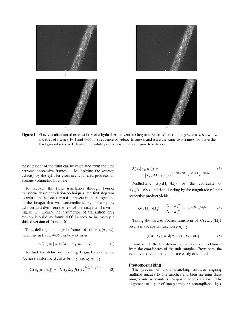
To recover the fluid translation through Fouriertransform phase correlation techniques, the first step wasto reduce the backscatter noise present in the backgroundof the image; this was accomplished by isolating thecylinder and dye from the rest of the image as shown inFigure 1. Clearly the assumption of translation onlymotion is valid as frame 4-06 is seen to be merely ashifted version of frame 4-01.
Thus, defining the image in frame 4-01 to be x1[n1, n2],the image in frame 4-06 can be written as:
(1)
To find the delay m1 and m2, begin by noting the
Fourier transforms, , of x1[n1, n2] and x2[n1, n2]:
(2)
(3)
Multiplying by the conjugate of
and then dividing by the magnitude of their
respective product yields:
(4)
Taking the inverse Fourier transform of
results in the spatial function g[n1,n2]
(5)
from which the translation measurements are obtainedfrom the coordinates of the unit sample. From here, thevelocity and volumetric rates are easily calculated.
PhotomosaickingThe process of photomosaicking involves aligning
multiple images to one another and then merging theseimages into a seamless composite representation. Thealignment of a pair of images may be accomplished by a
x2 n1 n2,[ ] x= 1 n1 m1– n2 m2–,[ ]
ℑ
ℑ x1 n1 n2,[ ]( ) X1 jΩ1 jΩ2,( ) eθx jΩ1 jΩ2,( )
=
ℑ x2 n1 n2,[ ]( )
X1 jΩ1 jΩ2,( ) eθx jΩ1 jΩ2,( )
ejm1Ω1–
ejm2Ω2–
=
X1 jΩ1 jΩ2,( )
X2 jΩ1 jΩ2,( )
G jΩ1 jΩ2,( )X1 X2
∗⋅X1 X2
∗⋅----------------------- e jm1Ω1e jm2Ω2= =
G jΩ1 jΩ2,( )
g n1 n2,[ ] δ n1 m1– n2 m2–,[ ]=
Figure 1. Flow visualization of exhaust flow of a hydrothermal vent in Guaymas Basin, Mexico. Images a and b show rawpicutres of frames 4-01 and 4-06 in a sequence of video. Images c and d are the same two frames, but have thebackground removed. Notice the validity of the assumption of pure translation.
a b
dc

variety of techniques which include manual tie pointlocation, spatial techniques, and Fourier transform basedmethods. A good survey of image registration techniquesis that by Brown[14]. These techniques vary from beingvery labour intensive to completely automated withattendant trade-offs in ease of use and accuracy. Inparticular, we look at manual tie point location and spatialtechniques and their roles in the context of underwaterapplications.
Manual Location of Tie PointsWe should point out that several packages exist that
provide an easy to use interface that allows manualphotomosaicking. Operators are presented with views ofthe images to be mosaicked and then select commonfeatures across these images. A linear least squares solverpackage is typically employed to solve the overconstrained set of equations that correspond to themanually selected tie points to estimate the transformationbetween the pair of images.
The residuals associated with the process of solving theover constrained set of equations provides a level ofquality control over the process. Typically, operators canfine-tune their choice of tie points to reject those withhigh residuals to produce an aesthetically pleasingmosaic.
The techniques associated with manual mosaickinghave additional significance in areas with unstructuredhard-to-model relief.
Spatial MethodsOur spatial approach to photomosaicking mirrors that
of Sawhney and Kumar[10], although it differs inimportant ways to deal with the peculiarities of theunderwater environment.
Let I1 ... IN be the N images that we are trying toregister.
If we consider an ideal coordinate system where a pointp is given by and is the
representation of that point in image Ii such that the pointp is related to pi by the mapping
(6)
where Ai is the 3D-to-2D or 2D-to-2D projectiontransformation that maps p to pi; Ai may be a Helmert,affine, projective, or higher order transformation.
For the purposes of this paper we assume Ai torepresent an eight parameter projective planetransformation
(7)
(8)
where ai11 through ai
33 are the plane projectiveparameters that correspond to image Ii.
The correspondence between the points in the imagesand the coordinate transformation must both beaccomplished simultaneously. The brightness constancyconstraint can be used in this respect as it relates
(9)
However, while this may serve as a good enoughapproximation in some cases, it is not generallyapplicable for underwater imagery. The light sourcemoves with the camera on underwater imaging platformsand in the case for non-uniformly illuminated images,equeation (4) does not hold true. Thus we deviate fromthe formulation proposed by Sawhney and Kumar in twoimportant ways.
1. We substitute adaptively histogram equalizedimagery in place of the original images even though, dueto aesthetic considerations, we may use the unequalizedimages for the mosaic.
2. We detect and discount the contribution due toshadows. As the light source moves, the shadows tend toalso shift. Due to the low contrast nature of underwaterimagery, techniques which rely on edge based operatorsare often fooled by this apparent motion across images.
Thus if we consider the ith histogram equalized image
Iih and the subset S of the original image I such that the
intensity in S corresponds to shadowed regions and theirneighbors, then we can minimize the error criterion,
(1)
This can be linearized
(10)
such that each iteration of the Levenberg-Marquadtoptimization procedure solves the following linear sum ofsquares problem
p x y,( )= pi xi yi,( )=
pi P p Ai;( )=
xi
a11i x a12
i y a13i+ +
a31i x a32
i y a33i+ +
-----------------------------------------=
yi
a21i x a22
i y a23i+ +
a31i x a32
i y a33i+ +
-----------------------------------------=
I i pi p Ai,( );( ) I i 1+ pi 1+ p Ai 1+,( );( )=
min
Ai Ai 1+,1
M p( )-------------- I i
h pi( ) I p( )–( )2
i i 1+,∑
p S∉∑
E pi p;( ) A;( ) 1
M p( )------------------ I i
h pi( ) I p( )–( )=

(11)
Our implementation uses a two step progressivelycomplex model in combination with a laplacian ofgaussian pyramid. We first estimate the translationparameters at a coarse level of the pyramid using ascheme similar to that used for fluid flow measurementsand then use those values to estimate the parameterscorresponding to the projective transformation.
The results of our techniques are highlighted in Figures2 and 3. Figure 2 shows the general methodology wefollow for the photomosaicking process. Figure 3 shows acomplete photomosaick of a 4th century B.C. Romanshipwreck located in ~800m of water in theMediterranean. This photomosaic is a composite of 180
images that were assembled in four strips that were thenmanually assembled into a composite photomosaic.
These and other results along with the implementationof this algorithm are discussed at length in [15].
ConclusionsIn this paper we have attempted to demonstrate a
unified framework to photomosaicking with a particularemphasis on the unique constraints of underwaterimagery. The techniques presented are general buildingblocks towards a global underwater image registrationsuite. Areas of future and on-going research here at DSLwhich work towards this end goal are: color histogramequalization to produce color mosaics, understanding andquantifying the effects of an unstructured 3D environmenton mosaics, and finally, 3D image reconstruction from asingle camera on a moving underwater platform.
min
δA E pi p;( ) ∇E pi p;( ) δA[ ]+( )
i∑
p s∉∑
Step 4 Ongoing work focuseson understanding and improv-ing the quantitative nature ofthe mosaicing process.
Ste p 1 Vehicle op-erators conduct acarefully plannedsurvey over the areaof interest to ensuresufficient coverageand overlap in theimagery. Image foot-prints are projectedon the area of inter-est to allow opera-tors to choose indi-vidual images foruse in the mosaic.
Step 2 Individual im-ages are processed to re-move lighting and otherartifacts. These imagesare then merged intosingle strip mosaics byindentifying commonfeatures in successiveimages.
Step 3 Individual stripsare then mosaiced togetherusing a technique similarto that used in Step 2.

Figure 3. Mosaic of a 4th Century B.C. Roman shipwreck located in ~800m of water in the Mediterranean; the mosaic was con-structed from 180 images taken from the Jason ROV.
sk97.056
sk97.071
sk97.064
lead sheathingpan tile
sk97.070hand quern
sk97.069
sk97.079
sk97.079ask97.080
sk97.078
sk97.052
sk97.053
sk97.073
Dressel 1c
sk97.075
sk97.054
sk97.059
sk97.060
sk97.077
sk97.076
sk97.051
sk97.050
sk97.058
sk97.065
sk97.068
sk97.112
sk97.113
sk97.067sk97.066
sk97.063
sk97.055
sk97.072
sk97.061
bilge pipe
sk97.074
sk97.062
AcknowledgmentThis work was supported by subcontract #1716 from the Institute of
Exploration, Mystic, CT, from grant #N00014-99-1-0109 awarded by the Office ofNaval Research.
References[1] Vine, A.C. Early History of Underwater
Photography, Oceanus, vol. 18, no. 3, Spring, pp. 2-10, 1975.
[2] Patterson, R.B. Future Developments in Deep-SeaImaging, Oceanus, vol. 18, no. 3, Spring, pp. 17-23,1975.
[3] Ballard, B.D. Photography from a SubmersibleDuring Project Famous, Oceanus, vol. 18, no. 3,Spring, pp. 40-43, 1975.
[4] Sulanowska, M.M., Humphris, S.E., Howland, J.C.Detailed Analysis of the Surface Morphology of theActive TAG Hydrothermal Mound by Mosaickingof Digital Images, EOS, Transactions of theAmerican Geophysical Union 77, p. 768, 1996.
[5] Howland, J.C., Singh, H., Marra, M., Potter, D.Digital Mosaicking of Underwater Imagery, SeaTechnology, pp. 65-69, June, 1999.
[6] Gracias, N., Santos-Victor, J. Underwater VideoMosaics as Visual Navigation Maps, ComputerVision and Image Understanding, vol. 79, pp. 66-91, 2000.
[7] Negahdaripour, S., Xu, X., Khamene, A.Applications of Direct 3D Motion Estimation forUnderwater Machine Vision Systems, inProceedings of the IEEE Oceans’98, Nice, France,September, 1998.
[8] Marks, R., Rock, S., Lee, M. Real-Time VideoMosaicking of the Ocean Floor, IEEE Journal ofOcean Engineering, vol. 20, no. 3, pp. 229-241,1995.
[9] Slama, C.C., Ed. Manual of Photogrammetry.American Society of Photogrammetry, FallsChurch, VA, 1980.
[10] Sawhney, H.S., Kumar, R. True Multi-ImageAlignment and Its Application to Mosaicing andLens Distortion Correction, IEEE Transactions onPattern Analysis and Machine Intelligence, vol. 21,no. 3, pp. 235-243, March, 1999.
[11] Mann, S., Picard, R.W. Virtual Bellows:Constructing High Quality Stills From Video, ICIP,1994.
[12] Peleg, S., Herman, J. Panoramic Mosaics byManifold Projection, CVPR, pp. 338-343, 1997.
[13] Szeliski, R. Image Mosaicing for Tele-RealityApplications, IEEE Workshop Applications ofComputer Vision, pp. 44-53, 1994.
[14] Brown, L.G. A Survey of Image RegistrationTechniques, ACM Computing Surveys, vol. 24, no.4, pp. 325-376, December, 1992.
[15] Singh, H., Howland, J., Pizarro, O., Eustice, R.,Large Area Photomosaicking Underwater,submitted to the IEEE Journal of OceanicEngineering.
Related Documents