UNDERWATER TURBIDITY MEASUREMENTS BY ATHELSTAN F. SPILHAUS JR. S.B. Massachusetts Institute of Technology (1959) SUBMITTED IN PARTIAL FULFILLMENT OF THE REQUIREMENTS FOR THE DEGREE OF MASTER OF SCIENCE LINDCREN at the MASSACHUSETTS INSTITUTE OF TECHNOLOGY May, 1960 Signature of Author Department of Geology and Geophysics May 21, 1960 Certified by Thesis Supervisor Accepted by Chairman, Departmental Committee on Graduate Students

Welcome message from author
This document is posted to help you gain knowledge. Please leave a comment to let me know what you think about it! Share it to your friends and learn new things together.
Transcript

UNDERWATER TURBIDITY MEASUREMENTS
BY
ATHELSTAN F. SPILHAUS JR.
S.B. Massachusetts Institute of Technology
(1959)
SUBMITTED IN PARTIAL FULFILLMENT
OF THE REQUIREMENTS FOR THE
DEGREE OF MASTER OF SCIENCE LINDCREN
at the
MASSACHUSETTS INSTITUTE OF TECHNOLOGY
May, 1960
Signature of Author
Department of Geology and GeophysicsMay 21, 1960
Certified by
Thesis Supervisor
Accepted by
Chairman, Departmental Committee on
Graduate Students

Abstract
Underwater Turbidity Measurements
by Athelatan F. Spilhaus Jr.
Submitted to the Department of Geology and
Geophysics in partial fulfillment of the requirements for
the degree of Master of Science,
The purpose of this study was to propose a designfor an underwater light sAttering photometer that will makemeasurements of certain potentially useful optical variablesin sea water. A very simple bathyphotometer was constructedand used to obtain first hand knowledge of some of the prob-lems of underwater instrumentation. A design and method ofcalibration are proposed for a new photometer. This instru-ment will yield values of the extinction coefficient for anumber of discrete wavelengths and the percent of polariza-tion of the light scattered at 90*. Some of the possibleinterpretations of these data are indicated.
Thesis Supervisor: Columbus O'Donnell IselinProfessor of Oceanography

TABLE OF CONTENTS
Page
I Introduction
II Experimental Procedure and Results
III Recommended Instrumentation
IV Data Processing
V Calibration Technique
VI Interpretation of Results
VII Literature Citations
25
27
28

TABLE OF FIGURES
Page
Figure 1. - Circuit for Photomultiplier RCA#931A
Figure 2a.- Side View of Frame
b.- Plan View of Frame
Figure 3. Circuitry of the Light Source
Figure 4. Filter Changin6 Mechanism
Figure 5a.- Pulsing Circuit
b.- Motor Circuit
Figure 6. - Circuit for Photomultiplier RCA#6217
20
20
23

I. INTRODUCTION
During the infancy of oceanography batches of sea
water were classified using simple thermometers and some
elementary chemical analyses. There were no techniques for
obtaining samples from depth and in order to measure the
temperature at a given location and to obtain a water sample
the ship had to heave to. As time proeressed the instrumen-
tation improved. Temperatures and water samples can now be
obtained from great depths; however, this is a tedious job
and very little space can be covered by a single ship that
is hove to most of the time. Further improvement has resulted
in continuously recording instruments for some variables as
a function of either depth or time. Extention of this to
greater depths and more variables is one of the major prob-
lems facing oceanographers today.
Sea water is generally classified by its tempera-
ture and salinity. Sometimes variables such as dissolved
oxygen are used. Only an overall picture of the steady state
can be obtained from such measurements because small scale
features are washed out by the movement of the sea during the
time ,required to retrieve the sample collectors. For obtain-
ing a view of small scale, rapidly changing features, con-
tinuous measurements are imperative.
Temperature and salinity can both be measured
continuously to moderate depths. Unfortunately these often

will not yield sufficient detail, especially where there is
little variation in them.
A further possibility for classifying sea water is
using some of its optical properties. The extinction coeffi-
cient, the absorbtion at various wavelengths and others
could prove valuable for labelling a parcel of water. The
coefficient, also called the turbidity, is defined for a
unit length of a given medium by: where
1 is the intensity of the light before it enters the medium
and T the intensity as it leaves.
The objective of the study was to propose a design
for an instrument to measure some of the useful optical var-
iables.
Previous work on this problem is confined mainly
to measurements of the extinction in the surface layer and
measurements of illumination at depth. The Secohi disk is
the oceanographer's primordial device for measuring turbi-
dity. As a matter of historical record, this, was the first
turbidimeter (13). An improvement on this technique has
been made by Clarke. He has devised a bathyphotometer
capable of measuring illumination continuously at great depths
(2). Prior to this attempts to use photographic methods
were made by Koczy and Jerlov (5). Jerlov has designed a
transparency-meter; however this would supply only infor-
mation regarding relative turbidities and is subject to
numerous errors arising from the complicated optical system

6.
employed (4).
The name of Tyler is also a prominent one in the
field of undorwater light transmission and scattering. He
has devised instruments for making individual measurements;
however, his work has been more closely related to how light
behaves in various m.edia than what use can be made of it
(8, 9, 10, 11, 12).
Much work has been done on samples brought onto
the deck ard further processed or analyzed immediately (1).
This is certainly less satisfactory than "in situ" records
if one desires a detailed picture, Measurements of spectral
absorbtion have been made by Hubbard using natural light and
an underwater spectrometer (3). Here again only relative
values were obtained. No information regarding the amount
or the size of the absorbing matter could be gathered from
these experiments.
Light-scattering measurements were made py Eetchum
and he attempted a correlation with Secchi disk readings (6).
Unfortunately the data obtained on one lowering could not
even be satisfactorily compared with the next because there
was no assurance that the geometry of the light path or the
intensity of the source remained constant.
In designing an instrument for use in measuring
optical variables the problem was to try to eliminate the
errors inherent in the devices of others and yet maintain a
device simple enough that the inevitable shipboard mishaps

7.
would not affect the data. Furthermore, only measurements
of actual physical quantities such as the extinction coeffiw
cient that are independent of the instrument were permitted.

II EXPERIMENTAL PROCEDURE AND RESULTS
After a survey of the literature and discussions
with some of the individuals who have worked with under-
water photometers, a very simple one was built. It consisted
of two pressure cases one of which contained a light source
and the other a photomultiplier dectector.
The light source was a three volt tungsten fila-
ment bulb placed at the focal point of a lens so designed
that a columnated beam emanated from the pressure case through
a plexiglass window. Dry cells supplied the necessary cur-
rent.
The pressure cases were 4 inch aluminum tubes.
The ends were flat plates fitted tightly with 0-rings. One
end held the plexiglass window and the other had a spark
plug that served as a electrical feed-in. The cases were
attached to a 6 foot piece of aluminum T by connecting devices
that allowed sliding along the T and complete rotation about
themselves. With this arrangement it was possible to obtain
any angle between the detector and the source. In direct
line separations up to one meter were achieved.
The photomultiplier detector was an RCA 931-A
which was wired as shown in figure 1. This circuit is a
modification of that employed by Ketchum (6). In order to
draw as little current as possible from the batteries 10
megohm resistors were placed between stages. When this was
done the light-activated current becomes an appreciable

FIGURE 1CIRCUIT FOR PHOTOMULTIPLIER RCA#931A

10.
fraction of that drawn from the batteries. To maintain an
equal potential drop across each stage the batteries must be
connected individually instead of simply using the whole 900
volts between the anode and the cathode. A 90 volt battery
was placed between the last stage and the cathode to ensure
a constant potential drop at this point. Such a bias extends
the range of linearity of the device. This range was checked
by using an optical bench and a point source of light and
comparing the inverse square law with the experimental
results. Further experimentation with the photomulitplier
tube revealed that the resistance between stages did not
affect the response of the device as long as the potential
across each stage was the same.
The signal was the voltage drop across a 100,000
ohm resistor that was kept on deck. It was read out with a
vacuum tube voltmeter and was between 0.1 and 2.5 volts.
In the detection unit Interference filters could
be situated in front of the photomultiplier tube. The wave-
lengths available were 466,546 and 669 millimicrons. A
polarizing filter was also available.
Several important design considerations were
pointed up by the experiments. The most important of these
was the steadiness of the light beam and optical components
that must be maintained in order to obtain consistent read-
ings. Slight misallignments can result in drastic errors,
especially if either the beam or the receiving aperture is
11.
small and there is variation in lizht intensity through the
beam.
Three wavelengths were not enough to make possible
a distinction between colour absorbtion and the change in
turbidity with wavelength that is due to the particle size.
A third problem was that of the disturbanee of the
water at the windows. This was caused by the fact that the
window protruded from the face of the pressure casing.
12.
III RECOMMENDED INSTRUMENTATION
A. General: The instrument recommended is a photo-
meter consisting of two detectors and a light source mounted
on a rigid frame. The detectors are at right angles to each
other and one measures the incident beam and the other the
light scattered at 900. There is a depth sensing potentio-
meter which is battery operated attached to the frame. The
instrument is connected with the surface by a four conductor
cable and data is obtained from the records of three high
input impedance recording potentiometers.
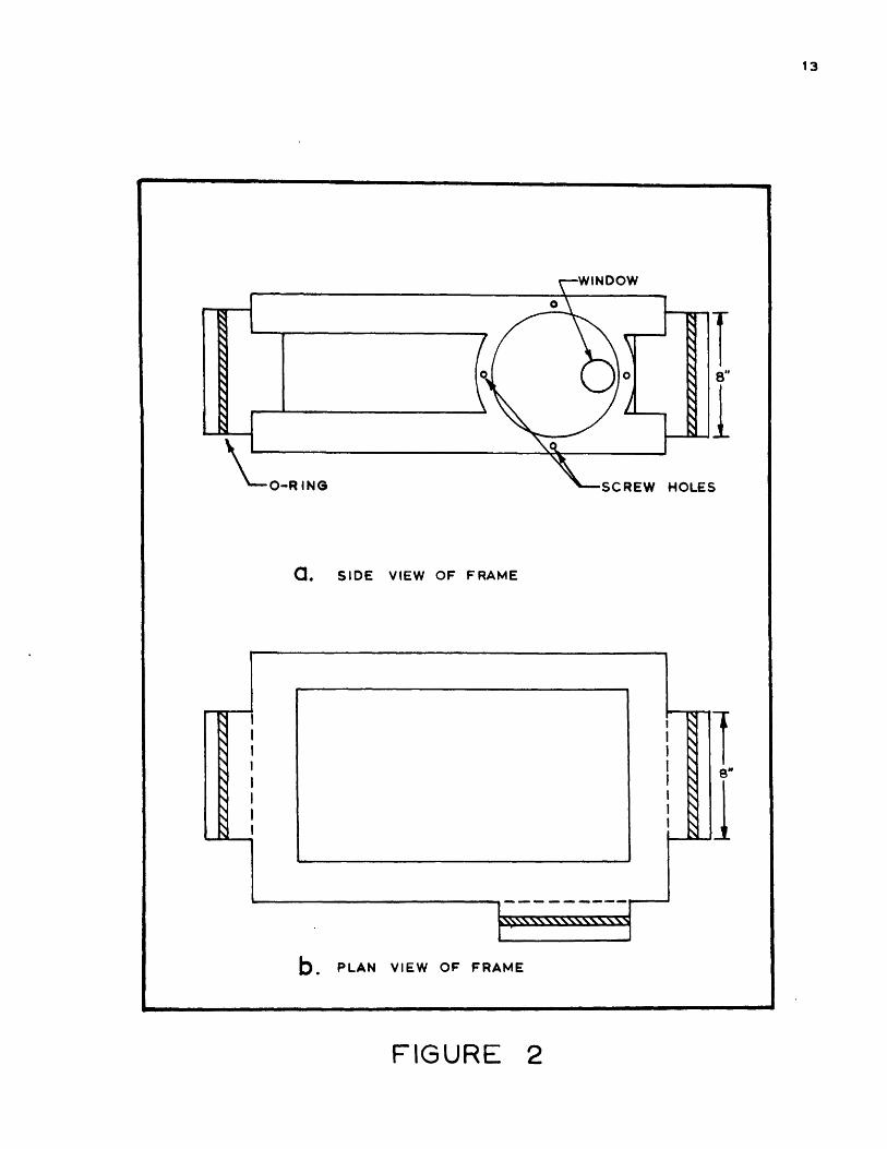
B. The Frame and Pressure Casings: The operating com-
ponents must be attached to a single rigid frame. This frame,
as shown in figure 2, consists of two rectangular shaped
pieces that are linked at three points by disks that serve
as the faces for the pressure eases that enclose the cir-
cuitry. It is for this reason that the outer sides of these
disks are raised and slotted for 0-rings. The cases are
attached by screws through holes drilled in the flangeulike
surface of the disk. The cases must have an inside diameter
of 8 inches in order to contain the filter changing mechanism.
The thickness of the walls depends entirely on the depth
range desired. In the back of each casing there should be
an appropriate number of electrical feed-in components. The
Joy Manufacturing Company produces a plug that screws in and
employs an 0-ring pressure seal that has been found quite
a. SIDE VIEW OF FRAME
b. PLAN VIEW OF FRAME
FIGURE

14.
satisfactory in these applications. The feed-in itself is
a male fixture and the connector is a rubberized female
plug that prevents electrical leakage through the sea water
to ground.
The faces must each have a plexiglass window set
into them. These windows should be located halfway between
the two frame members as iridicated in figure 2. This min-
imizes the error introduced by reflections off the frame into
the detectors. The windows should be set into a hole in the
face in such a way that the front is flush. This cuts down
the turbulence. 0-rings are necessary to ensure a water-
tight seal.
G. The Light Source: The light source must contain a
tungsten filament bulb. Such a bulb has a spectral output
that Increases toward the infrared. This partially compen-
sates for the decreasing response of the photomultiplier
tube in that direction.
The spectral output of a tungsten filament bulb is
largely dependent on the voltage across it. In order to
maintain a constant voltage the circuit shown in figure 3 is
used. A resistor is placed in series, and a zener diode in
paralell with the bulb. The diode should have a nominal
zener breakdown voltage equal to the voltage to be maintained
across the bulb. The resistance is determined by the for--
mula:R

RECHARGING TERMINALS
FIGURE 3CIRCUITRY OF THE LIGHT SOURCE

16.
is determined from: R I + , where
and I, is a characteristic of the diode chosen. The power
rating of the diode must be above that of the bulb to pro-
tect it in the event of a burnout.
A mercury switch is provided so that the source
may be turned off without opening the case. A rechargable
battery should be used and there must be two Joy plugs on
the light source pressure case for recharging purposes. An
excellent battery for this application is the Yardney silver-
cell. This battery has a 20 ampere-hour life and is a re-
chargable wet cell that can be used in any orientation.
The bulb should be firmly mounted behind a lense
in such a way that a reasonably columnate beam issues from
the window. A diaphram should be used in combination with
the lense to give a beam that is approximately 1/2 inch in
diameter. A beam of this size will more than cover the
whole filter in the detector and slight motions of the frame
due to tensions will not affect the results materially.
A device must be included for chopping the light
beam. Between the bulb and lense a light tight disk is
placed. This disk has one hole for the light to shine
through. A disk with a semicircular slot in it is then
rotated past the hole by an electric motor. The speed of this
motor should be such that the light goes on and off at least
once for every filter change. The slot coincides with the
hole half of the time; therefore, the motor should revolve
17.
once in a time equal to the sum of the charging and dis..
charging time of the capacitor in the pulsing circuit of
the filter changing mechanism. There must be felt around
the hole to insure no light leakage.
D. The Detection units; Both detectors are identical
except that the pulsing circuit for changing filters is
common to them. Working in from the windows the first thins
that one comes to is the filter chaning mechanism. This
consists of a disk 7 inches in diameter whose outer edge
has gear teeth. This disk holds the filters in a symetrical
array around it leaving 1/4 inch between each, There is
one blank spot so that the dark current of the photomulti-
plier tube can be determined. One spot is clear and one has
a polaroid filter. There are fourteen other positions and
each one is occupied by a 1/2 inch interference filter.
Each one of these filters has associated with it a diaphram
that makes the order of magnitude of all the signals the
same.
The hole through which the light is transmitted
from the window should not be much larger than the filter and
there should be felt between it and the filter disk as
shown in figure 4.
The filter is changed by a single rotation of the
motor. This acts through the gear train shown in figure 4
and is' made possible by cutting the gears correctly.
The filters must be moved at intervals that allow
the device to come to equilibrium after each change and yet

MOUNTING
'-PLEX IGLASSWINDOW
PHOTOMULTIPLIER
FIGURE 4FILTER CHANGING MECHANISM
19.
not so slowly as to incur the disadvantages attendant with
batch sampling. Each filter should remain in front of the
photomultiplier window for a few seconds. The time necessary
will be primarily dependent on the instrument used f6r record-
ins the data.
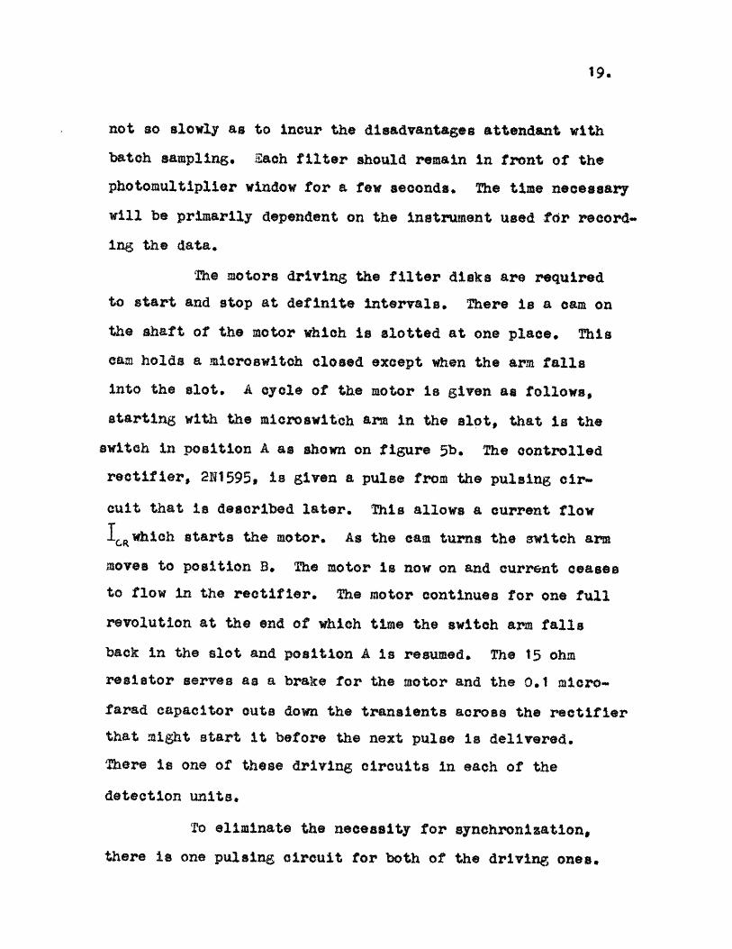
The motors driving the filter disks are required
to start and stop at definite intervals. There is a cam on
the shaft of the motor which is slotted at one place. This
cam holds a microswitch closed except when the arm falls
into the slot. A cycle of the motor is given as follows,
starting with the microswitch arm in the slot, that is the
switch in position A as shown on figure 5b. The controlled
rectifier, 2N1595, is given a pulse from the pulsing cir-*
cuit that is described later. This allows a current flow
ICRwhich starts the motor. As the cam turns the switch arm
moves to position B. The motor is now on and current ceases
to flow in the rectifier. The motor continues for one full
revolution at the end of which time the switch am falls
back in the slot and position A is resumed. The 15 ohm
resistor serves as a brake for the motor and the 0.1 micro-
farad capacitor outs down the transients across the rectifier
that might start it before the next pulse is delivered.
There is one of these driving circuits in each of the
detection units.
To eliminate the necessity for synchronization,
there is one pulsing circuit for both of the driving ones.

FIGURE 5

21.
the pulsing circuit is shown in figure 5a. It is an RC
circuit with the following modification. A four layer
transistor diode is placed in parallel with the capacitor
through the gates and cathodes of the controlled rectifiers.
Until the voltage across the diode reaches a certain level
it acts like a very high resistance and allows the capacitor
to charge. After this point it switches to a low resistance
and the capacitor discharges through it delivering a pulse
to the gate of the rectifier. The diode switches back to a
high resistance element when the current through it reaches
a sufficiently low level.
The parameters of this circuit can be calculated
as follows:
charging time constant = R Cwhere et [RR +PD] (
= discharging time constant = , Z
One fact that must be born in mind when calculating these
parameters is that must start above 20 milliamperes to
guarantee triggering both redtifiers.
During charging the voltage across the capacitor
is given as a function of time by:-t C
The charging ends whenEs reaches the switching voltage of
the diode and does not begin again until i falls below the
value for the holding current which is a characteristic of

22.
the component selected. This current may vary between 1.0
and 5.0 milliamperes.
The recommended photomultiplier tube is RCA 6217.
This is an end on sensitive tube with a spectral response
of greater than ninty percent of its peak between 36000A and
57000A, and greater than ten percent at 70000A. A circuit
for this tube is shown in figure 6. Batteries are used
across each stage instead of a voltage divider. This
ensures equidivision of the potential and in such a low
drain situation the life of the battery approximates its
shelf life the battery recommended is Burgess type XX69
which is 103 1/2 volts. Two of these are required between
the anode and the first stage and one more for each succeed-
ing stage. Between the last stage and the cathode there is
a resistor in series with the battery. The voltage drop
across this resistor is a measure of the output of the tube
and is the signal which is read on deck.
The tube should be wrapped with mu-metal for mag-
netic shielding.
The batteries used for the pulsing circuit and
for running the motors should be reohargable. Provision
must be made for recharging without opening the pressure
case.

RECORDING
POTENTIOMETER
(11)
FIGURE 6CIRCUIT FOR PHOTOMULTIPLIER RCA #6217
24.
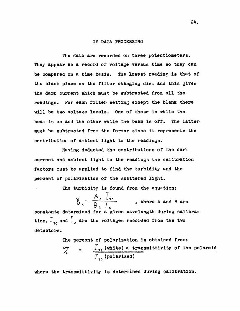
IV DATA PROCESSING
The data are recorded on three potentiometers.
They appear as a record of voltage versus time so they can
be compared on a time basis, The lowest reading is that of
the blank place on the filter changing disk and this gives
the dark current which must be subtracted from all the
readings. For each filter setting except the blank there
will be two voltage levels. One of these is while the
beam is on and the other while the beam is off. The latter
must be subtracted from the former since it represents the
contribution of ambient light to the readings.
Having deducted the contributions of the dark
current and ambient light to the readings the calibration
factors must be applied to find the turbidity and the
percent of polarization of the scattered light.
The turbidity is found from the equation:
Ax Et0 , where A and B are
constants determined for a given wavelength during calibra-
tion. 1 and are the voltages recorded from the two
detectors.
The percent of polarization is obtained from:
7 = r,(white) x tranemittivity of the polaroid
1, (polarized)
where the transmittivity is determined during calibration.

25.
V CALIBRATION TECHNIQUE
The spectral response of the system as a whole
must be found and a relation between the extinction oO-.
efficient and the recorded intensities established.
The first step is to hang the instrument in its
operating position in a dark place where the atmosphere is
relatively free from scatterers. The intensity is then read
on the voltmeter for each wavelength. Since there are
essentially no scatterers on absorbers, the intensity ehould
be equal at each wavelength. If it is not, find the factors,
B ; that will perform this function. Applying these factors
places the readings on the same basis so they can be com-
pared,
To determine the response of the scattering detector
a bath in which the instrument can be immersed must be pre-
pared. This bath should contain distilled water and duPont
Ludox. Ludox is a colloidal silica suspension that obeys the
fourth power law of scattering. This means that the turbidity
varies with the inverse of the fourth power of the wave-
length of the light used according to the theory of Lord
Rayliegh.
The instrument should be immersed in the bath and
the turbidity determined from the equation;
I at% 6. ewhere), is the length of solution between the source and the
detector. At the same time I, must be measured. This

26,
intensity is then'related to the turbity by:
S 3 v B I Gunder the assumption that the sum of the lengths from the
centre of the scattering volume to the detector windows
divided by 2.303 and multiplied by ' is small in relation toI1r r
log 3v 1. (7). For this reason the concentration of the bath
should be kept as low as possible. Since ) and II0and 1 6are
known 3 , a constant previously called can be calou-
lated.
To determine the transmittivity of the polaroid
filter the white intensity is measured in the Ludox solution
and then the intensity using the polaroid. Since the Ludox
particles are small, all the light scattered at 900 is
polarized, and, therefore, the ratio of the filtered to
the unfiltered light is the transmittivity of the polaroid
filter.

27.
VI INTERPRETATION OF RESULTS
The results obtained from the device are in the
form of turbidities and percent of to scattered light
polarized.
The turbidity is obtained at fourteen wavelengths.
If these turbidities are plotted on log graph paper versus
the wavelengths, a straight line is obtained in the absence
of absorbtion. If a straight line is drawn through as many
of these points as possible, bearing in mind that no points
may fall below this line, the slope is a measure of the
average particle size. The range is from minus four for
particles.smaller than the wavelength of light to zero for
very large particles. Points that fall above this line
indicate absorbtion increases at those wavelengths, Parti-
cular points to look for are 675 and 750 millimicrons which
are characteristic of chlorophyll and 475 millimicrons which
represents the yellow and blue matter in plants.
The percent of the scattered light that is polarized
gives the ratio of the Rayliegh to the Mie scattering. This
coupled with the turbidity measurements gives a qualitative
idea of the size distribution of the particles.
Use of such an instrument provides the means of
measuring parameters which have not previously been avail-
able to describe sea water.

28.
VII LITERATURE CITATIONS
(1) Clarke, G.L, and H.R. James, "Laboratory Analysisof the Selective abso'btion of light by Sea Water",J.O.S.A., 2, 43-55 (1939)
(2) Clarke, G.L. and Wertheim, "Measurements ofIllumination at Great Depths and at Night in the AtlanticOcean by means of a New Bathyphotometer", Deep SeaResearch, 2, no. 3, P 189 (1956)
(3) Hubbard, C.J. and W.S. Richardson, "Measurement of theSpectrum of Underwater Light", Wood Hole OceanographicInstitution, Unpublished Manuscript, Ref. #59-30,(June 1959)
(4) Jerlov, N.G. "A Transparency-Meter for Ocean Water",Tellus, 2, P 229 (1957)
(5) Jerlov, N.G. and F. Koczy, "Photographic Measure-ments of Daylight in Deep Water , Reports of the SwedishDeep Sea Expedition, Vol. 3, Physics and Chemistry No. 2,P 63-9.
(6) Ketchum, B.. and D.H. Shouting, "Optical Studiesof Particulate Matter in the Sea", Woods Hole Oceano-
aghio Institution, Unpublished Manuscript, Ref. #58-15rib.1958)
(7) Maron S.H. and Lou R.L.H., "Calibration of LightScattering Photometers with Ludox", Journal of PolymerScience, 1, 26.36, (1954)
(8) Tyler, J.E., "Underwater Photometer," J.O.S.A.,d 904A (1955)
(9) Tyler, J.E*, "Monochromatic Measurement of theVolume scattering of Natural Waters" J.O.S.A., ,745-747 (1957)

(956) 06 a *ouI Stuwdmoo tpuvnoowUWA a 'UQ;OtOUTa '0 Teevuy ;o spovwx tvjusnu4t
'ues 'y*p puo 14144ed '*T **H PWVtTTM
uoTnq;.z4s; vn jo uostwdwoo, "** a t4 (at)
(9S60) LSCtSC'Nrvsor t.'nwi t U0TtOUnA ?ulJlin* O UlftOA JO
4uonTG 4 40$ OWtemOtIdZ, q * f '4et4 (it()
(U6) v9t{ *1 **S*0* eftemeanewveJ4A4O~Ufl JO; 4040t*qdofl yo #*[*VAT 4 (00)
*6e
Related Documents