King Saud University College of Computer and Information Sciences Information Technology Department Designed by: Amal Al-Subaih Anfal Al-Awajy Eman Al-Rayes Hanan Al-Hindi Kholoud Al-Roumi Norah Al-Khaldi Safa'a Al-Bassam Supervised By: Prof. Mona Mursi Graduation Project (Cap 496) First semester 1430 – 2009 Group#23 Image Authentication and Steganalysis System

Welcome message from author
This document is posted to help you gain knowledge. Please leave a comment to let me know what you think about it! Share it to your friends and learn new things together.
Transcript
King Saud University
College of Computer and Information Sciences Information Technology Department
Designed by:
Amal Al-Subaih Anfal Al-Awajy Eman Al-Rayes Hanan Al-Hindi
Kholoud Al-Roumi Norah Al-Khaldi Safa'a Al-Bassam
Supervised By: Prof. Mona Mursi
Graduation Project (Cap 496) First semester 1430 – 2009
Group#23
Image Authentication and Steganalysis System
ii
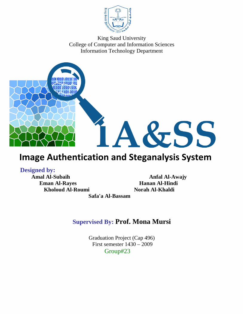
Abstract
This project addresses the ever-increasing problem of image tampering. The tampering
addressed could take on two forms: steganography and simple image alterations. Hence the
project has a two-fold objective: steganalysis and image authentication. In the first part of the
project, we deal with the steganalysis of Least Significant Bit (LSB) embedding for hiding
messages in digital images in the BMP format. A steganalysis technique is implemented that
enables us to reliably detect the presence of binary message randomly spread in a digital image.
The method is based on close color pair analysis. The results obtained were quite satisfactory in
terms of FAR and FDR.
In the second part of the project we deal with the issue of detection of image tampering
i.e. image authentication. Two approaches are adopted for image authentication. The first
approach deals with the authentication of BMP images. The method used for that is by deriving
and embedding a digital signature in the image. A second approach that deals with the
authentication of JPEG images is also implemented. A data embedding method is proposed for
image authentication based on table look-up in the frequency domain. A watermark is embedded
invisibly in the marked image which can be stored in the compressed form. The scheme can
detect malicious alteration of the original image while being tolerant to incidental image
alterations. In addition, a technique for self-embedding an image into itself as a means for
protecting the image content, was also implemented. The original image and extracted embedded
image are visibly compared by a human observer for possible differences. The results obtain are
quite successful and the method proved to be very efficient.
The proposed methodologies are characterized as blind fragile and semi-fragile
authentication techniques respectively, since they do not rely on the original image to decide
whether the image has been altered or not.

iii
الرحيم الرمحن ا بسم
..الكرم واسع.. العطاء جزيل.. الفضل عظيم احلمد
..العمل هذا بإمتام علينا من بأن وكرمه وفضله توفيقه على وأخريَا أوًال والشكر
..ورعاية سقايةً وتعاهداها البذرة هذه زرعا الذين احلبيبني والدي إىل
...وبركتهما حلبهما نتاجاً املشروع هذا أمثر حتى
...النور إىل املشروع هذا ظهر حتى سند خري لنا كانوا صاحل الذين/ حممد واألستاذ/ مالك واألستاذ/ خالد واألستاذ/د إىل
..ميل األلف درب يف خطواتي على يل عوناً كان محّاد الذي/ إىل إخوتنا وإىل األستاذ
يف لنا وإرشادها توجيهها حسن وعلى.. خطوة بعد خطوة املشروع هذا مراحل على وإشرافها معنا تعاوهنا على مرسي منى /د.أ نشكر كما
...مرحلة كل
..العني أبنائنا وأحبتنا قُرة وإىل
...إليه نصبو ما لتحقيق العزم وابتسامتهم براءهتم منحتنا الذين
...أحبائنا يا مجيعاً فإليكم
....الثمرة هذه هندي

iv
To the most Precious people to me Mum, Dad and Brothers
To the pure soul of my grandma who was looking forward to this date
Anfal
v
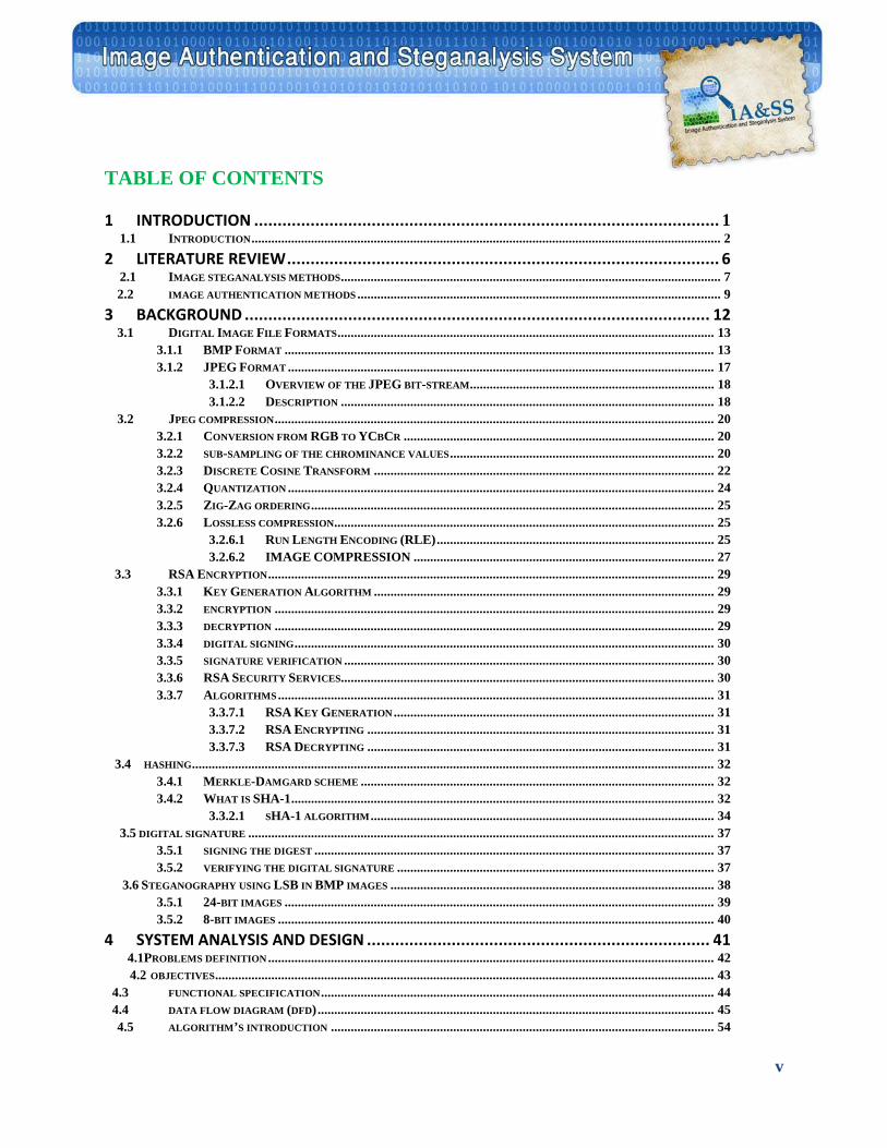
TABLE OF CONTENTS
1 INTRODUCTION ................................................................................................... 1 1.1 INTRODUCTION .............................................................................................................................................. 2 2 LITERATURE REVIEW ............................................................................................ 6 2.1 IMAGE STEGANALYSIS METHODS ................................................................................................................... 7 2.2 IMAGE AUTHENTICATION METHODS .............................................................................................................. 9 3 BACKGROUND ................................................................................................... 12 3.1 DIGITAL IMAGE FILE FORMATS .................................................................................................................. 13
3.1.1 BMP FORMAT .................................................................................................................................. 13 3.1.2 JPEG FORMAT ................................................................................................................................. 17
3.1.2.1 OVERVIEW OF THE JPEG BIT-STREAM .......................................................................... 18 3.1.2.2 DESCRIPTION ................................................................................................................. 18
3.2 JPEG COMPRESSION ..................................................................................................................................... 20 3.2.1 CONVERSION FROM RGB TO YCBCR .............................................................................................. 20 3.2.2 SUB-SAMPLING OF THE CHROMINANCE VALUES ................................................................................ 20 3.2.3 DISCRETE COSINE TRANSFORM ....................................................................................................... 22 3.2.4 QUANTIZATION ................................................................................................................................. 24 3.2.5 ZIG-ZAG ORDERING .......................................................................................................................... 25 3.2.6 LOSSLESS COMPRESSION................................................................................................................... 25
3.2.6.1 RUN LENGTH ENCODING (RLE) .................................................................................... 25 3.2.6.2 IMAGE COMPRESSION ........................................................................................... 27
3.3 RSA ENCRYPTION ....................................................................................................................................... 29 3.3.1 KEY GENERATION ALGORITHM ....................................................................................................... 29 3.3.2 ENCRYPTION ..................................................................................................................................... 29 3.3.3 DECRYPTION ..................................................................................................................................... 29 3.3.4 DIGITAL SIGNING ............................................................................................................................... 30 3.3.5 SIGNATURE VERIFICATION ................................................................................................................ 30 3.3.6 RSA SECURITY SERVICES................................................................................................................. 30 3.3.7 ALGORITHMS .................................................................................................................................... 31
3.3.7.1 RSA KEY GENERATION ................................................................................................. 31 3.3.7.2 RSA ENCRYPTING ......................................................................................................... 31 3.3.7.3 RSA DECRYPTING ......................................................................................................... 31
3.4 HASHING .............................................................................................................................................................. 32 3.4.1 MERKLE-DAMGARD SCHEME ........................................................................................................... 32 3.4.2 WHAT IS SHA-1 ................................................................................................................................ 32
3.3.2.1 SHA-1 ALGORITHM ........................................................................................................ 34 3.5 DIGITAL SIGNATURE ............................................................................................................................................. 37
3.5.1 SIGNING THE DIGEST ......................................................................................................................... 37 3.5.2 VERIFYING THE DIGITAL SIGNATURE ................................................................................................ 37
3.6 STEGANOGRAPHY USING LSB IN BMP IMAGES .................................................................................................. 38 3.5.1 24-BIT IMAGES .................................................................................................................................. 39 3.5.2 8-BIT IMAGES .................................................................................................................................... 40
4 SYSTEM ANALYSIS AND DESIGN ......................................................................... 41 4.1PROBLEMS DEFINITION ....................................................................................................................................... 42 4.2 OBJECTIVES ....................................................................................................................................................... 43 4.3 FUNCTIONAL SPECIFICATION ....................................................................................................................... 44 4.4 DATA FLOW DIAGRAM (DFD) ........................................................................................................................ 45 4.5 ALGORITHM’S INTRODUCTION .................................................................................................................... 54
vi
4.5.1 STEGANALYSIS FOR BMP IMAGES WITHOUT AUTHENTICATION SCHEME ...................................... 54 4.5.2 DIGITAL IMAGE AUTHENTICATION SCHEMES .................................................................................. 56
4.5.2.1 DIGITAL SIGNATURE OF BMP IMAGE WITH SELF EMBEDDING ..................................... 56 4.5.2.2 A DATA EMBEDDING SCHEME FOR JPEG IMAGE AUTHENTICATION .......................... 60
5 IMPLEMENTATION ………………………………………………………………………………………………65 5.1 STEGANALYSIS FOR BMP IMAGES WITHOUT AUTHENTICATION SCHEME…………………………………………………………66
5.1.1 EXPERIMENTAL OBSERVATIONS………………………………………………………………………………………………69
5.1.2 BMP STEGANALYSIS ........................................................................................................................................ 70 5.2 BMP IMAGE AUTHENTICATION SCHEMES WITH SELFEMBEDDING………………………………………………………………..76
5.2.A BMP_WATERMARK ()…………………………………………………………………………………………………………78 5.2.B BMP_ AUTHENTICATION ()……………………………………………………………………………………………………87 5.2.C BASIC FUNCTIONS…………………………………………………………………………………………………………………96 5.2.D HIDE AN IMAGE INTO ANOTHER IMAGE…………………………………………………………………………………….99
5.3 DATA EMBEDDING SCHEME FOR JPEG GRAYSCALE IMAGE AUTHENTICATION……………………………………………….101 5.3. A JPEG _WATERMARK………………………………………………………………………………………………………………104 5.3. B JPEG _VERIFY ……………………………………………………………………………………………………………………..110 5.3. C MATLAB FUNCTION…………………………………………………………………………………………………………..……115 5.4 USED TOOLS …………………………………………………………………………………………………………………………………..117
6 TESTING………………………………………………………………………………………………………………………118 6.1 BMP STEGANALYSIS……………………………………………………………………………………………………………………………..120
6.1.1 PRELIMINARY INVESTIGATION:…………………………………………………………………………………………………..120 6.1.2 THRESHOLD SELECTION……………………………………………………………………………………………………………121 6.1.3 DIFFERENT STEGO IMAGES…………………………………………………………………………………………………..….…123 6.1.4 SOME EXAMPLES:……………………………………………………………………………………..…………………………..123 6.1.4.1 NON STEGO-IMAGE………………………………………………………………………………………………………….……123 6.1.2.2 STEGO-IMAGE……………………………………………………………………………………………………………………..125 6.1.3 THE FINAL TEST RESULTS………………………………………………..………………………………………………………….127
6.2 BMP IMAGE AUTHENTICATION SCHEME …………………………………………………………………………………………………..128
6.2.1 SIGN A BMP IMAGE:……………………………………………………………………………………………………………….128 6.2.2 VERIFY FROM UN-TAMPERED IMAGE…………………………………………………………………………………………….131 6.2.3 VERIFY FROM SLIGHTEST MODIFIED IMAGE…………………………………………………………………………..………..132 6.2.4 VERIFY FROM MALICIOUSLY TAMPERED IMAGE………………………………………………………………………………..136 6.2.5 HIDE AN IMAGE INTO ANOTHER IMAGE……………………………………………………………………………………….140 6.2.6 FINAL TEST RESULT……………………………………………………………………………………………………..………..150
6.3 JPEG IMAGE AUTHENTICATION SCHEME …………………………………………………………………………………………………152
6.3.1 SIGN A JPEG IMAGE:…………………………………………………………………………………………………………….152 6.3.2 VERIFY AFTER UN-TAMPERED IMAGE……………………………………………………………………………………..….154 6.3.3 VERIFY AFTER TAMPERED IMAGE: ……………………………………………………………………………………….…..155 6.3.4 VERIFY AFTER COMPRESSED(25%) IMAGE: …………………………………………………………………………….…..157 6.3.5 VERIFY AFTER COMPRESSED(50%) IMAGE:…………………………………………………………………………….……158 6.3.6 VERIFY AFTER COMPRESSED(80%) IMAGE:………………………………………………………………………………….159 6.3.7 VERIFY AFTER UN-SIGNED IMAGE:…………………………………………………………………………………………....161 6.3.8 THE FINAL TEST RESULT………………………………………………………………………………………..................163
CONCLUSION…..………………. …………………………………………………………………………………………...164 REFERENCES………………………………………………………………………………………………………………..165
vii
List OF FIGURES FIGURE [1.1]: STEGANOGRAPHY TERMS ........................................................................................................................... 2 FIGURE [3.1]: BMP FORMAT ......................................................................................................................................... 13 FIGURE [3.2]: JPEG BITSTREAM ................................................................................................................................... 18 FIGURE [3.3]: SUB-SAMPLED IMAGE. ............................................................................................................................. 21 FIGURE [3.4]: YCBCR CHANNELS .................................................................................................................................. 21 FIGURE [3.5]: DC AND AC COMPONENTS. ...................................................................................................................... 23 FIGURE [3.6]: FREQUENCY DOMAIN. .............................................................................................................................. 25 FIGURE [3.7]: ZIG-ZAG ORDERING. ................................................................................................................................ 25 FIGURE [3.8]: OVERVIEW OF JPEG. .............................................................................................................................. 28 FIGURE [3.9]: MERKLE-DAMGARD SCHEME. ................................................................................................................. 32 FIGURE [3.10]: SHA-1. ................................................................................................................................................... 33 FIGURE [3.11]: DIGITAL SIGNATURE. ............................................................................................................................. 37 FIGURE [3.12]: LSB IN BMP IMAGE .............................................................................................................................. 38
FIGURE [4.1]: CLOSE COLOUR PAIR BETWEEN TWO PIXELS. .......................................................................................... 54 FIGURE [4.2]: UNIQUE COLOURS BETWEEB TWO PIXELS ................................................................................................ 55 FIGURE [4.3]: HASH VALUE OF TWO IMAGES .................................................................................................................. 57 FIGURE [4.4: COMPRESSED IMAGE ................................................................................................................................. 58 FIGURE [4.5]: SELF EMBEDDING IMAGE. ........................................................................................................................ 59 FIGURE [4.6]: PHANTOM IMAGE'S DIGITAL SIGNATURE IN ORIGINAL IMAGE ................................................................. 59
FIGURE [5.1]: VARIATION OF THE RELATIVE VALUES OF UNIQUE COLOR WITH CLOSE COLOR PAIR FOR BOTH SIMPLE. AND COMPLEX IMAGES ................................................................................................................................................... 68 FIGURE [5.2]: FLOWCHART OF STEGANALYSIS FOR BMP IMAGES SCHEME ................................................................ 71 FIGURE [5.3]: FLOWCHART OF CALCULATE THRESHOLD FUNCTION ............................................................................ 75 FIGURE [5.4]: A DIAGRAM SHOWING HOW AN RSA DIGITAL SIGNATURE IS APPLIED AND THEN VERIFIED. ................. 77 FIGURE [5.5]: A DIAGRAM OF BMP_WATERMARK FUNCTION ..................................................................................... 78 FIGURE [5.6]: CHANGE THE 2 LSBS OF THE BLUE COMPONENT TO ZEROS. .................................................................. 80 FIGURE [5.7]: BLOCK DIAGRAM OF SELF EMBEDDING FUNCTION .................................................................................. 82 FIGURE [5.8]: APPEND A DELIMITER, THEN A TAIL TO THE IMAGE................................................................................ 85 FIGURE [5.9]: CHANGE THE 2 LSBS OF THE BLUE COMPONENT TO HOLD THE DATA OF M AND N. ............................... 86 FIGURE [5.10]: BLOCK DIAGRAM OF BMP_ AUTHENTICATION FUNCTION ................................................................... 88 FIGURE [5.11]: A DIAGRAM SHOWING HOW WE EXTRACTED OUR DATA FROM THE IMAGE. .......................................... 89 FIGURE [5.12]: A BLOCK DIAGRAM OF HIDING AN IMAGE INTO ANOTHER ONE .............................................................. 99 Figure [5.13]: A BLOCK DIAGRAM OF EXTRACTING AN IMAGE INTO ANOTHER ONE………………….……………………………………………...100 FIGURE [5.14]: BLOCK DIAGRAM OF DATA EMBEDDING SCHEME FOR JPEG GRAYSCALE IMAGE AUTHENTICATION. …………………………………………………………………………………………………………………………..103 FIGURE [5.15]: BLOCK DIAGRAM OF JPEG _WATERMARK FUNCTION ....................................................................... 105 FIGURE [5.16]: EMBEDDING ONE BIT OF IMAGE FEATURE ........................................................................................... 108 FIGURE [5.17]: BLOCK DIAGRAM OF JPEG _VERIFY FUNCTION ................................................................................. 112 FIGURE [5.18]: QUANTIZED DCT BLOCK AT VERIFY SIDE ......................................................................................... 113 FIGURE [6.1]: OPEN CLEAN IMAGE ............................................................................................................................... 124 FIGURE[6.2]: CHECK THE LOAD IMAGE ....................................................................................................................... 124 FIGURE[6.3]: THE RESULT MESSAGE ............................................................................................................................ 125 FIGURE [6.4]: OPEN STEGO IMAGE .............................................................................................................................. 126
viii
FIGURE[6.5]: CHECK THE LOAD IMAGE ....................................................................................................................... 126 FIGURE[6.6]: THE RESULT MESSAGE ........................................................................................................................... 127 FIGURE[6.7]: LOAD BMP IMAGE FOR WATERMARKING ............................................................................................. 128 FIGURE[6.8]: WATERMARKED IMAGE .......................................................................................................................... 129 FIGURE [6.9]: SAVE WATERMARKED IMAGE ................................................................................................................ 129 FIGURE [6.10]: THE IMAGE AND THE WATERMARKED VERSION OF IT. ....................................................................... 130 FIGURE [6.11]: LOAD WATERMARKED IMAGE. ............................................................................................................ 131 FIGURE [6.12]: VERIFYING PROCESS. ........................................................................................................................... 132 FIGURE [6.13]: THE RESULT OF VERIFYING. ............................................................................................................... 132 FIGURE [6.14]: HEX EDITOR NEO. .............................................................................................................................. 133 FIGURE [6.15]: OPEN IMAGE FOR EDITING. ................................................................................................................ 133 FIGURE [6.16]: HEX EDITOR NEO INTERFACE. ............................................................................................................ 134 FIGURE [6.17]: EDIT IMAGE. ........................................................................................................................................ 134 FIGURE [6.18]: SAVE TAMPERED IMAGE. ..................................................................................................................... 135 FIGURE [6.19]: LOAD TAMPERED IMAGE. .................................................................................................................... 135 FIGURE [6.20]: RESULT OF VERIFYING TAMPERED IMAGE. ......................................................................................... 136 FIGURE [6.21]: PHANTOM OF TAMPERED IMAGE. ........................................................................................................ 136 FIGURE [6.22]: LOAD IMAGE. ...................................................................................................................................... 137 FIGURE [6.23]: SIGN IMAGE. ........................................................................................................................................ 137 FIGURE [6.24]: SAVE WATERMARKED IMAGE. ............................................................................................................. 138 FIGURE [6.25]: OPEN WATERMARKED TAMPERED IMAGE. .......................................................................................... 139 FIGURE [6.26]: VERIFYING PROCESS FOR WATERMARKED TAMPERED IMAGE. ........................................................... 139 FIGURE [6.27]: RESULT OF VERIFYING TAMPERED IMAGE ......................................................................................... 140 FIGURE [6.28]: TEST EMBEDDING PROCESS BUTTON ................................................................................................... 141 FIGURE [6.29]: TEST EMBEDDING PROCESS INTERFACE .............................................................................................. 141 FIGURE [6.30]: LOAD FIRST IMAGE .............................................................................................................................. 142 FIGURE [6.31]: LOAD TEST PHANTOM IMAGE ............................................................................................................... 143 FIGURE [6.32]: THE IMAGE AND TEST PHANTOM THAT WILL BE EMBEDDED ................................................................ 144 FIGURE [6.33]: EMBEDDING PROCESS ......................................................................................................................... 144 FIGURE [6.34]: SAVE THE STEGO IMAGE ...................................................................................................................... 145 FIGURE [6.35]: THE DIRECTORY THAT CONTAIN IMAGE AND TEST PHANTOM IMAGE .................................................. 145 FIGURE [6.36]: TEST PHANTOM IMAGE ........................................................................................................................ 146 FIGURE [6.37]: DELETE TEST PHANTOM IMAGE ........................................................................................................... 146 FIGURE [6.38]: THE DIRECTORY WHICH WAS CONTAINING THAT TEST PHANTOM IMAGE ........................................... 147 FIGURE [6.39]: LOAD THE STEGO IMAGE...................................................................................................................... 147 FIGURE [6.40]: EXTRACT THE TEST PHANTOM IMAGE FROM STEGO IMAGE ................................................................ 148 FIGURE [6.41]: THE EXTRACTED TEST PHANTOM IMAGE ............................................................................................ 149 FIGURE [6.42]: ANOTHER TEST PHANTOM IMAGE SHOWING BETTER RESOLUTION ..................................................... 149 FIGURE [6.43]: A) LOAD SIMPLE IMAGE – B) LOAD COMPLEX IMAGE ......................................................................... 152 FIGURE [6.44]: A) SIGN SIMPLE IMAGE – B) SIGN COMPLEX IMAGE ............................................................................. 153 FIGURE [6.45]: A) SAVE SIGNED SIMPLE IMAGE– B) SAVE SIGNED COMPLEX IMAGE ................................................... 153 FIGURE [6.46]:A) THE SIMPLE IMAGE AND ITS AUTHENTICATED VERSION -B) THE COMPLEX IMAGE AND ITS AUTHENTICATED VERSION…... ..................................................................................................................................... 154 FIGURE [6.47]: A) OPEN AUTHENTICATED VERSION OF SIMPLE IMAGE -B) OPEN AUTHENTICATED VERSION OF COMPLEX …........................... ....................................................................................................................................... 154 FIGURE [6.48]: A) THE AUTHENTICATED SIMPLE IMAGE. - B) THE AUTHENTICATED COMPLEX IMAGE ..................... 155 FIGURE [6.49]: VERIFYING RESULT .............................................................................................................................. 155 FIGURE [6.50]: A) LOAD TAMPERED SIMPLE IMAGE. – B) LOAD TAMPERED COMPLEX IMAGE ................................. 156 FIGURE [6.51]: A) VERIFY TAMPERED SIMPLE IMAGE – B) VERIFY TAMPERED COMPLEX IMAGE ............................. 156 FIGURE [6.52]: VERIFYING RESULT .............................................................................................................................. 156
ix
FIGURE [6.53]: A) LOAD 50% COMPRESSED SIMPLE IMAGE – B) LOAD 50%COMPRESSED COMPLEX IMAGE ....... 158 FIGURE [6.54]: A) VERIFY COMPRESSED SIMPLE IMAGE – B) VERIFY COMPRESSED COMPLEX IMAGE .......... 159 FIGURE [6.55]: VERIFYING RESULT .......................................................................................................................... 159 FIGURE [6.56]: A) LOAD 80% COMPRESSED SIMPLE IMAGE – B) LOAD 80% COMPRESSED COMPLEX IMAGE ... 160 FIGURE [6.57]: A) VERIFY COMPRESSED SIMPLE IMAGE – B) VERIFY COMPRESSED COMPLEX IMAGE ............ 160 FIGURE [6.58]: VERIFYING RESULT AND PHANTOM IMAGE ....................................................................................... 161 FIGURE [6.59]: LOAD UNSIGNED IMAGE ................................................................................................................... 161 FIGURE [6.60]: VERIFY UNSIGNED IMAGE ................................................................................................................ 162 FIGURE [6.61]: VERIFYING RESULT .......................................................................................................................... 162
x
LIST OF TABLES
TABLE [3.1]: BMP FORMAT ........................................................................................................................................... 13 TABLE [3.2]: SIZE OF TYPES. .......................................................................................................................................... 16 TABLE[ 3.3]: DCT COEFFICIENTS OF A PIXEL ............................................................................................................... 23 TABLE 3.4: QUANTIZED DCT COEFFICIENTS ................................................................................................................. 24 TABLE 3.5: IMAGE COMPRESSION .................................................................................................................................. 27 TABLE 3. 6: SHA-1 ......................................................................................................................................................... 33 TABLE 3.7: LOOK-UP TABLE. .......................................................................................................................................... 60
TABLE 5.1. EXPERIMENTAL DATA TO SHOW THE VARIATION OF THE RELATIVE VALUES OF UNIQUE COLOR WITH PACKING
DENSITY ..................................................................................................................................................................... 67 TABLE 5.2 THE LOOK UP TABLE ................................................................................................................................... 106 TABLE 5.3: THE LOOK UP TABLE ................................................................................................................................. 108 TABLE 5.4: SPECIAL CASE TO AVOID NOISE ................................................................................................................. 111 TABLE 6.1: EXAMPLE OF IMAGE CATEGORIES ............................................................................................................ 120 TABLE 6.2: EXPERIMENTAL RESULTS SHOWING THE DIFFERNCE BETWEEN M VALUES FOR CLEAN IMAGE AND ITS STEGO ................................................................................................................................................................... 121 TABLE. 6.3 THE VALUES OF THRESHOLD USING IA & SS ALGORITHM FOR DIFFERENT COMPLEX IMAGES ................ 122 TABLE. 6.4 THE VALUES OF THRESHOLD USING IA & SS ALGORITHM FOR DIFFERENT SIMPLE IMAGES ................... 122 TABLE 6.5 FAR AND FDR FOR BOTH SIMPLE IMAGES AND ITS STEGO[WITH DIFFERENT PAYLOAD SIZE] .................. 123 TABLE 6.6: FINAL TEST RESULT FOR STEGANALYSIS. ................................................................................................ 127 TABLE 6.7: FINAL TEST RESULT FOR BMP AUTHENTICATION .................................................................................... 150 TABLE 6.8: FINAL TEST RESULT FOR TEST EMBEDDING CODE..................................................................................... 151 TABLE 6.9: FINAL TEST RESULT FOR JPEG AUTHENTICATION .................................................................................. 163

1
Introduction
Chapter 1
2
CHAPTER 1 Introduction
Steganography is a Greek word (steganos-graphie) that means “covered writing” and it is a
form of security through obscurity. In another way, it is the art of hiding information in an
innocuous cover. It is different than cryptography. Cryptography encodes data such that an
unintended recipient cannot determine its intended meaning. In contrast, steganography attempts
to prevent an unintended recipient from suspecting that the data is there. It aims to make the
carrier media reveals nothing, neither the embedding of a message nor the embedded message
itself.
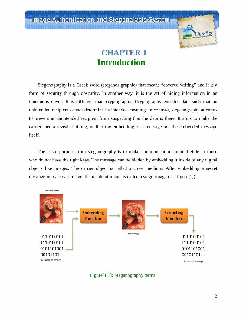
The basic purpose from steganography is to make communication unintelligible to those
who do not have the right keys. The message can be hidden by embedding it inside of any digital
objects like images. The carrier object is called a cover medium. After embedding a secret
message into a cover image, the resultant image is called a stego-image (see figure[1]).
Figure[1.1]: Steganography terms
3
The common approaches for message hiding in images include least significant bit(LSB)
insertion methods, frequency domain techniques, spread spectrum. The change in the behavior of
the stego-image depends on the specific approach used for hiding information. As the stego-
image cannot be easily recognized by human eyes, steganalysis tools are required to detect the
existence of hidden messages.
Steganalysis is the technology that attempts to defeat Steganography by detecting the
hidden information and extracting or destroying it if possible. The goal of steganalysis is to
identify suspected information streams, determine whether or not they have hidden messages
encoded into them, and, if possible, recover the hidden information.
There are various methods of steganalysis depending on what information is available:
Stego-only attack: Only the stego-object is available for analysis.
Known cover attack: The stego-object as well as the original medium is available. The stego-
object is compared with the original cover object to detect any hidden information.
Known message attack: The hidden message and the corresponding stego-image are known.
The analysis of patterns that correspond to the hidden information could help decipher such
messages in future.
Known stego attack: The steganography algorithm is known and both the original and stego-
object are available.
Chosen stego attack: The steganography algorithm and stego-object are known.
Chosen message attack: The steganalyst generates a stego-object from some steganography
tool or algorithm of a chosen message. The goal in this attack is to determine patterns in the
stego-object that may point to the use of specific steganography tools or algorithms.
In this project, we propose to implement a stego-only attack in LSB insertion for uncompressed
BMP images. This type of attack is the most common one because usually it is hard or impossible to get
the original image or to know the stego key or algorithm. The detection theory of the proposed
4
steganalysis method is based on statistical analysis of pixel pairs using their RGB components. We
believe that our method is effective for messages that are randomly scattered in the image.
Another important part of this project deals with image authentication. Authentication is the act of
establishing or confirming something (or someone) as authentic, that is that claims made by or about the
thing are true. Authenticating an object may mean confirming its provenance, whereas authenticating a
person often consists of verifying their identity. Authenticating an Image is the act of establishing or
confirming the image as authentic which has been taken by a camera, or if it has been tampered with or
if it has been used as a cover for a secret communication.
This can be done by adding visible watermarking, invisible or digital watermarking, distributed
source coding or by applying digital signature techniques. The location of authentication data could be
external or internal. If this data is stored in a separate file, two files have to be managed and it is quite
easy to lose this external authentication data. So it is better solution to store it inside the image file for
easy storage and maintenance.
A modern image authentication algorithm should have the following properties:
Integrity: The algorithm should be able to detect malicious modifications of the image data.
Embedding: The embedding of the authentication data into the image allows file conversions.
Robustness: The embedded data should be robust to non-malicious alterations of the image.
Visibility: The embedding induced image modification should not be visible to a human being.
Image dependence: The authentication data should be image dependent to prevent tampering.
Blindness: The integrity verification algorithm should not require the original image file.
Verification: Public verification must be allowed. No third party should be needed.
Security & Updatability: The integrity of the image data should not have an expiration date.
Since the security of an encryption scheme cannot be guaranteed forever, it must be possible to
update the encryption scheme without degrading the quality of the image in the future.
5
An effective authentication scheme should have the following desirable features:
• To be able to determine whether an image has been altered or not.
• To be able to locate any alteration made on the image.
• To be able to integrate authentication data with host image rather than as a separate data file.
• The embedded authentication data be invisible under normal viewing conditions.
• To allow the watermarked image be stored in lossy-compression format.
In this project we present an authentication scheme by embedding a bit string (derived from the image)
in the frequency domain of an image via table look-up. This scheme can be applied to compressed
image using JPEG. The visible alteration made on the marked image can be detected.
A number of authentication techniques based on digital watermarks have been proposed in
the literature.
A digital watermark is a secret key dependent signal inserted into a digital image and which can
be later detected/ extracted in order to make an assertion about the image. A digital watermark can be:
Fragile: if it fails to be detected after the slightest modification. Fragile watermarks are
commonly used for tamper detection.
Semi-fragile: if it resist benign transformations but fails detection after malignant
transformations. Semi-fragile watermarks are commonly used to detect malignant transformations.
Robust: if it resists a designated class of transformations. Robust watermarks are commonly
used in copyright applications (to carry ownership or forensic information) and copy protection
applications (to carry copy and access control information).
In this report, chapter two covers the literature review. Chapter three covers the necessary
background for the project. Chapter four covers the system analysis and design of the project. Chapter
five covers the project’s implementation. Chapter six covers the system testing.
6
Literature Review
Chapter 2
7
CHAPTER 2 Literature Review
2.1 Image Steganalysis Methods:
We classify and review current stego-detection algorithms that can be used to trace popular
steganographic products. We recognize several qualitatively different approaches to practical
steganalysis.
Westfield and Pfitzamann's histogram analysis [1] and Fridrich's RS-steganalysis [2]
algorithms are well-known model-based methods that target LSB embedding. Westfield and
Pfitzamann's technique is based on analyzing the pair of values (PoVs) in the image histogram.
The presence of the embedded message is detection with a ChiSqure test [1] that evaluate the
(dis)similarity between consecutive histogram bins. The method is most effective for images
with high payload, i.e. when most or all pixels used for LSB embedding. In RS-steganalysis [2],
Fridrich classify each pixel into regular and singular groups and perform detection based on the
relative number of such groups. A pixel is classified into regular (singular) group if its clique
potential is more(less) than its LSB flipped version. Computation of the potential over different
cliques takes the spatial distribution of pixels into account and imposes a smoothness constraint.
As a result, the algorithm is especially accurate when images conform with the smoothness
assumptions.
8
Jena and Krishna [3] proposed a new detection algorithm, which is an improved algorithm
to the difference image histogram algorithm and performed tests on a group of raw lossless
images.
Johnson and Jajodia [3,4] present a careful analysis of fingerprints introduced by current
steganographic software packages. They point out that most techniques for palette images with a
small number of colors can be easily broken by analyzing the palette for close pairs of colors.
Pfitzman and Westfield [5] introduce a powerful Chi-square steganalytic technique that can
reliably detect images with secret messages that are embedded in consecutive pixels (such as in
Steganos, J-Steg, S-tools, or EZ Stego). However, their technique will not be effective for raw
high-color images and for messages that are randomly scatteredin the image [6] .
Fridrich et al.[7,8] introduced a powerful steganalytic method (RS steganalysis) for
detection of LSB embedding that utilizes sensitive dual statistics derived from spatial
correlations in images . In a typical cover-image, the LSB plane can be predicted to some degree
from the remaining 7 bit-planes. This prediction becomes less reliable as the LSB is randomized.
This can be captured mathematically and used for building a sensitive and accurate steganalytic
method.
Fridrich et al [9] developed a steganographic method for detection of LSB embedding in
24-bit color images (the Raw Quick Pairs –RQP method). The RQP method is based on
analyzing close pairs of colors created by LSB embedding. It works reasonably well as long as
the number of unique colors in the cover image is less than 30% of the number of pixels. The
RQP method can only provide a rough estimate of the size of the secret message. The results
become progressively unreliable once the number of unique colors exceeds about 50 percent of
the number of pixels. This frequently happens for high resolution raw scans and images taken
with digital cameras stored in an uncompressed format. Another disadvantage of the RQP
method is that it cannot be applied to grayscale images [10].
9
2.2 Image Authentication Methods:
The well known adage that “seeing is believing” is no longer true due to the availability of
powerful image manipulation software. This technical development has decreased the credibility
that photography used to achieve .Development of robust image authentication techniques
becomes an important issue. Two main methods have been suggested for achieving the
authenticity of digital images: having a digital camera sign the image using a digital signature
[13], or embedding a secret code in the image [15]. The first method uses an encrypted digital
“signature,” which is generated in the capturing devices. A digital signature is based on the
method of Public Key Encryption .A private key is used to encrypt a hashed version of the
image. This encrypted message is called the “signature” of the image, and it provides a way to
ensure that this signature cannot be forged. This signature then travels with the image. The
authentication process of this image needs an associated public key to decrypt the signature. The
image received for authentication is hashed and compared to the codes of the signature. If they
match, then the received image is authenticated. The second method embeds a “watermark” in an
image [14], [15], [16]. The fragile watermark will usually be destroyed after manipulation.
Authenticity is determined by examining the watermark extracted from the received image. Both
the above methods have clear drawbacks. Authenticity will not be preserved unless every pixel
of the images is unchanged. However, since lossy compression such as JPEG is often
acceptable—or even desired—in practical applications, an authentication method needs to be
able to distinguish lossy compression from malicious manipulations [17].
Another method, Hashing Scheme for Image Authentication"[11] it is a hashing scheme to
authenticate digital images. it is designed to be resilient for acceptable manipulations like JPEG
compression and low pass filtering, and at the same time is sensitive enough to detect malicious
manipulations .It uses a key dependent feature extraction to enforce security. Specifically, the
10
scheme divides an image into a number of non overlapping blocks. Pixels in each block are
permuted using a secret key. For each permuted block, a feature vector is formed by choosing the
LL-sub-band coefficients which are then quantized to form the hash of that block.
Chia-Hung , Hao-Kuan , Der-Chyuan , and David [12] proposed a new method for image
authentication by Combining Digital Signature and Watermarking. The proposed method not
only can resist Holliman-Memon attack, but also can accurately detect the tampered location of
an image. First, a watermark is created from a protected image by using an edge detection
technique. Second, the created watermark is divided into blocks and embedded into the 2-LSB
(top layer) of the protected image. Third, all block signatures are calculated and embedded into
the 1-LSB (low layer) of the protected image. At the low layer, the calculated signatures can
resist Holliman- Memon attack. At the top layer, the created watermark can accurately detect the
tampered location of an image.
Another method of authentication is where the authentication data is stored in a separate
file, two files have to be managed. For example, strict authentication algorithms are based on
conventional cryptographic hash functions (e.g. MD2, MD5, SHA-1, SHA-256, RIP-MED-160).
These hash functions are sensitive to single bit changes. If even one bit of the input signal is
modified, the output of a classical hash function alters dramatically and hence no verification is
possible. Therefore, they are only suited for strict authentication. The hash value is usually stored
externally in a separate file. To allow signal processing operations, which preserve the content of
an image, non-strict authentication algorithms are required. One possibility is that, before the
hash is calculated, features of the image are extracted. These features must represent the image
content and be invariant to global content-preserving signal processing operations. Another often
used solution is the use of robust hash functions since it is quite easy to lose this external
authentication data; it is a better solution to store it inside the image file for easy storage and
maintenance. This can be done by adding authentication data as metadata to the image file or by
embedding the authentication data as a watermark inside the image. The advantage to store the
authentication data intern as metadata is, that the image quality is not degraded. The drawback of
this approach used in [18]-[19] is, however, that the authentication data is usually lost after the

11
image is converted into different file formats. Since it is quite common to convert the images
into different file formats, it is better to insert the authentication data as a watermark directly into
the image.[20]

12
CHAPTER 3
Chapter 3
Background
13
CHAPTER 3 Background
3.1 Digital Image File Formats
In this project, we will deal with two digital image file formats. The following is a
description of the formats:
3.1.1 BMP Format
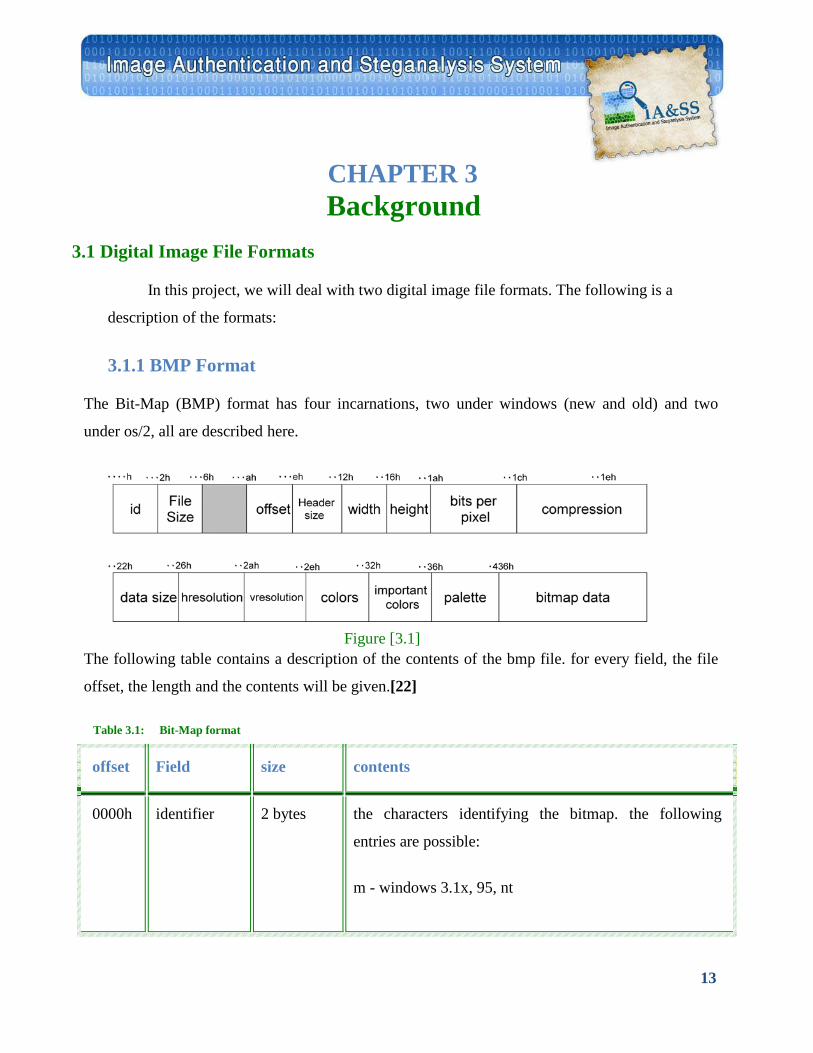
The Bit-Map (BMP) format has four incarnations, two under windows (new and old) and two
under os/2, all are described here.
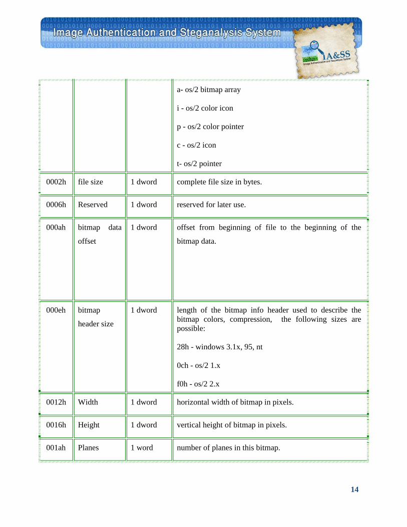
The following table contains a description of the contents of the bmp file. for every field, the file
offset, the length and the contents will be given.[22]
offset Field size contents
0000h identifier 2 bytes the characters identifying the bitmap. the following
entries are possible:
m - windows 3.1x, 95, nt
Table 3.1: Bit-Map format
Figure [3.1]
14
a- os/2 bitmap array
i - os/2 color icon
p - os/2 color pointer
c - os/2 icon
t- os/2 pointer
0002h file size 1 dword complete file size in bytes.
0006h Reserved 1 dword reserved for later use.
000ah bitmap data
offset
1 dword offset from beginning of file to the beginning of the
bitmap data.
000eh bitmap
header size
1 dword length of the bitmap info header used to describe the bitmap colors, compression, the following sizes are possible:
28h - windows 3.1x, 95, nt
0ch - os/2 1.x
f0h - os/2 2.x
0012h Width 1 dword horizontal width of bitmap in pixels.
0016h Height 1 dword vertical height of bitmap in pixels.
001ah Planes 1 word number of planes in this bitmap.
15
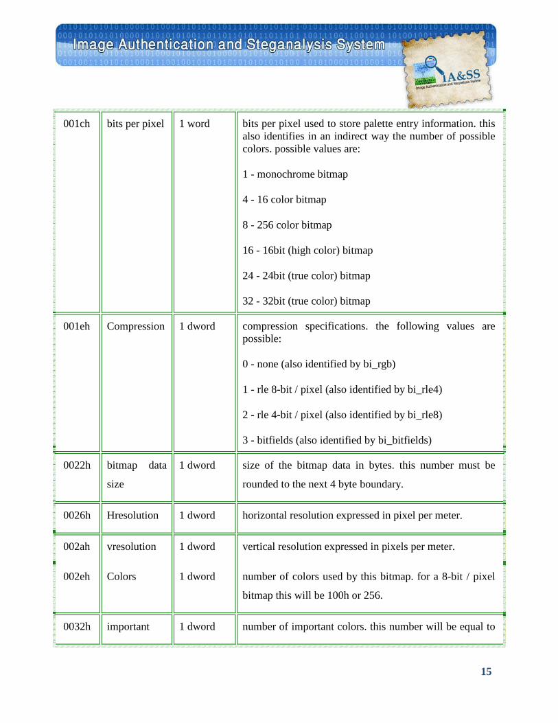
001ch bits per pixel 1 word bits per pixel used to store palette entry information. this also identifies in an indirect way the number of possible colors. possible values are:
1 - monochrome bitmap
4 - 16 color bitmap
8 - 256 color bitmap
16 - 16bit (high color) bitmap
24 - 24bit (true color) bitmap
32 - 32bit (true color) bitmap
001eh Compression 1 dword compression specifications. the following values are possible:
0 - none (also identified by bi_rgb)
1 - rle 8-bit / pixel (also identified by bi_rle4)
2 - rle 4-bit / pixel (also identified by bi_rle8)
3 - bitfields (also identified by bi_bitfields)
0022h bitmap data
size
1 dword size of the bitmap data in bytes. this number must be
rounded to the next 4 byte boundary.
0026h Hresolution 1 dword horizontal resolution expressed in pixel per meter.
002ah vresolution 1 dword vertical resolution expressed in pixels per meter.
002eh Colors 1 dword number of colors used by this bitmap. for a 8-bit / pixel
bitmap this will be 100h or 256.
0032h important 1 dword number of important colors. this number will be equal to

16
colors the number of colors when every color is important.
0036h Palette n * 4 byte the palette specification. for every entry in the palette four bytes are used to describe the rgb values of the color in the following way:
1 byte for blue component
Transfer interrupted!
p>
1 byte for red component
1 byte filler which is set to 0 (zero)
0436h bitmap data x bytes depending on the compression specifications, this field
contains all the bitmap data bytes which represent indices
in the color palette.
Note: the following sizes were used in the specification above:
size # bytes Sign
char 1 Signed
word 2 Unsigned
dword 4 Unsigned
Table 3.2: size of type
17
3.1.2 JPEG Format
The JPEG (Joint Photographic Experts Group; pronounced "jay-peg") file format was
developed by C-Cube Microsystems in 1992 to provide an efficient method of storing deep-pixel
images, such as scanned photographs, which are characterized by numerous subtle (and
sometimes not so subtle) variations in color. The greatest difference between JPEG and the other
file formats discussed here is that JPEG uses a lossy, not a lossless, compression algorithm.
Lossless compression preserves image data, so that a decompressed image matches the original
image exactly. Lossy compression sacrifices some image data in order to achieve greater
compression ratios. A decompressed JPEG image rarely matches the original exactly, but very
often the differences are so minor that they are barely detectable, if at all.
JPEG image compression is a complex process that frequently requires a hardware assist to
achieve acceptable performance. First, the image is tiled into blocks that measure 8 pixels to a
side. Each block is then compressed separately, in three stages. The first stage involves using a
discrete cosine transform (DCT) formula to convert the 8-by-8 block of pixel data into an 8-by-8
matrix of amplitude values representing different frequencies (or rates of color change) in the
image. In stage two, the values in the amplitude matrix are divided by the values in a
quantization matrix that's biased to filter out amplitudes that are less important to the overall
appearance of the image. In the third and final stage, the quantized amplitude matrix is
compressed using a lossless compression algorithm.
Because the quantized matrix lacks much of the high-frequency information of its
predecessor, it frequently compresses to half its original size or less. Lossless compression
methods are often unable to compress real-life photographic images at all, so a 50-percent
reduction is quite good. On the other hand, lossless compression methods can reduce some
images by 90 percent. Such images are poor candidates for JPEG compression.
The lossy part of the JPEG compression is stage two. The higher the values in the
quantization matrix, the greater the amount of information discarded from the image, and the
18
more tightly the image is compressed. The trade-off is that higher quantization values result in
poorer image quality. When a JPEG image is generated, its creator chooses a quality factor,
whose value drives the values in the quantization matrix. The optimal quality factor--the one that
exhibits the best balance between compression ratio and image quality--is different for every
image and is usually found only through trial and error. [28, 29]
3.1.2.1 Overview of the JPEG bit-stream:
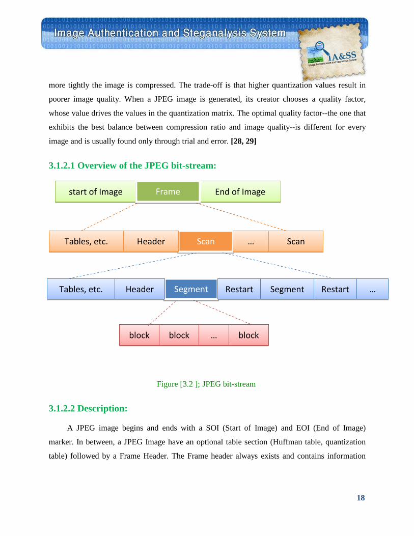
Figure [3.2 ]; JPEG bit-stream
3.1.2.2 Description:
A JPEG image begins and ends with a SOI (Start of Image) and EOI (End of Image)
marker. In between, a JPEG Image have an optional table section (Huffman table, quantization
table) followed by a Frame Header. The Frame header always exists and contains information
block block block …
Scan Tables, etc. Header Scan …
End of Image start of Image Frame
Segment Tables, etc. Header Restart Segment Restart …

19
such as the width and height of the image. The Frame header is then followed by a series of
scans.
A Scan may specify its own huffman tables and quantization tables, in which case it will
overwrite the tables specified before in the bit-stream. A Scan always contains a scan header,
which specifies information about the scan, such as which table to use, how many components
are there etc. Scan header is followed by scan data, which contains the encoded image.
The JpegHdr contains the huffman tables and the quantization tables, since only one valid set of tables can be present at any time. JpegScanHdr includes information from the scan header in the BitStream. Tables encountered while parsing a scan is updated into JpegHdr. The scan data representing the compressed image is stored as ScImages, after it is parsed from the Bit-Stream.
• "Frame" is a picture • "scan" is a pass through the pixels (e.g., the red component) • "segment" is a group of blocks • "block" is an 8x8 group of pixels.
Frame header: sample precision (width, height) of image number of components unique ID (for each component) horizontal/vertical sampling factors (for each component) quantization table to use (for each component)
Scan header:
Number of components in scan
component ID (for each component)
Huffman table for each component (for each component)
Misc. (can occur between headers)
Quantization tables
Huffman Tables
Arithmetic Coding Tables
20
Comments
Application Data
3.2 JPEG Compression
3.2.1 Conversion from RGB to YCbCr
JPEG files use a different color space than bitmaps. The three color coefficients (Red,
Green, Blue or RGB) for each pixel are transformed into a new coding scheme: one luminance
coefficient (the intensity - if we just keep this one we have a black and white image), and two
chrominance coefficients (the actual color in a 2D grid defined by a Blue/Yellow and a
Red/Green axis). After this step, we have YCbCr values.
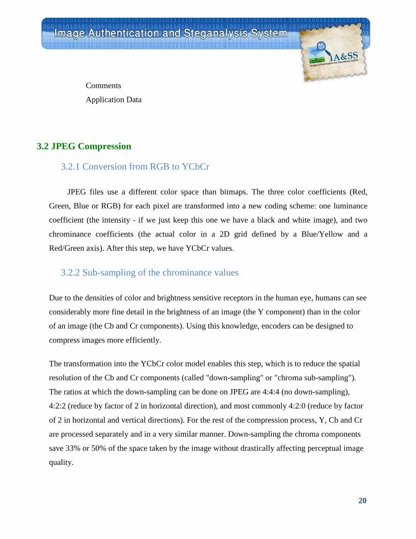
3.2.2 Sub-sampling of the chrominance values
Due to the densities of color and brightness sensitive receptors in the human eye, humans can see
considerably more fine detail in the brightness of an image (the Y component) than in the color
of an image (the Cb and Cr components). Using this knowledge, encoders can be designed to
compress images more efficiently.
The transformation into the YCbCr color model enables this step, which is to reduce the spatial
resolution of the Cb and Cr components (called "down-sampling" or "chroma sub-sampling").
The ratios at which the down-sampling can be done on JPEG are 4:4:4 (no down-sampling),
4:2:2 (reduce by factor of 2 in horizontal direction), and most commonly 4:2:0 (reduce by factor
of 2 in horizontal and vertical directions). For the rest of the compression process, Y, Cb and Cr
are processed separately and in a very similar manner. Down-sampling the chroma components
save 33% or 50% of the space taken by the image without drastically affecting perceptual image
quality.
21
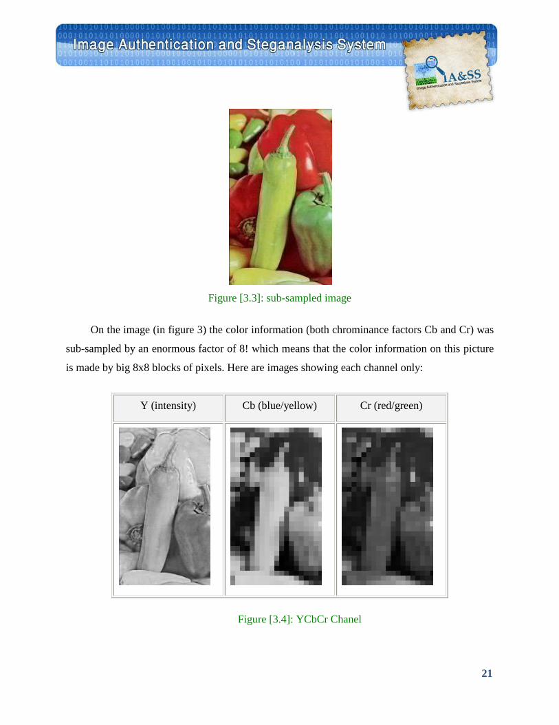
Figure [3.3]: sub-sampled image
On the image (in figure 3) the color information (both chrominance factors Cb and Cr) was
sub-sampled by an enormous factor of 8! which means that the color information on this picture
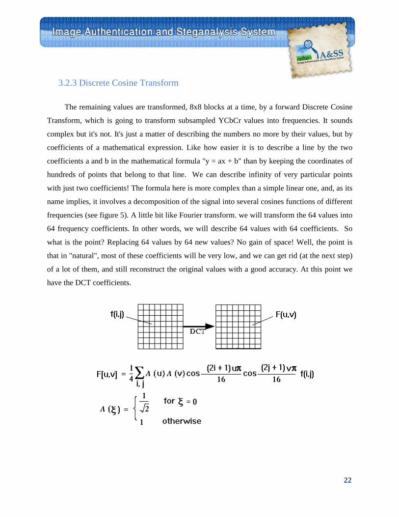
is made by big 8x8 blocks of pixels. Here are images showing each channel only:
Y (intensity) Cb (blue/yellow) Cr (red/green)
Figure [3.4]: YCbCr Chanel
22
3.2.3 Discrete Cosine Transform
The remaining values are transformed, 8x8 blocks at a time, by a forward Discrete Cosine
Transform, which is going to transform subsampled YCbCr values into frequencies. It sounds
complex but it's not. It's just a matter of describing the numbers no more by their values, but by
coefficients of a mathematical expression. Like how easier it is to describe a line by the two
coefficients a and b in the mathematical formula "y = ax + b" than by keeping the coordinates of
hundreds of points that belong to that line. We can describe infinity of very particular points
with just two coefficients! The formula here is more complex than a simple linear one, and, as its
name implies, it involves a decomposition of the signal into several cosines functions of different
frequencies (see figure 5). A little bit like Fourier transform. we will transform the 64 values into
64 frequency coefficients. In other words, we will describe 64 values with 64 coefficients. So
what is the point? Replacing 64 values by 64 new values? No gain of space! Well, the point is
that in "natural", most of these coefficients will be very low, and we can get rid (at the next step)
of a lot of them, and still reconstruct the original values with a good accuracy. At this point we
have the DCT coefficients.
23
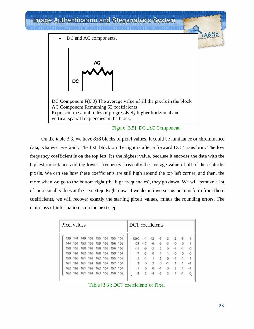
On the table 3.3, we have 8x8 blocks of pixel values. It could be luminance or chrominance
data, whatever we want. The 8x8 block on the right is after a forward DCT transform. The low
frequency coefficient is on the top left. It's the highest value, because it encodes the data with the
highest importance and the lowest frequency: basically the average value of all of these blocks
pixels. We can see how these coefficients are still high around the top left corner, and then, the
more when we go to the bottom right (the high frequencies), they go down. We will remove a lot
of these small values at the next step. Right now, if we do an inverse cosine transform from these
coefficients, we will recover exactly the starting pixels values, minus the rounding errors. The
main loss of information is on the next step.
Pixel values DCT coefficients
Table [3.3]: DCT coefficients of Pixel
• DC and AC components.
DC Component F(0,0) The average value of all the pixels in the block AC Component Remaining 63 coefficients Represent the amplitudes of progressively higher horizontal and vertical spatial frequencies in the block.
Figure [3.5]: DC ,AC Component
24
3.2.4 Quantization
The human eye is good at seeing small differences in brightness over a relatively large
area, but not so good at distinguishing the exact strength of a high frequency brightness
variation. This fact allows one to get away with greatly reducing the amount of information in
the high frequency components. This is done by simply dividing each component in the
frequency domain by a constant for that component, and then rounding to the nearest integer.
This is the main lossy operation in the whole process. As a result of this, it is typically the case
that many of the higher frequency components are rounded to zero, and many of the rest become
small positive or negative numbers, which take many fewer bits to store.
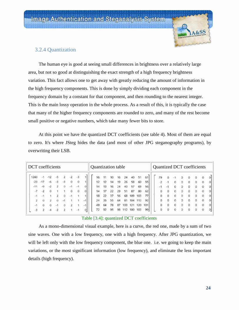
At this point we have the quantized DCT coefficients (see table 4). Most of them are equal
to zero. It's where JSteg hides the data (and most of other JPG steganography programs), by
overwriting their LSB.
DCT coefficients Quantization table Quantized DCT coefficients
Table [3.4]: quantized DCT coefficients
As a mono-dimensional visual example, here is a curve, the red one, made by a sum of two
sine waves. One with a low frequency, one with a high frequency. After JPG quantization, we
will be left only with the low frequency component, the blue one. i.e. we going to keep the main
variations, or the most significant information (low frequency), and eliminate the less important
details (high frequency).
25
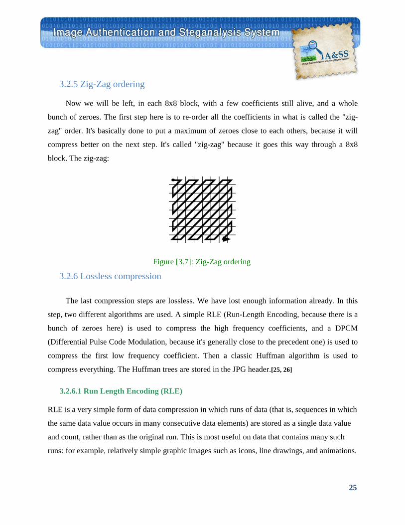
3.2.5 Zig-Zag ordering
Now we will be left, in each 8x8 block, with a few coefficients still alive, and a whole
bunch of zeroes. The first step here is to re-order all the coefficients in what is called the "zig-
zag" order. It's basically done to put a maximum of zeroes close to each others, because it will
compress better on the next step. It's called "zig-zag" because it goes this way through a 8x8
block. The zig-zag:
Figure [3.7]: Zig-Zag ordering
3.2.6 Lossless compression
The last compression steps are lossless. We have lost enough information already. In this
step, two different algorithms are used. A simple RLE (Run-Length Encoding, because there is a
bunch of zeroes here) is used to compress the high frequency coefficients, and a DPCM
(Differential Pulse Code Modulation, because it's generally close to the precedent one) is used to
compress the first low frequency coefficient. Then a classic Huffman algorithm is used to
compress everything. The Huffman trees are stored in the JPG header.[25, 26]
3.2.6.1 Run Length Encoding (RLE)
RLE is a very simple form of data compression in which runs of data (that is, sequences in which
the same data value occurs in many consecutive data elements) are stored as a single data value
and count, rather than as the original run. This is most useful on data that contains many such
runs: for example, relatively simple graphic images such as icons, line drawings, and animations.
26
For example, consider a screen containing plain black text on a solid white background. There
will be many long runs of white pixels in the blank space, and many short runs of black pixels
within the text. Let us take a hypothetical single scan line, with B representing a black pixel and
W representing white:
WWWWWWWWWWWWBWWWWWWWWWWWWBBBWWWWWWWWWWWWWWWWWWWWWWWWBWWWWWWWWWWWWWW
If we apply the run-length encoding (RLE) data compression algorithm to the above hypothetical
scan line, we get the following:
12W1B12W3B24W1B14W
Interpret this as twelve W's, one B, twelve W's, three B's, etc.
The run-length code represents the original 67 characters in only 18. Of course, the actual format
used for the storage of images is generally binary rather than ASCII characters like this, but the
principle remains the same. Even binary data files can be compressed with this method; file
format specifications often dictate repeated bytes in files as padding space.
JPEG uses the RLE quite effectively on the coefficients that remain after transforming and
quantizing image blocks. For example, RLE encodes as (skip, value) pairs, where skip is the
number of zeros and value is the next non-zero component. [27]
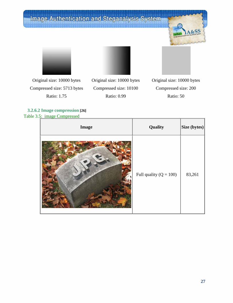
Example
The following 3 images illustrate the different extremes, the first image contains runs along
each row and will compress well. The second image is the same as the first but rotated 90
degrees so there are no runs giving worse case and a larger file. This suggests a natural extension
to RLE for images, that is, one compresses vertically and horizontally and uses the best, the flag
indicating which one is used is stored in the image header. The last case is the best scenario
where the whole image is a constant value. [30]
27
Original size: 10000 bytes
Compressed size: 5713 bytes
Ratio: 1.75
Original size: 10000 bytes
Compressed size: 10100
Ratio: 0.99
Original size: 10000 bytes
Compressed size: 200
Ratio: 50
3.2.6.2 Image compression [26]
Image Quality Size (bytes)
Full quality (Q = 100) 83,261
Table 3.5: image Compressed
28
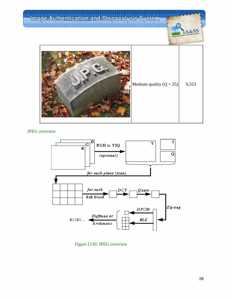
Medium quality (Q = 25) 9,553
JPEG overview
Figure [3.8]: JPEG overview
29
3.3 RSA Encryption
It is an Asymmetric algorithm published in 1977 and patented by MIT in 1983, It is the
most common asymmetric encryption and authentication algorithm. RSA algorithm’s security is
based on the difficulty of factoring large numbers (in particular, products of large primes) [31,32]
3.3.1 Key Generation Algorithm
1. Generate two large random primes, p and q, of approximately equal size such that their
product
2. n = p*q is of the required bit length, e.g. 1024 bits.
3. Compute n = p*q and (φ) phi = (p-1)*(q-1).
4. Choose an integer e, 1 < e < phi, such that gcd(e, phi) = 1.
5. Compute the secret exponent d, 1<d<phi, such that ed ≡ 1 (mod phi).
The public key is (n, e) and the private key is (n, d). The values of p, q, and phi should also be kept secret.
n is known as the modulus.
e is known as the public exponent or encryption exponent.
d is known as the secret exponent or decryption exponent.
3.3.2 Encryption Sender A does the following:- • Obtains the recipient B's public key (n, e).
• Represents the plaintext message as a positive integer m .
• Computes the ciphertext c = m^e mod n.
• Sends the ciphertext c to B.
3.3.3 Decryption Recipient B does the following:-
30
• Uses his private key (n, d) to compute m = c^d mod n.
• Extracts the plaintext from the integer representative m.
3.3.4 Digital signing Sender A does the following:- • Creates a message digest of the information to be sent.
• Represents this digest as an integer m between 0 and n-1.
• Uses her private key (n, d) to compute the signature s = m^d mod n.
• Sends this signature s to the recipient, B.
3.3.5 Signature verification Recipient B does the following:- • Uses sender A's public key (n, e) to compute integer v = s^e mod n.
• Extracts the message digest from this integer.
• Independently computes the message digest of the information that has been signed.
• If both message digests are identical, the signature is valid.
3.3.6 RSA Security Services Confidentiality: Only the owner of the private key knows it, so text encrypted with public key
cannot be read by anyone except the owner of the private key
Authentication: Only the owner of the private key knows it, so text encrypted with the private
key must have been generated by the owner
Integrity: Encrypted letters cannot be changed undetectably without knowing private key
Non-Repudiation: Message encrypted with private key came from someone who knew it
31
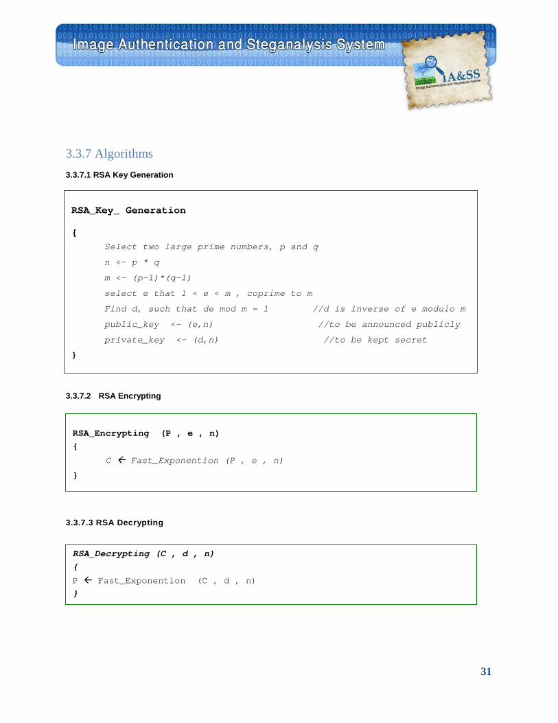
3.3.7 Algorithms 3.3.7.1 RSA Key Generation
3.3.7.2 RSA Encrypting
3.3.7.3 RSA Decrypting
RSA_Key_ Generation
{ Select two large prime numbers, p and q
n <- p * q
m <- (p-1)*(q-1)
select e that 1 < e < m , coprime to m
Find d, such that de mod m = 1 //d is inverse of e modulo m
public_key <- (e,n) //to be announced publicly
private_key <- (d,n) //to be kept secret
}
RSA_Encrypting (P , e , n) {
C Fast_Exponention (P , e , n)
}
RSA_Decrypting (C , d , n) {
P Fast_Exponention (C , d , n) }
32
3.4 Hashing
The Merkle-Damgard scheme is the basics for many cryptographic hash functions today.
The only thing we need to do is to design a compression function that is collision resistant and
insert it in the Merkle-Damgard scheme.
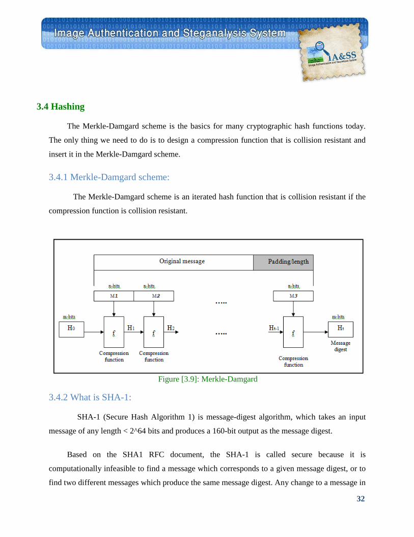
3.4.1 Merkle-Damgard scheme:
The Merkle-Damgard scheme is an iterated hash function that is collision resistant if the
compression function is collision resistant.
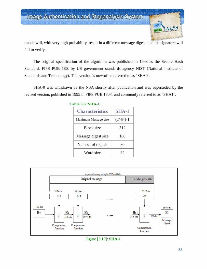
3.4.2 What is SHA-1:
SHA-1 (Secure Hash Algorithm 1) is message-digest algorithm, which takes an input
message of any length < 2^64 bits and produces a 160-bit output as the message digest.
Based on the SHA1 RFC document, the SHA-1 is called secure because it is
computationally infeasible to find a message which corresponds to a given message digest, or to
find two different messages which produce the same message digest. Any change to a message in
Figure [3.9]: Merkle-Damgard
33
transit will, with very high probability, result in a different message digest, and the signature will
fail to verify.
The original specification of the algorithm was published in 1993 as the Secure Hash
Standard, FIPS PUB 180, by US government standards agency NIST (National Institute of
Standards and Technology). This version is now often referred to as "SHA0".
SHA-0 was withdrawn by the NSA shortly after publication and was superseded by the
revised version, published in 1995 in FIPS PUB 180-1 and commonly referred to as "SHA1".
Characteristics SHA-1 Maximum Message size 2^64)-1(
Block size 512
Message digest size 160
Number of rounds 80
Word size 32
Table 3.6 :SHA-1
Figure [3.10]: SHA-1
34
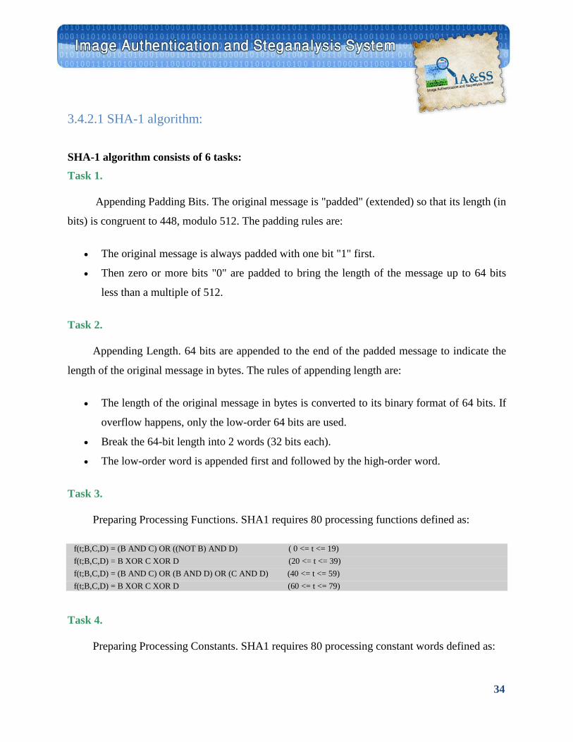
3.4.2.1 SHA-1 algorithm: SHA-1 algorithm consists of 6 tasks: Task 1.
Appending Padding Bits. The original message is "padded" (extended) so that its length (in
bits) is congruent to 448, modulo 512. The padding rules are:
• The original message is always padded with one bit "1" first.
• Then zero or more bits "0" are padded to bring the length of the message up to 64 bits
less than a multiple of 512.
Task 2.
Appending Length. 64 bits are appended to the end of the padded message to indicate the
length of the original message in bytes. The rules of appending length are:
• The length of the original message in bytes is converted to its binary format of 64 bits. If
overflow happens, only the low-order 64 bits are used.
• Break the 64-bit length into 2 words (32 bits each).
• The low-order word is appended first and followed by the high-order word.
Task 3.
Preparing Processing Functions. SHA1 requires 80 processing functions defined as:
f(t;B,C,D) = (B AND C) OR ((NOT B) AND D) ( 0 <= t <= 19) f(t;B,C,D) = B XOR C XOR D (20 <= t <= 39) f(t;B,C,D) = (B AND C) OR (B AND D) OR (C AND D) (40 <= t <= 59) f(t;B,C,D) = B XOR C XOR D (60 <= t <= 79)
Task 4.
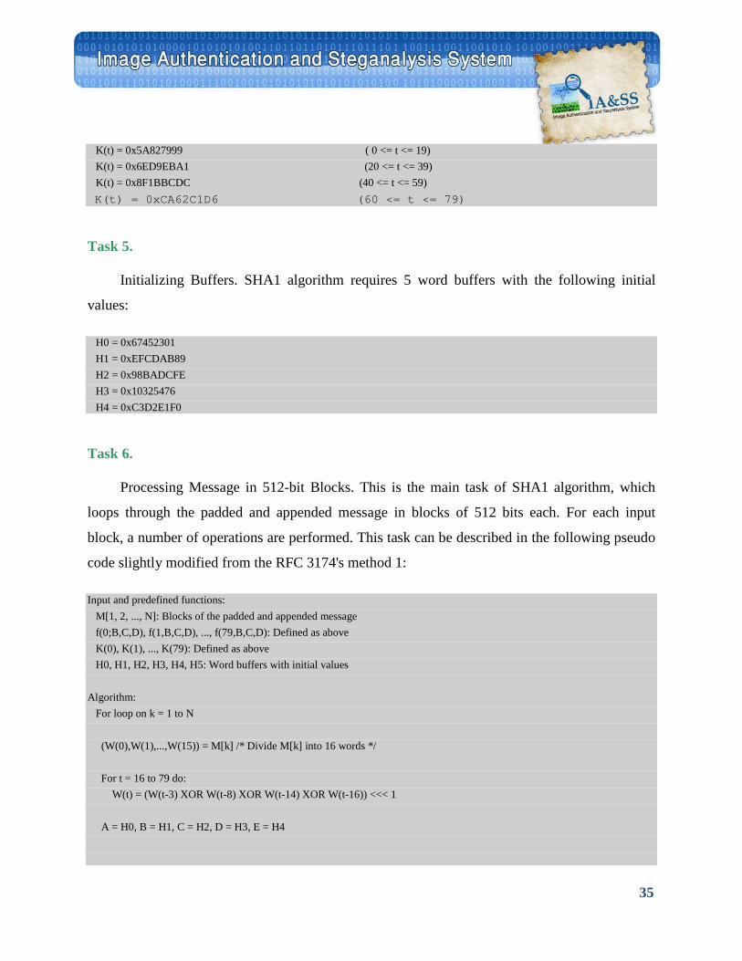
Preparing Processing Constants. SHA1 requires 80 processing constant words defined as:
35
K(t) = 0x5A827999 ( 0 <= t <= 19) K(t) = 0x6ED9EBA1 (20 <= t <= 39) K(t) = 0x8F1BBCDC (40 <= t <= 59) K(t) = 0xCA62C1D6 (60 <= t <= 79)
Task 5.
Initializing Buffers. SHA1 algorithm requires 5 word buffers with the following initial
values:
H0 = 0x67452301 H1 = 0xEFCDAB89 H2 = 0x98BADCFE H3 = 0x10325476 H4 = 0xC3D2E1F0
Task 6.
Processing Message in 512-bit Blocks. This is the main task of SHA1 algorithm, which
loops through the padded and appended message in blocks of 512 bits each. For each input
block, a number of operations are performed. This task can be described in the following pseudo
code slightly modified from the RFC 3174's method 1:
Input and predefined functions: M[1, 2, ..., N]: Blocks of the padded and appended message f(0;B,C,D), f(1,B,C,D), ..., f(79,B,C,D): Defined as above K(0), K(1), ..., K(79): Defined as above H0, H1, H2, H3, H4, H5: Word buffers with initial values Algorithm: For loop on k = 1 to N (W(0),W(1),...,W(15)) = M[k] /* Divide M[k] into 16 words */ For t = 16 to 79 do: W(t) = (W(t-3) XOR W(t-8) XOR W(t-14) XOR W(t-16)) <<< 1 A = H0, B = H1, C = H2, D = H3, E = H4
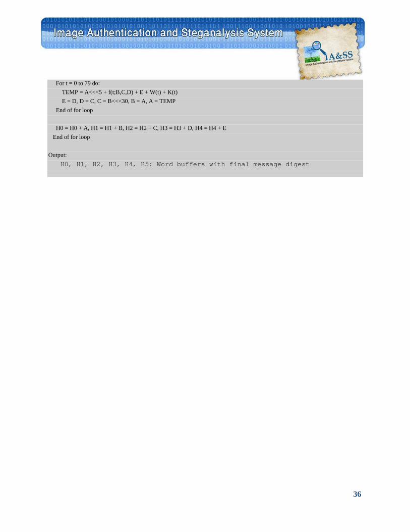
36
For t = 0 to 79 do: TEMP = A<<<5 + f(t;B,C,D) + E + W(t) + K(t) E = D, D = C, C = B<<<30, B = A, A = TEMP End of for loop H0 = H0 + A, H1 = H1 + B, H2 = H2 + C, H3 = H3 + D, H4 = H4 + E End of for loop Output: H0, H1, H2, H3, H4, H5: Word buffers with final message digest
37
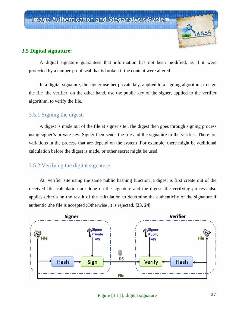
3.5 Digital signature:
A digital signature guarantees that information has not been modified, as if it were
protected by a tamper-proof seal that is broken if the content were altered.
In a digital signature, the signer use her private key, applied to a signing algorithm, to sign
the file .the verifier, on the other hand, use the public key of the signer, applied to the verifier
algorithm, to verify the file.
3.5.1 Signing the digest:
A digest is made out of the file at signer site .The digest then goes through signing process
using signer’s private key. Signer then sends the file and the signature to the verifier. There are
variations in the process that are depend on the system .For example, there might be additional
calculation before the digest is made, or other secret might be used.
3.5.2 Verifying the digital signature
At verifier site using the same public hashing function ,a digest is first create out of the
received file .calculation are done on the signature and the digest .the verifying process also
applies criteria on the result of the calculation to determine the authenticity of the signature if
authentic ,the file is accepted ;Otherwise ,it is rejected. [23, 24]
File
Verifier Signer
Signer Private Key Signer Public key
File
DS File
Hash Hash Sign Verify
Figure [3.11]: digital signature
38
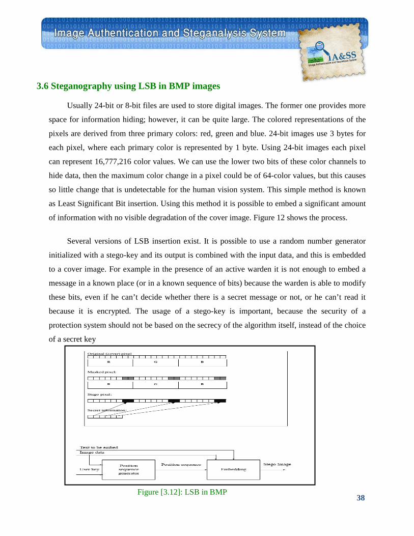
3.6 Steganography using LSB in BMP images
Usually 24-bit or 8-bit files are used to store digital images. The former one provides more
space for information hiding; however, it can be quite large. The colored representations of the
pixels are derived from three primary colors: red, green and blue. 24-bit images use 3 bytes for
each pixel, where each primary color is represented by 1 byte. Using 24-bit images each pixel
can represent 16,777,216 color values. We can use the lower two bits of these color channels to
hide data, then the maximum color change in a pixel could be of 64-color values, but this causes
so little change that is undetectable for the human vision system. This simple method is known
as Least Significant Bit insertion. Using this method it is possible to embed a significant amount
of information with no visible degradation of the cover image. Figure 12 shows the process.
Several versions of LSB insertion exist. It is possible to use a random number generator
initialized with a stego-key and its output is combined with the input data, and this is embedded
to a cover image. For example in the presence of an active warden it is not enough to embed a
message in a known place (or in a known sequence of bits) because the warden is able to modify
these bits, even if he can’t decide whether there is a secret message or not, or he can’t read it
because it is encrypted. The usage of a stego-key is important, because the security of a
protection system should not be based on the secrecy of the algorithm itself, instead of the choice
of a secret key
Figure [3.12]: LSB in BMP
39
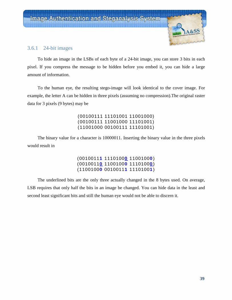
3.6.1 24-bit images
To hide an image in the LSBs of each byte of a 24-bit image, you can store 3 bits in each
pixel. If you compress the message to be hidden before you embed it, you can hide a large
amount of information.
To the human eye, the resulting stego-image will look identical to the cover image. For
example, the letter A can be hidden in three pixels (assuming no compression).The original raster
data for 3 pixels (9 bytes) may be
(00100111 11101001 11001000) (00100111 11001000 11101001) (11001000 00100111 11101001)
The binary value for a character is 10000011. Inserting the binary value in the three pixels
would result in
(00100111 11101000 11001000) (00100110 11001000 11101000) (11001000 00100111 11101001)
The underlined bits are the only three actually changed in the 8 bytes used. On average,
LSB requires that only half the bits in an image be changed. You can hide data in the least and
second least significant bits and still the human eye would not be able to discern it.
40
3.6.2 8-bit images
8-bit images are not as forgiving to LSB manipulation because of color limitations.
Steganography software authors have devised several approaches—some more successful than
others—to hide information in 8-bit images. First, the cover image must be more carefully
selected so that the stego-image will not broadcast the existence of an embedded message. When
information is inserted into the LSBs of the raster data, the pointers to the color entries in the
palette are changed. In an abbreviated example, a simple four-color palette of white, red, blue,
and green has corresponding palette position entries of 0 (00),1 (01), 2 (10), and 3 (11),
respectively. The raster values of four adjacent pixels of white, white, blue, and blue are 00 00
10 10. Hiding the binary value 1010 for the number 10 changes the raster data to 01 00 11 10,
which is red, white, green, blue. These gross changes in the image are visible and clearly
highlight the weakness of using 8-bit images. On the other hand, there is little visible difference
noticed between adjacent gray values.

41
System Analysis and
Design
Chapter 4

42
CHAPTER 4 System Analysis and Design
4.1 Problem Definition:
The rapid evolution of multimedia technology over the past decade has brought about many
advantages in the creation and distribution of image content .But beneath the ability of easy
copying, transmitting and editing digital images the need for image content protection increases.
Digital images can be modified or forged with a wide variety of available manipulation software
and hence it is rather difficult to tell if a picture is the original one, which has been taken by a
camera, or if has been tampered with.
Thus image authentication aims to prevent illegitimate tampering and fraudulent use of
modified image. Such tampering of images may take on one of two forms:
1.An image may be altered or forged and made to look very real to the unsuspecting eye, via the
usage of some very sophisticated image editing and manipulation software available on the
Internet.
2.An image may be used as cover to carry secret messages between individuals on the Internet, via
the usage of steganography tools also available on the Internet.
Hence there is a need for a means for image authentication and a tool for image analysis to
detect such illegitimate image manipulations.

43
4.2 Objectives: Powerful publicly available image processing software packages such as Adobe PhotoShop
make digital forgeries a reality. Feathered cropping enables replacing or adding features without
causing detectable edges. It is also possible to carefully cut out portions of several images and
combine them together while leaving barely detectable traces.
The purpose of this project is to present steganographic techniques for tamper detection and
authentication of digital images. Fragile, robust watermarks, and self-embedding are treated as a
means for detecting both malicious and inadvertent changes to digital imagery.
In this project we propose several techniques based on digital signature and data hiding in
images that will be designed and implemented as a means for detecting tampering in digital
images whether it be steganography or deliberate image tampering. We will also propose a
technique for self-embedding an image into itself as a means for protecting the image content
and recovering an approximation of it for visually detecting tampering.
44
4.3 Functional Specification The project has the following functions:
1. Sign an image(BMP OR JPEG):
Load image: the user selects image from a specific path. Sign image: the image is digitally signed by the system. Save image: the user selects a place to save the signed image in.
2. Detect stenography or tampering in an image(BMP OR JPEG) with
authentication feature:
Load image: the user selects image from specific path Check image's authenticity and display the result: this function checks and analyzes the authenticity of the image to detect whether the image has been edited or a massage has been embedded. Then, it displays result.
3. Detect steganography in an image(BMP ) with no authentication
feature:
Load image: the user selects image from specific path Check image and display result: this function analyzes image to detect steganography, and displays the result.
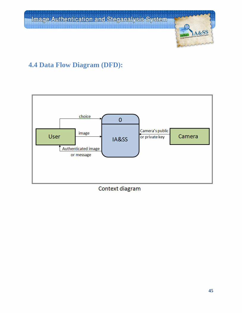
45
4.4 Data Flow Diagram (DFD):
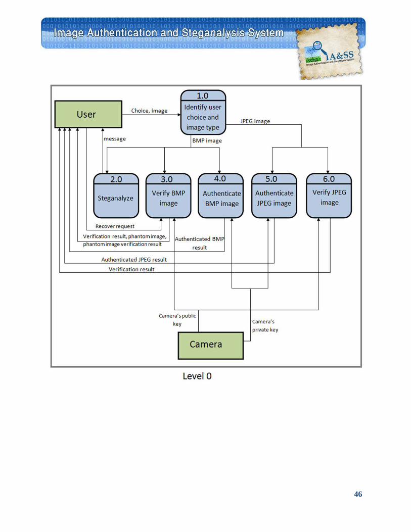
46
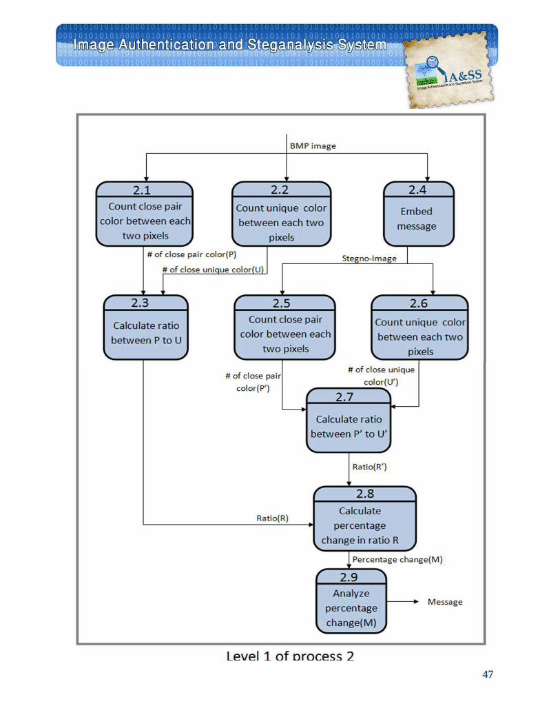
47
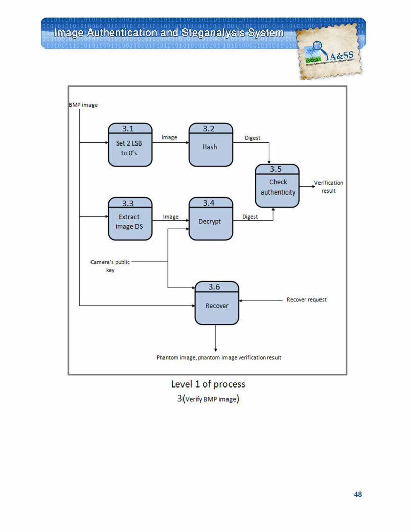
48
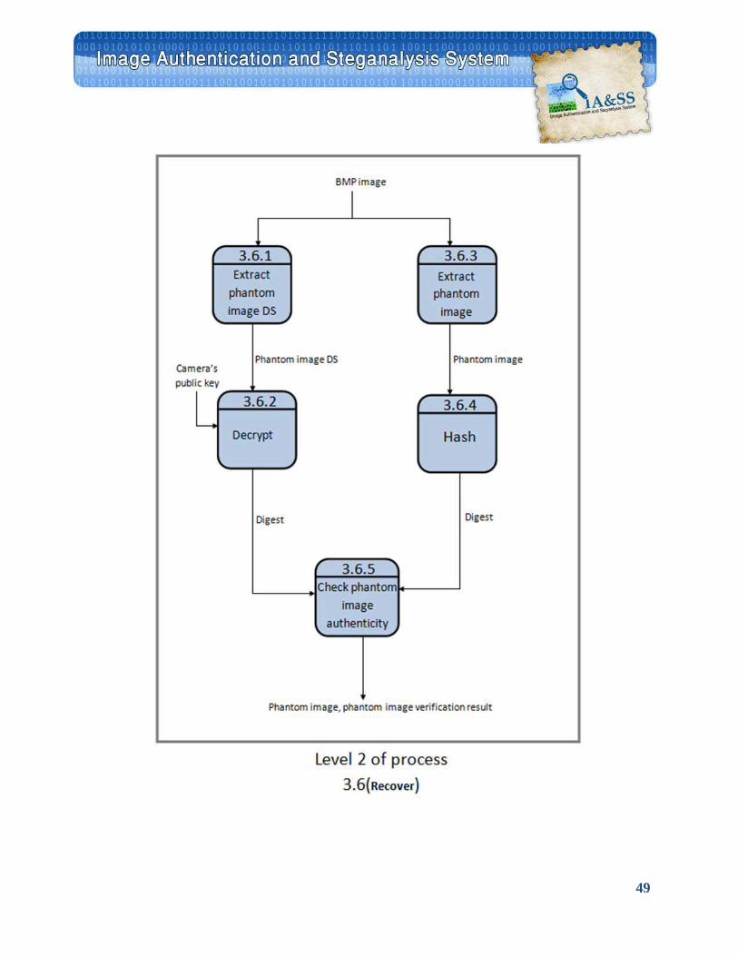
49
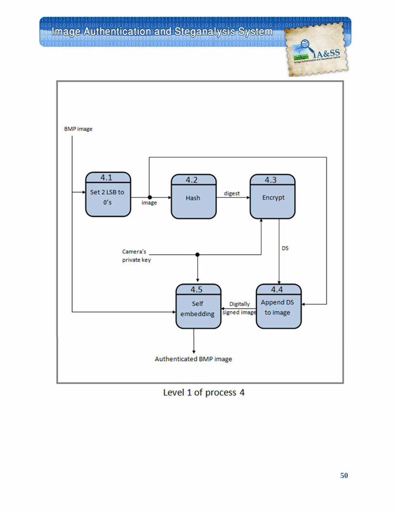
50
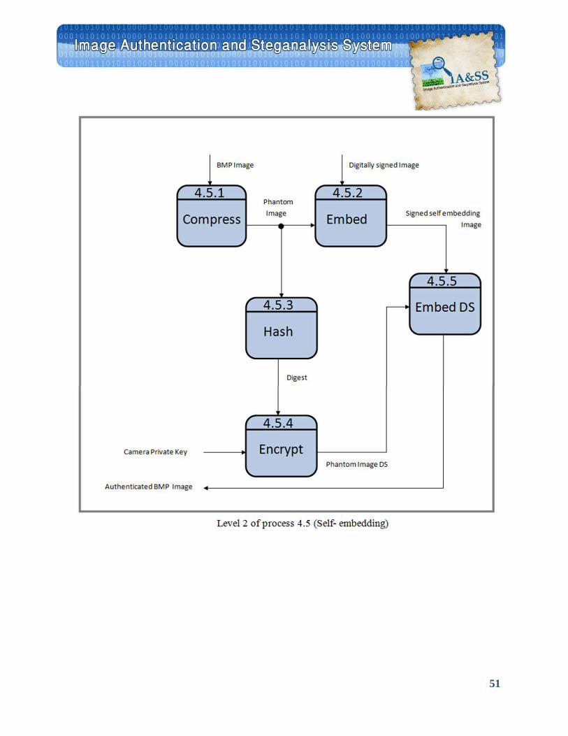
51
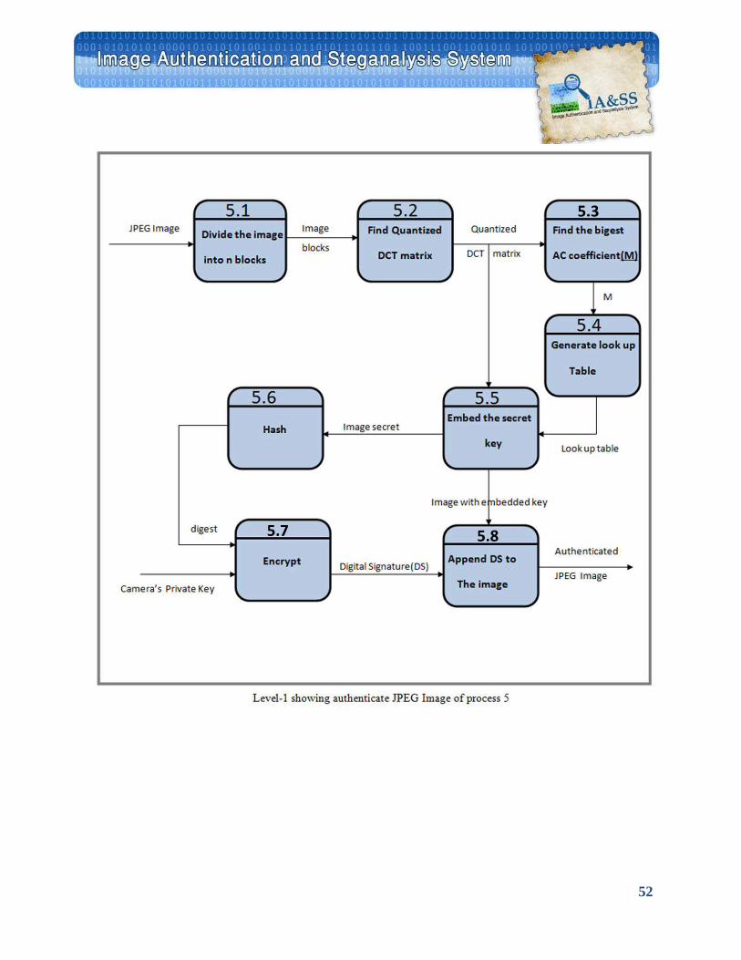
52
5.7 5.8
5.3
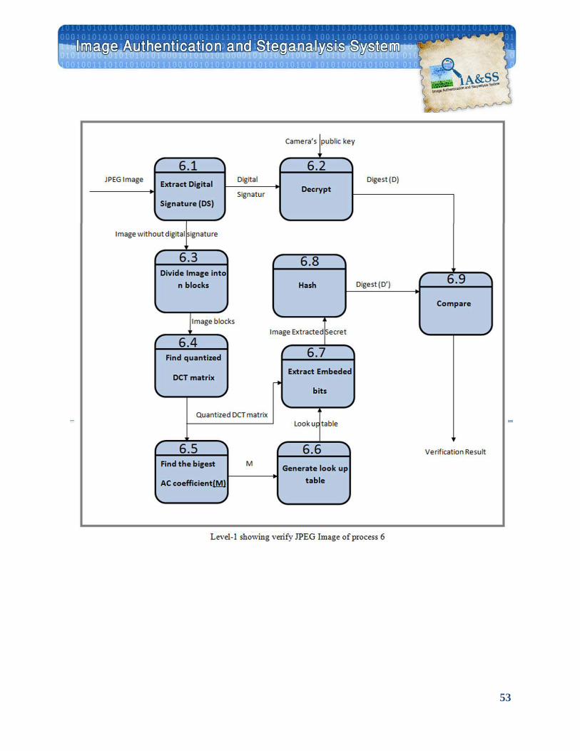
53
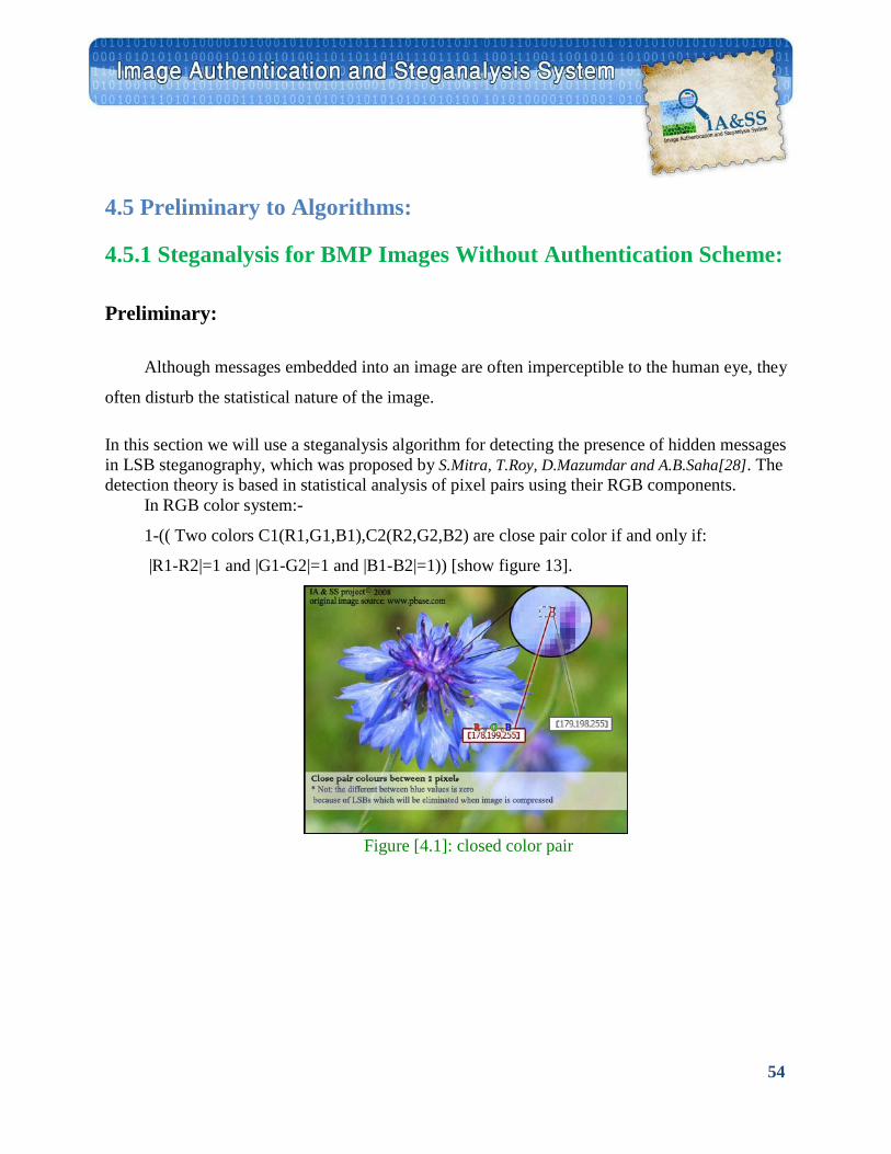
54
4.5 Preliminary to Algorithms:
4.5.1 Steganalysis for BMP Images Without Authentication Scheme:
Preliminary:
Although messages embedded into an image are often imperceptible to the human eye, they
often disturb the statistical nature of the image.
In this section we will use a steganalysis algorithm for detecting the presence of hidden messages in LSB steganography, which was proposed by S.Mitra, T.Roy, D.Mazumdar and A.B.Saha[28]. The detection theory is based in statistical analysis of pixel pairs using their RGB components.
In RGB color system:-
1-(( Two colors C1(R1,G1,B1),C2(R2,G2,B2) are close pair color if and only if:
|R1-R2|=1 and |G1-G2|=1 and |B1-B2|=1)) [show figure 13].
Figure [4.1]: closed color pair
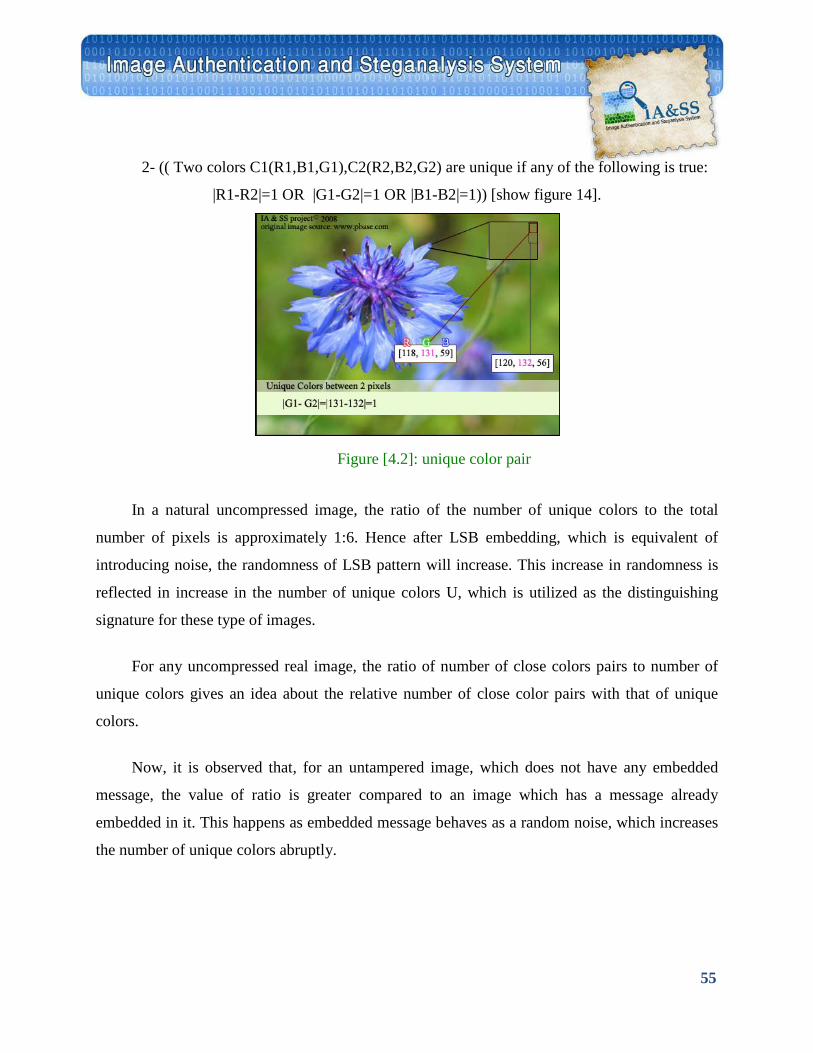
55
2- (( Two colors C1(R1,B1,G1),C2(R2,B2,G2) are unique if any of the following is true:
|R1-R2|=1 OR |G1-G2|=1 OR |B1-B2|=1)) [show figure 14].
In a natural uncompressed image, the ratio of the number of unique colors to the total
number of pixels is approximately 1:6. Hence after LSB embedding, which is equivalent of
introducing noise, the randomness of LSB pattern will increase. This increase in randomness is
reflected in increase in the number of unique colors U, which is utilized as the distinguishing
signature for these type of images.
For any uncompressed real image, the ratio of number of close colors pairs to number of
unique colors gives an idea about the relative number of close color pairs with that of unique
colors.
Now, it is observed that, for an untampered image, which does not have any embedded
message, the value of ratio is greater compared to an image which has a message already
embedded in it. This happens as embedded message behaves as a random noise, which increases
the number of unique colors abruptly.
Figure [4.2]: unique color pair

56
Two approaches will be adopted for tamper detection of authenticated digital image:
4.5.2 Digital Image Authentication Scheme
4.5.2.1 Digital signature of BMP Image with Self Embedding:
Image Hashing
Hash functions are frequently called message digest functions. Their purpose is to extract a
fixed-length bit-string from a message (computer file or image) of any length. Obviously, a
message digest function is a one-to-one mapping. In cryptography, hash functions are typically
used for digital signatures to authenticate the message being sent so that the recipient can verify
that the message is authentic and that it came from the right person.
The requirements for a cryptography hash function area:
• Given a message m and a hash function H , it should be easy and fast to compute the hash
h=H(m)
• Given h, it is hard to compute m such that h= H(m) (i.e., the hash function should be one-way)
• Given m , it is hard to find another message m' such that H(m')=H(m) (property of being
collision free)
From the above properties it is clear that hash functions are "infinitely" sensitive in the
sense that a small perturbation of the message m will give you a completely different bit-string h.
In application involving steganalysis and authentication of digital images, the requirements
on what should be a digest of an image are basically the same.
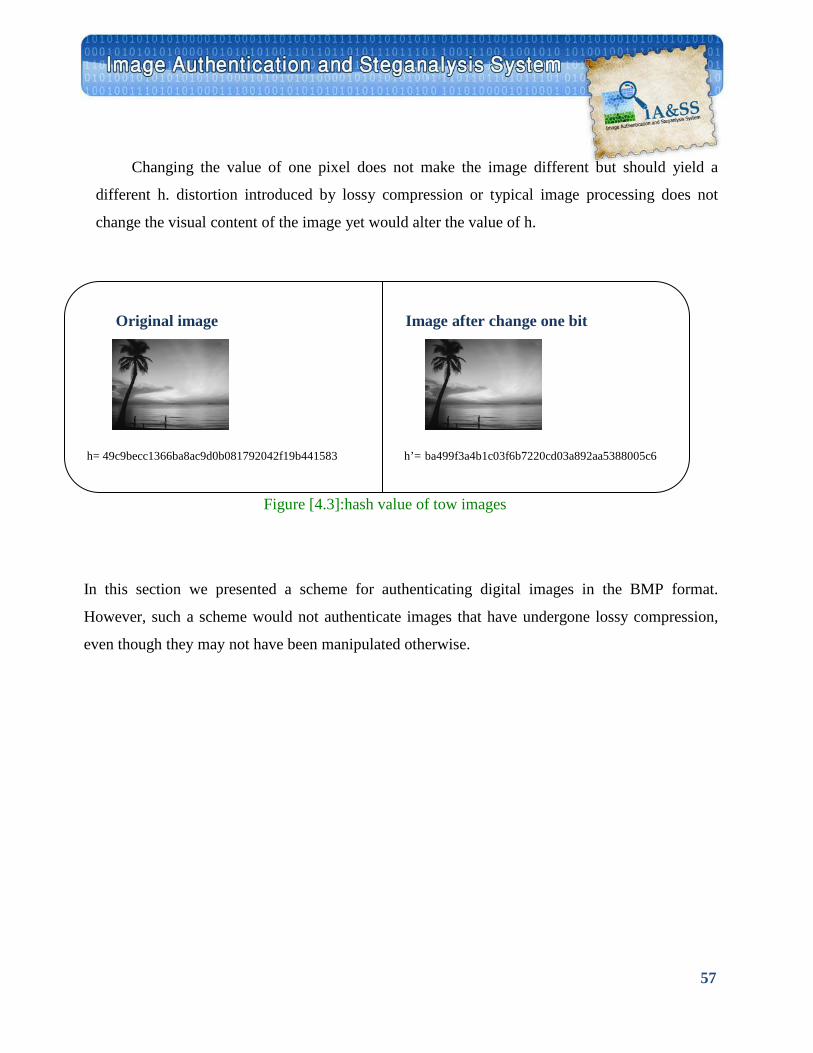
57
Changing the value of one pixel does not make the image different but should yield a
different h. distortion introduced by lossy compression or typical image processing does not
change the visual content of the image yet would alter the value of h.
Original image Image after change one bit
h= 49c9becc1366ba8ac9d0b081792042f19b441583 h’= ba499f3a4b1c03f6b7220cd03a892aa5388005c6
In this section we presented a scheme for authenticating digital images in the BMP format.
However, such a scheme would not authenticate images that have undergone lossy compression,
even though they may not have been manipulated otherwise.
Figure [4.3]:hash value of tow images
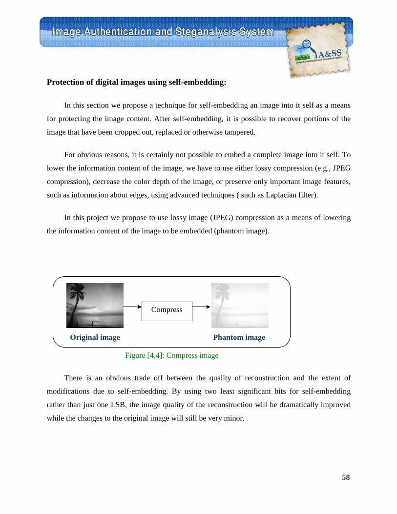
58
Protection of digital images using self-embedding:
In this section we propose a technique for self-embedding an image into it self as a means
for protecting the image content. After self-embedding, it is possible to recover portions of the
image that have been cropped out, replaced or otherwise tampered.
For obvious reasons, it is certainly not possible to embed a complete image into it self. To
lower the information content of the image, we have to use either lossy compression (e.g., JPEG
compression), decrease the color depth of the image, or preserve only important image features,
such as information about edges, using advanced techniques ( such as Laplacian filter).
In this project we propose to use lossy image (JPEG) compression as a means of lowering
the information content of the image to be embedded (phantom image).
There is an obvious trade off between the quality of reconstruction and the extent of
modifications due to self-embedding. By using two least significant bits for self-embedding
rather than just one LSB, the image quality of the reconstruction will be dramatically improved
while the changes to the original image will still be very minor.
Compress
Original image Phantom image
Figure [4.4]: Compress image
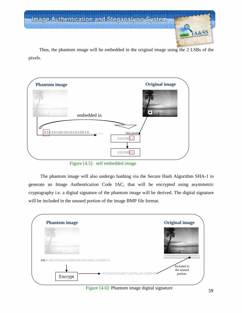
59
41f160e5555648fe7c41b76ac2b e39fd0189
Thus, the phantom image will be embedded in the original image using the 2 LSBs of the
pixels.
Phantom image
embedded in
0101010010101010010……… One pixel
The phantom image will also undergo hashing via the Secure Hash Algorithm SHA-1 to
generate an Image Authentication Code IAC, that will be encrypted using asymmetric
cryptography i.e. a digital signature of the phantom image will be derived. The digital signature
will be included in the unused portion of the image BMP file format.
01010011
01010001
Encrypt
Phantom image Original image
IAC= 89b2470a6d125df86439e7b61bd6ac333fd067a1
Original image
Figure [4.5]: self embedded image
Figure [4.6]: Phantom image digital signature
Included in the unused
portion
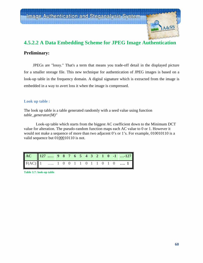
60
4.5.2.2 A Data Embedding Scheme for JPEG Image Authentication
Preliminary:
JPEGs are "lossy." That's a term that means you trade-off detail in the displayed picture
for a smaller storage file. This new technique for authentication of JPEG images is based on a
look-up table in the frequency domain. A digital signature which is extracted from the image is
embedded in a way to avert loss it when the image is compressed.
Look up table :
The look up table is a table generated randomly with a seed value using function table_generator(M)"
Look-up table which starts from the biggest AC coefficient down to the Minimum DCT value for alteration. The pseudo-random function maps each AC value to 0 or 1. However it would not make a sequence of more than two adjacent 0’s or 1’s. For example, 010010110 is a valid sequence but 01U000U10110 is not.
Table 3.7: look-up table
…-127 -1 0 1 2 3 4 5 6 7 8 9 127 ..… AC
…. 1 0 1 0 1 1 0 1 1 0 0 1 1 ….. F(AC)
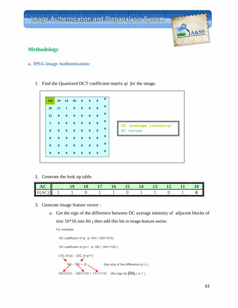
61
Methodology
a. JPEG image Authentication:
1. Find the Quantized DCT coefficient matrix qi for the image.
154 19 14 10 0 0 0 0
20 11 1 0 0 0 0 0
12 0 0 0 0 0 0 0
3 0 0 0 0 0 0 0
0 0 0 0 0 0 0 0
0 0 0 0 0 0 0 0
0 0 0 0 0 0 0 0
0 0 0 0 0 0 0 0
2. Generate the look up table.
10 11 12 13 14 15 16 17 18 19 AC 0 1 0 1 1 0 1 1 0 1 1 F(AC)
3. Generate image feature vector :
a. Get the sign of the difference between DC average intensity of adjacent blocks of
size 16*16 into bit I then add this bit to image feature vector.
For example:
DC coefficient of qi is 154 ( 10011010).
DC coefficient of qi+1 is 156 ( 10011100 ).
( DC of qi) – (DC of qi+1)
154 - 156 = -2 (the sing of the difference is (-) )
10011010 – 10011100 = 11111110 (the sign bit (biti ) is 1 )
DC (average intensity) AC values
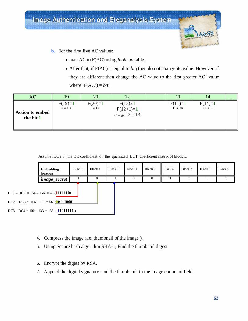
62
b. For the first five AC values:
• map AC to F(AC) using look_up table.
• After that, if F(AC) is equal to biti then do not change its value. However, if
they are different then change the AC value to the first greater AC’ value
where F(AC’) = biti.
4. Compress the image (i.e. thumbnail of the image ).
5. Using Secure hash algorithm SHA-1, Find the thumbnail digest.
6. Encrypt the digest by RSA.
7. Append the digital signature and the thumbnail to the image comment field.
.... 14 11 12 20 19 AC F(14)=1
It is OK F(11)=1
It is OK F(12)≠1
F(12+1)=1 Change 12 to 13
F(20)=1 It is OK
F(19)=1 It is OK
Action to embed the bit 1
Assume :DC i : the DC coefficient of the quantized DCT coefficient matrix of block i..
Block 9
Block 8
Block 7
Block 6
Block 5
Block 4
Block 3
Block 2
Block 1
Embedding location
0 1 1 1 0 0 1 0 1 image_secret
DC1 – DC2 = 154 – 156 = -2 (1111110)
DC2 - DC3 = 156 - 100 = 56 (00111000)
DC3 – DC4 = 100 – 133 = -33 ( 11011111 )
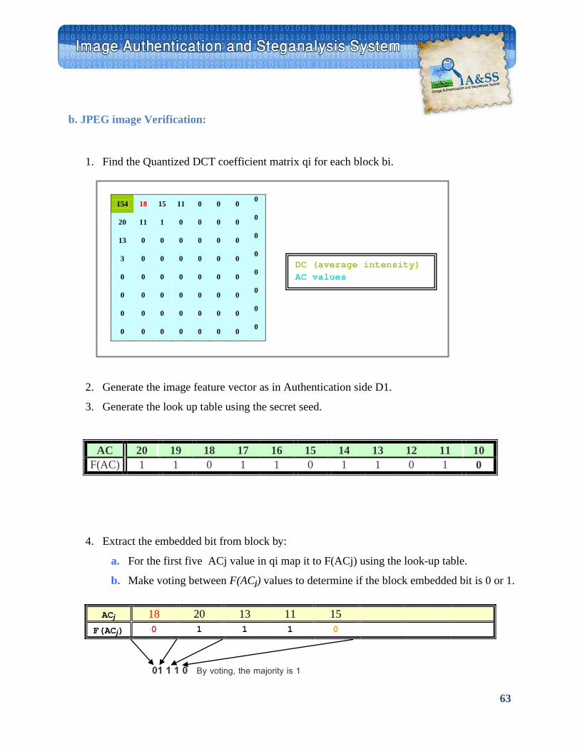
63
b. JPEG image Verification:
1. Find the Quantized DCT coefficient matrix qi for each block bi.
154 18 15 11 0 0 0 0
20 11 1 0 0 0 0 0
13 0 0 0 0 0 0 0
3 0 0 0 0 0 0 0
0 0 0 0 0 0 0 0
0 0 0 0 0 0 0 0
0 0 0 0 0 0 0 0
0 0 0 0 0 0 0 0
2. Generate the image feature vector as in Authentication side D1.
3. Generate the look up table using the secret seed.
10 11 12 13 14 15 16 17 18 19 20 AC 0 1 0 1 1 0 1 1 0 1 1 F(AC)
4. Extract the embedded bit from block by:
a. For the first five ACj value in qi map it to F(ACj) using the look-up table.
b. Make voting between F(ACj) values to determine if the block embedded bit is 0 or 1.
01 1 1 0 By voting, the majority is 1
ACj 18 20 13 11 15 F(ACj) 0 1 1 1 0
DC (average intensity) AC values

64
c. Add the previous step result to image feature vector D2.
Block 9
Block 8
Block 7
Block 6
Block 5
Block 4
Block 3
Block 2
Block 1
Extracting location
0 1 1 1 0 0 1 0 1 extracted_ secret
5. Compare D with D’, if they are the same then the image is authenticated. Otherwise, the
image may be tampered, cropped or has a hidden message.
In the previous example, the image is authenticated.

65
Implementation
Chapter 5
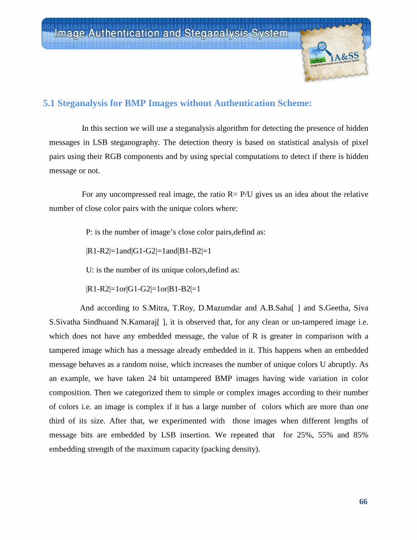
66
5.1 Steganalysis for BMP Images without Authentication Scheme:
In this section we will use a steganalysis algorithm for detecting the presence of hidden
messages in LSB steganography. The detection theory is based on statistical analysis of pixel
pairs using their RGB components and by using special computations to detect if there is hidden
message or not.
For any uncompressed real image, the ratio R= P/U gives us an idea about the relative
number of close color pairs with the unique colors where:
P: is the number of image’s close color pairs,defind as:
|R1-R2|=1and|G1-G2|=1and|B1-B2|=1
U: is the number of its unique colors,defind as:
|R1-R2|=1or|G1-G2|=1or|B1-B2|=1
And according to S.Mitra, T.Roy, D.Mazumdar and A.B.Saha[ ] and S.Geetha, Siva
S.Sivatha Sindhuand N.Kamaraj[ ], it is observed that, for any clean or un-tampered image i.e.
which does not have any embedded message, the value of R is greater in comparison with a
tampered image which has a message already embedded in it. This happens when an embedded
message behaves as a random noise, which increases the number of unique colors U abruptly. As
an example, we have taken 24 bit untampered BMP images having wide variation in color
composition. Then we categorized them to simple or complex images according to their number
of colors i.e. an image is complex if it has a large number of colors which are more than one
third of its size. After that, we experimented with those images when different lengths of
message bits are embedded by LSB insertion. We repeated that for 25%, 55% and 85%
embedding strength of the maximum capacity (packing density).
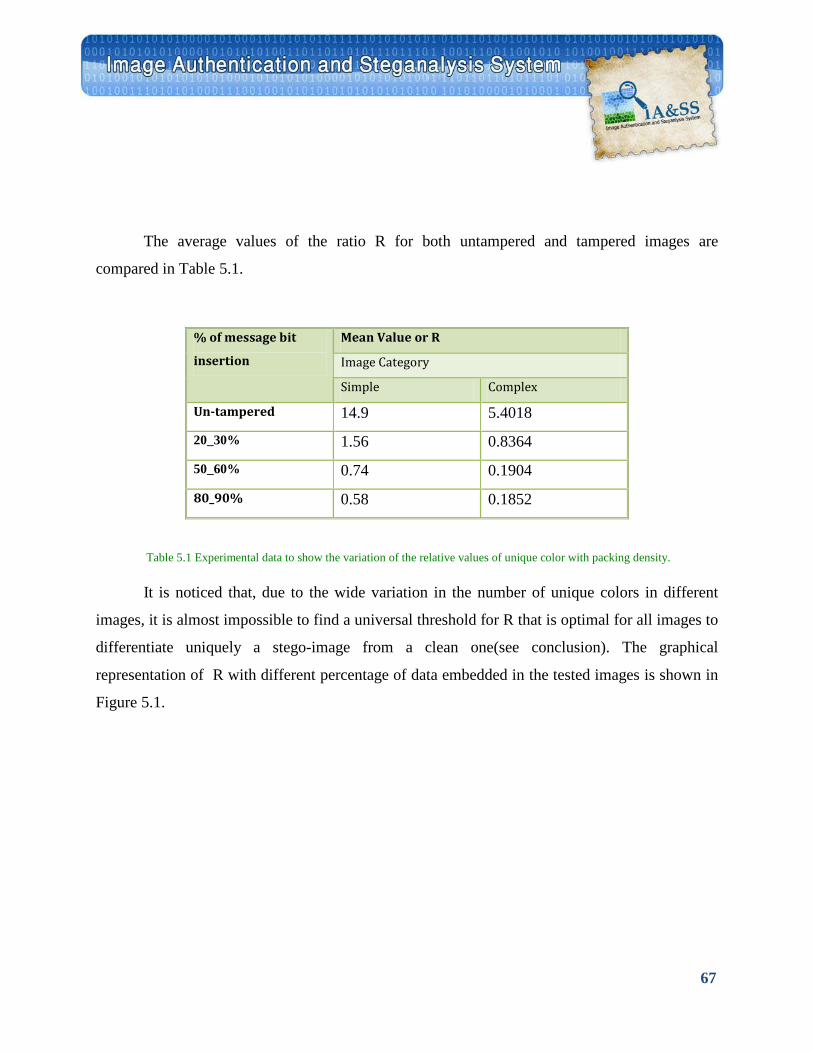
67
The average values of the ratio R for both untampered and tampered images are
compared in Table 5.1.
Table 5.1 Experimental data to show the variation of the relative values of unique color with packing density.
It is noticed that, due to the wide variation in the number of unique colors in different
images, it is almost impossible to find a universal threshold for R that is optimal for all images to
differentiate uniquely a stego-image from a clean one(see conclusion). The graphical
representation of R with different percentage of data embedded in the tested images is shown in
Figure 5.1.
% of message bit
insertion
Mean Value or R
Image Category
Simple Complex
Un-tampered 14.9 5.4018
20_30% 1.56 0.8364
50_60% 0.74 0.1904
80_90% 0.58 0.1852
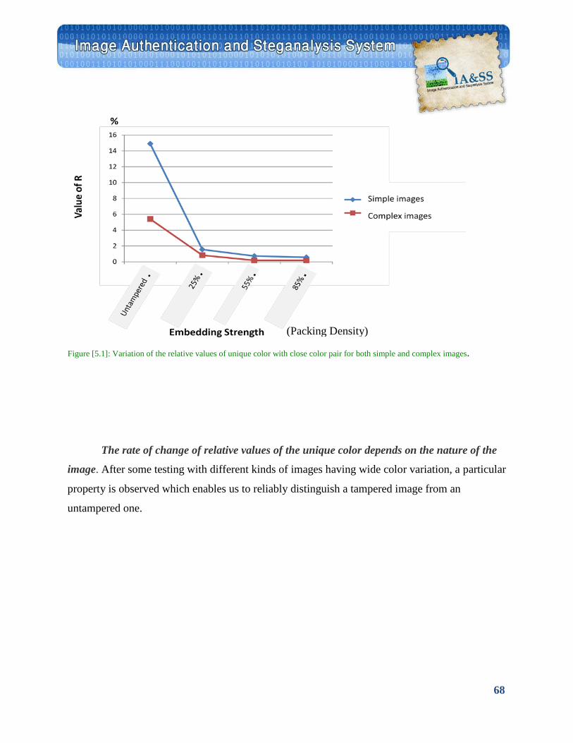
68
Figure [5.1]: Variation of the relative values of unique color with close color pair for both simple and complex images.
The rate of change of relative values of the unique color depends on the nature of the
image. After some testing with different kinds of images having wide color variation, a particular
property is observed which enables us to reliably distinguish a tampered image from an
untampered one.
Packing Density)(
69
5.1.1 Experimental Observations:
It is noticed that, if any test image is already tampered with a message, embedding it
further with additional bit streams will not modify the R value significantly. Alternately, under
repeated embedding, the highest disruption of the Signal characteristics is for the first embedding
and then decreases steadily. This principle of decreasing distortion is used to derive a
steganalysis tool that tries to detect the presence of hidden messages in an uncompressed 24 bits
BMP image.
To explore the decreasing property we have artificially pack the test image with
data, then recalculate the unique color U’ and the close color pair P’. So, R’= P’/U’ gives the
relative number of close color pair in the artificially tampered image.
The R changes ratio is measured in terms of M where, M is the percentage
of change in R that is defined as:
M= [ (R-R’)/R ] * 100
To detect if the image is tampered or clean ,we calculate the threshold according to number of
colors in the image; then we compare M with the threshold:
If M> threshold The Image is CLEAN
If M< threshold The Image is tampered
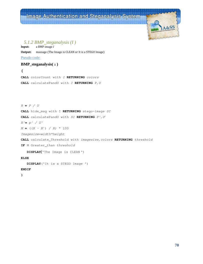
70
5.1.2 BMP_steganalysis (I ) Input: a BMP image I
Output: massage (The Image is CLEAN or It is a STEGO Image)
UPseudo code:
BMP_steganalysis( I ) {
CALL colorCount with I RETURNING colors
CALL calculatePandU with I RETURNING P,U
R = P / U
CALL hide_msg with I RETURNING stego-image SI
CALL calculatePandU with SI RETURNING P',U'
R'= p' / U'
M = ((R – R') / R) * 100
Imagesize=width*height
CALL calculate_Threshold with imagesize,colors RETURNING threshold
IF M Greater_than threshold
DISPLAY("The Image is CLEAN ")
ELSE
DISPLAY("It is a STEGO Image ")
ENDIF
}
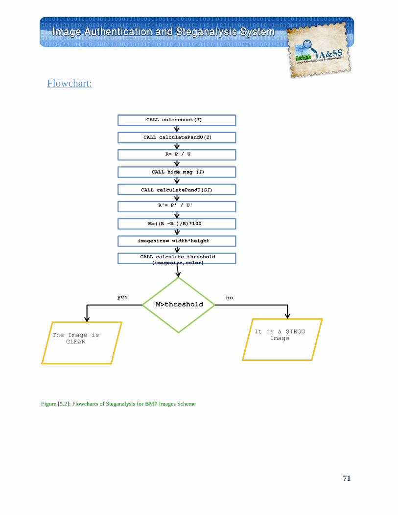
71
UFlowchart:
Figure [5.2]: Flowcharts of Steganalysis for BMP Images Scheme
CALL colorcount(I)
CALL calculatePandU(I)
R= P / U
CALL hide_msg (I)
CALL calculatePandU(SI)
R'= P' / U'
M=((R –R')/R)*100
imagesize= width*height
CALL calculate_threshold (imagesize,color)
M>threshold
The Image is CLEAN
It is a STEGO Image
yes no
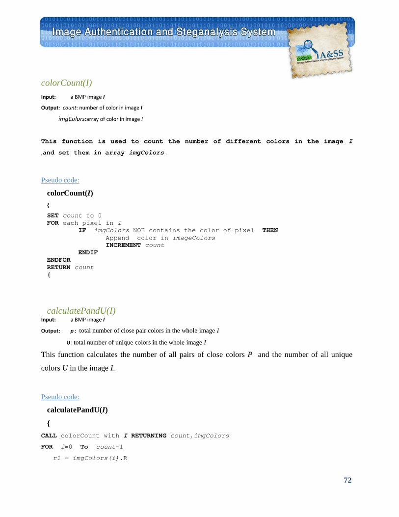
72
colorCount(I) Input: a BMP image I
Output: count: number of color in image I
imgColors:array of color in image I
This function is used to count the number of different colors in the image I
,and set them in array imgColors .
UPseudo code:
colorCount(I) {
SET count to 0 FOR each pixel in I IF imgColors NOT contains the color of pixel THEN Append color in imageColors INCREMENT count ENDIF ENDFOR RETURN count {
calculatePandU(I) Input: a BMP image I
Output: p: total number of close pair colors in the whole image I
U: total number of unique colors in the whole image I
This function calculates the number of all pairs of close colors P and the number of all unique
colors U in the image I.
UPseudo code:
calculatePandU(I)
{ CALL colorCount with I RETURNING count,imgColors
FOR i=0 To count-1
r1 = imgColors(i).R
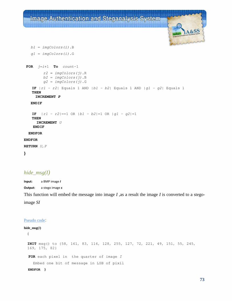
73
b1 = imgColors(i).B
g1 = imgColors(i).G
FOR j=i+1 To count-1
r2 = imgColors(j).R b2 = imgColors(j).B g2 = imgColors(j).G
IF |r1 - r2| Equals 1 AND |b1 - b2| Equals 1 AND |g1 - g2| Equals 1 THEN
INCREMENT P
ENDIF
IF |r1 - r2|==1 OR |b1 - b2|=1 OR |g1 - g2|=1 THEN INCREMENT U
ENDIF
ENDFOR
ENDFOR
RETURN U,P
}
hide_msg(I) Input: a BMP image I
Output: a stego image s
This function will embed the message into image I ,as a result the image I is converted to a stego-
image SI
UPseudo code U: hide_msg(I)
{
INIT msg() to {58, 161, 83, 116, 128, 255, 127, 72, 221, 49, 151, 55, 245, 169, 175, 82}
FOR each pixel in the quarter of image I
Embed one bit of message in LSB of pixil
ENDFOR }
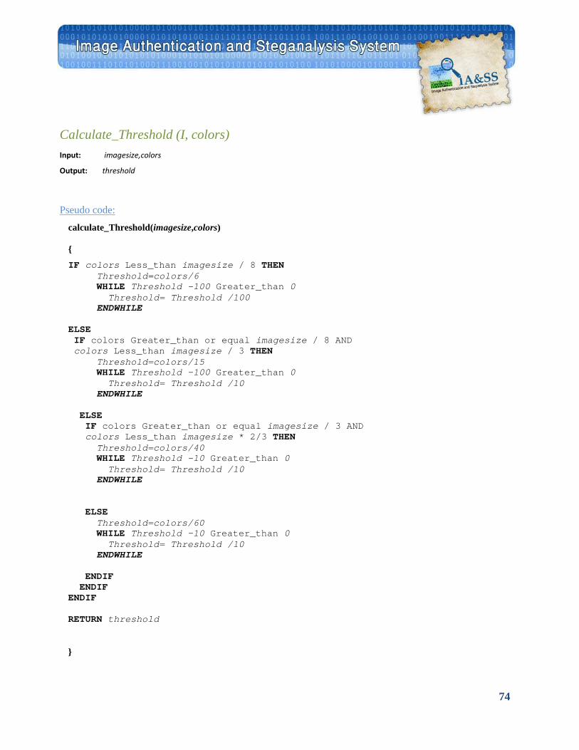
74
Calculate_Threshold (I, colors) Input: imagesize,colors
Output: threshold
UPseudo code:
calculate_Threshold(imagesize,colors) { IF colors Less_than imagesize / 8 THEN Threshold=colors/6 WHILE Threshold -100 Greater_than 0 Threshold= Threshold /100 ENDWHILE ELSE IF colors Greater_than or equal imagesize / 8 AND colors Less_than imagesize / 3 THEN Threshold=colors/15 WHILE Threshold -100 Greater_than 0 Threshold= Threshold /10 ENDWHILE ELSE IF colors Greater_than or equal imagesize / 3 AND colors Less_than imagesize * 2/3 THEN Threshold=colors/40 WHILE Threshold -10 Greater_than 0 Threshold= Threshold /10 ENDWHILE ELSE Threshold=colors/60 WHILE Threshold -10 Greater_than 0 Threshold= Threshold /10 ENDWHILE ENDIF ENDIF ENDIF RETURN threshold }
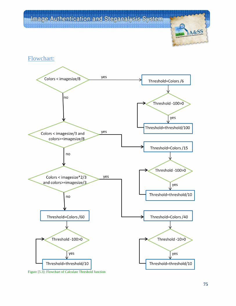
75
UFlowchart:
Figure [5.3]: Flowchart of Calculate Threshold function
76
BMP Image Authentication Schemes with Self Embedding5.2
In many scenarios, the user may have a need for confidence that an image has not been
altered. If the image is digitally signed, any change in the image will invalidate the signature.
Furthermore, there is no efficient way to modify the image and its signature to produce a new
image with a valid signature, because this is still considered to be computationally infeasible by
most cryptographic hash functions (i.e. collision resistance). So the digital signature is used to
ensure the integrity of an image. Also, it is used for authentication and non-repudiation purposes.
In this section we present a fragile scheme for authenticating BMP images. Fragile
schemes are commonly used for tamper detection, however, they will fail to authenticate an image
after the slightest modification. Our authentication technique will also embed the image into itself
(i.e. self-embedding) to help display the original image if some tampering was detected. As we will
use the two LSBs of the pixel for self-embedding rather than just one LSB, the phantom image (i.e.
the compressed image or thumbnail image) quality will be dramatically improved while the
changes to the original image will still be very minor virtually imperceptible to human eye. The
phantom image length and digital signature will be embedded also in those two LSBs. So, from
this digital signature or image authentication code (IAC), we will be able to detect whether the
phantom image was also tampered or not. Also, we append another copy of the phantom image
and its length to the end of image data in order to increase the ability of recovering the original
image.
A digital signature scheme typically consists of three parts:
1. A key generation algorithm that selects a private key uniformly at random from a set of
possible private keys. The algorithm outputs the private key and a corresponding public key.
2. A signing algorithm which, given an image and a private key, produces a signature.
3. A signature verifying algorithm which, given an image, public key and a signature, either
accepts or rejects.(See figure 5.4)
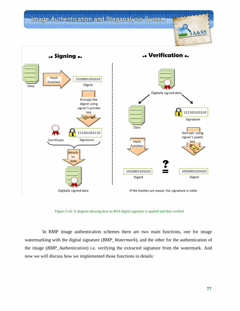
77
Figure [5.4]: A diagram showing how an RSA digital signature is applied and then verified.
In BMP image authentication schemes there are two main functions, one for image
watermarking with the digital signature (BMP_Watermark), and the other for the authentication of
the image (BMP_Authentication) i.e. verifying the extracted signature from the watermark. And
now we will discuss how we implemented those functions in details:
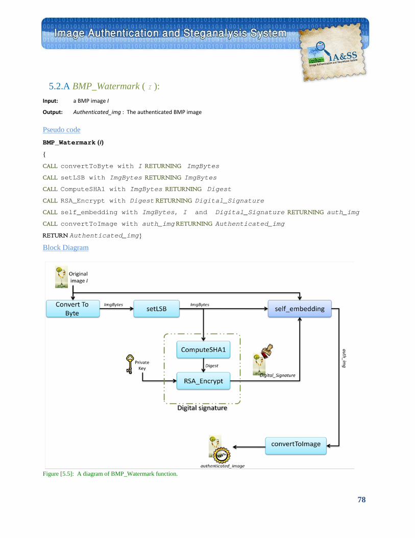
78
5.2.A BMP_Watermark ( I ): Input: a BMP image I
Output: Authenticated_img : The authenticated BMP image
UPseudo code
BMP_Watermark (I)
{
CALL convertToByte with I RETURNING ImgBytes
CALL setLSB with ImgBytes RETURNING ImgBytes
CALL ComputeSHA1 with ImgBytes RETURNING Digest
CALL RSA_Encrypt with Digest RETURNING Digital_Signature
CALL self_embedding with ImgBytes, I and Digital_Signature RETURNING auth_img
CALL convertToImage with auth_img RETURNING Authenticated_img
RETURN Authenticated_img}
UBlock Diagram
Figure [5.5]: A diagram of BMP_Watermark function.
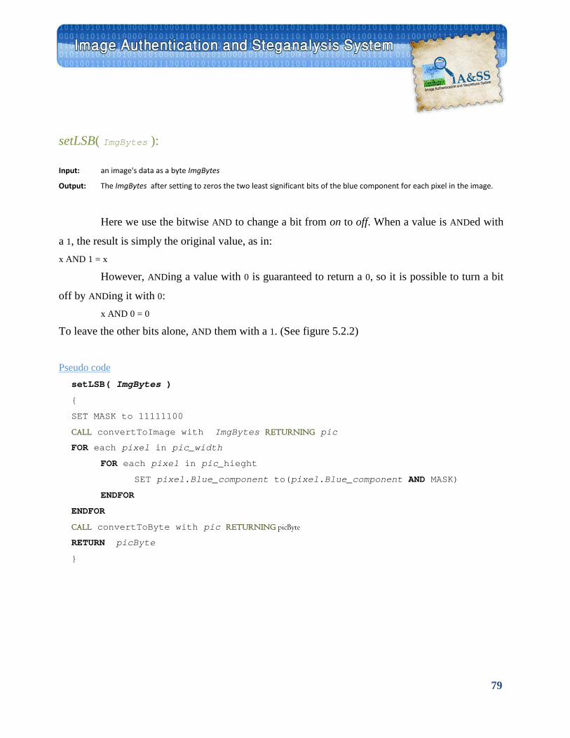
79
setLSB( ImgBytes ):
Input: an image's data as a byte ImgBytes
Output: The ImgBytes after setting to zeros the two least significant bits of the blue component for each pixel in the image.
Here we use the bitwise AND to change a bit from on to off. When a value is ANDed with
a 1, the result is simply the original value, as in:
x AND 1 = x
However, ANDing a value with 0 is guaranteed to return a 0, so it is possible to turn a bit
off by ANDing it with 0: x AND 0 = 0
To leave the other bits alone, AND them with a 1. (See figure 5.2.2)
UPseudo code setLSB( ImgBytes )
{
SET MASK to 11111100
CALL convertToImage with ImgBytes RETURNING pic
FOR each pixel in pic_width
FOR each pixel in pic_hieght
SET pixel.Blue_component to(pixel.Blue_component AND MASK)
ENDFOR
ENDFOR
CALL convertToByte with pic RETURNING picByte
RETURN picByte
}
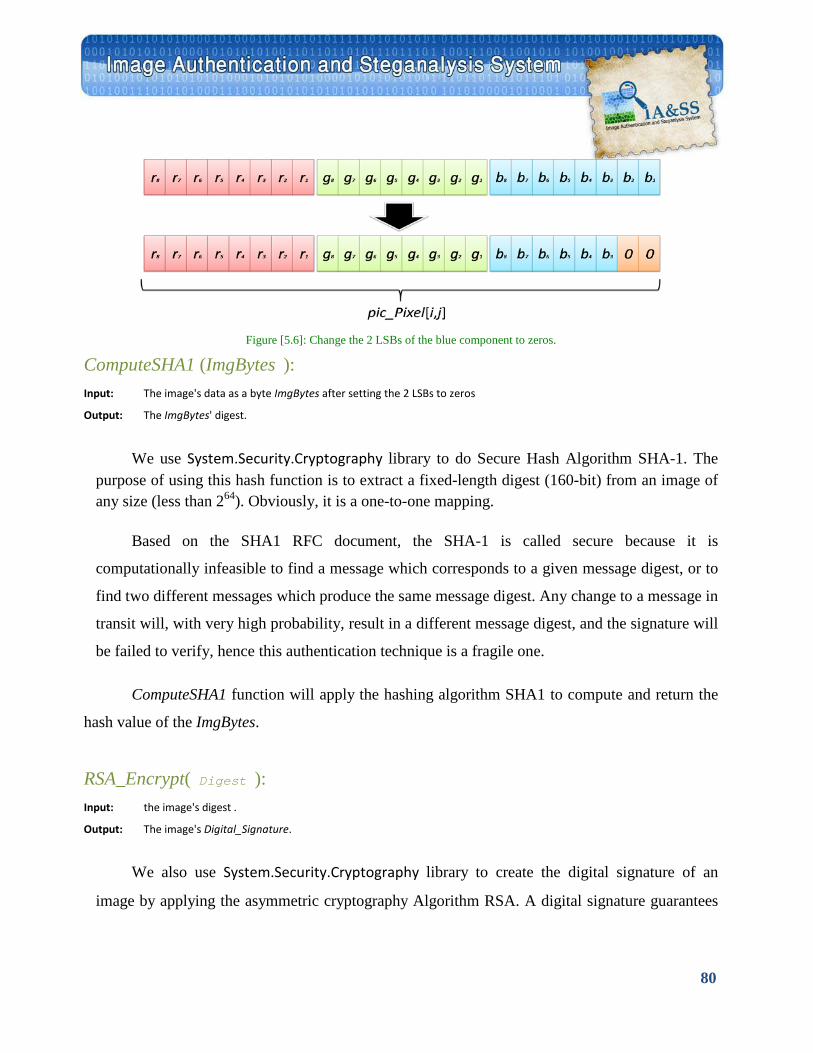
80
Figure [5.6]: Change the 2 LSBs of the blue component to zeros.
ComputeSHA1 (ImgBytes ): Input: The image's data as a byte ImgBytes after setting the 2 LSBs to zeros
Output: The ImgBytes' digest.
We use System.Security.Cryptography library to do Secure Hash Algorithm SHA-1. The purpose of using this hash function is to extract a fixed-length digest (160-bit) from an image of any size (less than 264). Obviously, it is a one-to-one mapping.
Based on the SHA1 RFC document, the SHA-1 is called secure because it is
computationally infeasible to find a message which corresponds to a given message digest, or to
find two different messages which produce the same message digest. Any change to a message in
transit will, with very high probability, result in a different message digest, and the signature will
be failed to verify, hence this authentication technique is a fragile one.
ComputeSHA1 function will apply the hashing algorithm SHA1 to compute and return the
hash value of the ImgBytes.
RSA_Encrypt( Digest ): Input: the image's digest .
Output: The image's Digital_Signature.
We also use System.Security.Cryptography library to create the digital signature of an
image by applying the asymmetric cryptography Algorithm RSA. A digital signature guarantees
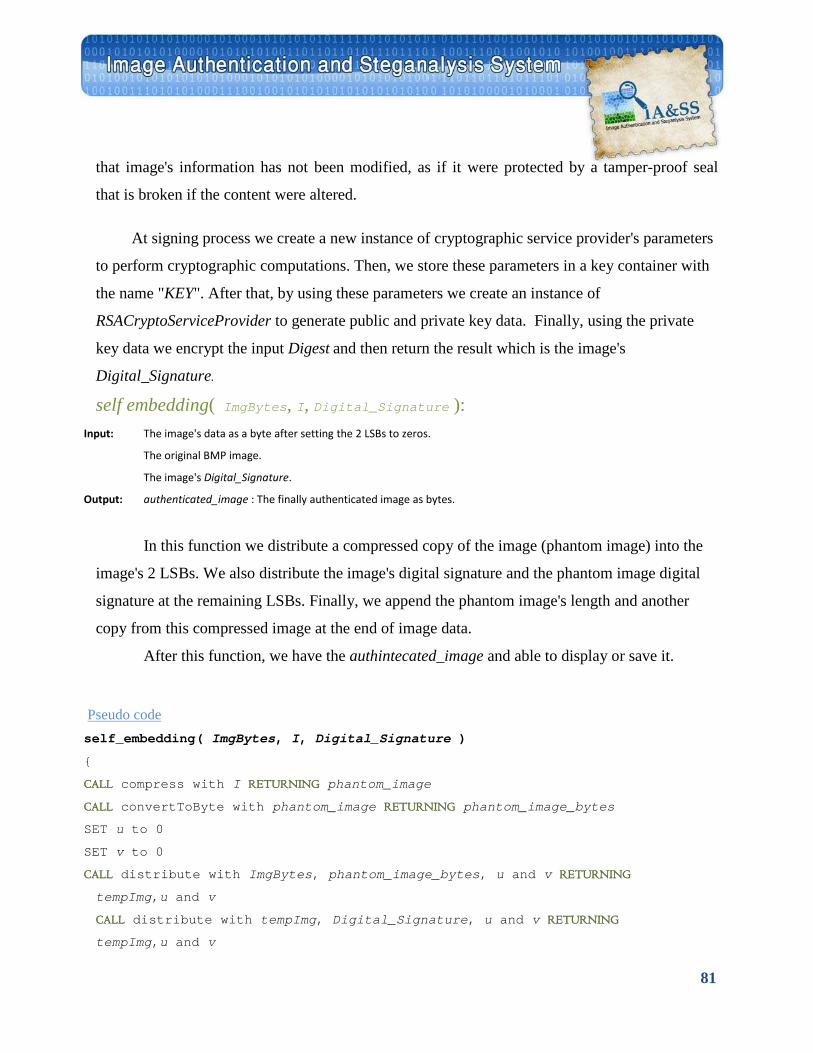
81
that image's information has not been modified, as if it were protected by a tamper-proof seal
that is broken if the content were altered.
At signing process we create a new instance of cryptographic service provider's parameters
to perform cryptographic computations. Then, we store these parameters in a key container with
the name "KEY". After that, by using these parameters we create an instance of
RSACryptoServiceProvider to generate public and private key data. Finally, using the private
key data we encrypt the input Digest and then return the result which is the image's
Digital_Signature.
self embedding( ImgBytes, I, Digital_Signature ): Input: The image's data as a byte after setting the 2 LSBs to zeros.
The original BMP image.
The image's Digital_Signature.
Output: authenticated_image : The finally authenticated image as bytes.
In this function we distribute a compressed copy of the image (phantom image) into the
image's 2 LSBs. We also distribute the image's digital signature and the phantom image digital
signature at the remaining LSBs. Finally, we append the phantom image's length and another
copy from this compressed image at the end of image data.
After this function, we have the authintecated_image and able to display or save it.
UPseudo code self_embedding( ImgBytes, I, Digital_Signature )
{
CALL compress with I RETURNING phantom_image
CALL convertToByte with phantom_image RETURNING phantom_image_bytes
SET u to 0
SET v to 0
CALL distribute with ImgBytes, phantom_image_bytes, u and v RETURNING
tempImg,u and v
CALL distribute with tempImg, Digital_Signature, u and v RETURNING
tempImg,u and v
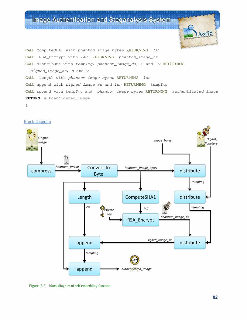
82
CALL ComputeSHA1 with phantom_image_bytes RETURNING IAC
CALL RSA_Encrypt with IAC RETURNING phantom_image_ds
CALL distribute with tempImg, phantom_image_ds, u and v RETURNING
signed_image_se, u and v
CALL Length with phantom_image_bytes RETURNING len
CALL append with signed_image_se and len RETURNING tempImg
CALL append with tempImg and phantom_image_bytes RETURNING authenticated_image
RETURN authenticated_image
}
UBlock Diagram
Figure [5.7]: block diagram of self embedding function
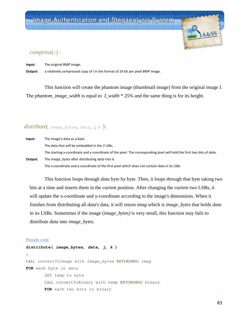
83
compress(I) :
Input: The original BMP image.
Output: a relatively compressed copy of I in the format of 24 bit per pixel BMP image.
This function will create the phantom image (thumbnail image) from the original image I.
The phantom_image_width is equal to I_width * 25% and the same thing is for its height.
distribute( image_bytes, data, j, k ):
Input: The image's data as a byte.
The data that will be embedded in the 2 LSBs.
The starting x-coordinate and y-coordinate of the pixel. The corresponding pixel will hold the first two bits of data.
Output: The image_bytes after distributing data into it.
The x-coordinate and y-coordinate of the first pixel which does not contain data in its LSBs
This function loops through data byte by byte. Then, it loops through that byte taking two
bits at a time and inserts them in the current position. After changing the current two LSBs, it
will update the x-coordinate and y-coordinate according to the image's dimensions. When it
finishes from distributing all data's data, it will return imag which is image_bytes that holds data
in its LSBs. Sometimes if the image (image_bytes) is very small, this function may fails to
distribute data into image_bytes.
UPseudo code distribute( image_bytes, data, j, k )
{
CALL convertToImage with image_bytes RETURNING imag
FOR each byte in data
SET temp to byte
CALL convertToBinary with temp RETURNING binary
FOR each two bits in binary
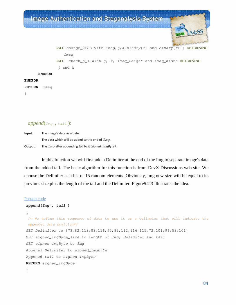
84
CALL change_2LSB with imag,j,k,binary[r] and binary[r+1] RETURNING
imag
CALL check_j_k with j, k, imag_Height and imag_Width RETURNING
j and k
ENDFOR
ENDFOR
RETURN imag
}
append(Img , tail ):
Input: The image's data as a byte.
The data which will be added to the end of Img.
Output: The Img after appending tail to it (signed_imgByte).
In this function we will first add a Delimiter at the end of the Img to separate image's data
from the added tail. The basic algorithm for this function is from DevX Discussions web site. We
choose the Delimiter as a list of 15 random elements. Obviously, Img new size will be equal to its
previous size plus the length of the tail and the Delimiter. Figure5.2.3 illustrates the idea.
UPseudo code append(Img , tail )
{
/* We define this sequence of data to use it as a delimeter that will indicate the
appended data position*/
SET Delimiter to {73,82,113,83,116,95,82,112,116,115,72,101,96,53,101}
SET signed_imgByte_size to length of Img, Delimiter and tail
SET signed_imgByte to Img
Appened Delimiter to signed_imgByte
Appened tail to signed_imgByte
RETURN signed_imgByte
}
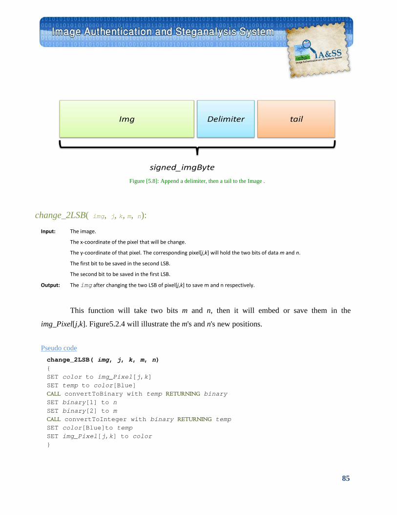
85
Figure [5.8]: Append a delimiter, then a tail to the Image .
change_2LSB( img, j, k, m, n):
Input: The image.
The x-coordinate of the pixel that will be change.
The y-coordinate of that pixel. The corresponding pixel[j,k] will hold the two bits of data m and n.
The first bit to be saved in the second LSB.
The second bit to be saved in the first LSB.
Output: The img after changing the two LSB of pixel[j,k] to save m and n respectively.
This function will take two bits m and n, then it will embed or save them in the
img_Pixel[j,k]. Figure5.2.4 will illustrate the m's and n's new positions.
UPseudo code change_2LSB( img, j, k, m, n) { SET color to img_Pixel[j,k] SET temp to color[Blue] CALL convertToBinary with temp RETURNING binary SET binary[1] to n SET binary[2] to m CALL convertToInteger with binary RETURNING temp SET color[Blue]to temp SET img_Pixel[j,k] to color }
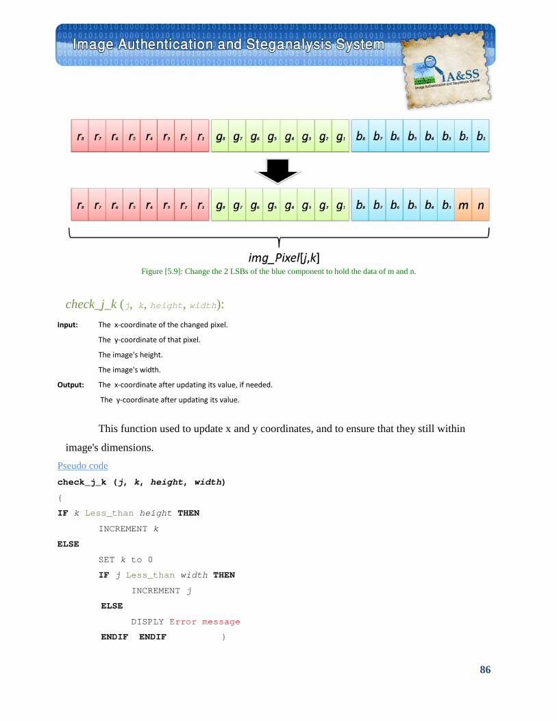
86
Figure [5.9]: Change the 2 LSBs of the blue component to hold the data of m and n.
check_j_k (j, k, height, width):
Input: The x-coordinate of the changed pixel.
The y-coordinate of that pixel.
The image's height.
The image's width.
Output: The x-coordinate after updating its value, if needed.
The y-coordinate after updating its value.
This function used to update x and y coordinates, and to ensure that they still within
image's dimensions. UPseudo code check_j_k (j, k, height, width)
{
IF k Less_than height THEN
INCREMENT k
ELSE
SET k to 0
IF j Less_than width THEN
INCREMENT j
ELSE
DISPLY Error message
ENDIF ENDIF }
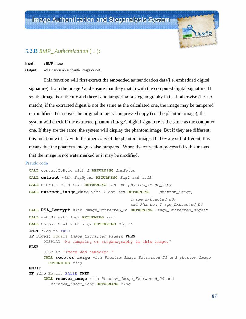
87
5.2.B BMP_ Authentication ( I ):
Input: a BMP image I
Output: Whether I is an authentic image or not.
This function will first extract the embedded authentication data(i.e. embedded digital
signature) from the image I and ensure that they match with the computed digital signature. If
so, the image is authentic and there is no tampering or steganography in it. If otherwise (i.e. no
match), if the extracted digest is not the same as the calculated one, the image may be tampered
or modified. To recover the original image's compressed copy (i.e. the phantom image), the
system will check if the extracted phantom image's digital signature is the same as the computed
one. If they are the same, the system will display the phantom image. But if they are different,
this function will try with the other copy of the phantom image. If they are still different, this
means that the phantom image is also tampered. When the extraction process fails this means
that the image is not watermarked or it may be modified. UPseudo code CALL convertToByte with I RETURNING ImgBytes
CALL extract with ImgBytes RETURNING Img1 and tail
CALL extract with tail RETURNING len and phantom_image_Copy
CALL extract_image_data with I and len RETURNING phantom_image,
Image_Extracted_DS, and Phantom_Image_Extracted_DS
CALL RSA_Decrypt with Image_Extracted_DS RETURNING Image_Extracted_Digest
CALL setLSB with Img1 RETURNING Img1
CALL ComputeSHA1 with Img1 RETURNING Digest
INIT flag to TRUE IF Digest Equals Image_Extracted_Digest THEN
DISPLAY "No tampring or steganography in this image." ELSE DISPLAY "Image was tampered."
CALL recover_image with Phantom_Image_Extracted_DS and phantom_image RETURNING flag
ENDIF IF flag Equals FALSE THEN
CALL recover_image with Phantom_Image_Extracted_DS and phantom_image_Copy RETURNING flag
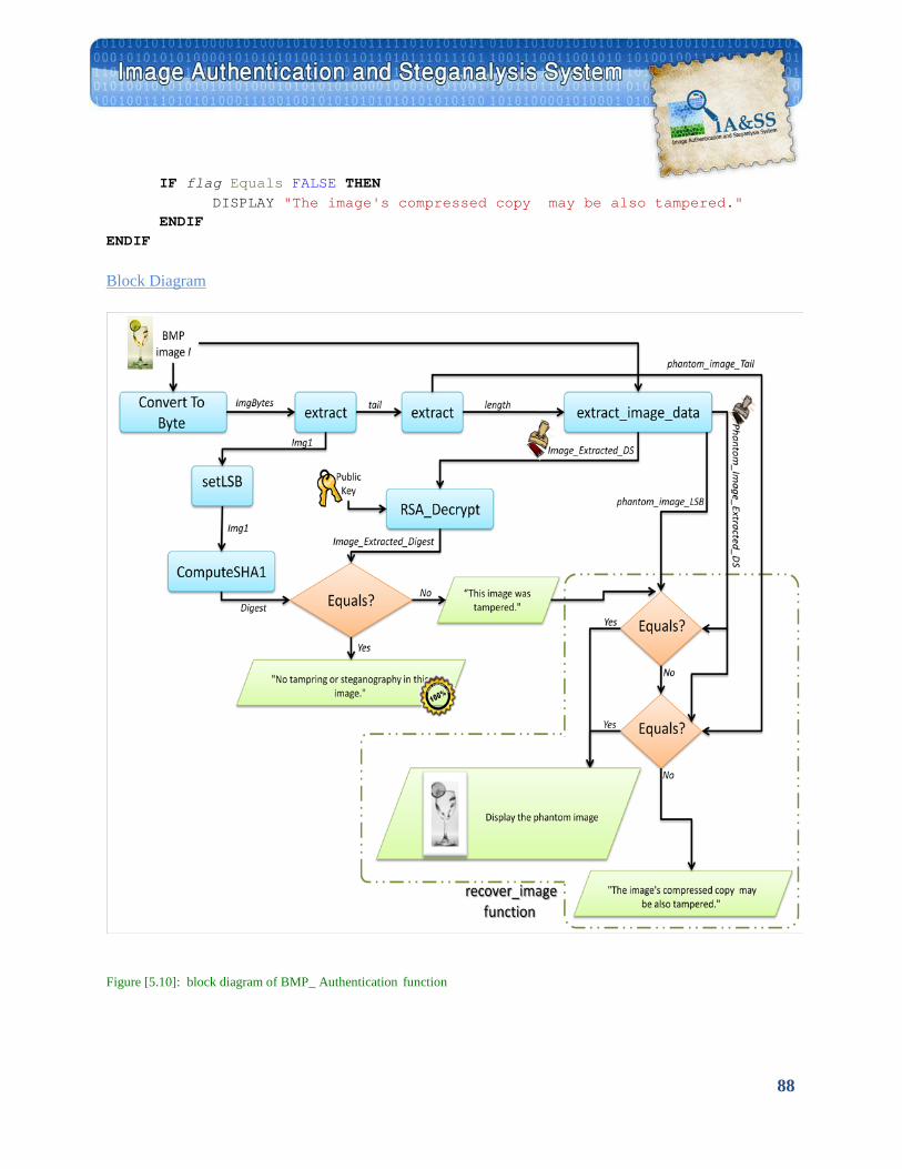
88
IF flag Equals FALSE THEN DISPLAY "The image's compressed copy may be also tampered."
ENDIF ENDIF
UBlock Diagram
Figure [5.10]: block diagram of BMP_ Authentication function
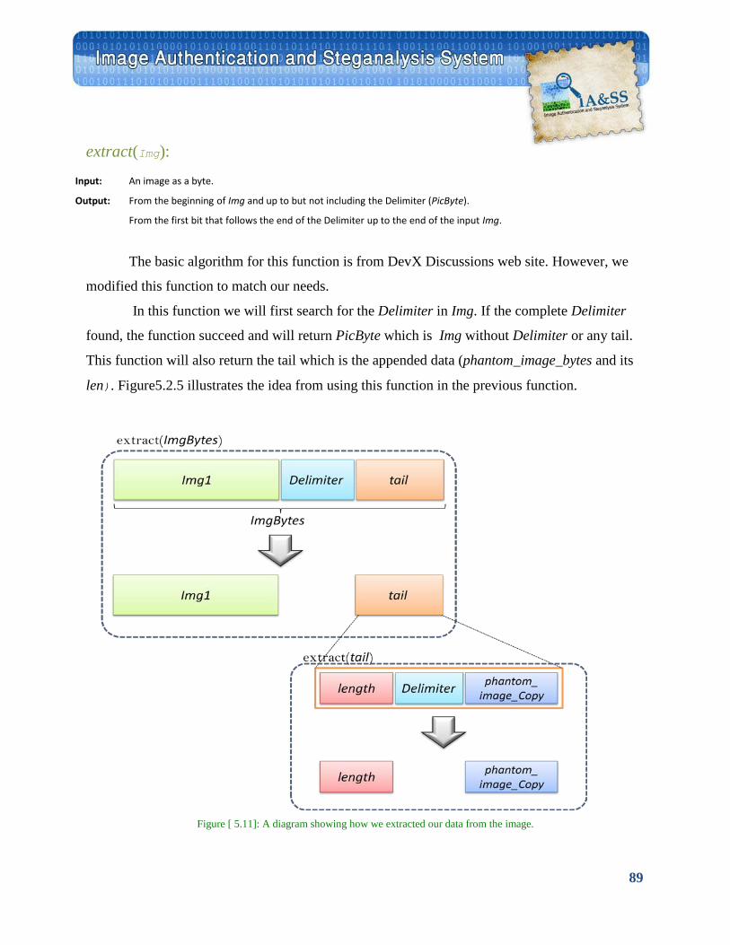
89
extract(Img):
Input: An image as a byte.
Output: From the beginning of Img and up to but not including the Delimiter (PicByte).
From the first bit that follows the end of the Delimiter up to the end of the input Img.
The basic algorithm for this function is from DevX Discussions web site. However, we
modified this function to match our needs.
In this function we will first search for the Delimiter in Img. If the complete Delimiter
found, the function succeed and will return PicByte which is Img without Delimiter or any tail.
This function will also return the tail which is the appended data (phantom_image_bytes and its
len). Figure5.2.5 illustrates the idea from using this function in the previous function.
Figure [ 5.11]: A diagram showing how we extracted our data from the image.
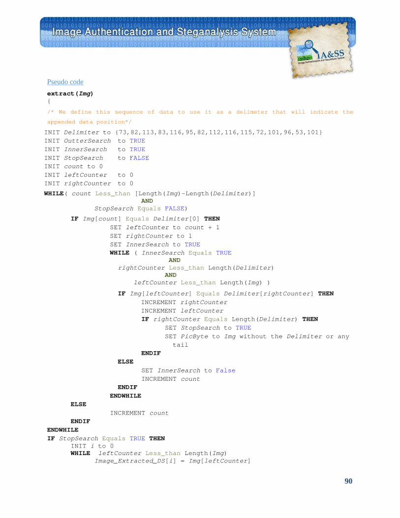
90
UPseudo code extract(Img) {
/* We define this sequence of data to use it as a delimeter that will indicate the
appended data position*/
INIT Delimiter to {73,82,113,83,116,95,82,112,116,115,72,101,96,53,101} INIT OutterSearch to TRUE INIT InnerSearch to TRUE INIT StopSearch to FALSE INIT count to 0 INIT leftCounter to 0 INIT rightCounter to 0
WHILE( count Less_than [Length(Img)-Length(Delimiter)] AND StopSearch Equals FALSE)
IF Img[count] Equals Delimiter[0] THEN SET leftCounter to count + 1 SET rightCounter to 1 SET InnerSearch to TRUE WHILE ( InnerSearch Equals TRUE
AND rightCounter Less_than Length(Delimiter)
AND leftCounter Less_than Length(Img) )
IF Img[leftCounter] Equals Delimiter[rightCounter] THEN INCREMENT rightCounter INCREMENT leftCounter
IF rightCounter Equals Length(Delimiter) THEN SET StopSearch to TRUE SET PicByte to Img without the Delimiter or any tail
ENDIF ELSE
SET InnerSearch to False INCREMENT count
ENDIF ENDWHILE
ELSE INCREMENT count
ENDIF ENDWHILE IF StopSearch Equals TRUE THEN
INIT i to 0 WHILE leftCounter Less_than Length(Img)
Image_Extracted_DS[i] = Img[leftCounter]
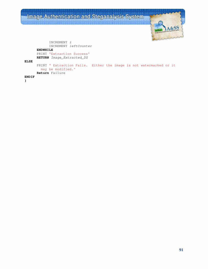
91
INCREMENT i INCREMENT leftCounter
ENDWHILE PRINT "Extraction Success"
RETURN Image_Extracted_DS ELSE
PRINT " Extraction Fails. Either the image is not watermarked or it may be modified." Return Failure
ENDIF }
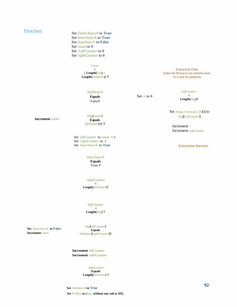
92
Set OutterSearch to True Set InnerSearch to True Set StopSearch to False Set count to 0 Set LeftCounter to 0 Set rightCounter to 0
Count
< [ Length(Img) –
Length(Delimiter)] ?
StopSearch Equals False?
Img[count] Equals
Delimiter[0] ?
Set leftCounter to count + 1 Set rightCounter to 1 Set InnerSearch to True
InnerSearch
Equals True ?
rightCounter <
Length(Delimiter)?
leftCounter <
Length(Img) ?
Img[leftCounter] Equals
Delimiter[rightCounter]?
Increment leftCounter Increment rightCounter
rightCounter Equals
Length(Delimiter) ?
Set StopSearch to True
Set PicByte to (Img without any tail or DS)
Set InnerSearch to False Increment count
Increment count
Set i to 0
Extraction Fails Either the Picture is not authenticated,
or it may be tampered.
Extraction Success
LeftCounter <
Length(Img)?
Set Image_Extracted_DS[i] to Img[LeftCounter]
Increment i Increment LeftCounter
Flowchart:
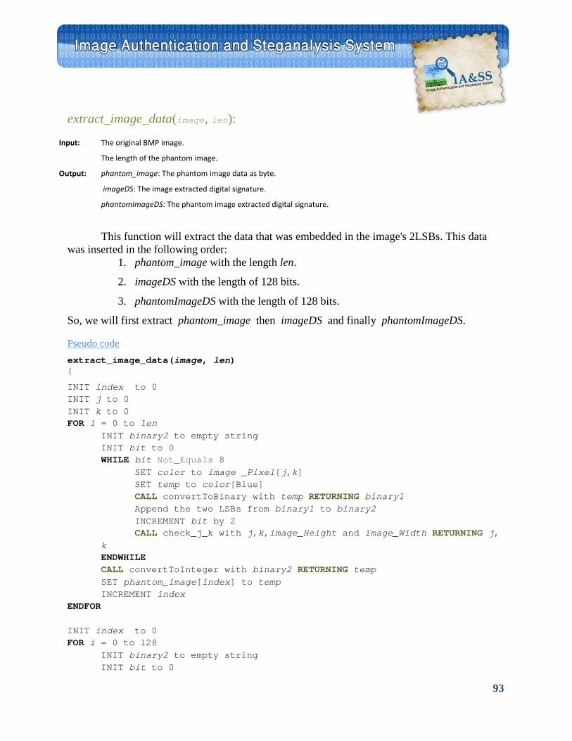
93
extract_image_data(image, len):
Input: The original BMP image.
The length of the phantom image.
Output: phantom_image: The phantom image data as byte.
imageDS: The image extracted digital signature.
phantomImageDS: The phantom image extracted digital signature.
This function will extract the data that was embedded in the image's 2LSBs. This data was inserted in the following order:
1. phantom_image with the length len.
2. imageDS with the length of 128 bits.
3. phantomImageDS with the length of 128 bits.
So, we will first extract phantom_image then imageDS and finally phantomImageDS. UPseudo code extract_image_data(image, len) {
INIT index to 0 INIT j to 0 INIT k to 0 FOR i = 0 to len
INIT binary2 to empty string INIT bit to 0 WHILE bit Not_Equals 8
SET color to image _Pixel[j,k] SET temp to color[Blue] CALL convertToBinary with temp RETURNING binary1 Append the two LSBs from binary1 to binary2 INCREMENT bit by 2 CALL check_j_k with j,k,image_Height and image_Width RETURNING j,
k ENDWHILE CALL convertToInteger with binary2 RETURNING temp SET phantom_image[index] to temp INCREMENT index
ENDFOR INIT index to 0 FOR i = 0 to 128
INIT binary2 to empty string INIT bit to 0
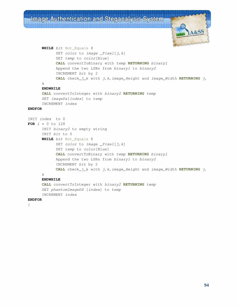
94
WHILE bit Not_Equals 8 SET color to image _Pixel[j,k] SET temp to color[Blue] CALL convertToBinary with temp RETURNING binary1 Append the two LSBs from binary1 to binary2 INCREMENT bit by 2 CALL check_j_k with j,k,image_Height and image_Width RETURNING j,
k ENDWHILE CALL convertToInteger with binary2 RETURNING temp SET imageDs[index] to temp INCREMENT index
ENDFOR INIT index to 0 FOR i = 0 to 128
INIT binary2 to empty string INIT bit to 0 WHILE bit Not_Equals 8
SET color to image _Pixel[j,k] SET temp to color[Blue] CALL convertToBinary with temp RETURNING binary1 Append the two LSBs from binary1 to binary2 INCREMENT bit by 2 CALL check_j_k with j,k,image_Height and image_Width RETURNING j,
k ENDWHILE CALL convertToInteger with binary2 RETURNING temp SET phantomImageDS [index] to temp INCREMENT index
ENDFOR }
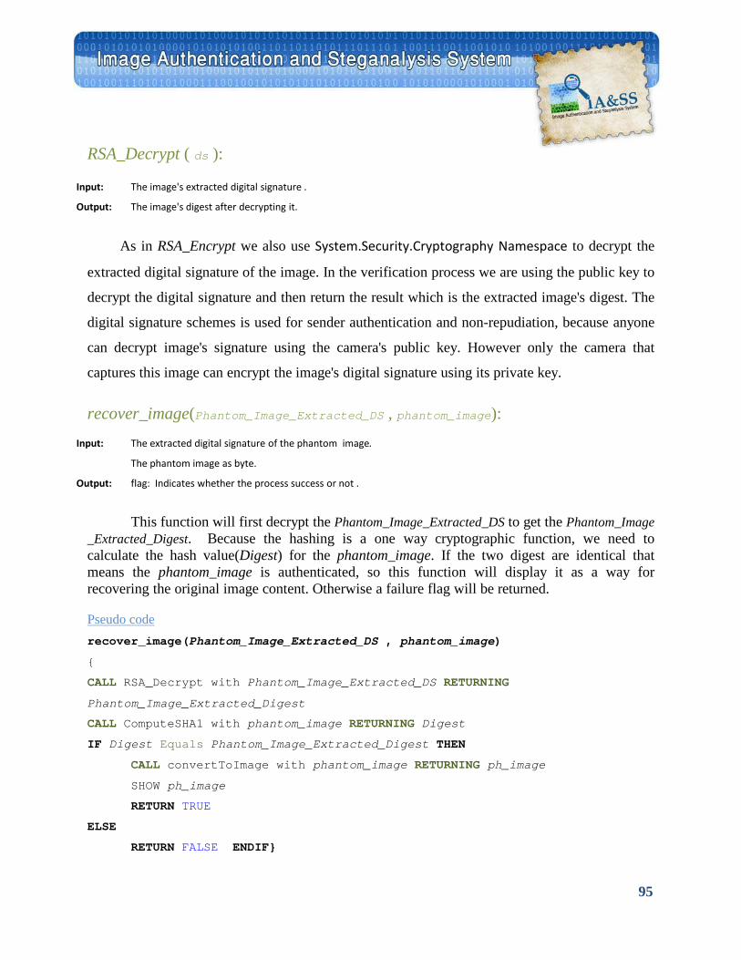
95
RSA_Decrypt ( ds ):
Input: The image's extracted digital signature .
Output: The image's digest after decrypting it.
As in RSA_Encrypt we also use System.Security.Cryptography Namespace to decrypt the
extracted digital signature of the image. In the verification process we are using the public key to
decrypt the digital signature and then return the result which is the extracted image's digest. The
digital signature schemes is used for sender authentication and non-repudiation, because anyone
can decrypt image's signature using the camera's public key. However only the camera that
captures this image can encrypt the image's digital signature using its private key.
recover_image(Phantom_Image_Extracted_DS , phantom_image):
Input: The extracted digital signature of the phantom image.
The phantom image as byte.
Output: flag: Indicates whether the process success or not .
This function will first decrypt the Phantom_Image_Extracted_DS to get the Phantom_Image _Extracted_Digest. Because the hashing is a one way cryptographic function, we need to calculate the hash value(Digest) for the phantom_image. If the two digest are identical that means the phantom_image is authenticated, so this function will display it as a way for recovering the original image content. Otherwise a failure flag will be returned.
UPseudo code recover_image(Phantom_Image_Extracted_DS , phantom_image)
{
CALL RSA_Decrypt with Phantom_Image_Extracted_DS RETURNING
Phantom_Image_Extracted_Digest
CALL ComputeSHA1 with phantom_image RETURNING Digest
IF Digest Equals Phantom_Image_Extracted_Digest THEN
CALL convertToImage with phantom_image RETURNING ph_image SHOW ph_image
RETURN TRUE
ELSE
RETURN FALSE ENDIF}
96
5.2.C Basic functions:
convertToBinary(num):
Input: An integer in the range 0-255
Output: The binary representation of that integer .
This function converts an integer to its binary representation as a one byte.
UPseudo code convertToBinary(num) {
INIT count to 1 WHILE num Not_Equals 0
SET binary[count] to the remainder of divideding num by 2 INCREMENT count num = Floor(num / 2)
ENDWHILE For i=count to 8 SET Binary[count] to 0 ENDFOR }
convertToInteger (binary):
Input: A binary number represented as a string.
Output: Its corresponding integer value .
This function converts a binary string to its integer value.
UPseudo code convertToInteger (binary) {
INIT num to 0 FOR i= 0 to 7
IF binary[i] Equals "1" THEN num += 27-i
ENDIF ENDFOR Return num }
97
convertToByte (img):
Input: A bitmap image.
Output: Its corresponding bytes representation .
This function converts a bitmap image to its binary representation (i.e. as bytes)by using
System.IO.MemoryStream Class.
convertToImage(img_byte): Input: A byte stream represent a BMP image.
Output: The corresponding bitmap picture .
By using System.Drawing.ImageConverter Class This function converts an array of bytes
to its bitmap image format.
Open(I):
Input: An image. Output: -
Open function uses System.Windows.Forms.OpenFileDialog Class. It prompts the user to
open a BMP image file. This class allows the user to check whether a file exists and to open it. If
the opening process success, the opened image file will be loaded into the application. Then, the
image dimensions will be displayed, and ResizeFileName function will be called in order to print
the image file name and path.
ResizeFileName(LongFileName , ShortFileName):
Input: A string specifying the file path . A string indicating the file name. Output: -
98
This function used to display the image file name and location. If the file path is too large
it will display part of it followed by five dots then the file name. Otherwise it will display the
complete file name and path.
Save(I):
Input: An image. Output: -
This function uses System.Windows.Forms.SaveFileDialog Class to help saving I as a
BMP image file. The SaveFileDialog class displays a dialog box from which the user can select a
file or type a file name. It also prompts the user to select a location for saving a file, and either
open and overwrite an existing file or create a new file.
BuClose( ):
Input: - Output: -
This function used to close the application.
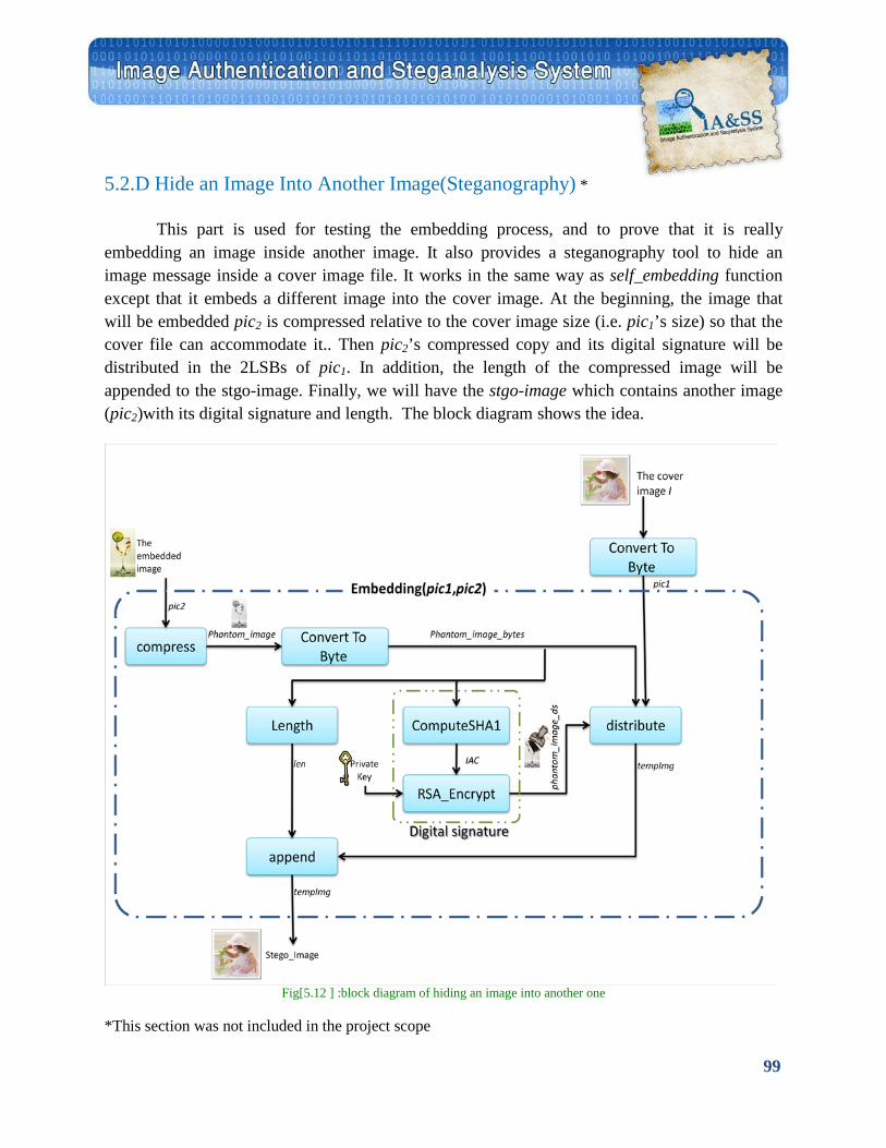
99
5.2.D Hide an Image Into Another Image(Steganography) *
This part is used for testing the embedding process, and to prove that it is really embedding an image inside another image. It also provides a steganography tool to hide an image message inside a cover image file. It works in the same way as self_embedding function except that it embeds a different image into the cover image. At the beginning, the image that will be embedded pic2 is compressed relative to the cover image size (i.e. pic1’s size) so that the cover file can accommodate it.. Then pic2’s compressed copy and its digital signature will be distributed in the 2LSBs of pic1. In addition, the length of the compressed image will be appended to the stgo-image. Finally, we will have the stgo-image which contains another image (pic2)with its digital signature and length. The block diagram shows the idea.
Fig[5.12 ] :block diagram of hiding an image into another one
*This section was not included in the project scope
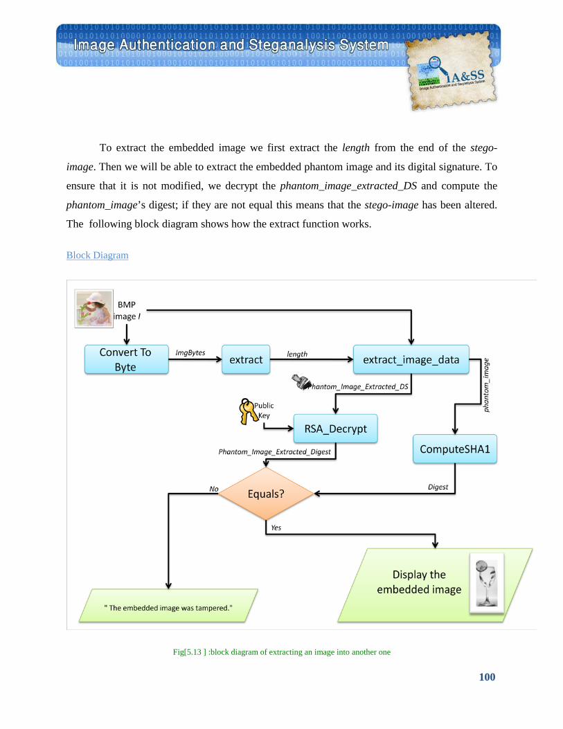
100
To extract the embedded image we first extract the length from the end of the stego-
image. Then we will be able to extract the embedded phantom image and its digital signature. To
ensure that it is not modified, we decrypt the phantom_image_extracted_DS and compute the
phantom_image’s digest; if they are not equal this means that the stego-image has been altered.
The following block diagram shows how the extract function works.
UBlock Diagram
Fig[5.13 ] :block diagram of extracting an image into another one
101
5.3 Data Embedding Scheme for JPEG Grayscale Image Authentication
This is a semi-fragile watermarking technique [33]that accepts JPEG lossy compression on
the watermarked image, and rejects malicious attacks. the method is based on the invariant
property of DCT coefficients before and after JPEG compressions. We use this property to
generate the authentication signature bits stream from the image , then each bit of that stream
is hidden by the modification of the AC components of the image. The security of the technique
is achieved by extracting the image’s feature vector and performing Exclusive OR with a secret
key. Also by using a secret mapping table controls the image’s feature vector authentication
signature embedding and extracting processes in the image frequency domain AC coefficients.
In additional to image authentication , we embed a thumbnail of the image for recovering if a
tampering was detected(self-embedding).
A data embedding scheme typically consists of four main processes:
o Image’s feature vector generation process.
o Mapping table generation (i.e. look up table) process.
o Image’s feature vector embedding process.
o Image’s feature vector extracting process.
The JPEG baseline coding algorithm consists of the following steps:
1. The image is divided into 8×8 non-overlapping blocks.
2. Each block is level-shifted by subtracting 128 from it.
3. Each level-shifted block is transformed with Discrete Cosine Transform (DCT).
4. Each block of DCT coefficients is quantized using a quantization table . Quantization
simply consists of dividing the DCT coefficients by a number that affect the image
quality and the amount of compression and then rounding the result to integer . It is
102
done because most of higher frequency DCT coefficients will typically be truncated to
zeros and can then be represented with a simple run –length code.
5. Each block of quantized DCT coefficients is reordered in accordance with a zigzag
pattern.
6. Each block is coded with Huffman coding that assigns shorter bit codes to the most
frequency used number and longer bit codes to the least frequency used number .
Figure 5.14 shows a block diagram of Data Embedding Scheme for JPEG Grayscale
Image Authentication
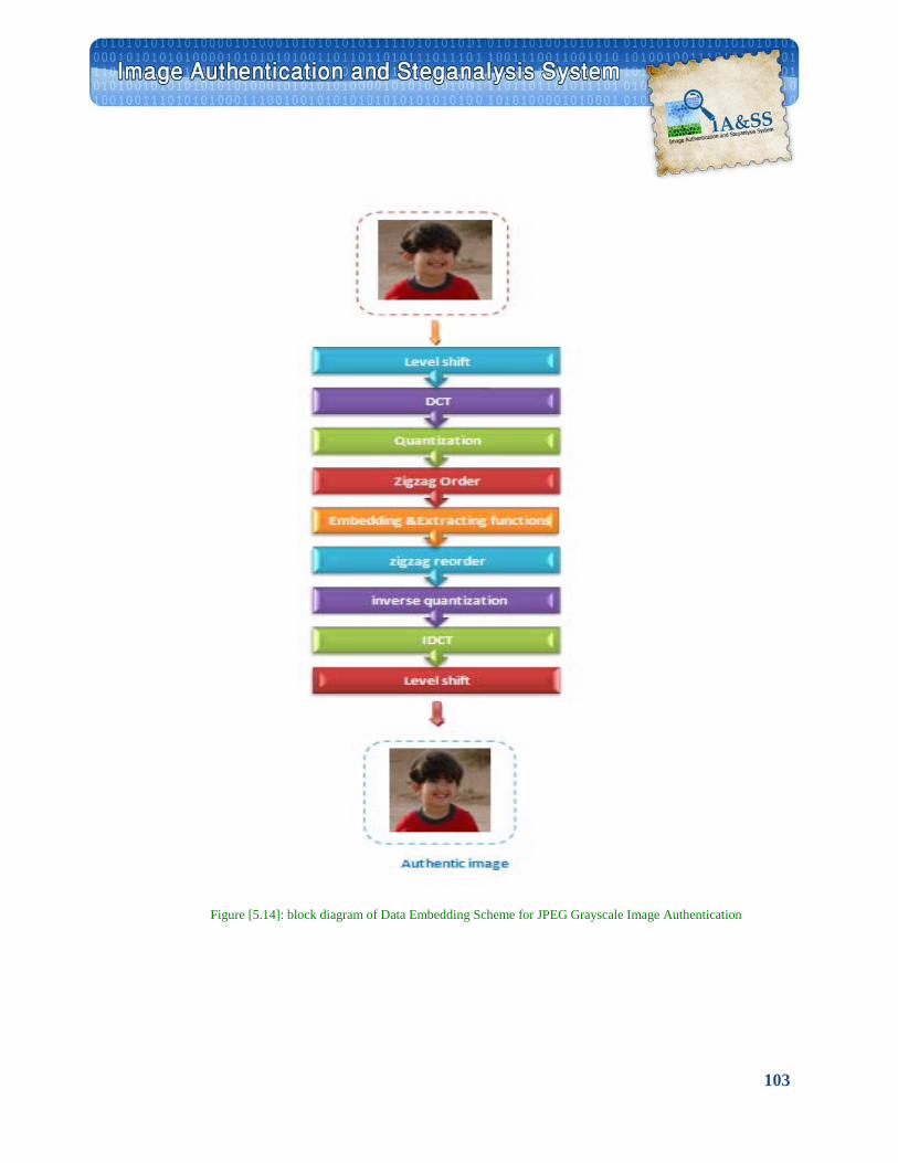
103
Figure [5.14]: block diagram of Data Embedding Scheme for JPEG Grayscale Image Authentication
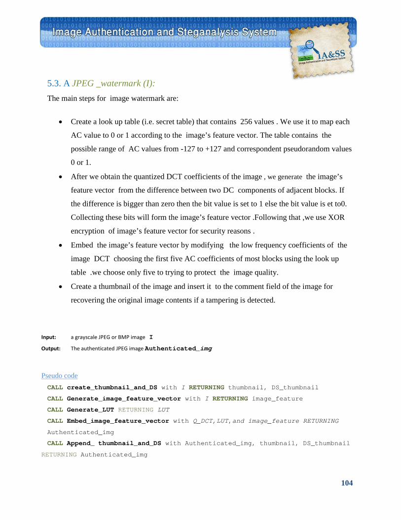
104
5.3. A JPEG _watermark (I): The main steps for image watermark are:
• Create a look up table (i.e. secret table) that contains 256 values . We use it to map each
AC value to 0 or 1 according to the image’s feature vector. The table contains the
possible range of AC values from -127 to +127 and correspondent pseudorandom values
0 or 1.
• After we obtain the quantized DCT coefficients of the image , we generate the image’s
feature vector from the difference between two DC components of adjacent blocks. If
the difference is bigger than zero then the bit value is set to 1 else the bit value is et to0.
Collecting these bits will form the image’s feature vector .Following that ,we use XOR
encryption of image’s feature vector for security reasons .
• Embed the image’s feature vector by modifying the low frequency coefficients of the
image DCT choosing the first five AC coefficients of most blocks using the look up
table .we choose only five to trying to protect the image quality.
• Create a thumbnail of the image and insert it to the comment field of the image for
recovering the original image contents if a tampering is detected.
Input: a grayscale JPEG or BMP image I
Output: The authenticated JPEG image Authenticated_img
UPseudo code CALL create_thumbnail_and_DS with I RETURNING thumbnail, DS_thumbnail
CALL Generate_image_feature_vector with I RETURNING image_feature
CALL Generate_LUT RETURNING LUT
CALL Embed_image_feature_vector with Q_DCT,LUT,and image_feature RETURNING
Authenticated_img
CALL Append_ thumbnail_and_DS with Authenticated_img, thumbnail, DS_thumbnail
RETURNING Authenticated_img
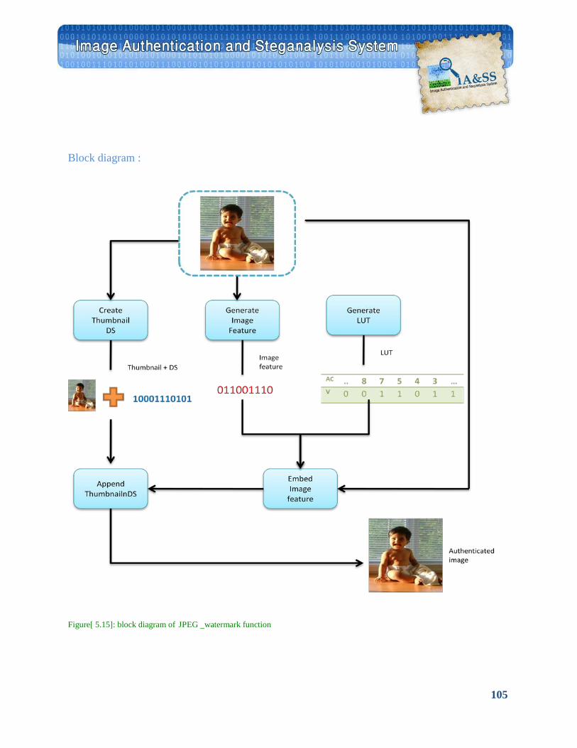
105
Block diagram :
Figure[ 5.15]: block diagram of JPEG _watermark function
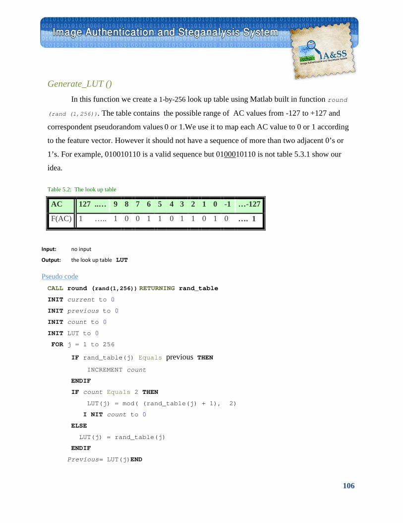
106
Generate_LUT () In this function we create a 1-by-256 look up table using Matlab built in function round
(rand (1,256)). The table contains the possible range of AC values from -127 to +127 and
correspondent pseudorandom values 0 or 1.We use it to map each AC value to 0 or 1 according
to the feature vector. However it should not have a sequence of more than two adjacent 0’s or
1’s. For example, 010010110 is a valid sequence but 01 U000U10110 is not table 5.3.1 show our
idea.
Table 5.2: The look up table
Input: no input
Output: the look up table LUT
UPseudo code CALL round (rand(1,256)) RETURNING rand_table
INIT current to 0
INIT previous to 0
INIT count to 0
INIT LUT to 0
FOR j = 1 to 256
IF rand_table(j) Equals previous THEN INCREMENT count
ENDIF
IF count Equals 2 THEN
LUT(j) = mod( (rand_table(j) + 1), 2)
I NIT count to 0
ELSE
LUT(j) = rand_table(j)
ENDIF
Previous= LUT(j)END
…-127 -1 0 1 2 3 4 5 6 7 8 9 127 ..… AC
…. 1 0 1 0 1 1 0 1 1 0 0 1 1 ….. F(AC)
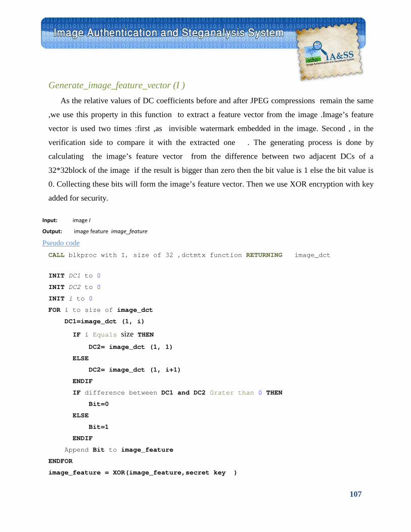
107
Generate_image_feature_vector (I ) As the relative values of DC coefficients before and after JPEG compressions remain the same
,we use this property in this function to extract a feature vector from the image .Image’s feature
vector is used two times :first ,as invisible watermark embedded in the image. Second , in the
verification side to compare it with the extracted one . The generating process is done by
calculating the image’s feature vector from the difference between two adjacent DCs of a
32*32block of the image if the result is bigger than zero then the bit value is 1 else the bit value is
0. Collecting these bits will form the image’s feature vector. Then we use XOR encryption with key
added for security.
Input: image I
Output: image feature image_feature
UPseudo code CALL blkproc with I, size of 32 ,dctmtx function RETURNING image_dct
INIT DC1 to 0
INIT DC2 to 0
INIT i to 0
FOR i to size of image_dct
DC1=image_dct (1, i)
IF i Equals size THEN DC2= image_dct (1, 1)
ELSE
DC2= image_dct (1, i+1)
ENDIF
IF difference between DC1 and DC2 Grater than 0 THEN
Bit=0
ELSE
Bit=1
ENDIF
Append Bit to image_feature
ENDFOR
image_feature = XOR(image_feature,secret key )
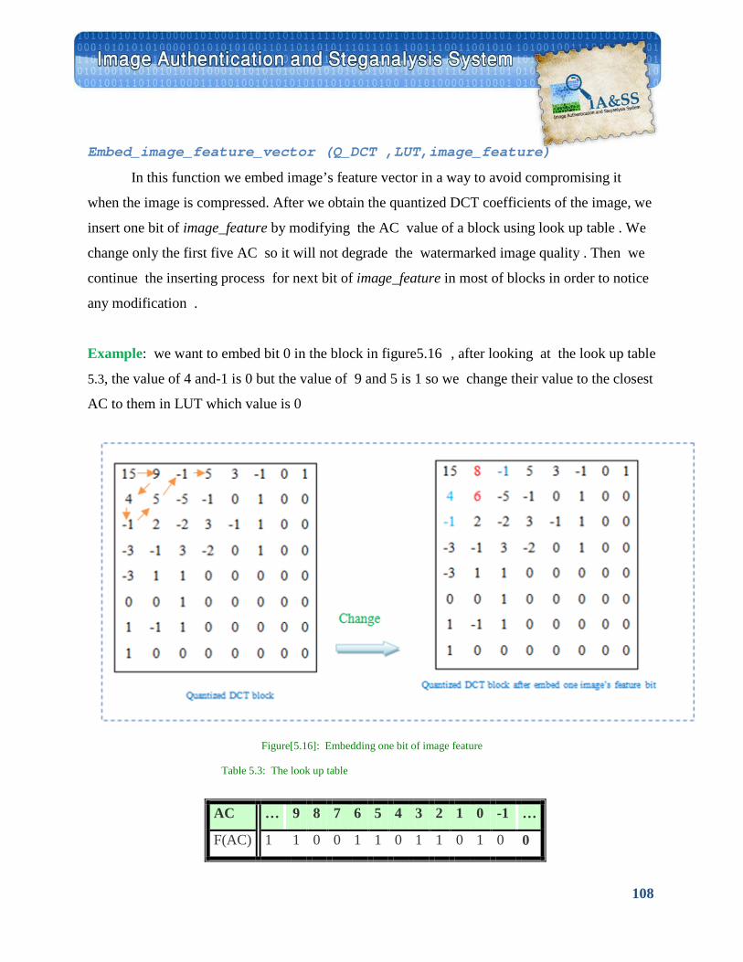
108
Embed_image_feature_vector (Q_DCT ,LUT,image_feature)
In this function we embed image’s feature vector in a way to avoid compromising it
when the image is compressed. After we obtain the quantized DCT coefficients of the image, we
insert one bit of image_feature by modifying the AC value of a block using look up table . We
change only the first five AC so it will not degrade the watermarked image quality . Then we
continue the inserting process for next bit of image_feature in most of blocks in order to notice
any modification .
Example: we want to embed bit 0 in the block in figure5.16 , after looking at the look up table
5.3, the value of 4 and-1 is 0 but the value of 9 and 5 is 1 so we change their value to the closest
AC to them in LUT which value is 0
Figure[5.16]: Embedding one bit of image feature
Table 5.3: The look up table
… -1 0 1 2 3 4 5 6 7 8 9 … AC
0 0 1 0 1 1 0 1 1 0 0 1 1 F(AC)
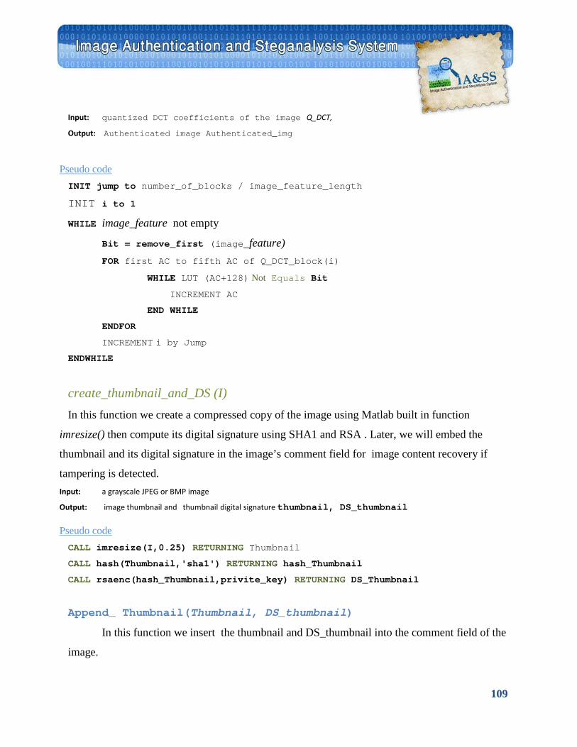
109
Input: quantized DCT coefficients of the image Q_DCT,
Output: Authenticated image Authenticated_img
UPseudo code INIT jump to number_of_blocks / image_feature_length
INIT i to 1
WHILE image_feature not empty
Bit = remove_first (image_feature) FOR first AC to fifth AC of Q_DCT_block(i)
WHILE LUT (AC+128) Not Equals Bit
INCREMENT AC
END WHILE
ENDFOR
INCREMENT i by Jump ENDWHILE
create_thumbnail_and_DS (I) In this function we create a compressed copy of the image using Matlab built in function
imresize() then compute its digital signature using SHA1 and RSA . Later, we will embed the
thumbnail and its digital signature in the image’s comment field for image content recovery if
tampering is detected. Input: a grayscale JPEG or BMP image
Output: image thumbnail and thumbnail digital signature thumbnail, DS_thumbnail
UPseudo code CALL imresize(I,0.25) RETURNING Thumbnail
CALL hash(Thumbnail,'sha1') RETURNING hash_Thumbnail
CALL rsaenc(hash_Thumbnail,privite_key) RETURNING DS_Thumbnail
Append_ Thumbnail(Thumbnail, DS_thumbnail)
In this function we insert the thumbnail and DS_thumbnail into the comment field of the
image.
110
5.3. B JPEG _Verify (I): The main steps for image watermark verification are:
• Create a 1-by-256 look up table and calculate the image’s feature vector (i.e.
image_featue_verifyside) as is done in watermark side .
• Extract the embedded authentication data (i.e. image_feature_embedded ) from the
image by mapping the first five AC that hold a bit of the image’s feature using the look
up table . Sometimes the value of AC is change due to rounding errors in reconstructing
DCT coefficients so we make a voting between these values to avoid that noise .
• Check for a match with the calculated image_feature_ verifyside if so, the image is
authentic and there is no tampering, otherwise, if the extracted image feature is not the
same as the calculated one * , the image may be tampered or modified.
• Recover the original image's compressed copy (i.e. the Thumbnail image), the system
will check if the extracted Thumbnail image's digital signature is as same as the
computed one. If this is the case the system will display it. But if they are different, this
means that the Thumbnail image is also tampered .
* Special case to avoid noise: we say that the image is authentic and there is no tampering if the
number of bits that are different (i.e. corrupted_bit) between image_feature_verifyside and
image_feature_embedded are less than 10% of image feature vector length with the condition
that the unequal bits are not in adjacent blocks i.e. they are scattered around the image.
In the table 5.3. 3 we accept case 1 but case 2 do not.
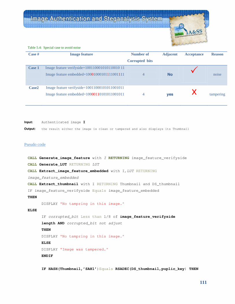
111
Table 5.4: Special case to avoid noise Case # Image feature Number of
Corrupted bits
Adjacent Acceptance Reason
Case 1
Image feature verifyside=100110001010110010 11
Image feature embedded=10001000101111001111
4
No
noise
Case2
Image feature verifyside=10011000101011001011
Image feature embedded=10000110101011001011
4
yes x
tampering
Input: Authenticated image I
Output: the result either the image is clean or tampered and also displays its Thumbnail
UPseudo code
CALL Generate_image_feature with I RETURNING image_feature_verifyside
CALL Generate_LUT RETURNING LUT
CALL Extract_image_feature_embedded with I,LUT RETURNING
image_feature_embedded
CALL Extract_thumbnail with I RETURNING Thumbnail and DS_thumbnail IF image_feature_verifyside Equals image_feature_embedded
THEN
DISPLAY "No tampring in this image."
ELSE
IF corrupted_bit Less than 1/8 of image_feature_verifyside
length AND corrupted_bit not adjust
THEN
DISPLAY "No tampring in this image."
ELSE
DISPLAY "Image was tampered."
ENDIF
IF HASH(Thumbnail,’SAH1’)Equals RSADEC(DS_thumbnail,puplic_key) THEN
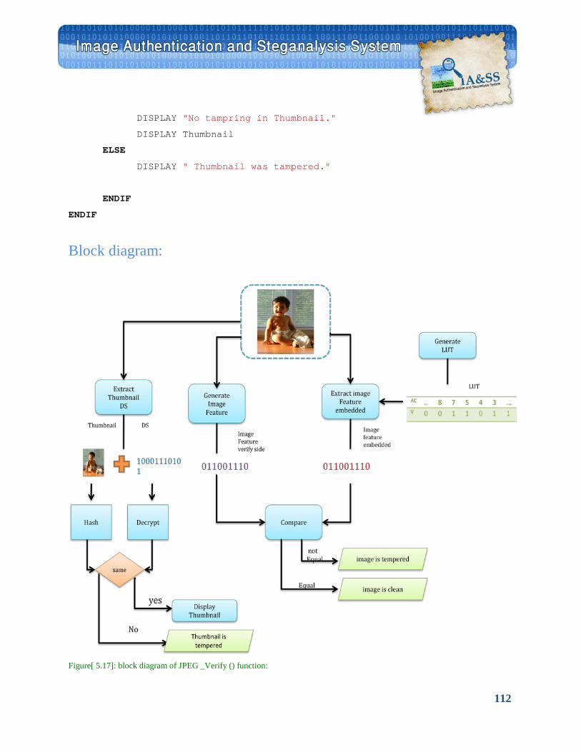
112
DISPLAY "No tampring in Thumbnail."
DISPLAY Thumbnail
ELSE
DISPLAY " Thumbnail was tampered."
ENDIF
ENDIF
Block diagram:
Figure[ 5.17]: block diagram of JPEG _Verify () function:
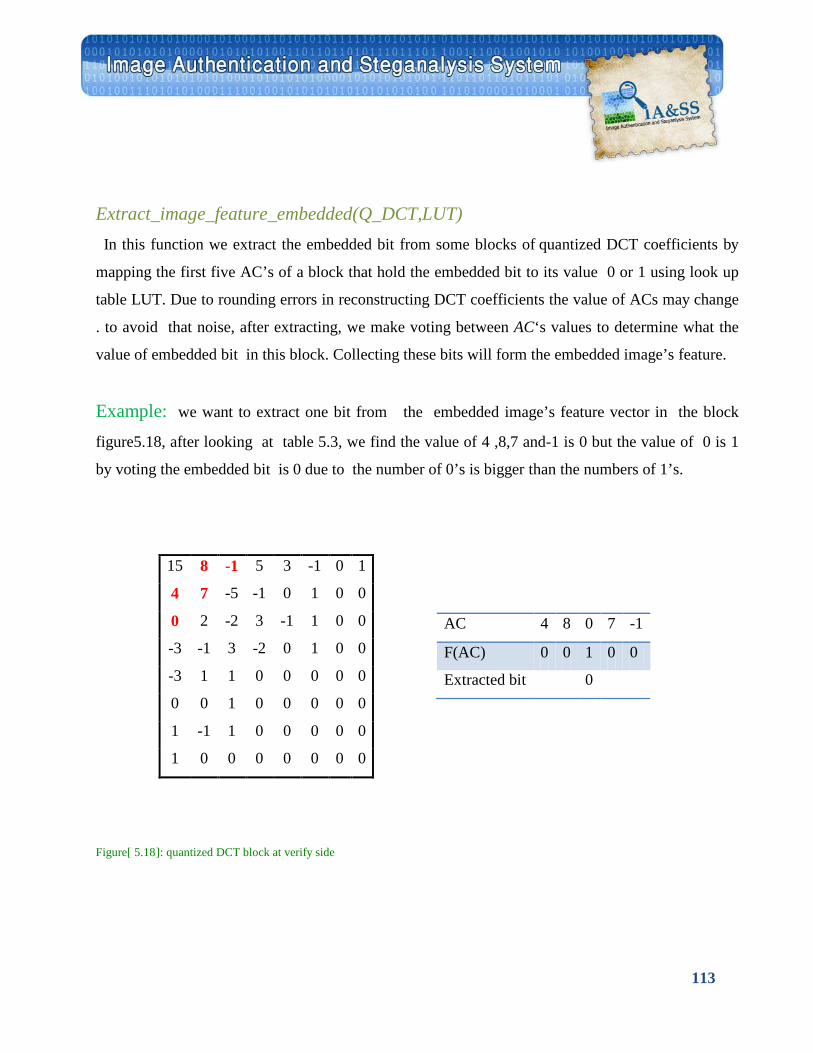
113
Extract_image_feature_embedded(Q_DCT,LUT) In this function we extract the embedded bit from some blocks of quantized DCT coefficients by
mapping the first five AC’s of a block that hold the embedded bit to its value 0 or 1 using look up
table LUT. Due to rounding errors in reconstructing DCT coefficients the value of ACs may change
. to avoid that noise, after extracting, we make voting between AC‘s values to determine what the
value of embedded bit in this block. Collecting these bits will form the embedded image’s feature.
Example: we want to extract one bit from the embedded image’s feature vector in the block
figure5.18, after looking at table 5.3, we find the value of 4 ,8,7 and-1 is 0 but the value of 0 is 1
by voting the embedded bit is 0 due to the number of 0’s is bigger than the numbers of 1’s.
Figure[ 5.18]: quantized DCT block at verify side
1 0 -1 3 5 -1 8 15
0 0 1 0 -1 -5 7 4
0 0 1 -1 3 -2 2 0
0 0 1 0 -2 3 -1 -3
0 0 0 0 0 1 1 -3
0 0 0 0 0 1 0 0
0 0 0 0 0 1 -1 1
0 0 0 0 0 0 0 1
AC 4 8 0 7 -1
F(AC) 0 0 1 0 0
Extracted bit 0
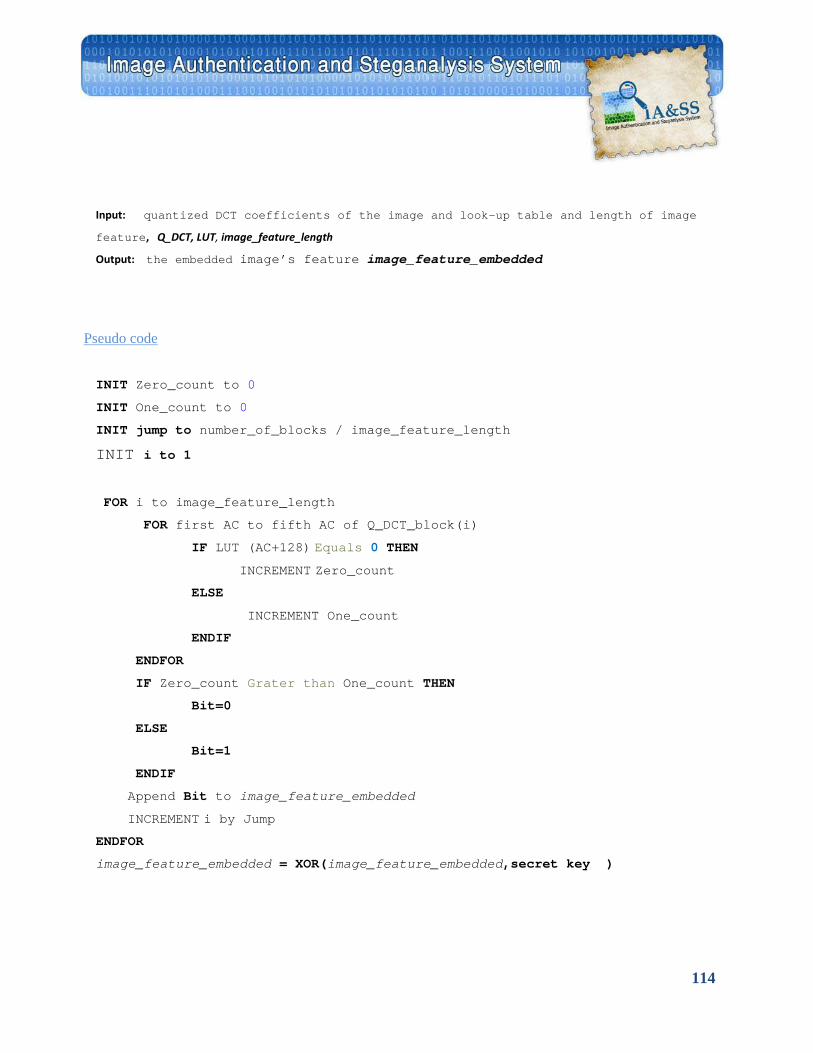
114
Input: quantized DCT coefficients of the image and look-up table and length of image
feature, Q_DCT, LUT, image_feature_length
Output: the embedded image’s feature image_feature_embedded
UPseudo code
INIT Zero_count to 0
INIT One_count to 0
INIT jump to number_of_blocks / image_feature_length
INIT i to 1
FOR i to image_feature_length
FOR first AC to fifth AC of Q_DCT_block(i)
IF LUT (AC+128) Equals 0 THEN
INCREMENT Zero_count ELSE
INCREMENT One_count
ENDIF
ENDFOR
IF Zero_count Grater than One_count THEN
Bit=0
ELSE
Bit=1
ENDIF
Append Bit to image_feature_embedded
INCREMENT i by Jump ENDFOR
image_feature_embedded = XOR(image_feature_embedded,secret key )

115
Extract_ thumbnail (I) In this function we extract thumbnail and DS_thumbnail from the comment filed of the
Authenticated image.
5.3. C Matlab function:
function uses
im2Jpeg Convert an IMAGE to a JPEGOBJ struct
It compresses image X based on 8 x 8 DCT transforms, coefficient quantization, and Huffman
symbol coding.
Jpeg2im
Convert a JPEGOBJ struct to an image.
RSADEC
Rapidly decrypt a short message using RSA.
RSAENC
Rapidly encrypt a short message using RSA.
HASH
Convert an input variable into a message digest using
any of several common hash algorithms.
MAT2HUFF
Huffman encodes a matrix.
HUFF2MAT
Decodes a Huffman encoded matrix.

116
imread
Read image file (MATLAP).
Imwrite
Write image file (MATLAP).
imresize
Resize image.
dctmtx
Discrete cosine transform matrix.
blkproc
Implement distinct block processing for image.
im2col
Rearrange image blocks into columns.
rand
Uniformly distributed random numbers and arrays.

117
5.4 Used Tools • Visual Basic .Net is an object-oriented computer language. It is the extended version of
Microsoft's Visual Basic (VB) implemented on the Microsoft .NET framework. We used version VB 8.0, which was released in 2005, to write the main code.
• MATLAB is a numerical computing environment and programming language.
"Maintained by The Math Works, MATLAB allows easy matrix manipulation, plotting of functions and data, implementation of algorithms, creation of user interfaces, and interfacing with programs in other languages.
• S-Tools is a steganography tool that hides files in BMP, GIF, and WAV files. You open
S-Tools window and drag pictures and sounds across to it. To hide files you only drag them over open sound or picture windows. You can hide many files in one sound or picture and your data is compressed before being encrypted then hidden. Multi-threaded procedure means that you can have many hide/reveal procedures going simultaneously without fear of them interfering with you or holding up your work. You can even close the original picture/sound with no effects to ongoing threads
• Hex Editor Neo is a binary files editing software utility for Windows
• Microsoft Office Word Used for documentation
• Microsoft Office Power Point Used for presentation for the project and draw block
diagram .
• Adobe Photoshop Used for make tampered image, design the logo and some touches in project
• Microsoft Office Project Used for draw Gantt char

118
Testing
Chapter 6

119
Testing is the period of time in the software life cycle during which the components of a software product are evaluated and integrated, and the software product is evaluated to determine whether or not requirements have been satisfied and correct functionality is insured. A primary purpose for testing is to detect software failures so that defects may be uncovered and corrected. It can be done on the following levels:
• Unit testing:
tests the minimal software component, or module. Each unit (basic component) of the
software is tested to verify that the detailed design for the unit has been correctly
implemented.
• Integration testing
exposes defects in the interfaces and interaction between integrated components
(modules). Progressively larger groups of tested software components corresponding to
elements of the architectural design are integrated and tested until the software works as a
system.
• System testing
tests a completely integrated system to verify that it meets its requirements.
• System integration testing
that a system is integrated to any external or third party systems defined verifies in the
system requirements.
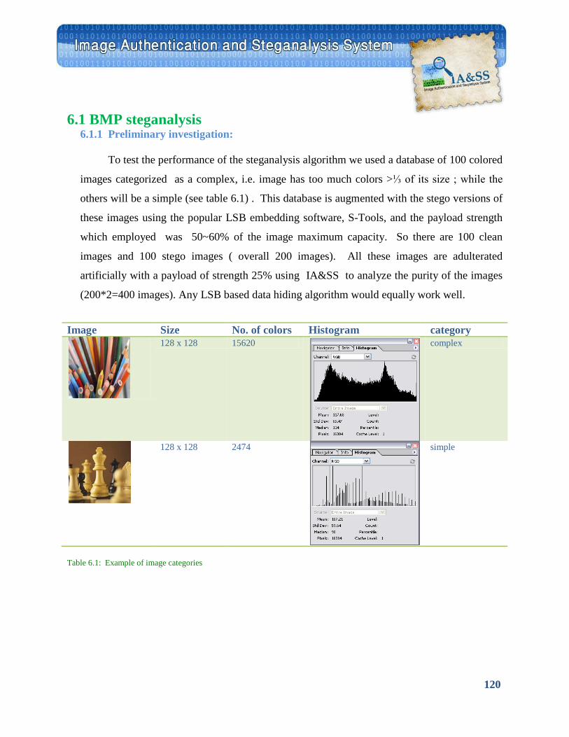
120
6.1 BMP steganalysis 6.1.1 Preliminary investigation: To test the performance of the steganalysis algorithm we used a database of 100 colored
images categorized as a complex, i.e. image has too much colors >⅓ of its size ; while the
others will be a simple (see table 6.1) . This database is augmented with the stego versions of
these images using the popular LSB embedding software, S-Tools, and the payload strength
which employed was 50~60% of the image maximum capacity. So there are 100 clean
images and 100 stego images ( overall 200 images). All these images are adulterated
artificially with a payload of strength 25% using IA&SS to analyze the purity of the images
(200*2=400 images). Any LSB based data hiding algorithm would equally work well.
Image Size No. of colors Histogram category
128 x 128 15620
complex
128 x 128 2474
simple
Table 6.1: Example of image categories
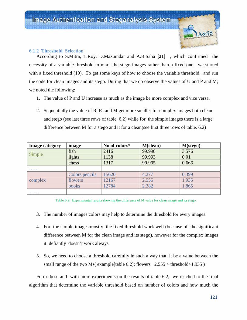
121
6.1.2 Threshold Selection According to S.Mitra, T.Roy, D.Mazumdar and A.B.Saha [21] , which confirmed the
necessity of a variable threshold to mark the stego images rather than a fixed one. we started
with a fixed threshold (10), To get some keys of how to choose the variable threshold, and run
the code for clean images and its stego. During that we do observe the values of U and P and M;
we noted the following:
1. The value of P and U increase as much as the image be more complex and vice versa.
2. Sequentially the value of R, R’ and M get more smaller for complex images both clean
and stego (see last three rows of table. 6.2) while for the simple images there is a large
difference between M for a stego and it for a clean(see first three rows of table. 6.2)
Image category image No of colors* M(clean) M(stego)
Simple
fish 2416 99.998 3.576 lights 1138 99.993 0.01 chess 1317 99.995 0.666
……
complex Colors pencils 15620 4.277 0.399 flowers 12167 2.555 1.935 books 12784 2.382 1.865
…...
3. The number of images colors may help to determine the threshold for every images.
4. For the simple images mostly the fixed threshold work well (because of the significant
difference between M for the clean image and its stego), however for the complex images
it defiantly doesn’t work always.
5. So, we need to choose a threshold carefully in such a way that it be a value between the
small range of the two Ms( example[table 6.2]: flowers 2.555 > threshold>1.935 )
Form these and with more experiments on the results of table 6.2, we reached to the final
algorithm that determine the variable threshold based on number of colors and how much the
Table 6.2: Experimental results showing the difference of M value for clean image and its stego.
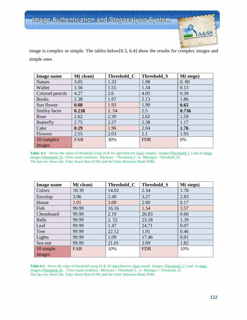
122
image is complex or simple. The tables below[6.3, 6.4] show the results for complex images and
simple ones
Image name M( clean) Threshold_C Threshold_S M( stego) Nature 3.05 1.33 1.98 0. 80 Wallet 1.56 1.55 1.34 0.13 Colored pencils 4.27 2.6 4.05 0.39 Books 2.38 1.97 2.13 1.86 Sun flower 0.08 1.93 1.99 0.65 Smiley faces 0.238 2. 54 2.5 0.736 Rose 2.62 2.39 2.62 1.59 Butterfly 2.75 2.27 2.38 1.17 Cake 0.19 1.96 2.04 1.76 Flowers 2.55 2.03 2.1 1.93 10 complex images
FAR 30% FDR 0%
Image name M( clean) Threshold_C Threshold_S M( stego) Colors 18.39 14.02 2.34 1.78 Envelop 3.96 2.49 3.27 2.83 House 1.01 3.09 2.00 0.17 Fish 99.99 16.16 1.54 3.57 Chessboard 99.99 2.19 26.83 0.66 Balls 99.99 2. 52 23.18 1.39 Leaf 99.99 1.47 24.71 0.07 Tree 99.99 22.12 1.91 0.46 Lights 99.99 1.09 17.46 0.01 Sea star 99.99 21.01 2.09 1.82 10 simple images
FAR 10% FDR 10%
Table. 6.3 Shows the values of threshold using IA & SS algorithm for clean complex images:(Threshold_C ) and its Stego images:(Threshold_S), [True result condition: M(clean) > Threshold_C or M(stego) < Threshold_S] The last row shows the False Alarm Rate (FAR )and the False Detection Rate( FDR)
Table.6.4 shows the value of threshold using IA & SS algorithm for clean simple images: (Threshold_C ) and its stego images:(Threshold_S), [True result condition: M(clean) > Threshold_C or M(stego) < Threshold_S] The last row shows the False Alarm Rate (FAR )and the False Detection Rate( FDR)
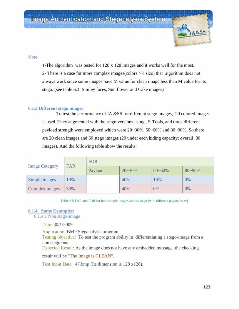
123
Note:
1-The algorithm was tested for 128 x 128 images and it works well for the most.
2- There is a case for more complex images(colors >⅔ size) that algorithm does not
always work since some images have M value for clean image less than M value for its
stego. (see table.6.3: Smiley faces, Sun flower and Cake images)
6.1.3 Different stego images To test the performance of IA &SS for different stego images, 20 colored images
is used. They augmented with the stego versions using , S‐Tools, and three different
payload strength were employed which were 20~30%, 50~60% and 80~90%. So there
are 20 clean images and 60 stego images (20 under each hiding capacity; overall 80
images). And the following table show the results:
Image Category FAR FDR
Payload 20~30% 50~60% 80~90%
Simple images 10% 40% 10% 0%
Complex images 30% 40% 0% 0% Table 6.5 FAR and FDR for both simple images and its stego [with different payload size] U6.1.4 Some Examples U: 6.1.4.1 Non stego-image
Date: 30/1/2009 Application: BMP Steganalysis program. Testing objective: To test the program ability in differentiating a stego-image from a non stego one. Expected Result: As the image does not have any embedded message, the checking
result will be "The Image is CLEAN".
Test Input Data: 47.bmp (Its dimension is 128 x128).
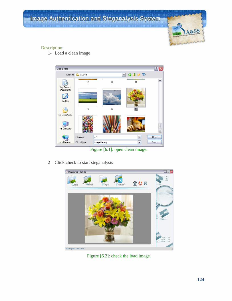
124
Description: 1- Load a clean image
Figure [6.1]: open clean image.
2- Click check to start steganalysis
Figure [6.2]: check the load image.
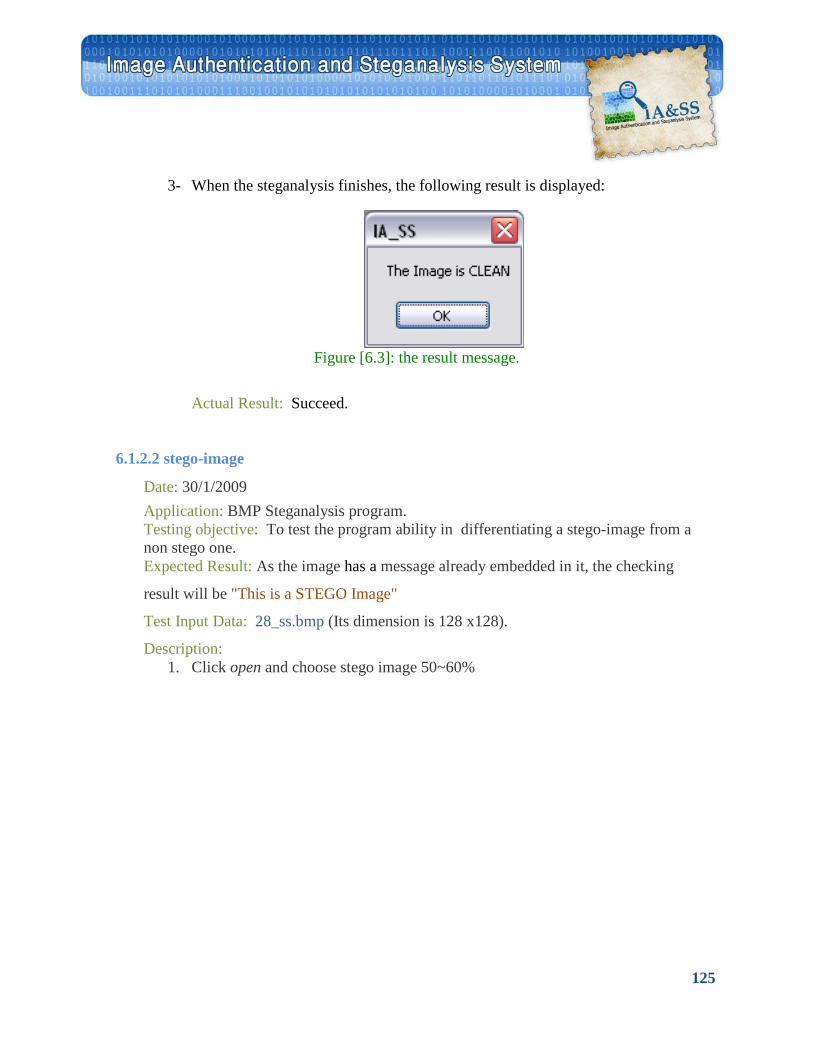
125
6.1.2.2 stego-image
3- When the steganalysis finishes, the following result is displayed:
Figure [6.3]: the result message.
Actual Result: Succeed.
Date: 30/1/2009 Application: BMP Steganalysis program. Testing objective: To test the program ability in differentiating a stego-image from a non stego one. Expected Result: As the image has a message already embedded in it, the checking
result will be "This is a STEGO Image"
Test Input Data: 28_ss.bmp (Its dimension is 128 x128).
Description: 1. Click open and choose stego image 50~60%
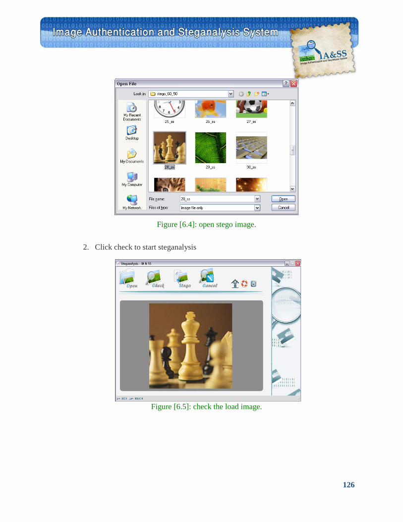
126
Figure [6.4]: open stego image.
2. Click check to start steganalysis
Figure [6.5]: check the load image.
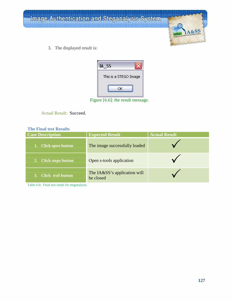
127
The Final test Results
Table 6.6: Final test result for steganalysis.
3. The displayed result is:
Figure [6.6]: the result message.
Actual Result: Succeed.
Case Description Expected Result Actual Result
1. Click open button The image successfully loaded 2. Click stego button Open s-tools application
3. Click exit button The IA&SS’s application will be closed
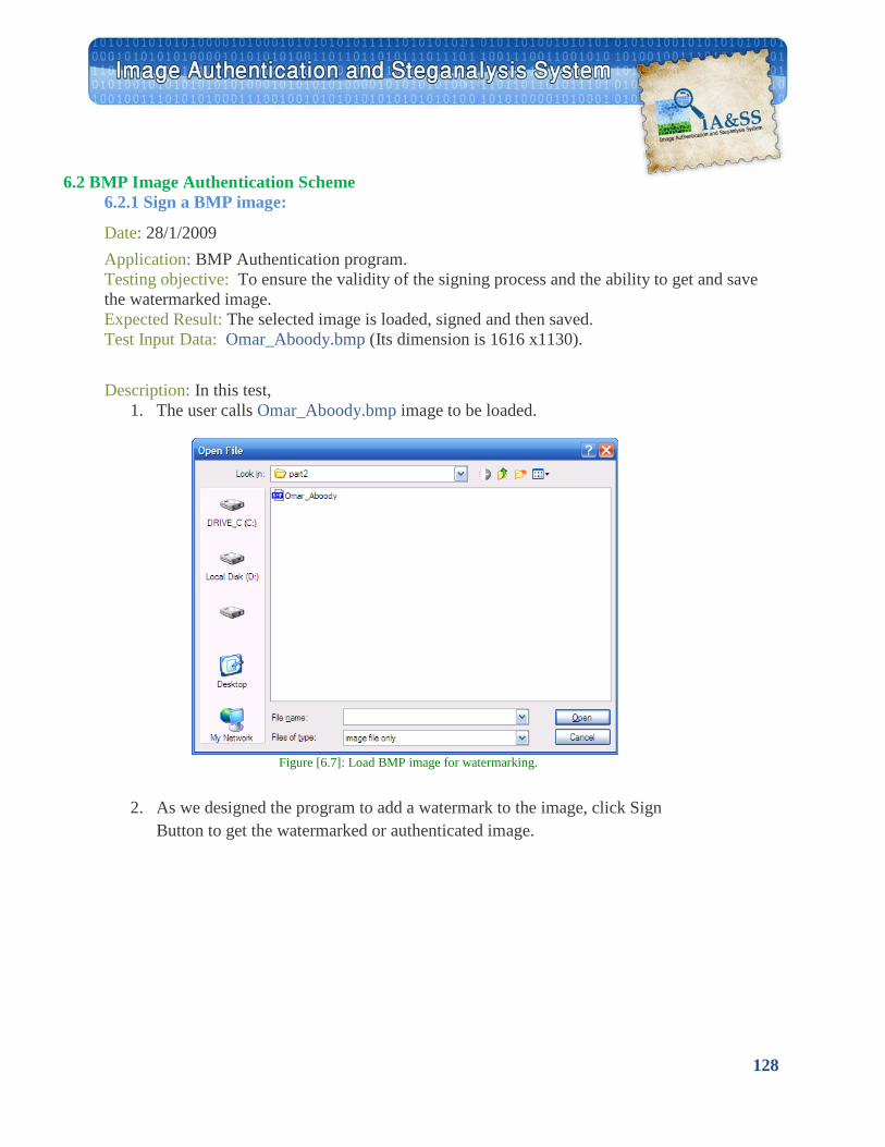
128
6.2 BMP Image Authentication Scheme 6.2.1 Sign a BMP image:
Date: 28/1/2009 Application: BMP Authentication program. Testing objective: To ensure the validity of the signing process and the ability to get and save the watermarked image. Expected Result: The selected image is loaded, signed and then saved. Test Input Data: Omar_Aboody.bmp (Its dimension is 1616 x1130).
Description: In this test, 1. The user calls Omar_Aboody.bmp image to be loaded.
Figure [6.7]: Load BMP image for watermarking.
2. As we designed the program to add a watermark to the image, click Sign
Button to get the watermarked or authenticated image.

129
Figure [6.8]: watermarked image.
3. When the signing process completes successfully, the user can save the
watermarked image in the desired path with the desired name, say Omar_Aboody watermarked.bmp.
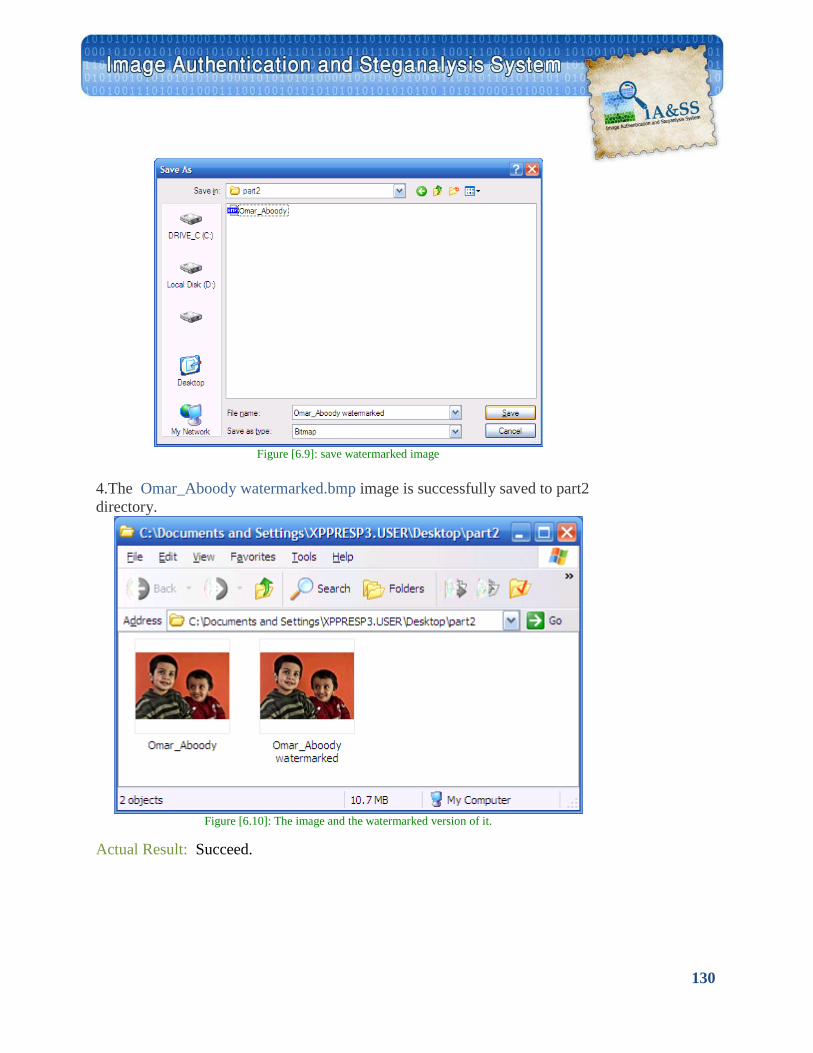
130
Figure [6.9]: save watermarked image
4.The Omar_Aboody watermarked.bmp image is successfully saved to part2 directory.
Figure [6.10]: The image and the watermarked version of it.
Actual Result: Succeed.
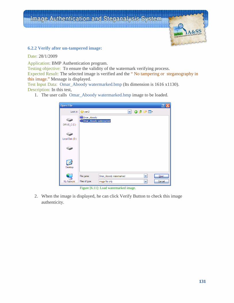
131
6.2.2 Verify after un-tampered image:
Date: 28/1/2009 Application: BMP Authentication program. Testing objective: To ensure the validity of the watermark verifying process. Expected Result: The selected image is verified and the “ No tampering or steganography in this image.” Message is displayed. Test Input Data: Omar_Aboody watermarked.bmp (Its dimension is 1616 x1130). Description: In this test,
1. The user calls Omar_Aboody watermarked.bmp image to be loaded.
Figure [6.11]: Load watermarked image.
2. When the image is displayed, he can click Verify Button to check this image
authenticity.
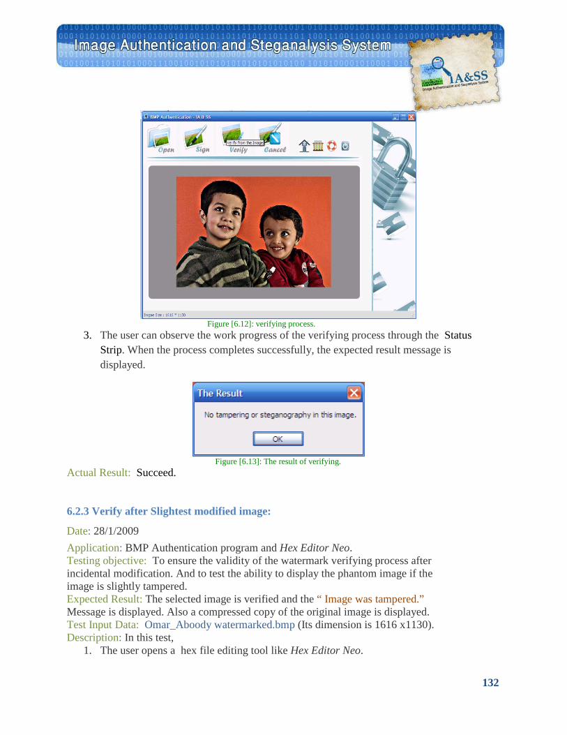
132
6.2.3 Verify after Slightest modified image:
Figure [6.12]: verifying process.
3. The user can observe the work progress of the verifying process through the Status Strip. When the process completes successfully, the expected result message is displayed.
Figure [6.13]: The result of verifying.
Actual Result: Succeed.
Date: 28/1/2009 Application: BMP Authentication program and Hex Editor Neo. Testing objective: To ensure the validity of the watermark verifying process after incidental modification. And to test the ability to display the phantom image if the image is slightly tampered. Expected Result: The selected image is verified and the “ Image was tampered.” Message is displayed. Also a compressed copy of the original image is displayed. Test Input Data: Omar_Aboody watermarked.bmp (Its dimension is 1616 x1130). Description: In this test,
1. The user opens a hex file editing tool like Hex Editor Neo.
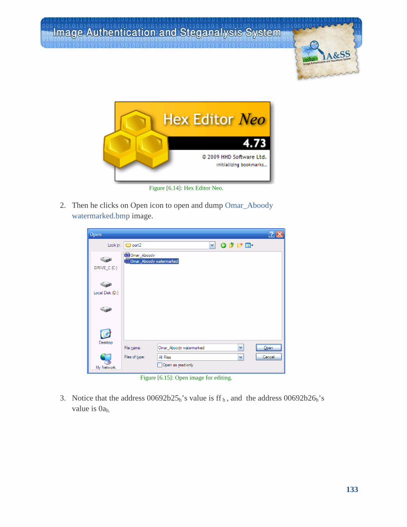
133
Figure [6.14]: Hex Editor Neo.
2. Then he clicks on Open icon to open and dump Omar_Aboody
watermarked.bmp image.
Figure [6.15]: Open image for editing.
3. Notice that the address 00692b25h’s value is ff h , and the address 00692b26h’s value is 0ah.
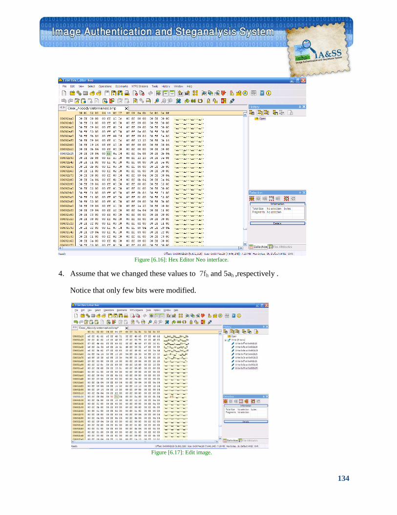
134
Figure [6.16]: Hex Editor Neo interface.
4. Assume that we changed these values to 7fh and 5ah ,respectively .
Notice that only few bits were modified.
Figure [6.17]: Edit image.
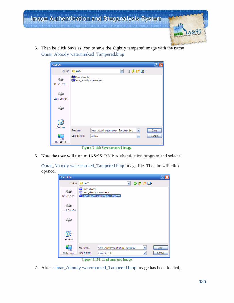
135
5. Then he click Save as icon to save the slightly tampered image with the name Omar_Aboody watermarked_Tampered.bmp
Figure [6.18]: Save tampered image.
6. Now the user will turn to IA&SS BMP Authentication program and selecte
Omar_Aboody watermarked_Tampered.bmp image file. Then he will click opened.
Figure [6.19]: Load tampered image.
7. After Omar_Aboody watermarked_Tampered.bmp image has been loaded,
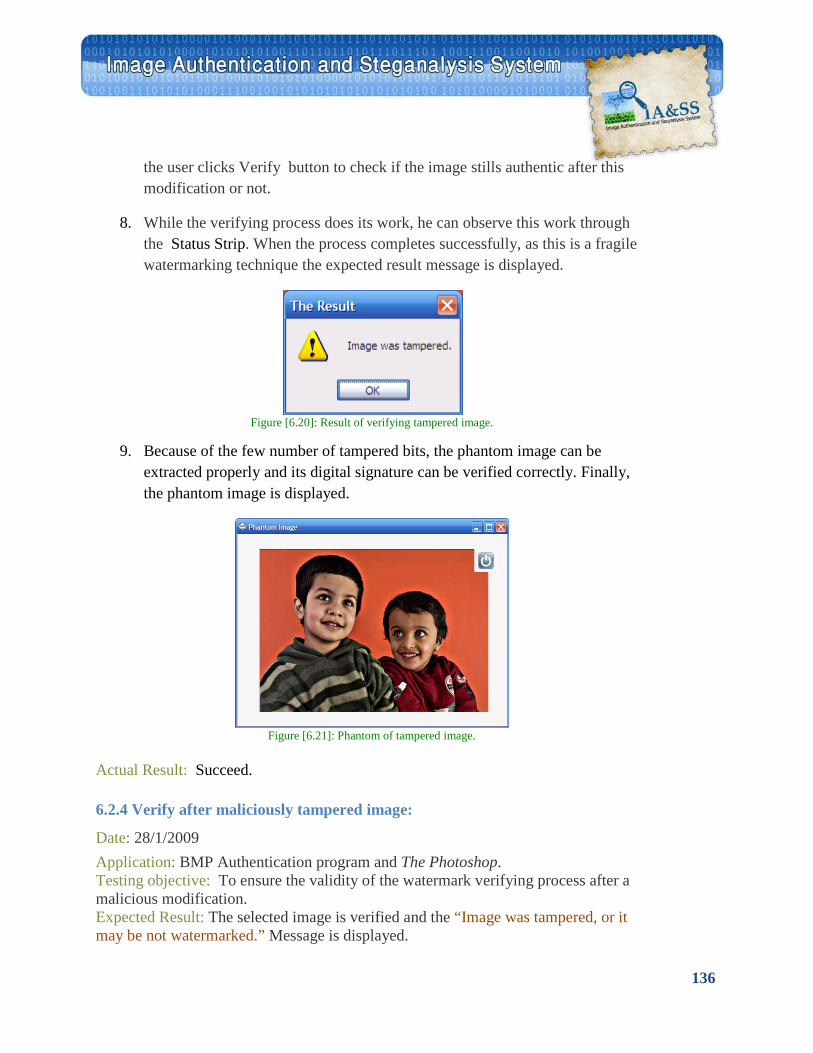
136
6.2.4 Verify after maliciously tampered image:
the user clicks Verify button to check if the image stills authentic after this modification or not.
8. While the verifying process does its work, he can observe this work through the Status Strip. When the process completes successfully, as this is a fragile watermarking technique the expected result message is displayed.
Figure [6.20]: Result of verifying tampered image.
9. Because of the few number of tampered bits, the phantom image can be
extracted properly and its digital signature can be verified correctly. Finally, the phantom image is displayed.
Figure [6.21]: Phantom of tampered image.
Actual Result: Succeed.
Date: 28/1/2009 Application: BMP Authentication program and The Photoshop. Testing objective: To ensure the validity of the watermark verifying process after a malicious modification. Expected Result: The selected image is verified and the “Image was tampered, or it may be not watermarked.” Message is displayed.
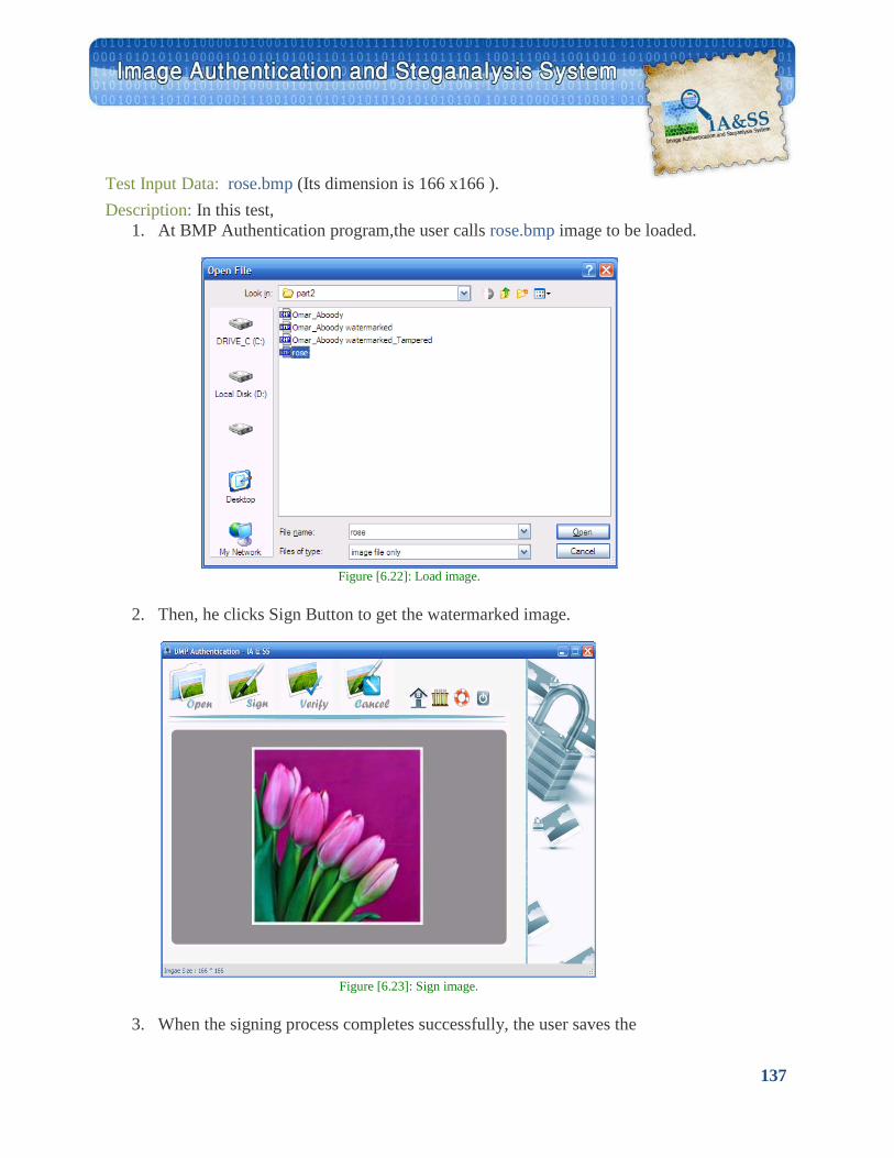
137
Test Input Data: rose.bmp (Its dimension is 166 x166 ). Description: In this test,
1. At BMP Authentication program,the user calls rose.bmp image to be loaded.
Figure [6.22]: Load image.
2. Then, he clicks Sign Button to get the watermarked image.
Figure [6.23]: Sign image.
3. When the signing process completes successfully, the user saves the
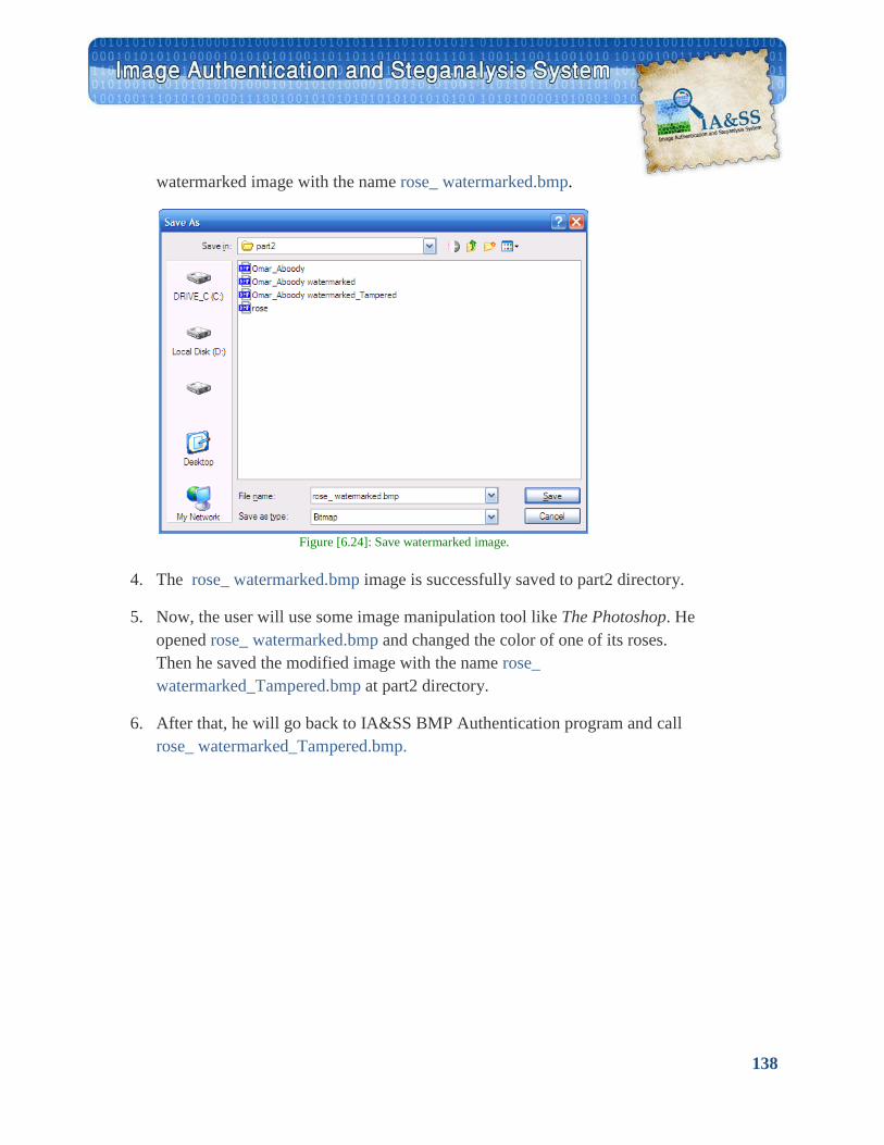
138
watermarked image with the name rose_ watermarked.bmp.
Figure [6.24]: Save watermarked image.
4. The rose_ watermarked.bmp image is successfully saved to part2 directory.
5. Now, the user will use some image manipulation tool like The Photoshop. He opened rose_ watermarked.bmp and changed the color of one of its roses. Then he saved the modified image with the name rose_ watermarked_Tampered.bmp at part2 directory.
6. After that, he will go back to IA&SS BMP Authentication program and call rose_ watermarked_Tampered.bmp.
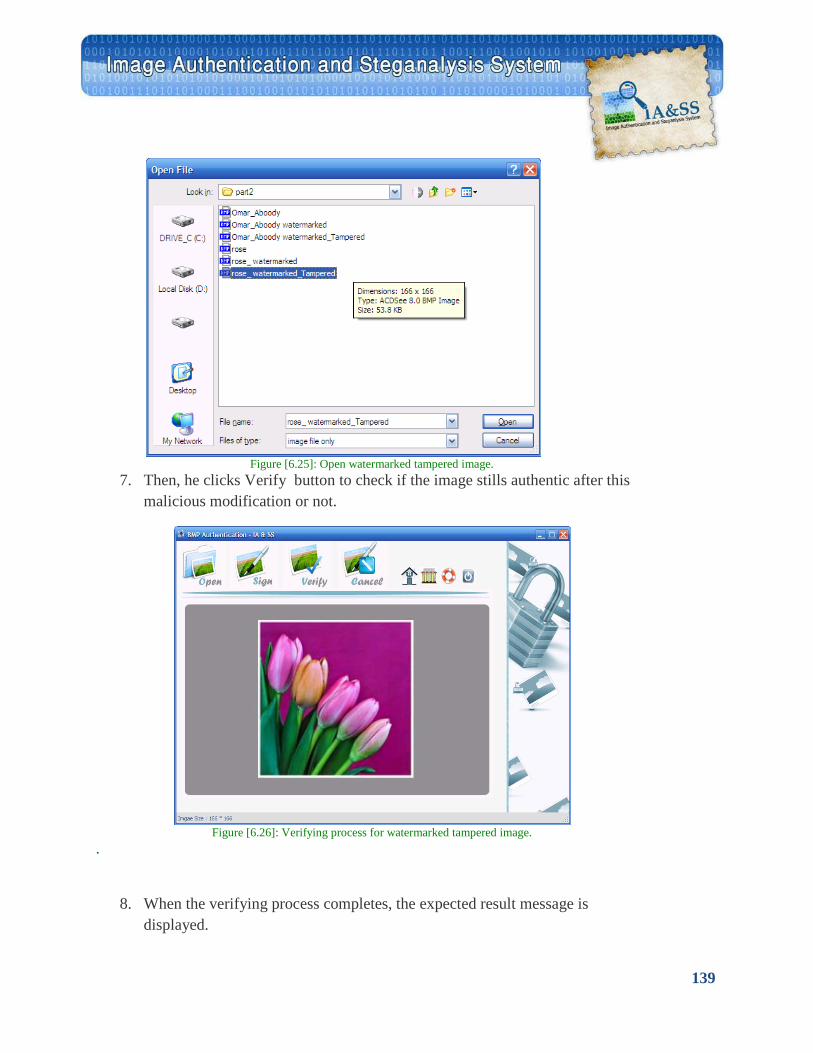
139
Figure [6.25]: Open watermarked tampered image.
7. Then, he clicks Verify button to check if the image stills authentic after this malicious modification or not.
Figure [6.26]: Verifying process for watermarked tampered image.
.
8. When the verifying process completes, the expected result message is displayed.

140
6.2.5 Hide an image into another image:
Figure [6.27]: Result of verifying tampered image
9. As this modification was malicious, the program will not be able to extract and verify the watermark or the phantom image data. So, the image will not be authentic.
Actual Result: Succeed.
Date: 28/1/2009 Application: BMP Authentication program. Testing objective: To ensure the validity of the image compressing and embedding processes. Expected Result: The cover-image will hold another image in its LSBs. We will obtain the stego-image and from it –if it is not tampered- we can extract the embedded image. Test Input Data: The cover-image: Amera.bmp (Its dimension is 124 x166 ).
The embedded image: Hessa.bmp (Its dimension is 1600 x1200 ). Description: In this test,
1. From IA&SS BMP Authentication program,the user clicks on Test the code button in order to test the program ability to hide an image into itself or into another image.
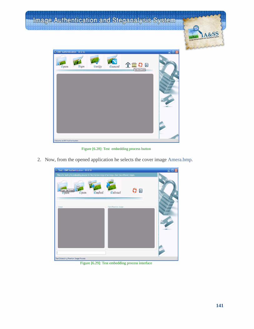
141
Figure [6.28]: Test embedding process button
2. Now, from the opened application he selects the cover image Amera.bmp.
Figure [6.29]: Test embedding process interface
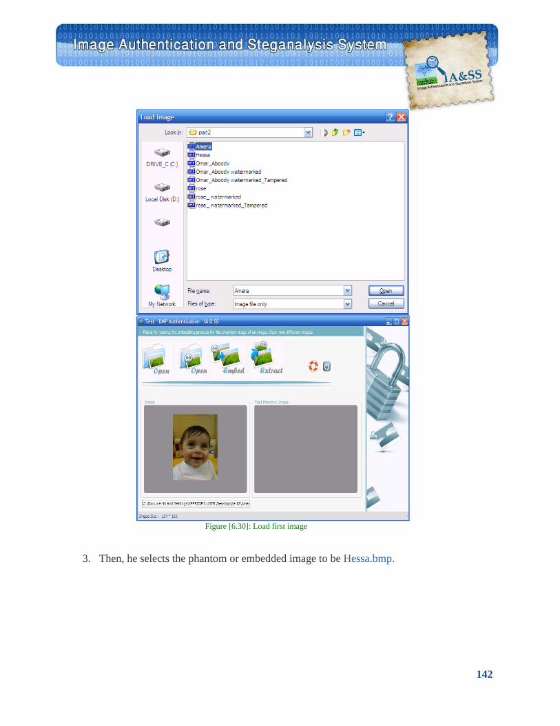
142
Figure [6.30]: Load first image
3. Then, he selects the phantom or embedded image to be Hessa.bmp.
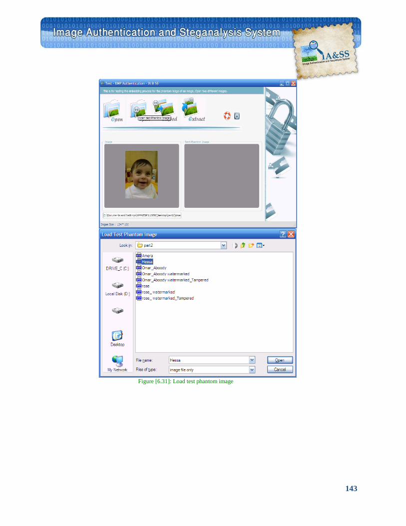
143
Figure [6.31]: Load test phantom image
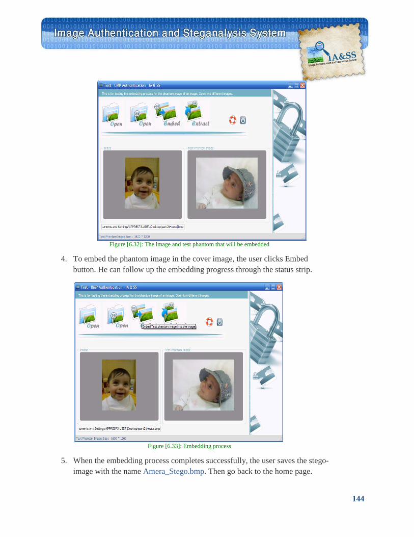
144
Figure [6.32]: The image and test phantom that will be embedded
4. To embed the phantom image in the cover image, the user clicks Embed
button. He can follow up the embedding progress through the status strip.
Figure [6.33]: Embedding process
5. When the embedding process completes successfully, the user saves the stego-
image with the name Amera_Stego.bmp. Then go back to the home page.
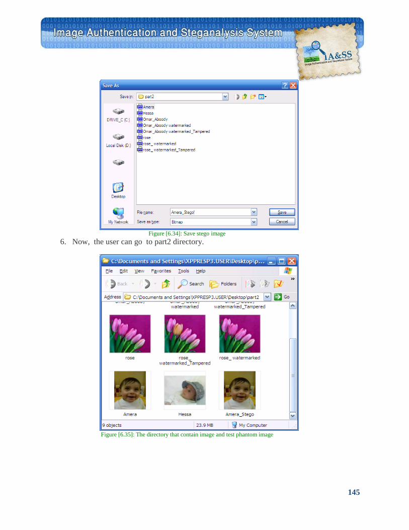
145
Figure [6.34]: Save stego image
6. Now, the user can go to part2 directory.
Figure [6.35]: The directory that contain image and test phantom image
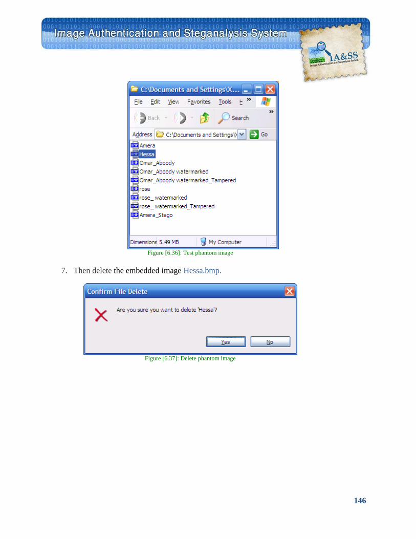
146
Figure [6.36]: Test phantom image
7. Then delete the embedded image Hessa.bmp.
Figure [6.37]: Delete phantom image
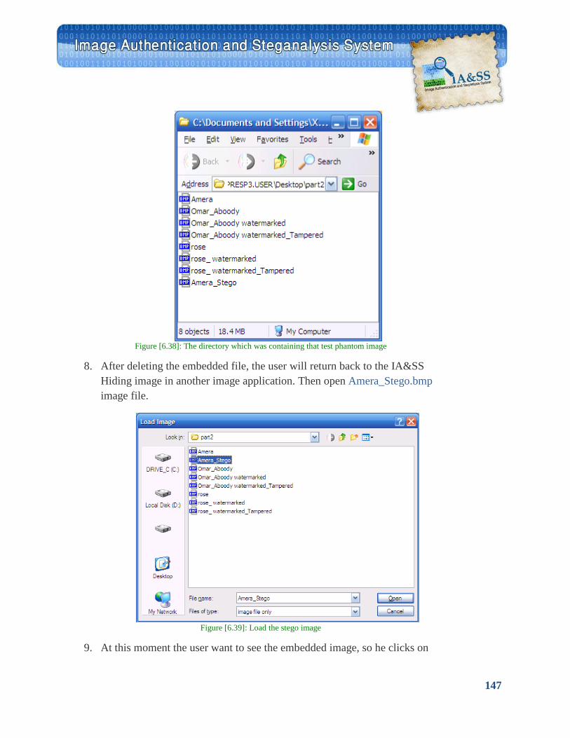
147
Figure [6.38]: The directory which was containing that test phantom image
8. After deleting the embedded file, the user will return back to the IA&SS
Hiding image in another image application. Then open Amera_Stego.bmp image file.
Figure [6.39]: Load the stego image
9. At this moment the user want to see the embedded image, so he clicks on
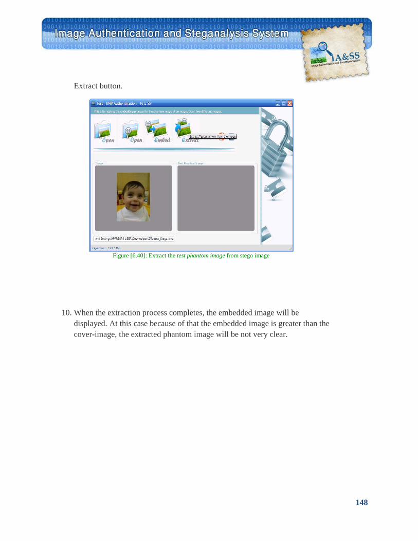
148
Extract button.
Figure [6.40]: Extract the test phantom image from stego image
10. When the extraction process completes, the embedded image will be displayed. At this case because of that the embedded image is greater than the cover-image, the extracted phantom image will be not very clear.
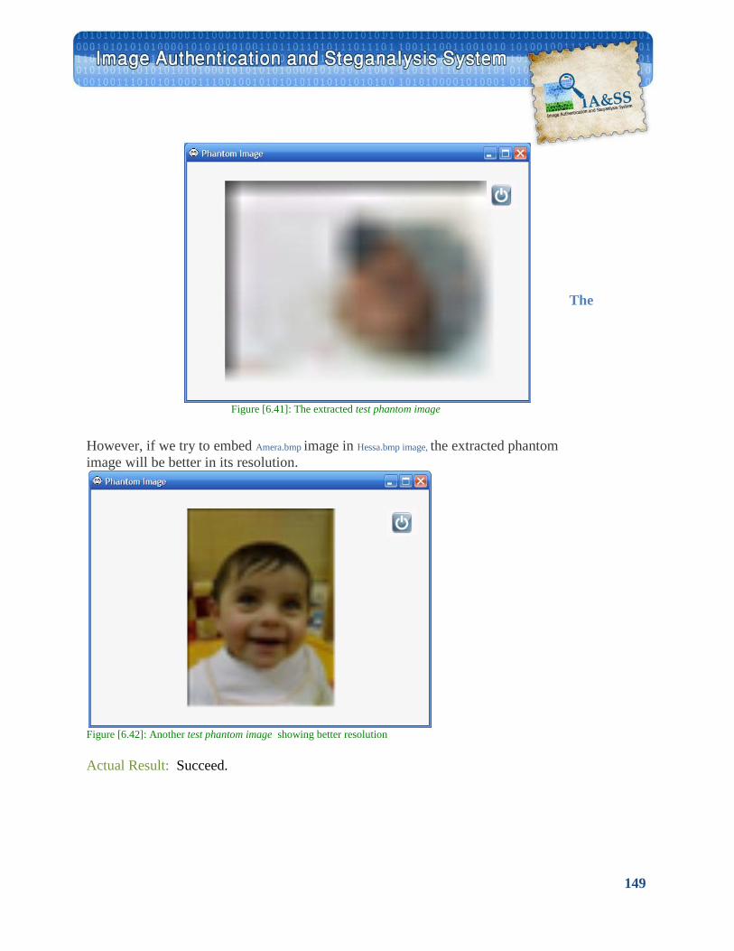
149
The
Figure [6.41]: The extracted test phantom image
However, if we try to embed Amera.bmp image in Hessa.bmp image, the extracted phantom image will be better in its resolution.
Figure [6.42]: Another test phantom image showing better resolution Actual Result: Succeed.
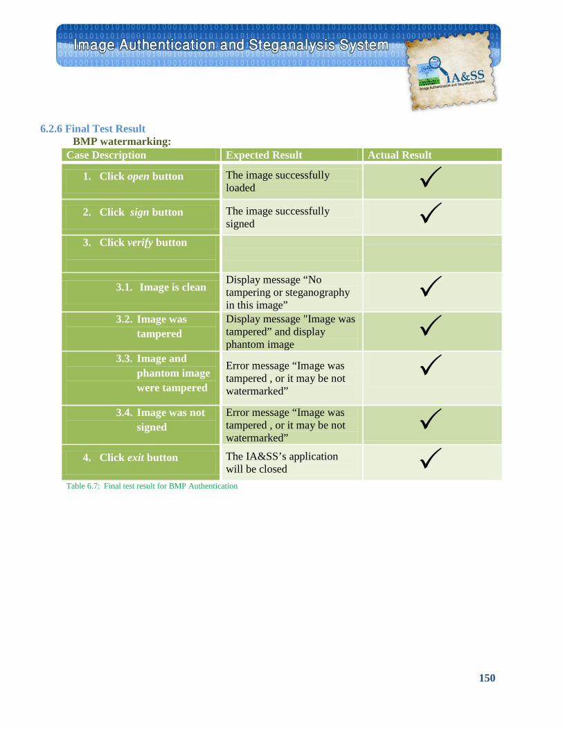
150
6.2.6 Final Test Result
BMP watermarking: Case Description Expected Result Actual Result
1. Click open button The image successfully loaded
2. Click sign button The image successfully signed
3. Click verify button
3.1. Image is clean Display message “No tampering or steganography in this image”
3.2. Image was
tampered Display message "Image was tampered” and display phantom image
3.3. Image and
phantom image were tampered
Error message “Image was tampered , or it may be not watermarked”
3.4. Image was not
signed Error message “Image was tampered , or it may be not watermarked”
4. Click exit button The IA&SS’s application
will be closed Table 6.7: Final test result for BMP Authentication
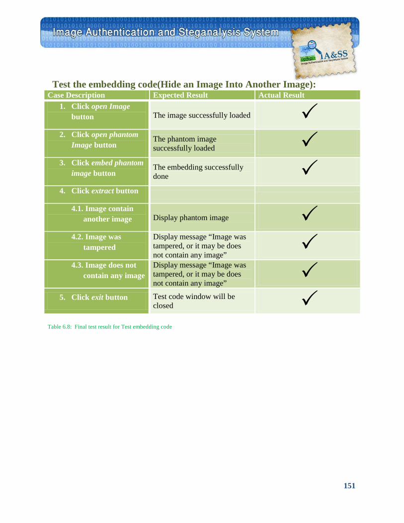
151
Test the embedding code(Hide an Image Into Another Image): Case Description Expected Result Actual Result
1. Click open Image button The image successfully loaded
2. Click open phantom Image button
The phantom image successfully loaded
3. Click embed phantom image button
The embedding successfully done
4. Click extract button
4.1. Image contain another image Display phantom image
4.2. Image was tampered
Display message “Image was tampered, or it may be does not contain any image”
4.3. Image does not contain any image
Display message “Image was tampered, or it may be does not contain any image”
5. Click exit button Test code window will be closed
Table 6.8: Final test result for Test embedding code
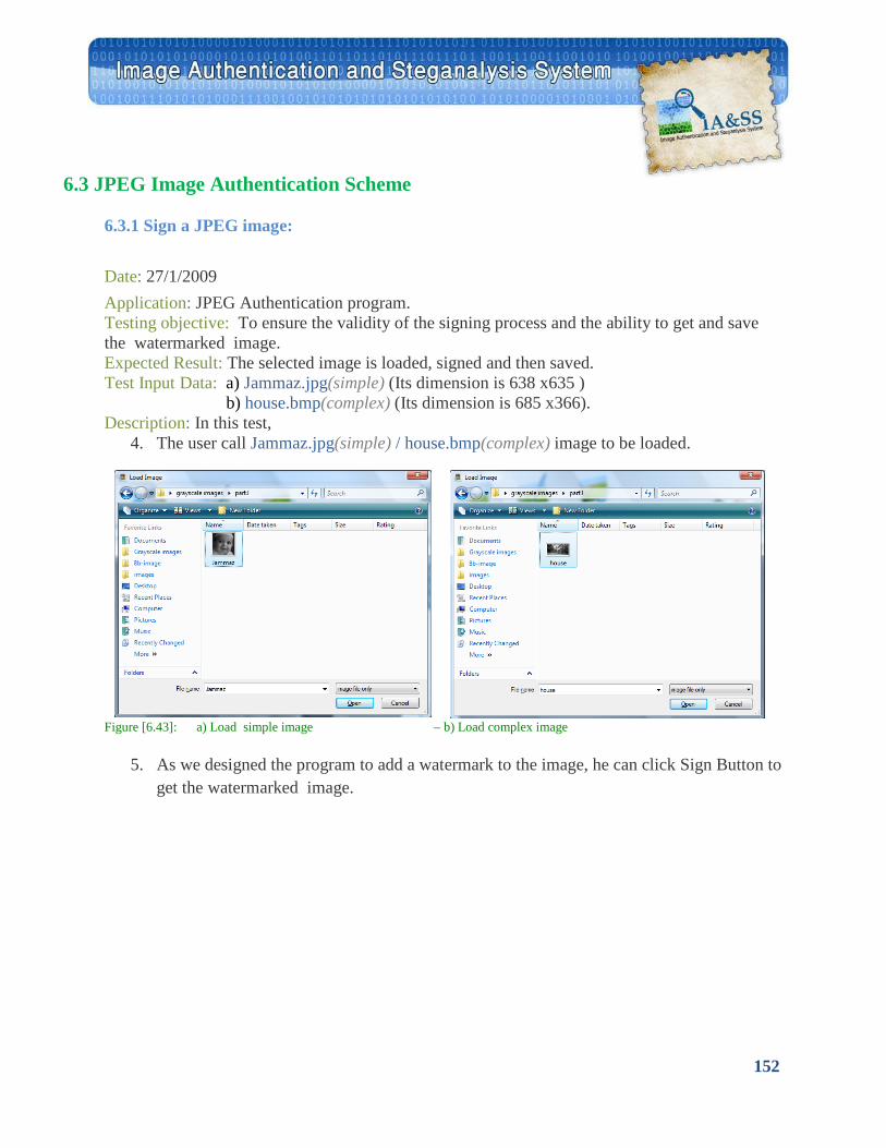
152
6.3 JPEG Image Authentication Scheme
6.3.1 Sign a JPEG image:
Date: 27/1/2009 Application: JPEG Authentication program. Testing objective: To ensure the validity of the signing process and the ability to get and save the watermarked image. Expected Result: The selected image is loaded, signed and then saved. Test Input Data: a) Jammaz.jpg(simple) (Its dimension is 638 x635 ) b) house.bmp(complex) (Its dimension is 685 x366). Description: In this test,
4. The user call Jammaz.jpg(simple) / house.bmp(complex) image to be loaded.
Figure [6.43]: a) Load simple image – b) Load complex image
5. As we designed the program to add a watermark to the image, he can click Sign Button to get the watermarked image.
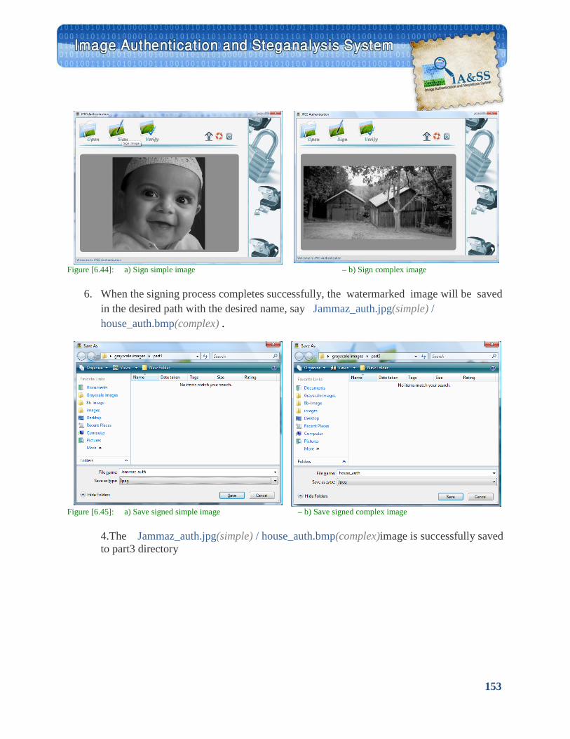
153
Figure [6.44]: a) Sign simple image – b) Sign complex image
6. When the signing process completes successfully, the watermarked image will be saved in the desired path with the desired name, say Jammaz_auth.jpg(simple) / house_auth.bmp(complex) .
Figure [6.45]: a) Save signed simple image – b) Save signed complex image
4.The Jammaz_auth.jpg(simple) / house_auth.bmp(complex)image is successfully saved to part3 directory
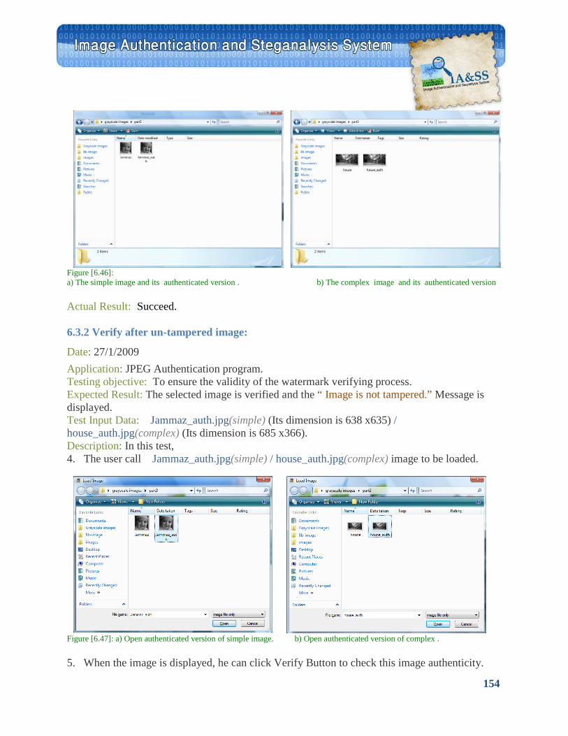
154
6.3.2 Verify after un-tampered image:
Figure [6.46]: a) The simple image and its authenticated version . b) The complex image and its authenticated version Actual Result: Succeed.
Date: 27/1/2009 Application: JPEG Authentication program. Testing objective: To ensure the validity of the watermark verifying process. Expected Result: The selected image is verified and the “ Image is not tampered.” Message is displayed. Test Input Data: Jammaz_auth.jpg(simple) (Its dimension is 638 x635) / house_auth.jpg(complex) (Its dimension is 685 x366). Description: In this test, 4. The user call Jammaz_auth.jpg(simple) / house_auth.jpg(complex) image to be loaded.
Figure [6.47]: a) Open authenticated version of simple image. b) Open authenticated version of complex . 5. When the image is displayed, he can click Verify Button to check this image authenticity.
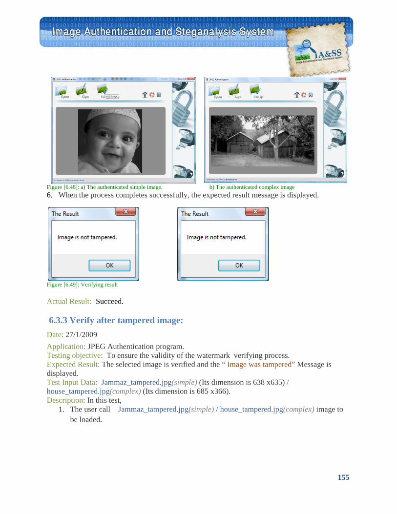
155
6.3.3 Verify after tampered image:
Figure [6.48]: a) The authenticated simple image. b) The authenticated complex image 6. When the process completes successfully, the expected result message is displayed.
Figure [6.49]: Verifying result Actual Result: Succeed.
Date: 27/1/2009 Application: JPEG Authentication program. Testing objective: To ensure the validity of the watermark verifying process. Expected Result: The selected image is verified and the “ Image was tampered” Message is displayed. Test Input Data: Jammaz_tampered.jpg(simple) (Its dimension is 638 x635) / house_tampered.jpg(complex) (Its dimension is 685 x366). Description: In this test,
1. The user call Jammaz_tampered.jpg(simple) / house_tampered.jpg(complex) image to be loaded.
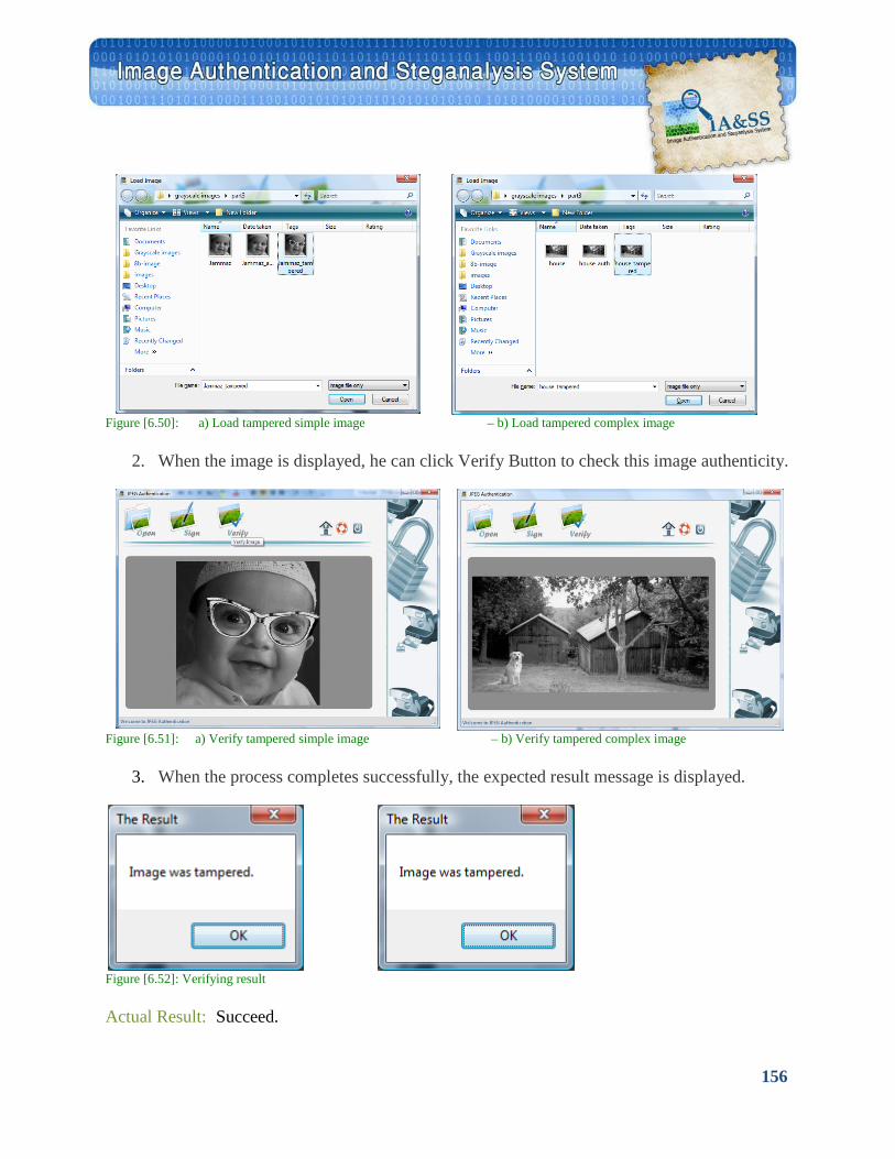
156
Figure [6.50]: a) Load tampered simple image – b) Load tampered complex image
2. When the image is displayed, he can click Verify Button to check this image authenticity.
Figure [6.51]: a) Verify tampered simple image – b) Verify tampered complex image
3. When the process completes successfully, the expected result message is displayed.
Figure [6.52]: Verifying result Actual Result: Succeed.
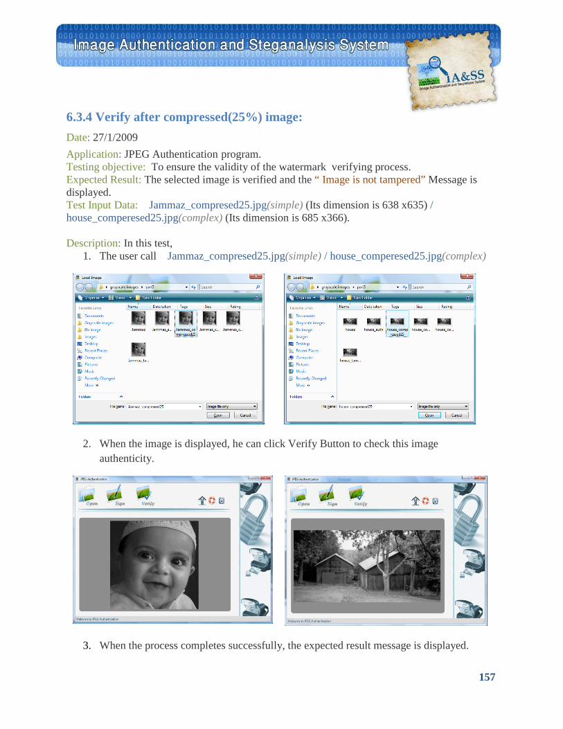
157
6.3.4 Verify after compressed(25%) image: Date: 27/1/2009 Application: JPEG Authentication program. Testing objective: To ensure the validity of the watermark verifying process. Expected Result: The selected image is verified and the “ Image is not tampered” Message is displayed. Test Input Data: Jammaz_compresed25.jpg(simple) (Its dimension is 638 x635) / house_comperesed25.jpg(complex) (Its dimension is 685 x366).
Description: In this test, 1. The user call Jammaz_compresed25.jpg(simple) / house_comperesed25.jpg(complex)
2. When the image is displayed, he can click Verify Button to check this image authenticity.
3. When the process completes successfully, the expected result message is displayed.
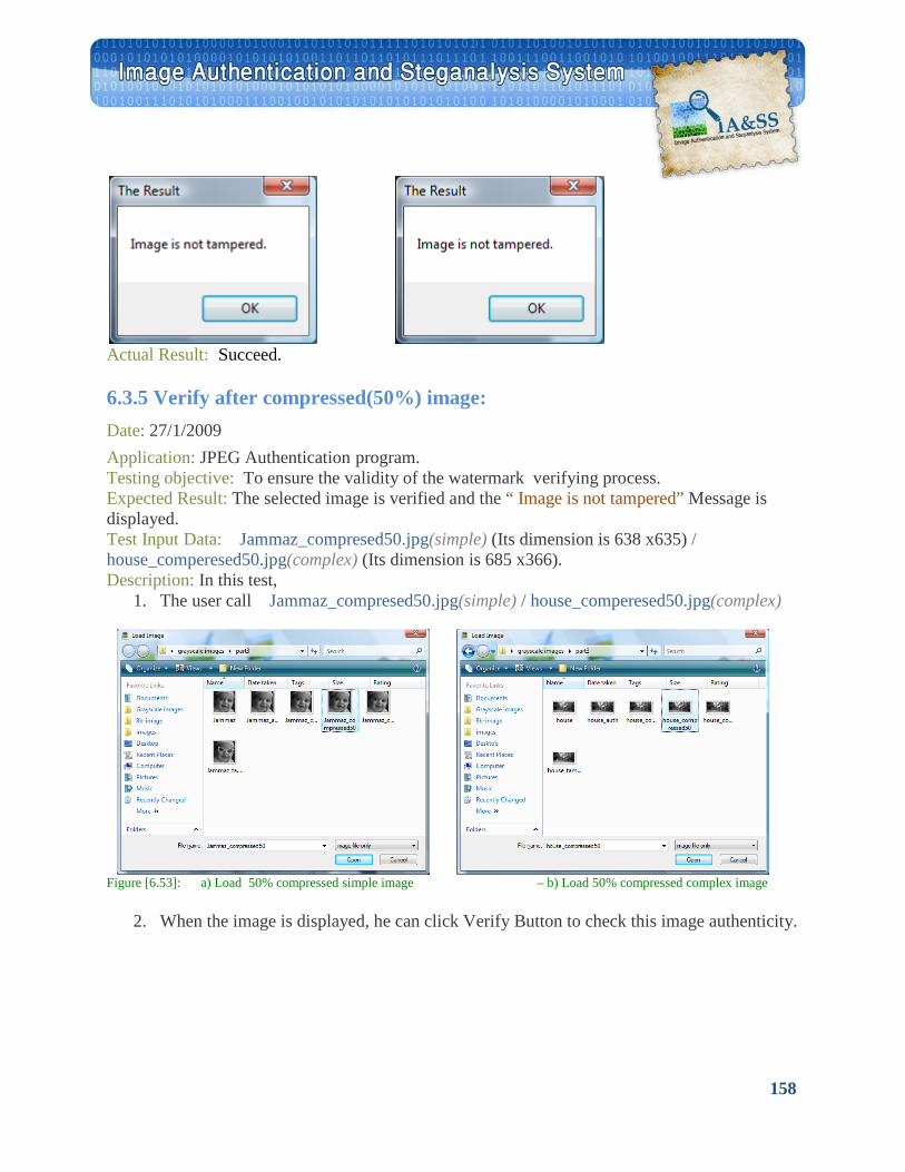
158
6.3.5 Verify after compressed(50%) image:
Actual Result: Succeed.
Date: 27/1/2009 Application: JPEG Authentication program. Testing objective: To ensure the validity of the watermark verifying process. Expected Result: The selected image is verified and the “ Image is not tampered” Message is displayed. Test Input Data: Jammaz_compresed50.jpg(simple) (Its dimension is 638 x635) / house_comperesed50.jpg(complex) (Its dimension is 685 x366). Description: In this test,
1. The user call Jammaz_compresed50.jpg(simple) / house_comperesed50.jpg(complex)
Figure [6.53]: a) Load 50% compressed simple image – b) Load 50% compressed complex image
2. When the image is displayed, he can click Verify Button to check this image authenticity.
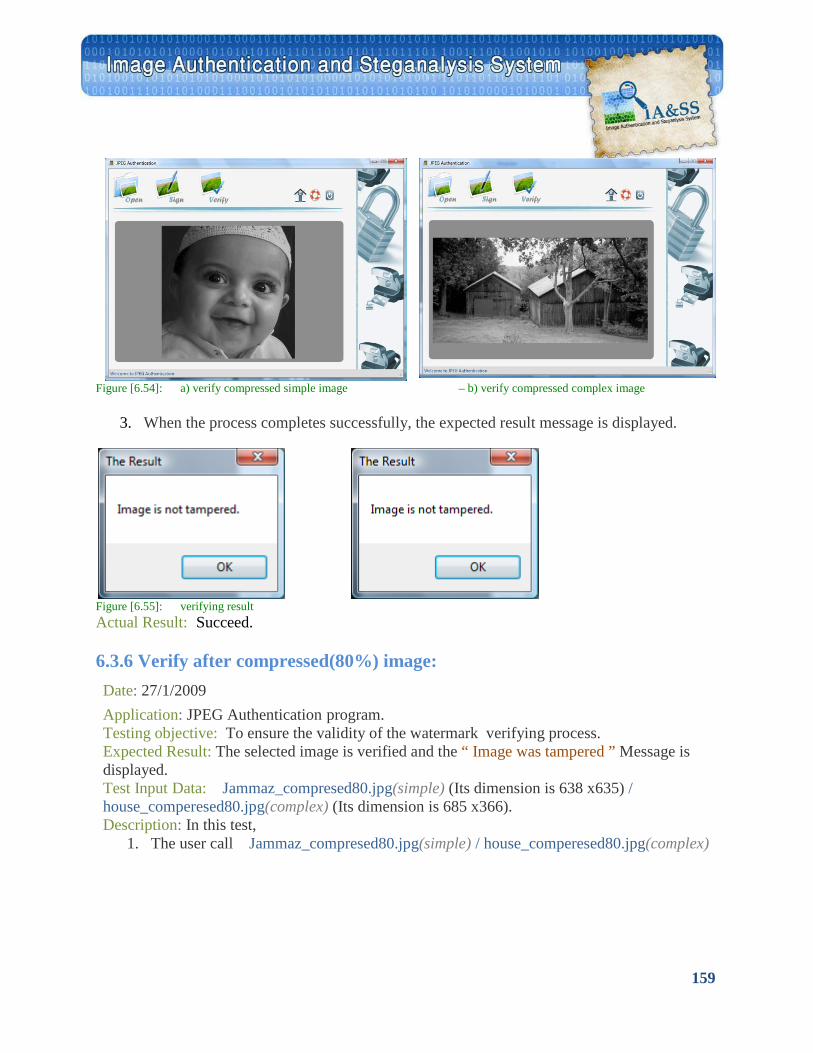
159
Figure [6.54]: a) verify compressed simple image – b) verify compressed complex image
3. When the process completes successfully, the expected result message is displayed.
Figure [6.55]: verifying result Actual Result: Succeed. 6.3.6 Verify after compressed(80%) image: Date: 27/1/2009 Application: JPEG Authentication program. Testing objective: To ensure the validity of the watermark verifying process. Expected Result: The selected image is verified and the “ Image was tampered ” Message is displayed. Test Input Data: Jammaz_compresed80.jpg(simple) (Its dimension is 638 x635) / house_comperesed80.jpg(complex) (Its dimension is 685 x366). Description: In this test,
1. The user call Jammaz_compresed80.jpg(simple) / house_comperesed80.jpg(complex)
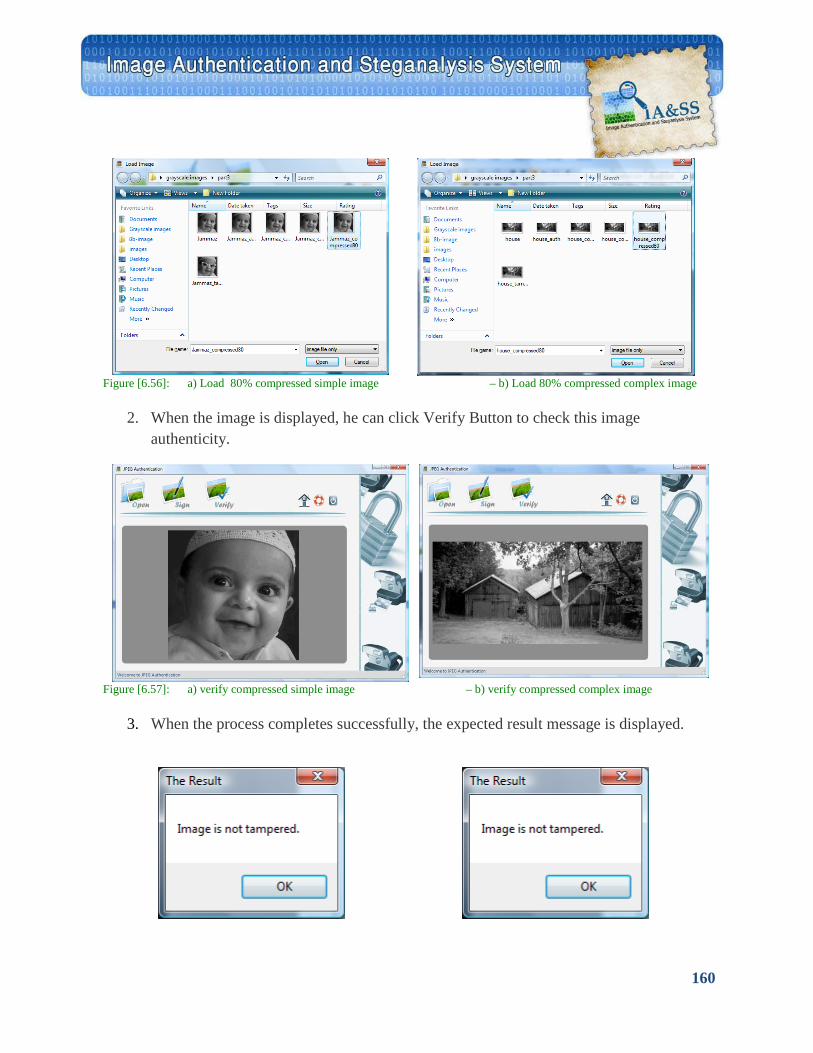
160
Figure [6.56]: a) Load 80% compressed simple image – b) Load 80% compressed complex image
2. When the image is displayed, he can click Verify Button to check this image authenticity.
Figure [6.57]: a) verify compressed simple image – b) verify compressed complex image
3. When the process completes successfully, the expected result message is displayed.
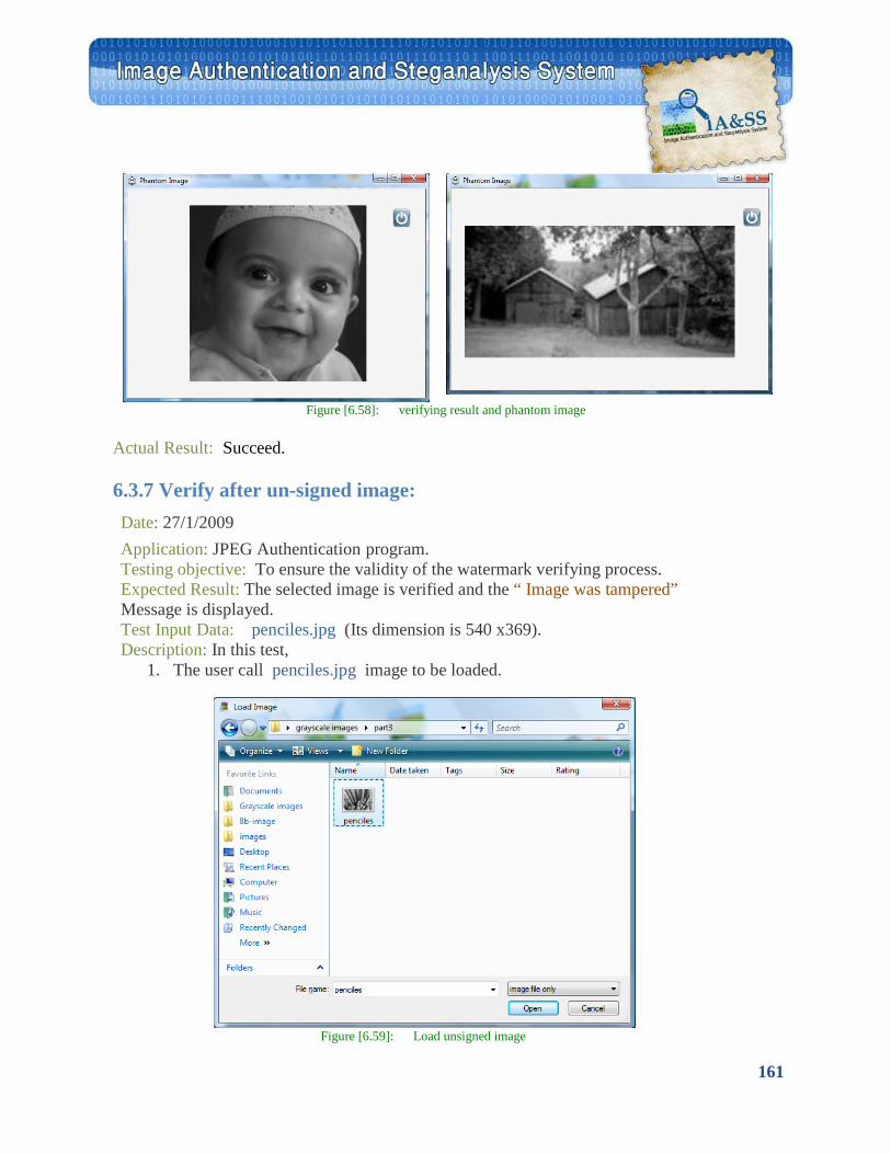
161
Figure [6.58]: verifying result and phantom image
Actual Result: Succeed.
6.3.7 Verify after un-signed image: Date: 27/1/2009 Application: JPEG Authentication program. Testing objective: To ensure the validity of the watermark verifying process. Expected Result: The selected image is verified and the “ Image was tampered” Message is displayed. Test Input Data: penciles.jpg (Its dimension is 540 x369). Description: In this test,
1. The user call penciles.jpg image to be loaded.
Figure [6.59]: Load unsigned image
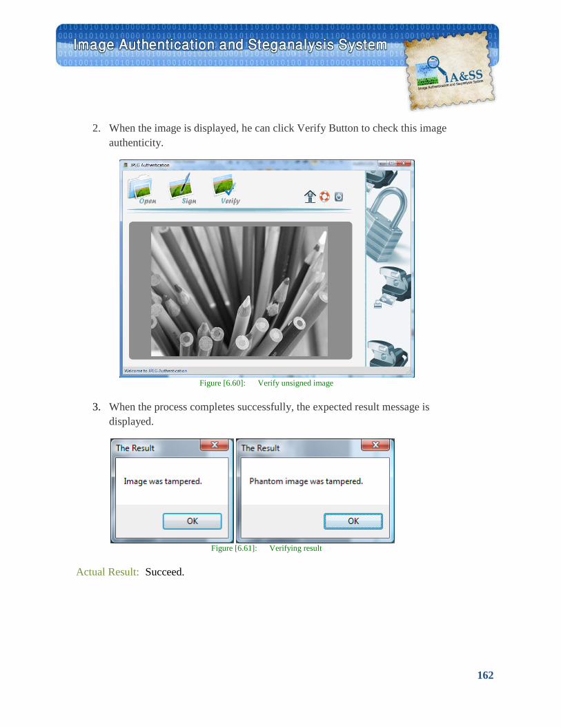
162
2. When the image is displayed, he can click Verify Button to check this image
authenticity.
Figure [6.60]: Verify unsigned image
3. When the process completes successfully, the expected result message is
displayed.
Figure [6.61]: Verifying result
Actual Result: Succeed.
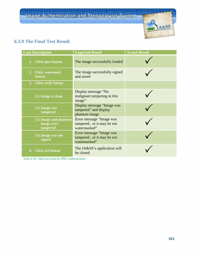
163
6.3.9 The Final Test Result
Case Description Expected Result Actual Result
1. Click open button The image successfully loaded 2. Click watermark
button The image successfully signed and saved
3. Click verify button
3.1. Image is clean Display message “No malignant tampering in this image”
3.2. Image was
tampered
Display message "Image was tampered” and display phantom image
3.3. Image and phantom
image were tampered
Error message “Image was tampered , or it may be not watermarked”
3.4. Image was not
signed
Error message “Image was tampered , or it may be not watermarked”
4. Click exit button The IA&SS’s application will
be closed Table 6.10: Final test result for JPEG Authentication
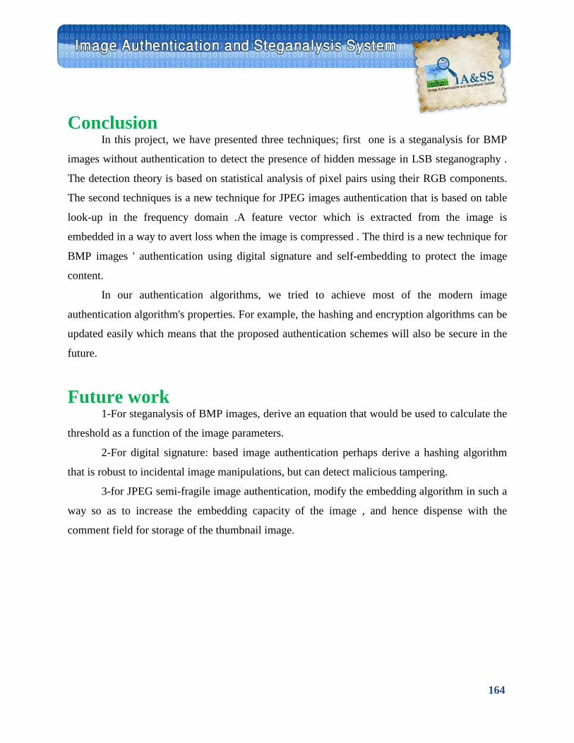
164
Conclusion In this project, we have presented three techniques; first one is a steganalysis for BMP
images without authentication to detect the presence of hidden message in LSB steganography .
The detection theory is based on statistical analysis of pixel pairs using their RGB components.
The second techniques is a new technique for JPEG images authentication that is based on table
look-up in the frequency domain .A feature vector which is extracted from the image is
embedded in a way to avert loss when the image is compressed . The third is a new technique for
BMP images ' authentication using digital signature and self-embedding to protect the image
content.
In our authentication algorithms, we tried to achieve most of the modern image
authentication algorithm's properties. For example, the hashing and encryption algorithms can be
updated easily which means that the proposed authentication schemes will also be secure in the
future.
Future work 1-For steganalysis of BMP images, derive an equation that would be used to calculate the
threshold as a function of the image parameters.
2-For digital signature: based image authentication perhaps derive a hashing algorithm
that is robust to incidental image manipulations, but can detect malicious tampering.
3-for JPEG semi-fragile image authentication, modify the embedding algorithm in such a
way so as to increase the embedding capacity of the image , and hence dispense with the
comment field for storage of the thumbnail image.
165
References:
[1] A. Westfield and A. Pfitzamann, "Attacks on steganographic systems" in 3rd
International Workshop on Information Hiding, pp. 61-76, 1999
[2] J. Fridrich, M. Goljan, D. Hogea and D. Soukal, "Quantitative steganalysis of digial
images: Estimating the secret message length" ACM Multimedia System Journal 9,Sept.
2003
[3] Deus Ex Machina Communications ,“STEGANOS.”
[4] Machado, Romana.,“E2 Stega”
[5] A.Westfield, A. and Pfitzmann A., “Attacks on Steganographic Systems“, Proc. 3rd
Info. Hiding Workshop,
Dresden, Germany, September 28-October 1, 1999, pp.
[6] Jiri Fridrich, bRui Du, bMeng Long “STAGANALYSIS OF LSB ENCODING IN
COLOR IMAGES”.
[7] J. Fridrich, R. Du, and L. Meng, “Steganalysis of LSB Encoding in Color Images,”
Proceedings IEEE International
Conference on Multimedia and Expo, July 30–August 2, 2000, New York City, NY.
[8]. J. Fridrich, M. Goljan, and R. Du, "Reliable Detection of LSB Steganography in
Grayscale and Color Images ",
Proc. ACM, Special Session on Multimedia Security and Watermarking, Ottawa, Canada,
October 5, 2001, pp. 27–30.
166
[9]. J. Fridrich, M. Goljan, and R. Du, “Detecting LSB Steganography in Color and Gray-
Scale Images”, Magazine of
IEEE Multimedia, Special Issue on Security, October-November issue, 2001, pp. 22–28.
[10] Jessica Fridrich*, Miroslav Goljan,”Practical Steganalysis of Digital Images – State
of the Art”
SUNY Binghamton, Department of Electrical Engineering, Binghamton, NY 13902-6000
[11] "A Secure and Robust Hashing Scheme for Image Authentication" Fawad Ahmed
and M.Y. Siyal
[12] Chia-Hung LU , Hao-Kuan TSO , Der-Chyuan LOU , and David Chien-Ting TAI
"Image Authentication Method by Combining Digital Signature and Watermarking"
[13] G. L. Friedman, “The trustworthy digital camera: Restoring credibility
to the photographic image,” IEEE Trans. Consumer Electron., vol. 39,
pp. 905–910, Nov. 1993.
[14] "A watermark-based robust image authentication method using wavelets,”
Columbia Univ., New York, ADVENT Project Rep., Apr.
1998.
[15] S.Walton, “Image authentication for a slippery new age,” Dr. Dobb’s J.,
pp. 18–26, April 1995.
[16] M. Yeung and F. Mintzer, “An invisible watermarking technique for image
verification,” in Proc. IEEE Int. Conf. Image Processing, Santa
Barbara, Oct.r 1997.
167
[17] Ching-Yung Lin, and Shih-Fu Chang, “A Robust Image Authentication Method
Distinguishing JPEG Compression from Malicious Manipulation”
[18] ] R. Grosbois, P. Gerbelot and T. Ebrahimi, „"Authentication and access control in the JPEG 2000 compressed domain”
[19] Y. Wu, D. Ma and R. H. Deng, „"Progressive protection of JPEG2000 codestreams”,
[20] T. Palfner, M. Schlauweg and E. Müller,"A Secure Semi-fragile Watermarking
Algorithm for Image Authentication in the Wavelet Domain of JPEG2000"
[21] S.Mitra, T.Roy, D.Mazumdar and A.B.Saha," STEGANALYSIS OF LSB ENCODING IN
UNCOMPRESSEDIMAGES BY CLOSE COLOUR PAIR ANALYSIS"
[22] http://atlc.sourceforge.net/bmp.html [23] http://encyclopedia2.thefreedictionary.com/Digital+signiture [24] Forouzan,B. Introduction to Cryptography and Network Security. McGraw-
Hill,International Edition [25] http://www.guillermito2.net/stegano/jsteg/ [26] http://en.wikipedia.org/wiki/JPEG [27] http://en.wikipedia.org/wiki/Run-length_encoding [28] http://www.cs.cornell.edu/dali/overview/jpeg.html [29] http://eilat.sci.brooklyn.cuny.edu/cis52/class/lesson10/other/15cjpeg.html [30]http://local.wasp.uwa.edu.au/~pbourke/dataformats/compress/ [31]www.pajhome.org.uk/crypt/rsa/index.html [32] www.di-mgt.com.au/rsa_alg.html [33] Mursi,MF, “ A Secure Semi –Fragile Watermarking Scheme of Authentication and Recovery
of Images based on DCT Transform", ECS jornal, March 2009

168
Related Documents