May, 2009 IEEE P802.15-09-0276-00-0006 WG submission CSEM IEEE P802.15 Wireless Personal Area Networks Project IEEE P802.15 Working Group for Wireless Personal Area Networks (WPANs) Title CSEM FM-UWB Proposal Date Submitted [4 May 2009] Source John Farserotu CSEM S.A Jaquet- Droz 1, CH2002 Neuchâtel, Switzerland John Gerrits – same address Jerome Rousselot – same address Gerrit van Veenendaal – NXP B. V. Manuel Lobeira – ACORDE Technologies S. A. John Long –TU Delft Voice: +41 32 720-5482 Fax: +41 32 720-5720 E-mail: [email protected] [email protected] [email protected] [email protected] [email protected] [email protected] Re: This is in response to the TG6 Call for Proposals (CFP), IEEE P802.15- 08-0811-03-0006. Abstract [The CSEM Frequency-Modulation Ultra Wide-band (FM-UWB) technology is described and the detailed in response to the BAN technical requirements document. Specifically, this proposal is submitted with respect to Low Data Rate (LDR) medical BAN.] Purpose Submitted as the candidate proposal for TG6-PHY-MAC Notice This document has been prepared to assist the IEEE P802.15. It is offered as a basis for discussion and is not binding on the contributing individual(s) or organization(s). The material in this document is subject to change in form and content after further study. The contributor(s) reserve(s) the right to add, amend or withdraw material contained herein. Release The contributor acknowledges and accepts that this contribution becomes the property of IEEE and may be made publicly available by P802.15.

Welcome message from author
This document is posted to help you gain knowledge. Please leave a comment to let me know what you think about it! Share it to your friends and learn new things together.
Transcript
May, 2009 IEEE P802.15-09-0276-00-0006
WG submission CSEM
IEEE P802.15
Wireless Personal Area Networks
Project IEEE P802.15 Working Group for Wireless Personal Area Networks (WPANs)
Title CSEM FM-UWB Proposal
Date Submitted
[4 May 2009]
Source John Farserotu CSEM S.A Jaquet- Droz 1, CH2002 Neuchâtel, Switzerland
John Gerrits – same address Jerome Rousselot – same address
Gerrit van Veenendaal – NXP B. V.
Manuel Lobeira – ACORDE Technologies S. A.
John Long –TU Delft
Voice: +41 32 720-5482
Fax: +41 32 720-5720
E-mail: [email protected]
[email protected] [email protected]
Re: This is in response to the TG6 Call for Proposals (CFP), IEEE P802.15-08-0811-03-0006.
Abstract [The CSEM Frequency-Modulation Ultra Wide-band (FM-UWB) technology is described and the detailed in response to the BAN technical requirements document. Specifically, this proposal is submitted with respect to Low Data Rate (LDR) medical BAN.]
Purpose Submitted as the candidate proposal for TG6-PHY-MAC
Notice This document has been prepared to assist the IEEE P802.15. It is offered as a basis for discussion and is not binding on the contributing individual(s) or organization(s). The material in this document is subject to change in form and content after further study. The contributor(s) reserve(s) the right to add, amend or withdraw material contained herein.
Release The contributor acknowledges and accepts that this contribution becomes the property of IEEE and may be made publicly available by P802.15.

May, 2009 IEEE P802.15-09-0276-00-0006
WG submission CSEM
Table of Contents
1 Introduction .......................................................................................................... 3
1.1 LDR medical BAN applications ...................................................................... 3
1.2 Requirements for wearable BAN applications ............................................... 4
2 The proposed solution ......................................................................................... 6
2.1 The radio ....................................................................................................... 6
2.2 The MAC ....................................................................................................... 6
2.3 The competitive edge .................................................................................... 7
3 FM-UWB PHY ..................................................................................................... 8
3.1 System characteristics ................................................................................... 8
3.2 Transmitter .................................................................................................... 9
3.2.1 Transmitter implementation aspects ..................................................... 10
3.3 RF-UWB signal generation .......................................................................... 12
3.3.1 Tx calibration ......................................................................................... 14
3.4 Receiver architecture ................................................................................... 15
3.4.1 Synchronization .................................................................................... 17
3.4.2 Receiver implementation aspects ......................................................... 17
3.4.2.1 Wideband FM demodulator ............................................................ 18
3.4.2.2 Subcarrier processing (SCP) .......................................................... 19
3.5 Antennas ..................................................................................................... 21
3.6 Radio performance ...................................................................................... 21
3.6.1 Link budget ........................................................................................... 21
3.6.2 Frequency-selective fading channel ...................................................... 23
3.7 Coexistence and interference resistance ..................................................... 26
3.7.1 Coexistence .......................................................................................... 26
3.7.2 Interference resistance ......................................................................... 27
4 FM-UWB MAC ................................................................................................... 28
4.1 Overview ..................................................................................................... 29
4.1.1 Low Power Mode .................................................................................. 29
4.1.2 High Availability Mode ........................................................................... 32
4.1.3 Multiple Channels ................................................................................. 34
4.1.4 Detect-and-Avoid .................................................................................. 35
4.2 Network architecture, topology and scalability ............................................. 36
4.3 Power saving modes and power consumption ............................................ 37
4.3.1 Store-and-Forward ................................................................................ 38
4.3.2 Convergecast Traffic ............................................................................. 40
4.4 Latency ........................................................................................................ 41
4.5 Mobility support ........................................................................................... 42
4.6 Framing, CRC and retransmissions ............................................................. 43
5 Proof of concept and target solution .................................................................. 44
5.1 Power consumption ..................................................................................... 45
5.2 Bit Error Rate and Packet Error Rate .......................................................... 47
5.3 Transmission range ..................................................................................... 48
5.4 Security ....................................................................................................... 48
6 Compliance with BAN requirements and technical characteristics .................... 50
7 Summary and concluding remarks .................................................................... 52
8 References ........................................................................................................ 53
9 Acronyms .......................................................................................................... 55
10 Annexes ............................................................................................................ 58

May, 2009 IEEE P802.15-09-0276-00-0006
WG submission CSEM
1 Introduction
This document contains the technical description of a Physical Layer and Medium Access
Control Layer (PHY-MAC) proposal to IEEE TG6, Body Area Networks (BAN), targeting non-
invasive, wearable, Low Data Rate (LDR), medical BAN applications. It is submitted in
response to the TG6 Call for Proposals [IEEE1].
The proposed PHY is Frequency Modulation UltraWideBand (FM-UWB) [GER1] and the
proposed MAC is the High Availability Wireless sensor Medium Access Control protocol
(WiseMAC-HA) [CSEM1, ROUS].
1.1 LDR medical BAN applications
Figure 1 provides an illustration of a typical future medical BAN operating scenario. In this
scenario, miniature, wearable, sensors communicate over short range wireless links to a
portable device(s), such as a handset, PDA or watch. This device serves as a gateway to
wide area networks (WAN) for the purposes of supporting end-to-end services.
Typical medical and health applications employing non-invasive, wearable medical BAN
solutions may include:
EEG Electroencephalography
ECG Electrocardiogram
EMG Electromyography (muscular)
Blood pressure
Blood SpO2
Blood pH
Respiration
Posture (human position)
Vital signals monitoring
Temperature (wearable thermometer)
Respiratory monitor
Wearable heart rate monitor
Wearable blood pressure monitor
Wearable glucose sensor
Muscle tension sensing and stimulation
Wearable weighing scale
Fall detection
Sports training aids

May, 2009 IEEE P802.15-09-0276-00-0006
WG submission CSEM
Many other health and medical applications may also be possible and wearable LDR
BANs are not limited to health and medical applications. However, LDR health and
medical applications are the focus of this proposal.
Figure 1 Medical BAN use scenario
1.2 Requirements for wearable BAN applications
The requirements for LDR medical BAN applications include [IEEE2-IEEE5]:
long autonomy (W-mW, possible operation via energy scavenging)
high robustness, high reliability
low cost
small size
good coexistence and the potential for unlicensed worldwide operation
and high scalability.

May, 2009 IEEE P802.15-09-0276-00-0006
WG submission CSEM
A summary of key technical requirements for wearable BAN applications is provided by
Table 1 [IEEE3, IEEE4]. As will be described in the sections that follow, the proposed FM-
UWB PHY-MAC solution meets or exceeds the requirements for wearable Medical BAN
applications.
Table 1: Summary of key technical requirements for wearable BAN
Parameter Wearable BAN Requirements
Coexistence and robustness Good (low interference to other systems, high tolerance to
interference)
Data Rates 10 kbps to 10 Mbps (LDR medical / MDR commercial)
Insertion/de-insertion < 3 seconds
Network topology Star (mandatory), mesh (optional)
Power consumption Low, autonomy > 1 year (e.g. with 1% duty cycle, MAC
sleep modes, 500 mAh battery)
QoS (Medical BAN) PER < 10%, delay < 125 ms
Reliability Robust to multipath interference
> 99% link success/availability
SAR regulations < 1.6 mW (US) / < 20 mW (EU)
Scalability High, up to 256 devices
Transmission range ≥ 3m

May, 2009 IEEE P802.15-09-0276-00-0006
WG submission CSEM
2 The proposed solution
The proposed PHY-MAC solution targets wearable Medical BAN. It combines Frequency
Modulation UltraWideBand (FM-UWB) radio with Wireless sensor Medium Access Control
High Availability (WiseMAC-HA).
2.1 The radio
FM-UWB was first identified as a promising technology for low power, low data rate (LDR),
yet robust medical telemonitoring applications in 2001. It has been developed from the start
specifically to support LDR wearable Medical BAN applications.
A first Proof-of-Concept (PoC) demonstrator was developed in the IST URSAFE (2002-2004)
project [URSA]. This demonstrator was implemented using Commercial-off-the-Shelf (COTS
components and operated at 1.25 GHz.
FM-UWB was studied in detail in the IST MAGNET project (2004-2005) and selected as the
LDR air interface. In the follow-on to MAGNET, the IST MAGNET Beyond (2006-2008)
project [MAGB], first generation IC building blocks were designed and manufactured for the
purpose of implementing an advanced prototype. This allowed for the validation of the power
consumption and confirmation of the robustness of FM-UWB to interference and multipath
and also for demonstrating the radio with a medical application.
Additionally, during the course of MAGNET Beyond, CSEM also initiated efforts to
standardize FM-UWB for medical BAN applications with the IEEE, ETSI and ECMA
Today, a working FM-UWB prototype exits. This prototype operates in the 7.25 to 8.5 GHz
band and meets worldwide regulatory limits for UWB radiated power.
7.25 GHz to 8.5 GHz band well suited for international operation and mobility
2.2 The MAC
The WiseMAC-HA protocol provides advantages in terms of ultra low power consumption,
robustness to interference and scalability with respect to network size. The protocol is traffic
limited. As such, it is scalable and can support potentially large numbers of wearable
devices. WiseMAC-HA is ultra low power for all nodes as there is no need for synchronizing.
WiseMAC-HA’s “fairness” allows for coexistence and simultaneous operation of independent
networks. The protocol implements “detect and avoid” (DAA) to deal with interferers
WiseMAC-HA is flexible. It supports both star and meshed network topologies and offers low
latency connectivity. It supports throughput and latency vs. energy tradeoffs, the ability to
decide on mode changes and the ability to accommodate other operating modes.

May, 2009 IEEE P802.15-09-0276-00-0006
WG submission CSEM
2.3 The competitive edge
The major advantages of low complexity FM-UWB technology are:
Ultra low power consumption
Robustness to interference and multipath
Good coexistence
Simple low cost design
Fast acquisition for nomadic users
High scalability.
The major advantages of WiseMAC-HA are:
Ultra Low Power
Robustness to Interference
Scalability with network size
Flexibility (star and mesh topologies)
Low latency
The proposed solution combines the advantages of the FM-UWB PHY with the WiseMAC-
HA protocol. FM-UWB is a very promising technology for short range wireless
communication [AWTE]. It was developed specifically to support LDR Medical BAN
applications and together with the scalable, ultra low power WiseMAC-HA protocol, it fully
satisfies the requirements for wearable, LDR Medical BAN [IEEE2- IEEE5].
Descriptions, technical details and performance of the FM-UWB radio and WiseMAC-HA
protocol are provided in the sections that follow.

May, 2009 IEEE P802.15-09-0276-00-0006
WG submission CSEM
3 FM-UWB PHY
FM-UWB exploits high modulation index analog FM to obtain an ultra-wide signal. Frequency
modulation has the unique property that the RF bandwidth BRF is not only related to the
bandwidth fm of the modulating signal, but also to the modulation index that can be chosen
freely. This yields either a bandwidth efficient narrow-band FM signal ( < 1) or a (ultra)
wideband signal ( >> 1) that can occupy any required bandwidth.
FM-UWB constitutes an analog implementation of a spread-spectrum system. This constant-
envelope approach, where peak power equals average power, yields a flat spectrum with
steep spectral roll-off. Instantaneous de-spreading in the receiver makes that the FM-UWB
radio behaves like a narrowband FSK radio from a synchronization and detection point-of-
view. FM-UWB technology combines low complexity with robustness against interference
and multipath. The following sub-sections present the FM-UWB system and its properties.
3.1 System characteristics
Table 2 presents the FM-UWB radio characteristics. The proposed solution is designed to
operate in the 7.25 – 8.5 GHz band. This band is suited for international operation and
mobility.
Table 2: FM-UWB system characteristics.
Parameter Value
RF center frequency 6.4 – 8.7 GHz
RF bandwidth 500 MHz
RF output power -15 dBm
Subcarrier frequency 1.0, 1.25, 1.50, 1.75 MHz
Subcarrier modulation FSK, = 1
Raw bit rate < 250 kbps
Receiver sensitivity <-85 dBm1
TX, RX switching time < 100 s
RX synchronization time < 500 s
1. At BER ≤ 10-6

May, 2009 IEEE P802.15-09-0276-00-0006
WG submission CSEM
3.2 Transmitter
Figure 2 shows the block diagram of the FM-UWB transmitter. Low modulation index digital
FSK is followed by high modulation index analog FM, creating a constant-envelope UWB
signal [GER1]. The transmitter consists of a 1-2 MHz subcarrier oscillator generating a
triangular signal that is FSK modulated by the transmit data. This subcarrier signal m(t)
modulates the RF VCO, yielding a constant-envelope UWB signal with a flat power spectral
density and steep spectral roll-off.
Figure 2 FM-UWB transmitter block diagram.
Low complexity transmitter
Figure 3 shows the data, the subcarrier and the UWB signal in the time domain for a data
transition at t = 0 and subcarrier frequency of 1 MHz; the center frequency of the UWB signal
V(t) is not to scale for the sake of clarity.
Figure 3: Time domain view of data d(t), subcarrier m(t) and UWB signal V(t).

May, 2009 IEEE P802.15-09-0276-00-0006
WG submission CSEM
Figure 4 shows an example of the power spectral density (PSD) of an ideal FM-UWB signal.
The signal is compliant with the relevant regulatory limits [IEEE6-IEEE7]. The signal power is
–15 dBm (112 mVpp in a 50 load). The subcarrier frequency is 1 MHz and the deviation f
is 250 MHz, yielding a modulation index of 250. The –10 dB bandwidth equals 500 MHz.
The power spectral density of a wideband FM signal is determined by and has the shape of
the probability density function (PDF) of the modulating signal m(t) [TAUB]. The use of a
triangular subcarrier waveform, which is characterized by a uniform PDF, results in a flat RF
spectrum. From an implementation point of view the triangular waveform is straightforward to
generate using either analog or digital circuit techniques.
The roll-off and noise floor of the FM-UWB signal in a practical circuit realization will be
determined by the RF oscillator phase noise and noise floor.
Figure 4: Spectral density of real-life FM-UWB signal
obtained with fSUB= 1 MHz and = 250.
Compliant with international regulatory limits for UWB. Rapid rolloff, low PSD, and low
radiated power for good coexistence, less than 50 W radiated power meets SAR.
3.2.1 Transmitter implementation aspects
Direct Digital Synthesis (DDS) techniques are advantageously used in the subcarrier
generation [NILS]. The DDS approach offers both precision and flexibility. Subcarrier

May, 2009 IEEE P802.15-09-0276-00-0006
WG submission CSEM
frequency and subcarrier frequency deviation can be easily modified. Table 3 presents the
DDS characteristics.
Table 3: DDS characteristics
Parameter Value
Clock frequency 24 MHz
Phase resolution 16 bits
Amplitude resolution 10 bits
Output frequency 1 – 2 MHz
Frequency resolution 366 Hz
Digital data pre-filtering Gaussian, BT = 0.7
5 shows the block diagram of the DDS used in the transmitter. The raw data d(t) may be
encoded (typically Manchester encoding) before it enters the DDS. Digital pre-filtering of the
data reduces the sidelobe level of the FSK signal. Pre-filtering is performed with 8 samples
per bit and easy-to-implement coefficients [NILS].
Figure 5: Transmitter DDS block diagram.
Generation of a triangular wave does not need a look-up table as would be required for the
generation of a sine wave, reducing the complexity and memory requirements of the circuit.
A bank of XOR circuits takes care of the sawtooth-to-triangle conversion [NILS]. The DDS
digital output word is converted into a triangular signal in a DAC. The DAC output signal is
next low-pass filtered in a 2nd order analog low-pass filter with cut-off frequency of 10 MHz to
attenuate the aliasing components. Figure 6 shows the spectrum of a 1 MHz FSK subcarrier
signal with deviation fSUB = 50 kHz.
Data
Pre-filtering
DDS DAC LPF d(t)
m(t)
fSUB
Subcarrier freq. fCLK amp

May, 2009 IEEE P802.15-09-0276-00-0006
WG submission CSEM
Figure 6: Spectrum of digitally generated subcarrier signal m(t).
The filtered DDS signal is passed on to the RF VCO. By using a multiplying DAC the
amplitude of the subcarrier signal and as a result the RF deviation of the FM-UWB output
signal can be adjusted. Table 4 shows the subcarrier frequencies for a 4-user 100 kbps FM-
UWB system.
Table 4: Subcarrier frequencies for the case of a 4-user 100 kbps system
Subcarrier Subcarrier frequency
1 1.00 MHz
2 1.25 MHz
3 1.50 MHz
4 1.75 MHz
3.3 RF-UWB signal generation
The subcarrier signal m(t) modulates the RF oscillator, that implements the analog spreading
and yields a constant-envelope UWB signal with a flat power spectral density and steep
spectral roll-off at its output.

May, 2009 IEEE P802.15-09-0276-00-0006
WG submission CSEM
The RF signal is generated by a free-running RF VCO that is regularly calibrated by a PLL
frequency synthesizer. This frequency synthesizer ensures the correct center frequency of
the UWB signal. As the PLL doesn’t operate continuously, it will not really impact transmitter
power consumption. Frequency modulation of the RF VCO with the subcarrier signal occurs
in open loop mode and the frequency synthesizer switched off.
Figure 7 shows the block diagram of the RF signal generation. The phase noise of the RF
oscillator in the sub-carrier bandwidth (at offset fSUB from the carrier) needs to be taken into
account. The demodulated phase noise (random frequency variations) from a strong FM-
UWB interferer may lower the subcarrier SNR of a weak wanted FM-UWB signal up to the
point where the probability of error of the demodulated sub-carrier becomes unacceptable. A
typical phase noise requirement for this oscillator is -80dBc/Hz at 1MHz offset from the
carrier, motivated by the possibility to cope with a 20dB stronger FM-UWB interferer at the
same center frequency [GER7].
The VCO output signal is the FM-UWB signal which is fed to the output amplifier OA
providing the appropriate RF output level. The VCO output signal is also fed into a fixed ratio
prescaler (P = 256) that reduces the high VCO output frequency (6-9 GHz) to a lower
frequency (23-35 MHz) compatible with the programmable divider hardware. The RF center
frequency is directly related to the division number N of the programmable divider by
REFRF NPff (1)
With a reference frequency fREF = 250 kHz, the center frequency of the UWB signal will have
a resolution of 64 MHz. Table 5 and Table 6 show two possible options for the RF center
frequencies.
Lock Detect
Open Loop
CAL
m(t) from DDS
Loop filter
ADC DAC
Cal uC EEPROM SW
RF VCO Phase
detector
fREF OUT AMP
Prog. Divider N
Fixed Divider p
V(t)
Figure 7: Block diagram of RF signal generation

May, 2009 IEEE P802.15-09-0276-00-0006
WG submission CSEM
Table 5: Transmitter RF center frequencies with 576 MHz channel spacing
Channel NRF RF center frequency
H1 100 6400 MHz
H2 109 6976 MHz
H3 118 7552 MHz
H4 127 8128 MHz
H5 136 8704 MHz
Table 6: Transmitter RF center frequencies with 512 MHz channel spacing (MBOA compatible)
Channel NRF RF center frequency
H1 101 6464 MHz
H2 109 6976 MHz
H3 117 7488 MHz
H4 125 8000 MHz
H5 133 8512 MHz
3.3.1 Tx calibration
The TX VCO is used in open loop mode. Due to IC process variations, it is necessary to
measure the TX VCO curve and memorize it. A complete calibration procedure is required
the very first time the transmitter is turned on, i.e., at the end of the manufacturing process.
Referring to Figure 7, the calibration procedure could be implemented as follows. With the
switch in the CAL position, the PLL is powered up and for the required transmit channel three
measurements are made for the following frequencies:
fc – 256 MHz
fc
fc +256 MHz

May, 2009 IEEE P802.15-09-0276-00-0006
WG submission CSEM
These three frequencies correspond to the channel center frequency and the channel edges.
For each of these frequencies, the PLL is allowed to settle to its final frequency (indicated by
the Lock Detect signal generated by the PLL phase detector) and next the VCO
corresponding to that frequency is measured by the ADC and stored in the micro-controller
memory. During calibration the DDS signal is not added to the VCO input signal.
After calibration, the switch is moved to the Open Loop position and a DC voltage
corresponding to the required center frequency is imposed by the DAC. The DDS voltage is
added to this DC value to yield the FM-UWB signal. The required DDS signal amplitude is
derived from the two measurements at the channel edge.
3.4 Receiver architecture
The receiver demodulates the FM-UWB signal without frequency translation (i.e., no mixing).
Figure 8 shows the receiver block diagram. The low complexity receiver comprises a LNA, a
wideband FM demodulator, and low-frequency subcarrier filtering, amplification and
demodulation circuitry.
Figure 8: FM-UWB receiver block diagram.
Ultra low complexity UWB receiver
The absence of carrier synchronization allows for rapid synchronization as required in ad-hoc
networks. Due to the instantaneous de-spreading in the wideband FM demodulator, the
system behaves like a narrowband FSK system where synchronization is limited by the bit
synchronization time.
The FM-UWB radio targets bit rates up to 250 kbps at a distance of 3 meters under free-
space propagation conditions using transmit and receive antennas with 0dBi gain. The
received signal power PRX is then given by Friis’ transmission equation
λ
πdPP TXRX
4log20dBmdBm 10 , (2)
where is the free-space wavelength (i.e., 4 cm at 7.45 GHz) and d is the separation
between transmitter and receiver. For 3 m range and a 500 MHz wide the FM-UWB signal
limited to -41.3 dBm/MHz (in accordance with the FCC), transmit power PTX is equal to -15
dBm and the resulting received signal power predicted from (2) of -74 dBm. Assuming a 50

May, 2009 IEEE P802.15-09-0276-00-0006
WG submission CSEM
antenna, 500 MHz bandwidth and a receiver noise figure (NF) equal to 5 dB, the equivalent
noise power at the receiver input is -82 dBm. The minimum required SNR to obtain an error
rate of 1x10⁻⁶ at 250 kbps is -7dB (see Figure 9) [GER1], corresponding to a signal of -89
dBm. This yields a margin of 15 dB which more than compensates for implementation losses
(4 dB) and frequency selective multipath (3 dB).
Figure 9: Probability of error for a narrowband FSK and a 500 MHz bandwidth FM-UWB system for various data rates.
Interference from other FM-UWB users also needs to be addressed. Assuming that the
worst-case interference scenario is another user 50 cm away, the interference level is -58
dBm at the receiver. This requires an input-referred third-order intercept point (IIP3) better
than -41 dBm in order to avoid blocking of the desired signal, which is easily attainable.
The key receiver building block is the wideband FM demodulator not preceded by any hard-
limiting device. As a result, the FM capture effect doesn’t occur. This allows for the
simultaneous demodulation (de-spreading) of multiple FM-UWB input signals at the same
center frequency with different subcarrier frequencies. The demodulator can be
advantageously implemented as a delay line demodulator, where the group delay of an all-
pass filter or band-pass filter implements the time delay [DONG, GER2].
The receiver processing gain is equal to the ratio of RF and subcarrier bandwidth
R
f
B
BG
SUB
RF
SUB
RFPdB
1
2log10log10 1010
(3)
May, 2009 IEEE P802.15-09-0276-00-0006
WG submission CSEM
In a 250 kbps LDR system with a RF bandwidth of 500 MHz a processing gain of 30 dB is
obtained. As a result a 250 kbps FM-UWB system can tolerate a 17 dB stronger FM-UWB
interferer before the probability of error degrades to 1x10⁻⁶ [GER3].
3.4.1 Synchronization
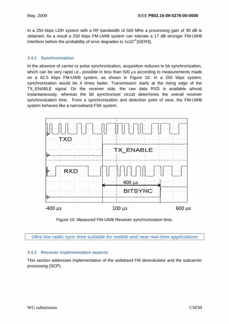
In the absence of carrier or pulse synchronization, acquisition reduces to bit synchronization,
which can be very rapid i.e., possible in less than 500 s according to measurements made
on a 62.5 kbps FM-UWB system, as shown in Figure 10. In a 250 kbps system,
synchronization would be 4 times faster. Transmission starts at the rising edge of the
TX_ENABLE signal. On the receiver side, the raw data RXD is available almost
instantaneously, whereas the bit synchronizer circuit determines the overall receiver
synchronization time. From a synchronization and detection point of view, the FM-UWB
system behaves like a narrowband FSK system.
Figure 10: Measured FM-UWB Receiver synchronization time.
Ultra low radio sync time suitable for mobile and near real-time applications
3.4.2 Receiver implementation aspects
This section addresses implementation of the wideband FM demodulator and the subcarrier
processing (SCP).
May, 2009 IEEE P802.15-09-0276-00-0006
WG submission CSEM
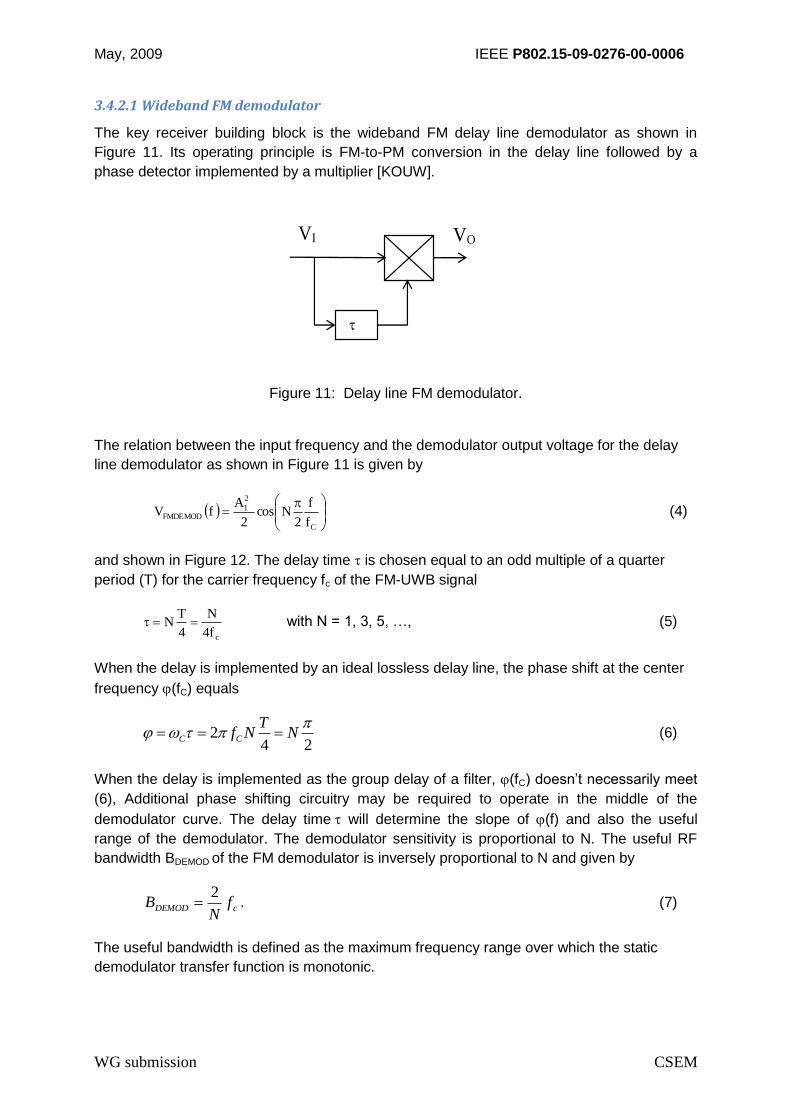
3.4.2.1 Wideband FM demodulator
The key receiver building block is the wideband FM delay line demodulator as shown in
Figure 11. Its operating principle is FM-to-PM conversion in the delay line followed by a
phase detector implemented by a multiplier [KOUW].
VI VO
Figure 11: Delay line FM demodulator.
The relation between the input frequency and the demodulator output voltage for the delay
line demodulator as shown in Figure 11 is given by
C
2
1FMDEMOD
f
f
2Ncos
2
AfV (4)
and shown in Figure 12. The delay time is chosen equal to an odd multiple of a quarter
period (T) for the carrier frequency fc of the FM-UWB signal
cf4
N
4
TN with N = 1, 3, 5, …, (5)
When the delay is implemented by an ideal lossless delay line, the phase shift at the center
frequency (fC) equals
24 2
C C
Tf N N
(6)
When the delay is implemented as the group delay of a filter, (fC) doesn’t necessarily meet
(6), Additional phase shifting circuitry may be required to operate in the middle of the
demodulator curve. The delay time will determine the slope of (f) and also the useful
range of the demodulator. The demodulator sensitivity is proportional to N. The useful RF
bandwidth BDEMOD of the FM demodulator is inversely proportional to N and given by
cDEMOD fN
B2
. (7)
The useful bandwidth is defined as the maximum frequency range over which the static
demodulator transfer function is monotonic.

May, 2009 IEEE P802.15-09-0276-00-0006
WG submission CSEM
Figure 12: Relation between normalized delay line demodulator input frequency and normalized output voltage for various values of N.
Various implementations of this demodulator have been realized and reported in [GER2] and
[DONG]. The latter publication describes a FM-UWB receiver front-end operating at 7.5 GHz
with LNA and wideband FM demodulator. The sensitivity of this front-end is -85 dBm.
Additional information concerning this front-end can be found in the chapter on the “Proof of
Concept and Target Solution”.
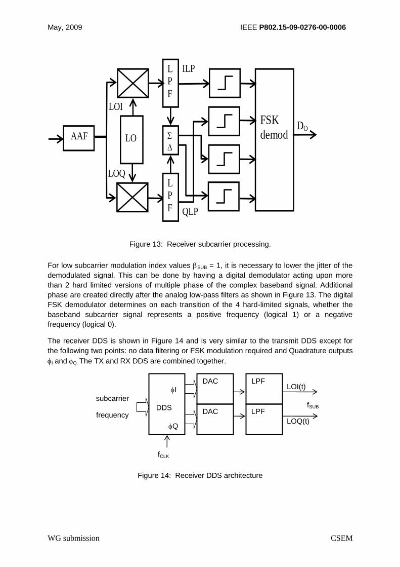
3.4.2.2 Subcarrier processing (SCP)
The expanded dynamic range of the subcarrier signal due to the quadratic transfer function
of the delay line demodulator requires steep filtering. Band-pass filters at the subcarrier
frequency do not provide sufficient filtering. A direct-conversion architecture with baseband
low-pass filters and a baseband FSK demodulator alleviates the filter requirements.
Figure 13 shows this architecture. Two double balanced mixers driven by the two quadrature
subcarrier LO signals LOI and LOQ. These LO signals are generated by a DDS and are
triangular resulting in additional attenuation of input signal components at odd multiples of
the LO frequency.
The low-pass filters after the mixers have a cut-off frequency fLP equal to half the subcarrier
bandwidth.
122
SUB
SUB
LP
RBf (8)
May, 2009 IEEE P802.15-09-0276-00-0006
WG submission CSEM
DO
QLP
LOI
LOQ
FSKdemod
ILP
AAF
LO
L
P
F
L
P
F
Figure 13: Receiver subcarrier processing.
For low subcarrier modulation index values SUB = 1, it is necessary to lower the jitter of the
demodulated signal. This can be done by having a digital demodulator acting upon more
than 2 hard limited versions of multiple phase of the complex baseband signal. Additional
phase are created directly after the analog low-pass filters as shown in Figure 13. The digital
FSK demodulator determines on each transition of the 4 hard-limited signals, whether the
baseband subcarrier signal represents a positive frequency (logical 1) or a negative
frequency (logical 0).
The receiver DDS is shown in Figure 14 and is very similar to the transmit DDS except for
the following two points: no data filtering or FSK modulation required and Quadrature outputs
I and Q. The TX and RX DDS are combined together.
Figure 14: Receiver DDS architecture
I
DDS
Q
DAC LPF
subcarrier
frequency
LOI(t)
LOQ(t)
fSUB
fCLK
DAC LPF
May, 2009 IEEE P802.15-09-0276-00-0006
WG submission CSEM
3.5 Antennas
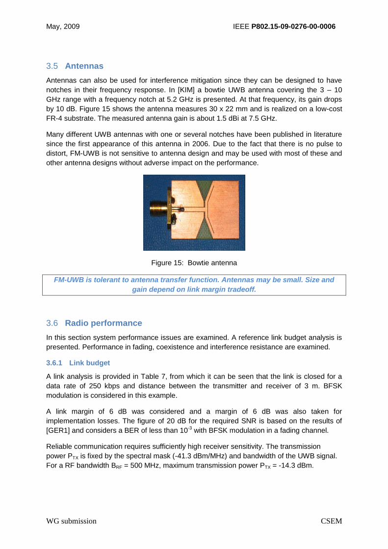
Antennas can also be used for interference mitigation since they can be designed to have
notches in their frequency response. In [KIM] a bowtie UWB antenna covering the 3 – 10
GHz range with a frequency notch at 5.2 GHz is presented. At that frequency, its gain drops
by 10 dB. Figure 15 shows the antenna measures 30 x 22 mm and is realized on a low-cost
FR-4 substrate. The measured antenna gain is about 1.5 dBi at 7.5 GHz.
Many different UWB antennas with one or several notches have been published in literature
since the first appearance of this antenna in 2006. Due to the fact that there is no pulse to
distort, FM-UWB is not sensitive to antenna design and may be used with most of these and
other antenna designs without adverse impact on the performance.
Figure 15: Bowtie antenna
FM-UWB is tolerant to antenna transfer function. Antennas may be small. Size and
gain depend on link margin tradeoff.
3.6 Radio performance
In this section system performance issues are examined. A reference link budget analysis is
presented. Performance in fading, coexistence and interference resistance are examined.
3.6.1 Link budget
A link analysis is provided in Table 7, from which it can be seen that the link is closed for a
data rate of 250 kbps and distance between the transmitter and receiver of 3 m. BFSK
modulation is considered in this example.
A link margin of 6 dB was considered and a margin of 6 dB was also taken for
implementation losses. The figure of 20 dB for the required SNR is based on the results of
[GER1] and considers a BER of less than 10-3 with BFSK modulation in a fading channel.
Reliable communication requires sufficiently high receiver sensitivity. The transmission
power PTX is fixed by the spectral mask (-41.3 dBm/MHz) and bandwidth of the UWB signal.
For a RF bandwidth BRF = 500 MHz, maximum transmission power PTX = -14.3 dBm.

May, 2009 IEEE P802.15-09-0276-00-0006
WG submission CSEM
Table 7: Example FM-UWB link analysis (CM 4 Channel)
Parameter Symbol Value Units Comments
Tx bandwidth BRF 500 MHz Nominal UWB signal bandwidth
Tx power PTX -14.3 dBm < 40 W (max power limit)
Tx antenna gain GTX 0.0 dBi
EIRP (peak) EIRP -14.3 dBm Peak EIRP
Center frequency fC 7.5 GHz High band operation (7.25-8.5 GHz)
Distance D 3.0 m 3 meters required for BAN
Free space path loss Lp -59.5 dB
Rx antenna gain GRX 0.0 dBi
Rx power PRX -73.8 dBm
Noise Figure NF 5.0 dB Equivalent system noise: 627 K
Noise power density N0 -169.0 dBm/Hz
Noise power N -82.0 dBm 500 MHz RF bandwidth
Data rate R 250 kbps High end for wearable Medical BAN
Subcarrier SNR SNRSC 13.4 dB Required subcarrier SNR, BFSK, BER ≤ 10-6
RF SNR SNRRF -7.0 dB Required RF SNR, SNR conversion [EURASIP]
Implementation losses Li 4.0 dB Miscellaneous losses + interference
Link margin M 3.0 dB Multipath fading, CM3 / CM4 channels
Remaining margin Mrem 8.2 dB Positive margin remaining indicates link closed
The LDR system targets short range indoor communication under line of sight (LOS)
conditions. Figure 16 shows the received power for operation at 7.5 GHz as function of the

May, 2009 IEEE P802.15-09-0276-00-0006
WG submission CSEM
distance for a path loss exponent n = 2 and antenna gain of 0 dBi. Measurements of
commercially available small UWB antennas show that antenna gain values of 0 dBi are
realistic.
Figure 16: Received power as a function of distance at 7.5 GHz.
3.6.2 Frequency-selective fading channel
BAN communication is subject to frequency-selective fading. Body surface-body-surface
communication is modeled by the CM3 channel. Body surface to external device
communication is modeled by the CM4 channel. Both models are provided in [IEEE8].
FM-UWB signals are robust to frequency-selective multipath [GER4]. Figure 17 shows
MATLAB simulation results of the RF fading level, i.e., the (equivalent) receiver input power
for 8000 realizations of the IEEE CM3 BAN channel and 4000 realizations of the IEEE CM4
channel (i.e., with Body Direction = 1, which yields worst case results).
From Figure 17, a fading level of 0 dB corresponds to the case of no fading i.e. relative to the
mean signal level. The mean and median values of the fading distribution, as seen at the
output of the FM-UWB demodulator, were both found to equal 0 dB meaning that 50% of the
time we expect a performance improvement and 50% of the time a degradation. This is
clearly illustrated by the histograms in Figure 17.
Figure 18 shows the Cumulative Density Function (CDF) of the fading level for the FM-UWB
signal. It can be seen that 99% of the time the fading level is above -2.8 dB for the CM3
channel and above -1.7 dB for the CM4 channel. This means that 2.8 dB of fading margin is
required to achieve 99% availability in the CM3 channel and only 1.7 dB of fading margin is

May, 2009 IEEE P802.15-09-0276-00-0006
WG submission CSEM
required in CM4. This compares favorably to a narrowband radio which requires 20 dB
higher received power for 99 % availability (i.e., based on a Rayleigh fading channel).
The reason for the improvement is the diversity gain provided by the ultrawideband transmit
signal over the frequency selective multipath fading channel as defined in CM3 and CM4.
Importantly, in the case of the FM-UWB, this is achieved without additional receiver
complexity given “narrowband” signal detection in the subcarrier.
Figure 17: Fading level in CM3 and CM4 BD1 channel.

May, 2009 IEEE P802.15-09-0276-00-0006
WG submission CSEM
Figure 18: CDF of fading level in CM3 and CM4 BD1 channel
Wideband signal robust to multipath fading combined with a low complexity receiver. 99% availability in CM3 and CM4 channels requiring < 3 dB margin

May, 2009 IEEE P802.15-09-0276-00-0006
WG submission CSEM
3.7 Coexistence and interference resistance
Low complexity FM-UWB offers good coexistence and robustness to interference. A
discussion follows.
3.7.1 Coexistence
The low radiated power of UWB signal combined with the steep spectral roll-off of the FM-
UWB realization provides good coexistence with existing radio systems, typically WLAN
systems operating between 5 and 6 GHz. Figure 19 shows the spectrum of the transmitter
output signal as observed on a spectrum analyzer. The noise floor observed is originating
from the spectrum analyzer.
Figure 19: Measured transmitter output signal
Compliance with international regulatory limits for UWB signals is confirmed by
measurements and FCC pre-certification for good coexistence worldwide.

May, 2009 IEEE P802.15-09-0276-00-0006
WG submission CSEM
3.7.2 Interference resistance
FM-UWB is an analog implementation of a spread-spectrum system. The various subcarrier
frequencies can be seen as the analog equivalent of spreading codes. The receiver
processing gain is equal to the ratio of RF and subcarrier bandwidth
R
f
B
BG
SUB
RF
SUB
RFPdB
1
2log10log10 1010
(9)
Figure 20: Illustration of FM-UWB in the presence of a strong narrowband interferer
Robust and reliable in the presence of interference
In a 250 kbps LDR system with a RF bandwidth of 500 MHz a processing gain of 30 dB is
obtained. As a result a 250 kbps FM-UWB system can tolerate a 17 dB stronger FM-UWB
interferer before the probability of error degrades to 1x10⁻⁶ [GER3].
Interference from in-band UWB users benefits from the receiver processing gain (Figure 20).
Simulations indicate that Impulse Radio and MBOFDM interference up to 15 dB stronger
than the FM-UWB signal degrades the probability of error to 1x10⁻⁶.
May, 2009 IEEE P802.15-09-0276-00-0006
WG submission CSEM
4 FM-UWB MAC
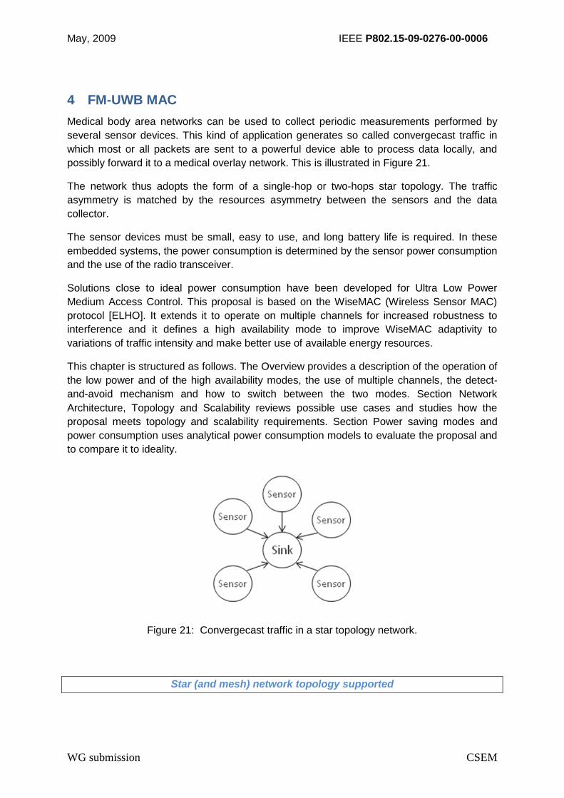
Medical body area networks can be used to collect periodic measurements performed by
several sensor devices. This kind of application generates so called convergecast traffic in
which most or all packets are sent to a powerful device able to process data locally, and
possibly forward it to a medical overlay network. This is illustrated in Figure 21.
The network thus adopts the form of a single-hop or two-hops star topology. The traffic
asymmetry is matched by the resources asymmetry between the sensors and the data
collector.
The sensor devices must be small, easy to use, and long battery life is required. In these
embedded systems, the power consumption is determined by the sensor power consumption
and the use of the radio transceiver.
Solutions close to ideal power consumption have been developed for Ultra Low Power
Medium Access Control. This proposal is based on the WiseMAC (Wireless Sensor MAC)
protocol [ELHO]. It extends it to operate on multiple channels for increased robustness to
interference and it defines a high availability mode to improve WiseMAC adaptivity to
variations of traffic intensity and make better use of available energy resources.
This chapter is structured as follows. The Overview provides a description of the operation of
the low power and of the high availability modes, the use of multiple channels, the detect-
and-avoid mechanism and how to switch between the two modes. Section Network
Architecture, Topology and Scalability reviews possible use cases and studies how the
proposal meets topology and scalability requirements. Section Power saving modes and
power consumption uses analytical power consumption models to evaluate the proposal and
to compare it to ideality.
Figure 21: Convergecast traffic in a star topology network.
Star (and mesh) network topology supported
May, 2009 IEEE P802.15-09-0276-00-0006
WG submission CSEM
4.1 Overview
Energy waste in wireless communications occurs for the following reasons [ELHO]:
Idle listening: listening to an idle channel to receive possible traffic.
Overhearing: a node receives packets that are destined to other nodes.
Overemitting: the transmission of a message when the destination node is not ready.
Collisions: these occur when a receiver node receives more than one packet at the same time. All packets that cause the collision have to be discarded and
retransmission of these packets is required.
Signaling overhead: the packet headers and the signaling required by the protocol in
addition to the transmission of data payloads.
These problems are always due to the radio transceiver spending time in reception or
transmission mode while it could be in sleep mode. Two strategies have been proposed in
the literature to address these problems:
Scheduled access protocols aim to reduce this waste by scheduling communications appropriately and rely on a network wide time synchronization mechanism. While this kind of approach has been successful in wired networks, the unreliability of the wireless channel makes it difficult to transpose to wireless communications.
Random access protocols take into account the possibility of packet losses and let nodes compete for channel access.
4.1.1 Low Power Mode
To minimize idle listening, all network nodes spend most of their time in an ultra low power
sleep mode. Each node periodically and independently wakes up every time interval
aWakeUpInterval, performs a clear channel assessment on its channel, and goes back to
sleep again if the channel is found idle. If the channel is found busy, the node keeps listening
and attempts frame reception. If no frame is received, the node goes back to sleep. If a
unicast frame is received and if its destination address matches the node address, an
acknowledgement is sent back to the source node, piggybacking timing information on its
next wake-up. Figure 22 illustrates the first packet exchange between two nodes.
Node 1 has a packet to send. It immediately starts transmitting a wake-up preamble whose
length is equal to the wake-up interval so that all reachable nodes are aware of the incoming
packet transmission. The wake-up preamble is followed by the packet itself. Node 2
acknowledges the packet and sends timing information to the source node 1. This timing
information will allow node 1 to greatly reduce the wake-up preamble at the next packet
exchange.

May, 2009 IEEE P802.15-09-0276-00-0006
WG submission CSEM
Figure 22: The WiseMAC low power mode uses the Long Preamble Listening mechanism at the first exchange.
Figure 23 shows a second packet exchange between the same two nodes. This time, node 1
does not send immediately its long wake-up preamble. Instead, it computes a minimal size
for the preamble, and waits as long as possible before transmitting it. Again, node 2 receives
the packet and acknowledges it, including some timing information.
Figure 23: The WiseMAC low power mode saves energy by using a greatly reduced wake-up preamble length after the first packet exchange.

May, 2009 IEEE P802.15-09-0276-00-0006
WG submission CSEM
This saves energy at the transmitter since its transmission is shorter. It also saves energy at
the destination node as it does not have to listen to a complete wake-up preamble.
Additionally, it saves energy at neighbor nodes since they will suffer less from overhearing.
Finally, it saves energy by reducing channel usage and thereby collisions. This, at the same
time, improves reliability and reduces latency.
Figure 24 shows all these exchanges. Node 1 sends two packets to Node 2, and Node 3
overhears the first packet but not the second one. The timing information is indicated with the
notation T*. The duration of the long wake-up preamble, indicated with the notation TW on
the figures, is equal to aWakeUpInterval.
Figure 24: The WiseMAC low power mode for 3 transceivers.
The packet is sent just after the preamble and the source node then switches to reception
mode and waits for an acknowledgement message. If it does not receive one, a counter
nbTxAttempts is incremented and if it is lower than a parameter MaxTxAttempts a new
transmission attempt will be made. If nbTxAttempts is equal to MaxTxAttempts the frame is
dropped and the upper layer is informed of the transmission failure.
When an acknowledgement message is received, the timing information piggybacked in the
message is saved in an associative array with the destination node address as key. This
value allows the source node to predict the next wake-up times of the destination node and
thus to reduce the length of the wake-up preamble. Due to the imprecision Theta of the
quartz used, the prediction is not perfect and its precision degrades with time. In practice, the
wake-up preamble length is computed with the formula
preambleLength = min(4 Theta L, aWakeUpInterval)

May, 2009 IEEE P802.15-09-0276-00-0006
WG submission CSEM
where L is the time interval between the time at which the last acknowledgement was
received from the destination node and the time at which the next packet arrives at the MAC
layer.
The formula can be explained as follows. If all nodes were using the same absolute time
reference, the wake-up preamble would be set to the smallest value detectable by the radio
transceiver for all upcoming transmissions.
In practice, all nodes have their own time reference, of given imprecision Theta (in parts per
million). This parameter tells us that after a time T, the value given by the time source will be
between T(1-Theta) and T(1+Theta). The maximum relative clock drift is 2Theta since one of
the time sources can be at the lowest possible frequency and the other at the highest
possible frequency. After a time L, the time difference between the two clocks is between -2
Theta L and +2 Theta L. Hence the minimal length of the wake-up preamble at a time L after
the last exchange is 4 Theta L. The wake-up preamble length should never exceed
aWakeUpInterval since this value is large enough to reach all nodes, thus the complete
expression is preambleLength = min(4 Theta L, aWakeUpInterval).
For broadcast transmissions, a long wake-up preamble is always used. Figure 24 shows the
states of three radio transceivers. Transceiver 1 sends two messages to transceiver 2. The
first message is sent using a long preamble and the second with a reduced length preamble.
Node 3 overhears the first transmission but not the second transmission thanks to the
decreased channel use.
4.1.2 High Availability Mode
Since some devices can have more energy resources than others, it is tempting to make use
of this additional energy to either further reduce the power consumption of energy limited
sensors or to use this energy to increase the throughput and decrease the latency of the
network.
Also, some low power network applications have two operation modes. The first mode is a
low power, low duty-cycle monitoring mode, and the other one is an emergency or alert
mode. While in the first case, power consumption is the main issue, in the latter case it does
not matter anymore (for instance with fire detection systems) and all the remaining energy
should be used to get the best possible performance in terms of latency and throughput. This
way, all time-critical data packets reach their destinations as early as possible.
Both cases, heterogeneous networks and dual-mode applications, highlight the need for a
high performance mode of the MAC layer. This mode should be interoperable with the low
power mode, since in the case of the heterogeneous network these high performance
communications should coexist with low power traffic between low powered nodes, and allow
asymmetric operations on the same link (low latency in one way and low power in the other).
The case of dual-mode applications highlight the requirement that a node should be able to
switch between the two modes depending on the application’s current needs and on the
state of the battery. Hence, a Carrier Sense Multiple Access (CSMA) mode (possibly the
same as IEEE 802.15.4 non beacon enabled mode) is a reasonable choice as it does not
impose regular signaling traffic (which would make coexistence of both traffic difficult). It also
allows all nodes to switch independently to this mode, by signaling the mode change with a

May, 2009 IEEE P802.15-09-0276-00-0006
WG submission CSEM
header flag in all data and acknowledgement packets sent by the node. And finally, it greatly
decreases latency and substantially increases maximum throughput.
CSMA can be seen as a limit case of WiseMAC in which aWakeUpInterval tends to zero. For
maximum flexibility and performance, the decision procedure for switching from one node to
the other is not specified in this document. The application should take the decision and
reconfigure the MAC layer appropriately.
Figure 25 shows three possible configurations for a network of four sensor nodes and one
data collector at the center. In Figure 25a, all links use the WiseMAC low power scheme.
Figure 25 : Possible network configurations
In figure 25b, the sink is high powered and thus it is able to keep its radio in reception mode
all the time. This allows resource-constrained sensor devices to access the sink in CSMA
mode, but the sink access the sensors with WiseMAC since the sensors must save energy.
Figure 25c shows a hybrid configuration in which the sink runs in CSMA mode and some
sensors can also be accessed using CSMA. This can be the case for instance when the sink
a) Low power downlinks and uplinks. b) Low power downlinks and low
latency uplinks.
c) Low power downlinks and mixed
low power and low latency uplinks.

May, 2009 IEEE P802.15-09-0276-00-0006
WG submission CSEM
has a lot of traffic to send to a sensor device: all sensors nodes would always access the
sink in CSMA, and the sensor would usually be accessed in WiseMAC mode, except when
asked by the sink to switch to CSMA mode for high data rate communications. Another
usage scenario for this mode is when some sensors are not resource constrained; they can
always operate in CSMA mode.
4.1.3 Multiple Channels
In addition to saving energy, a low power MAC protocol must also deliver messages as
reliably as possible. Hence, several mechanisms act at different levels to increase reliability.
At the lowest layer, error detection and correction techniques are used to guarantee the
integrity of the message and correct individual bit errors. When a message is incorrectly
received or not received at all, it is not acknowledged and a retransmission procedure is
triggered at the source node. When a node has a message to send, it contends for channel
access to prevent collisions. If the channel is found busy, the node waits for some time and
then retries.
As the traffic increases on a communication channel, it becomes more and more difficult to
get access to the medium: the channel will be found busy more often. Collisions will also
happen more frequently. These two factors both increase the latency, and the last one also
decreases the system’s reliability. From an energy viewpoint, an increase of traffic leads to
overhearing and collisions, which both increase the power consumption. Therefore, switching
to another communication channel is interesting both for performance reasons as latency
and reliability will both be improved, and for power consumption reasons as it decreases
overhearing and collisions.
A device should select a communication channel on which to perform its periodic carrier
sensing at random during its initialization time. When a device has a packet to send, it will
send it with a long preamble and wait for an acknowledgement message on each channel. If
it does not receive an acknowledgement, it will switch to another channel and send the
message with a long preamble again.
The procedure ends when the source node receives an acknowledgement packet or if it has
sent the packet on all channels without receiving any acknowledgement. If an
acknowledgement packet is received, the channel on which it was received is stored in
memory along with the timing information on the next wake-up interval.
Figure 26 illustrates this process with node 1 sending a first packet with a long preamble on
channels 1, 2 and 3. It times out for the acknowledgement on the first two channels but
receives one on channel 3, along with the timing information on node 2’s next channel
polling. Node 1 then uses this information to reduce the wake-up preamble to a minimum
size for the next packet.

May, 2009 IEEE P802.15-09-0276-00-0006
WG submission CSEM
Figure 26: Operation over multiple channels.
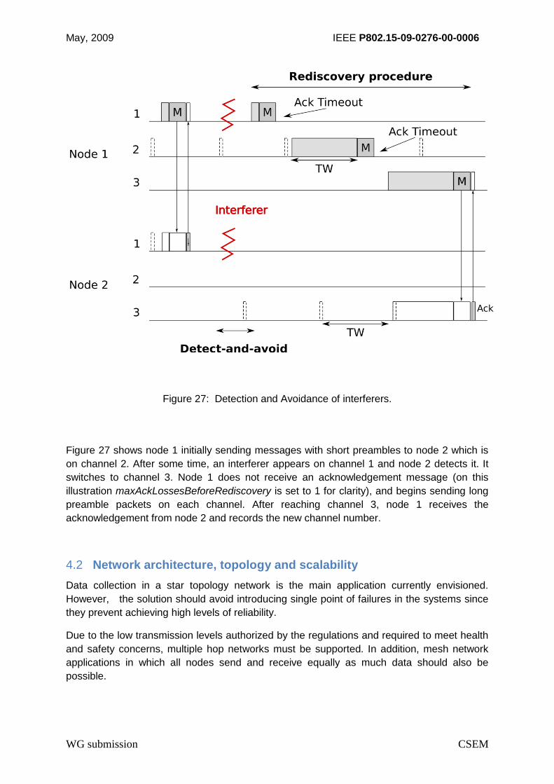
4.1.4 Detect-and-Avoid
The operation over multiple channels allows to further increase reliability and lower power
consumption. If a device often wakes up to receive invalid frames or to overhear frames, it
can switch to another, less used, channel. This solves two problems:
1) it balances channel use on all available channels when traffic increases, reducing overhearing and latency, and increasing fairness,
2) it allows the system to deal with wideband or narrow band interferers, by switching to a communication channel at a different frequency.
When a node switches to another communication channel, the other nodes are not aware of
this change. They will continue to address the node on its old channel. However, they will
deduce from the lack of an acknowledgement message that the destination node is not
receiving the messages anymore. After some retries, up to
maxAckLossesBeforeRediscovery retransmission attempts on the same communication
channel, a rediscovery procedure is initiated. It is the same procedure used when the source
node doesn’t know the destination node’s channel. The message is sent with a long
preamble on each channel, until an acknowledgement message is received.
May, 2009 IEEE P802.15-09-0276-00-0006
WG submission CSEM
Figure 27: Detection and Avoidance of interferers.
Figure 27 shows node 1 initially sending messages with short preambles to node 2 which is
on channel 2. After some time, an interferer appears on channel 1 and node 2 detects it. It
switches to channel 3. Node 1 does not receive an acknowledgement message (on this
illustration maxAckLossesBeforeRediscovery is set to 1 for clarity), and begins sending long
preamble packets on each channel. After reaching channel 3, node 1 receives the
acknowledgement from node 2 and records the new channel number.
4.2 Network architecture, topology and scalability
Data collection in a star topology network is the main application currently envisioned.
However, the solution should avoid introducing single point of failures in the systems since
they prevent achieving high levels of reliability.
Due to the low transmission levels authorized by the regulations and required to meet health
and safety concerns, multiple hop networks must be supported. In addition, mesh network
applications in which all nodes send and receive equally as much data should also be
possible.

May, 2009 IEEE P802.15-09-0276-00-0006
WG submission CSEM
Networks should scale to e.g. tens of sensor nodes. Multiple independent networks should
be able to operate simultaneously as body area networks are by essence mobile, making
nodes density hard to predict.
WiseMAC-HA supports equally well star and mesh topologies, both with low power consumption. This has been demonstrated in real-world deployments lasting several years.
Scalability is not an issue as the protocol only requires local information exchanges. There is no network wide signalling traffic. Multiple hops communications are supported without any special mechanism (such as synchronization of signalling traffic).
4.3 Power saving modes and power consumption
WiseMAC power consumption can be calculated by starting from a detailed radio model with
transition states as shown in Figure 28. This model has three steady states:
sleep mode (Sleep),
transmission mode (Tx)
reception mode (Rx)
as well as four transition states:
setup Transmission (SetupTx),
setup Reception (SetupRx),
switch from transmission to reception (SwitchTxRx)
switch from reception to transmission (SwitchRxTx).
All transitions to sleep mode are considered instantaneous. The time spent in a transient
state is a constant and noted T_State and the energy cost of transiting by this state is noted
E_State. The power consumption values in the steady states are noted P_State.
Figure 28: Radio states model.
May, 2009 IEEE P802.15-09-0276-00-0006
WG submission CSEM
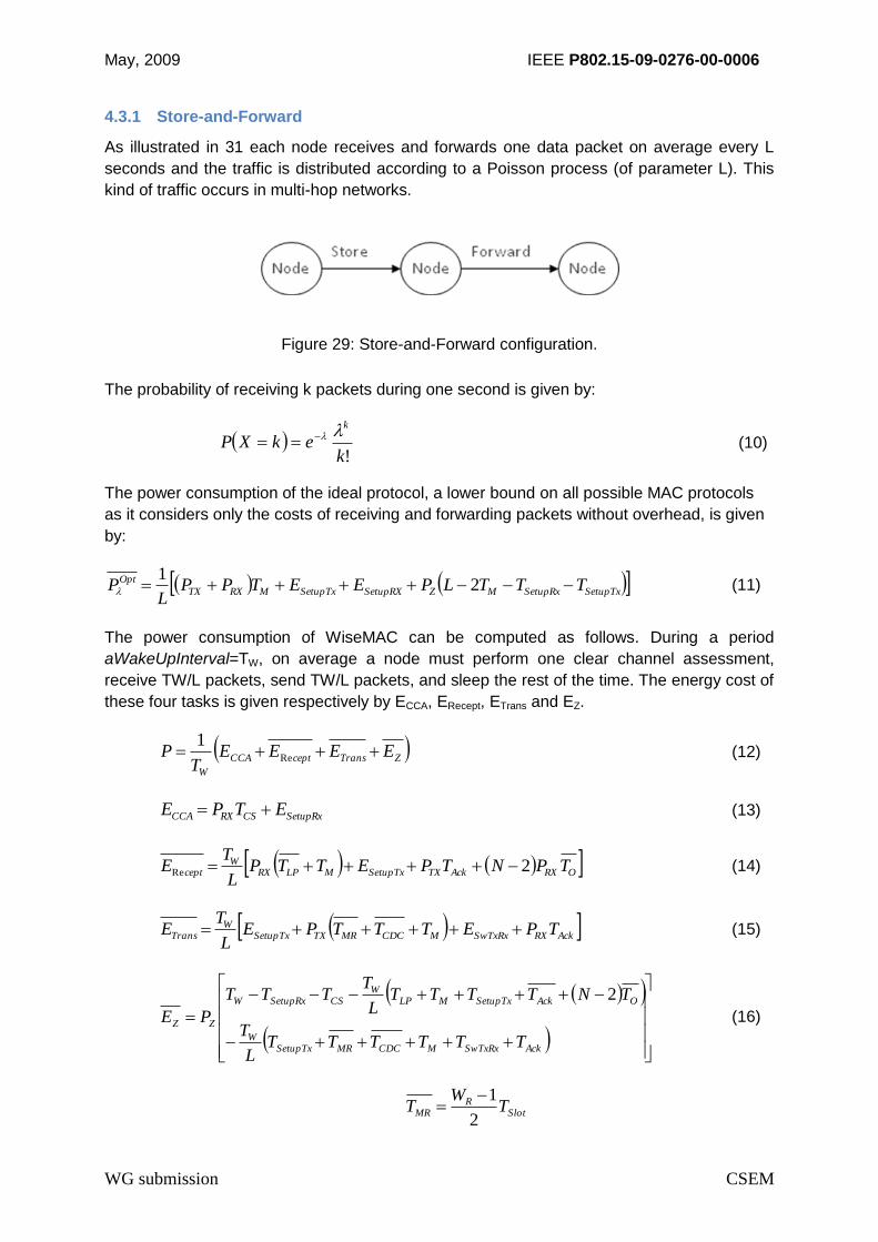
4.3.1 Store-and-Forward
As illustrated in 31 each node receives and forwards one data packet on average every L
seconds and the traffic is distributed according to a Poisson process (of parameter L). This
kind of traffic occurs in multi-hop networks.
Figure 29: Store-and-Forward configuration.
The probability of receiving k packets during one second is given by:
!k
ekXPk (10)
The power consumption of the ideal protocol, a lower bound on all possible MAC protocols
as it considers only the costs of receiving and forwarding packets without overhead, is given
by:
SetupTxSetupRxMZSetupRXSetupTxMRXTX
Opt TTTLPEETPPL
P 21
(11)
The power consumption of WiseMAC can be computed as follows. During a period
aWakeUpInterval=TW, on average a node must perform one clear channel assessment,
receive TW/L packets, send TW/L packets, and sleep the rest of the time. The energy cost of
these four tasks is given respectively by ECCA, ERecept, ETrans and EZ.
ZTransceptCCA
W
EEEET
P Re
1 (12)
SetupRxCSRXCCA ETPE (13)
ORXAckTXSetupTxMLPRXW
cept TPNTPETTPL
TE 2Re (14)
AckRXSwTxRxMCDCMRTXSetupTxW
Trans TPETTTPEL
TE (15)
AckSwTxRxMCDCMRSetupTxW
OAckSetupTxMLPW
CSSetupRxW
ZZ
TTTTTTL
T
TNTTTTL
TTTT
PE
2
(16)
SlotR
MR TW
T2
1

May, 2009 IEEE P802.15-09-0276-00-0006
WG submission CSEM
L
T
CDC
W
eLT 412
Figure 30 compares the power consumption of various MAC protocols as a function of traffic
intensity when running on a Texas Instruments CC 2420 radio transceiver. The following
assumptions were made with respect to Figure 30:
20 nodes
50 bytes data packets
4 bytes acknowledgement packets
Quartz precision of 30 ppm
250 kbps radio bit rate
Power consumption in reception mode: 8 mW
Power consumption in transmission mode: 4 mW
Power consumption in sleep mode: 60 W
WiseMAC wake-up interval TW: 500 ms
The other MAC protocol parameters are chosen such that they offer an average latency similar to WiseMAC’s latency (TW/2, or 250 ms).
Figure 30: Comparison of power consumptions in a store and forward scenario based upon the FM-UWB radio.

May, 2009 IEEE P802.15-09-0276-00-0006
WG submission CSEM
The ideal power consumption is shown in black at the bottom of the figure. L-MAC and
CrankShaft, two distributed TDMA protocols, are at the top of the figure. S-MAC, T-MAC and
SCP-MAC perform better, but are outperformed by WiseMAC and other preamble sampling-
based protocols (such as X-MAC, CSMA-MPS, SyncWUF). This data enables qualitative
evaluation of the WiseMAC low power mode of this proposal.
4.3.2 Convergecast Traffic
The models presented in the previous section can be adapted to evaluate sensor and sink
power consumption for the case of convergecast traffic and 802.15.4 CSMA, WiseMAC and
S-MAC protocols. CSMA power consumption is given by:
MTXSwTxRxAckRX
sensor
CSMA TPETPL
NP (17)
SwTxRxSwRxTxAckRXSwTxRxSwRxTxAckTX
k
CSMA TTTL
NPEETP
L
NP 1sin
(18)
Figure 31 shows the power consumption of a sensor and of the sink as a function of traffic
intensity (number of packets emitted by the sensor per second), for CSMA, S-MAC and
WiseMAC. A small network of five sensors and one sink is considered, each data packet
carries 16 bytes of data, and each acknowledgement packet is 4 bytes long. The radio
modeled here is an FM-UWB radio transceiver using 4 mW in transmission mode and 8 mW
in reception mode, and all communications occur on the same subcarrier operating at 250
kbps.
The gray areas are zones impossible to reach since they are below the ideal lower bound.
The dark gray area (below the gray line) concerns the ideal power consumption of the sensor
and the light gray area (below the black line) concerns the sink.
The top red line shows the power consumption at the sink in CSMA mode, which is almost
equal to the power consumption in reception mode as the radio transceiver leaves this mode
only to send acknowledgement messages. When a sensor accesses a sink in CSMA mode,
the sensor’s power consumption decreases slightly compared to WiseMAC because of the
absence of a wake-up preamble. This is shown by the second red line (“CSMA – sensor”).
The two green lines show the sink and sensor power consumption when using S-MAC, and
the power consumption in the low power WiseMAC mode is shown in blue.
The sink’s power consumption in WiseMAC mode is limited in traffic rate: it stops when the
sink receives on average one packet per sleep interval. In reality the sink can continue to
operate with higher packet rates but latency will greatly increase: as nodes will often
compete for sink access, once a node wins the contention phase it will send all its waiting
packets to the sink by making use of the more bit feature of WiseMAC. The results on
latency from Figure 32 confirm this point.

May, 2009 IEEE P802.15-09-0276-00-0006
WG submission CSEM
1
Figure 31: Sensor and sink power consumption for various protocols in convergecast traffic using the FM-UWB radio.
The switching condition between the two modes (low power WiseMAC mode and High
Availability CSMA mode) of the WiseMAC-HA protocol can be derived from this graphic
according to the system’s required operating life: for instance, a very long operating life on
battery excludes any switch to the high speed CSMA mode. The same assumptions were
made for Figure 31 as for the case of Figure 30:
4.4 Latency
The average latency is an important system parameter, especially for medical body area
networks and other highly reactive systems. The latency that can be obtained in each of the
two modes, CSMA and WiseMAC, can be evaluated with a simple queuing model if we
ignore buffer size problems and assume instead infinite capacity at each node. With a
Poisson arrival distribution, the system can be approximated as an M/D/1/infinity queuing
system. The expected delay for such a system is given by:
12
1DelayE (19)
where
is the traffic intensity and sN is the aggregate packet arrival rate (traffic
generation). The service time, i.e., the time to transmit the packet on the channel and receive
the acknowledgement, for the CSMA and the WiseMAC mode is given by
SIFSMCSMA TT 21 (20)
2
1 WWiseMAC
T (21)
Figure 32 shows the average latency for the low power mode WiseMAC and the High
Availability mode CSMA. The considered network has a star topology with one sink and a
number of sensor devices between 5 and 256. The following assumptions were made:
Data packets of 16 bytes
Acknowledgement packets of 4 bytes
Synchronization preamble of 500 s
WiseMAC wake-up interval TW of 200 ms
250 kbps radio bit rate
All traffic takes place on the same FM-UWB subcarrier
Radio setup times (Rx and Tx): 1 ms
Radio switching times: 0.1 ms
CSMA minimum Backoff exponent: 2
May, 2009 IEEE P802.15-09-0276-00-0006
WG submission CSEM
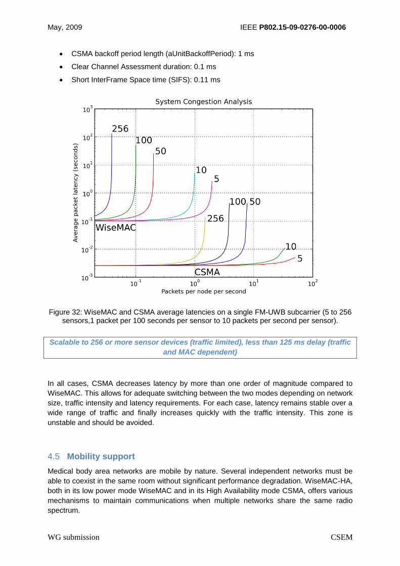
CSMA backoff period length (aUnitBackoffPeriod): 1 ms
Clear Channel Assessment duration: 0.1 ms
Short InterFrame Space time (SIFS): 0.11 ms
Figure 32: WiseMAC and CSMA average latencies on a single FM-UWB subcarrier (5 to 256 sensors,1 packet per 100 seconds per sensor to 10 packets per second per sensor).
Scalable to 256 or more sensor devices (traffic limited), less than 125 ms delay (traffic
and MAC dependent)
In all cases, CSMA decreases latency by more than one order of magnitude compared to
WiseMAC. This allows for adequate switching between the two modes depending on network
size, traffic intensity and latency requirements. For each case, latency remains stable over a
wide range of traffic and finally increases quickly with the traffic intensity. This zone is
unstable and should be avoided.
4.5 Mobility support
Medical body area networks are mobile by nature. Several independent networks must be
able to coexist in the same room without significant performance degradation. WiseMAC-HA,
both in its low power mode WiseMAC and in its High Availability mode CSMA, offers various
mechanisms to maintain communications when multiple networks share the same radio
spectrum.

May, 2009 IEEE P802.15-09-0276-00-0006
WG submission CSEM
WiseMAC and CSMA are both contention based: by monitoring channel usage before
transmitting, they can reduce collisions with independent networks. This allows operation of
several networks as long as they have low bandwidth requirements. If channel usage
increases, packet loss will increase and after some time, the system will automatically switch
to another channel (frequency band or FM subcarrier) thanks to its Detect-And-Avoid
mechanism.
Mobility support provided by the MAC protocol
4.6 Framing, CRC and retransmissions
The retransmission mechanism is similar to the IEEE 802.15.4 non beacon enabled mode.
Concerning framing, the protocol does not have special requirements that would constrain
the packet size. Limitations could come from the size of available buffer memory on a system
that should be as cheap as possible.
The MAC protocol does not make particular requirements for the addressing space. It only
requires setting the source and destination addresses in both data and acknowledgement
packets. It should be noted however that for low data rate systems, address fields should not
be too large. Or else, the transmission and reception of these addresses will have an impact
on power consumption, when considering small packet sizes.
May, 2009 IEEE P802.15-09-0276-00-0006
WG submission CSEM
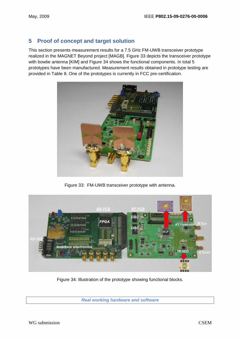
5 Proof of concept and target solution
This section presents measurement results for a 7.5 GHz FM-UWB transceiver prototype
realized in the MAGNET Beyond project [MAGB]. Figure 33 depicts the transceiver prototype
with bowtie antenna [KIM] and Figure 34 shows the functional components. In total 5
prototypes have been manufactured. Measurement results obtained in prototype testing are
provided in Table 8. One of the prototypes is currently in FCC pre-certification.
Figure 33: FM-UWB transceiver prototype with antenna.
Figure 34: Illustration of the prototype showing functional blocks.
Real working hardware and software

May, 2009 IEEE P802.15-09-0276-00-0006
WG submission CSEM
Table 8: Measured FM-UWB transceiver performance (first generation prototype)
Parameter Value
RF center frequency 7.5 GHz
RF bandwidth 500 MHz
RF output power -15 dBm
Subcarrier frequency 1- 2 MHz
Subcarrier modulation FSK, = 1,
Raw bit rate 31.25, 62.5,125 and 250
kbps
Receiver sensitivity (BER ≤ 10-6) -85 dBm
TX, RX switching time 200 s
Latency (at PHY level) 150 s
RX synchronisation time ≤ 400 s @ 62.5 kbps
Current consumption RX 15 mW
Current consumption TX 5.5 mW
5.1 Power consumption
The hardware implementation for FM-UWB is potentially low power and low cost. Phase
noise requirements for the transmitter VCO are relaxed (typically -80 dBc/Hz at 1 MHz offset)
and the digital subcarrier generation and constant-envelope RF signal allow for a low supply
voltage in the transmitter. A first generation of dedicated integrated circuits has been
designed in 0.25 m SiGe:C BiCMOS technology, manufactured and evaluated.
Figure 35 is a photograph of the receiver front-end chip [ZHAO]. It comprises a 21 dB gain
preamplifier and a 1GHz bandwidth FM demodulator. The measured overall receiver
sensitivity is -85 dBm (BER ≤ 10-6) and the front-end consumes 9 mW from a 1.8 V supply. A
sensitivity of -82 dBm is achieved at 6 mW power consumption. Measured power
consumption values of the overall FM-UWB radio prototype are 5.5 mW for the transmitter
and 15 mW for the receiver. An overview is provided by Table 9 for a 7.5 GHz transceiver
implementation.

May, 2009 IEEE P802.15-09-0276-00-0006
WG submission CSEM
Du RFgndgnd gnd
IF+ IF-gndgnd gnd
gnd
Vcc
VBin
Vcf
Vcc
gnd
VAGC
VCtr
VCtri
Vcc
gnd
Vtg
Vta
Vtb
gnd
gnd
VCC
gnd
gnd
Vt
demodulator
preamplifier
Figure 35: Die photo of the front-end test chip
Table 9: Power consumption of first generation FM-UWB transceiver
Parameter Value
Transmitter PTX 5.5 mW
RF VCO 2.5 mW
RF Output stage 2.0 mW
DDS 1.0 mW
Receiver PRX 15 mW
Low Noise Amplifier 5 mW
Wideband FM Demodulator 4 mW
Subcarrier processing 5 mW
DDS 1 mW
Ultra-low power UWB implementation on target to achieve, PTX ≤ 4 mW and PRX ≤ 8 mW
(continuous operation) for a fully integrated solution

May, 2009 IEEE P802.15-09-0276-00-0006
WG submission CSEM
It should be noted that the numbers mentioned for the receiver correspond to maximum
receiver sensitivity, which is not needed 100% of the time. Lowering the receiver sensitivity
also lowers power consumption. By sacrificing 3 dB of receiver sensitivity, a power
consumption of 12 mW has been obtained. Based on current results, it is the expectation of
the authors that the second generation of FM-UWB ICs will meet the target values of PTX ≤ 4
mW and PRX ≤ 8 mW.
5.2 Bit Error Rate and Packet Error Rate
The results of wired BER measurements made on 4 different receiver prototypes are shown
in Figure 36. The black solid line is the analytical reference curve for FM-UWB modulation.
The colored dashed lines represent the measurement results. Measurement time for the
lower BER values was 4 minutes, this corresponds to 4 x 60 x 50,000 = 12 million
transmitted bits. Measurement time for the lower BER values was 4 minutes, this
corresponds to 4 x 60 x 50,000 = 12 million transmitted bits.
Figure 36: BER measurements made on 4 receivers.
BER ≤ 10-6 (PER ≤ 10%) measured at approximately -85 dBm receive power level
From these results it can be concluded that the FM-UWB receiver sensitivity is about -85
dBm (BER ≤10-6), which is more than sufficient to support a Packet Error Rate (PER) of less
than 10% (i.e., for a 256 octet packet). All four receivers showed very similar performance in
testing. Additionally, receiver sensitivity can be further increased e.g. by increasing LNA gain.
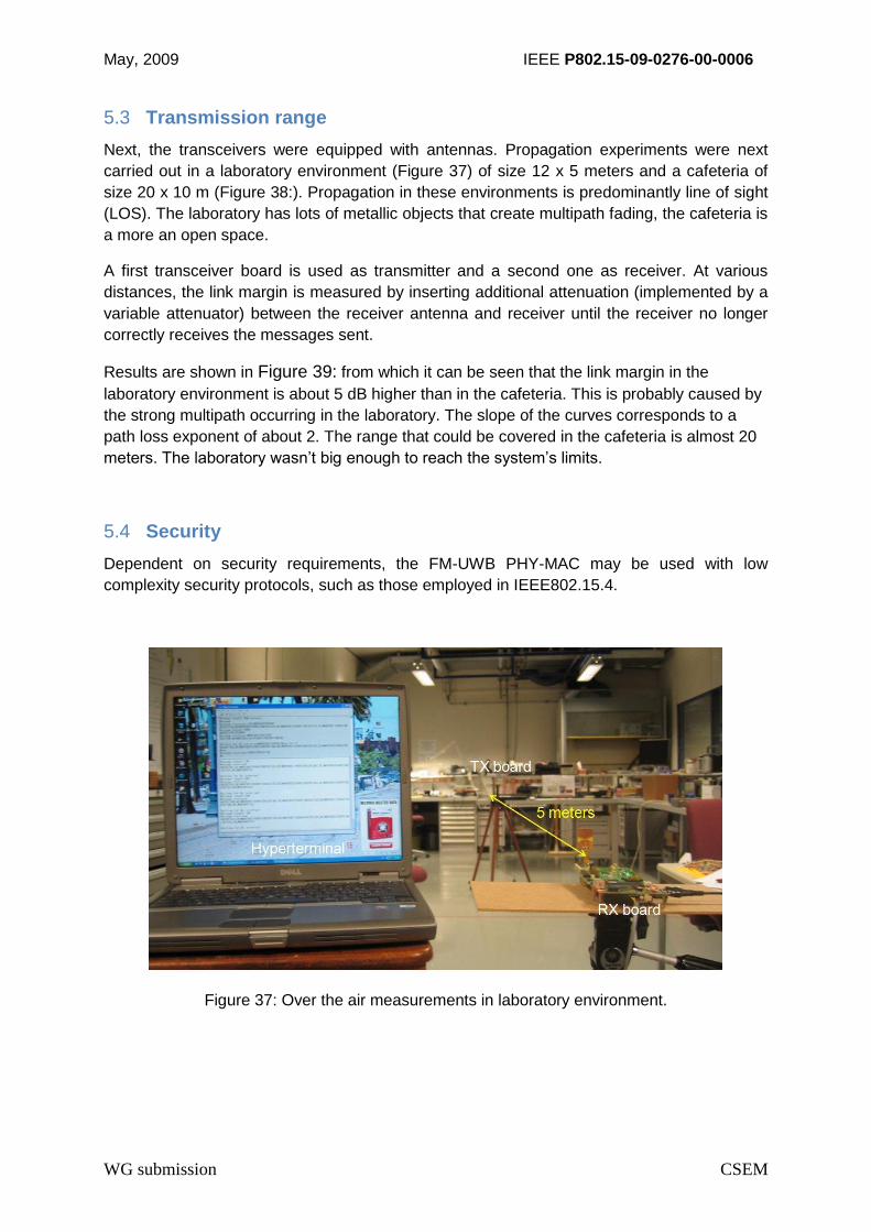
May, 2009 IEEE P802.15-09-0276-00-0006
WG submission CSEM
5.3 Transmission range
Next, the transceivers were equipped with antennas. Propagation experiments were next
carried out in a laboratory environment (Figure 37) of size 12 x 5 meters and a cafeteria of
size 20 x 10 m (Figure 38:). Propagation in these environments is predominantly line of sight
(LOS). The laboratory has lots of metallic objects that create multipath fading, the cafeteria is
a more an open space.
A first transceiver board is used as transmitter and a second one as receiver. At various
distances, the link margin is measured by inserting additional attenuation (implemented by a
variable attenuator) between the receiver antenna and receiver until the receiver no longer
correctly receives the messages sent.
Results are shown in Figure 39: from which it can be seen that the link margin in the
laboratory environment is about 5 dB higher than in the cafeteria. This is probably caused by
the strong multipath occurring in the laboratory. The slope of the curves corresponds to a
path loss exponent of about 2. The range that could be covered in the cafeteria is almost 20
meters. The laboratory wasn’t big enough to reach the system’s limits.
5.4 Security
Dependent on security requirements, the FM-UWB PHY-MAC may be used with low
complexity security protocols, such as those employed in IEEE802.15.4.
Figure 37: Over the air measurements in laboratory environment.
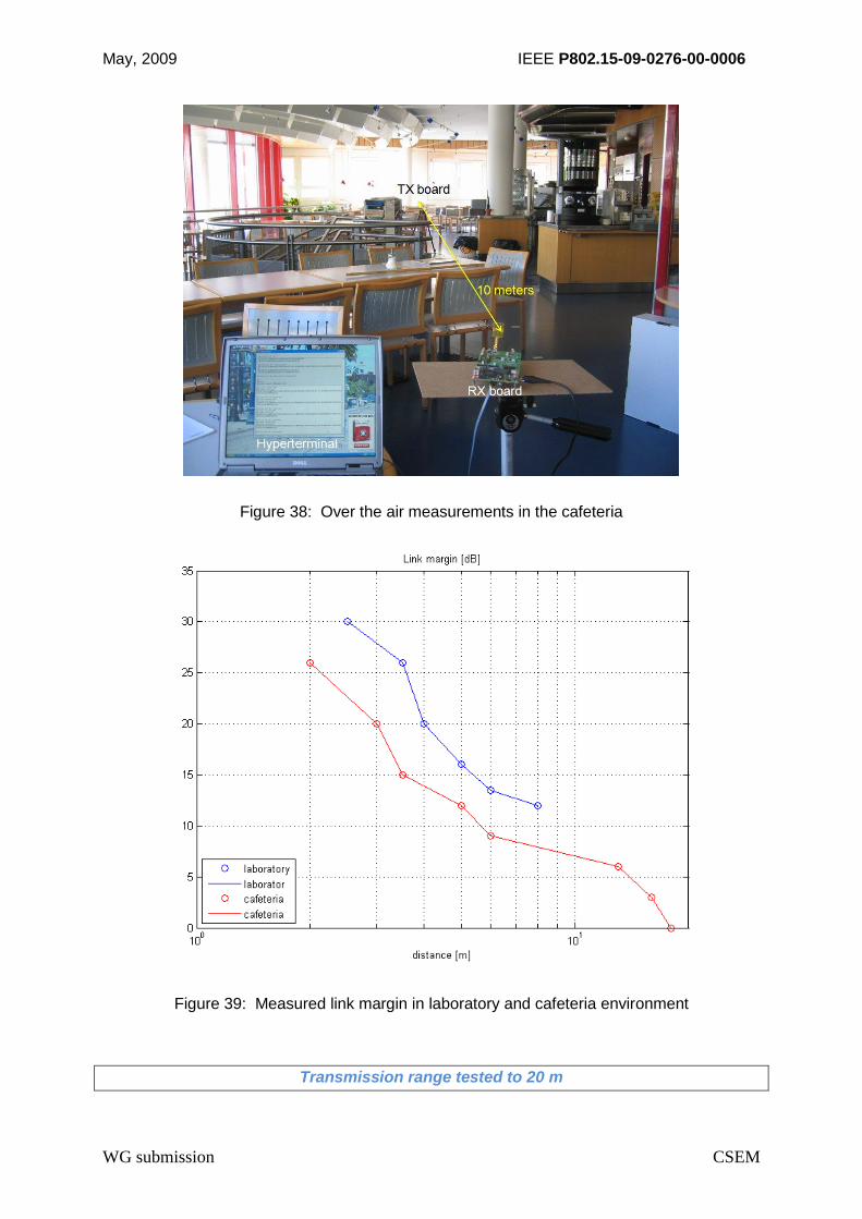
May, 2009 IEEE P802.15-09-0276-00-0006
WG submission CSEM
Figure 38: Over the air measurements in the cafeteria
Figure 39: Measured link margin in laboratory and cafeteria environment
Transmission range tested to 20 m

May, 2009 IEEE P802.15-09-0276-00-0006
WG submission CSEM
6 Compliance with BAN requirements and technical
characteristics
A compliance matrix is provided in Table 10. The proposed for the proposed FM-UWB –
WiseMAC-HA PHY-MAC is fully compliant with the IEEE802.15.6 system requirements.
Table 10: Compliance with IEEE802.15.6 BAN system requirements
Criteria FM-UWB - WiseMAC-HA
PHY-MAC Capabilities
Compliance with IEEE802.15.6
system requirements
Topology Star network (6-12 devices)
Mesh network (traffic limited)
Compliant
Bit rate Data rate
- Scalable to 250 kbps (BFSK)
Aggregate throughput
- 1 Mbps @ N = 4 RF channels
Compliant (wearable medical BAN)
Transmission
range
>3 m indoors Compliant
Security Compatible with IEEE802.15 Compliant (wearable Medical BAN)
QoS PER < 10% (256 octet packet)
Delay < 125 ms
PHY synchronisation ≤ 400 s
Optional FDMA-like MAC mode for near-
real-time operation
Compliant (wearable Medical BAN)
Reliability Robust to multipath interference
> 99% link success/availability
Compliant
Power
consumption
Low, autonomy > 1 year (e.g. with 1% duty
cycle, MAC sleep modes, 500 mAh
battery)
Compliant (wearable Medical BAN)
Tx ≤ 4 mW (continuous operation)
Rx ≤ 8 mW (continuous operation)
Average power: dependent on
application duty cycle
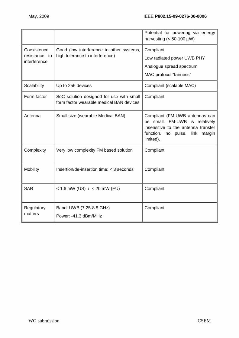
May, 2009 IEEE P802.15-09-0276-00-0006
WG submission CSEM
Potential for powering via energy
harvesting (< 50-100 W)
Coexistence,
resistance to
interference
Good (low interference to other systems,
high tolerance to interference)
Compliant
Low radiated power UWB PHY
Analogue spread spectrum
MAC protocol “fairness”
Scalability Up to 256 devices Compliant (scalable MAC)
Form factor SoC solution designed for use with small
form factor wearable medical BAN devices
Compliant
Antenna Small size (wearable Medical BAN) Compliant (FM-UWB antennas can
be small. FM-UWB is relatively
insensitive to the antenna transfer
function, no pulse, link margin
limited).
Complexity Very low complexity FM based solution Compliant
Mobility Insertion/de-insertion time: < 3 seconds Compliant
SAR < 1.6 mW (US) / < 20 mW (EU)
Compliant
Regulatory
matters
Band: UWB (7.25-8.5 GHz)
Power: -41.3 dBm/MHz
Compliant

May, 2009 IEEE P802.15-09-0276-00-0006
WG submission CSEM
7 Summary and concluding remarks
An FM-UWB PHY-MAC solution for wearable medical BAN applications is described in this
document. This solution fully satisfies the IEEE802.15.6 BAN system technical requirements
[IEEE3] defined for LDR applications, such as health and medical applications and meets or
exceeds the targets identified in the TG6 Proposal Comparison Criteria [IEEE4].
FM-UWB is proposed for standardization in response to the IEEE802.15.6 Call for Proposals,
targeting the wearable, LDR BAN applications domain. The proposed low complexity, FM-
UWB solution offers advantages with respect to:
low power consumption
scalability and flexibility of the PHY and MAC and
robust performance in BAN propagation environments.

May, 2009 IEEE P802.15-09-0276-00-0006
WG submission CSEM
8 References
[ANTO] E. Antoniono-Daviu, M. Cabedo-Fabrés, M. Ferrando-Bataller, and A. Vila-Jimenez,
"Acitve UWB Antenna with tunable band-notched behaviour", Electronics Letters, vol.
43, no. 18, August 2007, pp. 959-960.
[AWTE] A. Burri and M. Friedl, FM-UWB: a technology for low data rate communication with
high potential, 27 March 2007, AG fur Technologie und Innovation (AWTEC),
www.awtec.ch.
[DONG] Yunzhi Dong, Yi Zhao, John F.M. Gerrits, Gerrit van Veenendaal and John R. Long,
"A 9mW High Band FM-UWB Receiver Front-end", ESSCIRC2008, Edinburgh, 15 -
19 September 2008, pp.
[ELHO] A. El-Hoiydi and J.-D. Decotignie, “WiseMAC: An Ultra Low Power MAC Protocol for
Multi-hop Wireless Sensor Networks.”, Proceedings of the First International
Workshop on Algorithmic Aspects of Wireless Sensor Networks (ALGOSENSORS
2004), Lecture Notes in Computer Science, LNCS 3121, pp. 18-31. Springer-Verlag,
July 2004.
[GER1] J.F.M. Gerrits, M.H.L. Kouwenhoven, P.R. van der Meer, J.R. Farserotu, J.R. Long,
"Principles and Limitations of UWBFM Communications Systems", EURASIP Journal
of Applied Signal Processing, vol.2005, no.3, pp.382-396.
[GER2] J.F.M. Gerrits, J.R. Farserotu, and J.R. Long, "A Wideband FM Demodulator for a
Low-Complexity FM-UWB Receiver", Proceedings of the 9th European Conference
on Wireless Technology, September 2006, Manchester, UK, pp. 99-102.
[GER3] J.F.M. Gerrits, J.R. Farserotu, and J.R. Long, "Multiple-Access Interference in FM-
UWB Communication Systems", Proceedings of WPMC2005, Aalborg, Denmark,
September 2005, pp. 2027-2031.
[GER4] J.F.M. Gerrits, J.R. Farserotu, and J.R. Long, "Multipath Behavior of FM-UWB
Signals", Proceedings of ICUWB2007, Singapore, September 2007.
[GER5] J.F.M. Gerrits, J.R. Farserotu, and J.R. Long, "Low-Complexity Ultra Wideband
Communications", Proceedings of ISCAS 2007, New Orleans, USA, May 2007, pp.
757-760.
[GER6] J. Gerrits, and J. R. Farserotu, "FM-UWB: A Low Complexity Constant Envelope
LDR UWB Communication System", IEEE P802.15 Working Group for Wireless
Personal Area Networks (WPANs), July 2007, San Francisco, CA., USA, doc.:
IEEE802.15-07-0778-040ban, http://www.ieee802.org/15/pub/SGmban.html
[IEEE1] IEEE P802.15, TG6 Call for Proposals (CFP), IEEE P802.15-08-0811-03-0006,
March 23 2009.
[IEEE2] IEEEP802.15, Study Group Body Area Network, (SGban), BAN Technical
Requirements IEEE P802.15-07--0867-04-0ban

May, 2009 IEEE P802.15-09-0276-00-0006
WG submission CSEM
[IEEE3] IEEE 802.15.6, Technical Requirements Document (TRD), 15-08-0037-04-0006-
ieee-802-15-6
[IEEE4] IEEE 802.15.6, TG6 Proposal Comparison Criteria, 23 March 2009, IEEE P802.15-
08-831-05-006.
[IEEE5] IEEE Task Group 6 (TG6), Application matrix, 15-08-0406-00-006-tg6.
[IEEE6] IEEE TG15.6 Regulation summary, IEEE 802.15-08-0348-00-0006
[IEEE7] IEEE 802.15.6 Regulation Subcommittee Report, IEEE P802.15-08-0034-06-0006,
July 17, 2008
[IEEE8] K. Y. Yazdandoost, K. Sayrafian-Pour, “Channel Model for Body Area Network
(BAN), ” IEEE 802.15-08-0780-05-0006, February 2009.
[KIM] J. Kim, C.S. Cho, and J.W. Lee,"5.2 GHz notched ultra-wideband antenna using slot-
type SRR", Electronics Letters, vol. 42, no. 6, March 2006, pp. 315-316 .
[KOUW] M.H.L. Kouwenhoven, "High-Performance Frequency-Demodulation Systems", Delft
University Press, Delft, The Netherlands, 1998.
[LANS] J. Lansford, and D. Shoemaker, "Technology Tradeoffs for a Worldwide UWB
Transceiver", Proceedings of ICUWB2007, Singapore, September 2007.
[MAGB] European Information Society Technologies (IST) FP6 My personal Adaptive Global
NET Beyond project (MAGNET Beyond), European IST-027396, http://www.ist-
magnet.org/
[NILS] P. Nilsson, J. Gerrits, J. Yuan, "A Low Complexity DDS IC for FM-UWB Applications",
Proceedings of the 16th IST Mobile & Wireless Communications Summit, Budapest,
Hungary, July 2007.
[ROUS] J. Rousselot, WiseMAC – HA : A Flexible, Scalable, Robust and Ultra Low Power
MAC Protocol for Medical BANs, IEEE 802.15-08-0484-01-006, July 2008.
[TAUB] H. Taub, D. Schilling, Principles of Communication Systems, McGraw-Hill, New York,
NY, USA, 1971.
[URSA] IST URSAFE project, http://ursafe.tesa.prd.fr/
[ZHAO] Yi Zhao, Gerrit van Veenendaal, Hamid Bonakdar, John F.M. Gerrits and John R.
Long, "3.6mW 30dB Gain Preamplifiers for FM- UWB Receiver", IEEE
Bipolar/BiCMOS Circuits and Technology Meeting 2008, Monterey, 13 – 15 October
2008.
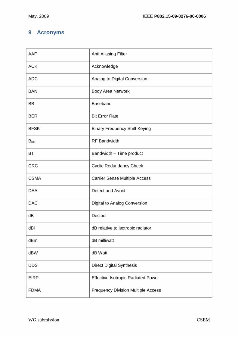
May, 2009 IEEE P802.15-09-0276-00-0006
WG submission CSEM
9 Acronyms
AAF Anti Aliasing Filter
ACK Acknowledge
ADC Analog to Digital Conversion
BAN Body Area Network
BB Baseband
BER Bit Error Rate
BFSK Binary Frequency Shift Keying
BRF RF Bandwidth
BT Bandwidth – Time product
CRC Cyclic Redundancy Check
CSMA Carrier Sense Multiple Access
DAA Detect and Avoid
DAC Digital to Analog Conversion
dB Decibel
dBi dB relative to isotropic radiator
dBm dB milliwatt
dBW dB Watt
DDS Direct Digital Synthesis
EIRP Effective Isotropic Radiated Power
FDMA Frequency Division Multiple Access
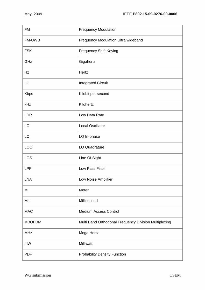
May, 2009 IEEE P802.15-09-0276-00-0006
WG submission CSEM
FM Frequency Modulation
FM-UWB Frequency Modulation Ultra wideband
FSK Frequency Shift Keying
GHz Gigahertz
Hz Hertz
IC Integrated Circuit
Kbps Kilobit per second
kHz Kilohertz
LDR Low Data Rate
LO Local Oscillator
LOI LO In-phase
LOQ LO Quadrature
LOS Line Of Sight
LPF Low Pass Filter
LNA Low Noise Amplifier
M Meter
Ms Millisecond
MAC Medium Access Control
MBOFDM Multi Band Orthogonal Frequency Division Multiplexing
MHz Mega Hertz
mW Milliwatt
PDF Probability Density Function

May, 2009 IEEE P802.15-09-0276-00-0006
WG submission CSEM
PHY Physical layer
PLL Phase Lock Loop
PRX Receiver power consumption
PSD Power Spectral Density
PTX Transmitter power consumption
RF Radio Frequency
Rx Receive
RXD Received Data
SIR Signal to Interference Ratio
S Signal to Noise Ratio
SoC System on a Chip
Tx Transmit
TXD Transmitted Data
m Micrometer
W MicroWatt
UWB Ultrawideband
VCO Voltage Controlled Oscillator
WAN Wide Area Network
WiseMAC Wireless Sensor Medium Access Control protocol
WiseMAC-HA WiseMAC High Availability

May, 2009 IEEE P802.15-09-0276-00-0006
WG submission CSEM
10 Annexes
Annex 1 : CDF of narrowband fading for CM3 showing 10 dB of margin required for 90%
availability, 20 dB for 99% availability and 30 dB for 99.9% availability; consistent with
Rayleigh fading.
Related Documents