AD-AOS3 316 FIED COMUAND IDNA) KIRTLAND AUo i F/O G is SFACILITIES INTIRACTION. UP RAN so LI M41NK UNCLASSIFIED PCIEFR-l END 5-801 nlCI

Welcome message from author
This document is posted to help you gain knowledge. Please leave a comment to let me know what you think about it! Share it to your friends and learn new things together.
Transcript
AD-AOS3 316 FIED COMUAND IDNA) KIRTLAND AUo i F/O G isSFACILITIES INTIRACTION. UP
RAN so LI M41NK
UNCLASSIFIED PCIEFR-l
END
5-801nlCI

11111 1120 __ 2.5i11111 IIII2
11112.
1111 ~*' 1 30 111112.0
1_25 III~ IB .
MICROCOPY RESOLUTION TEST CHARTNATtONAL BR[ALJ Of STANDARDS-1963-A

FC F-
EMP FACILITIES-INTERACTION
1MARCH 1980
"4__ - X A APR , 18
Approved for puhhc release;Dimribut'on Unliited
FIELD COMMAND
- I DEFENSE NUCLEAR AGENCYu-j ALBUQUERQUE, NEW MEXICO, 87115
C.V80 4 17 n-3'f/ 70?
" 'I

UNCLASSIFIEDSECURITY CLASSIFICATION OF THIS PAGE (Whomn Dae Frifeed)
EMP~EA FACIITIEUCNEIACNSNREPORT~6 DOUETAINPAEBFORE COGMPET FOME
q I E OjTU ER OVT CCESIONNo.3.RCPNT CARLRAN NUMBERa
Fiel CoriandAR& W OR. UNIT R NUMBE BES
I9. CEROROLING OFGAICEIO NAME AND ADDRESS 1 RGA LMN RJC.TS
Defense Nuclear Agency
Washington, D.C. 20305 514 MONITORING AGENCY NAME A ADDRESS(iI different from, Controlling Office) IS. SECURITY CLASS (of this report)
15s. DECLASSIFICATION DOWNGRADINGSCH EDULE
16. DISTRIBUTION STATEMENT (of this Report)
Approved for public release; distribution unlimited.
Ii GST RIBUTION STATEMENT (of the abstract entered in Block 20. lidlffet'ent fro., Report)
19 SUPPLEMENTARY NOTES
19 KEY WORDS (Continue on reverse aide it necessary end identify by block num~ber)
EMI VPDARES PhysiologyTRESTLE EMP
PD Interaction
2.ABSTRACT (Continue on reverse side ff necessary and identify by block numeber')
Electromagnetic Interaction of EMP facilities on Kirtland AFB was investi-gated and evaluated. Personnel safety from a physiological viewpoint isaddressed and energy comparisons made.
F\/
DD I OZt 1473 EDITION OF I NOV 65IS OBSOLETE UNCLASSIFIED~ t~t~ 7 URITY CLASSIFICATION OF THIS PAGE (lthen Data Entered)

TABLE OF CONTENTS
1. Introduction 1-1
2. Safety 2-1
3. Instrumentation and Test Object Impak-t 3-1
4. Test Support Equipment Impact 4-1
5. Data 5-1
6. Summary, Conclusions, and Recommendations 6-1
7. References 7-1
Access~ion For /N'TIS GaA'I IDDCI TABUnamnn,,.-.cJU St ir~
4'zt
o t

LIST OF ILLUSTRATIONS
FIGURE PAGE
1-1 Scaled map detailing the proximity of EMP facili-ties on Kirtland Air Force Base, New Mexico - - - 1-3
2-1 Safety Current Measurement Configuration 2-1
2-2 A3TK Umbilical Current (Missile and Zipper TubingGrounded --------------------- 2-5
2-3 A3TK Umbilical Current (Missile Grounded; ZipperTubing Ungrounded) ---------------- 2-6
2-4 A3TK Umbilical Current (Missile and Zipper TubingUngrounded) ------- -- --- -- --- --- 2-7
2-5 A3TK Umbilical Current (Composite) ------ -- 2-8
2-6 Physiological Effects of Electric Current ----- 2-9
5-1 TRESTLE EMI at the Center of the ARES WorkingVolume ....- ......- ..-.-------------- 5-5
5-1-1 Fourier Transform of Figure 5-1 ------- -- -- 5-6
5-2 HPD EMI on Level Three of the A3TK Isolation
Support Stand - - ---- --- -- --- -- --- 5-7
5-2-1 Fourier Transform of Figure 5-2 ------ ---- 5-8
5-3 Umbilical Current measured in the Data AcquisitionControl Complex (Zipper Tubing Ungrounded) - - - - 5-9
5-3-1 Fourier Transform of Figure 5-3 ------ ---- 5-10
5-3-2 Umbilical Current Measured in the Data AcquisitionControl Complex (Zipper Tubing Grounded) 5-11
5-3-3 Fourier Transform of Figure 5-3-2 ------ --- 5-12
5-4 Unfiltered EMI on ac Wall Outlet in Data Acquisi-tion Control Complex ----- --- --- -- -- 5-13
5-4-1 Fourier Transform of Figure 5-4 ------ ---- 5-14
5-4-2 Filtered EMI on ac Wall Outlet in the Data Acquisi-tion Control Complex ------ -- --- -- -- 5-15
2

LIST OF ILLUSTRATIONS (CONTINUED)
FIGURE PAGE
5-4-3 Fourier Transform of Figure 5-4-2 ------ --- 5-16
5-5 EMI on an East Walkway ac Outlet in the DataAcquisition Control Complex (Elevator Cable Dis-connected) ------ -- --- --- -- ---- 5-17
5-5-1 Fourier Transform of Figure 5-5 ------ ---- 5-18
5-5-2 EMI on an East Walkway ac Outlet in the DataAcquisition Control Complex (Elevator CableConnected) ------ --- -- --- -- ---- 5-19
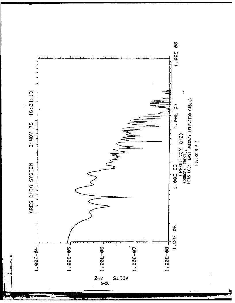
5-5-3 Fourier Transform of Figure 5-5-2 ------ --- 5-20
3
[Imn>nu.nnlnnm~m m unlNI l..

1. INTRODUCTION:
In a September 1979 message, HQDNA expressed concern over potential
electromagnetic interaction between the Advanced Research Electromagne-
tic Pulse Simulator (ARES) and TRESTLE EMP facilities. In a subsequent
message, HQAFSC Andrews AFB, MD extended this concern to include all
EMP facilities located at Kirtland Air Force Base, New Mexico.
There are four major EMP facilities that are of interest in this
potential interaction. Three are under the control of the Air Force
Weapons Lab (AFWL) and one is under the control of the Field Command,
Defense Nuclear Agency (FCDNA). The AFWL facilities are the Horizontally
Polarized Dipole (HPD), Vertically Polarized Dipole (VPD), and TRESTLE.
The FCDNA facility is the ARES. These four facilities are constructed
within a close proximity of one another (see figure one), thus generat-
ing a possible interaction in the far field. The TRESTLE and ARES
facilities are bounded wave simulators and the HPD and VPD are radiat-
ing simulators. Each facility was designed to do a specific job by
producing horizontally or vertically polarized E fields. TRESTLE
and HPD are horizontally polarized, and the ARES and VPD are vertically
polarized. Within design limitations, these facilities produce E
field strengths up to 100 Kilovolts per meter (KV/m). Each simulator,
bounded or not, radiates outward from its own source. These outward
radiations could potentially cause several problems.
a) Personnel Safety Hazards.
b) Test Object Degradations.
4, 1-1

c) Introduction of false triggers in test instrumentation.
d) Generation of unusable EMP environments.
e) Introduction of false data records.
f) Test support equipment damage or upsets.
Beginning the second week of October 1979, FCDNA personnel began an
extensive investigation into the EMP facility interaction. The objectives
of the investigation were to determine:
a) Is there an EMP interaction problem?
b) What is the extent of the interaction?
c) What is the potential impact on test operations?
d) What corrective actions are needed?
This report discusses FCDNA findings, corrective actions, and makes
recommendations for potential ARES users.
1-2

EMP FACILITIES LOCATION
/~I~7" . rt120
-.- ,~-'- - / /160
- -±--~ . .. -~200
K ~ / /280
'K,".~:(i~' ,' 'AA~- ( /1 ~ -320
i-Il Nv.~-'400
~ ~j'c' ______ V480
Z-1\ 560
- -.-- 7 z-~-600
* ... ~N ~ .\640
/ ~\ 720
N 760
'~' L 800840880
j;7 920
<A> \/->1040
FIGURE 1-1
1-3

2. SAFETY:
The question of safety in a simulated High Altitude EMP (HEMP)
test environment is an area where very little information is avail-
able. Most documentation deals with standardized safety procedures
associated with accomplishment of the daily workload. Only a small
amount of information is available that attempts to directly relate
unique Electromagnetic Pulse (EMP) hazards to the propagating Electro-
magnetic (EM) field. One very good reference is AF regulation 161-42
dated 7 November 1975 and titled "Radio-frequency Radiatlon Health
Hazards Control." This documentdefines the acceptable E field level
for personnel exposure as less than or equal to 100 KV/m and describes
the most probable hazard as "Startle hazard due to a reflex response."
Standard safety procedures will minimize the startle hazard.
Standard safety procedures include but are not necessarily limited to:
a) No personnel are permitted inside of the working volume during
pulser operations.
b) Working volume is monitored by closed circuit television.
c) Safety railings are installed at all levels of the isolation
support stand (ISS).
Although the above precedures work well for control of personnel during
local pulser operations, it does not prevent the possibility of person-
nel being present at the time that EMI from another facility arrives.
These personnel could be reconfiguring the test object for the next
series of test points. It is during this time that personnel are the
2-1
NUN

most vulnerable and is the reason for making the measurements shown
in Table 2-1 and graphically displayed in Figures 2-2, 2-3, 2-4, and
2-5. The currents shown are peak values.
FigLre 2-1 illustrates the configuration used for measuring the
current flow between a missile umbilical cable and the metallic por-
tion of the missile skin. Provisions were made for grounding the Zipper
Tubing containing the umbilical cable, and the missile skin. The symbol
®represents a Tektronix 485 oscilloscope and isolation box used to
photograph the current waveform. R was varied from 0-lOOK ohms and
current measurements were made. Existing conditions and measured
results are displayed in Table 2-1.
Although the amount of data is limited, there is sufficient data
for a simple determination of the potential hazard. The following
criteria were used to analyze the data:
a) Data discussed in section five of this report indicates that
the EMI levels at ARES from other facilities are 1 KV/m or less with 1.5
KV/m as worst case if TRESTLE is operated at 100%.
b) Measurements at 250 V/m are related to 1.5 KV/m by the factor
1500/250 = 6.
c) A typical resistance for the human body is 1 KA- 1 Mxa.
d) Minimum lethal current for a human being is 1/10 amp flowing
through the heart for 1 second at a frequency of 60 hz. (References 1,
2, 3, and 4 of this section verify (c) and (d), see figure 2-6).
e) A typical pulse duration is .7 micro-second.
2-2
L . .. ..A

f) R may represent the human body if personnel were to place them-
selves between the umbilical cable, etc and the missile.
g) Curve number 1 of Figure 2-5 and Figure 2-2 are worst case.
COMPUTATION OF ENERGY LETHAL TO HUMAN BEINGS
EnergylK (U) = 12 R t (2-1)
= (.l)2(lO00)(1) Joules (J)
= (.Ol)(lo) = 10 0
Lethal range of energies for current flow through the human heart is 10
Joules or more
COMPUTATION OF ENERGY FOR CRITERIA f OF THIS SECTION
The current waveform of the ARES is a double exponential of the
form:
i(t) = A(e-'t- e" ) (2-2)
where:
A amplitude (amps)
2.3/t decay
2.3/trise
tdecay =700ns
trise 5ns
If the rms value of current is computed using the following:
IRMS =e e(Ote'Bt)2dt (2-3)
where:
T = trise + tdecay
k 2-3
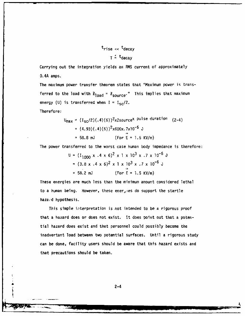
trise << tdecay
T tdecay
Carrying out the integration yields an RMS current of approximately
O.4A amps.
The maximum power transfer theorem states that "Maximum power is trans-
ferred to the load with Zload = Zsource" This implies that maximum
energy (U) is transferred when I = Isc/2.
Therefore:
Umax (Isc/2)(.4)(6))2xZsourcex pulse duration (2-4)
- (4.93)(.4)(6))2x6Dx.7xlO -6 j
- 58.8 m (For E = 1.5 KV/m)
The power transferred to the worst case human body impedance is therefore:
U = (Ilo00 x .4 x 6)2 x l x l03 x .7 x 10-6 j
= (3.8 x .4 x 6)2 x 1 x lO3 x .7 x 10-6 J
= 58.2 mJ (For E = 1.5 KV/m)
These energies are much less than the minimum amount considered lethal
to a human being. However, these energies do support the startle
haza,'d hypothesis.
This simple iterpretation is not intended to be a rigorous proof
that a hazard does or does not exist. It does point out that a poten-
tial hazard does exist and that personnel could possibly become the
inadvertant load between two potential surfaces. Until a rigorous study
can be done, facility users should be aware that this hazard exists and
that precautions should be taken.
2-4
!*

SAFETY CURRENT MEASUREMENT CONFIGURATION
E
UMBILICAL
/s
ARSGON LN
FIUE/-
2-
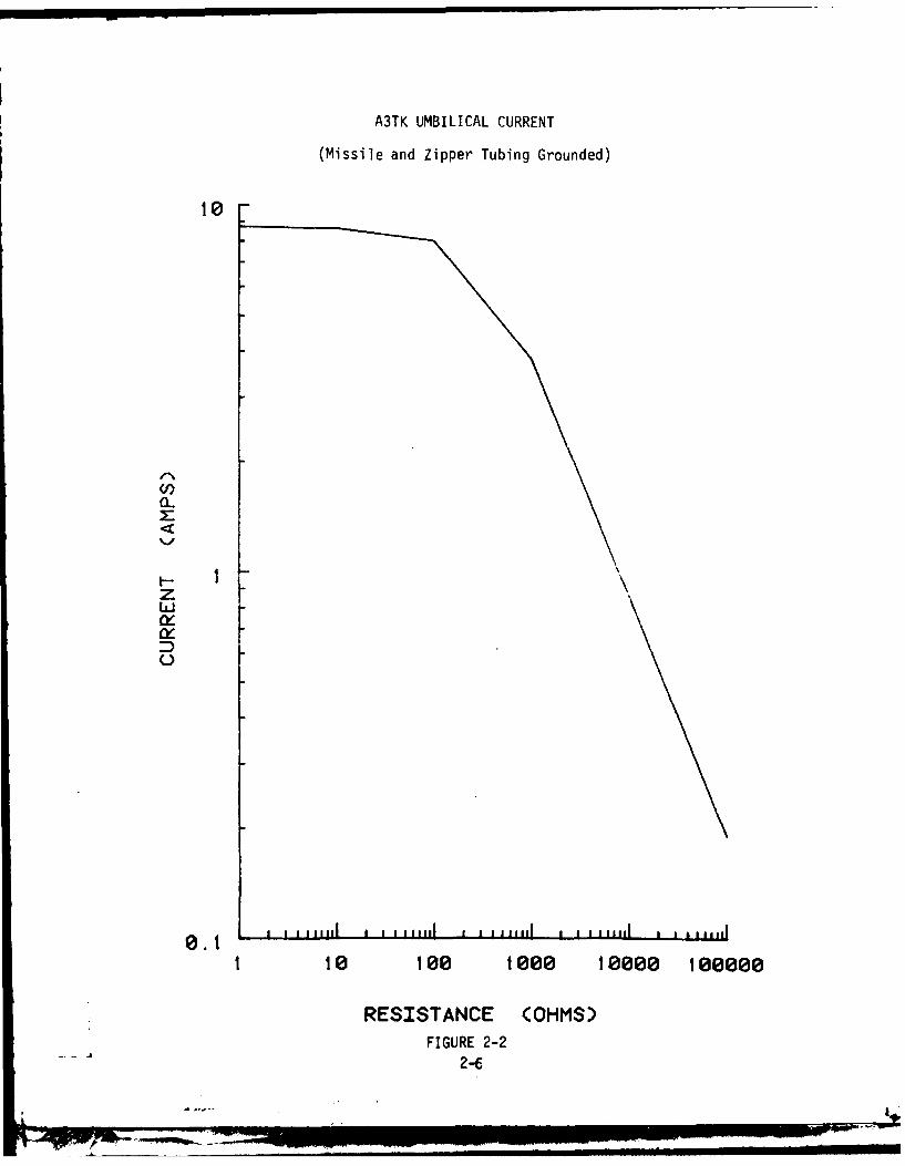
A3TK UMBILICAL CURRENT
(Missile and Zipper Tubing Grounded)
I-
z
0.1t110 100 1000 10000 100000
RESISTANCE (OHMS)FIGURE 2-2
4 2-6

A3TK UMBILICAL CURRENT
(Missile Grounded: Zipper Tubing Ungrounded)
10
0-
z
0 .1
1 too 1000 100e teeeoe
RESISTANCE (OHMS)FIGURE 2-3
2-7
K . _ __= ,... ... . _. . _ . ... _ .....

A3TK UMBILICAL CURRENT
(Missile and Zipper Tubing Ungrounded)
00
z
ixD
1 10 100 1000 10000 100008
RESISTANCE (OHMS)* FIGURE 2-4
2-8

A3TK UMBILICAL CURRENT
(COMPOSITE)
10 -
Z2
0-
3
z
0.1 1 mi i a i 11th m i i i i d 1111 a ,,Ii
1 10 too 1e0 100e 0 100000
RESISTANCE (OHMS)FIGURE 2-5
2-9
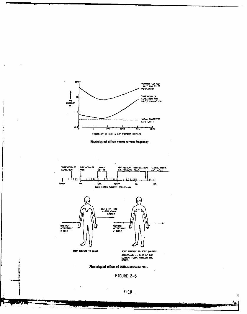
too- "CANNDT LET GO'LIMIT FOR "9.5%POPULAT ION
THRSOLDOFoSENSATION FOR99.5$ POPULATION
- -- -- --- -- - - -- -- - - 3OOvA SUSGESTEDSAFE LIMIT
FREQUECY or AM4-TO-AIp4 CURRENT (HERTZ)
PhySiOlO~icaI effects versus current frequency.
TRSHLD OF THRlESHOLD OF CANNOT VENIRICULAR FIDRILLATION SEVERE BURISSNTON PAIN LET GO AND PROLIAIL AT A1
SOOV A IOM O~MA IA IOA6014z SHOCK CURRENT Aft4.TO-AM
ACCEPABLEACCEPTABLEISVA A a300PA
OW~ SWRACE TO WEART BODY SNmAC TO BODY SURFACEAA-TO-ARM -- PART OF THECURRNT F'LOWS 110OUH THE
?hysoloical effects of 60H1z electric current.4 FIGURE 2-6
2-10

TABLE 2-1
Safety Current Measurements(E = 250 V/m)
MEASUREMENT R (p) SINGER PROBE I (Peak amps) f,(MHz)
(1) Missile and Zipper Tubing Grounded
Isc 0 94430-2 9.86 4.5
I10 10 94430-2 8.62 4.0
,100 100 94430-2 8.0 3.7
11000 1000 94430-2 3.8 3.08
I]OOK 100,000 94430-2 0.19 2.597
(2) Missile Grounded; Zipper Tubing Ungrounded
Isc 0 93686-4m 7.65
,100 100 94430-2 5.1 3.1-3.7
11000 1000 94430-2 2.0 4.24
(3) Missile and Zipper Tubing Ungrounded
Isc 0 93686-4m 8.33 2.1
l100 100 94430-2 5.3 2.1
1000 1000 94430-2 1.08 2.17
(4) Missile Ungrounded; Zipper Tubing Grounded
Io0 100 94430-2 10.6 2.66
2-11

3. INSTRUMENTATION AND TEST OBJECT IMPACT:
The data collected and discussed in section 5 indicate that there
is interaction, but that there are no fields present that are of buf-
ficient strength to influence the test object in any manner that would
degrade test data or test object performance.
During the fielding of two EMP hardening verification tests conduct-
ed during FY 78, 79, and 80, there were no documented or observed false
trigger pulses in the instrumentation system. However, based on a
correlation of TRESTLE and ARES pulser logs, there were several high
voltage pulser (EMP-45) pre-fires that were attributed to TRESTLE induced
environments. These pre-fires have in no way degraded test performance.
Concern has been expressed that simultaneous firings of any two of
the simulators mentioned would generate unusable environmental data.
This concern should be dismissed as inconsequential. Two observations
are used to validate this recommendation:
a) A simultaneous application of dual EMP environments would require
sub-microsecond timing between the two facilities and is therefore
highly improbable. If this does happen, the data could be viewed as
test object response to a multiple-source EMP environment.
b) The test object EMP environment is recorded on each shot. This
means that a test object response to a known recorded environment has
been obtained.
There is also, some concern over possible generation of false data
records. Previous testing at ARES has shown absolutely that no false
,3- IL __ _ _3-1
. _ . ....- _ ... ._ ..

data records have been generated. This is directly attributable to the
fact that the ARES data system is protected against the ARES simulator
environment and any reflected signals.
3-2

4. TEST SUPPORT EQUIPMENT IMPACT:
Experience with the A3TK test at the ARES (FY79-80) has shown that
some user furnished test support equipment could be sensitive to spuri-
ous signals induced inside of the Data Acquisition Control Complex (DACC)
as a result of reradiation from umbilicals, drop cords, or power cords
that extend into the working volume at the time an EMI pulse arrives.
These cords are not present during ARES pulse application. Data gathered
show that these inadvertant antennas are the major source of interaction
problems between the EMP facilities. The multitude of jobs that must
be accomplished prior to actual ARES pulser firing make inadvertant
antenna configuration control necessary. These inadvertant antennas
are necessary for the pre-pulse system configuration changes. However,
the post pulse test equipment configuration may require fewer conducting
lines for data extraction from the test object. This is the most criti-
cal time that an extraneous field must not be applied if unprotected
conductors are exposed to the EMP field. During this time period, data
could be lost if the support equipment is upset.
The A3TK test conducted at ARES had some specific pieces of test
support equipment, located in the DACC, but external to the permanent
screen room, that are sensitive to the fields and signals described in
section 5 of this report. The specific descriptions of these equipments
are irrelevant. It is sufficient to know that equipment external to the
screen room may need protection from low-level EMP fields and that data
links from the test object may need protection during the post-ARES
4-1
pulse configuration. The ARES EMP-45 pulser, at maximum output, gener-
ates a free field of approximately 500 V/m within the DACC. Information
contained in this report can be used by a potential user to determine
whether user furnished equipment is in need of additional protection.
The following fixes have been installed at ARES by FCDNA specifically
for the A3TK test support equipment, however, these fixes are applicable
to any test conducted at ARES:
a) Capacitor filters have been installed at power outlets inside
of the DACC.
b) Zipper tubing has been installed so as to shield the umbilical
cables extended from the unprotected DACC into the working volume.
c) A portable screen room has been installed in the DACC and sensi-
tive equipments have been placed inside.
The following coordination techniques have been used to good advan-
tage in coordinating time slots in a standard workday between ARES,
VPD, TRESTLE, and HPD when quiet times are needed by either:
a) Telephone contact is maintained throughout pulser operations.
b) Radio net contact is maintained using hand held radios.
c) Personal contact has resulted in a good working rapport and
arrangment of the few quiet times needed during the A3TK test.
There are two additional fixes that can still be done to increase
ARES hardness to EMP:
a) Place three-phase filters in the main power distribution.
b) Place the environment trigger on a lockout circuit if it be-
comes necessary. However, there is presently no need for this simple
fix.
4-2L.I
-. ...
5. DATA
Although a large volume of data has been gathered, only eight sets
are presented here. These eight sets are typical, demonstrate that
there is a potential interaction problem, and show that the potential
problems have been minimized. The entire volume of data is available
upon request to FCDNA, attention FCTMS.
Figures 5-1 and 5-1-1 are the time and frequency domain plots of
the TRESTLE waveform that is present in the center of the ARES working
volume on the ground plane. The TRESTLE reference sensor measured an
E field of 86 KV/m. The measurement was made using an MGL-l B sensor.
A peak field strength of 1 KV/m is observed. Obviously, there is some
interaction from TRESTLE into ARES.
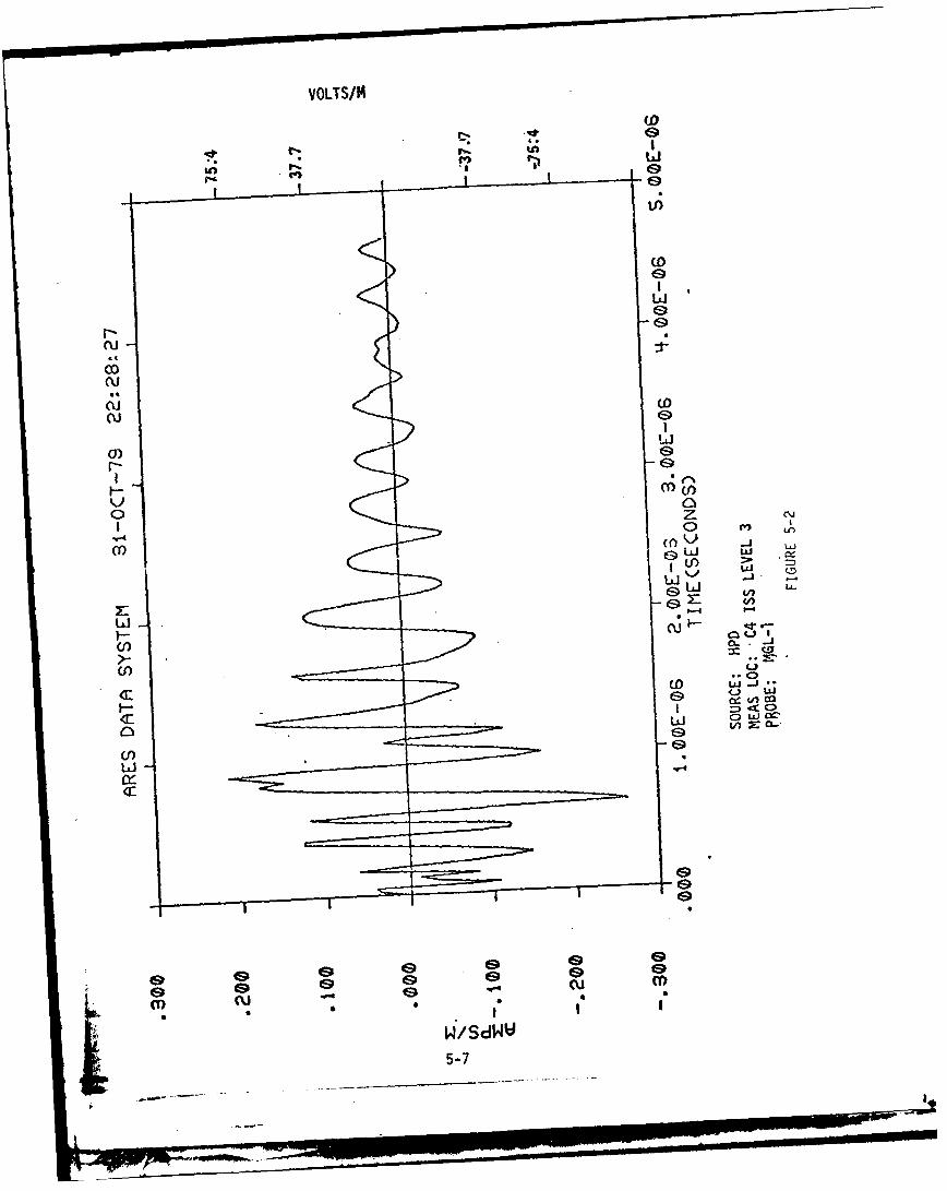
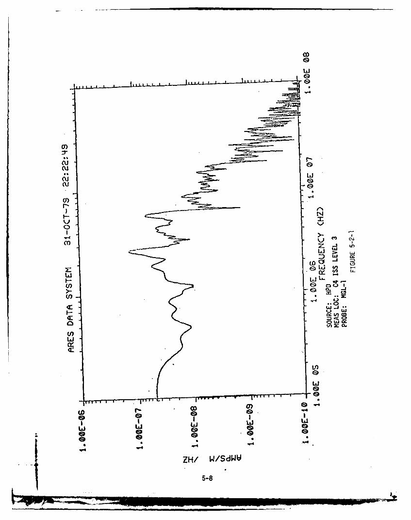
Figures 5-2 and 5-2-1 are the time and frequency domain plots of
the HPD waveform located approximately 30 feet above the ARES ground
plane at test object position. This measurement was also taken with
the MGL-l 1 sensor. A peak field strength of approximately 100 V/m is
observed adjacent to the ARES test object. There is some interaction
from HPD into ARES, however, it is very low level and has proven to
be inconsequential.
Figures 5-3, 5-3-1, 5-3-2, and 5-3-3 are time and frequency domain
plots of measurements made to determine the effectiveness of shielding
the missile umbilical cables and then grounding the shielding to the
ARES ground plane. These measurements were made using a Singer 93686-
4m current sensor. The measurements were made by inserting the umbili-
cal and zipper tubing through the sensor and measuring the current flow
5-1
AL7

first with the zipper tubing ungrounded and second with the zipper
tubing attached to the ARES ground plane. The TRESTLE pulsers were
charged to 3.5 MV each during this measurement. A marked decrease in
current amplitude was observed after the zipper tubing was grounded.
This demonstrates an extremely effective method of shunting unwanted
currents away from ARES test objects. Two dominant frequencies of
3.0 and 10.0 MHz are observed in figures 5-3-1 and 5-3-3. The corres-
ponding wavelengths are lOOm and 29.7m. These wavelengths approximate
closely four times the length-of the umbilical cable when it is un-
grounded and then grounded. The conclusion drawn from this information
is that the umbilical cable is acting as a quarter wavelength antenna
and coupling energy from sources external to ARES into the ARES test
object and equipment and that this effect can be minimized by using an
effective shielding technique.
Figures 5-4, 5-4-1, 5-4-2, and 5-4-3 illustrate that energy is
coupled into the ARES DACC when TRESTLE is pulsed. The TRESTLE pulsers
were charged to 4 MV each for this data set. Figure 5-4 shows the
TRESTLE waveform observed in the ARES DACC and measured at the north
wall ac outlets. A peak voltage of approximately 75 volts is observed.
Figure 5-4-2 illustrates the effectiveness of placing capacitor filters
at the wall outlets. Capacitors with a value of 0.1 microfarads and
a peak voltage rating of 1000 volts were used to filter the spurious
voltages. A maximum peak of approximately 6 volts was observed after
placement of the filters. This simple method can be used to harden
test site power distribution systems against spurous signals from other
5-2

facilities. Equipment upsets after filtering were minimal. The domin-
ant frequencies in figures 5-4-1 and 5-4-3 have wavelengths that approxi-
mate four times the distance between the commerical power line poles at
the facility.
Figures 5-5, 5-5-1, 5-5-2, and 5-5-3 demonstrate that power cords
of other types of cables that extend into the ARES working volume dur-
ing TRESTLE pulser discharge furnish another point of entry of EMI into
the ARES DACC and test support equipment. These cords are not present
during ARES pulser discharge but are essential for test object recon-
figuration and may be present during pulser operations at other facilities.
These cords could cause equipment upsets by passing spurious signals
through the power lines or by reradiation of EMI into the DACC. Dominant
frequencies approximate four times the length of the heater and drop
cords. This data set was taken with 1 trestle pulser charge to 4 MV.
Calculation., show that VPD levels approximate those of TRESTLE.
For an approximation of VPD levels in ARES, consider the following:V
E = K - (5-1)
V is the VPD pulser charge voltage, measured in volts. R is the distance
from the VPD pulser to the ARES test object. K is an experimentally
determined, dimensionless constant based on previous VPD mapping data
and is equal to 0.36.
Considering the maximum charge voltage on VPD as 1.6 x 10⁶ volts,
the E field in the ARES working volume would be:
-* .36 x 1.6 x 106 VE ~ 2
7.6 x 10 m
t 5-3
7on P. -'

7.58 x 10² V/m
758 V/m
This approximation is a line of sight (LOS) approximation. It must be
understood that the ARES working volume and test object are below LOS.
This could attenuate VPD EMI even more. Measured TRESTLE levels thus
far in the ARES working volume have a peak value of 1000 V/m.
Data has been collected and calculations have been verified. This
data is available upon request.
5-4
i)

VOLTS/M
0 (0D
II-
gLJJ
a_ I__ _ _ _L
((U
C' U
ILI WIAJ
cn a.
0)w
f-.dw5- .5

cco
Cu-
(U-
to cc L A
cLLJ Cz I
rL cnoe a _ .W -L
LULL Lu
=:) < CDa- LU0
I-0LJ
U)
Lii
5-6e
(NN
VOLTS/M
cqo
. I.ODi
or))
kii
cu CD
0)U)
w -1 U-
In
CD ()LJI-cr V) ofca
4: oUl u*
WCo
oNow
0)
cu(U
0)N
:3 w
-4j
CD0 0rw
Li t c= -C cDuS c
W~-
ww
COD
GG
99 1Li Li LLI iL
ZH/ W/SdWU
5-8

co
0JLIs
z 4m
CD -
() r '41E
a-i
(0U
F--

LLImajes a 2 1131 1 1 1 A111 I 111
r- C
> CZ
I CO
Lzj
o3 N oL
- L0 0 Lf-
wD -
L)(-
I- LL
CC zn ca-
0 G,
C9
ZLU Sd.J *
C,) c5-1w

0(
U) C a
U) C) dG CD
ciC)LI-
0 5~zW
(--
ILLJ
LAJ
wA C.3
LiU
SdWV
-777 a

LI)d
U/)
> C =
z ILw
F- M
L-)
UJ)
u UAw~L cc. tnC
P-: ODd 0
I II SdWIId Id U 5U12

(D
Z i
L/)U
W C
:1--
w wo
LOi
I* W-

LiJA... 1 2., 1. 1 1~ L- *
:1-9
* w
LLI
zz
w
L j LALLjJ
I-c
OC-
w 'nF- 0
LCJO
C c a
U)U)
LiL
ft I Iu I I& IIII
Li ow LiLIL
5-1LI-Ail

U')
LI) U
Cu-
w WUr-
(-J
oQ c<zdcc le
C> i
Si'10A

cuo
LI)I
(LU
w ( -D
0) L) '-
F- ( -I IL LJ
Cu 'h-, -
LiA
H G1 'OD
(I) Q:U LL
ZHL/a SIIO
U) 5_16

LfJ
-j(U
LI))
U) LO
E0l LJ
41 C])
(10 u
U)U
ow
(U U)
S110A~
P-7-

Liip p p p lip I p p p p I IPI I I t i~ el p t t 1
Li~
U))
Z < LA~
Ld In
(3) 4-
CC
LI; C
w V c
C)-G 0
Lfl (0 C
LLJ L L Li Li
ZH/ SIIQA
5-18

(D a
-3
I-- (L
< C
0 c
U IpLa LO
Z- F- to
ZLn
CD
(D C-) LA
W C) uJ 0L,
L *C a JU) I ~ OLii
La I La "u
S-L'10
5-19
co
LJ
ClC)
i0'
.5-4 LA
k-) -LIJ
U")
ztJLL
L&JCO E) Ld
F-4
LiI
LA
U) (0
iLi Lai L) Li
ZH/ S.L1OA5-20

6. SUMMARY, CONCLUSIONS, AND RECOMMENDATIONS:
SUMMARY:
Data presented in this report confirms that some facility EMP
interaction does take place. However, the interaction of other facili-
ties with ARES is minimal and can be readily remedied. Three major
points of entry (POE) have been defined and appropriate steps have
been taken to minimize any problems. The three POEs are:
a) Commerical Power Lines
b) Umbilical Cables
c) Heater and Drops Cords
These POEs can be and have been EMP hardened by placement of filters
and shielding described in section four of this report. If quiet times
are needed by either facility, they need only minimal coordination.
CONCLUSIONS:
- Standard safety procedures and coordination techniques employed
at all facilities can eliminate any personnel safety problems.
- Inadvertant antennas act as quarter wavelength antennas to
couple EMI into the ARES DACC.
- Mutually exclusive operation of the involved facilities is
not required.
- Tests can be conducted in ARES independent of ongoing tests
in other facilities.
RECOMMENDATIONS:
- Potential ARES users develop a conscientious program of con-
figuration control over inadvertant antennas.
6-1

- Potential ARES users place added protection devices at the
input to equipment identified as sensitive to the EMP levels described
in this report.
- Potential ARES users provide shielding for all inadvertent
antennas in or near the ARES working volume.
- FCDNA coordinate quiet times as necessary to eliminate equip-
ment problems described in section four of this report.
6-2 £

REFERENCES
1) Bruner, "Hazards of Electrical Apparatus," Anesthesiology, Mar-Apr 1967.
2) Cromwell/Weibell/Pfeiffer/Usselman," Biomedical Instrumentationand Measurements," Prentice Hall, 1973
3) Strong, "Biophysical Measurements," Tektronix, Inc., 1970.
4) Thomas, "Handbook of Biomedical Instrumentation and Measurements,"Reston Publishing Company Inc., 1974
7-1
I-7-! . .... .. ~ .. 7
! lm -lnm . ....

DISTRIBUTION LIST
DEPARTMENT OF DEFENSE
Defense Nuclear AgencyATTN: DDSTATTN: ADDST(EXP RESEARCH)ATTN: RAEV
4cy ATTN: TITLATTN: STRA
FIELD COMMANDDefense Nuclear Agency
ATTN: FCT20cyATTN: FCTMS4cy ATTN: FCTMD
ATTN: FCPRATTN: FCTMOF
Defense Documentation Center2cy ATTN: DD
DEPARTMENT OF THE AIR FORCE
2cy ATTN: AFWL(NTMSE)
DEPARTMENT OF THE NAVY2cy ATTN: SSPO(SP 27334)
DEPARTMENT OF DEFENSE CONTRACTORS
Lockheed Missile and Space Company,INCATTN: C4 Program OfficeATTN: A3 Program Office
Di st:-

Related Documents


![saMpadkIya - VIZAG STEEL saMpadkIya Aba 12 A@tUbar 2014 ka idna ivaSaaKp+Nama Sahr AaOr ]sako inavaaisayaaoM ko ilae AivasmaNaIya idna bana gayaa hOÊ @yaaoMik ]sa idna yah ivahÐsata](https://static.cupdf.com/doc/110x72/5b0685cb7f8b9ac33f8ceeba/sampadkiya-vizag-sampadkiya-aba-12-atubar-2014-ka-idna-ivasaakpnama-sahr-aaor.jpg)