ideacentre All-In-One 510 Computer Hardware Maintenance Manual Machine Types: FOCB[AIO 510 22-ISH/Energy Star]/FOCC[AIO 510 22-ASR/Energy Star]/FOCD[AIO 510 23-ISH/Energy Star]/FOCE[AIO 510 23-ASR/Energy Star]

Welcome message from author
This document is posted to help you gain knowledge. Please leave a comment to let me know what you think about it! Share it to your friends and learn new things together.
Transcript
ideacentre All-In-One 510 Computer HardwareMaintenance Manual
Machine Types: FOCB[AIO 510 22-ISH/Energy Star]/FOCC[AIO 51022-ASR/Energy Star]/FOCD[AIO 510 23-ISH/Energy Star]/FOCE[AIO510 23-ASR/Energy Star]

ideacentre All-In-One 510 ComputerHardware Maintenance Manual
Machine Types: FOCB[AIO 510 22-ISH/Energy Star]/FOCC[AIO 51022-ASR/Energy Star]/FOCD[AIO 510 23-ISH/Energy Star]/FOCE[AIO510 23-ASR/Energy Star]

First Edition (July 2016)14th
© Copyright Lenovo 2016.
LIMITED AND RESTRICTED RIGHTS NOTICE: If data or software are delivered pursuant a General ServicesAdministration “GSA” contract, use, reproduction, or disclosure is subject to restrictions set forth in Contract No.GS-35F-05925
Contents
Chapter 1. About this manual . . . . . 1Important Safety Information . . . . . . . . . 1
Chapter 2. Safety information. . . . . 3General safety . . . . . . . . . . . . . . . 3Electrical safety . . . . . . . . . . . . . . 3Safety inspection guide . . . . . . . . . . . 5Handling electrostatic discharge-sensitivedevices . . . . . . . . . . . . . . . . . 5Grounding requirements . . . . . . . . . . . 6Safety notices . . . . . . . . . . . . . . . 6
Chapter 3. General information . . . . 9Specifications . . . . . . . . . . . . . . . 9
Chapter 4. General Checkout . . . . . 11
Chapter 5. Using the Setup Utility. . . 13Starting the Lenovo BIOS Setup Utility program . 13Viewing and changing settings . . . . . . . . 13Using passwords. . . . . . . . . . . . . . 13Enabling or disabling a device . . . . . . . . 15Selecting a startup device . . . . . . . . . . 16Exiting the Lenovo BIOS Setup Utility program . . 17
Chapter 6. Symptom-to-FRU Index . . 19Hard disk drive boot error . . . . . . . . . . 19Power Supply Problems . . . . . . . . . . . 19POST error codes . . . . . . . . . . . . . 20Undetermined problems . . . . . . . . . . . 20
Chapter 7. Locating connectors,controls and components . . . . . . 21
Chapter 8. Replacing hardware . . . . 27General information. . . . . . . . . . . . . 27Replacing the keyboard and mouse . . . . . . 28Replacing the adapter . . . . . . . . . . . . 28Removing the stand base . . . . . . . . . . 29Removing the rear cover . . . . . . . . . . . 29Replacing the hard disk drive . . . . . . . . . 30Replacing the optical drive . . . . . . . . . . 31Replacing the memory module . . . . . . . . 33Replacing the solid state drive . . . . . . . . 34Removing the stand holder . . . . . . . . . . 35Replacing the power switch board . . . . . . . 36Removing the middle cover . . . . . . . . . 37Removing the EMI cover . . . . . . . . . . . 39Replacing the LCD panel module . . . . . . . 40Replacing the Wi-Fi card. . . . . . . . . . . 43Replacing the system fan . . . . . . . . . . 44Replacing the heat-sink . . . . . . . . . . . 45Replacing the motherboard. . . . . . . . . . 47Replacing the speaker system . . . . . . . . 48Replacing the camera . . . . . . . . . . . . 50
Chapter 9. FRU lists . . . . . . . . . . 53
Chapter 10. General information . . . 87Additional Service Information . . . . . . . . 87
© Copyright Lenovo 2016 iii

iv ideacentre All-In-One 510 Computer Hardware Maintenance Manual

Chapter 1. About this manual
This manual contains service and reference information for Lenovo All-In-One 510 series computers listed onthe cover. It is intended only for trained servicers who are familiar with Lenovo computer products.
Before servicing a Lenovo product, be sure to read the Safety Information.
The description of the TV-tuner card in this manual applies only to computers with a TV-tuner card installed.It does not apply to computers without a TV-tuner card.
Important Safety InformationBe sure to read all CAUTION and DANGER sections in this manual before following any of the instructions.
Veuillez lire toutes les consignes de type DANGER et ATTENTION du présent document avant d’exécuterles instructions.
Lesen Sie unbedingt alle Hinweise vom Typ “ACHTUNG” oder “VORSICHT” in dieser Dokumentation, bevorSie irgendwelche Vorgänge durchführen
Leggere le istruzioni introdotte da ATTENZIONE e PERICOLO presenti nel manuale prima di eseguire unaqualsiasi delle istruzioni
Certifique-se de ler todas as instruções de cuidado e perigo neste manual antes de executar qualqueruma das instruções
Es importante que lea todas las declaraciones de precaución y de peligro de este manual antes de seguirlas instrucciones.
© Copyright Lenovo 2016 1

2 ideacentre All-In-One 510 Computer Hardware Maintenance Manual

Chapter 2. Safety information
This chapter contains the safety information that you need to be familiar with before servicing a computer.
General safetyFollow these rules to ensure general safety:
• Keep the areas around the computer clear and clean during and after maintenance.
• When lifting any heavy object:
1. Ensure you can stand safely without slipping.
2. Distribute the weight of the object equally across both feet.
3. Lift slowly. Never move suddenly or twist when you attempt to lift.
4. Lift by standing or by pushing up with your leg muscles; this action removes the strain from themuscles in your back.Do not attempt to lift any objects that weigh more than 16 kg (35 lb) or objects that you think aretoo heavy for you.
• Do not perform any action that would create a hazard for the customer, or would make the computerunsafe.
• Before you start the computer, ensure that other service representatives and customer personnel are notin a position that would create a hazard for them.
• Place removed covers and other parts in a safe place, away from all personnel, while you are servicing thecomputer.
• Keep your tool case away from areas that people may walk through to ensure no-one trips over it.
• Do not wear loose clothing that can be trapped in the moving parts of a machine. Ensure that your sleevesare fastened or rolled up above your elbows. If your hair is long, tie or fasten it back.
• Insert the ends of your necktie or scarf inside clothing or fasten it with a non-conductive clip,approximately 8 centimeters (3 inches) from the end.
• Do not wear jewelry, chains, metal-frame eyeglasses, or metal fasteners for your clothing.Remember: Metal objects are good electrical conductors.
• Wear safety glasses when you are: hammering, drilling soldering, cutting wire, attaching springs, usingsolvents, or working in any other conditions that might be hazardous to your eyes.
• After service, reinstall all safety shields, guards, labels, and ground wires. Replace any safety devicethat is worn or defective.
• Reattach all covers correctly before returning the computer to the customer.
Electrical safety
CAUTION:Electrical current from power, telephone, and communication cables can be hazardous. To avoidpersonal injury or equipment damage, disconnect any attached power cords, telecommunicationcables, network cables, and modem cables before you open the computer covers, unless instructedotherwise in the installation and configuration procedures.
© Copyright Lenovo 2016 3

Observe the following rules when working on electrical equipment.
Important: Use only approved tools and test equipment. Some hand tools have handles covered with a softmaterial that does not insulate you when working with live electrical currents. Many customers have rubberfloor mats near their equipment that contain small conductive fibers to decrease electrostatic discharge.
• Find the room emergency power-off (EPO) switch, disconnecting switch, or electrical outlet. If an electricalaccident occurs, you can then operate the switch or unplug the power cord quickly.
• Do not work alone under hazardous conditions or near equipment that has hazardous voltages.
• Disconnect all power before:
– Performing a mechanical inspection
– Working near power supplies
– Removing or installing Field Replaceable Units (FRUs)
• Before you start to work on the computer, unplug the power cord. If you cannot unplug it, ask thecustomer to power-off the electrical outlet that supplies power to the machine and to lock the electricaloutlet in the off position.
• If you need to work on a computer that has exposed electrical circuits, observe the following precautions:
– Ensure that another person, familiar with the power-off controls, is near you.Remember: Another person must be there to switch off the power, if necessary.
– Use only one hand when working with powered-on electrical equipment; keep the other hand in yourpocket or behind your back.Remember: There must be a complete circuit to cause electrical shock. By observing the above rule,you may prevent a current from passing through your body.
– When using a tester, set the controls correctly and use the approved probe leads and accessories forthat tester.
– Stand on suitable rubber mats (obtained locally, if necessary) to insulate you from grounds such asmetal floor strips and machine frames.
Observe the special safety precautions when you work with very high voltages; these instructions are inthe safety sections of the maintenance information. Use extreme care when measuring high voltages.
• Regularly inspect and maintain your electrical hand tools to ensure they are safe to use.
• Do not use worn or broken tools and testers.
• Never assume that power has been disconnected from a circuit. First, check that it has been powered off.
• Always look carefully for possible hazards in your work area. Examples of these hazards are wet floors,non-grounded power extension cables, conditions that may cause or allow power surges, and missingsafety grounds.
• Do not touch live electrical circuits with the reflective surface of a plastic dental mirror. This surface isconductive, and touching a live circuit can cause personal injury and damage to the computer.
• Do not service the following parts with the power on when they are removed from their normal operatingpositions in a computer:
– Power supply units
– Pumps
– Blowers and fans
– Motor generators
and similar units. (This practice ensures correct grounding of the units.)
• If an electrical accident occurs:
– Use caution; do not become a victim yourself.
4 ideacentre All-In-One 510 Computer Hardware Maintenance Manual

– Switch off power.
– Send another person to get medical aid.
Safety inspection guideThe intent of this inspection guide is to assist you in identifying potential hazards posed by these products.Each computer, as it was designed and built, had required safety items installed to protect users andservice personnel from injury. This guide addresses only those items. However, good judgment should beused to identify potential safety hazards due to attachment of features or options not covered by thisinspection guide.
If any hazards are present, you must determine how serious the apparent hazard could be and whether youcan continue without first resolving the problem.
Consider the following items and the safety hazards they present:
• Electrical hazards, especially primary power (primary voltage on the frame can cause serious or fatalelectrical shock).
• Explosive hazards, such as a damaged CRT face or bulging capacitor
• Mechanical hazards, such as loose or missing hardware
The guide consists of a series of steps presented as a checklist. Begin the checks with the power off, andthe power cord disconnected.
Checklist:
1. Check exterior covers for damage (loose, broken, or sharp edges).
2. Power-off the computer. Disconnect the power cord.
3. Check the power cord for:
a. A third-wire ground connector in good condition. Use a meter to measure third-wire groundcontinuity for 0.1 ohm or less between the external ground pin and frame ground.
b. The power cord should be the appropriate type as specified in the parts listings.
c. Insulation must not be frayed or worn.
4. Remove the cover.
5. Check for any obvious alterations. Use good judgment as to the safety of any alterations.
6. Check inside the unit for any obvious hazards, such as metal filings, contamination, water or otherliquids, or signs of fire or smoke damage.
7. Check for worn, frayed, or pinched cables.
8. Check that the power-supply cover fasteners (screws or rivets) have not been removed or tampered with.
Handling electrostatic discharge-sensitive devicesAny computer part containing transistors or integrated circuits (ICs) should be considered sensitive toelectrostatic discharge (ESD). ESD damage can occur when there is a difference in charge between objects.Protect against ESD damage by equalizing the charge so that the computer, the part, the work mat, and theperson handling the part are all at the same charge.
Notes:
1. Use product-specific ESD procedures when they exceed the requirements noted here.
2. Make sure that the ESD protective devices you use have been certified (ISO 9000) as fully effective.
When handling ESD-sensitive parts:
Chapter 2. Safety information 5
• Keep the parts in protective packages until they are inserted into the product.
• Avoid contact with other people while handling the part.
• Wear a grounded wrist strap against your skin to eliminate static on your body.
• Prevent the part from touching your clothing. Most clothing is insulative and retains a charge evenwhen you are wearing a wrist strap.
• Use the black side of a grounded work mat to provide a static-free work surface. The mat is especiallyuseful when handling ESD-sensitive devices.
• Select a grounding system, such as those listed below, to provide protection that meets the specificservice requirement.
Note: The use of a grounding system is desirable but not required to protect against ESD damage.
– Attach the ESD ground clip to any frame ground, ground braid, or green-wire ground.
– Use an ESD common ground or reference point when working on a double-insulated orbattery-operated system. You can use coax or connector-outside shells on these systems.
– Use the round ground-prong of the AC plug on AC-operated computers.
Grounding requirementsElectrical grounding of the computer is required for operator safety and correct system function. Propergrounding of the electrical outlet can be verified by a certified electrician.
Safety noticesThe CAUTION and DANGER safety notices in this section are provided in the language of English.
DANGER
Electrical current from power, telephone and communication cables is hazardous.
To avoid a shock hazard:
• Do not connect or disconnect any cables or perform installation, maintenance, or reconfigurationof this product during an electrical storm.
• Connect all power cords to a properly wired and grounded electrical outlet.
• Connect any equipment that will be attached to this product to a properly wired outlet.
• When possible, use one hand only to connect or disconnect signal cables.
• Never turn on any equipment when there is evidence of fire, water, or structural damage.
• Disconnect the attached power cords, telecommunications cables, network cables, and modemcables before you open the device covers, unless instructed otherwise in the installation andconfiguration procedures.
• Connect and disconnect cables as described in the following table when installing, moving, oropening covers on this product or attached devices.
6 ideacentre All-In-One 510 Computer Hardware Maintenance Manual
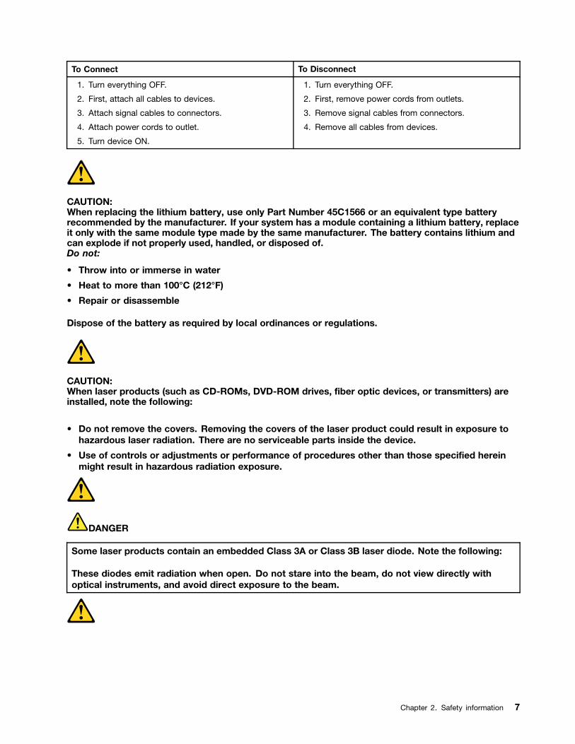
To Connect To Disconnect
1. Turn everything OFF.
2. First, attach all cables to devices.
3. Attach signal cables to connectors.
4. Attach power cords to outlet.
5. Turn device ON.
1. Turn everything OFF.
2. First, remove power cords from outlets.
3. Remove signal cables from connectors.
4. Remove all cables from devices.
CAUTION:When replacing the lithium battery, use only Part Number 45C1566 or an equivalent type batteryrecommended by the manufacturer. If your system has a module containing a lithium battery, replaceit only with the same module type made by the same manufacturer. The battery contains lithium andcan explode if not properly used, handled, or disposed of.Do not:
• Throw into or immerse in water
• Heat to more than 100°C (212°F)
• Repair or disassemble
Dispose of the battery as required by local ordinances or regulations.
CAUTION:When laser products (such as CD-ROMs, DVD-ROM drives, fiber optic devices, or transmitters) areinstalled, note the following:
• Do not remove the covers. Removing the covers of the laser product could result in exposure tohazardous laser radiation. There are no serviceable parts inside the device.
• Use of controls or adjustments or performance of procedures other than those specified hereinmight result in hazardous radiation exposure.
DANGER
Some laser products contain an embedded Class 3A or Class 3B laser diode. Note the following:
These diodes emit radiation when open. Do not stare into the beam, do not view directly withoptical instruments, and avoid direct exposure to the beam.
Chapter 2. Safety information 7
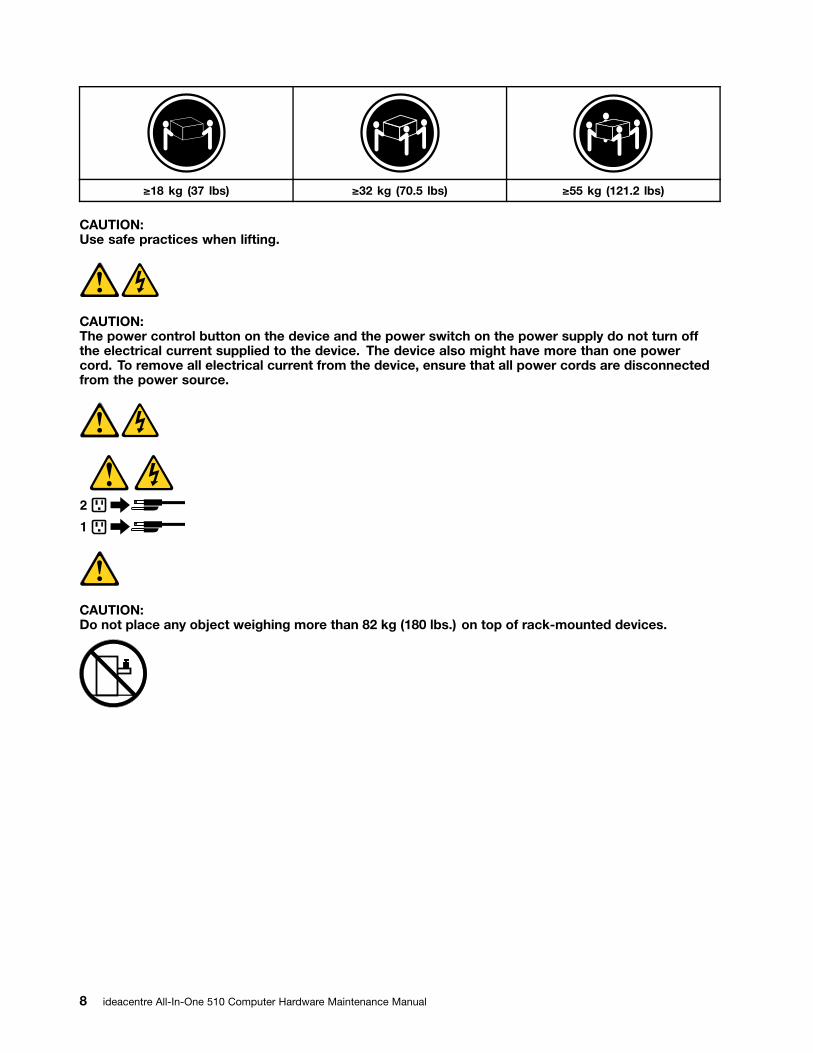
≥18 kg (37 lbs) ≥32 kg (70.5 lbs) ≥55 kg (121.2 lbs)
CAUTION:Use safe practices when lifting.
CAUTION:The power control button on the device and the power switch on the power supply do not turn offthe electrical current supplied to the device. The device also might have more than one powercord. To remove all electrical current from the device, ensure that all power cords are disconnectedfrom the power source.
1
2
CAUTION:Do not place any object weighing more than 82 kg (180 lbs.) on top of rack-mounted devices.
8 ideacentre All-In-One 510 Computer Hardware Maintenance Manual

Chapter 3. General information
This chapter provides general information that applies to all computer models covered by this manual.
SpecificationsThis section lists the physical specifications for your computer.
This section lists the physical specifications for your computer.
Type Lenovo All-In-One 510
This section lists the physical specifications.
Environment
Air temperature:
Operating: 10° to 35°C
Transit: -20° to 55°C
Humidity:
Operating: 35% to 80%
Transit: 20% to 90% (40°C)
Altitude: 86KPa to 106KPa
Electrical input:
Input voltage: 90V-264V(AC)
Input frequency: 47Hz-63Hz
© Copyright Lenovo 2016 9

10 ideacentre All-In-One 510 Computer Hardware Maintenance Manual
Chapter 4. General Checkout
Attention: The drives in the computer you are servicing might have been rearranged or the drive startupsequence may have been changed. Be extremely careful during write operations such as copying, saving, orformatting. Data or programs can be overwritten if you select an incorrect drive.
General error messages appear if a problem or conflict is found by an application, the operating system, orboth. For an explanation of these messages, refer to the information supplied with that software package.
Use the following procedure to help determine the cause of the problem:
1. Power-off the computer and all external devices.
2. Check all cables and power cords.
3. Set all display controls to the middle position.
4. Power-on all external devices.
5. Power-on the computer.
• Look for displayed error codes.
• Look for readable instructions or a main menu on the display.
If you did not receive the correct response, proceed to step 6.
If you did receive the correct response, proceed to step 7.
6. If one of the following happens, follow the instruction given:
• If the computer displays a POST error, go to “POST error codes”.
• If the computer hangs and no error is displayed, continue at step 7.
7. If the test stops and you cannot continue, replace the last device tested.
© Copyright Lenovo 2016 11

12 ideacentre All-In-One 510 Computer Hardware Maintenance Manual
Chapter 5. Using the Setup Utility
The Setup Utility program is used to view and change the configuration settings of your computer, regardlessof which operating system you are using. However, the operating system settings might override any similarsettings in the Setup Utility program.
Starting the Lenovo BIOS Setup Utility programTo start the Lenovo BIOS Setup Utility program, do the following:
1. If your computer is already on when you start this procedure, shut down the operating system andturn off the computer.
2. Press and hold the F1 key then turn on the computer. When the Lenovo BIOS Setup Utility program isdisplayed, release the F1 key.
Note: If a Power-On Password or an Administrator Password has been set, the Setup Utility program menuwill not be displayed until you type your password. For more information, see “Using passwords.”
Viewing and changing settingsSystem configuration options are listed in the Lenovo BIOS Setup Utility program menu. To view or changesettings, see “Starting the Setup Utility program.”
You must use the keyboard when using the Lenovo BIOS Setup Utility menu. The keys used to performvarious tasks are displayed on the bottom of each screen.
Using passwordsYou can use the Lenovo BIOS Setup Utility program to set passwords to prevent unauthorized personsfrom gaining access to your computer and data. See “Starting the Setup Utility program.” The followingtypes of passwords are available:
• Administrator Password
• Power-On Password
You do not have to set any passwords to use your computer. However, if you decide to set passwords, readthe following sections.
Password considerations
A password can be any combination of letters and numbers up to 16 characters (a-z and 0-9). For securityreasons, it is a good idea to use a strong password that cannot be easily compromised. We suggest thatpasswords should follow these rules:
• For a strong password, use 7-16 characters and a mix of letters and numbers.
• Do not use your name or your user name.
• Do not use a common word or a common name.
• Use something significantly different from your previous password.
Attention: Administrator and Power-On passwords are not case sensitive.
© Copyright Lenovo 2016 13
Administrator Password
Setting an Administrator Password deters unauthorized persons from changing configuration settings. Youmight want to set an Administrator Password if you are responsible for maintaining the settings of severalcomputers.
After you set an Administrator Password, a password prompt is displayed every time you access the LenovoBIOS Setup Utility program.
If both the Administrator and Power-On Password are set, you can type either password. However, you mustuse your Administrator Password to change any configuration settings.
Setting, changing, or deleting an Administrator password
To set an Administrator Password, do the following:
Note: A password can be any combination of letters and numbers up to 16 characters (a-z and 0-9). Formore information, see “Password considerations” on page 13.
1. Start the Lenovo BIOS Setup Utility program (see “Starting the Lenovo BIOS Setup Utility program” onpage 13).
2. From the Security menu, select Set Administrator Password and press the Enter key.
3. The password dialog box will be displayed. Type the password then press the Enter key.
4. Re-type the password to confirm, then press the Enter key. If you typed the password correctly,the password will be installed.
To change an Administrator Password, do the following:
1. Start the Lenovo BIOS Setup Utility program (see “Starting the Lenovo BIOS Setup Utility program” onpage 13).
2. From the Security menu, select Set Administrator Password and press the Enter key.
3. The password dialog box will be displayed. Type the current password then press the Enter key.
4. Type the new password, then press the Enter key. Re-type the password to confirm the new password.If you typed the new password correctly, the new password will be installed. A Setup Noticed confirmingthat changes have been saved will be displayed.
To delete a previously set Administrator Password, do the following :
1. From the Security menu, select Set Administrator Password and press the Enter key.
2. The password dialog box will be displayed. Type the current password and press the Enter key.
3. To delete an Administrator Password, leave each new password line item blank, then press the Enterkey. A Setup Notice confirming that changes have been saved will be displayed.
4. Return to the Lenovo BIOS Setup Utility program menu and select the Exit option.
5. Select Save changes and Exit from the menu.
Power-On Password
When a Power-On Password is set, you cannot start the Lenovo BIOS Setup Utility program until a validpassword is typed from the keyboard.
Setting, changing, or deleting a Power-On Password
Note: A password can be any combination of letters and numbers up to 16 characters (a-z and 0-9).
14 ideacentre All-In-One 510 Computer Hardware Maintenance Manual
To set a Power-On Password, do the following:
1. Start the Lenovo BIOS Setup Utility program (See ”Starting the Lenovo BIOS Setup Utility program” onpage 13.)
2. From the Security menu, select Set Power-On Password and press the Enter key.
3. The password dialog box will be displayed. Type the password, then press the Enter key.
4. Re-type the password to confirm. If you typed the password correctly, the password will be installed.
To change a Power-On Password, do the following:
1. Start the Lenovo BIOS Setup Utility program (See ”Starting the Lenovo BIOS Setup Utility program” onpage 13.)
2. From the Security menu, select Set Power-On Password and press the Enter key.
3. The password dialog box will be displayed. Type the current password then press the Enter key.
4. Type the new password, then press the Enter key. Re-type the password to confirm the new password.If you typed the new password correctly, the new password will be installed. A Setup Noticed confirmingthat changes have been saved will be displayed.
To delete a previously set Power-On Password, do the following :
1. From the Security menu, select Set Power-On Password and press the Enter key.
2. The password dialog box will be displayed. Type the current password and press the Enter key.
3. To delete the Power-On Password, leave each new password line item blank, then press Enter. A SetupNotice confirming that changes have been saved will be displayed.
4. Return to the Lenovo BIOS Setup Utility program menu and select the Exit option.
5. Select Save changes and Exit from the menu.
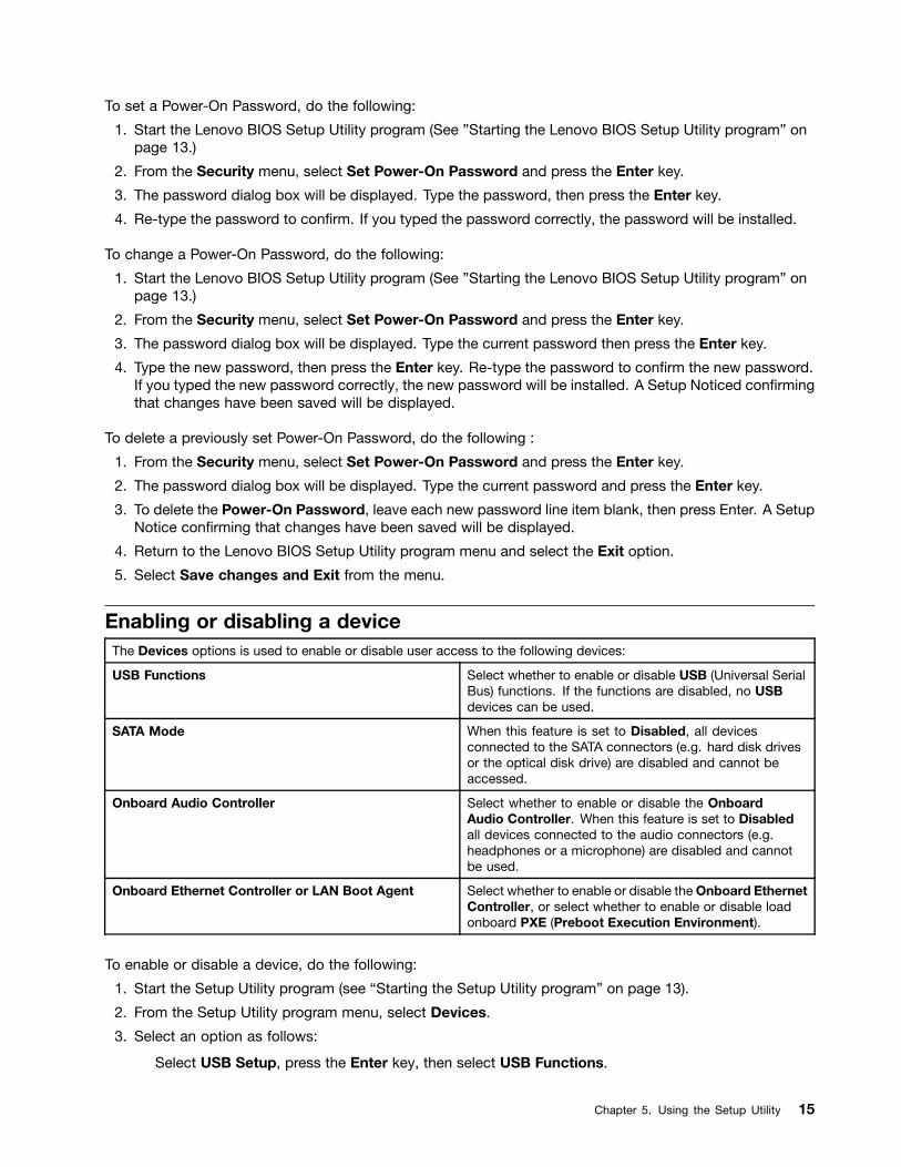
Enabling or disabling a deviceThe Devices options is used to enable or disable user access to the following devices:
USB Functions Select whether to enable or disable USB (Universal SerialBus) functions. If the functions are disabled, no USBdevices can be used.
SATA Mode When this feature is set to Disabled, all devicesconnected to the SATA connectors (e.g. hard disk drivesor the optical disk drive) are disabled and cannot beaccessed.
Onboard Audio Controller Select whether to enable or disable the OnboardAudio Controller. When this feature is set to Disabledall devices connected to the audio connectors (e.g.headphones or a microphone) are disabled and cannotbe used.
Onboard Ethernet Controller or LAN Boot Agent Select whether to enable or disable the Onboard EthernetController, or select whether to enable or disable loadonboard PXE (Preboot Execution Environment).
To enable or disable a device, do the following:
1. Start the Setup Utility program (see “Starting the Setup Utility program” on page 13).
2. From the Setup Utility program menu, select Devices.
3. Select an option as follows:
Select USB Setup, press the Enter key, then select USB Functions.
Chapter 5. Using the Setup Utility 15

Select ATA Device Setup, press the Enter key, then select SATA Mode.
Select Audio Setup, press the Enter key, then select Onboard Audio Controller.
Select Network Setup, press the Enter key, then select Onboard Ethernet Support or LAN BootAgent.
4. Select Disabled or Enabled and press the Enter key.
5. Return to the Lenovo BIOS Setup Utility program menu and select the Exit option.
6. Select Save changes and Exit from the menu.
Notes:
a. If you do not want to save the settings, select Discard changes and Exit from the menu.
b. Select IDE/AHCI Mode: Device driver support is required for ACHI. Depending on how the hard diskimage was installed, changing this setting may prevent the system from booting.
Selecting a startup deviceIf your computer does not boot from a device such as the CD/DVD-ROM drive disk or hard disk as expected,follow one of the procedures below.
Selecting a temporary startup device
Use this procedure to start up from any boot device.
Note: Not all CDs, DVDs or hard disk drives are bootable.
1. Turn off your computer.
2. Press and hold the F12 key then turn on the computer. When the Startup Device Menu appears,release the F12 key.
Note: If the Startup Device Menu does not display using these steps, repeatedly press and release theF12 key rather than keeping it pressed when turning on the computer.
3. Use ↑ and ↓ arrows to select the desired startup device from the Startup Device Menu and pressthe Enter key to begin.
Note: Selecting a startup device from the Startup Device Menu does not permanently change thestartup sequence.
Selecting or changing the startup device sequence
To view or permanently change the configured startup device sequence, do the following:
1. Start the Lenovo BIOS Setup Utility program (see “Starting the Lenovo BIOS Setup Utility program” onpage 13).
2. From the Lenovo BIOS Setup Utility program main menu, select the Startup option.
3. Press the Enter key, and select the devices for the Primary Boot Sequence. Read the informationdisplayed on the right side of the screen.
4. Use and ¯ arrows to select a device. Use the <+> or <-> keys to move a device up or down. Use the<×> key to exclude the device from or include the device in the boot sequence.
5. Return to the Lenovo BIOS Setup Utility program menu and select the Exit option.
6. Select Save changes and Exit from the menu.
Notes:
16 ideacentre All-In-One 510 Computer Hardware Maintenance Manual

a. If you do not want to save the settings, select Discard changes and Exit from the menu.
b. If you have changed these settings and want to return to the default settings, select Load OptimalDefaults from the menu.
Exiting the Lenovo BIOS Setup Utility programAfter you finish viewing or changing settings, press the Esc key to return to the Lenovo BIOS Setup Utilityprogram main menu. You might have to press the Esc key several times. Do one of the following:
• If you want to save the new settings, select Save changes and Exit from the menu. When the Save &reset window shows, select the Yes button, and then press the Enter key to exit the Lenovo BIOSSetup Utility program.
• If you do not want to save the settings, select Discard changes and Exit from the menu. When theReset Without Saving window shows, select the Yes button, and then press the Enter key to exit theLenovo BIOS Setup Utility program.
Chapter 5. Using the Setup Utility 17

18 ideacentre All-In-One 510 Computer Hardware Maintenance Manual

Chapter 6. Symptom-to-FRU Index
The Symptom-to-FRU index lists error symptoms and possible causes. The most likely cause is listed first.Always begin with Chapter 4, “General Checkout,” on page 11. This index can also be used to help youdecide which FRUs to have available when servicing a computer. If you are unable to correct the problemusing this index, go to “Undetermined problems” on page 20.
Notes:
• If you have both an error message and an incorrect audio response, diagnose the error message first.
• If you cannot run the diagnostic tests or you get a diagnostic error code when running a test but didreceive a POST error message, diagnose the POST error message first.
• If you did not receive any error message look for a description of your error symptoms in the first part ofthis index.
Hard disk drive boot errorA hard disk drive boot error can be caused by the following.
Error FRU/Action
The startup drive is not included in the boot sequenceconfiguration.
Check the configuration and ensure the startup drive isin the boot sequence.
No operating system is installed on the boot drive. Install an operating system on the boot drive.
The boot sector on the startup drive is corrupted. The drive must be formatted. Do the following:
1. Attempt to back up the data on the failing hard diskdrive.
2. Use the operating system to format the hard diskdrive.
The drive is defective. Replace the hard disk drive.
Power Supply ProblemsFollow these procedures if you suspect there is a power supply problem.
Check/Verify FRU/Action
Check that the following are properly installed:
• Power Cord
• On/Off Switch connector
• System Board Power Supply connectors
• Microprocessor connections
Reseat connectors
Check the power cord. Power Cord
Check the power-on switch. Power-on Switch
© Copyright Lenovo 2016 19

POST error codesEach time you turn the computer on, it performs a series of tests to check that the system is operatingcorrectly and that certain options are set. This series of tests is called the Power-On Self-Test, or POST.POST does the following:
• Checks some basic motherboard operations
• Checks that the memory is working correctly
• Starts video operations
• Verifies that the boot drive is working
POST Error Message Description/Action
Keyboard error Cannot initialize the keyboard. Make sure the keyboardis properly connected to the computer and that no keysare held pressed during POST. To purposely configurethe computer without a keyboard, select Keyboardlessoperation in Startup and set the option to Enabled. TheBIOS then ignores the missing keyboard during POST.
Reboot and Select proper Boot device or Insert BootMedia in selected Boot device
The BIOS was unable to find a suitable boot device. Makesure the boot drive is properly connected to the computer.Make sure you have bootable media in the boot device.
Undetermined problems1. Power-off the computer.
2. Remove or disconnect the following components (if connected or installed) one at a time.
a. External devices (modem, printer, or mouse)
b. Extended video memory
c. External Cache
d. External Cache RAM
e. Hard disk drive
f. Disk drive
3. Power-on the computer to re-test the system.
4. Repeat steps 1 through 3 until you find the failing device or component.
If all devices and components have been removed and the problem continues, replace the system board.
20 ideacentre All-In-One 510 Computer Hardware Maintenance Manual
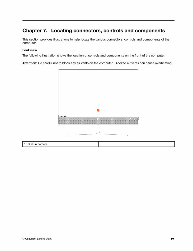
Chapter 7. Locating connectors, controls and components
This section provides illustrations to help locate the various connectors, controls and components of thecomputer.
Font view
The following illustration shows the location of controls and components on the front of the computer.
Attention: Be careful not to block any air vents on the computer. Blocked air vents can cause overheating.
1. Built-in camera
© Copyright Lenovo 2016 21

Left and right view
The following illustration shows the location of connectors, controls and components on the left and rightside of the computer.
1. USB 3.0 connectors 5. Optical drive eject button
2. USB 3.0 connectors 6. Optical drive
3. Memory card reader 7. Power button
4. Combo audio jack
22 ideacentre All-In-One 510 Computer Hardware Maintenance Manual

Rear view
The following illustration shows the location of connectors and components on the rear of the computer.
1. Security cable slot 5. USB 2.0 connector
2. Power connector 6. USB 2.0 connector
3. Ethernet connector 7. USB 2.0 connector
4. HDMI-out connector 8. HDMI-in connector
Chapter 7. Locating connectors, controls and components 23
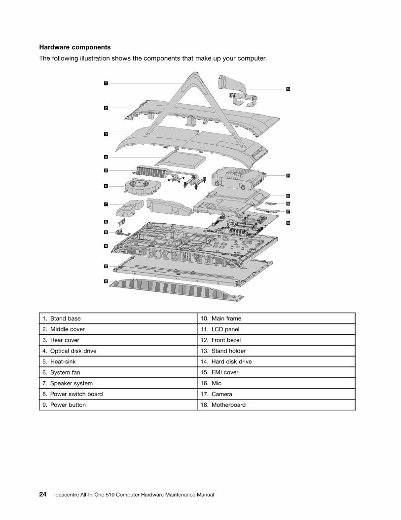
Hardware components
The following illustration shows the components that make up your computer.
1
2
3
4
5
8
7
6
9
12
15
16
17
18
14
11
10
13
1. Stand base 10. Main frame
2. Middle cover 11. LCD panel
3. Rear cover 12. Front bezel
4. Optical disk drive 13. Stand holder
5. Heat-sink 14. Hard disk drive
6. System fan 15. EMI cover
7. Speaker system 16. Mic
8. Power switch board 17. Camera
9. Power button 18. Motherboard
24 ideacentre All-In-One 510 Computer Hardware Maintenance Manual

Identifying parts on the motherboard
The motherboard (sometimes called the planar or system board) is the main circuit board in your computer.It provides basic computing functions and supports a variety of devices that are factory-installed or thatyou can install later. The following illustration shows the location of connectors and components on thefront of the motherboard.
�� ��
��
����
��
��
��
��
��
��
�� ��
�� �� ������ �� �������� �� �������� �� �������� �� �������� �� ���� �� ������ �� ���� �� ���� �� ���� �� �� ��
�� ��
�� ��
�� ��
�� ��
�� ��
1. System fan connector 15. Ethernet connector
2. ODD power connector 16. HDMI-out connector
3. HDD power connector 17. USB 2.0 connector
4. Touch panel connector 18. USB 2.0 connector
5. ODD SATA connector 19. USB 2.0 connector
6. HDD SATA connector 20. HDMI-in connector
7. LVDS connector 21. Mic connector
8. Battery 22. Speaker connector
9. SSD SATA connector 23. Combo audio jack
10. Converter connector 24. Card reader connector
11. Power switch board connector 25. USB 3.0 connector
12. Camera connector 26. USB 3.0 connector
Chapter 7. Locating connectors, controls and components 25
13. Wi-Fi card connector 27. Memory socket
14. Power connector 28. CPU socket
26 ideacentre All-In-One 510 Computer Hardware Maintenance Manual
Chapter 8. Replacing hardware
Attention: Do not remove the computer cover or attempt any repair before reading the “Important safety information”in the Safety and Warranty Guide that was included with your computer. To obtain copies of the Safety and WarrantyGuide, go to the Support Web site at: http://consumersupport.lenovo.com.
Note: Use only parts provided by Lenovo.
General informationPre-disassembly instructions
Before starting the disassembly procedure, make sure that you do the following:
1. Turn off the power to the system and all peripherals.
2. Unplug all power and signal cables from the computer.
3. Place the system on a flat, stable surface.
© Copyright Lenovo 2016 27

Replacing the keyboard and mouseNote: Your keyboard will be connected to a USB connector at either side or at the rear of the computer.
To replace the keyboard and mouse:
Step 1. Remove any media from the drives, shut down the computer, and turn off all attached devices.
Step 2. Unplug all power cords from electrical outlets.
Step 3. Disconnect all cables attached to the computer. This includes power cords, input/output (I/O)cables, and any other cables that are connected to the computer. .
Step 4. Locate the connector for the keyboard. Refer to Locating connectors, controls and components tolocate the various connectors.
Step 5. Disconnect the defective keyboard cable from the computer and connect the new keyboard cableto the same connector.
Step 6. The mouse can be replaced using the same method.
Replacing the adapterAttention: Turn off the computer and wait 3 to 5 minutes to let it cool down before removing the cover.
Step 1. Remove any media from the drives, shut down the operating system, and turn off the computerand all attached devices.
Step 2. Disconnect the adapter from the connector on the computer, then unplug the adapter fromelectrical outlet.
28 ideacentre All-In-One 510 Computer Hardware Maintenance Manual
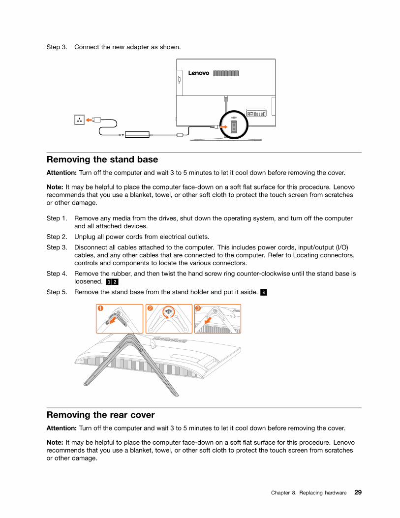
Step 3. Connect the new adapter as shown.
Removing the stand baseAttention: Turn off the computer and wait 3 to 5 minutes to let it cool down before removing the cover.
Note: It may be helpful to place the computer face-down on a soft flat surface for this procedure. Lenovorecommends that you use a blanket, towel, or other soft cloth to protect the touch screen from scratchesor other damage.
Step 1. Remove any media from the drives, shut down the operating system, and turn off the computerand all attached devices.
Step 2. Unplug all power cords from electrical outlets.
Step 3. Disconnect all cables attached to the computer. This includes power cords, input/output (I/O)cables, and any other cables that are connected to the computer. Refer to Locating connectors,controls and components to locate the various connectors.
Step 4. Remove the rubber, and then twist the hand screw ring counter-clockwise until the stand base isloosened. 1 2
Step 5. Remove the stand base from the stand holder and put it aside. 3
Removing the rear coverAttention: Turn off the computer and wait 3 to 5 minutes to let it cool down before removing the cover.
Note: It may be helpful to place the computer face-down on a soft flat surface for this procedure. Lenovorecommends that you use a blanket, towel, or other soft cloth to protect the touch screen from scratchesor other damage.
Chapter 8. Replacing hardware 29

Step 1. Remove any media from the drives, shut down the operating system, and turn off the computerand all attached devices.
Step 2. Unplug all power cords from electrical outlets.
Step 3. Disconnect all cables attached to the computer. This includes power cords, input/output (I/O)cables, and any other cables that are connected to the computer. Refer to Locating connectors,controls and components to locate the various connectors.
Step 4. Remove the stand base. Refer to Removing the stand base.
Step 5. Lift up the rear cover from the two notches at the bottom of the computer.
Step 6. To reattach the rear cover:
a. Align the rear cover with the chassis.
b. Press the rear cover until it snaps into position.
Replacing the hard disk driveAttention: Turn off the computer and wait 3 to 5 minutes to let it cool down before removing the cover.
Note: It may be helpful to place the computer face-down on a soft flat surface for this procedure. Lenovorecommends that you use a blanket, towel, or other soft cloth to protect the touch screen from scratchesor other damage.
Step 1. Remove any media from the drives, shut down the operating system, and turn off the computerand all attached devices.
Step 2. Unplug all power cords from electrical outlets.
Step 3. Disconnect all cables attached to the computer. This includes power cords, input/output (I/O)cables, and any other cables that are connected to the computer. Refer to Locating connectors,controls and components to locate the various connectors.
Step 4. Remove the stand base. Refer to Removing the stand base.
Step 5. Remove the rear cover. Refer to Removing the rear cover.
30 ideacentre All-In-One 510 Computer Hardware Maintenance Manual

Step 6. Pull the hard disk drive and bracket to left 1 , and then lift them up. 2
Step 7. Disconnect the signal cable from the hard disk drive.
Step 8. Remove the four screws that secure the hard disk drive to the bracket. 3
Step 9. To install the new hard disk drive:
a. Line up the new hard disk drive with the bracket and secure it with four screws.
b. Connect the data and power cables to the new hard disk drive.
c. Slide the hard disk drive and bracket back into position.
Step 10. Reattach the rear cover and stand base.
Replacing the optical driveAttention: Turn off the computer and wait 3 to 5 minutes to let it cool down before removing the cover.
Note: It may be helpful to place the computer face-down on a soft flat surface for this procedure. Lenovorecommends that you use a blanket, towel, or other soft cloth to protect the touch screen from scratchesor other damage.
Step 1. Remove any media from the drives, shut down the operating system, and turn off the computerand all attached devices.
Step 2. Unplug all power cords from electrical outlets.
Step 3. Disconnect all cables attached to the computer. This includes power cords, input/output (I/O)cables, and any other cables that are connected to the computer. Refer to Locating connectors,controls and components to locate the various connectors.
Step 4. Remove the stand base. Refer to Removing the stand base.
Step 5. Remove the rear cover. Refer to Removing the rear cover.
Chapter 8. Replacing hardware 31

Step 6. Locate the optical removal notch, and then push the optical drive out using a screw driver .
Step 7. Push a small iron stick (paper clip) into the small hole on the optical drive bezel so that the disksprings out as shown.
32 ideacentre All-In-One 510 Computer Hardware Maintenance Manual

Step 8. Remove the optical drive bezel from the optical drive as shown. 1 2
Step 9. To install the new optical drive:
a. Insert the tabs on the optical drive bezel into the corresponding holes in the new optical drive,and then push the bezel back into position.
b. Gently push the disk forward until it snaps into position.
c. Slide the new optical drive into the drive bay.
Step 10. Reattach the rear cover and stand base.
Replacing the memory moduleAttention: Turn off the computer and wait 3 to 5 minutes to let it cool down before removing the cover.
Note: It may be helpful to place the computer face-down on a soft flat surface for this procedure. Lenovorecommends that you use a blanket, towel, or other soft cloth to protect the touch screen from scratchesor other damage.
Step 1. Remove any media from the drives, shut down the operating system, and turn off the computerand all attached devices.
Step 2. Unplug all power cords from electrical outlets.
Step 3. Disconnect all cables attached to the computer. This includes power cords, input/output (I/O)cables, and any other cables that are connected to the computer. Refer to Locating connectors,controls and components to locate the various connectors.
Step 4. Remove the stand base. Refer to Removing the stand base.
Step 5. Remove the rear cover. Refer to Removing the rear cover.
Chapter 8. Replacing hardware 33

Step 6. Remove the memory cover. 1
Step 7. Open the retaining clips 2 and gently pull the memory module out of the memory socket. 3
Step 8. To install the new memory module:
a. Position the new memory module over the memory slot. Ensure that the notch 2 on thememory module aligns correctly with the slot key 1 in the memory socket. Press the memorymodule down until snaps into position.
b. Reinstall the memory cover.
Step 9. Reattach the rear cover and stand base.
Replacing the solid state driveAttention: Turn off the computer and wait 3 to 5 minutes to let it cool down before removing the cover.
Note: It may be helpful to place the computer face-down on a soft flat surface for this procedure. Lenovorecommends that you use a blanket, towel, or other soft cloth to protect the touch screen from scratchesor other damage.
Step 1. Remove any media from the drives, shut down the operating system, and turn off the computerand all attached devices.
Step 2. Unplug all power cords from electrical outlets.
34 ideacentre All-In-One 510 Computer Hardware Maintenance Manual

Step 3. Disconnect all cables attached to the computer. This includes power cords, input/output (I/O)cables, and any other cables that are connected to the computer. Refer to Locating connectors,controls and components to locate the various connectors.
Step 4. Remove the stand base. Refer to Removing the stand base.
Step 5. Remove the rear cover. Refer to Removing the rear cover.
Step 6. Remove the memory cover. 1
Step 7. Remove the screw that secure the solid state drive to the motherboard 2 , and then slide out thesolid state drive. 3
Step 8. To install the new solid state drive:
a. Insert the solid state drive into the slot.
b. Secure the new solid state drive to motherboard with one screw.
c. Reinstall the memory cover.
Step 9. Reattach the rear cover and stand base.
Removing the stand holderAttention: Turn off the computer and wait 3 to 5 minutes to let it cool down before removing the cover.
Note: It may be helpful to place the computer face-down on a soft flat surface for this procedure. Lenovorecommends that you use a blanket, towel, or other soft cloth to protect the touch screen from scratchesor other damage.
Step 1. Remove any media from the drives, shut down the operating system, and turn off the computerand all attached devices.
Step 2. Unplug all power cords from electrical outlets.
Step 3. Disconnect all cables attached to the computer. This includes power cords, input/output (I/O)cables, and any other cables that are connected to the computer. Refer to Locating connectors,controls and components to locate the various connectors.
Step 4. Remove the stand base. Refer to Removing the stand base.
Chapter 8. Replacing hardware 35

Step 5. Remove the rear cover. Refer to Removing the rear cover.
Step 6. Remove the hard disk drive. Refer to Replacing the hard disk drive.
Step 7. Remove the two screws that secure the stand holder to the chassis, and then lift up the standholder to remove it.
Step 8. To reattach the stand holder:
a. Align the holes in the stand holder with the corresponding holes in the chassis.
b. Secure the stand holder to the chassis with two screws.
Replacing the power switch boardNote: Turn off the computer and wait 3 to 5 minutes to let it cool down before removing the cover.
Note: It may be helpful to place the computer face-down on a soft flat surface for this procedure. Lenovorecommends that you use a blanket, towel, or other soft cloth to protect the computer screen from scratchesor other damage.
To replace the power switch board
Step 1. Remove any media from the drives, shut down the operating system, and turn off the computerand all attached devices.
Step 2. Unplug all power cords from electrical outlets.
Step 3. Disconnect all cables attached to the computer. This includes power cords, input/output (I/O)cables, and any other cables that are connected to the computer. Refer to Locating connectors,controls and components to locate the various connectors.
Step 4. Remove the stand base. Refer to Removing the stand base.
Step 5. Remove the rear cover. Refer to Removing the rear cover.
36 ideacentre All-In-One 510 Computer Hardware Maintenance Manual

Step 6. Disconnect the signal cable from the power switch board. 1
Step 7. Push the locking pin outward to release the power switch board 2 , and then lift the power switchboard up to remove it.
Step 8. To install the new power switch board:
a. Attach the new power switch board to the chassis and secure it with the locking pin.
b. Connect the signal cable to the new power switch board.
Step 9. Reattach the rear cover and stand base.
Removing the middle coverNote: Turn off the computer and wait 3 to 5 minutes to let it cool down before removing the cover.
Note: It may be helpful to place the computer face-down on a soft flat surface for this procedure. Lenovorecommends that you use a blanket, towel, or other soft cloth to protect the computer screen from scratchesor other damage.
To remove the middle cover:
Step 1. Remove any media from the drives, shut down the operating system, and turn off the computerand all attached devices.
Step 2. Unplug all power cords from electrical outlets.
Step 3. Disconnect all cables attached to the computer. This includes power cords, input/output (I/O)cables, and any other cables that are connected to the computer. Refer to Locating connectors,controls and components to locate the various connectors.
Step 4. Remove the stand base. Refer to Removing the stand base.
Step 5. Remove the rear cover. Refer to Removing the rear cover.
Step 6. Remove the hard disk drive. Refer to Replacing the hard disk drive.
Step 7. Remove the optical drive. Refer to Replacing the optical drive.
Chapter 8. Replacing hardware 37
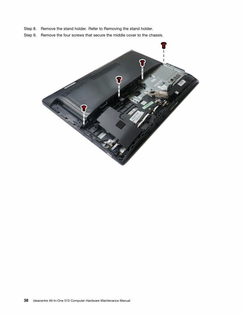
Step 8. Remove the stand holder. Refer to Removing the stand holder.
Step 9. Remove the four screws that secure the middle cover to the chassis.
38 ideacentre All-In-One 510 Computer Hardware Maintenance Manual

Step 10. Lift up the middle cover as shown.
Step 11. To reattach the middle cover:
a. Line up the middle cover with the chassis.
b. Secure the middle cover to the chassis with four screws.
Removing the EMI coverNote: Turn off the computer and wait 3 to 5 minutes to let it cool down before removing the cover.
Note: It may be helpful to place the computer face-down on a soft flat surface for this procedure. Lenovorecommends that you use a blanket, towel, or other soft cloth to protect the computer screen from scratchesor other damage.
To replace the EMI cover
Step 1. Remove any media from the drives, shut down the operating system, and turn off the computerand all attached devices.
Step 2. Unplug all power cords from electrical outlets.
Step 3. Disconnect all cables attached to the computer. This includes power cords, input/output (I/O)cables, and any other cables that are connected to the computer. Refer to Locating connectors,controls and components to locate the various connectors.
Step 4. Remove the stand base. Refer to Removing the stand base.
Step 5. Remove the rear cover. Refer to Removing the rear cover.
Step 6. Remove the hard disk drive. Refer to Replacing the hard disk drive.
Step 7. Remove the optical drive. Refer to Replacing the optical drive.
Step 8. Remove the stand holder. Refer to Removing the stand holder.
Chapter 8. Replacing hardware 39

Step 9. Remove the middle cover. Refer to Removing the middle cover.
Step 10. Remove the six screws that secure the EMI cover to the chassis, and then lift it up.
Step 11. To install the new EMI cover:
a. Align the holes in the EMI cover with the mounting holes in the chassis.
b. Secure the EMI cover to the chassis with six screws.
Replacing the LCD panel moduleNote: Turn off the computer and wait 3 to 5 minutes to let it cool down before removing the cover.
Note: It may be helpful to place the computer face-down on a soft flat surface for this procedure. Lenovorecommends that you use a blanket, towel, or other soft cloth to protect the computer screen from scratchesor other damage.
To replace the LCD panel module:
Step 1. Remove any media from the drives, shut down the operating system, and turn off the computerand all attached devices.
Step 2. Unplug all power cords from electrical outlets.
Step 3. Disconnect all cables attached to the computer. This includes power cords, input/output (I/O)cables, and any other cables that are connected to the computer. Refer to Locating connectors,controls and components to locate the various connectors.
Step 4. Remove the stand base. Refer to Removing the stand base.
Step 5. Remove the rear cover. Refer to Removing the rear cover.
Step 6. Remove the hard disk drive. Refer to Replacing the hard disk drive.
Step 7. Remove the optical drive. Refer to Replacing the optical drive.
40 ideacentre All-In-One 510 Computer Hardware Maintenance Manual
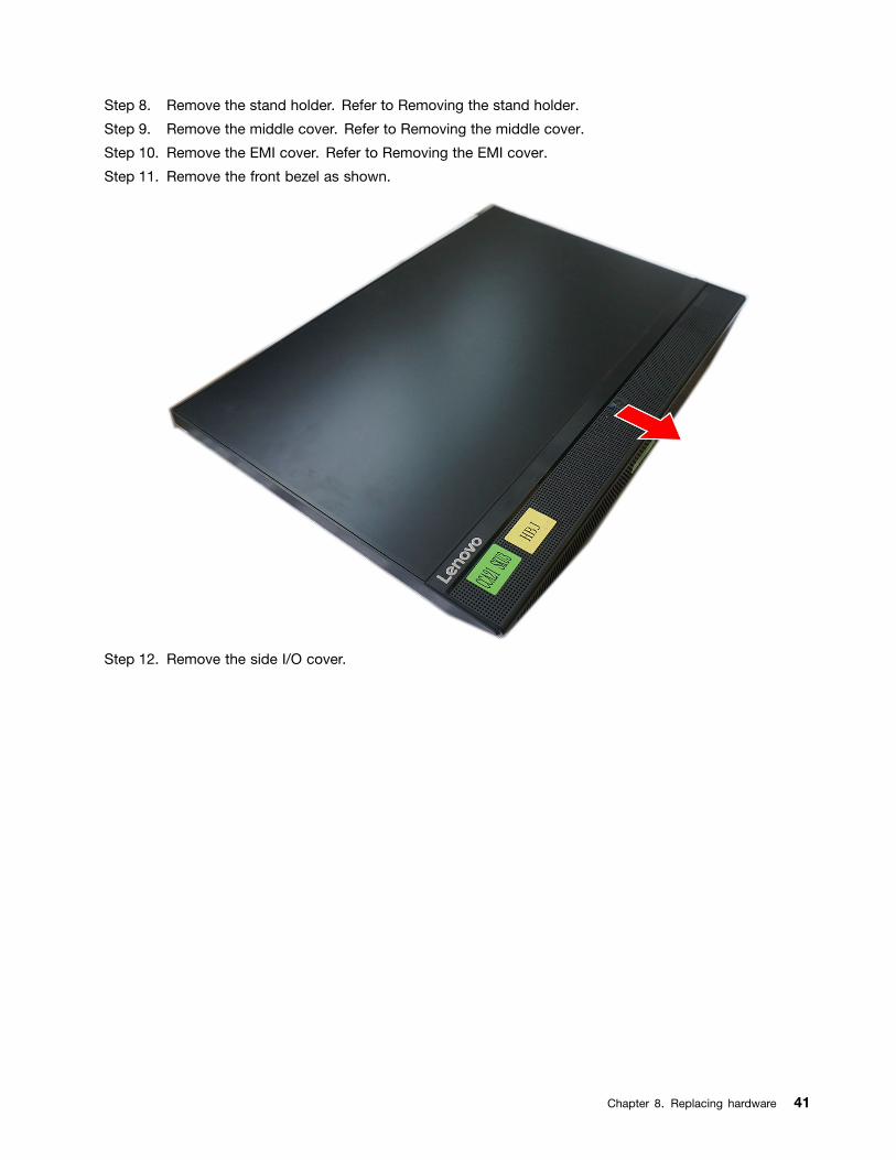
Step 8. Remove the stand holder. Refer to Removing the stand holder.
Step 9. Remove the middle cover. Refer to Removing the middle cover.
Step 10. Remove the EMI cover. Refer to Removing the EMI cover.
Step 11. Remove the front bezel as shown.
Step 12. Remove the side I/O cover.
Chapter 8. Replacing hardware 41

Step 13. Disconnect the converter cable 1 and LVDS cable 2 .
Step 14. Remove the thirteen screws that secure the main frame to the LCD panel.
Step 15. Lift up the main frame as shown to remove it.
42 ideacentre All-In-One 510 Computer Hardware Maintenance Manual

Step 16. If your device is a touch computer, disconnect the touch cable from the connector on themotherboard. Otherwise, skip this step. Refer to Locating connectors, controls and components tolocate the touch connector.
Step 17. To install the new the LCD panel module:
a. Align the new LCD panel with the main frame.
b. Secure the new LCD panel to the main frame with thirteen screws.
c. Connect the touch(touch model only), LVDS and converter cables to the connectors in thenew LCD panel.
Step 18. Reattach the side I/O cover, EMI cover, middle cover, front bezel, stand holder, optical drive,hard disk drive, rear cover, and stand base.
Replacing the Wi-Fi cardNote: Turn off the computer and wait 3 to 5 minutes to let it cool down before removing the cover.
Note: It may be helpful to place the computer face-down on a soft flat surface for this procedure. Lenovorecommends that you use a blanket, towel, or other soft cloth to protect the computer screen from scratchesor other damage.
To replace the Wi-Fi card:
Step 1. Remove any media from the drives, shut down the operating system, and turn off the computerand all attached devices.
Step 2. Unplug all power cords from electrical outlets.
Step 3. Disconnect all cables attached to the computer. This includes power cords, input/output (I/O)cables, and any other cables that are connected to the computer. Refer to Locating connectors,controls and components to locate the various connectors.
Step 4. Remove the stand base. Refer to Removing the stand base.
Step 5. Remove the rear cover. Refer to Removing the rear cover.
Step 6. Remove the hard disk drive. Refer to Replacing the hard disk drive.
Step 7. Remove the optical drive. Refer to Replacing the optical drive.
Step 8. Remove the stand holder. Refer to Removing the stand holder.
Step 9. Remove the middle cover. Refer to Removing the middle cover.
Step 10. Remove the EMI cover. Refer to Removing the EMI cover.
Chapter 8. Replacing hardware 43

Step 11. Disconnect the antenna cables from the Wi-Fi card. 1
Step 12. Remove the screw that secures the Wi-Fi card to the motherboard. 2
Step 13. Pull the Wi-Fi card out of the slot.
Step 14. To install the new Wi-Fi card:
a. Insert the new Wi-Fi card into the Wi-Fi card slot.
b. Secure new the Wi-Fi card to the motherboard with the screw.
c. Connect the antenna cables to the new Wi-Fi card.
Step 15. Reattach the EMI cover, middle cover, stand holder, optical drive, hard disk drive, rear cover,and stand base.
Replacing the system fanNote: Turn off the computer and wait 3 to 5 minutes to let it cool down before removing the cover.
Note: It may be helpful to place the computer face-down on a soft flat surface for this procedure. Lenovorecommends that you use a blanket, towel, or other soft cloth to protect the computer screen from scratchesor other damage.
To replace the system fan
Step 1. Remove any media from the drives, shut down the operating system, and turn off the computerand all attached devices.
Step 2. Unplug all power cords from electrical outlets.
Step 3. Disconnect all cables attached to the computer. This includes power cords, input/output (I/O)cables, and any other cables that are connected to the computer. Refer to Locating connectors,controls and components to locate the various connectors.
44 ideacentre All-In-One 510 Computer Hardware Maintenance Manual

Step 4. Remove the stand base. Refer to Removing the stand base.
Step 5. Remove the rear cover. Refer to Removing the rear cover.
Step 6. Remove the hard disk drive. Refer to Replacing the hard disk drive.
Step 7. Remove the optical drive. Refer to Replacing the optical drive.
Step 8. Remove the stand holder. Refer to Removing the stand holder.
Step 9. Remove the middle cover. Refer to Removing the middle cover.
Step 10. Remove the EMI cover. Refer to Removing the EMI cover.
Step 11. Remove the screw that secures the system fan to the chassis.
Step 12. Disconnect the system fan power cable from the motherboard.
Step 13. Lift the system fan up to remove it.
Step 14. To install the new system fan:
a. Place the new system fan into position, and then secure it to the chassis with one screw.
b. Connect the system fan power cable to the connector on the motherboard.
Step 15. Reattach the EMI cover, middle cover, stand holder, optical drive, hard disk drive, rear cover,and stand base.
Replacing the heat-sinkNote: Turn off the computer and wait 3 to 5 minutes to let it cool down before removing the cover.
Note: It may be helpful to place the computer face-down on a soft flat surface for this procedure. Lenovorecommends that you use a blanket, towel, or other soft cloth to protect the computer screen from scratchesor other damage.
Chapter 8. Replacing hardware 45

To replace the heat-sink:
Step 1. Remove any media from the drives, shut down the operating system, and turn off the computerand all attached devices.
Step 2. Unplug all power cords from electrical outlets.
Step 3. Disconnect all cables attached to the computer. This includes power cords, input/output (I/O)cables, and any other cables that are connected to the computer. Refer to Locating connectors,controls and components to locate the various connectors.
Step 4. Remove the stand base. Refer to Removing the stand base.
Step 5. Remove the rear cover. Refer to Removing the rear cover.
Step 6. Remove the hard disk drive. Refer to Replacing the hard disk drive.
Step 7. Remove the optical drive. Refer to Replacing the optical drive.
Step 8. Remove the stand holder. Refer to Removing the stand holder.
Step 9. Remove the middle cover. Refer to Removing the middle cover.
Step 10. Remove the EMI cover. Refer to Removing the EMI cover.
Step 11. Loosen the nine screws that secure the heat-sink to the motherboard, and then lift up the heat-sinkand remove it.
Attention: Place the heat-sink upside down on a flat surface to prevent thermal grease from contaminatingother components.
Attention: Use an alcohol pad to wipe the thermal grease off the CPU.
Step 12. To install the new heat-sink:
46 ideacentre All-In-One 510 Computer Hardware Maintenance Manual

a. Position the new heat-sink on the motherboard so that the nine screws are aligned with theholes in the motherboard and wind shielding.
b. Tighten the screws in numeric order to secure the new heat-sink to the motherboard.
Step 13. Reattach the EMI cover, middle cover, stand holder, optical drive, hard disk drive, rear cover,and stand base.
Replacing the motherboardNote: Turn off the computer and wait 3 to 5 minutes to let it cool down before removing the cover.
Note: It may be helpful to place the computer face-down on a soft flat surface for this procedure. Lenovorecommends that you use a blanket, towel, or other soft cloth to protect the computer screen from scratchesor other damage.
To replace the motherboard:
Step 1. Remove any media from the drives, shut down the operating system, and turn off the computerand all attached devices.
Step 2. Unplug all power cords from electrical outlets.
Step 3. Disconnect all cables attached to the computer. This includes power cords, input/output (I/O)cables, and any other cables that are connected to the computer. Refer to Locating connectors,controls and components to locate the various connectors.
Step 4. Remove the stand base. Refer to Removing the stand base.
Step 5. Remove the rear cover. Refer to Removing the rear cover.
Step 6. Remove the hard disk drive. Refer to Replacing the hard disk drive.
Step 7. Remove the optical drive. Refer to Replacing the optical drive.
Step 8. Remove the stand holder. Refer to Removing the stand holder.
Step 9. Remove the middle cover. Refer to Removing the middle cover.
Step 10. Remove the EMI cover. Refer to Removing the EMI cover.
Step 11. Remove the memory modules. Refer to Replacing the memory module.
Step 12. Remove the solid state drive. Refer to Replacing the solid state drive.
Step 13. Remove the heat-sink. Refer to Replacing the heat-sink.
Step 14. Remove the Wi-Fi card. Refer to Replacing the Wi-Fi card.
Step 15. Remove all the cables from the motherboard.
Chapter 8. Replacing hardware 47
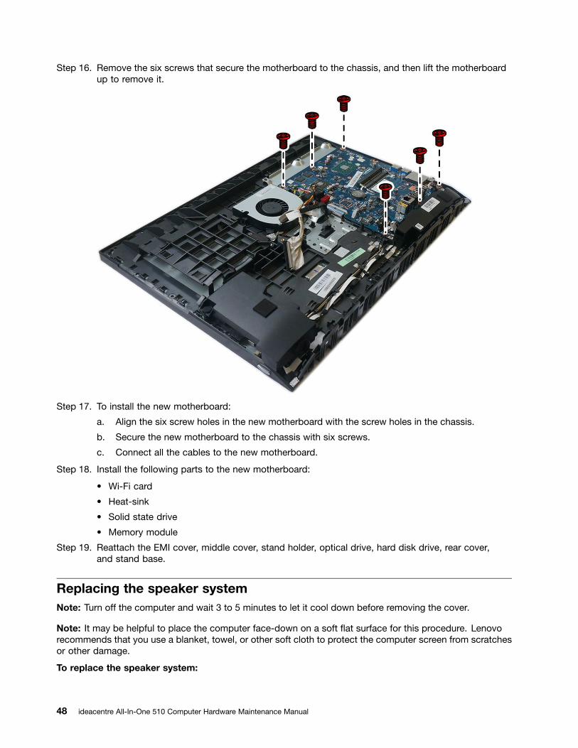
Step 16. Remove the six screws that secure the motherboard to the chassis, and then lift the motherboardup to remove it.
Step 17. To install the new motherboard:
a. Align the six screw holes in the new motherboard with the screw holes in the chassis.
b. Secure the new motherboard to the chassis with six screws.
c. Connect all the cables to the new motherboard.
Step 18. Install the following parts to the new motherboard:
• Wi-Fi card
• Heat-sink
• Solid state drive
• Memory module
Step 19. Reattach the EMI cover, middle cover, stand holder, optical drive, hard disk drive, rear cover,and stand base.
Replacing the speaker systemNote: Turn off the computer and wait 3 to 5 minutes to let it cool down before removing the cover.
Note: It may be helpful to place the computer face-down on a soft flat surface for this procedure. Lenovorecommends that you use a blanket, towel, or other soft cloth to protect the computer screen from scratchesor other damage.
To replace the speaker system:
48 ideacentre All-In-One 510 Computer Hardware Maintenance Manual

Step 1. Remove any media from the drives, shut down the operating system, and turn off the computerand all attached devices.
Step 2. Unplug all power cords from electrical outlets.
Step 3. Disconnect all cables attached to the computer. This includes power cords, input/output (I/O)cables, and any other cables that are connected to the computer. Refer to Locating connectors,controls and components to locate the various connectors.
Step 4. Remove the stand base. Refer to Removing the stand base.
Step 5. Remove the rear cover. Refer to Removing the rear cover.
Step 6. Remove the hard disk drive. Refer to Replacing the hard disk drive.
Step 7. Remove the optical drive. Refer to Replacing the optical drive.
Step 8. Remove the stand holder. Refer to Removing the stand holder.
Step 9. Remove the middle cover. Refer to Removing the middle cover.
Step 10. Remove the EMI cover. Refer to Removing the EMI cover.
Step 11. Disconnect the speaker cable from the connector on the motherboard 1 , and then slide the rubberscrews of the speaker system out of the screw slots.
Step 12. Lift up the speaker system to remove it. 2
Step 13. To install the new speaker system:
a. Slide in the rubber screws of the new speaker system into the screw slots in the chassis.
b. Connect the cable to the motherboard.
Step 14. Reattach EMI cover, middle cover, stand holder, optical drive, hard disk drive, rear cover, andstand base.
Chapter 8. Replacing hardware 49
Replacing the cameraNote: Turn off the computer and wait 3 to 5 minutes to let it cool down before removing the cover.
Note: It may be helpful to place the computer face-down on a soft flat surface for this procedure. Lenovorecommends that you use a blanket, towel, or other soft cloth to protect the computer screen from scratchesor other damage.
To replace the camera:
Step 1. Remove any media from the drives, shut down the operating system, and turn off the computerand all attached devices.
Step 2. Unplug all power cords from electrical outlets.
Step 3. Disconnect all cables attached to the computer. This includes power cords, input/output (I/O)cables, and any other cables that are connected to the computer. Refer to Locating connectors,controls and components to locate the various connectors.
Step 4. Remove the stand base. Refer to Removing the stand base.
Step 5. Remove the rear cover. Refer to Removing the rear cover.
Step 6. Remove the hard disk drive. Refer to Replacing the hard disk drive.
Step 7. Remove the optical drive. Refer to Replacing the optical drive.
Step 8. Remove the stand holder. Refer to Removing the stand holder.
Step 9. Remove the middle cover. Refer to Removing the middle cover.
Step 10. Remove the EMI cover. Refer to Removing the EMI cover.
Step 11. Remove the speaker system. Refer to Replacing the speaker system.
Step 12. Disconnect the camera cable form the corresponding connector on the motherboard. Refer toLocating connectors, controls and components.
50 ideacentre All-In-One 510 Computer Hardware Maintenance Manual

Step 13. Push the locking pin outwards 1 , and then lift up the camera module. 2
Step 14. To install the new camera:
a. Connect the camera cable to the new camera.
b. Push the camera locking pin outwards, and then place the new camera into position.
Step 15. Reattach the speaker system, EMI cover, middle cover, stand holder, optical drive, hard diskdrive, rear cover, and stand base.
Chapter 8. Replacing hardware 51

52 ideacentre All-In-One 510 Computer Hardware Maintenance Manual

Chapter 9. FRU lists
This chapter lists the information on the field replaceable units (FRUs) for ideacentre All-In-One 510 desktopcomputer.
Attention: Be sure to read and understand all the safety information before replacing any FRUs.
Notes: FRUs that have a 1 or 2 in the CRU column are Customer Replaceable Units (CRUs).
• 1– identifies parts that are fairly simple to replace, requiring few or no tools.
• 2– identifies parts that are slightly more difficult to replace.
• N-identifies parts that are not to be replaced by the customer.
Table 1. AIO 510–22ASR FRU list
FRU P/N Description
AC_ADAPTER
00PC726 AC_ADAPTER,90W,100-240Vac,3P
00PC727 AC_ADAPTER,120W,100-240Vac,3P
ANTENNA
00XJ086 C4C5 antenna
BDPLANAR
00UW342 MB,A9,UMA,NO,DPK
00UW343 MB,A9,UMA,WIN,DPK
00UW344 MB,A6,UMA,NO,DPK
00UW345 MB,A6,UMA,WIN,DPK
00UW346 MB,E2,UMA,NO,DPK
00UW347 MB,E2,UMA,WIN,DPK
00UW348 MB,A9,M435,1G,NO,DPK
00UW349 MB,A9,M435,1G,WIN,DPK
00UW350 MB,A6,M435,1G,NO,DPK
00UW351 MB,A6,M435,1G,WIN,DPK
00UW352 MB,A9,UMA,HDMI IN,NO,DPK
00UW353 MB,A9,UMA,HDMI IN,WIN,DPK
00UW354 MB,A6,UMA,HDMI IN,NO,DPK
00UW355 MB,A6,UMA,HDMI IN,WIN,DPK
00UW356 MB,E2,UMA,HDMI IN,NO,DPK
00UW357 MB,E2,UMA,HDMI IN,WIN,DPK
01GJ028 MB,E2,M435,1G,NO DPK
01GJ029 MB,E2,M435,1G,WIN DPK
CABLE
31032953 GS BLK1.0m3wire CCC power cord(R)
© Copyright Lenovo 2016 53

Table 1. AIO 510–22ASR FRU list (continued)
31033857 LW BLK1.0m3wire ULCSA power cord(R)
31033858 VL BLK1.0m3wire ULCSA power cord(R)
31035332 LW BLK 1.0m VDE power cord(R)
31035395 LW BLK 1.0m India power cord(R)
31035396 LW BLK 1.0m UK power cord(R)
31035397 LW BLK 1.0m ANZ power cord(R)
31035828 LW BLK 1.0m Brazil power cord(R)
31038885 LW BLK 1.0m Taiwan C5 power cord(R)
31039100 LW BLK 1.0m Argentina C5 power cord(R)
31039101 LW BLK 1.0m Denmark C5 power cord(R)
31039103 LW BLK 1.0m Switzerland C5 power cord(R)
31039104 LW BLK 1.0m Italy C5 power cord(R)
31039105 LW BLK 1.0m SA C5 power cord(R)
31039106 LW BLK 1.0m Korea C5 power cord(R)
31039107 LW BLK 1.0m Israel C5 power cord(R)
31045147 LX(ASAP) 1.0M C5 CCC power cord
31049496 Volex 1.0M C5 UK power cord
31049497 Volex 1.0M C5 EU power cord
31049498 Volex 1.0M C5 KOR power cord
31049499 Volex 1.0M C5 TW power cord
31049500 Volex 1.0M C5 ANZ power cord
31049501 Volex 1.0M C5 SA power cord
31049502 Volex 1.0M C5 ISI power cord
31049503 Volex 1.0M C5 DEN power cord
31049504 Volex 1.0M C5 ITY power cord
31049505 Volex 1.0M C5 BR power cord
31049507 Volex 1.0M C5 LA power cord
31049508 Volex 1.0M C5 SWI power cord
31049517 LX(ASAP) 1.0M C5 UL power cord
31049518 LX(ASAP) 1.0M C5 EU power cord
31049520 LX(ASAP) 1.0M C5 ANZ power cord
00XJ043 C4C5 HDD SATA cable
00XJ045 C4 ODD SATA cable
00XJ049 C4C5 Power board FFC
00XJ051 C4 LVDS cable
00XJ053 C4C5S5 Camera cable
00XJ055 C4C5S5 MIC cable
00XJ056 C4C5S5 Touch cable
CAMERA
54 ideacentre All-In-One 510 Computer Hardware Maintenance Manual

Table 1. AIO 510–22ASR FRU list (continued)
01AH324 AIO 510 720P Cam
COVER
01EF427 Rear Cover Black,nHDMI In,C4
01EF428 Rear Cover White,nHDMI In,C4
01EF429 Rear Cover Black,HDMI In,C4
01EF430 Rear Cover White,HDMI In,C4
DT_KYB
00UW407 Liteon SK-8861 2.4G KB(BR)-BLK
00XH587 USB Calliope KB BK ENG
00XH588 USB Calliope KB BK ARA
00XH591 USB,Calliope,KB,BK,BEL ENG
00XH593 USB Calliope KB BK BUL
00XH594 USB Calliope KB BK TC/ENG
00XH595 USB Calliope KB BK CZE
00XH598 USB Calliope KB BK FRA
00XH601 USB Calliope KB BK GER
00XH602 USB Calliope KB BK GRE
00XH604 USB Calliope KB BK HBW
00XH605 USB Calliope KB BK HUN
00XH607 USB Calliope KB BK ITA
00XH608 USB Calliope KB BK JPN
00XH610 USB Calliope KB BK KOR
00XH611 USB,Calliope,KB,BK,LA SPA
00XH614 USB Calliope KB BK POR
00XH616 USB Calliope KB BK RUS
00XH618 USB Calliope KB BK SLK
00XH619 USB Calliope KB BK SPA
00XH621 USB Calliope KB BK SWS
00XH622 USB Calliope KB BK THAI
00XH624 USB Calliope KB BK TUR
00XH625 USB Calliope KB BK UKE
00XH626 USB Calliope KB BK EURO ENG
00XH627 USB Calliope KB BK SLV
00XH630 USB Calliope KB BK IND ENG
00XH633 USB Calliope KB BK NORDIC
00XH635 USB Calliope KB BK CAN ENG/FRA
00XH637 USB,Calliope,KB,WH,ENG
00XH638 USB,Calliope,KB,WH,ARA
00XH641 USB,Calliope,KB,WH,BEL ENG
Chapter 9. FRU lists 55

Table 1. AIO 510–22ASR FRU list (continued)
00XH643 USB,Calliope,KB,WH,BUL
00XH644 USB,Calliope,KB,WH,TC/ENG
00XH645 USB,Calliope,KB,WH,CZE
00XH648 USB,Calliope,KB,WH,FRA
00XH651 USB,Calliope,KB,WH,GER
00XH652 USB,Calliope,KB,WH,GRE
00XH654 USB,Calliope,KB,WH,HBW
00XH655 USB,Calliope,KB,WH,HUN
00XH657 USB,Calliope,KB,WH,ITA
00XH658 USB,Calliope,KB,WH,JPN
00XH660 USB,Calliope,KB,WH,KOR
00XH661 USB Calliope KB WH LA SPA
00XH664 USB,Calliope,KB,WH,POR
00XH666 USB,Calliope,KB,WH,RUS
00XH668 USB,Calliope,KB,WH,SLK
00XH669 USB,Calliope,KB,WH,SPA
00XH671 USB,Calliope,KB,WH,SWS
00XH672 USB,Calliope,KB,WH,THAI
00XH674 USB,Calliope,KB,WH,TUR
00XH675 USB,Calliope,KB,WH,UKE
00XH676 USB,Calliope,KB,WH,EURO,ENG
00XH677 USB,Calliope,KB,WH,SLV
00XH680 USB,Calliope,KB,WH,IND,ENG
00XH683 USB,Calliope,KB,WH,NORDIC
00XH685 USB,Calliope,KB,WH,CAN,ENG/FRA
01AH627 Liteon 2.4G Black SK-8861 US
01AH628 Liteon 2.4G Black SK-8861 US-MY
01AH629 Liteon 2.4G Black SK-8861 TW
01AH630 Liteon 2.4G Black SK-8861 TH
01AH631 Liteon 2.4G Black SK-8861 CS-SK
01AH632 Liteon 2.4G Black SK-8861 US-IN
01AH633 Liteon 2.4G Black SK-8861 RU
01AH634 Liteon 2.4G Black SK-8861 GB
01AH635 Liteon 2.4G Black SK-8861 Nordic
01AH636 Liteon 2.4G Black SK-8861 LA
01AH637 Liteon 2.4G Black SK-8861 LA-AR
01AH638 Liteon 2.4G Black SK-8861 SA
01AH639 Liteon 2.4G Black SK-8861 CH
01AH640 Liteon 2.4G Black SK-8861 DE
56 ideacentre All-In-One 510 Computer Hardware Maintenance Manual

Table 1. AIO 510–22ASR FRU list (continued)
01AH641 Liteon 2.4G Black SK-8861 TR
01AH642 Liteon 2.4G Black SK-8861 ES
01AH643 Liteon 2.4G Black SK-8861 SL
01AH644 Liteon 2.4G Black SK-8861 IT
01AH645 Liteon 2.4G Black SK-8861 IL
01AH646 Liteon 2.4G Black SK-8861 FR
01AH647 Liteon 2.4G Black SK-8861 GR
01AH648 Liteon 2.4G Black SK-8861 HU
01AH649 Liteon 2.4G Black SK-8861 BG
01AH650 Liteon 2.4G Black SK-8861 KR
01AH651 Liteon 2.4G Black SK-8861 JP
01AH652 Liteon 2.4G Black SK-8861 EN-FR
01AH653 Liteon 2.4G Black SK-8861 PT
01AH654 Liteon 2.4G Black SK-8861 BE-EN
01AH655 Liteon 2.4G Black SK-8861 US-EU
FAN
00XD821 Sysfan for QT 90x15mm
HDD_ASM
00PC550 HDD,500G,7200,DT3,SATA3,STD
00PC551 HDD,1TB,7200,DT3,SATA3,STD
45K0623 HDD,1TB,7200,DT3,SATA3,STD
45K0629 HDD,500G,7200,DT3,SATA3,STD
HEATSINK
01EF355 FRU UMA Thermal Module
01EF356 FRU DIS Thermal Module
KYB_MOUSE
25210987 Liteon SK-8861(US) 2.4G KB-White8
25210988 Liteon SK-8861(US-MY) 2.4G KB-White8
25210989 Liteon SK-8861(TW) 2.4G KB-White8
25210990 Liteon SK-8861(TH) 2.4G KB-White8
25210991 Liteon SK-8861(CS-SK) 2.4G KB-White8
25210992 Liteon SK-8861(US-IN) 2.4G KB-White8
25210993 Liteon SK-8861(RU) 2.4G KB-White8
25210994 Liteon SK-8861(GB) 2.4G KB-White8
25210995 Liteon SK-8861(Nordic) 2.4G KB-White8
25210996 Liteon SK-8861(LA) 2.4G KB-White8
25210997 Liteon SK-8861(LA-AR) 2.4G KB-White8
25210998 Liteon SK-8861(SA) 2.4G KB-White8
25210999 Liteon SK-8861(CH) 2.4G KB-White8
Chapter 9. FRU lists 57

Table 1. AIO 510–22ASR FRU list (continued)
25211000 Liteon SK-8861(DE) 2.4G KB-White8
25211001 Liteon SK-8861(TR) 2.4G KB-White8
25211002 Liteon SK-8861(ES) 2.4G KB-White8
25211003 Liteon SK-8861(SL) 2.4G KB-White8
25211004 Liteon SK-8861(IT) 2.4G KB-White8
25211005 Liteon SK-8861(IL) 2.4G KB-White8
25211006 Liteon SK-8861(FR) 2.4G KB-White8
25211007 Liteon SK-8861(GR) 2.4G KB-White8
25211008 Liteon SK-8861(HU) 2.4G KB-White8
25211009 Liteon SK-8861(BG) 2.4G KB-White8
25211010 Liteon SK-8861(KR) 2.4G KB-White8
25211011 Liteon SK-8861(JP) 2.4G KB-White8
25211012 Liteon SK-8861(EN-FR) 2.4G KB-White8
25211013 Liteon SK-8861(PT) 2.4G KB-White8
25211014 Liteon SK-8861(BE-EN) 2.4G KB-White8
25211015 Liteon SK-8861(US-EU) 2.4G KB-White8
25211016 Liteon SM-8861(WW) 2.4G Mouse White
25211017 Liteon SM-8861 2.4G Mouse(No Battery)WTE
LINECORD
31503352 LX(ASAP) 1.0M C5 UK power cord
31503353 LX(ASAP) 1.0M C5 India power cord
31503354 LX(ASAP) 1.0M C5 Taiwan power cord
31503355 LX(ASAP) 1.0M C5 South Africa power cord
31503356 LX(ASAP) 1.0M C5 Argentina power cord
31503357 LX(ASAP) 1.0M C5 Brazil power cord
31503358 LX(ASAP) 1.0M C5 Korea power cord
31503359 LX(ASAP) 1.0M C5 Italy power cord
31503360 LX(ASAP) 1.0M C5 Danmark power cord
31503361 LX(ASAP) 1.0M C5 Switzerland power cord
31503362 LX(ASAP) 1.0M C5 Israel power cord
31503423 Longwell 1.0M C5 2pin Japan power cord
31503424 Volex 1.0M C5 2pin Japan power cord
31503425 LS 1.0M C5 2pin Japan power cord
00XL002 Fru, JP,Anti-TR,1M,2P,NON-LH
00XL003 Fru, JP,Anti-TR,1M,2P,NON-LH
00XL051 Fru,US/CA,1M,3P,NON-LH
00XL052 Fru, US/CA,1M,3P,NON-LH
00XL053 Fru, US/CA,1M,3P,NON-LH
00XL057 Fru, LINECORD,AR,1M,3P,NON-LH
58 ideacentre All-In-One 510 Computer Hardware Maintenance Manual
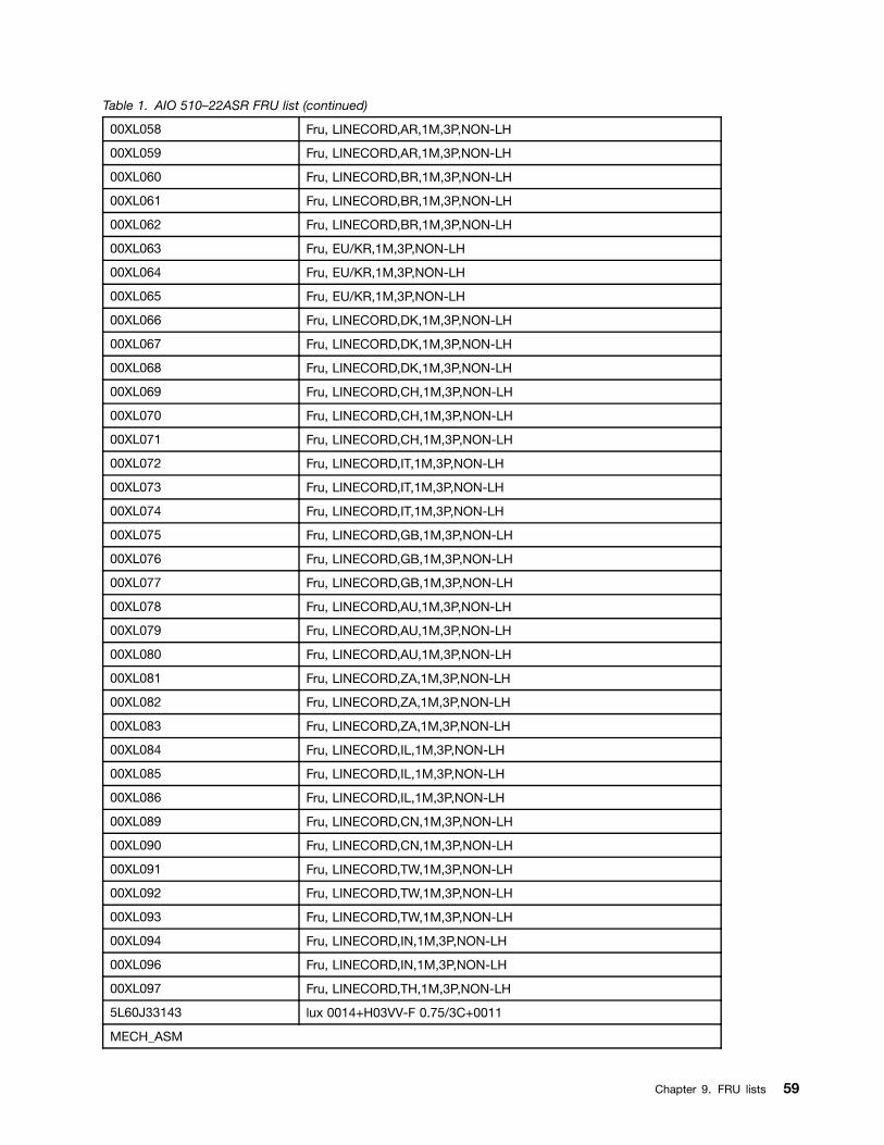
Table 1. AIO 510–22ASR FRU list (continued)
00XL058 Fru, LINECORD,AR,1M,3P,NON-LH
00XL059 Fru, LINECORD,AR,1M,3P,NON-LH
00XL060 Fru, LINECORD,BR,1M,3P,NON-LH
00XL061 Fru, LINECORD,BR,1M,3P,NON-LH
00XL062 Fru, LINECORD,BR,1M,3P,NON-LH
00XL063 Fru, EU/KR,1M,3P,NON-LH
00XL064 Fru, EU/KR,1M,3P,NON-LH
00XL065 Fru, EU/KR,1M,3P,NON-LH
00XL066 Fru, LINECORD,DK,1M,3P,NON-LH
00XL067 Fru, LINECORD,DK,1M,3P,NON-LH
00XL068 Fru, LINECORD,DK,1M,3P,NON-LH
00XL069 Fru, LINECORD,CH,1M,3P,NON-LH
00XL070 Fru, LINECORD,CH,1M,3P,NON-LH
00XL071 Fru, LINECORD,CH,1M,3P,NON-LH
00XL072 Fru, LINECORD,IT,1M,3P,NON-LH
00XL073 Fru, LINECORD,IT,1M,3P,NON-LH
00XL074 Fru, LINECORD,IT,1M,3P,NON-LH
00XL075 Fru, LINECORD,GB,1M,3P,NON-LH
00XL076 Fru, LINECORD,GB,1M,3P,NON-LH
00XL077 Fru, LINECORD,GB,1M,3P,NON-LH
00XL078 Fru, LINECORD,AU,1M,3P,NON-LH
00XL079 Fru, LINECORD,AU,1M,3P,NON-LH
00XL080 Fru, LINECORD,AU,1M,3P,NON-LH
00XL081 Fru, LINECORD,ZA,1M,3P,NON-LH
00XL082 Fru, LINECORD,ZA,1M,3P,NON-LH
00XL083 Fru, LINECORD,ZA,1M,3P,NON-LH
00XL084 Fru, LINECORD,IL,1M,3P,NON-LH
00XL085 Fru, LINECORD,IL,1M,3P,NON-LH
00XL086 Fru, LINECORD,IL,1M,3P,NON-LH
00XL089 Fru, LINECORD,CN,1M,3P,NON-LH
00XL090 Fru, LINECORD,CN,1M,3P,NON-LH
00XL091 Fru, LINECORD,TW,1M,3P,NON-LH
00XL092 Fru, LINECORD,TW,1M,3P,NON-LH
00XL093 Fru, LINECORD,TW,1M,3P,NON-LH
00XL094 Fru, LINECORD,IN,1M,3P,NON-LH
00XL096 Fru, LINECORD,IN,1M,3P,NON-LH
00XL097 Fru, LINECORD,TH,1M,3P,NON-LH
5L60J33143 lux 0014+H03VV-F 0.75/3C+0011
MECH_ASM
Chapter 9. FRU lists 59

Table 1. AIO 510–22ASR FRU list (continued)
01EF402 GT Stand light silver C4/5
01EF403 GT Stand deep silver C4/5
01EF404 Stronkin Stand light silver
01EF405 Stronkin Stand deep silver
01EF415 HDD CAGE
01EF416 ASSY Shielding for HDD
01EF417 ASSY Frame for MB_ASR
01EF418 MB SHIELDING,W/HDMI
01EF431 ASSY Mid Cover, Black, C4 ASR
01EF432 ASSY Mid Cover, White, C4 ASR
01EF435 ASSY Panel housing_ASR, white
01EF436 ASSY Panel housing_ASR, black
01EF439 ODD Bezel Black,C4
01EF440 ODD Bezel White,C4
01EF441 ASSY PANEL LGD LM215WF9-SSA1 NT
01EF442 ASSY PANEL BOE MV215FHM-N40,NT
01EF443 ASSY PANEL LGD LM215WFA-SSA1 T
01EF444 FRONT COVER,NON-CAM Black C4
01EF445 FRONT COVER,NON-CAM WHITE C4
01EF446 FRONT COVER,W/CAM Black C4
01EF447 FRONT COVER,W/CAM WHITE C4
01EF471 DUMMY ODD Bezel Black,C4
01EF472 DUMMY ODD Bezel White,C4
01EF473 MB SHIELDING,WO/HDMI
MECHANICAL
01EF422 Rubber, For speaker lock
01EF448 Cover, Side IO Cover,White
01EF449 Cover, Side IO Cover,Black
01EF450 SPONGE, For Front housing, C4
01EF457 Bracket, For kensinton lock
01EF458 Bracket, For camera module
01EF459 Bracket, For Panel,C5
01EF469 Bracket,For WIFI Antenna Kit
01EF537 Bracket Latch, For ODD
MEMORY
01AG700 2GB DDR4 2400 SoDIMM
01AG701 4GB DDR4 2400 SoDIMM
01AG704 2GB DDR4 2400 SoDIMM
01AG705 2GB DDR4 2400 SoDIMM
60 ideacentre All-In-One 510 Computer Hardware Maintenance Manual

Table 1. AIO 510–22ASR FRU list (continued)
01AG706 2GB DDR4 2400 SoDIMM
01AG707 4GB DDR4 2400 SoDIMM
01AG708 4GB DDR4 2400 SoDIMM
01AG709 4GB DDR4 2400 SoDIMM
01AG710 8GB DDR4 2400 SoDIMM
01AG711 8GB DDR4 2400 SoDIMM
01AG712 8GB DDR4 2400 SoDIMM
MICROPHONE
01AH402 AIO 510 Microphone
MOUSE
00PH131 USB Calliope Mouse Black(Orange wh
00PH132 USB,Calliope,Mouse,White
00UW408 Liteon SM-8861(WW) Mouse Black
01AH700 Liteon SM-8861(WW) Mouse Black
OPT_DRIVE
00FC442 SMD,DT,SATA,9.5mm,x8,w/o bezel
SPEAKERINT
01AH925 AIO 510 speaker
WIRELESS
00JT482 Wireless,CMB,CBT,8821AE
01AX709 Wireless,CMB,LTN,NFA435A
Table 2. AIO 510–22ISH FRU list
FRU P/N Description
AC_ADAPTER
00PC727 AC_ADAPTER,120W,100-240Vac,3P
ANTENNA
00XJ086 C4C5 antenna
BDPLANAR
00UW358 MB UMA NO DPK
00UW359 MB UMA WIN DPK
00UW360 MB M435 1G NO DPK
00UW361 MB M435 1G WIN DPK
00UW362 MB M435 2G NO DPK
00UW363 MB M435 2G WIN DPK
00UW364 MB,UMA,HDMI IN,NO DPK
00UW365 MB,UMA,HDMI IN,WIN DPK
CABLE
31032953 GS BLK1.0m3wire CCC power cord(R)
Chapter 9. FRU lists 61

Table 2. AIO 510–22ISH FRU list (continued)
31033857 LW BLK1.0m3wire ULCSA power cord(R)
31033858 VL BLK1.0m3wire ULCSA power cord(R)
31035332 LW BLK 1.0m VDE power cord(R)
31035395 LW BLK 1.0m India power cord(R)
31035396 LW BLK 1.0m UK power cord(R)
31035397 LW BLK 1.0m ANZ power cord(R)
31035828 LW BLK 1.0m Brazil power cord(R)
31038885 LW BLK 1.0m Taiwan C5 power cord(R)
31039100 LW BLK 1.0m Argentina C5 power cord(R)
31039101 LW BLK 1.0m Denmark C5 power cord(R)
31039103 LW BLK 1.0m Switzerland C5 power cord(R)
31039104 LW BLK 1.0m Italy C5 power cord(R)
31039105 LW BLK 1.0m SA C5 power cord(R)
31039106 LW BLK 1.0m Korea C5 power cord(R)
31039107 LW BLK 1.0m Israel C5 power cord(R)
31045147 LX(ASAP) 1.0M C5 CCC power cord
31049496 Volex 1.0M C5 UK power cord
31049497 Volex 1.0M C5 EU power cord
31049498 Volex 1.0M C5 KOR power cord
31049499 Volex 1.0M C5 TW power cord
31049500 Volex 1.0M C5 ANZ power cord
31049501 Volex 1.0M C5 SA power cord
31049502 Volex 1.0M C5 ISI power cord
31049503 Volex 1.0M C5 DEN power cord
31049504 Volex 1.0M C5 ITY power cord
31049505 Volex 1.0M C5 BR power cord
31049507 Volex 1.0M C5 LA power cord
31049508 Volex 1.0M C5 SWI power cord
31049517 LX(ASAP) 1.0M C5 UL power cord
31049518 LX(ASAP) 1.0M C5 EU power cord
31049520 LX(ASAP) 1.0M C5 ANZ power cord
00XJ043 C4C5 HDD SATA cable
00XJ045 C4 ODD SATA cable
00XJ049 C4C5 Power board FFC
00XJ051 C4 LVDS cable
00XJ053 C4C5S5 Camera cable
00XJ055 C4C5S5 MIC cable
00XJ056 C4C5S5 Touch cable
CAMERA
62 ideacentre All-In-One 510 Computer Hardware Maintenance Manual
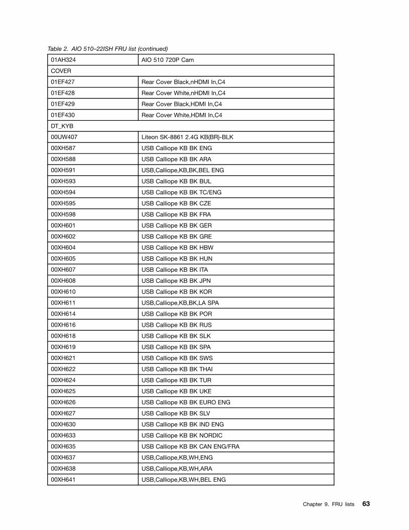
Table 2. AIO 510–22ISH FRU list (continued)
01AH324 AIO 510 720P Cam
COVER
01EF427 Rear Cover Black,nHDMI In,C4
01EF428 Rear Cover White,nHDMI In,C4
01EF429 Rear Cover Black,HDMI In,C4
01EF430 Rear Cover White,HDMI In,C4
DT_KYB
00UW407 Liteon SK-8861 2.4G KB(BR)-BLK
00XH587 USB Calliope KB BK ENG
00XH588 USB Calliope KB BK ARA
00XH591 USB,Calliope,KB,BK,BEL ENG
00XH593 USB Calliope KB BK BUL
00XH594 USB Calliope KB BK TC/ENG
00XH595 USB Calliope KB BK CZE
00XH598 USB Calliope KB BK FRA
00XH601 USB Calliope KB BK GER
00XH602 USB Calliope KB BK GRE
00XH604 USB Calliope KB BK HBW
00XH605 USB Calliope KB BK HUN
00XH607 USB Calliope KB BK ITA
00XH608 USB Calliope KB BK JPN
00XH610 USB Calliope KB BK KOR
00XH611 USB,Calliope,KB,BK,LA SPA
00XH614 USB Calliope KB BK POR
00XH616 USB Calliope KB BK RUS
00XH618 USB Calliope KB BK SLK
00XH619 USB Calliope KB BK SPA
00XH621 USB Calliope KB BK SWS
00XH622 USB Calliope KB BK THAI
00XH624 USB Calliope KB BK TUR
00XH625 USB Calliope KB BK UKE
00XH626 USB Calliope KB BK EURO ENG
00XH627 USB Calliope KB BK SLV
00XH630 USB Calliope KB BK IND ENG
00XH633 USB Calliope KB BK NORDIC
00XH635 USB Calliope KB BK CAN ENG/FRA
00XH637 USB,Calliope,KB,WH,ENG
00XH638 USB,Calliope,KB,WH,ARA
00XH641 USB,Calliope,KB,WH,BEL ENG
Chapter 9. FRU lists 63

Table 2. AIO 510–22ISH FRU list (continued)
00XH643 USB,Calliope,KB,WH,BUL
00XH644 USB,Calliope,KB,WH,TC/ENG
00XH645 USB,Calliope,KB,WH,CZE
00XH648 USB,Calliope,KB,WH,FRA
00XH651 USB,Calliope,KB,WH,GER
00XH652 USB,Calliope,KB,WH,GRE
00XH654 USB,Calliope,KB,WH,HBW
00XH655 USB,Calliope,KB,WH,HUN
00XH657 USB,Calliope,KB,WH,ITA
00XH658 USB,Calliope,KB,WH,JPN
00XH660 USB,Calliope,KB,WH,KOR
00XH661 USB Calliope KB WH LA SPA
00XH664 USB,Calliope,KB,WH,POR
00XH666 USB,Calliope,KB,WH,RUS
00XH668 USB,Calliope,KB,WH,SLK
00XH669 USB,Calliope,KB,WH,SPA
00XH671 USB,Calliope,KB,WH,SWS
00XH672 USB,Calliope,KB,WH,THAI
00XH674 USB,Calliope,KB,WH,TUR
00XH675 USB,Calliope,KB,WH,UKE
00XH676 USB,Calliope,KB,WH,EURO,ENG
00XH677 USB,Calliope,KB,WH,SLV
00XH680 USB,Calliope,KB,WH,IND,ENG
00XH683 USB,Calliope,KB,WH,NORDIC
00XH685 USB,Calliope,KB,WH,CAN,ENG/FRA
01AH627 Liteon 2.4G Black SK-8861 US
01AH628 Liteon 2.4G Black SK-8861 US-MY
01AH629 Liteon 2.4G Black SK-8861 TW
01AH630 Liteon 2.4G Black SK-8861 TH
01AH631 Liteon 2.4G Black SK-8861 CS-SK
01AH632 Liteon 2.4G Black SK-8861 US-IN
01AH633 Liteon 2.4G Black SK-8861 RU
01AH634 Liteon 2.4G Black SK-8861 GB
01AH635 Liteon 2.4G Black SK-8861 Nordic
01AH636 Liteon 2.4G Black SK-8861 LA
01AH637 Liteon 2.4G Black SK-8861 LA-AR
01AH638 Liteon 2.4G Black SK-8861 SA
01AH639 Liteon 2.4G Black SK-8861 CH
01AH640 Liteon 2.4G Black SK-8861 DE
64 ideacentre All-In-One 510 Computer Hardware Maintenance Manual
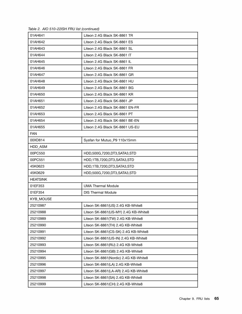
Table 2. AIO 510–22ISH FRU list (continued)
01AH641 Liteon 2.4G Black SK-8861 TR
01AH642 Liteon 2.4G Black SK-8861 ES
01AH643 Liteon 2.4G Black SK-8861 SL
01AH644 Liteon 2.4G Black SK-8861 IT
01AH645 Liteon 2.4G Black SK-8861 IL
01AH646 Liteon 2.4G Black SK-8861 FR
01AH647 Liteon 2.4G Black SK-8861 GR
01AH648 Liteon 2.4G Black SK-8861 HU
01AH649 Liteon 2.4G Black SK-8861 BG
01AH650 Liteon 2.4G Black SK-8861 KR
01AH651 Liteon 2.4G Black SK-8861 JP
01AH652 Liteon 2.4G Black SK-8861 EN-FR
01AH653 Liteon 2.4G Black SK-8861 PT
01AH654 Liteon 2.4G Black SK-8861 BE-EN
01AH655 Liteon 2.4G Black SK-8861 US-EU
FAN
00XD814 Sysfan for Mutuo_P9 110x15mm
HDD_ASM
00PC550 HDD,500G,7200,DT3,SATA3,STD
00PC551 HDD,1TB,7200,DT3,SATA3,STD
45K0623 HDD,1TB,7200,DT3,SATA3,STD
45K0629 HDD,500G,7200,DT3,SATA3,STD
HEATSINK
01EF353 UMA Thermal Module
01EF354 DIS Thermal Module
KYB_MOUSE
25210987 Liteon SK-8861(US) 2.4G KB-White8
25210988 Liteon SK-8861(US-MY) 2.4G KB-White8
25210989 Liteon SK-8861(TW) 2.4G KB-White8
25210990 Liteon SK-8861(TH) 2.4G KB-White8
25210991 Liteon SK-8861(CS-SK) 2.4G KB-White8
25210992 Liteon SK-8861(US-IN) 2.4G KB-White8
25210993 Liteon SK-8861(RU) 2.4G KB-White8
25210994 Liteon SK-8861(GB) 2.4G KB-White8
25210995 Liteon SK-8861(Nordic) 2.4G KB-White8
25210996 Liteon SK-8861(LA) 2.4G KB-White8
25210997 Liteon SK-8861(LA-AR) 2.4G KB-White8
25210998 Liteon SK-8861(SA) 2.4G KB-White8
25210999 Liteon SK-8861(CH) 2.4G KB-White8
Chapter 9. FRU lists 65

Table 2. AIO 510–22ISH FRU list (continued)
25211000 Liteon SK-8861(DE) 2.4G KB-White8
25211001 Liteon SK-8861(TR) 2.4G KB-White8
25211002 Liteon SK-8861(ES) 2.4G KB-White8
25211003 Liteon SK-8861(SL) 2.4G KB-White8
25211004 Liteon SK-8861(IT) 2.4G KB-White8
25211005 Liteon SK-8861(IL) 2.4G KB-White8
25211006 Liteon SK-8861(FR) 2.4G KB-White8
25211007 Liteon SK-8861(GR) 2.4G KB-White8
25211008 Liteon SK-8861(HU) 2.4G KB-White8
25211009 Liteon SK-8861(BG) 2.4G KB-White8
25211010 Liteon SK-8861(KR) 2.4G KB-White8
25211011 Liteon SK-8861(JP) 2.4G KB-White8
25211012 Liteon SK-8861(EN-FR) 2.4G KB-White8
25211013 Liteon SK-8861(PT) 2.4G KB-White8
25211014 Liteon SK-8861(BE-EN) 2.4G KB-White8
25211015 Liteon SK-8861(US-EU) 2.4G KB-White8
25211016 Liteon SM-8861(WW) 2.4G Mouse White
25211017 Liteon SM-8861 2.4G Mouse(No Battery)WTE
25211018 Liteon SM-8861 2.4G Mouse(MY) White
25211019 Liteon SM-8861 2.4G Mouse(JP) White
LINECORD
31503352 LX(ASAP) 1.0M C5 UK power cord
31503353 LX(ASAP) 1.0M C5 India power cord
31503354 LX(ASAP) 1.0M C5 Taiwan power cord
31503355 LX(ASAP) 1.0M C5 South Africa power cord
31503356 LX(ASAP) 1.0M C5 Argentina power cord
31503357 LX(ASAP) 1.0M C5 Brazil power cord
31503358 LX(ASAP) 1.0M C5 Korea power cord
31503359 LX(ASAP) 1.0M C5 Italy power cord
31503360 LX(ASAP) 1.0M C5 Danmark power cord
31503361 LX(ASAP) 1.0M C5 Switzerland power cord
31503362 LX(ASAP) 1.0M C5 Israel power cord
31503423 Longwell 1.0M C5 2pin Japan power cord
31503424 Volex 1.0M C5 2pin Japan power cord
31503425 LS 1.0M C5 2pin Japan power cord
00XL002 Fru, JP,Anti-TR,1M,2P,NON-LH
00XL003 Fru, JP,Anti-TR,1M,2P,NON-LH
00XL051 Fru,US/CA,1M,3P,NON-LH
00XL052 Fru, US/CA,1M,3P,NON-LH
66 ideacentre All-In-One 510 Computer Hardware Maintenance Manual
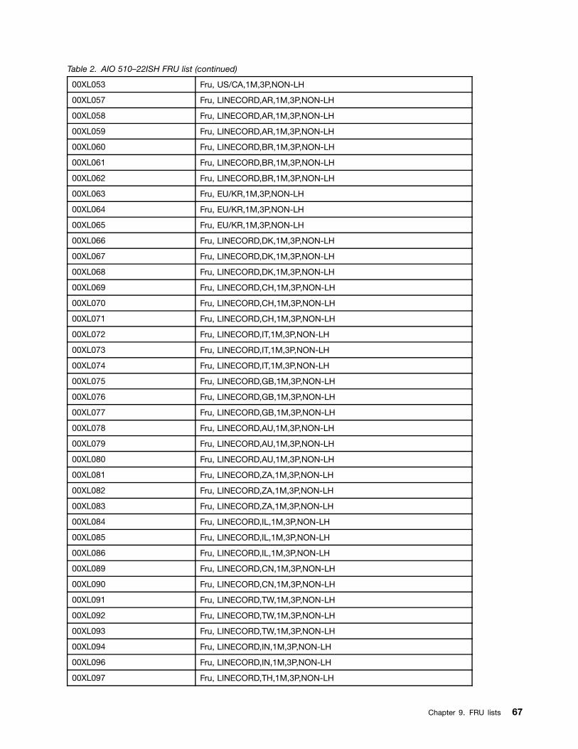
Table 2. AIO 510–22ISH FRU list (continued)
00XL053 Fru, US/CA,1M,3P,NON-LH
00XL057 Fru, LINECORD,AR,1M,3P,NON-LH
00XL058 Fru, LINECORD,AR,1M,3P,NON-LH
00XL059 Fru, LINECORD,AR,1M,3P,NON-LH
00XL060 Fru, LINECORD,BR,1M,3P,NON-LH
00XL061 Fru, LINECORD,BR,1M,3P,NON-LH
00XL062 Fru, LINECORD,BR,1M,3P,NON-LH
00XL063 Fru, EU/KR,1M,3P,NON-LH
00XL064 Fru, EU/KR,1M,3P,NON-LH
00XL065 Fru, EU/KR,1M,3P,NON-LH
00XL066 Fru, LINECORD,DK,1M,3P,NON-LH
00XL067 Fru, LINECORD,DK,1M,3P,NON-LH
00XL068 Fru, LINECORD,DK,1M,3P,NON-LH
00XL069 Fru, LINECORD,CH,1M,3P,NON-LH
00XL070 Fru, LINECORD,CH,1M,3P,NON-LH
00XL071 Fru, LINECORD,CH,1M,3P,NON-LH
00XL072 Fru, LINECORD,IT,1M,3P,NON-LH
00XL073 Fru, LINECORD,IT,1M,3P,NON-LH
00XL074 Fru, LINECORD,IT,1M,3P,NON-LH
00XL075 Fru, LINECORD,GB,1M,3P,NON-LH
00XL076 Fru, LINECORD,GB,1M,3P,NON-LH
00XL077 Fru, LINECORD,GB,1M,3P,NON-LH
00XL078 Fru, LINECORD,AU,1M,3P,NON-LH
00XL079 Fru, LINECORD,AU,1M,3P,NON-LH
00XL080 Fru, LINECORD,AU,1M,3P,NON-LH
00XL081 Fru, LINECORD,ZA,1M,3P,NON-LH
00XL082 Fru, LINECORD,ZA,1M,3P,NON-LH
00XL083 Fru, LINECORD,ZA,1M,3P,NON-LH
00XL084 Fru, LINECORD,IL,1M,3P,NON-LH
00XL085 Fru, LINECORD,IL,1M,3P,NON-LH
00XL086 Fru, LINECORD,IL,1M,3P,NON-LH
00XL089 Fru, LINECORD,CN,1M,3P,NON-LH
00XL090 Fru, LINECORD,CN,1M,3P,NON-LH
00XL091 Fru, LINECORD,TW,1M,3P,NON-LH
00XL092 Fru, LINECORD,TW,1M,3P,NON-LH
00XL093 Fru, LINECORD,TW,1M,3P,NON-LH
00XL094 Fru, LINECORD,IN,1M,3P,NON-LH
00XL096 Fru, LINECORD,IN,1M,3P,NON-LH
00XL097 Fru, LINECORD,TH,1M,3P,NON-LH
Chapter 9. FRU lists 67
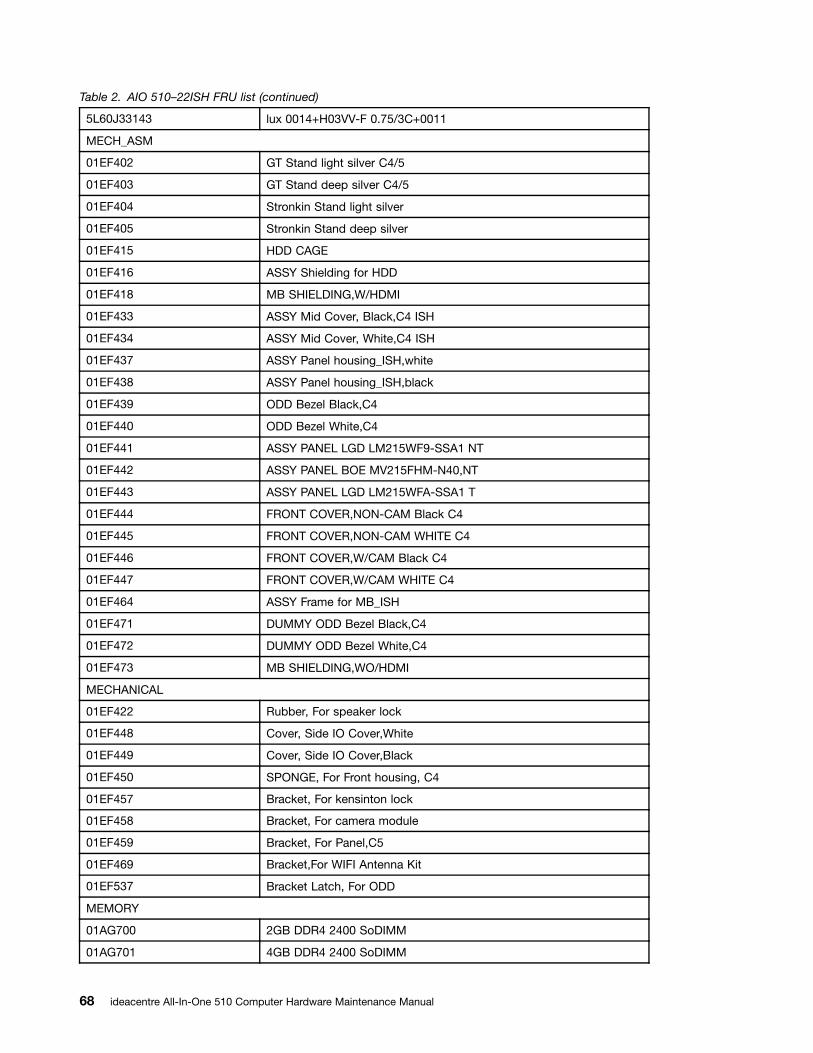
Table 2. AIO 510–22ISH FRU list (continued)
5L60J33143 lux 0014+H03VV-F 0.75/3C+0011
MECH_ASM
01EF402 GT Stand light silver C4/5
01EF403 GT Stand deep silver C4/5
01EF404 Stronkin Stand light silver
01EF405 Stronkin Stand deep silver
01EF415 HDD CAGE
01EF416 ASSY Shielding for HDD
01EF418 MB SHIELDING,W/HDMI
01EF433 ASSY Mid Cover, Black,C4 ISH
01EF434 ASSY Mid Cover, White,C4 ISH
01EF437 ASSY Panel housing_ISH,white
01EF438 ASSY Panel housing_ISH,black
01EF439 ODD Bezel Black,C4
01EF440 ODD Bezel White,C4
01EF441 ASSY PANEL LGD LM215WF9-SSA1 NT
01EF442 ASSY PANEL BOE MV215FHM-N40,NT
01EF443 ASSY PANEL LGD LM215WFA-SSA1 T
01EF444 FRONT COVER,NON-CAM Black C4
01EF445 FRONT COVER,NON-CAM WHITE C4
01EF446 FRONT COVER,W/CAM Black C4
01EF447 FRONT COVER,W/CAM WHITE C4
01EF464 ASSY Frame for MB_ISH
01EF471 DUMMY ODD Bezel Black,C4
01EF472 DUMMY ODD Bezel White,C4
01EF473 MB SHIELDING,WO/HDMI
MECHANICAL
01EF422 Rubber, For speaker lock
01EF448 Cover, Side IO Cover,White
01EF449 Cover, Side IO Cover,Black
01EF450 SPONGE, For Front housing, C4
01EF457 Bracket, For kensinton lock
01EF458 Bracket, For camera module
01EF459 Bracket, For Panel,C5
01EF469 Bracket,For WIFI Antenna Kit
01EF537 Bracket Latch, For ODD
MEMORY
01AG700 2GB DDR4 2400 SoDIMM
01AG701 4GB DDR4 2400 SoDIMM
68 ideacentre All-In-One 510 Computer Hardware Maintenance Manual

Table 2. AIO 510–22ISH FRU list (continued)
01AG704 2GB DDR4 2400 SoDIMM
01AG705 2GB DDR4 2400 SoDIMM
01AG706 2GB DDR4 2400 SoDIMM
01AG707 4GB DDR4 2400 SoDIMM
01AG708 4GB DDR4 2400 SoDIMM
01AG709 4GB DDR4 2400 SoDIMM
01AG710 8GB DDR4 2400 SoDIMM
01AG711 8GB DDR4 2400 SoDIMM
01AG712 8GB DDR4 2400 SoDIMM
MICROPHONE
01AH402 AIO 510 Microphone
MOUSE
00PH131 USB Calliope Mouse Black(Orange wh
00PH132 USB,Calliope,Mouse,White
00UW408 Liteon SM-8861(WW) Mouse Black
01AH700 Liteon SM-8861(WW) Mouse Black
01AH701 Liteon SM-8861 Mouse(MY) Black
01AH702 Liteon SM-8861(JP) Mouse-Black
OPT_DRIVE
00FC442 SMD,DT,SATA,9.5mm,x8,w/o bezel
SP
00XG111 Intel Core i3-6100T 3.2GHz 35W
00XG113 Intel Celeron G3900T 2.6GHz 35W
00XG114 Intel Pentium G4400T 2.9GHz 35W
01AG005 I I5-6400T 2.2GHz/4C/6M 35W
01AG047 I I5-6400T 2.2GHz/4C/6M 35W
SPEAKERINT
01AH925 AIO 510 speaker
SSD_ASM
00JT086 128G,M.2,2280,SATA6G,LTON,STD
00UP420 128G,M.2,2280,SATA6G,SAMSG,STD
WIRELESS
00JT482 Wireless,CMB,CBT,8821AE
00JT497 Wireless,CMB,IN,3165 ac
Table 3. AIO 510–23ASR FRU list
FRU P/N Description
AC_ADAPTER
00PC726 AC_ADAPTER,90W,100-240Vac,3P
Chapter 9. FRU lists 69

Table 3. AIO 510–23ASR FRU list (continued)
00PC727 AC_ADAPTER,120W,100-240Vac,3P
ANTENNA
00XJ086 C4C5 antenna
BDPLANAR
00UW366 MB AMD A9-941 UMA NO DPK
00UW367 MB AMD A9-941 UMA WIN DPK
00UW368 MB AMD A6-921 UMA NO DPK
00UW369 MB AMD A6-921 UMA WIN DPK
00UW370 MB AMD E2-901 UMA NO DPK
00UW371 MB AMD E2-901 UMA WIN DPK
00UW372 MB AMD A9-941 M435 2G NO DPK
00UW373 MB AMD A9-941 M435 2G WIN DPK
00UW374 MB AMD A6-921 M435 2G NO DPK
00UW375 MB AMD A6-921 M435 2G WIN DPK
CABLE
31032953 GS BLK1.0m3wire CCC power cord(R)
31033857 LW BLK1.0m3wire ULCSA power cord(R)
31033858 VL BLK1.0m3wire ULCSA power cord(R)
31035332 LW BLK 1.0m VDE power cord(R)
31035395 LW BLK 1.0m India power cord(R)
31035396 LW BLK 1.0m UK power cord(R)
31035397 LW BLK 1.0m ANZ power cord(R)
31035828 LW BLK 1.0m Brazil power cord(R)
31038885 LW BLK 1.0m Taiwan C5 power cord(R)
31039100 LW BLK 1.0m Argentina C5 power cord(R)
31039101 LW BLK 1.0m Denmark C5 power cord(R)
31039103 LW BLK 1.0m Switzerland C5 power cord(R)
31039104 LW BLK 1.0m Italy C5 power cord(R)
31039105 LW BLK 1.0m SA C5 power cord(R)
31039106 LW BLK 1.0m Korea C5 power cord(R)
31039107 LW BLK 1.0m Israel C5 power cord(R)
31045147 LX(ASAP) 1.0M C5 CCC power cord
31049496 Volex 1.0M C5 UK power cord
31049497 Volex 1.0M C5 EU power cord
31049498 Volex 1.0M C5 KOR power cord
31049499 Volex 1.0M C5 TW power cord
31049500 Volex 1.0M C5 ANZ power cord
31049501 Volex 1.0M C5 SA power cord
31049502 Volex 1.0M C5 ISI power cord
70 ideacentre All-In-One 510 Computer Hardware Maintenance Manual
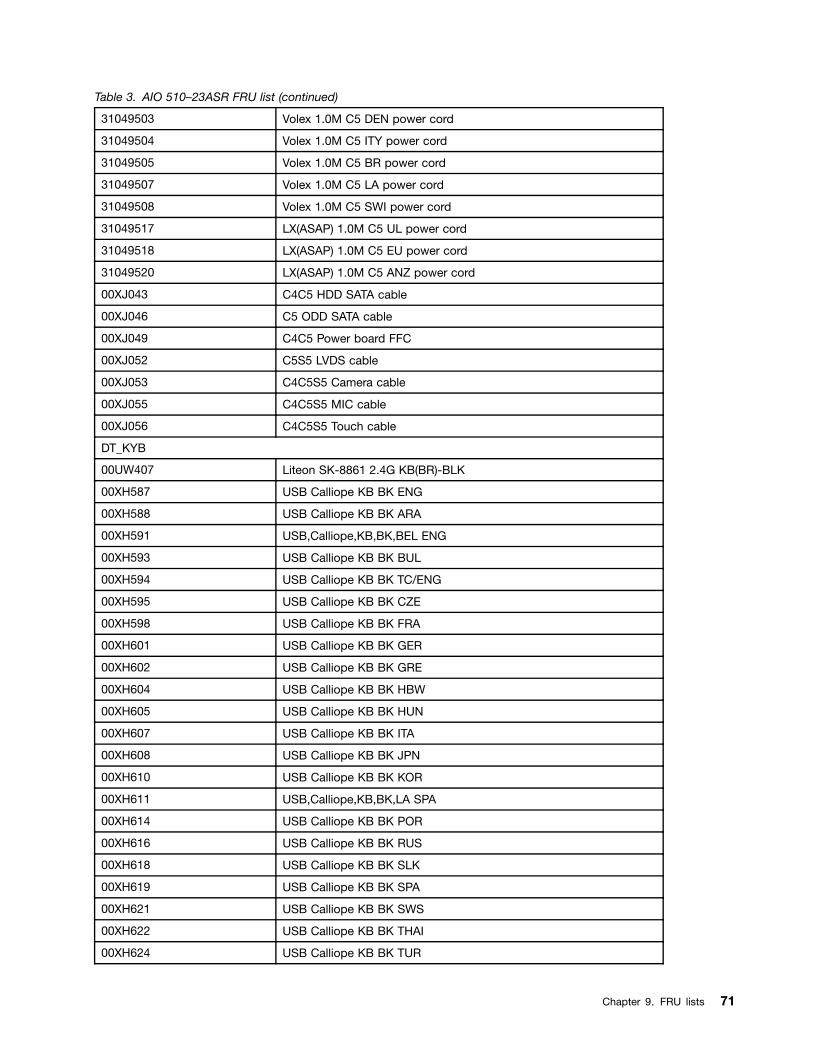
Table 3. AIO 510–23ASR FRU list (continued)
31049503 Volex 1.0M C5 DEN power cord
31049504 Volex 1.0M C5 ITY power cord
31049505 Volex 1.0M C5 BR power cord
31049507 Volex 1.0M C5 LA power cord
31049508 Volex 1.0M C5 SWI power cord
31049517 LX(ASAP) 1.0M C5 UL power cord
31049518 LX(ASAP) 1.0M C5 EU power cord
31049520 LX(ASAP) 1.0M C5 ANZ power cord
00XJ043 C4C5 HDD SATA cable
00XJ046 C5 ODD SATA cable
00XJ049 C4C5 Power board FFC
00XJ052 C5S5 LVDS cable
00XJ053 C4C5S5 Camera cable
00XJ055 C4C5S5 MIC cable
00XJ056 C4C5S5 Touch cable
DT_KYB
00UW407 Liteon SK-8861 2.4G KB(BR)-BLK
00XH587 USB Calliope KB BK ENG
00XH588 USB Calliope KB BK ARA
00XH591 USB,Calliope,KB,BK,BEL ENG
00XH593 USB Calliope KB BK BUL
00XH594 USB Calliope KB BK TC/ENG
00XH595 USB Calliope KB BK CZE
00XH598 USB Calliope KB BK FRA
00XH601 USB Calliope KB BK GER
00XH602 USB Calliope KB BK GRE
00XH604 USB Calliope KB BK HBW
00XH605 USB Calliope KB BK HUN
00XH607 USB Calliope KB BK ITA
00XH608 USB Calliope KB BK JPN
00XH610 USB Calliope KB BK KOR
00XH611 USB,Calliope,KB,BK,LA SPA
00XH614 USB Calliope KB BK POR
00XH616 USB Calliope KB BK RUS
00XH618 USB Calliope KB BK SLK
00XH619 USB Calliope KB BK SPA
00XH621 USB Calliope KB BK SWS
00XH622 USB Calliope KB BK THAI
00XH624 USB Calliope KB BK TUR
Chapter 9. FRU lists 71

Table 3. AIO 510–23ASR FRU list (continued)
00XH625 USB Calliope KB BK UKE
00XH626 USB Calliope KB BK EURO ENG
00XH627 USB Calliope KB BK SLV
00XH630 USB Calliope KB BK IND ENG
00XH633 USB Calliope KB BK NORDIC
00XH635 USB Calliope KB BK CAN ENG/FRA
00XH637 USB,Calliope,KB,WH,ENG
00XH638 USB,Calliope,KB,WH,ARA
00XH641 USB,Calliope,KB,WH,BEL ENG
00XH643 USB,Calliope,KB,WH,BUL
00XH644 USB,Calliope,KB,WH,TC/ENG
00XH645 USB,Calliope,KB,WH,CZE
00XH648 USB,Calliope,KB,WH,FRA
00XH651 USB,Calliope,KB,WH,GER
00XH652 USB,Calliope,KB,WH,GRE
00XH654 USB,Calliope,KB,WH,HBW
00XH655 USB,Calliope,KB,WH,HUN
00XH657 USB,Calliope,KB,WH,ITA
00XH658 USB,Calliope,KB,WH,JPN
00XH660 USB,Calliope,KB,WH,KOR
00XH661 USB Calliope KB WH LA SPA
00XH664 USB,Calliope,KB,WH,POR
00XH666 USB,Calliope,KB,WH,RUS
00XH668 USB,Calliope,KB,WH,SLK
00XH669 USB,Calliope,KB,WH,SPA
00XH671 USB,Calliope,KB,WH,SWS
00XH672 USB,Calliope,KB,WH,THAI
00XH674 USB,Calliope,KB,WH,TUR
00XH675 USB,Calliope,KB,WH,UKE
00XH676 USB,Calliope,KB,WH,EURO,ENG
00XH677 USB,Calliope,KB,WH,SLV
00XH680 USB,Calliope,KB,WH,IND,ENG
00XH683 USB,Calliope,KB,WH,NORDIC
00XH685 USB,Calliope,KB,WH,CAN,ENG/FRA
01AH627 Liteon 2.4G Black SK-8861 US
01AH628 Liteon 2.4G Black SK-8861 US-MY
01AH629 Liteon 2.4G Black SK-8861 TW
01AH630 Liteon 2.4G Black SK-8861 TH
01AH631 Liteon 2.4G Black SK-8861 CS-SK
72 ideacentre All-In-One 510 Computer Hardware Maintenance Manual
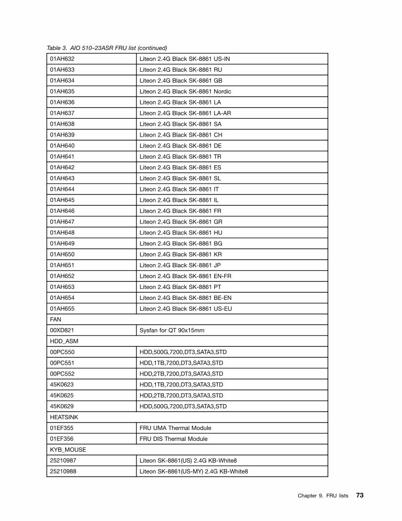
Table 3. AIO 510–23ASR FRU list (continued)
01AH632 Liteon 2.4G Black SK-8861 US-IN
01AH633 Liteon 2.4G Black SK-8861 RU
01AH634 Liteon 2.4G Black SK-8861 GB
01AH635 Liteon 2.4G Black SK-8861 Nordic
01AH636 Liteon 2.4G Black SK-8861 LA
01AH637 Liteon 2.4G Black SK-8861 LA-AR
01AH638 Liteon 2.4G Black SK-8861 SA
01AH639 Liteon 2.4G Black SK-8861 CH
01AH640 Liteon 2.4G Black SK-8861 DE
01AH641 Liteon 2.4G Black SK-8861 TR
01AH642 Liteon 2.4G Black SK-8861 ES
01AH643 Liteon 2.4G Black SK-8861 SL
01AH644 Liteon 2.4G Black SK-8861 IT
01AH645 Liteon 2.4G Black SK-8861 IL
01AH646 Liteon 2.4G Black SK-8861 FR
01AH647 Liteon 2.4G Black SK-8861 GR
01AH648 Liteon 2.4G Black SK-8861 HU
01AH649 Liteon 2.4G Black SK-8861 BG
01AH650 Liteon 2.4G Black SK-8861 KR
01AH651 Liteon 2.4G Black SK-8861 JP
01AH652 Liteon 2.4G Black SK-8861 EN-FR
01AH653 Liteon 2.4G Black SK-8861 PT
01AH654 Liteon 2.4G Black SK-8861 BE-EN
01AH655 Liteon 2.4G Black SK-8861 US-EU
FAN
00XD821 Sysfan for QT 90x15mm
HDD_ASM
00PC550 HDD,500G,7200,DT3,SATA3,STD
00PC551 HDD,1TB,7200,DT3,SATA3,STD
00PC552 HDD,2TB,7200,DT3,SATA3,STD
45K0623 HDD,1TB,7200,DT3,SATA3,STD
45K0625 HDD,2TB,7200,DT3,SATA3,STD
45K0629 HDD,500G,7200,DT3,SATA3,STD
HEATSINK
01EF355 FRU UMA Thermal Module
01EF356 FRU DIS Thermal Module
KYB_MOUSE
25210987 Liteon SK-8861(US) 2.4G KB-White8
25210988 Liteon SK-8861(US-MY) 2.4G KB-White8
Chapter 9. FRU lists 73

Table 3. AIO 510–23ASR FRU list (continued)
25210989 Liteon SK-8861(TW) 2.4G KB-White8
25210990 Liteon SK-8861(TH) 2.4G KB-White8
25210991 Liteon SK-8861(CS-SK) 2.4G KB-White8
25210992 Liteon SK-8861(US-IN) 2.4G KB-White8
25210993 Liteon SK-8861(RU) 2.4G KB-White8
25210994 Liteon SK-8861(GB) 2.4G KB-White8
25210995 Liteon SK-8861(Nordic) 2.4G KB-White8
25210996 Liteon SK-8861(LA) 2.4G KB-White8
25210997 Liteon SK-8861(LA-AR) 2.4G KB-White8
25210998 Liteon SK-8861(SA) 2.4G KB-White8
25210999 Liteon SK-8861(CH) 2.4G KB-White8
25211000 Liteon SK-8861(DE) 2.4G KB-White8
25211001 Liteon SK-8861(TR) 2.4G KB-White8
25211002 Liteon SK-8861(ES) 2.4G KB-White8
25211003 Liteon SK-8861(SL) 2.4G KB-White8
25211004 Liteon SK-8861(IT) 2.4G KB-White8
25211005 Liteon SK-8861(IL) 2.4G KB-White8
25211006 Liteon SK-8861(FR) 2.4G KB-White8
25211007 Liteon SK-8861(GR) 2.4G KB-White8
25211008 Liteon SK-8861(HU) 2.4G KB-White8
25211009 Liteon SK-8861(BG) 2.4G KB-White8
25211010 Liteon SK-8861(KR) 2.4G KB-White8
25211011 Liteon SK-8861(JP) 2.4G KB-White8
25211012 Liteon SK-8861(EN-FR) 2.4G KB-White8
25211013 Liteon SK-8861(PT) 2.4G KB-White8
25211014 Liteon SK-8861(BE-EN) 2.4G KB-White8
25211015 Liteon SK-8861(US-EU) 2.4G KB-White8
25211016 Liteon SM-8861(WW) 2.4G Mouse White
LINECORD
31503352 LX(ASAP) 1.0M C5 UK power cord
31503353 LX(ASAP) 1.0M C5 India power cord
31503354 LX(ASAP) 1.0M C5 Taiwan power cord
31503355 LX(ASAP) 1.0M C5 South Africa power cord
31503356 LX(ASAP) 1.0M C5 Argentina power cord
31503357 LX(ASAP) 1.0M C5 Brazil power cord
31503358 LX(ASAP) 1.0M C5 Korea power cord
31503359 LX(ASAP) 1.0M C5 Italy power cord
31503360 LX(ASAP) 1.0M C5 Danmark power cord
31503361 LX(ASAP) 1.0M C5 Switzerland power cord
74 ideacentre All-In-One 510 Computer Hardware Maintenance Manual
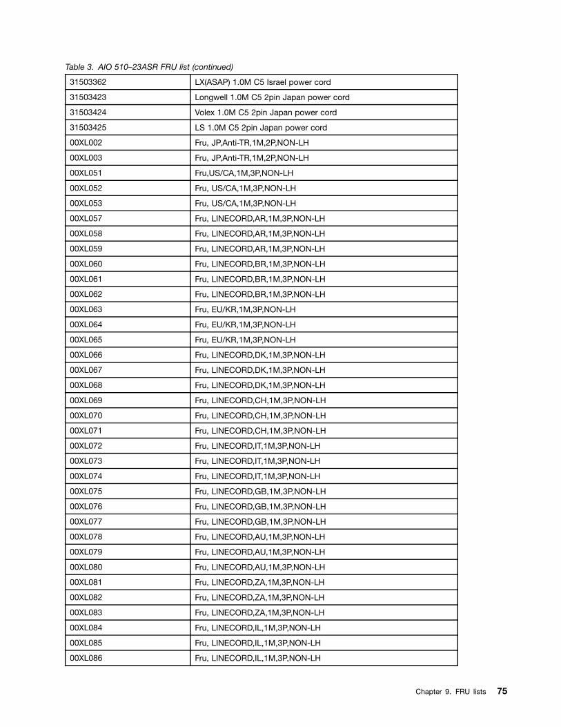
Table 3. AIO 510–23ASR FRU list (continued)
31503362 LX(ASAP) 1.0M C5 Israel power cord
31503423 Longwell 1.0M C5 2pin Japan power cord
31503424 Volex 1.0M C5 2pin Japan power cord
31503425 LS 1.0M C5 2pin Japan power cord
00XL002 Fru, JP,Anti-TR,1M,2P,NON-LH
00XL003 Fru, JP,Anti-TR,1M,2P,NON-LH
00XL051 Fru,US/CA,1M,3P,NON-LH
00XL052 Fru, US/CA,1M,3P,NON-LH
00XL053 Fru, US/CA,1M,3P,NON-LH
00XL057 Fru, LINECORD,AR,1M,3P,NON-LH
00XL058 Fru, LINECORD,AR,1M,3P,NON-LH
00XL059 Fru, LINECORD,AR,1M,3P,NON-LH
00XL060 Fru, LINECORD,BR,1M,3P,NON-LH
00XL061 Fru, LINECORD,BR,1M,3P,NON-LH
00XL062 Fru, LINECORD,BR,1M,3P,NON-LH
00XL063 Fru, EU/KR,1M,3P,NON-LH
00XL064 Fru, EU/KR,1M,3P,NON-LH
00XL065 Fru, EU/KR,1M,3P,NON-LH
00XL066 Fru, LINECORD,DK,1M,3P,NON-LH
00XL067 Fru, LINECORD,DK,1M,3P,NON-LH
00XL068 Fru, LINECORD,DK,1M,3P,NON-LH
00XL069 Fru, LINECORD,CH,1M,3P,NON-LH
00XL070 Fru, LINECORD,CH,1M,3P,NON-LH
00XL071 Fru, LINECORD,CH,1M,3P,NON-LH
00XL072 Fru, LINECORD,IT,1M,3P,NON-LH
00XL073 Fru, LINECORD,IT,1M,3P,NON-LH
00XL074 Fru, LINECORD,IT,1M,3P,NON-LH
00XL075 Fru, LINECORD,GB,1M,3P,NON-LH
00XL076 Fru, LINECORD,GB,1M,3P,NON-LH
00XL077 Fru, LINECORD,GB,1M,3P,NON-LH
00XL078 Fru, LINECORD,AU,1M,3P,NON-LH
00XL079 Fru, LINECORD,AU,1M,3P,NON-LH
00XL080 Fru, LINECORD,AU,1M,3P,NON-LH
00XL081 Fru, LINECORD,ZA,1M,3P,NON-LH
00XL082 Fru, LINECORD,ZA,1M,3P,NON-LH
00XL083 Fru, LINECORD,ZA,1M,3P,NON-LH
00XL084 Fru, LINECORD,IL,1M,3P,NON-LH
00XL085 Fru, LINECORD,IL,1M,3P,NON-LH
00XL086 Fru, LINECORD,IL,1M,3P,NON-LH
Chapter 9. FRU lists 75
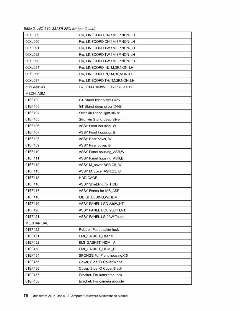
Table 3. AIO 510–23ASR FRU list (continued)
00XL089 Fru, LINECORD,CN,1M,3P,NON-LH
00XL090 Fru, LINECORD,CN,1M,3P,NON-LH
00XL091 Fru, LINECORD,TW,1M,3P,NON-LH
00XL092 Fru, LINECORD,TW,1M,3P,NON-LH
00XL093 Fru, LINECORD,TW,1M,3P,NON-LH
00XL094 Fru, LINECORD,IN,1M,3P,NON-LH
00XL096 Fru, LINECORD,IN,1M,3P,NON-LH
00XL097 Fru, LINECORD,TH,1M,3P,NON-LH
5L60J33143 lux 0014+H03VV-F 0.75/3C+0011
MECH_ASM
01EF402 GT Stand light silver C4/5
01EF403 GT Stand deep silver C4/5
01EF404 Stronkin Stand light silver
01EF405 Stronkin Stand deep silver
01EF406 ASSY Front housing, W
01EF407 ASSY Front housing, B
01EF408 ASSY Rear cover, W
01EF409 ASSY Rear cover, B
01EF410 ASSY Panel housing_ASR,W
01EF411 ASSY Panel housing_ASR,B
01EF412 ASSY M_cover ASR,C5, W
01EF413 ASSY M_cover ASR,C5, B
01EF415 HDD CAGE
01EF416 ASSY Shielding for HDD
01EF417 ASSY Frame for MB_ASR
01EF418 MB SHIELDING,W/HDMI
01EF419 ASSY PANEL LGD 230W,NT
01EF420 ASSY PANEL BOE 230FH,NT
01EF421 ASSY PANEL LG 23W Touch
MECHANICAL
01EF422 Rubber, For speaker lock
01EF451 EMI_GASKET_Rear IO
01EF452 EMI_GASKET_HDMI_A
01EF453 EMI_GASKET_HDMI_B
01EF454 SPONGE,For Front housing,C5
01EF455 Cover, Side IO Cover,White
01EF456 Cover, Side IO Cover,Black
01EF457 Bracket, For kensinton lock
01EF458 Bracket, For camera module
76 ideacentre All-In-One 510 Computer Hardware Maintenance Manual

Table 3. AIO 510–23ASR FRU list (continued)
01EF459 Bracket, For Panel,C5
01EF465 ASSY Bezel with ODD,RAM,W
01EF466 ASSY Bezel with ODD,RAM,B
01EF467 Bezel,Without ODD White C5
01EF468 Bezel,Without ODD BlackC5
01EF469 Bracket,For WIFI Antenna Kit
01EF537 Bracket Latch, For ODD
MEMORY
01AG700 2GB DDR4 2400 SoDIMM
01AG701 4GB DDR4 2400 SoDIMM
01AG704 2GB DDR4 2400 SoDIMM
01AG705 2GB DDR4 2400 SoDIMM
01AG706 2GB DDR4 2400 SoDIMM
01AG707 4GB DDR4 2400 SoDIMM
01AG708 4GB DDR4 2400 SoDIMM
01AG709 4GB DDR4 2400 SoDIMM
01AG710 8GB DDR4 2400 SoDIMM
01AG711 8GB DDR4 2400 SoDIMM
01AG712 8GB DDR4 2400 SoDIMM
MICROPHONE
01AH402 AIO 510 Microphone
MOUSE
00PH131 USB Calliope Mouse Black(Orange wh
00PH132 USB,Calliope,Mouse,White
01AH700 Liteon SM-8861(WW) Mouse Black
OPT_DRIVE
00FC442 SMD,DT,SATA,9.5mm,x8,w/o bezel
SPEAKERINT
01AH925 AIO 510 speaker
SSD_ASM
00JT086 128G,M.2,2280,SATA6G,LTON,STD
00JT087 256G,M.2,2280,SATA6G,LTON,STD
00UP420 128G,M.2,2280,SATA6G,SAMSG,STD
00UP422 256G,M.2,2280,SATA6G,SAMSG,STD
WIRELESS
00JT482 Wireless,CMB,CBT,8821AE
01AX709 Wireless,CMB,LTN,NFA435A
Chapter 9. FRU lists 77
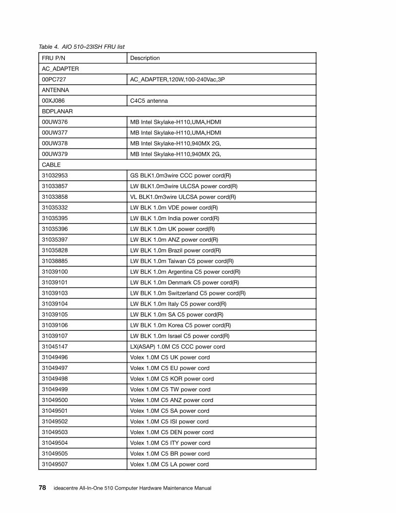
Table 4. AIO 510–23ISH FRU list
FRU P/N Description
AC_ADAPTER
00PC727 AC_ADAPTER,120W,100-240Vac,3P
ANTENNA
00XJ086 C4C5 antenna
BDPLANAR
00UW376 MB Intel Skylake-H110,UMA,HDMI
00UW377 MB Intel Skylake-H110,UMA,HDMI
00UW378 MB Intel Skylake-H110,940MX 2G,
00UW379 MB Intel Skylake-H110,940MX 2G,
CABLE
31032953 GS BLK1.0m3wire CCC power cord(R)
31033857 LW BLK1.0m3wire ULCSA power cord(R)
31033858 VL BLK1.0m3wire ULCSA power cord(R)
31035332 LW BLK 1.0m VDE power cord(R)
31035395 LW BLK 1.0m India power cord(R)
31035396 LW BLK 1.0m UK power cord(R)
31035397 LW BLK 1.0m ANZ power cord(R)
31035828 LW BLK 1.0m Brazil power cord(R)
31038885 LW BLK 1.0m Taiwan C5 power cord(R)
31039100 LW BLK 1.0m Argentina C5 power cord(R)
31039101 LW BLK 1.0m Denmark C5 power cord(R)
31039103 LW BLK 1.0m Switzerland C5 power cord(R)
31039104 LW BLK 1.0m Italy C5 power cord(R)
31039105 LW BLK 1.0m SA C5 power cord(R)
31039106 LW BLK 1.0m Korea C5 power cord(R)
31039107 LW BLK 1.0m Israel C5 power cord(R)
31045147 LX(ASAP) 1.0M C5 CCC power cord
31049496 Volex 1.0M C5 UK power cord
31049497 Volex 1.0M C5 EU power cord
31049498 Volex 1.0M C5 KOR power cord
31049499 Volex 1.0M C5 TW power cord
31049500 Volex 1.0M C5 ANZ power cord
31049501 Volex 1.0M C5 SA power cord
31049502 Volex 1.0M C5 ISI power cord
31049503 Volex 1.0M C5 DEN power cord
31049504 Volex 1.0M C5 ITY power cord
31049505 Volex 1.0M C5 BR power cord
31049507 Volex 1.0M C5 LA power cord
78 ideacentre All-In-One 510 Computer Hardware Maintenance Manual
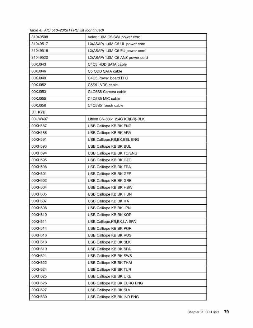
Table 4. AIO 510–23ISH FRU list (continued)
31049508 Volex 1.0M C5 SWI power cord
31049517 LX(ASAP) 1.0M C5 UL power cord
31049518 LX(ASAP) 1.0M C5 EU power cord
31049520 LX(ASAP) 1.0M C5 ANZ power cord
00XJ043 C4C5 HDD SATA cable
00XJ046 C5 ODD SATA cable
00XJ049 C4C5 Power board FFC
00XJ052 C5S5 LVDS cable
00XJ053 C4C5S5 Camera cable
00XJ055 C4C5S5 MIC cable
00XJ056 C4C5S5 Touch cable
DT_KYB
00UW407 Liteon SK-8861 2.4G KB(BR)-BLK
00XH587 USB Calliope KB BK ENG
00XH588 USB Calliope KB BK ARA
00XH591 USB,Calliope,KB,BK,BEL ENG
00XH593 USB Calliope KB BK BUL
00XH594 USB Calliope KB BK TC/ENG
00XH595 USB Calliope KB BK CZE
00XH598 USB Calliope KB BK FRA
00XH601 USB Calliope KB BK GER
00XH602 USB Calliope KB BK GRE
00XH604 USB Calliope KB BK HBW
00XH605 USB Calliope KB BK HUN
00XH607 USB Calliope KB BK ITA
00XH608 USB Calliope KB BK JPN
00XH610 USB Calliope KB BK KOR
00XH611 USB,Calliope,KB,BK,LA SPA
00XH614 USB Calliope KB BK POR
00XH616 USB Calliope KB BK RUS
00XH618 USB Calliope KB BK SLK
00XH619 USB Calliope KB BK SPA
00XH621 USB Calliope KB BK SWS
00XH622 USB Calliope KB BK THAI
00XH624 USB Calliope KB BK TUR
00XH625 USB Calliope KB BK UKE
00XH626 USB Calliope KB BK EURO ENG
00XH627 USB Calliope KB BK SLV
00XH630 USB Calliope KB BK IND ENG
Chapter 9. FRU lists 79

Table 4. AIO 510–23ISH FRU list (continued)
00XH633 USB Calliope KB BK NORDIC
00XH635 USB Calliope KB BK CAN ENG/FRA
00XH637 USB,Calliope,KB,WH,ENG
00XH638 USB,Calliope,KB,WH,ARA
00XH641 USB,Calliope,KB,WH,BEL ENG
00XH643 USB,Calliope,KB,WH,BUL
00XH644 USB,Calliope,KB,WH,TC/ENG
00XH645 USB,Calliope,KB,WH,CZE
00XH648 USB,Calliope,KB,WH,FRA
00XH651 USB,Calliope,KB,WH,GER
00XH652 USB,Calliope,KB,WH,GRE
00XH654 USB,Calliope,KB,WH,HBW
00XH655 USB,Calliope,KB,WH,HUN
00XH657 USB,Calliope,KB,WH,ITA
00XH658 USB,Calliope,KB,WH,JPN
00XH660 USB,Calliope,KB,WH,KOR
00XH661 USB Calliope KB WH LA SPA
00XH664 USB,Calliope,KB,WH,POR
00XH666 USB,Calliope,KB,WH,RUS
00XH668 USB,Calliope,KB,WH,SLK
00XH669 USB,Calliope,KB,WH,SPA
00XH671 USB,Calliope,KB,WH,SWS
00XH672 USB,Calliope,KB,WH,THAI
00XH674 USB,Calliope,KB,WH,TUR
00XH675 USB,Calliope,KB,WH,UKE
00XH676 USB,Calliope,KB,WH,EURO,ENG
00XH677 USB,Calliope,KB,WH,SLV
00XH680 USB,Calliope,KB,WH,IND,ENG
00XH683 USB,Calliope,KB,WH,NORDIC
00XH685 USB,Calliope,KB,WH,CAN,ENG/FRA
01AH627 Liteon 2.4G Black SK-8861 US
01AH628 Liteon 2.4G Black SK-8861 US-MY
01AH629 Liteon 2.4G Black SK-8861 TW
01AH630 Liteon 2.4G Black SK-8861 TH
01AH631 Liteon 2.4G Black SK-8861 CS-SK
01AH632 Liteon 2.4G Black SK-8861 US-IN
01AH633 Liteon 2.4G Black SK-8861 RU
01AH634 Liteon 2.4G Black SK-8861 GB
01AH635 Liteon 2.4G Black SK-8861 Nordic
80 ideacentre All-In-One 510 Computer Hardware Maintenance Manual

Table 4. AIO 510–23ISH FRU list (continued)
01AH636 Liteon 2.4G Black SK-8861 LA
01AH637 Liteon 2.4G Black SK-8861 LA-AR
01AH638 Liteon 2.4G Black SK-8861 SA
01AH639 Liteon 2.4G Black SK-8861 CH
01AH640 Liteon 2.4G Black SK-8861 DE
01AH641 Liteon 2.4G Black SK-8861 TR
01AH642 Liteon 2.4G Black SK-8861 ES
01AH643 Liteon 2.4G Black SK-8861 SL
01AH644 Liteon 2.4G Black SK-8861 IT
01AH645 Liteon 2.4G Black SK-8861 IL
01AH646 Liteon 2.4G Black SK-8861 FR
01AH647 Liteon 2.4G Black SK-8861 GR
01AH648 Liteon 2.4G Black SK-8861 HU
01AH649 Liteon 2.4G Black SK-8861 BG
01AH650 Liteon 2.4G Black SK-8861 KR
01AH651 Liteon 2.4G Black SK-8861 JP
01AH652 Liteon 2.4G Black SK-8861 EN-FR
01AH653 Liteon 2.4G Black SK-8861 PT
01AH654 Liteon 2.4G Black SK-8861 BE-EN
01AH655 Liteon 2.4G Black SK-8861 US-EU
FAN
00XD814 Sysfan for Mutuo_P9 110x15mm
HDD_ASM
00PC550 HDD,500G,7200,DT3,SATA3,STD
00PC551 HDD,1TB,7200,DT3,SATA3,STD
00PC552 HDD,2TB,7200,DT3,SATA3,STD
45K0623 HDD,1TB,7200,DT3,SATA3,STD
45K0625 HDD,2TB,7200,DT3,SATA3,STD
45K0629 HDD,500G,7200,DT3,SATA3,STD
HEATSINK
01EF353 UMA Thermal Module
01EF354 DIS Thermal Module
KYB_MOUSE
25210987 Liteon SK-8861(US) 2.4G KB-White8
25210988 Liteon SK-8861(US-MY) 2.4G KB-White8
25210989 Liteon SK-8861(TW) 2.4G KB-White8
25210990 Liteon SK-8861(TH) 2.4G KB-White8
25210991 Liteon SK-8861(CS-SK) 2.4G KB-White8
25210992 Liteon SK-8861(US-IN) 2.4G KB-White8
Chapter 9. FRU lists 81

Table 4. AIO 510–23ISH FRU list (continued)
25210993 Liteon SK-8861(RU) 2.4G KB-White8
25210994 Liteon SK-8861(GB) 2.4G KB-White8
25210995 Liteon SK-8861(Nordic) 2.4G KB-White8
25210996 Liteon SK-8861(LA) 2.4G KB-White8
25210997 Liteon SK-8861(LA-AR) 2.4G KB-White8
25210998 Liteon SK-8861(SA) 2.4G KB-White8
25210999 Liteon SK-8861(CH) 2.4G KB-White8
25211000 Liteon SK-8861(DE) 2.4G KB-White8
25211001 Liteon SK-8861(TR) 2.4G KB-White8
25211002 Liteon SK-8861(ES) 2.4G KB-White8
25211003 Liteon SK-8861(SL) 2.4G KB-White8
25211004 Liteon SK-8861(IT) 2.4G KB-White8
25211005 Liteon SK-8861(IL) 2.4G KB-White8
25211006 Liteon SK-8861(FR) 2.4G KB-White8
25211007 Liteon SK-8861(GR) 2.4G KB-White8
25211008 Liteon SK-8861(HU) 2.4G KB-White8
25211009 Liteon SK-8861(BG) 2.4G KB-White8
25211010 Liteon SK-8861(KR) 2.4G KB-White8
25211011 Liteon SK-8861(JP) 2.4G KB-White8
25211012 Liteon SK-8861(EN-FR) 2.4G KB-White8
25211013 Liteon SK-8861(PT) 2.4G KB-White8
25211014 Liteon SK-8861(BE-EN) 2.4G KB-White8
25211015 Liteon SK-8861(US-EU) 2.4G KB-White8
25211016 Liteon SM-8861(WW) 2.4G Mouse White
25211018 Liteon SM-8861 2.4G Mouse(MY) White
LINECORD
31503352 LX(ASAP) 1.0M C5 UK power cord
31503353 LX(ASAP) 1.0M C5 India power cord
31503354 LX(ASAP) 1.0M C5 Taiwan power cord
31503355 LX(ASAP) 1.0M C5 South Africa power cord
31503356 LX(ASAP) 1.0M C5 Argentina power cord
31503357 LX(ASAP) 1.0M C5 Brazil power cord
31503358 LX(ASAP) 1.0M C5 Korea power cord
31503359 LX(ASAP) 1.0M C5 Italy power cord
31503360 LX(ASAP) 1.0M C5 Danmark power cord
31503361 LX(ASAP) 1.0M C5 Switzerland power cord
31503362 LX(ASAP) 1.0M C5 Israel power cord
31503423 Longwell 1.0M C5 2pin Japan power cord
31503424 Volex 1.0M C5 2pin Japan power cord
82 ideacentre All-In-One 510 Computer Hardware Maintenance Manual

Table 4. AIO 510–23ISH FRU list (continued)
31503425 LS 1.0M C5 2pin Japan power cord
00XL002 Fru, JP,Anti-TR,1M,2P,NON-LH
00XL003 Fru, JP,Anti-TR,1M,2P,NON-LH
00XL051 Fru,US/CA,1M,3P,NON-LH
00XL052 Fru, US/CA,1M,3P,NON-LH
00XL053 Fru, US/CA,1M,3P,NON-LH
00XL057 Fru, LINECORD,AR,1M,3P,NON-LH
00XL058 Fru, LINECORD,AR,1M,3P,NON-LH
00XL059 Fru, LINECORD,AR,1M,3P,NON-LH
00XL060 Fru, LINECORD,BR,1M,3P,NON-LH
00XL061 Fru, LINECORD,BR,1M,3P,NON-LH
00XL062 Fru, LINECORD,BR,1M,3P,NON-LH
00XL063 Fru, EU/KR,1M,3P,NON-LH
00XL064 Fru, EU/KR,1M,3P,NON-LH
00XL065 Fru, EU/KR,1M,3P,NON-LH
00XL066 Fru, LINECORD,DK,1M,3P,NON-LH
00XL067 Fru, LINECORD,DK,1M,3P,NON-LH
00XL068 Fru, LINECORD,DK,1M,3P,NON-LH
00XL069 Fru, LINECORD,CH,1M,3P,NON-LH
00XL070 Fru, LINECORD,CH,1M,3P,NON-LH
00XL071 Fru, LINECORD,CH,1M,3P,NON-LH
00XL072 Fru, LINECORD,IT,1M,3P,NON-LH
00XL073 Fru, LINECORD,IT,1M,3P,NON-LH
00XL074 Fru, LINECORD,IT,1M,3P,NON-LH
00XL075 Fru, LINECORD,GB,1M,3P,NON-LH
00XL076 Fru, LINECORD,GB,1M,3P,NON-LH
00XL077 Fru, LINECORD,GB,1M,3P,NON-LH
00XL078 Fru, LINECORD,AU,1M,3P,NON-LH
00XL079 Fru, LINECORD,AU,1M,3P,NON-LH
00XL080 Fru, LINECORD,AU,1M,3P,NON-LH
00XL081 Fru, LINECORD,ZA,1M,3P,NON-LH
00XL082 Fru, LINECORD,ZA,1M,3P,NON-LH
00XL083 Fru, LINECORD,ZA,1M,3P,NON-LH
00XL084 Fru, LINECORD,IL,1M,3P,NON-LH
00XL085 Fru, LINECORD,IL,1M,3P,NON-LH
00XL086 Fru, LINECORD,IL,1M,3P,NON-LH
00XL089 Fru, LINECORD,CN,1M,3P,NON-LH
00XL090 Fru, LINECORD,CN,1M,3P,NON-LH
00XL091 Fru, LINECORD,TW,1M,3P,NON-LH
Chapter 9. FRU lists 83

Table 4. AIO 510–23ISH FRU list (continued)
00XL092 Fru, LINECORD,TW,1M,3P,NON-LH
00XL093 Fru, LINECORD,TW,1M,3P,NON-LH
00XL094 Fru, LINECORD,IN,1M,3P,NON-LH
00XL096 Fru, LINECORD,IN,1M,3P,NON-LH
00XL097 Fru, LINECORD,TH,1M,3P,NON-LH
5L60J33143 lux 0014+H03VV-F 0.75/3C+0011
MECH_ASM
01EF402 GT Stand light silver C4/5
01EF403 GT Stand deep silver C4/5
01EF404 Stronkin Stand light silver
01EF405 Stronkin Stand deep silver
01EF406 ASSY Front housing, W
01EF407 ASSY Front housing, B
01EF408 ASSY Rear cover, W
01EF409 ASSY Rear cover, B
01EF415 HDD CAGE
01EF416 ASSY Shielding for HDD
01EF418 MB SHIELDING,W/HDMI
01EF419 ASSY PANEL LGD 230W,NT
01EF420 ASSY PANEL BOE 230FH,NT
01EF421 ASSY PANEL LG 23W Touch
01EF460 ASSY Panel housing_ISH,W
01EF461 ASSY Panel housing_ISH,B
01EF462 ASSY M_cover for ISH,C5,W
01EF463 ASSY M_cover for ISH,C5, B
01EF464 ASSY Frame for MB_ISH
MECHANICAL
01EF422 Rubber, For speaker lock
01EF451 EMI_GASKET_Rear IO
01EF452 EMI_GASKET_HDMI_A
01EF453 EMI_GASKET_HDMI_B
01EF454 SPONGE,For Front housing,C5
01EF455 Cover, Side IO Cover,White
01EF456 Cover, Side IO Cover,Black
01EF457 Bracket, For kensinton lock
01EF458 Bracket, For camera module
01EF459 Bracket, For Panel,C5
01EF465 ASSY Bezel with ODD,RAM,W
01EF466 ASSY Bezel with ODD,RAM,B
84 ideacentre All-In-One 510 Computer Hardware Maintenance Manual
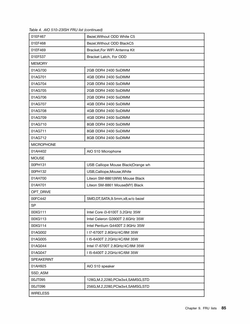
Table 4. AIO 510–23ISH FRU list (continued)
01EF467 Bezel,Without ODD White C5
01EF468 Bezel,Without ODD BlackC5
01EF469 Bracket,For WIFI Antenna Kit
01EF537 Bracket Latch, For ODD
MEMORY
01AG700 2GB DDR4 2400 SoDIMM
01AG701 4GB DDR4 2400 SoDIMM
01AG704 2GB DDR4 2400 SoDIMM
01AG705 2GB DDR4 2400 SoDIMM
01AG706 2GB DDR4 2400 SoDIMM
01AG707 4GB DDR4 2400 SoDIMM
01AG708 4GB DDR4 2400 SoDIMM
01AG709 4GB DDR4 2400 SoDIMM
01AG710 8GB DDR4 2400 SoDIMM
01AG711 8GB DDR4 2400 SoDIMM
01AG712 8GB DDR4 2400 SoDIMM
MICROPHONE
01AH402 AIO 510 Microphone
MOUSE
00PH131 USB Calliope Mouse Black(Orange wh
00PH132 USB,Calliope,Mouse,White
01AH700 Liteon SM-8861(WW) Mouse Black
01AH701 Liteon SM-8861 Mouse(MY) Black
OPT_DRIVE
00FC442 SMD,DT,SATA,9.5mm,x8,w/o bezel
SP
00XG111 Intel Core i3-6100T 3.2GHz 35W
00XG113 Intel Celeron G3900T 2.6GHz 35W
00XG114 Intel Pentium G4400T 2.9GHz 35W
01AG002 I I7-6700T 2.8GHz/4C/8M 35W
01AG005 I I5-6400T 2.2GHz/4C/6M 35W
01AG044 Intel I7-6700T 2.8GHz/4C/8M 35W
01AG047 I I5-6400T 2.2GHz/4C/6M 35W
SPEAKERINT
01AH925 AIO 510 speaker
SSD_ASM
00JT095 128G,M.2,2280,PCIe3x4,SAMSG,STD
00JT096 256G,M.2,2280,PCIe3x4,SAMSG,STD
WIRELESS
Chapter 9. FRU lists 85

Table 4. AIO 510–23ISH FRU list (continued)
00JT482 Wireless,CMB,CBT,8821AE
00JT497 Wireless,CMB,IN,3165 ac
86 ideacentre All-In-One 510 Computer Hardware Maintenance Manual

Chapter 10. General information
This chapter provides general information that applies to all computer models covered by this manual.
Additional Service InformationThis chapter provides additional information that the service representative might find helpful.
Power management
Power management reduces the power consumption of certain components of the computer such as thesystem power supply, processor, hard disk drives, and some monitors.
Advanced configuration and power interface (ACPI) BIOS
As this computer has an ACPI BIOS system, the operating system is allowed to control the powermanagement features of the computer and the settings for Advanced Power Management (APM) BIOS modeis ignored. Not all operating systems support ACPI BIOS mode.
Automatic Power-On features
The Automatic Power-On features within the Power Management menu allow you to enable and disablefeatures that turn on the computer automatically.
• Wake Up on Alarm: You can specify a date and time at which the computer will be turned on automatically.This can be either a single event , a daily event or a weekly event.
• Wake Up on LAN: This feature allows LAN adapter card to wake the System.
© Copyright Lenovo 2016 87
Related Documents