www.3dpuser.com All Rights Reserved 10/2/07 Spectrum Z ™ 510 3D Printer Hardware Manual Rev J; Part Number 09537; August 2007

Welcome message from author
This document is posted to help you gain knowledge. Please leave a comment to let me know what you think about it! Share it to your friends and learn new things together.
Transcript
www.3dpuser.com All Rights Reserved 10/2/07
Spectrum Z™510
3D Printer
Hardware Manual
Rev J; Part Number 09537; August 2007

Spectrum Z™510 3D Printer
Hardware Manual
TABLE OF CONTENTS
1 Overview........................................................................................................... 1 1.1 Use Of Equipment .................................................................................... 1 1.2 Manual Sections ....................................................................................... 12 What's New....................................................................................................... 33 Introduction ....................................................................................................... 4 3.1 How It Works ............................................................................................ 4 3.2 System Components ................................................................................ 7 3.3 Printer Components.................................................................................. 7 3.4 Printer Control Panel ................................................................................ 8 3.5 Internal, Printer Assembly and Service Station Components ................... 8 3.6 ZD5 Powder Recycling System ................................................................ 10 3.7 Z510 Powders, Accessories and Tools .................................................... 11 3.8 New Accessories Available for 3D Printers .............................................. 13 3.9 ZPrint Software Installation....................................................................... 144 Quick Start Guide ............................................................................................. 15 4.1 Preparing The 3D Printer.......................................................................... 15 4.2 Preparing the Build in ZPrint Software...................................................... 17 4.3 Removing the Part .................................................................................... 185 Routine Operations........................................................................................... 20 5.1 Preparing the Build Area........................................................................... 20 5.2 Cleaning the Service Station .................................................................... 22 5.3 Checking Fluid Levels............................................................................... 246 Using the ZPrint Firmware and Software.......................................................... 27 6.1 Firmware Overview................................................................................... 27 6.2 Install Firmware from the 3DP™ User Website ........................................ 27 6.3 Tips on Setting up the Build...................................................................... 27 6.4 Open or Import the File(s)......................................................................... 28 6.5 Part Orientation......................................................................................... 29 6.5.1 Parts Containing an Opening or Hollow Area ................................... 29 6.5.2 Parts Containing Overhangs............................................................. 29 6.6 Checking Build Settings............................................................................ 29 6.7 Printing the Build....................................................................................... 307 Post-Processing the Part .................................................................................. 32 7.1 Tips on Gross and Fine Depowdering ...................................................... 32 7.2 Post-Processing Tools.............................................................................. 32 7.3 Removing the Finished Part ..................................................................... 34 7.4 Depowdering the Part ............................................................................... 36 7.5 Drying the Part.......................................................................................... 37 7.6 Part Infiltration........................................................................................... 37 7.6.1 Using Paraplast X-TRA Wax ............................................................ 38 7.6.2 Using Z-Bond™ Cyanoacrylate ........................................................ 38 7.6.3 Using Z-Max™ Epoxy....................................................................... 398 Service Menu and Other Maintenance ............................................................. 43 8.1 Unpark ...................................................................................................... 43
www.3dpuser.com i
10/2/07 All Rights Reserved

8.2 Change Print Heads ................................................................................. 43 8.3 Purge Print Head ...................................................................................... 47 8.4 Check Powder Level................................................................................. 47 8.5 Drop Feed Piston...................................................................................... 47 8.6 Fill Bed...................................................................................................... 47 8.7 Preheat Printer.......................................................................................... 47 8.8 Maintenance ............................................................................................. 47 8.8.1 Fast Axis Lubrication ........................................................................ 48 8.8.2 Slow Axis Lubrication........................................................................ 50 8.8.3 Piston Screws Lubrication ................................................................ 51 8.8.4 Cleaning the Fast Axis Rails and Bumpers ...................................... 52 8.9 Bleed Air ................................................................................................... 53 8.10 Service Print Heads ................................................................................ 57 8.11 Prime Wash Line .................................................................................... 57 8.12 Stripe Test .............................................................................................. 57 8.13 Cleaning the Spreader Roller / Toggle Roller ......................................... 57 8.14 Check Status .......................................................................................... 58 8.15 Report Capabilities ................................................................................. 58 8.16 Print Head Report ................................................................................... 59 8.17 View Printer Log ..................................................................................... 59 8.18 Other Service Menu Items ...................................................................... 59 8.19 Printer Storage Preparation .................................................................... 59 8.19.1 Replace Fluid Lines with Distilled Water......................................... 59 8.20 Best Practices for Powder Management ................................................ 609 Troubleshooting ................................................................................................ 61 9.1 The binder solution is being applied in erratic stripes............................... 61 9.2 ZPrint Software freezes up during the print job ........................................ 61 9.3 Thin planar parts are warping ................................................................... 61 9.4 Nothing happens when I try to print .......................................................... 61 9.5 Parts are unusually weak or crumbly........................................................ 62 9.6 Printer looks like it is printing, but is not laying down binder..................... 62 9.7 Air has Entered the Binder Fluid Lines ..................................................... 62 9.8 Air has Entered into the Wash Fluid Line ................................................. 63 9.9 Communication Errors Between Print Head and Printer .......................... 6410 3D Printer System Details............................................................................... 65 10.1 System Specifications............................................................................. 66 10.2 Symbols Used......................................................................................... 66 10.3 Description of Rear Panel....................................................................... 6711 Appendix......................................................................................................... 68 11.1 Restoring Network and Firmware Settings ............................................. 68 11.2 Error Codes ............................................................................................ 70
www.3dpuser.com ii
10/2/07 All Rights Reserved

Spectrum Z™510 3D Printer Hardware Manual Overview
1 Overview
1.1 Use Of Equipment
Z Corporation's Equipment, and use of the Equipment, may be subject to limitations imposed under pat-ents licensed to or owned by Z Corp., and is to be used solely for the fabrication of appearance models and prototypes using new Z Corporation-supplied consumables from Z Corporation or its authorized dis-tributors in the original packaging. Other uses may be restricted; contact Z Corporation for further informa-tion. Consult the User's Manual before operation of any Z Corporation Equipment. The Equipment may be covered by the following U.S. Patents and/or U.S. Patent Applications:
5,204,055 5,340,656 5,387,380 6,007,318 6,375,874 5,902,44160/558,940 08/771,009 60/612,068 60/789,758 10/999,847 11/000100 60/741,573 60/808,721 09/706,350 09/835,292 11/453,695 60/472,221 10/848,831 6,416,850 6,610,429 6,403,002 6,989,115 7,037,382 7,087,109 11/335,282 10/817,159 10/650,086
The Equipment is designed to be used by design engineers and other professionals in the production of early-stage 3D appearance models and prototypes. The Equipment is not to be used to produce, either directly or indirectly, medical or other products that may require precise dimensions or tolerances to ensure the safe and effective operation of such products. You agree to indemnify, defend and hold Z Corporation and its officers, directors and employees harmless from and against any and all claims, losses, damages, costs and expenses resulting from any use of the Equipment other than for the production of early-stage appearance models and prototypes.
If the customer has purchased all relevant casting-specific products as recommended by Z Corp. (casting-specific service contract, hardware, software, and consumables), as well as a casting license, then the customer may also utilize the Equipment to fabricate molds for casting using new Z Corporation-supplied consumables from Z Corporation or its authorized distributors in the original packaging.
1.2 Manual Sections
This Z510 3D Printer Hardware Manual will speed you along the path towards quickly and inexpensively building parts. The manual contains the following sections:
• What's New in the 3D Printer User Manual. This section briefly describes the new updates and changes to the manual.
• Introduction. This section will give you an overview of the principles behind the 3D Printer System; familiarize you with the terminology we will use to describe the 3D Printer System; and illustrate the dif-ferent parts of the printer.
• Quick Start Guide. This section contains a short step-by-step process of how to get a print job running on your printer. For a more detailed explanation, see Routine Operations, Using the ZPrint Firmware and Software, and Post-Processing the Part.
• Routine Operations. This section will guide you through putting powder, binder solution and wash fluid in the printer, and preparing the system to print a part.
www.3dpuser.com 1
10/2/07 All Rights Reserved

Spectrum Z™510 3D Printer Hardware Manual Overview
• Using the ZPrint™ Firmware and Software. This section gives you an overview of how to download firmware and how to set up a build on the ZPrint Software. For more information about the software and its features, please refer to the ZPrint Software Manual.
• Post-Processing the Part. This section guides you through removing your printed part, depowdering, and infiltrating the part with resin to improve strength and finish. It will also explain how to use the most common infiltrants available from Z Corporation. For information on other infiltrants or applications, visit the 3DP User Website at www.3dpusers.com.
• ZPrint Service Menu and Other Maintenance. This section contains instructions for keeping your printer in proper condition through regular preventative maintenance.
• Troubleshooting. This section offers some troubleshooting tips. For service contact information, see our Service page on the 3DP User Website.
• 3D Printer System Details. This section contains system specifications about the Z510 3D Printer and material storage recommendations.
• Appendix. This section contains useful information on how to setup your printer and shows a list of common error codes.
• Index.
www.3dpuser.com 2
10/2/07 All Rights Reserved

Spectrum Z™510 3D Printer Hardware Manual What's New
www.3dpuser.com 3
10/2/07 All Rights Reserved
2 What's New
This section briefly describes what’s new in this version of the Spectrum Z510 3D Printer Hardware Man-ual.
• New firmware installation instructions. The function of firmware is to test and check certain diag-nostics related to printer cleaning/lubrication maintenance prior to each build. When the firmware detects that this type of maintenance is required, a message is displayed in the ZPrint software and on the printer control panel. Click 3D Printers to go to our 3DP User Website and download firmware for the Z510 Printer.
See Section 6.2 for instructions on how to download the latest firmware for the Spectrum Z510 3D Printer.
• New Overflow Bin Cover - minimizes airborne powder from the overflow bin during a build. See Best Practices for Powder Management.
• New Vacuum Attachment - fits your 3D Printer vacuum hose and attaches to the side of the feed box to capture airborne powder as powder is being added to the feed box. See Best Practices for Powder Management.

Spectrum Z™510 3D Printer Hardware Manual Introduction
3 Introduction
3.1 How It Works
The 3D Printer System is based on the Massachusetts Institute of Technology's patented 3DP™ (3D Print-ing) technology.
The software first converts a three-dimensional design built using 3D CAD into cross sections or slices that are between 0.0035" - 0.004" (0.0875 - 0.1 mm) thick.
The printer then prints these cross-sections one after another from the bottom of the part to the top.
Inside the printer there are two pistons (see diagram below). The feed piston is represented in the dia-grams below. Starting on the left the piston is shown in the 'down' position filled with powder. The build pis-ton is the piston on the right, and is shown below in the 'up' position. Also represented in the diagrams are the roller (drawn as a circle) and the print assembly (drawn as a square.) On the printer, the roller and the print assembly are mounted together on the gantry which moves horizontally across the build area.
To begin the 3D printing process, the printer first spreads a layer of powder in the same thickness as the cross-section to be printed. The print heads then apply a binder solution to the powder causing the powder particles to bind to one another and to the printed cross-section one level below. The feed piston comes up one layer and the build piston drops one layer. The printer then spreads a new layer of powder and repeats the process, and in a short time the entire part is printed.
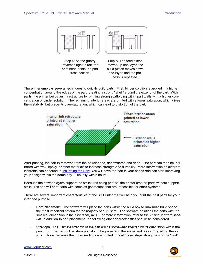
Step 1: As the gantry traverses left to right, the
roller collects powder.
Step 2: The roller spreads a thin layer of powder over the
build piston.
Step 3: The roller discharges excess powder down the powder overflow chute.
www.3dpuser.com 4
10/2/07 All Rights Reserved
Spectrum Z™510 3D Printer Hardware Manual Introduction
The printer employs several techniques to quickly build parts. First, binder solution is applied in a higher concentration around the edges of the part, creating a strong "shell" around the exterior of the part. Within parts, the printer builds an infrastructure by printing strong scaffolding within part walls with a higher con-centration of binder solution. The remaining interior areas are printed with a lower saturation, which gives them stability, but prevents over-saturation, which can lead to distortion of the part.
After printing, the part is removed from the powder bed, depowdered and dried. The part can then be infil-trated with wax, epoxy, or other materials to increase strength and durability. More information on different infiltrants can be found in Infiltrating the Part. You will have the part in your hands and can start improving your design within the same day — usually within hours.
Because the powder layers support the structures being printed, the printer creates parts without support structures and will print parts with complex geometries that are impossible for other systems.
There are several important characteristics of the 3D Printer that will help you print the best parts for your intended purpose.
• Part Placement. The software will place the parts within the build box to maximize build speed, the most important criteria for the majority of our users. The software positions the parts with the smallest dimension in the z (vertical) axis. For more information, refer to the ZPrint Software Man-ual. In addition to part placement, the following other characteristics should be considered.
• Strength. The ultimate strength of the part will be somewhat affected by its orientation within the print box. The part will be strongest along the y-axis and the x-axis and less strong along the z-axis. This is because the cross sections are printed in continuous strips along the y or the "fast"
Step 4: As the gantry traverses right to left, the print head prints the part
cross-section.
Step 5: The feed piston moves up one layer, the build piston moves down one layer, and the pro-
cess is repeated.
www.3dpuser.com 5
10/2/07 All Rights Reserved

Spectrum Z™510 3D Printer Hardware Manual Introduction
axis (the print heads’ direction of travel), bands across the x or the "slow" axis (the gantry direction of travel) and laminated layers along the z-axis. This discussion only applies to untreated parts; once parts are infiltrated, they uniformly take on the strength characteristics of the infiltrating mate-rial.
• Accuracy. The accuracy of the system depends on the materials you choose. You can employ the anisotropic scaling feature in the software to adjust for expected shrinkage and bring your parts into true scale. More information on anisotropic scaling factors can be found in the ZPrint Software Manual.
www.3dpuser.com 6
10/2/07 All Rights Reserved

Spectrum Z™510 3D Printer Hardware Manual Introduction
3.2 System Components
3.3 Printer Components
Z510 3D Printer ZD5 Powder Recycling System
www.3dpuser.com 7
10/2/07 All Rights Reserved

Spectrum Z™510 3D Printer Hardware Manual Introduction
3.4 Printer Control Panel
3.5 Internal, Printer Assembly and Service Station Components
Internal Components
www.3dpuser.com 8
10/2/07 All Rights Reserved

Spectrum Z™510 3D Printer Hardware Manual Introduction
Printer Assembly with Carriage Insert
Service Station
www.3dpuser.com 9
10/2/07 All Rights Reserved

Spectrum Z™510 3D Printer Hardware Manual Introduction
3.6 ZD5 Powder Recycling System
Click ZD5 Depowder Unit to see the User Manual for this unit and other accessories available for your 3D Printers.
www.3dpuser.com 10
10/2/07 All Rights Reserved

Spectrum Z™510 3D Printer Hardware Manual Introduction
3.7 Z510 Powders, Accessories and Tools
Refer to the following table regarding powder types available for use with the Z510 Printer. Click Applica-tions for additional information regarding high performance, casting, specialty materials, and infiltrants. Click MSDS to see information about material storage and safety precautions on the 3DP™ User Website.
NOTE: Parts printed with High Performance Composite materials can be reliability printed to be within a +/- 1.0% or +/- 0.007” dimensional tolerance.
zp®130 - High Performance Powder Improves on the properties of zp®102 with up to:
• 8x increase in early strength.
• 25% faster print times.
• Prints finer details, richer colors, and a better surface finish.
• Accurately represents design details.
Read the zp®130 MSDS
zp®131 - Premium Performance Powder zp131 is a multi-purpose powder that offers the strongest parts, the best resolution,and great color accuracy. It is ideal for fit and functional testing.
• Stronger Parts – Optimized when infiltrated with Z-Bond™. 50% stronger than our zp130 powder when infiltrated with Z-Bond.
• Improved Process – Higher green strength, great surface appearance, and less dust.
• Great Color Accuracy – Robust color gamut with more addressable colors, as well as improved color consistency and uniformity.
Read the zp131 MSDSRead the zp131 User Guide
www.3dpuser.com 11
10/2/07 All Rights Reserved

Spectrum Z™510 3D Printer Hardware Manual Introduction
The Z510 Accessories Kit and Tool Kit contain parts for user maintenance and items frequently used while post-processing printed parts.
Accessories Kit
Includes: 12 Disposable Pour Spouts 38-400 Thread; 1 32 oz. Scoop; 1 10’ Ethernet Cable (blue); 1 CAT5e RJ45 Crossover Cable (red); and 1 Box of Nitrile Gloves - 100 Count, Large. Not Pictured: Powder
Tamp, ZPrint Software CD, and trays.
zp®140 High Performance Plus Powder zp140 is a multi-purpose material system that offers significantly easier post-processingand exceptional color performance. The "Plus" in our High Performance powder is thenew Water Cure process.
• Water Cure – The easiest and safest post-processing available. Only tap water is required to seal and strengthen your printed parts, and it has the lowest cost per in³.
• Vivid Colors - zp140 delivers the most vivid colors when infiltrated with Z-Bond.
• Brightest Whites – 180% whiter than zp130.
Read the zp®140 MSDSRead the zp140 User Guide
z®Cast 501 Direct Casting Powder Our zCast 501 Direct Casting Material can be used to create sand casting molds for non-fer-rous metals. This material is a blend of foundry sand, plaster and other additives that have been combined to provide strong molds with good sur-face finish. It is designed to withstand the heat required to cast non-ferrous metals.
Read the z®Cast MSDS
zp®15e Specialty Powder The zp15e Elastomeric Material has been opti-mized for infiltration with an elastomer to create parts with rubber-like properties.
Read the zp®15e MSDS
www.3dpuser.com 12
10/2/07 All Rights Reserved

Spectrum Z™510 3D Printer Hardware Manual Introduction
Tool Kit
3.8 New Accessories Available for 3D Printers
To order, contact Z Corporation.
• New Overflow Bin Cover - minimizes airborne powder from the overflow bin during a build.
Document 09523 Post Processing Tools Use Instructions.
Service Form Documents to be com- pleted and returned to Z Corp.
1. Scraper, 5” Wide Utility
2. Brush, Double-Ended
3. Brush, 2” China Bristle
4. Brush, Acid
5. Brush, Toothbrush Style
6. Scraper, 3” Wide Utility
1. No longer included in kit 2. Extra Screws 3. Syringe for cleaning Service Station 4. Syringe Tube and Fitting 5. Grease Gun, Mini for 3oz. Cartridge 6. Grease, Silicone with PTFE, 3oz. 7. Wash Bottle, 8oz. 8. Lubriplate White Grease 9. Syringe, Luer-Lock, 20cc 10. Small Philips Screwdriver 11. Grease Gun Nozzle 12. L-Hex Key Set
www.3dpuser.com 13
10/2/07 All Rights Reserved

Spectrum Z™510 3D Printer Hardware Manual Introduction
• New Vacuum Attachment - fits the Z510 3D Printer vacuum hose and attaches to the side of the feed box to capture airborne powder when powder is being added to the feed box.
3.9 ZPrint Software Installation
The ZPrint Software is the file processing tool that sends information from the user's workstation to the 3D Printer. Please refer to the ZPrint Software Manual for installation and use instructions.
www.3dpuser.com 14
10/2/07 All Rights Reserved

Spectrum Z™510 3D Printer Hardware Manual Quick Start Guide
4 Quick Start Guide
This section is a short step-by-step process of how to get a print job running on your printer. For a more detailed explanation, see Routine Operations, Using the ZPrint Firmware and Software, and Post Process-ing the Part.
4.1 Preparing The 3D Printer
1. Fill the feed box with powder.
2. With the printer offline, spread powder over build area by pressing the Spread button on the control panel for four spreads. The printer will automatically spread powder over the build area.
3. Clean the service station by rinsing and wiping the parking caps and rubber wiper.
www.3dpuser.com 15
10/2/07 All Rights Reserved

Spectrum Z™510 3D Printer Hardware Manual Quick Start Guide
4. Check the binder bottles. Fill if necessary.
5. Check the wash fluid and the waste fluid. Fill the wash fluid and dispose of the waste fluid.
6. Put printer online by pressing the Online button on the control panel.
Technical Tip LEAVE THE PRINTER ON! This allows the printer to perform a periodic self maintenance.
www.3dpuser.com 16
10/2/07 All Rights Reserved

Spectrum Z™510 3D Printer Hardware Manual Quick Start Guide
4.2 Preparing the Build in ZPrint Software
1. Launch ZPrint and open or import your file(s).
2. Orient and scale the file, if needed.
www.3dpuser.com 17
10/2/07 All Rights Reserved

Spectrum Z™510 3D Printer Hardware Manual Quick Start Guide
3. Open the File menu and select 3D Print Setup. In the 3D Print Setup dialog, select your Printer, Powder Type, and Layer Thickness options.
4. Select 3D Print on the File Menu or click the 3D icon on the Toolbar. Choose your settings in the Printing Options dialog and click OK. Proceed through the series of preparation dialogs that appear before the build starts.
4.3 Removing the Part
1. Wait for part to complete printing. Check the software for part orientation.
2. Gross depowder the part and remove from build area.
www.3dpuser.com 18
10/2/07 All Rights Reserved

Spectrum Z™510 3D Printer Hardware Manual Quick Start Guide
3. Fine depowder part and post-process as needed.
www.3dpuser.com 19
10/2/07 All Rights Reserved

Spectrum Z™510 3D Printer Hardware Manual Routine Operations
5 Routine Operations
The routine maintenance tasks described in this chapter should be performed before every build.
5.1 Preparing the Build Area
IMPORTANTUse only powder supplied by Z Corporation. Use of any other material may impact theperformance and/or safety of your 3D Printer System and will void warranty of equip-ment.
1. Preheat printer, if needed. Preheating the printer will reduce the print time if the printer has not reached the required temperature. To preheat the printer, select the Preheat Printer option under the Service menu.
2. Lower feed piston by pressing down on the Feed DOWN button until the feed piston automatically drops.
3. Take printer offline by pressing 'Offline' on the control panel.
4. Lift the top cover of the printer.
5. Raise build piston by pressing Build UP. Once build piston has stopped, press Build UP once. You will see 'Hold for Unload' on the control panel.
www.3dpuser.com 20
10/2/07 All Rights Reserved

Spectrum Z™510 3D Printer Hardware Manual Routine Operations
6. Hold the Build UP button until the build piston raises. The build piston will expose the build plate hold-ers.
7. Place build plate on top of holders. Make sure build plate is secure. Press any button on the control panel to lower the build piston.
8. Fill the feed box with powder. First empty the powder from the overflow bin and then add fresh powder if needed.
9. Tamp powder and raise the feed piston until the powder reaches the top edge of the feed box.
www.3dpuser.com 21
10/2/07 All Rights Reserved
Spectrum Z™510 3D Printer Hardware Manual Routine Operations
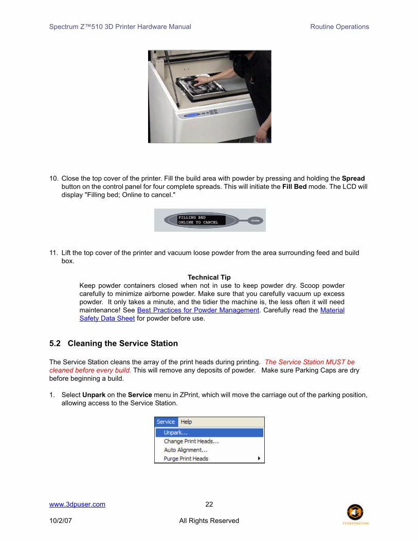
10. Close the top cover of the printer. Fill the build area with powder by pressing and holding the Spread button on the control panel for four complete spreads. This will initiate the Fill Bed mode. The LCD will display "Filling bed; Online to cancel."
11. Lift the top cover of the printer and vacuum loose powder from the area surrounding feed and build box.
Technical TipKeep powder containers closed when not in use to keep powder dry. Scoop powdercarefully to minimize airborne powder. Make sure that you carefully vacuum up excesspowder. It only takes a minute, and the tidier the machine is, the less often it will needmaintenance! See Best Practices for Powder Management. Carefully read the MaterialSafety Data Sheet for powder before use.
5.2 Cleaning the Service Station
The Service Station cleans the array of the print heads during printing. The Service Station MUST be cleaned before every build. This will remove any deposits of powder. Make sure Parking Caps are dry before beginning a build.
1. Select Unpark on the Service menu in ZPrint, which will move the carriage out of the parking position, allowing access to the Service Station.
www.3dpuser.com 22
10/2/07 All Rights Reserved

Spectrum Z™510 3D Printer Hardware Manual Routine Operations
2. With the Service Station exposed, rinse rubber Parking Cap with distilled water (If needed, remove rubber Parking Caps and rinse under running water). Wipe dry with paper towel.
PLEASE NOTE: Make sure the Parking Caps are sitting flat in their holders.
3. Clean squirt manifold holes by carefully inserting the luer lock needle into the squirt manifold holes. DO NOT PRESS HARD. The needle should go in. Clean one by one all six holes. Be careful not to scratch or score holes.
4. Rinse rubber wiper blade with distilled water and wipe dry with paper towel. Ensure that there is no powder buildup anywhere in the proximity of the rubber wiper.
www.3dpuser.com 23
10/2/07 All Rights Reserved
Spectrum Z™510 3D Printer Hardware Manual Routine Operations
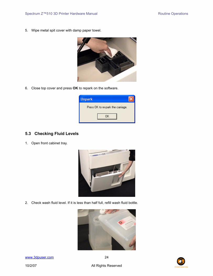
5. Wipe metal spit cover with damp paper towel.
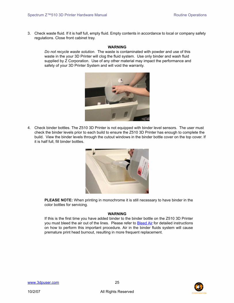
6. Close top cover and press OK to repark on the software.
5.3 Checking Fluid Levels
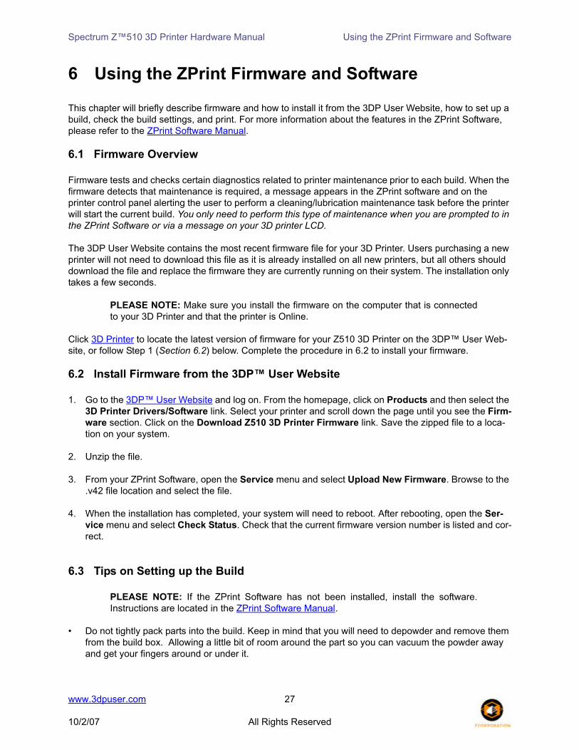
1. Open front cabinet tray.
2. Check wash fluid level. If it is less than half full, refill wash fluid bottle.
www.3dpuser.com 24
10/2/07 All Rights Reserved
Spectrum Z™510 3D Printer Hardware Manual Routine Operations
3. Check waste fluid. If it is half full, empty fluid. Empty contents in accordance to local or company safety regulations. Close front cabinet tray.
WARNINGDo not recycle waste solution. The waste is contaminated with powder and use of this waste in the your 3D Printer will clog the fluid system. Use only binder and wash fluid supplied by Z Corporation. Use of any other material may impact the performance and safety of your 3D Printer System and will void the warranty.
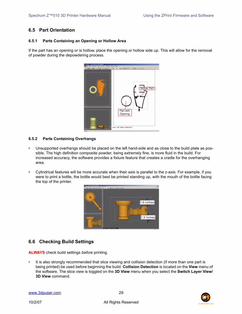
4. Check binder bottles. The Z510 3D Printer is not equipped with binder level sensors. The user must check the binder levels prior to each build to ensure the Z510 3D Printer has enough to complete the build. View the binder levels through the cutout windows in the binder bottle cover on the top cover. If it is half full, fill binder bottles.
PLEASE NOTE: When printing in monochrome it is still necessary to have binder in thecolor bottles for servicing.
WARNINGIf this is the first time you have added binder to the binder bottle on the Z510 3D Printeryou must bleed the air out of the lines. Please refer to Bleed Air for detailed instructionson how to perform this important procedure. Air in the binder fluids system will causepremature print head burnout, resulting in more frequent replacement.
www.3dpuser.com 25
10/2/07 All Rights Reserved

Spectrum Z™510 3D Printer Hardware Manual Routine Operations
Refer to the following links to learn about other periodic maintenance tasks. The following tasks should only be performed when prompted to by ZPrint or when you see a message on your 3D Printer LCD.
Fast Axis LubricationSlow Axis LubricationPiston Screws LubricationChange Print Heads
www.3dpuser.com 26
10/2/07 All Rights Reserved
Spectrum Z™510 3D Printer Hardware Manual Using the ZPrint Firmware and Software
6 Using the ZPrint Firmware and Software
This chapter will briefly describe firmware and how to install it from the 3DP User Website, how to set up a build, check the build settings, and print. For more information about the features in the ZPrint Software, please refer to the ZPrint Software Manual.
6.1 Firmware Overview
Firmware tests and checks certain diagnostics related to printer maintenance prior to each build. When the firmware detects that maintenance is required, a message appears in the ZPrint software and on the printer control panel alerting the user to perform a cleaning/lubrication maintenance task before the printer will start the current build. You only need to perform this type of maintenance when you are prompted to in the ZPrint Software or via a message on your 3D printer LCD.
The 3DP User Website contains the most recent firmware file for your 3D Printer. Users purchasing a new printer will not need to download this file as it is already installed on all new printers, but all others should download the file and replace the firmware they are currently running on their system. The installation only takes a few seconds.
PLEASE NOTE: Make sure you install the firmware on the computer that is connectedto your 3D Printer and that the printer is Online.
Click 3D Printer to locate the latest version of firmware for your Z510 3D Printer on the 3DP™ User Web-site, or follow Step 1 (Section 6.2) below. Complete the procedure in 6.2 to install your firmware.
6.2 Install Firmware from the 3DP™ User Website
1. Go to the 3DP™ User Website and log on. From the homepage, click on Products and then select the 3D Printer Drivers/Software link. Select your printer and scroll down the page until you see the Firm-ware section. Click on the Download Z510 3D Printer Firmware link. Save the zipped file to a loca-tion on your system.
2. Unzip the file.
3. From your ZPrint Software, open the Service menu and select Upload New Firmware. Browse to the .v42 file location and select the file.
4. When the installation has completed, your system will need to reboot. After rebooting, open the Ser-vice menu and select Check Status. Check that the current firmware version number is listed and cor-rect.
6.3 Tips on Setting up the Build
PLEASE NOTE: If the ZPrint Software has not been installed, install the software.Instructions are located in the ZPrint Software Manual.
• Do not tightly pack parts into the build. Keep in mind that you will need to depowder and remove them from the build box. Allowing a little bit of room around the part so you can vacuum the powder away and get your fingers around or under it.
www.3dpuser.com 27
10/2/07 All Rights Reserved

Spectrum Z™510 3D Printer Hardware Manual Using the ZPrint Firmware and Software
• Orient parts so delicate features are supported in the z-axis, i.e. keep the attaching feature directly below the fragile features. If a delicate feature is only supported by unprinted powder the chances of breaking that small feature during depowdering is greatly increased.
• When building delicate parts use the "Fixture" function to cradle the part. Raising the part 0.25" (6.4 mm) from the bottom of the build and creating a fixture under the part will produce a cradle that can be handled. The part inside the cradle can easily be transported to an oven or the depowderer.
• Do not enable the bleed compensation feature if you are building a part with features under 0.050" (1.27 mm). Enabling bleed compensation may reduce the feature size.
• To increase the strength of thin parts, you can decrease the layer thickness to 0.0035" (0.089 mm) if you are using high composite powder systems. Choose to override the saturation values and input the saturation values used for printing at 0.004" (0.102 mm). This increases the binder to powder ratio and wets more of the resins in the powder system. As you increase the strength of the part in this manner you are also increasing the amount of time to dry the part. Oven drying the part is recommended.
6.4 Open or Import the File(s)
1. Launch the ZPrint Software. The Open dialog box appears.
2. Choose the file you wish to open.
3. Click Open or double-click the file.
4. Choose the dimensions and powder type you will be using.
5. Click OK.
6. The file will be brought into the software in a new window.
7. If you would like to add additional files to this build, choose the Import option on the File menu.
www.3dpuser.com 28
10/2/07 All Rights Reserved
Spectrum Z™510 3D Printer Hardware Manual Using the ZPrint Firmware and Software
6.5 Part Orientation
6.5.1 Parts Containing an Opening or Hollow Area
If the part has an opening or is hollow, place the opening or hollow side up. This will allow for the removal of powder during the depowdering process.
6.5.2 Parts Containing Overhangs
• Unsupported overhangs should be placed on the left hand-side and as close to the build plate as pos-sible. The high definition composite powder, being extremely fine, is more fluid in the build. For increased accuracy, the software provides a fixture feature that creates a cradle for the overhanging area.
• Cylindrical features will be more accurate when their axis is parallel to the z-axis. For example, if you were to print a bottle, the bottle would best be printed standing up, with the mouth of the bottle facing the top of the printer.
6.6 Checking Build Settings
ALWAYS check build settings before printing.
• It is also strongly recommended that slice viewing and collision detection (if more than one part is being printed) be used before beginning the build. Collision Detection is located on the View menu of the software. The slice view is toggled on the 3D View menu when you select the Switch Layer View/ 3D View command.
www.3dpuser.com 29
10/2/07 All Rights Reserved

Spectrum Z™510 3D Printer Hardware Manual Using the ZPrint Firmware and Software
• Slice viewing allows you to view the cross sections of the part to identify any errors in the file.
• Collision detection will scan through the slices and report the layer in which part overlapping is found.
Follow the steps below to check your build settings.
1. Choose the 3D Print Setup on the File menu, or click the icon on the Toolbar.
2. Check that the selected printer, powder type, and powder settings for the build are correct. The soft-ware settings are the recommended values.
3. If the settings need to be changed, select Override. Press OK to confirm.
For more information on how to change these settings, please refer to the ZPrint Software Manual.
6.7 Printing the Build
It is strongly recommended that the build settings be confirmed before printing. To check build settings, choose 3D Print Setup on the File menu or click on the icon located on the taskbar. After all build settings have been confirmed:
1. Choose 3D Print on the File menu, or click the icon on the Toolbar. 2. A dialog box will appear asking that powder and fluid levels be checked. Check off the boxes to con-
firm that these have been inspected before beginning the build.
3. Once the build has begun, a dialog box will appear reporting the status of the build.
www.3dpuser.com 30
10/2/07 All Rights Reserved

Spectrum Z™510 3D Printer Hardware Manual Using the ZPrint Firmware and Software
www.3dpuser.com 31
10/2/07 All Rights Reserved

Spectrum Z™510 3D Printer Hardware Manual Post-Processing the Part
7 Post-Processing the Part7.1 Tips on Gross and Fine Depowdering
• For additional information regarding post-processing, click Applications to go to the 3DP™ User web-site, or Knowledge Base to use our searchable knowledge base on the website.
• Become familiar with where the parts are placed and how they are oriented in the build box so you do not accidentally bump or brush against a fragile part during the depowdering process.
• When performing the gross depowdering (removal of excess powder in the build box) do not plunge the vacuum nozzle into the powder bed. Begin at the outer perimeter of the build box and slowly work your way into the build. Hold the tip of vacuum nozzle approximately 0.25" (6.4 mm) to 0.375" (9.5 mm) away from the powder and allow the vacuum to pull the powder up. Slanting the vacuum nozzle will enable you to control the suction. This will decrease the chance of breaking a part that is hidden beneath the surface of the powder.
• While fine depowdering, always start with a low air pressure and gradually increase the pressure as the fine details and features of the part become visible. When the top and sides of the part are com-pletely depowdered tilt the part onto one of its sides. Handle the part carefully. The part may be fragile and brittle before infiltration. If none of the sides of the part will be able to support the weight of the part you can apply a small amount of resin or epoxy to strengthen it. You want to be careful not to let any of the infiltrant come into contact with any unprinted powder that may still be on the part. Let the infiltrant dry before continuing to depowder.
7.2 Post-Processing Tools
There are six tools included in the accessories kit that assist the user with gross depowdering and cleaning the part.
Wide Blade Utility Scraper: This tool is used to move powder from the build cham-ber or deck surface back into the feed cham-ber.
Polypropylene Scraper: When gross depowdering a bulky part, such as the engine block, the user may choose to carve powder away from the part instead of mov-ing it away with the vacuum.
www.3dpuser.com 32
10/2/07 All Rights Reserved

Spectrum Z™510 3D Printer Hardware Manual Post-Processing the Part
Soft Horsehair Brush: This brush has very soft bristles and assists the user with the gross depowdering process. Brushing pow-der away from the part is a useful technique prior to the vacuuming step.
Stiff Detailing Brush: This brush has very stiff bristles, which is useful for scrubbing caked powder out of tight areas of a part. The brush is also used for removing fringing from color part surfaces.
Stiff Handle Brush: This tool serves the same purpose as the Stiff Detailing Brush. It is slightly larger and is used for working with a larger surface area.
Soft Acid Brush: This tool is used to remove caked powder from hard to reach areas. The soft bristles make this brush per-fect for delicate features.
www.3dpuser.com 33
10/2/07 All Rights Reserved

Spectrum Z™510 3D Printer Hardware Manual Post-Processing the Part
7.3 Removing the Finished Part
After the build is complete, remove the finished parts from the build box as follows:
1. Leave the part in the bed for approximately 30-60 minutes. Take a moment to look at the computer screen and determine exactly where parts lie in the build box.
2. Take the printer offline by pressing the Online button and lift the top cover.
3. Press the Feed DOWN button to lower the feed piston.
4. Remove powder away from the buried parts, and clean powder out of the margins against the walls of the build box.
5. Without raising the build piston, begin removing powder around the part either by using the vacuum or post-processing tools. When vacuuming, hold the end of the hose on a 20° to 30° degree angle over the powder so the hose inlet is 1/4" to 3/8" above the surface of the powder. This generates enough of a draft to lift loose powder without damaging the parts. For more information about the post-processing tools, refer to Post-Processing Tools.
www.3dpuser.com 34
10/2/07 All Rights Reserved

Spectrum Z™510 3D Printer Hardware Manual Post-Processing the Part
6. To gain access to the sides of the parts, raise the build piston by holding down the Build UP button.
7. When finished, you may remove the part by hand or press the Build UP button on the control panel. When it stops moving, press Build UP one more time to initiate the unload feature. The build plate will now be exposed and easy to lift off the build envelope.
8. Place a tray on the top of the feed area. Remove the build plate and place on the tray. The part is now ready to be fine depowdered.
WARNING
When performing any vacuuming operation, use the vacuum provided as part of the 3D Printer System. Vacuuming powder can generate static electricity, and use of a non-grounded vacuum will create static charges, which may affect the operation of the 3D Printer System and harm the operator.
www.3dpuser.com 35
10/2/07 All Rights Reserved

Spectrum Z™510 3D Printer Hardware Manual Post-Processing the Part
7.4 Depowdering the Part
1. Place parts inside the depowdering station.
2. Turn on the vacuum cleaner.
3. Turn on the air compressor.
4. Change the air pressure as needed and check the pressure with your hand before applying air on the part.
Technical TipThe air pressure on your depowdering station is adjustable. For bulky parts, turn the airpressure up. For delicate parts, turn the air pressure down.
www.3dpuser.com 36
10/2/07 All Rights Reserved
Spectrum Z™510 3D Printer Hardware Manual Post-Processing the Part
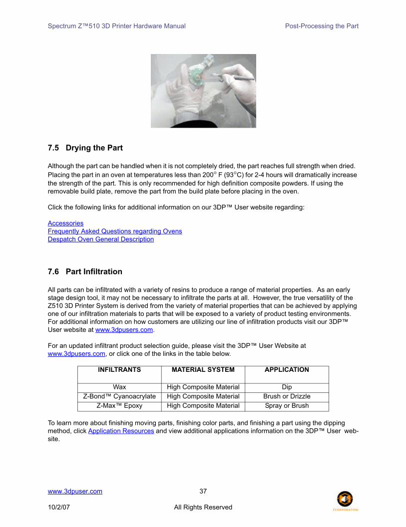
7.5 Drying the Part
Although the part can be handled when it is not completely dried, the part reaches full strength when dried. Placing the part in an oven at temperatures less than 200° F (93°C) for 2-4 hours will dramatically increase the strength of the part. This is only recommended for high definition composite powders. If using the removable build plate, remove the part from the build plate before placing in the oven.
Click the following links for additional information on our 3DP™ User website regarding:
AccessoriesFrequently Asked Questions regarding OvensDespatch Oven General Description
7.6 Part Infiltration
All parts can be infiltrated with a variety of resins to produce a range of material properties. As an early stage design tool, it may not be necessary to infiltrate the parts at all. However, the true versatility of the Z510 3D Printer System is derived from the variety of material properties that can be achieved by applying one of our infiltration materials to parts that will be exposed to a variety of product testing environments. For additional information on how customers are utilizing our line of infiltration products visit our 3DP™ User website at www.3dpusers.com.
For an updated infiltrant product selection guide, please visit the 3DP™ User Website at www.3dpusers.com, or click one of the links in the table below.
To learn more about finishing moving parts, finishing color parts, and finishing a part using the dipping method, click Application Resources and view additional applications information on the 3DP™ User web-site.
INFILTRANTS MATERIAL SYSTEM APPLICATION
Wax High Composite Material Dip Z-Bond™ Cyanoacrylate High Composite Material Brush or Drizzle
Z-Max™ Epoxy High Composite Material Spray or Brush
www.3dpuser.com 37
10/2/07 All Rights Reserved

Spectrum Z™510 3D Printer Hardware Manual Post-Processing the Part
7.6.1 Using Paraplast X-TRA Wax
Paraplast X-TRA is a low viscosity, general purpose, infiltration wax formulated to melt at very low temper-atures (122° F or 50° C) and strengthen parts. This material cures rapidly and enhances the vibrancy of color parts. Paraplast is available in a case of eight 2.2 lb. (1 kilogram) bag of chips. Paraplast X-TRA Wax can be used in both the ZW3 and ZW4 Waxers. Read the Paraplast X-TRA Wax User Guide to learn more.
Safety Precautions
• Liquid wax is hot and may cause burns. Follow all manufacturer recommended safety precautions for your dip tank prior to use.
• Wear gloves when handling hot parts.
General Application Notes
• Parts should be dried in an oven at 100° F (38° C) prior to infiltrating with wax for deeper wax pen-etration.
• If the part is bulky, you may preheat it at 150° F (66° C) for up to 30 minutes.
• Soak part in liquid wax tank (follow all tank manufacturer's instructions).
• Remove infiltrated part from dip tank.
• Place part in an oven at 150° F (66° C) until the wax has penetrated or melted off your part (usu-ally around 15 minutes).
• Be aware that these are simple guidelines. Your specific applications may require additional steps.
Curing Information
• Allow your parts to cool after removal from the oven until the part is no longer warm to the touch.
7.6.2 Using Z-Bond™ Cyanoacrylate
Z-Bond cyanoacrylate is an extremely fast setting, low viscosity, general-purpose infiltration resin. This resin is designed to rapidly strengthen parts. Z-Bond is a one part, user-friendly, no-odor, non-blooming resin that may eliminate the need for special ventilation. This resin is easily sanded and enhances the vibrancy of color parts. Z-Bond 100 is available in several quantities in both bottle and spray forms. Read the Z-Bond User Guide to learn more.
Safety Precautions
• Do not use or handle this product until the Material Safety Data Sheet has been read and under-stood.
• Wear lab coat, gloves (we recommend Nitrile Examination Gloves), face shield or goggles. Face shield is required if spraying. Apply in ventilated hood.
• Specialized containers recommended for dispensing and application. System for avoiding spills: Catch pan, waxed paper, or plastic drop cloth.
www.3dpuser.com 38
10/2/07 All Rights Reserved

Spectrum Z™510 3D Printer Hardware Manual Post-Processing the Part
• Label disposal materials.
• Wear dust mask when sanding finished parts.
General Application Notes
• Part should be fully dried before applying resin. Resin reacts with water and produces heat. If the part is not dried, it will heat up the part and produce gas that may be an irritant to the mucous membranes.
• Material can be brushed, dipped or dripped.
• Material will penetrate between 0.08 - 0.12 inches (2-3 mm).
• Do not over apply the material, as it will pool off the part during cure cycle.
Curing Information
• The part should be placed on a non-stick material (wax paper, Teflon, etc.) to prevent it from adhering to the surface it is sitting on while curing.
• Wear gloves when handling the parts to avoid contact with uncured resin.
• Parts will attain full strength in two minutes.
Tips
• Always infiltrate the most delicate features of the part first. Z-Bond resin gives almost immediate strength to the area of the part that has been infiltrated. As you handle the areas of the part that have been infiltrated it will be less likely to break it.
• Try to avoid infiltrating the part by applying Z-Bond resin from spot to spot. Pick a good starting place hold that area upward relative to the rest of the part. With your free hand, place the tip of the Z-Bond bottle against the part and allow the cyanoacrylate (CA) to flow from the bottle. It is impor-tant that the CA flows at a uniform rate making it easier for you the judge how quickly it will flow from the tip of the bottle before it wicks into the part. By seeing how quickly it wicks into the part you will be able to judge where and how quickly to move the tip of the bottle while applying the CA, being sure not to apply the CA to the same place more than once.
7.6.3 Using Z-Max™ Epoxy
A Z-Max Epoxy User Guide is also available on the 3DP User website. For more information on the uses of Z-Max epoxy, please logon to our website.
Safety Precautions
• Wear lab coat, gloves (we recommend PVC Examination Gloves), face shield or goggles. Face shield is required if spraying. Apply in ventilated hood.
• Use specialized containers recommended for dispensing and application. A system for avoiding spills includes: Catch pan, waxed paper, or plastic drop cloth.
www.3dpuser.com 39
10/2/07 All Rights Reserved

Spectrum Z™510 3D Printer Hardware Manual Post-Processing the Part
• Label disposal materials.
• Wear dust mask when sanding finished parts.
• Read the Material Safety Data Sheet for Z-Max prior to the use of this material.
Mixing Instructions
• When using the 250 gm Z-Max kit simply pour the entire contents of the Z-Max Hardener container into the Z-Max Resin container and mix the two parts thoroughly for two minutes prior to applica-tion. If less than 250 grams is desired, follow the instructions for mixing by weight or volume.
• Mix 100 parts Z-Max Resin to 37 parts Z-Max Hardener by weight or 100 parts Z-Max Resin to 41 parts Z-Max Hardener by volume. Mix the two parts thoroughly for two minutes before application. The material has a working time of 35 minutes in a 425 gram mass. Please be aware of the gel time while preparing quantities of material as the gel time decreases as the quantity of material increases. It is recommended not to mix quantities over 425 grams.
General Application Notes
• Material can be brushed or sprayed.
• Material will penetrate between 0.079-0.28 inches (2 - 7 mm).
• Material will pool off the part during curing, if it is over-applied.
• Better penetration depth is achieved by applying several light coats of material.
• Allow all mixed materials to cure prior to disposal. Spraying Instructions
• Use Gravity Feed High Volume Low Pressure Sprayer (Z Corp. Part # 14206). We recommend Devilbiss Sprayer with 14 - 18 mm tip. Other sprayers are compatible, however the use of a HVLP sprayer will minimize the amount of overspray generated. The Devilbiss Sprayer is available with disposable canister liners (Z Corp. Part # 14207). and will minimize the amount of cleanup.
• Have the sprayer, parts and materials ready before mixing the resin.• Mix resin and pour into the disposable liner in the canister.
• Always spray in a vented hood. Use of a respirator is also recommended.
• Spray resin between 15 - 20 psi.
www.3dpuser.com 40
10/2/07 All Rights Reserved

Spectrum Z™510 3D Printer Hardware Manual Post-Processing the Part
• When finished, remove the disposable liner and clean sprayer with ethyl alcohol or acetone.
• Remove the tip and thoroughly clean by hand to avoid resin buildup. (Cleanup takes approxi-mately 15 minutes).
Curing Information
• Allow the part to cure for 1 hour at ambient temperature to avoid discoloration prior to placing in the oven for accelerated cure.
• The resin can be cured at an accelerated rate in an oven. The oven must be vented. Ventilation designs need to meet each customer's respective governmental health and safety requirements. A reference frequently used by U.S. firms to comply with OSHA regulations is the American Con-ference of Governmental Industrial Hygienists Industrial Ventilation Manual.
• At 160° F (71° C) your part will reach full strength in 2 hours.
• The part should be placed on a non-stick, material (wax paper, Teflon, etc.) to prevent it from adhering to the surface it is sitting on while curing.
• Wear gloves when handling the parts when they are still at an elevated temperature. Parts will attain full strength and be safe to handle once they cool to room temperature.
• The resin will cure at room temperature after 24 hours.
Tips
• If the part has delicate features, infiltrate them last as the feature will be less strong after being infiltrated until the epoxy begins to cure. This will decrease the chance the feature will break from the part if nudged or bumped.
• If the part has multiple delicate features or it is impossible to handle the part without breaking a feature you may infiltrate these features only. Allow the Z-Max to cure. Then infiltrate the rest of the part. This will add time to post-processing the part but it ensures that you have a good strong part without any fractures.
Open the following links to learn about:
Casting MethodsElectroplatingFinite Element AnalysisFunctional Testing of Molded Plastic Parts
www.3dpuser.com 41
10/2/07 All Rights Reserved

Spectrum Z™510 3D Printer Hardware Manual Post-Processing the Part
Creating High Finsh Color PartsPaintingPowder ManagementRTV MoldingThermoformingTough Durable PartsWater TransferWater Transfer High-Strength Parts
www.3dpuser.com 42
10/2/07 All Rights Reserved

Spectrum Z™510 3D Printer Hardware Manual Service Menu and Other Maintenance
8 Service Menu and Other Maintenance
The ZPrint Service menu is the primary interface from the desktop when performing routine maintenance on the Spectrum Z™510 3D Printer.
8.1 Unpark
Unpark moves the Carriage from its parked position at the Service Station to the opposite side of the Fast Axis to allow easy access for routine cleaning.
8.2 Change Print Heads
1. Determine which print head needs to be changed. This is done either by an error message during printing, or by accessing the Print Head Report command located on the ZPrint Service menu.
2. Place the printer Online.
3. Select Service > Change Print Heads > Start. When you click Start in the Change Print Heads dia-log, the printer moves the Carriage over to the opposite side of the Fast Axis for easy access.
www.3dpuser.com 43
10/2/07 All Rights Reserved
Spectrum Z™510 3D Printer Hardware Manual Service Menu and Other Maintenance
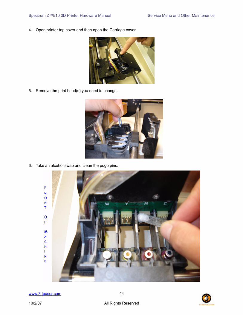
4. Open printer top cover and then open the Carriage cover.
5. Remove the print head(s) you need to change.
6. Take an alcohol swab and clean the pogo pins.
www.3dpuser.com 44
10/2/07 All Rights Reserved

Spectrum Z™510 3D Printer Hardware Manual Service Menu and Other Maintenance
7. Re-insert a new print head(s) and press down. Press firmly on both ends of the print head to secure into place.
8. Close the Carriage cover.
9. Using a moist paper towel, wipe the alignment window located on the bottom, left side of the Carriage. Dry off with a dry paper towel and close the printer top cover.
10. Click Done on the Change Print Heads dialog.
11. Select Service > Purge Print Heads. You can choose to purge only a new print head or all of the print heads. The printer will purge the print head(s) of all of its ink and replace it with binder.
www.3dpuser.com 45
10/2/07 All Rights Reserved
Spectrum Z™510 3D Printer Hardware Manual Service Menu and Other Maintenance
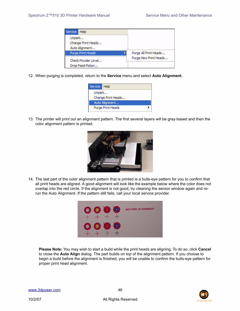
12. When purging is completed, return to the Service menu and select Auto Alignment.
13. The printer will print out an alignment pattern. The first several layers will be gray-based and then the color alignment pattern is printed.
14. The last part of the color alignment pattern that is printed is a bulls-eye pattern for you to confirm that all print heads are aligned. A good alignment will look like the example below where the color does not overlap into the red circle. If the alignment is not good, try cleaning the sensor window again and re-run the Auto Alignment. If the pattern still fails, call your local service provider.
Please Note: You may wish to start a build while the print heads are aligning. To do so, click Cancel to close the Auto Align dialog. The part builds on top of the alignment pattern. If you choose to begin a build before the alignment is finished, you will be unable to confirm the bulls-eye pattern for proper print head alignment.
www.3dpuser.com 46
10/2/07 All Rights Reserved

Spectrum Z™510 3D Printer Hardware Manual Service Menu and Other Maintenance
8.3 Purge Print Head
Always purge a new print head immediately after replacing an expired print head. When you initiate a purge cycle, there are two options to choose from - Purge All Print Heads and Purge New Print Head.
Purge All Print Heads will initiate a purge cycle for all print heads regardless of whether they are new or not. Purge New Print Heads will initiate a purge cycle only for the new print heads.
8.4 Check Powder Level
Check Powder Level will see if the Z510 3D Printer currently has enough powder in the feed piston to complete the build currently active in ZPrint, based on the feed pistons current position.
8.5 Drop Feed Piston
Drop Feed Piston will drop the feed piston to its lowest position so you can easily add additional powder or begin gross depowdering a printed part in the build envelope.
8.6 Fill Bed
Fill Bed initiates a cycle that will prepare the build envelope for printing by automatically spreading powder from the feed piston to the build piston.
8.7 Preheat Printer
Preheat Printer will activate the heater in the Z510 3D Printer and heat the build chamber to a predeter-mined temperature based on the material being used. While the build chamber is pre-heating to the desired temperature, the heat powers on and off for 2-5 minutes until the target temperature is reached.
8.8 Maintenance
The Maintenance dialog keeps a record of the distance travel by the Fast Axis, Slow Axis and the Pistons. The Maintenance dialog will open automatically when it is time to perform lubrication maintenance on these components as long as the Activate Maintenance Reminder option is checked in the Settings > General Preferences > General tab. Only perform maintenance on these components when you are prompted to in ZPrint.
www.3dpuser.com 47
10/2/07 All Rights Reserved

Spectrum Z™510 3D Printer Hardware Manual Service Menu and Other Maintenance
While lubrication of the Fast and Slow Axis is very important, it is equally important not to over-grease the bearings when lubricating. Only a very small amount of grease is required to keep these parts working opti-mally. Using too much grease will create a situation where the grease will leach onto the Fast Axis and buildup on the bumpers located at each end of the Fast Axis. When this happens, you need to clean the Fast Axis rails and bumpers. See Section 8.8.4 for instructions on how to clean these components.
The following sections detail the instructions for lubrication and cleaning maintenance when the need arises.
8.8.1 Fast Axis Lubrication
1. Assemble the grease gun as instructed on its packaging.
2. Select Service > Unpark to unpark the Carriage.
3. Open the printer top cover.
4. Clean the Fast Axis rails of residue with a dry paper towel.
www.3dpuser.com 48
10/2/07 All Rights Reserved
Spectrum Z™510 3D Printer Hardware Manual Service Menu and Other Maintenance
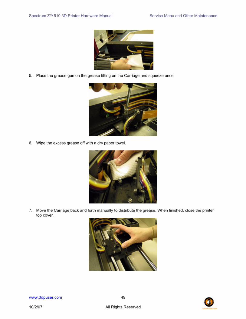
5. Place the grease gun on the grease fitting on the Carriage and squeeze once.
6. Wipe the excess grease off with a dry paper towel.
7. Move the Carriage back and forth manually to distribute the grease. When finished, close the printer top cover.
www.3dpuser.com 49
10/2/07 All Rights Reserved

Spectrum Z™510 3D Printer Hardware Manual Service Menu and Other Maintenance
8.8.2 Slow Axis Lubrication
1. Assemble the grease gun as instructed on its packaging.
2. Select Service > Unpark.
3. Open the printer top cover.
4. Wipe off the slow axis rail with a dry paper towel.
5. Locate the two grease fittings located behind the gantry. Manually move the gantry if you need to gain access to the grease fittings.
6. Engage the grease gun into the fittings and squeeze once.
7. Wipe off the excess grease with a dry paper towel and close the printer top cover.
www.3dpuser.com 50
10/2/07 All Rights Reserved

Spectrum Z™510 3D Printer Hardware Manual Service Menu and Other Maintenance
8. With the printer offline, press the Spread button on the control panel to distribute the grease.
8.8.3 Piston Screws Lubrication
1. Lower both the feed and build pistons all the way down.
2. Open the front cabinet tray.
3. Locate the piston screws and apply grease from top to bottom.
4. Use your finger to distribute the grease evenly over each piston screw. Close the front cabinet tray.
www.3dpuser.com 51
10/2/07 All Rights Reserved

Spectrum Z™510 3D Printer Hardware Manual Service Menu and Other Maintenance
5. Raise and lower both the feed and build pistons a couple of times to evenly distribute the grease. Any excess grease should be wiped off with a paper towel.
8.8.4 Cleaning the Fast Axis Rails and Bumpers
1. Select Service > Unpark. After the Carriage is unparked, you can manually move it in order to clean.
2. Place the printer in Offline mode and open the printer top cover.
3. Locate the rubber bumper at each end of the Fast Axis. Wipe away any grease you see on the bumper. Be sure to clean both bumpers.Thoroughly clean the Fast Axis rail of any visible grease.
4. Manually move the Carriage back and forth and wipe the entire axis clean.
www.3dpuser.com 52
10/2/07 All Rights Reserved
Spectrum Z™510 3D Printer Hardware Manual Service Menu and Other Maintenance
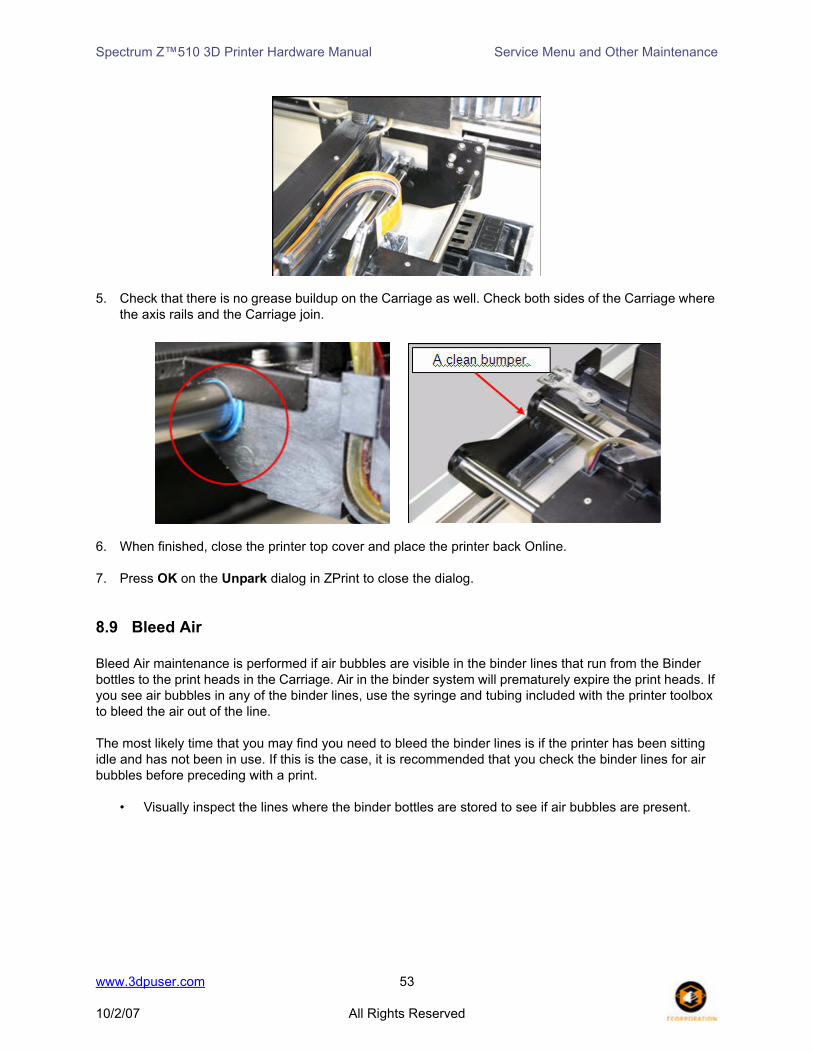
5. Check that there is no grease buildup on the Carriage as well. Check both sides of the Carriage where the axis rails and the Carriage join.
6. When finished, close the printer top cover and place the printer back Online.
7. Press OK on the Unpark dialog in ZPrint to close the dialog.
8.9 Bleed Air
Bleed Air maintenance is performed if air bubbles are visible in the binder lines that run from the Binder bottles to the print heads in the Carriage. Air in the binder system will prematurely expire the print heads. If you see air bubbles in any of the binder lines, use the syringe and tubing included with the printer toolbox to bleed the air out of the line.
The most likely time that you may find you need to bleed the binder lines is if the printer has been sitting idle and has not been in use. If this is the case, it is recommended that you check the binder lines for air bubbles before preceding with a print.
• Visually inspect the lines where the binder bottles are stored to see if air bubbles are present.
www.3dpuser.com 53
10/2/07 All Rights Reserved

Spectrum Z™510 3D Printer Hardware Manual Service Menu and Other Maintenance
• Visually inspect the lines where they connect to the Carriage to see if air bubbles are present.
Follow the procedure below if you see air in one or more of the binder lines.
1. In ZPrint, select Service > Bleed Air > Start to move the carriage to the front of the printer where you have easy access to the carriage.
2. Open the carriage cover and remove the print heads for each binder line that has air bubbles present.
3. Use an alcohol crush swab to wipe the pogo pins clean for each removed print head.
www.3dpuser.com 54
10/2/07 All Rights Reserved

Spectrum Z™510 3D Printer Hardware Manual Service Menu and Other Maintenance
4. Attach the syringe tubing to the tip of the syringe and ensure the plunger is pushed all the way down.
5. Place the syringe tube fitting over a printhead septum and slowly pull the syringe plunger to draw binder through the tubing and into the syringe. You will see the air bubbles come through the syringe tubing. When there is no air present, the tubing looks solid with binder.
www.3dpuser.com 55
10/2/07 All Rights Reserved

Spectrum Z™510 3D Printer Hardware Manual Service Menu and Other Maintenance
6. Have a paper towel ready as you lift the syringe tube fitting off of the septum to prevent binder from dripping onto the print head contacts or into the print head housing.
7. In most cases, you can empty the syringe contents into a waste container, but you should check your company, local, and state regulations to ensure you dispose of the binder in accordance to those guidelines.
8. Repeat Steps 5, 6, and 7 for each binder line that needs bleeding. When finished, re-insert the print head(s) and close the Carriage cover.
www.3dpuser.com 56
10/2/07 All Rights Reserved
Spectrum Z™510 3D Printer Hardware Manual Service Menu and Other Maintenance
9. Close the printer top cover and press Cancel to close the Bleed Air dialog in ZPrint.
8.10 Service Print Heads
Service Print Heads will initiate a standard service on the print heads.
8.11 Prime Wash Line
Prime Wash Line will remove any air from the wash fluid pumping system. This should be performed upon initial machine setup and any time the wash fluid is allowed to run dry.
8.12 Stripe Test
Authorized Z CORPORATION service personnel use Stripe Test to aid in troubleshooting.
8.13 Cleaning the Spreader Roller / Toggle Roller
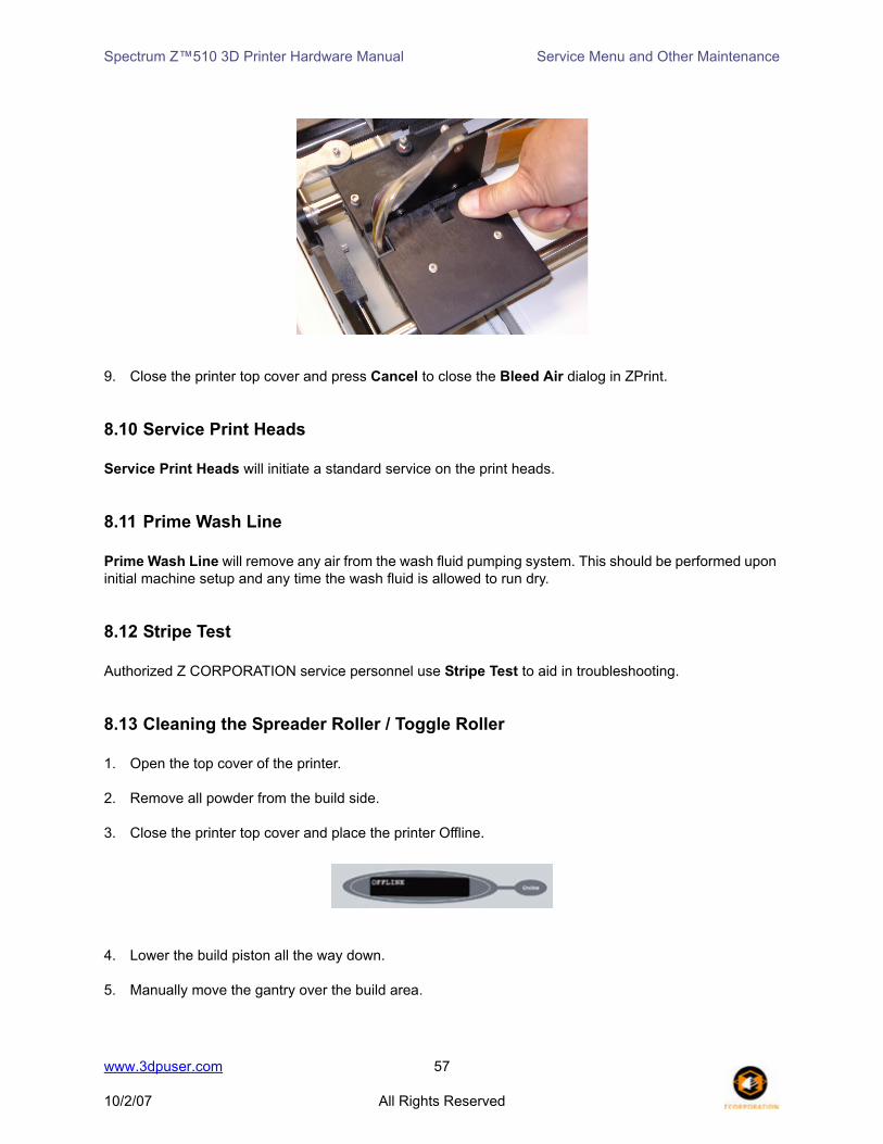
1. Open the top cover of the printer. 2. Remove all powder from the build side.
3. Close the printer top cover and place the printer Offline.
4. Lower the build piston all the way down.
5. Manually move the gantry over the build area.
www.3dpuser.com 57
10/2/07 All Rights Reserved
Spectrum Z™510 3D Printer Hardware Manual Service Menu and Other Maintenance
6. Put the printer Online.
7. Select Service > Toggle Roller On/Off.
8. Using a moist paper towel, wipe under the gantry making sure to remove all powder residue. Dry the area with a paper towel. Select Toggle Roller On/Off to turn off the roller.
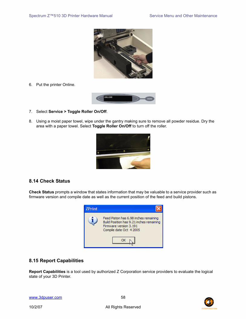
8.14 Check Status
Check Status prompts a window that states information that may be valuable to a service provider such as firmware version and compile date as well as the current position of the feed and build pistons.
8.15 Report Capabilities
Report Capabilities is a tool used by authorized Z Corporation service providers to evaluate the logical state of your 3D Printer.
www.3dpuser.com 58
10/2/07 All Rights Reserved
Spectrum Z™510 3D Printer Hardware Manual Service Menu and Other Maintenance
8.16 Print Head Report
Print Head Report is a useful tool for identifying how old each print head is. The user should access Print Head Report prior to each print job to determine if there is enough print head life to complete a job or to see if any or all of the print heads require changing.
8.17 View Printer Log
View Printer Log is a text file that stores usage information, error codes, and any event that occurs during operation. As part of the troubleshooting process, you may be asked by your service provider to save and submit the log. There is no proprietary information about printed parts in the Printer Log.
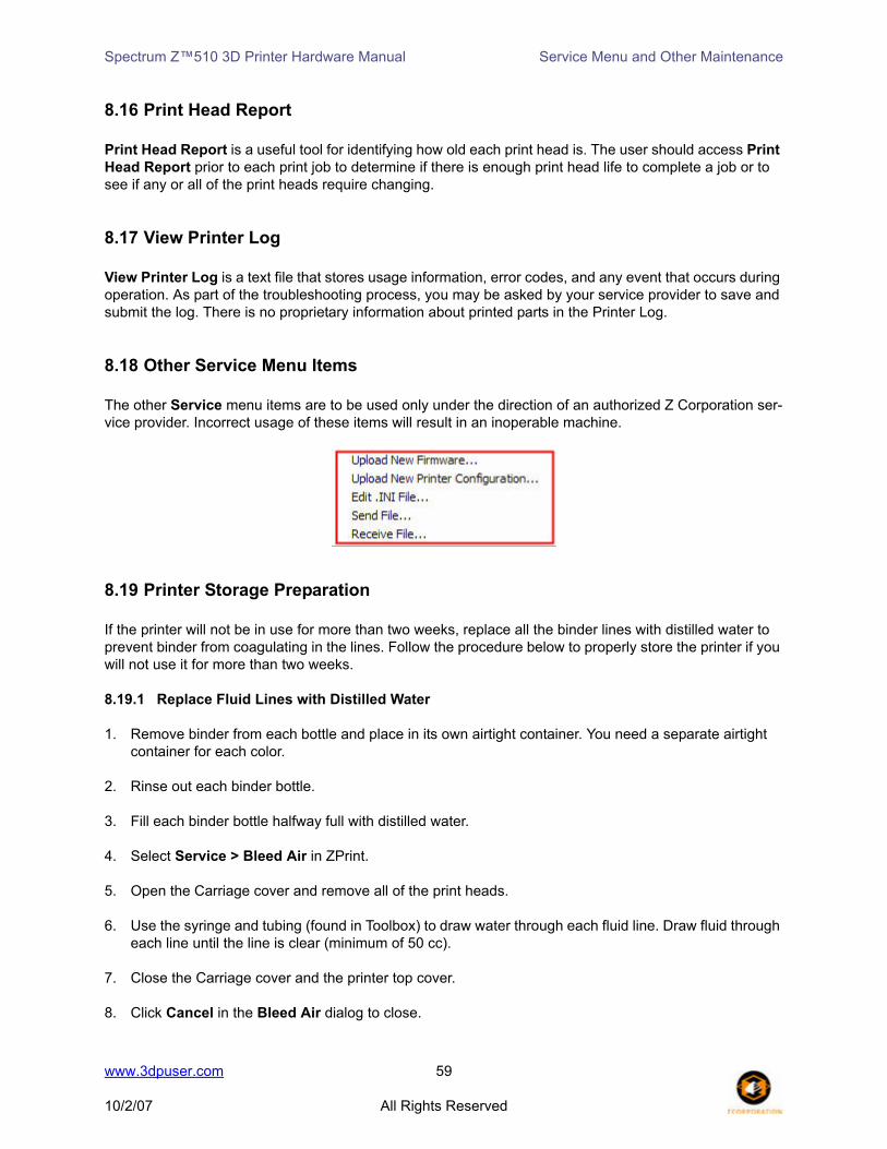
8.18 Other Service Menu Items
The other Service menu items are to be used only under the direction of an authorized Z Corporation ser-vice provider. Incorrect usage of these items will result in an inoperable machine.
8.19 Printer Storage Preparation
If the printer will not be in use for more than two weeks, replace all the binder lines with distilled water to prevent binder from coagulating in the lines. Follow the procedure below to properly store the printer if you will not use it for more than two weeks.
8.19.1 Replace Fluid Lines with Distilled Water
1. Remove binder from each bottle and place in its own airtight container. You need a separate airtight container for each color.
2. Rinse out each binder bottle.
3. Fill each binder bottle halfway full with distilled water.
4. Select Service > Bleed Air in ZPrint.
5. Open the Carriage cover and remove all of the print heads.
6. Use the syringe and tubing (found in Toolbox) to draw water through each fluid line. Draw fluid through each line until the line is clear (minimum of 50 cc).
7. Close the Carriage cover and the printer top cover.
8. Click Cancel in the Bleed Air dialog to close.
www.3dpuser.com 59
10/2/07 All Rights Reserved

Spectrum Z™510 3D Printer Hardware Manual Service Menu and Other Maintenance
8.20 Best Practices for Powder Management
It is important to use best practices to maintain a clean working environment during the operation of your 3D printers. A small amount of extra care to follow these practices can go a long way to keep your powder in your printer where it is most valuable to you. Good powder management promotes a clean work environ-ment and will keep your printer optimally running so you can be productive.
Z Corporation recommends all users go to the Z Corporation 3DP™ User Website for tips and best prac-tices information, or click the following link:
Best Practices for Powder Management
www.3dpuser.com 60
10/2/07 All Rights Reserved
Spectrum Z™510 3D Printer Hardware Manual Troubleshooting
9 Troubleshooting
9.1 The binder solution is being applied in erratic stripes
If the binder appears to be applied in fragmented stripes, check the following:
1. Rinse the squeegee clear of any debris.2. Make sure binder supply is full.
If this does not correct the problem, your print heads may be worn out. Replace the print heads as outlined in Change Print Heads.
9.2 ZPrint Software freezes up during the print job
Exit the software by pressing Ctrl_Alt_Delete. Check to see if the software is responding or not. Complex parts can take some time to load, render, and compute slices during printing. Look for excessive disk activ-ity which may indicate lack of RAM. If it is not responding, choose End Task from the Task Manager, and restart the software. You may choose to go to the Detailed Log Report under the View menu for the last layer printed for that build and continue from the last printed layer.
9.3 Thin planar parts are warping
In general, warping is caused by uneven drying of parts. By adjusting print orientation and drying time, warping can be minimized. You can take steps to ensure that drying is occurring evenly by:
• Reorienting your part within the build box. If a thin planar surface of a part lies flat along the top of the build box, the broad exposed area may dry unevenly and bow towards the top. Reorient the part so that the thin planar surface lies perpendicular to the top of the build box.
• Ensure that you are not over-drying the part. Reduce drying time to a minimum. Refer to Section 7.5, Drying the Part to ensure you allow enough drying time.
• Decreasing the layer thickness without proportionally changing the minimum and maximum satu-rations will over saturate the part causing it to warp and may also cause individual layers to curl during printing.
9.4 Nothing happens when I try to print
• Is the network connection connected properly?
Remove the cord and carefully reinstall. Reboot the Printer. The LCD will display Spectrum Z510 when booting. It will then display Use Serial if a network connection is not found. To restore net-work settings, see Restoring Network and Firmware Settings in the Appendix.
• Are any of the lights on the control panel illuminated?
www.3dpuser.com 61
10/2/07 All Rights Reserved

Spectrum Z™510 3D Printer Hardware Manual Troubleshooting
If the control pad illuminates but nothing happens after that, shut the machine off and turn it back on again. The machine should come online. But if it does not, please contact your authorizedZ Corporation Service Provider.
9.5 Parts are unusually weak or crumbly
• Is the data file known to be without errors?
If the *.stl file is not near perfect you will have problems printing the part. Open the file in the soft-ware and inspect it layer by layer to ensure there are no gaps and the part does not overlap other parts.
• Is there enough binder in the feed bottles?
When you start the build, a reminder box will pop up asking you to check if there is enough binder in the feed bottles. If you plan to start a large build make sure binder bottles are full.
• Is the saturation too low?
If your parts are unusually crumbly, check to make sure your saturation levels are not set too low for this type of part. Return to working with the default saturation values for the material type. If this does not work, please contact your authorized Z Corporation Service Provider.
9.6 Printer looks like it is printing, but is not laying down binder
If you are using Bleed Compensation, it is not uncommon for the printer to move and lay down little or no binder for the first few layers of a part.
As you begin printing, carefully watch the printer to see if it is printing normally. It may be that the print heads are not properly seated in the carriage. This can cause a bad connection with the temperature sen-sor and the print heads will overheat. Prolonged periods of attempting to print without binder flow will dam-age the print head. You will need to replace the print heads.
9.7 Air has Entered the Binder Fluid Lines
Bleed Air maintenance is performed if air bubbles are visible in the binder lines that run from the Binder bottles to the Printheads in the Carriage. Air in the binder system will prematurely expire the Printheads. If you see air bubbles in any of the binder lines, use the syringe and tubing included with the printer Toolbox to bleed the air out of the lines. See Bleed Air for instructions on how to bleed air out of the binder lines.
The most likely time you may find you need to bleed the binder lines is if the printer has been sitting idle and has not been in use, if a binder line is disconnected from a binder bottle, or if the binder runs out while printing. If any of these are the case, it is recommended that you check the binder lines for air bubbles before preceding with a print.
www.3dpuser.com 62
10/2/07 All Rights Reserved

Spectrum Z™510 3D Printer Hardware Manual Troubleshooting
9.8 Air has Entered into the Wash Fluid Line
You will need to use the Prime Wash Fluid feature when there is no wash fluid or air has entered the wash fluid line. This can occur in a few instances such as when first installing the Printer, when running out of wash fluid, or when the connection to the fluid line has been disconnected. Air can be easily detected by looking to see if there are air bubbles in the wash fluid line. To remove air from the line, follow the instruc-tions below:
1. Place the printer Online.
2. Select Service > Prime Wash Line.
3. Click Start.
4. The Prime Wash Fluid status box will close when priming is completed.
www.3dpuser.com 63
10/2/07 All Rights Reserved

Spectrum Z™510 3D Printer Hardware Manual Troubleshooting
9.9 Communication Errors Between Print Head and Printer
In general, clean the pogo pins whenever you replace or remove a printhead. Doing this will greatly reduce errors in communication between the printhead and printer. To clean the pogo pins, follow these instruc-tions:
1. Get an alcohol swab (Toolbox) and remove it from its packaging. Crush the plastic casing to release the alcohol into the swab.
2. Unpark the gantry and manually move the gantry to the front of the printer.
3. Open the carriage cover and remove the printhead.
4. Wipe the pogo pins and reinsert the printhead.
5. Close the carriage cover and repark the gantry.
www.3dpuser.com 64
10/2/07 All Rights Reserved

Spectrum Z™510 3D Printer Hardware Manual 3D Printer System Details
10 3D Printer System Details
10.1 System Specifications
Warning: Check ratings marked on product BEFORE plugging into a power source.
Dedicated power outlet requirements: 110 -120 VAC; 50/60Hz; 6.8A max., or220 - 240 VAC:50/60Hz; 3.4A max., or100 VAC; 50/60Hz; 7.8A max.
Network Ethernet 10/100 base TTemperature 68-85° F. (20-30° C)Relative Humidity 20-60%, non-condensedWeight 470 lbs. (210 kg)3D Printer Z510 Dimensions Cover Closed
42" x 31.25" x 50.5" (107cm x 79cm x 128cm)Cover Open42" x 31.25" x 73" (107cm x 79cm x 185cm)
Click System Requirements for additional information regarding system specifications for all 3D Printers on the 3DP™ User Website.
Lithium Battery
Internal to the 3D Printer is a lithium coin cell type battery. This may be any one of the following: Type: CR2032, either Maxell, Panasonic, Renata, Sanyo or Sony.
PLEASE NOTE: This battery is not in a user accessible area and is not user replace-able. The expected lifetime of the battery is in excess of five years. Replacement will behandled by your Z Corporation Customer Service Representative.
FCC Notice
This equipment has been tested and found to comply with the limits for a Class A digital device, pursuant to part 15 of the FCC rules. These limits are designed to provide reasonable protection against harmful interference when the equipment is operated in a commercial environment. This equipment generates, uses, and can radiate radio frequency energy and, if not installed and used in accordance with the instruc-tion manual, may cause harmful interference to radio communications. Operation of this equipment in a residential area is likely to cause harmful interference in which case the user will be required to correct the interference at their own expense.
CENELEC Class A Warning
This equipment has been tested and found to comply with the limits for a Class A digital device, pursuant to EN 55022. Class A devices are for office and light industrial environments, and are not generally suit-able for home use.
WARNINGThis is a Class A product. In a domestic environment this product may cause radio inter-ference in which case the user may be required to take adequate measures.
www.3dpuser.com 65
10/2/07 All Rights Reserved
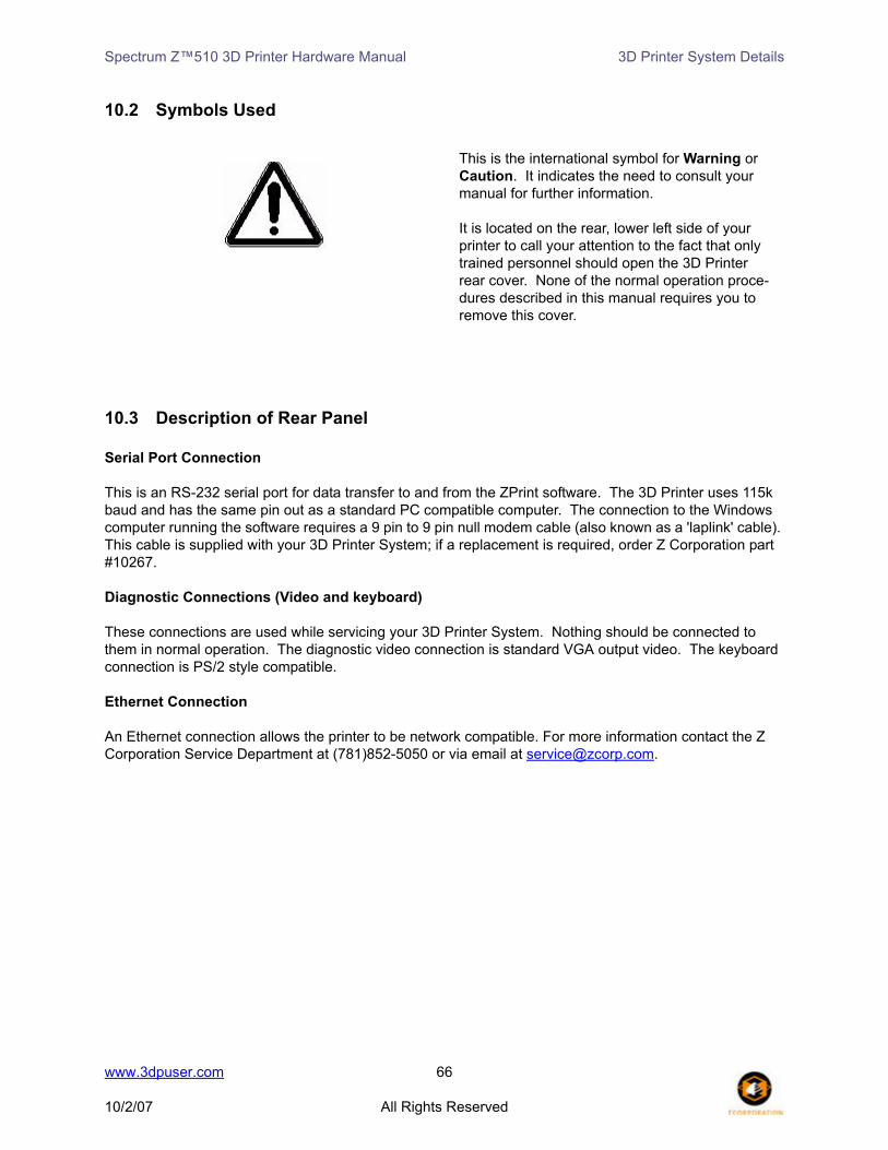
Spectrum Z™510 3D Printer Hardware Manual 3D Printer System Details
10.2 Symbols Used
10.3 Description of Rear Panel
Serial Port Connection
This is an RS-232 serial port for data transfer to and from the ZPrint software. The 3D Printer uses 115k baud and has the same pin out as a standard PC compatible computer. The connection to the Windows computer running the software requires a 9 pin to 9 pin null modem cable (also known as a 'laplink' cable). This cable is supplied with your 3D Printer System; if a replacement is required, order Z Corporation part #10267.
Diagnostic Connections (Video and keyboard)
These connections are used while servicing your 3D Printer System. Nothing should be connected to them in normal operation. The diagnostic video connection is standard VGA output video. The keyboard connection is PS/2 style compatible.
Ethernet Connection
An Ethernet connection allows the printer to be network compatible. For more information contact the Z Corporation Service Department at (781)852-5050 or via email at [email protected].
This is the international symbol for Warning or Caution. It indicates the need to consult your manual for further information.
It is located on the rear, lower left side of your printer to call your attention to the fact that only trained personnel should open the 3D Printer rear cover. None of the normal operation proce-dures described in this manual requires you to remove this cover.
www.3dpuser.com 66
10/2/07 All Rights Reserved

Spectrum Z™510 3D Printer Hardware Manual 3D Printer System Details
Material Storage Precautions
Review the Material Safety Data Sheets (MSDS) carefully before using any Z Corporation materials.
Material Storage Usage
Powder Store powder on pallets in a cool, dry, ventilated area away from sources of heat, moisture, and incompatible materials. Keep containers tightly closed.
Use of powder in environments with more than 30% rela-tive humidity will affect powder perfor-mance.
Binder and Wash Fluid
Store in cool, dry place, away from sun. Keep tightly capped.
Binders and wash fluids are NOT RECYCLABLE.
Printheads Store in cool, dry place, away from sun. Life expectancy depends on usage.
Infiltrants Store in cool, dry place, away from sun. Keep tightly capped.
For more informa-tion, visit the 3DP User Website at www.3dpuser.com.
www.3dpuser.com 67
10/2/07 All Rights Reserved

Spectrum Z™510 3D Printer Hardware Manual Appendix
11 Appendix
11.1 Restoring Network and Firmware Settings
Configuration mode is obtained by pressing and holding the ONLINE key on the printer control panel.
Configuration mode is indicated when the LCD displays: NETWORK SETTINGS
The Configuration menu consists of these 5 choices: NETWORK SETTINGS
RESTORE FIRMWARE
DIAGNOSTIC MODE
SAVE AND EXIT
DISCARD AND EXIT
Press the < Build UP > or < Build DN > keys to scroll through the Configuration menu.
Press the < Feed UP > key to select an item on the Configuration menu to edit. The LCD displays your selection.
Selecting NETWORK SETTINGS displays: NETWORK SETTINGSUSE NETWORK? YES
Press the < Build UP > or < Build DN > keys to toggle YES/NO.Selecting NO means the serial port will be used.
Press the < Feed UP > key to display:
DHCP/STATIC IPUSE DHCP? YES
Press the < Build UP > and < Build DN > keys to toggle YES/NO.
If NO is selected, and the < Feed UP > key is pressed, the LCD dis-plays:
IP ADDRESS0. 0. 0. 0.
www.3dpuser.com 68
10/2/07 All Rights Reserved

Spectrum Z™510 3D Printer Hardware Manual Appendix
Press the < Feed UP > key to move the cursor to the right.Press the < Feed DN > key to move the cursor to the left.Press the < Build UP > or < Build DN > keys to change the value at the current cursor position.
• If the cursor is at the rightmost IP ADDRESS field, and the < Feed UP > key is pressed, the LCD display reads:
SUBNET MASK 0. 0. 0. 0.
Press the < Feed UP > key to move the cursor to the right.Press the < Feed DN > key to move the cursor to the left.Press the < Build UP > or < Build DN > keys to change the value at the current cursor position.
If the cursor is at the rightmost SUBNET MASK field and the < Feed UP > key is pressed, you are returned to the Configuration menu.
If the cursor is at the leftmost SUBNET MASK field and the < Feed DN > key is pressed, you are returned to IP ADDRESS.
• If the cursor is at the leftmost IP ADDRESS field, and the < Feed DN > key is pressed, the LCD display reads:
DHCP/STATIC IPUSE DHCP? YES
Press the < Build UP > or < Build DN > keys to toggle YES/NO.
If YES is selected and you press the < Feed UP > key, you are returned to the Configuration menu.
Selecting RESTORE FIRMWARE displays: RESTORE FIRMWARERESTORE FIRMWARE? NO
Press the < Build UP > and < Build DN > keys to toggle YES/NO.YES means the printer will use the previous version of firmware prior to the firmware you just installed.
Press the < Feed UP > key to return to the Configuration menu.
Selecting DIAGNOSTIC MODE displays: DIAG MODE?DIAG MODE? NO
Press the < Build UP > or < Build DN > keys to toggle YES/NO.NO is normal operation. YES will skip the rezero calibration (fast, slow axis and pistons) for the current session and causes the pistons to rezero on the next powerup.
Press the < Feed UP > key to return to the Configuration menu.
www.3dpuser.com 69
10/2/07 All Rights Reserved

Spectrum Z™510 3D Printer Hardware Manual Appendix
Selecting SAVE AND EXIT displays: SAVE AND EXIT
Press the < Feed UP > key to save your changes and terminate the Configuration menu.
Selecting DISCARD AND EXIT displays: DISCARD AND EXIT
Press the < Feed UP > key to terminate the Configuration menu. Your changes for the current session will not be saved.
11.2 Error Codes
PLEASE NOTE: %d is a placeholder for numbers corresponding either to a print headnumber or a value. Contact our Service Department at [email protected] if you needadditional help.
Error Code LCD Display
1000, PRINTHEAD ERROR)1001, PRINTHEAD POWER FAIL)1003, PRINTHEAD %d ERROR)1004, PRINTHEAD POWER FAIL)1005, PRINTHEAD %d ERROR)1006, PRINTHEAD %d OVERTEMP)1007, PRINTHEAD POWER FAIL)1009, PRINTHEAD POWER FAIL)1010, PRINTHEAD %d ERROR)1802, USE SERIAL PORT)1905, LAYER TOO BIG)2303, AXIS %d ERROR)2304, AXIS %d ERROR)2305, AXIS %d ERROR)2400, AXIS %d REZERO ERROR)40006, CLEAN SENSOR WINDOW)40007, ALIGNMENT FAILED)40008, ALIGNMENT FAILED)40204, MOTOR DRIVE OVERLOAD)40205, MOTOR DRIVE OVERLOAD)40207, 24V FAIL)40208, MOTOR DRIVE OVERLOAD)40800, PRINTHEAD %d ERROR)40801, HEADCARD POWER FAIL)40802, PRINTHEAD %d NOT HP11)40901, TEMP SENSOR FAILED)40902, TEMP OUT OF RANGE)
www.3dpuser.com 70
10/2/07 All Rights Reserved

Spectrum Z™510 3D Printer Hardware Manual
Numerics3D Print Setup Dialog, 30
AAir In The Binder Fluid Lines, 62Air In The Wash Fluid Line, 63Air Pressure When Depowdering, 36Alcohol Swabs Part Number, 66Alignment Pattern, 46
BBest Practices For Powder Management, 60Binder Solution, 5Binders And Printing In Monochrome, 25Bleed Air, 53Bleed Compensation, 28Build Piston, 4Build Plate Holders, 21Bulls-Eye Pattern, 46
CCENELEC Class A Warning, 65Change Print Heads, 53Check Binder Bottles, 16Check Build Settings, 29Check Fluid Levels, 24Check Powder Level Command, 47Check Status, 58Check Wash Fluid And Waste Fluid, 16Class A Digital Device Disclaimer, 65Clean Alignment Window, 45Clean Service Station, 15Clean Squirt Manifold Holes, 23Cleaning The Service Station, 22Cleaning The Spreader Roller, 57Cleaning The Toggle Roller, 57Collision Detection, 29Communication Errors Between Print Head And Printer, 64Cylindrical Features, 29
DData File Errors, 62Depowdering The Part, 36Description Of Rear Panel, 67Description Of The 3D Printing Process, 4Detailed Log Report, 61Devilbiss Sprayer, 40Diagnostic Connections, 66Diagram Of 3D Printing Process, 4
Diagram Of Interior And Exterior Saturation, 5Drop Feed Piston Command, 47
EEmpty The Powder From The Overflow Bin, 21Error Codes Table, 70Ethernet Connector, 66Excess Powder, 22
FFast Axis Lubrication, 48Feed Piston, 4Fill Bed Command, 47Fill Feed Box, 15Firmware Description, 27Fixture, 28Fragmented Stripes In Binder Application, 61Front Cabinet Tray, 24
GGantry, 4
HHold For Unload command, 20How It Works, 4
IIncrease Strength Of Thin Parts, 28Initiate The Fill Bed Mode, 22Install Firmware, 27Internal, Printer Assembly And Service Station Components, 8International Symbol For Warning Or Caution, 66Introduction, 4
LLithium Coin Cell Battery, 65Lower Feed Piston, 20
MMaintenance Command, 47Material Storage Precautions, 67
NNetwork Connection Troubleshooting, 68New Accessories Available, 13New Overflow Bin Cover, 13
www.3dpuser.com i

Spectrum Z™510 3D Printer Hardware Manual
New Vacuum Attachment Image, 14
OOffline Mode, 20Online Mode, 43Open Or Hollow Area Of Part, 29Open Or Import Files, 28Orient Parts, 28Other Service Menu Items, 59Overflow Bin Cover, 3Overview, 1
PParaplast Application Notes, 38Paraplast Curing Information, 38Paraplast Safety Precautions, 38Part Accuracy, 6Part Infiltration, 37Part Orientation, 29Part Orientation, 28Part Placement, 5Part Strength, 5Parts Are Weak Or Crumbly, 62Parts Containing Overhangs, 29Piston Screws Lubrication, 51Place Printer Online, 16Polypropylene Scraper, 32Post-processing Tools, 32Powder Recycling System Components, 10Powder Recycling System Image, 7Preheat Printer, 20Preheat Printer Command, 47Preparing The 3d Printer, 15Preparing The Build Area, 20Preparing The Build In Zprint Software, 17Prime Wash Line, 57Print Assembly, 4Print Dialog, 30Print Head Report, 59Print Head Report Dialog, 43Printer Assembly With Carriage Insert, 9Printer Components, 7Printer Control Panel, 8Printer Periodic Self Maintenance, 16Printer Storage Preparation, 59Printing The Build, 30Purge Print Head Command, 43
QQuick Start Guide, 15
RRemoving The Finished Part, 34Removing The Part, 18Replace Fluid Lines With Distilled Water, 59Report Capabilities, 58Restoring Network And Firmware Settings, 68Rinse Rubber Parking Cap, 23Rinse Rubber Wiper Blade, 23Roller, 4Routine Operations, 20
SSaturation Troubleshooting, 62Serial Port Connection, 66Service Menu, 43Service Print Heads, 57Service Station, 9Slice View, 30Slow Axis Lubrication, 50Soft Acid Brush, 33Soft Horsehair Brush, 33Stiff Detailing Brush, 33Stiff Handle Brush, 33Stripe Test, 57System Components, 7System Specifications, 66
TTamp Powder, 21Thin Planar Parts Are Warping, 61Tips On Gross And Fine Depowdering, 32Tips On Setting Up The Build, 27
UUnpark Command, 43Use Of Equipment, 1Using Paraplast X-TRA Wax, 38Using Z-Bond Cyanoacrylate, 38Using Z-Max Epoxy, 39
VVacuum Attachment, 3Vacuuming Operation Warning, 35View Binder Levels, 25View Printer Log, 59Void Warranty, 20
WWaste Fluid Disposal, 25
www.3dpuser.com ii

Spectrum Z™510 3D Printer Hardware Manual
Wide Blade Utility Scraper, 32Wipe Metal Spit Cover, 24
Zz®Cast Description, 12Z510 3D Printer Image, 7Z510 Powders, Accessories And Tools, 11Z510 Toolkit Tools, 12Z-Bond Application Notes, 39Z-Bond Curing Information, 39Z-Bond Safety Precautions, 38ZD5 Depowder Unit, 10Z-Max Application Notes, 40Z-Max Curing Information, 41Z-Max Mixing Instructions, 40Z-Max Safety Precautions, 39Z-Max Spraying Instructions, 40zp®15e Description, 12ZPrint Dialog, 58ZPrint Software Freezes, 61
www.3dpuser.com iii
Related Documents