ICND2 Interconnecting Cisco Networking Devices Part 2 Version 1.0 Lab Guide Editorial, Production, and Web Services (EPWS): 07.25.07 The PDF files and any printed representation for this material are the property of Cisco Systems, Inc., for the sole use by Cisco employees for personal study. The files or printed representations may not be used in commercial training, and may not be distributed for purposes other than individual self-study.

Welcome message from author
This document is posted to help you gain knowledge. Please leave a comment to let me know what you think about it! Share it to your friends and learn new things together.
Transcript

8/3/2019 Icnd210lg Cracked
http://slidepdf.com/reader/full/icnd210lg-cracked 1/120
ICND2
Interconnecting CiscoNetworking Devices
Part 2Version 1.0
Lab Guide
Editorial, Production, and Web Services (EPWS): 07.25.07
The PDF files and any printed representation for this material are the property of Cisco Systems, Inc.,for the sole use by Cisco employees for personal study. The files or printed representations may not beused in commercial training, and may not be distributed for purposes other than individual self-study.

8/3/2019 Icnd210lg Cracked
http://slidepdf.com/reader/full/icnd210lg-cracked 2/120
DISCLAIMER WARRANTY: THIS CONTENT IS BEING PROVIDED “AS IS.” CISCO MAKES AND YOU RECEIVE NO WARRANTIES IN
CONNECTION WITH THE CONTENT PROVIDED HEREUNDER, EXPRESS, IMPLIED, STATUTORY OR IN ANY OTHER PROVISION OF
THIS CONTENT OR COMMUNICATION BETWEEN CISCO AND YOU. CISCO SPECIFICALLY DISCLAIMS ALL IMPLIED
WARRANTIES, INCLUDING WARRANTIES OF MERCHANTABILITY, NON-INFRINGEMENT AND FITNESS FOR A PARTICULAR
PURPOSE, OR ARISING FROM A COURSE OF DEALING, USAGE OR TRADE PRACTICE. This learning product may contain early release
content, and while Cisco believes it to be accurate, it falls subject to the disclaimer above.
The PDF files and any printed representation for this material are the property of Cisco Systems, Inc.,for the sole use by Cisco employees for personal study. The files or printed representations may not beused in commercial training, and may not be distributed for purposes other than individual self-study.
8/3/2019 Icnd210lg Cracked
http://slidepdf.com/reader/full/icnd210lg-cracked 3/120
ICND2
Lab Guide
OverviewThis guide presents the instructions and other information concerning the activities for thiscourse. You can find the solutions in the Lab Activity Answer Key.
Outline
This guide includes these activities:
Lab 1-1: Implementing a Small Network (Review Lab)
Lab 2-1: Configuring Expanded Switched Networks
Lab 2-2: Troubleshooting Switched Networks
Lab 4-1: Implementing OSPF
Lab 4-2: Troubleshooting OSPF
Lab 5-1: Implementing EIGRP
Lab 5-2: Troubleshooting EIGRP
Lab 6-1: Implementing and Troubleshooting ACLs
Lab 7-1: Configuring NAT and PAT
Lab 7-2: Implementing IPv6
Lab 8-1: Establishing a Frame Relay WAN
Lab 8-2: Troubleshooting Frame Relay WANs
Answer Key
The PDF files and any printed representation for this material are the property of Cisco Systems, Inc.,for the sole use by Cisco employees for personal study. The files or printed representations may not beused in commercial training, and may not be distributed for purposes other than individual self-study.
8/3/2019 Icnd210lg Cracked
http://slidepdf.com/reader/full/icnd210lg-cracked 4/120
2 Interconnecting Cisco Networking Devices Part 2 (ICND2) v1.0 © 2007 Cisco Systems, Inc.
Lab 1-1: Implementing a Small Network(Review Lab)
Complete this lab activity to practice what you reviewed in the related module.
Activity Objective
In this activity, you will use the skills and knowledge that you acquired prior to taking thiscourse to implement a small network. You will use the commands reviewed in the related
module to provide your workgroup switch and router with a basic configuration for IP
connectivity.
After completing this activity, you will be able to meet these objectives:
Return your workgroup switch and router to their default configurations
Configure your workgroup switch and router with their proper identities and IP addressing
Provide basic security with passwords and port security
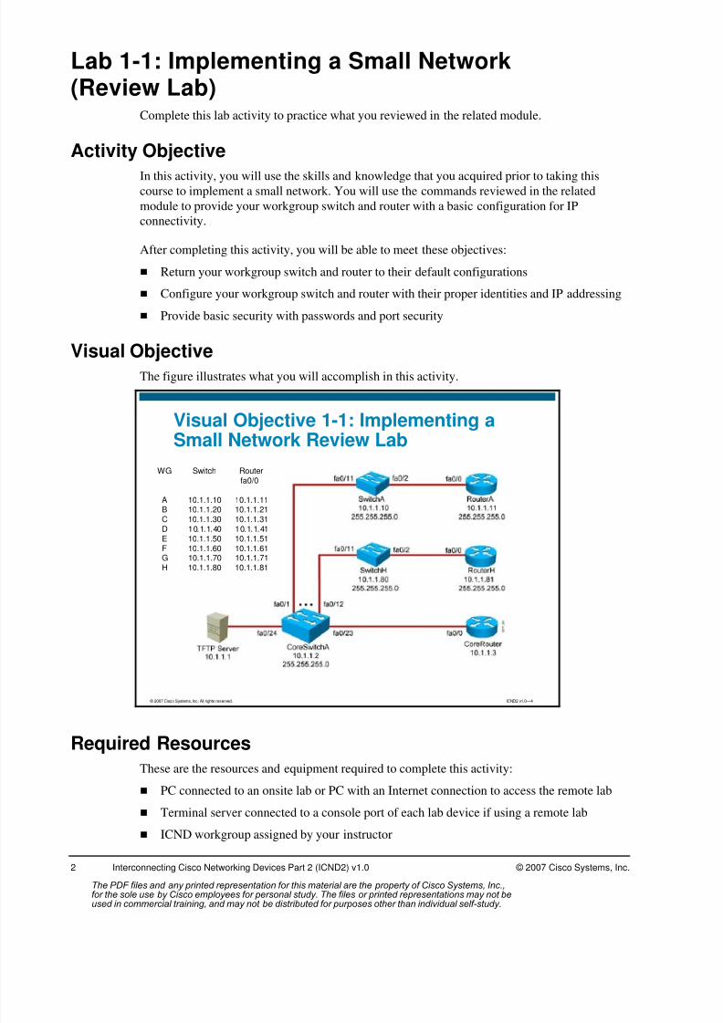
Visual ObjectiveThe figure illustrates what you will accomplish in this activity.
© 2007 Cisco Systems, Inc. All rights reserved. ICND2 v1.0—4
Visual Objective 1-1: Implementing aSmall Network Review Lab
WG Switch Routerfa0/0
A 10.1.1.10 10.1.1.11B 10.1.1.20 10.1.1.21C 10.1.1.30 10.1.1.31
D 10.1.1.40 10.1.1.41E 10.1.1.50 10.1.1.51F 10.1.1.60 10.1.1.61G 10.1.1.70 10.1.1.71H 10.1.1.80 10.1.1.81
Required Resources
These are the resources and equipment required to complete this activity:
PC connected to an onsite lab or PC with an Internet connection to access the remote lab
Terminal server connected to a console port of each lab device if using a remote lab
ICND workgroup assigned by your instructor
The PDF files and any printed representation for this material are the property of Cisco Systems, Inc.,for the sole use by Cisco employees for personal study. The files or printed representations may not beused in commercial training, and may not be distributed for purposes other than individual self-study.

8/3/2019 Icnd210lg Cracked
http://slidepdf.com/reader/full/icnd210lg-cracked 5/120
© 2007 Cisco Systems, Inc. Lab Guide
Your instructor will provide setup information that you need to complete this and the
subsequent lab activities. Your instructor will also assign you to a workgroup, identified by the
letters A through H. Complete the following information as provided by your instructor:
Value Information Provided by Your Instructor
Your workgroup
IP address of your terminal
Subnet mask
IP address of the default gateway
IP address of the terminal server
Username to access the terminal server
Password to access the terminal server
IP address of the TFTP server
The PDF files and any printed representation for this material are the property of Cisco Systems, Inc.,for the sole use by Cisco employees for personal study. The files or printed representations may not beused in commercial training, and may not be distributed for purposes other than individual self-study.

8/3/2019 Icnd210lg Cracked
http://slidepdf.com/reader/full/icnd210lg-cracked 6/120
4 Interconnecting Cisco Networking Devices Part 2 (ICND2) v1.0 © 2007 Cisco Systems, Inc.
Command List
The table describes the commands used in this activity. The commands are listed in
alphabetical order so that you can easily locate the information you need. Refer to this list if
you need configuration command assistance during the lab activity.
Review Commands
Command Description
banner motd Configures the message-of-the-day banner.
configure terminal Enters global configuration mode.
copy running-configstartup-config
Saves the running configuration into NVRAM as the startupconfiguration.
description Adds a descriptive comment to the configuration of aninterface—very useful with complex configurations.
duplex full Enables full duplex on an interface.
enable Enters the privileged EXEC mode command interpreter.
enable secret password Sets an enable secret password to enter privilege EXEC.
erase startup-configuration
Erases the startup configuration from NVRAM.
hostname name Assigns your device a hostname.
interface interface Specifies an interface and enters interface configurationmode.
ip address address mask Sets the IP address and mask of the device.
ip default-gateway address Sets the default gateway of the switch.
line console 0 Specifies the console line and enters line configurationmode.
line vty 0 4 Specifies the vty lines and enters line configuration mode.
login Sets password checking at login.
logging synchronous Enables synchronous logging of messages.
password password Sets a password on a line.
ping ip_address Uses ICMP echo requests and ICMP echo replies todetermine whether a remote host is reachable.
reload Reboots the device to make your changes take effect.
show cdp neighbors Displays the Cisco Discovery Protocol updates received oneach local interface of the device.
show interfaces Displays information on all of the device interfaces.
show port-security[interface interface-id ][address]
Displays the administrative and operational status of allsecure ports on a switch. Optionally displays specificinterface security settings or all secure MAC addresses.
show running-configuration Displays the active configuration.
show startup-configuration Displays the startup configuration settings that are saved inNVRAM.
shutdown/no shutdown Disables or enables an interface.
The PDF files and any printed representation for this material are the property of Cisco Systems, Inc.,for the sole use by Cisco employees for personal study. The files or printed representations may not beused in commercial training, and may not be distributed for purposes other than individual self-study.
8/3/2019 Icnd210lg Cracked
http://slidepdf.com/reader/full/icnd210lg-cracked 7/120
© 2007 Cisco Systems, Inc. Lab Guide
Command Description
speed speed Sets the speed of the port.
switchport mode access Sets the port to access mode. Use the no version of thiscommand to reset default values.
switchport port-security Enables port security on an interface. Entered withoutkeywords.
switchport port-security
mac-address mac-address
Assigns a secure MAC address on a port. Use the no form
of this command to remove it.
switchport port-security maximum value
Sets the maximum number of secure MAC addresses forthe interface.
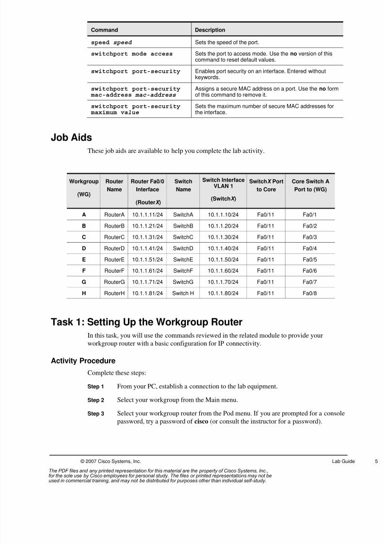
Job Aids
These job aids are available to help you complete the lab activity.
Workgroup
(WG)
Router
Name
Router Fa0/0
Interface
(RouterX )
Switch
Name
Switch Interface
VLAN 1
(SwitchX )
SwitchX Port
to Core
Core Switch A
Port to (WG)
A RouterA 10.1.1.11/24 SwitchA 10.1.1.10/24 Fa0/11 Fa0/1
B RouterB 10.1.1.21/24 SwitchB 10.1.1.20/24 Fa0/11 Fa0/2
C RouterC 10.1.1.31/24 SwitchC 10.1.1.30/24 Fa0/11 Fa0/3
D RouterD 10.1.1.41/24 SwitchD 10.1.1.40/24 Fa0/11 Fa0/4
E RouterE 10.1.1.51/24 SwitchE 10.1.1.50/24 Fa0/11 Fa0/5
F RouterF 10.1.1.61/24 SwitchF 10.1.1.60/24 Fa0/11 Fa0/6
G RouterG 10.1.1.71/24 SwitchG 10.1.1.70/24 Fa0/11 Fa0/7
H RouterH 10.1.1.81/24 Switch H 10.1.1.80/24 Fa0/11 Fa0/8
Task 1: Setting Up the Workgroup Router
In this task, you will use the commands reviewed in the related module to provide your
workgroup router with a basic configuration for IP connectivity.
Activity Procedure
Complete these steps:
Step 1 From your PC, establish a connection to the lab equipment.
Step 2 Select your workgroup from the Main menu.
Step 3 Select your workgroup router from the Pod menu. If you are prompted for a console
password, try a password of cisco (or consult the instructor for a password).
The PDF files and any printed representation for this material are the property of Cisco Systems, Inc.,for the sole use by Cisco employees for personal study. The files or printed representations may not beused in commercial training, and may not be distributed for purposes other than individual self-study.
8/3/2019 Icnd210lg Cracked
http://slidepdf.com/reader/full/icnd210lg-cracked 8/120
6 Interconnecting Cisco Networking Devices Part 2 (ICND2) v1.0 © 2007 Cisco Systems, Inc.
Step 4 Enter privileged EXEC mode. If you are prompted for a privileged EXEC password,
try a password of sanfran. If a password of sanfran does not work, please consult
with your instructor.
Step 5 Erase the startup configuration of your workgroup router.
Step 6 Reload your workgroup router. If you are prompted to save modifications, answer N.
When you are prompted to confirm reload, answer Y.
Step 7 After your workgroup router reboots, you will be asked if you want to enter theConfiguration Dialog. Answer N. If you are asked if you want to terminate
AutoInstall, answer Y.
Step 8 Configure your workgroup router with a hostname. Use the name listed in the Job
Aids table for this lab activity.
Step 9 Configure an enable secret password of sanfran, which will be used to gain access
to privileged EXEC mode.
Step 10 Assign an IP address to the first Ethernet interface (Fa0/0) of your workgroup router.
The IP address is listed in the Job Aids table for this lab.
Step 11 Enable the first Ethernet interface (Fa0/0) of your workgroup router.
Step 12 Provide a description for the interface configuration describing the connected
destination.
Step 13 Configure a message of the day banner warning unauthorized users not to log in.
Step 14 Configure the router to require a password when accessing the router through the
console port. Use the password cisco.
Step 15 Configure the router to require a password when accessing the router through the
first five vty lines, 0 through 4. Use a password of sanjose.
Step 16 Configure the console port with the logging synchronous command.
Step 17 Save your running configuration to NVRAM.
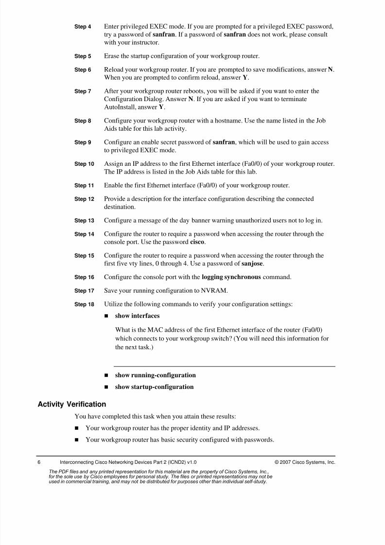
Step 18 Utilize the following commands to verify your configuration settings:
show interfaces
What is the MAC address of the first Ethernet interface of the router (Fa0/0)
which connects to your workgroup switch? (You will need this information for
the next task.)
show running-configuration
show startup-configuration
Activity Verification
You have completed this task when you attain these results:
Your workgroup router has the proper identity and IP addresses.
Your workgroup router has basic security configured with passwords.
The PDF files and any printed representation for this material are the property of Cisco Systems, Inc.,for the sole use by Cisco employees for personal study. The files or printed representations may not beused in commercial training, and may not be distributed for purposes other than individual self-study.

8/3/2019 Icnd210lg Cracked
http://slidepdf.com/reader/full/icnd210lg-cracked 9/120
© 2007 Cisco Systems, Inc. Lab Guide
Task 2: Setting Up the Workgroup SwitchIn this task, you will use the commands reviewed in the related module to provide your
workgroup switch with a basic configuration for IP connectivity.
Activity Procedure
Complete these steps:
Step 1 From your PC, establish a connection to the lab equipment.
Step 2 Select your workgroup from the Main menu.
Step 3 Select your workgroup switch from the Pod menu. If you are prompted with a
console password, try a password of cisco (or consult the instructor).
Step 4 Enter privileged EXEC mode. If you are prompted with a privileged EXEC
password, try a password of sanfran, or consult your instructor if this password does
not work.
Step 5 Erase your workgroup switch startup configuration.
Step 6 Delete the workgroup switch VLAN database using the following command:
delete flash:vlan.dat.
Note When asked “Delete filename [vlan.dat]?” press the Enter key.
When asked “Delete flash:vlan.dat? [confirm]” press the Enter key.
Step 7 Reload your switch. If you are prompted to save modifications, answer N. When you
are prompted to confirm reload, answer Y.
Step 8 After your switch reboots, you will be asked if you want to enter Configuration
Dialog. Answer N.
Step 9 Configure your switch with a hostname. Use the name listed in the Job Aids table
for this lab activity.
Step 10 Configure an enable secret password of sanfran, which will be used to gain access
to privileged EXEC mode.
Step 11 Assign an IP address to the management VLAN interface of your workgroup switch.
Use the IP address listed in the Job Aids table for this lab activity.
Step 12 Enable the management VLAN interface of your workgroup switch.
Step 13 Assign a default gateway to your workgroup switch. Use the address of the core
router, 10.1.1.3.Step 14 Configure a message-of-the-day banner warning unauthorized users not to log in.
Step 15 Set the speed of port Fa0/11 on your workgroup switch to 100Mb/s.
Step 16 Set the duplex setting of port Fa0/11 on your workgroup switch to full duplex.
Step 17 Provide a description for the Fa0/11 interface describing the connected destination.
The PDF files and any printed representation for this material are the property of Cisco Systems, Inc.,for the sole use by Cisco employees for personal study. The files or printed representations may not beused in commercial training, and may not be distributed for purposes other than individual self-study.
8/3/2019 Icnd210lg Cracked
http://slidepdf.com/reader/full/icnd210lg-cracked 10/120
8 Interconnecting Cisco Networking Devices Part 2 (ICND2) v1.0 © 2007 Cisco Systems, Inc.
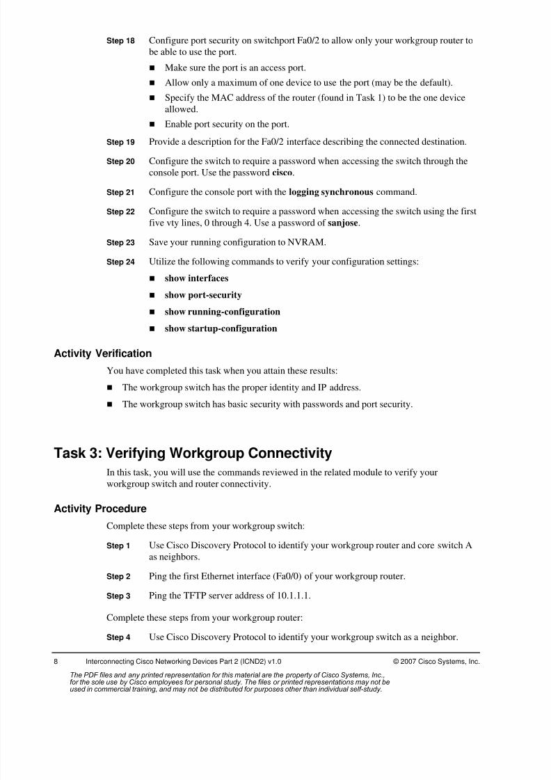
Step 18 Configure port security on switchport Fa0/2 to allow only your workgroup router to
be able to use the port.
Make sure the port is an access port.
Allow only a maximum of one device to use the port (may be the default).
Specify the MAC address of the router (found in Task 1) to be the one device
allowed.
Enable port security on the port.
Step 19 Provide a description for the Fa0/2 interface describing the connected destination.
Step 20 Configure the switch to require a password when accessing the switch through the
console port. Use the password cisco.
Step 21 Configure the console port with the logging synchronous command.
Step 22 Configure the switch to require a password when accessing the switch using the first
five vty lines, 0 through 4. Use a password of sanjose.
Step 23 Save your running configuration to NVRAM.
Step 24 Utilize the following commands to verify your configuration settings:
show interfaces
show port-security
show running-configuration
show startup-configuration
Activity Verification
You have completed this task when you attain these results:
The workgroup switch has the proper identity and IP address.
The workgroup switch has basic security with passwords and port security.
Task 3: Verifying Workgroup Connectivity
In this task, you will use the commands reviewed in the related module to verify your
workgroup switch and router connectivity.
Activity Procedure
Complete these steps from your workgroup switch:
Step 1 Use Cisco Discovery Protocol to identify your workgroup router and core switch A
as neighbors.
Step 2 Ping the first Ethernet interface (Fa0/0) of your workgroup router.
Step 3 Ping the TFTP server address of 10.1.1.1.
Complete these steps from your workgroup router:
Step 4 Use Cisco Discovery Protocol to identify your workgroup switch as a neighbor.
The PDF files and any printed representation for this material are the property of Cisco Systems, Inc.,for the sole use by Cisco employees for personal study. The files or printed representations may not beused in commercial training, and may not be distributed for purposes other than individual self-study.

8/3/2019 Icnd210lg Cracked
http://slidepdf.com/reader/full/icnd210lg-cracked 11/120
© 2007 Cisco Systems, Inc. Lab Guide
Step 5 Ping the VLAN 1 interface of your workgroup switch.
Step 6 Ping the TFTP server address of 10.1.1.1.
Step 7 Notify your instructor that you have completed the activity.
Activity Verification
You have completed this task when you attain these results:
You have successfully viewed your directly connected Cisco Discovery Protocol neighborsfrom you workgroup router and switch.
All of the pings from your workgroup router and switch were successful.
The PDF files and any printed representation for this material are the property of Cisco Systems, Inc.,for the sole use by Cisco employees for personal study. The files or printed representations may not beused in commercial training, and may not be distributed for purposes other than individual self-study.

8/3/2019 Icnd210lg Cracked
http://slidepdf.com/reader/full/icnd210lg-cracked 12/120
10 Interconnecting Cisco Networking Devices Part 2 (ICND2) v1.0 © 2007 Cisco Systems, Inc.
Lab 2-1: Configuring Expanded SwitchedNetworks
Complete this lab activity to practice what you learned in the related module.
Activity Objective
In this activity, you will configure a switch to meet the specific VLAN requirements. After
completing this activity, you will be able to meet these objectives:
Configure the switch to participate in a VTP domain and configure the switch for
transparent mode
Configure trunking on a trunk port to provide access to a router on the network
Configure separate VLANs for separate logical networks
Enable RSTP and configure the root switch and backup root switch
Visual Objective
The figure illustrates what you will accomplish in this activity.
© 2007 Cisco Systems, Inc. All rights reserved. ICND2 v1.0—5
Visual Objective 2-1: ConfiguringExpanded Switched Networks
Subnet VLAN Devices10.1.1.0 1 Core Switches, CoreRouter, SwitchX10.2.2.0 2 CoreRouter, RouterA10.3.3.0 3 CoreRouter, RouterB10.4.4.0 4 CoreRouter, RouterC10.5.5.0 5 CoreRouter, RouterD10.6.6.0 6 CoreRouter, RouterE10.7.7.0 7 CoreRouter, RouterF10.8.8.0 8 CoreRouter, RouterG10.9.9.0 9 CoreRouter, RouterH
The PDF files and any printed representation for this material are the property of Cisco Systems, Inc.,for the sole use by Cisco employees for personal study. The files or printed representations may not beused in commercial training, and may not be distributed for purposes other than individual self-study.

8/3/2019 Icnd210lg Cracked
http://slidepdf.com/reader/full/icnd210lg-cracked 13/120
© 2007 Cisco Systems, Inc. Lab Guide
Required Resources
These are the resources and equipment required to complete this activity:
PC connected to an onsite lab or PC with an Internet connection to access the remote lab
Terminal server connected to a console port of each lab device if using a remote lab
ICND workgroup assigned by your instructor
Command List
The table describes the commands used in this activity. The commands are listed in
alphabetical order so that you can easily locate the information you need. Refer to this list if
you need configuration command assistance during the lab activity.
Commands
Command Description
ping <cr> Executes an extended ping command. You will set the pingcount and other options manually. (Use this command in
privileged EXEC mode.)
switchport mode trunk Interface configuration mode to set a Fast Ethernet or GigabitEthernet port to trunk mode.
switchport access vlanvlan#
Interface configuration mode to assign a port to a VLAN.
ping ip-address Common tool used to troubleshoot the accessibility ofdevices. It uses ICMP echo requests and ICMP echo repliesto determine whether a remote host is active. The ping command also measures the amount of time it takes toreceive the echo reply.
show interface interface Displays the trunk parameters.
show spanning-tree vlanvlan#
Displays spanning-tree information for a particular VLAN.
show interfacesinterface switchport
Displays VLAN and trunk information.
show vlan Displays information on all configured VLANs.
show vtp status Displays the VTP status.
shutdown/no shutdown Disables or enables an interface.
vlan vlan-id Global configuration mode to add a VLAN and enter config- vlan subconfiguration mode. Use the no form of thiscommand to delete the VLAN.
name vlan-name Defines a VLAN name from config-vlan subconfigurationmode.
The PDF files and any printed representation for this material are the property of Cisco Systems, Inc.,for the sole use by Cisco employees for personal study. The files or printed representations may not beused in commercial training, and may not be distributed for purposes other than individual self-study.
8/3/2019 Icnd210lg Cracked
http://slidepdf.com/reader/full/icnd210lg-cracked 14/120
12 Interconnecting Cisco Networking Devices Part 2 (ICND2) v1.0 © 2007 Cisco Systems, Inc.
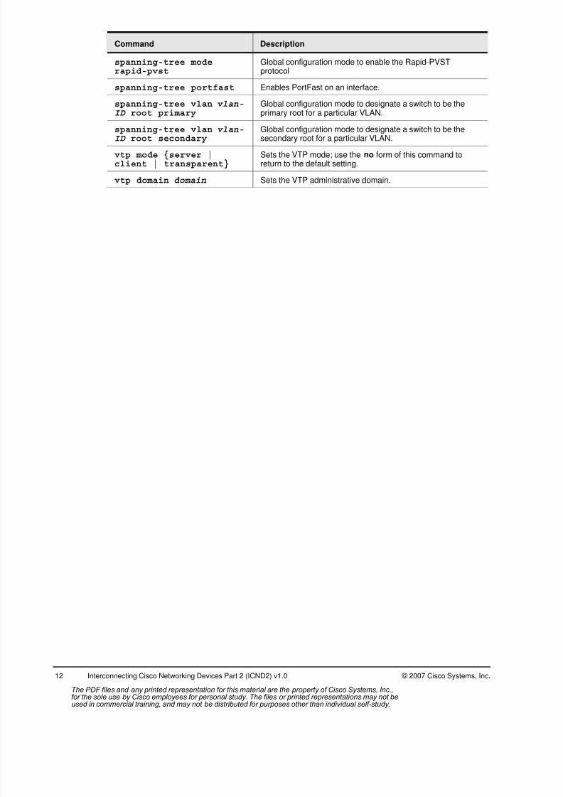
Command Description
spanning-tree moderapid-pvst
Global configuration mode to enable the Rapid-PVSTprotocol
spanning-tree portfast Enables PortFast on an interface.
spanning-tree vlan vlan-ID root primary
Global configuration mode to designate a switch to be theprimary root for a particular VLAN.
spanning-tree vlan vlan-
ID root secondary
Global configuration mode to designate a switch to be the
secondary root for a particular VLAN.
vtp mode {server |client | transparent}
Sets the VTP mode; use the no form of this command toreturn to the default setting.
vtp domain domain Sets the VTP administrative domain.
The PDF files and any printed representation for this material are the property of Cisco Systems, Inc.,for the sole use by Cisco employees for personal study. The files or printed representations may not beused in commercial training, and may not be distributed for purposes other than individual self-study.
8/3/2019 Icnd210lg Cracked
http://slidepdf.com/reader/full/icnd210lg-cracked 15/120
© 2007 Cisco Systems, Inc. Lab Guide
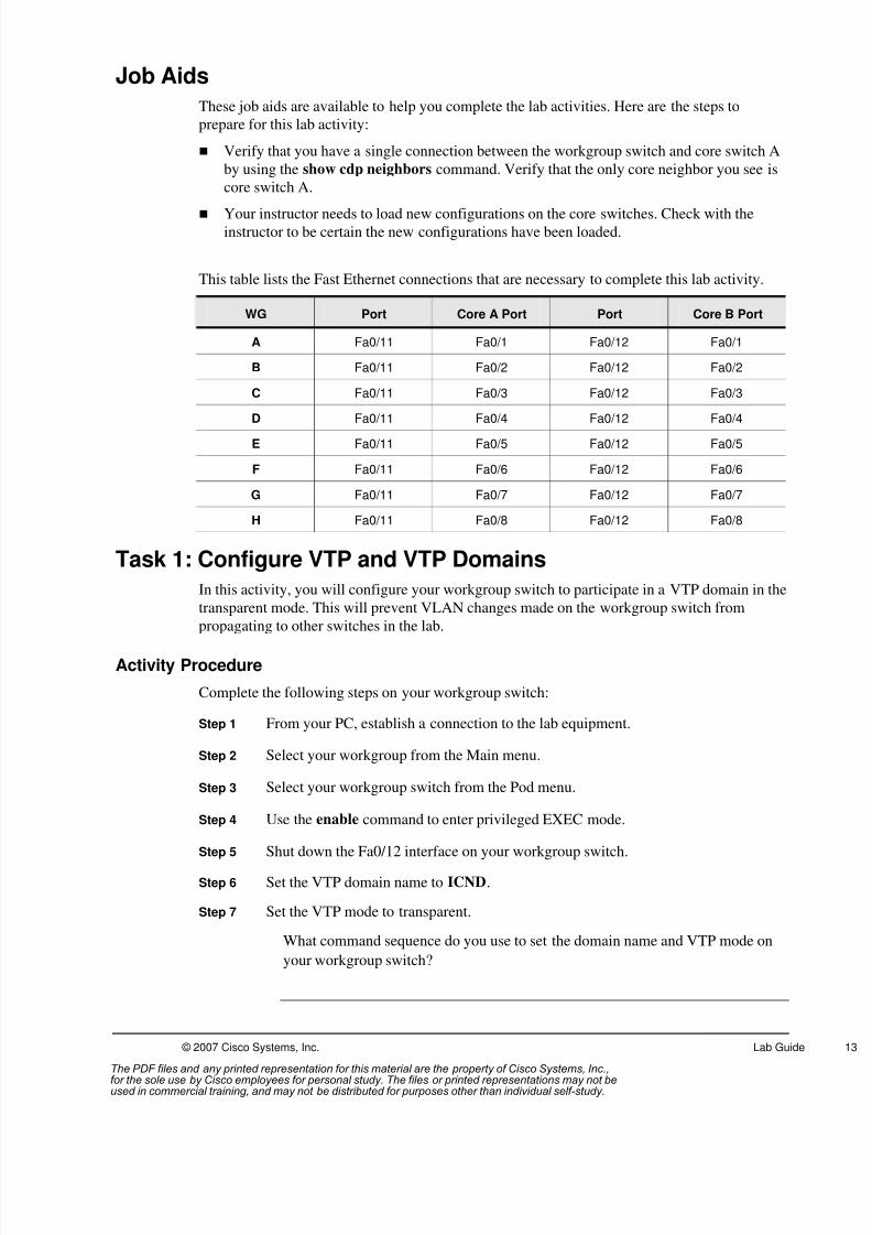
Job Aids
These job aids are available to help you complete the lab activities. Here are the steps to
prepare for this lab activity:
Verify that you have a single connection between the workgroup switch and core switch A
by using the show cdp neighbors command. Verify that the only core neighbor you see is
core switch A.
Your instructor needs to load new configurations on the core switches. Check with theinstructor to be certain the new configurations have been loaded.
This table lists the Fast Ethernet connections that are necessary to complete this lab activity.
WG Port Core A Port Port Core B Port
A Fa0/11 Fa0/1 Fa0/12 Fa0/1
B Fa0/11 Fa0/2 Fa0/12 Fa0/2
C Fa0/11 Fa0/3 Fa0/12 Fa0/3
D Fa0/11 Fa0/4 Fa0/12 Fa0/4
E Fa0/11 Fa0/5 Fa0/12 Fa0/5
F Fa0/11 Fa0/6 Fa0/12 Fa0/6
G Fa0/11 Fa0/7 Fa0/12 Fa0/7
H Fa0/11 Fa0/8 Fa0/12 Fa0/8
Task 1: Configure VTP and VTP Domains
In this activity, you will configure your workgroup switch to participate in a VTP domain in the
transparent mode. This will prevent VLAN changes made on the workgroup switch from
propagating to other switches in the lab.
Activity Procedure
Complete the following steps on your workgroup switch:
Step 1 From your PC, establish a connection to the lab equipment.
Step 2 Select your workgroup from the Main menu.
Step 3 Select your workgroup switch from the Pod menu.
Step 4 Use the enable command to enter privileged EXEC mode.
Step 5 Shut down the Fa0/12 interface on your workgroup switch.
Step 6 Set the VTP domain name to ICND.
Step 7 Set the VTP mode to transparent.
What command sequence do you use to set the domain name and VTP mode on
your workgroup switch?
The PDF files and any printed representation for this material are the property of Cisco Systems, Inc.,for the sole use by Cisco employees for personal study. The files or printed representations may not beused in commercial training, and may not be distributed for purposes other than individual self-study.
8/3/2019 Icnd210lg Cracked
http://slidepdf.com/reader/full/icnd210lg-cracked 16/120
14 Interconnecting Cisco Networking Devices Part 2 (ICND2) v1.0 © 2007 Cisco Systems, Inc.
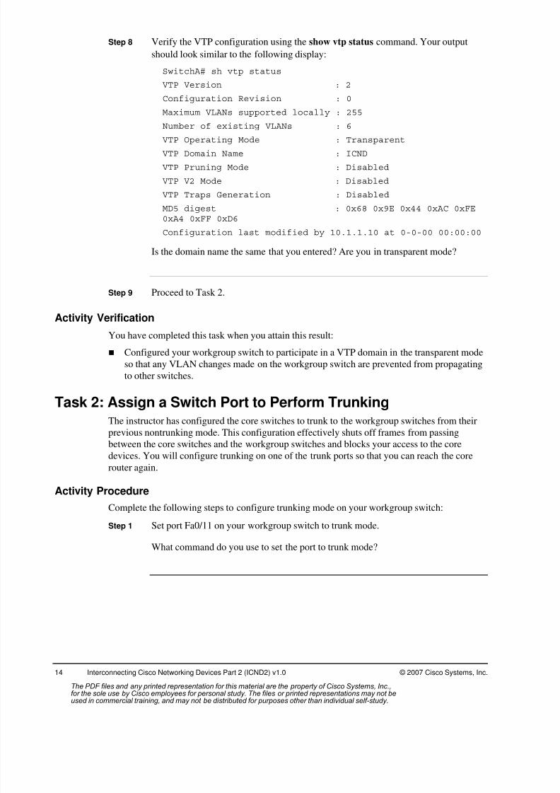
Step 8 Verify the VTP configuration using the show vtp status command. Your output
should look similar to the following display:
SwitchA# sh vtp status
VTP Version : 2
Configuration Revision : 0
Maximum VLANs supported locally : 255
Number of existing VLANs : 6
VTP Operating Mode : Transparent
VTP Domain Name : ICND
VTP Pruning Mode : Disabled
VTP V2 Mode : Disabled
VTP Traps Generation : Disabled
MD5 digest : 0x68 0x9E 0x44 0xAC 0xFE0xA4 0xFF 0xD6
Configuration last modified by 10.1.1.10 at 0-0-00 00:00:00
Is the domain name the same that you entered? Are you in transparent mode?
Step 9 Proceed to Task 2.
Activity Verification
You have completed this task when you attain this result:
Configured your workgroup switch to participate in a VTP domain in the transparent mode
so that any VLAN changes made on the workgroup switch are prevented from propagating
to other switches.
Task 2: Assign a Switch Port to Perform TrunkingThe instructor has configured the core switches to trunk to the workgroup switches from their
previous nontrunking mode. This configuration effectively shuts off frames from passing
between the core switches and the workgroup switches and blocks your access to the core
devices. You will configure trunking on one of the trunk ports so that you can reach the core
router again.
Activity Procedure
Complete the following steps to configure trunking mode on your workgroup switch:
Step 1 Set port Fa0/11 on your workgroup switch to trunk mode.
What command do you use to set the port to trunk mode?
The PDF files and any printed representation for this material are the property of Cisco Systems, Inc.,for the sole use by Cisco employees for personal study. The files or printed representations may not beused in commercial training, and may not be distributed for purposes other than individual self-study.
8/3/2019 Icnd210lg Cracked
http://slidepdf.com/reader/full/icnd210lg-cracked 17/120
© 2007 Cisco Systems, Inc. Lab Guide
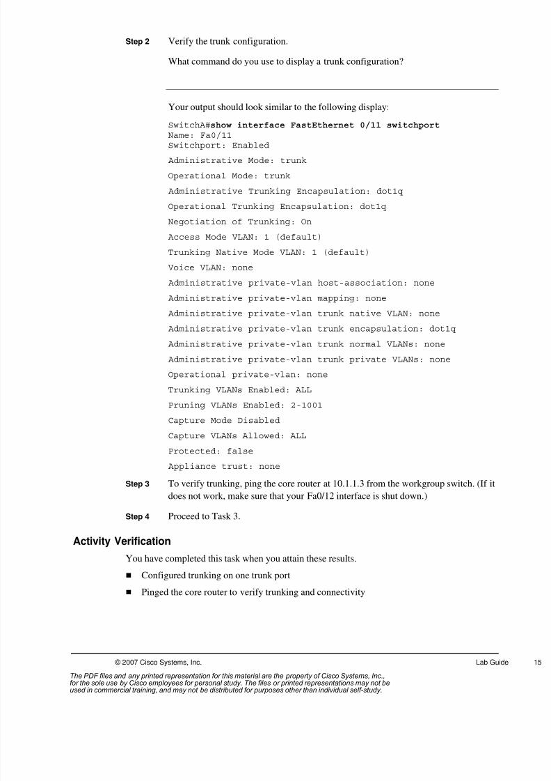
Step 2 Verify the trunk configuration.
What command do you use to display a trunk configuration?
Your output should look similar to the following display:
SwitchA#show interface FastEthernet 0/11 switchport
Name: Fa0/11Switchport: Enabled
Administrative Mode: trunk
Operational Mode: trunk
Administrative Trunking Encapsulation: dot1q
Operational Trunking Encapsulation: dot1q
Negotiation of Trunking: On
Access Mode VLAN: 1 (default)
Trunking Native Mode VLAN: 1 (default)
Voice VLAN: none Administrative private-vlan host-association: none
Administrative private-vlan mapping: none
Administrative private-vlan trunk native VLAN: none
Administrative private-vlan trunk encapsulation: dot1q
Administrative private-vlan trunk normal VLANs: none
Administrative private-vlan trunk private VLANs: none
Operational private-vlan: none
Trunking VLANs Enabled: ALL
Pruning VLANs Enabled: 2-1001
Capture Mode Disabled
Capture VLANs Allowed: ALL
Protected: false
Appliance trust: none
Step 3 To verify trunking, ping the core router at 10.1.1.3 from the workgroup switch. (If it
does not work, make sure that your Fa0/12 interface is shut down.)
Step 4 Proceed to Task 3.
Activity Verification
You have completed this task when you attain these results.
Configured trunking on one trunk port
Pinged the core router to verify trunking and connectivity
The PDF files and any printed representation for this material are the property of Cisco Systems, Inc.,for the sole use by Cisco employees for personal study. The files or printed representations may not beused in commercial training, and may not be distributed for purposes other than individual self-study.

8/3/2019 Icnd210lg Cracked
http://slidepdf.com/reader/full/icnd210lg-cracked 18/120
16 Interconnecting Cisco Networking Devices Part 2 (ICND2) v1.0 © 2007 Cisco Systems, Inc.
Task 3: Configure Separate VLANs on the Switch
In this task, you will configure a VLAN for the switch port that is connected to your workgroup
router and change the IP address of the first Ethernet interface on your workgroup router. The
new address is in the VLAN that is assigned to your workgroup, and it can only reach other
devices in the workgroup (in a different VLAN) via the core router. Your instructor has
configured the core router to support inter-VLAN routing.
The table, or VLAN assignment chart, provides information you need to complete this task.
WG VLAN Number VLAN Name Core Router RouterX Fa0/0
(in which x is the
workgroup letter)
A 2 VLAN0002 10.2.2.3 10.2.2.12
B 3 VLAN0003 10.3.3.3 10.3.3.12
C 4 VLAN0004 10.4.4.3 10.4.4.12
D 5 VLAN0005 10.5.5.3 10.5.5.12
E 6 VLAN0006 10.6.6.3 10.6.6.12
F 7 VLAN0007 10.7.7.3 10.7.7.12
G 8 VLAN0008 10.8.8.3 10.8.8.12
H 9 VLAN0009 10.9.9.3 10.9.9.12
Activity Procedure
Complete the following steps to configure separate VLANs on your workgroup switch:
Step 1 Using the VLAN assignment chart, create a VLAN only for your workgroup.
What command do you use to create a VLAN on your switch?
Step 2 Using the show vlan command from the EXEC mode, verify that the correct VLAN
has been added.
Your output should look similar to the following display:
SwitchA# sh vlan
VLAN Name Status Ports---- -------------------------------- --------- -------------------------------1 default active Fa0/1, Fa0/2, Fa0/3, Fa0/4
Fa0/5, Fa0/6, Fa0/7, Fa0/8Fa0/9, Fa0/10, Fa0/12, Fa0/13Fa0/14, Fa0/15, Fa0/16, Fa0/17Fa0/18, Fa0/19, Fa0/20, Fa0/21Fa0/22, Fa0/23, Fa0/24, Gi0/1Gi0/2
2 VLAN0002 active1002 fddi-default act/unsup1003 token-ring-default act/unsup1004 fddinet-default act/unsup1005 trnet-default act/unsup
The PDF files and any printed representation for this material are the property of Cisco Systems, Inc.,for the sole use by Cisco employees for personal study. The files or printed representations may not beused in commercial training, and may not be distributed for purposes other than individual self-study.
8/3/2019 Icnd210lg Cracked
http://slidepdf.com/reader/full/icnd210lg-cracked 19/120
© 2007 Cisco Systems, Inc. Lab Guide
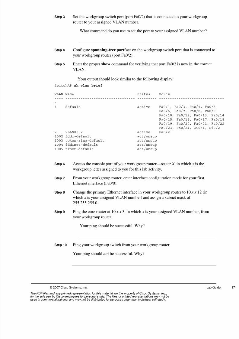
Step 3 Set the workgroup switch port (port Fa0/2) that is connected to your workgroup
router to your assigned VLAN number.
What command do you use to set the port to your assigned VLAN number?
Step 4 Configure spanning-tree portfast on the workgroup switch port that is connected to
your workgroup router (port Fa0/2).
Step 5 Enter the proper show command for verifying that port Fa0/2 is now in the correct
VLAN.
Your output should look similar to the following display:
SwitchA# sh vlan brief
VLAN Name Status Ports---- -------------------------------- --------- ------------------------------1 default active Fa0/1, Fa0/3, Fa0/4, Fa0/5
Fa0/6, Fa0/7, Fa0/8, Fa0/9
Fa0/10, Fa0/12, Fa0/13, Fa0/1Fa0/15, Fa0/16, Fa0/17, Fa0/1Fa0/19, Fa0/20, Fa0/21, Fa0/2Fa0/23, Fa0/24, Gi0/1, Gi0/2
2 VLAN0002 active Fa0/21002 fddi-default act/unsup1003 token-ring-default act/unsup1004 fddinet-default act/unsup1005 trnet-default act/unsup
Step 6 Access the console port of your workgroup router—router X , in which x is the
workgroup letter assigned to you for this lab activity.
Step 7 From your workgroup router, enter interface configuration mode for your first
Ethernet interface (Fa0/0).
Step 8 Change the primary Ethernet interface in your workgroup router to 10. x.x.12 (in
which x is your assigned VLAN number) and assign a subnet mask of
255.255.255.0.
Step 9 Ping the core router at 10. x.x.3, in which x is your assigned VLAN number, from
your workgroup router.
Your ping should be successful. Why?
Step 10 Ping your workgroup switch from your workgroup router.
Your ping should not be successful. Why?
The PDF files and any printed representation for this material are the property of Cisco Systems, Inc.,for the sole use by Cisco employees for personal study. The files or printed representations may not beused in commercial training, and may not be distributed for purposes other than individual self-study.

8/3/2019 Icnd210lg Cracked
http://slidepdf.com/reader/full/icnd210lg-cracked 20/120
18 Interconnecting Cisco Networking Devices Part 2 (ICND2) v1.0 © 2007 Cisco Systems, Inc.
Step 11 Enable inter-VLAN communications by configuring a default route on your
workgroup router that points to the core router using the ip route 0.0.0.0 0.0.0.0
10. x.x.3 command, in which x is your assigned VLAN number. Now ping your
workgroup switch.
Your ping should be successful? Why?
Note Notice that the default gateway on your workgroup switch is set to 10.1.1.3 so that your
workgroup switch can ping devices in other VLANs via the core router. If the default gateway
is not present in your configuration, add it by using the ip default-gateway 10.1.1.3
command in global configuration mode.
Step 12 Proceed to Task 4.
Activity Verification
You have completed this task when you attain these results:
Configured a VLAN and assigned that VLAN to the switch port that is connected to your
workgroup router
Changed the IP address of the first Ethernet interface on your workgroup router
Assigned a default route to your workgroup router
Pinged devices in other VLANs to verify connectivity
The PDF files and any printed representation for this material are the property of Cisco Systems, Inc.,for the sole use by Cisco employees for personal study. The files or printed representations may not beused in commercial training, and may not be distributed for purposes other than individual self-study.
8/3/2019 Icnd210lg Cracked
http://slidepdf.com/reader/full/icnd210lg-cracked 21/120
© 2007 Cisco Systems, Inc. Lab Guide
Task 4: Configure the Rapid-PVST Protocol
In this task, you will configure the Rapid-PVST protocol, configure the second trunk port on
your workgroup switch so that it trunks to core switch B, and observe the Rapid-PVST
convergence when a loop is created.
Activity Procedure
Complete the following steps to configure the Rapid-PVST protocol on your workgroupswitch:
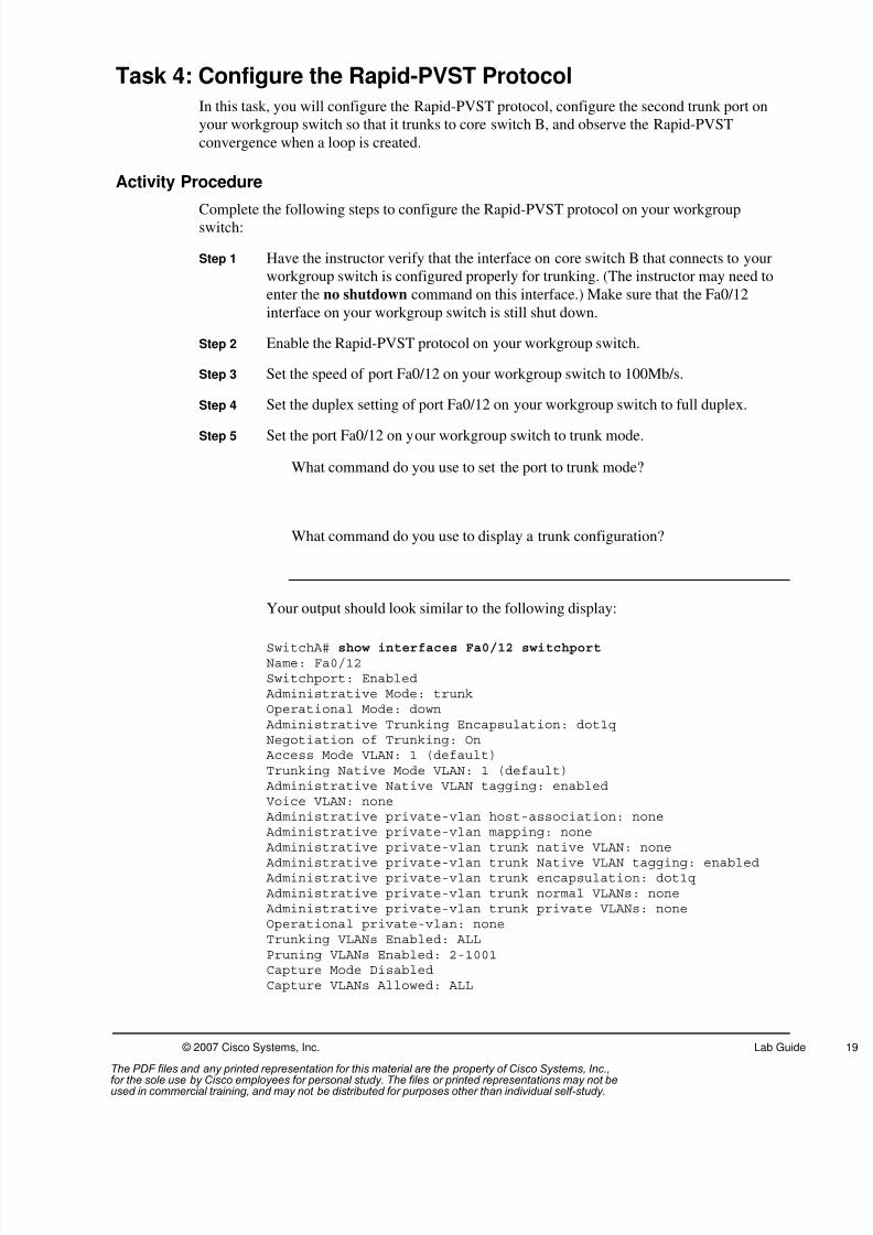
Step 1 Have the instructor verify that the interface on core switch B that connects to your
workgroup switch is configured properly for trunking. (The instructor may need to
enter the no shutdown command on this interface.) Make sure that the Fa0/12
interface on your workgroup switch is still shut down.
Step 2 Enable the Rapid-PVST protocol on your workgroup switch.
Step 3 Set the speed of port Fa0/12 on your workgroup switch to 100Mb/s.
Step 4 Set the duplex setting of port Fa0/12 on your workgroup switch to full duplex.
Step 5 Set the port Fa0/12 on your workgroup switch to trunk mode.
What command do you use to set the port to trunk mode?
What command do you use to display a trunk configuration?
Your output should look similar to the following display:
SwitchA# show interfaces Fa0/12 switchportName: Fa0/12Switchport: Enabled
Administrative Mode: trunkOperational Mode: down
Administrative Trunking Encapsulation: dot1qNegotiation of Trunking: On
Access Mode VLAN: 1 (default)Trunking Native Mode VLAN: 1 (default)
Administrative Native VLAN tagging: enabledVoice VLAN: none
Administrative private-vlan host-association: none Administrative private-vlan mapping: none
Administrative private-vlan trunk native VLAN: none Administrative private-vlan trunk Native VLAN tagging: enabled Administrative private-vlan trunk encapsulation: dot1q Administrative private-vlan trunk normal VLANs: none Administrative private-vlan trunk private VLANs: noneOperational private-vlan: noneTrunking VLANs Enabled: ALLPruning VLANs Enabled: 2-1001Capture Mode DisabledCapture VLANs Allowed: ALL
The PDF files and any printed representation for this material are the property of Cisco Systems, Inc.,for the sole use by Cisco employees for personal study. The files or printed representations may not beused in commercial training, and may not be distributed for purposes other than individual self-study.
8/3/2019 Icnd210lg Cracked
http://slidepdf.com/reader/full/icnd210lg-cracked 22/120
20 Interconnecting Cisco Networking Devices Part 2 (ICND2) v1.0 © 2007 Cisco Systems, Inc.
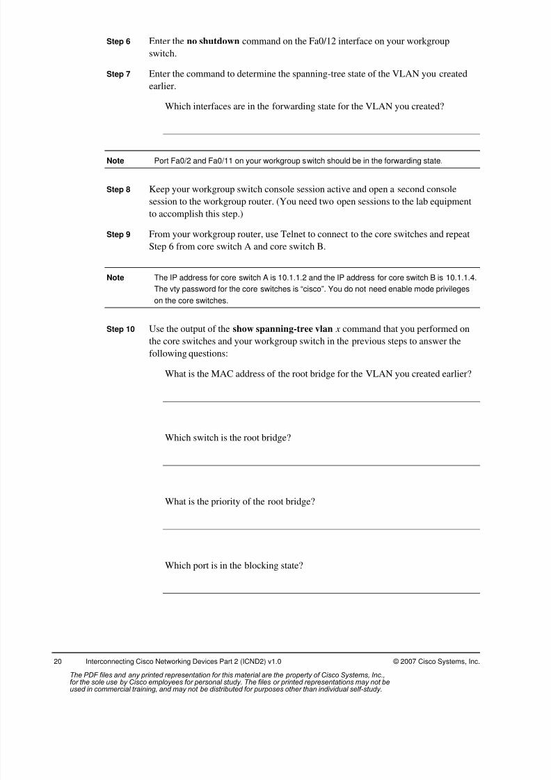
Step 6 Enter the no shutdown command on the Fa0/12 interface on your workgroup
switch.
Step 7 Enter the command to determine the spanning-tree state of the VLAN you created
earlier.
Which interfaces are in the forwarding state for the VLAN you created?
Note Port Fa0/2 and Fa0/11 on your workgroup switch should be in the forwarding state.
Step 8 Keep your workgroup switch console session active and open a second console
session to the workgroup router. (You need two open sessions to the lab equipment
to accomplish this step.)
Step 9 From your workgroup router, use Telnet to connect to the core switches and repeat
Step 6 from core switch A and core switch B.
Note The IP address for core switch A is 10.1.1.2 and the IP address for core switch B is 10.1.1.4.
The vty password for the core switches is “cisco”. You do not need enable mode privileges
on the core switches.
Step 10 Use the output of the show spanning-tree vlan x command that you performed on
the core switches and your workgroup switch in the previous steps to answer the
following questions:
What is the MAC address of the root bridge for the VLAN you created earlier?
Which switch is the root bridge?
What is the priority of the root bridge?
Which port is in the blocking state?
The PDF files and any printed representation for this material are the property of Cisco Systems, Inc.,for the sole use by Cisco employees for personal study. The files or printed representations may not beused in commercial training, and may not be distributed for purposes other than individual self-study.

8/3/2019 Icnd210lg Cracked
http://slidepdf.com/reader/full/icnd210lg-cracked 23/120
© 2007 Cisco Systems, Inc. Lab Guide
Your output should look similar to the following display:
CoreSwitchA> show spanning-tree vlan 2
VLAN0002Spanning tree enabled protocol rstpRoot ID Priority 24578
Address 001a.6dd7.1880This bridge is the rootHello Time 2 sec Max Age 20 sec Forward Delay 15 sec
Bridge ID Priority 24578 (priority 24576 sys-id-ext 2) Address 001a.6dd7.1880Hello Time 2 sec Max Age 20 sec Forward Delay 15 sec Aging Time 300
Interface Role Sts Cost Prio.Nbr Type---------------- ---- --- --------- -------- --------------------------------Fa0/1 Desg FWD 19 128.1 P2pFa0/2 Desg FWD 19 128.2 P2pFa0/3 Desg FWD 19 128.3 P2pFa0/4 Desg FWD 19 128.4 P2pFa0/5 Desg FWD 19 128.5 P2pFa0/6 Desg FWD 19 128.6 P2pFa0/23 Desg FWD 19 128.23 P2pPo1 Desg FWD 12 128.72 P2p Peer(STP)
CoreSwitchB> sh spanning-tree vlan 2
VLAN0002Spanning tree enabled protocol ieeeRoot ID Priority 24578
Address 001a.6dd7.1880Cost 12Port 72 (Port-channel1)Hello Time 2 sec Max Age 20 sec Forward Delay 15 sec
Bridge ID Priority 28674 (priority 28672 sys-id-ext 2) Address 001a.6de6.d800
Hello Time 2 sec Max Age 20 sec Forward Delay 15 sec Aging Time 300
Interface Role Sts Cost Prio.Nbr Type---------------- ---- --- --------- -------- --------------------------------Fa0/1 Desg FWD 19 128.1 P2pFa0/2 Desg FWD 19 128.2 P2pFa0/3 Desg FWD 19 128.3 P2pFa0/4 Desg FWD 19 128.4 P2pFa0/5 Desg FWD 19 128.5 P2pFa0/6 Desg FWD 19 128.6 P2pPo1 Root FWD 12 128.72 P2p
Step 11 While keeping the two console sessions active, (one to your switch and one to your
router), from your workgroup router, perform an extended ping to the core router(10. x.x.3, in which x is your assigned VLAN number) with a count of 45000.
Is the ping successful?
Your output should look similar to the following display:
RouterA# ping
Protocol [ip]:
Target IP address: 10.1.1.3
The PDF files and any printed representation for this material are the property of Cisco Systems, Inc.,for the sole use by Cisco employees for personal study. The files or printed representations may not beused in commercial training, and may not be distributed for purposes other than individual self-study.
8/3/2019 Icnd210lg Cracked
http://slidepdf.com/reader/full/icnd210lg-cracked 24/120
22 Interconnecting Cisco Networking Devices Part 2 (ICND2) v1.0 © 2007 Cisco Systems, Inc.
Repeat count [5]: 45000
Datagram size [100]:
Timeout in seconds [2]:
Extended commands [n]:
Sending 45000, 100-byte ICMP Echos to 10.1.1.3, timeout is 2seconds:
Note You should see continuous successful ping replies from the core router. The current path
from your switch to the core router should be via your FastEthernet0/11 port. If not, do not
proceed to the next step; instead, troubleshoot the problem or ask your instructor for help.
Step 12 At your workgroup switch, shut down interface Fa0/11.
What happened to the extended ping to the core router?
Is the ping successful after a few seconds?
Step 13 At your workgroup switch, re-enable interface Fa0/11.
What happened to the extended ping to the core router?
Is the ping successful after a few seconds?
Step 14 Stop the extended ping from your workgroup router to the core router by pressing
Ctrl-Shift-6, then Ctrl-Shift-6 again.
Step 15 Save your configuration to NVRAM, using copy run start.
Step 16 Notify your instructor that you have completed the activity.
Activity Verification
You have completed this activity when you attain these results:
Configured a second trunk port on your workgroup switch to trunk to core switch B
Observed an extended ping to the core router and shut down the forwarding trunking portto observe a break in the pings
The PDF files and any printed representation for this material are the property of Cisco Systems, Inc.,for the sole use by Cisco employees for personal study. The files or printed representations may not beused in commercial training, and may not be distributed for purposes other than individual self-study.

8/3/2019 Icnd210lg Cracked
http://slidepdf.com/reader/full/icnd210lg-cracked 25/120
© 2007 Cisco Systems, Inc. Lab Guide
Task 5: Configure Primary and Secondary Root Bridges(Optional)
In this task, you will work with a student in another workgroup. You will configure two more
VLANs, a primary and secondary. Your workgroup switch will become the root bridge for your
primary VLAN and the secondary root bridge for the primary VLAN of your partner.
Group Assignments: A-B, C-D, E-F, G-H
Primary and Secondary VLAN Assignment
WG Primary VLAN
Number
Secondary VLAN
Number
A 20 30
B 30 20
C 40 50
D 50 40
E 60 70
F 70 60
G 80 90
H 90 80
Activity Procedure
Complete the following steps to configure the primary and secondary root bridge on your
workgroup switch:
Step 1 Using the Primary and Secondary VLAN Assignment table, create only the primary
VLAN for your workgroup.
Step 2 Using the Primary and Secondary VLAN Assignment table, create only the
secondary VLAN for your workgroup.
What command do you use to create a VLAN on your switch?
Step 3 Using the show vlan command from the EXEC mode, verify that the correct
VLANs have been added.
Step 4 Configure your workgroup switch to be the root bridge for your primary VLAN.
What command do you use to make a switch the root bridge for a particular
VLAN?
Step 5 Configure your workgroup switch to be the secondary root bridge for the primary
VLAN of your partner.
What command do you use to make a switch the secondary root bridge?
The PDF files and any printed representation for this material are the property of Cisco Systems, Inc.,for the sole use by Cisco employees for personal study. The files or printed representations may not beused in commercial training, and may not be distributed for purposes other than individual self-study.
8/3/2019 Icnd210lg Cracked
http://slidepdf.com/reader/full/icnd210lg-cracked 26/120
24 Interconnecting Cisco Networking Devices Part 2 (ICND2) v1.0 © 2007 Cisco Systems, Inc.
Step 6 Enter the command to determine the spanning-tree state of the VLANs you created
earlier in this task.
Which interfaces are in the forwarding state for the VLANs you created?
Step 7 Keep your workgroup switch console session active and open a second consolesession to the workgroup router. (You need two open sessions to the lab equipment
to accomplish this step.)
Step 8 From your workgroup router, establish a Telnet session to the core switches and
enter the command to determine the spanning-tree state of your primary VLAN and
your secondary VLAN on core switch A and core switch B.
Note The IP address for core switch A is 10.1.1.2, and the IP address for core switch B is
10.1.1.4. The vty password for the core switches is cisco. You do not need enable mode
privileges on the core switches.
Step 9 From the output of the show spanning-tree vlan x command performed on the core
switches and your workgroup switch in the previous steps, answer the following
questions:
What is the MAC address of the root bridge for the primary VLAN you created
earlier? What is the MAC address of the secondary VLAN?
Which switch is the root bridge for the primary VLAN? Which switch is the rootbridge for the secondary VLAN?
What is the priority of the root bridge for the primary VLAN? What is the
priority of the secondary VLAN?
Which port is in the blocking state for the primary VLAN? Which port is in the
blocking state for the secondary VLAN?
The PDF files and any printed representation for this material are the property of Cisco Systems, Inc.,for the sole use by Cisco employees for personal study. The files or printed representations may not beused in commercial training, and may not be distributed for purposes other than individual self-study.

8/3/2019 Icnd210lg Cracked
http://slidepdf.com/reader/full/icnd210lg-cracked 27/120
© 2007 Cisco Systems, Inc. Lab Guide
Your output should look similar to the following display:
SwitchA# sh spanning-tree vlan 20
VLAN0020Spanning tree enabled protocol rstpRoot ID Priority 24596
Address 0017.596d.2a00This bridge is the rootHello Time 2 sec Max Age 20 sec Forward Delay 15 sec
Bridge ID Priority 24596 (priority 24576 sys-id-ext 20) Address 0017.596d.2a00Hello Time 2 sec Max Age 20 sec Forward Delay 15 sec Aging Time 300
Interface Role Sts Cost Prio.Nbr Type---------------- ---- --- --------- -------- ----------------------------Fa0/11 Desg FWD 19 128.11 P2pFa0/12 Desg FWD 19 128.12 P2p Peer(STP)
SwitchA# sh spanning-tree vlan 30
VLAN0030Spanning tree enabled protocol rstpRoot ID Priority 24606
Address 0017.596d.1580Cost 38Port 11 (FastEthernet0/11)Hello Time 2 sec Max Age 20 sec Forward Delay 15 sec
Bridge ID Priority 28702 (priority 28672 sys-id-ext 30) Address 0017.596d.2a00Hello Time 2 sec Max Age 20 sec Forward Delay 15 sec Aging Time 300
Interface Role Sts Cost Prio.Nbr Type---------------- ---- --- --------- -------- ----------------------------Fa0/11 Root FWD 19 128.11 P2pFa0/12 Altn BLK 19 128.12 P2p Peer(STP)
CoreSwitchA> sh spanning-tree vlan 20
VLAN0020Spanning tree enabled protocol rstpRoot ID Priority 24596
Address 0017.596d.2a00Cost 19Port 1 (FastEthernet0/1)Hello Time 2 sec Max Age 20 sec Forward Delay 15 sec
Bridge ID Priority 32788 (priority 32768 sys-id-ext 20) Address 001a.6dd7.1880
Hello Time 2 sec Max Age 20 sec Forward Delay 15 sec Aging Time 300
Interface Role Sts Cost Prio.Nbr Type---------------- ---- --- --------- -------- ----------------------------Fa0/1 Root FWD 19 128.1 P2pFa0/2 Desg FWD 19 128.2 P2pFa0/3 Desg FWD 19 128.3 P2pFa0/4 Desg FWD 19 128.4 P2pFa0/5 Desg FWD 19 128.5 P2pFa0/6 Desg FWD 19 128.6 P2pFa0/23 Desg FWD 19 128.23 P2p
The PDF files and any printed representation for this material are the property of Cisco Systems, Inc.,for the sole use by Cisco employees for personal study. The files or printed representations may not beused in commercial training, and may not be distributed for purposes other than individual self-study.
8/3/2019 Icnd210lg Cracked
http://slidepdf.com/reader/full/icnd210lg-cracked 28/120
26 Interconnecting Cisco Networking Devices Part 2 (ICND2) v1.0 © 2007 Cisco Systems, Inc.
Interface Role Sts Cost Prio.Nbr Type---------------- ---- --- --------- -------- ----------------------------
Po1 Desg FWD 12 128.72 P2p Peer(STP)
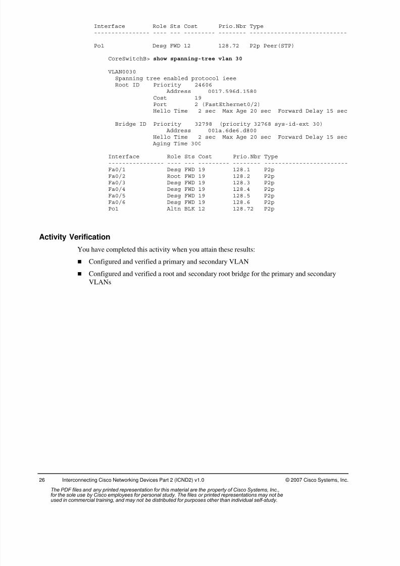
CoreSwitchB> show spanning-tree vlan 30
VLAN0030Spanning tree enabled protocol ieeeRoot ID Priority 24606
Address 0017.596d.1580
Cost 19Port 2 (FastEthernet0/2)Hello Time 2 sec Max Age 20 sec Forward Delay 15 sec
Bridge ID Priority 32798 (priority 32768 sys-id-ext 30) Address 001a.6de6.d800Hello Time 2 sec Max Age 20 sec Forward Delay 15 sec Aging Time 300
Interface Role Sts Cost Prio.Nbr Type---------------- ---- --- --------- -------- ------------------------Fa0/1 Desg FWD 19 128.1 P2pFa0/2 Root FWD 19 128.2 P2pFa0/3 Desg FWD 19 128.3 P2pFa0/4 Desg FWD 19 128.4 P2p
Fa0/5 Desg FWD 19 128.5 P2pFa0/6 Desg FWD 19 128.6 P2pPo1 Altn BLK 12 128.72 P2p
Activity Verification
You have completed this activity when you attain these results:
Configured and verified a primary and secondary VLAN
Configured and verified a root and secondary root bridge for the primary and secondary
VLANs
The PDF files and any printed representation for this material are the property of Cisco Systems, Inc.,for the sole use by Cisco employees for personal study. The files or printed representations may not beused in commercial training, and may not be distributed for purposes other than individual self-study.

8/3/2019 Icnd210lg Cracked
http://slidepdf.com/reader/full/icnd210lg-cracked 29/120
© 2007 Cisco Systems, Inc. Lab Guide
Lab 2-2: Troubleshooting Switched NetworksComplete this lab activity to practice what you learned in the related module.
Activity Objective
In this activity, you will use the troubleshooting guidelines discussed in the corresponding
module to gather symptoms and isolate and correct problems commonly found in a switchednetwork. After completing this activity, you will be able to meet these objectives:
Discover switched network connectivity issues, follow troubleshooting guidelines to
ascertain switched connectivity problems, and re-establish switched network connectivity
Visual Objective
The figure illustrates what you will accomplish in this activity.
© 2007 Cisco Systems, Inc. All rights reserved. ICND2 v1.0—6
Visual Objective 2-2:
Troubleshooting Switched NetworksWG Switch Router
fa0/0
A 10.1.1.10 10.2.2.12B 10.1.1.20 10.3.3.12C 10.1.1.30 10.4.4.12D 10.1.1.40 10.5.5.12E 10.1.1.50 10.6.6.12F 10.1.1.60 10.7.7.12G 10.1.1.70 10.8.8.12H 10.1.1.80 10.9.9.12
Required Resources
These are the resources and equipment required to complete this activity:
PC connected to an onsite lab or PC with an Internet connection to access the remote lab Terminal server connected to a console port of each lab device if using a remote lab
ICND workgroup assigned by your instructor
The PDF files and any printed representation for this material are the property of Cisco Systems, Inc.,for the sole use by Cisco employees for personal study. The files or printed representations may not beused in commercial training, and may not be distributed for purposes other than individual self-study.

8/3/2019 Icnd210lg Cracked
http://slidepdf.com/reader/full/icnd210lg-cracked 30/120
28 Interconnecting Cisco Networking Devices Part 2 (ICND2) v1.0 © 2007 Cisco Systems, Inc.
Command List
The table describes the commands used in this activity. The commands are listed in
alphabetical order so that you can easily locate the information you need. Refer to this list if
you need configuration command assistance during the lab activity.
Commands
Command Description
copy tftp running-configuration
Merges a file on the TFTP server with device running-config
ping 10.1.1.1 Tests Layer 3 connectivity
show interface Displays interface status and statistics
show interface switchport Displays switching-related interface statistics
show interface trunk Displays interfaces configured to be trunk ports
show port-security Displays interfaces configured with port security
show port-security address Displays the MAC addresses found on a secure port
show spanning-tree vlan # Displays spanning tree statusshow vlan Displays a switch VLAN database
show vtp status Displays VTP settings
Job Aids
These job aids are available to help you complete the lab activity. Use the table to document the
troubleshooting process.
Troubleshooting Steps
Command to Gather
Symptoms
Isolate the Problem Command to Correct the Problem
Example:
ping 172.16.2.2 fails -----
show ip interface brief int Fa0/1 is administrativelydown
no shutdown
ping 172.16.2.2 still fails -----
show interface Fa0/1 has incorrect ip address ip address 192.168.1.2
ping 172.16.2.2 succeeds
The PDF files and any printed representation for this material are the property of Cisco Systems, Inc.,for the sole use by Cisco employees for personal study. The files or printed representations may not beused in commercial training, and may not be distributed for purposes other than individual self-study.

8/3/2019 Icnd210lg Cracked
http://slidepdf.com/reader/full/icnd210lg-cracked 31/120
© 2007 Cisco Systems, Inc. Lab Guide
Task 1: Update Your Workgroup Configurations
In this task, you will download new supplemental configurations to your workgroup switch and
router from the TFTP server. These supplemental configurations may introduce a problem that
will prevent you from completing the task, so you will troubleshoot to isolate and correct the
problem.
Activity Procedure
Complete these steps:
Step 1 Shutdown the port Fa0/12 of your workgroup switch.
Step 2 Ping the TFTP server (10.1.1.1) from your workgroup router.
Step 3 Ensure connectivity with the TFTP server. Ping the TFTP server (10.1.1.1) from
your workgroup switch.
Note If either of the pings is unsuccessful, contact your instructor.
Step 4 From your workgroup switch, download the supplemental configuration from the
TFTP server into the running configuration of your workgroup switch. The name of
the file to download is i2-wg_sw-config-lab2-2.txt.
Step 5 Type exit from the privilege EXEC prompt and ensure your switch banner reads:
************** wg_sw-config-lab2-2 ***********************
Step 6 From your workgroup router, download the supplemental configuration from the
TFTP server into the running configuration of your workgroup router. The name of
the file to download is i2-wg_ro-config-lab2-2.txt.
Was the download successful?
Can you ping the TFTP server from your workgroup router?
Step 7 Without utilizing the show run command, use the troubleshooting guidelines and
commands discussed in the corresponding module to gather symptoms, isolate the
problem, and correct the problem. Use the Job Aids table on the previous page to
document the troubleshooting process.
Step 8 Once you have re-established connectivity, download the supplemental
configuration from the TFTP server into the running configuration of your
workgroup router. The name of the file to download is i2-wg_ro-config-lab2-2.txt.
Step 9 Type exit from the privilege EXEC prompt and ensure your switch banner reads:
****** Congratulations! You have successfully completed the lab. ******
Step 10 Save your running configuration to NVRAM.
Step 11 Notify your instructor that you have completed the activity.
The PDF files and any printed representation for this material are the property of Cisco Systems, Inc.,for the sole use by Cisco employees for personal study. The files or printed representations may not beused in commercial training, and may not be distributed for purposes other than individual self-study.
8/3/2019 Icnd210lg Cracked
http://slidepdf.com/reader/full/icnd210lg-cracked 32/120
30 Interconnecting Cisco Networking Devices Part 2 (ICND2) v1.0 © 2007 Cisco Systems, Inc.
Activity Verification
You have completed this task when you attain these results:
Both your workgroup switch and workgroup router are able to ping the TFTP server.
Both your workgroup switch and workgroup router have downloaded their lab2-2
configuration into their running configuration.
The PDF files and any printed representation for this material are the property of Cisco Systems, Inc.,for the sole use by Cisco employees for personal study. The files or printed representations may not beused in commercial training, and may not be distributed for purposes other than individual self-study.

8/3/2019 Icnd210lg Cracked
http://slidepdf.com/reader/full/icnd210lg-cracked 33/120
© 2007 Cisco Systems, Inc. Lab Guide
Lab 4-1: Implementing OSPFComplete this lab activity to practice what you learned in the related module.
Activity Objective
In this activity, you will determine IP routes with the OSPF routing protocol. After completing
this activity, you will be able to meet these objectives: Disable the LAN connections to the core
Enable the serial connections on a workgroup router
Configure OSPF on a workgroup router
Configure plain text authentication for OSPF
Verify the correct operation and configuration of OSPF routing and OSPF plain text
authentication
Visual Objective
The figure illustrates what you will accomplish in this lab activity.
© 2007 Cisco Systems, Inc. All rights reserved. ICND2 v1.0—8
Visual Objective 4-1: Implementing OSPF
Required Resources
These are the resources and equipment required to complete this activity:
PC connected to an onsite lab or PC with an Internet connection to access the remote lab
Terminal server connected to a console port of each lab device if using a remote lab
ICND workgroup assigned by your instructor
The PDF files and any printed representation for this material are the property of Cisco Systems, Inc.,for the sole use by Cisco employees for personal study. The files or printed representations may not beused in commercial training, and may not be distributed for purposes other than individual self-study.

8/3/2019 Icnd210lg Cracked
http://slidepdf.com/reader/full/icnd210lg-cracked 34/120
32 Interconnecting Cisco Networking Devices Part 2 (ICND2) v1.0 © 2007 Cisco Systems, Inc.
Command List
The table describes the commands used in this activity. The commands are listed in
alphabetical order so that you can easily locate the information you need. Refer to this list if
you need configuration command assistance during the lab activity.
Cisco Catalyst Switch Commands
Command Description
interface vlan1ip address ip-address mask
Defines the IP address and subnet mask for the Cisco Catalystswitch.
ip default-gateway ip-address
Defines a default gateway on the Cisco Catalyst switch.
ping ip-address Common tool used to troubleshoot the accessibility of devices.This tool uses ICMP echo requests and ICMP echo replies todetermine whether a remote host is active. The ping commandalso measures the amount of time it takes to receive the echoreply.
show interfaces vlan 1 Displays IP configuration on the Cisco Catalyst switch.
show vlan Displays VLAN information on the Cisco Catalyst switch.
switchport access vlan 1 Defines the VLAN membership of an interface
Cisco Router Commands
Command Description
bandwidth Configures the bandwidth on serial interfaces.
clock rate Configures the clock rate on serial interfaces.
debug ip ospf events Displays a summary of OSPF transaction information.
interface loopbackUses the interface global configuration command to configure aninterface type and enter interface configuration mode.
ip ospf authentication-key password
Assigns a password to be used for OSPF authentication.
ip ospf authentication Enables plain text OSPF authentication.
network network-number wildcard-mask area area-id
Starts the routing protocol on all interfaces that the router has inthe specified network; specifies the number of bits significant forthis network and the OSPF area with which the network isassociated.
ping ip-address Common tool used to troubleshoot the accessibility of devices.This tool uses ICMP echo requests and ICMP echo replies todetermine whether a remote host is active. The ping commandalso measures the amount of time it takes to receive the echo
reply.
router ospf router- process-id
Enables the OSPF routing protocol.
show controllers type Displays the controller state that is specific to the controllerhardware.
show interfaces type Displays statistics for interfaces configured on the router.
show ip ospf neighbor Determines the state of an OSPF neighbor.
show ip protocols Displays values about routing protocols and routing protocol timerinformation associated with the router.
The PDF files and any printed representation for this material are the property of Cisco Systems, Inc.,for the sole use by Cisco employees for personal study. The files or printed representations may not beused in commercial training, and may not be distributed for purposes other than individual self-study.

8/3/2019 Icnd210lg Cracked
http://slidepdf.com/reader/full/icnd210lg-cracked 35/120
© 2007 Cisco Systems, Inc. Lab Guide
Command Description
show ip route Displays the IP routing table.
shutdown/no shutdown Disables or enables an interface.
undebug all Turns off all debugging displays.
Job Aids
These job aids are available to help you complete the lab activity.
In this activity, you will use the default encapsulation for a serial link, HDLC, to distribute
routing protocol traffic from your workgroup to the core. This requires shutting down the
uplinks to the core switches on your workgroup switch and assigning an IP address to the first
serial interface of your router.
You will also configure the OSPF routing protocol, implementing OSPF authentication to
ensure routing update authenticity. Then you will verify the configuration and operation of
OSPF.
The following table lists the IP addresses that you will use in this lab activity. Subnet masks are
designated with “/bits” to indicate the number of network bits in the mask.
IP Addresses
WG Switch
Interface
VLAN 1
(SwitchX )
Router
Fa0/0
Interface
(RouterX )
Router
Loopback 0
Interface
(RouterX )
Router
S0/0/0
Interface
(RouterX )
Router
S0/0/1
Interface
(RouterX )
Core Router
Serial
Interface
(Core
Router)
A 10.2.2.11/24 10.2.2.3/24 192.168.1.65/28 10.140.1.2/24 10.23.23.1/24 10.140.1.1/24
B 10.3.3.11/24 10.3.3.3/24 192.168.1.81/28 10.140.2.2/24 10.23.23.2/24 10.140.2.1/24
C 10.4.4.11/24 10.4.4.3/24 192.168.2.65/28 10.140.3.2/24 10.45.45.1/24 10.140.3.1/24
D 10.5.5.11/24 10.5.5.3/24 192.168.2.81/28 10.140.4.2/24 10.45.45.2/24 10.140.4.1/24
E 10.6.6.11/24 10.6.6.3/24 192.168.3.65/28 10.140.5.2/24 10.67.67.1/24 10.140.5.1/24
F 10.7.7.11/24 10.7.7.3/24 192.168.3.81/28 10.140.6.2/24 10.67.67.2/24 10.140.6.1/24
G 10.8.8.11/24 10.8.8.3/24 192.168.4.65/28 10.140.7.2/24 10.89.89.1/24 10.140.7.1/24
H 10.9.9.11/24 10.9.9.3/24 192.168.4.81/28 10.140.8.2/24 10.89.89.2/24 10.140.8.1/24
The PDF files and any printed representation for this material are the property of Cisco Systems, Inc.,for the sole use by Cisco employees for personal study. The files or printed representations may not beused in commercial training, and may not be distributed for purposes other than individual self-study.

8/3/2019 Icnd210lg Cracked
http://slidepdf.com/reader/full/icnd210lg-cracked 36/120
34 Interconnecting Cisco Networking Devices Part 2 (ICND2) v1.0 © 2007 Cisco Systems, Inc.
Task 1: Disable LAN Connections to the Core
This task requires that you shut down the LAN connection from your workgroup to the core.
You will also change the IP address on your workgroup switch and the first Ethernet interface
on your router.
Activity Procedure
Complete the following steps to disable the LAN connections between the workgroup and core:
Step 1 From your PC, establish a connection to the lab equipment.
Step 2 Select your workgroup from the Main menu.
Step 3 Select your workgroup switch from the Pod menu.
Step 4 Shut down the ports (Fa0/11 and Fa0/12) that connect to core switch A and core
switch B.
Step 5 Change the IP address on the VLAN 1 interface of your workgroup switch to the
address listed in the Job Aids table for this lab activity.
Step 6 Change the default gateway on the switch to be the first Ethernet interface of your
workgroup router. Check the address listed in the Job Aids table for this lab activity.
For example, for workgroup A, the default gateway for the workgroup switch is
10.2.2.3.
Step 7 Change the workgroup switch port that is connected to your workgroup router
(Fa0/2) to VLAN 1 by entering interface configuration mode and issuing the
appropriate command.
Step 8 Exit global configuration mode.
Step 9 Enter the show interface vlan 1 command to verify that you have configured thecorrect IP address.
Your output should look similar to the following display:
SwitchA# sh interface vlan 1 Vlan1 is up, line protocol is upHardware is EtherSVI, address is 0017.596d.2a40 (bia
0017.596d.2a40)Internet address is 10.2.2.11/24MTU 1500 bytes, BW 1000000 Kbit, DLY 10 usec,
reliability 255/255, txload 1/255, rxload 1/255Encapsulation ARPA, loopback not set ARP type: ARPA, ARP Timeout 04:00:00Last input 00:11:45, output 00:11:45, output hang never
Last clearing of "show interface" counters neverInput queue: 0/75/0/0 (size/max/drops/flushes); Total output drops:
0Queueing strategy: fifoOutput queue: 0/40 (size/max)5 minute input rate 0 bits/sec, 0 packets/sec5 minute output rate 0 bits/sec, 0 packets/sec
280 packets input, 28716 bytes, 0 no bufferReceived 0 broadcasts (0 IP multicast)0 runts, 0 giants, 0 throttles0 input errors, 0 CRC, 0 frame, 0 overrun, 0 ignored142 packets output, 15568 bytes, 0 underruns
The PDF files and any printed representation for this material are the property of Cisco Systems, Inc.,for the sole use by Cisco employees for personal study. The files or printed representations may not beused in commercial training, and may not be distributed for purposes other than individual self-study.
8/3/2019 Icnd210lg Cracked
http://slidepdf.com/reader/full/icnd210lg-cracked 37/120
© 2007 Cisco Systems, Inc. Lab Guide
0 output errors, 1 interface resets0 output buffer failures, 0 output buffers swapped out
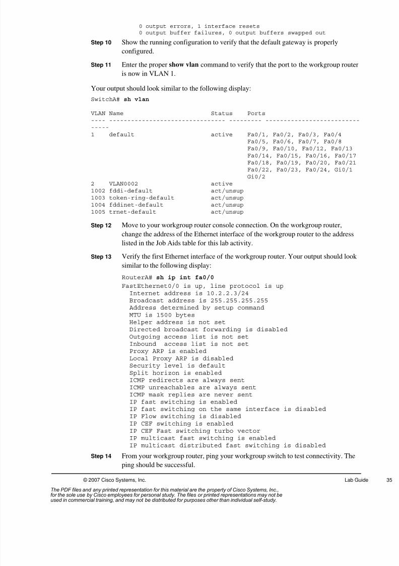
Step 10 Show the running configuration to verify that the default gateway is properly
configured.
Step 11 Enter the proper show vlan command to verify that the port to the workgroup router
is now in VLAN 1.
Your output should look similar to the following display:
SwitchA# sh vlan
VLAN Name Status Ports---- -------------------------------- --------- -------------------------------1 default active Fa0/1, Fa0/2, Fa0/3, Fa0/4
Fa0/5, Fa0/6, Fa0/7, Fa0/8Fa0/9, Fa0/10, Fa0/12, Fa0/13Fa0/14, Fa0/15, Fa0/16, Fa0/17Fa0/18, Fa0/19, Fa0/20, Fa0/21Fa0/22, Fa0/23, Fa0/24, Gi0/1Gi0/2
2 VLAN0002 active1002 fddi-default act/unsup1003 token-ring-default act/unsup1004 fddinet-default act/unsup1005 trnet-default act/unsup
Step 12 Move to your workgroup router console connection. On the workgroup router,
change the address of the Ethernet interface of the workgroup router to the address
listed in the Job Aids table for this lab activity.
Step 13 Verify the first Ethernet interface of the workgroup router. Your output should look
similar to the following display:
RouterA# sh ip int fa0/0
FastEthernet0/0 is up, line protocol is up
Internet address is 10.2.2.3/24Broadcast address is 255.255.255.255 Address determined by setup commandMTU is 1500 bytesHelper address is not setDirected broadcast forwarding is disabledOutgoing access list is not setInbound access list is not setProxy ARP is enabledLocal Proxy ARP is disabledSecurity level is defaultSplit horizon is enabledICMP redirects are always sent
ICMP unreachables are always sentICMP mask replies are never sentIP fast switching is enabledIP fast switching on the same interface is disabledIP Flow switching is disabledIP CEF switching is enabledIP CEF Fast switching turbo vectorIP multicast fast switching is enabledIP multicast distributed fast switching is disabled
Step 14 From your workgroup router, ping your workgroup switch to test connectivity. The
ping should be successful.
The PDF files and any printed representation for this material are the property of Cisco Systems, Inc.,for the sole use by Cisco employees for personal study. The files or printed representations may not beused in commercial training, and may not be distributed for purposes other than individual self-study.
8/3/2019 Icnd210lg Cracked
http://slidepdf.com/reader/full/icnd210lg-cracked 38/120
36 Interconnecting Cisco Networking Devices Part 2 (ICND2) v1.0 © 2007 Cisco Systems, Inc.
Step 15 Proceed to Task 2.
Activity Verification
You have completed this task when you attain these results:
Shut down the LAN connection from your workgroup to the core
Changed the IP address on your workgroup switch and the first Ethernet interface on your
router
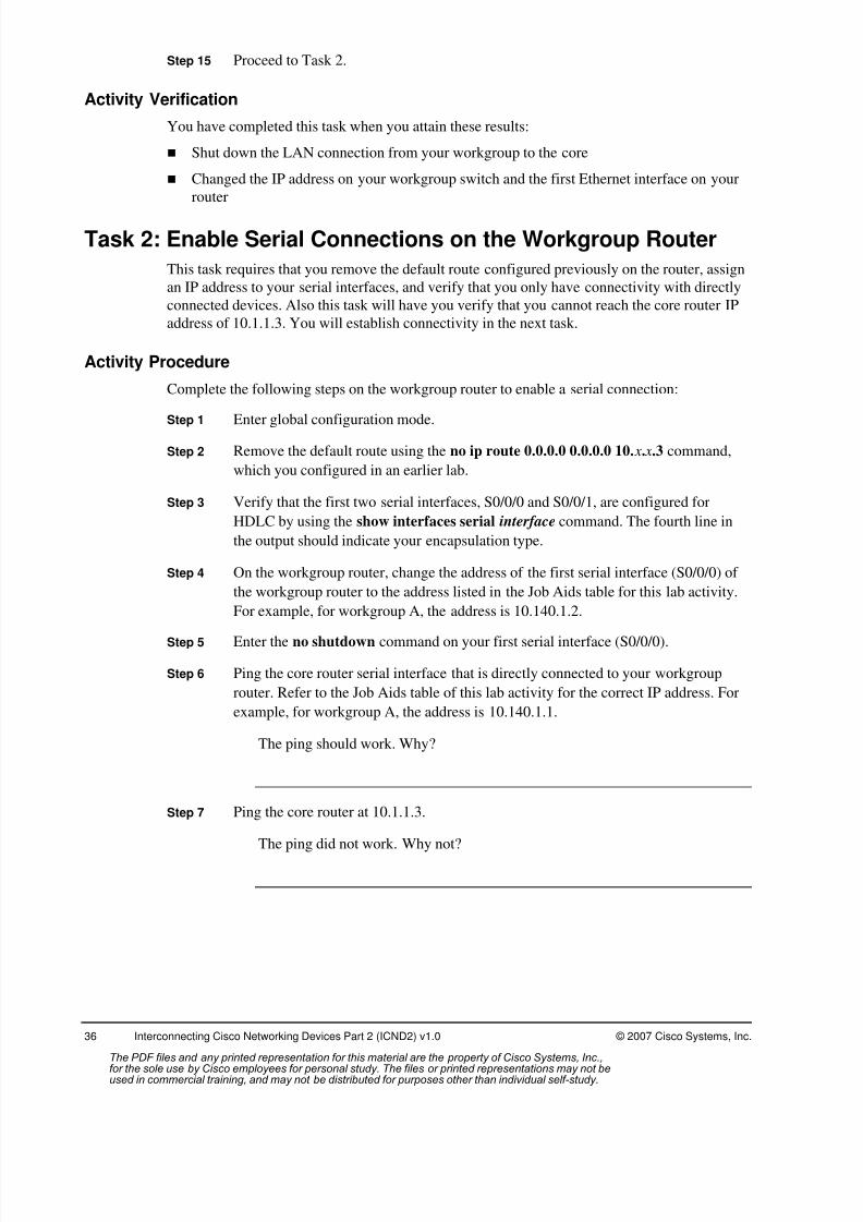
Task 2: Enable Serial Connections on the Workgroup Router
This task requires that you remove the default route configured previously on the router, assign
an IP address to your serial interfaces, and verify that you only have connectivity with directly
connected devices. Also this task will have you verify that you cannot reach the core router IP
address of 10.1.1.3. You will establish connectivity in the next task.
Activity Procedure
Complete the following steps on the workgroup router to enable a serial connection:
Step 1 Enter global configuration mode.
Step 2 Remove the default route using the no ip route 0.0.0.0 0.0.0.0 10. x. x.3 command,
which you configured in an earlier lab.
Step 3 Verify that the first two serial interfaces, S0/0/0 and S0/0/1, are configured for
HDLC by using the show interfaces serial interface command. The fourth line in
the output should indicate your encapsulation type.
Step 4 On the workgroup router, change the address of the first serial interface (S0/0/0) of
the workgroup router to the address listed in the Job Aids table for this lab activity.
For example, for workgroup A, the address is 10.140.1.2.
Step 5 Enter the no shutdown command on your first serial interface (S0/0/0).
Step 6 Ping the core router serial interface that is directly connected to your workgroup
router. Refer to the Job Aids table of this lab activity for the correct IP address. For
example, for workgroup A, the address is 10.140.1.1.
The ping should work. Why?
Step 7 Ping the core router at 10.1.1.3.
The ping did not work. Why not?
The PDF files and any printed representation for this material are the property of Cisco Systems, Inc.,for the sole use by Cisco employees for personal study. The files or printed representations may not beused in commercial training, and may not be distributed for purposes other than individual self-study.
8/3/2019 Icnd210lg Cracked
http://slidepdf.com/reader/full/icnd210lg-cracked 39/120
© 2007 Cisco Systems, Inc. Lab Guide
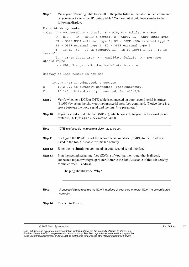
Step 8 View your IP routing table to see all of the paths listed in the table. Which command
do you enter to view the IP routing table? Your output should look similar to the
following display:
RouterA# sh ip route
Codes: C - connected, S - static, R - RIP, M - mobile, B - BGP
D - EIGRP, EX - EIGRP external, O - OSPF, IA - OSPF inter area
N1 - OSPF NSSA external type 1, N2 - OSPF NSSA external type 2
E1 - OSPF external type 1, E2 - OSPF external type 2i - IS-IS, su - IS-IS summary, L1 - IS-IS level-1, L2 - IS-IS
level-2
ia - IS-IS inter area, * - candidate default, U - per-userstatic route
o - ODR, P - periodic downloaded static route
Gateway of last resort is not set
10.0.0.0/24 is subnetted, 2 subnets
C 10.2.2.0 is directly connected, FastEthernet0/0
C 10.140.1.0 is directly connected, Serial0/0/0
Step 9 Verify whether a DCE or DTE cable is connected on your second serial interface
(S0/0/1) by using the show controllers serial interface command. (Notice there is a
space between the word serial and the interface parameter.)
Step 10 If your second serial interface (S0/0/1), which connects to your partner workgroup
router, is DCE, assign a clock rate of 64000.
Note DTE interfaces do not require a clock rate to be set.
Step 11 Configure the IP address of the second serial interface (S0/0/1) to the IP addresslisted in the Job Aids table for this lab activity.
Step 12 Enter the no shutdown command on your second serial interface.
Step 13 Ping the second serial interface (S0/0/1) of your partner router that is directly
connected to your workgroup router. Refer to the Job Aids table of this lab activity
for the correct IP address.
The ping should work. Why?
Note A successful ping requires the S0/0/1 interface of your partner router S0/0/1 to be configured
correctly.
Step 14 Proceed to Task 3.
The PDF files and any printed representation for this material are the property of Cisco Systems, Inc.,for the sole use by Cisco employees for personal study. The files or printed representations may not beused in commercial training, and may not be distributed for purposes other than individual self-study.

8/3/2019 Icnd210lg Cracked
http://slidepdf.com/reader/full/icnd210lg-cracked 40/120
38 Interconnecting Cisco Networking Devices Part 2 (ICND2) v1.0 © 2007 Cisco Systems, Inc.
Activity Verification
You have completed this task when you attain these results:
Removed the default route configured previously on the router
Assigned an IP address to your serial interfaces
Verified connectivity with your directly connected serial interface neighbor routers
Verified that you cannot reach the core router IP address of 10.1.1.3 by unsuccessfully
pinging the router
Task 3: Enable Routing with OSPFThe purpose of this task is to configure OSPF on the router. You will do this by assigning the
routing process ID and identifying the networks that will participate in the OSPF routing
process.
Activity Procedure
Complete the following steps on the workgroup router:
Step 1 Configure the loopback 0 interface with the address indicated in the Job Aids tableof this lab activity.
Step 2 Enable the OSPF routing protocol. Use an OSPF process ID of 100.
Step 3 Enable OSPF on your loopback 0 interface, Fa0/0 interface, and two serial
interfaces, S0/0/0 and S0/0/1. Refer to the Job Aids table of this lab activity. All of
the interfaces should be in area 0. Use four network statements with a wildcard mask
of 0.0.0.0 for each. For example:
RouterA(config)#router ospf 100
RouterA(config-router)#network 192.168.1.65 0.0.0.0 area 0
RouterA(config-router)#network 10.2.2.3 0.0.0.0 area 0RouterA(config-router)#network 10.140.1.2 0.0.0.0 area 0
RouterA(config-router)#network 10.23.23.1 0.0.0.0 area 0
Step 4 Configure a bandwidth of 64 Kb on both serial interfaces, S0/0/0 and S0/0/1.
Step 5 Proceed to Task 4.
Activity Verification
You have completed this task when you attain these results:
Assigned the routing process ID
Identified the networks that will participate in the OSPF routing process
The PDF files and any printed representation for this material are the property of Cisco Systems, Inc.,for the sole use by Cisco employees for personal study. The files or printed representations may not beused in commercial training, and may not be distributed for purposes other than individual self-study.

8/3/2019 Icnd210lg Cracked
http://slidepdf.com/reader/full/icnd210lg-cracked 41/120
© 2007 Cisco Systems, Inc. Lab Guide
Task 4: Enable OSPF Plain Text AuthenticationThe purpose of this task is to configure OSPF authentication on the router. The OSPF protocol
will not advertise routes between neighbors until they have correctly identified themselves.
Activity Procedure
Complete the following steps on the workgroup router:
Step 1 Assign a password to be used with all neighboring routers that use OSPF plain textpassword authentication (core router and partner router). Use san-fran as a
password.
Step 2 Enable your workgroup router to utilize plain text OSPF authentication with each of
your neighbor OSPF routers.
Step 3 Proceed to Task 5.
Activity Verification
You have completed this task when you attain these results:
Assigned an authentication password
Enabled authentication
Task 5: Verify OSPF Routing and Plain Text Authentication
In this topic, you will verify the operation and configuration of the OSPF routing protocol and
plain text authentication. You will do this using several show commands.
Activity Procedure
Complete the following steps on the workgroup router:
Step 1 Use the show ip route command to verify the routes learned from the OSPF routingprotocol. Your output should look similar to the following display:
RouterA# sh ip route Codes: C - connected, S - static, R - RIP, M - mobile, B - BGP
D - EIGRP, EX - EIGRP external, O - OSPF, IA - OSPF inter areaN1 - OSPF NSSA external type 1, N2 - OSPF NSSA external type 2E1 - OSPF external type 1, E2 - OSPF external type 2i - IS-IS, su - IS-IS summary, L1 - IS-IS level-1, L2 - IS-IS
level-2ia - IS-IS inter area, * - candidate default, U - per-user static
routeo - ODR, P - periodic downloaded static route
Gateway of last resort is not set
10.0.0.0/24 is subnetted, 5 subnetsC 10.23.23.0 is directly connected, Serial0/0/1C 10.2.2.0 is directly connected, FastEthernet0/0O 10.1.1.0 [110/1563] via 10.140.1.1, 00:03:15, Serial0/0/0O 10.140.2.0 [110/3124] via 10.140.1.1, 00:03:15, Serial0/0/0
[110/3124] via 10.23.23.2, 00:03:15, Serial0/0/1C 10.140.1.0 is directly connected, Serial0/0/0
192.168.1.0/24 is variably subnetted, 2 subnets, 2 masksC 192.168.1.64/28 is directly connected, Loopback0O 192.168.1.81/32 [110/1563] via 10.23.23.2, 00:03:17, Serial0/0/1
The PDF files and any printed representation for this material are the property of Cisco Systems, Inc.,for the sole use by Cisco employees for personal study. The files or printed representations may not beused in commercial training, and may not be distributed for purposes other than individual self-study.

8/3/2019 Icnd210lg Cracked
http://slidepdf.com/reader/full/icnd210lg-cracked 42/120
40 Interconnecting Cisco Networking Devices Part 2 (ICND2) v1.0 © 2007 Cisco Systems, Inc.
Step 2 Use the show ip protocols command to verify that the OSPF routing protocol is
enabled and that the routing process ID that you assigned in Task 1 are recognized
by OSPF (the router ID should be the IP address of the loopback interface of your
workgroup router). Your output should look similar to the following display:
RouterA# sh ip protocol
Routing Protocol is "ospf 100"
Outgoing update filter list for all interfaces is not set
Incoming update filter list for all interfaces is not set
Router ID 192.168.1.65
Number of areas in this router is 1. 1 normal 0 stub 0 nssa
Maximum path: 4
Routing for Networks:
10.2.2.3 0.0.0.0 area 0
10.23.23.1 0.0.0.0 area 0
10.140.1.2 0.0.0.0 area 0
192.168.1.65 0.0.0.0 area 0
Reference bandwidth unit is 100 mbps
Routing Information Sources:
Gateway Distance Last Update
192.168.1.81 110 00:04:52
172.16.31.100 110 00:04:52
Distance: (default is 110)
Step 3 Use the show ip ospf neighbor command to display the neighbor status. Your
output should look similar to the following display:
RouterA# sh ip ospf neighbor
Neighbor ID Pri State Dead Time Address Interface172.16.31.100 0 FULL/ - 00:00:31 10.140.1.1 Serial0/0/0192.168.1.81 0 FULL/ - 00:00:31 10.23.23.2 Serial0/0/1
What is the neighbor state to the core and adjacent workgroup router?
What is the neighbor ID used by these routers?
Note You will not see your neighbors until they complete the preceding tasks of this lab activity.
Step 4 Ping the TFTP server at 10.1.1.1. Ping the Ethernet interface of another workgroup
router. Use the Job Aids table for this lab activity to find an address to ping. If the
other workgroup also has OSPF successfully configured, these pings should be
successful.
The PDF files and any printed representation for this material are the property of Cisco Systems, Inc.,for the sole use by Cisco employees for personal study. The files or printed representations may not beused in commercial training, and may not be distributed for purposes other than individual self-study.
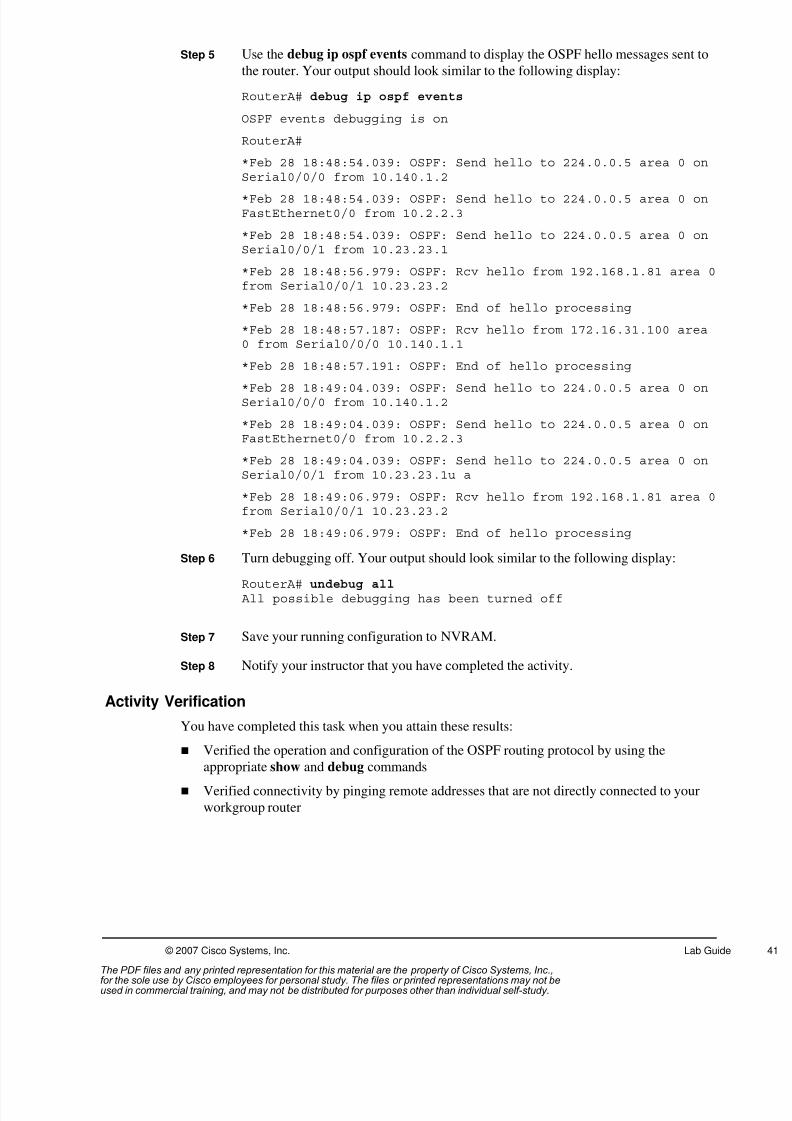
8/3/2019 Icnd210lg Cracked
http://slidepdf.com/reader/full/icnd210lg-cracked 43/120
© 2007 Cisco Systems, Inc. Lab Guide
Step 5 Use the debug ip ospf events command to display the OSPF hello messages sent to
the router. Your output should look similar to the following display:
RouterA# debug ip ospf events
OSPF events debugging is on
RouterA#
*Feb 28 18:48:54.039: OSPF: Send hello to 224.0.0.5 area 0 onSerial0/0/0 from 10.140.1.2
*Feb 28 18:48:54.039: OSPF: Send hello to 224.0.0.5 area 0 onFastEthernet0/0 from 10.2.2.3
*Feb 28 18:48:54.039: OSPF: Send hello to 224.0.0.5 area 0 onSerial0/0/1 from 10.23.23.1
*Feb 28 18:48:56.979: OSPF: Rcv hello from 192.168.1.81 area 0from Serial0/0/1 10.23.23.2
*Feb 28 18:48:56.979: OSPF: End of hello processing
*Feb 28 18:48:57.187: OSPF: Rcv hello from 172.16.31.100 area0 from Serial0/0/0 10.140.1.1
*Feb 28 18:48:57.191: OSPF: End of hello processing
*Feb 28 18:49:04.039: OSPF: Send hello to 224.0.0.5 area 0 onSerial0/0/0 from 10.140.1.2
*Feb 28 18:49:04.039: OSPF: Send hello to 224.0.0.5 area 0 onFastEthernet0/0 from 10.2.2.3
*Feb 28 18:49:04.039: OSPF: Send hello to 224.0.0.5 area 0 onSerial0/0/1 from 10.23.23.1u a
*Feb 28 18:49:06.979: OSPF: Rcv hello from 192.168.1.81 area 0from Serial0/0/1 10.23.23.2
*Feb 28 18:49:06.979: OSPF: End of hello processing
Step 6 Turn debugging off. Your output should look similar to the following display:
RouterA# undebug all All possible debugging has been turned off
Step 7 Save your running configuration to NVRAM.
Step 8 Notify your instructor that you have completed the activity.
Activity Verification
You have completed this task when you attain these results:
Verified the operation and configuration of the OSPF routing protocol by using the
appropriate show and debug commands Verified connectivity by pinging remote addresses that are not directly connected to your
workgroup router
The PDF files and any printed representation for this material are the property of Cisco Systems, Inc.,for the sole use by Cisco employees for personal study. The files or printed representations may not beused in commercial training, and may not be distributed for purposes other than individual self-study.

8/3/2019 Icnd210lg Cracked
http://slidepdf.com/reader/full/icnd210lg-cracked 44/120
42 Interconnecting Cisco Networking Devices Part 2 (ICND2) v1.0 © 2007 Cisco Systems, Inc.
Lab 4-2: Troubleshooting OSPFComplete this lab activity to practice what you learned in the related module.
Activity Objective
In this activity, you will use the troubleshooting guidelines discussed in the corresponding
module to gather symptoms, isolate problems, and correct problems commonly found in anOSPF network. After completing this activity, you will be able to meet these objectives:
Discover OSPF network connectivity issues and follow troubleshooting guidelines to
isolate and fix OSPF connectivity problems
Visual Objective
The figure illustrates what you will accomplish in this activity.
© 2007 Cisco Systems, Inc. All rights reserved. ICND2 v1.0—9
Visual Objective 4-2:
Troubleshooting OSPF
Required Resources
These are the resources and equipment that are required to complete this activity:
PC connected to an onsite lab or PC with an Internet connection to access the remote lab Terminal server connected to a console port of each lab device if using a remote lab
ICND workgroup assigned by your instructor
The PDF files and any printed representation for this material are the property of Cisco Systems, Inc.,for the sole use by Cisco employees for personal study. The files or printed representations may not beused in commercial training, and may not be distributed for purposes other than individual self-study.

8/3/2019 Icnd210lg Cracked
http://slidepdf.com/reader/full/icnd210lg-cracked 45/120
© 2007 Cisco Systems, Inc. Lab Guide
Command List
The table describes the commands used in this activity. The commands are listed in
alphabetical order so that you can easily locate the information you need. Refer to this list if
you need configuration command assistance during the lab activity.
OSPF Troubleshooting Commands
Command Description
copy tftp running-configuration
Merges file on the TFTP server with the device running-config
debug ip ospf adj Displays the OSPF neighbor establishment process
debug ip ospf events Displays a summary of OSPF transaction information
ping 10.1.1.1 Tests Layer 3 connectivity
show interfaces type Displays statistics for interfaces configured on the router
show ip ospf interface Displays statistics for interfaces that have OSPF enabled
show ip ospf neighbor Determines the state of an OSPF neighborshow ip protocols Displays values about routing protocols and routing protocol
timer information associated with the router
show ip route Displays the routing table
Job Aids
These job aids are available to help you complete the lab activity.
WG Switch
Interface
VLAN 1
(SwitchX )
Router
Fa0/0
Interface
(RouterX )
Router
Loopback 0
Interface
(RouterX )
Router
S0/0/0
Interface
(RouterX )
Router
S0/0/1
Interface
(RouterX )
Core Router
Serial
Interface
(Core
Router)
A 10.2.2.11/24 10.2.2.3/24 192.168.1.65/28 10.140.1.2/24 10.23.23.1/24 10.140.1.1/24
B 10.3.3.11/24 10.3.3.3/24 192.168.1.81/28 10.140.2.2/24 10.23.23.2/24 10.140.2.1/24
C 10.4.4.11/24 10.4.4.3/24 192.168.2.65/28 10.140.3.2/24 10.45.45.1/24 10.140.3.1/24
D 10.5.5.11/24 10.5.5.3/24 192.168.2.81/28 10.140.4.2/24 10.45.45.2/24 10.140.4.1/24
E 10.6.6.11/24 10.6.6.3/24 192.168.3.65/28 10.140.5.2/24 10.67.67.1/24 10.140.5.1/24
F 10.7.7.11/24 10.7.7.3/24 192.168.3.81/28 10.140.6.2/24 10.67.67.2/24 10.140.6.1/24
G 10.8.8.11/24 10.8.8.3/24 192.168.4.65/28 10.140.7.2/24 10.89.89.1/24 10.140.7.1/24
H 10.9.9.11/24 10.9.9.3/24 192.168.4.81/28 10.140.8.2/24 10.89.89.2/24 10.140.8.1/24
The PDF files and any printed representation for this material are the property of Cisco Systems, Inc.,for the sole use by Cisco employees for personal study. The files or printed representations may not beused in commercial training, and may not be distributed for purposes other than individual self-study.

8/3/2019 Icnd210lg Cracked
http://slidepdf.com/reader/full/icnd210lg-cracked 46/120
44 Interconnecting Cisco Networking Devices Part 2 (ICND2) v1.0 © 2007 Cisco Systems, Inc.
Use the table to document the troubleshooting process.
Troubleshooting Steps
Command to Gather
Symptoms
Isolate the Problem Command to Correct the Problem
Example:
ping 172.16.2.2 fails -----
show ip interface brief int Fa0/1 is administrativelydown
no shutdown
ping 172.16.2.2 still fails -----
show interface Fa0/1 has incorrect ip address ip address 192.168.1.2
ping 172.16.2.2 succeeds
Task 1: Update Your Workgroup ConfigurationsIn this task, you will download a new supplemental configuration to your workgroup router
from the TFTP server. However, the supplemental configuration that you download contains
configuration errors that cause loss of connectivity with the rest of the network. You will
troubleshoot to isolate and correct the problem or problems that this supplemental file
introduces.
Activity Procedure
Complete these steps:
Step 1 Ensure connectivity with the TFTP server. Ping the TFTP server (10.1.1.1) from
your workgroup router.
Note If your ping is unsuccessful, contact your instructor.
Step 2 Download the supplement configuration from the TFTP server into the running
configuration of your workgroup router. The name of the file to download is i2-
wg_ro-config-lab4-2.txt.
The PDF files and any printed representation for this material are the property of Cisco Systems, Inc.,for the sole use by Cisco employees for personal study. The files or printed representations may not beused in commercial training, and may not be distributed for purposes other than individual self-study.

8/3/2019 Icnd210lg Cracked
http://slidepdf.com/reader/full/icnd210lg-cracked 47/120
© 2007 Cisco Systems, Inc. Lab Guide
Step 3 Type exit from the privilege EXEC prompt and ensure your router banner reads:
************** wg_ro-config-lab4-2 ***********************
Step 4 Ping the TFTP server from your workgroup router. Are you successful?
Step 5 Check your workgroup router routing table. Check the OSPF neighbor relationships.
What did you find?
Step 6 Use the debug ip ospf events command. What did you find?
Step 7 Without utilizing the show run command, use the troubleshooting guidelines and
commands discussed in the corresponding module to gather symptoms and isolate
and correct the problems. Use the Job Aids table of this lab to document the
troubleshooting process.
Step 8 Once you have fixed the problem, save your running configuration to NVRAM.
Activity Verification
You have completed this task when you attain these results:
Re-established OSPF neighbor relationships with your directly connected routers
Populated the routing table of your workgroup router with OSPF-learned routes from the
core router
Re-established network connectivity and can successfully ping the TFTP server
The PDF files and any printed representation for this material are the property of Cisco Systems, Inc.,for the sole use by Cisco employees for personal study. The files or printed representations may not beused in commercial training, and may not be distributed for purposes other than individual self-study.
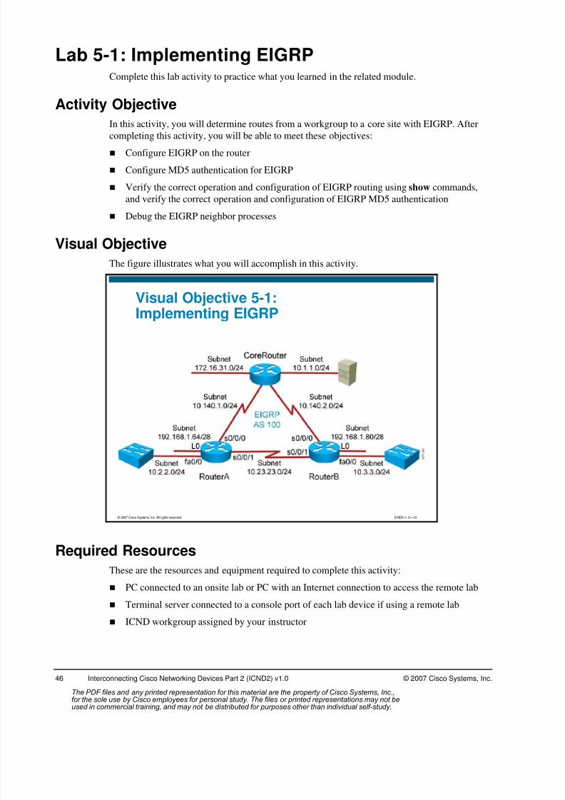
8/3/2019 Icnd210lg Cracked
http://slidepdf.com/reader/full/icnd210lg-cracked 48/120
46 Interconnecting Cisco Networking Devices Part 2 (ICND2) v1.0 © 2007 Cisco Systems, Inc.
Lab 5-1: Implementing EIGRPComplete this lab activity to practice what you learned in the related module.
Activity Objective
In this activity, you will determine routes from a workgroup to a core site with EIGRP. After
completing this activity, you will be able to meet these objectives: Configure EIGRP on the router
Configure MD5 authentication for EIGRP
Verify the correct operation and configuration of EIGRP routing using show commands,
and verify the correct operation and configuration of EIGRP MD5 authentication
Debug the EIGRP neighbor processes
Visual Objective
The figure illustrates what you will accomplish in this activity.
© 2007 Cisco Systems, Inc. All rights reserved. ICND2 v1.0—10
Visual Objective 5-1:Implementing EIGRP
Required ResourcesThese are the resources and equipment required to complete this activity:
PC connected to an onsite lab or PC with an Internet connection to access the remote lab
Terminal server connected to a console port of each lab device if using a remote lab
ICND workgroup assigned by your instructor
The PDF files and any printed representation for this material are the property of Cisco Systems, Inc.,for the sole use by Cisco employees for personal study. The files or printed representations may not beused in commercial training, and may not be distributed for purposes other than individual self-study.

8/3/2019 Icnd210lg Cracked
http://slidepdf.com/reader/full/icnd210lg-cracked 49/120
© 2007 Cisco Systems, Inc. Lab Guide
Command List
The table describes the commands used in this activity. The commands are listed in
alphabetical order so that you can easily locate the information you need. Refer to this list if
you need configuration command assistance during the lab activity.
Commands
Command Description
debug eigrp neighbors Displays EIGRP neighbors discovered by EIGRP
ip authentication modeeigrp autonomous-system md5
Specifies MD5 authentication for EIGRP packets
ip authentication key-chain eigrp autonomous-system
name-of-chain
Enables authentication of EIGRP packets using the key in thekeychain
key chain name-of-chain Enters configuration mode for the keychain
key key-id Identifies a key and enters configuration mode for the keyid
key-string text Identifies a key string (password)
network network-number Enables the routing protocol on the interfaces that match thespecified network
no debug all Turns off all debugging displays
ping ip-address Tests Layer 3 connectivity
router eigrp autonomous-system
Enables EIGRP
show interfaces Displays statistics for the interfaces configured on the router
show ip eigrp neighbors Determines the state of an EIGRP neighbor
show ip protocols Displays values about routing protocols and routing protocoltimer information associated with the router
show ip route Displays the IP routing table
Job Aids
These job aids are available to help you complete the lab activity.
In this activity, you will use the default encapsulation for a serial link, HDLC, to distribute
routing protocol traffic from your workgroup to the core. You will configure the EIGRP routing
protocol, implementing EIGRP MD5 authentication to ensure routing update authenticity. Thenyou will verify the configuration and operation of EIGRP.
The following table lists the IP addresses that you will use in this lab activity. Subnet masks are
designated with “/bits” to indicate the number of network bits in the mask.
The PDF files and any printed representation for this material are the property of Cisco Systems, Inc.,for the sole use by Cisco employees for personal study. The files or printed representations may not beused in commercial training, and may not be distributed for purposes other than individual self-study.
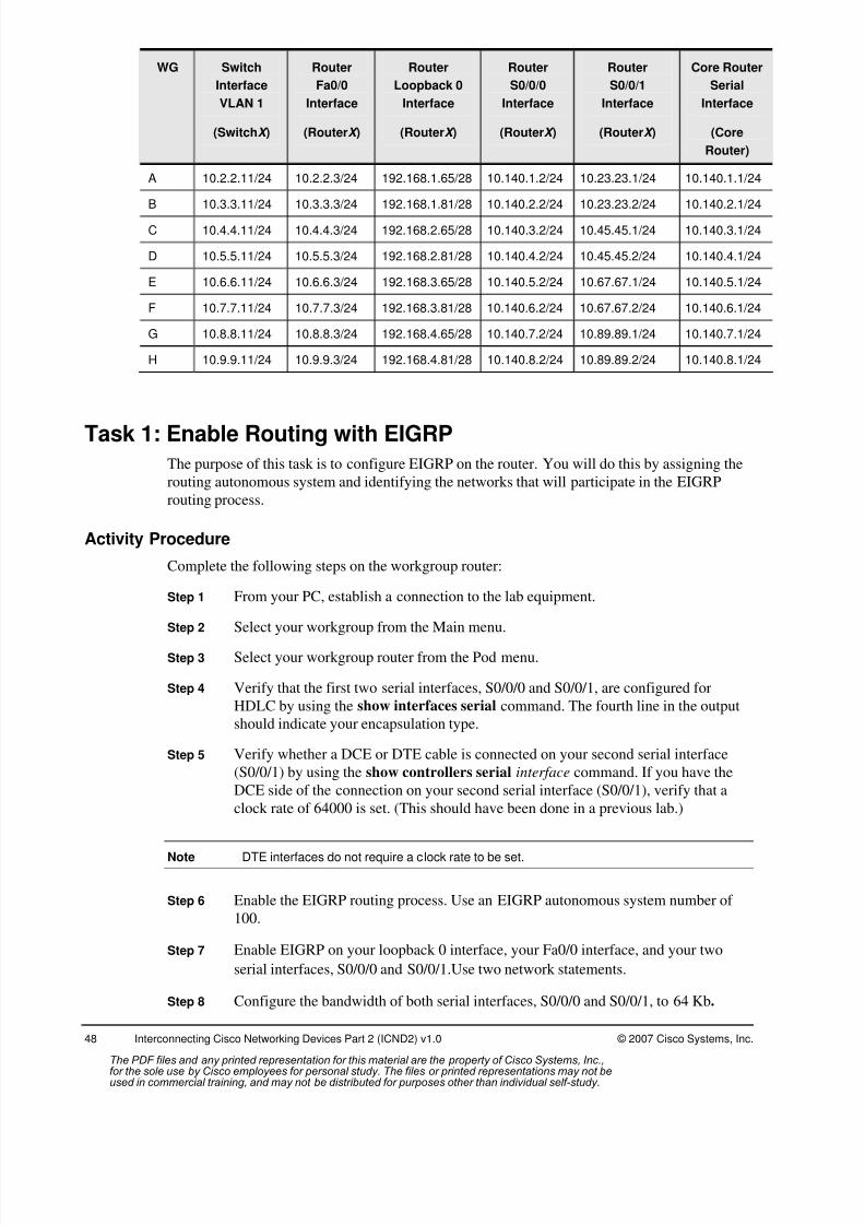
8/3/2019 Icnd210lg Cracked
http://slidepdf.com/reader/full/icnd210lg-cracked 50/120
48 Interconnecting Cisco Networking Devices Part 2 (ICND2) v1.0 © 2007 Cisco Systems, Inc.
WG Switch
Interface
VLAN 1
(SwitchX )
Router
Fa0/0
Interface
(RouterX )
Router
Loopback 0
Interface
(RouterX )
Router
S0/0/0
Interface
(RouterX )
Router
S0/0/1
Interface
(RouterX )
Core Router
Serial
Interface
(Core
Router)
A 10.2.2.11/24 10.2.2.3/24 192.168.1.65/28 10.140.1.2/24 10.23.23.1/24 10.140.1.1/24
B 10.3.3.11/24 10.3.3.3/24 192.168.1.81/28 10.140.2.2/24 10.23.23.2/24 10.140.2.1/24
C 10.4.4.11/24 10.4.4.3/24 192.168.2.65/28 10.140.3.2/24 10.45.45.1/24 10.140.3.1/24
D 10.5.5.11/24 10.5.5.3/24 192.168.2.81/28 10.140.4.2/24 10.45.45.2/24 10.140.4.1/24
E 10.6.6.11/24 10.6.6.3/24 192.168.3.65/28 10.140.5.2/24 10.67.67.1/24 10.140.5.1/24
F 10.7.7.11/24 10.7.7.3/24 192.168.3.81/28 10.140.6.2/24 10.67.67.2/24 10.140.6.1/24
G 10.8.8.11/24 10.8.8.3/24 192.168.4.65/28 10.140.7.2/24 10.89.89.1/24 10.140.7.1/24
H 10.9.9.11/24 10.9.9.3/24 192.168.4.81/28 10.140.8.2/24 10.89.89.2/24 10.140.8.1/24
Task 1: Enable Routing with EIGRP
The purpose of this task is to configure EIGRP on the router. You will do this by assigning the
routing autonomous system and identifying the networks that will participate in the EIGRP
routing process.
Activity Procedure
Complete the following steps on the workgroup router:
Step 1 From your PC, establish a connection to the lab equipment.
Step 2 Select your workgroup from the Main menu.Step 3 Select your workgroup router from the Pod menu.
Step 4 Verify that the first two serial interfaces, S0/0/0 and S0/0/1, are configured for
HDLC by using the show interfaces serial command. The fourth line in the output
should indicate your encapsulation type.
Step 5 Verify whether a DCE or DTE cable is connected on your second serial interface
(S0/0/1) by using the show controllers serial interface command. If you have the
DCE side of the connection on your second serial interface (S0/0/1), verify that a
clock rate of 64000 is set. (This should have been done in a previous lab.)
Note DTE interfaces do not require a clock rate to be set.
Step 6 Enable the EIGRP routing process. Use an EIGRP autonomous system number of
100.
Step 7 Enable EIGRP on your loopback 0 interface, your Fa0/0 interface, and your two
serial interfaces, S0/0/0 and S0/0/1.Use two network statements.
Step 8 Configure the bandwidth of both serial interfaces, S0/0/0 and S0/0/1, to 64 Kb.
The PDF files and any printed representation for this material are the property of Cisco Systems, Inc.,for the sole use by Cisco employees for personal study. The files or printed representations may not beused in commercial training, and may not be distributed for purposes other than individual self-study.
8/3/2019 Icnd210lg Cracked
http://slidepdf.com/reader/full/icnd210lg-cracked 51/120
© 2007 Cisco Systems, Inc. Lab Guide
Step 9 Proceed to Task 2.
Activity Verification
You have completed this task when you attain these results:
Enabled EIGRP and assigned the autonomous system number
Identified the networks that will participate in the EIGRP routing process
Task 2: Enable EIGRP MD5 Authentication
The purpose of this task is to configure EIGRP authentication on the router. The EIGRP
protocol will not advertise routes between neighbors until they have correctly identified
themselves.
Activity Procedure
Complete the following steps on the workgroup router:
Step 1 Create a keychain named icndchain.
Step 2 Configure a key 1 that has a key string of san-fran.
Step 3 Enable the workgroup router to utilize EIGRP MD5 authentication with each of your
EIGRP neighbors and to use the keychain icndchain.
Step 4 Proceed to Task 3.
Activity Verification
You have completed this task when you attain these results:
Created and implemented an EIGRP keychain
Enabled the EIGRP MD5 authentication
Task 3: Verify EIGRP Routing and MD5 Authentication
In this topic, you will verify the operation and configuration of the EIGRP routing protocol.
You will do this using several show commands.
Activity Procedure
Complete the following steps on the workgroup router:
Step 1 Use the show ip route command to verify that the routes are learned from EIGRP.
Your output should look similar to the following display:
RouterA# sh ip route Codes: C - connected, S - static, R - RIP, M - mobile, B - BGP
D - EIGRP, EX - EIGRP external, O - OSPF, IA - OSPF inter areaN1 - OSPF NSSA external type 1, N2 - OSPF NSSA external type 2E1 - OSPF external type 1, E2 - OSPF external type 2i - IS-IS, su - IS-IS summary, L1 - IS-IS level-1, L2 - IS-IS
level-2ia - IS-IS inter area, * - candidate default, U - per-user static
routeo - ODR, P - periodic downloaded static route
The PDF files and any printed representation for this material are the property of Cisco Systems, Inc.,for the sole use by Cisco employees for personal study. The files or printed representations may not beused in commercial training, and may not be distributed for purposes other than individual self-study.
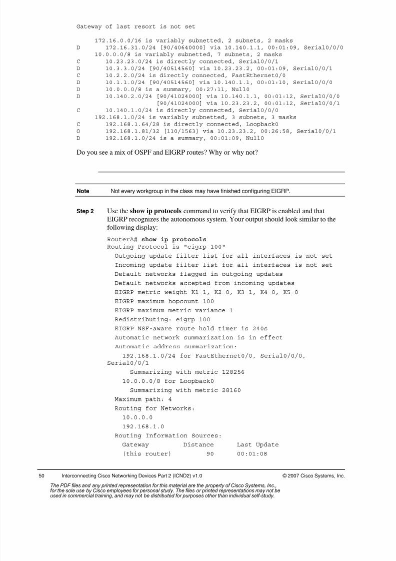
8/3/2019 Icnd210lg Cracked
http://slidepdf.com/reader/full/icnd210lg-cracked 52/120
50 Interconnecting Cisco Networking Devices Part 2 (ICND2) v1.0 © 2007 Cisco Systems, Inc.
Gateway of last resort is not set
172.16.0.0/16 is variably subnetted, 2 subnets, 2 masksD 172.16.31.0/24 [90/40640000] via 10.140.1.1, 00:01:09, Serial0/0/0
10.0.0.0/8 is variably subnetted, 7 subnets, 2 masksC 10.23.23.0/24 is directly connected, Serial0/0/1D 10.3.3.0/24 [90/40514560] via 10.23.23.2, 00:01:09, Serial0/0/1C 10.2.2.0/24 is directly connected, FastEthernet0/0D 10.1.1.0/24 [90/40514560] via 10.140.1.1, 00:01:10, Serial0/0/0D 10.0.0.0/8 is a summary, 00:27:11, Null0
D 10.140.2.0/24 [90/41024000] via 10.140.1.1, 00:01:12, Serial0/0/0[90/41024000] via 10.23.23.2, 00:01:12, Serial0/0/1
C 10.140.1.0/24 is directly connected, Serial0/0/0192.168.1.0/24 is variably subnetted, 3 subnets, 3 masks
C 192.168.1.64/28 is directly connected, Loopback0O 192.168.1.81/32 [110/1563] via 10.23.23.2, 00:26:58, Serial0/0/1D 192.168.1.0/24 is a summary, 00:01:09, Null0
Do you see a mix of OSPF and EIGRP routes? Why or why not?
Note Not every workgroup in the class may have finished configuring EIGRP.
Step 2 Use the show ip protocols command to verify that EIGRP is enabled and that
EIGRP recognizes the autonomous system. Your output should look similar to the
following display:
RouterA# show ip protocols Routing Protocol is "eigrp 100"
Outgoing update filter list for all interfaces is not set
Incoming update filter list for all interfaces is not set
Default networks flagged in outgoing updates
Default networks accepted from incoming updates
EIGRP metric weight K1=1, K2=0, K3=1, K4=0, K5=0EIGRP maximum hopcount 100
EIGRP maximum metric variance 1
Redistributing: eigrp 100
EIGRP NSF-aware route hold timer is 240s
Automatic network summarization is in effect
Automatic address summarization:
192.168.1.0/24 for FastEthernet0/0, Serial0/0/0,Serial0/0/1
Summarizing with metric 128256
10.0.0.0/8 for Loopback0
Summarizing with metric 28160
Maximum path: 4
Routing for Networks:
10.0.0.0
192.168.1.0
Routing Information Sources:
Gateway Distance Last Update
(this router) 90 00:01:08
The PDF files and any printed representation for this material are the property of Cisco Systems, Inc.,for the sole use by Cisco employees for personal study. The files or printed representations may not beused in commercial training, and may not be distributed for purposes other than individual self-study.

8/3/2019 Icnd210lg Cracked
http://slidepdf.com/reader/full/icnd210lg-cracked 53/120
© 2007 Cisco Systems, Inc. Lab Guide
10.140.1.1 90 00:01:08
Distance: internal 90 external 170
Step 3 Use the show ip eigrp neighbor command to display the neighbor status. Your
output should look similar to the following display:
RouterA# sh ip eigrp neighbors IP-EIGRP neighbors for process 100H Address Interface Hold Uptime SRTT RTO Q Seq
(sec) (ms) Cnt Num1 10.23.23.2 Se0/0/1 13 00:02:26 29 2280 0 150 10.140.1.1 Se0/0/0 10 00:28:26 24 2280 0 25
Note You cannot see your neighbors until they complete the preceding tasks of this lab activity.
Step 4 Ping the loopback interface (172.16.31.100) of the core router. Once another
workgroup has finished configuring EIGRP, ping their Ethernet LAN interface listed
in the Job Aids table for this lab activity. These pings should be successful.
Step 5 Proceed to Task 4.
Activity Verification
You have completed this task when you attain these results:
Verified the operation and configuration of the EIGRP routing protocol by using the show
commands
Verified connectivity by pinging remote addresses not directly connected to your
workgroup router
Task 4: Debug Routing with EIGRP
In this task, you will debug EIGRP. This will help you know what to look for when you need to
troubleshoot EIGRP issues.
Activity Procedure
Complete the following steps on the workgroup router:
Step 1 Display the EIGRP neighbor events with the debug eigrp neighbors command.
Step 2 Enter interface configuration mode and enter the shutdown command on your
second serial interface.
Step 3 Wait ten seconds and then enter the no shutdown command on your serial interface.
Your output should look similar to the following display:
RouterA#debug eigrp neighbors *Feb 28 22:05:51.651: %OSPF-5-ADJCHG: Process 100, Nbr 192.168.1.81 onSerial0/0/1 from FULL to DOWN, Neighbor Down: Interface down or detached*Feb 28 22:05:51.659: %DUAL-5-NBRCHANGE: IP-EIGRP(0) 100: Neighbor 10.23.23.2(Serial0/0/1) is down: interface downn*Feb 28 22:05:51.659: Going down: Peer 10.23.23.2 total=1 stub 0 template=1,iidb-stub=0 iid-all=0*Feb 28 22:05:51.659: EIGRP: Neighbor 10.23.23.2 went down on Serial0/0/1*Feb 28 22:05:52.559: EIGRP: Packet from ourselves ignoredo*Feb 28 22:05:53.651: %LINK-5-CHANGED: Interface Serial0/0/1, changed state toadministratively down*Feb 28 22:05:54.651: %LINEPROTO-5-UPDOWN: Line protocol on InterfaceSerial0/0/1, changed state to do
The PDF files and any printed representation for this material are the property of Cisco Systems, Inc.,for the sole use by Cisco employees for personal study. The files or printed representations may not beused in commercial training, and may not be distributed for purposes other than individual self-study.

8/3/2019 Icnd210lg Cracked
http://slidepdf.com/reader/full/icnd210lg-cracked 54/120
52 Interconnecting Cisco Networking Devices Part 2 (ICND2) v1.0 © 2007 Cisco Systems, Inc.
*Feb 28 22:05:57.391: EIGRP: Packet from ourselves ignoredn*Feb 28 22:06:02.271: EIGRP: Packet from ourselves ignoredo shutRouterA(config-if)#*Feb 28 22:06:06.955: EIGRP: Packet from ourselves ignored*Feb 28 22:06:07.355: %LINK-3-UPDOWN: Interface Serial0/0/1, changed state toup*Feb 28 22:06:07.515: %OSPF-5-ADJCHG: Process 100, Nbr 192.168.1.81 onSerial0/0/1 from LOADING to FULL, Loading Done*Feb 28 22:06:08.355: %LINEPROTO-5-UPDOWN: Line protocol on InterfaceSerial0/0/1, changed state to up*Feb 28 22:06:10.715: EIGRP: New peer 10.23.23.2 total=2 stub 0 template=1
idbstub=0 iidball=1*Feb 28 22:06:10.715: %DUAL-5-NBRCHANGE: IP-EIGRP(0) 100: Neighbor 10.23.23.2(Serial0/0/1) is up: new adjacency
Step 4 Turn debugging off.
Step 5 Save your running configuration to NVRAM.
Step 6 Notify your instructor that you have completed the activity.
Activity Verification
You have completed this activity when you attain this result:
Debugged EIGRP by using the debug eigrp neighbor command
The PDF files and any printed representation for this material are the property of Cisco Systems, Inc.,for the sole use by Cisco employees for personal study. The files or printed representations may not beused in commercial training, and may not be distributed for purposes other than individual self-study.

8/3/2019 Icnd210lg Cracked
http://slidepdf.com/reader/full/icnd210lg-cracked 55/120
© 2007 Cisco Systems, Inc. Lab Guide
Lab 5-2: Troubleshooting EIGRPComplete this lab activity to practice what you learned in the related module.
Activity Objective
In this activity, you will use the troubleshooting guidelines discussed in the corresponding
module to gather symptoms and isolate and correct problems commonly found in an EIGRPnetwork. After completing this activity, you will be able to meet these objectives:
Discover EIGRP network connectivity issues and follow troubleshooting guidelines to
isolate and fix EIGRP connectivity problems
Test EIGRP network connectivity
Visual Objective
The figure illustrates what you will accomplish in this activity.
© 2007 Cisco Systems, Inc. All rights reserved. ICND2 v1.0—11
Visual Objective 5-2:Troubleshooting EIGRP
Required Resources
These are the resources and equipment that are required to complete this activity: PC connected to an onsite lab or PC with an Internet connection to access the remote lab
Terminal server connected to a console port of each lab device if using a remote lab
ICND workgroup assigned by your instructor
The PDF files and any printed representation for this material are the property of Cisco Systems, Inc.,for the sole use by Cisco employees for personal study. The files or printed representations may not beused in commercial training, and may not be distributed for purposes other than individual self-study.

8/3/2019 Icnd210lg Cracked
http://slidepdf.com/reader/full/icnd210lg-cracked 56/120
54 Interconnecting Cisco Networking Devices Part 2 (ICND2) v1.0 © 2007 Cisco Systems, Inc.
Command List
The table describes the commands used in this activity. The commands are listed in
alphabetical order so that you can easily locate the information you need. Refer to this list if
you need configuration command assistance during the lab activity.
EIGRP Troubleshooting Commands
Command Description
debug ip eigrp Displays a summary of EIGRP transaction information
interface loopback 1 Creates a loopback interface
network 172.16.0.0 Enables the routing protocol on the interfaces that match thespecified network
ping <cr> An extended ping that tests Layer 3 connectivity, allowingyou to provide options
show interfaces type Displays statistics for interfaces configured on the router
show ip eigrp neighbor Determines the state of an EIGRP neighbor
show ip protocols Displays values about routing protocols and routing protocoltimer information associated with the router
show ip route Displays the routing table
Job Aids
In this lab exercise, loopback interfaces on your workgroup router and the core router will
represent LANs that you will interconnect via the EIGRP routing protocol. You will create a
new loopback interface on your workgroup router that will represent a LAN and test
connectivity to the core router loopback. If connectivity fails, you will troubleshoot to isolate
and correct the problem.
These job aids are available to help you complete the lab activity.
WG Router
Fa0/0
Interface
(RouterX )
Router
Loopback 0
Interface
(RouterX )
Router
Loopback 1
Interface
(RouterX )
Router
S0/0/0
Interface
(RouterX )
Router
S0/0/1
Interface
(RouterX )
Core Router
Serial
Interface
(Core
Router)
A 10.2.2.3/24 192.168.1.65/28 172.16.2.1/24 10.140.1.2/24 10.23.23.1/24 10.140.1.1/24
B 10.3.3.3/24 192.168.1.81/28 172.16.3.1/24 10.140.2.2/24 10.23.23.2/24 10.140.2.1/24
C 10.4.4.3/24 192.168.2.65/28 172.16.4.1/24 10.140.3.2/24 10.45.45.1/24 10.140.3.1/24
D 10.5.5.3/24 192.168.2.81/28 172.16.5.1/24 10.140.4.2/24 10.45.45.2/24 10.140.4.1/24
E 10.6.6.3/24 192.168.3.65/28 172.16.6.1/24 10.140.5.2/24 10.67.67.1/24 10.140.5.1/24
F 10.7.7.3/24 192.168.3.81/28 172.16.7.1/24 10.140.6.2/24 10.67.67.2/24 10.140.6.1/24
G 10.8.8.3/24 192.168.4.65/28 172.16.8.1/24 10.140.7.2/24 10.89.89.1/24 10.140.7.1/24
H 10.9.9.3/24 192.168.4.81/28 172.16.9.1/24 10.140.8.2/24 10.89.89.2/24 10.140.8.1/24
The PDF files and any printed representation for this material are the property of Cisco Systems, Inc.,for the sole use by Cisco employees for personal study. The files or printed representations may not beused in commercial training, and may not be distributed for purposes other than individual self-study.

8/3/2019 Icnd210lg Cracked
http://slidepdf.com/reader/full/icnd210lg-cracked 57/120
© 2007 Cisco Systems, Inc. Lab Guide
Use the table to document the troubleshooting process.
Troubleshooting Steps
Command to Gather
Symptoms
Isolate the Problem Command to Correct the Problem
Example:
ping 172.16.2.2 fails -----
show ip interface brief int Fa0/1 is administrativelydown
no shutdown
ping 172.16.2.2 still fails -----
show interface Fa0/1 has incorrect ip address ip address 192.168.1.2
ping 172.16.2.2 succeeds
Task 1: Create and Advertise Your LANIn this task, you will create a new loopback interface on your workgroup router that will
represent a LAN and advertise it to the rest of the network.
Activity Procedure
Complete these steps:
Step 1 Ensure connectivity with the loopback interface of the core router. Ping the loopback
interface of the core router (172.16.31.100) from your workgroup router.
Note If your ping is unsuccessful, contact your instructor.
Step 2 Create a loopback 1 interface on your workgroup router, and assign it the address
listed in the Job Aids table for this lab activity.
Step 3 Configure EIGRP on your workgroup router to advertise the loopback 1 network
(172.16.0.0).
The PDF files and any printed representation for this material are the property of Cisco Systems, Inc.,for the sole use by Cisco employees for personal study. The files or printed representations may not beused in commercial training, and may not be distributed for purposes other than individual self-study.
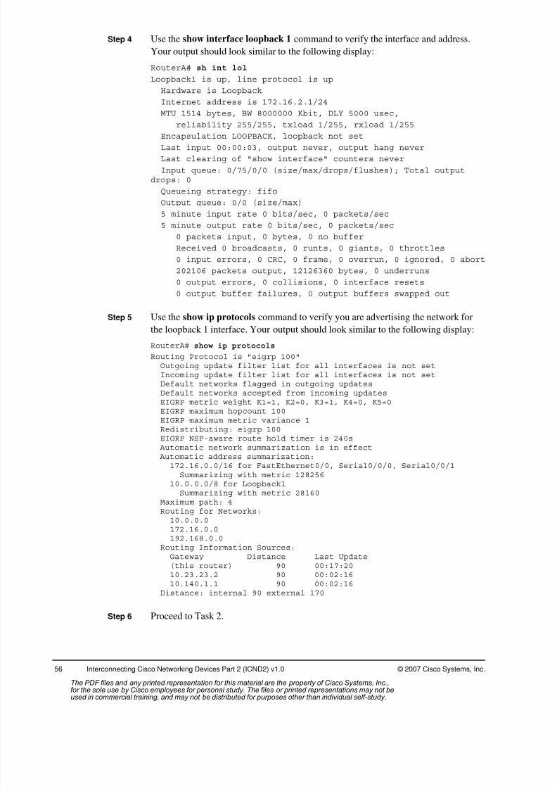
8/3/2019 Icnd210lg Cracked
http://slidepdf.com/reader/full/icnd210lg-cracked 58/120
56 Interconnecting Cisco Networking Devices Part 2 (ICND2) v1.0 © 2007 Cisco Systems, Inc.
Step 4 Use the show interface loopback 1 command to verify the interface and address.
Your output should look similar to the following display:
RouterA# sh int lo1
Loopback1 is up, line protocol is up
Hardware is Loopback
Internet address is 172.16.2.1/24
MTU 1514 bytes, BW 8000000 Kbit, DLY 5000 usec,
reliability 255/255, txload 1/255, rxload 1/255
Encapsulation LOOPBACK, loopback not setLast input 00:00:03, output never, output hang never
Last clearing of "show interface" counters never
Input queue: 0/75/0/0 (size/max/drops/flushes); Total outputdrops: 0
Queueing strategy: fifo
Output queue: 0/0 (size/max)
5 minute input rate 0 bits/sec, 0 packets/sec
5 minute output rate 0 bits/sec, 0 packets/sec
0 packets input, 0 bytes, 0 no buffer
Received 0 broadcasts, 0 runts, 0 giants, 0 throttles
0 input errors, 0 CRC, 0 frame, 0 overrun, 0 ignored, 0 abort
202106 packets output, 12126360 bytes, 0 underruns0 output errors, 0 collisions, 0 interface resets
0 output buffer failures, 0 output buffers swapped out
Step 5 Use the show ip protocols command to verify you are advertising the network for
the loopback 1 interface. Your output should look similar to the following display:
RouterA# show ip protocols
Routing Protocol is "eigrp 100"Outgoing update filter list for all interfaces is not setIncoming update filter list for all interfaces is not setDefault networks flagged in outgoing updatesDefault networks accepted from incoming updatesEIGRP metric weight K1=1, K2=0, K3=1, K4=0, K5=0
EIGRP maximum hopcount 100EIGRP maximum metric variance 1Redistributing: eigrp 100EIGRP NSF-aware route hold timer is 240s Automatic network summarization is in effect Automatic address summarization:
172.16.0.0/16 for FastEthernet0/0, Serial0/0/0, Serial0/0/1Summarizing with metric 128256
10.0.0.0/8 for Loopback1Summarizing with metric 28160
Maximum path: 4Routing for Networks:10.0.0.0172.16.0.0192.168.0.0
Routing Information Sources:Gateway Distance Last Update(this router) 90 00:17:2010.23.23.2 90 00:02:1610.140.1.1 90 00:02:16
Distance: internal 90 external 170
Step 6 Proceed to Task 2.
The PDF files and any printed representation for this material are the property of Cisco Systems, Inc.,for the sole use by Cisco employees for personal study. The files or printed representations may not beused in commercial training, and may not be distributed for purposes other than individual self-study.

8/3/2019 Icnd210lg Cracked
http://slidepdf.com/reader/full/icnd210lg-cracked 59/120
© 2007 Cisco Systems, Inc. Lab Guide
Activity Verification
You have completed this task when you attain these results:
Created interface loopback 1 and assigned it an address
Advertised the loopback 1 network via EIGRP
Task 2: Test ConnectivityIn this task, you will test connectivity from your LAN (interface loopback 1) to the core router
LAN (the core router loopback interface). If connectivity fails, you will troubleshoot to isolate
and correct the problem.
Activity Procedure
Complete these steps:
Step 1 In addition to increasing the number of packets sent in a ping, an extended ping also
gives you the ability to change the source address of a ping. On your workgroup
router, establish an extended ping, using your loopback 1 interface as the source and
the core router loopback (172.16.31.100) as the target. The output will be similar tothe following:
RouterA# ping
Protocol [ip]:
Target IP address: 172.16.31.100
Repeat count [5]:
Datagram size [100]:
Timeout in seconds [2]:
Extended commands [n]: y
Source address or interface: loopback 1
Type of service [0]:Set DF bit in IP header? [no]:
Validate reply data? [no]:
Data pattern [0xABCD]:
Loose, Strict, Record, Timestamp, Verbose[none]:
Sweep range of sizes [n]:
Type escape sequence to abort.
Sending 5, 100-byte ICMP Echos to 172.16.31.100, timeout is 2seconds:
Packet sent with a source address of 172.16.2.1
Note You can also change the source address of the router ping using the command
ping [destination_address] source [source_address|loopback ]
Was the ping successful?
The PDF files and any printed representation for this material are the property of Cisco Systems, Inc.,for the sole use by Cisco employees for personal study. The files or printed representations may not beused in commercial training, and may not be distributed for purposes other than individual self-study.
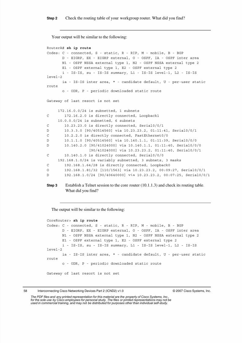
8/3/2019 Icnd210lg Cracked
http://slidepdf.com/reader/full/icnd210lg-cracked 60/120
58 Interconnecting Cisco Networking Devices Part 2 (ICND2) v1.0 © 2007 Cisco Systems, Inc.
Step 2 Check the routing table of your workgroup router. What did you find?
Your output will be similar to the following:
RouterA# sh ip route
Codes: C - connected, S - static, R - RIP, M - mobile, B - BGP
D - EIGRP, EX - EIGRP external, O - OSPF, IA - OSPF inter areaN1 - OSPF NSSA external type 1, N2 - OSPF NSSA external type 2
E1 - OSPF external type 1, E2 - OSPF external type 2
i - IS-IS, su - IS-IS summary, L1 - IS-IS level-1, L2 - IS-ISlevel-2
ia - IS-IS inter area, * - candidate default, U - per-user staticroute
o - ODR, P - periodic downloaded static route
Gateway of last resort is not set
172.16.0.0/24 is subnetted, 1 subnets
C 172.16.2.0 is directly connected, Loopback1
10.0.0.0/24 is subnetted, 6 subnets
C 10.23.23.0 is directly connected, Serial0/0/1
D 10.3.3.0 [90/40514560] via 10.23.23.2, 01:11:41, Serial0/0/1
C 10.2.2.0 is directly connected, FastEthernet0/0
D 10.1.1.0 [90/40514560] via 10.140.1.1, 01:11:39, Serial0/0/0
D 10.140.2.0 [90/41024000] via 10.140.1.1, 01:11:40, Serial0/0/0
[90/41024000] via 10.23.23.2, 01:11:40, Serial0/0/1
C 10.140.1.0 is directly connected, Serial0/0/0
192.168.1.0/24 is variably subnetted, 3 subnets, 3 masks
C 192.168.1.64/28 is directly connected, Loopback0
O 192.168.1.81/32 [110/1563] via 10.23.23.2, 00:09:27, Serial0/0/1
D 192.168.1.0/24 [90/40640000] via 10.23.23.2, 00:07:25, Serial0/0/1
Step 3 Establish a Telnet session to the core router (10.1.1.3) and check its routing table.
What did you find?
The output will be similar to the following:
CoreRouter> sh ip route
Codes: C - connected, S - static, R - RIP, M - mobile, B - BGP
D - EIGRP, EX - EIGRP external, O - OSPF, IA - OSPF inter area
N1 - OSPF NSSA external type 1, N2 - OSPF NSSA external type 2E1 - OSPF external type 1, E2 - OSPF external type 2
i - IS-IS, su - IS-IS summary, L1 - IS-IS level-1, L2 - IS-ISlevel-2
ia - IS-IS inter area, * - candidate default, U - per-user staticroute
o - ODR, P - periodic downloaded static route
Gateway of last resort is not set
The PDF files and any printed representation for this material are the property of Cisco Systems, Inc.,for the sole use by Cisco employees for personal study. The files or printed representations may not beused in commercial training, and may not be distributed for purposes other than individual self-study.
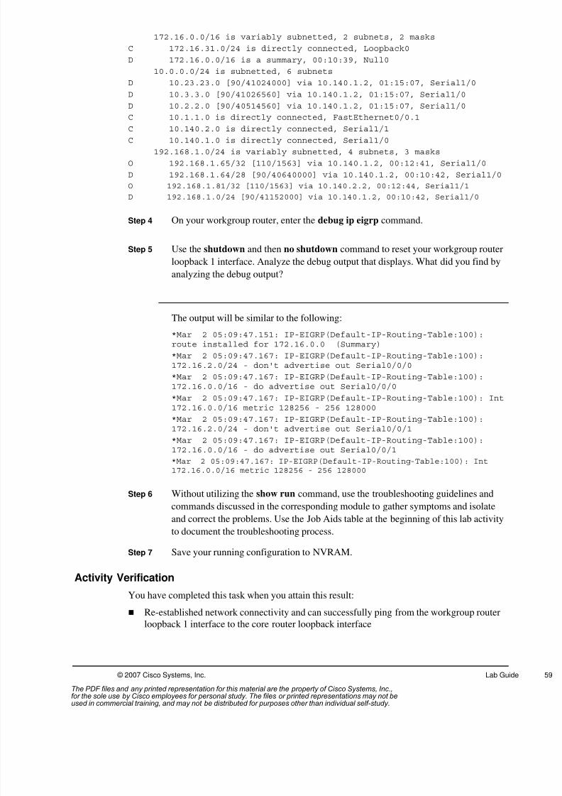
8/3/2019 Icnd210lg Cracked
http://slidepdf.com/reader/full/icnd210lg-cracked 61/120
© 2007 Cisco Systems, Inc. Lab Guide
172.16.0.0/16 is variably subnetted, 2 subnets, 2 masks
C 172.16.31.0/24 is directly connected, Loopback0
D 172.16.0.0/16 is a summary, 00:10:39, Null0
10.0.0.0/24 is subnetted, 6 subnets
D 10.23.23.0 [90/41024000] via 10.140.1.2, 01:15:07, Serial1/0
D 10.3.3.0 [90/41026560] via 10.140.1.2, 01:15:07, Serial1/0
D 10.2.2.0 [90/40514560] via 10.140.1.2, 01:15:07, Serial1/0
C 10.1.1.0 is directly connected, FastEthernet0/0.1
C 10.140.2.0 is directly connected, Serial1/1
C 10.140.1.0 is directly connected, Serial1/0192.168.1.0/24 is variably subnetted, 4 subnets, 3 masks
O 192.168.1.65/32 [110/1563] via 10.140.1.2, 00:12:41, Serial1/0
D 192.168.1.64/28 [90/40640000] via 10.140.1.2, 00:10:42, Serial1/0
O 192.168.1.81/32 [110/1563] via 10.140.2.2, 00:12:44, Serial1/1
D 192.168.1.0/24 [90/41152000] via 10.140.1.2, 00:10:42, Serial1/0
Step 4 On your workgroup router, enter the debug ip eigrp command.
Step 5 Use the shutdown and then no shutdown command to reset your workgroup router
loopback 1 interface. Analyze the debug output that displays. What did you find by
analyzing the debug output?
The output will be similar to the following:
*Mar 2 05:09:47.151: IP-EIGRP(Default-IP-Routing-Table:100):route installed for 172.16.0.0 (Summary)
*Mar 2 05:09:47.167: IP-EIGRP(Default-IP-Routing-Table:100):172.16.2.0/24 - don't advertise out Serial0/0/0
*Mar 2 05:09:47.167: IP-EIGRP(Default-IP-Routing-Table:100):172.16.0.0/16 - do advertise out Serial0/0/0
*Mar 2 05:09:47.167: IP-EIGRP(Default-IP-Routing-Table:100): Int
172.16.0.0/16 metric 128256 - 256 128000*Mar 2 05:09:47.167: IP-EIGRP(Default-IP-Routing-Table:100):172.16.2.0/24 - don't advertise out Serial0/0/1
*Mar 2 05:09:47.167: IP-EIGRP(Default-IP-Routing-Table:100):172.16.0.0/16 - do advertise out Serial0/0/1
*Mar 2 05:09:47.167: IP-EIGRP(Default-IP-Routing-Table:100): Int172.16.0.0/16 metric 128256 - 256 128000
Step 6 Without utilizing the show run command, use the troubleshooting guidelines and
commands discussed in the corresponding module to gather symptoms and isolate
and correct the problems. Use the Job Aids table at the beginning of this lab activity
to document the troubleshooting process.
Step 7 Save your running configuration to NVRAM.
Activity Verification
You have completed this task when you attain this result:
Re-established network connectivity and can successfully ping from the workgroup router
loopback 1 interface to the core router loopback interface
The PDF files and any printed representation for this material are the property of Cisco Systems, Inc.,for the sole use by Cisco employees for personal study. The files or printed representations may not beused in commercial training, and may not be distributed for purposes other than individual self-study.

8/3/2019 Icnd210lg Cracked
http://slidepdf.com/reader/full/icnd210lg-cracked 62/120
60 Interconnecting Cisco Networking Devices Part 2 (ICND2) v1.0 © 2007 Cisco Systems, Inc.
Lab 6-1: Implementing and TroubleshootingACLs
Complete the lab activity to practice what you learned in the related module.
Activity Objective
In this activity, you will configure IP ACLs. After completing this activity, you will be able to
meet these objectives:
Create an IP extended access list to block Telnet traffic, apply it to an interface, and verify
its operation
Create an IP extended ACL to block TFTP requests from a workgroup
Troubleshoot to isolate and resolve an ACL problem
Visual Objective
The figure illustrates what you will accomplish in this activity.
© 2007 Cisco Systems, Inc. All rights reserved. ICND2 v1.0—12
Visual Objective 6-1: Implementingand Troubleshooting ACLs
WG Router s0/0/0 Router fa0/0 Switch
A 10.140.1.2 10.2.2.3 10.2.2.11B 10.140.2.2 10.3.3.3 10.3.3.11C 10.140.3.2 10.4.4.3 10.4.4.11D 10.140.4.2 10.5.5.3 10.5.5.11E 10.140.5.2 10.6.6.3 10.6.6.11F 10.140.6.2 10.7.7.3 10.7.7.11G 10.140.7.2 10.8.8.3 10.8.8.11H 10.140.8.2 10.9.9.3 10.9.9.11
SwitchH
The PDF files and any printed representation for this material are the property of Cisco Systems, Inc.,for the sole use by Cisco employees for personal study. The files or printed representations may not beused in commercial training, and may not be distributed for purposes other than individual self-study.

8/3/2019 Icnd210lg Cracked
http://slidepdf.com/reader/full/icnd210lg-cracked 63/120
© 2007 Cisco Systems, Inc. Lab Guide
Required Resources
These are the resources and equipment required to complete this activity:
PC connected to an onsite lab or PC with an Internet connection to access the remote lab
Terminal server connected to a console port of each lab device if using a remote lab
ICND workgroup assigned by your instructor
Command List
The table describes the commands used in this activity. The commands are listed in
alphabetical order so that you can easily locate the information you need. Refer to this list if
you need configuration command assistance during the lab activity.
Commands
Command Description
access-list access-list-number {permit |deny} {test conditions}
Creates an extended IP ACL
copy tftp://10.1.1.1/filename running-config
Copies the configuration from a TFTP server into RAM on a CiscoCatalyst switch
ip access-group access-list-number {in | out}
Enables an IP ACL on an interface
ping ip-address Common tool used to troubleshoot the accessibility of devices
show ip access-list Displays the contents of all IP ACLs
show ip interfaceinterface-type interface-number
Displays IP-specific information of an interface, including the ACLsapplied on an interface
telnet ip-address Starts a terminal emulation program from a PC, router, or switchthat permits you to access network devices remotely over thenetwork
The PDF files and any printed representation for this material are the property of Cisco Systems, Inc.,for the sole use by Cisco employees for personal study. The files or printed representations may not beused in commercial training, and may not be distributed for purposes other than individual self-study.
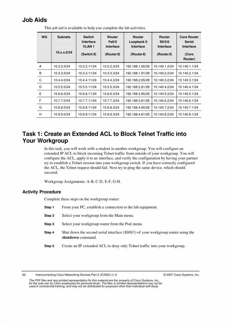
8/3/2019 Icnd210lg Cracked
http://slidepdf.com/reader/full/icnd210lg-cracked 64/120
62 Interconnecting Cisco Networking Devices Part 2 (ICND2) v1.0 © 2007 Cisco Systems, Inc.
Job Aids
This job aid is available to help you complete the lab activities.
WG Subnets
10.x.x.0/24
Switch
Interface
VLAN 1
(SwitchX )
Router
Fa0/0
Interface
(RouterX )
Router
Loopback 0
Interface
(RouterX )
Router
S0/0/0
Interface
(RouterX )
Core Router
Serial
Interface
(CoreRouter)
A 10.2.2.0/24 10.2.2.11/24 10.2.2.3/24 192.168.1.65/28 10.140.1.2/24 10.140.1.1/24
B 10.3.3.0/24 10.3.3.11/24 10.3.3.3/24 192.168.1.81/28 10.140.2.2/24 10.140.2.1/24
C 10.4.4.0/24 10.4.4.11/24 10.4.4.3/24 192.168.2.65/28 10.140.3.2/24 10.140.3.1/24
D 10.5.5.0/24 10.5.5.11/24 10.5.5.3/24 192.168.2.81/28 10.140.4.2/24 10.140.4.1/24
E 10.6.6.0/24 10.6.6.11/24 10.6.6.3/24 192.168.3.65/28 10.140.5.2/24 10.140.5.1/24
F 10.7.7.0/24 10.7.7.11/24 10.7.7.3/24 192.168.3.81/28 10.140.6.2/24 10.140.6.1/24
G 10.8.8.0/24 10.8.8.11/24 10.8.8.3/24 192.168.4.65/28 10.140.7.2/24 10.140.7.1/24
H 10.9.9.0/24 10.9.9.11/24 10.9.9.3/24 192.168.4.81/28 10.140.8.2/24 10.140.8.1/24
Task 1: Create an Extended ACL to Block Telnet Traffic intoYour Workgroup
In this task, you will work with a student in another workgroup. You will configure an
extended IP ACL to block incoming Telnet traffic from outside of your workgroup. You will
configure the ACL, apply it to an interface, and verify the configuration by having your partner
try to establish a Telnet session into your workgroup switch. If you have correctly configured
the ACL, the Telnet request should fail. Next try to ping the same device, which shouldsucceed.
Workgroup Assignments: A-B, C-D, E-F, G-H.
Activity Procedure
Complete these steps on the workgroup router:
Step 1 From your PC, establish a connection to the lab equipment.
Step 2 Select your workgroup from the Main menu.
Step 3 Select your workgroup router from the Pod menu.
Step 4 Shut down the second serial interface (S0/0/1) of your workgroup router using the
shutdown command.
Step 5 Create an IP extended ACL to deny only Telnet traffic into your workgroup.
The PDF files and any printed representation for this material are the property of Cisco Systems, Inc.,for the sole use by Cisco employees for personal study. The files or printed representations may not beused in commercial training, and may not be distributed for purposes other than individual self-study.

8/3/2019 Icnd210lg Cracked
http://slidepdf.com/reader/full/icnd210lg-cracked 65/120
© 2007 Cisco Systems, Inc. Lab Guide
Step 6 Apply the IP extended ACL to your first serial interface.
Should the extended ACL be applied as an inbound or outbound ACL?
Step 7 Enter the show ip access-list command to display the content of your IP extended
ACL.
Step 8 Enter the show ip interface serial interface command to verify that the ACL is
applied to the first serial interface.
Step 9 Ask your partner to establish a Telnet session into your workgroup switch,
(10.x.x.11), from their workgroup router.
Note All attempts to use Telnet into your workgroup switch should fail.
Step 10 Ask your partner to ping your workgroup switch (10.x.x.11) from their workgroup
router.
Note All traffic into your workgroup devices except Telnet traffic should be successful.
Step 11 Proceed to Task 2.
Activity Verification
You have completed this task when you attain this result:
Created an IP extended ACL that blocks incoming Telnet traffic, but allows all other traffic
from outside of your workgroup
Task 2: Edit an Extended ACL to Block TFTP Requests fromYour Workgroup
In this task, you are asked to download a new supplemental configuration to your workgroup
router from the TFTP server. The supplement configuration implements an ACL that restricts
all further TFTP requests from your workgroup subnet.
However, the supplemental configuration that you download contains configuration errors that
will cause a loss of connectivity with the rest of the network. You will troubleshoot the
configuration to isolate and correct the problem by editing the extended IP ACL.
Activity ProcedureStep 1 Ensure connectivity with the TFTP server. Ping the TFTP server (10.1.1.1) from
your workgroup switch.
Step 2 Ping the TFTP server (10.1.1.1) from your workgroup router.
Note If either of these pings is unsuccessful, contact your instructor.
The PDF files and any printed representation for this material are the property of Cisco Systems, Inc.,for the sole use by Cisco employees for personal study. The files or printed representations may not beused in commercial training, and may not be distributed for purposes other than individual self-study.

8/3/2019 Icnd210lg Cracked
http://slidepdf.com/reader/full/icnd210lg-cracked 66/120
64 Interconnecting Cisco Networking Devices Part 2 (ICND2) v1.0 © 2007 Cisco Systems, Inc.
Step 3 Download the supplemental configuration from the TFTP server into the running
configuration of your workgroup router. The name of the file to download is i2-
wg_ro-config-lab6-1.txt.
Step 4 Type exit from the privilege EXEC prompt and ensure your router banner reads:
************** wg_ro-config-lab6-1 ***********************
Note If the download was unsuccessful, contact your instructor.
Enter the show ip access-list command in order to display the contents of the IP
extended ACL you just downloaded, access-list 175. Your output should look
similar to the following display:
RouterA# sh ip access-lists
Extended IP access list 101
10 deny tcp 10.140.2.0 0.0.0.255 any eq telnet (12 matches)
20 permit ip any any (353 matches)
Extended IP access list 175
10 deny udp any any eq tftp
20 permit udp any any
Step 5 Enter the show ip interface serial interface command to verify that the ACL you
just downloaded, access-list 175, is applied to the interface. Your output should look
similar to the following display:
RouterA# sh ip int s0/0/0
Serial0/0/0 is up, line protocol is up
Internet address is 10.140.1.2/24
Broadcast address is 255.255.255.255
Address determined by non-volatile memory
MTU is 1500 bytes
Helper address is not set
Directed broadcast forwarding is disabled
Multicast reserved groups joined: 224.0.0.10 224.0.0.5
Outgoing access list is 175
Inbound access list is 101
Proxy ARP is enabled
Local Proxy ARP is disabled
Security level is default
Split horizon is enabled
ICMP redirects are always sent
ICMP unreachables are always sent
ICMP mask replies are never sent
IP fast switching is enabled
IP fast switching on the same interface is enabled
IP Flow switching is disabled
IP CEF switching is enabled
IP CEF Feature Fast switching turbo vector
IP multicast fast switching is enabled
IP multicast distributed fast switching is disabled
IP route-cache flags are Fast, CEF
-----Output omitted--------
The PDF files and any printed representation for this material are the property of Cisco Systems, Inc.,for the sole use by Cisco employees for personal study. The files or printed representations may not beused in commercial training, and may not be distributed for purposes other than individual self-study.

8/3/2019 Icnd210lg Cracked
http://slidepdf.com/reader/full/icnd210lg-cracked 67/120
© 2007 Cisco Systems, Inc. Lab Guide
Step 6 Can you ping the TFTP server from your workgroup switch now?
Step 7 On your workgroup router, enter the show ip route command to verify a route to the
TFTP server subnet, (10.1.1.0).
What did you find?
Step 8 Edit access-list 175 so that it only denies TFTP requests from your workgroup but
allows all other traffic.
Step 9 Once you have edited the ACL, test its effectiveness. From your workgroup switch,
try to use TFTP to copy the configuration file i2-wg_sw-config-lab6-1.txt from the
TFTP server (10.1.1.1) to your switch startup configuration.
Note All TFTP requests from your workgroup switch should fail with the IP extended ACL in place.
You may have to wait for the TFTP to fail. The switch will retry the TFTP multiple times
before displaying an error message.
Step 10 From your workgroup switch, ping the TFTP server and the loopback interface of
the core router, 172.16.31.100.
Note All traffic other than TFTP should be successful.
Step 11 Proceed to Task 3.
Activity Verification
You have completed this task when you attain these results:
Copied your workgroup router configuration from the TFTP server and verified the loss of
connectivity from your workgroup switch to the TFTP server
Edited an extended IP ACL on your workgroup router that restricts TFTP requests from
your workgroup, but allows all other traffic
Task 3: Remove the ACLs from the Serial Interface
In this task, you will clean up after the lab so that the configuration changes you made here do
not negatively affect the next lab. It is important to complete this task.
Activity Procedure
Complete these steps on the workgroup router:
Step 1 Enter interface configuration mode for your serial interface.
Step 2 Remove all access groups from the serial interface.
Step 3 Enter global configuration mode.
The PDF files and any printed representation for this material are the property of Cisco Systems, Inc.,for the sole use by Cisco employees for personal study. The files or printed representations may not beused in commercial training, and may not be distributed for purposes other than individual self-study.

8/3/2019 Icnd210lg Cracked
http://slidepdf.com/reader/full/icnd210lg-cracked 68/120
66 Interconnecting Cisco Networking Devices Part 2 (ICND2) v1.0 © 2007 Cisco Systems, Inc.
Step 4 Remove both ACLs.
Step 5 Save your running configuration to NVRAM.
Step 6 Notify your instructor that you have completed the activity.
Activity Verification
You have completed this activity when you attain these results:
Removed all access groups from the serial interface
Removed both ACLs in global configuration mode
The PDF files and any printed representation for this material are the property of Cisco Systems, Inc.,for the sole use by Cisco employees for personal study. The files or printed representations may not beused in commercial training, and may not be distributed for purposes other than individual self-study.

8/3/2019 Icnd210lg Cracked
http://slidepdf.com/reader/full/icnd210lg-cracked 69/120
© 2007 Cisco Systems, Inc. Lab Guide
Lab 7-1: Configuring NAT and PATComplete this lab activity to practice what you learned in the related module.
Activity Objective
In this activity, you will configure your workgroup router for PAT. After completing this
activity, you will be able to meet these objectives: Configure inside and outside NAT interfaces and an IP ACL to permit hosts to use PAT
Use show commands to verify the NAT configuration
Visual Objective
The figure illustrates what you will accomplish in this activity.
© 2007 Cisco Systems, Inc. All rights reserved. ICND2 v1.0—13
Visual Objective 7-1:Configuring NAT and PAT
WG Router s0/0/0 Router fa0/0 Switch
A 10.140.1.2 10.2.2.3 10.2.2.11B 10.140.2.2 10.3.3.3 10.3.3.11C 10.140.3.2 10.4.4.3 10.4.4.11D 10.140.4.2 10.5.5.3 10.5.5.11E 10.140.5.2 10.6.6.3 10.6.6.11F 10.140.6.2 10.7.7.3 10.7.7.11G 10.140.7.2 10.8.8.3 10.8.8.11H 10.140.8.2 10.9.9.3 10.9.9.11
Required Resources
These are the resources and equipment required to complete this activity:
PC connected to an onsite lab or PC with an Internet connection to access the remote lab
Terminal server connected to a console port of each lab device if using a remote lab
ICND workgroup assigned by your instructor
The PDF files and any printed representation for this material are the property of Cisco Systems, Inc.,for the sole use by Cisco employees for personal study. The files or printed representations may not beused in commercial training, and may not be distributed for purposes other than individual self-study.

8/3/2019 Icnd210lg Cracked
http://slidepdf.com/reader/full/icnd210lg-cracked 70/120
68 Interconnecting Cisco Networking Devices Part 2 (ICND2) v1.0 © 2007 Cisco Systems, Inc.
Command List
The table describes the commands used in this activity. The commands are listed in
alphabetical order so that you can easily locate the information you need. Refer to this list if
you need configuration command assistance during the lab activity.
Commands
Command Description
debug ip nat Debugs the NAT translation process
ip nat inside Marks the interface as connected to the inside network
ip nat inside sourcelist access-list-number interface interface overload
Establishes dynamic source translation, specifying the access list
ip nat outside Marks the interface as connected to the outside network
show ip nat statistics Displays translation statistics
show ip nattranslations
Displays active translations
Job Aids
This job aid is available to help you complete the lab activities.
WG Workgroup
FastEthernet
Subnets
10.x.x.0/24
Switch
Interface
VLAN 1
(SwitchX )
Router
Fa0/0
Interface
(RouterX )
Router
Loopback 0
Interface
(RouterX )
Router
S0/0/0
Interface
(RouterX )
Core Router
Serial
Interface
(Core
Router)
A 10.2.2.0/24 10.2.2.11/24 10.2.2.3/24 192.168.1.65/28 10.140.1.2/24 10.140.1.1/24
B 10.3.3.0/24 10.3.3.11/24 10.3.3.3/24 192.168.1.81/28 10.140.2.2/24 10.140.2.1/24
C 10.4.4.0/24 10.4.4.11/24 10.4.4.3/24 192.168.2.65/28 10.140.3.2/24 10.140.3.1/24
D 10.5.5.0/24 10.5.5.11/24 10.5.5.3/24 192.168.2.81/28 10.140.4.2/24 10.140.4.1/24
E 10.6.6.0/24 10.6.6.11/24 10.6.6.3/24 192.168.3.65/28 10.140.5.2/24 10.140.5.1/24
F 10.7.7.0/24 10.7.7.11/24 10.7.7.3/24 192.168.3.81/28 10.140.6.2/24 10.140.6.1/24
G 10.8.8.0/24 10.8.8.11/24 10.8.8.3/24 192.168.4.65/28 10.140.7.2/24 10.140.7.1/24
H 10.9.9.0/24 10.9.9.11/24 10.9.9.3/24 192.168.4.81/28 10.140.8.2/24 10.140.8.1/24
The PDF files and any printed representation for this material are the property of Cisco Systems, Inc.,for the sole use by Cisco employees for personal study. The files or printed representations may not beused in commercial training, and may not be distributed for purposes other than individual self-study.
8/3/2019 Icnd210lg Cracked
http://slidepdf.com/reader/full/icnd210lg-cracked 71/120
© 2007 Cisco Systems, Inc. Lab Guide
Task 1: Configure PAT
In this task, you will configure your router to provide a single address to the outside world for
any workgroup address that needs to access the public network. First you will verify that you
have connectivity from your workgroup router to the core router. Then you will configure both
inside and outside NAT interfaces. Finally, you will configure an IP ACL to permit certain
hosts to use PAT.
Activity Procedure
Complete these steps to configure port address translation:
Step 1 From your PC, establish a connection to the lab equipment.
Step 2 Select your workgroup from the Main menu.
Step 3 Select your workgroup from the Pod menu.
Step 4 From your workgroup switch, verify that you can ping the core router (10.1.1.3).
Note If the ping is not successful, contact your instructor.
Step 5 To begin your NAT configuration, configure the first Ethernet interface on your
workgroup router as the inside interface.
Step 6 To continue the NAT configuration, configure the first serial interface of your
workgroup router as the outside interface.
Step 7 Configure a standard IP ACL to permit any host on your workgroup FastEthernet
subnet, 10. x.x.0/24, to be translated by the PAT process. Check the subnet
addressing listed in the Job Aids table for this lab activity.
Step 8 Configure PAT using the first serial interface IP address as the inside global IPaddress.
Step 9 Enable NAT debugging.
Step 10 Proceed to Task 2.
Activity Verification
You have completed this task when you attain these results:
Verified that you have connectivity from your workgroup router to the core router
Configured both inside and outside NAT interfaces
Configured an IP ACL to permit certain hosts to use PAT
The PDF files and any printed representation for this material are the property of Cisco Systems, Inc.,for the sole use by Cisco employees for personal study. The files or printed representations may not beused in commercial training, and may not be distributed for purposes other than individual self-study.

8/3/2019 Icnd210lg Cracked
http://slidepdf.com/reader/full/icnd210lg-cracked 72/120
70 Interconnecting Cisco Networking Devices Part 2 (ICND2) v1.0 © 2007 Cisco Systems, Inc.
Task 2: Verify PAT Using show and debug Commands
In this task, you will verify that PAT is configured correctly.
Activity Procedure
Complete these steps to verify port address translation:
Step 1 From your workgroup switch, verify that you can ping the core router (10.1.1.3) to
trigger the PAT process on your workgroup router.
Step 2 You should see output from the NAT debug command.
Step 3 From your workgroup router, enter the show ip nat translations command. Your
output should look similar to the following display:
RouterA# show ip nat translations Pro Inside global Inside local Outside local Outside global
icmp 10.140.1.2:13 10.2.2.11:13 10.1.1.3:13 10.1.1.3:13
Step 4 Enter the show ip nat statistics command. Your output should look similar to the
following display:RouterA# show ip nat statistics Total active translations: 1 (0 static, 1 dynamic; 1 extended)
Outside interfaces:
Serial0/0/0
Inside interfaces:
FastEthernet0/0
Hits: 9 Misses: 1
CEF Translated packets: 10, CEF Punted packets: 0
Expired translations: 0
Dynamic mappings:
-- Inside Source
[Id: 2] access-list 1 interface Serial0/0/0 refcount 1
Queued Packets: 0
Step 5 Disable all of the PAT configurations on your workgroup router.
Step 6 Ping the core router (10.1.1.3) from your workgroup switch to verify that your
configuration is working.
Step 7 Save your running configuration to NVRAM.
Step 8 Notify your instructor that you have completed the activity.
Activity Verification
You have completed this activity when you attain these results:
Verified that PAT is configured correctly by pinging the core router (10.1.1.3)
Disabled all PAT configurations on your workgroup router
The PDF files and any printed representation for this material are the property of Cisco Systems, Inc.,for the sole use by Cisco employees for personal study. The files or printed representations may not beused in commercial training, and may not be distributed for purposes other than individual self-study.
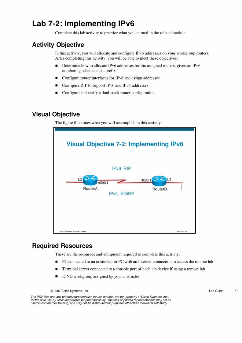
8/3/2019 Icnd210lg Cracked
http://slidepdf.com/reader/full/icnd210lg-cracked 73/120
© 2007 Cisco Systems, Inc. Lab Guide
Lab 7-2: Implementing IPv6Complete this lab activity to practice what you learned in the related module.
Activity Objective
In this activity, you will allocate and configure IPv6 addresses on your workgroup routers.
After completing this activity, you will be able to meet these objectives: Determine how to allocate IPv6 addresses for the assigned routers, given an IPv6
numbering scheme and a prefix
Configure router interfaces for IPv6 and assign addresses
Configure RIP to support IPv6 and IPv6 addresses
Configure and verify a dual-stack router configuration
Visual Objective
The figure illustrates what you will accomplish in this activity.
© 2007 Cisco Systems, Inc. All rights reserved. ICND2 v1.0—14
Visual Objective 7-2: Implementing IPv6
Required Resources
These are the resources and equipment required to complete this activity:
PC connected to an onsite lab or PC with an Internet connection to access the remote lab
Terminal server connected to a console port of each lab device if using a remote lab
ICND workgroup assigned by your instructor
The PDF files and any printed representation for this material are the property of Cisco Systems, Inc.,for the sole use by Cisco employees for personal study. The files or printed representations may not beused in commercial training, and may not be distributed for purposes other than individual self-study.

8/3/2019 Icnd210lg Cracked
http://slidepdf.com/reader/full/icnd210lg-cracked 74/120
72 Interconnecting Cisco Networking Devices Part 2 (ICND2) v1.0 © 2007 Cisco Systems, Inc.
Command List
The table describes the commands used in this activity. The commands are listed in
alphabetical order so that you can easily locate the information you need. Refer to this list if
you need configuration command assistance during the lab activity.
Commands
Command Description
ipv6 address ipv6 address/prefix length eui-64
Enables an IPv6 address on an interface and forcesthe router to complete the low-order 64-bit of theaddress by using the interface link-layer address(MAC address)
ipv6 address ipv6-address/prefix-length
Statically assigns an IPv6 address and a prefix lengthto the tunnel interface
ipv6 rip name enable Enables the specified IPv6 RIP routing process on aninterface.
ipv6 router rip name Configures an IPv6 RIP routing process and entersrouter configuration mode for the IPv6 RIP routingprocess
ipv6 unicast-routing Enables IPv6 traffic forwarding
show ipv6 interface Displays IPv6 information about an interface
show ipv6 rip Displays information about the current IPv6 RIPprocesses
show ipv6 route Displays the IPv6 routing table
Job Aids
This job aid is available to help you complete the lab activities.
Workgroup Group# Router# IPv4 Loopback 2
Interface
Address (Router
X)
A 1 1 10.123.123.1/24
B 1 2 10.132.132.1/24
C 2 3 10.145.145.1/24
D 2 4 10.154.154.1/24
E 3 5 10.167.167.1/24
F 3 6 10.176.176.1/24
G 4 7 10.189.189.1/24
H 4 8 10.198.198.1/24
Task 1: IPv6 Preparation
Task 1 is an address-planning exercise. Configuration will begin in Task 2. You will be
working with a student in another workgroup.
Group Assignments: A-B, C-D, E-F, G-H.
The PDF files and any printed representation for this material are the property of Cisco Systems, Inc.,for the sole use by Cisco employees for personal study. The files or printed representations may not beused in commercial training, and may not be distributed for purposes other than individual self-study.

8/3/2019 Icnd210lg Cracked
http://slidepdf.com/reader/full/icnd210lg-cracked 75/120
© 2007 Cisco Systems, Inc. Lab Guide
Activity Procedure
Complete these steps:
Step 1 Use the information below to complete the following worksheet for each router in
your group:
Group
#
(X)
Router
#
(Y)
Interface S0/0/1 IPv6 Address Interface Loopback 2 IPv6
Address
Your router:
Your partnerrouter:
In this lab activity, the second serial interface (S0/0/1) will use the following IPv6
address format:
2001:0410:000 x:10::/64 eui-64
In which x = your group number listed in the Job Aids table for this activity
For example, the IPv6 address of the second serial interface (S0/0/1) of router A
would be 2001:0410:0001:10::/64 eui-64.
Note The :10 is the subnet portion of your IPv6 address. For this lab, it is important that the S0/0/1
interfaces that are in the same group have the same subnet address.
The eui-64 parameter forces the router to complete the low-order 64-bits of the address (the
host portion) by using the interface link-layer address (MAC address).
You will be creating a loopback 2 interface on your workgroup router in Task 2. Theloopback 2 interface for each workgroup router will use the following IPv6 address
format:
2001:0410:000 x: y::/64 eui-64
In which x = your group number listed in the Job Aids table for this activity and y =
your router number listed in the Job Aids table for this activity.
For example, the IPv6 address of the loopback 2 interface of router A would be
2001:0410:0001:1::/64 eui-64.
Note The subnet portion of the IPv6 address is :y . It is important for this lab that the loopback 2
interface of each router is in a different subnet.
The PDF files and any printed representation for this material are the property of Cisco Systems, Inc.,for the sole use by Cisco employees for personal study. The files or printed representations may not beused in commercial training, and may not be distributed for purposes other than individual self-study.

8/3/2019 Icnd210lg Cracked
http://slidepdf.com/reader/full/icnd210lg-cracked 76/120
74 Interconnecting Cisco Networking Devices Part 2 (ICND2) v1.0 © 2007 Cisco Systems, Inc.
Activity Verification
You have completed this activity when you attain this result:
Determined which IPv6 addresses will be assigned to all interfaces
Task 2: Configure IPv6 Addresses
You will enable IPv6 globally on your router and configure IPv6 addresses on interfaces S0/0/1
and Lo2.
Activity Procedure
Complete these steps:
Step 1 Shutdown the first serial interface (S0/0/0) of your workgroup router that connects
to the core using the shutdown command.
Step 2 Enable the second serial interface (S0/0/1) of your workgroup router using the no
shutdown command.
Step 3 Enable IPv6 on your workgroup router.
Step 4 Assign the second serial interface (S0/0/1) the IPv6 address determined in Task 1.
Step 5 Create a loopback 2 interface and assign it the IPv6 address determined in Task 1.
Step 6 Display the IPv6 interface information to verify that all of the interfaces on your
workgroup router are configured with the appropriate IPv6 address.
Your output should resemble the following:
RouterA# show ipv6 int
Serial0/0/1 is down, line protocol is down
IPv6 is enabled, link-local address is FE80::21A:6CFF:FE59:D60
[TEN]Global unicast address(es):
2001:410:1:10:21A:6CFF:FE59:D60, subnet is 2001:410:1:10::/64[EUI/TEN]
Joined group address(es):
FF02::1
FF02::2
FF02::1:FF59:D60
MTU is 1500 bytes
ICMP error messages limited to one every 100 milliseconds
ICMP redirects are enabled
ND DAD is enabled, number of DAD attempts: 1
ND reachable time is 30000 millisecondsHosts use stateless autoconfig for addresses.
Loopback2 is up, line protocol is up
IPv6 is enabled, link-local address is FE80::21A:6CFF:FE59:D60
Global unicast address(es):
2001:410:1:1:21A:6CFF:FE59:D60, subnet is 2001:410:1:1::/64[EUI]
Joined group address(es):
FF02::1
The PDF files and any printed representation for this material are the property of Cisco Systems, Inc.,for the sole use by Cisco employees for personal study. The files or printed representations may not beused in commercial training, and may not be distributed for purposes other than individual self-study.

8/3/2019 Icnd210lg Cracked
http://slidepdf.com/reader/full/icnd210lg-cracked 77/120
© 2007 Cisco Systems, Inc. Lab Guide
FF02::2
FF02::1:FF59:D60
MTU is 1514 bytes
ICMP error messages limited to one every 100 milliseconds
ICMP redirects are enabled
ND DAD is not supported
ND reachable time is 30000 milliseconds
Hosts use stateless autoconfig for addresses.
Note The status of your S0/0/1 IPv6 interface depends upon whether your partner has completed
Task 2.
On each of the IPv6 interfaces, do you see an IPv6 address that you have not configured? If so,
what is that address?
Activity Verification
You have completed this activity when you attain these results:
Enabled IPv6 globally and configured IPv6 addresses on S0/0/1 and Lo2 interfaces
Shut down the first serial interface and enabled the second serial interface of your
workgroup router
Task 3: Enable RIP for IPv6
In this task, you will enable RIP for IPv6 on your workgroup router.
Activity Procedure
Step 1 On your workgroup router, globally enable IPv6 RIP. Use the process name cisco.
Step 2 Enable the IPv6 RIP process on your second serial interface (S0/0/1) and loopback 2
interface.
Step 3 Display the IPv6 RIP information to confirm that you have enabled IPv6 RIP on
your routers.
The output from your routers should resemble the following:
RouterA# show ipv6 rip
RIP process "cisco", port 521, multicast-group FF02::9, pid 230
Administrative distance is 120. Maximum paths is 16
Updates every 30 seconds, expire after 180
Holddown lasts 0 seconds, garbage collect after 120
Split horizon is on; poison reverse is off
Default routes are not generated
Periodic updates 6, trigger updates 1
Interfaces:
The PDF files and any printed representation for this material are the property of Cisco Systems, Inc.,for the sole use by Cisco employees for personal study. The files or printed representations may not beused in commercial training, and may not be distributed for purposes other than individual self-study.

8/3/2019 Icnd210lg Cracked
http://slidepdf.com/reader/full/icnd210lg-cracked 78/120
76 Interconnecting Cisco Networking Devices Part 2 (ICND2) v1.0 © 2007 Cisco Systems, Inc.
Loopback2
Serial0/0/1
Redistribution:
None
Step 4 View the IPv6 routing table on your router. Your display should resemble the
following:
RouterA# show ipv6 route
IPv6 Routing Table - 7 entries
Codes: C - Connected, L - Local, S - Static, R - RIP, B - BGP
U - Per-user Static route
I1 - ISIS L1, I2 - ISIS L2, IA - ISIS interarea, IS - ISISsummary
O - OSPF intra, OI - OSPF inter, OE1 - OSPF ext 1, OE2 -OSPF ext 2
ON1 - OSPF NSSA ext 1, ON2 - OSPF NSSA ext 2
C 2001:410:1:1::/64 [0/0]
via ::, Loopback2
L 2001:410:1:1:21A:6CFF:FE59:D60/128 [0/0]
via ::, Loopback2
R 2001:410:1:2::/64 [120/2]
via FE80::217:5AFF:FE2E:F570, Serial0/0/1
C 2001:410:1:10::/64 [0/0]
via ::, Serial0/0/1
L 2001:410:1:10:21A:6CFF:FE59:D60/128 [0/0]
via ::, Serial0/0/1
L FE80::/10 [0/0]
via ::, Null0
L FF00::/8 [0/0]
via ::, Null0
Note Your IPv6 routing table should display a route to the loopback 2 interface network of your
partner.
Activity Verification
You have completed this activity when you attain this result:
You have learned the IPv6 network of the loopback 2 interface of your partner router.
The PDF files and any printed representation for this material are the property of Cisco Systems, Inc.,for the sole use by Cisco employees for personal study. The files or printed representations may not beused in commercial training, and may not be distributed for purposes other than individual self-study.

8/3/2019 Icnd210lg Cracked
http://slidepdf.com/reader/full/icnd210lg-cracked 79/120
© 2007 Cisco Systems, Inc. Lab Guide
Task 4: Configuring and Verifying a Dual-Stack Router
In this task, you will enable IPv4 connectivity between networks currently configured for IPv6
on your workgroup router.
Activity Procedure
Step 1 On your workgroup router, configure the loopback 2 interface with the IPv4 address
indicated in the Job Aids table of this lab activity.Step 2 Use the show ip route command to verify EIGRP has learned the network of the
loopback 2 interface of your partner.
Note The EIGRP network statement you configured in a previous lab (network 10.0.0.0) should
advertise the IPv4 network assigned to the loopback 2 interface.
Step 3 Ping all of the IPv4 addresses of your partner workgroup router, including the
loopback 2 interface.
Step 4 Ping all of the IPv6 addresses of your partner workgroup router, including the
loopback 2 interface.
Note To make it easier to ping the IPv6 addresses for the remainder of this activity, obtain the
IPv6 addresses of all of the routers in your workgroup and copy them into a Notepad
document. You can use the show cdp neighbor detail command to display the IPv6
address of the directly connected interface of your partner router. You can also establish a
Telnet session into the router of your partner and use the show ipv6 interface brief
command to display the IPv6 addresses of the rest of the interfaces of your partner router.
When you have documented the IPv6 addresses, simply copy the address from the Notepad
file and paste it into the ping command when you wish to ping the IPv6 interface of one of
your neighboring routers.
Step 5 Your output should resemble the following:
RouterA# ping 2001:410:1:2:216:9DFF:FEB0:EA48
Type escape sequence to abort.
Sending 5, 100-byte ICMP Echos to2001:410:1:2:216:9DFF:FEB0:EA48, timeout is 2
seconds:
!!!!!
Success rate is 100 percent (5/5), round-trip min/avg/max = 28/28/32 ms
Activity Verification
You have completed this activity when you attain this result:
You have IPv4 and IPv6 connectivity between routers in your group.
The PDF files and any printed representation for this material are the property of Cisco Systems, Inc.,for the sole use by Cisco employees for personal study. The files or printed representations may not beused in commercial training, and may not be distributed for purposes other than individual self-study.
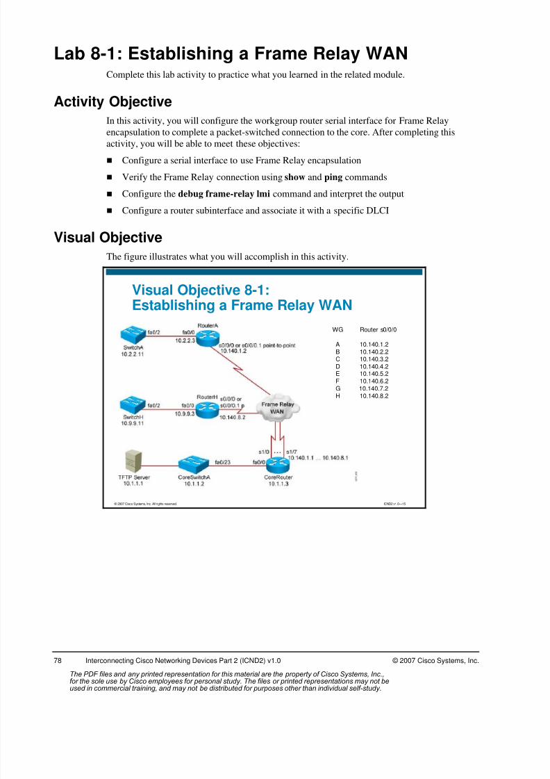
8/3/2019 Icnd210lg Cracked
http://slidepdf.com/reader/full/icnd210lg-cracked 80/120
78 Interconnecting Cisco Networking Devices Part 2 (ICND2) v1.0 © 2007 Cisco Systems, Inc.
Lab 8-1: Establishing a Frame Relay WANComplete this lab activity to practice what you learned in the related module.
Activity Objective
In this activity, you will configure the workgroup router serial interface for Frame Relay
encapsulation to complete a packet-switched connection to the core. After completing thisactivity, you will be able to meet these objectives:
Configure a serial interface to use Frame Relay encapsulation
Verify the Frame Relay connection using show and ping commands
Configure the debug frame-relay lmi command and interpret the output
Configure a router subinterface and associate it with a specific DLCI
Visual Objective
The figure illustrates what you will accomplish in this activity.
© 2007 Cisco Systems, Inc. All rights reserved. ICND2 v1.0—15
Visual Objective 8-1:Establishing a Frame Relay WAN
WG Router s0/0/0
A 10.140.1.2B 10.140.2.2C 10.140.3.2D 10.140.4.2E 10.140.5.2F 10.140.6.2G 10.140.7.2H 10.140.8.2
The PDF files and any printed representation for this material are the property of Cisco Systems, Inc.,for the sole use by Cisco employees for personal study. The files or printed representations may not beused in commercial training, and may not be distributed for purposes other than individual self-study.
8/3/2019 Icnd210lg Cracked
http://slidepdf.com/reader/full/icnd210lg-cracked 81/120
© 2007 Cisco Systems, Inc. Lab Guide
Required Resources
These are the resources and equipment required to complete this activity:
PC connected to an onsite lab or PC with an Internet connection to access the remote lab
Terminal server connected to a console port of each lab device if using a remote lab
ICND workgroup assigned by your instructor
Command List
The table describes the commands used in this activity. The commands are listed in
alphabetical order so that you can easily locate the information you need. Refer to this list if
you need configuration command assistance during the lab activity.
Command
Command Description
debug frame relay lmi Displays debug information for Frame Relay LMI signaling.
encapsulation frame-relay
Enables Frame Relay encapsulation on an interface.
frame-relay interface-dlci dlci-number
Specifies a DLCI identifier on a point-to-point subinterface.
interface serial number .subinterface-number {multipoint |point-to-point}
Enters subinterface configuration mode and selects either a point-to-point or a multipoint connection.
ping ip-address Common tool used to troubleshoot the accessibility of devices. It usesICMP echo requests and ICMP echo replies to determine whether aremote host is active. The ping command also measures the amountof time it takes to receive the echo reply.
show frame-relay lmi Displays LMI information.
show frame-relay map Displays Frame Relay route maps.
show frame-relay pvc Displays PVC traffic statistics.
show interfaces Displays interface information.
show running-config Displays the active configuration.
show running-configinterface typeslot/port
Displays the running configuration of the interface.
The PDF files and any printed representation for this material are the property of Cisco Systems, Inc.,for the sole use by Cisco employees for personal study. The files or printed representations may not beused in commercial training, and may not be distributed for purposes other than individual self-study.

8/3/2019 Icnd210lg Cracked
http://slidepdf.com/reader/full/icnd210lg-cracked 82/120
80 Interconnecting Cisco Networking Devices Part 2 (ICND2) v1.0 © 2007 Cisco Systems, Inc.
Job Aids
These job aids are available to help you complete the lab activities. The table lists the IP
addresses for the serial connection.
WG Switch
Interface
VLAN 1
(Switch X )
Router
Fa0/0
Interface
(Router X )
Router
S0/0/0
Interface
(Router X )
Local DLCI
Identifying
PVC
to Core
Core Router
Serial
Interface
(Core
Router)
A 10.2.2.11/24 10.2.2.3/24 10.140.1.2/24 100 10.140.1.1/24
B 10.3.3.11/24 10.3.3.3/24 10.140.2.2/24 110 10.140.2.1/24
C 10.4.4.11/24 10.4.4.3/24 10.140.3.2/24 120 10.140.3.1/24
D 10.5.5.11/24 10.5.5.3/24 10.140.4.2/24 130 10.140.4.1/24
E 10.6.6.11/24 10.6.6.3/24 10.140.5.2/24 140 10.140.5.1/24
F 10.7.7.11/24 10.7.7.3/24 10.140.6.2/24 150 10.140.6.1/24
G 10.8.8.11/24 10.8.8.3/24 10.140.7.2/24 160 10.140.7.1/24
H 10.9.9.11/24 10.9.9.3/24 10.140.8.2/24 170 10.140.8.1/24
Task 1: Enable a Frame Relay Connection
For this task, you will configure your first serial interface to use Frame Relay encapsulation.
Activity Procedure
Step 1 From your PC, establish a connection to the lab equipment.
Step 2 Select your workgroup from the Main menu.
Step 3 Select your workgroup router from the Pod menu.
Step 4 Enter interface configuration mode for the first serial interface on the workgroup
router (S0/0/0) and disable it with the shutdown command.
Step 5 Enable Frame Relay on the first serial interface (S0/0/0) of your router.
Note The LMI type will be determined using autosensing. Inverse ARP will be used to map IP
addresses to DLCIs.
Step 6 Enable the first serial interface, (S0/0/0), using the no shutdown command.
Step 7 Use the show running-config command for the S0/0/0 interface. Your outputshould look similar to the following display:
interface Serial 0/0/0ip address 10.140.1.2 255.255.255.0encapsulation frame-relayno ip mroute-cacheno fair-queue
Step 8 Proceed to Task 2.
The PDF files and any printed representation for this material are the property of Cisco Systems, Inc.,for the sole use by Cisco employees for personal study. The files or printed representations may not beused in commercial training, and may not be distributed for purposes other than individual self-study.

8/3/2019 Icnd210lg Cracked
http://slidepdf.com/reader/full/icnd210lg-cracked 83/120
© 2007 Cisco Systems, Inc. Lab Guide
Activity Verification
You have completed this task when you attain this result:
Configured your first serial interface to use Frame Relay encapsulation
Task 2: Verify a Frame Relay Connection
For this task, you will verify the configuration by using show commands and by executing a
ping to the core router.
Activity Procedure
Complete the following steps on your workgroup router to verify the Frame Relay connection:
Step 1 Verify that your first serial interface is in the up/up state with the show interfaces
serial command. Your output should look similar to the following display:
RouterA#show interfaces s0/0/0 Serial0/0/0 is up, line protocol is up
Hardware is HD64570Internet address is 10.140.1.2/24MTU 1500 bytes, BW 1544 Kbit, DLY 20000 usec, rely 255/255,
load 1/255Encapsulation FRAME-RELAY, loopback not set, keepalive set (10sec)
LMI enq sent 19, LMI stat recvd 20, LMI upd recvd 0, DTE LMIup
LMI enq recvd 0, LMI stat sent 0, LMI upd sent 0LMI DLCI 1023 LMI type is CISCO frame relay DTEFR SVC disabled, LAPF state downBroadcast queue 0/64, broadcasts sent/dropped 8/0, interface
broadcasts 5Last input 00:00:02, output 00:00:02, output hang neverLast clearing of "show interface" counters neverQueueing strategy: fifoOutput queue 0/40, 0 drops; input queue 0/75, 0 drops
5 minute input rate 0 bits/sec, 0 packets/sec5 minute output rate 0 bits/sec, 0 packets/sec38756 packets input, 5695381 bytes, 0 no bufferReceived 24172 broadcasts, 0 runts, 0 giants, 0 throttles0 input errors, 0 CRC, 0 frame, 0 overrun, 0 ignored, 0
abort38777 packets output, 2164927 bytes, 0 underruns0 output errors, 0 collisions, 6069 interface resets0 output buffer failures, 0 output buffers swapped out510 carrier transitionsDCD=up DSR=up DTR=up RTS=up CTS=up
Step 2 Verify the LMI type with the show frame-relay lmi command. Your output should
look similar to the following display:
RouterA#show frame-relay lmiLMI Statistics for interface Serial0/0/0 (Frame Relay DTE) LMITYPE = CISCO
Invalid Unnumbered info 0 Invalid Prot Disc 0 Invalid dummy Call Ref 0 Invalid Msg Type 0 Invalid Status Message 0 Invalid Lock Shift 0 Invalid Information ID 0 Invalid Report IE Len 0 Invalid Report Request 0 Invalid Keep IE Len 0 Num Status Enq. Sent 18 Num Status msgs Rcvd 19Num Update Status Rcvd 0 Num Status Timeouts 0
The PDF files and any printed representation for this material are the property of Cisco Systems, Inc.,for the sole use by Cisco employees for personal study. The files or printed representations may not beused in commercial training, and may not be distributed for purposes other than individual self-study.

8/3/2019 Icnd210lg Cracked
http://slidepdf.com/reader/full/icnd210lg-cracked 84/120
82 Interconnecting Cisco Networking Devices Part 2 (ICND2) v1.0 © 2007 Cisco Systems, Inc.
Step 3 Verify the PVC status with the show frame-relay pvc command. Your output
should look similar to the following display:
RouterA#show frame-relay pvcPVC Statistics for interface Serial0/0/0 (Frame Relay DTE)
DLCI = 100, DLCI USAGE = LOCAL, PVC STATUS = ACTIVE, INTERFACE= Serial0/0/0
input pkts 28 output pkts 10 in bytes8398
out bytes 1198 dropped pkts 0 in FECNpkts 0
in BECN pkts 0 out FECN pkts 0 out BECNpkts 0
in DE pkts 0 out DE pkts 0 out bcast pkts 10 out bcast bytes 1198 pvc create time 00:03:46, last time pvc status changed
00:03:47
Step 4 Verify that your Frame Relay map table lists a path to the core router by using the
show frame-relay map command. Your output should look similar to the following
display:
RouterA#show frame-relay mapSerial0/0/0 (up): ip 10.140.1.1 dlci 100(0x64,0x1840),dynamic,
broadcast, status defined, active
Step 5 Ping the core router serial interface directly connected to your workgroup router.
Use the address provided in the Job Aids table for this lab activity.
Step 6 Ping the TFTP server, 10.1.1.1.
Note All pings should be successful.
Step 7 Proceed to Task 3.
Activity Verification
You have completed this task when you attain this result:
Used show commands and successfully executed a ping to the core router to verify the
frame relay configuration on your workgroup router
The PDF files and any printed representation for this material are the property of Cisco Systems, Inc.,for the sole use by Cisco employees for personal study. The files or printed representations may not beused in commercial training, and may not be distributed for purposes other than individual self-study.

8/3/2019 Icnd210lg Cracked
http://slidepdf.com/reader/full/icnd210lg-cracked 85/120
© 2007 Cisco Systems, Inc. Lab Guide
Task 3: Use the debug frame-relay lmi Command to View LMIExchanges
LMI is used to convey information between a Frame Relay edge device, such as a router, and a
Frame Relay switch. It is useful to see the LMI updates passed between the router and the
switch when troubleshooting. In this task, you will configure the debug frame-relay lmi
command and interpret the output.
Activity Procedure
Complete the following steps on your workgroup router to view LMI exchanges:
Step 1 View the exchange of LMI status frames, including the Inverse ARP information,
using the debug frame-relay lmi command. Your output should look similar to the
following display:
RouterA#debug frame lmi Frame Relay LMI debugging is onDisplaying all Frame Relay LMI dataRouterA#1w2d: Serial0/0/0(out): StEnq, myseq 140, yourseen 139, DTE up
1w2d: datagramstart = 0xE008EC, datagramsize = 131w2d: FR encap = 0xFCF103091w2d: 00 75 01 01 01 03 02 8C 8B1w2d:1w2d: Serial0/0/0(in): Status, myseq 1401w2d: RT IE 1, length 1, type 11w2d: KA IE 3, length 2, yourseq 140, myseq 1401w2d: Serial0/0/0(out): StEnq, myseq 141, yourseen 140, DTE up1w2d: datagramstart = 0xE008EC, datagramsize = 131w2d: FR encap = 0xFCF103091w2d: 00 75 01 01 01 03 02 8D 8C1w2d:1w2d: Serial0/0/0(in): Status, myseq 141
1w2d: RT IE 1, length 1, type 11w2d: KA IE 3, length 2, yourseq 141, myseq 1411w2d: Serial0/0/0(out): StEnq, myseq 142, yourseen 141, DTE up1w2d: datagramstart = 0xE008EC, datagramsize = 131w2d: FR encap = 0xFCF103091w2d: 00 75 01 01 00 03 02 8E 8D1w2d:1w2d: Serial0/0/0(in): Status, myseq 1421w2d: RT IE 1, length 1, type 01w2d: KA IE 3, length 2, yourseq 142, myseq 1421w2d: PVC IE 0x7 , length 0x6 , dlci 100, status 0x2 , bw 01w2d: Serial0/0/0(out): StEnq, myseq 143, yourseen 142, DTE up1w2d: datagramstart = 0xE008EC, datagramsize = 131w2d: FR encap = 0xFCF10309
1w2d: 00 75 01 01 01 03 02 8F 8E
Step 2 Turn off all debugging.
Step 3 Proceed to Task 4.
Activity Verification
You have completed this task when you attain this result:
Viewed the output of the debug frame-relay lmi command
The PDF files and any printed representation for this material are the property of Cisco Systems, Inc.,for the sole use by Cisco employees for personal study. The files or printed representations may not beused in commercial training, and may not be distributed for purposes other than individual self-study.

8/3/2019 Icnd210lg Cracked
http://slidepdf.com/reader/full/icnd210lg-cracked 86/120
84 Interconnecting Cisco Networking Devices Part 2 (ICND2) v1.0 © 2007 Cisco Systems, Inc.
Task 4: Configure and Verify Frame Relay Subinterfaces
It is frequently necessary to use routing protocols to overcome split horizon issues. One way to
resolve split horizon issues is to implement multiple logical interfaces on a single physical
interface. These are called subinterfaces, and each may have its own IP address. In this task,
you will configure a subinterface to be associated with a specific DLCI, Frame Relay Layer 2
addressing convention.
Activity ProcedureStep 1 Enter interface configuration mode for the first serial interface on the workgroup
router (S0/0/0) and disable it with the shutdown command.
Step 2 On the first serial interface, remove the IP address.
Step 3 Enter the show run interface s0/0/0 command. Which commands were removed
from the interface when the IP address was removed?
Step 4 Enter subinterface configuration mode for the first serial interface. The subinterface
should be point-to-point and the LMI type will be determined by autosensing.
Step 5 On the subinterface, assign the IP address that was on the first physical serial
interface, (S0/0/0). Use the address listed in the Job Aids table of this lab activity.
Step 6 On the subinterface, configure the local DLCI, identifying the PVC connection to
the core router. The DLCI numbers are listed in the Job Aids table of this lab
activity.
Step 7 On the subinterface, configure EIGRP authentication using the keychain of
icndchain.
Step 8 Enable the first physical serial interface, (S0/0/0), using the no shutdown command.
Step 9 Verify your configuration by using the show running-config interface s0/0/0 and
the show running-config interface s0/0/0.1 commands. Your output should look
similar to the following display:
RouterA#show running-config interface s0/0/0 Building configuration...
Current configuration:!interface Serial0/0/0no ip addressno ip directed-broadcast
encapsulation frame-relayno ip mroute-cacheno fair-queue
end
RouterA#show running-config interface s0/0/0.1 Building configuration...
Current configuration:!interface Serial0/0/0.1 point-to-point
The PDF files and any printed representation for this material are the property of Cisco Systems, Inc.,for the sole use by Cisco employees for personal study. The files or printed representations may not beused in commercial training, and may not be distributed for purposes other than individual self-study.

8/3/2019 Icnd210lg Cracked
http://slidepdf.com/reader/full/icnd210lg-cracked 87/120
© 2007 Cisco Systems, Inc. Lab Guide
ip address 10.140.12.2 255.255.255.0no ip directed-broadcast
ip authentication mode eigrp 100 md5
ip authentication key-chain eigrp 100 icndchainframe-relay interface-dlci 230end
Step 10 Ping the TFTP server at 10.1.1.1 to verify connectivity.
Step 11 Save your configuration to NVRAM.
Step 12 Notify your instructor that you have completed the activity.
Activity Verification
You have completed this activity when you attain these results:
Configured Frame Relay on a serial subinterface
Completed a successful ping to the core router across the Frame Relay connection to verify
connectivity
The PDF files and any printed representation for this material are the property of Cisco Systems, Inc.,for the sole use by Cisco employees for personal study. The files or printed representations may not beused in commercial training, and may not be distributed for purposes other than individual self-study.

8/3/2019 Icnd210lg Cracked
http://slidepdf.com/reader/full/icnd210lg-cracked 88/120
86 Interconnecting Cisco Networking Devices Part 2 (ICND2) v1.0 © 2007 Cisco Systems, Inc.
Lab 8-2: Troubleshooting Frame Relay WANsComplete this lab activity to practice what you learned in the related module.
Activity Objective
In this activity, you will use the troubleshooting guidelines discussed in the corresponding
module to gather symptoms and isolate and correct problems commonly found in a FrameRelay network. After completing this activity, you will be able to meet these objectives:
Discover Frame Relay network connectivity issues and follow troubleshooting guidelines
to determine and fix frame relay connectivity problems
Visual Objective
The figure illustrates what you will accomplish in this activity.
© 2007 Cisco Systems, Inc. All rights reserved. ICND2 v1.0—16
Visual Objective 8-2:
Troubleshooting Frame Relay WANsWG Router s0/0/0
A 10.140.1.2B 10.140.2.2C 10.140.3.2D 10.140.4.2E 10.140.5.2F 10.140.6.2G 10.140.7.2H 10.140.8.2
The PDF files and any printed representation for this material are the property of Cisco Systems, Inc.,for the sole use by Cisco employees for personal study. The files or printed representations may not beused in commercial training, and may not be distributed for purposes other than individual self-study.
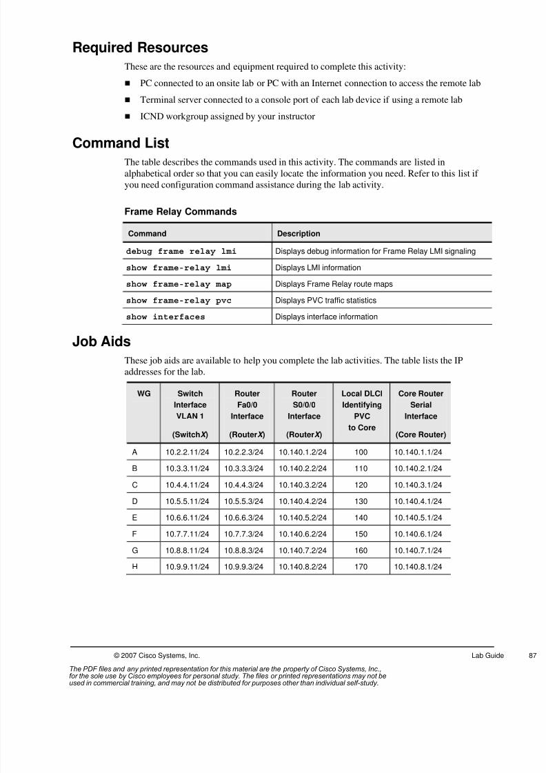
8/3/2019 Icnd210lg Cracked
http://slidepdf.com/reader/full/icnd210lg-cracked 89/120
© 2007 Cisco Systems, Inc. Lab Guide
Required Resources
These are the resources and equipment required to complete this activity:
PC connected to an onsite lab or PC with an Internet connection to access the remote lab
Terminal server connected to a console port of each lab device if using a remote lab
ICND workgroup assigned by your instructor
Command List
The table describes the commands used in this activity. The commands are listed in
alphabetical order so that you can easily locate the information you need. Refer to this list if
you need configuration command assistance during the lab activity.
Frame Relay Commands
Command Description
debug frame relay lmi Displays debug information for Frame Relay LMI signaling
show frame-relay lmi Displays LMI information
show frame-relay map Displays Frame Relay route maps
show frame-relay pvc Displays PVC traffic statistics
show interfaces Displays interface information
Job Aids
These job aids are available to help you complete the lab activities. The table lists the IP
addresses for the lab.
WG Switch
Interface
VLAN 1
(SwitchX )
Router
Fa0/0
Interface
(RouterX )
Router
S0/0/0
Interface
(RouterX )
Local DLCI
Identifying
PVC
to Core
Core Router
Serial
Interface
(Core Router)
A 10.2.2.11/24 10.2.2.3/24 10.140.1.2/24 100 10.140.1.1/24
B 10.3.3.11/24 10.3.3.3/24 10.140.2.2/24 110 10.140.2.1/24
C 10.4.4.11/24 10.4.4.3/24 10.140.3.2/24 120 10.140.3.1/24
D 10.5.5.11/24 10.5.5.3/24 10.140.4.2/24 130 10.140.4.1/24
E 10.6.6.11/24 10.6.6.3/24 10.140.5.2/24 140 10.140.5.1/24
F 10.7.7.11/24 10.7.7.3/24 10.140.6.2/24 150 10.140.6.1/24
G 10.8.8.11/24 10.8.8.3/24 10.140.7.2/24 160 10.140.7.1/24
H 10.9.9.11/24 10.9.9.3/24 10.140.8.2/24 170 10.140.8.1/24
The PDF files and any printed representation for this material are the property of Cisco Systems, Inc.,for the sole use by Cisco employees for personal study. The files or printed representations may not beused in commercial training, and may not be distributed for purposes other than individual self-study.

8/3/2019 Icnd210lg Cracked
http://slidepdf.com/reader/full/icnd210lg-cracked 90/120
88 Interconnecting Cisco Networking Devices Part 2 (ICND2) v1.0 © 2007 Cisco Systems, Inc.
Use the table to document the troubleshooting process.
Troubleshooting Steps
Command to Gather
Symptoms
Isolate the Problem Command to Correct the
Problem
Example:
ping 172.16.2.2 fails -----
show ip interface brief int Fa0/1 is administratively down no shutdown
ping 172.16.2.2 still fails -----
show interface Fa0/1 has incorrect ip address ip address 192.168.1.2
ping 172.16.2.2 succeeds
Task 1: Update Your Workgroup Configurations
In this task, you will download a new supplemental configuration to your workgroup router
from the TFTP server. However, the supplemental configuration that you download containsconfiguration errors that will cause a loss of connectivity with the rest of the network. You will
troubleshoot to isolate and correct the problem.
Activity Procedure
Complete these steps:
Step 1 Ensure connectivity with the TFTP server. Ping the TFTP server (10.1.1.1) from
your workgroup router.
Note If your ping is unsuccessful, contact your instructor.
Step 2 Download the supplemental configuration from the TFTP server into the running
configuration of your workgroup router. The name of the file to download is i2-
wg_ro-config-lab8-2.txt.
Step 3 Type exit from the privilege EXEC prompt and ensure your router banner reads:
************** wg_ro-config-lab8-2 ***********************
The PDF files and any printed representation for this material are the property of Cisco Systems, Inc.,for the sole use by Cisco employees for personal study. The files or printed representations may not beused in commercial training, and may not be distributed for purposes other than individual self-study.

8/3/2019 Icnd210lg Cracked
http://slidepdf.com/reader/full/icnd210lg-cracked 91/120
© 2007 Cisco Systems, Inc. Lab Guide
Step 4 Ping the TFTP server from your workgroup router. Were you successful?
Step 5 Check the routing table of your workgroup router. Check the EIGRP neighbor
relationships. What did you find?
Step 6 Check the status of your Frame Relay serial interface. What did you find?
Step 7 Without utilizing the show run command, use the troubleshooting guidelines and
commands discussed in the corresponding module to gather symptoms, and then
isolate and correct the problems. Use the Job Aids table on the previous page to
document the troubleshooting process.
Step 8 Ping the TFTP server (10.1.1.1) from your workgroup router to confirm you have
fixed the problem.
Step 9 Save your running configuration to NVRAM.
Activity Verification
You have completed this task when you attain these results:
Re-established Frame Relay connection with your directly connected routers
Populated the routing table of your workgroup router with EIGRP-learned routes from the
core router
Re-established network connectivity and can successfully ping the TFTP server
The PDF files and any printed representation for this material are the property of Cisco Systems, Inc.,for the sole use by Cisco employees for personal study. The files or printed representations may not beused in commercial training, and may not be distributed for purposes other than individual self-study.

8/3/2019 Icnd210lg Cracked
http://slidepdf.com/reader/full/icnd210lg-cracked 92/120
90 Interconnecting Cisco Networking Devices Part 2 (ICND2) v1.0 © 2007 Cisco Systems, Inc.
Lab Activity Answer Key
Lab Activity 1-1 Answer Key: Implementing a Small Network(Review Lab)
Workgroup Switch Configuration
When you complete this lab activity, your workgroup switch configuration will be similar tothe following, with differences that are specific to your workgroup:
version 12.2no service padservice timestamps debug uptimeservice timestamps log uptimeno service password-encryption!hostname SwitchX!enable secret 5 $1$DbHt$Zq1t4P2kmfMGUeZSRRy0g0!no aaa new-modelip subnet-zero
!!!!!!no file verify autospanning-tree mode pvstspanning-tree extend system-id!vlan internal allocation policy ascending!interface FastEthernet0/1!interface FastEthernet0/2
description To RouterX Fa0/0switchport mode accessswitchport port-securityswitchport port-security mac-address xxxx.xxxx.xxxx!interface FastEthernet0/3!interface FastEthernet0/4!interface FastEthernet0/5!interface FastEthernet0/6!interface FastEthernet0/7!
interface FastEthernet0/8!interface FastEthernet0/9!interface FastEthernet0/10!interface FastEthernet0/11description Connected to CoreSwitchAspeed 100duplex full!interface FastEthernet0/12
The PDF files and any printed representation for this material are the property of Cisco Systems, Inc.,for the sole use by Cisco employees for personal study. The files or printed representations may not beused in commercial training, and may not be distributed for purposes other than individual self-study.

8/3/2019 Icnd210lg Cracked
http://slidepdf.com/reader/full/icnd210lg-cracked 93/120
© 2007 Cisco Systems, Inc. Lab Guide
!interface FastEthernet0/13!interface FastEthernet0/14!interface FastEthernet0/15!interface FastEthernet0/16!interface FastEthernet0/17!
interface FastEthernet0/18!interface FastEthernet0/19!interface FastEthernet0/20!interface FastEthernet0/21!interface FastEthernet0/22!interface FastEthernet0/23!interface FastEthernet0/24!interface GigabitEthernet0/1
!interface GigabitEthernet0/2!interface Vlan1ip address 10.1.1.X 255.255.255.0no ip route-cache!ip default-gateway 10.1.1.3ip http serverip http secure-server!control-plane!banner motd ^C Authorized access only. Unauthorized users disconnect.^C
!line con 0password ciscologging synchronousloginline vty 0 4password sanjoseloginline vty 5 15no login!end
Workgroup Router Configuration
When you complete this lab activity, your workgroup router configuration will be similar to the
following, with differences that are specific to your workgroup:
version 12.4service timestamps debug datetime msecservice timestamps log datetime msecno service password-encryption!hostname RouterX!boot-start-marker
The PDF files and any printed representation for this material are the property of Cisco Systems, Inc.,for the sole use by Cisco employees for personal study. The files or printed representations may not beused in commercial training, and may not be distributed for purposes other than individual self-study.

8/3/2019 Icnd210lg Cracked
http://slidepdf.com/reader/full/icnd210lg-cracked 94/120
92 Interconnecting Cisco Networking Devices Part 2 (ICND2) v1.0 © 2007 Cisco Systems, Inc.
boot-end-marker!enable secret 5 $1$HNdR$hOG1GhzoNoHMEgZQU21mo1!no aaa new-model!!ip cef!!!
!voice-card 0no dspfarm!interface FastEthernet0/0description To SwitchX Fa0/2ip address 10.1.1.X 255.255.255.0duplex autospeed auto!interface FastEthernet0/1no ip addressshutdownduplex autospeed auto
!interface Serial0/0/0no ip addressshutdown!interface Serial0/0/1no ip addressshutdown!!!ip http serverno ip http secure-server!!
!!!control-plane!banner motd ^C Authorized access only. Unauthorized users disconnect.^C!line con 0password ciscologging synchronousloginline aux 0line vty 0 4password sanjose
login!scheduler allocate 20000 1000!end
The PDF files and any printed representation for this material are the property of Cisco Systems, Inc.,for the sole use by Cisco employees for personal study. The files or printed representations may not beused in commercial training, and may not be distributed for purposes other than individual self-study.

8/3/2019 Icnd210lg Cracked
http://slidepdf.com/reader/full/icnd210lg-cracked 95/120
© 2007 Cisco Systems, Inc. Lab Guide
Lab Activity 2-1 Answer Key: Configuring Expanded SwitchedNetworks
Workgroup Switch Configuration
When you complete this lab activity, your workgroup switch configuration will be similar to
the following, with differences that are specific to your workgroup:
version 12.2
no service padservice timestamps debug uptimeservice timestamps log uptimeno service password-encryption!hostname SwitchX!enable secret 5 $1$.9i2$TbVkDQfzCgf/CeFNEKMm9/!no aaa new-modelvtp domain ICNDvtp mode transparentip subnet-zero!no file verify auto
!spanning-tree mode rapid-pvstspanning-tree extend system-idspanning-tree vlan X0 priority 24576spanning-tree vlan X0 priority 28672!vlan internal allocation policy ascending!vlan X,X0,X0!interface FastEthernet0/1!interface FastEthernet0/2description To RouterX Fa0/0spanning-tree portfast
switchport access vlan Xswitchport mode accessswitchport port-securityswitchport port-security mac-address xxxx.xxxx.xxxx!interface FastEthernet0/3!interface FastEthernet0/4!interface FastEthernet0/5!interface FastEthernet0/6!interface FastEthernet0/7!
interface FastEthernet0/8!interface FastEthernet0/9!interface FastEthernet0/10!interface FastEthernet0/11description port connected to CoreSwitchAswitchport mode trunkspeed 100duplex full!
The PDF files and any printed representation for this material are the property of Cisco Systems, Inc.,for the sole use by Cisco employees for personal study. The files or printed representations may not beused in commercial training, and may not be distributed for purposes other than individual self-study.

8/3/2019 Icnd210lg Cracked
http://slidepdf.com/reader/full/icnd210lg-cracked 96/120
94 Interconnecting Cisco Networking Devices Part 2 (ICND2) v1.0 © 2007 Cisco Systems, Inc.
interface FastEthernet0/12description port connected to CoreSwitchBswitchport mode trunkspeed 100duplex full!interface FastEthernet0/13!interface FastEthernet0/14!interface FastEthernet0/15
!interface FastEthernet0/16!interface FastEthernet0/17!interface FastEthernet0/18!interface FastEthernet0/19!interface FastEthernet0/20!interface FastEthernet0/21!interface FastEthernet0/22!
interface FastEthernet0/23!interface FastEthernet0/24!interface GigabitEthernet0/1!interface GigabitEthernet0/2!interface Vlan1description Management VLAN interfaceip address 10.1.1.X 255.255.255.0no ip route-cache!ip default-gateway 10.1.1.3ip http server
ip http secure-server!control-plane!banner motd ^C Authorized Access Only!^C!line con 0password ciscologging synchronousloginline vty 0 4password sanjoselogin
line vty 5 15no login!end
Workgroup Router Configuration
When you complete this lab activity, your workgroup router configuration will be similar to the
following, with differences that are specific to your workgroup:
version 12.4
The PDF files and any printed representation for this material are the property of Cisco Systems, Inc.,for the sole use by Cisco employees for personal study. The files or printed representations may not beused in commercial training, and may not be distributed for purposes other than individual self-study.
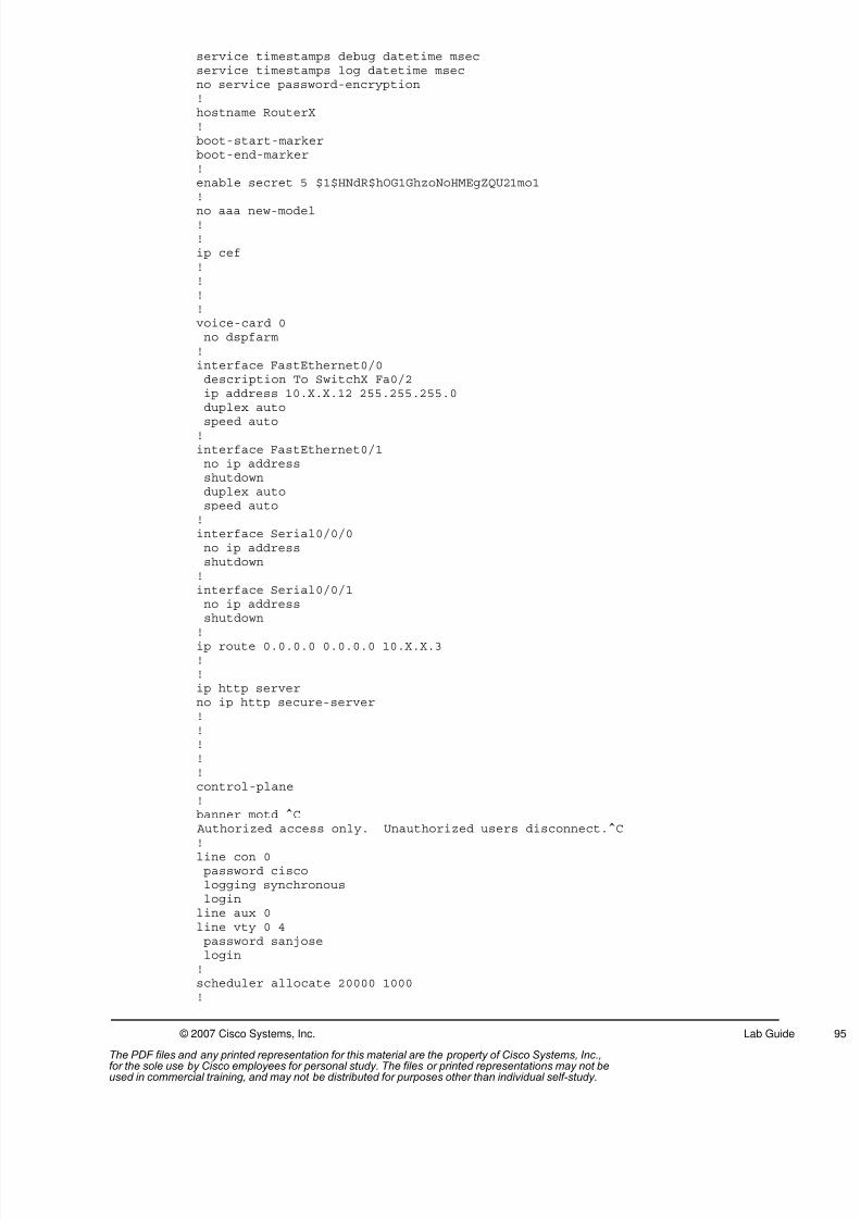
8/3/2019 Icnd210lg Cracked
http://slidepdf.com/reader/full/icnd210lg-cracked 97/120
© 2007 Cisco Systems, Inc. Lab Guide
service timestamps debug datetime msecservice timestamps log datetime msecno service password-encryption!hostname RouterX!boot-start-markerboot-end-marker!enable secret 5 $1$HNdR$hOG1GhzoNoHMEgZQU21mo1!
no aaa new-model!!ip cef!!!!voice-card 0no dspfarm!interface FastEthernet0/0description To SwitchX Fa0/2ip address 10.X.X.12 255.255.255.0duplex auto
speed auto!interface FastEthernet0/1no ip addressshutdownduplex autospeed auto!interface Serial0/0/0no ip addressshutdown!interface Serial0/0/1no ip addressshutdown
!ip route 0.0.0.0 0.0.0.0 10.X.X.3!!ip http serverno ip http secure-server!!!!!control-plane!banner motd ^C Authorized access only. Unauthorized users disconnect.^C
!line con 0password ciscologging synchronousloginline aux 0line vty 0 4password sanjoselogin!scheduler allocate 20000 1000!
The PDF files and any printed representation for this material are the property of Cisco Systems, Inc.,for the sole use by Cisco employees for personal study. The files or printed representations may not beused in commercial training, and may not be distributed for purposes other than individual self-study.
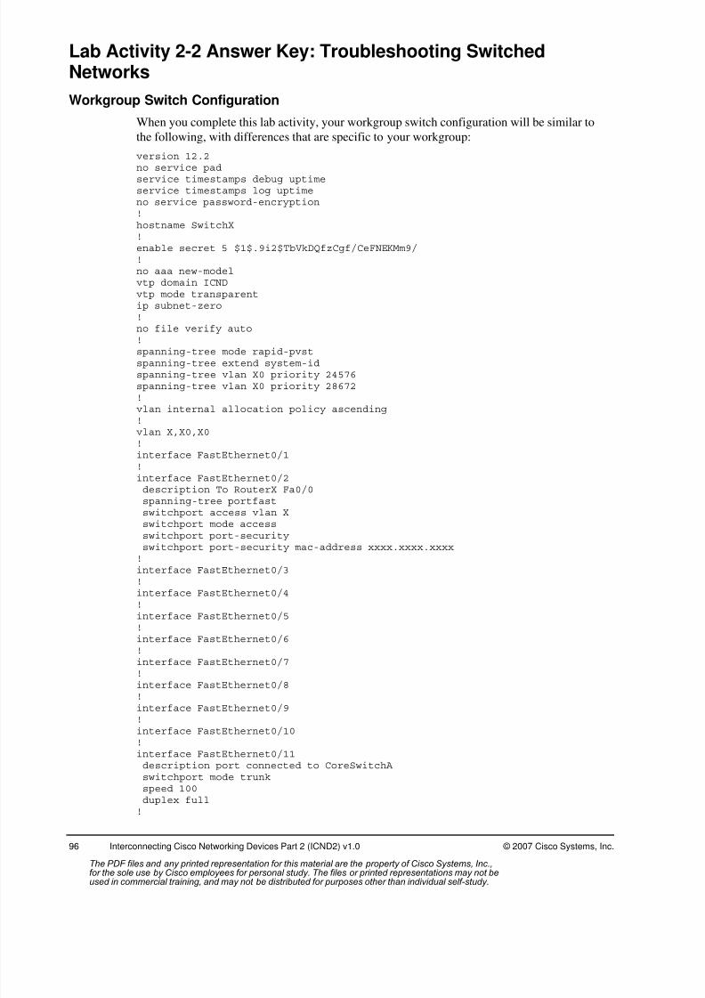
8/3/2019 Icnd210lg Cracked
http://slidepdf.com/reader/full/icnd210lg-cracked 98/120
96 Interconnecting Cisco Networking Devices Part 2 (ICND2) v1.0 © 2007 Cisco Systems, Inc.
Lab Activity 2-2 Answer Key: Troubleshooting SwitchedNetworks
Workgroup Switch Configuration
When you complete this lab activity, your workgroup switch configuration will be similar to
the following, with differences that are specific to your workgroup:
version 12.2
no service padservice timestamps debug uptimeservice timestamps log uptimeno service password-encryption!hostname SwitchX!enable secret 5 $1$.9i2$TbVkDQfzCgf/CeFNEKMm9/!no aaa new-modelvtp domain ICNDvtp mode transparentip subnet-zero!no file verify auto
!spanning-tree mode rapid-pvstspanning-tree extend system-idspanning-tree vlan X0 priority 24576spanning-tree vlan X0 priority 28672!vlan internal allocation policy ascending!vlan X,X0,X0!interface FastEthernet0/1!interface FastEthernet0/2description To RouterX Fa0/0spanning-tree portfast
switchport access vlan Xswitchport mode accessswitchport port-securityswitchport port-security mac-address xxxx.xxxx.xxxx!interface FastEthernet0/3!interface FastEthernet0/4!interface FastEthernet0/5!interface FastEthernet0/6!interface FastEthernet0/7!
interface FastEthernet0/8!interface FastEthernet0/9!interface FastEthernet0/10!interface FastEthernet0/11description port connected to CoreSwitchAswitchport mode trunkspeed 100duplex full!
The PDF files and any printed representation for this material are the property of Cisco Systems, Inc.,for the sole use by Cisco employees for personal study. The files or printed representations may not beused in commercial training, and may not be distributed for purposes other than individual self-study.

8/3/2019 Icnd210lg Cracked
http://slidepdf.com/reader/full/icnd210lg-cracked 99/120
© 2007 Cisco Systems, Inc. Lab Guide
interface FastEthernet0/12description port connected to CoreSwitchBswitchport mode trunkshutdownspeed 100duplex full!interface FastEthernet0/13!interface FastEthernet0/14!
interface FastEthernet0/15!interface FastEthernet0/16!interface FastEthernet0/17!interface FastEthernet0/18!interface FastEthernet0/19!interface FastEthernet0/20!interface FastEthernet0/21!interface FastEthernet0/22
!interface FastEthernet0/23!interface FastEthernet0/24!interface GigabitEthernet0/1!interface GigabitEthernet0/2!interface Vlan1description Management VLAN interfaceip address 10.1.1.X 255.255.255.0no ip route-cache!ip default-gateway 10.1.1.3
ip http serverip http secure-server!control-plane!banner motd ^C
***************************************************************
wg_sw-config-lab2-2
****************************************************************
^C!line con 0password ciscologging synchronousloginline vty 0 4password sanjoselogin
The PDF files and any printed representation for this material are the property of Cisco Systems, Inc.,for the sole use by Cisco employees for personal study. The files or printed representations may not beused in commercial training, and may not be distributed for purposes other than individual self-study.

8/3/2019 Icnd210lg Cracked
http://slidepdf.com/reader/full/icnd210lg-cracked 100/120
98 Interconnecting Cisco Networking Devices Part 2 (ICND2) v1.0 © 2007 Cisco Systems, Inc.
line vty 5 15no login!end
Workgroup Router Configuration
When you complete this lab activity, your workgroup router configuration will be similar to the
following, with differences that are specific to your workgroup:
version 12.4service timestamps debug datetime msecservice timestamps log datetime msecno service password-encryption!hostname RouterX!boot-start-markerboot-end-marker!enable secret 5 $1$8qBT$p6X.Rp20jVs3qobVevWSj/!no aaa new-model!resource policy
!ip cef!voice-card 0no dspfarm!interface FastEthernet0/0description To SwitchX F0/2ip address 10.X.X.12 255.255.255.0duplex autospeed auto!interface FastEthernet0/1no ip addressshutdown
duplex autospeed auto!interface Serial0/0/0no ip addressshutdown!interface Serial0/0/1no ip addressshutdown!ip route 0.0.0.0 0.0.0.0 10.X.X.3!!ip http server
no ip http secure-server!control-plane!banner motd ^C
********************************************************************
wg_ro-config-lab2-2
The PDF files and any printed representation for this material are the property of Cisco Systems, Inc.,for the sole use by Cisco employees for personal study. The files or printed representations may not beused in commercial training, and may not be distributed for purposes other than individual self-study.

8/3/2019 Icnd210lg Cracked
http://slidepdf.com/reader/full/icnd210lg-cracked 101/120
© 2007 Cisco Systems, Inc. Lab Guide
*******************************************************************
^C!line con 0password ciscologging synchronousloginline aux 0
line vty 0 4password sanjoselogging synchronouslogin!scheduler allocate 20000 1000!end
Lab Activity 4-1 Answer Key: Implementing OSPF
Workgroup Switch Configuration
When you complete this lab activity, your workgroup switch configuration will be similar to
the following, with differences that are specific to your workgroup:
version 12.2no service padservice timestamps debug uptimeservice timestamps log uptimeno service password-encryption!hostname SwitchX!enable secret 5 $1$.9i2$TbVkDQfzCgf/CeFNEKMm9/!no aaa new-model
vtp domain ICNDvtp mode transparentip subnet-zero!no file verify auto!spanning-tree mode rapid-pvstspanning-tree extend system-idspanning-tree vlan X0 priority 24576spanning-tree vlan X0 priority 28672!vlan internal allocation policy ascending!vlan X,X0,X0!
interface FastEthernet0/1!interface FastEthernet0/2description To RouterX Fa0/0spanning-tree portfastswitchport mode accessswitchport port-securityswitchport port-security mac-address xxxx.xxxx.xxxx!interface FastEthernet0/3!interface FastEthernet0/4
The PDF files and any printed representation for this material are the property of Cisco Systems, Inc.,for the sole use by Cisco employees for personal study. The files or printed representations may not beused in commercial training, and may not be distributed for purposes other than individual self-study.

8/3/2019 Icnd210lg Cracked
http://slidepdf.com/reader/full/icnd210lg-cracked 102/120
100 Interconnecting Cisco Networking Devices Part 2 (ICND2) v1.0 © 2007 Cisco Systems, Inc.
!interface FastEthernet0/5!interface FastEthernet0/6!interface FastEthernet0/7!interface FastEthernet0/8!interface FastEthernet0/9!
interface FastEthernet0/10!interface FastEthernet0/11description port connected to CoreSwitchAswitchport mode trunkshutdownspeed 100duplex full!interface FastEthernet0/12description port connected to CoreSwitchBswitchport mode trunkshutdownspeed 100duplex full
!interface FastEthernet0/13!interface FastEthernet0/14!interface FastEthernet0/15!interface FastEthernet0/16!interface FastEthernet0/17!interface FastEthernet0/18!interface FastEthernet0/19!
interface FastEthernet0/20!interface FastEthernet0/21!interface FastEthernet0/22!interface FastEthernet0/23!interface FastEthernet0/24!interface GigabitEthernet0/1!interface GigabitEthernet0/2!interface Vlan1
description Management VLAN interfaceip address 10.X.X.11 255.255.255.0no ip route-cache!ip default-gateway 10.X.X.3ip http serverip http secure-server!control-plane!banner motd ^C
The PDF files and any printed representation for this material are the property of Cisco Systems, Inc.,for the sole use by Cisco employees for personal study. The files or printed representations may not beused in commercial training, and may not be distributed for purposes other than individual self-study.
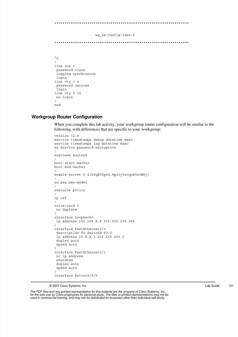
8/3/2019 Icnd210lg Cracked
http://slidepdf.com/reader/full/icnd210lg-cracked 103/120
© 2007 Cisco Systems, Inc. Lab Guide
*****************************************************************
wg_sw-config-lab2-2
*****************************************************************
^C!line con 0password ciscologging synchronousloginline vty 0 4password sanjoseloginline vty 5 15no login!end
Workgroup Router Configuration
When you complete this lab activity, your workgroup router configuration will be similar to the
following, with differences that are specific to your workgroup:
version 12.4service timestamps debug datetime msecservice timestamps log datetime msecno service password-encryption!hostname RouterX!boot-start-markerboot-end-marker!
enable secret 5 $1$8qBT$p6X.Rp20jVs3qobVevWSj/!no aaa new-model!resource policy!ip cef!voice-card 0no dspfarm!interface Loopback0ip address 192.168.X.X 255.255.255.240!interface FastEthernet0/0
description To SwitchX F0/2ip address 10.X.X.3 255.255.255.0duplex autospeed auto!interface FastEthernet0/1no ip addressshutdownduplex autospeed auto!interface Serial0/0/0
The PDF files and any printed representation for this material are the property of Cisco Systems, Inc.,for the sole use by Cisco employees for personal study. The files or printed representations may not beused in commercial training, and may not be distributed for purposes other than individual self-study.

8/3/2019 Icnd210lg Cracked
http://slidepdf.com/reader/full/icnd210lg-cracked 104/120
102 Interconnecting Cisco Networking Devices Part 2 (ICND2) v1.0 © 2007 Cisco Systems, Inc.
bandwidth 64ip address 10.140.X.2 255.255.255.0ip ospf authenticationip ospf authentication-key san-fran!interface Serial0/0/1bandwidth 64ip address 10.XX.XX.X 255.255.255.0ip ospf authenticationip ospf authentication-key san-fran!
router ospf 100log-adjacency-changesnetwork 10.X.X.3 0.0.0.0 area 0network 10.XX.XX.X 0.0.0.0 area 0network 10.140.X.2 0.0.0.0 area 0network 192.168.X.X 0.0.0.0 area 0!ip http serverno ip http secure-server!control-plane!banner motd ^C
********************************************************************wg_ro-config-lab2-2
********************************************************************
^C!line con 0password ciscologging synchronousloginline aux 0
line vty 0 4password sanjoselogging synchronouslogin!scheduler allocate 20000 1000!end
Lab Activity 4-2 Answer Key: Troubleshooting OSPF
Workgroup Router Configuration
When you complete this lab activity, your workgroup router configuration will be similar to the
following, with differences that are specific to your workgroup:
version 12.4service timestamps debug datetime msecservice timestamps log datetime msecno service password-encryption!hostname RouterX!boot-start-marker
The PDF files and any printed representation for this material are the property of Cisco Systems, Inc.,for the sole use by Cisco employees for personal study. The files or printed representations may not beused in commercial training, and may not be distributed for purposes other than individual self-study.

8/3/2019 Icnd210lg Cracked
http://slidepdf.com/reader/full/icnd210lg-cracked 105/120
© 2007 Cisco Systems, Inc. Lab Guide
boot-end-marker!enable secret 5 $1$8qBT$p6X.Rp20jVs3qobVevWSj/!no aaa new-model!resource policy!ip cef!voice-card 0
no dspfarm!interface Loopback0ip address 192.168.X.X 255.255.255.240!interface FastEthernet0/0description To SwitchX F0/2ip address 10.X.X.3 255.255.255.0duplex autospeed auto!interface FastEthernet0/1no ip addressshutdownduplex auto
speed auto!interface Serial0/0/0bandwidth 64ip address 10.140.X.2 255.255.255.0ip ospf authenticationip ospf authentication-key san-fran!interface Serial0/0/1bandwidth 64ip address 10.XX.XX.X 255.255.255.0ip ospf authenticationip ospf authentication-key san-fran!router ospf 100
log-adjacency-changesnetwork 10.X.X.3 0.0.0.0 area 0network 10.XX.XX.X 0.0.0.0 area 0network 10.140.X.2 0.0.0.0 area 0network 192.168.X.X 0.0.0.0 area 0!ip http serverno ip http secure-server!control-plane!banner motd ^C
***********************************************************************
wg_ro-config-lab4-2
***********************************************************************
^C!line con 0password cisco
The PDF files and any printed representation for this material are the property of Cisco Systems, Inc.,for the sole use by Cisco employees for personal study. The files or printed representations may not beused in commercial training, and may not be distributed for purposes other than individual self-study.

8/3/2019 Icnd210lg Cracked
http://slidepdf.com/reader/full/icnd210lg-cracked 106/120
104 Interconnecting Cisco Networking Devices Part 2 (ICND2) v1.0 © 2007 Cisco Systems, Inc.
logging synchronousloginline aux 0line vty 0 4password sanjoselogging synchronouslogin!scheduler allocate 20000 1000!end
Lab Activity 5-1 Answer Key: Implementing EIGRP
Workgroup Router Configuration
When you complete this lab activity, your workgroup router configuration will be similar to the
following, with differences that are specific to your workgroup:
version 12.4service timestamps debug datetime msecservice timestamps log datetime msecno service password-encryption
!hostname RouterX!boot-start-markerboot-end-marker!enable secret 5 $1$8qBT$p6X.Rp20jVs3qobVevWSj/!no aaa new-model!resource policy!ip cef!voice-card 0
no dspfarm!!key chain icndchainkey 1key-string san-fran
!interface Loopback0ip address 192.168.X.X 255.255.255.240!interface FastEthernet0/0description To SwitchX F0/2ip address 10.X.X.3 255.255.255.0duplex autospeed auto
!interface FastEthernet0/1no ip addressshutdownduplex autospeed auto!interface Serial0/0/0bandwidth 64ip address 10.140.X.2 255.255.255.0ip authentication mode eigrp 100 md5ip authentication key-chain eigrp 100 icndchain
The PDF files and any printed representation for this material are the property of Cisco Systems, Inc.,for the sole use by Cisco employees for personal study. The files or printed representations may not beused in commercial training, and may not be distributed for purposes other than individual self-study.
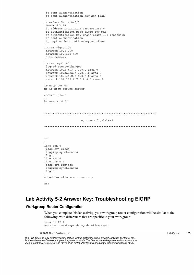
8/3/2019 Icnd210lg Cracked
http://slidepdf.com/reader/full/icnd210lg-cracked 107/120
© 2007 Cisco Systems, Inc. Lab Guide
ip ospf authenticationip ospf authentication-key san-fran!interface Serial0/0/1bandwidth 64ip address 10.XX.XX.X 255.255.255.0ip authentication mode eigrp 100 md5ip authentication key-chain eigrp 100 icndchainip ospf authenticationip ospf authentication-key san-fran!
router eigrp 100network 10.0.0.0network 192.168.X.0auto-summary!router ospf 100log-adjacency-changesnetwork 10.X.X.3 0.0.0.0 area 0network 10.XX.XX.X 0.0.0.0 area 0network 10.140.X.2 0.0.0.0 area 0network 192.168.X.X 0.0.0.0 area 0!ip http serverno ip http secure-server!
control-plane!banner motd ^C
******************************************************************
wg_ro-config-lab4-2
******************************************************************
^C
!line con 0password ciscologging synchronousloginline aux 0line vty 0 4password sanjoselogging synchronouslogin!scheduler allocate 20000 1000!end
Lab Activity 5-2 Answer Key: Troubleshooting EIGRP
Workgroup Router Configuration
When you complete this lab activity, your workgroup router configuration will be similar to the
following, with differences that are specific to your workgroup:
version 12.4service timestamps debug datetime msec
The PDF files and any printed representation for this material are the property of Cisco Systems, Inc.,for the sole use by Cisco employees for personal study. The files or printed representations may not beused in commercial training, and may not be distributed for purposes other than individual self-study.
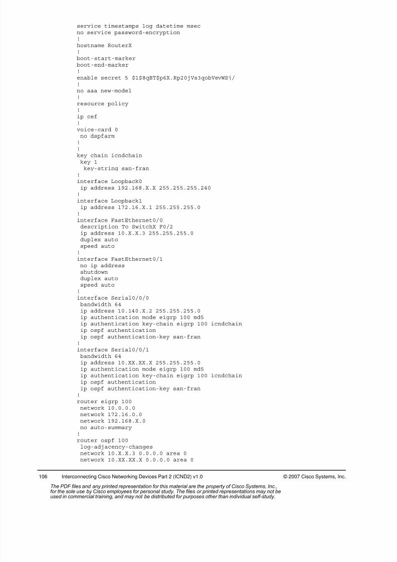
8/3/2019 Icnd210lg Cracked
http://slidepdf.com/reader/full/icnd210lg-cracked 108/120
106 Interconnecting Cisco Networking Devices Part 2 (ICND2) v1.0 © 2007 Cisco Systems, Inc.
service timestamps log datetime msecno service password-encryption!hostname RouterX!boot-start-markerboot-end-marker!enable secret 5 $1$8qBT$p6X.Rp20jVs3qobVevWSj/!no aaa new-model
!resource policy!ip cef!voice-card 0no dspfarm!!key chain icndchainkey 1key-string san-fran
!interface Loopback0ip address 192.168.X.X 255.255.255.240
!interface Loopback1ip address 172.16.X.1 255.255.255.0!interface FastEthernet0/0description To SwitchX F0/2ip address 10.X.X.3 255.255.255.0duplex autospeed auto!interface FastEthernet0/1no ip addressshutdownduplex autospeed auto
!interface Serial0/0/0bandwidth 64ip address 10.140.X.2 255.255.255.0ip authentication mode eigrp 100 md5ip authentication key-chain eigrp 100 icndchainip ospf authenticationip ospf authentication-key san-fran!interface Serial0/0/1bandwidth 64ip address 10.XX.XX.X 255.255.255.0ip authentication mode eigrp 100 md5ip authentication key-chain eigrp 100 icndchainip ospf authentication
ip ospf authentication-key san-fran!router eigrp 100network 10.0.0.0network 172.16.0.0network 192.168.X.0no auto-summary!router ospf 100log-adjacency-changesnetwork 10.X.X.3 0.0.0.0 area 0network 10.XX.XX.X 0.0.0.0 area 0
The PDF files and any printed representation for this material are the property of Cisco Systems, Inc.,for the sole use by Cisco employees for personal study. The files or printed representations may not beused in commercial training, and may not be distributed for purposes other than individual self-study.
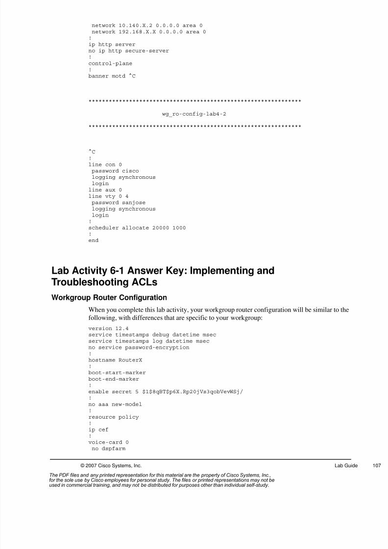
8/3/2019 Icnd210lg Cracked
http://slidepdf.com/reader/full/icnd210lg-cracked 109/120
© 2007 Cisco Systems, Inc. Lab Guide
network 10.140.X.2 0.0.0.0 area 0network 192.168.X.X 0.0.0.0 area 0!ip http serverno ip http secure-server!control-plane!banner motd ^C
***************************************************************
wg_ro-config-lab4-2
***************************************************************
^C!line con 0password ciscologging synchronouslogin
line aux 0line vty 0 4password sanjoselogging synchronouslogin!scheduler allocate 20000 1000!end
Lab Activity 6-1 Answer Key: Implementing and
Troubleshooting ACLsWorkgroup Router Configuration
When you complete this lab activity, your workgroup router configuration will be similar to the
following, with differences that are specific to your workgroup:
version 12.4service timestamps debug datetime msecservice timestamps log datetime msecno service password-encryption!hostname RouterX!boot-start-marker
boot-end-marker!enable secret 5 $1$8qBT$p6X.Rp20jVs3qobVevWSj/!no aaa new-model!resource policy!ip cef!voice-card 0no dspfarm
The PDF files and any printed representation for this material are the property of Cisco Systems, Inc.,for the sole use by Cisco employees for personal study. The files or printed representations may not beused in commercial training, and may not be distributed for purposes other than individual self-study.
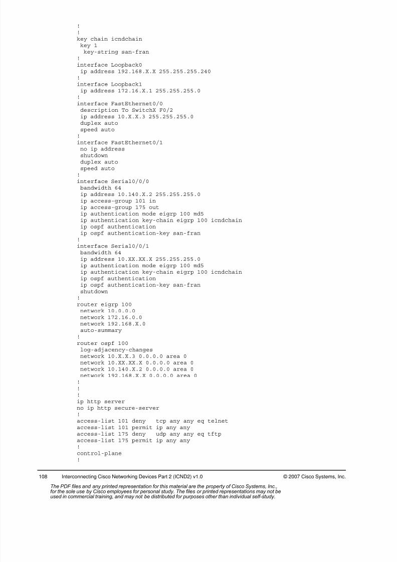
8/3/2019 Icnd210lg Cracked
http://slidepdf.com/reader/full/icnd210lg-cracked 110/120
108 Interconnecting Cisco Networking Devices Part 2 (ICND2) v1.0 © 2007 Cisco Systems, Inc.
!!key chain icndchainkey 1key-string san-fran
!interface Loopback0ip address 192.168.X.X 255.255.255.240!interface Loopback1ip address 172.16.X.1 255.255.255.0
!interface FastEthernet0/0description To SwitchX F0/2ip address 10.X.X.3 255.255.255.0duplex autospeed auto!interface FastEthernet0/1no ip addressshutdownduplex autospeed auto!interface Serial0/0/0bandwidth 64
ip address 10.140.X.2 255.255.255.0ip access-group 101 inip access-group 175 outip authentication mode eigrp 100 md5ip authentication key-chain eigrp 100 icndchainip ospf authenticationip ospf authentication-key san-fran!interface Serial0/0/1bandwidth 64ip address 10.XX.XX.X 255.255.255.0ip authentication mode eigrp 100 md5ip authentication key-chain eigrp 100 icndchainip ospf authenticationip ospf authentication-key san-fran
shutdown!router eigrp 100network 10.0.0.0network 172.16.0.0network 192.168.X.0auto-summary!router ospf 100log-adjacency-changesnetwork 10.X.X.3 0.0.0.0 area 0network 10.XX.XX.X 0.0.0.0 area 0network 10.140.X.2 0.0.0.0 area 0network 192.168.X.X 0.0.0.0 area 0!
!!ip http serverno ip http secure-server!access-list 101 deny tcp any any eq telnetaccess-list 101 permit ip any anyaccess-list 175 deny udp any any eq tftpaccess-list 175 permit ip any any!control-plane!
The PDF files and any printed representation for this material are the property of Cisco Systems, Inc.,for the sole use by Cisco employees for personal study. The files or printed representations may not beused in commercial training, and may not be distributed for purposes other than individual self-study.

8/3/2019 Icnd210lg Cracked
http://slidepdf.com/reader/full/icnd210lg-cracked 111/120
© 2007 Cisco Systems, Inc. Lab Guide
banner motd ^C
***************************************************************
wg_ro-config-lab6-1
**************************************************************
^C!line con 0password ciscologging synchronousloginline aux 0line vty 0 4password sanjoselogging synchronouslogin!scheduler allocate 20000 1000!
end
================
OR
==============
!interface Serial0/0/0bandwidth 64ip address 10.140.X.2 255.255.255.0ip access-group KILLTELNET inip access-group 175 outip authentication mode eigrp 100 md5
ip authentication key-chain eigrp 100 icndchainip ospf authenticationip ospf authentication-key san-fran!!ip access-list extended KILLTELNETdeny tcp any any eq telnetpermit ip any any!
Lab Activity 7-1 Answer Key: Configuring NAT and PAT
Workgroup Router Configuration
When you complete this lab activity, your workgroup router configuration will be similar to thefollowing, with differences that are specific to your workgroup:
version 12.4service timestamps debug datetime msecservice timestamps log datetime msecno service password-encryption!hostname RouterX!boot-start-markerboot-end-marker
The PDF files and any printed representation for this material are the property of Cisco Systems, Inc.,for the sole use by Cisco employees for personal study. The files or printed representations may not beused in commercial training, and may not be distributed for purposes other than individual self-study.
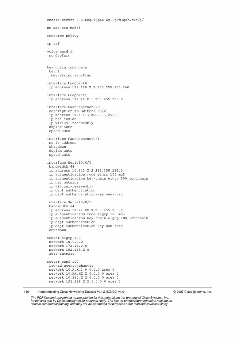
8/3/2019 Icnd210lg Cracked
http://slidepdf.com/reader/full/icnd210lg-cracked 112/120
110 Interconnecting Cisco Networking Devices Part 2 (ICND2) v1.0 © 2007 Cisco Systems, Inc.
!enable secret 5 $1$8qBT$p6X.Rp20jVs3qobVevWSj/!no aaa new-model!resource policy!ip cef!voice-card 0no dspfarm
!!key chain icndchainkey 1key-string san-fran
!interface Loopback0ip address 192.168.X.X 255.255.255.240!interface Loopback1ip address 172.16.X.1 255.255.255.0!interface FastEthernet0/0description To SwitchX F0/2ip address 10.X.X.3 255.255.255.0
ip nat insideip virtual-reassemblyduplex autospeed auto!interface FastEthernet0/1no ip addressshutdownduplex autospeed auto!interface Serial0/0/0bandwidth 64ip address 10.140.X.2 255.255.255.0ip authentication mode eigrp 100 md5
ip authentication key-chain eigrp 100 icndchainip nat outsideip virtual-reassemblyip ospf authenticationip ospf authentication-key san-fran!interface Serial0/0/1bandwidth 64ip address 10.XX.XX.X 255.255.255.0ip authentication mode eigrp 100 md5ip authentication key-chain eigrp 100 icndchainip ospf authenticationip ospf authentication-key san-franshutdown!
router eigrp 100network 10.0.0.0network 172.16.0.0network 192.168.X.0auto-summary!router ospf 100log-adjacency-changesnetwork 10.X.X.3 0.0.0.0 area 0network 10.XX.XX.X 0.0.0.0 area 0network 10.140.X.2 0.0.0.0 area 0network 192.168.X.X 0.0.0.0 area 0
The PDF files and any printed representation for this material are the property of Cisco Systems, Inc.,for the sole use by Cisco employees for personal study. The files or printed representations may not beused in commercial training, and may not be distributed for purposes other than individual self-study.
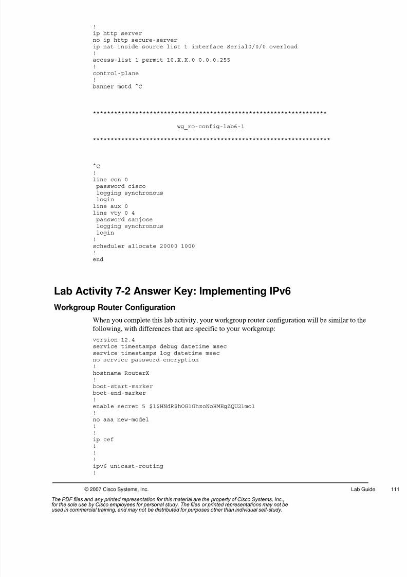
8/3/2019 Icnd210lg Cracked
http://slidepdf.com/reader/full/icnd210lg-cracked 113/120
© 2007 Cisco Systems, Inc. Lab Guide
!ip http serverno ip http secure-serverip nat inside source list 1 interface Serial0/0/0 overload!access-list 1 permit 10.X.X.0 0.0.0.255!control-plane!banner motd ^C
******************************************************************
wg_ro-config-lab6-1
*******************************************************************
^C!line con 0password ciscologging synchronous
loginline aux 0line vty 0 4password sanjoselogging synchronouslogin!scheduler allocate 20000 1000!end
Lab Activity 7-2 Answer Key: Implementing IPv6
Workgroup Router Configuration
When you complete this lab activity, your workgroup router configuration will be similar to the
following, with differences that are specific to your workgroup:
version 12.4service timestamps debug datetime msecservice timestamps log datetime msecno service password-encryption!hostname RouterX!boot-start-markerboot-end-marker
!enable secret 5 $1$HNdR$hOG1GhzoNoHMEgZQU21mo1!no aaa new-model!!ip cef!!!ipv6 unicast-routing!
The PDF files and any printed representation for this material are the property of Cisco Systems, Inc.,for the sole use by Cisco employees for personal study. The files or printed representations may not beused in commercial training, and may not be distributed for purposes other than individual self-study.

8/3/2019 Icnd210lg Cracked
http://slidepdf.com/reader/full/icnd210lg-cracked 114/120
112 Interconnecting Cisco Networking Devices Part 2 (ICND2) v1.0 © 2007 Cisco Systems, Inc.
voice-card 0no dspfarm!!key chain icndchainkey 1key-string san-fran
!interface Loopback0ip address 192.168.X.X 255.255.255.252!
interface Loopback1ip address 172.16.X.1 255.255.255.0!interface Loopback2ip address 10.XXX.XXX.1 255.255.255.0ipv6 address 2001:410:4:8::/64 eui-64ipv6 rip cisco enable!interface FastEthernet0/0description To SwtichX Fa0/2ip address 10.X.X.3 255.255.255.0duplex autospeed auto!interface FastEthernet0/1
no ip addressshutdownduplex autospeed auto!interface Serial0/0/0bandwidth 64ip address 10.140.X.2 255.255.255.0ip authentication mode eigrp 100 md5ip authentication key-chain eigrp 100 icndchainip ospf authenticationip ospf authentication-key san-franshutdown!interface Serial0/0/1
bandwidth 64ip address 10.XX.XX.X 255.255.255.0ip authentication mode eigrp 100 md5ip authentication key-chain eigrp 100 icndchainip ospf authenticationip ospf authentication-key san-franipv6 address 2001:410:4:10::/65 eui-64ipv6 rip cisco enable!router eigrp 100network 10.0.0.0network 192.168.X.0auto-summary!router ospf 100
log-adjacency-changesnetwork 10.X.X.3 0.0.0.0 area 0network 10.XX.XX.X 0.0.0.0 area 0network 10.140.X.2 0.0.0.0 area 0network 192.168.X.XX 0.0.0.0 area 0!!!ip http serverno ip http secure-server!ipv6 router rip cisco
The PDF files and any printed representation for this material are the property of Cisco Systems, Inc.,for the sole use by Cisco employees for personal study. The files or printed representations may not beused in commercial training, and may not be distributed for purposes other than individual self-study.

8/3/2019 Icnd210lg Cracked
http://slidepdf.com/reader/full/icnd210lg-cracked 115/120
© 2007 Cisco Systems, Inc. Lab Guide
!control-plane!banner motd ^C
******************************************************************
wg_ro-config-lab6-1
*******************************************************************
^C!banner motd ^C Authorized access only. Unauthorized users disconnect.^C!line con 0password ciscologging synchronousloginline aux 0line vty 0 4
password sanjoselogin!scheduler allocate 20000 1000!end
Lab Activity 8-1 Answer Key: Establishing a Frame Relay WAN
Workgroup Router Configuration
When you complete this lab activity, your workgroup router configuration will be similar to the
following, with differences that are specific to your workgroup:
version 12.4service timestamps debug datetime msecservice timestamps log datetime msecno service password-encryption!hostname RouterX!boot-start-markerboot-end-marker!enable secret 5 $1$8qBT$p6X.Rp20jVs3qobVevWSj/!no aaa new-model!
resource policy!ip cef!voice-card 0no dspfarm!!key chain icndchainkey 1key-string san-fran
!
The PDF files and any printed representation for this material are the property of Cisco Systems, Inc.,for the sole use by Cisco employees for personal study. The files or printed representations may not beused in commercial training, and may not be distributed for purposes other than individual self-study.

8/3/2019 Icnd210lg Cracked
http://slidepdf.com/reader/full/icnd210lg-cracked 116/120
114 Interconnecting Cisco Networking Devices Part 2 (ICND2) v1.0 © 2007 Cisco Systems, Inc.
interface Loopback0ip address 192.168.X.X 255.255.255.240!interface Loopback1ip address 172.16.X.1 255.255.255.0!interface Loopback2ip address 10.XXX.XXX.1 255.255.255.0ipv6 address 2001:410:4:8::/64 eui-64ipv6 rip cisco enable!
interface FastEthernet0/0description To SwitchX F0/2ip address 10.X.X.3 255.255.255.0duplex autospeed auto!interface FastEthernet0/1no ip addressshutdownduplex autospeed auto!interface Serial0/0/0bandwidth 64no ip address
encapsulation frame-relayip ospf authenticationip ospf authentication-key san-fran!interface Serial0/0/0.1 point-to-pointip address 10.140.X.2 255.255.255.0ip authentication mode eigrp 100 md5ip authentication key-chain eigrp 100 icndchainframe-relay interface-dlci 120!interface Serial0/0/1bandwidth 64ip address 10.XX.XX.X 255.255.255.0ip authentication mode eigrp 100 md5ip authentication key-chain eigrp 100 icndchain
ip ospf authenticationip ospf authentication-key san-franshutdown!router eigrp 100network 10.0.0.0network 172.16.0.0network 192.168.X.0no auto-summary!router ospf 100log-adjacency-changesnetwork 10.X.X.3 0.0.0.0 area 0network 10.XX.XX.X 0.0.0.0 area 0network 10.140.X.2 0.0.0.0 area 0
network 192.168.X.X 0.0.0.0 area 0!
ip http serverno ip http secure-server!access-list 1 permit 10.X.X.0 0.0.0.255!control-plane!banner motd ^C
The PDF files and any printed representation for this material are the property of Cisco Systems, Inc.,for the sole use by Cisco employees for personal study. The files or printed representations may not beused in commercial training, and may not be distributed for purposes other than individual self-study.

8/3/2019 Icnd210lg Cracked
http://slidepdf.com/reader/full/icnd210lg-cracked 117/120
© 2007 Cisco Systems, Inc. Lab Guide
****************************************************************
wg_ro-config-lab6-1
**********************************************************
^C
!line con 0password ciscologging synchronousloginline aux 0line vty 0 4password sanjoselogging synchronouslogin!scheduler allocate 20000 1000!end
Lab Activity 8-2 Answer Key: Troubleshooting Frame RelayWANs
Workgroup Router Configuration
When you complete this lab activity, your workgroup router configuration will be similar to the
following, with differences that are specific to your workgroup:
version 12.4service timestamps debug datetime msecservice timestamps log datetime msec
no service password-encryption!hostname RouterX!boot-start-markerboot-end-marker!enable secret 5 $1$8qBT$p6X.Rp20jVs3qobVevWSj/!no aaa new-model!resource policy!ip cef!
voice-card 0no dspfarm!!key chain icndchainkey 1key-string san-fran
!interface Loopback0ip address 192.168.X.X 255.255.255.240!interface Loopback1
The PDF files and any printed representation for this material are the property of Cisco Systems, Inc.,for the sole use by Cisco employees for personal study. The files or printed representations may not beused in commercial training, and may not be distributed for purposes other than individual self-study.

8/3/2019 Icnd210lg Cracked
http://slidepdf.com/reader/full/icnd210lg-cracked 118/120
116 Interconnecting Cisco Networking Devices Part 2 (ICND2) v1.0 © 2007 Cisco Systems, Inc.
ip address 172.16.X.1 255.255.255.0!interface Loopback2ip address 10.XXX.XXX.1 255.255.255.0ipv6 address 2001:410:4:8::/64 eui-64ipv6 rip cisco enable!interface FastEthernet0/0description To SwitchX F0/2ip address 10.X.X.3 255.255.255.0duplex auto
speed auto!interface FastEthernet0/1no ip addressshutdownduplex autospeed auto!interface Serial0/0/0bandwidth 64no ip addressencapsulation frame-relay IETFip ospf authenticationip ospf authentication-key san-fran!
interface Serial0/0/0.1 point-to-pointip address 10.140.X.2 255.255.255.0ip authentication mode eigrp 100 md5ip authentication key-chain eigrp 100 icndchainframe-relay interface-dlci 120!interface Serial0/0/1bandwidth 64ip address 10.XX.XX.X 255.255.255.0ip authentication mode eigrp 100 md5ip authentication key-chain eigrp 100 icndchainip ospf authenticationip ospf authentication-key san-franshutdown!
router eigrp 100network 10.0.0.0network 172.16.0.0network 192.168.X.0no auto-summary!router ospf 100log-adjacency-changesnetwork 10.X.X.3 0.0.0.0 area 0network 10.XX.XX.X 0.0.0.0 area 0network 10.140.X.2 0.0.0.0 area 0network 192.168.X.X 0.0.0.0 area 0!
ip http server
no ip http secure-server!access-list 1 permit 20.4.4.0 0.0.0.255!control-plane!banner motd ^C
**********************************************************************
The PDF files and any printed representation for this material are the property of Cisco Systems, Inc.,for the sole use by Cisco employees for personal study. The files or printed representations may not beused in commercial training, and may not be distributed for purposes other than individual self-study.

8/3/2019 Icnd210lg Cracked
http://slidepdf.com/reader/full/icnd210lg-cracked 119/120
© 2007 Cisco Systems, Inc. Lab Guide
wg_ro-config-lab8-2
**********************************************************************
^C!line con 0password ciscologging synchronous
loginline aux 0line vty 0 4password sanjoselogging synchronouslogin!scheduler allocate 20000 1000!end
The PDF files and any printed representation for this material are the property of Cisco Systems, Inc.,for the sole use by Cisco employees for personal study. The files or printed representations may not beused in commercial training, and may not be distributed for purposes other than individual self-study.

8/3/2019 Icnd210lg Cracked
http://slidepdf.com/reader/full/icnd210lg-cracked 120/120
Related Documents