Welcome. . . Thank you for buying an IBM xSeries server. This server contains information for setting up and configuring your server. For detailed information about your server, view the publications on the You can also find the most current information about your server on the IBM Web site at: http://www.ibm.com/pc/support Your server is based on the X-Architecture technology, and it features superior performance, availability, and scalability. Documentation CD. Installation Guide Go to the Server Support flowchart Cable the server and options Start the server Install options: • Drives • Microprocessors • Adapters • Memory Did the server start correctly? Yes No Use ServerGuide to set up and configure hardware Did configuration complete? Use ServerGuide to install operating system? Install applications, such as IBM systems management software and IBM ServeRAID programs System is ready to use. Go to the Server Support flowchart to register and profile your server. Go to the Web for instructions, http://www.ibm.com/pc/support No Yes Yes No Installation Guide Install the server in the rack, if required xSeries 235 Type 8671

Welcome message from author
This document is posted to help you gain knowledge. Please leave a comment to let me know what you think about it! Share it to your friends and learn new things together.
Transcript
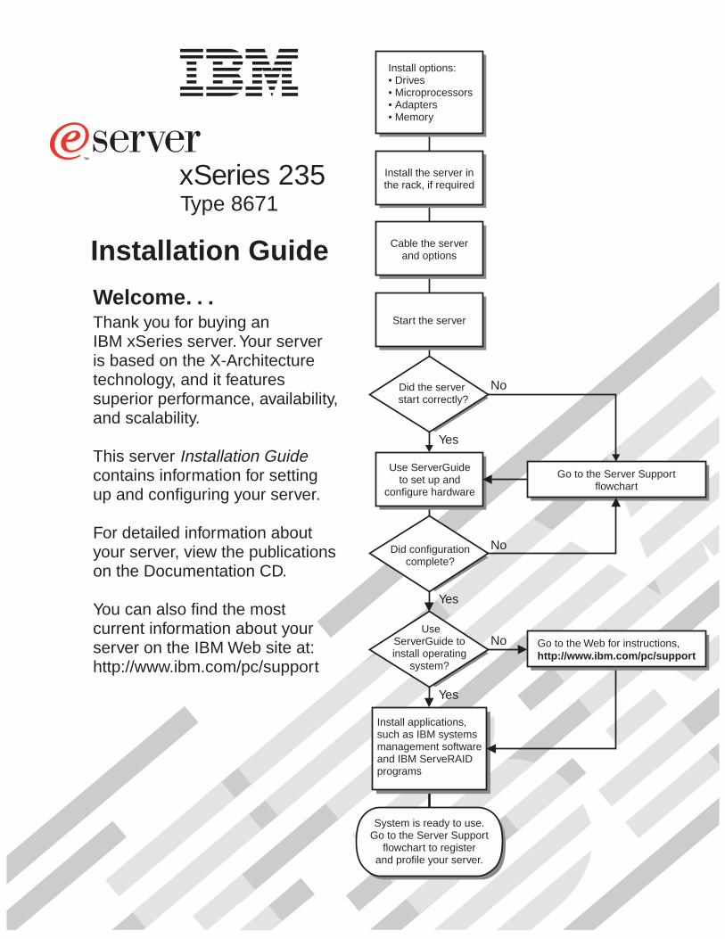
Welcome. . .Thank you for buying anIBM xSeries server.
This servercontains information for settingup and configuring your server.
For detailed information aboutyour server, view the publicationson the
You can also find the mostcurrent information about yourserver on the IBM Web site at:http://www.ibm.com/pc/support
Your serveris based on the X-Architecturetechnology, and it featuressuperior performance, availability,and scalability.
Documentation CD.
Installation GuideGo to the Server Support
flowchart
Cable the serverand options
Start the server
Install options:• Drives• Microprocessors• Adapters• Memory
Did the serverstart correctly?
Yes
No
Use ServerGuideto set up and
configure hardware
Did configurationcomplete?
UseServerGuide toinstall operating
system?
Install applications,such as IBM systemsmanagement softwareand IBM ServeRAIDprograms
System is ready to use.Go to the Server Support
flowchart to registerand profile your server.
Go to the Web for instructions,http://www.ibm.com/pc/support
No
Yes
Yes
No
Installation Guide
Install the server inthe rack, if requiredxSeries 235
Type 8671
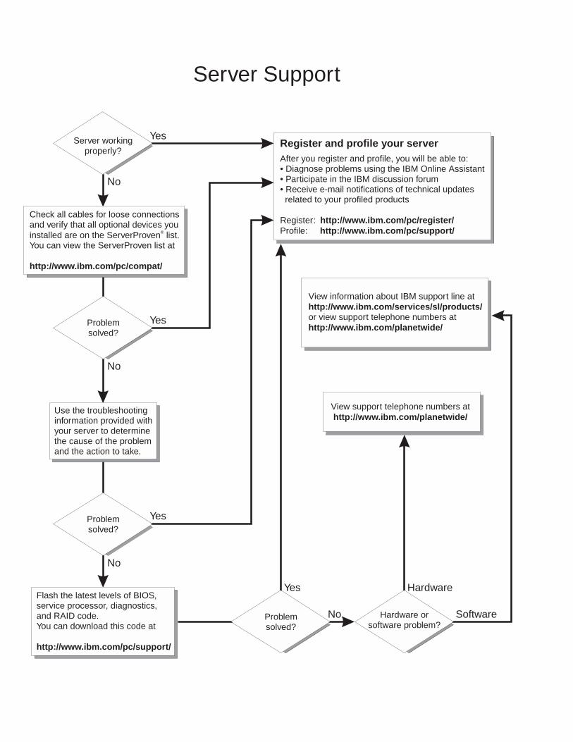
Server Support
After you register and profile, you will be able to:• Diagnose problems using the IBM Online Assistant• Participate in the IBM discussion forum• Receive e-mail notifications of technical updatesrelated to your profiled products
Register:Profile:
http://www.ibm.com/pc/register/http://www.ibm.com/pc/support/
Register and profile your serverYes
No
No
Use the troubleshootinginformation provided withyour server to determinethe cause of the problemand the action to take.
Flash the latest levels of BIOS,service processor, diagnostics,and RAID code.You can download this code at
http://www.ibm.com/pc/support/
No
No Software
Yes
Yes
Yes Hardware
Check all cables for loose connectionsand verify that all optional devices youinstalled are on the ServerProven list.You can view the ServerProven list at
®
http://www.ibm.com/pc/compat/
Server workingproperly?
Problemsolved?
Problemsolved?
Problemsolved?
Hardware orsoftware problem?
View support telephone numbers athttp://www.ibm.com/planetwide/
View information about IBM support line at
or view support telephone numbers athttp://www.ibm.com/services/sl/products/
http://www.ibm.com/planetwide/
IBM xSeries 235 Type 8671
Installation Guide
SC25-R464-60
���
Note:
Before using this information and the product it supports, be sure to read the general information in Appendix B, “Warranty
information,” on page 73 and Appendix C, “Notices,” on page 85.
Fourth Edition (February 2005)
© Copyright International Business Machines Corporation 2005. All rights reserved.
US Government Users Restricted Rights – Use, duplication or disclosure restricted by GSA ADP Schedule Contract
with IBM Corp.
Contents
Safety . . . . . . . . . . . . . . . . . . . . . . . . . . . . v
Chapter 1. Introduction . . . . . . . . . . . . . . . . . . . . . . 1
The IBM xSeries Documentation CD . . . . . . . . . . . . . . . . . 2
Hardware and software requirements . . . . . . . . . . . . . . . . 2
Using the Documentation Browser . . . . . . . . . . . . . . . . . 2
Features and specifications . . . . . . . . . . . . . . . . . . . . . 3
Notices and statements in this book . . . . . . . . . . . . . . . . . 4
Major components of your server . . . . . . . . . . . . . . . . . . 5
System-board component locations . . . . . . . . . . . . . . . . . . 6
System-board option connectors . . . . . . . . . . . . . . . . . . 6
System-board internal cable connectors . . . . . . . . . . . . . . . 7
System-board external port connectors . . . . . . . . . . . . . . . 8
System-board switches and jumpers . . . . . . . . . . . . . . . . 9
System-board LED locations . . . . . . . . . . . . . . . . . . . 10
Chapter 2. Installing options . . . . . . . . . . . . . . . . . . . 11
Installation guidelines . . . . . . . . . . . . . . . . . . . . . . 11
System reliability considerations . . . . . . . . . . . . . . . . . 11
Working inside the server with the power on . . . . . . . . . . . . . 12
Handling static-sensitive devices . . . . . . . . . . . . . . . . . 12
Removing the server door (tower model) . . . . . . . . . . . . . . . 13
Removing the server left-side cover and bezel (tower model) . . . . . . . . 14
Removing the left-side cover . . . . . . . . . . . . . . . . . . . 14
Removing the bezel . . . . . . . . . . . . . . . . . . . . . . 15
Removing the server top cover and bezel (rack configuration) . . . . . . . 16
Removing the top cover . . . . . . . . . . . . . . . . . . . . 16
Removing the bezel . . . . . . . . . . . . . . . . . . . . . . 17
Removing and installing the adapter-support bracket . . . . . . . . . . . 18
Working with adapters . . . . . . . . . . . . . . . . . . . . . . 20
Adapter considerations . . . . . . . . . . . . . . . . . . . . . 21
Installing a hot-plug adapter (slots 5 and 6) . . . . . . . . . . . . . 22
Installing a non-hot-plug adapter (any slot) . . . . . . . . . . . . . . 25
Installing memory modules . . . . . . . . . . . . . . . . . . . . 27
Installing a hot-swap drive . . . . . . . . . . . . . . . . . . . . . 29
Installing an additional microprocessor . . . . . . . . . . . . . . . . 31
Completing the installation . . . . . . . . . . . . . . . . . . . . . 35
Installing the server bezel and left-side cover (tower model) . . . . . . . 35
Installing the server door (tower model) . . . . . . . . . . . . . . . 37
Installing the server bezel and top cover (rack configuration) . . . . . . . 38
Cabling the server . . . . . . . . . . . . . . . . . . . . . . . 40
Updating your server configuration . . . . . . . . . . . . . . . . . 42
Chapter 3. Server controls, indicators, and power . . . . . . . . . . . 43
Front view . . . . . . . . . . . . . . . . . . . . . . . . . . 43
Rear view . . . . . . . . . . . . . . . . . . . . . . . . . . . 45
Operator information panel . . . . . . . . . . . . . . . . . . . . 46
Server power features . . . . . . . . . . . . . . . . . . . . . . 47
Turning on the server . . . . . . . . . . . . . . . . . . . . . 47
Turning off the server . . . . . . . . . . . . . . . . . . . . . 48
Standby mode . . . . . . . . . . . . . . . . . . . . . . . . 49
Chapter 4. Configuring your server . . . . . . . . . . . . . . . . 51
© Copyright IBM Corp. 2005 iii
Using the ServerGuide Setup and Installation CD . . . . . . . . . . . . 52
Using the Configuration/Setup Utility program . . . . . . . . . . . . . 52
Using the LSI Logic Configuration Utility program . . . . . . . . . . . . 52
Using ServeRAID Manager . . . . . . . . . . . . . . . . . . . . 53
Using ServeRAID Manager in startable-CD mode . . . . . . . . . . . 54
Viewing your configuration . . . . . . . . . . . . . . . . . . . . 58
Getting assistance . . . . . . . . . . . . . . . . . . . . . . 59
Chapter 5. Installing IBM Director updates . . . . . . . . . . . . . . 61
Chapter 6. Solving problems . . . . . . . . . . . . . . . . . . . 63
POST beep code descriptions . . . . . . . . . . . . . . . . . . . 63
POST error messages . . . . . . . . . . . . . . . . . . . . . . 64
ServerGuide program problems . . . . . . . . . . . . . . . . . . . 65
Troubleshooting chart . . . . . . . . . . . . . . . . . . . . . . 66
Appendix A. Getting help and technical assistance . . . . . . . . . . 71
Before you call . . . . . . . . . . . . . . . . . . . . . . . . . 71
Using the documentation . . . . . . . . . . . . . . . . . . . . . 71
Getting help and information from the World Wide Web . . . . . . . . . . 71
Software service and support . . . . . . . . . . . . . . . . . . . 72
Hardware service and support . . . . . . . . . . . . . . . . . . . 72
Appendix B. Warranty information . . . . . . . . . . . . . . . . . 73
Warranty period . . . . . . . . . . . . . . . . . . . . . . . . 73
Problem determination . . . . . . . . . . . . . . . . . . . . . 73
Warranty service and support . . . . . . . . . . . . . . . . . . 74
International Warranty Service . . . . . . . . . . . . . . . . . . 75
Purchasing additional services . . . . . . . . . . . . . . . . . . 75
IBM Statement of Limited Warranty Z125-4753-06 8/2000 . . . . . . . . . 76
Part 1 - General Terms . . . . . . . . . . . . . . . . . . . . . 76
Part 2 - Country-unique Terms . . . . . . . . . . . . . . . . . . 78
Appendix C. Notices . . . . . . . . . . . . . . . . . . . . . . 85
Edition notice . . . . . . . . . . . . . . . . . . . . . . . . . 85
Trademarks . . . . . . . . . . . . . . . . . . . . . . . . . . 86
Important notes . . . . . . . . . . . . . . . . . . . . . . . . . 86
Electronic emission notices . . . . . . . . . . . . . . . . . . . . 87
Federal Communications Commission (FCC) statement . . . . . . . . . 87
Industry Canada Class A emission compliance statement . . . . . . . . 87
Australia and New Zealand Class A statement . . . . . . . . . . . . 88
United Kingdom telecommunications safety requirement . . . . . . . . . 88
European Union EMC Directive conformance statement . . . . . . . . . 88
Taiwan electrical emission statement . . . . . . . . . . . . . . . . 88
Japanese Voluntary Control Council for Interference (VCCI) statement . . . 88
Power cords . . . . . . . . . . . . . . . . . . . . . . . . . . 89
Index . . . . . . . . . . . . . . . . . . . . . . . . . . . . 91
iv IBM xSeries 235 Type 8671: Installation Guide
Safety
Before installing this product, read the Safety Information.
Antes de instalar este produto, leia as Informações de Segurança.
Pred instalací tohoto produktu si prectete prírucku bezpecnostních instrukcí.
Læs sikkerhedsforskrifterne, før du installerer dette produkt.
Lees voordat u dit product installeert eerst de veiligheidsvoorschriften.
Ennen kuin asennat tämän tuotteen, lue turvaohjeet kohdasta Safety Information.
Avant d’installer ce produit, lisez les consignes de sécurité.
Vor der Installation dieses Produkts die Sicherheitshinweise lesen.
Prima di installare questo prodotto, leggere le Informazioni sulla Sicurezza.
Les sikkerhetsinformasjonen (Safety Information) før du installerer dette produktet.
Antes de instalar este produto, leia as Informações sobre Segurança.
© Copyright IBM Corp. 2005 v
Antes de instalar este producto, lea la información de seguridad.
Läs säkerhetsinformationen innan du installerar den här produkten.
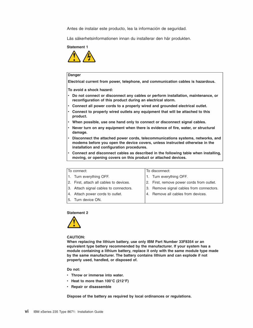
Statement 1
Danger
Electrical current from power, telephone, and communication cables is hazardous.
To avoid a shock hazard:
v Do not connect or disconnect any cables or perform installation, maintenance, or
reconfiguration of this product during an electrical storm.
v Connect all power cords to a properly wired and grounded electrical outlet.
v Connect to properly wired outlets any equipment that will be attached to this
product.
v When possible, use one hand only to connect or disconnect signal cables.
v Never turn on any equipment when there is evidence of fire, water, or structural
damage.
v Disconnect the attached power cords, telecommunications systems, networks, and
modems before you open the device covers, unless instructed otherwise in the
installation and configuration procedures.
v Connect and disconnect cables as described in the following table when installing,
moving, or opening covers on this product or attached devices.
To connect:
1. Turn everything OFF.
2. First, attach all cables to devices.
3. Attach signal cables to connectors.
4. Attach power cords to outlet.
5. Turn device ON.
To disconnect:
1. Turn everything OFF.
2. First, remove power cords from outlet.
3. Remove signal cables from connectors.
4. Remove all cables from devices.
Statement 2
CAUTION:
When replacing the lithium battery, use only IBM Part Number 33F8354 or an
equivalent type battery recommended by the manufacturer. If your system has a
module containing a lithium battery, replace it only with the same module type made
by the same manufacturer. The battery contains lithium and can explode if not
properly used, handled, or disposed of.
Do not:
v Throw or immerse into water.
v Heat to more than 100°C (212°F)
v Repair or disassemble
Dispose of the battery as required by local ordinances or regulations.
vi IBM xSeries 235 Type 8671: Installation Guide
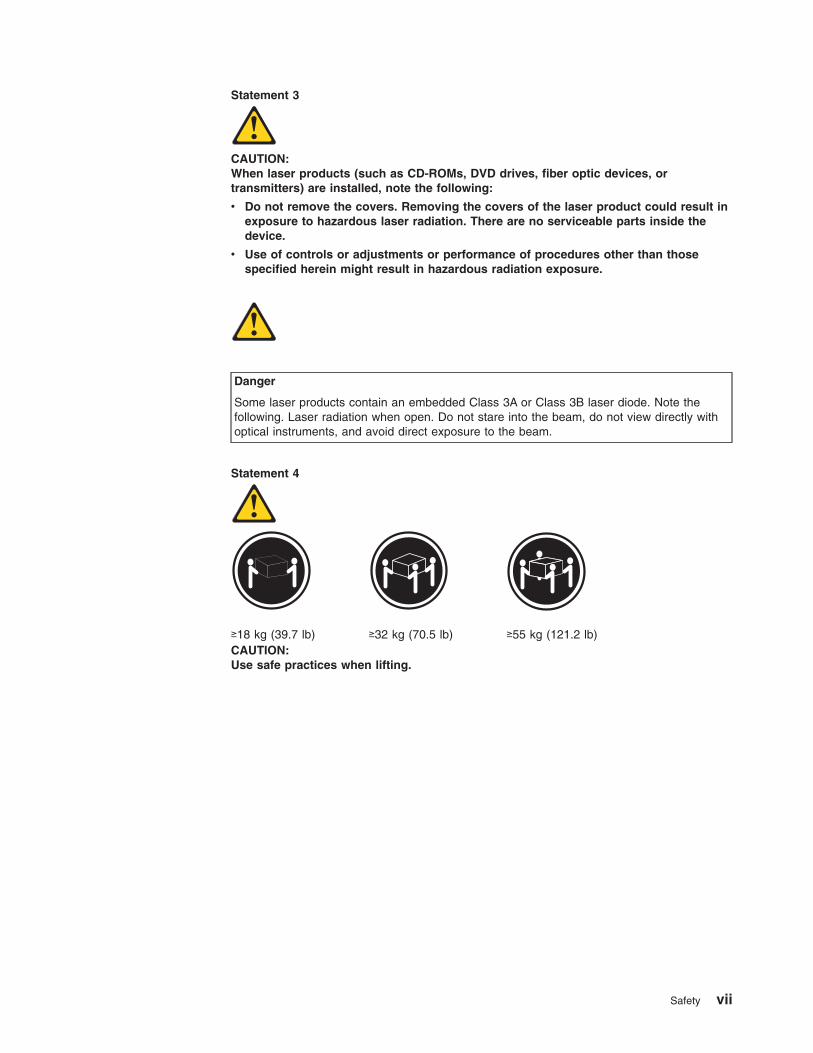
Statement 3
CAUTION:
When laser products (such as CD-ROMs, DVD drives, fiber optic devices, or
transmitters) are installed, note the following:
v Do not remove the covers. Removing the covers of the laser product could result in
exposure to hazardous laser radiation. There are no serviceable parts inside the
device.
v Use of controls or adjustments or performance of procedures other than those
specified herein might result in hazardous radiation exposure.
Danger
Some laser products contain an embedded Class 3A or Class 3B laser diode. Note the
following. Laser radiation when open. Do not stare into the beam, do not view directly with
optical instruments, and avoid direct exposure to the beam.
Statement 4
≥18 kg (39.7 lb)
≥32 kg (70.5 lb)
≥55 kg (121.2 lb)
CAUTION:
Use safe practices when lifting.
Safety vii
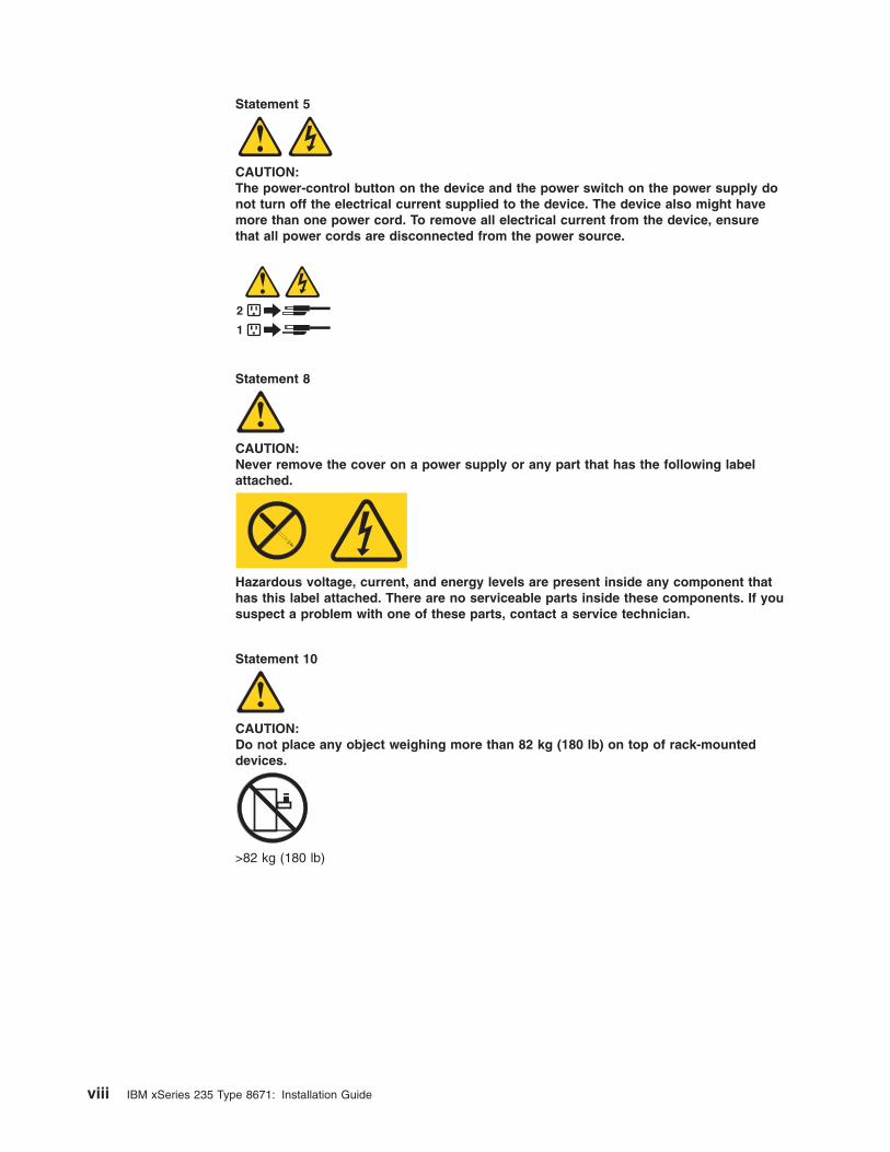
Statement 5
CAUTION:
The power-control button on the device and the power switch on the power supply do
not turn off the electrical current supplied to the device. The device also might have
more than one power cord. To remove all electrical current from the device, ensure
that all power cords are disconnected from the power source.
1
2
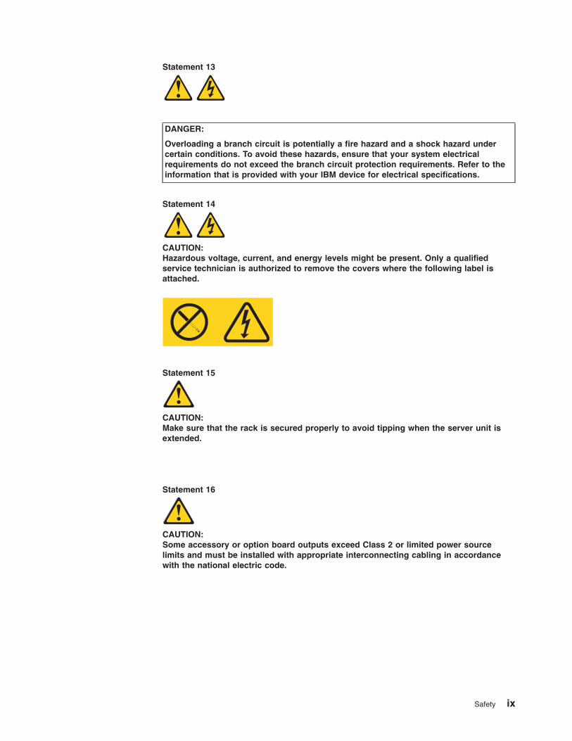
Statement 8
CAUTION:
Never remove the cover on a power supply or any part that has the following label
attached.
Hazardous voltage, current, and energy levels are present inside any component that
has this label attached. There are no serviceable parts inside these components. If you
suspect a problem with one of these parts, contact a service technician.
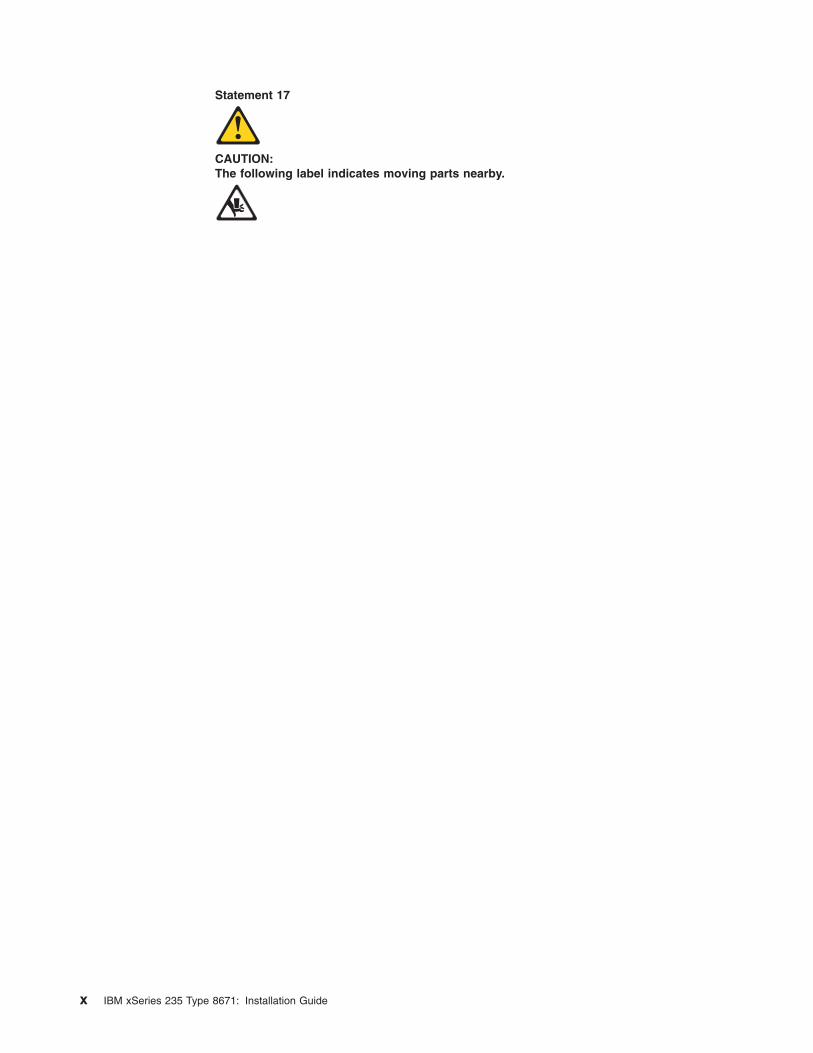
Statement 10
CAUTION:
Do not place any object weighing more than 82 kg (180 lb) on top of rack-mounted
devices.
>82 kg (180 lb)
viii IBM xSeries 235 Type 8671: Installation Guide
Statement 13
DANGER:
Overloading a branch circuit is potentially a fire hazard and a shock hazard under
certain conditions. To avoid these hazards, ensure that your system electrical
requirements do not exceed the branch circuit protection requirements. Refer to the
information that is provided with your IBM device for electrical specifications.
Statement 14
CAUTION:
Hazardous voltage, current, and energy levels might be present. Only a qualified
service technician is authorized to remove the covers where the following label is
attached.
Statement 15
CAUTION:
Make sure that the rack is secured properly to avoid tipping when the server unit is
extended.
Statement 16
CAUTION:
Some accessory or option board outputs exceed Class 2 or limited power source
limits and must be installed with appropriate interconnecting cabling in accordance
with the national electric code.
Safety ix
Statement 17
CAUTION:
The following label indicates moving parts nearby.
x IBM xSeries 235 Type 8671: Installation Guide
Chapter 1. Introduction
Thank you for purchasing an IBM®
Eserver xSeries® 235 Type 8671 server. Your
server is based on the IBM X-Architecture™ technology; it features superior
performance, availability, and scalability.
This Installation Guide provides the information that is needed to:
v Set up and cable your server
v Start and configure your server
v Install your network operating system (NOS)
Packaged with this Installation Guide are software CDs that help you configure
hardware, install device drivers, and install the network operating system (NOS).
Also included is an IBM xSeries Documentation CD that provides detailed
information about this server.
If you have access to the Internet, you can obtain up-to-date information about your
server model and other IBM server products at
http://www.ibm.com/pc/us/eserver/xseries/ on the World Wide Web.
For rack configurations, see the Rack Installation Instructions provided on the IBM
xSeries Documentation CD for complete installation and removal instructions.
Record your product information in this table.
Product name _________________________________________
Machine type _________________________________________
Model number _________________________________________
Serial number _________________________________________
Your server serial number and model number are on labels on the bottom of the
server and on the front, visible through the bezel. You will need these numbers
when you register your server with IBM. The information label containing the serial
number, machine type, model number, and agency marks for your server is located
as follows:
v Tower model: On the bottom of the server
v Rack configuration: On the side of the server
Note: The illustrations in this document might differ slightly from your hardware.
© Copyright IBM Corp. 2005 1
The IBM xSeries Documentation CD
The IBM xSeries Documentation CD contains documentation for your server in
Portable Document Format (PDF) and includes the IBM Documentation Browser to
help you find information quickly.
Hardware and software requirements
The IBM xSeries Documentation CD requires the following minimum hardware and
software:
v Microsoft Windows NT 4.0 (with Service Pack 3 or later), Windows 98, or
Windows 2000.
v 100 MHz Intel Pentium microprocessor.
v 32 MB of RAM.
v Adobe Acrobat Reader 3.0 or later. Acrobat Reader software is included on the
CD, and you can install it when you run the Documentation Browser.
Using the Documentation Browser
Use the Documentation Browser to browse the contents of the CD, read brief
descriptions of the books, and view books using Adobe Acrobat Reader. The
Documentation Browser automatically detects the regional settings in use in your
system and displays the books in the language for that region (if available). If a
book is not available in the language for that region, the English version is
displayed.
Use one of the following procedures to start the Documentation Browser:
v If Autostart is enabled, insert the CD into your CD-ROM drive. The
Documentation Browser starts automatically.
v If Autostart is disabled, insert the CD into your CD-ROM drive and click Start -->
Run. In the Open field, type
e:\win32.bat
where e is the drive letter of your CD-ROM drive, and click OK.
Select your server from the Product menu. The Available Topics list displays all
the books for your server. Some books might be in folders. A plus sign (+) indicates
each folder or book that has additional books under it. Click the plus sign to display
the additional books.
When you select a book, a description of the book appears under Topic
Description. To select more than one book, press and hold the Ctrl key while you
select the books. Click View Book to view the selected book or books in Acrobat
Reader. If you selected more than one book, all the selected books are opened in
Acrobat Reader.
To search all the books, type a word or word string in the Search field and click
Search. The books in which the word or word string appears are listed in order of
the most occurrences. Click a book to view it, and press Crtl+F to use the Acrobat
search function within the book.
Click Help for detailed information about using the Documentation Browser.
2 IBM xSeries 235 Type 8671: Installation Guide
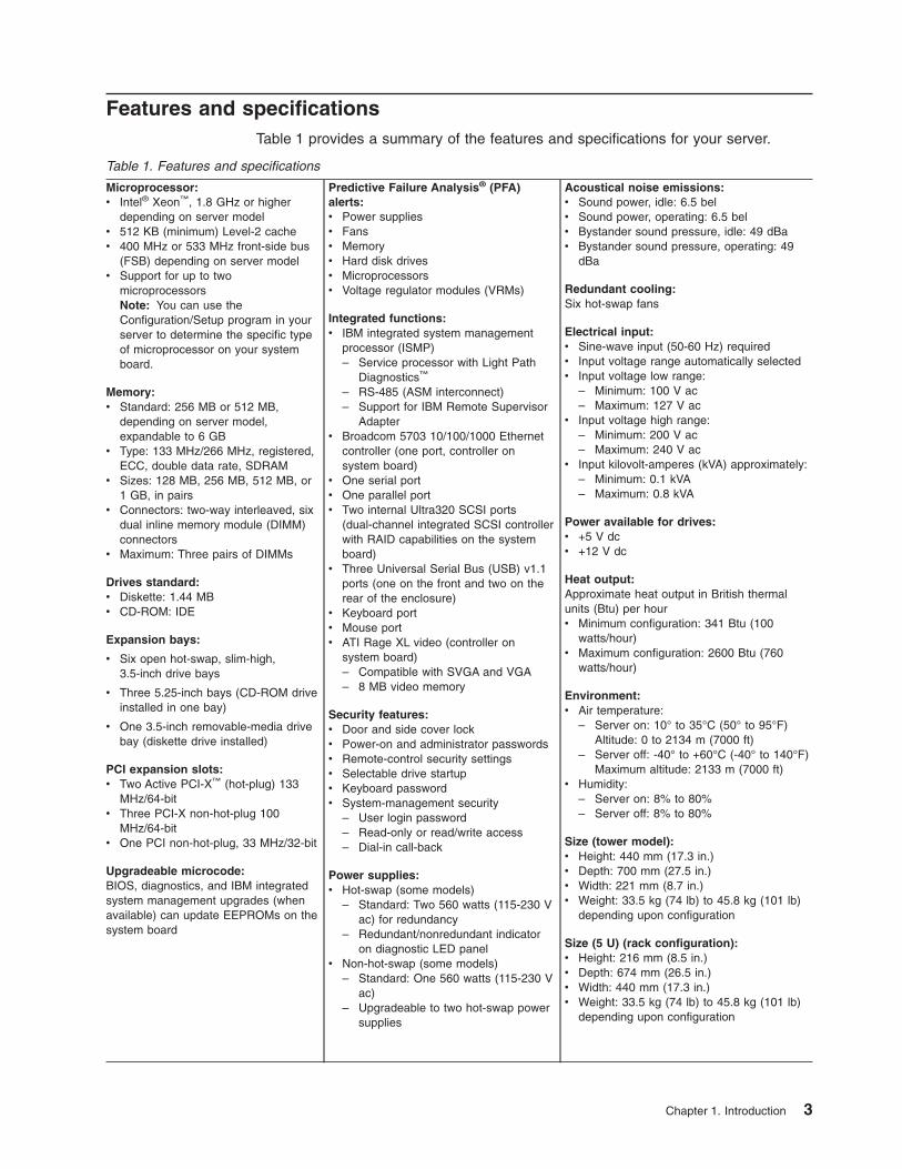
Features and specifications
Table 1 provides a summary of the features and specifications for your server.
Table 1. Features and specifications
Microprocessor:
v Intel® Xeon™, 1.8 GHz or higher
depending on server model
v 512 KB (minimum) Level-2 cache
v 400 MHz or 533 MHz front-side bus
(FSB) depending on server model
v Support for up to two
microprocessors
Note: You can use the
Configuration/Setup program in your
server to determine the specific type
of microprocessor on your system
board.
Memory:
v Standard: 256 MB or 512 MB,
depending on server model,
expandable to 6 GB
v Type: 133 MHz/266 MHz, registered,
ECC, double data rate, SDRAM
v Sizes: 128 MB, 256 MB, 512 MB, or
1 GB, in pairs
v Connectors: two-way interleaved, six
dual inline memory module (DIMM)
connectors
v Maximum: Three pairs of DIMMs
Drives standard:
v Diskette: 1.44 MB
v CD-ROM: IDE
Expansion bays:
v Six open hot-swap, slim-high,
3.5-inch drive bays
v Three 5.25-inch bays (CD-ROM drive
installed in one bay)
v One 3.5-inch removable-media drive
bay (diskette drive installed)
PCI expansion slots:
v Two Active PCI-X™ (hot-plug) 133
MHz/64-bit
v Three PCI-X non-hot-plug 100
MHz/64-bit
v One PCI non-hot-plug, 33 MHz/32-bit
Upgradeable microcode:
BIOS, diagnostics, and IBM integrated
system management upgrades (when
available) can update EEPROMs on the
system board
Predictive Failure Analysis® (PFA)
alerts:
v Power supplies
v Fans
v Memory
v Hard disk drives
v Microprocessors
v Voltage regulator modules (VRMs)
Integrated functions:
v IBM integrated system management
processor (ISMP)
– Service processor with Light Path
Diagnostics™
– RS-485 (ASM interconnect)
– Support for IBM Remote Supervisor
Adapterv Broadcom 5703 10/100/1000 Ethernet
controller (one port, controller on
system board)
v One serial port
v One parallel port
v Two internal Ultra320 SCSI ports
(dual-channel integrated SCSI controller
with RAID capabilities on the system
board)
v Three Universal Serial Bus (USB) v1.1
ports (one on the front and two on the
rear of the enclosure)
v Keyboard port
v Mouse port
v ATI Rage XL video (controller on
system board)
– Compatible with SVGA and VGA
– 8 MB video memory
Security features:
v Door and side cover lock
v Power-on and administrator passwords
v Remote-control security settings
v Selectable drive startup
v Keyboard password
v System-management security
– User login password
– Read-only or read/write access
– Dial-in call-back
Power supplies:
v Hot-swap (some models)
– Standard: Two 560 watts (115-230 V
ac) for redundancy
– Redundant/nonredundant indicator
on diagnostic LED panelv Non-hot-swap (some models)
– Standard: One 560 watts (115-230 V
ac)
– Upgradeable to two hot-swap power
supplies
Acoustical noise emissions:
v Sound power, idle: 6.5 bel
v Sound power, operating: 6.5 bel
v Bystander sound pressure, idle: 49 dBa
v Bystander sound pressure, operating: 49
dBa
Redundant cooling:
Six hot-swap fans
Electrical input:
v Sine-wave input (50-60 Hz) required
v Input voltage range automatically selected
v Input voltage low range:
– Minimum: 100 V ac
– Maximum: 127 V acv Input voltage high range:
– Minimum: 200 V ac
– Maximum: 240 V acv Input kilovolt-amperes (kVA) approximately:
– Minimum: 0.1 kVA
– Maximum: 0.8 kVA
Power available for drives:
v +5 V dc
v +12 V dc
Heat output:
Approximate heat output in British thermal
units (Btu) per hour
v Minimum configuration: 341 Btu (100
watts/hour)
v Maximum configuration: 2600 Btu (760
watts/hour)
Environment:
v Air temperature:
– Server on: 10° to 35°C (50° to 95°F)
Altitude: 0 to 2134 m (7000 ft)
– Server off: -40° to +60°C (-40° to 140°F)
Maximum altitude: 2133 m (7000 ft)v Humidity:
– Server on: 8% to 80%
– Server off: 8% to 80%
Size (tower model):
v Height: 440 mm (17.3 in.)
v Depth: 700 mm (27.5 in.)
v Width: 221 mm (8.7 in.)
v Weight: 33.5 kg (74 lb) to 45.8 kg (101 lb)
depending upon configuration
Size (5 U) (rack configuration):
v Height: 216 mm (8.5 in.)
v Depth: 674 mm (26.5 in.)
v Width: 440 mm (17.3 in.)
v Weight: 33.5 kg (74 lb) to 45.8 kg (101 lb)
depending upon configuration
Chapter 1. Introduction 3
Notices and statements in this book
The caution and danger statements used in this book also appear in the multilingual
Safety Information book provided on the IBM xSeries Documentation CD. Each
caution and danger statement is numbered for easy reference to the corresponding
statements in the safety book.
The following types of notices and statements are used in this book:
v Note: These notices provide important tips, guidance, or advice.
v Important: These notices provide information or advice that might help you avoid
inconvenient or problem situations.
v Attention: These notices indicate possible damage to programs, devices, or
data. An attention notice is placed just before the instruction or situation in which
damage could occur.
v Caution: These statements indicate situations that can be potentially hazardous
to you. A caution statement is placed just before the description of a potentially
hazardous procedure step or situation.
v Danger: These statements indicate situations that can be potentially lethal or
extremely hazardous to you. A danger statement is placed just before the
description of a potentially lethal or extremely hazardous procedure step or
situation.
4 IBM xSeries 235 Type 8671: Installation Guide
Major components of your server
The orange color on components and labels in your server identifies hot-swap or
hot-plug components. You can install or remove hot-swap and hot-plug components
while the system is running, provided that your system is configured to support this
function. For complete details about installing or removing a hot-swap or hot-plug
component, see the detailed information in Chapter 2, “Installing options,” on page
11.
The blue color on components and labels indicates touch points where a
component can be gripped, a latch moved, and so on.
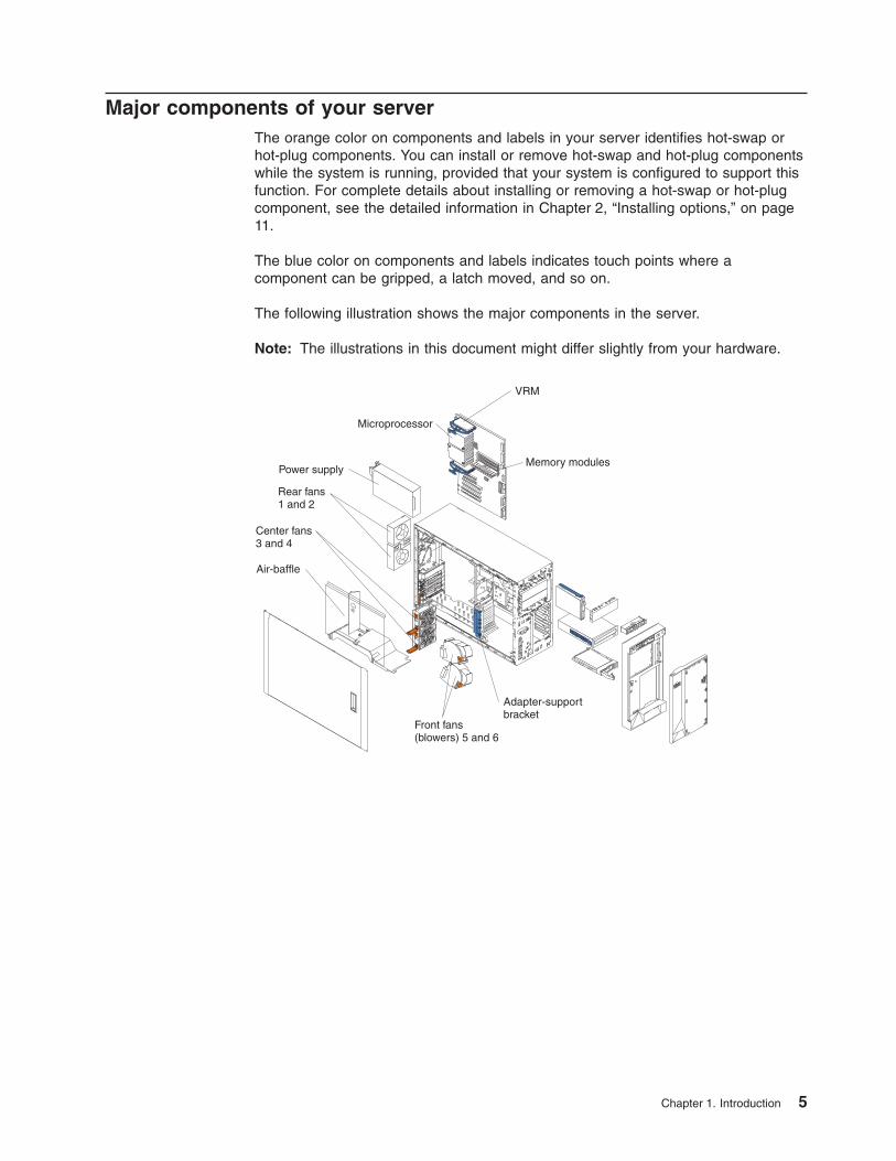
The following illustration shows the major components in the server.
Note: The illustrations in this document might differ slightly from your hardware.
Microprocessor
Memory modulesPower supply
Rear fans1 and 2
Front fans(blowers) 5 and 6
Adapter-supportbracket
Air-baffle
VRM
Center fans3 and 4
Chapter 1. Introduction 5
System-board component locations
This section provides illustrations of the system board showing the locations of
connectors, switch and jumper blocks, and LEDs.
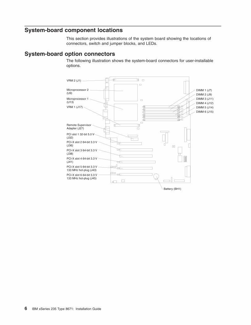
System-board option connectors
The following illustration shows the system-board connectors for user-installable
options.
DIMM 1 (J7)
DIMM 2 (J9)
DIMM 3 (J11)
DIMM 4 (J12)
DIMM 5 (J14)
DIMM 6 (J15)
Battery (BH1)
VRM 2 (J1)
Microprocessor 2(U9)
Microprocessor 1(U13)
VRM 1 (J17)
Remote SupervisorAdapter (J27)
PCI slot 1 32-bit 5.0 V(J32)
PCI-X slot 2 64-bit 3.3 V(J36)
PCI-X slot 3 64-bit 3.3 V(J38)
PCI-X slot 4 64-bit 3.3 V(J41)
PCI-X slot 5 64-bit 3.3 V133 MHz hot-plug (J43)
PCI-X slot 6 64-bit 3.3 V133 MHz hot-plug (J45)
6 IBM xSeries 235 Type 8671: Installation Guide
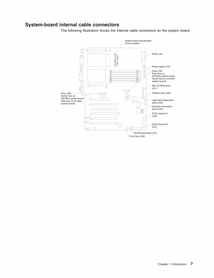
System-board internal cable connectors
The following illustration shows the internal cable connectors on the system board.
Power (J4)
Power signal (J10)
Fans (J18)Rear fans on533 MHz system boardCenter fans on all othersystem boards
IDE CD-ROM drive(J21)
Diskette drive (J22)
Light Path Diagnosticspanel (J23)
Operator informationpanel (J24)
SCSI channel A(J44)
SCSI channel B(J51)
On/off/reset panel (J47)
Front fans (J50)
Fans (J25)Center fans on533 MHz system boardRear fans on all othersystem boards
System-board identification(some models)
533
MN
z FS
BC
PU
ON
LY
Chapter 1. Introduction 7
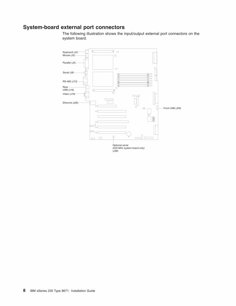
System-board external port connectors
The following illustration shows the input/output external port connectors on the
system board.
Front USB (J29)
Keyboard (J2)Mouse (J3)
Parallel (J5)
Serial (J8)
RS-485 (J13)
RearUSB (J16)
Video (J19)
Ethernet (J26)
Optional serial(533 MHz system board only)(J48)
8 IBM xSeries 235 Type 8671: Installation Guide
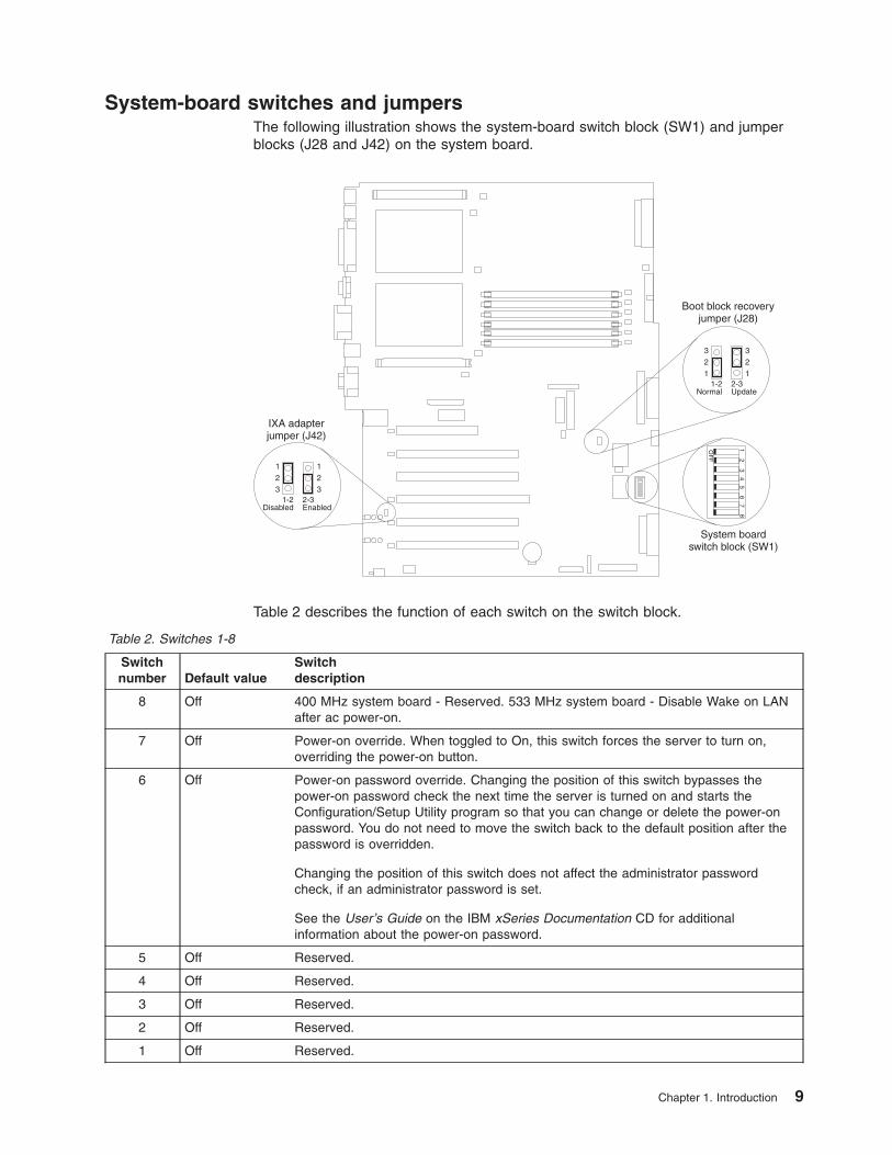
System-board switches and jumpers
The following illustration shows the system-board switch block (SW1) and jumper
blocks (J28 and J42) on the system board.
System boardswitch block (SW1)
1 2 3 4 5 6 7 8
OF
F
123
123
321
321
1-2Disabled
1-2Normal
2-3Enabled
2-3Update
Boot block recoveryjumper (J28)
IXA adapterjumper (J42)
Table 2 describes the function of each switch on the switch block.
Table 2. Switches 1-8
Switch
number Default value
Switch
description
8 Off 400 MHz system board - Reserved. 533 MHz system board - Disable Wake on LAN
after ac power-on.
7 Off Power-on override. When toggled to On, this switch forces the server to turn on,
overriding the power-on button.
6 Off Power-on password override. Changing the position of this switch bypasses the
power-on password check the next time the server is turned on and starts the
Configuration/Setup Utility program so that you can change or delete the power-on
password. You do not need to move the switch back to the default position after the
password is overridden.
Changing the position of this switch does not affect the administrator password
check, if an administrator password is set.
See the User’s Guide on the IBM xSeries Documentation CD for additional
information about the power-on password.
5 Off Reserved.
4 Off Reserved.
3 Off Reserved.
2 Off Reserved.
1 Off Reserved.
Chapter 1. Introduction 9
CAUTION:
Before changing any switch settings or moving any jumpers, make sure that
the server is turned off and that all power cords and external cables are
disconnected.
Note: Any system-board switch or jumper blocks that are not shown in the
illustrations in this book are reserved.
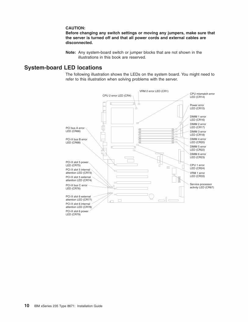
System-board LED locations
The following illustration shows the LEDs on the system board. You might need to
refer to this illustration when solving problems with the server.
VRM 2 error LED (CR1)
VRM 1 errorLED (CR33)
CPU 2 error LED (CR4)
CPU 1 errorLED (CR24)
CPU mismatch errorLED (CR14)
Power errorLED (CR15)
DIMM 1 errorLED (CR16)
DIMM 2 errorLED (CR17)
DIMM 3 errorLED (CR18)
DIMM 4 errorLED (CR20)
DIMM 5 errorLED (CR22)
DIMM 6 errorLED (CR23)
Service processoractivity LED (CR67)
PCI bus A errorLED (CR66)
PCI-X bus B errorLED (CR68)
PCI-X bus C errorLED (CR76)
PCI-X slot 5 powerLED (CR75)
PCI-X slot 6 powerLED (CR79)
PCI-X slot 5 internalattention LED (CR73)
PCI-X slot 6 internalattention LED (CR78)
PCI-X slot 5 externalattention LED (CR74)
PCI-X slot 6 externalattention LED (CR77)
10 IBM xSeries 235 Type 8671: Installation Guide
Chapter 2. Installing options
This chapter provides the basic information needed to install options in your server.
This section is for all users, but it is written with the experienced user in mind. If
you need more detailed installation information, see the Option Installation Guide on
the IBM xSeries Documentation CD.
If you have no options to install, continue with “Cabling the server” on page 40.
Installation guidelines
Before you begin to install options in your server, read the following information:
v Become familiar with the information provided in “Safety” on page v and
“Handling static-sensitive devices” on page 12. These guidelines will help you
work safely while working with your server options.
v You do not need to turn off the server to install or replace hot-swap power
supplies, hot-swap drives, hot-swap fans, Active PCI™ (hot-plug) adapters, or
hot-plug Universal Serial Bus (USB) devices.
v The orange color on components and labels in your server identifies hot-swap or
hot-plug component. You can install or remove hot-swap and hot-plug
components while the system is running, provided that your system is configured
to support this function. For complete details about installing or removing a
hot-swap or hot-plug component, see the detailed information in this chapter.
v The blue color on components and labels identifies touch points where you can
grip a component, move a latch, and so on.
v Make sure that you have an adequate number of properly grounded electrical
outlets for your server, monitor, and any other options that you intend to install.
v Back up all important data before you make changes to disk drives.
v For a list of supported options for your server, go to
http://www.ibm.com/pc/us/compat/ on the World Wide Web.
System reliability considerations
To help ensure proper cooling and system reliability, make sure that:
v Each of the drive bays has either a drive or a filler panel installed.
v Each of the power supply-bays has a power supply installed.
v For tower models, make sure that there is at least 50 mm (2 inches) of ventilated
space at the sides of the server and 100 mm (4 inches) at the front and rear of
the server.
For rack configurations, make sure that space is available around the server to
enable the server cooling system to work properly. See the documentation that
comes with the rack for additional information.
v The server cover is in place during normal operation.
v The air-baffle cover over the microprocessors remains closed during normal
operation.
v A removed hot-swap drive is replaced within 2 minutes of removal.
v Cables for optional adapters are routed according to the instructions provided
with the adapters.
v A failed fan is replaced within 48 hours.
v The server is turned off and the power cords are disconnected before you open
the air-baffle cover.
© Copyright IBM Corp. 2005 11
v The air-baffle assembly is always installed in the server except when you are
installing or removing the components that are under the air-baffle cover.
v When the air-baffle assembly is installed in the server, the air-baffle cover is
always closed.
v Microprocessor socket 2 always contains either a microprocessor baffle or a
microprocessor.
Working inside the server with the power on
Your server supports hot-plug, hot-add, and hot-swap devices and is designed to
operate safely while turned on with the cover removed. Follow these guidelines
when you work inside a server that is turned on:
v Avoid loose-fitting clothing on your forearms. Button long-sleeved shirts before
working inside the server; do not wear cuff links while you are working inside the
server.
v Do not allow your necktie or scarf to hang inside the server.
v Remove jewelry, such as bracelets, necklaces, rings, and loose-fitting wrist
watches.
v Remove items from your shirt pocket (such as pens or pencils) that could fall into
the server as you lean over it.
v Avoid dropping any metallic objects, such as paper clips, hair pins, or screws,
into the server.
Handling static-sensitive devices
Attention: Static electricity can damage electronic devices and your system. To
avoid damage, keep static-sensitive devices in their static-protective packages until
you are ready to install them.
To reduce the possibility of electrostatic discharge, observe the following
precautions:
v Limit your movement. Movement can cause static electricity to build up around
you.
v Handle the device carefully, holding it by its edges or its frame.
v Do not touch solder joints, pins, or exposed printed circuitry.
v Do not leave the device where others can handle and possibly damage the
device.
v While the device is still in its static-protective package, touch it to an unpainted
metal part of the server for at least 2 seconds. (This drains static electricity from
the package and from your body.)
v Remove the device from its package and install it directly into the server without
setting down the device. If it is necessary to set down the device, put it back into
its static-protective package. Do not place the device on your server cover or on
a metal surface.
v Take additional care when handling devices during cold weather because heating
reduces indoor humidity and increases static electricity.
12 IBM xSeries 235 Type 8671: Installation Guide
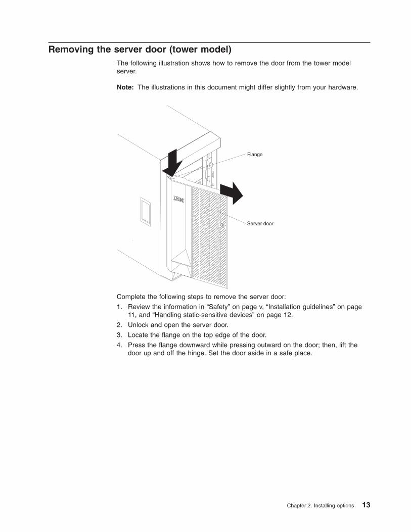
Removing the server door (tower model)
The following illustration shows how to remove the door from the tower model
server.
Note: The illustrations in this document might differ slightly from your hardware.
CPUVRMMEMORY HDD
PCI BUS
NMISMISERVICE PROCESSOR
BUS
NON REDUNDANT
POWER SUPPLY
1 2 3
A B
1 2 3
FAN
TEMPERATURE
Flange
Server door
Complete the following steps to remove the server door:
1. Review the information in “Safety” on page v, “Installation guidelines” on page
11, and “Handling static-sensitive devices” on page 12.
2. Unlock and open the server door.
3. Locate the flange on the top edge of the door.
4. Press the flange downward while pressing outward on the door; then, lift the
door up and off the hinge. Set the door aside in a safe place.
Chapter 2. Installing options 13
Removing the server left-side cover and bezel (tower model)
This section describes how to remove the left-side cover and bezel from the tower
model server.
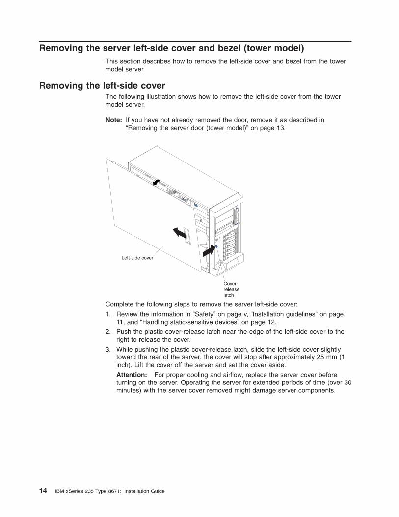
Removing the left-side cover
The following illustration shows how to remove the left-side cover from the tower
model server.
Note: If you have not already removed the door, remove it as described in
“Removing the server door (tower model)” on page 13.
Left-side cover
Cover-releaselatch
Complete the following steps to remove the server left-side cover:
1. Review the information in “Safety” on page v, “Installation guidelines” on page
11, and “Handling static-sensitive devices” on page 12.
2. Push the plastic cover-release latch near the edge of the left-side cover to the
right to release the cover.
3. While pushing the plastic cover-release latch, slide the left-side cover slightly
toward the rear of the server; the cover will stop after approximately 25 mm (1
inch). Lift the cover off the server and set the cover aside.
Attention: For proper cooling and airflow, replace the server cover before
turning on the server. Operating the server for extended periods of time (over 30
minutes) with the server cover removed might damage server components.
14 IBM xSeries 235 Type 8671: Installation Guide
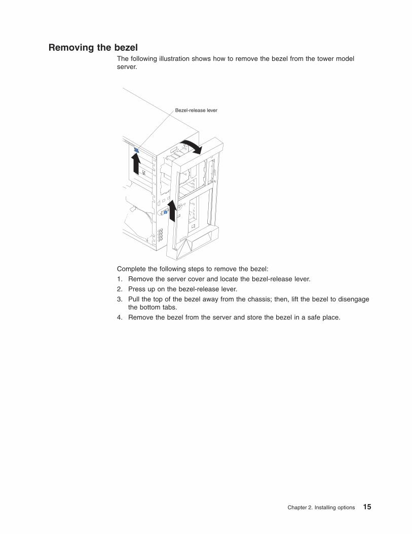
Removing the bezel
The following illustration shows how to remove the bezel from the tower model
server.
Bezel-release lever
Complete the following steps to remove the bezel:
1. Remove the server cover and locate the bezel-release lever.
2. Press up on the bezel-release lever.
3. Pull the top of the bezel away from the chassis; then, lift the bezel to disengage
the bottom tabs.
4. Remove the bezel from the server and store the bezel in a safe place.
Chapter 2. Installing options 15
Removing the server top cover and bezel (rack configuration)
This section describes how to remove the top cover and bezel from the rack
configuration server.
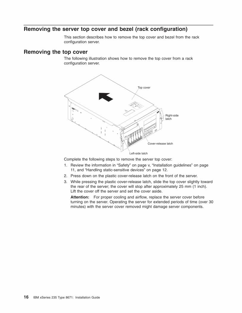
Removing the top cover
The following illustration shows how to remove the top cover from a rack
configuration server.
Top cover
Left-side latch
Right-sidelatch
Cover-release latch
CPU
VRM
MEMORY
HDD
PCI BUS
NMI
SMI
SERVICE PROCESSOR
BUS
NON REDUNDANT
POWER SUPPLY
1 2 3A B
1 2 3FAN
TEMPERATURE
Complete the following steps to remove the server top cover:
1. Review the information in “Safety” on page v, “Installation guidelines” on page
11, and “Handling static-sensitive devices” on page 12.
2. Press down on the plastic cover-release latch on the front of the server.
3. While pressing the plastic cover-release latch, slide the top cover slightly toward
the rear of the server; the cover will stop after approximately 25 mm (1 inch).
Lift the cover off the server and set the cover aside.
Attention: For proper cooling and airflow, replace the server cover before
turning on the server. Operating the server for extended periods of time (over 30
minutes) with the server cover removed might damage server components.
16 IBM xSeries 235 Type 8671: Installation Guide
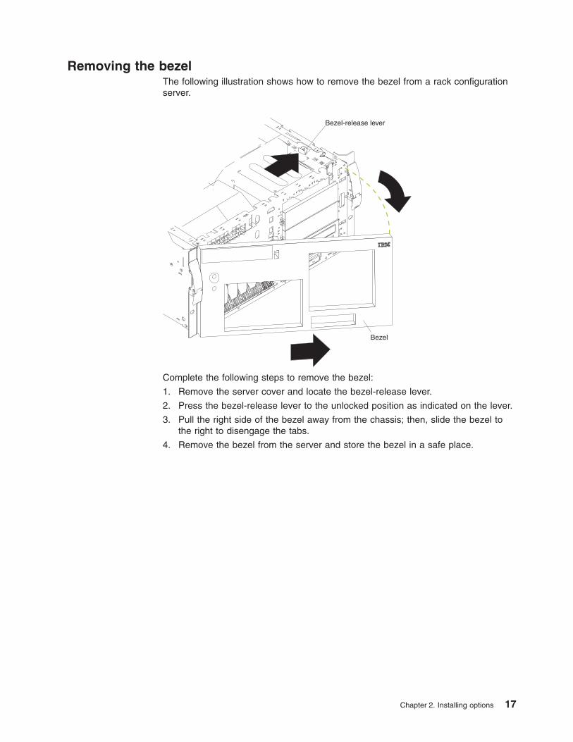
Removing the bezel
The following illustration shows how to remove the bezel from a rack configuration
server.
Bezel-release lever
Bezel
Complete the following steps to remove the bezel:
1. Remove the server cover and locate the bezel-release lever.
2. Press the bezel-release lever to the unlocked position as indicated on the lever.
3. Pull the right side of the bezel away from the chassis; then, slide the bezel to
the right to disengage the tabs.
4. Remove the bezel from the server and store the bezel in a safe place.
Chapter 2. Installing options 17
Removing and installing the adapter-support bracket
You might need to remove the adapter-support bracket to access certain
components or connectors on the system board.
Note: The adapter-support bracket is attached to the center-fan bracket in the
server. Both brackets are removed and installed together as a single unit.
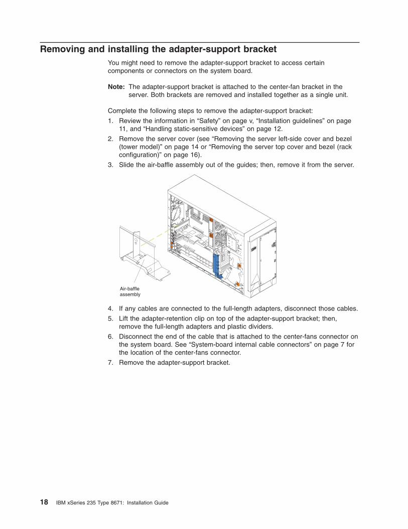
Complete the following steps to remove the adapter-support bracket:
1. Review the information in “Safety” on page v, “Installation guidelines” on page
11, and “Handling static-sensitive devices” on page 12.
2. Remove the server cover (see “Removing the server left-side cover and bezel
(tower model)” on page 14 or “Removing the server top cover and bezel (rack
configuration)” on page 16).
3. Slide the air-baffle assembly out of the guides; then, remove it from the server.
Air-baffleassembly
4. If any cables are connected to the full-length adapters, disconnect those cables.
5. Lift the adapter-retention clip on top of the adapter-support bracket; then,
remove the full-length adapters and plastic dividers.
6. Disconnect the end of the cable that is attached to the center-fans connector on
the system board. See “System-board internal cable connectors” on page 7 for
the location of the center-fans connector.
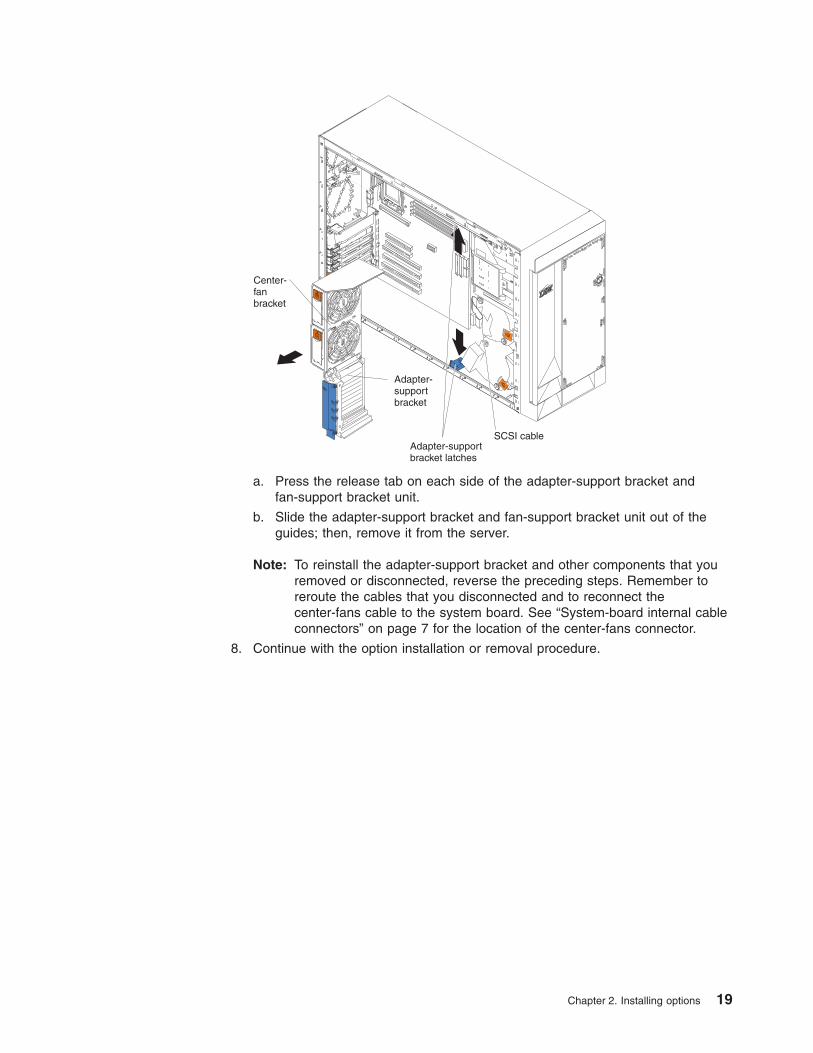
7. Remove the adapter-support bracket.
18 IBM xSeries 235 Type 8671: Installation Guide
SCSI cable
Adapter-supportbracket
Adapter-supportbracket latches
Center-fanbracket
a. Press the release tab on each side of the adapter-support bracket and
fan-support bracket unit.
b. Slide the adapter-support bracket and fan-support bracket unit out of the
guides; then, remove it from the server.
Note: To reinstall the adapter-support bracket and other components that you
removed or disconnected, reverse the preceding steps. Remember to
reroute the cables that you disconnected and to reconnect the
center-fans cable to the system board. See “System-board internal cable
connectors” on page 7 for the location of the center-fans connector.
8. Continue with the option installation or removal procedure.
Chapter 2. Installing options 19
Working with adapters
This section describes how to install hot-plug and non-hot-plug PCI and PCI-X
adapters. Before you continue with the adapter-installation procedures, review
“Adapter considerations” on page 21.
Attention: When you handle static-sensitive devices, take precautions to avoid
damage from static electricity. For details on handling these devices, see “Handling
static-sensitive devices” on page 12.
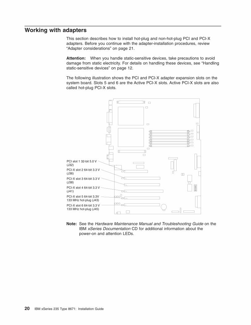
The following illustration shows the PCI and PCI-X adapter expansion slots on the
system board. Slots 5 and 6 are the Active PCI-X slots. Active PCI-X slots are also
called hot-plug PCI-X slots.
PCI slot 1 32-bit 5.0 V(J32)
PCI-X slot 2 64-bit 3.3 V(J36)
PCI-X slot 3 64-bit 3.3 V(J38)
PCI-X slot 4 64-bit 3.3 V(J41)
PCI-X slot 5 64-bit 3.3V133 MHz hot-plug (J43)
PCI-X slot 6 64-bit 3.3 V133 MHz hot-plug (J45)
Note: See the Hardware Maintenance Manual and Troubleshooting Guide on the
IBM xSeries Documentation CD for additional information about the
power-on and attention LEDs.
20 IBM xSeries 235 Type 8671: Installation Guide
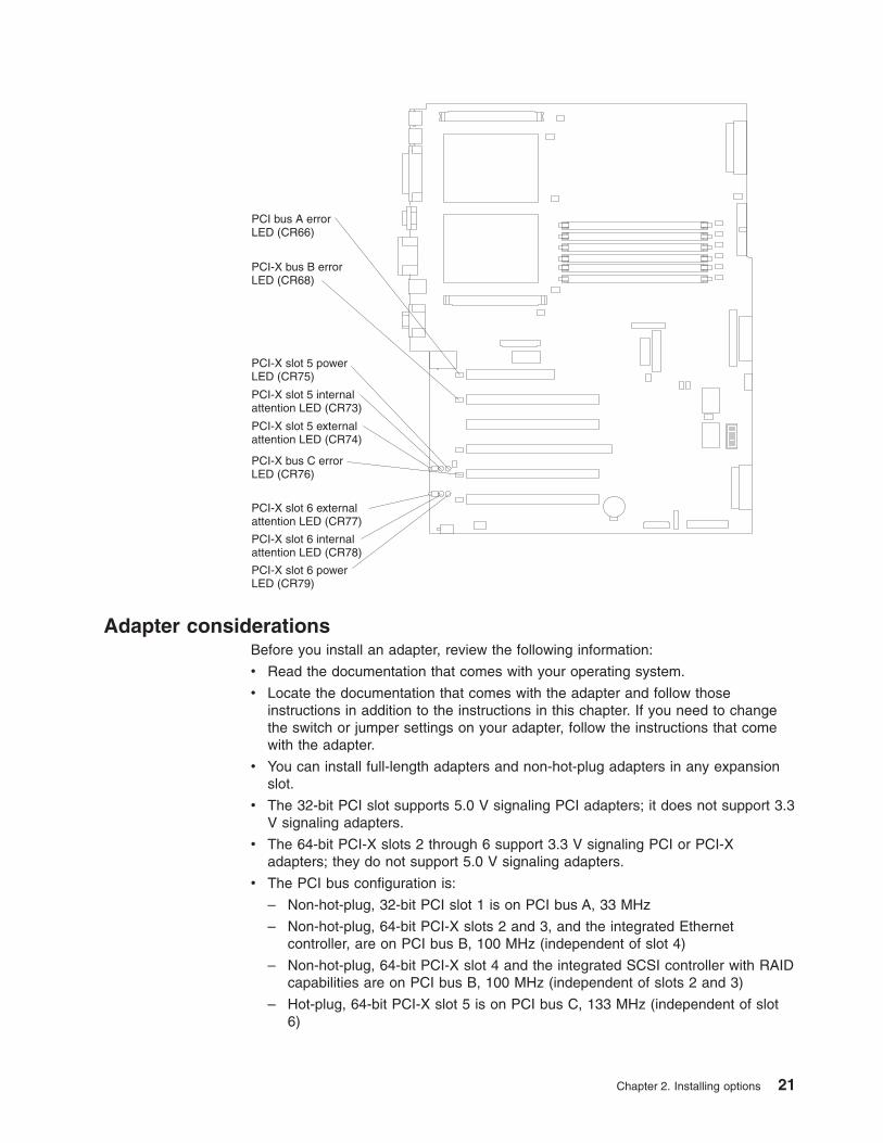
PCI bus A errorLED (CR66)
PCI-X bus B errorLED (CR68)
PCI-X bus C errorLED (CR76)
PCI-X slot 5 powerLED (CR75)
PCI-X slot 6 powerLED (CR79)
PCI-X slot 5 internalattention LED (CR73)
PCI-X slot 6 internalattention LED (CR78)
PCI-X slot 5 externalattention LED (CR74)
PCI-X slot 6 externalattention LED (CR77)
Adapter considerations
Before you install an adapter, review the following information:
v Read the documentation that comes with your operating system.
v Locate the documentation that comes with the adapter and follow those
instructions in addition to the instructions in this chapter. If you need to change
the switch or jumper settings on your adapter, follow the instructions that come
with the adapter.
v You can install full-length adapters and non-hot-plug adapters in any expansion
slot.
v The 32-bit PCI slot supports 5.0 V signaling PCI adapters; it does not support 3.3
V signaling adapters.
v The 64-bit PCI-X slots 2 through 6 support 3.3 V signaling PCI or PCI-X
adapters; they do not support 5.0 V signaling adapters.
v The PCI bus configuration is:
– Non-hot-plug, 32-bit PCI slot 1 is on PCI bus A, 33 MHz
– Non-hot-plug, 64-bit PCI-X slots 2 and 3, and the integrated Ethernet
controller, are on PCI bus B, 100 MHz (independent of slot 4)
– Non-hot-plug, 64-bit PCI-X slot 4 and the integrated SCSI controller with RAID
capabilities are on PCI bus B, 100 MHz (independent of slots 2 and 3)
– Hot-plug, 64-bit PCI-X slot 5 is on PCI bus C, 133 MHz (independent of slot
6)
Chapter 2. Installing options 21
– Hot-plug, 64-bit PCI-X slot 6 is on PCI bus C, 133 MHz (independent of slot
5)
Notes:
1. PCI bus A is often referred to as bus 0; PCI bus B is often referred to as bus
1 and bus 2; and PCI bus C is often referred to as bus 3 and bus 5.
However, the bus numbers vary according to the adapters that are installed.
2. If an optional ServeRAID-5i controller is installed, it overrides the standard
functionality of the integrated SCSI controller with RAID capabilities and
forces PCI-X slot 4 to 66 MHz. The ServeRAID-5i controller must be installed
in slot 4 using the 3-U bracket that comes with the controller.
3. The integrated SCSI controller with RAID capabilities is on PCI bus B.
v The optional IBM Remote Supervisor Adapter must be installed in PCI slot 1 only.
Use the ribbon cable that comes with the adapter to connect the adapter to the
Remote Supervisor Adapter connector (J27) on the system board.
v The system scans PCI and PCI-X slots 1 through 6 to assign system resources.
The system then starts (boots) the system devices in the following order, if you
have not changed the default boot precedence: integrated SCSI controller with
RAID capabilities (or optional ServeRAID-5i controller), integrated Ethernet
controller, and then PCI and PCI-X slots 1 through 6.
Note: To change the boot precedence for PCI and PCI-X devices, start the
Configuration/Setup Utility program and select Start Options from the
main menu. See the User’s Guide on the IBM xSeries Documentation CD
for details about using the Configuration/Setup Utility program.
v The Active PCI-X slots contain:
– Power-on LEDs
– Internal attention LEDs
– External attention LEDs
Installing a hot-plug adapter (slots 5 and 6)
This section contains the procedure for installing a hot-plug PCI or PCI-X adapter. If
your operating system supports hot-plug PCI or PCI-X adapters, you can replace a
failing hot-plug PCI or PCI-X adapter with a new adapter of the same type without
turning off power to the server. If your operating system and adapter also support
the hot-add feature, you can install a new adapter without turning off the power to
the server.
Notes:
1. Although an optional Integrated xSeries Adapter (IXA) can be installed only in
slots 5 and 6, it is not a hot-plug adapter. See “Installing a non-hot-plug adapter
(any slot)” on page 25 for instructions for installing an IXA adapter.
2. You do not have to turn off the server to install hot-plug adapters in the hot-plug
slots. However, you must turn off the server when performing any steps that
involve installing or removing cables.
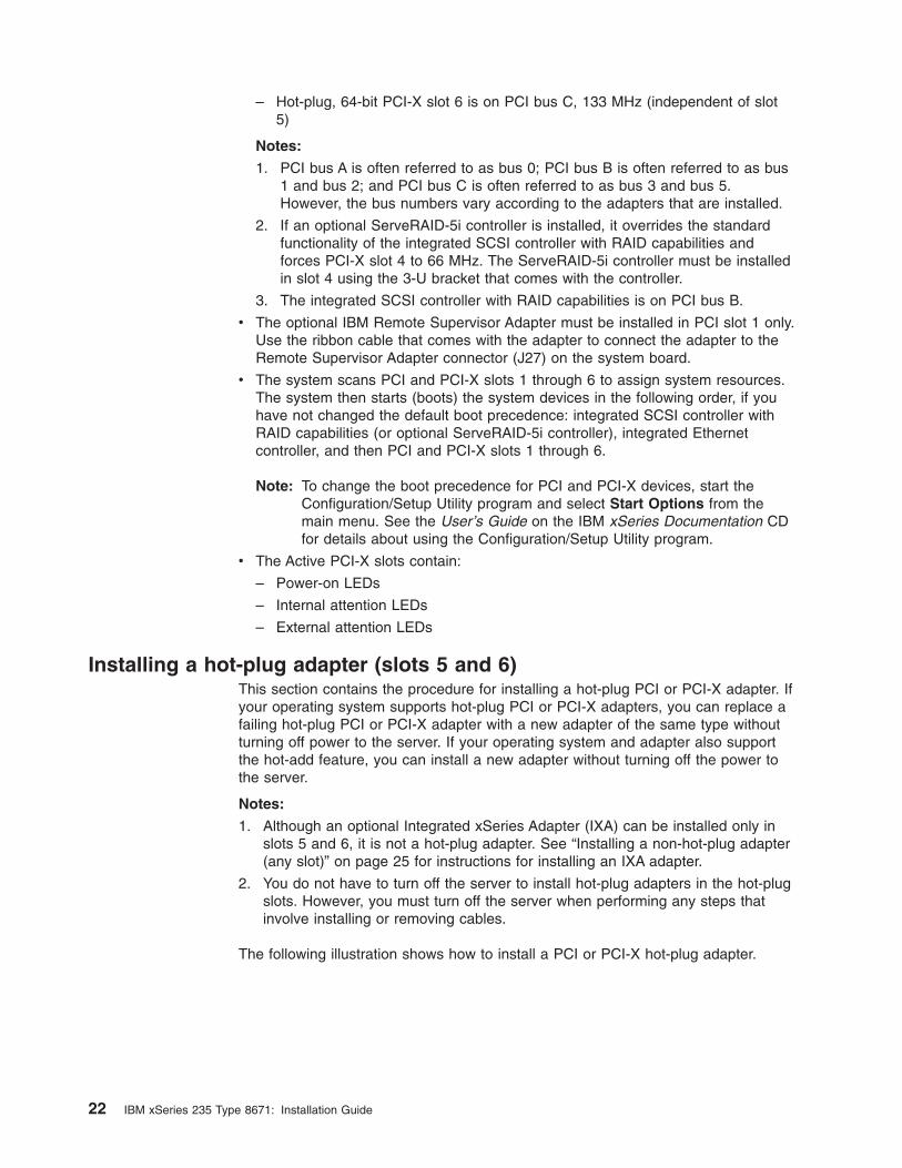
The following illustration shows how to install a PCI or PCI-X hot-plug adapter.
22 IBM xSeries 235 Type 8671: Installation Guide
Adapter
Adapter-retentionlatch
Expansion-slot cover
Adapter-retentionclip
Adapter-supportbracket
Complete the following steps to install a hot-plug PCI or PCI-X adapter:
1. Review the information in “Safety” on page v, “Installation guidelines” on page
11, and “Handling static-sensitive devices” on page 12.
2. Remove the server cover (see “Removing the server left-side cover and bezel
(tower model)” on page 14 or “Removing the server top cover and bezel (rack
configuration)” on page 16).
3. Determine which expansion slot you will use for the adapter.
Note: Only PCI-X slots 5 and 6 support hot-plug adapters.
4. Slide the adapter-retention-latch release toward the rear of the server and hold
it there while you lift the adapter-retention latch to the unlocked (open) position
as indicated by the arrow.
Attention: Expansion slot covers must be installed on all empty slots. This
maintains the electronic emissions characteristics of the system and ensures
proper cooling of system components.
5. Remove the expansion-slot cover from the server. Store it in a safe place for
future use.
6. If you are installing a full-length adapter, lift the adapter-retention clip on the
adapter-support bracket. Otherwise, continue with the next step.
7. See the documentation that comes with your adapter for any cabling
instructions. It might be easier for you to route cables before you install the
adapter.
Attention: Avoid touching the components and gold-edge connectors on the
adapter.
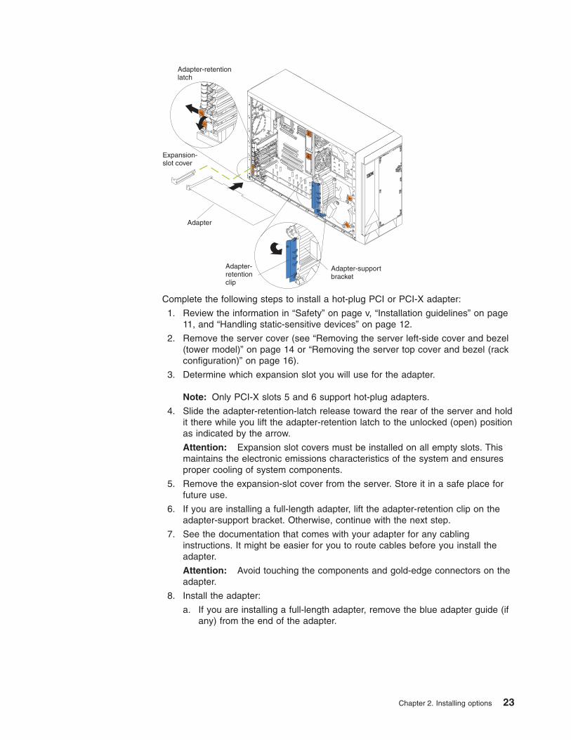
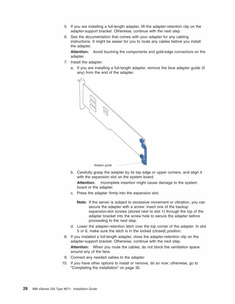
8. Install the adapter:
a. If you are installing a full-length adapter, remove the blue adapter guide (if
any) from the end of the adapter.
Chapter 2. Installing options 23
Adapter guide
b. Carefully grasp the adapter by its top edge or upper corners, and align it
with the expansion slot on the system board.
Attention: Incomplete insertion might cause damage to the system
board or the adapter.
c. Press the adapter firmly into the expansion slot.
d. Lower the adapter-retention latch over the top corner of the adapter. The
adapter-retention latch automatically locks into place.
Important: Power cannot be provided to the adapter slot if the latch is not
lowered into place.
9. If you installed a full-length adapter, close the adapter-retention clip on the
adapter-support bracket. Otherwise, continue with the next step.
Attention: When you route the cables, do not block the ventilation space
around any of the fans.
10. Connect any needed cables to the adapter.
Note: You will need to enable the hot-plug PCI-X slot after installing your
operating system. See the documentation that comes with your
operating system for information about enabling a hot-plug PCI-X slot.
11. If you have other options to install or remove, do so now; otherwise, go to
“Completing the installation” on page 35.
24 IBM xSeries 235 Type 8671: Installation Guide
Installing a non-hot-plug adapter (any slot)
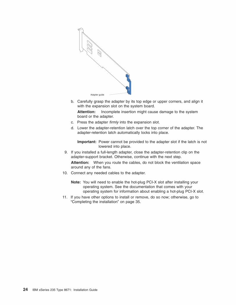
The following illustration shows how to install a non-hot-plug PCI or PCI-X adapter.
Adapter
Adapter-retentionlatch
Expansion-slot cover
Adapter-retentionclip
Adapter-supportbracket
Backup expansion-slotscrews
Attention: You must install the IXA adapter jumper (J42) between pins 2 and 3
when using an Integrated xSeries Adapter (IXA) in slots 5 and 6.
Notes:
1. Although the optional IXA adapter is not a hot-plug adapter, it must be installed
in slots 5 and 6. It is a double width adapter that installs in slot 5 and spans
slots 5 and 6.
2. You can install an optional ServeRAID-5i controller only in PCI-X slot 4. Slot 4 is
the only PCI-X slot that supports the ServeRAID-5i controller requirements.
Install the ServeRAID-5i controller using the 3-U bracket that comes with the
controller.
Complete the following steps to install a non-hot-plug PCI or PCI-X adapter:
1. Review the information in “Safety” on page v, “Installation guidelines” on page
11, and “Handling static-sensitive devices” on page 12.
2. Remove the server cover (see “Removing the server left-side cover and bezel
(tower model)” on page 14 or “Removing the server top cover and bezel (rack
configuration)” on page 16).
Attention: Expansion slot covers must be installed on all empty slots. This
maintains the electronic emissions characteristics of the system and ensures
proper cooling of system components.
3. Determine which expansion slot you will use for the adapter, and remove the
expansion-slot cover. See the Option Installation Guide on the IBM xSeries
Documentation CD for details.
4. If you are installing an IXA adapter in slots 5 and 6, make sure that the IXA
adapter jumper (J42) is installed between pins 2 and 3; otherwise, make sure it
is installed between pins 1 and 2. (See “System-board switches and jumpers”
on page 9 for the jumper location.)
Chapter 2. Installing options 25
5. If you are installing a full-length adapter, lift the adapter-retention clip on the
adapter-support bracket. Otherwise, continue with the next step.
6. See the documentation that comes with your adapter for any cabling
instructions. It might be easier for you to route any cables before you install
the adapter.
Attention: Avoid touching the components and gold-edge connectors on the
adapter.
7. Install the adapter:
a. If you are installing a full-length adapter, remove the blue adapter guide (if
any) from the end of the adapter.
Adapter guide
b. Carefully grasp the adapter by its top edge or upper corners, and align it
with the expansion slot on the system board.
Attention: Incomplete insertion might cause damage to the system
board or the adapter.
c. Press the adapter firmly into the expansion slot.
Note: If the server is subject to excessive movement or vibration, you can
secure the adapter with a screw: insert one of the backup
expansion-slot screws (stored next to slot 1) through the top of the
adapter bracket into the screw hole to secure the adapter before
proceeding to the next step.
d. Lower the adapter-retention latch over the top corner of the adapter. In slot
5 or 6, make sure the latch is in the locked (closed) position.
8. If you installed a full-length adapter, close the adapter-retention clip on the
adapter-support bracket. Otherwise, continue with the next step.
Attention: When you route the cables, do not block the ventilation space
around any of the fans.
9. Connect any needed cables to the adapter.
10. If you have other options to install or remove, do so now; otherwise, go to
“Completing the installation” on page 35.
26 IBM xSeries 235 Type 8671: Installation Guide
Installing memory modules
Adding memory to your server is an easy way to make programs run faster. You
can increase the amount of memory in your server by installing memory-module
options. When you install memory, you must install a pair of matched dual inline
memory modules (DIMMs). See the Option Installation Guide on the IBM xSeries
Documentation CD for more details.
Notes:
1. When you install additional DIMMs, be sure to install them in pairs. All the
DIMMs in a single pair must be the same size, speed, type, and technology.
You can mix compatible DIMMs from various manufacturers.
2. The second pair does not have to contain DIMMs of the same size, speed, type,
and technology as the first pair.
3. Install only 133 MHz/266 MHz, 2.5 V, 184-pin, double-data-rate (DDR), PC2100,
registered synchronous dynamic random-access memory (SDRAM) with error
correcting code (ECC) DIMMs. These DIMMs must be compatible with the latest
PC2100 SDRAM Registered DIMM specification. For a list of supported options
for your server, go to http://www.ibm.com/us/compat/ on the World Wide Web.
4. Your server supports Chipkill™ memory if the DIMMs are all type x4 and larger
than 128 MB. Using any 128 MB DIMMs, or DIMMs that are not of type x4, on
your server disables Chipkill memory.
5. You do not need to save new configuration information when installing or
removing DIMMs. The only exception is if you replace a faulty DIMM that was
marked as Disabled in the Memory Settings menu. In this case, you need to
re-enable that memory row in the Configuration/Setup Utility or reload the
default memory settings. See the User’s Guide on the IBM xSeries
Documentation CD for more information.
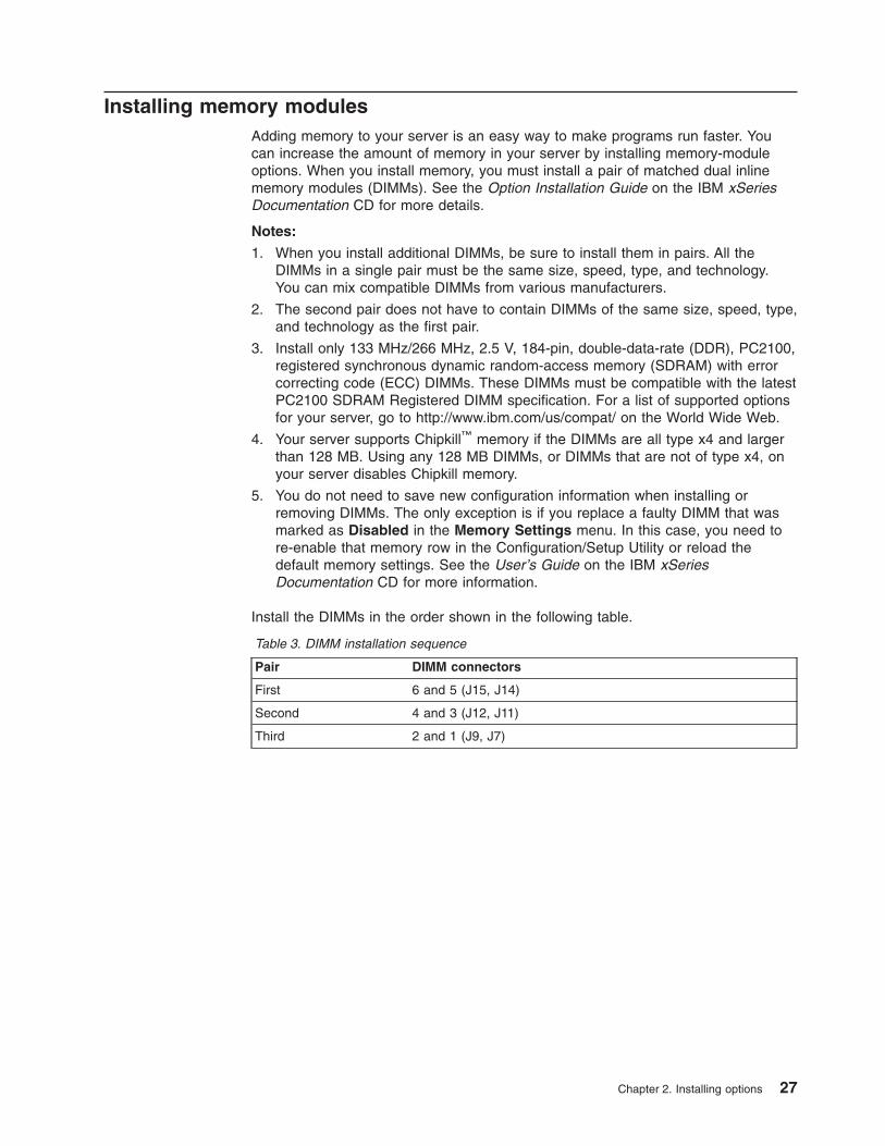
Install the DIMMs in the order shown in the following table.
Table 3. DIMM installation sequence
Pair DIMM connectors
First 6 and 5 (J15, J14)
Second 4 and 3 (J12, J11)
Third 2 and 1 (J9, J7)
Chapter 2. Installing options 27
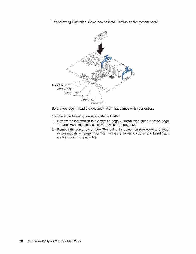
The following illustration shows how to install DIMMs on the system board.
DIMM 5 (J14)
DIMM 6 (J15)
DIMM 4 (J12)DIMM 3 (J11)
DIMM 2 (J9)
DIMM 1 (J7)
Before you begin, read the documentation that comes with your option.
Complete the following steps to install a DIMM:
1. Review the information in “Safety” on page v, “Installation guidelines” on page
11, and “Handling static-sensitive devices” on page 12.
2. Remove the server cover (see “Removing the server left-side cover and bezel
(tower model)” on page 14 or “Removing the server top cover and bezel (rack
configuration)” on page 16).
28 IBM xSeries 235 Type 8671: Installation Guide
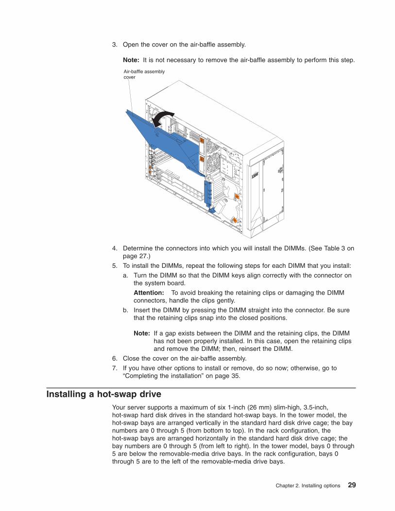
3. Open the cover on the air-baffle assembly.
Note: It is not necessary to remove the air-baffle assembly to perform this step.
Air-baffle assemblycover
4. Determine the connectors into which you will install the DIMMs. (See Table 3 on
page 27.)
5. To install the DIMMs, repeat the following steps for each DIMM that you install:
a. Turn the DIMM so that the DIMM keys align correctly with the connector on
the system board.
Attention: To avoid breaking the retaining clips or damaging the DIMM
connectors, handle the clips gently.
b. Insert the DIMM by pressing the DIMM straight into the connector. Be sure
that the retaining clips snap into the closed positions.
Note: If a gap exists between the DIMM and the retaining clips, the DIMM
has not been properly installed. In this case, open the retaining clips
and remove the DIMM; then, reinsert the DIMM.
6. Close the cover on the air-baffle assembly.
7. If you have other options to install or remove, do so now; otherwise, go to
“Completing the installation” on page 35.
Installing a hot-swap drive
Your server supports a maximum of six 1-inch (26 mm) slim-high, 3.5-inch,
hot-swap hard disk drives in the standard hot-swap bays. In the tower model, the
hot-swap bays are arranged vertically in the standard hard disk drive cage; the bay
numbers are 0 through 5 (from bottom to top). In the rack configuration, the
hot-swap bays are arranged horizontally in the standard hard disk drive cage; the
bay numbers are 0 through 5 (from left to right). In the tower model, bays 0 through
5 are below the removable-media drive bays. In the rack configuration, bays 0
through 5 are to the left of the removable-media drive bays.
Chapter 2. Installing options 29
You cannot install hot-swap drives in the removable-media or non-hot-swap drive
bays on the front side of the server, unless you install the 3-Pack Ultra320
Hot-Swap Expansion option. See the Option Installation Guide on the IBM xSeries
Documentation CD for instructions for installing this option.
Notes:
1. All hot-swap drives being used in the server should have the same throughput
speed rating; mixing speed ratings might cause all drives to operate at the lower
throughput speed.
2. To minimize the possibility of damage to the hard disk drives when you are
installing them in a rack configuration, install the server in the rack before
installing the hard disk drives.
3. You do not have to turn off the server to install hot-swap drives in the hot-swap
drive bays. However, you must turn off the server when performing any steps
that involve installing or removing cables.
4. You can install three additional hot-swap hard disk drives in the server after you
install the 3-Pack Ultra320 Hot-Swap Expansion option. These drives are in the
optional hard disk drive cage.
5. Some filler panels come with a slim filler.
6. The SCSI ID for each hot-swap hard disk drive is printed on the bezel.
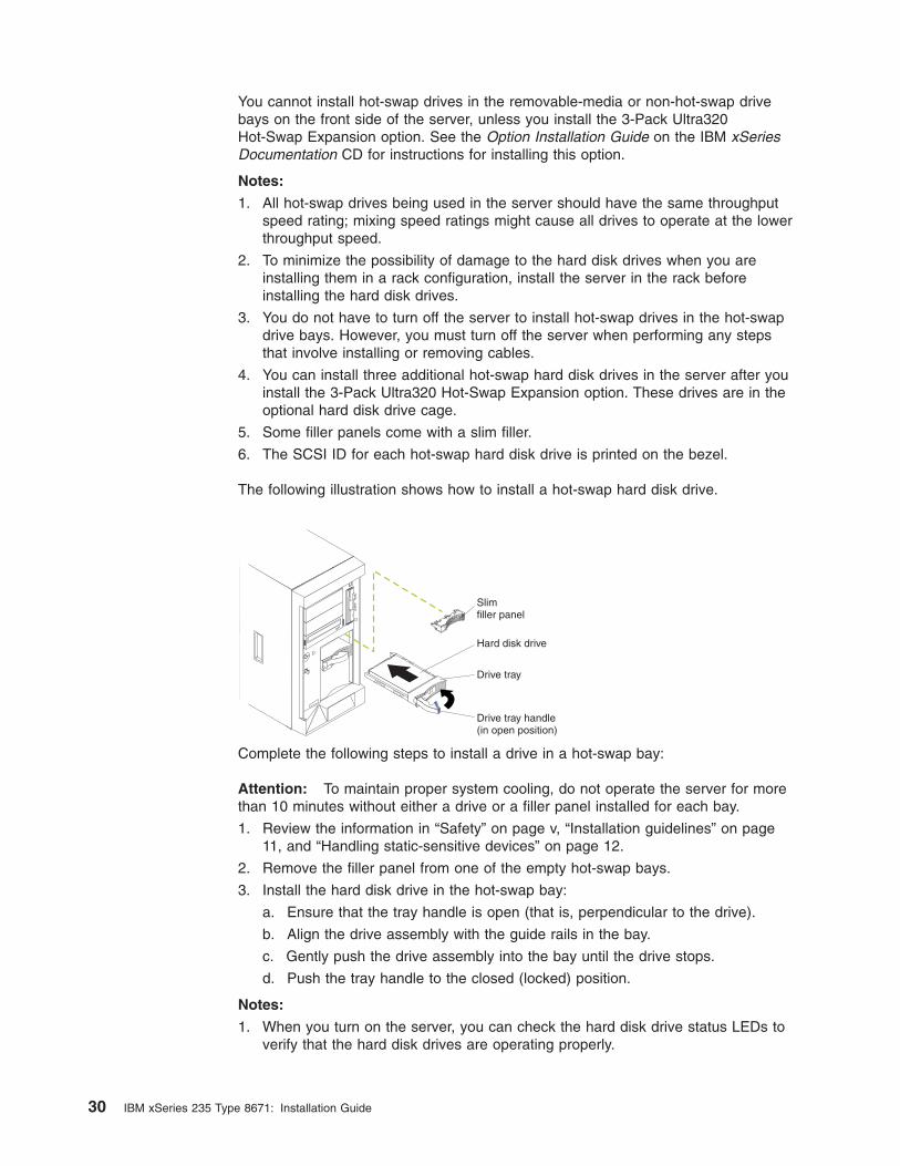
The following illustration shows how to install a hot-swap hard disk drive.
Slimfiller panel
Hard disk drive
Drive tray
Drive tray handle(in open position)
Complete the following steps to install a drive in a hot-swap bay:
Attention: To maintain proper system cooling, do not operate the server for more
than 10 minutes without either a drive or a filler panel installed for each bay.
1. Review the information in “Safety” on page v, “Installation guidelines” on page
11, and “Handling static-sensitive devices” on page 12.
2. Remove the filler panel from one of the empty hot-swap bays.
3. Install the hard disk drive in the hot-swap bay:
a. Ensure that the tray handle is open (that is, perpendicular to the drive).
b. Align the drive assembly with the guide rails in the bay.
c. Gently push the drive assembly into the bay until the drive stops.
d. Push the tray handle to the closed (locked) position.
Notes:
1. When you turn on the server, you can check the hard disk drive status LEDs to
verify that the hard disk drives are operating properly.
30 IBM xSeries 235 Type 8671: Installation Guide
If the amber hard disk drive status LED for a drive is lit continuously, that drive
is faulty and needs to be replaced. If the green hard disk drive activity LED is
flashing, the drive is being accessed.
2. If your server will be configured for RAID operation using the integrated SCSI
controller with RAID capabilities or an optional ServeRAID™ controller, you will
need to configure your disk arrays before installing your operating system. See
the ServeRAID documentation on the IBM ServeRAID Support CD for additional
information about RAID operation and complete instructions for using
ServeRAID Manager.
Installing an additional microprocessor
Your server comes with one or two microprocessors installed on the system board.
Your server supports two microprocessors. With two microprocessors, your server
can operate as a symmetric multiprocessing (SMP) server. With SMP, certain
operating systems and application programs can distribute the processing load
among the microprocessors. If your server comes with one microprocessor, you can
install a second microprocessor.
Attention: To ensure proper server operation when you install an additional
microprocessor, use microprocessors that have the same cache size and type, and
the same clock speed. Microprocessor internal and external clock frequencies must
be identical. You can use the Configuration/Setup Utility program in your server to
determine the specific type of microprocessor on your system board.
Important: A boot processor must always be installed in socket U13 of the system
board.
Notes:
1. To order additional microprocessor options, contact your IBM reseller or IBM
marketing representative.
2. When you install a microprocessor in socket U9, you must also install the
voltage regulator module (VRM) that comes with the microprocessor, in VRM
connector J1.
3. The microprocessor sockets in this server contain built-in termination for the
microprocessor bus; therefore, terminator cards are not required for empty
microprocessor sockets. However, for airflow, an empty microprocessor socket
must contain a microprocessor baffle.
4. The microprocessor speeds are automatically set for this server; therefore, you
do not need to set any microprocessor frequency-selection jumpers or switches.
5. If you need to replace a microprocessor, call for service.
Chapter 2. Installing options 31
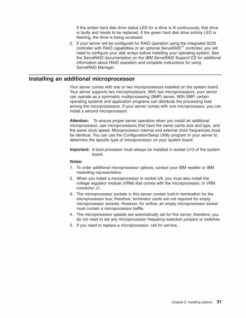
The following illustration is a simplified layout of the microprocessor connector
locations and other microprocessor-related components on the system board.
Attention: The speed of the microprocessor must match the speed of the system
board. The 533 MHz system board is identified as shown in the following
illustration; the 400 MHz system board is not marked.
VRM 2 (J1)
VRM 1 (J17)
Microprocessor 2 (U9)
Microprocessor 1 (U13)
533
MN
z FS
BC
PU
ON
LY
System board identification(some models)
Complete the following steps to install an additional microprocessor kit:
1. Review the information in “Safety” on page v, “Installation guidelines” on page
11, and “Handling static-sensitive devices” on page 12.
2. Remove the server cover (see “Removing the server left-side cover and bezel
(tower model)” on page 14 or “Removing the server top cover and bezel (rack
configuration)” on page 16).
3. Open the cover on the air-baffle assembly. (See the illustration following step 3
on page 29, if needed.)
Note: It is not necessary to remove the air-baffle assembly to perform this
step.
4. Locate the second microprocessor socket (connector U9) on the system board.
5. Remove the microprocessor baffle from the second microprocessor socket.
6. If the second microprocessor socket is covered with protective film, peel and
remove the film.
32 IBM xSeries 235 Type 8671: Installation Guide

DIMMs
VRM 2
Captive screwsHeatsink 2
Microprocessor 2
Microprocessorbaffle
Microprocessor-release lever
7. Install a VRM in the corresponding VRM connector (J1):
a. Center the VRM over the connector. Make sure that the VRM is oriented
and aligned correctly.
b. Carefully but firmly push down the VRM clip handle to seat the VRM in the
connector.
c. Make sure that the VRM clip locks on the VRM connector at both sides.
CAUTION:
You must lift up the microprocessor-release lever before inserting the
microprocessor into the socket. Inserting the microprocessor into the
socket without lifting up the microprocessor-release lever can damage
the microprocessor and system board.
8. Install the microprocessor:
a. Touch the static-protective package containing the new microprocessor to
any unpainted metal surface on the server; then, remove the
microprocessor from the package.
b. Pull out and lift up on the microprocessor-release lever to unlock the
microprocessor socket.
c. Center the microprocessor over the microprocessor socket. Align the
triangle on the corner on the microprocessor with the triangle on the corner
on the socket and carefully press the microprocessor into the socket.
Attention:
v Do not use excessive force when pressing the microprocessor into the
socket.
v Make sure that the microprocessor is oriented and aligned correctly with
pin number 1 in the socket before you try to close the
microprocessor-release lever.
Microprocessor 2
Microprocessor 1
Microprocessorsocket 2
Microprocessorsocket 1
Alignment marks
Alignment marks
Chapter 2. Installing options 33
d. Carefully close the microprocessor-release lever to secure the
microprocessor in the socket.
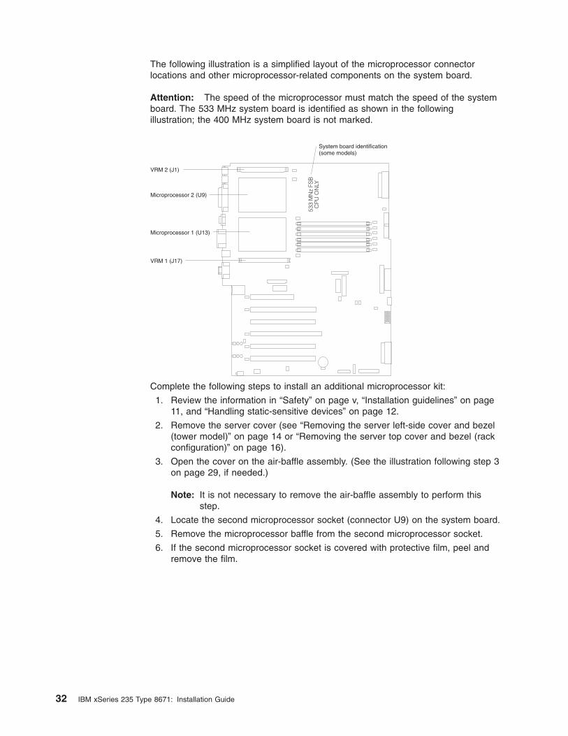
9. Install a heat sink on the microprocessor:
a. Remove the protective film from the bottom of the heat sink.
Notes:
1) Do not set the heat sink down after you remove the protective film.
Heat sink
Thermal grease
2) Do not touch the thermal grease on the bottom of the heat sink.
Touching the thermal grease will contaminate it. If the thermal grease
on the microprocessor or heat sink becomes contaminated, contact
your service technician.
b. Align and place the heat sink on top of the microprocessor in the retention
bracket. Press firmly on the heat sink.
Attention: Alternate the tightening of the two captive screws to prevent
damage to the microprocessor. Ensure that the screws are completely
tightened until they stop; otherwise, damage to the microprocessor will
occur.
c. Secure the heat sink to the microprocessor. Alternate between the two
captive screws in the heat sink while tightening them.
10. If you have other options to install or remove, do so now; otherwise, go to
“Completing the installation” on page 35.
34 IBM xSeries 235 Type 8671: Installation Guide
Completing the installation
To complete your installation, you must reinstall the bezel, reinstall the server cover,
connect all the cables and, for certain options, run the Configuration/Setup Utility
program. Follow the instructions in this section.
Attention:
v For proper cooling and airflow, replace the server cover before turning on the
server. Operating the server for extended periods of time (over 30 minutes) with
the server cover removed might damage server components.
v To ensure proper server operation, do not remove the air-baffle assembly from
the server except when installing or removing the components that are under the
air-baffle cover.
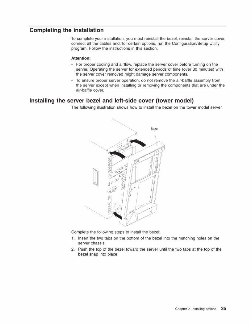
Installing the server bezel and left-side cover (tower model)
The following illustration shows how to install the bezel on the tower model server.
Bezel
Complete the following steps to install the bezel:
1. Insert the two tabs on the bottom of the bezel into the matching holes on the
server chassis.
2. Push the top of the bezel toward the server until the two tabs at the top of the
bezel snap into place.
Chapter 2. Installing options 35
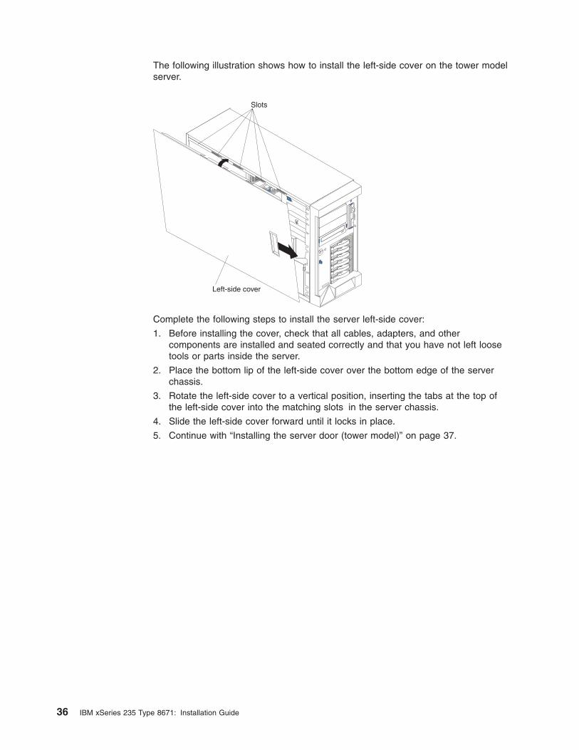
The following illustration shows how to install the left-side cover on the tower model
server.
Slots
Left-side cover
Complete the following steps to install the server left-side cover:
1. Before installing the cover, check that all cables, adapters, and other
components are installed and seated correctly and that you have not left loose
tools or parts inside the server.
2. Place the bottom lip of the left-side cover over the bottom edge of the server
chassis.
3. Rotate the left-side cover to a vertical position, inserting the tabs at the top of
the left-side cover into the matching slots in the server chassis.
4. Slide the left-side cover forward until it locks in place.
5. Continue with “Installing the server door (tower model)” on page 37.
36 IBM xSeries 235 Type 8671: Installation Guide
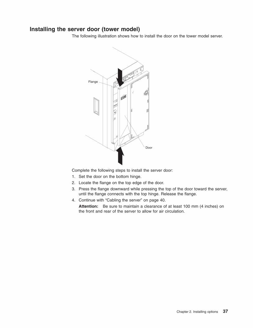
Installing the server door (tower model)
The following illustration shows how to install the door on the tower model server.
Flange
Door
Complete the following steps to install the server door:
1. Set the door on the bottom hinge.
2. Locate the flange on the top edge of the door.
3. Press the flange downward while pressing the top of the door toward the server,
until the flange connects with the top hinge. Release the flange.
4. Continue with “Cabling the server” on page 40.
Attention: Be sure to maintain a clearance of at least 100 mm (4 inches) on
the front and rear of the server to allow for air circulation.
Chapter 2. Installing options 37
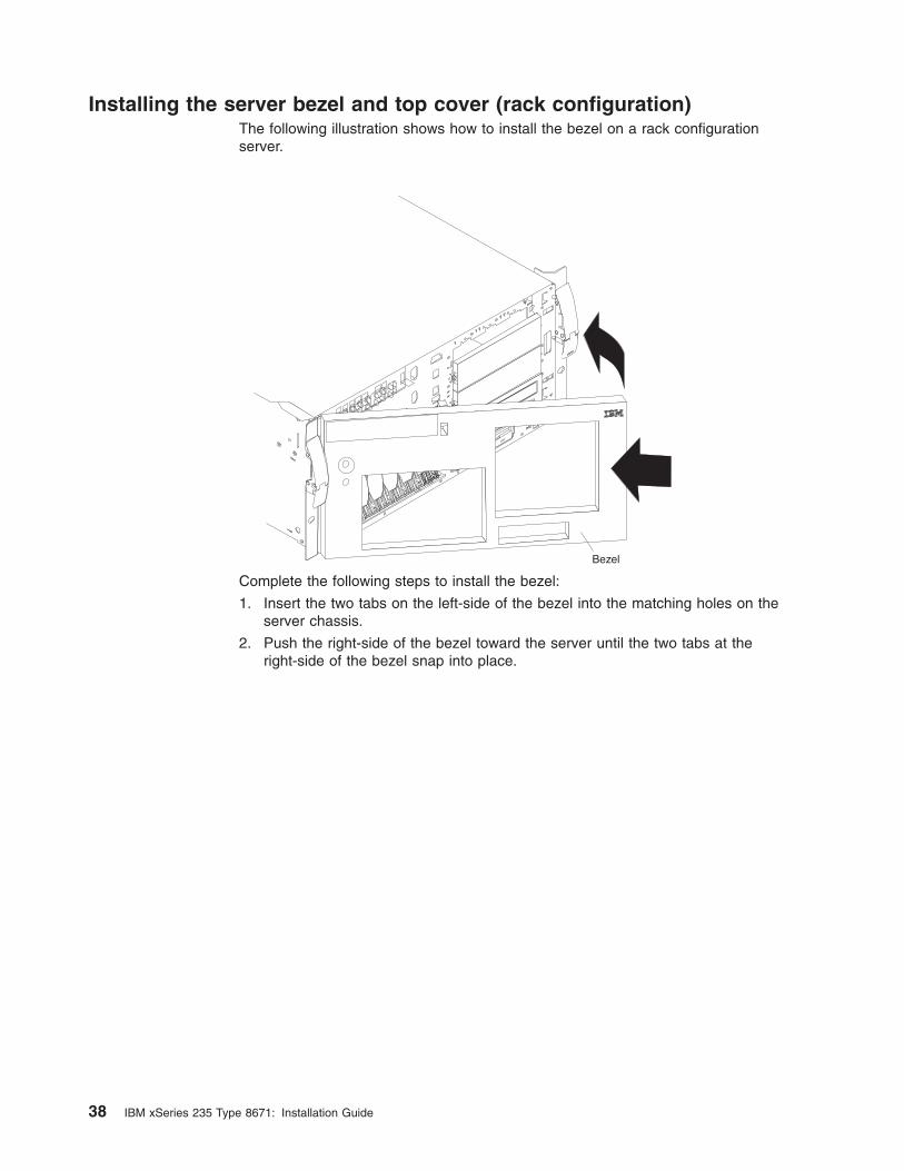
Installing the server bezel and top cover (rack configuration)
The following illustration shows how to install the bezel on a rack configuration
server.
Bezel
Complete the following steps to install the bezel:
1. Insert the two tabs on the left-side of the bezel into the matching holes on the
server chassis.
2. Push the right-side of the bezel toward the server until the two tabs at the
right-side of the bezel snap into place.
38 IBM xSeries 235 Type 8671: Installation Guide
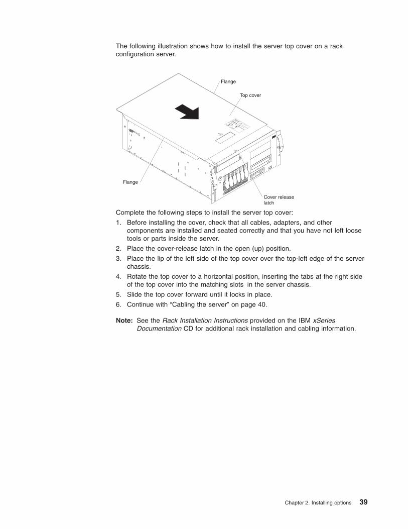
The following illustration shows how to install the server top cover on a rack
configuration server.
Top cover
Cover releaselatch
CPU
VRM
MEMORY
HDD
PCI BUS
NMI
SMI
SERVICE PROCESSOR
BUS
NON REDUNDANT
POWER SUPPLY
1 2 3A B
1 2 3FAN
TEMPERATURE
Flange
Flange
Complete the following steps to install the server top cover:
1. Before installing the cover, check that all cables, adapters, and other
components are installed and seated correctly and that you have not left loose
tools or parts inside the server.
2. Place the cover-release latch in the open (up) position.
3. Place the lip of the left side of the top cover over the top-left edge of the server
chassis.
4. Rotate the top cover to a horizontal position, inserting the tabs at the right side
of the top cover into the matching slots in the server chassis.
5. Slide the top cover forward until it locks in place.
6. Continue with “Cabling the server” on page 40.
Note: See the Rack Installation Instructions provided on the IBM xSeries
Documentation CD for additional rack installation and cabling information.
Chapter 2. Installing options 39
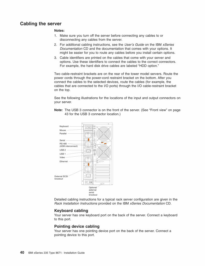
Cabling the server
Notes:
1. Make sure you turn off the server before connecting any cables to or
disconnecting any cables from the server.
2. For additional cabling instructions, see the User’s Guide on the IBM xSeries
Documentation CD and the documentation that comes with your options. It
might be easier for you to route any cables before you install certain options.
3. Cable identifiers are printed on the cables that come with your server and
options. Use these identifiers to connect the cables to the correct connectors.
For example, the hard disk drive cables are labeled “HDD option.”
Two cable-restraint brackets are on the rear of the tower model servers. Route the
power cords through the power-cord restraint bracket on the bottom. After you
connect the cables to the selected devices, route the cables (for example, the
cables that are connected to the I/O ports) through the I/O cable-restraint bracket
on the top.
See the following illustrations for the locations of the input and output connectors on
your server.
Note: The USB 3 connector is on the front of the server. (See “Front view” on page
43 for the USB 3 connector location.)
12
Keyboard
Mouse
Parallel
Serial
RS-485(ASM interconnect)
USB 2
USB 1
Video
Ethernet
External SCSIknockout
Optionalexternalserialknockout
Detailed cabling instructions for a typical rack server configuration are given in the
Rack Installation Instructions provided on the IBM xSeries Documentation CD.
Keyboard cabling
Your server has one keyboard port on the back of the server. Connect a keyboard
to this port.
Pointing device cabling
Your server has one pointing device port on the back of the server. Connect a
pointing device to this port.
40 IBM xSeries 235 Type 8671: Installation Guide
Parallel port cabling
Your server has one parallel port on the back of the server. You can connect a
parallel device to this port.
Serial cabling
Your server has one standard serial port on the back of the server and one optional
serial port. You can connect a serial device to each of these ports.
Advanced System Management Interconnect cabling
Your server has two Advanced System Management (ASM) Interconnect ports on
the back of the server. Use these ports to connect the server to a Remote
Supervisor Adapter in a remote server. The ports support full asynchronous RS-485
communication through a daisy-chain cable in half-duplex mode. Both ports have
automatic termination, and either port can be used if your server is at the beginning
or end of an RS-485 network.
Notes:
1. Do not confuse the two ASM Interconnect ports that are next to the video port
with the Gigabit Ethernet port.
2. If you install an optional Remote Supervisor Adapter in your server, use the
RS-485 ports on the Remote Supervisor Adapter and not the integrated RS-485
ports on the back of your server.
USB cabling
Your server has three USB ports, one on the front and two on the back of the
server. You can connect USB devices to these ports.
Video cabling
Your server has one video port on the back of the server. Connect a monitor to this
port.
Gigabit Ethernet cabling
Your server has one Ethernet port on the back of the server. Use this port to
connect the server to a LAN.
Note: Do not confuse the Gigabit Ethernet port with the two ASM Interconnect
ports that are next to the video port.
Power cabling
Your server comes with one or two power cords that you can connect to an
uninterruptible power supply or to an external source, such as a properly grounded
electrical outlet.
Complete the following steps to attach the power supply power cords:
1. Connect each power-supply cord to one of the system power connectors on the
rear of the server.
2. Plug the other end of each power-supply cord into a properly grounded
electrical outlet or uninterruptible power supply.
Note: Plugging the power-supply cords into electrical outlets might cause the
server to start automatically. This is an acceptable action.
3. See “Turning on the server” on page 47 for detailed information about turning on
the server.
Chapter 2. Installing options 41
Updating your server configuration
When you start your server for the first time after you add or remove an internal
option or an external SCSI device, you might see a message telling you that the
configuration has changed. The Configuration/Setup Utility program automatically
starts so that you can save the new configuration information. See Chapter 4,
“Configuring your server,” on page 51 for additional information.
Some options have device drivers that you need to install. See the documentation
that comes with your option for information about installing any required device
drivers.
Your server comes with one or two microprocessors installed on the system board.
If you have installed an additional microprocessor, your server can now operate as
an SMP server. Therefore, you might need to upgrade your operating system to
support SMP. See the User’s Guide on the IBM xSeries Documentation CD and
your operating-system documentation for additional information.
If your server has a RAID configuration using the integrated SCSI controller with
RAID capabilities or has a ServeRAID controller installed and you have installed or
removed a hard disk drive, see the ServeRAID documentation that comes with your
server for information about reconfiguring your disk arrays.
42 IBM xSeries 235 Type 8671: Installation Guide
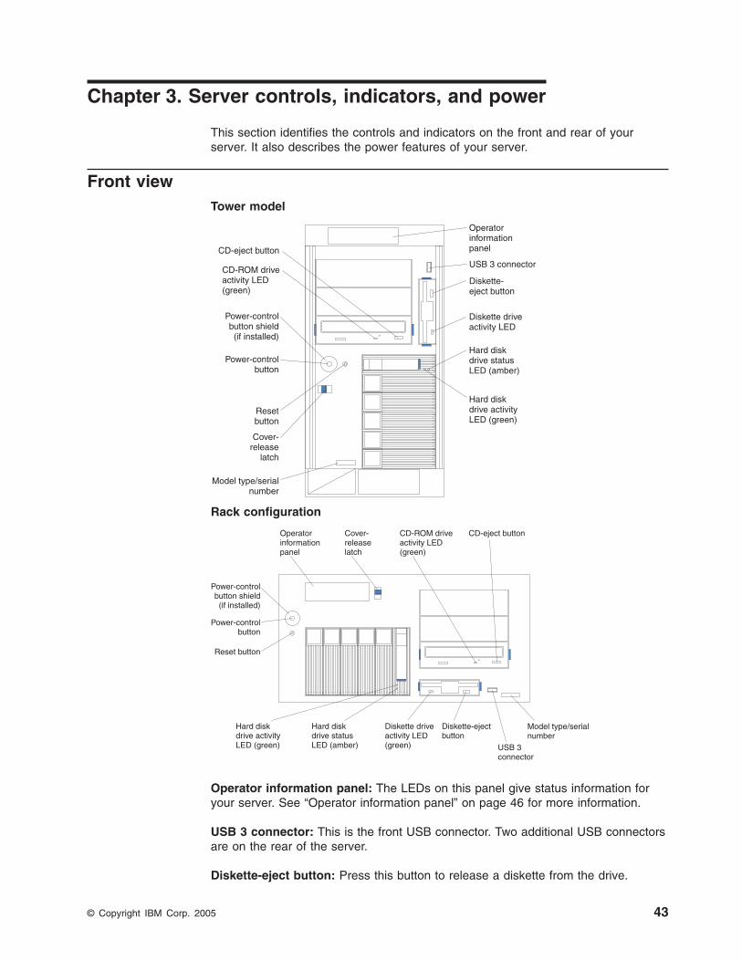
Chapter 3. Server controls, indicators, and power
This section identifies the controls and indicators on the front and rear of your
server. It also describes the power features of your server.
Front view
Tower model
Hard diskdrive activityLED (green)
Diskette driveactivity LED
Diskette-eject button
USB 3 connector
Hard diskdrive statusLED (amber)
Resetbutton
Power-controlbutton
Power-controlbutton shield(if installed)
Cover-release
latch
Model type/serialnumber
OperatorinformationpanelCD-eject button
CD-ROM driveactivity LED(green)
Rack configuration
Hard diskdrive activityLED (green)
Hard diskdrive statusLED (amber)
Reset button
Power-controlbutton
Cover-releaselatch
Operatorinformationpanel
Power-controlbutton shield(if installed)
Model type/serialnumber
CD-ROM driveactivity LED(green)
CD-eject button
Diskette driveactivity LED(green)
Diskette-ejectbutton
USB 3connector
Operator information panel: The LEDs on this panel give status information for
your server. See “Operator information panel” on page 46 for more information.
USB 3 connector: This is the front USB connector. Two additional USB connectors
are on the rear of the server.
Diskette-eject button: Press this button to release a diskette from the drive.
© Copyright IBM Corp. 2005 43
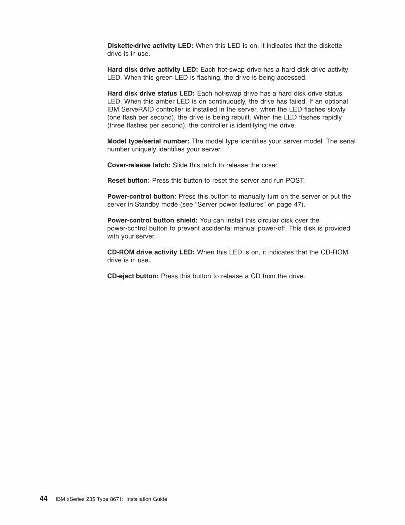
Diskette-drive activity LED: When this LED is on, it indicates that the diskette
drive is in use.
Hard disk drive activity LED: Each hot-swap drive has a hard disk drive activity
LED. When this green LED is flashing, the drive is being accessed.
Hard disk drive status LED: Each hot-swap drive has a hard disk drive status
LED. When this amber LED is on continuously, the drive has failed. If an optional
IBM ServeRAID controller is installed in the server, when the LED flashes slowly
(one flash per second), the drive is being rebuilt. When the LED flashes rapidly
(three flashes per second), the controller is identifying the drive.
Model type/serial number: The model type identifies your server model. The serial
number uniquely identifies your server.
Cover-release latch: Slide this latch to release the cover.
Reset button: Press this button to reset the server and run POST.
Power-control button: Press this button to manually turn on the server or put the
server in Standby mode (see “Server power features” on page 47).
Power-control button shield: You can install this circular disk over the
power-control button to prevent accidental manual power-off. This disk is provided
with your server.
CD-ROM drive activity LED: When this LED is on, it indicates that the CD-ROM
drive is in use.
CD-eject button: Press this button to release a CD from the drive.
44 IBM xSeries 235 Type 8671: Installation Guide
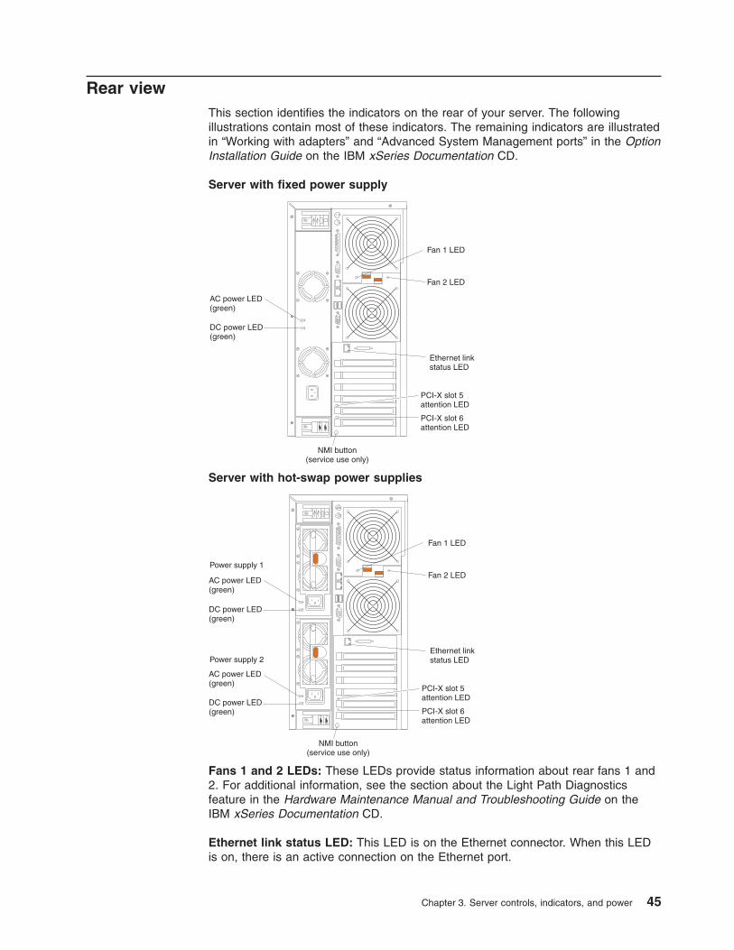
Rear view
This section identifies the indicators on the rear of your server. The following
illustrations contain most of these indicators. The remaining indicators are illustrated
in “Working with adapters” and “Advanced System Management ports” in the Option
Installation Guide on the IBM xSeries Documentation CD.
Server with fixed power supply
12
AC power LED(green)
DC power LED(green)
Fan 1 LED
Fan 2 LED
Ethernet linkstatus LED
PCI-X slot 5attention LED
PCI-X slot 6attention LED
NMI button(service use only)
Server with hot-swap power supplies
12
AC power LED(green)
AC power LED(green)
DC power LED(green)
DC power LED(green)
Ethernet linkstatus LED
PCI-X slot 5attention LED
PCI-X slot 6attention LED
Power supply 2
Power supply 1
Fan 1 LED
Fan 2 LED
NMI button(service use only)
Fans 1 and 2 LEDs: These LEDs provide status information about rear fans 1 and
2. For additional information, see the section about the Light Path Diagnostics
feature in the Hardware Maintenance Manual and Troubleshooting Guide on the
IBM xSeries Documentation CD.
Ethernet link status LED: This LED is on the Ethernet connector. When this LED
is on, there is an active connection on the Ethernet port.
Chapter 3. Server controls, indicators, and power 45
PCI-X slot attention LED: This green LED flashes approximately once per second
when it is on. This LED is visible from the rear of the server and from inside the
server. The meaning of the attention LED is defined by your operating system. For
an illustration showing this LED on the system board, see the Option Installation
Guide on the IBM xSeries Documentation CD. For additional information, see “LEDs
for Active PCI slots” in the Hardware Maintenance Manual and Troubleshooting
Guide on the IBM xSeries Documentation CD.
NMI button: The Non-Maskable Interrupt (NMI) button is for service use only.
DC power LED: This green LED provides status information about the power
supply. During typical operation, both the ac and dc power LEDs are on. For any
other combination of LEDs, see the Hardware Maintenance Manual and
Troubleshooting Guide on the IBM xSeries Documentation CD.
AC power LED: This green LED provides status information about the power
supply. During typical operation, both the ac and dc power LEDs are on. For any
other combination of LEDs, see the Hardware Maintenance Manual and
Troubleshooting Guide on the IBM xSeries Documentation CD.
Operator information panel
The following illustration shows the status LEDs on the operator information panel
on the front of the server.
TXRX
OK
1
Power-onLED
POST-complete LED
Hard disk driveactivity LED
InformationLED
System-error LED
Ethernet transmit/receive activity LED
/
Important: If the power-on LED is off, it does not mean there is no electrical
current present in the server. The LED might be burned out. To remove
all electrical current from the server, you must unplug the server power
cords from the electrical outlets or from the uninterruptible power
device.
Power-on LED: When this green LED is on, power is present in the server.
When this LED flashes, the server is in Standby mode (the system operating
system is turned off and ac current is present). When this LED is off, the power
subsystem, the ac power, or an LED has failed.
POST-complete LED: This green LED is on when POST is completed without
any errors.
Hard disk drive activity LED: This green LED flickers when there is activity on
a hard disk drive.
Information LED: When this amber LED is on, the server power supplies are
nonredundant, or some other noncritical event has occurred. The event is
recorded in the Error log. See the User’s Guide on the IBM xSeries
Documentation CD for instructions for viewing the Error log. Check the
46 IBM xSeries 235 Type 8671: Installation Guide
diagnostic LED panel for more detailed information (see the Hardware
Maintenance Manual and Troubleshooting Guide on the IBM xSeries
Documentation CD).
System-error LED: This amber LED is on when a system error occurs. An LED
on the diagnostic LED panel will also be on to further isolate the error. See the
Hardware Maintenance Manual and Troubleshooting Guide on the IBM xSeries
Documentation CD for additional information.
Ethernet transmit/receive activity LED: When this green LED is on, there is
activity between the server and the network.
Server power features
This section contains information about how to properly turn your server on and off.
Turning on the server
Turning on the server refers to the act of plugging the power cords of your server
into the power source and starting the operating system.
You can turn on the server in any of the following ways:
v If the power cords are connected to a power source, you can press the
power-control button on the front of the server.
Notes:
1. You can install a circular disk over the power-control button to prevent
accidental manual power-off. This disk, known as the power-control button
shield, comes with your server.
2. After you plug the power cords of your server into the electrical outlets, wait
approximately 20 seconds before pressing the power-control button. During
this time, the system-management adapter is initializing; therefore, the
power-control button does not respond.
v If the server is turned on and a power failure occurs, the server will restart
automatically when power is restored.
v If ac power is present, the server is in Standby mode, and the server is
connected to an ASM interconnect network that contains at least one system with
an optional Remote Supervisor Adapter installed, the server can be turned on
from the Remote Supervisor Adapter user interface.
v If ac power is present, the server is in Standby mode, and an optional Remote
Supervisor Adapter is installed in the server, the server can be turned on from
the Remote Supervisor Adapter user interface.
v When you plug in your server for the first time, Wake on LAN® can turn on the
server.
v If your server was previously turned on, it must be properly placed in Standby
mode for the Wake on LAN feature to turn on the server.
Chapter 3. Server controls, indicators, and power 47
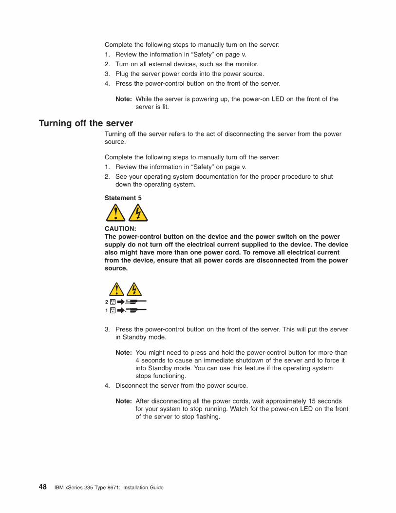
Complete the following steps to manually turn on the server:
1. Review the information in “Safety” on page v.
2. Turn on all external devices, such as the monitor.
3. Plug the server power cords into the power source.
4. Press the power-control button on the front of the server.
Note: While the server is powering up, the power-on LED on the front of the
server is lit.
Turning off the server
Turning off the server refers to the act of disconnecting the server from the power
source.
Complete the following steps to manually turn off the server:
1. Review the information in “Safety” on page v.
2. See your operating system documentation for the proper procedure to shut
down the operating system.
Statement 5
CAUTION:
The power-control button on the device and the power switch on the power
supply do not turn off the electrical current supplied to the device. The device
also might have more than one power cord. To remove all electrical current
from the device, ensure that all power cords are disconnected from the power
source.
1
2
3. Press the power-control button on the front of the server. This will put the server
in Standby mode.
Note: You might need to press and hold the power-control button for more than
4 seconds to cause an immediate shutdown of the server and to force it
into Standby mode. You can use this feature if the operating system
stops functioning.
4. Disconnect the server from the power source.
Note: After disconnecting all the power cords, wait approximately 15 seconds
for your system to stop running. Watch for the power-on LED on the front
of the server to stop flashing.
48 IBM xSeries 235 Type 8671: Installation Guide
Standby mode
Standby mode refers to the condition in which the server is connected to an ac
power source but the server operating system is not running and all core logic is
shut down except for the service processor. In Standby mode, the server can
respond to service processor requests, such as a remote request to turn on the
server. When the server is in Standby mode, the power-on LED on the front of the
server flashes (when the server is running, the power-on LED stays on and does
not flash).
You can put the server in Standby mode in any of the following ways:
v You can press the power-control button on the server. This starts an orderly
shutdown of the operating system, if this feature is supported by your operating
system.
v If the server is connected to an ASM interconnect network which contains at least
one system with an optional Remote Supervisor Adapter installed, the server can
be placed in Standby mode from the Remote Supervisor Adapter user interface.
v If an optional Remote Supervisor Adapter is installed in the server, the server can
be placed in Standby mode from the Remote Supervisor Adapter user interface.
Attention: You must disconnect all the server power cords from the electrical
outlets to remove all power from the server.
Complete the following steps to put the server into Standby mode:
1. See the operating system documentation for the proper procedure to shut down
the operating system.
Note: Each operating system is different. Read all the documentation about
shutting down the operating system before continuing.
2. Press the power-control button on the front of the server.
Notes:
a. After you place the server in Standby mode, wait at least 5 seconds before
you turn on the server again.
b. You might need to press and hold the power-control button for more than 4
seconds to cause an immediate shutdown of the operating system and to
force it into Standby mode. You can use this feature if the operating system
stops functioning.
The ISMP can put the server in Standby mode as an automatic response to a
critical system failure. You can also put the server into Standby mode remotely by
means of an optional Remote Supervisor Adapter or through connection to an ASM
interconnect network.
Chapter 3. Server controls, indicators, and power 49

50 IBM xSeries 235 Type 8671: Installation Guide
Chapter 4. Configuring your server
The ServerGuide™ Setup and Installation CD provides software setup tools and
installation tools that are specifically designed for your IBM server. Use this CD
during the initial installation of your server to configure basic hardware features and
to simplify your network operating system (NOS) installation. (See “Using the
ServerGuide Setup and Installation CD” on page 52 for more information.)
In addition to the ServerGuide Setup and Installation CD, you can use the following
configuration programs to customize your server hardware:
v Configuration/Setup Utility
This program is part of the basic input/output system (BIOS) code that comes
with your server. You can use this program to configure serial and parallel port
assignments, change interrupt request (IRQ) settings, change the drive startup
sequence, set the date and time, and set passwords. You also can use this
program to view the system configuration settings, for example, the number and
type of installed microprocessors, the amount of installed memory, or the BIOS
diagnostics version level. See “Using the Configuration/Setup Utility program” on
page 52 for more information.
v LSI Logic Configuration Utility
With the built-in LSI Logic Configuration Utility program, you can configure the
integrated SCSI controller and the devices that are attached to it. See “Using the
LSI Logic Configuration Utility program” on page 52.
v ServeRAID Manager
The ServeRAID programs come with your server. If your server has a ServeRAID
controller installed, you must use the ServeRAID Configuration program to define
and configure your disk-array subsystem before you install your operating
system. See “Using ServeRAID Manager” on page 53 for more information.
This section provides the instructions for starting the utility programs. See the
User’s Guide on the IBM xSeries Documentation CD for detailed instructions for
using the configuration programs and ServerGuide Setup and Installation CD.
© Copyright IBM Corp. 2005 51
Using the ServerGuide Setup and Installation CD
The ServerGuide Setup and Installation CD provides state-of-the-art programs to
detect the server model and hardware options that are installed, configures the
server hardware, provides device drivers, and helps you install your operating
system.
Note: If the ServerGuide Setup and Installation CD does not start, see
“ServerGuide program problems” on page 65.
1. Insert the ServerGuide Setup and Installation CD, and restart the server.
2. Follow the instructions that appear on the screen to:
a. Select your language.
b. Select your keyboard layout and country.
c. View the overview to learn about ServerGuide features.
d. View the README file to review installation tips about your operating
system and adapter.
e. Start the setup and hardware configuration programs.
f. Start the operating system installation. You will need your copy of the
operating system CD.
Note: For information about the supported operating system versions, see
the ServerGuide Setup and Installation CD label.
Using the Configuration/Setup Utility program
The Configuration/Setup Utility program is a menu-driven utility program that is part
of the BIOS code that comes with your server. You can use it to:
v Configure serial port assignments
v Change the drive startup sequence
v Enable USB keyboard and mouse support
v Resolve configuration conflicts
v Set the date and time
v Set passwords
Complete the following steps to start the Configuration/Setup Utility program:
1. Turn on the server and watch the monitor screen.
2. When the message Press F1 for Configuration/Setup appears, press F1.
Note: If you have previously set both levels of passwords (power-on and
administrator), you must type the administrator password to access the
full Configuration/Setup Utility menu. Without the administrator password,
limited Configuration/Setup Utility program functions are available.
3. Follow the instructions that appear on the screen.
Using the LSI Logic Configuration Utility program
LSI Logic Configuration is a built-in, menu-driven configuration utility program that
you can use to:
v Perform a low-level format of a SCSI hard disk drive
v Set a SCSI device scan order
v Set a SCSI ID for a controller
52 IBM xSeries 235 Type 8671: Installation Guide

Notes:
1. The integrated SCSI controller with RAID capabilities in your server supports
only RAID level-1. Installing an optional ServeRAID-5i controller provides
additional RAID levels. See “Using ServeRAID Manager” for information about
configuring your server for RAID operation.
2. If you install a different type of RAID adapter in your server, use the
configuration method supplied with the RAID adapter to view or change SCSI
settings for attached devices.
Complete the following steps to start the LSI Logic Configuration Utility program:
1. Turn on the server.
2. When the <<< Press <CTRL><C> to start LSI Logic Configuration Utility
>>> prompt appears, press Ctrl+C.
Note: If an administrator password has been set, you are prompted to type the
password to start the LSI Logic Configuration Utility program.
3. Use the arrow keys to select a controller (channel) from the list of adapters;
then, press Enter.
4. Follow the instructions on the resulting screen to change the settings of the
selected items; then, press Enter. The Device Properties and Mirroring
Properties choices produce additional screens of parameters to review or
change.
Using ServeRAID Manager
You can use the ServeRAID Manager program, provided on the IBM ServeRAID
Support CD, to:
v Configure a redundant array of independent disks (RAID)
v Restore a SCSI hard disk to factory-default settings, erasing all data
v View your RAID configuration and associated devices
v Monitor operation of your RAID controllers
The ServeRAID Manager program operates in two ways:
v Startable-CD mode
v As an installed software program
The following sections provide instructions for running ServeRAID Manager in
startable-CD mode to configure your integrated SCSI controller with RAID
capabilities and perform an initial RAID configuration on your server. See the
ServeRAID documentation on the IBM ServeRAID Support CD for additional
information about RAID technology and instructions for using ServeRAID Manager
to configure your integrated SCSI controller with RAID capabilities.
Notes:
1. The integrated SCSI controller with RAID capabilities in your server supports
only RAID level-1. Installing an optional ServeRAID-5i controller provides
additional RAID levels.
2. If you install a different type of RAID adapter in your server, use the
configuration method supplied with the RAID adapter to view or change SCSI
settings for attached devices.
Before you install your operating system, you must configure the controller that is
attached to the hard disk drives. You must use the configuration program on the
Chapter 4. Configuring your server 53
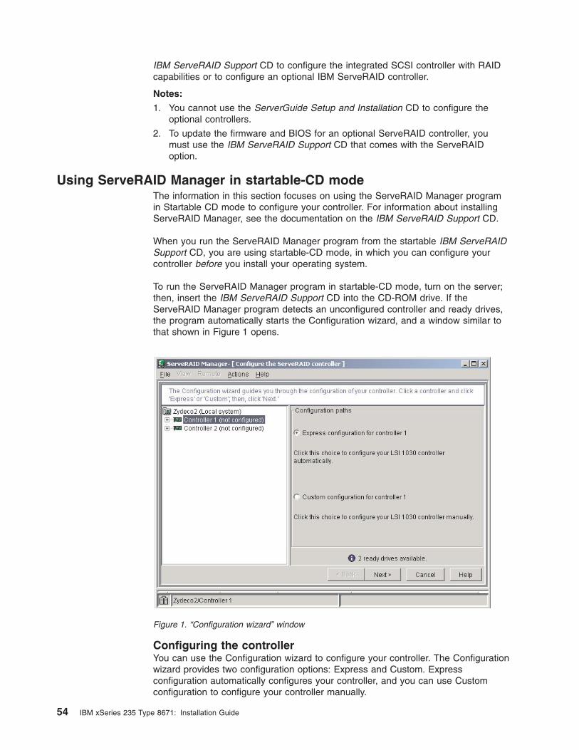
IBM ServeRAID Support CD to configure the integrated SCSI controller with RAID
capabilities or to configure an optional IBM ServeRAID controller.
Notes:
1. You cannot use the ServerGuide Setup and Installation CD to configure the
optional controllers.
2. To update the firmware and BIOS for an optional ServeRAID controller, you
must use the IBM ServeRAID Support CD that comes with the ServeRAID
option.
Using ServeRAID Manager in startable-CD mode
The information in this section focuses on using the ServeRAID Manager program
in Startable CD mode to configure your controller. For information about installing
ServeRAID Manager, see the documentation on the IBM ServeRAID Support CD.
When you run the ServeRAID Manager program from the startable IBM ServeRAID
Support CD, you are using startable-CD mode, in which you can configure your
controller before you install your operating system.
To run the ServeRAID Manager program in startable-CD mode, turn on the server;
then, insert the IBM ServeRAID Support CD into the CD-ROM drive. If the
ServeRAID Manager program detects an unconfigured controller and ready drives,
the program automatically starts the Configuration wizard, and a window similar to
that shown in Figure 1 opens.
Configuring the controller
You can use the Configuration wizard to configure your controller. The Configuration
wizard provides two configuration options: Express and Custom. Express
configuration automatically configures your controller, and you can use Custom
configuration to configure your controller manually.
Figure 1. “Configuration wizard” window
54 IBM xSeries 235 Type 8671: Installation Guide
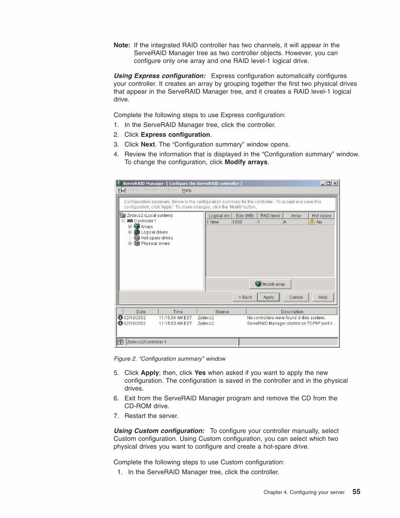
Note: If the integrated RAID controller has two channels, it will appear in the
ServeRAID Manager tree as two controller objects. However, you can
configure only one array and one RAID level-1 logical drive.
Using Express configuration: Express configuration automatically configures
your controller. It creates an array by grouping together the first two physical drives
that appear in the ServeRAID Manager tree, and it creates a RAID level-1 logical
drive.
Complete the following steps to use Express configuration:
1. In the ServeRAID Manager tree, click the controller.
2. Click Express configuration.
3. Click Next. The “Configuration summary” window opens.
4. Review the information that is displayed in the “Configuration summary” window.
To change the configuration, click Modify arrays.
5. Click Apply; then, click Yes when asked if you want to apply the new
configuration. The configuration is saved in the controller and in the physical
drives.
6. Exit from the ServeRAID Manager program and remove the CD from the
CD-ROM drive.
7. Restart the server.
Using Custom configuration: To configure your controller manually, select
Custom configuration. Using Custom configuration, you can select which two
physical drives you want to configure and create a hot-spare drive.
Complete the following steps to use Custom configuration:
1. In the ServeRAID Manager tree, click the controller.
Figure 2. “Configuration summary” window
Chapter 4. Configuring your server 55
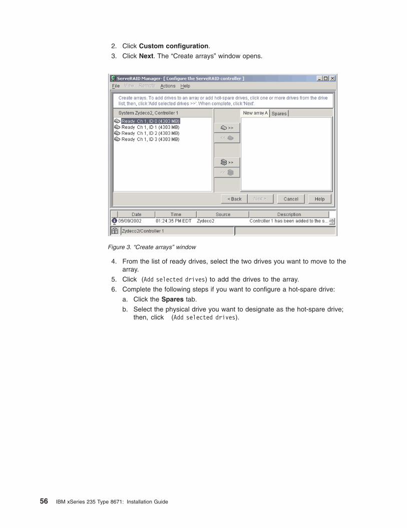
2. Click Custom configuration.
3. Click Next. The “Create arrays” window opens.
4. From the list of ready drives, select the two drives you want to move to the
array.
5. Click
(Add selected drives) to add the drives to the array.
6. Complete the following steps if you want to configure a hot-spare drive:
a. Click the Spares tab.
b. Select the physical drive you want to designate as the hot-spare drive;
then, click
(Add selected drives).
Figure 3. “Create arrays” window
56 IBM xSeries 235 Type 8671: Installation Guide
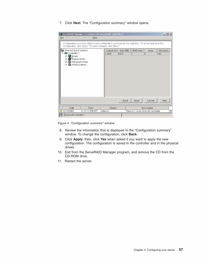
7. Click Next. The “Configuration summary” window opens.
8. Review the information that is displayed in the “Configuration summary”
window. To change the configuration, click Back.
9. Click Apply; then, click Yes when asked if you want to apply the new
configuration. The configuration is saved in the controller and in the physical
drives.
10. Exit from the ServeRAID Manager program, and remove the CD from the
CD-ROM drive.
11. Restart the server.
Figure 4. “Configuration summary” window
Chapter 4. Configuring your server 57
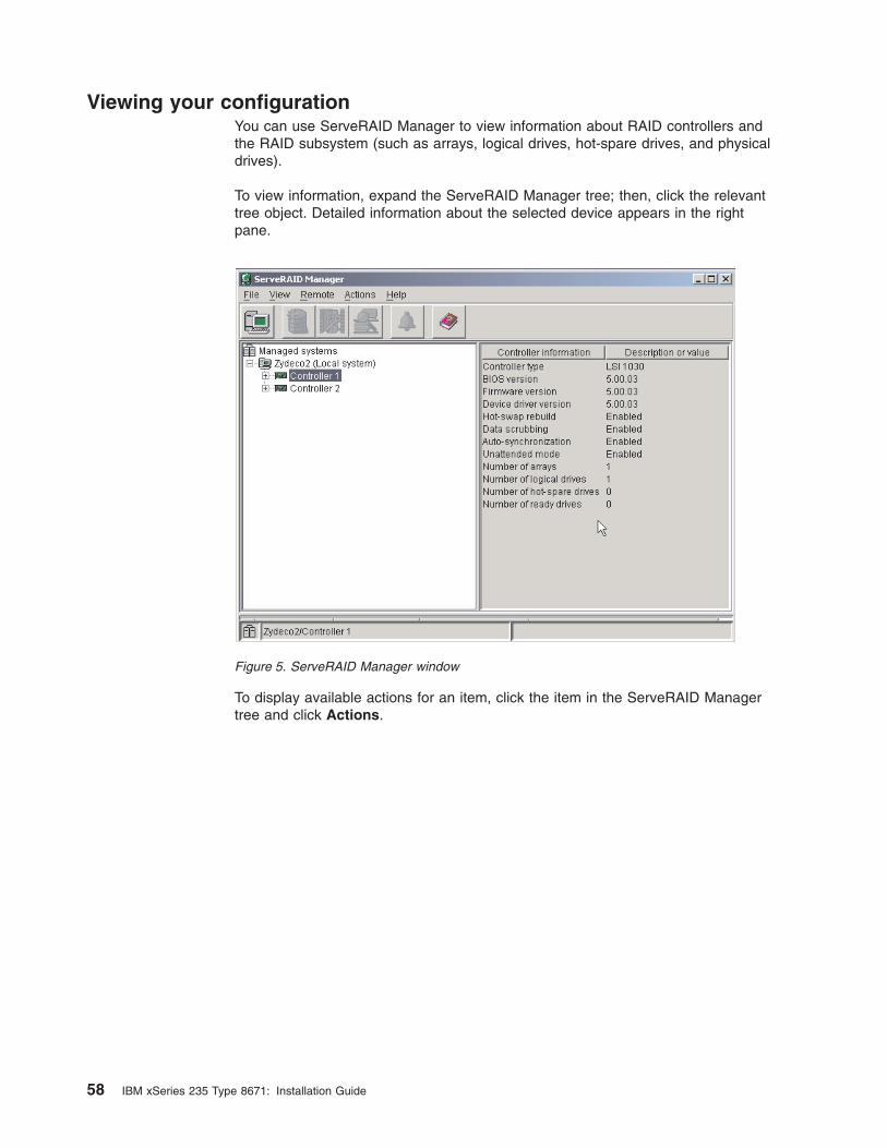
Viewing your configuration
You can use ServeRAID Manager to view information about RAID controllers and
the RAID subsystem (such as arrays, logical drives, hot-spare drives, and physical
drives).
To view information, expand the ServeRAID Manager tree; then, click the relevant
tree object. Detailed information about the selected device appears in the right
pane.
To display available actions for an item, click the item in the ServeRAID Manager
tree and click Actions.
Figure 5. ServeRAID Manager window
58 IBM xSeries 235 Type 8671: Installation Guide
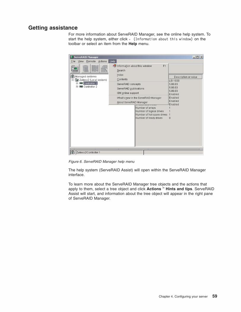
Getting assistance
For more information about ServeRAID Manager, see the online help system. To
start the help system, either click
(Information about this window) on the
toolbar or select an item from the Help menu.
The help system (ServeRAID Assist) will open within the ServeRAID Manager
interface.
To learn more about the ServeRAID Manager tree objects and the actions that
apply to them, select a tree object and click Actions ” Hints and tips. ServeRAID
Assist will start, and information about the tree object will appear in the right pane
of ServeRAID Manager.
Figure 6. ServeRAID Manager help menu
Chapter 4. Configuring your server 59
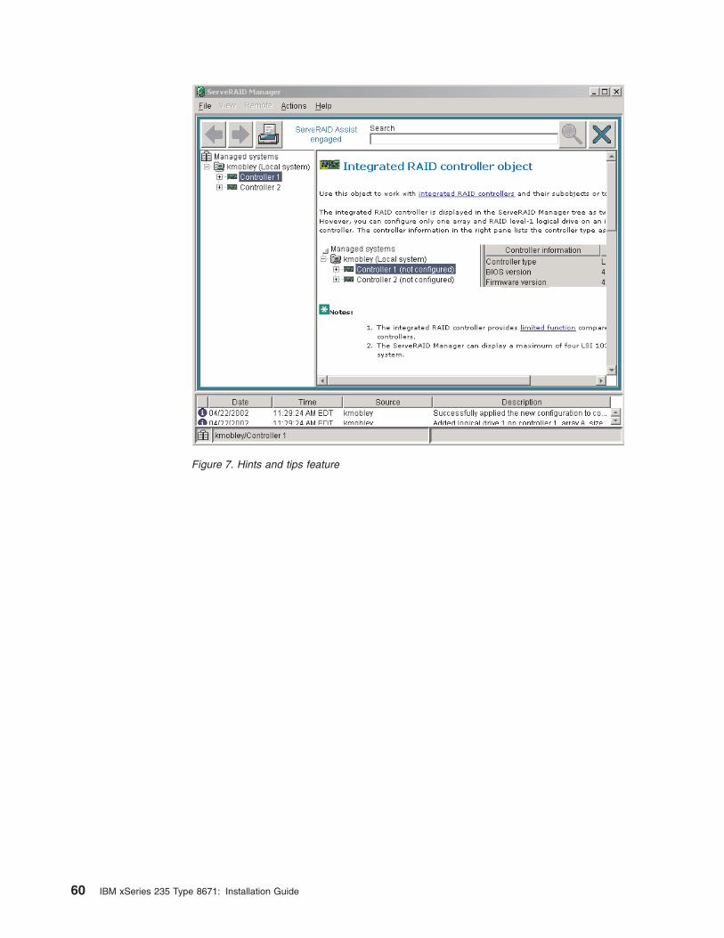
Figure 7. Hints and tips feature
60 IBM xSeries 235 Type 8671: Installation Guide
Chapter 5. Installing IBM Director updates
If you plan to use IBM Director to manage your server, you must install the
applicable IBM Director updates, which could include a Service Pack for your
release of IBM Director, individual emergency fixes (eFixes), and a Director System
Support Package (DSSP) for this server.
Note: For Automatic Server Restart (ASR) support and environmental-sensor
support, you must install version 3.1.1 of IBM Director.
To install the IBM Director updates, complete the following steps, in order:
1. If you plan to enable the Automatic Server Restart (ASR) feature, install the
ASR device driver, which is available from the IBM Web site:
a. Go to the IBM Web site at http://www.ibm.com.
b. Click Support & downloads.
c. In the Technical support keyword search field, type Advanced System
Management 8647 and click Go.
d. From the next page, click IBM Advanced System Management Device
Driver Diskette for Microsoft Windows 2000 and Windows NT 4.0
Version 2.07 (or a later version, if it is available).
e. From the next page, download the executable file and follow the instructions
in the readme file to install the device driver.
2. Install the IBM Director application.
3. If the IBM Director CD that comes with your server includes the IBM Director
Service Pack, install the Service Pack. If the CD does not contain the Service
Pack, check the IBM Web site to see if a Service Pack is available. If it is,
download and install the Service Pack according to the instructions in its
readme file.
4. Install any applicable eFixes, DSSPs, and additional updates for your server
from the IBM Web site.
Complete the following steps to obtain and install eFixes, DSSPs, or other updates:
1. Go to the IBM Web site at http://www.ibm.com.
2. Click Support & downloads.
3. In the Technical support keyword search field, type Director 8647 and click
Go.
4. From the next page, click the eFix, DSSP, or update that you want to download.
5. From the next page, download the executable file and follow the instructions in
the readme file to install the update.
© Copyright IBM Corp. 2005 61

62 IBM xSeries 235 Type 8671: Installation Guide
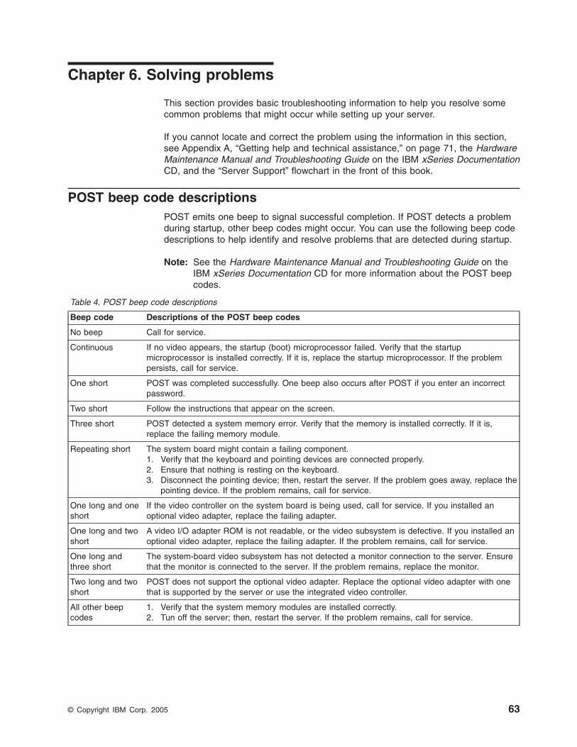
Chapter 6. Solving problems
This section provides basic troubleshooting information to help you resolve some
common problems that might occur while setting up your server.
If you cannot locate and correct the problem using the information in this section,
see Appendix A, “Getting help and technical assistance,” on page 71, the Hardware
Maintenance Manual and Troubleshooting Guide on the IBM xSeries Documentation
CD, and the “Server Support” flowchart in the front of this book.
POST beep code descriptions
POST emits one beep to signal successful completion. If POST detects a problem
during startup, other beep codes might occur. You can use the following beep code
descriptions to help identify and resolve problems that are detected during startup.
Note: See the Hardware Maintenance Manual and Troubleshooting Guide on the
IBM xSeries Documentation CD for more information about the POST beep
codes.
Table 4. POST beep code descriptions
Beep code Descriptions of the POST beep codes
No beep Call for service.
Continuous If no video appears, the startup (boot) microprocessor failed. Verify that the startup
microprocessor is installed correctly. If it is, replace the startup microprocessor. If the problem
persists, call for service.
One short POST was completed successfully. One beep also occurs after POST if you enter an incorrect
password.
Two short Follow the instructions that appear on the screen.
Three short POST detected a system memory error. Verify that the memory is installed correctly. If it is,
replace the failing memory module.
Repeating short The system board might contain a failing component.
1. Verify that the keyboard and pointing devices are connected properly.
2. Ensure that nothing is resting on the keyboard.
3. Disconnect the pointing device; then, restart the server. If the problem goes away, replace the
pointing device. If the problem remains, call for service.
One long and one
short
If the video controller on the system board is being used, call for service. If you installed an
optional video adapter, replace the failing adapter.
One long and two
short
A video I/O adapter ROM is not readable, or the video subsystem is defective. If you installed an
optional video adapter, replace the failing adapter. If the problem remains, call for service.
One long and
three short
The system-board video subsystem has not detected a monitor connection to the server. Ensure
that the monitor is connected to the server. If the problem remains, replace the monitor.
Two long and two
short
POST does not support the optional video adapter. Replace the optional video adapter with one
that is supported by the server or use the integrated video controller.
All other beep
codes
1. Verify that the system memory modules are installed correctly.
2. Tun off the server; then, restart the server. If the problem remains, call for service.
© Copyright IBM Corp. 2005 63
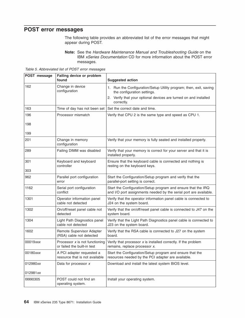
POST error messages
The following table provides an abbreviated list of the error messages that might
appear during POST.
Note: See the Hardware Maintenance Manual and Troubleshooting Guide on the
IBM xSeries Documentation CD for more information about the POST error
messages.
Table 5. Abbreviated list of POST error messages
POST message Failing device or problem
found Suggested action
162 Change in device
configuration
1. Run the Configuration/Setup Utility program; then, exit, saving
the configuration settings.
2. Verify that your optional devices are turned on and installed
correctly.
163 Time of day has not been set Set the correct date and time.
196
198
199
Processor mismatch Verify that CPU 2 is the same type and speed as CPU 1.
201 Change in memory
configuration
Verify that your memory is fully seated and installed properly.
289 Failing DIMM was disabled Verify that your memory is correct for your server and that it is
installed properly.
301
303
Keyboard and keyboard
controller
Ensure that the keyboard cable is connected and nothing is
resting on the keyboard keys.
962 Parallel port configuration
error
Start the Configuration/Setup program and verify that the
parallel-port setting is correct.
1162 Serial port configuration
conflict
Start the Configuration/Setup program and ensure that the IRQ
and I/O port assignments needed by the serial port are available.
1301 Operator information panel
cable not detected
Verify that the operator information panel cable is connected to
J24 on the system board.
1302 On/off/reset panel cable not
detected
Verify that the on/off/reset panel cable is connected to J47 on the
system board.
1304 Light Path Diagnostics panel
cable not detected
Verify that the Light Path Diagnostics panel cable is connected to
J23 on the system board.
1602 Remote Supervisor Adapter
(RSA) cable not detected
Verify that the RSA cable is connected to J27 on the system
board.
00019xxx Processor x is not functioning
or failed the built-in test
Verify that processor x is installed correctly. If the problem
remains, replace processor x.
00180xxx A PCI adapter requested a
resource that is not available
Start the Configuration/Setup program and ensure that the
resources needed by the PCI adapter are available.
012980xx
012981xx
Data for processor x Download and install the latest system BIOS level.
I9990305 POST could not find an
operating system.
Install your operating system.
64 IBM xSeries 235 Type 8671: Installation Guide
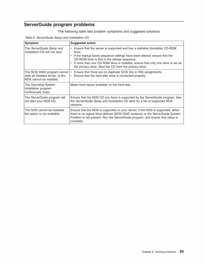
ServerGuide program problems
The following table lists problem symptoms and suggested solutions.
Table 6. ServerGuide Setup and Installation CD
Symptom Suggested action
The ServerGuide Setup and
Installation CD will not start.
v Ensure that the server is supported and has a startable (bootable) CD-ROM
drive.
v If the startup (boot) sequence settings have been altered, ensure that the
CD-ROM drive is first in the startup sequence.
v If more than one CD-ROM drive is installed, ensure that only one drive is set as
the primary drive. Start the CD from the primary drive.
The SCSI RAID program cannot
view all installed drives, or the
NOS cannot be installed.
v Ensure that there are no duplicate SCSI IDs or IRQ assignments.
v Ensure that the hard disk drive is connected properly.
The Operating System
Installation program
continuously loops.
Make more space available on the hard disk.
The ServerGuide program will
not start your NOS CD.
Ensure that the NOS CD you have is supported by the ServerGuide program. See
the ServerGuide Setup and Installation CD label for a list of supported NOS
versions.
The NOS cannot be installed;
the option is not available.
Ensure that the NOS is supported on your server. If the NOS is supported, either
there is no logical drive defined (SCSI RAID systems) or the ServerGuide System
Partition is not present. Run the ServerGuide program, and ensure that setup is
complete.
Chapter 6. Solving problems 65
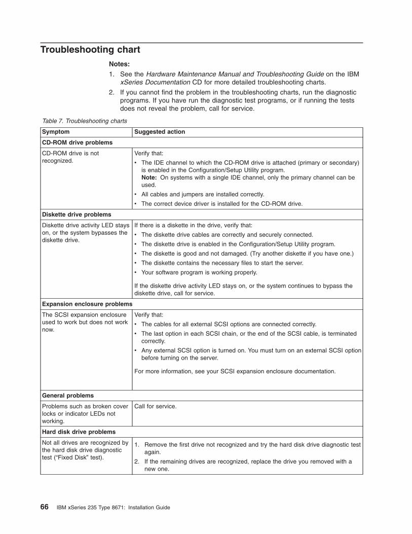
Troubleshooting chart
Notes:
1. See the Hardware Maintenance Manual and Troubleshooting Guide on the IBM
xSeries Documentation CD for more detailed troubleshooting charts.
2. If you cannot find the problem in the troubleshooting charts, run the diagnostic
programs. If you have run the diagnostic test programs, or if running the tests
does not reveal the problem, call for service.
Table 7. Troubleshooting charts
Symptom Suggested action
CD-ROM drive problems
CD-ROM drive is not
recognized.
Verify that:
v The IDE channel to which the CD-ROM drive is attached (primary or secondary)
is enabled in the Configuration/Setup Utility program.
Note: On systems with a single IDE channel, only the primary channel can be
used.
v All cables and jumpers are installed correctly.
v The correct device driver is installed for the CD-ROM drive.
Diskette drive problems
Diskette drive activity LED stays
on, or the system bypasses the
diskette drive.
If there is a diskette in the drive, verify that:
v The diskette drive cables are correctly and securely connected.
v The diskette drive is enabled in the Configuration/Setup Utility program.
v The diskette is good and not damaged. (Try another diskette if you have one.)
v The diskette contains the necessary files to start the server.
v Your software program is working properly.
If the diskette drive activity LED stays on, or the system continues to bypass the
diskette drive, call for service.
Expansion enclosure problems
The SCSI expansion enclosure
used to work but does not work
now.
Verify that:
v The cables for all external SCSI options are connected correctly.
v The last option in each SCSI chain, or the end of the SCSI cable, is terminated
correctly.
v Any external SCSI option is turned on. You must turn on an external SCSI option
before turning on the server.
For more information, see your SCSI expansion enclosure documentation.
General problems
Problems such as broken cover
locks or indicator LEDs not
working.
Call for service.
Hard disk drive problems
Not all drives are recognized by
the hard disk drive diagnostic
test (“Fixed Disk” test).
1. Remove the first drive not recognized and try the hard disk drive diagnostic test
again.
2. If the remaining drives are recognized, replace the drive you removed with a
new one.
66 IBM xSeries 235 Type 8671: Installation Guide
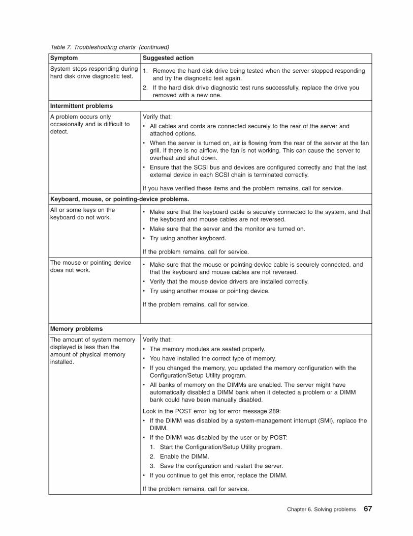
Table 7. Troubleshooting charts (continued)
Symptom Suggested action
System stops responding during
hard disk drive diagnostic test.
1. Remove the hard disk drive being tested when the server stopped responding
and try the diagnostic test again.
2. If the hard disk drive diagnostic test runs successfully, replace the drive you
removed with a new one.
Intermittent problems
A problem occurs only
occasionally and is difficult to
detect.
Verify that:
v All cables and cords are connected securely to the rear of the server and
attached options.
v When the server is turned on, air is flowing from the rear of the server at the fan
grill. If there is no airflow, the fan is not working. This can cause the server to
overheat and shut down.
v Ensure that the SCSI bus and devices are configured correctly and that the last
external device in each SCSI chain is terminated correctly.
If you have verified these items and the problem remains, call for service.
Keyboard, mouse, or pointing-device problems.
All or some keys on the
keyboard do not work.
v Make sure that the keyboard cable is securely connected to the system, and that
the keyboard and mouse cables are not reversed.
v Make sure that the server and the monitor are turned on.
v Try using another keyboard.
If the problem remains, call for service.
The mouse or pointing device
does not work.
v Make sure that the mouse or pointing-device cable is securely connected, and
that the keyboard and mouse cables are not reversed.
v Verify that the mouse device drivers are installed correctly.
v Try using another mouse or pointing device.
If the problem remains, call for service.
Memory problems
The amount of system memory
displayed is less than the
amount of physical memory
installed.
Verify that:
v The memory modules are seated properly.
v You have installed the correct type of memory.
v If you changed the memory, you updated the memory configuration with the
Configuration/Setup Utility program.
v All banks of memory on the DIMMs are enabled. The server might have
automatically disabled a DIMM bank when it detected a problem or a DIMM
bank could have been manually disabled.
Look in the POST error log for error message 289:
v If the DIMM was disabled by a system-management interrupt (SMI), replace the
DIMM.
v If the DIMM was disabled by the user or by POST:
1. Start the Configuration/Setup Utility program.
2. Enable the DIMM.
3. Save the configuration and restart the server.
v If you continue to get this error, replace the DIMM.
If the problem remains, call for service.
Chapter 6. Solving problems 67
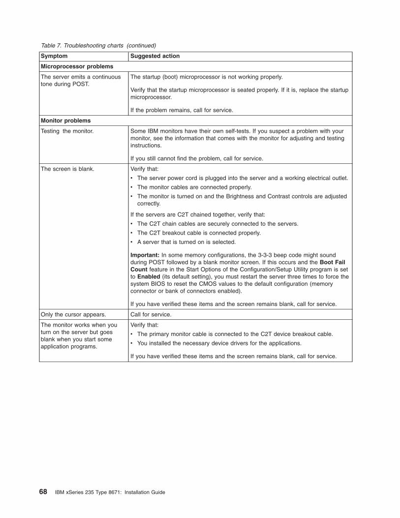
Table 7. Troubleshooting charts (continued)
Symptom Suggested action
Microprocessor problems
The server emits a continuous
tone during POST.
The startup (boot) microprocessor is not working properly.
Verify that the startup microprocessor is seated properly. If it is, replace the startup
microprocessor.
If the problem remains, call for service.
Monitor problems
Testing the monitor. Some IBM monitors have their own self-tests. If you suspect a problem with your
monitor, see the information that comes with the monitor for adjusting and testing
instructions.
If you still cannot find the problem, call for service.
The screen is blank. Verify that:
v The server power cord is plugged into the server and a working electrical outlet.
v The monitor cables are connected properly.
v The monitor is turned on and the Brightness and Contrast controls are adjusted
correctly.
If the servers are C2T chained together, verify that:
v The C2T chain cables are securely connected to the servers.
v The C2T breakout cable is connected properly.
v A server that is turned on is selected.
Important: In some memory configurations, the 3-3-3 beep code might sound
during POST followed by a blank monitor screen. If this occurs and the Boot Fail
Count feature in the Start Options of the Configuration/Setup Utility program is set
to Enabled (its default setting), you must restart the server three times to force the
system BIOS to reset the CMOS values to the default configuration (memory
connector or bank of connectors enabled).
If you have verified these items and the screen remains blank, call for service.
Only the cursor appears. Call for service.
The monitor works when you
turn on the server but goes
blank when you start some
application programs.
Verify that:
v The primary monitor cable is connected to the C2T device breakout cable.
v You installed the necessary device drivers for the applications.
If you have verified these items and the screen remains blank, call for service.
68 IBM xSeries 235 Type 8671: Installation Guide

Table 7. Troubleshooting charts (continued)
Symptom Suggested action
The screen is wavy, unreadable,
rolling, distorted, or has screen
jitter.
If the monitor self-tests show the monitor is working properly, consider the location
of the monitor. Magnetic fields around other devices (such as transformers,
appliances, fluorescent lights, and other monitors) can cause screen jitter or wavy,
unreadable, rolling, or distorted screen images. If this happens, turn off the monitor.
(Moving a color monitor while it is turned on might cause screen discoloration.)
Then move the device and the monitor at least 305 mm (12 in.) apart. Turn on the
monitor.
Notes:
1. To prevent diskette drive read/write errors, be sure the distance between
monitors and diskette drives is at least 76 mm (3 in.).
2. Non-IBM monitor cables might cause unpredictable problems.
3. An enhanced monitor cable with additional shielding is available for the 9521
and 9527 monitors. For information about the enhanced monitor cable, contact
your IBM reseller or IBM marketing representative.
If the problem remains, call for service.
Wrong characters appear on the
screen.
If the wrong language is displayed, update the BIOS code with the correct
language.
If the problem remains, call for service.
Option problems
An IBM option that was just
installed does not work.
Verify that:
v The option is designed for the server. See the “Server Support” flowchart for
information about obtaining ServerProven® compatibility information from the
World Wide Web.
v You followed the installation instructions that came with the option.
v The option is installed correctly.
v You have not loosened any other installed options or cables.
v You updated the configuration information in the Configuration/Setup Utility
program. Whenever memory or an option is changed, you must update the
configuration.
If the problem remains, call for service.
An IBM option that used to work
does not work now.
Verify that all of the option hardware and cable connections are secure.
If the option comes with its own test instructions, use those instructions to test the
option.
If the failing option is a SCSI option, verify that:
v The cables for all external SCSI options are connected correctly.
v The last option in each SCSI chain, or the end of the SCSI cable, is terminated
correctly.
v Any external SCSI option is turned on. You must turn on an external SCSI option
before turning on the server.
If the problem remains, call for service.
Power problems
The server does not turn on. Verify that:
v The power cords are properly connected to the server.
v The electrical outlet functions properly.
v The type of memory installed is correct.
v If you just installed an option, remove it, and restart the server. If the server now
turns on, you might have installed more options than the power supply supports.
If the problem remains, call for service.
Chapter 6. Solving problems 69
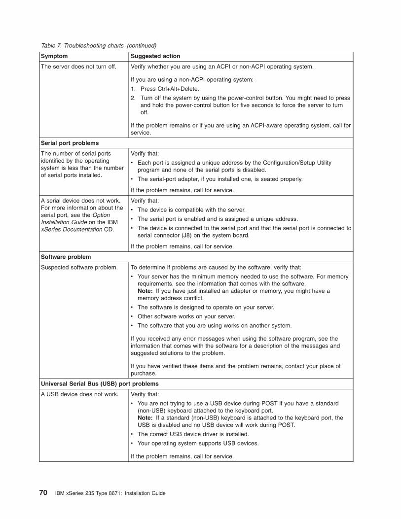
Table 7. Troubleshooting charts (continued)
Symptom Suggested action
The server does not turn off. Verify whether you are using an ACPI or non-ACPI operating system.
If you are using a non-ACPI operating system:
1. Press Ctrl+Alt+Delete.
2. Turn off the system by using the power-control button. You might need to press
and hold the power-control button for five seconds to force the server to turn
off.
If the problem remains or if you are using an ACPI-aware operating system, call for
service.
Serial port problems
The number of serial ports
identified by the operating
system is less than the number
of serial ports installed.
Verify that:
v Each port is assigned a unique address by the Configuration/Setup Utility
program and none of the serial ports is disabled.
v The serial-port adapter, if you installed one, is seated properly.
If the problem remains, call for service.
A serial device does not work.
For more information about the
serial port, see the Option
Installation Guide on the IBM
xSeries Documentation CD.
Verify that:
v The device is compatible with the server.
v The serial port is enabled and is assigned a unique address.
v The device is connected to the serial port and that the serial port is connected to
serial connector (J8) on the system board.
If the problem remains, call for service.
Software problem
Suspected software problem. To determine if problems are caused by the software, verify that:
v Your server has the minimum memory needed to use the software. For memory
requirements, see the information that comes with the software.
Note: If you have just installed an adapter or memory, you might have a
memory address conflict.
v The software is designed to operate on your server.
v Other software works on your server.
v The software that you are using works on another system.
If you received any error messages when using the software program, see the
information that comes with the software for a description of the messages and
suggested solutions to the problem.
If you have verified these items and the problem remains, contact your place of
purchase.
Universal Serial Bus (USB) port problems
A USB device does not work. Verify that:
v You are not trying to use a USB device during POST if you have a standard
(non-USB) keyboard attached to the keyboard port.
Note: If a standard (non-USB) keyboard is attached to the keyboard port, the
USB is disabled and no USB device will work during POST.
v The correct USB device driver is installed.
v Your operating system supports USB devices.
If the problem remains, call for service.
70 IBM xSeries 235 Type 8671: Installation Guide
Appendix A. Getting help and technical assistance
If you need help, service, or technical assistance or just want more information
about IBM products, you will find a wide variety of sources available from IBM to
assist you. This appendix contains information about where to go for additional
information about IBM and IBM products, what to do if you experience a problem
with your xSeries or IntelliStation® system, and whom to call for service, if it is
necessary.
Before you call
Before you call, make sure that you have taken these steps to try to solve the
problem yourself:
v Check all cables to make sure that they are connected.
v Check the power switches to make sure that the system is turned on.
v Use the troubleshooting information in your system documentation, and use the
diagnostic tools that come with your system.
v Go to the IBM Support Web site at http://www.ibm.com/pc/support/ to check for
technical information, hints, tips, and new device drivers.
v Use an IBM discussion forum on the IBM Web site to ask questions.
You can solve many problems without outside assistance by following the
troubleshooting procedures that IBM provides in the online help or in the
publications that are provided with your system and software. The information that
comes with your system also describes the diagnostic tests that you can perform.
Most xSeries and IntelliStation systems, operating systems, and programs come
with information that contains troubleshooting procedures and explanations of error
messages and error codes. If you suspect a software problem, see the information
for the operating system or program.
Using the documentation
Information about your IBM xSeries or IntelliStation system and preinstalled
software, if any, is available in the documentation that comes with your system.
That documentation includes printed books, online books, README files, and help
files. See the troubleshooting information in your system documentation for
instructions for using the diagnostic programs. The troubleshooting information or
the diagnostic programs might tell you that you need additional or updated device
drivers or other software. IBM maintains pages on the World Wide Web where you
can get the latest technical information and download device drivers and updates.
To access these pages, go to http://www.ibm.com/pc/support/ and follow the
instructions. Also, you can order publications through the IBM Publications Ordering
System at
http://www.elink.ibmlink.ibm.com/public/applications/publications/cgibin/pbi.cgi.
Getting help and information from the World Wide Web
On the World Wide Web, the IBM Web site has up-to-date information about IBM
xSeries and IntelliStation products, services, and support. The address for IBM
xSeries information is http://www.ibm.com/eserver/xseries/. The address for IBM
IntelliStation information is http://www.ibm.com/pc/intellistation/.
© Copyright IBM Corp. 2005 71
You can find service information for your IBM products, including supported options,
at http://www.ibm.com/pc/support/. If you click Profile from the support page, you
can create a customized support page. The support page has many sources of
information and ways for you to solve problems, including:
v Diagnosing problems, using the IBM Online Assistant
v Downloading the latest device drivers and updates for your products
v Viewing Frequently Asked Questions (FAQ)
v Viewing hints and tips to help you solve problems
v Participating in IBM discussion forums
v Setting up e-mail notification of technical updates about your products
Software service and support
Through IBM Support Line, you can get telephone assistance, for a fee, with usage,
configuration, and software problems with xSeries servers, IntelliStation
workstations, and appliances. For information about which products are supported
by Support Line in your country or region, go to
http://www.ibm.com/services/sl/products/.
For more information about Support Line and other IBM services, go to
http://www.ibm.com/services/, or go to http://www.ibm.com/planetwide/ for support
telephone numbers.
Hardware service and support
You can receive hardware service through IBM Integrated Technology Services or
through your IBM reseller, if your reseller is authorized by IBM to provide warranty
service. Go to http://www.ibm.com/planetwide/ for support telephone numbers.
In the U.S. and Canada, hardware service and support is available 24 hours a day,
7 days a week. In the U.K., these services are available Monday through Friday,
from 9 a.m. to 6 p.m.
72 IBM xSeries 235 Type 8671: Installation Guide
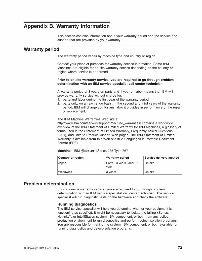
Appendix B. Warranty information
This section contains information about your warranty period and the service and
support that are provided by your warranty.
Warranty period
The warranty period varies by machine type and country or region.
Contact your place of purchase for warranty service information. Some IBM
Machines are eligible for on-site warranty service depending on the country or
region where service is performed.
Prior to on-site warranty service, you are required to go through problem
determination with an IBM service specialist call center technician.
A warranty period of 3 years on parts and 1 year on labor means that IBM will
provide warranty service without charge for:
1. parts and labor during the first year of the warranty period
2. parts only, on an exchange basis, in the second and third years of the warranty
period. IBM will charge you for any labor it provides in performance of the repair
or replacement.
The IBM Machine Warranties Web site at
http://www.ibm.com/servers/support/machine_warranties/ contains a worldwide
overview of the IBM Statement of Limited Warranty for IBM Machines, a glossary of
terms used in the Statement of Limited Warranty, Frequently Asked Questions
(FAQ), and links to Product Support Web pages. The IBM Statement of Limited
Warranty is available from this Web site in 29 languages in Portable Document
Format (PDF).
Machine - IBM Eserver xSeries 235 Type 8671
Country or region Warranty period Service delivery method
Japan Parts - 3 years, labor - 1
year
On-site
Worldwide 3 years On-site
Problem determination
Prior to on-site warranty service, you are required to go through problem
determination with an IBM service specialist call center technician. The service
specialist will run diagnostic tests on the hardware and check the software.
Running diagnostics
The IBM service specialist will help you determine whether your equipment is
functioning as specified. It might be necessary to isolate the failing xSeries,
Netfinity®, or IntelliStation system; IBM component; or both from any active
production environment to run diagnostics and perform defect-isolation programs.
You are responsible for making the system, IBM component, or both available for
running diagnostics and defect-isolation programs.
© Copyright IBM Corp. 2005 73
Checking software
The IBM service specialist will help you ensure that the correct BIOS code,
firmware, device drivers, and other supporting IBM software are installed and
correctly configured. It might be necessary to manually gather information about the
relevant software levels or run IBM-approved utility programs to gather this
information. It might be necessary to isolate the failing system from any active
production environment to gather this information. You are responsible, with
assistance from the service specialist, for gathering this information. The IBM
Statement of Limited Warranty does not include on-site assistance with this activity.
Warranty service and support
With the original purchase of an IBM xSeries or IntelliStation system, you have
access to extensive service and support. During the IBM Machine warranty period,
you may call IBM or your reseller for problem-determination assistance under the
terms of the IBM Statement of Limited Warranty.
The following services are available during the warranty period:
v Problem determination - Trained personnel are available to assist you with
determining if you have a hardware problem and deciding what action is
necessary to fix the problem.
v IBM hardware repair - If the problem is determined to be caused by IBM
hardware under warranty, trained service personnel are available to provide the
applicable level of service, either on-site or at an IBM service center as
determined by IBM.
v Engineering Change management - Occasionally, there might be changes that
are required after a product has been shipped from IBM. In those instances, IBM
will make Engineering Changes (ECs) available that apply to your hardware.
v Customer replaceable units (CRUs) - Some parts of IBM servers are
designated as customer replaceable units. IBM ships CRUs to you for
replacement by you. CRUs include keyboards, monitors, memory, diskette drives,
hard disk drives, and mice (this list is not inclusive of all CRUs).
The following items are not covered under warranty service:
v Replacement or use of non-IBM parts. All IBM parts contain a 7-character
identification in the format IBM FRU XXXXXXX.
v Identification of software problem sources.
v Installation of customer replaceable units (CRUs).
v Installation and configuration of BIOS code, firmware, or device drivers that are
designated as customer installable.
See the IBM Statement of Limited Warranty for a full explanation of IBM warranty
terms. Be sure to retain your proof of purchase to obtain warranty service.
Please have the following information ready when you call:
v The machine type and model of your IBM hardware product (if available)
v Serial numbers of your IBM hardware products
v A description of the problem
v The exact wording of any error messages
v Hardware and software configuration information
74 IBM xSeries 235 Type 8671: Installation Guide
International Warranty Service
If you travel with your xSeries or IntelliStation system or relocate it to a country
where your system is sold and serviced by IBM or IBM resellers authorized to
perform warranty service, International Warranty Service (IWS) is available during
the warranty period. Eligible IBM systems are identified by their four-digit machine
types.
You can obtain IWS through the service delivery method (such as depot, carry-in, or
on-site) provided in the servicing country. Service methods and procedures vary by
country, and some service or parts might not be available in all countries. Service
centers in certain countries might not be able to service all models of a particular
machine type. In addition, some countries might have fees and restrictions that
apply at the time of service.
To determine whether your system is eligible for IWS, go to
http://www.ibm.com/pc/support/ and click Warranty lookup.
Purchasing additional services
During and after the warranty period, you can purchase additional services, such as
support for IBM and non-IBM hardware, operating systems, and application
programs; network setup and configuration; upgraded or extended hardware repair
services; and custom installations. Service availability and service name might vary
by country or region.
For more information about these services, contact your IBM marketing
representative.
Appendix B. Warranty information 75
IBM Statement of Limited Warranty Z125-4753-06 8/2000
Part 1 - General Terms
This Statement of Limited Warranty includes Part 1 - General Terms and Part 2 -
Country-unique Terms. The terms of Part 2 replace or modify those of Part 1. The
warranties provided by IBM in this Statement of Limited Warranty apply only to
Machines you purchase for your use, and not for resale, from IBM or your reseller.
The term “Machine” means an IBM machine, its features, conversions, upgrades,
elements, or accessories, or any combination of them. The term “Machine” does not
include any software programs, whether pre-loaded with the Machine, installed
subsequently or otherwise. Unless IBM specifies otherwise, the following warranties
apply only in the country where you acquire the Machine. Nothing in this Statement
of Limited Warranty affects any statutory rights of consumers that cannot be waived
or limited by contract. If you have any questions, contact IBM or your reseller.
The IBM Warranty for Machines: IBM warrants that each Machine 1) is free from
defects in materials and workmanship and 2) conforms to IBM’s Official Published
Specifications (“Specifications”). The warranty period for a Machine is a specified,
fixed period commencing on its Date of Installation. The date on your sales receipt
is the Date of Installation unless IBM or your reseller informs you otherwise.
If a Machine does not function as warranted during the warranty period, and IBM or
your reseller are unable to either 1) make it do so or 2) replace it with one that is at
least functionally equivalent, you may return it to your place of purchase and your
money will be refunded.
Extent of Warranty: The warranty does not cover the repair or exchange of a
Machine resulting from misuse, accident, modification, unsuitable physical or
operating environment, improper maintenance by you, or failure caused by a
product for which IBM is not responsible. The warranty is voided by removal or
alteration of Machine or parts identification labels.
THESE WARRANTIES ARE YOUR EXCLUSIVE WARRANTIES AND REPLACE
ALL OTHER WARRANTIES OR CONDITIONS, EXPRESS OR IMPLIED,
INCLUDING, BUT NOT LIMITED TO, THE IMPLIED WARRANTIES OR
CONDITIONS OF MERCHANTABILITY AND FITNESS FOR A PARTICULAR
PURPOSE. THESE WARRANTIES GIVE YOU SPECIFIC LEGAL RIGHTS AND
YOU MAY ALSO HAVE OTHER RIGHTS WHICH VARY FROM JURISDICTION TO
JURISDICTION. SOME JURISDICTIONS DO NOT ALLOW THE EXCLUSION OR
LIMITATION OF EXPRESS OR IMPLIED WARRANTIES, SO THE ABOVE
EXCLUSION OR LIMITATION MAY NOT APPLY TO YOU. IN THAT EVENT, SUCH
WARRANTIES ARE LIMITED IN DURATION TO THE WARRANTY PERIOD. NO
WARRANTIES APPLY AFTER THAT PERIOD.
Items Not Covered by Warranty: IBM does not warrant uninterrupted or error-free
operation of a Machine. Any technical or other support provided for a Machine
under warranty, such as assistance via telephone with “how-to” questions and those
regarding Machine set-up and installation, will be provided WITHOUT
WARRANTIES OF ANY KIND.
Warranty Service: To obtain warranty service for a Machine, contact IBM or your
reseller. If you do not register your Machine with IBM, you may be required to
present proof of purchase.
76 IBM xSeries 235 Type 8671: Installation Guide
During the warranty period, IBM or your reseller, if approved by IBM to provide
warranty service, provides without charge certain types of repair and exchange
service to keep Machines in, or restore them to, conformance with their
Specifications. IBM or your reseller will inform you of the available types of service
for a Machine based on its country of installation. At its discretion, IBM or your
reseller will 1) either repair or exchange the failing Machine and 2) provide the
service either at your location or a service center. IBM or your reseller will also
manage and install selected engineering changes that apply to the Machine.
Some parts of IBM Machines are designated as Customer Replaceable Units
(called “CRUs”), e.g., keyboards, memory, or hard disk drives. IBM ships CRUs to
you for replacement by you. You must return all defective CRUs to IBM within 30
days of your receipt of the replacement CRU. You are responsible for downloading
designated Machine Code and Licensed Internal Code updates from an IBM
Internet Web site or from other electronic media, and following the instructions that
IBM provides.
When warranty service involves the exchange of a Machine or part, the item IBM or
your reseller replaces becomes its property and the replacement becomes yours.
You represent that all removed items are genuine and unaltered. The replacement
may not be new, but will be in good working order and at least functionally
equivalent to the item replaced. The replacement assumes the warranty service
status of the replaced item. Many features, conversions, or upgrades involve the
removal of parts and their return to IBM. A part that replaces a removed part will
assume the warranty service status of the removed part.
Before IBM or your reseller exchanges a Machine or part, you agree to remove all
features, parts, options, alterations, and attachments not under warranty service.
You also agree to
1. ensure that the Machine is free of any legal obligations or restrictions that
prevent its exchange;
2. obtain authorization from the owner to have IBM or your reseller service a
Machine that you do not own; and
3. where applicable, before service is provided:
a. follow the problem determination, problem analysis, and service request
procedures that IBM or your reseller provides;
b. secure all programs, data, and funds contained in a Machine;
c. provide IBM or your reseller with sufficient, free, and safe access to your
facilities to permit them to fulfill their obligations; and
d. inform IBM or your reseller of changes in a Machine’s location.
IBM is responsible for loss of, or damage to, your Machine while it is 1) in IBM’s
possession or 2) in transit in those cases where IBM is responsible for the
transportation charges.
Neither IBM nor your reseller is responsible for any of your confidential, proprietary
or personal information contained in a Machine which you return to IBM or your
reseller for any reason. You should remove all such information from the Machine
prior to its return.
Limitation of Liability: Circumstances may arise where, because of a default on
IBM’s part or other liability, you are entitled to recover damages from IBM. In each
such instance, regardless of the basis on which you are entitled to claim damages
from IBM (including fundamental breach, negligence, misrepresentation, or other
Appendix B. Warranty information 77
contract or tort claim), except for any liability that cannot be waived or limited by
applicable laws, IBM is liable for no more than
1. damages for bodily injury (including death) and damage to real property and
tangible personal property; and
2. the amount of any other actual direct damages, up to the charges (if recurring,
12 months’ charges apply) for the Machine that is subject of the claim. For
purposes of this item, the term “Machine” includes Machine Code and Licensed
Internal Code.
This limit also applies to IBM’s suppliers and your reseller. It is the maximum for
which IBM, its suppliers, and your reseller are collectively responsible.
UNDER NO CIRCUMSTANCES IS IBM LIABLE FOR ANY OF THE FOLLOWING:
1) THIRD-PARTY CLAIMS AGAINST YOU FOR DAMAGES (OTHER THAN
THOSE UNDER THE FIRST ITEM LISTED ABOVE); 2) LOSS OF, OR DAMAGE
TO, YOUR RECORDS OR DATA; OR 3) SPECIAL, INCIDENTAL, OR INDIRECT
DAMAGES OR FOR ANY ECONOMIC CONSEQUENTIAL DAMAGES, LOST
PROFITS OR LOST SAVINGS, EVEN IF IBM, ITS SUPPLIERS OR YOUR
RESELLER IS INFORMED OF THEIR POSSIBILITY. SOME JURISDICTIONS DO
NOT ALLOW THE EXCLUSION OR LIMITATION OF INCIDENTAL OR
CONSEQUENTIAL DAMAGES, SO THE ABOVE LIMITATION OR EXCLUSION
MAY NOT APPLY TO YOU.
Governing Law: Both you and IBM consent to the application of the laws of the
country in which you acquired the Machine to govern, interpret, and enforce all of
your and IBM’s rights, duties, and obligations arising from, or relating in any manner
to, the subject matter of this Agreement, without regard to conflict of law principles.
Part 2 - Country-unique Terms
AMERICAS
BRAZIL
Governing Law: The following is added after the first sentence:Any litigation arising from this Agreement will be settled exclusively by the court of
Rio de Janeiro.
NORTH AMERICA
Warranty Service: The following is added to this Section:
To obtain warranty service from IBM in Canada or the United States, call
1-800-IBM-SERV (426-7378).
CANADA
Governing Law: The following replaces “laws of the country in which you acquired
the Machine” in the first sentence:
laws in the Province of Ontario.
UNITED STATES
Governing Law: The following replaces “laws of the country in which you acquired
the Machine” in the first sentence:
laws of the State of New York.
ASIA PACIFIC
78 IBM xSeries 235 Type 8671: Installation Guide
AUSTRALIA
The IBM Warranty for Machines: The following paragraph is added to this Section:
The warranties specified in this Section are in addition to any rights you may have
under the Trade Practices Act 1974 or other similar legislation and are only limited
to the extent permitted by the applicable legislation.
Limitation of Liability: The following is added to this Section:
Where IBM is in breach of a condition or warranty implied by the Trade Practices
Act 1974 or other similar legislation, IBM’s liability is limited to the repair or
replacement of the goods or the supply of equivalent goods. Where that condition
or warranty relates to right to sell, quiet possession or clear title, or the goods are of
a kind ordinarily acquired for personal, domestic or household use or consumption,
then none of the limitations in this paragraph apply.
Governing Law: The following replaces “laws of the country in which you acquired
the Machine” in the first sentence:
laws of the State or Territory.
CAMBODIA, LAOS, AND VIETNAM
Governing Law: The following replaces “laws of the country in which you acquired
the Machine” in the first sentence:laws of the State of New York.
The following is added to this Section:
Disputes and differences arising out of or in connection with this Agreement shall be
finally settled by arbitration which shall be held in Singapore in accordance with the
rules of the International Chamber of Commerce (ICC). The arbitrator or arbitrators
designated in conformity with those rules shall have the power to rule on their own
competence and on the validity of the Agreement to submit to arbitration. The
arbitration award shall be final and binding for the parties without appeal and the
arbitral award shall be in writing and set forth the findings of fact and the
conclusions of law.
All proceedings shall be conducted, including all documents presented in such
proceedings, in the English language. The number of arbitrators shall be three, with
each side to the dispute being entitled to appoint one arbitrator.
The two arbitrators appointed by the parties shall appoint a third arbitrator before
proceeding upon the reference. The third arbitrator shall act as chairman of the
proceedings. Vacancies in the post of chairman shall be filled by the president of
the ICC. Other vacancies shall be filled by the respective nominating party.
Proceedings shall continue from the stage they were at when the vacancy occurred.
If one of the parties refuses or otherwise fails to appoint an arbitrator within 30 days
of the date the other party appoints its, the first appointed arbitrator shall be the
sole arbitrator, provided that the arbitrator was validly and properly appointed.
The English language version of this Agreement prevails over any other language
version.
HONG KONG AND MACAU
Appendix B. Warranty information 79
Governing Law: The following replaces “laws of the country in which you acquired
the Machine” in the first sentence:
laws of Hong Kong Special Administrative Region.
INDIA
Limitation of Liability: The following replaces items 1 and 2 of this Section:
1. liability for bodily injury (including death) or damage to real property and tangible
personal property will be limited to that caused by IBM’s negligence;
2. as to any other actual damage arising in any situation involving nonperformance
by IBM pursuant to, or in any way related to the subject of this Statement of
Limited Warranty, IBM’s liability will be limited to the charge paid by you for the
individual Machine that is the subject of the claim.
JAPAN
Governing Law: The following sentence is added to this Section:Any doubts concerning this Agreement will be initially resolved between us in good
faith and in accordance with the principle of mutual trust.
NEW ZEALAND
The IBM Warranty for Machines: The following paragraph is added to this Section:
The warranties specified in this Section are in addition to any rights you may have
under the Consumer Guarantees Act 1993 or other legislation which cannot be
excluded or limited. The Consumer Guarantees Act 1993 will not apply in respect of
any goods which IBM provides, if you require the goods for the purposes of a
business as defined in that Act.
Limitation of Liability: The following is added to this Section:Where Machines are not acquired for the purposes of a business as defined in the
Consumer Guarantees Act 1993, the limitations in this Section are subject to the
limitations in that Act.
PEOPLE’S REPUBLIC OF CHINA (PRC)
Governing Law: The following replaces this Section:
Both you and IBM consent to the application of the laws of the State of New York
(except when local law requires otherwise) to govern, interpret, and enforce all your
and IBM’s rights, duties, and obligations arising from, or relating in any manner to,
the subject matter of this Agreement, without regard to conflict of law principles.
Any disputes arising from or in connection with this Agreement will first be resolved
by friendly negotiations, failing which either of us has the right to submit the dispute
to the China International Economic and Trade Arbitration Commission in Beijing,
the PRC, for arbitration in accordance with its arbitration rules in force at the time.
The arbitration tribunal will consist of three arbitrators. The language to be used
therein will be English and Chinese. An arbitral award will be final and binding on all
the parties, and will be enforceable under the Convention on the Recognition and
Enforcement of Foreign Arbitral Awards (1958).
The arbitration fee will be borne by the losing party unless otherwise determined by
the arbitral award.
80 IBM xSeries 235 Type 8671: Installation Guide
During the course of arbitration, this Agreement will continue to be performed
except for the part which the parties are disputing and which is undergoing
arbitration.
EUROPE, MIDDLE EAST, AFRICA (EMEA)
THE FOLLOWING TERMS APPLY TO ALL EMEA COUNTRIES:
The terms of this Statement of Limited Warranty apply to Machines purchased from
IBM or an IBM reseller.
Warranty Service: If you purchase an IBM Machine in Austria, Belgium, Denmark,
Estonia, Finland, France, Germany, Greece, Iceland, Ireland, Italy, Latvia, Lithuania,
Luxembourg, Netherlands, Norway, Portugal, Spain, Sweden, Switzerland or United
Kingdom, you may obtain warranty service for that Machine in any of those
countries from either (1) an IBM reseller approved to perform warranty service or
(2) from IBM. If you purchase an IBM Personal Computer Machine in Albania,
Armenia, Belarus, Bosnia and Herzegovina, Bulgaria, Croatia, Czech Republic,
Georgia, Hungary, Kazakhstan, Kirghizia, Federal Republic of Yugoslavia, Former
Yugoslav Republic of Macedonia (FYROM), Moldova, Poland, Romania, Russia,
Slovak Republic, Slovenia, or Ukraine, you may obtain warranty service for that
Machine in any of those countries from either (1) an IBM reseller approved to
perform warranty service or (2) from IBM.
If you purchase an IBM Machine in a Middle Eastern or African country, you may
obtain warranty service for that Machine from the IBM entity within the country of
purchase, if that IBM entity provides warranty service in that country, or from an
IBM reseller, approved by IBM to perform warranty service on that Machine in that
country. Warranty service in Africa is available within 50 kilometers of an IBM
authorized service provider. You are responsible for transportation costs for
Machines located outside 50 kilometers of an IBM authorized service provider.
Governing Law: The applicable laws that govern, interpret and enforce rights,
duties, and obligations of each of us arising from, or relating in any manner to, the
subject matter of this Statement, without regard to conflict of laws principles, as well
as Country-unique terms and competent court for this Statement are those of the
country in which the warranty service is being provided, except that in 1) Albania,
Bosnia-Herzegovina, Bulgaria, Croatia, Hungary, Former Yugoslav Republic of
Macedonia, Romania, Slovakia, Slovenia, Armenia, Azerbaijan, Belarus, Georgia,
Kazakhstan, Kyrgyzstan, Moldova, Russia, Tajikistan, Turkmenistan, Ukraine, and
Uzbekistan, the laws of Austria apply; 2) Estonia, Latvia, and Lithuania, the laws of
Finland apply; 3) Algeria, Benin, Burkina Faso, Cameroon, Cape Verde, Central
African Republic, Chad, Congo, Djibouti, Democratic Republic of Congo, Equatorial
Guinea, France, Gabon, Gambia, Guinea, Guinea-Bissau, Ivory Coast, Lebanon,
Mali, Mauritania, Morocco, Niger, Senegal, Togo, and Tunisia, this Agreement will
be construed and the legal relations between the parties will be determined in
accordance with the French laws and all disputes arising out of this Agreement or
related to its violation or execution, including summary proceedings, will be settled
exclusively by the Commercial Court of Paris; 4) Angola, Bahrain, Botswana,
Burundi, Egypt, Eritrea, Ethiopia, Ghana, Jordan, Kenya, Kuwait, Liberia, Malawi,
Malta, Mozambique, Nigeria, Oman, Pakistan, Qatar, Rwanda, Sao Tome, Saudi
Arabia, Sierra Leone, Somalia, Tanzania, Uganda, United Arab Emirates, United
Kingdom, West Bank/Gaza, Yemen, Zambia, and Zimbabwe, this Agreement will be
governed by English Law and disputes relating to it will be submitted to the
exclusive jurisdiction of the English courts; and 5) in Greece, Israel, Italy, Portugal,
Appendix B. Warranty information 81

and Spain any legal claim arising out of this Statement will be brought before, and
finally settled by, the competent court of Athens, Tel Aviv, Milan, Lisbon, and Madrid,
respectively.
THE FOLLOWING TERMS APPLY TO THE COUNTRY SPECIFIED:
AUSTRIA AND GERMANY
The IBM Warranty for Machines: The following replaces the first sentence of the
first paragraph of this Section:
The warranty for an IBM Machine covers the functionality of the Machine for its
normal use and the Machine’s conformity to its Specifications.
The following paragraphs are added to this Section:
The minimum warranty period for Machines is six months. In case IBM or your
reseller is unable to repair an IBM Machine, you can alternatively ask for a partial
refund as far as justified by the reduced value of the unrepaired Machine or ask for
a cancellation of the respective agreement for such Machine and get your money
refunded.
Extent of Warranty: The second paragraph does not apply.
Warranty Service: The following is added to this Section:
During the warranty period, transportation for delivery of the failing Machine to IBM
will be at IBM’s expense.
Limitation of Liability: The following paragraph is added to this Section:
The limitations and exclusions specified in the Statement of Limited Warranty will
not apply to damages caused by IBM with fraud or gross negligence and for
express warranty.
The following sentence is added to the end of item 2:
IBM’s liability under this item is limited to the violation of essential contractual terms
in cases of ordinary negligence.
EGYPT
Limitation of Liability: The following replaces item 2 in this Section:
as to any other actual direct damages, IBM’s liability will be limited to the total
amount you paid for the Machine that is the subject of the claim. For purposes of
this item, the term “Machine” includes Machine Code and Licensed Internal Code.
Applicability of suppliers and resellers (unchanged).
FRANCE
Limitation of Liability: The following replaces the second sentence of the first
paragraph of this Section:In such instances, regardless of the basis on which you are entitled to claim
damages from IBM, IBM is liable for no more than: (items 1 and 2 unchanged).
IRELAND
Extent of Warranty: The following is added to this Section:
Except as expressly provided in these terms and conditions, all statutory conditions,
82 IBM xSeries 235 Type 8671: Installation Guide
including all warranties implied, but without prejudice to the generality of the
foregoing all warranties implied by the Sale of Goods Act 1893 or the Sale of
Goods and Supply of Services Act 1980 are hereby excluded.
Limitation of Liability: The following replaces items one and two of the first
paragraph of this Section:1. death or personal injury or physical damage to your real property solely caused
by IBM’s negligence; and
2. the amount of any other actual direct damages, up to 125 percent of the charges
(if recurring, the 12 months’ charges apply) for the Machine that is the subject of
the claim or which otherwise gives rise to the claim.
Applicability of suppliers and resellers (unchanged).
The following paragraph is added at the end of this Section:
IBM’s entire liability and your sole remedy, whether in contract or in tort, in respect
of any default shall be limited to damages.
ITALY
Limitation of Liability: The following replaces the second sentence in the first
paragraph:In each such instance unless otherwise provided by mandatory law, IBM is liable for
no more than:
1. (unchanged)
2. as to any other actual damage arising in all situations involving nonperformance
by IBM pursuant to, or in any way related to the subject matter of this Statement of
Warranty, IBM’s liability, will be limited to the total amount you paid for the Machine
that is the subject of the claim.
Applicability of suppliers and resellers (unchanged).
The following replaces the third paragraph of this Section:
Unless otherwise provided by mandatory law, IBM and your reseller are not liable
for any of the following: (items 1 and 2 unchanged) 3) indirect damages, even if
IBM or your reseller is informed of their possibility.
SOUTH AFRICA, NAMIBIA, BOTSWANA, LESOTHO AND SWAZILAND
Limitation of Liability: The following is added to this Section:
IBM’s entire liability to you for actual damages arising in all situations involving
nonperformance by IBM in respect of the subject matter of this Statement of
Warranty will be limited to the charge paid by you for the individual Machine that is
the subject of your claim from IBM.
UNITED KINGDOM
Limitation of Liability: The following replaces items 1 and 2 of the first paragraph
of this Section:
1. death or personal injury or physical damage to your real property solely caused
by IBM’s negligence;
2. the amount of any other actual direct damages or loss, up to 125 percent of the
charges (if recurring, the 12 months’ charges apply) for the Machine that is the
subject of the claim or which otherwise gives rise to the claim;
Appendix B. Warranty information 83

The following item is added to this paragraph:
3. breach of IBM’s obligations implied by Section 12 of the Sale of Goods Act 1979
or Section 2 of the Supply of Goods and Services Act 1982.
Applicability of suppliers and resellers (unchanged).
The following is added to the end of this Section:
IBM’s entire liability and your sole remedy, whether in contract or in tort, in respect
of any default shall be limited to damages.
84 IBM xSeries 235 Type 8671: Installation Guide
Appendix C. Notices
This publication was developed for products and services offered in the U.S.A.
IBM may not offer the products, services, or features discussed in this document in
other countries. Consult your local IBM representative for information on the
products and services currently available in your area. Any reference to an IBM
product, program, or service is not intended to state or imply that only that IBM
product, program, or service may be used. Any functionally equivalent product,
program, or service that does not infringe any IBM intellectual property right may be
used instead. However, it is the user’s responsibility to evaluate and verify the
operation of any non-IBM product, program, or service.
IBM may have patents or pending patent applications covering subject matter
described in this document. The furnishing of this document does not give you any
license to these patents. You can send license inquiries, in writing, to:
IBM Director of Licensing
IBM Corporation
North Castle Drive
Armonk, NY 10504-1785
U.S.A.
INTERNATIONAL BUSINESS MACHINES CORPORATION PROVIDES THIS
PUBLICATION “AS IS” WITHOUT WARRANTY OF ANY KIND, EITHER EXPRESS
OR IMPLIED, INCLUDING, BUT NOT LIMITED TO, THE IMPLIED WARRANTIES
OF NON-INFRINGEMENT, MERCHANTABILITY OR FITNESS FOR A
PARTICULAR PURPOSE. Some jurisdictions do not allow disclaimer of express or
implied warranties in certain transactions, therefore, this statement may not apply to
you.
This information could include technical inaccuracies or typographical errors.
Changes are periodically made to the information herein; these changes will be
incorporated in new editions of the publication. IBM may make improvements and/or
changes in the product(s) and/or the program(s) described in this publication at any
time without notice.
Any references in this publication to non-IBM Web sites are provided for
convenience only and do not in any manner serve as an endorsement of those
Web sites. The materials at those Web sites are not part of the materials for this
IBM product, and use of those Web sites is at your own risk.
IBM may use or distribute any of the information you supply in any way it believes
appropriate without incurring any obligation to you.
Edition notice
© COPYRIGHT INTERNATIONAL BUSINESS MACHINES CORPORATION, 2005.
All rights reserved.
Note to U.S. Government Users — Documentation related to restricted rights —
Use, duplication or disclosure is subject to restrictions set forth in GSA ADP
Schedule Contract with IBM Corp.
© Copyright IBM Corp. 2005 85
Trademarks
The following terms are trademarks of International Business Machines Corporation
in the United States, other countries, or both:
Active Memory Predictive Failure Analysis
Active PCI PS/2
Active PCI-X ServeRAID
Alert on LAN ServerGuide
C2T Interconnect ServerProven
Chipkill TechConnect
EtherJet Tivoli
e-business logo Tivoli Enterprise
FlashCopy Update Connector
HelpWare Wake on LAN
IBM XA-32
Light Path Diagnostics XA-64
NetBAY X-Architecture
Netfinity XceL4
NetView XpandOnDemand
OS/2 WARP xSeries
Lotus, Lotus Notes, and Domino are trademarks of Lotus Development Corporation
and/or IBM Corporation in the United States, other countries, or both.
Intel, Celeron, MMX, LANDesk, Pentium, Pentium II Xeon, Pentium III Xeon, and
Xeon are trademarks of Intel Corporation in the United States, other countries, or
both.
Microsoft, Windows, and Windows NT are trademarks of Microsoft Corporation in
the United States, other countries, or both.
UNIX is a registered trademark of The Open Group in the United States and other
countries.
Java and all Java-based trademarks and logos are trademarks or registered
trademarks of Sun Microsystems, Inc. in the United States, other countries, or both.
Linux is a registered trademark of Linus Torvalds.
Other company, product, or service names may be the trademarks or service marks
of others.
Important notes
Processor speeds indicate the internal clock speed of the microprocessor; other
factors also affect application performance.
CD-ROM drive speeds list the variable read rate. Actual speeds vary and are often
less than the maximum possible.
When referring to processor storage, real and virtual storage, or channel volume,
KB stands for approximately 1000 bytes, MB stands for approximately 1 000 000
bytes, and GB stands for approximately 1 000 000 000 bytes.
86 IBM xSeries 235 Type 8671: Installation Guide

When referring to hard disk drive capacity or communications volume, MB stands
for 1 000 000 bytes, and GB stands for 1 000 000 000 bytes. Total user-accessible
capacity may vary depending on operating environments.
Maximum internal hard disk drive capacities assume the replacement of any
standard hard disk drives and population of all hard disk drive bays with the largest
currently supported drives available from IBM.
Maximum memory may require replacement of the standard memory with an
optional memory module.
IBM makes no representation or warranties regarding non-IBM products and
services that are ServerProven®, including but not limited to the implied warranties
of merchantability and fitness for a particular purpose. These products are offered
and warranted solely by third parties.
IBM makes no representations or warranties with respect to non-IBM products.
Support (if any) for the non-IBM products is provided by the third party, not IBM.
Some software may differ from its retail version (if available), and may not include
user manuals or all program functionality.
Electronic emission notices
Federal Communications Commission (FCC) statement
Note: This equipment has been tested and found to comply with the limits for a
Class A digital device, pursuant to Part 15 of the FCC Rules. These limits are
designed to provide reasonable protection against harmful interference when the
equipment is operated in a commercial environment. This equipment generates,
uses, and can radiate radio frequency energy and, if not installed and used in
accordance with the instruction manual, may cause harmful interference to radio
communications. Operation of this equipment in a residential area is likely to cause
harmful interference, in which case the user will be required to correct the
interference at his own expense.
Properly shielded and grounded cables and connectors must be used in order to
meet FCC emission limits. Properly shielded and grounded cables and connectors
must be used in order to meet FCC emission limits.IBM is not responsible for any
radio or television interference causedby using other than recommended cables and
connectors or by using other than recommended cables and connectors or by
unauthorized changes or modifications to this equipment. Unauthorized changes or
modifications could void the user’s authority to operate the equipment.
This device complies with Part 15 of the FCC Rules. Operation is subject to the
following two conditions: (1) this device may not cause harmful interference, and (2)
this device must accept any interference received, including interference that may
cause undesired operation.
Industry Canada Class A emission compliance statement
This Class A digital apparatus complies with Canadian ICES-003.
Avis de conformité à la réglementation d’Industrie Canada
Appendix C. Notices 87

Cet appareil numérique de la classe A est conforme à la norme NMB-003 du
Canada.
Australia and New Zealand Class A statement
Attention: This is a Class A product. In a domestic environment this product may
cause radio interference in which case the user may be required to take adequate
measures.
United Kingdom telecommunications safety requirement
Notice to Customers
This apparatus is approved under approval number NS/G/1234/J/100003 for indirect
connection to public telecommunication systems in the United Kingdom.
European Union EMC Directive conformance statement
This product is in conformity with the protection requirements of EU Council
Directive 89/336/EEC on the approximation of the laws of the Member States
relating to electromagnetic compatibility. IBM cannot accept responsibility for any
failure to satisfy the protection requirements resulting from a nonrecommended
modification of the product, including the fitting of non-IBM option cards.
This product has been tested and found to comply with the limits for Class A
Information Technology Equipment according to CISPR 22/European Standard EN
55022. The limits for Class A equipment were derived for commercial and industrial
environments to provide reasonable protection against interference with licensed
communication equipment.
Attention: This is a Class A product. In a domestic environment this product may
cause radio interference in which case the user may be required to take adequate
measures.
Taiwan electrical emission statement
Japanese Voluntary Control Council for Interference (VCCI) statement
88 IBM xSeries 235 Type 8671: Installation Guide
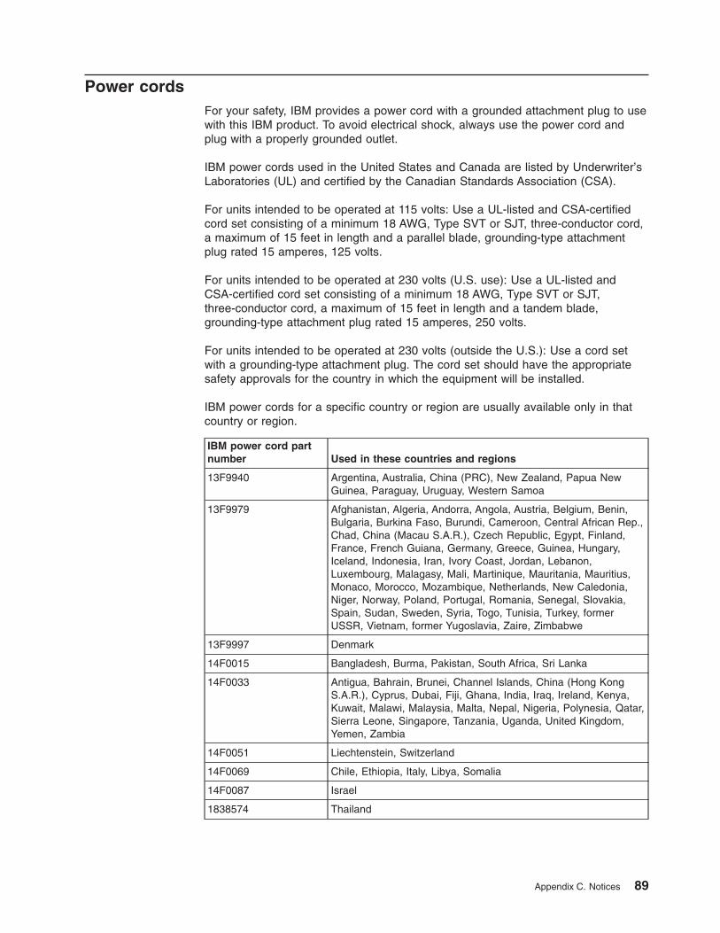
Power cords
For your safety, IBM provides a power cord with a grounded attachment plug to use
with this IBM product. To avoid electrical shock, always use the power cord and
plug with a properly grounded outlet.
IBM power cords used in the United States and Canada are listed by Underwriter’s
Laboratories (UL) and certified by the Canadian Standards Association (CSA).
For units intended to be operated at 115 volts: Use a UL-listed and CSA-certified
cord set consisting of a minimum 18 AWG, Type SVT or SJT, three-conductor cord,
a maximum of 15 feet in length and a parallel blade, grounding-type attachment
plug rated 15 amperes, 125 volts.
For units intended to be operated at 230 volts (U.S. use): Use a UL-listed and
CSA-certified cord set consisting of a minimum 18 AWG, Type SVT or SJT,
three-conductor cord, a maximum of 15 feet in length and a tandem blade,
grounding-type attachment plug rated 15 amperes, 250 volts.
For units intended to be operated at 230 volts (outside the U.S.): Use a cord set
with a grounding-type attachment plug. The cord set should have the appropriate
safety approvals for the country in which the equipment will be installed.
IBM power cords for a specific country or region are usually available only in that
country or region.
IBM power cord part
number Used in these countries and regions
13F9940 Argentina, Australia, China (PRC), New Zealand, Papua New
Guinea, Paraguay, Uruguay, Western Samoa
13F9979 Afghanistan, Algeria, Andorra, Angola, Austria, Belgium, Benin,
Bulgaria, Burkina Faso, Burundi, Cameroon, Central African Rep.,
Chad, China (Macau S.A.R.), Czech Republic, Egypt, Finland,
France, French Guiana, Germany, Greece, Guinea, Hungary,
Iceland, Indonesia, Iran, Ivory Coast, Jordan, Lebanon,
Luxembourg, Malagasy, Mali, Martinique, Mauritania, Mauritius,
Monaco, Morocco, Mozambique, Netherlands, New Caledonia,
Niger, Norway, Poland, Portugal, Romania, Senegal, Slovakia,
Spain, Sudan, Sweden, Syria, Togo, Tunisia, Turkey, former
USSR, Vietnam, former Yugoslavia, Zaire, Zimbabwe
13F9997 Denmark
14F0015 Bangladesh, Burma, Pakistan, South Africa, Sri Lanka
14F0033 Antigua, Bahrain, Brunei, Channel Islands, China (Hong Kong
S.A.R.), Cyprus, Dubai, Fiji, Ghana, India, Iraq, Ireland, Kenya,
Kuwait, Malawi, Malaysia, Malta, Nepal, Nigeria, Polynesia, Qatar,
Sierra Leone, Singapore, Tanzania, Uganda, United Kingdom,
Yemen, Zambia
14F0051 Liechtenstein, Switzerland
14F0069 Chile, Ethiopia, Italy, Libya, Somalia
14F0087 Israel
1838574 Thailand
Appendix C. Notices 89

IBM power cord part
number Used in these countries and regions
6952301 Bahamas, Barbados, Bermuda, Bolivia, Brazil, Canada, Cayman
Islands, Colombia, Costa Rica, Dominican Republic, Ecuador, El
Salvador, Guatemala, Guyana, Haiti, Honduras, Jamaica, Japan,
Korea (South), Liberia, Mexico, Netherlands Antilles, Nicaragua,
Panama, Peru, Philippines, Saudi Arabia, Suriname, Taiwan,
Trinidad (West Indies), United States of America, Venezuela
90 IBM xSeries 235 Type 8671: Installation Guide
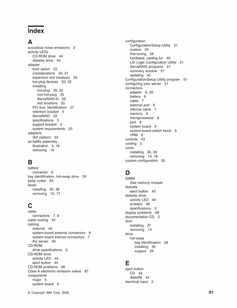
Index
Aacoustical noise emissions 3
activity LEDsCD-ROM drive 44
diskette drive 44
adapterboot option 22
considerations 20, 21
expansion slot locations 20
hot-plug devices 20, 22
installinghot-plug 20, 22
non-hot-plug 25
ServeRAID-5i 25
slot locations 20
PCI bus, identification 21
retention bracket 5
ServeRAID 22
specifications 3
support bracket 5
system requirements 20
adaptersIXA (option) 22
air-baffle assemblyillustration 5, 18
removing 18
Bbattery
connector 6
bay identification, hot-swap drive 29
beep codes 63
bezelinstalling 35, 38
removing 15, 17
Ccable
connectors 7, 8
cable routing 40
cablingexternal 40
system-board external connectors 8
system-board internal connectors 7
the server 40
CD-ROMdrive specifications 3
CD-ROM driveactivity LED 44
eject button 44
CD-ROM problems 66
Class A electronic emission notice 87
componentsmajor 5
system board 6
configurationConfiguration/Setup Utility 51
custom 55
fine-tuning 58
hardware, cabling for 40
LSI Logic Configuration Utility 51
ServeRAID programs 51
summary window 57
updating 42
Configuration/Setup Utility program 51
configuring your server 51
connectorsadapter 6, 20
battery 6
cable 7
external port 8
internal cable 7
memory 6
microprocessor 6
port 8
system board 6
system-board switch block 9
VRM 6
controls 43
cooling 3
coverinstalling 36, 39
removing 14, 16
custom configuration 55
DDIMM.
See memory module
disketteeject button 43
diskette driveactivity LED 44
problem 66
specifications 3
display problems 68
documentation CD 2
doorinstalling 37
removing 13
drivehot-swap
bay identification 29
installing 30
support 29
Eeject button
CD 44
diskette 43
electrical input 3
© Copyright IBM Corp. 2005 91
electrical safety information viii
electronic emission Class A notice 87
environment 3
error messages, POST 64
Ethernet activity LED 47
Ethernet-link status link LED 45
expansion enclosure problems 66
external cabling 40
Ffan 1 LED 45
fan 2 LED 45
FCC Class A notice 87
features, server 3
filler panel, hard disk drive bay 30
Hhandling static-sensitive devices 12
hard disk drive activity LED 44, 46
hard disk drive status LED 44
heat output 3
hot-plug adapter.See adapter
hot-swap and hot-plug devicesadapters 20, 22
drives 5, 30
fans 5
hot-swap drivebay identification 29
installing 30
specifications 3
IIBM Director 61
indicators 43
information label 1
information LED 46
information light 46
information panel 43, 46
installation order, memory modules 27
installingbezel 35, 38
cover 36, 39
door 37
hot-plug adapter 20, 22
hot-swap drive 30
memory module 27
microprocessor 31
non-hot-plug adapter 25
options 11
ServeRAID-5i 25
VRM 33
integrated RAID controllerconfiguring 54
using ServeRAID Manager 54
intermittent problems 67
Kkeyboard problems 67
LLEDs
CD-ROM drive activity 44
diskette drive activity 44
Ethernet activity 47
Ethernet-link status 45
external Attention 22
fan 1 45
fan 2 45
front of server 46
front view 43
hard disk drive 46
hard disk drive activity 44, 46
hard disk drive status 44
Information 46
internal Attention 22
operator panel 46
POST-complete 46
power-on 46
power-on (for Active PCI slots) 22
rear view 45
system board 10
system error 47
system-management adapter 45
left-side coverinstalling 36
removing 14
lights.See LEDs
LSI Logic Configuration Utilitydescription 52
starting 53
LSI Logic Configuration Utility program 51
Mmajor components 5
memoryproblems 67
specifications 3
memory moduleinstalling 27
order of installation 27
specifications 3
microprocessorheat sink 34
installing 31
problem 68
specifications 3
VRM 33
microprocessor specifications 3
monitor problems 68
mouse problems 67
92 IBM xSeries 235 Type 8671: Installation Guide
Nnotes, important 86
noticeselectronic emission 87
FCC, Class A 87
used in this book 4
Ooperator panel 46
option problems 69
optionsinstalling 11
order of installation, memory modules 27
PPCI
bus A 21
bus B 21
bus C 21, 22
PCI expansion slots 3, 20
pointing device problems 67
portconnectors 8
POST error messages 64
POST-complete LED 46
power cords 89
power problems 69
power supplyspecifications 3
power supply specifications 3
power-control button 44
power-control button shield 44, 47
power-on LED 46
power-on password override switch 9
problemsCD-ROM drive 66
diskette drive 66
expansion enclosure 66
intermittent 67
keyboard 67
memory 67
microprocessor 68
monitor 68
mouse 67
option 69
pointing device 67
power 69
serial port 70
software 70
solving 63
USB port 70
Rrack, installing server in 40
removingair-baffle assembly 18
bezel 15, 17
removing (continued)cover 14, 16
door 13
reset button 44
Ssafety information
electrical vi, viii
laser vii
lifting vii
SCSI adapter boot option 22
SCSI connectorlocation 7
serial port problems 70
ServeRAID Manager 58
Configuration wizard 54
(illus.) 54
Custom configuration 54
description 53
Express configuration 54
online help 59
overview 53
startable-CD mode 53
ServeRAID programs 51
ServeRAID-5iinstalling 25
ServerGuideCDs 51
error symptoms 65
shield, power-control button 44, 47
size 3
software problems 70
solving problems 63
specifications 3
startable-CD mode 53
startingLSI Logic Configuration Utility 53
starting the server 47
static electricity 12
static-sensitive deviceshandling 12, 20
status LEDs 43, 45, 46
switch block 9
switch, power-on password override 9
system boardconnectors
external port 8
internal cable 7
SCSI 7
user-installable options 6
LEDs 10
switch block 9
system error LED 47
system reliability 11
Ttemperature 3
thermal material, heat sink 34
Index 93
top coverinstalling 39
removing 16
trademarks 86
troubleshooting chart 66
turning on the server 47
UUnited States electronic emission Class A notice 87
United States FCC Class A notice 87
Universal Serial Bus (USB) problems 70
utilityLSI Logic Configuration 52
ServeRAID Manager 53
Vvideo 3
video controller 3
voltage regulator module installing 33
VRMSee voltage regulator module
WWeb site
compatible options 11
DIMM specification 27
IBM server products 1
weight 3
working inside server with power on 12
World Wide Web 1
94 IBM xSeries 235 Type 8671: Installation Guide

����
Part Number: 25R4646
Printed in USA
SC25-R464-60
(1P)
P/
N: 25
R464
6
Related Documents