ibm.com/redbooks Front cover IBM Midrange System Storage Implementation and Best Practices Guide Sangam Racherla Bruce Allworth Alessio Bagnaresi Chris Bogdanowicz Corne Lottering Pablo Pedrazas Frank Schubert John Sexton Alexander Watson Managing and using Midrange System Storage with SVC Advanced configuration and performance tuning Performance measurement using TPC for Disk

Welcome message from author
This document is posted to help you gain knowledge. Please leave a comment to let me know what you think about it! Share it to your friends and learn new things together.
Transcript

ibm.com/redbooks
Front cover
IBM Midrange System Storage Implementation and Best Practices Guide
Sangam RacherlaBruce Allworth
Alessio BagnaresiChris Bogdanowicz
Corne LotteringPablo PedrazasFrank Schubert
John SextonAlexander Watson
Managing and using Midrange System Storage with SVC
Advanced configuration and performance tuning
Performance measurement using TPC for Disk


International Technical Support Organization
IBM Midrange System Storage Implementation and Best Practices Guide
March 2010
SG24-6363-04

© Copyright International Business Machines Corporation 2004-2010. All rights reserved.Note to U.S. Government Users Restricted Rights -- Use, duplication or disclosure restricted by GSA ADP ScheduleContract with IBM Corp.
Fifth Edition (March 2010)
This edition applies to:IBM Midrange System Storage running v7.60 firmwareIBM DS Storage Manager v10.60
Note: Before using this information and the product it supports, read the information in “Notices” on page xi.

Contents
Notices . . . . . . . . . . . . . . . . . . . . . . . . . . . . . . . . . . . . . . . . . . . . . . . . . . . . . . . . . . . . . . . . . xiTrademarks . . . . . . . . . . . . . . . . . . . . . . . . . . . . . . . . . . . . . . . . . . . . . . . . . . . . . . . . . . . . . . xii
Preface . . . . . . . . . . . . . . . . . . . . . . . . . . . . . . . . . . . . . . . . . . . . . . . . . . . . . . . . . . . . . . . . xiiiThe team who wrote this book . . . . . . . . . . . . . . . . . . . . . . . . . . . . . . . . . . . . . . . . . . . . . . . xiiiNow you can become a published author, too! . . . . . . . . . . . . . . . . . . . . . . . . . . . . . . . . . . xviComments welcome. . . . . . . . . . . . . . . . . . . . . . . . . . . . . . . . . . . . . . . . . . . . . . . . . . . . . . . xviStay connected to IBM Redbooks publications . . . . . . . . . . . . . . . . . . . . . . . . . . . . . . . . . . xvi
Chapter 1. Introduction to IBM Midrange System Storage and SAN . . . . . . . . . . . . . . . 11.1 DS4000 and DS5000 family fit . . . . . . . . . . . . . . . . . . . . . . . . . . . . . . . . . . . . . . . . . . . . 21.2 DS4000 and DS5000 features and family members . . . . . . . . . . . . . . . . . . . . . . . . . . . . 31.3 DS4000/DS5000 expansion enclosure . . . . . . . . . . . . . . . . . . . . . . . . . . . . . . . . . . . . . . 5
1.3.1 Supported drives of the midrange family. . . . . . . . . . . . . . . . . . . . . . . . . . . . . . . . . 61.3.2 DS4000 and DS5000 series product comparison. . . . . . . . . . . . . . . . . . . . . . . . . . 6
1.4 DS Storage Manager . . . . . . . . . . . . . . . . . . . . . . . . . . . . . . . . . . . . . . . . . . . . . . . . . . . 71.5 Introduction to SAN . . . . . . . . . . . . . . . . . . . . . . . . . . . . . . . . . . . . . . . . . . . . . . . . . . . . . 9
1.5.1 SAN components . . . . . . . . . . . . . . . . . . . . . . . . . . . . . . . . . . . . . . . . . . . . . . . . . 101.5.2 SAN zoning . . . . . . . . . . . . . . . . . . . . . . . . . . . . . . . . . . . . . . . . . . . . . . . . . . . . . . 12
Chapter 2. IBM System Storage DS5000 Storage System planning tasks. . . . . . . . . . 152.1 Planning your SAN and storage server . . . . . . . . . . . . . . . . . . . . . . . . . . . . . . . . . . . . . 16
2.1.1 SAN zoning for the DS5000 Storage System . . . . . . . . . . . . . . . . . . . . . . . . . . . . 172.1.2 Enhanced Remote Mirroring considerations. . . . . . . . . . . . . . . . . . . . . . . . . . . . . 18
2.2 Planning for physical components . . . . . . . . . . . . . . . . . . . . . . . . . . . . . . . . . . . . . . . . 182.2.1 Rack considerations . . . . . . . . . . . . . . . . . . . . . . . . . . . . . . . . . . . . . . . . . . . . . . . 182.2.2 Cables and connectors . . . . . . . . . . . . . . . . . . . . . . . . . . . . . . . . . . . . . . . . . . . . . 202.2.3 Cable management and labeling . . . . . . . . . . . . . . . . . . . . . . . . . . . . . . . . . . . . . 232.2.4 Fibre Channel adapters . . . . . . . . . . . . . . . . . . . . . . . . . . . . . . . . . . . . . . . . . . . . 252.2.5 Disk expansion enclosures . . . . . . . . . . . . . . . . . . . . . . . . . . . . . . . . . . . . . . . . . . 272.2.6 Selecting drives. . . . . . . . . . . . . . . . . . . . . . . . . . . . . . . . . . . . . . . . . . . . . . . . . . . 28
2.3 Planning your storage structure . . . . . . . . . . . . . . . . . . . . . . . . . . . . . . . . . . . . . . . . . . 302.3.1 Logical drives and controller ownership . . . . . . . . . . . . . . . . . . . . . . . . . . . . . . . . 322.3.2 Hot spare drives . . . . . . . . . . . . . . . . . . . . . . . . . . . . . . . . . . . . . . . . . . . . . . . . . . 332.3.3 Storage partitioning. . . . . . . . . . . . . . . . . . . . . . . . . . . . . . . . . . . . . . . . . . . . . . . . 342.3.4 Segment size . . . . . . . . . . . . . . . . . . . . . . . . . . . . . . . . . . . . . . . . . . . . . . . . . . . . 382.3.5 Media scan . . . . . . . . . . . . . . . . . . . . . . . . . . . . . . . . . . . . . . . . . . . . . . . . . . . . . . 392.3.6 Cache parameters . . . . . . . . . . . . . . . . . . . . . . . . . . . . . . . . . . . . . . . . . . . . . . . . 41
2.4 Planning for premium features . . . . . . . . . . . . . . . . . . . . . . . . . . . . . . . . . . . . . . . . . . . 412.4.1 FlashCopy. . . . . . . . . . . . . . . . . . . . . . . . . . . . . . . . . . . . . . . . . . . . . . . . . . . . . . . 422.4.2 VolumeCopy . . . . . . . . . . . . . . . . . . . . . . . . . . . . . . . . . . . . . . . . . . . . . . . . . . . . . 422.4.3 Enhanced Remote Mirroring . . . . . . . . . . . . . . . . . . . . . . . . . . . . . . . . . . . . . . . . . 422.4.4 FC/SATA Intermix . . . . . . . . . . . . . . . . . . . . . . . . . . . . . . . . . . . . . . . . . . . . . . . . . 432.4.5 Drive Security . . . . . . . . . . . . . . . . . . . . . . . . . . . . . . . . . . . . . . . . . . . . . . . . . . . . 442.4.6 Obtaining premium features key . . . . . . . . . . . . . . . . . . . . . . . . . . . . . . . . . . . . . . 45
2.5 Additional planning considerations . . . . . . . . . . . . . . . . . . . . . . . . . . . . . . . . . . . . . . . . 452.5.1 Planning for systems with LVM: AIX example. . . . . . . . . . . . . . . . . . . . . . . . . . . . 452.5.2 Planning for systems without LVM: Windows example. . . . . . . . . . . . . . . . . . . . . 482.5.3 Virtualization . . . . . . . . . . . . . . . . . . . . . . . . . . . . . . . . . . . . . . . . . . . . . . . . . . . . . 50
© Copyright IBM Corp. 2004-2010. All rights reserved. iii
2.5.4 IBM System Storage SAN Volume Controller overview . . . . . . . . . . . . . . . . . . . . 502.6 Host support and multipathing . . . . . . . . . . . . . . . . . . . . . . . . . . . . . . . . . . . . . . . . . . . 51
2.6.1 Supported server platforms. . . . . . . . . . . . . . . . . . . . . . . . . . . . . . . . . . . . . . . . . . 512.6.2 Supported operating systems . . . . . . . . . . . . . . . . . . . . . . . . . . . . . . . . . . . . . . . . 512.6.3 Clustering support . . . . . . . . . . . . . . . . . . . . . . . . . . . . . . . . . . . . . . . . . . . . . . . . . 512.6.4 Multipathing. . . . . . . . . . . . . . . . . . . . . . . . . . . . . . . . . . . . . . . . . . . . . . . . . . . . . . 512.6.5 Microsoft Windows . . . . . . . . . . . . . . . . . . . . . . . . . . . . . . . . . . . . . . . . . . . . . . . . 522.6.6 MPIO. . . . . . . . . . . . . . . . . . . . . . . . . . . . . . . . . . . . . . . . . . . . . . . . . . . . . . . . . . . 522.6.7 AIX MPIO . . . . . . . . . . . . . . . . . . . . . . . . . . . . . . . . . . . . . . . . . . . . . . . . . . . . . . . 532.6.8 AIX Subsystem Device Driver Path Control Module . . . . . . . . . . . . . . . . . . . . . . . 532.6.9 HP-UX IBM Subsystem Device Driver . . . . . . . . . . . . . . . . . . . . . . . . . . . . . . . . . 542.6.10 Linux: RHEL/SLES . . . . . . . . . . . . . . . . . . . . . . . . . . . . . . . . . . . . . . . . . . . . . . . 542.6.11 Function of Auto-Logical Drive Transfer feature . . . . . . . . . . . . . . . . . . . . . . . . . 55
2.7 Operating system restrictions . . . . . . . . . . . . . . . . . . . . . . . . . . . . . . . . . . . . . . . . . . . . 572.7.1 Maximum capacity for a logical drive . . . . . . . . . . . . . . . . . . . . . . . . . . . . . . . . . . 582.7.2 Maximum number of LUNs per host . . . . . . . . . . . . . . . . . . . . . . . . . . . . . . . . . . . 58
Chapter 3. Configuring the DS Storage Server . . . . . . . . . . . . . . . . . . . . . . . . . . . . . . . 593.1 Configuring the DS Storage Server. . . . . . . . . . . . . . . . . . . . . . . . . . . . . . . . . . . . . . . . 60
3.1.1 Defining hot spare drives . . . . . . . . . . . . . . . . . . . . . . . . . . . . . . . . . . . . . . . . . . . 613.1.2 Creating arrays and logical drives. . . . . . . . . . . . . . . . . . . . . . . . . . . . . . . . . . . . . 663.1.3 Configuring storage partitioning . . . . . . . . . . . . . . . . . . . . . . . . . . . . . . . . . . . . . . 743.1.4 iSCSI configuration and management . . . . . . . . . . . . . . . . . . . . . . . . . . . . . . . . . 803.1.5 Configuring for Copy Services functions. . . . . . . . . . . . . . . . . . . . . . . . . . . . . . . 104
3.2 Event monitoring and alerts . . . . . . . . . . . . . . . . . . . . . . . . . . . . . . . . . . . . . . . . . . . . 1053.2.1 ADT alert notification. . . . . . . . . . . . . . . . . . . . . . . . . . . . . . . . . . . . . . . . . . . . . . 1063.2.2 Failover alert delay . . . . . . . . . . . . . . . . . . . . . . . . . . . . . . . . . . . . . . . . . . . . . . . 1073.2.3 IBM Remote Support Manager (RSM) . . . . . . . . . . . . . . . . . . . . . . . . . . . . . . . . 108
3.3 Software and microcode upgrades . . . . . . . . . . . . . . . . . . . . . . . . . . . . . . . . . . . . . . . 1143.3.1 Staying up-to-date with your drivers and firmware using My support . . . . . . . . . 1143.3.2 Compatibility matrix. . . . . . . . . . . . . . . . . . . . . . . . . . . . . . . . . . . . . . . . . . . . . . . 1153.3.3 DS firmware components and prerequisites . . . . . . . . . . . . . . . . . . . . . . . . . . . . 1153.3.4 Updating the DS subsystem firmware. . . . . . . . . . . . . . . . . . . . . . . . . . . . . . . . . 1163.3.5 Updating DS5000 host software . . . . . . . . . . . . . . . . . . . . . . . . . . . . . . . . . . . . . 118
3.4 Capacity upgrades, system upgrades. . . . . . . . . . . . . . . . . . . . . . . . . . . . . . . . . . . . . 1203.4.1 Capacity upgrades and increased bandwidth . . . . . . . . . . . . . . . . . . . . . . . . . . . 1203.4.2 Storage server upgrades . . . . . . . . . . . . . . . . . . . . . . . . . . . . . . . . . . . . . . . . . . 121
Chapter 4. Host configuration guide . . . . . . . . . . . . . . . . . . . . . . . . . . . . . . . . . . . . . . . 1254.1 Windows 2008. . . . . . . . . . . . . . . . . . . . . . . . . . . . . . . . . . . . . . . . . . . . . . . . . . . . . . . 126
4.1.1 Installing Storage Manager software. . . . . . . . . . . . . . . . . . . . . . . . . . . . . . . . . . 1264.1.2 Updating the host software . . . . . . . . . . . . . . . . . . . . . . . . . . . . . . . . . . . . . . . . . 1294.1.3 HBA and Multipath device drivers . . . . . . . . . . . . . . . . . . . . . . . . . . . . . . . . . . . . 1304.1.4 Load balance policy . . . . . . . . . . . . . . . . . . . . . . . . . . . . . . . . . . . . . . . . . . . . . . 1374.1.5 Matching DS logical drives with Windows devices . . . . . . . . . . . . . . . . . . . . . . . 1384.1.6 Using Windows Disk Manager . . . . . . . . . . . . . . . . . . . . . . . . . . . . . . . . . . . . . . 1404.1.7 Using the IBM Device Driver utilities . . . . . . . . . . . . . . . . . . . . . . . . . . . . . . . . . . 1454.1.8 Collecting information . . . . . . . . . . . . . . . . . . . . . . . . . . . . . . . . . . . . . . . . . . . . . 148
4.2 AIX . . . . . . . . . . . . . . . . . . . . . . . . . . . . . . . . . . . . . . . . . . . . . . . . . . . . . . . . . . . . . . . 1494.2.1 Installing DS5000 Storage Manager software on an AIX host . . . . . . . . . . . . . . 1494.2.2 Instructions for each installation method. . . . . . . . . . . . . . . . . . . . . . . . . . . . . . . 150
4.3 Linux . . . . . . . . . . . . . . . . . . . . . . . . . . . . . . . . . . . . . . . . . . . . . . . . . . . . . . . . . . . . . . 1624.3.1 Installing the host bus adapter drivers . . . . . . . . . . . . . . . . . . . . . . . . . . . . . . . . 162
iv IBM Midrange System Storage Implementation and Best Practices Guide

4.3.2 Installing the Linux multipath driver. . . . . . . . . . . . . . . . . . . . . . . . . . . . . . . . . . . 1654.3.3 Installing DS Storage Manager software. . . . . . . . . . . . . . . . . . . . . . . . . . . . . . . 1714.3.4 Configuring Linux for iSCSI attachment . . . . . . . . . . . . . . . . . . . . . . . . . . . . . . . 1774.3.5 Managing DS Storage volumes from Linux. . . . . . . . . . . . . . . . . . . . . . . . . . . . . 1854.3.6 Collecting information . . . . . . . . . . . . . . . . . . . . . . . . . . . . . . . . . . . . . . . . . . . . . 195
4.4 i5/OS . . . . . . . . . . . . . . . . . . . . . . . . . . . . . . . . . . . . . . . . . . . . . . . . . . . . . . . . . . . . . . 1954.5 VMware . . . . . . . . . . . . . . . . . . . . . . . . . . . . . . . . . . . . . . . . . . . . . . . . . . . . . . . . . . . . 1954.6 HyperV . . . . . . . . . . . . . . . . . . . . . . . . . . . . . . . . . . . . . . . . . . . . . . . . . . . . . . . . . . . . 196
Chapter 5. SAN boot with the IBM System Storage DS5000 storage subsystem . . . 1975.1 Introduction to SAN boot . . . . . . . . . . . . . . . . . . . . . . . . . . . . . . . . . . . . . . . . . . . . . . . 198
5.1.1 SAN boot implementation . . . . . . . . . . . . . . . . . . . . . . . . . . . . . . . . . . . . . . . . . . 1985.1.2 Installing local hard disk for high-load environments . . . . . . . . . . . . . . . . . . . . . 2015.1.3 Comparison: iSCSI versus Fibre Channel . . . . . . . . . . . . . . . . . . . . . . . . . . . . . 2015.1.4 iSCSI initiators . . . . . . . . . . . . . . . . . . . . . . . . . . . . . . . . . . . . . . . . . . . . . . . . . . 202
5.2 AIX FC SAN boot for IBM POWER systems. . . . . . . . . . . . . . . . . . . . . . . . . . . . . . . . 2045.2.1 Creating a boot disk with alt_disk_install . . . . . . . . . . . . . . . . . . . . . . . . . . . . . . 2055.2.2 Installation on external storage from a bootable AIX CD-ROM. . . . . . . . . . . . . . 2075.2.3 AIX SAN installation with NIM. . . . . . . . . . . . . . . . . . . . . . . . . . . . . . . . . . . . . . . 2095.2.4 Advanced configuration procedures . . . . . . . . . . . . . . . . . . . . . . . . . . . . . . . . . . 210
5.3 Windows 2008 SAN boot with Fibre Channel and iSCSI . . . . . . . . . . . . . . . . . . . . . . 2135.3.1 Configuration overview for FC SAN boot with BladeCenter servers . . . . . . . . . . 2135.3.2 Configuration procedure overview for iSCSI SAN boot with System x . . . . . . . . 2155.3.3 Step-by-step FC SAN boot implementation for Windows 2008 server . . . . . . . . 2165.3.4 Step-by-step iSCSI SAN boot implementation for Windows 2008 servers . . . . . 2255.3.5 Windows 2008 OS installation on SAN boot target. . . . . . . . . . . . . . . . . . . . . . . 234
5.4 FC SAN boot for RHEL5.3 on IBM system x servers . . . . . . . . . . . . . . . . . . . . . . . . . 2465.4.1 Linux SAN boot: Configuration overview. . . . . . . . . . . . . . . . . . . . . . . . . . . . . . . 2465.4.2 Linux SAN boot: Step-by-step procedure . . . . . . . . . . . . . . . . . . . . . . . . . . . . . . 2485.4.3 Controller failure simulation. . . . . . . . . . . . . . . . . . . . . . . . . . . . . . . . . . . . . . . . . 259
5.5 iSCSI SAN boot for RHEL5.3 on IBM system x servers . . . . . . . . . . . . . . . . . . . . . . . 2635.5.1 Configuration procedure overview for iSCSI SAN boot with System x . . . . . . . . 2645.5.2 Step-by-step iSCSI SAN boot implementation for RHEL v5.3 servers . . . . . . . . 265
5.6 Implementing Windows Server 2008 Failover Clustering with SAN boot . . . . . . . . . . 2865.6.1 Implementing Windows 2008 Failover Clustering step-by-step . . . . . . . . . . . . . 2885.6.2 Configuration steps after cluster is running on all configured nodes. . . . . . . . . . 296
5.7 OS support for SAN boot . . . . . . . . . . . . . . . . . . . . . . . . . . . . . . . . . . . . . . . . . . . . . . 297
Chapter 6. Midrange performance tuning . . . . . . . . . . . . . . . . . . . . . . . . . . . . . . . . . . . 2996.1 Workload types . . . . . . . . . . . . . . . . . . . . . . . . . . . . . . . . . . . . . . . . . . . . . . . . . . . . . . 3006.2 Solution-wide considerations for performance . . . . . . . . . . . . . . . . . . . . . . . . . . . . . . 3016.3 Host considerations. . . . . . . . . . . . . . . . . . . . . . . . . . . . . . . . . . . . . . . . . . . . . . . . . . . 302
6.3.1 Host based settings . . . . . . . . . . . . . . . . . . . . . . . . . . . . . . . . . . . . . . . . . . . . . . 3026.3.2 Host setting examples. . . . . . . . . . . . . . . . . . . . . . . . . . . . . . . . . . . . . . . . . . . . . 304
6.4 Application considerations . . . . . . . . . . . . . . . . . . . . . . . . . . . . . . . . . . . . . . . . . . . . . 3096.4.1 Transaction environments. . . . . . . . . . . . . . . . . . . . . . . . . . . . . . . . . . . . . . . . . . 3096.4.2 Throughput environments . . . . . . . . . . . . . . . . . . . . . . . . . . . . . . . . . . . . . . . . . . 3106.4.3 Application examples . . . . . . . . . . . . . . . . . . . . . . . . . . . . . . . . . . . . . . . . . . . . . 311
6.5 Midrange storage subsystem considerations . . . . . . . . . . . . . . . . . . . . . . . . . . . . . . . 3116.5.1 Which model fits best . . . . . . . . . . . . . . . . . . . . . . . . . . . . . . . . . . . . . . . . . . . . . 3116.5.2 Storage subsystem processes . . . . . . . . . . . . . . . . . . . . . . . . . . . . . . . . . . . . . . 3116.5.3 Storage subsystem modification functions . . . . . . . . . . . . . . . . . . . . . . . . . . . . . 3136.5.4 Storage Subsystem parameters . . . . . . . . . . . . . . . . . . . . . . . . . . . . . . . . . . . . . 315
Contents v

6.5.5 Disk drive types. . . . . . . . . . . . . . . . . . . . . . . . . . . . . . . . . . . . . . . . . . . . . . . . . . 3166.5.6 Arrays and logical drives. . . . . . . . . . . . . . . . . . . . . . . . . . . . . . . . . . . . . . . . . . . 317
6.6 Fabric considerations . . . . . . . . . . . . . . . . . . . . . . . . . . . . . . . . . . . . . . . . . . . . . . . . . 328
Chapter 7. IBM Midrange Storage Subsystem tuning with typical applications . . . . 3297.1 DB2 database . . . . . . . . . . . . . . . . . . . . . . . . . . . . . . . . . . . . . . . . . . . . . . . . . . . . . . . 330
7.1.1 Data location . . . . . . . . . . . . . . . . . . . . . . . . . . . . . . . . . . . . . . . . . . . . . . . . . . . . 3307.1.2 Database structure . . . . . . . . . . . . . . . . . . . . . . . . . . . . . . . . . . . . . . . . . . . . . . . 3307.1.3 Database RAID type . . . . . . . . . . . . . . . . . . . . . . . . . . . . . . . . . . . . . . . . . . . . . . 3327.1.4 DB2 logs and archives . . . . . . . . . . . . . . . . . . . . . . . . . . . . . . . . . . . . . . . . . . . . 333
7.2 Oracle databases . . . . . . . . . . . . . . . . . . . . . . . . . . . . . . . . . . . . . . . . . . . . . . . . . . . . 3337.2.1 Data types. . . . . . . . . . . . . . . . . . . . . . . . . . . . . . . . . . . . . . . . . . . . . . . . . . . . . . 3337.2.2 Data location . . . . . . . . . . . . . . . . . . . . . . . . . . . . . . . . . . . . . . . . . . . . . . . . . . . . 3347.2.3 Database RAID and disk types . . . . . . . . . . . . . . . . . . . . . . . . . . . . . . . . . . . . . . 3347.2.4 Redo logs: RAID types . . . . . . . . . . . . . . . . . . . . . . . . . . . . . . . . . . . . . . . . . . . . 3357.2.5 TEMP table space. . . . . . . . . . . . . . . . . . . . . . . . . . . . . . . . . . . . . . . . . . . . . . . . 3367.2.6 Cache memory settings . . . . . . . . . . . . . . . . . . . . . . . . . . . . . . . . . . . . . . . . . . . 3367.2.7 Load balancing between controllers . . . . . . . . . . . . . . . . . . . . . . . . . . . . . . . . . . 3377.2.8 Volume management . . . . . . . . . . . . . . . . . . . . . . . . . . . . . . . . . . . . . . . . . . . . . 3377.2.9 Performance monitoring . . . . . . . . . . . . . . . . . . . . . . . . . . . . . . . . . . . . . . . . . . . 337
7.3 Microsoft SQL Server . . . . . . . . . . . . . . . . . . . . . . . . . . . . . . . . . . . . . . . . . . . . . . . . . 3397.3.1 Allocation unit size . . . . . . . . . . . . . . . . . . . . . . . . . . . . . . . . . . . . . . . . . . . . . . . 3397.3.2 RAID levels . . . . . . . . . . . . . . . . . . . . . . . . . . . . . . . . . . . . . . . . . . . . . . . . . . . . . 3407.3.3 File locations . . . . . . . . . . . . . . . . . . . . . . . . . . . . . . . . . . . . . . . . . . . . . . . . . . . . 3407.3.4 User database files . . . . . . . . . . . . . . . . . . . . . . . . . . . . . . . . . . . . . . . . . . . . . . . 3407.3.5 Tempdb database files . . . . . . . . . . . . . . . . . . . . . . . . . . . . . . . . . . . . . . . . . . . . 3407.3.6 Transaction logs . . . . . . . . . . . . . . . . . . . . . . . . . . . . . . . . . . . . . . . . . . . . . . . . . 3417.3.7 Maintenance plans . . . . . . . . . . . . . . . . . . . . . . . . . . . . . . . . . . . . . . . . . . . . . . . 342
7.4 IBM Tivoli Storage Manager backup server . . . . . . . . . . . . . . . . . . . . . . . . . . . . . . . . 3427.5 Microsoft Exchange. . . . . . . . . . . . . . . . . . . . . . . . . . . . . . . . . . . . . . . . . . . . . . . . . . . 344
7.5.1 Exchange configuration . . . . . . . . . . . . . . . . . . . . . . . . . . . . . . . . . . . . . . . . . . . 3457.5.2 Calculating theoretical Exchange I/O usage . . . . . . . . . . . . . . . . . . . . . . . . . . . . 3467.5.3 Calculating Exchange I/O usage from historical data . . . . . . . . . . . . . . . . . . . . . 3467.5.4 Path LUN assignment (MPIO). . . . . . . . . . . . . . . . . . . . . . . . . . . . . . . . . . . . . . . 3487.5.5 Storage sizing for capacity and performance . . . . . . . . . . . . . . . . . . . . . . . . . . . 3497.5.6 Storage system settings . . . . . . . . . . . . . . . . . . . . . . . . . . . . . . . . . . . . . . . . . . . 3517.5.7 Aligning Exchange I/O with storage track boundaries. . . . . . . . . . . . . . . . . . . . . 3527.5.8 Guidelines specific to Windows Exchange Server 2007. . . . . . . . . . . . . . . . . . . 353
Chapter 8. Storage Manager Performance Monitor . . . . . . . . . . . . . . . . . . . . . . . . . . . 3558.1 Analyzing performance . . . . . . . . . . . . . . . . . . . . . . . . . . . . . . . . . . . . . . . . . . . . . . . . 356
8.1.1 Gathering host server data . . . . . . . . . . . . . . . . . . . . . . . . . . . . . . . . . . . . . . . . . 3568.1.2 Gathering fabric network data. . . . . . . . . . . . . . . . . . . . . . . . . . . . . . . . . . . . . . . 3578.1.3 Gathering DS5000 Storage Server data . . . . . . . . . . . . . . . . . . . . . . . . . . . . . . . 358
8.2 Storage Manager Performance Monitor . . . . . . . . . . . . . . . . . . . . . . . . . . . . . . . . . . . 3598.2.1 Starting the Performance Monitor . . . . . . . . . . . . . . . . . . . . . . . . . . . . . . . . . . . . 3598.2.2 Using the Performance Monitor . . . . . . . . . . . . . . . . . . . . . . . . . . . . . . . . . . . . . 3628.2.3 Using the Performance Monitor: An illustration. . . . . . . . . . . . . . . . . . . . . . . . . . 367
8.3 Use of Performance Monitor Data. . . . . . . . . . . . . . . . . . . . . . . . . . . . . . . . . . . . . . . . 3728.3.1 Disk Magic . . . . . . . . . . . . . . . . . . . . . . . . . . . . . . . . . . . . . . . . . . . . . . . . . . . . . 3728.3.2 Tivoli Storage Productivity Centre (TPC) for Disk . . . . . . . . . . . . . . . . . . . . . . . . 372
Chapter 9. IBM Tivoli Storage Productivity Center for Disk . . . . . . . . . . . . . . . . . . . . 3739.1 IBM Tivoli Storage Productivity Center . . . . . . . . . . . . . . . . . . . . . . . . . . . . . . . . . . . . 374
vi IBM Midrange System Storage Implementation and Best Practices Guide
9.1.1 Tivoli Storage Productivity Center structure . . . . . . . . . . . . . . . . . . . . . . . . . . . . 3749.1.2 Standards and protocols used in IBM Tivoli Storage Productivity Center. . . . . . 376
9.2 Managing DS4000/DS5000 using IBM TPC for Disk . . . . . . . . . . . . . . . . . . . . . . . . . 3789.2.1 Installing the CIM agent for DS4000/DS5000 . . . . . . . . . . . . . . . . . . . . . . . . . . . 3799.2.2 Registering the Engenio SMI-S provider in TPC. . . . . . . . . . . . . . . . . . . . . . . . . 3849.2.3 Probing the CIM agent . . . . . . . . . . . . . . . . . . . . . . . . . . . . . . . . . . . . . . . . . . . . 3879.2.4 Creating a Performance Monitor job . . . . . . . . . . . . . . . . . . . . . . . . . . . . . . . . . . 392
9.3 TPC reporting for DS4000/DS5000. . . . . . . . . . . . . . . . . . . . . . . . . . . . . . . . . . . . . . . 3959.3.1 DS4000/DS5000 performance report . . . . . . . . . . . . . . . . . . . . . . . . . . . . . . . . . 3959.3.2 Generating reports . . . . . . . . . . . . . . . . . . . . . . . . . . . . . . . . . . . . . . . . . . . . . . . 396
9.4 TPC Reports and Disk Magic . . . . . . . . . . . . . . . . . . . . . . . . . . . . . . . . . . . . . . . . . . . 4089.4.1 TPC and Disk Magic: Overview . . . . . . . . . . . . . . . . . . . . . . . . . . . . . . . . . . . . . 4089.4.2 TPC and Disk Magic: Analysis example . . . . . . . . . . . . . . . . . . . . . . . . . . . . . . . 410
Chapter 10. Disk Magic . . . . . . . . . . . . . . . . . . . . . . . . . . . . . . . . . . . . . . . . . . . . . . . . . . 43510.1 Disk Magic overview . . . . . . . . . . . . . . . . . . . . . . . . . . . . . . . . . . . . . . . . . . . . . . . . . 43610.2 Information required for DS4000/DS5000 modeling with Disk Magic . . . . . . . . . . . . 436
10.2.1 Windows perfmon and Disk Magic . . . . . . . . . . . . . . . . . . . . . . . . . . . . . . . . . . 43710.2.2 iostat and Disk Magic . . . . . . . . . . . . . . . . . . . . . . . . . . . . . . . . . . . . . . . . . . . . 45110.2.3 Mixed platforms and Disk Magic . . . . . . . . . . . . . . . . . . . . . . . . . . . . . . . . . . . . 453
10.3 Disk Magic configuration example . . . . . . . . . . . . . . . . . . . . . . . . . . . . . . . . . . . . . . 45610.3.1 Report . . . . . . . . . . . . . . . . . . . . . . . . . . . . . . . . . . . . . . . . . . . . . . . . . . . . . . . . 46810.3.2 Graph . . . . . . . . . . . . . . . . . . . . . . . . . . . . . . . . . . . . . . . . . . . . . . . . . . . . . . . . 46910.3.3 Disk Magic and DS Storage Manager Performance Monitor . . . . . . . . . . . . . . 474
Chapter 11. SVC guidelines for DS4000/DS5000 series . . . . . . . . . . . . . . . . . . . . . . . 48111.1 IBM System Storage SAN Volume Controller overview . . . . . . . . . . . . . . . . . . . . . . 482
11.1.1 Storage virtualization concepts . . . . . . . . . . . . . . . . . . . . . . . . . . . . . . . . . . . . . 48211.1.2 SVC glossary of terms . . . . . . . . . . . . . . . . . . . . . . . . . . . . . . . . . . . . . . . . . . . 48311.1.3 Benefits of the IBM System Storage SAN Volume Controller . . . . . . . . . . . . . . 48511.1.4 Key points for using DS4000 and DS5000 Storage Systems with SVC . . . . . . 48711.1.5 SVC licensing . . . . . . . . . . . . . . . . . . . . . . . . . . . . . . . . . . . . . . . . . . . . . . . . . . 48711.1.6 SVC publications. . . . . . . . . . . . . . . . . . . . . . . . . . . . . . . . . . . . . . . . . . . . . . . . 487
11.2 SVC copy services . . . . . . . . . . . . . . . . . . . . . . . . . . . . . . . . . . . . . . . . . . . . . . . . . . 48811.2.1 SVC FlashCopy . . . . . . . . . . . . . . . . . . . . . . . . . . . . . . . . . . . . . . . . . . . . . . . . 48811.2.2 Metro Mirror . . . . . . . . . . . . . . . . . . . . . . . . . . . . . . . . . . . . . . . . . . . . . . . . . . . 49011.2.3 Global Mirror . . . . . . . . . . . . . . . . . . . . . . . . . . . . . . . . . . . . . . . . . . . . . . . . . . . 49111.2.4 Differences between DS4000/DS5000 and SVC copy services . . . . . . . . . . . . 492
11.3 SVC maximum configuration. . . . . . . . . . . . . . . . . . . . . . . . . . . . . . . . . . . . . . . . . . . 49411.4 SVC considerations. . . . . . . . . . . . . . . . . . . . . . . . . . . . . . . . . . . . . . . . . . . . . . . . . . 495
11.4.1 Preferred node . . . . . . . . . . . . . . . . . . . . . . . . . . . . . . . . . . . . . . . . . . . . . . . . . 49611.4.2 Expanding VDisks. . . . . . . . . . . . . . . . . . . . . . . . . . . . . . . . . . . . . . . . . . . . . . . 49611.4.3 Multipathing. . . . . . . . . . . . . . . . . . . . . . . . . . . . . . . . . . . . . . . . . . . . . . . . . . . . 49611.4.4 SVC aliases: Guidelines . . . . . . . . . . . . . . . . . . . . . . . . . . . . . . . . . . . . . . . . . . 49711.4.5 SVC SAN zoning rules . . . . . . . . . . . . . . . . . . . . . . . . . . . . . . . . . . . . . . . . . . . 500
11.5 SVC with DS4000/DS5000 best practices . . . . . . . . . . . . . . . . . . . . . . . . . . . . . . . . 50411.5.1 Disk allocation process . . . . . . . . . . . . . . . . . . . . . . . . . . . . . . . . . . . . . . . . . . . 50411.5.2 DS4000/DS5000 tuning summary. . . . . . . . . . . . . . . . . . . . . . . . . . . . . . . . . . . 509
11.6 DS4000/DS5000 configuration with SVC . . . . . . . . . . . . . . . . . . . . . . . . . . . . . . . . . 50911.6.1 Setting DS5000/DS4000 so both controllers have the same WWNN. . . . . . . . 50911.6.2 Host definition in Storage Manager. . . . . . . . . . . . . . . . . . . . . . . . . . . . . . . . . . 51111.6.3 Arrays and logical drives. . . . . . . . . . . . . . . . . . . . . . . . . . . . . . . . . . . . . . . . . . 51311.6.4 Logical drive mapping . . . . . . . . . . . . . . . . . . . . . . . . . . . . . . . . . . . . . . . . . . . . 513
Contents vii

11.7 Managing SVC objects . . . . . . . . . . . . . . . . . . . . . . . . . . . . . . . . . . . . . . . . . . . . . . . 51411.7.1 Adding a new DS5000/DS4000 to a SVC cluster configuration . . . . . . . . . . . . 51411.7.2 Removing a storage system . . . . . . . . . . . . . . . . . . . . . . . . . . . . . . . . . . . . . . . 51611.7.3 Monitoring the MDisk Status . . . . . . . . . . . . . . . . . . . . . . . . . . . . . . . . . . . . . . . 51611.7.4 SVC error reporting and event notification . . . . . . . . . . . . . . . . . . . . . . . . . . . . 517
11.8 Migration . . . . . . . . . . . . . . . . . . . . . . . . . . . . . . . . . . . . . . . . . . . . . . . . . . . . . . . . . . 51811.8.1 Migration overview and concepts . . . . . . . . . . . . . . . . . . . . . . . . . . . . . . . . . . . 51811.8.2 Migration procedure . . . . . . . . . . . . . . . . . . . . . . . . . . . . . . . . . . . . . . . . . . . . . 519
11.9 SVC with DS4000/DS5000 configuration example . . . . . . . . . . . . . . . . . . . . . . . . . . 52311.9.1 Zoning for a non-SVC host . . . . . . . . . . . . . . . . . . . . . . . . . . . . . . . . . . . . . . . . 52411.9.2 Zoning for SVC and hosts that will use the SVC. . . . . . . . . . . . . . . . . . . . . . . . 52411.9.3 Configuring the DS5000 Storage Server. . . . . . . . . . . . . . . . . . . . . . . . . . . . . . 52511.9.4 Using the LUN in SVC . . . . . . . . . . . . . . . . . . . . . . . . . . . . . . . . . . . . . . . . . . . 528
Chapter 12. DS5000 with AIX, PowerVM, and PowerHA . . . . . . . . . . . . . . . . . . . . . . . 53312.1 Configuring DS5000 in an AIX environment . . . . . . . . . . . . . . . . . . . . . . . . . . . . . . . 534
12.1.1 Host Bus Adapters in an AIX environment for DS5000 Attachment . . . . . . . . . 53412.1.2 Verifying the microcode level . . . . . . . . . . . . . . . . . . . . . . . . . . . . . . . . . . . . . . 53412.1.3 Upgrading HBA firmware levels . . . . . . . . . . . . . . . . . . . . . . . . . . . . . . . . . . . . 536
12.2 AIX device drivers . . . . . . . . . . . . . . . . . . . . . . . . . . . . . . . . . . . . . . . . . . . . . . . . . . . 53612.2.1 RDAC drivers on AIX . . . . . . . . . . . . . . . . . . . . . . . . . . . . . . . . . . . . . . . . . . . . 53612.2.2 AIX MPIO . . . . . . . . . . . . . . . . . . . . . . . . . . . . . . . . . . . . . . . . . . . . . . . . . . . . . 53612.2.3 SDDPCM . . . . . . . . . . . . . . . . . . . . . . . . . . . . . . . . . . . . . . . . . . . . . . . . . . . . . 538
12.3 Installing the AIX MPIO and SDDPCM device drivers . . . . . . . . . . . . . . . . . . . . . . . 54012.3.1 AIX MPIO . . . . . . . . . . . . . . . . . . . . . . . . . . . . . . . . . . . . . . . . . . . . . . . . . . . . . 54012.3.2 SDDPCM . . . . . . . . . . . . . . . . . . . . . . . . . . . . . . . . . . . . . . . . . . . . . . . . . . . . . 540
12.4 Attachment to the AIX host . . . . . . . . . . . . . . . . . . . . . . . . . . . . . . . . . . . . . . . . . . . . 54112.4.1 Storage partitioning for AIX. . . . . . . . . . . . . . . . . . . . . . . . . . . . . . . . . . . . . . . . 54312.4.2 HBA configurations . . . . . . . . . . . . . . . . . . . . . . . . . . . . . . . . . . . . . . . . . . . . . . 54512.4.3 Unsupported HBA configurations . . . . . . . . . . . . . . . . . . . . . . . . . . . . . . . . . . . 548
12.5 Device drivers: Coexistence . . . . . . . . . . . . . . . . . . . . . . . . . . . . . . . . . . . . . . . . . . . 54812.6 HBA and device settings . . . . . . . . . . . . . . . . . . . . . . . . . . . . . . . . . . . . . . . . . . . . . . 550
12.6.1 HBA settings . . . . . . . . . . . . . . . . . . . . . . . . . . . . . . . . . . . . . . . . . . . . . . . . . . . 55012.6.2 Device settings . . . . . . . . . . . . . . . . . . . . . . . . . . . . . . . . . . . . . . . . . . . . . . . . . 551
12.7 PowerVM DS5000 attachment to Dual VIO Servers . . . . . . . . . . . . . . . . . . . . . . . . . 55512.8 DS5000 series: Dynamic functions . . . . . . . . . . . . . . . . . . . . . . . . . . . . . . . . . . . . . . 557
12.8.1 Overview: The dynamic functions in AIX environments . . . . . . . . . . . . . . . . . . 55712.8.2 Example: Increasing DS5000 logical volume size in AIX step by step . . . . . . . 558
12.9 PowerHA and DS5000 . . . . . . . . . . . . . . . . . . . . . . . . . . . . . . . . . . . . . . . . . . . . . . . 56112.9.1 Earlier PowerVM version HACMP/ES and ESCRM . . . . . . . . . . . . . . . . . . . . . 56212.9.2 Supported environment. . . . . . . . . . . . . . . . . . . . . . . . . . . . . . . . . . . . . . . . . . . 56312.9.3 General rules . . . . . . . . . . . . . . . . . . . . . . . . . . . . . . . . . . . . . . . . . . . . . . . . . . 56312.9.4 Configuration limitations and restrictions for PowerHA. . . . . . . . . . . . . . . . . . . 56412.9.5 Planning considerations . . . . . . . . . . . . . . . . . . . . . . . . . . . . . . . . . . . . . . . . . . 56512.9.6 Cluster disks setup . . . . . . . . . . . . . . . . . . . . . . . . . . . . . . . . . . . . . . . . . . . . . . 56712.9.7 Shared LVM component configuration . . . . . . . . . . . . . . . . . . . . . . . . . . . . . . . 56912.9.8 Fast disk takeover . . . . . . . . . . . . . . . . . . . . . . . . . . . . . . . . . . . . . . . . . . . . . . . 57212.9.9 Forced varyon of volume groups. . . . . . . . . . . . . . . . . . . . . . . . . . . . . . . . . . . . 57212.9.10 Heartbeat over disks . . . . . . . . . . . . . . . . . . . . . . . . . . . . . . . . . . . . . . . . . . . . 573
Appendix A. GPFS . . . . . . . . . . . . . . . . . . . . . . . . . . . . . . . . . . . . . . . . . . . . . . . . . . . . . 579GPFS concepts . . . . . . . . . . . . . . . . . . . . . . . . . . . . . . . . . . . . . . . . . . . . . . . . . . . . . . . . . 580
Performance advantages with GPFS file system . . . . . . . . . . . . . . . . . . . . . . . . . . . . . 580
viii IBM Midrange System Storage Implementation and Best Practices Guide

Data availability advantages with GPFS . . . . . . . . . . . . . . . . . . . . . . . . . . . . . . . . . . . . 581GPFS configuration . . . . . . . . . . . . . . . . . . . . . . . . . . . . . . . . . . . . . . . . . . . . . . . . . . . . . . 581
DS4000 and DS5000 configuration limitations with GPFS . . . . . . . . . . . . . . . . . . . . . . 582DS4000 or DS5000 settings for GPFS environment. . . . . . . . . . . . . . . . . . . . . . . . . . . 582
Related publications . . . . . . . . . . . . . . . . . . . . . . . . . . . . . . . . . . . . . . . . . . . . . . . . . . . . 585IBM Redbooks publications . . . . . . . . . . . . . . . . . . . . . . . . . . . . . . . . . . . . . . . . . . . . . . . . 585Other publications . . . . . . . . . . . . . . . . . . . . . . . . . . . . . . . . . . . . . . . . . . . . . . . . . . . . . . . 585Online resources . . . . . . . . . . . . . . . . . . . . . . . . . . . . . . . . . . . . . . . . . . . . . . . . . . . . . . . . 586How to get Redbooks publications. . . . . . . . . . . . . . . . . . . . . . . . . . . . . . . . . . . . . . . . . . . 586Help from IBM . . . . . . . . . . . . . . . . . . . . . . . . . . . . . . . . . . . . . . . . . . . . . . . . . . . . . . . . . . 586
Index . . . . . . . . . . . . . . . . . . . . . . . . . . . . . . . . . . . . . . . . . . . . . . . . . . . . . . . . . . . . . . . . . 587
Contents ix

x IBM Midrange System Storage Implementation and Best Practices Guide
Notices
This information was developed for products and services offered in the U.S.A.
IBM may not offer the products, services, or features discussed in this document in other countries. Consult your local IBM representative for information on the products and services currently available in your area. Any reference to an IBM product, program, or service is not intended to state or imply that only that IBM product, program, or service may be used. Any functionally equivalent product, program, or service that does not infringe any IBM intellectual property right may be used instead. However, it is the user's responsibility to evaluate and verify the operation of any non-IBM product, program, or service.
IBM may have patents or pending patent applications covering subject matter described in this document. The furnishing of this document does not give you any license to these patents. You can send license inquiries, in writing, to: IBM Director of Licensing, IBM Corporation, North Castle Drive, Armonk, NY 10504-1785 U.S.A.
The following paragraph does not apply to the United Kingdom or any other country where such provisions are inconsistent with local law: INTERNATIONAL BUSINESS MACHINES CORPORATION PROVIDES THIS PUBLICATION "AS IS" WITHOUT WARRANTY OF ANY KIND, EITHER EXPRESS OR IMPLIED, INCLUDING, BUT NOT LIMITED TO, THE IMPLIED WARRANTIES OF NON-INFRINGEMENT, MERCHANTABILITY OR FITNESS FOR A PARTICULAR PURPOSE. Some states do not allow disclaimer of express or implied warranties in certain transactions, therefore, this statement may not apply to you.
This information could include technical inaccuracies or typographical errors. Changes are periodically made to the information herein; these changes will be incorporated in new editions of the publication. IBM may make improvements and/or changes in the product(s) and/or the program(s) described in this publication at any time without notice.
Any references in this information to non-IBM Web sites are provided for convenience only and do not in any manner serve as an endorsement of those Web sites. The materials at those Web sites are not part of the materials for this IBM product and use of those Web sites is at your own risk.
IBM may use or distribute any of the information you supply in any way it believes appropriate without incurring any obligation to you.
Information concerning non-IBM products was obtained from the suppliers of those products, their published announcements or other publicly available sources. IBM has not tested those products and cannot confirm the accuracy of performance, compatibility or any other claims related to non-IBM products. Questions on the capabilities of non-IBM products should be addressed to the suppliers of those products.
This information contains examples of data and reports used in daily business operations. To illustrate them as completely as possible, the examples include the names of individuals, companies, brands, and products. All of these names are fictitious and any similarity to the names and addresses used by an actual business enterprise is entirely coincidental.
COPYRIGHT LICENSE:
This information contains sample application programs in source language, which illustrate programming techniques on various operating platforms. You may copy, modify, and distribute these sample programs in any form without payment to IBM, for the purposes of developing, using, marketing or distributing application programs conforming to the application programming interface for the operating platform for which the sample programs are written. These examples have not been thoroughly tested under all conditions. IBM, therefore, cannot guarantee or imply reliability, serviceability, or function of these programs.
© Copyright IBM Corp. 2004-2010. All rights reserved. xi

Trademarks
IBM, the IBM logo, and ibm.com are trademarks or registered trademarks of International Business Machines Corporation in the United States, other countries, or both. These and other IBM trademarked terms are marked on their first occurrence in this information with the appropriate symbol (® or ™), indicating US registered or common law trademarks owned by IBM at the time this information was published. Such trademarks may also be registered or common law trademarks in other countries. A current list of IBM trademarks is available on the Web at http://www.ibm.com/legal/copytrade.shtml
The following terms are trademarks of the International Business Machines Corporation in the United States, other countries, or both:
AIX 5L™AIX®BladeCenter®DB2®DS4000®DS6000™DS8000®eServer™Express Storage™FICON®FlashCopy®GPFS™HACMP™
i5/OS®IBM®iSeries®Netfinity®NUMA-Q®Power Systems™POWER6®PowerHA™PowerVM™POWER®pSeries®Redbooks®Redpapers™
Redbooks (logo) ®RS/6000®System i®System p®System Storage™System Storage DS®System x®Tivoli®TotalStorage®XIV®z/OS®zSeries®
The following terms are trademarks of other companies:
Emulex, HBAnyware, and the Emulex logo are trademarks or registered trademarks of Emulex Corporation.
Disk Magic, IntelliMagic, and the IntelliMagic logo are trademarks of IntelliMagic BV in the United States, other countries, or both.
Engenio, LSI, SANtricity, and the LSI logo are trademarks or registered trademarks of LSI Corporation.
Novell, SUSE, the Novell logo, and the N logo are registered trademarks of Novell, Inc. in the United States and other countries.
Oracle, JD Edwards, PeopleSoft, Siebel, and TopLink are registered trademarks of Oracle Corporation and/or its affiliates.
QLogic, SANsurfer, and the QLogic logo are registered trademarks of QLogic Corporation. SANblade is a registered trademark in the United States.
Red Hat, and the Shadowman logo are trademarks or registered trademarks of Red Hat, Inc. in the U.S. and other countries.
VMware, the VMware "boxes" logo and design are registered trademarks or trademarks of VMware, Inc. in the United States and/or other jurisdictions.
Java, and all Java-based trademarks are trademarks of Sun Microsystems, Inc. in the United States, other countries, or both.
Microsoft, Windows, and the Windows logo are trademarks of Microsoft Corporation in the United States, other countries, or both.
Intel, Itanium, Intel logo, Intel Inside logo, and Intel Centrino logo are trademarks or registered trademarks of Intel Corporation or its subsidiaries in the United States and other countries.
UNIX is a registered trademark of The Open Group in the United States and other countries.
Linux is a trademark of Linus Torvalds in the United States, other countries, or both.
Other company, product, or service names may be trademarks or service marks of others.
xii IBM Midrange System Storage Implementation and Best Practices Guide
Preface
This IBM® Redbooks® publication represents a compilation of best practices for deploying and configuring IBM Midrange System Storage™ servers, which include the IBM DS4000® and the DS5000 family of products. This book is intended for IBM technical professionals, Business Partners, and customers responsible for the planning, deployment, and maintenance of the IBM Midrange System Storage family of products. We realize that setting up DS4000 and DS5000 Storage Servers can be a complex task. There is no single configuration that will be satisfactory for every application or situation.
First, we provide a conceptual framework for understanding the hardware in a Storage Area Network. Then we offer our guidelines, hints, and tips for the physical installation, cabling, and zoning, using the Storage Manager setup tasks. After that, we turn our attention to the performance and tuning of various components and features, including numerous guidelines. We look at performance implications for various application products such as IBM DB2®, Oracle, IBM Tivoli® Storage Manager, Microsoft® SQL server, and in particular, Microsoft Exchange with IBM Midrange System Storage servers.
Then we review the various tools available to simulate workloads and to measure, collect, and analyze performance data. We also consider the IBM AIX® environment, including IBM High Availability Cluster Multiprocessing (HACMP™) and IBM General Parallel File System (GPFS™). Finally, we provide a quick guide to the Storage Server installation and configuration using best practices. This edition of the book also includes guidelines for managing and using the DS4000 and DS5000 with the IBM System Storage SAN Volume Controller (SVC).
This book is designed specifically to help you with the implementation and best practice scenarios and can be used in conjunction with these other IBM Midrange System Storage Redbooks publications:
� IBM Midrange System Storage Hardware Guide, SG24-7676 � IBM Midrange System Storage Copy Services Guide, SG24-7822
The team who wrote this book
This book was produced by a team of specialists from around the world working at the International Technical Support Organization (ITSO), San Jose Center.
Sangam Racherla is an IT Specialist and Project Leader working at the International Technical Support Organization (ITSO), San Jose Center. He holds a degree in electronics and communication engineering and has nine years of experience in the IT field. He has been with the ITSO for the past six years and has extensive experience installing and supporting the ITSO lab equipment for various Redbooks publication projects. His areas of expertise include Microsoft Windows®, Linux®, AIX, IBM System x®, and IBM System p® servers and various SAN and storage products.
Note: This book, previously published in 2007, has since been completely rewritten for the 2010 edition.
© Copyright IBM Corp. 2004-2010. All rights reserved. xiii
Bruce Allworth is a Senior IT Specialist working in IBM Americas Storage Advanced Technical Support (ATS). He is a Subject Matter Expert and the ATS Team Leader for the DS5000, DS4000, and DS3000 product lines. He has many years of experience with these products, including management, solution design, advanced problem determination, and disaster recovery. He works closely with various IBM divisions and LSI in launching new products, creating critical documentation, including Technical and Delivery Assessment Checklists, and developing and delivering technical training for a wide range of audiences.
Alessio Bagnaresi is a Senior Solution Architect and Technical Sales Manager at Infracom, a major IBM Business Partner in Italy. Currently he is working on customer assessments and proof of concept about Desktop/Server/storage virtualization, consolidation, infrastructure optimization, and platform management. He is certified on several platforms such as AIX, Linux, VMware, Citrix, Xen, Tivoli Software, and IBM Enterprise System Storage products. His job includes the planning, design, and delivery of Platform Management, Business Continuity, Disaster Recovery, Backup/Restore and Storage/Server/Desktop Virtualization solutions involving IBM Director, IBM System p, System x, and System Storage platforms (mostly covering IBM San Volume Controller, IBM DS4000/DS5000 Midrange Storage Server, IBM DS8000® Enterprise Storage and IBM NSeries). In his professional career, he previously worked at IBM as Cross-Brand System Architect. He supported customer projects in Server Consolidation (IBM PowerVM™, VMware, Hyper-V and Xen), Business Continuity (DS8000 Advanced Copy Services, Power HA XD, AIX Cross-site Mirroring, DB2 High Availability and Disaster Recovery, DS4000/DS5000 Enhanced Remote Mirror), Disaster Recovery (Tivoli Storage Manager DRM, ProtecTier TS7650G), and Storage Virtualization (SVC and NSeries).
Chris Bogdanowicz has over 20 years of experience in the IT industry. He joined Sequent Computer Systems 15 years ago, initially specializing in the symmetric multiprocessing UNIX® platforms and later IBM NUMA-Q® technology. He remained in a support role when Sequent merged with IBM in 1999. He is currently a member of the IBM MTS SAN and midrange storage hardware support team in the UK. In addition, he is part of a Virtual EMEA Team (VET) providing Level 2 support for DS4000 and DS5000 products within Europe. He also maintains a keen interest in performance and configuration issues through participation in the Storage Solution Expert (SSE) program.
Corne Lottering is a Systems Storage Sales Specialist in the IBM Sub Saharan Africa Growth Market Region for Systems and Technology Group. His primary focus is Sales in the Central African countries but also provides pre-sales support to the Business Partner community across Africa. He as been with IBM for nine years and has experience in a wide variety of storage technologies including the DS4000, DS5000, DS8000, IBM XIV®. IBM SAN switches, IBM Tape Systems, and storage software. Since joining IBM, he has been responsible for various implementation and support projects for customers across Africa.
Pablo Pedrazas is a Hardware Specialist working with Power Servers and Storage Products at IBM Argentina Support Center, doing post-sales second level support for Spanish speaking Latin American countries in the Maintenance & Technical Support Organization. He has 21 years of experience in the IT industry, developing expertise in UNIX Servers and Storage products. He holds a bachelor's degree in Computer Science and a Master of Science in Information Technology and Telecommunications Management from the EOI of Madrid.
Frank Schubert is an IBM Certified Systems Expert and Education Specialist for DS4000 Storage systems. He is working for IBM Global Technology Services (GTS) in the Technical Education and Competence Center (TECC) in Mainz, Germany. He focuses on deploying education and training IBM service personnel in EMEA to maintain, service, and implement IBM storage products, such as DS4000, DS5000, and N series. He has been with IBM for the last 14 years and has gained storage experience since 2003 in various support rules.
xiv IBM Midrange System Storage Implementation and Best Practices Guide

John Sexton is a Certified Consulting IT Specialist, based in Auckland, New Zealand and has over 20 years experience working in IT. He has worked at IBM for the last 13 years. His areas of expertise include IBM eServer™. IBM pSeries®, AIX, HACMP, virtualization, storage, TSM, SAN, SVC, and business continuity. He provides pre-sales support and technical services for clients throughout New Zealand, including consulting, solution implementation, troubleshooting, performance monitoring, system migration, and training. Prior to joining IBM in New Zealand, John worked in the United Kingdom supporting and maintaining systems in the financial and advertising industries.
Alexander Watson is a Senior IT Specialist for Storage ATS Americas in the United States. He is a Subject Matter Expert on SAN switches and the DS4000 products. He has over ten years of experience in planning, managing, designing, implementing, problem analysis, and tuning of SAN environments. He has worked at IBM for ten years. His areas of expertise include SAN fabric networking, Open System Storage IO and the IBM Midrange Storage Subsystems family of products.
The authors want to express their thanks to the following people, whose expertise and support were integral to the writing of this book:
Doris KoniecznyHarold PikePete UrbisciScott RainwaterMichael D RollMark BrougherBill WilsonRichard HutzlerShawn AndrewsPaul GoetzMark S. FlemingHarsha Gunatilaka
IBM
Amanda RyanStacey DershemBrad BreaultDavid WorleyRyan Leonard
LSI Corporation
Brian Steffler Jed Bless
Brocade Communications Systems, Inc.
Thanks to the following people for their contributions to this project:
Alex OsunaJon TateBertrand DufrasneAnn Lund
International Technical Support Organization, San Jose Center
Many thanks also to the authors of the previous editions of this book.
Preface xv

Now you can become a published author, too!
Here's an opportunity to spotlight your skills, grow your career, and become a published author - all at the same time! Join an ITSO residency project and help write a book in your area of expertise, while honing your experience using leading-edge technologies. Your efforts will help to increase product acceptance and customer satisfaction, as you expand your network of technical contacts and relationships. Residencies run from two to six weeks in length, and you can participate either in person or as a remote resident working from your home base.
Find out more about the residency program, browse the residency index, and apply online at:
ibm.com/redbooks/residencies.html
Comments welcome
Your comments are important to us!
We want our books to be as helpful as possible. Send us your comments about this book or other IBM Redbooks publications in one of the following ways:
� Use the online Contact us review Redbooks form found at:
ibm.com/redbooks
� Send your comments in an e-mail to:
� Mail your comments to:
IBM Corporation, International Technical Support OrganizationDept. HYTD Mail Station P0992455 South RoadPoughkeepsie, NY 12601-5400
Stay connected to IBM Redbooks publications
� Find us on Facebook:
http://www.facebook.com/pages/IBM-Redbooks/178023492563?ref=ts
� Follow us on twitter:
http://twitter.com/ibmredbooks
� Look for us on LinkedIn:
http://www.linkedin.com/groups?home=&gid=2130806
� Explore new Redbooks publications, residencies, and workshops with the IBM Redbooks publications weekly newsletter:
https://www.redbooks.ibm.com/Redbooks.nsf/subscribe?OpenForm
� Stay current on recent Redbooks publications with RSS Feeds:
http://www.redbooks.ibm.com/rss.html
xvi IBM Midrange System Storage Implementation and Best Practices Guide
Chapter 1. Introduction to IBM Midrange System Storage and SAN
In this chapter, we introduce IBM Midrange System Storage products with a brief description of the various models, their features, and where they fit in terms of a storage solution. We also summarize the functions of the DS Storage Manager (SM) software. Finally, we include a review of basic concepts and topologies of Storage Area Networks that we explain in other parts of the book.
Readers already familiar with the IBM Midrange product line and SAN concepts can skip this chapter.
1
© Copyright IBM Corp. 2004-2010. All rights reserved. 1
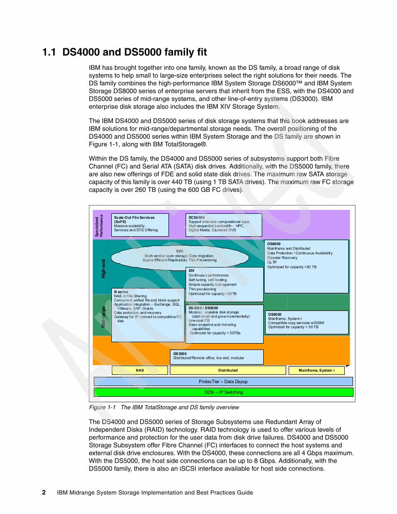
1.1 DS4000 and DS5000 family fitIBM has brought together into one family, known as the DS family, a broad range of disk systems to help small to large-size enterprises select the right solutions for their needs. The DS family combines the high-performance IBM System Storage DS6000™ and IBM System Storage DS8000 series of enterprise servers that inherit from the ESS, with the DS4000 and DS5000 series of mid-range systems, and other line-of-entry systems (DS3000). IBM enterprise disk storage also includes the IBM XIV Storage System.
The IBM DS4000 and DS5000 series of disk storage systems that this book addresses are IBM solutions for mid-range/departmental storage needs. The overall positioning of the DS4000 and DS5000 series within IBM System Storage and the DS family are shown in Figure 1-1, along with BM TotalStorage®.
Within the DS family, the DS4000 and DS5000 series of subsystems support both Fibre Channel (FC) and Serial ATA (SATA) disk drives. Additionally, with the DS5000 family, there are also new offerings of FDE and solid state disk drives. The maximum raw SATA storage capacity of this family is over 440 TB (using 1 TB SATA drives). The maximum raw FC storage capacity is over 260 TB (using the 600 GB FC drives).
Figure 1-1 The IBM TotalStorage and DS family overview
The DS4000 and DS5000 series of Storage Subsystems use Redundant Array of Independent Disks (RAID) technology. RAID technology is used to offer various levels of performance and protection for the user data from disk drive failures. DS4000 and DS5000 Storage Subsystem offer Fibre Channel (FC) interfaces to connect the host systems and external disk drive enclosures. With the DS4000, these connections are all 4 Gbps maximum. With the DS5000, the host side connections can be up to 8 Gbps. Additionally, with the DS5000 family, there is also an iSCSI interface available for host side connections.
© 2009 IBM Cor poration
Lo
w E
nd
Distributed Mainframe, System i
Hig
h-e
nd
Mid
-ran
ge
DS8000Mainframe and DistributedData Protection / Continuous Availability Disaster RecoveryOLTPOptimized for capacity >50 TB
DS4000 / DS5000Modular, scalable disk storage
(start small and grow incrementally)Low cost /TBBasic snapshot and mirroring
capabilitiesOptimized for capacity < 50TBs
DS6000Mainframe, System ICompatible copy services w/DS8KOptimized for capacity < 50 TB
NAS
N seriesNAS or File SharingConcurrent unified file and block support Application integration – Exchange, SQL,
VMware, SAP, OracleData protection and recoveryGateway for IP connect to competitive FC
disk
DCS9900Support intensive computational apps. High sequential bandwidth - HPC, Digital Media, Clustered DVS
Sp
eci
aliz
edP
erfo
rman
ce
Scale-Out File Services (SoFS) Massive scalabilityServices and STG Offering
SVCMulti-vendor open storage; Data migration;
Space Eff icient Replication; Thin Provisioning
DS3000Distributed/Remote office, low end, modular
ProtecTier – Data Depup
DCN – IP Switching
XIVContinuous performanceSelf-tuning, self-healingSimple capacity managementThin provisioningOptimized for capacity >50TB
2 IBM Midrange System Storage Implementation and Best Practices Guide

1.2 DS4000 and DS5000 features and family members
The DS4000 and DS5000 series provide high system availability through the use of hot-swappable and redundant components, which is crucial when the storage subsystem is placed in high-end customer environments such as server consolidation on Storage Area Networks (SANs). The current models also offer a number of advanced features and functions that can be implemented dynamically without stopping normal operations. These advanced features are:
� Dynamic Capacity Expansion: Allows for adding additional drives to an array group. Automatically re-stripes the LUNs to make use of the additional drive resources immediately.
� Dynamic Volume Expansion: Allows for increasing the size of a specific LUN which is already defined and in use. The additional space will be used when the host allows it to be recognized.
� Dynamic Segment Size: Allows for better handling of the host IO when alignment and IO block size issues are encountered.
� Dynamic Cache Block Size: Allows for dynamic change to be made to the selected cache block size to better handle host IO block size with minimal management.
� Dynamic RAID type: Allows for RAID type to be changed dynamically from one RAID type to another to improve performance and availability as needed.
Many of these features can be used together to resolve configuration based issues discovered after implementing the storage into production; or in cases where growth has exceeded the planned model.
The DS4000 and DS5000 storage subsystems support host connectivity through the following interfaces:
� 4 Gbps FC host ports (DS4700, DS5100 and DS5300)� 8 Gbps FC host ports (DS5020, DS5100 and DS5300)� 1 Gbps iSCSI host ports (DS5020, DS5100 and DS5300)
The current DS4000 and DS5000 series consist of the following models:
� IBM DS5020 Storage Subsystem:
The DS5020 is the newest member of the DS5000 series and is designed to help address midrange or departmental storage requirements. The DS5020 is a 3U rack-mountable enclosure, has four 4 Gbps FC drive interfaces, and can be composed of a maximum of six EXP520 expansion units for a total of up to 112 disk drives. Through a specific activation feature, six EXP810 expansions can be used in place of the EXP520s.
The DS5020 can be configured with 2 or 4 GB of cache memory and the following host connectivity options:
– Two 8 Gbps FC host ports on each of its two controllers – Four 8 Gbps FC host ports on each of its two controllers– Two 8 Gbps FC host ports and two 1 Gbps iSCSI on each of its two controllers
� IBM DS5100 Storage Subsystem:
The DS5100 is targeted at high-end DS4000 customers. This storage subsystem is a 4U rack-mountable enclosure, has sixteen 4 Gbps FC drive interfaces, and can hold a maximum of twenty-eight EXP5000 expansion units or for migration purposes, up to twenty-eight expansion units composed of a mix of EXP5000 and EXP810 for a total of up to 448 disk drives.
Chapter 1. Introduction to IBM Midrange System Storage and SAN 3

The DS5100 can have up to 64 GB of cache memory and various host connectivity options as listed here:
– Four 4 Gbps or 8 Gbps FC host ports on each of its two controllers– Two 1 Gbps iSCSI host ports on each of its two controllers– Eight 4 Gbps or 8 Gbps FC host ports on each of its two controllers– Four 8 Gbps FC host ports and Two 1 Gbps iSCSI host ports on each of its two
controllers– Four 1 Gbps iSCSI host ports on each of its two controllers
� IBM DS5300 Storage Subsystem:
The DS5300 server has greater scalability than the DS5100. This storage subsystem is a 4U rack-mountable enclosure, has sixteen 4 Gbps FC drive interfaces and can connect a maximum of twenty-eight EXP5000 expansion units or for migration purposes, up to twenty-eight expansion units composed of a mix of EXP5000 and EXP810 for a total of up to 448 Fibre Channel or SATA disk drives. With the new EXP 5060 and SATA drives only, this number will increase to a maximum of 480 disk drives. The DS5300 is designed to deliver data throughput of up to 400 MBps per drive port.
The DS5300 can support up to 64 GB of cache memory and various host connectivity options as listed here:
– Four 4 Gbps or 8 Gbps FC host ports on each of its two controllers– Four 1 Gbps iSCSI host ports on each of its two controllers– Eight 4 Gbps or 8 Gbps FC host ports on each of its two controllers– Four 8 Gbps FC host ports and four 1 Gbps iSCSI host ports on each of its two
controllers– Eight 1 Gbps iSCSI host ports on each of its two controllers
With the DS5300 Disk Storage System and the Enhanced Remote Mirroring feature an environment can design a near-enterprise-class disaster recovery strategies.
� IBM DS4700 Express Storage™ Subsystem:
The DS4700 Storage Subsystem is targeted at entry-level to mid-level customers. It can hold a maximum of sixteen disk drives inside the Storage Subsystem enclosure and can attach up to six EXP810 Expansion Units for a total of up to 112 Fibre Channel or SATA disk drives.
The DS4700 comes in two models, Model 72 and Model 70. The Model 72 has a total of eight 4 Gbps FC host ports and 4 GB of cache memory, whereas Model 70 has a total of four 4 Gbps FC host ports and 2 GB of cache memory. The DS4700 is a good choice for environments with intense replication requirements because it is designed to efficiently handle the additional performance demands of IBM FlashCopy®, Volume Copy, and Enhanced Remote Mirroring.
Note: The DS4700 Express and the EXP810 Storage Expansion Unit offer models designed to be powered from a - 48 V dc Telco industry standard power source and are NEBS-3 compliant.
4 IBM Midrange System Storage Implementation and Best Practices Guide

1.3 DS4000/DS5000 expansion enclosure
At the time of writing, the DS4000/DS5000 series expansion enclosures offer a 4 Gbps FC interface. Four models are available:
� EXP810 Expansion Enclosure:
This expansion unit is packaged in a 3U rack-mountable enclosure, and supports up to 16 FC disk drives or E-DMM SATA drives. It contains 16 drive bays, dual-switched 4 Gbps ESMs, and dual power supplies and cooling components. Fully populated with 450 GB FC disk drive modules, this enclosure offers up to 7.2 TB of raw storage capacity or up to 16 TB when populated with the 1000 GB E-DDM SATA drives. The EXP810 expansion unit is the only one that can be connected to every storage subsystem of the DS4000/DS5000 family. Through the proper firmware level, this expansion unit is able to host both FC and SATA drives. Intermix of FC and SATA drives is supported within this expansion enclosure.
� EXP5000 Expansion Enclosure:
This expansion unit is packaged in a 3U rack-mountable enclosure, and supports up to 16 FC disk drives, E-DMM SATA drives, Full Disk Encryption (FDE) drives, and up to 20 SSDs per subsystem. It contains 16 drive bays, dual-switched 4 Gbps ESMs, and dual power supplies and cooling components. Fully populated with 450 GB FC disk drive modules, this enclosure offers up to 7.2 TB of raw storage capacity or up to 16 TB when populated with the 1000 GB E-DDM SATA drives. The EXP5000 expansion unit can be connected to the DS5100 or DS5300 storage server. Through the proper firmware level, this expansion unit is able to host both FDE, FC, SATA drives and SSD as well. Intermix of FC, SATA, FDE, and SSD drives is supported within this expansion enclosure.
� EXP520 Expansion Enclosure:
This expansion unit is packaged in a 3U rack-mountable enclosure, and supports up to 16 FC disk drives, E-DMM SATA drives, or Full Disk Encryption (FDE) drives. It contains 16 drive bays, dual-switched 4 Gbps ESMs, and dual power supplies and cooling components. Fully populated with 450 GB FC disk drive modules, this enclosure offers up to 7.2 TB of raw storage capacity or up to 16 TB when populated with the 1 TB E-DDM SATA drives. The EXP520 expansion unit can be connected to the DS5020 storage server. Through the proper firmware level, this expansion unit is able to host both FDE, FC, and SATA drives. Intermix of FC, SATA, FDE drives is supported within this expansion enclosure.
� EXP5060 Expansion Enclosure:
The IBM System Storage EXP5060 storage expansion enclosure provides high-capacity SATA disk storage for the DS5100 and DS5300 storage subsystems. The storage expansion enclosure provides continuous, reliable service, using hot-swap technology for easy replacement without shutting down the system, and supports redundant, dual-loop configurations. External cables and Small Form-Factor Pluggable (SFP) modules connect the DS5100 or DS5300 storage subsystem to the EXP5060 storage expansion enclosure. The EXP5060 uses redundant 4 Gbps Fibre Channels to make connections to the DS5100 or DS5300 storage subsystem and another EXP5060 storage expansion enclosure in a cascading cabling configuration, offering reliability and performance.
Note: A maximum of eight EXP5060 storage expansion enclosures (with 480 hard drives) can be attached only to the DS5100 and DS5300 storage subsystems, and only SATA disks are supported in the EXP5060 expansion.
Chapter 1. Introduction to IBM Midrange System Storage and SAN 5

The EXP5060 is a 4U rack-mountable enclosure that supports up to 60 SATA Disk Drive Modules (DDMs), offering up to 60 TB of SATA disk space per enclosure using 1 TB SATA DDMs. The expansion enclosure contains 60 drive bays (arranged on five stacked drawers with twelve drives for each drawer), dual-switched 4 Gbps ESMs, and dual power supplies and cooling components. Coupled with a storage subsystem (DS5100 or DS5300), you can configure RAID protected storage solutions of up to 480 TB when using 1 TB SATA DDMs and eight EXP5060 storage expansion enclosures, providing economical and scalable storage for your rapidly growing application needs. The Attach up to 8 EXP5060s feature pack must be purchased for the DS5100/DS5300 storage subsystem to enable it to be connected to up to 8 EXP5060 storage expansion enclosures.
1.3.1 Supported drives of the midrange family
At the time of writing, the IBM Midrange Storage Subsystem family supports Fibre Channel drives in the sizes of: 36 GB, 73 GB, 146 GB, 300 GB, 450 GB, and 600 GB at a speed of 15K rpm, and 73 GB, 146 GB, 300 GB, at a speed of 10K rpm. It supports 250 GB and 400 GB SATA I drives, 500 GB, and 1 TB SATA II drives, all at a speed of 7500 rpm. Additionally, the DS5100 and DS5300 also support the new 73 GB solid-state disk (SSD) technology. With the new SSD drives, the subsystem can support a maximum of twenty SSD drives in the subsystem.
1.3.2 DS4000 and DS5000 series product comparisonIn Figure 1-2 and Figure 1-3, the DS4000 and DS5000 series are summarized in both their positioning and the characteristics of each of the family members. The models are grouped by their respective size for ease of comparison.
Figure 1-2 DS4000/DS5000 series positioning
DS4000/DS5000 Series Positioning
High-endMidrangeEntry-level
This table represents general positioning and not technical capaThis table represents general positioning and not technical capabilitiesbilities
DS5300
DS5100
DS4700
DS3000
DS5020
6 IBM Midrange System Storage Implementation and Best Practices Guide

Figure 1-3 DS4000 and DS5000 series comparison chart
1.4 DS Storage ManagerThe DS Storage Manager software is the primary tool for managing, configuring, monitoring, and updating firmware, support data collection for the DS3000, DS4000, and DS5000 series of storage subsystems, and repair procedures. This tool provides two interfaces for using it with a user friendly graphical user interface (GUI), and a command line interpreter (smcli) interface for use with scripts to make repetitive work easy. Various types of work that can be performed are configuration of RAID arrays and logical drives, assigning logical drives to a host, expanding the size of the arrays and logical drives, and converting from one RAID level to another.
The tool can be used for troubleshooting and management tasks, such as checking the status of the storage subsystem components, updating the firmware of the RAID controllers, replacement procedures for failed components, including rebuilding drives for use, and managing the storage subsystem. Finally, it offers implementation and management capabilities for advanced premium feature functions such as FlashCopy, Volume Copy, and Enhanced Remote Mirroring. The Storage Manager software package also includes the required host software components for the specific host environments that are planned to be supported.
The Storage Manager software level is closely tied to the features of the level of the firmware code level that is being run on the subsystem. Newer Storage Manager level are designed to be backward compatible with current firmware levels for previous generations of products as well as earlier versions of firmware for the current product line. Newer firmware levels might require a newer version of the Storage Manager to be installed.
Chapter 1. Introduction to IBM Midrange System Storage and SAN 7

The Storage Manager software is now packaged as follows:
� Host-based software:
– Storage Manager 10.6x Client (SMclient):
The SMclient component provides the GUI and the “smcli” interfaces for managing storage subsystems through the Ethernet network or from the host computer.
– Storage Manager 10.6x Runtime (SMruntime):
The SMruntime is a Java™ runtime environment that is required for the SMclient to function. It is not available on every platform as a separate package, but in those cases, it has been bundled into the SMclient package.
– Storage Manager 10.6x Agent (SMagent):
The SMagent package is an optional component that allows in-band management of the DS4000 and DS5000 storage subsystems.
– Storage Manager 10.6x Utilities (SMutil):
The Storage Manager Utilities package contains command line tools for making logical drives available to the operating system for specific host environments.
– Multipath drivers:
The storage manager offers a choice of multipath drivers, RDAC, or MPIO. This choice might be limited depending on host operating systems. Consult the Storage Manager readme file for the specific release being used.
During the installation you are prompted to choose between RDAC or MPIO. Both are Fibre Channel I/O path failover drivers that are installed on host computers. These are only required if the host computer has a host bus adapter (HBA) installed.
� Controller-based software:
– DS4000 and DS5000 Storage Subsystem controller firmware and NVSRAM:
The controller firmware and NVSRAM are always installed as a pair and provide the “brains” of the DS4000 and DS5000 Storage Subsystem.
– DS4000 and DS5000 Storage Subsystem Environmental Service Modules (ESM) firmware:
The ESM firmware controls the interface between the controller and the drives.
– DS4000 and DS5000 Storage Subsystem Drive firmware:
The drive firmware is the software that tells the specific drive types how to perform and behave on the back-end FC loops.
Note: Always consult the System Storage Interoperation Center for the latest supported host types and operating systems:
http://www-03.ibm.com/systems/support/storage/config/ssic/displayesssearchwithoutjs.wss?start_over=yes
8 IBM Midrange System Storage Implementation and Best Practices Guide

1.5 Introduction to SANFor businesses, data access is critical and requires performance, availability, and flexibility. In other words, there is a need for a data access network that is fast, redundant (multipath), easy to manage, and always available. That network is a Storage Area Network (SAN).
A SAN is a high-speed network that enables the establishment of switched, routed, or direct connections between storage devices and hosts (servers) within the specific distance supported by the designed environment. At the basic level, the SAN is a Fibre Channel (FC) network; however, new technology now enables this network to be routed or tunneled over many other networks as well.
The SAN can be viewed as an extension of the storage bus concept, which enables storage devices to be interconnected using concepts similar to that of local area networks (LANs) and wide area networks (WANs). A SAN can be shared between servers or dedicated to one server, or both. It can be local or extended over geographical distances.
The diagram in Figure 1-4 shows a brief overview of a SAN connecting multiple servers to multiple storage systems.
Chapter 1. Introduction to IBM Midrange System Storage and SAN 9
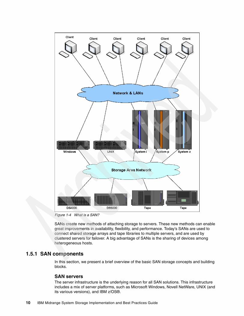
Figure 1-4 What is a SAN?
SANs create new methods of attaching storage to servers. These new methods can enable great improvements in availability, flexibility, and performance. Today’s SANs are used to connect shared storage arrays and tape libraries to multiple servers, and are used by clustered servers for failover. A big advantage of SANs is the sharing of devices among heterogeneous hosts.
1.5.1 SAN componentsIn this section, we present a brief overview of the basic SAN storage concepts and building blocks.
SAN serversThe server infrastructure is the underlying reason for all SAN solutions. This infrastructure includes a mix of server platforms, such as Microsoft Windows, Novell NetWare, UNIX (and its various versions), and IBM z/OS®.
10 IBM Midrange System Storage Implementation and Best Practices Guide
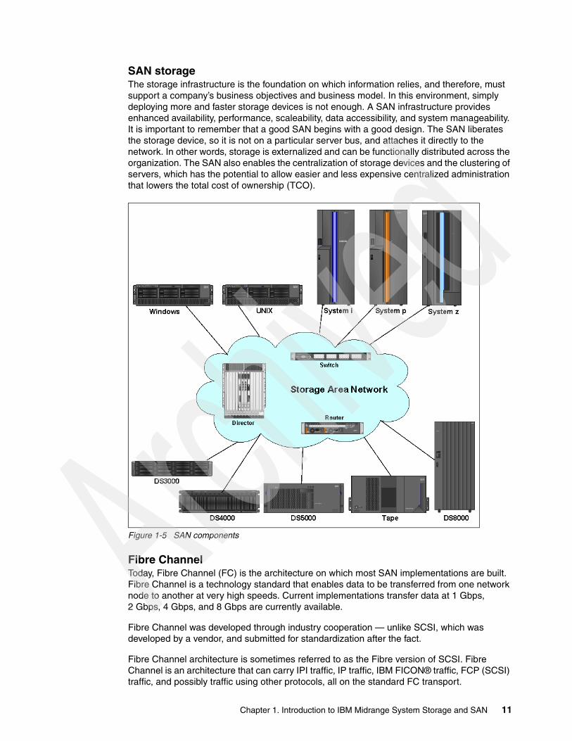
SAN storageThe storage infrastructure is the foundation on which information relies, and therefore, must support a company’s business objectives and business model. In this environment, simply deploying more and faster storage devices is not enough. A SAN infrastructure provides enhanced availability, performance, scaleability, data accessibility, and system manageability. It is important to remember that a good SAN begins with a good design. The SAN liberates the storage device, so it is not on a particular server bus, and attaches it directly to the network. In other words, storage is externalized and can be functionally distributed across the organization. The SAN also enables the centralization of storage devices and the clustering of servers, which has the potential to allow easier and less expensive centralized administration that lowers the total cost of ownership (TCO).
Figure 1-5 SAN components
Fibre Channel Today, Fibre Channel (FC) is the architecture on which most SAN implementations are built. Fibre Channel is a technology standard that enables data to be transferred from one network node to another at very high speeds. Current implementations transfer data at 1 Gbps, 2 Gbps, 4 Gbps, and 8 Gbps are currently available.
Fibre Channel was developed through industry cooperation — unlike SCSI, which was developed by a vendor, and submitted for standardization after the fact.
Fibre Channel architecture is sometimes referred to as the Fibre version of SCSI. Fibre Channel is an architecture that can carry IPI traffic, IP traffic, IBM FICON® traffic, FCP (SCSI) traffic, and possibly traffic using other protocols, all on the standard FC transport.
Chapter 1. Introduction to IBM Midrange System Storage and SAN 11
SAN topologiesFibre Channel interconnects nodes using three physical topologies that can have variants. These three topologies are:
� Point-to-point: The point-to-point topology consists of a single connection between two nodes. All the bandwidth is dedicated to these two nodes.
� Loop: In the loop topology, the bandwidth is shared between all the nodes connected to the loop. The loop can be wired node-to-node, and is how the DS4000 and DS5000 subsystems perform their direct connection to single host without switch attachment; however, if a node fails or is not powered on, the loop is out of operation, which can be overcome by using a hub. A hub opens the loop when a new node is connected, and closes it when a node disconnects.
� Switched or fabric: A switch enables multiple concurrent connections between nodes. There are two types of switches: circuit switches and frame switches. Circuit switches establish a dedicated connection between two nodes, whereas frame switches route frames between nodes and establish the connection only when needed, which is also known as switched fabric.
SAN interconnectsFibre Channel employs a fabric to connect devices. A fabric can be as simple as a single cable connecting two devices. However, the term is most often used to describe a more complex network using cables and interface connectors, HBAs, extenders, and switches.
Fibre Channel switches function in a manner similar to traditional network switches to provide increased bandwidth, scalable performance, an increased number of devices, and in certain cases, increased redundancy. Fibre Channel switches vary from simple edge switches to enterprise-scalable core switches or Fibre Channel directors.
Inter-Switch Links (ISLs)Switches can be linked together using either standard connections or Inter-Switch Links. Under normal circumstances, traffic moves around a SAN using the Fabric Shortest Path First (FSPF) protocol, which allows data to move around a SAN from initiator to target using the quickest of alternate routes. However, it is possible to implement a direct, high-speed path between switches in the form of ISLs.
TrunkingInter-Switch Links can be combined into logical groups to form trunks. In IBM TotalStorage switches, trunks can be groups of up to four ports on a switch connected to four ports on a second switch. At the outset, a trunk master is defined, and subsequent trunk slaves can be added, which has the effect of aggregating the throughput across all links. Therefore, in the case of switches with 8 Gbps ports, if we trunk up to four ports, we allow for a 32 Gbps Inter-Switch Link.
1.5.2 SAN zoningA zone is a group of fabric-connected devices arranged into a specified grouping. Zones can vary in size depending on the number of fabric-connected devices, and devices can belong to more than one zone.
Note: The fabric (or switched) topology gives the most flexibility and ability to grow your installation for future needs.
12 IBM Midrange System Storage Implementation and Best Practices Guide
Typically, you can use zones to do the following tasks:
� Provide security: Use zones to provide controlled access to fabric segments and to establish barriers between operating environments. For example, isolate systems with various uses or protect systems in a heterogeneous environment.
� Customize environments: Use zones to create logical subsets of the fabric to accommodate closed user groups or to create functional areas within the fabric. For example, include selected devices within a zone for the exclusive use of zone members, or create separate test or maintenance areas within the fabric.
� Optimize IT resources: Use zones to consolidate equipment logically for IT efficiency, or to facilitate time-sensitive functions. For example, create a temporary zone to back up non-member devices.
Without zoning, failing devices that are no longer following the defined rules of fabric behavior might attempt to interact with other devices in the fabric. This type of event is similar to an Ethernet device causing broadcast storms or collisions on the whole network, instead of being restricted to one single segment or switch port. With zoning, these failing devices cannot affect devices outside of their zone.
Zone typesA zone member can be specified using one of the following zone types:
Port level zone A zone containing members specified by switch ports (domain ID, port number) only. Port level zoning is enforced by hardware in the switch.
WWPN zone A zone containing members specified by device World Wide Port Name (WWPN) only. WWPN zones are hardware enforced in the switch.
Mixed zone A zone containing various members specified by WWPN and certain members specified by switch port. Mixed zones are software enforced through the fabric name server.
Zones can be hardware enforced or software enforced:
� In a hardware-enforced zone, zone members can be specified by physical port number, or in recent switch models, through WWPN, but not within the same zone.
� A software-enforced zone is created when a port member and WWPN members are in the same zone.
For more complete information regarding Storage Area Networks, see the following Redbooks publications:
� Introduction to Storage Area Networks, SG24-5470� IBM SAN Survival Guide, SG24-6143
Note: Utilizing zoning is always a good idea with SANs that include more than one host. With SANs that include more than one operating system, or SANs that contain both tape and disk devices, it is mandatory.
Note: You do not explicitly specify a type of enforcement for a zone. The type of zone enforcement (hardware or software) depends on the type of member it contains (WWPNs or ports).
Chapter 1. Introduction to IBM Midrange System Storage and SAN 13

Zoning configurationZoning is not hard to understand or configure. Using your switch management software, you can use WWPN zoning to set up each zone so that it contains one server port, and whatever storage device ports that host port requires access to. You do not need to create a separate zone for each source/destination pair. Do not put disk and tape access in the same zone. Also avoid using the same HBA for disk and tape access.
We cannot stress enough to ensure that all zoning information be fully documented and that documentation is kept up to date. This information must be kept in a safe location for reference, documentation, and planning purposes. If done correctly, the document can be used to assist in diagnosing zoning problems.
When configuring World Wide Name (WWN) based zoning, it is important to always use the World Wide Port Name (WWPN), not the World Wide Node Name (WWNN). With many systems, the WWNN is based on the Port WWN of the first adapter detected by the HBA driver. If the adapter that the WWNN is based on happens to fail, and you based your zoning on the WWNN, then your zoning configuration becomes invalid. Subsequently, the host with the failing adapter then completely loses access to the storage attached to that switch.
Keep in mind that you will need to update the zoning information, if you ever need to replace a Fibre Channel adapter in one of your servers. Most storage systems such as the DS4000, Enterprise Storage Subsystem, and IBM Tape Libraries have a WWN tied to the Vital Product Data of the system unit, so individual parts can usually be replaced with no effect on zoning.
For more details on configuring zoning with your particular switch, see Implementing an IBM/Brocade SAN with 8 Gbps Directors and Switches, SG24-6116.
Multiple fabricsDepending on the size, levels of redundancy, and budget, you might want more than one switched fabric. Multiple fabrics increase the redundancy and resilience of your SAN by duplicating the fabric infrastructure. With multiple fabrics, the hosts and the resources have simultaneous access to both fabrics, and have zoning to allow multiple paths over each fabric.
� Each server can have two or more HBAs. In a two-HBA configuration, each HBA can connect to a separate fabric.
� Each DS4000 and DS5000 can use separate host ports or mini hubs to connect to multiple fabrics, thus giving a presence in each fabric.
� Zoning in each fabric means that the server can have many paths to its resources, which also means that the zoning has to be done in each fabric separately.
� The complete loss of a fabric means that the host can still access the resources through the other fabric.
The multiple fabric increases the complexity, resiliency, and redundancy of the SAN infrastructure. This, however, comes at a larger cost due to the duplication of switches, HBAs, zoning administration, and fiber connections. This trade-off has to be carefully examined to see whether your SAN infrastructure requirements require multiple fabrics.
14 IBM Midrange System Storage Implementation and Best Practices Guide

Chapter 2. IBM System Storage DS5000 Storage System planning tasks
Careful planning is essential to any new storage installation. This chapter provides guidelines to help you with the planning process.
Choosing the right equipment and software, and also knowing what the right settings are for a particular installation, can be challenging. Every installation has to answer these questions and accommodate specific requirements, and there can be many variations in the solution.
Having a well thought-out design and plan prior to the implementation will help you get the most out of your investment for the present and protect it for the future.
During the planning process, you need to answer numerous questions about your environment:
� What are my SAN requirements?� What hardware do I need to buy?� What reliability do I require?� What redundancy do I need? (For example, do I need off-site mirroring?)� What compatibility issues do I need to address?� Will I use any storage virtualization product such as IBM SAN Volume controller?� Will I use any unified storage product such as the IBM System Storage N series?� What operating system am I going to use (existing or new installation)?� What applications will access the storage subsystem?� What are the hardware and software requirements of these applications?� What will be the physical layout of the installation? Only local site, or remote sites as well?� What level of performance do I need?� How much does it cost?
This list of questions is not exhaustive, and as you can see, certain questions go beyond simply configuring the DS5000 Storage System.
2
© Copyright IBM Corp. 2004-2010. All rights reserved. 15
2.1 Planning your SAN and storage serverWhen planning the setup of a Storage Area Network (SAN), you want the solution to answer your current requirements and fulfill your future needs.
First, the SAN fabric must be able to accommodate a growing demand in storage (it is estimated that storage needs double every two years). Second, the SAN must be able to keep up with the constant evolution of technology and resulting hardware upgrades and improvements. It is estimated that a storage installation needs to be upgraded every 2 to 3 years.
Ensuring compatibility among various pieces of equipment is crucial when planning the installation. The important question is what device works with what, and also who has tested and certified that equipment.
When designing a SAN storage solution, it is a best practice to complete the following steps:
1. Produce a statement outlining the solution requirements that can be used to determine the type of configuration you need. Then use this statement to cross-check that the solution design delivers the basic requirements. The statement must have easily defined bullet points covering the requirements, for example:
– New installation or upgrade of existing infrastructure
– Host Bus Adapter (HBA) selection
– HBA driver type selection: SCSIPort or StorPort
– Multipath Driver selection: RDAC, MPIO, or SDDPCM
– Types of applications accessing the SAN (whether I/O intensive or high throughput)
– Required capacity
– Required redundancy levels
– Type of data protection needed
– Current data growth patterns for your environment
– Whether current data is more read or write based
– Backup strategies in use: Network, LAN-free, or Server-less
– Premium features required: FC/SATA Intermix, Partitioning, FlashCopy, Volume Copy, or Enhanced Remote Mirroring
– Number of host connections required
– Types of hosts and operating systems that will connect to the SAN
– Zoning required
– Distances between equipment and sites (if there is there more than one site)
2. Produce a hardware checklist. It must cover such items that require you to:
– Make an inventory of existing hardware infrastructure. Ensure that any existing hardware meets the minimum hardware requirements and is supported with the DS5000 Storage System.
– Make a complete list of the planned hardware requirements.
– Ensure that you have enough rack space for future capacity expansion.
– Ensure that the power and environmental requirements are met.
– Ensure that your existing Fibre Channel switches and cables are properly configured.
16 IBM Midrange System Storage Implementation and Best Practices Guide

3. Produce a software checklist to cover all the required items that need to be certified and checked. It must include such items that require you to:
– Ensure that the existing versions of firmware and storage management software are up to date.
– Ensure that host operating systems are supported with the DS5000 Storage System. Check the IBM System Storage DS5000 interoperability matrix available at this Web site for more information:
http://www.ibm.com/servers/storage/disk
These lists are not exhaustive, but the creation of the statements is an exercise in information gathering and planning; it gives you a greater understanding of what your needs are in your current environment and creates a clearer picture of your future requirements. The goal ought to be quality rather than quantity of information.
Use this chapter as a reference to help you gather the information for the statements.
Understanding the applications is another important consideration in planning for your DS5000 Storage System setup. Applications can typically either be I/O intensive, such as high number of I/O per second (IOPS); or characterized by large I/O requests, that is, high throughput or MBps.
� Typical examples of high IOPS environments are Online Transaction Processing (OLTP), databases, and Microsoft Exchange servers. These have random writes and fewer reads.
� Typical examples of high throughput applications are data mining, imaging, and backup storage pools. These have large sequential reads and writes.
By understanding your data and applications, you can also better understand growth patterns. Being able to estimate an expected growth is vital for the capacity planning of your DS5000 Storage System installation. Clearly indicate the expected growth in the planning documents: The actual patterns might differ from the plan according to the dynamics of your environment.
Selecting the right DS5000 Storage System model for your current and perceived future needs is one of the most crucial decisions you will make. The good side, however, is that the DS5000 offers scalability and expansion flexibility. Premium features can be purchased and installed at a later time to add functionality to the storage server.
In any case, it is perhaps better to purchase a higher model than one strictly dictated by your current requirements and expectations, which will allow for greater performance and scalability as your needs and data grow.
2.1.1 SAN zoning for the DS5000 Storage SystemZoning is an important part of integrating a DS5000 Storage System in a SAN. When done correctly, it can eliminate many common problems.
A best practice is to create a zone for the connection between the host bus adapter (HBA1) and controller A and a separate zone that contains the other HBA2 to controller B, and then create additional zones for access to other resources. For a single HBA server, use a separate zone to controller A and a separate zone to controller B.
Best practice: Create separate zones for the connection between each HBA and each controller (one zone for HBA1 to controller A and one zone for HBA2 to controller B), which isolates each zone to its simplest form.
Chapter 2. IBM System Storage DS5000 Storage System planning tasks 17

2.1.2 Enhanced Remote Mirroring considerations
The Enhanced Remote Mirroring (ERM) Fibre Channel connection must be dedicated for data replication between the subsystems. The ports used for ERM cannot receive I/Os from any host. These requirements are addressed by defining SAN zoning. The zones must separate the host ports from the storage system mirroring ports and also separate the mirroring ports between the redundant controllers.
When using ERM, you must create two additional zones:
� The first zone contains the ERM source DS5000 controller A and ERM target DS5000 controller A.
� The second zone contains the ERM source DS5000 controller B and ERM target DS5000 controller B.
ERM is detailed further in IBM Midrange System Storage Copy Services Guide, SG24-7822.
2.2 Planning for physical componentsIn this section, we review elements related to physical characteristics of an installation, such as rack considerations, fiber cables, Fibre Channel adapters, and other elements related to the structure of the storage system and disks, including enclosures, arrays, controller ownership, segment size, storage partitioning, caching, hot spare drives, and Enhanced Remote Mirroring.
2.2.1 Rack considerationsThe DS5000 Storage System and possible expansions are mounted in rack enclosures.
General planningConsider the following general planning guidelines. Determine:
� The size of the floor area required by the equipment:
– Floor-load capacity– Space needed for expansion– Location of columns
� The power and environmental requirements
Create a floor plan to check for clearance problems. Be sure to include the following considerations in the layout plan:
� Determine service clearances required for each rack or suite of racks.
� If the equipment is on a raised floor, determine:
– The height of the raised floor– Things that might obstruct cable routing
Important: Disk and tape must be on separate HBAs, following the best practice for zoning; then the disk and tape access will also be in separate zones. With certain UNIX systems, this arrangement is supported by the DS5000 Storage System, but might have hardware limitations; therefore, do not share HBAs between disk storage and tape.
18 IBM Midrange System Storage Implementation and Best Practices Guide
� If the equipment is not on a raised floor, determine:
– The placement of cables to minimize obstruction
– If the cable routing is indirectly between racks (such as along walls or suspended), the amount of additional cable needed
– Cleanliness of floors, so that the fan units will not attract foreign material such as dust or carpet fibers
� Determine the location of:
– Power receptacles– Air conditioning equipment, placement of grilles, and controls– File cabinets, desks, and other office equipment– Room emergency power-off controls– All entrances, exits, windows, columns, and pillars– Fire control systems
� Check access routes for potential clearance problems through doorways and passage ways, around corners, and in elevators for racks and additional hardware that will require installation.
� Store all spare materials that can burn in properly designed and protected areas.
Rack layoutTo be sure that you have enough space for the racks, create a floor plan before installing the racks. You might need to prepare and analyze several layouts before choosing the final plan.
If you are installing the racks in two or more stages, prepare a separate layout for each stage.
The following considerations apply when you make a layout:
� The flow of work and personnel within the area
� Operator access to units, as required
� If the rack is on a raised floor, determine:
– The need for adequate cooling and ventilation
� If the rack is not on a raised floor, determine:
– The maximum cable lengths– The need for cable guards, ramps, and so on to protect equipment and personnel
� Location of any planned safety equipment
� Future expansion
Review the final layout to ensure that cable lengths are not too long and that the racks have enough clearance.
You need at least 152 cm (60 in.) of clearance at the front and at least 76 cm (30 in.) at the rear of the 42U rack suites. This space is necessary for opening the front and rear doors and for installing and servicing the rack. It also allows air circulation for cooling the equipment in the rack. All vertical rack measurements are given in rack units (U). One U is equal to 4.45 cm (1.75 in.). The U levels are marked on labels on one front mounting rail and one rear mounting rail.
Chapter 2. IBM System Storage DS5000 Storage System planning tasks 19
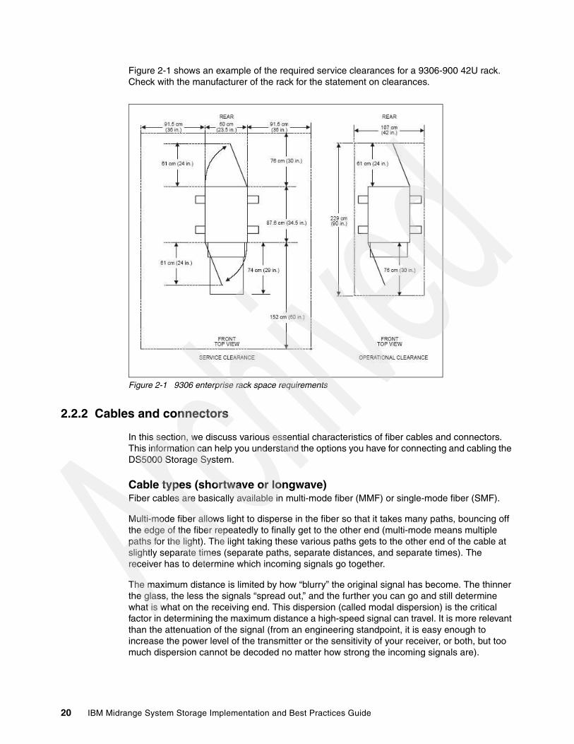
Figure 2-1 shows an example of the required service clearances for a 9306-900 42U rack. Check with the manufacturer of the rack for the statement on clearances.
Figure 2-1 9306 enterprise rack space requirements
2.2.2 Cables and connectors
In this section, we discuss various essential characteristics of fiber cables and connectors. This information can help you understand the options you have for connecting and cabling the DS5000 Storage System.
Cable types (shortwave or longwave)Fiber cables are basically available in multi-mode fiber (MMF) or single-mode fiber (SMF).
Multi-mode fiber allows light to disperse in the fiber so that it takes many paths, bouncing off the edge of the fiber repeatedly to finally get to the other end (multi-mode means multiple paths for the light). The light taking these various paths gets to the other end of the cable at slightly separate times (separate paths, separate distances, and separate times). The receiver has to determine which incoming signals go together.
The maximum distance is limited by how “blurry” the original signal has become. The thinner the glass, the less the signals “spread out,” and the further you can go and still determine what is what on the receiving end. This dispersion (called modal dispersion) is the critical factor in determining the maximum distance a high-speed signal can travel. It is more relevant than the attenuation of the signal (from an engineering standpoint, it is easy enough to increase the power level of the transmitter or the sensitivity of your receiver, or both, but too much dispersion cannot be decoded no matter how strong the incoming signals are).
20 IBM Midrange System Storage Implementation and Best Practices Guide

There are two core sizes of multi-mode cabling available: 50 micron and 62.5 micron. The intermixing of the two core sizes can produce unpredictable and unreliable operation. Therefore, core size mixing is not supported by IBM. Users with an existing optical fiber infrastructure are advised to ensure that it meets Fibre Channel specifications and is a consistent size between pairs of FC transceivers.
Single-mode fiber (SMF) is so thin (9 microns) that the light can barely “squeeze” through and it tunnels through the center of the fiber using only one path (or mode). This behavior can be explained (although not simply) through the laws of optics and physics. The result is that because there is only one path that the light takes to the receiver, there is no “dispersion confusion” at the receiver. However, the concern with single mode fiber is attenuation of the signal. Table 2-1 lists the supported distances.
Table 2-1 Cable type overview
Note that the “maximum distance” shown in Table 2-1 is just that, a maximum. Low quality fiber, poor terminations, excessive numbers of patch panels, and so on, can cause these maximums to be far shorter.
All IBM fiber feature codes that are orderable with the DS5000 Storage System will meet the standards.
Interfaces, connectors, and adaptersIn Fibre Channel technology, frames are moved from source to destination using gigabit transport, which is a requirement to achieve fast transfer rates. To communicate with gigabit transport, both sides have to support this type of communication, which is accomplished by using specially designed interfaces that can convert other types of communication transport into gigabit transport.
The interfaces that are used to convert the internal communication transport of gigabit transport are Small Form Factor Transceivers (SFF), also often called Small Form Pluggable (SFP). See Figure 2-2. Gigabit Interface Converters (GBIC) are no longer used on current models although the term GBIC is still sometimes incorrectly used to describe these connections.
Fiber type Speed Maximum distance
9 micron SMF (longwave) 1 Gbps 10 km
9 micron SMF (longwave) 2 Gbps 2 km
50 micron MMF (shortwave) 1 Gbps 500 m
50 micron MMF (shortwave) 2 Gbps 300 m
50 micron MMF (shortwave) 4 Gbps 150 m
50 micron MMF (shortwave) 8 Gbps 50 m
62.5 micron MMF (shortwave) 1 Gbps 300 m
62.5 micron MMF (shortwave) 2 Gbps 150 m
62.5 micron MMF (shortwave) 4 Gbps 70 m
62.5 micron MMF (shortwave) 8 Gbps 21 m
Chapter 2. IBM System Storage DS5000 Storage System planning tasks 21

Figure 2-2 Small Form Pluggable (SFP) with LC connector fiber cable
Obviously, the particular connectors used to connect a fiber cable to a component will depend upon the receptacle into which they are being plugged.
LC connectorConnectors that plug into SFF or SFP devices are called LC connectors. The two fibers each have their own part of the connector. The connector is keyed to ensure correct polarization when connected, that is, transmit to receive and vice-versa.
The main advantage that these LC connectors have over the SC connectors is that they are of a smaller form factor, and so manufacturers of Fibre Channel components are able to provide more connections in the same amount of space.
All DS5000 series products use SFP transceivers and LC fiber cables. See Figure 2-3.
Figure 2-3 LC fiber cable connector
Interoperability of 2 Gbps, 4 Gbps, and 8 Gbps devices The Fibre Channel standard specifies a procedure for speedy auto-detection. Therefore, if a 4 Gbps port on a switch or device is connected to a 2 Gbps port, it must negotiate down and the link will run at 2 Gbps. If there are two 8 Gbps ports on either end of a link, the negotiation runs the link at 8 Gbps if the link is up to specifications. A link that is too long or “dirty” can end up running at 4 Gbps, even with 8 Gbps ports at either end, so care must be taken with cable lengths distances and connector quality is sound.
Best practice: When you are not using an SFP, it is best to remove it from the port on the DS4000/5000 storage controller and replace it with a cover. Similarly, unused cables must be stored with ends covered, which will help eliminate risk of dirt or particles contaminating the connection while not in use.
22 IBM Midrange System Storage Implementation and Best Practices Guide

The same rules apply to 8 Gbps devices relative to 4 Gbps and 2 Gbps environments. The 8 Gbps and 4 Gbps devices have the ability to automatically negotiate back down to either 4 Gbps, 2 Gbps or 1 Gbps, depending upon the attached device and the link quality. If the link does unexpectedly negotiate to a slower speed than expected, then the causes or reasons for this ought to be investigated and remedied.
The DS5000 Storage System now has 8 Gbps functionality; there are several switches and directors that operate at this speed.
2.2.3 Cable management and labeling Cable management and labeling for solutions using racks, n-node clustering, and Fibre Channel are increasingly important in open systems solutions. Cable management and labeling needs have expanded from the traditional labeling of network connections to management and labeling of most cable connections between your servers, disk subsystems, multiple network connections, and power and video subsystems. Examples of solutions include Fibre Channel configurations, n-node cluster solutions, multiple unique solutions located in the same rack or across multiple racks, and solutions where components might not be physically located in the same room, building, or site.
Why more detailed cable management is requiredThe necessity for detailed cable management and labeling is due to the complexity of today's configurations, potential distances between solution components, and the increased number of cable connections required to attach additional value-add computer components. Benefits from more detailed cable management and labeling include ease of installation, ongoing solutions/systems management, and increased serviceability.
Solutions installation and ongoing management are easier to achieve when your solution is correctly and consistently labeled. Labeling helps make it possible to know what system you are installing or managing, for example, when it is necessary to access the CD-ROM or DVD-ROM of a particular system, and you are working from a centralized management console. It is also helpful to be able to visualize where each server is when completing custom configuration tasks, such as node naming and assigning IP addresses.
Cable management and labeling improve service and support by reducing problem determination time, ensuring that the correct cable is disconnected when necessary. Labels will assist in quickly identifying which cable needs to be removed when connected to a device such as a hub that might have multiple connections of the same cable type. Labels also help identify which cable to remove from a component, which is especially important when a cable connects two components that are not in the same rack, room, or even the same site.
Cable planningSuccessful cable management planning includes three basic activities: site planning (before your solution is installed), cable routing, and cable labeling.
Note: On certain fiber switch vendor models, it might be necessary to configure the port to a specific speed of 2, 4, or 8 Gbps to obtain the required speed instead of leaving “auto-detection” on the port.
Chapter 2. IBM System Storage DS5000 Storage System planning tasks 23

Site planningHaving adequate site planning completed before your solution is installed will result in a reduced chance of installation problems. Significant attributes covered by site planning are location specifications, electrical considerations, raised/non-raised floor determinations, and determination of cable lengths. Consult the documentation of your solution for special site planning considerations. There is IBM Netfinity® Racks site planning information in the IBM Netfinity Rack Planning and Installation Guide, part number 24L8055.
Cable routingWith effective cable routing, you can keep your solution's cables organized, reduce the risk of damaging cables, and allow for affective service and support. Use the following guidelines to assist with cable routing:
� When installing cables to devices mounted on sliding rails:
– Run the cables neatly along equipment cable-management arms and tie the cables to the arms. (Obtain the cable ties locally.)
– Take particular care when attaching fiber optic cables to the rack. See the instructions included with your fiber optic cables for guidance on minimum radius, handling, and care of fiber optic cables.
– Run the cables neatly along the rack rear corner posts.
– Use cable ties to secure the cables to the corner posts.
– Make sure the cables cannot be pinched or cut by the rack rear door.
– Run internal cables that connect devices in adjoining racks through the open rack sides.
– Run external cables through the open rack bottom.
– Leave enough slack so that the device can be fully extended without putting a strain on the cables.
– Tie the cables so that the device can be retracted without pinching or cutting the cables.
� To avoid damage to your fiber optic cables, follow these guidelines:
– Use great care when utilizing cable management arms.
– When attaching to a device on slides, leave enough slack in the cable so that it does not bend to a radius smaller than that as advised by your fiber optic cable guide when extended or become pinched when retracted.
– Route the cable away from places where it can be snagged by other devices in the rack.
– Do not overtighten the cable straps or bend the cables to a radius smaller than that as advised by your fiber optic cable guide.
– Do not put excess weight on the cable at the connection point and be sure that it is well supported. For example, a cable that goes from the top of the rack to the bottom must have a method of support other than the strain relief boots built into the cable.
– For long cable runs, ensure that enough slack is made for rack movement in accordance with your computer room standards for earthquake proofing.
Note: Do not use cable-management arms for fiber cables.
24 IBM Midrange System Storage Implementation and Best Practices Guide

Additional information for routing cables for IBM Netfinity Rack products can be found in IBM Netfinity Rack Planning and Installation Guide, part number 24L8055. This publication includes pictures providing more details about how to set up the cable routing.
Cable labelingWhen labeling your solution, follow these tips:
� As you install cables in the rack, label each cable with the appropriate identification.
� Remember to attach labels to any cables that you replace.
� Document deviations from the label scheme you use. Keep a copy with your Change Control Log book.
� Comply with an existing cable naming convention or define and adhere to a simple logical naming convention
An example of label naming convention might include these attributes:
� The function, to help identify the purpose of the cable.
� Location information must be broad to specific (for example, the site/building to a specific port on a server or hub).
Other cabling mistakesAvoid making these common mistakes in cabling:
� Leaving cables hanging from connections with no support.
� Not using dust caps.
� Not keeping connectors clean. (Certain cable manufacturers require the use of lint-free alcohol wipes in order to maintain the cable warranty.)
� Leaving cables on the floor where people might kick or trip over them.
� Not removing old cables when they are no longer needed or planned for future use.
2.2.4 Fibre Channel adaptersWe now review topics related to Fibre Channel adapters:
� Placement on the host system bus� Distributing the load among several adapters� Queue depth� Driver selection
Host system busToday, there is a choice of high-speed adapters for connecting disk drives. Fast adapters can provide better performance. The HBA must be placed in the fastest supported slot available.
Tip: Collect all SFP, HBA, and cable dust caps, store in a dust free container, to be used for future cabling work. Do not re-use dust caps which have been left loose in the rack or computer room.
Important: Do not place all the high-speed Host Bus Adapters (HBAs) on a single system bus; otherwise, the computer bus becomes the performance bottleneck.
Chapter 2. IBM System Storage DS5000 Storage System planning tasks 25

It is always a best practice to distribute high-speed adapters across several buses. When you use PCI adapters, make sure that you first review your system specifications. Certain systems include a PCI adapter placement guide.
The number of adapters you can install depends on the number of PCI slots available on your server, but also on what traffic volume you expect on your SAN. The rationale behind multiple adapters is either redundancy (failover) or load sharing.
FailoverWhen multiple adapters are installed on the host system and used with a multipath driver, the multipath driver checks to see if all the available paths to the storage server are still functioning. In the event of an HBA or cabling failure, the path is changed to the other HBA, and the host continues to function without loss of data or functionality.
In general, all operating systems support two paths to the DS5000 Storage System. Microsoft Windows 2003 and 2008 and Linux support up to four paths to the storage controller. AIX can also support four paths to the controller, provided that there are two partitions accessed within the DS5000 Storage System. You can configure up to two HBAs per partition and up to two partitions per DS5000 Storage System.
Load balancingLoad balancing or load sharing means distributing I/O requests from the hosts between multiple adapters, which can be done by assigning LUNs to both the DS5000 controllers A and B alternatively (see also 2.3.1, “Logical drives and controller ownership” on page 32).
Figure 2-4 shows the principle for a load-sharing setup. A multipath driver checks all available paths to the controller. In Figure 2-4, that is two paths (red and blue). The driver forces the data down all paths in a round-robin scheme, which means that it does not really check for the workload on a single path, but moves the data down in a rotational manner (round-robin).
Figure 2-4 Load sharing approach for multiple HBAs
26 IBM Midrange System Storage Implementation and Best Practices Guide

The RDAC drivers for Linux supports round-robin load balancing.
Queue depthThe queue depth is the maximum number of commands that can be queued on the system at the same time.
For the latest firmware for the DS5000 controller, see the following Web site:
http://www-03.ibm.com/systems/storage/disk/
For QLogic based HBAs, the queue depth is known as execution throttle, which can be set with either QLogic SANsurfer or in the BIOS of the QLogic-based HBA by pressing Ctl+Q during the boot process.
2.2.5 Disk expansion enclosures The DS5000 Storage Systems offer the EXP5000 expansion enclosure, and is compatible with the EXP810 for migration purposes. When planning for which enclosure to use with your DS5000, you must look at the applications and data that you will be using. The EXP520 is a new expansion enclosure that will be used solely with the DS5020 storage system. The DS4000 models will continue to use EXP810 expansion enclosures.
The EXP5000 and EXP520 enclosures can accommodate either Fibre Channel, SSD, or SATA II drives. Intermixing of the drives is permitted. The EXP5000 and EXP520 is an 8 or 4 Gbps capable enclosure, offering high performance and value.
Enclosure IDsIt is very important to correctly set the tray (enclosure) IDs. They are used to differentiate multiple EXP enclosures that are connected to the same DS5000 Storage System. Each EXP enclosure must use a unique value. The DS5000 Storage Manager (SM) uses the tray IDs to identify each EXP enclosure.
For the EXP5000, the enclosure ID is indicated by a dual seven-segment LED located on the back of each ESM next to the other ESM indicator lights. The storage server firmware automatically sets the enclosure ID number. If needed, you can change the enclosure ID setting through the DS5000 storage management software only. There are no switches on the EXP5000 or EXP810 chassis to manually set the enclosure ID.
Figure 2-5 Enclosure ID LEDs for EXP5000
Note: In a cluster environment, you need a single path to the each of the controllers (A and B) of the DS5000 Storage System. However, if the cluster software and host application can do persistent reservations, you can keep multiple paths and the multipath driver will route the I/O request using the appropriate path to the reserved logical drive.
Tray ID
Chapter 2. IBM System Storage DS5000 Storage System planning tasks 27
Enclosure guidelinesThe base controller unit and each expansion enclosure has an ID number associated with it. The ID allows each enclosure to be identified properly to the base controller unit.
Because the base and all enclosures are connected by Fibre Channel loop, it is necessary for each ID address to be distinct and unique for I/O to flow properly. An ID address is composed of two digits: a tens digit (x10) and a ones digit (x1). Enclosure IDs are typically between the values of x00 and x77.
The EXP5000 is automatically assigned enclosure IDs.
Because the storage system follows a specific address assignment scheme for the drives, you have to observe a few guidelines when assigning enclosure IDs to expansion units if you were to assign these manually. Failure to adhere to these guidelines can cause issues with I/O error recovery, and make the troubleshooting of certain drive communication issues more difficult:
� Whenever possible, maintain an even number of expansion units on the DS5000 Storage System and configure it for enclosure loss protection. Add EXP expansion units in pairs and (ideally) for the DS5000 Storage System in groups of four.
� Add drives into an expansion enclosure in pairs.
2.2.6 Selecting drivesThe speed and the type of the drives used will impact the performance. Typically, the faster the drive, the higher the performance. This increase in performance comes at a cost; the faster drives typically cost more than the lower performance drives. FC drives outperform the SATA drives.
The DS5000 Storage System supports solid-state drives (SSD), Fibre Channel and SATA drives. The following types of FC drives are currently available:
� 4 Gbps FC, 73.4 GB / 15K Enhanced Disk Drive Module� 4 Gbps FC, 146.8 GB / 15K Enhanced Disk Drive Module � 4 Gbps FC, 300 GB / 15K Enhanced Disk Drive Module � 4 Gbps FC, 450 GB / 15K Enhanced Disk Drive Module � 4 Gbps FC, 600 GB / 15K Enhanced Disk Drive Module
The following SATA drives are currently available:
� 4 Gbps SATA: 7.2K rpm, 500 GB E-DDM� 4 Gbps SATA: 7.2K rpm, 750 GB E-DDM� 4 Gbps SATA: 7.2K rpm 1000 GB (1 TB) E-DDM
The following Solid State Drives (SSD) are currently available:
� SSD 73 GB � SSD 300 GB1
In addition DS5000 systems support Full Disk Encryption (FDE) drives are drives with built-in disk encryption hardware that prevents unauthorized access to the data on a drive that is physically removed from the storage subsystem:
� Encryption Capable 4 Gbps 15K rpm FC, 146.8 GB � Encryption Capable 4 Gbps, 15K rpm FC 300 GB � Encryption Capable 4 Gbps, 15K rpm FC 450 GB
1 Currently 300 GB SSD drive is only available through the RPQ process from IBM.
28 IBM Midrange System Storage Implementation and Best Practices Guide

Table 2-2 compares the Fibre Channel 10K, 15K, and SATA drives (single drive).
Table 2-2 Comparison between Fibre Channel and SATA
The speed of the drive is measured by the number or revolutions per minute (RPM). A 15K drive rotates 15,000 times per minute. With higher speeds, the drives tend to be denser, because a large diameter plate driving at such speeds is likely to wobble. With the faster speeds, greater throughput is possible.
Seek time is the measure of how long it takes for the drive head to move to the correct sectors on the drive to either read or write data. It is measured in thousands of a second (milliseconds or ms). The faster the seek time, the quicker data can be read from or written to the drive. The average seek time reduces when the speed of the drive increases. Typically, a 7.2K drive will have an average seek time of around 9 ms, a 10K drive will have an average seek time of around 5.5 ms, and a 15K drive will have an average seek time of around 3.5 ms.
Command queuing (or queue depth) allows for multiple commands to be outstanding to the disk drive at the same time. The drives have a queue where outstanding commands can be dynamically rescheduled or re-ordered, along with the necessary tracking mechanisms for outstanding and completed portions of workload. The SATA disks do not have command queuing, SATA-2 disks have a command queue depth of 4, and the Fibre Channel disks currently have a command queue depth of 16.
Avoid using the SATA drives for high IOPS operations. SATA can, however, be used for streaming and archiving applications. These are both very good uses for SATA, where good throughput rates are required, but at a lower cost.
Best practice: Use the fastest drives available for best performance.
Drive feature Fibre Channel SATA SATA-2 SATA difference
Spin speed 10K and 15K 7.2 K
Command queuing
Yes16 Max
No1 Max
Yes4 Max
Single disk I/O Rate (# of 512 bytes IOPS)a
a. Note that the IOPS and bandwidth figures are from disk manufacturer tests in ideal lab conditions. In practice, you will see lower numbers, but the ratio between SATA and FC disks still applies.
280 & 340 88 88 .31 and .25
Read bandwidth (MBps)
69 & 76 60 60 .86 and .78
Write bandwidth (MBps)
68 & 71 30 30 .44
Chapter 2. IBM System Storage DS5000 Storage System planning tasks 29
2.3 Planning your storage structure
It is important to configure a storage system in accordance to the needs of the user. An important question and primary concern for most users or storage administrators is how to configure the storage subsystem to achieve the best performance. There is no simple answer, and no best guideline for storage performance optimization that is valid in every environment and for every particular situation. We provide a preliminary (and less detailed) performance discussion in this section.
Also, in this section, we review other aspects of the system configuration that can help optimize the storage capacity and resilience of the system. In particular, we review array configuration, and enclosure loss protection. Use of RAID protection is another important area and is discussed separately in IBM Midrange System Storage Hardware Guide, SG24-7676.
Array configurationBefore you can start using the physical disk space, you must configure it. You divide your (physical) disk drives into arrays and create one or more logical drives inside each array.
In simple configurations, you can use all of your drive capacity with just one array and create all of your logical drives in that particular array. However, the following drawbacks exist:
� If you experience a (physical) drive failure, the rebuild process affects all logical drives, and the overall system performance goes down.
� Read/write operations to various logical drives are still being made to the same set of physical hard drives.
The array configuration is crucial to performance. You must take into account all the logical drives inside the array, because all logical drives inside the array will impact the same physical disks. If you have two logical drives inside an array and they both are high throughput, then there can be contention for access to the physical drives as large read or write requests are serviced. It is crucial to know the type of data that each logical drive is used for and try to balance the load so contention for the physical drives is minimized. Contention is impossible to eliminate unless the array only contains one logical drive.
Number of drivesThe more physical drives you have per array, the shorter the access time for read and write I/O operations.
You can determine how many physical drives must be associated with a RAID controller by looking at disk transfer rates (rather than at the megabytes per second). For example, if a hard disk drive is capable of 75 nonsequential (random) I/Os per second, about 26 hard disk drives working together might, theoretically, produce 2000 nonsequential I/Os per second, or enough to hit the maximum I/O handling capacity of a single RAID controller. If the hard disk drive can sustain 150 sequential I/Os per second, it takes only about 13 hard disk drives working together to produce the same 2000 sequential I/Os per second and keep the RAID controller running at maximum throughput.
30 IBM Midrange System Storage Implementation and Best Practices Guide
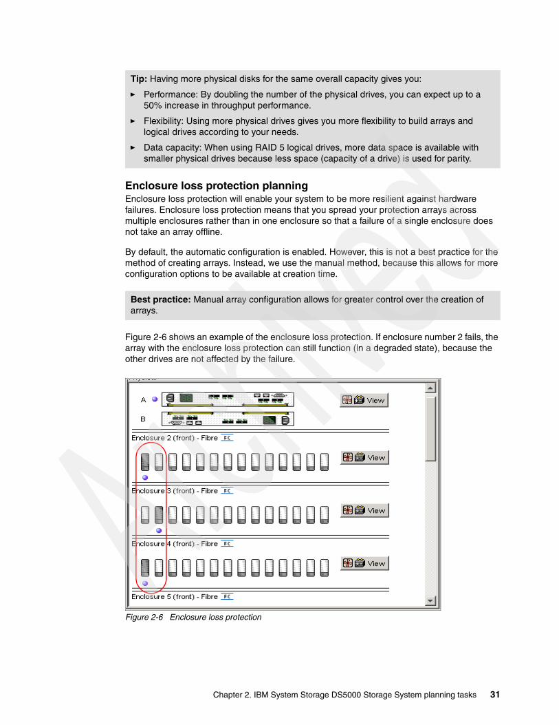
Enclosure loss protection planningEnclosure loss protection will enable your system to be more resilient against hardware failures. Enclosure loss protection means that you spread your protection arrays across multiple enclosures rather than in one enclosure so that a failure of a single enclosure does not take an array offline.
By default, the automatic configuration is enabled. However, this is not a best practice for the method of creating arrays. Instead, we use the manual method, because this allows for more configuration options to be available at creation time.
Figure 2-6 shows an example of the enclosure loss protection. If enclosure number 2 fails, the array with the enclosure loss protection can still function (in a degraded state), because the other drives are not affected by the failure.
Figure 2-6 Enclosure loss protection
Tip: Having more physical disks for the same overall capacity gives you:
� Performance: By doubling the number of the physical drives, you can expect up to a 50% increase in throughput performance.
� Flexibility: Using more physical drives gives you more flexibility to build arrays and logical drives according to your needs.
� Data capacity: When using RAID 5 logical drives, more data space is available with smaller physical drives because less space (capacity of a drive) is used for parity.
Best practice: Manual array configuration allows for greater control over the creation of arrays.
Chapter 2. IBM System Storage DS5000 Storage System planning tasks 31
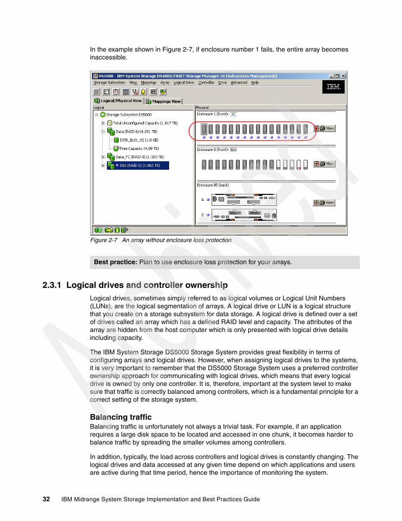
In the example shown in Figure 2-7, if enclosure number 1 fails, the entire array becomes inaccessible.
Figure 2-7 An array without enclosure loss protection
2.3.1 Logical drives and controller ownershipLogical drives, sometimes simply referred to as logical volumes or Logical Unit Numbers (LUNs), are the logical segmentation of arrays. A logical drive or LUN is a logical structure that you create on a storage subsystem for data storage. A logical drive is defined over a set of drives called an array which has a defined RAID level and capacity. The attributes of the array are hidden from the host computer which is only presented with logical drive details including capacity.
The IBM System Storage DS5000 Storage System provides great flexibility in terms of configuring arrays and logical drives. However, when assigning logical drives to the systems, it is very important to remember that the DS5000 Storage System uses a preferred controller ownership approach for communicating with logical drives, which means that every logical drive is owned by only one controller. It is, therefore, important at the system level to make sure that traffic is correctly balanced among controllers, which is a fundamental principle for a correct setting of the storage system.
Balancing trafficBalancing traffic is unfortunately not always a trivial task. For example, if an application requires a large disk space to be located and accessed in one chunk, it becomes harder to balance traffic by spreading the smaller volumes among controllers.
In addition, typically, the load across controllers and logical drives is constantly changing. The logical drives and data accessed at any given time depend on which applications and users are active during that time period, hence the importance of monitoring the system.
Best practice: Plan to use enclosure loss protection for your arrays.
32 IBM Midrange System Storage Implementation and Best Practices Guide

Enhanced remote mirror considerationsA secondary logical drive in a remote mirror does not have a preferred owner. Instead, the ownership of the secondary logical drive is determined by the controller owner of the associated primary logical drive. For example, if controller A owns the primary logical drive in the primary storage subsystem, controller A owns the associated secondary logical drive in the secondary storage subsystem. If controller ownership changes on the primary logical drive, then this will cause a corresponding controller ownership change of the secondary logical drive.
2.3.2 Hot spare drives A hot spare drive is like a replacement drive installed in advance. Hot spare disk drives provide additional protection that might prove to be essential in case of a disk drive failure in a fault tolerant array.
There is no definitive rule as to how many hot spares you have to install, but it is common practice to use a ratio of one hot spare for about 30 drives of the same type.
When possible, split the hot spares so that they are in separate enclosures and are not on the same drive loops (see Figure 2-8).
Best practice: Here are guidelines for logical drive assignment and storage partitioning:
� Assign logical drives across both controllers to balance controller utilization.
� Use the manual method of creating logical drives, which allows greater flexibility for configuration settings, such as enclosure loss protection and utilizing all drive loops.
� If you have highly used logical drives, where possible, move them away from other logical drives and put them in a separate or dedicated array, which will reduce disk contention for that array.
� Always leave a small amount of free space in the array after the logical drives have been created.
Best practice: When assigning disks as hot spares, make sure that they have enough storage capacity. If the failed disk drive is larger than the hot spare, reconstruction is not possible. Ensure that you have at least one of each size or all larger drives configured as hot spares. See 3.1.1, “Defining hot spare drives” on page 61 for more details on defining hot spare drives.
Chapter 2. IBM System Storage DS5000 Storage System planning tasks 33
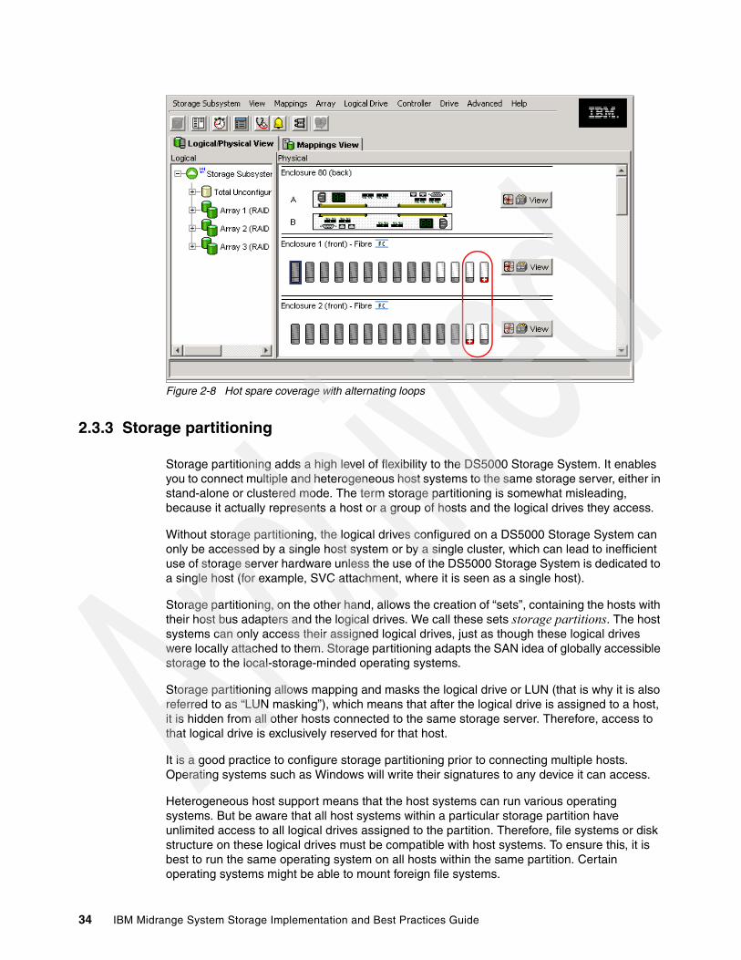
Figure 2-8 Hot spare coverage with alternating loops
2.3.3 Storage partitioning
Storage partitioning adds a high level of flexibility to the DS5000 Storage System. It enables you to connect multiple and heterogeneous host systems to the same storage server, either in stand-alone or clustered mode. The term storage partitioning is somewhat misleading, because it actually represents a host or a group of hosts and the logical drives they access.
Without storage partitioning, the logical drives configured on a DS5000 Storage System can only be accessed by a single host system or by a single cluster, which can lead to inefficient use of storage server hardware unless the use of the DS5000 Storage System is dedicated to a single host (for example, SVC attachment, where it is seen as a single host).
Storage partitioning, on the other hand, allows the creation of “sets”, containing the hosts with their host bus adapters and the logical drives. We call these sets storage partitions. The host systems can only access their assigned logical drives, just as though these logical drives were locally attached to them. Storage partitioning adapts the SAN idea of globally accessible storage to the local-storage-minded operating systems.
Storage partitioning allows mapping and masks the logical drive or LUN (that is why it is also referred to as “LUN masking”), which means that after the logical drive is assigned to a host, it is hidden from all other hosts connected to the same storage server. Therefore, access to that logical drive is exclusively reserved for that host.
It is a good practice to configure storage partitioning prior to connecting multiple hosts. Operating systems such as Windows will write their signatures to any device it can access.
Heterogeneous host support means that the host systems can run various operating systems. But be aware that all host systems within a particular storage partition have unlimited access to all logical drives assigned to the partition. Therefore, file systems or disk structure on these logical drives must be compatible with host systems. To ensure this, it is best to run the same operating system on all hosts within the same partition. Certain operating systems might be able to mount foreign file systems.
34 IBM Midrange System Storage Implementation and Best Practices Guide

Storage partition topology is a collection of topological elements (default group, host groups, hosts, and host ports) shown as nodes in the topology view of the mappings view. To map a logical drive or LUN to a specific host server or group of hosts, each component of the storage partition must be defined.
A storage partition contains several components:
� Host groups� Hosts� Host ports� Logical drive mappings
A host group is a collection of hosts that are allowed to access certain logical drives, for example, a cluster of two systems.
A host is a single system that can be mapped to a logical drive.
A host port is the FC port of the host bus adapter (HBA) on the host system. The host port is identified by its world-wide name (WWN). A single host can contain more than one host port. If the servers are attached using full redundancy, each server will have two host bus adapters, that is, it needs two host ports within the same host system. It is possible to have a host with a single HBA, but for redundancy, it must be able to access both DS5000 controllers, which can be achieved by SAN zoning.
The DS5000 Storage System only communicates through the use of the WWN. The storage system is not aware of which host bus adapters are in the same server or in servers that have a certain relationship, such as a cluster. The host groups, the hosts, and their host ports reflect a logical view of the physical connections of the SAN, as well as the logical connection between servers, such as clusters.
With the logical setup defined as previously described, mappings are specific assignments of logical drives to particular host groups or hosts.
The storage partition is the combination of all these components. It ensures correct access to the various logical drives even if there are several hosts or clusters connected.
The default host group is a placeholder for hosts that are defined but have not been mapped. The default host group is also normally used only when storage partitioning is not enabled. If this is the case, then only one type of operating system must be sharing the logical drives.
Every unassigned logical drive is mapped to the undefined mappings group, which means that no host (or host port, to be precise) can access these logical drives until they are mapped.
With Storage Manager, it is possible to have up to 512 storage partitions on a DS5000, which allows the storage subsystem to have storage capacity to a greater amount of heterogeneous hosts, allowing for greater flexibility and scalability.
Chapter 2. IBM System Storage DS5000 Storage System planning tasks 35
For the number of maximum storage partitions for a specific model, see Table 2-3. Note that on DS5000 models, the number of partitions also depends on the premium feature licences that have been purchased.
Table 2-3 Host logical drive restrictions
Every mapping of a logical drive to a new host or host group creates a new storage partition. If additional logical drives are required for an existing host or host group, a new storage partition is not required. For example, a cluster with two nodes with redundant I/O paths gets configured as one host group with two hosts. Each host then has two host ports for redundancy, and several logical drives are mapped to this host group. All these components represent one storage partition. If another single host system is attached to the same storage system and other logical drives are mapped to that host, another storage partition then has to be created for it. If a new logical drive is created and mapped to either the cluster or the single host, it uses an existing storage partition.
For a step-by-step guide, see 3.1.3, “Configuring storage partitioning” on page 74.
Storage partitioning considerationsIn a heterogeneous environment, the “access” logical drive is mapped only to the default host group. If in-band management is being used, then the access logical drive must be mapped to the storage partition for the managing host.
In a security-sensitive environment, you can also assign the access logical drive to a particular storage partition and ensure host-based management access only through the servers in this storage partition. In this environment, you can assign a password to the storage system as well.
In order to configure the storage partitioning correctly, you need the WWN of your host HBAs. Mapping is done on a WWN basis. Depending on your HBA, you can obtain the WWN either from the BIOS or QLogic SANsurfer tool if you have QLogic cards. Emulex adapters and IBM adapters for IBM System p and IBM System i® servers have a sticker on the back of the card. The WWN is also usually printed on the adapter itself or the box that the adapter was shipped in.
Operating system Maximum number of logical drives supported per partition
Windows Server 2003 255
Windows Server 2007 255
HP-UX 127
AIX 255
Linux 255
Note: There are limitations as to how many logical drives you can map per host. DS5000 series storage servers will support up to 256 logical drives (including the “access” logical drive) per partition (although there are also restrictions, depending on the host operating system) and a maximum of two partitions per host. Keep these limitations in mind when planning the DS5000 Storage System installation.
Note: Each host with separately assigned storage will use a storage partition. Each host group with separately assigned storage will also use an additional storage partition.
36 IBM Midrange System Storage Implementation and Best Practices Guide

If you are connected to a hub or switch, check the Name Server Table of the hub or switch to identify the WWN of the HBAs.
When planning your partitioning, keep in mind that:
� In a cluster environment, you need to use host groups.� You can optionally purchase partitions.
When planning for your storage partitioning, create a table of planned partitions and groups so that you can clearly map out and define your environment.
Table 2-4 shows an example of a storage partitioning plan, which clearly shows the host groups, hosts, port names, WWN of the ports, and the operating systems used in that environment. Other columns can be added to the table for future references, such as HBA BIOS levels, driver revisions, and switch ports used, all of which can then form the basis of a change control log.
Table 2-4 Sample plan for storage partitioning
Heterogeneous hosts When implementing a DS5000 Storage System solution, a mixture of host servers with various operating systems can be used (clustered and non-clustered variants of the same operating systems). However, all logical drives in a single storage partition must be configured for the same operating system. Also, all hosts in that same storage partition must run the same defined operating system.
Best practice: If you have a single server in a host group that has one or more LUNs assigned to it, do the mapping to the host and not the host group. All servers with the same host type (for example, Windows servers) can be in the same group if you want, but by mapping the storage at the host level, you can define what specific server accesses which specific logical drives.
However, if you have a cluster, it is good practice to assign the logical drives at the host group, so that all of the servers on the host group have access to all the logical drives.
Host group Host name Port name WWN OS type
Windows 2003 Windows Host MailAdp_A 200000E08B28773C Windows 2003 Non-Clustered
MailAdp_B 200000E08B08773C
Linux Linux_Host LinAdp_A 200100E08B27986D Linux
LinAdp_B 200000E08B07986D
POWER6® AIX_Host AIXAdp_A 20000000C926B6D2 AIX
AIXAdp_B 20000000C926B08
Important: Heterogeneous hosts are only supported with storage partitioning enabled.
Chapter 2. IBM System Storage DS5000 Storage System planning tasks 37
Delete the access logical drive (31)The DS5000 Storage System will automatically create a logical drive for each host attached (logical drive id 31). This drive is used for in-band management, so if you do not plan to manage the DS5000 Storage System from that host, you can delete this logical drive, which will give you one more logical drive to use per host.
If you attached a Linux or AIX to the DS5000 Storage System, you need to delete the mapping of this access logical drive.
2.3.4 Segment sizeThe segment size is the maximum amount of data that the controller can write at once on one physical disk in a logical drive before writing to the next physical disk.
The choice of a segment size can have a major influence on performance in both IOPS and throughput. Small segment sizes increase the request rate (IOPS) by allowing multiple disk drives to respond to multiple requests. Large segment sizes increase the data transfer rate (Mbps) by allowing multiple disk drives to participate in one I/O request. Use a small segment size relative to the I/O size to increase sequential performance.
Segment size = I/O requestHere are a few typical results of this choice:
� Fewer disks used per request� Higher IOPS� Ideal for random I/O requests, such as the database file system
Segment size < I/O requestHere are a few typical results of this choice:
� More disks used/requested� Higher throughput (Mbps)� Ideal for sequential writes, such as a large multimedia application
The performance monitor can be used to evaluate how a given segment size affects the workload. Use the following guidelines:
� If the typical I/O size is larger than the segment size, increase the segment size in order to minimize the number of drives needed to satisfy an I/O request, which is especially true in a multi-user, database, or file system storage environment. Using a single drive for a single request leaves other drives available to simultaneously service other requests.
� If the logical drive in a single-user, large I/O environment (such as for multimedia application storage) is being used, performance is optimized when a single I/O request can be serviced with a single data stripe (the segment size multiplied by the number of drives in the array that are used for I/O). In this case, multiple disks are used for the same request, but each disk is only accessed once.
38 IBM Midrange System Storage Implementation and Best Practices Guide

2.3.5 Media scan
Media scan is a background process that checks the physical disks for defects by reading the raw data from the disk and writing it back, which detects possible problems caused by bad sectors of the physical disks before they disrupt normal data reads or writes. This process is sometimes known as data scrubbing.
Media scan continuously runs in the background, using spare cycles to complete its work. The default media scan is for a scan every 30 days, that is, the maximum time media scan will have to complete the task. During the scan process, the DS5000 calculates how much longer the scan process will take to complete, and adjusts the priority of the scan to ensure that the scan completes within the time setting allocated. After the media scan has completed, it will start over again and reset its time for completion to the current setting. This media scan setting can be reduced, however if the setting is too low, priority will be given to media scan over host activity to ensure that the scan completes in the allocated time. This scan can impact on performance, but improve data integrity.
Media scan must be enabled for the entire storage subsystem. The system wide enabling specifies the duration over which the media scan will run. The logical drive enabling specifies whether or not to do a redundancy check as well as media scan.
A media scan can be considered a surface scan of the hard drives, whereas a redundancy check scans the blocks of a RAID 3, 5, or 6 logical drive and compares it against the redundancy data. In the case of a RAID 1 logical drive, then the redundancy scan compares blocks between copies on mirrored drives.
Tips: The possible segment sizes available are 8 KB, 16 KB, 32 KB, 64 KB, 128 KB, 256 KB, and 512 KB:
� Storage Manager sets a default block size of 64 KB.
� For database applications, block sizes between 32 KB to 128 KB have shown to be more effective.
� In a large file environment, such as media streaming or CAD, 128 KB or more are preferable.
� For a Web server or file and print server, the range must be between 16–64 KB.
Note: A performance testing schedule must be undertaken in the environment before going into production with a given segment size. Segment size can be dynamically changed, but only by rewriting the data, which consumes bandwidth and impacts performance. Plan this configuration carefully to avoid having to reconfigure the options chosen.
Chapter 2. IBM System Storage DS5000 Storage System planning tasks 39

We have seen no effect on I/O with a 30 day setting unless the processor is utilized in excess of 95%. The length of time that it will take to scan the LUNs depends on the capacity of all the LUNs on the system and the utilization of the controller. Figure 2-9 shows an example of default media scan settings.
Figure 2-9 Default media scan settings at storage system
Note: If you change the media scan duration setting, the changes will not take effect until the current media scan cycle completes or the controller is reset.
40 IBM Midrange System Storage Implementation and Best Practices Guide

An example of logical drive changes to the media scan settings is shown in Figure 2-10.
Figure 2-10 Logical drive changes to media scan settings
2.3.6 Cache parameters
Cache memory is an area of temporary volatile storage (RAM) on the controller that has a faster access time than the drive media. This cache memory is shared for read and write operations.
Efficient use of the RAID controller cache is essential for good performance of the DS5000 Storage System. See 7.2.6, “Cache memory settings” for detailed explanation about the cache parameter settings.
2.4 Planning for premium featuresThe premium features that come with the DS5000 Storage Manager software are enabled by purchasing a premium feature license key for each feature. When planning for any of the premium features, it is a good idea to document what are the goals and rationale for purchasing the feature, which clearly defines from the outset what you want to achieve and why.
Note: You cannot enable background media scans on a logical drive comprised of Solid State Disks (SSDs).
Chapter 2. IBM System Storage DS5000 Storage System planning tasks 41

Consider the following requirements:
� Which premium feature to use (FlashCopy, VolumeCopy, or Enhanced Remote Mirroring)� The data size to copy� Additional arrays required� Amount of free space� Number of copies� Retention of copies� Automated or manual copies� Disaster recovery or backup operations
Then document all of these needs and requirements.
2.4.1 FlashCopyA FlashCopy logical drive is a point-in-time image of a logical drive. It is the logical equivalent of a complete physical copy, but you can create it much more quickly than a physical copy. Additionally, it requires less disk space. In DS5000 Storage Manager, the logical drive from which you are basing the FlashCopy, called the base logical drive, must be a standard logical drive in the storage server. Typically, you create a FlashCopy so that an application (for example, an application to take backups) can access the FlashCopy and read the data while the base logical drive remains online and user-accessible.
Plan carefully with regard to the space available to make a FlashCopy of a logical drive even though FlashCopy takes only a small amount of space compared to the base image.
2.4.2 VolumeCopy The VolumeCopy feature is a firmware-based mechanism for replicating logical drive data within a storage subsystem. This feature is designed as a system management tool for tasks, such as relocating data to other drives for hardware upgrades or performance management, data backup, and restoring snapshot logical drive data.
A VolumeCopy creates a complete physical replication of one logical drive (source) to another (target) within the same storage subsystem. The target logical drive is an exact copy or clone of the source logical drive. VolumeCopy can be used to clone logical drives to other arrays inside the DS5000 Storage System.
The VolumeCopy premium feature must be enabled by purchasing a Feature Key. For efficient use of VolumeCopy, FlashCopy must be installed as well.
2.4.3 Enhanced Remote MirroringThe Enhanced Remote Mirroring (ERM) option is used for online, real-time replication of data between storage subsystems over a remote distance.
Operating modes for ERMEnhanced Remote Mirroring (formerly named “Remote Volume Mirroring”) offers three operating modes:
� Metro mirroring:
Metro mirroring is a synchronous mirroring mode. Any host write requests are written to the primary (local) storage subsystem and then to the secondary (remote) storage subsystem. The remote storage controller acknowledges the write request operation to the local storage controller, which reports a write completion to the host. This mode is called
42 IBM Midrange System Storage Implementation and Best Practices Guide

synchronous. The host application does not get the write request result until the write request has been executed on both (local and remote) storage controllers.
� Global copy:
This mode copies a non-synchronous, remote copy function designed to complete write operations on the primary storage system before they are received by the secondary storage system. This capability is designed to prevent primary performance from being affected by wait time from writes on the secondary system. Therefore, the primary and secondary copies can be separated by long distances. This function is appropriate for remote data migration, offsite backups, and transmission of inactive database logs at virtually unlimited distances.
� Global mirroring:
This mode is a two-site remote data mirroring function designed to maintain a complete and consistent remote mirror of data asynchronously at virtually unlimited distances with virtually no degradation of application response time. Separating data centers by longer distances helps provide protection from regional outages. This asynchronous technique can help achieve better performance for unlimited distances by allowing the secondary site to trail in data currency a few seconds behind the primary site. With Global Mirror, currency can be configured to be as little as three to five seconds with respect to host I/O. This two-site data mirroring function is designed to provide a high-performance, cost-effective global distance data replication and disaster recovery solution.
The Enhanced Remote Mirroring has also been equipped with new functions for better business continuance solution design and maintenance tasks.
A minimum of two storage subsystems is required. One storage subsystem can have primary volumes being mirrored to arrays on other storage subsystems and hold secondary volumes from other storage subsystems. Also note that because replication is managed on a per-logical drive basis, you can mirror individual logical drives in a primary storage subsystem to appropriate secondary logical drives in several separate remote storage subsystems.
Planning considerations for ERMHere are various planning considerations to keep in mind:
� DS5000 Storage Systems (minimum of two)� Fiber links between sites� Distances between sites (ensure that it is supported)� Switches or directors used� Redundancy� Additional storage space requirements
2.4.4 FC/SATA Intermix The DS5000 FC/SATA Intermix premium feature supports the concurrent attachment of Fibre Channel and SATA storage expansion enclosures for a single DS5000 controller configuration. With this premium feature, you can create and manage distinct arrays or logical drives that are built from either Fibre Channel disks or SATA disks in a DS5000 Storage System, and allocate the drives to the appropriate applications in the attached host servers.
Note: ERM requires a dedicated switched fabric connection per controller to be attached to Host port 4 on both A and B controllers.
This dedication is required at both ends of the ERM solution.
Chapter 2. IBM System Storage DS5000 Storage System planning tasks 43
Consider these three classes of storage:
� Online (or primary) storage: This is the storage for applications that require immediate access to data, such as databases and frequently accessed user data. Primary storage holds business-critical information and data with the highest value and importance. This storage requires high performance and high availability technologies such as Fibre Channel technology.
� Near-line (or secondary) storage: This storage is used for applications that do not require immediate access but still require the performance, availability, and flexibility of disk storage. It can also be used to cache online storage to reduce the time required for data backups. Secondary storage represents a large percentage of a company’s data and is an ideal fit for Serial Advanced Technology Attachment (SATA).
� Offline (archival) storage: This storage is used for backup or long-term storage. For this type of storage, tape remains the most economical solution.
After determining that SATA technology is best suited to near-line storage usage, we have the following considerations regarding its use in the same storage server as online storage:
� Performance: Instead of having a storage server for online storage and another for near-line storage, both types of storage can be combined with one storage server, and benefit from the use of higher performance controllers.
� Scalability: The total SATA disk capacity is far greater than the Fibre Channel offering. The new EV-DDM and E-DDM drives are 1000 GB, as compared to the largest FC drive being 450 GB.
� Cost: Consider an existing Fibre Channel environment for which you want to implement SATA technology. This consideration is further enhanced with Fibre Channel and SATA drive intermixing within the same enclosures. The cost considerations of intermixing versus implementing a separate SATA storage server are:
– Implementation costs of a new SATA storage server versus intermixing with the existing Fibre Channel enclosures.
– SAN infrastructure costs for more ports or hardware.
– Administration costs (effort) depend on the number of controllers managed. Intermixing eliminates controller pairs by utilizing existing controllers.
After these factors have been considered and the criteria for the environment has been identified, the choice to intermix or not can be determined.
2.4.5 Drive Security
This is a new premium feature where Full Disk Encryption (FDE) protects the data on the disks only when the drives are removed from storage subsystem enclosures. Drive Security requires security capable drives (FDE) and provide access to data only through a controller that has the correct security key when Drive Security is enabled.
Note: You must obtain the FC/SATA Enclosure Intermix premium feature for each DS4000 Storage System that will have drive channels/loops intermixing SATA and Fibre Channel technology drives.
With DS5000 models, this feature is now automatically integrated and no longer required.
44 IBM Midrange System Storage Implementation and Best Practices Guide
RequirementsBusinesses must comply with a growing number of corporate standards and government regulations, Drive security is one tool that can enhance security thus complying with these new standards and regulations.
Full Disk EncryptionFull Disk Encryption (FDE) does not prevent someone from copying the data in the storage subsystems through Fibre Channel host port connections when the drives are unlocked and operating. FDE also does not prevent unauthorized management access. A security capable drive encrypts data during writes and decrypts data during reads. FDE prevents the physical removal of the disk from the DS5000 system and interpreting data it contained. The FDE drive with Drive Security enabled will be locked on power up and will only unlock after successful authentication with the DS5000 system.
The Encryption Key is generated by the drive and never leaves the drive, so it always stays secure. It is stored in encrypted form performing symmetric encryption and decryption of data at full disk speed with no impact on disk performance. Each FDE drive uses its own unique encryption key which is generated when the disk is manufactured and regenerated when required by the storage administrator using the DS5000 Disk Encryption Manager.
The security enabled drives can be used as normal drives and intermixed in an array with drives of equal type and capacity when this feature is not enabled. This new feature is detailed in IBM Midrange System Storage Hardware Guide, SG24-7676.
2.4.6 Obtaining premium features key
You can generate the feature key file by using the premium feature activation tool that is located at the following Web site:
http://www-912.ibm.com/PremiumFeatures/jsp/keyInput.jsp
The key can then be added to your DS5000 system as detailed in IBM Midrange System Storage Hardware Guide, SG24-7676.
2.5 Additional planning considerationsIn this section, we review additional elements to consider when planning your DS5000 Storage Systems using a Logical Volume Manager and virtualization options.
2.5.1 Planning for systems with LVM: AIX exampleMany modern operating systems implement the concept of a Logical Volume Manager (LVM) that can be used to manage the distribution of data on physical disk devices.
The Logical Volume Manager controls disk resources by mapping data between a simple and flexible logical view of storage space and the actual physical disks. The Logical Volume Manager does this by using a layer of device driver code that runs above the traditional physical device drivers. This logical view of the disk storage is provided to applications and is independent of the underlying physical disk structure.
Chapter 2. IBM System Storage DS5000 Storage System planning tasks 45

Figure 2-11 illustrates the layout of those components in the case of the AIX Logical Volume Manager.
Figure 2-11 AIX Logical Volume Manager
Hierarchy of structures in disk storageA hierarchy of structures is used to manage the actual disk storage, and there is a well defined relationship among these structures.
In AIX, each individual disk drive is called a physical volume (PV) and has a name, usually /dev/hdiskx (where x is a unique integer on the system). In the case of the DS5000 Storage System, such physical volumes correspond to a LUN.
� Every physical volume in use belongs to a volume group (VG) unless it is being used as a raw storage device.
� Each physical volume is divided into physical partitions (PPs) of a fixed size for that physical volume.
� Within each volume group, one or more logical volumes (LVs) are defined. Logical volumes are groups of information located on physical volumes. Data on logical volumes appear contiguous to the user, but can be spread (striped) on multiple physical volumes.
� Each logical volume consists of one or more logical partitions (LPs). Each logical partition corresponds to at least one physical partition (see Figure 2-12). If mirroring is specified for the logical volume, additional physical partitions are allocated to store the additional copies of each logical partition.
� Logical volumes can serve a number of system purposes (paging, for example), but each logical volume that holds ordinary systems, user data, or programs, contains a single journaled file system (JFS or JFS2). Each file system consists of a pool of page-size blocks. In AIX Version 4.1 and later, a given file system can be defined as having a fragment size of less than 4 KB (512 bytes, 1 KB, or 2 KB).
46 IBM Midrange System Storage Implementation and Best Practices Guide

Figure 2-12 Relationships between LP and PP
The Logical Volume Manager controls disk resources by mapping data between a simple and flexible logical view of storage space and the actual physical disks. The Logical Volume Manager does this by using a layer of device driver code that runs above the traditional physical device drivers. This logical view of the disk storage is provided to applications and is independent of the underlying physical disk structure (Figure 2-13).
Figure 2-13 AIX LVM conceptual view
The AIX LVM provides a number of facilities or policies for managing both the performance and availability characteristics of logical volumes. The policies that have the greatest impact on performance in general disk environment are the intra-disk allocation, inter-disk allocation, write scheduling, and write-verify policies.
Best practice: When using a DS5000 Storage System with operating systems that have a built-in LVM, or if a LVM is available, you need to make use of the LVM.
LP1 LP8 LP9 LP8 LP9Logical Volume - Iv04 Logical Volume - mirrlv
PP8
PP42
PP19 PP18
PP45
PP18
PP45
Physical Volume(/dev/hdisk9) LP: Logical Partitions
PP: Physical Partitions
PhysicalPartitions
PhysicalPartitions
PhysicalPartitions
Physical Volume
Physical Volume
Physical Volume
ROOTVGROOTVG
LogicalPartitions
Logical Volume
hdisk1
hdisk2
hdisk0
Three physical disks in the box forma single volume group (rootvg).
Chapter 2. IBM System Storage DS5000 Storage System planning tasks 47

Because a DS5000 Storage System has its own RAID arrays and logical volumes, we do not work with real physical disks in the system. Functions, such as intra-disk allocation, write scheduling, and write-verify policies, do not help much, and it is hard to determine the performance benefits when using them. They must only be used after additional testing, and it is not unusual that trying to use these functions will lead to worse results.
On the other hand, we must not forget about the important inter-disk allocation policy.
Inter-disk allocation policyThe inter-disk allocation policy is used to specify the number of disks and how the logical partitions (LPs) are placed on specified physical volumes, which is also referred to as range of physical volumes in the smitty mklv screen:
� With an inter-disk allocation policy of minimum, LPs are placed on the first PV until it is full, then on the second PV, and so on.
� With an inter-disk allocation policy of maximum, the first LP is placed on the first PV listed, the second LP is placed on the second PV listed and so on, in a round robin fashion.
By setting the inter-physical volume allocation policy to maximum, you also ensure that the reads and writes are shared among PVs, and in systems such as a DS5000 Storage System, also among controllers and communication paths.
If systems are using only one big volume, it is owned by one controller, and all the traffic goes through one path only, which happens because of the static load balancing that DS5000 controllers use.
2.5.2 Planning for systems without LVM: Windows exampleToday, the Microsoft Windows operating system does not have a powerful LVM such as certain UNIX systems. Distributing the traffic among controllers in such an environment might be a little bit harder. Actually, Windows systems have an integrated reduced version of Veritas Volume Manager (also known as Veritas Foundation Suite) called Logical Disk Manager (LDM), but it does not offer the same flexibility as regular LVM products. The integrated LDM version in Windows that is used for the creation and use of dynamic disks.
With Windows 2003 and 2008, there are two types of disks: basic disks and dynamic disks. By default, when a Windows system is installed, the basic disk system is used.
Basic disks and basic volumes are the storage types most often used with Microsoft Windows operating systems. A basic disk refers to a disk that contains basic volumes, such as primary partitions and logical drives. A basic volume refers to a partition on a basic disk. For Windows 2003 and 2008, a primary partition on a basic disk can be extended using the extend command in the diskpart.exe utility.
Dynamic disks provide features that basic disks do not, such as the ability to create volumes that span multiple disks (spanned and striped volumes), as well as the ability to create software level fault tolerant volumes (mirrored and RAID 5 volumes). All volumes on dynamic disks are known as dynamic volumes.
Best practice: For random I/O, the best practice is to create arrays of the same type and size. For applications that do not spread I/Os equally across containers, create VGs comprised of one logical drive from every array, use a maximum inter-disk allocation policy for all LVs in the VG, and use a random disk order for each LV. Check that the ownership of logical drives selected are spread evenly across DS5000 controllers. Applications that spread their I/Os equally across containers, such as DB2, use another layout.
48 IBM Midrange System Storage Implementation and Best Practices Guide

With the DS5000 Storage System, you can use either basic or dynamic disks, depending upon your needs and requirements (certain features might not be supported when using dynamic disks). There are cases for both disk types; this depends on your individual circumstances. In certain large installations, where you might have the requirement to span or stripe logical drives and controllers to balance the work load, dynamic disk might be your only choice. For smaller to mid-size installations, you might be able to simplify and just use basic disks, which is entirely dependent upon your environment and your choice of disk system has to be made on those circumstances.
When using the DS5000 Storage System, the use of software mirroring and software RAID 5 is not required. Instead, configure the storage on the DS5000 Storage System for the redundancy level required.
If you need greater performance and more balanced systems, you have two options:
� If you want to have the UNIX-like capabilities of LVM, you can purchase and use the Veritas Storage Foundation (from Symantec) suite or a similar product. With this product, you get several features that go beyond LDM. Volume Manager does not just replace the Microsoft Management Console (MMC) snap-in; it adds a much more sophisticated set of storage services to Windows 2003 and 2008. After Windows is upgraded with Volume Manager, you are able to manage better multidisk direct server-attached (DAS) storage, JBODs (just a bunch of disks), Storage Area Networks (SANs), and RAID.
The main benefit is the ability to define sub-disks and disk groups. You can divide a dynamic disk into one or more sub-disks. A sub-disk is a set of contiguous disk blocks that represent a specific portion of a dynamic disk, which is mapped to a specific region of a physical disk. A sub-disk is a portion of a dynamic disk's public region.
A sub-disk is the smallest unit of storage in Volume Manager. Therefore, sub-disks are the building blocks for Volume Manager arrays. A sub-disk can be compared to a physical partition. With disk groups, you can organize disks into logical collections.
Assign disks to disk groups for management purposes, such as to hold the data for a specific application or set of applications. A disk group can be compared to a volume group. By using these concepts, you can make a disk group with more LUNs that are spread among the controllers.
Using Veritas Volume Manager and tuning the databases and applications goes beyond the scope of this guide. Browse the application vendor sites and vendor documentation for more information.
For Veritas Volume Manager (VxVM), see:
http://www.symantec.com/enterprise/products/overview.jsp?pcid=1020&pvid=203_1
� You can use the DS5000 Storage System and Windows dynamic disks to spread the workload between multiple logical drives and controllers, which can be achieved with spanned, striped, mirrored, or RAID 5:
– Spanned volumes combine areas of un-allocated space from multiple disks into one logical volume. The areas of un-allocated space can be various sizes. Spanned volumes require two disks, and you can use up to 32 disks. If one of the disks containing a spanned volume fails, the entire volume fails, and all data on the spanned volume becomes inaccessible.
– Striped volumes can be used to distribute I/O requests across multiple disks. Striped volumes are composed of stripes of data of equal size written across each disk in the volume. They are created from equally sized, un-allocated areas on two or more disks. The size of each stripe is 64 KB and cannot be changed. Striped volumes cannot be extended and do not offer fault tolerance. If one of the disks containing a striped volume fails, the entire volume fails, and all data on the striped volume becomes inaccessible.
Chapter 2. IBM System Storage DS5000 Storage System planning tasks 49

– Mirrored and RAID 5 options are software implementations that have an additional impact on top of the existing underlying fault tolerance level configured on the DS5000 Storage System. They can be employed to spread the workload between multiple disks, but then there are two lots of redundancy happening at two separate levels.
These possibilities must be tested in your environment to ensure that the solution chosen suits your needs and requirements.
2.5.3 Virtualization
With the growth and popularity of storage area networks, storage environments are getting more and more complex. Storage virtualization reduces the complexity and costs of managing storage environments and optimizes storage utilization in a heterogeneous environment.
The IBM Storage Area Network Volume Controller (SVC) and IBM TotalStorage Productivity Center products addresses certain needs.
2.5.4 IBM System Storage SAN Volume Controller overview
The IBM System Storage SAN Volume Controller is a scalable hardware and software solution to allow aggregation of storage from various disk subsystems. It provides storage virtualization and a consistent view of storage across a Storage Area Network (SAN).
The SAN Volume Controller provides in-band storage virtualization by creating a pool of managed disks from attached back-end disk storage systems. These managed disks are then mapped to a set of virtual disks for use by various host systems.
In conjunction with the DS5000 Storage System family, the SAN Volume Controller (SVC) can increase the storage copy services functionality and also the flexibility of SAN-based storage. The SVC is very flexible in its use. It can manage all host storage requirements or just part of them. A DS5000 Storage System can still be used to allocate storage to hosts or use the SVC, which is dependent upon various needs and requirements.
The SVC also offers an alternative to FlashCopy, VolumeCopy, and Enhanced Remote Mirroring for disaster recovery, high availability, and maintenance. If the use of SVC with a DS5000 Storage System is planned, then these premium features will not be required.
The SVC can also reduce the requirement for additional partitions. The SVC only consumes one storage partition. If you plan to use the SVC for all of your hosts, then a storage partition upgrade might not be required.
SVC is licensed by the capacity that is being managed. This capacity also includes the capacity used by the copy services.
For detailed information about SVC implementation, see Implementing the IBM System Storage SAN Volume Controller V4.3, SG24-6423.
For more information about Storage Virtualization, see the IBM TotalStorage Virtualization Web site at:
http://www.ibm.com/servers/storage/software/virtualization/index.html
For more information about SAN Volume Controller, see its home page at:
http://www.ibm.com/servers/storage/software/virtualization/svc/index.html
50 IBM Midrange System Storage Implementation and Best Practices Guide
2.6 Host support and multipathing
Our intent in this section is to list the most popular supported operating system platforms and topologies. For a complete and up-to-date list, see the DS5000 series interoperability matrix, available at:
http://www-01.ibm.com/systems/support/storage/config/ssic/index.jsp
In 2.6.4, “Multipathing” on page 51, we discuss the available multipathing drivers as well as their supported operating systems.
2.6.1 Supported server platforms
The following server platforms are supported:
� IBM System x� IBM System p� IBM System i� IBM BladeCenter®� HP (Intel®)
2.6.2 Supported operating systems
At the time of publication, the following operating systems are supported:
� Microsoft Windows Server 2003 SP2� Microsoft Windows Server 2008 SP1� Red Hat Enterprise Linux 4.6� Red Hat Enterprise Linux 5.1� Novell SUSE SLES 9 SP4� Novell SUSE SLES 10 SP1� VMware ESX 4.0� IBM AIX 5L™ V5.1, V5.2, and V5.3, and V6.1� HP-UX 11iv2 (11.23) and HP-UX 11iv3 (11.31)
2.6.3 Clustering support
The following clustering services are supported:
� Microsoft Cluster Services� Linux RHEL Native Cluster� Steeleye - Lifekeeper 5.3, 6.0 U1� HP MC/Service Guard 11.18.00� IBM SAN Volume Controller (SVC) V4.2.1.5, and V4.3.0� IBM PowerHA™ v5.x
2.6.4 Multipathing
IBM offers various multipath drivers that you can use with your DS5000 Storage System. Only one of these drivers is required. Each driver offers multipath support, I/O load balancing, and automatic path failover.
The multipath driver is a proxy for the real, physical-level HBA drivers. Each multipath driver hides from the application the fact that there are redundant connections by creating a virtual device. The application uses this virtual device, and the multipath driver will connect the application to the correct physical path.
Chapter 2. IBM System Storage DS5000 Storage System planning tasks 51

When you create a logical drive, you assign one of the two active controllers to own the logical drive (called preferred controller ownership, as described in 2.3.1, “Logical drives and controller ownership” on page 32) and to control the I/O between the logical drive and the application host along the I/O path. The preferred controller normally receives the I/O requests from the logical drive. If a problem along the data path (such as a component failure) causes an I/O to fail, the multipath driver issues the I/O to the alternate controller.
A multipath device driver is not required when the host operating system has its own mechanism to handle multiple I/O paths.
Table 2-5 shows the DS5000 Storage System interoperability matrix of multipathing drivers.
Table 2-5 DS5000 Storage System interoperability matrix of multipathing drivers
2.6.5 Microsoft Windows
In this section we discuss the available Windows multipath options.
2.6.6 MPIO
MPIO is a Driver Development Kit (DDK) from Microsoft for developing code that manages multipath devices. It contains a core set of binary drivers, which are installed with the DS5000 Device Specific Module (DSM) to provide a transparent system architecture that relies on Microsoft Plug and Play to provide LUN multipath functionality as well as maintaining compatibility with existing Microsoft Windows device driver stacks.
Windows 2003/2008
RHEL SLES AIX 5L V5.3
AIX V6.1
HP-UX 11.23
HP-UX 11.31
DS5000 RDAC X X
Win MPIO X
AIX MPIO Xa
a. Included in the operating system
Xa
AIX SDDPCM X X
LVM (HP-UX) X X
SDD for HP-UX X
Note: The MPIO Driver is included in the Storage Manager software package for Windows and supports Microsoft Windows 2003 and 2008 on 32-bit and x64 systems. In Windows 2008, MPIO is already part of the operating system.
52 IBM Midrange System Storage Implementation and Best Practices Guide
The MPIO driver performs the following tasks:
� Detects and claims the physical disk devices presented by the DS5000 Storage Systems based on vendor/product ID strings and manages the logical paths to the physical devices.
� Presents a single instance of each LUN to the rest of the Windows operating system.
� Provides an optional interface through WMI for use by user-mode applications.
� Relies on the vendor’s (IBM) customized Device Specific Module (DSM) for the information about the behavior of storage subsystem devices in regard to:
– I/O routing information
– Conditions requiring a request to be retried, failed, failed over, or failed back (for example, vendor-specific errors)
– Handling of miscellaneous functions, such as release/reservation commands
� Multiple Device Specific Modules (DSMs) for various disk storage subsystems can be installed in the same host server.
See 2.6.11, “Function of Auto-Logical Drive Transfer feature” on page 55 or more discussion about multipathing and failover considerations.
For compatibility information, always see the current DS5000 interoperability matrix or the readme file for your HBA driver. See the following Web site:
http://www-01.ibm.com/systems/support/storage/config/ssic/index.jsp
2.6.7 AIX MPIO
With Multiple Path I/O (MPIO), a device can be individually detected through one or more physical connections, or paths. A path-control module (PCM) provides the path management functions.
An MPIO-capable device driver can control more than one type of target device. A PCM can support one or more specific devices. Therefore, one device driver can be interfaced to multiple PCMs that control the I/O across the paths to each of the target devices.
The AIX PCM has a health-check capability that can be used to do the following:
� Check the paths and determine which paths are currently usable for sending I/O.
� Enable a path that was previously marked failed because of a temporary path fault (for example, when a cable to a device was removed and then reconnected).
� Check currently unused paths that might used if a failover occurred (for example, when the algorithm attribute value is failover, the health check can test the alternate paths).
MPIO is part of the AIX operating system and does not need to be installed separately.
2.6.8 AIX Subsystem Device Driver Path Control Module
The Subsystem Device Driver Path Control Module (SDDPCM) is a loadable path control module for supported storage devices to supply path management functions and error recovery algorithms. When the supported storage devices are configured as Multipath I/O (MPIO) devices, SDDPCM is loaded as part of the AIX MPIO FCP (Fibre Channel Protocol) device driver during the configuration. The AIX MPIO-capable device driver with the supported storage devices SDDPCM module enhances the data availability and I/O load balancing.
Chapter 2. IBM System Storage DS5000 Storage System planning tasks 53

2.6.9 HP-UX IBM Subsystem Device Driver
IBM now offers a Subsystem Device Driver (SDD) for HP-UX. The SDD is only supported through RPQ and provides the following functions:
� Enhanced data availability� Dynamic input/output (I/O) load balancing across multiple paths� Automatic path failover protection� Concurrent download and installation of licensed machine code
See Figure 2-14 for information about the flow of an I/O operation.
Figure 2-14 SDD on HP-UX
SDD in combination with a DS5000 Storage System only HP-UX 11iv2 (11.23) is supported. LVM is supported on HP-UX 11iv2 (11.23) and 11iv3 (11.31) as a multipathing driver.
More information about the architecture and installation of SDD can be found in the latest Multipath Subsystem Device Driver User’s Guide, S7000303), or at the following link.
http://www.ibm.com/servers/storage/support/software/sdd
2.6.10 Linux: RHEL/SLES
In this section we discuss the Linux multipath options.
Redundant Disk Array ControllerThe Redundant Disk Array Controller (RDAC), also known as Multi-Path Proxy (MPP), is the preferred multipathing driver for Linux based operating systems such as Red Hat Enterprise Linux (RHEL) or SUSE Linux Enterprise Server (SLES).
The current RDAC driver implementation performs the following tasks:
� Detects and claims the physical devices (LUNs) presented from the DS5000 Storage Systems (hides them) based on vendor/product ID strings and manages all of the paths to the physical devices.
� Presents a single instance of each LUN to the rest of the Linux operating system components.
� Manages all of the Plug and Play interactions.
� Provides I/O routing information.
� Identifies conditions requiring a request to be retried, failed, or failed over.
� Automatically fails over the LUNs to their alternate controller when detecting problems in sending I/Os to the LUNs in their preferred controller, and fails back the LUNs to their preferred controller when detecting the problems in the preferred path fixed.
� Handles miscellaneous functions, such as persistent reservation translation.
� Uses a round robin (load distribution or load balancing) model.
54 IBM Midrange System Storage Implementation and Best Practices Guide
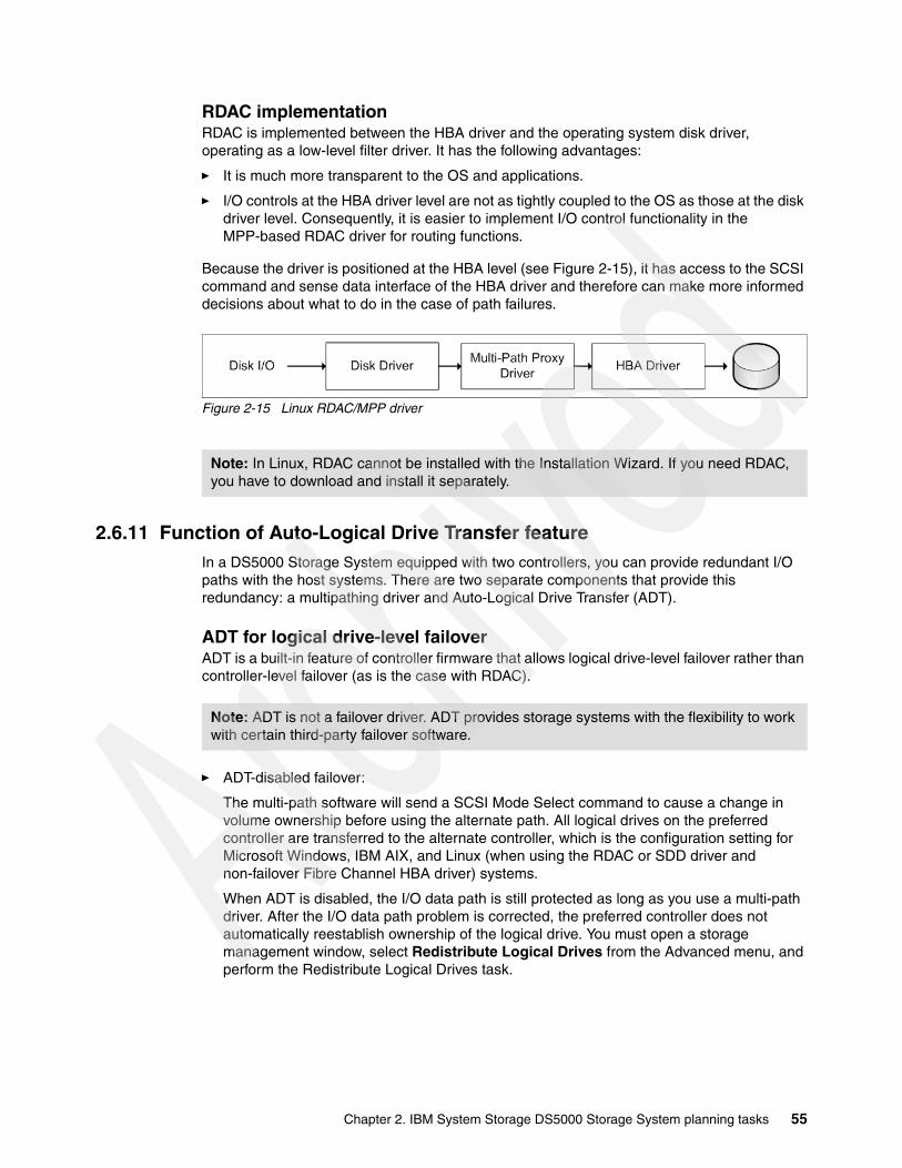
RDAC implementationRDAC is implemented between the HBA driver and the operating system disk driver, operating as a low-level filter driver. It has the following advantages:
� It is much more transparent to the OS and applications.
� I/O controls at the HBA driver level are not as tightly coupled to the OS as those at the disk driver level. Consequently, it is easier to implement I/O control functionality in the MPP-based RDAC driver for routing functions.
Because the driver is positioned at the HBA level (see Figure 2-15), it has access to the SCSI command and sense data interface of the HBA driver and therefore can make more informed decisions about what to do in the case of path failures.
Figure 2-15 Linux RDAC/MPP driver
2.6.11 Function of Auto-Logical Drive Transfer featureIn a DS5000 Storage System equipped with two controllers, you can provide redundant I/O paths with the host systems. There are two separate components that provide this redundancy: a multipathing driver and Auto-Logical Drive Transfer (ADT).
ADT for logical drive-level failoverADT is a built-in feature of controller firmware that allows logical drive-level failover rather than controller-level failover (as is the case with RDAC).
� ADT-disabled failover:
The multi-path software will send a SCSI Mode Select command to cause a change in volume ownership before using the alternate path. All logical drives on the preferred controller are transferred to the alternate controller, which is the configuration setting for Microsoft Windows, IBM AIX, and Linux (when using the RDAC or SDD driver and non-failover Fibre Channel HBA driver) systems.
When ADT is disabled, the I/O data path is still protected as long as you use a multi-path driver. After the I/O data path problem is corrected, the preferred controller does not automatically reestablish ownership of the logical drive. You must open a storage management window, select Redistribute Logical Drives from the Advanced menu, and perform the Redistribute Logical Drives task.
Note: In Linux, RDAC cannot be installed with the Installation Wizard. If you need RDAC, you have to download and install it separately.
Note: ADT is not a failover driver. ADT provides storage systems with the flexibility to work with certain third-party failover software.
Chapter 2. IBM System Storage DS5000 Storage System planning tasks 55

Figure 2-16 shows the ADT-disabled failover mode phases.
Figure 2-16 ADT-disabled mode path failover
� ADT-enabled failover:
The multi-path driver starts using the alternate path by sending the I/O down the path it chooses and lets the ADT react, which is the normal configuration setting for Novell NetWare, Linux (when using FC HBA failover driver instead of RDAC), and Hewlett Packard HP-UX systems. After the I/O data path problem is corrected, the preferred controller automatically reestablishes ownership of the logical drive as soon as the multipath driver detects that the path is normal again.
Note: In ADT-disabled mode, you are required to issue a redistribution command manually to get the LUNs balanced across the controllers.
Host / Server
1
0 1 2 3
1 2 3
A[2]
B[3]
Fa
ilover D
riverX
Application 0
0
Host / Server
1
0 1 2 3
1 2 3
A[2]
B[3]
Fa
ilover D
riverX
Application 0
0
Host / Server
1
0
1
2
3
1
2
3
A[2]
B[3]
Fa
ilover D
riverX
Application 00
Host / Server
1
0
1
2
3
1
2
3
A[2]
B[3]
Fa
ilover D
riverX
Application 00
Port 0 receive an error. connection is no longer valid, error is passed on to the failover driver- 020 failed- 130 alternate
The failover driver can now use the alternate path for any retried or new I/Os- 020 failed- 130 current
Application is using LUN 0Failover driver hides the two physical paths to LUN- 020 current (colored)- 130 alternate (white)
Failover driver determine usage of alternate path to continue I/O. Send a Mode Select SCSI command to the storage. Volume ownership changes as a result of SCSI mode select command.
- 020 failed
4
3
2
1
56 IBM Midrange System Storage Implementation and Best Practices Guide

Phases of failoverFigure 2-17 shows the phases of failover in an ADT-enabled case.
Figure 2-17 ADT-enabled mode path failover
2.7 Operating system restrictions
In your planning, you must also consider the restrictions of your operating system that might apply. We have covered the maximum file system size ordered by the operating system and their commonly used file systems, the maximum number of LUNs that can be assigned to one host, and the maximum logical volume size supported by various operating systems.
Note: In ADT mode, RDAC automatically redistributes the LUNs to their preferred path after the failed path is again operational.
Host / Server
1
0 1 2 3
1 2 3
A[2]
B[3]
Fa
ilover D
riverX
Application 0
0
Host / Server
1
0
1 2 3
1 2 3
A[2]
B[3]
Fa
ilover D
riverX
Application 00
Phase1-2 see Figure 2-16
The LUN 0 volume transfers to controller B which currently has I/O activity for that volume.- 020 failed- 130 current
The failover driver will choose to use the alternate path for any retried or new I/Os.
- 020 failed- 130 current
4
3
Chapter 2. IBM System Storage DS5000 Storage System planning tasks 57
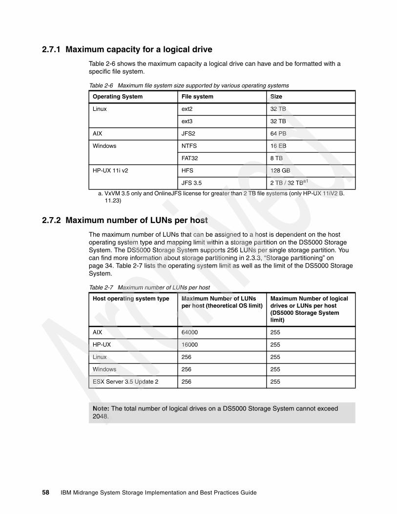
2.7.1 Maximum capacity for a logical drive
Table 2-6 shows the maximum capacity a logical drive can have and be formatted with a specific file system.
Table 2-6 Maximum file system size supported by various operating systems
2.7.2 Maximum number of LUNs per host
The maximum number of LUNs that can be assigned to a host is dependent on the host operating system type and mapping limit within a storage partition on the DS5000 Storage System. The DS5000 Storage System supports 256 LUNs per single storage partition. You can find more information about storage partitioning in 2.3.3, “Storage partitioning” on page 34. Table 2-7 lists the operating system limit as well as the limit of the DS5000 Storage System.
Table 2-7 Maximum number of LUNs per host
Operating System File system Size
Linux ext2 32 TB
ext3 32 TB
AIX JFS2 64 PB
Windows NTFS 16 EB
FAT32 8 TB
HP-UX 11i v2 HFS 128 GB
JFS 3.5 2 TB / 32 TBa1
a. VxVM 3.5 only and OnlineJFS license for greater than 2 TB file systems (only HP-UX 11iV2 B. 11.23)
Host operating system type Maximum Number of LUNs per host (theoretical OS limit)
Maximum Number of logical drives or LUNs per host (DS5000 Storage System limit)
AIX 64000 255
HP-UX 16000 255
Linux 256 255
Windows 256 255
ESX Server 3.5 Update 2 256 255
Note: The total number of logical drives on a DS5000 Storage System cannot exceed 2048.
58 IBM Midrange System Storage Implementation and Best Practices Guide

Chapter 3. Configuring the DS Storage Server
In this chapter we provide a sequence of tasks and guidelines to properly set up, install, and configure IBM System Storage DS® Storage Server:
� Initial setup of DS Storage Server� Configuring the DS Storage Server with the Storage Manager (SM) Client� Defining logical drives and hot spare drives� Setting up storage partitioning� Configuring iSCSi with specific card or software initiators� Event monitoring and alerts� Software and firmware upgrades� Capacity upgrades
3
© Copyright IBM Corp. 2004-2010. All rights reserved. 59

3.1 Configuring the DS Storage Server
For the course of this chapter, we assume that you have installed the operating system on the host server; and have all the necessary device drivers and host software installed and configured. We also assume that you have a good understanding and working knowledge of the DS Storage Server product. If you require detailed information about how to perform the installation, setup, and configuration of this product, see the IBM Midrange System Storage Hardware Guide, SG24-7676.
Now that you have set up the storage server and it is connected to a server or the SAN, you can proceed with additional configuration and storage setting tasks. If there is previous configuration data on the DS Storage Server that you want to be able to reference, then first save a copy of the storage subsystem profile to a file. After you have completed your changes, you must save the profile to a separate file as well, which will be of great value when you are discussing questions or problems with support; or reviewing your configuration with your performance data.
The configuration changes that you want can be done using the Subsystem Management Setup view of the DS Storage Manager, or by following the steps outlined here.
Before defining arrays or logical drives, you must perform certain basic configuration steps, which also applies when you reset the configuration of your DS5000 Storage Server:
1. Give literal names to the servers if you install more than one DS Storage Server. To name or rename the DS Storage Server, open the Subsystem Management window, select the Setup View, and click the option Rename Storage Subsystem, or select from the top menu bar Storage Subsystem Rename.
Make sure that you are renaming the right subsystem, if you have more than one. Select the option Locate Storage Subsystem in the Setup view. This action turns on a light in the front of the selected subsystem, so you can individualize it.
2. Synchronize the controller clocks with the time of the host system used to manage the DS Subsystems, because the DS Storage Server stores its own event log. If you have not already set the clocks on the storage servers, set them now. Be sure that your local system is working using the correct time. Then, click Storage Subsystem Set Controller Clock.
3. Set a password to prevent unauthorized users from making configuration changes, for security reasons, especially if the DS Storage Server has Full Disk Encryption (FDE) security-capable drives, or is attached directly attached to the network. This password is required for all actions on the DS Storage Server that change or update the configuration in any way. You are prompted to set it each time you start managing your subsystem, with the following reminder window as in Figure 3-1.
Best practice: You must save a new profile each time that you change the configuration of the DS5000 storage subsystem, which applies to all changes regardless of how minor they might be. The profile must be stored in a location where it is available even after a complete configuration loss, for example, after a site loss.
Best Practice: Synchronize the DS Storage subsystem controller clocks with the Management station and hosts servers using it, which simplifies error determination when you start comparing the various event logs. A network time server can be useful for this purpose.
60 IBM Midrange System Storage Implementation and Best Practices Guide
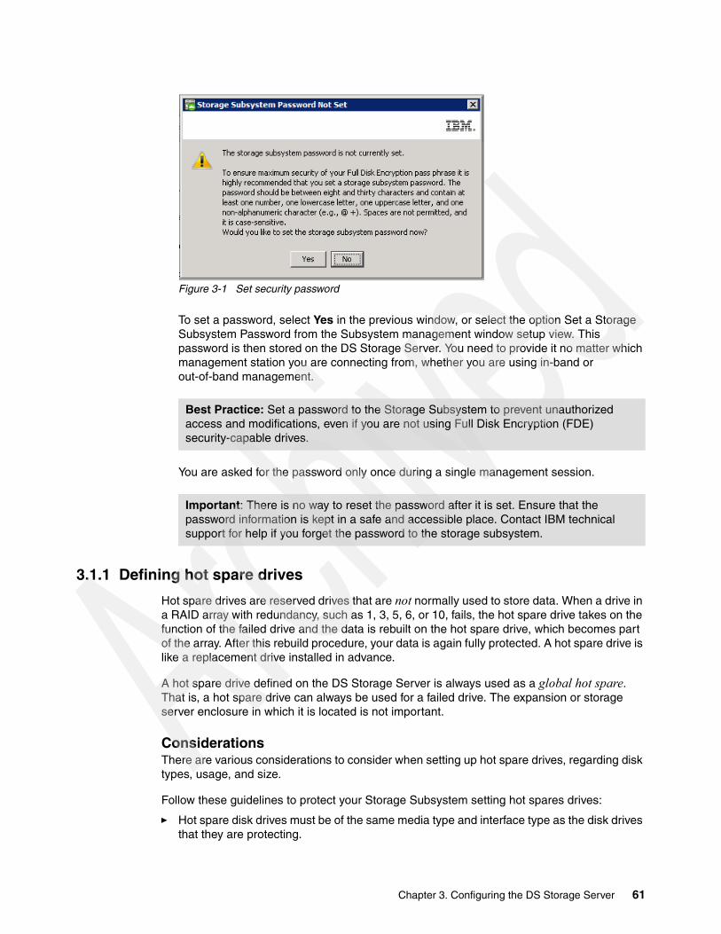
Figure 3-1 Set security password
To set a password, select Yes in the previous window, or select the option Set a Storage Subsystem Password from the Subsystem management window setup view. This password is then stored on the DS Storage Server. You need to provide it no matter which management station you are connecting from, whether you are using in-band or out-of-band management.
You are asked for the password only once during a single management session.
3.1.1 Defining hot spare drives
Hot spare drives are reserved drives that are not normally used to store data. When a drive in a RAID array with redundancy, such as 1, 3, 5, 6, or 10, fails, the hot spare drive takes on the function of the failed drive and the data is rebuilt on the hot spare drive, which becomes part of the array. After this rebuild procedure, your data is again fully protected. A hot spare drive is like a replacement drive installed in advance.
A hot spare drive defined on the DS Storage Server is always used as a global hot spare. That is, a hot spare drive can always be used for a failed drive. The expansion or storage server enclosure in which it is located is not important.
ConsiderationsThere are various considerations to consider when setting up hot spare drives, regarding disk types, usage, and size.
Follow these guidelines to protect your Storage Subsystem setting hot spares drives:
� Hot spare disk drives must be of the same media type and interface type as the disk drives that they are protecting.
Best Practice: Set a password to the Storage Subsystem to prevent unauthorized access and modifications, even if you are not using Full Disk Encryption (FDE) security-capable drives.
Important: There is no way to reset the password after it is set. Ensure that the password information is kept in a safe and accessible place. Contact IBM technical support for help if you forget the password to the storage subsystem.
Chapter 3. Configuring the DS Storage Server 61
� Similarly, hard disk drives can only be hot spares for other hard disk drives, not Solid State Disks (SSDs).
� Hot spare disk drives must have capacities equal to or larger than the used capacity on the disk drives that they are protecting. The DS Storage Server can use a larger drive to recover a smaller failed drive to it. It will not use smaller drives to recover a larger failed drive. If a larger drive is used, the remaining excess capacity is blocked from use.
� FDE disk drives provide coverage for both security capable and non-security capable disk drives. Non-security capable disk drives can provide coverage only for other non-security capable disk drives:
– For an array that has secured FDE drives, the hot spare drive must be an unsecured FDE drive of the same or greater capacity.
– For an array that has unsecured FDE drives, the hot spare drive can be either an unsecured FDE drive or a non-FDE drive.
In a mixed disk environment that includes non-security capable SATA drives, non-security capable Fibre Channel drives, and FDE Fibre Channel drives (with security enabled or not enabled), use at least one type of global hot spare drive (FDE Fibre Channel and a SATA drive) at the largest capacity within the array. If a secure-capable FDE Fibre Channel and SATA hot spare drive are included, all arrays are protected.
Hot spare best practicesWe have already reviewed the considerations to assign drives as hot spares. Here we provide a summary of best practices:
� For maximum data protection, you must use only the largest capacity drives for hot spare drives in mixed capacity hard drive configurations, and highest speed drives.
� Hot spare drives distributed across separate disk expansions provide maximized performance and availability, preventing unlikely but possible failures such as the loss of a complete expansion or a drive channel.
� Use a minimum ratio of one hot spare drive for every 30 drives of a particular media type and interface type, or one for every two fully populated enclosures.
� Use the option View/change current hot spare coverage to ensure that all the defined arrays are hot spare protected.
Drive capacity and speedWhen a drive failure occurs on a storage server configured with multiple hot spare drives, the DS Storage Server will attempt to find a hot spare drive in the enclosure with the failed drive first. It will find a drive that is at least the same size as the failed drive, but not necessarily giving preference to one the exact same size as the failed drive. If a match does not exist in the same enclosure, it will look for spares in the other enclosures that contain sufficient capacity to handle the task.
The controller uses a free hot spare drive as soon as it finds one, even if there is another one that might be closer to the failed drive. If various speed drives (10 K or 15 K) are used, the fastest hot spares are used so as to not slow down an array if the hot spare is required.
Hot spare locationsDistribute the hot spare drives evenly across the various expansions of your storage subsystem and avoid having multiple drives in a single enclosure. Because hot spare drives are in standby, without traffic or I/O until a drive fails, then you want to maximize the overall performance of your system, evenly distributing your production drives across the various expansions. At the same time, this avoids the risk of a single disk drive channel, or expansion enclosure failure, causing loss of access to all hot spare drives in the storage subsystem.
62 IBM Midrange System Storage Implementation and Best Practices Guide
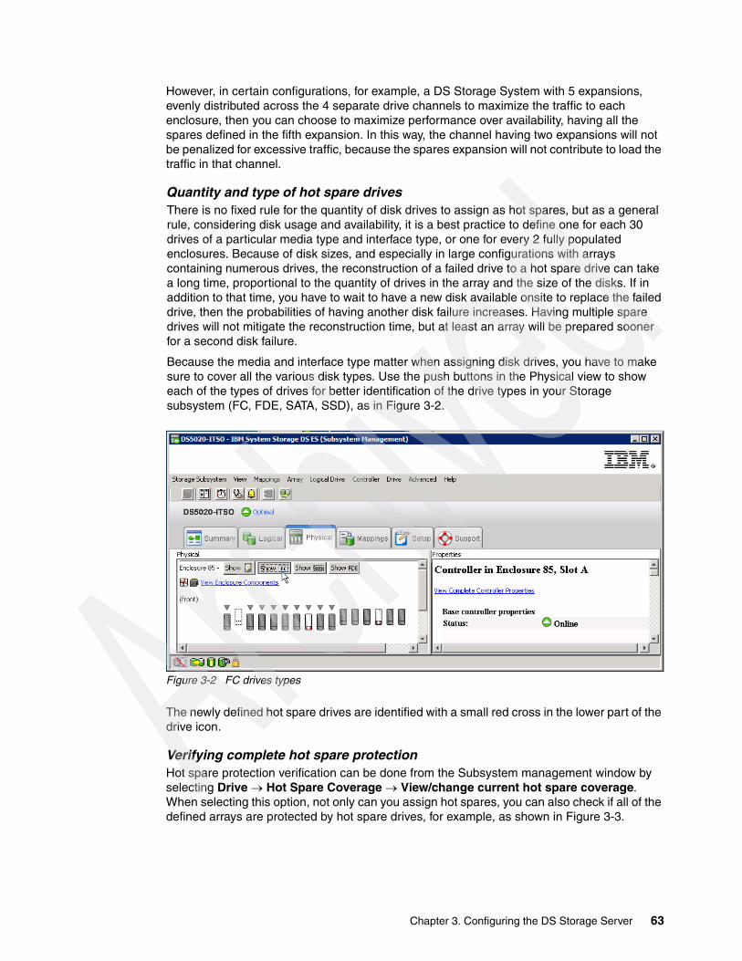
However, in certain configurations, for example, a DS Storage System with 5 expansions, evenly distributed across the 4 separate drive channels to maximize the traffic to each enclosure, then you can choose to maximize performance over availability, having all the spares defined in the fifth expansion. In this way, the channel having two expansions will not be penalized for excessive traffic, because the spares expansion will not contribute to load the traffic in that channel.
Quantity and type of hot spare drivesThere is no fixed rule for the quantity of disk drives to assign as hot spares, but as a general rule, considering disk usage and availability, it is a best practice to define one for each 30 drives of a particular media type and interface type, or one for every 2 fully populated enclosures. Because of disk sizes, and especially in large configurations with arrays containing numerous drives, the reconstruction of a failed drive to a hot spare drive can take a long time, proportional to the quantity of drives in the array and the size of the disks. If in addition to that time, you have to wait to have a new disk available onsite to replace the failed drive, then the probabilities of having another disk failure increases. Having multiple spare drives will not mitigate the reconstruction time, but at least an array will be prepared sooner for a second disk failure.
Because the media and interface type matter when assigning disk drives, you have to make sure to cover all the various disk types. Use the push buttons in the Physical view to show each of the types of drives for better identification of the drive types in your Storage subsystem (FC, FDE, SATA, SSD), as in Figure 3-2.
Figure 3-2 FC drives types
The newly defined hot spare drives are identified with a small red cross in the lower part of the drive icon.
Verifying complete hot spare protectionHot spare protection verification can be done from the Subsystem management window by selecting Drive Hot Spare Coverage View/change current hot spare coverage. When selecting this option, not only can you assign hot spares, you can also check if all of the defined arrays are protected by hot spare drives, for example, as shown in Figure 3-3.
Chapter 3. Configuring the DS Storage Server 63
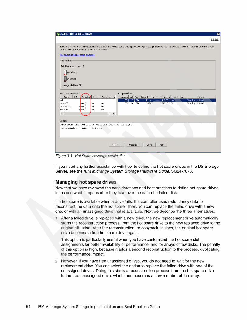
Figure 3-3 Hot Spare coverage verification
If you need any further assistance with how to define the hot spare drives in the DS Storage Server, see the IBM Midrange System Storage Hardware Guide, SG24-7676.
Managing hot spare drivesNow that we have reviewed the considerations and best practices to define hot spare drives, let us see what happens after they take over the data of a failed disk.
If a hot spare is available when a drive fails, the controller uses redundancy data to reconstruct the data onto the hot spare. Then, you can replace the failed drive with a new one, or with an unassigned drive that is available. Next we describe the three alternatives:
1. After a failed drive is replaced with a new drive, the new replacement drive automatically starts the reconstruction process, from the hot spare drive to the new replaced drive to the original situation. After the reconstruction, or copyback finishes, the original hot spare drive becomes a free hot spare drive again.
This option is particularly useful when you have customized the hot spare slot assignments for better availability or performance, and for arrays of few disks. The penalty of this option is high, because it adds a second reconstruction to the process, duplicating the performance impact.
2. However, if you have free unassigned drives, you do not need to wait for the new replacement drive. You can select the option to replace the failed drive with one of the unassigned drives. Doing this starts a reconstruction process from the hot spare drive to the free unassigned drive, which then becomes a new member of the array.
64 IBM Midrange System Storage Implementation and Best Practices Guide
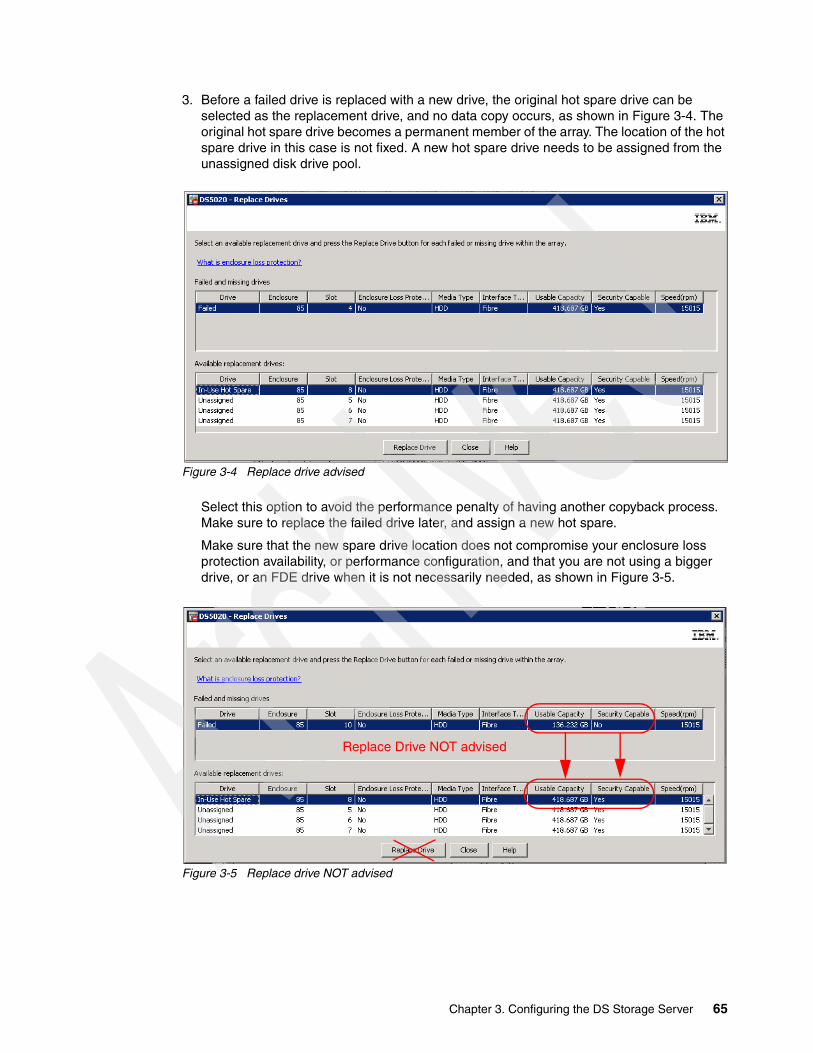
3. Before a failed drive is replaced with a new drive, the original hot spare drive can be selected as the replacement drive, and no data copy occurs, as shown in Figure 3-4. The original hot spare drive becomes a permanent member of the array. The location of the hot spare drive in this case is not fixed. A new hot spare drive needs to be assigned from the unassigned disk drive pool.
Figure 3-4 Replace drive advised
Select this option to avoid the performance penalty of having another copyback process. Make sure to replace the failed drive later, and assign a new hot spare.
Make sure that the new spare drive location does not compromise your enclosure loss protection availability, or performance configuration, and that you are not using a bigger drive, or an FDE drive when it is not necessarily needed, as shown in Figure 3-5.
Figure 3-5 Replace drive NOT advised
Replace Drive NOT advised
Chapter 3. Configuring the DS Storage Server 65

FDE enabled drivesIf a global hot spare drive is an unsecured FDE drive, it can be used as a spare drive in secured or unsecured arrays with FDE drives, or as a spare drive in arrays with non-FDE drives, as shown in Figure 3-6.
Figure 3-6 Spare FDE protecting FDE secured and FC drives
When a global hot spare drive is used as a spare for a failed drive in a secure array, it becomes a secure FDE drive and remains secure as long as it is a spare in the secure array. After the failed drive in the secure array is replaced and the data in the global hot spare drive is copied back to the replaced drive, the global hot spare drive is automatically reprovisioned by the controllers to become an unsecured FDE global hot spare drive.
If instead of doing the copyback, you select the spare drive as a permanent drive of the array, then you must secure erase the FDE drive to change it to unsecured state before it can be used as a global hot spare drive.
3.1.2 Creating arrays and logical drivesAt this stage, the storage subsystem has been installed and hot spares drives defined. You can now configure the arrays and logical drives according to your requirements. With the SMclient, you can use an automatic default configuration mode to configure the arrays and LUNs for the sizes you want and the RAID type you select. If you have planned your configuration for maximum performance and reliability as discussed in 2.3, “Planning your storage structure” on page 30, you will need to define them manually to enter your specific configuration and needs.
66 IBM Midrange System Storage Implementation and Best Practices Guide

For more information about defining arrays, logical drives, and the restrictions that apply, see the IBM Midrange System Storage Hardware Guide, SG24-7676.
To create logical drives, you can define them from unconfigured-capacity, un-assigned drives, or from free capacity in an already existing array:
� When you create a logical drive from unconfigured capacity, you create an array and the logical drive at the same time. Note that the unconfigured capacity for Fibre Channel and SATA disks are grouped separately.
� When you create a logical drive from free capacity, you create an additional logical drive on an already existing array from free unconfigured space that is available.
While creating your logical drives, select Customize settings to be able to set specific values for the cache settings, and segment size for the logical drive options. Follow these steps:
1. Right-click the unconfigured capacity in the Subsystem Management window and select Create Logical Drive. This action starts the wizard for creating the logical drives. The first window of the wizard is an introduction to the process, as shown in Figure 3-7. Read the introduction and then click Next in order to proceed. We present the best practices during the array creation process.
Figure 3-7 Create Logical Drive
Best practice: When you define the arrays and logical drives for your configuration, plan your layout and use the manual configuration method to select the desired drives and specify your settings.
Chapter 3. Configuring the DS Storage Server 67
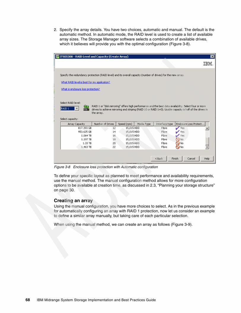
2. Specify the array details. You have two choices, automatic and manual. The default is the automatic method. In automatic mode, the RAID level is used to create a list of available array sizes. The Storage Manager software selects a combination of available drives, which it believes will provide you with the optimal configuration (Figure 3-8).
Figure 3-8 Enclosure loss protection with Automatic configuration
To define your specific layout as planned to meet performance and availability requirements, use the manual method. The manual configuration method allows for more configuration options to be available at creation time, as discussed in 2.3, “Planning your storage structure” on page 30.
Creating an arrayUsing the manual configuration, you have more choices to select. As in the previous example for automatically configuring an array with RAID 1 protection, now let us consider an example to define a similar array manually, but taking care of each particular selection.
When using the manual method, we can create an array as follows (Figure 3-9).
68 IBM Midrange System Storage Implementation and Best Practices Guide
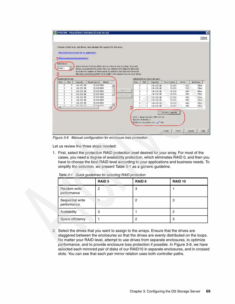
Figure 3-9 Manual configuration for enclosure loss protection
Let us review the three steps needed:
1. First, select the protection RAID protection level desired for your array. For most of the cases, you need a degree of availability protection, which eliminates RAID 0, and then you have to choose the best RAID level according to your applications and business needs. To simplify the selection, we present Table 3-1 as a generic guideline.
Table 3-1 Quick guidelines for selecting RAID protection
2. Select the drives that you want to assign to the arrays. Ensure that the drives are staggered between the enclosures so that the drives are evenly distributed on the loops. No matter your RAID level, attempt to use drives from separate enclosures, to optimize performance, and to provide enclosure loss protection if possible. In Figure 3-9, we have selected each mirrored pair of disks of our RAID10 in separate enclosures, and in crossed slots. You can see that each pair mirror relation uses both controller paths.
RAID 5 RAID 6 RAID 10
Random write performance
2 3 1
Sequential write performance
1 2 3
Availability 3 1 2
Space efficiency 1 2 3
2
1
3
Chapter 3. Configuring the DS Storage Server 69

3. Click Calculate Capacity to proceed, after selecting the drives. When enclosure loss protection is achieved, then a checkmark and the word Yes will appear in the bottom right side of the window, otherwise, it will have a circle with a line through it and the word No. After you are satisfied that capacity and protection have been obtained, click Finish to create the array. See Figure 3-9 on page 69.
After creating the array, the logical drive creating wizard windows are displayed.
Creating logical drivesAfter creating an array, you are prompted to continue creating logical drives. You can alternatively select a free capacity space in any array, right-click it, and select Create Logical Drive.
In the first dialog window, define the logical drive capacity size, assign a name to the logical drive. Then select either Use recommended settings, or Customize Settings to optimize the new logical drive, by specifying segment size or cache settings option, and click Next.
Choosing array drives:
� Select same size and speed of drives to create an array.
� To maximize IOPS:
– More drives are better. Reasonable: 10 drives for RAID 5, 16 drives for RAID 10.– Select SSD disk types, then FC, avoiding SATA drives.
� To maximize MBps:
– Create relatively compact arrays, 4+P or 8+P.– Select either FC or SATA drives, not SSD.
� Attempt to select drives from separate enclosures, to optimize controller access performance and array availability, in case of a complete enclosure problem.
� Select drives evenly across both even and odd slots. Because Controller A has a preference to manage odd slots, and Controller B to manage even slots, this approach can result in better performance.
� In configurations with multiple enclosures and high performance requirements, select drives from only odd loop pairs, or only even loop pairs, because controller A is the preferred path to odd loop pairs, and Controller B to even loop pairs.
Best practice: Select Customize Settings in the creation of the logical drive, so you can set your planned specific values according to your configuration. The defaults using the Use Recommended Settings option sets a default segment size of 128 KB for every logical volume, except for RAID 3 volumes, which are set to 256 KB.
70 IBM Midrange System Storage Implementation and Best Practices Guide
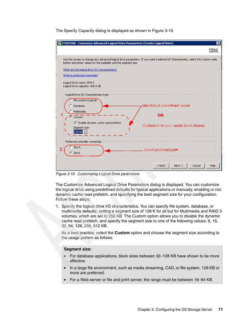
The Specify Capacity dialog is displayed as shown in Figure 3-10.
Figure 3-10 Customizing Logical Drive parameters
The Customize Advanced Logical Drive Parameters dialog is displayed. You can customize the logical drive using predefined defaults for typical applications or manually, enabling or not, dynamic cache read prefetch, and specifying the best segment size for your configuration. Follow these steps:
1. Specify the logical drive I/O characteristics. You can specify file system, database, or multimedia defaults, setting a segment size of 128 K for all but for Multimedia and RAID 3 volumes, which are set to 256 KB. The Custom option allows you to disable the dynamic cache read prefetch, and specify the segment size to one of the following values: 8, 16, 32, 64, 128, 256, 512 KB.
As a best practice, select the Custom option and choose the segment size according to the usage pattern as follows.
Segment size:
� For database applications, block sizes between 32–128 KB have shown to be more effective.
� In a large file environment, such as media streaming, CAD, or file system, 128 KB or more are preferred.
� For a Web server or file and print server, the range must be between 16–64 KB.
Use default predefined values
Customize to your needs (best choice)
OR
Select preferred path2
1
Chapter 3. Configuring the DS Storage Server 71

– The read ahead setting is really an on or off decision because the read ahead multiplier is dynamically adjusted in the firmware. After it is enabled, the dynamic cache read-ahead function will automatically load in advance as many blocks as the current usage pattern.
– If the reads are mostly sequential, then many blocks are read in advance; if it is random, then it will not read ahead any blocks at all. However, in order to analyze the traffic pattern, and decide how many blocks to read in advance, the controller is using processing cycles.
– If you know in advance that the traffic pattern is random, as in database environments, then it is a good choice to disable this option, so you can save this additional processing made by the controllers.
2. Choose the preferred controller ownership option as follows.
You can distribute your logical drives between both controllers to provide better load balancing between them:
– The default is to alternate the logical drives on the two controllers, so after creating one logical drive, the next one is assigned automatically to the other controller. The problem with this option is that because not all the logical drives are normally used in the same way, you can end with one controller being much more used than the other.
– Obviously it is better to spread the logical drives by the load they cause on the controller. It is possible to monitor the load of each logical drive on the controllers with the Performance Monitor and change the preferred controller in case of need, so you can split the traffic load evenly across both.
– The best option, however, which is suitable for configurations with multiple enclosures, is to assign all the logical drives within an enclosure to the specific controller that has the preferred path to the enclosure channel, based on architecture design. Figure 3-11 shows the order of expansion enclosures installation (first column) and the preferred path for each enclosure according to the channel, port loop (first row).
Dynamic cache read prefetch:
� Disable this option for databases, or all traffic patterns where you are sure that the reads are random, to save controller processing time analyzing the traffic to calculate how many blocks are read in advance.
� Enable this option for file system, multimedia, or any other applications that use sequential I/O traffic to increase the read throughput.
72 IBM Midrange System Storage Implementation and Best Practices Guide
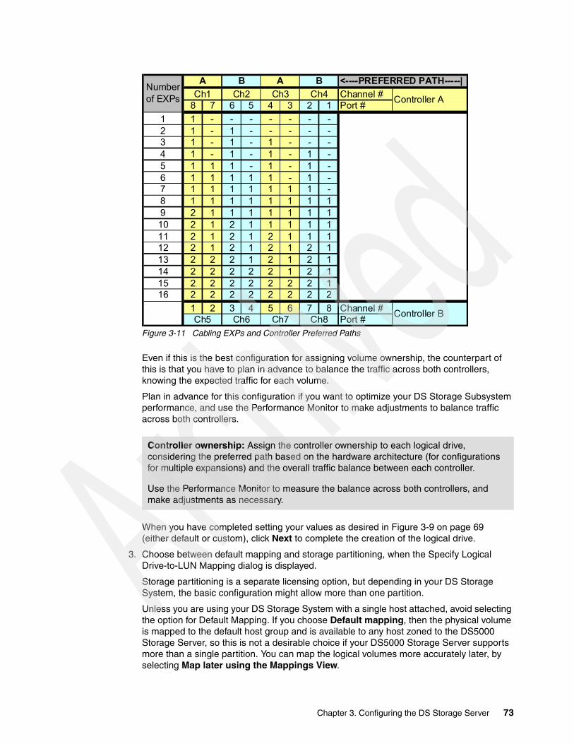
Figure 3-11 Cabling EXPs and Controller Preferred Paths
Even if this is the best configuration for assigning volume ownership, the counterpart of this is that you have to plan in advance to balance the traffic across both controllers, knowing the expected traffic for each volume.
Plan in advance for this configuration if you want to optimize your DS Storage Subsystem performance, and use the Performance Monitor to make adjustments to balance traffic across both controllers.
When you have completed setting your values as desired in Figure 3-9 on page 69 (either default or custom), click Next to complete the creation of the logical drive.
3. Choose between default mapping and storage partitioning, when the Specify Logical Drive-to-LUN Mapping dialog is displayed.
Storage partitioning is a separate licensing option, but depending in your DS Storage System, the basic configuration might allow more than one partition.
Unless you are using your DS Storage System with a single host attached, avoid selecting the option for Default Mapping. If you choose Default mapping, then the physical volume is mapped to the default host group and is available to any host zoned to the DS5000 Storage Server, so this is not a desirable choice if your DS5000 Storage Server supports more than a single partition. You can map the logical volumes more accurately later, by selecting Map later using the Mappings View.
Controller ownership: Assign the controller ownership to each logical drive, considering the preferred path based on the hardware architecture (for configurations for multiple expansions) and the overall traffic balance between each controller.
Use the Performance Monitor to measure the balance across both controllers, and make adjustments as necessary.
Channel #8 7 6 5 4 3 2 1 Port #
1 1 - - - - - - -2 1 - 1 - - - - -3 1 - 1 - 1 - - -4 1 - 1 - 1 - 1 -5 1 1 1 - 1 - 1 -6 1 1 1 1 1 - 1 -7 1 1 1 1 1 1 1 -8 1 1 1 1 1 1 1 19 2 1 1 1 1 1 1 110 2 1 2 1 1 1 1 111 2 1 2 1 2 1 1 112 2 1 2 1 2 1 2 113 2 2 2 1 2 1 2 114 2 2 2 2 2 1 2 115 2 2 2 2 2 2 2 116 2 2 2 2 2 2 2 2
1 2 3 4 5 6 7 8 Channel #Port #Ch5 Ch6
<----PREFERRED PATH-----|
Controller A
Ch7 Ch8
Ch3 Ch4
Controller B
B A BNumber of EXPs Ch1 Ch2
A
Chapter 3. Configuring the DS Storage Server 73
If the logical drive is smaller than the total capacity of the array, a window opens and asks whether you want to define another logical drive on the array. The alternative is to leave the space as unconfigured capacity. After you define all logical drives on the array, the array is now initialized and immediately accessible.
If you left unconfigured capacity inside the array, you can define another logical drive later in this array. Just highlight this capacity, right-click, and choose Create Logical Drive. Simply follow the steps that we outlined in this section, except for the selection of drives and RAID level. Because you already defined arrays that contain free capacity, you can choose where to store the new logical drive, on an existing array or on a new one.
In the past, various enhancements provided in new code versions encountered difficulties in implementing certain changes when all the space in the array was used. Therefore, as a good practice, keep extra space free in each array whenever you are able to afford having empty space.
3.1.3 Configuring storage partitioningBecause the DS Storage Server is capable of having heterogeneous hosts attached, a way is needed to define which hosts are able to access which logical drives on the DS Storage Server. Therefore, you need to configure storage partitioning, for two reasons:
� Each host operating system has particular settings that vary slightly, required for proper operation on the DS Storage Server. For that reason, you need to tell the storage subsystem the host type that is attached.
� There is interference between the hosts if every host has access to every logical drive. By using storage partitioning, you mask logical drives from hosts which are not to use them (also known as LUN masking), and you ensure that each host or host group only has access to its assigned logical drives. You can have a maximum of 256 logical drives assigned to a single storage partition. A maximum of 2048 logical drives (LUNs) per storage server is possible, depending on the model.
The overall process of defining the storage partitions is as follows:
1. Define host groups. 2. Define hosts. 3. Define host ports for each host. 4. Define storage partitions by assigning logical drives to the hosts or host groups.
Defining the partitionsFollow these detailed steps to define the partitions:
1. First, select the Mappings View in the Subsystem Management window. All functions that are performed with regard to partitioning are performed from within this view.
If you have not defined any storage partitions yet, the Mapping Start-Up Help window is displayed. You are advised to create only the host groups that you intend to use. For example, if you want to attach a cluster of host servers, then you have to create a host group for them. On the other hand, if you want to attach a host that is not a part of the cluster, it is not necessary to put it into a particular host group; however, it might help you to have them grouped together.
Restriction: The maximum logical drives per partition can exceed certain host limits. Check to be sure that the host can support the number of logical drives that you are configuring for the partition. In certain cases you might need to split the logical drives across two separate partitions, with a second set of host side HBAs.
74 IBM Midrange System Storage Implementation and Best Practices Guide

For detailed information about each of the process steps, see the IBM Midrange System Storage Hardware Guide, SG24-7676.
Here are a few additional points to be aware of when performing your partition mapping:
– Before starting to map logical volumes, create hosts, or host groups, make sure to activate the premium feature for partitions, to expand the current limit to the new limit purchased.
– When creating logical volumes, avoid mapping them to the default group. Whenever possible, select the option to map them later, so you can assign them individually as needed.
– All information, such as host ports and logical drive mappings, is shown and configured in the Mappings View. The right side of the window lists all mappings that are owned by the object you choose in the left side, as shown in Figure 3-12.
Figure 3-12 Mappings View
If you highlight the storage subsystem, you see a list of all defined mappings. If you highlight a specific host group or host, only its mappings are listed.
2. Move the host if necessary. If you accidentally assigned a host to the wrong host group, you can move the host to another group. Simply right-click the host name and select Move. A pop-up window opens so you can specify the host group name.
3. Storage partitioning of the DS Storage Server is based on the World Wide Names of the host ports for FC, and the iSCSI Qualified Name (IQN), for iSCSI. The definitions for the host groups and the hosts only represent a view of the physical and logical setup of your fabric. Having this structure available makes it much easier to identify which host ports are allowed to see the same logical drives, and which are in separate storage partitions.
For iSCSI, before creating the host and assigning the host ports, it is better have the connectivity to the host so you can pick up the host ID instead of typing it manually, as you do with the FC WWPNs.
Best practice: Although not required, mapping all hosts to a host group for their specific purpose can prevent confusion and mistakes.
Chapter 3. Configuring the DS Storage Server 75

4. Define the iSCSI host ports of each of the ports of both controllers planned to connect iSCSI hosts, selecting from the Setup tab of the Subsystem management window, the option Configure iSCSI Host Ports, as shown in Figure 3-13.
Figure 3-13 Configure iSCSI Host Ports
Select an iSCSI host port, and assign the IP address, subnet mask, and gateway as usually with all Ethernet cards, in either of the IPv4 or IPv6 tabs. If you are planning to use VLANs, or Ethernet priority, click Advanced IP Settings to define them. Repeat the process for at least one port in controller A, and one port in controller B.
If you plan to use Jumbo frames, click Advanced Host Port Settings, to enable it and select the frame size up to a maximum of 9000 Bytes. You can change here the default TCP port 3260 for any other.
76 IBM Midrange System Storage Implementation and Best Practices Guide

5. Create your host definitions according to your connection type. Select the connection method first (FC or iSCSI), and assign the host port identifier (WWPN for FC, or IQN for iSCSI. If the host is properly configured, and attached to the DS Storage System of the Storage Are Network, you can select the port identifier from a list.
If for any reason the hosts are not yet configured, or the SAN not zoned, or the network switches not available, then you cannot pick the port identifiers from the dialog box to select it. However, you can still type in the IQN or WWPN of the host adapter manually, like in Figure 3-14 to avoid further delays with your implementation:
Figure 3-14 Host Port Identifiers
In order to determine the WWPN, you can read it from the external side of the HBA in certain cases. If not, from Windows, use the utility provided by the HBA manufacturer, as SANsurfer, or equivalent. In AIX, you can query the adapter VPD using the lscfg command, as shown in Example 3-1.
Example 3-1 Determine WWPN in AIX
# lscfg -vl fcs0 |grep Network Network Address.............10000000C955E566#
Chapter 3. Configuring the DS Storage Server 77

6. Ensure that if your DS Storage System has mixed host interface cards for both FC and iSCSI, a given partition does not contain hosts that are FC-based as well as hosts that are iSCSI-based. Also, a single host must not be configured for both iSCSI connections and FC connections to the storage system.
Storage partitioning is not the only function of the storage server that uses the definition of the host ports. When you define the host port, the host type of the attached host is defined as well. Through this information, the DS Storage System modifies the NVSRAM settings to behave according to the host type defined. The most common of the specifications that differ according to the host type setting is the Auto Volume Transfer function, or AVT, which is set as enable for certain host types, and disable for others.
It is important to carefully choose the correct host type from the list of available types, because this is the part of the configuration dealing with heterogeneous host support. Each operating system expects slight variations in settings and can handle SCSI commands separately. Incorrect selections can result in failure to boot, or loss of path failover function when attached to the storage server.
7. Assign the mapping of a logical volume to a host group, only if you need to share the volume across more than one host. If you have a single server in a host group that has one or more logical drives assigned to it, and no other host has to use the same volumes, assign the mapping to the host, and not the host group. Numerous servers can share a common host group; but might not necessarily share drives. Only place drives on the host group mapping that you truly want all hosts in the group to be able to share.
8. If you have a cluster, assign the logical drives that are to be shared across all, to the host group, so that all of the host nodes on the host group have access to them.
9. If you attached a host server that is not configured to use the in-band management capabilities, ensure that the access LUNs are deleted or unconfigured from that host server’s mapping list.
Highlight the host or host group containing the system in the Mappings View. In the right side of the window, you see the list of all logical drives mapped to this host or host group. To delete the mapping of the access logical drive, right-click it and select Remove. The mapping of that access logical drive is deleted immediately. If you need to use the access LUN with another server, you will have the opportunity to do so when you create the host mapping. An access LUN is created whenever a host server partition is created.
Follow the aforementioned best practices to configure your mappings, hosts, and partitions. Remember that after this has been done, the host mapped can already start using the logical volumes mapped.
Note: If you create a new mapping or change an existing mapping of a logical drive, the change happens immediately. Therefore, make sure that this logical drive is not in use or is even assigned by any of the machines attached to the storage subsystem.
78 IBM Midrange System Storage Implementation and Best Practices Guide

Managing host port identifiersWith the hosts already defined, now let us see how we can get additional help using the Storage Manager to view and make changes to the assignments already done,
Because your DS Storage subsystem can support many hosts, you can use the option Mappings Manage Host Port Identifiers from the Subsystem management window to list all the host port identifiers defined in your configuration, with the added facility of listing all hosts or selecting a specific one in a single window. See Figure 3-15.
Figure 3-15 Manage Host Port Identifiers
Use this window if you want to modify a host attachment setting, such as replacing a host bus adapter. You can also use it to add new host mappings, however, remember that this first view only shows defined hosts.
Chapter 3. Configuring the DS Storage Server 79

To check what other host port identifiers are already recognized by your Storage Subsystem, but are not already assigned to a Host, select the option Mappings View Unassociated Host Port Identifiers from the Subsystem management window. If there are any, they are shown in a window as in Figure 3-16.
Figure 3-16 Unassociated host port Identifiers
Depending on your operating system, you can use a utility to dynamically discover the mapped logical volume, avoiding a complete rescan or reboot. The utility, installed with the DS Utilities package, provides the hot_add command line tool for certain operating systems. You simply run hot_add, and all host bus adapters are re-scanned for new devices, and the devices must be accessible to the operating system.
You will need to take appropriate steps to enable the use of the storage inside the operating system, or by the volume manager software.
3.1.4 iSCSI configuration and management
The DS Storage System has two separate host interface card options to connect your hosts, iSCSI and FC. Configuring the arrays and logical drives is the same for both connection types. The only difference to configure iSCSI attachment from your DS Storage Manager is how the hosts are defined, by its iSCSI Qualified Name (IQN), instead of the WWPN as in Fibre Channel, as presented in 3.1.3, “Configuring storage partitioning” on page 74.
Next we show how to set up a Windows host for iSCSI, and the specific options available in the Storage Manager for setup and management of iSCSI connections.
For additional information about iSCSI, see the IBM Midrange System Storage Hardware Guide, SG24-7676.
80 IBM Midrange System Storage Implementation and Best Practices Guide

Configuring iSCSITo configure iSCSI, follow these steps:
1. Start the iSCSI attachment configuration defining the iSCSI host ports. Do this for each of the ports of both controllers that you are planning to use for connecting iSCSI hosts. From the Setup tab of the Subsystem management window, select the option Configure iSCSI Host Ports, as shown in Figure 3-17.
Figure 3-17 Configure iSCSI Host Ports
2. Select an iSCSI host port, and assign the IP address, mask, and gateway as usual with all Ethernet cards, in either of the IPv4 or IPv6 tabs. If you are planning to use VLAN Tags (802.1Q), or set Ethernet priority (802.1P), click Advanced IP Settings to define them, as shown in Figure 3-18. Repeat the process for at least one port in controller A, and one port in controller B.
Chapter 3. Configuring the DS Storage Server 81

Figure 3-18 VLAN and Priority
3. If you plan to use Jumbo frames, click Advanced Host Port Settings, to enable it and select the frame size to either 1500 or 9000 Bytes. You can change here the default TCP port 3260 for any other port. See Figure 3-19.
Figure 3-19 Jumbo Frames
Now you can create your hosts definitions according to your connection type. However, the host server has to be already configured, so you can easily map its port identifiers to the DS Storage Manager host definition.
82 IBM Midrange System Storage Implementation and Best Practices Guide
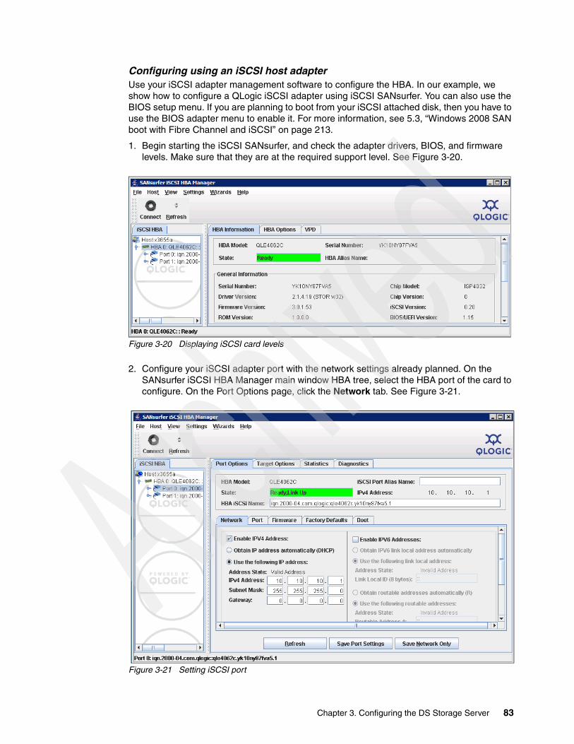
Configuring using an iSCSI host adapterUse your iSCSI adapter management software to configure the HBA. In our example, we show how to configure a QLogic iSCSI adapter using iSCSI SANsurfer. You can also use the BIOS setup menu. If you are planning to boot from your iSCSI attached disk, then you have to use the BIOS adapter menu to enable it. For more information, see 5.3, “Windows 2008 SAN boot with Fibre Channel and iSCSI” on page 213.
1. Begin starting the iSCSI SANsurfer, and check the adapter drivers, BIOS, and firmware levels. Make sure that they are at the required support level. See Figure 3-20.
Figure 3-20 Displaying iSCSI card levels
2. Configure your iSCSI adapter port with the network settings already planned. On the SANsurfer iSCSI HBA Manager main window HBA tree, select the HBA port of the card to configure. On the Port Options page, click the Network tab. See Figure 3-21.
Figure 3-21 Setting iSCSI port
Chapter 3. Configuring the DS Storage Server 83

Enable IPv4 or IPv6, and select DHCP or manually assign the IP address, mask, and gateway. You can also assign an alias name for the port. Save the setting when done.
3. Set Jumbo frames, VLAN, and Ethernet priority settings according your previous configuration settings defined using the Storage Manager. Move to the Firmware Tab and edit the values as shown in Figure 3-22.
Figure 3-22 iSCSI additional customization
Set Jumbo Frames, VLANs, and Ethernet priority in the iSCSI adapter in accordance to the settings specified in the DS Storage Manager in Figure 3-18, “VLAN and Priority” on page 82.
84 IBM Midrange System Storage Implementation and Best Practices Guide

4. Now move to the Target Settings tab, and add the IP of the controller A of your subsystem as shown in Figure 3-23.
Figure 3-23 Setting Target
5. Save the configuration of the HBA selecting the option, Save Target Settings (after adding the Target of the DS Storage Controller to map to this iSCSI HBA port). The adapter resets and refreshes its configuration, querying the added target server, and showing any devices discovered.
6. Repeat the same process to add the controller B. For redundancy, use dual iSCSI HBA cards. In our example, we used a dual port iSCSI HBA.
Chapter 3. Configuring the DS Storage Server 85
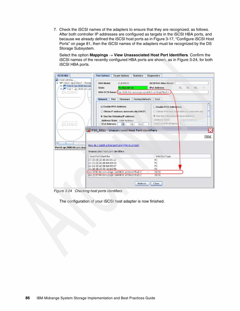
7. Check the iSCSI names of the adapters to ensure that they are recognized, as follows. After both controller IP addresses are configured as targets in the iSCSI HBA ports, and because we already defined the iSCSI host ports as in Figure 3-17, “Configure iSCSI Host Ports” on page 81, then the iSCSI names of the adapters must be recognized by the DS Storage Subsystem.
Select the option Mappings View Unassociated Host Port Identifiers Confirm the iSCSI names of the recently configured HBA ports are shown, as in Figure 3-24, for both iSCSI HBA ports.
Figure 3-24 Checking host ports identifiers
The configuration of your iSCSI host adapter is now finished.
86 IBM Midrange System Storage Implementation and Best Practices Guide
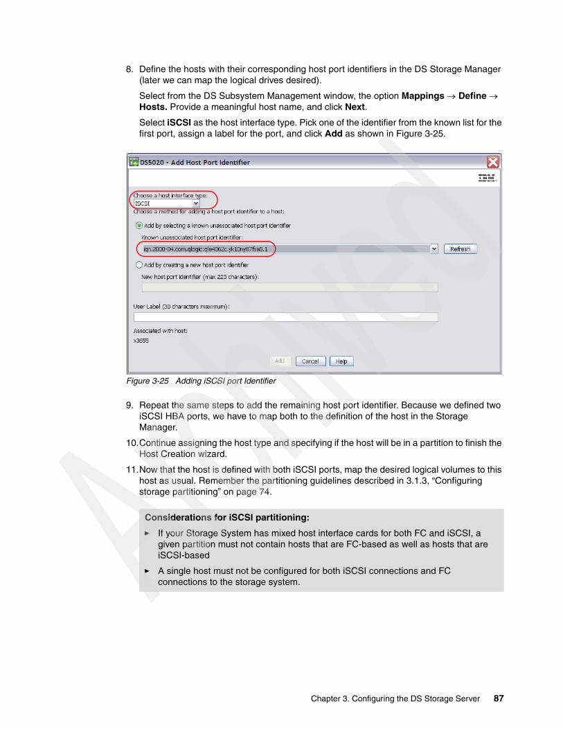
8. Define the hosts with their corresponding host port identifiers in the DS Storage Manager (later we can map the logical drives desired).
Select from the DS Subsystem Management window, the option Mappings Define Hosts. Provide a meaningful host name, and click Next.
Select iSCSI as the host interface type. Pick one of the identifier from the known list for the first port, assign a label for the port, and click Add as shown in Figure 3-25.
Figure 3-25 Adding iSCSI port Identifier
9. Repeat the same steps to add the remaining host port identifier. Because we defined two iSCSI HBA ports, we have to map both to the definition of the host in the Storage Manager.
10.Continue assigning the host type and specifying if the host will be in a partition to finish the Host Creation wizard.
11.Now that the host is defined with both iSCSI ports, map the desired logical volumes to this host as usual. Remember the partitioning guidelines described in 3.1.3, “Configuring storage partitioning” on page 74.
Considerations for iSCSI partitioning:
� If your Storage System has mixed host interface cards for both FC and iSCSI, a given partition must not contain hosts that are FC-based as well as hosts that are iSCSI-based
� A single host must not be configured for both iSCSI connections and FC connections to the storage system.
Chapter 3. Configuring the DS Storage Server 87

12.Confirm that the logical volumes mapped are recognized by the host, as shown in Figure 3-26.
Figure 3-26 Viewing Mapped LUNs at the host
For additional information about using the mapped hosts and verifying multipath driver configuration, see Chapter 4., “Host configuration guide” on page 125.
We cover additional iSCSI settings such as security authentication and iSNS target discovery in “Managing iSCSI” on page 97.
Configuring using an Ethernet adapter and SW InitiatorTo configure a regular adapter to access your DS Storage System using iSCSI, you need to install and configure a software initiator to provide the added protocol to the adapter.
Windows 2008 already has the Microsoft Initiator driver installed, however, you must use the DSM that is provided with the Storage Manager software to make sure that failover and I/O access are correct. If the native MPIO from the Microsoft iSCSI Software Initiator is used, it causes unwanted effects.
Our implementation example is using Windows 2008, and only one Ethernet card, but with two paths from the network switch to the DS Storage System. The DS Storage System iSCSI ports are defined as 9.11.218.158 for ctl A, and 9.11.218.161 for ctl B.
Follow these steps:
1. Install the Host Software package form the IBM DS Storage Manager installation CD.
2. Define the network TCP/IP settings for the Ethernet card that you want to use for attaching your DS Storage System, and according to your network parameters, IPv4 or IPv6, Jumbo Frames, VLAN, Ethernet Priority, These settings need to provide IP connectivity to the already defined iSCSI Host Ports in your DS Storage System.
Check the IP connectivity between your host network adapter and your storage using the ping command.
88 IBM Midrange System Storage Implementation and Best Practices Guide

3. From your Windows 2008 host, select Start Programs Administrative Tools iSCSI Initiator, thus launching the interface to configure the Initiator Properties as shown in Figure 3-27.
The General tab presents the name assigned to the adapter, or IQN. You will need this name later to define the host port in the DS Storage Manager, because you need the WWPN of an HBA.
Figure 3-27 iSCSI Initiator Properties
4. Enter the CHAP Secret password if you want to configure mutual authentication for added security. If so, then you need to provide the same key later in your DS Storage System.
5. Select the Discovery tab and click the Add Portal option. Enter any of the IP addresses set to the iSCSI Host Interface ports of your DS Storage System, as shown in Figure 3-28.
Chapter 3. Configuring the DS Storage Server 89
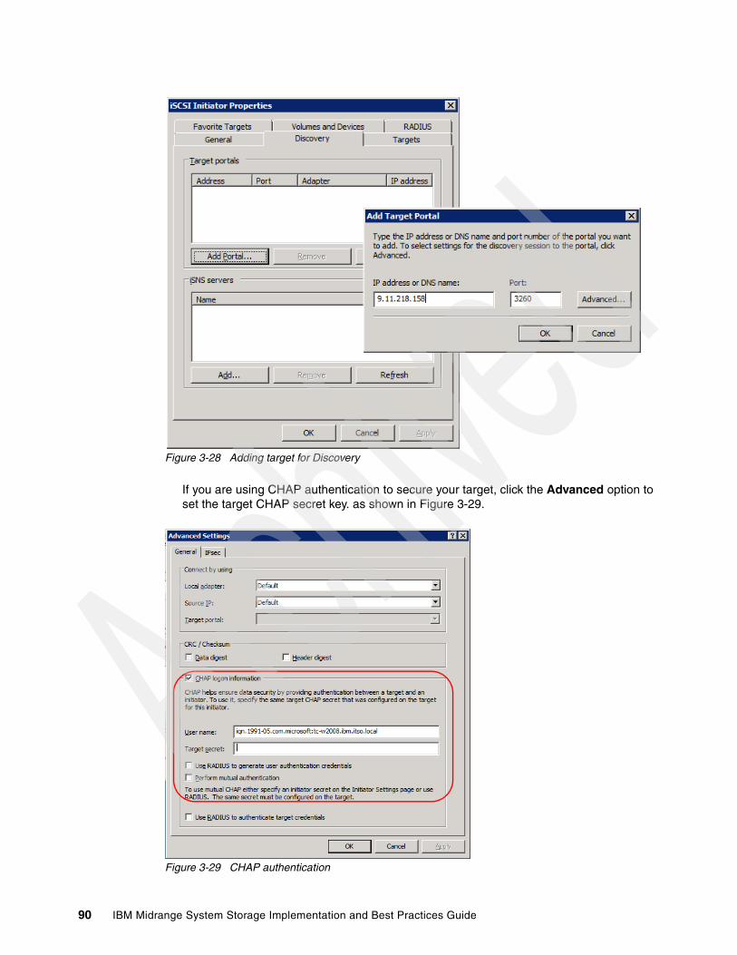
Figure 3-28 Adding target for Discovery
If you are using CHAP authentication to secure your target, click the Advanced option to set the target CHAP secret key. as shown in Figure 3-29.
Figure 3-29 CHAP authentication
90 IBM Midrange System Storage Implementation and Best Practices Guide
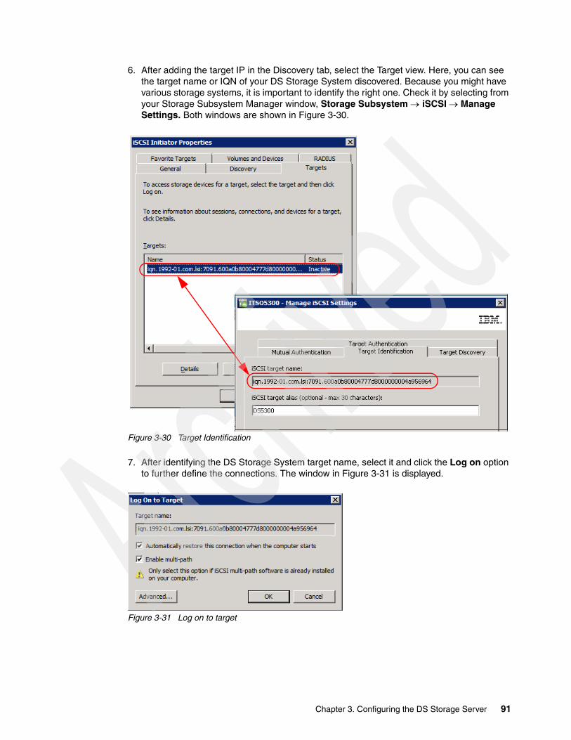
6. After adding the target IP in the Discovery tab, select the Target view. Here, you can see the target name or IQN of your DS Storage System discovered. Because you might have various storage systems, it is important to identify the right one. Check it by selecting from your Storage Subsystem Manager window, Storage Subsystem iSCSI Manage Settings. Both windows are shown in Figure 3-30.
Figure 3-30 Target Identification
7. After identifying the DS Storage System target name, select it and click the Log on option to further define the connections. The window in Figure 3-31 is displayed.
Figure 3-31 Log on to target
Chapter 3. Configuring the DS Storage Server 91
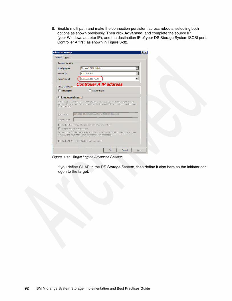
8. Enable multi path and make the connection persistent across reboots, selecting both options as shown previously. Then click Advanced, and complete the source IP (your Windows adapter IP), and the destination IP of your DS Storage System iSCSI port, Controller A first, as shown in Figure 3-32.
Figure 3-32 Target Log on Advanced Settings
If you define CHAP in the DS Storage System, then define it also here so the initiator can logon to the target.
Controller A IP address
92 IBM Midrange System Storage Implementation and Best Practices Guide

9. Click OK to finish the Advanced Settings, and OK again to finish the Log on process. The status of the Target changes from Inactive to Connected, as shown in Figure 3-33.
Figure 3-33 Target Connected
Now the DS Storage System is connected, by using only a connection to the A controller, based on the Destination target IP address given. We add the second path to the B controller, selecting our connected target name, and clicking Log On. These steps can be repeated until all paths are defined.
Chapter 3. Configuring the DS Storage Server 93

10.In the next window, check the multipath option again to automatically restore connections, as shown in Figure 3-34, and click Advanced.
Figure 3-34 Adding second path
In our previous example, the source IP address is the same for both paths defined, because this implementation example is using only one Ethernet card.
Controller B IP address
94 IBM Midrange System Storage Implementation and Best Practices Guide
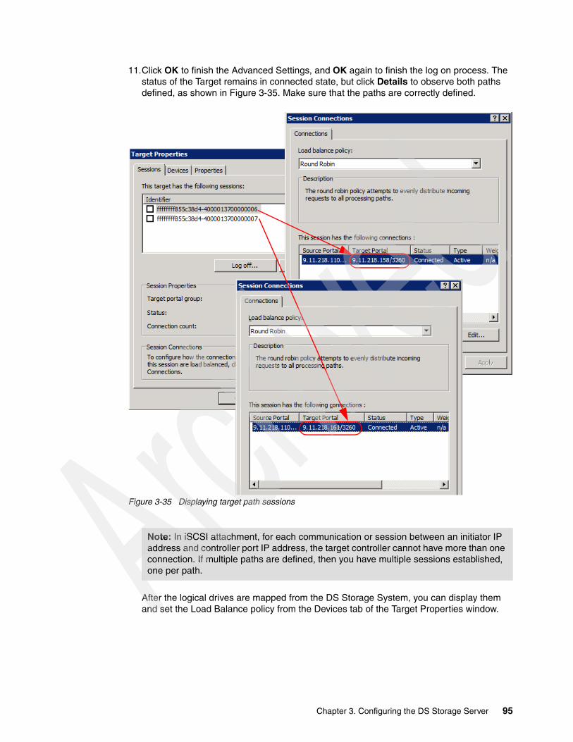
11.Click OK to finish the Advanced Settings, and OK again to finish the log on process. The status of the Target remains in connected state, but click Details to observe both paths defined, as shown in Figure 3-35. Make sure that the paths are correctly defined.
Figure 3-35 Displaying target path sessions
After the logical drives are mapped from the DS Storage System, you can display them and set the Load Balance policy from the Devices tab of the Target Properties window.
Note: In iSCSI attachment, for each communication or session between an initiator IP address and controller port IP address, the target controller cannot have more than one connection. If multiple paths are defined, then you have multiple sessions established, one per path.
Chapter 3. Configuring the DS Storage Server 95
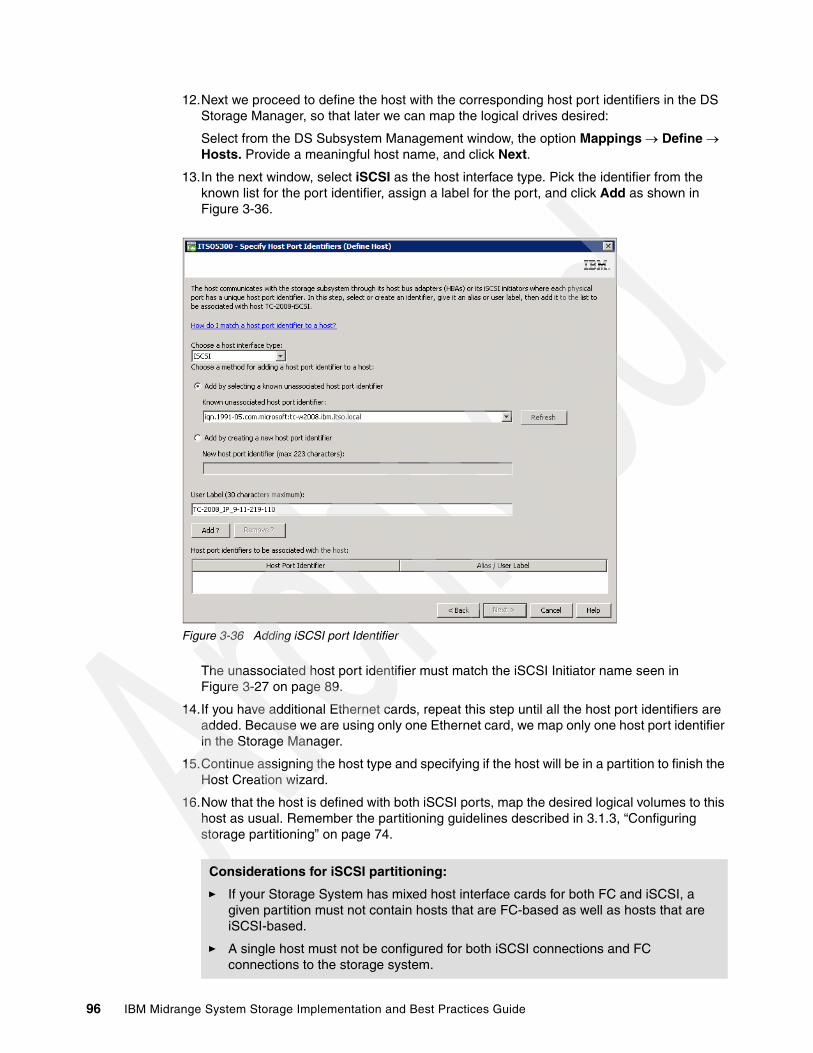
12.Next we proceed to define the host with the corresponding host port identifiers in the DS Storage Manager, so that later we can map the logical drives desired:
Select from the DS Subsystem Management window, the option Mappings Define Hosts. Provide a meaningful host name, and click Next.
13.In the next window, select iSCSI as the host interface type. Pick the identifier from the known list for the port identifier, assign a label for the port, and click Add as shown in Figure 3-36.
Figure 3-36 Adding iSCSI port Identifier
The unassociated host port identifier must match the iSCSI Initiator name seen in Figure 3-27 on page 89.
14.If you have additional Ethernet cards, repeat this step until all the host port identifiers are added. Because we are using only one Ethernet card, we map only one host port identifier in the Storage Manager.
15.Continue assigning the host type and specifying if the host will be in a partition to finish the Host Creation wizard.
16.Now that the host is defined with both iSCSI ports, map the desired logical volumes to this host as usual. Remember the partitioning guidelines described in 3.1.3, “Configuring storage partitioning” on page 74.
Considerations for iSCSI partitioning:
� If your Storage System has mixed host interface cards for both FC and iSCSI, a given partition must not contain hosts that are FC-based as well as hosts that are iSCSI-based.
� A single host must not be configured for both iSCSI connections and FC connections to the storage system.
96 IBM Midrange System Storage Implementation and Best Practices Guide

17.With the logical volumes mapped to the host, go to the Windows Device Manager and select the option Scan for hardware changes. You see the mapped LUNs under Disk Drives, each representing a LUN, with their internal paths.
18.Use the Devices tab in the Target Properties window now to see the detected LUNs. Select one device, click Advanced, and select the MPIO tab to view paths of the device, as in Figure 3-37. Confirm redundancy, making sure each device has a path to each controller.
Figure 3-37 Viewing MPIO path details
For additional information about using the mapped hosts and verifying multipath driver configuration, see Chapter 4, “Host configuration guide” on page 125.
We cover additional iSCSI settings such as security authentication, and iSNS target discovery in the following section.
Managing iSCSIFor a quick review of your current iSCSI configuration, you can select the Logical tab of the Subsystem Management window, and go down in the right frame to display iSCSI properties, as shown Figure 3-38.
Chapter 3. Configuring the DS Storage Server 97

Figure 3-38 Viewing iSCSI settings
In order to manage the iSCSI connections and configuration, select from Subsystem Management in the Storage Manager, Storage Subsystem iSCSI Manage Settings, as in Figure 3-39, or select the option Manage iSCSI Settings from the Setup tab.
Figure 3-39 iSCSI Manage Settings
98 IBM Midrange System Storage Implementation and Best Practices Guide
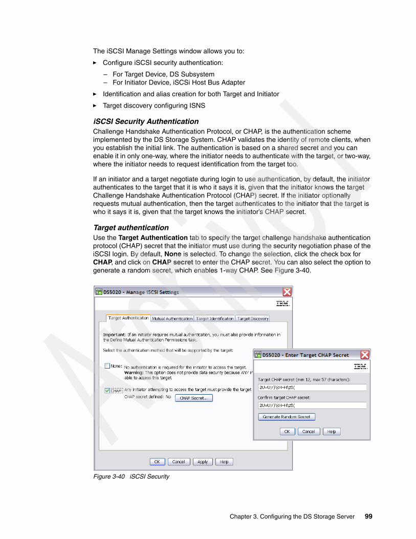
The iSCSI Manage Settings window allows you to:
� Configure iSCSI security authentication:
– For Target Device, DS Subsystem– For Initiator Device, iSCSi Host Bus Adapter
� Identification and alias creation for both Target and Initiator
� Target discovery configuring ISNS
iSCSI Security AuthenticationChallenge Handshake Authentication Protocol, or CHAP, is the authentication scheme implemented by the DS Storage System. CHAP validates the identity of remote clients, when you establish the initial link. The authentication is based on a shared secret and you can enable it in only one-way, where the initiator needs to authenticate with the target, or two-way, where the initiator needs to request identification from the target too.
If an initiator and a target negotiate during login to use authentication, by default, the initiator authenticates to the target that it is who it says it is, given that the initiator knows the target Challenge Handshake Authentication Protocol (CHAP) secret. If the initiator optionally requests mutual authentication, then the target authenticates to the initiator that the target is who it says it is, given that the target knows the initiator’s CHAP secret.
Target authenticationUse the Target Authentication tab to specify the target challenge handshake authentication protocol (CHAP) secret that the initiator must use during the security negotiation phase of the iSCSI login. By default, None is selected. To change the selection, click the check box for CHAP, and click on CHAP secret to enter the CHAP secret. You can also select the option to generate a random secret, which enables 1-way CHAP. See Figure 3-40.
Figure 3-40 iSCSI Security
Chapter 3. Configuring the DS Storage Server 99
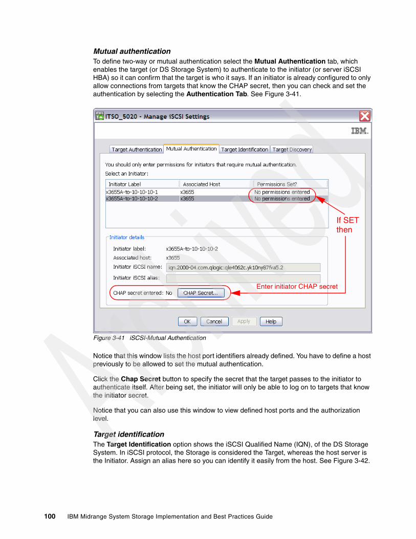
Mutual authenticationTo define two-way or mutual authentication select the Mutual Authentication tab, which enables the target (or DS Storage System) to authenticate to the initiator (or server iSCSI HBA) so it can confirm that the target is who it says. If an initiator is already configured to only allow connections from targets that know the CHAP secret, then you can check and set the authentication by selecting the Authentication Tab. See Figure 3-41.
Figure 3-41 iSCSI-Mutual Authentication
Notice that this window lists the host port identifiers already defined. You have to define a host previously to be allowed to set the mutual authentication.
Click the Chap Secret button to specify the secret that the target passes to the initiator to authenticate itself. After being set, the initiator will only be able to log on to targets that know the initiator secret.
Notice that you can also use this window to view defined host ports and the authorization level.
Target identificationThe Target Identification option shows the iSCSI Qualified Name (IQN), of the DS Storage System. In iSCSI protocol, the Storage is considered the Target, whereas the host server is the Initiator. Assign an alias here so you can identify it easily from the host. See Figure 3-42.
If SET
Enter initiator CHAP secret
then
100 IBM Midrange System Storage Implementation and Best Practices Guide
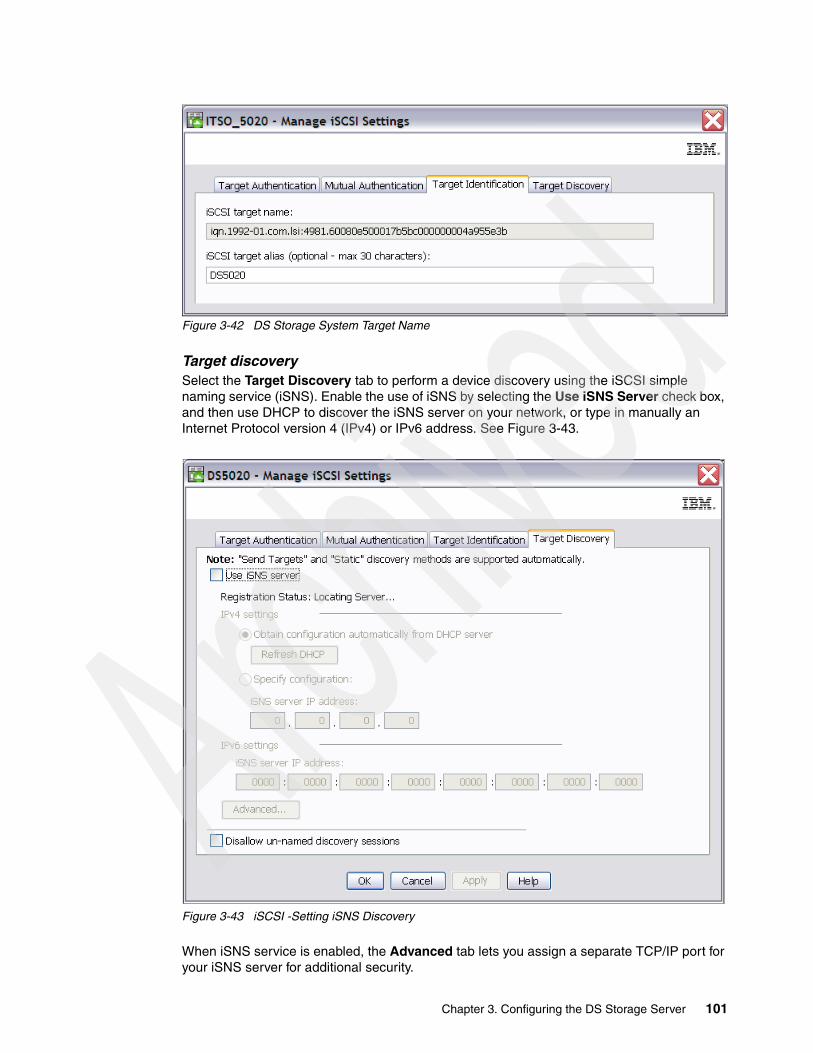
Figure 3-42 DS Storage System Target Name
Target discoverySelect the Target Discovery tab to perform a device discovery using the iSCSI simple naming service (iSNS). Enable the use of iSNS by selecting the Use iSNS Server check box, and then use DHCP to discover the iSNS server on your network, or type in manually an Internet Protocol version 4 (IPv4) or IPv6 address. See Figure 3-43.
Figure 3-43 iSCSI -Setting iSNS Discovery
When iSNS service is enabled, the Advanced tab lets you assign a separate TCP/IP port for your iSNS server for additional security.
Chapter 3. Configuring the DS Storage Server 101

Managing iSCSI sessionsFrom your Subsystem Management window, select Storage Subsystem iSCSI End Sessions (Figure 3-44). Doing this will not terminate any session unless you later select it.
Figure 3-44 Manage iSCSI Sessions
After selecting End Sessions, the following window opens. See Figure 3-45.
Figure 3-45 View/End iSCSI Sessions
102 IBM Midrange System Storage Implementation and Best Practices Guide
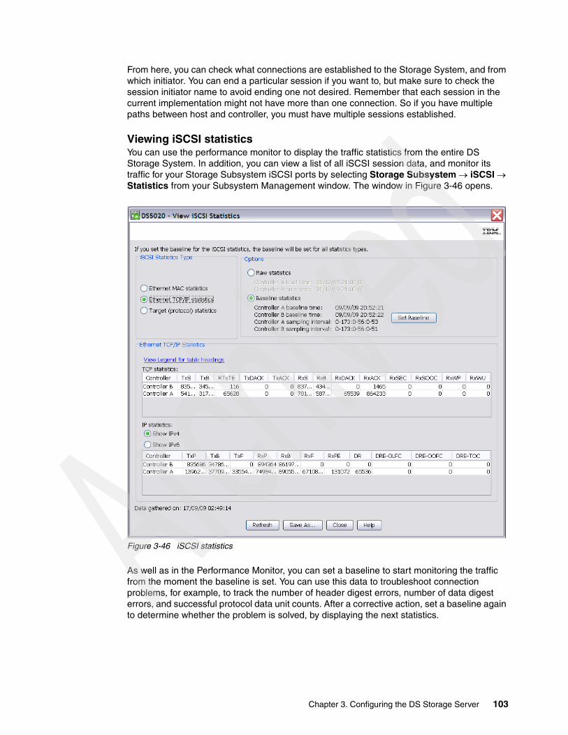
From here, you can check what connections are established to the Storage System, and from which initiator. You can end a particular session if you want to, but make sure to check the session initiator name to avoid ending one not desired. Remember that each session in the current implementation might not have more than one connection. So if you have multiple paths between host and controller, you must have multiple sessions established.
Viewing iSCSI statisticsYou can use the performance monitor to display the traffic statistics from the entire DS Storage System. In addition, you can view a list of all iSCSI session data, and monitor its traffic for your Storage Subsystem iSCSI ports by selecting Storage Subsystem iSCSI Statistics from your Subsystem Management window. The window in Figure 3-46 opens.
Figure 3-46 iSCSI statistics
As well as in the Performance Monitor, you can set a baseline to start monitoring the traffic from the moment the baseline is set. You can use this data to troubleshoot connection problems, for example, to track the number of header digest errors, number of data digest errors, and successful protocol data unit counts. After a corrective action, set a baseline again to determine whether the problem is solved, by displaying the next statistics.
Chapter 3. Configuring the DS Storage Server 103

3.1.5 Configuring for Copy Services functionsThe DS5000 Storage Server has a complete set of Copy Services functions that can be added to it. These features are all enabled by premium feature keys, which come in the following types:
� FlashCopy:
FlashCopy is used to create a point-in-time image copy of the base LUN for use by other system applications while the base LUN remains available to the base host application. The secondary applications can be read-only, such as a backup application, or they might also be read/write, for example, such as a test system or analysis application. For more in-depth application uses, it is a best practice to use your FlashCopy image to create a VolumeCopy, which will be a complete image drive and fully independent of the base LUN image.
� VolumeCopy:
VolumeCopy creates a complete physical replication of one logical drive (source) to another (target) within the same storage subsystem. The target logical drive is an exact copy or clone of the source logical drive. This feature is designed as a system management tool for tasks such as relocating data to other drives for hardware upgrades or performance management, data backup, and restoring snapshot logical drive data. Because VolumeCopy is a full replication of a point-in-time image, it allows for analysis, mining, and testing without any degradation of the production logical drive performance. It also brings improvements to backup and restore operations, making them faster and eliminating I/O contention on the primary (source) logical drive. The use of the FlashCopy Volume copy combined process is a best practice when used with ERM for Business Continuance and Disaster Recovery (BCDR) solutions with short recovery time objectives (RTOs).
� Enhanced Remote Mirroring:
Enhanced Remote Mirroring (ERM) is used to allow mirroring to another DS Storage Server either co-located, or situated at another site. The main usage of this premium feature is for to enable business continuity in the event of a disaster or unrecoverable error at the primary storage server. It achieves this by maintaining two copies of a data set in two separate locations, on two or more separate storage servers, and enabling a second storage subsystem to take over responsibility. Methods available for use with this feature are: synchronous, asynchronous, and asynchronous with write order consistency (WOC).
To connect both DS Storage Systems, only FC is allowed, not iSCSi host interface cards.
Configurations of all of these features are documented in great detail in IBM Midrange System Storage Hardware Guide, SG24-7676 and IBM Midrange System Storage Copy Services Guide, SG24-7822.
Note: Enhanced Remote Mirror is only allowed using Fibre Channel Host Interface Cards, not with the iSCSI host interfaces. After the mirror ports are presented in the SAN, then you can use FC-IP routers to reach the destination DS Storage Subsystem.
104 IBM Midrange System Storage Implementation and Best Practices Guide
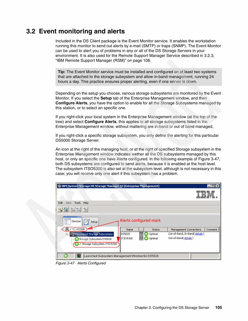
3.2 Event monitoring and alertsIncluded in the DS Client package is the Event Monitor service. It enables the workstation running this monitor to send out alerts by e-mail (SMTP) or traps (SNMP). The Event Monitor can be used to alert you of problems in any or all of the DS Storage Servers in your environment. It is also used for the Remote Support Manager Service described in 3.2.3, “IBM Remote Support Manager (RSM)” on page 108.
Depending on the setup you choose, various storage subsystems are monitored by the Event Monitor. If you select the Setup tab of the Enterprise Management window, and then Configure Alerts, you have the option to enable for all the Storage Subsystems managed by this station, or to select an specific one.
If you right-click your local system in the Enterprise Management window (at the top of the tree) and select Configure Alerts, this applies to all storage subsystems listed in the Enterprise Management window, without mattering are in-band or out of band managed.
If you right-click a specific storage subsystem, you only define the alerting for this particular DS5000 Storage Server.
An icon at the right of the managing host, or at the right of specified Storage subsystem in the Enterprise Management window indicates wether all the DS subsystems managed by this host, or only an specific one have Alerts configured. In the following example of Figure 3-47, both DS subsystems are configured to send alerts, because it is enabled at the host level. The subsystem ITSO5300 is also set at the subsystem level, although is not necessary in this case; you will receive only one alert if this subsystem has a problem.
Figure 3-47 Alerts Configured
Tip: The Event Monitor service must be installed and configured on at least two systems that are attached to the storage subsystem and allow in-band management, running 24 hours a day. This practice ensures proper alerting, even if one server is down.
Alerts configured mark
Chapter 3. Configuring the DS Storage Server 105

See the IBM Midrange System Storage Hardware Guide, SG24-7676, for specific details about configuring event notifications. For example:
� You can configure alert notifications for all your DS storage subsystems, or at least, for your most critical DS Storage Systems.
� As a best practice, configure your critical system with both in-band and out of band management capabilities, so in case of problems with one of the management methods, you are still notified.
� Make sure that the Event Monitor service is installed and running as an automatic service in at least two systems attached to your DS subsystems, and allow in-band management, running 24 hours a day. This practice ensures proper alerting, even if one server is down, although you will receive duplicate messages.
� You can replicate the alert settings defined in the first Storage Management station by copying the emwdata.bin generated in the file to every storage management station from which you want to receive alerts.
� If you do not install the Event Monitor, or if the active process or service is stopped, then alerts are not sent unless the Storage Management station is open.
� If you want to send e-mail alerts, you have to define an SMTP server first, and then the e-mail addresses to which alerts are sent. If you do not define an address, no SMTP alerts are sent.
� Make sure to take the option to test a notification to the added e-mail addresses to ensure a correct delivery and test your setup.
� If you choose the SNMP tab, you can define the settings for SNMP alerts: the IP address of your SNMP console and the community name. As with the e-mail addresses, you can define several trap destinations, and test each one for correct operation.
� You need an SNMP console for receiving and handling the traps sent by the service. There is an MIB file included in the Storage Manager software, which must be compiled into the SNMP console to allow proper display of the traps. See the documentation for the SNMP console that you are using to learn how to compile a new MIB.
� With these notifications set, and the appropriate software, you can forward these alerts to your pager or cell phone.
3.2.1 ADT alert notificationADT alert notification, which is provided with Storage Manager, accomplishes three things:
� It provides notifications for persistent “Logical drive not on preferred controller” conditions that resulted from ADT.
� It guards against spurious alerts by giving the host a “delay period” after a preferred controller change, so it can get reoriented to the new preferred controller.
� It minimizes the potential for the user or administrator to receive a flood of alerts when many logical drives fail over at nearly the same point in time due to a single upstream event, such as an HBA failure.
Upon an ADT event or an induced logical drive ownership change, the DS5000 controller firmware waits for a configurable time interval, called the alert delay period, after which it reassesses the logical drive distribution among the arrays.
Best practice: Configure alert notifications through SNMP, e-mail, or both, to receive instant notifications of all critical events of your Storage Subsystem. Such alerts can help you take the appropriate corrective action as soon as the problem is logged.
106 IBM Midrange System Storage Implementation and Best Practices Guide
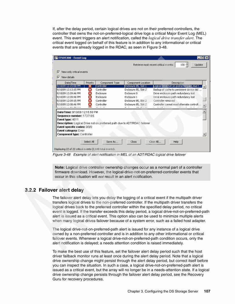
If, after the delay period, certain logical drives are not on their preferred controllers, the controller that owns the not-on-preferred-logical drive logs a critical Major Event Log (MEL) event. This event triggers an alert notification, called the logical drive transfer alert. The critical event logged on behalf of this feature is in addition to any informational or critical events that are already logged in the RDAC, as seen in Figure 3-48.
Figure 3-48 Example of alert notification in MEL of an ADT/RDAC logical drive failover
3.2.2 Failover alert delayThe failover alert delay lets you delay the logging of a critical event if the multipath driver transfers logical drives to the non-preferred controller. If the multipath driver transfers the logical drives back to the preferred controller within the specified delay period, no critical event is logged. If the transfer exceeds this delay period, a logical drive-not-on-preferred-path alert is issued as a critical event. This option also can be used to minimize multiple alerts when many logical drives failover because of a system error, such as a failed host adapter.
The logical drive-not-on-preferred-path alert is issued for any instance of a logical drive owned by a non-preferred controller and is in addition to any other informational or critical failover events. Whenever a logical drive-not-on-preferred-path condition occurs, only the alert notification is delayed; a needs attention condition is raised immediately.
To make the best use of this feature, set the failover alert delay period such that the host driver failback monitor runs at least once during the alert delay period. Note that a logical drive ownership change might persist through the alert delay period, but correct itself before you can inspect the situation. In such a case, a logical drive-not-on-preferred-path alert is issued as a critical event, but the array will no longer be in a needs-attention state. If a logical drive ownership change persists through the failover alert delay period, see the Recovery Guru for recovery procedures.
Note: Logical drive controller ownership changes occur as a normal part of a controller firmware download. However, the logical-drive-not-on-preferred-controller events that occur in this situation will not result in an alert notification.
Chapter 3. Configuring the DS Storage Server 107

Considerations for failover alerts
Changing the failover alert delayTo change the failover alert delay, follow these steps:
1. Select the storage subsystem from the Subsystem Management window, and then select either the Storage Subsystem Change Failover Alert Delay menu option, or right-click and select Change Failover Alert Delay. See Figure 3-49.
Figure 3-49 Changing the failover alert delay
2. In the Failover Alert Delay dialog box opens, enter the desired delay interval in minutes and click OK.
3.2.3 IBM Remote Support Manager (RSM)The IBM Remote Support Manager for Storage (RSM for Storage) is a non-charge software package that installs on an IBM System x server running Novell SUSE Linux Enterprise Server 9, SUSE Linux Enterprise Server 10, Red Hat Enterprise Linux 4 Advanced Server, or Red Hat Enterprise Linux 5. It provides problem reporting and remote access for IBM Service for the DS3000, DS4000, and DS5000 families of IBM Storage Systems.
Important: Here are several considerations regarding failover alerts:
� The failover alert delay option operates at the storage subsystem level, so one setting applies to all logical drives.
� The failover alert delay option is reported in minutes in the storage subsystem profile as a storage subsystem property.
� The default failover alert delay interval is five minutes. The delay period can be set within a range of 0 to 60 minutes. Setting the alert delay to a value of zero results in instant notification of a logical drive not on the preferred path. A value of zero does not mean that alert notification is disabled.
� The failover alert delay is activated after controller start-of-day completes to determine if all logical drives were restored during the start-of-day operation. Thus, the earliest that the not-on-preferred path alert will be generated is after boot up and the configured failover alert delay.
108 IBM Midrange System Storage Implementation and Best Practices Guide

RSM relies on the Event Monitor for problem reporting. The problem reporting provided by the RSM application automatically creates an entry in the IBM call management system for each storage subsystem that reports a problem. Monitoring of storage subsystems is performed by your existing IBM Storage Manager application, which is configured to send SNMP traps to the Remote Support Manager when critical events are detected.
RSM must be installed on a dedicated workstation. IBM service personnel can remotely access the RSM server through a modem connection and a command line interface. but only after access has been authorized. Files and logs needed for problem determination are sent to IBM using e-mail or an FTP connection using the RSM server Ethernet interface.
After being installed, the server can be considered a single purpose appliance for problem reporting and remote access support for your DS5000 storage subsystems.
Isolation of remote and local users of the system from other devices on your intranet is performed by an internal firewall that is managed by the RSM for Storage application. Remote users do not have the ability to change any security features of the application.
One RSM for Storage system can support up to 50 subsystems. The RSM for Storage system must have IP connectivity to the Ethernet management ports of the subsystems.
RSM for Storage has the following hardware and software requirements.
Hardware requirementsRSM for Storage can be run on a dedicated System x server or in a VMware client running on a System x server. IBM internal databases that support RSM for Storage use the IBM Machine Type and Serial Numbers of the servers, and therefore an IBM System x server must be used, which is required in order to properly register heartbeat records from the RSM for Storage system in IBM tracking databases.
For the minimum server requirements and a list of the specific servers that have been tested with the RSM software, see the IBM RSM for Storage Compatibility Guide, available at:
http://www.ibm.com/support/docview.wss?uid=psg1MIGR-66062&rs=594
Tested serversThe following servers have been tested with the RSM for Storage software, and installation instructions are available for configuring and using them with RSM for Storage software:
� x3250 4364� x306m 8849 � x3550 7978� IBM 1818-RS1*� IBM 1818-RS2*
IBM Remote Support Manager for Storage: Installation Hints and Tips contains specific information about the BIOS configuration and device drivers that might be required to install the Linux OS on the servers just mentioned. You can find this document at the Web site:
http://www.ibm.com/support/docview.wss?uid=psg1MIGR-66062&rs=594
Note: The IBM System Storage DS Remote Support Manager for the Storage (DS-RSM) IBM 1818 Model RS2 server is available to simplify the task of obtaining the hardware and software components required for running the RSM for Storage software, because it is preloaded with Novell SLES 10 and RSM for Storage software that is ready configure. The DS-RSM Model RS2 can be ordered as an appliance with your IBM DS Storage Subsystem.
Chapter 3. Configuring the DS Storage Server 109

Other IBM serversYou can use other System x servers that meet these requirements:
� Memory: 512 MB of memory is necessary.
� Disk space: 20 GB of disk space is required.
� Serial port: The serial port must be on the server system board. Certain servers have a build-in Remote Supervisor Adapter (RSA) that also includes a serial port. The serial port on the RSA cannot be accessed by the RSM for Storage software.
� Ethernet port: If your SAN devices are on a private management LAN, a second Ethernet port for accessing your company's SMTP server and the Internet will be required if your selected server has only a single Ethernet port.
The IBM RSM for Storage Compatibility Guide also contains the setup required for a VMware client that will host the Linux operating system running RSM for Storage. See the Web site:
http://www.ibm.com/support/docview.wss?uid=psg1MIGR-66062&rs=594
RSM for Storage in a VMware Virtual ClientRSM for Storage has been tested for operation in a VMware virtual client. See the aforementioned IBM RSM for Storage Compatibility Guide for specific configurations.
In setting up the virtual client, allocate the following resources:
� Storage: 20 GB.� Memory: 512 MB.� Ownership: Assign exclusive physical ownership of the host system’s first serial port to the
virtual client as /dev/ttyS0.
The client must be configured to start automatically when the host reboots.
RSM for Storage has been tested on both SLES 10 and RHEL 5 running on a System x server with:
� VMware Server 1.05� VMware ESX Server 3
Software requirementsThe RSM for Storage software requires the following prerequisite software to monitor an IBM Midrange Storage Subsystem:
� IBM Storage Manager V9.16 or later (the latest version is preferable) with Event Monitor installed on a management station in another server.
� Storage subsystems with controller firmware supported by Storage Manager V9.16 or later. The latest supported firmware version is preferable.
� One of the following operating systems to install the RSM for Storage software:
– Novell SUSE Linux Enterprise Server 9 (SP3, or SP4) – Novell SUSE Linux Enterprise Server 10 (Base, SP1, or SP2)– Red Hat Enterprise Linux 4 AS (Update 4, 5, or 5)– Red Hat Enterprise Linux 5 (Base, Update 1, or 2)
Note: To use servers other than those specifically tested with RSM for Storage, see the System x server support Web site for technical information about BIOS configuration and device drivers that might be required to install the Linux OS or configure the server’s internal RAID capability.
110 IBM Midrange System Storage Implementation and Best Practices Guide

The RSM for Storage software receives SNMP traps from the Event Monitor included with IBM DS Storage Manager. Be aware that the RSM for Storage software cannot be installed on the same system used to manage your storage network.
How RSM for Storage worksRSM for Storage uses an Ethernet connection for problem reporting and a modem (optional) for remote access by IBM Service, as shown in Figure 3-50. The storage system can be any supported IBM Midrange disk subsystem.
Figure 3-50 RSM for Storage connection
The RSM for Storage server must have IP connectivity to the Ethernet management ports of the storage subsystems to be monitored and the management station running IBM Storage Manager’s Event Monitor. It is also required that all storage subsystems, the management station, the e-mail server, and Internet gateway are accessible from the RSM server without requiring authorization through a firewall.
If your managed storage subsystems or other SAN devices are on a private management LAN, a second Ethernet port for accessing your company's SMTP server and the Internet will be required if your selected RSM server has only a single Ethernet port (see Figure 3-50).
Figure 3-50 shows that certain storage subsystems and other SAN devices are managed through a private management LAN and the others are managed through the customer intranet. Therefore, the RSM server in this instance needs at least two network adapters.
Note: See the IBM RSM for Storage Compatibility Guide for the latest update of supported servers, modem, and operating systems. This guide can be downloaded from the following Web page:
http://www.ibm.com/support/docview.wss?uid=psg1MIGR-66062&rs=594
Chapter 3. Configuring the DS Storage Server 111
After RSM is installed, configured, and activated, here are the steps in a sample scenario for RSM. See Figure 3-50 on page 111 to understand the flow:
1. Suppose that an error occurs in one of the storage subsystems and a critical event is logged in the management station (running DS Storage Manager).
2. The management station reports the critical event to the RSM server through an SNMP trap. The RSM system receives notification of the critical event and sends an alert to IBM Service.
When an alert is received from the management station, RSM downloads logs and other problem determination data, such as the Major Event Log (MEL), Read Link Status (RLS), and storage system profile of the storage subsystem’s controllers that reports the problem using the out-of-band Ethernet interfaces, and sends them along with the alert to IBM Service by e-mail.
SNMP traps are sent by the IBM Storage Manager client or the IBM Storage Manager's Event Monitor service. Make sure to install Event Monitor service if you plan on not leaving the Storage Manager Client running all the time. See the Storage Manager documentation to check the installation of Event Monitor.
See 3.2, “Event monitoring and alerts” on page 105 to configure the SNMP trap in Storage Manager.
3. IBM Support does problem determination based on information sent by the alert along with the problem determination data, such as MEL, RLS, and the subsystem profile. If the problem can be fixed with existing information, IBM Support contacts the customer either by phone or e-mail to resolve the problem. After the problem is solved, either IBM Support or the customer must indicate Service Complete for all alerts in the RSM. IBM Support can dial to the RSM modem or use an SSH connection to specify acknowledge and indicate Service Complete for all alerts for the subsystem.
4. If the problem cannot be fixed with existing information, IBM Support dials the RSM modem or uses an SSH connection, acknowledges the alert, and performs troubleshooting by connecting to the storage subsystem using the command line interface (SMcli) or RLOGIN. IBM Support might need to contact the customer to obtain the password for the storage subsystem to use SMcli. IBM might also have to contact the customer to enable RLOGIN access. As a best practice, disable RLOGIN and enable it only when needed.
If IBM Support needs to send or upload logs or other information from the RSM server to IBM, they can use FTP or e-mail commands from the Linux shell at the RSM server while connected through the modem line or using SSH connection. Any data connected is sent to an IBM server through a customer network, not through the modem line (the modem connection is a TTY serial console, not an IP connection).
5. After the problem is resolved, all alerts must be closed either by IBM Support or the customer before reporting will resume for that subsystem.
Security considerationsAdding a modem to one of your systems creates a potential entry point for unauthorized access to your network. The RSM for Storage application modifies many characteristics and behaviors of the system that it is installed on, to protect this entry point and to maximize the amount of control you have in managing remote access. To ensure the integrity of these
Note: After the RSM for Storage reports a problem to IBM for a given subsystem, no additional problems will be reported to IBM for that particular subsystem until all existing alerts are closed.
112 IBM Midrange System Storage Implementation and Best Practices Guide
controls, you must consider the server that the RSM for Storage application is installed on, to be a single purpose appliance.
There are several security features in RSM for Storage to maximize protection from unauthorized access. Remote access to your system has the following four layers of control:
� The modem is configured to answer only when remote access is enabled by the RSM for Storage software. Likewise, the SSH daemon is only allowed to respond to connection attempts when remote access is enabled:
– You can manually enable and disable remote access, or you can choose to have remote access automatically enabled when a storage subsystem reports a problem. When remote access is enabled, a timer is started that will automatically disable remote access when it expires. You do not have to remember to make the system secure after service has been completed.
– The person identified as the primary contact for the RSM for Storage system is notified by e-mail whenever a change in the remote access settings occurs, and all state changes are also written to the Security Log.
� The userid reserved for remote access (rservice) is only valid when remote access is enabled. Attempts to log in using the root, admin or lservice userids are rejected.
� The initial login password is changed daily at midnight UTC. IBM Service has an internal tool that provides the current password for RSM for Storage systems.
� After validation of the initial login password, remote users are presented with a challenge string, which also requires access to an internal IBM tool in order to obtain the correct response. The response also includes an IBM employee user name that is recorded in the RSM for Storage Security Log.
User IDDuring installation, the RSM software creates three user IDs:
� admin: This is the administrative user that can perform management and configuration tasks.
� lservice: This is the local service user intended for use by IBM Service when on site. This user ID has certain restrictions on directories it can access. This precaution is to prevent any configuration change that might affect the security of the system.
� rservice: This is the remote service (IBM Service) user that is used exclusively for remote access to the system and only valid when remote access is enabled. This user ID also does not have the ability to change any of the RSM security features.
Passwords for user ID admin and lservice for the RSM for Storage browser user interface can be changed by the Linux root user using the command rsm-passwd admin or rsm-passwd lservice. The best practice is to set a separate password for each user ID.
For the remote user (rservice), the password is automatically generated by RSM and it is changed daily at midnight UTC. IBM Service has an internal tool that provides the current password, so you do not need to provide the current RSM password to IBM Service.
The Switch User (su) command is disabled to prevent a normal user from attempting to become “root” and have unrestricted access to the system. The RSM for Storage software makes other changes in program and directory permissions to limit what programs and files these users can access.
Internal firewallRSM for Storage includes an internal firewall to limit the scope of access that a remote user has to your network. Without an internal firewall, the remote user can have unrestricted
Chapter 3. Configuring the DS Storage Server 113
access to your network. The RSM software configures an internal firewall on the RSM system to limit the scope of access that users of the RSM system have to your network. See Figure 3-50 on page 111 for an illustration.
When no alerts are active, the firewall only allows incoming SNMP traps and outbound SMTP e-mail. When an alert occurs, a rule is automatically added to the firewall to allow access to the configured controllers for the storage subsystem reporting the problem. There might be times when you want to allow IBM Service to be able to access a device to troubleshoot a problem (such as a performance issue) for a subsystem that is not reporting a failure. You can manually enable “Service Access” for any configured storage subsystem. Service Access settings have a configurable time-out from 12 to 96 hours, after which the firewall rules for access are removed.
Firewall rules added for a device that is reporting an alert are removed when the alert is closed on the RSM for Storage system. While the internal firewall effectively limits the scope of access for remote users, at the same time it also limits the access of any program running on the server. Because management applications such as IBM Storage Manager or IBM Director require access to all devices being managed, the presence of this internal firewall prevents the use of the RSM server as a management station. Therefore the RSM for Storage system must be considered to be a single purpose appliance dedicated to problem reporting and remote access for IBM Service.
The configurations of all of these features are documented in great detail in the IBM Midrange System Storage Hardware Guide, SG24-7676.
3.3 Software and microcode upgradesPeriodically, IBM releases new firmware (which is posted on the support the Web site) that will need to be installed. Occasionally, IBM might remove old firmware versions from support. Upgrades from unsupported levels are mandatory to receive warranty support.
Upgrades to the DS5000 Storage Server firmware must generally be preceded by an upgrade to the latest available version of the Storage Manager client software because this might be required to access the DS Storage Server when the firmware upgrade completes. In most cases, it is possible to manage a DS Storage Server running down-level firmware with the latest SMclient, but not possible to manage a storage server running the latest version of firmware with a down-level client. In certain cases the only management capability provided might be to upgrade the firmware to newer level; which is the desired goal.
3.3.1 Staying up-to-date with your drivers and firmware using My supportMy support registration provides E-mail notification when new firmware levels have been updated and are available for download and installation. To register for My support, visit:
http://www.ibm.com/support/mysupport/us/en
Here we describe the registration process.
Note: The version number of the Storage Manager firmware and the Storage Manager client are not completely connected. For example, Storage Manager 10.60 can manage storage servers that are running storage server firmware 5.41or later on them.
Always check the readme file for details of the latest storage manager release and special usage.
114 IBM Midrange System Storage Implementation and Best Practices Guide

1. The Sign In window displays:
– If you have a valid IBM ID and password, then sign in.– If you are not currently registered with the site, click Register now and register your
details.
2. If this is your first time on the Notifications Web site, or subscribing to any Disk Systems product, click Subscribe, then select Disk Systems under Storage, and click each of the products you want to receive notifications.
If you are already subscribed for any Disk Systems products, click My Subscriptions, then click your Subscription folder for Disks Products, and then click edit for the Disk Systems category.
3. Select all the products of your interest to receive notifications and then click Continue
4. Complete the remaining fields for your new subscription, select the frequency of the notifications, daily or weekly, and click Submit
5. Click Sign Out to log out of My Support.
You will be notified whenever there is new firmware available for the products you selected during registration
Also, explore and customize to your needs the other options available under My support. If you need more details on the My Support configuration, see the following presentation:
ftp://ftp.software.ibm.com/systems/support/tools/mynotifications/overview.pdf
3.3.2 Compatibility matrixIn order to stay at a supported level for all your components of the solution, any time you need to upgrade your OS version, driver, firmware, etc. plan ahead your changes checking also in the IBM System Storage Interoperation Center (SSIC) Web site for latest
http://www.ibm.com/systems/support/storage/config/ssic/index.jsp
3.3.3 DS firmware components and prerequisitesThe microcode of the DS Storage Server is separated in the following packages:
� The Storage Manager package� The Controller Firmware package, including NVSRAM and scripts for specific usage� The environmental service module (ESM) and Hard disk drive (HDD) package
The Storage Manager package includes a set of client and host tools to manage your Storage subsystem form your management workstation.
The firmware and the NVSRAM are closely tied to each other and are therefore not independent. Be sure to install the correct combination of the two packages. The NVSRAM is similar to the settings in the BIOS of a host system. You can change certain specific settings using the scripts provided, with this package.
Upgrading the firmware and management software for the DS Storage Server is a relatively simple procedure. While it is not a requirement, when possible, schedule a maintenance window for all firmware updates, thus minimizing any possible exposure. The times for upgrading all the associated firmware and software are given in Table 3-2. These times are only approximate and can vary from system to system.
Note: Use the IBM System Interoperation Center Web site to check latest compatibility information before doing any change in your Storage Subsystem environment
Chapter 3. Configuring the DS Storage Server 115
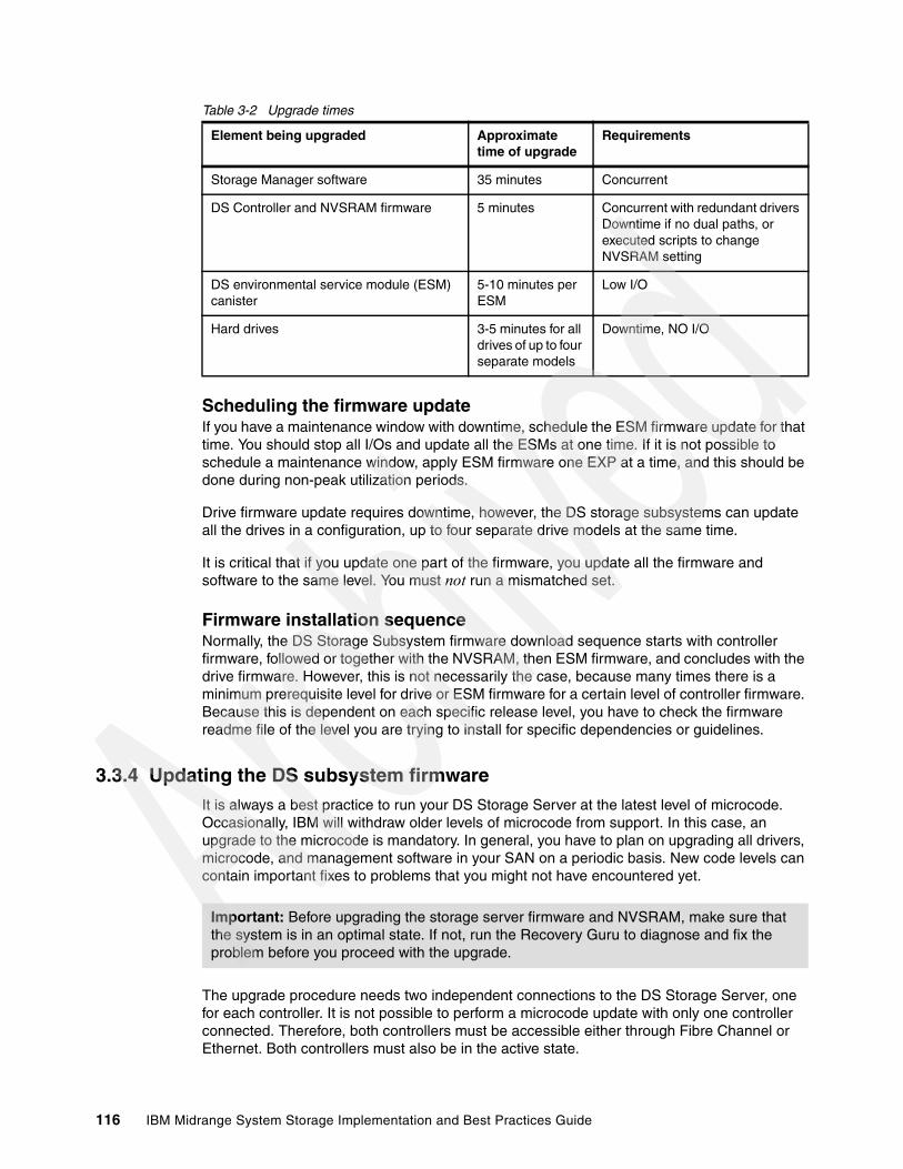
Table 3-2 Upgrade times
Scheduling the firmware updateIf you have a maintenance window with downtime, schedule the ESM firmware update for that time. You should stop all I/Os and update all the ESMs at one time. If it is not possible to schedule a maintenance window, apply ESM firmware one EXP at a time, and this should be done during non-peak utilization periods.
Drive firmware update requires downtime, however, the DS storage subsystems can update all the drives in a configuration, up to four separate drive models at the same time.
It is critical that if you update one part of the firmware, you update all the firmware and software to the same level. You must not run a mismatched set.
Firmware installation sequenceNormally, the DS Storage Subsystem firmware download sequence starts with controller firmware, followed or together with the NVSRAM, then ESM firmware, and concludes with the drive firmware. However, this is not necessarily the case, because many times there is a minimum prerequisite level for drive or ESM firmware for a certain level of controller firmware. Because this is dependent on each specific release level, you have to check the firmware readme file of the level you are trying to install for specific dependencies or guidelines.
3.3.4 Updating the DS subsystem firmwareIt is always a best practice to run your DS Storage Server at the latest level of microcode. Occasionally, IBM will withdraw older levels of microcode from support. In this case, an upgrade to the microcode is mandatory. In general, you have to plan on upgrading all drivers, microcode, and management software in your SAN on a periodic basis. New code levels can contain important fixes to problems that you might not have encountered yet.
The upgrade procedure needs two independent connections to the DS Storage Server, one for each controller. It is not possible to perform a microcode update with only one controller connected. Therefore, both controllers must be accessible either through Fibre Channel or Ethernet. Both controllers must also be in the active state.
Element being upgraded Approximate time of upgrade
Requirements
Storage Manager software 35 minutes Concurrent
DS Controller and NVSRAM firmware 5 minutes Concurrent with redundant driversDowntime if no dual paths, or executed scripts to change NVSRAM setting
DS environmental service module (ESM) canister
5-10 minutes per ESM
Low I/O
Hard drives 3-5 minutes for all drives of up to four separate models
Downtime, NO I/O
Important: Before upgrading the storage server firmware and NVSRAM, make sure that the system is in an optimal state. If not, run the Recovery Guru to diagnose and fix the problem before you proceed with the upgrade.
116 IBM Midrange System Storage Implementation and Best Practices Guide
Considerations for the upgradeIf you plan to upgrade doing in-band management, make sure that you have a multipath I/O driver installed on your management host. This precaution is necessary because access logical drive moves from one controller to the other during this procedure and the DS Storage Server must be manageable during the entire time.
Controller microcode upgradeAs mentioned before, DS Storage subsystem, controller firmware can be updated concurrently as long as you have dual paths to all the hosts using the storage.
You can load the controller firmware and NVSRAM to a designated flash area on the DS controllers and activate it at a later time, staged microcode upgrade. Of course, you can still transfer the controller microcode to the storage subsystem and activate it in one step, which is the preferable method if you are doing in a maintenance window or during a non peak hours as an additional precaution.
Download the controller firmware and NVSRAM at the same time by selecting the option check box in the controller firmware download window. However if you have executed any any script to change the host parameters NVSRAM settings (like Enable AVT on Windows), downloading NVSRAM will overwrite those changes, changing the current behavior of your Storage Subsystem. In that case, schedule the controller firmware and NVSRAM during a maintenance window, so you can reapply the modifications after loading the new NVSRAM file.
The firmware is transferred to one of the controllers. This controller copies the image to the other controller. The image is verified through a CRC check on both controllers. If the checksum is OK, the uploaded firmware is marked ready and available for activation. If one of the two controllers fails to validate the CRC, the image is marked invalid on both controllers and not available for activation. An error is returned to the management station as well.
Important: Here are various considerations for your upgrade:
� See the readme file to determine whether the ESM or the controllers must be upgraded first. In certain cases, the expansion enclosure ESMs must be updated to the latest firmware level before starting the controller update (outdated ESM firmware can make your expansion enclosures inaccessible after the DS Storage Server firmware update). In certain cases it is just the opposite.
� Ensure that all hosts attached to the DS Storage Server have a multipath I/O driver installed.
� Any power or Network/SAN interruption during the update process might lead to configuration corruption. Therefore, do not power off the DS Storage Server or the management station during the update. If you are using in-band management and have Fibre Channel hubs or managed hubs, then make sure no SAN connected devices are powered up during the update. Otherwise, this can cause a loop initialization process and interrupt the process.
Note: If you applied any changes to the NVSRAM settings, for example, running a script, you must re-apply them after the download of the new NVSRAM completes. The NVSRAM update resets all settings stored in the NVSRAM to their defaults.
Chapter 3. Configuring the DS Storage Server 117

The activation procedure is similar to previous firmware versions. The first controller moves all logical drives to the second one. Then it reboots and activates new firmware. After that it takes ownership of all logical drives, and the second controller is rebooted in order to have its new firmware activated. When both controllers are up again, the logical drives are redistributed to the preferred paths. Because the logical drives move between the controllers during the procedure and are all handled by just one controller at a certain point, the new firmware activation should be done when the disk I/O is relatively low.
A normal reboot of a controller or a power cycle of the DS does not activate the new firmware. It is only activated after the user has chosen to activate the firmware.
In addition to the normal procedure, if your DS Storage System controllers are currently running firmware version 7.36.08.00 or 7.36.12.00, you must install and execute DbFix Utility, before and after the upgrade to a higher level. see the “File System Check Utility_vXX.doc” document packaged with the DbFix utility for specific installation and usage instructions. The DbFix utility must be downloaded from the following LSI Web site:
http://www.lsi.com/support/sstor1/
For specific details and guided step by step procedure updating DS Storage System firmware, see the IBM Midrange System Storage Hardware Guide, SG24-7676.
3.3.5 Updating DS5000 host softwareThis section describes how to update the DS5000 software in Windows and Linux environments. This procedure is also covered in detail in Chapter 4, “Host configuration guide” on page 125 for various operating systems.
Updating in a Windows environmentTo update the host software in a Windows environment:
1. Verify that IBM HBA firmware and device driver versions are current, and at the supported level of compatibility from the host Storage Manager software and firmware you are installing (see the SSIC Web site). If they are not current, download the latest versions and study the readme file located with the device driver, then upgrade the device drivers.
2. From the IBM Disk Support Web site, (http://www-304.ibm.com/jct01004c/systems/support/storage/disk), select your DS storage hardware and click Download, then select the Storage Manager package for your operating system.
3. Begin the installation of your downloaded package in your server. Accept the license terms, and select Custom as the installation type.
4. In the next window, select the components to update, DS Storage Manager client, Utilities, Agent, MPIO drivers.
5. Because you are updating your installation, without uninstalling the previous version, the installation program detects existing versions of software components and presents the warning panel shown in Figure 3-51.
118 IBM Midrange System Storage Implementation and Best Practices Guide

Figure 3-51 Updating host software warning
6. As noticed, back up the file emwdata.bin in case of failures, copying it to other directory outside the installation folder of the Storage Manager. This file contains the alerts notifications setup.
7. Click OK to continue installation, confirming the remaining windows. You are normally requested to restart your machine after the installation finishes.
Updating in a Linux environmentTo update the host software in a Linux environment:
1. Uninstall the storage manager components in the following order:
a. DS5000 Runtime environmentb. SMutilc. RDACd. SMclient
2. Verify that IBM host adapter device driver versions are current. If they are not current, see the readme file located with the device driver and then upgrade the device drivers.
3. Install the storage manager components in the following order:
a. SMagentb. DS5000 Runtime environmentc. RDACd. SMutile. SMclient
Note: In pre-9.1x versions the SMagent was not used, and so did not need to be uninstalled.
Chapter 3. Configuring the DS Storage Server 119

3.4 Capacity upgrades, system upgradesThe DS Storage subsystem has the ability to accept new disks or EXP units dynamically, with no downtime to the DS unit. In fact, the DS5000 must remain powered on when adding new hardware.
3.4.1 Capacity upgrades and increased bandwidthWith the DS Storage Server you can add capacity by adding expansion enclosures or disks to the enclosure being used. Care must be taken when performing these tasks to avoid damaging the configuration currently in place. For this reason you must follow the detailed steps laid out for each part.
For more information, see the IBM Midrange System Storage Hardware Guide, SG24-7676.
After physical installation, use Storage Manager to create new arrays/LUNs, or extend existing arrays/LUNs. (Note that certain operating systems might not support dynamic LUN expansion.)
Observe these guidelines to add new disks to your configuration:
1. Make additions to the DS Storage Subsystem only while it is powered on and in optimal state.
2. To add new expansion enclosures, schedule the addition at a time period of low I/O between the DS Storage Subsystem and host servers. You can complete this process while the DS Storage Subsystem is receiving I/O from the hosts, however, you might have a performance problem while the drive loops are interrupted momentarily during the addition.
3. If these expansion enclosures or disks added are the first of this type in your DS configuration:
a. Review the minimum requirements of firmware for your DS Storage Subsystem, and its corresponding Storage Manager software. Also check the System Storage Interoperation Center (SSIC) Web site.
b. Check if your DS Storage Subsystem supports the new disk or expansion to add, and if the expansion supports the new disk type.
c. Check if the new hardware is compatible to operate in the current speed of the current drive side Fibre Channel speed.
4. Temporarily disable the alert monitoring, because it will report unnecessary drive enclosure lost redundancy path errors while the new expansion is connected.
Important: Prior to physically installing new hardware, see the instructions in the IBM System Storage DS4000/DS5000 Hard Disk Drive and Storage Expansion Enclosure Installation and Migration Guide, GC26-7849, available at:
http://www-947.ibm.com/systems/support/supportsite.wss/docdisplay?lndocid=MIGR-57818&brandind=5000028
Failure to consult this documentation might result in data loss, corruption, or loss of availability to your storage.
120 IBM Midrange System Storage Implementation and Best Practices Guide

3.4.2 Storage server upgrades The procedures to migrate disks and enclosures or upgrade to a newer DS Storage System controller are not particularly difficult, but care must be taken to ensure that data is not lost. The checklist for ensuring data integrity and the complete procedure for performing capacity upgrades or disk migration is beyond the scope of this book.
Here we explain the DS feature that makes it easy for upgrading subsystems and moving disk enclosures. This feature is known as DACstore.
DACstoreDACstore is an area on each drive in a storage subsystem or expansion enclosure where configuration information is stored. This 512 MB reservation (as pictured in Figure 3-52) is invisible to a user and contains information about the DS5000 configuration.
Figure 3-52 The DACstore area of a DS5000 disk drive
The standard DACstore on every drive stores:
� Drive state and status� WWN of the DS5000 controller (A or B) behind which the disk resides� Logical drives contained on the disk
Certain drives also store extra global controller and subsystem level information; these are called sundry drives. The DS5000 controllers will assign one drive in each array as a sundry drive, although there will always be a minimum of three sundry drives even if only one or two arrays exist.
Additional information stored in the DACstore region of the sundry drive includes:
� Failed drive information� Global Hot Spare state/status� Storage subsystem identifier (SAI or SA Identifier)� SAFE premium feature identifier (SAFE ID)� Storage subsystem password� Media scan rate� Cache configuration of the storage subsystem� Storage user label� MEL logs� LUN mappings, host types, and so on.� Copy of the controller NVSRAM
Chapter 3. Configuring the DS Storage Server 121

Why DACstore is usedThis particular feature of DS4000 storage servers offers a number of benefits:
� Storage system level reconfiguration: Drives can be rearranged within a storage system to maximize performance and availability through channel optimization.
� Low risk maintenance: If drives or disk expansion units are relocated, there is no risk of data being lost. Even if a whole DS4000 subsystem needed to be replaced, all of the data and the subsystem configuration can be imported from the disks.
� Data intact upgrades and migrations: All DS4000 subsystem recognize configuration and data from other DS4000 subsystems so that migrations can be for the entire disk subsystem as shown in Figure 3-53, or for array-group physical relocation as illustrated in Figure 3-54.
Figure 3-53 Upgrading DS4000 controllers
Figure 3-54 Relocating arrays
122 IBM Midrange System Storage Implementation and Best Practices Guide
Other considerations when adding expansion enclosures and drivesHere are various considerations to keep in mind:
� If new enclosures have been added to the DS Storage System, and you want to optimize your resulting configuration for maximum availability or performance, plan for the necessary downtime to re-distribute the physical drives of arrays between enclosures.
Drives can be moved from one slot (or enclosure, or loop) to another with no effect on the data contained on the drive. This operation must, however, be done following a specific procedure: exporting the array, removing array disks, reinserting all of them in their final destination, importing back the array. All must be done while the subsystem is online, as explained in the IBM System Storage DS4000/DS5000 Hard Disk Drive and Storage Expansion Enclosure Installation and Migration Guide
� When adding drives to an expansion unit, do not add more than two drives at a time.
� For maximum resiliency in the case of failure, arrays must be spread out among as many EXP units as possible. If you merely create a multi drive array in a new drawer every time you add an EXP, all of the traffic for that array will be going to that one tray, which can affect performance and redundancy (see also “Enclosure loss protection planning” on page 31).
� For best balance of LUNs and I/O traffic, drives must be added into expansion units in pairs. In other words, every EXP must contain an even number of drives, not an odd number such as 5.
� If you are utilizing two drive loop pairs, approximately half of the drives in a given array must be on each loop pair. In addition, for performance reasons, half of the drives in an array must be in even numbered slots, and half in odd-numbered slots within the EXP units. (The slot number affects the default loop for traffic to a drive.)
� To balance load among the two power supplies in an EXP, there must also be a roughly equal number of drives on the left and right hand halves of any given EXP. In other words, when adding pairs of drives to an EXP, add one drive to each end of the EXP.
The complete procedure for drive migration is given in the Fibre Channel Hard Drive and Storage Expansion Enclosure Installation and Migration Guide, GC26-7639.
Chapter 3. Configuring the DS Storage Server 123

Increasing bandwidthYou can increase bandwidth by moving expansion enclosures to a new or unused mini-hub pair (this doubles the drive-side bandwidth).
This reconfiguration can also be accomplished with no disruption to data availability or interruption of I/O.
Let us assume that the initial configuration is the one depicted on the left in Figure 3-55. We are going to move EXP2 to the unused mini-hub pair on the DS4500.
Figure 3-55 Increasing bandwidth
To move EXP2 to the unused mini-hub pair, proceed as follows:
1. Remove the drive loop B cable between the second mini-hub and EXP2 (cable labeled a). Move the cable from EXP2 going to EXP1 (cable labeled b, from loop B) and connect to the second mini-hub from EXP1 (cable labeled 1).
2. Connect a cable from the fourth mini-hub to EXP2, establishing drive loop D (represented by cable labeled 2).
3. Remove the drive loop A cable between EXP1 and EXP2 (cable labeled c) and connect a cable from the third mini-hub to EXP2, establishing drive loop C (represented by the cable, labeled 3).
124 IBM Midrange System Storage Implementation and Best Practices Guide

Chapter 4. Host configuration guide
In this chapter we explain how to manage your DS5000 Storage Server from the most common Host Servers and operating system environments. After describing the installation of the Storage Manager (SM) software, we explain how to verify a correct installation and show you how to view your storage logical drives from your hosts. We discuss specific tools and give you the commands necessary to use the tools from various operating systems such as Windows 2008, Linux, and AIX. Finally, we refer you to other sources of information for VMware, IBM i5/OS®, and HiperV.
We assume that you have already performed the necessary planning, and have set up and configured the DS Storage System.
Whatever operating system you have to connect to your DS Storage System, make sure to use the guidelines for levels of firmware and device driver levels of each component of the solution. For the supported levels, see the IBM System Storage Interoperation Center (SSIC) Web site:
http://www-03.ibm.com/systems/support/storage/config/ssic
If you need to update any components, you can find details at the IBM System Storage support Web site:
http://www-304.ibm.com/jct01004c/systems/support/storage/disk
4
© Copyright IBM Corp. 2004-2010. All rights reserved. 125

4.1 Windows 2008
In the following section, we present the steps that you need to perform from your Windows 2008 host in order to install and manage your DS Storage System from this operating system.
4.1.1 Installing Storage Manager software
This section covers a guided installation of the DS5000 Storage Manager V10.60 software in a Windows Server 2008 host environment. You can also use this information as a reference for installing in environments using Windows Server 2003 and DS4000.
The host software for Windows includes the following components:
� SMclient � Multipath driver � SMagent � SMutil
Follow these steps to install the software:
1. Log on with administrator rights for installing the new software, including new drivers.
2. Locate and run the installation executable file, either in the appropriate CD-ROM directory, or the file that you have downloaded from the IBM support Web site. After it has been executed, select your language of choice. After presenting the introduction and copyright statement windows, you are asked to accept the terms of the license agreement, which is required to proceed with the installation.
3. Select the installation target directory of your choice. The default installation path is:
C:\Program Files\IBM_DS
4. Select the installation type, as shown in Figure 4-1.
Figure 4-1 InstallAnywhere: Select Installation Type
a. Select the installation type to define the components that will be installed. In most cases, you can select either the Management Station or Host installation type. For example, if you select Management Station, then the multipath driver and Agent components will not be installed, because they are not required on the management computer.
126 IBM Midrange System Storage Implementation and Best Practices Guide

b. Decide what type of installation you want. Two additional choices are offered: Typical (Full Installation) and Custom. As the name indicates, Typical (Full Installation) installs all components and Custom installation lets you choose the components, as you can see in Figure 4-2.
Figure 4-2 InstallAnywhere: Select Storage Manager components
In addition to the usual Storage Manager components, you can choose to install Java Access Bridge. This selection enables support for the window reader (such as JAWS from Freedom Scientific, Inc.) for blind or visually impaired users.
5. Decide whether you want to automatically start the Storage Manager Event Monitor, as shown in Figure 4-3, which depends on your particular management setup. In case there are several management machines, the Event Monitor must only run on one. If you want to use the Event Monitor with SNMP, you have to install the Microsoft SNMP service first, because the Event Monitor uses its functionality.
Note: Remember that the SM Failover drivers (MPIO/DSM) are only supported for connection to DS5000 Storage Servers with controller firmware V6.19 and later.
Note: The Event Monitor must be enabled for both the automatic ESM synchronization and the automatic support bundle collection on critical events.
Chapter 4. Host configuration guide 127
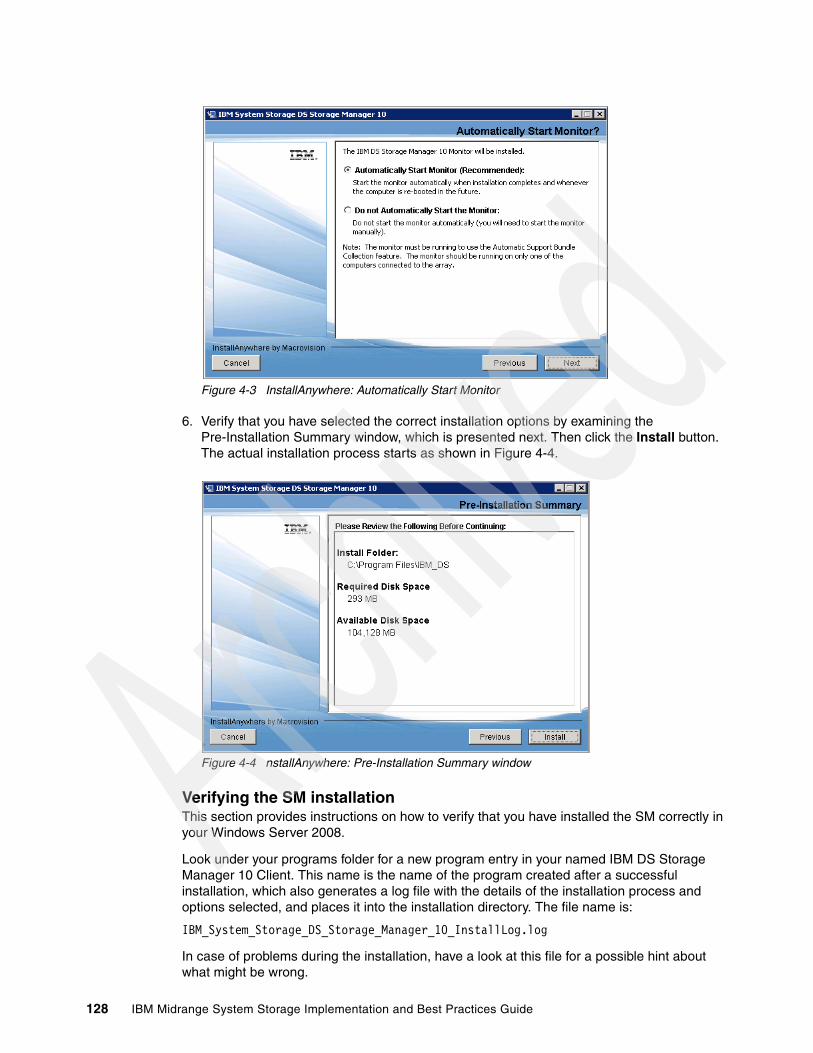
Figure 4-3 InstallAnywhere: Automatically Start Monitor
6. Verify that you have selected the correct installation options by examining the Pre-Installation Summary window, which is presented next. Then click the Install button. The actual installation process starts as shown in Figure 4-4.
Figure 4-4 nstallAnywhere: Pre-Installation Summary window
Verifying the SM installation This section provides instructions on how to verify that you have installed the SM correctly in your Windows Server 2008.
Look under your programs folder for a new program entry in your named IBM DS Storage Manager 10 Client. This name is the name of the program created after a successful installation, which also generates a log file with the details of the installation process and options selected, and places it into the installation directory. The file name is:
IBM_System_Storage_DS_Storage_Manager_10_InstallLog.log
In case of problems during the installation, have a look at this file for a possible hint about what might be wrong.
128 IBM Midrange System Storage Implementation and Best Practices Guide
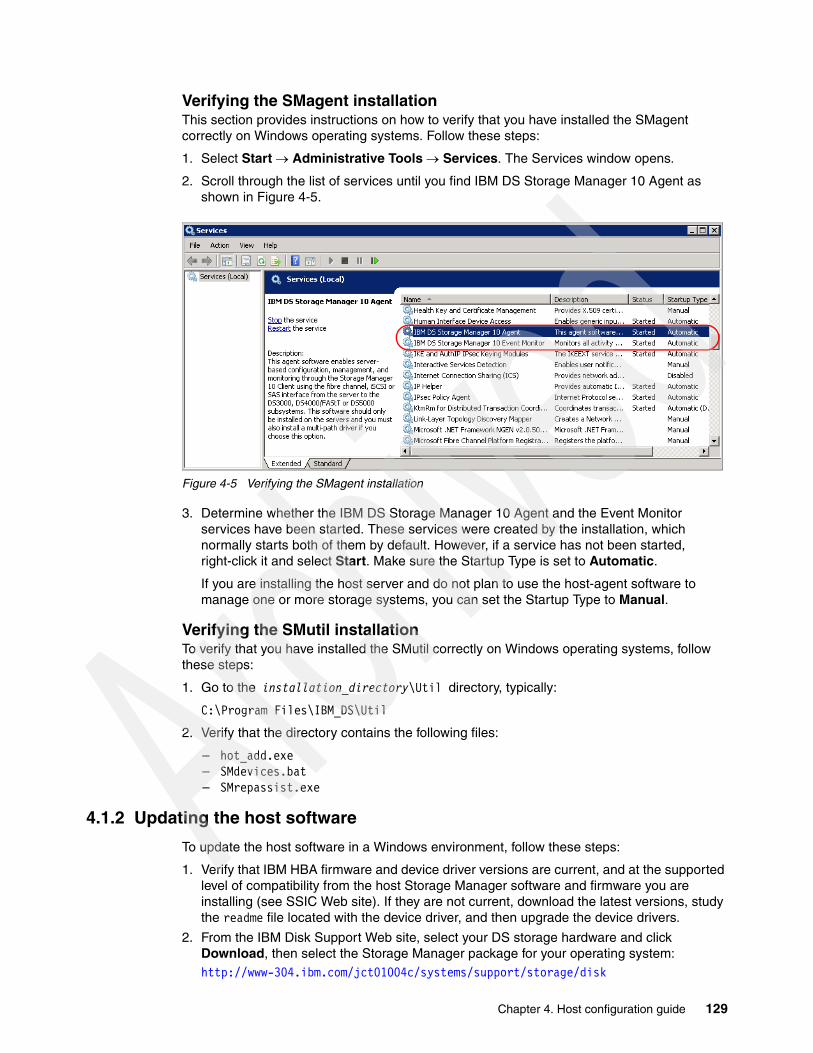
Verifying the SMagent installation This section provides instructions on how to verify that you have installed the SMagent correctly on Windows operating systems. Follow these steps:
1. Select Start Administrative Tools Services. The Services window opens.
2. Scroll through the list of services until you find IBM DS Storage Manager 10 Agent as shown in Figure 4-5.
Figure 4-5 Verifying the SMagent installation
3. Determine whether the IBM DS Storage Manager 10 Agent and the Event Monitor services have been started. These services were created by the installation, which normally starts both of them by default. However, if a service has not been started, right-click it and select Start. Make sure the Startup Type is set to Automatic.
If you are installing the host server and do not plan to use the host-agent software to manage one or more storage systems, you can set the Startup Type to Manual.
Verifying the SMutil installationTo verify that you have installed the SMutil correctly on Windows operating systems, follow these steps:
1. Go to the installation_directory\Util directory, typically:
C:\Program Files\IBM_DS\Util
2. Verify that the directory contains the following files:
– hot_add.exe – SMdevices.bat – SMrepassist.exe
4.1.2 Updating the host software
To update the host software in a Windows environment, follow these steps:
1. Verify that IBM HBA firmware and device driver versions are current, and at the supported level of compatibility from the host Storage Manager software and firmware you are installing (see SSIC Web site). If they are not current, download the latest versions, study the readme file located with the device driver, and then upgrade the device drivers.
2. From the IBM Disk Support Web site, select your DS storage hardware and click Download, then select the Storage Manager package for your operating system:http://www-304.ibm.com/jct01004c/systems/support/storage/disk
Chapter 4. Host configuration guide 129
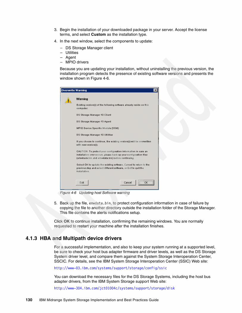
3. Begin the installation of your downloaded package in your server. Accept the license terms, and select Custom as the installation type.
4. In the next window, select the components to update:
– DS Storage Manager client– Utilities– Agent– MPIO drivers
Because you are updating your installation, without uninstalling the previous version, the installation program detects the presence of existing software versions and presents the window shown in Figure 4-6.
Figure 4-6 Updating host Software warning
5. Back up the file, emwdata.bin, to protect configuration information in case of failure by copying the file to another directory outside the installation folder of the Storage Manager. This file contains the alerts notifications setup.
Click OK to continue installation, confirming the remaining windows. You are normally requested to restart your machine after the installation finishes.
4.1.3 HBA and Multipath device drivers
For a successful implementation, and also to keep your system running at a supported level, be sure to check your host bus adapter firmware and driver levels, as well as the DS Storage System driver level, and compare them against the System Storage Interoperation Center, SSCIC. For details, see the IBM System Storage Interoperation Center (SSIC) Web site:
http://www-03.ibm.com/systems/support/storage/config/ssic
You can download the necessary files for the DS Storage Systems, including the host bus adapter drivers, from the IBM System Storage support Web site:
http://www-304.ibm.com/jct01004c/systems/support/storage/disk
130 IBM Midrange System Storage Implementation and Best Practices Guide
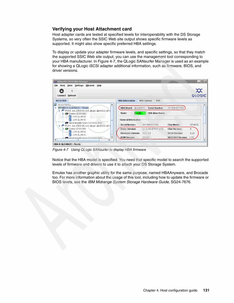
Verifying your Host Attachment cardHost adapter cards are tested at specified levels for interoperability with the DS Storage Systems, so very often the SSIC Web site output shows specific firmware levels as supported. It might also show specific preferred HBA settings.
To display or update your adapter firmware levels, and specific settings, so that they match the supported SSIC Web site output, you can use the management tool corresponding to your HBA manufacturer. In Figure 4-7, the QLogic SANsurfer Manager is used as an example for showing a QLogic iSCSI adapter additional information, such as firmware, BIOS, and driver versions.
Figure 4-7 Using QLogic SANsurfer to display HBA firmware
Notice that the HBA model is specified. You need that specific model to search the supported levels of firmware and drivers to use it to attach your DS Storage System.
Emulex has another graphic utility for the same purpose, named HBAAnyware, and Brocade too. For more information about the usage of this tool, including how to update the firmware or BIOS levels, see the IBM Midrange System Storage Hardware Guide, SG24-7676.
Chapter 4. Host configuration guide 131

Verifying your Host Attachment cards driver levelTo check or update your host bus adapter driver level in Windows, use the Device Manager to display the status of your host bus adapter cards for both Fibre Channel or iSCSI depending on your system configuration. See Figure 4-8.
Figure 4-8 Displaying HBA drivers
From here you can display the installed driver level of your adapter card, and even update it by selecting the option Update Driver. This procedure is easy, however, it is important to make sure which kind of adapter you have, and its specific model, because both driver and firmware might be specifics for the adapter types. The Windows Device Manager does not provides this information, so it is a better alternative to use your adapter specific management tool to determine the exact adapter type, as seen in Figure 4-7 on page 131.
Verifying the SM Failover driver (MPIO/DSM)The following drivers are supported for the DS storage Systems in Windows:
� Microsoft MPIO:
Included with Windows operating systems.
� IBM Device Specific Module (DSM):
Available for download form the IBM Support Web site.
� LSI MPIO Device Specific Module (DSM):
Provided with the DS Storage Manager installation CD.
The former RDAC drivers for Windows are no longer supported, starting with DS4000 Storage Manager 10.10 (firmware 7.10).
132 IBM Midrange System Storage Implementation and Best Practices Guide

Follow these steps to verify the installation of the MPIO/DSM driver provided with the Storage Manager software:
1. Check the install directory for the SM Failover driver. The default install directory is:
C:\Program Files\DSMDrivers\ds4dsm
2. Open the Device Manager in Computer Management. There must be a Multi-Path Support entry under the System Devices folder, corresponding to the Device Specific Module loaded during the Storage Manager installation.
3. Right-click it, select Properties, and check the Driver tab for the version, as shown in Figure 4-9.
Figure 4-9 Verifying DSM driver level
Recognizing the DS Storage volumesAfter the host software is installed in your Windows host, together with the host bus adapter drivers, and the DS Storage System is configured with logical volumes properly mapped, then you can recognize the DS Storage volumes in your host.
However, before starting to work on recognizing these volumes in your host, make sure that the SAN zoning is properly set up, if you are working in an FC environment, according to your planned configuration. For specific steps to configure SAN FC Zoning, see Implementing an IBM/Brocade SAN with 8 Gbps Directors and Switches, SG24-6116 and IBM Midrange System Storage Hardware Guide, SG24-7676.
For iSCSI attachment, make sure that the network being used is properly configured (IP, VLANs, Frame size, and so on), and has enough bandwidth to provide Storage attachment. You have to analyze and understand the impact of the network into which an iSCSI target is to be deployed prior to the actual installation and configuration of an IBM DS5000 storage system. See the “iSCSI” sections of the IBM Midrange System Storage Hardware Guide, SG24-7676.
Chapter 4. Host configuration guide 133

Follow these steps to detect DS Storage logical volumes mapped to your Windows 2008 host:
1. Go to the Windows device manager, and highlight the Disks folder. After everything is configured, connected, and mapped correctly, select from the Server Manager window Action Scan for hardware changes. Observe the results shown in Figure 4-10.
Figure 4-10 Displaying Logical volumes and Access LUNs
2. Each logical drive is presented as an IBM XXX Multipath Disk Device under the Disk drives folder, where XXX is the product ID of the DS Storage subsystem. Notice that in Figure 4-10, there are disk drives of various types, because in this example, we have mapped to this host, the logical volumes from two DS Storage Systems. The IBM 1814 is a DS5020, and the IBM 1818 is a DS5300.
3. Count the number of drives that you are detecting as coming from your DS Storage Systems, and make sure that this number is the same as the number of logical volumes mapped in your Storage Systems. It does not matter how many paths each volume has, it shows only as one device in the Disks folder.
Later we explain how to individualize each disk drive presented in the device manager, to the logical drive, and how to check all the paths.
4. The DS Access LUNs are the volumes used for In-Band management. If you are not planning to manage your DS Storage Systems using the FC or iSCSI cards, you can unmap the access LUNs in your DS Storage Mappings tab.
DS Storage volumes
DS Access LUNs
134 IBM Midrange System Storage Implementation and Best Practices Guide

Determining device pathsFrom the Windows Device Manager, select a disk drive, right-click it, and select Properties. In the Properties windows, select the MPIO tab to display the configured paths to the selected disks. See Figure 4-11.
:
Figure 4-11 Checking Device Paths
Important: After a new installation, make sure to check the paths available for each detected disk, and their state. You must see only one disk per logical volume mapped in the Device Manager, but each one has to have as many paths as defined by your cabling, SAN Zoning, or iSCSI configuration.
Chapter 4. Host configuration guide 135

Matching device path to DS controllerTo figure out which device path corresponds to your DS Storage System A or B controller, from the disk drive Properties window, select the MPIO tab, highlight one specific path, and click Edit. In the following examples, for both iSCSI connection options, we show how to match each path to the specific DS Storage System controller (you see the same information about an FC attached disk drive). See Figure 4-12.
Figure 4-12 Matching device path to DS controller
To display the controller serial number, go to the Physical tab of the Subsystem Management window of the DS Storage System, click in the controller, and move down in the right frame until the Serial Number is displayed. Repeat for each controller. You can use this method when troubleshooting path problems.
To find which is the current path of a particular logical volume, select it from the Subsystem Management Logical View, and in the right frame, scroll down until the Current Owner is displayed. You will also see the Preferred Owner information for the same logical volume.
iSCSI HBA Example iSCSI SW Initiator Example
136 IBM Midrange System Storage Implementation and Best Practices Guide

4.1.4 Load balance policy
When you have multiple paths to the DS Storage System, the driver can select between various options specifying how to manage the traffic between the Host and the Storage. The following options are available for Windows.
One path per controller: Fail OverThe Fail Over option is not a balancing algorithm, but we include it here because it is presented to select it together with the actual balancing policies. The driver uses Fail Over only when there is one path to each controller of your system. Using Fail Over, one of the device paths is Active, and the other is in Standby State.
Multiple paths per controllerThe multi-path driver transparently balances I/O workload without administrator intervention, across multiple paths to the same controller, but not across both controllers. The load balance policy uses one of three algorithms:
� Round robin with subset� Least queue depth with subset� Least path weight with subset
For specific details about how to select the right policy for your installation, see Chapter 2, “IBM System Storage DS5000 Storage System planning tasks” on page 15.
Determining load balance policyTo determine or change the load balance policy algorithm used by the device driver to redistribute the traffic between your host and the DS Storage System, follow these steps:
1. Open the Device Manager folder in your Windows host. With MPIO, each device listed here represents a Logical volume of your DS Storage System. In order to display the path failover policy, paths, and device driver version, select one of them, right-click it, and then choose Properties.
2. Select the MPIO tab to display the various paths to the DS Storage System. From the same Properties window, you can set the various Load Balance policies for the MPIO driver. Depending on the current physical path state and the policy selected, the paths are either both Active (round robin, weighted paths), or one is Active and the other is Standby (Fail Over, Least Queue Depth). See Figure 4-13.
Chapter 4. Host configuration guide 137

Figure 4-13 MPIO Device Paths Load Balance policy
Using the same window, you can also check the status of each path, and also the DSM driver level. In the previous example, two paths are Active, and two are Standby. The Active paths are the ones going to the current controller owning the logical volume.
4.1.5 Matching DS logical drives with Windows devices
The logical drives configured and mapped to your Windows host are represented in the Windows Device Manager under the Disk drives section. To work with them, follow these steps:
1. Open the Device Manager folder to see the detected mapped logical volumes. Each logical drive is presented as IBM xxx Multipath Disk Device under the Disk drives folder, where xxx is the product ID of the DS Storage subsystem, as shown in Figure 4-14.
Driver Load Balance Policy
138 IBM Midrange System Storage Implementation and Best Practices Guide

Figure 4-14 Verifying new disks in Device Manager
If the MPIO DSM driver is installed and your DS Storage System was configured properly to map each logical drive to each of the hosts adapters, then you can see in the Device Manager, the same number of devices as logical drives mapped in your DS Storage subsystem.
2. For a correct data assignment to your defined logical volumes, you need to determine which of the disks drives in the Windows Device Manager, or Disk Manager relates to the previously defined logical volumes of your DS Storage System. Select the disk drive to identify, right-click, and choose Properties.
3. Use the LUN number to isolate each logical drive as shown in Figure 4-15, comparing it against the Storage Subsystem Mapping tab.
Figure 4-15 Matching LUNs between Windows host and SM
LUN Identification
Chapter 4. Host configuration guide 139
4. Finally, use the Windows Disk Management panel to start using your newly mapped DS disks. Before making any changes to your disk structure, make sure to identify your disks correctly. You can get the same information presented previously in Figure 4-15, by right-clicking each of the drives and selecting Properties, as shown in Figure 4-16.
Figure 4-16 Windows Disk Management
4.1.6 Using Windows Disk Manager
When the logical volumes are mapped to your Windows host from the DS Storage Manager, you can use the Device Manager to individualize them and adjust the driver properties.
After that, in order to start using these volumes, follow these steps:
1. Open the Windows Disk Manager to make the volumes available for data. Initially, the new disks are presented in offline state.
2. To start using one of the disks, right-click it and select Online, as shown in Figure 4-17.
Important: Before making any changes in the disk configuration for your server, make sure that you have correctly selected the drive that you want to configure or modify, displaying the Device Properties to check LUN, disk name, and size. Do not rely only on the LUN information, because you might have various partitions in DS Storage Systems, each with the same LUN being presented to the host. Use the device driver utilities for further help.
140 IBM Midrange System Storage Implementation and Best Practices Guide
Figure 4-17 Changing disks to Online
The disk changes from Unknown, Offline, to Unknown, Online.
3. After it is in Online state, right-click it again and now select Initialize, as shown in Figure 4-18.
Figure 4-18 Initializing Disks
4. After running the Initialize option, the disk is ready to be used. Create a partition by right-clicking in the Unallocated space area, and selecting New Simple Volume, thus launching the New Simple Volume Wizard.
By default, a basic disk is created, but you can later change it to a dynamic disk, which allows added features. With the DS Storage Server, you can use either basic or dynamic disks, depending upon your needs and requirements, although certain features might not be supported when using dynamic disks. For more information, see the “Advanced maintenance and toubleshooting” section of the IBM Midrange System Storage Hardware Guide, SG24-7676.
Chapter 4. Host configuration guide 141

5. Select the size that you want for the new partition being created. Click Next to continue.
6. Select the desired drive letter to assign to this partition, or specify the mount point. Click Next to continue.
7. Specify the format options for the volume and other characteristics such as allocation unit size, volume label, and format type. Click Next and Finish.
The wizard finishes with a new volume available for use, according to the specifications set.
Expanding logical drivesIt is possible to increase the size of logical drives after they are already created, which is called Dynamic Volume Expansion (DVE).
To increase the logical drive capacity, on the Subsystem Manager Logical Tab, highlight the logical drive to be expanded, right-click it, and select Increase Capacity. In the Increase Logical Drive Capacity window, Figure 4-19, enter the amount of space by which the logical drive will be enlarged.
Figure 4-19 Dynamic logical drive expansion
In the top part of the window shown in Figure 4-19, the current size of the logical drive and the available free capacity in the array are displayed. If no free configured space is available but there are unassigned drives, these can be added from this same window by clicking Add Drives before proceeding to enlarge the logical drive.
After the capacity of the logical drive is increased, you have to work in your host definition of the volume to make it available to use.
142 IBM Midrange System Storage Implementation and Best Practices Guide

Extending capacity on a Windows Basic disk In the following example, we have a Windows 2008 system with a basic disk partition of 1 GB. The partition has data on it, the partition is disk 6, and its drive letter is J. We have used the DS5000 Dynamic Volume Expansion (DVE) to expand the logical drive to add 100 GB. Doing this leaves the operating system with a disk of 101 GB, with a partition of 1 GB and free space of 100 GB, as shown in Figure 4-20.
Figure 4-20 Dynamic volume expansion in Windows 2008
We use the Windows 2008 command line utility diskpart.exe to extend the original 1 GB partition to the full size of the disk. See Example 4-1.
Example 4-1 The diskpart utility to extend the basic disk in a command window
Microsoft DiskPart version 6.0.6002Copyright (C) 1999-2007 Microsoft Corporation.On computer: TC-W2008
DISKPART> list volume
Volume ### Ltr Label Fs Type Size Status Info ---------- --- ----------- ----- ---------- ------- --------- -------- Volume 0 D DVD-ROM 0 B No Media Volume 1 G DVD-ROM 0 B No Media Volume 2 C System NTFS Partition 117 GB Healthy System Volume 3 H TC-2008-1 NTFS Partition 20 GB Healthy Volume 4 E TC-2008-2 NTFS Partition 25 GB Healthy Volume 5 RAW Partition 136 GB Healthy Volume 6 F SDD_TC-2008 NTFS Partition 15 GB Healthy Volume 7 I SDD_TC-2008 NTFS Partition 15 GB Healthy Volume 8 J Volume1 NTFS Partition 1021 MB Healthy
DISKPART> select volume 8
Chapter 4. Host configuration guide 143

Volume 8 is the selected volume.
DISKPART> extend
DiskPart successfully extended the volume.
DISKPART> list volume
Volume ### Ltr Label Fs Type Size Status Info ---------- --- ----------- ----- ---------- ------- --------- -------- Volume 0 D DVD-ROM 0 B No Media Volume 1 G DVD-ROM 0 B No Media Volume 2 C System NTFS Partition 117 GB Healthy System Volume 3 H TC-2008-1 NTFS Partition 20 GB Healthy Volume 4 E TC-2008-2 NTFS Partition 25 GB Healthy Volume 5 RAW Partition 136 GB Healthy Volume 6 F SDD_TC-2008 NTFS Partition 15 GB Healthy Volume 7 I SDD_TC-2008 NTFS Partition 15 GB Healthy* Volume 8 J Volume1 NTFS Partition 101 GB Healthy
DISKPART>exit
After diskpart.exe has extended the disk, the partition is now 100 GB. All the data is still intact and usable, as shown in Figure 4-21.
Figure 4-21 Disk Management after diskpart has extended the partition
With dynamic disks, the Disk Management GUI utility can be used to expand logical drives.
144 IBM Midrange System Storage Implementation and Best Practices Guide

4.1.7 Using the IBM Device Driver utilities
Storage Manager provides other utilities to display the logical drives mapped.
Storage Manager SMdevices utilityMove to the folder until under your Storage Manager installation directory:
C:\Program Files\IBM_DS\util by default
Then run the SMdevices utility from the cmd prompt.
You can use the information provided by the SMdevices utility as follows:
� It helps you to determine the Storage Manager utility version (which is the same as the Storage Manager version).
� It provides a complete list of all the logical volumes, including these:
– Parent Storage Subsystem Name– Logical Drive name as assigned from Storage Manager– LUN ID– Preferred path in use
You can use this output to easily relate your Windows devices with your DS Storage Manager mappings as shown in Figure 4-22.
Figure 4-22 Matching LUNs using SMdevices cmd
Pay special attention to the following example, because there are two LUNs 0, but from separate DS Storage Systems, this might generate confusion if not all the information is analyzed (see Figure 4-23).
C:\Program Files\IBM_DS\util>SMdevicesDS Storage Manager Utilities Version 10.01.35.01....\\.\PHYSICALDRIVE0 [Storage Subsystem ITSO5300, Logical Drive Windows_SANBoot_x3655A, LUN 0, Logical Drive ID <600a0b800047709c00007f4b4ab0bb89>, Preferred Path (Controller-A): In Use]\\.\PHYSICALDRIVE1 [Storage Subsystem ITSO5300, Logical Drive DB, LUN 1, Logical Drive ID <600a0b80004777d8000078384aabab4a>, Preferred Path (Controller-B): In Use]
Chapter 4. Host configuration guide 145

Figure 4-23 Matching LUNs from various Storage Systems
MPIO DSM dsmUtilDSMUtil is part of the IBM DSM driver installed by default in the directory:
C:\Program Files\DSMDrivers\ds4dsm
You can use this utility for the following options:
� dsmUtil -a
Lists all the Storage Subsystem mapped to this host. See Example 4-2.
Example 4-2 dsmUtil -a
C:\Program Files\DSMDrivers\ds4dsm>dsmutil -aHostname = x3655A---------------------------------------------------------------------------Info of Array Module's seen by this Host.---------------------------------------------------------------------------ID WWN Interface(s) Name--------------------------------------------------------------------------- 0 600a0b80004777d8000000004a956964 iSCSI ITSO5300 1 60080e500017b5bc000000004a955e3b iSCSI DS5020---------------------------------------------------------------------------
C:\Program Files\IBM_DS\util>SMdevicesDS Storage Manager Utilities Version 10.01.35.01\\.\PHYSICALDRIVE0 [Storage Subsystem ITSO5300,Logical Drive Windows_SANBoot_x3655A,LUN 0 Logical Drive ID <600a0b800047709c00007f4b4ab0bb89>, Preferred Path (Controller-A): In Use]\\.\PHYSICALDRIVE1 [Storage Subsystem ITSO5300, Logical Drive DB, LUN 1, Logical Drive ID <600a0b80004777d8000078384aabab4a>, Preferred Path (Controller-B): In Use]\\.\PHYSICALDRIVE2 [Storage Subsystem DS5020, Logical Drive Blade03-Data1,LUN 0, Logical Drive ID <60080e500017b5bc000046cf4aa7a088>, Preferred Path (Controller-B): In Use]
146 IBM Midrange System Storage Implementation and Best Practices Guide

� dsmUtil -M
Lists all LUNs with including System Name and Logical Name assigned from DS Storage Manager. It is similar to the SMdevices output, so you can use it to relate your DS Logical volumes to its corresponding representation in your Windows host. It also shows the number of paths per device. See Example 4-3.
Example 4-3 dsmUtil -M
C:\Program Files\DSMDrivers\ds4dsm>dsmutil -M\\.\PHYSICALDRIVE0 MPIO Disk0 [Storage Array ITSO5300, Volume Windows_SANBoot_x3655A, Lun 0, Serial Number <600a0b800047709c00007f4b4ab0bb89>][Physical Paths <2>, DSM Driver <IBM DS3000/DS4000/DS5000 DSM>]\\.\PHYSICALDRIVE1 MPIO Disk1 [Storage Array ITSO5300, Volume DB, Lun 1, Serial Number <600a0b80004777d8000078384aabab4a>][Physical Paths <2>, DSM Driver<IBM DS3000/DS4000/DS5000 DSM>]\\.\PHYSICALDRIVE2 MPIO Disk2 [Storage Array DS5020, Volume Blade03-Data1, Lun 0, Serial Number <60080e500017b5bc000046cf4aa7a088>][Physical Paths <2>, DSM Driver <IBM DS3000/DS4000/DS5000 DSM>]
In the previous example, observe there are two LUNs 0, each from a separate DS Storage System. Make sure that you select the correct one for use, especially before doing changes.
� dsmUtil -a SysName
Lists the complete information for the given Sysname. It includes detailed information about each volume and paths, useful for troubleshooting path problems. See Example 4-4.
Example 4-4 Detailed data using dsmUtil
C:\Program Files\DSMDrivers\ds4dsm>dsmutil -a DS5020Hostname = x3655A
MPP Information:---------------- ModuleName: DS5020 SingleController: N VirtualTargetID: 0x000 ScanTriggered: N ObjectCount: 0x000 AVTEnabled: N WWN: 60080e500017b5bc000000004a955e3b RestoreCfg: N ModuleHandle: 0x849C8080 Page2CSubPage: Y FirmwareVersion: 7.60.13.0 FailoverMethod: C ScanTaskState: 0x00000000 LBPolicy: LeastQueueDepth
Controller 'A' Status:-----------------------ControllerHandle: 0x849CA510 ControllerPresent: Y UTMLunExists: N Failed: N NumberOfPaths: 1 FailoverInProg: N ServiceMode: NPath #1--------- DirectoryVertex: 0x85FFFC1C Present: Y PathState: OPTIMAL PathId: 0x77040001 (P04P00I01) InterfaceType: iSCSI ReqInProgress: 0
Controller 'B' Status:-----------------------ControllerHandle: 0x84C19B50 ControllerPresent: Y UTMLunExists: N Failed: N
Chapter 4. Host configuration guide 147

NumberOfPaths: 1 FailoverInProg: N ServiceMode: NPath #1--------- DirectoryVertex: 0x85FFFE30 Present: Y PathState: OPTIMAL PathId: 0x77050001 (P05P00I01) InterfaceType: iSCSI ReqInProgress: 0
Lun Information--------------- Lun #0 - WWN: 60080e500017b5bc000046cf4aa7a088 ---------------- LunObject: 0x0 CurrentOwningPath: B RemoveEligible: N BootOwningPath: B NotConfigured: N PreferredPath: B DevState: N/A NeedsReservationCheck: N LBPolicy: LeastQueueDepth TASBitSet: Y NotReady: N Busy: N Quiescent: N Controller 'A' Path -------------------- NumLunObjects: 1 RoundRobinIndex: 0 Path #1: LunPathDevice: 0x85FEF408 DevState: OPTIMAL PathWeight: 0 RemoveState: 0x0 StartState: 0x0 PowerState: 0x0 Controller 'B' Path -------------------- NumLunObjects: 1 RoundRobinIndex: 1 Path #1: LunPathDevice: 0x85FEE408 DevState: OPTIMAL PathWeight: 0 RemoveState: 0x0 StartState: 0x0 PowerState: 0x0
4.1.8 Collecting information
In addition to the information mentioned in IBM Midrange System Storage Hardware Guide, SG24-7676, your service provider might also require you to send the following information from your Windows host system to perform problem determination over certain failures:
� System event log: Right-click the my computer icon on your desktop and select Manage to open the System Management window. From the system tools option under Computer Management, select Event viewer System. Now click Action from the pull-down menu, and select Save Log File as to save the event view log file.
� Application log: Proceed as described for the system event log, but this time, select the application log.
� Dynamic system analysis, DSA log: IBM Dynamic System Analysis (DSA) collects and analyzes system information to aid in diagnosing system problems. This tool was developed initially for System x servers and not only collects the system event and application logs, but also information from your adapters, drivers, and configuration, which allows you to easily provide all the information that your support representative needs in one package. To access this tool, go to:
http://www-03.ibm.com/systems/management/dsa.html
148 IBM Midrange System Storage Implementation and Best Practices Guide

� SMdevices: Use this command and capture the output to show all the devices detected by the DSM driver.
4.2 AIX
In the following section we present the steps that you need to perform on your AIX server to install and manage your DS Storage System. Although most of these steps were documented using the IBM System Storage DS Storage Manager v10.30, similar steps also apply for v10.60.
For more details about the AIX configuration, see Chapter 12, “DS5000 with AIX, PowerVM, and PowerHA” on page 533.
4.2.1 Installing DS5000 Storage Manager software on an AIX host
This section covers the installation of the IBM System Storage DS Storage Manager software components attached to a host server running the AIX operating system. When referring to an AIX host system, it can be a stand-alone IBM System p machine, an LPAR running AIX, or even a Virtual I/O (VIO) server.
Before installing SMclient, make sure that you have met the following conditions:
� The System p server hardware to which you connect the DS5000 Storage Server meets the required specifications for your storage model.
� The AIX host on which you install SMruntime meets the minimum software requirements.
� You have prepared the correct file sets for the installation on an AIX system.
SMruntime provides the Java runtime environment required to run the SMclient. The AIX FCP disk array driver (also known as MPIO for AIX), provides redundancy in the I/O paths, and is part of the AIX operating system, and is therefore not included in the DS5000 Storage Manager software CD shipped with the storage server.
Depending on your configuration and environment, you have the option to install the software packages using two possible methods:
� From a graphic workstation using the installation wizard� Using the standard command line method.
Guideline: DO NOT install Storage Manager software on a VIO server.
Important: Review your system requirements and additional support information in the latest Storage Manager readme file for your specific DS5000 storage system and code level.
Note: The installation package requires sufficient free space in several file systems. It identifies and informs you of the space needed during the installation. You need to allocate enough space to successfully install the software.
Chapter 4. Host configuration guide 149

4.2.2 Instructions for each installation method
We describe both installation methods in the following sections. You might need to adjust the instructions for the specifics of your environment. No AIX reboot is required during the installation process.
Installation through a graphical desktop To install the Storage Manager software using the installation wizard, use the following sequence:
1. Locate the installation code file, either in the appropriate CD-ROM directory or on the IBM support Web site, and transfer the code to a directory on your AIX system.
2. Make sure that the file has permissions to execute. If not, type the following command to allow its execution:
# ls -la SM*-rw-r----- 1 root system 262690421 Aug 23 08:49 SMIA-AIX-10.30.G5.00.bin
# chmod +x SMIA-AIX-10.30.G5.00.bin# ls -la SM*-rwxr-x--x 1 root system 262690421 Aug 23 08:49 SMIA-AIX-10.30.G5.00.bin
3. Execute the file to begin installation. If you have insufficient free space in /tmp, you get the warning shown in Figure 4-24.
Figure 4-24 Launch failure in AIX
4. To remedy this warning, either increase the /tmp file system to have sufficient free space, according to the warning given, or set the environment variable IATEMPDIR to a directory with sufficient free space.
5. After the installer is launched, proceed by selecting the language, and go through the introduction window, copyright statement, and license agreement windows. Acceptance of the license agreement is required to continue.
150 IBM Midrange System Storage Implementation and Best Practices Guide

6. Now select the installation type, as shown in Figure 4-25:
– The installation type that you select defines the components that are installed. For example, if you select Management Station, the agent component is not installed, because it is not required on the management computer. In most cases, you can select either the Management Station or Host installation type.
– Because having only these two options might be a limitation, two additional choices are offered: full and custom installation. As the name indicates, a full installation installs all components, whereas a custom installation lets you choose from the following components:
• IBM Storage Manager 10 Client• IBM Storage Manager 10 Utilities• IBM Storage Manager 10 Agent
Figure 4-25 Installing Storage Manager software in AIX
7. After selecting an installation type, you are presented with the Pre-Installation Summary window.
Verify that you have enough space in the designated file systems and click the Install button to proceed with the installation.
Installing using the AIX smit interfaceIf you prefer to install the packages individually, you can use the AIX smit interface:
1. Copy all the individual packages to a temporary directory. For our example, we use /tmp.
2. Issue the following command to create the installable list:
# inutoc /tmp
3. Invoke the AIX management interface calling the install program:
# smitty installp
4. Select the “Install Software” option.
Chapter 4. Host configuration guide 151
5. For the input directory, type in the chosen directory name (in our case, “/tmp”), and press Enter.
6. Select all packages or any individual package to install.
Installing through the command lineIn this section, we discuss an alternative method for individual package installation done from the AIX command line. This method can be used when you only have access to a regular text terminal.
To successfully install the client software through the AIX command line, you must install the various packages in the following sequence:
1. SMruntime2. SMesm 3. SMclient (optional)4. SMagent (optional)5. SMutil (optional)
Installing SMruntimeTo install, follow these steps:
1. Install SMruntime by typing the following command:
# installp -a -d /complete path name/SMruntime-AIX-10.30.65.00.bff SMruntime.aix.rte
2. Verify that the installation was successful by typing the following command:
# lslpp -ah SMruntime.aix.rte
The verification process returns a table that describes the software installation, including the install package file name, version number, action, and action status:
Fileset Level Action Status Date Time ----------------------------------------------------------------------------Path: /usr/lib/objrepos SMruntime.aix.rte 10.30.6500.0 COMMIT COMPLETE 08/26/08 11:04:46 10.30.6500.0 APPLY COMPLETE 08/26/08 11:04:46
Installing SMesm This package provides firmware images for the disk expansion enclosure controller cards and can be used in case of compatibility problems. SMesm is required if installing SMclient. Follow these steps:
1. Install SMesm by typing the following command:
# installp -a -d /tmp/SM10/SMesm-AIX-10.30.G5.00.bff SMesm.aix.rte
2. Verify it by typing the following command:
# lslpp -ah SMesm.aix.rte
This generates output showing the status of the package installed.
Note: If you install the packages individually, be sure to install them in the sequence shown in “Installing through the command line” on page 152.
Note: Check the Status column for the complete installation. The levels have to match your specific version.
152 IBM Midrange System Storage Implementation and Best Practices Guide

Installing SMclientSMclient is required only if you plan to run the management client from the AIX host. Follow these steps:
1. Install SMclient by typing the following command:
# installp -a -d /complete path name/SMclient-AIX-10.30.G5.04.bff SMclient.aix.rte
2. Verify that the installation was successful by typing the following command:
# lslpp -ah SMclient.aix.rte
The verification process returns a table that describes the software installation, including the install package file name, version number, action, and action status:
Fileset Level Action Status Date Time ----------------------------------------------------------------------------Path: /usr/lib/objrepos SMclient.aix.rte 10.30.6504.0 COMMIT COMPLETE 08/26/08 11:33:23 10.30.6504.0 APPLY COMPLETE 08/26/08 11:33:23
3. To start the client, issue the following command:
# /usr/SMclient/SMclient
Installing SMagentSMagent is required only for in-band management (that is, through Fibre Channel) Follow these steps:
1. Install the SMagent by typing the following command:
# installp -a -d /tmp/SM10/SMagent-AIX-10.00.65.03.bff SMagent.aix.rte
2. Verify the installation by typing the following command:
# lslpp -ah SMagent.aix.rte
The verification process returns a table that describes the software installation, including the install package file name, version number, action, and action status:
Fileset Level Action Status Date Time ----------------------------------------------------------------------------Path: /usr/lib/objrepos SMagent.aix.rte 10.0.6503.0 COMMIT COMPLETE 08/26/08 11:38:44 10.0.6503.0 APPLY COMPLETE 08/26/08 11:38:44
Note: If the Fibre Channel connections to the controllers are lost, the SMclient software cannot be accessed for problem determination. Having IP network connectivity as well can enable you to continue to manage and troubleshoot the storage subsystem when there are problems with the Fibre Channel links.
Chapter 4. Host configuration guide 153
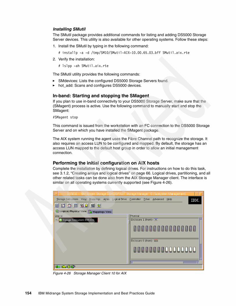
Installing SMutilThe SMutil package provides additional commands for listing and adding DS5000 Storage Server devices. This utility is also available for other operating systems. Follow these steps:
1. Install the SMutil by typing in the following command:
# installp -a -d /tmp/SM10/SMutil-AIX-10.00.65.03.bff SMutil.aix.rte
2. Verify the installation:
# lslpp -ah SMutil.aix.rte
The SMutil utility provides the following commands:
� SMdevices: Lists the configured DS5000 Storage Servers found.� hot_add: Scans and configures DS5000 devices.
In-band: Starting and stopping the SMagentIf you plan to use in-band connectivity to your DS5000 Storage Server, make sure that the (SMagent) process is active. Use the following command to manually start and stop the SMagent:
#SMagent stop
This command is issued from the workstation with an FC connection to the DS5000 Storage Server and on which you have installed the SMagent package.
The AIX system running the agent uses the Fibre Channel path to recognize the storage. It also requires an access LUN to be configured and mapped. By default, the storage has an access LUN mapped to the default host group in order to allow an initial management connection.
Performing the initial configuration on AIX hostsComplete the installation by defining logical drives. For instructions on how to do this task, see 3.1.2, “Creating arrays and logical drives” on page 66. Logical drives, partitioning, and all other related tasks can be done also from the AIX Storage Manager client. The interface is similar on all operating systems currently supported (see Figure 4-26).
Figure 4-26 Storage Manager Client 10 for AIX
154 IBM Midrange System Storage Implementation and Best Practices Guide

Follow the instructions in the IBM Midrange System Storage Hardware Guide, SG24-7676 to create a host group, host, and host ports for the AIX server. After you set up storage partitioning, perform the following steps to verify that the host ports match the AIX host:
1. Type the following command:
# lscfg -l fcs*
A list is displayed containing all the HBAs in the system.
2. Use the second column of this list to determine the adapter slot location placement in your server when you need to cable the fibers:
# lscfg -l fcs* fcs1 U0.1-P2-I5/Q1 FC Adapter fcs0 U0.1-P2-I4/Q1 FC Adapter
3. If you have multiple adapters, identify the fcs number of the HBAs to use with your DS5000 Storage Server.
4. Check the adapter microcode by typing the following command for each of the HBAs used by the DS5000 Storage Server, as shown in Example 4-5.
Example 4-5 Check HBA microcode level
# lsmcode -d fcs0
DISPLAY MICROCODE LEVEL 802111fcs0 FC Adapter
The current microcode level for fcs0 is 391101.
Use Enter to continue.
Use the level seen in the output, together with the type or feature code of your HBA, to make sure that you have at least the minimum level listed at the IBM support Web site:
http://www-01.ibm.com/systems/support/storage/config/ssic/index.jsp
5. Type the following command to determine the adapter’s WWN:
# lscfg -vl fcs? |grep Network
Where fcs? is the fcs number of the HBA that is connected to the DS5000 Storage Server.
You will need this information later when mapping the logical drives, or configuring zoning if your DS5000 Storage Server is connected through a SAN. The network address number of the HBA is displayed, as shown in the following example:
# lscfg -vl fcs0 |grep Network Network Address.............10000000C932A75D
6. Verify that the network address number matches the host port number that displays on the host partition table of SMclient.
7. Repeat this procedure to verify the other host ports.
Reminder: Do not share the same HBAs for tape and disk traffic.
Chapter 4. Host configuration guide 155

8. Depending on the HBA, you need specific file sets, as shown in Table 4-1.
Table 4-1 FC HBA and AIX drivers
9. Always check for at least the minimum required levels for your adapter driver, as well as adapter microcode. You will find that information at the IBM support Web site.
10.Get your AIX installation CDs and install the foregoing file sets from the media.
Installing the MPIO driver
The MPIO driver is part of the AIX operating system. Table 4-2 lists the minimum AIX release levels needed to support MPIO and the DS5000 Storage Server correctly. Although these are just the minimum prerequisites, when possible, always upgrade to the latest version available.
Table 4-2 Required AIX levels
Ensure that the file set devices.common.IBM.mpio.rte is installed by issuing the command:
lslpp -ah devices.common.IBM.mpio.rte
Verification tasksAfter the DS5000 storage system has been set up, the logical drives assigned to the host, and the MPIO driver installed, you must verify that all of your DS5000 Storage Server device names and paths are correct and that AIX recognizes your LUNs.
You must do this before you mount file systems and install applications. Type the following command to probe for the new devices:
# cfgmgr -v
HBA feature code Description AIX driver
6227 1 Gb Fibre Channel Adapter PCI devices.pci.df1000f7
6228 2 Gb Fibre Channel Adapter PCI devices.pci.df1000f9
6239 2 Gb Fibre Channel PCI-X devices.pci.df1080f9
5716 2 Gb Fibre Channel PCI-X devices.pci.df1000fa
5758 4 Gb Single-Port Fibre Channel PCI-X devices.pci.df1000fd
5759 4 Gb Dual-Port Fibre Channel PCI-X devices.pci.df1000fd
5773 4 Gb PCI Express Single Port devices.pciex.df1000fe
5774 4 Gb PCI Express Dual Port devices.pciex.df1000fe
Important: RDAC under AIX is no longer supported with the DS5000 Storage Server.
AIX release APAR number
52TL10 IZ13624
53TL6 IZ13625
53TL7 IZ13626
61TL0 IZ13627
156 IBM Midrange System Storage Implementation and Best Practices Guide

Use the lsdev -Cc disk command to see whether the FCP array disk software recognizes each DS5000 Storage Server logical drive correctly.
The following example illustrates the results of the command for a set of DS5300 storage server LUNs:
# lsdev -Cc diskhdisk0 Available 10-80-00-2,0 16 Bit LVD SCSI Disk Drivehdisk1 Available 10-90-02 MPIO Other FC SCSI Disk Drivehdisk2 Available 10-90-02 MPIO Other FC SCSI Disk Drive
At the time this book was written, AIX did not recognize the disk as an 1818 DS5000 Disk Array Device, so the exact output is subject to change in further versions. We expect it to look similar to the DS4700 output shown in Example 4-6.
Example 4-6 lsdev command
# lsdev -Cc diskhdisk3 Available 01-08-02 1814 DS4700 Disk Array Devicehdisk4 Available 01-09-02 1814 DS4700 Disk Array Device
Use the AIX mpio_get_config command to perform the following verification tasks:
� Correlate AIX hdisk numbers to the logical drive name displayed in the Storage Manager Client. The logical drive name from the Storage Manager Client is displayed under the User Label heading.
� Make sure that the logical drives are on the preferred DS5000 Storage Server controller.
� Make sure that the correct number of storage controllers are discovered.
– Controller count: 1 (indicates a single-controller configuration)– Controller count: 2 (indicates a dual-controller configuration)
� Make sure that the Partition count matches the number of storage partitions configured in the Storage Manager Client.
Example 4-7 shows an output of the mpio_get_config -Av command with a dual-controller DS5000 storage subsystem.
Example 4-7 mpio_get_config command
# mpio_get_config -AvFrame id 0: Storage Subsystem worldwide name: 60ab80029ed220000489c6f56 Controller count: 2 Partition count: 1 Partition 0: Storage Subsystem Name = 'DS5000' hdisk LUN # Ownership User Label hdisk1 0 A (preferred) b50-a hdisk2 1 A (non-preferred) b50-b
Note: You must run cfgmgr after the DS5000 Storage Server is cabled to allow the Storage Manager client to discover the AIX HBA WWN. Otherwise, you are not able to define the host port under the partitioning section.
Chapter 4. Host configuration guide 157

There are several ways to correlate a system’s configuration and monitor the state of DS5000 storage systems.
Example 4-8 shows that the two disks that we configured on the DS5000 Storage Server are in the available state. The third column shows the location code. In this example, it is 10-90-02. Each AIX system has its own set of location codes that describe the internal path of that device, including bus and host adapter locations. See the service manual for your system type to identify device locations.
Example 4-8 Show MPIO disks
# lsdev -C | grep -i mpiohdisk1 Available 10-90-02 MPIO Other FC SCSI Disk Drivehdisk2 Available 10-90-02 MPIO Other FC SCSI Disk Drive
Example 4-9 uses the lsdev command to show the status and location codes of two DS5300 storage server hdisks mapped and the local configured hdisk0. Notice that the location codes of the DS5300 storage server and the local disks are not the same.
Example 4-9 Disks status and location codes
# lsdev -Cc diskhdisk0 Available 10-80-00-2,0 16 Bit LVD SCSI Disk Drivehdisk1 Available 10-90-02 MPIO Other FC SCSI Disk Drivehdisk2 Available 10-90-02 MPIO Other FC SCSI Disk Drive
Use the lspath command to verify that the correct number of paths are detected and that they are enabled. Example 4-10 shows the output for a dual-controller DS5300 storage server with a single-controller host configuration with two LUNs attached.
Example 4-10 Path detection
# lspath | sortEnabled hdisk0 scsi0Enabled hdisk1 fscsi0Enabled hdisk1 fscsi0Enabled hdisk2 fscsi0Enabled hdisk2 fscsi0
Example 4-10 shows that all paths are enabled and each LUN on the DS5300 storage server has two paths.
The lsattr command provides detailed information about a disk drive, including information that allows you to map the system device name to the logical drive on the DS5000 storage system.
158 IBM Midrange System Storage Implementation and Best Practices Guide

In Example 4-11, we run the lsattr command on the LUN named hdisk1. The command output provides the size information and LUN ID (0).
Example 4-11 Disk drive information
# lsattr -El hdisk1PCM PCM/friend/otherapdisk Path Control Module FalsePR_key_value none Persistant Reserve Key Value Truealgorithm fail_over Algorithm Trueclr_q no Device CLEARS its Queue on error Truecntl_delay_time 0 Controller Delay Time Truecntl_hcheck_int 0 Controller Health Check Interval Truedist_err_pcnt 0 Distributed Error Percentage Truedist_tw_width 50 Distributed Error Sample Time Truehcheck_cmd inquiry Health Check Command Truehcheck_interval 60 Health Check Interval Truehcheck_mode nonactive Health Check Mode Truelocation Location Label Truelun_id 0x0 Logical Unit Number ID Falsemax_transfer 0x40000 Maximum TRANSFER Size Truenode_name 0x200600a0b829eb78 FC Node Name Falsepvid 0004362a0a2c1cd30000000000000000 Physical volume identifier Falseq_err yes Use QERR bit Trueq_type simple Queuing TYPE Truequeue_depth 10 Queue DEPTH Truereassign_to 120 REASSIGN time out value Truereserve_policy single_path Reserve Policy Truerw_timeout 30 READ/WRITE time out value Truescsi_id 0x6f1e00 SCSI ID Falsestart_timeout 60 START unit time out value Trueww_name 0x204600a0b829eb78 FC World Wide Name False
Changing ODM attribute settings in AIX After a logical drive has been created and mapped to the host, devices can be configured and the Object Data Manager (ODM) is updated with the default parameters. In most cases and for most configurations, the default parameters are satisfactory. However, there are various parameters that can be modified for maximum performance and availability. See the Installation and Support Guide for AIX, HP-UX, Solaris and Linux, which is provided with the Storage Manager software.
You can actually change the ODM attributes for the disk driver and DS5000 Storage Server; here we explain the basic functions of the chdev command.
As an example, we focus here on the queue_depth parameter. Setting the queue_depth attribute to the appropriate value is important for system performance. For large DS5000 Storage Server configurations with many logical drives and hosts attached, this is a critical setting for high availability. Reduce this number if the array is returning a BUSY status on a consistent basis. Possible values are from 1 to 64.
Use the following formula to determine the maximum queue depth for your system:
Maximum queue depth = DS5000 Storage Server queue depth / (number-of-hosts * LUNs-per-host)
Where DS5000 queue depth = 4096.
Chapter 4. Host configuration guide 159
For example, a DS5300 storage server with four hosts, each with 32 LUNs, has a maximum queue depth of 32:
Maximum queue depth = 4096 / ( 4 * 32 ) = 32
In this case, you can set the queue_depth attribute for hdiskX as follows:
#chdev -l hdiskX -a queue_depth=16 -P
To make the attribute changes permanent, use the -P option to update the AIX ODM attribute.
AIX restrictionsWhen connecting the DS5000 Storage Server to AIX systems, there are various restrictions and guidelines that you have to take into account. This statement does not mean that other configurations will not work, but you might end up with unstable or unpredictable configurations that are hard to manage and troubleshoot. All the references to an AIX host can be used for a stand-alone system, an LPAR, or a VIOS.
SAN and connectivity restrictionsThe following restrictions apply:
� AIX hosts or LPARS can support multiple host bus adapters (HBAs) and DS5000 Storage Server devices. However, you can only connect up to two HBAs to any DS5000 Storage Server partition, and up to two partitions. Additional HBAs can be added for additional DS5000 Storage Servers and other SAN devices, up to the limits of your specific server platform.
� Storage Manager V10.30 and higher versions allow the creation of logical drives greater than 2 TB. However, when selecting your boot disk, remember that the AIX boot logical drive must reside within the first 2 TB.
� Single-switch configurations are allowed, but each HBA and DS5000 Storage Server controller combination must be in a separate SAN zone.
� Other storage devices, such as tape devices or other disk storage, must be connected through separate HBAs and SAN zones.
Queue depth:
� Use the maximum queue depth as a guideline, and adjust the setting as necessary for your specific configuration.
� In systems with one or more SATA devices attached, you might need to set the queue depth attribute to a lower value than the maximum queue depth.
160 IBM Midrange System Storage Implementation and Best Practices Guide

� Single HBA configurations are allowed, but each single HBA configuration requires that both controllers in the DS5000 Storage Server be connected to the HBA through a switch with both controllers zoned to the HBA, as shown in Figure 4-27.
Figure 4-27 Single HBA configuration in an AIX environment
Restrictions when booting up your system from the SANThe following restrictions apply:
� If you create more than 32 LUNs on a partition, you cannot use the AIX 5L V5.1 release CD to install AIX on a DS5000 Storage Server device on that partition.
� When you boot your system from a DS5000 Storage Server device (SAN boot), both paths to the controller must be up and running.
� The system cannot use path failover during the AIX boot process. After the AIX host has started, failover operates normally.
� If you have FC and SATA drives in your DS5000 Storage Server, do not use SATA drives as boot devices.
Important: Having a single HBA configuration can lead to a loss of data in the event of a path failure.
Chapter 4. Host configuration guide 161

Partitioning restrictionsThe following restrictions apply:
� The maximum number of partitions per AIX host, per DS5000 Storage Server, is two.
� All logical drives that are configured for AIX must be mapped to an AIX host group. If using a default host group, change your default host type to AIX.
� On each controller, you must configure at least one LUN with an ID between 0 and 31 that is not an utm or access logical drive.
Interoperability restrictionsThe following restrictions apply:
� Concurrent download is not supported with certain controller firmware versions.
� See the latest Storage Manager readme file for AIX to learn which firmware versions support concurrent download.
Dynamic volume expansion (DVE) is supported in AIX 5L Version 5.2 and later.
For further discussions regarding AIX restrictions on partitioning and SAN connectivity, see Chapter 12, “DS5000 with AIX, PowerVM, and PowerHA” on page 533.
4.3 Linux
In the following section we present the steps that you need to perform in your Linux host to install and manage your DS Storage System from the Linux operating system.
We assume that you have already configured the DS Storage Manager, with the logical volumes already mapped to the Linux host. In this example, we cover Linux Red Hat 5.3, kernel version 2.6.18-128.el5. We also cover specific details for iSCSi implementation.
You will perform the following basic steps in this sequence:
1. Install the host bus adapter hardware and drivers to attach your DS Storage System.
2. Install the IBM DS Storage System Linux RDAC driver by using the instructions provided in the readme file located in the LinuxRDAC directory on the installation CD or downloaded with the device driver source package from the IBM support Web site.
3. If there is a previous version 7.x, 8.x or 9.xx of the IBM DS Storage Manager host software (that is, SMRuntime, SMClient, RDAC, SMUtil, and SMAgent packages) installed in the server, uninstall the previous version first before installing the new version of the storage manager host software.
4. Install the new Storage Manager host software version from the CD-ROM directory or from the host software package that you downloaded from the IBM Support Web site.
4.3.1 Installing the host bus adapter drivers
The device driver enables the operating system to communicate with the host bus adapter.
In order for your Linux distribution to support the FC or iSCSI adapter, you must ensure that you have the correct drivers installed. To download the Linux drivers for both FC and iSCSI host bus adapters, go to the following Web site:
http://www-1.ibm.com/servers/storage/support/disk
162 IBM Midrange System Storage Implementation and Best Practices Guide
In the Web site, select your DS Storage System product. Then click the Download option to find all the available packages for download for the various HBAs supported for connecting your DS Storage System. Select the package for your specific model. If you are not sure what your adapter model is, you can use your adapter Management software to obtain the information, as seen next using SANsurfer. You can also query the events in your Linux host for the adapter type as shown in Example 4-12.
Example 4-12 Determining HBA type installed
[root@TC-2008 /]# dmesg |grep -i emulex[root@TC-2008 /]# dmesg |grep -i qlogicQLogic Fibre Channel HBA Driver QLogic Fibre Channel HBA Driver: 8.02.00.06.05.03-k QLogic QLA2340 - 133MHz PCI-X to 2Gb FC, Single Channel QLogic Fibre Channel HBA Driver: 8.02.00.06.05.03-k QLogic QLA2340 - 133MHz PCI-X to 2Gb FC, Single Channel
In Example 4-12, there are two QLogic QLA2340 adapters installed. The device drive level is also displayed.
Depending on your adapter model, the driver might be already packaged with your Linux distribution. The readme file mentions that as an “in-distro” driver, because they are packed together with the Linux distribution. If the driver is indicated as “standard” in the readme file for your adapter, then you need to download and install the appropriate driver separately.
In this example, for FC attachment we used QLogic FC cards with Red Hat 5.3, which already has included the adapter driver of the QLogic Fibre Channel Host Bus Adapters, so there is no need to install it. If you are using iSCSI QLogic HBAs, install the specific package for your adapter and Linux distribution from the previous Web site.
Before installing the driver, make sure that your system meets the requirements stated in the readme file of the driver package regarding kernel versions, host adapter settings, and so on. You might have to install the kernel headers and kernel source for the supported version of kernel before you install the drivers. You can download them from the following Web site:
http://updates.redhat.com
Set your adapter settings according to the readme file specifications. For our example, we set all adapter settings, except for the following ones, which maintain the IBM defaults:
� Host Adapter settings:
Loop reset delay - 8
� Advanced Adapter Settings:
LUNs per target - 0Enable Target Reset - YesPort down retry count - 12
To change your adapter settings and update the firmware or BIOS of your adapter, you can use the Management software provided by your HBA manufacturer. In our case we used QLogic SANsurfer.
Note: For redundancy, use multiple HBAs to access your DS Storage System. Only like-type adapters can be configured as a failover pair. For example, an IBM FAStT FC2-133 Host Bus Adapter cannot fail over to an IBM DS4000 FC 4 Gbps Host Bus Adapter.
Chapter 4. Host configuration guide 163

Installing the QLogic SANsurferThe QLogic SANsurfer component is the graphical interface to manage your QLogic adapters. You can use this application to determine your adapter type; check its status; determine the firmware, BIOS, and driver levels; set specific parameters; and display the LUNs available. Here we cover the installation on a Linux host.
The QLogic SANsurfer contains these components:
� QLogic SANsurfer GUI: This is a Java-based GUI application for the management of HBAs on host servers.
� Linux QLogic SANsurfer Agent (or qlremote agent): This software is required on servers where HBAs reside.
You can install either from the GUI or from the command line, as explained in the following two sections. If you do not have a graphical console in your Linux system, then you can still install just the agent, and run the GUI from a separate Management station.
GUI installation The name of the installation file indicates the SANsurfer version. At the time of writing, the file package name is sandalone_sansurfer5.0.1b34_linux_install.tgz for the FC version. When working with iSCSi, select the appropriate package. You can alternative select the combined version of SANsurfer Pro that has both iSCSI and FC management.
Follow these steps for the installation:
1. Change to the directory where you downloaded the file, and uncompress it using the following command:
tar -zxvf sandalone_sansurfer5.0.1b34_linux_install.tgz
2. Execute a change to the directory where the installation file is located and run the command:
sh ./sandalone_sansurfer5.0.1b34_linux_install.bin
This initiates the installation process.
3. Confirm the first windows by clicking Next, and select the components to install. Continue the installation process. Do not select to Enable QLogic Failover Configuration, because we are planning to install RDAC as the multipath driver. See Figure 4-28.
Important: When installing SANsurfer, do not enable FC HBA adapter failover, because the preferred multipath driver is RDAC.
Note: Starting with Version 2.0.30b62, IBM no longer releases a specialized IBM version of the QLogic SANsurfer HBA Manager or SANsurfer PRO program. You can still use the QLogic versions, the latest 5.x for FC or iSCSI, or the 2.X for combining both.
164 IBM Midrange System Storage Implementation and Best Practices Guide

Figure 4-28 Linux SANsurfer install
Command line installation In the following example, we show how to install the QLogic combined version from a terminal command line. Follow these steps:
1. Open a shell and change to the directory that contains the FAStT MSJ installation file.
2. If you want to install both FAStT MSJ GUI and the qlremote agent, type the following command:
sh ./sansurfer2.0.30b81_linux_install-i.bin -i silent -D SILENT_INSTALL_SET="QMSJ_G_LA"
3. If you want to install the qlremote agent only, use the following command:
sh ./sansurfer2.0.30b81_linux_install-i.bin -i silent -D SILENT_INSTALL_SET="QMSJ_LA"
For more details on QLogic SANsurfer and other HBA Management tools, see the “Advanced Maintenance” section of the IBM Midrange System Storage Hardware Guide, SG24-7676.
4.3.2 Installing the Linux multipath driver
The Linux MPP driver, or RDAC, is the current multipath supported driver for attaching your DS Storage System to your Linux host.
Linux distribution can also have another HBA failover driver, or it can be installed from the HBA driver if it not in integrated with Linux, however, the preferred driver to use is RDAC.
The Linux RDAC provides redundant failover/failback support for the logical drives in the DS4000/DS5000 storage subsystem that are mapped to the Linux host server. The Linux host server must have host connections to the ports of both controllers A and B of the DS Storage subsystem. It is provided as a redundant path failover/failback driver alternative to the Linux FC host bus adapter failover device driver.
Chapter 4. Host configuration guide 165
In addition, RDAC provides functions and utilities to get much better information about the DS Storage System from the operating system. After the RDAC driver is installed, you have access to several commands, useful for problem determination and fixing. We cover these utilities later.
The RDAC driver for Linux is not part of the Storage Manager software. You can download the RDAC driver from either of the following Web sites:
http://www.ibm.com/servers/storage/support/disk http://www.lsi.com/rdac/
At the time of writing, there are two versions of the Linux RDAC driver:
� Version 09.03.0C05.0214: For use in 2.6 Kernel, Red Hat 5, Red Hat 5.1, 5.2, and 5.3, SUSE SLES10 SP1 and SP2, and SLES 11 operating system environments.
� Version 09.03.0B05.0214: For use in Linux 2.6 kernel RHEL4-7, SLES9-SP4, and SLES10 operating system environments
Because in our example, we cover Red Hat 5.3, we used the first version. Just as with the HBA drivers, make sure that your system meets the requirements stated in the readme file of the driver package regarding kernel versions, HBA settings, and so on. Also pay attention to the installation sequence
At the time of writing, the following Linux RDAC restrictions apply. You can find more information about them in the readme file:
� The Linux RDAC driver cannot coexist with the failover HBA driver.
� Auto Logical Drive Transfer (ADT/AVT) mode is not supported.
� The Linux SCSI layer does not support sparse/skipped LUNs, which means that mapped LUNs must be sequentially numbered for the Linux host to see them.
� When using multiple FC HBAs on the host server and if each HBA port sees both controllers (via an un-zoned switch), the Linux RDAC driver might return I/O errors during controller failover.
� The Linux RDAC reports I/O failures immediately if it detects failure of all paths to the storage server. This behavior is unlike that of the HBA failover driver, which delayed for a certain period of time.
� The DS Storage Server must be connected to the HBAs in order for the virtual HBA driver to be loaded.
Note: In Linux, the multipath device driver RDAC is not installed together with the Storage Manager software. You must download and install it separately.
Note: Before you install RDAC, make sure that the HBA driver is installed, the partitions and LUNs are configured and mapped to a Linux host type, and script disable AVT was executed.
Note: The guideline here is for each HBA to have a path to both the controllers in the DS Storage Server, either using multiple SAN Switches or using one SAN Switch with appropriate zoning. The intent here is to not have multiple initiators in the same zone.
166 IBM Midrange System Storage Implementation and Best Practices Guide

Next we cover how to install the RDAC driver. If you are planning to use your Linux system to configure your DS Storage System, then skip to the next section to install the DS Storage Manager first, and then configure and map the logical drives planned to the Linux host, in order to meet the previous guidelines.
To install the Linux RDAC driver, proceed as follows (for the latest details, always check the readme file that comes with the driver package):
1. Install the kernel-source RPM files for the supported kernel. These files are available from your Linux vendor or your OS installation CD set. Also, be sure that the ncurses packages and the gcc packages have been installed:
# rpm -iv kernel-source*.rpm (SLES9)# rpm -iv kernel-syms*.rpm (SLES9)# rpm -iv kernel-devel*.rpm (RH)# rpm -iv kernel-utils*.rpm# rpm -iv ncurses*.rpm # rpm -iv ncurses-devel*.rpm # rpm -iv gcc*.rpm # rpm -iv libgcc*.rpm
Query the installed packages with the following commands:
# rpm -qa | grep kernel# rpm -qa | grep ncurses# rpm -qa | grep gcc
2. This Linux RDAC release does not support auto-volume transfer/auto-disk transfer (AVT/ADT) mode. AVT/ADT is automatically enabled in the Linux storage partitioning host type. Disable it by using the script that is bundled in the IBM Linux RDAC Web package or in the \Scripts directory of the DSStorage Manager Version Linux CD. The name of the script file is DisableAVT_Linux.scr.
Use the following steps to disable the AVT/ADT mode in your Linux host type partition. To change it:
a. Start the SMclient on your management station.
b. From the Enterprise Management window, highlight the storage system that is used with the Linux host. Select Tools Execute Script.
c. In the script editing window, select File Load Script. Select the full path name for the script (<CDROM>/scripts/DisableAVT_Linux.scr).
d. Select Tools Verify and Execute.
This script resets the controllers individually.
We assume that the Linux host type is selected for the storage partition in which the Linux host server HBA port is defined. This Linux host type has AVT/ADT enabled as the default.
Be sure that all connected hosts have redundant FC paths to the DS4000 subsystem, as each controller is rebooted, one at a time, and the FC paths swap temporarily.
3. The host server must have the non-failover Fibre Channel HBA device driver properly built and installed before the Linux RDAC driver installation.
Tip: Save a copy of the existing initial ramdisk before installing the RDAC driver. This backup copy, together with a separate stanza in /etc/lilo.conf or /boot/grub/menu.lst, is needed in case the system does not boot after installing the RDAC device driver.
Chapter 4. Host configuration guide 167

4. Change to the directory when the RDAC package was downloaded, and type the following command to uncompress the file:
# tar -zxvf rdac-LINUX-xx.xx.xx.xx-source.tar.gz
Here, xx. xx.xx.xx is the release version of the RDAC driver.
In our case, we used the command:
# tar -zxvf rdac-LINUX-09.03.0C05.0214-source.tar.gz
5. Change to the directory where the files are extracted.
In our case, we used the command:
# cd /RDAC/linuxrdac-09.03.0c05.0214
6. Remove the old driver modules in case of previous RDAC installations. Type the following command and press Enter:
# make clean
7. To compile all driver modules and utilities in a multiple-CPU server (SMP kernel), type the following command and press Enter:
# make
8. To install the driver, type the following command:
# make install
This command:
– Copies the driver modules to the kernel module tree
– Builds the new RAMdisk image (mpp-`uname -r`.img), which includes the RDAC driver modules and all driver modules that are needed at boot
9. Follow the instructions displayed at the end of the build process to add a new boot menu option that uses /boot/mpp-`uname -r`.img as the initial RAMdisk image. In this case, we edit the /boot/grub/menu.lst file as in Example 4-13.
Example 4-13 Edit /boot/grub/menu.lst
title Red Hat Linux (2.6.18-128.el5) with MPP support root (hd0,1) kernel /vmlinuz-2.6.18-128.el5 ro root=/dev/VolGroup00/LogVol00 rhgb quiet initrd /mpp-2.6.18-128.el5.imgtitle Red Hat Enterprise Linux Server (2.6.18-128.el5) root (hd0,1) kernel /vmlinuz-2.6.18-128.el5 ro root=/dev/VolGroup00/LogVol00 rhgb quiet initrd /initrd-2.6.18-128.el5.img
10.Reboot the system.
11.Verify that the following modules are loaded by running the /sbin/lsmod command, as shown in Figure 4-29:
– sd_mod– sg– mpp_Upper– qla2xxx– mpp_Vhba
168 IBM Midrange System Storage Implementation and Best Practices Guide
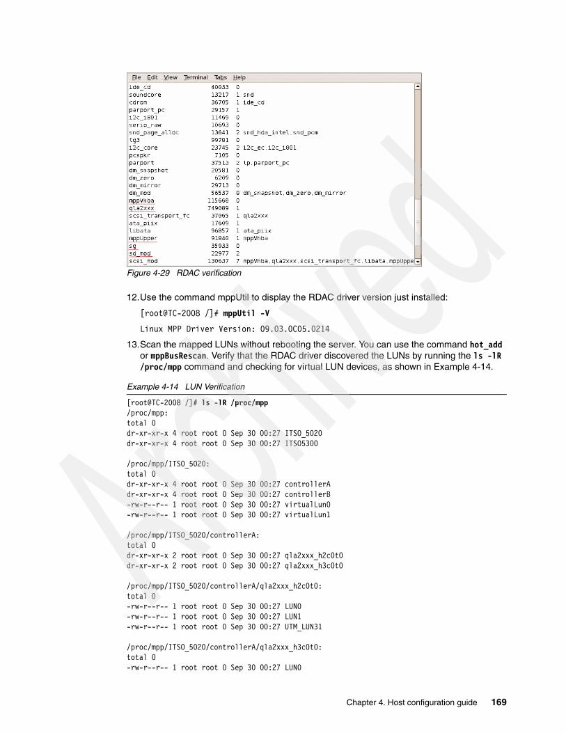
Figure 4-29 RDAC verification
12.Use the command mppUtil to display the RDAC driver version just installed:
[root@TC-2008 /]# mppUtil -V
Linux MPP Driver Version: 09.03.0C05.0214
13.Scan the mapped LUNs without rebooting the server. You can use the command hot_add or mppBusRescan. Verify that the RDAC driver discovered the LUNs by running the ls -lR /proc/mpp command and checking for virtual LUN devices, as shown in Example 4-14.
Example 4-14 LUN Verification
[root@TC-2008 /]# ls -lR /proc/mpp/proc/mpp:total 0dr-xr-xr-x 4 root root 0 Sep 30 00:27 ITSO_5020dr-xr-xr-x 4 root root 0 Sep 30 00:27 ITSO5300
/proc/mpp/ITSO_5020:total 0dr-xr-xr-x 4 root root 0 Sep 30 00:27 controllerAdr-xr-xr-x 4 root root 0 Sep 30 00:27 controllerB-rw-r--r-- 1 root root 0 Sep 30 00:27 virtualLun0-rw-r--r-- 1 root root 0 Sep 30 00:27 virtualLun1
/proc/mpp/ITSO_5020/controllerA:total 0dr-xr-xr-x 2 root root 0 Sep 30 00:27 qla2xxx_h2c0t0dr-xr-xr-x 2 root root 0 Sep 30 00:27 qla2xxx_h3c0t0
/proc/mpp/ITSO_5020/controllerA/qla2xxx_h2c0t0:total 0-rw-r--r-- 1 root root 0 Sep 30 00:27 LUN0-rw-r--r-- 1 root root 0 Sep 30 00:27 LUN1-rw-r--r-- 1 root root 0 Sep 30 00:27 UTM_LUN31
/proc/mpp/ITSO_5020/controllerA/qla2xxx_h3c0t0:total 0-rw-r--r-- 1 root root 0 Sep 30 00:27 LUN0
Chapter 4. Host configuration guide 169

-rw-r--r-- 1 root root 0 Sep 30 00:27 LUN1-rw-r--r-- 1 root root 0 Sep 30 00:27 UTM_LUN31
/proc/mpp/ITSO_5020/controllerB:total 0dr-xr-xr-x 2 root root 0 Sep 30 00:27 qla2xxx_h2c0t1dr-xr-xr-x 2 root root 0 Sep 30 00:27 qla2xxx_h3c0t1
/proc/mpp/ITSO_5020/controllerB/qla2xxx_h2c0t1:total 0-rw-r--r-- 1 root root 0 Sep 30 00:27 LUN0-rw-r--r-- 1 root root 0 Sep 30 00:27 LUN1-rw-r--r-- 1 root root 0 Sep 30 00:27 UTM_LUN31
/proc/mpp/ITSO_5020/controllerB/qla2xxx_h3c0t1:total 0-rw-r--r-- 1 root root 0 Sep 30 00:27 LUN0-rw-r--r-- 1 root root 0 Sep 30 00:27 LUN1-rw-r--r-- 1 root root 0 Sep 30 00:27 UTM_LUN31
/proc/mpp/ITSO5300:total 0dr-xr-xr-x 3 root root 0 Sep 30 00:27 controllerAdr-xr-xr-x 3 root root 0 Sep 30 00:27 controllerB-rw-r--r-- 1 root root 0 Sep 30 00:27 virtualLun0-rw-r--r-- 1 root root 0 Sep 30 00:27 virtualLun1
/proc/mpp/ITSO5300/controllerA:total 0dr-xr-xr-x 2 root root 0 Sep 30 00:27 qla2xxx_h3c0t2
/proc/mpp/ITSO5300/controllerA/qla2xxx_h3c0t2:total 0-rw-r--r-- 1 root root 0 Sep 30 00:27 LUN0-rw-r--r-- 1 root root 0 Sep 30 00:27 LUN1
/proc/mpp/ITSO5300/controllerB:total 0dr-xr-xr-x 2 root root 0 Sep 30 00:27 qla2xxx_h2c0t2
/proc/mpp/ITSO5300/controllerB/qla2xxx_h2c0t2:total 0-rw-r--r-- 1 root root 0 Sep 30 00:27 LUN0-rw-r--r-- 1 root root 0 Sep 30 00:27 LUN1
In our example, we have two DS Storage Systems with two LUNs each mapped to this Linux host. The DS Subsystem named ITSO_5020 has also mapped an access LUN. The Linux host has two HBAs, each mapped to both controllers on each Storage System.
If any changes are made to the MPP configuration file (/etc/mpp.conf) or persistent binding file (/var/mpp/devicemapping), then the mppUpdate executable can be used to rebuild the RAMdisk.
The RDAC multipath driver consists of two parts. One part (mppUpper) is loaded before any HBA is loaded and prevents the HBA from advertising the LUNs to the system, whereas the other part (mppVhba) is a virtual HBA on top of the real HBA, which is responsible for bundling the various paths to the same LUN to a single (multipath) device.
170 IBM Midrange System Storage Implementation and Best Practices Guide

To dynamically re-load the driver stack (scsi_mod, sd_mod, sg, mpp_Upper, <physical HBA driver>, mpp_Vhba) without rebooting the system, follow these steps:
1. Comment out all scsi_hostadapter entries in /etc/module.conf.2. Issue the command modprobe -r mpp_Upper to unload the driver stack.3. Then issue the command modprobe mpp_Upper to reload the driver stack.
Reboot the system whenever you have to unload the driver stack.
4.3.3 Installing DS Storage Manager software
In this section we describe the installation of the host software on a System x server running a Linux distribution with kernel v2.6. There are versions of the components available for 32-bit and 64-bit architectures. In our example, we used Red Hat Enterprise Linux 5.3, kernel 2.6.18-128.EL5.
The DS Storage Manager software needed to install and manage your system from a Linux host is available for download at the following Web site:
http://www-1.ibm.com/servers/storage/support/disk
In the Web site, select your DS Storage System product, and then click the Download option.
Select the Storage Manager software for your Linux distribution and also server type, because there are three separate IBM DS Storage Manager host software version 10.60 packages for Linux operating system environments:
� 32-bit X86 and 64-bit x86_64 or X64 (AMD64 or EM64T). � Intel Itanium® II 64-bit. � Linux on Power (LoP).
Make sure to check the readme file, because earlier or later versions of Linux kernels might not have been tested with this DS Storage Manager version, so you need to upgrade your system to a specific kernel version according to the readme file contained in the Storage MAnager package. Updated kernel packages are available for download for the various distributions.
For the Linux Red Hat updates, see the following Web sites:
http://www.redhat.comhttp://updates.redhat.com
Also check the readme file for firmware prerequisites that might exist for your Storage System.
The DS Storage Manager software for Linux operating systems is available as a single package that you can install using the installation wizard, or as individual packages that you can install manually in case you do not have a graphics adapter.
The DS Storage Manager Installation Wizard is a Java-based interactive method of choosing which packages to automatically install on your host system. The installation wizard package can be used to install all of the host software packages that are included in a single DS Storage Manager host software package:
� SMruntime� SMclien� SMesm� SMuti� SMagent
Chapter 4. Host configuration guide 171
During the execution of the wizard, you can select to install the following components:
� Typical, or Full Installation: Installs all Storage Manager software packages necessary for managing the storage subsystem from this host and providing I/O connectivity to storage
� Management Station: Installs the packages required to manage and monitor the storage subsystem (SMruntime and SMclient)
� Host: Installs the packages required to provide I/O connectivity to the storage subsystem (SMruntime, SMagent, and SMutil)
� Custom: Allows you to select which packages you want to install
The installation wizard requires a GUI interface, and this might not be available on all Linux servers, but you can still use the shell command to install DS Storage Manager using the installer through sh to run in console mode. You also have the possibility to install each of the Storage Manager components manually.
Installing Storage Manager packages with the installation wizard The installation wizard greatly simplifies the installation process of the Storage Manager. The basic installation steps are as follows:
1. If any earlier version of Storage Manager is installed, uninstall all its components. See “Uninstalling wizard-installed Storage Manager packages” on page 172.
2. Install the driver for the HBA. See “Installing the host bus adapter drivers” on page 162.
3. Install Linux RDAC from a separate package. See “Installing the Linux multipath driver” on page 165.
4. Install the Storage Manager components using the SMIA installation file. See “Installing the components using the installation wizard” on page 173. You can choose between the following installation types:
– Typical (Full) Installation: This option installs all Storage Manager components. – Management Station: Installs SMruntime and SMclient components. – Host: Installs SMruntime, SMagent, and SMutil. – Custom: You can select the components that you want.
Uninstalling wizard-installed Storage Manager packages The DS4000 Storage Manager Installation Wizard creates an uninstall directory in the directory that you specified to install the Storage Manager host software. The current default name for this directory is /opt/IBM_DS. If you have older version installed, look instead in folder /opt/IBMDS4000. Look inside for an uninstall directory or a file starting with Uninstall_IBM.
To uninstall the host software, change to the directory of the previous installation, and execute the uninstall program found there as follows:
# pwd/opt/IBM_DS/Uninstall IBM System Storage DS Storage Manager 10
# sh ./Uninstall_IBM_System_Storage_DS_Storage_Manager_10
When the wizard opens, follow the instructions.
Note: In case of problems installing the Storage Manager software in Linux Red Hat distribution, install the following libraries manually:
� libXp-1.0.0-8� compat-libstdc++-33-3.2.3
172 IBM Midrange System Storage Implementation and Best Practices Guide
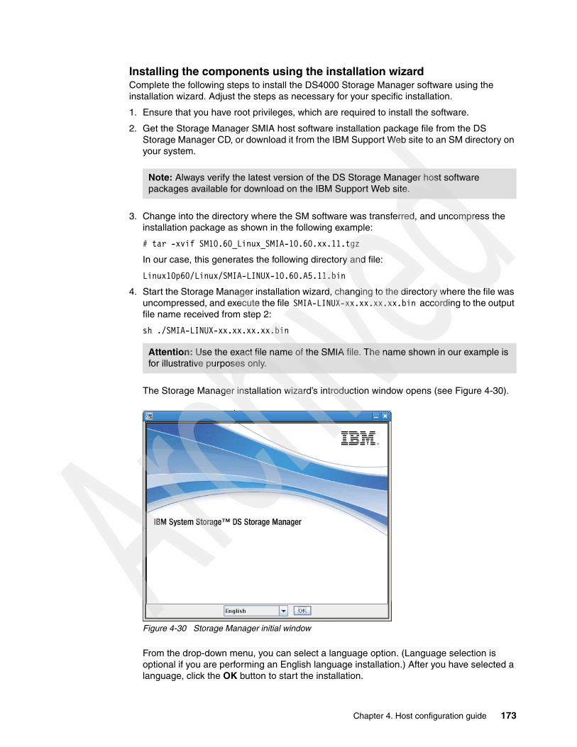
Installing the components using the installation wizardComplete the following steps to install the DS4000 Storage Manager software using the installation wizard. Adjust the steps as necessary for your specific installation.
1. Ensure that you have root privileges, which are required to install the software.
2. Get the Storage Manager SMIA host software installation package file from the DS Storage Manager CD, or download it from the IBM Support Web site to an SM directory on your system.
3. Change into the directory where the SM software was transferred, and uncompress the installation package as shown in the following example:
# tar -xvif SM10.60_Linux_SMIA-10.60.xx.11.tgz
In our case, this generates the following directory and file:
Linux10p60/Linux/SMIA-LINUX-10.60.A5.11.bin
4. Start the Storage Manager installation wizard, changing to the directory where the file was uncompressed, and execute the file SMIA-LINUX-xx.xx.xx.xx.bin according to the output file name received from step 2:
sh ./SMIA-LINUX-xx.xx.xx.xx.bin
The Storage Manager installation wizard’s introduction window opens (see Figure 4-30).
Figure 4-30 Storage Manager initial window
From the drop-down menu, you can select a language option. (Language selection is optional if you are performing an English language installation.) After you have selected a language, click the OK button to start the installation.
Note: Always verify the latest version of the DS Storage Manager host software packages available for download on the IBM Support Web site.
Attention: Use the exact file name of the SMIA file. The name shown in our example is for illustrative purposes only.
Chapter 4. Host configuration guide 173

5. Follow the instructions in each window of the wizard. When you select the installation type, you can choose one of the following options:
– Typical (Full) Installation: Installs all Storage Manager software packages – Management Station: Installs SMruntime and SMclient– Host: Installs SMruntime, SMagent, and SMutil– Custom: Allows you to select which packages you want to install
The result is that the DS4000 Storage Manager software packages are installed in the /opt/IBM_DS directory.
The various launch scripts are located in the /opt/IBM_DS directory and respective sub-directories.
Installing the components manually In case you cannot or do not want to use the InstallAnywhere wizard, you must install each component separately. To do so:
1. If an earlier version of Storage Manager is installed, remove it. See “Uninstalling Storage Manager components” on page 174.
2. Install SMruntime.
3. Install SMesm.
4. Install SMclient.
5. Install SMagent (if required for in-band management).
6. Install SMutil.
Uninstalling Storage Manager componentsBefore installing the new version of Storage Manager, you must remove and verify removal of any previous versions using the Linux rpm commands, as shown in Table 4-3.
Table 4-3 Software removal/verification commands
Steps for installing the Storage Manager components manually Use the procedures in this section to install the applicable Storage Manager software packages on a management station or host computer. These software installation procedures can also be performed using an rpm-compatible, GUI-based package manager.
Note: If you experience problems with the installation wizard installation, you must install the following packages manually:
� libXp-1.0.0-8 � compat-libstdc++-33-3.2.3
Package name Removal command Verification command
SMutil rpm -e SMutil rpm -qi SMutil
SMesm rmp -e SMesm rpm -qi SMesm
SMclient rpm -e SMclient rpm -qi SMclient
SMagent rpm -e SMagent rpm -qi SMagent
SMruntime rpm -e SMruntime rpm -qi SMruntime
174 IBM Midrange System Storage Implementation and Best Practices Guide
Ensure that you have root privileges, which are required to install the software.
Installing the Storage Manager Runtime: SMruntimeInstallation of the SMruntime package is necessary for both hosts and storage management stations. To install SMruntime, follow these steps:
1. Type the following command at the command prompt and press Enter:
rpm -ivh SMruntime-LINUX<version number>.rpm
2. To verify the installation of the SMruntime package, type the following command at the command prompt and press Enter:
rpm -qa SMruntime
3. If the installation was successful, and no failure was reported, continue with the next section. If the installation was unsuccessful, repeat steps 1 and 2. If the failure persists, see the Storage Manager Release Notes or contact your IBM technical support representative.
Installing Storage Manager ESM: SMesmInstallation of the SMesm is required for the possibility of Environmental Service Module (ESM) firmware upgrades. To install the SMesm package, follow these steps:
1. Type the following command at the system prompt and press Enter.
rpm -ivh SMesm-LINUX<version number>.rpm
2. To verify installation of the SMagent package, type the following command at the system prompt and press Enter:
rpm -qa SMesm
3. If the installation was unsuccessful, repeat steps 1 and 2. If the failure persists, see the Storage Manager Release Notes or contact your IBM technical support representative.
The result is that the DS4000 Storage Manager software packages are installed in the /opt/IBM_DS4000 directory.
The various launch scripts are located in the /opt/IBM_DS4000 directory and respective sub-directories.
Installing the Storage Manager Client: SMclientInstallation of the SMclient package is necessary only if the system is a storage management station or if the system is a host acting as a storage management station. To install the SMclient, follow these steps:
1. Type the following command at the command prompt and press Enter:
rpm -ivh SMclient-LINUX<version number>.rpm
2. To verify the installation of the SMclient package, type the following command at the command prompt and press Enter:
rpm -qa SMclient
3. If the installation was unsuccessful, repeat steps 1 and 2. If the failure persists, see the Storage Manager Release Notes or contact your IBM technical support representative.
Important: Before installing the client software, install the runtime software. A system reboot is only required when installing the RDAC driver package. The Event Monitor software is installed automatically during the client software installation.
Chapter 4. Host configuration guide 175

Disabling and enabling the Event Monitor The Event Monitor, which comes with the client software, installs automatically during the client software installation. The Event Monitor handles storage subsystem error notification through e-mail or SNMP traps when the storage management software is not actively running on the management station or host computer.
You can disable and enable the Event Monitor while the Event Monitor is running, or you can disable and enable the boot-time reloading of the Event Monitor. If you disable the Event Monitor while it is running, it starts automatically at the next reboot.
To disable the Event Monitor while the software is running, at the command prompt, type the following command and press Enter:
SMmonitor stop
When the program shutdown is complete, the system displays the following message, where xxxx represents the process ID number:
Stopping SMmonitor process <xxxx>
To enable the Event Monitor while the software is running, at the command prompt, type the following command and press Enter:
SMmonitor start
When the program startup begins, the system displays the following message:
SMmonitor started.
To disable boot-time loading of the Event Monitor, at the command prompt, type the following command and press Enter:
mv /etc/rc2.d/S99SMmonitor /etc/rc2.d/disabledS99SMmonitor
You are returned to the command prompt.
To enable boot-time loading of the Event Monitor, at the command prompt, type the following command and press Enter:
mv /etc/rc2.d/S99SMmonitor /etc/rc2.d/S99SMmonitor
You are returned to the command prompt.
Installing the Storage Manager Agent: SMagentInstallation of the Storage Manager Agent software is necessary only if the system is a host and the storage array is to be managed using the in-band storage array management method. In addition, RDAC must be installed. Follow these steps:
1. To install the SMagent package, type the following command at the system prompt and press Enter:
rpm -ivh SMagent-LINUX<version number>.rpm
Important: The Event Monitor must remain enabled if you intend to use automatic Environmental Service Modules (ESM) firmware synchronization.
If you installed the client software and configured alert notifications on multiple hosts, you might receive duplicate error messages from the same storage subsystem. To avoid receiving duplicate error messages, disable the Event Monitor on all but one system. You must run the Event Monitor on one host (server) that will run continually.
176 IBM Midrange System Storage Implementation and Best Practices Guide

2. To verify installation of the SMagent package, type the following command at the system prompt and press Enter:
rpm -qa SMagent
If the installation was unsuccessful, repeat steps 1 and 2. If the failure persists, see the Storage Manager Release Notes or contact your IBM technical support representative.
Installing the Storage Manager Utility: SMutilInstalling the SMutil package is necessary only if the system is a host. Follow these steps:
1. To install the SMutil, type the following command at the system prompt and press Enter:
rpm -ivh SMutil-LINUX<version number>.rpm
2. To verify installation of the SMutil package, type the following command at the system prompt and press Enter:
rpm -qa SMutil
If the installation was successful, and no failure was reported, continue with the following section. If the installation was unsuccessful, repeat steps 1 and 2. If the failure persists, see the Storage Manager Release Notes or contact your IBM technical support representative.
Updating the host softwareTo update the host software in a Linux environment, follow these steps:
1. Uninstall the storage manager components in the following order:
a. DS4000 Runtime environmentb. SMutilc. RDACd. SMclient
Verify that IBM host adapter device driver versions are current. If they are not current, see the readme file located with the device driver and then upgrade the device drivers.
2. Install the storage manager components in the following order:
a. SMagentb. DS Runtime environment\c. RDACd. SMutile. SMclient
4.3.4 Configuring Linux for iSCSI attachment
The DS Storage Systems has the option to attach your hosts using iSCSI interfaces. In this section we show how to define your Linux to use a regular Ethernet network interface card, NIC, using software iSCSI Initiator to connect to a DS5020 system with iSCSI host interface cards.
Installing and configuring the iSCSI software initiatorRed Hat Enterprise Linux includes an iSCSI software initiator. The software initiator is included in the installation media in the package directory as an RPM file.
To check if you already have the iSCSI initiator software installed, use the command shown in Example 4-15.
Chapter 4. Host configuration guide 177

Example 4-15 Checking initiator software
[root@TC-2008 /]# rpm -qi iscsi-initiator-utilsName : iscsi-initiator-utils Relocations: (not relocatable)Version : 6.2.0.871 Vendor: Red Hat, Inc.Release : 0.10.el5 Build Date: Wed 12 Aug 2009 09:58:30 AM MSTInstall Date: Tue 29 Sep 2009 05:45:53 PM MST Build Host: ls20-bc2-13.build.redhat.comGroup : System Environment/Daemons Source RPM: iscsi-initiator-utils-6.2.0.871-0.10.el5.src.rpmSize : 1882387 License: GPLSignature : DSA/SHA1, Thu 13 Aug 2009 07:47:25 AM MST, Key ID 5326810137017186Packager : Red Hat, Inc. <http://bugzilla.redhat.com/bugzilla>URL : http://www.open-iscsi.orgSummary : iSCSI daemon and utility programsDescription :The iscsi package provides the server daemon for the iSCSI protocol,as well as the utility programs used to manage it. iSCSI is a protocolfor distributed disk access using SCSI commands sent over InternetProtocol networks.
If you do not see a similar output, install the software initiator. Mount the installation media and install the iSCSI software initiator RPM file, as in Example 4-16.
Example 4-16 Installation of the iSCSI software initiator RPM file
[root@TC-2008 /]]# mount /dev/cdrom[root@TC-2008 /]]# cd /media/cdrom/Server[root@TC-2008 /]]# rpm -ivh iscsi-initiator-utils-6.2.0.868-0.18.el5.i386.rpmPreparing... ########################################### [100%] 1:iscsi-initiator-utils ########################################### [100%][root@TC-2008 /]]#
After the iSCSI software initiator is installed, we need to check two configuration files in the /etc/iscsi directory.
Determining the initiator nameThe initiator name assigned by default is in file /etc/iscsi/initiatorname.iscsi. After the iSCSI daemon is started for the first time, this file will be populated with the iSCSI qualified name of the host.
Example 4-17 shows the file with an automatically generated iSCSI Qualified Name (IQN). This IQN is regenerated to the same value when the software initiator gets reinstalled.
Example 4-17 /etc/iscsi/nitiatorname.iscsi after first iSCSI daemon start
root@TC-2008 /]# more /etc/iscsi/initiatorname.iscsiInitiatorName=iqn.1994-05.com.redhat:aa8ddfdec39c[root@TC-2008 /]#
You can generate a new IQN to assign to your host using the iscsi-iname command, which will generate a unique IQN with the correct format and output it to the console. Example 4-18 shows how to use the iscsi-iname command to define the IQN of a given host. The output can be redirected into /etc/initiatorname.iscsi to change the actual host initiator name.
178 IBM Midrange System Storage Implementation and Best Practices Guide

Example 4-18 iscsi-iname
[root@TC-2008 /]# iscsi-inameiqn.1994-05.com.redhat:93a8855dcc2[root@TC-2008 /]#
Starting the iSCSI serviceWith the iscsi tools configured, then we start the iscsi daemon, and we configure it to start automatically after each reboot. Use the commands, as shown in Example 4-19.
Example 4-19 Starting iSCSI daemon
[root@TC-2008 /]# service iscsid startTurning off network shutdown. Starting iSCSI daemon: [ OK ] [ OK ][root@TC-2008 /]#
To load the iSCSI driver during reboot, it is necessary to modify the service database. Run the command chkconfig iscsi on to enable the load of the iSCSI driver during system start, as shown in Example 4-20.
Example 4-20 Enable iSCSI during system start
[root@TC-2008 /]# chkconfig iscsi on[root@TC-2008 /]#
Configuring the connection to the targetWith the iSCSI service running, we can start using the utility iscsiadm. This command is used for managing and configuring iSCSi in general, so we will continue to use it later.
To obtain a list of available targets from a given host, we use the iscsiadm command to discovery any available targets, providing the IP address of any of your DS Storage System iSCSI host ports. In our example, the DS5020 has its iSCSI host port addresses set to 9.11.218.158 and 9.11.218.161.
Example 4-21 Discovering targets
[root@TC-2008 /]# iscsiadm -m discovery -t sendtargets -p 9.11.218.15810.10.10.20:3260,2 iqn.1992-01.com.lsi:4981.60080e500017b5bc000000004a955e3b9.11.218.161:3260,2 iqn.1992-01.com.lsi:4981.60080e500017b5bc000000004a955e3b9.11.218.158:3260,1 iqn.1992-01.com.lsi:4981.60080e500017b5bc000000004a955e3b[fe80:0000:0000:0000:02a0:b8ff:fe20:d0a3]:3260,2 iqn.1992-01.com.lsi:4981.60080e500017b5bc000000004a955e3b[fe80:0000:0000:0000:02a0:b8ff:fe20:d099]:3260,1 iqn.1992-01.com.lsi:4981.60080e500017b5bc000000004a955e3b[fe80:0000:0000:0000:02a0:b8ff:fe20:d0a1]:3260,2 iqn.1992-01.com.lsi:4981.60080e500017b5bc000000004a955e3b[2002:090b:e002:0218:02a0:b8ff:fe20:d0a3]:3260,2 iqn.1992-01.com.lsi:4981.60080e500017b5bc000000004a955e3b[2002:090b:e002:0218:02a0:b8ff:fe20:d09b]:3260,1 iqn.1992-01.com.lsi:4981.60080e500017b5bc000000004a955e3b10.10.10.10:3260,1 iqn.1992-01.com.lsi:4981.60080e500017b5bc000000004a955e3b[fe80:0000:0000:0000:02a0:b8ff:fe20:d09b]:3260,1 iqn.1992-01.com.lsi:4981.60080e500017b5bc000000004a955e3b
Chapter 4. Host configuration guide 179
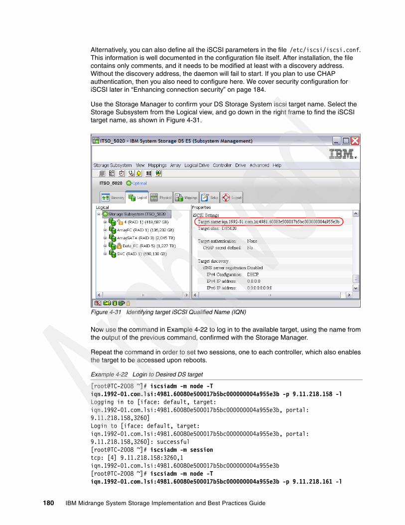
Alternatively, you can also define all the iSCSI parameters in the file /etc/iscsi/iscsi.conf. This information is well documented in the configuration file itself. After installation, the file contains only comments, and it needs to be modified at least with a discovery address. Without the discovery address, the daemon will fail to start. If you plan to use CHAP authentication, then you also need to configure here. We cover security configuration for iSCSI later in “Enhancing connection security” on page 184.
Use the Storage Manager to confirm your DS Storage System iscsi target name. Select the Storage Subsystem from the Logical view, and go down in the right frame to find the iSCSI target name, as shown in Figure 4-31.
Figure 4-31 Identifying target iSCSI Qualified Name (IQN)
Now use the command in Example 4-22 to log in to the available target, using the name from the output of the previous command, confirmed with the Storage Manager.
Repeat the command in order to set two sessions, one to each controller, which also enables the target to be accessed upon reboots.
Example 4-22 Login to Desired DS target
[root@TC-2008 ~]# iscsiadm -m node -T iqn.1992-01.com.lsi:4981.60080e500017b5bc000000004a955e3b -p 9.11.218.158 -lLogging in to [iface: default, target: iqn.1992-01.com.lsi:4981.60080e500017b5bc000000004a955e3b, portal: 9.11.218.158,3260]Login to [iface: default, target: iqn.1992-01.com.lsi:4981.60080e500017b5bc000000004a955e3b, portal: 9.11.218.158,3260]: successful[root@TC-2008 ~]# iscsiadm -m sessiontcp: [4] 9.11.218.158:3260,1 iqn.1992-01.com.lsi:4981.60080e500017b5bc000000004a955e3b[root@TC-2008 ~]# iscsiadm -m node -T iqn.1992-01.com.lsi:4981.60080e500017b5bc000000004a955e3b -p 9.11.218.161 -l
180 IBM Midrange System Storage Implementation and Best Practices Guide

Logging in to [iface: default, target: iqn.1992-01.com.lsi:4981.60080e500017b5bc000000004a955e3b, portal: 9.11.218.161,3260]Login to [iface: default, target: iqn.1992-01.com.lsi:4981.60080e500017b5bc000000004a955e3b, portal: 9.11.218.161,3260]: successful
Defining the host in the DS Storage SystemAfter successfully logging in to the desired DS Storage System, go to the Storage Manager software and create a host, adding the newly found host port identifier corresponding to the Linux server initiator name.
From the Subsystem Management window of the Storage Manager, select Mappings Define Host. After assigning a name, you have to select the connection interface type, and host port identifier. Because the server is already logged to the DS Storage System, you can pick the host port identifier from the known unassociated list, which has to match with the initiator name of your server. Display the file /etc/iscsi/initiatorname from your server to make sure assign the correct identifier for the host, as shown in Figure 4-32:
Figure 4-32 Defining Host with discovered Initiator name
Now, with the Host defined, proceed to map the logical volumes planned to attach to the Linux host. After it is mapped, proceed to install the RDAC driver in your Linux operating system, as detailed in 4.3.2, “Installing the Linux multipath driver” on page 165.
root@TC-2008 /]# more /etc/iscsi/initiatorname.iscsiInitiatorName=iqn.1994-05.com.redhat:aa8ddfdec39c
Chapter 4. Host configuration guide 181

Displaying iSCSI sessionsAn iSCSI session is a communication link established between an initiator and a target. In our installation example, we have a single NIC with connections established to both controllers during the login, executed as described in “Configuring the connection to the target” on page 179.
The DS Storage System implementation does not allow for multiple connections per target, so each session will have only one connection established against a single controller port. If you have a single Ethernet card in your host attaching your storage, and only one ISCSI port defined per controller, then you must have two sessions established, one to each controller, as in this implementation example.
Use the iscsi adm command to display the sessions in your host. To display the session information from the DS Storage Manager, select from your Storage subsystem Management window, Storage Subsystem iSCSI End Sessions, as shown in Figure 4-33.
Figure 4-33 Displaying sessions established
Always check that you have established connections to each controller, as in the example. In the details section of the View/End iSCSI Sessions window, you can confirm the IP address participating in each session.
To display the details of each section from your Linux host, use the iscsiadm command, with the parameters shown in Example 4-23.
[root@TC-2008 sbin]# iscsiadm -m sessiontcp: [4] 9.11.218.158:3260,1 iqn.1992-01.com.lsi:4981.60080e500017b5bc000000004a955e3btcp: [5] 9.11.218.161:3260,2 iqn.1992-01.com.lsi:4981.60080e500017b5bc000000004a955e3b
182 IBM Midrange System Storage Implementation and Best Practices Guide
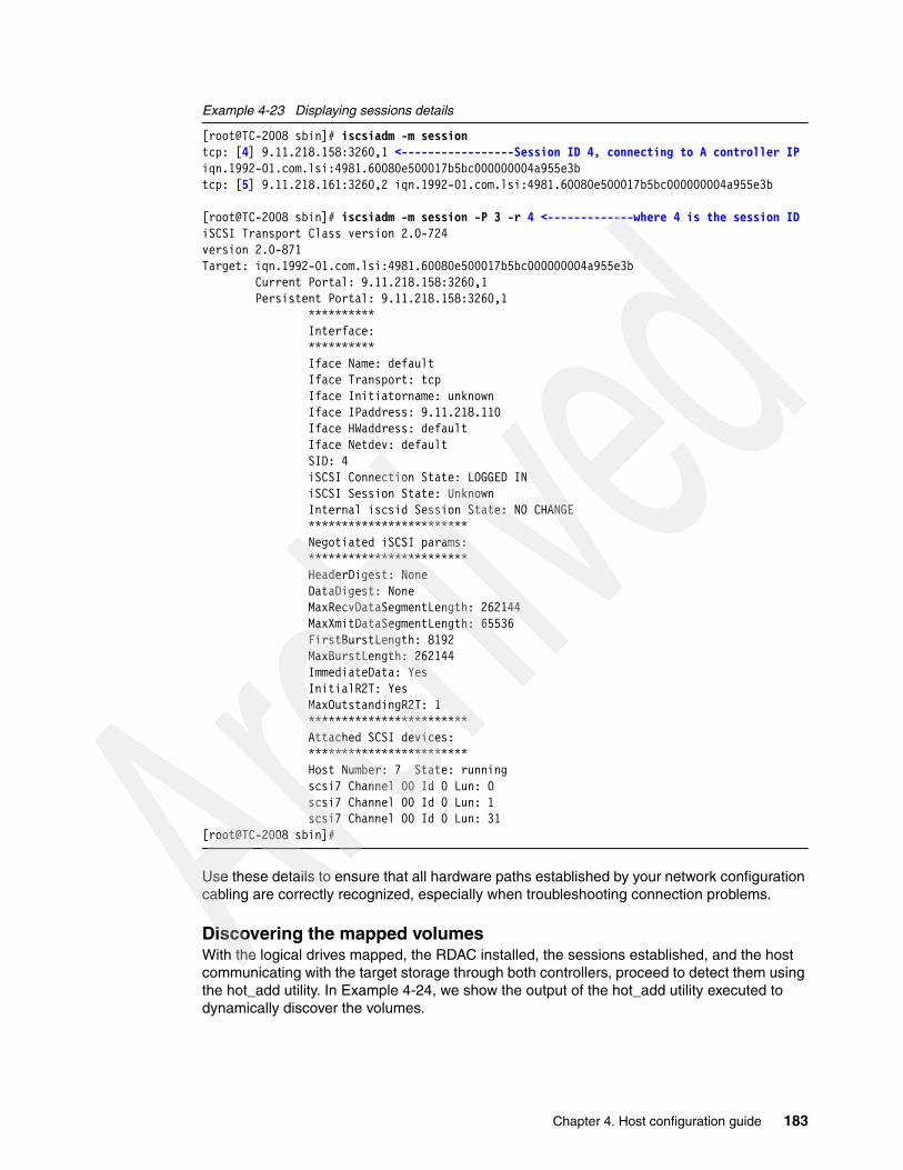
Example 4-23 Displaying sessions details
[root@TC-2008 sbin]# iscsiadm -m sessiontcp: [4] 9.11.218.158:3260,1 <-----------------Session ID 4, connecting to A controller IPiqn.1992-01.com.lsi:4981.60080e500017b5bc000000004a955e3btcp: [5] 9.11.218.161:3260,2 iqn.1992-01.com.lsi:4981.60080e500017b5bc000000004a955e3b
[root@TC-2008 sbin]# iscsiadm -m session -P 3 -r 4 <-------------where 4 is the session IDiSCSI Transport Class version 2.0-724version 2.0-871Target: iqn.1992-01.com.lsi:4981.60080e500017b5bc000000004a955e3b Current Portal: 9.11.218.158:3260,1 Persistent Portal: 9.11.218.158:3260,1 ********** Interface: ********** Iface Name: default Iface Transport: tcp Iface Initiatorname: unknown Iface IPaddress: 9.11.218.110 Iface HWaddress: default Iface Netdev: default SID: 4 iSCSI Connection State: LOGGED IN iSCSI Session State: Unknown Internal iscsid Session State: NO CHANGE ************************ Negotiated iSCSI params: ************************ HeaderDigest: None DataDigest: None MaxRecvDataSegmentLength: 262144 MaxXmitDataSegmentLength: 65536 FirstBurstLength: 8192 MaxBurstLength: 262144 ImmediateData: Yes InitialR2T: Yes MaxOutstandingR2T: 1 ************************ Attached SCSI devices: ************************ Host Number: 7 State: running scsi7 Channel 00 Id 0 Lun: 0 scsi7 Channel 00 Id 0 Lun: 1 scsi7 Channel 00 Id 0 Lun: 31[root@TC-2008 sbin]#
Use these details to ensure that all hardware paths established by your network configuration cabling are correctly recognized, especially when troubleshooting connection problems.
Discovering the mapped volumesWith the logical drives mapped, the RDAC installed, the sessions established, and the host communicating with the target storage through both controllers, proceed to detect them using the hot_add utility. In Example 4-24, we show the output of the hot_add utility executed to dynamically discover the volumes.
Chapter 4. Host configuration guide 183

Example 4-24 Discovering mapped volumes
[root@TC-2008 /]# hot_addscan iSCSI software initiator host /sys/class/scsi_host/host8... found 8:0:0:0 found 8:0:0:1scan iSCSI software initiator host /sys/class/scsi_host/host7... found 7:0:0:0 found 7:0:0:1run /usr/sbin/mppUtil -s busscan...ls: /sys/bus/scsi/drivers/sd/*/block:*: No such file or directoryls: /sys/bus/scsi/drivers/sd/*/block:*: No such file or directory[root@TC-2008 /]
Now the iSCSI driver and MPP are loaded, recognizing the multiple paths per disk volume. We verify the volume and its connections later in 4.3.5, “Managing DS Storage volumes from Linux” on page 185.
Enhancing connection securityAfter everything is working and tested, you must implement security for the iSCSI connection; essentially, this means configuring initiator and target authentication. Initiator authentication means that an initiator must prove its identity with a password that is known by the target when the initiator attempts access. Target authentication is the opposite; the target authenticates itself to the initiator with a password.
Because an iSCSI qualified name can be modified within Storage Manager, this does not protect against spoofing of the qualified name, and hence security can be compromised. We describe the steps required to set up initiator and target authentication.
Just like a hardware based initiator, the software initiator requires initiator authentication as a prerequisite for target authentication. Follow these steps:
1. Use the iscsiadm command or directly edit the configuration file /etc/iscsi/iscsid.conf of the iSCSI software initiator. Define the incoming and outgoing user names and passwords in this file. Incoming means that the target has to authenticate itself against the initiator, and is also called target authentication. Outgoing represents the initiator authentication. The initiator has to authenticate against a target.
Incoming and outgoing user names are limited to valid IQNs by the DS5020 defined as host ports.
Example 4-25 shows the /etc/iscsi/iscsid.conf file with the incoming and outgoing account details. The incoming account was configured as a local option for the target and not a global option. Other subsystems might use another password.
Example 4-25 Configuration of the iSCSI software initiator
HeaderDigest=alwaysDataDigest=alwaysOutgoingUsername=iqn.1994-05.com.redhat:aa8ddfdec39cOutgoingPassword=b1234567890h
Targetname=iqn.1992-01.com.lsi:4981.60080e500017b5bc000000004a955e3b Enabled=yes IncomingUsername=iqn.1992-01.com.lsi:4981.60080e500017b5bc000000004a955e3b IncomingPassword=a1234567890t ConnFailTimeout=15
184 IBM Midrange System Storage Implementation and Best Practices Guide

2. Shut down the server until the DS5020 is also configured.
3. Use the Storage Manager CLI commands (set iscsiInitiator) shown in Example 4-26 to set up the CHAP secret (Challenge Handshake Authentication Protocol) for the already defined host ports of host TC-2008.
Example 4-26 SMcli commands to set CHAP secrets for initiators
# SMcli -n ITSO_5020 -c "set iscsiInitiator [\"TC-2008\"] host=\"TC-2008\" chapSecret=\"b1234567890h\"; " -S#
4. Clarify if there are any initiators without target authentication configured that access the DS5020. In that case, use the command in Example 4-27; otherwise, use the command shown in Example 4-28.
Example 4-27 SMcli - Set target authentication - CHAP only
# SMcli -n ITSO_5020 -c "set iscsiTarget <\"iqn.1992-01.com.lsi:4981.60080e500017b5bc000000004a955e3b\"> authenticationMethod=chap chapSecret=\"a01234567890t\";" -S#
Example 4-28 SMcli - Set target authentication - CHAP and no CHAP
# SMcli -n ITSO_5020 -c "set iscsiTarget <\"iqn.1992-01.com.lsi:4981.60080e500017b5bc000000004a955e3b\"> authenticationMethod=none authenticationMethod=chap chapSecret=\"a01234567890t\";" -S#
After modifying the configuration on the DS5020, reboot the server to get access to the logical drives by using initiator and target authentication.
4.3.5 Managing DS Storage volumes from Linux
Next we cover how to verify and display the resources presented to the Linux host related to the Storage systems mapped. To do that, we use Linux commands, RDAC utilities, and SMutil software utilities.
Here we describe the RDAC utilities and their functions:
� mppUtil: This utility is used with the Linux RDAC driver to perform the various functions provided by the driver.
� hot_add: This command rescans your HBA to detect and configure new devices on SAN. It is actually a link to the mppBusRescan.
� mppBusRescan: This program is equivalent to hot_add and also probes the physical bus hardware to discover any newly attached DS4000 devices, which can either be new LUNs on an existing system or a new storage system, or new paths to an already configured disk. All the physical buses are scanned for new devices or LUNs. Any that are found are registered with the OS and attached to the RDAC driver. This script must be run any time that new storage server devices are connected, new LUNs are mapped, or new paths added.
Note: CHAP (RFC1944) is the most basic level of iSCSI security available.
Chapter 4. Host configuration guide 185
� mppUpdate: This script uses the mppUtil utility to discover the RDAC-assigned virtual target IDs of the attached subsystems. It then updates the RDAC driver configuration file (/var/mpp/devicemapping), so the entries will be persistent after a reboot. The first time that the RDAC driver sees a storage system, it will arbitrarily assign a target ID for the virtual target that represents the storage system. At this point the target ID assignment is not persistent. It can change on a reboot. The mppUpdate utility updates the RDAC driver configuration files so that these target ID assignments are persistent and do not change across reboots. After it has been made persistent, the user does not have to worry about the possibility of device names changing and invalidating mount points.
mppUpdate must be executed after a DS is added to or removed from the system. If a storage system is added to the installation, mppBusRescan also must be run before mppUpdate is run. mppUpdate must also be executed whenever a user changes the RDAC configuration file /etc/mpp.conf to rebuild the new configuration file into the RAM Disk image that will be used for the next reboot.
The SMutil host software utility package provides additional commands for listing and adding DS5000 Storage Server devices.
SMdevices: This utility, also available in other operating systems with the SMutil package installed, provides a complete list of all logical volumes mapped to your host, indicating the name set in the Storage Manager for each logical volume, for easy identification.
Next we show examples of usage for each utility.
Verifying detected pathsWe use the following commands in this section to verify devices and paths detected:
� cat /proc/scsi/scsi� ls -lR /proc/mpp/*
cat /proc/scsi/scsiAfter the LUNs are mapped to your Linux server, and the hardware scanned for changes, the kernel builds the file /proc/scsi/scsi with the information observed in all the possible paths beginning with each storage adapter.
Because in our implementation example, we have one port of each controller defined for iSCSI, each with a session established to the single Ethernet card configured for iSCSI, the file /proc/scsi/scsi will show each disk mapped twice, one per each path.
Later, the MPP or RDAC driver use this path structures recognized at the HBA level, and combines them to show only one disk to the user.
In Example 4-29 we show the contents of the file /proc/scsi/scsi for this implementation.
Example 4-29 Displaying /proc/scsi/scsi output
[root@TC-2008 /]# cat /proc/scsi/scsiAttached devices:Host: scsi8 Channel: 00 Id: 00 Lun: 00 Vendor: IBM Model: 1814 FAStT Rev: 1060 Type: Direct-Access ANSI SCSI revision: 05Host: scsi8 Channel: 00 Id: 00 Lun: 01 Vendor: IBM Model: 1814 FAStT Rev: 1060 Type: Direct-Access ANSI SCSI revision: 05Host: scsi8 Channel: 00 Id: 00 Lun: 31 Vendor: IBM Model: Universal Xport Rev: 1060 Type: Direct-Access ANSI SCSI revision: 05
186 IBM Midrange System Storage Implementation and Best Practices Guide

Host: scsi7 Channel: 00 Id: 00 Lun: 00 Vendor: IBM Model: 1814 FAStT Rev: 1060 Type: Direct-Access ANSI SCSI revision: 05Host: scsi7 Channel: 00 Id: 00 Lun: 01 Vendor: IBM Model: 1814 FAStT Rev: 1060 Type: Direct-Access ANSI SCSI revision: 05Host: scsi7 Channel: 00 Id: 00 Lun: 31 Vendor: IBM Model: Universal Xport Rev: 1060 Type: Direct-Access ANSI SCSI revision: 05Host: scsi9 Channel: 00 Id: 00 Lun: 00 Vendor: IBM Model: VirtualDisk Rev: 1060 Type: Direct-Access ANSI SCSI revision: 05Host: scsi9 Channel: 00 Id: 00 Lun: 01 Vendor: IBM Model: VirtualDisk Rev: 1060 Type: Direct-Access ANSI SCSI revision: 05[root@TC-2008 /]#
The implementation in the example shows two LUNs mapped, ID 0 and 1, and the access LUN. Each one is reached through two separate paths, belonging from adapters named scsi 8 and scsi 7, as well as the Access LUN, id 31, also called Universal Xport.
The VirtualDisks observed, are already an abstraction of each LUN, to be presented to the user as physical disks.
ls -lR /proc/mppThe MPP driver adds a directory in the proc file system that allows us to verify what paths are active and which devices and LUNs are discovered. Example 4-30 shows the directory structure of /proc/mpp with targets and LUNs that are handled by the MPP driver.
Example 4-30 /proc/mpp/ directory structure
[root@TC-2008 /]# ls -lR /proc/mpp/proc/mpp:total 0dr-xr-xr-x 4 root root 0 Sep 30 18:07 ITSO_5020
/proc/mpp/ITSO_5020:total 0dr-xr-xr-x 3 root root 0 Sep 30 18:07 controllerAdr-xr-xr-x 3 root root 0 Sep 30 18:07 controllerB-rw-r--r-- 1 root root 0 Sep 30 18:07 virtualLun0-rw-r--r-- 1 root root 0 Sep 30 18:07 virtualLun1
/proc/mpp/ITSO_5020/controllerA:total 0dr-xr-xr-x 2 root root 0 Sep 30 18:07 iscsi_tcp_h7c0t0
/proc/mpp/ITSO_5020/controllerA/iscsi_tcp_h7c0t0:total 0-rw-r--r-- 1 root root 0 Sep 30 18:07 LUN0-rw-r--r-- 1 root root 0 Sep 30 18:07 LUN1-rw-r--r-- 1 root root 0 Sep 30 18:07 UTM_LUN31
/proc/mpp/ITSO_5020/controllerB:total 0dr-xr-xr-x 2 root root 0 Sep 30 18:07 iscsi_tcp_h8c0t0
Chapter 4. Host configuration guide 187

/proc/mpp/ITSO_5020/controllerB/iscsi_tcp_h8c0t0:total 0-rw-r--r-- 1 root root 0 Sep 30 18:07 LUN0-rw-r--r-- 1 root root 0 Sep 30 18:07 LUN1-rw-r--r-- 1 root root 0 Sep 30 18:07 UTM_LUN31
Now you can partition and format the drives for use.
The RDAC driver for Linux provides several utilities to manage your DS Storage from your Linux host. In addition, you can also use the host software utility, if SMutil is installed, running the SMdevices command.
Next we show more usage examples for those utilities.
Listing DS Storage Systems from LinuxIf you want to scan for all the DS Storage Systems that are attached to your Linux host, you must use the command mpputil -a, as shown in Example 4-31.
Example 4-31 mppUtil -a
[root@TC-2008 /]# mppUtil -aHostname = TC-2008Domainname = (none)Time = GMT 09/30/2009 04:34:27
---------------------------------------------------------------Info of Array Module's seen by this Host.---------------------------------------------------------------ID WWN Type Name--------------------------------------------------------------- 0 60080e500017b5bc000000004a955e3b FC ITSO_5020 1 600a0b80004777d8000000004a956964 FC ITSO5300---------------------------------------------------------------
In Example 4-31 two DS5000s are presented to the Linux host. Each one is listed by its name, as set in the Storage Manager. Use the name to query for specific details of the subsystem, for example, executing either mppUtil -a ITSO5300 or mppUtil -g 1.
Displaying DS Storage devices from LinuxIn addition to the RDAC utilities, when installing the Storage Manager host software, you get access to the same utilities as in other operating systems.
SMdevices is the command to display the available resources mapped from all the DS Storage Systems. It presents a simple output with valuable information to identify the logical volumes as seen by the host, but still showing the names assigned in the DS Storage configuration.
In Example 4-32, we show a sample SMdevices output.
Example 4-32 SMdevices output
[root@TC-2008 /]# SMdevicesDS Storage Manager Utilities Version 10.00.A5.13.... /dev/sda (/dev/sg0) [Storage Subsystem ITSO_5020, Logical Drive TC-2008-1, LUN 0, Logical Drive ID <60080e500017b5bc000047d04aaa2559>, Preferred Path (Controller-A): In Use]
188 IBM Midrange System Storage Implementation and Best Practices Guide
/dev/sdb (/dev/sg1) [Storage Subsystem ITSO_5020, Logical Drive TC-2008-2, LUN 1, Logical Drive ID <60080e500017b5bc000048444aafd60a>, Preferred Path (Controller-B): In Use] <n/a> (/dev/sg2) [Storage Subsystem ITSO_5020, Logical Drive Access, LUN 31, Logical Drive ID <60080e500017b5bc000043834a955f8a>] <n/a> (/dev/sg3) [Storage Subsystem ITSO_5020, Logical Drive Access, LUN 31, Logical Drive ID <60080e500017b5bc000043834a955f8a>] <n/a> (/dev/sg4) [Storage Subsystem ITSO_5020, Logical Drive Access, LUN 31, Logical Drive ID <60080e500017b5bc000043834a955f8a>] <n/a> (/dev/sg5) [Storage Subsystem ITSO_5020, Logical Drive Access, LUN 31, Logical Drive ID <60080e500017b5bc000043834a955f8a>] /dev/sdc (/dev/sg6) [Storage Subsystem ITSO5300, Logical Drive TC-2008-Vol1, LUN 0, Logical Drive ID <600a0b800047709c0000852c4abb84f4>, Preferred Path (Controller-A): In Use] /dev/sdd (/dev/sg7) [Storage Subsystem ITSO5300, Logical Drive TC-2008-Vol2, LUN 1, Logical Drive ID <600a0b80004777d800007e764abb86b6>, Preferred Path (Controller-B): In Use]
Notice that the SMdevices output lists all the volumes found, from any DS Storage System with LUNs mapped to this host. If you have more than one system, use the Storage Subsystem name to identify each LUN, not only the LUN ID.
You can use the LUN, logical drive ID, logical drive name, or Linux assigned name (such as /dev/sdc) alternatively to identify each volume. See Example 4-33.
Example 4-33 mppUtil -a DSname
[root@TC-2008 /]# mppUtil -a ITSO5300Hostname = TC-2008Domainname = (none)Time = GMT 09/30/2009 04:42:45
MPP Information:---------------- ModuleName: ITSO5300 SingleController: N VirtualTargetID: 0x001 ScanTriggered: N ObjectCount: 0x000 AVTEnabled: Y WWN: 600a0b80004777d8000000004a956964 RestoreCfg: N ModuleHandle: none Page2CSubPage: Y FirmwareVersion: 7.60.13.xx ScanTaskState: 0x00000000 LBPolicy: LeastQueueDepth
Controller 'A' Status:-----------------------ControllerHandle: none ControllerPresent: Y UTMLunExists: N Failed: N NumberOfPaths: 1 FailoverInProg: N ServiceMode: N Path #1 --------- DirectoryVertex: present Present: Y PathState: OPTIMAL PathId: 77030002 (hostId: 3, channelId: 0, targetId: 2)
Controller 'B' Status:-----------------------ControllerHandle: none ControllerPresent: Y UTMLunExists: N Failed: N NumberOfPaths: 1 FailoverInProg: N ServiceMode: N Path #1 ---------
Chapter 4. Host configuration guide 189
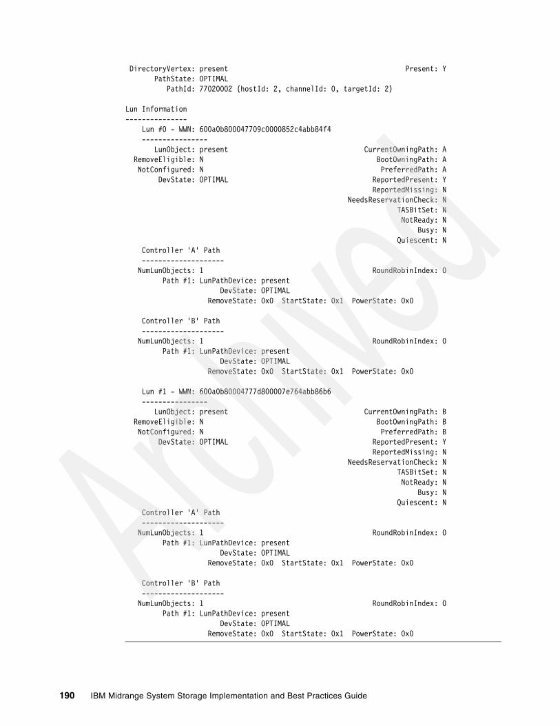
DirectoryVertex: present Present: Y PathState: OPTIMAL PathId: 77020002 (hostId: 2, channelId: 0, targetId: 2)
Lun Information--------------- Lun #0 - WWN: 600a0b800047709c0000852c4abb84f4 ---------------- LunObject: present CurrentOwningPath: A RemoveEligible: N BootOwningPath: A NotConfigured: N PreferredPath: A DevState: OPTIMAL ReportedPresent: Y ReportedMissing: N NeedsReservationCheck: N TASBitSet: N NotReady: N Busy: N Quiescent: N Controller 'A' Path -------------------- NumLunObjects: 1 RoundRobinIndex: 0 Path #1: LunPathDevice: present DevState: OPTIMAL RemoveState: 0x0 StartState: 0x1 PowerState: 0x0
Controller 'B' Path -------------------- NumLunObjects: 1 RoundRobinIndex: 0 Path #1: LunPathDevice: present DevState: OPTIMAL RemoveState: 0x0 StartState: 0x1 PowerState: 0x0
Lun #1 - WWN: 600a0b80004777d800007e764abb86b6 ---------------- LunObject: present CurrentOwningPath: B RemoveEligible: N BootOwningPath: B NotConfigured: N PreferredPath: B DevState: OPTIMAL ReportedPresent: Y ReportedMissing: N NeedsReservationCheck: N TASBitSet: N NotReady: N Busy: N Quiescent: N Controller 'A' Path -------------------- NumLunObjects: 1 RoundRobinIndex: 0 Path #1: LunPathDevice: present DevState: OPTIMAL RemoveState: 0x0 StartState: 0x1 PowerState: 0x0
Controller 'B' Path -------------------- NumLunObjects: 1 RoundRobinIndex: 0 Path #1: LunPathDevice: present DevState: OPTIMAL RemoveState: 0x0 StartState: 0x1 PowerState: 0x0
190 IBM Midrange System Storage Implementation and Best Practices Guide
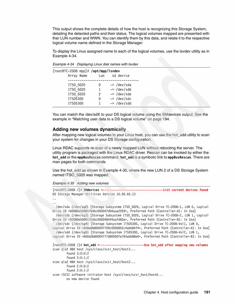
This output shows the complete details of how the host is recognizing this Storage System, detailing the detected paths and their status. The logical volumes mapped are presented with ther LUN number and WWN. You can identify them by this data, and relate it to the respective logical volume name defined in the Storage Manager.
To display the Linux assigned name to each of the logical volumes, use the lsvdev utility as in Example 4-34.
Example 4-34 Displaying Linux disk names with lsvdev
[root@TC-2008 mpp]# /opt/mpp/lsvdev Array Name Lun sd device ------------------------------------- ITSO_5020 0 -> /dev/sda ITSO_5020 1 -> /dev/sdb ITSO_5020 2 -> /dev/sde ITSO5300 0 -> /dev/sdc ITSO5300 1 -> /dev/sdd
You can match the /dev/sdX to your DS logical volume using the SMdevices output. See the example in “Matching user data to a DS logical volume” on page 194.
Adding new volumes dynamicallyAfter mapping new logical volumes to your Linux host, you can use the hot_add utility to scan your system for changes in your DS Storage configuration.
Linux RDAC supports re-scan of a newly mapped LUN without rebooting the server. The utility program is packaged with the Linux RDAC driver. Rescan can be invoked by either the hot_add or the mppBusRescan command. hot_add is a symbolic link to mppBusRescan. There are man pages for both commands.
Use the hot_add as shown in Example 4-35, where the new LUN 2 of a DS Storage System named ITSO_5020 was mapped:
Example 4-35 Adding new volumes
[root@TC-2008 /]# SMdevices <-----------------------------------List current devices foundDS Storage Manager Utilities Version 10.00.A5.13.... /dev/sda (/dev/sg2) [Storage Subsystem ITSO_5020, Logical Drive TC-2008-1, LUN 0, Logical Drive ID <60080e500017b5bc000047d04aaa2559>, Preferred Path (Controller-A): In Use] /dev/sdb (/dev/sg3) [Storage Subsystem ITSO_5020, Logical Drive TC-2008-2, LUN 1, Logical Drive ID <60080e500017b5bc000048444aafd60a>, Preferred Path (Controller-B): In Use] /dev/sdc (/dev/sg4) [Storage Subsystem ITSO5300, Logical Drive TC-2008-Vol1, LUN 0, Logical Drive ID <600a0b800047709c0000852c4abb84f4>, Preferred Path (Controller-A): In Use] /dev/sdd (/dev/sg5) [Storage Subsystem ITSO5300, Logical Drive TC-2008-Vol2, LUN 1, Logical Drive ID <600a0b80004777d800007e764abb86b6>, Preferred Path (Controller-B): In Use]
[root@TC-2008 /]# hot_add <--------------------------Use hot_add after mapping new volumesscan qla2 HBA host /sys/class/scsi_host/host3... found 3:0:0:2 found 3:0:1:2scan qla2 HBA host /sys/class/scsi_host/host2... found 2:0:0:2 found 2:0:1:2scan iSCSI software initiator host /sys/class/scsi_host/host6... no new device found
Chapter 4. Host configuration guide 191

scan iSCSI software initiator host /sys/class/scsi_host/host5... no new device foundrun /usr/sbin/mppUtil -s busscan...scan mpp virtual host /sys/class/scsi_host/host4... found 4:0:0:2->/dev/sde
[root@TC-2008 /]# SMdevices <-------List again to see the differences due new devices foundDS Storage Manager Utilities Version 10.00.A5.13.... /dev/sda (/dev/sg2) [Storage Subsystem ITSO_5020, Logical Drive TC-2008-1, LUN 0, Logical Drive ID <60080e500017b5bc000047d04aaa2559>, Preferred Path (Controller-A): In Use] /dev/sdb (/dev/sg3) [Storage Subsystem ITSO_5020, Logical Drive TC-2008-2, LUN 1, Logical Drive ID <60080e500017b5bc000048444aafd60a>, Preferred Path (Controller-B): In Use] /dev/sdc (/dev/sg4) [Storage Subsystem ITSO5300, Logical Drive TC-2008-Vol1, LUN 0, Logical Drive ID <600a0b800047709c0000852c4abb84f4>, Preferred Path (Controller-A): In Use] /dev/sdd (/dev/sg5) [Storage Subsystem ITSO5300, Logical Drive TC-2008-Vol2, LUN 1, Logical Drive ID <600a0b80004777d800007e764abb86b6>, Preferred Path (Controller-B): In Use] /dev/sde (/dev/sg8) [Storage Subsystem ITSO_5020, Logical Drive WIN-1, LUN 2, Logical Drive ID <60080e500017b53e00004c694ab0e049>, Preferred Path (Controller-A): In Use]
The Linux RDAC driver does not support LUN deletion. You must reboot the server after deleting the mapped logical drives.
Configuring the mapped volumes as disk spaceWith the mapped logical drives visible on the host server, you can create partitions and format them. Linux provides various tools for partition management, for example, fdisk or parted.
The logical drives are presented to Linux as /dev/sdx. Next we show an example after creating one partition on each disk, recognized as /dev/sdb1 and /dev/sdb2.
1. List all recognized disks with their partition information, using the fdisk command as in Example 4-36.
Example 4-36 Listing disks and partitions
[root@TC-2008 /]# fdisk -lDisk /dev/hda: 251.0 GB, 251000193024 bytes255 heads, 63 sectors/track, 30515 cylindersUnits = cylinders of 16065 * 512 = 8225280 bytes
Device Boot Start End Blocks Id System/dev/hda1 * 1 15266 122616816 7 HPFS/NTFS/dev/hda2 15267 15278 96390 83 Linux/dev/hda3 15279 30515 122391202+ 8e Linux LVM
Disk /dev/sda: 21.4 GB, 21474836480 bytes64 heads, 32 sectors/track, 20480 cylindersUnits = cylinders of 2048 * 512 = 1048576 bytes
Device Boot Start End Blocks Id System/dev/sda1 1 20480 20971504 83 Linux
Disk /dev/sdb: 26.8 GB, 26843545600 bytes255 heads, 63 sectors/track, 3263 cylindersUnits = cylinders of 16065 * 512 = 8225280 bytes
Device Boot Start End Blocks Id System/dev/sdb1 1 3263 26210016 83 Linux
192 IBM Midrange System Storage Implementation and Best Practices Guide

The two logical drives accessed over iSCSI appear here as /dev/sda and /dev/sdb with one partition for each previously created.
2. Create a file system on the partitions created, as in Example 4-37.
Example 4-37 Create file system
[root@TC-2008 /]# mkfs.ext3 /dev/sdb1mke2fs 1.39 (29-May-2006)Filesystem label=OS type: LinuxBlock size=4096 (log=2)Fragment size=4096 (log=2)3276800 inodes, 6552504 blocks327625 blocks (5.00%) reserved for the super userFirst data block=0Maximum filesystem blocks=0200 block groups32768 blocks per group, 32768 fragments per group16384 inodes per groupSuperblock backups stored on blocks: 32768, 98304, 163840, 229376, 294912, 819200, 884736, 1605632, 2654208, 4096000
Writing inode tables: doneCreating journal (32768 blocks): doneWriting superblocks and filesystem accounting information:done
This filesystem will be automatically checked every 28 mounts or180 days, whichever comes first. Use tune2fs -c or -i to override.[root@TC-2008 /]# mkfs.ext3 /dev/sda1
3. To each file system created, assign a label so you can later identify it and assign easily to the /etc/fstab, as in Example 4-38.
Example 4-38 Assigning a label to each partition
[root@TC-2008 /]# /sbin/e2label /dev/sda1 /TC-Linux1[root@TC-2008 /]# /sbin/e2label /dev/sdb1 /TC-Linux2[root@TC-2008 /]#
Whenever possible, provide a name related to the logical volume name assigned in Storage Manager for easy identification. For details, see “Matching user data to a DS logical volume” on page 194.
Check label and partition data with the command /sbin/tune2fs -l /dev/sdXX
4. Create the mount points and mount the file systems as shown in Example 4-39.
Example 4-39 Mounting file systems
[root@TC-2008 /]# mkdir /TC-Linux1[root@TC-2008 /]# mkdir /TC-Linux2[root@TC-2008 /]# mount /dev/sda1 /TC-Linux1[root@TC-2008 /]# mount /dev/sdb1 /TC-Linux2[root@TC-2008 /]# df -kFilesystem 1K-blocks Used Available Use% Mounted on/dev/mapper/VolGroup00-LogVol00 113570344 5248864 102459288 5% //dev/hda2 93327 26496 62012 30% /boottmpfs 1549124 0 1549124 0% /dev/shm
Chapter 4. Host configuration guide 193
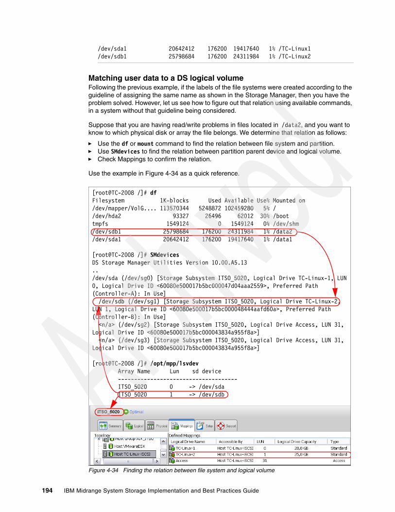
/dev/sda1 20642412 176200 19417640 1% /TC-Linux1/dev/sdb1 25798684 176200 24311984 1% /TC-Linux2
Matching user data to a DS logical volumeFollowing the previous example, if the labels of the file systems were created according to the guideline of assigning the same name as shown in the Storage Manager, then you have the problem solved. However, let us see how to figure out that relation using available commands, in a system without that guideline being considered.
Suppose that you are having read/write problems in files located in /data2, and you want to know to which physical disk or array the file belongs. We determine that relation as follows:
� Use the df or mount command to find the relation between file system and partition.� Use SMdevices to find the relation between partition parent device and logical volume.� Check Mappings to confirm the relation.
Use the example in Figure 4-34 as a quick reference.
Figure 4-34 Finding the relation between file system and logical volume
[root@TC-2008 /]# dfFilesystem 1K-blocks Used Available Use% Mounted on/dev/mapper/VolG.... 113570344 5248872 102459280 5% //dev/hda2 93327 26496 62012 30% /boottmpfs 1549124 0 1549124 0% /dev/shm/dev/sdb1 25798684 176200 24311984 1% /data2/dev/sda1 20642412 176200 19417640 1% /data1
[root@TC-2008 /]# SMdevicesDS Storage Manager Utilities Version 10.00.A5.13../dev/sda (/dev/sg0) [Storage Subsystem ITSO_5020, Logical Drive TC-Linux-1, LUN 0, Logical Drive ID <60080e500017b5bc000047d04aaa2559>, Preferred Path (Controller-A): In Use] /dev/sdb (/dev/sg1) [Storage Subsystem ITSO_5020, Logical Drive TC-Linux-2, LUN 1, Logical Drive ID <60080e500017b5bc000048444aafd60a>, Preferred Path (Controller-B): In Use] <n/a> (/dev/sg2) [Storage Subsystem ITSO_5020, Logical Drive Access, LUN 31, Logical Drive ID <60080e500017b5bc000043834a955f8a>] <n/a> (/dev/sg3) [Storage Subsystem ITSO_5020, Logical Drive Access, LUN 31, Logical Drive ID <60080e500017b5bc000043834a955f8a>]
[root@TC-2008 /]# /opt/mpp/lsvdev Array Name Lun sd device ------------------------------------- ITSO_5020 0 -> /dev/sda ITSO_5020 1 -> /dev/sdb
194 IBM Midrange System Storage Implementation and Best Practices Guide

4.3.6 Collecting information
You can use the following commands to collect additional information about your Linux host server.
� SMdevices: Lists all DS Storage volumes recognized by your server (if SMutil is installed).
� rpm -qa: Lists the installed software.
� uname -r: Displays the kernel version.
� mppUtil -V: Lists the installed disk driver version.
� mppUtil -a DSname: Lists all the details for the Storage name provided.
� ls -lR /proc/mpp: Lists devices recognized by the RDAC driver.
� cat /proc/scsi/scsi: Displays LUNs recognized by the HBAs, with all the paths. Because it is not under the RDAC driver usage, then you see all LUNs from all the paths.
� /opt/mpp/lsvdev: Provides a relation between the logical volumes and the Linux disk assigned names.
� /opt/mpp/mppSupport: Script provided by RDAC to collect information. Generates a compressed file in the /tmp folder that you can use yourself or share with your support representative for debugging problems.
� IBM Dynamic System Analysis (DSA) log: DSA collects and analyzes system information to aid in diagnosing system problems. This tool was developed initially for System x servers, available for Linux and Windows, and when executed in your server, can provide all the information that your support representative will need in one package. To find the DSA tools, see the following Web site:
http://www-03.ibm.com/systems/management/dsa.html
4.4 i5/OS
The DS Storage System is supported now connected to i5/OS, both in client partitions of VIOS, and as a direct attach to the newest DS5000 Systems.
For more details about the Midrange Storage attachment to i5/OS, see the IBM i and Midrange External Storage, SG24-7668.
4.5 VMware
The DS Storage Systems are supported with VMware Operating systems. There is a separate IBM Redpapers™ publication covering all the information about this topic, and much more.
See VMware Implementation with IBM System Storage DS4000/DS5000, REDP-4609. This document is a compilation of best practices for planning, designing, implementing, and maintaining IBM Midrange storage solutions and, more specifically, configurations for a VMware ESX and VMware ESXi Server based host environment. Setting up an IBM Midrange Storage Subsystem can be a challenging task and the principal objective of this book is to give users a sufficient overview to effectively enable SAN storage and VMWare.
Chapter 4. Host configuration guide 195
4.6 HyperV
Microsoft Hyper-V Server 2008 is a hypervisor-based server virtualization product that allows you to virtualize machines onto a single physical server, and provides additional functions such as workload administration, live partition migration, and host clustering.
Because Microsoft Hyper-V Server uses standard Windows drivers, and can also run SAN attached disks, both iSCSI and FC, there is no difference in the setup of your host and DS Storage System than for using Windows 2008 as described in 4.1, “Windows 2008” on page 126. Remember that if you plan to use clustering or live migration, then you need to configure your DS Storage System with the logical volumes mapped to the Host Group containing the hosts participating on the cluster or migration.
196 IBM Midrange System Storage Implementation and Best Practices Guide
Chapter 5. SAN boot with the IBM System Storage DS5000 storage subsystem
SAN boot is a technique that allows servers to utilize an OS image installed on external SAN-based storage to boot up, rather than booting off their own local disk or direct attached storage.
Now that iSCSI has become more popular, we have to use the terms remote boot or network boot rather than SAN boot because iSCSI is typically not a SAN. However, because the iSCSI and Fibre Channel worlds are merging together, we are using the term SAN boot in this chapter to explain booting using both the Fibre Channel and iSCSI techniques.
In this chapter we explain the concept and implementation examples of SAN boot using various operating systems on several platforms.
We describe the following implementations:
� AIX FC SAN boot for IBM Power Systems™� Windows 2008 SAN boot with Fibre Channel and iSCSI� FC SAN boot for RHEL5.3 on IBM system x servers� iSCSI SAN boot for RHEL5.3 on IBM system x servers� Implementing Windows Server 2008 Failover Clustering with SAN boot
5
© Copyright IBM Corp. 2004-2010. All rights reserved. 197

5.1 Introduction to SAN bootSAN boot is a technique that allows servers to utilize an OS image installed on external SAN-based storage to boot up, rather than booting off their own local disk or direct attached storage. Using SAN boot has the following distinct advantages:
� Interchangeable servers:
By allowing boot images to be stored on the SAN, servers are no longer physically bound to their startup configurations. Therefore, if a server were to fail, it becomes very easy to replace it with another generic server and resume operations with the exact same boot image from the SAN (only minor reconfiguration is required on the storage subsystem). This quick interchange will help reduce downtime and increase host application availability.
� Provisioning for peak usage:
Because the boot image is available on the SAN, it becomes easy to deploy additional servers to temporarily cope with high workloads.
� Centralized administration:
SAN boot enables simpler management of the startup configurations of servers. Rather than needing to manage boot images at the distributed level at each individual server, SAN boot empowers administrators to manage and maintain the images at a central location in the SAN. This feature enhances storage personnel productivity and helps to streamline administration.
� Utilizing high-availability features of SAN storage:
SANs and SAN-based storage are typically designed with high availability in mind. SANs can utilize redundant features in the storage network fabric and RAID controllers to ensure that users do not incur any downtime. Most boot images that are located on local disk or direct attached storage do not share the same protection. Using SAN boot allows boot images to take advantage of the inherent availability built-in to most SANs, which helps to increase availability and reliability of the boot image and reduce downtime.
� Efficient disaster recovery process:
Assuming that data (boot image and application data) is mirrored over the SAN between a primary site and a recovery site, servers can take over at the secondary site in case a disaster destroys servers at the primary site.
� Reduced overall cost of servers:
Placing server boot images on external SAN storage eliminates the need for local disk in the server, which helps lower costs and allows SAN boot users to purchase servers at a reduced cost but still maintain the same functionality. In addition, SAN boot minimizes the IT costs through consolidation, what is realized by electricity, floor space cost savings, and by the benefits of centralized management.
5.1.1 SAN boot implementationSetting up and executing SAN boot requires performing certain steps on both the server and the storage sides of the SAN. We first provide a brief overview of how a user can implement SAN boot and how SAN boot works.
SAN boot relies on configuring servers with a virtual boot device, which enables the server to access the actual boot information stored on a specific LUN in the storage subsystem. The virtual boot device is configured on the HBA in the server and thus assumes that the HBA BIOS supports booting from SAN attached storage.
198 IBM Midrange System Storage Implementation and Best Practices Guide

Multiple LUNs can be configured with various boot images if there is a need for separate operating system images. Each LUN that contains a boot image for a specific operating system is referred to as a boot partition. Boot partitions are created, configured, and mapped just like normal storage partitions on the DS5000 storage subsystem.
Figure 5-1 shows a 4+P RAID 5 array that is carved up into boot partition LUNs. Each of these LUNs corresponds to a separate server. The LUNs can be connected to various homogeneous hosts, or they can be connected to heterogeneous hosts.
Figure 5-1 Boot partition LUNs on a RAID 5 array
Figure 5-2 shows five heterogeneous servers that use SAN boot and store their boot images on the same DS5000 storage subsystem. However, this diagram only shows Fibre Channel SAN topology. Many of these configurations can be adapted to iSCSI SAN as well. For more detailed information about iSCSI SAN boot, see “Configuration procedure overview for iSCSI SAN boot with System x” on page 215.
Figure 5-2 Logical diagram of SAN boot partitions
In order to implement SAN boot, you must first ensure that all your hosts are properly zoned to the storage subsystems in the SAN fabric. Zoning emulates a direct connection from the storage to each server. Storage partitioning, which needs to be done on the DS5000, only ensures that authorized hosts can access their storage through the SAN.
Chapter 5. SAN boot with the IBM System Storage DS5000 storage subsystem 199
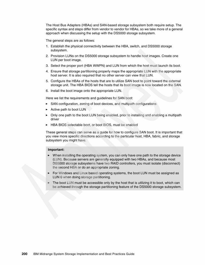
The Host Bus Adapters (HBAs) and SAN-based storage subsystem both require setup. The specific syntax and steps differ from vendor to vendor for HBAs, so we take more of a general approach when discussing the setup with the DS5000 storage subsystem.
The general steps are as follows:
1. Establish the physical connectivity between the HBA, switch, and DS5000 storage subsystem.
2. Provision LUNs on the DS5000 storage subsystem to handle host images. Create one LUN per boot image.
3. Select the proper port (HBA WWPN) and LUN from which the host must launch its boot.
4. Ensure that storage partitioning properly maps the appropriate LUN with the appropriate host server. It is also required that no other server can view that LUN.
5. Configure the HBAs of the hosts that are to utilize SAN boot to point toward the external storage unit. The HBA BIOS tell the hosts that its boot image is now located on the SAN.
6. Install the boot image onto the appropriate LUN.
Here we list the requirements and guidelines for SAN boot:
� SAN configuration, zoning of boot devices, and multipath configurations
� Active path to boot LUN
� Only one path to the boot LUN being enabled, prior to installing and enabling a multipath driver
� HBA BIOS selectable boot, or boot BIOS, must be enabled
These general steps can serve as a guide for how to configure SAN boot. It is important that you view more specific directions according to the particular host, HBA, fabric, and storage subsystem you might have.
Important:
� When installing the operating system, you can only have one path to the storage device (LUN). Because servers are generally equipped with two HBAs, and because most DS5000 storage subsystems have two RAID controllers, you must isolate (disconnect) the second HBA or do an appropriate zoning.
� For Windows and Linux based operating systems, the boot LUN must be assigned as LUN 0 when doing storage partitioning.
� The boot LUN must be accessible only by the host that is utilizing it to boot, which can be achieved through the storage partitioning feature of the DS5000 storage subsystem.
200 IBM Midrange System Storage Implementation and Best Practices Guide

5.1.2 Installing local hard disk for high-load environments
It is always best to install the local hard disk for high-load environments. The operating system or applications can experience errors and become unstable due to latency with accessing the page file. Thus, having page file on a local disk ensures reliable access to the page file. Specifically, we elect to use the local disk for swap/RAS.
See the following Microsoft Knowledge Base (KB) articles on Boot from SAN issues:
� Microsoft SAN support:
http://www.microsoft.com/windowsserversystem/storage/sansupport.mspx#top
� Support for booting from a SAN:
http://support.microsoft.com/default.aspx?scid=kb;en-us;305547
� Support for multiple clusters attached to the same SAN device:
http://support.microsoft.com/default.aspx?scid=kb;en-us;304415
5.1.3 Comparison: iSCSI versus Fibre Channel
The iSCSI protocol is a transport for SCSI over TCP/IP. Until recently, standard IP protocol infrastructure (for example, Ethernet) was not able to provide the necessary high bandwidth and low-latency needed for storage access. Special communications infrastructure, mainly Fibre Channel running FCP (SCSI over Fibre Channel), was developed to allow for Storage Area Networks (SANs). With the recent advances in Ethernet technology, it is now practical (from a performance perspective) to access storage devices over an IP network. 1 Gigabit Ethernet is now widely available and is competitive with 1 and 2 Gigabit Fibre Channel. 10 Gigabit Ethernet is readily becoming available.
Similar to FCP, iSCSI allows storage to be accessed over a Storage Area Network, allowing shared access to storage. A major advantage of iSCSI over FCP is that iSCSI can run over standard, off-the-shelf Ethernet network components. A network that incorporates iSCSI SANs needs to use only a single kind of network infrastructure (Ethernet) for both data and storage traffic, whereas use of FCP requires a separate type of infrastructure (Fibre Channel) and administration for the storage. Furthermore, iSCSI (TCP) based SANs can extend over arbitrary distances, and are not subject to distance limitations that currently limit FCP.
Because iSCSI is designed to run on an IP network, it can take advantage of existing features and tools that were already developed for IP networks. The very use of TCP utilizes TCP’s features of guaranteed delivery of data and congestion control. IPSec can be utilized to provide security for an iSCSI SAN, whereas a new security mechanism might have to be developed for the Fibre Channel. Service Location Protocol (SLP) can be used by iSCSI to discover iSCSI entities in the network. Thus, in addition to iSCSI running on standard, cheaper, off-the-shelf hardware, iSCSI also benefits from using existing, standard IP-based tools and services.
Note: Fibre Channel security is available. It is defined by the T11 organization (that defines all the Fibre Channel specs). It is the FC-SP spec and can be found at the following Web site:
http://www.t11.org/ftp/t11/pub/fc/sp/06-157v0.pdf
Chapter 5. SAN boot with the IBM System Storage DS5000 storage subsystem 201
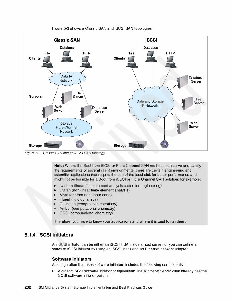
Figure 5-3 shows a Classic SAN and iSCSI SAN topologies.
Figure 5-3 Classic SAN and an iSCSI SAN topology
5.1.4 iSCSI initiators
An iSCSI initiator can be either an iSCSI HBA inside a host server, or you can define a software iSCSI initiator by using an iSCSI stack and an Ethernet network adapter.
Software initiatorsA configuration that uses software initiators includes the following components:
� Microsoft iSCSI software initiator or equivalent: The Microsoft Server 2008 already has the iSCSI software initiator built in.
WebServer
FileServer
StorageFibre Channel
Network
Storage
Servers
Database
Clients
Classic SAN
DatabaseServer
HTTPFile
Storage
Data and Storage IP Network
Database
Clients
iSCSI
WebServer
FileServer
DatabaseServer
HTTPFile
Data IP Network
WebServer
FileServer
StorageFibre Channel
Network
Storage
Servers
Database
Clients
Classic SAN
DatabaseServer
HTTPFile
Storage
Data and Storage IP Network
Database
Clients
iSCSI
WebServer
FileServer
DatabaseServer
HTTPFile
Data IP Network
Note: Where the Boot from iSCSI or Fibre Channel SAN methods can serve and satisfy the requirements of several client environments, there are certain engineering and scientific applications that require the use of the local disk for better performance and might not be feasible for a Boot from iSCSI or Fibre Channel SAN solution; for example:
� Nastran (linear finite element analysis codes for engineering)� Dytran (non-linear finite element analysis)� Marc (another non-linear code)� Fluent (fluid dynamics)� Gaussian (computation chemistry)� Amber (computational chemistry)� GCG (computational chemistry)
Therefore, you have to know your applications and where it is best to run them.
202 IBM Midrange System Storage Implementation and Best Practices Guide

� One or two Ethernet cards: There is no iSCSI card required on the server to implement a connection to an iSCSI SAN environment.
For more information about iSCSI on Microsoft, visit the Microsoft support pages:
http://www.microsoft.com/windowsserver2003/technologies/storage/iscsi/default.mspx
Hardware initiatorsA configuration that uses hardware initiators includes the following components:
� One or two iSCSI cards for each server, which access the storage array and associated drivers.
For BladeCenters, you use the QLogic iSCSI Expansion Card for IBM BladeCenter. This iSCSI Expansion Card option is a hardware initiator that provides iSCSI communication from the blade server to an iSCSI storage device. It delivers full TCP/IP Offload Engine (TOE) functionality to reduce CPU processing. For more information, see the Web link:
http://www-306.ibm.com/common/ssi/rep_ca/4/897/ENUS105-194/ENUS105-194.PDF
System x servers currently support these iSCSI TOE adapters:
– QLogic iSCSI Single Port PCIe HBA for IBM System x (39Y6146)– QLogic iSCSI Dual Port PCIe HBA for IBM System x (42C1770)– IBM iSCSI Server TX Adapter (30R5201)– IBM iSCSI Server SX Adapter (30R5501)– IBM iSCSI Server Adapter (73P3601)
For more information, view the Web link:
http://www-947.ibm.com/systems/support/supportsite.wss/docdisplay?brandind=5000008&lndocid=MIGR-57073
� One or two Ethernet switches, preferably using two Ethernet switches for high availability.
TOE benefitsWe know that the processing of TCP packets from an Ethernet connection consumes many CPU resources, and iSCSI protocol only adds another layer of processing. With the number of packets and their corresponding interrupts required for iSCSI, the software iSCSI packet processing can burden the host system with 50–65% CPU usage. Depending upon signaling options used, high CPU usage might even render certain host applications unusable.
Therefore, it is important that efficient iSCSI systems depend on a hardware TCP Offload Engine (TOE) to handle the transportation protocols of iSCSI. A TOE network interface card (NIC) is a special interface card specifically designed for interfacing a server to the IP-SAN and will offload iSCSI as well and TCP/IP encapsulation from the server CPUs. A hardware TOE implements the entire standard TCP and iSCSI protocol stacks into the hardware. This approach completely offloads the iSCSI protocol from the primary CPU, processing storage communications efficiently and enabling applications to run faster and more reliably. By using the TCP Offload Engine, a single system can run multiple initiators for improved throughput.
Choosing between hardware and software initiatorsUsing hardware initiators offers the following key benefits:
� Their performance is noticeably faster.
� They do not interfere with data networking traffic if the network topology is designed to segregate storage traffic such as by using a separate set of switches to connect servers to iSCSI storage.
Chapter 5. SAN boot with the IBM System Storage DS5000 storage subsystem 203

� The traffic that passes through them will not load the server's CPU to the same extent that might be the case if the storage traffic passed through the standard IP stack.
� It is possible to implement iSCSI boot from SAN with hardware initiators.
Using software initiators offers the following key benefits:
� The cost of the iSCSI hardware is avoided.
� It is possible to use one set of switches for both data and storage networking, avoiding the cost of additional switches but possibly impacting performance.
� It is possible to access other network storage devices such as NAS, NFS, or other file servers using the same network interfaces as are used for iSCSI.
5.2 AIX FC SAN boot for IBM POWER systems
This section contains a step-by-step illustration of SAN boot implementation for the IBM POWER® (formerly IBM eServer pSeries) in an AIX 6.1 environment.
Implementation possibilitiesImplementations of SAN boot with AIX include the following possibilities:
� To implement SAN boot on a system with an already installed AIX operating system, you can:
– Use the alt_disk_install system utility.– Mirror an existing SAN Installation to several other LUNs using Volume Copy.
� To implement SAN boot on a new system, you can:
– Start the AIX installation from a bootable AIX CD install package.– Use the Network Installation Manager (NIM).
The methods known as alt_disk_install or mirroring are simpler to implement than the more complete and more sophisticated method using the Network Installation Manager (NIM).
Prerequisites and considerationsBefore implementing SAN boot, consider the following requirements and stipulations:
� Booting from a DS5000 storage subsystem utilizing SATA drives for the boot image is supported but is not preferred due to performance reasons.
� Boot images can be located on a volume in DS5000 storage subsystem partitions that have greater than 32 LUNs per partition if utilizing AIX release CDs 5.2 ml-4 (5.2H) and 5.3.0 ml-0 or higher. These CDs contain DS5000 storage subsystem drivers that support greater than 32 LUNS per partition. If older CDs are being used, the boot image must reside in a partition with 32 LUNS or less.
� When booting from a DS5000 storage subsystem, both storage controller fiber connections to the boot device must be up and operational. Single HBA configurations are supported, but must be zoned, enabling connection to both controllers.
Single HBA configurations are allowed, but each single HBA configuration requires that both controllers in the DS5000 storage subsystem be connected to the host. In a switched environment, both controllers must be connected to the switch within the same SAN zone as the HBA.
� Path failover is not supported during the AIX boot process. After the AIX host has booted, failover operates normally.
204 IBM Midrange System Storage Implementation and Best Practices Guide
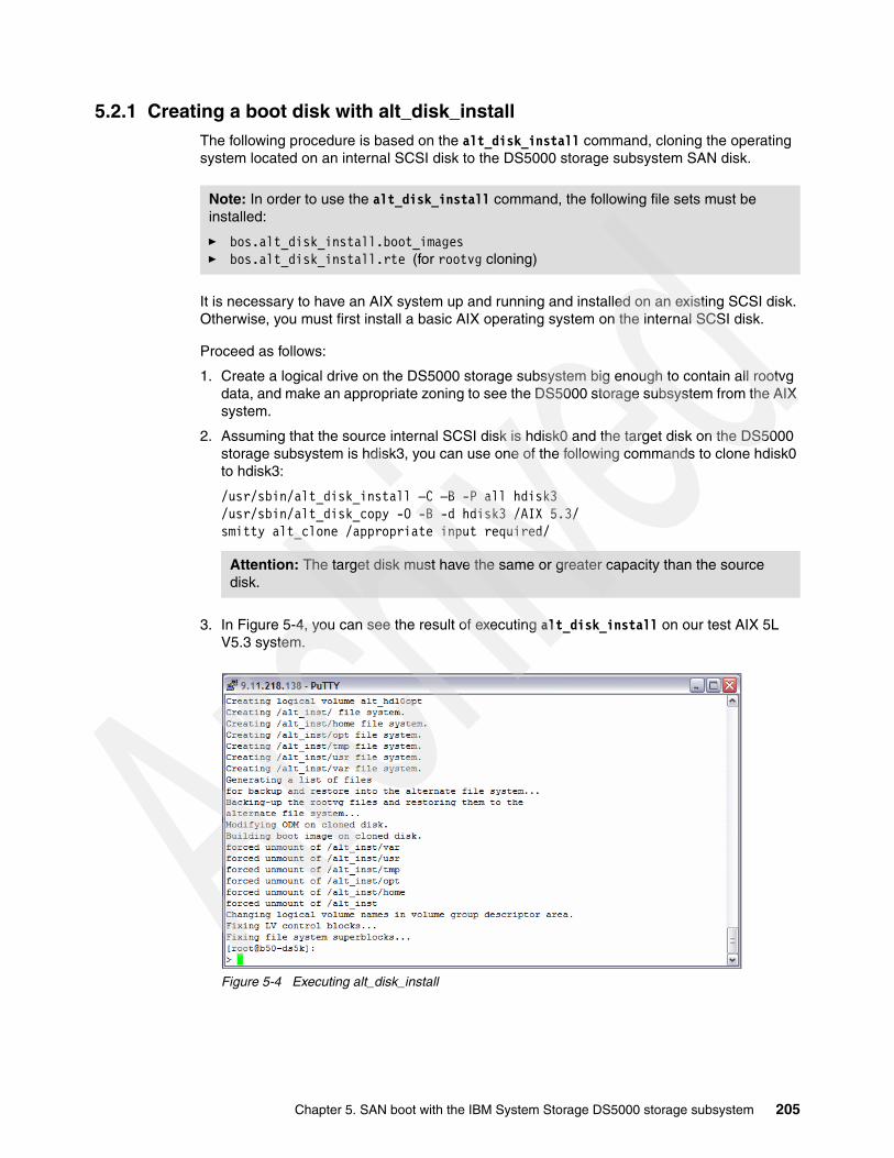
5.2.1 Creating a boot disk with alt_disk_installThe following procedure is based on the alt_disk_install command, cloning the operating system located on an internal SCSI disk to the DS5000 storage subsystem SAN disk.
It is necessary to have an AIX system up and running and installed on an existing SCSI disk. Otherwise, you must first install a basic AIX operating system on the internal SCSI disk.
Proceed as follows:
1. Create a logical drive on the DS5000 storage subsystem big enough to contain all rootvg data, and make an appropriate zoning to see the DS5000 storage subsystem from the AIX system.
2. Assuming that the source internal SCSI disk is hdisk0 and the target disk on the DS5000 storage subsystem is hdisk3, you can use one of the following commands to clone hdisk0 to hdisk3:
/usr/sbin/alt_disk_install –C –B -P all hdisk3/usr/sbin/alt_disk_copy -O -B -d hdisk3 /AIX 5.3/smitty alt_clone /appropriate input required/
3. In Figure 5-4, you can see the result of executing alt_disk_install on our test AIX 5L V5.3 system.
Figure 5-4 Executing alt_disk_install
Note: In order to use the alt_disk_install command, the following file sets must be installed:
� bos.alt_disk_install.boot_images � bos.alt_disk_install.rte (for rootvg cloning)
Attention: The target disk must have the same or greater capacity than the source disk.
Chapter 5. SAN boot with the IBM System Storage DS5000 storage subsystem 205

4. The alt_disk_install command can run for several minutes. It creates a new volume group on the DS5000 storage subsystem disk called altinst_rootvg and creates and copies all logical volumes from rootvg. You can verify the result with the lspv command, activating the volume group with varyonvg altinst_rootvg and lsvg -l altinst_rootvg. See Figure 5-5.
Figure 5-5 Checking the results of alt_disk_install
5. Clean up the alternate disk volume group and make hdisk0 a system disk using either of the following commands:
alt_disk_install -Xalt_rootvg_op -X / AIX 5.3/
6. Ensure the proper boot logical setting for the target disk:
/usr/lpp/bosinst/blvset -d /dev/hdisk3 -g level
7. If you find that the boot logical volume settings on the cloned disk are blank, update the cloned boot logical volume manually with the following command:
echo y | /usr/lpp/bosinst/blvset -d /dev/hdisk3 -plevel
8. Change the AIX boot list to force AIX to start on hdisk3 at the next reboot with a fallback or secondary boot disk of hdisk0 if there is any problem with hdisk3:
bootlist -m normal hdisk3 hdisk0
The system comes back up, booting from the DS5000 storage subsystem rootvg disk.
Consideration: If the rootvg is mirrored, remove the second copy needs before running the alt_disk_install command, or alternatively, use the other mirroring method, which is described in 5.2.2, “Installation on external storage from a bootable AIX CD-ROM” on page 207.
Attention: This procedure requires a reboot, so run shutdown -Fr.
206 IBM Midrange System Storage Implementation and Best Practices Guide

9. Check which disk was used to boot by using the following command:
bootinfo -b
For more information about the use of the alt_disk_install command, see AIX 5L Version 5.3: Installing AIX, SC23-4887.
Alternatively, the cloned disk (hdisk3 in the previous example) can be remapped on the DS5000 and used to boot up another AIX machine (or LPAR), a method that is significantly quicker than installing from CDROM a second machine. An added advantage is that any customizations on the source AIX system such as user IDs and tuning parameters are duplicated on the new AIX system or LPAR. Be careful using this method on the new machine, because any network adapters will carry duplicated IP addresses causing network problems. This problem can be easily overcome by ensuring that the new machine does not have any physical network connectivity when it is initially booted using the cloned disk.
5.2.2 Installation on external storage from a bootable AIX CD-ROM To install AIX on DS5000 storage subsystem disks, make the following preparations:
1. Update the system/service processor microcode to the latest level. For the downloadable versions, see the following Web site:
http://techsupport.services.ibm.com/server/mdownload/
2. Update the FC adapter (HBA) microcode to the latest supported level. For a detailed description about how to update the microcode, see “Updating the microcode on the adapter” on page 210.
3. Make sure that you have an appropriate SAN configuration. Check that the host is properly connected to the SAN, the zoning configuration is updated, and at least one LUN is mapped to the host.
The HBA has its own topology setting, in contrast to earlier versions of the firmware, and also to the device driver's auto detection of the topology. The default value for the topology is mostly Auto Topology (Loop-1st PTP-2nd), but if you are attaching the adapter in a point-to-point (or switched) topology and are concerned that the adapter might cause a disruption when initially booted, follow the procedure in “Setting the Fibre Channel adapter's topology” on page 212. Use the same procedure to display the current topology settings.
Identifying the logical drive to hdiskBecause a SAN allows access to a large number of devices, identifying the logical drive to hdisk for installation of AIX onto it can be difficult. Use the following method to facilitate the discovery of the lun_id to hdisk correlation:
1. For a new POWER machine that does not have AIX installed, map only the logical drive that you want to install AIX on. After AIX has been installed, then map all other logical drives required.
2. If more than one disk is assigned to an installed AIX host, you need to make sure you are using the right hdisk and its associated logical drive mapped on DS5000:
– Identify the hdisk by comparing the unique ID of the hdisk with the logical drive id when viewing its properties on the DS5000. On AIX, use the lsattr command to identify the unique ID, for example, on hdisk9, which correlates to “logical drive ID” when you view its properties on the DS5000:
Note: If the system cannot see the SAN fabric at login, you can configure the HBAs at the server prompt, Open Firmware.
Chapter 5. SAN boot with the IBM System Storage DS5000 storage subsystem 207

lsattr -El hdisk9 | grep unique_id | awk '{print (substr($2,6,32))}'600A0B80004777D800006FC14AA6F708
– The simplest method of checking on AIX system already running where native AIX MPIO is being used is to run the following command:
mpio_get_config -Av1
The output of this command clearly details the hdisk - logical drive relationship: Frame id 0: Storage Subsystem worldwide name: 608e50017b5bc00004a955e3b Controller count: 2 Partition count: 1 Partition 0: Storage Subsystem Name = 'ITSO_5020' hdisk LUN # Ownership User Label hdisk2 2 A (preferred) Secured1 hdisk3 3 A (preferred) AIX_Boot hdisk4 4 A (preferred) test3 hdisk5 40 B (preferred) p630_Test_40_64KB hdisk6 41 A (preferred) p630_Test_41_8KB hdisk7 42 B (preferred) p630_Test_42_512KB hdisk8 43 A (preferred) p630_Test_43_128KB
– For AIX systems using SDDPCM with AIX MPIO, then issuing the equivalent command to the mpio_get_config will give the output in the same format as before:
sddpcm_get_config -Av
Installation procedureProceed as follows:
1. Insert disk 1 of the AIX Installation CD set (this has a bootable image) into the CD-ROM.
2. For a new AIX system, select CD-ROM as the Install Device to make the system boot from the CD using the System Management Services (SMS) menu.
3. Let the system boot from the AIX CD image after you have left the SMS menu.
After a few minutes, the console displays a window that directs you to press the specified key on the device to be used as the system console.
A window is displayed that prompts you to select an installation language.
4. On the Welcome to the Base Operating System Installation and Maintenance window that is displayed, change the installation and system settings that have been set for this machine in order to select a Fibre Channel-attached disk as a target disk. Type 2 and press Enter.
5. At the Installation and Settings window, enter 1 to change the system settings and choose the New and Complete Overwrite option.
6. On the Change (the destination) Disk window that is presented, select the Fibre Channel disks that are mapped to your system. To obtain more information, type 77 to display the detailed information window. The system shows the PVID. Type 77 again to show WWPN and LUN_ID information as well. Type the number, but do not press Enter, for each disk you choose. Typing the number of a selected disk will deselect the device. Choose the only DS5000 storage subsystem disk that has been mapped as explained previously.
7. Verify the installation settings shown on the Installation and Settings window, which is displayed with the selected disks after you have selected Fibre Channel-attached disks.
1 This command is for AIX6.x. For AIX5.x, use the command fget_config -Av.
208 IBM Midrange System Storage Implementation and Best Practices Guide

8. If everything looks OK, type 0 and press Enter. The installation process begins.
Note that the AIX operating system installation of IBM BladeCenter POWER blade servers varies slightly for JS20. See the following Web site:
http://www.ibm.com/support/docview.wss?rs=113&uid=psg1MIGR-57235&loc=en_US
5.2.3 AIX SAN installation with NIMNetwork Installation Manager (NIM) is a client server infrastructure and service that allows remote installation of the operating system, manages software updates, and can be configured to install and update third-party applications. Although both the NIM server and client file sets are part of the operating system, a separate NIM server has to be configured that will keep the configuration data and the installable product file sets.
NIM preparationsWe assume that the following preparations have been completed:
� The NIM environment is deployed and all of the necessary configuration on the NIM master is already done.
� The NIM server is properly configured as the NIM master, and the basic NIM resources have been defined.
� The Fibre Channel Adapters are already installed in the machine onto which AIX is to be installed.
� The Fibre Channel Adapters are connected to a SAN and, on the DS5000 storage subsystem, have the designated logical drive defined and mapped to the host or NIM client.
� The target machine (NIM client) currently has no operating system installed and is configured to boot from the NIM server.
For more information about how to configure a NIM server, see NIM from A to Z in AIX 5L, SG24-7296.
NIM installation procedurePrior the installation, you can modify the bosinst.data file (for a more automated install), where the installation control is stored. Insert your appropriate values at the following stanza:
SAN_DISKID
This stanza specifies the World Wide Port Name and a Logical Unit ID for Fibre Channel attached disks. The (World Wide Port Name) and (Logical Unit ID) are each in the format returned by the lsattr command, that is, “0x” followed by 1-16 hexadecimal digits. The ww_name and lun_id are separated by two slashes (//):
SAN_DISKID = <worldwide_portname//lun_id>
For example:
SAN_DISKID = 0x0123456789FEDCBA//0x2000000000000
Important: Be sure that you have made the correct selection for root volume group, because the existing data in the destination root volume group will be destroyed during Base Operating System (BOS) installation.
Chapter 5. SAN boot with the IBM System Storage DS5000 storage subsystem 209

You can specify PVID (the example uses an internal disk):
target_disk_data:PVID = 000c224a004a07faSAN_DISKID =CONNECTION = scsi0//10,0LOCATION = 10-60-00-10,0SIZE_MB = 34715HDISKNAME = hdisk0
To install the NIM, follow these steps:
1. Enter the command:
# smit nim_bosinst
2. Select the lpp_source resource for the BOS installation.
3. Select the SPOT resource for the BOS installation.
4. Select the BOSINST_DATA to use during installation option, and select a bosinst_data resource that is capable of performing a unprompted BOS installation.
5. Select the RESOLV_CONF to use for network configuration option, and select a resolv_conf resource.
6. Select the Accept New License Agreements option, and select Yes. Accept the default values for the remaining menu options.
7. Press Enter to confirm and begin the NIM client installation.
8. To check the status of the NIM client installation, for example, where client name is “va09” enter the command:
# lsnim -l va09
5.2.4 Advanced configuration proceduresThis section covers advanced configuration procedures, which might be necessary to prepare or further customize the AIX SAN boot details.
Updating the microcode on the adapterThere are ways to update the microcode on the Fibre Channel adapter using an installed AIX operating system, but in the absence of an operating system, use the Standalone Diagnostic CD-ROM as follows:
1. Boot the machine containing the Fibre Channel Adapter from a Standalone Diagnostics CD. You can find one of the appropriate versions of the Standalone Diagnostics CD at the following Web site:
http://www14.software.ibm.com/webapp/set2/sas/f/diags/download/home.html
2. Press Enter when the first diagnostic window is displayed.
3. Select Task Selection (Diagnostics, Advanced Diagnostics, and Service Aids).
4. Select Microcode Tasks.
5. Select Download Microcode.
6. Select the fcsX devices by highlighting them and then pressing Enter.
7. Press F7 to commit the selections.
8. Press Enter at the warning window.
9. Select Input device for Microcode and follow instructions.
10.Press F7 to commit.
210 IBM Midrange System Storage Implementation and Best Practices Guide

Using Open Firmware commands to locate the HBAsIf the target machine will be unattended during the reboot following the AIX installation, it is always best to have multiboot startup enabled on that machine. In this case, the system will boot to the Multiboot menu, allowing easy access to the Open Firmware (or OK) prompt without having an operator present during the reboot.
To enable multiboot startup, during the boot, after the banner is displayed, and after the word keyboard is displayed, press 1 (tty) or F1 (1ft) to enter the SMS menus. From there, select Multiboot, and then enable Multiboot startup. The same procedure can be used to disable Multiboot startup after executing this procedure, if so desired.
In case of Hardware Management Console (HMC) managed machines, the boot procedure can be specified through the HMC. Proceed as follows:
1. Boot the system to an Open Firmware prompt.
2. Press 8 (tty to serial port) or F8 (1ft) after the IBM RS/6000® or System p banner is displayed at the word keyboard, or select OK prompt from the Multiboot menu if Multiboot startup is enabled. HMC managed machines boot are configurable by right-clicking the profile and selecting Properties.
3. Use the following commands to display the device tree for the system (press Ctrl+s and Ctrl+q to stop and resume scrolling):
> 0 dev /> 0 lsor> 0 show-devs
The output will look as shown in Example 5-1.
Example 5-1 Listing devices
00cde198: /pci@f9c0000000d42f78: /scsi@b00d486d8: /sd00d49638: /st00d4a978: /ethernet@c00ce0c40: /pci@f9d0000000d50960: /scsi@c00d560c0: /sd00d57020: /st00d58360: /token-ring@d00d586f0: /display@e00ce36e8: /pci@f9e0000000d5b170: /scsi@b00d608d0: /sd00d61830: /st00d62b70: /lpfc@d00d6cb18: /sd
4. In the previous example, there is a Fibre Channel adapter that is a child of the /pci@f9e00000 device; the Fibre Channel Adapter is specified as device /pci@f9e00000/lpfc@d.
Chapter 5. SAN boot with the IBM System Storage DS5000 storage subsystem 211

5. If more than one Fibre Channel adapter are in the system, you can determine the mapping between devices and physical slot location by looking at the properties of each device:
a. Select the device with the select-dev command. For example:
> 0 “ /pci@f9e00000/lpfc@d" select-dev
b. Show the properties of the device with the.properties command.
The ibm, loc-code property will have a format similar to:
UO.1-P1-l8/Q1
This data that indicates the adapter is in slot 8 (from l8) of drawer 0 (from.1, l/O drawers are numbered starting from 0, but the location codes start at 1). See the installation and service guide for your system to get more information about location codes.
Repeat these steps for any other adapters to determine their corresponding physical locations.
To leave the Open Firmware prompt, choose one of the following possibilities:
� To boot the system:
> 0 boot
� To go back to SMS menu:
> 0 dev /packages/gui> 0 obe
Setting the Fibre Channel adapter's topologyThe Open Boot portion of the adapter firmware has a setting for the topology to be used during the boot procedure. This topology setting does not affect the manner in which the device driver will bring up the link after AIX is booted. This setting is only used during the boot process. Proceed as follows:
1. Find the Fibre Channel adapter's device information using the Using Open Firmware commands to locate the HBAs procedure (see “Using Open Firmware commands to locate the HBAs” on page 211).
2. At the Open Firmware prompt, select the Fibre Channel Adapter with the select-dev command. For example:
> 0 “/pci@f9e00000/lpfc@d” select-dev
3. Set the appropriate topology:
– For point-to-point (switch): set-ptp – For FC-AL: set-fc-al
Note: There is a space between the first “ and the /. The “ marks must be entered.
Note: There is a space between the first “ and the /, and the “s must be entered.
Note: The current topology can be checked by using the.topology command.
212 IBM Midrange System Storage Implementation and Best Practices Guide

Recovering from NVRAM corruption or SAN changesIf the NVRAM of the system becomes corrupted, or if changes are made to the SAN environment that cause the WWPN, SCSI ID (destination ID), or lun_id to change, you need to reconfigure portions of this procedure to get the SAN boot working again.
Follow these steps:
1. Boot the system from an Installation/Maintenance image.
2. From the main install menu, select Start Maintenance Mode for System Recovery Access Advanced Maintenance Functions Enter the Limited Function Maintenance Shell.
3. From the shell prompt, locate the hdisk on which the AIX image you want to boot is installed.
You can use the command odmget q”attribute=lun_id AND value=OxNN..N" CuAt, where OxNN..N is the lun_id you are looking for. This command will print out the ODM stanzas for the hdisks that have this lun_id. You can also use the command Isattr -ElhdiskN to see the WWPN associated with a particular hdisk.
4. Use the bootlist command to update the boot list for the machine and to reset the necessary NVRAM variables.
To set the normal mode boot list to a particular hdisk, hdisk6 for this example, issue the following command:
bosboot -ad /dev/hdisk6bootlist -m normal hdisk6
5. Reboot the system.
5.3 Windows 2008 SAN boot with Fibre Channel and iSCSIHere we describe sample configurations of a Fibre Channel SAN and iSCSI SAN boot with a DS5000 storage subsystem attached to the IBM BladeCenter HS20/HS40 and System x servers. This information serves as a guide to give you a better understanding of Windows SAN boot.
5.3.1 Configuration overview for FC SAN boot with BladeCenter servers
Procedure for HS20 or HS40 bladesThe boot from SAN configuration for the HS20 and HS40 blades is very similar. The only difference for the HS40 blade is that it requires the boot device to be configured from the startup sequence options in the blade setup menu (accessed by breaking the boot sequence using the F1 key). Otherwise, the procedure explained here for an HS20 blade also applies to HS40 blades.
1. HS20 blade configuration:
a. Power on the HS20 blade.
b. Disable the IDE devices in the HS20 blade’s BIOS.
c. Configure the Fibre Channel BIOS parameters for the first HBA port from the FastT!Util menu.
Note: For iSCSI SAN boot, skip this section and continue at 5.3.2, “Configuration procedure overview for iSCSI SAN boot with System x” on page 215.
Chapter 5. SAN boot with the IBM System Storage DS5000 storage subsystem 213

2. FC switched fabric configuration: Ensure that the Fibre Channel SAN fabric is correctly implemented, according to the following steps:
a. Complete the necessary fiber cable connections with the DS5000 storage controllers, BladeCenter, and any external devices that will be connected to the SAN, and ensure that all the devices are properly connected.
b. Verify that all the switches in the fabric are configured with unique domain ID and IP addresses.
c. Verify and confirm that the two external ports on Brocade switch modules are enabled from the BladeCenter Management Module Advance Setup menu.
d. Verify and confirm that all the switches in the fabric are running the latest and compatible firmware version.
e. Define and activate zoning.
3. DS5000 storage subsystem configuration for the primary path:
a. Create a logical drive to be used as the operating system (C drive) disk for the HS20 blade.
b. Complete the host, and host port definitions.
c. Define the storage partition to map the logical drive with LUN ID 0 to the first host port on the host group.
d. Delete the Access LUN (ID =31) if it was automatically assigned to the host group while defining the storage partition for the logical drive.
4. Fibre Channel host configuration for primary path:
Configure the boot device (FC BIOS parameter) for the primary path from the HS20 blades to the DS5000 controller A.
a. Identify and select the boot device.
b. Configure the boot device for the HS40 blade from the BIOS only.
5. Operating system installation:
a. Install the Windows 2003/2008 operating system, relevant service packs, MPIO driver, and optional storage management software.
b. Verify that the HS20 blade successfully boots from the logical drive on the primary path by a power off/on or by restarting the HS20 blade.
6. Fibre Channel switched fabric configuration for the secondary path:
a. Add another zone to include the second port on the HS20 blade FC HBA and the DS5000 controller B as members of that zone.
b. Modify the active zone config to add the new zone.
c. Enable the zone config.
d. Verify the active zone config lists the correct configuration.
7. DS5000 storage subsystem configuration for the secondary path:
a. Define the host port for the second port on the HBA under the same host group used for the primary path configuration. The host type must be the same as for the first host port.
b. Add the access logical drive with LUN ID = 31 (optional).
Note: Verify that the displayed WWPN matches the WWPN of the DS5000 controller A zoned with the first port on the FC HBA and the LUN ID=0.
214 IBM Midrange System Storage Implementation and Best Practices Guide
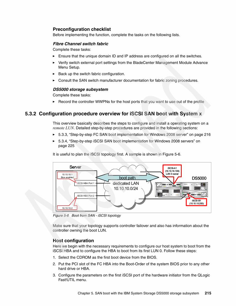
Preconfiguration checklistBefore implementing the function, complete the tasks on the following lists.
Fibre Channel switch fabricComplete these tasks:
� Ensure that the unique domain ID and IP address are configured on all the switches.
� Verify switch external port settings from the BladeCenter Management Module Advance Menu Setup.
� Back up the switch fabric configuration.
� Consult the SAN switch manufacturer documentation for fabric zoning procedures.
DS5000 storage subsystemComplete these tasks:
� Record the controller WWPNs for the host ports that you want to use out of the profile
5.3.2 Configuration procedure overview for iSCSI SAN boot with System x
This overview basically describes the steps to configure and install a operating system on a remote LUN. Detailed step-by-step procedures are provided in the following sections:
� 5.3.3, “Step-by-step FC SAN boot implementation for Windows 2008 server” on page 216
� 5.3.4, “Step-by-step iSCSI SAN boot implementation for Windows 2008 servers” on page 225
It is useful to plan the iSCSI topology first. A sample is shown in Figure 5-6.
Figure 5-6 Boot from SAN - iSCSI topology
Make sure that your topology supports controller failover and also has information about the controller owning the boot LUN.
Host configurationHere we begin with the necessary requirements to configure our host system to boot from the iSCSI HBA and to configure the HBA to boot from its first LUN 0. Follow these steps:
1. Select the CDROM as the first boot device from the BIOS.
2. Put the PCI slot of the FC HBA into the Boot-Order of the system BIOS prior to any other hard drive or HBA.
3. Configure the parameters on the first iSCSI port of the hardware initiator from the QLogic Fast!UTIL menu.
dedicated LAN10.10.10.0/24
dedicated LAN10.10.10.0/24
iSCSI-A1 (10.10.10.100)LUN 0 owner
iSCSI-B1 (10.10.10.200)
iSCSI HBA Port 1
iSCSI HBA Port 2
10.10.10.1 Bios enabled
10.10.10.2
Server
DS5000boot path
dedicated LAN10.10.10.0/24
dedicated LAN10.10.10.0/24
iSCSI-A1 (10.10.10.100)LUN 0 owner
iSCSI-B1 (10.10.10.200)
iSCSI HBA Port 1
iSCSI HBA Port 2
10.10.10.1 Bios enabled
10.10.10.2
Server
DS5000boot path
Chapter 5. SAN boot with the IBM System Storage DS5000 storage subsystem 215

HBA network configurationEarly in the process, set up the network addresses of your iSCSI ports on the server. Follow these instructions to set up the IPs for the initiator ports:
1. Set the IP address and subnet mask on both iSCSI HBA ports. Gateway and IQN names are optional.
2. Verify the MTU size. Best practice is to set the MTU size to 9000, but this is required on all devices in your network.
For a successful installation of the Windows 2008 server operating system over the iSCSI SAN attached boot disk, it is critical that there is a single and separate path from the initiator to the target device. Additionally, the OS must only see the boot LUN during the OS install process. Any additional LUNs can be added after the OS and MPIO drivers are installed. Best practice is to disconnect the second iSCSI port on the server.
It is also preferred that the host and target ports reside in the same VLAN/Subnet.
3. After the network configuration is complete, validate the IP connectivity from the host to the target by pinging the IP address of the device interfaces.
Storage configurationThe necessary requirements to configure your storage system are as follows:
1. Provision the boot logical unit number (LUN) which is a regular DS5000 LUN.
2. Define the host:– Define the host OS type– Define the host (initiator) IQN name
3. Map the LUN to the host.
iSCSI boot settingsThe iSCSI boot settings are as follows:
� Select the desired Adapter Boot Mode.� Set the Primary Boot Device Setting.� Configure the IP address of the primary target device.
5.3.3 Step-by-step FC SAN boot implementation for Windows 2008 serverThe following major steps illustrate the procedure for booting an IBM BladeCenter HS20 blade from an IBM System Storage DS5000 storage subsystem through the Storage Area Network (SAN) using Windows 2008 server. Each major step is divided into sub-steps (tasks) to simplify the description.
Hint: To define the host ports (IQN name) for the host definition, it is helpful to let the HBA log in to the storage (see Figure 5-28 on page 232) prior to the host definition.
216 IBM Midrange System Storage Implementation and Best Practices Guide
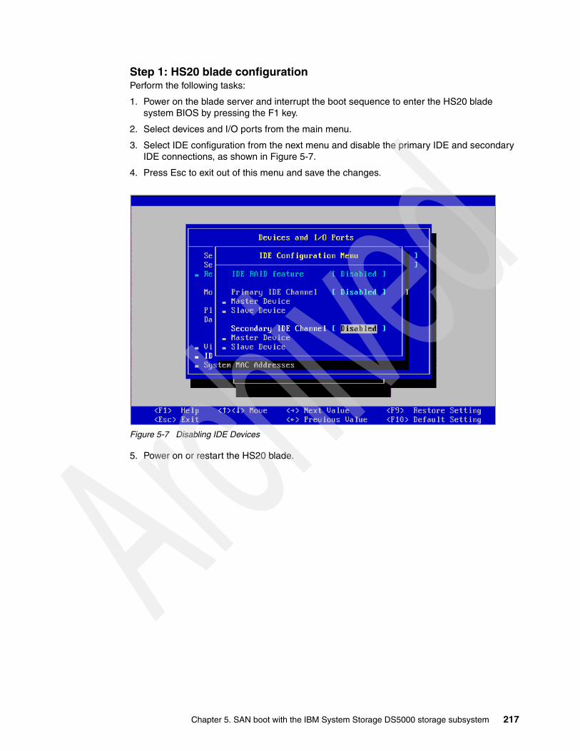
Step 1: HS20 blade configurationPerform the following tasks:
1. Power on the blade server and interrupt the boot sequence to enter the HS20 blade system BIOS by pressing the F1 key.
2. Select devices and I/O ports from the main menu.
3. Select IDE configuration from the next menu and disable the primary IDE and secondary IDE connections, as shown in Figure 5-7.
4. Press Esc to exit out of this menu and save the changes.
Figure 5-7 Disabling IDE Devices
5. Power on or restart the HS20 blade.
Chapter 5. SAN boot with the IBM System Storage DS5000 storage subsystem 217
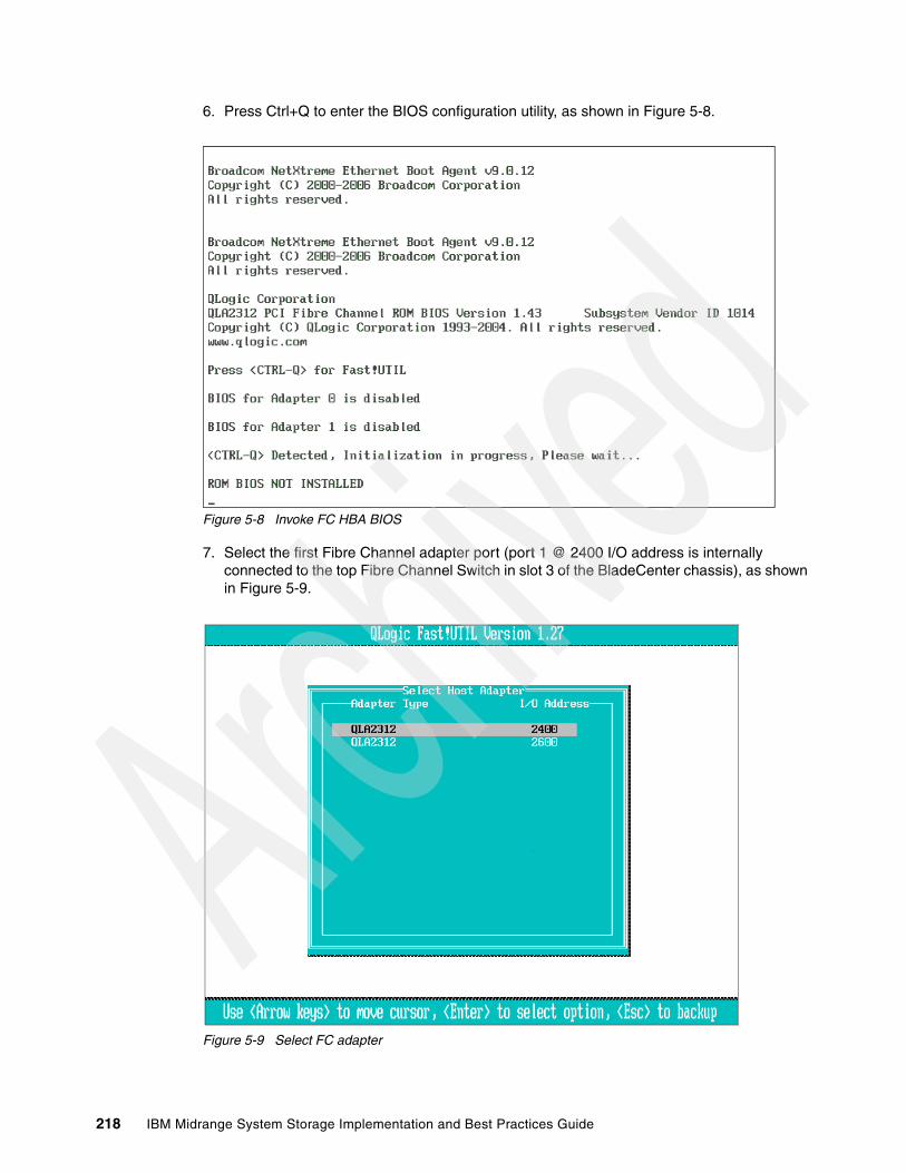
6. Press Ctrl+Q to enter the BIOS configuration utility, as shown in Figure 5-8.
Figure 5-8 Invoke FC HBA BIOS
7. Select the first Fibre Channel adapter port (port 1 @ 2400 I/O address is internally connected to the top Fibre Channel Switch in slot 3 of the BladeCenter chassis), as shown in Figure 5-9.
Figure 5-9 Select FC adapter
© 2008 IBM Corporation
218 IBM Midrange System Storage Implementation and Best Practices Guide

8. Select Configuration Settings - Adapter Settings, as shown in Figure 5-10.
9. Change the Host Adapter BIOS to enabled (the default value is disabled).
Figure 5-10 Enable FC BIOS
10.Record the World-Wide Port Name (WWPN) of this host bus adapter. It will be needed while configuring storage partitioning on the DS5000 storage subsystem and also for fabric zone configuration.
© 2008 IBM Corporation
Chapter 5. SAN boot with the IBM System Storage DS5000 storage subsystem 219
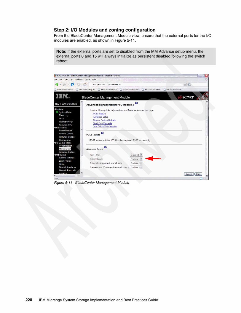
Step 2: I/O Modules and zoning configurationFrom the BladeCenter Management Module view, ensure that the external ports for the I/O modules are enabled, as shown in Figure 5-11.
Figure 5-11 BladeCenter Management Module
Note: If the external ports are set to disabled from the MM Advance setup menu, the external ports 0 and 15 will always initialize as persistent disabled following the switch reboot.
220 IBM Midrange System Storage Implementation and Best Practices Guide

As depicted in Figure 5-12, there is only one link at this stage from the DS5000 controller A to the switch. The second link from controller B to the switch is intentionally disconnected while installing the operating system so that the OS sees a separate path to the storage. Zone your switch accordingly.
Figure 5-12 Zone1 configuration
Attention: Ensure that there is only one path to the logical drive during installation. As soon as the operating system and multipathing drivers are installed, the second path can be zoned up.
Chapter 5. SAN boot with the IBM System Storage DS5000 storage subsystem 221
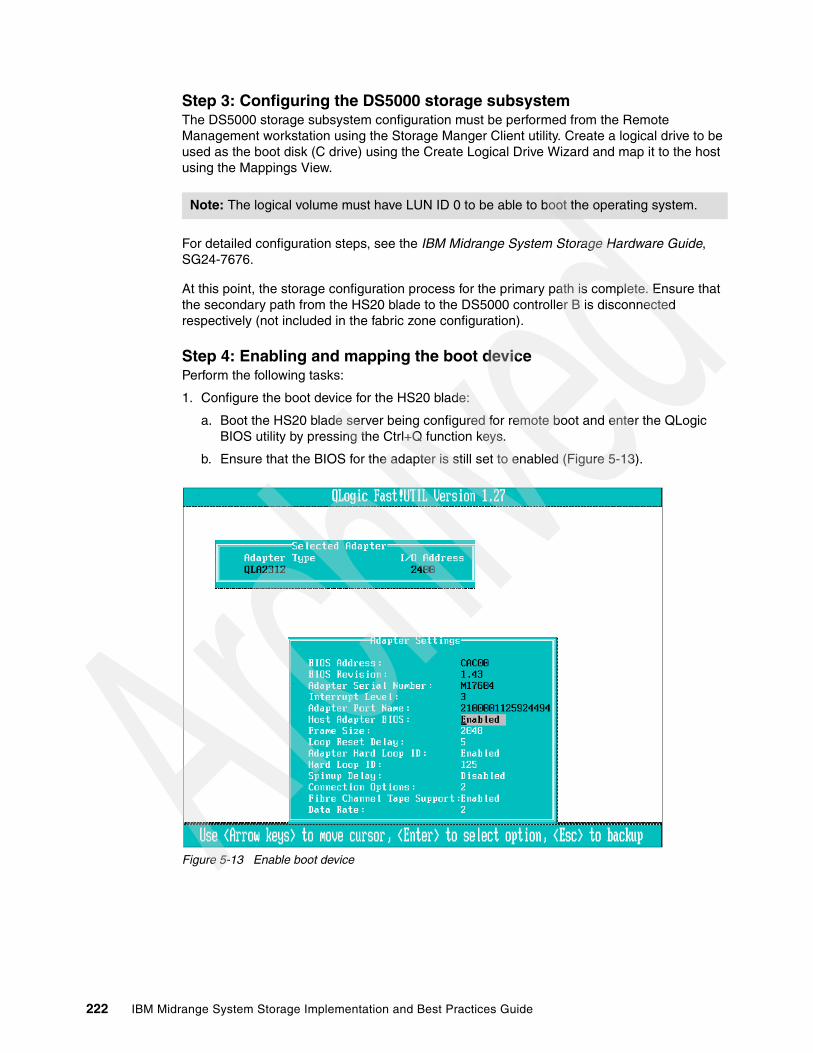
Step 3: Configuring the DS5000 storage subsystemThe DS5000 storage subsystem configuration must be performed from the Remote Management workstation using the Storage Manger Client utility. Create a logical drive to be used as the boot disk (C drive) using the Create Logical Drive Wizard and map it to the host using the Mappings View.
For detailed configuration steps, see the IBM Midrange System Storage Hardware Guide, SG24-7676.
At this point, the storage configuration process for the primary path is complete. Ensure that the secondary path from the HS20 blade to the DS5000 controller B is disconnected respectively (not included in the fabric zone configuration).
Step 4: Enabling and mapping the boot devicePerform the following tasks:
1. Configure the boot device for the HS20 blade:
a. Boot the HS20 blade server being configured for remote boot and enter the QLogic BIOS utility by pressing the Ctrl+Q function keys.
b. Ensure that the BIOS for the adapter is still set to enabled (Figure 5-13).
Figure 5-13 Enable boot device
Note: The logical volume must have LUN ID 0 to be able to boot the operating system.
© 2008 IBM Corporation
222 IBM Midrange System Storage Implementation and Best Practices Guide

c. Exit the menu by pressing the Esc key.
d. Select Selectable Boot Settings from the main menu.
e. Under the Selectable Boot Settings option, set the boot device to the controller's World Wide Port Name, as shown in Figure 5-14.
Figure 5-14 Map boot device
f. Set the boot LUN to reflect LUN 0.
g. Save all changes and exit from the BIOS menu by pressing Esc.
h. Reboot to enter the setup menu for the HS40 blade.
2. Configure the startup device for the HS40 blade only (Phoenix and AMI BIOS).
Following the reboot initiated in the preceding step, carefully watch the boot sequence for the Setup menu:
a. Press the F1 key to enter the setup menu.
b. Select startup options.
c. Select startup sequence options.
Chapter 5. SAN boot with the IBM System Storage DS5000 storage subsystem 223
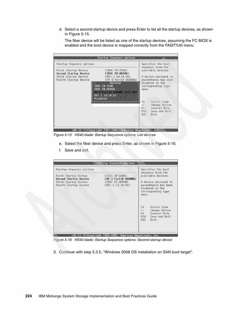
d. Select a second startup device and press Enter to list all the startup devices, as shown in Figure 5-15.
The fiber device will be listed as one of the startup devices, assuming the FC BIOS is enabled and the boot device is mapped correctly from the FAStT!Util menu.
Figure 5-15 HS40 blade: Startup Sequence options: List devices
e. Select the fiber device and press Enter, as shown in Figure 5-16.
f. Save and exit.
Figure 5-16 HS40 blade: Startup Sequence options: Second startup device
3. Continue with step 5.3.5, “Windows 2008 OS installation on SAN boot target”.
224 IBM Midrange System Storage Implementation and Best Practices Guide
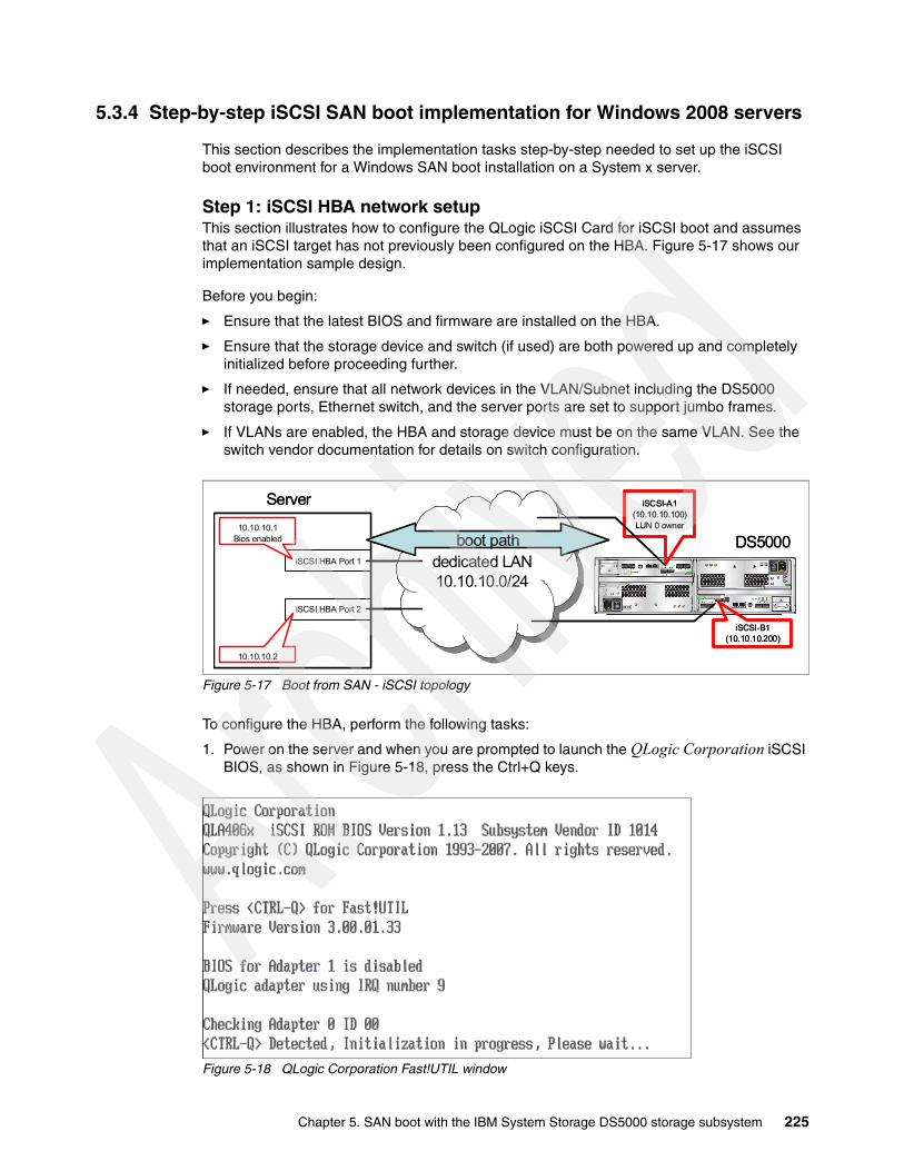
5.3.4 Step-by-step iSCSI SAN boot implementation for Windows 2008 servers
This section describes the implementation tasks step-by-step needed to set up the iSCSI boot environment for a Windows SAN boot installation on a System x server.
Step 1: iSCSI HBA network setupThis section illustrates how to configure the QLogic iSCSI Card for iSCSI boot and assumes that an iSCSI target has not previously been configured on the HBA. Figure 5-17 shows our implementation sample design.
Before you begin:
� Ensure that the latest BIOS and firmware are installed on the HBA.
� Ensure that the storage device and switch (if used) are both powered up and completely initialized before proceeding further.
� If needed, ensure that all network devices in the VLAN/Subnet including the DS5000 storage ports, Ethernet switch, and the server ports are set to support jumbo frames.
� If VLANs are enabled, the HBA and storage device must be on the same VLAN. See the switch vendor documentation for details on switch configuration.
Figure 5-17 Boot from SAN - iSCSI topology
To configure the HBA, perform the following tasks:
1. Power on the server and when you are prompted to launch the QLogic Corporation iSCSI BIOS, as shown in Figure 5-18, press the Ctrl+Q keys.
Figure 5-18 QLogic Corporation Fast!UTIL window
dedicated LAN10.10.10.0/24
dedicated LAN10.10.10.0/24
iSCSI-A1 (10.10.10.100)LUN 0 owner
iSCSI-B1 (10.10.10.200)
iSCSI HBA Port 1
iSCSI HBA Port 2
10.10.10.1 Bios enabled
10.10.10.2
Server
DS5000boot path
dedicated LAN10.10.10.0/24
dedicated LAN10.10.10.0/24
iSCSI-A1 (10.10.10.100)LUN 0 owner
iSCSI-B1 (10.10.10.200)
iSCSI HBA Port 1
iSCSI HBA Port 2
10.10.10.1 Bios enabled
10.10.10.2
Server
DS5000boot path
Chapter 5. SAN boot with the IBM System Storage DS5000 storage subsystem 225

2. After pressing the Ctrl+Q keys, you enter the QLogic iSCSI Card BIOS utility. You see a window similar to Figure 5-19.
Figure 5-19 QLogic Fast!UTIL menu window
3. From the QLogic Fast!UTIL menu, select the first host bus adapter port (port 0) and press Enter. You see a window similar to Figure 5-20.
Figure 5-20 Fast!UTIL Options menu window
226 IBM Midrange System Storage Implementation and Best Practices Guide

4. From the Fast!UTIL Options window (Figure 5-20 on page 226), select Configuration Settings and press Enter. From the same window, select Host Adapter Settings and press Enter to input the HBA configuration parameters, which must be specified before any targets can be configured. You see a window similar to Figure 5-21.
Figure 5-21 Host Adapter Settings window
5. Pressing Enter on the Initiator IP Settings as shown in Figure 5-21. A new window is displayed (Figure 5-22) where all IP settings can be changed. Press Enter for each entry you want to change.
Figure 5-22 Initiator IP Settings windows
Chapter 5. SAN boot with the IBM System Storage DS5000 storage subsystem 227

6. Specify the following parameters if you are configuring manually:
– Initiator IP Address (Figure 5-22 on page 227)– Subnet Mask– Gateway IP Address
If using DHCP to obtain these parameters from a DHCP server, you need only enable the Initiator IP Address through DHCP.
Optional: Specify the Initiator iSCSI Name. A default name is provided, but you have the option to manually change it. The name must be in the form of a correctly formatted RFC 3720 iSCSI Qualified name (IQN).
Optionally, if using Chap authentication with the target, specify the Initiator Chap Name and Initiator Chap Secret on this window. Best practice is to set authentication to archive the right security level for your boot environment. In our case, we do not use Chap to keep the procedure simple. See “Enhancing connection security” on page 184 for details about how to set Chap authentication.
7. After changing each setting and pressing Enter, press Esc to exit. You see a window similar to Figure 5-22 on page 227. In our example, we only changed the IP address and subnet mask.
Important: Use the same iSCSI Qualified Name (IQN) for all host ports.
The same iSCSI Qualified Name (IQN) applies to all iSCSI HBA ports on the host and the Microsoft iSCSI software initiator in the system. All iSCSI HBAs and software initiators configured on the same machine must share the same name for the IQN.
Caution: If it is predetermined that the Microsoft MPIO driver packaged with the MS iSCSI initiator service will be used to achieve failover in a iSCSI SAN Boot environment, then it is critical to use the MS IQN naming format. The Microsoft MPIO driver (bundled with the MS iSCSI initiator service) installer utility, automatically without warning or prompting, overwrites the IQN name of the system as well as the iSCSI expansion card.
As a result, in an iSCSI SAN boot environment, the host will lose access to the boot LUN (where the OS resides) during the MPIO driver install process, thus causing the system to crash. Worse, the system cannot be recovered even after the boot path is restored by redefining the host and LUN mapping on the storage. Thus re-installing the OS is the only option available at this point.
It is very critical that the MS IQN naming format be used from the beginning for the SAN Boot environment. The format is very simple:
iqn.1991-05.com.microsoft:{Windows Server Name}
For environments that use Active Directory server, the server name will be the full FQDN name, for example, servername.domain.com, and thus the IQN name will be iqn.1991-05.com.microsoft:servername.domain.com.
228 IBM Midrange System Storage Implementation and Best Practices Guide
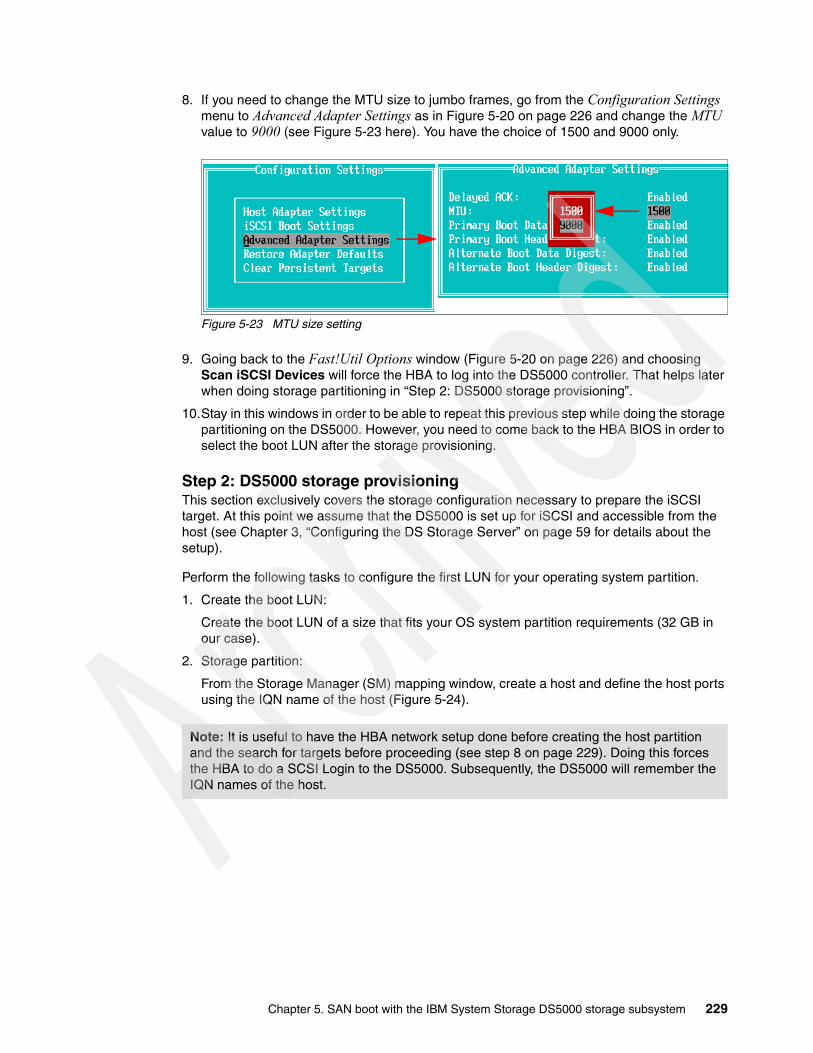
8. If you need to change the MTU size to jumbo frames, go from the Configuration Settings menu to Advanced Adapter Settings as in Figure 5-20 on page 226 and change the MTU value to 9000 (see Figure 5-23 here). You have the choice of 1500 and 9000 only.
Figure 5-23 MTU size setting
9. Going back to the Fast!Util Options window (Figure 5-20 on page 226) and choosing Scan iSCSI Devices will force the HBA to log into the DS5000 controller. That helps later when doing storage partitioning in “Step 2: DS5000 storage provisioning”.
10.Stay in this windows in order to be able to repeat this previous step while doing the storage partitioning on the DS5000. However, you need to come back to the HBA BIOS in order to select the boot LUN after the storage provisioning.
Step 2: DS5000 storage provisioningThis section exclusively covers the storage configuration necessary to prepare the iSCSI target. At this point we assume that the DS5000 is set up for iSCSI and accessible from the host (see Chapter 3, “Configuring the DS Storage Server” on page 59 for details about the setup).
Perform the following tasks to configure the first LUN for your operating system partition.
1. Create the boot LUN:
Create the boot LUN of a size that fits your OS system partition requirements (32 GB in our case).
2. Storage partition:
From the Storage Manager (SM) mapping window, create a host and define the host ports using the IQN name of the host (Figure 5-24).
Note: It is useful to have the HBA network setup done before creating the host partition and the search for targets before proceeding (see step 8 on page 229). Doing this forces the HBA to do a SCSI Login to the DS5000. Subsequently, the DS5000 will remember the IQN names of the host.
Chapter 5. SAN boot with the IBM System Storage DS5000 storage subsystem 229
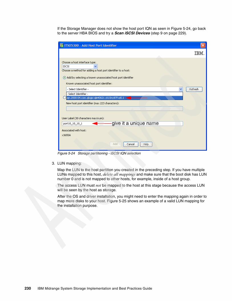
If the Storage Manager does not show the host port IQN as seen in Figure 5-24, go back to the server HBA BIOS and try a Scan iSCSI Devices (step 9 on page 229).
Figure 5-24 Storage partitioning - iSCSI IQN selection
3. LUN mapping:
Map the LUN to the host partition you created in the preceding step. If you have multiple LUNs mapped to this host, delete all mappings and make sure that the boot disk has LUN number 0 and is not mapped to other hosts, for example, inside of a host group.
The access LUN must not be mapped to the host at this stage because the access LUN will be seen by the host as storage.
After the OS and driver installation, you might need to enter the mapping again in order to map more disks to your host. Figure 5-25 shows an example of a valid LUN mapping for the installation purpose.
give it a unique name
230 IBM Midrange System Storage Implementation and Best Practices Guide
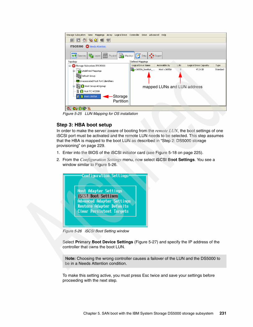
Figure 5-25 LUN Mapping for OS installation
Step 3: HBA boot setupIn order to make the server aware of booting from the remote LUN, the boot settings of one iSCSI port must be activated and the remote LUN needs to be selected. This step assumes that the HBA is mapped to the boot LUN as described in “Step 2: DS5000 storage provisioning” on page 229.
1. Enter into the BIOS of the iSCSI initiator card (see Figure 5-18 on page 225).
2. From the Configuration Settings menu, now select iSCSI Boot Settings. You see a window similar to Figure 5-26.
Figure 5-26 iSCSI Boot Setting window
Select Primary Boot Device Settings (Figure 5-27) and specify the IP address of the controller that owns the boot LUN.
To make this setting active, you must press Esc twice and save your settings before proceeding with the next step.
Note: Choosing the wrong controller causes a failover of the LUN and the DS5000 to be in a Needs Attention condition.
Storage
mapped LUNs and LUN address
Partition
Chapter 5. SAN boot with the IBM System Storage DS5000 storage subsystem 231

Figure 5-27 HBA Boot Target IP setting
3. Reenter into the iSCSI Boot Settings. You see a window like shown in Figure 5-28 that now represents the new primary boot target IP address but still no IQN name.
Figure 5-28 iSCSI Boot Settings window
4. When pressing the Enter key at the Primary LUN (Figure 5-28), the adapter probes the SCSI Bus for iSCSI targets and comes back with the selection of iSCSI targets found at this stage (see Figure 5-29).
Note: At this time, the iSCSI initiator SCSI protocol will login to the DS5000 and the DS5000 will recognize the new IQN to be used in the storage partitioning later on.
232 IBM Midrange System Storage Implementation and Best Practices Guide
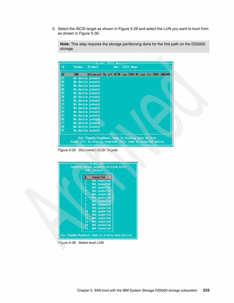
5. Select the iSCSI target as shown in Figure 5-29 and select the LUN you want to boot from as shown in Figure 5-30.
Figure 5-29 Discovered iSCSI Targets
Figure 5-30 Select boot LUN
Note: This step requires the storage partitioning done for the first path on the DS5000 storage.
Chapter 5. SAN boot with the IBM System Storage DS5000 storage subsystem 233

6. Change the Adapter Boot Mode (Figure 5-31) to Manual to enable the BIOS on this port.
7. The boot settings window finally looks as shown in Figure 5-31.
Figure 5-31 iSCSI Boot Settings window
8. To save changes to the HBA, press Esc twice. When prompted, select Save changes. The HBA is now configured to allow for iSCSI boot.
9. The operating system installation can now begin as though installing to a local disk. For a trouble-free installation, ensure that there is only one path available to the operating system during the installation.
This completes the host and storage configuration process necessary for the primary path.
5.3.5 Windows 2008 OS installation on SAN boot target
This short step-by-step guide shows examples of the Microsoft Windows 2008 Server installation itself with FC and iSCSI SAN boot. Certain steps are dedicated to the Fibre Channel (FC) or iSCSI installation and are mentioned accordingly.
Step 1: OS installation (Windows 2008)In order to install Windows 2008, we assume to use the Windows 2008 installation CD for the following tasks:
1. Depending on the FC HBA or iSCSI HBA card, the device driver might be already included in the Windows operating system. Loading a specific driver during the installation is not necessary. However, if it is necessary, you can use a floppy disk with the drivers to load them during the installation setup (Figure 5-32).
234 IBM Midrange System Storage Implementation and Best Practices Guide

Figure 5-32 Windows 2008 setup - load HBA drivers
2. After the drive is correctly recognized, select the drive and click Next (Figure 5-33).
Figure 5-33 SAN Disk recognition
3. Proceed with the installation just like a regular installation on a local hard disk:
a. Install the necessary service packs and reboot.
b. Install the necessary and optional DS5000 storage subsystem host management software packages, such as Storage Manager Client, multipath driver, agent, and utilities.
At this stage, Windows has the failover drivers installed, but the environment still has only one path to the storage. Proceed with the next step to get a redundant environment.
Chapter 5. SAN boot with the IBM System Storage DS5000 storage subsystem 235

Step 2: Configuring the secondary path for failoverThis step covers two types of SAN boot versions.
Fibre Channel SAN boot versionProper SAN zoning is required to enable the secondary path for failover.
Perform the following tasks:
1. Plug the second fiber cable (previously unplugged), back into the controller B (Figure 5-34).
Figure 5-34 Zone up the secondary path
2. Enable the BIOS setting for the second port on the HBA to be zoned with the DS5000 controller B.
3. Modify fabric zoning to add the secondary path from the blade host port 2 to the DS5000 controller B.
236 IBM Midrange System Storage Implementation and Best Practices Guide
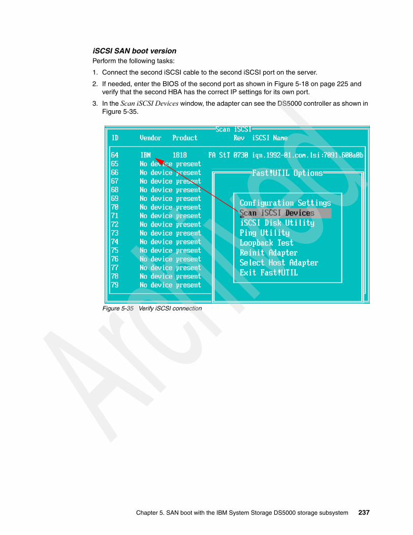
iSCSI SAN boot versionPerform the following tasks:
1. Connect the second iSCSI cable to the second iSCSI port on the server.
2. If needed, enter the BIOS of the second port as shown in Figure 5-18 on page 225 and verify that the second HBA has the correct IP settings for its own port.
3. In the Scan iSCSI Devices window, the adapter can see the DS5000 controller as shown in Figure 5-35.
Figure 5-35 Verify iSCSI connection
Chapter 5. SAN boot with the IBM System Storage DS5000 storage subsystem 237

Step 3: Configuring secondary path to DS5000 storage subsystemThis task applies to both the iSCSI and FC SAN boot versions.
Perform the following tasks:
1. In Storage Manager mapping view, select the host and define the second host port of the server to be part of the storage partition as seen in Figure 5-36.
Figure 5-36 Storage Manager - Manage Host Port Identifiers
238 IBM Midrange System Storage Implementation and Best Practices Guide

2. From the Add Host Port Identifier window, select the interface, known IQN, or WWPN from the Known unassociated host port identifier drop-down list and define a host port name. (see Figure 5-37).
Figure 5-37 Add Host Port Identifier
3. Make it possible for the host to see the secondary path to the DS5000 storage subsystem:
– You can add the access drive using Additional Mapping in Storage Manager and add the LUN ID = 31 for in-band management if needed.
– You can also configure any additional host storage if needed.
Step 4: Installation verificationThe best tool for this verification is the QLogic SANsurfer, but it is used only for QLogic HBAs. See the advanced maintenance and troubleshooting section of the IBM Midrange System Storage Hardware Guide, SG24-7676 for details of other HBAs and their management tools. However, the tools of the other HBA vendors, such as Brocade (HCM) or Emulex (HBAnyware), are very similar to the SANsurfer.
The following steps show how to verify that the drivers have installed and that the OS sees the LUN through all paths. Depending on your topology, you might see the LUN through two, four, or more paths.
define a host port name
select the interface
choose the IQN or WWPN
Chapter 5. SAN boot with the IBM System Storage DS5000 storage subsystem 239

Verifying driver installation using Windows toolsOpen the Device Manager from the Windows Start Menu Control Panel System. You see a window similar to Figure 5-38. Notice that you must see an IBM 1818 FAStT Multi-Path Disk Device, which is your boot LUN in that case. It does not reflect the number of physical paths in this view.
The Storage controllers section lists the iSCSI, Fibre Channel, and other controllers. If the driver is not installed correctly, You see an attention mark on the icon. Also the Microsoft Multi-Path Bus Driver must be installed (Figure 5-38).
Figure 5-38 Device Manager
MPIO virtual LUN
MPIO DriverFC HBA Driver
iSCSI HBA Driver
240 IBM Midrange System Storage Implementation and Best Practices Guide
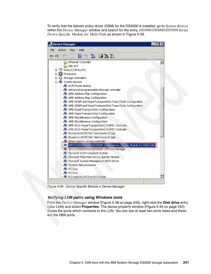
To verify that the failover policy driver (DSM) for the DS5000 is installed, go to System devices within the Device Manager window and search for the entry, DS3000/DS4000/DS5000 Series Device Specific Module for Multi-Path as shown in Figure 5-39.
Figure 5-39 Device Specific Module in Device Manager
Verifying LUN paths using Windows tools From the Device Manager window (Figure 5-38 on page 240), right-click the Disk drive entry (your LUN) and select Properties. The device property window (Figure 5-40 on page 242) shows the ports which connects to the LUN. You can see at least two ports listed and these are the HBA ports.
Chapter 5. SAN boot with the IBM System Storage DS5000 storage subsystem 241
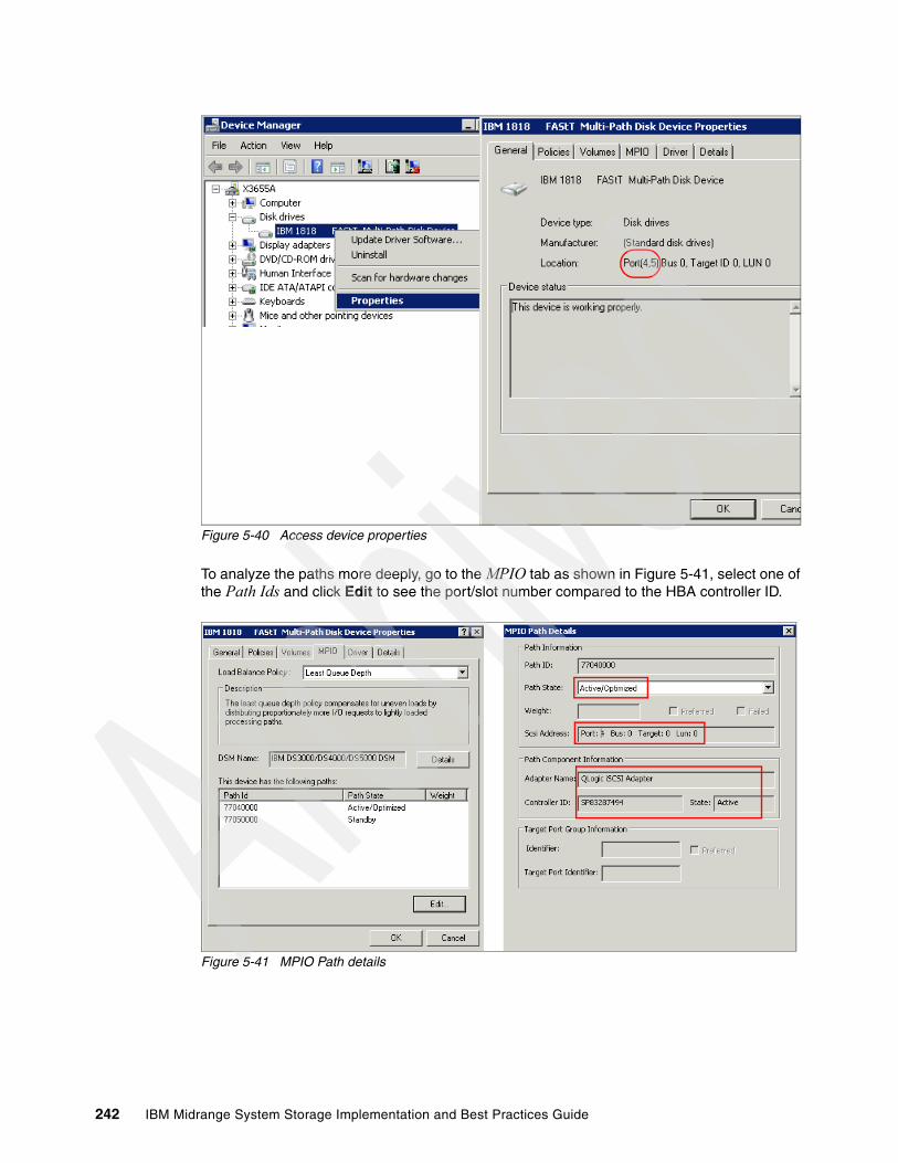
Figure 5-40 Access device properties
To analyze the paths more deeply, go to the MPIO tab as shown in Figure 5-41, select one of the Path Ids and click Edit to see the port/slot number compared to the HBA controller ID.
Figure 5-41 MPIO Path details
242 IBM Midrange System Storage Implementation and Best Practices Guide
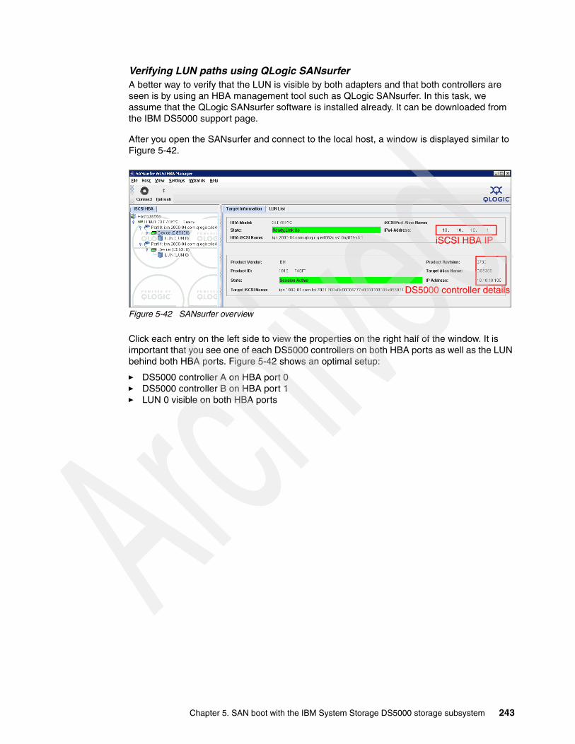
Verifying LUN paths using QLogic SANsurferA better way to verify that the LUN is visible by both adapters and that both controllers are seen is by using an HBA management tool such as QLogic SANsurfer. In this task, we assume that the QLogic SANsurfer software is installed already. It can be downloaded from the IBM DS5000 support page.
After you open the SANsurfer and connect to the local host, a window is displayed similar to Figure 5-42.
Figure 5-42 SANsurfer overview
Click each entry on the left side to view the properties on the right half of the window. It is important that you see one of each DS5000 controllers on both HBA ports as well as the LUN behind both HBA ports. Figure 5-42 shows an optimal setup:
� DS5000 controller A on HBA port 0� DS5000 controller B on HBA port 1� LUN 0 visible on both HBA ports
DS5000 controller details
iSCSI HBA IP
Chapter 5. SAN boot with the IBM System Storage DS5000 storage subsystem 243

Step 5: Failover/failback verification testTo verify that the server can successfully access the secondary path in case of a primary path failure while Windows is booted up completely, perform the following tasks:
1. From the Storage Manager Subsystem Management window (Logical view), check which controller currently has the drive ownership of the boot disk for the server (Figure 5-43). In optimal condition, the preferred and current controller must be the same.
Figure 5-43 Check controller ownership
Note: The Storage Manager layout has changed in version 10.50. Therefore Logical/Physical is not on one tab anymore; rather it is separated into two tabs now.
244 IBM Midrange System Storage Implementation and Best Practices Guide

2. Now disconnect the cable on the primary server host port 1.
3. Within 120 seconds, the multipath driver will cause a failover to the secondary path, which is attached to controller B on the DS5000 storage subsystem (Figure 5-44).
Figure 5-44 Controller B takes ownership
4. After the failover is done, connect the cable back into the server HBA port. You can see the path moving back to its primary controller within the next 120 seconds automatically.
This concludes the configuration and verification process for the Windows 2008 remote boot.
Limitations of booting from Windows 2008When the server is configured with storage access and path redundancy, you can observe the following limitations:
� If there is a path failure and the host is generating I/O, the boot drive moves to the other path. However, while this transition is occurring, the system appears to halt for up to 30 seconds.
� If the boot device (LUN 0) is not on the same path as the bootable HBA port, you receive an INACCESSIBLE_BOOT_DEVICE error message.
� By booting from the DS5000 storage subsystem, most of the online diagnostic strategies are effectively canceled, and path problem determination must be done from the diagnostics panel, which can be accessed by pressing Ctrl+q.
� The IDE disk devices must not be re-enabled.
Chapter 5. SAN boot with the IBM System Storage DS5000 storage subsystem 245
5.4 FC SAN boot for RHEL5.3 on IBM system x servers
In this section, we discuss how to implement Red Hat 5.u3 Linux SAN boot with an IBM System x server connected to a DS5000 storage subsystem through Fibre Channel.
Certain steps are similar to those presented in the Windows 2008 SAN boot section, but there are several key differences.
The DS5000 still supports Linux only with the RDAC driver. There are particular versions of drivers for the various Linux kernel versions available. See each RDAC readme file for a list of compatible Linux kernels.
The following Linux kernels are supported with the current RDAC version 09.03.0C05.0214:
� SLES 11: 2.6.27.19-5� SLES 10-SP2: 2.6.16.60-0.21� RHEL5-u2: 2.6.18-92� RHEL5-u3: 2.6.18-128
Consider the following precautions and guidelines when using RDAC with Linux:
� Read the RDAC readme file for a full list of limitations.
� Auto Logical Drive Transfer (ADT/AVT) mode is automatically enabled in the Linux storage partitioning host type. This mode causes contention when an RDAC is installed.
If using the “Linux” host type, it must be disabled using the script that is bundled in this Linux RDAC Web package or in the \Scripts directory of this DS Storage Manager version 10 support for Linux CD. The name of the script file is DisableAVT_Linux.scr.
If using the “LNXCLVMWARE” host type, you do not need to disable AVT, because this host type has AVT disabled by default. This host type is preferred for Linux with RDAC.
� The Linux SCSI layer does support skipped (sparse) LUNs with 2.6 and higher kernels. However, it is best that all mapped LUNs be contiguous.
� The guideline is to use multiple unconnected FC switches to zone the FC switch into multiple zones so that each HBA port sees only one controller in a DS5000 storage subsystem.
� The RDAC driver reports I/O failures immediately after all paths are failed. When the RDAC driver detects that all paths to a DS4000/DS5000 storage subsystem are failed, it will report I/O failure immediately. This behavior varies from the IBM Fibre Channel (FC) HBA failover device driver. The FC HBA failover device driver will wait for a certain time out/retry period before reporting an I/O failure to the host application. There is no work-around.
5.4.1 Linux SAN boot: Configuration overview
Here we present a summary of the Linux SAN boot configuration. For a step-by-step example, go to 5.4.2, “Linux SAN boot: Step-by-step procedure” on page 248.
1. Server HBA configuration:
Note: Always check the hardware and software, including firmware and operating system compatibility, before you implement SAN boot. Use the System Storage Interoperation Center (SSIC) Web site:
http://www.ibm.com/systems/support/storage/config/ssic/index.jsp
246 IBM Midrange System Storage Implementation and Best Practices Guide

a. Power on the server.
b. Disable the local such as IDE, SAS, and SATA drives in the server BIOS.
c. Record the WWPN and enable the BIOS of the first FC HBA using the FastT!Util menu.
2. SAN switches configuration:
Ensure that the Fibre Channel SAN switches are correctly set, according to the following guidelines:
a. Complete the necessary fiber cable connections with the DS5000 storage subsystem controllers, SAN switches, and server’s HBAs, and ensure that all the devices are properly connected.
b. Verify that all the switches in the fabric are configured with separate domain ID and IP addresses.
c. Verify and confirm that all of the switches are running the latest and compatible firmware version.
d. Define and activate zoning. Include only one HBA and one storage controller port in one zone.
3. DS5000 storage subsystem configuration for the primary path:
a. Create a logical drive to be used as the operating system disk for the server.
b. Complete the host group, host, and first host port definitions.
c. Define the storage partition and map the logical drive with LUN ID 0 to the first host port on the host group.
4. Fibre Channel host configuration for primary path:
Configure the boot device (FC BIOS parameter) for the primary path from the server to the DS5000 storage subsystem controller A by identifying and selecting the boot device.
5. Operating system installation:
a. Install the Linux operating system, update the QLogic HBA driver, and install the RDAC driver and the optional storage management software.
b. Verify that the server successfully boots from the logical drive on the primary path with a power off/on or by restarting the server.
6. Fibre Channel switched fabric configuration for the secondary path:
a. Add another zone to include the second FC HBA of the server and the DS5000 storage subsystem controller B as members of that zone.
b. Modify the active zone config to add the new zone.
c. Enable the zone config.
d. Verify that the active zone config lists the correct configuration.
7. DS5000 storage subsystem configuration for the secondary path:
a. Define the host port for the second port of the HBA under the same host group used for the primary path configuration. The host type must be the same as for the first host port.
b. Add the access logical drive with LUN ID = 31 (optional).
Note: Verify that the displayed WWPN matches the WWPN of the DS5000 storage controller A zoned with the first FC HBA and the LUN ID=0.
Chapter 5. SAN boot with the IBM System Storage DS5000 storage subsystem 247

8. Verify and test access to the secondary path from the host:
a. Check whether both controllers are visible from the host.
b. Test path redundancy.
5.4.2 Linux SAN boot: Step-by-step procedure
As a best practice, it is safer to have only one path from the server to the storage when doing the Linux OS installation, thus ensuring that the server only sees a separate path to the storage. You can disconnect the cable from the server’s second HBA for this purpose, as shown in Figure 5-45.
Figure 5-45 Installation diagram
Step 1: Server BIOS configurationPerform the following tasks:
1. Power on the server and press the F1 key to interrupt the boot sequence and enter the server system BIOS.
2. Select devices and I/O ports from the main menu.
3. Select the IDE configuration from the next menu and disable the primary IDE and secondary IDE connections, as shown in Figure 5-46. If necessary, also disable SAS or SATA controllers. Make sure that the CD drive will still operate. Do not disable the interface to the CD drive.
248 IBM Midrange System Storage Implementation and Best Practices Guide
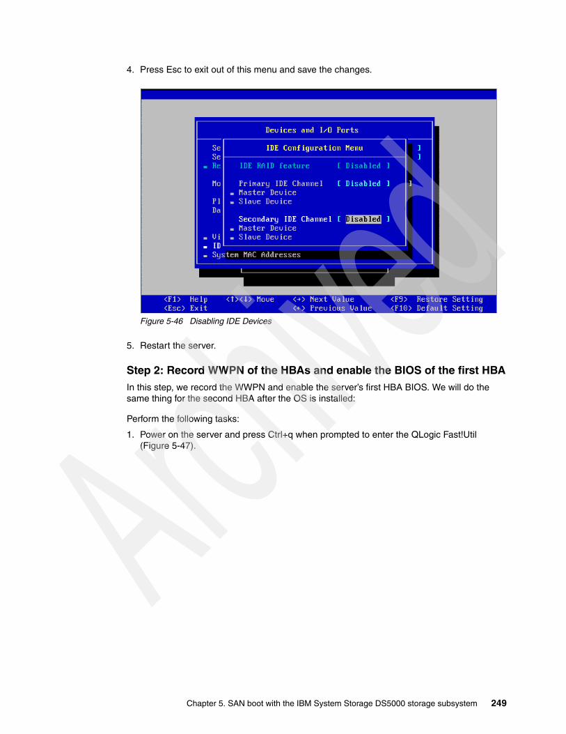
4. Press Esc to exit out of this menu and save the changes.
Figure 5-46 Disabling IDE Devices
5. Restart the server.
Step 2: Record WWPN of the HBAs and enable the BIOS of the first HBAIn this step, we record the WWPN and enable the server’s first HBA BIOS. We will do the same thing for the second HBA after the OS is installed:
Perform the following tasks:
1. Power on the server and press Ctrl+q when prompted to enter the QLogic Fast!Util (Figure 5-47).
Chapter 5. SAN boot with the IBM System Storage DS5000 storage subsystem 249

Figure 5-47 Invoke FC HBA BIOS
2. In the QLogic Fast!Util, highlight the first HBA and press Enter, as shown in Figure 5-48.
Figure 5-48 Select the first HBA
3. Select Configuration Settings, and then Host Adapter Settings, to bring up the Adapter Settings window, as shown in Figure 5-49.
© 2008 IBM Corporation
250 IBM Midrange System Storage Implementation and Best Practices Guide
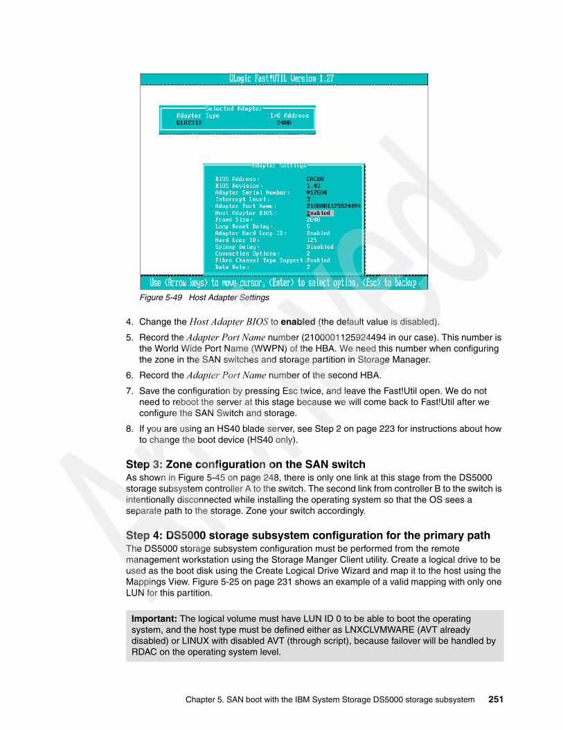
Figure 5-49 Host Adapter Settings
4. Change the Host Adapter BIOS to enabled (the default value is disabled).
5. Record the Adapter Port Name number (2100001125924494 in our case). This number is the World Wide Port Name (WWPN) of the HBA. We need this number when configuring the zone in the SAN switches and storage partition in Storage Manager.
6. Record the Adapter Port Name number of the second HBA.
7. Save the configuration by pressing Esc twice, and leave the Fast!Util open. We do not need to reboot the server at this stage because we will come back to Fast!Util after we configure the SAN Switch and storage.
8. If you are using an HS40 blade server, see Step 2 on page 223 for instructions about how to change the boot device (HS40 only).
Step 3: Zone configuration on the SAN switchAs shown in Figure 5-45 on page 248, there is only one link at this stage from the DS5000 storage subsystem controller A to the switch. The second link from controller B to the switch is intentionally disconnected while installing the operating system so that the OS sees a separate path to the storage. Zone your switch accordingly.
Step 4: DS5000 storage subsystem configuration for the primary pathThe DS5000 storage subsystem configuration must be performed from the remote management workstation using the Storage Manger Client utility. Create a logical drive to be used as the boot disk using the Create Logical Drive Wizard and map it to the host using the Mappings View. Figure 5-25 on page 231 shows an example of a valid mapping with only one LUN for this partition.
Important: The logical volume must have LUN ID 0 to be able to boot the operating system, and the host type must be defined either as LNXCLVMWARE (AVT already disabled) or LINUX with disabled AVT (through script), because failover will be handled by RDAC on the operating system level.
© 2008 IBM Corporation
Chapter 5. SAN boot with the IBM System Storage DS5000 storage subsystem 251

For detailed configuration information, see Chapter 3, “Configuring the DS Storage Server” on page 59.
At this point, the storage configuration process for the primary path is complete. Ensure that the secondary path from the server to the DS5000 storage controller B is disconnected and not included in the fabric zone configuration.
Step 5: Fibre Channel host configuration for primary pathBack in the Fast!Util menu, we continue to configure the server’s first HBA to enable and map the boot device.
In the Fast!Util menu, select Configuration Settings, then select Selectable Boot Settings. In the Selectable Boot Settings, change the value of Selectable Boot to Enabled. Move the cursor down to (Primary) Boot Port Name, and press Enter to select the boot device to the DS5000 storage controller A WWPN and ensure that the boot LUN is 0, as shown in Figure 5-50.
Figure 5-50 Selectable Boot Settings
After the WWPN has been verified, press Esc twice to save the setting. Exit Fast!Util and reboot the server.
The server can now detect a new DS5000 storage subsystem logical disk and we can proceed with the Linux operating system installation.
Step 6: Operating system installationIn this example, we install Red Hat Enterprise Linux 5 Update 3. The installation process is similar to local disk installation. Start by inserting the installation media of the RHEL5U3 installer into the server’s CD/DVD drive and boot the server from CD/DVD.
The installation process explained here assumes that the server does not have any special hardware (SCSI card or HBA) that requires a specific Linux driver not included on the installer CD. If you have a device driver diskette for a specific device driver to be loaded during the installation process, you need to type Linux dd at the installation boot prompt before the installation wizard is loaded.
The first task is to install the Linux operating system (assuming standard drivers). Next we update the QLogic HBA driver and install the Linux RDAC driver for multipathing.
Note: If you cannot find the LUN when you configure the boot port name, review your steps from the beginning. One possibility is that the logical drive you created is currently owned by the other controller or it is not correctly mapped in the storage partitioning. In this example, the logical drive created must be owned by controller A of the DS5000 storage subsystem.
252 IBM Midrange System Storage Implementation and Best Practices Guide

Installing the operating systemIf the server successfully boots from the CD, a welcome message is displayed, as shown in Figure 5-51.
Figure 5-51 Red Hat Installer welcome window
Click Next to start the installation wizard.
Chapter 5. SAN boot with the IBM System Storage DS5000 storage subsystem 253
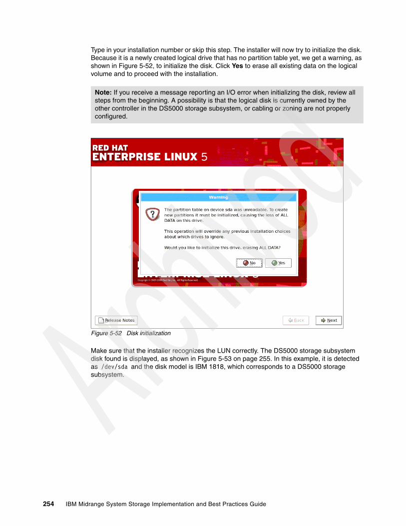
Type in your installation number or skip this step. The installer will now try to initialize the disk. Because it is a newly created logical drive that has no partition table yet, we get a warning, as shown in Figure 5-52, to initialize the disk. Click Yes to erase all existing data on the logical volume and to proceed with the installation.
Figure 5-52 Disk initialization
Make sure that the installer recognizes the LUN correctly. The DS5000 storage subsystem disk found is displayed, as shown in Figure 5-53 on page 255. In this example, it is detected as /dev/sda and the disk model is IBM 1818, which corresponds to a DS5000 storage subsystem.
Note: If you receive a message reporting an I/O error when initializing the disk, review all steps from the beginning. A possibility is that the logical disk is currently owned by the other controller in the DS5000 storage subsystem, or cabling or zoning are not properly configured.
254 IBM Midrange System Storage Implementation and Best Practices Guide

Figure 5-53 Disk partitioning
Follow the installation wizard until you reach the Package Group Selection. When you select a packages group to be installed, also install the Software Development Tools package. Indeed, you need certain tools for the compile driver, for example, after the OS has been completely installed.
After you have completed the package group selection installation, proceed with the remaining steps of the installation wizard until finished and reboot the server. If there was no error during the installation process, the server can boot and load the Linux OS that you just installed on the DS5000 storage subsystem disk.
Updating QLogic HBA driver for older Linux versions (RHEL 4)The next task is to update the HBA driver for older RHEL4 installations. No update is required for RHEL5. If you are going to install RHEL5, you can proceed with “Installing RDAC” on page 257.
In our example, we update to QLogic HBA driver V8.01.06, which can be downloaded from IBM or directly from the QLogic Web site at:
http://support.qlogic.com/support/oem_ibm.asp
There is a choice of either a failover or non-failover Linux kernel 2.6 device driver. RDAC requires the non-failover driver, but we do not have to manually configure for the non-failover driver because RDAC will configure it during the RDAC installation.
Note: RHEL 5 already includes a newer and working version of the QLogic driver.
Chapter 5. SAN boot with the IBM System Storage DS5000 storage subsystem 255
After downloading the driver, follow this procedure to update the driver:
1. Extract the file using the following command:
[root@taurus ~]# tar xfvz ibm_dd_ds4kfc_8.01.06_linux2.6_anycpu.tgz
2. Enter the following commands to extract the driver source:
[root@taurus ~]# cd qlogic/[root@taurus ~]# ./drvrsetupExtracting QLogic driver source...Done.
3. Enter the following command to install/set up the SNIA API library:
[root@taurus ~]# ./libinstall
4. Enter the following command to build and install the driver module files:
[root@taurus ~]# cd qla2xxx-8.01.06/[root@taurus ~]# ./extras/build.sh install
5. Add/edit the following lines into /etc/modules.conf:
alias scsi_hostadapter0 qla2xxx_confalias scsi_hostadapter1 qla2xxxalias scsi_hostadapter2 qla2300
Here is an example of the /etc/modules.conf file after installing the driver and adding the lines mentioned previously:
[root@taurus ~]# cat /etc/modules.confalias eth0 e100alias eth1 e100alias scsi_hostadapter aic7xxxalias usb-controller ohci-hcd
install qla2xxx /sbin/modprobe qla2xxx_conf; /sbin/modprobe --ignore-install qla2xxxremove qla2xxx /sbin/modprobe -r --first-time --ignore-remove qla2xxx && { /sbin/modprobe -r --ignore-remove qla2xxx_conf; }
alias scsi_hostadapter0 qla2xxx_confalias scsi_hostadapter1 qla2xxxalias scsi_hostadapter2 qla2300
6. Create a new RAM disk image:
[root@taurus ~]# depmod -a[root@taurus ~]# mkinitrd -f /boot/new-initrd-`uname -r`.img `uname -r`
The previous command creates a new RAM disk image named /boot/new-initrd-2.6.9-42.ELsmp.img, because we use Linux kernel 2.6.9-42.ELsmp.
7. Configure the boot loader with the new RAM disk image by modifying the /boot/grub/menu.lst file.
Note: You also need to update the OS default HBA driver if you plan to install QLogic SANsurfer in Linux because SANsurfer will not recognize the HBA if the device driver is still the default driver supplied with the OS.
Attention: Be careful when modifying the /boot/grub/menu.lst file. A typing error can make your Linux boot fail.
256 IBM Midrange System Storage Implementation and Best Practices Guide
Here is sample content from the /boot/grub/menu.lst file after modification:
title Red Hat Enterprise Linux AS (2.6.9-42.ELsmp)root (hd0,0)kernel /vmlinuz-2.6.9-42.ELsmp ro root=LABEL=/ rhgb quietinitrd /new-initrd-2.6.9-42.ELsmp.img
8. Reboot the server.
9. Verify that new driver is installed and loaded using the following commands:
[root@taurus ~]# ls -al /proc/scsi/qla2xxx/total 0dr-xr-xr-x 2 root root 0 Nov 22 23:21 .dr-xr-xr-x 5 root root 0 Nov 22 23:21 ..-rw-r--r-- 1 root root 0 Nov 22 23:21 2-rw-r--r-- 1 root root 0 Nov 22 23:21 3
[root@taurus ~]# cat /proc/scsi/qla2xxx/2QLogic PCI to Fibre Channel Host Adapter for QCP2340:Firmware version 3.03.19 IPX, Driver version 8.01.06-foISP: ISP2312, Serial# H96488...{truncated}
[root@taurus ~]# cat /proc/scsi/qla2xxx/3QLogic PCI to Fibre Channel Host Adapter for QCP2340:Firmware version 3.03.19 IPX, Driver version 8.01.06-foISP: ISP2312, Serial# H95592...{truncated}
From the previous commands, we can see that there are two HBAs installed (there are two folders under the /proc/scsi/qla2xxx/ folder) and both of them are loaded using driver Version 8.01.06-fo, which is the new driver we just installed.
The parameter -fo after the driver version (in the previous example, the driver version is 8.01.06-fo) means that the loaded driver is in failover mode, which is the default. To configure the new driver to be a non-failover driver, you can insert the line options qla2xxx ql2xfailover=0 into the /etc/modprobe.conf file, rebuild the RAM disk image, modify the /boot/grub/menu.lst file, and reboot the server.
Installing RDACSee the IBM Midrange System Storage Hardware Guide, SG24-7676 for information about installing the RDAC driver.
Note: Modifying the /etc/modprobe.conf file to configure the HBA driver to be a non-failover driver as explained previously is not necessary if you plan to use RDAC as the multipathing driver. The reason is that RDAC will put and activate the same parameter into the file /opt/mpp/modprobe.conf.mppappend during the RDAC installation to force the QLogic driver to load the non-failover mode.
Chapter 5. SAN boot with the IBM System Storage DS5000 storage subsystem 257
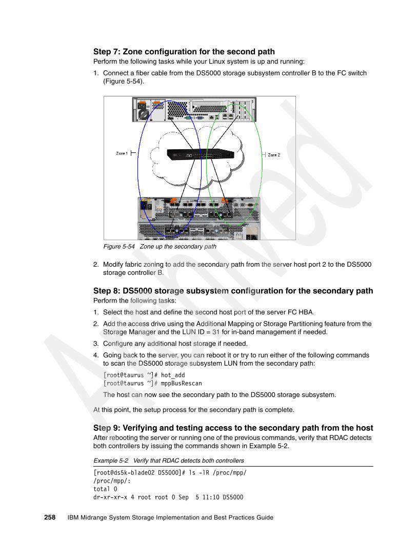
Step 7: Zone configuration for the second pathPerform the following tasks while your Linux system is up and running:
1. Connect a fiber cable from the DS5000 storage subsystem controller B to the FC switch (Figure 5-54).
Figure 5-54 Zone up the secondary path
2. Modify fabric zoning to add the secondary path from the server host port 2 to the DS5000 storage controller B.
Step 8: DS5000 storage subsystem configuration for the secondary pathPerform the following tasks:
1. Select the host and define the second host port of the server FC HBA.
2. Add the access drive using the Additional Mapping or Storage Partitioning feature from the Storage Manager and the LUN ID = 31 for in-band management if needed.
3. Configure any additional host storage if needed.
4. Going back to the server, you can reboot it or try to run either of the following commands to scan the DS5000 storage subsystem LUN from the secondary path:
[root@taurus ~]# hot_add[root@taurus ~]# mppBusRescan
The host can now see the secondary path to the DS5000 storage subsystem.
At this point, the setup process for the secondary path is complete.
Step 9: Verifying and testing access to the secondary path from the hostAfter rebooting the server or running one of the previous commands, verify that RDAC detects both controllers by issuing the commands shown in Example 5-2.
Example 5-2 Verify that RDAC detects both controllers
[root@ds5k-blade02 DS5000]# ls -lR /proc/mpp//proc/mpp/:total 0dr-xr-xr-x 4 root root 0 Sep 5 11:10 DS5000
258 IBM Midrange System Storage Implementation and Best Practices Guide

/proc/mpp/DS5000:total 0dr-xr-xr-x 3 root root 0 Sep 5 11:14 controllerAdr-xr-xr-x 3 root root 0 Sep 5 11:14 controllerB-rw-r--r-- 1 root root 0 Sep 5 11:14 virtualLun0
/proc/mpp/DS5000/controllerA:total 0dr-xr-xr-x 2 root root 0 Sep 5 11:14 qla2xxx_h1c0t1
/proc/mpp/DS5000/controllerA/qla2xxx_h1c0t1:total 0-rw-r--r-- 1 root root 0 Sep 5 11:14 LUN0
/proc/mpp/DS5000/controllerB:total 0dr-xr-xr-x 2 root root 0 Sep 5 11:14 qla2xxx_h1c0t0
/proc/mpp/DS5000/controllerB/qla2xxx_h1c0t0:total 0-rw-r--r-- 1 root root 0 Sep 5 11:14 LUN0
From the foregoing results, we can see that RDAC now sees two LUNs, one from controller A and one from controller B. Because there is actually one physical LUN in the DS5000 storage subsystem, RDAC will still create only one virtual LUN.
5.4.3 Controller failure simulation
In this section, we show you how RDAC works when a controller of the DS5000 storage subsystem fails. We use the mppUtil command to display information about the LUNs and the path status. See the mppUtil manual page (man mppUtil) for the list of parameters you can use and their explanation.
To check all LUNs seen by the host, run the commands shown in Example 5-3.
Example 5-3 Check all LUNs seen by the host
[root@ds5k-blade02 DS5000]# mppUtil -aHostname = ds5k-blade02Domainname = (none)Time = GMT 09/05/2008 18:17:45
---------------------------------------------------------------Info of Array Module's seen by this Host.---------------------------------------------------------------ID WWN Type Name--------------------------------------------------------------- 0 600a0b800029ed2200000000489c6f56 FC DS5000---------------------------------------------------------------
The result in this example shows one LUN with a virtual target ID 0 detected by RDAC. This LUN is in the DS5000 storage subsystem where the operating system is installed.
Chapter 5. SAN boot with the IBM System Storage DS5000 storage subsystem 259

To check the path status, run the commands shown in Example 5-4.
Example 5-4 Check all LUNs seen by the host
[root@ds5k-blade02 DS5000]# mppUtil -g 0Hostname = ds5k-blade02Domainname = (none)Time = GMT 09/05/2008 18:18:16
MPP Information:---------------- ModuleName: DS5000 SingleController: N VirtualTargetID: 0x000 ScanTriggered: N ObjectCount: 0x000 AVTEnabled: N WWN: 600a0b800029ed2200000000489c6f56 RestoreCfg: N ModuleHandle: none Page2CSubPage: Y FirmwareVersion: 7.30.21.xx ScanTaskState: 0x00000000 LBPolicy: LeastQueueDepth
Controller 'A' Status:-----------------------ControllerHandle: none ControllerPresent: Y UTMLunExists: N Failed: N NumberOfPaths: 1 FailoverInProg: N ServiceMode: N
Path #1 --------- DirectoryVertex: present Present: Y PathState: OPTIMAL PathId: 77010001 (hostId: 1, channelId: 0, targetId: 1)
Controller 'B' Status:-----------------------ControllerHandle: none ControllerPresent: Y UTMLunExists: N Failed: N NumberOfPaths: 1 FailoverInProg: N ServiceMode: N
Path #1 --------- DirectoryVertex: present Present: Y PathState: OPTIMAL PathId: 77010000 (hostId: 1, channelId: 0, targetId: 0)
Lun Information--------------- Lun #0 - WWN: 600a0b800029eb780000174848bed064 ---------------- LunObject: present CurrentOwningPath: A RemoveEligible: N BootOwningPath: A
260 IBM Midrange System Storage Implementation and Best Practices Guide

NotConfigured: N PreferredPath: A DevState: OPTIMAL ReportedPresent: Y ReportedMissing: N NeedsReservationCheck: N TASBitSet: Y NotReady: N Busy: N Quiescent: N
Controller 'A' Path -------------------- NumLunObjects: 1 RoundRobinIndex: 0 Path #1: LunPathDevice: present DevState: OPTIMAL RemoveState: 0x0 StartState: 0x1 PowerState: 0x0
Controller 'B' Path -------------------- NumLunObjects: 1 RoundRobinIndex: 0 Path #1: LunPathDevice: present DevState: OPTIMAL RemoveState: 0x0 StartState: 0x1 PowerState: 0x0
The result shows that the DS5000 storage subsystem controller A and controller B are detected and all paths are in optimal status. It shows that LUN 0, for which the preferred and boot path are to controller A, is also currently owned by controller A, which is the normal and expected situation.
Now we simulate a controller failure by deleting Zone1 (Figure 5-54 on page 258). The path to Controller A immediately becomes unavailable and the failover takes place to switch to the second path to controller B. Of course, do not do this in your production environment!
After controller A fails, the server will be still running if RDAC was properly installed. Check the path status again from the server as shown in Example 5-5.
Example 5-5 Check the path status again
[root@ds5k-blade02 DS5000]# mppUtil -g 0Hostname = ds5k-blade02Domainname = (none)Time = GMT 09/05/2008 18:27:24
MPP Information:---------------- ModuleName: DS5000 SingleController: N VirtualTargetID: 0x000 ScanTriggered: N ObjectCount: 0x000 AVTEnabled: N WWN: 600a0b800029ed2200000000489c6f56 RestoreCfg: N ModuleHandle: none Page2CSubPage: Y FirmwareVersion: 7.30.21.xx ScanTaskState: 0x00000000 LBPolicy: LeastQueueDepth
Controller 'A' Status:-----------------------
Chapter 5. SAN boot with the IBM System Storage DS5000 storage subsystem 261

ControllerHandle: none ControllerPresent: Y UTMLunExists: N Failed: Y NumberOfPaths: 1 FailoverInProg: N ServiceMode: N
Path #1 --------- DirectoryVertex: present Present: Y PathState: FAILED PathId: 77010001 (hostId: 1, channelId: 0, targetId: 1)
Controller 'B' Status:-----------------------ControllerHandle: none ControllerPresent: Y UTMLunExists: N Failed: N NumberOfPaths: 1 FailoverInProg: N ServiceMode: N
Path #1 --------- DirectoryVertex: present Present: Y PathState: OPTIMAL PathId: 77010000 (hostId: 1, channelId: 0, targetId: 0)
Lun Information--------------- Lun #0 - WWN: 600a0b800029eb780000174848bed064 ---------------- LunObject: present CurrentOwningPath: B RemoveEligible: N BootOwningPath: A NotConfigured: N PreferredPath: A DevState: OPTIMAL ReportedPresent: Y ReportedMissing: N NeedsReservationCheck: N TASBitSet: Y NotReady: N Busy: N Quiescent: N
Controller 'A' Path -------------------- NumLunObjects: 1 RoundRobinIndex: 0 Path #1: LunPathDevice: present DevState: FAILED RemoveState: 0x0 StartState: 0x1 PowerState: 0x0
Controller 'B' Path -------------------- NumLunObjects: 1 RoundRobinIndex: 0 Path #1: LunPathDevice: present DevState: OPTIMAL RemoveState: 0x0 StartState: 0x1 PowerState: 0x0
262 IBM Midrange System Storage Implementation and Best Practices Guide

The result shows that the controller A status is failed and that the path is also failed. The LUN ownership is now controller B, but the preferred path and booting path are still on controller A.
When the failed controller is back online, the LUN fails back to controller A automatically. Verify this in Storage Manager and run mppUtil again to check.
If you reboot your server while the LUN ownership is not on the preferred controller, you have to enter Fast!Util during the boot sequence (press Ctrl+q when prompted), disable the BIOS of the first HBA, and then enable the BIOS of the second HBA and configure the boot device from the second HBA, as explained in “Step 5: Fibre Channel host configuration for primary path” on page 252.
5.5 iSCSI SAN boot for RHEL5.3 on IBM system x servers
This section describes a sample configuration of iSCSI SAN boot with a DS5000 storage subsystem attached to a System x server running RHEL v5.3.
This is meant to act as a guide to help you gain a better understanding of iSCSI SAN boot.
In our sample configuration, we use the following components:
� IBM System x3655 server.
� QLogic iSCSI HBA hardware initiator card - QLE4062C. (Ensure that your iSCSI HBAs are installed in the correct server PCI slots. See your vendor specific documentation for more information.)
� IBM DS5300 Storage Subsystem with v7.60 controller firmware
� IBM DS Storage Manager v10.60
The DS5000 still supports Linux only with the RDAC driver failover driver. There are particular versions of drivers for the various Linux kernel versions available. See each RDAC readme file for a list of compatible Linux kernels.
The following Linux kernels are supported with the current RDAC version 09.03.0C05.0214:
� SLES 11: 2.6.27.19-5� SLES 10-SP2: 2.6.16.60-0.21� RHEL5-u2: 2.6.18-92� RHEL5-u3: 2.6.18-128
Observe the following precautions and guidelines when using RDAC with Linux:
� Read the RDAC readme file for a full list of limitations.
� Auto Logical Drive Transfer (ADT/AVT) mode, is automatically enabled in the Linux storage partitioning host type. This mode causes contention when an RDAC is installed.
Best practice: Enable the BIOS on only one HBA to avoid confusion. In Linux, you can only boot from SAN if the controller that is visible from the BIOS-enabled HBA is the owner of the boot LUN.
Note: Always check the hardware and software, including firmware and operating system compatibility, before you implement iSCSI SAN boot. Use the System Storage Interoperation Center (SSIC) Web site:
http://www.ibm.com/systems/support/storage/config/ssic/index.jsp
Chapter 5. SAN boot with the IBM System Storage DS5000 storage subsystem 263
– If using the “Linux” host type, it has to be disabled using the script that is bundled in this Linux RDAC Web package or in the \Scripts directory of this DS Storage Manager version 10 support for Linux CD. The name of the script file is DisableAVT_Linux.scr.
– If using the “LNXCLVMWARE” host type, you do not need to disable AVT, because this host type has AVT disabled by default, which is the preferred host type for Linux with RDAC.
� The Linux SCSI layer does support skipped (sparse) LUNs with 2.6 and higher kernels. However, it is best that all mapped LUNs be contiguous.
The RDAC driver reports I/O failures immediately after all paths are failed. When the RDAC driver detects that all paths to a DS4000/DS5000 storage subsystem are failed, it will report I/O failure immediately.
5.5.1 Configuration procedure overview for iSCSI SAN boot with System x
This overview describes the basic steps to configure and install a RHEL v5.3 operating system on a remote LUN on the IBM DS5300 Storage Subsystem. Go to 5.3.4, “Step-by-step iSCSI SAN boot implementation for Windows 2008 servers” on page 225 for the detailed step-by-step procedure.
It is useful to plan the iSCSI topology first. A sample is shown in Figure 5-55.
Figure 5-55 Boot from SAN - iSCSI topology
Make sure that your topology supports controller failover and also has information about the controller owning the boot LUN.
Host configurationHere we begin with the necessary requirements to configure our host system to boot from the iSCSI HBA and to configure the HBA to boot from its first LUN 0.
Perform the following tasks:
1. Disable the local such as IDE, SAS, and SATA drives in the server BIOS.
2. Set the IP address and subnet mask on both iSCSI HBA ports. Gateway and IQN name is optional. Ensure that only the primary iSCSI HBA path is plugged to the network switch at this time.
3. For a successful install of the RHEL v5.3 operating system over the iSCSI attached boot disk, it is critical that there is a single and separate path from the initiator to the target device. Additionally, the OS can only see the boot LUN during the OS install process. Any additional LUNs can be added after the OS and RDAC drivers are installed. Best practise is do disconnect the second iSCSI port on the server.
dedicated LAN10.10.10.0/24
dedicated LAN10.10.10.0/24
iSCSI-A1 (10.10.10.100)LUN 0 owner
iSCSI-B1 (10.10.10.200)
iSCSI HBA Port 1
iSCSI HBA Port 2
10.10.10.1 Bios enabled
10.10.10.2
Server
DS5000boot path
dedicated LAN10.10.10.0/24
dedicated LAN10.10.10.0/24
iSCSI-A1 (10.10.10.100)LUN 0 owner
iSCSI-B1 (10.10.10.200)
iSCSI HBA Port 1
iSCSI HBA Port 2
10.10.10.1 Bios enabled
10.10.10.2
Server
DS5000boot path
264 IBM Midrange System Storage Implementation and Best Practices Guide
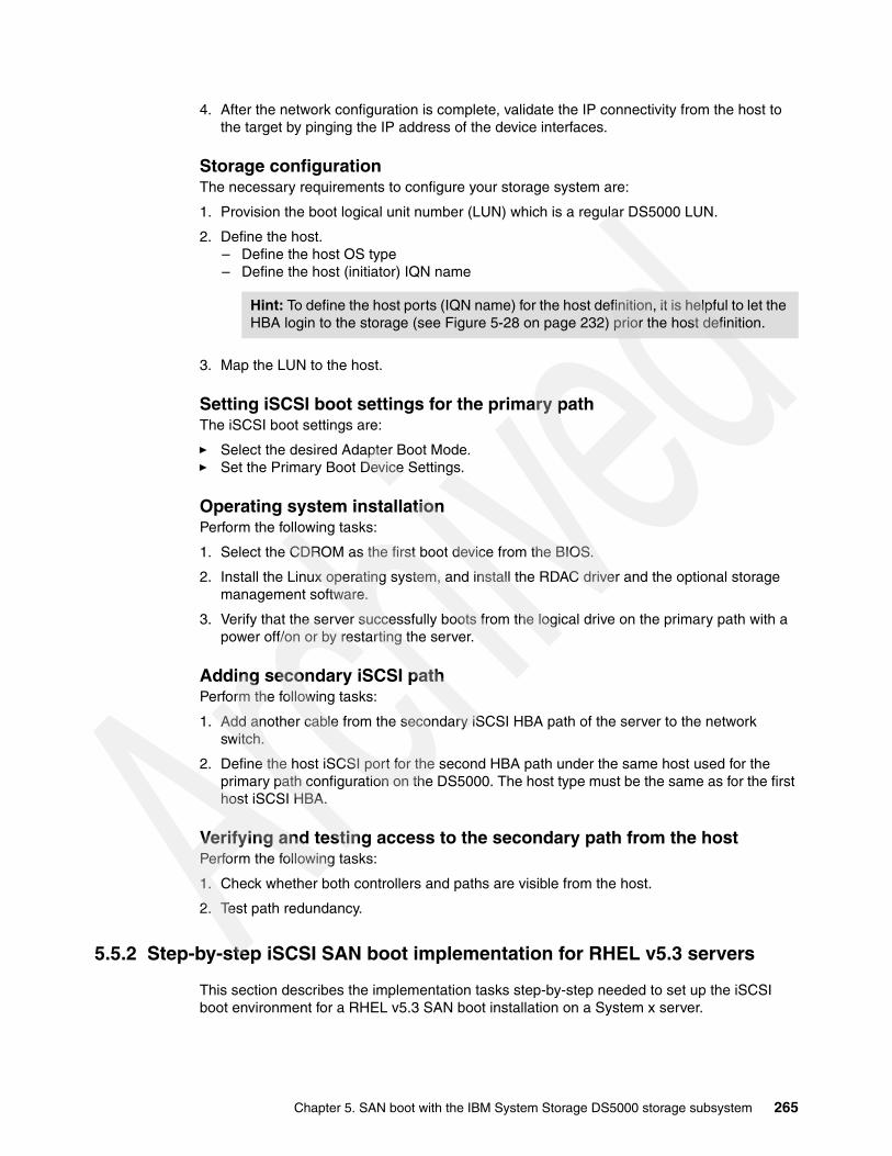
4. After the network configuration is complete, validate the IP connectivity from the host to the target by pinging the IP address of the device interfaces.
Storage configurationThe necessary requirements to configure your storage system are:
1. Provision the boot logical unit number (LUN) which is a regular DS5000 LUN.
2. Define the host.– Define the host OS type– Define the host (initiator) IQN name
3. Map the LUN to the host.
Setting iSCSI boot settings for the primary pathThe iSCSI boot settings are:
� Select the desired Adapter Boot Mode.� Set the Primary Boot Device Settings.
Operating system installationPerform the following tasks:
1. Select the CDROM as the first boot device from the BIOS.
2. Install the Linux operating system, and install the RDAC driver and the optional storage management software.
3. Verify that the server successfully boots from the logical drive on the primary path with a power off/on or by restarting the server.
Adding secondary iSCSI pathPerform the following tasks:
1. Add another cable from the secondary iSCSI HBA path of the server to the network switch.
2. Define the host iSCSI port for the second HBA path under the same host used for the primary path configuration on the DS5000. The host type must be the same as for the first host iSCSI HBA.
Verifying and testing access to the secondary path from the hostPerform the following tasks:
1. Check whether both controllers and paths are visible from the host.
2. Test path redundancy.
5.5.2 Step-by-step iSCSI SAN boot implementation for RHEL v5.3 servers
This section describes the implementation tasks step-by-step needed to set up the iSCSI boot environment for a RHEL v5.3 SAN boot installation on a System x server.
Hint: To define the host ports (IQN name) for the host definition, it is helpful to let the HBA login to the storage (see Figure 5-28 on page 232) prior the host definition.
Chapter 5. SAN boot with the IBM System Storage DS5000 storage subsystem 265

Step1: Initial host configurationThis section illustrates how to configure the QLogic iSCSI Card for iSCSI boot and assumes that an iSCSI target has not previously been configured on the HBA. Figure 5-56 shows our implementation sample design.
Before you begin:
� Ensure that the latest BIOS and firmware is installed on the HBA.
� Ensure that the storage device and switch (if used) are both powered up and completely initialized before proceeding further.
� Ensure that only the primary iSCSI host HBA path is plugged to the network switch at this time. Leave the secondary iSCSI host HBA path cable unplugged for now.
Figure 5-56 Boot from SAN - iSCSI topology
Server BIOS configurationPerform the following tasks:
1. Power on the server and press the F1 key to interrupt the boot sequence and enter the server system BIOS.
2. Select devices and I/O ports from the main menu.
3. Disable any onboard or internal hard drives. Select the IDE configuration from the next menu and disable the primary IDE and secondary IDE connections, as shown in Figure 5-57. If necessary, also disable SAS or SATA controllers. Make sure that the CD drive will still operate. Do not disable the interface to the CD drive.
dedicated LAN10.10.10.0/24
dedicated LAN10.10.10.0/24
iSCSI-A1 (10.10.10.100)LUN 0 owner
iSCSI-B1 (10.10.10.200)
iSCSI HBA Port 1
iSCSI HBA Port 2
10.10.10.1 Bios enabled
10.10.10.2
Server
DS5000boot path
dedicated LAN10.10.10.0/24
dedicated LAN10.10.10.0/24
iSCSI-A1 (10.10.10.100)LUN 0 owner
iSCSI-B1 (10.10.10.200)
iSCSI HBA Port 1
iSCSI HBA Port 2
10.10.10.1 Bios enabled
10.10.10.2
Server
DS5000boot path
266 IBM Midrange System Storage Implementation and Best Practices Guide

4. Press Esc to exit out of this menu and save the changes.
Figure 5-57 Disabling IDE Devices
5. Restart the server.
iSCSI HBA ConfigurationPerform the following tasks:
1. On server startup and when you are prompted to launch the QLogic Corporation iSCSI BIOS, as shown in Figure 5-58, press the Ctrl+Q keys.
Figure 5-58 QLogic Corporation Fast!UTIL window
Chapter 5. SAN boot with the IBM System Storage DS5000 storage subsystem 267
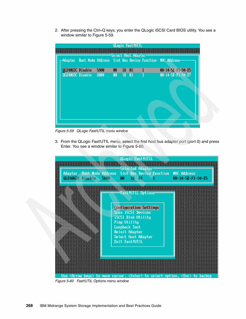
2. After pressing the Ctrl+Q keys, you enter the QLogic iSCSI Card BIOS utility. You see a window similar to Figure 5-59.
Figure 5-59 QLogic Fast!UTIL menu window
3. From the QLogic Fast!UTIL menu, select the first host bus adapter port (port 0) and press Enter. You see a window similar to Figure 5-60.
Figure 5-60 Fast!UTIL Options menu window
268 IBM Midrange System Storage Implementation and Best Practices Guide
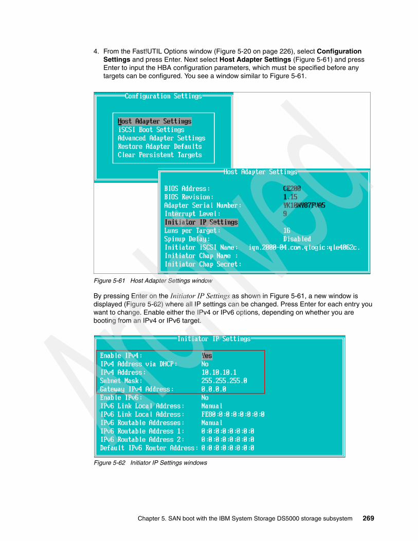
4. From the Fast!UTIL Options window (Figure 5-20 on page 226), select Configuration Settings and press Enter. Next select Host Adapter Settings (Figure 5-61) and press Enter to input the HBA configuration parameters, which must be specified before any targets can be configured. You see a window similar to Figure 5-61.
Figure 5-61 Host Adapter Settings window
By pressing Enter on the Initiator IP Settings as shown in Figure 5-61, a new window is displayed (Figure 5-62) where all IP settings can be changed. Press Enter for each entry you want to change. Enable either the IPv4 or IPv6 options, depending on whether you are booting from an IPv4 or IPv6 target.
Figure 5-62 Initiator IP Settings windows
Chapter 5. SAN boot with the IBM System Storage DS5000 storage subsystem 269

5. Specify the following parameters (Figure 5-62), if you are manually configuring them:
– Initiator IP Address – Subnet Mask – Gateway IP Address
If using DHCP to obtain these parameters from a DHCP server, you need only enable the Initiator IP Address through DHCP.
Optional: Specify the Initiator iSCSI Name. A default name is provided but you have the option to manually change it. The name must be in the form of a correctly formatted RFC 3720 IQN (iSCSI Qualified name).
Optionally, if using Chap authentication with the target, specify the Initiator Chap Name and Initiator Chap Secret on this window. Best practice is to set authentication to archive the right security level for your boot environment. In our case, we do not use Chap to keep the procedure simple. See “Enhancing connection security” on page 184 for details how to set Chap.
6. After changing each setting and pressing Enter, press Esc to exit. You see a window similar to Figure 5-63. In our example, we only changed the IP address and subnet mask. Press Esc again to go to the Configuration Settings menu.
7. From the Configuration Settings menu, select iSCSI Boot Settings. You see a window similar to Figure 5-63.
Figure 5-63 iSCSI Boot Setting window
Select Primary Boot Device Settings (Figure 5-64) and specify the IP address of the controller which owns the boot LUN.
To make this setting is active, you must press Esc twice and save your settings before proceeding with the next step.
Note: Choosing the wrong controller causes a failover of the LUN and the DS5000 to be in a Needs Attention condition.
270 IBM Midrange System Storage Implementation and Best Practices Guide

Figure 5-64 HBA Boot Target IP setting
8. Change the Adapter Boot Mode to Manual to enable the BIOS on this port. The boot settings window finally looks like Figure 5-65.
Figure 5-65 iSCSI Boot Settings window
Chapter 5. SAN boot with the IBM System Storage DS5000 storage subsystem 271
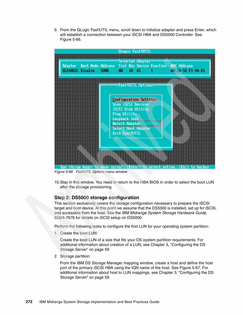
9. From the QLogic Fast!UTIL menu, scroll down to initialize adapter and press Enter, which will establish a connection between your iSCSI HBA and DS5000 Controller. See Figure 5-66.
Figure 5-66 Fast!UTIL Options menu window
10.Stay in this window. You need to return to the HBA BIOS in order to select the boot LUN after the storage provisioning.
Step 2: DS5000 storage configurationThis section exclusively covers the storage configuration necessary to prepare the iSCSI target and boot device. At this point we assume that the DS5000 is installed, set up for iSCSI, and accessible from the host. See the IBM Midrange System Storage Hardware Guide, SG24-7676 for details on iSCSI setup on DS5000.
Perform the following tasks to configure the first LUN for your operating system partition:
1. Create the boot LUN:
Create the boot LUN of a size that fits your OS system partition requirements. For additional information about creation of a LUN, see Chapter 3, “Configuring the DS Storage Server” on page 59
2. Storage partition:
From the IBM DS Storage Manager mapping window, create a host and define the host port of the primary iSCSI HBA using the IQN name of the host. See Figure 5-67. For additional information about host to LUN mappings, see Chapter 3, “Configuring the DS Storage Server” on page 59.
272 IBM Midrange System Storage Implementation and Best Practices Guide
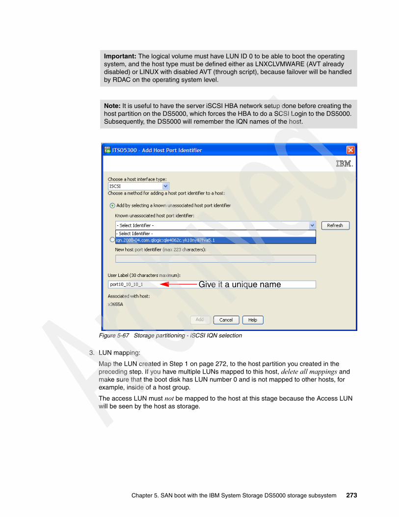
Figure 5-67 Storage partitioning - iSCSI IQN selection
3. LUN mapping:
Map the LUN created in Step 1 on page 272, to the host partition you created in the preceding step. If you have multiple LUNs mapped to this host, delete all mappings and make sure that the boot disk has LUN number 0 and is not mapped to other hosts, for example, inside of a host group.
The access LUN must not be mapped to the host at this stage because the Access LUN will be seen by the host as storage.
Important: The logical volume must have LUN ID 0 to be able to boot the operating system, and the host type must be defined either as LNXCLVMWARE (AVT already disabled) or LINUX with disabled AVT (through script), because failover will be handled by RDAC on the operating system level.
Note: It is useful to have the server iSCSI HBA network setup done before creating the host partition on the DS5000, which forces the HBA to do a SCSI Login to the DS5000. Subsequently, the DS5000 will remember the IQN names of the host.
Give it a unique name
Chapter 5. SAN boot with the IBM System Storage DS5000 storage subsystem 273

After the OS and RDAC failover driver installation, you might need to enter the mapping again in order to map additional data disks to your host. Figure 5-68 shows an example of a valid LUN mapping for the installation purpose. For detailed steps on host to LUN mappings, see Chapter 3, “Configuring the DS Storage Server” on page 59.
Figure 5-68 LUN Mapping for OS installation
Step 3: Additional host configurationBack on the host server iSCSI BIOS configuration, perform the following tasks:
1. Reenter into the iSCSI Boot Settings. You see a window as shown in Figure 5-69 that now represents the new primary boot target IP address but there is still no IQN name.
Figure 5-69 iSCSI Boot Settings window
2. Press the Enter key at the Primary LUN (Figure 5-69), and the adapter probes the SCSI Bus for iSCSI targets and comes back with the selection of iSCSI targets found at this stage (see Figure 5-70).
Mapped LUNs and LUN address
select the LUN and hit enter for discovery
274 IBM Midrange System Storage Implementation and Best Practices Guide
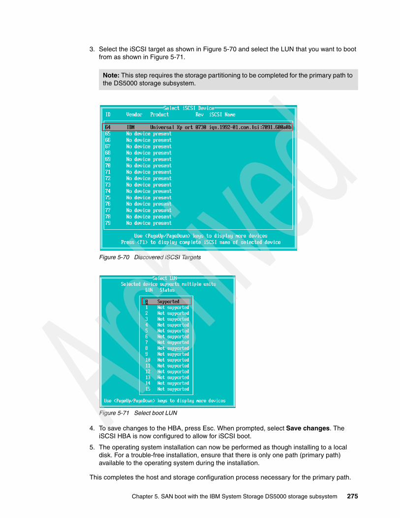
3. Select the iSCSI target as shown in Figure 5-70 and select the LUN that you want to boot from as shown in Figure 5-71.
Figure 5-70 Discovered iSCSI Targets
Figure 5-71 Select boot LUN
4. To save changes to the HBA, press Esc. When prompted, select Save changes. The iSCSI HBA is now configured to allow for iSCSI boot.
5. The operating system installation can now be performed as though installing to a local disk. For a trouble-free installation, ensure that there is only one path (primary path) available to the operating system during the installation.
This completes the host and storage configuration process necessary for the primary path.
Note: This step requires the storage partitioning to be completed for the primary path to the DS5000 storage subsystem.
Chapter 5. SAN boot with the IBM System Storage DS5000 storage subsystem 275

Step 4: Operating system installationIn this example, we install Red Hat Enterprise Linux v5.3. The installation process is similar to local disk installation. Start by inserting the installation media of the RHEL v5.3 installer into the server’s CD/DVD drive and boot the server from CD/DVD.
The installation process explained here assumes that the server does not have any special hardware (iSCSI card) that requires a specific Linux driver not included on the installer CD. If you have a device driver diskette for a specific device driver to be loaded during the installation process, you have to type Linux dd at the installation boot prompt before the installation wizard is loaded.
The first task is to install the Linux operating system (assuming standard drivers). Next we install the Linux RDAC driver for multipathing.
Installing the operating systemPerform the following tasks:
1. Determine if the server successfully boots from the CD. If so, a welcome message is displayed, as shown in Figure 5-72.
Figure 5-72 Red Hat Installer welcome window
2. Click Next to start the installation wizard.
3. Type in your installation number or skip this step.
Note: Ensure that the defined boot LUN is associated with the controller of which you enter the IP address. Also check that the detail you enter here is correct.
276 IBM Midrange System Storage Implementation and Best Practices Guide

4. The installer will now try to initialize the disk. Because it is a newly created logical drive that has no partition table yet, we get a warning, as shown in Figure 5-73, to initialize the disk. Click Yes to erase all existing data on the logical volume and to proceed with the installation.
Figure 5-73 Disk initialization
Note: If you receive a message reporting an I/O error when initializing the disk, review all steps from the beginning. A possibility is that the logical disk is currently owned by the other controller in the DS5000 storage subsystem, or cabling or zoning are not properly configured.
Chapter 5. SAN boot with the IBM System Storage DS5000 storage subsystem 277

5. Make sure that the installer recognizes the LUN correctly. The DS5000 storage subsystem disk found is displayed, as shown in Figure 5-74. In this example, it is detected as /dev/sda and the disk model is IBM 1818, which corresponds to a DS5000 storage subsystem.
Figure 5-74 Disk partitioning
6. Follow the installation wizard until you reach the Package Group Selection. When you select a package group to be installed, also install the Software Development Tools package. Indeed, you need certain tools for the compile driver, for example, after the OS has been completely installed.
7. After you have completed the package group selection installation, proceed with the remaining steps of the installation wizard until finished and reboot the server. If there was no error during the installation process, the server can boot and load the Linux OS you just installed on the DS5000 storage subsystem disk.
8. After the installation is done and the server reboots, enter the QLogic FastUtil again.
Installing RDACSee the IBM Midrange System Storage Hardware Guide, SG24-7676 for information about installing the RDAC driver.
Step 5: Configuring the secondary path for failoverWe now proceed with setting up the secondary path to the storage that will provide failover in the event of a failure of the primary path.
Initial preparationPerform the following tasks:
1. Connect the second iSCSI cable to the second iSCSI port on the server.
2. Enter the BIOS of the second port as shown in and set the IP settings for the second HBA path as were performed for the primary path.
278 IBM Midrange System Storage Implementation and Best Practices Guide
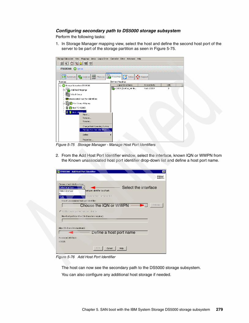
Configuring secondary path to DS5000 storage subsystemPerform the following tasks:
1. In Storage Manager mapping view, select the host and define the second host port of the server to be part of the storage partition as seen in Figure 5-75.
Figure 5-75 Storage Manager - Manage Host Port Identifiers
2. From the Add Host Port Identifier window, select the interface, known IQN or WWPN from the Known unassociated host port identifier drop-down list and define a host port name.
Figure 5-76 Add Host Port Identifier
The host can now see the secondary path to the DS5000 storage subsystem.
You can also configure any additional host storage if needed.
Define a host port name
Select the interface
Choose the IQN or WWPN
Chapter 5. SAN boot with the IBM System Storage DS5000 storage subsystem 279

3. Going back to the server, you can reboot it or try to run either of the following commands to scan the DS5000 storage subsystem LUN from the secondary path:
[root@ds5k-Linux ~]# hot_add[root@ds5k-Linux ~]# mppBusRescan
The host can now see the secondary path to the DS5000 storage subsystem.
At this point, the setup process for the secondary path is complete.
Step 6: Verifying and testing access to secondary path from the hostAfter rebooting the server or running one of the previous commands, verify that RDAC detects both controllers by issuing the command shown in Example 5-6.
Example 5-6 Verify that RDAC detects both controllers
[root@ds5k-Linux DS5000]# ls -lR /proc/mpp//proc/mpp/:total 0dr-xr-xr-x 4 root root 0 Sep 5 11:10 DS5000
/proc/mpp/DS5000:total 0dr-xr-xr-x 3 root root 0 Sep 5 11:14 controllerAdr-xr-xr-x 3 root root 0 Sep 5 11:14 controllerB-rw-r--r-- 1 root root 0 Sep 5 11:14 virtualLun0
/proc/mpp/DS5000/controllerA:total 0dr-xr-xr-x 2 root root 0 Sep 5 11:14 qla4xxx_h1c0t1
/proc/mpp/DS5000/controllerA/qla4xxx_h1c0t1:total 0-rw-r--r-- 1 root root 0 Sep 5 11:14 LUN0
/proc/mpp/DS5000/controllerB:total 0dr-xr-xr-x 2 root root 0 Sep 5 11:14 qla4xxx_h1c0t0
/proc/mpp/DS5000/controllerB/qla4xxx_h1c0t0:total 0-rw-r--r-- 1 root root 0 Sep 5 11:14 LUN0
From the previous results, we can see that RDAC now sees two LUNs, one from controller A and one from controller B. Because there is actually one physical LUN in the DS5000 storage subsystem, RDAC will still create only one virtual LUN.
280 IBM Midrange System Storage Implementation and Best Practices Guide
Controller failure simulationIn this section, we show you how RDAC works when a controller of the DS5000 storage subsystem fails. We use the mppUtil command to display information about the LUNs and the path status. See the mppUtil manual page (man mppUtil) for the list of parameters you can use and their explanation.
To check all LUNs seen by the host, run the command shown in Example 5-7.
Example 5-7 Check all LUNs seen by host
[root@ds5k-Linux DS5000]# mppUtil -aHostname = ds5k-LinuxDomainname = (none)Time = GMT 09/05/2009 18:17:45
---------------------------------------------------------------Info of Array Module's seen by this Host.---------------------------------------------------------------ID WWN Type Name--------------------------------------------------------------- 0 600a0b800029ed2200000000489c6f56 FC DS5000---------------------------------------------------------------
The result in this example shows one LUN with a virtual target ID 0 detected by RDAC. This LUN is in the DS5000 storage subsystem where the operating system is installed.
To check the path status, run the command shown in Example 5-8.
Example 5-8 Check the path status
[root@ds5k-Linux DS5000]# mppUtil -g 0Hostname = ds5k-LinuxDomainname = (none)Time = GMT 09/05/2009 18:18:16
MPP Information:---------------- ModuleName: DS5000 SingleController: N VirtualTargetID: 0x000 ScanTriggered: N ObjectCount: 0x000 AVTEnabled: N WWN: 600a0b800029ed2200000000489c6f56 RestoreCfg: N ModuleHandle: none Page2CSubPage: Y FirmwareVersion: 7.60.13.xx ScanTaskState: 0x00000000 LBPolicy: LeastQueueDepth
Controller 'A' Status:-----------------------ControllerHandle: none ControllerPresent: Y UTMLunExists: N Failed: N NumberOfPaths: 1 FailoverInProg: N ServiceMode: N
Path #1 ---------
Chapter 5. SAN boot with the IBM System Storage DS5000 storage subsystem 281

DirectoryVertex: present Present: Y PathState: OPTIMAL PathId: 77010001 (hostId: 1, channelId: 0, targetId: 1)
Controller 'B' Status:-----------------------ControllerHandle: none ControllerPresent: Y UTMLunExists: N Failed: N NumberOfPaths: 1 FailoverInProg: N ServiceMode: N
Path #1 --------- DirectoryVertex: present Present: Y PathState: OPTIMAL PathId: 77010000 (hostId: 1, channelId: 0, targetId: 0)
Lun Information--------------- Lun #0 - WWN: 600a0b800029eb780000174848bed064 ---------------- LunObject: present CurrentOwningPath: A RemoveEligible: N BootOwningPath: A NotConfigured: N PreferredPath: A DevState: OPTIMAL ReportedPresent: Y ReportedMissing: N NeedsReservationCheck: N TASBitSet: Y NotReady: N Busy: N Quiescent: N
Controller 'A' Path -------------------- NumLunObjects: 1 RoundRobinIndex: 0 Path #1: LunPathDevice: present DevState: OPTIMAL RemoveState: 0x0 StartState: 0x1 PowerState: 0x0
Controller 'B' Path -------------------- NumLunObjects: 1 RoundRobinIndex: 0 Path #1: LunPathDevice: present DevState: OPTIMAL RemoveState: 0x0 StartState: 0x1 PowerState: 0x0
The result shows that the DS5000 storage subsystem controller A and controller B are detected and all paths are in optimal status. It shows that LUN 0, for which the preferred and boot path are to controller A, is also currently owned by controller A, which is the normal and expected situation.
282 IBM Midrange System Storage Implementation and Best Practices Guide
Now we simulate a controller failure. The path to Controller A immediately becomes unavailable and the failover takes place to switch to the second path to controller B.
After controller A fails, the server will be running as normal, if RDAC was properly installed. Check the path status again from the server as shown in Example 5-9.
Example 5-9 Check the path status again
[root@ds5k-Linux DS5000]# mppUtil -g 0Hostname = ds5k-LinuxDomainname = (none)Time = GMT 09/05/2009 18:27:24
MPP Information:---------------- ModuleName: DS5000 SingleController: N VirtualTargetID: 0x000 ScanTriggered: N ObjectCount: 0x000 AVTEnabled: N WWN: 600a0b800029ed2200000000489c6f56 RestoreCfg: N ModuleHandle: none Page2CSubPage: Y FirmwareVersion: 7.60.13.xx ScanTaskState: 0x00000000 LBPolicy: LeastQueueDepth
Controller 'A' Status:-----------------------ControllerHandle: none ControllerPresent: Y UTMLunExists: N Failed: Y NumberOfPaths: 1 FailoverInProg: N ServiceMode: N
Path #1 --------- DirectoryVertex: present Present: Y PathState: FAILED PathId: 77010001 (hostId: 1, channelId: 0, targetId: 1)
Controller 'B' Status:-----------------------ControllerHandle: none ControllerPresent: Y UTMLunExists: N Failed: N NumberOfPaths: 1 FailoverInProg: N ServiceMode: N
Path #1 --------- DirectoryVertex: present Present: Y PathState: OPTIMAL PathId: 77010000 (hostId: 1, channelId: 0, targetId: 0)
Lun Information---------------
Chapter 5. SAN boot with the IBM System Storage DS5000 storage subsystem 283
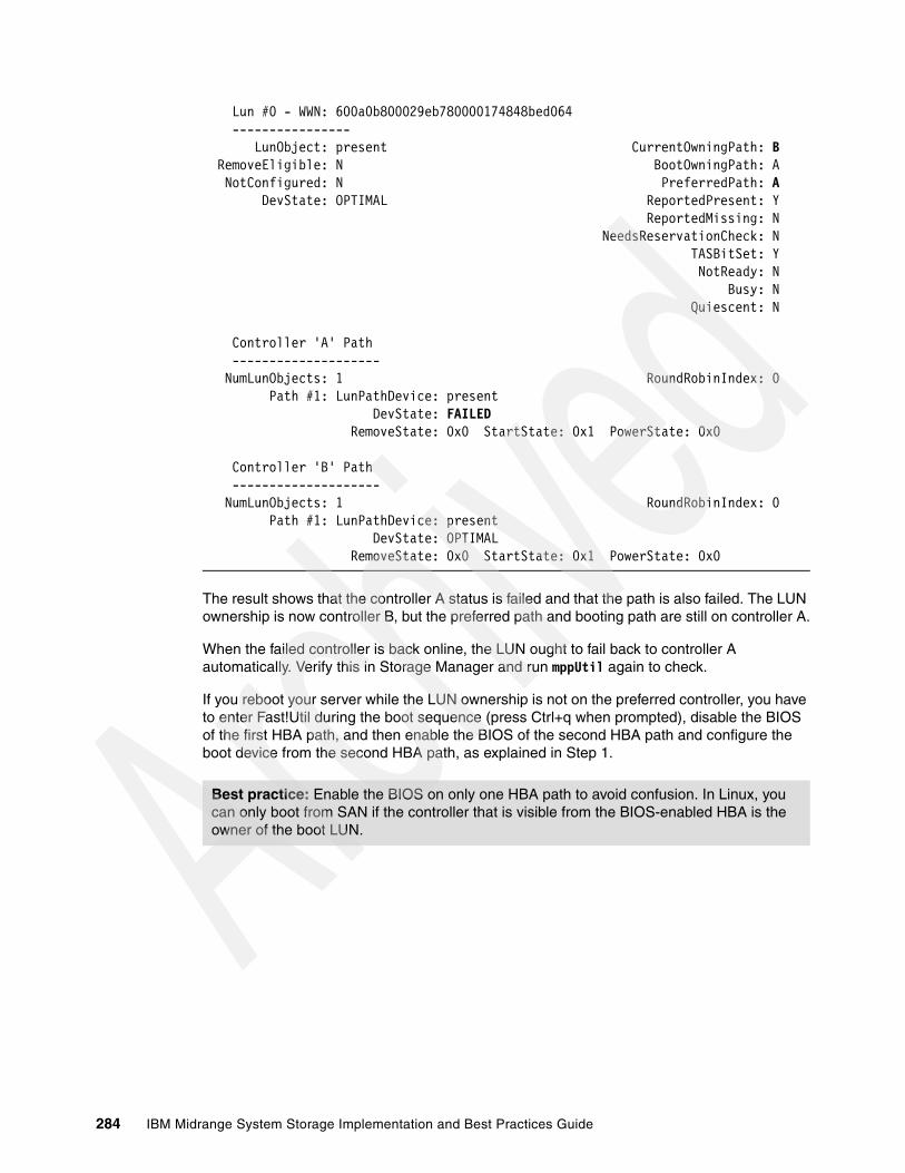
Lun #0 - WWN: 600a0b800029eb780000174848bed064 ---------------- LunObject: present CurrentOwningPath: B RemoveEligible: N BootOwningPath: A NotConfigured: N PreferredPath: A DevState: OPTIMAL ReportedPresent: Y ReportedMissing: N NeedsReservationCheck: N TASBitSet: Y NotReady: N Busy: N Quiescent: N
Controller 'A' Path -------------------- NumLunObjects: 1 RoundRobinIndex: 0 Path #1: LunPathDevice: present DevState: FAILED RemoveState: 0x0 StartState: 0x1 PowerState: 0x0
Controller 'B' Path -------------------- NumLunObjects: 1 RoundRobinIndex: 0 Path #1: LunPathDevice: present DevState: OPTIMAL RemoveState: 0x0 StartState: 0x1 PowerState: 0x0
The result shows that the controller A status is failed and that the path is also failed. The LUN ownership is now controller B, but the preferred path and booting path are still on controller A.
When the failed controller is back online, the LUN ought to fail back to controller A automatically. Verify this in Storage Manager and run mppUtil again to check.
If you reboot your server while the LUN ownership is not on the preferred controller, you have to enter Fast!Util during the boot sequence (press Ctrl+q when prompted), disable the BIOS of the first HBA path, and then enable the BIOS of the second HBA path and configure the boot device from the second HBA path, as explained in Step 1.
Best practice: Enable the BIOS on only one HBA path to avoid confusion. In Linux, you can only boot from SAN if the controller that is visible from the BIOS-enabled HBA is the owner of the boot LUN.
284 IBM Midrange System Storage Implementation and Best Practices Guide

Failover/failback verification testTo verify that the server can successfully access the secondary path in case of a primary path failure while Linux is booted up completely, perform the following tasks:
1. From the Storage Manager Subsystem Management window (Logical view), check which controller currently has the drive ownership of the boot disk for the server. In optimal condition, the preferred and current controller must be the same (Figure 5-77).
Figure 5-77 Check controller ownership
2. Now disconnect the cable on the primary server host port 1.
3. Within 120 seconds, the multipath driver will cause a failover to the secondary path, which is attached to controller B on the DS5000 storage subsystem (Figure 5-78).
Note: The Storage Manager layout has changed in version 10.50. Therefore Logical/Physical in not one tab anymore rather it is separated in two tabs now.
Chapter 5. SAN boot with the IBM System Storage DS5000 storage subsystem 285
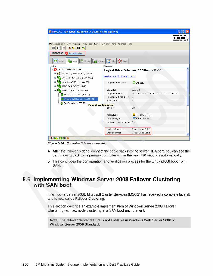
Figure 5-78 Controller B takes ownership
4. After the failover is done, connect the cable back into the server HBA port. You can see the path moving back to its primary controller within the next 120 seconds automatically.
5. This concludes the configuration and verification process for the Linux iSCSI boot from SAN.
5.6 Implementing Windows Server 2008 Failover Clustering with SAN boot
In Windows Server 2008, Microsoft Cluster Services (MSCS) has received a complete face lift and is now called Failover Clustering.
This section describe an example implementation of Windows Server 2008 Failover Clustering with two node clustering in a SAN boot environment.
Note: The failover cluster feature is not available in Windows Web Server 2008 or Windows Server 2008 Standard.
286 IBM Midrange System Storage Implementation and Best Practices Guide

You can find more details about Windows 2008 and Failover Clustering at the following Web sites:
� For a description of Windows Server 2008 R2, see:
http://www.microsoft.com/windowsserver2008/en/us/product-information.aspx
� For a description of Windows Server 2008 Failover Clustering, see:
http://www.microsoft.com/windowsserver2008/en/us/failover-clustering-main.aspx
The following guidelines and requirements apply to Windows Server 2008 Failover Clustering when booting the nodes from SAN. See our sample topology on Figure 5-79.
� With SAN boot, boot LUNs must be separated from data/shared cluster LUNs in the clustered environment.
� Boot LUNs must be owned by each individual host within the cluster and must be seen by the relevant hosts only.
� Data/shared cluster LUNs must be shared across all hosts, which is achieved by creating a host group on the DS5000 storage subsystem for all hosts in the cluster with all data/shared cluster LUNs mapped to the host group.
� Individual cluster hosts must be created within a host group containing their private boot LUNs as LUN #0. Individual HBA host ports must be mapped to these hosts.
� Zoning must be implemented in a single initiator/multi-target fashion, as illustrated in Figure 5-80, where each cluster host HBA port is mapped to both controllers of the DS5000 storage subsystem, enabling redundant paths to the boot and data/shared LUNs from the host HBAs.
Figure 5-79 Example Windows Failover Cluster topology
ITSO_ClusterWindows 2008 R2
DS5300A1 B1DS5300A1 B1
x3655A
HBA1 HBA2
x3655A
HBA1 HBA2
x3655B
HBA1 HBA2
x3655B
HBA1 HBA2
Host Group: ITSO_ClusterHost: x3655A Host: x3655B
x3655B_boot_LUN = LUN0
x3655A_boot_LUN=LUN0
zone 1
zone 2
zone 3
zone 4
ITSO_cluster_shared1 = LUN2
witness = LUN1
Chapter 5. SAN boot with the IBM System Storage DS5000 storage subsystem 287
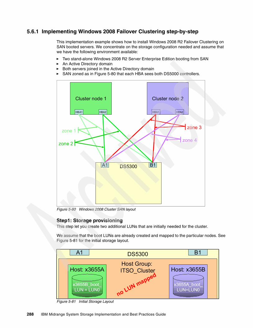
5.6.1 Implementing Windows 2008 Failover Clustering step-by-step
This implementation example shows how to install Windows 2008 R2 Failover Clustering on SAN booted servers. We concentrate on the storage configuration needed and assume that we have the following environment available:
� Two stand-alone Windows 2008 R2 Server Enterprise Edition booting from SAN� An Active Directory domain� Both servers joined in the Active Directory domain� SAN zoned as in Figure 5-80 that each HBA sees both DS5000 controllers.
Figure 5-80 Windows 2008 Cluster SAN layout
Step1: Storage provisioningThis step let you create two additional LUNs that are initially needed for the cluster.
We assume that the boot LUNs are already created and mapped to the particular nodes. See Figure 5-81 for the initial storage layout.
Figure 5-81 Initial Storage Layout
DS5300A1 B1DS5300A1 B1
Cluster node 1
HBA1 HBA2
Cluster node 1
HBA1 HBA2
Cluster node 2
HBA1 HBA2
Cluster node 2
HBA1 HBA2
zone 1
zone 2
zone 3
zone 4
DS5300A1 B1DS5300A1 B1
Host Group: ITSO_ClusterHost: x3655A Host: x3655B
x3655B_boot_LUN = LUN0
x3655A_boot_LUN=LUN0
no LUN mapped
288 IBM Midrange System Storage Implementation and Best Practices Guide
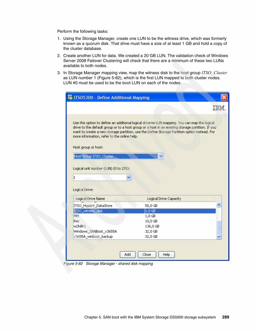
Perform the following tasks:
1. Using the Storage Manager, create one LUN to be the witness drive, which was formerly known as a quorum disk. That drive must have a size of at least 1 GB and hold a copy of the cluster database.
2. Create another LUN for data. We created a 20 GB LUN. The validation check of Windows Server 2008 Failover Clustering will check that there are a minimum of these two LUNs available to both nodes.
3. In Storage Manager mapping view, map the witness disk to the host group ITSO_Cluster as LUN number 1 (Figure 5-82), which is the first LUN mapped to both cluster nodes. LUN #0 must be used to be the boot LUN on each of the nodes.
Figure 5-82 Storage Manager - shared disk mapping
Chapter 5. SAN boot with the IBM System Storage DS5000 storage subsystem 289
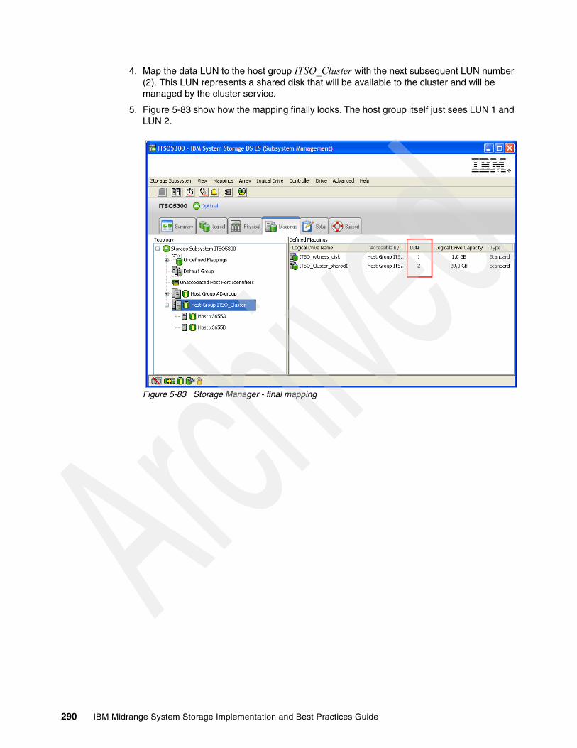
4. Map the data LUN to the host group ITSO_Cluster with the next subsequent LUN number (2). This LUN represents a shared disk that will be available to the cluster and will be managed by the cluster service.
5. Figure 5-83 show how the mapping finally looks. The host group itself just sees LUN 1 and LUN 2.
Figure 5-83 Storage Manager - final mapping
290 IBM Midrange System Storage Implementation and Best Practices Guide
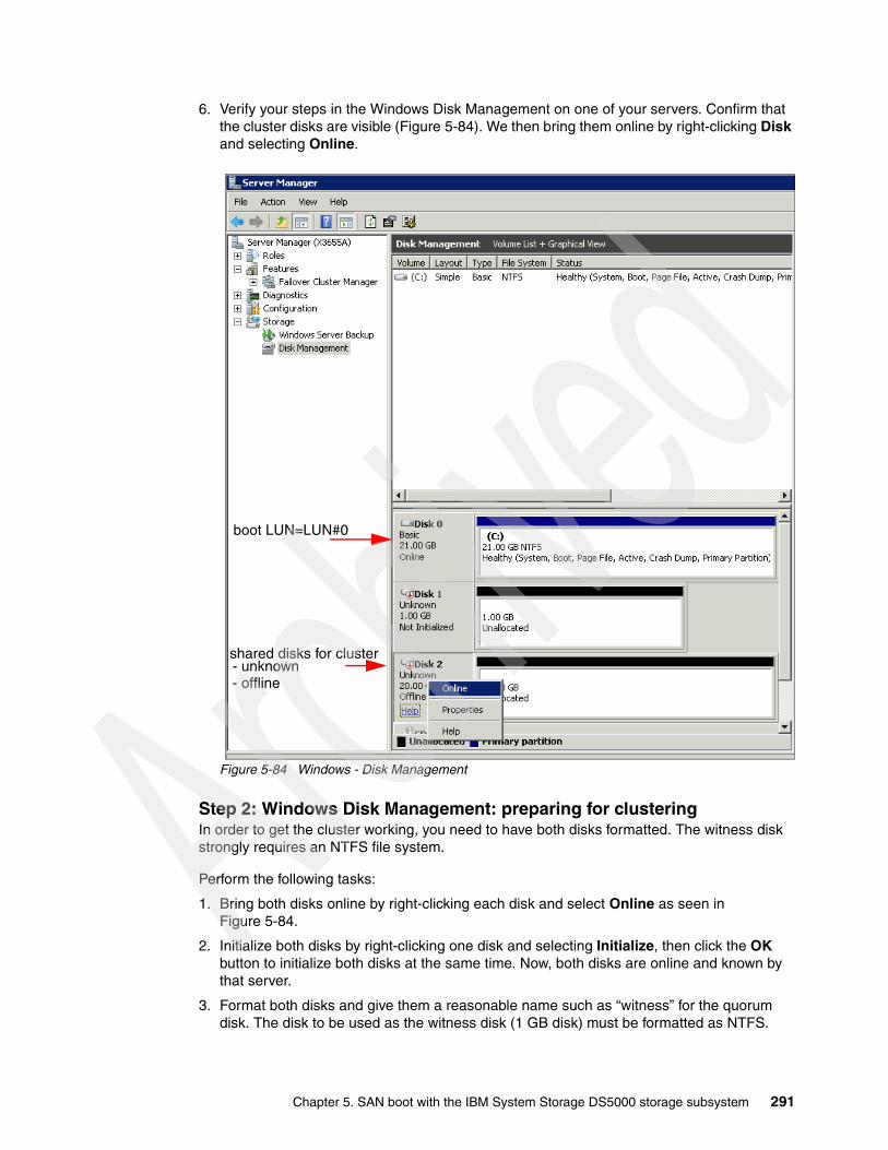
6. Verify your steps in the Windows Disk Management on one of your servers. Confirm that the cluster disks are visible (Figure 5-84). We then bring them online by right-clicking Disk and selecting Online.
Figure 5-84 Windows - Disk Management
Step 2: Windows Disk Management: preparing for clusteringIn order to get the cluster working, you need to have both disks formatted. The witness disk strongly requires an NTFS file system.
Perform the following tasks:
1. Bring both disks online by right-clicking each disk and select Online as seen in Figure 5-84.
2. Initialize both disks by right-clicking one disk and selecting Initialize, then click the OK button to initialize both disks at the same time. Now, both disks are online and known by that server.
3. Format both disks and give them a reasonable name such as “witness” for the quorum disk. The disk to be used as the witness disk (1 GB disk) must be formatted as NTFS.
boot LUN=LUN#0
shared disks for cluster- unknown- offline
Chapter 5. SAN boot with the IBM System Storage DS5000 storage subsystem 291
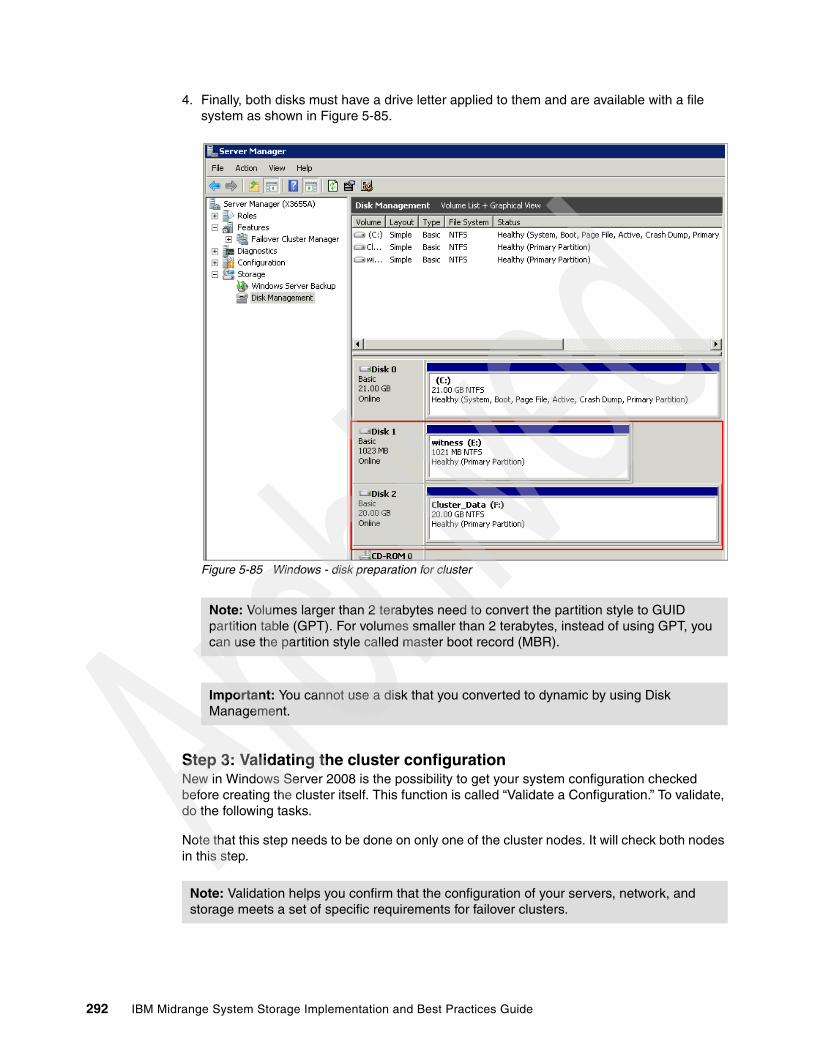
4. Finally, both disks must have a drive letter applied to them and are available with a file system as shown in Figure 5-85.
Figure 5-85 Windows - disk preparation for cluster
Step 3: Validating the cluster configurationNew in Windows Server 2008 is the possibility to get your system configuration checked before creating the cluster itself. This function is called “Validate a Configuration.” To validate, do the following tasks.
Note that this step needs to be done on only one of the cluster nodes. It will check both nodes in this step.
Note: Volumes larger than 2 terabytes need to convert the partition style to GUID partition table (GPT). For volumes smaller than 2 terabytes, instead of using GPT, you can use the partition style called master boot record (MBR).
Important: You cannot use a disk that you converted to dynamic by using Disk Management.
Note: Validation helps you confirm that the configuration of your servers, network, and storage meets a set of specific requirements for failover clusters.
292 IBM Midrange System Storage Implementation and Best Practices Guide

Perform the following tasks:
1. From the Windows Server Manager, select the Failover Cluster Manager (Figure 5-86). The Actions pane on the right will show available actions. The first action that is displayed is “Validate a Configuration”. Click that entry to start the wizard.
Figure 5-86 Windows Failover Cluster Manager
2. Enter the host names of both/all nodes of your configuration to be validated in this step (Figure 5-87). Enter each host name separately and click Add. After all hosts are in the list, click Next.
Figure 5-87 Validation - enter hosts
3. To fully validate your configuration, leave the radio button on Run all tests on the next window before creating a cluster.
Host name
Chapter 5. SAN boot with the IBM System Storage DS5000 storage subsystem 293
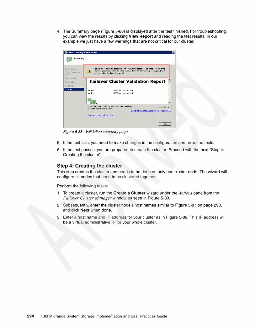
4. The Summary page (Figure 5-88) is displayed after the test finished. For troubleshooting, you can view the results by clicking View Report and reading the test results. In our example we just have a few warnings that are not critical for our cluster.
Figure 5-88 Validation summary page
5. If the test fails, you need to make changes in the configuration and rerun the tests.
6. If the test passes, you are prepared to create the cluster. Proceed with the next “Step 4: Creating the cluster”.
Step 4: Creating the clusterThis step creates the cluster and needs to be done on only one cluster node. The wizard will configure all nodes that need to be clustered together.
Perform the following tasks:
1. To create a cluster, run the Create a Cluster wizard under the Actions pane from the Failover Cluster Manager window as seen in Figure 5-89.
2. Subsequently, enter the cluster node’s host names similar to Figure 5-87 on page 293, and click Next when done.
3. Enter a host name and IP address for your cluster as in Figure 5-89. This IP address will be a virtual administrative IP for your whole cluster.
294 IBM Midrange System Storage Implementation and Best Practices Guide

Figure 5-89 Create Cluster wizard
Next, the wizard configures the nodes and a Summary page is displayed
4. To view a report of the tasks the wizard performed, click View Report or Finish (Figure 5-90).
Figure 5-90 Cluster Create wizard - summary page
Chapter 5. SAN boot with the IBM System Storage DS5000 storage subsystem 295

5. Validate the cluster by entering back into the Failover Cluster Manager as seen in (Figure 5-91).
Notice which LUN has been taken for the witness disk and which for data.
Figure 5-91 Failover Cluster Manager results
5.6.2 Configuration steps after cluster is running on all configured nodes
The cluster is now running on all configured nodes. Proceed with normal Cluster configuration as you might do in a normal cluster environment, including one of the following tasks:
� Configuring failover services� Configuring applications� Configuring more shared storage
For more step-by-step instructions, see the Microsoft Technet Web site:
http://technet.microsoft.com/en-us/library/cc732488(WS.10).aspx
296 IBM Midrange System Storage Implementation and Best Practices Guide

5.7 OS support for SAN boot
For a list of supported operating systems for SAN boot and their limitations, see the IBM System Storage Interpretability Center Web site:
http://www.ibm.com/systems/support/storage/config/ssic/index.jsp
Table 5-1 shows a matrix for SAN boot supported operating systems and their supported HBAs.
Table 5-1 SAN boot Support matrix
Operating System HBA
Windows 2003 -SP2Windows 2008 -SP1 (including Vista and Hyper-V)Solaris 9 (SPARC only)Solaris 10 (SPARC and x86)Red Hat 4.7, 4.8Red Hat 5.3SLES 10.2SLES 11HPUX 10, 11
Supported with all HBAs except in IA64 systems
AIX 5.3 -TL10AIX 6.1 -TL3VMware 3.5-U3, 3.5-U4VMware 4
Supported with all HBAs
Chapter 5. SAN boot with the IBM System Storage DS5000 storage subsystem 297

298 IBM Midrange System Storage Implementation and Best Practices Guide

Chapter 6. Midrange performance tuning
In this chapter we consider performance topics as they apply to the IBM Midrange Storage Subsystems. Although the focus here is the IBM Midrange Storage Subsystem performance, we also discuss various workload types generally observed in storage, as well as how their impact on performance can be addressed by the configuration and parameters.
With all Midrange Storage Subsystems, good planning and data layout can make the difference between having excellent workload and application performance, and having poor workload, with high response times resulting in poor application performance. It is therefore not surprising that first-time clients ask for advice on how to optimally layout their storage subsystems.
This chapter covers the following topics:
� Understanding workload � Solution wide considerations� Host considerations� Application considerations� Midrange storage subsystem considerations� Performance data analysis� Midrange storage subsystem tuning
6
© Copyright IBM Corp. 2004-2010. All rights reserved. 299
6.1 Workload typesIn general, you can expect to see two types of data workload (processing):
� transaction based � throughput based
These two workloads are vary widely in their nature, and you must plan for them quite differently. Knowing and understanding how your host servers and applications handle their workload is important to your success in your storage configuration efforts, and the resulting performance of the Midrange Storage Subsystem.
To best understand what is meant by transaction based and throughput based, we must first define a workload. The workload is the total amount of work that is performed at the storage subsystem, and is measured through the following formula:
Workload = [transactions (number of host IO’s sent)] * [ throughput (amount of data sent in all the IO’s)] for the measured timeframe
Knowing that a storage subsystem can sustain a given maximum workload, we can see with the previous formula that if the number of host transactions increases, then the throughput must decrease. Conversely, if the host is sending large volumes of data with each I/O, the number of transactions must decrease.
A workload characterized by a high number of transactions (IOPS) is called a transaction based workload. A workload characterized by large I/Os is called throughput based workload. These two workload types are conflicting in nature, and consequently work best with a wide range of configuration settings across all the pieces of the storage solution.
But first, let us describe each type of processing in greater detail, and explain what you can expect to encounter in each case.
Transaction based processes (IOPS)High performance in transaction based environments cannot be created with a low cost model (with a small quantity of physical drives) of a storage subsystem. Transaction intense applications frequently use a small random data block pattern to transfer data. Read cache is far less effective, and the misses need to be retrieved from disk.
This results in these applications being heavily dependent on the number of back-end drives that are available for parallel processing of the host’s workload. With too few drives, high queuing with longer response times will be encountered.
Determining at what point the performance can be accepted is important in deciding how large a subsystem is needed. Willingness to have higher response times can help in reducing the cost, but might not be acceptable by the user community. Cost and this factor frequently result in decisions needing to be made on just how many drives will be enough.
In many cases, slow transaction performance problems can be traced directly to “hot” files that cause a bottleneck on a particular critical component (such as a single physical disk). This situation can occur even when the overall storage subsystem is seeing a fairly light workload. When bottlenecks occur, they can present a very difficult and frustrating task to resolve.
Because workload content can be continually changing throughout the course of the day, these bottlenecks can be very mysterious in nature and appear and disappear, or move from one location to another over time.
300 IBM Midrange System Storage Implementation and Best Practices Guide
Generally, I/O and therefore application performance are best when the I/O activity is evenly spread across most, if not all, of the I/O subsystem.
Throughput based processes (MBps)Throughput based workloads are seen with applications or processes that require massive amounts of data sent, and frequently use large sequential blocks to reduce disk latency. Throughput rates are heavily dependent on the storage subsystem’s internal bandwidth. Generally, a much lower number of the drives are needed to reach maximum throughput rates with the storage subsystem. This number can vary between the various members of the midrange family and their respective bandwidth handling capabilities. Newer storage subsystems with broader bandwidths are able to reach higher numbers and bring higher rates to bear. In this environment, read operations make use of the cache to stage greater chunks of data at a time, to improve the overall performance.
Optimizing both workload typesWith the Midrange Storage Subsystem, these two workload types have various parameter settings that are used to optimize their specific workload environments. These settings are not limited strictly to the storage subsystem, but span the entire solution being used. With care and consideration, it is possible to create an environment of very good performance with both workload types and share the same Midrange Storage Subsystem. However, it must be understood that portions of the storage subsystem configuration will be tuned to better serve one workload over the other.
For maximum performance of both workloads, consider using two separate smaller storage subsystems each tuned for their specific workload, rather than one large server being shared. When this model is not financially feasible, a DS5100 or DS5300 can be used with planning and careful configuring of the solution to gain very good performance for both of the mixed workloads with a single subsystem solution.
6.2 Solution-wide considerations for performanceConsidering the various pieces of the solution that can impact performance, we first look at the host and the operating systems settings, as well as how volume managers come into play. Then we look at the applications; what their workload is like, as well as how many particular types of data patterns they might have to use and that we must plan for.
Of course, we also look at the Midrange Storage Subsystem and the configuration and many parameter settings that must be considered in accordance to the environment where the storage subsystem is deployed. And finally, we look at specific SAN settings that can affect the storage environment as well.
When looking at performance, we must first consider the location of the data in three areas:
� With regard to the path that the host uses to access it. Here we consider the host volume manager, HBA, SAN fabric, and the storage subsystem controller used in accessing the logical drive. Many performance issues stem from mis-configured settings in these areas.
� Within the storage subsystem on its configured array and logical drive. We check that the array has been laid out to give best performance, and the RAID type is the most optimal for the type of workload. Also, if multiple logical drives reside in the same array, we check for interference from other logical drive members when doing their workload.
Chapter 6. Midrange performance tuning 301

� On the back-end drives that make up the array. We consider how the data is carved up (segmented and striped) across all the members of the array, including the number of drives being used, as well as their size, and speed. This area can have a great deal of impact that is very application specific, and in many cases can be addressed by tuning to get the best results.
In the following sections, we discuss each of these areas.
6.3 Host considerationsIn regard to performance, we need to consider far more than just the performance of the I/O workload itself. Many settings within the host frequently affect the overall performance of the system and its applications. We must check all areas to ensure that we are not focusing on a result rather than the cause. However, in this book we are concerned with the I/O subsystem part of the performance puzzle; so we discuss items that affect its operation.
Certain settings and parameters discussed in this section are defined and must match both for the host operating system and for the HBAs that are being used as well. Many operating systems have built-in definitions that can be changed to enable the HBAs to be set to the new values. In this section we present two examples using AIX and Windows operating systems as illustrations of these concepts.
6.3.1 Host based settingsCertain host operating systems can set values for the Midrange Storage Subsystem logical drives assigned to them. For instance, hosts can change the write cache and the cache read-ahead values through attribute settings. These settings can affect both the transaction and throughput workloads. Settings that affect cache usage can have a great impact in most environments.
High transaction environmentsOther host device attributes that can affect high transaction environments are those affecting the blocksize and queue depth capabilities of the logical drives:
� The blocksize value used by the host I/O helps to determined the best segment size choice. Set the segment size at least to twice the size of the I/O blocksize being used by the host for the high transaction workload types.
� The queue depth value cannot exceed the storage subsystem maximum of 4096 for Midrange Storage Subsystems running firmware 7.1x and later; and a maximum of 2048 for firmware 6.60.x. All logical drives on the storage subsystem must share these queue limits. Certain hosts define the queue depth only at the HBA level, whereas others might also define this limit at the device level, which ties to the logical drive. You can use the following formulas to determine a good starting point for your queue depth value on a per logical drive basis:
– For firmware level 7.1x and higher: 4096 / (number-of-hosts * logical drives-per-host) – For firmware level 6.60.xx: 2048 / (number-of-hosts * logical drives-per-host)
As an example, a storage subsystem with 4 hosts with 12, 14, 16, and 64 logical drives attached respectively can be calculated as follows:
4096 / 4 * 64 (largest number of logical drives per host) = 16 2048 / 4 * 64 (largest number of logical drives per host) = 8
If configuring only at the HBA level, for the respective firmware levels, use the formula:
4096 / (total number-of-HBAs), and 2048 / (total number-of-HBAs)
302 IBM Midrange System Storage Implementation and Best Practices Guide
In the high throughput environments, we are interested in settings that affect the large I/O blocksize. Try to use a host I/O blocksize that is equal to, or an even multiple of, the stripe width of the logical drive being used.
Also check for settings mentioned earlier that might force a cache read-ahead value from the host. Ensure that the cache read-ahead value is being enabled. We discuss this function in detail later in this chapter; but certain operating system environments might have a variable value for changing it through device settings. Allowing the Midrange Storage Subsystem to manage this setting is the best method for handling.
Finally, there are settings that might also impact performance with various host servers and HBA types that enhance FC tape support. This setting must not be used with FC disks attached to the HBA.
Host data layoutWhen possible, ensure the host operating system aligns its device data partitions or slices, with those of the logical drive. Misalignment can result in multiple back-end drive IOs, referred to as boundary crossings, which are responsible for unnecessary multiple drive I/Os. Certain operating systems do this automatically, and you just need to know the alignment boundary they use. Others, however, might require manual intervention to set their start point to a value which can align them.
Understand how your host based volume manager (if used) defines and makes use of the logical drives after they are presented as an important part of the data layout. As an example, the AIX Logical Volume Manager (LVM) is discussed in 2.5.1, “Planning for systems with LVM: AIX example” on page 45).
Volume managers are generally set up to place logical drives into groups for their use. The volume manager then creates volumes by carving up the logical drives into partitions (sometimes referred to as a slice); and then building a volume from them by either striping, or concatenating them to form the volume size desired. How the partitions are selected for use and laid out can vary from system to system. In all cases, you need to ensure that spreading of the partitions is done in a manner to achieve maximum I/Os available to the logical drives in the group.
Generally, large volumes are built across a number of separate logical drives to bring more resources to bear. The selection of logical drives when doing this must be made carefully so as not to use logical drives that will compete for resources, and degrade performance. Important rules to follow when designing and building these volumes are as follows:
� Ensure that the logical drives are selected from separate array groups, and the preferred paths are spread across various controllers, thus the logical drives will not be in conflict with each other when the volume is used and both slices are accessed. See 6.5.6, “Arrays and logical drives” on page 317 for further details.
Important: Setting queue depth too high can result in high IO queuing, slow response times, busy being sent to the host, possible loss of data, and possible file corruption; therefore, being conservative with these settings is better than pushing the limits.
Best practice: As supported in theory, it is always best to keep the Fibre Channel tape and Fibre Channel disks on separate HBAs. These devices have two very unique data patterns when operating in their optimal mode, and the switching between them can cause undesired overhead and performance slowdown for the applications.
Chapter 6. Midrange performance tuning 303
� If striping is used, ensure that the stripe size chosen is a value that is complementing the size of the underlying stripe width defined for the logical drives (see “Logical drive segments” on page 325). The value used here will be dependent on the application and host I/O workload that will be using the volume. If the stripe width can be configured to sizes that complement the logical drives stripe; then benefits can be seen with using it. In most cases this model requires larger stripe values and careful planning to properly implement.
The exception to this is for single threaded application processes with sequential I/O streams that have a high throughput requirement. In this case a small LVM stripe size of 64 K or 128 K can allow for the throughput to be spread across multiple logical drives on multiple arrays and controllers, spreading that single I/O thread out, and potentially giving you better performance. This model is generally not preferred for most workloads as the small stripe size of LVM can impair the storage subsystem’s ability to detect and optimize for high sequential I/O workloads.
� With file systems you again will want to revisit the need to ensure that they are aligned with the volume manager or the underlying RAID. Frequently, an offset is needed to ensure that the alignment is proper. Focus here on avoiding involving multiple drives for a small I/O request due to poor data layout. Additionally, with certain operating systems, you can encounter interspersing of file index (also known as an inode) data with the user data, which can have a negative impact if you have implemented a full stripe write model. To avoid this issue, you might want to use raw devices (volumes) for full stripe write implementations.
6.3.2 Host setting examplesThe following example settings can be used to start off your configuration in the specific workload environment. These settings are guidelines, and they are not guaranteed to be the answer to all configurations. Always try to set up a test of your data with your configuration to see if there is further tuning that might be of more help (see Chapter 8, “Storage Manager Performance Monitor” on page 355 for more information). Again, knowledge of your specific data I/O pattern is extremely helpful.
AIX operating system settingsThe following section outlines the settings that can affect performance on an AIX host. We look at these in relation to how they impact the two particular workload types.
All attribute values that are changeable can be changed using the chdev command for AIX. See the AIX man pages for details on the usage of chdev.
Transaction settingsEarly AIX driver releases allowed for the changing of the cache read-ahead through the logical drive attribute settings, but has been discontinued with current releases. Cache read-ahead is now set by the storage subsystem value, and can only report the value from the operating system.
One of the most common settings that has been found to need adjusting is the queue_depth. This value can be increased to help improve high transaction based applications to keep the storage subsystem always busy. However, if set too high, the result can be very high
Best practice: For best performance, when building (host) volumes from a single storage subsystem using any RAID type, use logical drives from various groups of arrays with their preferred paths evenly spread between the two controllers of the Midrange Storage Subsystem.
304 IBM Midrange System Storage Implementation and Best Practices Guide
response time values, IO retries, and application slowdowns. Changing this setting to higher values must be done in steps of smaller change to see where the peak of the desired performance is. Monitoring the performance over time can also indicate that further change (up or down) might be necessary. To make any change to this value for the logical drive, the change is performed on the hdisk in AIX, and the setting is the attribute queue_depth:
# chdev -l hdiskX -a queue_depth=Y -P
In the previous example, “X” is the hdisk number, and “Y” is the value for the queue_depth that you are setting it to.
Another setting of interest is for an HBA setting of the attribute num_cmd_elem for the fcs device being used. This value must not exceed 512:
chdev -l fcsX -a num_cmd_elem=256 -P
Throughput based settingsIn the throughput based environment, you might want to decrease the queue depth setting to a smaller value such as 16. In a mixed application environment, you do not want to lower the “num_cmd_elem” setting, because other logical drives might need this higher value to perform. In a pure high throughput workload, this value will have no effect.
AIX settings which can directly affect throughput performance with large I/O blocksize are the lg_term_dma, and max_xfer_size parameters for the fcs device.
Note that setting the max_xfer_size affects the size of a memory area used for data transfer by the adapter. With the default value of max_xfer_size=0x100000, the area is 16 MB in size, and for other allowable values of max_xfer_size, the memory area is 128 MB in size.
Also see 12.6.1, “HBA settings” on page 550.
AIX LVM impactAIX uses Logical Volume Manager (LVM) to manage the logical drives and physical partitions. By default, with standard and big VGs, LVM reserves the first 512 bytes of the volume for the Logical Volume Control Block. Therefore, the first data block will start at an offset of 512 bytes into the volume. Care must be taken when laying out the segment size of the logical drive to enable the best alignment. You can eliminate the Logical Volume Control Block on the LV by using a scalable VG, or by using the -T 0 option for big VGs.
Additionally, in AIX, file systems are aligned on a 16 K boundary. Remembering these two items helps when planning for AIX to fit well with the DS4000 segment size. JFS and JFS2 file systems intersperse inode data with the actual user data, and can potentially disrupt the full stripe write activity. To avoid this issue, you can place files with heavy sequential writes on raw logical volumes. See also the guidelines defined in “Logical drive segments” on page 325.
With AIX LVM, it is generally best to spread high transaction logical volumes across the multiple logical drives that you have chosen, using the maximum interpolicy setting (also known as maximum range of physical volumes) with a random ordering of PVs for each LV.
Best practice: For high transactions on AIX, set num_cmd_elem to 256 for the fcs devices being used.
Best practice: The best start values for high throughput sequential I/O environments are lg_term_dma = 0x800000 and max_xfr_size = 0x200000.
Chapter 6. Midrange performance tuning 305
Ensure that your logical drive selection is done as explained previously, and is appropriate for the RAID type selected.
In environments with very high rate, sequentially accessed structures and a large I/O size, try to make the segment size times the (N-1 for RAID 5, or N/2 for RAID 10) to be equal to the application I/O size. And keep the number of sequential I/O streams per array to be less than the number of disks in the array.
Windows operating system settingsIn this section we discuss settings for performance with the Windows operating system and the DS4000 storage subsystem, including the following topics:
� Fabric settings� Windows disk types� Disk alignment� Allocation unit size
Fabric settingsWith Windows operating systems, the queue depth settings are the responsibility of the host adapters, and are configured through the BIOS setting, varying from vendor to vendor. See your manufacturer’s instructions on how to configure your specific cards.
For IBM FAStT FC2-133 (and QLogic based HBAs), the queue depth is known as execution throttle, which can be set with either the QLogic SANsurfer tool, or in the BIOS of the QLogic based HBA, by pressing CTL+Q during the boot process.
Disk types: Basic disks and dynamic disksWith Windows 2000 and later versions, there are two types of disks, basic disks and dynamic disks. By default, when a Windows system is installed, the basic disk is used. Disks can be changed from basic to dynamic at any time without impact on system or data.
Basic disks use partitions. These partitions are set to the size they are created. In Windows 2003 and later, a primary partition on a basic disk can be extended using the extend command in the diskpart.exe utility.
In Windows 2000 and later, dynamic disks allow for expansion, spanning, striping, software mirroring, and software RAID 5.
With the Midrange Storage Subsystem, you can use either basic or dynamic disks. The appropriate type depends on your individual circumstances:
� In large installations where you might have the requirement to span or stripe logical drives and controllers to balance the workload, then dynamic disks might be your only choice.
� For smaller to mid-size installations, you might be able to simplify and just use basic disks.
When using the Midrange Storage Subsystem, the use of software mirroring and software RAID 5 is not required. Instead, configure the storage subsystem for the RAID redundancy level required for protection needs.
Basic disks and basic volumes are the storage types most often used with Windows operating systems. Basic disk is the default disk type during initial installation. A basic disk refers to a disk that contains basic volumes, such as primary partitions and logical drives. A basic volume refers to a partition on a basic disk. Basic disks are used in both x86-based and Itanium-based computers.
306 IBM Midrange System Storage Implementation and Best Practices Guide

Basic disks support clustered disks. Basic disks do not support spanning, striping, mirroring and software level RAID 5. To use these functions, you must convert the basic disk to a dynamic disk. If you want to add more space to existing primary partitions and logical drives, you can extend the volume using the extend command in the diskpart utility.
With dynamic disks, you use the Disk Management GUI utility to expand logical drives.
Dynamic disks offer greater flexibility for volume management because they use a database to track information about dynamic volumes on the disk, they also store information about other dynamic disks in the computer. Because each dynamic disk in a computer stores a replica of the dynamic disk database, you can repair a corrupted database on one dynamic disk by using the database from another dynamic disk in the computer.
The location of the database is determined by the partition style of the disk:
� On MBR disks, the database is contained in the last 1 megabyte of the disk.
� On GPT disks, the database is contained in a 1 MB reserved (hidden) partition known as the Logical Disk Manager (LDM) Metadata partition.
All online dynamic disks in a computer must be members of the same disk group, which is a collection of dynamic disks. A computer can have only one dynamic disk group, called the primary disk group. Each disk in a disk group stores a replica of the dynamic disk database. A disk group usually has a name consisting of the computer name plus a suffix of Dg0.
To determine the best choice of disk type for your environment, see the following Web site:
http://support.microsoft.com/kb/816307/
Disk alignmentWith the midrange logical drives, as with physical disks that maintain 64 sectors per track, the Windows 2003 and earlier operating systems always create the partition starting with the sixty-fourth sector. With Windows 2008, this has changed somewhat with new alignment practices being introduced that use an alignment default of 1024 KB (2048 sectors), thus allowing all current segment size offerings to align with the partition offset being used. However, with the earlier Windows releases, it is important to ensure that the alignment of the partition and the logical drive are the same; failure to align can result in added processing being required for handling the host IO. To ensure that these are both aligned, you can use the diskpar.exe or diskpart.exe command, to define the start location of the partition.
The diskpar.exe command is part of the Microsoft Windows Server 2000 Resource Kit;it is for Windows 2000 and Windows 2003. The diskpar.exe functionality was put into diskpart.exe with Windows Server 2003 Service Pack 1 and is included with Windows Server 2008.
Using this tool, you can set the starting offset in the Master Boot Record (MBR) by selecting the number of 512 byte sectors desired to be offset. By setting this value to 128, you will skip the first 64 K before the start of first partition. If you set this value to 256, you will skip the first full 128 K (where the MBR resides) before the start of the partition. The setting that you define must depend on the segment size defined for the logical drive being used.
Doing so ensures track alignment and improves the performance. Other values can be defined, but these two offer the best chance to start out with the best alignment values. As a best practice, you must ensure that you aligned to a minimum of one segment size boundary for complete alignment. Failure to do so can cause a single I/O operation to require the storage subsystem to perform multiple I/O operations on its internal processing, causing extra work for a small host I/O, and resulting in performance degradation.
Chapter 6. Midrange performance tuning 307
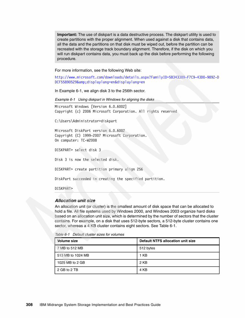
For more information, see the following Web site:
http://www.microsoft.com/downloads/details.aspx?FamilyID=5B343389-F7C9-43D0-9892-DDCF55890529&displaylang=en&displaylang=en
In Example 6-1, we align disk 3 to the 256th sector.
Example 6-1 Using diskpart in Windows for aligning the disks
Microsoft Windows [Version 6.0.6002]Copyright (c) 2006 Microsoft Corporation. All rights reserved
C:\Users\Administrator>diskpart
Microsoft DiskPart version 6.0.6002Copyright (C) 1999-2007 Microsoft Corporation.On computer: TC-W2008
DISKPART> select disk 3
Disk 3 is now the selected disk.
DISKPART> create partition primary align 256
DiskPart succeeded in creating the specified partition.
DISKPART>
Allocation unit sizeAn allocation unit (or cluster) is the smallest amount of disk space that can be allocated to hold a file. All file systems used by Windows 2000, and Windows 2003 organize hard disks based on an allocation unit size, which is determined by the number of sectors that the cluster contains. For example, on a disk that uses 512-byte sectors, a 512-byte cluster contains one sector, whereas a 4 KB cluster contains eight sectors. See Table 6-1.
Table 6-1 Default cluster sizes for volumes
Important: The use of diskpart is a data destructive process. The diskpart utility is used to create partitions with the proper alignment. When used against a disk that contains data, all the data and the partitions on that disk must be wiped out, before the partition can be recreated with the storage track boundary alignment. Therefore, if the disk on which you will run diskpart contains data, you must back up the disk before performing the following procedure.
Volume size Default NTFS allocation unit size
7 MB to 512 MB 512 bytes
513 MB to 1024 MB 1 KB
1025 MB to 2 GB 2 KB
2 GB to 2 TB 4 KB
308 IBM Midrange System Storage Implementation and Best Practices Guide
In the Disk Management snap-in, you can specify an allocation unit size of up to 64 KB when you format a volume. If you use the format command to format a volume, but do not specify a an allocation unit size by using the /a:size parameter, the default values shown in Table 6-1 are used. If you want to change the cluster size after the volume is formatted, you must reformat the volume and select the new allocation size from the drop-down box selection list, which must be done with care, as all data is lost when a volume is formatted. The available allocation unit sizes when formatting are 512 bytes, 1 K, 2 K, 4 K, 8 K, 16 K, 32 K, and 64 K.
For more information about formatting an NTFS disk, see the Microsoft Windows documentation for your specific environment’s release.
6.4 Application considerationsWhen gathering data for planning from the application side, again it is important to first consider the workload type for the application.
If multiple applications or workload types will be sharing the system, you need to know the type of workloads each have; and if mixed (transaction and throughput based) which will be the most critical. Many environments have a mix of transaction and throughput workloads; with generally the transaction performance being considered the most critical.
However, in dedicated environments (for example, a TSM backup server with a dedicated Midrange Storage Subsystem attached), the streaming high throughput workload of the backup itself is the critical part of the operation; and the backup database, though a transaction centered workload, is the less critical piece.
6.4.1 Transaction environments
Applications that use high transaction workloads are OnLine Transaction Processing (OLTP), mostly databases, mail servers, Web servers, and file servers.
If you have a database, you can tune the server type parameters as well as the database’s logical drives to meet the needs of the database application. If the host server has a secondary role of performing nightly backups for the business, you need another set of logical drives that are tuned for high throughput for the best backup performance you can get within the limitations of the mixed storage subsystem’s parameters.
Best practice: When creating a disk partition for use with Microsoft SQL Server, format the partition with an allocation unit size of 64 K.
Important: The allocation unit size is set during a format of a volume. This procedure is data destructive, so if the volume on which you will run a format contains data, you must back up the volume before performing the format procedure.
Restriction: In Windows 2000 and Windows 2003, setting an allocation unit size larger than 4 K will disable file or folder compression on that partition.
In Windows 2000, the disk defragmenter ceased to function with an allocation size greater than 4 K. In Windows 2003 and 2008, the disk defragmenter functions correctly.
Always check the documentation for your environment and test to ensure that all the functionality remains after any changes.
Chapter 6. Midrange performance tuning 309

So, what are the traits of a transaction based application? In the following sections we explain this in more detail.
As mentioned earlier, you can expect to see a high number of transactions and a fairly small block size. Various databases use particular I/O sizes for their logs (see the following examples), these vary from vendor to vendor. In all cases the logs are generally high write workloads. For table spaces, most databases use between a 4 KB and 32 KB blocksize. In certain applications, larger chunks (for example, 64 KB) will be moved to host application cache memory for processing. Understanding how your application is going to handle its I/O is critical to laying out the data properly on the storage subsystem.
In many cases the table space is generally a large file made up of small blocks of data records. The records are normally accessed using small I/Os of a random nature, which can result in about a 50% cache miss ratio.
For this reason, and to not waste space with unused data, plan for the storage subsystem to read and write data into cache in small chunks. Avoid also doing any cache read-ahead with the logical drives, due to the random nature of the I/Os (Web servers and file servers frequently use 8 KB as well, and generally follow these rules as well).
Another point to consider is whether the typical I/O is read, or write. In most OLTP environments, this is generally seen to be a mix of about 70% reads and 30% writes. However, the transaction logs of a database application have a much higher write ratio, and as such, perform better in another RAID array. This reason also adds to the need to place the logs on a separate logical drive, which for best performance, must be located on a separate array that is defined to better support the heavy write need. Mail servers also frequently have a higher write ratio than read. Use the RAID array configuration for your specific usage model, which is covered in detail in “RAID array types” on page 317.
6.4.2 Throughput environments
With throughput workloads, you have fewer transactions, but much larger I/O sizes, normally 128 K or greater; and these I/Os are generally of a sequential nature. Applications that typify this type of workload are imaging, video servers, seismic processing, high performance computing (HPC), and backup servers.
With large size I/O, it is better to use large cache blocks to be able to write larger chunks into cache with each operation. Ensure that the storage subsystem is configured for this type of I/O load, covered in detail in “Cache blocksize selection” on page 315.
Such environments work best when defining the I/O layout to be equal to or an even multiple of the storage subsystems stripe width. There are advantages with writes in the RAID 5 configurations that make setting the I/O size to equal that of the full stripe performant. See Figure 6-1 on page 318 for the amount of read operations that will be required with writes to fewer drives. Generally, the intent here is to make the sequential I/Os take as few back-end operations as possible, and to get maximum throughput from them. So, care must be taken when deciding how the logical drive will be defined. We discuss these choices in greater detail in “Logical drive segments” on page 325.
Best practice: Database table spaces, journals, and logs must never be co-located on the same logical drive or RAID array. Refer to 6.5, “Midrange storage subsystem considerations” on page 311 for more information on RAID types to use.
310 IBM Midrange System Storage Implementation and Best Practices Guide
Another application consideration is when storing sequentially accessed files separately to use larger segment size on the LUNs to help keep the disk heads in position for the sequential I/Os, which reduces the amount of time required to seek the data. In this type environment, using a 256 KB or larger segment size can be beneficial.
6.4.3 Application examplesFor general guidelines and tips to consider when implementing certain applications with the Midrange Storage Subsystems, see Chapter 7, “IBM Midrange Storage Subsystem tuning with typical applications” on page 329.
6.5 Midrange storage subsystem considerations In this section we look at the specific details surrounding the Midrange Storage Subsystem itself when considering performance planning and configuring. We cover the following topics:
� Which model fits best� Storage subsystem processes� Storage subsystem modification functions� Storage subsystem parameters� Disk drive types� Arrays and logical drives� Additional NVSRAM parameters of concern
6.5.1 Which model fits bestWhen planning for a Midrange Storage Subsystem, the first thing to consider is the choice of an appropriate model for your environment and the type of workload that it will handle.
If your workload is going to require a high number of disks, you want to be sure that the system chosen will support them, and the I/O workload that they will be processing. If the workload you have requires a high storage subsystem bandwidth, then you want your storage subsystem to have a data bus bandwidth in line with the throughput and workload needs.
Figure 1-3 on page 7 shows details of the IBM Midrange Storage Subsystem family comparison.
In addition to doing your primary processing work, you might also have various storage subsystem background processes you want to run. All work being performed requires resources, and you need to understand how they all will impact your storage subsystem.
6.5.2 Storage subsystem processesWhen planning for the system, remember to take into consideration any background processes, additional premium features, and background management utilities that you are planning to implement with the storage solution.
Midrange copy servicesWith the Midrange Storage Subsystem, a complete suite of copy services features is available. All of these features run internally on the storage subsystem, and therefore use processing resources. It is important that you understand the amount of overhead that these features require, and how they can impact your primary I/O processing performance.
Chapter 6. Midrange performance tuning 311

Enhanced Remote MirroringEnhanced Remote Mirroring (ERM) is a critical back-end process to consider, as in most cases, it is expected to be constantly running with all applications while it is mirroring the primary logical drive to the secondary location. After the initial synchronization is complete, we have continuous mirroring updates that will run. These updates can be performed by metro mirror (synchronous), global mirror (asynchronous with write order consistency (WOC)) or global copy (asynchronous without WOC) methods of transfer. For further details on these methods and their specific impacts, see IBM Midrange System Storage Copy Services Guide, SG24-7822.
When planning to use ERM with any application, you must carefully review the data workload model of the production environment. With ERM feature implemented there is about an initial 25% overhead that can be expected on the production subsystem. Various additional processes required to establish and re-synchronized mirrored pairs can add further cost while they are running as well. There is also a requirement to dedicate the last host side Fibre Channel port from each controller to the mirroring network alone.
Another major factor that can be of impact here is the networking path followed by the remote data. Bandwidth is a critical factor in whether or not the ERM solution will be successful. Making sure that the path is not a bottleneck to the passing of IO traffic between the two mirrors becomes crucial to the success of both metro mirroring and global mirroring methods. A restricted network can make any ERM solution behave poorly and, in certain cases, can result in production side slowdowns of performance.
The DS5300 is the best choice when ERM is a strategic part of your storage plan.
Consider also the impact of the initial synchronization overhead. When a storage subsystem logical drive is a primary logical drive and a full synchronization is necessary, the controller owner performs the full synchronization in the background while processing local I/O writes to the primary logical drive and associated remote writes to the secondary logical drive. Because the full synchronization diverts controller processing resources from I/O activity, it will impact performance on the host application. The synchronization priority allows you to define how much processing time is allocated for synchronization activities relative to other system work so that you can maintain accepted performance.
The synchronization priority rates are lowest, low, medium, high, and highest.
Understanding the timing of these various priorities can be critical to the planning of the disaster recovery model being used for the environment. It might be better to plan for synchronizing of the mirrored pair during a low usage period when highest priority can be used to ensure the recovery point and time objectives can be met. See IBM Midrange System Storage Copy Services Guide, SG24-7822 for a description and guidelines on the using the various priority settings.
The synchronization progress bar at the bottom of the Mirroring tab of the logical drive Properties dialog box displays the progress of a full synchronization.
VolumeCopy functionWith VolumeCopy, several factors contribute to system performance, including I/O activity, logical drive RAID level, logical drive configuration (number of drives in the array or cache parameters), and logical drive type. Copying from a FlashCopy, logical drives might take more
Note: The lowest priority rate favors system performance, but the full synchronization takes longer. The highest priority rate favors full synchronization, but system performance can be compromised.
312 IBM Midrange System Storage Implementation and Best Practices Guide

time to copy than standard logical drives. A major point to consider is whether you want to be able to perform the function while the host server applications are functioning, or during an outage. If the outage is not desired, using the FlashCopy volume as the source will allow you to perform your VolumeCopy in the background while normal processing continues.
Like the ERM functions, VolumeCopy does have a background process penalty which you need to decide how much you want it to affect your front-end host. With the FlashCopy image you can use lower priority and leave it run for more extended time, which will make your VolumeCopy creation take longer but decrease the performance hit. Because this value can be adjusted dynamically, you can increase it when host processing is slower.
You can select the copy priority when you are creating a new logical drive copy, or you can change it later using the Copy Manager. The copy priority rates are lowest, low, medium, high, and highest.
FlashCopy functionIf you no longer need a FlashCopy logical drive, you have to disable it. As long as a FlashCopy logical drive is enabled, your storage subsystem performance is impacted by the copy-on-write activity to the associated FlashCopy repository logical drive. When you disable a FlashCopy logical drive, the copy-on-write activity stops.
If you disable the FlashCopy logical drive instead of deleting it, you can retain it and its associated repository. Then, when you need to create another FlashCopy of the same base logical drive, you can use the re-create option to reuse a disabled FlashCopy, which takes less time.
6.5.3 Storage subsystem modification functionsThe Midrange Storage Subsystems have many modification functions that can be used to change, tune, clean, or redefine the storage dynamically. Various functions help improve the performance as well. However, all of these will have an impact on the performance of the storage subsystem and its host I/O processing while the inspection or conversion is being performed. All of these functions use the modification priority rates to determine their process priority. Values to choose from are lowest, low, medium, high, and highest.
In the following sections we describe the use of each of these functions and their impact on performance.
Media scanMedia scan is a background check performed on all logical drives in the Midrange Storage Subsystem when selected to ensure that the blocks of data are good, which is accomplished by reading the logical drives one data stripe at a time into cache, and if successful it moves on to the next stripe. If a bad block is encountered, it will retry three times to read the block, and then go into its recovery process to rebuild the data block.
Note: The lowest priority rate supports I/O activity, but the logical drive copy takes longer. The highest priority rate supports the logical drive copy, but I/O activity can be affected.
Note: The lowest priority rate favors system performance, but the modification operation takes longer. The highest priority rate favors the modification operation, but system performance can be compromised.
Chapter 6. Midrange performance tuning 313

Media scan is configured to run on selected logical drives; and has a parameter for defining the maximum amount of time allowed to complete its run through all the logical drives selected. If the media scan process sees it is reaching its maximum run time and calculates that it is not going to complete in the time remaining, it will increase its priority and can impact host processing. Generally, it has been found that media scan scheduled with a “30 day” completion schedule, is able to complete if controller utilization does not exceed 95%. Shorter schedules require lower utilization rates to avoid impact.
Defragmenting an arrayA fragmented array can result from logical drive deletion resulting in free space node or not using all available free capacity in a free capacity node during a logical drive creation.
Because creation of new logical drives cannot spread across several free space nodes, the logical drive size is limited to the greatest amount of a free space node available, even if there is more free space in the array. The array needs to be defragmented first to consolidate all free space nodes to one free capacity node for the array. Then, a new logical drive can use the whole available free space.
Use the defragment option to consolidate all free capacity on a selected array. The defragmentation runs concurrently with normal I/O; it impacts performance, because the data of the logical drives must be moved within the array. Depending on the array configuration, this process continues to run for a long period of time.
The defragmentation done on the Midrange Storage Subsystem only applies to the free space nodes on the array. It is not connected to a defragmentation of the file system used by the host operating systems in any way.
CopybackCopyback refers to the copying of data from a hot spare drive (used as a standby in case of possible drive failure) to a replacement drive. When you physically replace the failed drive, a copyback operation automatically occurs from the hot spare drive to the replacement drive.
With the new 7.x code releases, whether or not to perform the copyback function has become an option that must be selected if desired. In a high performance environment where data layout and array and LUN configuration matter, using the copyback feature is necessary to ensure continued balance of the workload spread.
InitializationThis is the deletion of all data on a drive, logical drive, or array. In previous versions of the storage management software, this was called format.
Dynamic Segment SizingDynamic Segment Sizing (DSS) is a modification operation where the segment size for a select logical drive is changed to increase or decrease the number of data blocks that the segment size contains. A segment is the amount of data that the controller writes on a single drive in a logical drive before writing data on the next drive.
Best practice: Setting media scan to 30 days has been found to be a good general all around value to aid in keeping media clear and server background process load at an acceptable level.
Important: After this procedure is started, it cannot be stopped; and no configuration changes can be performed on the array while it is running.
314 IBM Midrange System Storage Implementation and Best Practices Guide
Dynamic Reconstruction Rate (DRR)Dynamic Reconstruction Rate (DRR) is a modification operation where data and parity within an array are used to regenerate the data to a replacement drive or a hot spare drive. Only data on a RAID 1, RAID 3, or RAID 5 logical drive can be reconstructed.
Dynamic RAID Level MigrationDynamic RAID Level Migration (DRM) is a modification operation used to change the RAID level on a selected array. The RAID level selected determines the level of performance and parity of an array.
Dynamic Capacity Expansion Dynamic Capacity Expansion (DCE) is a modification operation used to increase the available free capacity on an array. The increase in capacity is achieved by selecting unassigned drives to be added to the array. After the capacity expansion is completed, additional free capacity is available on the array for the creation of other logical drives. The additional free capacity can then be used to perform a Dynamic logical drive Expansion (DVE) on a standard or FlashCopy repository logical drive.
Dynamic Logical Drive ExpansionDynamic Logical Drive Expansion (DVE) is a modification operation used to increase the capacity of a standard logical drive or a FlashCopy repository logical drive. The increase in capacity is achieved by using the free capacity available on the array of the standard or FlashCopy repository logical drive.
6.5.4 Storage Subsystem parametersSettings on the DS4000 storage subsystem are divided into two groups:
� Storage subsystem wide parameters affecting all workloads that reside on the storage.� Settings that are specific to the array or logical drive where the data resides
Cache blocksize selectionOn the Midrange Storage Subsystem, the cache blocksize is a variable value that can be set to 4 K, 8 K, or 16 K. The general default setting is 8 K. The main goals with setting this value are to minimize the number of cache IO’s needed, and at the same time, not waste space. This value is a storage subsystem wide parameter, and when set, it is the value to be used by all cache operations.
For example, if the I/O of greatest interest is taken from your database operations during the day rather than from your weekly backups, you want to tune this value to handle the high transactions best. Knowing that the higher transactions will have smaller I/O sizes, using the 4 K settings is generally best for transaction intense environments.
In a throughput intense environment, as we discussed earlier, you want to get as much data into cache as possible. In this environment it is generally best to use the 16 K blocksize for the cache.
Best practice: Set the cache blocksize to 4 K for the Midrange Storage Subsystem, normally for transaction intense environments.
Best practice: Set the cache blocksize to 16 K for the DS4000 system, normally for throughput intense environments.
Chapter 6. Midrange performance tuning 315
In mixed workload environments, you must decide which workload type is most critical and set the system wide settings to best handle your business needs.
Cache flush control settingsIn addition to the cache blocksize, the Midrange Storage Subsystem also has a cache control, which determines the amount of data that can be held in write cache. With the cache flush settings, you can determine what level of write cache usage can be reached before the server will start to flush the data to disk, and at what level the flushing will stop.
By default, these parameters are set to the value of “80” for each, which means that the server will wait until 80% of the write cache is used before it will flush the data to disk. In a fairly active write environment, this value might be far too high. You can adjust these settings up and down until you find a particular value that best suits your environment. If the values are not the same, then back-end drive inactive time increases, and you have surging with peaks and valleys occurring instead of a steady usage of back-end disks.
You can also vary the maximum amount of time the write data can remain in cache prior to being forced out, and written to disks. This value by default is set to ten seconds but can be changed by using the Storage Manager (SM) command line interface command:
‘set logical Drive [LUN] cacheflushModifier=[new_value];’
6.5.5 Disk drive typesWith the Midrange Storage Subsystem, many types of disk drives are available for you to choose from. There are both the Fibre Channel (FC), as well as the Serial ATA (SATA) drives. The FC drives have both standard and FDE models available. With the DS5000 subsystem, there are also new solid state drives available as well.
With the new SSD technology, solid state drives are the highest performing drives available for use. However, with the limit of 20 per 73 GB drives per subsystem, this limits the capacity that can be defined. So for the larger capacity environments, 15K RPM models of Fibre Channel drives provide the best performance. The 10K RPM drives are a close third; whereas the 7200 RPM drives are the slowest. SATA drives can be used in lower transaction intense environments where maximum performance needs are less important, and high storage capacity, or price are main concerns. SATA drives do provide good throughput performance and can be a very good choice for these environments.
Drive sizes available for selecting from are 36 GB, 73 GB, 146 GB, and a 300 GB/10K RPM on the Fibre Channel side; and a 250 GB, 400 GB, or 500 GB SATA drive. When selecting a drive size for a performant DS4000 environment you must consider how much data will reside on each disk. If large drives are used to store a heavy transaction environment on fewer drives, then the performance will be impacted. If using large size drives and high numbers of
Best practice: Set the cache blocksize to 8 K for the Midrange Storage Subsystem, normally for mixed workload environments.
Tip: Throughput operations, though impacted by smaller cache blocksize, can still perform reasonably if all other efforts have been accounted for. Transaction based operations are normally the higher concern, and therefore must be the focus for setting the server wide values if applicable.
Best practice: Begin with Start/Stop flush settings of 50/50, and adjust from there. Always keep them equal to each other.
316 IBM Midrange System Storage Implementation and Best Practices Guide

them, then how the drive will be used becomes another variable. In certain cases, where you prefer RAID 1 to RAID 5, a larger drive might be a reasonable cost compromise; but only testing with your real data and environment can show for sure.
The current Midrange Storage Subsystems support a drive side I/O queue depth of “16” for the Fibre Channel disks. The SATA drives support a queue depth of “4” I/Os. See 2.2.6, “Selecting drives” on page 28 additional information.
6.5.6 Arrays and logical drives
When setting up the Midrange Storage Subsystem, the configuration of the arrays and logical drives is most likely the single most critical piece in your planning. Understanding how your workload will use the storage is crucial to the success of your performance, and your planning of the arrays and logical drives to be used.
Next we further discuss various considerations for the Midrange Storage Subsystems.
RAID array typesWhen configuring a Midrange Storage Subsystem for the transaction intense environment, you need to consider also whether it will be a read or write intensive workload. As mentioned earlier, in a database environment we actually have two separate environments with the table space, and the journals and logs. Because the table space is normally high reads and low writes, and the journals and logs are high writes with low reads, this environment is best served by two RAID types.
RAID 0, which is striping, without mirroring or parity protection, is generally the best choice for almost all environments for maximum performance; however, there is no protection built into RAID 0 at all, and a drive failure requires a complete restore. For protection it is necessary to look toward either a software mirroring solution of one of the other RAID types.
On the Midrange Storage Subsystem, RAID 1 is disk mirroring for the first pair of disks, and for larger arrays of four or more, disks mirroring and striping (RAID10 model) is used. This RAID type is a very good performer for high random read and write environments. It outperforms RAID 5 due to additional reads that RAID 5 requires in performing its parity check when doing the write operations. With RAID1, there are two writes performed per operation; where as with RAID 5, there are two reads and two writes required for the same operation, totaling four I/Os.
A common use for RAID 1 is for the mail server environment, where random writes can frequently out-weigh the reads.
With database journals and logs being generally sequential write intensive I/Os, they are also a good fit for a RAID 1 as well, which is generally due to the small IO size that they use for their updates. However, this is something that must be reviewed for your specific environment. If these processes are found to be of an IO size that is better served by a design with RAID 5 and a full stripe write, then better performance can be gained from that layout.
Random reads can be served well by both RAID 1 and RAID 5. RAID 1 when laid out with a set of disks that are designed to handle a specific capacity is compared to a RAID 5 design of few disks to handle the same capacity can outperform the RAID 5 due to the extra spindles it
Best practice: For transaction intense workload, 36 GB or 73 GB drives provide the best performance.
Chapter 6. Midrange performance tuning 317

is designed with. In many cases this advantage has been found to be too small to justify the added cost of the extra drives required.
When the RAID 5 array is created with an equal number of spindles to handle the same workload as the RAID 1 array, it will outperform the RAID 1 array, due to the positioning of the LUN on the RAID 5 array and its being striped across the outside tracks, whereas the RAID 1 array needs to use the full disks for its LUN layout. For this reason, it is best to use RAID 5 for the OLTP table space even for large database environments.i
In the sequential high throughput environment, RAID 5 performance is excellent, as it can be configured to perform just one additional parity write when using “full stripe writes” (also known as “full stride writes”) to perform a large write I/O, as compared to the two writes per data drive (self, and its mirror) that are needed by RAID 1. As shown in Figure 6-1, this model is a definite advantage with RAID 5 array groups.
Figure 6-1 RAID 5 write penalty chart
The decrease in the overhead read operations with the full stripe write operation is the advantage you are looking for. You must be very careful when implementing this type of layout to ensure that your data pattern does not change, and decrease its effectiveness. However, this layout might work well for you in a large sequential write environment. Due to the small size of segments, reads might suffer, so mixed I/O environments might not fare well, which might be worth testing if your writes are high.
When performing high sequent IO workloads it is often overlooked that the seek time for the small blocksize on the same drive becomes “zero”. This result in itself is a great benefit to be had when using a larger segment size with mixed read and write sequential IO workloads which use a small host blocksize, which is also why storing sequentially accessed files separately keeps the disk heads in position for sequential I/O, which reduces the amount of time required to locate data.
Applications where this has shown high success are with backups, imaging, video and high performance computing (HPC).
Tip: There are no guaranteed choices as to which type of RAID to use, because this is very much dependent on the workload read and write activity. A good general guide might be to consider using RAID 1 if random writes exceed about 25%, with a peak sustained I/O rate that exceeds 50% of the storage subsystem’s capacity.
318 IBM Midrange System Storage Implementation and Best Practices Guide

The differences in RAID 1 and RAID 5 make them both better suited for certain workload types. Take care not to try to force a fit for an unsuitable workload.
With the amount of variance that can exist with each customer environment, it is a good idea to test your specific case for best performance; and decide which layout to use. With the write cache capability, in many cases RAID 5 write penalties are not noticed, as long as the back-end disk configuration is capable of keeping up with the front-end I/O load so processing is not being slowed, which again points to ensuring that proper spreading is done for best performance.
Number of disks per arrayIn the transaction intense environment, it is more important to ensure that there are enough disk drives configured to perform the I/Os demanded by the host application, than to focus on the amount of possible storage space on the storage subsystem.
With the Midrange Storage Subsystems, you can purchase the new 73 GB SSD disk drives; or the 36 GB, 73 GB, 146 GB, 300 GB, 450 GB, or 600 GB 15k RPM Fibre Channel disk drive types. Previous 10 K RPM Fibre Channel disk drives are also supported in the Midrange Storage Subsystems. Obviously, with the larger drives, you can store more data using fewer drives. Also available are the 500 GB and 1 TB SATA 2 7500 RPM disk drives. Obviously, with the larger drives you can store more data using fewer drives; however, this might not serve your purpose as well as you might want.
Transaction intensive workloadIn a transaction intense environment, you want to have higher drive numbers involved. This can be done by creating larger arrays with more disks. The storage subsystems can have a maximum of 30 drives per RAID 5 array/logical drive and 448 drives (with the DS5100 and DS5300) for a full subsystem RAID 10 array.
With a RAID 10 array, the logical drive size can be configured to encompass the entire array, although operating system limitations on maximum logical drive size might restrict the usefulness of this capability. Though there are circumstances where this model can work well, it is best that smaller arrays be used to better balance the drive usage and access patterns across the controllers so to avoid contusion from intermixed IO.
Configuring multiple LUNs striped across a single large array can be used to make use of all the capacity. However, with this layout, consideration must be given to the workload types for which these LUNs are used, so as not to mix throughput and transaction based IO on the same array.
Another factor to consider is congestion when accessing the drives on the back-end loops. This situation can be avoided by using multiple arrays.
Generally, an array of 8 to 16 disks provides the best performance for RAID 5 workloads that are OLTP based.
Best practice: The differences described so far outline the major reasons to keep the journals and logs on arrays other than the table spaces for database applications.
Best practice: For high transaction environments requiring highest redundancy and protection, logical drives must be built on arrays with 8 to 16 disks when using RAID 5. With RAID 10, use the highest number of available drives / 4 to build two equally sized arrays/LUNs to be preferred across the two controllers.
Chapter 6. Midrange performance tuning 319

For large size databases, consider using the host volume management software to spread the workload evenly across multiple arrays/LUNs to evenly balance the workload on all. Build the volume across sets of logical drives laid out per the RAID type in the previous discussion. In using multiple arrays, you will also be able to increase the controllers which are involved in handling the load, therefore getting full use of the storage subsystems resources.
For example: If needing to build a database that is 1 TB in size, you can use five 300 GB drives in a 4 + 1parity RAID 5 single array/logical drive; or you can create two RAID 5 arrays of 8 + 1parity using 73 GB drives, giving two 584 GB logical drives on which to build the 1 TB database. In most cases the second method for large databases will work best, as it brings twelve more disks into play for handling the host side high transaction workload.
Large throughput workloadIn the large throughput environment, it typically does not take high numbers of disks to reach the maximum sustained throughput. Considering that this type of workload is usually made of sequential I/O, which reduces disk latency, in most cases about 20 to 28 drives are enough to reach the maximum throughput.
This does, however, require that the drives be spread evenly across the Midrange Storage Subsystem to best utilize the server bandwidth. The storage subsystem is optimized in its firmware to give increased throughput when the load is spread across all parts. Here, bringing all the Midrange Storage Subsystem resources into play is extremely important. Keeping the drives, channels, and bus busy with high data throughput is the winning answer, which is also a perfect model for using the high capacity drives, as we are looking to push a large volume of data and it will likely be large blocks of sequential reads and writes.
Consider building smaller arrays with single logical drives for higher combined throughput.
An example configuration for this environment is to have a single logical drive /array with 16+1 parity 300 GB disks doing all the transfers through one single path and controller; An alternative consists of two 8 + 1 parity defined to the two controllers using separate paths, doing two separate streams of heavy throughput in parallel and filling all the channels and resources at the same time, which keeps the whole server busy with a cost of one additional drive.
Further improvements can be gained by splitting the two 8 + 1 parity into four 4 + 1 parity arrays giving four streams, but addition of three drives is needed. A main consideration here is to plan for the array data drive count to be a number such that the host I/O blocksize can be evenly spread using one of the storage subsystem’s segment size selections, which will enable the full stripe write capability discussed in the next section.
DS5000 special considerationsWhen setting up the DS5100 or DS5300, you have to consider how the storage subsystem handles its back-end loops and how best to spread the workload for maximum performance and balance of the workload. We discuss various features of the subsystem’s design to help with your understanding.
In Figure 6-2, we see the subsystem’s drive ports are outlined with their associated channels. The numbers shown in the center are the preferred sequence of connecting the first eight expansions to gain the best use of all the subsystem’s resources for smaller configurations.
Best practice: For high throughput, logical drives must be built on arrays with 4+1, or 8+1 drives in them when using RAID 5. Data drive number and segment size must equal host I/O blocksize for full stripe write. Use multiple logical drives on separate arrays for maximum throughput.
320 IBM Midrange System Storage Implementation and Best Practices Guide
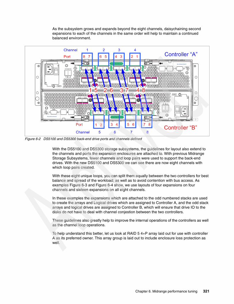
As the subsystem grows and expands beyond the eight channels, daisychaining second expansions to each of the channels in the same order will help to maintain a continued balanced environment.
Figure 6-2 DS5100 and DS5300 back-end drive ports and channels defined
With the DS5100 and DS5300 storage subsystems, the guidelines for layout also extend to the channels and ports the expansion enclosures are attached to. With previous Midrange Storage Subsystems, fewer channels and loop pairs were used to support the back-end drives. With the new DS5100 and DS5300 we can see there are now eight channels with which loop pairs created.
With these eight unique loops, you can split them equally between the two controllers for best balance and spread of the workload; as well as to avoid contention with bus access. As examples Figure 6-3 and Figure 6-4 show, we use layouts of four expansions on four channels and sixteen expansions on all eight channels.
In these examples the expansions which are attached to the odd numbered stacks are used to create the arrays and Logical drives which are assigned to Controller A, and the odd stack arrays and logical drives are assigned to Controller B, which will ensure that drive IO to the disks do not have to deal with channel conjestion between the two controllers.
These guidelines also greatly help to improve the internal operations of the controllers as well as the channel loop operations.
To help understand this better, let us look at RAID 5 4+P array laid out for use with controller A as its preferred owner. This array group is laid out to include enclosure loss protection as well.
Chapter 6. Midrange performance tuning 321

There are many variables that can come into play with the design of the layout that will be needed. These can include LUN size, desired RAID protection level, number of enclosures, number of drives, as the more common ones. The main point to remember is” First, and foremost to make use of as many resources of the subsystem as possible.” then align to include the other best practices. Smaller subsystem designs have greater difficulty with covering all the best practices as they frequently do not have the number of drive enclosures to spread out over all the back-end channels. To help with possible guidance the following sample configurations are offered for review. These configurations can be tuned to best fit the need of the environment.
Figure 6-3 Example layout of a four expansion 4 + P array configuration
In the layout used in Figure 6-4, we are giving up enclosure loss protection to have a greater amount of user capacity with RAID 5 versus RAID 10, and only use four expansions. In Figure 6-4, we show a configuration of sixteen expansions being used to layout 7 + P, RAID 5 array groups with enclosure loss protection. This configuration is frequently used for database application layouts with high random transaction processing.
Figure 6-4 Example layout of a sixteen expansion 7+ P array configuration
322 IBM Midrange System Storage Implementation and Best Practices Guide

If you need a full RAID 10 configuration, you can use the arrangement in Figure 6-5 as a sample to tune to meet the need.
Figure 6-5 Four expansion 3 + 3 RAID 10 example
Array and logical drive creationAn array is the grouping of drives together in a specific RAID type format on which the logical drive will be built for presentation to the hosts. As described in 3.1.2, “Creating arrays and logical drives” on page 66, there are a number of ways to create an array on the Midrange Storage Subsystem using the Storage Manager Client.
For best layout and optimum performance, you can manually select the drives when defining arrays.
Build the array groups by selecting drives equally from odd and even drive slots in the expansion enclosures. This task can be performed using either a “barber pole” pattern as shown in Figure 6-6 on page 324. or a “zig zag” (aka “zipper”) pattern as shown used in Figure 6-3 on page 322 and Figure 6-4 on page 322.
This type of balancing can also be extended to RAID10 arrays in a simplified manner as shown in Figure 6-5. These layouts help to spread the IO across both of the paths in the channel so that greater bandwidth and resources are being used.
Chapter 6. Midrange performance tuning 323
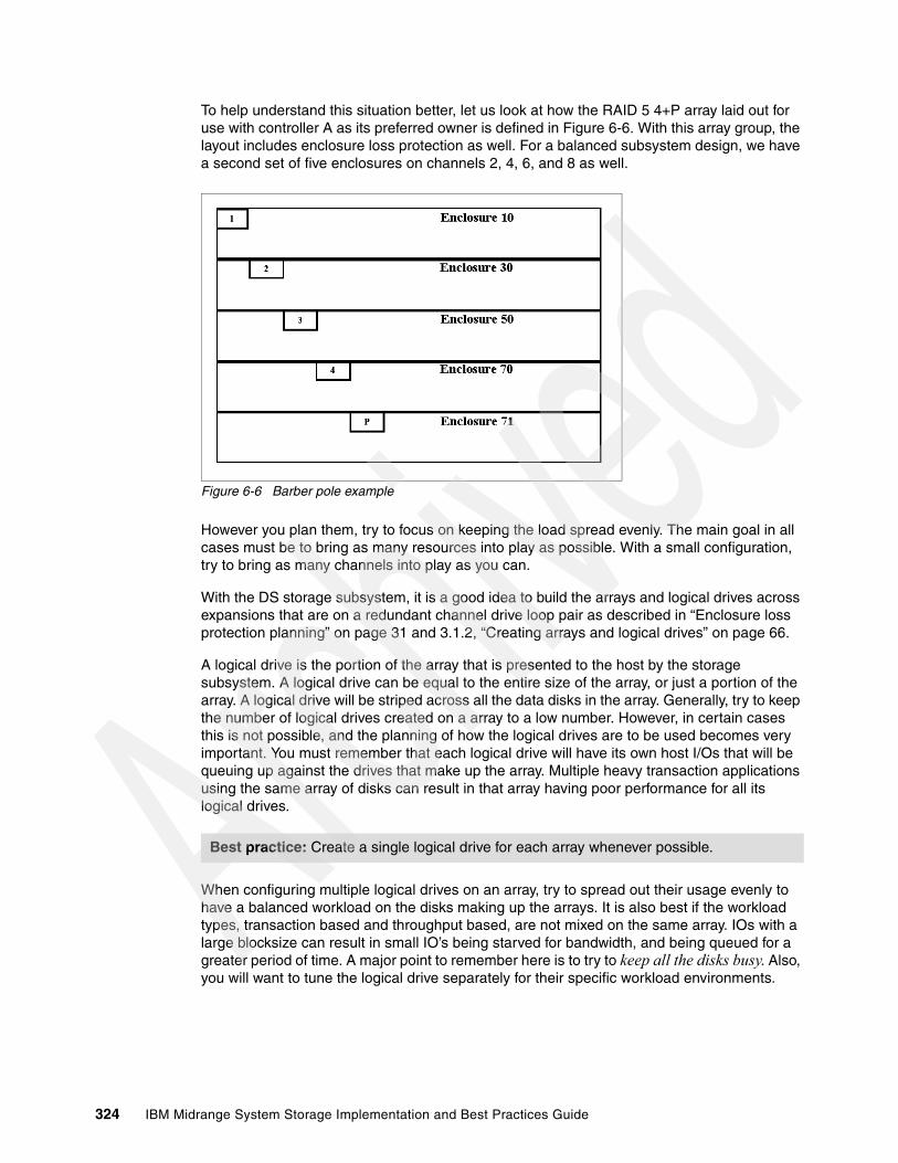
To help understand this situation better, let us look at how the RAID 5 4+P array laid out for use with controller A as its preferred owner is defined in Figure 6-6. With this array group, the layout includes enclosure loss protection as well. For a balanced subsystem design, we have a second set of five enclosures on channels 2, 4, 6, and 8 as well.
Figure 6-6 Barber pole example
However you plan them, try to focus on keeping the load spread evenly. The main goal in all cases must be to bring as many resources into play as possible. With a small configuration, try to bring as many channels into play as you can.
With the DS storage subsystem, it is a good idea to build the arrays and logical drives across expansions that are on a redundant channel drive loop pair as described in “Enclosure loss protection planning” on page 31 and 3.1.2, “Creating arrays and logical drives” on page 66.
A logical drive is the portion of the array that is presented to the host by the storage subsystem. A logical drive can be equal to the entire size of the array, or just a portion of the array. A logical drive will be striped across all the data disks in the array. Generally, try to keep the number of logical drives created on a array to a low number. However, in certain cases this is not possible, and the planning of how the logical drives are to be used becomes very important. You must remember that each logical drive will have its own host I/Os that will be queuing up against the drives that make up the array. Multiple heavy transaction applications using the same array of disks can result in that array having poor performance for all its logical drives.
When configuring multiple logical drives on an array, try to spread out their usage evenly to have a balanced workload on the disks making up the arrays. It is also best if the workload types, transaction based and throughput based, are not mixed on the same array. IOs with a large blocksize can result in small IO’s being starved for bandwidth, and being queued for a greater period of time. A major point to remember here is to try to keep all the disks busy. Also, you will want to tune the logical drive separately for their specific workload environments.
Best practice: Create a single logical drive for each array whenever possible.
324 IBM Midrange System Storage Implementation and Best Practices Guide
Drive loop communicationsThe drive loop channels can be used to transfer IOs to disks, for transfer of controller to controller internal communications and cache mirroring operations. These operations are performed through the use of the controller’s “exchange control blocks” (XCB). XCB’s are used to track the handling of all back-end and control processes that require the use of back-end Fibre Channel transfers to be performed, which includes operations between the controllers or for disk operations.
Each controller is allocated 512 XCBs per channel for its own operations. These are not shared XCBs, but dedicated to that controller. When a controller to controller operations is performed an XCB is used from both controllers to handle it from both sides. If a controller’s XCB’s are depleted a “queue full” condition is reported to the Destination Driver Event (DDE) and further operations from the controller to that specific channel are prevented until an XCB is freed up and write cache becomes internally disabled.
This makes the spreading of the workload across the subsystem resources very important to avoid running out of XCBs. As a recovery, when this event occurs, the controller will try to automatically send the request down a second channel to see if it can succeed through it. However, as expected, any recovery steps needing to be run will have a performance impact that might be better avoided when possible.
With the design of the DS5100 and DS5300, there are separate cache mirroring busses that are used for the write mirroring processes that allows for the XCB’s to be used only for the inter-controller communications and Fibre Channel disks operations only, which improves the amount of XCB resources available to the production disk IO operations. However, it is still important for performance to properly balance the IO workload.
Logical drive segments The segment size is the maximum amount of data that is written or read from a disk per operation before the next disk in the array is used. For small host I/Os, as mentioned earlier, set the segment size larger than the host I/O size. Doing this makes it unnecessary to access a second drive for a single small host I/O. For certain storage subsystems, having the segment size equal to the host I/O size is preferred, which is not the case with the Midrange Storage Subsystems.
There is no advantage in using a smaller segment size with RAID 1; only in a few instances does this help with RAID 5 (which we discuss later). Because only the data that is to be written to the disk is written to cache for an I/O, there is no cache penalty encountered either. As mentioned earlier in the host sections, aligning data on segment boundaries is very important for performance. With larger segment sizes, there are less occasions to have misaligned boundaries impacting your performance, as more small I/O boundaries reside within a single segment decreasing the chance of a host I/O spanning multiple drives. This technique can be used to help mask the effect of poor layout of the host data on the disks due to boundary differences.
With high throughput workload, the focus is on moving larger but fewer I/Os. This workload is generally sequential in nature.
Best practice: For most high transaction workloads with the Midrange Storage Subsystems, the segment size of 64 KB to 128 KB (default) works best.
Best practice: In the high throughput environment, you want the stripe size to be equal to, or an even multiple of, the host I/O size.
Chapter 6. Midrange performance tuning 325

The total of all the segments for one pass of all the back-end data disks is a stripe. So, large segment sizes that can equal the I/O size might be desired to accomplish the higher throughput you are looking for. For high read throughput, you want to have large segments (128 K or higher) to get the most from each stripe. For example if the host I/O is 512 KB, and the write is to a RAID 10 array, you want to use a segment size of 512 KB to limit the disk operations as much as possible.
When the workload is high writes, and we are using RAID 5, we can use a method known as full stripe (stride) write, which can work well to improve your performance. With RAID 5 the parity is based on the value calculated for a stripe. As discussed earlier in “RAID array types” on page 317, when the I/O being written is spread across the entire stripe width, no reads are required to calculate the parity; and the I/O completes with fewer back-end I/Os being required.
This design can use a smaller segment size to align the host I/O size with the size of the stripe width. For instance with our previous example, if the array is a 4+P RAID 5 you want to use a 128 KB segment size to achieve a full stripe write. This type of management requires that very few host I/Os not equal a full stripe width.
Logical drive cache settingsNow, to help enhance the use of the storage subsystem data cache, the Midrange Storage Subsystem’s have very useful tuning parameters which help the specific logical drive in its defined environment. One such parameter is the cache read-ahead multiplier (see also 2.3.6, “Cache parameters” on page 41). This parameter is used to increase the number of segments that are read into cache to increase the amount of data that is readily available to present to the host for sequential I/O requests. To avoid excess read I/Os in the random small transaction intense environments you must disable the cache read-ahead multiplier for the logical drive by setting it to 0.
In the throughput environment where you want more throughput faster, you must generally enable this parameter to deliver more than one segment to the cache at a time, which can be done by simply setting the value to 1 (or any non-zero value).
For write I/O in a transaction based environment you can enable write cache, and write cache mirroring for cache protection. Doing this allows the write I/Os to be acknowledged even before they are written to disks as the data is in cache, and backed up by the second mirror in the other controller’s cache. improving write performance dramatically.
This sequence is actually a set of two operations doing both write caching, and mirroring to the second cache. If you are performing a process that can handle loss of data, and can be restarted, you can choose to disable the mirroring, for further improved performance.
With the DS5100 and DS5300 the amount of improvement might not be worth the gain as the new subsystem uses a dedicated private high speed bus for internal data cache operations and the impact is far less than that seen with the lower end DS5020 and earlier DS4000 systems. With these subsystems the design of the mirror path was to use the back-end Fibre Channel loops which shared this function with other controller communications and back-end disk IO operations.
Best practice: For high throughput with sequential I/O, enable the cache read-ahead multiplier. For high transactions with random I/O, disable this feature.
326 IBM Midrange System Storage Implementation and Best Practices Guide
Be aware that, in most transaction intense environments where the data is a live OLTP update environment, this is not an option that can be chosen; however, in cases such as table updates, where you are loading in new values, and can restart the load over, this can be a way of reducing the load time; and therefore shortening your downtime outage window. For the earlier subsystem design, the improvement can be as much as three times.
For write I/O in the throughput sequential environment, these two parameters again come into play and can give you the same basic values. It must be noted that many sequential applications are more likely to be able to withstand the possible interrupt of data loss with the no cache mirroring selection, and therefore are better candidates for having the mirroring disabled. However, knowing the ability to recover is critical before using this feature for improved performance.
In addition to usage of write cache to improve the host I/O response, you also have a control setting that can be varied on a per logical drive basis that defines the amount of time the write can remain in cache. This value by default is set to ten seconds, which generally has been found to be a very acceptable time; in cases where less time is needed, it can be changed by using the following Storage Manager command line interface command:
set logical Drive [LUN] cacheflushModifier=[new_value];
This value can also be adjusted to higher values when application needs are better served by holding data in cache for longer periods. Acceptable values to choose from are: immediate, 250ms, 500ms, 750ms,1sec, 1500ms, 2sec, 5sec,10sec, 20sec, 60sec, 120sec, 300sec, 1200sec, 3600sec and infinite.
Additional NVSRAM parameters of concernThere are a number of Midrange Storage Subsystem parameters that are defined specifically for the host type that is planned to be connected to the storage. These parameters are stored in the NVSRAM values that are defined for each host type. Two of these parameters can impact performance if not properly set for the environment. NVSRAM settings requiring change must be made using the Storage Manager Enterprise Management window and selecting the script execution tool.
The Forced Unit Access setting is used to instruct the storage subsystem to not use cache for I/O, but rather go direct to the disks. This parameter must be configured to ignore.
The Synchronize Cache setting is used to instruct the storage subsystem to honor the SCSI cache flush to permanent storage command when received from the host servers. This parameter must be configured to ignore.
The AVT/ADT enable setting can also have an effect on how the cache is used by the logical drives. With AVT/ADT enabled on any of the host types the cache usage is limited to 16 MB per logical drive. With AVT/ADT disabled for all host types this limitation is lifted. However, this is only an viable option when all host types being used do not make use of the AVT/ADT option for path management and failover. This setting is desired to be used when supporting VMWare host on their own private storage subsystem.
Tip: The setting of these values is dynamic and can be varied as needed online. Starting and stopping of the mirroring can be implemented as a part of an update process when used.
Note: When defining a storage subsystem for usage with VMWare host servers alone, it is desired that AVT/ADT be disabled for all host type regions.
Chapter 6. Midrange performance tuning 327

6.6 Fabric considerationsWhen connecting the Midrange Storage Subsystem to your SAN fabric, it is best to consider what are all the other devices and servers that will share the fabric network, which is related to how you configure your zoning. See 2.1, “Planning your SAN and storage server” on page 16, for guidelines and details on how to establish the SAN infrastructure for your environment. Remember that a noisy fabric is a slow fabric. Unnecessary traffic makes for poor performance.
Specific SAN switch settings that are of particular interest to the Midrange Storage Subsystem environment, and can impact performance, are those that help to ensure in-order-delivery (IOD) of frames to the endpoints. The Midrange Storage Subsystems cannot manage out of order frames, and retransmissions will be required for all frames of the transmitted packet. See your specific switch documentation for details on configuring parameters.
328 IBM Midrange System Storage Implementation and Best Practices Guide
Chapter 7. IBM Midrange Storage Subsystem tuning with typical applications
In this chapter we provide general guidelines and tips to consider when implementing certain popular applications with the IBM Midrange Storage Subsystem.
Our intent is not to present a single way to set up your solution, but rather to show various areas of interest that you have to consider when implementing these applications. Each situation and implementation will have its own specific requirements.
We provide general guidance and tips for using the following software products:
� IBM DB2� Oracle Database � Microsoft SQLserver� IBM Tivoli Storage Manager� Microsoft Exchange
7
© Copyright IBM Corp. 2004-2010. All rights reserved. 329

7.1 DB2 databaseIn this section we discuss the usage of the IBM Midrange Storage Subsystem with a DB2 database. We cover the following topics:
� Data location� Database structure� Database RAID type� Redo logs RAID type� Volume management
7.1.1 Data locationDB2 applications generally have two types of data:
Data consisting of application programs, indexes, and tables, and stored in table spaces. Recovery data, made up of the database logs, archives, and backup management.
In an OLTP environment, it is a good idea to store these two data types separately, that is, on separate logical drives, on separate arrays. Under certain circumstances, it can be advantageous to have both logs and data co-located on the same logical drives, but these are special cases and require testing to ensure that the benefit will be there for you.
7.1.2 Database structureTable spaces can be configured in three possible environments:
� Database Managed Storage (DMS) table space� System Managed Storage (SMS) table space� Automatic Storage (AS) table space — new with V8.2.2
In a DMS environment, all the DB2 objects (data, indexes, large object data (LOB) and long field (LF)) for the same table space are stored in the same files. DB2 also stores metadata with these files as well for object management.
In an SMS environment, all the DB2 objects (data, indexes, LOB, and LF) for the same table space are stored in separate files in the directory.
In both DMS and SMS table space environments, you must define the container type to be used; either file system or raw device.
In the AS table space environment, there are no containers defined. This model has a single management method for all the table spaces on the server that manages where the data is located for them on the storage.
In all cases, striping of the data is done on an extent basis. An extent can only belong to one object.
Restriction: When using concurrent or direct I/O (CIO or DIO) with earlier versions than AIX 5.2B, you must separate the LOB and LF files on separate table spaces due to I/O alignment issues.
330 IBM Midrange System Storage Implementation and Best Practices Guide

DB2 performs data retrieval by using three type of I/O prefetch:
� RANGE: Sequential access either in the query plan or through sequential detection at run time. Range request can be affected most by poor configuration settings.
� LIST: Prefetches a list of pages that are not necessarily in sequential order.
� LEAF: Prefetches an index leaf page and the data pages pointed to by the leaf.
– LEAF page is done as a single I/O.– Data pages on a leaf are submitted as a LISTrequest.
Prefetch is defined by configuring the application for the following parameter settings:
� PREFETCHSIZE (PS): A block of contiguous pages requested. The block is broken up into prefetch I/Os and placed on the prefetch queue based on the level of I/O parallelism that can be performed:
– PS must be equal to the size of all the storage subsystem’s logical drives stripe sizes so that all drives that make up the container are accessed for the prefetch request.
– For example, if a container resides across two logical drives that were created on two separate RAID arrays of 8+1p, then when the prefetch is done, all 16 data drives have to be accessed in parallel.
� Prefetch is done on one extent at a time; but with careful layout planning can be paralleled.
� EXTENTSIZE (ES): This is both the unit of striping granularity, and the unit of prefetch I/O size. Good performance of prefetch is dependent on a well configured ES:
– Choose an extent size that is equal to or a multiple of the segment size used by the subsystem’s logical drives.
– In general, configure the extent size to be between 128 KB and 1 MB, but at least must be equal to 16 pages. DB2 supports page sizes equal to 4 KB, 8 KB, 16 KB, or 32 KB in size, which means that an ES must not be less than 64 KB (16 X 4 KB (DB2’s smallest page size)).
� Prefetch I/O parallelism for midrange storage performance requires DB2_PARALLEL_IO to be enabled, which allows you to configure for all or one table space to be enabled for it.
� NUM_IOSERVERS: The number of parallel I/O requests that you will be able to perform on a single table space.
� Starting with V8.2 of DB2, a new feature AUTOMATIC_PREFETCHSIZE was introduced.
A new database tablespace will have DFT_PREFETCH_SZ= AUTOMATIC.
The AUTOMATIC setting assumes a RAID 5 array of 6+1p, and will not work properly with an 8+1p size array. See the DB2 documentation for details on proper settings to configure this new feature.
Note: DB2 will convert a LIST request to RANGE if it detects that sequential ranges exist.
Best practice: The ES value must be a multiple of the segment size, and be evenly divisible into the stripe size.
Chapter 7. IBM Midrange Storage Subsystem tuning with typical applications 331

Figure 7-1 provides a diagram showing how all these pieces fit together.
Figure 7-1 Diagram of tablespace I/O prefetch structure
7.1.3 Database RAID typeIn many cases, OLTP environments contain a fairly high level of read workload. In this area, your application might vary, and behavior is very unpredictable, so try to test performance with your actual application and data.
In most cases, it has been found that laying out the datafile tables across a number of logical drives that were created across several RAID 5 arrays of 8+1 parity disks, and configured with a segment size of 64 KB or 128 KB, is a good starting point to begin testing with. This, coupled with host guidelines to help avoid offset and striping conflicts, seem to provide a good performance start point to build from. A point to remember is that high write percentages might result in a need to use RAID 10 arrays rather than the RAID 5, which is environment specific and will require testing to determine. A rule of thumb is, if there are greater than 25–30% writes, then you might want to look at RAID 10 over RAID 5.
Best practice: Spread the containers across as many drives as possible, and ensure that the logical drive spread is evenly shared across the Midrange Storage Subsystem’s resources. Use multiple arrays where larger containers are needed.
332 IBM Midrange System Storage Implementation and Best Practices Guide

DB2 uses a block based buffer pool to load the prefetched RANGE of I/O into. Though the RANGE is a sequential prefetch of data; in many cases the available blocks in the buffer might not be sequential, which can result in a performance impact. To assist with this management, certain operating system primitives can help. These are VECTOR or SCATTER/GATHER I/O primitives. For certain operating systems, you might need to enable DB2_SCATTERED_IO to accomplish this function. There are also page cleaning parameters that can be configured to help clear out the old or cold data from the memory buffers. See your DB2 documentation for details and guidelines.
7.1.4 DB2 logs and archivesThe DB2 logs and archive files generally are high write workloads, and sequential in nature. RAID 10 logical drives are best suited for this type of workload.
Because these are critical files to protect in case of failures, it is a good idea to keep two full copies of these files on separate disk arrays in the storage server, thus protecting you from the extremely unlikely occurrence of a double disk failure, which can result in data loss.
Also, because these are generally smaller files and require less space, you can use two separate arrays of 1+1 or 2+2 RAID1 to hold the logs and the mirror pair separately.
Logs in DB2 use the operating system’s default blocksize for I/O (generally 4 K) of sequential data at this time. Because the small write size has no greater penalty on the Midrange Storage Subsystem with higher segment size, you can configure the logical drive with a 64 KB or 128 KB segment size.
Also, it is best to place the redo logs on raw devices or volumes on the host system versus on the file system.
7.2 Oracle databasesIn this section we discuss the usage of the IBM Midrange Storage Subsystem with an Oracle database application environment. We cover the following topics:
� Data types� Data location� Database RAID and disk type� Redo logs RAID type� Volume management
7.2.1 Data typesOracle stores data at three levels:
� The first or lowest level consists of data blocks, also called logical blocks or pages.
One data block corresponds to a specific number of bytes corresponding to physical database space on the disk. A data block is the smallest unit of data used by a database. In contrast, at the physical, operating system level, all data is stored in bytes. Each operating system has a block size. Oracle requests data in multiples of Oracle data blocks, not operating system blocks.
� The second level consist of extents.
An extent is a specific number of contiguous data blocks, which are allocated for storing a specific type of information.
Chapter 7. IBM Midrange Storage Subsystem tuning with typical applications 333

A table space that manages its extents locally can have either uniform extent sizes or variable extent sizes that are determined automatically by the system:
– For uniform extents, the default size of an extent is 1 MB.
– For system-managed extents, Oracle determines the optimal size of additional extents, with a minimum extent size of 64 KB. If the table spaces are created with a segment space management auto, and if the database block size is 16 KB or higher, then Oracle manages segment size by creating extents with a minimum size of 1 MB, which is the default for permanent table spaces.
� The third level of database storage greater than an extent is called a segment.
A segment is a set of extents, each of which has been allocated for a specific data structure and all of which are stored in the same table space. Oracle allocates space for segments in units of one extent, as extents are allocated as needed. The extents of a segment might or might not be contiguous on disk. A segment and all its extents are stored in one table space. Within a table space, a segment can include extents from more than one file. The segment can span datafiles. However, each extent can contain data from only one datafile.
7.2.2 Data location
With Oracle applications, there are generally two types of data:
� Primary data, consisting of application programs, indexes, and tables � Recovery data, consisting of database backups, archive logs, and redo logs
For data recovery reasons, in the past there has always been a guideline that several categories of the RDBMS files be isolated from each other and placed in separate physical disk locations. Thus the redo logs had to be separated from your data, indexes separated from the tables, and rollback segments as well. Today, the guideline is to keep user datafiles separated from any files needed to recover from any datafile failure.
This strategy ensures that the failure of a disk that contains a datafile does not also cause the loss of the backups or the redo logs needed to recover the datafile.
Because indexes can be rebuilt from the table data, it is not critical that they be physically isolated from the recovery-related files.
Because the Oracle control files, online redo logs, and archived redo logs are crucial for most backup and recovery operations, it is a good idea to keep at least two copies of these files stored on separate RAID arrays, and that both sets of these files must be isolated from your base user data as well.
In most cases with Oracle, the user data application workload is transaction based with high random I/O activity. With an OLTP application environment, you might see that an 8 KB database block size has been used, whereas with Data Warehousing applications, a 16 KB database block size is typical. Knowing what these values are set to, and how the devices on which the datafiles reside were formatted, can help in prevention of added disk I/O due to layout conflicts. For additional information, see the previous discussion of host parameters in 2.6, “Host support and multipathing” on page 51.
7.2.3 Database RAID and disk typesIn many cases, OLTP environments contain a fairly high level of read workload. In this area your application might vary, and behavior is very unpredictable. Try to test performance with your actual application and data.
334 IBM Midrange System Storage Implementation and Best Practices Guide
With the default extent size of 1 MB, the segment size must be selected to allow a full stripe write across all disks. In most cases, it has been found that laying out the datafile tables across a number of logical drives that were created across several RAID 5 arrays of 8+1 disks, and configured with a segment size of 64 KB or 128 KB, is a good starting point. This, coupled with host guidelines to help avoid offset and striping conflicts, seems to provide a good performance start point to build from.
Keep in mind also that high write percentages might result in a need to use RAID 10 arrays rather than RAID 5, which is environment specific and will require testing to determine. A rule of thumb is if there are greater than 25–30% writes, then you might want to look at RAID 10 over RAID 5.
Enclosure loss protection must always be employed, which will ensure that in the unlikely event of an enclosure failure, then all the arrays and databases will continue to operate, although in a degraded state. Without enclosure loss protection, any failure of an enclosure will have major impact on those LUNs residing within that enclosure.
With the introduction of the new SSD drives, if the table space is of a size where it will fit on these devices, you might want to place it on them. However, in many cases the table space can be much larger and then the use of 15 K rpm drives is best to ensure maximum throughput. The use of the 15 K rpm drives gives a 20–30% performance increase over 10 K rpm disks. Using more spindles to spread the workload across provides a definite advantage to building a large logical drive on high capacity disks to use fewer spindles, which gives definite transaction response time advantages, but does make use of more disks.
Ensure that enough spare drives are on hand to ensure that any disk failure can fail over onto a spare disk. Also ensure that for each type and speed of disk utilized that enough spares are employed to cover them. It is possibly good practice to use only high-speed versions of the drives used, because this will ensure that when a spare is in use that it does not degrade the array by having a slower speed drive introduced on a disk failure. A slower disk introduced to any array will cause the array to run at the slower speed.
7.2.4 Redo logs: RAID types
The redo logs and control files of Oracle generally are both high write workloads, and are sequential in nature. As these are critical files, it is a good idea to keep two full copies on separate disk arrays in the storage server. You do this to protect against the (extremely) unlikely occurrence of a double disk failure, which can result in data loss.
Place the redo logs on RAID 10 logical drives. Avoid RAID 5 for these logs; dedicate a set of disks for the redo logs.
Because these are generally smaller files and require less space, you can use two separate arrays of 1+1 or 2+2 RAID 1 to hold the logs and the mirror pair separately.
Redo logs in Oracle use a 512 byte I/O blocksize of sequential data at this time. Because the small write size has no greater penalty on the Midrange Storage Subsystem with higher segment size, configure the logical drive with a 64 KB or 128 KB segment size.
Best practice: Spread the datafiles across as many drives as possible, and ensure that the logical drive spread is evenly shared across the Midrange Storage Subsystems resources.
Chapter 7. IBM Midrange Storage Subsystem tuning with typical applications 335
Also, place the redo logs on raw devices or volumes on the host system rather than the file system. Furthermore, keep the archive logs on separate disks, because disk performance can degrade when the redo logs are being archived.
7.2.5 TEMP table space
If the files with high I/O are datafiles that belong to the TEMP table space, then investigate whether to tune the SQL statements performing disk sorts to avoid this activity, or to tune the sorting process. After the application has been tuned and the sort process checked to avoid unnecessary I/O, if the layout is still not able to sustain the required throughput, then consider separating the TEMP table space onto its own disks.
7.2.6 Cache memory settings
The default cache memory on the Midrange Storage Subsystem is 8 KB (on firmware 7.xx and higher), because 8 KB is an optimal database block size. Setting the cache block size to 16 KB can allow for better cache write performance by lessening the operations, but can decrease the cache availability for usage by other operations and applications. Doing this might or might not be a good solution; a better choice might be to set the blocksize to the new 8 KB size that is available with the 7.xx firmware levels.
Setting the Start/Stop Flushing size to 50/50 is a good place to start. Monitor the cache settings for best performance and tune the settings to requirements. See Figure 7-2.
The Oracle Automatic Storage Management (ASM) can be utilized to provide various levels of redundancy to the environment. The methods available are external redundancy, normal redundancy, and high redundancy.
External redundancy means that we are counting on a fault-tolerant disk storage subsystem. So that is what we use with DS3K/4K/5K with RAID 5 or RAID 10.
Normal redundancy means that ASM does software mirroring with two separate devices either from separate or common storage subsystems.
High redundancy means that ASM does software mirroring with 3 copies of the data, which is generally used to create a disaster recovery solution for the environment by placing the mirrors on two separate servers locally, and a third that is remote.
These methods can be used enhance the midrange RAID level to provide either an extra measure of protection or for remote disaster recovery.
In all cases, it is always best that write cache mirroring on the storage subsystem be enabled, even though an additional copy is being made, because the write to each storage device must be protected to decrease the need to for recovery actions.
Though using write cache in this situation does have a small performance cost, unless this is a data base update or initial load, there is no good justification to risk the data on the mirror. Write cache mirroring being disabled must only be done during large loads, and then only when they can be restarted again if errors occur. Finally, as discussed earlier with the new DS5100 and DS5300 the design improvements in the new subsystems make the mirrored operations perform far faster than previous subsystems even for the large loads so the benefit becomes marginal.
336 IBM Midrange System Storage Implementation and Best Practices Guide
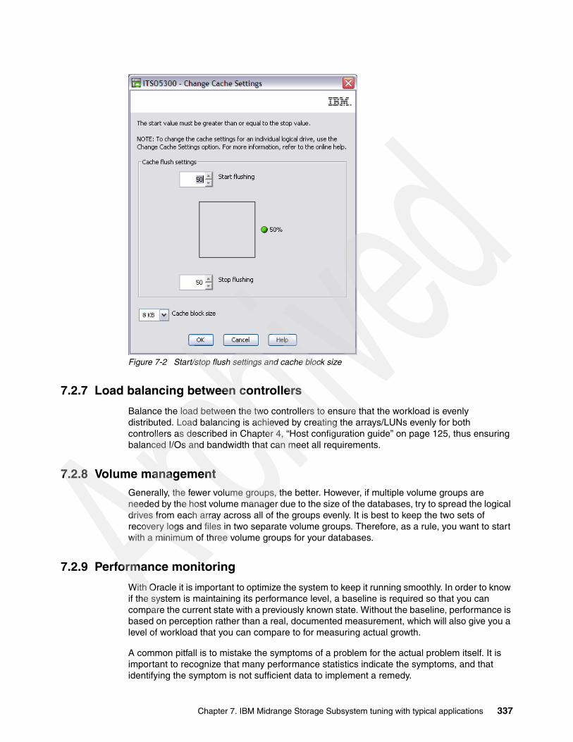
Figure 7-2 Start/stop flush settings and cache block size
7.2.7 Load balancing between controllers
Balance the load between the two controllers to ensure that the workload is evenly distributed. Load balancing is achieved by creating the arrays/LUNs evenly for both controllers as described in Chapter 4, “Host configuration guide” on page 125, thus ensuring balanced I/Os and bandwidth that can meet all requirements.
7.2.8 Volume managementGenerally, the fewer volume groups, the better. However, if multiple volume groups are needed by the host volume manager due to the size of the databases, try to spread the logical drives from each array across all of the groups evenly. It is best to keep the two sets of recovery logs and files in two separate volume groups. Therefore, as a rule, you want to start with a minimum of three volume groups for your databases.
7.2.9 Performance monitoring
With Oracle it is important to optimize the system to keep it running smoothly. In order to know if the system is maintaining its performance level, a baseline is required so that you can compare the current state with a previously known state. Without the baseline, performance is based on perception rather than a real, documented measurement, which will also give you a level of workload that you can compare to for measuring actual growth.
A common pitfall is to mistake the symptoms of a problem for the actual problem itself. It is important to recognize that many performance statistics indicate the symptoms, and that identifying the symptom is not sufficient data to implement a remedy.
Chapter 7. IBM Midrange Storage Subsystem tuning with typical applications 337

For example, consider the situation of a slow physical I/O, which is generally caused by poorly configured disks. However, it might also be caused by a significant amount of unnecessary physical I/O on those disks due to poorly tuned SQL statements or queries.
Ideally, baseline data gathered includes these statistics:
� Application statistics� Database statistics� Operating system statistics� Midrange storage subsystem statistics
Application statistics consist of figures such as active session histories, transaction volumes, and response times.
Database statistics provide information about the type of load on the database, as well as the internal and external resources used by the database.
Operating system statistics are CPU, memory, disk, and network statistics. For Windows environments, Windows Performance Monitor can be used to gather performance data. For UNIX and Linux environments, a range of tools can be employed to gather the performance data. See Table 7-1.
Table 7-1 Linux tools commonly used to gather performance data
For the Midrange Storage Subsystem, the IBM System Storage DS Storage Manager 10 offers a performance monitoring tool to gather data of what the Midrange Storage Subsystem sees its workload to be. A collection of the Support Data can also be helpful when trying to see what resources are being impacted.
CPU statisticsCPU utilization is the most important operating system statistic in the tuning process. Make sure to gather CPU utilization for the entire system and for each individual CPU in a multiprocessor environments. The utilization figure for each CPU can help detect single threading and scalability issues.
Most operating systems report CPU usage as time spent in user mode and time spent in kernel mode. These additional statistics allow better analysis of what is actually being executed on the CPU.
On an Oracle data server, where there is generally only one application running, the server runs database activity in user mode. Activities required to service database requests, such as scheduling, synchronization, and memory management, run in kernel mode.
Virtual memory statisticsVirtual memory statistics mainly ought to be used as a check to validate that there is very little paging on the system. System performance degrades rapidly and unpredictably when excessive paging activity occurs.
Component Linux/UNIX tool to collect statistics
CPU sar, vmstat, mpstat, or iostat
Memory sar, vmstat
Disk sar, iostat
Network netstat
338 IBM Midrange System Storage Implementation and Best Practices Guide
Individual process memory statistics can detect memory leaks due to a programming fault to deallocate memory. These statistics can be used to validate that memory usage does not rapidly increase after the system has reached a steady state after startup.
Disk statisticsBecause the database resides on a set of disks, the performance of the I/O subsystem is very important to the performance of the database. Most operating systems provide extensive statistics about disk performance. The most important disk statistics are the throughput, current response times and the length of the disk queues. These statistics show if the disk is performing optimally or if the disk is being overworked.
Measure the normal performance of the I/O system. If the response times are much higher than the normal performance value, then it is performing badly or is overworked. If disk queues start to exceed two, then the disk subsystem is a potential bottleneck of the system.
Comparing the host reported IO statistics with those of the Midrange Storage Subsystem can help in isolating down the location of a problem.
Network statisticsNetwork statistics can be used in much the same way as disk statistics to determine whether a network or network interface is overloaded or not performing optimally. For today’s range of networked applications, network latency can be a large portion of the actual user response time. For this reason, these statistics are a crucial debugging tool.
7.3 Microsoft SQL ServerIn this section we describe various considerations for Microsoft SQL server and the Midrange Storage Subsystem environment. Review the information in 4.1, “Windows 2008” on page 126 for information specific to Windows OS. As with all guidelines, these settings must be checked to ensure that they suit your specific environment. Testing your own applications with your own data is the only true measurement.
We cover the following topics:
� Allocation unit size and SQL Server� RAID levels� Disk drives� File locations� Transaction logs� Databases� Maintenance plans
7.3.1 Allocation unit sizeWhen running on Windows 2003, or Windows 2008 SQL Server must be installed on disks formatted using NTFS, because NTFS gives better performance and security to the file system. In all the Windows versions, setting the file system allocation unit size to 64 KB will improve performance. Allocation unit size is set when a disk is formatted.
Adjusting the allocation unit other than the default does affect features, for example, file compression. Use this setting first in a test environment to ensure that it gives the desired performance level and that the required features are enabled.
For more information about formatting an NTFS disk, see the appropriate Windows release documentation.
Chapter 7. IBM Midrange Storage Subsystem tuning with typical applications 339

7.3.2 RAID levelsRedundancy and performance are required for the SQL environment.
� RAID 1 or RAID 10 must be used for the databases, tempdb, and transaction logs.� RAID 1, RAID 5, or RAID 10 can be used for the maintenance plans.
7.3.3 File locationsAs with all database applications, the database files and the transaction logs must be kept on separate logical drives and separate arrays, for best protection. Also, the tempdb and the backup area for any maintenance plans must be kept separate as well. Limit other uses for these arrays to minimize contention.
It is not a good idea to place any of the database, transaction logs, maintenance plans, or tempdb files in the same location as the operating system page file.
7.3.4 User database filesGeneral guidelines for user database files are as follows:
� Create the databases on a physically separate RAID array. The databases are being constantly being read from and written to; therefore, using separate, dedicated arrays does not interfere with other operations such as the transaction logs, or maintenance plans. Depending upon the current size of the databases and expected growth, either a RAID 1 or RAID 10 array can give best performance and redundancy. RAID 5 can also be used, but with a slightly lower performance. Data redundancy is critical in the operation of the databases.
� Consider the speed of the disk, which will also affect performance. Use the 15K RPM disks rather than 10K RPM disks. Avoid using SATA drives for the databases.
� Spread the array over many drives. The more drives that the I/O operations are being sent to, the better the performance. Keep in mind that best performance is between 5 to 12 drives.
Midrange storage array settings: Use the following settings, as appropriate:
� Segment size 64 K or 128 K (dependent on I/O profile)� Read cache on� Write cache on� Write cache with mirroring on� Read ahead multiplier enabled (1)
7.3.5 Tempdb database filesTempdb is a default database created by SQL Server. It is used as a shared working area for a variety of activities, including temporary tables, sorting, subqueries, and aggregates with GROUP BY or ORDER BY queries using DISTINCT (temporary worktables have to be created to remove duplicate rows), cursors, and hash joins.
It is good to enable tempdb I/O operations to occur in parallel to the I/O operations of related transactions. Because tempdb is a scratch area and very update intensive, use RAID 1 or RAID 10 to achieve optimal performance benefits. RAID 5 is not suited for this use. The tempdb is reconstructed with each server restart.
The ALTER DATABASE command can be used to change the physical file location of the SQL Server logical file name associated with tempdb; hence the actual tempdb database.
340 IBM Midrange System Storage Implementation and Best Practices Guide
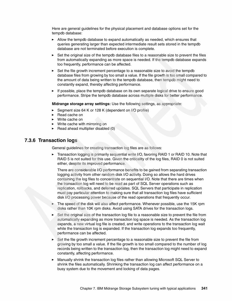
Here are general guidelines for the physical placement and database options set for the tempdb database:
� Allow the tempdb database to expand automatically as needed, which ensures that queries generating larger than expected intermediate result sets stored in the tempdb database are not terminated before execution is complete.
� Set the original size of the tempdb database files to a reasonable size to prevent the files from automatically expanding as more space is needed. If the tempdb database expands too frequently, performance can be affected.
� Set the file growth increment percentage to a reasonable size to avoid the tempdb database files from growing by too small a value. If the file growth is too small compared to the amount of data being written to the tempdb database, then tempdb might need to constantly expand, thereby affecting performance.
� If possible, place the tempdb database on its own separate logical drive to ensure good performance. Stripe the tempdb database across multiple disks for better performance.
Midrange storage array settings: Use the following settings, as appropriate:
� Segment size 64 K or 128 K (dependent on I/O profile)� Read cache on� Write cache on� Write cache with mirroring on� Read ahead multiplier disabled (0)
7.3.6 Transaction logsGeneral guidelines for creating transaction log files are as follows:
� Transaction logging is primarily sequential write I/O, favoring RAID 1 or RAID 10. Note that RAID 5 is not suited for this use. Given the criticality of the log files, RAID 0 is not suited either, despite its improved performance.
There are considerable I/O performance benefits to be gained from separating transaction logging activity from other random disk I/O activity. Doing so allows the hard drives containing the log files to concentrate on sequential I/O. Note that there are times when the transaction log will need to be read as part of SQL Server operations such as replication, rollbacks, and deferred updates. SQL Servers that participate in replication must pay particular attention to making sure that all transaction log files have sufficient disk I/O processing power because of the read operations that frequently occur.
� The speed of the disk will also affect performance. Whenever possible, use the 15K rpm disks rather than 10K rpm disks. Avoid using SATA drives for the transaction logs.
� Set the original size of the transaction log file to a reasonable size to prevent the file from automatically expanding as more transaction log space is needed. As the transaction log expands, a new virtual log file is created, and write operations to the transaction log wait while the transaction log is expanded. If the transaction log expands too frequently, performance can be affected.
� Set the file growth increment percentage to a reasonable size to prevent the file from growing by too small a value. If the file growth is too small compared to the number of log records being written to the transaction log, then the transaction log might need to expand constantly, affecting performance.
� Manually shrink the transaction log files rather than allowing Microsoft SQL Server to shrink the files automatically. Shrinking the transaction log can affect performance on a busy system due to the movement and locking of data pages.
Chapter 7. IBM Midrange Storage Subsystem tuning with typical applications 341

Midrange storage array settings: Use the following settings, as appropriate:
� Segment size 64 K or 128 K (dependent on I/O profile)� Read cache on� Write cache on� Write cache with mirroring on� Read ahead multiplier disabled (0)
7.3.7 Maintenance plansMaintenance plans are used to perform backup operations with the database still running. For best performance, it is advisable to place the backup files in a location that is separate from the database files. Here are general guidelines for maintenance plans:
� Maintenance plans allow you to back up the database while it is still running, The location for the database backups must be in a dedicated array that is separate from both the databases and transaction logs. For the most part, these are large sequential files.
� This array needs to be much larger than the database array, as you will keep multiple copies of the database backups and transaction log backups. A RAID 5 array will give good performance and redundancy.
� The speed of the disk will also affect performance, but will not be as critical as the database or transaction log arrays. The preference is to use 15K disks for maximum performance, but 10K or even SATA drives can be used for the maintenance plans; this depends on your environment’s performance needs.
� Spread the array over many drives. The more drives that the I/O operations are being sent to, the better the performance. Keep in mind that best performance is between 5 to 12 drives. For more details on array configurations see “Array configuration” on page 30.
� Verify the integrity of the backup upon completion. Doing this performs an internal consistency check of the data and data pages within the database to ensure that a system or software problem has not damaged data.
Midrange storage array settings: Use the following settings, as appropriate:
� Segment size 128 K or higher (dependent on I/O profile)� Read cache on� Write cache on� Write cache with mirroring off� Read ahead multiplier enabled (1)
7.4 IBM Tivoli Storage Manager backup serverWith a Tivoli Storage Manager (TSM) backup server environment, the major workload to be considered is the backup and restore functions which are generally throughput intensive environments. Therefore, try to ensure that the Midrange Storage Subsystem’s server-wide settings are set for the high throughput settings specified for cache blocksize. For a Midrange Storage Subsystem dedicated to the TSM environment, the cache blocksize must be set to 16 KB.
The TSM application has two separate sets of data storage needs. TSM uses an instance database to manage its storage operations and storage pools for storing the backup data.
Best practice: For a Midrange Storage Subsystem dedicated to the TSM environment, the cache blocksize must be set to 16 KB.
342 IBM Midrange System Storage Implementation and Best Practices Guide

In the following section, we use an example of a site with three TSM host servers sharing a Midrange Storage Subsystem, and managing twelve TSM instances across them. These servers manage the data stored in a 16 TB storage pool that is spread across them in fairly even portions. It is estimated that the database needs for this will be about 1.7 TB in size, giving us about 100-150 GB per instance.
In our example, the customer has chosen to use 146 GB FC drives for the databases, and 250 GB SATA drives for the storage pools.
Here are the general guidelines we followed for creating the TSM databases:
� For a Midrange Storage Subsystem being used for the TSM databases, you have a fairly high random write workload. We used the following general guideline guidelines for our TSM site with three TSM host servers (TSM1,2 and 3), and database needs to handle twelve TSM instances per server:
– Use a RAID 10 array, with four or more drives (remember, the higher the drive count, the better the performance with high transaction workloads). If you have a number of TSM host servers, create a large RAID 10 array out of which you can create the logical drives that will handle the database needs for all the hosts applications. In our scenario we created a single RAID 10 array of 13 x 13 drives.
– With TSM databases of 1-100 and 11-150 GB size being requested, we created logical drives of 50 GB striped across the previous RAID 10 array; giving us 35 logical drives.
– For TSM databases, we have found that the logical drives must have a large segment size defined. The guideline of 256 K has been found to work well.
– Ensure that cache read-ahead is disabled by setting it to “0”.
� Use partition mapping to assign each TSM server the logical drives it will use for the databases it will have. Ensure that the correct host type setting is selected.
� Because the fabric connections will support both high transaction, and high throughput, you will need to set the host and any HBA settings available for high I/O support and high throughput both of these means:
– HBA setting for high IOPS to be to be queued– Large blocksize support, in both memory and I/O transmission drivers
� Set the host device and any logical drive specific settings for high transaction support, Especially, ensure that you have a good queue depth level set for the logical drives being used. A queue depth of “32” per logical drive and 256 per host adapter are good values to start with.
� Using the host volume manager, we created a large volume group in which we placed all of the logical drives we have assigned to handle each of the instances managed by the TSM server. As an example, suppose TSM1 has four instances to handle, each requiring 150 GB databases. In this case we have twelve logical drives for which we will build the volume group. Create the volume group using the following parameters:
– Logical drives need to be divided into small partitions to be used for volume creation across them.
– For each TSM instance, create a volume of 150 GB in size spread across three of the logical drives using minimum interpolicy.
– Configure the TSM database volume to have a file system on it.
Tip: Use a partition size that is one size larger than the minimum allowed.
Chapter 7. IBM Midrange Storage Subsystem tuning with typical applications 343
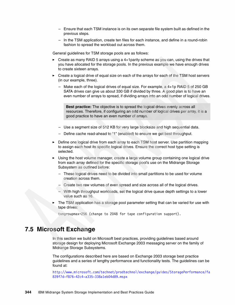
– Ensure that each TSM instance is on its own separate file system built as defined in the previous steps.
– In the TSM application, create ten files for each instance, and define in a round-robin fashion to spread the workload out across them.
General guidelines for TSM storage pools are as follows:
� Create as many RAID 5 arrays using a 4+1parity scheme as you can, using the drives that you have allocated for the storage pools. In the previous example we have enough drives to create sixteen arrays.
� Create a logical drive of equal size on each of the arrays for each of the TSM host servers (in our example, three).
– Make each of the logical drives of equal size. For example, a 4+1p RAID 5 of 250 GB SATA drives can give us about 330 GB if divided by three. A good plan is to have an even number of arrays to spread, if dividing arrays into an odd number of logical drives.
– Use a segment size of 512 KB for very large blocksize and high sequential data.
– Define cache read-ahead to “1” (enabled) to ensure we get best throughput.
� Define one logical drive from each array to each TSM host server. Use partition mapping to assign each host its specific logical drives. Ensure the correct host type setting is selected.
� Using the host volume manager, create a large volume group containing one logical drive from each array defined for the specific storage pool’s use on the Midrange Storage Subsystem as outlined before:
– These logical drives need to be divided into small partitions to be used for volume creation across them.
– Create two raw volumes of even spread and size across all of the logical drives.
– With high throughput workloads, set the logical drive queue depth settings to a lower value such as 16.
� The TSM application has a storage pool parameter setting that can be varied for use with tape drives:
txngroupmax=256 (change to 2048 for tape configuration support).
7.5 Microsoft ExchangeIn this section we build on Microsoft best practices, providing guidelines based around storage design for deploying Microsoft Exchange 2003 messaging server on the family of Midrange Storage Subsystems.
The configurations described here are based on Exchange 2003 storage best practice guidelines and a series of lengthy performance and functionality tests. The guidelines can be found at:
http://www.microsoft.com/technet/prodtechnol/exchange/guides/StoragePerformance/fa839f7d-f876-42c4-a335-338a1eb04d89.mspx
Best practice: The objective is to spread the logical drives evenly across all resources. Therefore, if configuring an odd number of logical drives per array, it is a good practice to have an even number of arrays.
344 IBM Midrange System Storage Implementation and Best Practices Guide

This section is primarily concerned with the storage configuration and does not go into the decisions behind the Exchange 2003 configurations referenced. For more information about Exchange design, see the following Web site:
http://www.microsoft.com/technet/prodtechnol/exchange/2003/library/default.mspx
We assume that:
� Exchange 2003 Enterprise Edition is running in a stand-alone configuration (non-clustered).
� Windows 2003 operating system, page file, and all application binaries are located on locally attached disks.
� All additional data, including Exchange logs, storage groups (SG), SMTP queues, and RSG (Recovery Storage Groups) are located on a Midrange Storage Subsystem.
7.5.1 Exchange configurationAll Exchange data is located in the Exchange store, consisting of three major components:
� Jet database (.edb file)� Streaming database (.stm file)� Transaction log files (.log files)
Each Exchange store component is written to separately. Performance will be greatly enhanced if the .edb files and corresponding .stm files are located on the same storage group, on one array, and the transaction log files are placed on a separate array.
The following list shows how the disk read/writes are performed for each Exchange store component:
� Jet database (.edb file):
– Reads and writes are random– 4 KB page size
� Streaming database (.stm file):
– Reads and writes are sequential– Variable page size that averages 8 KB in production
� Transaction log files (.log files):
– 100% sequential writes during normal operations– 100% sequential reads during recovery operations– Writes vary in size from 512 bytes to the log buffer size, which is 5 MB
Additional activities that affect I/OHere is a list of such activities:
� Zero out deleted database pages� Content indexing� SMTP mail transmission� Paging� MTA message handling� Maintenance mode� Virus scanning
User profilesTable 7-2 lists mailbox profiles that can be used as a guideline for capacity planning of Exchange mailbox servers. These profiles represent mailbox access for the peak of an
Chapter 7. IBM Midrange Storage Subsystem tuning with typical applications 345
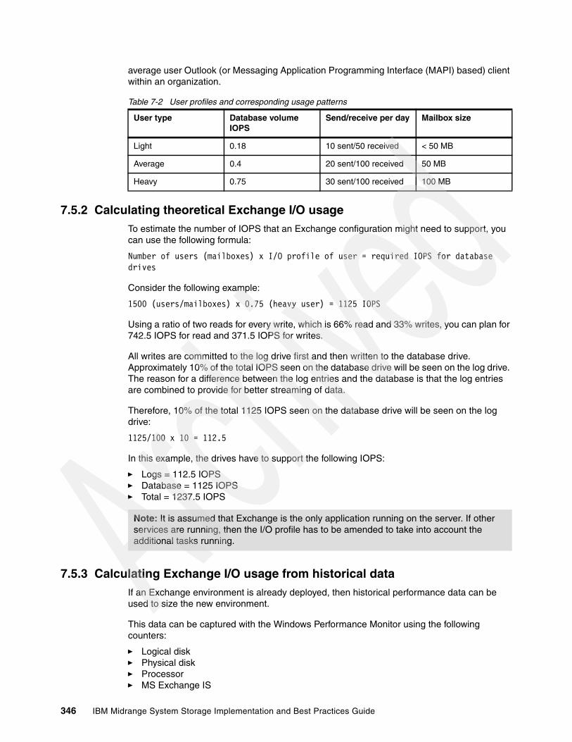
average user Outlook (or Messaging Application Programming Interface (MAPI) based) client within an organization.
Table 7-2 User profiles and corresponding usage patterns
7.5.2 Calculating theoretical Exchange I/O usage To estimate the number of IOPS that an Exchange configuration might need to support, you can use the following formula:
Number of users (mailboxes) x I/O profile of user = required IOPS for database drives
Consider the following example:
1500 (users/mailboxes) x 0.75 (heavy user) = 1125 IOPS
Using a ratio of two reads for every write, which is 66% read and 33% writes, you can plan for 742.5 IOPS for read and 371.5 IOPS for writes.
All writes are committed to the log drive first and then written to the database drive. Approximately 10% of the total IOPS seen on the database drive will be seen on the log drive. The reason for a difference between the log entries and the database is that the log entries are combined to provide for better streaming of data.
Therefore, 10% of the total 1125 IOPS seen on the database drive will be seen on the log drive:
1125/100 x 10 = 112.5
In this example, the drives have to support the following IOPS:
� Logs = 112.5 IOPS� Database = 1125 IOPS� Total = 1237.5 IOPS
7.5.3 Calculating Exchange I/O usage from historical dataIf an Exchange environment is already deployed, then historical performance data can be used to size the new environment.
This data can be captured with the Windows Performance Monitor using the following counters:
� Logical disk� Physical disk� Processor� MS Exchange IS
User type Database volume IOPS
Send/receive per day Mailbox size
Light 0.18 10 sent/50 received < 50 MB
Average 0.4 20 sent/100 received 50 MB
Heavy 0.75 30 sent/100 received 100 MB
Note: It is assumed that Exchange is the only application running on the server. If other services are running, then the I/O profile has to be amended to take into account the additional tasks running.
346 IBM Midrange System Storage Implementation and Best Practices Guide

To get the initial IOPS of the Exchange database, monitor the Logical Disk Disk Transfers/sec Instance=Drive letter that houses the Exchange Store database. (Add all drive letters that contain Exchange Database files). Monitor this situation over time to determine times of peak load.
Next we provide an example of how to calculate the I/O requirements for an Exchange deployment based on a DS4000 Storage System using RAID 10 arrays and having all Exchange transaction log and storage groups on their own individual arrays.
Assume the following values:
� Users/mailboxes = 1500� Mailbox size = 50 MB� Database IOPS = 925
To calculate the individual IOPS of a user, divide database IOPS by the number of users.
925/1500 = 0.6166
To calculate the I/O overhead of a given RAID level, you need to have an understanding of the various RAID types. RAID 0 has no RAID penalty, as it is just a simple stripe over a number of disks — so, 1 write will equal 1 I/O. RAID 1 or RAID 10 is a mirrored pair of drives or multiple mirrored drives striped together, because of the mirror, it means that for every write committed 2 I/Os will be generated. RAID 5 uses disk striping with parity so, for every write committed, this will often translate to 4 I/Os, due to the need to read the original data and parity before writing the new data and new parity. For further information about RAID levels, see IBM Midrange System Storage Hardware Guide, SG24-7676.
To calculate the RAID I/O penalty in these formulas, use the following substitutions:
� RAID 0 = 1� RAID 1 or RAID 10 = 2� RAID 5 = 4
Using the formula:
[(IOPS/mailbox × READ RATIO%)] + [(IOPS/mailbox × WRITE RATIO%) x RAID penalty]
Gives us:
[(925/1500 x 66/100) = 0.4069] + [(925/1500 x 33/100) = 0.2034 > (x 2) = 0.4069]
That is a total of 0.8139 IOPS per user, including the penalty for RAID 10.
Exchange 2003 EE supports up to four storage groups (SGs) with five databases within each storage group. Therefore, in this example, the Exchange server will have the 1500 users spread over three storage groups with 500 users in each storage group. The fourth storage group will be used as a recovery storage group (RSG). For more information about RSGs, see the following Web site:
http://www.microsoft.com/technet/prodtechnol/exchange/guides/UseE2k3RecStorGrps/d42ef860-170b-44fe-94c3-ec68e3b0e0ff.mspx
Here we describe our calculations:
� To calculate the IOPS required for a storage group to support 500 users, apply the following formula:
Users per storage group x IOPS per user = required IOPS per storage group500 x 0.8139 = 406.95 IOPS per storage group
Chapter 7. IBM Midrange Storage Subsystem tuning with typical applications 347

A percentage must be added for non-user tasks such as Exchange Online Maintenance, anti-virus, mass deletions, and various additional I/O intensive tasks. Best practice is to add 20% to the per user I/O figure.
� To calculate the additional IOPS per storage group, use the following formula:
Users per storage group x IOPS per user x 20% = overhead in IOPS per storage group500 x 0.8139/100 x 20 = 81.39 IOPS overhead per SG
� The final IOPS required per storage group is determined by adding the user IOPS per storage group with the overhead IOPS per storage group.
User IOPS per SG + overhead in IOPS per SG = total IOPS per SG406.95 + 81.39 = 488.34
� The total required IOPS for the Exchange server in general is as follows:
Total IOPS per SG x total number of SGs488.34 x 3 = 1465.02
� The new IOPS user profile is obtained by dividing total IOPS by total number of users:
1465.02/1500 = 0.9766 IOPS per user
� Taking this last figure and rounding it up gives us a 1.0 IOPS per user. This figure allows for times of extraordinary peak load on the server.
� Multiplying by the 1500 users supported by the server gives a figure of 1500 IOPS across all three storage groups, divided by the three storage groups on the server, means that each storage group will have to be able to sustain 500 IOPS.
� Microsoft best practice is that log drives be designed to take loads equal to 10% of those being handled by the storage group logical drive, for example:
500/100 x 10 = 50 IOPS
� Microsoft best practice is that log files be kept on separate spindles (physical disks) from each other and the storage groups.
After extensive testing, it has been determined that a RAID 1 (mirrored pair) provides the best performance for Exchange transaction logs on the DS4000 series, which is consistent with Microsoft best practices. In addition, Microsoft best practice is that the storage groups be placed on RAID 10. Again, this has proved to provide the best performance, however, RAID 5 will also provide the required IOPS performance in environments where the user I/O profile is less demanding.
Taking the same data used in the example for RAID 10, for the Exchange storage groups only and substituting the RAID 10 penalty, which is 2 I/Os for the RAID 5 penalty, which can be up to 4 I/Os, the new RAID 5 storage groups each have to deliver an additional 500 IOPS than for the RAID 10 configuration.
7.5.4 Path LUN assignment (MPIO)With the recent release of 7.xx IBM DS Controller Firmware, the Midrange Storage Subsystems moved from using the previous proprietary RDAC/MPP (multi-path proxy) driver to fully supporting and using the Microsoft Windows MPIO driver for handling multipathing and failover functionality. See 4.1, “Windows 2008” on page 126 for details on the use of MPIO for Windows.
348 IBM Midrange System Storage Implementation and Best Practices Guide

7.5.5 Storage sizing for capacity and performanceMailbox quota, database size, and the number of users are all factors that you have to consider during capacity planning. Considerations for additional capacity must include NTFS fragmentation, growth, and dynamic mailbox movement. Experience has determined that it is always a best practice to double capacity requirements wherever possible to allow for unplanned needs, for example:
� A 200 MB maximum mailbox quota� About 25 GB maximum database size*� Total mailbox capacity to be 1500 users� Mailboxes to be located on one Exchange server
Maximum database size for Exchange 2003 SE (Standard Edition) is 16 GB, increasing to 75 GB with SP2, and the theoretical limit for Exchange 2003 EE (Enterprise Edition) is 16 TB.
Exchange SE supports four storage groups with one mailbox store and one public folder database store. Exchange EE supports four storage groups with five mailbox or public folder database stores, located within each storage group to a maximum of 20 mailbox or public store databases across the four storage groups. For more information, see the Web site:
http://support.microsoft.com/default.aspx?scid=kb;en-us;822440
Capacity planning calculationsUsing the previous data, the capacity planning was done as follows:
Database size / maximum mailbox size = number of mailboxes per database25GB / 200MB = 125 mailboxes per database
There is a maximum of five databases per storage group:
Maximum mailboxes per database x database instances per SG = maximum mailboxes per SG 125 x 5 = 625 mailboxes per SG
There are three active storage groups on the Exchange server:
Storage groups per server x maximum mailboxes per SG = maximum mailboxes per server3 x 625 = 1875 mailboxes per server
In addition to the database storage requirements listed previously, logical drives and capacity must be provided for the following items:
� Log files
� Extra space added to each storage group for database maintenance and emergency database expansion
� A 50 GB logical drive for the SMTP and MTA working directories
� Additional logical drive capacity for one additional storage group, for spare capacity or as a recovery group to recover from a database corruption
� An additional logical drive for use with either the additional storage group or recovery storage group
Chapter 7. IBM Midrange Storage Subsystem tuning with typical applications 349

Logical view of the storage design with capacitiesFigure 7-3 shows a logical view of the storage design.
Figure 7-3 Logical view of the storage design with capacities
OS C: 10GB
Page file D: 6GB
Apps E: 20GB
RSG Logs I: 33GB
Exchange Server
HBA 1 Path A
Internal SCSI bus
HBA 2 Path B
SG1 Logs F: 33GB
SG2 Logs G: 33GB
SG3 Logs H: 33GB
SG1 J: 272GB
SG2 K: 272GB
SG3 L: 272GB
RSG M: 272GB
SMTP N: 50GB
350 IBM Midrange System Storage Implementation and Best Practices Guide
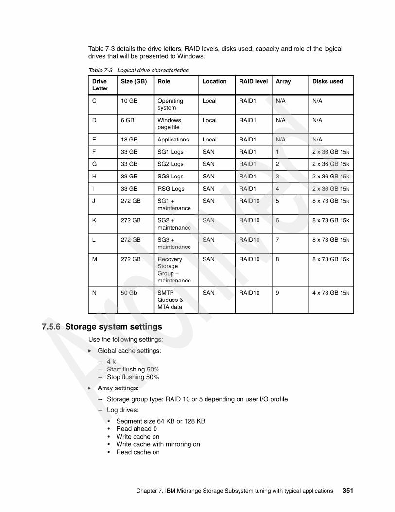
Table 7-3 details the drive letters, RAID levels, disks used, capacity and role of the logical drives that will be presented to Windows.
Table 7-3 Logical drive characteristics
7.5.6 Storage system settingsUse the following settings:
� Global cache settings:
– 4 k– Start flushing 50%– Stop flushing 50%
� Array settings:
– Storage group type: RAID 10 or 5 depending on user I/O profile
– Log drives:
• Segment size 64 KB or 128 KB• Read ahead 0• Write cache on• Write cache with mirroring on• Read cache on
Drive Letter
Size (GB) Role Location RAID level Array Disks used
C 10 GB Operating system
Local RAID1 N/A N/A
D 6 GB Windows page file
Local RAID1 N/A N/A
E 18 GB Applications Local RAID1 N/A N/A
F 33 GB SG1 Logs SAN RAID1 1 2 x 36 GB 15k
G 33 GB SG2 Logs SAN RAID1 2 2 x 36 GB 15k
H 33 GB SG3 Logs SAN RAID1 3 2 x 36 GB 15k
I 33 GB RSG Logs SAN RAID1 4 2 x 36 GB 15k
J 272 GB SG1 + maintenance
SAN RAID10 5 8 x 73 GB 15k
K 272 GB SG2 + maintenance
SAN RAID10 6 8 x 73 GB 15k
L 272 GB SG3 + maintenance
SAN RAID10 7 8 x 73 GB 15k
M 272 GB Recovery Storage Group + maintenance
SAN RAID10 8 8 x 73 GB 15k
N 50 Gb SMTP Queues & MTA data
SAN RAID10 9 4 x 73 GB 15k
Chapter 7. IBM Midrange Storage Subsystem tuning with typical applications 351
7.5.7 Aligning Exchange I/O with storage track boundariesIn this section we discuss various considerations regarding disk partitioning.
Basic precautionsWith a physical disk that maintains 64 sectors per track, Windows always creates the partition starting at the sixty-fourth sector, therefore misaligning it with the underlying physical disk. To be certain of disk alignment, use diskpart.exe, a disk partition tool. The diskpart.exe utility is contained within Windows Server 2003 and later, or with Windows 2000 Server and can explicitly set the starting offset in the master boot record (MBR).
By setting the starting offset, you can track alignment and improve disk performance. Exchange Server 2003 writes data in multiples of 4 KB I/O operations (4 KB for the databases and up to 32 KB for streaming files). Therefore, make sure that the starting offset is a multiple of 32KB. Failure to do so can cause a single I/O operation to span two tracks, causing performance degradation.
For more information, see the Web site:
http://www.microsoft.com/technet/prodtechnol/exchange/guides/StoragePerformance/0e24eb22-fbd5-4536-9cb4-2bd8e98806e7.mspx
The diskpart utility supersedes the functionality previously found in diskpar.exe. Both diskpar and diskpart must only be used if the drive is translated as 64 sectors per track.
Additional considerationsIt is important in planning an Exchange configuration to recognize that disks not only provide capacity but determine performance.
After extensive testing, it has been proven that the log drives perform best on a RAID 1 mirrored pair.
In line with Microsoft Exchange best practices, it has also been proven that RAID 10 for storage groups outperforms other RAID configurations. That said, depending on the user profile, RAID 5 will provide the required IOPS performance in certain instances.
Laying out the file system with diskpart provides additional performance improvements and also reduces the risk of performance degradation over time as the file system fills.
Dedicating HBAs for specific data transfer has a significant impact on performance. For example, HBA1 to controller A for log drives (sequential writes), and HBA 2 to controller B for storage groups (random read and writes). However, in a two HBA environment with the DS5100 and DS5300 this can restrict the back-end performance for the handling of the workload.
Disk latency can be relieved by adding additional HBAs to the server. Four HBAs with logs and storage groups assigned to pairs of HBAs can provide a significant improvement in limiting disk latency and also reduces performance problems in the event of a path failure.
Important: Using the diskpart utility to align storage track boundaries is data destructive. When used against a disk, all data on the disk will be wiped out during the storage track boundary alignment process. Therefore, if the disk on which you will run diskpart contains data, back up the disk before performing the operation.
Best practice: Set the offset to equal the segment size used for the logical drive, to ensure that the user data will start on a segment boundary.
352 IBM Midrange System Storage Implementation and Best Practices Guide
The Windows Performance Monitor can be used effectively to monitor an active Exchange server. Here are the counters of interest:
� Average disk sec/write� Average disk sec/read� Current disk queue length� Disk transfers/sec
The average for the average disk sec/write and average disk sec/read on all database and log drives must be less than 20 ms.
The maximum of the average disk sec/write and average disk sec/read on all database and log drives must be less than 40 ms.
7.5.8 Guidelines specific to Windows Exchange Server 2007
With Exchange Server 2007, we have found the following areas that you need to consider when creating your layout on the Midrange Storage Subsystems.
Storage layout across the storage subsystemThe Exchange Server is a disk-intensive application. Based on the tests we performed, here is a summary of best practices to improve the storage performance:
� Be sure to create arrays and logical drives (LUNs) by spreading them across as much of the storage subsystem’s resources as possible. Following the transaction based model outlined in 6.1, “Workload types” on page 300 will help to ensure that you are spreading the workload out evenly and keep all the resources busy as well as avoiding conjestion and conflicts.
� With the Exchange Server 2007, we have seen a variety of IO sizes and workload patterns that were both random and sequential in nature. Due to these various operational patterns, a 64 K NTFS allocation unit size is best suited.
� Keep the Exchange 2007 LUNs isolated from other disk intensive applications. Sharing arrays with other applications can have a negative impact on the performance of your Exchange server.
� Isolate Exchange 2007 database and log disk I/O on separate array groups. Separate the transaction log files (sequential I/O) from databases (random I/O) to maximize I/O performance and increase fault tolerance. From a recoverability perspective, separating a storage group's transaction logs and databases ensure that a catastrophic failure of a particular set of physical disks will not cause a loss of both database and transaction logs.
� The cache block size is a global parameter for the storage subsystem. Set the cache block size closest to the typical I/O size, which is 16 K size for large block and sequential I/O.
� Configure the entire capacity of a array group in a single LUN. Multiple LUNs on one volume group typically increases the seek time penalty.
� Use all available host and drive side channels if at all possible. Switch zoning and multi-pathing HBA drivers are all useful tools to ensure that all channels are kept active.
� Balance I/O across the dual controllers of the storage system and strive to keep both controllers and all back-end paths busy. Locate database LUNs and their corresponding log LUNs on separate back-end paths.
� Create volume groups across drive trays to distribute I/O across drive-side loops. See 6.5.6, “Arrays and logical drives” on page 317 for details.
� Choose faster disks. A 15K RPM drive yields ~15% more performance than a 10K RPM drive.
Chapter 7. IBM Midrange Storage Subsystem tuning with typical applications 353

� For the log LUNs, use RAID 10 volumes and enable write cache with mirroring.
� For the database LUNS, enable read caching and enable write caching with mirroring.
� See the following Microsoft documentation for storage based replication best practices and support criteria:
For Deployment Guidelines for Data Replication, see the following Web site:
http://www.microsoft.com/technet/prodtechnol/exchange/guides/E2k3DataRepl/bedf62a9-dff7-49a8-bd27-b2f1c46d5651.mspx
For information about the Multi-site data replication support for Exchange, see the following Web site:
http://support.microsoft.com/?kbid=895847
Other areas that can affect performanceThere are many other areas that can affect the performance of your Exchange Server. For further guidance, see the following Web sites:
http://go.microsoft.com/fwlink/?LinkId=23454http://technet.microsoft.com/en-us/library/bb124518.aspx
354 IBM Midrange System Storage Implementation and Best Practices Guide
Chapter 8. Storage Manager Performance Monitor
When implementing a storage solution, whether it is directly attached to a server, connected to the enterprise network (NAS), or on its own network (Fibre Channel SAN or iSCSI SAN), it is important to know just how well the storage server and its components perform. If this information is not available or collected, growth and capacity planning along with management becomes very difficult.
There are many utilities and products that can help measure and analyze performance. In this chapter, we use the Storage Manager (SM) Performance Monitor utility to view the performance of an IBM System Storage DS5000 Storage Server in real time and how to collect part of the data. We also look at two other products at the end of the chapter; first, one that uses data gathered by Performance Monitor, and second, one where DS5000 is compliant and allows data gathering and management functions using methods other than Storage Manager and Performance Monitor.
8
© Copyright IBM Corp. 2004-2010. All rights reserved. 355
8.1 Analyzing performanceTo determine where a performance problem exists, it is important to gather data from all the components of the storage solution. It is not uncommon to be misled by a single piece of information and lulled into a false sense of knowing the cause of a poor system performance, only to realize that another component of the system is truly the cause.
In this section, we look at the Storage Manager Performance Monitor and how it can be used to analyze and monitor the environment.
Storage applications can be categorized according to two types of workloads: transaction based or throughput based.
� Transaction performance is generally perceived to be poor when the following conditions occur:
– Random reads/writes are exceeding 20 ms, without write cache.– Random writes are exceeding 2 ms, with cache enabled.– I/Os are queuing up in the operating system I/O stack (due to bottleneck).
� Throughput performance is generally perceived to be poor when the disk capability is not being reached. Causes of this condition can occur from the following situations:
– With reads, read-ahead is being limited, preventing higher amounts of immediate data availability.
– I/Os are queuing up in the operating system I/O stack (due to bottleneck).
We consider the following topics:
� Gathering host server data� Gathering fabric network data� Gathering DS5000 Storage Server data
8.1.1 Gathering host server dataWhen gathering data from the host systems to analyze performance, it is important to gather the data from all attached hosts, even though a few might not see any slow performance. Indeed, a normally unrelated host might be impacting others with its processing.
Gather all the statistics possible from the operating system tools and utilities. Data from these will help when comparing it with what is seen by SM Performance Monitor and other measurement products. Utilities vary from operating system to operating system, so check with administrators or the operating system vendors.
Many UNIX type systems offer utilities that report disk I/O statistics and system statistics, such as iostat, sar, vmstat, filemon, nmon, and iozone, to mention a few. All are very helpful with determining where the poor performance originates. With each of these commands, gather a sample period of statistics that need to be collected. Gathering one minute to 15 minutes worth of samples during the slow period can give a fair sampling of data to review.
356 IBM Midrange System Storage Implementation and Best Practices Guide

In the example shown in Figure 8-1, we see the following information:
� Interval time = (894 + 4 KB)/15 KBps = 60 sec (hdisk1)� Average I/O size = 227.8 KBps/26.9 tps = 8.5 KB (hdisk4)� Estimated average I/O service time = 0.054/26.9 tps = 2 ms (hdisk4)� tps < 75 No I/O bottleneck!� Disk service times good: No I/O bottleneck� Disks not well balanced: hdisk0, hdisk1, hdisk5?
Figure 8-1 Example AIX iostat report
The information shown here does not necessarily indicate a problem. Hdisk5 might be a new drive that is not yet being used. All other indications appear to be within expected levels.
Windows operating systems offer device manager tools that can have performance gathering capabilities in them. Also, many third-party products are available and frequently provide greater detail and graphical presentations of the data gathered.
8.1.2 Gathering fabric network dataTo ensure that the host path is clean and operating as desired, gather any statistical information available from the switches or fabric analyzers for review of the switch configuration settings, and any logs or error data that might be gathered, which can be critical in determining problems that might cross multiple switch fabrics or other extended network environments. Again, as with gathering host data, fabric network data will help when comparing it with what is seen by SM Performance Monitor.
IBM and Brocade switches offer a supportshow tool that enables you to run a single command and gather all support data at one time. Cisco switches offer this with their show tech command.
Additionally, gather the host bus adapter parameter settings to review and ensure that they are configured for the best performance for the environment. Many of these adapters have BIOS type utilities that will provide this information. Certain operating systems (such as AIX) can also provide much of this information through system attribute and configuration setting commands. As shown in Example 8-1, the AIX HBA and associated SCSI controller is displayed with the tunable parameters.
tty: tin tout avg-cpu: % user % sys % idle % iowait 24.7 71.3 8.3 2.4 85.6 3.6
Disks: % tm_act Kbps tps Kb_read Kb_wrtnhdisk0 2.2 19.4 2.6 268 894hdisk1 1.0 15.0 1.7 4 894hdisk2 5.0 231.8 28.1 1944 11964hdisk4 5.4 227.8 26.9 2144 11524hdisk3 4.0 215.9 24.8 2040 10916hdisk5 0.0 0.0 0.0 0 0
Chapter 8. Storage Manager Performance Monitor 357

Example 8-1 AIX HBA tunable parameters marked with “TRUE” in right hand column.
root@itsop630:/root# lsattr -El fscsi0attach switch How this adapter is CONNECTED Falsedyntrk no Dynamic Tracking of FC Devices Truefc_err_recov delayed_fail FC Fabric Event Error RECOVERY Policy Truescsi_id 0x70800 Adapter SCSI ID Falsesw_fc_class 3 FC Class for Fabric Trueroot@itsop630:/root# lsattr -El fcs0bus_intr_lvl 105 Bus interrupt level Falsebus_io_addr 0x2ec00 Bus I/O address Falsebus_mem_addr 0xec020000 Bus memory address Falseinit_link al INIT Link flags Trueintr_priority 3 Interrupt priority Falselg_term_dma 0x800000 Long term DMA Truemax_xfer_size 0x100000 Maximum Transfer Size Truenum_cmd_elems 200 Maximum number of COMMANDS to queue to the adapter Truepref_alpa 0x1 Preferred AL_PA Truesw_fc_class 2 FC Class for Fabric Trueroot@itsop630:/root
8.1.3 Gathering DS5000 Storage Server dataWhen gathering data from the DS5000 Storage Server for analysis, there are two major functions that can be used to document how the system is configured and how it performs. These two functions are:
� Performance Monitor:
Using the performance Monitor, the DS5000 Storage Server can provide a point in time presentation of its performance at a specified time interval for a specified number of occurrences, which is useful to compare with the host data collected at the same time and can be very helpful in determining hot spots or other tuning issues to be addressed.
We provide details about the Performance Monitor in 8.2, “Storage Manager Performance Monitor” on page 359.
� Collect All Support Data:
This function can be run from the IBM TotalStorage DS5000 Storage Manager Subsystem Management window by selecting Advanced TroubleShooting Collect All Support Data (see Figure 8-2).
Figure 8-2 Collecting support data
358 IBM Midrange System Storage Implementation and Best Practices Guide
This selection creates a .zip file of all the internal information of the DS5000 Storage Server for review by the support organization, which includes the storage Subsystems Profile, majorEventLog, driveDiagnosticData, NVSRAM data, readLinkStatus, performanceStatistics, and many others. This information, when combined and compared to the Performance Monitor data, can give a good picture of how the DS5000 Storage Server sees its workload being handled, and any areas it sees that are having trouble.
The performanceStatistics file provides a far greater amount of coverage of data gathering, and a further breakdown of the I/O details of what the storage server workload has been. In this spreadsheet based log, the read and write ratio can be seen for all the logical drives, controllers, and the storage server’s workload. Also, the cache hits and misses for each type (read and write) can be viewed.
8.2 Storage Manager Performance MonitorThe Storage Performance Monitor is a tool built into the DS5000 Storage Manager client. It monitors performance on each logical drive, and collects the following information:
� Total I/Os� Read percentage� Cache hit percentage� Current KBps and maximum KBps� Current I/O per sec and maximum I/O per sec
In the remainder of this chapter we describe in detail how to use data from the Performance Monitor, as well as monitoring the effect of a tuning option parameter in the DS5000 Storage Server that affects the storage server performance.
8.2.1 Starting the Performance MonitorTo launch the Performance Monitor from the SMclient Subsystem Management window, do these steps:
� Select the Monitor Performance icon.
� Select Storage Subsystem Monitor Performance.
� Select the storage subsystem node in the Logical View or Mappings View, right-click, and select Monitor Performance.
Chapter 8. Storage Manager Performance Monitor 359

The Performance Monitor window opens with all logical drives displayed, as shown in Figure 8-3.
Figure 8-3 Performance Monitor
Table 8-1 describes the information collected by the Performance Monitor.
Table 8-1 Information collected by Performance Monitor
Data field Description
Total I/Os Total I/Os performed by this device since the beginning of the polling session.
Read percentage
The percentage of total I/Os that are read operations for this device. Write percentage can be calculated as 100 minus this value.
Cache hit percentage
The percentage of reads that are processed with data from the cache rather than requiring a read from disk.
Current KBps Average transfer rate during the polling session. The transfer rate is the amount of data in kilobytes that can be moved through the I/O data connection in a second (also called throughput).
Maximum KBps
The maximum transfer rate that was achieved during the Performance Monitor polling session.
Current I/O per second
The average number of I/O requests serviced per second during the current polling interval (also called an I/O request rate).
Maximum I/O per second
The maximum number of I/O requests serviced during a one-second interval over the entire polling session.
360 IBM Midrange System Storage Implementation and Best Practices Guide
Here we describe the following fields:
� Total I/Os:
This data is useful for monitoring the I/O activity of a specific controller and a specific logical drive, which can help identify possible high-traffic I/O areas.
If I/O rate is slow on a logical drive, try increasing the array size.
There might be a disparity in the Total I/Os (workload) of controllers, for example, the workload of one controller is heavy or is increasing over time, whereas that of the other controller is lighter or more stable. In this case, consider changing the controller ownership of one or more logical drives to the controller with the lighter workload. Use the logical drive Total I/O statistics to determine which logical drives to move.
If the workload across the storage subsystem (Storage Subsystem Totals Total I/O statistic) continues to increase over time, while application performance decreases, this might indicate that you need to add additional storage subsystems to the installation so that the application needs can be met at an acceptable performance level.
� Read percentage:
Use the read percentage for a logical drive to determine actual application behavior. If there is a low percentage of read activity relative to write activity, consider reviewing the characteristics of the host and application using the logical drive with a view of changing tuning parameters for improved performance.
� Cache hit percentage:
The percentage of reads that are fulfilled by data from the cache rather than requiring an actual read from disk. A higher percentage is desirable for optimal application performance. There is a positive correlation between the cache hit percentage and I/O rates.
The cache hit percentage of all of the logical drives might be low or trending downward. This value might indicate inherent randomness in access patterns, or, at the storage subsystem or controller level, it can indicate the need to install more controller cache memory if the maximum amount of memory is not yet installed.
If an individual logical drive is experiencing a low cache hit percentage, consider enabling cache read-ahead for that logical drive. Cache read ahead can increase the cache hit percentage for a sequential I/O workload.
To determine if your I/O has sequential characteristics, try enabling a conservative cache read-ahead multiplier (four, for example). Then, examine the logical drive cache hit percentage to see if it has improved. If it has, indicating that your I/O has a sequential pattern, and enable a more aggressive cache read-ahead multiplier (eight, for example). Continue to customize logical drive cache read-ahead to arrive at the optimal multiplier (in the case of a random I/O pattern, the optimal multiplier is zero).
� Current KB/sec and maximum KB/sec:
The Current KB/sec value is the average size of the amount of data that was transferred over one second during a particular interval period (or since the “update” was selected) that was monitored. The Maximum KB/sec value is the highest amount that was transferred over any one second period during all of the interval periods in the number of iterations that we ran for a specific command. This value can show when a peak transfer rate period was detected during the command run time.
Tip: If Maximum KB/sec is the same as the last interval’s Current KB/sec, extend the number of iterations to see when the peak rate is actually reached. Because it might be on the rise, the aim is to determine the maximum rate.
Chapter 8. Storage Manager Performance Monitor 361
The transfer rates of the controller are determined by the application I/O size and the I/O rate. Generally, small application I/O requests result in a lower transfer rate, but provide a faster I/O rate and shorter response time. With larger application I/O requests, higher throughput rates are possible. Understanding the typical application I/O patterns can help determine the maximum I/O transfer rates for a given storage subsystem.
Consider a storage subsystem equipped with Fibre Channel controllers that supports a maximum transfer rate of 100 MBps (100,000 KBps). The storage subsystem typically achieves an average transfer rate of 20,000 Kbps. (The typical I/O size for applications is, for example, 4 KB, with 5,000 I/Os transferred per second for an average rate of 20,000 Kbps.) In this case, I/O size is small. Because there is an impact associated with each I/O, the transfer rates will not approach 100,000 Kbps. However, if the typical I/O size is large, a transfer rate within a range of 80,000 to 90,000 Kbps can be achieved.
� Current I/O per second and maximum I/O per second
The Current IO/sec value is the average number of I/Os serviced in one second during a particular interval period that was monitored. The Maximum IO/sec value is the highest number of I/Os serviced in any one second period, during all of the interval periods in the number of iterations that were ran for a specific command. This value can show when the peak I/O period was detected during the command run time.
Factors that affect I/Os per second include access pattern (random or sequential), I/O size, RAID level, segment size, and number of drives in the arrays or storage subsystem. The higher the cache hit rate, the higher the I/O rates.
Performance improvements caused by changing the segment size can be seen in the I/Os per second statistics for a logical drive. Experiment to determine the optimal segment size, or use the file system or database block size.
Higher write I/O rates are experienced with write caching enabled compared to disabled. In deciding whether to enable write caching for an individual logical drive, consider the current and maximum I/Os per second. You can expect to see higher rates for sequential I/O patterns than for random I/O patterns. Regardless of the I/O pattern, write caching must be enabled to maximize I/O rate and shorten application response time.
8.2.2 Using the Performance MonitorThe Performance Monitor queries the storage subsystem at regular intervals. To change the polling interval and to select only the logical drives and the controllers required to be monitored, click the Settings button.
To change the polling interval, choose a number of seconds in the spin box as shown in Figure 8-4. Each time the polling interval elapses, the Performance Monitor re-queries the storage subsystem and updates the statistics in the table. If monitoring the storage subsystem is in real time, update the statistics frequently by selecting a short polling interval, for example, five seconds. If results are being saved to a file for later review, choose a slightly longer interval, for example, 30 to 60 seconds, to decrease the performance impact.
Tip: If Maximum I/Ops is the same as the last interval’s Current I/Ops, extend the number of iterations to see when the peak is actually reached, as this might be on the rise, the aim is to determine the maximum rate.
362 IBM Midrange System Storage Implementation and Best Practices Guide

Figure 8-4 Performance Monitor Settings
The Performance Monitor will not dynamically update its display if any configuration changes occur while the monitor window is open (for example, creation of new logical drives, change in logical drive ownership, and so on). The Performance Monitor window must be closed and then reopened for the changes to appear.
If the storage subsystem monitored begins or transitions to an unresponsive state, a window opens stating that the Performance Monitor cannot poll the storage subsystem for performance data.
The Performance Monitor is a real time tool; it is not possible to collect performance data over time with the Storage Manager GUI. However, a simple script can be used to collect performance data over a period of time for later analysis.
The script can be run from the command line using SMcli or from the Storage Manager Script Editor GUI. From the Storage Manager Enterprise management window, select Tools Execute Script. Data collected while executing the script is saved in the file and directory specified in the storage Subsystem file parameter.
Note: Using the Performance Monitor to retrieve performance data can affect the normal storage subsystem performance, depending on how many items you want to monitor and the refresh interval.
Chapter 8. Storage Manager Performance Monitor 363

Using the script editor GUIA sample of the script editor GUI is shown in Figure 8-5.
Figure 8-5 Script to collect Performance Monitor data over time
A sample of the output file is shown in Example 8-2.
Example 8-2 Script output file
"Performance Monitor Statistics for Storage Subsystem: ITSO_5020 - Date/Time: 21/09/09 10:39:56 - Polling interval in seconds: 5"
"Storage Subsystems ","Total IOs ","Read Percentage ","Cache Hit Percentage ","Current KB/second ","Maximum KB/second ","Current IO/second ","Maximum IO/second""Date/Time: 21/09/09 10:45:06","","","","","","","""CONTROLLER IN SLOT A","12560.0","16.6","12.9","5453.6","26440.6","213.2","354.2""Logical Drive AIX_Boot","4537.0","45.8","12.0","3506.4","7444.6","197.4","197.4""Logical Drive Blade03-boot","0.0","0.0","0.0","0.0","0.0","0.0","0.0""Logical Drive Secure3","0.0","0.0","0.0","0.0","0.0","0.0","0.0""Logical Drive Secure4","0.0","0.0","0.0","0.0","0.0","0.0","0.0""Logical Drive Secure5","0.0","0.0","0.0","0.0","0.0","0.0","0.0""Logical Drive Secure6","0.0","0.0","0.0","0.0","0.0","0.0","0.0""Logical Drive Secured1","8022.0","0.1","100.0","1947.2","18996.0","15.8","296.8""Logical Drive Secured1-1","0.0","0.0","0.0","0.0","0.0","0.0","0.0""Logical Drive Secured1-R1","0.0","0.0","0.0","0.0","0.0","0.0","0.0""Logical Drive TC-2008-1","0.0","0.0","0.0","0.0","0.0","0.0","0.0""Logical Drive WIN-1","0.0","0.0","0.0","0.0","0.0","0.0","0.0""Logical Drive test3","1.0","100.0","0.0","0.0","0.8","0.0","0.2""Logical Drive x3655_Win2k8_F_iscsi","0.0","0.0","0.0","0.0","0.0","0.0","0.0""CONTROLLER IN SLOT B","0.0","0.0","0.0","0.0","0.0","0.0","0.0""Logical Drive Blade03-Data1","0.0","0.0","0.0","0.0","0.0","0.0","0.0""Logical Drive SVC_1","0.0","0.0","0.0","0.0","0.0","0.0","0.0""Logical Drive Secure2","0.0","0.0","0.0","0.0","0.0","0.0","0.0""Logical Drive TC-2008-2","0.0","0.0","0.0","0.0","0.0","0.0","0.0""STORAGE SUBSYSTEM TOTALS","12560.0","16.6","12.9","5453.6","26440.6","213.2","354.2""Capture Iteration: 59","","","","","","",""
364 IBM Midrange System Storage Implementation and Best Practices Guide

Using the command line interface (CLI)The SMcli can also be used to gather Performance Monitor data over a period of time. It requires scripting skills in order to set up. Example 8-3 shows a test_script file for execution under AIX, using the ksh test_script:
# cat SMcli_1_scr
Example 8-3 Test script
#!/bin/ksh#The information is captured from a single Linux/AIX server by running the# following “Storage Manager Command Line Interface Utility” Linux/AIX commandCMD='set session performanceMonitorInterval=60 performanceMonitorIterations=2; \ show allLogicalDrives performanceStats;'/usr/SMclient/SMcli -e -S 9.1.39.26 9.1.39.27 -p xxxxxx -c "$CMD"#(Note; this will run every minute for 2 times; if run every 10 minutes for 10 # times set the# "performanceMonitorinterval=600"# "performanceMonitorIterations=10"
The first executable line sets the CMD variable; the second executable line invokes the SMcli command. Note that for the -S parameter, it is necessary to specify the IP address of both DS5000 controllers (A and B).
The output resulting from the script execution can be redirected to a file by typing the following command:
./SMcli_1_scr > script1.o 2>&1
This test script collects information for all logical drives, but it is possible to select specific logical drives. Example 8-4 shows how to select only two drives, p630_Test_42_512KB p630_Test_43_128KB.
Example 8-4 Test script for two logical drives for a UNIX platform
#!/bin/ksh#The information is captured from a single Linux/AIX server by running the# following "Storage Manager Command Line Interface Utility" Linux/AIX commandCMD='set session performanceMonitorInterval=20 performanceMonitorIterations=9;show LogicalDrives [p630_Test_42_512KB p630_Test_43_128KB ] performanceStats;'/usr/SMclient/SMcli -e -S 9.11.218.182 9.11.218.183 -c "$CMD"
Chapter 8. Storage Manager Performance Monitor 365

For Windows platform users who want to run a similar script from a Windows server or their own PCs, the script shown in Example 8-5 performs the same function.
Example 8-5 Similar test script for four logical drives on WIN platform
rem Run Performance Managerrem replacement for CLI2 for all logical drivesrem CLI2=show AllLogicalDrives performanceStats;"
set CMD="C:\Program Files\IBM_DS\client\SMcli.exe"set IP=9.11.218.182 9.11.218.183set CLI1="set session performanceMonitorInterval=60 performanceMonitorIterations=20;set CLI2=show LogicalDrives [p630_Test_42_512KB p630_Test_43_128KB p630_Test_40_64KB p630_Test_43_128KB] performanceStats;"set OUT="C:\temp\WIN_SCR.txt"
rem cd %CD%%CMD% -e -S %IP% -p xxxxxxx -c %CLI1% %CLI2% -o %OUT%
We created a file called script2.o:
./SMcli_2_scr > script2.o 2>&1
The output file (called script2.o) of this script is shown in Example 8-6.
Example 8-6 Output file: script2.o
"Performance Monitor Statistics for Storage Subsystem: DS5000 - Date/Time: 8/26/08 3:53:54 PM - Polling interval in seconds: 20"
"Storage Subsystems ","Total IOs ","Read Percentage ","Cache Hit Percentage ","Current KB/second ","Maximum KB/second ","Current IO/second ","Maximum IO/second""Capture Iteration: 1","","","","","","","""Date/Time: 8/26/08 3:53:55 PM","","","","","","","""CONTROLLER IN SLOT B","4975.0","100.0","100.0","60341.2","60341.2","236.9","236.9""Logical Drive p630_Test_43_128KB","4975.0","100.0","100.0","60341.2","60341.2","236.9","236.9""CONTROLLER IN SLOT A","9839.0","3.0","100.0","58101.5","58101.5","468.5","468.5""Logical Drive p630_Test_42_512KB","9839.0","3.0","100.0","58101.5","58101.5","468.5","468.5""STORAGE SUBSYSTEM TOTALS","14814.0","35.6","100.0","118442.8","118442.8","705.4","705.4""Capture Iteration: 2","","","","","","","""Date/Time: 8/26/08 3:54:16 PM","","","","","","","""CONTROLLER IN SLOT B","4975.0","100.0","100.0","0.0","60341.2","0.0","236.9""Logical Drive p630_Test_43_128KB","4975.0","100.0","100.0","0.0","60341.2","0.0","236.9""CONTROLLER IN SLOT A","9839.0","3.0","100.0","0.0","58101.5","0.0","468.5""Logical Drive p630_Test_42_512KB","9839.0","3.0","100.0","0.0","58101.5","0.0","468.5""STORAGE SUBSYSTEM TOTALS","14814.0","35.6","100.0","0.0","118442.8","0.0","705.4"
366 IBM Midrange System Storage Implementation and Best Practices Guide

All the data saved in the file is comma delimited so that the file can be easily imported into a spreadsheet for easier analysis and review (Figure 8-6).
Figure 8-6 Importing results into a spreadsheet
8.2.3 Using the Performance Monitor: An illustrationTo illustrate the use of the Performance Monitor, we compare the difference in throughput of four logical devices that have been created on the same array; each LUN is the same size but with varying segment sizes. These logical devices have been mapped to an AIX platform running AIX V6.1. Two identical host bus adapters were attached to the IBM POWER AIX machine and a single SAN fabric switch was used. Example 8-7 shows the configuration where the AIX hdisks are distributed across both HBAs and DS5000 controllers.
Example 8-7 LUN attachment to AIX
# mpio_get_config -AvFrame id 0: Storage Subsystem worldwide name: 608e50017b5bc00004a955e3b Controller count: 2 Partition count: 1 Partition 0: Storage Subsystem Name = 'ITSO_5020' hdisk LUN # Ownership User Label hdisk2 4 A (preferred) test3 hdisk4 2 A (preferred) Secured1 hdisk5 3 A (preferred) AIX_Boot hdisk6 40 B (preferred) p630_Test_40_64KB hdisk7 41 A (preferred) p630_Test_41_8KB hdisk8 42 B (preferred) p630_Test_42_512KB hdisk9 43 A (preferred) p630_Test_43_128KB
Chapter 8. Storage Manager Performance Monitor 367
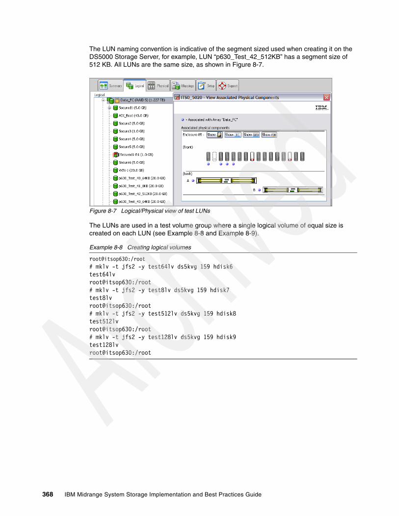
The LUN naming convention is indicative of the segment sized used when creating it on the DS5000 Storage Server, for example, LUN “p630_Test_42_512KB” has a segment size of 512 KB. All LUNs are the same size, as shown in Figure 8-7.
Figure 8-7 Logical/Physical view of test LUNs
The LUNs are used in a test volume group where a single logical volume of equal size is created on each LUN (see Example 8-8 and Example 8-9).
Example 8-8 Creating logical volumes
root@itsop630:/root# mklv -t jfs2 -y test64lv ds5kvg 159 hdisk6test64lvroot@itsop630:/root# mklv -t jfs2 -y test8lv ds5kvg 159 hdisk7test8lvroot@itsop630:/root# mklv -t jfs2 -y test512lv ds5kvg 159 hdisk8test512lvroot@itsop630:/root# mklv -t jfs2 -y test128lv ds5kvg 159 hdisk9test128lvroot@itsop630:/root
368 IBM Midrange System Storage Implementation and Best Practices Guide
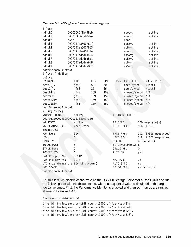
Example 8-9 AIX logical volumes and volume group
# lspvhdisk0 00000000f1b495eb rootvg activehdisk1 000000006d598dee rootvg activehdisk2 none Nonehdisk3 0007041aa50076cf ds5kvg activehdisk4 0007041aa5007563 ds5kvg activehdisk5 0007041ab945d714 rootvg activehdisk6 0007041adddca404 ds5kvg activehdisk7 0007041adddca5a1 ds5kvg activehdisk8 0007041adddca6d8 ds5kvg activehdisk9 0007041adddca80f ds5kvg activeroot@itsop630:/root# lsvg -l ds5kvgds5kvg:LV NAME TYPE LPs PPs PVs LV STATE MOUNT POINTtest1_lv jfs2 50 50 1 open/syncd /test1test2_lv jfs2 26 26 1 open/syncd /test2test64lv jfs2 159 159 1 closed/syncd N/Atest8lv jfs2 159 159 1 closed/syncd N/Atest512lv jfs2 159 159 1 closed/syncd N/Atest128lv jfs2 159 159 1 closed/syncd N/Aroot@itsop630:/root# lsvg ds5kvgVOLUME GROUP: ds5kvg VG IDENTIFIER: 0007041a00004c0000000123a500779eVG STATE: active PP SIZE: 128 megabyte(s)VG PERMISSION: read/write TOTAL PPs: 914 (116992 megabytes)MAX LVs: 256 FREE PPs: 202 (25856 megabytes)LVs: 6 USED PPs: 712 (91136 megabytes)OPEN LVs: 2 QUORUM: 4 (Enabled)TOTAL PVs: 6 VG DESCRIPTORS: 6STALE PVs: 0 STALE PPs: 0ACTIVE PVs: 6 AUTO ON: yesMAX PPs per VG: 32512MAX PPs per PV: 1016 MAX PVs: 32LTG size (Dynamic): 256 kilobyte(s) AUTO SYNC: noHOT SPARE: no BB POLICY: relocatableroot@itsop630:/root
For this test, we disable cache write on the DS5000 Storage Server for all the LUNs and run the following test with the dd command, where a sequential write is simulated to the target logical volumes. First, the Performance Monitor is enabled and then commands are run, as shown in Example 8-10.
Example 8-10 dd command
time dd if=/dev/zero bs=128k count=12000 of=/dev/test8lvtime dd if=/dev/zero bs=128k count=12000 of=/dev/test64lvtime dd if=/dev/zero bs=128k count=12000 of=/dev/test128lvtime dd if=/dev/zero bs=128k count=12000 of=/dev/test512lv
Chapter 8. Storage Manager Performance Monitor 369

The Performance Monitor that ran for the duration of the commands is shown in Figure 8-8.
The test was then repeated with cache write turned on by the DS5000 Storage Server for each of the LUNs, and the Performance Monitor was stopped and restarted between tests. Figure 8-9 shows the results of this test.
Figure 8-8 Observe with Performance Monitor (Cache Write Off)
Figure 8-9 Observe with Performance Monitor (Cache Write On)
Both Figure 8-8 and Figure 8-9 show the results after the identical tests were run. Looking at the “Maximum IO/Second” and “Maximum KB/Second” columns for each figure, we see quite a difference after making a single (albeit major) performance tuning parameter change on each LUN. The maximum IO/second and KB/second columns indicate that, with write cache disabled, the transfer is much slower than when it is enabled.
370 IBM Midrange System Storage Implementation and Best Practices Guide
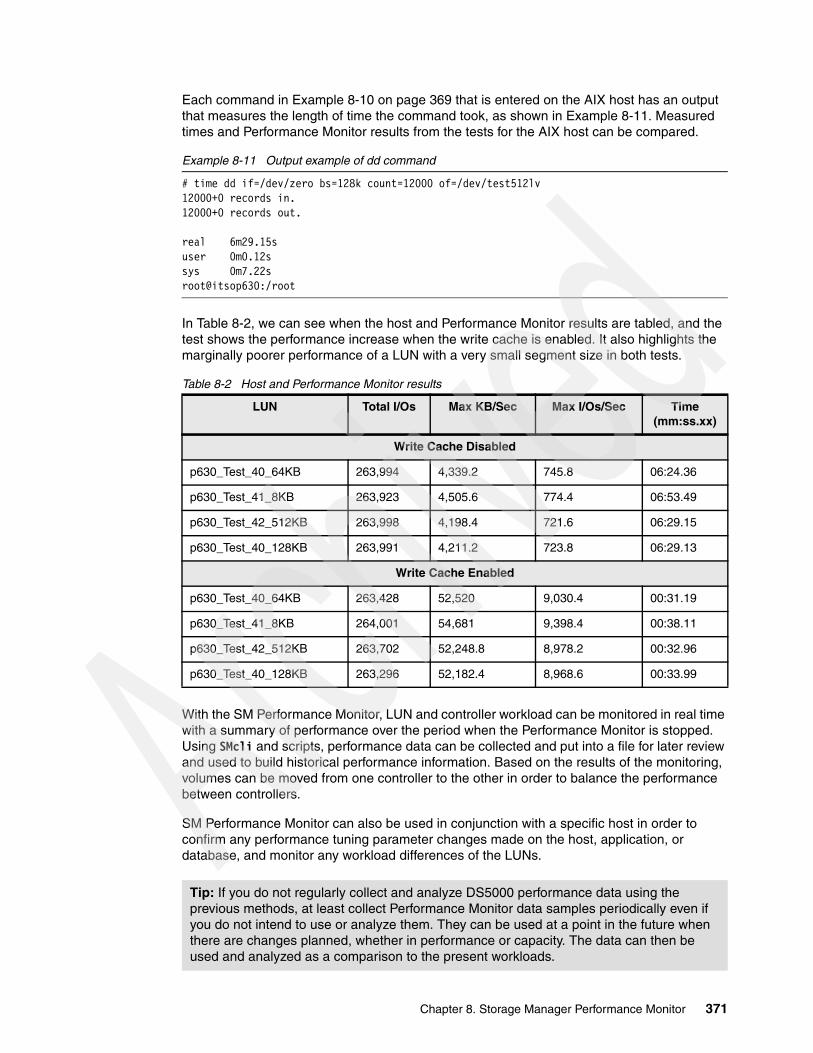
Each command in Example 8-10 on page 369 that is entered on the AIX host has an output that measures the length of time the command took, as shown in Example 8-11. Measured times and Performance Monitor results from the tests for the AIX host can be compared.
Example 8-11 Output example of dd command
# time dd if=/dev/zero bs=128k count=12000 of=/dev/test512lv12000+0 records in.12000+0 records out.
real 6m29.15suser 0m0.12ssys 0m7.22sroot@itsop630:/root
In Table 8-2, we can see when the host and Performance Monitor results are tabled, and the test shows the performance increase when the write cache is enabled. It also highlights the marginally poorer performance of a LUN with a very small segment size in both tests.
Table 8-2 Host and Performance Monitor results
With the SM Performance Monitor, LUN and controller workload can be monitored in real time with a summary of performance over the period when the Performance Monitor is stopped. Using SMcli and scripts, performance data can be collected and put into a file for later review and used to build historical performance information. Based on the results of the monitoring, volumes can be moved from one controller to the other in order to balance the performance between controllers.
SM Performance Monitor can also be used in conjunction with a specific host in order to confirm any performance tuning parameter changes made on the host, application, or database, and monitor any workload differences of the LUNs.
LUN Total I/Os Max KB/Sec Max I/Os/Sec Time (mm:ss.xx)
Write Cache Disabled
p630_Test_40_64KB 263,994 4,339.2 745.8 06:24.36
p630_Test_41_8KB 263,923 4,505.6 774.4 06:53.49
p630_Test_42_512KB 263,998 4,198.4 721.6 06:29.15
p630_Test_40_128KB 263,991 4,211.2 723.8 06:29.13
Write Cache Enabled
p630_Test_40_64KB 263,428 52,520 9,030.4 00:31.19
p630_Test_41_8KB 264,001 54,681 9,398.4 00:38.11
p630_Test_42_512KB 263,702 52,248.8 8,978.2 00:32.96
p630_Test_40_128KB 263,296 52,182.4 8,968.6 00:33.99
Tip: If you do not regularly collect and analyze DS5000 performance data using the previous methods, at least collect Performance Monitor data samples periodically even if you do not intend to use or analyze them. They can be used at a point in the future when there are changes planned, whether in performance or capacity. The data can then be used and analyzed as a comparison to the present workloads.
Chapter 8. Storage Manager Performance Monitor 371

8.3 Use of Performance Monitor Data
The data from Performance Monitor can be used in other performance related tools; it can be imported into these tools to be analyzed. Data generated from Performance Monitor output file (as described in 8.2.2, “Using the Performance Monitor” on page 362 and “Using the command line interface (CLI)” on page 365) can be used by tools so that their meaning can be interpreted easier and analyzed more efficiently.
8.3.1 Disk Magic
Disk Magic uses the Performance Monitor “raw data” file by first creating a comma separated variable (CSV) file and then importing selected data into the tool along with the DS5000 profile. We explain how to do this in Chapter 10, “Disk Magic” on page 435, where data from logical volume and storage controller summaries are manually copied from the CSV file into the Disk Magic tool base line model. Data such as caching statistics including cache hit figures are particularly useful when using Disk Magic.
8.3.2 Tivoli Storage Productivity Centre (TPC) for Disk
TPC for Disk has the ability to collect information from the DS5000 independently of the DS5000 Performance Monitor and is an example of an external tool which, among other functions, can monitor DS5000 performance. TPC is able to store and report both actual and historical data to the same detail as the Performance Manager. The method that TPC employs varies from that used by Disk Magic in that it can collect the data as the DS5000 reports it continuously after the DS5000 is defined to TPC and connected. TPC can also provide logical volume creation and management as well as performance data gathering and reporting.
TPC for Disk uses a number of industry standards supported on an increasing range of equipment that can be managed, thus replacing proprietary software with a common standard. The DS5000 is compliant with the Common Interface Module (CIM) communicating with a CIM Object Module (CIMOM) which will interface with TPC. The CIMOM will have a specific plug-in device handler that manages instructions to and from the DS5000.
The CIM standard for storage management has been integrated into the Storage Network Industry Association (SNIA) in their Storage Management Initiative Specification (SMI-S) allowing a universal open interface for managing storage devices. TPC uses these standards to manage and report on the DS5000 performance and thus becomes a very versatile tool in providing both performance data and historical performance data on the DS5000.
For further details about TPC for disk, see Chapter 9, “IBM Tivoli Storage Productivity Center for Disk” on page 373 and IBM TotalStorage Productivity Center V3.1: The Next Generation, SG24-7194.
372 IBM Midrange System Storage Implementation and Best Practices Guide
Chapter 9. IBM Tivoli Storage Productivity Center for Disk
In this chapter we discuss how to use IBM Tivoli Storage Productivity Center for Disk (TPC for Disk) to manage and monitor performance on the DS4000/DS5000 Storage Servers.
The first part of this chapter is a brief overview of the overall TPC offering that includes components such as TPC for Fabric, TPC for Data, TPC for Disk, and TPC for Replication.
The second part of the chapter focuses on TPC for Disk and the steps required to manage and monitor the DS4000/DS5000 from a TPC server. It also includes examples of performance reports that TPC for Disk can generate.
For more detailed information about TPC, see IBM TotalStorage Productivity Center V3.1: The Next Generation, SG24-7194 and TotalStorage Productivity Center V3.3 Update Guide, SG24-7490.
9
© Copyright IBM Corp. 2004-2010. All rights reserved. 373
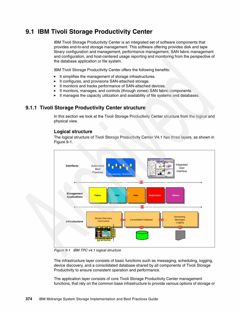
9.1 IBM Tivoli Storage Productivity Center
IBM Tivoli Storage Productivity Center is an integrated set of software components that provides end-to-end storage management. This software offering provides disk and tape library configuration and management, performance management, SAN fabric management and configuration, and host-centered usage reporting and monitoring from the perspective of the database application or file system.
IBM Tivoli Storage Productivity Center offers the following benefits:
� It simplifies the management of storage infrastructures.� It configures, and provisions SAN-attached storage.� It monitors and tracks performance of SAN-attached devices.� It monitors, manages, and controls (through zones) SAN fabric components.� It manages the capacity utilization and availability of file systems and databases.
9.1.1 Tivoli Storage Productivity Center structure
In this section we look at the Tivoli Storage Productivity Center structure from the logical and physical view.
Logical structureThe logical structure of Tivoli Storage Productivity Center V4.1 has three layers, as shown in Figure 9-1.
Figure 9-1 IBM TPC v4.1 logical structure
The infrastructure layer consists of basic functions such as messaging, scheduling, logging, device discovery, and a consolidated database shared by all components of Tivoli Storage Productivity to ensure consistent operation and performance.
The application layer consists of core Tivoli Storage Productivity Center management functions, that rely on the common base infrastructure to provide various options of storage or
Device DiscoveryAnd Control
Device DiscoveryAnd Control Consolidated Datab aseConsolidated Database
Scheduling, Messages Logging
Scheduling, Messages Logging
DataOthers
FabricFabric
DiskDisk
ReplicationData PerformanceReplication …
Provisioning / Workflow
Discover API
ProcessProcessProcess
Job Engine
Queue Queue Queue Queue
CIMScanner CIMParse r
CIMObjectParser CIMXMLParse r
CIMProcesso r
SLPScanner SLPParser
Profile
Lege ndInfrastru ctureDomain specificPlug - ins
ClassMapper
ClassMapper
ClassMapper
ClassMapper
DB Driver
CIMClientLibrary
ESSNILibrary
SNMPLibrary
ControlInterface
DiscoveryInterface
MonitorInterface
ControlTranslator
MonitorCopy
Services(eCS )
AgentLibrary
…
Discover API
ProcessProcessProcess
Job Engine
Queue Queue Queue Queue
CIMScanner CIMParse r
CIMObjectParser CIMXMLParse r
CIMProcesso r
SLPScanner SLPParser
Profile
Lege ndInfrastru ctureDomain specificPlug - ins
ClassMapper
ClassMapper
ClassMapper
ClassMapper
DB Driver
ClassMapper
ClassMapper
ClassMapper
ClassMapper
DB Driver
CIMClientLibrary
ESSNILibrary
SNMPLibrary
ControlInterface
DiscoveryInterface
MonitorInterface
ControlTranslator
MonitorCopy
Services(eCS )
AgentLibrary
…
Infrastructure
ManagementApplications
Interfaces IntegratedUser
Interface
WSDL CL
AutomatedBest
Practices
374 IBM Midrange System Storage Implementation and Best Practices Guide
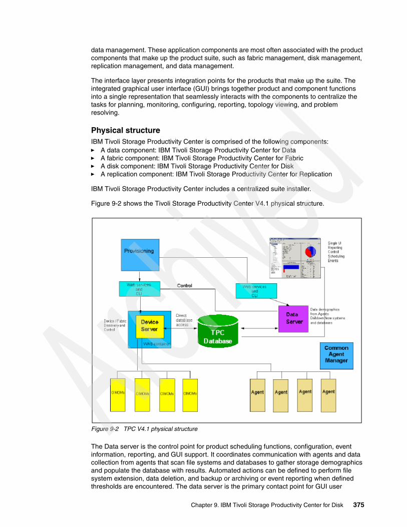
data management. These application components are most often associated with the product components that make up the product suite, such as fabric management, disk management, replication management, and data management.
The interface layer presents integration points for the products that make up the suite. The integrated graphical user interface (GUI) brings together product and component functions into a single representation that seamlessly interacts with the components to centralize the tasks for planning, monitoring, configuring, reporting, topology viewing, and problem resolving.
Physical structureIBM Tivoli Storage Productivity Center is comprised of the following components:� A data component: IBM Tivoli Storage Productivity Center for Data� A fabric component: IBM Tivoli Storage Productivity Center for Fabric� A disk component: IBM Tivoli Storage Productivity Center for Disk � A replication component: IBM Tivoli Storage Productivity Center for Replication
IBM Tivoli Storage Productivity Center includes a centralized suite installer.
Figure 9-2 shows the Tivoli Storage Productivity Center V4.1 physical structure.
Figure 9-2 TPC V4.1 physical structure
The Data server is the control point for product scheduling functions, configuration, event information, reporting, and GUI support. It coordinates communication with agents and data collection from agents that scan file systems and databases to gather storage demographics and populate the database with results. Automated actions can be defined to perform file system extension, data deletion, and backup or archiving or event reporting when defined thresholds are encountered. The data server is the primary contact point for GUI user
Chapter 9. IBM Tivoli Storage Productivity Center for Disk 375

interface functions. It also includes functions that schedule data collection and discovery for the device server.
The device server component discovers, gathers information from, analyzes performance of, and controls storage subsystems and SAN fabrics. It coordinates communication with agents and data collection from agents that scan SAN fabrics.
The single database instance serves as the repository for all Tivoli Storage Productivity Center components.
The Data agents and Fabric agents gather host, application, and SAN fabric information and send this information to the data server or device server.
The GUI allows you to enter information or receive information for all Tivoli Storage Productivity Center components.
The command line interface (CLI) allows you to issue commands for major Tivoli Storage Productivity Center functions.
9.1.2 Standards and protocols used in IBM Tivoli Storage Productivity Center
TPC was built upon storage industry standards. In this section we present an overview of the standards used within the various TPC components.
Common Information Model/Web-Based Enterprise ManagementWeb-Based Enterprise Management (WBEM) is an initiative of the Distributed Management Task Force (DMTF) with the objective to enable the management of complex IT environments. It defines a set of management and Internet standard technologies to unify the management of complex IT environments.
The main conceptual elements of the WBEM initiative are as follows:
� Common Information Model (CIM): A formal object-oriented modeling language that is used to describe the management aspects of systems
� xmlCIM: The syntax used to describe CIM declarations and messages used by the CIM protocol.
� Hypertext Transfer Protocol (HTTP)
� Hypertext Transfer Protocol over Secure Socket Layer (HTTPS)
HTTP and HTTPS are used as a way to enable communication between a management application and a device that both use CIM.
The CIM Agent provides a means by which a device can be managed by common building blocks rather than proprietary software. If a device is CIM-compliant, software that is also CIM-compliant can manage the device. Using CIM, you can perform tasks in a consistent manner across devices and vendors.
The CIM/WBEM architecture defines the following elements:
� Agent code or CIM Agent:
An open-systems standard that interprets CIM requests and responses as they transfer between the client application and the device. The Agent is normally embedded into a device, which can be hardware or software. When not embedded (which is the case for devices that are not CIM-ready such as the DS4000/DS5000), a device provider (usually provided by the device manufacturer) is required.
376 IBM Midrange System Storage Implementation and Best Practices Guide

� CIM Object Manager (CIMOM):
The common conceptual framework for data management that receives, validates, and authenticates the CIM requests from the client application (such as TPC for disk). It then directs the requests to the appropriate component or a device provider.
� Client application or CIM Client:
A storage management program, such as Tivoli Storage Productivity Center, that initiates CIM requests to the CIM Agent for the device. A CIM Client can reside anywhere in the network, because it uses HTTP to talk to CIM Object Managers and Agents.
� Device or CIM Managed Object:
A Managed Object is a hardware or software component that can be managed by a management application by using CIM (for example, a DS5000 Storage Server).
� Device provider:
A device-specific handler that serves as a plug-in for the CIMOM. That is, the CIMOM uses the handler to interface with the device. There is a device provider for the DS4000/DS5000.
Figure 9-3 CIM architecture elements
For more information, see the following site:
http://www.dmtf.org/standards/wbem/
Note: The terms CIM Agent and CIMOM are often used interchangeably. At this time, few devices come with an integrated CIM Agent. Most devices need a external CIMOM for CIM to enable management applications (CIM Clients) to talk to the device.
Chapter 9. IBM Tivoli Storage Productivity Center for Disk 377
Storage Management Initiative - SpecificationThe Storage Networking Industry Association (SNIA) has fully adopted and enhanced the CIM for Storage Management in its Storage Management Initiative - Specification (SMI-S). SMI-S was launched in mid-2002 to create and develop a universal open interface for managing storage devices, including storage networks.
The idea behind SMI-S is to standardize the management interfaces so that management applications can use these and provide cross-device management, which means that a newly introduced device can be immediately managed as it conforms to the standards. TPC for disk uses that standard.
Service Location ProtocolThe Service Location Protocol (SLP) is an IETF standard that SLP provides as a scalable framework for the discovery and selection of network services.
SLP enables the discovery and selection of generic services, which can range in function from hardware services such as those for printers or fax machines, to software services such as those for file servers, e-mail servers, Web servers, databases, or any other possible services that are accessible through an IP network.
Traditionally, to use a particular service, an end-user or client application needs to supply the host name or network IP address of that service. With SLP, however, the user or client no longer needs to know individual host names or IP addresses (for the most part). Instead, the user or client can search the network for the desired service type and an optional set of qualifying attributes.
The SLP architecture includes three major components:
� Service agent (SA):
A process working on the behalf of one or more network services to broadcast the services.
� User agent (UA):
A process working on the behalf of the user to establish contact with a network service. The UA retrieves network service information from the service agents or directory agents.
� Directory agent (DA):
A process that collects network service broadcasts.
The SA and UA are required components in an SLP environment, where the SLP DA is optional.
The SMI-S specification introduces SLP as the method for the management applications (the CIM clients) to locate managed objects. In SLP, an SA is used to report to UAs that a service that has been registered with the SA is available.
9.2 Managing DS4000/DS5000 using IBM TPC for Disk
TPC for Disk enables device configuration and management of SAN-attached devices from a single console. It allows you to manage network storage components based on SMI-S, such as IBM System Storage SAN Volume Controller (SVC), IBM System Storage Disk Subsystems (DS3000, DS4000, DS5000, DS6000, and DS8000 series), and other storage subsystems that support the SMI-S standards.
378 IBM Midrange System Storage Implementation and Best Practices Guide
TPC for Disk also includes performance monitoring and reporting capabilities such as these:
� Collects and stores performance data and provide alerts� Provides graphical performance reports� Helps optimize storage allocation� Provides volume contention analysis
The performance function starts with the data collection task, responsible for capturing performance statistics for the devices and storing the data in the database.
Thresholds can be set for certain performance metrics depending on the type of device. Threshold checking is performed during data collection. When performance is outside the specified boundaries, alerts can be generated.
After performance data has been collected, you can configure Tivoli Storage Productivity Center for Disk to present graphical or text reports on the historical performance behavior of specified devices.
For DS4000/DS5000 Storage Servers, you can use TPC for Disk to perform storage provisioning, logical drive (LUN) creation and assignment, performance management, and reporting. TPC for Disk can monitor the disk subsystem ports, arrays, and measure logical drives throughput, IOPS, and cache rates.
Device discovery is performed by the SLP, and configuration of the discovered devices is possible in conjunction with CIM agents associated with those devices, using the standard mechanisms defined in SMI-S.
For devices that are not CIM ready, as the DS4000/DS5000, the installation of a proxy application (CIM Agent) is required.
To monitor and manage a DS4000/DS5000 through TPC, perform the following task sequence:
1. Install the CIM agent for DS4000/DS5000.2. Register CIMOM in TPC.3. Probe discovered DS4000/DS5000 to gather device information.4. Create Performance Monitor job.
9.2.1 Installing the CIM agent for DS4000/DS5000
In this section we discuss the implementation of the CIM agent for a DS4000/DS5000, assuming that a TPC environment is already in place (we used a TPC v4.1.0.111 environment during the preparation of this book).
The DS4000/DS5000 is not a CIM-ready device. Therefore, a DS4000/DS5000 Device provider (acting as the CIM Agent) must be installed (on a host system) to bridge communications between the DS4000/DS5000 and the TPC server. The device provider (agent) for the DS4000/DS5000 is delivered by Engenio and is called the SANtricity SMI Provider.
Note: It is considered mandatory to run the CIM Agent software on a separate host from the Tivoli Storage Productivity Center server. Attempting to run a full Tivoli Storage Productivity Center implementation on the same host as the CIM agent will result in dramatically increased wait times for data retrieval. You might also experience resource contention and port conflicts.
Chapter 9. IBM Tivoli Storage Productivity Center for Disk 379
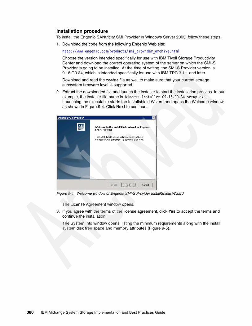
Installation procedureTo install the Engenio SANtricity SMI Provider in Windows Server 2003, follow these steps:
1. Download the code from the following Engenio Web site:
http://www.engenio.com/products/smi_provider_archive.html
Choose the version intended specifically for use with IBM Tivoli Storage Productivity Center and download the correct operating system of the server on which the SMI-S Provider is going to be installed. At the time of writing, the SMI-S Provider version is 9.16.G0.34, which is intended specifically for use with IBM TPC 3.1.1 and later.
Download and read the readme file as well to make sure that your current storage subsystem firmware level is supported.
2. Extract the downloaded file and launch the installer to start the installation process. In our example, the installer file name is Windows_Installer_09.16.G0.34_setup.exe. Launching the executable starts the Installshield Wizard and opens the Welcome window, as shown in Figure 9-4. Click Next to continue.
Figure 9-4 Welcome window of Engenio SMI-S Provider InstallShield Wizard
The License Agreement window opens.
3. If you agree with the terms of the license agreement, click Yes to accept the terms and continue the installation.
The System Info window opens, listing the minimum requirements along with the install system disk free space and memory attributes (Figure 9-5).
380 IBM Midrange System Storage Implementation and Best Practices Guide

Figure 9-5 Minimum System Requirements window
4. Click Next if your system meets the minimum requirements.
The Choose Destination Location window opens.
5. Click Browse to choose another location or click Next to begin the installation of the CIM agent (Figure 9-6).
Figure 9-6 Choose Destination Location window
The InstallShield Wizard is now preparing and copying files into the destination folder.
Chapter 9. IBM Tivoli Storage Productivity Center for Disk 381

6. In the next window, enter IP addresses or host names of devices to be discovered by the SMI-S Provider at startup, as shown in Figure 9-7. In this case, you need to enter the controller management IP addresses of each of the DS4000/DS5000 Storage Server that you intend to monitor.
Figure 9-7 Device List window
Use the Add New Entry button to add the management IP addresses or host names of the controllers of each DS4000/DS5000 Storage Servers with which this DS4000/DS5000 CIM Agent will communicate. Enter one IP address or host name at a time until all of the controllers of all of the DS4000/DS5000 Storage Servers have been entered and click Next, as shown in Figure 9-8.
Note that you can only make one entry at a time. Click Add New Entry again to add the other IP address or host name of your DS4000/DS5000 storage subsystem.
Figure 9-8 Add IP address or host name window
382 IBM Midrange System Storage Implementation and Best Practices Guide

In our example, we enter the two management IP addresses of a DS5020 Storage Server, as shown in Figure 9-9.
Figure 9-9 Modify device window
7. Click Next to start the Engenio SMI-S Provider Service. When the Service has started, the installation of the Engenio SMI-S Provider is complete. You can click Finish on the InstallShield Wizard Complete window, as shown in Figure 9-10.
Figure 9-10 InstallShield Wizard Complete window
During the start of the service, the Engenio code processes all of the entries in the arrayhosts.txt file. The configuration is stored in an another file named:
C:\Program Files\EngenioProvider\SMI_SProvider\bin\providerStore
Caution: Do not enter the controller management IP addresses of a DS4000/DS5000 Storage Server in multiple DS4000/DS5000 CIM Agents within the same subnet. Doing this can cause unpredictable results on the Tivoli Storage Productivity Center for Disk server and can cause a loss of communication with the DS4000/DS5000 devices.
Chapter 9. IBM Tivoli Storage Productivity Center for Disk 383

Every time you change anything with the registered DS4000/DS5000 controllers and restart the Engenio CIMOM, and when you make a new discovery, the providerStore and arrayhosts.txt are updated with a new time stamp.
Verifying the Engenio SMI-S Provider ServiceTo verify that the service has started, open the Windows Services window (Start All Programs Administrative Tools Services) and checking the status of the Engenio SMI-S Provider Server service, as shown in Figure 9-11.
Figure 9-11 Verify Engenio SMI-S Provider Service
Use this interface to start/stop/restart the service. Note that you need to restart the service after any modification to the file arrayhost.txt.
9.2.2 Registering the Engenio SMI-S provider in TPC
The Engenio SMI-S provider must now be registered as a CIMOM agent in TPC, which can be done by SLP-DA, if the service is installed, or manually by the CIMOM registration menu at the TPC console. In our example, we register the CIMOM manually because we did not implement SLP-DA (for more information about SLP-DA and how to register CIMOM by SLP-DA, see IBM Tivoli Storage Productivity Center: The Next Generation, SG24-7194).
Important: You cannot have the DS4000/DS5000 management password set if you are using IBM TotalStorage Productivity Center, because the Engenio CIMOM has no capability to keep track of the user ID and password combinations that are necessary to get into all of the managed DS4000/DS5000 subsystems.
384 IBM Midrange System Storage Implementation and Best Practices Guide
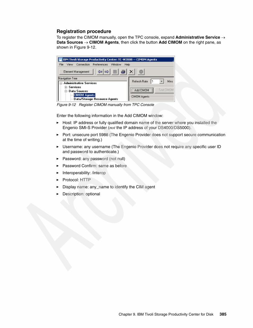
Registration procedureTo register the CIMOM manually, open the TPC console, expand Administrative Service Data Sources CIMOM Agents, then click the button Add CIMOM on the right pane, as shown in Figure 9-12.
Figure 9-12 Register CIMOM manually from TPC Console
Enter the following information in the Add CIMOM window:
� Host: IP address or fully qualified domain name of the server where you installed the Engenio SMI-S Provider (not the IP address of your DS4000/DS5000).
� Port: unsecure port 5988 (The Engenio Provider does not support secure communication at the time of writing.)
� Username: any username (The Engenio Provider does not require any specific user ID and password to authenticate.)
� Password: any password (not null)
� Password Confirm: same as before
� Interoperability: /interop
� Protocol: HTTP
� Display name: any_name to identify the CIM agent
� Description: optional
Chapter 9. IBM Tivoli Storage Productivity Center for Disk 385

Figure 9-13 shows an example of the Add CIMOM window.
Figure 9-13 Add CIMOM window
If the “Test CIMOM connectivity before adding” check box is checked, you will see the connectivity status after clicking Save, as illustrated in Figure 9-14.
Figure 9-14 CIMOM connection test status
If the connection test failed, you must verify that your Engenio SMI-S Provider is properly installed in the server and that the service is running. Also, check for any connectivity or possible firewall problems.
Use DOS utilities such as ping, netstat and telnet from the TPC server to the server where Engenio SMI-S Provider is installed to check the connecivity.
386 IBM Midrange System Storage Implementation and Best Practices Guide

Showing Managed DevicesAfter the CIM agent was successfully registered, you can view the devices managed by the CIM agent (the Engenio SMI-S provider in our case). Highlight the CIMOM agent in the Navigation pane, and click Show Managed Devices, as shown in Figure 9-15. Note that two DS4000/DS5000 series Storage Servers have been found, such as a DS5020 and a DS5300 Storage Server.
Figure 9-15 Show Managed Devices
9.2.3 Probing the CIM agent
The CIMOM discovery and registration process will only detect and recognize devices bridged by the CIMOM agent. TPC needs to get more detailed information about a device to effectively manage and monitor it, which can be accomplished by running a probe job. The probe interacts with the CIM agent by sending a request for information about the configured device. The probe job must in fact be performed before you attempt to manage the device.
With the DS4000/DS5000, a probe job needs to be run before volume (logical drive) management and performance monitoring can be performed on the storage subsystem.
Chapter 9. IBM Tivoli Storage Productivity Center for Disk 387

Configuring a probe jobTo configure a probe job, open the TPC console, and expand IBM Tivoli Storage Productivity Center Monitoring Probes. Right-click Probes and click Create Probe, as shown in Figure 9-16.
Figure 9-16 Create probe
The Create Probe tab is displayed in the right pane. Expand Storage Subsystems, select the DS4000/DS5000 you want to probe, and click the >> button, as shown in Figure 9-17.
Figure 9-17 Select storage subsystem to probe
388 IBM Midrange System Storage Implementation and Best Practices Guide
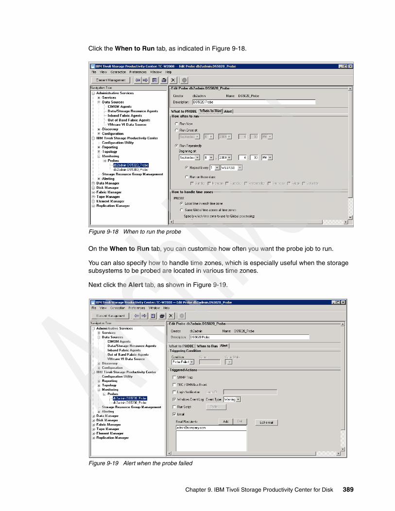
Click the When to Run tab, as indicated in Figure 9-18.
Figure 9-18 When to run the probe
On the When to Run tab, you can customize how often you want the probe job to run.
You can also specify how to handle time zones, which is especially useful when the storage subsystems to be probed are located in various time zones.
Next click the Alert tab, as shown in Figure 9-19.
Figure 9-19 Alert when the probe failed
Chapter 9. IBM Tivoli Storage Productivity Center for Disk 389
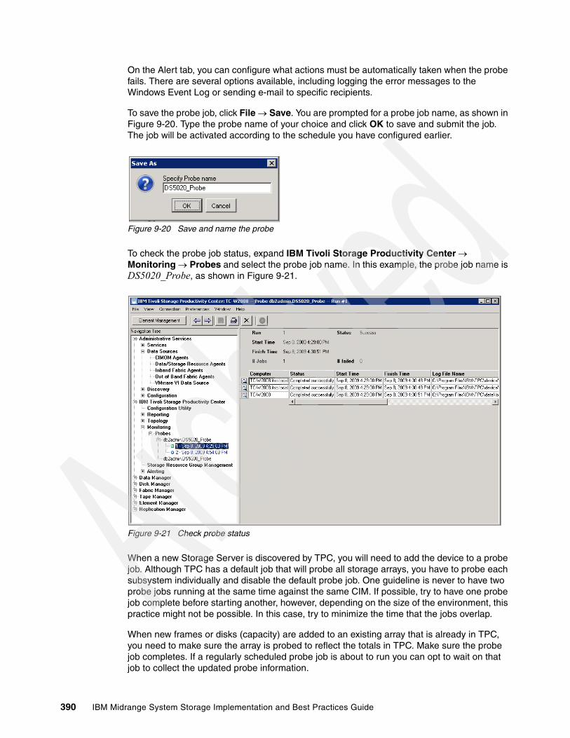
On the Alert tab, you can configure what actions must be automatically taken when the probe fails. There are several options available, including logging the error messages to the Windows Event Log or sending e-mail to specific recipients.
To save the probe job, click File Save. You are prompted for a probe job name, as shown in Figure 9-20. Type the probe name of your choice and click OK to save and submit the job. The job will be activated according to the schedule you have configured earlier.
Figure 9-20 Save and name the probe
To check the probe job status, expand IBM Tivoli Storage Productivity Center Monitoring Probes and select the probe job name. In this example, the probe job name is DS5020_Probe, as shown in Figure 9-21.
Figure 9-21 Check probe status
When a new Storage Server is discovered by TPC, you will need to add the device to a probe job. Although TPC has a default job that will probe all storage arrays, you have to probe each subsystem individually and disable the default probe job. One guideline is never to have two probe jobs running at the same time against the same CIM. If possible, try to have one probe job complete before starting another, however, depending on the size of the environment, this practice might not be possible. In this case, try to minimize the time that the jobs overlap.
When new frames or disks (capacity) are added to an existing array that is already in TPC, you need to make sure the array is probed to reflect the totals in TPC. Make sure the probe job completes. If a regularly scheduled probe job is about to run you can opt to wait on that job to collect the updated probe information.
390 IBM Midrange System Storage Implementation and Best Practices Guide
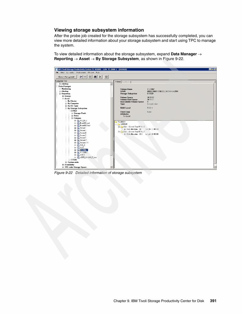
Viewing storage subsystem informationAfter the probe job created for the storage subsystem has successfully completed, you can view more detailed information about your storage subsystem and start using TPC to manage the system.
To view detailed information about the storage subsystem, expand Data Manager Reporting Asset By Storage Subsystem, as shown in Figure 9-22.
Figure 9-22 Detailed information of storage subsystem
Chapter 9. IBM Tivoli Storage Productivity Center for Disk 391
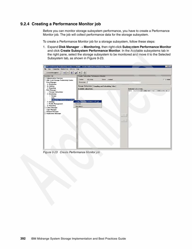
9.2.4 Creating a Performance Monitor job
Before you can monitor storage subsystem performance, you have to create a Performance Monitor job. The job will collect performance data for the storage subsystem.
To create a Performance Monitor job for a storage subsystem, follow these steps:
1. Expand Disk Manager Monitoring, then right-click Subsystem Performance Monitor and click Create Subsystem Performance Monitor. In the Available subsystems tab in the right pane, select the storage subsystem to be monitored and move it to the Selected Subsystem tab, as shown in Figure 9-23.
Figure 9-23 Create Performance Monitor job
392 IBM Midrange System Storage Implementation and Best Practices Guide

2. Select the Sampling and Scheduling tabs to configure the interval length, duration, and scheduling of the Performance Monitor job to be submitted, as shown in Figure 9-24.
Figure 9-24 Sampling and scheduling
3. Go to the Alert tab to select what actions must be triggered if the monitor fails, as shown in Figure 9-25.
Figure 9-25 Alert tab
Chapter 9. IBM Tivoli Storage Productivity Center for Disk 393
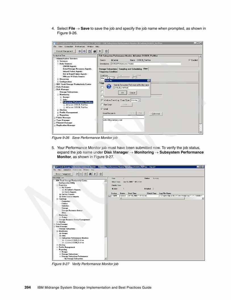
4. Select File Save to save the job and specify the job name when prompted, as shown in Figure 9-26.
Figure 9-26 Save Performance Monitor job
5. Your Performance Monitor job must have been submitted now. To verify the job status, expand the job name under Disk Manager Monitoring Subsystem Performance Monitor, as shown in Figure 9-27.
Figure 9-27 Verify Performance Monitor job
394 IBM Midrange System Storage Implementation and Best Practices Guide
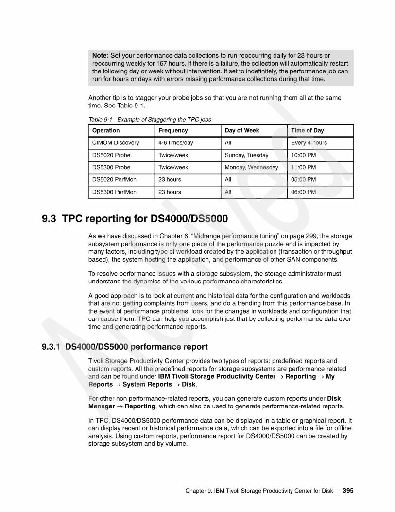
Another tip is to stagger your probe jobs so that you are not running them all at the same time. See Table 9-1.
Table 9-1 Example of Staggering the TPC jobs
9.3 TPC reporting for DS4000/DS5000
As we have discussed in Chapter 6, “Midrange performance tuning” on page 299, the storage subsystem performance is only one piece of the performance puzzle and is impacted by many factors, including type of workload created by the application (transaction or throughput based), the system hosting the application, and performance of other SAN components.
To resolve performance issues with a storage subsystem, the storage administrator must understand the dynamics of the various performance characteristics.
A good approach is to look at current and historical data for the configuration and workloads that are not getting complaints from users, and do a trending from this performance base. In the event of performance problems, look for the changes in workloads and configuration that can cause them. TPC can help you accomplish just that by collecting performance data over time and generating performance reports.
9.3.1 DS4000/DS5000 performance report
Tivoli Storage Productivity Center provides two types of reports: predefined reports and custom reports. All the predefined reports for storage subsystems are performance related and can be found under IBM Tivoli Storage Productivity Center Reporting My Reports System Reports Disk.
For other non performance-related reports, you can generate custom reports under Disk Manager Reporting, which can also be used to generate performance-related reports.
In TPC, DS4000/DS5000 performance data can be displayed in a table or graphical report. It can display recent or historical performance data, which can be exported into a file for offline analysis. Using custom reports, performance report for DS4000/DS5000 can be created by storage subsystem and by volume.
Note: Set your performance data collections to run reoccurring daily for 23 hours or reoccurring weekly for 167 hours. If there is a failure, the collection will automatically restart the following day or week without intervention. If set to indefinitely, the performance job can run for hours or days with errors missing performance collections during that time.
Operation Frequency Day of Week Time of Day
CIMOM Discovery 4-6 times/day All Every 4 hours
DS5020 Probe Twice/week Sunday, Tuesday 10:00 PM
DS5300 Probe Twice/week Monday, Wednesday 11:00 PM
DS5020 PerfMon 23 hours All 05:00 PM
DS5300 PerfMon 23 hours All 06:00 PM
Chapter 9. IBM Tivoli Storage Productivity Center for Disk 395

For DS4000/DS5000, there are several metrics/parameters can be monitored by TPC, as shown in Table 9-2.
Table 9-2 DS4000/DS5000 performance metrics
9.3.2 Generating reports
This section provides several examples of how to generate reports using predefined and custom reports.
Example 1: DS4000/DS5000 predefined performance reportIn this example, we compare the overall read I/O rate of DS5020 and DS5300 Storage Servers. Remember that the results are affected by many factors including the workload on each storage subsystem. This example only illustrates the steps required to compare the performance of storage subsystems within a TPC environment.
To generate the report using TPC predefined reports:
1. Expand IBM Tivoli Storage Productivity Center Reporting My Reports System Reports Disk to see a list of system supplied performance reports.
Metrics Description
Read I/O rateWrite I/O rateTotal I/O rate
Average number of I/O operations per second for both sequential and non-sequential read/write/total operations for a particular component over a time interval.
Read cache hitsWrite cache hitsTotal cache hits
Percentage of cache hits for non-sequential read/write/total operations for a particular component over a time interval.
Read Data RateWrite Data RateTotal Data Rate
Average number of megabytes (10^6 bytes) per second that were transferred for read/write/total operations for a particular component over a time interval.
Read transfer sizeWrite transfer sizeOverall transfer size
Average number of KB per I/O for read/write/total operations for a particular component over a time interval.
Total port I/O rate
Total port data rate
Average number of I/O operations per second for send and receive operations for a particular port over a time interval.
Average number of megabytes (10^6 bytes) per second that were transferred for send and receive operations for a particular port over a time interval.
Total port transfer size Average number of KB transferred per I/O by a particular port over a time interval.
396 IBM Midrange System Storage Implementation and Best Practices Guide

2. Click one of the listed predefined reports (note that not all predefined performance reports support DS4000/DS5000 at the time of writing). In the example, shown in Figure 9-28, we click Subsystem Performance report to display a list of all storage subsystems monitored by TPC with their performance metrics values. Note that column Subsystem shows the machine type and model followed by its serial number.
Figure 9-28 Subsystem Performance report
You can click the chart icon to generate a graph or click the Selection tab to modify this predefined report and regenerate it.
3. In our example, we click the Selection tab because we want to generate a report that compares the overall read I/O rate of the DS5020 and the DS5300. Move to the Included column the performance metrics (Time, Internal and Overall Read I/O rate) you want to include in the report, as shown in Figure 9-29.
Figure 9-29 Selection of performance metrics
Chapter 9. IBM Tivoli Storage Productivity Center for Disk 397

4. Click Selection on the Selection tab to select the storage subsystems for which you want to generate the report. In our case, we select DS5020 and DS5300, as shown in Figure 9-30.
Figure 9-30 Storage subsystem selection
5. Click Generate Report (still on the Selection tab) and you get the result shown in Figure 9-31.
Figure 9-31 Generated report based on selection
398 IBM Midrange System Storage Implementation and Best Practices Guide
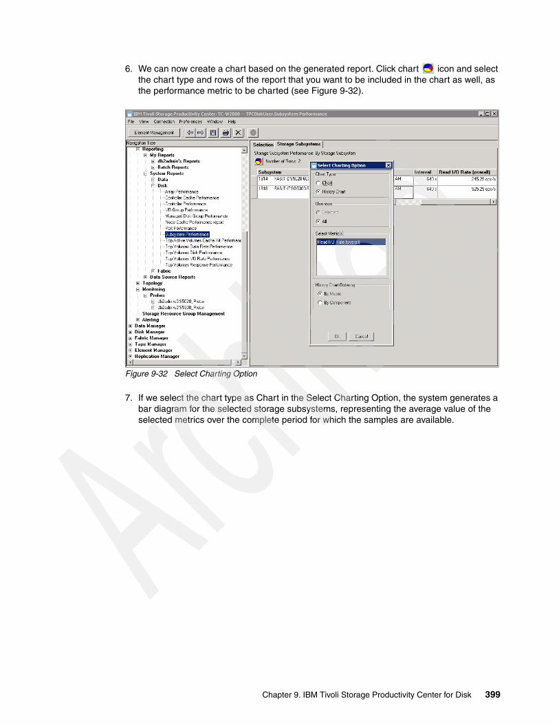
6. We can now create a chart based on the generated report. Click chart icon and select the chart type and rows of the report that you want to be included in the chart as well, as the performance metric to be charted (see Figure 9-32).
Figure 9-32 Select Charting Option
7. If we select the chart type as Chart in the Select Charting Option, the system generates a bar diagram for the selected storage subsystems, representing the average value of the selected metrics over the complete period for which the samples are available.
Chapter 9. IBM Tivoli Storage Productivity Center for Disk 399
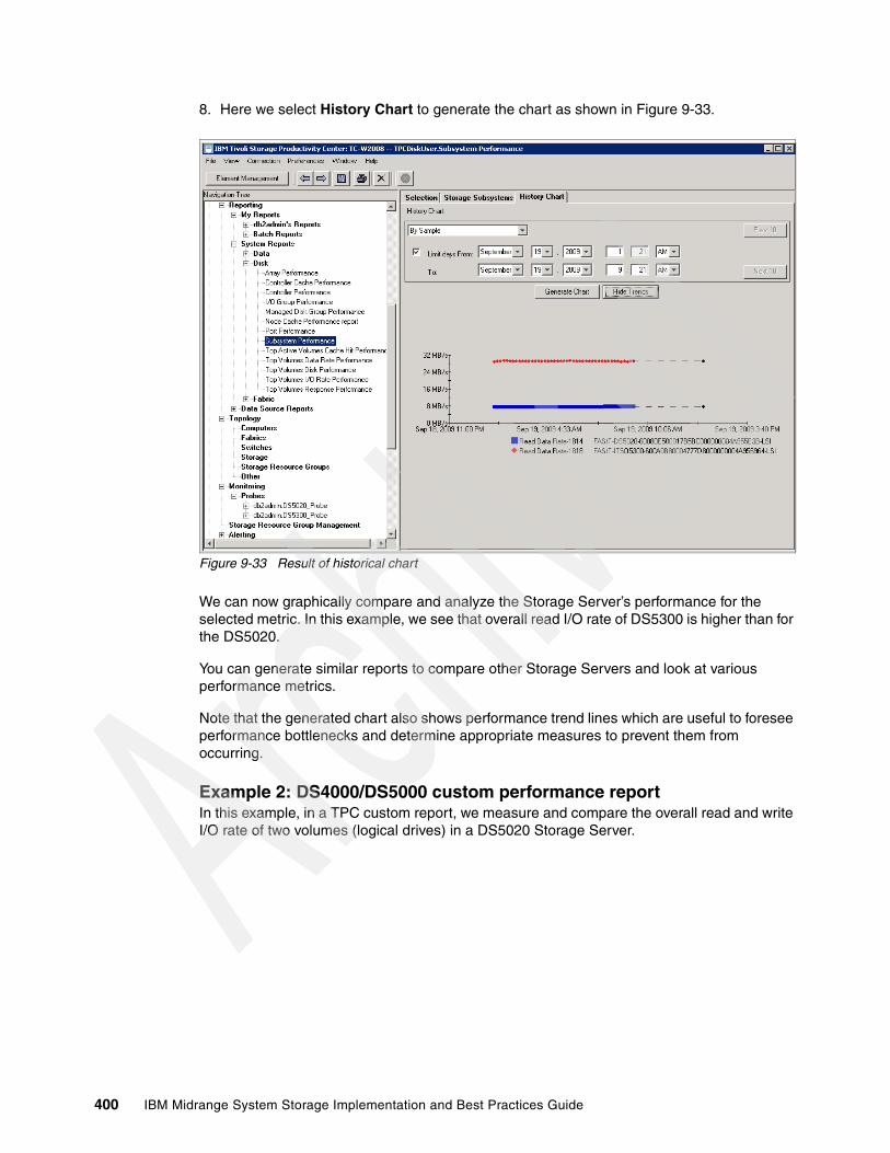
8. Here we select History Chart to generate the chart as shown in Figure 9-33.
Figure 9-33 Result of historical chart
We can now graphically compare and analyze the Storage Server’s performance for the selected metric. In this example, we see that overall read I/O rate of DS5300 is higher than for the DS5020.
You can generate similar reports to compare other Storage Servers and look at various performance metrics.
Note that the generated chart also shows performance trend lines which are useful to foresee performance bottlenecks and determine appropriate measures to prevent them from occurring.
Example 2: DS4000/DS5000 custom performance reportIn this example, in a TPC custom report, we measure and compare the overall read and write I/O rate of two volumes (logical drives) in a DS5020 Storage Server.
400 IBM Midrange System Storage Implementation and Best Practices Guide

Follow these steps to generate this particular custom performance report in TPC:
1. Expand Disk Manager Reporting Storage Subsystem Performance, then click By Volume.
2. On the Selection tab, move all performance metrics in the Included Columns into the Available Columns, except for read I/O rate (overall) and write I/O rate (overall) metrics. Check the Display historic performance data check box and select the start and end dates to generate a historical report, as shown in Figure 9-34.
Figure 9-34 Selecting performance metrics and historical data
Chapter 9. IBM Tivoli Storage Productivity Center for Disk 401
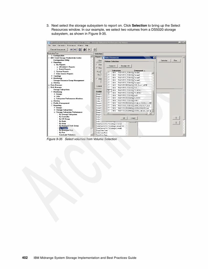
3. Next select the storage subsystem to report on. Click Selection to bring up the Select Resources window. In our example, we select two volumes from a DS5020 storage subsystem, as shown in Figure 9-35.
Figure 9-35 Select volumes from Volume Selection
402 IBM Midrange System Storage Implementation and Best Practices Guide
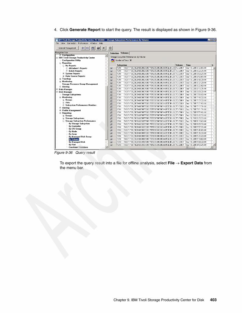
4. Click Generate Report to start the query. The result is displayed as shown in Figure 9-36.
Figure 9-36 Query result
To export the query result into a file for offline analysis, select File Export Data from the menu bar.
Chapter 9. IBM Tivoli Storage Productivity Center for Disk 403

5. Now we generate a chart. Select all of the results and click the chart icon, then select History Chart and all of the metrics, as shown in Figure 9-37.
Figure 9-37 Select Charting window
404 IBM Midrange System Storage Implementation and Best Practices Guide

The chart is displayed as shown in Figure 9-38.
Figure 9-38 Graphical report result
From the chart result, we see that volume TC-2008-1 has both an higher read I/O rate and write I/O rate compared to volume TC-2008-2, which means that volume TC-2008-1 is sustaining an heavier workload. As we discussed earlier in this book, this type of information can be used, for example, to do performance tuning from the application, operating system, or the storage subsystem side.
Chapter 9. IBM Tivoli Storage Productivity Center for Disk 405

Example 3: DS4000/DS5000 volume to HBA assignment reportTPC reporting is also able to generate non-performance reports. The following example shows steps required to generate a Volume to HBA assignment report for a DS5020 and a DS5300 that were part of our TPC environment. Because there are no predefined non-performance-related reports, we need to generate a custom report.
Follow these steps to generate a Volume to HBA Assignment report By Storage Subsystem in TPC:
1. Expand Disk Manager Reporting Storage Subsystems Volume to HBA Assignment By Storage Subsystem. Remove unnecessary information from the Included Columns into Available Columns, and click Selection to select the storage subsystems for which you want to create this report. In our example, we only include Volume WWN, HBA Port WWN, and SMI-S Host Alias, and selected one DS5300 and one DS5020 among the list of storage subsystems known to our TPC environment, which is shown in Figure 9-39.
Figure 9-39 Volume to HBA assignment, select storage subsystems
406 IBM Midrange System Storage Implementation and Best Practices Guide
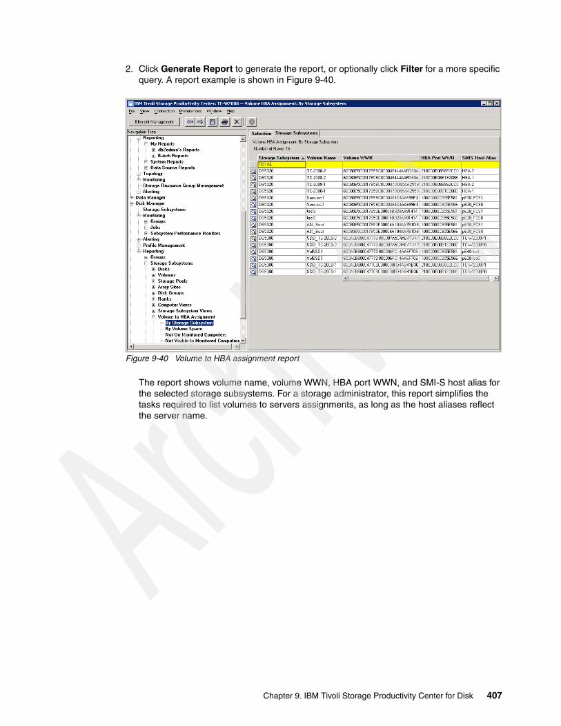
2. Click Generate Report to generate the report, or optionally click Filter for a more specific query. A report example is shown in Figure 9-40.
Figure 9-40 Volume to HBA assignment report
The report shows volume name, volume WWN, HBA port WWN, and SMI-S host alias for the selected storage subsystems. For a storage administrator, this report simplifies the tasks required to list volumes to servers assignments, as long as the host aliases reflect the server name.
Chapter 9. IBM Tivoli Storage Productivity Center for Disk 407
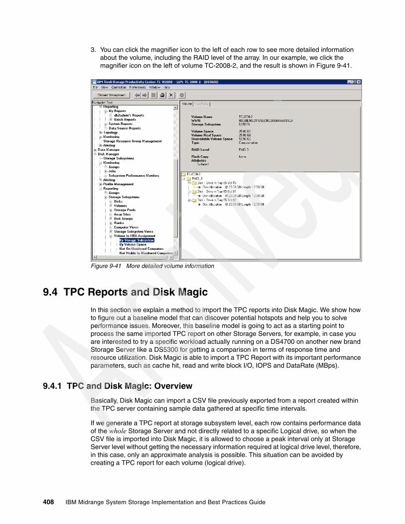
3. You can click the magnifier icon to the left of each row to see more detailed information about the volume, including the RAID level of the array. In our example, we click the magnifier icon on the left of volume TC-2008-2, and the result is shown in Figure 9-41.
Figure 9-41 More detailed volume information
9.4 TPC Reports and Disk Magic
In this section we explain a method to import the TPC reports into Disk Magic. We show how to figure out a baseline model that can discover potential hotspots and help you to solve performance issues. Moreover, this baseline model is going to act as a starting point to process the same imported TPC report on other Storage Servers, for example, in case you are interested to try a specific workload actually running on a DS4700 on another new brand Storage Server like a DS5300 for getting a comparison in terms of response time and resource utilization. Disk Magic is able to import a TPC Report with its important performance parameters, such as cache hit, read and write block I/O, IOPS and DataRate (MBps).
9.4.1 TPC and Disk Magic: Overview
Basically, Disk Magic can import a CSV file previously exported from a report created within the TPC server containing sample data gathered at specific time intervals.
If we generate a TPC report at storage subsystem level, each row contains performance data of the whole Storage Server and not directly related to a specific Logical drive, so when the CSV file is imported into Disk Magic, it is allowed to choose a peak interval only at Storage Server level without getting the necessary information required at logical drive level, therefore, in this case, only an approximate analysis is possible. This situation can be avoided by creating a TPC report for each volume (logical drive).
408 IBM Midrange System Storage Implementation and Best Practices Guide

As explained in Chapter 10, “Disk Magic” on page 435, a Disk Magic Storage Server model analysis must be composed of a number of Host Servers equal to the number of Logical Drives managed by the Storage Server, so that the Disk Magic fields are going to be correctly filled with specific Logical Drive data.
Note that if a real Host Server has multiple Logical Drives mapped, Disk Magic can emulate this configuration by creating a “pseudo-Host Server” for each Logical Drive mapped, giving the opportunity of filling specific data at individual Logical Drive level. Within Disk Magic we assume that always exists a 1:1 mapping between an Host or Pseudo-Host Server and a Logical Drive.
Figure 9-42 shows a Flow Diagram of the steps we are going to describe in detail in the following paragraph. Each block of the diagram represent a specific procedure to be performed at TPC or Disk Magic Level. From a storage configuration standpoint, note that a DS storage profile is required for collecting the Storage Server configuration layout, including logical drive capacity, array ownership, number of disks, RAID protection, disk drive’s type, speed and size.
Figure 9-42 Block Diagram of the method
During the import phase of the TPC CSV files, Disk Magic reads the data and automatically sets the most important parameters for the baseline including read cache hit, write I/O blocksize, read I/O blocksize, read percentage, IOps, and DataRate in MBps.
Note: Keep in mind that each Logical Drive’s data placed onto Disk Magic, must be gathered using the same sample time interval. This interval is going to be the one in which the whole Storage Server’s performance data get its maximum value. In this way a real aggregate peak analysis can be performed.
Chapter 9. IBM Tivoli Storage Productivity Center for Disk 409

During the processing of the imported Volumes (Logical Drives) CSV files, Disk Magic creates a Host Server and a Storage Server for each Logical Drive parsed, and because of this view, you might be surprised: Disk Magic has a special function that is able to merge multiple Storage Servers, creating a separate Storage Server that serves all the back-end logical drives previously imported.
At this point, on the DiskMagic screen you can discover a number of Host Servers equal to the number of Logical Drives that you intend to process and a merged Storage Server that manages all these Logical Drives as well, which is going to be exactly what we are looking for.
In the following sections, we describe and show the entire procedure by means of a simple example.
9.4.2 TPC and Disk Magic: Analysis example
This example gives you an overview of the procedure required to parse the TPC “by Volume” Reports within Disk Magic. Such a method can be useful for the following scenarios:
� Detect performance issues in your DS4000/DS5000 Storage Server (for example, too high service time or excessive disk utilization) and simulate various configuration layouts for Storage Servers in order to solve the problem (for example, changing the RAID level, or increasing the number of disks within the array, or even changing the Storage Server model)
� Get the current Storage Server’s resource utilization (CPU, FC Bus, Disks Utilization, Processor Utilization)
� Map the peak workload’s time interval of your current Storage Server model to another model in order to get a comparison in terms of performance and resource utilization (What-if Analysis)
� Perform a Potential Analysis, increasing the workload (in terms of MBps or IOps) up to the maximum reachable value and take note of which Storage Server hardware resource becomes the bottleneck inhibiting further workload growth.
410 IBM Midrange System Storage Implementation and Best Practices Guide
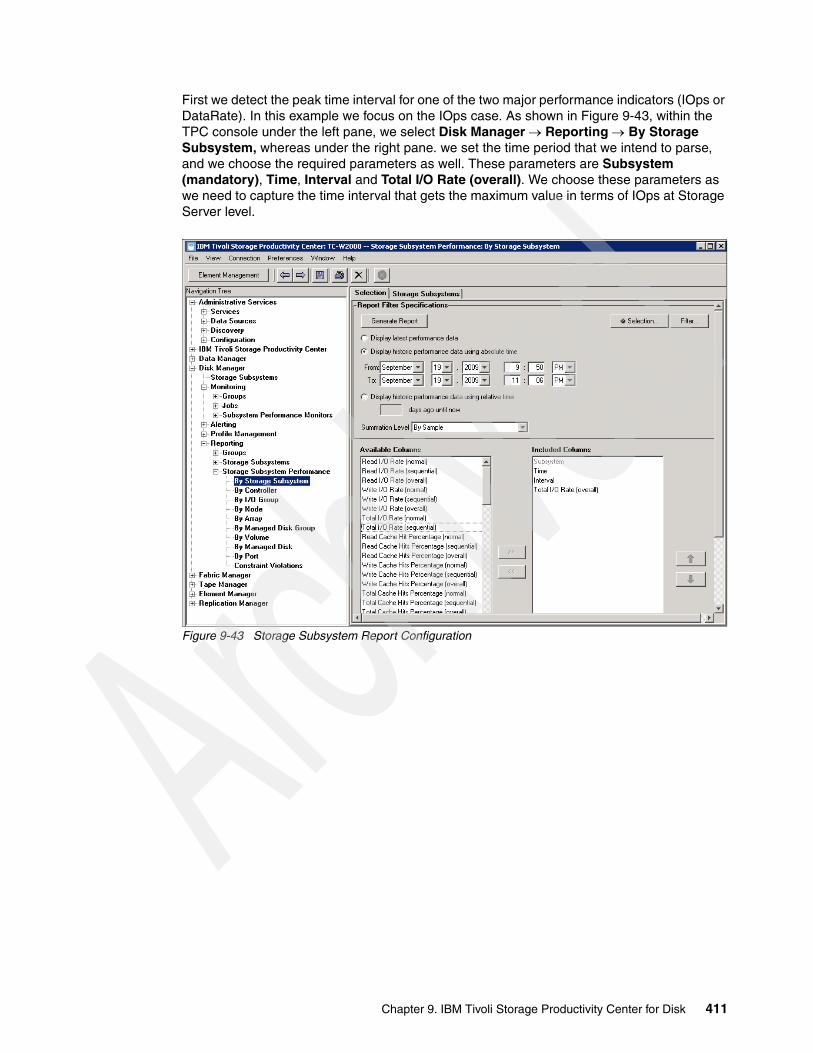
First we detect the peak time interval for one of the two major performance indicators (IOps or DataRate). In this example we focus on the IOps case. As shown in Figure 9-43, within the TPC console under the left pane, we select Disk Manager Reporting By Storage Subsystem, whereas under the right pane. we set the time period that we intend to parse, and we choose the required parameters as well. These parameters are Subsystem (mandatory), Time, Interval and Total I/O Rate (overall). We choose these parameters as we need to capture the time interval that gets the maximum value in terms of IOps at Storage Server level.
Figure 9-43 Storage Subsystem Report Configuration
Chapter 9. IBM Tivoli Storage Productivity Center for Disk 411
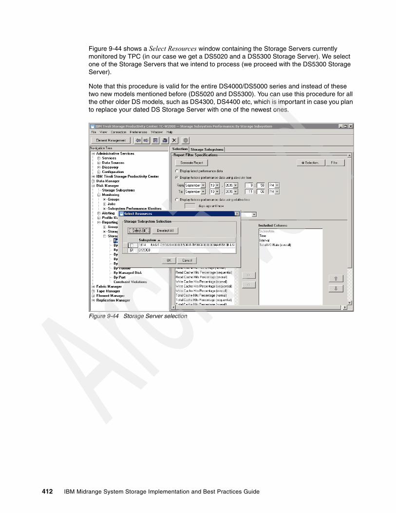
Figure 9-44 shows a Select Resources window containing the Storage Servers currently monitored by TPC (in our case we get a DS5020 and a DS5300 Storage Server). We select one of the Storage Servers that we intend to process (we proceed with the DS5300 Storage Server).
Note that this procedure is valid for the entire DS4000/DS5000 series and instead of these two new models mentioned before (DS5020 and DS5300). You can use this procedure for all the other older DS models, such as DS4300, DS4400 etc, which is important in case you plan to replace your dated DS Storage Server with one of the newest ones.
Figure 9-44 Storage Server selection
412 IBM Midrange System Storage Implementation and Best Practices Guide

After selecting the appropriate Storage Server, click OK to come back to the main TPC window where you can click Generate Report to get to the window shown in Figure 9-45.
The tab Storage Subsystems under the right pane contains a table with all the samples gathered during the selected period of time. Note that the columns are exactly the same that we have chosen in Figure 9-43 on page 411. Clicking the column header leads to a sorting in increasing or decreasing order. Obviously, after sorting the Total I/O Rate (overall) column by increasing order, the peak value (at Storage Subsystem level) moves to the first row of the table. This peak occurs in September, 19th 2009 at 9:56:51 PM and gets a total amount of 993.1 operations per second (ops/s)
Figure 9-45 Storage Subsystems Report
Chapter 9. IBM Tivoli Storage Productivity Center for Disk 413
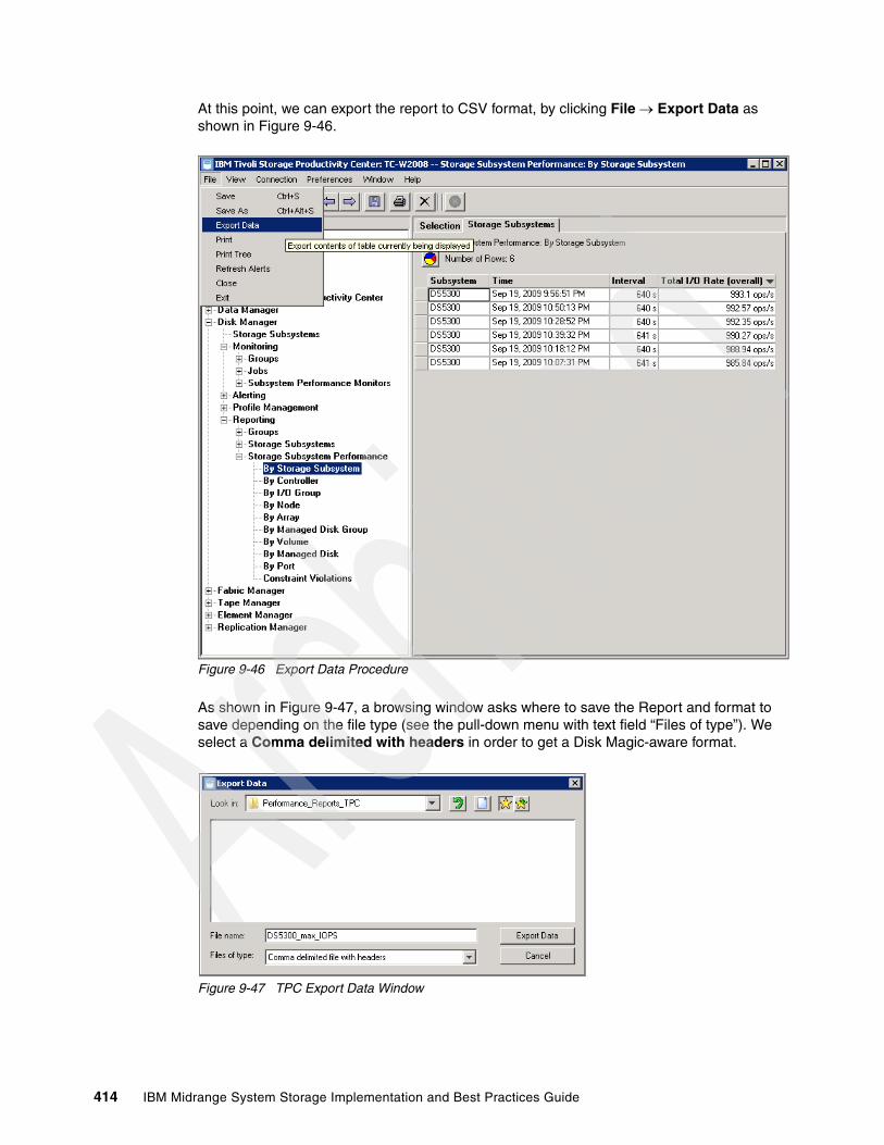
At this point, we can export the report to CSV format, by clicking File Export Data as shown in Figure 9-46.
Figure 9-46 Export Data Procedure
As shown in Figure 9-47, a browsing window asks where to save the Report and format to save depending on the file type (see the pull-down menu with text field “Files of type”). We select a Comma delimited with headers in order to get a Disk Magic-aware format.
Figure 9-47 TPC Export Data Window
414 IBM Midrange System Storage Implementation and Best Practices Guide
As shown in Figure 9-48, the CSV file looks pretty similar to the TPC table previously shown in Figure 9-46. Note that the Interval column indicates the sample time interval in seconds.
Figure 9-48 Exported data on CVS file
At this point, for each Volume (or Logical Drive using the DS4000/DS5000 terminology) managed by our Storage Server, we are going to generate a report within the same time frame used during the generation of the Storage Subsystem Report. To do that, in the left pane of the main TPC window, we select Disk Manager Reporting By Volume followed by a specific column selection in the right pane under Included Columns:
� Subsytem (mandatory)� Volume (mandatory)� Time� Read I/O Rate (overall)� Write I/O Rate (overall)� Total I/O Rate (overall)� Read Cache Hits Percentage (overall)� Write Cache Hits Percentage (overall)� Total Cache Hits Percentage (overall)� Read Data Rate� Write Data Rate� Total Data Rate� Read Transfer Size� Write Transfer Size� Overall Transfer Size
Chapter 9. IBM Tivoli Storage Productivity Center for Disk 415

Figure 9-49 shows the related TPC window. All the parameters listed in the text pane labeled under “Included Columns” are required by Disk Magic in order to automatically set the workload and the cache profile for each Logical Drive. This Disk Magic capability is a useful time saving task that permits to avoid human errors in case of manual input.
Figure 9-49 Volume Report Configuration
Click the Selection button at the top of the right pane in order to select the individual Logical Drive to parse.
416 IBM Midrange System Storage Implementation and Best Practices Guide
The Select Resources window opens as shown in Figure 9-50 and all the Logical Drives belonging to all the managed Storage Servers are listed and checkable. Potentially a Report containing all the Logical Drives can be done but it is not useful for our intent, because we need to generate an individual CSV file for each Logical Drive, therefore we must check an individual check box at a time.
Figure 9-50 Volume Selection
After choosing the Logical Drive (x3655_Data1 as shown in Figure 9-50), come back to the parent window (Figure 9-49 on page 416) and click the Generate Report button.
The window in Figure 9-51 opens and in the right pane, under the Volumes tab and you can see a table containing the measured data for the specific x3655_Data1 Logical Drive. Again, it is possible to sort the column to get an increasing or decreasing order. In this case, we must detect the time frame that gets the maximum value of the IOps at Storage Subsystem level (September 19th 2009 at 9:56:51 PM) as mentioned before (see Figure 9-48).
Chapter 9. IBM Tivoli Storage Productivity Center for Disk 417
Figure 9-51 Volume Report
As previously done with the Storage Subsystem Report, we export the results to a CSV file by clicking File Export Data as shown in Figure 9-52.
Figure 9-52 Export Data Procedure
418 IBM Midrange System Storage Implementation and Best Practices Guide
Again, we export in Comma delimited file with headers format as shown in Figure 9-53. Name each CSV file with the name of the logical drive that it represents, so that you make sure to import into Disk Magic all the Logical Drives required.
Figure 9-53 TPC Export Data Window
Within the Storage Manager (SM) client, in the left pane of the Subsystem Management window under the Logical tab, we can see the two Logical Drives that we take into consideration (Figure 9-54). In this phase we are interested to pick up the Storage Server configuration in terms of Logical drive Capacity, array RAID protection, number of disks per array and Hard Disk Drive (HDD) type/speed. We can find all this information in the Storage Manager client or in the storage profile text file.
Figure 9-54 Logical Drive size
Figure 9-55 shows the CSV Report File for the whole Storage Subsystem, where we can underline the peak interval row in order to easily verify that the sum of the Total I/O Rate (overall) for each Logical Drive is going to match exactly the value underlined in Figure 9-55 (in this example 993.1ops/sec).
Figure 9-55 Storage Subsystem CSV Report File
Chapter 9. IBM Tivoli Storage Productivity Center for Disk 419

In Figure 9-56, we show the CSV files for one of the two Logical Drives processed (x3655_Data2).
Figure 9-56 Volume CSV Report File
At this point, a work around is required to correctly import all the CSV Logical Drive files into Disk Magic. While TPC generates Reports by Volume including two mandatory columns, that are the Subsystem and the Volume columns (as you can see in Figure 9-56), this format cannot be imported into Disk Magic, which occurs because at the time of writing, Disk Magic is thought to import only Reports at Storage Subsystem level, which obviously does not have the Volume column.
As mentioned before, a single Storage Subsystem analysis can be done but it is not as accurate as we need, so we assume that each Logical Drive acts as a pseudo Storage Subsystem overwriting the rows belonging to the Subsystem column with the rows belonging to the Volume column and subsequently removing the column Volume.
See Figure 9-57 to view the new Logical Drive CSV format.
Figure 9-57 Modify CSV Report File for Disk Magic
Finally, before importing on Disk Magic, we intend to figure out the RAID arrays that host the appropriate Logical Drives as shown in Figure 9-58.
Keep in mind that our test DS5300 has many Logical Drives, but we are going to arrest the I/O activity on all but the two Logical Drives of interest in order to simplify our example. The RAID array used in this example is a (7+P) RAID 5 array with FC Hard Disk Drives (HDD) of 146 GB capacity and 15000 revolutions per minute (PRM) speed. The iometer tool has been used to generate specific I/O activity on these two Logical Drives. For more details about iometer, see the following Web site:
http://www.iometer.org/
420 IBM Midrange System Storage Implementation and Best Practices Guide

Figure 9-58 Array configuration
At this point we have all the information required to concurrently import all the Logical Drive CSV files into Disk Magic. To do that, open the Disk Magic program and in the Welcome to Disk Magic window, select the radiobox “Open and iSeries Automated input (*.IOSTAT, *.TXT, *.CSV)” and click the “OK” button (Figure 9-59).
Figure 9-59 Disk Magic welcome window
Chapter 9. IBM Tivoli Storage Productivity Center for Disk 421
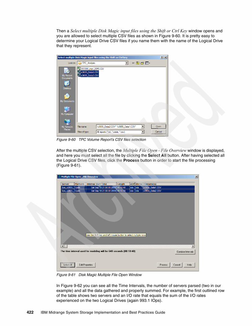
Then a Select multiple Disk Magic input files using the Shift or Ctrl Key window opens and you are allowed to select multiple CSV files as shown in Figure 9-60. It is pretty easy to determine your Logical Drive CSV files if you name them with the name of the Logical Drive that they represent.
Figure 9-60 TPC Volume Report’s CSV files selection
After the multiple CSV selection, the Multiple File Open - File Overview window is displayed, and here you must select all the file by clicking the Select All button. After having selected all the Logical Drive CSV files, click the Process button in order to start the file processing (Figure 9-61).
Figure 9-61 Disk Magic Multiple File Open Window
In Figure 9-62 you can see all the Time Intervals, the number of servers parsed (two in our example) and all the data gathered and properly summed. For example, the first outlined row of the table shows two servers and an I/O rate that equals the sum of the I/O rates experienced on the two Logical Drives (again 993.1 IOps).
422 IBM Midrange System Storage Implementation and Best Practices Guide
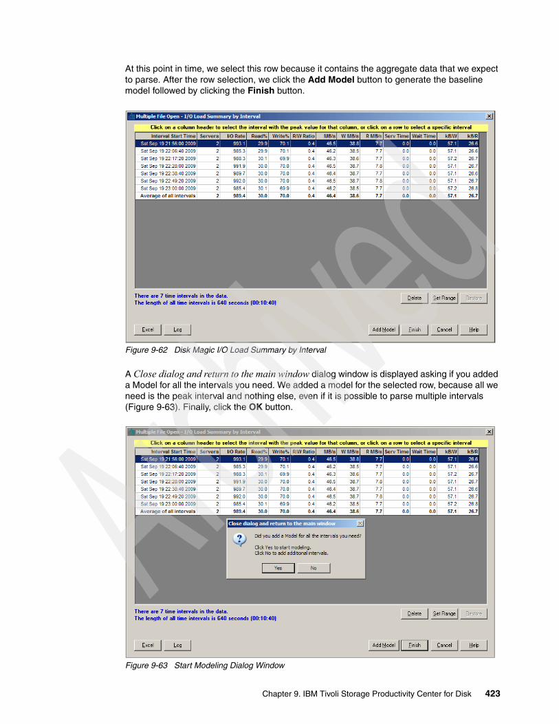
At this point in time, we select this row because it contains the aggregate data that we expect to parse. After the row selection, we click the Add Model button to generate the baseline model followed by clicking the Finish button.
Figure 9-62 Disk Magic I/O Load Summary by Interval
A Close dialog and return to the main window dialog window is displayed asking if you added a Model for all the intervals you need. We added a model for the selected row, because all we need is the peak interval and nothing else, even if it is possible to parse multiple intervals (Figure 9-63). Finally, click the OK button.
Figure 9-63 Start Modeling Dialog Window
Chapter 9. IBM Tivoli Storage Productivity Center for Disk 423

As mentioned before, Disk Magic creates a model with two Host Server and two (pseudo) Storage Servers as you can see in Figure 9-64. Each (pseudo) Storage Server is named with the Logical Drive name and contains only its performance and cache data. It is as if a single Host Server generates I/O activity on an individual Logical Drive managed by an individual Storage Server.
The subsequent Disk Magic merge operation is going to consolidate all the Logical Drives under an individual (and no more “pseudo”) Storage Server.
Figure 9-64 Disk Magic main window after the import process
424 IBM Midrange System Storage Implementation and Best Practices Guide

In Figure 9-65, in the right pane, we can see that by default Disk Magic generates a model with a DS8100 Storage Servers. Obviously you can change the Storage Server model, selecting the one you own (a DS5300 in this example) in case you plan to have a point in time analysis of your current environment. Otherwise, you can select another Storage Server model in order to re-map your point in time peak workload on it (for example, in case you intend to replace your own dated Storage Server).
Figure 9-65 Disk Magic main window after the import process
Double-clicking the pseudo Storage Server (x3655_Data1 or x3655_Data2), a window representing the pseudo Storage Server opens as shown in Figure 9-66. This window is composed of four tabs, that are General, Interfaces, Open Disk, and Open Workload.
The Open Workload tab is automatically filled with the performance and cache data of the specific Logical Drive with which the pseudo Storage Server is called (x3655_Data1 in Figure 9-66), whereas the other Logical Drives, although present in the Open Workload tab, get all the performance and cache data equal to zero. This configuration makes sense because each pseudo Storage Server must sustain only the I/O activity for the Logical Drives that represents.
Before the merging operation, in the General tab, you can change the model and the cache of the pseudo Storage Server, whereas in the Interfaces tab you can change the front-end connectivity in terms of number of FC host ports, number of FC HBA ports per Host Server and speed (1,2, 4 or 8 Gbps).
Chapter 9. IBM Tivoli Storage Productivity Center for Disk 425

Figure 9-66 Pseudo Storage Server window - Changeable parameters
The Open Disk tab contains a number of tabs equals to the number of Host Servers (therefore equals to the number of Logical Drives because of the 1:1 mapping) imported into Disk Magic from TPC. Starting from the DS storage profile or simply looking at the Storage Manager, you can capture all the information required for each Logical Drive in order to fill the mandatory fields for this tab:
� Capacity allocated to the Logical Drive� Type of Physical Hard Disk Drive (HDD)� RAID protection� Number of HDD per array
Figure 9-67 shows the tab Sys_x3655_Data1 filled with its Logical Drive data. Select the Distribute Open Server workloads over arrays of same disk type check box because when selected, capacity will be distributed over all available RAID arrays with the requested HDD type. Now RAID arrays will be used to their capacity and the workload will be equally distributed over all available arrays, which is the default.
426 IBM Midrange System Storage Implementation and Best Practices Guide

Figure 9-67 Pseudo Storage Server window - Changeable parameters
Figure 9-68 shows the Logical Drive configuration data for the other Host Server present in this analysis, that is, Sys_x3655_Data2.
Figure 9-68 Pseudo Storage Server window - Changeable parameters
Figure 9-69 shows the performance data automatically filled during the parsing of the Logical Drive CVS files. Keep in mind that the Open Workload of each pseudo Storage Server contains as many tabs as the number of Host Servers (and therefore Logical Drives) imported from TPC. But within each pseudo Storage Server Open Workload tab, only the tab of the Logical Drive that it represents will be automatically filled with valid data. The other tabs related to other Logical Drives contain zero values within this pseudo Storage Server. Of course the same is valid for each pseudo Storage Server. Note that the data automatically filled includes I/Os per sec, throughput in MB per sec and read/write transfer size in KB and Cache statistics.
Chapter 9. IBM Tivoli Storage Productivity Center for Disk 427
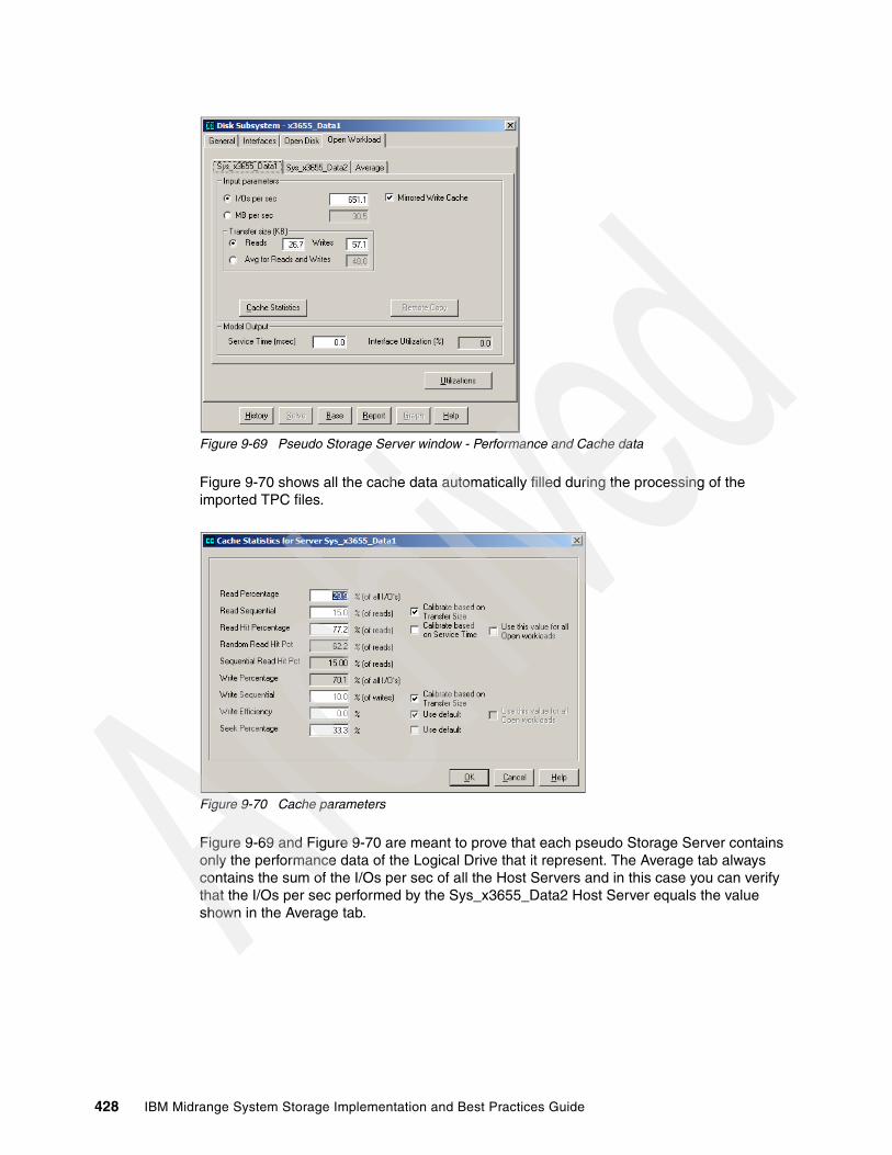
Figure 9-69 Pseudo Storage Server window - Performance and Cache data
Figure 9-70 shows all the cache data automatically filled during the processing of the imported TPC files.
Figure 9-70 Cache parameters
Figure 9-69 and Figure 9-70 are meant to prove that each pseudo Storage Server contains only the performance data of the Logical Drive that it represent. The Average tab always contains the sum of the I/Os per sec of all the Host Servers and in this case you can verify that the I/Os per sec performed by the Sys_x3655_Data2 Host Server equals the value shown in the Average tab.
428 IBM Midrange System Storage Implementation and Best Practices Guide

Figure 9-71 Average Performance data profile
Before proceeding with the merge of all the pseudo Storage Servers in a separate Storage Server, for each pseudo Storage Server, a base creation is required; to do that, click the Base button at the bottom of the window. The Disk Magic Base process establishes an internal set of values that will be used as a starting / reference point for any subsequent modeling, which is true for IBM zSeries®, IBM iSeries®, UNIX systems, and Windows systems workloads. The reference values are collectively referred to as the Base or the baseline model.
The term base is used because in each subsequent modeling step Disk Magic starts from the values in the base to predict the effect of changes to either the configuration or workload, such as an increase of the overall I/O rate or cache size, or a change of hardware or device type.
You must have Disk Magic establish a base after you have completed the initial input of the configuration and workload data, which is accomplished by clicking the Base button in the Disk Subsystem dialog. Note that establishing a base automatically includes the calibration process.
Note: Disk Magic automatically establishes a new base when you merge existing Disk Subsystems together or when a new Host Server is added to the model.
Chapter 9. IBM Tivoli Storage Productivity Center for Disk 429

Figure 9-72 shows how to merge the pseudo Storage Servers into the target Storage Server. You have to select all the pseudo Storage Servers on the right pane, then right-click and select Merge Add Merge Source Collection and create New Target.
Figure 9-72 Disk Magic Merge Operation
In Figure 9-73 you can see the window that merges the pseudo Storage Servers. The default name assigned by DiskMagic is “MergeTarget1”. You must click the Start Merge button to start the merge operation.
Figure 9-73 The Merge Target Window
430 IBM Midrange System Storage Implementation and Best Practices Guide

As shown in Figure 9-74, you can select the radio button, I want to merge all workloads on the selected DSSs.
Figure 9-74 Pseudo Storage Servers selection for merging process
As shown in Figure 9-75, the target Storage Server is going to inherit all the characteristics of the pseudo Storage Server members.
Figure 9-75 Changing the Merged Storage Server characteristics
Chapter 9. IBM Tivoli Storage Productivity Center for Disk 431
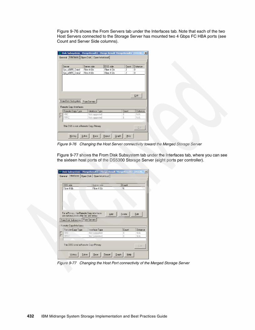
Figure 9-76 shows the From Servers tab under the Interfaces tab. Note that each of the two Host Servers connected to the Storage Server has mounted two 4 Gbps FC HBA ports (see Count and Server Side columns).
Figure 9-76 Changing the Host Server connectivity toward the Merged Storage Server
Figure 9-77 shows the From Disk Subsystem tab under the Interfaces tab, where you can see the sixteen host ports of the DS5300 Storage Server (eight ports per controller).
Figure 9-77 Changing the Host Port connectivity of the Merged Storage Server
432 IBM Midrange System Storage Implementation and Best Practices Guide

Finally in Figure 9-78, under the Average tab, you can see the performance data related to all the Logical Drives included in the analysis. By clicking the Solve button, you can get the outcomes in terms of:
� Service Time (msec)� Interface Utilization (%)� Utilizations
Figure 9-78 Summary of the consolidated performance data
Finally, by clicking the Utilizations button in Figure 9-78, the window Utilizations IBM DS5300 is displayed as shown in Figure 9-79. Here you can check the utilization of the Storage Server’s resources. See Chapter 10., “Disk Magic” on page 435 for more detailed information about Disk Magic parameters and HOWTOs. Briefly in this example, you can see that the DS5300 resources are under utilized, except for the Highest HDD Utilization (%).
Figure 9-79 Storage Server’s resources utilization
Chapter 9. IBM Tivoli Storage Productivity Center for Disk 433

434 IBM Midrange System Storage Implementation and Best Practices Guide
Chapter 10. Disk Magic
This chapter describes and illustrates the use of Disk Magic, developed by the company IntelliMagic.
Disk Magic is a tool for sizing and modelling disk systems for various servers. It performs accurate performance and analysis planning for IBM DS4000, DS5000, DS6000, DS8000 Storage Servers, SAN Volume Controller (SVC), and other vendors’ storage servers. Disk Magic allows for capacity planning and performance analysis work to be undertaken prior to the purchase of new equipment.
10
© Copyright IBM Corp. 2004-2010. All rights reserved. 435
10.1 Disk Magic overview
Disk Magic is a flexible and powerful tool to model the performance and capacity requirements of each storage server belonging to the midrange DS4000/DS5000 series.
Disk Magic helps you evaluate important considerations such as which disk type to use, which RAID levels are appropriate for your applications, the cache size requirements, and the utilization level of HBAs. Disk Magic shows current and expected response times, utilization levels, and throughput limits for your own installation’s I/O load and server configuration.
In a Disk Magic study, you start by collecting data about you current server and storage environment. The collected data is entered (automated or manual input) in Disk Magic and is used by Disk Magic to establish a baseline. You must have Disk Magic establish a base after you have completed the initial entering of the configuration and workload data.
With the data, Disk Magic can create a simulated model of your environment. Disk Magic allows for what-if analysis on items such as disk upgrades, moving workloads from one disk subsystem to another, or using another RAID level. Disk Magic keeps a history of all of the configuration changes made, which allows for the restoration of the project to a known stage.
Disk Magic can produce reports and graphs showing utilization figures on CPU and disk loads. The Report function creates a report of the current step in the model, as well as the base from which this model was derived. The report can be used to verify that all data was entered correctly. It also serves as a summary of the model results. The report lists all model parameters, including the ones that Disk Magic generates internally. You can also produce various graph types.
Disk magic runs in a Microsoft Windows environment. It does not require a connection with the storage subsystem to perform any of its functions because it processes manually entered data or input data coming from other useful tools such as UNIX/AIX/Linux iostat or Windows Performance Monitor log files.
At the time of writing, Disk Magic software does not support the DS5020 Storage Server and the newest features such as iSCSI connectivity, FC 8 Gbps connectivity, Solid State Disks and Full Disk Encryption. Go to the IntelliMagic Web site in order to determine the latest enhancements.
10.2 Information required for DS4000/DS5000 modeling with Disk Magic
The importance of gathering accurate performance data for the servers and the disk subsystem cannot be stressed enough. This information must reflect the environment as a good base line in itself.
To collect the data, identify one or two peak periods with a workload that is critical to your installation. Indeed, because you need to make sure that the storage server will be able to handle peak workloads, it makes sense to feed Disk Magic with peak workload data. However, in the selection of peak periods, you must avoid extremes (that is, an I/O workload that is unusually high or unusually low).
Make sure as well that the collection time is bounded to the peak period, as to not skew the statistics by periods of low activity within the same interval, which means that if you choose a long sampling interval there is a risk that I/O workload peaks will be cushioned by periods of low activity within the same interval.
436 IBM Midrange System Storage Implementation and Best Practices Guide
Finally, make sure that your statistics are complete and include all the servers that use the disk subsystem, whereas in case of San Volume Controller (SVC) that manages more disk subsystems, you must gather the input data for all disk subsystems to be attached to the SVC.
You can automate the gathering of data by using iostat (in a Linux, AIX, or UNIX environment) or perfmon log files (in a Windows environment) for all of the servers that use the disk subsystem. In this case, DiskMagic automatically summarizes in a table all the input data by interval (each column header indicates a performance counter specified in iostat or perfmon log file), and across all servers that contribute workload to the disk subsystem. Then, it is possible to select the interval with the peak value for a specific performance counter and use it as a baseline for your analysis.
The measurement data generated with iostat or Windows perfmon is limited because Storage Server layout configuration data (Total capacity, Physical Device Type, RAID type, HDDs per RAID array) and cache statistics are not specified, which makes it more difficult for Disk Magic to establish a fine-tuned calibrated model. However, Disk Magic can use the available statistics to compute a reasonable cache read hit ratio and to set the percent of read and write sequential activity.
� The cache Read Hit Ratio is computed based on the measured service time in combination with the configuration information, such as storage server type and physical disk type. Note that this only works if the data is collected on a disk subsystem supported by Disk Magic, and not when it is collected on internal disks. For internal disks, Disk Magic uses a default Read Hit Percentage.
� The Read Sequential and Write Sequential percentages are selected based on their transfer sizes. A large transfer size indicates a higher sequential content. and a small transfer size indicates a higher random access content.
Next we briefly describe how to use perfmon and iostat to collect statistics for Disk Magic.
If these files are unavailable, you can manually enter the following: blocksize, read/write ratio, read hit ratio, and I/O rate. Note that, except for the I/O rate, Disk Magic will provide defaults for all other parameters when you do not know or cannot easily collect this data.
10.2.1 Windows perfmon and Disk Magic
Windows Performance Monitor (or perfmon) is a useful tool for gathering performance statistics for Disk Magic. Disk Magic can automatically process the performance data in a Windows perfmon file.
To start the Performance Monitor on Windows Server 2008 and set up the logging, go to the task bar and click Start Control Panel Administrative Tools Reliability and Performance Data Collector Sets User Defined then right-click, select New and then Data Collector Set. The Create new Data Collector Set opens and here you can enter the name of the collector set (in this case MyDataCollector) and then select the radiobox Create manually (Advanced) as shown in Figure 10-1. The manual selection allows you to select the counters of interest in your analysis.
Note: As a best practice you can (and must) choose to enter the sequential percentages yourself if they are known to you from another source.
Chapter 10. Disk Magic 437

Figure 10-1 Create new log file
In the following window you have to select Create data logs and flag the check box Performance counter in order to gather performance data, as shown in Figure 10-2. Then click the Next button.
438 IBM Midrange System Storage Implementation and Best Practices Guide
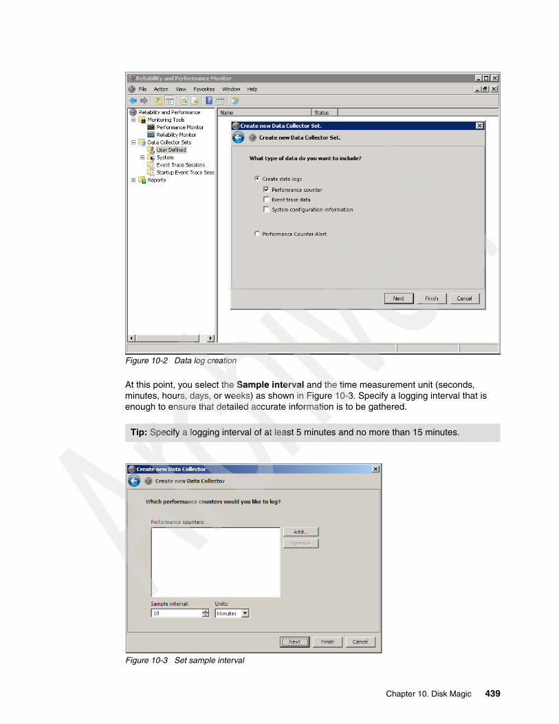
Figure 10-2 Data log creation
At this point, you select the Sample interval and the time measurement unit (seconds, minutes, hours, days, or weeks) as shown in Figure 10-3. Specify a logging interval that is enough to ensure that detailed accurate information is to be gathered.
Figure 10-3 Set sample interval
Tip: Specify a logging interval of at least 5 minutes and no more than 15 minutes.
Chapter 10. Disk Magic 439
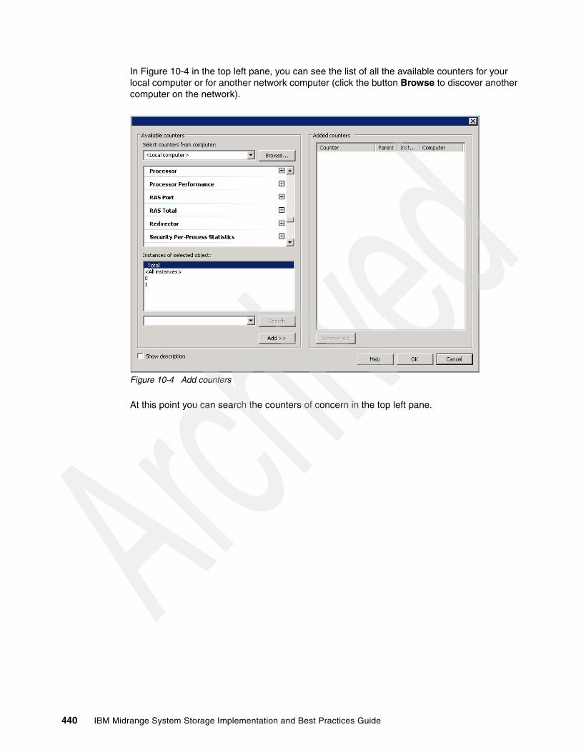
In Figure 10-4 in the top left pane, you can see the list of all the available counters for your local computer or for another network computer (click the button Browse to discover another computer on the network).
Figure 10-4 Add counters
At this point you can search the counters of concern in the top left pane.
440 IBM Midrange System Storage Implementation and Best Practices Guide

In Figure 10-5 you can see the selection of all of the counters for the PhysicalDisk parameter. Note that we are going to choose only the external disks on the DS Storage Server and not the internal system disk.
Figure 10-5 Add all counters only for PhysicalDisk parameter
On the bottom left pane named Instances of selected object (Figure 10-5), you can select the physical disks for which the performance must be logged. These are only the disks that are managed by the external Storage Server. This selection must not include the system drive, which is normally the server’s internal disk drive.
Otherwise, in case of SAN boot, you must select the boot Logical Drive in order to check a potentially high paging activity.
You can select more than one disk, but keep in mind that only the SAN-based disks (Logical Drives) must be selected. You can also include the total, but it will be disregarded by Disk Magic because it performs its own total for the selected disks. Click OK to return to the Reliability and Performance Monitor window.
Next, on the right pane in Figure 10-5, you select the DataCollector01 entry, right-click and then click Properties to open the DataCollector01 Properties window (Figure 10-6).
Note: The entity that can be modeled by Disk Magic is the physical disk, that is, a Logical Drive on an external Storage Server. So when you need to use perfmon to gather I/O load statistics, you must make sure to run the perfmon procedure on each host server that accesses the Storage Server to be analyzed and to start and stop the perfmon procedure at the same time on each host server.
Chapter 10. Disk Magic 441

In this window, under the Performance Counters tab, you specify the logging file format by selecting the item Comma Separated in the Log format pull-down menu as shown in Figure 10-6. This procedure is going to produce a comma delimited file (.CSV file).
Figure 10-6 Log file format selection
442 IBM Midrange System Storage Implementation and Best Practices Guide

Click the File tab and select the name of your CSV file and if necessary, the file format. Choose a meaningful format and naming convention for your CSV files (Figure 10-7).
Figure 10-7 Log file format selection
Note that if a Host Server has multiple Logical Drives mapped, Disk Magic can emulate this configuration by creating a “pseudo-Host Server” for each Logical Drive mapped, thus giving the opportunity of filling specific performance data for each Logical Drive individually mapped to each pseudo-Host Server.
We can concurrently generate a CSV file for each Logical Drive mapped onto an individual Host Server in order to have a more accurate scenario from the DiskMagic standpoint. Then you must rename the host name column inside each CSV file belonging to the same Host Server in order to stick to the real scenario in terms of Logical Drives.
Naming convention: Consider the following situation:
� Suppose that you have a Windows 2008 Server with hostname NJS001 and with two LUNs mapped (named Data1 and Data2).
� You can create two CSV files named NJS001_Data1_22September2009.csv and NJS001_Data1_22September2009.csv, respectively.
� Then, within these two CSV files, you must rename each hostname’s reference with NJS001_Data1 and NJS001_Data2.
Tip: Check the Prefix file with computer name check box to easily recognize the Host Server when the file is going to be imported within Disk Magic.
Note: Within Disk Magic, we assume that always exists a 1:1 mapping between a Host Server or Pseudo-Host Server and a Logical Drive.
Chapter 10. Disk Magic 443

Finally, you must define the date and time the logging is to be started and stopped and which days of the week must be included in the collection, which can be easily done on the Schedule tab, as you can see in Figure 10-8. Ensure that perfmon is set to gather I/O load statistics on each server that accesses the disk subsystem to be analyzed. Also, make sure to start and stop the perfmon procedure at the same time on each Windows server that gets its Logical Drives from the external Storage Server.
Figure 10-8 Set schedule for how long to log for
444 IBM Midrange System Storage Implementation and Best Practices Guide

Finally, you are ready to start the collecting process moving in the left pane of the Reliability and Performance Monitor window, right-clicking the name of your personal Data Collector Set (in this case MyDataCollector) and then clicking the Start item.
In order to use this perfmon file in Disk Magic, start Disk Magic and select the radiobox Open and iSeries Automated Input (*.IOSTAT, *.TXT, *.CSV) as shown in Figure 10-9. As an alternative to the previous procedure, use File > Open input for iSeries and/or Open... from the Disk Magic main window and set the file type to Perfmon Reports (*.csv). This method can be used when Disk Magic is already running and you want to start a new project.
Figure 10-9 Importing Windows performance data into Disk Magic
Chapter 10. Disk Magic 445
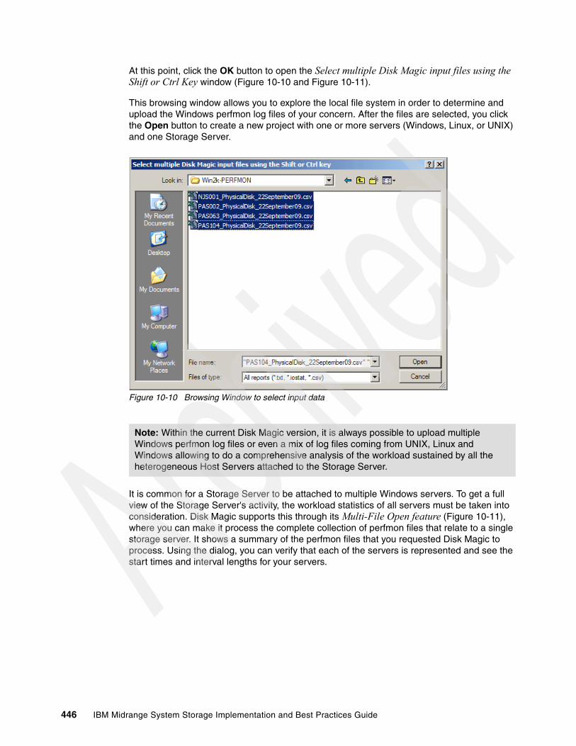
At this point, click the OK button to open the Select multiple Disk Magic input files using the Shift or Ctrl Key window (Figure 10-10 and Figure 10-11).
This browsing window allows you to explore the local file system in order to determine and upload the Windows perfmon log files of your concern. After the files are selected, you click the Open button to create a new project with one or more servers (Windows, Linux, or UNIX) and one Storage Server.
Figure 10-10 Browsing Window to select input data
It is common for a Storage Server to be attached to multiple Windows servers. To get a full view of the Storage Server's activity, the workload statistics of all servers must be taken into consideration. Disk Magic supports this through its Multi-File Open feature (Figure 10-11), where you can make it process the complete collection of perfmon files that relate to a single storage server. It shows a summary of the perfmon files that you requested Disk Magic to process. Using the dialog, you can verify that each of the servers is represented and see the start times and interval lengths for your servers.
Note: Within the current Disk Magic version, it is always possible to upload multiple Windows perfmon log files or even a mix of log files coming from UNIX, Linux and Windows allowing to do a comprehensive analysis of the workload sustained by all the heterogeneous Host Servers attached to the Storage Server.
446 IBM Midrange System Storage Implementation and Best Practices Guide

Figure 10-11 Multiple File Open
At this stage, Disk Magic did not read every file in full; it just reads enough to pick up the start time of the period for which the file was created, and the interval length. At this time, it does not know yet how many intervals are included in each file. You must use the next dialog, that is, the I/O Load Summary by Interval (Figure 10-12), to make sure that each file contains data for each interval. The interval lengths will typically be round values (00:10:00 or 00:15:00 or something similar). You might see unique interval lengths for particular files, for instance, 10 minutes on the UNIX servers and 5 minutes on the Windows servers. This difference will be handled automatically by Disk Magic by aggregating all data to the least common multiple of all intervals. The least common multiple is shown in the left bottom area of the dialog.
You might see start times that are slightly mismatched, for instance one measurement period started at the hour (20:00:00) and another starts at a little after the hour (20:01:03). Again, this is something that Disk Magic will handle automatically, no action from you side is required.
Disk Magic then summarizes the data and allows you to identify the interval you intend to create a model for with Disk Magic. The challenge in summarizing the data generated by multiple servers is to find the most relevant overall interval: Disk Magic finds the peak of the sums, rather than the sum of the peaks.
After you have selected the files and clicked the Open button, a summary table of all the gathered data samples is displayed as shown in Figure 10-12. At this point, you can click a column header to select the interval with the peak value for that column, or click a row to select a specific interval to enter.
Chapter 10. Disk Magic 447

Figure 10-12 I/O Load Summary by Interval
By clicking the button Add Model, the perfmon file is processed and Disk Magic displays a pop-up a message: “DMW1311A Is this workload currently on a Disk Subsystem type that is supported in Disk Magic? (If it is, Disk Magic will use the measured service times for calibration purposes.)” where you answer yes, because DS4000/DS5000 is fully supported in Disk Magic.
This completes the first part of any Disk Magic study: the creation of a Baseline model. You can now proceed to model the effects of changing the hardware, interfaces, or I/O load.
In Figure 10-13 you can see in the left pane (called TreeView), four servers (represented by a red icon followed by the server host name) and a storage server (represented by a pale blue icon followed by DSS1). You can change the name of the Storage Server from DSS1 to a more suitable name, right-clicking the pale blue icon and selecting rename. As you can see in Figure 10-13, we have selected an Hardware Type IBM DS5300 and we have renamed the storage server as DS5300.
Note: Disk Magic uses the term Disk Storage Subsystem (DSS) to identify a Storage Server and, in the baseline model creation, it works out with a default Storage Server IBM System Storage DS8100 Turbo model. After having created the baseline model, you can easily change the Storage Server model with the model that you need.
448 IBM Midrange System Storage Implementation and Best Practices Guide

Figure 10-13 Disk Magic view showing the imported servers from PerfLog files
Because you have changed the Storage Server model from default to a DS4000/DS5000 series Storage Server model, you also need to adjust the host connectivity both from the Storage Server side and from the Host Server side, in order to set the FC connectivity layout that you have in mind. For example, in Figure 10-14 under the column header “Count”, we have used sixteen 4 Gbps host ports for the Storage Server.
Chapter 10. Disk Magic 449
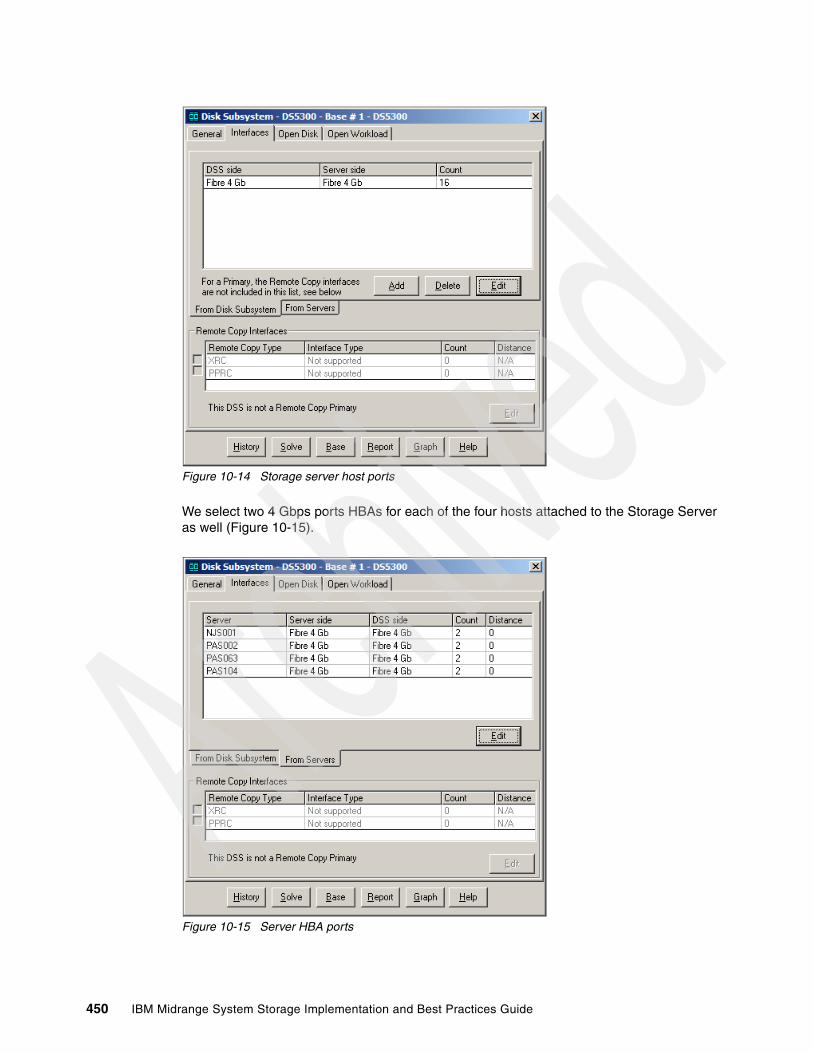
Figure 10-14 Storage server host ports
We select two 4 Gbps ports HBAs for each of the four hosts attached to the Storage Server as well (Figure 10-15).
Figure 10-15 Server HBA ports
450 IBM Midrange System Storage Implementation and Best Practices Guide

The measurement data generated with iostat or Windows perfmon is limited because it does not contain Storage Server configuration information such as Total capacity, Physical Device Type, RAID type, HDDs per RAID array. At this point, this configuration data can be picked up from the DS storage profile or directly from the DS Storage Manager (SM). For example, Figure 10-16 shows that the Host Server PAS104 has been mapped to a Logical drive of 250GB in a RAID 5 array composed of seven FC 300 GB 15k Hard Disk Drives (HDD).
Figure 10-16 Storage server disk configuration
10.2.2 iostat and Disk Magic
For the Linux and UNIX environments, performance data can be captured using iostat. The resulting output file (report) can be processed for use with Disk Magic.
Automated input for UNIX and Linux is supported for:
� AIX� HP UNIX� Sun Solaris� Linux (Redhat and SUSE)
The iostat command produces I/O load statistics, including MBs read and write.
Cache statistics or information about the type of disk subsystem is not included in the iostat report. The cache size must be entered manually into Disk Magic before Disk Magic can create the base line.
The iostat reports do not include information that can allow Disk Magic to identify the entity of a storage server, and therefore it is not possible for Disk Magic to separate the I/O load statistics by disk subsystem. Consequently, you must not create an iostat file that covers more than one disk subsystem.
Chapter 10. Disk Magic 451
You must make sure to run the iostat procedure on each server that accesses the disk subsystem to be analyzed. Make sure as well to start and stop the iostat procedure at the same time on each server.
The iostat automated input process is performed as follows:
1. Enter the command depending upon the operating system:
– For AIX
iostat i n > servername.iostat
– For HP UNIX
iostat i n > servername.iostat
– For Sun Solaris
iostat -xtc i n > servername.iostat or iostat -xnp il n > systemname.iostat
– For Linux
iostat -xk i n > servername.iostat
Where:
– i is the interval in seconds.– n is the number of intervals, which must always be greater than 1.– servername.iostat is the output file. Its file type must always be iostat.
A sample Linux command is:
iostat -xk 600 10 > linuxserver.iostat.
Make sure the person that collects the data confirms what interval length and number of intervals were used in the command as well as what time of day the data collection was started. The commands do not document this information in the output file.
2. When the data collection has finished, edit servername.iostat to insert two lines of header information:
os iostat system=servername interval=i count=nddmonyyyy hh:mm
– os is the operating system on which the iostat performance data was collected, such as AIX, HP-UX, Sun Solaris, or Linux. It does not matter whether you use upper-case or lower-case, or a mix. Disk Magic will also accept the following permutations of the UNIX / Linux names: hp ux, hpux, sunsolaris, sun-solaris, solaris, sun, redhat, and suse.
– i and n must be the same as in the original iostat command.
– dd, yyyy, hh, and mm are numerical, and 'mon' is alphabetic and reflects the month of the date. They must reflect date and time of the first interval in the iostat gathering period.
For example, the line to add for an Iostat Linux file is:
redhat iostat system=linuxserver interval=600 count=1013nov2006 10:10
Note: With automated input, the number can be quite large if necessary in order to try to capture a peak time or IO activity. A day or a week at most is common (when input had to be calculated manually from the data, a guideline for the number of intervals collected was only 10 intervals at 10 minutes each). Moreover, an interval length of 10 minutes (600 seconds) works well, however, it can be anything between 5 minutes and 30 minutes.
452 IBM Midrange System Storage Implementation and Best Practices Guide

To use the resulting iostat file in Disk Magic, start Disk Magic and select the radiobox Open and iSeries Automated Input (*.IOSTAT, *.TXT, *.CSV) as shown in Figure 10-17, which will create a new project with one or more servers and one disk system. Later, you can add more iostat data from other servers. As an alternative to the previous option, use File Open input for iSeries and/or Open... from the Disk Magic main window and set the file type to iostat Reports (*.iostat). This last method can be used when Disk Magic is already running and you want to start a new project.
Figure 10-17 Importing an iostat file into Disk Magic
Keep in mind that the measurement data generated with iostat or Windows perfmon is limited because it does not contain cache statistics and configuration information such as Total capacity, Physical Device Type, RAID type, HDDs per RAID array. At this point, you must manually insert the configuration data as you see fit.
10.2.3 Mixed platforms and Disk Magic
As mentioned before, it is common for a storage server to be attached to multiple UNIX, Linux, or Windows servers. To get a full view of the disk subsystem's activity, the workload statistics of all servers (Linux, UNIX, Windows) need to be taken into consideration. Disk Magic supports this through its Multi-File Open feature: you can make it process the complete collection of iostat files, perfmon files that relate to a single storage server. The Multiple File Open-File Overview shows a summary of the iostat, perfmon files that you requested Disk Magic to process (Figure 10-18).
Chapter 10. Disk Magic 453

Figure 10-18 Multiple File Open for Mixed Environment
In the Multiple File Open - File Overview window shown in Figure 10-18, you can verify that each of the servers is represented and see the start times and interval lengths for your servers.
At this stage, Disk Magic did not read every file in full; it just reads enough to pick up the start time of the period for which the file was created, and the interval length. At this time, it does not know yet how many intervals are included in each file. You must use the next dialog, the I/O Load Summary by Interval, to make sure that each file contains data for each interval.
The interval lengths will typically be round values (00:10:00 or 00:15:00 or something similar). You might see unique interval lengths for particular files, for instance, 10 minutes on the UNIX servers and 5 minutes on the Windows servers. This difference will be handled automatically by Disk Magic by aggregating all data to the least common multiple of all intervals. The least common multiple is shown in the left bottom area of the dialog.
You might see start times that are slightly mismatched, for instance one measurement period started at the hour (20:00:00) and another starts at a little after the hour (20:01:03). Again, this is something that Disk Magic will handle automatically, no action from you side is required.
For perfmon data, there might be a deviation in the interval length, because of the way perfmon writes the intervals. You must verify that you are seeing only round values for all lines in the File Overview. When a server has an interval length that is not a round value, such as 00:14:21 instead of 00:15:00, then you must select that line and press Edit Properties to change this to the normalized value. For instance, when there are 5 Windows servers and 4 of them show an interval length of 00:15:00 but one shows an interval length of 00:14:43 then you must change the last one to 00:15:00 (Figure 10-19).
454 IBM Midrange System Storage Implementation and Best Practices Guide
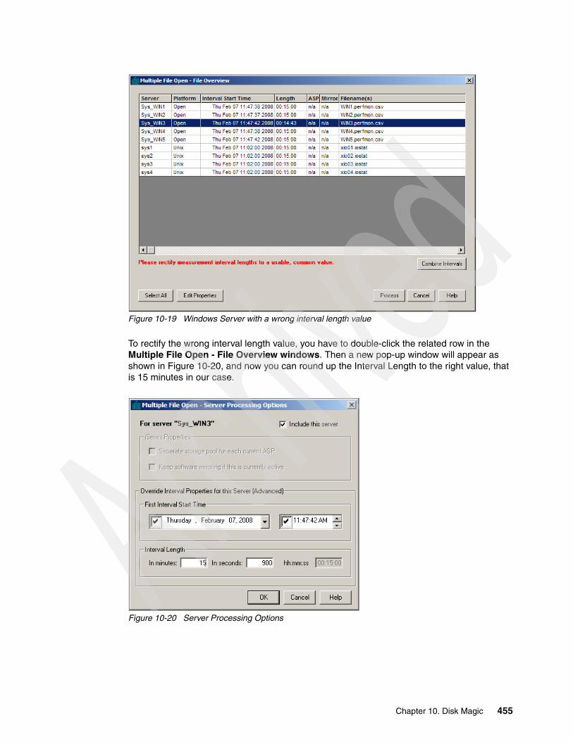
Figure 10-19 Windows Server with a wrong interval length value
To rectify the wrong interval length value, you have to double-click the related row in the Multiple File Open - File Overview windows. Then a new pop-up window will appear as shown in Figure 10-20, and now you can round up the Interval Length to the right value, that is 15 minutes in our case.
Figure 10-20 Server Processing Options
Chapter 10. Disk Magic 455

10.3 Disk Magic configuration example
To illustrate the use of Disk Magic, consider the following environment:
� A DS5300, with EXP5000 enclosures.
� All arrays need to have enclosure loss protection.
� Five separate hosts (three of these are Windows based, whereas the other two are Linux based) can access the DS5300 through SAN, and each host is equipped with two 4 Gbps HBAs.
As these are Windows hosts, the host type will be defined as open in Disk Magic. The statistics gained from the perfmon files are used in Disk Magic as a base line.
The hosts are as follows:
� Host 1: database server
– It requires 350 GB of RAID 5 with 146 GB high-speed drives.– It has an expected workload of 100 I/Os per second with a 16 K transfer size.– Read percentage is expected to be 63%.
� Host 2: file and print server
– It requires at least 1 TB of storage of RAID 5 with 450 GB on 15K drives.– It has an expected workload of 50 I/Os per second with an 8 K transfer size.– Read percentage is expected to be 60%.
� Host 3: database server
– It requires 500 GB of RAID 5 with 146 GB high-speed drives.– It has an expected workload of 150 I/Os per second with a 4 K transfer size.– Read percentage is expected to be 60%.
� Host 4: e-mail server
– It requires 350 GB of RAID 10 with73 GB high-speed drives.– It has 500 users, and an expected I/O load of 1 I/O per second per mailbox.– Its expected workload is 550 I/Os per second with a 4 K transfer size.– Read percentage is expected to be 50%.
� Host 5: database server
– It requires 400 GB of RAID 10 with 146 GB high-speed drives.– It has an expected workload of 150 I/Os per second with an 8 K transfer size.– Read percentage is expected to be 65%.
456 IBM Midrange System Storage Implementation and Best Practices Guide

We create a new project in Disk Magic and we initially upload only one Windows server using the procedure described in “Windows perfmon and Disk Magic” on page 437.
Figure 10-21 Add additional performance counters
As you can see in Figure 10-21, the main window is divided in three panes:
� The TreeView displays the structure of a project with the servers and hosts that are included in a model. We started by specifying just one Disk Subsystem (DS5300) and one open server (DBServer1).
� The ListView shows the content of any entity selected in the TreeView.
� The Browser is used to display reports and also informational and error messages.
Chapter 10. Disk Magic 457
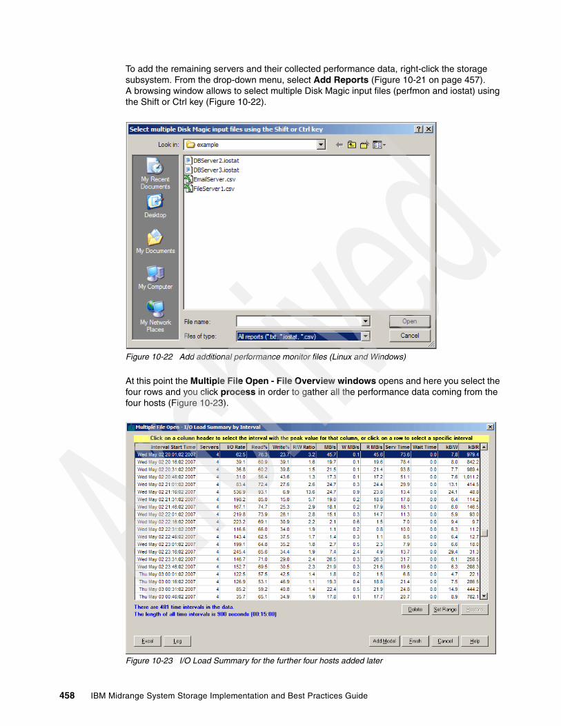
To add the remaining servers and their collected performance data, right-click the storage subsystem. From the drop-down menu, select Add Reports (Figure 10-21 on page 457). A browsing window allows to select multiple Disk Magic input files (perfmon and iostat) using the Shift or Ctrl key (Figure 10-22).
Figure 10-22 Add additional performance monitor files (Linux and Windows)
At this point the Multiple File Open - File Overview windows opens and here you select the four rows and you click process in order to gather all the performance data coming from the four hosts (Figure 10-23).
Figure 10-23 I/O Load Summary for the further four hosts added later
458 IBM Midrange System Storage Implementation and Best Practices Guide

By clicking the column header I/O rate in order to select the aggregate I/O peak, clicking Add Model and then Finish on the I/O Load summary by Interval window (Figure 10-23 on page 458), you create a base line model and so are able to do analysis on the whole solution.
If you double-click the storage subsystem, the Disk Subsystem dialog opens. It contains the following tabs:
� The General tab allows you to enter Disk Subsystem level configuration data, such as the brand and type of subsystem and cache size. You can rename the disk subsystem and set the appropriate type, as shown in Figure 10-24.
Figure 10-24 Storage subsystem General tab
Note: Keep in mind that when you process multiple files and you select a specific column header in the I/O Load summary by Interval window, DiskMagic figures out the peak of the sum and not the sum of the peaks for the metric selected.
Chapter 10. Disk Magic 459
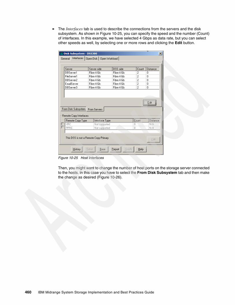
� The Interfaces tab is used to describe the connections from the servers and the disk subsystem. As shown in Figure 10-25, you can specify the speed and the number (Count) of interfaces. In this example, we have selected 4 Gbps as data rate, but you can select other speeds as well, by selecting one or more rows and clicking the Edit button.
Figure 10-25 Host Interfaces
Then, you might want to change the number of host ports on the storage server connected to the hosts. In this case you have to select the From Disk Subsystem tab and then make the change as desired (Figure 10-26).
460 IBM Midrange System Storage Implementation and Best Practices Guide

Figure 10-26 Change host-port connectivity in the storage server
� The Open Disk page, shown in Figure 10-27, is used to describe the physical disk and Logical Drive (LUN) configuration for each host.
Figure 10-27 Set the disk size, number of disks, and RAID level
Chapter 10. Disk Magic 461
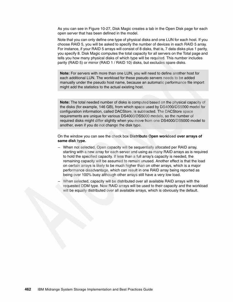
As you can see in Figure 10-27, Disk Magic creates a tab in the Open Disk page for each open server that has been defined in the model.
Note that you can only define one type of physical disks and one LUN for each host. If you choose RAID 5, you will be asked to specify the number of devices in each RAID 5 array. For instance, if your RAID 5 arrays will consist of 8 disks, that is, 7 data disks plus 1 parity, you specify 8. Disk Magic computes the total capacity for all servers on the Total page and tells you how many physical disks of which type will be required. This number includes parity (RAID 5) or mirror (RAID 1 / RAID 10) disks, but excludes spare disks.
On the window you can see the check box Distribute Open workload over arrays of same disk type.
– When not selected, Open capacity will be sequentially allocated per RAID array, starting with a new array for each server and using as many RAID arrays as is required to hold the specified capacity. If less than a full array’s capacity is needed, the remaining capacity will be assumed to remain unused. Another effect is that the load on certain arrays is likely to be much higher than on other arrays, which is a major performance disadvantage, which can result in one RAID array being reported as being over 100% busy although other arrays still have a very low load.
– When selected, capacity will be distributed over all available RAID arrays with the requested DDM type. Now RAID arrays will be used to their capacity and the workload will be equally distributed over all available arrays, which is obviously the default.
Note: For servers with more than one LUN, you will need to define another host for each additional LUN. The workload for these pseudo servers needs to be added manually under the pseudo host name, because an automatic performance file import might add the statistics to the actual existing host.
Note: The total needed number of disks is computed based on the physical capacity of the disks (for example, 146 GB), from which space used by DS4000/DS5000 model for configuration information, called DACStore, is subtracted. The DACStore space requirements are unique for various DS4000/DS5000 models, so the number of required disks might differ slightly when you move from one DS4000/DS5000 model to another, even if you do not change the disk type.
462 IBM Midrange System Storage Implementation and Best Practices Guide

� The Open Workload page is used to enter the I/O load statistics for each server in the model.
All of the data elements are entered at the subsystem level. I/O rate or MBps are required. Importing the performance files will automatically populate these fields. Note that it is also possible to select the check box Mirrored Write Cache in order to mirror every write operation toward a specific LUN from controller owner’s cache to the other controller’s cache (Figure 10-28).
Figure 10-28 Set the workload per host
Chapter 10. Disk Magic 463

Optionally, click the Cache Statistics button to enter the cache statistics as shown in Figure 10-29.
If you have measured cache statistics for the disk subsystem being analyzed, de-select Calibrate based on Service Time and Calibrate based on Transfer Size to enter those statistics manually.
Figure 10-29 Adjust cache statistics
Note: Note that you must not change the Read and Write percentages if you used automated input, because iostat (except HP-UX iostat) and perfmon contain precise information about read and write rates.
464 IBM Midrange System Storage Implementation and Best Practices Guide
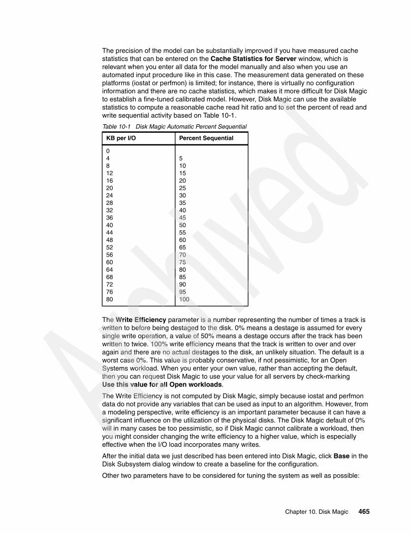
The precision of the model can be substantially improved if you have measured cache statistics that can be entered on the Cache Statistics for Server window, which is relevant when you enter all data for the model manually and also when you use an automated input procedure like in this case. The measurement data generated on these platforms (iostat or perfmon) is limited; for instance, there is virtually no configuration information and there are no cache statistics, which makes it more difficult for Disk Magic to establish a fine-tuned calibrated model. However, Disk Magic can use the available statistics to compute a reasonable cache read hit ratio and to set the percent of read and write sequential activity based on Table 10-1.
Table 10-1 Disk Magic Automatic Percent Sequential
The Write Efficiency parameter is a number representing the number of times a track is written to before being destaged to the disk. 0% means a destage is assumed for every single write operation, a value of 50% means a destage occurs after the track has been written to twice. 100% write efficiency means that the track is written to over and over again and there are no actual destages to the disk, an unlikely situation. The default is a worst case 0%. This value is probably conservative, if not pessimistic, for an Open Systems workload. When you enter your own value, rather than accepting the default, then you can request Disk Magic to use your value for all servers by check-marking Use this value for all Open workloads.
The Write Efficiency is not computed by Disk Magic, simply because iostat and perfmon data do not provide any variables that can be used as input to an algorithm. However, from a modeling perspective, write efficiency is an important parameter because it can have a significant influence on the utilization of the physical disks. The Disk Magic default of 0% will in many cases be too pessimistic, so if Disk Magic cannot calibrate a workload, then you might consider changing the write efficiency to a higher value, which is especially effective when the I/O load incorporates many writes.
After the initial data we just described has been entered into Disk Magic, click Base in the Disk Subsystem dialog window to create a baseline for the configuration.
Other two parameters have to be considered for tuning the system as well as possible:
KB per I/O Percent Sequential
048121620242832364044485256606468727680
5101520253035404550556065707580859095100
Chapter 10. Disk Magic 465
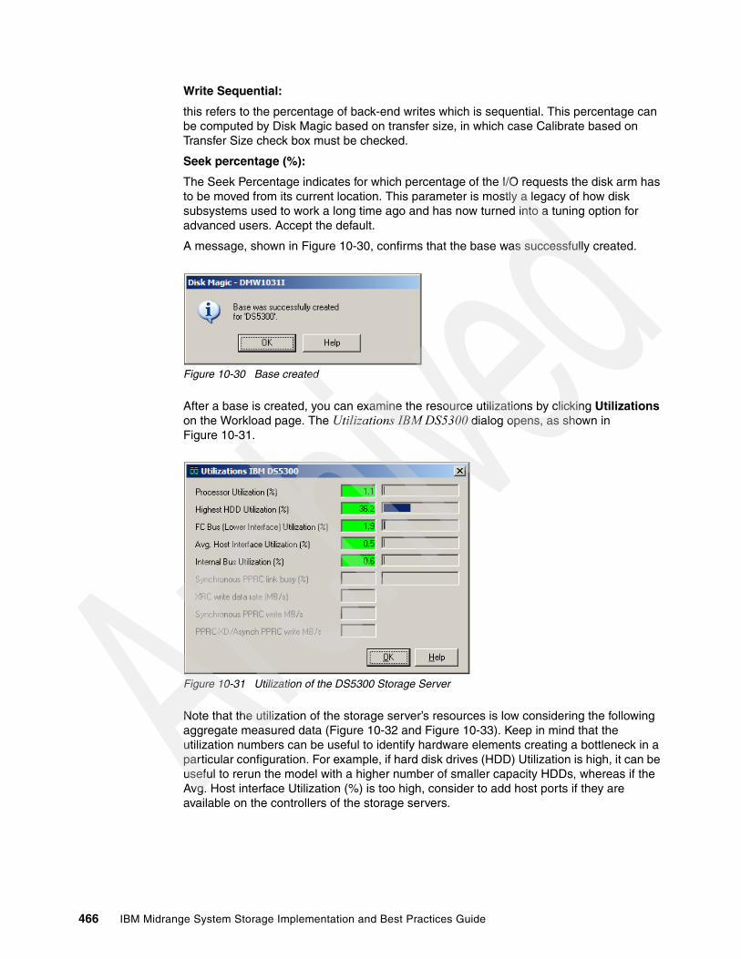
Write Sequential:
this refers to the percentage of back-end writes which is sequential. This percentage can be computed by Disk Magic based on transfer size, in which case Calibrate based on Transfer Size check box must be checked.
Seek percentage (%):
The Seek Percentage indicates for which percentage of the I/O requests the disk arm has to be moved from its current location. This parameter is mostly a legacy of how disk subsystems used to work a long time ago and has now turned into a tuning option for advanced users. Accept the default.
A message, shown in Figure 10-30, confirms that the base was successfully created.
Figure 10-30 Base created
After a base is created, you can examine the resource utilizations by clicking Utilizations on the Workload page. The Utilizations IBM DS5300 dialog opens, as shown in Figure 10-31.
Figure 10-31 Utilization of the DS5300 Storage Server
Note that the utilization of the storage server’s resources is low considering the following aggregate measured data (Figure 10-32 and Figure 10-33). Keep in mind that the utilization numbers can be useful to identify hardware elements creating a bottleneck in a particular configuration. For example, if hard disk drives (HDD) Utilization is high, it can be useful to rerun the model with a higher number of smaller capacity HDDs, whereas if the Avg. Host interface Utilization (%) is too high, consider to add host ports if they are available on the controllers of the storage servers.
466 IBM Midrange System Storage Implementation and Best Practices Guide

Figure 10-32 Aggregate Performance View
Figure 10-33 Total Number and Type of disk drives used
Disk Magic keeps a history of all of the configuration changes made, which allows for the restoration of the project to a known stage. To get the History Control Panel, click History in the Disk Subsystem window.
Chapter 10. Disk Magic 467

In our case, Figure 10-34 shows that at this point in time only the base has been created.
Figure 10-34 Base image - History Control Panel
After the base is established, what-if analysis can be undertaken. For example, you can analyze the effect of:
� Changing the number of disks in an array� Changing the RAID protection of a specific array � Analyzing the difference between SATA and Fibre Channel disks� Comparing various storage servers
As you perform your various what-if analyses and select Solve, additional reports appear in this History Control Panel. Rename each entry to reflect what the changes represent.
10.3.1 Report
Selecting Report in the Disk Subsystem window creates a report of the current step in the model, as well as the base from which this model was derived. The report can be used to verify that all data was entered correctly. It also serves as a summary of the model results. The report lists all model parameters, including the ones that Disk Magic generates internally.
Example 10-1 shows a sample report.
Example 10-1 Base output from the project
Base model for this configurationProject Project1
Model Model1
Disk Subsystem name: DS5300
Type: DS5300 (IBM)Cache size: 16384 MbyteInterfaces: 16 Fibre 4 Gb FAStT, 4 Gb Server Interface Adapters
Total Capacity: 2600.0 GB approximately 25 disks of type DS5000 146GB/15k approximately 5 disks of type DS5000 450GB/15k
Remote copy type: No Remote Copy Active or Remote Copy Not Supported
468 IBM Midrange System Storage Implementation and Best Practices Guide
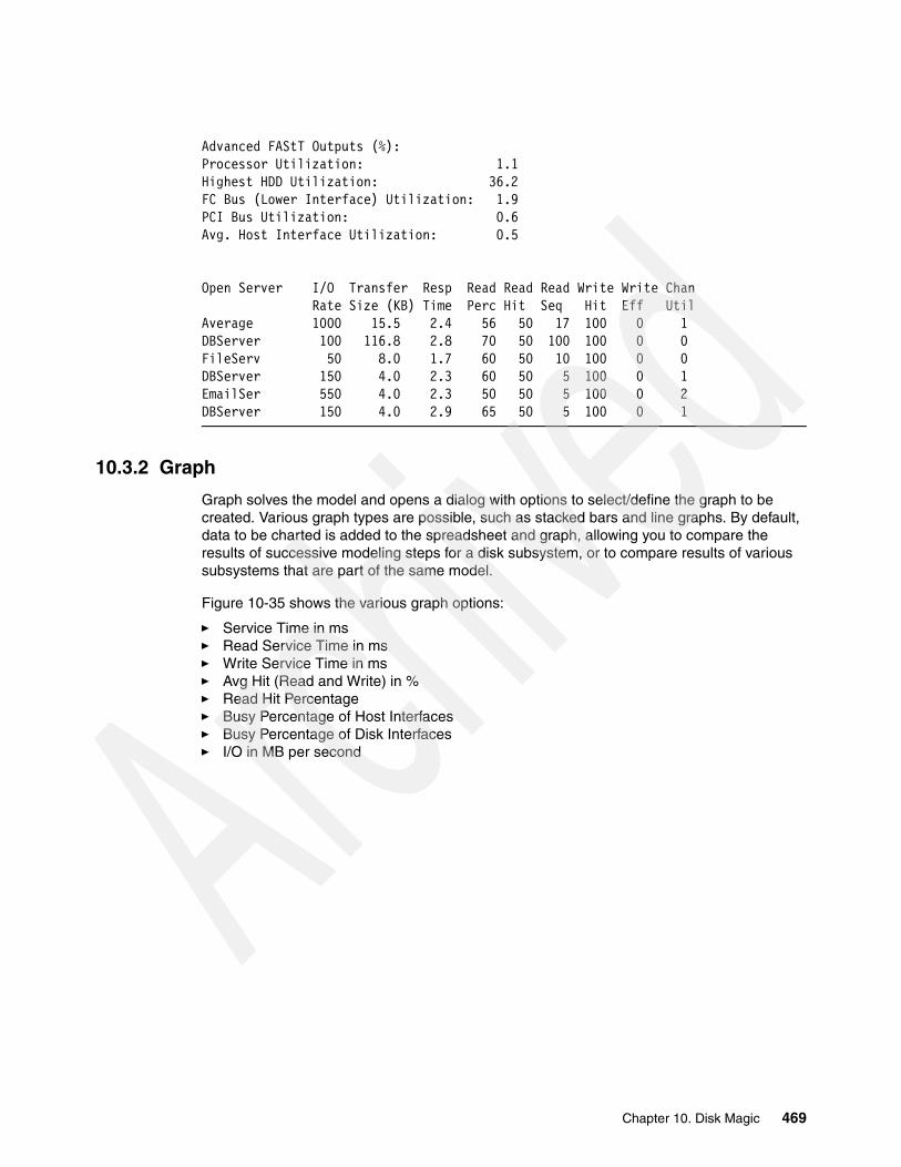
Advanced FAStT Outputs (%):Processor Utilization: 1.1Highest HDD Utilization: 36.2FC Bus (Lower Interface) Utilization: 1.9PCI Bus Utilization: 0.6Avg. Host Interface Utilization: 0.5
Open Server I/O Transfer Resp Read Read Read Write Write Chan Rate Size (KB) Time Perc Hit Seq Hit Eff UtilAverage 1000 15.5 2.4 56 50 17 100 0 1DBServer 100 116.8 2.8 70 50 100 100 0 0FileServ 50 8.0 1.7 60 50 10 100 0 0DBServer 150 4.0 2.3 60 50 5 100 0 1EmailSer 550 4.0 2.3 50 50 5 100 0 2DBServer 150 4.0 2.9 65 50 5 100 0 1
10.3.2 Graph
Graph solves the model and opens a dialog with options to select/define the graph to be created. Various graph types are possible, such as stacked bars and line graphs. By default, data to be charted is added to the spreadsheet and graph, allowing you to compare the results of successive modeling steps for a disk subsystem, or to compare results of various subsystems that are part of the same model.
Figure 10-35 shows the various graph options:
� Service Time in ms� Read Service Time in ms� Write Service Time in ms� Avg Hit (Read and Write) in %� Read Hit Percentage� Busy Percentage of Host Interfaces� Busy Percentage of Disk Interfaces� I/O in MB per second
Chapter 10. Disk Magic 469
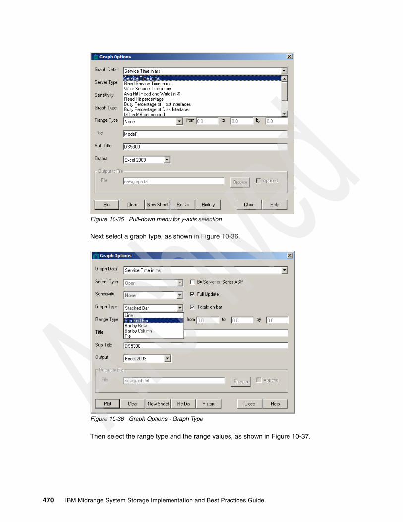
Figure 10-35 Pull-down menu for y-axis selection
Next select a graph type, as shown in Figure 10-36.
Figure 10-36 Graph Options - Graph Type
Then select the range type and the range values, as shown in Figure 10-37.
470 IBM Midrange System Storage Implementation and Best Practices Guide
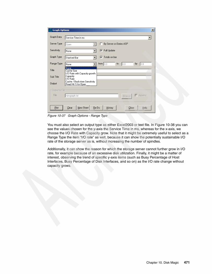
Figure 10-37 Graph Options - Range Type
You must also select an output type as either Excel2003 or text file. In Figure 10-38 you can see the values chosen for the y-axis the Service Time in ms, whereas for the x-axis, we choose the I/O Rate with Capacity grow. Note that it might be extremely useful to select as a Range Type the item “I/O rate” as well, because it can show the potentially sustainable I/O rate of the storage server as is, without increasing the number of spindles.
Additionally, it can show the reason for which the storage server cannot further grow in I/O rate, for example because of an excessive disk utilization. Finally, it might be a matter of interest, observing the trend of specific y-axis items (such as Busy Percentage of Host Interfaces, Busy Percentage of Disk Interfaces, and so on) as the I/O rate change without capacity grows.
Chapter 10. Disk Magic 471

Figure 10-38 Setting for Service Time graph with range type of I/O rate with Capacity grow
Select Plot to generate the graph.
The resulting graph is shown in Figure 10-39.
Figure 10-39 Output of Service Time graph with I/O Rate with Growth Capacity
472 IBM Midrange System Storage Implementation and Best Practices Guide
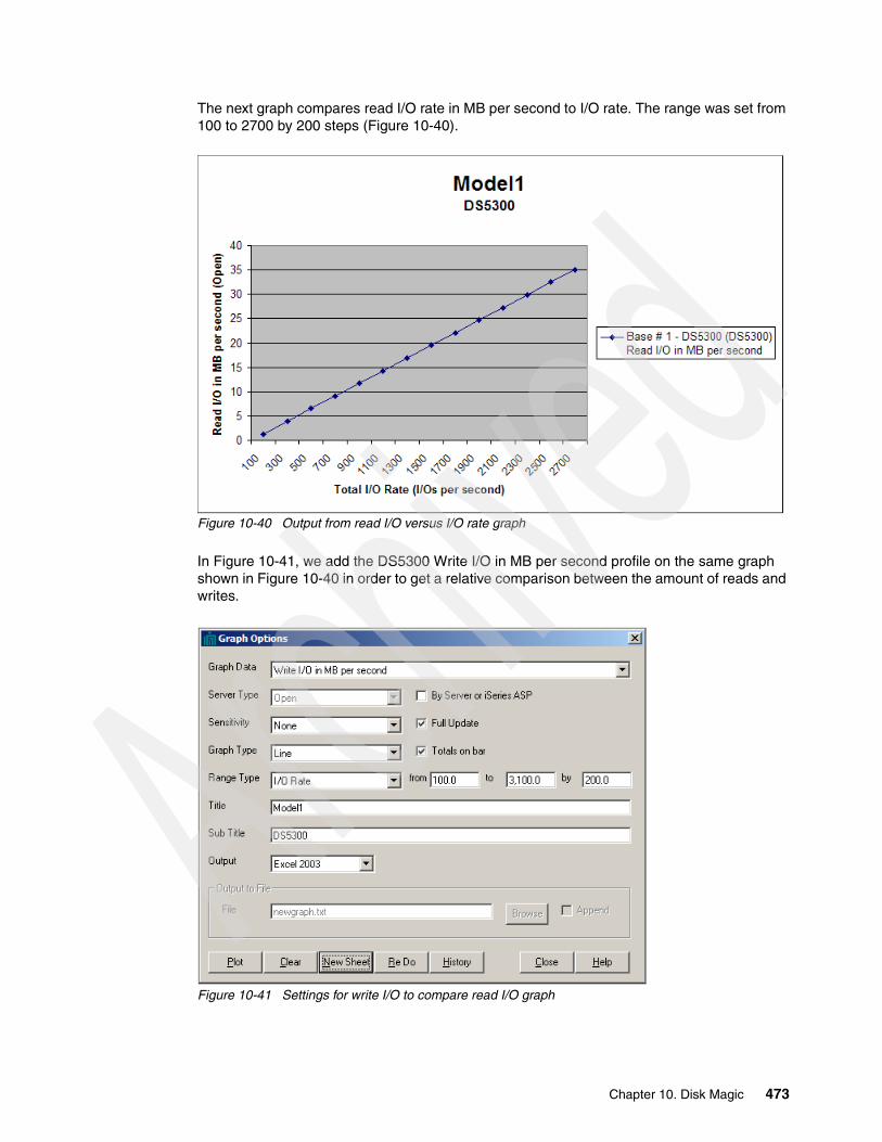
The next graph compares read I/O rate in MB per second to I/O rate. The range was set from 100 to 2700 by 200 steps (Figure 10-40).
Figure 10-40 Output from read I/O versus I/O rate graph
In Figure 10-41, we add the DS5300 Write I/O in MB per second profile on the same graph shown in Figure 10-40 in order to get a relative comparison between the amount of reads and writes.
Figure 10-41 Settings for write I/O to compare read I/O graph
Chapter 10. Disk Magic 473
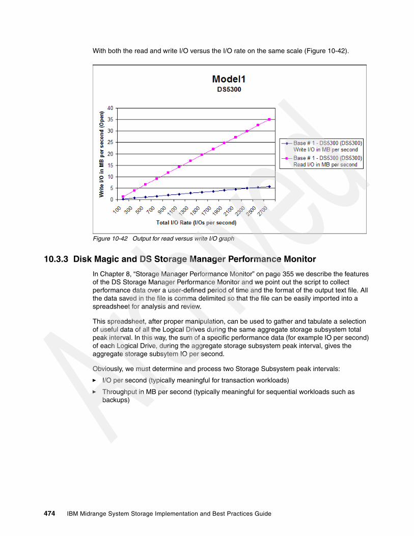
With both the read and write I/O versus the I/O rate on the same scale (Figure 10-42).
Figure 10-42 Output for read versus write I/O graph
10.3.3 Disk Magic and DS Storage Manager Performance Monitor
In Chapter 8, “Storage Manager Performance Monitor” on page 355 we describe the features of the DS Storage Manager Performance Monitor and we point out the script to collect performance data over a user-defined period of time and the format of the output text file. All the data saved in the file is comma delimited so that the file can be easily imported into a spreadsheet for analysis and review.
This spreadsheet, after proper manipulation, can be used to gather and tabulate a selection of useful data of all the Logical Drives during the same aggregate storage subsystem total peak interval. In this way, the sum of a specific performance data (for example IO per second) of each Logical Drive, during the aggregate storage subsystem peak interval, gives the aggregate storage subsytem IO per second.
Obviously, we must determine and process two Storage Subsystem peak intervals:
� I/O per second (typically meaningful for transaction workloads)
� Throughput in MB per second (typically meaningful for sequential workloads such as backups)
474 IBM Midrange System Storage Implementation and Best Practices Guide
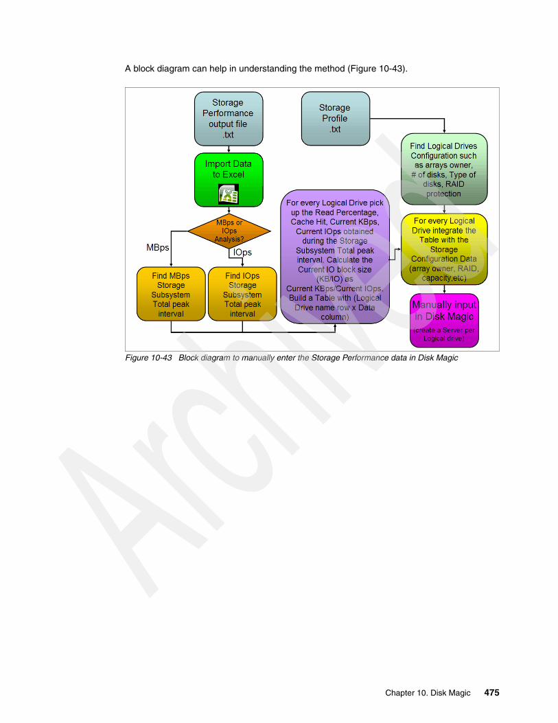
A block diagram can help in understanding the method (Figure 10-43).
Figure 10-43 Block diagram to manually enter the Storage Performance data in Disk Magic
Chapter 10. Disk Magic 475
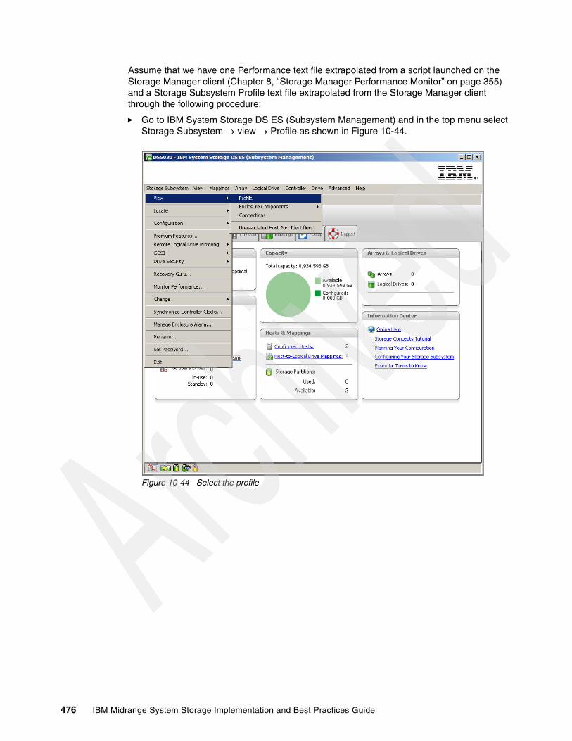
Assume that we have one Performance text file extrapolated from a script launched on the Storage Manager client (Chapter 8, “Storage Manager Performance Monitor” on page 355) and a Storage Subsystem Profile text file extrapolated from the Storage Manager client through the following procedure:
� Go to IBM System Storage DS ES (Subsystem Management) and in the top menu select Storage Subsystem view Profile as shown in Figure 10-44.
Figure 10-44 Select the profile
476 IBM Midrange System Storage Implementation and Best Practices Guide

� The Storage Subsystem Profile opens as shown in Figure 10-45.
Figure 10-45 Storage Subsystem Profile View
� Save the file in text format, including all the section as shown in Figure 10-46.
Figure 10-46 Save the profile file in text format including all the sections
Chapter 10. Disk Magic 477
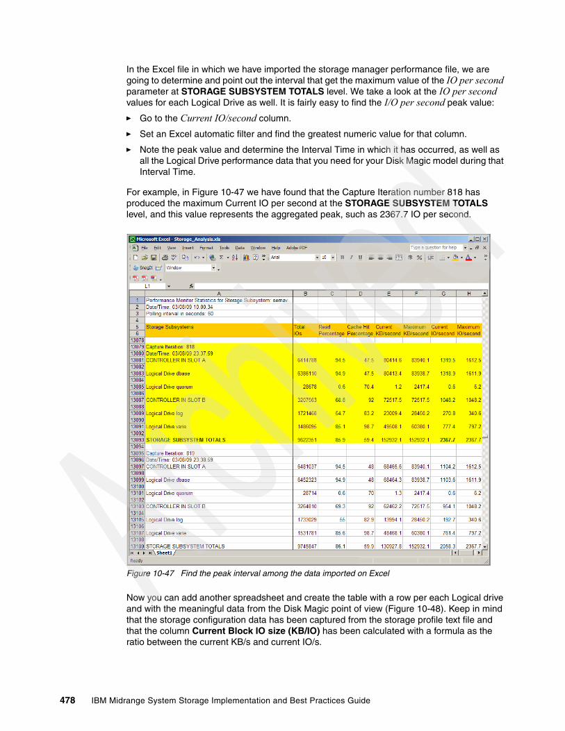
In the Excel file in which we have imported the storage manager performance file, we are going to determine and point out the interval that get the maximum value of the IO per second parameter at STORAGE SUBSYSTEM TOTALS level. We take a look at the IO per second values for each Logical Drive as well. It is fairly easy to find the I/O per second peak value:
� Go to the Current IO/second column.
� Set an Excel automatic filter and find the greatest numeric value for that column.
� Note the peak value and determine the Interval Time in which it has occurred, as well as all the Logical Drive performance data that you need for your Disk Magic model during that Interval Time.
For example, in Figure 10-47 we have found that the Capture Iteration number 818 has produced the maximum Current IO per second at the STORAGE SUBSYSTEM TOTALS level, and this value represents the aggregated peak, such as 2367.7 IO per second.
Figure 10-47 Find the peak interval among the data imported on Excel
Now you can add another spreadsheet and create the table with a row per each Logical drive and with the meaningful data from the Disk Magic point of view (Figure 10-48). Keep in mind that the storage configuration data has been captured from the storage profile text file and that the column Current Block IO size (KB/IO) has been calculated with a formula as the ratio between the current KB/s and current IO/s.
478 IBM Midrange System Storage Implementation and Best Practices Guide

Figure 10-48 Table building as input for Disk Magic
At this point we have all the information required to create a base line model with Disk Magic, and in particular we have gotten an important parameter to model the cache statistics, such as the Cache Hit parameter.
First of all, we create a new project using manual input as shown in Figure 10-49. Note that we have selected a number of open servers equal to the number of Logical Drives.
Figure 10-49 Create a manual project
Chapter 10. Disk Magic 479

Then we rename the open servers in order to fit the Logical drive names (Figure 10-50).
Figure 10-50 Server names match Logical drive Names
Finally, we manually insert in Disk Magic fields, all the data collected in the tables created in the Excel worksheet (Figure 10-48 on page 479).
480 IBM Midrange System Storage Implementation and Best Practices Guide
Chapter 11. SVC guidelines for DS4000/DS5000 series
In this chapter we briefly introduce IBM System Storage SAN Volume Control (SVC), describing its components and concepts, comparing the SVC Copy Services with those of the DS4000/DS5000 series. We focus on general best practices and guidelines for the use of SVC with the DS4000/DS5000 Storage Server, including a configuration example.
11
© Copyright IBM Corp. 2004-2010. All rights reserved. 481
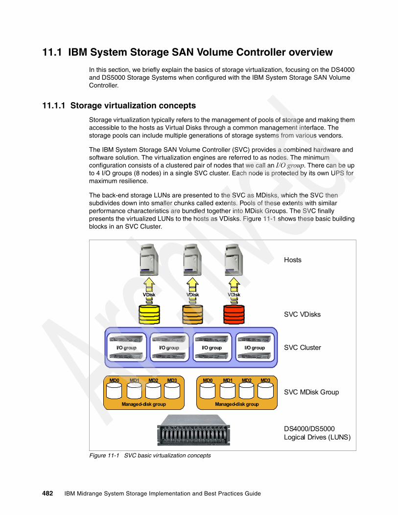
11.1 IBM System Storage SAN Volume Controller overview
In this section, we briefly explain the basics of storage virtualization, focusing on the DS4000 and DS5000 Storage Systems when configured with the IBM System Storage SAN Volume Controller.
11.1.1 Storage virtualization concepts
Storage virtualization typically refers to the management of pools of storage and making them accessible to the hosts as Virtual Disks through a common management interface. The storage pools can include multiple generations of storage systems from various vendors.
The IBM System Storage SAN Volume Controller (SVC) provides a combined hardware and software solution. The virtualization engines are referred to as nodes. The minimum configuration consists of a clustered pair of nodes that we call an I/O group. There can be up to 4 I/O groups (8 nodes) in a single SVC cluster. Each node is protected by its own UPS for maximum resilience.
The back-end storage LUNs are presented to the SVC as MDisks, which the SVC then subdivides down into smaller chunks called extents. Pools of these extents with similar performance characteristics are bundled together into MDisk Groups. The SVC finally presents the virtualized LUNs to the hosts as VDisks. Figure 11-1 shows these basic building blocks in an SVC Cluster.
Figure 11-1 SVC basic virtualization concepts
Hosts
SVC VDisks
SVC Cluster
SVC MDisk Group
DS4000/DS5000Logical Drives (LUNS)
MD0 MD1 MD2 MD3
Managed-disk group
I/O group I/O group I/O group I/O group
MD0 MD1 MD2 MD3
Managed-disk group
VDisk VDisk VDisk
482 IBM Midrange System Storage Implementation and Best Practices Guide
11.1.2 SVC glossary of terms
An SVC implementation consists of both hardware and software. The hardware consists of a management console server, a minimum of two node pairs to form the SVC cluster, and a minimum of two UPSs. Here we define various concepts and terminology used with SVC.
SVC clusterWhen the first two nodes are installed, they form an SVC cluster, which can contain up to eight nodes (four pairs of nodes). All of the nodes must be located in close proximity to each other. Each pair of nodes is known as an I/O group and each node can be in only one I/O group. To span longer distances, it is best to create two separate clusters.
System Storage Productivity Center (SSPC)The System Storage Productivity Center (SSPC) is an integrated hardware and software solution that provides a single management console for managing IBM SAN Volume controller and other components of your data storage infrastructure. The current release of the SSPC is made up of four major components: SSPC hardware, IBM TotalStorage Productivity Center (TPC) Basic Edition, SAN Volume Controller Console and Common Information Model (CIM) agent. All the software components installed on the SSPC can be ordered and installed on hardware that meets or exceeds minimum requirements. The SVC Console software components are also available on the IBM Web site.
NodeA node is a name given to the individual servers in a SAN Volume Controller cluster on which the SVC software runs. Nodes are always installed as pairs. Each node must be connected to its own UPS.
Managed disksA managed disk (MDisk) is a SCSI disk presented by the storage (for instance, a DS5000 logical drive) and managed by the SVC. A managed disk provides usable blocks (or extents) of physical storage to the SVC cluster. The MDisks are not visible to hosts systems on the SAN.
An MDisk can be in one of three states in SVC: unmanaged, managed, or image mode:
� An unmanaged disk is one that has been assigned to the SVC but not yet managed by SVC.
� A managed disk is one that is managed by SVC.
� An image mode disk is one that has been imported into SVC and contains data. This technique is used when migrating existing LUNs (logical drives) with data into SVC. The data on the LUN is preserved. To extend the disk after being managed by the SVC, this type of disk must be migrated to an MDisk.
Managed disk groupThe managed disk group (MDG) is a collection of MDisks. Each MDG is divided into a number of extents, which are numbered sequentially, starting with 0. When creating an MDG, you must choose an extent size. After being set, the extent size stays constant for the life of that MDG and cannot be changed. Each MDG can have a unique extent size.
Chapter 11. SVC guidelines for DS4000/DS5000 series 483
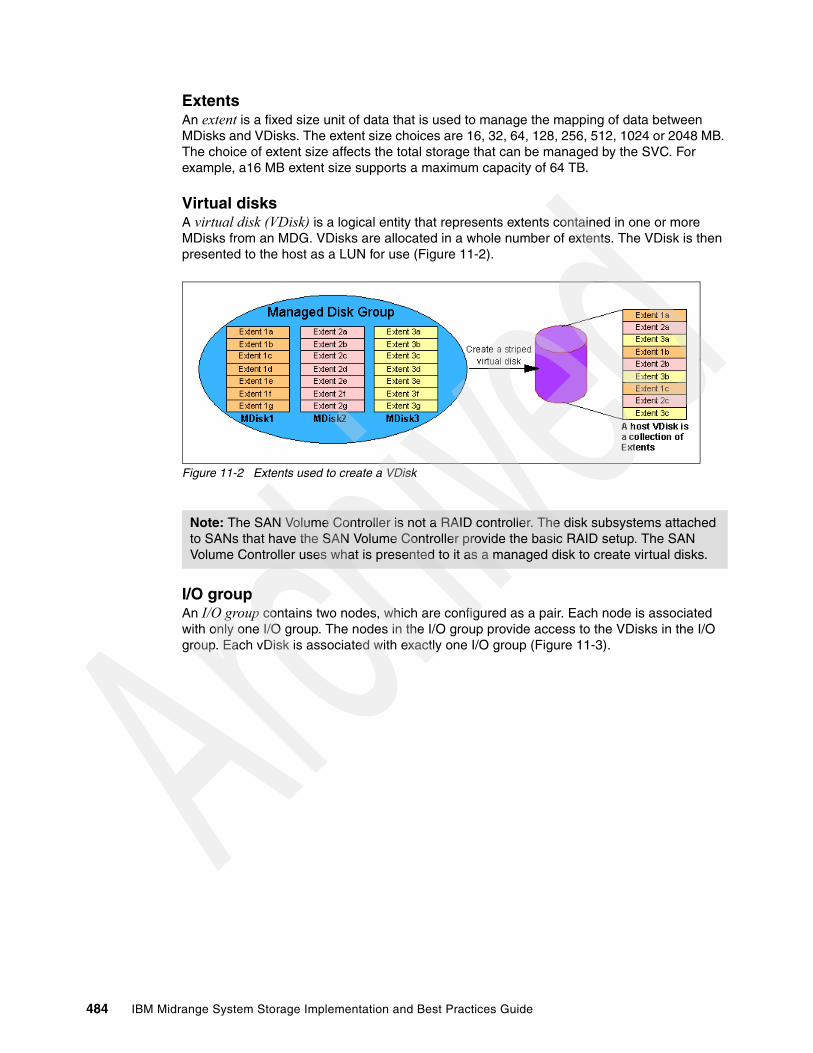
ExtentsAn extent is a fixed size unit of data that is used to manage the mapping of data between MDisks and VDisks. The extent size choices are 16, 32, 64, 128, 256, 512, 1024 or 2048 MB. The choice of extent size affects the total storage that can be managed by the SVC. For example, a16 MB extent size supports a maximum capacity of 64 TB.
Virtual disksA virtual disk (VDisk) is a logical entity that represents extents contained in one or more MDisks from an MDG. VDisks are allocated in a whole number of extents. The VDisk is then presented to the host as a LUN for use (Figure 11-2).
Figure 11-2 Extents used to create a VDisk
I/O groupAn I/O group contains two nodes, which are configured as a pair. Each node is associated with only one I/O group. The nodes in the I/O group provide access to the VDisks in the I/O group. Each vDisk is associated with exactly one I/O group (Figure 11-3).
Note: The SAN Volume Controller is not a RAID controller. The disk subsystems attached to SANs that have the SAN Volume Controller provide the basic RAID setup. The SAN Volume Controller uses what is presented to it as a managed disk to create virtual disks.
484 IBM Midrange System Storage Implementation and Best Practices Guide

Figure 11-3 Relationships between physical and virtual disks
Consistency groupConsistency groups address the issue where the objective is to preserve data consistency across multiple VDisks, because the applications have related data that spans multiple VDisks. A requirement for preserving the integrity of data being written is to ensure that dependent writes are executed in the application's intended sequence.
Multipathing device driversThe multipathing device driver supported by the SVC is the IBM Subsystem Device Driver (SDD). SDD groups all available paths to a virtual disk device and presents it to the operating system. SDD performs all the path handling and selects the active I/O paths.
Always consult the IBM SVC Web site for the latest device drivers and the support matrix:
http://www.ibm.com/storage/support/2145
11.1.3 Benefits of the IBM System Storage SAN Volume Controller
SVC delivers a single view of the storage attached to the SAN. Administrators can manage, add, and migrate physical disks non-disruptively even between various storage subsystems. The SAN is zoned in such a way that the application servers cannot see the back-end storage, preventing any possible conflict between SVC and the application servers both trying to manage the back-end storage.
Chapter 11. SVC guidelines for DS4000/DS5000 series 485

The SAN Volume Controller provides storage virtualization by creating a pool of managed disks from attached back-end disk storage subsystems. These managed disks are then mapped to a set of virtual disks for use by various host computer systems:
� Performance, availability, and other service level agreements can be mapped by using various storage pools and advanced functions.
� Dependencies, which exist in a SAN environment with heterogeneous storage and server systems, are reduced.
We summarize the key benefits of the SVC here:
Concurrent Migration This function is probably the single most important one that the SVC adds to any storage environment. MDisks can be migrated transparently to the host application, which allows data to be moved non-disruptively from a Storage System in preparation for a scheduled maintenance activity. It also gives the System Administrator the flexibility to balance I/O workload on the fly or easily migrate across to a storage pool with more appropriate performance/resilience characteristics as needs demand.
Single Management The SVC provides a single common management interface for Interface provisioning heterogeneous storage.
Copy Services In an SVC environment, there is no need to purchase separate Copy Services licenses from each storage vendor. Furthermore, the source and target or a copy relationship can be on separate Storage Systems.
Increased Utilization Having the flexibility to pool storage across the SAN results in much improved storage capacity utilization. Spare capacity on underlying physical disks can be reallocated non-disruptively from an application server point of view irrespective of the server operating system or platform type. Logical disks can be created from any of the physical disks being managed by the virtualization device (that is, vendor independent).
Performance A well designed SVC configuration can significantly improve overall performance by reducing hot spots and making use of the additional cache in the SVC nodes.
Connectivity Each vendor storage subsystem traditionally requires a vendor’s device driver on the host to access the subsystem. Where there are many subsystems in the environment, regardless of whether any one host is accessing more than one vendor’s storage subsystems, then managing the range of device drivers is unnecessarily complex. The IBM approach means that only one device driver, the IBM System Storage Subsystem Device Driver (SDD), is required to access any virtualized storage on the SAN regardless of the vendor storage subsystem.
iSCSI Connectivity Starting from SVC code 5.1, there is support for iSCSI attached hosts, which provides both cost saving and flexibility because FC Host Bus Adapters (HBA) are no longer required to access the FC storage server.
Scalability It is possible to expand the SVC cluster up to four I/O groups (8 nodes) as performance and capacity requirements increase. Moreover, you can take advantage of the latest technologies by mixing various generations of hardware nodes within the same SVC cluster.
486 IBM Midrange System Storage Implementation and Best Practices Guide

11.1.4 Key points for using DS4000 and DS5000 Storage Systems with SVC
It is important to understand that the SVC does not provide any RAID redundancy protection for the MDisks that are presented to it. Therefore, it is essential that the back-end storage subsystem is sufficiently resilient to provide the level of protection expected in an enterprise class environment as well as meeting any performance level criteria. In this area, the DS4000 and DS5000 Storage Servers become a perfect compliment for the SVC. Supporting an extensive selection of drive types and capacities together with a choice of RAID level protection and no single points of failure all combine to make the DS4000 and DS5000 Storage Servers an extremely flexible partner for SVC.
SVC is very flexible in its use. It can be used to manage all of your disk storage requirements or just part. In other words, when using SVC with the DS4000/DS5000, you can still use the DS4000/DS5000 Storage Manager (SM) functions to allocate part of the storage to certain hosts. The DS5000/DS4000 partitioning feature must be used to separate groups of logical units that are directly attached to hosts or groups of hosts from the logical units that are accessed by the SAN Volume Controller cluster.
SVC offers a large scalable cache and can also reduce the requirement for additional partitions. The SVC only consumes one storage partition for each storage server that connects to it. If you plan to use the SVC for all your hosts then a storage partition upgrade on the DS4000/DS5000 might not be required. In a configuration with the SVC, the DS4000/DS5000 only needs to speak a single language (the SVC) rather than multiple languages when it is attached in a heterogeneous enterprise. To the DS4000/DS5000 Storage Server, the SVC is the only host that it sees.
In addition it improves capacity utilization. Spare capacity on underlying physical disks can be reallocated non disruptively from an application server point of view irrespective of the server operating system or platform type.
11.1.5 SVC licensing
SVC offering is composed of two versions:
� Entry Edition: This licensing scheme is based on the number of physical disks that you are virtualizing and whether you selected to license FlashCopy feature, the Metro Mirror and Global Mirror feature, or both of these features. If you expand beyond the physical disk drive limit, SVC Entry Edition configurations can easily be converted without application disruption to the enterprise SAN Volume Controller offering.
� Enterprise Edition: This version is licensed by the capacity that is being managed. With this type of licensing, you select the number of terabytes available for your license for base virtualization, the FlashCopy feature, and the Metro Mirror and Global Mirror features.
Capacity upgrades can be carried out at anytime during the life of the SVC by purchasing a licence for the additional capacity required.
For more detailed information, you can consult your IBM sales representative.
11.1.6 SVC publications
SVC supports a wide variety of disk storage and host operating system platforms. For the latest information, see the IBM Web site:
http://www-03.ibm.com/systems/storage/software/virtualization/svc/interop.html
Chapter 11. SVC guidelines for DS4000/DS5000 series 487

Now we review the basic SVC concepts and components. For details and information about SVC implementation and best practices, see the following publications:
� Implementing the IBM System Storage SAN Volume Controller V5.1, SG24-6423
� SAN Volume Controller Best Practices and Performance Guidelines, SG24-7521
� Implementing the SVC in an OEM Environment, SG24-7275
� SAN Volume Controller V4.3.0 Advanced Copy Services, SG24-7574
You must ensure that the firmware level of the DS4000/DS5000 Storage Server can be used with the SAN Volume Controller cluster.
For specific firmware levels and the latest supported hardware, as well as maximum number of LUNs per partition that are supported by the firmware level, see the following Web site:
www.ibm.com/storage/support/2145
11.2 SVC copy services
The copy services offered by the SVC are FlashCopy, Metro Mirror, and Global Mirror. If you plan to use SVC for all of your copy services, then purchasing the additional premium features, such and FlashCopy, VolumeCopy, or Enhanced Remote Mirroring for the DS4000/DS5000, might not be necessary.
The SVC copy services functions provide various interesting capabilities, for example:
� SVC supports consistency groups for FlashCopy, Metro Mirror, and Global Mirror.
� Consistency groups in SVC can span across underlying storage systems.
� FlashCopy source volumes that reside on one disk system can write to target volumes on another disk system.
� Metro Mirror and Global Mirror source volumes can be copied to target volumes on a dissimilar storage system.
11.2.1 SVC FlashCopy
FlashCopy provides the capability to perform an instantaneous point-in-time (PiT) copy of one or more VDisks, which is a copy of the VDisk at that PiT. After being created, it no longer requires the source to be active or available.
FlashCopy works by defining a FlashCopy mapping consisting of a source VDisk and a target VDisk. Multiple FlashCopy mappings can be defined, and PiT consistency can be observed across multiple FlashCopy mappings using consistency groups.
When FlashCopy is started, it makes a copy of a source VDisk to a target VDisk, and the original contents of the target VDisk are overwritten.
When the FlashCopy operation is started, the target VDisk presents the contents of the source VDisk as they existed at the single point in time (PiT) the FlashCopy was started.
Note: As is the case with the DS4000/DS5000, the first step before invoking this function is to make sure that all of the application data is written to disk. In other words, determine that the application data is consistent. Such a result can be achieved, for example, by quiescing a database and flushing all data buffers to disk.
488 IBM Midrange System Storage Implementation and Best Practices Guide

When a FlashCopy is started, the source and target VDisks are instantaneously available. The reason is that, when started, bitmaps are created to govern and redirect I/O to the source or target VDisk, respectively, depending on where the requested block is present, while the blocks are copied in the background from the source to the target VDisk.
Both the source and target VDisks are available for read and write operations, although the background copy process has not yet completed copying across the data from the source to target volumes. See Figure 11-4.
Figure 11-4 Implementation of SVC FlashCopy
SVC can provide several features that increase the flexibility and usefulness of FlashCopy including:
� FlashCopy Consistency Groups� Multiple Target FlashCopy (MTFC)� Cascaded FlashCopy (CFC)� Incremental FlashCopy (IFC)� Space-Efficient FlashCopy (SEFC)
For more details about these capabilities, see SAN Volume Controller V4.3.0 Advanced Copy Services, SG24-7574.
Compared to the native DS4000/DS5000 FlashCopy, the SVC FlashCopy is more like a combination of the DS4000/DS5000 FlashCopy and VolumeCopy functions, whereas the SVC Space-Efficient FlashCopy (SEFC) is very similar to the DS4000/DS5000 FlashCopy.
FlashCopy command is issued.Copy is immediately availableafter bitmaps (metadata) are built. Read/write to copy is possible.
Write ReadBlocks that are not yet written to the target are read from the source. Before a write to the source, data is copied to the target.
When a background copy is complete, the source and target are logically independent, and the FlashCopy mapping can be deleted without affecting the target.
Source Target
Source Target
T0
T0 + t
Chapter 11. SVC guidelines for DS4000/DS5000 series 489

11.2.2 Metro Mirror
The general application of Metro Mirror is to maintain two real-time synchronized copies of a data set. Often, the two copies are geographically dispersed on two SVC clusters, although it is possible to use Metro Mirror in a single cluster (within an I/O group). If the primary copy fails, the secondary copy can then be enabled for I/O operation.
Metro Mirror works by defining a Metro Mirror relationship between VDisks of equal size. When creating the Metro Mirror relationship, one VDisk must be defined as the master, and the other as the auxiliary. In most common applications of Metro Mirror, the master VDisk contains the production copy of the data, and is used by the host application, whereas the auxiliary VDisk contains a mirrored copy of the data and is used for failover in disaster recovery scenarios.
The contents of the auxiliary VDisk that existed when the relationship was created are destroyed.
To provide management (and consistency) across a number of Metro Mirror relationships, consistency groups are supported (as with FlashCopy).
The SVC provides both intracluster and intercluster Metro Mirror, as described next.
Intracluster Metro MirrorIntracluster Metro Mirror can be applied within any single I/O group. Metro Mirror across I/O groups in the same SVC cluster is not supported.
Intercluster Metro MirrorIntercluster Metro Mirror operations require a pair of SVC clusters that are separated by a number of moderately high bandwidth links. The two SVC clusters must be defined in an SVC partnership, which must be performed on both SVC clusters to establish a fully functional Metro Mirror partnership.
Using standard single mode connections, the supported distance between two SVC clusters in a Metro Mirror partnership is 10 km, although greater distances can be achieved by using extenders.
A typical application of this function is to set up a dual-site solution using two SVC clusters where the first site is considered the primary production site, and the second site is considered the failover site, which is activated when a failure of the first site is detected.
Note: Because intracluster Metro Mirror will consume more resources for a specific cluster, compared to an intercluster Metro Mirror relationship, use intercluster Metro Mirror whenever possible.
490 IBM Midrange System Storage Implementation and Best Practices Guide
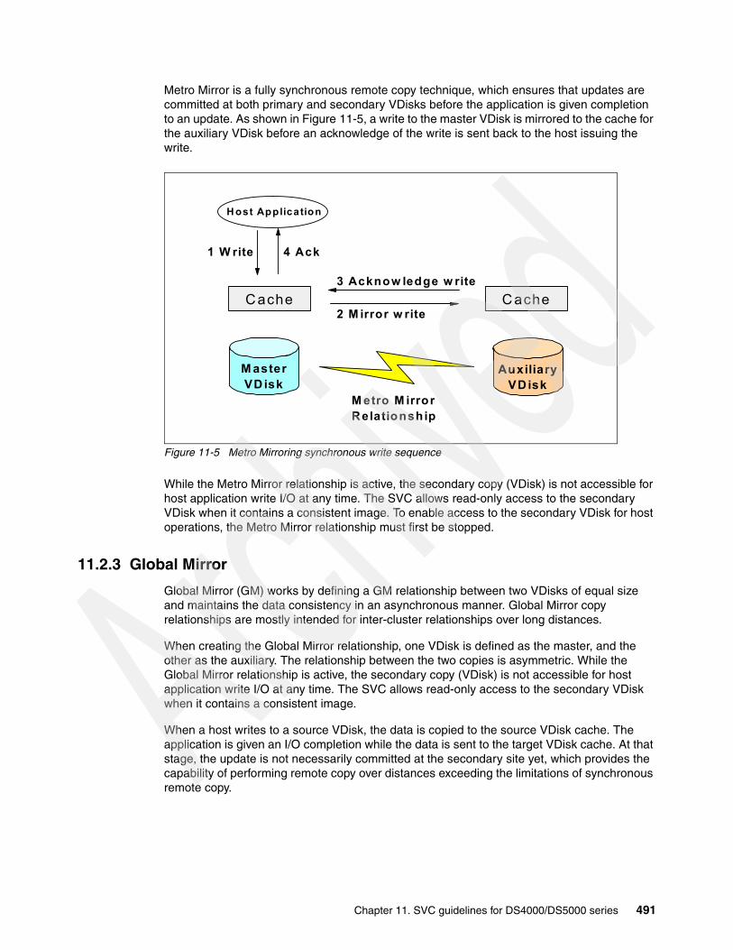
Metro Mirror is a fully synchronous remote copy technique, which ensures that updates are committed at both primary and secondary VDisks before the application is given completion to an update. As shown in Figure 11-5, a write to the master VDisk is mirrored to the cache for the auxiliary VDisk before an acknowledge of the write is sent back to the host issuing the write.
Figure 11-5 Metro Mirroring synchronous write sequence
While the Metro Mirror relationship is active, the secondary copy (VDisk) is not accessible for host application write I/O at any time. The SVC allows read-only access to the secondary VDisk when it contains a consistent image. To enable access to the secondary VDisk for host operations, the Metro Mirror relationship must first be stopped.
11.2.3 Global Mirror
Global Mirror (GM) works by defining a GM relationship between two VDisks of equal size and maintains the data consistency in an asynchronous manner. Global Mirror copy relationships are mostly intended for inter-cluster relationships over long distances.
When creating the Global Mirror relationship, one VDisk is defined as the master, and the other as the auxiliary. The relationship between the two copies is asymmetric. While the Global Mirror relationship is active, the secondary copy (VDisk) is not accessible for host application write I/O at any time. The SVC allows read-only access to the secondary VDisk when it contains a consistent image.
When a host writes to a source VDisk, the data is copied to the source VDisk cache. The application is given an I/O completion while the data is sent to the target VDisk cache. At that stage, the update is not necessarily committed at the secondary site yet, which provides the capability of performing remote copy over distances exceeding the limitations of synchronous remote copy.
M asterVD isk
AuxiliaryVDisk
M etro M irrorRelationship
Cache C ache
1 W rite
2 M irror w rite
3 Acknow ledge w rite
4 Ack
H ost Application
Chapter 11. SVC guidelines for DS4000/DS5000 series 491
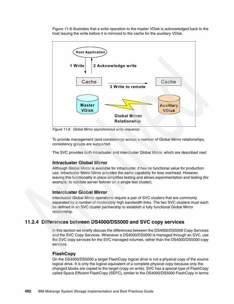
Figure 11-6 illustrates that a write operation to the master VDisk is acknowledged back to the host issuing the write before it is mirrored to the cache for the auxiliary VDisk.
Figure 11-6 Global Mirror asynchronous write sequence
To provide management (and consistency) across a number of Global Mirror relationships, consistency groups are supported.
The SVC provides both intracluster and intercluster Global Mirror, which are described next.
Intracluster Global MirrorAlthough Global Mirror is available for intracluster, it has no functional value for production use. Intracluster Metro Mirror provides the same capability for less overhead. However, leaving this functionality in place simplifies testing and allows experimentation and testing (for example, to validate server failover on a single test cluster).
Intercluster Global MirrorIntercluster Global Mirror operations require a pair of SVC clusters that are commonly separated by a number of moderately high bandwidth links. The two SVC clusters must each be defined in an SVC cluster partnership to establish a fully functional Global Mirror relationship.
11.2.4 Differences between DS4000/DS5000 and SVC copy services
In this section we briefly discuss the differences between the DS4000/DS5000 Copy Services and the SVC Copy Services. Whenever a DS4000/DS5000 is managed through an SVC, use the SVC copy services for the SVC managed volumes, rather than the DS4000/DS5000 copy services.
FlashCopyOn the DS4000/DS5000 a target FlashCopy logical drive is not a physical copy of the source logical drive. It is only the logical equivalent of a complete physical copy because only the changed blocks are copied to the target (copy on write). SVC has a special type of FlashCopy called Space Efficient FlashCopy (SEFC), similar to the DS4000/DS5000 FlashCopy in terms
MasterVDisk
AuxiliaryVDisk
Global MirrorRelationship
Cache Cache
1 Write
3 Write to remote
2 Acknowledge write
Host Application
492 IBM Midrange System Storage Implementation and Best Practices Guide

of functionality. These kinds of FlashCopy are well-suited for applications that read data from the FlashCopy target logical drives or VDisks, such as backup and data mining.
On the SVC, the normal FlashCopy creates a point-in-time image of the Fully Allocated VDisk, and in this case the target VDisk always has the same size as a source VDisk, not only in what it presents to a storage client, but as well in how much space it allocates from the MDisk Group (MDG). After being created, it no longer requires the source VDisk to be active or available. This image, after being created, is available to be mounted on other host servers or for recovery purposes.
To get the equivalent function of the normal SVC FlashCopy on the DS4000/DS5000 Storage Servers, you have to combine FlashCopy and VolumeCopy functions (that is, make a VolumeCopy of the FlashCopy target).
Metro Mirror and Global MirrorBoth the DS4000/DS5000 Copy Services and the SVC Copy Services offer a Metro Mirror and a Global Mirror. These copy services are similar in function between the two technologies, even though the underlying technology that creates and maintains these copies varies.
From a DS4000/DS5000 standpoint, an important difference when using SVC Copy Services over the DS4000/DS5000 Copy Services is in host port requirement. The DS4000/DS5000 Mirroring requires a dedicated host port from each of the DS4000/DS5000 controllers, which means that ideally you need a DS4000/DS5000 model with at least four host ports per controller (such as the DS5020 or the DS5100 storage servers) if you want to still have dual redundant host SAN fabrics when Remote Mirroring is implemented.
The SVC does not dedicate ports for its mirroring services (nor does it require dedicated ports on the DS4000/DS5000 Storage Server). Rather, a zoning configuration dedicates paths between the SVC clusters.
SVC mirroring also offers the following advantages:
� SVC maintains a control link on top of the FC link that is used for the Global/Metro Mirror I/O. No IP connection is needed to manage both SVC clusters from one centralized administration point.
� SVC has a huge cache (depending on the number of SVC cluster nodes).
� SVC makes it possible to mirror between various IBM storage server models and also between storage servers from other vendors, which gives a possibility for data migration between various types of storage. You can find a complete list of supported storage servers at the following link:
http://www-01.ibm.com/support/docview.wss?rs=591&uid=ssg1S1003277
� SVC implements a configuration model that maintains the mirror configuration and state through major events such as failover, recovery, and resynchronization to minimize user configuration action through these events.
� SVC implements flexible resynchronization support, enabling it to re-synchronize VDisk pairs that have suffered write I/O to both disks and to resynchronize only those regions that are known to have changed.
Consistency groupsThe SVC can use consistency groups for all copy services including FlashCopy, Metro Mirror and Global Mirror. The use of consistency groups is so that the data is written in the same sequence as intended by the application. The DS4000/DS5000 can use consistency groups for Global Mirror.
Chapter 11. SVC guidelines for DS4000/DS5000 series 493

Premium featuresWith the DS4000/DS5000, you must purchase premium features such as FlashCopy, VolumeCopy, Enhanced Remote Mirror Copy Services, and additional storage partitioning to connect various hosts.
SVC consumes only one storage partition. All of the hosts that are managed by the SVC are virtualized behind that single storage partition. Of course, if you only partially manage the DS4000/DS5000 through SVC, you still need the additional storage partitions on the DS4000/DS5000 for the various hosts that need access to the logical drives not managed through SVC.
11.3 SVC maximum configuration
Table 11-1 summarizes the maximum configuration numbers supported for SVC at the time of writing. Obviously, the numbers in Table 11-1 can change with subsequent hardware and software releases. For the latest configuration information, always see the IBM Web site:
http://www.ibm.com/storage/support/2145
Table 11-1 SVC maximum configuration
Objects Maximum number
Comments
Nodes per SVC cluster 8 Arranged as 4 I/O groups
Nodes per fabric 32 Max nodes that can be present on the same fabric with visibility of each other
I/O groups per cluster 4 Each containing 2 nodes
Fabrics per cluster 4 Number of counterpart SANs which are supported
Managed disks (MDisks) 4096 Max number of LUNs that can be managed by SVC
MDisk groups 128
MDisks per Mdisk group 128
MDisk size 2 TB
Total storage manageable per SVC cluster
8 PB If maximum extent size of 2048 Mb used
Virtual disks (Vdisks) 8192
VDisks per I/O group 2048
VDisk size 2 TB
VDisks per host object 512 The limit might not be the same on the host operating system.
Storage controller ports 256
LUNs per storage subsystem 4096
Ports per storage subsystem 16
Host paths per VDisk 8
494 IBM Midrange System Storage Implementation and Best Practices Guide

11.4 SVC considerationsIt is important to know the following restrictions when considering SVC:
� Cluster considerations:
– All nodes in an SVC cluster must be located close to one another (the maximum is 100 meters), within the same room or adjacent rooms for ease of service and maintenance. An SVC cluster can be connected (by the SAN fabric switches) to application hosts, disk subsystems, or other SVC clusters, by short wave only optical FC connections.
– Long wave connections are no longer supported.
– With short wave, distances can be up to 150 m (short wave 8 Gbps), 175 m (short wave 4 Gbps), 300 m (short wave 2 Gbps), or 500 m (short wave 1 Gbps) between the cluster and the host, and between the cluster and the disk subsystem.
– Longer distances are supported between SVC clusters when using intercluster Metro or Global Mirror.
� Node considerations:
– SVC nodes such as the 8A4, 8G4, and CF8 always contain one host bus adapter (HBA) with four Fibre Channel (FC) ports. Models 8A4 and 8G4 can operate at 1, 2 or 4 Gbps, whereas model CF8 can operate at 2,4 or 8 Gbps.
– A node will not function unless it is behind the appropriate UPS unit. That is one of the design considerations with the SVC. Even though the room might already be supplied with UPS-protected power, a dedicated UPS unit for each node is required.
� Network considerations:
All nodes in a cluster must be on the same IP subnet, which is because the nodes in the cluster must be able to assume the same cluster, or service IP address.
� Fabric considerations:
– SVC node FC ports must be connected to the Fibre Channel fabric. If you are going to provide iSCSI connectivity to your hosts, you must connect the SVC node Ethernet ports to Ethernet switches. Direct connections between SVC and host, or SVC and storage server, are not supported.
– The Fibre Channel switch must be zoned to permit the hosts to see the SVC nodes, and the SVC nodes to see the storage servers. The SVC nodes within a cluster must be zoned in such a way as to allow them to see each other, the disk subsystems, and the front-end host HBAs.
– When a local and a remote fabric are connected together for Metro Mirror purposes, the ISL hop count between a local node and a remote node cannot exceed seven hops.
– No ISL hops are permitted between the SAN Volume Controller nodes within the same I/O group.
– One ISL hop is permitted between SAN Volume Controller nodes that are in the same cluster through various I/O groups.
– One ISL hop between the SAN Volume Controller nodes and the DS4000/DS5000 Storage Server controllers is permitted. Ideally, all storage controllers must be connected to the same Fibre Channel switches as the SAN Volume Controller nodes.
– In larger configurations, it is common to have ISLs between host systems and the SAN Volume Controller nodes.
Note: Only the DS5000 Storage Server model can have 8 Gbps host port connectivity through its 8 Gbps Host Interface Cards (HIC).
Chapter 11. SVC guidelines for DS4000/DS5000 series 495
11.4.1 Preferred node
The preferred node is responsible for I/Os for the VDisk and coordinates sending the I/Os to the alternate node. While both systems will exhibit similar CPU utilization, the preferred node is a little busier. To be precise, a preferred node is always responsible for the destaging of writes for VDisks that it owns.
If a node fails, the other node in the I/O group takes over the I/O responsibilities of the failed node. Data loss during a node failure is prevented by mirroring the I/O write data cache between the two nodes in an I/O group. If a node has failed in an I/O group, the cache goes into write-through mode. Therefore, any write operations for the VDisk that are assigned to this I/O group are not cached but are sent directly to the storage server. If both nodes in an I/O group go offline, the VDisk that are assigned to the I/O group cannot be accessed.
11.4.2 Expanding VDisks
It is possible to expand a VDisk in the SVC cluster, even if it is mapped to a host. Certain operating systems, such as Windows Server 2008, can handle the volumes being expanded even if the host has applications running.
However, a VDisk that is defined to be in a FlashCopy, Metro Mirror, or Global Mirror mapping on the SVC cannot get expanded unless the mapping is removed, which means that the FlashCopy, Metro Mirror, or Global Mirror on that VDisk has to be stopped before it is possible to expand the VDisk.
11.4.3 Multipathing
Each SVC node presents a virtual disk (VDisk) to the SAN through four paths. Because in normal operation two nodes are used to provide redundant paths to the same storage, this means that a host with two HBAs can see eight paths to each VDisk presented by the SVC. Use zoning to limit the pathing from a minimum of two paths to the maximum available of eight paths, depending on the kind of high availability and performance you want to have in your configuration.
The multipathing device driver supported and delivered by SVC is IBM Subsystem Device Driver (SDD) and two specific packages for AIX (SDDPCM) and Windows Server 2003/2008 (SDDDSM) are available.
Subsystem Device Driver Device Specific Module (SDDDSM) provides Multipath I/O (MPIO) support based on the MPIO technology of Microsoft.
Subsystem Device Driver Path Control Module (SDDPCM) is a loadable path control module for supported storage devices to supply path management functions and error recovery algorithms. When the supported storage devices are configured as MPIO devices, SDDPCM is loaded as part of the AIX MPIO FCP (Fibre Channel Protocol) device driver during the configuration.
Depending on the operating system and the system architecture, SVC can work with various multipath device drivers.
For a complete and updated list of supported Multipath device drivers see the Web site:
http://www-01.ibm.com/support/docview.wss?rs=591&uid=ssg1S1003278
496 IBM Midrange System Storage Implementation and Best Practices Guide

Note that the prior levels of host software packages that were specified are also tested for SVC 5.1 and allow for flexibility in maintaining the host software levels with respect to the SVC software version. In other words, it is possible to upgrade the SVC before upgrading the host software levels or after upgrading the software levels, depending on your maintenance schedule.
The number of paths from the SVC nodes in a I/O group to a host must not exceed eight, even if this is not the maximum paths number handled by SDD. It is a supported configuration to have eight paths to each VDisk, but this design provides no performance benefit (indeed, under certain circumstances, it can even reduce performance), and it does not improve reliability or availability by any significant degree.
In case of four host HBA ports and because eight paths are not an optimum number, you have to configure your SVC Host Definitions (and zoning) as though the single host is two separate hosts. Then you have to map each of the two pseudo-hosts to VDisks properly assigned to various preferred nodes in order to balance the I/O.
11.4.4 SVC aliases: Guidelines
Modern SAN switches have three types of zoning available: port zoning, worldwide node name (WWNN) zoning, and worldwide port name (WWPN) zoning.
If available on your particular type of SAN switch, use zoning aliases when creating the SVC zones. Zoning aliases make your zoning easier to configure and understand, and result n fewer possibilities for errors.
One approach is to include multiple members in one alias, because zoning aliases can normally contain multiple members (just like zones). Create the following aliases:
� Create one alias that holds all the SVC node ports on each fabric. SVC has an extremely predictable WWPN structure because it always starts with 50:05:07:68 and ends with two octets that distinguish for you which node is which. The first digit of the third octet from the end is the port number on the node.
In Example 11-1, notice that in the fabric switch (SAN_A) we have connected port 1 and port 3 of each of the two nodes of a SVC cluster composed of only one I/O group (I/O group 0).
Example 11-1 SVC cluster alias
SVC_Cluster_SAN_A:50:05:07:68:01:10:37:e550:05:07:68:01:30:37:e550:05:07:68:01:10:37:dc50:05:07:68:01:30:37:dc
Tip: Even though a maximum of eight paths are supported with multipathing software, limiting the number of paths to four solves many issues with high port fanouts, fabric state changes, and host memory management, as well as improving performance.
Note: The preferred method is to use only WWPN zoning.
Chapter 11. SVC guidelines for DS4000/DS5000 series 497

� Create one alias for each of the two controllers for a DS4000/DS5000 Storage Server. See Example 11-2.
Example 11-2 Storage aliases
DS5300_CtrlA_SAN_A:20:04:00:a0:b8:17:44:3220:04:00:a0:b8:17:44:33
DS5300_CtrlB_SAN_A:20:05:00:a0:b8:17:44:3220:05:00:a0:b8:17:44:33
� Create one alias for each I/O group port pair (that is, it needs to contain the first node in the I/O group, port 1, and the second node in the I/O group, port 1), because the best practices that we have described specify that each host HBA port is only supposed to see a single port on each of the two nodes in a SVC cluster composed of a single I/O group, in order to keep the maximum or four paths. In case of multiple I/O groups within the SVC, assign the hosts to separate I/O groups, maintaining the rule of the four paths per host and considering a comparison among the workload generated by each host, in order to have a fair traffic balance among the nodes. See Example 11-3.
Example 11-3 I/O group port pair aliases
SVC_IOGroup0_Port1_SAN_A:50:05:07:68:01:10:37:e550:05:07:68:01:10:37:dc
SVC_IOGroup0_Port3_SAN_A:50:05:07:68:01:30:37:e550:05:07:68:01:30:37:dc
� We can then create an alias for each host HBA port, even if it is not strictly necessary, because each host is only going to appear in a single zone. See Example 11-4.
Example 11-4 Host alias
SVC_Host_HBA1_SAN_A:21:00:00:e0:8b:05:28:f9
498 IBM Midrange System Storage Implementation and Best Practices Guide

Figure 11-7 shows a zoning configuration in which we have used the aliases in the previous examples.
Figure 11-7 Aliases and zoning configuration example
Chapter 11. SVC guidelines for DS4000/DS5000 series 499

11.4.5 SVC SAN zoning rules
We use a 4-node SVC cluster SAN environment as shown in Figure 11-8 to demonstrate the zoning rules.
Figure 11-8 SAN Cabling Topology
Zoning on the SAN fabric(s) is used to ensure that all nodes in a cluster can communicate with each other as well as also preventing the hosts from accessing the back-end storage LUNs. Having cabled and created our SVC Cluster, we now need to proceed with defining our SAN fabric zones. We assume that aliases are created following the best practices guidelines described in the previous section. The SVC configuration rules state that there must be at least three separate zones on each fabric with connections to the SVC ports.
Cluster ZoneA Cluster Zone is required for inter-node communications. Every SVC node must be zoned to see every other node in the SVC cluster. In our example, Figure 11-9, we have four SVC nodes and two independent SAN fabrics. Eight SVC ports are connected to Switch X and the remaining eight ports connect to Switch Y. Therefore, our Cluster Zone must include just the eight SVC ports visible on that fabric.
When configuring zones for communication between nodes in the same cluster, the minimum configuration requires that all Fibre Channel ports on a node detect at least one Fibre Channel port on each other node in the same cluster.
Note: Up to 4 independent SAN fabrics are supported with the SAN Volume Controller.
I/O Group 1
I/O Group 00
SVC Node A1 2 3
8
SAN Switch X9 10 11 12 13 14 15
0 1 2 3 4 5 6 7
0
Host P1 0
Host Q1 0
Host R1 2 3
0
SVC Node B1 2 3
8
SAN Switch Y9 10 11 12 13 14 15
0 1 2 3 4 5 6 7
0
Cntlr-A1 2 3 0
Cntlr-B1 2 3
DS5100
0
SVC Node C1 2 3 0
SVC Node D1 2 3
500 IBM Midrange System Storage Implementation and Best Practices Guide

Figure 11-9 highlights all the ports in red that must be included in the single Cluster Zone on Switch X. Identical zones must be created on Switch Y.
Figure 11-9 The SVC Cluster Zone
Host zonesA VDisk is always presented through all eight FC ports in the two SVC nodes that make up the I/O group which owns it. Therefore, in a dual fabric configuration, the number of paths to a VDisk is four multiplied by the number of host ports if there was no zoning to limit the available paths. Each dual HBA host has eight paths and the 4-HBA host has 16.
The number of VDisk paths from the SAN Volume Controller nodes to a host must not exceed eight. Configurations in which this number is exceeded are not supported.
This rule exists to limit the number of paths that must be resolved by the multipathing device driver. It is best practice to restrict the number of Vdisk paths from a host to four. To achieve this, zone the switches so that each host bus adapter (HBA) port is zoned with one SAN Volume Controller port for each node in an I/O group. Zone each HBA port on the same host to another set of SAN Volume Controller ports to maximize performance and redundancy.
If all hosts are running the same operating system and contain identical HBAs, then it is acceptable to create a single zone containing HBAs from all hosts together with a single port from each SVC I/O group. However, HBAs from miscellaneous vendors or running various operating systems must not be included within the same zone.
It is always preferable to reduce the zoning granularity. Ideally, we must aim to define each zone to include just a single initiator (HBA port), which isolates the host from any SAN fabric problems on neighboring hosts.
I/O Group 1
I/O Group 0
8
SAN Switch X9 10 11 12 13 14 15
0 1 2 3 4 5 6 7
0
Host P1 0
Host Q1 0
Host R1 0 1
8
SAN Switch Y9 10 11 12 13 14 15
0 1 2 3 4 5 6 7
0Cntlr-A
1 2 3 0Cntlr-B
1 2 3
DS5100
0
SVC Node A1 2 3 0
SVC Node B1 2 3
0
SVC Node C1 2 3 0
SVC Node D1 2 3
Chapter 11. SVC guidelines for DS4000/DS5000 series 501

In our example configuration, hosts P and Q each have dual HBAs, whereas host R has four HBAs.
Figure 11-10 shows how we can use zoning to restrict the available paths from each host through SAN Switch X. For clarity and best practice, we create an alias for each pair of FC ports within each I/O group, which then makes it easy to define separate host zones without exceeding the path limits. Identical zones must be created on Switch Y.
Figure 11-10 SVC host zones
By implementing the red and blue zones in our example configuration, we have evenly distributed the host access across all SVC ports whilst keeping within the maximum path limits. Now each VDisk has just 4 paths to each host.
In our example, we assume that host P only requires access to I/O group 0 VDisks, host Q only requires access to I/O group 1 and host R accesses VDisks in both I/O groups.
Storage ZoneSwitch zones that contain storage system ports must not have more than 40 ports. A configuration that exceeds 40 ports is not supported. The DS5000/DS4000 Storage System must be configured with at least two ports per controller for a total of four ports per DS5000/DS4000.
Figure 11-11 shows the ports present within the Storage Zone on Switch X in our example configuration. It includes all SVC node ports together with a pair of DS5100 host ports from each controller. An identical zone must be created on Switch Y.
I/O Group 0
I/O Group 1
8
SAN Switch X9 12 13 14 15
0 1 2 3 4 5 6 7
0
Host P1 0
Host Q1
8
SAN Switch Y9 10 11 12 13 14 15
0 1 2 3 4 5 6 7
0Cntlr-A
1 2 3 0Cntlr-B
1 2 3
DS5100
0
SVC Node A1 2 3 0
SVC Node B1 2 3
0
SVC Node C1 2 3 0
SVC Node D1 2 3
10 11
0
Host R1 2 3
502 IBM Midrange System Storage Implementation and Best Practices Guide
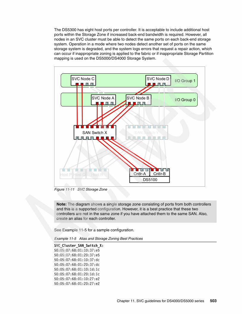
The DS5300 has eight host ports per controller. It is acceptable to include additional host ports within the Storage Zone if increased back-end bandwidth is required. However, all nodes in an SVC cluster must be able to detect the same ports on each back-end storage system. Operation in a mode where two nodes detect another set of ports on the same storage system is degraded, and the system logs errors that request a repair action, which can occur if inappropriate zoning is applied to the fabric or if inappropriate Storage Partition mapping is used on the DS5000/DS4000 Storage System.
Figure 11-11 SVC Storage Zone
See Example 11-5 for a sample configuration.
Example 11-5 Alias and Storage Zoning Best Practices
SVC_Cluster_SAN_Switch_X:50:05:07:68:01:10:37:e550:05:07:68:01:20:37:e550:05:07:68:01:10:37:dc50:05:07:68:01:20:37:dc50:05:07:68:01:10:1d:1c50:05:07:68:01:20:1d:1c50:05:07:68:01:10:27:e250:05:07:68:01:20:27:e2
Note: The diagram shows a single storage zone consisting of ports from both controllers and this is a supported configuration. However, it is a best practice that these two controllers are not in the same zone if you have attached them to the same SAN. Also, create an alias for each controller.
I/O Group 1
I/O Group 0
8
SAN Switch X9 10 11 12 13 14 15
0 1 2 3 4 5 6 7
0
Host P1 0
Host Q1 0
Host R10 1
8
SAN Switch Y9 10 11 12 13 14 15
0 1 2 3 4 5 6 7
0Cntlr-A
1 2 3 0Cntlr-B
1 2 3
DS5100
0
SVC Node A1 2 3 0
SVC Node B1 2 3
0
SVC Node C1 2 3 0
SVC Node D1 2 3
Chapter 11. SVC guidelines for DS4000/DS5000 series 503

DS5k_Ctrl_A_SAN_Switch_X:20:04:00:a0:b8:17:44:3220:04:00:a0:b8:17:44:33
DS5k_Ctrl_B_SAN_Switch_X:20:05:00:a0:b8:17:44:3220:05:00:a0:b8:17:44:33
SVC_DS5k_Zone_Ctrl_A_SAN_Switch_X:SVC_Cluster_SAN_ADS5k_Ctrl_A_SAN_Switch_X
SVC_DS5k_Zone_Ctrl_B_SAN_Switch_X:SVC_Cluster_SAN_ADS5k_Ctrl_B_SAN_Switch_X
SVC Inter-Cluster ZoneAn Inter-Cluster Zone is only required when Metro Mirroring or Global Mirroring is used between SVC Clusters. It includes only SVC ports from both SVC clusters.
11.5 SVC with DS4000/DS5000 best practicesThere are several best practices and guidelines to follow when a DS4000 is used through SVC so that it performs well with most applications.
The key is to plan how the DS4000/DS5000 disks (logical drives or LUNs) will be allocated and used by SVC because LUNs (which are the actual disks seen by SVC as MDisks) have to be created first on the DS4000/DS5000 Storage Server.
11.5.1 Disk allocation process
Here we list a simplified process of allocating disk from the storage array to the SVC:
1. The LUN is created from the array using Storage Manager.2. The LUN is presented to SVC by assigning the LUN to the SVCHost.3. The LUN is discovered by the management console and then gets created as an MDisk. 4. The MDisk is assigned to an MDG. The MDG determines the extent size. 5. The MDG is assigned to an I/O group.6. The MDisk is then used to create VDisks that are presented to the host.7. The host is created on the SVC.8. The VDisks are mapped to the host.
LUN creationThe storage arrays created on the DS4000/DS5000 when defining LUNs that will be assigned to the SVC must be configured with only one LUN per array. The LUN must be sized to utilize all of the available storage space on the array. In the DS4000/DS5000, you must have an equal number of arrays and LUNs, equally spread on the two controllers. After having assigned spare disks in the DS4000/DS5000, define your arrays with RAID protection, and create as few LUNs as you can in the array. If possible, make the LUNs the same size, so you can utilize the full capacity when striping VDisks on the SVC.
504 IBM Midrange System Storage Implementation and Best Practices Guide
The decision for array RAID level and which DS4000/DS5000 physical disks it contains is made when creating LUNs on the DS4000/DS5000 before it is defined as an SVC MDisk and mapped to an SVC VDisk. It is essential to know at that point which particular host and the nature of the host applications that will access the VDisk.
In other words, key decisions for reliability, availability, and performance are still made at the DS4000/DS5000 level. Therefore you still have to follow the guidelines given specifically for the DS4000/DS5000 in previous chapters of this book.
Here we summarize the most important guidelines:
� For data protection, ensure that the array is created with enclosure loss protection so that if an enclosure fails on the DS4000/DS5000, the array will still remain functional.
� For database transaction logs, RAID 10 gives maximum protection and performance. Database transaction logs require sequential writes to the log files. These must be well protected and must deliver high performance. For database data files, RAID 5 and RAID 6 offers a balance between protection and performance.
For best practice, the transaction logs and data files are best to be in a dedicated array:
– Create an array with one LUN of the appropriate size for the logs. Because this DS4000/DS5000 LUN will then be defined as an SVC MDisk and assigned to an MDG, make sure that the LUN size is appropriate for the extent size assigned to this MDG.
– Map the whole MDisk (all extents) and only extents from that MDisk to the VDisk. Doing so ensures that the host has dedicated use of that physical disk (DS4000/DS5000 LUN), which also ensures that no other VDisks will be mapped to that MDisk and possibly cause disk thrashing.
– For applications with small, highly random I/Os, you can stripe VDisks across multiple MDisks inside the same Managed Disk Group (MDG) for performance improvement. However, this is only true with applications that generate small high random I/Os. In a case of large blocksize I/Os that are mainly sequential data, using multiple MDdisks to stripe the extents across does not give a performance benefit.
� For file Server environment, RAID 5 offers a good level of performance and protection.
If their requirements are not too demanding, several host applications can use the same MDisk (that is, they use separate VDisks but carved from extents of the same MDIsk). In other words, in this case several hosts share the same DS4000 LUN through SVC. Still, you must monitor the DS4000/DS5000 LUN (array) to ensure that excessive disk thrashing is not occurring. If thrashing occurs then the VDisk can be migrated to another MDG.
Also, ensure that only LUNs from one storage server, such as a specific DS4000/DS5000, form part of an MDG, mainly for availability reasons, because the failure of one storage server will make the MDG go offline, and thereby all VDisks mapped to MDisks belonging to the MDG will go offline.
It is important that LUNs are properly balanced across the controllers prior to performing MDisk discovery. Failing to properly balance LUNs across storage controllers in advance can result in a suboptimal pathing configuration to the back-end disks, which can cause a performance degradation. Ensure that storage subsystems have all controllers online and that all LUNs have been distributed to their preferred controller (local affinity) prior to performing MDisk discovery. Pathing can always be rebalanced later, however, often not until after lengthy problem isolation has taken place.
Chapter 11. SVC guidelines for DS4000/DS5000 series 505
Controller affinity and preferred pathIn this context, affinity refers to the controller in a dual-controller subsystem (such as the DS4000/DS5000 Storage servers) that has been assigned access to the back-end storage for a specific LUN under nominal conditions (that is to say, both controllers are active). Preferred path refers to the host side connections that are physically connected to the controller that has the assigned affinity for the corresponding LUN being accessed.
For the DS4000/DS5000, preferred path is important, because Fibre Channel cards are integrated into the controller. This architecture allows “dynamic” multipathing and “active/standby” pathing through Fibre Channel cards that are attached to the same controller (the SVC does not support dynamic multipathing) and an alternate set of paths, which are configured to the other controller that will be used if the corresponding controller fails. The DS4000/DS5000 differs from other storage servers such as the DS6000 and DS8000, because it has the capability to transfer ownership of LUNs at the LUN level as opposed to the controller level.
The SVC attempts to follow IBM DS4000/DS5000 series specified preferred ownership. You can specify which controller (A or B) is used as the preferred path to perform I/O operations to a given LUN. If the SVC can see the ports of the preferred controller and no error conditions exist, then the SVC accesses that LUN through one of the ports on that controller. Under error conditions, the preferred ownership is ignored.
ADT for DS4000/DS5000The DS4000/DS5000 has a feature called Auto Logical Drive Transfer (ADT). This feature allows logical drive level failover as opposed to controller level failover. When you enable this option, the DS4000/DS5000 moves LUN ownership between controllers according to the path used by the host.For the SVC, the ADT feature is enabled by default when you select the “IBM TS SAN VCE” host type when you configure the DS4000/DS5000.
MDisksIt is important that LUNs are properly balanced across storage controllers prior to performing MDisk discovery. Failing to properly balance LUNs across storage controllers in advance can result in a suboptimal pathing configuration to the back-end disks, which can cause a performance degradation. Ensure that storage subsystems have all controllers online and that all LUNs have been distributed to their preferred controller prior to performing MDisk discovery. Pathing can always be rebalanced later, however, often not until after lengthy problem isolation has taken place.
If you discover that the LUNs are not evenly distributed across the dual controllers in a DS4000/DS5000, you can dynamically change the LUN affinity. However, the SVC will move them back to the original controller, and the DS4000/DS5000 will generate an error indicating that the LUN is no longer on its preferred controller. To correct this situation, you need to run the SVC command svctask detectmdisk or use the GUI option “Discover MDisks.” SVC will query the DS4000/DS5000 again and access the LUNs through the new preferred controller configuration.
Note: It is important that you select the “IBM TS SAN VCE” host type when configuring the DS4000/DS5000 for SVC attachment in order to allow the SVC to properly manage the back-end paths. If the host type is incorrect, SVC will report a 1625 (“incorrect controller configuration”) error.
506 IBM Midrange System Storage Implementation and Best Practices Guide
VDisks and extent sizeVDisks are allocated in whole numbers of extents so the VDisk size must be created as multiples to the extent size, so as not to waste storage at the end of each VDisk. For example if the extent size is 16 MB then the VDisk must be created in multiples of 16 MB.
The selection of the extents can be done manually or automatically. If done manually, the storage administrator needs to devise a method to make sure that the beginning of the VDisks remains random. The SVC does this by default to reduce any contention or thrashing on an array / MDisk.
DS4000/DS5000 array and segment sizeThe DS4000/DS5000 identifies the SVC as a host and does not needs to be configured for specific applications. The stripe width is a key parameter and in this context it refers to the number of disks that makes up a Redundant Array of Independent (RAID) array.
With RAID 5 arrays, determining the number of physical drives to put into an array always presents a compromise. Striping across a larger number of drives can improve performance for transaction-based workloads. However, striping can also have a negative effect on sequential workloads. A common mistake that people make when selecting array stripe width is the tendency to focus only on the capability of a single array to perform various workloads. However, you must also consider in this decision the aggregate throughput requirements of the entire storage server. A large number of physical disks in an array can create a workload imbalance between the controllers, because only one controller of the DS4000/DS5000 actively accesses a specific array.
When selecting stripe width, you must consider its effect on rebuild time and availability. A larger number of disks in an array increases the rebuild time for disk failures, which can have a negative effect on performance. Additionally, more disks in an array increase the probability of having a second drive fail within the same array prior to the rebuild completion of an initial drive failure, which is an inherent exposure to the RAID 5 architecture.
The segment size is the maximum amount of data that the controller can write at once on one physical disk in a logical drive before writing to the next physical disk.
With hosts attached to the storage server without SVC, considerations are often made to align device data partitions to physical drive boundaries within the storage server. For the SVC, aligning device data partitions to physical drive boundaries within the storage server is less critical based on the caching that the SVC provides and based on the fact that there is less variation in its I/O profile, which is used to access back-end disks. Because the maximum destage size for the SVC is 32 KB, it is impossible to achieve full stride writes for random workloads.
For the SVC, the only opportunity for full stride writes occurs with large sequential workloads, and in that case, the larger the segment size is, the better. However, larger segment sizes can adversely affect random I/O, because they can cause disk fragmentation. The SVC and controller cache do a good job of hiding the RAID 5 write penalty for random I/O, and therefore, larger segment sizes can be accommodated. The primary consideration for selecting segment size is to ensure that a single host I/O will fit within a single segment to prevent accessing multiple physical drives. Testing has shown that the best compromise for handling all workloads is to use a segment size of 256 KB.
Note: For the DS4000/DS5000, a stripe width of 4+P and 8+P is best suited for RAID 5 protection, and a stripe width of 8+P+Q is best suited for RAID 6.
Chapter 11. SVC guidelines for DS4000/DS5000 series 507

Overall, in an SVC configuration, larger DS4000/DS5000 segment sizes will give you better performance even in a random IO environment due to the SVC’s use of extents that generally provide a sequential IO pattern on the DS4000/DS5000 even with random IO requests from the host.
The smaller the MDisk / array / LUN, then the greater the spread of the extents across the MDisks in the Managed Disk Group (MDG), which reduces disk thrashing as the number of VDisks increases. When a VDisk is created, extents are taken one at a time from each MDisk in the group, so with more MDisks in the group, the array contention is kept to a minimum.
Cache block sizeThe size of the cache memory allocation unit can be either 4 K, 8 K, 16 K, or 32 K. The DS4000/DS5000 series uses a 4 KB cache block size by default; however, it can be changed to 8 KB, 16 KB or 32 KB. Depending on the IBM DS5000 or IBM DS4000 model, use a host type of IBM TS SAN VCE to establish the correct cache block size for the SAN Volume Controller cluster. Either set this as the system default host type or, if partitioning is enabled, associate each SAN Volume Controller port with the host type mentioned before.
Disk thrashingSVC makes it simple to carve up storage and allocate it to the hosts, which also can cause problems if multiple hosts use the same physical disks and cause them to be very heavily utilized. Multiple hosts using the same array is not a problem in itself, it is the disk requirements of each host that might cause the problems. For example, you might not want a database to share the same disks as the e-mail server or a backup server. The disk requirements might vary widely. Careful planning must be undertaken to ensure that the hosts that share the same array do not cause a problem due to heavy I/O operations.
Dual SAN fabricTo meet the business requirements for high availability, build a dual fabric network (that is, two independent fabrics that do not connect to each other). Resources such as DS4000/DS5000 Storage servers have two or more host ports per controller. These are used to connect both controllers of the storage server to each fabric, which means that controller A in the DS4000/DS5000 is connected to counterpart SAN A, and controller B in the DS4000/DS5000 is connected to counterpart SAN B, which improves data bandwidth performance. However, this does increase the cost, as switches and ports are duplicated.
Distance limitationsEnsure that the nodes of the cluster do not exceed any of the distance limitations. Ideally, you will want all nodes in the same room. If you want to have SVC in separate locations that are in separate buildings or farther away, then create a separate cluster. For disaster recovery and business continuity purposes, using the appropriate copy services between the two clusters will provide the level of protection required.
Similarly, if you have more than one data center, then you want a single SVC cluster in each data center and replicate any data between the clusters.
Tip: Use 256 KB segment size as the best compromise for all workloads.
Tip: To evenly spread the performance, arrays can be all the same size within an MDisk group.
508 IBM Midrange System Storage Implementation and Best Practices Guide

11.5.2 DS4000/DS5000 tuning summary
In Table 11-2 we summarize the best values for the main SVC and DS4000/DS5000 tunable parameters.
Table 11-2 Tuning summary
11.6 DS4000/DS5000 configuration with SVC
In this section we describe the configuration tasks required on the DS5000/DS4000 Storage System, including rules for the configuration.
11.6.1 Setting DS5000/DS4000 so both controllers have the same WWNN
The SAN Volume Controller recognizes that the DS5000/DS4000 controllers belong to the same storage system unit if they both have the same World Wide Node Name. This WWNN setting can be changed through the script editor on the DS5000/DS4000.
There are a number of ways to determine whether this is set correctly for SVC. The WWPN and WWNN of all devices logged in to the fabric can be checked from the SAN switch GUI. Confirm that the WWPN of all DS5000/DS4000 host ports are unique but the WWNN are identical for all ports belonging to a single storage unit.
The same information can be obtained from the Controller section when viewing the Storage Subsystem Profile from the Storage Manager GUI, which will list the WWPN and WWNN information for each host port:
World-wide port identifier: 20:27:00:80:e5:17:b5:bc World-wide node identifier: 20:06:00:80:e5:17:b5:bc
Alternatively, to confirm the status of the WWNN setting from, type in the statements in Figure 11-12 on the upper pane of the script editor. Press ENTER after each statement.
To run a script, select Tools Execute Script from the Storage Manager Enterprise Management Window.
Models Attribute Value
SVC Extent Size (MB) 256
SVC Managed Mode Striped
DS4000/DS5000 Segment Size (KB) 256
DS4000/DS5000 Cache Block Size (KB) 8
DS4000/DS5000 Cache Flush Control 80/80
DS4000/DS5000 Read Ahead 1(Enabled)
DS4000/DS5000 RAID5 4+P, 8+P
DS4000/DS5000 RAID6 8+P+Q
Chapter 11. SVC guidelines for DS4000/DS5000 series 509

Figure 11-12 Script to check state of WWNN setting
Then select Tools Verify and Execute from the menu options in the script editor. If there are no typing errors, then the output of the commands must be displayed in the bottom pane as shown in Figure 11-13.
Figure 11-13 Storage Manager script
Unfortunately, this does not provide a simple YES/NO answer.
The returned output is the hexadecimal value of the NVSRAM byte at offset 0x34 for each controller. The binary value of bit #1 (where bit #0 is the Least Significant Bit) determines whether the WWNNs are identical or not. See Table 11-3.
Table 11-3 Node names on each controller
In our example, the script returned a value of 0x73 for each controller. The second digit value of 3 confirms that bit #1 is set and hence the World Wide Node Names are identical on both controllers, which is the correct setting for the SAN Volume Controller, therefore no further action is required.
show "Showing the current state of WWNN NVSRAM setting"; show controller[a] nvsrambyte[0x34]; show controller[b] nvsrambyte[0x34];
Bit #1 Description
0 Various node names (WWNN) on each controller
1 Identical node names (WWNN) on each controller
510 IBM Midrange System Storage Implementation and Best Practices Guide
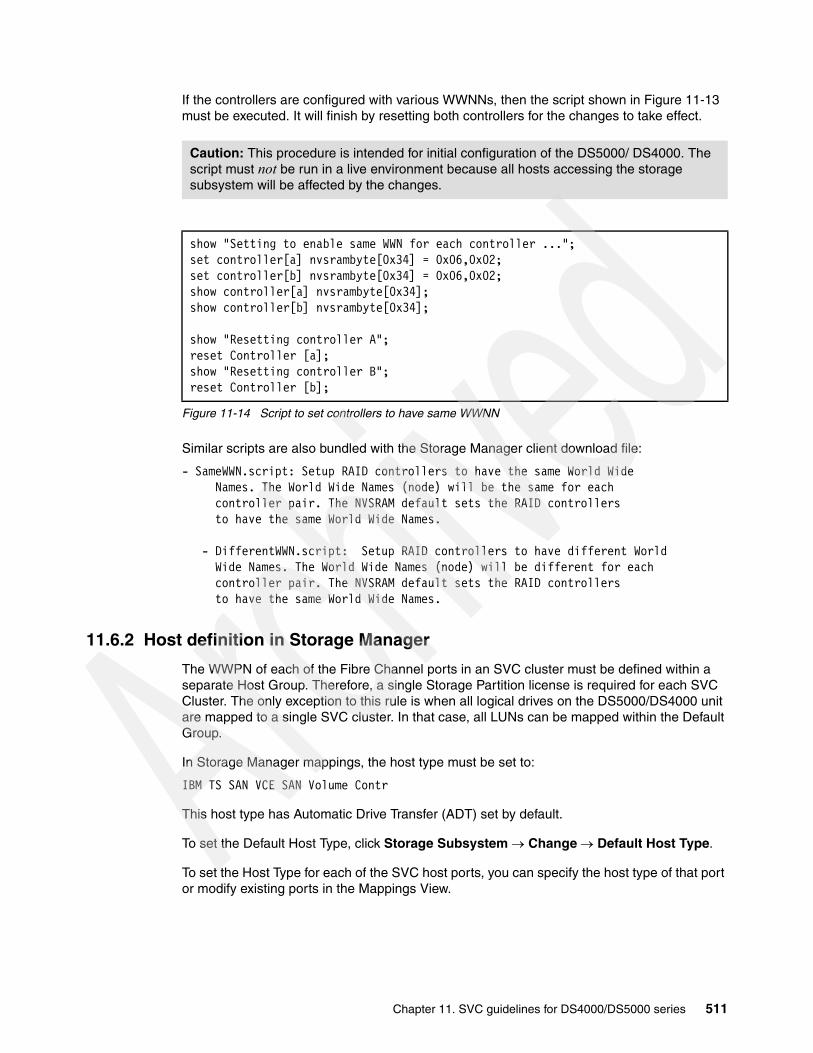
If the controllers are configured with various WWNNs, then the script shown in Figure 11-13 must be executed. It will finish by resetting both controllers for the changes to take effect.
Figure 11-14 Script to set controllers to have same WWNN
Similar scripts are also bundled with the Storage Manager client download file:
- SameWWN.script: Setup RAID controllers to have the same World Wide Names. The World Wide Names (node) will be the same for each controller pair. The NVSRAM default sets the RAID controllers to have the same World Wide Names.
- DifferentWWN.script: Setup RAID controllers to have different World Wide Names. The World Wide Names (node) will be different for each controller pair. The NVSRAM default sets the RAID controllers to have the same World Wide Names.
11.6.2 Host definition in Storage Manager
The WWPN of each of the Fibre Channel ports in an SVC cluster must be defined within a separate Host Group. Therefore, a single Storage Partition license is required for each SVC Cluster. The only exception to this rule is when all logical drives on the DS5000/DS4000 unit are mapped to a single SVC cluster. In that case, all LUNs can be mapped within the Default Group.
In Storage Manager mappings, the host type must be set to:
IBM TS SAN VCE SAN Volume Contr
This host type has Automatic Drive Transfer (ADT) set by default.
To set the Default Host Type, click Storage Subsystem Change Default Host Type.
To set the Host Type for each of the SVC host ports, you can specify the host type of that port or modify existing ports in the Mappings View.
Caution: This procedure is intended for initial configuration of the DS5000/ DS4000. The script must not be run in a live environment because all hosts accessing the storage subsystem will be affected by the changes.
show "Setting to enable same WWN for each controller ..."; set controller[a] nvsrambyte[0x34] = 0x06,0x02;set controller[b] nvsrambyte[0x34] = 0x06,0x02;show controller[a] nvsrambyte[0x34]; show controller[b] nvsrambyte[0x34];
show "Resetting controller A"; reset Controller [a]; show "Resetting controller B"; reset Controller [b];
Chapter 11. SVC guidelines for DS4000/DS5000 series 511
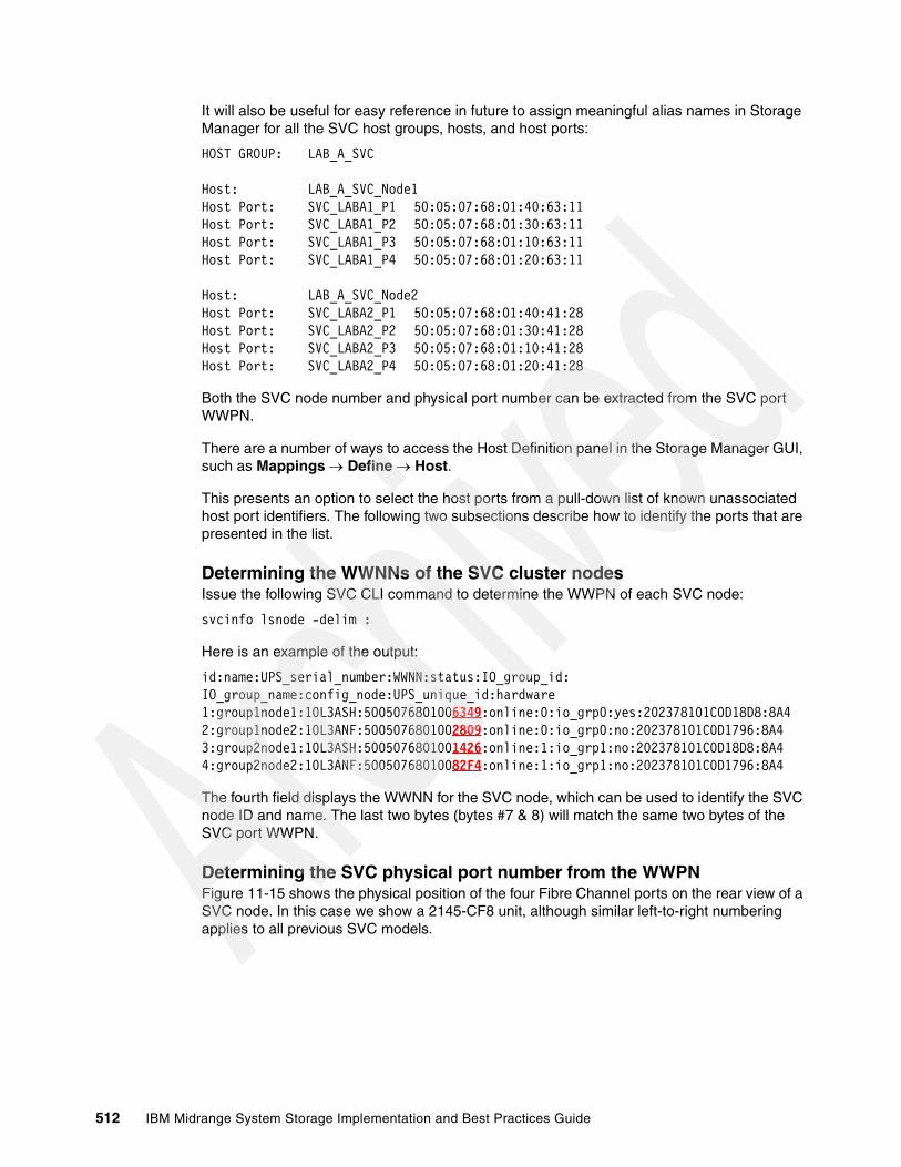
It will also be useful for easy reference in future to assign meaningful alias names in Storage Manager for all the SVC host groups, hosts, and host ports:
HOST GROUP: LAB_A_SVC
Host: LAB_A_SVC_Node1 Host Port: SVC_LABA1_P1 50:05:07:68:01:40:63:11Host Port: SVC_LABA1_P2 50:05:07:68:01:30:63:11Host Port: SVC_LABA1_P3 50:05:07:68:01:10:63:11Host Port: SVC_LABA1_P4 50:05:07:68:01:20:63:11
Host: LAB_A_SVC_Node2 Host Port: SVC_LABA2_P1 50:05:07:68:01:40:41:28Host Port: SVC_LABA2_P2 50:05:07:68:01:30:41:28Host Port: SVC_LABA2_P3 50:05:07:68:01:10:41:28Host Port: SVC_LABA2_P4 50:05:07:68:01:20:41:28
Both the SVC node number and physical port number can be extracted from the SVC port WWPN.
There are a number of ways to access the Host Definition panel in the Storage Manager GUI, such as Mappings Define Host.
This presents an option to select the host ports from a pull-down list of known unassociated host port identifiers. The following two subsections describe how to identify the ports that are presented in the list.
Determining the WWNNs of the SVC cluster nodesIssue the following SVC CLI command to determine the WWPN of each SVC node:
svcinfo lsnode -delim :
Here is an example of the output:
id:name:UPS_serial_number:WWNN:status:IO_group_id:IO_group_name:config_node:UPS_unique_id:hardware1:group1node1:10L3ASH:5005076801006349:online:0:io_grp0:yes:202378101C0D18D8:8A42:group1node2:10L3ANF:5005076801002809:online:0:io_grp0:no:202378101C0D1796:8A43:group2node1:10L3ASH:5005076801001426:online:1:io_grp1:no:202378101C0D18D8:8A44:group2node2:10L3ANF:50050768010082F4:online:1:io_grp1:no:202378101C0D1796:8A4
The fourth field displays the WWNN for the SVC node, which can be used to identify the SVC node ID and name. The last two bytes (bytes #7 & 8) will match the same two bytes of the SVC port WWPN.
Determining the SVC physical port number from the WWPNFigure 11-15 shows the physical position of the four Fibre Channel ports on the rear view of a SVC node. In this case we show a 2145-CF8 unit, although similar left-to-right numbering applies to all previous SVC models.
512 IBM Midrange System Storage Implementation and Best Practices Guide

Figure 11-15 Physical Fibre Channel port numbers on the 2145-CF8 SVC node
The first digit of byte #6 of the SVC port WWPN is used to identify the physical port:
50:05:07:68:01:40:41:28
Table 11-4 can then be used to identify the physical port numbers from the list of unassociated port identifiers in Storage Manager.
Table 11-4 Identifying physical port numbers
11.6.3 Arrays and logical drives
You must follow normal logical drive creation guidelines when defining SVC storage on the DS5000 and DS4000 Storage system. Distribute the logical drives evenly between the two controllers.
According to various SVC documentation, wait for the logical drive initialization to complete before mapping it to the SVC because it can result in excessive discovery times. Waiting might not be necessary on the DS5000/DS4000 Storage systems because the Immediate Availability Format (IAF) feature makes the LUNs accessible while initialization is in progress.
11.6.4 Logical drive mapping
All logical drives must be mapped to the single host group representing the entire SVC cluster. It is not permitted to map LUNs to certain nodes or ports in the SVC cluster while excluding others.
The Access LUN allows in-band management of a IBM System Storage DS5000 or IBM DS4000 Storage System. It must only be mapped to hosts capable of running the Storage Manager Client and Agent. The San Volume Controller will ignore the Access LUN if it is mapped to it. Nonetheless, it is good practice to remove the Access LUN from the SVC host group mappings.
The SVC code v5.1 does not support any iSCSI storage devices. All DS5000 logical drives must be mapped to the SVC by Fibre Channel SAN ports.
Physical port # WWPN byte #6
1 4
2 3
3 1
4 2
Important: The Access LUN must never be mapped as LUN #0.
Chapter 11. SVC guidelines for DS4000/DS5000 series 513

11.7 Managing SVC objects
In this section, we discuss various procedures relevant for monitoring and managing DS5000/DS4000 Storage system devices on the SAN Volume Controller.
11.7.1 Adding a new DS5000/DS4000 to a SVC cluster configuration
DS5000/DS4000 Storage Systems can be added to an existing SAN Volume Controller configuration at any time and without disruption. This procedure can be performed using either the SSPC (Master Console) GUI or SVC CLI commands.
First, see “Setting DS5000/DS4000 so both controllers have the same WWNN” on page 509 to ensure that the controllers are set up correctly for use with the SAN Volume Controller.
Then, if required, create the arrays, logical drives, host group definition, and mappings following the basic guidelines in 11.6, “DS4000/DS5000 configuration with SVC” on page 509.
When the new DS5000/DS4000 Storage System is added to the Fibre Channel SAN and included in the same switch zone as a SAN Volume Controller cluster, the cluster automatically discovers it. It then integrates the unit to determine the storage that is presented to the SAN Volume Controller nodes. The logical drives that are mapped to it are displayed as unmanaged MDisks.
Procedure using the SSPC (Master Console) GUIFollow these steps to add a new DS5000/DS4000 Storage System to the SVC cluster:
1. Ensure that the cluster has detected the new storage (MDisks):
a. Click Work with Managed Disks Managed Disks. The Viewing Managed Disks panel is displayed.
b. Select Discover MDisks from the task list and click Go.
2. Determine the storage controller name to validate that this is the correct controller. The new DS5000/DS4000 Storage System will have automatically been assigned a default name.
3. If you are unsure which DS5000/DS4000 unit is presenting the MDisks, perform the following steps:
a. Click Work with Managed Disks Disk Controller Systems. The Viewing Disk Controller Systems panel is displayed.
b. Find the new controller in the list. The new controller has the highest numbered default name.
4. Record the field controller LUN number. The controller LUN number corresponds with the LUN number that we assigned in Storage Manager when mapping the logical drives to the SVC cluster:
a. Click Work with Managed Disks Managed Disks. The Viewing Managed Disks panel is displayed.
Note: The automatic discovery that is performed by SAN Volume Controller cluster does not write anything to an unmanaged MDisk. You must instruct the SAN Volume Controller cluster to add an MDisk to an MDisk group or use an MDisk to create an image mode virtual disk (VDisk)
514 IBM Midrange System Storage Implementation and Best Practices Guide

b. Find the MDisks that are not in managed mode. These MDisks must correspond with the RAID arrays or partitions that you created.
5. Create a new MDisk group and add only logical drives belonging to the new DS5000/DS4000 system to this MDisk group. A separate MDisk group will need to be created for each group of new logical drives with separate performance or resilience characteristics. Give each MDisk group a descriptive name, such as SATA_8+P, FC15K_4+P, or FC10K_RAID10:
a. Click Work with Managed Disks Managed Disk Groups.
b. Select Create an MDisk Group from the task list and click Go. The Create Managed Disk Group wizard begins.
c. Complete the wizard to create a new MDisk group.
Procedure using the SVC CLIFollow these steps to add a new DS5000/DS4000 Storage System to the SVC cluster:
1. Issue the following CLI command to ensure that the cluster has detected the new storage (MDisks):
svctask detectmdisk
2. Determine the storage controller name to validate that this is the correct controller. The new DS5000/DS4000 Storage System will have automatically been assigned a default name.
3. If you are unsure which DS5000/DS4000 Storage System is presenting the MDisks, then:
a. issue the following command to list the controllers:
svcinfo lscontroller
b. Find the new controller in the list. The new controller has the highest numbered default name.
4. Record the name of the new controller.
5. Issue the following command to change the controller name to something that you can easily use to identify it:
svctask chcontroller -name newname oldname
Where newname is the name that you want to change the controller to and oldname is the name that you are changing.
6. Issue the following command to list the unmanaged MDisks:
svcinfo lsmdisk -filtervalue mode=unmanaged:controller_name=new_name
These MDisks must correspond with the logical drives mapped from the new DS5000/DS4000 Storage System.
7. Record the field controller LUN number. The controller LUN number corresponds with the LUN number that we assigned in Storage Manager when mapping the logical drives to the SVC cluster.
8. Create a new MDisk group and add only logical drives belonging to the new DS5000/DS4000 system to this MDisk group. A separate MDisk group must be created for each group of new logical drives with separate performance or resilience characteristics. Give each MDisk group a descriptive name, such as SATA_8+P, FC15K_4+P, FC10K_RAID10.
svctask mkmdiskgrp -ext 16 -name mdisk_grp_name -mdisk {colon separated list of new mdisks returned in step 6}
Chapter 11. SVC guidelines for DS4000/DS5000 series 515

This creates a new MDisk group with an extent size of 16 MB. There is further discussion in the DS5000/DS4000 Best Practice Guide on selecting extent size.
11.7.2 Removing a storage system
Normally, you can use one of the procedures described in 11.8, “Migration” on page 518 to migrate data before the storage system is removed from the SVC cluster. This procedure assumes that the DS5000/DS4000 Storage System has been removed or the logical drives are no longer accessible. The managed disks (MDisks) that represent those logical drives might still exist in the cluster. However, the cluster cannot access these MDisks because the logical drives that these MDisks represent have been unconfigured or removed from the storage system. You must remove these MDisks.
Perform the following steps to remove MDisks:
1. Run the svctask includemdisk CLI command on all the affected MDisks.
2. Run the svctask rmmdisk CLI command on all affected MDisks. Doing this puts the MDisks into the unmanaged mode.
3. Run the svctask detectmdisk CLI command. The cluster detects that the MDisks no longer exist in the storage system.
All of the MDisks that represent unconfigured logical drives are removed from the cluster.
11.7.3 Monitoring the MDisk Status
Use the SSPC (Master Console) or CLI commands to check the status of the MDisks. On the SSPC Master Console, click Work with Managed Disks Managed Disks. The Viewing Managed Disks panel is displayed.
Alternatively, you can use the svctask lsmdisk CLI command to generate a similar list.
The MDisk can be in one of the following states:
Online The MDisk can be accessed by all online nodes. That is, all the nodes that are currently working members of the cluster can access this MDisk. The MDisk is online when the following conditions are met:All timeout error recovery procedures complete and report the disk as online.Logical unit number (LUN) inventory of the target ports correctly reported the MDisk.Discovery of this LUN completed successfully.All of the MDisk target ports report this LUN as available with no fault conditions.
Degraded Paths The MDisk is not accessible to one or more nodes in the cluster. Degraded path status is most likely the result of incorrect configuration of either the disk controller or the Fibre Channel fabric. However, hardware failures in the disk controller, Fibre Channel fabric, or node can also be a contributing factor to this state.
Complete the following actions to recover from this state:1. Verify that fabric configuration rules for storage systems are correct.2. Ensure that you have configured the storage system properly.3. Correct any errors in the error log.
516 IBM Midrange System Storage Implementation and Best Practices Guide
Degraded Ports The MDisk has one or more 1220 errors in the error log. The 1220 error indicates that the remote Fibre Channel port has been excluded from the MDisk. This error might cause reduced performance on the storage controller and usually indicates a hardware problem with the storage controller. To fix this problem you must resolve any hardware problems on the storage controller and fix the 1220 errors in the error log. To resolve these errors in the log, select Service and Maintenance Run Maintenance Procedures in the SAN Volume Controller Console. On the Maintenance Procedures panel, select Start Analysis. This action displays a list of unfixed errors that are currently in the error log. For these unfixed errors, select the error name to begin a guided maintenance procedure to resolve them. Errors are listed in descending order with the highest priority error listed first. Resolve highest priority errors first.
Excluded The MDisk has been excluded from use by the cluster after repeated access errors. Run the Directed Maintenance Procedures to determine the problem.
Offline The MDisk cannot be accessed by any of the online nodes. That is, all of the nodes that are currently working members of the cluster cannot access this MDisk. This state can be caused by a failure in the SAN, storage system, or one or more physical disks connected to the storage system. The MDisk is reported as offline if all paths to the disk fail.
11.7.4 SVC error reporting and event notification
Errors detected by the SAN Volume Controller are saved in an error log. As soon as an entry is made in this error log, the error condition is analyzed. If any service activity is required, the user is notified of the error.
Viewing the SVC error event logYou can view the error event log by using the SAN Volume Controller command line interface (CLI) or the SAN Volume Controller Console.
Viewing the full contents of each error-event log entry using the CLITo view the contents of the log, follow these steps:
1. Dump the contents of the error log to a file.
a. Issue the svctask dumperrlog command to create a dump file that contains the current error-event log data.
b. Issue the svcinfo lserrlogdumps command to determine the name of the dump file that you have just created.
c. Issue the secure copy command (scp) to copy the dump file to the IBM System Storage Productivity Center.
2. View the file with a text viewer after the dump file is extracted from the cluster.
Viewing the error event log using the SAN Volume Controller ConsoleTo view the contents of the log, click Service and Maintenance Analyze Error Log. You can view the entire log or filter it so that only certain events are displayed. If you are repairing a fault, you might only want to select the option to Show unfixed errors.
Chapter 11. SVC guidelines for DS4000/DS5000 series 517

11.8 Migration
In this section, we discuss a migration scenario where we are replacing a pre-virtualized storage system (a DS4000 in this case) with a DS5000 Storage System using SVC environment.
11.8.1 Migration overview and concepts
In this section we discuss various migration concepts.
MDisk modes: It is important to understand these three basic MDisk modes:
Unmanaged MDisk An MDisk is reported as unmanaged when it is not a member of any MDisk Group. An unmanaged MDisk is not associated with any VDisks and has no metadata stored on it. The SVC will not write to an MDisk that is in unmanaged mode except when it attempts to change the mode of the MDisk to one of the other modes.
Image Mode MDisk Image Mode provides a direct block-for-block translation from the MDisk to the VDisk with no virtualization. Image Mode VDisks have a minimum size of one block (512 bytes) and always occupy at least one extent. An Image Mode MDisk is associated with exactly one VDisk.
Managed Mode MDisk Managed Mode Mdisks contribute extents to the pool of extents available in the MDG.
The SVC cannot differentiate unmanaged-mode managed disks (MDisks) that contain existing data from unmanaged-mode MDisks that are blank. Therefore, it is vital that you control the introduction of these MDisks to the cluster by adding them one at a time. For example, map a single LUN from your RAID controller to the cluster and refresh the view of MDisks. The newly detected MDisk is displayed.
518 IBM Midrange System Storage Implementation and Best Practices Guide

11.8.2 Migration procedure
Figure 11-16 shows a DS4000 unit with three attached hosts. Each host has a number of logical drives mapped to it through a separate partition. All data on the DS4000 must be preserved.
In addition, a new DS5000 Storage System has been introduced to the SAN. A storage zone has been created on the SAN fabrics to allow the SVC to access the DS5000 logical drives. Logical drives have been created on the DS5000 unit and mapped to the SVC.
Note that the DS5000 only requires a single partition for the SVC cluster.
In this example, we assume that all the logical drives mapped to these 3 hosts have similar performance and resilience requirements, such as all 4+P RAID 5 FC 10K. Therefore, we can migrate them all into the same MDisk Group. However, sometimes it is preferred to create separate MDisk Groups for each host operating system.
Figure 11-16 Migration - Initial Configuration
The host C LUNs will be the first to be migrated to the DS5000 by SVC. Here, we summarize the basic steps involved in the migration. For further details, see the SVC reference documentation.
1. Create an MDisk Group for the new DS5000 LUNs:
a. All new volumes must be automatically discovered.
b. Use the CLI command svctask detectmdisk to manually scan for new devices.
c. Use the CLI command svcinfo lsdiscoverystatus to check status of the discovery.
d. Use the CLI command svcinfo lsmdiskcandidate to show unmanaged MDisks.
e. Use the CLI command svctask mkdiskgrp to add the new MDisks to a MDisk Group:
svctask mkmdiskgrp -name ds5kgrp -ext 512 -mdisk mdisk1:mdisk2:mdisk3:mdisk4
2. Stop all applications on host C.
3. Remove the RDAC multipath driver on host C.
4. Install the SDD multipath driver on host C.
DS4000
Partition 0Host Type: Windows
Partition 1Host Type: AIX
Partition 2Host Type: Linux
Host Ampio
Host Bmpio
Host Crdac
Partition 0Host Type: SVC VCE
SVCCluster
DS5000
Chapter 11. SVC guidelines for DS4000/DS5000 series 519

5. Change SAN zoning so that host C is only presented the SVC Cluster ports.
6. Define Host C to the SVC:
a. Use the CLI command svcinfo lshbaportcandidate to list unassigned host WWPNs.
b. Use the CLI command svctask mkhost to define the host.
c. Use the CLI command svctask lshost to verify that host was defined successfully.
7. Shut down Host C.
8. Change Host Type definitions for partition 2 on the DS4000 to IBM TS SVC VCE.
9. Detect new MDisks:
a. All new volumes must be automatically discovered.
b. Use the CLI command svctask detectmdisk to manually scan for new devices.
c. Use the CLI command svcinfo lsdiscoverystatus to check status of the discovery.
d. Use the CLI command svcinfo lscontroller to list all storage systems.
e. Use the CLI command svcinfo lsmdiskcandidate to show unmanaged MDisks.
10.Create an empty MDisk Group for the imported image volumes from the DS4000:
a. Use the CLI command svctask mkdiskgrp to create the empty MDisk Group.
b. Use the CLI command svcinfo lsmdiskgrp to list MDisk Groups.
11.Create image mode VDisks from data volumes on the DS4000:
a. Use the CLI command svcinfo lsmdiskcandidate to show unmanaged MDisks.
b. Use the CLI command svctask mkvdisk to create the image mode VDisk:
svctask mkvdisk -mdiskgrp imggrp -iogrp 0 -vtype image -name DS401 -mdisk mdisk4
c. Use the CLI command svcinfo lsvdisk vdiskname to check new vdisk properties.
12.Map the Image VDisks to the Host:
a. Use the CLI command svctask mkvdiskhostmap to map the new vdisk to the host.
b. Virtualized images of the LUNs in partition 2 on the DS4000 Storage System are now accessible on host C.
13.Boot Host C.
14.You can start all applications on Host C to minimize downtime.
520 IBM Midrange System Storage Implementation and Best Practices Guide
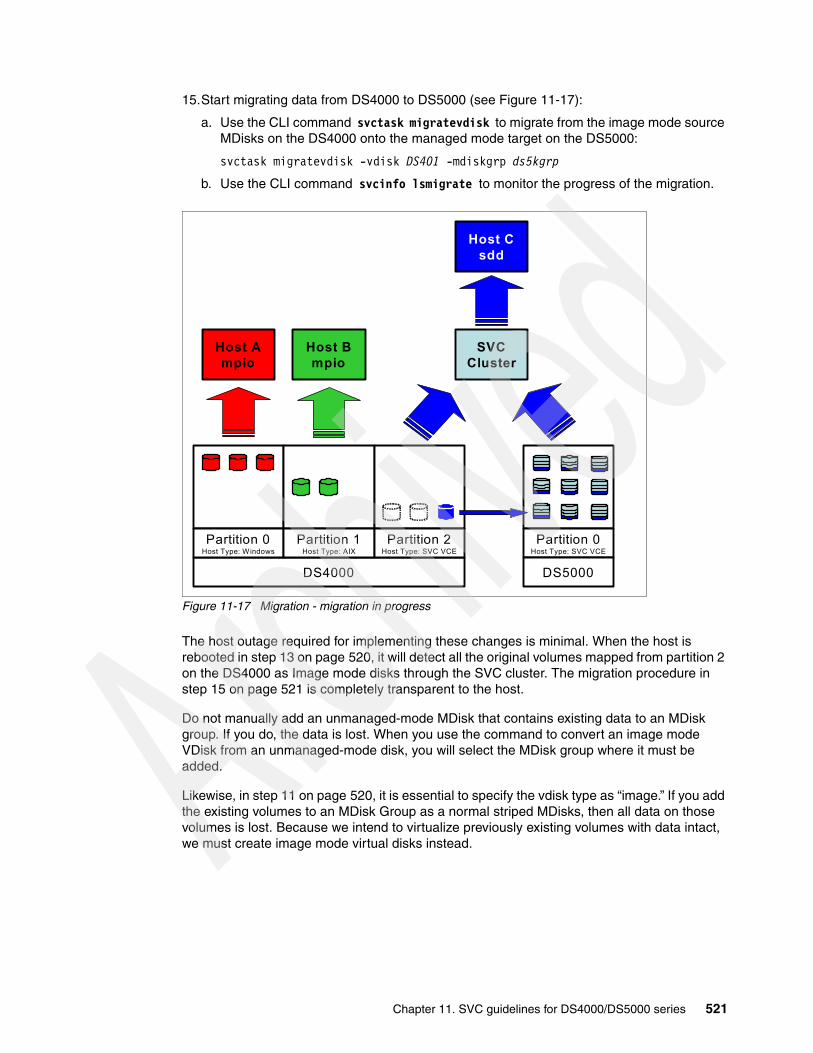
15.Start migrating data from DS4000 to DS5000 (see Figure 11-17):
a. Use the CLI command svctask migratevdisk to migrate from the image mode source MDisks on the DS4000 onto the managed mode target on the DS5000:
svctask migratevdisk -vdisk DS401 -mdiskgrp ds5kgrp
b. Use the CLI command svcinfo lsmigrate to monitor the progress of the migration.
Figure 11-17 Migration - migration in progress
The host outage required for implementing these changes is minimal. When the host is rebooted in step 13 on page 520, it will detect all the original volumes mapped from partition 2 on the DS4000 as Image mode disks through the SVC cluster. The migration procedure in step 15 on page 521 is completely transparent to the host.
Do not manually add an unmanaged-mode MDisk that contains existing data to an MDisk group. If you do, the data is lost. When you use the command to convert an image mode VDisk from an unmanaged-mode disk, you will select the MDisk group where it must be added.
Likewise, in step 11 on page 520, it is essential to specify the vdisk type as “image.” If you add the existing volumes to an MDisk Group as a normal striped MDisks, then all data on those volumes is lost. Because we intend to virtualize previously existing volumes with data intact, we must create image mode virtual disks instead.
DS4000
Host Ampio
Host Bmpio
Host Csdd
SVCCluster
Partition 0Host Type: Windows
Partition 1Host Type: AIX
Partition 2Host Type: SVC VCE
Partition 0Host Type: SVC VCE
DS5000
Chapter 11. SVC guidelines for DS4000/DS5000 series 521

Repeat the same procedure for all remaining hosts with storage on the DS4000 (Figure 11-18).
Figure 11-18 Migration - All LUNs moved to DS5000 by SVC
You can remove the original partitions and create a new partition on the DS4000 in order to present the unused capacity as managed disks on the SVC. Then you can migrate certain members of the original data volumes back onto it if required.
Although we used a migration from a DS4000 Storage System to a DS5000 as an example, the same procedure applies if we were migrating from other storage platforms.
Host Asdd
Host Bsdd
Host Csdd
SVCCluster
DS4000
Partition 0Host Type: Windows
Partition 1Host Type: AIX
Partition 2Host Type: SVC VCE
Partition 0Host Type: SVC VCE
DS5000
522 IBM Midrange System Storage Implementation and Best Practices Guide
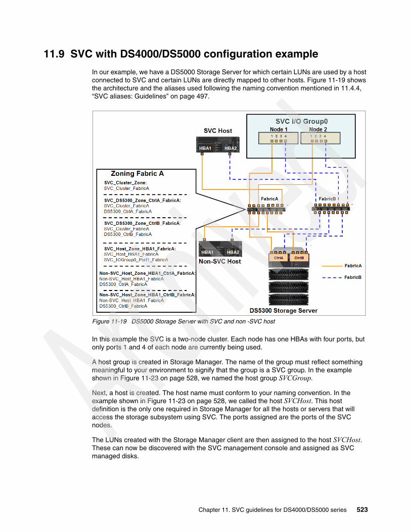
11.9 SVC with DS4000/DS5000 configuration example
In our example, we have a DS5000 Storage Server for which certain LUNs are used by a host connected to SVC and certain LUNs are directly mapped to other hosts. Figure 11-19 shows the architecture and the aliases used following the naming convention mentioned in 11.4.4, “SVC aliases: Guidelines” on page 497.
Figure 11-19 DS5000 Storage Server with SVC and non -SVC host
In this example the SVC is a two-node cluster. Each node has one HBAs with four ports, but only ports 1 and 4 of each node are currently being used.
A host group is created in Storage Manager. The name of the group must reflect something meaningful to your environment to signify that the group is a SVC group. In the example shown in Figure 11-23 on page 528, we named the host group SVCGroup.
Next, a host is created. The host name must conform to your naming convention. In the example shown in Figure 11-23 on page 528, we called the host SVCHost. This host definition is the only one required in Storage Manager for all the hosts or servers that will access the storage subsystem using SVC. The ports assigned are the ports of the SVC nodes.
The LUNs created with the Storage Manager client are then assigned to the host SVCHost. These can now be discovered with the SVC management console and assigned as SVC managed disks.
Chapter 11. SVC guidelines for DS4000/DS5000 series 523

11.9.1 Zoning for a non-SVC host
Zoning rules for hosts that will not use the SVC remain unchanged. They must still follow the best practice where, for each host, multiple zones are created such that each host HBA port is paired with a specific controller on the DS5000 Storage System. For example, for a host with two HBA ports, the zoning is as follows:
� Host zone 1: HBA_1 is in a zone with DS5000 controller A.� Host zone 2: HBA_2 is in a zone with DS5000 controller A.� Host zone 3: HBA_1 is in a zone with DS5000 controller B.� Host zone 4: HBA_2 is in a zone with DS5000 controller B.
In Figure 11-8 on page 500 we show only the zoning for the Fabric A, therefore two zones are created:
� Non-SVC_Host_Zone_HBA1_CtrlA_FabricA contains two aliases
– Non-SVC_Host_HBA1_FabricA
– DS5300_CtrlA_FabricA
� Non-SVC_Host_Zone_HBA1_CtrlB_FabricA contains two aliases
– Non-SVC_Host_HBA1_FabricA
– DS5300_CtrlB_FabricA
Obviously the counterpart FabricB is going to get the other two zones:
� Non-SVC_Host_Zone_HBA2_CtrlA_FabricB contains two aliases
– Non-SVC_Host_HBA2_FabricAB
– DS5300_CtrlA_FabricB
� Non-SVC_Host_Zone_HBA2_CtrlB_FabricB contains two aliases
– Non-SVC_Host_HBA2_FabricB
– DS5300_CtrlB_FabricB
11.9.2 Zoning for SVC and hosts that will use the SVC
All SVC nodes in the SVC cluster are connected to the same SAN, and present virtual disks to the hosts. These virtual disks are created from managed disks presented by the storage server.
In our example, the zoning for SVC must be such that each node (node 1 and node 2) can address the DS5000 Storage Server.
Each SVC node has one HBA with four fiber ports. We have only used two ports from the HBA present in each SVC node (ports 1 and 4).
Storage zoning has to be done for the SVC to utilize the DS5000 Storage Server (see Figure 11-8 on page 500):
For the Fabric A, we have the following zones (one per controller):
� SVC_DS5300_Zone_CtrlB _FabricA contains two aliases:
– SVC_Cluster_FabricA
– DS5300_CtrlB_FabricA
524 IBM Midrange System Storage Implementation and Best Practices Guide
� SVC_DS5300_Zone_CtrlA_FabricA contains two aliases:
– SVC_Cluster_FabricA
– DS5300_CtrlA_FabricA
For the Fabric B, we create the following zones:
� SVC_DS5300_Zone_CtrlB_FabricB contains two aliases:
– SVC_Cluster_FabricB
– DS5300_CtrlB_FabricB
� SVC_DS5300_Zone_CtrlA_FabricB contains two aliases:
– SVC_Cluster_FabricB
– DS5300_CtrlA_FabricB
Note that the two aliases SVC_Cluster_FabricA and SVC_Cluster_FabricB contains respectively the ports 1 of each node and the ports 4 of each node.
With this zoning, each port of the SVC nodes connected to the fabric can address each DS5000 controller. It also offers many paths from the nodes to the storage for redundancy.
Host zoning has to be done for every host that will use SVC to manage the disks.
� Host zone 1: HBA_1 is in a zone with SVC node 1 port 1 and SVC node 2 port 1.� Host zone 2: HBA_2 is in a zone with SVC node 1 port 4 and SVC node 2 port 4.
With this zoning, each host HBA can see a port on each node that is connected to the fabric. It also offers many paths to the storage that the SVC will manage.
In Figure 11-8 on page 500 we show only the zoning for the Fabric A, therefore we have:
� SVC_Host_Zone_HBA1 contains two aliases
– SVC_Host_HBA1_FabricA
– SVC_IOGroup0_Port1_FabricA
On the other side, the counterpart FabricB is going to get the following zone:
� SVC_Host_Zone_HBA2 contains two aliases
– SVC_Host_HBA2_FabricA
– SVC_IOGroup0_Port4_FabricA
11.9.3 Configuring the DS5000 Storage Server
The storage arrays must be created with only one LUN per array. The LUN must be sized to utilize all of the available storage space on the array. This single LUN will then be used to create smaller VDisks, which will be made available to the hosts. Choose the RAID level required for the LUN. This RAID level is dependent upon the nature of the application that will use this LUN.
When creating the host type, ensure that you select the particular host type for SVC of IBM TotalStorage SAN Volume Controller Engine (TS SAN VCE). Remember that the LUNs can be used by all types of hosts and applications attached to SVC.
In our example, we created three SVC LUNs that will be managed by the SVC. These LUNs start with the letters SVC for clarity.
Chapter 11. SVC guidelines for DS4000/DS5000 series 525
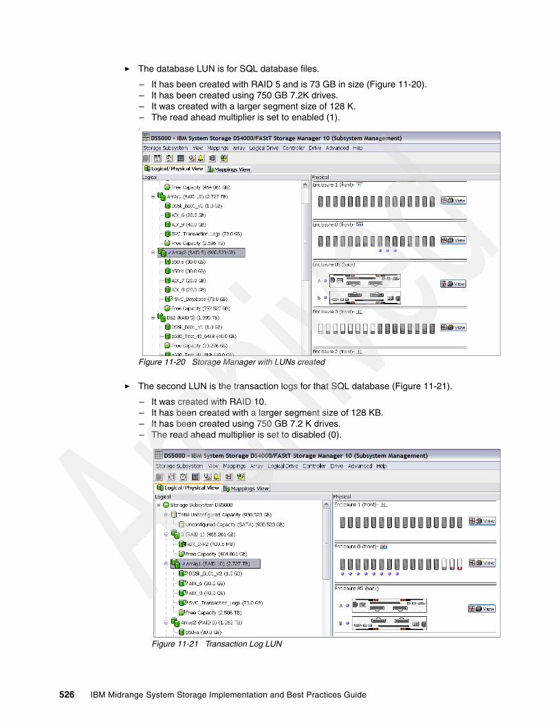
� The database LUN is for SQL database files.
– It has been created with RAID 5 and is 73 GB in size (Figure 11-20). – It has been created using 750 GB 7.2K drives.– It was created with a larger segment size of 128 K. – The read ahead multiplier is set to enabled (1)..
Figure 11-20 Storage Manager with LUNs created
� The second LUN is the transaction logs for that SQL database (Figure 11-21).
– It was created with RAID 10. – It has been created with a larger segment size of 128 KB.– It has been created using 750 GB 7.2 K drives.– The read ahead multiplier is set to disabled (0).
Figure 11-21 Transaction Log LUN
526 IBM Midrange System Storage Implementation and Best Practices Guide

� The third LUN is the file and print LUN (Figure 11-22).
As the file and print LUN is not as read or write intensive as the database or transaction log LUNs, it can be shared between multiple hosts. Most of the files are very small, and the environment is more of a read than write.
– It has been created with a segment size of 64 KB.– It has been created using 7.2 K drives.– The read ahead multiplier is set to enabled (1).
Figure 11-22 File and Print LUN
Chapter 11. SVC guidelines for DS4000/DS5000 series 527

The SVC nodes must be able to access all of the LUNs that SVC will manage. Therefore, the LUNs need to be mapped to all of the available SVC Fibre Channel host ports. The storage is mapped at the host SVCHost. The host type must be set to IBM TS SAN VCE (Figure 11-23).
Figure 11-23 LUNs managed by the SVC are mapped to the host SVCHost
11.9.4 Using the LUN in SVC
The LUN can now be discovered by the management console and defined as an MDisk. The MDisk is then assigned to an MDG. Extents from the MDG are used to define a VDisk that can in turn be mapped to a SVC host.
Follow these steps:
1. To discover the disks, log in at the SVC console with appropriate privileges.
Select Work with Managed Disks Managed Disks. In the Viewing Managed Disks window (Figure 11-24), if your MDisks are not displayed, re-scan the Fibre Channel network. Select Discover MDisks from the list and click Go. Discovered disks appear as unmanaged.
If your MDisks (DS5000 LUNs) are still not visible, check that the logical unit numbers (LUNs) from the DS5000 Storage Server are properly assigned to the SVC and that appropriate zoning is in place (SVC can see the disk subsystem).
528 IBM Midrange System Storage Implementation and Best Practices Guide
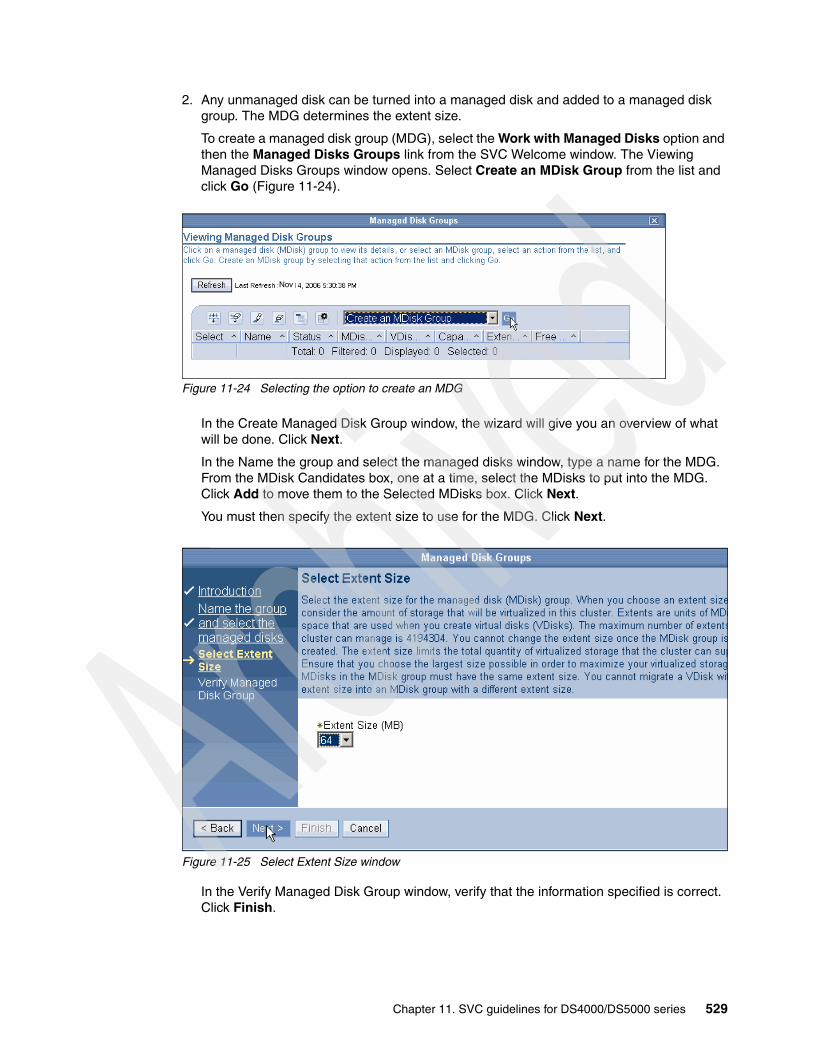
2. Any unmanaged disk can be turned into a managed disk and added to a managed disk group. The MDG determines the extent size.
To create a managed disk group (MDG), select the Work with Managed Disks option and then the Managed Disks Groups link from the SVC Welcome window. The Viewing Managed Disks Groups window opens. Select Create an MDisk Group from the list and click Go (Figure 11-24).
Figure 11-24 Selecting the option to create an MDG
In the Create Managed Disk Group window, the wizard will give you an overview of what will be done. Click Next.
In the Name the group and select the managed disks window, type a name for the MDG. From the MDisk Candidates box, one at a time, select the MDisks to put into the MDG. Click Add to move them to the Selected MDisks box. Click Next.
You must then specify the extent size to use for the MDG. Click Next.
Figure 11-25 Select Extent Size window
In the Verify Managed Disk Group window, verify that the information specified is correct. Click Finish.
Nov
Chapter 11. SVC guidelines for DS4000/DS5000 series 529

3. Return to the Viewing Managed Disk Groups window where the MDG is displayed (Figure 11-26).
Figure 11-26 View managed disk groups
4. Use the MDisk to create VDisks that will be presented to the host, which can be done by selecting Working with Virtual Disk Virtual Disks from the SVC Welcome window. From the drop-down menu, select Create VDisk (Figure 11-27).
Figure 11-27 Working with virtual disks
530 IBM Midrange System Storage Implementation and Best Practices Guide
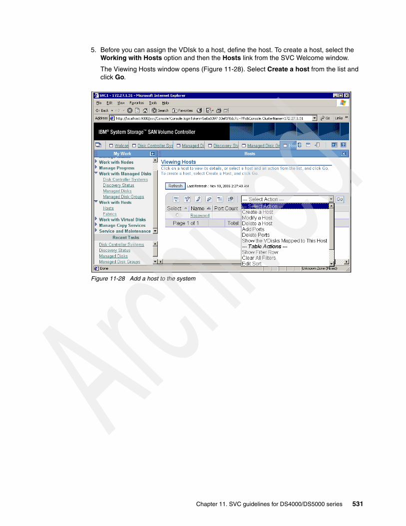
5. Before you can assign the VDIsk to a host, define the host. To create a host, select the Working with Hosts option and then the Hosts link from the SVC Welcome window.
The Viewing Hosts window opens (Figure 11-28). Select Create a host from the list and click Go.
Figure 11-28 Add a host to the system
Chapter 11. SVC guidelines for DS4000/DS5000 series 531

Enter details for the host, such as the name of the host, the type of host, I/O groups, and HBA ports, as shown in Figure 11-29. This window shows all WWNs that are visible to the SVC and that have not already been defined to a host. If your WWN does not appear, check that the host has logged into the switch and that zoning in the switches is updated to allow SVC and host ports to see each other.
Figure 11-29 Creating Hosts window
6. In Figure 11-30, map the VDisks to the host. Select Working with Virtual Disks and select the VDisk. From the drop-down Select Action menu, select Map VDisk to a Host.
Figure 11-30 Map the VDisk to the host
532 IBM Midrange System Storage Implementation and Best Practices Guide
Chapter 12. DS5000 with AIX, PowerVM, and PowerHA
In this chapter, we present configuration information relevant to the DS5000 Storage Server attached to IBM POWER servers. We also review special considerations for PowerHA formerly known as High Availability Cluster Multiprocessing (HACMP) configurations in AIX.
AIX 5L and AIX6 are award winning operating systems, delivering superior scalability, reliability, and manageability. AIX runs across the entire range of IBM POWER from entry-level servers and workstations to powerful supercomputers able to handle the most complex commercial and technical workloads in the world.
In addition, AIX has an excellent history of binary compatibility, which provides assurance that your critical applications will continue to run as you upgrade to newer versions of AIX.
PowerHA is IBM software for building highly available clusters on a combination of POWER systems. It is supported by a wide range of POWER servers, with the new storage systems, and network types, and it is one of the highest-rated, UNIX-based clustering solutions in the industry.
12
© Copyright IBM Corp. 2004-2010. All rights reserved. 533

12.1 Configuring DS5000 in an AIX environmentIn this section we review the prerequisites and specifics for deploying the DS5000 Storage Server in an AIX host environment. With the broad POWER product range enabling multiple combinations for a solution for a client requirements, it is therefore necessary to plan and scope the best option available for the requirements.
12.1.1 Host Bus Adapters in an AIX environment for DS5000 AttachmentMultiple combinations of systems, AIX versions, and Host Bus Adapters (HBAs) can be used in order to connect a POWER system to DS5000 storage. For detailed HBA and systems information regarding combinations, see the following Web site to access the System Storage Interoperation Center (SSIC):
http://www-03.ibm.com/systems/support/storage/config/ssic
The SSIC can provide the interoperability matrix, given the criteria requested. The SSIC is a selection driven tool where you provide the criteria for your configuration. SSIC then offers various options to satisfy your query, as listed in Table 12-1.
Table 12-1 SSIC Options for AIX interoperability matrix required information
To be able to complete the SSIC interoperability matrix, you must have all the requested details available. For new POWER systems, it is always a good idea to use the latest firmware versions. For existing systems, you planning must include ascertaining the prerequisites and upgrade paths to achieve a fully supported system.
For further interoperabilty information, see the following Web site:
http://www-03.ibm.com/systems/storage/product/interop.html
12.1.2 Verifying the microcode level
Always make sure that the HBA is at a supported microcode level for the model and firmware version installed on your DS5000.
Option type Select options
Product Family IBM System storage Midrange Disk
Product Model DS5020, DS5100, DS5300
Product Version DS5xxx (select version)
Host Platform IBM Power Systems
Operation Systems AIX (select version and TL level)
Connection Protocol Fibre Channel
HBA Model (Select HBA model)
SAN Vendor Select Vendor
SAN Model Select SAN model
Clustering IBM PowerHA (select version)
Multipathing IBM MPIO, IBM SDD PCM (select version)
534 IBM Midrange System Storage Implementation and Best Practices Guide

There are a number of methods to check the current microcode level on the HBA adapter. For example, with adapter fcs0, you can use the following methods:
1. The first method uses the lscfg command. It returns much of the information in the adapter Vital Product data (VPD). The Z9 or ZA field contains the firmware level. This method also displays the FRU number and Assembly part number, and the World Wide Name WWn. The following output from the lscfg command is typical:
# lscfg -vl fcs0 fcs0 U0.1-P2-I3/Q1 FC Adapter
Part Number.................80P4383 EC Level....................A Serial Number...............1F6240C38A Manufacturer................001F Customer Card ID Number.....2765 FRU Number.................. 80P4384 Network Address.............10000000C955E566 ROS Level and ID............02C03974 Device Specific.(Z0)........2002606D Device Specific.(Z1)........00000000 Device Specific.(Z2)........00000000 Device Specific.(Z3)........03000909 Device Specific.(Z4)........FF401210 Device Specific.(Z5)........02C03974 Device Specific.(Z6)........06433974 Device Specific.(Z7)........07433974 Device Specific.(Z8)........20000000C955E566 Device Specific.(Z9)........CS3.91X4 Device Specific.(ZA)........C1D3.91X4 Device Specific.(ZB)........C2D3.91X4 Device Specific.(ZC)........00000000 Hardware Location Code......U0.1-P2-I3/Q1
2. The second method uses the lsmcocde command. It returns the extension of the firmware image file that is installed. This method only works with the latest adapters:
# lsmcode -c -d fcs0The current microcode level for fcs0 is 391304.
3. The third method uses the fcstat command, which shows all Fibre Channel statistics details. The beginning of the output, as displayed here, shows firmware details:
# fcstat fcs0
FIBRE CHANNEL STATISTICS REPORT: fcs0
Device Type: FC Adapter (df1000f9)Serial Number: 1F6240C38AOption ROM Version: 02C03974Firmware Version: C1D3.91X4World Wide Node Name: 0x20000000C955E566World Wide Port Name: 0x10000000C955E566
Always check that you have the latest supported level of the firmware and drivers. If not, download the latest level and upgrade and enter the details of your requirements at the Fix Central site:
http://www-933.ibm.com/support/fixcentral/
Chapter 12. DS5000 with AIX, PowerVM, and PowerHA 535

Fix Central require machine, adapter, or feature code options before providing the relevant latest adapter firmware and links in order to download. When you have selected the correct adapter, the description link for that adapter will provide the full instructions on how to download and install the code.
12.1.3 Upgrading HBA firmware levels
Upgrading the firmware level consists of downloading the firmware (microcode) from your AIX host system to the adapter. After the update has been installed on AIX, you must apply it to each adapter.
Follow these steps to complete this operation:
1. From the AIX command prompt, enter diag and press Enter.
2. Highlight the Task Selection option.
3. Highlight the Download Microcode option.
4. Press Enter to select all the Fibre Channel adapters to which you want to download firmware. Press F7.
The Download panel is displayed with one of the selected adapters highlighted. Press Enter to continue.
5. Highlight /etc/microcode and press Enter.
6. Follow the instructions that are displayed to download the firmware, one adapter at a time.
12.2 AIX device drivers
In this section we describe the AIX device drivers available.
12.2.1 RDAC drivers on AIX
The Redundant Disk Array Controller (RDAC) has limited support on older versions of DS4000 and AIX, it is not supported on DS5000 or AIX version 6.1 (or VIO 1.5) with the exception of HBA FC5758. Multipath IO (MPIO) and Subsystem Device Driver Patch Control Module (SDDPCM) has replaced RDAC and will be supported on existing and future versions of AIX and DS5000. Therefore, RDAC should not be used for any new installations.
12.2.2 AIX MPIO
With Multiple Path I/O (MPIO), a device can be separately detected through one or more physical connections, or paths. A path-control module (PCM) provides the path management functions. An MPIO-capable device driver can control more than one type of target device. A PCM can support one or more specific devices. Therefore, one device driver can be interfaced to multiple PCMs that control the I/O across the paths to each of the target devices.
Figure 12-1 shows the interaction between the components that make up the MPIO solution. The MPIO device driver can also control multiple types of target devices, each requiring a particular PCM.
Tip: When checking the firmware and adapter update instructions or readme files from Fix Central, cross-check the feature code (FC) with the FRU number of the adapter listed in the lscfg -vl fcsx command to confirm that you have the correct firmware.
536 IBM Midrange System Storage Implementation and Best Practices Guide

The AIX PCM consists of the following components:
� PCM RTL configuration module, which is a runtime loadable module that enables the device methods to detect additional PCM KE device-specific or path ODM attributes that the PCM KE requires. The PCM RTL is loaded by a device method. One or more routines within the PCM RTL are then accessed to perform specific operations that initialize or modify PM KE variables.
� PCM KE kernel extension, which supplies path-control management capabilities to any device driver that supports the MPIO interface. The PCM KE depends on device configuration to detect paths and communicate that information to the device driver. Each MPIO-capable device driver adds the paths to a device from its immediate parent or parents. The maintenance and scheduling of I/O across various paths is provided by the PCM KE and is not apparent to the MPIO-capable device driver. The PCM KE can provide more than one routing algorithm, which can be selected by the user. The PCM KE also helps collect information that can be used to determine and select the best path for any I/O request. The PCM KE can select the best path based on a variety of criteria, including load balancing, connection speed and connection failure.
Figure 12-1 MPIO component interaction
Before a device can take advantage of MPIO, the device's driver, methods, and predefined attributes in the Object Data Manager (ODM) must be modified to support detection, configuration, and management of multiple paths. The parallel SCSI and Fibre Channel device drivers and their device methods have been modified to support MPIO devices. Also, the predefined attributes for certain devices in the ODM have been modified for MPIO.
The AIX PCM supports a set of devices defined in the devices.common.IBM.mpio.rte file set, including DS5000 logical drives. For other types of devices, the device vendor must provide attributes predefined in the ODM, a PCM, and any other supporting code necessary to recognize the device as MPIO-capable. The standard AIX MPIO is therefore capable of managing paths using the mkpath, chpath, rmpath, and lspath commands for DS5000 logical drives.
Object Data Manager(ODM)
PCM RTLDevice Methods
Device Driver
Adapter Driver
PCM KE
Chapter 12. DS5000 with AIX, PowerVM, and PowerHA 537
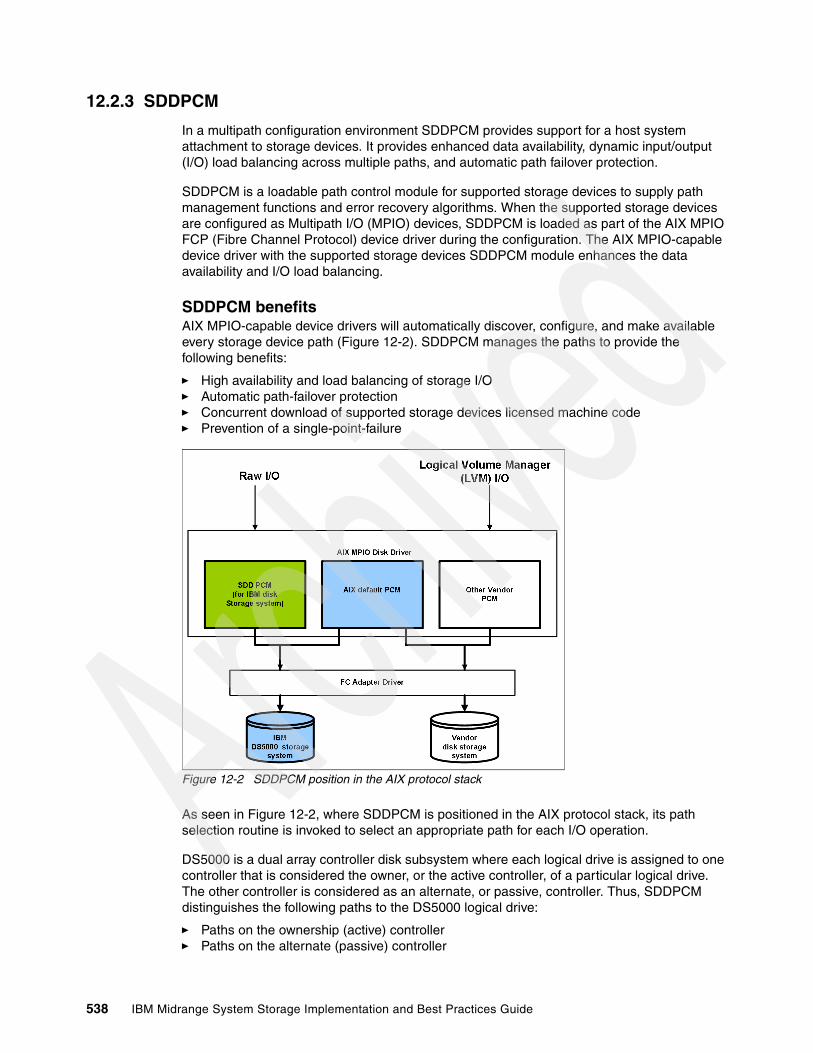
12.2.3 SDDPCM
In a multipath configuration environment SDDPCM provides support for a host system attachment to storage devices. It provides enhanced data availability, dynamic input/output (I/O) load balancing across multiple paths, and automatic path failover protection.
SDDPCM is a loadable path control module for supported storage devices to supply path management functions and error recovery algorithms. When the supported storage devices are configured as Multipath I/O (MPIO) devices, SDDPCM is loaded as part of the AIX MPIO FCP (Fibre Channel Protocol) device driver during the configuration. The AIX MPIO-capable device driver with the supported storage devices SDDPCM module enhances the data availability and I/O load balancing.
SDDPCM benefitsAIX MPIO-capable device drivers will automatically discover, configure, and make available every storage device path (Figure 12-2). SDDPCM manages the paths to provide the following benefits:
� High availability and load balancing of storage I/O � Automatic path-failover protection � Concurrent download of supported storage devices licensed machine code � Prevention of a single-point-failure
Figure 12-2 SDDPCM position in the AIX protocol stack
As seen in Figure 12-2, where SDDPCM is positioned in the AIX protocol stack, its path selection routine is invoked to select an appropriate path for each I/O operation.
DS5000 is a dual array controller disk subsystem where each logical drive is assigned to one controller that is considered the owner, or the active controller, of a particular logical drive. The other controller is considered as an alternate, or passive, controller. Thus, SDDPCM distinguishes the following paths to the DS5000 logical drive:
� Paths on the ownership (active) controller � Paths on the alternate (passive) controller
538 IBM Midrange System Storage Implementation and Best Practices Guide
With this type of active/passive dual-controller subsystem device, I/O can be sent only to the ownership controller. When the SDDPCM selects paths for I/O, it selects paths that are connected only to the ownership controller. If there is no path on the ownership controller that can be used, SDDPCM changes the logical drive controller ownership to the alternate controller, switches the paths that were passive to active, and then selects these active paths for I/O.
Supported SDDPCM featuresThe following SDDPCM features are supported for DS5000:
� v 32- and 64-bit kernels � Four types of reserve policies:
– No_reserve policy – Exclusive host access single path policy – Persistent reserve exclusive host policy – Persistent reserve shared host access policy
� Three path-selection algorithms: – Failover – Round robin – Load balancing
� Automatic failed paths reclamation by healthchecker � Failback error-recovery algorithm � Fibre Channel dynamic device tracking � Support SAN boot device on MPIO supported storage devices � Support for external supported MPIO storage devices as the primary or secondary dump
device� Support storage devices multipath devices as system paging space� Support SDDPCM server daemon enhanced path health check function� Support a maximum of 1200 LUNs v Dynamically adding paths or adapters� Dynamically removing paths or adapters� Dynamically changing the device path selection algorithm� Dynamically changing the device hc_interval� Dynamically changing the device hc_mode� Reserve last path of a device in OPEN mode� Support the essutil Product Engineering tool in SDDPCM’s pcmpath command line
program� Support HACMP with Enhanced Concurrent Mode volume group in concurrent resource
groups and non concurrent resource groups � Support GPFS in AIX 5.2 TL06 (or later) and 5.3 TL02 (or later) � Support AIX 5.3 VIO server
SDDPCM is supported on DS4700, DS5100, DS5300, and DS5020 as well as certain older models in the DS4000 range.
Attention: SDD and SDDPCM are exclusive software packages on a server and must not be confused with each other. You cannot install both software packages on a server for supported storage devices. Only SDDPCM is supported on DS5000 where the logical volumes presented to AIX are MPIO capable. SDD supports storage devices which are configured as non-MPIO-capable devices (that is, multiple logical device instances are created for a physical LUN) such as DS8000 LUNs.
Chapter 12. DS5000 with AIX, PowerVM, and PowerHA 539

As described, SDDPCM supports a maximum of 1200 configured devices and a maximum of 16 paths per device, meaning that the maximum number of host adapter ports that are supported is 16. However, with the round robin or load balance path selection algorithms, configuring more than four paths per device might impact the I/O performance.
12.3 Installing the AIX MPIO and SDDPCM device driversThis section details how to install the AIX MPIO and SDDPCM device drivers required for connectivity to the DS5000 Storage System.
12.3.1 AIX MPIO
This device driver is packaged with the AIX set of installation media and will automatically be installed with AIX if the POWER system has HBAs physically on the machine or LPAR when it was installed. If the HBAs are physically installed afterwards or dynamically associated with the LPAR then there is a possibility that all License Program Products (LPPs) and prerequisites for the MPIO (and the HBA device drivers) are not installed. In this case the AIX installation media might be required when the command cfgmgr is run. The command will automatically configure the HBAs to AIX and, with the installation media install all the required HBA and MPIO LPPs. For example, to use the media on device /dev/cd0, insert installation media CD 1 in the CDROM and enter the command:
cfgmgr -i /dev/cd0
You might be prompted to insert another CD media if needed to complete the configuration, after which you can re-apply the Technology Level (TL) package again, containing updates to the base level file sets just installed on the CD media. To do this, follow your normal procedure of applying TL maintenance to AIX.
12.3.2 SDDPCM
You can install SDDPCM on AIX by using the installp command or by using the System Management Interface Tool (SMIT) with the shortcut command, smitty installp.
To obtain the LPPs and instructions on how to download and install, see the following following Web site:
http://www.ibm.com/servers/storage/support/software/sdd
SDDPCM (at the time of writing, SDDPCM v2.4.0.3) is supported on the following AIX levels with APARs specified:
AIX5.3:
� AIX53 TL06: APAR IZ36257 � AIX53 TL07: APAR IZ36258� AIX53 TL08: APAR IZ36259 � AIX53 TL09: APAR IZ36203� AIX53 TL10: APAR IZ36343� AIX53 TL11: APAR IZ36538
Tip: Use the minimum number of paths necessary to achieve sufficient redundancy in the SAN environment. The preferred number of paths per device is four.
540 IBM Midrange System Storage Implementation and Best Practices Guide

AIX6.1:
� AIX61 TL00: APAR IZ36255 � AIX61 TL01: APAR IZ36256 � AIX61 TL02: APAR IZ36221� AIX61 TL03: APAR IZ37573 � AIX61 TL04: APAR IZ37960
A prerequisite for this level of SDDPCM is:
devices.fcp.disk.ibm.mpio.rte (version 1.0.0.15)
It is always a good practice to use the latest versions available for SDDPCM with DS5000 SM v10.6.
12.4 Attachment to the AIX host
You must plan the physical attachment from the AIX host to the DS5000 so as to avoid a single point of failure. The POWER machine with AIX can be attached directly to the DS5000 Storage System but more often than not it will be connected by a SAN fabric. This is done to enable shared host port connectivity on DS5000 with other SAN attached servers in the fabric.
The AIX host must be able to communicate with both DS5000 controllers. Figure 12-3 shows a dual HBA system where each HBA is zoned to a DS5000 controller. This configuration is preferred where the AIX initiators are isolated from each other. In the example the SAN fabric can be deemed as a single point of failure but where possible the HBAs and controllers must be on separate SAN switches or fabrics.
Figure 12-3 Two HBA attachment with zones to the AIX host
Chapter 12. DS5000 with AIX, PowerVM, and PowerHA 541

After the zoning has been configured on the SAN switch as shown in Figure 12-3, the HBA worldwide names (WWN) must be visible to the DS5000 by each controller. To check this on the DS5000, select from the main Storage Manager (SM) window, Mappings View Unassociated Host Port Identifiers. You must be able to see the WWN of the HBAs which can be verified for each HBA from the AIX command prompt with command:
lscfg -vl fcsx | grep "Network Address"
Where “x” is the HBA number. For example, the WWNs are shown in Figure 12-4.
Figure 12-4 Example of showing the WWNs of HBAs fcs0 and fcs1
The WWNs can then be verified as in our example in Figure 12-5. Our host has already been defined and the WWNs have been labelled and associated with a host name.
Figure 12-5 WWNs as seen from DS5000
root@itsop630:/root# lscfg -vl fcs0 | grep "Network Address" Network Address.............10000000C955E566root@itsop630:/root# lscfg -vl fcs1 | grep "Network Address" Network Address.............10000000C955E581root@itsop630:/root
Note: You will need to run cfgmgr from the AIX command prompt (as root user) after the SAN zoning is complete so that the DS5000 will receive the WWN details from the SAN fabric, this will confirm that the SAN zoning change is complete and active.
542 IBM Midrange System Storage Implementation and Best Practices Guide
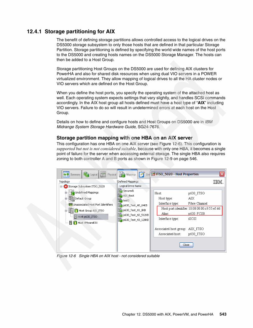
12.4.1 Storage partitioning for AIXThe benefit of defining storage partitions allows controlled access to the logical drives on the DS5000 storage subsystem to only those hosts that are defined in that particular Storage Partition. Storage partitioning is defined by specifying the world wide names of the host ports to the DS5000 and creating hosts names on the DS5000 Storage Manager. The hosts can then be added to a Host Group.
Storage partitioning Host Groups on the DS5000 are used for defining AIX clusters for PowerHA and also for shared disk resources when using dual VIO servers in a POWER virtualized environment. They allow mapping of logical drives to all the HA cluster nodes or VIO servers which are defined on the Host Group.
When you define the host ports, you specify the operating system of the attached host as well. Each operating system expects settings that vary slightly, and handles SCSI commands accordingly. In the AIX host group all hosts defined must have a host type of “AIX” including VIO servers. Failure to do so will result in undetermined errors at each host on the Host Group.
Details on how to define and configure hosts and Host Groups on DS5000 are in IBM Midrange System Storage Hardware Guide, SG24-7676.
Storage partition mapping with one HBA on an AIX serverThis configuration has one HBA on one AIX server (see Figure 12-6). This configuration is supported but not is not considered suitable, because with only one HBA, it becomes a single point of failure for the server when accessing external storage. The single HBA also requires zoning to both controller A and B ports as shown in Figure 12-9 on page 546.
Figure 12-6 Single HBA on AIX host - not considered suitable
Chapter 12. DS5000 with AIX, PowerVM, and PowerHA 543

Storage partition mapping with two HBAs on one AIX serverThis configuration, which is the most common, is shown in Figure 12-7. For the situation where an HBA is zoned to a DS5000 controller, see Figure 12-3 on page 541.
Figure 12-7 Two HBAs on a single AIX host
Two storage partitions mapping with four HBAs on two AIX serversSee Figure 12-8 and Figure 12-9 for this configuration, which is a common configuration used in PowerHA with two cluster nodes. More AIX servers can be added to the Storage Group if required in the PowerHA cluster. This configuration is also typical in a POWERVM environment where dual VIO servers are used.
Figure 12-8 Two storage partitions - Two HBAs for each storage partition
544 IBM Midrange System Storage Implementation and Best Practices Guide

Mapping to a default group (not supported)The Default Host Group in DS5000 is used for hosts that are not participating in specific mappings. For AIX hosts, a Host Group (or groups) must be created where AIX defined hosts can be allocated, which is a best practice in order to keep various host types segregated from each other, AIX hosts must be in a separate Host Group.
One storage partition mapping with four HBAs on one AIX serverMapping with four HBA on one server with only one Storage Partition is not supported. The AIX host with four HBAs must be defined on DS5000 as two separate hosts each in a separate host group. The logical drives on DS5000 can then be mapped to either one Host Group or the other.
12.4.2 HBA configurationsIn this section we review the guidelines for HBA configurations.
Configuration with one HBA on host and two controllers on DS5000Although dual HBA controllers are best to use where possible, one HBA zoned to two controllers on DS5000 is supported. Single HBA configurations require both controllers in the DS5000 to be connected to the host. In a switched environment, both controllers must be connected to the switch within the same SAN zone as the HBA.
In this case, we have one HBA on the AIX server included in a single zone for access to controller A and controller B respectively. In Storage Manager, you can define one storage partition with one host HBA. See Figure 12-6 on page 543.
This configuration is supported, but is not considered suitable. This zoning is preferred to creating one zone for each controller because it is now a best practice for SANs and does make the fabric zoning simpler. There is only one initiator in the zone in Figure 12-9, hence it complies with general SAN best practices.
Chapter 12. DS5000 with AIX, PowerVM, and PowerHA 545
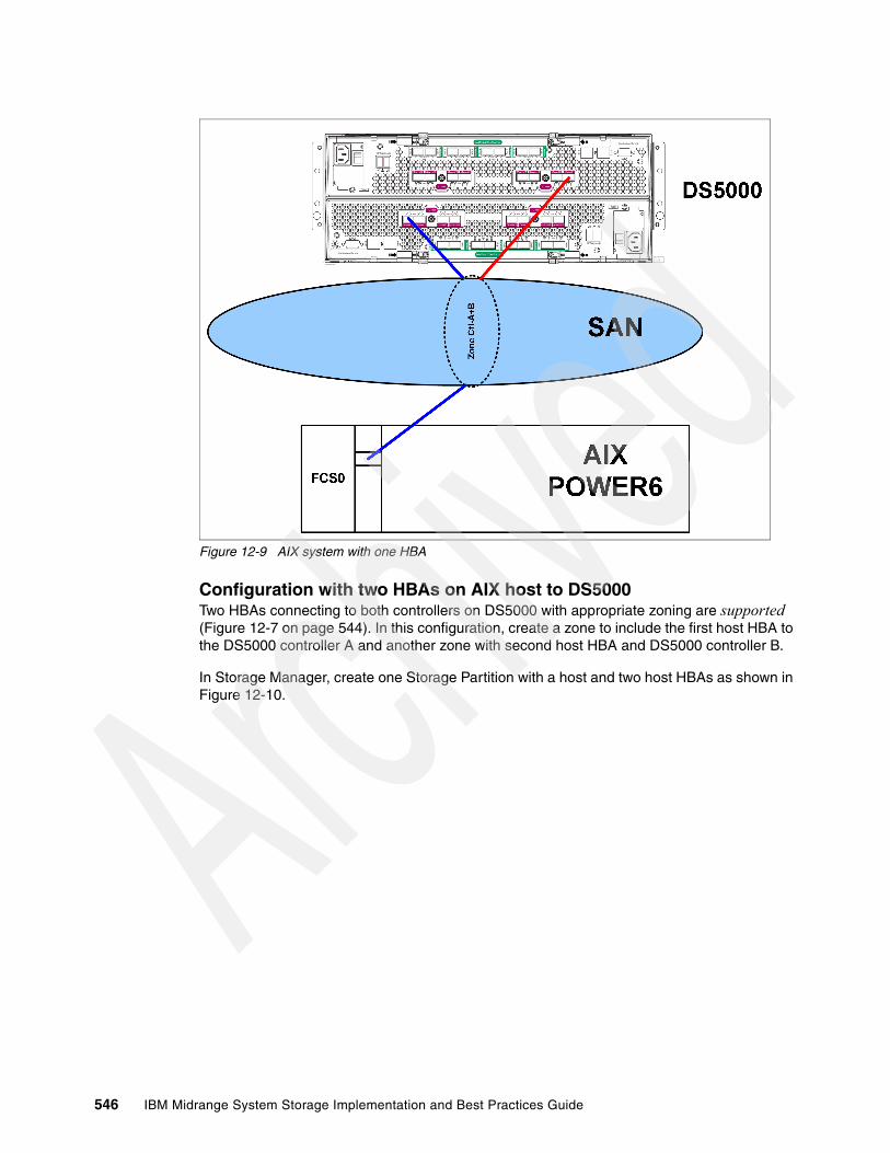
Figure 12-9 AIX system with one HBA
Configuration with two HBAs on AIX host to DS5000Two HBAs connecting to both controllers on DS5000 with appropriate zoning are supported (Figure 12-7 on page 544). In this configuration, create a zone to include the first host HBA to the DS5000 controller A and another zone with second host HBA and DS5000 controller B.
In Storage Manager, create one Storage Partition with a host and two host HBAs as shown in Figure 12-10.
546 IBM Midrange System Storage Implementation and Best Practices Guide
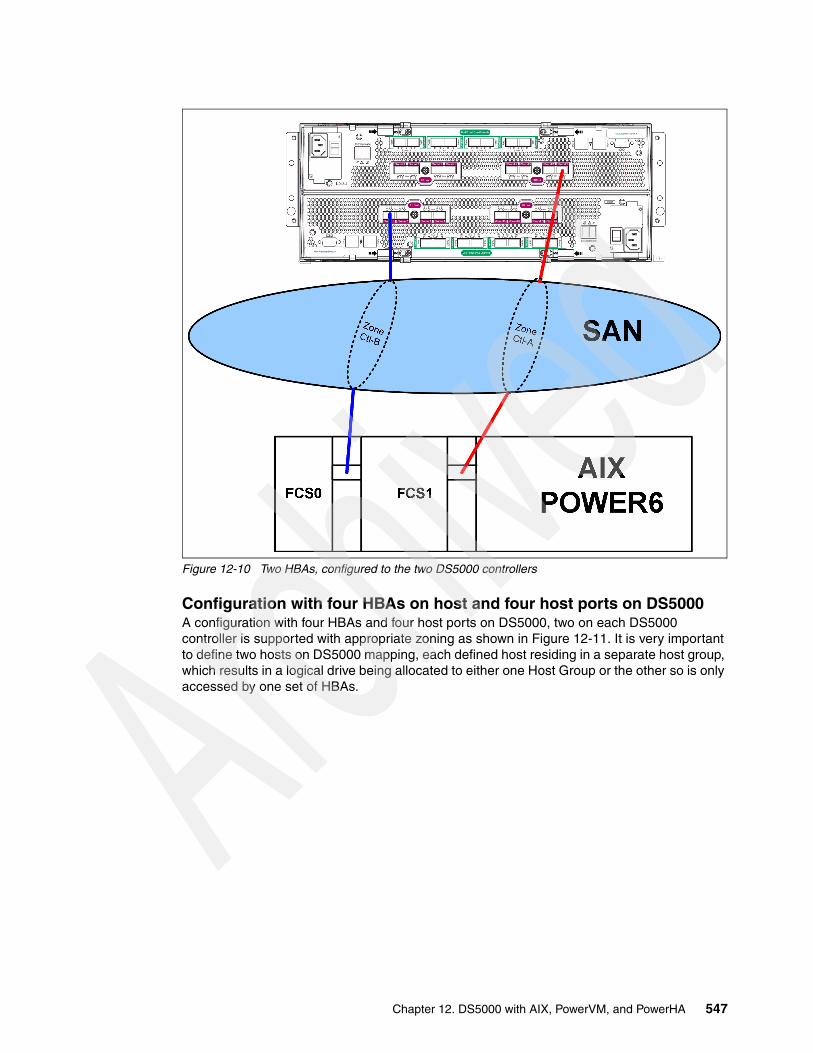
Figure 12-10 Two HBAs, configured to the two DS5000 controllers
Configuration with four HBAs on host and four host ports on DS5000A configuration with four HBAs and four host ports on DS5000, two on each DS5000 controller is supported with appropriate zoning as shown in Figure 12-11. It is very important to define two hosts on DS5000 mapping, each defined host residing in a separate host group, which results in a logical drive being allocated to either one Host Group or the other so is only accessed by one set of HBAs.
Chapter 12. DS5000 with AIX, PowerVM, and PowerHA 547
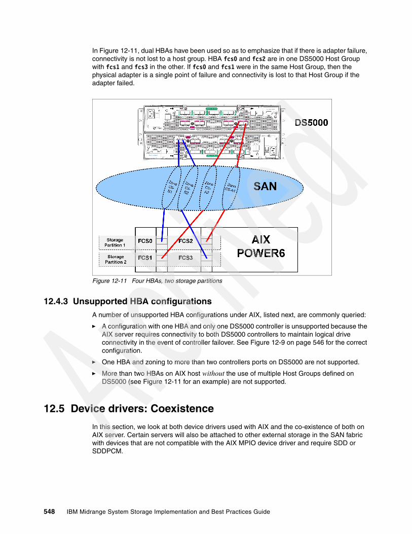
In Figure 12-11, dual HBAs have been used so as to emphasize that if there is adapter failure, connectivity is not lost to a host group. HBA fcs0 and fcs2 are in one DS5000 Host Group with fcs1 and fcs3 in the other. If fcs0 and fcs1 were in the same Host Group, then the physical adapter is a single point of failure and connectivity is lost to that Host Group if the adapter failed.
Figure 12-11 Four HBAs, two storage partitions
12.4.3 Unsupported HBA configurationsA number of unsupported HBA configurations under AIX, listed next, are commonly queried:
� A configuration with one HBA and only one DS5000 controller is unsupported because the AIX server requires connectivity to both DS5000 controllers to maintain logical drive connectivity in the event of controller failover. See Figure 12-9 on page 546 for the correct configuration.
� One HBA and zoning to more than two controllers ports on DS5000 are not supported.
� More than two HBAs on AIX host without the use of multiple Host Groups defined on DS5000 (see Figure 12-11 for an example) are not supported.
12.5 Device drivers: Coexistence
In this section, we look at both device drivers used with AIX and the co-existence of both on AIX server. Certain servers will also be attached to other external storage in the SAN fabric with devices that are not compatible with the AIX MPIO device driver and require SDD or SDDPCM.
548 IBM Midrange System Storage Implementation and Best Practices Guide

Coexistence between AIX MPIO and SDD: AIX MPIO and SDD (used by DS6000, and DS8000) are supported on the same AIX host but on separate HBAs and using separate zones (Figure 12-12). This configuration is commonly used when the AIX server accesses DS5000 storage as well as DS8000 or SVC managed storage.
Figure 12-12 AIX MPIO and SDD coexistence using separate HBAs and zoning
From Figure 12-12 it is possible to configure the SDD driver as used with the ESS, DS8000, DS6000 or SVC, and the MPIO driver used by the DS5000. However, it is necessary a pair of HBAs for access to the DS5000 and another pair of HBAs for access to the ESS or similar on the AIX machine. You must also define separate zones for each HBA.
Note: You cannot install both SDD and SDDPCM software packages on a server for supported storage devices.
Chapter 12. DS5000 with AIX, PowerVM, and PowerHA 549

12.6 HBA and device settings
There are a number of Fibre Channel adapter and device settings that can set that can help performance, throughput, load balancing, the settings can vary depending on environment that the AIX server is in.
12.6.1 HBA settings
In this section we discuss various considerations regarding HBA settings and performance.
HBA settings that can affect performance Review the following three parameters for the HBA settings that can affect performance. The type and workload of I/O using the adapter is a major consideration when making any changes to these parameters:
� num_cmd_elems:
num_cmd_elems controls the maximum number of commands to queue to the adapter. The default value is 200. You can set it to a higher value in I/O intensive environments. The maximum of num_cmd_elems for a 2 Gb HBA is 2048. However, there is a cost in real memory (DMA region) for a num_cmd_elem with a high value. In the throughput based environment, you want to decrease the queue depth setting to a smaller value, such as 16. In a mixed application environment, you do not want to lower the “num_cmd_elem” setting, as other logical drives might need this higher value for optimal performance. In a pure high throughput workload, this value will have no effect. There is no real specified value.
Use performance measurement tools as discussed in Chapter 8, “Storage Manager Performance Monitor” on page 355 and observe the results for various values of num_cmd_elems.
� lg_term_dma:
lg_term_dma controls the size of a DMA address region requested by the Fibre Channel driver at startup. Doing this does not set aside real memory, rather it sets aside PCI DMA address space. Each device that is opened uses a portion of this DMA address region. The region controlled by lg_term_dma is not used to satisfy I/O requests.
The lg_term_dma can be set to 0x1000000 (16 MB). The default is 0x200000 (2MB). You must be able to safely reduce this to the default. The first symptom of lg_term_dma exhaustion is that disk open requests begin to fail with ENOMEM message in the error log (errpt command). In that case you probably cannot vary on certain volume groups. Too small a value is not likely to cause any runtime performance issue. Reducing the value will free up physical memory and DMA address space for other uses.
� max_xfer_size:
This is the maximum I/O size that the adapter will support. The default maximum transfer size is 0x100000 which is 16 MB of a memory area used by the adapter. Consider changing this value to 0x200000 or larger, for other allowable values of max_xfer_size, the memory area is 128 MB in size.
Increasing this value increases the DMA memory area used for data transfer. You must resist the urge to just set these attributes to the maximums. There is a limit to the amount of DMA region available per slot and PCI bus. Setting these values too high might result in certain adapters failing to configure because other adapters on the bus have already exhausted the resources. On the other hand, if too little space is set aside here, I/Os might be delayed in the FC adapter driver waiting for previous I/Os to finish. You will generally see errors in errpt if this happens.
550 IBM Midrange System Storage Implementation and Best Practices Guide

Viewing and changing HBA settings You can review and change the HBA settings by using the following commands, where fcs0 is used as an example (see Figure 12-13):
� To view possible attribute values of max_xfer_size for the fcs0 adapter, enter the command:
lsattr -Rl fcs0 -a max_xfer_size
Figure 12-13 Sample output for possible attributes for HBA parameters
� The following command changes the maximum transfer size (max_xfer_size) and the maximum number of commands to queue (num_cmd_elems) of an HBA (fcs0) upon the next system reboot:
chdev -l fcs0 -P -a max_xfer_size=<value> -a num_cmd_elems=<value> -P
This will not take affect until after the system is rebooted as indicated by “-P” parameter.
� If you want to avoid a system reboot, make sure all activity is stopped on the adapter, and issue the following commands:
rmdev -l fcs0 -Rchdev -l fcs0 -a max_xfer_size=<value> -a num_cmd_elems=<value>
Then recreate all child devices with the cfgmgr command.
12.6.2 Device settings
As with the HBA settings, there are a number of device settings that can be changed depending on the environment that is being used and which device driver is managing the hdisk. The devices include both disk (hdisk) and the Fibre Channel device driver
Disk device settingsTo display disk device settings for a particular hdisk, enter the following command:
lsattr -El hdiskx
root@itsop630:/root# lsattr -Rl fcs0 -a max_xfer_size0x1000000x2000000x4000000x8000000x1000000root@itsop630:/root# lsattr -Rl fcs0 -a lg_term_dma0x1000000x2000000x4000000x8000000x10000000x20000000x40000000x8000000root@itsop630:/root# lsattr -Rl fcs0 -a num_cmd_elems20...2048 (+1)
Chapter 12. DS5000 with AIX, PowerVM, and PowerHA 551

Typical output for hdisk4 is shown in Figure 12-14.
Figure 12-14 Example of attributes listing of a hdisk using “lsattr” command
Following are a few of the key parameters that must be changed depending on the DS5000 and AIX environment that the hdisk is being used for:
� reserve_policy:
There are four reserve policies that can be set:
no_reserve: There is no reserve being made on MPIO devices. A device without reservation can be accessed by any initiators at any time. I/O can be sent from all the paths of the MPIO device. PowerHA supports no_reserve policy with Enhanced Concurrent Mode volume group and is the most suitable setting for VIO servers in a PowerVM environment. This policy is the default reserve policy of SDDPCM.
# lsattr -El hdisk4PCM PCM/friend/otherapdisk Path Control Module FalsePR_key_value none Persistant Reserve Key Value Truealgorithm fail_over Algorithm Trueautorecovery no Path/Ownership Autorecovery Trueclr_q no Device CLEARS its Queue on error Truecntl_delay_time 0 Controller Delay Time Truecntl_hcheck_int 0 Controller Health Check Interval Truedist_err_pcnt 0 Distributed Error Percentage Truedist_tw_width 50 Distributed Error Sample Time Truehcheck_cmd inquiry Health Check Command Truehcheck_interval 60 Health Check Interval Truehcheck_mode nonactive Health Check Mode Truelocation Location Label Truelun_id 0x4000000000000 Logical Unit Number ID Falselun_reset_spt yes LUN Reset Supported Truemax_retry_delay 60 Maximum Quiesce Time Truemax_transfer 0x40000 Maximum TRANSFER Size Truenode_name 0x20060080e517b5bc FC Node Name Falsepvid none Physical volume identifier Falseq_err yes Use QERR bit Trueq_type simple Queuing TYPE Truequeue_depth 10 Queue DEPTH Truereassign_to 120 REASSIGN time out value Truereserve_policy no_reserve Reserve Policy Truerw_timeout 30 READ/WRITE time out value Truescsi_id 0x70400 SCSI ID Falsestart_timeout 60 START unit time out value Trueunique_id 3E21360080E500017B53E00004B924AA914140F1814 FAStT03IBMfcp Unique device identifier Falseww_name 0x20160080e517b5bc FC World Wide Name Falseroot@itsop630:/root
552 IBM Midrange System Storage Implementation and Best Practices Guide

single_path: This is the SCSI-2 reservation policy. If you set this reserve policy for MPIO devices, only the fail_over path selection algorithm can be selected for the devices. With this reservation policy, an MPIO device has all paths being opened; however, only one path made a SCSI-2 reservation on the device. I/O can only be sent through this path. When this path is broken, reserve is released, another path is selected, and SCSI-2 reserve is reissued by this new path. All input and output is now routed to this new path. This policy is the default reserve policy of AIX MPIO.
PR_exclusive: If you set an MPIO device with this persistent reserve policy, a persistent reservation is made on this device with a persistent reserve (PR) key. Any initiators who register with the same PR key can access this device. Normally, you must pick a unique PR key for a server. Separate servers must have unique PR keys. I/O is routed to all paths of the MPIO device, because all paths of an MPIO device are registered with the same PR key. In a nonconcurrence clustering environment, such as PowerHA (HACMP), this is the reserve policy that you must select.
PR_shared: A persistent reservation is made on this device with a persistent reserve (PR) key. However, any initiators that implemented persistent registration can access this MPIO device, even if the initiators are registered with other PR keys. In a concurrent clustering environment, such as PowerHA, this is the reserve policy that you must select for sharing resources among multiple servers.
� algorithm:
There are two algorithm settings for MPIO and three with SDDPCM, as follows:
failover: Sends all I/O down a single path. If the path is determined to be faulty, an alternate path is selected for sending all I/O. This algorithm keeps track of all the enabled paths in an ordered list. If the path being used to send I/O becomes marked failed or disabled, the next enabled path in the list is selected. The sequence within the list is determined by the path priority attribute.
round_robin: Distributes the I/O across all enabled paths. The path priority is determined by the path priority attribute value. If a path becomes marked failed or disabled, it is no longer used for sending I/O. The priority of the remaining paths is then recalculated to determine the percentage of I/O that must be sent down each path. If all paths have the same value, then the I/O is then equally distributed across all enabled paths.
load_balance: (SDDPCM only) This algorithm is based on the existing load balancing algorithm, but it also uses the incorporated I/O statistics on each target port to which the host is connected. You can use this algorithm for SAN configurations where I/O throughput is unbalanced on the storage targets.
� hcheck_mode:
Healthchecking supports the following modes of operations:
enabled: When this value is selected, the healthcheck command will be sent to paths that are opened with a normal path mode.
failed: When this value is selected, the healthcheck command is sent to paths that are in failed state.
nonactive: When this value is selected, the healthcheck command will be sent to paths that have no active I/O, including paths that are opened or in failed state, which is the default setting for MPIO devices.
Fibre Channel controller settings Review the parameters in the Fibre Channel SCSI I/O controller, using the lsattr command, as shown in Figure 12-15.
Chapter 12. DS5000 with AIX, PowerVM, and PowerHA 553

Figure 12-15 Attributes of FC SCSI I/O Controller
The changeable parameters which must be reviewed and changed depending on the AIX and DS5000 environment being used are:
� dyntrk: The default for this setting is “no”. When set to “yes” it will enable dynamic tracking of FC devices, the FC adapter driver detects when the Fibre Channel N_Port ID of a device changes. The FC adapter driver then reroutes traffic destined for that device to the new address while the devices are still online. Events that can cause an N_Port ID to change include moving a cable between a switch and storage device from one switch port to another, connecting two separate switches using an inter-switch link (ISL), and possibly rebooting a switch.
� fc_err_recov: This parameter controllers the fast I/O failure and is useful in situations where multipathing software is used. Setting the fc_err_recov attribute to fast_fail can decrease the I/O fail times because of link loss between the storage device and switch. This technique supports faster failover to alternate paths when FC adapter driver detects a link event, such as a lost link between a storage device and a switch. The FC adapter driver waits a short period of time, approximately 15 seconds, so that the fabric can stabilize, this occurs when the default setting of “delayed_fail” is set. At that point, if the FC adapter driver detects that the device is not on the fabric, it begins failing all I/Os at the adapter driver. Any new I/O or future retries of the failed I/Os are failed immediately by the adapter until the adapter driver detects that the device has rejoined the fabric. In single-path configurations, especially configurations with a single path to a paging device, the delayed_fail default setting is preferred, one such scenario is AIX server direct attachment to the DS5000 controller host port.
For both parameters, support is dependent on firmware levels being at their latest for certain HBAs (FC 6227, FC 6228, FC 6239).
The following command shows how to change the FC I/O controller:
chdev -l fscsi0 -a fc_err_recov=fast_fail -a dyntrk=yes
Changing these HBA and device attribute parameters can require stopping I/O to the devices. The previous command requires you to issue the following command beforehand in order to make the change:
rmdev -l fscsi0 -R
After the chdev command was successful, you have to issue cfgmgr command to make all devices available again, which significantly impacts any running applications on AIX, therefore making any changes to HBAs or devices requires a certain amount of pre-planning. Changes can be made to the ODM only using the “-P” option with any chdev command, the change is then be applied after the system has been re booted and can be scheduled with other maintenance tasks.
Reviewing these parameters must be undertaken after AIX has been installed and before any logical drives have been mapped by DS5000.
# lsattr -El fscsi0attach switch How this adapter is CONNECTED Falsedyntrk no Dynamic Tracking of FC Devices Truefc_err_recov delayed_fail FC Fabric Event Error RECOVERY Policy Truescsi_id 0x70800 Adapter SCSI ID Falsesw_fc_class 3 FC Class for Fabric True
554 IBM Midrange System Storage Implementation and Best Practices Guide
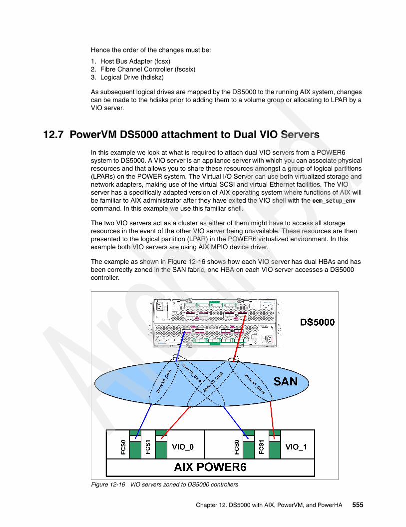
Hence the order of the changes must be:
1. Host Bus Adapter (fcsx)2. Fibre Channel Controller (fscsix)3. Logical Drive (hdiskz)
As subsequent logical drives are mapped by the DS5000 to the running AIX system, changes can be made to the hdisks prior to adding them to a volume group or allocating to LPAR by a VIO server.
12.7 PowerVM DS5000 attachment to Dual VIO Servers
In this example we look at what is required to attach dual VIO servers from a POWER6 system to DS5000. A VIO server is an appliance server with which you can associate physical resources and that allows you to share these resources amongst a group of logical partitions (LPARs) on the POWER system. The Virtual I/O Server can use both virtualized storage and network adapters, making use of the virtual SCSI and virtual Ethernet facilities. The VIO server has a specifically adapted version of AIX operating system where functions of AIX will be familiar to AIX administrator after they have exited the VIO shell with the oem_setup_env command. In this example we use this familiar shell.
The two VIO servers act as a cluster as either of them might have to access all storage resources in the event of the other VIO server being unavailable. These resources are then presented to the logical partition (LPAR) in the POWER6 virtualized environment. In this example both VIO servers are using AIX MPIO device driver.
The example as shown in Figure 12-16 shows how each VIO server has dual HBAs and has been correctly zoned in the SAN fabric, one HBA on each VIO server accesses a DS5000 controller.
Figure 12-16 VIO servers zoned to DS5000 controllers
Chapter 12. DS5000 with AIX, PowerVM, and PowerHA 555

With the zoning complete, the Host Group on the DS5000 can be created and hosts defined. Figure 12-17 shows this completed with four logical drives VIOR1-4 mapped to the group.
Figure 12-17 VIO Servers defined and in same Host Group
With the zoning and mapping complete, the VIO servers must be able to configure each logical drive as an hdisk when cfgdev (cfgmgr) is run. Before the logical drives are mapped to the VIO servers, the HBA and FC controller settings can be configured on each VIO server, as there is no I/O yet on the adapters or child devices defined the changes will have least impact on resource availability for the VIO server.
For this example we will go out of the VIO shell (oem_setup_env command) and into the more familiar AIX root shell.
HBA setting max_xfer_size is the only parameter changed as specified to both adapters on each VIO server (Figure 12-18).
Figure 12-18 Change max_xfer_size
The FC I/O controller settings are then changed to the specified settings for VIO servers and clusters on DS5000 (Figure 12-19).
Figure 12-19 Change FC controller settings
The cfgmgr command can now be run on each VIO server where the four logical drives will be configured and appear as hdisks. These hdisks will not be used in volume groups but for allocation by each VIO server to a specific LPAR in the PowerVM environment.
# chdev -l fcs0 -a max_xfer_size=0x200000# chdev -l fcs1 -a max_xfer_size=0x200000
# chdev -l fscsi0 -a dyntrk=yes -a fc_err_recov=fast_fail# chdev -l fscsi1 -a dyntrk=yes -a fc_err_recov=fast_fail
556 IBM Midrange System Storage Implementation and Best Practices Guide

Figure 12-20 hdisks mapped to VIO server
Before being allocated, the attributes (as shown in example Figure 12-14 on page 552) will be changed to reflect their use in a dual VIO server environment. For the dual VIO server running with AIX MPIO, we will change the algorithm and reserve_policy attributes of each disk as shown in Figure 12-21.
Figure 12-21 Command to change hdisk attributes for VIO servers
The logical drives can now be allocated by each VIO server to the assigned LPAR in the PowerVM environment. For further details about PowerVM, see PowerVM Virtualization on IBM System p: Introduction and Configuration Fourth Edition, SG24-7940.
12.8 DS5000 series: Dynamic functions
The DS5000 offers the following dynamic functions:
� Dynamic Segment Sizing (DSS) � Dynamic RAID Migration (DRM) � Dynamic Capacity Expansion (DCE) � Dynamic Volume Expansion (DVE)
12.8.1 Overview: The dynamic functions in AIX environments
The dynamic functions are supported on AIX operating environments with certain exceptions (for detailed information about supported platforms and operating systems, see the DS5000 compatibility matrix).
Frame id 0: Storage Subsystem worldwide name: 60ab8004777d800004a956964 Controller count: 2 Partition count: 1 Partition 0: Storage Subsystem Name = 'ITSO5300' hdisk LUN # Ownership User Label hdisk9 4 B (preferred) VIOR1 hdisk10 5 A (preferred) VIOR2 hdisk11 6 B (preferred) VIOR3 hdisk12 7 A (preferred) VIOR4
# chdev -l hdisk9 -a reserve_policy=no_reserve -a algorithm=round_robinhdisk9 changed# chdev -l hdisk10 -a reserve_policy=no_reserve -a algorithm=round_robinhdisk10 changed# chdev -l hdisk11 -a reserve_policy=no_reserve -a algorithm=round_robinhdisk11 changed# chdev -l hdisk12 -a reserve_policy=no_reserve -a algorithm=round_robinhdisk12 changed#
Chapter 12. DS5000 with AIX, PowerVM, and PowerHA 557
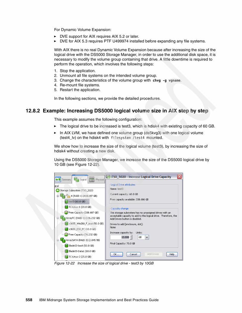
For Dynamic Volume Expansion:
� DVE support for AIX requires AIX 5.2 or later.� DVE for AIX 5.3 requires PTF U499974 installed before expanding any file systems.
With AIX there is no real Dynamic Volume Expansion because after increasing the size of the logical drive with the DS5000 Storage Manager, in order to use the additional disk space, it is necessary to modify the volume group containing that drive. A little downtime is required to perform the operation, which involves the following steps:
1. Stop the application.2. Unmount all file systems on the intended volume group.3. Change the characteristics of the volume group with chvg -g vgname.4. Re-mount file systems.5. Restart the application.
In the following sections, we provide the detailed procedures.
12.8.2 Example: Increasing DS5000 logical volume size in AIX step by step
This example assumes the following configuration:
� The logical drive to be increased is test3, which is hdisk4 with existing capacity of 60 GB.
� In AIX LVM, we have defined one volume group (ds5kvg3) with one logical volume (test4_lv) on the hdisk4 with filesystem /test4 mounted.
We show how to increase the size of the logical volume (test3), by increasing the size of hdisk4 without creating a new disk.
Using the DS5000 Storage Manager, we increase the size of the DS5000 logical drive by 10 GB (see Figure 12-22).
Figure 12-22 Increase the size of logical drive - test3 by 10GB
558 IBM Midrange System Storage Implementation and Best Practices Guide

You can verify the size of the corresponding hdisk in AIX, by typing the lspv and bootinfo commands as shown in Figure 12-23 prior to the increase.
Figure 12-23 Sizes of hdisk4 prior to increasing size
The output of the command gives the size of disk in megabytes, 61440 (60 GB).
Now, stop the application, unmount all file systems on the volume group:
varyoffvg ds5kvg3
Figure 12-24 Wait for increase capacity process to complete
Modify the volume group to use the new space, with the following commands:
varyonvg ds5kvg3chvg -g ds5kvg3
# bootinfo -s hdisk461440root@itsop630:/root# lspv hdisk4PHYSICAL VOLUME: hdisk4 VOLUME GROUP: ds5kvg3PV IDENTIFIER: 0007041a0cf29ecf VG IDENTIFIER 0007041a00004c00000001240cf29fcdPV STATE: activeSTALE PARTITIONS: 0 ALLOCATABLE: yesPP SIZE: 64 megabyte(s) LOGICAL VOLUMES: 1TOTAL PPs: 959 (61376 megabytes) VG DESCRIPTORS: 2FREE PPs: 659 (42176 megabytes) HOT SPARE: noUSED PPs: 300 (19200 megabytes) MAX REQUEST: 256 kilobytesFREE DISTRIBUTION: 192..192..00..83..192USED DISTRIBUTION: 00..00..191..109..00MIRROR POOL: Noneroot@itsop630:/root
Note: We found from our lab tests that it was best to wait for the DS5000 increase capacity process on the array to complete as shown in Figure 12-24 before continuing with the chvg command on AIX.
Chapter 12. DS5000 with AIX, PowerVM, and PowerHA 559

Figure 12-25 shows the same disk hdisk4 with its new size of 71680 (70 GB).
Figure 12-25 Following DS5000 capacity change, increased size of hdisk4
Finally, mount all file systems and restart the application.
You can also verify the available new space for the volume group with the command lsvg DS5kvg3. You can now use the new space created and enlarge the logical volumes or file systems.
# chvg -g ds5kvg30516-1164 chvg: Volume group ds5kvg3 changed. With given characteristics ds5kvg3 can include upto 16 physical volumes with 2032 physical partitions each.root@itsop630:/root# bootinfo -s hdisk471680root@itsop630:/root# mount /test4root@itsop630:/root# lspv hdisk4PHYSICAL VOLUME: hdisk4 VOLUME GROUP: ds5kvg3PV IDENTIFIER: 0007041a0cf29ecf VG IDENTIFIER 0007041a00004c00000001240cf29fcdPV STATE: activeSTALE PARTITIONS: 0 ALLOCATABLE: yesPP SIZE: 64 megabyte(s) LOGICAL VOLUMES: 1TOTAL PPs: 1119 (71616 megabytes) VG DESCRIPTORS: 2FREE PPs: 819 (52416 megabytes) HOT SPARE: noUSED PPs: 300 (19200 megabytes) MAX REQUEST: 256 kilobytesFREE DISTRIBUTION: 224..160..00..211..224USED DISTRIBUTION: 00..64..223..13..00MIRROR POOL: Noneroot@itsop630:/root
560 IBM Midrange System Storage Implementation and Best Practices Guide
12.9 PowerHA and DS5000Clustering servers is the linking of two or more computers or nodes into a single, unified resource. High-availability clusters are designed to provide continuous access to business-critical data and applications through component redundancy and application failover.
PowerHA (formerly known as HACMP) is designed to automatically detect system or network failures and eliminate a single point-of-failure by managing failover to a recovery processor with a minimal loss of end-user time. The current release of PowerHA can detect and react to software failures severe enough to cause a system crash and network or adapter failures. The Enhanced Scalability capabilities of PowerHA offer additional availability benefits through the use of the Reliable Scalable Cluster Technology (RSCT) function of AIX.
PowerHA makes use of redundant hardware configured in the cluster to keep an application running, restarting it on a backup processor if necessary. Using PowerHA can virtually eliminate planned outages, because users, applications, and data can be moved to backup systems during scheduled system maintenance. Such advanced features as Cluster Single Point of Control and Dynamic Reconfiguration allow the automatic addition of users, files, hardware, and security functions without stopping mission-critical jobs.
PowerHA clusters can be configured to meet complex and varied application availability and recovery needs. Configurations can include mutual takeover or idle standby recovery processes. With an PowerHA mutual takeover configuration, applications and their workloads are assigned to specific servers, thus maximizing application throughput and utilizing investments in hardware and software. In an idle standby configuration, an extra node is added to the cluster to back up any of the other nodes in the cluster.
In an PowerHA environment, each server in a cluster is a node. Up to 32 POWER AIX servers can participate in an PowerHA cluster. Each node has access to shared disk resources that are accessed by other nodes. When there is a failure, PowerHA transfers ownership of shared disks and other resources based on how you define the relationship among nodes in a cluster. This process is known as node failover or node failback.
Ultimately, the goal of any IT solution in a critical environment is to provide continuous service and data protection. The high availability is just one building block in achieving the continuous operation goal. The high availability is based on the availability of the hardware, software (operating system and its components), application, and network components.
For a high availability solution, you need the following capabilities:
� Redundant servers� Redundant network paths� Redundant network adapters� Redundant network paths� Redundant storage (data) paths� Redundant (mirrored/RAID) storage� Monitoring� Failure detection� Failure diagnosis� Automated failover� Automated reintegration
Chapter 12. DS5000 with AIX, PowerVM, and PowerHA 561

The main objective of the PowerHA is eliminate Single Points of Failure (SPOFs) as detailed in Table 12-2.
Table 12-2 Eliminate SPOFs
Each of the items listed in Table 12-2 in the Cluster Object column is a physical or logical component that, if it fails, will result in the application being unavailable for serving clients.
The PowerHA software provides the framework and a set of tools for integrating applications in a highly available system. Applications to be integrated in a PowerHA cluster require a fair amount of customization, not at the application level, but rather at the PowerHA and AIX platform level. PowerHA is a flexible platform that allows integration of generic applications running on AIX platform, providing for high available systems at a reasonable cost.
12.9.1 Earlier PowerVM version HACMP/ES and ESCRM
Scalability, support of large clusters, and therefore, large configurations of nodes and potentially disks leads to a requirement to manage “clusters” of nodes. To address management issues and take advantage of new disk attachment technologies, PowerHA Enhanced Scalable (HACMP/ES) was released. It was originally only available for the RS6000/SP where tools were already in place with PSSP to manage larger clusters.
Enhanced Scalability Concurrent Resource Manager (ESCRM) optionally adds concurrent shared-access management for the supported RAID disk subsystems. Concurrent access is provided at the raw disk level. The application must support a mechanism to control access to the shared data, such as locking. The ESCRM includes the HACMP/ES components and the HACMP distributed lock manager.
Cluster object Eliminated as a single point of failure by:
Node (servers) Multiple nodes
Power supply Multiple circuits or power supplies
Network adapter Redundant network adapters
Network Multiple networks connected to each nodes, redundantnetwork paths with independent hardware between eachnode and the clients.
TCP/IP subsystem A non- IP networks to back up TCP/IP
I/O Adapter Redundant I/O Adapters
Controllers Use of redundant controllers
Sites Use of more than one site for disaster recovery
Storage Redundant hardware, enclosures, disk mirroring / RAIDtechnology, redundant data paths
Resource Groups Use of resource groups to control all resources required byan application
562 IBM Midrange System Storage Implementation and Best Practices Guide
12.9.2 Supported environment
For up-to-date information about the supported environments for DS5000, see the Web site:
http://www-03.ibm.com/systems/storage/disk/ds5000/interop-matrix.html
For PowerHA, see the Web site:
http://www-03.ibm.com/systems/power/software/availability/aix/resources/index.html
Alternatively, you can also use the System Storage Interoperation Center (SSIC) to assist with your planning. See the Web site:
http://www-03.ibm.com/systems/support/storage/config/ssic
12.9.3 General rulesThe primary goal of a PowerHA environment is to eliminate single points of failure. Figure 12-26 contains a diagram of a two-node PowerHA cluster (this is not a limitation; you can have more nodes) attached to a DS5000 Storage Server through a fully redundant SAN fabric. This type of configuration eliminates a Fibre Channel (FC) adapter, switch, or cable from being a single point of failure (PowerHA itself protects against a node failure).
Using only one single FC switch is possible (with appropriate zoning), but is considered a single point of failure. If the FC switch fails, you cannot access the DS5000 volumes from either PowerHA cluster node. So, with only a single FC switch, PowerHA becomes ineffective in the event of a switch failure. This is an example configuration for a fully redundant production environment. Each PowerHA cluster node must also contain at least two Fibre Channel host adapters to eliminate the adapter as a single point of failure. Note that each adapter in a particular cluster node is connected to a separate switch (cross cabling).
Zoning on the FC switches is necessary in order to cater for the cluster requirements. Every adapter in the AIX system can see only one controller (these are AIX-specific zoning restrictions, not PowerHA specific).
Important: Before installing DS5000 in a PowerHA environment, always read the AIX readme file, the DS5000 readme for the specific Storage Manager version and model, and the PowerHA configuration and compatibility matrix information.
Chapter 12. DS5000 with AIX, PowerVM, and PowerHA 563
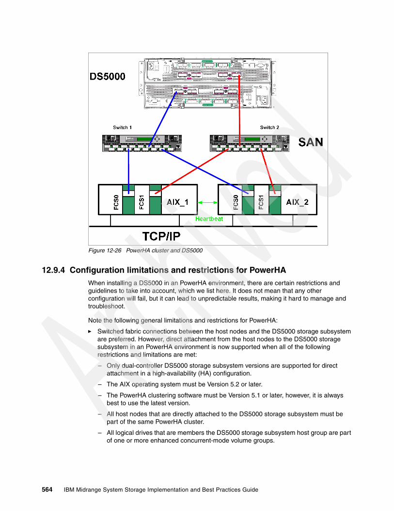
Figure 12-26 PowerHA cluster and DS5000
12.9.4 Configuration limitations and restrictions for PowerHAWhen installing a DS5000 in an PowerHA environment, there are certain restrictions and guidelines to take into account, which we list here. It does not mean that any other configuration will fail, but it can lead to unpredictable results, making it hard to manage and troubleshoot.
Note the following general limitations and restrictions for PowerHA:
� Switched fabric connections between the host nodes and the DS5000 storage subsystem are preferred. However, direct attachment from the host nodes to the DS5000 storage subsystem in an PowerHA environment is now supported when all of the following restrictions and limitations are met:
– Only dual-controller DS5000 storage subsystem versions are supported for direct attachment in a high-availability (HA) configuration.
– The AIX operating system must be Version 5.2 or later.
– The PowerHA clustering software must be Version 5.1 or later, however, it is always best to use the latest version.
– All host nodes that are directly attached to the DS5000 storage subsystem must be part of the same PowerHA cluster.
– All logical drives that are members the DS5000 storage subsystem host group are part of one or more enhanced concurrent-mode volume groups.
564 IBM Midrange System Storage Implementation and Best Practices Guide

– The volume group varyon is in the active state only on the host node that owns the PowerHA non-concurrent resource group (which contains the enhanced concurrent-mode volume group or groups). For all other host nodes in the PowerHA cluster, the enhanced concurrent-mode volume group varyon is in the passive state.
– Direct operations on the logical drives in the enhanced concurrent-mode volume groups cannot be performed from any host nodes in the PowerHA cluster if the operations bypass the Logical Volume Manager (LVM) layer of the AIX operating system. For example, you cannot use a DD command while logged in as the root user.
– Each host node in the PowerHA cluster must have two Fibre Channel connections to the DS5000 storage subsystem. One direct Fibre Channel connection must be to controller A in the DS5000 storage subsystem, and the other direct Fibre Channel connection must be to controller B in the DS5000 Storage System.
– You can directly attach a maximum of two host nodes in an PowerHA cluster to a DS5000 storage subsystem. Each host node must have two direct Fibre Channel connections to the storage subsystem.
� PowerHA Cluster-Single Point of Control (C-SPOC) cannot be used to add a DS5000 disk to AIX through the Add a Disk to the Cluster facility.
� PowerHA C-SPOC does not support enhanced concurrent mode volume groups.
� PowerHA Versions 5.x are supported on the IBM Power* 595 (9119-FHA). clustered configurations.
� PowerHA is now supported in Heterogeneous server environments. For more information regarding a particular operating system environment, see the specific Installation and Support Guide.
� PowerHA clusters can support 2-32 servers for DS5000 partition. In this environment, be sure to read and understand the AIX device drivers queue depth settings, as documented in “Changing ODM attribute settings in AIX” on page 159.
� Non-clustered AIX hosts can be connected to the same DS5000 that is attached to an PowerHA cluster, but must be configured on separate DS5000 host partitions (Host Group).
� Single HBA configurations are allowed, but each single HBA configuration requires that both controllers in the DS5000 be connected to a switch within the same SAN zone as the HBA. although single HBA configurations are supported, using a single HBA configuration is not considered suitable for PowerHA environments, due to the fact that it introduces a single point of failure in the storage I/O path.
� PowerHA from version V5.4 onwards supports Linux, extending many of its robust capabilities and heritage to the Linux environment. Support for Linux will include the base capabilities for reliable monitoring and failure detection available for AIX.
For further PowerHA information, see the following Web site:
http://www-03.ibm.com/systems/power/software/availability/aix/resources/index.html
12.9.5 Planning considerationsWhen planning a high availability cluster, you must consider the sizing of the nodes, storage, network and so on, to provide the necessary resources for the applications to run properly, even in a takeover situation.
Chapter 12. DS5000 with AIX, PowerVM, and PowerHA 565
Sizing: Choosing the nodes in the clusterBefore you start the implementation of the cluster, you must know how many nodes are required, and the type of the nodes that must be used. The type of nodes to be used is important in terms of the resources required by the applications.
Sizing of the nodes must consider the following aspects:
� CPU (number of CPUs and speed)� Amount of random access memory (RAM) in each node� Disk storage (internal)� Number of communication and disk adapters in each node� Node reliability
The number of nodes in the cluster depends on the number of applications to be made highly available, and also on the degree of availability desired. Having more than one spare node for each application in the cluster increases the overall availability of the applications.
PowerHA V5.x supports a variety of nodes, ranging from desktop systems to high-end servers. Logical Partitions (LPARs) are supported as well.
The cluster resource sharing is based on the applications requirements. Nodes that perform tasks that are not directly related to the applications to be made highly available and do not need to share resources with the application nodes must be configured in separate clusters for easier implementation and administration.
All nodes must provide sufficient resources (CPU, memory, and adapters) to sustain execution of all the designated applications in a fail-over situation (to take over the resources from a failing node).
Where possible, use cluster nodes with a similar hardware configuration, especially when implementing clusters with applications in mutual takeover or concurrent configurations. Doing this makes it easier to distribute resources and to perform administrative operations (software maintenance and so on).
Sizing: Storage considerationsApplications to be made highly available require a shared storage space for application data. The shared storage space is used either for concurrent access, or for making the data available to the application on the takeover node (in a fail-over situation).
The storage to be used in a cluster must provide shared access from all designated nodes for each application. The technologies currently supported for PowerHA shared storage are SCSI, SAS, and Fibre Channel — as is the case with the DS5000.
The storage configuration must be defined according to application requirements as non-shared (“private”) or shared storage. The private storage can reside on internal disks and is not involved in any takeover activity.
Shared storage must provide mechanisms for controlled access, considering the following reasons:
� Data placed in shared storage must be accessible from whichever node the application might be running at a point in time. In certain cases, the application is running on only one node at a time (non-concurrent), but in certain cases, concurrent access to the data must be provided. On DS5000 the Host Groups are used for the PowerHA cluster
� In a non-concurrent environment, if the shared data is updated by the wrong node, this can result in data corruption.
566 IBM Midrange System Storage Implementation and Best Practices Guide

� In a concurrent environment, the application must provide its own data access mechanism, because the storage controlled access mechanisms are by-passed by the platform concurrent software (AIX/PowerHA).
12.9.6 Cluster disks setupThe following sections relate important information about cluster disk setup, and in particular describes cabling, AIX configuration, microcode loading, and configuration of DS5000 disks.
Figure 12-27 shows a simple two-node PowerHA cluster. The basic cabling configuration ensures redundancy and allows for possible future expansion. It can also support remote mirroring because it leaves two available controllers on the DS5000.
Figure 12-27 HACMP - Preferred cabling and zoning
Log on to each of the AIX nodes in the cluster and verify that you have a working configuration. You must get an output similar to what is illustrated next for the various commands:
� AIX_1:
# lsdev -Ccadapterfcs0 Available 1Z-08 FC Adapterfcs1 Available 1D-08 FC Adapter
AIX_2: lsdev -Cc adapterfcs0 Available 1Z-08 FC Adapterfcs1 Available 1D-08 FC Adapter
Chapter 12. DS5000 with AIX, PowerVM, and PowerHA 567

Using Storage Manager, define a Host Group for the cluster and include the various hosts (nodes) and host ports as illustrated in Figure 12-28.
Figure 12-28 Cluster - Host Group and Mappings
Follow these steps:
1. Verify the disks on node 1:
# lsdev -Ccdisk
# lsdev -Cc diskhdisk9 Available 1n-08-02 IBM MPIO DS5000 Array Diskhdisk10 Available 1n-08-02 IBM MPIO DS5000 Array Diskhdisk11 Available 1n-08-02 IBM MPIO DS5000 Array Diskhdisk12 Available 1n-08-02 IBM MPIO DS5000 Array Disk
# lspv
# lspvhdisk9 0007041a08050518 Nonehdisk10 0007041a080506c5 Nonehdisk11 0007041a0805086f Nonehdisk12 0007041a080509be None
2. Verify the disks on node 2:
# # lsdev -Ccdisk
# lsdev -Cc diskhdisk9 Available 1n-08-02 IBM MPIO DS5000 Array Diskhdisk10 Available 1n-08-02 IBM MPIO DS5000 Array Diskhdisk11 Available 1n-08-02 IBM MPIO DS5000 Array Diskhdisk12 Available 1n-08-02 IBM MPIO DS5000 Array Disk
# lspv
# lspvhdisk9 0007041a08050518 Nonehdisk10 0007041a080506c5 Nonehdisk11 0007041a0805086f Nonehdisk12 0007041a080509be None
568 IBM Midrange System Storage Implementation and Best Practices Guide

12.9.7 Shared LVM component configurationIn this section we describe how to define the LVM components shared by cluster nodes in an PowerHA for AIX cluster environment.
Creating the volume groups, logical volumes, and file systems shared by the nodes in an PowerHA cluster requires that you perform steps on all nodes in the cluster. In general, you define the components on one node (source node) and then import the volume group on the other nodes in the cluster (destination nodes), which ensures that the ODM definitions of the shared components are the same on all nodes in the cluster.
Non-concurrent access environments typically use journaled file systems to manage data, whereas concurrent access environments use raw logical volumes. In this chapter we provide other instructions for defining shared LVM components in non-concurrent access and concurrent access environments.
Creating a shared volume group In the following sections we provide information about creating a non-concurrent volume group as well as a volume group for concurrent access.
Creating a non-concurrent volume groupUse the smit mkvg fast path to create a shared volume group. Use the default field values unless your site has other requirements. See Table 12-3 for the smit mkvg options.
Table 12-3 smit mkvg options
Creating a volume group for concurrent accessThe procedure used to create a concurrent access volume group varies, depending on which type of device you are using. In our case we will assume DS5000 disks.
To use a concurrent access volume group, defined on a DS5000 disk subsystem, you must create it as a concurrent-capable volume group. A concurrent-capable volume group can be activated (varied on) in either non-concurrent mode or concurrent access mode.
Options Description
VOLUME GROUP name The name of the shared volume group must be unique within the cluster.
Physical partition SIZE in megabytes
Accept the default.
PHYSICAL VOLUME NAMES Specify the names of the physical volumes you want included in the volume group.
Activate volume group AUTOMATICALLY at system restart?
Set to no so that the volume group can be activated as appropriate by the cluster event scripts.
Volume Group MAJOR NUMBER If you are not using NFS, you can use the default (which is the next available number in the valid range). If you are using NFS, you must make sure to use the same major number on all nodes. Use the lvlstmajor command on each node to determine a free major number common to all nodes.
Create VG concurrent capable? Set this field to no (leave default)
Auto-varyon concurrent mode? Accept the default.
Chapter 12. DS5000 with AIX, PowerVM, and PowerHA 569
To define logical volumes on a concurrent-capable volume group, it must be varied on in non-concurrent mode.
Use smit mkvg with the options shown in Table 12-4 to build the volume group.
Table 12-4 Options for volume group
Creating shared logical volumes and file systemsUse the smit crjfs fast path to create the shared file system on the source node. When you create a journaled file system, AIX creates the corresponding logical volume. Therefore, you do not need to define a logical volume. You do, however, need to later rename both the logical volume and the log logical volume for the file system and volume group (Table 12-5).
Table 12-5 smit crjfs options
Renaming a jfslog and logical volumes on the source nodeAIX assigns a logical volume name to each logical volume it creates. Examples of logical volume names are /dev/lv00 and /dev/lv01. Within an PowerHA cluster, the name of any shared logical volume must be unique. Also, the journaled file system log (jfslog) is a logical volume that requires a unique name in the cluster.
To make sure that logical volumes have unique names, rename the logical volume associated with the file system and the corresponding jfslog logical volume. Use a naming scheme that indicates the logical volume is associated with a certain file system. For example, lvsharefs can name a logical volume for the /sharefs file system.
Options Description
VOLUME GROUP name The name of the shared volume group must be unique within the cluster.
Physical partition SIZE in megabytes Accept the default.
PHYSICAL VOLUME NAMES Specify the names of the physical volumes you want included in the volume group.
Activate volume group AUTOMATICALLY at system restart?
Set this field to no so that the volume group can be activated, as appropriate, by the cluster event scripts.
Volume Group MAJOR NUMBER While it is only really required when you are using NFS, it is always good practice in an HACMP cluster to have a shared volume group have the same major number on all the nodes that serve it. Use the lvlstmajor command on each node to determine a free major number common to all nodes.
Create VG concurrent capable? Set this field to yes so that the volume group can be activated in concurrent access mode by the HACMP for AIX event scripts
Auto-varyon concurrent mode? Set this field to no so that the volume group can be activated, as appropriate, by the cluster event scripts.
Options Description
Mount AUTOMATICALLY at system restart? Make sure this field is set to no.
Start Disk Accounting Make sure this field is set to no.
570 IBM Midrange System Storage Implementation and Best Practices Guide

Follow these steps to rename the logical volumes:
1. Use the lsvg -l volume_group_name command to determine the name of the logical volume and the log logical volume (jfslog) associated with the shared volume groups. In the resulting display, look for the logical volume name that has type jfs, which is the logical volume. Then look for the logical volume name that has type jfslog, which is the log logical volume.
2. Use the smit chlv fast path to rename the logical volume and the log logical volume.
3. After renaming the jfslog or a logical volume, check the /etc/filesystems file to make sure the dev and log attributes reflect the change. Check the log attribute for each file system in the volume group, and make sure that it has the new jfslog name. Check the dev attribute for the logical volume that you renamed, and make sure that it has the new logical volume name.
Importing to other nodesThe following sections cover varying off a volume group on the source node, importing it onto the destination node, changing its startup status, and varying it off on the destination nodes.
Varying off a volume group on the source nodeUse the varyoffvg command to deactivate the shared volume group. You vary off the volume group so that it can be properly imported onto a destination node and activated as appropriate by the cluster event scripts. Enter the following command:
varyoffvg volume_group_name
Make sure that all the file systems of the volume group have been unmounted; otherwise, the varyoffvg command will not work.
Importing a volume group onto the destination nodeTo import a volume group onto destination nodes you can use the SMIT interface or the TaskGuide utility. The TaskGuide uses a graphical interface to guide you through the steps of adding nodes to an existing volume group. Importing the volume group onto the destination nodes synchronizes the ODM definition of the volume group on each node on which it is imported.
You can use the smit importvg fast path to import the volume group (Table 12-6).
Table 12-6 smit importvg options
Options Description
VOLUME GROUP name Enter the name of the volume group that you are importing. Make sure the volume group name is the same name that you used on the source node.
PHYSICAL VOLUME name Enter the name of a physical volume that resides in the volume group. Note that a disk might have another logical name on other nodes. Make sure that you use the disk name as it is defined on the destination node.
Volume Group MAJOR NUMBER If you are not using NFS, you can use the default (which is the next available number in the valid range). If you are using NFS, you must make sure to use the same major number on all nodes. Use the lvlstmajor command on each node to determine a free major number common to all nodes.
Chapter 12. DS5000 with AIX, PowerVM, and PowerHA 571
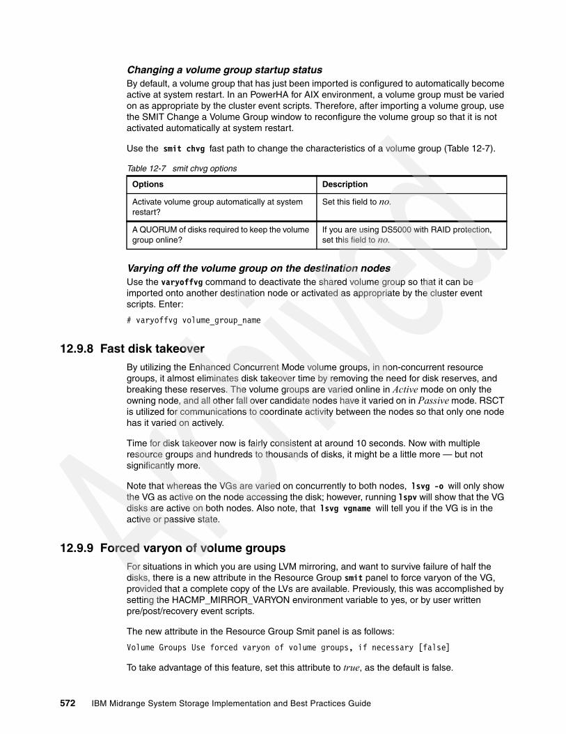
Changing a volume group startup statusBy default, a volume group that has just been imported is configured to automatically become active at system restart. In an PowerHA for AIX environment, a volume group must be varied on as appropriate by the cluster event scripts. Therefore, after importing a volume group, use the SMIT Change a Volume Group window to reconfigure the volume group so that it is not activated automatically at system restart.
Use the smit chvg fast path to change the characteristics of a volume group (Table 12-7).
Table 12-7 smit chvg options
Varying off the volume group on the destination nodesUse the varyoffvg command to deactivate the shared volume group so that it can be imported onto another destination node or activated as appropriate by the cluster event scripts. Enter:
# varyoffvg volume_group_name
12.9.8 Fast disk takeoverBy utilizing the Enhanced Concurrent Mode volume groups, in non-concurrent resource groups, it almost eliminates disk takeover time by removing the need for disk reserves, and breaking these reserves. The volume groups are varied online in Active mode on only the owning node, and all other fall over candidate nodes have it varied on in Passive mode. RSCT is utilized for communications to coordinate activity between the nodes so that only one node has it varied on actively.
Time for disk takeover now is fairly consistent at around 10 seconds. Now with multiple resource groups and hundreds to thousands of disks, it might be a little more — but not significantly more.
Note that whereas the VGs are varied on concurrently to both nodes, lsvg -o will only show the VG as active on the node accessing the disk; however, running lspv will show that the VG disks are active on both nodes. Also note, that lsvg vgname will tell you if the VG is in the active or passive state.
12.9.9 Forced varyon of volume groupsFor situations in which you are using LVM mirroring, and want to survive failure of half the disks, there is a new attribute in the Resource Group smit panel to force varyon of the VG, provided that a complete copy of the LVs are available. Previously, this was accomplished by setting the HACMP_MIRROR_VARYON environment variable to yes, or by user written pre/post/recovery event scripts.
The new attribute in the Resource Group Smit panel is as follows:
Volume Groups Use forced varyon of volume groups, if necessary [false]
To take advantage of this feature, set this attribute to true, as the default is false.
Options Description
Activate volume group automatically at system restart?
Set this field to no.
A QUORUM of disks required to keep the volume group online?
If you are using DS5000 with RAID protection, set this field to no.
572 IBM Midrange System Storage Implementation and Best Practices Guide

12.9.10 Heartbeat over disksHeartbeat provides the ability to use existing shared disks, regardless of disk type, to provide serial network type connectivity, which can replace needs of using integrated serial ports or 8-port async adapters and the additional cables needed for it.
This feature utilizes a special reserve area, previously used by SSA Concurrent volume groups. Because Enhanced Concurrent does not use this space, it makes it available for use, which also means that the disk chosen for serial heartbeat can be, and probably will normally be, part of a data volume group.
The disk heartbeating code went into the 2.2.1.30 version of RSCT. Certain APARs can be used to bring that version up to 2.2.1.31. If you have that level installed, as well as HACMP 5.1 and higher, you can use disk heartbeating. The relevant file to look for is /usr/sbin/rsct/bin/hats_diskhb_nim. Though it is supported mainly through RSCT, at least AIX 5.2 is best when utilizing disk heartbeat.
In HACMP 5.1 with AIX 5.1, enhanced concurrent mode volume groups can be used only in concurrent (or “online on all available nodes”) resource groups. From AIX 5.2 onwards, disk heartbeats can exist on an enhanced concurrent VG that resides in a non-concurrent resource group.
To use disk heartbeats, no node can issue a SCSI reserve for the disk. This is because both nodes using it for heartbeating must be able to read and write to that disk. It is sufficient that the disk be in an enhanced concurrent volume group to meet this requirement.
Chapter 12. DS5000 with AIX, PowerVM, and PowerHA 573

Creating a disk heartbeat device in HACMP v5.1 or laterThis example consists of a two-node cluster (nodes Atlantic and Kanaga) with shared DS4000 disk devices. If more than two nodes exist in your cluster, you will need N number of non-IP heartbeat networks, where N represents the number of nodes in the cluster. (that is, a three node cluster requires three non-IP heartbeat networks), which creates a heartbeat ring (Figure 12-29).
Figure 12-29 Disk heartbeat device
PrerequisitesWe assumed that the shared storage devices are already made available and configured to AIX, and that the proper levels of RSCT and HACMP are already installed.
Configuring disk heartbeatAs mentioned previously, disk heartbeat utilizes enhanced-concurrent volume groups. If starting with a new configuration of disks, you will want to create enhanced concurrent volume groups by utilizing Cluster-Single Point of Control (C-SPOC).
To be able to use Cluster-Single Point of Control (C-SPOC) successfully, it is required that a basic IP based topology already exists, and that the storage devices have their PVIDs in both system’s ODMs, which can be verified by running lspv on each system. If a PVID does not exist on each system, it is necessary to run chdev -l <hdisk#> -a pv=yes on each system, which will allow Cluster-Single Point of Control (C-SPOC) to match up the devices as known shared storage devices.
Note: Because utilizing enhanced-concurrent volume groups, it is also necessary to make sure that bos.clvm.enh is installed, which is not normally installed as part of a PowerHA installation by the installp command.
574 IBM Midrange System Storage Implementation and Best Practices Guide

In the following example, because hdisk devices are being used, the following smit screen paths were used.
smitty cl_admin Go to HACMP Concurrent Logical Volume Management Concurrent Volume Groups Create a Concurrent Volume Group.
Choose the appropriate nodes, and then choose the appropriate shared storage devices based on pvids (hdiskx). Choose a name for the VG, desired PP size, make sure that Enhanced Concurrent Mode is set to true and press Enter, which will create the shared enhanced-concurrent VG needed for our disk heartbeat.
On node1 AIX_1:
# lspvhdisk7 000a7f5af78e0cf4 hacmp_hb_vg
On node2 AIX_2:
# lspvhdisk3 000a7f5af78e0cf4 hacmp_hb_vg
Creating disk heartbeat devices and networkThere are two ways to do this. Because we have already created the enhanced concurrent VG, we can use the discovery method (1) and let HA find it for us. Or we can do this manually by the Pre-defined devices method (2). Following is an example of each.
1. Creating by the Discover Method:
Enter smitty hacmp and select Extended Configuration Discover HACMP-related Information from Configured Nodes.
This will run automatically and create a clip_config file that contains the information it has discovered. After being completed, go back to the Extended Configuration menu and choose Extended Topology Configuration Configure HACMP Communication Interfaces/Devices Add Communication Interfaces/Devices Add Discovered Communication Interface and Devices Communication Devices. Choose the appropriate devices (for example. hdisk3 and hdisk7)
a. Select Point-to-Point Pair of Discovered Communication Devices to Add.b. Move the cursor to the desired item and press F7. Use arrow keys to scroll.c. One or more items can be selected.d. Press Enter after making all selections.
# Node Device Pvid> nodeAtlantic hdisk7 000a7f5af78> nodeKanaka hdisk3 000a7f5af78
2. Creating by the Pre-Defined Devices Method:
When using this method, it is necessary to create a diskhb network first, then assign the disk-node pair devices to the network. Create the diskhb network by entering smitty hacmp and selecting Extended Configuration Extended Topology Configuration Configure HACMP Networks Add a Network to the HACMP cluster.
Choose diskhb.
Attention: It is a good idea to verify by lspv after this has completed to make sure the device and VG is shown appropriately.
Chapter 12. DS5000 with AIX, PowerVM, and PowerHA 575

Enter the desired network name (for example, disknet1) and press Enter. Enter smitty hacmp and select Extended Configuration Extended Topology Configuration Configure HACMP Communication Interfaces/Devices Add Communication Interfaces/Devices Add Pre-Defined Communication Interfaces and Devices.
a. Communication Devices Choose your diskhb Network Name
b. Add a communication device.
c. Type or select values in the entry fields.
d. Press Enter after making all desired changes:
Device Name [AIX_1_hboverdisk] Network Type diskhb Network Name disknet1 Device Path [/dev/hdisk7] Node Name [AIX_1]
For Device Name, that is a unique name you can choose. It will show up in your topology under this name, much like serial heartbeat and ttys have in the past.
For the Device Path, you want to put in /dev/<device name>. Then choose the corresponding node for this device and device name (ex. Atlantic). Then press Enter.
You will repeat this process for the other node (for example, Kanaga) and the other device (hdisk3), which will complete both devices for the diskhb network.
Testing disk heartbeat connectivityAfter the device and network definitions have been created, test the system and make sure communications are working properly. (If the volume group is varied on in normal mode on one of the nodes, the test will probably not work, so make sure it is varied off).
To test the validity of a disk heartbeat connection, use the following command:
/usr/sbin/rsct/bin/dhb_read
The usage of dhb_read is as follows:
dhb_read -p devicename //dump diskhb sector contentsdhb_read -p devicename -r //receive data over diskhb networkdhb_read -p devicename -t //transmit data over diskhb network
To test that disknet1, in our example configuration, can communicate from nodeB (Atlantic) to nodeA (Kanaga), you can run the following commands:
� On nodeA, enter:
dhb_read -p hdisk7-r
� On nodeB, enter:
dhb_read -p hdisk3 -t
If the link from nodeB to nodeA is operational, both nodes will display:
Link operating normally.
You can run this again and swap which node transmits and which one receives. To make the network active, it is necessary to sync up the cluster. Because the volume group has not been added to the resource group, we will sync up once instead of twice.
576 IBM Midrange System Storage Implementation and Best Practices Guide

Adding shared disk as a shared resourceIn most cases you have your diskhb device on a shared data volume group. It is necessary to add that VG into your resource group and synchronize the cluster.
1. Use the command smitty hacmp and select Extended Configuration Extended Resource Configuration Extended Resource Group Configuration Change/Show Resources and Attributes for a Resource Group.
2. Press Enter and choose the appropriate resource group.
3. Enter the new VG (enhconcvg) into the volume group list and press Enter.
4. Return to the top of the Extended Configuration menu and synchronize the cluster.
Monitoring disk heartbeatAfter the cluster is up and running, you can monitor the activity of the disk (actually all) heartbeats using the command lssrc -ls topsvcs, which produces output like this:
Subsystem Group PID Statustopsvcs topsvcs 32108 activeNetwork Name Indx Defd Mbrs St Adapter ID Group IDdisknet1 [ 3] 2 2 S 255.255.10.0 255.255.10.1disknet1 [ 3] hdisk3 0x86cd1b02 0x86cd1b4fHB Interval = 2 secs. Sensitivity = 4 missed beatsMissed HBs: Total: 0 Current group: 0Packets sent : 229 ICMP 0 Errors: 0 No mbuf: 0Packets received: 217 ICMP 0 Dropped: 0NIM's PID: 28724
Be aware that there is a grace period for heartbeats to start processing, which is normally around 60 seconds. So if you run this command quickly after starting the cluster, you might not see anything at all until heartbeat processing is started after the grace period time has elapsed.
Performance concerns with disk heartbeatMost modern disks take somewhere around 15 milliseconds to service an I/O request, which means that they cannot do much more than 60 seeks per second. The sectors used for disk heartbeating are part of the VGDA, which is at the outer edge of the disk, and might not be near the application data.
This means that every time a disk heartbeat is done, a seek will have to be done. Disk heartbeating will typically (with the default parameters) require four (4) seeks per second. That, is each of two nodes will write to the disk and read from the disk once/second, for a total of 4 IOPS. So, if possible, a disk must be selected as a heartbeat path that does not normally do more than about 50 seeks per second. The filemon tool can be used to monitor the seek activity on a disk.
In cases where a disk that already has a high seek rate must be used for heartbeating, it might be necessary to change the heartbeat timing parameters to prevent long write delays from being seen as a failure.
Chapter 12. DS5000 with AIX, PowerVM, and PowerHA 577

578 IBM Midrange System Storage Implementation and Best Practices Guide

Appendix A. GPFS
In this Appendix we look at the basic concepts behind the GPFS file system and show how the DS4000 and DS5000 Storage Servers can be configured in this environment.
A
© Copyright IBM Corp. 2004-2010. All rights reserved. 579
GPFS concepts
The IBM General Parallel File System (GPFS) is a powerful file system that provides:
� Global namespace� Shared file system access among GPFS clusters� Simultaneous file access from multiple nodes� High recoverability and data availability due to replication� Ability to make certain changes while a file system is mounted� Simplified administration that is similar to existing UNIX systems.
GPFS provides file system services to parallel and serial applications. It allows parallel applications simultaneous access to the same files, or other files, from any node that has the GPFS file system mounted, as well as managing a high level of control over all file system operations.
GPFS is particularly appropriate in an environment where the aggregate peak need for data bandwidth exceeds the capability of a distributed file system server.
GPFS allows users shared file access within a single GPFS cluster and across multiple GPFS clusters. Shared file system access among GPFS clusters GPFS allows users shared access to files in either the cluster where the file system was created or other GPFS clusters. Each site in the network is managed as a separate cluster, while allowing shared file system access.
A GPFS cluster can consist of the following types of nodes:
� Linux nodes� AIX nodes� Windows nodes� combination of Linux, AIX and Windows nodes
GPFS includes a Network Shared Disk component which provides a method for cluster-wide disk naming and access. All disks used by GPFS must first be given a globally-accessible NSD name.
Performance advantages with GPFS file system
Using GPFS to store and retrieve your files can improve system performance by:
� Allowing multiple processes or applications on all nodes in the cluster simultaneous access to the same file using standard file system calls.
� Increasing aggregate bandwidth of your file system by spreading reads and writes across multiple disks.
� Balancing the load evenly across all disks to maximize their combined throughput. One disk is no more active than another.
� Supporting very large file and file system sizes.
� Allowing concurrent reads and writes from multiple nodes.
� Allowing for distributed token (lock) management. Distributing token management reduces system delays associated with a lockable object waiting to obtaining a token.
� Allowing for the specification of other networks for GPFS daemon communication and for GPFS administration command usage within your cluster.
580 IBM Midrange System Storage Implementation and Best Practices Guide

Achieving high throughput to a single, large file requires striping data across multiple disks and multiple disk controllers. Rather than relying on striping in a separate volume manager layer, GPFS implements striping in the file system. Managing its own striping affords GPFS the control it needs to achieve fault tolerance and to balance load across adapters, storage controllers, and disks. Large files in GPFS are divided into equal sized blocks, and consecutive blocks are placed on various disks in a round-robin fashion.
To exploit disk parallelism when reading a large file from a single-threaded application, whenever it can recognize a pattern, GPFS prefetches data into its buffer pool, issuing I/O requests in parallel to as many disks as necessary to achieve the bandwidth of which the switching fabric is capable. GPFS recognizes sequential, reverse sequential, and various forms of striped access patterns.
Data availability advantages with GPFS
GPFS failover support allows you to organize your hardware into failure groups. A failure group is a set of disks that share a common point of failure that might cause them all to become simultaneously unavailable. When used in conjunction with the replication feature of GPFS, the creation of multiple failure groups provides for increased file availability if a group of disks fails. GPFS maintains each instance of replicated data and metadata on disks in various failure groups. If a set of disks becomes unavailable, GPFS fails over to the replicated copies in another failure group.
Disks can be added and deleted while the file system is mounted. Equally, nodes can be added or deleted without having to stop and restart the GPFS daemon on all nodes.
GPFS configuration
GPFS can be configured in a variety of ways. Here we just explore a configuration where all NSDs are SAN-attached to all nodes in the cluster and the nodes in the cluster are either all Linux (Figure A-1) or all AIX. For documentation listing the latest hardware that GPFS has been tested with, see the following Web site:
http://publib.boulder.ibm.com/infocenter/clresctr/vxrx/index.jsp?topic=/com.ibm.cluster.gpfs.doc/gpfs_faqs/gpfsclustersfaq.html
Figure A-1 Linux only GPFS cluster with SAN attached disks
Appendix A. GPFS 581

DS4000 and DS5000 configuration limitations with GPFS
The following limitations apply to PSSP and GPFS configurations:
� Direct connection is not allowed between the host node and a DS4000/DS5000 Storage Subsystem.
� Only switched fabric connection is allowed.
� RVSD clusters can support up to two IBM Virtual Shared Disk and RVSD servers for each DS4000/DS5000 partition.
� Single node quorum is not supported in a dual-node GPFS cluster with DS4000/DS5000 disks in the configuration.
� Heterogeneous configurations are not supported.
DS4000 or DS5000 settings for GPFS environment
In GPFS file systems, the following DS4000/DS5000 cache settings are supported:
� Read cache enabled or disabled� Write cache enabled or disabled� Cache mirroring enabled or disabled (depending upon the write cache mirroring setting)
The performance benefits of read or write caching depend on the application. Because the cache settings can be easily adjusted from Storage Manager (SM), preferably carry out your performance tests during implementation. Here is a sample configuration you can use as a starting point for NSD servers or other GPFS nodes that are directly attached to a SAN over a Fibre Channel network:
1. Use the following cache settings:
Read cache = enabledRead ahead multiplier = 0Write cache = disabledWrite cache mirroring = disabledWrite block size = 16 K
2. When the storage server disks are configured for RAID5, certain configuration settings can affect GPFS performance:
– GPFS block size– Maximum I/O size of host Fibre Channel (FC) host bus adapter (HBA) device driver– Storage server RAID5 stripe size
For optimal performance, GPFS block size must be a multiple of the maximum I/O size of the FC HBA device driver. In addition, the maximum I/O size of the FC HBA device driver must be a multiple of the RAID5 stripe size.
3. The following guidelines can help avoid the performance penalty of read-modify-write at the storage server for GPFS writes. Here are a few examples of the settings:
– 8+P RAID5:
• GPFS block size = 512K• Storage Server RAID5 segment size = 64 K (RAID5 stripe size=512 K)• Maximum IO size of FC HBA device driver = 512K
– 4+P RAID5:
• GPFS block size = 256 K• Storage Server RAID5 segment size = 64 K (RAID5 stripe size = 256 K)• Maximum IO size of FC HBA device driver = 256 K
582 IBM Midrange System Storage Implementation and Best Practices Guide
For the example settings using 8+P and 4+P RAID5, the RAID5 parity can be calculated from the data written and will avoid reading from disk to calculate the RAID5 parity. The maximum IO size of the FC HBA device driver can be verified using iostat or the Storage Server performance monitor. In certain cases, the device driver might need to be patched to increase the default maximum IO size.
4. The GPFS parameter maxMBpS can limit the maximum throughput of an NSD server or a single GPFS node that is directly attached to the SAN with a FC HBA. Increase the maxMBpS from the default value of 150 to 200 (200 MBps). The maxMBpS parameter is changed by issuing the mmchconfig command. After this change is made, restart GPFS on the nodes and test both read and write performance of both a single node in addition to a large number of nodes.
5. The layout and distribution of the disks across the drive-side channels on the DS5000 Storage Server can also be an important factor when attempting to maximize throughput and IOPs.
Appendix A. GPFS 583

584 IBM Midrange System Storage Implementation and Best Practices Guide
Related publications
The publications listed in this section are considered particularly suitable for a more detailed discussion of the topics covered in this book.
IBM Redbooks publications
For information about ordering these publications, see “How to get Redbooks publications” on page 586. Note that certain documents referenced here might be available in softcopy only:
� IBM Midrange System Storage Copy Services Guide, SG24-7822
� IBM Midrange System Storage Hardware Guide, SG24-7676
� IBM System Storage/Brocade Multiprotocol Routing: An Introduction and Implementation, SG24-7544
� IBM System Storage Business Continuity: Part 1 Planning Guide, SG24-6547
� IBM System Storage Business Continuity: Part 2 Solutions Guide, SG24-6548
� IBM System Storage Copy Services and IBM i: A Guide to Planning and Implementation, SG24-7103
� IBM System Storage DS3000: Introduction and Implementation Guide, SG24-7065
� IBM System Storage DS4000 and Storage Manager V10.30, SG24-7010
� Implementing an IBM/Cisco SAN, SG24-7545
� Implementing an IBM/Brocade SAN with 8 Gbps Directors and Switches, SG24-6116
Other publications
These publications are also relevant as further information sources:
� DS5100, DS5300, and EXP5000 Quick Start Guide, GC53-1134
� IBM System Storage DS Storage Manager Version 10 IBM System Storage DS Storage Manager Installation and Host Support Guide, GC53-1135
� IBM System Storage DS Storage Manager Version 10.50 Copy Services User's Guide, GC53-1136
� IBM System Storage DS Storage Manager Version 10.60 Copy Services User’s Guide, GC53-1136-02
� IBM System Storage DS3000, DS4000, and DS5000 Command Line Interface and Script Commands Programming Guide, GC52-1275
� IBM System Storage DS4000 Concepts Guide, GC26-7734
� IBM System Storage DS4000/DS5000 EXP810 Storage Expansion Enclosure Installation, User's and Maintenance Guide, GC26-7798
� IBM System Storage DS4000/DS5000 Fibre Channel and Serial ATA Intermix Premium Feature Installation Overview, GC53-1137
© Copyright IBM Corp. 2004-2010. All rights reserved. 585

� IBM System Storage DS4000/DS5000 Hard Drive and Storage Expansion Enclosure Installation and Migration Guide, GC53-1139
� IBM System Storage DS4800 Storage Subsystem Installation, User's, and Maintenance Guide, GC26-7845
� IBM System Storage DS4800 Storage Subsystem Quick Start Guide, GC27-2148
� IBM System Storage DS5000 EXP5000 Storage Expansion Enclosure Installation, User's, and Maintenance Guide, GC53-1141
� IBM System Storage DS5100 and DS5300 Storage Subsystems Installation, User's, and Maintenance Guide, GC53-1140
Online resources
These Web sites are also relevant as further information sources:
� System Storage Interoperation Center (SSIC):
http://www-03.ibm.com/systems/support/storage/config/ssic/displayesssearchwithoutjs.wss?start_over=yes
� Support for IBM Disk Systems:
http://www.ibm.com/systems/support/storage/disk
How to get Redbooks publications
You can search for, view, or download Redbooks publications, Redpapers publications, Technotes, draft publications, and Additional materials, as well as order hardcopy Redbooks publications, at this Web site:
ibm.com/redbooks
Help from IBM
IBM Support and downloads:
ibm.com/support
IBM Global Services:
ibm.com/services
586 IBM Midrange System Storage Implementation and Best Practices Guide
Index
Aaccess logical drive 38, 78access LUN 38, 78, 154active zone config 214Adapter Boot Mode 265ADT 55, 106, 506Advanced Technology Attachment (ATA) 2, 316AIX 5.1 573AIX 5.2 558, 573AIX 5L operating system 533AIX environment 534, 572AIX host 304, 534, 541, 543–544, 549, 565AIX host physical attachment 541AIX LVM 558AIX MPIO 548AIX MPIO FCP 496AIX system 546alert delay 108Alert Delay Period 106alert notification 106algorithm 553alignment 303, 307, 352allocation unit 308–309, 339Allocation unit size 308–309, 339allocation unit size 306–307, 339analyze performance 356Application Log 148archival 44archive log 334array 32, 60–61, 513
configuration 30–31creating 66defragment 314size 361
arrayhost.txt 384AS (Automatic Storage) 330ASM 336attenuation 21Auto-Logical Drive Transfer. See ADTautomatic storage management (ASM) 336autonomic 3auxiliary 491auxiliary VDisk 492availability reasons 505AVT 57AVT-disabled failover 55AVT-enabled failover 56
Bbackup 309bandwidth 124, 301basic disc 48, 306basic disc primary partition 48, 306basic disk primary partition 143
© Copyright IBM Corp. 2004-2010. All rights reserved.
BIOS configuration utility 218blocksize 39, 70, 302, 333boundary crossing 303Brocade (HCM) 239Business Continuance and Disaster Recovery (BCDR) 104
Ccable
labeling 23, 25length 19management 23routing 24types 20
cabling 20cabling mistakes 25cache 41, 301, 310, 326, 492
block size 315, 508hit percentage 361memory 4, 361Read Hit Ratio 437read-ahead 302–304, 361read-ahead multiplier 326, 361setting 67
capacity 74, 316unconfigured 74upgrade 120
Cascaded FlashCopy (CFC) 489Centralized administration 198cfgmgr 157Challenge Handshake Authentication Protocol 185Chap authentication 228, 270CHAP secret 100, 185, 228chdev 304checklist 17
hardware 17software 17
CIM Agent 376, 379CIM Client 377CIM Managed Object 377CIM Object Manager (CIMOM) 377CIM-compliant 376CIMOM 384CIM-ready device 379clock 60cluster 78, 308–309, 561, 563Cluster considerations 495Cluster Zone 500clustered disks 307clustering solutions 533Cluster-Single Point of Control (C-SPOC) 565, 574command line interface (CLI) 365command line tool 8Common Information Model (CIM) 376
587
complete pathname/SMclient-AIX-09.10.G5.02.bff SMclient.aix.rte 153name/SMruntime-AIX-09.10.65.01.bff SMruntime.aix.rte 152
Concurrent Migration 486connectors 20Consistency groups 485container 332contention 30, 33controller
clock 60firmware 8, 117ownership 32, 361
Controller affinity 506Controller ownership 73Controller-based 8copy
FlashCopy 16, 315Volume Copy 16
copy priority 313copy priority rate 313copy services 104, 311, 486copyback 314copy-on-write 313CPU statistics 338CPU utilization 338Create Probe 388
DDACstore 121data blocks 333Data location 330, 333data location 330, 333data pattern 301data scrubbing 39database
log 310, 319, 330RAID 334structure 330
Database structure 330datafile table 332, 335DB2 330DB2 logs 333DB2 object 330dd command 369DDK 52default group 35defragment 314Degraded Paths 516Degraded Ports 517destination node 571–572destination node volume group 571device driver 45Device Manager 241Device Path 136Device provider 377, 379Device Specific Module 53Directory agent (DA) 378disk array driver 149
disk drive 2, 7, 29–30, 33, 38, 46, 121, 311, 316, 319disk group 49, 307disk heartbeat 573–574, 576–577disk latency 301, 320Disk Magic 372, 408, 435Disk Management 144, 307, 309disk statistics 339disk system 2disk thrashing 508diskhb network 575–576diskpar.exe 307diskpart 48, 143, 306–308, 352diskpart utility 143, 307dispersion 20Distance limitations 508distribute 72DMA 550DMS (Database Managed Storage) 330drive interfaces 3DRIVE Loop 33, 123–124drive loop 324drive loop communications 325drive port 4Drive Security feature 44drive selection 28Driver Development Kit (DDK) 52DS family 2DS family positioning 2DS Storage Manager 171DS Storage Server product 60DS3000 2DS4000 2–3
capacity upgrade 120configuring 60models 311overall positioning 2rename 60set password 60software update 118
DS4000 Storage Server 3, 6, 8, 15, 17–18, 20, 36, 59–60, 299–302, 304, 330, 333, 335, 339, 342, 356, 359, 533, 563
logical drive 42, 344model 317, 320overall positioning 2
DS4700 4DS4800 4DS5000 5DS5000 Storage Server 26, 358–359, 534DS5020 3DS5100 3–4DS5100 Storage Server 3DS5300 4DS5300 Storage Server 4DS6000 2DS8000 2DSM 53dual SAN fabric 508dual VIO servers 544, 555Dynamic cache read prefetch 72
588 IBM Midrange System Storage Implementation and Best Practices Guide

Dynamic Capacity Expansion (DCE) 315, 557dynamic disk 48–49, 306–307Dynamic Logical Drive Expansion (DVE) 315Dynamic RAID Migration (DRM) 315, 557Dynamic Reconstruction Rate (DRR) 315Dynamic Segment Sizing (DSS) 314, 557Dynamic System Analysis 148dynamic tracking 554Dynamic Volume Expansion (DVE) 142–143, 557
EE-DDM 5e-mail 105–106Emulex 36Emulex (HBAnyware) 239enclosure
ID 27–28loss protection 31, 70migrating 121
Engenio providerarrayhosts.txt 383–384providerStore 384
Enhanced Remote Mirroring (ERM) 7, 16, 18, 33, 42–43, 104, 312Enhanced Scalability Concurrent Resource Manager (ESCRM) 562Enterprise Edition 487Enterprise Management window 167Entry Edition 487environmental requirements 16, 18Environmental Service Module (ESM) 8errpt 550ESM 8, 117ESM board 27ESS 2, 549Ethernet 116Ethernet network 8event log 60Event Monitor 105–106event monitor 127Event viewer 148Exchange
IOPS 346mailbox 345sizing 349storage groups 347
Excluded MDisk 517execution throttle 27, 306EXP unit 120, 123EXP5000 3–5EXP5060 5EXP520 5EXP810 4expansion enclosure 27–28, 117, 123expansion unit 123extend 48, 306extent 333, 484extent size (ES) 331, 562
Ffabric 12fabric considerations 495Fabric Shortest Path First (FSPF) 12failed drive 61–63, 121, 314failover 10, 26, 107, 553
alert delay 107–108Failover Cluster Manager 296FAStT MSJ 27, 36FC drive 4FC HBA 234FCP 11, 201fcs 155, 305fcs device 305FDE 62, 66feature key 104fiber, single-mode 21Fibre Channel 2, 11
adapter 14, 25, 550, 563controller 18, 116director 12hub 117I/O path failover driver 8loop 8SAN 214switch 22, 563technology 44unconfigured capacity 67
Fibre Channel (FC) 2, 8–9, 11–12, 14, 16, 18, 21–23, 25, 28–29, 67, 116–117, 303, 316–317, 319, 355, 362, 528, 550, 563, 566FICON 11file system 34, 46, 71, 156, 305, 308, 314, 330, 333, 336, 339, 343, 352, 362, 558, 569, 571filesystem 344, 570–571firewall 386firmware 114–115, 211Firmware version 114, 118, 534FlashCopy 7, 16, 42, 104, 312–313, 315FlashCopy Consistency Groups 489floor plan 18floor-load 18Forced Unit Access 327format 314frame switch 12free capacity 67free capacity logical drive 67free space node 314FSPF 12ftp 109Full Disk Encryption (FDE) 28, 44full stripe write 304–305, 320
GGBIC 21General Parallel File System (GPFS) 580Gigabit Ethernet 201Gigabit Interface Converters 21gigabit transport 21
Index 589
Global copy 43Global Mirror 491Global mirroring 43GPFS 579graphical user interface (GUI) 8growth estimations 17
HHACMP 533HACMP cluster
configuration 563, 575node 561, 563
HACMP environment 561, 563–564HACMP V5.1 disk heartbeat device 574Hardware Management Console (HMC) 211HBA 8, 14, 106, 301–303, 305–306, 343, 352, 534, 543HBA BIOS 198, 200HBA boot setup 231HBA setting 166HBA WWPN 200HBAs 12, 74, 302–303, 306, 352, 544, 546–547hcheck_mode 553heterogeneous hosts 37, 74High Availability Cluster Multi-Processing (HACMP) 562host 35, 37, 302
data layout 303performance 302settings 302
Host Bus Adapter (HBA) 8, 17–18, 25–27, 34–37, 80, 155, 160, 302–303, 343, 352, 357, 534, 543–549
FC port 35sharing 18
host bus adapter (HBA) 162host computer 8, 50, 486host connection 16host group 35, 37, 73–75, 78, 155, 162, 568
single server 37, 78host operating system 36host path 301host port 14, 35, 43, 74–75, 78, 155, 528, 543, 568Host Port Identifiers 79host software 126, 171host system 34–35, 115Host system bus 25Host Type 37, 74, 78, 327, 343–344Host Zones 501Host-based 8hot spare 18, 33, 61–62, 314
global 61ratio 62
hot spare drive 61, 63hot_add 80hot-scaling 123hot-spare 33hot-spare drive 61hub 12Hypertext Transfer Protocol (HTTP) 376Hypertext Transfer Protocol over Secure Socket Layer (HTTPS) 376
II/O group 484I/O path 149I/O per second 474I/O rate 361–362I/O request 17, 26, 38, 52, 360, 362IATEMPDIR 150IBM Device Driver utilities 145IBM POWER servers 533IBM Subsystem Device Driver (SDD) 485IBM System Storage DS5300 storage server 4IBM System Storage SAN Volume Control (SVC) 481IBM Tivoli Storage Productivity Center for Disk (TPC for Disk) 373IBM TotalStorage Productivity Center (TPC) 483IETF standard 378Image Mode MDisk 518in-band 61in-band management 8, 36, 38, 105–106, 117, 153, 174Incremental FlashCopy (IFC) 489initialization 314initiator authentication 184Initiator IP Address 270Initiator IP Settings 269Initiator iSCSI Name 270in-order-delivery 328Installation Wizard 172Intercluster Global Mirror 492Intercluster Metro Mirror 490inter-disk allocation 47–48interoperability matrix 17interpolicy 305inter-switch link 12Intracluster Global Mirror 492Intracluster Metro Mirror 490intra-disk allocation 48IO blocksize 302IO rate 29, 318IO request 304, 331, 577IOD 328IOPS 17, 29, 38, 300, 343, 346–347, 352, 577iostat 451IP address 23, 365IQN 178, 216, 228iSCSI 80, 486iSCSI Boot Settings 231iSCSI HBA 202, 234iSCSI HBA hardware initiator card 263iSCSI host adapter 83iSCSI host interface cards 177iSCSI Initiator 177iSCSI initiator 202, 232iSCSI protocol 201iSCSI qualified name 178, 184iSCSI Qualified name (IQN) 228iSCSI SAN boot 213, 234iSCSI Security Authentication 99iSCSI sessions 182iSCSI simple naming service (iSNS) 101iSCSI software initiator 177
590 IBM Midrange System Storage Implementation and Best Practices Guide

iSCSI stack 202ISL 12ISL hop count 495
JJet database 345JFS 305JFS2 305journal 310, 319Journaled File System (JFS) 570
KKB 39, 70
Llabeling 23latency 301, 320LC connector 22LDM 48leaf page 331lg_term_dma 305, 550License Program Products (LPPs) 540Linux 37, 80, 119, 162list 331Load Balance Policy 137load balance policy 137load balancing 26, 48, 54, 72, 337load distribution 54load sharing 26load_balance 553Logical Disk Manager (LDM) 307logical drive 7–8, 30, 32–34, 38, 67, 70, 72–73, 75, 78, 104, 142–143, 154, 159, 162, 166, 301–306, 332–333, 335, 341, 343–344, 348, 359, 361, 363, 443, 513, 558
cache settings 326capacity 74create 323creating 66current size 142instant notification 108ownership 118physical disk 38preferred path 118primary 33, 104, 312second statistics 362secondary 33, 312segment size 362single drive 314source 104specific assignments 35target 104
Logical Drive Mapping 513logical drive transfer alert 107logical unit number (LUN) 34, 73, 159, 162, 169, 504, 525logical view 35, 45, 47, 350, 359logical volume 32, 45–49, 305, 558, 560, 569–571, 575Logical Volume Control Block 305
Logical Volume Manager (LVM) 303, 305long field (LF) 330longwave 20loop 12loss protection 70LPAR 557lservice 113lsmcocde 535LUN 32, 34, 38, 78, 104, 120, 316, 327, 348LUN creation 504LUN masking 74LUNs 34, 74, 159, 161, 166, 169, 528LUNs by running (LR) 169LVM 47LVM component 569LVM conceptual view 47
MMajor Event Log (MEL) 107, 112, 121managed disk (MDisk) 483managed disk group (MDG) 483managed disk group viewing 530Managed Mode MDisk 518management station 117, 167Managing Hot Spares 64mapping 37, 73, 75mapping logical drives to host systems 36Mappings View 35, 73master 491Master Boot Record (MBR) 307master boot record (MBR) 292, 352Master Console 514max_xfer_size 305, 550–551maximum I/O transfer rates for a storage subsystem 362maximum IOs 303maximum number of LUNs 58MDG 483MDisk 506MDisks 482Media Scan 313Media scan 39, 314Messaging Application Programming Interface (MAPI) 346Metro Mirror 490Metro Mirroring 42microcode 115, 210, 534
staged upgrade 117upgrade 114
Microsoft Cluster Services (MSCS) 286Microsoft Exchange 344Microsoft iSCSI software initiator 202Microsoft Management Console (MMC) 49Microsoft SQL server 339
transaction log 341Microsoft Windows
2000 Resource Kit 307resource kit 307
Micrsoft SQL servermaintenance plans 342
Migration 519
Index 591

mirrored 492mirroring 307misalignment 303Mixed zone 13mklv 48modal dispersion 20modification priority 313monitoring 32MPIO 16, 52, 536–537, 540MPIO DSM dsmUtil 146mppBusRescan 169, 191mppUpper 170mppVhba 170MTU size 216multi-mode fiber (MMF) 20Multi-Path Proxy (MPP) 54multipathing device driver 485, 496multipathing driver 55multiple disk arrays 505multiple fabric 14Multiple Path I/O (MPIO) 53, 536Multiple Target FlashCopy (MTFC) 489Mutual Authentication 100My support 114MyDataCollector 437
Nnear-line 44Network considerations 495Network Installation Manager (NIM) 209NIM server 209no_reserve 552Node considerations 495node failover 561node-to-node 12non-concurrent access 569
shared LVM components 569non-failover driver 255Novell NetWare 10NTFS 339num_cmd_elem 305num_cmd_elems 550Number of drives 30NVSRAM 8, 78, 115–117, 311, 327, 359
OObject Data Manager (ODM) 159, 569, 571ODM 554offset 304, 332OnLine Transaction Processing (OLTP) 309online transaction processing (OLTP) 17, 309operating system 8operating system (OS) 10, 30, 37, 149, 162, 166, 300, 347–348, 359–360, 362, 550operating system (OS) command line tool 80Oracle
cache memory 336database 333logs 335
volume management 337Oracle database 329, 333out-of-band 61ownership 32, 118, 361
Ppaging 338parity 320password 60Path failover 204path-control module (PCM) 536PCI bus 550PCI slots 26PCM 536perfmon data 454perfmon tool 437performance 30, 356performance improvement 505performance monitor 38, 72, 346, 353, 358–360, 362–365, 367, 370–371performance monitor job 392Performance Monitoring 337persistent reservation 54physical disk 38physical partitions (PPs) 46physical volume 46, 48, 73, 569–571planning 15–16Plug and Play 54point-in-time 104point-to-point 12polling interval 362Port level zone 13PowerHA 533, 561PowerVM 555PR_exclusive 553PR_shared 553preferred controller 32, 52, 107preferred node 496preferred path 118, 506prefetch 331, 333Pre-Installation Summary 151premium features 41previous version 174primary 104Primary Boot Device Settings 265primary path 251probe job 387Probing CIM agent 387profile 60Provisioning 198proxy 51PTF U499974 558
QQLogic 36QLogic Fast!UTIL 226QLogic Fast!Util 250QLogic FastUtil 278QLogic iSCSI Expansion Card 203
592 IBM Midrange System Storage Implementation and Best Practices Guide
QLogic SANSurfer 243QLogic SANsurfer 164qlremote 164queue depth 25, 27, 29, 302–303, 305–306, 317, 343–344, 565queuing 29QUORUM 572
Rrack 18rack layout 19RAID 7RAID 5 advantage 318RAID controller 7, 484RAID level 32, 68, 74, 312, 315, 339–340, 347, 351, 362RAID types 317RAMdisk 168range 331range of physical volumes 48raw device 304, 330, 333, 336RDAC 8, 16, 54, 166, 246, 536RDAC driver 126, 165, 169, 257, 264Read cache 340–342, 351Read Link Status (RLS) 112read percentage 361Read Sequential 437read-ahead 302–304, 361read-ahead multiplier 326readme file 163, 171rebuild 61Recovery Guru 107, 116recovery storage group (RSG) 347, 349, 351recovery time objective (RTO) 104Redbooks publications Web site 586
Contact us xviredo log 334redo log RAID types 335redundant array of independent disks (RAID) 2Redundant Disk Array Controller (RDAC) 54, 107, 119, 177, 348, 536Reliable Scalable Cluster Technology (RSCT) 561remote access 108Remote Support Manager (RSM) 108reservation 121reserve_policy 552revolutions per minute (RPM) 29RLOGIN 112round-robin 26, 54, 553RPM 29rservice 113RSM 108, 112
change password 113security 113user ID 113
rsm-passwd 113
SSAN 9, 11, 16SAN boot 197
SAN topologies 12SAN Volume Controller (SVC) 15, 482, 549SANtricity 380SANtricity SMI Provider 379SATA drive 2, 28–29, 316–317, 340–344SC connector 22script 117SCSI 11SCSIPort 16SDD 54, 485, 496, 548sddgetdata 149SDDPCM 16, 53, 496, 538, 548secondary 44security 60, 113Seek percentage (%) 466seek time 29segment 334segment size 18, 38–39, 67, 70–71, 302, 305, 314, 320, 325–326, 331–333, 335, 340–344, 351, 362, 507sequential IO high throughput 326server platform 160Service agent (SA) 378Service Alert 108Service Location Protocol (SLP) 201, 378SFF 21SFP 21shortwave 20Simple Network Management Protocol (SNMP) 127Single Points of Failure (SPOFs) 562single_path 553single-mode fiber (SMF) 20–21site planning 24slice 303SLP 379SM Failover driver (MPIO/DSM) 132SMagent 8, 126, 153–154, 176Small Form Factor plug (SFP) 22Small Form Factor Transceivers 21Small Form Pluggable 21SMclient 66, 126, 149, 152–153, 155, 167, 174–175SMdevices 195SMesm 152, 175SMI Provider 380SMI-S 378smit 151, 569–572, 575SMruntime 175SMS (System Managed Storage) 330SMTP 105–106SMTP queue 345, 351SMutil 126, 177SNMP 105–106, 112software initiators 202software update 118Solid State Drives (SSD) 28source logical drive 104Space-Efficient FlashCopy (SEFC) 489spanned volume 49spanning 307SQL Server
logical file name 340
Index 593

operation 341SSPC 483, 514staged microcode upgrade 117Standard Edition (SE) 349statistics
CPU 338network 339virtual memory 338
step-by-step guide 36storage area network (SAN) 50, 160Storage Area Network, see SANStorage Area Networks (SANs) 201Storage Area Networks (SANs) server consolidation 3storage bus 9storage capacity 2storage group 345, 347–349, 352
overhead IOPS 348required IOPS 347
Storage Management Initiative - Specification (SMI-S) 378Storage Manager (SM) 7, 27, 39, 68, 149, 154
9.1 Agent 8new version 174software 159
Storage Manager 9.1Agent 174Client 8, 174Environmental Service Modules 174Runtime 8, 174Utility 8, 174
Storage Manager Performance Monitor utility 355Storage Networking Industry Association (SNIA) 378storage partition 34–36, 74–75, 543–546, 548storage partitioning 33–34, 73–74storage server 2, 35, 50, 158, 185
logical drives 32, 60, 301–302, 359storage subsystem 117, 185, 486storage subsystem totals 478storage virtualization 482Storage Zone 502StorPort 16Storrage Network Industry Association (SNIA) 372Streaming database 345stripe size 304, 325stripe VDisks 505stripe width 303–304, 310striped volume 48–49striping 303, 307, 332sub-disk 49Subnet Mask 270Subsystem Device Driver (SDD) 54Subsystem Device Driver Device Specific Module (SDDDSM) 496Subsystem Device Driver Path Control Module (SDDPCM) 53Subsystem management window 60, 67, 74, 108, 359Subsystem Management window Mappings View 74sundry drive 121support, My support 114surface scan 39
SVC CLI 515SVC cluster 483SVC copy services 488SVC FlashCopy 488SVC Inter-Cluster Zone 504SVC Licensing 487switch 12synchronization 312Synchronize Cache 327synchronous mirroring 42System Event Log 148System Management Services (SMS) 208System Storage Interoperation Center (SSIC) 534System Storage Productivity Center (SSPC) 483
Ttable space 310, 317, 319, 330–332, 334tape 18, 303Target Authentication 99, 184Target Discovery 101Target Identification 100target logical drive 104TCO 11TCP Offload Engine (TOE) 203Telco 4TEMP table space 336tempdb 340tempdb database 340–341throughput 17, 31, 38, 300–301, 305, 310throughput based 309throughput based processes (MBps) 301time server 60Tivoli Storage Manager (TSM) 309, 342–344topology 212total cost of ownership (TCO) 11total I/O 361Total Storage Centre (TPC) 372TPC
Data agent 376Data server 375Device server 376Fabric agent 376reporting 395
TPC components 376TPC for Data 373TPC for Disk 372–373, 378TPC for Fabric 373TPC for Replication 373TPC reports 408transaction 300transaction based 309Transaction based processes (IOPS) 300Transaction log 310, 339–342, 345, 347–348transceivers 21tray ID 27trunking 12TSM database 343TSM instance 343
594 IBM Midrange System Storage Implementation and Best Practices Guide

Uunconfigured capacity 67
logical drive 67Unmanaged MDisk 518unsupported HBA configurations 548upgrade 120User agent (UA) 378User profile 345–346, 348, 352utilities 8
VVDisk 484, 496, 507Veritas Volume Manager 49vg 46, 305, 569–570, 572viewing managed disk groups 530VIO 543virtual disks (VDisk) 484virtual memory 338virtual memory statistics 338virtualization 50volume 32volume group 46, 49, 337, 343–344, 369, 558–559, 569–574
available new space 560file systems 569, 571forced varyon 572logical drives 343
VolumeCopy 42, 104, 312VxVM 49
WWeb-Based Enterprise Management (WBEM) 376Windows
basic disc 306dynamic disk 306
Windows 2000 26, 37, 48–49, 126, 306–309, 339DS4000 storage server management software components 126dynamic disks 48, 306
Windows 2003 26, 48, 143, 306–309, 339, 345Windows Disk Manager 140Windows Event Log 390Windows perfmon 451Windows Performance Monitor 338, 437WMI 53workload 300–301
throughput based 300transaction based 300
workload type 309World Wide Name 75World Wide Name (WWN) 13–14, 35–36, 121, 535, 543World Wide Node Name (WWNN) 14World Wide Port Name (WWPN) 13–14, 219write cache 302, 326write cache mirroring 326Write Efficiency 465write order consistency 104write order consistency (WOC) 104Write Sequential 437, 466
WWN 75WWNN 509WWPN 13, 509, 511WWPN zone 13WWPNs 215
XxmlCIM 376
Zzone 12zone config 214Zone types 13zoning 13, 16–17, 524, 547zoning rules 500
Index 595

596 IBM Midrange System Storage Implementation and Best Practices Guide
(1.0” spine)0.875”<
->1.498”
460 <->
788 pages
IBM M
idrange System Storage Im
plementation and Best Practices
IBM M
idrange System Storage
Implem
entation and Best Practices Guide
IBM M
idrange System Storage
Implem
entation and Best Practices Guide
IBM M
idrange System Storage Im
plementation and Best Practices Guide

IBM M
idrange System Storage
Implem
entation and Best Practices Guide
IBM M
idrange System Storage
Implem
entation and Best Practices Guide

®
SG24-6363-04 ISBN 0738434132
INTERNATIONAL TECHNICALSUPPORTORGANIZATION
BUILDING TECHNICAL INFORMATION BASED ON PRACTICAL EXPERIENCE
IBM Redbooks are developed by the IBM International Technical Support Organization. Experts from IBM, Customers and Partners from around the world create timely technical information based on realistic scenarios. Specific recommendations are provided to help you implement IT solutions more effectively in your environment.
For more information:ibm.com/redbooks
®
IBM Midrange System Storage Implementation and Best Practices Guide
Managing and using Midrange System Storage with SVC
Advanced configuration and performance tuning
Performance measurement using TPC for Disk
This IBM Redbooks publication represents a compilation of best practices for deploying and configuring IBM Midrange System Storage servers, which include the DS4000 and the DS5000 family of products. This book is intended for IBM technical professionals, Business Partners, and customers responsible for the planning, deployment, and maintenance of the IBM Midrange System Storage family of products. We realize that setting up DS4000 and DS5000 Storage Servers can be a complex task. There is no single configuration that will be satisfactory for every application or situation.
First, we provide a conceptual framework for understanding the hardware in a Storage Area Network. Then we offer our guidelines, hints, and tips for the physical installation, cabling, and zoning, using the Storage Manager setup tasks. After that, we turn our attention to the performance and tuning of various components and features, including numerous guidelines. We look at performance implications for various application products such as DB2, Oracle, Tivoli Storage Manager, Microsoft SQL server, and in particular, Microsoft Exchange with IBM Midrange System Storage servers.
Then we review the various tools available to simulate workloads and to measure, collect, and analyze performance data. We also consider the AIX environment, including High Availability Cluster Multiprocessing (HACMP) and General Parallel File System (GPFS). Finally, we provide a quick guide to the storage server installation and configuration using best practices. This edition of the book also includes guidelines for managing and using the DS4000 and DS5000 with the IBM System Storage SAN Volume Controller (SVC).
Back cover
Related Documents