IAI America, Inc. XSEL Controller P/Q R/S Function of Electronic CAM Operation Manual Fifth Edition

Welcome message from author
This document is posted to help you gain knowledge. Please leave a comment to let me know what you think about it! Share it to your friends and learn new things together.
Transcript
IAI America, Inc.
XSEL Controller P/Q R/S Function of Electronic CAM
Operation Manual Fifth Edition

Please Read Before Use
Thank you for purchasing our product.
This Operation Manual explains the handling methods, structure and maintenance of this product, among others, providing the information you need to know to use the product safely.
Before using the product, be sure to read this manual and fully understand the contents explained herein to ensure safe use of the product. The CD or DVD that comes with the product contains operation manuals for IAI products. When using the product, refer to the necessary portions of the applicable operation manual by printing them out or displaying them on a PC.
After reading the Operation Manual, keep it in a convenient place so that whoever is handling this product can reference it quickly when necessary.
[Important] The product cannot be operated in any way unless expressly specified in this Operation Manual. IAI
shall assume no responsibility for the outcome of any operation not specified herein. Information contained in this Operation Manual is subject to change without notice for the purpose of
product improvement. If you have any question or comment regarding the content of this manual, please contact the IAI
sales office near you.

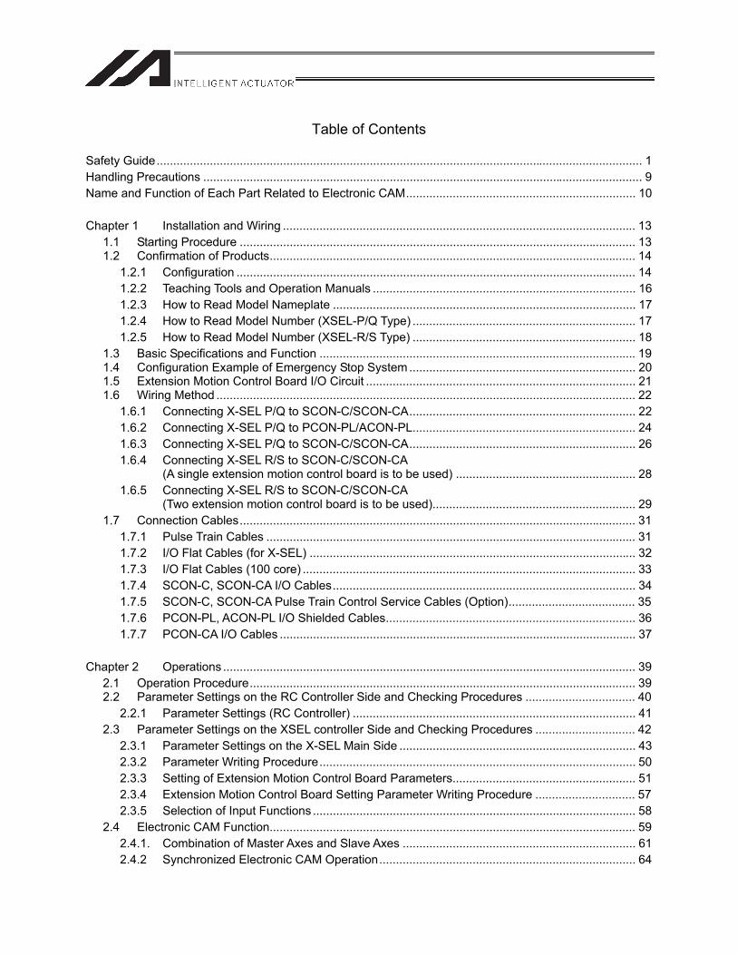
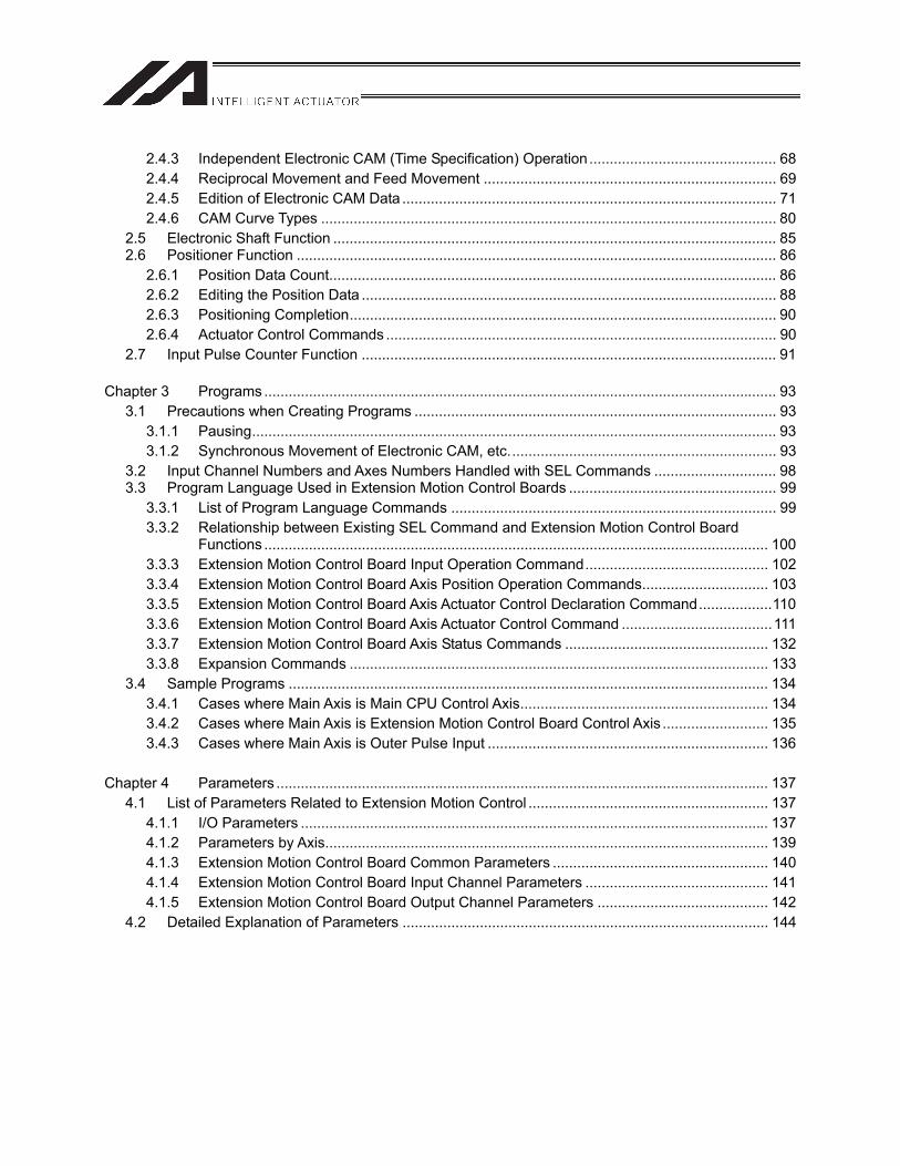
Table of Contents
Safety Guide.................................................................................................................................................. 1 Handling Precautions .................................................................................................................................... 9Name and Function of Each Part Related to Electronic CAM..................................................................... 10
Chapter 1 Installation and Wiring .......................................................................................................... 131.1 Starting Procedure ....................................................................................................................... 131.2 Confirmation of Products.............................................................................................................. 14
1.2.1 Configuration ........................................................................................................................ 141.2.2 Teaching Tools and Operation Manuals ............................................................................... 161.2.3 How to Read Model Nameplate ........................................................................................... 171.2.4 How to Read Model Number (XSEL-P/Q Type) ................................................................... 171.2.5 How to Read Model Number (XSEL-R/S Type) ................................................................... 18
1.3 Basic Specifications and Function ............................................................................................... 191.4 Configuration Example of Emergency Stop System .................................................................... 201.5 Extension Motion Control Board I/O Circuit ................................................................................. 211.6 Wiring Method .............................................................................................................................. 22
1.6.1 Connecting X-SEL P/Q to SCON-C/SCON-CA.................................................................... 221.6.2 Connecting X-SEL P/Q to PCON-PL/ACON-PL................................................................... 241.6.3 Connecting X-SEL P/Q to SCON-C/SCON-CA.................................................................... 261.6.4 Connecting X-SEL R/S to SCON-C/SCON-CA
(A single extension motion control board is to be used) ...................................................... 281.6.5 Connecting X-SEL R/S to SCON-C/SCON-CA
(Two extension motion control board is to be used)............................................................. 291.7 Connection Cables....................................................................................................................... 31
1.7.1 Pulse Train Cables ............................................................................................................... 311.7.2 I/O Flat Cables (for X-SEL) .................................................................................................. 321.7.3 I/O Flat Cables (100 core) .................................................................................................... 331.7.4 SCON-C, SCON-CA I/O Cables........................................................................................... 341.7.5 SCON-C, SCON-CA Pulse Train Control Service Cables (Option)...................................... 351.7.6 PCON-PL, ACON-PL I/O Shielded Cables........................................................................... 361.7.7 PCON-CA I/O Cables ........................................................................................................... 37
Chapter 2 Operations ............................................................................................................................ 392.1 Operation Procedure.................................................................................................................... 392.2 Parameter Settings on the RC Controller Side and Checking Procedures ................................. 40
2.2.1 Parameter Settings (RC Controller) ..................................................................................... 412.3 Parameter Settings on the XSEL controller Side and Checking Procedures .............................. 42
2.3.1 Parameter Settings on the X-SEL Main Side ....................................................................... 432.3.2 Parameter Writing Procedure............................................................................................... 502.3.3 Setting of Extension Motion Control Board Parameters....................................................... 512.3.4 Extension Motion Control Board Setting Parameter Writing Procedure .............................. 572.3.5 Selection of Input Functions ................................................................................................. 58
2.4 Electronic CAM Function.............................................................................................................. 592.4.1. Combination of Master Axes and Slave Axes ...................................................................... 612.4.2 Synchronized Electronic CAM Operation............................................................................. 64
2.4.3 Independent Electronic CAM (Time Specification) Operation.............................................. 68 2.4.4 Reciprocal Movement and Feed Movement ........................................................................ 69 2.4.5 Edition of Electronic CAM Data ............................................................................................ 71 2.4.6 CAM Curve Types ................................................................................................................ 80
2.5 Electronic Shaft Function ............................................................................................................. 85 2.6 Positioner Function ...................................................................................................................... 86
2.6.1 Position Data Count.............................................................................................................. 86 2.6.2 Editing the Position Data ...................................................................................................... 88 2.6.3 Positioning Completion......................................................................................................... 90 2.6.4 Actuator Control Commands ................................................................................................ 90
2.7 Input Pulse Counter Function ...................................................................................................... 91 Chapter 3 Programs .............................................................................................................................. 93
3.1 Precautions when Creating Programs ......................................................................................... 93 3.1.1 Pausing................................................................................................................................. 93 3.1.2 Synchronous Movement of Electronic CAM, etc.................................................................. 93
3.2 Input Channel Numbers and Axes Numbers Handled with SEL Commands .............................. 98 3.3 Program Language Used in Extension Motion Control Boards ................................................... 99
3.3.1 List of Program Language Commands ................................................................................ 99 3.3.2 Relationship between Existing SEL Command and Extension Motion Control Board
Functions ............................................................................................................................ 100 3.3.3 Extension Motion Control Board Input Operation Command............................................. 102 3.3.4 Extension Motion Control Board Axis Position Operation Commands............................... 103 3.3.5 Extension Motion Control Board Axis Actuator Control Declaration Command..................110 3.3.6 Extension Motion Control Board Axis Actuator Control Command .....................................111 3.3.7 Extension Motion Control Board Axis Status Commands .................................................. 132 3.3.8 Expansion Commands ....................................................................................................... 133
3.4 Sample Programs ...................................................................................................................... 134 3.4.1 Cases where Main Axis is Main CPU Control Axis............................................................. 134 3.4.2 Cases where Main Axis is Extension Motion Control Board Control Axis .......................... 135 3.4.3 Cases where Main Axis is Outer Pulse Input ..................................................................... 136
Chapter 4 Parameters ......................................................................................................................... 137
4.1 List of Parameters Related to Extension Motion Control ........................................................... 137 4.1.1 I/O Parameters ................................................................................................................... 137 4.1.2 Parameters by Axis............................................................................................................. 139 4.1.3 Extension Motion Control Board Common Parameters ..................................................... 140 4.1.4 Extension Motion Control Board Input Channel Parameters ............................................. 141 4.1.5 Extension Motion Control Board Output Channel Parameters .......................................... 142
4.2 Detailed Explanation of Parameters .......................................................................................... 144
Chapter 5 Handling Errors................................................................................................................... 159
5.1 Troubleshooting.......................................................................................................................... 159 5.2 List of Error Codes ..................................................................................................................... 163
5.2.1 On Error Levels .................................................................................................................. 163 5.2.2 Errors Related to Extension Motion Control Boards (Secret Level and Message Level) .. 165 5.2.3 Errors Related to Extension Motion Control Boards (Movement Cancellation Level) ....... 166 5.2.4 Errors Related to Extension Motion Control Boards (Cold Start Cancellation Level) ........ 170
Chapter 6 Operations of X-SEL PC Software Extension Motion Control Functions ........................... 175
6.1 Supported Versions.................................................................................................................... 175 6.2 Setting Extension Motion Control Board Window ...................................................................... 175 6.3 Position Data Edit (Extension Motion Control Board) Window .................................................. 190

1
Safety Guide“Safety Guide” has been written to use the machine safely and so prevent personal injury or property damage beforehand. Make sure to read it before the operation of this product.
Safety Precautions for Our Products The common safety precautions for the use of any of our robots in each operation.
No. OperationDescription Description
1 Model Selection
This product has not been planned and designed for the application where high level of safety is required, so the guarantee of the protection of human life is impossible. Accordingly, do not use it in any of the following applications. 1) Medical equipment used to maintain, control or otherwise affect human
life or physical health. 2) Mechanisms and machinery designed for the purpose of moving or
transporting people (For vehicle, railway facility or air navigation facility)3) Important safety parts of machinery (Safety device, etc.)
Do not use the product outside the specifications. Failure to do so may considerably shorten the life of the product.
Do not use it in any of the following environments. 1) Location where there is any inflammable gas, inflammable object or
explosive2) Place with potential exposure to radiation 3) Location with the ambient temperature or relative humidity exceeding
the specification range 4) Location where radiant heat is added from direct sunlight or other large
heat source 5) Location where condensation occurs due to abrupt temperature
changes 6) Location where there is any corrosive gas (sulfuric acid or hydrochloric
acid) 7) Location exposed to significant amount of dust, salt or iron powder 8) Location subject to direct vibration or impact
For an actuator used in vertical orientation, select a model which is equipped with a brake. If selecting a model with no brake, the moving part may drop when the power is turned OFF and may cause an accident such as an injury or damage on the work piece.
2
No. OperationDescription Description
2 Transportation When carrying a heavy object, do the work with two or more persons or utilize equipment such as crane.
When the work is carried out with 2 or more persons, make it clear who is to be the leader and who to be the follower(s) and communicate well with each other to ensure the safety of the workers.
When in transportation, consider well about the positions to hold, weight and weight balance and pay special attention to the carried object so it would not get hit or dropped.
Transport it using an appropriate transportation measure. The actuators available for transportation with a crane have eyebolts attached or there are tapped holes to attach bolts. Follow the instructions in the operation manual for each model.
Do not step or sit on the package. Do not put any heavy thing that can deform the package, on it. When using a crane capable of 1t or more of weight, have an operator who has qualifications for crane operation and sling work.
When using a crane or equivalent equipments, make sure not to hang a load that weighs more than the equipment’s capability limit.
Use a hook that is suitable for the load. Consider the safety factor of the hook in such factors as shear strength.
Do not get on the load that is hung on a crane. Do not leave a load hung up with a crane. Do not stand under the load that is hung up with a crane.
3 Storage and Preservation
The storage and preservation environment conforms to the installation environment. However, especially give consideration to the prevention of condensation.
Store the products with a consideration not to fall them over or drop due to an act of God such as earthquake.
4 Installation and Start
(1) Installation of Robot Main Body and Controller, etc. Make sure to securely hold and fix the product (including the work part). A fall, drop or abnormal motion of the product may cause a damage or injury.Also, be equipped for a fall-over or drop due to an act of God such as earthquake.
Do not get on or put anything on the product. Failure to do so may cause an accidental fall, injury or damage to the product due to a drop of anything, malfunction of the product, performance degradation, or shortening of its life.
When using the product in any of the places specified below, provide a sufficient shield. 1) Location where electric noise is generated 2) Location where high electrical or magnetic field is present 3) Location with the mains or power lines passing nearby 4) Location where the product may come in contact with water, oil or
chemical droplets
3
No. OperationDescription Description
(2) Cable Wiring Use our company’s genuine cables for connecting between the actuator and controller, and for the teaching tool.
Do not scratch on the cable. Do not bend it forcibly. Do not pull it. Do not coil it around. Do not insert it. Do not put any heavy thing on it. Failure to do so may cause a fire, electric shock or malfunction due to leakage or continuity error.
Perform the wiring for the product, after turning OFF the power to the unit, so that there is no wiring error.
When the direct current power (+24V) is connected, take the great care of the directions of positive and negative poles. If the connection direction is not correct, it might cause a fire, product breakdown or malfunction.
Connect the cable connector securely so that there is no disconnection or looseness. Failure to do so may cause a fire, electric shock or malfunction of the product.
Never cut and/or reconnect the cables supplied with the product for the purpose of extending or shortening the cable length. Failure to do so may cause the product to malfunction or cause fire.
4 Installation and Start
(3) Grounding The grounding operation should be performed to prevent an electric shock or electrostatic charge, enhance the noise-resistance ability and control the unnecessary electromagnetic radiation.
For the ground terminal on the AC power cable of the controller and the grounding plate in the control panel, make sure to use a twisted pair cable with wire thickness 0.5mm2 (AWG20 or equivalent) or more for grounding work. For security grounding, it is necessary to select an appropriate wire thickness suitable for the load. Perform wiring that satisfies the specifications (electrical equipment technical standards).
Perform Class D Grounding (former Class 3 Grounding with ground resistance 100 or below).
4
No. OperationDescription Description
4 Installation and Start
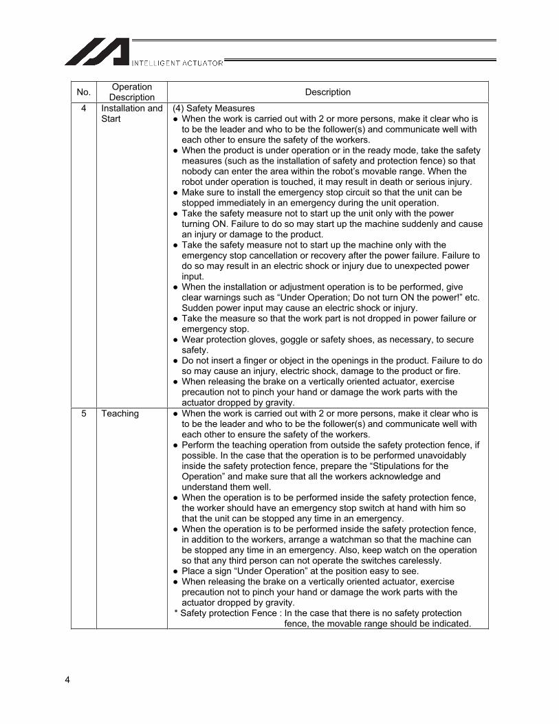
(4) Safety Measures When the work is carried out with 2 or more persons, make it clear who is to be the leader and who to be the follower(s) and communicate well with each other to ensure the safety of the workers.
When the product is under operation or in the ready mode, take the safety measures (such as the installation of safety and protection fence) so that nobody can enter the area within the robot’s movable range. When the robot under operation is touched, it may result in death or serious injury.
Make sure to install the emergency stop circuit so that the unit can be stopped immediately in an emergency during the unit operation.
Take the safety measure not to start up the unit only with the power turning ON. Failure to do so may start up the machine suddenly and cause an injury or damage to the product.
Take the safety measure not to start up the machine only with the emergency stop cancellation or recovery after the power failure. Failure to do so may result in an electric shock or injury due to unexpected power input.
When the installation or adjustment operation is to be performed, give clear warnings such as “Under Operation; Do not turn ON the power!” etc. Sudden power input may cause an electric shock or injury.
Take the measure so that the work part is not dropped in power failure or emergency stop.
Wear protection gloves, goggle or safety shoes, as necessary, to secure safety.
Do not insert a finger or object in the openings in the product. Failure to do so may cause an injury, electric shock, damage to the product or fire.
When releasing the brake on a vertically oriented actuator, exercise precaution not to pinch your hand or damage the work parts with the actuator dropped by gravity.
5 Teaching When the work is carried out with 2 or more persons, make it clear who is to be the leader and who to be the follower(s) and communicate well with each other to ensure the safety of the workers.
Perform the teaching operation from outside the safety protection fence, if possible. In the case that the operation is to be performed unavoidably inside the safety protection fence, prepare the “Stipulations for the Operation” and make sure that all the workers acknowledge and understand them well.
When the operation is to be performed inside the safety protection fence, the worker should have an emergency stop switch at hand with him so that the unit can be stopped any time in an emergency.
When the operation is to be performed inside the safety protection fence, in addition to the workers, arrange a watchman so that the machine can be stopped any time in an emergency. Also, keep watch on the operation so that any third person can not operate the switches carelessly.
Place a sign “Under Operation” at the position easy to see. When releasing the brake on a vertically oriented actuator, exercise precaution not to pinch your hand or damage the work parts with the actuator dropped by gravity.
* Safety protection Fence : In the case that there is no safety protection fence, the movable range should be indicated.
5
No. OperationDescription Description
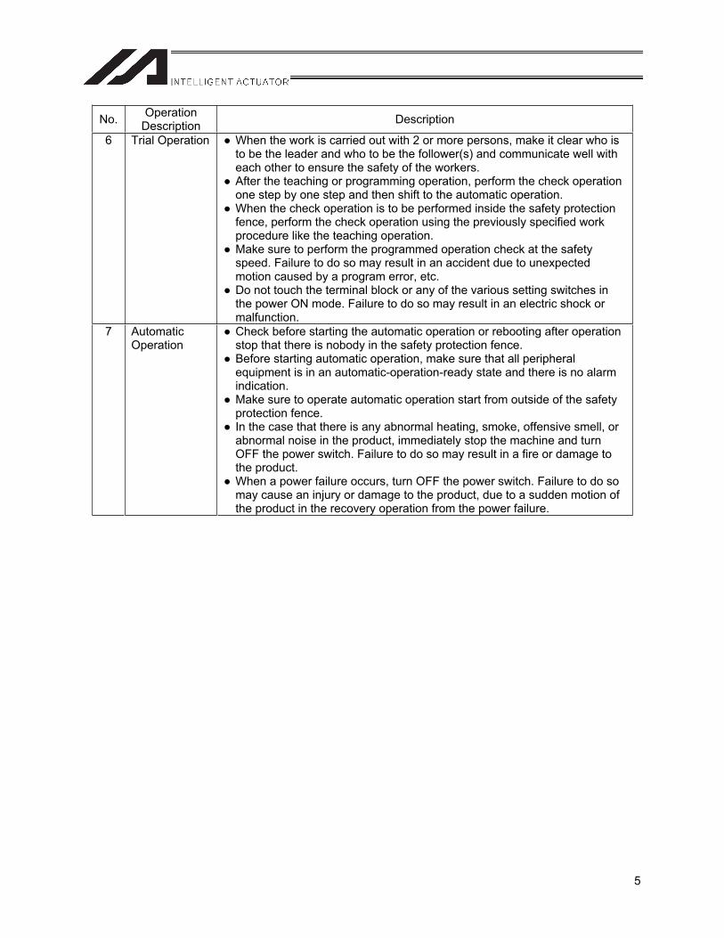
6 Trial Operation When the work is carried out with 2 or more persons, make it clear who is to be the leader and who to be the follower(s) and communicate well with each other to ensure the safety of the workers.
After the teaching or programming operation, perform the check operation one step by one step and then shift to the automatic operation.
When the check operation is to be performed inside the safety protection fence, perform the check operation using the previously specified work procedure like the teaching operation.
Make sure to perform the programmed operation check at the safety speed. Failure to do so may result in an accident due to unexpected motion caused by a program error, etc.
Do not touch the terminal block or any of the various setting switches in the power ON mode. Failure to do so may result in an electric shock or malfunction.
7 Automatic Operation
Check before starting the automatic operation or rebooting after operation stop that there is nobody in the safety protection fence.
Before starting automatic operation, make sure that all peripheral equipment is in an automatic-operation-ready state and there is no alarm indication.
Make sure to operate automatic operation start from outside of the safety protection fence.
In the case that there is any abnormal heating, smoke, offensive smell, or abnormal noise in the product, immediately stop the machine and turn OFF the power switch. Failure to do so may result in a fire or damage to the product.
When a power failure occurs, turn OFF the power switch. Failure to do so may cause an injury or damage to the product, due to a sudden motion of the product in the recovery operation from the power failure.
6
No. OperationDescription Description
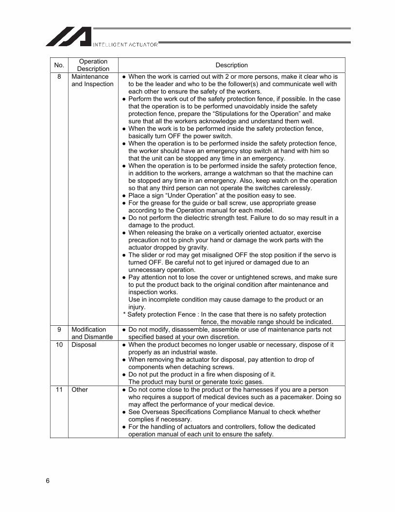
8 Maintenance and Inspection
When the work is carried out with 2 or more persons, make it clear who is to be the leader and who to be the follower(s) and communicate well with each other to ensure the safety of the workers.
Perform the work out of the safety protection fence, if possible. In the case that the operation is to be performed unavoidably inside the safety protection fence, prepare the “Stipulations for the Operation” and make sure that all the workers acknowledge and understand them well.
When the work is to be performed inside the safety protection fence, basically turn OFF the power switch.
When the operation is to be performed inside the safety protection fence, the worker should have an emergency stop switch at hand with him so that the unit can be stopped any time in an emergency.
When the operation is to be performed inside the safety protection fence, in addition to the workers, arrange a watchman so that the machine can be stopped any time in an emergency. Also, keep watch on the operation so that any third person can not operate the switches carelessly.
Place a sign “Under Operation” at the position easy to see. For the grease for the guide or ball screw, use appropriate grease according to the Operation manual for each model.
Do not perform the dielectric strength test. Failure to do so may result in a damage to the product.
When releasing the brake on a vertically oriented actuator, exercise precaution not to pinch your hand or damage the work parts with the actuator dropped by gravity.
The slider or rod may get misaligned OFF the stop position if the servo is turned OFF. Be careful not to get injured or damaged due to an unnecessary operation.
Pay attention not to lose the cover or untightened screws, and make sure to put the product back to the original condition after maintenance and inspection works. Use in incomplete condition may cause damage to the product or an injury.
* Safety protection Fence : In the case that there is no safety protection fence, the movable range should be indicated.
9 Modification and Dismantle
Do not modify, disassemble, assemble or use of maintenance parts not specified based at your own discretion.
10 Disposal When the product becomes no longer usable or necessary, dispose of it properly as an industrial waste.
When removing the actuator for disposal, pay attention to drop of components when detaching screws.
Do not put the product in a fire when disposing of it. The product may burst or generate toxic gases.
11 Other Do not come close to the product or the harnesses if you are a person who requires a support of medical devices such as a pacemaker. Doing so may affect the performance of your medical device.
See Overseas Specifications Compliance Manual to check whether complies if necessary.
For the handling of actuators and controllers, follow the dedicated operation manual of each unit to ensure the safety.
7
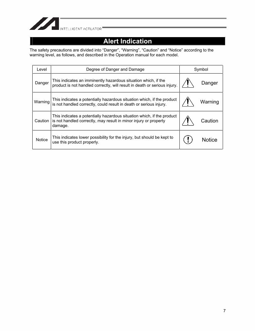
Alert Indication The safety precautions are divided into “Danger”, “Warning”, “Caution” and “Notice” according to the warning level, as follows, and described in the Operation manual for each model.
Level Degree of Danger and Damage Symbol
Danger This indicates an imminently hazardous situation which, if the product is not handled correctly, will result in death or serious injury. Danger
Warning This indicates a potentially hazardous situation which, if the product is not handled correctly, could result in death or serious injury. Warning
Caution This indicates a potentially hazardous situation which, if the product is not handled correctly, may result in minor injury or property damage.
Caution
Notice This indicates lower possibility for the injury, but should be kept to use this product properly. Notice

8

9
Handling Precautions
1. Precautions on Wiring
[1] It should be handled according to the operation manual for the XSEL-P/Q or R/S controller and RC controller. Make sure to implement countermeasures against noise for electric devices sharing the same power supply or within the same equipment.
[2] RC controllers shall be connected to the same 24-VDC power as a general rule. Our PS24 products can be connected in parallel, but if commercially available DC power supply units are to be used, connect each controller’s power supply to common ground (0 V).
[3] Wire the emergency stop to the X-SEL-P/Q controller and each RC controller in the same system such that the emergency stop signal is input to the X-SEL-P/Q controller and each RC controller at the same time. If a command from the X-SEL controller enters in the emergency stop status on the RC controller side only when the servo is turned on, the error No. 458 "Pulse train driver servo OFF error during pulse I/O board axis servo ON” occurs.
Power supply 1
Power supply 2
(common)
Emergency stop on!

10
Edit the electric cam table, position data, program, etc.
PC software
RC axis RC axis RC axis
Up to 16 axes can be controlled. * With the use of 2 pulse I/O boards
Cartesian robot
Extensionmotioncontrolboard
DIOboard
MainCPUboard
Electric cam/ positioner operation (pulse train command)
RC axis operation command from the SEL program, etc.
* It is possible to use the electronic CAM function with the XSEL-P/Q controller only. (Refer to 2.3.2)
PIO control of the RC controller (such as home return and servo ON/OFF operations)
Name and Function of Each Part Related to Electronic CAM
Incorporating the extension motion control board in the I/O slots of the XSEL-P/Q or R/S controller, enables the operator to control the electronic CAM and other functions from the SEL program. There are two methods for operation; 1) controlling XSEL-P/Q or R/S axes, or 2) controlling external controller units (SCON-C, SCON-CA, PCON-CA, ACON-PL, or PCON-PL). (In this manual, from this point forward the XSEL-P/Q controller or R/S controller is referred as “X-SEL” and the external controller as “RC controller”,)
System Overview
X-SEL
ACONSCON PCON
11
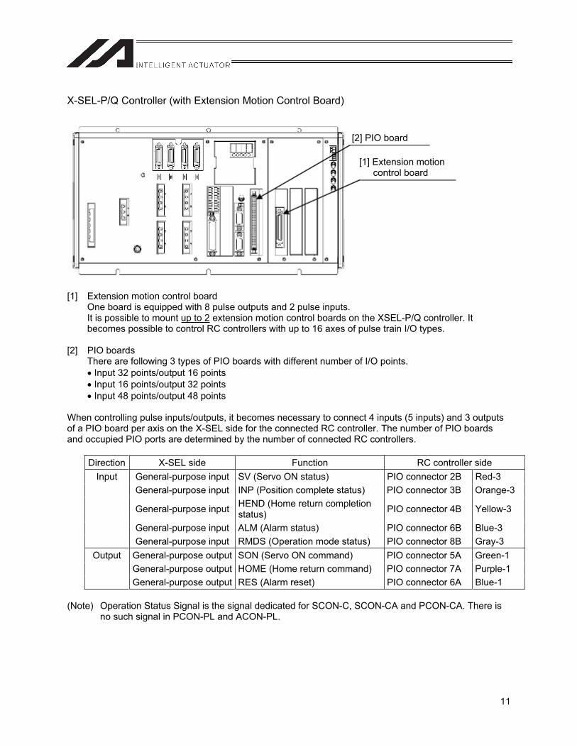
X-SEL-P/Q Controller (with Extension Motion Control Board)
[1] Extension motion control board One board is equipped with 8 pulse outputs and 2 pulse inputs. It is possible to mount up to 2 extension motion control boards on the XSEL-P/Q controller. It becomes possible to control RC controllers with up to 16 axes of pulse train I/O types.
[2] PIO boards There are following 3 types of PIO boards with different number of I/O points. Input 32 points/output 16 points Input 16 points/output 32 points Input 48 points/output 48 points
When controlling pulse inputs/outputs, it becomes necessary to connect 4 inputs (5 inputs) and 3 outputs of a PIO board per axis on the X-SEL side for the connected RC controller. The number of PIO boards and occupied PIO ports are determined by the number of connected RC controllers.
Direction X-SEL side Function RC controller side Input General-purpose input SV (Servo ON status) PIO connector 2B Red-3
General-purpose input INP (Position complete status) PIO connector 3B Orange-3
General-purpose input HEND (Home return completion status) PIO connector 4B Yellow-3
General-purpose input ALM (Alarm status) PIO connector 6B Blue-3 General-purpose input RMDS (Operation mode status) PIO connector 8B Gray-3
Output General-purpose output SON (Servo ON command) PIO connector 5A Green-1 General-purpose output HOME (Home return command) PIO connector 7A Purple-1 General-purpose output RES (Alarm reset) PIO connector 6A Blue-1
(Note) Operation Status Signal is the signal dedicated for SCON-C, SCON-CA and PCON-CA. There is no such signal in PCON-PL and ACON-PL.
[2] PIO board
[1] Extension motion control board

12
Chapter 1 Installation and W
iring
13
Chapter 1 Installation and Wiring
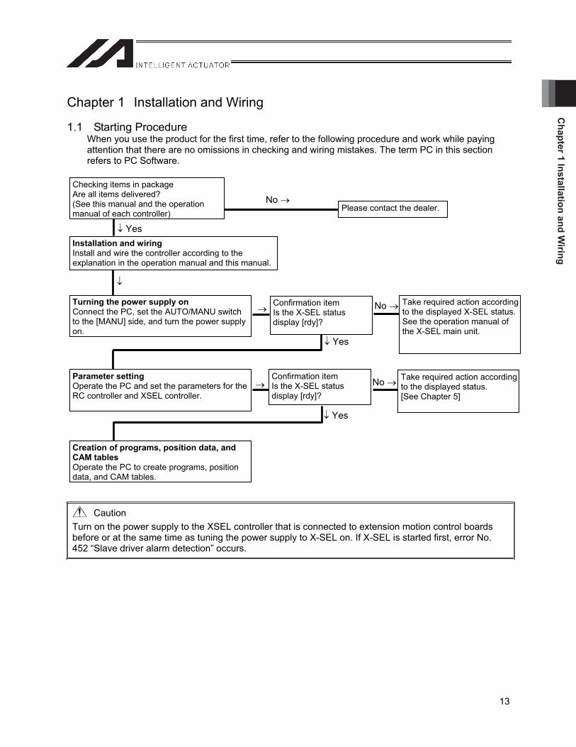
1.1 Starting Procedure When you use the product for the first time, refer to the following procedure and work while paying attention that there are no omissions in checking and wiring mistakes. The term PC in this section refers to PC Software.
Caution Turn on the power supply to the XSEL controller that is connected to extension motion control boards before or at the same time as tuning the power supply to X-SEL on. If X-SEL is started first, error No. 452 “Slave driver alarm detection” occurs.
Yes
No
No
No
Yes
Please contact the dealer.
Checking items in package Are all items delivered? (See this manual and the operation manual of each controller)
Installation and wiring Install and wire the controller according to the explanation in the operation manual and this manual.
Turning the power supply on Connect the PC, set the AUTO/MANU switch to the [MANU] side, and turn the power supply on.
Confirmation item Is the X-SEL status display [rdy]?
Take required action according to the displayed X-SEL status.See the operation manual of the X-SEL main unit.
Parameter setting Operate the PC and set the parameters for the RC controller and XSEL controller.
Confirmation item Is the X-SEL status display [rdy]?
Take required action according to the displayed status. [See Chapter 5]
Creation of programs, position data, and CAM tables Operate the PC to create programs, position data, and CAM tables.
Yes
Cha
pter
1 In
stal
latio
n an
d W
iring
14
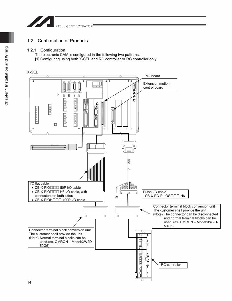
1.2 Confirmation of Products
1.2.1 Configuration The electronic CAM is configured in the following two patterns. [1] Configuring using both X-SEL and RC controller or RC controller only
X-SEL
Connecter terminal block conversion unit The customer shall provide the unit. (Note) Normal terminal blocks can be
used.(ex. OMRON – Model:XW2D-50G6)
Connector terminal block conversion unit The customer shall provide the unit. (Note) The connector can be disconnected
and normal terminal blocks can be used. (ex. OMRON – Model:XW2D-50G6)
RC controller
Pulse I/O cable CB-X-PQ-PLIOS H6
PIO board
Extension motion control board
I/O flat cable CB-X-PIO 50P I/O cable CB-X-PIO H6 I/O cable, with connectors on both sides
CB-X-PIOH 100P I/O cable

Chapter 1 Installation and W
iring
15
[2] Configuring with X-SEL only
X-SEL main unit
The pulse train command of the extension motion control board control axis shall be output to the main CPU control axis. With this setting, the actuator operates (positioning and synchronization (synchronization of electronic cam, etc.)) following the extension motion control board output pulses as a slave. This eliminates the wiring of extension motion control board and PIO board (except for connection with external devices).
X-SEL main unit
Caution The number of main CPU control axes which can be specified as a slave to the extension motion control board using the XSEL-R/S controller, is up to seven per board (All eight axes cannot be specified as slaves). When all eight axes are specified, the error No. 527: Extension motion control board pulse output setting parameter error will occur. In order to operate all eight axes as slaves, two extension motion control boards are required.
PIO board
Extension motion control board
Wiring not required
Main CPU control axis
Main CPU control axis Driver
Extensionmotion control board
Actuator
Command
Cha
pter
1 In
stal
latio
n an
d W
iring
16
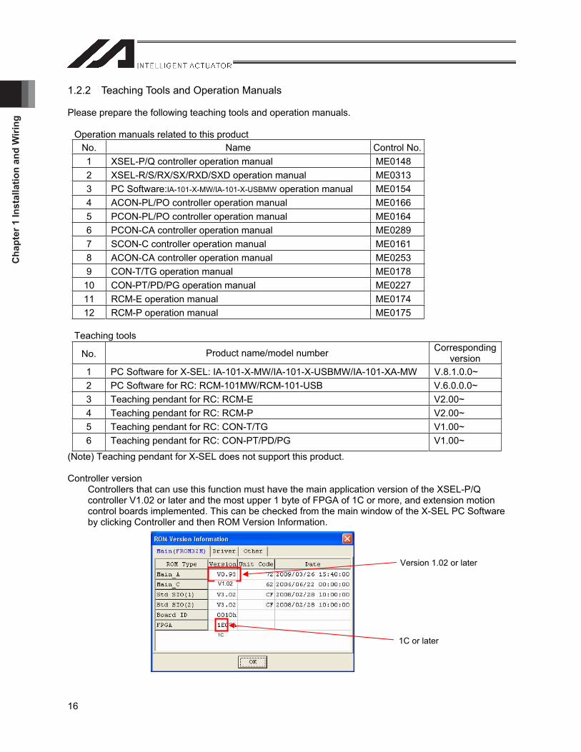
1.2.2 Teaching Tools and Operation Manuals
Please prepare the following teaching tools and operation manuals.
Operation manuals related to this product No. Name Control No. 1 XSEL-P/Q controller operation manual ME0148 2 XSEL-R/S/RX/SX/RXD/SXD operation manual ME0313 3 PC Software:IA-101-X-MW/IA-101-X-USBMW operation manual ME01544 ACON-PL/PO controller operation manual ME0166 5 PCON-PL/PO controller operation manual ME0164 6 PCON-CA controller operation manual ME0289 7 SCON-C controller operation manual ME0161 8 ACON-CA controller operation manual ME0253 9 CON-T/TG operation manual ME0178 10 CON-PT/PD/PG operation manual ME0227 11 RCM-E operation manual ME0174 12 RCM-P operation manual ME0175
Teaching tools
(Note) Teaching pendant for X-SEL does not support this product.
Controller version Controllers that can use this function must have the main application version of the XSEL-P/Q controller V1.02 or later and the most upper 1 byte of FPGA of 1C or more, and extension motion control boards implemented. This can be checked from the main window of the X-SEL PC Software by clicking Controller and then ROM Version Information.
No. Product name/model number Corresponding version
1 PC Software for X-SEL: IA-101-X-MW/IA-101-X-USBMW/IA-101-XA-MW V.8.1.0.0~ 2 PC Software for RC: RCM-101MW/RCM-101-USB V.6.0.0.0~ 3 Teaching pendant for RC: RCM-E V2.00~ 4 Teaching pendant for RC: RCM-P V2.00~ 5 Teaching pendant for RC: CON-T/TG V1.00~ 6 Teaching pendant for RC: CON-PT/PD/PG V1.00~
Version 1.02 or later
1C or later
V1.02
1C
Chapter 1 Installation and W
iring
17
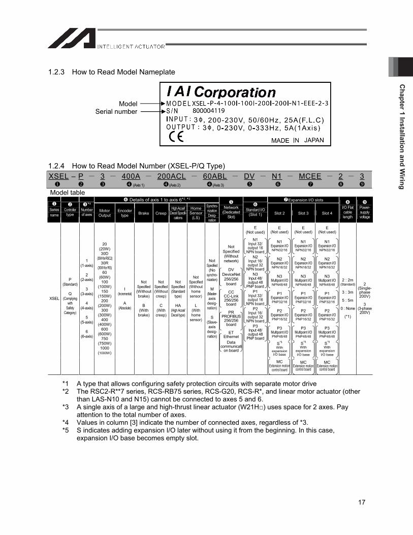
1.2.3 How to Read Model Nameplate
1.2.4 How to Read Model Number (XSEL-P/Q Type)
*1 A type that allows configuring safety protection circuits with separate motor drive *2 The RSC2-R**7 series, RCS-RB75 series, RCS-G20, RCS-R*, and linear motor actuator (other
than LAS-N10 and N15) cannot be connected to axes 5 and 6. *3 A single axis of a large and high-thrust linear actuator (W21H ) uses space for 2 axes. Pay
attention to the total number of axes. *4 Values in column [3] indicate the number of connected axes, regardless of *3. *5 S indicates adding expansion I/O later without using it from the beginning. In this case,
expansion I/O base becomes empty slot.
ModelSerial number
XSEL – P 3 400A 200ACL 60ABL DV N1 MCEE 2 3 (Axis 1) (Axis 2) (Axis 3)
Model table Details of axis 1 to axis 6*2, *3 Expansion I/O slots
Series name
Controller type
*4
Number of axes
Motor Output
Encoder type Brake Creep
High Accel/Decel Specifi-
cations
Home Sensor
(LS)
Synchro-nization Desig- nation
Network (Dedicated
Slot)
Standard I/O(Slot 1) Slot 2 Slot 3 Slot 4
I/O Flat cablelength
Power-supply voltage
E(Not used)
E(Not used)
E(Not used)
E(Not used)
N1 Input 32/ output 16
NPN board
N1 Expansion I/ONPN32/16
N1 Expansion I/ONPN32/16
N1 Expansion I/ONPN32/16
N2 Input 16/ output 32
NPN board
N2 Expansion I/ONPN16/32
N2 Expansion I/ONPN16/32
N2 Expansion I/ONPN16/32
N3 Input 48/ output 48
PNP board
N3 Multipoint I/ONPN48/48
N3 Multipoint I/ONPN48/48
N3 Multipoint I/ONPN48/48
P1Input 32/ output 16
NPN board
P1Expansion I/OPNP32/16
P1Expansion I/OPNP32/16
P1Expansion I/OPNP32/16
P2Input 16/ output 32
NPN board
P2Expansion I/OPNP16/32
P2Expansion I/OPNP16/32
P2Expansion I/OPNP16/32
P3Input 48/ output 48
PNP board
P3Multipoint I/OPNP48/48
P3Multipoint I/OPNP48/48
P3Multipoint I/OPNP48/48
S*5
With expansion I/O base
S*5
With expansion I/O base
S*5
With expansion I/O base
XSEL
P(Standard)
Q(Complying
with Safety
Category)
1(1-axis)
2(2-axis)
3(3-axis)
4(4-axis)
5(5-axis)
6(6-axis)
20(20W) 30D
(30W for RSC2) 30R
(30W for RS) 60
(60W) 100
(100W) 150
(150W) 200
(200W) 300
(300W) 400
(400W) 600
(600W) 750
(750W) 1000
(1000W)
I(Incremental)
A(Absolute)
Not Specified(Without brake)
B(With brake)
Not Specified(Without creep)
C(With creep)
Not Specified(Standard
type)
HA (High Accel/Decel type)
Not Specified(Without
home sensor)
L(With home
sensor)
NotSpecified(No
synchro-nization)
M(Master-axis
desig-nation)
S(Slave-axis
desig-nation)
Not Specified(Without network)
DV DeviceNet 256/256board
CCCC-Link256/256board
PR PROFIBUS
256/256board
ET Ethernet
Data communicati
on board
MCExtension motion
control board
MCExtension motion
control board
MCExtension motion
control board
2 : 2m(Standard)
3 : 3m
5 : 5m
0 : None
(*1)
2(Single-phase 200V)
3(3-phase200V)
Cha
pter
1 In
stal
latio
n an
d W
iring
18
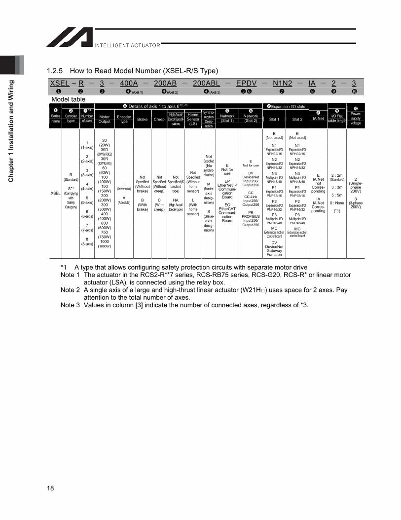
1.2.5 How to Read Model Number (XSEL-R/S Type)
*1 A type that allows configuring safety protection circuits with separate motor drive Note 1 The actuator in the RCS2-R**7 series, RCS-RB75 series, RCS-G20, RCS-R* or linear motor
actuator (LSA), is connected using the relay box.Note 2 A single axis of a large and high-thrust linear actuator (W21H ) uses space for 2 axes. Pay
attention to the total number of axes. Note 3 Values in column [3] indicate the number of connected axes, regardless of *3.
XSEL – R 3 400A 200AB 200ABL EPDV N1N2 IA 2 3 (Axis 1) (Axis 2) (Axis 3)
Model table Details of axis 1 to axis 6*2, *3 Expansion I/O slots
Series name
Controller type
*4
Number of axes
Motor Output
Encoder type Brake Creep
High Accel/Decel Specifi-
cations
Home Sensor
(LS)
Synchro-nization Desig- nation
Network (Slot 1)
Network(Slot 2) Slot 1 Slot 2 IA Net I/O Flat
cable length
Power- supply voltage
E(Not used)
E(Not used)
N1 Expansion I/ONPN32/16
N1 Expansion I/ONPN32/16
N2 Expansion I/ONPN16/32
N2 Expansion I/ONPN16/32
N3 Multipoint I/ONPN48/48
N3 Multipoint I/ONPN48/48
P1Expansion I/OPNP32/16
P1Expansion I/OPNP32/16
P2Expansion I/OPNP16/32
P2Expansion I/OPNP16/32
P3Multipoint I/OPNP48/48
P3Multipoint I/OPNP48/48
MCExtension motion
control board
MCExtension motion
control board
XSEL
R(Standard)
S*1
(Complying with
Safety Category)
1(1-axis)
2(2-axis)
3(3-axis)
4(4-axis)
5(5-axis)
6(6-axis)
7(7-axis)
8(8-axis)
20(20W) 30D
(30W for RSC2) 30R
(30W for RS) 60
(60W) 100
(100W) 150
(150W) 200
(200W) 300
(300W) 400
(400W) 600
(600W) 750
(750W) 1000
(1000W)
I(Incremental)
A(Absolute)
Not Specified(Without brake)
B(With brake)
Not Specified(Without creep)
C(With creep)
Not Specified(S
tandard type)
HA (High Accel/Decel type)
Not Specified(Without
home sensor)
L(With home
sensor)
NotSpecified(No
synchro-nization)
M(Master-axis
desig-nation)
S(Slave-axis
desig-nation)
ENot for
use
EPEtherNet/IPCommuni-
cation Board
EC EtherCATCommuni-
cation Board
ENot for use
DVDeviceNetInput256/ Output256
CCCC-Link Input256/ Output256
PRPROFIBUSInput256/ Output256
DV DeviceNet Gateway Function
EIA Net
notCorres-ponding
IAIA NetCorres-ponding
2 : 2m(Standard)
3 : 3m
5 : 5m
0 : None
(*1)
2(Single-phase 200V)
3(3-phase200V)
Chapter 1 Installation and W
iring
19
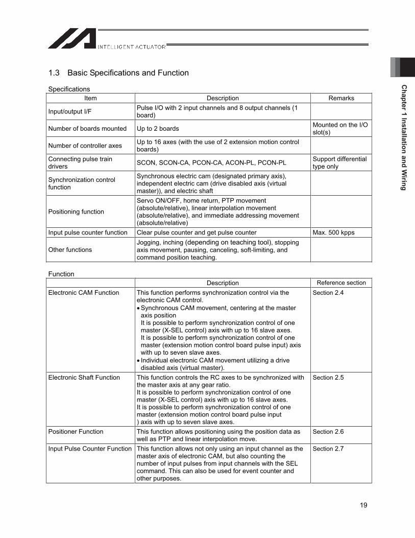
1.3 Basic Specifications and Function
Specifications Item Description Remarks
Input/output I/F Pulse I/O with 2 input channels and 8 output channels (1 board)
Number of boards mounted Up to 2 boards Mounted on the I/O slot(s)
Number of controller axes Up to 16 axes (with the use of 2 extension motion control boards)
Connecting pulse train drivers SCON, SCON-CA, PCON-CA, ACON-PL, PCON-PL Support differential
type only
Synchronization control function
Synchronous electric cam (designated primary axis), independent electric cam (drive disabled axis (virtual master)), and electric shaft
Positioning function
Servo ON/OFF, home return, PTP movement (absolute/relative), linear interpolation movement (absolute/relative), and immediate addressing movement (absolute/relative)
Input pulse counter function Clear pulse counter and get pulse counter Max. 500 kpps
Other functions Jogging, inching (depending on teaching tool), stopping axis movement, pausing, canceling, soft-limiting, and command position teaching.
Function Description Reference section
Electronic CAM Function This function performs synchronization control via the electronic CAM control. Synchronous CAM movement, centering at the master axis position It is possible to perform synchronization control of one master (X-SEL control) axis with up to 16 slave axes. It is possible to perform synchronization control of one master (extension motion control board pulse input) axis with up to seven slave axes. Individual electronic CAM movement utilizing a drive disabled axis (virtual master).
Section 2.4
Electronic Shaft Function This function controls the RC axes to be synchronized with the master axis at any gear ratio. It is possible to perform synchronization control of one master (X-SEL control) axis with up to 16 slave axes. It is possible to perform synchronization control of one master (extension motion control board pulse input ) axis with up to seven slave axes.
Section 2.5
Positioner Function This function allows positioning using the position data as well as PTP and linear interpolation move.
Section 2.6
Input Pulse Counter Function This function allows not only using an input channel as the master axis of electronic CAM, but also counting the number of input pulses from input channels with the SEL command. This can also be used for event counter and other purposes.
Section 2.7
Cha
pter
1 In
stal
latio
n an
d W
iring
20
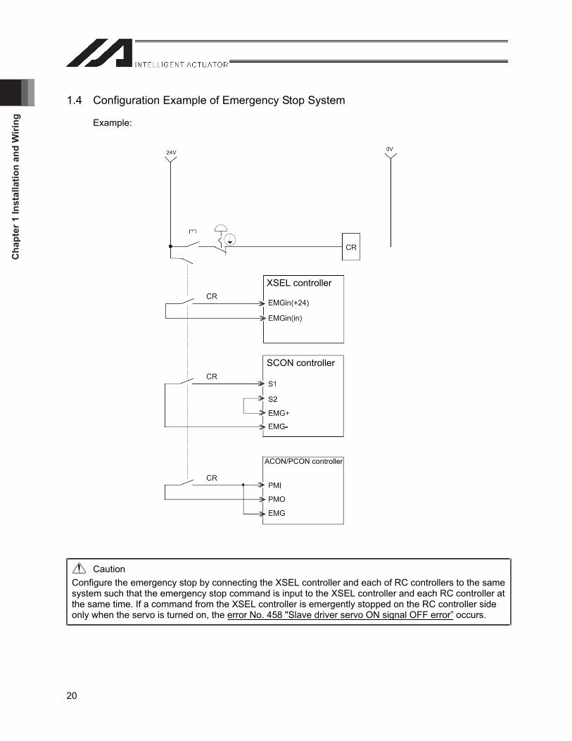
1.4 Configuration Example of Emergency Stop System
Example:
Caution Configure the emergency stop by connecting the XSEL controller and each of RC controllers to the same system such that the emergency stop command is input to the XSEL controller and each RC controller at the same time. If a command from the XSEL controller is emergently stopped on the RC controller side only when the servo is turned on, the error No. 458 "Slave driver servo ON signal OFF error” occurs.
XSEL controller
SCON controller
ACON/PCON controller
Chapter 1 Installation and W
iring
21
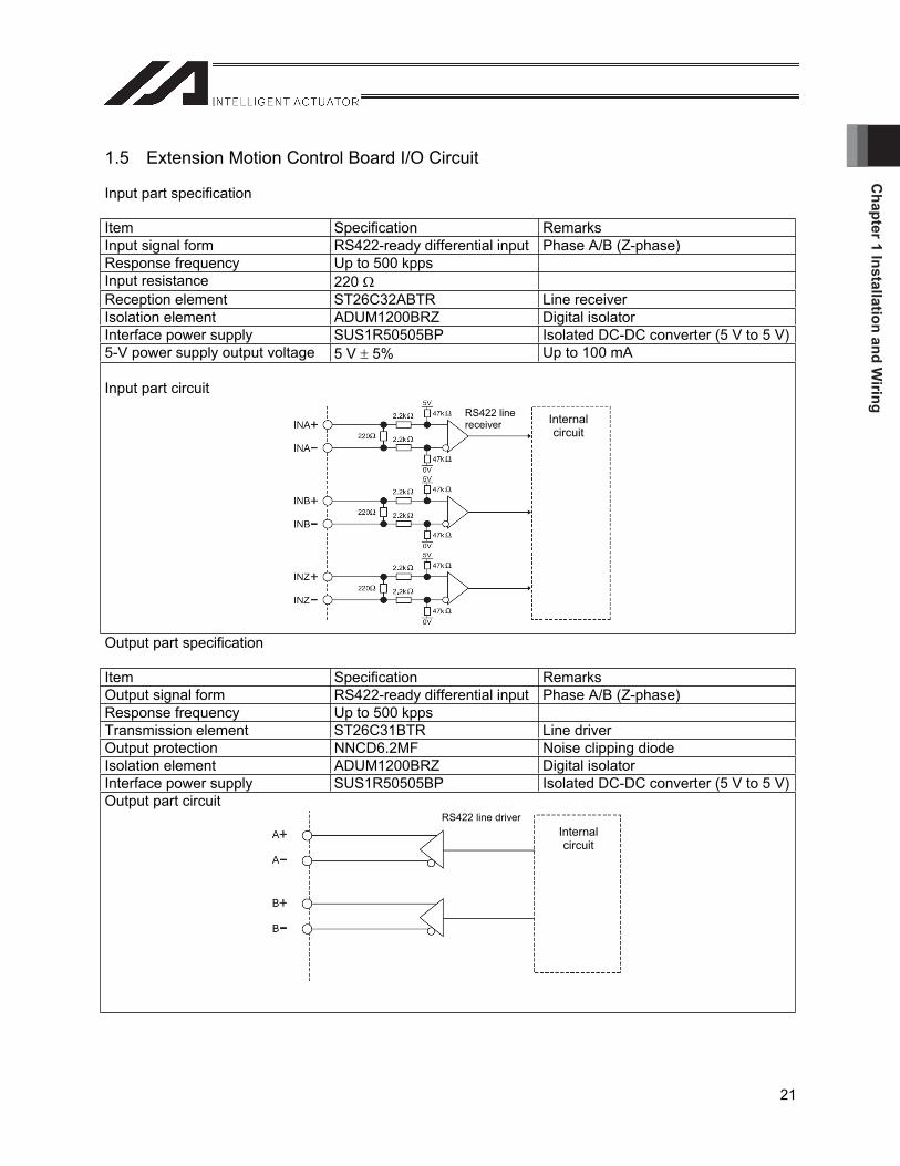
1.5 Extension Motion Control Board I/O Circuit
Input part specification
Item Specification Remarks Input signal form RS422-ready differential input Phase A/B (Z-phase) Response frequency Up to 500 kpps Input resistance 220Reception element ST26C32ABTR Line receiver Isolation element ADUM1200BRZ Digital isolator Interface power supply SUS1R50505BP Isolated DC-DC converter (5 V to 5 V)5-V power supply output voltage 5 V 5% Up to 100 mA
Input part circuit
Output part specification
Item Specification Remarks Output signal form RS422-ready differential input Phase A/B (Z-phase) Response frequency Up to 500 kpps Transmission element ST26C31BTR Line driver Output protection NNCD6.2MF Noise clipping diode Isolation element ADUM1200BRZ Digital isolator Interface power supply SUS1R50505BP Isolated DC-DC converter (5 V to 5 V)Output part circuit
RS422 line receiver Internal
circuit
Internalcircuit
RS422 line driver
Cha
pter
1 In
stal
latio
n an
d W
iring
22
1.6 Wiring Method
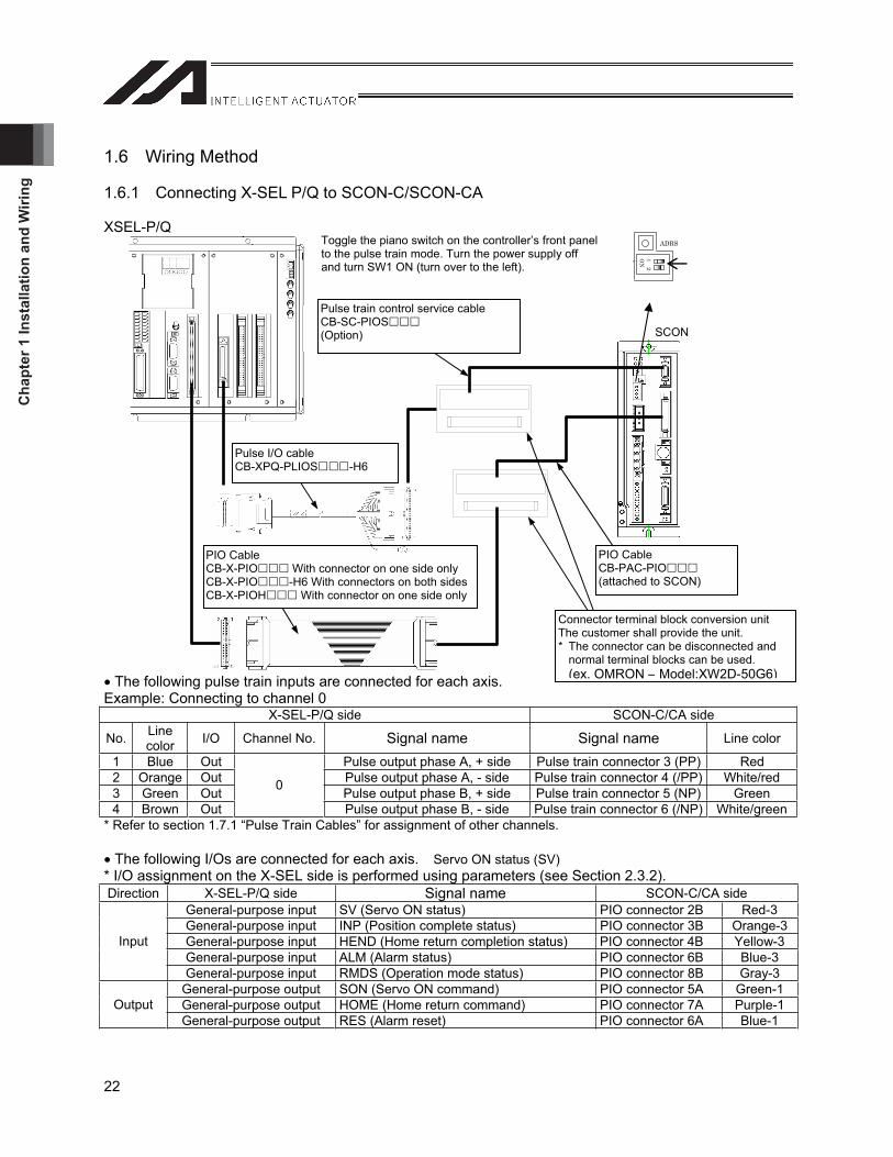
1.6.1 Connecting X-SEL P/Q to SCON-C/SCON-CA
XSEL-P/Q
The following pulse train inputs are connected for each axis. Example: Connecting to channel 0
X-SEL-P/Q side SCON-C/CA side
No. Line color I/O Channel No. Signal name Signal name Line color
1 Blue Out Pulse output phase A, + side Pulse train connector 3 (PP) Red 2 Orange Out Pulse output phase A, - side Pulse train connector 4 (/PP) White/red 3 Green Out Pulse output phase B, + side Pulse train connector 5 (NP) Green 4 Brown Out
0
Pulse output phase B, - side Pulse train connector 6 (/NP) White/green* Refer to section 1.7.1 “Pulse Train Cables” for assignment of other channels.
The following I/Os are connected for each axis. Servo ON status (SV)* I/O assignment on the X-SEL side is performed using parameters (see Section 2.3.2). Direction X-SEL-P/Q side Signal name SCON-C/CA side
General-purpose input SV (Servo ON status) PIO connector 2B Red-3 General-purpose input INP (Position complete status) PIO connector 3B Orange-3General-purpose input HEND (Home return completion status) PIO connector 4B Yellow-3General-purpose input ALM (Alarm status) PIO connector 6B Blue-3
Input
General-purpose input RMDS (Operation mode status) PIO connector 8B Gray-3 General-purpose output SON (Servo ON command) PIO connector 5A Green-1 General-purpose output HOME (Home return command) PIO connector 7A Purple-1OutputGeneral-purpose output RES (Alarm reset) PIO connector 6A Blue-1
Pulse train control service cable CB-SC-PIOS(Option)
12
ON
ADRS
PIO Cable CB-X-PIO With connector on one side only CB-X-PIO -H6 With connectors on both sidesCB-X-PIOH With connector on one side only
Toggle the piano switch on the controller’s front panel to the pulse train mode. Turn the power supply off and turn SW1 ON (turn over to the left).
SCON
Connector terminal block conversion unit The customer shall provide the unit. * The connector can be disconnected and
normal terminal blocks can be used.(ex. OMRON – Model:XW2D-50G6)
PIO Cable CB-PAC-PIO(attached to SCON)
Pulse I/O cable CB-XPQ-PLIOS -H6
Chapter 1 Installation and W
iring
23
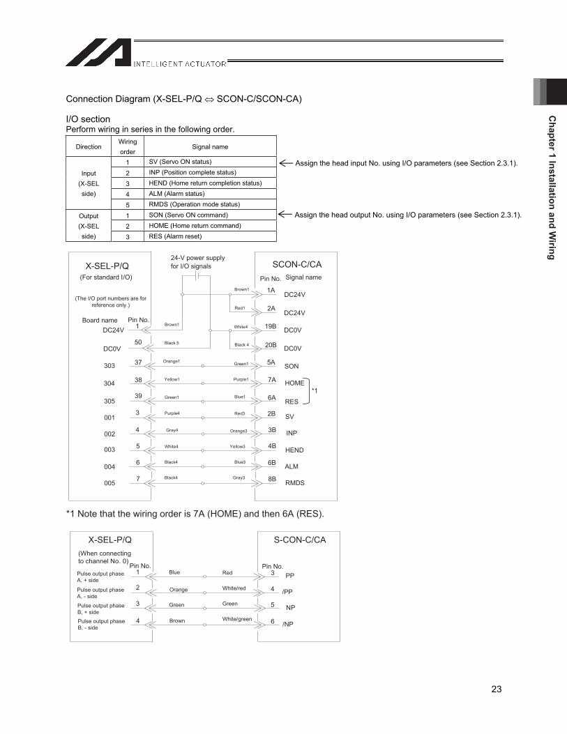
Connection Diagram (X-SEL-P/Q SCON-C/SCON-CA)
I/O section Perform wiring in series in the following order.
Direction Wiring order
Signal name
1 SV (Servo ON status)
2 INP (Position complete status)
3 HEND (Home return completion status)
4 ALM (Alarm status)
Input (X-SEL side)
5 RMDS (Operation mode status)
1 SON (Servo ON command)
2 HOME (Home return command) Output (X-SEL side) 3 RES (Alarm reset)
Assign the head input No. using I/O parameters (see Section 2.3.1).
Assign the head output No. using I/O parameters (see Section 2.3.1).
*1 Note that the wiring order is 7A (HOME) and then 6A (RES).
DC24V
DC0V
001
HOME
SV
RES
ALM
INP
HEND
SCON-C/CA24-V power supply for I/O signals
1 Brown1
50 Black 5
X-SEL-P/Q
DC24V
DC0V
3
4
37
5
38
39
002
003
303
304
305
Orange1
Yellow1
Green1
Black4
Purple4
Gray4
SON
(The I/O port numbers are for reference only.)
004 6
DC24V
DC0V
1A
2A
19B
20B
5A
6A
7A
2B
3B
4B
6B
005 7 8B RMDS
Brown1
Red1
White4
Black 4
Green1
Purple1
Blue1
Red3
Orange3
Yellow3
Blue3
Gray3
(For standard I/O)
White4
Black4
4White/red
3Red
6
Green 5
White/green
BluePulse output phase A, + side
Brown
Green
/PP
PP
/NP
NP
Orange
X-SEL-P/Q
1
2
3
4
S-CON-C/CA
Pulse output phase A, - side
Pulse output phase B, + sidePulse output phase B, - side
(When connecting to channel No. 0)
*1
Pin No.
Pin No.
Pin No. Pin No.
Board name
Signal name
Cha
pter
1 In
stal
latio
n an
d W
iring
24
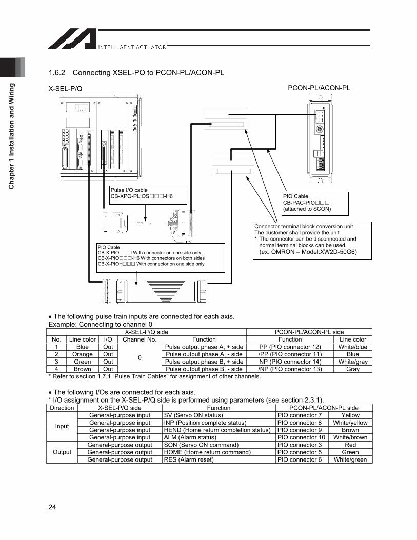
1.6.2 Connecting XSEL-PQ to PCON-PL/ACON-PL
X-SEL-P/Q
The following pulse train inputs are connected for each axis. Example: Connecting to channel 0
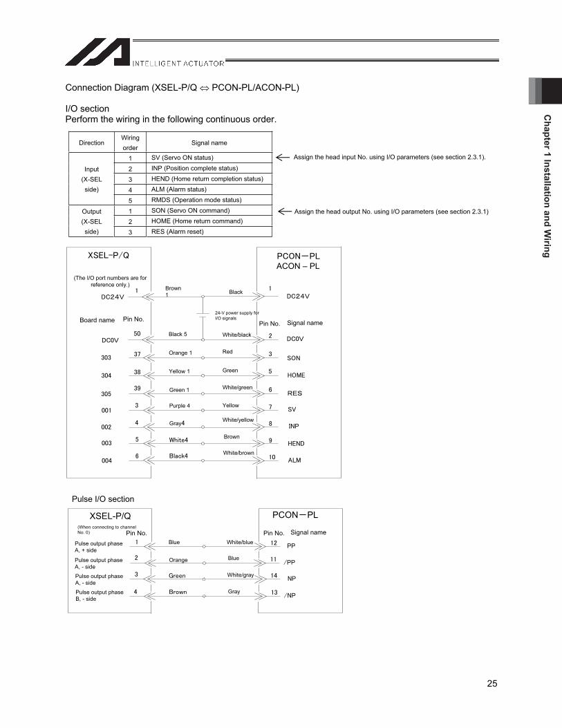
X-SEL-P/Q side PCON-PL/ACON-PL side No. Line color I/O Channel No. Function Function Line color1 Blue Out Pulse output phase A, + side PP (PIO connector 12) White/blue2 Orange Out Pulse output phase A, - side /PP (PIO connector 11) Blue 3 Green Out Pulse output phase B, + side NP (PIO connector 14) White/gray4 Brown Out
0
Pulse output phase B, - side /NP (PIO connector 13) Gray * Refer to section 1.7.1 “Pulse Train Cables” for assignment of other channels.
The following I/Os are connected for each axis. * I/O assignment on the X-SEL-P/Q side is performed using parameters (see section 2.3.1). Direction X-SEL-P/Q side Function PCON-PL/ACON-PL side
General-purpose input SV (Servo ON status) PIO connector 7 Yellow General-purpose input INP (Position complete status) PIO connector 8 White/yellowGeneral-purpose input HEND (Home return completion status) PIO connector 9 Brown Input
General-purpose input ALM (Alarm status) PIO connector 10 White/brownGeneral-purpose output SON (Servo ON command) PIO connector 3 Red General-purpose output HOME (Home return command) PIO connector 5 Green OutputGeneral-purpose output RES (Alarm reset) PIO connector 6 White/green
Connector terminal block conversion unit The customer shall provide the unit. * The connector can be disconnected and
normal terminal blocks can be used.(ex. OMRON – Model:XW2D-50G6)
PIO Cable CB-PAC-PIO(attached to SCON)
Pulse I/O cable CB-XPQ-PLIOS -H6
PIO Cable CB-X-PIO With connector on one side only CB-X-PIO -H6 With connectors on both sides CB-X-PIOH With connector on one side only
PCON-PL/ACON-PL
Chapter 1 Installation and W
iring
25
Connection Diagram (XSEL-P/Q PCON-PL/ACON-PL)
I/O section Perform the wiring in the following continuous order.
Pulse I/O section
Assign the head input No. using I/O parameters (see section 2.3.1).
Assign the head output No. using I/O parameters (see section 2.3.1)
Direction Wiring order
Signal name
1 SV (Servo ON status)
2 INP (Position complete status)
3 HEND (Home return completion status)
4 ALM (Alarm status)
Input (X-SEL side)
5 RMDS (Operation mode status)
1 SON (Servo ON command)
2 HOME (Home return command) Output (X-SEL side) 3 RES (Alarm reset)
Black
White/black
Red
Green
White/green
Yellow
White/yellow
Brown
24-V power supply for I/O signals
Brown 1
Black 5
White/brown
Orange 1
Yellow 1
Green 1
Purple 4
Gray
(The I/O port numbers are for reference only.)
PCON PL
Blue
Orange Blue
White/blue
Gray
White/gray
Pulse output phase A, + side
XSEL-P/Q
Pulse output phase A, - side
Pulse output phase A, - side
Pulse output phase B, - side
(When connecting to channel No. 0)
Pin No.Pin No.
Pin No. Pin No.
Board name Signal name
Signal name
ACON – PL
Cha
pter
1 In
stal
latio
n an
d W
iring
26
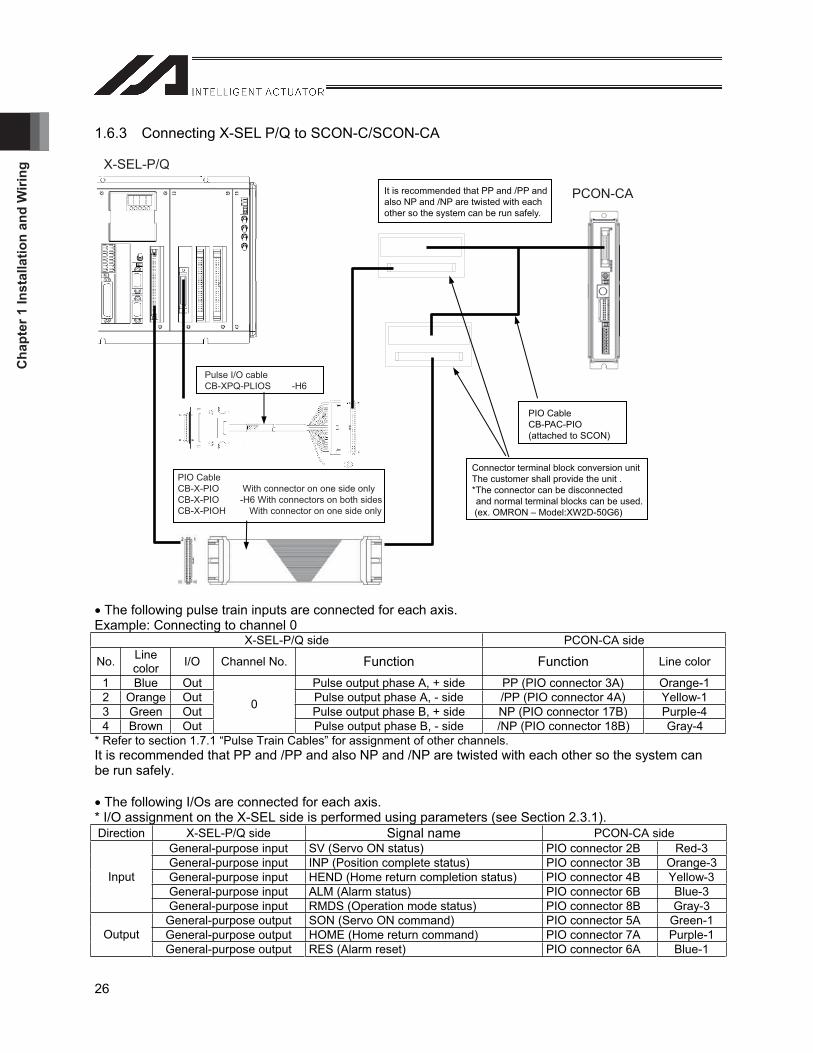
1.6.3 Connecting X-SEL P/Q to SCON-C/SCON-CA
X-SEL-P/Q
PCON-CA
Pulse I/O cableCB-XPQ-PLIOS -H6
PIO CableCB-X-PIO With connector on one side onlyCB-X-PIO -H6 With connectors on both sidesCB-X-PIOH With connector on one side only
PIO CableCB-PAC-PIO(attached to SCON)
Connector terminal block conversion unitThe customer shall provide the unit .*The connector can be disconnected and normal terminal blocks can be used.
(ex. OMRON – Model:XW2D-50G6)
It is recommended that PP and /PP andalso NP and /NP are twisted with eachother so the system can be run safely.
The following pulse train inputs are connected for each axis. Example: Connecting to channel 0
X-SEL-P/Q side PCON-CA side
No. Line color I/O Channel No. Function Function Line color
1 Blue Out Pulse output phase A, + side PP (PIO connector 3A) Orange-1 2 Orange Out Pulse output phase A, - side /PP (PIO connector 4A) Yellow-1 3 Green Out Pulse output phase B, + side NP (PIO connector 17B) Purple-4 4 Brown Out
0
Pulse output phase B, - side /NP (PIO connector 18B) Gray-4 * Refer to section 1.7.1 “Pulse Train Cables” for assignment of other channels. It is recommended that PP and /PP and also NP and /NP are twisted with each other so the system can be run safely.
The following I/Os are connected for each axis. * I/O assignment on the X-SEL side is performed using parameters (see Section 2.3.1). Direction X-SEL-P/Q side Signal name PCON-CA side
General-purpose input SV (Servo ON status) PIO connector 2B Red-3 General-purpose input INP (Position complete status) PIO connector 3B Orange-3General-purpose input HEND (Home return completion status) PIO connector 4B Yellow-3General-purpose input ALM (Alarm status) PIO connector 6B Blue-3
Input
General-purpose input RMDS (Operation mode status) PIO connector 8B Gray-3 General-purpose output SON (Servo ON command) PIO connector 5A Green-1 General-purpose output HOME (Home return command) PIO connector 7A Purple-1OutputGeneral-purpose output RES (Alarm reset) PIO connector 6A Blue-1
Chapter 1 Installation and W
iring
27
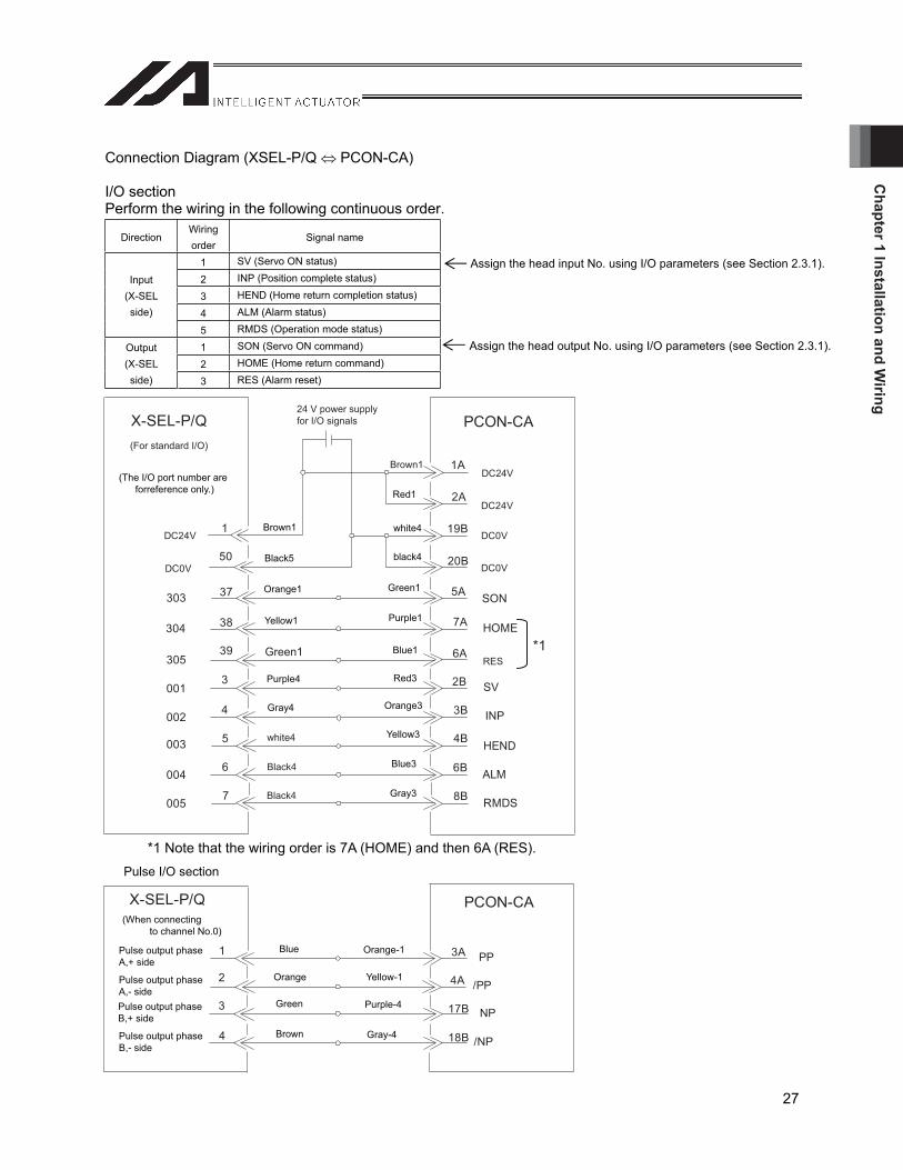
Connection Diagram (XSEL-P/Q PCON-CA)
I/O section Perform the wiring in the following continuous order.
Direction Wiring order
Signal name
1 SV (Servo ON status)
2 INP (Position complete status)
3 HEND (Home return completion status)
4 ALM (Alarm status)
Input (X-SEL side)
5 RMDS (Operation mode status)
1 SON (Servo ON command)
2 HOME (Home return command) Output (X-SEL side) 3 RES (Alarm reset)
Assign the head input No. using I/O parameters (see Section 2.3.1).
Assign the head output No. using I/O parameters (see Section 2.3.1).
DC24V
DC0V
001
HOME
SV
RES
ALM
INP
HEND
PCON-CA24 V power supplyfor I/O signals
1
50
X-SEL-P/Q
DC24V
DC0V
3
4
37
5
38
39
002
003
303
304
305Green1
white4
Black4
SON
0046
DC24V
DC0V
1A
2A
19B
20B
5A
6A
7A
2B
3B
4B
6B
Black4005
7 8B RMDS
Brown1
(For standard I/O)
4A
3A
18B
17B
/PP
PP
/NP
NP
X-SEL-P/Q
1
2
3
4
PCON-CA
*1
(The I/O port number are forreference only.)
Brown1
Black5
Orange1
Yellow1
Purple4
Gray4
Red1
white4
black4
Green1
Purple1
Blue1
Red3
Orange3
Yellow3
Blue3
Gray3
(When connecting to channel No.0)
Pulse output phaseA,+ side
Pulse output phaseA,- sidePulse output phaseB,+ side
Pulse output phaseB,- side
Blue
Orange
Green
Brown
Orange-1
Yellow-1
Purple-4
Gray-4
*1 Note that the wiring order is 7A (HOME) and then 6A (RES).Pulse I/O section

Cha
pter
1 In
stal
latio
n an
d W
iring
28
1.6.4 Connecting X-SEL R/S to SCON-C/SCON-CA (A single extension motion control board is to be used).
XSEL-R/S
12
ON
ADRS
SCON
I/O board
Toggle the piano switch on the controller’s front panel to the pulse train mode. Turn the power supply off and turn SW1 ON (turn over to the left).
Pulse train control service cableCB-SC-PIOS(Option)
PIO CableCB-X-PIO With connector on one side onlyCB-X-PIO -H6 With connectors on both sidesCB-X-PIOH With connector on one side only
Pulse I/O cableCB-XPQ-PLIOS -H6
PIO CableCB-PAC-PIO(attached to SCON)
Connector terminal block conversion unitThe customer shall provide the unit .*The connector can be disconnected and normal terminal blocks can be used.(ex. OMRON – Model:XW2D-50G6)
Extension Motion Control Board
The following pulse train inputs are connected for each axis. Example: Connecting to channel 0
X-SEL-R/S side SCON-C/CA side
No. Line color I/O Channel No. Signal name Signal name Line color
1 Blue Out Pulse output phase A, + side Pulse train connector 3 (PP) Red 2 Orange Out Pulse output phase A, - side Pulse train connector 4 (/PP) White/red 3 Green Out Pulse output phase B, + side Pulse train connector 5 (NP) Green 4 Brown Out
0
Pulse output phase B, - side Pulse train connector 6 (/NP) White/green* Refer to section 1.7.1 “Pulse Train Cables” for assignment of other channels.
The following I/Os are connected for each axis. Servo ON status (SV) * I/O assignment on the X-SEL side is performed using parameters (see Section 2.3.2). Direction X-SEL-R/S side Signal name SCON-C/CA side
General-purpose input SV (Servo ON status) PIO connector 2B Red-3 General-purpose input INP (Position complete status) PIO connector 3B Orange-3General-purpose input HEND (Home return completion status) PIO connector 4B Yellow-3General-purpose input ALM (Alarm status) PIO connector 6B Blue-3
Input
General-purpose input RMDS (Operation mode status) PIO connector 8B Gray-3 General-purpose output SON (Servo ON command) PIO connector 5A Green-1 General-purpose output HOME (Home return command) PIO connector 7A Purple-1OutputGeneral-purpose output RES (Alarm reset) PIO connector 6A Blue-1

Chapter 1 Installation and W
iring
29
1.6.5 Connecting X-SEL R/S to SCON-C/SCON-CA (Two extension motion control board is to be used).
XSEL-R/S
12
ON
ADRSSCON
Toggle the piano switch on the controller’s front panel to the pulse train mode.Turn the power supply off and turn SW1 ON (turn over to the left).
Pulse train control service cableCB-SC-PIOS(Option)
PIO CableCB-PAC-PIO(attached to SCON)
PIO CableCB-X-PIO With connector on one side onlyCB-X-PIO -H6 With connectors on both sidesCB-X-PIOH With connector on one side only
Connector terminal block conversion unitThe customer shall provide the unit .*The connector can be disconnected and normal terminal blocks can be used. (ex. OMRON – Model:XW2D-50G6)
Pulse I/O cableCB-XPQ-PLIOS -H6
Extension I/O board (to be connected using the IA net).
Terminal Resistance
Terminal Resistance
. . .
The following pulse train inputs are connected for each axis. Example: Connecting to channel 0
X-SEL-R/S side SCON-C/CA side
No. Line color I/O Channel No. Signal name Signal name Line color
1 Blue Out Pulse output phase A, + side Pulse train connector 3 (PP) Red 2 Orange Out Pulse output phase A, - side Pulse train connector 4 (/PP) White/red 3 Green Out Pulse output phase B, + side Pulse train connector 5 (NP) Green 4 Brown Out
0
Pulse output phase B, - side Pulse train connector 6 (/NP) White/green* Refer to section 1.7.1 “Pulse Train Cables” for assignment of other channels.
The following I/Os are connected for each axis. Servo ON status (SV) * I/O assignment on the X-SEL side is performed using parameters (see Section 2.3.2). Direction X-SEL-R/S side Signal name SCON-C/CA side
General-purpose input SV (Servo ON status) PIO connector 2B Red-3 General-purpose input INP (Position complete status) PIO connector 3B Orange-3General-purpose input HEND (Home return completion status) PIO connector 4B Yellow-3General-purpose input ALM (Alarm status) PIO connector 6B Blue-3
Input
General-purpose input RMDS (Operation mode status) PIO connector 8B Gray-3 General-purpose output SON (Servo ON command) PIO connector 5A Green-1 General-purpose output HOME (Home return command) PIO connector 7A Purple-1OutputGeneral-purpose output RES (Alarm reset) PIO connector 6A Blue-1
Cha
pter
1 In
stal
latio
n an
d W
iring
30
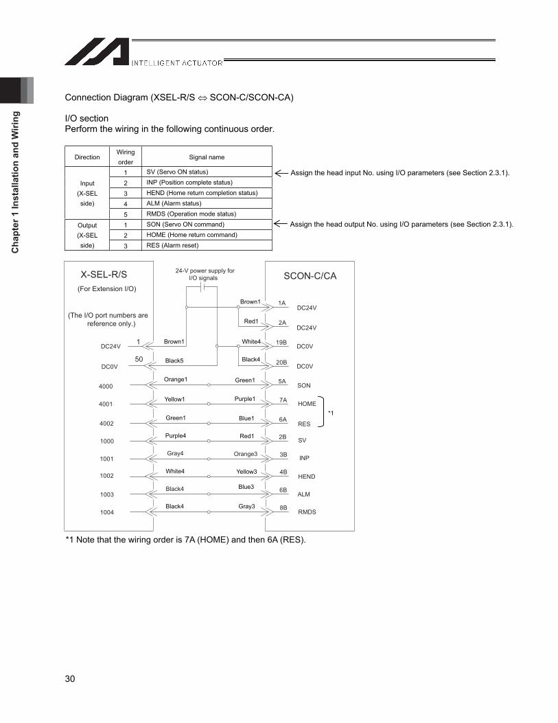
Connection Diagram (XSEL-R/S SCON-C/SCON-CA)
I/O section Perform the wiring in the following continuous order.
Direction Wiring order
Signal name
1 SV (Servo ON status)
2 INP (Position complete status)
3 HEND (Home return completion status)
4 ALM (Alarm status)
Input (X-SEL side)
5 RMDS (Operation mode status)
1 SON (Servo ON command)
2 HOME (Home return command) Output (X-SEL side) 3 RES (Alarm reset)
Assign the head input No. using I/O parameters (see Section 2.3.1).
Assign the head output No. using I/O parameters (see Section 2.3.1).
DC24V
DC0V
1000
HOME
SV
RES
ALM
INP
HEND
SCON-C/CA24-V power supply for I/O signals
1
50
X-SEL-R/S
DC24V
DC0V
1001
1002
4000
4001
4002
Black4
Gray4
SON
(The I/O port numbers are reference only.)
1003
DC24V
DC0V
1A
2A
19B
20B
5A
6A
7A
2B
3B
4B
6B
10048B
RMDS
Orange3
(For Extension I/O)
*1 Note that the wiring order is 7A (HOME) and then 6A (RES).
Brown1
Black5
Orange1
Yellow1
Green1
Purple4
White4
Black4
Brown1
Red1
White4
Black4
Green1
Purple1
Blue1
Red1
Yellow3
Blue3
Gray3
*1

Chapter 1 Installation and W
iring
31
1.7 Connection Cables
1.7.1 Pulse Train Cables
Type: CB-XPQ-PLIOS -H6* Specify the cable length for the part (e.g., specify CB-XPQ-PLIOS20-H6 for the cable length of 2 m).
Cable diagram
XSEL controller side RC controller side (See this table for the connection.)No. Line color Name Channel
No. Function No. Line color Name ChannelNo. Function
1 Green/white 2 RSV_COM1 - Do not connect anything. 1 Blue 0A+ Pulse output phase A, + side 2 Blue 0A+ Pulse output phase A, + side 2 Orange 0A- Pulse output phase A, - side 3 Orange 0A- Pulse output phase A, - side 3 Green 0B+ Pulse output phase B, + side 4 Green 0B+ Pulse output phase B, + side 4 Brown 0B-
0
Pulse output phase B, - side 5 Brown 0B-
0
Pulse output phase B, - side 5 Gray 2A+ Pulse output phase A, + side 6 Gray 2A+ Pulse output phase A, + side 6 Red 2A- Pulse output phase A, - side 7 Red 2A- Pulse output phase A, - side 7 Black 2B+ Pulse output phase B, + side 8 Black 2B+ Pulse output phase B, + side 8 Yellow 2B-
2
Pulse output phase B, - side 9 Yellow 2B-
2
Pulse output phase B, - side 9 Pink 4A+ Pulse output phase A, + side 10 Pink 4A+ Pulse output phase A, + side 10 Purple 4A- Pulse output phase A, - side 11 Purple 4A- Pulse output phase A, - side 11 White 4B+ Pulse output phase B, + side 12 White 4B+ Pulse output phase B, + side 12 Blue/red 1 4B-
4
Pulse output phase B, - side 13 Blue/red 1 4B-
4
Pulse output phase B, - side 13 Orange/white 1 6A+ Pulse output phase A, + side 14 Orange/white 1 6A+ Pulse output phase A, + side 14 Green/white 1 6A- Pulse output phase A, - side 15 Green/white 1 6A- Pulse output phase A, - side 15 Brown/white 1 6B+ Pulse output phase B, + side 16 Brown/white 1 6B+ Pulse output phase B, + side 16 Gray/white 1 6B-
6
Pulse output phase B, - side 17 Gray/white 1 6B-
6
Pulse output phase B, - side 17 Red/white 1 INA+0 Pulse output phase A, + side 18 Red/white 1 INA+0 Pulse output phase A, + side 18 Black/white 1 INA-0 Pulse output phase A, - side 19 Black/white 1 INA-0 Pulse output phase A, - side 19 Yellow/black 1 INB+0 Pulse output phase B, + side 20 Yellow/black 1 INB+0 Pulse output phase B, + side 20 Pink/black 1 INB-0 Pulse output phase B, - side 21 Pink/black 1 INB-0 Pulse output phase B, - side 21 Purple/white 1 INZ+0 Do not connect anything. 22 Purple/white 1 INZ+0 Do not connect anything. 22 White/blue 1 INZ-0 Do not connect anything. 23 White/blue 1 INZ-0 Do not connect anything. 23 Blue/red 2 E5V0 Encoder power supply output (5 VDC): Up to
100 mA 24 Blue/red 2 E5V0 Encoder power supply output (5 VDC): Up to
100 mA 24 Orange/white 2 E0V0
0
Encoder power supply ground
25 Orange/white 2 E0V0
0
Encoder power supply ground 25 Green/white 2 RSV_COM1 Do not connect anything. 26 Brown/white 2 RSV_COM2 - Do not connect anything. 26 Brown/white 2 RSV_COM2 - Do not connect anything. 27 Gray/white 2 1A+ Pulse output phase A, + side 27 Gray/white 2 1A+ Pulse output phase A, + side 28 Red/white 2 1A- Pulse output phase A, - side 28 Red/white 2 1A- Pulse output phase A, - side 29 Black/white 2 1B+ Pulse output phase B, + side 29 Black/white 2 1B+ Pulse output phase B, + side 30 Yellow/black 2 1B-
1
Pulse output phase B, - side 30 Yellow/black 2 1B-
1
Pulse output phase B, - side 31 Pink/black 2 3A+ Pulse output phase A, + side 31 Pink/black 2 3A+ Pulse output phase A, + side 32 Purple/white 2 3A- Pulse output phase A, - side 32 Purple/white 2 3A- Pulse output phase A, - side 33 White/blue 2 3B+ Pulse output phase B, + side 33 White/blue 2 3B+ Pulse output phase B, + side 34 Blue/black 1 3B-
3
Pulse output phase B, - side 34 Blue/black 1 3B-
3
Pulse output phase B, - side 35 Orange/black 1 5A+ Pulse output phase A, + side 35 Orange/black 1 5A+ Pulse output phase A, + side 36 Green/black 1 5A- Pulse output phase A, - side 36 Green/black 1 5A- Pulse output phase A, - side 37 Brown/black 1 5B+ Pulse output phase B, + side 37 Brown/black 1 5B+ Pulse output phase B, + side 38 Green/black 1 5B-
5
Pulse output phase B, - side 38 Green/black 1 5B-
5
Pulse output phase B, - side 39 Red/black 1 7A+ Pulse output phase A, + side 39 Red/black 1 7A+ Pulse output phase A, + side 40 Yellow/red 1 7A- Pulse output phase A, - side 40 Yellow/red 1 7A- Pulse output phase A, - side 41 Pink/red 1 7B+ Pulse output phase B, + side 41 Pink/red 1 7B+ Pulse output phase B, + side 42 Purple/black 1 7B-
7
Pulse output phase B, - side 42 Purple/black 1 7B-
7
Pulse output phase B, - side 43 White/black 1 INA+1 Pulse output phase A, + side 43 White/black 1 INA+1 Pulse output phase A, + side 44 Blue/black 2 INA-1 Pulse output phase A, - side 44 Blue/black 2 INA-1 Pulse output phase A, - side 45 Orange/black 2 INB+1 Pulse output phase B, + side 45 Orange/black 2 INB+1 Pulse output phase B, + side 46 Green /black 2 INB-1 Pulse output phase B, - side 46 Green /black 2 INB-1 Pulse output phase B, - side 47 Brown/black 2 INZ+1 Do not connect anything. 47 Brown/black 2 INZ+1 Do not connect anything. 48 Gray/black 2 INZ-1 Do not connect anything. 48 Gray/black 2 INZ-1 Do not connect anything. 49 Red/black 2 E5V1 Encoder power supply output (5 VDC): Up to
100 mA 49 Red/black 2 E5V1 Encoder power supply output (5 VDC): Up to 100 mA
50 Yellow/red 2 E0V1
1
Encoder power supply ground 50 Yellow/red 2 E0V1
1
Encoder power supply ground Connect shield to the hood with clamp. Connect the crimping terminal with shield.
XSEL controller side RC controller side
Plug connector: 10150-3000PE (Sumitomo 3M) Hood: 10350-52A0-008 (Sumitomo 3M)
Socket (with strain relief): XG4M-5030-T (Omron)Crimping terminal: V1.25-4 (J.S.T. Mfg.)

Cha
pter
1 In
stal
latio
n an
d W
iring
32
1.7.2 I/O Flat Cables (for X-SEL)
Type: CB-X-PIO* Specify the cable length for the part (e.g., specify CB-X-PIO020 for the cable length of 2 m).
Flat cable: KFX-50 (S) (color) (Kaneko Cord)
Socket (with strain relief): XG4M-5030-T (Omron)
Standard I/O Expansion I/O Pin No. Line color Port No.
(*)Function
I/O symbol N1/P1 Port No.
(*)Function
I/O symbol N2/P2 Port No. Function I/O symbol N1/P1
Function I/O symbol N2/P2
1 Brown 1 - External power supply of 24 V - External power supply of 24 V - External power supply of 24 V
External power supply of 24 V
2 Red 1 000 Program start 0003 Orange 1 001 001 4 Yellow 1 002 002 5 Green 1 003 003 6 Blue 1 004 004 7 Purple 1 005 005 8 Gray 1 006
General-purpose input
006
General-purpose input
9 White 1 007 Program specification (PRG No. 1) (general-purpose input) 007 Program specification (PRG No. 1) (general-
purpose input)
10 Black 1 008 Program specification (PRG No. 2) (general-purpose input) 008 Program specification (PRG No. 2) (general-
purpose input)
11 Brown 2 009 Program specification (PRG No. 4) (general-purpose input) 009 Program specification (PRG No. 4) (general-
purpose input)
12 Red 2 010 Program specification (PRG No. 8) (general-purpose input) 010 Program specification (PRG No. 8) (general-
purpose input)
13 Orange 2 011 Program specification (PRG No. 10) (general-purpose input) 011 Program specification (PRG No. 10)
(general-purpose input)
14 Yellow 2 012 Program specification (PRG No. 20) (general-purpose input) 012 Program specification (PRG No. 20)
(general-purpose input)
15 Green 2 013 Program specification (PRG No. 40) (general-purpose input) 013 Program specification (PRG No. 40)
(general-purpose input) 16 Blue 2 014 014 17 Purple 2 015 015
General-purpose input
General-purpose input
18 Gray 2 016 300 Alarm output 19 White 2 017 301 Ready output 20 Black 2 018 302 Emergency stop output 21 Brown 3 019 303 22 Red 3 020 304 23 Orange 3 021 305 24 Yellow 3 022 306 25 Green 3 023 307 26 Blue 3 024 308 27 Purple 3 024 309 28 Gray 3 025 310 29 White 3 026 311 30 Black 3 027 312 31 Brown 4 028 313 32 Red 4 029 314 33 Orange 4 030
General-purpose input
315
General-purpose input
34 Yellow 4 300 Alarm output 31635 Green 4 301 Ready output 31736 Blue 4 302 Emergency stop output 31837 Purple 4 303 319 38 Gray 4 304 320 39 White 4 305 321 40 Black 4 306 322 41 Brown 5 307 323 42 Red 5 308 324 43 Orange 5 309 325 44 Yellow 5 310 326 45 Green 5 311 327 46 Blue 5 312 328 47 Purple 5 313 329 48 Gray 5 314 330 49 White 5 315
General-purpose output
331
General-purpose output
Continued from
standard I/O
General-purpose output
General-purpose output
50 Black 5 - External power supply of 0 V - External power supply of 0 V External power supply of 0 V
External power supply of 0 V
* The port numbers can be changed by parameter settings.
Cut off
Flat cable (50 core)
Chapter 1 Installation and W
iring
33
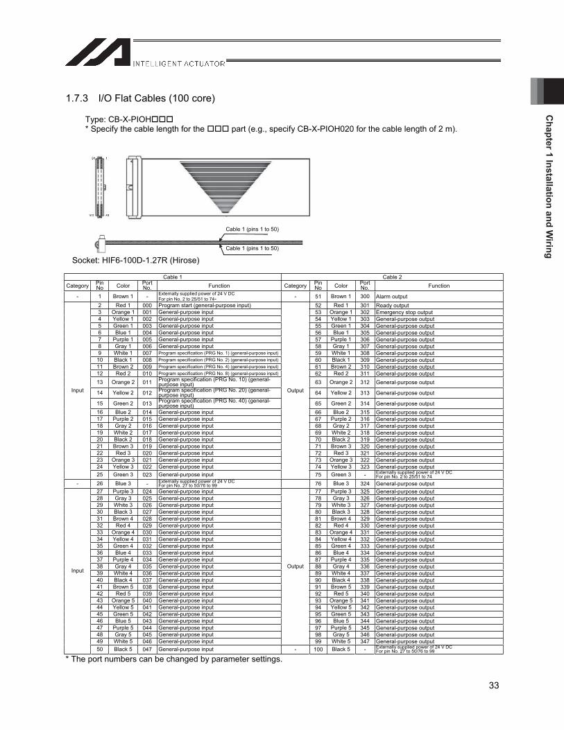
1.7.3 I/O Flat Cables (100 core)
Type: CB-X-PIOH* Specify the cable length for the part (e.g., specify CB-X-PIOH020 for the cable length of 2 m).
Socket: HIF6-100D-1.27R (Hirose)
Cable 1 Cable 2 Category Pin
No Color Port No. Function Category Pin
No Color Port No. Function
- 1 Brown 1 - Externally supplied power of 24 V DC For pin No. 2 to 25/51 to 74- - 51 Brown 1 300 Alarm output
2 Red 1 000 Program start (general-purpose input) 52 Red 1 301 Ready output 3 Orange 1 001 General-purpose input 53 Orange 1 302 Emergency stop output 4 Yellow 1 002 General-purpose input 54 Yellow 1 303 General-purpose output 5 Green 1 003 General-purpose input 55 Green 1 304 General-purpose output 6 Blue 1 004 General-purpose input 56 Blue 1 305 General-purpose output 7 Purple 1 005 General-purpose input 57 Purple 1 306 General-purpose output 8 Gray 1 006 General-purpose input 58 Gray 1 307 General-purpose output 9 White 1 007 Program specification (PRG No. 1) (general-purpose input) 59 White 1 308 General-purpose output
10 Black 1 008 Program specification (PRG No. 2) (general-purpose input) 60 Black 1 309 General-purpose output 11 Brown 2 009 Program specification (PRG No. 4) (general-purpose input) 61 Brown 2 310 General-purpose output 12 Red 2 010 Program specification (PRG No. 8) (general-purpose input) 62 Red 2 311 General-purpose output 13 Orange 2 011 Program specification (PRG No. 10) (general-
purpose input) 63 Orange 2 312 General-purpose output
14 Yellow 2 012 Program specification (PRG No. 20) (general-purpose input) 64 Yellow 2 313 General-purpose output
15 Green 2 013 Program specification (PRG No. 40) (general-purpose input) 65 Green 2 314 General-purpose output
16 Blue 2 014 General-purpose input 66 Blue 2 315 General-purpose output 17 Purple 2 015 General-purpose input 67 Purple 2 316 General-purpose output 18 Gray 2 016 General-purpose input 68 Gray 2 317 General-purpose output 19 White 2 017 General-purpose input 69 White 2 318 General-purpose output 20 Black 2 018 General-purpose input 70 Black 2 319 General-purpose output 21 Brown 3 019 General-purpose input 71 Brown 3 320 General-purpose output 22 Red 3 020 General-purpose input 72 Red 3 321 General-purpose output 23 Orange 3 021 General-purpose input 73 Orange 3 322 General-purpose output 24 Yellow 3 022 General-purpose input 74 Yellow 3 323 General-purpose output
Input
25 Green 3 023 General-purpose input
Output
75 Green 3 - Externally supplied power of 24 V DC For pin No. 2 to 25/51 to 74
- 26 Blue 3 - Externally supplied power of 24 V DC For pin No. 27 to 50/76 to 99 76 Blue 3 324 General-purpose output
27 Purple 3 024 General-purpose input 77 Purple 3 325 General-purpose output 28 Gray 3 025 General-purpose input 78 Gray 3 326 General-purpose output 29 White 3 026 General-purpose input 79 White 3 327 General-purpose output 30 Black 3 027 General-purpose input 80 Black 3 328 General-purpose output 31 Brown 4 028 General-purpose input 81 Brown 4 329 General-purpose output 32 Red 4 029 General-purpose input 82 Red 4 330 General-purpose output 33 Orange 4 030 General-purpose input 83 Orange 4 331 General-purpose output 34 Yellow 4 031 General-purpose input 84 Yellow 4 332 General-purpose output 35 Green 4 032 General-purpose input 85 Green 4 333 General-purpose output 36 Blue 4 033 General-purpose input 86 Blue 4 334 General-purpose output 37 Purple 4 034 General-purpose input 87 Purple 4 335 General-purpose output 38 Gray 4 035 General-purpose input 88 Gray 4 336 General-purpose output 39 White 4 036 General-purpose input 89 White 4 337 General-purpose output 40 Black 4 037 General-purpose input 90 Black 4 338 General-purpose output 41 Brown 5 038 General-purpose input 91 Brown 5 339 General-purpose output 42 Red 5 039 General-purpose input 92 Red 5 340 General-purpose output 43 Orange 5 040 General-purpose input 93 Orange 5 341 General-purpose output 44 Yellow 5 041 General-purpose input 94 Yellow 5 342 General-purpose output 45 Green 5 042 General-purpose input 95 Green 5 343 General-purpose output 46 Blue 5 043 General-purpose input 96 Blue 5 344 General-purpose output 47 Purple 5 044 General-purpose input 97 Purple 5 345 General-purpose output 48 Gray 5 045 General-purpose input 98 Gray 5 346 General-purpose output 49 White 5 046 General-purpose input
Output
99 White 5 347 General-purpose output
Input
50 Black 5 047 General-purpose input - 100 Black 5 - Externally supplied power of 24 V DC For pin No. 27 to 50/76 to 99
* The port numbers can be changed by parameter settings.
Cable 1 (pins 1 to 50)
Cable 1 (pins 1 to 50)
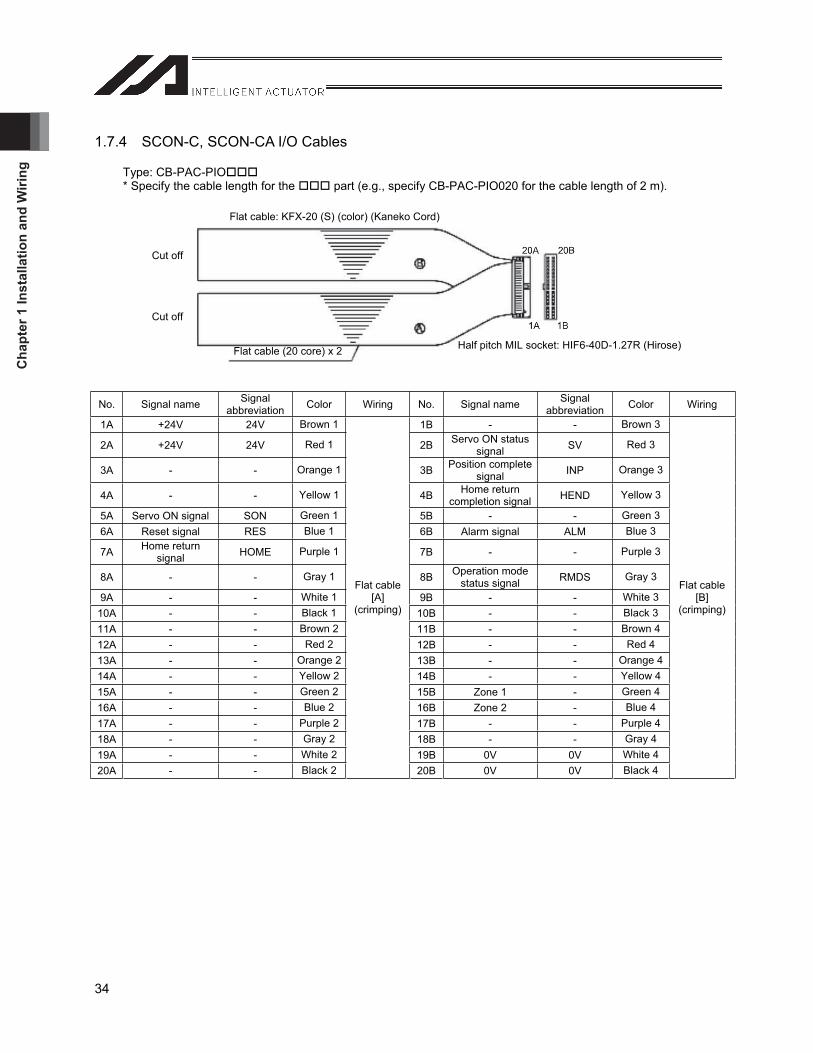
Cha
pter
1 In
stal
latio
n an
d W
iring
34
1.7.4 SCON-C, SCON-CA I/O Cables
Type: CB-PAC-PIO* Specify the cable length for the part (e.g., specify CB-PAC-PIO020 for the cable length of 2 m).
No. Signal name Signalabbreviation Color Wiring No. Signal name Signal
abbreviation Color Wiring
1A +24V 24V Brown 1 1B - - Brown 3
2A +24V 24V Red 1 2B Servo ON status signal SV Red 3
3A - - Orange 1 3B Position complete signal INP Orange 3
4A - - Yellow 1 4B Home return completion signal HEND Yellow 3
5A Servo ON signal SON Green 1 5B - - Green 36A Reset signal RES Blue 1 6B Alarm signal ALM Blue 3
7A Home return signal HOME Purple 1 7B - - Purple 3
8A - - Gray 1 8B Operation mode status signal RMDS Gray 3
9A - - White 1 9B - - White 310A - - Black 1 10B - - Black 311A - - Brown 2 11B - - Brown 412A - - Red 2 12B - - Red 4 13A - - Orange 2 13B - - Orange 414A - - Yellow 2 14B - - Yellow 415A - - Green 2 15B Zone 1 - Green 416A - - Blue 2 16B Zone 2 - Blue 4 17A - - Purple 2 17B - - Purple 418A - - Gray 2 18B - - Gray 4 19A - - White 2 19B 0V 0V White 420A - - Black 2
Flat cable [A]
(crimping)
20B 0V 0V Black 4
Flat cable [B]
(crimping)
Flat cable: KFX-20 (S) (color) (Kaneko Cord)
Cut off
Cut off
Flat cable (20 core) x 2 Half pitch MIL socket: HIF6-40D-1.27R (Hirose)
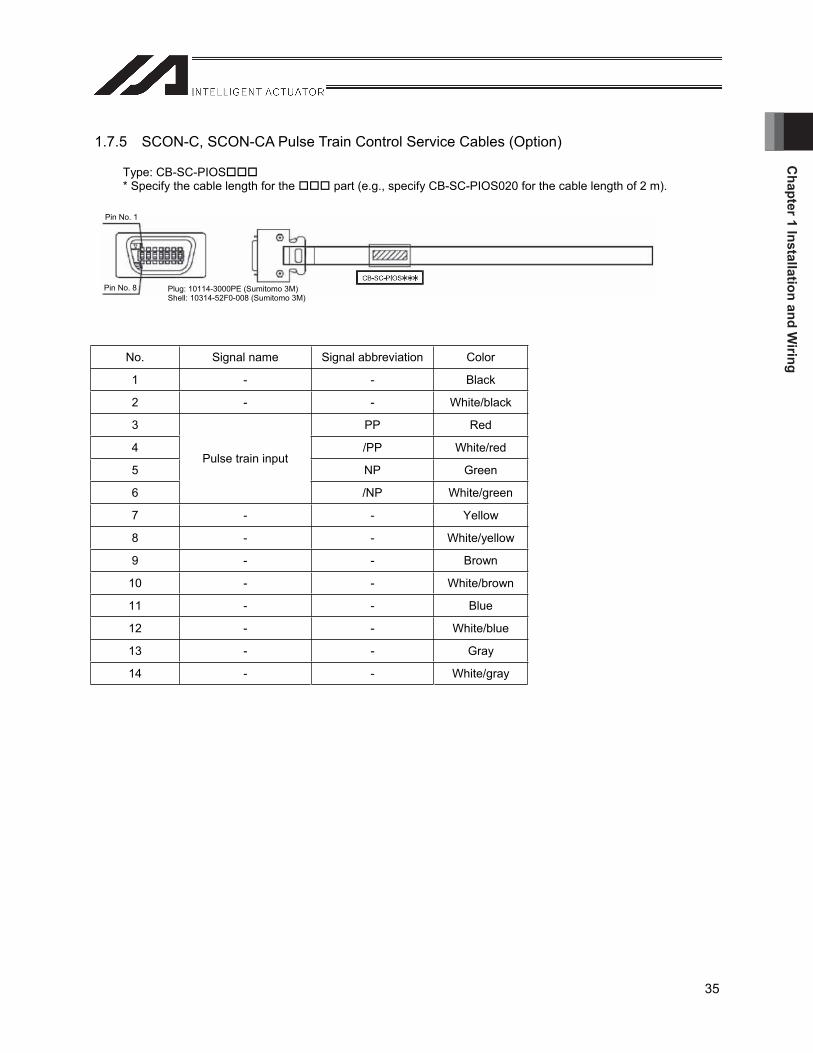
Chapter 1 Installation and W
iring
35
1.7.5 SCON-C, SCON-CA Pulse Train Control Service Cables (Option)
Type: CB-SC-PIOS* Specify the cable length for the part (e.g., specify CB-SC-PIOS020 for the cable length of 2 m).
No. Signal name Signal abbreviation Color
1 - - Black
2 - - White/black
3 PP Red
4 /PP White/red
5 NP Green
6
Pulse train input
/NP White/green
7 - - Yellow
8 - - White/yellow
9 - - Brown
10 - - White/brown
11 - - Blue
12 - - White/blue
13 - - Gray
14 - - White/gray
Pin No. 1
Pin No. 8 Plug: 10114-3000PE (Sumitomo 3M) Shell: 10314-52F0-008 (Sumitomo 3M)
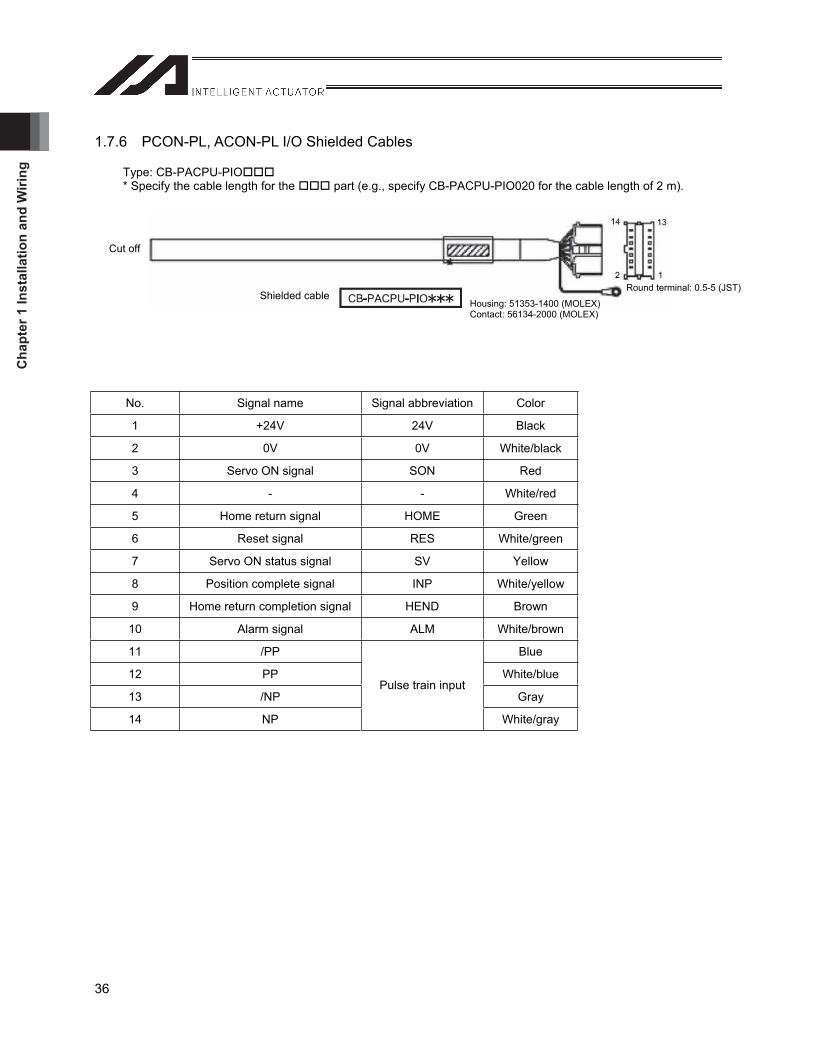
Cha
pter
1 In
stal
latio
n an
d W
iring
36
1.7.6 PCON-PL, ACON-PL I/O Shielded Cables
Type: CB-PACPU-PIO* Specify the cable length for the part (e.g., specify CB-PACPU-PIO020 for the cable length of 2 m).
No. Signal name Signal abbreviation Color
1 +24V 24V Black
2 0V 0V White/black
3 Servo ON signal SON Red
4 - - White/red
5 Home return signal HOME Green
6 Reset signal RES White/green
7 Servo ON status signal SV Yellow
8 Position complete signal INP White/yellow
9 Home return completion signal HEND Brown
10 Alarm signal ALM White/brown
11 /PP Blue
12 PP White/blue
13 /NP Gray
14 NP
Pulse train input
White/gray
Cut off
Shielded cableHousing: 51353-1400 (MOLEX) Contact: 56134-2000 (MOLEX)
Round terminal: 0.5-5 (JST)
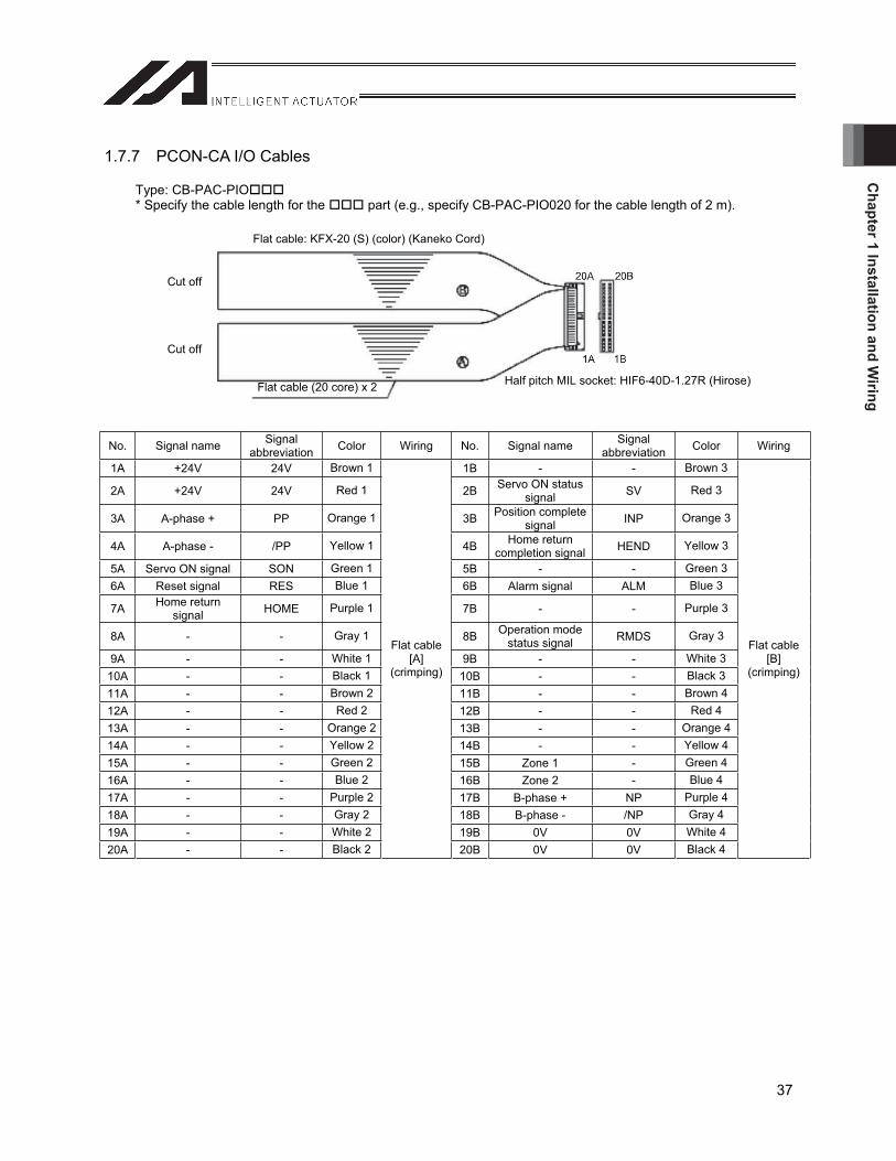
Chapter 1 Installation and W
iring
37
1.7.7 PCON-CA I/O Cables
Type: CB-PAC-PIO* Specify the cable length for the part (e.g., specify CB-PAC-PIO020 for the cable length of 2 m).
No. Signal name Signalabbreviation Color Wiring No. Signal name Signal
abbreviation Color Wiring
1A +24V 24V Brown 1 1B - - Brown 3
2A +24V 24V Red 1 2B Servo ON status signal SV Red 3
3A A-phase + PP Orange 1 3B Position complete signal INP Orange 3
4A A-phase - /PP Yellow 1 4B Home return completion signal HEND Yellow 3
5A Servo ON signal SON Green 1 5B - - Green 36A Reset signal RES Blue 1 6B Alarm signal ALM Blue 3
7A Home return signal HOME Purple 1 7B - - Purple 3
8A - - Gray 1 8B Operation mode status signal RMDS Gray 3
9A - - White 1 9B - - White 310A - - Black 1 10B - - Black 311A - - Brown 2 11B - - Brown 412A - - Red 2 12B - - Red 4 13A - - Orange 2 13B - - Orange 414A - - Yellow 2 14B - - Yellow 415A - - Green 2 15B Zone 1 - Green 416A - - Blue 2 16B Zone 2 - Blue 4 17A - - Purple 2 17B B-phase + NP Purple 418A - - Gray 2 18B B-phase - /NP Gray 4 19A - - White 2 19B 0V 0V White 420A - - Black 2
Flat cable [A]
(crimping)
20B 0V 0V Black 4
Flat cable [B]
(crimping)
Flat cable: KFX-20 (S) (color) (Kaneko Cord)
Cut off
Cut off
Flat cable (20 core) x 2 Half pitch MIL socket: HIF6-40D-1.27R (Hirose)

Cha
pter
1 In
stal
latio
n an
d W
iring
38
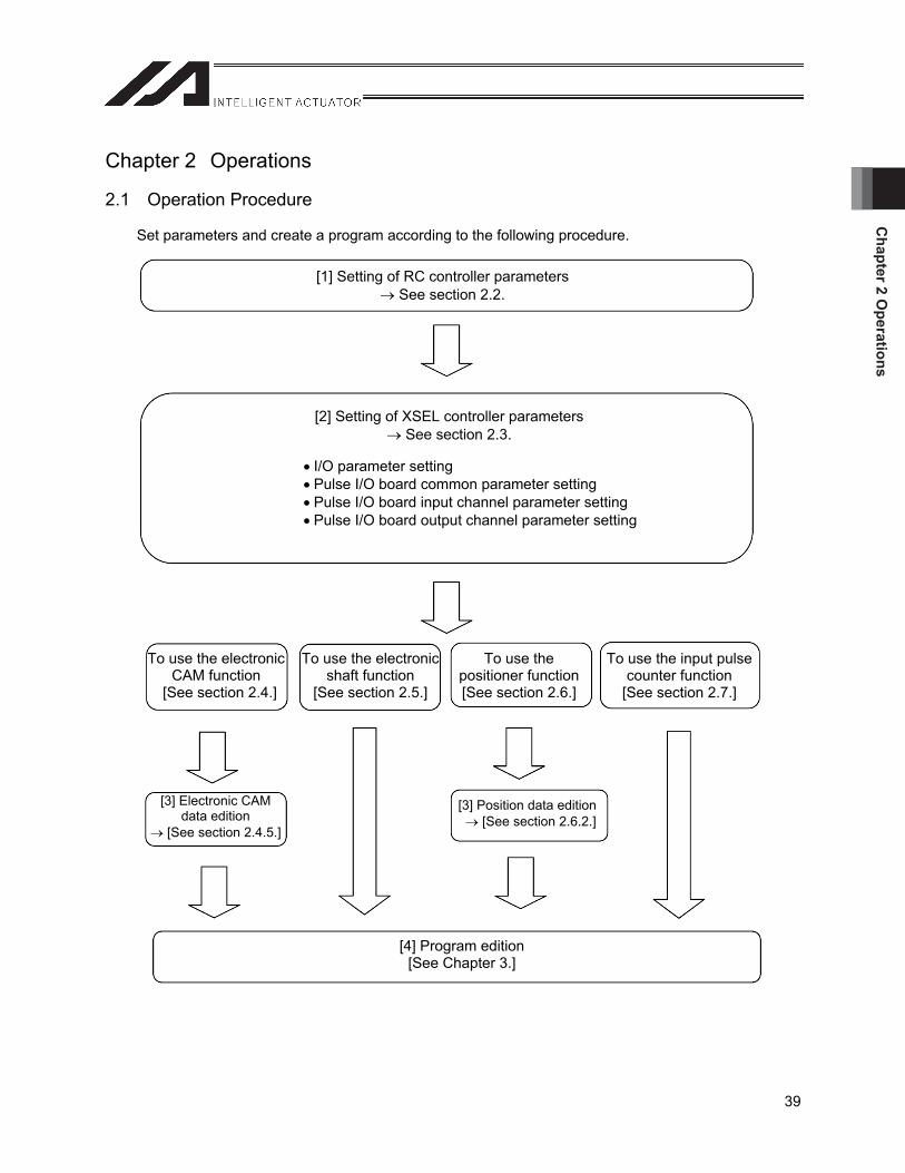
Chapter 2 O
perations
39
Chapter 2 Operations
2.1 Operation Procedure
Set parameters and create a program according to the following procedure.
[1] Setting of RC controller parameters See section 2.2.
[2] Setting of XSEL controller parameters See section 2.3.
I/O parameter setting Pulse I/O board common parameter setting Pulse I/O board input channel parameter setting Pulse I/O board output channel parameter setting
To use the electronic CAM function
[See section 2.4.]
To use the electronic shaft function
[See section 2.5.]
To use the positioner function[See section 2.6.]
To use the input pulse counter function
[See section 2.7.]
[3] Electronic CAM data edition
[See section 2.4.5.]
[3] Position data edition [See section 2.6.2.]
[4] Program edition [See Chapter 3.]
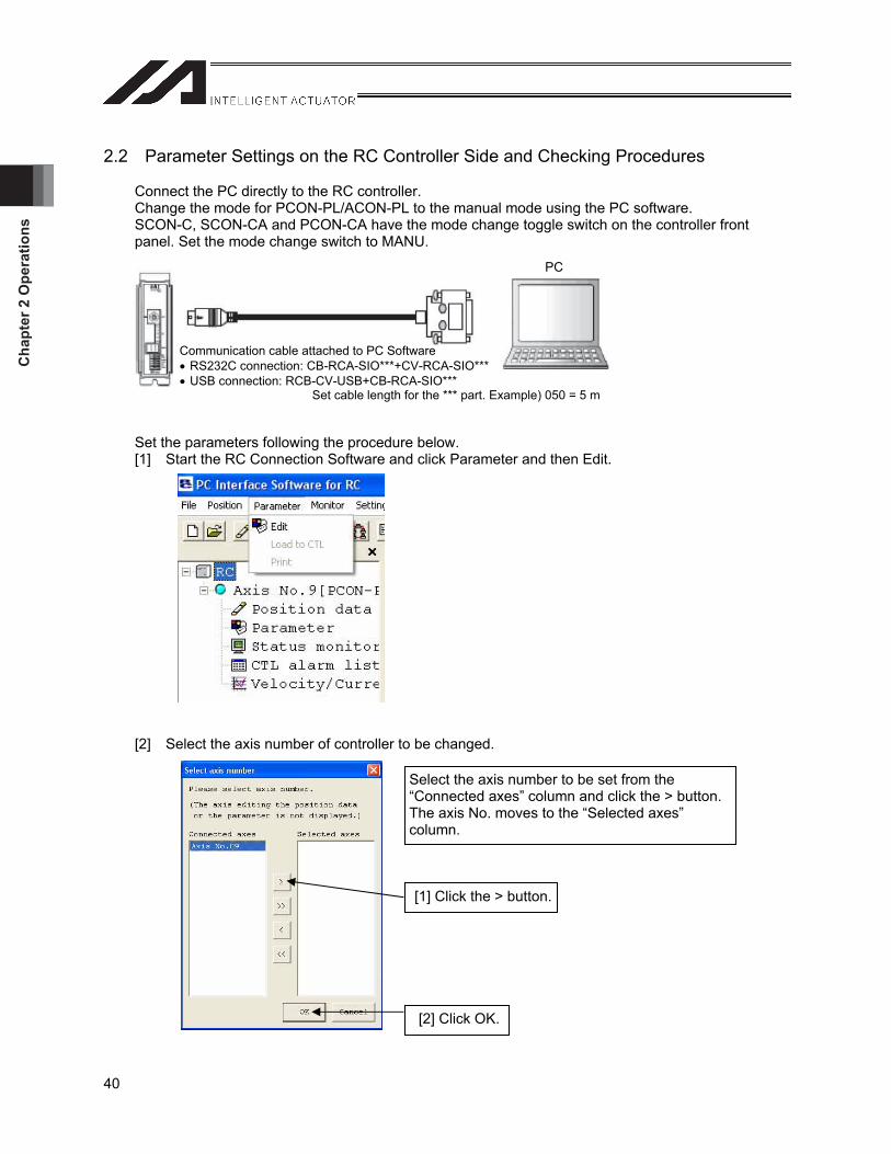
Cha
pter
2 O
pera
tions
40
2.2 Parameter Settings on the RC Controller Side and Checking Procedures
Connect the PC directly to the RC controller. Change the mode for PCON-PL/ACON-PL to the manual mode using the PC software. SCON-C, SCON-CA and PCON-CA have the mode change toggle switch on the controller front panel. Set the mode change switch to MANU.
Set the parameters following the procedure below. [1] Start the RC Connection Software and click Parameter and then Edit.
[2] Select the axis number of controller to be changed.
Communication cable attached to PC Software RS232C connection: CB-RCA-SIO***+CV-RCA-SIO*** USB connection: RCB-CV-USB+CB-RCA-SIO***
Set cable length for the *** part. Example) 050 = 5 m
PC
Select the axis number to be set from the “Connected axes” column and click the > button. The axis No. moves to the “Selected axes” column.
[1] Click the > button.
[2] Click OK.
Chapter 2 O
perations
41
2.2.1 Parameter Settings (RC Controller)
Following seven parameters are RC controller parameters which need to be confirmed and set in order to perform control on the extension motion control board.
[1] Software limit + side (user parameter No. 3) The same setting as the extension motion control board output channel parameter No. 7 “software limit +” is set for this parameter. Record the setting value of parameter No. 7 beforehand.
[2] Software limit - side (user parameter No. 4) The same setting as the extension motion control board output channel parameter No. 8 “software limit -” is set for this parameter. Record the setting value of parameter No. 8 beforehand.
[3] Command pulse input mode (user parameter No. 63) Set the same setting as the extension motion control board output channel parameter No. 2 “pulse output mode” for this parameter. (If you have not changed the default value, use the parameter as is.)
[4] Command pulse input mode polarity (user parameter No. 64) Set the same setting as the extension motion control board output channel parameter No. 3 “pulse output mode polarity” for this parameter. (If you have not changed the default value, use the parameter as is.)
[5] Electronic gear numerator (user parameter No. 65) Set the same setting as the extension motion control board output channel parameter No. 10 “electronic gear numerator” for this parameter. (Refer to the operation manual for each RC controller for the electronic gear setting values.)
[6] Electronic gear denominator (user parameter No. 66) Set the same setting as the extension motion control board output channel parameter No. 11 “electronic gear denominator” for this parameter. (Refer to the operation manual for each RC controller for the electronic gear setting values.)
[7] Ball screw lead length (user parameter No. 77) The same setting as the extension motion control board output channel parameter No. 6 “screw lead” is set for this parameter. Record the setting value of parameter No. 6 beforehand.
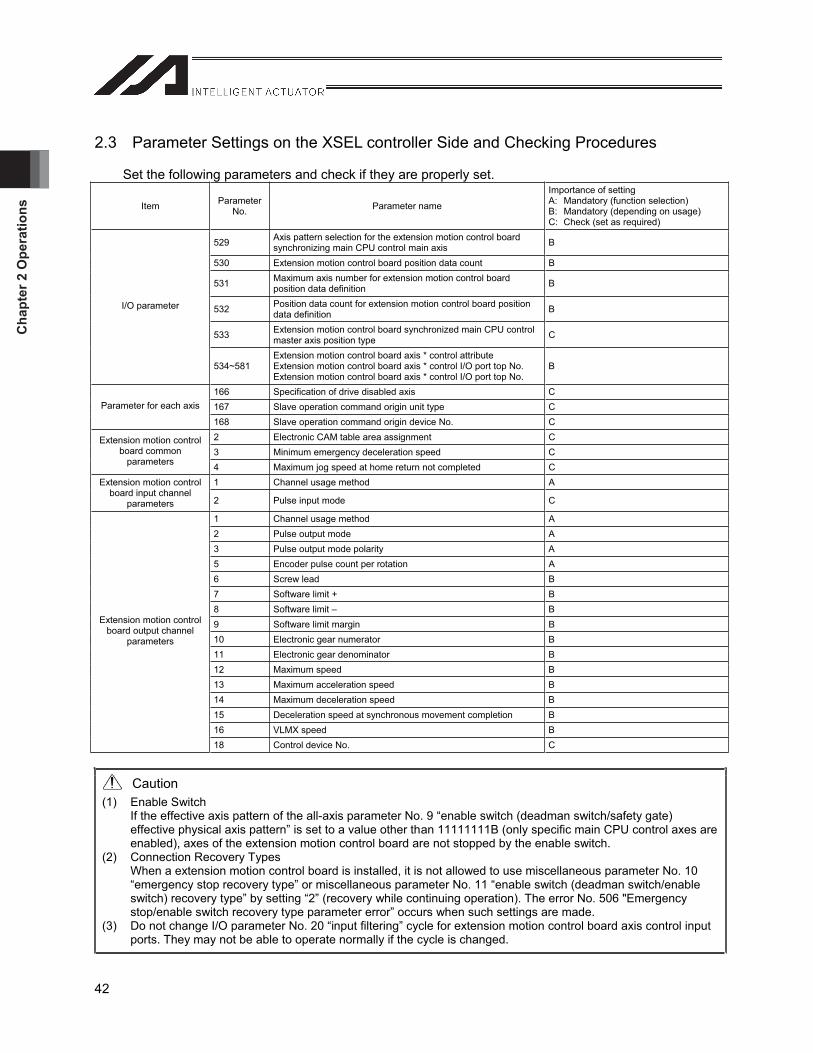
Cha
pter
2 O
pera
tions
42
2.3 Parameter Settings on the XSEL controller Side and Checking Procedures
Set the following parameters and check if they are properly set.
Item Parameter No. Parameter name
Importance of setting A: Mandatory (function selection) B: Mandatory (depending on usage) C: Check (set as required)
529 Axis pattern selection for the extension motion control board synchronizing main CPU control main axis B
530 Extension motion control board position data count B
531 Maximum axis number for extension motion control board position data definition B
532 Position data count for extension motion control board position data definition B
533 Extension motion control board synchronized main CPU control master axis position type C
I/O parameter
534~581Extension motion control board axis * control attribute Extension motion control board axis * control I/O port top No. Extension motion control board axis * control I/O port top No.
B
166 Specification of drive disabled axis C 167 Slave operation command origin unit type C Parameter for each axis
168 Slave operation command origin device No. C 2 Electronic CAM table area assignment C 3 Minimum emergency deceleration speed C
Extension motion control board common
parameters 4 Maximum jog speed at home return not completed C 1 Channel usage method A Extension motion control
board input channel parameters 2 Pulse input mode C
1 Channel usage method A 2 Pulse output mode A 3 Pulse output mode polarity A 5 Encoder pulse count per rotation A 6 Screw lead B 7 Software limit + B 8 Software limit – B 9 Software limit margin B 10 Electronic gear numerator B 11 Electronic gear denominator B 12 Maximum speed B 13 Maximum acceleration speed B 14 Maximum deceleration speed B 15 Deceleration speed at synchronous movement completion B 16 VLMX speed B
Extension motion control board output channel
parameters
18 Control device No. C
Caution (1) Enable Switch
If the effective axis pattern of the all-axis parameter No. 9 “enable switch (deadman switch/safety gate) effective physical axis pattern” is set to a value other than 11111111B (only specific main CPU control axes are enabled), axes of the extension motion control board are not stopped by the enable switch.
(2) Connection Recovery Types When a extension motion control board is installed, it is not allowed to use miscellaneous parameter No. 10 “emergency stop recovery type” or miscellaneous parameter No. 11 “enable switch (deadman switch/enable switch) recovery type” by setting “2” (recovery while continuing operation). The error No. 506 "Emergency stop/enable switch recovery type parameter error” occurs when such settings are made.
(3) Do not change I/O parameter No. 20 “input filtering” cycle for extension motion control board axis control input ports. They may not be able to operate normally if the cycle is changed.
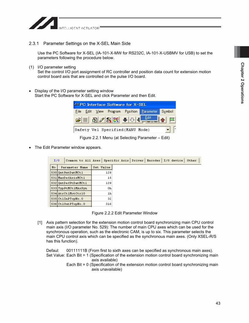
Chapter 2 O
perations
43
2.3.1 Parameter Settings on the X-SEL Main Side
Use the PC Software for X-SEL (IA-101-X-MW for RS232C, IA-101-X-USBMV for USB) to set the parameters following the procedure below.
(1) I/O parameter setting Set the control I/O port assignment of RC controller and position data count for extension motion control board axis that are controlled on the pulse I/O board.
Display of the I/O parameter setting window Start the PC Software for X-SEL and click Parameter and then Edit.
Figure 2.2.1 Menu (at Selecting Parameter – Edit)
The Edit Parameter window appears.
Figure 2.2.2 Edit Parameter Window
[1] Axis pattern selection for the extension motion control board synchronizing main CPU control main axis (I/O parameter No. 529): The number of main CPU axes which can be used for the synchronous operation, such as the electronic CAM, is up to six. This parameter selects the main CPU control axis which can be specified as the synchronous main axes. (Only XSEL-R/S has this function).
Defaul: 00111111B (From first to sixth axes can be specified as synchronous main axes). Set Value: Each Bit = 1 (Specification of the extension motion control board synchronizing main
axis available) Each Bit = 0 (Specification of the extension motion control board synchronizing main
axis unavailable)
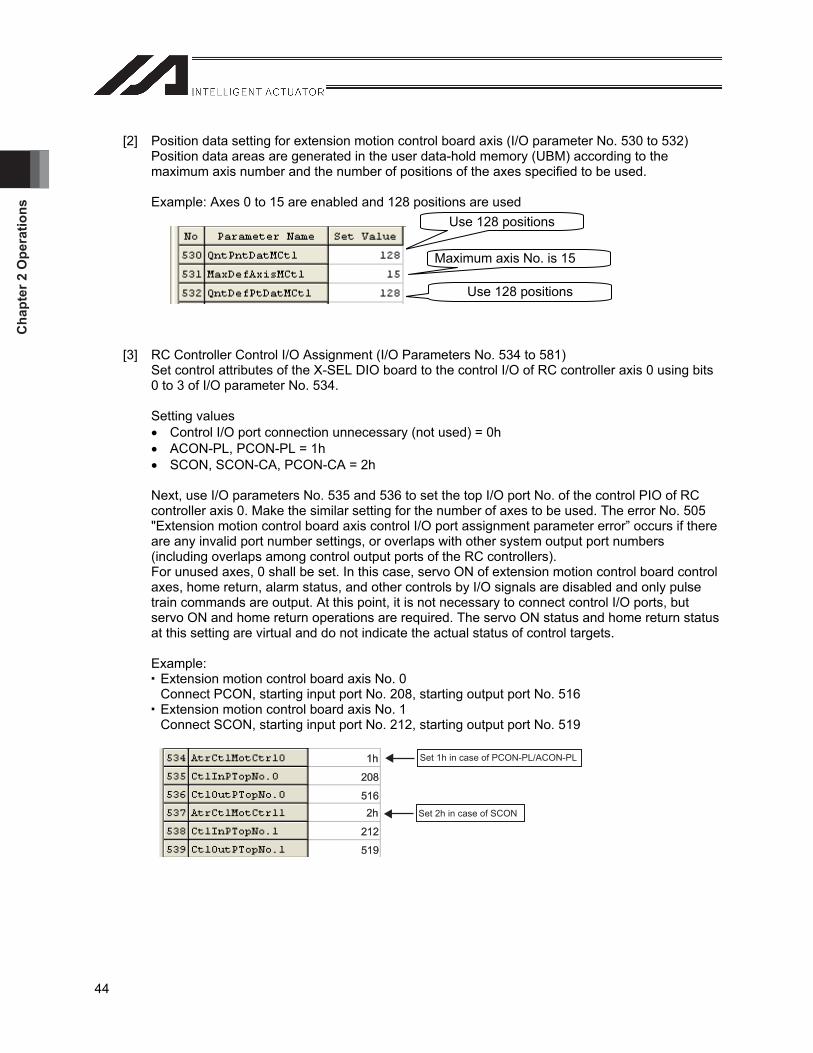
Cha
pter
2 O
pera
tions
44
[2] Position data setting for extension motion control board axis (I/O parameter No. 530 to 532) Position data areas are generated in the user data-hold memory (UBM) according to the maximum axis number and the number of positions of the axes specified to be used.
Example: Axes 0 to 15 are enabled and 128 positions are used
[3] RC Controller Control I/O Assignment (I/O Parameters No. 534 to 581) Set control attributes of the X-SEL DIO board to the control I/O of RC controller axis 0 using bits 0 to 3 of I/O parameter No. 534.
Setting values Control I/O port connection unnecessary (not used) = 0h ACON-PL, PCON-PL = 1h SCON, SCON-CA, PCON-CA = 2h
Next, use I/O parameters No. 535 and 536 to set the top I/O port No. of the control PIO of RC controller axis 0. Make the similar setting for the number of axes to be used. The error No. 505 "Extension motion control board axis control I/O port assignment parameter error” occurs if there are any invalid port number settings, or overlaps with other system output port numbers (including overlaps among control output ports of the RC controllers). For unused axes, 0 shall be set. In this case, servo ON of extension motion control board control axes, home return, alarm status, and other controls by I/O signals are disabled and only pulse train commands are output. At this point, it is not necessary to connect control I/O ports, but servo ON and home return operations are required. The servo ON status and home return status at this setting are virtual and do not indicate the actual status of control targets.
Example: Extension motion control board axis No. 0 Connect PCON, starting input port No. 208, starting output port No. 516
Extension motion control board axis No. 1 Connect SCON, starting input port No. 212, starting output port No. 519
208208208
516516516
212212212
519519519
Set 1h in case of PCON-PL/ACON-PL
Set 2h in case of SCON
1h1h1h
2h2h2h
Use 128 positions
Maximum axis No. is 15
Use 128 positions
Chapter 2 O
perations
45
Caution (1) The position data for extension motion control board axis shares the user data-hold memory in the
main CPU board as the data saving areas, with the position data for RC axes of the RC gateway function. For this reason, if the RC gateway function (method of using position data within X-SEL) is used, some restrictions apply to the number of position data points that can be used. [Refer to “2.6.1 Number of Position Data Points” for the detailed explanation.]
(2) If you use the position data for RC axes with the RC gateway function, back up the position data for RC axes before changing the parameters above. The position data of the RC gateway function is cleared when the parameters above are changed. Perform the operations explained in 2.3.3, "Note” to initialize the memory and reset the software and then transfer the saved backup data to the controller, write to Flash ROM, and reset the software. [Refer to the section 2.3.2.]
(3) Under normal circumstances, set the same values for I/O parameters No. 530 and No. 532. The number of set points of I/O parameter No. 530 becomes valid within the data area defined on the UBM with I/O parameters No. 531 and No. 532. If the value set for I/O parameter No. 530 is smaller than the value set for I/O parameter No. 532, the 6A1 error does not occur; such setting should be used when you want to change the number of data points to be used temporarily for debugging purpose.
[4] Synchronization point type setting of main CPU control master axis (I/O parameter No. 533) Use this parameter to select the position to which slave axes should follow at synchronous movement using a main CPU control axis as the master axis. Set “0” (current command position) or “1” (current position) for each of the main CPU control axes. All axes are set to ”0” (current command position) at the shipment. When “0” is specified, slave axes perform synchronous movement to the current command position of the main CPU control master axis. Since tracking commands of slave axes are output synchronous with the command position of the main CPU control master axis, following error of slave axis position to the master axis position can be made smaller. When “1” is set, slave axes perform synchronous movement to the current position (feedback value) of the main CPU control master axis. It is possible to synchronize the operation while checking the current position of the main CPU control master axis, but since a command to move to the corresponding slave axis position is output after the master axis reaches the current position, the slave axis position tracking of the master axis potion delays. Select the appropriate option according to the control specification of the device to be constructed and so on.
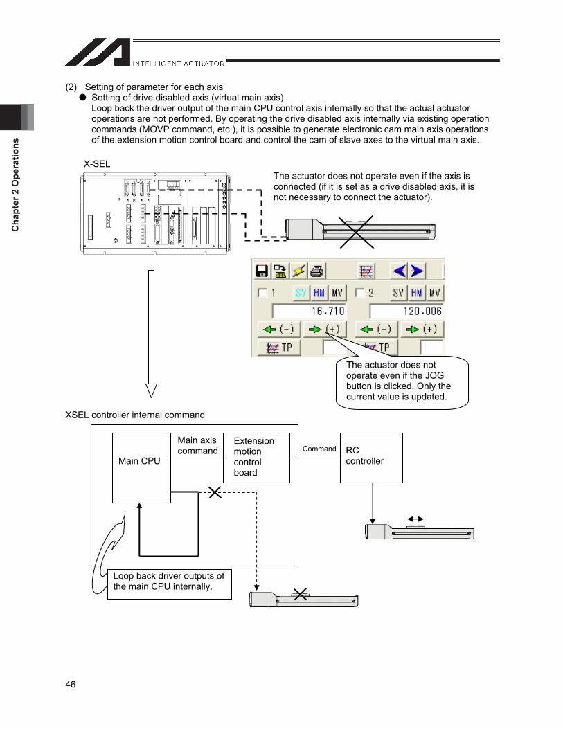
Cha
pter
2 O
pera
tions
46
(2) Setting of parameter for each axis Setting of drive disabled axis (virtual main axis) Loop back the driver output of the main CPU control axis internally so that the actual actuator operations are not performed. By operating the drive disabled axis internally via existing operation commands (MOVP command, etc.), it is possible to generate electronic cam main axis operations of the extension motion control board and control the cam of slave axes to the virtual main axis.
XSEL controller internal command
X-SEL
The actuator does not operate even if the JOG button is clicked. Only the current value is updated.
The actuator does not operate even if the axis is connected (if it is set as a drive disabled axis, it is not necessary to connect the actuator).
Loop back driver outputs of the main CPU internally.
Main CPU
Extensionmotioncontrolboard
RCcontroller
Main axis command Command
Chapter 2 O
perations
47
[1] Drive disabled specification (parameter for each axis No. 166) 0 = drive axis enabled (actuator connected) 1 = drive axis disabled (actuator not connected)
The resolutions for the drive disabled axes are set using the following parameters in the same way as the normal axes.
Parameter for each axis No. 42 “Encoder resolution” Parameter for each axis No. 43 “Encoder division” Parameter for each axis No. 47 “Screw lead” Parameter for each axis No. 50 “Gear ratio numerator” Parameter for each axis No. 51 “Gear ratio denominator”
The same moving commands as normal axes are used to move drive disabled axes. It is necessary to execute the servo ON and home return commands before executing moving commands. When the home return command is executed, the current position is set to the value set by parameter for each axis No. 12 “Home preset value.”
Caution: If the following faults exist, the corresponding error occurs.
[1] The following errors occur in the case of wrong parameter settings.
(1) Error code 532 (drive disabled specification parameter error) Parameter for each axis No. 38 “Encoder ABS/INC type” is set to 1 (ABS). The axis is set as a synchronized axis (parameter for each axis No. 65 “Synchronized axis No.”). ZR unit setting is made (parameter for each axis No. 109 “Specification of ball screw spline (linear
move axis + rotation axis) corrected axis).” The value of parameter for each axis No. 28 “Maximum operation speed of each axis” exceeds
3000 mm/sec. The resolution setting is out of range (10 to 16000 pulses/mm).
(2) Error code B80 (specification prohibition axis error) The PUSH command was used.
[2] Driver ROM version, driver parameter production information, and similar data are not displayed in the PC software and teaching pendant. If it is necessary to check such information, temporarily cancel/remove all existing drive disabled axes specifications. Check the information, and then you may redefine the drive disabled axes once again.
[3] You still need a motor drive power even if driving is disabled for all axes. If no motor drive power is supplied, Error Code 607 “Motor power voltage low error” will occur.
(Note) Driving-disable axes are supported in Main Application Version 0.98 or later (XSEL-P/Q).
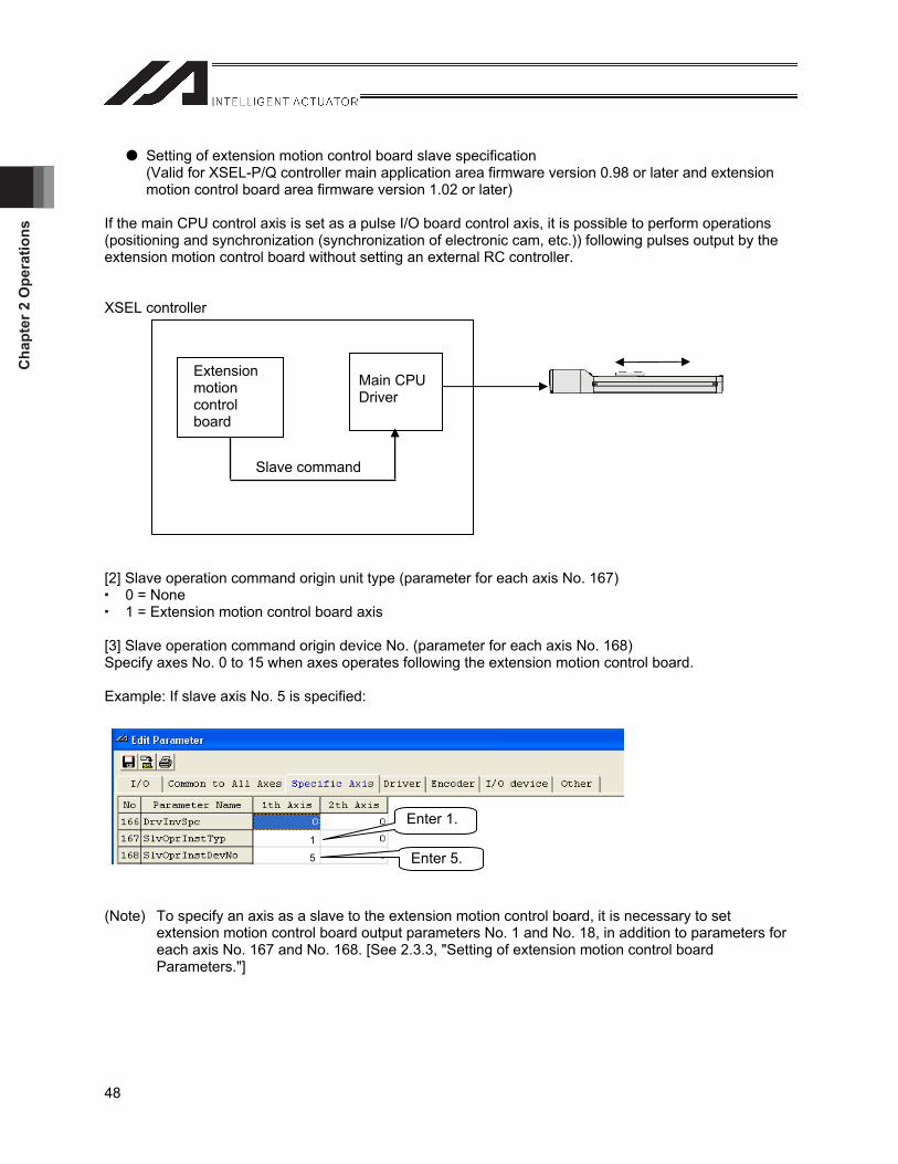
Cha
pter
2 O
pera
tions
48
Setting of extension motion control board slave specification (Valid for XSEL-P/Q controller main application area firmware version 0.98 or later and extension motion control board area firmware version 1.02 or later)
If the main CPU control axis is set as a pulse I/O board control axis, it is possible to perform operations (positioning and synchronization (synchronization of electronic cam, etc.)) following pulses output by the extension motion control board without setting an external RC controller.
XSEL controller
[2] Slave operation command origin unit type (parameter for each axis No. 167) 0 = None 1 = Extension motion control board axis
[3] Slave operation command origin device No. (parameter for each axis No. 168) Specify axes No. 0 to 15 when axes operates following the extension motion control board.
Example: If slave axis No. 5 is specified:
(Note) To specify an axis as a slave to the extension motion control board, it is necessary to set extension motion control board output parameters No. 1 and No. 18, in addition to parameters for each axis No. 167 and No. 168. [See 2.3.3, "Setting of extension motion control board Parameters."]
Main CPU Driver
Extensionmotioncontrolboard
Slave command
Enter 1.
Enter 5. 1
5
Chapter 2 O
perations
49
Caution: (1) Axes specified as slaves to the extension motion control board operate with operation commands by
the extension motion control board axis only. If the main CPU axis is instructed to operate, it is treated as an invalid axis and error No. C7F “no valid axis error” occurs. Set the resolution of the drive disabled axes with the following parameters in the same manner as normal axes.
(2) Set extension motion control board output channel parameters No. 5 to 8, 10 to 14, and 16 according to the main CPU control axis operating as a slave. [See 2.3.3, " Extension Motion Control Board Parameter Setting."] At this point, error No. 52D “Extension motion control board main CPU axis control parameter error” occurs in the following cases.
Resolution set with an output channel parameter does not match with resolution of the main CPU control axis.
Output channel parameter No. 12 “Maximum speed” exceeds the maximum speed of the main CPU control axis (parameter for each axis No. 27/28).
Output channel parameter No. 13 “Maximum acceleration” exceeds the maximum acceleration of the main CPU control axis (all-axis parameter 22).
Output channel parameter No. 14 “Maximum deceleration” exceeds the maximum acceleration of the main CPU control axis (all-axis parameter 23).
(3) The following axes cannot be specified as a slave to the extension motion control board. Error No. 531 “Slave operation parameter error” occurs.
Rotary Movement Axis Shorter Circuit Control (Parameter for each axis No. 67 “Rotary movement axis shorter circuit control selection” = 1)
Endless Stroke Mode (Parameter for each axis No. 68 “Linear movement axis mode selection = 1)
Synchronous Axis Setting (Parameter for each axis No. 65 “Axis No. with which the synchronous operation is performed). * Using the main application firmware version 1.08 or later (XSEL-P/Q), the synchronous
master axis can be specified as a slave to the extension motion control board. (4) When the synchronous master axis is specified as a slave to the extension motion control board and
the position of the synchronous master axis is greatly different from the slave axis (in the case that the synchronous axis is not coupled, etc.), Error No. 511 “Extension motion control axis servo ON/OFF timeout error” might occur because the position synchronizing correction movement is accompanied when the servo-motor is turned ON. In this case, change the extension motion control board channel parameter No. 31 “Pulse train driver servo ON completion confirmation time” (set to “15 seconds” at the delivery) according to the user’s system.
(5) The number of the main CPU control axes which can be specified as a slave to the extension motion control board using the XSEL-R/S controller, is up to seven per board (All eight axes can not be specified as slaves). When all eight axes are specified, the error No. 527: Extension motion control board pulse output setting parameter error will occur. In order to operate all eight axes as slaves, two extension control boards are required.
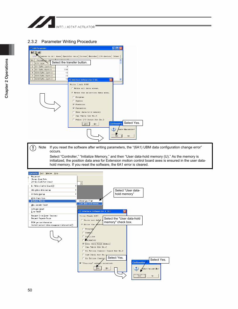
Cha
pter
2 O
pera
tions
50
2.3.2 Parameter Writing Procedure
Note If you reset the software after writing parameters, the “(6A1) UBM data configuration change error” occurs.Select “Controller,” “Initialize Memory,” and then “User data-hold memory (U).” As the memory is initialized, the position data area for Extension motion control board axes is ensured in the user data-hold memory. If you reset the software, the 6A1 error is cleared.
Select the transfer button.
Select Yes.
Select “User data-hold memory”
Select the "User data-hold memory" check box.
Select Yes. Select Yes.
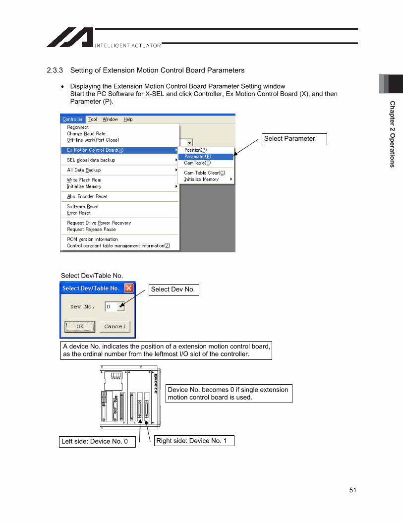
Chapter 2 O
perations
51
2.3.3 Setting of Extension Motion Control Board Parameters
Displaying the Extension Motion Control Board Parameter Setting window Start the PC Software for X-SEL and click Controller, Ex Motion Control Board (X), and then Parameter (P).
Select Dev/Table No.
Select Parameter.
Select Dev No.
A device No. indicates the position of a extension motion control board, as the ordinal number from the leftmost I/O slot of the controller.
Device No. becomes 0 if single extension motion control board is used.
Left side: Device No. 0 Right side: Device No. 1
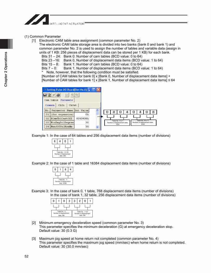
Cha
pter
2 O
pera
tions
52
(1) Common Parameter [1] Electronic CAM table area assignment (common parameter No. 2)
The electronic CAM table storage area is divided into two banks (bank 0 and bank 1) and common parameter No. 2 is used to assign the number of tables and variable data (assign in units of 1 KB: 256 pieces of displacement data can be stored per 1 KB) for each bank.
Bits 31 – 24: Bank 0: Number of cam tables (BCD value: 0 to 64) Bits 23 –16: Bank 0, Number of displacement data items (BCD value: 1 to 64) Bits 15 – 8: Bank 1: Number of cam tables (BCD value: 0 to 64) Bits 7 – 0: Bank 1, Number of displacement data items (BCD value: 1 to 64) * Note, however, that the following condition must be satisfied. [Number of CAM tables for bank 0] x [Bank 0, Number of displacement data items] + [Number of CAM tables for bank 1] x [Bank 1, Number of displacement data items] 64
Example 1: In the case of 64 tables and 256 displacement data items (number of divisions)
Example 2: In the case of 1 table and 16384 displacement data items (number of divisions)
Example 3: In the case of bank 0, 1 table, 768 displacement data items (number of divisions) In the case of bank 1, 32 table, 256 displacement data items (number of divisions)
[2] Minimum emergency deceleration speed (common parameter No. 3) This parameter specifies the minimum deceleration (G) at emergency deceleration stop. Default value: 30 (0.3 G)
[3] Maximum jog speed at home return not completed (common parameter No. 4) This parameter specifies the maximum jog speed (mm/sec) when home return is not completed. Default value: 30 (30.0 mm/sec)
Table No. 0 to 7 Number of displacement data:
1024
Table No. 8 to 11 Number of displacement data:
2048
Table No.. 0 63Number of displacement
data 256
Table No.. 0 Number of displacement
data 16384
Table No. 0Number of displacement
data 768
Table No. 1~32Number of displacement
data 256
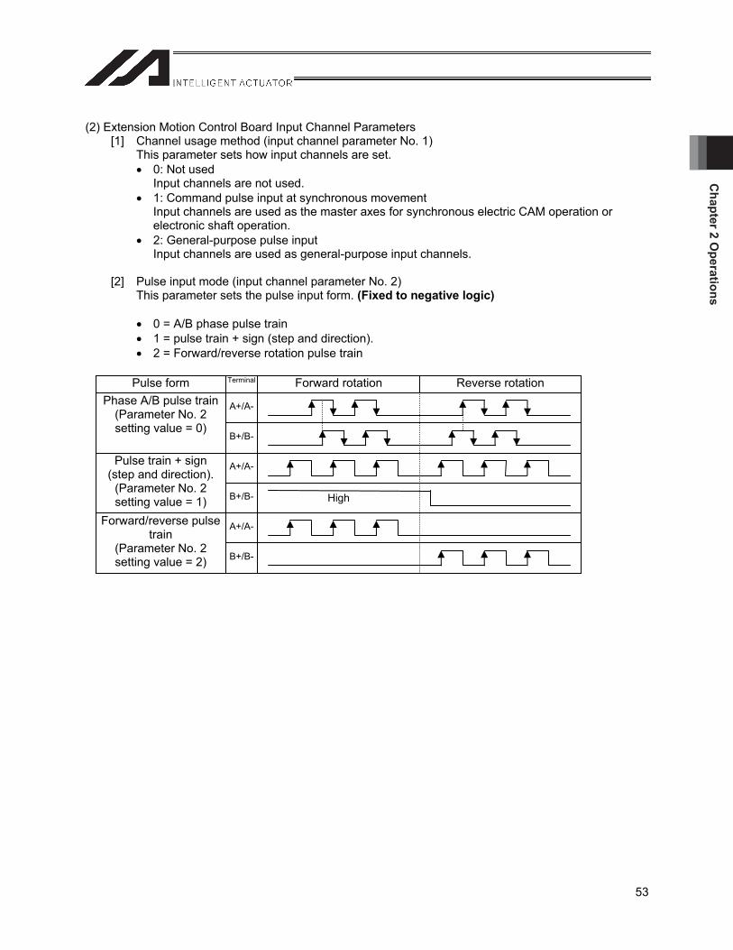
Chapter 2 O
perations
53
(2) Extension Motion Control Board Input Channel Parameters [1] Channel usage method (input channel parameter No. 1)
This parameter sets how input channels are set. 0: Not used
Input channels are not used. 1: Command pulse input at synchronous movement
Input channels are used as the master axes for synchronous electric CAM operation or electronic shaft operation.
2: General-purpose pulse input Input channels are used as general-purpose input channels.
[2] Pulse input mode (input channel parameter No. 2) This parameter sets the pulse input form. (Fixed to negative logic)
0 = A/B phase pulse train 1 = pulse train + sign (step and direction). 2 = Forward/reverse rotation pulse train
Forward rotation Reverse rotation Terminal Pulse form
A+/A-
B+/B-
Phase A/B pulse train (Parameter No. 2 setting value = 0)
A+/A-
B+/B-
Pulse train + sign (step and direction).
(Parameter No. 2 setting value = 1)
A+/A-
B+/B-
Forward/reverse pulse train
(Parameter No. 2 setting value = 2)
High
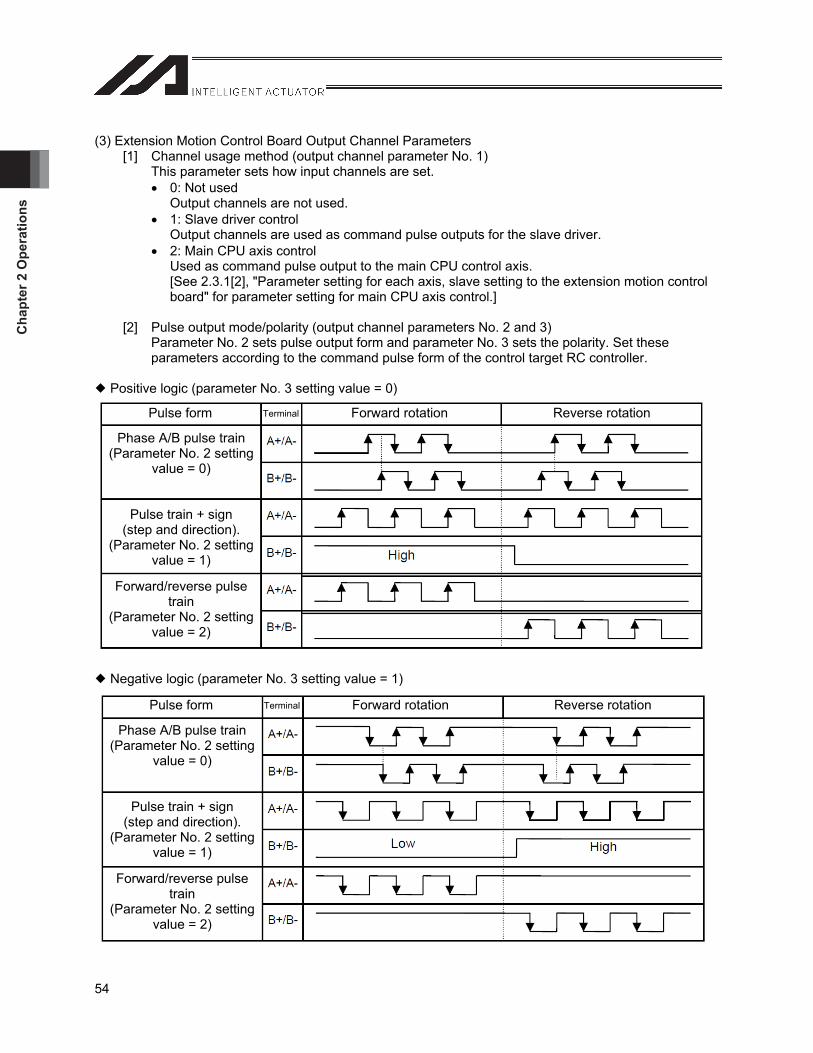
Cha
pter
2 O
pera
tions
54
(3) Extension Motion Control Board Output Channel Parameters [1] Channel usage method (output channel parameter No. 1)
This parameter sets how input channels are set. 0: Not used
Output channels are not used. 1: Slave driver control
Output channels are used as command pulse outputs for the slave driver. 2: Main CPU axis control
Used as command pulse output to the main CPU control axis. [See 2.3.1[2], "Parameter setting for each axis, slave setting to the extension motion control board" for parameter setting for main CPU axis control.]
[2] Pulse output mode/polarity (output channel parameters No. 2 and 3) Parameter No. 2 sets pulse output form and parameter No. 3 sets the polarity. Set these parameters according to the command pulse form of the control target RC controller.
Positive logic (parameter No. 3 setting value = 0)
Negative logic (parameter No. 3 setting value = 1)
Pulse form Terminal Forward rotation Reverse rotation
Phase A/B pulse train (Parameter No. 2 setting
value = 0)
Pulse train + sign (step and direction).
(Parameter No. 2 setting value = 1)
Forward/reverse pulse train
(Parameter No. 2 setting value = 2)
Pulse form Terminal Forward rotation Reverse rotation
Phase A/B pulse train (Parameter No. 2 setting
value = 0)
Pulse train + sign (step and direction).
(Parameter No. 2 setting value = 1)
Forward/reverse pulse train
(Parameter No. 2 setting value = 2)

Chapter 2 O
perations
55
[3] Encoder pulse count per rotation (output channel parameter No. 5) This parameter sets the number of pulses per encoder rotation of the control target axis (unit: pulse). Make the setting according to the specification of the control target axis.
[4] Screw lead (output channel parameter No. 6) This parameter sets the ball screw lead length of the control target axis (unit: 0.001 mm). Make the setting according to the specification of the control target axis.
[5] Software limit +/software limit - (output channel parameters No. 7 and 8) These parameters set the software limit + and -, respectively, of the control target axis (unit: 0.001 mm). Make the setting according to the specification of the control target axis.
[6] Software limit margin (output channel parameter No. 9) This parameter sets the maximum following error at which instance an error is detected while synchronous movement is being performed (unit: 0.001 mm). The software limit error occurs in the following cases. Command position > [software limit +] + [software limit margin] Command position < [software limit -] - [software limit margin]
Caution: Set these parameters taking the distance from the software limit to the mechanical end of the control target axis into consideration. If the setting value is too large, there is a risk that an axis collides with the mechanical end.

Cha
pter
2 O
pera
tions
56
[7] Electronic gear numerator/electronic gear denominator (output channel parameters No. 10 and 11)These parameters set the electronic gear numerator and denominator used to determine the unit movement amount of command pulses (mm/pulse). Make the setting according to the specification of the control target axis. Electronic gear numerator/electronic gear denominator = number of pulses per one encoder rotation (pulse/rev) / screw lead (mm/rev) x unit movement amount (mm/pulse)
*1 Unit movement amount: Movement of actuator per command pulse
Caution: The maximum output pulse frequency of a extension motion control board is 500,000 (pulse/sec). For this reason, the following condition must be satisfied. Maximum speed (mm/sec) / unit movement amount (M/pulse) 500,000 (pulse/sec) If this condition is not satisfied, the error No. 51E “Extension motion control board output channel parameter error” occurs.
[8] Maximum speed, maximum acceleration, maximum deceleration (output channel parameters No. 12, 13, 14) These parameters set the maximum speed (unit: mm/sec), maximum acceleration (unit: 0.01 G), and maximum deceleration (unit: 0.01 G) of the control target axis. Make the setting according to the specification of the control target axis.
[9] Deceleration at synchronous movement completion (output channel parameter No. 15) This parameter sets deceleration before stopping at the completion of one cycle of synchronous electronic CAM operation as well as at the completion of synchronous movement by the synchronous movement end command and so on (unit: 0.01G).
[10] VLMX speed (output channel parameter No. 16) This parameter sets the actuator moving speed when the VLMX speed is specified (execution of VLMX command) in a SEL program (unit: mm/sec). Note that if the VLMX speed exceeds the maximum speed (output channel parameter No. 12), the speed is restricted by the maximum speed (VLMX speed = maximum speed).
[11] Control device No. (output channel parameter No. 18) This parameter sets the main CPU control axis No. (1 to 6 for XSEL-P/Q, and 1 to 8 for XSEL-R/S), to operate as a slave to the extension motion control board. Error No. 531 “slave operation parameter error” and/or error No. 52D “Extension motion control board main CPU axis control parameter error” occur if the settings of parameters for each axis No. 167 and 168 and/or extension motion control board output channel parameters No. 1 and 18 are not correct.
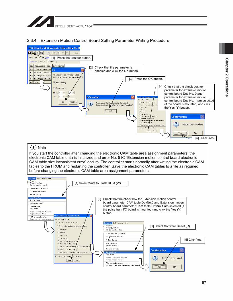
Chapter 2 O
perations
57
2.3.4 Extension Motion Control Board Setting Parameter Writing Procedure
NoteIf you start the controller after changing the electronic CAM table area assignment parameters, the electronic CAM table data is initialized and error No. 51C “Extension motion control board electronic CAM table size inconsistent error” occurs. The controller starts normally after writing the electronic CAM tables to the FROM and restarting the controller. Save the electronic CAM tables to a file as required before changing the electronic CAM table area assignment parameters.
[1] Press the transfer button.
[3] Press the OK button.
[5] Click Yes.
[4] Check that the check box for parameter for extension motion control board Dev No. 0 and parameter for extension motion control board Dev No. 1 are selected (if the board is mounted) and click the Yes (Y) button.
[5] Click Yes.
[1] Select Write to Flash ROM (W).
[1] Select Software Reset (R).
[2] Check that the check box for Extension motion control board parameter CAM table DevNo.0 and Extension motion control board parameter CAM table DevNo.1 are selected (if the pulse train I/O board is mounted) and click the Yes (Y) button.
[2] Check that the parameter is enabled and click the OK button.
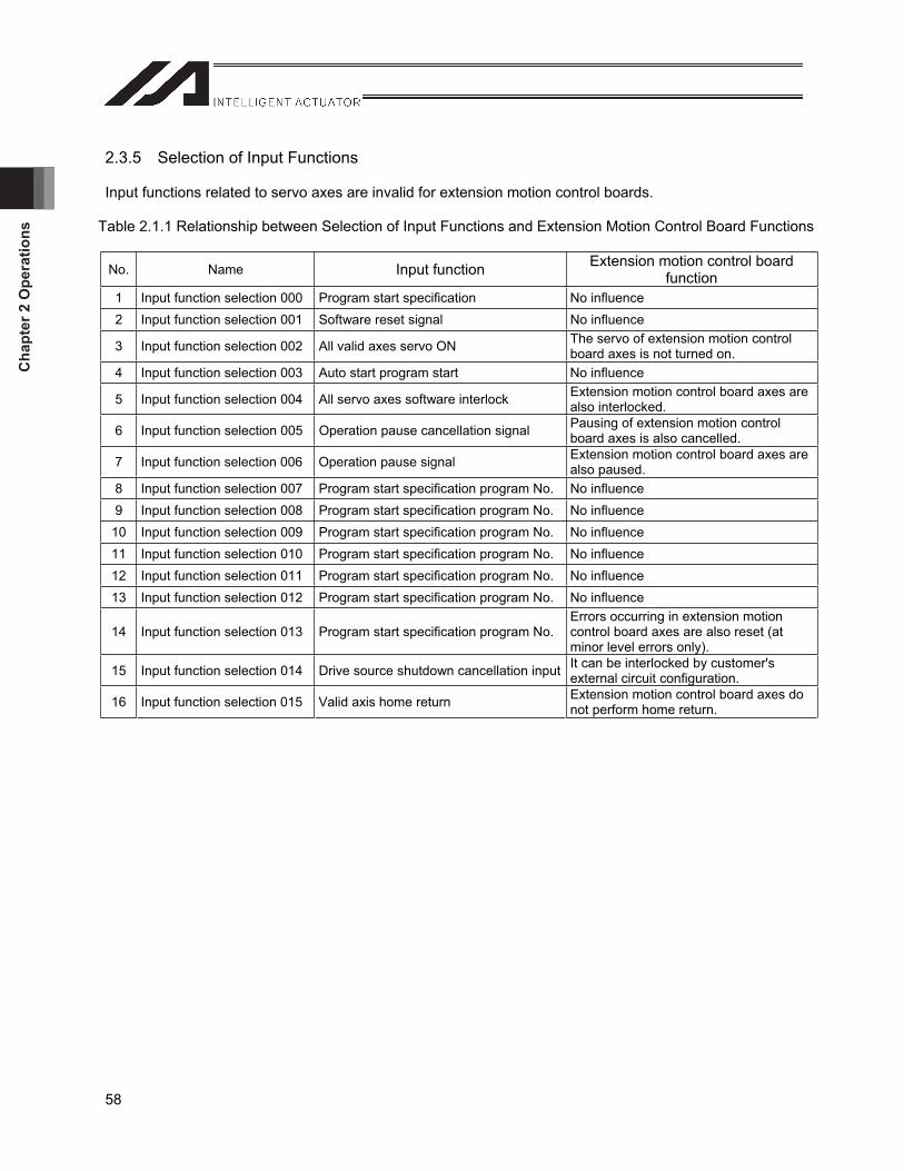
Cha
pter
2 O
pera
tions
58
2.3.5 Selection of Input Functions
Input functions related to servo axes are invalid for extension motion control boards.
Table 2.1.1 Relationship between Selection of Input Functions and Extension Motion Control Board Functions
No. Name Input function Extension motion control board function
1 Input function selection 000 Program start specification No influence 2 Input function selection 001 Software reset signal No influence
3 Input function selection 002 All valid axes servo ON The servo of extension motion control board axes is not turned on.
4 Input function selection 003 Auto start program start No influence
5 Input function selection 004 All servo axes software interlock Extension motion control board axes are also interlocked.
6 Input function selection 005 Operation pause cancellation signal Pausing of extension motion control board axes is also cancelled.
7 Input function selection 006 Operation pause signal Extension motion control board axes are also paused.
8 Input function selection 007 Program start specification program No. No influence 9 Input function selection 008 Program start specification program No. No influence
10 Input function selection 009 Program start specification program No. No influence 11 Input function selection 010 Program start specification program No. No influence 12 Input function selection 011 Program start specification program No. No influence 13 Input function selection 012 Program start specification program No. No influence
14 Input function selection 013 Program start specification program No.Errors occurring in extension motion control board axes are also reset (at minor level errors only).
15 Input function selection 014 Drive source shutdown cancellation input It can be interlocked by customer's external circuit configuration.
16 Input function selection 015 Valid axis home return Extension motion control board axes do not perform home return.
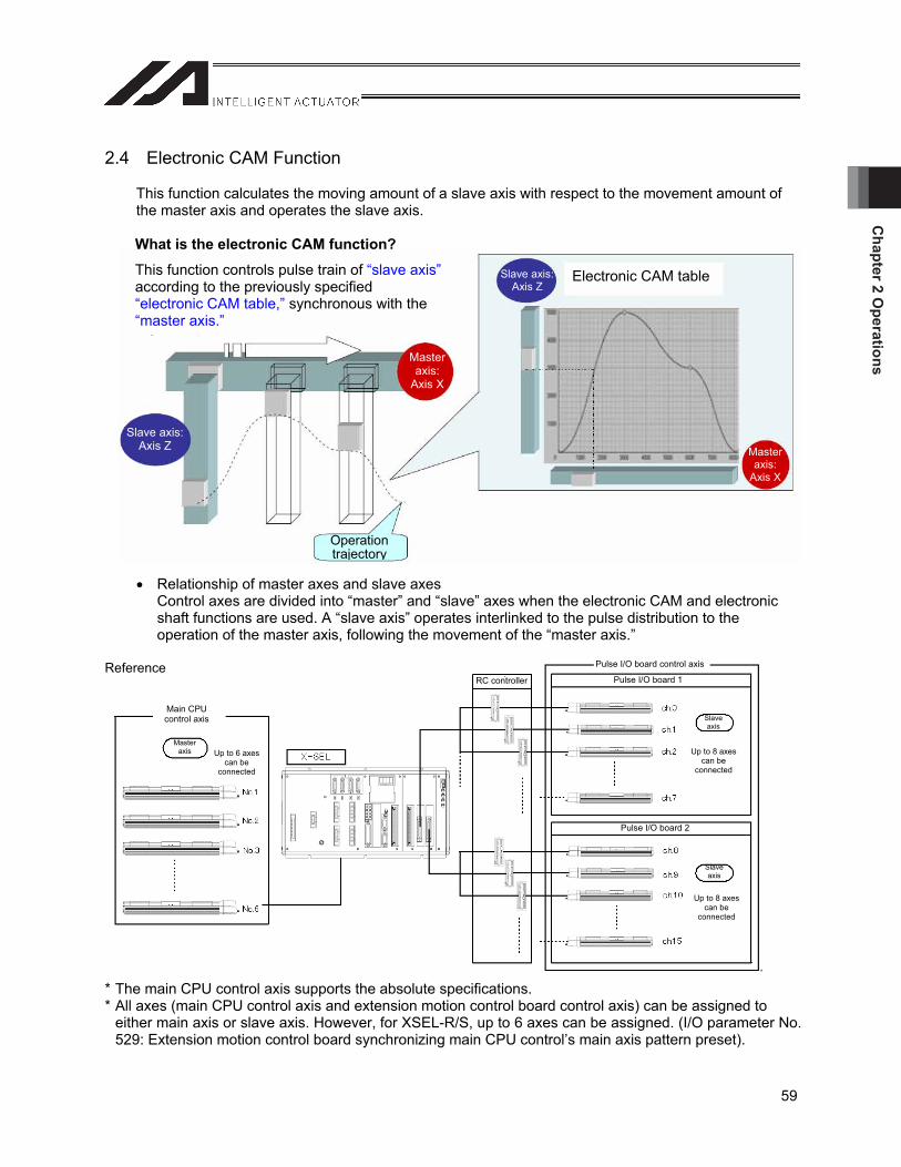
Chapter 2 O
perations
59
Master axis
RC controller
Slave axis
Slave axis
Pulse I/O board 1
Pulse I/O board 2
Main CPU control axis
Pulse I/O board control axis
Up to 6 axes can be
connected
Up to 8 axes can be
connected
Up to 8 axes can be
connected
2.4 Electronic CAM Function
This function calculates the moving amount of a slave axis with respect to the movement amount of the master axis and operates the slave axis.
Relationship of master axes and slave axes Control axes are divided into “master” and “slave” axes when the electronic CAM and electronic shaft functions are used. A “slave axis” operates interlinked to the pulse distribution to the operation of the master axis, following the movement of the “master axis.”
Reference
* The main CPU control axis supports the absolute specifications. * All axes (main CPU control axis and extension motion control board control axis) can be assigned to
either main axis or slave axis. However, for XSEL-R/S, up to 6 axes can be assigned. (I/O parameter No. 529: Extension motion control board synchronizing main CPU control’s main axis pattern preset).
What is the electronic CAM function?
This function controls pulse train of “slave axis”according to the previously specified “electronic CAM table,” synchronous with the “master axis.”
Slave axis: Axis Z
Masteraxis:
Axis X
Slave axis: Axis Z
Operation trajectory
Electronic CAM table
Masteraxis:
Axis X
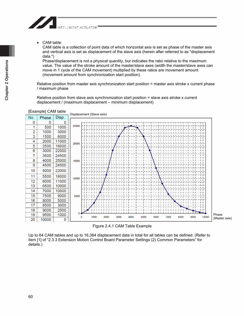
Cha
pter
2 O
pera
tions
60
Phase Disp.
CAM table CAM table is a collection of point data of which horizontal axis is set as phase of the master axis and vertical axis is set as displacement of the slave axis (herein after referred to as "displacement data.")Phase/displacement is not a physical quantity, but indicates the ratio relative to the maximum value. The value of the stroke amount of the master/slave axes (width the master/slave axes can move in 1 cycle of the CAM movement) multiplied by these ratios are movement amount (movement amount from synchronization start position).
Relative position from master axis synchronization start position = master axis stroke x current phase / maximum phase
Relative position from slave axis synchronization start position = slave axis stroke x current displacement / (maximum displacement – minimum displacement)
[Example] CAM table
Figure 2.4.1 CAM Table Example
Up to 64 CAM tables and up to 16,384 displacement data in total for all tables can be defined. (Refer to item [1] of “2.3.3 Extension Motion Control Board Parameter Settings (2) Common Parameters” for details.)
Phase(Master axis)
Displacement (Slave axis)

Chapter 2 O
perations
61
Master axis
RC controller
Slave axis
Extension motion control board 1
Extension motion control board 2
Slave axis
Main CPU control axis
Main CPU control axis
Extension motion control board control axis
Extension motion control board control axis
RC controller
Slave axis
Extension motion control board 1
Slave axis
Master axis
Master axis
Master axis
Synchronization control can be performed for up to 17 axes (1 master axis and 16 slave axes).
Synchronization is possible only for axes connected to the same extension motion control board.
Synchronization among multiple boards is not possible
Synchronization control can be performed for up to 8 axes (1 master axis and 7 slave axes).
Up to 8 axes can be
connected
Up to 8 axes can be
connected
Up to 6 axes can be
connected
2.4.1 Combination of Master Axes and Slave Axes This section explains combination of slave axes allowed for the main axis setting. The table below shows combination of slave axes that can be controlled in a given setting. * Assignment of main and slave axes is specified in programs (XCAS commands).
: Allowed X: Not allowed Main axis
Main CPU control axis Extension motion control board control axis Extension motion control board input channelSlave axis XSEL-P/Q Axis No. 1 to 6XSEL-R/S Axis No. 1 to 8 Axis No. 0 to 7 Axis No. 8 to 15 CH No. 0 to 1 CH No. 2 to 3
Main CPU control axis
XSEL-P/Q Axis No. 1 to 6
XSEL-R/S Axis No. 1 to 8
Axis No. 0 to 7 x xExtension motion control board control axis Axis No. 8 to 15 x x
[1] When main axis is main CPU control axis
[2] When main axis is extension motion control board control axis
Caution If two extension motion control boards are installed, synchronized operation among the two boards is not possible.
Extension motion control board 2
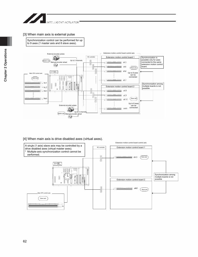
Cha
pter
2 O
pera
tions
62
[3] When main axis is external pulse
[4] When main axis is drive disabled axes (virtual axes).
Synchronization control can be performed for up to 9 axes (1 master axis and 8 slave axes).
Master axis
RC controller
Slave axis
Extension motion control board 1
Extension motion control board 2
Slave axis
Main CPU control axis
Main CPU control axis
Extension motion control board control axis
Slave axis
Master axis
Slave axis
External encoder pulses
Manual encoder wheel
External encoder pulses
Manual encoder wheel
RC controller
Slave axis
Extension motion control board 1
Extension motion control board 2
Slave axis
Extension motion control board control axis
Synchronization is possible only for axes connected to the same extension motion control board.
Synchronization among multiple boards is not possible
Synchronization among multiple boards is not possible
Up to 2 channels
Up to 2 channels
Up to 8 axes can be
connected
Up to 8 axes can be
connected
A single (1 axis) slave axis may be controlled by a drive disabled axes (virtual master axes). * Multiple-axis synchronization control cannot be
performed.
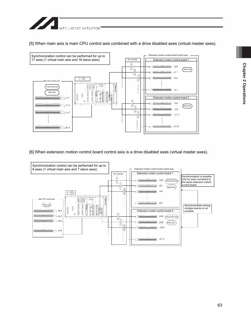
Chapter 2 O
perations
63
[5] When main axis is main CPU control axis combined with a drive disabled axes (virtual master axes).
[6] When extension motion control board control axis is a drive disabled axes (virtual master axes).
RC controller
Slave axis
Extension motion control board 1
Extension motion control board 2
Slave axis
Extension motion control board control axis
Slave axis
RC controller
Slave axis
Extension motion control board 1
Extension motion control board 2
Slave axis
Extension motion control board control axis
Slave axis
Main CPU control axis
Main CPU control axis
Virtual main axis
Virtual main axis
Virtual main axis
Synchronization control can be performed for up to 17 axes (1 virtual main axis and 16 slave axes)
Synchronization control can be performed for up to 8 axes (1 virtual main axis and 7 slave axes)
Synchronization is possible only for axes connected to the same extension motion control board.
Synchronization among multiple boards is not possible
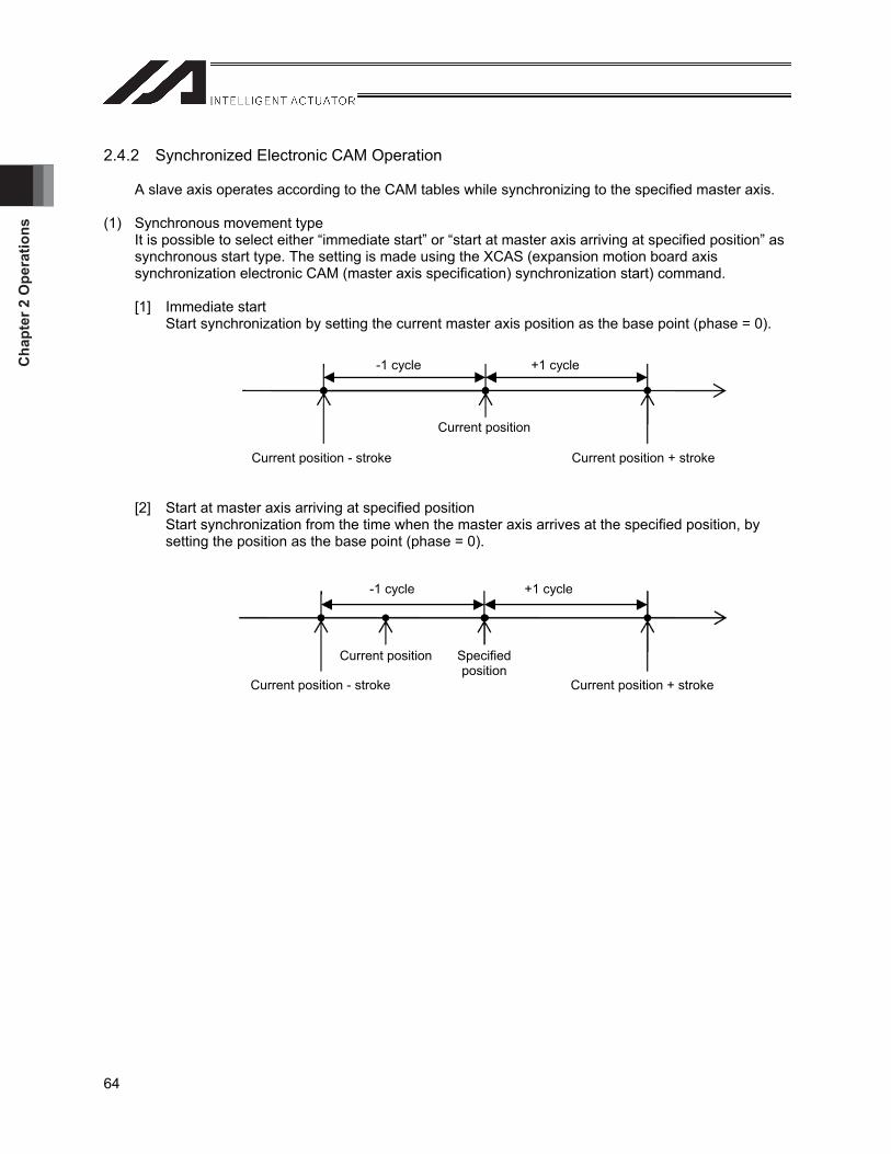
Cha
pter
2 O
pera
tions
64
2.4.2 Synchronized Electronic CAM Operation
A slave axis operates according to the CAM tables while synchronizing to the specified master axis.
(1) Synchronous movement type It is possible to select either “immediate start” or “start at master axis arriving at specified position” as synchronous start type. The setting is made using the XCAS (expansion motion board axis synchronization electronic CAM (master axis specification) synchronization start) command.
[1] Immediate start Start synchronization by setting the current master axis position as the base point (phase = 0).
[2] Start at master axis arriving at specified position Start synchronization from the time when the master axis arrives at the specified position, by setting the position as the base point (phase = 0).
-1 cycle +1 cycle
Current position
Current position - stroke Current position + stroke
-1 cycle +1 cycle
Current position Specified position
Current position - stroke Current position + stroke
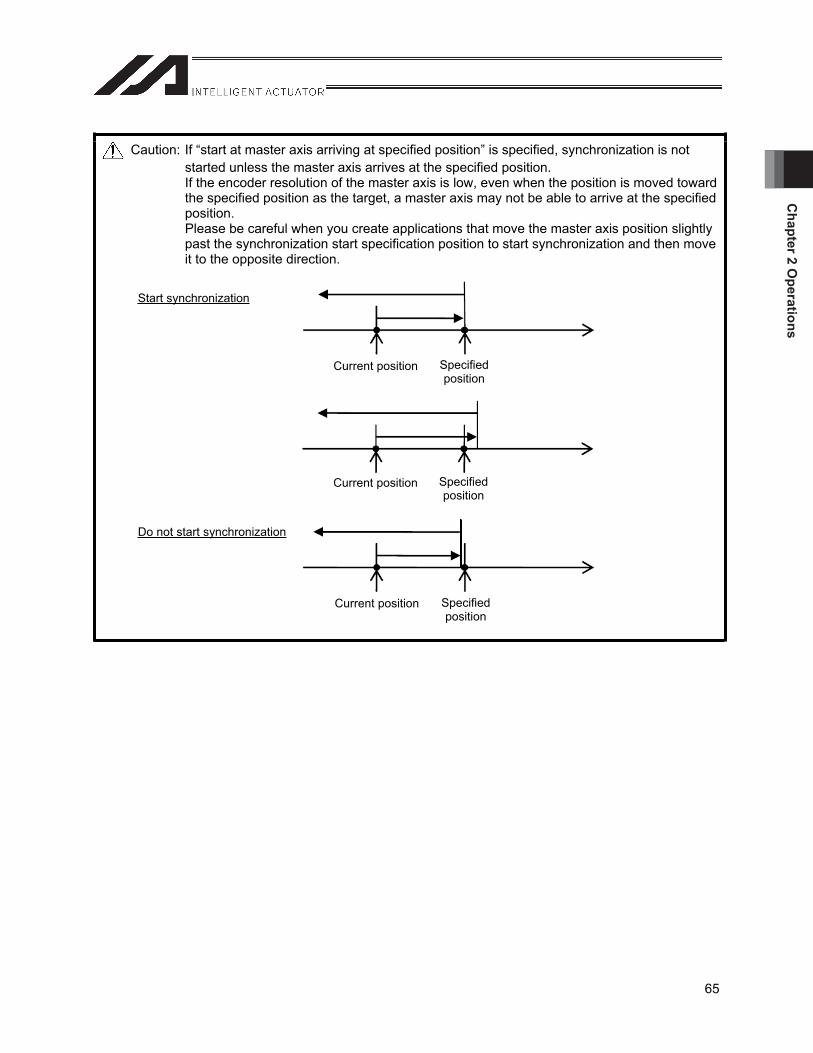
Chapter 2 O
perations
65
Caution: If “start at master axis arriving at specified position” is specified, synchronization is not started unless the master axis arrives at the specified position. If the encoder resolution of the master axis is low, even when the position is moved toward the specified position as the target, a master axis may not be able to arrive at the specified position. Please be careful when you create applications that move the master axis position slightly past the synchronization start specification position to start synchronization and then move it to the opposite direction.
Start synchronization
Do not start synchronization
Current position Specified position
Current position Specified position
Current position Specified position
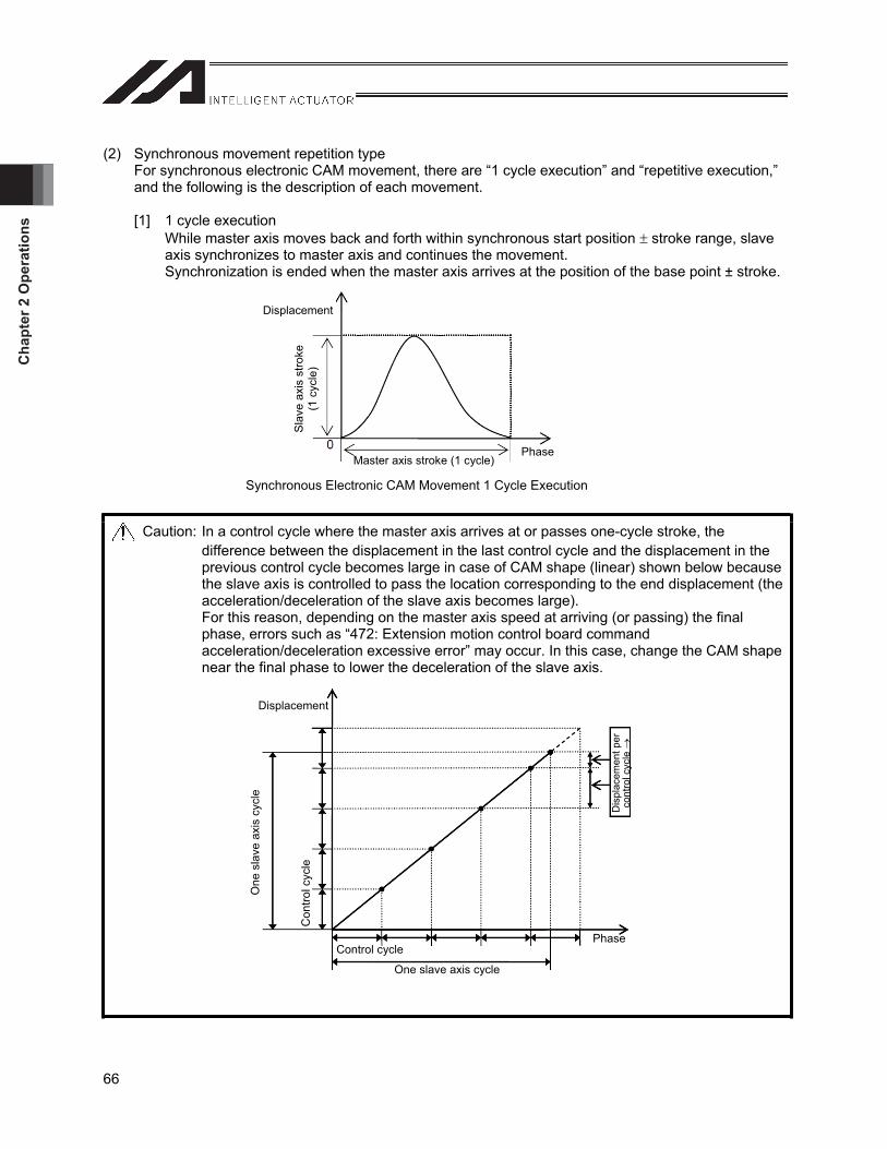
Cha
pter
2 O
pera
tions
66
(2) Synchronous movement repetition type For synchronous electronic CAM movement, there are “1 cycle execution” and “repetitive execution,” and the following is the description of each movement.
[1] 1 cycle execution While master axis moves back and forth within synchronous start position stroke range, slave axis synchronizes to master axis and continues the movement. Synchronization is ended when the master axis arrives at the position of the base point ± stroke.
Caution: In a control cycle where the master axis arrives at or passes one-cycle stroke, the difference between the displacement in the last control cycle and the displacement in the previous control cycle becomes large in case of CAM shape (linear) shown below because the slave axis is controlled to pass the location corresponding to the end displacement (the acceleration/deceleration of the slave axis becomes large). For this reason, depending on the master axis speed at arriving (or passing) the final phase, errors such as “472: Extension motion control board command acceleration/deceleration excessive error” may occur. In this case, change the CAM shape near the final phase to lower the deceleration of the slave axis.
DisplacementS
lave
axi
s st
roke
(1
cyc
le)
Master axis stroke (1 cycle) Phase
Synchronous Electronic CAM Movement 1 Cycle Execution
Displacement
One
sla
ve a
xis
cycl
e
Con
trol c
ycle
Dis
plac
emen
t per
co
ntro
l cyc
le
PhaseControl cycle
One slave axis cycle

Chapter 2 O
perations
67
[2] Repetitive execution Each time master axis conducts the movement of specified stroke, returns to synchronous starting phase and repeats synchronous movement setting the current position as origin. Synchronization is finished if the following factors to stop synchronization occur.
When synchronization end command is executed (XSYE command) At servo OFF At emergency stop At occurrence of error more serious than operation cancellation level error
Figure 2.4.2 Synchronous Electronic CAM Movement Repetitive Execution
Displacement
Sla
ve a
xis
stro
ke
(1 c
ycle
)
Master axis stroke (1 cycle) Master axis stroke (1 cycle) Phase
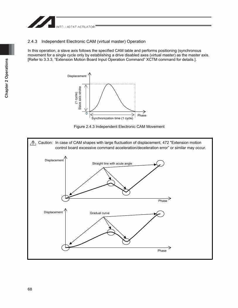
Cha
pter
2 O
pera
tions
68
2.4.3 Independent Electronic CAM (virtual master) Operation
In this operation, a slave axis follows the specified CAM table and performs positioning (synchronous movement for a single cycle only by establishing a drive disabled axes (virtual master) as the master axis. [Refer to 3.3.3, “Extension Motion Board Input Operation Command” XCTM command for details.].
Figure 2.4.3 Independent Electronic CAM Movement
Caution: In case of CAM shapes with large fluctuation of displacement, 472 "Extension motion control board excessive command acceleration/deceleration error” or similar may occur.
Displacement(1
cyc
le)
Sla
ve a
xis
stro
ke
PhaseSynchronization time (1 cycle)
Displacement
Phase
Displacement
Phase
Straight line with acute angle
Gradual curve
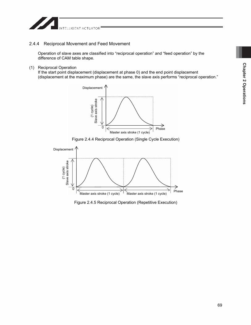
Chapter 2 O
perations
69
2.4.4 Reciprocal Movement and Feed Movement
Operation of slave axes are classified into “reciprocal operation” and “feed operation” by the difference of CAM table shape.
(1) Reciprocal Operation If the start point displacement (displacement at phase 0) and the end point displacement (displacement at the maximum phase) are the same, the slave axis performs “reciprocal operation.”
Figure 2.4.4 Reciprocal Operation (Single Cycle Execution)
Figure 2.4.5 Reciprocal Operation (Repetitive Execution)
Displacement(1
cyc
le)
Sla
ve a
xis
stro
ke
PhaseMaster axis stroke (1 cycle)
Displacement
(1 c
ycle
) S
lave
axi
s st
roke
Master axis stroke (1 cycle) Master axis stroke (1 cycle) Phase
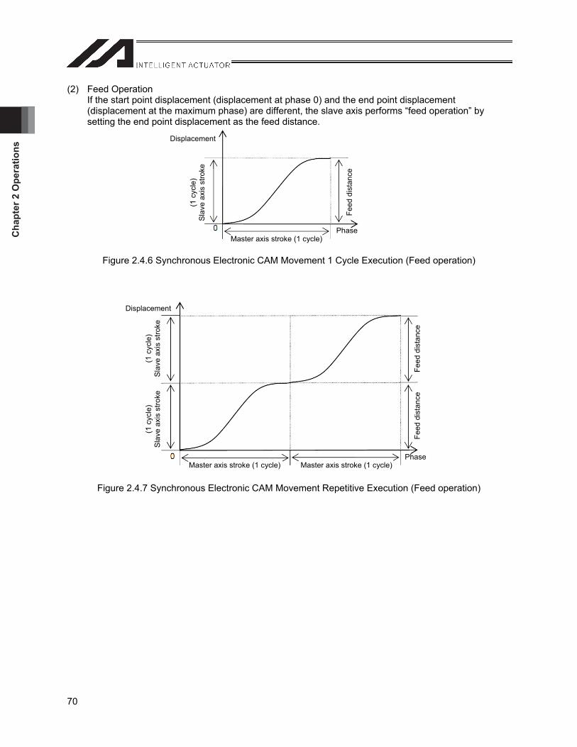
Cha
pter
2 O
pera
tions
70
(2) Feed Operation If the start point displacement (displacement at phase 0) and the end point displacement (displacement at the maximum phase) are different, the slave axis performs “feed operation” by setting the end point displacement as the feed distance.
Figure 2.4.6 Synchronous Electronic CAM Movement 1 Cycle Execution (Feed operation)
Figure 2.4.7 Synchronous Electronic CAM Movement Repetitive Execution (Feed operation)
Displacement
(1 c
ycle
) S
lave
axi
s st
roke
Master axis stroke (1 cycle) Phase
Feed
dis
tanc
e
Displacement
(1 c
ycle
) S
lave
axi
s st
roke
Master axis stroke (1 cycle)
(1 c
ycle
) S
lave
axi
s st
roke
Feed
dis
tanc
e Fe
ed d
ista
nce
PhaseMaster axis stroke (1 cycle)
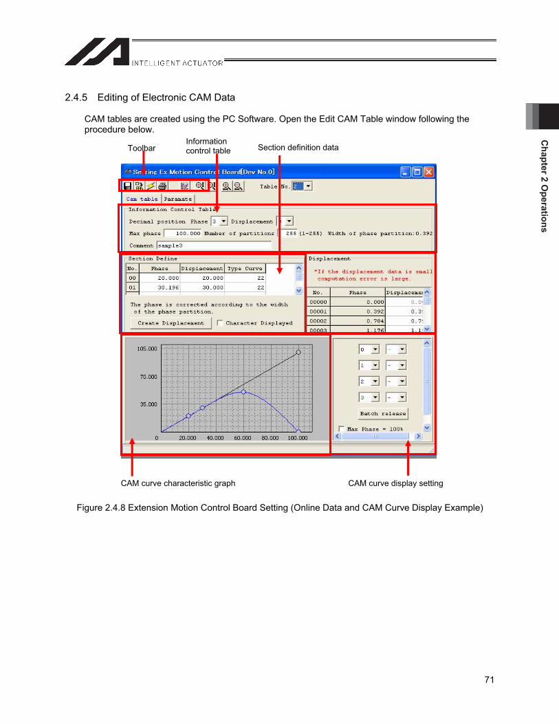
Chapter 2 O
perations
71
2.4.5 Editing of Electronic CAM Data
CAM tables are created using the PC Software. Open the Edit CAM Table window following the procedure below.
Figure 2.4.8 Extension Motion Control Board Setting (Online Data and CAM Curve Display Example)
Toolbar Informationcontrol table Section definition data
CAM curve characteristic graph CAM curve display setting
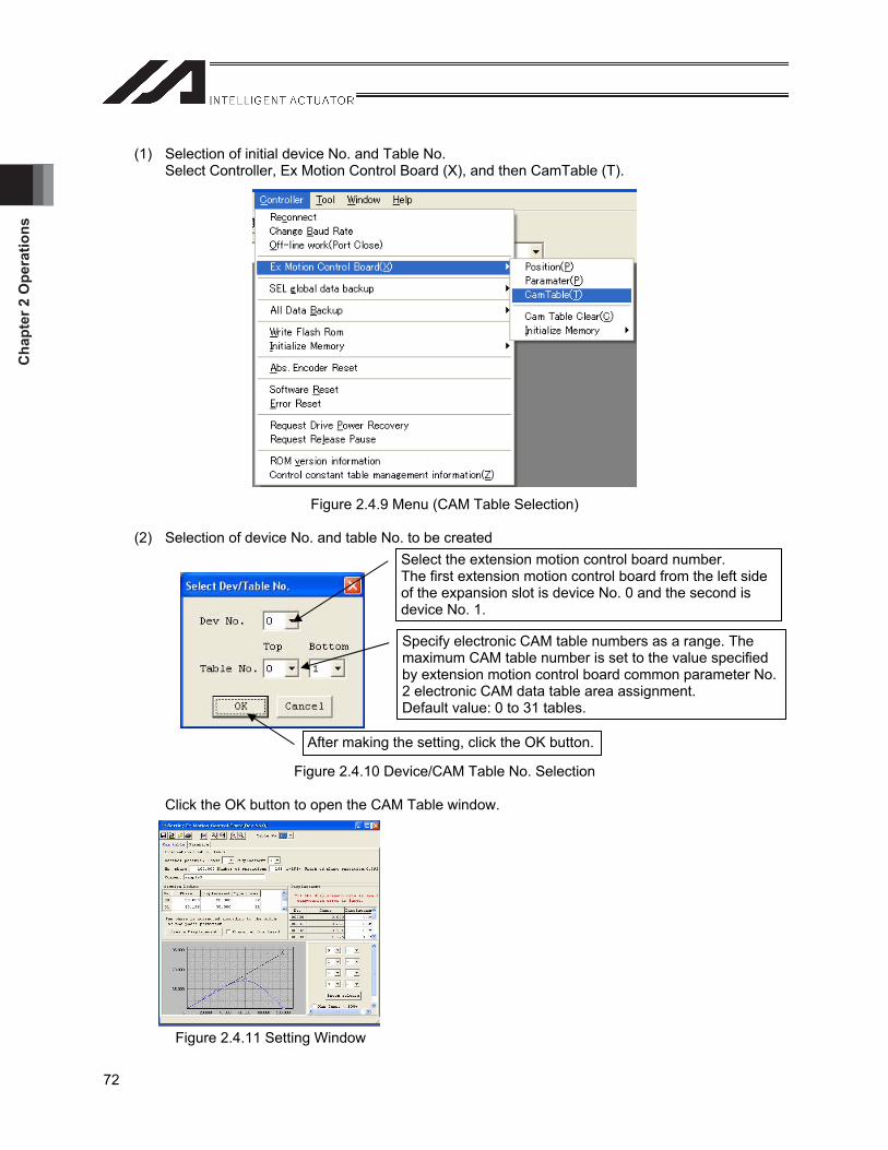
Cha
pter
2 O
pera
tions
72
(1) Selection of initial device No. and Table No. Select Controller, Ex Motion Control Board (X), and then CamTable (T).
Figure 2.4.9 Menu (CAM Table Selection)
(2) Selection of device No. and table No. to be created
Figure 2.4.10 Device/CAM Table No. Selection
Click the OK button to open the CAM Table window.
Figure 2.4.11 Setting Window
Select the extension motion control board number. The first extension motion control board from the left side of the expansion slot is device No. 0 and the second is device No. 1.
Specify electronic CAM table numbers as a range. The maximum CAM table number is set to the value specified by extension motion control board common parameter No. 2 electronic CAM data table area assignment. Default value: 0 to 31 tables.
After making the setting, click the OK button.
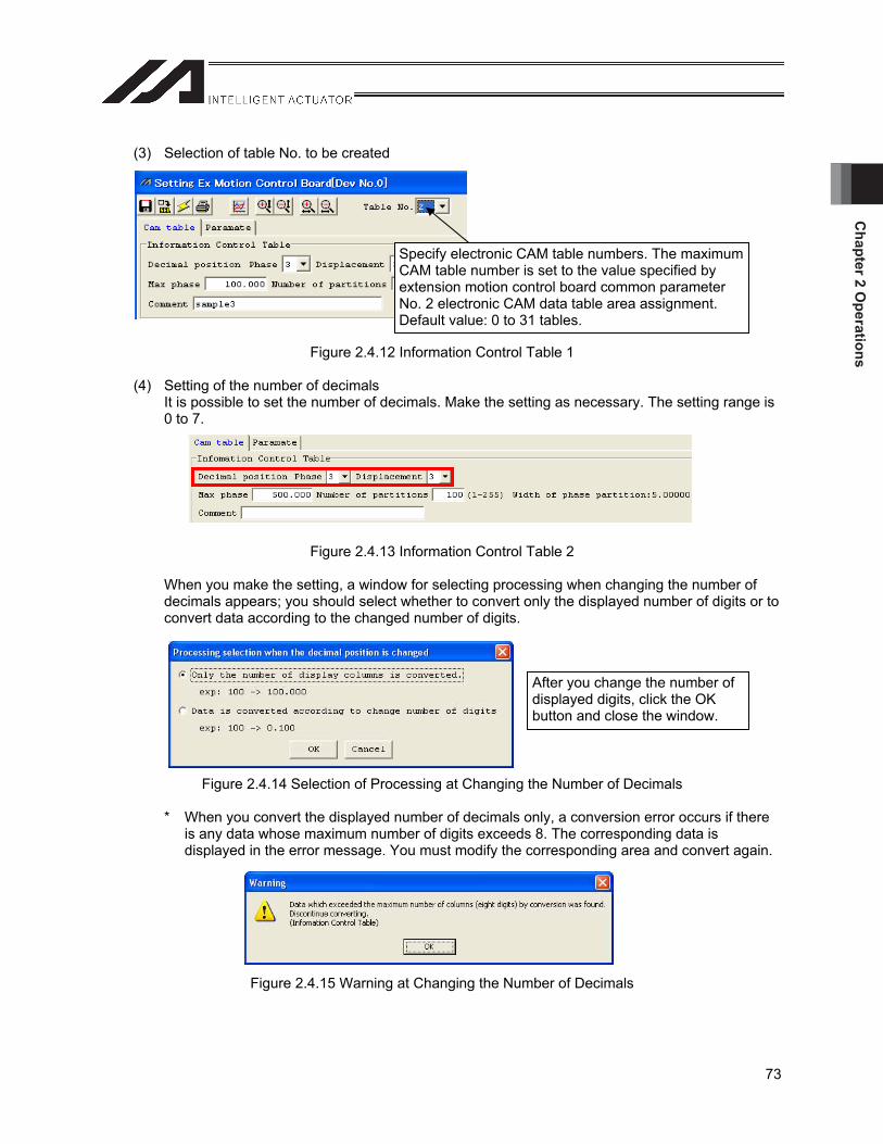
Chapter 2 O
perations
73
(3) Selection of table No. to be created
Figure 2.4.12 Information Control Table 1
(4) Setting of the number of decimals It is possible to set the number of decimals. Make the setting as necessary. The setting range is 0 to 7.
Figure 2.4.13 Information Control Table 2
When you make the setting, a window for selecting processing when changing the number of decimals appears; you should select whether to convert only the displayed number of digits or to convert data according to the changed number of digits.
Figure 2.4.14 Selection of Processing at Changing the Number of Decimals
* When you convert the displayed number of decimals only, a conversion error occurs if there is any data whose maximum number of digits exceeds 8. The corresponding data is displayed in the error message. You must modify the corresponding area and convert again.
Figure 2.4.15 Warning at Changing the Number of Decimals
Specify electronic CAM table numbers. The maximum CAM table number is set to the value specified by extension motion control board common parameter No. 2 electronic CAM data table area assignment. Default value: 0 to 31 tables.
After you change the number of displayed digits, click the OK button and close the window.
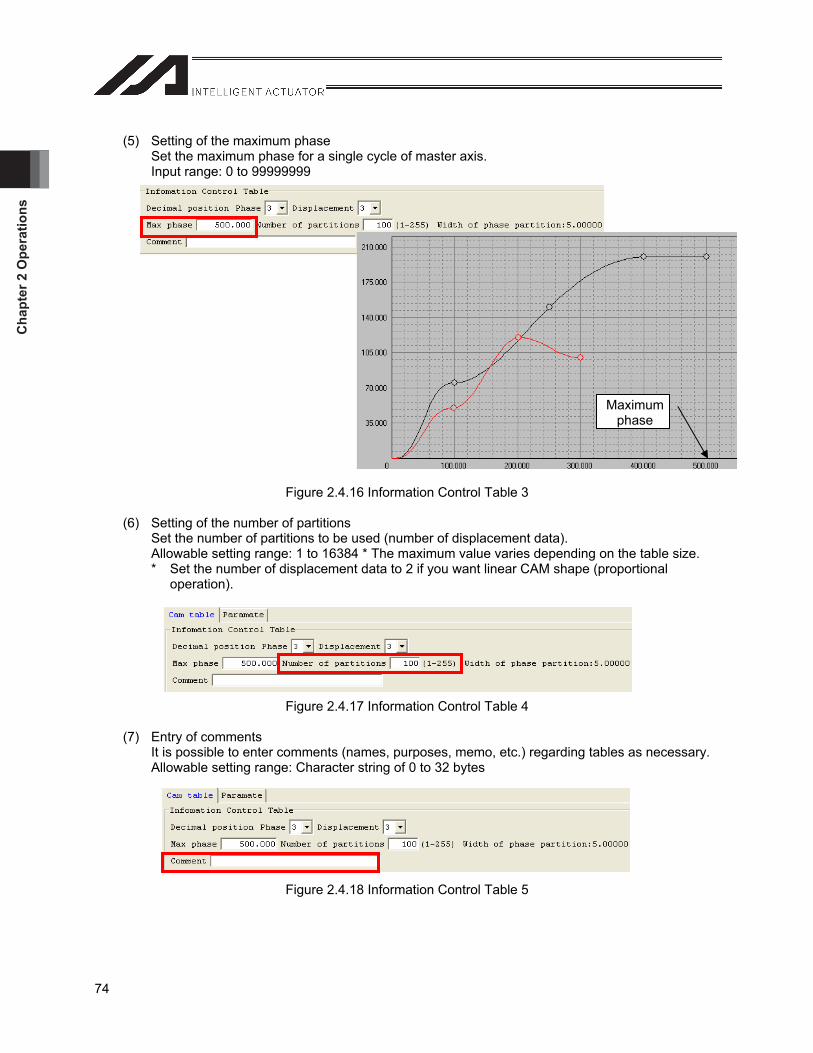
Cha
pter
2 O
pera
tions
74
(5) Setting of the maximum phase Set the maximum phase for a single cycle of master axis. Input range: 0 to 99999999
Figure 2.4.16 Information Control Table 3
(6) Setting of the number of partitions Set the number of partitions to be used (number of displacement data). Allowable setting range: 1 to 16384 * The maximum value varies depending on the table size. * Set the number of displacement data to 2 if you want linear CAM shape (proportional
operation).
Figure 2.4.17 Information Control Table 4
(7) Entry of comments It is possible to enter comments (names, purposes, memo, etc.) regarding tables as necessary. Allowable setting range: Character string of 0 to 32 bytes
Figure 2.4.18 Information Control Table 5
Maximumphase
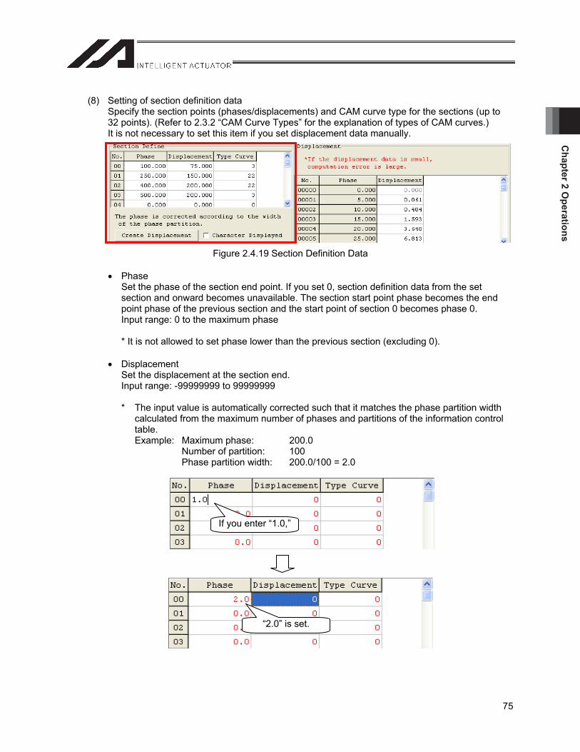
Chapter 2 O
perations
75
(8) Setting of section definition data Specify the section points (phases/displacements) and CAM curve type for the sections (up to 32 points). (Refer to 2.3.2 “CAM Curve Types” for the explanation of types of CAM curves.) It is not necessary to set this item if you set displacement data manually.
Figure 2.4.19 Section Definition Data
Phase Set the phase of the section end point. If you set 0, section definition data from the set section and onward becomes unavailable. The section start point phase becomes the end point phase of the previous section and the start point of section 0 becomes phase 0. Input range: 0 to the maximum phase
* It is not allowed to set phase lower than the previous section (excluding 0).
Displacement Set the displacement at the section end. Input range: -99999999 to 99999999
* The input value is automatically corrected such that it matches the phase partition width calculated from the maximum number of phases and partitions of the information control table.Example: Maximum phase: 200.0 Number of partition: 100 Phase partition width: 200.0/100 = 2.0
If you enter “1.0,”
“2.0” is set.
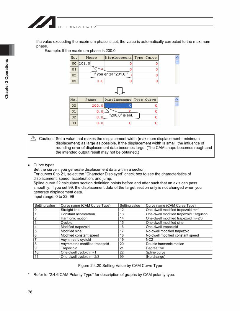
Cha
pter
2 O
pera
tions
76
If a value exceeding the maximum phase is set, the value is automatically corrected to the maximum phase.
Example: If the maximum phase is 200.0
Caution: Set a value that makes the displacement width (maximum displacement - minimum displacement) as large as possible. If the displacement width is small, the influence of rounding error of displacement data becomes large. (The CAM shape becomes rough and the intended output result may not be obtained.)
Curve types Set the curve if you generate displacement data within a section. For curves 0 to 21, select the “Character Displayed” check box to see the characteristics of displacement, speed, acceleration, and jump. Spline curve 22 calculates section definition points before and after such that an axis can pass smoothly. If you set 99, the displacement data of the target section only is not changed when you generate displacement data. Input range: 0 to 22, 99
Setting value Curve name (CAM Curve Type) Setting value Curve name (CAM Curve Type) 0 Straight line 12 One-dwell modified trapezoid m=1 1 Constant acceleration 13 One-dwell modified trapezoid Ferguson 2 Harmonic motion 14 One-dwell modified trapezoid m=2/3 3 Cycloid 15 One-dwell modified sine 4 Modified trapezoid 16 One-dwell trapecloid 5 Modified sine 17 No-dwell modified trapezoid 6 Modified constant speed 18 No-dwell modified constant speed 7 Asymmetric cycloid 19 NC2 8 Asymmetric modified trapezoid 20 Double harmonic motion 9 Trapecloid 21 Degree five 10 One-dwell cycloid m=1 22 Spline curve 11 One-dwell cycloid m=2/3 99 (No change)
Figure 2.4.20 Setting Value by CAM Curve Type
* Refer to “2.4.6 CAM Polarity Type” for description of graphs by CAM polarity type.
If you enter “201.0,”
“200.0” is set.
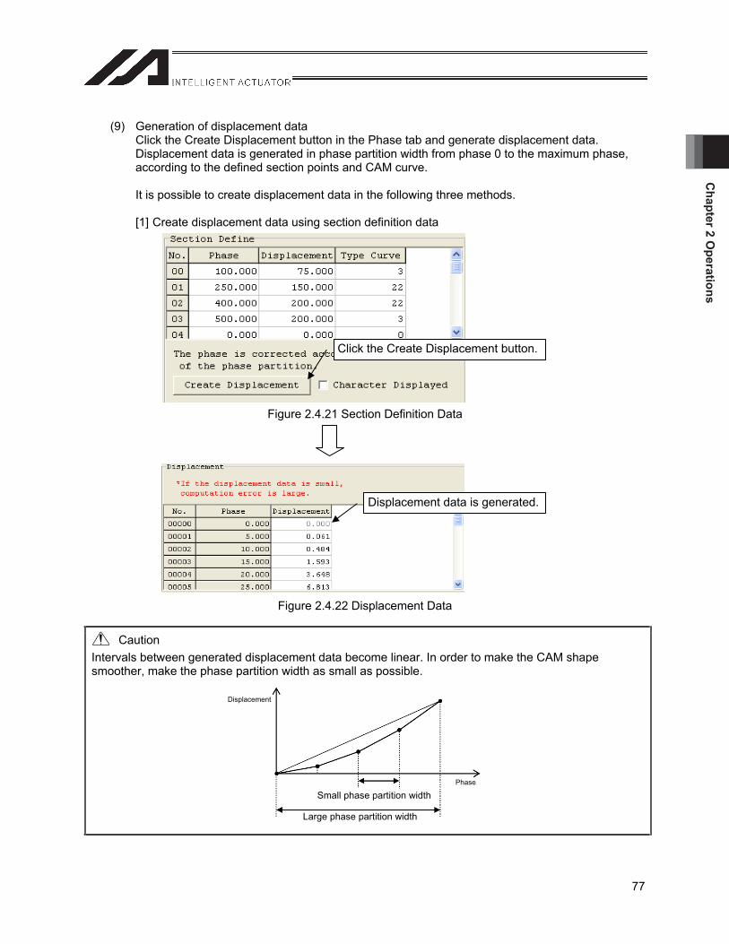
Chapter 2 O
perations
77
(9) Generation of displacement data Click the Create Displacement button in the Phase tab and generate displacement data. Displacement data is generated in phase partition width from phase 0 to the maximum phase, according to the defined section points and CAM curve.
It is possible to create displacement data in the following three methods.
[1] Create displacement data using section definition data
Figure 2.4.21 Section Definition Data
Figure 2.4.22 Displacement Data
Caution Intervals between generated displacement data become linear. In order to make the CAM shape smoother, make the phase partition width as small as possible.
Click the Create Displacement button.
Displacement data is generated.
Displacement
Phase
Small phase partition width
Large phase partition width
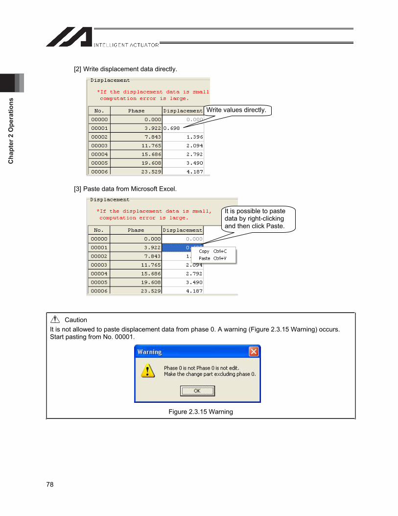
Cha
pter
2 O
pera
tions
78
[2] Write displacement data directly.
[3] Paste data from Microsoft Excel.
Caution It is not allowed to paste displacement data from phase 0. A warning (Figure 2.3.15 Warning) occurs. Start pasting from No. 00001.
Figure 2.3.15 Warning
Write values directly.
It is possible to paste data by right-clicking and then click Paste.
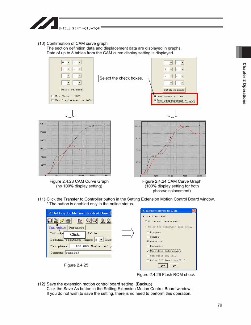
Chapter 2 O
perations
79
(10) Confirmation of CAM curve graph The section definition data and displacement data are displayed in graphs. Data of up to 8 tables from the CAM curve display setting is displayed.
(11) Click the Transfer to Controller button in the Setting Extension Motion Control Board window. * The button is enabled only in the online status.
Figure 2.4.25
Figure 2.4.26 Flash ROM check
(12) Save the extension motion control board setting. (Backup) Click the Save As button in the Setting Extension Motion Control Board window. If you do not wish to save the setting, there is no need to perform this operation.
Select the check boxes.
Figure 2.4.23 CAM Curve Graph (no 100% display setting)
Figure 2.4.24 CAM Curve Graph (100% display setting for both
phase/displacement)
Click.
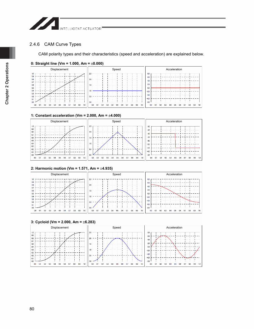
Cha
pter
2 O
pera
tions
80
2.4.6 CAM Curve Types
CAM polarity types and their characteristics (speed and acceleration) are explained below.
2: Harmonic motion (Vm = 1.571, Am = 4.935)
0: Straight line (Vm = 1.000, Am = 0.000)
1: Constant acceleration (Vm = 2.000, Am = 4.000)
3: Cycloid (Vm = 2.000, Am = 6.283)
Displacement Speed Acceleration
Displacement Speed Acceleration
Displacement Speed Acceleration
Displacement Speed Acceleration
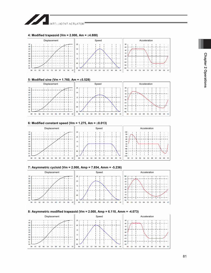
Chapter 2 O
perations
81
4: Modified trapezoid (Vm = 2.000, Am = 4.888)
5: Modified sine (Vm = 1.760, Am = 5.528)
Displacement Speed Acceleration
6: Modified constant speed (Vm = 1.275, Am = 8.013)
7: Asymmetric cycloid (Vm = 2.000, Amp = 7.854, Amm = -5.236)
8: Asymmetric modified trapezoid (Vm = 2.000, Amp = 6.110, Amm = -4.073)
Displacement Speed Acceleration
Displacement Speed Acceleration
Displacement Speed Acceleration
Displacement Speed Acceleration
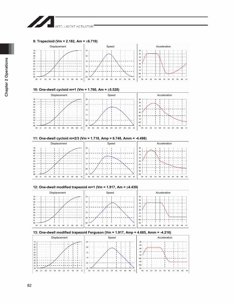
Cha
pter
2 O
pera
tions
82
9: Trapecloid (Vm = 2.182, Am = 6.710)
10: One-dwell cycloid m=1 (Vm = 1.760, Am = 5.528)
11: One-dwell cycloid m=2/3 (Vm = 1.718, Amp = 6.748, Amm = -4.498)
12: One-dwell modified trapezoid m=1 (Vm = 1.917, Am = 4.439)
13: One-dwell modified trapezoid Ferguson (Vm = 1.917, Amp = 4.685, Amm = -4.216)
Displacement Speed Acceleration
Displacement Speed Acceleration
Displacement Speed Acceleration
Displacement Speed Acceleration
Displacement Speed Acceleration
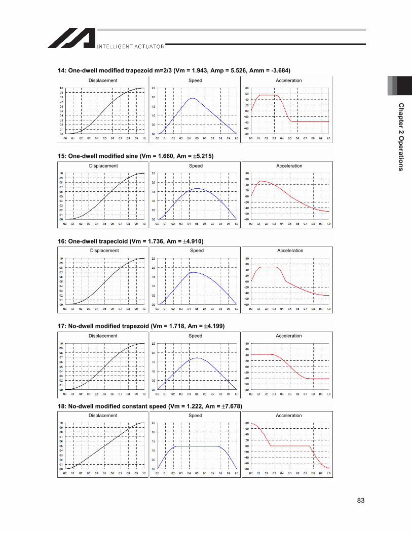
Chapter 2 O
perations
83
14: One-dwell modified trapezoid m=2/3 (Vm = 1.943, Amp = 5.526, Amm = -3.684)
15: One-dwell modified sine (Vm = 1.660, Am = 5.215)
16: One-dwell trapecloid (Vm = 1.736, Am = 4.910)
17: No-dwell modified trapezoid (Vm = 1.718, Am = 4.199)
18: No-dwell modified constant speed (Vm = 1.222, Am = 7.678)
Displacement Speed Acceleration
Displacement Speed Acceleration
Displacement Speed Acceleration
Displacement Speed Acceleration
Displacement Speed Acceleration
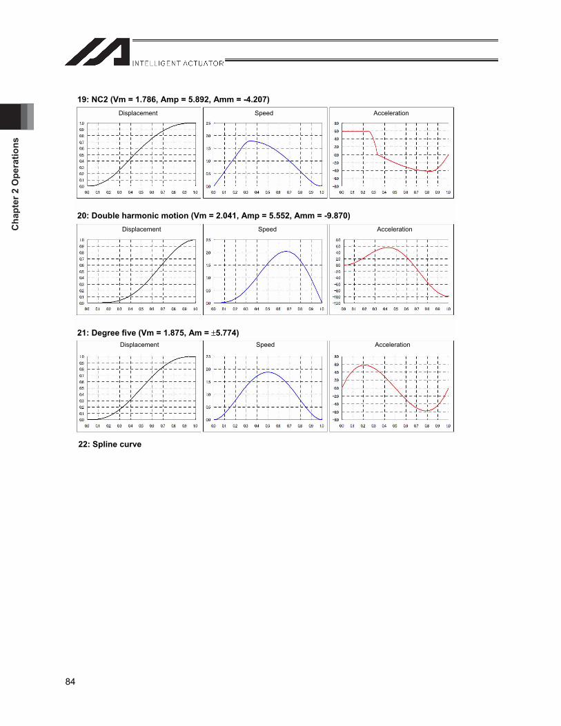
Cha
pter
2 O
pera
tions
84
22: Spline curve
19: NC2 (Vm = 1.786, Amp = 5.892, Amm = -4.207)
20: Double harmonic motion (Vm = 2.041, Amp = 5.552, Amm = -9.870)
21: Degree five (Vm = 1.875, Am = 5.774)
Displacement Speed Acceleration
Displacement Speed Acceleration
Displacement Speed Acceleration
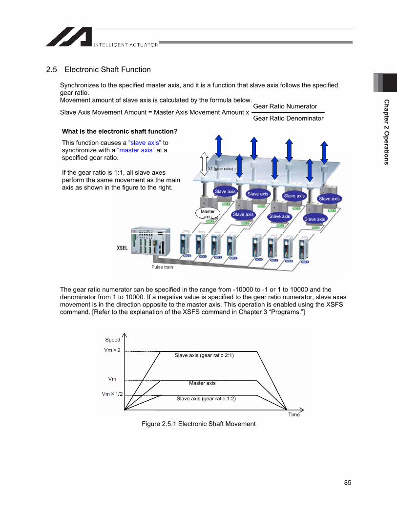
Chapter 2 O
perations
85
2.5 Electronic Shaft Function
Synchronizes to the specified master axis, and it is a function that slave axis follows the specified gear ratio. Movement amount of slave axis is calculated by the formula below.
Gear Ratio Numerator Slave Axis Movement Amount = Master Axis Movement Amount x
Gear Ratio Denominator
The gear ratio numerator can be specified in the range from -10000 to -1 or 1 to 10000 and the denominator from 1 to 10000. If a negative value is specified to the gear ratio numerator, slave axes movement is in the direction opposite to the master axis. This operation is enabled using the XSFS command. [Refer to the explanation of the XSFS command in Chapter 3 “Programs.”]
Figure 2.5.1 Electronic Shaft Movement
What is the electronic shaft function?
This function causes a “slave axis” to synchronize with a “master axis” at a specified gear ratio.
If the gear ratio is 1:1, all slave axes perform the same movement as the main axis as shown in the figure to the right.
X1 (gear ratio) =
Slave axis Slave axis Slave axis Slave axis
Slave axis Slave axis Slave axis
Master axis
Pulse train
Speed
Slave axis (gear ratio 2:1)
Master axis
Slave axis (gear ratio 1:2)
Time
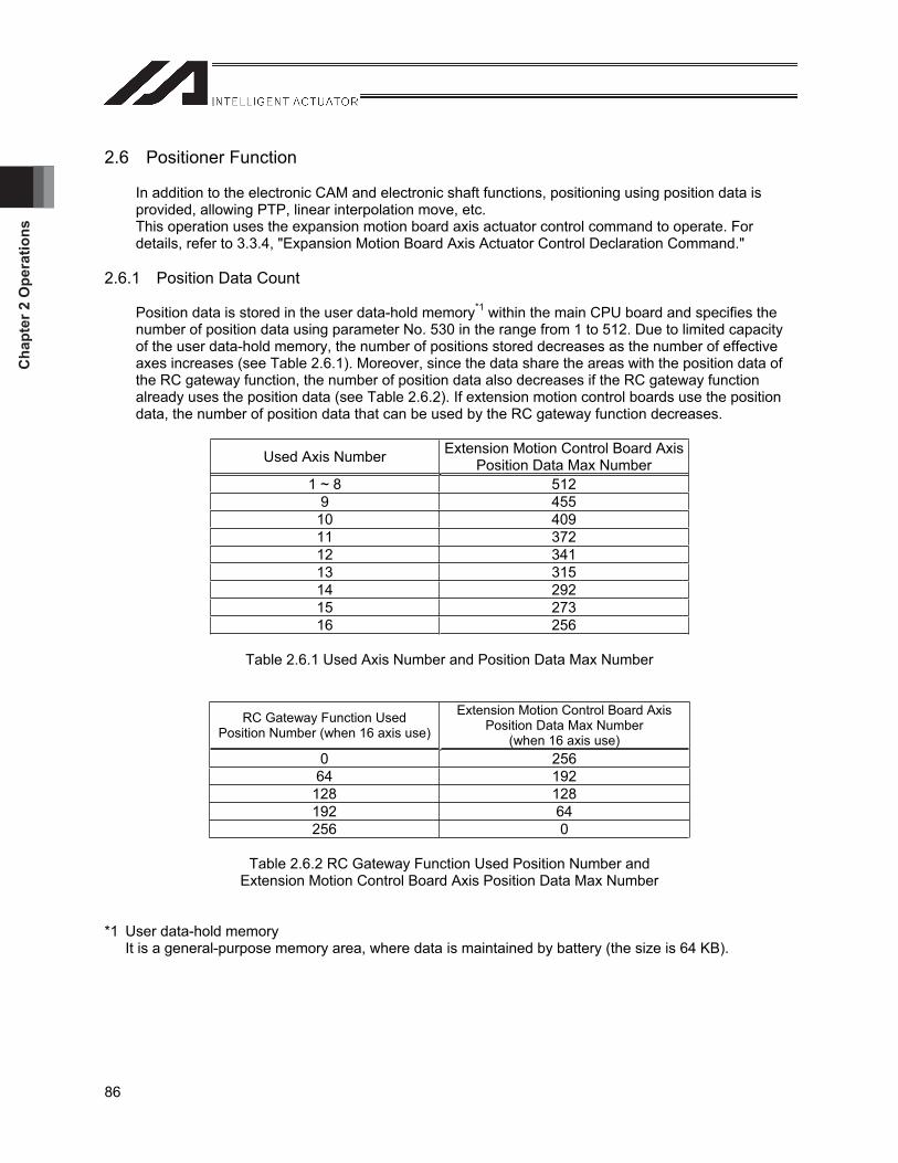
Cha
pter
2 O
pera
tions
86
2.6 Positioner Function
In addition to the electronic CAM and electronic shaft functions, positioning using position data is provided, allowing PTP, linear interpolation move, etc. This operation uses the expansion motion board axis actuator control command to operate. For details, refer to 3.3.4, "Expansion Motion Board Axis Actuator Control Declaration Command."
2.6.1 Position Data Count
Position data is stored in the user data-hold memory*1 within the main CPU board and specifies the number of position data using parameter No. 530 in the range from 1 to 512. Due to limited capacity of the user data-hold memory, the number of positions stored decreases as the number of effective axes increases (see Table 2.6.1). Moreover, since the data share the areas with the position data of the RC gateway function, the number of position data also decreases if the RC gateway function already uses the position data (see Table 2.6.2). If extension motion control boards use the position data, the number of position data that can be used by the RC gateway function decreases.
Used Axis Number Extension Motion Control Board Axis Position Data Max Number
1 ~ 8 512 9 455 10 409 11 372 12 341 13 315 14 292 15 273 16 256
Table 2.6.1 Used Axis Number and Position Data Max Number
RC Gateway Function Used Position Number (when 16 axis use)
Extension Motion Control Board Axis Position Data Max Number
(when 16 axis use) 0 256 64 192
128 128 192 64 256 0
Table 2.6.2 RC Gateway Function Used Position Number and Extension Motion Control Board Axis Position Data Max Number
*1 User data-hold memory It is a general-purpose memory area, where data is maintained by battery (the size is 64 KB).
Chapter 2 O
perations
87
Calculation of position data count Position data for extension motion control board axes and the RC gateway function uses 16 bytes of memory per axis and point.
Example: Number of positions that can be used with 16 axes of extension motion control board axes when 8 axes and 64 points of position data are used by the RC gateway function
(User data-hold memory capacity – RC gateway function position data capacity) / (16 [bytes] x number of extension motion control board axes) = (65536 [bytes] – 16 [bytes] x 64 [points] x 8 [axes]) / 16 [bytes] x 16 [axes]) = 224 [points]
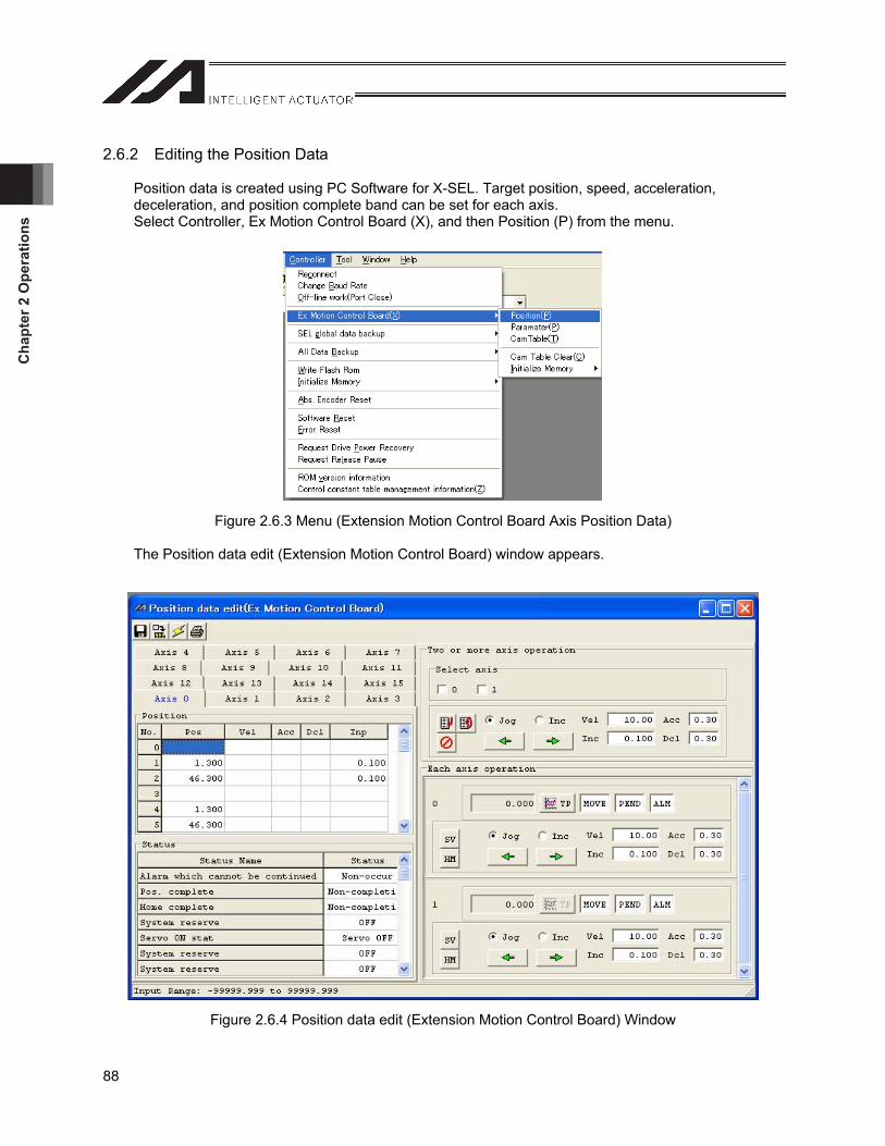
Cha
pter
2 O
pera
tions
88
2.6.2 Editing the Position Data
Position data is created using PC Software for X-SEL. Target position, speed, acceleration, deceleration, and position complete band can be set for each axis. Select Controller, Ex Motion Control Board (X), and then Position (P) from the menu.
Figure 2.6.3 Menu (Extension Motion Control Board Axis Position Data)
The Position data edit (Extension Motion Control Board) window appears.
Figure 2.6.4 Position data edit (Extension Motion Control Board) Window
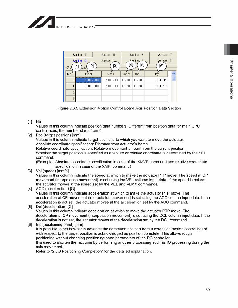
Chapter 2 O
perations
89
Figure 2.6.5 Extension Motion Control Board Axis Position Data Section
[1] No. Values in this column indicate position data numbers. Different from position data for main CPU control axes, the number starts from 0.
[2] Pos (target position) [mm] Values in this column indicate target positions to which you want to move the actuator. Absolute coordinate specification: Distance from actuator’s home Relative coordinate specification: Relative movement amount from the current position Whether the target position is specified as absolute or relative coordinate is determined by the SEL command. (Example: Absolute coordinate specification in case of the XMVP command and relative coordinate
specification in case of the XMPI command) [3] Vel (speed) [mm/s]
Values in this column indicate the speed at which to make the actuator PTP move. The speed at CP movement (interpolation movement) is set using the VEL collumn input data. If the speed is not set, the actuator moves at the speed set by the VEL and VLMX commands.
[4] ACC (acceleration) [G] Values in this column indicate acceleration at which to make the actuator PTP move. The acceleration at CP movement (interpolation movement) is set using the ACC column input data. If the acceleration is not set, the actuator moves at the acceleration set by the ACC command.
[5] Dcl (deceleration) [G] Values in this column indicate deceleration at which to make the actuator PTP move. The deceleration at CP movement (interpolation movement) is set using the DCL column input data. If the deceleration is not set, the actuator moves at the deceleration set by the DCL command.
[6] Inp (positioning band) [mm] It is possible to set how far in advance the command position from a extension motion control board with respect to the target position is acknowledged as position complete. This allows rough positioning without changing positioning band parameters of the RC controller. It is used to shorten the tact time by performing another processing such as IO processing during the axis movement. Refer to “2.6.3 Positioning Completion” for the detailed explanation.
[1] [2] [3] [4] [5] [6]
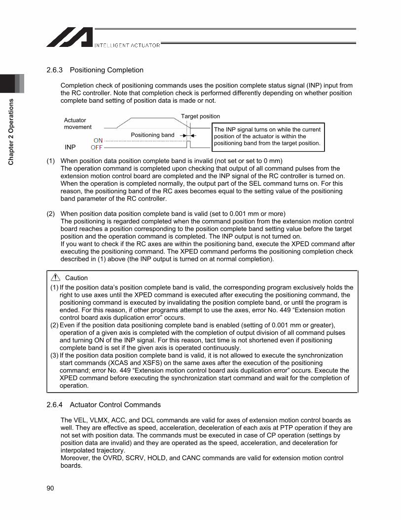
Cha
pter
2 O
pera
tions
90
2.6.3 Positioning Completion
Completion check of positioning commands uses the position complete status signal (INP) input from the RC controller. Note that completion check is performed differently depending on whether position complete band setting of position data is made or not.
(1) When position data position complete band is invalid (not set or set to 0 mm) The operation command is completed upon checking that output of all command pulses from the extension motion control board are completed and the INP signal of the RC controller is turned on. When the operation is completed normally, the output part of the SEL command turns on. For this reason, the positioning band of the RC axes becomes equal to the setting value of the positioning band parameter of the RC controller.
(2) When position data position complete band is valid (set to 0.001 mm or more) The positioning is regarded completed when the command position from the extension motion control board reaches a position corresponding to the position complete band setting value before the target position and the operation command is completed. The INP output is not turned on. If you want to check if the RC axes are within the positioning band, execute the XPED command after executing the positioning command. The XPED command performs the positioning completion check described in (1) above (the INP output is turned on at normal completion).
Caution (1) If the position data’s position complete band is valid, the corresponding program exclusively holds the
right to use axes until the XPED command is executed after executing the positioning command, the positioning command is executed by invalidating the position complete band, or until the program is ended. For this reason, if other programs attempt to use the axes, error No. 449 “Extension motion control board axis duplication error” occurs.
(2) Even if the position data positioning complete band is enabled (setting of 0.001 mm or greater), operation of a given axis is completed with the completion of output division of all command pulses and turning ON of the INP signal. For this reason, tact time is not shortened even if positioning complete band is set if the given axis is operated continuously.
(3) If the position data position complete band is valid, it is not allowed to execute the synchronization start commands (XCAS and XSFS) on the same axes after the execution of the positioning command; error No. 449 “Extension motion control board axis duplication error” occurs. Execute the XPED command before executing the synchronization start command and wait for the completion of operation.
2.6.4 Actuator Control Commands
The VEL, VLMX, ACC, and DCL commands are valid for axes of extension motion control boards as well. They are effective as speed, acceleration, deceleration of each axis at PTP operation if they are not set with position data. The commands must be executed in case of CP operation (settings by position data are invalid) and they are operated as the speed, acceleration, and deceleration for interpolated trajectory. Moreover, the OVRD, SCRV, HOLD, and CANC commands are valid for extension motion control boards.
Actuatormovement
Positioning band
Target position
The INP signal turns on while the current position of the actuator is within the positioning band from the target position. INP
Chapter 2 O
perations
91
2.7 Input Pulse Counter Function
The input pulse channel provides additional functionality beyond usage as the master axis of an electronic CAM. It is possible to count input pulses by a SEL program command, to be used arbitrarily in such applications as an event counter, etc. If it is used as the master axis, use the XCAS command. If you use the function as the event counter, use the XCRP (pulse input count clear) and XGTP (pulse input counter current value acquisition) commands. [Refer to 3.3.3, “Extension Motion Board Input Operation Command” for details.]

Cha
pter
2 O
pera
tions
92
Chapter 3 Program
s
93
Chapter 3 Programs
3.1 Precautions when Creating Programs
3.1.1 Pausing
(1) The HOLD command is valid for axes of extension motion control boards, but the servo is not turned off even if servo OFF type is specified.
(2) During synchronous movement of electronic CAM, etc. setting the main CPU control axis as the master axis, the master axis cannot be paused by the servo OFF type HOLD command. Master and slave axis error No. 461 “Extension motion control board synchronization master axis serve OFF error” occurs.
(3) During synchronous movement of electronic CAM, etc. setting the master axis as a pulse input channel, slave axes cannot be paused. They pause but error No. 462 “Extension motion control board synchronization slave axis restart error” occurs after the pause is cancelled (because synchronization cannot be continued). When slave axes perform synchronization with a program different from the program for moving the master axis, if you pause the slave side program at the HOLD command, the master axis pauses at the same time. If the master axis performs PTP operation, however, other axes operating together with the master axes do not stop. If you want to pause axes operating together with the master axis as well, pause them using the HOLD command of the master axis side program.
3.1.2 Synchronous Movement of Electronic CAM, etc.
(1) It is not allowed to specify synchronous axis or ZR unit as the master axis of electronic CAM or electronic shaft.
(2) If you start the controller after changing electronic CAM table area assignment parameters, the electronic CAM table data is initialized and error No. 51C “Extension motion control board electronic CAM table size inconsistent error” occurs. The controller starts normally by restarting the controller after writing the electronic CAM tables to the Flash ROM. Save the electronic CAM tables to files as required before changing the electronic CAM table area assignment parameters.
(3) If the master axis resolution is too low for slave axes at electronic CAM synchronous movement, the speed may become uneven.
(4) The control between extension motion control boards and each pulse train control driver is open loop. The intended trajectory may not be drawn depending on the mechanical load, sliding friction, etc. of the control target axis. Moreover, the master axis keeps on operating according to the given operation plan unless slave axes stop due to alarm.
(5) If you perform synchronous movement, it is necessary to specify speed, acceleration, and deceleration of the master axis such that the speed, acceleration, and deceleration of slave axes at actual operation do not exceed the maximum speed, acceleration, and deceleration.
(6) If the resolution of the master axis is lower than the resolution of slave axes, error No. 471 “Extension motion control board excessive command speed error,” error No. 472 “Extension motion control board excessive command acceleration/deceleration error,” error No. 473 "Extension motion control board servo command position software limit over error” may occur.
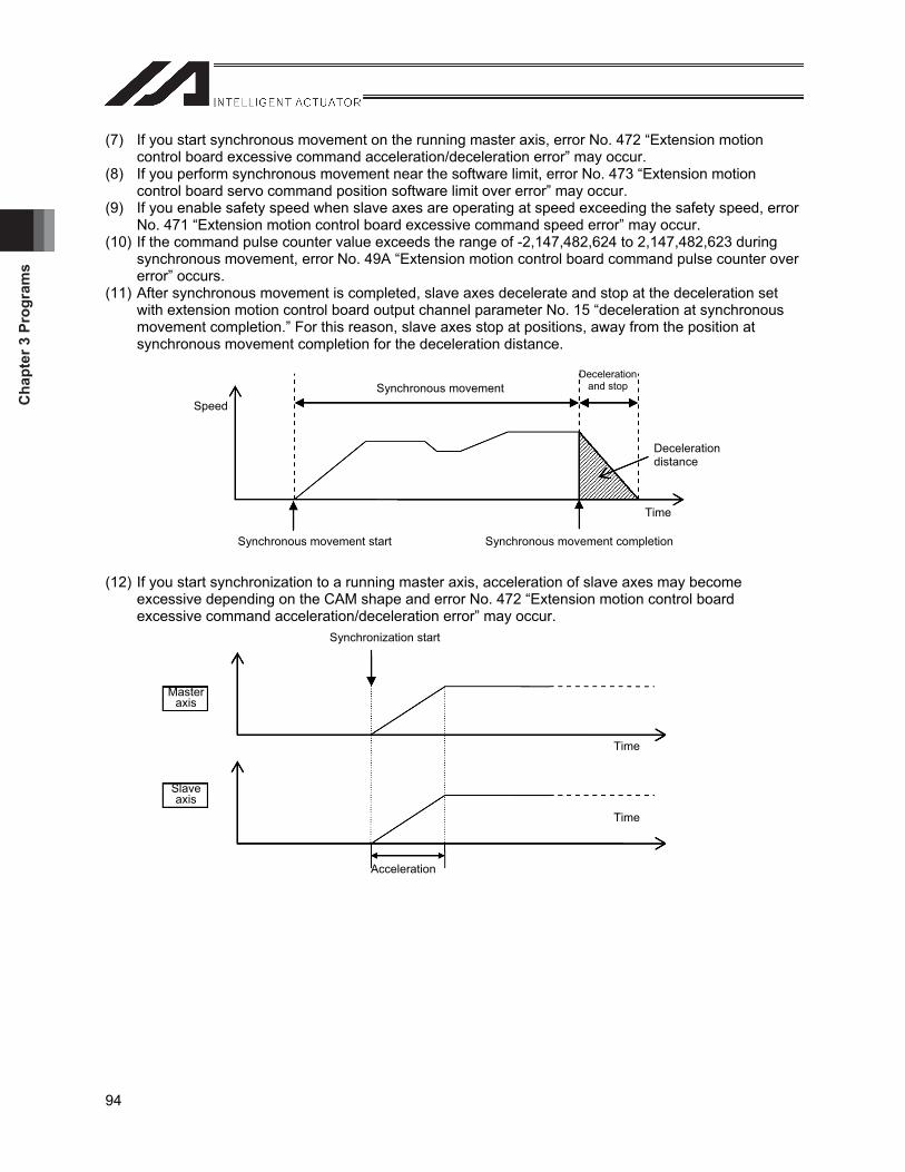
Cha
pter
3 P
rogr
ams
94
(7) If you start synchronous movement on the running master axis, error No. 472 “Extension motion control board excessive command acceleration/deceleration error” may occur.
(8) If you perform synchronous movement near the software limit, error No. 473 “Extension motion control board servo command position software limit over error” may occur.
(9) If you enable safety speed when slave axes are operating at speed exceeding the safety speed, error No. 471 “Extension motion control board excessive command speed error” may occur.
(10) If the command pulse counter value exceeds the range of -2,147,482,624 to 2,147,482,623 during synchronous movement, error No. 49A “Extension motion control board command pulse counter over error” occurs.
(11) After synchronous movement is completed, slave axes decelerate and stop at the deceleration set with extension motion control board output channel parameter No. 15 “deceleration at synchronous movement completion.” For this reason, slave axes stop at positions, away from the position at synchronous movement completion for the deceleration distance.
(12) If you start synchronization to a running master axis, acceleration of slave axes may become excessive depending on the CAM shape and error No. 472 “Extension motion control board excessive command acceleration/deceleration error” may occur.
SpeedSynchronous movement
Deceleration and stop
Decelerationdistance
Time
Synchronous movement start Synchronous movement completion
Time
Time
Synchronization start
Acceleration
Masteraxis
Slaveaxis
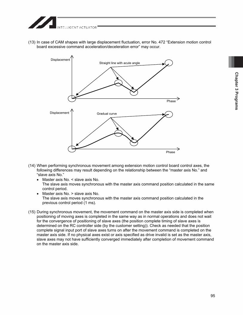
Chapter 3 Program
s
95
(13) In case of CAM shapes with large displacement fluctuation, error No. 472 “Extension motion control board excessive command acceleration/deceleration error” may occur.
(14) When performing synchronous movement among extension motion control board control axes, the following differences may result depending on the relationship between the “master axis No.” and “slave axis No.” Master axis No. < slave axis No.
The slave axis moves synchronous with the master axis command position calculated in the same control period.
Master axis No. > slave axis No. The slave axis moves synchronous with the master axis command position calculated in the previous control period (1 ms).
(15) During synchronous movement, the movement command on the master axis side is completed when positioning of moving axes is completed in the same way as in normal operations and does not wait for the convergence of positioning of slave axes (the position complete timing of slave axes is determined on the RC controller side (by the customer setting)). Check as needed that the position complete signal input port of slave axes turns on after the movement command is completed on the master axis side. If no physical axes exist or axis specified as drive invalid is set as the master axis, slave axes may not have sufficiently converged immediately after completion of movement command on the master axis side.
Displacement
Phase
Displacement
Phase
Straight line with acute angle
Gradual curve
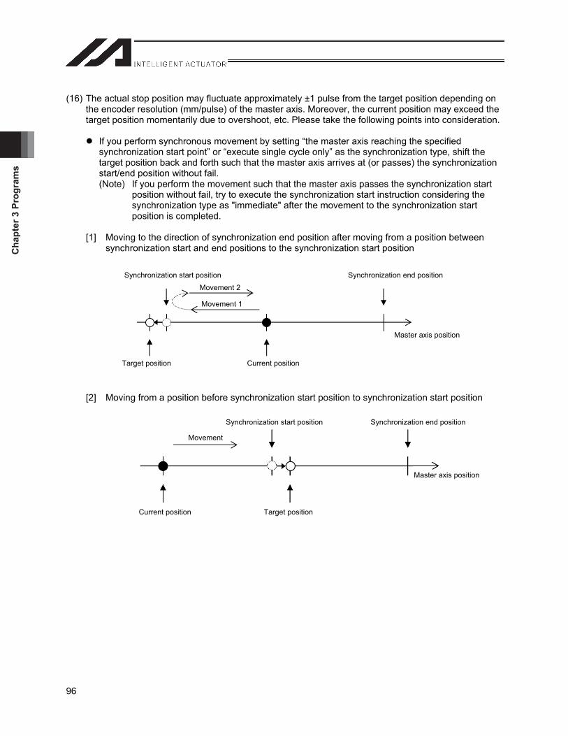
Cha
pter
3 P
rogr
ams
96
(16) The actual stop position may fluctuate approximately ±1 pulse from the target position depending on the encoder resolution (mm/pulse) of the master axis. Moreover, the current position may exceed the target position momentarily due to overshoot, etc. Please take the following points into consideration.
If you perform synchronous movement by setting “the master axis reaching the specified synchronization start point” or “execute single cycle only” as the synchronization type, shift the target position back and forth such that the master axis arrives at (or passes) the synchronization start/end position without fail. (Note) If you perform the movement such that the master axis passes the synchronization start
position without fail, try to execute the synchronization start instruction considering the synchronization type as "immediate" after the movement to the synchronization start position is completed.
[1] Moving to the direction of synchronization end position after moving from a position between synchronization start and end positions to the synchronization start position
[2] Moving from a position before synchronization start position to synchronization start position
Synchronization start position Synchronization end position
Movement 2
Movement 1
Master axis position
Target position Current position
Synchronization start position Synchronization end position
Master axis position
Current position Target position
Movement
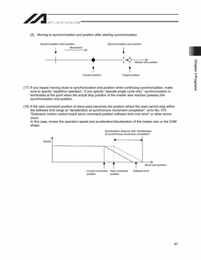
Chapter 3 Program
s
97
[3] Moving to synchronization end position after starting synchronization
(17) If you repeat moving close to synchronization end position while continuing synchronization, make sure to specify “repetitive operation.” If you specify “operate single cycle only,” synchronization is terminated at the point when the actual stop position of the master axis reaches (passes) the synchronization end position.
(18) If the next command position of slave axes becomes the position where the axes cannot stop within the software limit range at “deceleration at synchronous movement completion”, error No. 473 "Extension motion control board servo command position software limit over error” or other errors occur.In this case, review the operation speed and acceleration/deceleration of the master axis or the CAM shape.
Speed
Deceleration distance with “deceleration at synchronous movement completion”
Current command position
Next command position
Software limit
Slave axis position
Synchronization start position Synchronization end position
Master axis position
Current position Target position
Movement
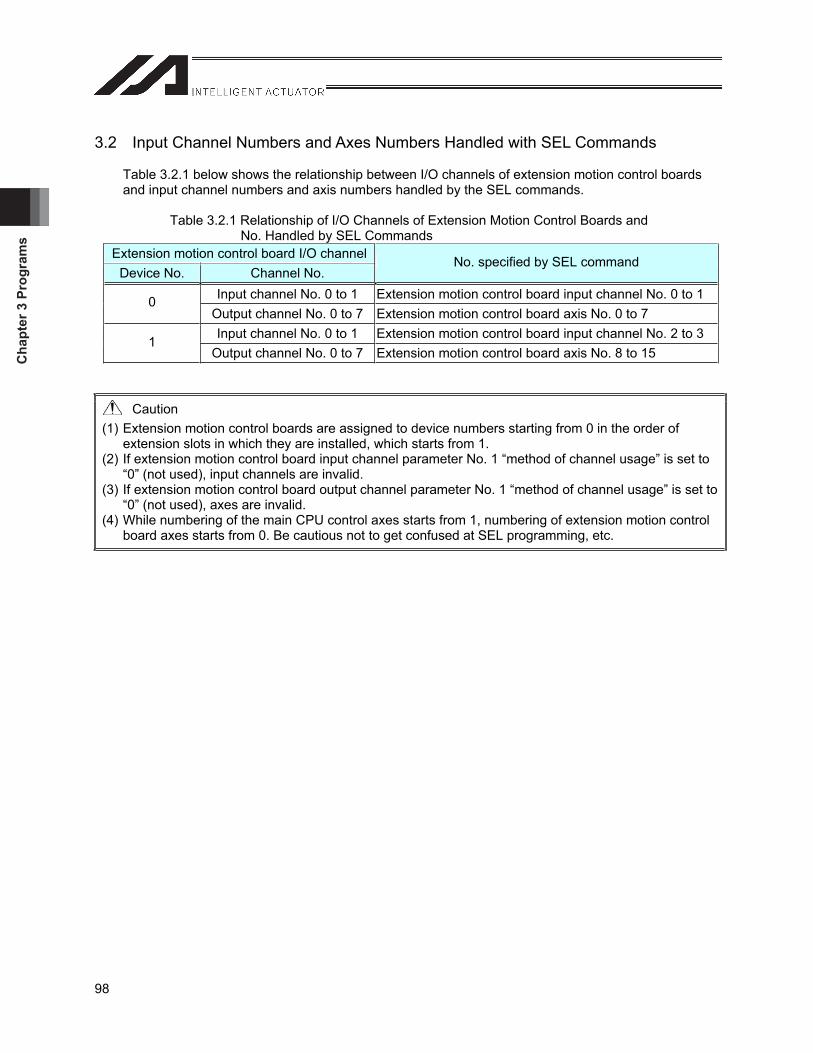
Cha
pter
3 P
rogr
ams
98
3.2 Input Channel Numbers and Axes Numbers Handled with SEL Commands
Table 3.2.1 below shows the relationship between I/O channels of extension motion control boards and input channel numbers and axis numbers handled by the SEL commands.
Table 3.2.1 Relationship of I/O Channels of Extension Motion Control Boards and No. Handled by SEL Commands
Extension motion control board I/O channelDevice No. Channel No.
No. specified by SEL command
Input channel No. 0 to 1 Extension motion control board input channel No. 0 to 1 0Output channel No. 0 to 7 Extension motion control board axis No. 0 to 7 Input channel No. 0 to 1 Extension motion control board input channel No. 2 to 3 1
Output channel No. 0 to 7 Extension motion control board axis No. 8 to 15
Caution (1) Extension motion control boards are assigned to device numbers starting from 0 in the order of
extension slots in which they are installed, which starts from 1. (2) If extension motion control board input channel parameter No. 1 “method of channel usage” is set to
“0” (not used), input channels are invalid. (3) If extension motion control board output channel parameter No. 1 “method of channel usage” is set to
“0” (not used), axes are invalid. (4) While numbering of the main CPU control axes starts from 1, numbering of extension motion control
board axes starts from 0. Be cautious not to get confused at SEL programming, etc.
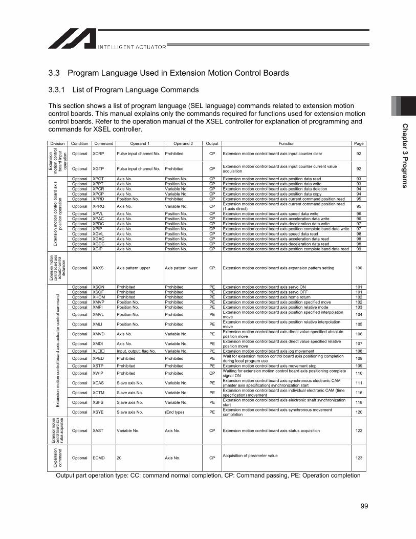
Chapter 3 Program
s
99
3.3 Program Language Used in Extension Motion Control Boards
3.3.1 List of Program Language Commands
This section shows a list of program language (SEL language) commands related to extension motion control boards. This manual explains only the commands required for functions used for extension motion control boards. Refer to the operation manual of the XSEL controller for explanation of programming and commands for XSEL controller.
Division Condition Command Operand 1 Operand 2 Output Function Page
Optional XCRP Pulse input channel No. Prohibited CP Extension motion control board axis input counter clear 92
Ext
ensi
on
mot
ion
cont
rol
boar
d in
put
oper
atio
n
Optional XGTP Pulse input channel No. Prohibited CP Extension motion control board axis input counter current value acquisition 92
Optional XPGT Axis No. Position No. CP Extension motion control board axis position data read 93 Optional XPPT Axis No. Position No. CP Extension motion control board axis position data write 93 Optional XPCR Axis No. Variable No. CP Extension motion control board axis position data deletion 94 Optional XPCP Axis No. Variable No. CP Extension motion control board axis position data copy 94 Optional XPRD Position No. Prohibited CP Extension motion control board axis current command position read 95
Optional XPRQ Axis No. Variable No. CP Extension motion control board axis current command position read (1-axis direct) 95
Optional XPVL Axis No. Position No. CP Extension motion control board axis speed data write 96 Optional XPAC Axis No. Position No. CP Extension motion control board axis acceleration data write 96 Optional XPDC Axis No. Position No. CP Extension motion control board axis deceleration data write 97 Optional XPIP Axis No. Position No. CP Extension motion control board axis position complete band data write 97 Optional XGVL Axis No. Position No. CP Extension motion control board axis speed data read 98 Optional XGAC Axis No. Position No. CP Extension motion control board axis acceleration data read 98 Optional XGDC Axis No. Position No. CP Extension motion control board axis deceleration data read 98 E
xten
sion
mot
ion
cont
rol b
oard
axi
s po
sitio
n op
erat
ion
Optional XGIP Axis No. Position No. CP Extension motion control board axis position complete band data read 99
Exte
nsion
moti
on
cont
rol b
oard
axis
actu
ator c
ontro
l de
clara
tion
Optional XAXS Axis pattern upper Axis pattern lower CP Extension motion control board axis expansion pattern setting 100
Optional XSON Prohibited Prohibited PE Extension motion control board axis servo ON 101Optional XSOF Prohibited Prohibited PE Extension motion control board axis servo OFF 101Optional XHOM Prohibited Prohibited PE Extension motion control board axis home return 102Optional XMVP Position No. Prohibited PE Extension motion control board axis position specified move 102Optional XMPI Position No. Prohibited PE Extension motion control board axis position relative mode 103
Optional XMVL Position No. Prohibited PE Extension motion control board axis position specified interpolation move 104
Optional XMLI Position No. Prohibited PE Extension motion control board axis position relative interpolation move 105
Optional XMVD Axis No. Variable No. PE Extension motion control board axis direct value specified absolute position move 106
Optional XMDI Axis No. Variable No. PE Extension motion control board axis direct value specified relative position move 107
Optional XJ Input, output, flag No. Variable No. PE Extension motion control board axis jog movement 108
Optional XPED Prohibited Prohibited PE Wait for extension motion control board axis positioning completion during local program use 109
Optional XSTP Prohibited Prohibited PE Extension motion control board axis movement stop 109
Optional XWIP Prohibited Prohibited CP Waiting for extension motion control board axis positioning complete signal ON 110
Optional XCAS Slave axis No. Variable No. PE Extension motion control board axis synchronous electronic CAM (master axis specification) synchronization start 111
Optional XCTM Slave axis No. Variable No. PE Extension motion control board axis individual electronic CAM (time specification) movement 116
Optional XSFS Slave axis No. Variable No. PE Extension motion control board axis electronic shaft synchronization start 118
Ext
ensi
on m
otio
n co
ntro
l boa
rd a
xis
actu
ator
con
trol c
omm
and
Optional XSYE Slave axis No. (End type) PE Extension motion control board axis synchronous movement completion 120
Exte
nsion
moti
on
cont
rol b
oard
axis
status
acqu
isitio
n
Optional XAST Variable No. Axis No. CP Extension motion control board axis status acquisition 122
Exp
ansi
on
com
man
d
Optional ECMD 20 Axis No. CP Acquisition of parameter value 123
Output part operation type: CC: command normal completion, CP: Command passing, PE: Operation completion
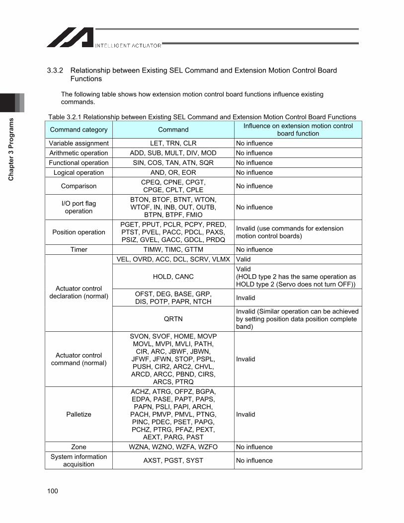
Cha
pter
3 P
rogr
ams
100
3.3.2 Relationship between Existing SEL Command and Extension Motion Control Board Functions
The following table shows how extension motion control board functions influence existing commands.
Table 3.2.1 Relationship between Existing SEL Command and Extension Motion Control Board Functions
Command category Command Influence on extension motion control board function
Variable assignment LET, TRN, CLR No influence Arithmetic operation ADD, SUB, MULT, DIV, MOD No influence Functional operation SIN, COS, TAN, ATN, SQR No influence
Logical operation AND, OR, EOR No influence
Comparison CPEQ, CPNE, CPGT, CPGE, CPLT, CPLE No influence
I/O port flag operation
BTON, BTOF, BTNT, WTON, WTOF, IN, INB, OUT, OUTB,
BTPN, BTPF, FMIO No influence
Position operation PGET, PPUT, PCLR, PCPY, PRED, PTST, PVEL, PACC, PDCL, PAXS, PSIZ, GVEL, GACC, GDCL, PRDQ
Invalid (use commands for extension motion control boards)
Timer TIMW, TIMC, GTTM No influence VEL, OVRD, ACC, DCL, SCRV, VLMX Valid
HOLD, CANC Valid(HOLD type 2 has the same operation as HOLD type 2 (Servo does not turn OFF))
OFST, DEG, BASE, GRP, DIS, POTP, PAPR, NTCH Invalid
Actuator control declaration (normal)
QRTN Invalid (Similar operation can be achieved by setting position data position complete band)
Actuator control command (normal)
SVON, SVOF, HOME, MOVP MOVL, MVPI, MVLI, PATH, CIR, ARC, JBWF, JBWN,
JFWF, JFWN, STOP, PSPL, PUSH, CIR2, ARC2, CHVL, ARCD, ARCC, PBND, CIRS,
ARCS, PTRQ
Invalid
Palletize
ACHZ, ATRG, OFPZ, BGPA, EDPA, PASE, PAPT, PAPS, PAPN, PSLI, PAPI, ARCH,
PACH, PMVP, PMVL, PTNG, PINC, PDEC, PSET, PAPG, PCHZ, PTRG, PFAZ, PEXT,
AEXT, PARG, PAST
Invalid
Zone WZNA, WZNO, WZFA, WZFO No influence System information
acquisition AXST, PGST, SYST No influence
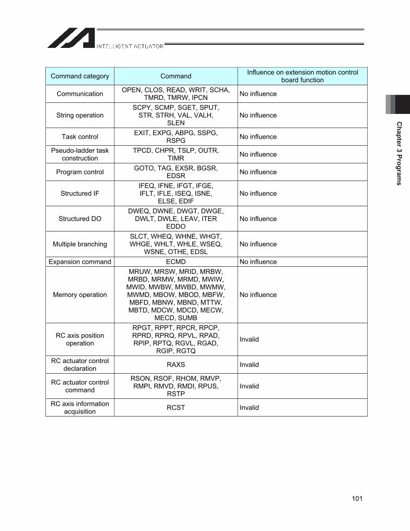
Chapter 3 Program
s
101
Command category Command Influence on extension motion control board function
Communication OPEN, CLOS, READ, WRIT, SCHA, TMRD, TMRW, IPCN No influence
String operation SCPY, SCMP, SGET, SPUT,
STR, STRH, VAL, VALH, SLEN
No influence
Task control EXIT, EXPG, ABPG, SSPG, RSPG No influence
Pseudo-ladder task construction
TPCD, CHPR, TSLP, OUTR, TIMR No influence
Program control GOTO, TAG, EXSR, BGSR, EDSR No influence
Structured IF IFEQ, IFNE, IFGT, IFGE, IFLT, IFLE, ISEQ, ISNE,
ELSE, EDIF No influence
Structured DO DWEQ, DWNE, DWGT, DWGE,
DWLT, DWLE, LEAV, ITER EDDO
No influence
Multiple branching SLCT, WHEQ, WHNE, WHGT, WHGE, WHLT, WHLE, WSEQ,
WSNE, OTHE, EDSL No influence
Expansion command ECMD No influence
Memory operation
MRUW, MRSW, MRID, MRBW, MRBD, MRMW, MRMD, MWIW, MWID, MWBW, MWBD, MWMW, MWMD, MBOW, MBOD, MBFW, MBFD, MBNW, MBND, MTTW, MBTD, MDCW, MDCD, MECW,
MECD, SUMB
No influence
RC axis position operation
RPGT, RPPT, RPCR, RPCP, RPRD, RPRQ, RPVL, RPAD, RPIP, RPTQ, RGVL, RGAD,
RGIP, RGTQ
Invalid
RC actuator control declaration RAXS Invalid
RC actuator control command
RSON, RSOF, RHOM, RMVP, RMPI, RMVD, RMDI, RPUS,
RSTPInvalid
RC axis information acquisition RCST Invalid
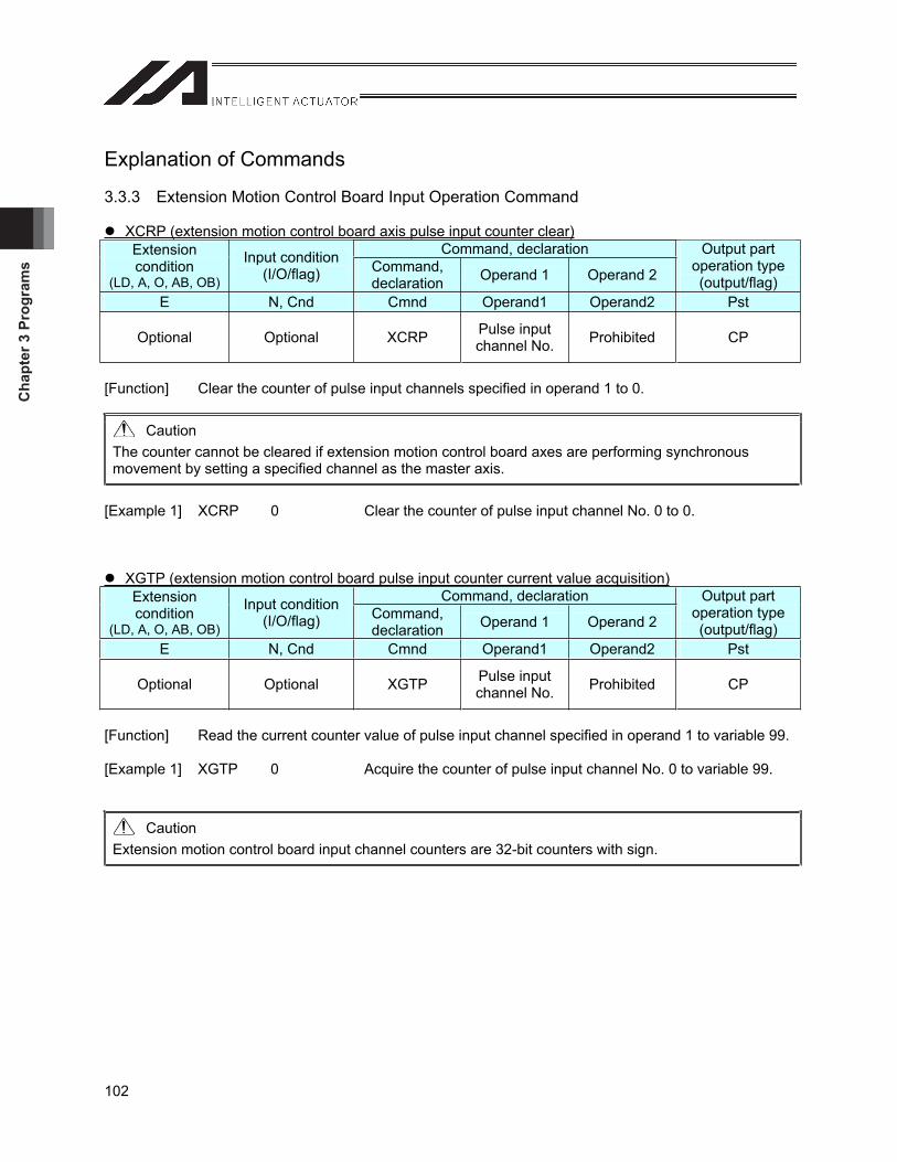
Cha
pter
3 P
rogr
ams
102
Explanation of Commands
3.3.3 Extension Motion Control Board Input Operation Command
XCRP (extension motion control board axis pulse input counter clear)Command, declaration Extension
condition(LD, A, O, AB, OB)
Input condition (I/O/flag) Command,
declaration Operand 1 Operand 2
Output part operation type (output/flag)
E N, Cnd Cmnd Operand1 Operand2 Pst
Optional Optional XCRP Pulse input channel No. Prohibited CP
[Function] Clear the counter of pulse input channels specified in operand 1 to 0.
Caution The counter cannot be cleared if extension motion control board axes are performing synchronous movement by setting a specified channel as the master axis.
[Example 1] XCRP 0 Clear the counter of pulse input channel No. 0 to 0.
XGTP (extension motion control board pulse input counter current value acquisition)Command, declaration Extension
condition(LD, A, O, AB, OB)
Input condition (I/O/flag) Command,
declaration Operand 1 Operand 2
Output part operation type (output/flag)
E N, Cnd Cmnd Operand1 Operand2 Pst
Optional Optional XGTP Pulse input channel No. Prohibited CP
[Function] Read the current counter value of pulse input channel specified in operand 1 to variable 99. [Example 1] XGTP 0 Acquire the counter of pulse input channel No. 0 to variable 99.
Caution Extension motion control board input channel counters are 32-bit counters with sign.
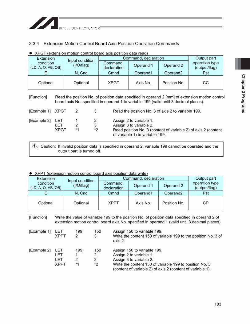
Chapter 3 Program
s
103
3.3.4 Extension Motion Control Board Axis Position Operation Commands
XPGT (extension motion control board axis position data read)Command, declaration Extension
condition(LD, A, O, AB, OB)
Input condition (I/O/flag) Command,
declaration Operand 1 Operand 2
Output part operation type (output/flag)
E N, Cnd Cmnd Operand1 Operand2 Pst
Optional Optional XPGT Axis No. Position No. CC
[Function] Read the position No, of position data specified in operand 2 [mm] of extension motion control board axis No. specified in operand 1 to variable 199 (valid until 3 decimal places).
[Example 1] XPGT 2 3 Read the position No. 3 of axis 2 to variable 199. [Example 2] LET 1 2 Assign 2 to variable 1. LET 2 3 Assign 3 to variable 2. XPGT *1 *2 Read position No. 3 (content of variable 2) of axis 2 (content
of variable 1) to variable 199.
Caution: If invalid position data is specified in operand 2, variable 199 cannot be operated and the output part is turned off.
XPPT (extension motion control board axis position data write)Command, declaration Extension
condition(LD, A, O, AB, OB)
Input condition (I/O/flag) Command,
declaration Operand 1 Operand 2
Output part operation type (output/flag)
E N, Cnd Cmnd Operand1 Operand2 Pst
Optional Optional XPPT Axis No. Position No. CP
[Function] Write the value of variable 199 to the position No. of position data specified in operand 2 of extension motion control board axis No. specified in operand 1 (valid until 3 decimal places).
[Example 1] LET 199 150 Assign 150 to variable 199. XPPT 2 3 Write the content 150 of variable 199 to the position No. 3 of
axis 2. [Example 2] LET 199 150 Assign 150 to variable 199. LET 1 2 Assign 2 to variable 1. LET 2 3 Assign 3 to variable 2. XPPT *1 *2 Write the content 150 of variable 199 to position No. 3
(content of variable 2) of axis 2 (content of variable 1).
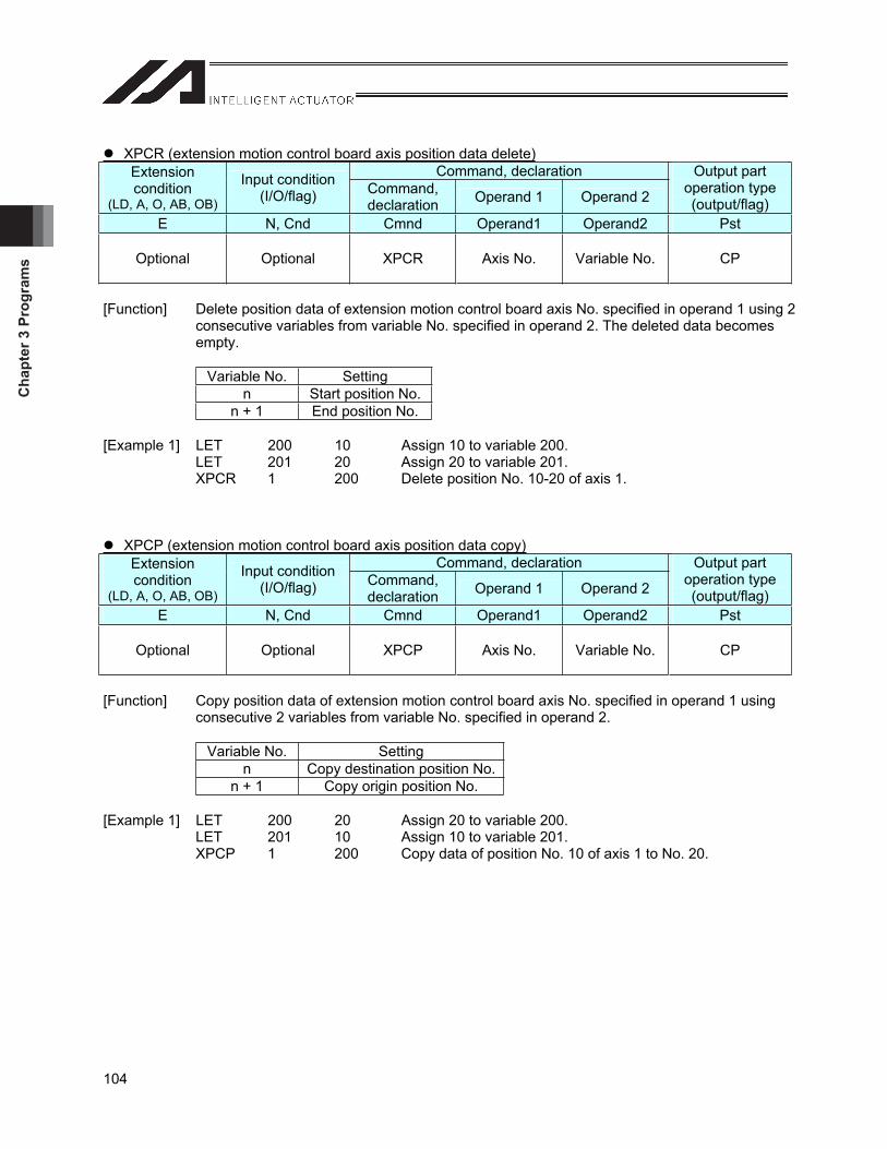
Cha
pter
3 P
rogr
ams
104
XPCR (extension motion control board axis position data delete)Command, declaration Extension
condition(LD, A, O, AB, OB)
Input condition (I/O/flag) Command,
declaration Operand 1 Operand 2
Output part operation type (output/flag)
E N, Cnd Cmnd Operand1 Operand2 Pst
Optional Optional XPCR Axis No. Variable No. CP
[Function] Delete position data of extension motion control board axis No. specified in operand 1 using 2 consecutive variables from variable No. specified in operand 2. The deleted data becomes empty.
Variable No. Setting n Start position No.
n + 1 End position No.
[Example 1] LET 200 10 Assign 10 to variable 200. LET 201 20 Assign 20 to variable 201. XPCR 1 200 Delete position No. 10-20 of axis 1.
XPCP (extension motion control board axis position data copy)Command, declaration Extension
condition(LD, A, O, AB, OB)
Input condition (I/O/flag) Command,
declaration Operand 1 Operand 2
Output part operation type (output/flag)
E N, Cnd Cmnd Operand1 Operand2 Pst
Optional Optional XPCP Axis No. Variable No. CP
[Function] Copy position data of extension motion control board axis No. specified in operand 1 using consecutive 2 variables from variable No. specified in operand 2.
Variable No. Setting n Copy destination position No.
n + 1 Copy origin position No.
[Example 1] LET 200 20 Assign 20 to variable 200. LET 201 10 Assign 10 to variable 201. XPCP 1 200 Copy data of position No. 10 of axis 1 to No. 20.
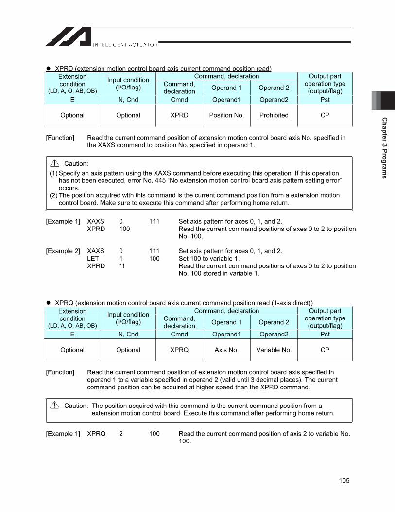
Chapter 3 Program
s
105
XPRD (extension motion control board axis current command position read)Command, declaration Extension
condition(LD, A, O, AB, OB)
Input condition (I/O/flag) Command,
declaration Operand 1 Operand 2
Output part operation type (output/flag)
E N, Cnd Cmnd Operand1 Operand2 Pst
Optional Optional XPRD Position No. Prohibited CP
[Function] Read the current command position of extension motion control board axis No. specified in the XAXS command to position No. specified in operand 1.
Caution: (1) Specify an axis pattern using the XAXS command before executing this operation. If this operation
has not been executed, error No. 445 “No extension motion control board axis pattern setting error” occurs.
(2) The position acquired with this command is the current command position from a extension motion control board. Make sure to execute this command after performing home return.
[Example 1] XAXS 0 111 Set axis pattern for axes 0, 1, and 2. XPRD 100 Read the current command positions of axes 0 to 2 to position
No. 100. [Example 2] XAXS 0 111 Set axis pattern for axes 0, 1, and 2. LET 1 100 Set 100 to variable 1. XPRD *1 Read the current command positions of axes 0 to 2 to position
No. 100 stored in variable 1.
XPRQ (extension motion control board axis current command position read (1-axis direct))Command, declaration Extension
condition(LD, A, O, AB, OB)
Input condition (I/O/flag) Command,
declaration Operand 1 Operand 2
Output part operation type (output/flag)
E N, Cnd Cmnd Operand1 Operand2 Pst
Optional Optional XPRQ Axis No. Variable No. CP
[Function] Read the current command position of extension motion control board axis specified in operand 1 to a variable specified in operand 2 (valid until 3 decimal places). The current command position can be acquired at higher speed than the XPRD command.
Caution: The position acquired with this command is the current command position from a extension motion control board. Execute this command after performing home return.
[Example 1] XPRQ 2 100 Read the current command position of axis 2 to variable No. 100.
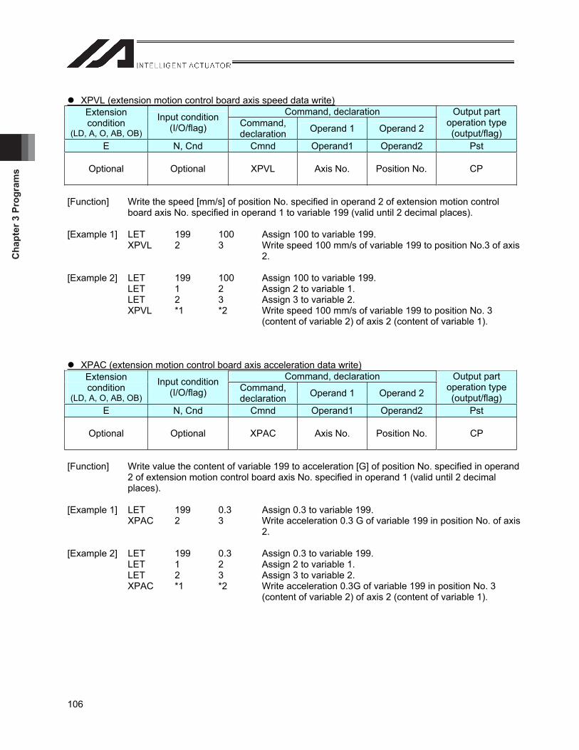
Cha
pter
3 P
rogr
ams
106
XPVL (extension motion control board axis speed data write)Command, declaration Extension
condition(LD, A, O, AB, OB)
Input condition (I/O/flag) Command,
declaration Operand 1 Operand 2
Output part operation type (output/flag)
E N, Cnd Cmnd Operand1 Operand2 Pst
Optional Optional XPVL Axis No. Position No. CP
[Function] Write the speed [mm/s] of position No. specified in operand 2 of extension motion control board axis No. specified in operand 1 to variable 199 (valid until 2 decimal places).
[Example 1] LET 199 100 Assign 100 to variable 199. XPVL 2 3 Write speed 100 mm/s of variable 199 to position No.3 of axis
2. [Example 2] LET 199 100 Assign 100 to variable 199. LET 1 2 Assign 2 to variable 1. LET 2 3 Assign 3 to variable 2. XPVL *1 *2 Write speed 100 mm/s of variable 199 to position No. 3
(content of variable 2) of axis 2 (content of variable 1).
XPAC (extension motion control board axis acceleration data write)Command, declaration Extension
condition(LD, A, O, AB, OB)
Input condition (I/O/flag) Command,
declaration Operand 1 Operand 2
Output part operation type (output/flag)
E N, Cnd Cmnd Operand1 Operand2 Pst
Optional Optional XPAC Axis No. Position No. CP
[Function] Write value the content of variable 199 to acceleration [G] of position No. specified in operand 2 of extension motion control board axis No. specified in operand 1 (valid until 2 decimal places).
[Example 1] LET 199 0.3 Assign 0.3 to variable 199. XPAC 2 3 Write acceleration 0.3 G of variable 199 in position No. of axis
2. [Example 2] LET 199 0.3 Assign 0.3 to variable 199. LET 1 2 Assign 2 to variable 1. LET 2 3 Assign 3 to variable 2. XPAC *1 *2 Write acceleration 0.3G of variable 199 in position No. 3
(content of variable 2) of axis 2 (content of variable 1).
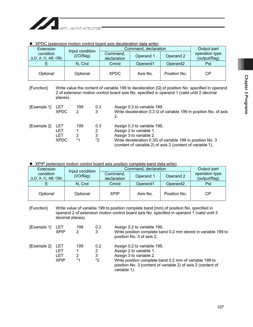
Chapter 3 Program
s
107
XPDC (extension motion control board axis deceleration data write)Command, declaration Extension
condition(LD, A, O, AB, OB)
Input condition (I/O/flag) Command,
declaration Operand 1 Operand 2
Output part operation type (output/flag)
E N, Cnd Cmnd Operand1 Operand2 Pst
Optional Optional XPDC Axis No. Position No. CP
[Function] Write value the content of variable 199 to deceleration [G] of position No. specified in operand 2 of extension motion control board axis No. specified in operand 1 (valid until 2 decimal places).
[Example 1] LET 199 0.3 Assign 0.3 to variable 199. XPDC 2 3 Write deceleration 0.3 G of variable 199 in position No. of axis
2. [Example 2] LET 199 0.3 Assign 0.3 to variable 199. LET 1 2 Assign 2 to variable 1. LET 2 3 Assign 3 to variable 2. XPDC *1 *2 Write deceleration 0.3G of variable 199 in position No. 3
(content of variable 2) of axis 2 (content of variable 1).
XPIP (extension motion control board axis position complete band data write)Command, declaration Extension
condition(LD, A, O, AB, OB)
Input condition (I/O/flag) Command,
declaration Operand 1 Operand 2
Output part operation type (output/flag)
E N, Cnd Cmnd Operand1 Operand2 Pst
Optional Optional XPIP Axis No. Position No. CP
[Function] Write value of variable 199 to position complete band [mm] of position No. specified in operand 2 of extension motion control board axis No. specified in operand 1 (valid until 3 decimal places).
[Example 1] LET 199 0.2 Assign 0.2 to variable 199. XPIP 2 3 Write position complete band 0.2 mm stored in variable 199 to
position No. 3 of axis 2. [Example 2] LET 199 0.2 Assign 0.2 to variable 199. LET 1 2 Assign 2 to variable 1. LET 2 3 Assign 3 to variable 2. XPIP *1 *2 Write position complete band 0.2 mm of variable 199 to
position No. 3 (content of variable 2) of axis 2 (content of variable 1).
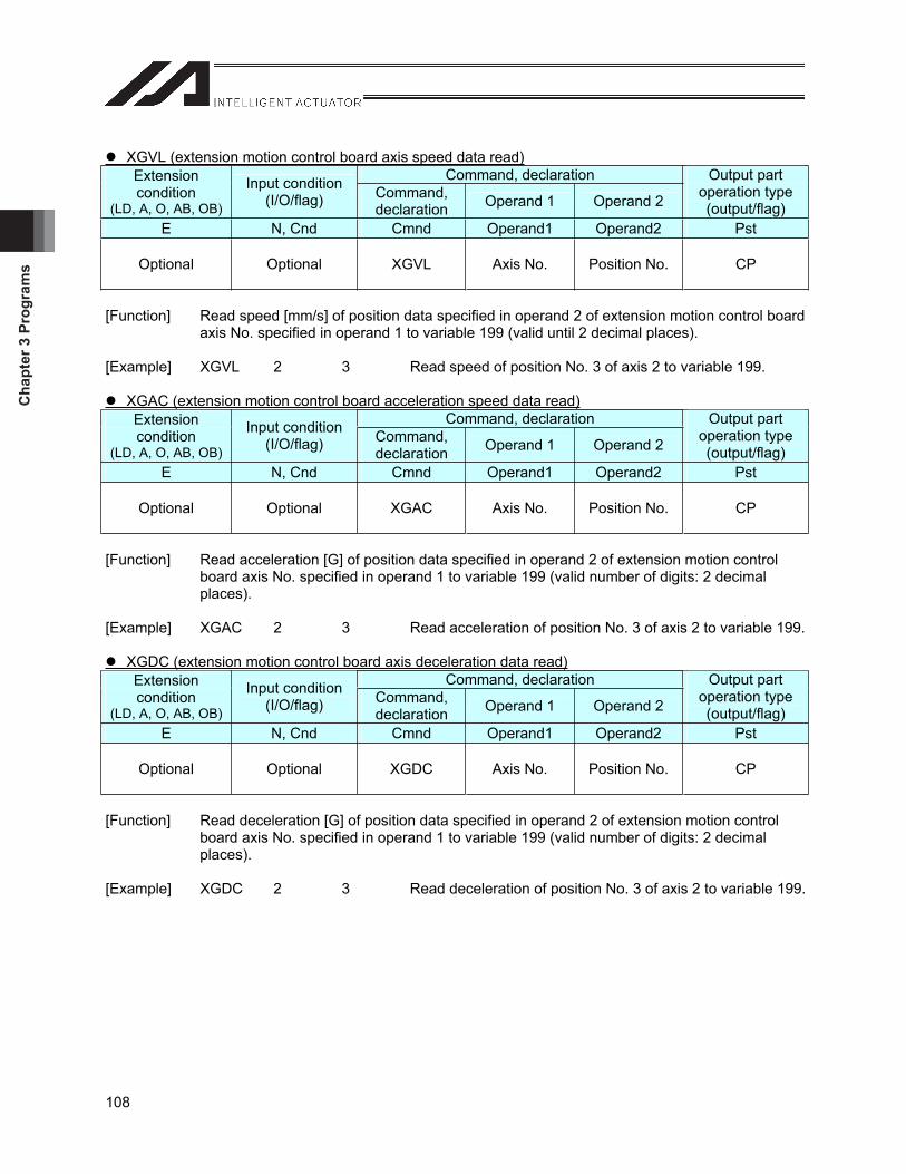
Cha
pter
3 P
rogr
ams
108
XGVL (extension motion control board axis speed data read)Command, declaration Extension
condition(LD, A, O, AB, OB)
Input condition (I/O/flag) Command,
declaration Operand 1 Operand 2
Output part operation type (output/flag)
E N, Cnd Cmnd Operand1 Operand2 Pst
Optional Optional XGVL Axis No. Position No. CP
[Function] Read speed [mm/s] of position data specified in operand 2 of extension motion control board axis No. specified in operand 1 to variable 199 (valid until 2 decimal places).
[Example] XGVL 2 3 Read speed of position No. 3 of axis 2 to variable 199.
XGAC (extension motion control board acceleration speed data read)Command, declaration Extension
condition(LD, A, O, AB, OB)
Input condition (I/O/flag) Command,
declaration Operand 1 Operand 2
Output part operation type (output/flag)
E N, Cnd Cmnd Operand1 Operand2 Pst
Optional Optional XGAC Axis No. Position No. CP
[Function] Read acceleration [G] of position data specified in operand 2 of extension motion control board axis No. specified in operand 1 to variable 199 (valid number of digits: 2 decimal places).
[Example] XGAC 2 3 Read acceleration of position No. 3 of axis 2 to variable 199.
XGDC (extension motion control board axis deceleration data read)Command, declaration Extension
condition(LD, A, O, AB, OB)
Input condition (I/O/flag) Command,
declaration Operand 1 Operand 2
Output part operation type (output/flag)
E N, Cnd Cmnd Operand1 Operand2 Pst
Optional Optional XGDC Axis No. Position No. CP
[Function] Read deceleration [G] of position data specified in operand 2 of extension motion control board axis No. specified in operand 1 to variable 199 (valid number of digits: 2 decimal places).
[Example] XGDC 2 3 Read deceleration of position No. 3 of axis 2 to variable 199.
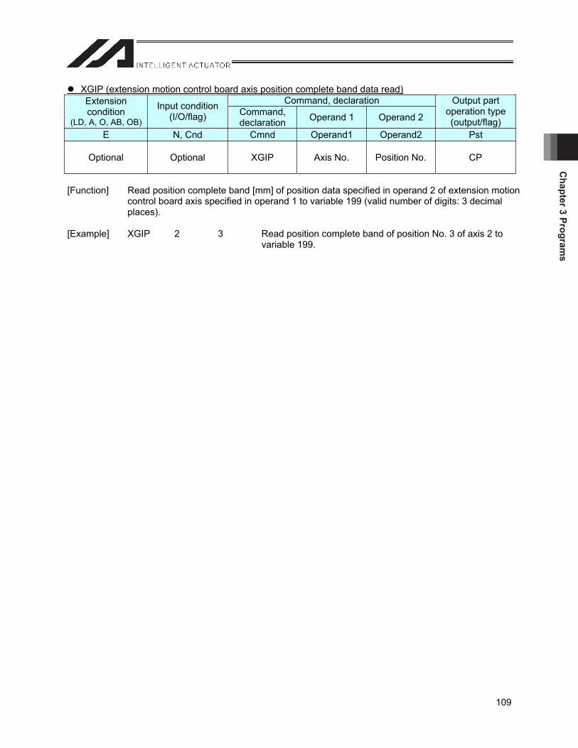
Chapter 3 Program
s
109
XGIP (extension motion control board axis position complete band data read)Command, declaration Extension
condition(LD, A, O, AB, OB)
Input condition (I/O/flag) Command,
declaration Operand 1 Operand 2
Output part operation type (output/flag)
E N, Cnd Cmnd Operand1 Operand2 Pst
Optional Optional XGIP Axis No. Position No. CP
[Function] Read position complete band [mm] of position data specified in operand 2 of extension motion control board axis specified in operand 1 to variable 199 (valid number of digits: 3 decimal places).
[Example] XGIP 2 3 Read position complete band of position No. 3 of axis 2 to
variable 199.

Cha
pter
3 P
rogr
ams
110
3.3.5 Extension Motion Control Board Axis Actuator Control Declaration Command
XAXS (extension motion control board axis pattern setting)Command, declaration Extension
condition(LD, A, O, AB, OB)
Input condition (I/O/flag) Command,
declaration Operand 1 Operand 2
Output part operation type (output/flag)
E N, Cnd Cmnd Operand1 Operand2 Pst
Optional Optional XAXS Axis pattern upper
Axis pattern lower CP
[Function] Set axis patterns for extension motion control board axes 8 to 15 with operand 1 and axes 0 to 7 with operand 2.
Operand 1 Operand 2
Axis pattern setting is a command that specifies axis No. that executes actuator control command to extension motion control board control axis commanded afterward. The specification of axis No. is valid until the power supply is turned OFF or the command is executed again.
After starting to execute a program, use this command to set axis patterns before executing the following commands. If the XAXS axis pattern setting command has not been executed, error No. 445 “No extension motion control board axis pattern setting error” occurs.
XPRD: Extension motion control board axis current command position read XSON: Extension motion control board axis servo ON XSOF: Extension motion control board axis servo OFF XHOM: Extension motion control board axis home return XMVP: Extension motion control board axis position specification move XMPI: Extension motion control board axis position relative move XMVL: Extension motion control board axis position specified interpolation move XMLI: Extension motion control board axis position relative interpolation move XSTP: Extension motion control board axis move stop
[Example] XAXS XSONXMVP
1010101
20
10101010 Set axis pattern for axes 1, 3, 5, 7, 8, 10, 12, and 14. Turn the servo of axes 1, 3, 5, 7, 8, 10, 12, and 14 on. Move axes 1, 3, 5, 7, 8, 10, 12, and 14 to position 20.
8th axis
15th axis
0th axis
7th axis
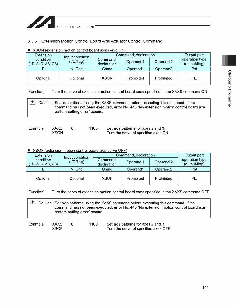
Chapter 3 Program
s
111
3.3.6 Extension Motion Control Board Axis Actuator Control Command
XSON (extension motion control board axis servo ON)Command, declaration Extension
condition(LD, A, O, AB, OB)
Input condition (I/O/flag) Command,
declaration Operand 1 Operand 2
Output part operation type (output/flag)
E N, Cnd Cmnd Operand1 Operand2 Pst
Optional Optional XSON Prohibited Prohibited PE
[Function] Turn the servo of extension motion control board axes specified in the XAXS command ON.
Caution : Set axis patterns using the XAXS command before executing this command. If the command has not been executed, error No. 445 “No extension motion control board axe pattern setting error” occurs.
[Example] XAXS 0 1100 Set axis patterns for axes 2 and 3. XSON Turn the servo of specified axes ON.
XSOF (extension motion control board axis servo OFF)Command, declaration Extension
condition(LD, A, O, AB, OB)
Input condition (I/O/flag) Command,
declaration Operand 1 Operand 2
Output part operation type (output/flag)
E N, Cnd Cmnd Operand1 Operand2 Pst
Optional Optional XSOF Prohibited Prohibited PE
[Function] Turn the servo of extension motion control board axes specified in the XAXS command OFF.
Caution : Set axis patterns using the XAXS command before executing this command. If the command has not been executed, error No. 445 “No extension motion control board axe pattern setting error” occurs.
[Example] XAXS 0 1100 Set axis patterns for axes 2 and 3. XSOF Turn the servo of specified axes OFF.
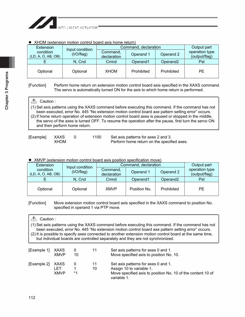
Cha
pter
3 P
rogr
ams
112
XHOM (extension motion control board axis home return)Command, declaration Extension
condition(LD, A, O, AB, OB)
Input condition (I/O/flag) Command,
declaration Operand 1 Operand 2
Output part operation type (output/flag)
E N, Cnd Cmnd Operand1 Operand2 Pst
Optional Optional XHOM Prohibited Prohibited PE
[Function] Perform home return on extension motion control board axis specified in the XAXS command. The servo is automatically turned ON for the axis to which home return is performed.
Caution : (1) Set axis patterns using the XAXS command before executing this command. If the command has not
been executed, error No. 445 “No extension motion control board axe pattern setting error” occurs. (2) If home return operation of extension motion control board axes is paused or stopped in the middle,
the servo of the axes is turned OFF. To resume the operation after the pause, first turn the servo ON and then perform home return.
[Example] XAXS 0 1100 Set axis patterns for axes 2 and 3. XHOM Perform home return on the specified axes.
XMVP (extension motion control board axis position specification move)Command, declaration Extension
condition(LD, A, O, AB, OB)
Input condition (I/O/flag) Command,
declaration Operand 1 Operand 2
Output part operation type (output/flag)
E N, Cnd Cmnd Operand1 Operand2 Pst
Optional Optional XMVP Position No. Prohibited PE
[Function] Move extension motion control board axis specified in the XAXS command to position No. specified in operand 1 via PTP move.
Caution : (1) Set axis patterns using the XAXS command before executing this command. If the command has not
been executed, error No. 445 “No extension motion control board axe pattern setting error” occurs. (2) It is possible to specify axes connected to another extension motion control board at the same time,
but individual boards are controlled separately and they are not synchronized.
[Example 1] XAXS 0 11 Set axis patterns for axes 0 and 1. XMVP 10 Move specified axis to position No. 10. [Example 2] XAXS 0 11 Set axis patterns for axes 0 and 1. LET 1 10 Assign 10 to variable 1. XMVP *1 Move specified axis to position No. 10 of the content 10 of
variable 1.
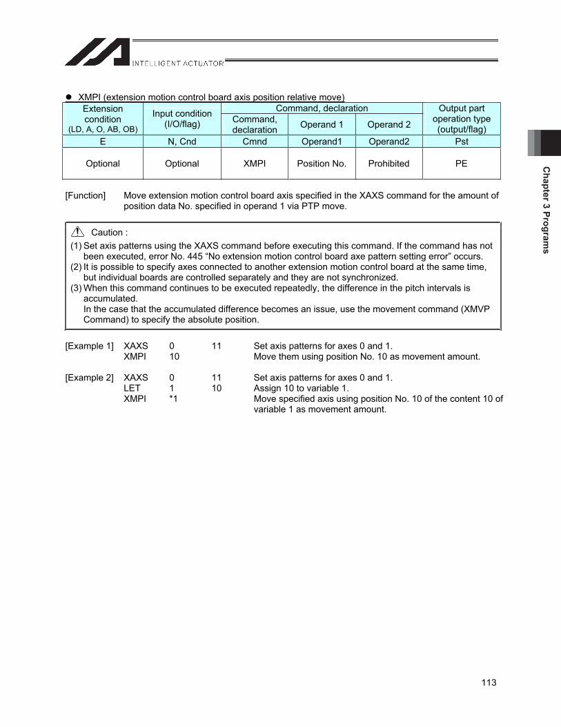
Chapter 3 Program
s
113
XMPI (extension motion control board axis position relative move)Command, declaration Extension
condition(LD, A, O, AB, OB)
Input condition (I/O/flag) Command,
declaration Operand 1 Operand 2
Output part operation type (output/flag)
E N, Cnd Cmnd Operand1 Operand2 Pst
Optional Optional XMPI Position No. Prohibited PE
[Function] Move extension motion control board axis specified in the XAXS command for the amount of position data No. specified in operand 1 via PTP move.
Caution : (1) Set axis patterns using the XAXS command before executing this command. If the command has not
been executed, error No. 445 “No extension motion control board axe pattern setting error” occurs. (2) It is possible to specify axes connected to another extension motion control board at the same time,
but individual boards are controlled separately and they are not synchronized. (3) When this command continues to be executed repeatedly, the difference in the pitch intervals is
accumulated. In the case that the accumulated difference becomes an issue, use the movement command (XMVP Command) to specify the absolute position.
[Example 1] XAXS 0 11 Set axis patterns for axes 0 and 1. XMPI 10 Move them using position No. 10 as movement amount. [Example 2] XAXS 0 11 Set axis patterns for axes 0 and 1. LET 1 10 Assign 10 to variable 1. XMPI *1 Move specified axis using position No. 10 of the content 10 of
variable 1 as movement amount.
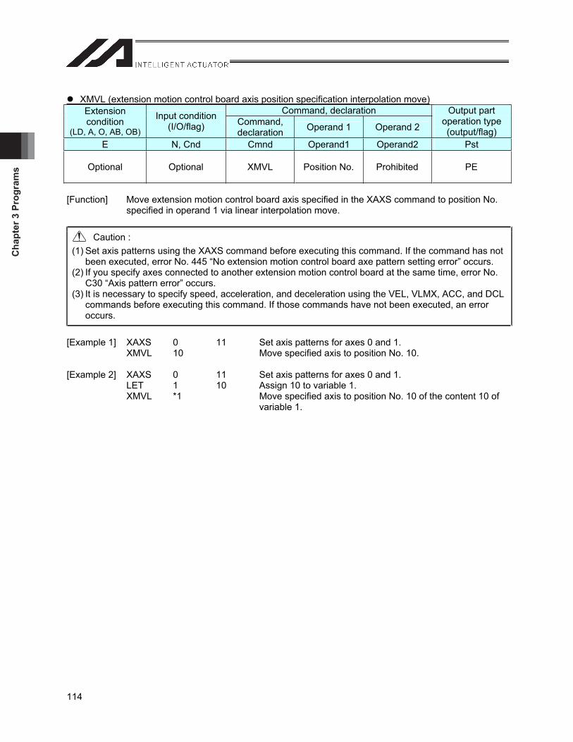
Cha
pter
3 P
rogr
ams
114
XMVL (extension motion control board axis position specification interpolation move)Command, declaration Extension
condition(LD, A, O, AB, OB)
Input condition (I/O/flag) Command,
declaration Operand 1 Operand 2
Output part operation type (output/flag)
E N, Cnd Cmnd Operand1 Operand2 Pst
Optional Optional XMVL Position No. Prohibited PE
[Function] Move extension motion control board axis specified in the XAXS command to position No. specified in operand 1 via linear interpolation move.
Caution : (1) Set axis patterns using the XAXS command before executing this command. If the command has not
been executed, error No. 445 “No extension motion control board axe pattern setting error” occurs. (2) If you specify axes connected to another extension motion control board at the same time, error No.
C30 “Axis pattern error” occurs. (3) It is necessary to specify speed, acceleration, and deceleration using the VEL, VLMX, ACC, and DCL
commands before executing this command. If those commands have not been executed, an error occurs.
[Example 1] XAXS 0 11 Set axis patterns for axes 0 and 1. XMVL 10 Move specified axis to position No. 10. [Example 2] XAXS 0 11 Set axis patterns for axes 0 and 1. LET 1 10 Assign 10 to variable 1. XMVL *1 Move specified axis to position No. 10 of the content 10 of
variable 1.
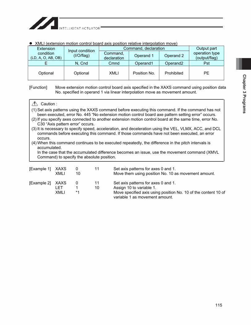
Chapter 3 Program
s
115
XMLI (extension motion control board axis position relative interpolation move)Command, declaration Extension
condition(LD, A, O, AB, OB)
Input condition (I/O/flag) Command,
declaration Operand 1 Operand 2
Output part operation type (output/flag)
E N, Cnd Cmnd Operand1 Operand2 Pst
Optional Optional XMLI Position No. Prohibited PE
[Function] Move extension motion control board axis specified in the XAXS command using position data No. specified in operand 1 via linear interpolation move as movement amount.
Caution : (1) Set axis patterns using the XAXS command before executing this command. If the command has not
been executed, error No. 445 “No extension motion control board axe pattern setting error” occurs. (2) If you specify axes connected to another extension motion control board at the same time, error No.
C30 “Axis pattern error” occurs. (3) It is necessary to specify speed, acceleration, and deceleration using the VEL, VLMX, ACC, and DCL
commands before executing this command. If those commands have not been executed, an error occurs.
(4) When this command continues to be executed repeatedly, the difference in the pitch intervals is accumulated. In the case that the accumulated difference becomes an issue, use the movement command (XMVL Command) to specify the absolute position.
[Example 1] XAXS 0 11 Set axis patterns for axes 0 and 1. XMLI 10 Move them using position No. 10 as movement amount. [Example 2] XAXS 0 11 Set axis patterns for axes 0 and 1. LET 1 10 Assign 10 to variable 1. XMLI *1 Move specified axis using position No. 10 of the content 10 of
variable 1 as movement amount.
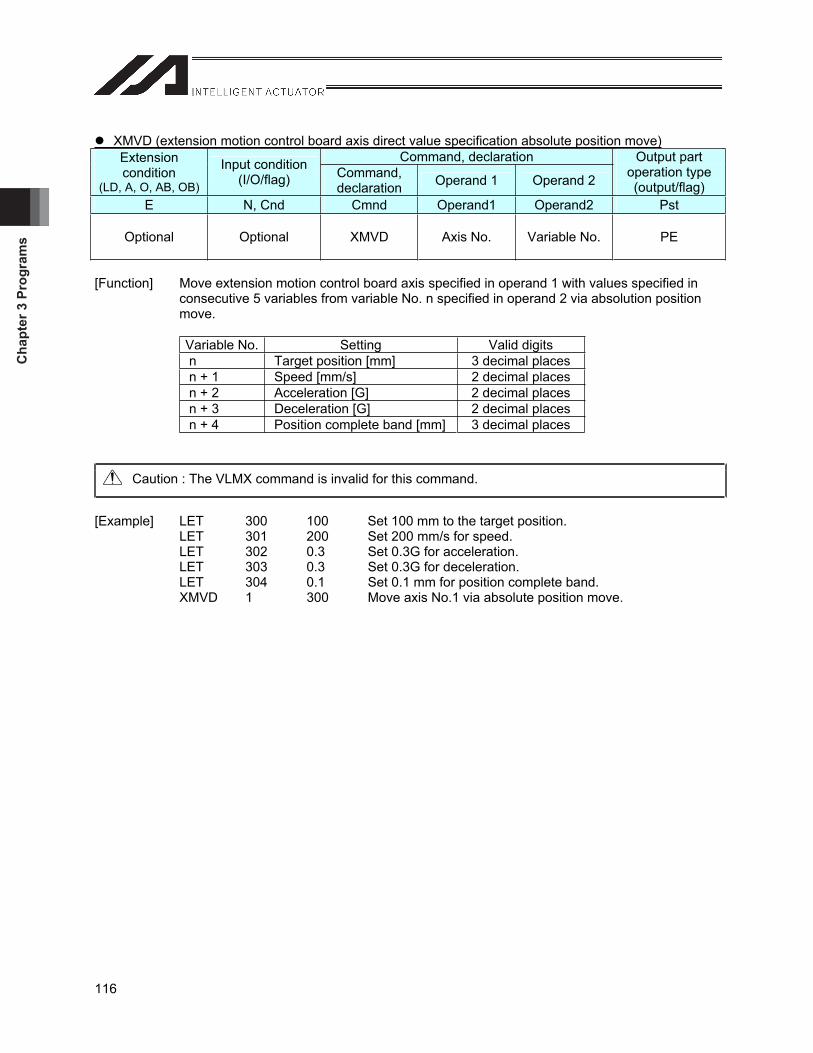
Cha
pter
3 P
rogr
ams
116
XMVD (extension motion control board axis direct value specification absolute position move)Command, declaration Extension
condition(LD, A, O, AB, OB)
Input condition (I/O/flag) Command,
declaration Operand 1 Operand 2
Output part operation type (output/flag)
E N, Cnd Cmnd Operand1 Operand2 Pst
Optional Optional XMVD Axis No. Variable No. PE
[Function] Move extension motion control board axis specified in operand 1 with values specified in consecutive 5 variables from variable No. n specified in operand 2 via absolution position move.
Variable No. Setting Valid digits n Target position [mm] 3 decimal places n + 1 Speed [mm/s] 2 decimal places n + 2 Acceleration [G] 2 decimal places n + 3 Deceleration [G] 2 decimal places n + 4 Position complete band [mm] 3 decimal places
Caution : The VLMX command is invalid for this command.
[Example] LET 300 100 Set 100 mm to the target position. LET 301 200 Set 200 mm/s for speed. LET 302 0.3 Set 0.3G for acceleration. LET 303 0.3 Set 0.3G for deceleration. LET 304 0.1 Set 0.1 mm for position complete band. XMVD 1 300 Move axis No.1 via absolute position move.
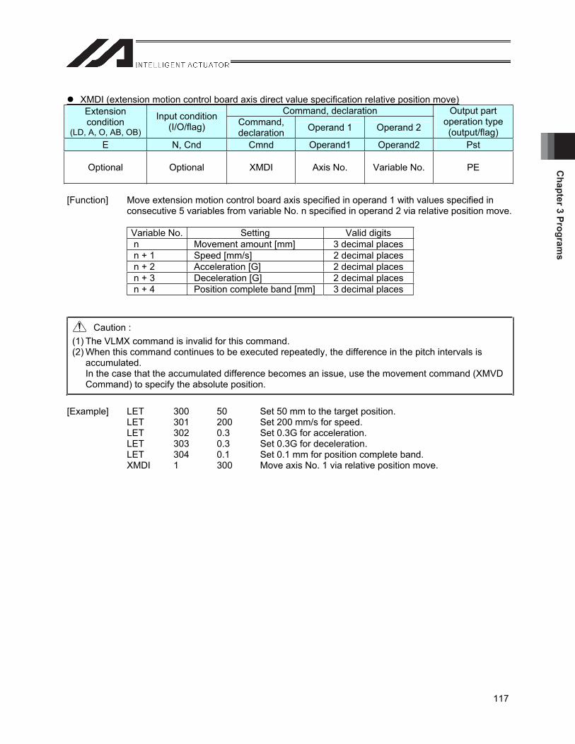
Chapter 3 Program
s
117
XMDI (extension motion control board axis direct value specification relative position move)Command, declaration Extension
condition(LD, A, O, AB, OB)
Input condition (I/O/flag) Command,
declaration Operand 1 Operand 2
Output part operation type (output/flag)
E N, Cnd Cmnd Operand1 Operand2 Pst
Optional Optional XMDI Axis No. Variable No. PE
[Function] Move extension motion control board axis specified in operand 1 with values specified in consecutive 5 variables from variable No. n specified in operand 2 via relative position move.
Variable No. Setting Valid digits n Movement amount [mm] 3 decimal places n + 1 Speed [mm/s] 2 decimal places n + 2 Acceleration [G] 2 decimal places n + 3 Deceleration [G] 2 decimal places n + 4 Position complete band [mm] 3 decimal places
Caution : (1) The VLMX command is invalid for this command. (2) When this command continues to be executed repeatedly, the difference in the pitch intervals is
accumulated. In the case that the accumulated difference becomes an issue, use the movement command (XMVD Command) to specify the absolute position.
[Example] LET 300 50 Set 50 mm to the target position. LET 301 200 Set 200 mm/s for speed. LET 302 0.3 Set 0.3G for acceleration. LET 303 0.3 Set 0.3G for deceleration. LET 304 0.1 Set 0.1 mm for position complete band. XMDI 1 300 Move axis No. 1 via relative position move.

Cha
pter
3 P
rogr
ams
118
XJ (extension motion control board axis jog movement)Command, declaration Extension
condition(LD, A, O, AB, OB)
Input condition (I/O/flag) Command,
declaration Operand 1 Operand 2
Output part operation type (output/flag)
E N, Cnd Cmnd Operand1 Operand2 Pst
Optional Optional XJ Input, output, flag No. Prohibited PE
[Function] It is possible to move the extension motion control board control axis specified by the XAXS command forward/backward by turning ON/OFF input port or output port specified by operation 1 or flag.
XJFN … Moves forward when the specified port is turned ON XJFF … Moves forward when the specified port is turned OFF XJBN… Moves backward when the specified port is turned ON XJBF… Moves backward when the specified port is turned OFF
Caution : (1) Set axis patterns using the XAXS command before executing this command. If the command has not
been executed, error No. 445 “No extension motion control board axe pattern setting error” occurs. (2) This command is valid for axes that have not completed home return, but the speed is limited by
parameter common for extension motion control board No. 4 “maximum jog speed when home return not completed.” Since the coordinates at this point are meaningless, exercise sufficient care not to cause interference to work parts and stroke end.
[Example 1] VEL 100 Set 100 mm/s for speed. XAXS 0 11 Set axis patterns for axes 0 and 1. XJBF 10 Move axes 0 and 1 backward when input port No. 10 is turned
OFF. [Example 2] VEL 100 Set 100 mm/s for speed. LET 5 20 Assign 20 to variable No. 5. XAXS 0 11 Set axis patterns for axes 0 and 1. XJFN *5 Move axes 0 and 1 forward when input ports whose variable
No. 5 is set to 20 are turned ON.
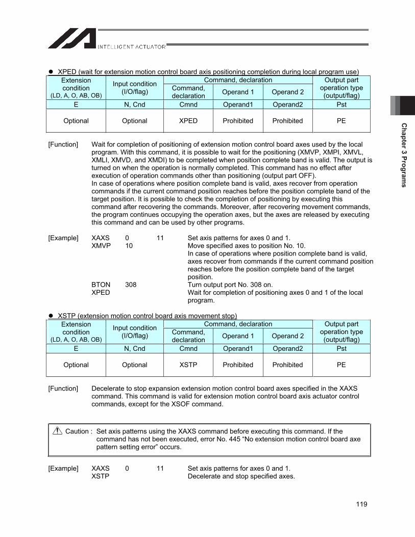
Chapter 3 Program
s
119
XPED (wait for extension motion control board axis positioning completion during local program use)Command, declaration Extension
condition(LD, A, O, AB, OB)
Input condition (I/O/flag) Command,
declaration Operand 1 Operand 2
Output part operation type (output/flag)
E N, Cnd Cmnd Operand1 Operand2 Pst
Optional Optional XPED Prohibited Prohibited PE
[Function] Wait for completion of positioning of extension motion control board axes used by the local program. With this command, it is possible to wait for the positioning (XMVP, XMPI, XMVL, XMLI, XMVD, and XMDI) to be completed when position complete band is valid. The output is turned on when the operation is normally completed. This command has no effect after execution of operation commands other than positioning (output part OFF). In case of operations where position complete band is valid, axes recover from operation commands if the current command position reaches before the position complete band of the target position. It is possible to check the completion of positioning by executing this command after recovering the commands. Moreover, after recovering movement commands, the program continues occupying the operation axes, but the axes are released by executing this command and can be used by other programs.
[Example] XAXS 0 11 Set axis patterns for axes 0 and 1. XMVP 10 Move specified axes to position No. 10.
In case of operations where position complete band is valid, axes recover from commands if the current command position reaches before the position complete band of the target position.
BTON 308 Turn output port No. 308 on. XPED Wait for completion of positioning axes 0 and 1 of the local
program.
XSTP (extension motion control board axis movement stop)Command, declaration Extension
condition(LD, A, O, AB, OB)
Input condition (I/O/flag) Command,
declaration Operand 1 Operand 2
Output part operation type (output/flag)
E N, Cnd Cmnd Operand1 Operand2 Pst
Optional Optional XSTP Prohibited Prohibited PE
[Function] Decelerate to stop expansion extension motion control board axes specified in the XAXS command. This command is valid for extension motion control board axis actuator control commands, except for the XSOF command.
Caution : Set axis patterns using the XAXS command before executing this command. If the command has not been executed, error No. 445 “No extension motion control board axe pattern setting error” occurs.
[Example] XAXS 0 11 Set axis patterns for axes 0 and 1. XSTP Decelerate and stop specified axes.
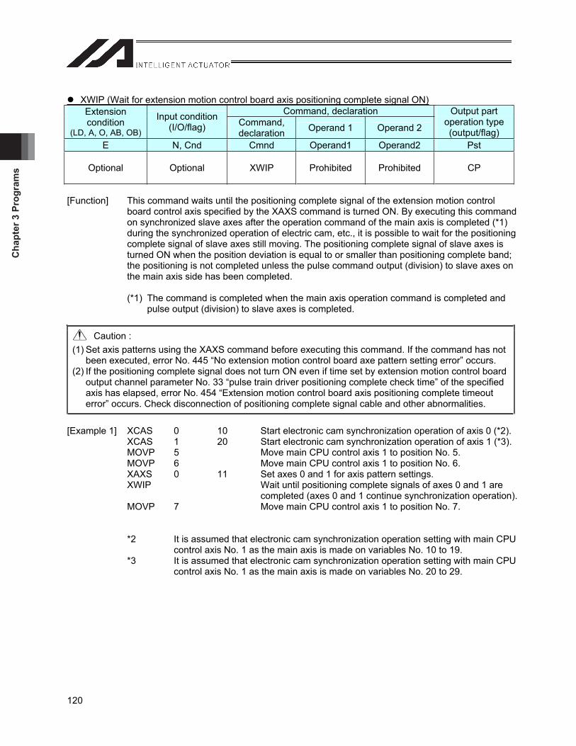
Cha
pter
3 P
rogr
ams
120
XWIP (Wait for extension motion control board axis positioning complete signal ON)Command, declaration Extension
condition(LD, A, O, AB, OB)
Input condition (I/O/flag) Command,
declaration Operand 1 Operand 2
Output part operation type (output/flag)
E N, Cnd Cmnd Operand1 Operand2 Pst
Optional Optional XWIP Prohibited Prohibited CP
[Function] This command waits until the positioning complete signal of the extension motion control board control axis specified by the XAXS command is turned ON. By executing this command on synchronized slave axes after the operation command of the main axis is completed (*1) during the synchronized operation of electric cam, etc., it is possible to wait for the positioning complete signal of slave axes still moving. The positioning complete signal of slave axes is turned ON when the position deviation is equal to or smaller than positioning complete band; the positioning is not completed unless the pulse command output (division) to slave axes on the main axis side has been completed.
(*1) The command is completed when the main axis operation command is completed and pulse output (division) to slave axes is completed.
Caution : (1) Set axis patterns using the XAXS command before executing this command. If the command has not
been executed, error No. 445 “No extension motion control board axe pattern setting error” occurs. (2) If the positioning complete signal does not turn ON even if time set by extension motion control board
output channel parameter No. 33 “pulse train driver positioning complete check time” of the specified axis has elapsed, error No. 454 “Extension motion control board axis positioning complete timeout error” occurs. Check disconnection of positioning complete signal cable and other abnormalities.
[Example 1] XCAS 0 10 Start electronic cam synchronization operation of axis 0 (*2). XCAS 1 20 Start electronic cam synchronization operation of axis 1 (*3). MOVP 5 Move main CPU control axis 1 to position No. 5. MOVP 6 Move main CPU control axis 1 to position No. 6. XAXS 0 11 Set axes 0 and 1 for axis pattern settings. XWIP Wait until positioning complete signals of axes 0 and 1 are
completed (axes 0 and 1 continue synchronization operation). MOVP 7 Move main CPU control axis 1 to position No. 7. *2 It is assumed that electronic cam synchronization operation setting with main CPU
control axis No. 1 as the main axis is made on variables No. 10 to 19. *3 It is assumed that electronic cam synchronization operation setting with main CPU
control axis No. 1 as the main axis is made on variables No. 20 to 29.
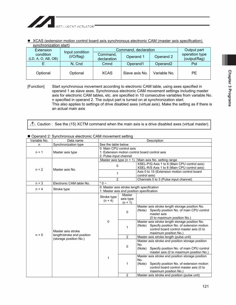
Chapter 3 Program
s
121
XCAS (extension motion control board axis synchronous electronic CAM (master axis specification) synchronization start)
Command, declaration Extensioncondition
(LD, A, O, AB, OB)
Input condition (I/O/flag) Command,
declaration Operand 1 Operand 2
Output part operation type (output/flag)
E N, Cnd Cmnd Operand1 Operand2 Pst
Optional Optional XCAS Slave axis No. Variable No. PE
[Function] Start synchronous movement according to electronic CAM table, using axes specified in operand 1 as slave axes. Synchronous electronic CAM movement settings including master axis for electronic CAM tables, etc. are specified in 10 consecutive variables from variable No. n specified in operand 2. The output part is turned on at synchronization start. This also applies to settings of drive disabled axes (virtual axis). Make the setting as if there is an actual main axis
Caution : See the (15) XCTM command when the main axis is a drive disabled axes (virtual master).
Operand 2: Synchronous electronic CAM movement setting Variable No. Data name Description
n Synchronization type See the table below.
n + 1 Master axis type 0: Main CPU control axis 1: Extension motion control board control axis 2: Pulse input channel Master axis type (n + 1) Main axis No. setting range
0 XSEL-P/Q Axis 1 to 6 (Main CPU control axis) XSEL-R/S Axis 1 to 8 (Main CPU control axis)
1 Axis 0 to 15 (Extension motion control board control axis)
n + 2 Master axis No.
2 Channels 0 to 3 (Pulse input channel) n + 3 Electronic CAM table No. * 0 ~
n + 4 Stroke type 0: Master axis stroke length specification 1: Master axis end position specification
Stroke type(n + 4)
Masteraxis type (n + 1)
0
Master axis stroke length storage position No. (Note) Specify position No. of main CPU control
master axis (0 to maximum position No.)
1
Master axis stroke length storage position No. (Note) Specify position No. of extension motion
control board control master axis (0 to maximum position No.)
0
2 Master axis stroke length (pulse unit)
0
Master axis stroke end position storage position No. (Note) Specify position No. of main CPU control
master axis (0 to maximum position No.)
1
Master axis stroke end position storage position No. (Note) Specify position No. of extension motion
control board control master axis (0 to maximum position No.)
n + 5 Master axis stroke length/stroke end position (storage position No.)
1
2 Master axis stroke end position (pulse unit)
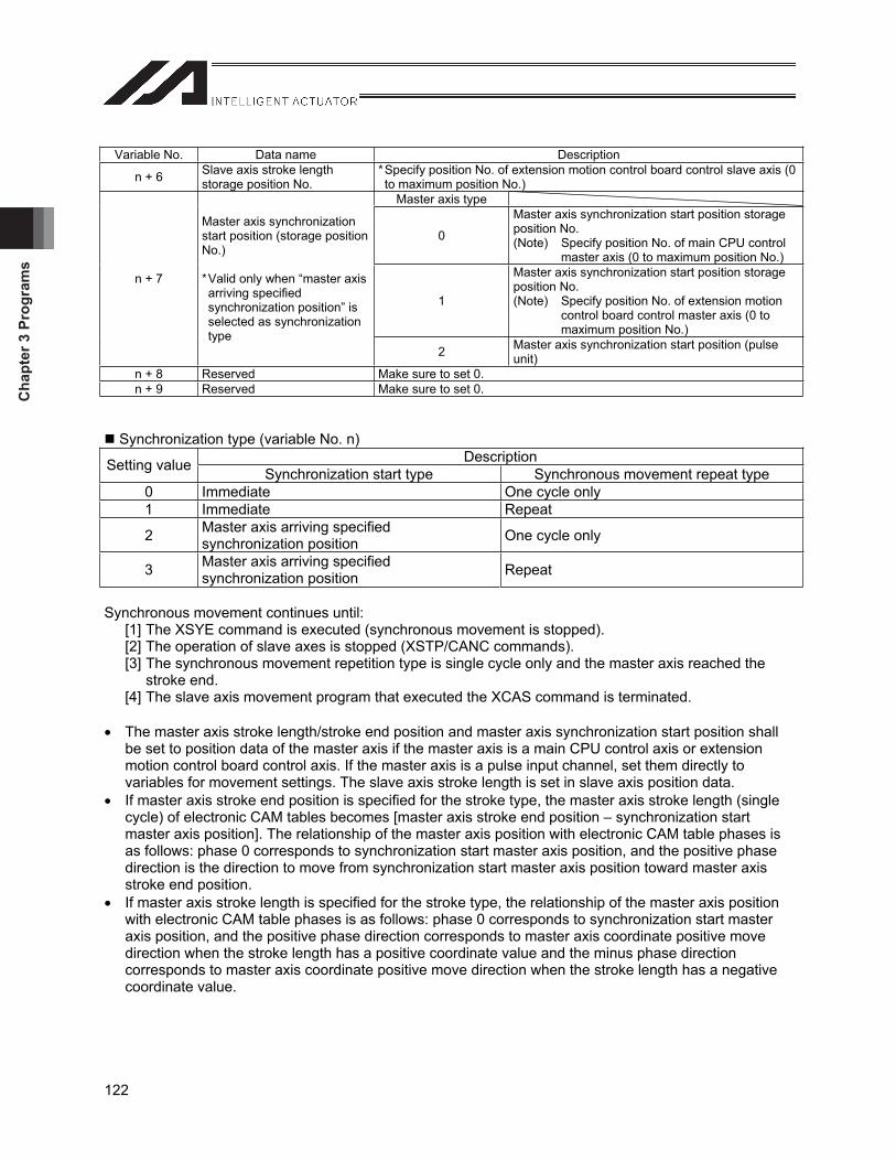
Cha
pter
3 P
rogr
ams
122
Variable No. Data name Description
n + 6 Slave axis stroke length storage position No.
* Specify position No. of extension motion control board control slave axis (0 to maximum position No.)
Master axis type
0
Master axis synchronization start position storage position No. (Note) Specify position No. of main CPU control
master axis (0 to maximum position No.)
1
Master axis synchronization start position storage position No. (Note) Specify position No. of extension motion
control board control master axis (0 to maximum position No.)
n + 7
Master axis synchronization start position (storage position No.)
* Valid only when “master axis arriving specified synchronization position” is selected as synchronization type
2 Master axis synchronization start position (pulse unit)
n + 8 Reserved Make sure to set 0. n + 9 Reserved Make sure to set 0.
Synchronization type (variable No. n) Description Setting value Synchronization start type Synchronous movement repeat type
0 Immediate One cycle only 1 Immediate Repeat
2 Master axis arriving specified synchronization position One cycle only
3 Master axis arriving specified synchronization position Repeat
Synchronous movement continues until: [1] The XSYE command is executed (synchronous movement is stopped). [2] The operation of slave axes is stopped (XSTP/CANC commands). [3] The synchronous movement repetition type is single cycle only and the master axis reached the
stroke end. [4] The slave axis movement program that executed the XCAS command is terminated.
The master axis stroke length/stroke end position and master axis synchronization start position shall be set to position data of the master axis if the master axis is a main CPU control axis or extension motion control board control axis. If the master axis is a pulse input channel, set them directly to variables for movement settings. The slave axis stroke length is set in slave axis position data.
If master axis stroke end position is specified for the stroke type, the master axis stroke length (single cycle) of electronic CAM tables becomes [master axis stroke end position – synchronization start master axis position]. The relationship of the master axis position with electronic CAM table phases is as follows: phase 0 corresponds to synchronization start master axis position, and the positive phase direction is the direction to move from synchronization start master axis position toward master axis stroke end position.
If master axis stroke length is specified for the stroke type, the relationship of the master axis position with electronic CAM table phases is as follows: phase 0 corresponds to synchronization start master axis position, and the positive phase direction corresponds to master axis coordinate positive move direction when the stroke length has a positive coordinate value and the minus phase direction corresponds to master axis coordinate positive move direction when the stroke length has a negative coordinate value.
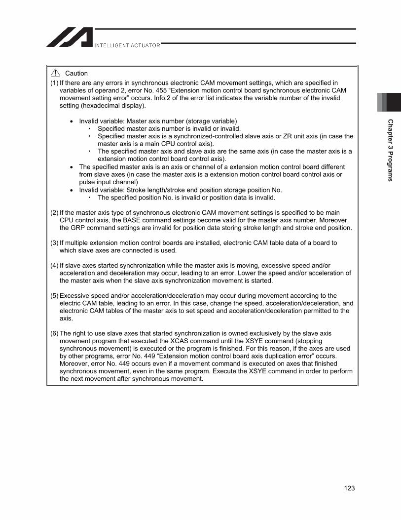
Chapter 3 Program
s
123
Caution (1) If there are any errors in synchronous electronic CAM movement settings, which are specified in
variables of operand 2, error No. 455 “Extension motion control board synchronous electronic CAM movement setting error” occurs. Info.2 of the error list indicates the variable number of the invalid setting (hexadecimal display).
Invalid variable: Master axis number (storage variable) Specified master axis number is invalid or invalid. Specified master axis is a synchronized-controlled slave axis or ZR unit axis (in case the
master axis is a main CPU control axis). The specified master axis and slave axis are the same axis (in case the master axis is a
extension motion control board control axis). The specified master axis is an axis or channel of a extension motion control board different
from slave axes (in case the master axis is a extension motion control board control axis or pulse input channel)
Invalid variable: Stroke length/stroke end position storage position No. The specified position No. is invalid or position data is invalid.
(2) If the master axis type of synchronous electronic CAM movement settings is specified to be main CPU control axis, the BASE command settings become valid for the master axis number. Moreover, the GRP command settings are invalid for position data storing stroke length and stroke end position.
(3) If multiple extension motion control boards are installed, electronic CAM table data of a board to which slave axes are connected is used.
(4) If slave axes started synchronization while the master axis is moving, excessive speed and/or acceleration and deceleration may occur, leading to an error. Lower the speed and/or acceleration of the master axis when the slave axis synchronization movement is started.
(5) Excessive speed and/or acceleration/deceleration may occur during movement according to the electric CAM table, leading to an error. In this case, change the speed, acceleration/deceleration, and electronic CAM tables of the master axis to set speed and acceleration/deceleration permitted to the axis.
(6) The right to use slave axes that started synchronization is owned exclusively by the slave axis movement program that executed the XCAS command until the XSYE command (stopping synchronous movement) is executed or the program is finished. For this reason, if the axes are used by other programs, error No. 449 “Extension motion control board axis duplication error” occurs. Moreover, error No. 449 occurs even if a movement command is executed on axes that finished synchronous movement, even in the same program. Execute the XSYE command in order to perform the next movement after synchronous movement.
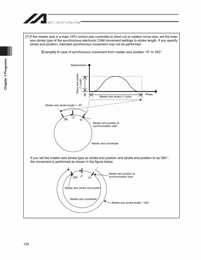
Cha
pter
3 P
rogr
ams
124
(7) If the master axis is a main CPU control axis controlled to short cut to rotation move axis, set the main axis stroke type of the synchronous electronic CAM movement settings to stroke length. If you specify stroke end position, intended synchronous movement may not be performed.
[Example] In case of synchronous movement from master axis position 10 to 350
If you set the master axis stroke type as stroke end position and stroke end position to be 350 ,the movement is performed as shown in the figure below.
Master axis position at synchronization start
Master axis stroke length = -20
Master axis coordinate
Displacement
Sla
ve a
xis
stro
ke
(1 c
ycle
)
Master axis stroke (1 cycle) Phase
Master axis stroke end position
Master axis position at synchronization start
Master axis stroke length = 340Master axis coordinate
350
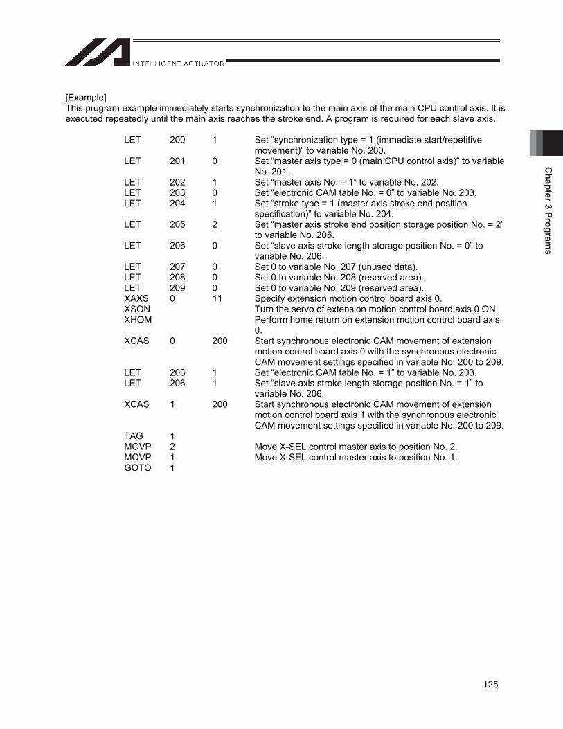
Chapter 3 Program
s
125
[Example] This program example immediately starts synchronization to the main axis of the main CPU control axis. It is executed repeatedly until the main axis reaches the stroke end. A program is required for each slave axis. LET 200 1 Set “synchronization type = 1 (immediate start/repetitive
movement)” to variable No. 200. LET 201 0 Set “master axis type = 0 (main CPU control axis)” to variable
No. 201. LET 202 1 Set “master axis No. = 1” to variable No. 202. LET 203 0 Set “electronic CAM table No. = 0” to variable No. 203. LET 204 1 Set “stroke type = 1 (master axis stroke end position
specification)” to variable No. 204. LET 205 2 Set “master axis stroke end position storage position No. = 2”
to variable No. 205. LET 206 0 Set “slave axis stroke length storage position No. = 0” to
variable No. 206. LET 207 0 Set 0 to variable No. 207 (unused data). LET 208 0 Set 0 to variable No. 208 (reserved area). LET 209 0 Set 0 to variable No. 209 (reserved area). XAXS 0 11 Specify extension motion control board axis 0. XSON Turn the servo of extension motion control board axis 0 ON. XHOM Perform home return on extension motion control board axis
0. XCAS 0 200 Start synchronous electronic CAM movement of extension
motion control board axis 0 with the synchronous electronic CAM movement settings specified in variable No. 200 to 209.
LET 203 1 Set “electronic CAM table No. = 1” to variable No. 203. LET 206 1 Set “slave axis stroke length storage position No. = 1” to
variable No. 206. XCAS 1 200 Start synchronous electronic CAM movement of extension
motion control board axis 1 with the synchronous electronic CAM movement settings specified in variable No. 200 to 209.
TAG 1 MOVP 2 Move X-SEL control master axis to position No. 2. MOVP 1 Move X-SEL control master axis to position No. 1. GOTO 1
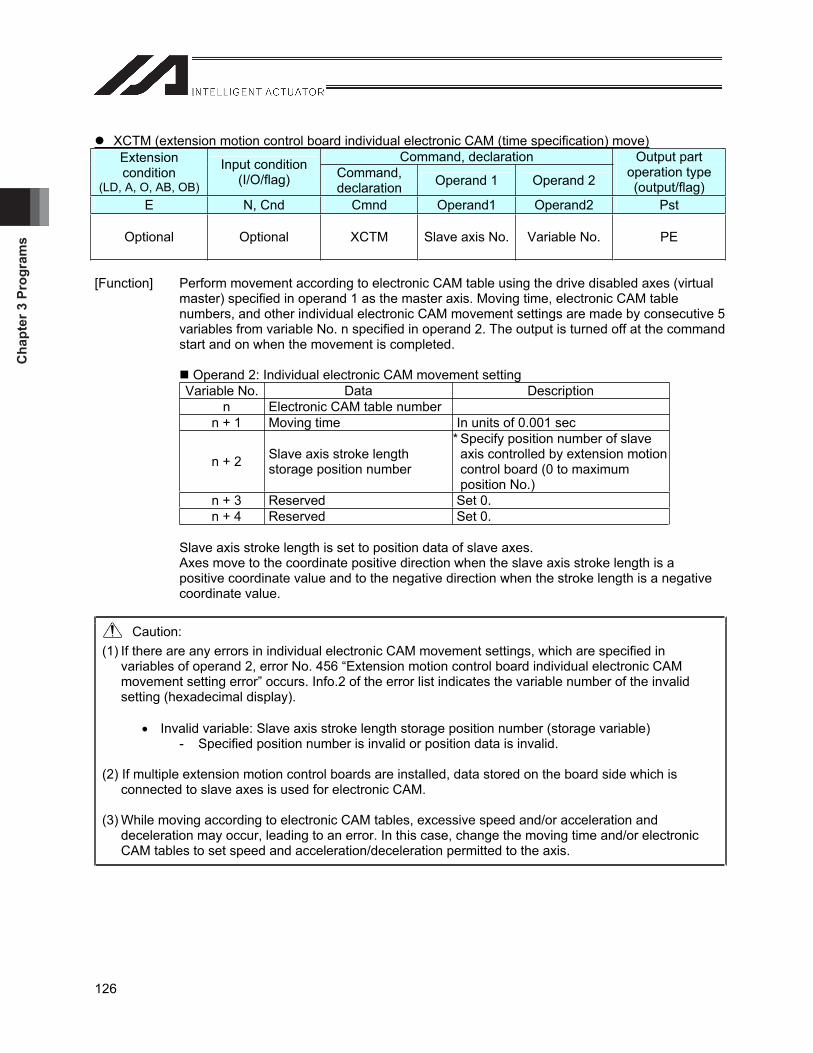
Cha
pter
3 P
rogr
ams
126
XCTM (extension motion control board individual electronic CAM (time specification) move)Command, declaration Extension
condition(LD, A, O, AB, OB)
Input condition (I/O/flag) Command,
declaration Operand 1 Operand 2
Output part operation type (output/flag)
E N, Cnd Cmnd Operand1 Operand2 Pst
Optional Optional XCTM Slave axis No. Variable No. PE
[Function] Perform movement according to electronic CAM table using the drive disabled axes (virtual master) specified in operand 1 as the master axis. Moving time, electronic CAM table numbers, and other individual electronic CAM movement settings are made by consecutive 5 variables from variable No. n specified in operand 2. The output is turned off at the command start and on when the movement is completed.
Operand 2: Individual electronic CAM movement setting Variable No. Data Description
n Electronic CAM table number n + 1 Moving time In units of 0.001 sec
n + 2 Slave axis stroke length storage position number
* Specify position number of slave axis controlled by extension motion control board (0 to maximum position No.)
n + 3 Reserved Set 0. n + 4 Reserved Set 0.
Slave axis stroke length is set to position data of slave axes. Axes move to the coordinate positive direction when the slave axis stroke length is a positive coordinate value and to the negative direction when the stroke length is a negative coordinate value.
Caution: (1) If there are any errors in individual electronic CAM movement settings, which are specified in
variables of operand 2, error No. 456 “Extension motion control board individual electronic CAM movement setting error” occurs. Info.2 of the error list indicates the variable number of the invalid setting (hexadecimal display).
Invalid variable: Slave axis stroke length storage position number (storage variable) - Specified position number is invalid or position data is invalid.
(2) If multiple extension motion control boards are installed, data stored on the board side which is connected to slave axes is used for electronic CAM.
(3) While moving according to electronic CAM tables, excessive speed and/or acceleration and deceleration may occur, leading to an error. In this case, change the moving time and/or electronic CAM tables to set speed and acceleration/deceleration permitted to the axis.
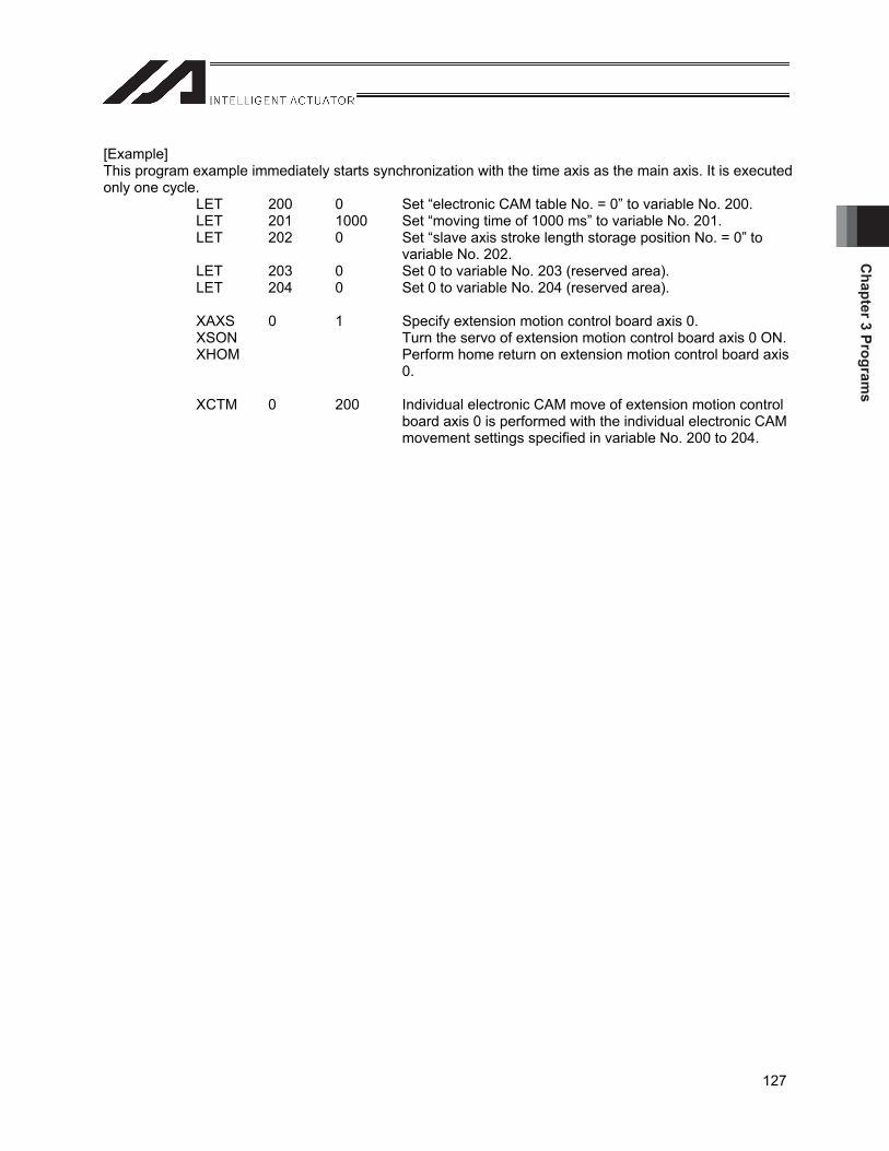
Chapter 3 Program
s
127
[Example] This program example immediately starts synchronization with the time axis as the main axis. It is executed only one cycle. LET 200 0 Set “electronic CAM table No. = 0” to variable No. 200. LET 201 1000 Set “moving time of 1000 ms” to variable No. 201. LET 202 0 Set “slave axis stroke length storage position No. = 0” to
variable No. 202. LET 203 0 Set 0 to variable No. 203 (reserved area). LET 204 0 Set 0 to variable No. 204 (reserved area). XAXS 0 1 Specify extension motion control board axis 0. XSON Turn the servo of extension motion control board axis 0 ON. XHOM Perform home return on extension motion control board axis
0. XCTM 0 200 Individual electronic CAM move of extension motion control
board axis 0 is performed with the individual electronic CAM movement settings specified in variable No. 200 to 204.
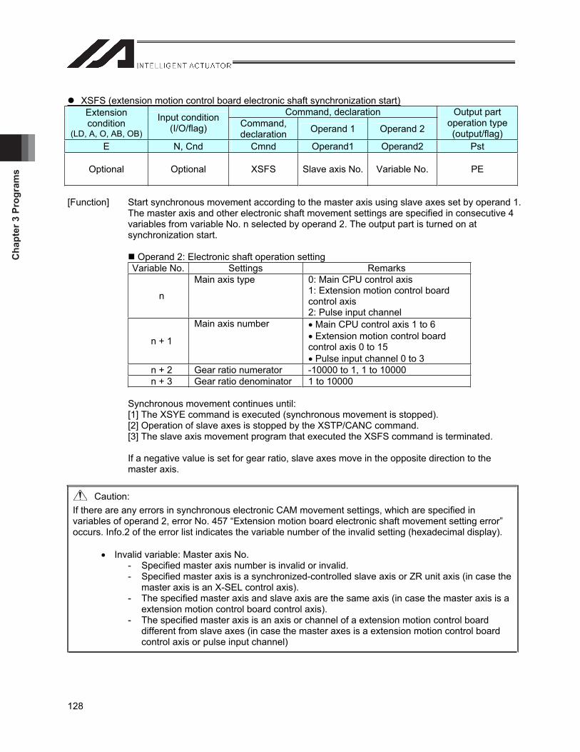
Cha
pter
3 P
rogr
ams
128
XSFS (extension motion control board electronic shaft synchronization start)Command, declaration Extension
condition(LD, A, O, AB, OB)
Input condition (I/O/flag) Command,
declaration Operand 1 Operand 2
Output part operation type (output/flag)
E N, Cnd Cmnd Operand1 Operand2 Pst
Optional Optional XSFS Slave axis No. Variable No. PE
[Function] Start synchronous movement according to the master axis using slave axes set by operand 1. The master axis and other electronic shaft movement settings are specified in consecutive 4 variables from variable No. n selected by operand 2. The output part is turned on at synchronization start.
Operand 2: Electronic shaft operation setting Variable No. Settings Remarks
n
Main axis type 0: Main CPU control axis 1: Extension motion control board control axis 2: Pulse input channel
n + 1
Main axis number Main CPU control axis 1 to 6 Extension motion control board
control axis 0 to 15 Pulse input channel 0 to 3
n + 2 Gear ratio numerator -10000 to 1, 1 to 10000 n + 3 Gear ratio denominator 1 to 10000
Synchronous movement continues until: [1] The XSYE command is executed (synchronous movement is stopped). [2] Operation of slave axes is stopped by the XSTP/CANC command.[3] The slave axis movement program that executed the XSFS command is terminated.
If a negative value is set for gear ratio, slave axes move in the opposite direction to the master axis.
Caution: If there are any errors in synchronous electronic CAM movement settings, which are specified in variables of operand 2, error No. 457 “Extension motion board electronic shaft movement setting error” occurs. Info.2 of the error list indicates the variable number of the invalid setting (hexadecimal display).
Invalid variable: Master axis No. - Specified master axis number is invalid or invalid. - Specified master axis is a synchronized-controlled slave axis or ZR unit axis (in case the
master axis is an X-SEL control axis). - The specified master axis and slave axis are the same axis (in case the master axis is a
extension motion control board control axis). - The specified master axis is an axis or channel of a extension motion control board
different from slave axes (in case the master axes is a extension motion control board control axis or pulse input channel)
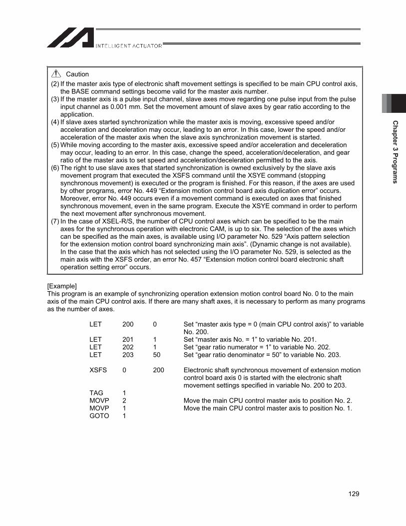
Chapter 3 Program
s
129
Caution (2) If the master axis type of electronic shaft movement settings is specified to be main CPU control axis,
the BASE command settings become valid for the master axis number. (3) If the master axis is a pulse input channel, slave axes move regarding one pulse input from the pulse
input channel as 0.001 mm. Set the movement amount of slave axes by gear ratio according to the application.
(4) If slave axes started synchronization while the master axis is moving, excessive speed and/or acceleration and deceleration may occur, leading to an error. In this case, lower the speed and/or acceleration of the master axis when the slave axis synchronization movement is started.
(5) While moving according to the master axis, excessive speed and/or acceleration and deceleration may occur, leading to an error. In this case, change the speed, acceleration/deceleration, and gear ratio of the master axis to set speed and acceleration/deceleration permitted to the axis.
(6) The right to use slave axes that started synchronization is owned exclusively by the slave axis movement program that executed the XSFS command until the XSYE command (stopping synchronous movement) is executed or the program is finished. For this reason, if the axes are used by other programs, error No. 449 “Extension motion control board axis duplication error” occurs. Moreover, error No. 449 occurs even if a movement command is executed on axes that finished synchronous movement, even in the same program. Execute the XSYE command in order to perform the next movement after synchronous movement.
(7) In the case of XSEL-R/S, the number of CPU control axes which can be specified to be the main axes for the synchronous operation with electronic CAM, is up to six. The selection of the axes which can be specified as the main axes, is available using I/O parameter No. 529 “Axis pattern selection for the extension motion control board synchronizing main axis”. (Dynamic change is not available). In the case that the axis which has not selected using the I/O parameter No. 529, is selected as the main axis with the XSFS order, an error No. 457 “Extension motion control board electronic shaft operation setting error” occurs.
[Example] This program is an example of synchronizing operation extension motion control board No. 0 to the main axis of the main CPU control axis. If there are many shaft axes, it is necessary to perform as many programs as the number of axes. LET 200 0 Set “master axis type = 0 (main CPU control axis)” to variable
No. 200. LET 201 1 Set “master axis No. = 1” to variable No. 201. LET 202 1 Set “gear ratio numerator = 1” to variable No. 202. LET 203 50 Set “gear ratio denominator = 50” to variable No. 203. XSFS 0 200 Electronic shaft synchronous movement of extension motion
control board axis 0 is started with the electronic shaft movement settings specified in variable No. 200 to 203.
TAG 1 MOVP 2 Move the main CPU control master axis to position No. 2. MOVP 1 Move the main CPU control master axis to position No. 1. GOTO 1
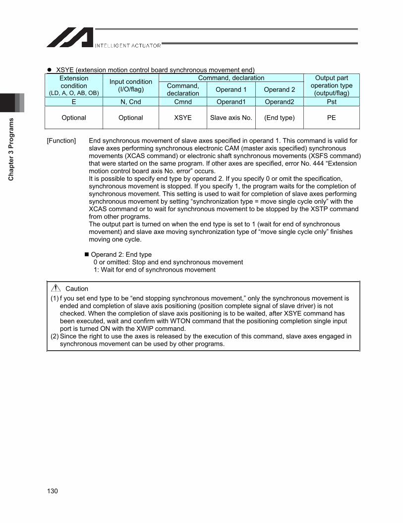
Cha
pter
3 P
rogr
ams
130
XSYE (extension motion control board synchronous movement end)Command, declaration Extension
condition(LD, A, O, AB, OB)
Input condition (I/O/flag) Command,
declaration Operand 1 Operand 2
Output part operation type (output/flag)
E N, Cnd Cmnd Operand1 Operand2 Pst
Optional Optional XSYE Slave axis No. (End type) PE
[Function] End synchronous movement of slave axes specified in operand 1. This command is valid for slave axes performing synchronous electronic CAM (master axis specified) synchronous movements (XCAS command) or electronic shaft synchronous movements (XSFS command) that were started on the same program. If other axes are specified, error No. 444 “Extension motion control board axis No. error” occurs. It is possible to specify end type by operand 2. If you specify 0 or omit the specification, synchronous movement is stopped. If you specify 1, the program waits for the completion of synchronous movement. This setting is used to wait for completion of slave axes performing synchronous movement by setting “synchronization type = move single cycle only” with the XCAS command or to wait for synchronous movement to be stopped by the XSTP command from other programs. The output part is turned on when the end type is set to 1 (wait for end of synchronous movement) and slave axe moving synchronization type of “move single cycle only” finishes moving one cycle.
Operand 2: End type 0 or omitted: Stop and end synchronous movement 1: Wait for end of synchronous movement
Caution (1) f you set end type to be “end stopping synchronous movement,” only the synchronous movement is
ended and completion of slave axis positioning (position complete signal of slave driver) is not checked. When the completion of slave axis positioning is to be waited, after XSYE command has been executed, wait and confirm with WTON command that the positioning completion single input port is turned ON with the XWIP command.
(2) Since the right to use the axes is released by the execution of this command, slave axes engaged in synchronous movement can be used by other programs.
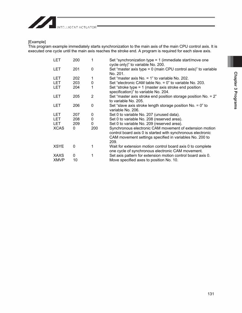
Chapter 3 Program
s
131
[Example] This program example immediately starts synchronization to the main axis of the main CPU control axis. It is executed one cycle until the main axis reaches the stroke end. A program is required for each slave axis. LET 200 1 Set “synchronization type = 1 (immediate start/move one
cycle only)” to variable No. 200. LET 201 0 Set “master axis type = 0 (main CPU control axis)” to variable
No. 201. LET 202 1 Set “master axis No. = 1” to variable No. 202. LET 203 0 Set “electronic CAM table No. = 0” to variable No. 203. LET 204 1 Set “stroke type = 1 (master axis stroke end position
specification)” to variable No. 204. LET 205 2 Set “master axis stroke end position storage position No. = 2”
to variable No. 205. LET 206 0 Set “slave axis stroke length storage position No. = 0” to
variable No. 206. LET 207 0 Set 0 to variable No. 207 (unused data). LET 208 0 Set 0 to variable No. 208 (reserved area). LET 209 0 Set 0 to variable No. 209 (reserved area). XCAS 0 200 Synchronous electronic CAM movement of extension motion
control board axis 0 is started with synchronous electronic CAM movement settings specified in variables No. 200 to 209.
XSYE 0 1 Wait for extension motion control board axis 0 to complete one cycle of synchronous electronic CAM movement.
XAXS 0 1 Set axis pattern for extension motion control board axis 0. XMVP 10 Move specified axes to position No. 10.
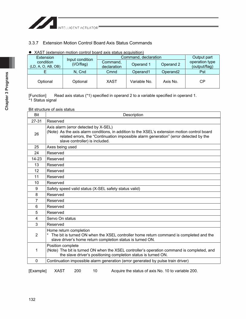
Cha
pter
3 P
rogr
ams
132
3.3.7 Extension Motion Control Board Axis Status Commands
XAST (extension motion control board axis status acquisition)Command, declaration Extension
condition(LD, A, O, AB, OB)
Input condition (I/O/flag) Command,
declaration Operand 1 Operand 2
Output part operation type (output/flag)
E N, Cnd Cmnd Operand1 Operand2 Pst
Optional Optional XAST Variable No. Axis No. CP
[Function] Read axis status (*1) specified in operand 2 to a variable specified in operand 1. *1 Status signal
Bit structure of axis status Bit Description
27-31 Reserved
26
Axis alarm (error detected by X-SEL) (Note) As the axis alarm conditions, in addition to the XSEL’s extension motion control board
related errors, the “Continuation impossible alarm generation” (error detected by the slave controller) is included.
25 Axes being used 24 Reserved
14-23 Reserved 13 Reserved 12 Reserved 11 Reserved 10 Reserved 9 Safety speed valid status (X-SEL safety status valid) 8 Reserved 7 Reserved 6 Reserved 5 Reserved 4 Servo On status 3 Reserved
2Home return completion * The bit is turned ON when the XSEL controller home return command is completed and the
slave driver’s home return completion status is turned ON.
1Position complete (Note) The bit is turned ON when the XSEL controller’s operation command is completed, and
the slave driver’s positioning completion status is turned ON.0 Continuation impossible alarm generation (error generated by pulse train driver)
[Example] XAST 200 10 Acquire the status of axis No. 10 to variable 200.

Chapter 3 Program
s
133
3.3.8 Expansion Commands ECMD20 (parameter value acquisition)
Command, declaration Extensioncondition
(LD, A, O, AB, OB)
Input condition (I/O/flag) Command,
declaration Operand 1 Operand 2
Output part operation type (output/flag)
E N, Cnd Cmnd Operand1 Operand2 Pst
Optional Optional XAST Variable No. Axis No. CP
[Function] This command uses data stored in 5 consecutive variables from the variable No. specified in operand 2 to store the value of specified parameter in variable 99. The setting items and range of variable data are shown in the table below. If values outside the range are specified, the “C44 SEL data error” occurs. It is possible to acquire parameters for extension motion control board by setting 10 for parameter type. Also, parameter detail types (n + 3) and channel No. (n + 4) are required.
When n is specified in operand 2
Variable No Settingitem Setting value/range of each variable
n Parametertype 10 (extension motion control board)
n+1 Device No. 0~1
n+2 ParameterNo. 1~100
n+3 Parameterdetail type
0: Common 1: Input channel
2: Output channel
n+4 Channel No.
The range varies depending on parameter detail type (n + 3). Parameter detail type (n + 3). Range of channel No. (n + 4)
0 (Common) Reserved (fixed to 0) 1 (Input channel) 0~1
2 (Output channel) 0~7
Specify integer type variables in operand 2 (it is not allowed to specify integer type variables 96 to 99, 296 to 299, 1096 to 1099, 1296 to 1299 because 5 consecutive integer variables cannot be secured). If variables other than integer type are specified, the “C3C variable No. error” occurs.
[Example] LET 1250 10 Variable No. 1250: Parameter type (extension motion control board)
LET 1251 1 Variable No. 1251: Device No. LET 1252 2 Variable No. 1252: Parameter No. (No. 2) LET 1253 2 Variable No. 1252: Parameter No. (output channel) LET 1254 5 Variable No. 1252: Parameter No. (output channel 5) ECMD 20 1250 Expansion command 20 (use variable No. 1250 to 1254)
Store the value of extension motion control board parameter No. 2 of output channel 5 (pulse output mode) to variable 99.
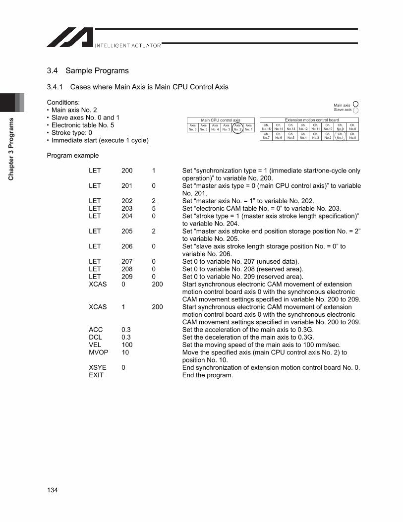
Cha
pter
3 P
rogr
ams
134
3.4 Sample Programs
3.4.1 Cases where Main Axis is Main CPU Control Axis
Conditions: Main axis No. 2 Slave axes No. 0 and 1 Electronic table No. 5 Stroke type: 0 Immediate start (execute 1 cycle)
Program example LET 200 1 Set “synchronization type = 1 (immediate start/one-cycle only
operation)” to variable No. 200. LET 201 0 Set “master axis type = 0 (main CPU control axis)” to variable
No. 201. LET 202 2 Set “master axis No. = 1” to variable No. 202. LET 203 5 Set “electronic CAM table No. = 0” to variable No. 203. LET 204 0 Set “stroke type = 1 (master axis stroke length specification)”
to variable No. 204. LET 205 2 Set “master axis stroke end position storage position No. = 2”
to variable No. 205. LET 206 0 Set “slave axis stroke length storage position No. = 0” to
variable No. 206. LET 207 0 Set 0 to variable No. 207 (unused data). LET 208 0 Set 0 to variable No. 208 (reserved area). LET 209 0 Set 0 to variable No. 209 (reserved area). XCAS 0 200 Start synchronous electronic CAM movement of extension
motion control board axis 0 with the synchronous electronic CAM movement settings specified in variable No. 200 to 209.
XCAS 1 200 Start synchronous electronic CAM movement of extension motion control board axis 0 with the synchronous electronic CAM movement settings specified in variable No. 200 to 209.
ACC 0.3 Set the acceleration of the main axis to 0.3G. DCL 0.3 Set the deceleration of the main axis to 0.3G. VEL 100 Set the moving speed of the main axis to 100 mm/sec. MVOP 10 Move the specified axis (main CPU control axis No. 2) to
position No. 10. XSYE 0 End synchronization of extension motion control board No. 0. EXIT End the program.
Extension motion control boardCh.
No.15Ch.
No.14Ch.
No.13Ch.
No.12Ch.
No.11Ch.
No.10Ch.No.9
Ch.No.8
Ch.No.7
Ch.No.6
Ch.No.5
Ch.No.4
Ch.No.3
Ch.No.2
Ch.No.1
Ch.No.0
Main CPU control axisAxisNo. 6
Axis No. 5
Axis No. 4
Axis No. 3
AxisNo. 2
AxisNo. 1
Main axis Slave axis
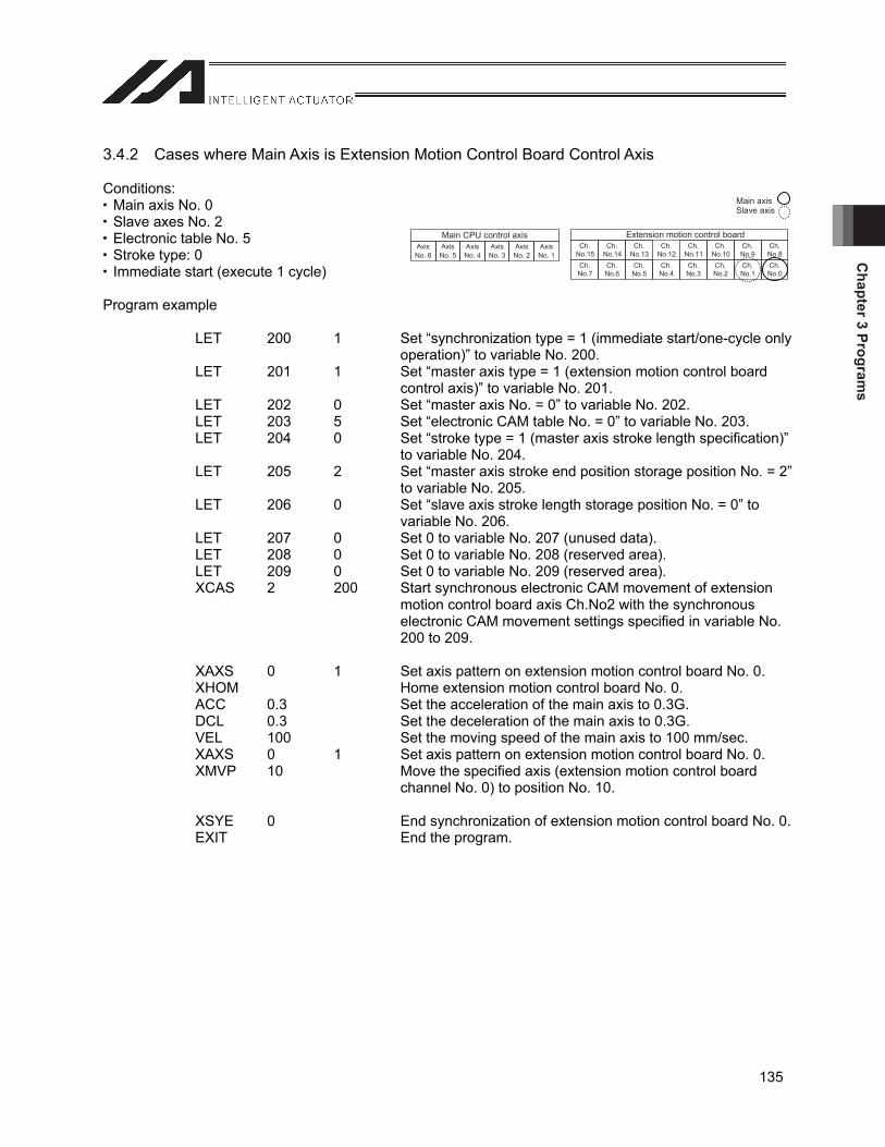
Chapter 3 Program
s
135
3.4.2 Cases where Main Axis is Extension Motion Control Board Control Axis
Conditions: Main axis No. 0 Slave axes No. 2 Electronic table No. 5 Stroke type: 0 Immediate start (execute 1 cycle)
Program example LET 200 1 Set “synchronization type = 1 (immediate start/one-cycle only
operation)” to variable No. 200. LET 201 1 Set “master axis type = 1 (extension motion control board
control axis)” to variable No. 201. LET 202 0 Set “master axis No. = 0” to variable No. 202. LET 203 5 Set “electronic CAM table No. = 0” to variable No. 203. LET 204 0 Set “stroke type = 1 (master axis stroke length specification)”
to variable No. 204. LET 205 2 Set “master axis stroke end position storage position No. = 2”
to variable No. 205. LET 206 0 Set “slave axis stroke length storage position No. = 0” to
variable No. 206. LET 207 0 Set 0 to variable No. 207 (unused data). LET 208 0 Set 0 to variable No. 208 (reserved area). LET 209 0 Set 0 to variable No. 209 (reserved area). XCAS 2 200 Start synchronous electronic CAM movement of extension
motion control board axis Ch.No2 with the synchronous electronic CAM movement settings specified in variable No. 200 to 209.
XAXS 0 1 Set axis pattern on extension motion control board No. 0. XHOM Home extension motion control board No. 0. ACC 0.3 Set the acceleration of the main axis to 0.3G. DCL 0.3 Set the deceleration of the main axis to 0.3G. VEL 100 Set the moving speed of the main axis to 100 mm/sec. XAXS 0 1 Set axis pattern on extension motion control board No. 0. XMVP 10 Move the specified axis (extension motion control board
channel No. 0) to position No. 10. XSYE 0 End synchronization of extension motion control board No. 0. EXIT End the program.
Extension motion control boardCh.
No.15Ch.
No.14Ch.
No.13Ch.
No.12Ch.
No.11Ch.
No.10Ch.No.9
Ch.No.8
Ch.No.7
Ch.No.6
Ch.No.5
Ch.No.4
Ch.No.3
Ch.No.2
Ch.No.1
Ch.No.0
Main CPU control axisAxisNo. 6
AxisNo. 5
Axis No. 4
Axis No. 3
AxisNo. 2
AxisNo. 1
Main axis Slave axis
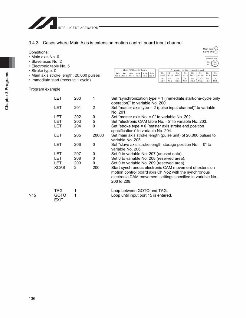
Cha
pter
3 P
rogr
ams
136
3.4.3 Cases where Main Axis is extension motion control board input channel
Conditions: Main axis No. 0 Slave axes No. 2 Electronic table No. 5 Stroke type: 0 Main axis stroke length: 20,000 pulses Immediate start (execute 1 cycle)
Program example LET 200 1 Set “synchronization type = 1 (immediate start/one-cycle only
operation)” to variable No. 200. LET 201 2 Set “master axis type = 2 (pulse input channel)” to variable
No. 201. LET 202 0 Set “master axis No. = 0” to variable No. 202. LET 203 5 Set “electronic CAM table No. =5” to variable No. 203. LET 204 0 Set “stroke type = 0 (master axis stroke end position
specification)” to variable No. 204. LET 205 20000 Set main axis stroke length (pulse unit) of 20,000 pulses to
variable No. 205. LET 206 0 Set “slave axis stroke length storage position No. = 0” to
variable No. 206. LET 207 0 Set 0 to variable No. 207 (unused data). LET 208 0 Set 0 to variable No. 208 (reserved area). LET 209 0 Set 0 to variable No. 209 (reserved area). XCAS 2 200 Start synchronous electronic CAM movement of extension
motion control board axis Ch.No2 with the synchronous electronic CAM movement settings specified in variable No. 200 to 209.
TAG 1 Loop between GOTO and TAG. N15 GOTO 1 Loop until input port 15 is entered. EXIT
Extension motion control board
Outer pulse input
Ch.No.1
Ch.No.0
Ch.No.15
Ch.No.14
Ch.No.13
Ch.No.12
Ch.No.11
Ch.No.10
Ch.No.9
Ch.No.8
Ch.No.7
Ch.No.6
Ch.No.5
Ch.No.4
Ch.No.3
Ch.No.2
Ch.No.1
Ch.No.0
Main CPU control axisAxisNo. 6
AxisNo. 5
Axis No. 4
Axis No. 3
AxisNo. 2
AxisNo. 1
Main axis Slave axis
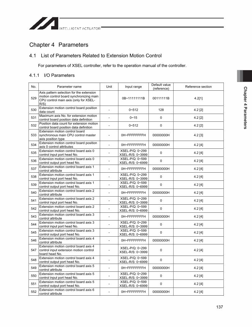
Chapter 4 Param
eters
137
Chapter 4 Parameters
4.1 List of Parameters Related to Extension Motion Control
For parameters of XSEL controller, refer to the operation manual of the controller.
4.1.1 I/O Parameters
No. Parameter name Unit Input range Default value (reference) Reference section
529
Axis pattern selection for the extension motion control board synchronizing main CPU control main axis (only for XSEL-R/S)
0B~11111111B 00111111B 4.2[1]
530 Extension motion control board position data count - 0~512 128 4.2 [2]
531 Maximum axis No. for extension motion control board position data definition - 0~15 0 4.2 [2]
532 Position data count for extension motion control board position data definition - 0~512 0 4.2 [2]
533Extension motion control board synchronous main CPU control master axis position type
- 0H~FFFFFFFFH 00000000H 4.2 [3]
534 Extension motion control board position axis 0 control attributes - 0H~FFFFFFFFH 00000000H 4.2 [4]
535 Extension motion control board axis 0 control input port head No. - XSEL-P/Q: 0~299
XSEL-R/S: 0~3999 0 4.2 [4]
536 Extension motion control board axis 0 control output port head No. - XSEL-P/Q: 0~599
XSEL-R/S: 0~6999 0 4.2 [4]
537 Extension motion control board axis 1 control attribute - 0H~FFFFFFFFH 00000000H 4.2 [4]
538 Extension motion control board axis 1 control input port head No. - XSEL-P/Q: 0~299
XSEL-R/S: 0~3999 0 4.2 [4]
539 Extension motion control board axis 1 control output port head No. - XSEL-P/Q: 0~599
XSEL-R/S: 0~6999 0 4.2 [4]
540 Extension motion control board axis 2 control attribute - 0H~FFFFFFFFH 00000000H 4.2 [4]
541 Extension motion control board axis 2 control input port head No. - XSEL-P/Q: 0~299
XSEL-R/S: 0~3999 0 4.2 [4]
542 Extension motion control board axis 2 control output port head No. - XSEL-P/Q: 0~599
XSEL-R/S: 0~6999 0 4.2 [4]
543 Extension motion control board axis 3 control attribute - 0H~FFFFFFFFH 00000000H 4.2 [4]
544 Extension motion control board axis 3 control input port head No. - XSEL-P/Q: 0~299
XSEL-R/S: 0~3999 0 4.2 [4]
545 Extension motion control board axis 3 control output port head No. - XSEL-P/Q: 0~599
XSEL-R/S: 0~6999 0 4.2 [4]
546 Extension motion control board axis 4 control attribute - 0H~FFFFFFFFH 00000000H 4.2 [4]
547Extension motion control board axis 4 control input extension motion control board head No.
- XSEL-P/Q: 0~299XSEL-R/S: 0~3999 0 4.2 [4]
548 Extension motion control board axis 4 control output port head No. - XSEL-P/Q: 0~599
XSEL-R/S: 0~6999 0 4.2 [4]
549 Extension motion control board axis 5 control attribute - 0H~FFFFFFFFH 00000000H 4.2 [4]
550 Extension motion control board axis 5 control input port head No. - XSEL-P/Q: 0~299
XSEL-R/S: 0~3999 0 4.2 [4]
551 Extension motion control board axis 5 control output port head No. - XSEL-P/Q: 0~599
XSEL-R/S: 0~6999 0 4.2 [4]
552 Extension motion control board axis 6 control attribute - 0H~FFFFFFFFH 00000000H 4.2 [4]
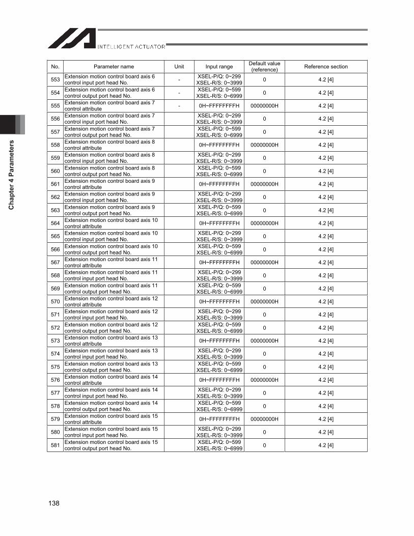
Cha
pter
4 P
aram
eter
s
138
No. Parameter name Unit Input range Default value (reference) Reference section
553 Extension motion control board axis 6 control input port head No. - XSEL-P/Q: 0~299
XSEL-R/S: 0~3999 0 4.2 [4]
554 Extension motion control board axis 6 control output port head No. - XSEL-P/Q: 0~599
XSEL-R/S: 0~6999 0 4.2 [4]
555 Extension motion control board axis 7 control attribute - 0H~FFFFFFFFH 00000000H 4.2 [4]
556 Extension motion control board axis 7 control input port head No.
XSEL-P/Q: 0~299XSEL-R/S: 0~3999 0 4.2 [4]
557 Extension motion control board axis 7 control output port head No.
XSEL-P/Q: 0~599XSEL-R/S: 0~6999 0 4.2 [4]
558 Extension motion control board axis 8 control attribute 0H~FFFFFFFFH 00000000H 4.2 [4]
559 Extension motion control board axis 8 control input port head No.
XSEL-P/Q: 0~299XSEL-R/S: 0~3999 0 4.2 [4]
560 Extension motion control board axis 8 control output port head No.
XSEL-P/Q: 0~599XSEL-R/S: 0~6999 0 4.2 [4]
561 Extension motion control board axis 9 control attribute 0H~FFFFFFFFH 00000000H 4.2 [4]
562 Extension motion control board axis 9 control input port head No.
XSEL-P/Q: 0~299XSEL-R/S: 0~3999 0 4.2 [4]
563 Extension motion control board axis 9 control output port head No.
XSEL-P/Q: 0~599XSEL-R/S: 0~6999 0 4.2 [4]
564 Extension motion control board axis 10 control attribute 0H~FFFFFFFFH 00000000H 4.2 [4]
565 Extension motion control board axis 10 control input port head No.
XSEL-P/Q: 0~299XSEL-R/S: 0~3999 0 4.2 [4]
566 Extension motion control board axis 10 control output port head No.
XSEL-P/Q: 0~599XSEL-R/S: 0~6999 0 4.2 [4]
567 Extension motion control board axis 11 control attribute 0H~FFFFFFFFH 00000000H 4.2 [4]
568 Extension motion control board axis 11 control input port head No.
XSEL-P/Q: 0~299XSEL-R/S: 0~3999 0 4.2 [4]
569 Extension motion control board axis 11 control output port head No.
XSEL-P/Q: 0~599XSEL-R/S: 0~6999 0 4.2 [4]
570 Extension motion control board axis 12 control attribute 0H~FFFFFFFFH 00000000H 4.2 [4]
571 Extension motion control board axis 12 control input port head No.
XSEL-P/Q: 0~299XSEL-R/S: 0~3999 0 4.2 [4]
572 Extension motion control board axis 12 control output port head No.
XSEL-P/Q: 0~599XSEL-R/S: 0~6999 0 4.2 [4]
573 Extension motion control board axis 13 control attribute 0H~FFFFFFFFH 00000000H 4.2 [4]
574 Extension motion control board axis 13 control input port head No.
XSEL-P/Q: 0~299XSEL-R/S: 0~3999 0 4.2 [4]
575 Extension motion control board axis 13 control output port head No.
XSEL-P/Q: 0~599XSEL-R/S: 0~6999 0 4.2 [4]
576 Extension motion control board axis 14 control attribute 0H~FFFFFFFFH 00000000H 4.2 [4]
577 Extension motion control board axis 14 control input port head No.
XSEL-P/Q: 0~299XSEL-R/S: 0~3999 0 4.2 [4]
578 Extension motion control board axis 14 control output port head No.
XSEL-P/Q: 0~599XSEL-R/S: 0~6999 0 4.2 [4]
579 Extension motion control board axis 15 control attribute 0H~FFFFFFFFH 00000000H 4.2 [4]
580 Extension motion control board axis 15 control input port head No.
XSEL-P/Q: 0~299XSEL-R/S: 0~3999 0 4.2 [4]
581 Extension motion control board axis 15 control output port head No.
XSEL-P/Q: 0~599XSEL-R/S: 0~6999 0 4.2 [4]

Chapter 4 Param
eters
139
4.1.2 Parameters by Axis
No. Parameter name Unit Input range Default value (reference) Reference section
166Drive invalid specification (XSEL-P/Q Main application version 0.98 or later)
- 0~1 0 4.2 [5]
167Slave movement command origin unit type (XSEL-P/Q Main application version 0.98 or later)
- 0~10 0 4.2 [6]
168Slave movement command origin device No. (XSEL-P/Q Main application version 0.98 or later)
- 0~99999999 0 4.2 [6]
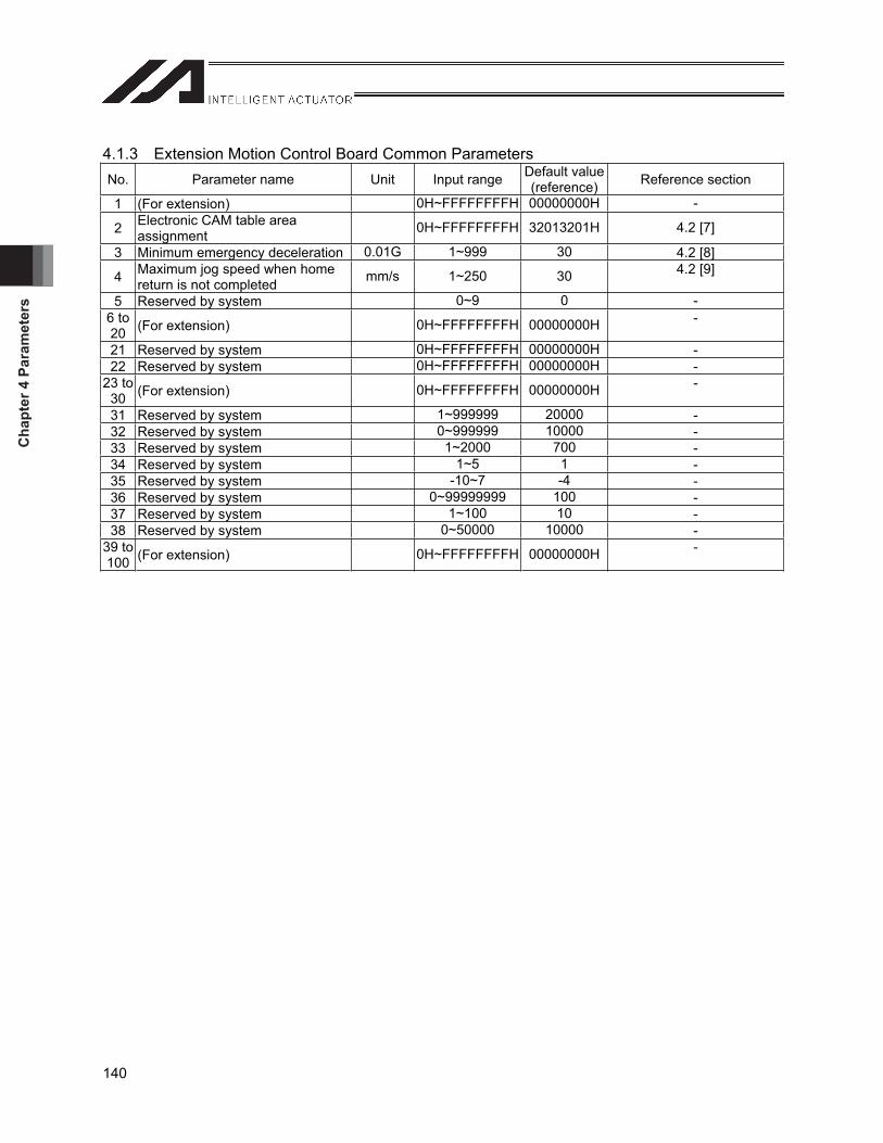
Cha
pter
4 P
aram
eter
s
140
4.1.3 Extension Motion Control Board Common Parameters No. Parameter name Unit Input range Default value
(reference) Reference section
1 (For extension) 0H~FFFFFFFFH 00000000H -
2 Electronic CAM table area assignment 0H~FFFFFFFFH 32013201H 4.2 [7]
3 Minimum emergency deceleration 0.01G 1~999 30 4.2 [8]
4 Maximum jog speed when home return is not completed mm/s 1~250 30 4.2 [9]
5 Reserved by system 0~9 0 - 6 to 20 (For extension) 0H~FFFFFFFFH 00000000H -
21 Reserved by system 0H~FFFFFFFFH 00000000H -22 Reserved by system 0H~FFFFFFFFH 00000000H -
23 to 30 (For extension) 0H~FFFFFFFFH 00000000H -
31 Reserved by system 1~999999 20000 -32 Reserved by system 0~999999 10000 -33 Reserved by system 1~2000 700 -34 Reserved by system 1~5 1 -35 Reserved by system -10~7 -4 -36 Reserved by system 0~99999999 100 -37 Reserved by system 1~100 10 -38 Reserved by system 0~50000 10000 -
39 to 100 (For extension) 0H~FFFFFFFFH 00000000H -
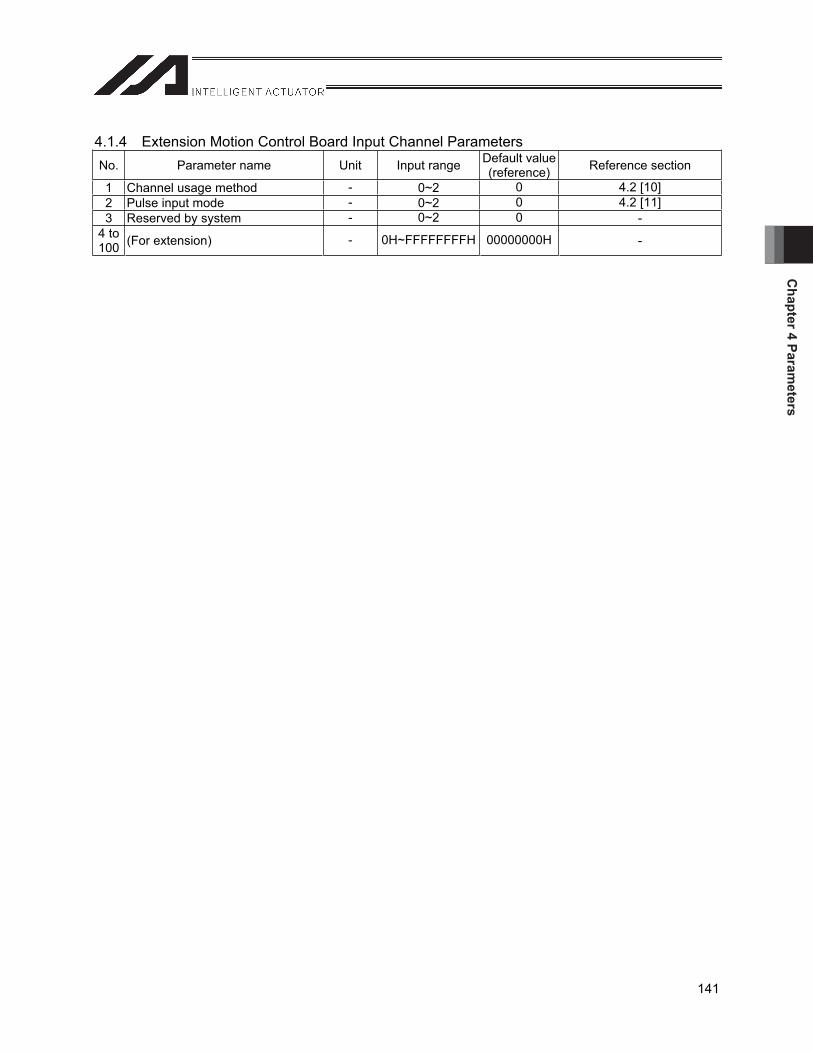
Chapter 4 Param
eters
141
4.1.4 Extension Motion Control Board Input Channel Parameters No. Parameter name Unit Input range Default value
(reference) Reference section
1 Channel usage method - 0~2 0 4.2 [10] 2 Pulse input mode - 0~2 0 4.2 [11] 3 Reserved by system - 0~2 0 -
4 to 100 (For extension) - 0H~FFFFFFFFH 00000000H -
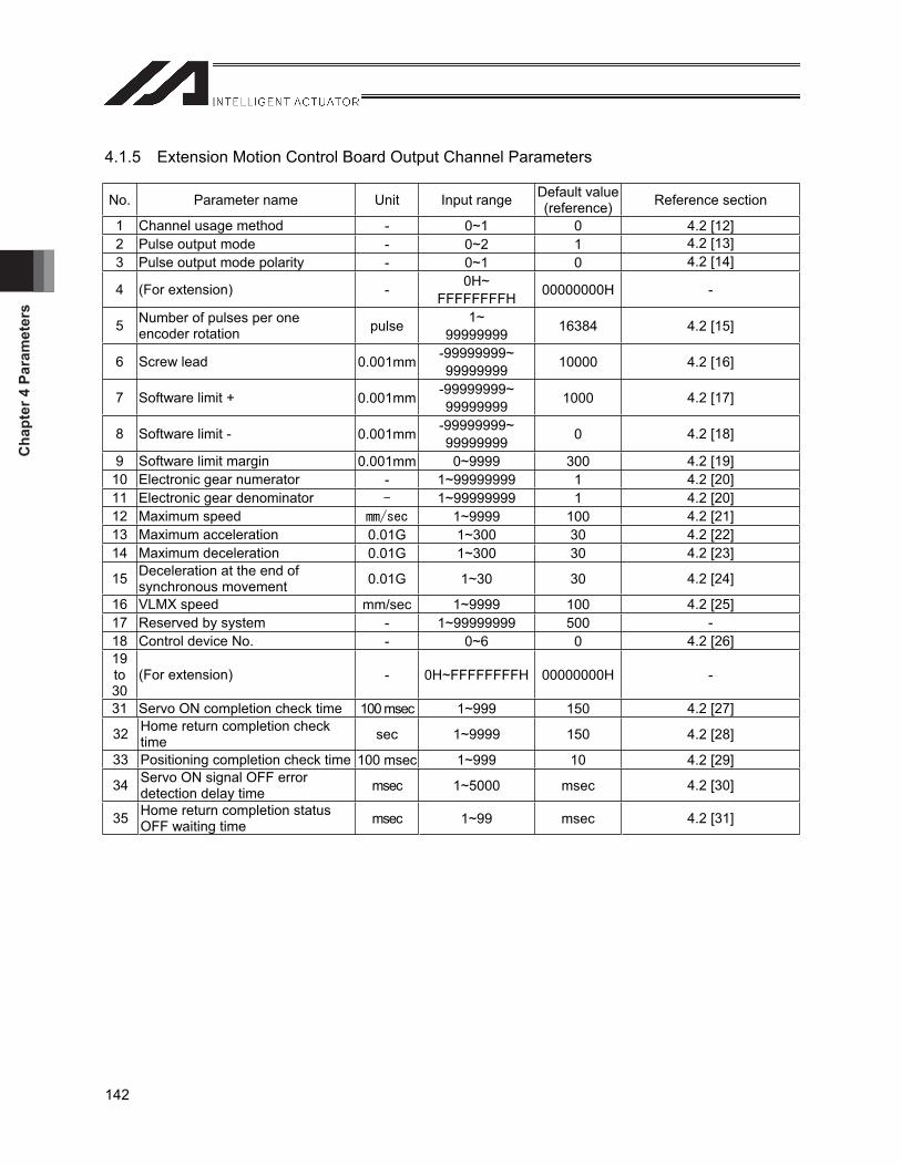
Cha
pter
4 P
aram
eter
s
142
4.1.5 Extension Motion Control Board Output Channel Parameters
No. Parameter name Unit Input range Default value (reference) Reference section
1 Channel usage method - 0~1 0 4.2 [12] 2 Pulse output mode - 0~2 1 4.2 [13] 3 Pulse output mode polarity - 0~1 0 4.2 [14]
4 (For extension) - 0H~FFFFFFFFH 00000000H -
5 Number of pulses per one encoder rotation pulse 1~
99999999 16384 4.2 [15]
6 Screw lead 0.001mm -99999999~99999999 10000 4.2 [16]
7 Software limit + 0.001mm -99999999~99999999 1000 4.2 [17]
8 Software limit - 0.001mm -99999999~99999999 0 4.2 [18]
9 Software limit margin 0.001mm 0~9999 300 4.2 [19] 10 Electronic gear numerator - 1~99999999 1 4.2 [20] 11 Electronic gear denominator 1~99999999 1 4.2 [20] 12 Maximum speed 1~9999 100 4.2 [21] 13 Maximum acceleration 0.01G 1~300 30 4.2 [22] 14 Maximum deceleration 0.01G 1~300 30 4.2 [23]
15 Deceleration at the end of synchronous movement 0.01G 1~30 30 4.2 [24]
16 VLMX speed mm/sec 1~9999 100 4.2 [25] 17 Reserved by system - 1~99999999 500 -18 Control device No. - 0~6 0 4.2 [26] 19to30
(For extension) - 0H~FFFFFFFFH 00000000H -
31 Servo ON completion check time 100 msec 1~999 150 4.2 [27]
32 Home return completion check time sec 1~9999 150 4.2 [28]
33 Positioning completion check time 100 msec 1~999 10 4.2 [29]
34 Servo ON signal OFF error detection delay time msec 1~5000 msec 4.2 [30]
35 Home return completion status OFF waiting time msec 1~99 msec 4.2 [31]
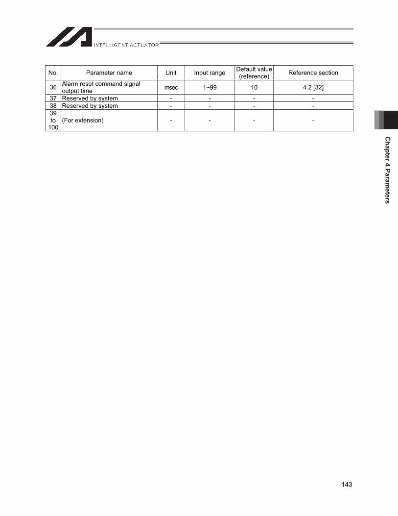
Chapter 4 Param
eters
143
No. Parameter name Unit Input range Default value (reference) Reference section
36 Alarm reset command signal output time msec 1~99 10 4.2 [32]
37 Reserved by system - - - - 38 Reserved by system - - - - 39to
100(For extension) - - - -
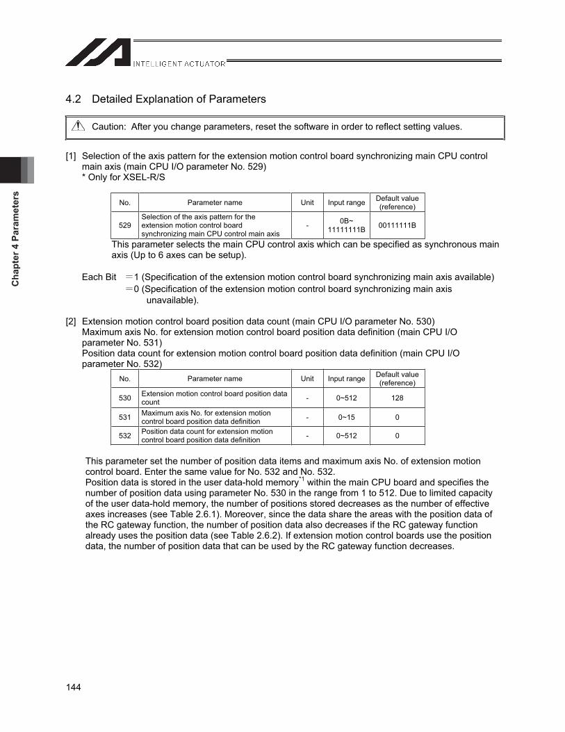
Cha
pter
4 P
aram
eter
s
144
4.2 Detailed Explanation of Parameters
Caution: After you change parameters, reset the software in order to reflect setting values.
[1] Selection of the axis pattern for the extension motion control board synchronizing main CPU control main axis (main CPU I/O parameter No. 529)
* Only for XSEL-R/S
No. Parameter name Unit Input range Default value (reference)
529Selection of the axis pattern for the extension motion control board synchronizing main CPU control main axis
- 0B~11111111B 00111111B
This parameter selects the main CPU control axis which can be specified as synchronous main axis (Up to 6 axes can be setup).
Each Bit 1 (Specification of the extension motion control board synchronizing main axis available) 0 (Specification of the extension motion control board synchronizing main axis
unavailable).
[2] Extension motion control board position data count (main CPU I/O parameter No. 530) Maximum axis No. for extension motion control board position data definition (main CPU I/O
parameter No. 531) Position data count for extension motion control board position data definition (main CPU I/O
parameter No. 532) No. Parameter name Unit Input range Default value
(reference)
530 Extension motion control board position data count - 0~512 128
531 Maximum axis No. for extension motion control board position data definition - 0~15 0
532 Position data count for extension motion control board position data definition - 0~512 0
This parameter set the number of position data items and maximum axis No. of extension motion control board. Enter the same value for No. 532 and No. 532. Position data is stored in the user data-hold memory*1 within the main CPU board and specifies the number of position data using parameter No. 530 in the range from 1 to 512. Due to limited capacity of the user data-hold memory, the number of positions stored decreases as the number of effective axes increases (see Table 2.6.1). Moreover, since the data share the areas with the position data of the RC gateway function, the number of position data also decreases if the RC gateway function already uses the position data (see Table 2.6.2). If extension motion control boards use the position data, the number of position data that can be used by the RC gateway function decreases.
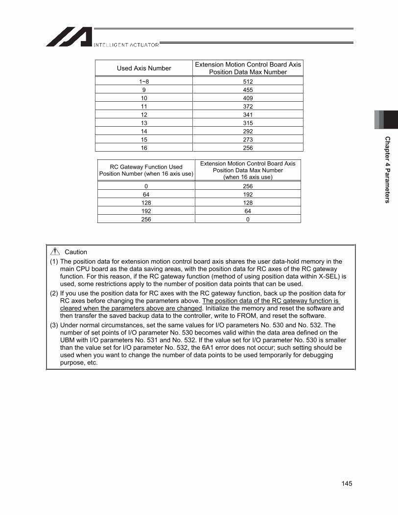
Chapter 4 Param
eters
145
Caution (1) The position data for extension motion control board axis shares the user data-hold memory in the
main CPU board as the data saving areas, with the position data for RC axes of the RC gateway function. For this reason, if the RC gateway function (method of using position data within X-SEL) is used, some restrictions apply to the number of position data points that can be used.
(2) If you use the position data for RC axes with the RC gateway function, back up the position data for RC axes before changing the parameters above. The position data of the RC gateway function is cleared when the parameters above are changed. Initialize the memory and reset the software and then transfer the saved backup data to the controller, write to FROM, and reset the software.
(3) Under normal circumstances, set the same values for I/O parameters No. 530 and No. 532. The number of set points of I/O parameter No. 530 becomes valid within the data area defined on the UBM with I/O parameters No. 531 and No. 532. If the value set for I/O parameter No. 530 is smaller than the value set for I/O parameter No. 532, the 6A1 error does not occur; such setting should be used when you want to change the number of data points to be used temporarily for debugging purpose, etc.
Used Axis Number Extension Motion Control Board Axis Position Data Max Number
1~8 512 9 455
10 409 11 372 12 341 13 315 14 292 15 273 16 256
RC Gateway Function Used Position Number (when 16 axis use)
Extension Motion Control Board Axis Position Data Max Number
(when 16 axis use) 0 256 64 192
128 128 192 64 256 0
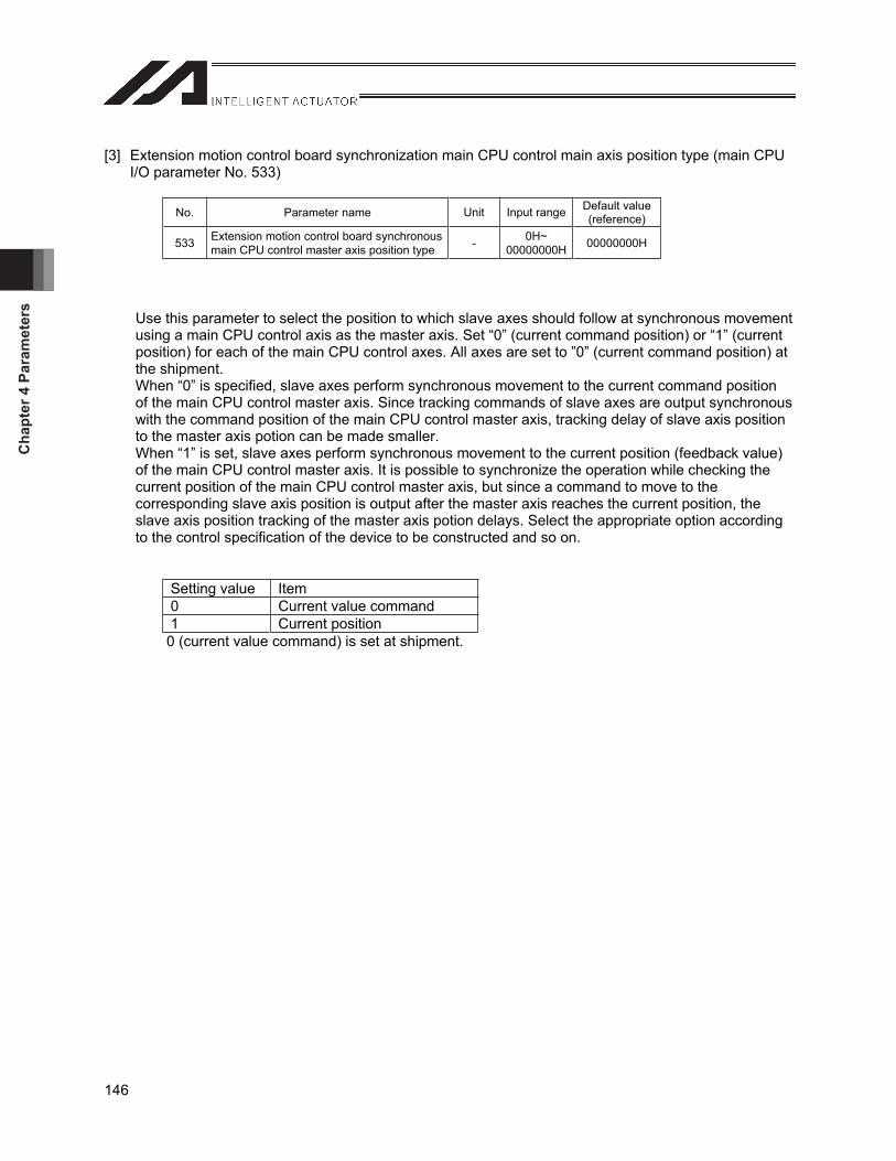
Cha
pter
4 P
aram
eter
s
146
[3] Extension motion control board synchronization main CPU control main axis position type (main CPU I/O parameter No. 533)
No. Parameter name Unit Input range Default value (reference)
533 Extension motion control board synchronous main CPU control master axis position type - 0H~
00000000H 00000000H
Use this parameter to select the position to which slave axes should follow at synchronous movement using a main CPU control axis as the master axis. Set “0” (current command position) or “1” (current position) for each of the main CPU control axes. All axes are set to ”0” (current command position) at the shipment. When “0” is specified, slave axes perform synchronous movement to the current command position of the main CPU control master axis. Since tracking commands of slave axes are output synchronous with the command position of the main CPU control master axis, tracking delay of slave axis position to the master axis potion can be made smaller. When “1” is set, slave axes perform synchronous movement to the current position (feedback value) of the main CPU control master axis. It is possible to synchronize the operation while checking the current position of the main CPU control master axis, but since a command to move to the corresponding slave axis position is output after the master axis reaches the current position, the slave axis position tracking of the master axis potion delays. Select the appropriate option according to the control specification of the device to be constructed and so on.
Setting value Item 0 Current value command 1 Current position 0 (current value command) is set at shipment.
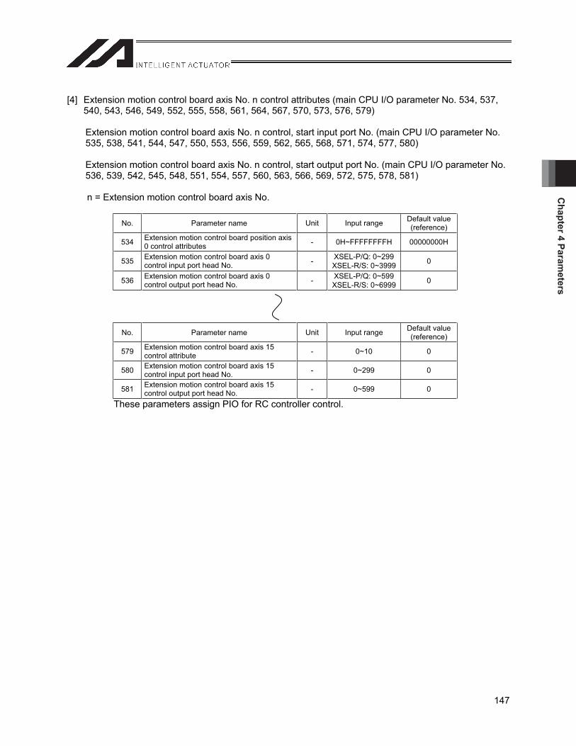
Chapter 4 Param
eters
147
[4] Extension motion control board axis No. n control attributes (main CPU I/O parameter No. 534, 537, 540, 543, 546, 549, 552, 555, 558, 561, 564, 567, 570, 573, 576, 579)
Extension motion control board axis No. n control, start input port No. (main CPU I/O parameter No. 535, 538, 541, 544, 547, 550, 553, 556, 559, 562, 565, 568, 571, 574, 577, 580)
Extension motion control board axis No. n control, start output port No. (main CPU I/O parameter No. 536, 539, 542, 545, 548, 551, 554, 557, 560, 563, 566, 569, 572, 575, 578, 581)
n = Extension motion control board axis No.
No. Parameter name Unit Input range Default value (reference)
534 Extension motion control board position axis 0 control attributes - 0H~FFFFFFFFH 00000000H
535 Extension motion control board axis 0 control input port head No. - XSEL-P/Q: 0~299
XSEL-R/S: 0~3999 0
536 Extension motion control board axis 0 control output port head No. - XSEL-P/Q: 0~599
XSEL-R/S: 0~6999 0
No. Parameter name Unit Input range Default value (reference)
579 Extension motion control board axis 15 control attribute - 0~10 0
580 Extension motion control board axis 15 control input port head No. - 0~299 0
581 Extension motion control board axis 15 control output port head No. - 0~599 0
These parameters assign PIO for RC controller control.
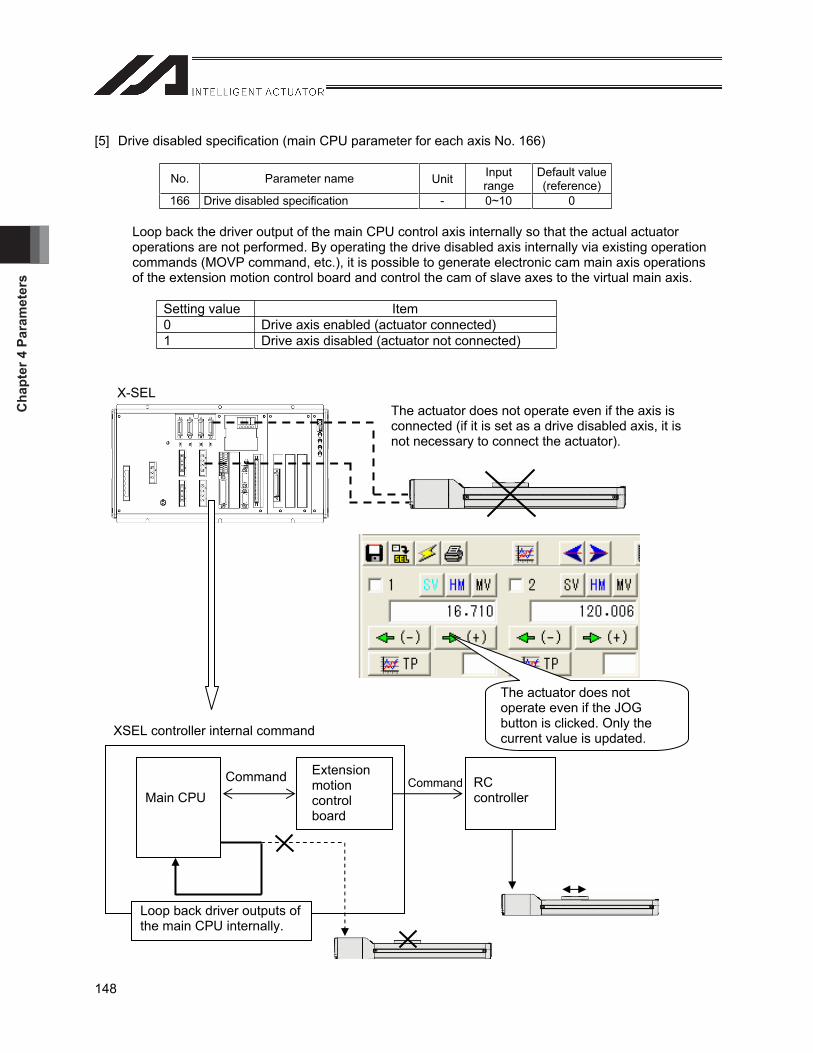
Cha
pter
4 P
aram
eter
s
148
[5] Drive disabled specification (main CPU parameter for each axis No. 166)
No. Parameter name Unit Inputrange
Default value (reference)
166 Drive disabled specification - 0~10 0
Loop back the driver output of the main CPU control axis internally so that the actual actuator operations are not performed. By operating the drive disabled axis internally via existing operation commands (MOVP command, etc.), it is possible to generate electronic cam main axis operations of the extension motion control board and control the cam of slave axes to the virtual main axis.
Setting value Item 0 Drive axis enabled (actuator connected) 1 Drive axis disabled (actuator not connected)
XSEL controller internal command
Main CPU
Extensionmotioncontrolboard
RCcontroller
Loop back driver outputs of the main CPU internally.
X-SEL
The actuator does not operate even if the JOG button is clicked. Only the current value is updated.
The actuator does not operate even if the axis is connected (if it is set as a drive disabled axis, it is not necessary to connect the actuator).
Command Command
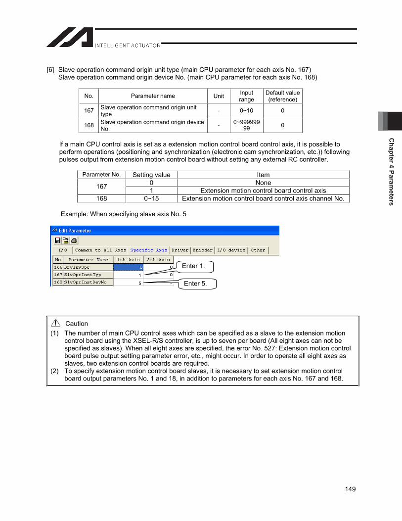
Chapter 4 Param
eters
149
[6] Slave operation command origin unit type (main CPU parameter for each axis No. 167) Slave operation command origin device No. (main CPU parameter for each axis No. 168)
No. Parameter name Unit Inputrange
Default value (reference)
167 Slave operation command origin unit type - 0~10 0
168 Slave operation command origin device No. - 0~999999
99 0
If a main CPU control axis is set as a extension motion control board control axis, it is possible to perform operations (positioning and synchronization (electronic cam synchronization, etc.)) following pulses output from extension motion control board without setting any external RC controller.
Parameter No. Setting value Item 0 None 167 1 Extension motion control board control axis
168 0~15 Extension motion control board control axis channel No.
Example: When specifying slave axis No. 5
Caution (1) The number of main CPU control axes which can be specified as a slave to the extension motion
control board using the XSEL-R/S controller, is up to seven per board (All eight axes can not be specified as slaves). When all eight axes are specified, the error No. 527: Extension motion control board pulse output setting parameter error, etc., might occur. In order to operate all eight axes as slaves, two extension control boards are required.
(2) To specify extension motion control board slaves, it is necessary to set extension motion control board output parameters No. 1 and 18, in addition to parameters for each axis No. 167 and 168.
Enter 1.
Enter 5. 1
5

Cha
pter
4 P
aram
eter
s
150
[7] Electronic cam table area assignment (extension motion control board common parameter No. 2)
No. Parameter name Unit Input range Default value (reference)
2 Electronic cam table data area assignment - 0H~FFFFFFFFH 32013201H
The electronic cam table storage area is divided into 2 banks (banks 0 and 1). This parameter assigns the number of tables and the number of displacement data items of each bank (assigns in units of 1 KB: possible to store 256 displacement data items).
Bits 31 to 24: Number of cam tables of bank 0 (BCD value: 0 to 64) Bits 23 to 16: Number of displacement data items of bank 0 (BCD value: 0 to 64) Bits 15 to 8: Number of cam tables of bank 1 (BCD value: 0 to 64) Bits 7 to 0: Number of displacement data items of bank 1 (BCD value: 1 to 64) * Note, however, that the following condition must be satisfied. [Number of CAM tables for bank 0] x [Bank 0, Number of displacement data items] + [Number of CAM tables for bank 1] x [Bank 1, Number of displacement data items] 64
Example 1: In the case of 64 tables and 256 displacement data items (number of divisions)
Example 2: In the case of 1 table and 16384 displacement data items (number of divisions)
Example 3: In the case of bank 0, 1 table, 768 displacement data items (number of divisions) In the case of bank 1, 32 table, 256 displacement data items (number of divisions)
Table No. 0 to 7 Number of displacement data:
1024
Table No. 8 to 11 Number of displacement data:
2048
Table No.. 0 63Number of displacement
data 256
Table No.. 0 Number of displacement
data 16384
Table No. 0Number of displacement
data 768
Table No. 1~32Number of displacement
data 256
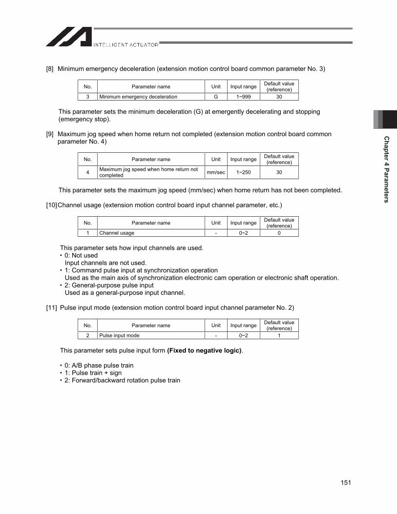
Chapter 4 Param
eters
151
[8] Minimum emergency deceleration (extension motion control board common parameter No. 3)
No. Parameter name Unit Input range Default value (reference)
3 Minimum emergency deceleration G 1~999 30
This parameter sets the minimum deceleration (G) at emergently decelerating and stopping (emergency stop).
[9] Maximum jog speed when home return not completed (extension motion control board common parameter No. 4)
No. Parameter name Unit Input range Default value (reference)
4 Maximum jog speed when home return not completed mm/sec 1~250 30
This parameter sets the maximum jog speed (mm/sec) when home return has not been completed.
[10] Channel usage (extension motion control board input channel parameter, etc.)
No. Parameter name Unit Input range Default value (reference)
1 Channel usage - 0~2 0
This parameter sets how input channels are used. 0: Not used Input channels are not used.
1: Command pulse input at synchronization operation Used as the main axis of synchronization electronic cam operation or electronic shaft operation.
2: General-purpose pulse input Used as a general-purpose input channel.
[11] Pulse input mode (extension motion control board input channel parameter No. 2)
No. Parameter name Unit Input range Default value (reference)
2 Pulse input mode - 0~2 1
This parameter sets pulse input form (Fixed to negative logic).
0: A/B phase pulse train 1: Pulse train + sign 2: Forward/backward rotation pulse train
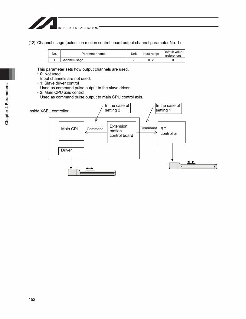
Cha
pter
4 P
aram
eter
s
152
[12] Channel usage (extension motion control board output channel parameter No. 1)
No. Parameter name Unit Input range Default value (reference)
1 Channel usage - 0~2 0
This parameter sets how output channels are used. 0: Not used Input channels are not used.
1: Slave driver control Used as command pulse output to the slave driver.
2: Main CPU axis control Used as command pulse output to main CPU control axis.
Inside XSEL controller
Main CPU Extensionmotioncontrol board
RCcontroller
In the case of setting 2
In the case of setting 1
Driver
Command Command
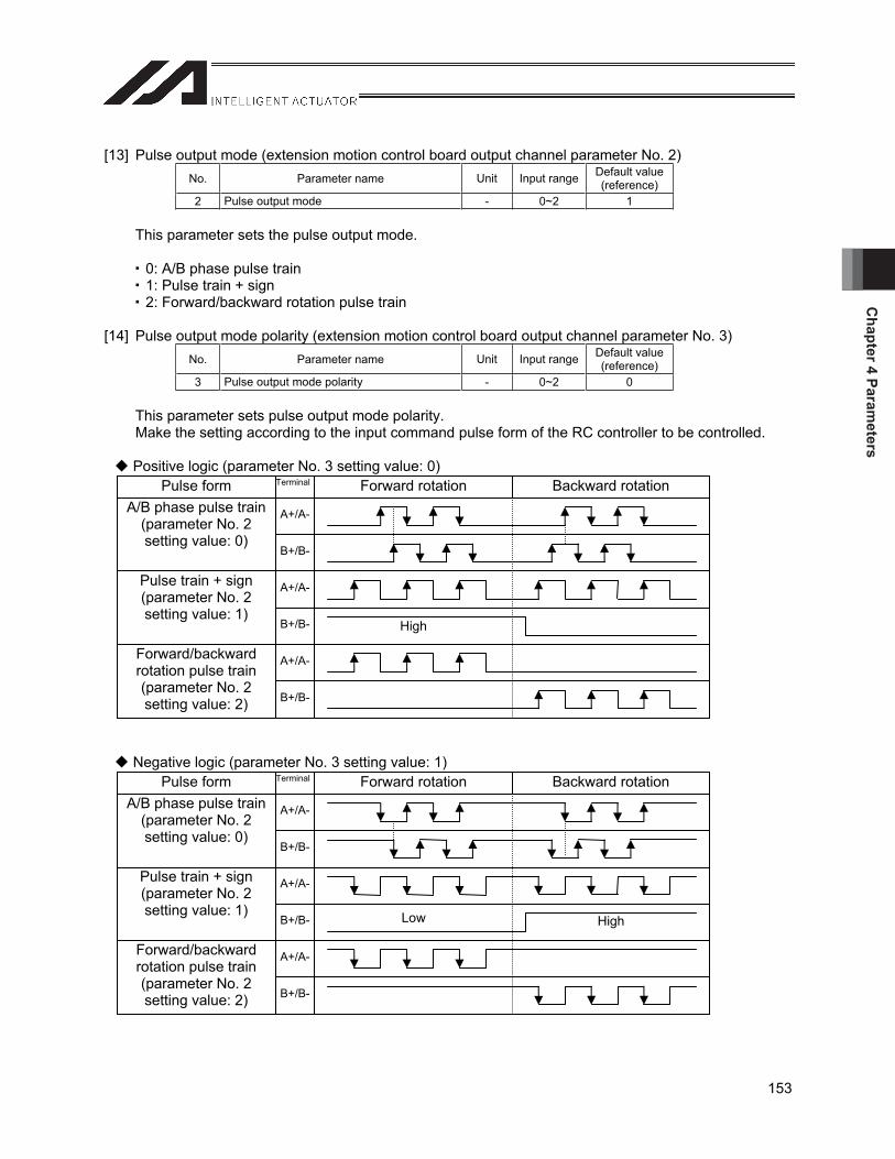
Chapter 4 Param
eters
153
[13] Pulse output mode (extension motion control board output channel parameter No. 2) No. Parameter name Unit Input range Default value
(reference) 2 Pulse output mode - 0~2 1
This parameter sets the pulse output mode.
0: A/B phase pulse train 1: Pulse train + sign 2: Forward/backward rotation pulse train
[14] Pulse output mode polarity (extension motion control board output channel parameter No. 3) No. Parameter name Unit Input range Default value
(reference) 3 Pulse output mode polarity - 0~2 0
This parameter sets pulse output mode polarity. Make the setting according to the input command pulse form of the RC controller to be controlled.
Positive logic (parameter No. 3 setting value: 0)
Negative logic (parameter No. 3 setting value: 1) Forward rotation Backward rotation Terminal Pulse form
A+/A-
B+/B-
A/B phase pulse train (parameter No. 2 setting value: 0)
A+/A-
B+/B-
Pulse train + sign (parameter No. 2 setting value: 1)
A+/A-
B+/B-
Forward/backward rotation pulse train (parameter No. 2 setting value: 2)
Low High
Forward rotation Backward rotation Terminal Pulse form
A+/A-
B+/B-
A/B phase pulse train (parameter No. 2 setting value: 0)
A+/A-
B+/B-
Pulse train + sign (parameter No. 2 setting value: 1)
A+/A-
B+/B-
Forward/backward rotation pulse train (parameter No. 2 setting value: 2)
High
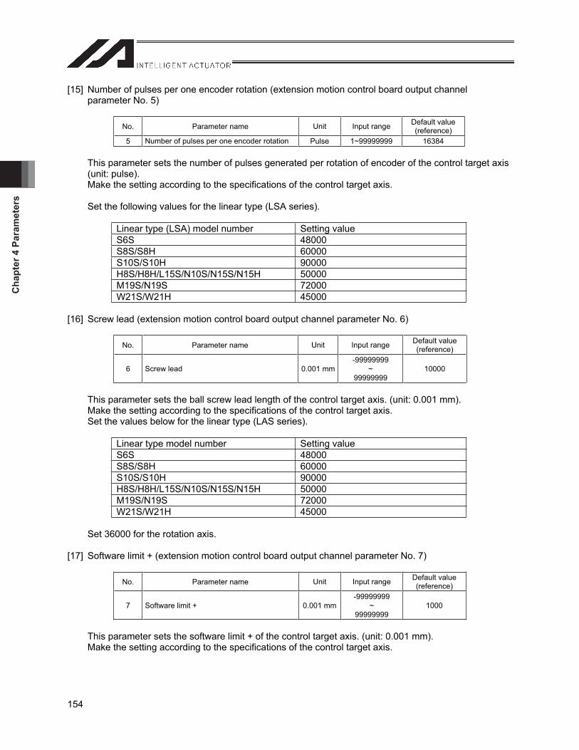
Cha
pter
4 P
aram
eter
s
154
[15] Number of pulses per one encoder rotation (extension motion control board output channel parameter No. 5)
No. Parameter name Unit Input range Default value (reference)
5 Number of pulses per one encoder rotation Pulse 1~99999999 16384
This parameter sets the number of pulses generated per rotation of encoder of the control target axis (unit: pulse). Make the setting according to the specifications of the control target axis.
Set the following values for the linear type (LSA series).
Linear type (LSA) model number Setting value S6S 48000 S8S/S8H 60000 S10S/S10H 90000 H8S/H8H/L15S/N10S/N15S/N15H 50000 M19S/N19S 72000 W21S/W21H 45000
[16] Screw lead (extension motion control board output channel parameter No. 6)
No. Parameter name Unit Input range Default value (reference)
6 Screw lead 0.001 mm-99999999
~99999999
10000
This parameter sets the ball screw lead length of the control target axis. (unit: 0.001 mm). Make the setting according to the specifications of the control target axis. Set the values below for the linear type (LAS series).
Linear type model number Setting value S6S 48000 S8S/S8H 60000 S10S/S10H 90000 H8S/H8H/L15S/N10S/N15S/N15H 50000 M19S/N19S 72000 W21S/W21H 45000
Set 36000 for the rotation axis.
[17] Software limit + (extension motion control board output channel parameter No. 7)
No. Parameter name Unit Input range Default value (reference)
7 Software limit + 0.001 mm-99999999
~99999999
1000
This parameter sets the software limit + of the control target axis. (unit: 0.001 mm). Make the setting according to the specifications of the control target axis.

Chapter 4 Param
eters
155
[18] Software limit – (extension motion control board output channel parameter No. 8)
No. Parameter name Unit Input range Default value (reference)
8 Software limit - 0.001 mm-99999999
~99999999
0
This parameter sets the software limit - of the control target axis. (unit: 0.001 mm). Make the setting according to the specifications of the control target axis.
* Set “359999” when the parameter for each axis No. 66 “selection of rotation movement axis mode” (index mode) is set to 1 for the control target axis.
[19] Software limit margin (extension motion control board output channel parameter No. 9)
No. Parameter name Unit Input range Default value (reference)
9 Software limit margin 0.001 mm 0~9999 300
This parameter sets the exceeded amount from software limit at which an error is detected while synchronous movement is being performed. A software limit error occurs at (unit: 0.001 mm) or less. Command position > [software limit +] + [software limit margin] Command position < [software limit -] - [software limit margin]
[20] Electronic gear numerator (extension motion control board output channel parameter No. 10) Electronic gear denominator (extension motion control board output channel parameter No. 11)
No. Parameter name Unit Input range Default value (reference)
10 Electronic gear numerator - 1~99999999 1 11 Electronic gear denominator - 1~99999999 1
This parameter sets electronic gear numerator and denominator for determining the unit movement (mm/pulse) of the command pulse. Make the settings according to the specifications of the control target axis. Electronic gear numerator/electronic gear denominator = number of pulses per one encoder rotation (pulse/rev) / screw lead (mm/rev) x unit movement amount (mm/pulse)
Unit movement amount: Movement of actuator per command pulse
Caution: The maximum output pulse frequency of a extension motion control board is 500,000 (pulse/sec). For this reason, the following condition must be satisfied. Maximum speed (mm/sec) / unit movement amount (M/pulse) 500,000 (pulse/sec) If this condition is not satisfied, the error No. 51E “Extension motion control board output channel parameter error” occurs.
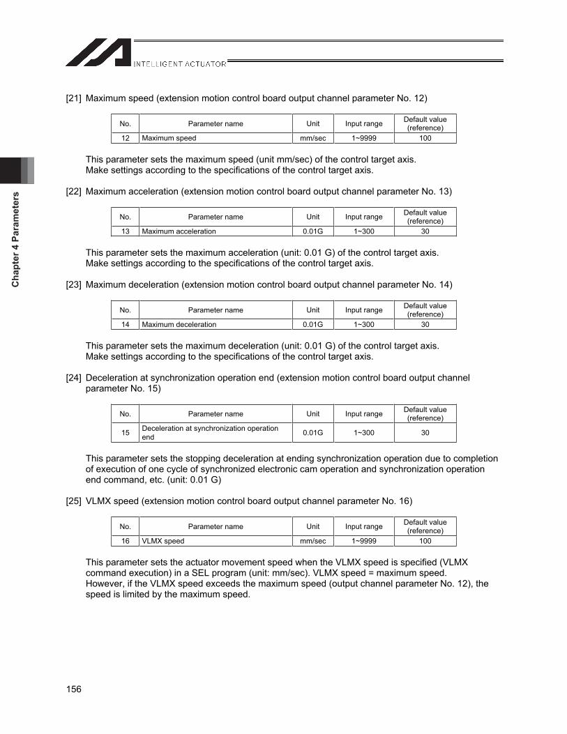
Cha
pter
4 P
aram
eter
s
156
[21] Maximum speed (extension motion control board output channel parameter No. 12)
No. Parameter name Unit Input range Default value (reference)
12 Maximum speed mm/sec 1~9999 100
This parameter sets the maximum speed (unit mm/sec) of the control target axis. Make settings according to the specifications of the control target axis.
[22] Maximum acceleration (extension motion control board output channel parameter No. 13)
No. Parameter name Unit Input range Default value (reference)
13 Maximum acceleration 0.01G 1~300 30
This parameter sets the maximum acceleration (unit: 0.01 G) of the control target axis. Make settings according to the specifications of the control target axis.
[23] Maximum deceleration (extension motion control board output channel parameter No. 14)
No. Parameter name Unit Input range Default value (reference)
14 Maximum deceleration 0.01G 1~300 30
This parameter sets the maximum deceleration (unit: 0.01 G) of the control target axis. Make settings according to the specifications of the control target axis.
[24] Deceleration at synchronization operation end (extension motion control board output channel parameter No. 15)
No. Parameter name Unit Input range Default value (reference)
15 Deceleration at synchronization operation end 0.01G 1~300 30
This parameter sets the stopping deceleration at ending synchronization operation due to completion of execution of one cycle of synchronized electronic cam operation and synchronization operation end command, etc. (unit: 0.01 G)
[25] VLMX speed (extension motion control board output channel parameter No. 16)
No. Parameter name Unit Input range Default value (reference)
16 VLMX speed mm/sec 1~9999 100
This parameter sets the actuator movement speed when the VLMX speed is specified (VLMX command execution) in a SEL program (unit: mm/sec). VLMX speed = maximum speed. However, if the VLMX speed exceeds the maximum speed (output channel parameter No. 12), the speed is limited by the maximum speed.
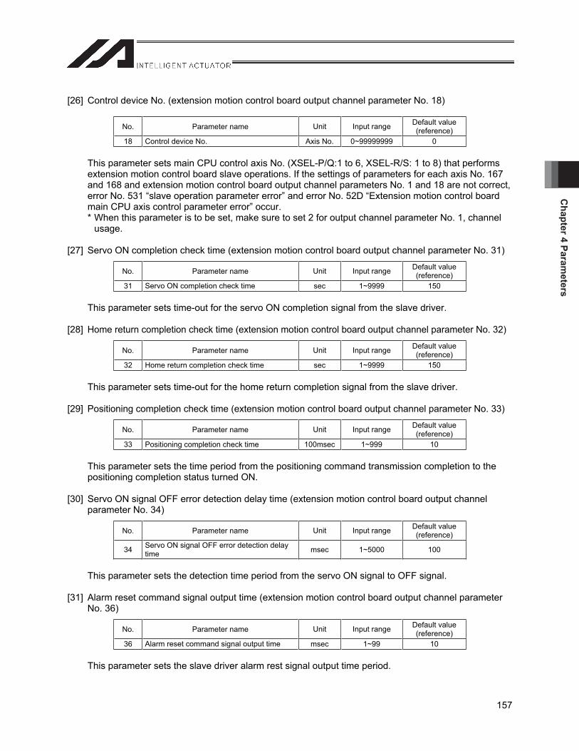
Chapter 4 Param
eters
157
[26] Control device No. (extension motion control board output channel parameter No. 18)
No. Parameter name Unit Input range Default value (reference)
18 Control device No. Axis No. 0~99999999 0
This parameter sets main CPU control axis No. (XSEL-P/Q:1 to 6, XSEL-R/S: 1 to 8) that performs extension motion control board slave operations. If the settings of parameters for each axis No. 167 and 168 and extension motion control board output channel parameters No. 1 and 18 are not correct, error No. 531 “slave operation parameter error” and error No. 52D “Extension motion control board main CPU axis control parameter error” occur. * When this parameter is to be set, make sure to set 2 for output channel parameter No. 1, channel
usage.
[27] Servo ON completion check time (extension motion control board output channel parameter No. 31)
No. Parameter name Unit Input range Default value (reference)
31 Servo ON completion check time sec 1~9999 150
This parameter sets time-out for the servo ON completion signal from the slave driver.
[28] Home return completion check time (extension motion control board output channel parameter No. 32)
No. Parameter name Unit Input range Default value (reference)
32 Home return completion check time sec 1~9999 150
This parameter sets time-out for the home return completion signal from the slave driver.
[29] Positioning completion check time (extension motion control board output channel parameter No. 33)
No. Parameter name Unit Input range Default value (reference)
33 Positioning completion check time 100msec 1~999 10
This parameter sets the time period from the positioning command transmission completion to the positioning completion status turned ON.
[30] Servo ON signal OFF error detection delay time (extension motion control board output channel parameter No. 34)
No. Parameter name Unit Input range Default value (reference)
34 Servo ON signal OFF error detection delay time msec 1~5000 100
This parameter sets the detection time period from the servo ON signal to OFF signal.
[31] Alarm reset command signal output time (extension motion control board output channel parameter No. 36)
No. Parameter name Unit Input range Default value (reference)
36 Alarm reset command signal output time msec 1~99 10
This parameter sets the slave driver alarm rest signal output time period.

Cha
pter
4 P
aram
eter
s
158
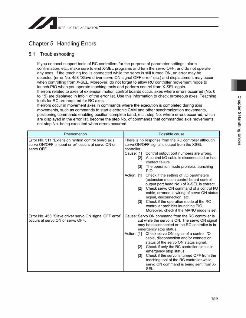
Chapter 5 H
andling Errors
159
Chapter 5 Handling Errors
5.1 Troubleshooting
If you connect support tools of RC controllers for the purpose of parameter settings, alarm confirmation, etc., make sure to end X-SEL programs and turn the servo OFF, and do not operate any axes. If the teaching tool is connected while the servo is still turned ON, an error may be detected (error No. 458 “Slave driver servo ON signal OFF error” etc.) and displacement may occur when controlling from X-SEL. Moreover, do not forget to allow RC controller movement mode to launch PIO when you operate teaching tools and perform control from X-SEL again. If errors related to axes of extension motion control boards occur, axes where errors occurred (No. 0 to 15) are displayed in Info.1 of the error list. Use this information to check erroneous axes. Teaching tools for RC are required for RC axes. If errors occur in movement axes in commands where the execution is completed during axis movements, such as commands to start electronic CAM and other synchronization movements, positioning commands enabling position complete band, etc., step No. where errors occurred, which are displayed in the error list, become the step No. of commands that commanded axis movements, not step No. being executed when errors occurred.
Phenomenon Possible cause Error No. 511 “Extension motion control board axis servo ON/OFF timeout error” occurs at servo ON or servo OFF.
There is no response from the RC controller although servo ON/OFF signal is output from the XSEL controller. Cause: [1] Control output port numbers are wrong.
[2] A control I/O cable is disconnected or has contact failure.
[3] The operation mode prohibits launching PIO.
Action: [1] Check if the setting of I/O parameters (extension motion control board control output port head No.) of X-SEL is correct.
[2] Check servo ON command of a control I/O cable, erroneous wiring of servo ON status signal, disconnection, etc.
[3] Check if the operation mode of the RC controller prohibits launching PIO. Moreover, check if the MANU mode is set.
Error No. 458 “Slave driver servo ON signal OFF error” occurs at servo ON or servo OFF.
Cause: Servo ON command from the RC controller is cut while the servo is ON. The servo ON signal may be disconnected or the RC controller is in emergency stop status.
Action: [1] Check servo ON signal of a control I/O cable, disconnection and/or connection status of the servo ON status signal.
[2] Check if only the RC controller side is in emergency stop status.
[3] Check if the servo is turned OFF from the teaching tool of the RC controller while servo ON command is being sent from X-SEL.
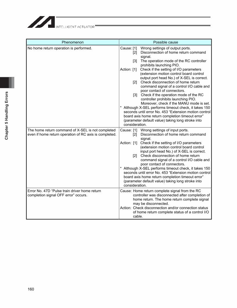
Cha
pter
5 H
andl
ing
Erro
rs
160
Phenomenon Possible cause No home return operation is performed. Cause: [1] Wrong settings of output ports.
[2] Disconnection of home return command signal.
[3] The operation mode of the RC controller prohibits launching PIO.
Action: [1] Check if the setting of I/O parameters (extension motion control board control output port head No.) of X-SEL is correct.
[2] Check disconnection of home return command signal of a control I/O cable and poor contact of connectors.
[3] Check if the operation mode of the RC controller prohibits launching PIO. Moreover, check if the MANU mode is set.
* Although X-SEL performs timeout check, it takes 150 seconds until error No. 453 “Extension motion control board axis home return completion timeout error” (parameter default value) taking long stroke into consideration.
The home return command of X-SEL is not completed even if home return operation of RC axis is completed.
Cause: [1] Wrong settings of input ports. [2] Disconnection of home return command
signal.Action: [1] Check if the setting of I/O parameters
(extension motion control board control input port head No.) of X-SEL is correct.
[2] Check disconnection of home return command signal of a control I/O cable and poor contact of connectors.
* Although X-SEL performs timeout check, it takes 150 seconds until error No. 453 “Extension motion control board axis home return completion timeout error” (parameter default value) taking long stroke into consideration.
Error No. 47D “Pulse train driver home return completion signal OFF error” occurs.
Cause: Home return complete signal from the RC controller was disconnected after completion of home return. The home return complete signal may be disconnected.
Action: Check disconnection and/or connection status of home return complete status of a control I/O cable.
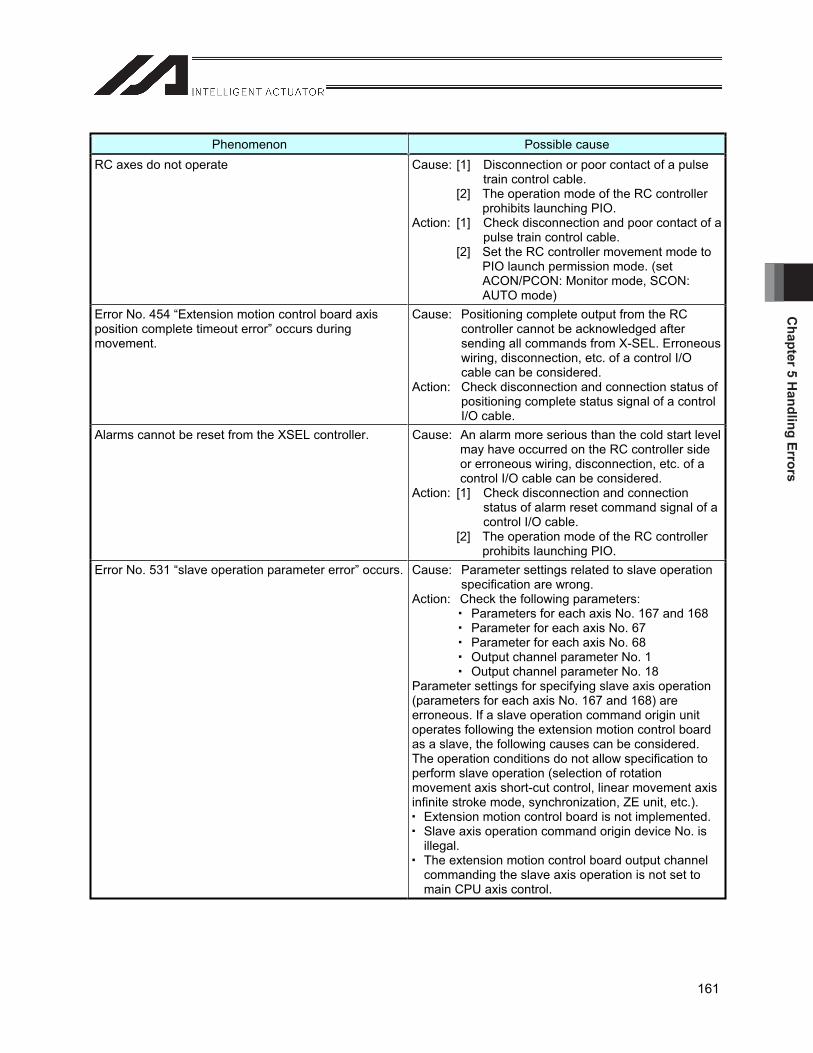
Chapter 5 H
andling Errors
161
Phenomenon Possible cause RC axes do not operate Cause: [1] Disconnection or poor contact of a pulse
train control cable. [2] The operation mode of the RC controller
prohibits launching PIO. Action: [1] Check disconnection and poor contact of a
pulse train control cable. [2] Set the RC controller movement mode to
PIO launch permission mode. (set ACON/PCON: Monitor mode, SCON: AUTO mode)
Error No. 454 “Extension motion control board axis position complete timeout error” occurs during movement.
Cause: Positioning complete output from the RC controller cannot be acknowledged after sending all commands from X-SEL. Erroneous wiring, disconnection, etc. of a control I/O cable can be considered.
Action: Check disconnection and connection status of positioning complete status signal of a control I/O cable.
Alarms cannot be reset from the XSEL controller. Cause: An alarm more serious than the cold start level may have occurred on the RC controller side or erroneous wiring, disconnection, etc. of a control I/O cable can be considered.
Action: [1] Check disconnection and connection status of alarm reset command signal of a control I/O cable.
[2] The operation mode of the RC controller prohibits launching PIO.
Error No. 531 “slave operation parameter error” occurs. Cause: Parameter settings related to slave operation specification are wrong.
Action: Check the following parameters: Parameters for each axis No. 167 and 168 Parameter for each axis No. 67 Parameter for each axis No. 68 Output channel parameter No. 1 Output channel parameter No. 18
Parameter settings for specifying slave axis operation (parameters for each axis No. 167 and 168) are erroneous. If a slave operation command origin unit operates following the extension motion control board as a slave, the following causes can be considered. The operation conditions do not allow specification to perform slave operation (selection of rotation movement axis short-cut control, linear movement axis infinite stroke mode, synchronization, ZE unit, etc.). Extension motion control board is not implemented. Slave axis operation command origin device No. is
illegal. The extension motion control board output channel
commanding the slave axis operation is not set to main CPU axis control.
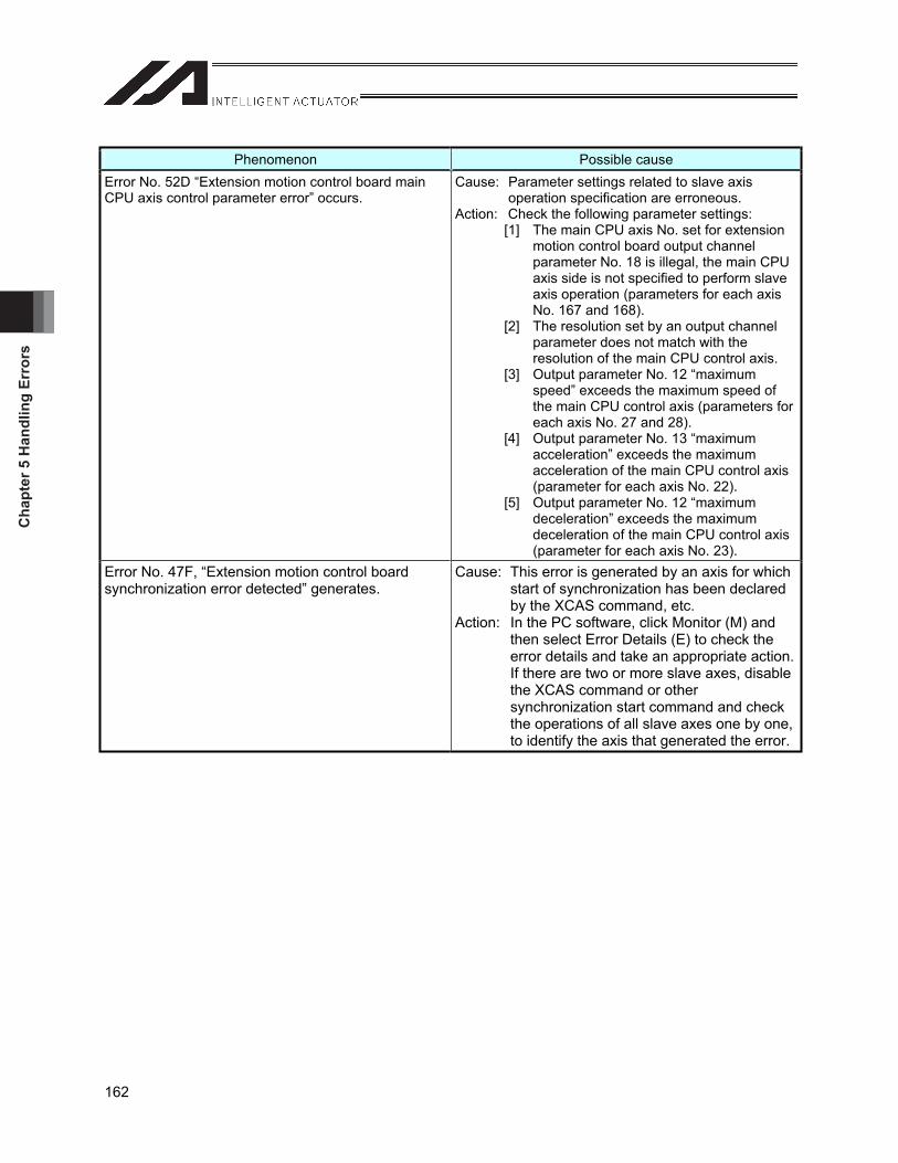
Cha
pter
5 H
andl
ing
Erro
rs
162
Phenomenon Possible cause Error No. 52D “Extension motion control board main CPU axis control parameter error” occurs.
Cause: Parameter settings related to slave axis operation specification are erroneous.
Action: Check the following parameter settings: [1] The main CPU axis No. set for extension
motion control board output channel parameter No. 18 is illegal, the main CPU axis side is not specified to perform slave axis operation (parameters for each axis No. 167 and 168).
[2] The resolution set by an output channel parameter does not match with the resolution of the main CPU control axis.
[3] Output parameter No. 12 “maximum speed” exceeds the maximum speed of the main CPU control axis (parameters for each axis No. 27 and 28).
[4] Output parameter No. 13 “maximum acceleration” exceeds the maximum acceleration of the main CPU control axis (parameter for each axis No. 22).
[5] Output parameter No. 12 “maximum deceleration” exceeds the maximum deceleration of the main CPU control axis (parameter for each axis No. 23).
Error No. 47F, “Extension motion control board synchronization error detected” generates.
Cause: This error is generated by an axis for which start of synchronization has been declared by the XCAS command, etc.
Action: In the PC software, click Monitor (M) and then select Error Details (E) to check the error details and take an appropriate action. If there are two or more slave axes, disable the XCAS command or other synchronization start command and check the operations of all slave axes one by one, to identify the axis that generated the error.
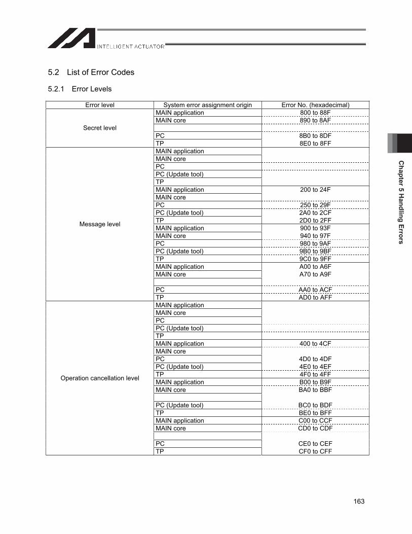
Chapter 5 H
andling Errors
163
5.2 List of Error Codes
5.2.1 Error Levels
Error level System error assignment origin Error No. (hexadecimal) MAIN application 800 to 88F MAIN core 890 to 8AF
PC 8B0 to 8DF Secret level
TP 8E0 to 8FF MAIN application MAIN core PC PC (Update tool) TP MAIN application 200 to 24F MAIN core PC 250 to 29F PC (Update tool) 2A0 to 2CF TP 2D0 to 2FF MAIN application 900 to 93F MAIN core 940 to 97F PC 980 to 9AF PC (Update tool) 9B0 to 9BF TP 9C0 to 9FF MAIN application A00 to A6F MAIN core A70 to A9F
PC AA0 to ACF
Message level
TP AD0 to AFF MAIN application MAIN core PC PC (Update tool) TP MAIN application 400 to 4CF MAIN core PC 4D0 to 4DF PC (Update tool) 4E0 to 4EF TP 4F0 to 4FF MAIN application B00 to B9F MAIN core BA0 to BBF
PC (Update tool) BC0 to BDF TP BE0 to BFF MAIN application C00 to CCF MAIN core CD0 to CDF
PC CE0 to CEF
Operation cancellation level
TP CF0 to CFF
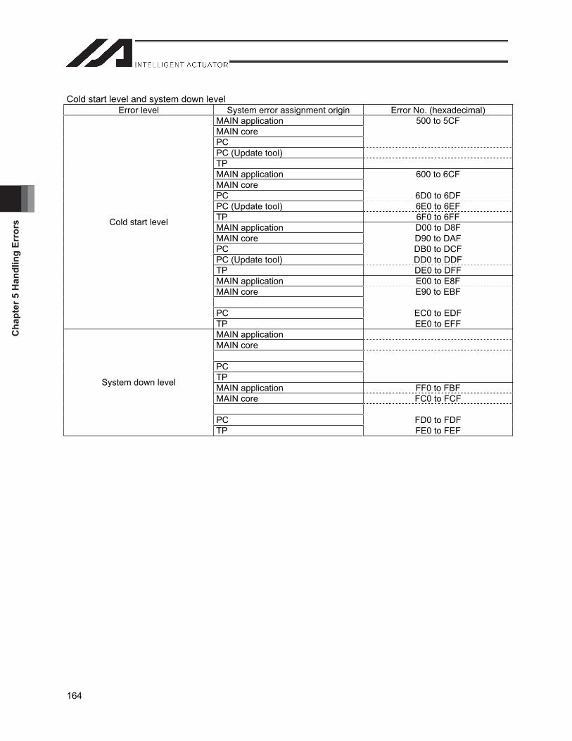
Cha
pter
5 H
andl
ing
Erro
rs
164
Cold start level and system down level Error level System error assignment origin Error No. (hexadecimal)
MAIN application 500 to 5CF MAIN core PC PC (Update tool) TP MAIN application 600 to 6CF MAIN core PC 6D0 to 6DF PC (Update tool) 6E0 to 6EF TP 6F0 to 6FF MAIN application D00 to D8F MAIN core D90 to DAF PC DB0 to DCF PC (Update tool) DD0 to DDF TP DE0 to DFF MAIN application E00 to E8F MAIN core E90 to EBF
PC EC0 to EDF
Cold start level
TP EE0 to EFF MAIN application MAIN core
PC TP MAIN application FF0 to FBF MAIN core FC0 to FCF
PC FD0 to FDF
System down level
TP FE0 to FEF
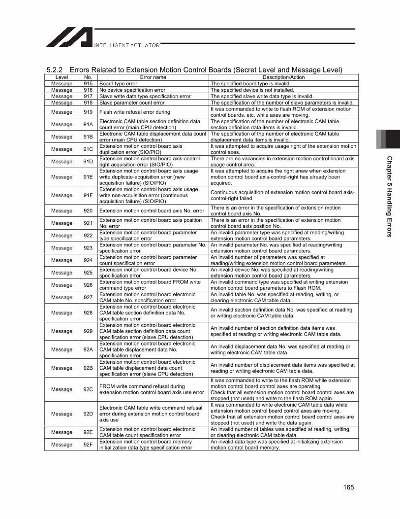
Chapter 5 H
andling Errors
165
5.2.2 Errors Related to Extension Motion Control Boards (Secret Level and Message Level) Level No. Error name Description/Action
Message 915 Board type error The specified board type is invalid. Message 916 No device specification error The specified device is not installed. Message 917 Slave write data type specification error The specified slave write data type is invalid. Message 918 Slave parameter count error The specification of the number of slave parameters is invalid.
Message 919 Flash write refusal error during It was commanded to write to flash ROM of extension motion control boards, etc. while axes are moving.
Message 91A Electronic CAM table section definition data count error (main CPU detection)
The specification of the number of electronic CAM table section definition data items is invalid.
Message 91B Electronic CAM table displacement data count error (main CPU detection)
The specification of the number of electronic CAM table displacement data items is invalid.
Message 91C Extension motion control board axis duplication error (SIO/PIO)
It was attempted to acquire usage right of the extension motion control axes.
Message 91D Extension motion control board axis-control-right acquisition error (SIO/PIO)
There are no vacancies in extension motion control board axis usage control area.
Message 91EExtension motion control board axis usage write duplicate-acquisition error (new acquisition failure) (SIO/PIO)
It was attempted to acquire the right anew when extension motion control board axis-control-right has already been acquired.
Message 91FExtension motion control board axis usage write non-acquisition error (continuous acquisition failure) (SIO/PIO)
Continuous acquisition of extension motion control board axis-control-right failed.
Message 920 Extension motion control board axis No. error There is an error in the specification of extension motion control board axis No.
Message 921 Extension motion control board axis position No. error
There is an error in the specification of extension motion control board axis position No.
Message 922 Extension motion control board parameter type specification error
An invalid parameter type was specified at reading/writing extension motion control board parameters.
Message 923 Extension motion control board parameter No. specification error
An invalid parameter No. was specified at reading/writing extension motion control board parameters.
Message 924 Extension motion control board parameter count specification error
An invalid number of parameters was specified at reading/writing extension motion control board parameters.
Message 925 Extension motion control board device No. specification error
An invalid device No. was specified at reading/writing extension motion control board parameters.
Message 926 Extension motion control board FROM write command type error
An invalid command type was specified at writing extension motion control board parameters to Flash ROM.
Message 927 Extension motion control board electronic CAM table No. specification error
An invalid table No. was specified at reading, writing, or clearing electronic CAM table data.
Message 928Extension motion control board electronic CAM table section definition data No. specification error
An invalid section definition data No. was specified at reading or writing electronic CAM table data.
Message 929Extension motion control board electronic CAM table section definition data count specification error (slave CPU detection)
An invalid number of section definition data items was specified at reading or writing electronic CAM table data.
Message 92AExtension motion control board electronic CAM table displacement data No. specification error
An invalid displacement data No. was specified at reading or writing electronic CAM table data.
Message 92BExtension motion control board electronic CAM table displacement data count specification error (slave CPU detection)
An invalid number of displacement data items was specified at reading or writing electronic CAM table data.
Message 92C FROM write command refusal during extension motion control board axis use error
It was commanded to write to the flash ROM while extension motion control board control axes are operating. Check that all extension motion control board control axes are stopped (not used) and write to the flash ROM again.
Message 92DElectronic CAM table write command refusal error during extension motion control board axis use
It was commanded to write electronic CAM table data while extension motion control board control axes are moving. Check that all extension motion control board control axes are stopped (not used) and write the data again.
Message 92E Extension motion control board electronic CAM table count specification error
An invalid number of tables was specified at reading, writing, or clearing electronic CAM table data.
Message 92F Extension motion control board memory initialization data type specification error
An invalid data type was specified at initializing extension motion control board memory.

Cha
pter
5 H
andl
ing
Erro
rs
166
5.2.3 Errors Related to Extension Motion Control Boards (Movement Cancellation Level) Level No. Error name Description/Action
Movementcancellation 444 Extension motion control board axis No. error There are errors in extension motion control board axis No.
specification. Movement
cancellation 445 No extension motion control board axis pattern setting error No axis patterns were set. Execute the XAXS command.
Movementcancellation 446 Extension motion control board axis position
No. error There are errors in extension motion control board axis position No specification.
Movementcancellation 447 No position data generation extension motion
control board axis specification error
Extension motion control board axes for which position data area has not been generated were specified. Check if the specified axis is defined by I/O parameter No. 531, and errors related to position data generation or UBM have occurred.
Movementcancellation 448 Extension motion control board servo OFF
axis use error It was attempted to use extension motion control board axes while the servo is turned OFF.
Movementcancellation 449 Extension motion control board axis
duplication error
It was attempted to acquire usage right of extension motion control board axes that are already in use. In the case that the position data position complete band is valid and the synchronization start command (XAXS, XFSF) is executed for the same axis, after the positioning operation command (XMVP, etc.), the same error occurs.
Movementcancellation 44A Extension motion control board axis-control-
right acquisition error There are no vacancies in extension motion control board axis-control area.
Movementcancellation 44B
Extension motion control board axis-control-right duplicate-acquisition error (new acquisition failure)
It was attempted to acquire the right anew when extension motion control board axis-control-right has already been acquired.
Movementcancellation 44C
No extension motion control board axis-control-right error (continuous acquisition failure)
Continuous acquisition of extension motion control board axis-control-right failed.
Movementcancellation 44D Extension motion control board axis home
return incomplete error Home return of extension motion control board axes has not completed.
Movementcancellation 44E Operation command error in extension motion
control board servo OFF It was attempted to execute a movement command while the servo is turned OFF.
Movementcancellation 44F Error of using the axis where an extension
motion control board error occurred It was attempted to use extension motion control board axes currently generating error.
Movementcancellation 450 Extension motion control board axis in-use
servo OFF error The servo of extension motion control board axes being used (processing) was turned off.
Movementcancellation 451 Extension motion control board direct
command type error Processing logic error.
Movementcancellation 452 Slave driver alarm detection
An alarm signal for the slave driver (SCON, PCON or ACON) controlled using the extension motion control board (while the main axis is being controlled), has been detected. Causes can be that any alarm occurred in slave drivers, the power is not turned on, cables are disconnected, etc. Check the slave driver or cables.
Movementcancellation 453 Extension motion control board axis home
return completion timeout error The home return completion status of slave driver could not be confirmed. Check for cable disconnection, pulse train driver movement mode (prohibited to start PIO), etc.
Movementcancellation 454 Extension motion control board axis position
complete timeout error The positioning complete status of slave driver could not be confirmed. Check for cable disconnection, pulse train driver operation mode (prohibited to start PIO), etc.
Movementcancellation 455
Extension motion control board synchronization electronic CAM movement setting error
Synchronization electronic CAM movement settings specified in operand 2 of the XCAS command are invalid.
Movementcancellation 456 Extension motion control board individual
electronic CAM movement setting error Individual electronic CAM movement settings specified in operand 2 of the XCTM command are invalid.
Movementcancellation 457 Extension motion control board electronic
shaft movement setting error Electronic shaft movement settings specified in operand 2 of the XSFS command are invalid.
Movementcancellation 458 Slave driver servo ON signal OFF error
The servo ON signal turned OFF for the slave driver (SCON, PCON or ACON) has been detected while the extension motion control board axis servo ON is being controlled. This error also occurs if only slave driver entered the emergency stop status, the servo is turned OFF from slave driver support tool while X-SEL is commanding servo ON, etc.
Movementcancellation 459 Slave driver MANU mode detection
It was detected that the operation mode status signal of slavedriver (SCON, etc.) entered the MANU mode during controlling extension motion control board axis servo ON. Check mode switch and so on.

Chapter 5 H
andling Errors
167
Level No. Error name Description/Action Movement
cancellation 45A Extension motion control board input channel No. error
Specification of input channels of extension motion control boards is invalid. Check for channel No. outside the range, channels set as “not used” in parameter settings and so on.
Movementcancellation 45B
Input channel counter clear error during extension motion control board synchronous movement
It was attempted to clear the counter of extension motion control board input channels performing synchronous movement.
Movementcancellation 45C Error extension motion control board input
channels use error It was attempted to use extension motion control board input channels currently generating error.
Movementcancellation 45D
Extension motion control board synchronization slave axis program end detection
A slave axis movement program was ended during extension motion control board synchronous movement. This error also occurs if errors not related to axes occur during synchronous movement and the slave axis movement program is cancelled. If the master and slave axes move using different programs, it is not allowed to end the slave axis movement program only during synchronous movement. End the synchronous movement first and then end the program. If the program is closed from the PC Software or teaching pendant, cancel all movements or close the master axis movement program, etc.
Movementcancellation 45E
Extension motion control board synchronization master axis program end detection
A master axis movement program was ended during extension motion control board synchronous movement. If a value other than 11111111 is set for all-axis parameter No. 9 “enable switch (deadman switch/safety gate) enable physical axis pattern,” slave axes of the master axis for which the enable switch is enabled must be moved using the same program as the master axis.
Movementcancellation 460 Extension motion control board
synchronization master error detection
It was attempted to start extension motion control board synchronous movement using an axis currently generating error as the master axis. Check the error generating in the master axis.
Movementcancellation 461 Extension motion control board
synchronization master axis servo OFF error
The servo of the master axis was turned OFF during extension motion control board synchronous movement. The servo of the master axis must not be turned OFF during synchronous movement. End the synchronous movement first and then turn the servo OFF.
Movementcancellation 462 Extension motion control board
synchronization slave axis restart error
It was attempted to cancel pause during synchronous movement using a extension motion control board input channel as the master axis. During synchronous movement using an input axis as the master channel, it is not allowed to cancel pause and restart the movement.
Movementcancellation 463 Extension motion control board individual
electronic CAM movement axis restart error
It was attempted to cancel pause during extension motion control board individual electronic CAM movement. During individual electronic CAM movement, it is not allowed to cancel pause and restart the movement.
Movementcancellation 464 Extension motion control board serial bus
command code error
An error occurred at controller internal communication. The following causes can be considered: [1] Communication failures (controller internal communication failures) due to noise, short-circuit, circuit failures, etc. [2] The main CPU application firmware version and the extension motion control board application firmware version are not consistent (wrong combination).
Movementcancellation 465 Extension motion control board duplicate flash
write command refusal error While writing to the flash ROM, a writing command was issued again. Issue the next write command after the completion of writing.
Movementcancellation 466 Extension motion control board flash ROM
deletion count over error The number of deletion times of flash ROM of extension motion control boards exceeded the allowable value.
Movementcancellation 467 Extension motion control board flash ROM
write error An error occurred during writing to the flash ROM of extension motion control boards.
Movementcancellation 468
Operation command error at extension motion control board servo OFF (slave CPU detection)
A movement command was issued to axes in servo-OFF status. Issue movement commands to axes in servo-ON status.
Movementcancellation 469 Extension motion control board servo non-
definition command detection error
An error occurred at controller internal communication. The following causes can be considered: [1] Communication failures (controller internal communication
failures) due to noise, short-circuit, circuit failures, etc. [2] The main CPU application firmware version and the
extension motion control board application firmware version are not consistent (wrong combination).
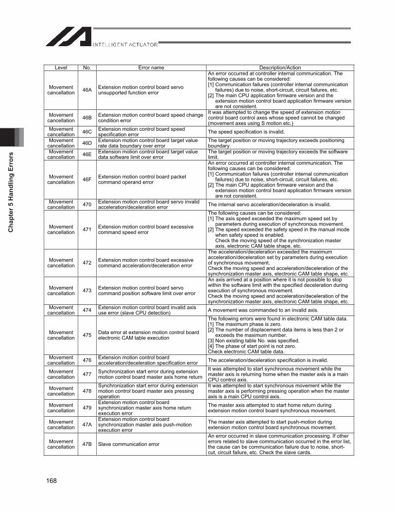
Cha
pter
5 H
andl
ing
Erro
rs
168
Level No. Error name Description/Action
Movementcancellation 46A Extension motion control board servo
unsupported function error
An error occurred at controller internal communication. The following causes can be considered: [1] Communication failures (controller internal communication
failures) due to noise, short-circuit, circuit failures, etc. [2] The main CPU application firmware version and the
extension motion control board application firmware version are not consistent.
Movementcancellation 46B Extension motion control board speed change
condition error It was attempted to change the speed of extension motion control board control axes whose speed cannot be changed (movement axes using S motion etc.)
Movementcancellation 46C Extension motion control board speed
specification error The speed specification is invalid. Movement
cancellation 46D Extension motion control board target value rate data boundary over error
The target position or moving trajectory exceeds positioning boundary.
Movementcancellation 46E Extension motion control board target value
data software limit over error The target position or moving trajectory exceeds the software limit.
Movementcancellation 46F Extension motion control board packet
command operand error
An error occurred at controller internal communication. The following causes can be considered: [1] Communication failures (controller internal communication
failures) due to noise, short-circuit, circuit failures, etc. [2] The main CPU application firmware version and the
extension motion control board application firmware version are not consistent.
Movementcancellation 470 Extension motion control board servo invalid
acceleration/deceleration error The internal servo acceleration/deceleration is invalid.
Movementcancellation 471 Extension motion control board excessive
command speed error
The following causes can be considered: [1] The axis speed exceeded the maximum speed set by
parameters during execution of synchronous movement. [2] The speed exceeded the safety speed in the manual mode
when safety speed is enabled. Check the moving speed of the synchronization master axis, electronic CAM table shape, etc.
Movementcancellation 472 Extension motion control board excessive
command acceleration/deceleration error
The acceleration/deceleration exceeded the maximum acceleration/deceleration set by parameters during execution of synchronous movement. Check the moving speed and acceleration/deceleration of the synchronization master axis, electronic CAM table shape, etc.
Movementcancellation 473 Extension motion control board servo
command position software limit over error
An axis arrived at a position where it is not possible to stop within the software limit with the specified deceleration during execution of synchronous movement. Check the moving speed and acceleration/deceleration of the synchronization master axis, electronic CAM table shape, etc.
Movementcancellation 474 Extension motion control board invalid axis
use error (slave CPU detection) A movement was commanded to an invalid axis.
Movementcancellation 475 Data error at extension motion control board
electronic CAM table execution
The following errors were found in electronic CAM table data. [1] The maximum phase is zero. [2] The number of displacement data items is less than 2 or
exceeds the maximum number. [3] Non existing table No. was specified. [4] The phase of start point is not zero. Check electronic CAM table data.
Movementcancellation 476 Extension motion control board
acceleration/deceleration specification error The acceleration/deceleration specification is invalid.
Movementcancellation 477 Synchronization start error during extension
motion control board master axis home returnIt was attempted to start synchronous movement while the master axis is returning home when the master axis is a main CPU control axis.
Movementcancellation 478
Synchronization start error during extension motion control board master axis pressing operation
It was attempted to start synchronous movement while the master axis is performing pressing operation when the master axis is a main CPU control axis.
Movementcancellation 479
Extension motion control board synchronization master axis home return execution error
The master axis attempted to start home return during extension motion control board synchronous movement.
Movementcancellation 47A
Extension motion control board synchronization master axis push-motion execution error
The master axis attempted to start push-motion during extension motion control board synchronous movement.
Movementcancellation 47B Slave communication error
An error occurred in slave communication processing. If other errors related to slave communication occurred in the error list, the cause can be communication failure due to noise, short-cut, circuit failure, etc. Check the slave cards.
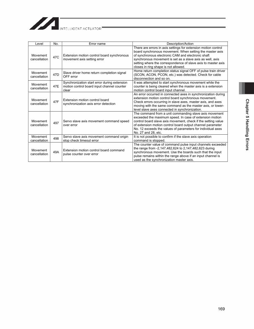
Chapter 5 H
andling Errors
169
Level No. Error name Description/Action
Movementcancellation 47C Extension motion control board synchronous
movement axis setting error
There are errors in axis settings for extension motion control board synchronous movement. When setting the master axis of synchronous electronic CAM and electronic shaft synchronous movement is set as a slave axis as well, axis setting where the correspondence of slave axis to master axis closes in ring shape is not allowed.
Movementcancellation 47D Slave driver home return completion signal
OFF error
Home return completion status signal OFF of pulse train driver (SCON, ACON, PCON, etc.) was detected. Check for cable disconnection and so on.
Movementcancellation 47E
Synchronization start error during extension motion control board input channel counter clear
It was attempted to start synchronous movement while the counter is being cleared when the master axis is a extension motion control board input channel.
Movementcancellation 47F Extension motion control board
synchronization axis error detection
An error occurred in connected axes in synchronization during extension motion control board synchronous movement. Check errors occurring in slave axes, master axis, and axes moving with the same command as the master axis, or lower-level slave axes connected in synchronization.
Movementcancellation 497 Servo slave axis movement command speed
over error
The command from a unit commanding slave axis movement exceeded the maximum speed. In case of extension motion control board slave axis movement, check if the setting value of extension motion control board output channel parameter No. 12 exceeds the values of parameters for individual axes No. 27 and 28, etc.
Movementcancellation 498 Servo slave axis movement command origin
stop check timeout error It is not possible to confirm if the slave axis operation command is stopped.
Movementcancellation 49A Extension motion control board command
pulse counter over error
The counter value of command pulse input channels exceeded the range from -2,147,482,624 to 2,147,482,623 during synchronous movement. Use the boards such that the input pulse remains within the range above if an input channel is used as the synchronization master axis.

Cha
pter
5 H
andl
ing
Erro
rs
170
5.2.4 Errors Related to Extension Motion Control Boards (Cold Start Cancellation Level) Level No. Error name Description/Action
Cold start 500 Slave board flash ROM write error Writing to the flash ROM of a slave board failed. Failure of slave board and similar can be the cause. Check the installed slave boards.
Cold start 501 Slave board flash ROM write completion check timeout error
Completion of writing to the flash ROM of a slave board could not be confirmed. Failure of slave board and similar can be the cause. Check the installed slave boards. Moreover, this error can occur when error No. 6BE, 6BF, 6C0, 6C4, 6C5, etc. occur at the same time.
Cold start 502 Slave transmission data generation logic error Slave transmission data generation error
Cold start 503 Extension motion control board ready check timeout error
Normal startup of boards could not be confirmed. Check installed extension motion control boards.
Cold start 504 Extension motion control board target information initialization error
Initialization sequence of extension motion control board information was not normally completed. Check installed extension motion control boards.
Cold start 505 Extension motion control board axis control I/O port assignment parameter error
Setting values of parameters related to extension motion control board axis control I/O port assignment are invalid. Check I/O parameter Nos. 534 to 581 for invalid port No., duplicated specification with other system I/O ports and so on.
Cold start 506 Emergency stop/enable switch recovery type parameter error
Setting values of emergency stop/enable switch recovery type parameters are invalid. If extension motion control boards are installed, it is not allowed to specify to recover while continuing movement. Check miscellaneous parameters No. 10 and 11.
Cold start 507 Extension motion control board axis position data setting error
Position data settings for extension motion control board axes are invalid. Check I/O parameters No. 530, 531, and 532.
Cold start 508 Extension motion control board axis position data valid address error
It is attempted to access valid position data of extension motion control board axes.
Cold start 509 Extension motion control board DPRAM access right timeout error
Unable to acquire DPRAM access right for a specified time or longer.
Cold start 50A Extension motion control board DPRAM access logic error (main CPU detection) An error in DPRAM access right control was detected.
Cold start 50B Extension motion control board non-definition DPRAM format ID error (main CPU detection)
An error occurred during controller internal communication. The following causes can be considered: [1] Communication failures (controller internal communication
failures) due to noise, short-circuit, circuit failures, etc. [2] The main CPU application firmware version and board
application area firmware version are not consistent (wrong combination).
Cold start 50C Extension motion control board DPRAM data sum check error (main CPU detection)
A DPRAM data sum check error was detected. Failures of extension motion control boards, etc. can be considered to be the cause. Check installed extension motion control boards.
Cold start 50D Extension motion control board fatal failure error
A fatal failure error occurred in extension motion control boards (SLVALM).
Cold start 50E Extension motion control board CPU ready OFF error CPU ready of extension motion control boards was turned off.
Cold start 50F Extension motion control board slave CPU servo underrun detection error (main CPU detection)
A servo control underrun error was detected in extension motion control boards. It is necessary to turn the power supply on again.
Cold start 510 Extension motion control board error
An error occurred in extension motion control boards. This error occurs if the main CPU board software does not support error codes of extension motion control boards. Take actions according to the error list. If Info.2 of the error list is 76h: The same error as error No. 49A occurred in extension motion control boards. Refer to the item explaining the corresponding error No.
In other cases, contact us and report the description of the error list.
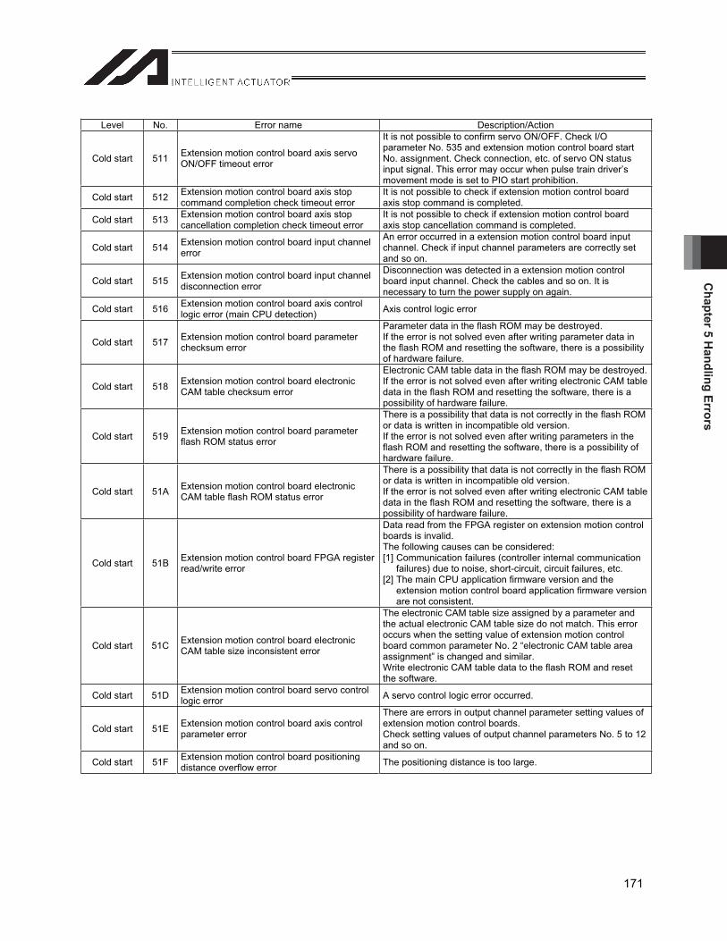
Chapter 5 H
andling Errors
171
Level No. Error name Description/Action
Cold start 511 Extension motion control board axis servo ON/OFF timeout error
It is not possible to confirm servo ON/OFF. Check I/O parameter No. 535 and extension motion control board start No. assignment. Check connection, etc. of servo ON status input signal. This error may occur when pulse train driver’s movement mode is set to PIO start prohibition.
Cold start 512 Extension motion control board axis stop command completion check timeout error
It is not possible to check if extension motion control board axis stop command is completed.
Cold start 513 Extension motion control board axis stop cancellation completion check timeout error
It is not possible to check if extension motion control board axis stop cancellation command is completed.
Cold start 514 Extension motion control board input channel error
An error occurred in a extension motion control board input channel. Check if input channel parameters are correctly set and so on.
Cold start 515 Extension motion control board input channel disconnection error
Disconnection was detected in a extension motion control board input channel. Check the cables and so on. It is necessary to turn the power supply on again.
Cold start 516 Extension motion control board axis control logic error (main CPU detection) Axis control logic error
Cold start 517 Extension motion control board parameter checksum error
Parameter data in the flash ROM may be destroyed. If the error is not solved even after writing parameter data in the flash ROM and resetting the software, there is a possibility of hardware failure.
Cold start 518 Extension motion control board electronic CAM table checksum error
Electronic CAM table data in the flash ROM may be destroyed.If the error is not solved even after writing electronic CAM table data in the flash ROM and resetting the software, there is a possibility of hardware failure.
Cold start 519 Extension motion control board parameter flash ROM status error
There is a possibility that data is not correctly in the flash ROM or data is written in incompatible old version. If the error is not solved even after writing parameters in the flash ROM and resetting the software, there is a possibility of hardware failure.
Cold start 51A Extension motion control board electronic CAM table flash ROM status error
There is a possibility that data is not correctly in the flash ROM or data is written in incompatible old version. If the error is not solved even after writing electronic CAM table data in the flash ROM and resetting the software, there is a possibility of hardware failure.
Cold start 51B Extension motion control board FPGA register read/write error
Data read from the FPGA register on extension motion control boards is invalid. The following causes can be considered: [1] Communication failures (controller internal communication
failures) due to noise, short-circuit, circuit failures, etc. [2] The main CPU application firmware version and the
extension motion control board application firmware version are not consistent.
Cold start 51C Extension motion control board electronic CAM table size inconsistent error
The electronic CAM table size assigned by a parameter and the actual electronic CAM table size do not match. This error occurs when the setting value of extension motion control board common parameter No. 2 “electronic CAM table area assignment” is changed and similar. Write electronic CAM table data to the flash ROM and reset the software.
Cold start 51D Extension motion control board servo control logic error A servo control logic error occurred.
Cold start 51E Extension motion control board axis control parameter error
There are errors in output channel parameter setting values of extension motion control boards. Check setting values of output channel parameters No. 5 to 12 and so on.
Cold start 51F Extension motion control board positioning distance overflow error The positioning distance is too large.
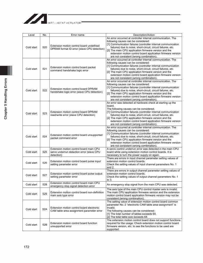
Cha
pter
5 H
andl
ing
Erro
rs
172
Level No. Error name Description/Action
Cold start 520 Extension motion control board undefined DPRAM format ID error (slave CPU detection)
An error occurred at controller internal communication. The following causes can be considered: [1] Communication failures (controller internal communication
failures) due to noise, short-circuit, circuit failures, etc. [2] The main CPU application firmware version and the
extension motion control board application firmware version are not consistent (wrong combination).
Cold start 521 Extension motion control board packet command handshake logic error
An error occurred at controller internal communication. The following causes can be considered: [1] Communication failures (controller internal communication
failures) due to noise, short-circuit, circuit failures, etc. [2] The main CPU application firmware version and the
extension motion control board application firmware version are not consistent (wrong combination).
Cold start 522 Extension motion control board DPRAM handshake logic error (slave CPU detection)
An error occurred at controller internal communication. The following causes can be considered: [1] Communication failures (controller internal communication
failures) due to noise, short-circuit, circuit failures, etc. [2] The main CPU application firmware version and the
extension motion control board application firmware version are not consistent (wrong combination).
Cold start 523 Extension motion control board DPRAM read/write error (slave CPU detection)
An error was detected at hardware check at starting up the board.The following causes can be considered. [1] Communication failures (controller internal communication
failures) due to noise, short-circuit, circuit failures, etc. [2] The main CPU application firmware version and the
extension motion control board application firmware version are not consistent (wrong combination).
Cold start 524 Extension motion control board unsupported packet command error
An error occurred at controller internal communication. The following causes can be considered: [1] Communication failures (controller internal communication
failures) due to noise, short-circuit, circuit failures, etc. [2] The main CPU application firmware version and the
extension motion control board application firmware version are not consistent (wrong combination).
Cold start 525 Extension motion control board main CPU servo underrun detection error (slave CPU detection)
A servo control underrun error was detected in the main CPU board while using extension motion control boards. It is necessary to turn the power supply on again.
Cold start 526 Extension motion control board pulse input setting parameter error
There are errors in input channel parameter setting values of extension motion control boards. Check the setting values of input channel parameters No. 1 and 2.
Cold start 527 Extension motion control board pulse output setting parameter error
There are errors in output channel parameter setting values of extension motion control boards. Check the setting values of output channel parameters No. 1 to 3.
Cold start 528 Extension motion control board main CPU emergency stop signal detection error An emergency stop signal from the main CPU was detected.
Cold start 529 Extension motion control board non-definition main axis type error
The axis type of the main CPU control master axis is invalid. The main CPU application firmware version and the extension motion control board application firmware version may not be consistent (wrong combination).
Cold start 52A Extension motion control board electronic CAM table area assignment parameter error
The setting value of extension motion control board common parameter No. 2 “electronic CAM table area assignment” is invalid.The following causes can be considered: [1] The total number of tables exceeds 64. [2] The total table size exceeds 64.
Cold start 52B Extension motion control board function unsupported error
The extension motion control board does not support functions required for the usage. Check extension motion control board firmware version, etc. to see the functions to be used are supported.
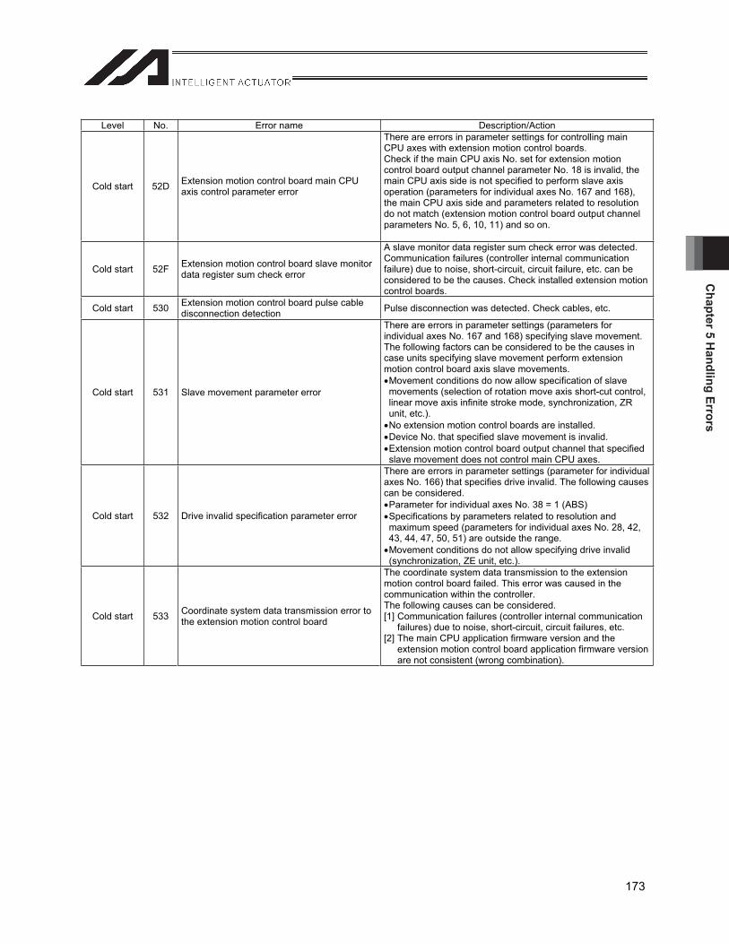
Chapter 5 H
andling Errors
173
Level No. Error name Description/Action
Cold start 52D Extension motion control board main CPU axis control parameter error
There are errors in parameter settings for controlling main CPU axes with extension motion control boards. Check if the main CPU axis No. set for extension motion control board output channel parameter No. 18 is invalid, the main CPU axis side is not specified to perform slave axis operation (parameters for individual axes No. 167 and 168), the main CPU axis side and parameters related to resolution do not match (extension motion control board output channel parameters No. 5, 6, 10, 11) and so on.
Cold start 52F Extension motion control board slave monitor data register sum check error
A slave monitor data register sum check error was detected. Communication failures (controller internal communication failure) due to noise, short-circuit, circuit failure, etc. can be considered to be the causes. Check installed extension motion control boards.
Cold start 530 Extension motion control board pulse cable disconnection detection Pulse disconnection was detected. Check cables, etc.
Cold start 531 Slave movement parameter error
There are errors in parameter settings (parameters for individual axes No. 167 and 168) specifying slave movement. The following factors can be considered to be the causes in case units specifying slave movement perform extension motion control board axis slave movements. Movement conditions do now allow specification of slave movements (selection of rotation move axis short-cut control, linear move axis infinite stroke mode, synchronization, ZR unit, etc.). No extension motion control boards are installed. Device No. that specified slave movement is invalid. Extension motion control board output channel that specified slave movement does not control main CPU axes.
Cold start 532 Drive invalid specification parameter error
There are errors in parameter settings (parameter for individual axes No. 166) that specifies drive invalid. The following causes can be considered. Parameter for individual axes No. 38 = 1 (ABS) Specifications by parameters related to resolution and maximum speed (parameters for individual axes No. 28, 42, 43, 44, 47, 50, 51) are outside the range. Movement conditions do not allow specifying drive invalid (synchronization, ZE unit, etc.).
Cold start 533 Coordinate system data transmission error to the extension motion control board
The coordinate system data transmission to the extension motion control board failed. This error was caused in the communication within the controller. The following causes can be considered. [1] Communication failures (controller internal communication
failures) due to noise, short-circuit, circuit failures, etc. [2] The main CPU application firmware version and the
extension motion control board application firmware version are not consistent (wrong combination).

Cha
pter
5 H
andl
ing
Erro
rs
174
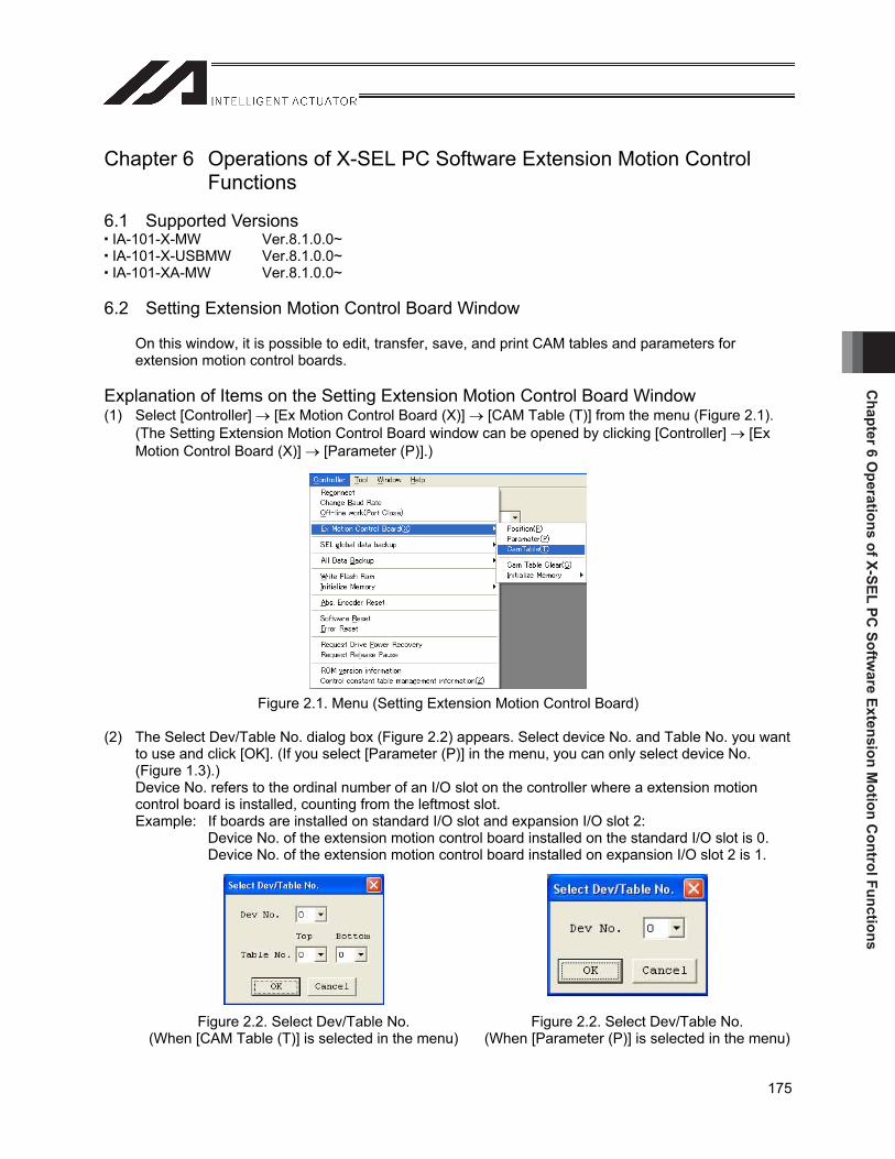
Chapter 6 O
perations of X-SEL PC Softw
are Extension Motion C
ontrol Functions
175
Chapter 6 Operations of X-SEL PC Software Extension Motion Control Functions
6.1 Supported Versions IA-101-X-MW Ver.8.1.0.0~ IA-101-X-USBMW Ver.8.1.0.0~ IA-101-XA-MW Ver.8.1.0.0~
6.2 Setting Extension Motion Control Board Window
On this window, it is possible to edit, transfer, save, and print CAM tables and parameters for extension motion control boards.
Explanation of Items on the Setting Extension Motion Control Board Window (1) Select [Controller] [Ex Motion Control Board (X)] [CAM Table (T)] from the menu (Figure 2.1).
(The Setting Extension Motion Control Board window can be opened by clicking [Controller] [Ex Motion Control Board (X)] [Parameter (P)].)
Figure 2.1. Menu (Setting Extension Motion Control Board)
(2) The Select Dev/Table No. dialog box (Figure 2.2) appears. Select device No. and Table No. you want to use and click [OK]. (If you select [Parameter (P)] in the menu, you can only select device No. (Figure 1.3).) Device No. refers to the ordinal number of an I/O slot on the controller where a extension motion control board is installed, counting from the leftmost slot. Example: If boards are installed on standard I/O slot and expansion I/O slot 2:
Device No. of the extension motion control board installed on the standard I/O slot is 0. Device No. of the extension motion control board installed on expansion I/O slot 2 is 1.
Figure 2.2. Select Dev/Table No. (When [CAM Table (T)] is selected in the menu)
Figure 2.2. Select Dev/Table No. (When [Parameter (P)] is selected in the menu)

Cha
pter
6 O
pera
tions
of X
-SEL
PC
Sof
twar
e Ex
tens
ion
Mot
ion
Con
trol
Fun
ctio
ns
176
(3) The Setting Extension Motion Control Board window appears (Figure 2.4). This window contains the following items.
Figure 2.4. Setting Extension Motion Control Board (Online Data and CAM Curve Display)
Figure 2.5. Setting Extension Motion Control Board (File Data and Curve Characteristic)
[1] Toolbar [3] Section definition data [2] Information control table [4] Displacement data
[5] CAM curve graph [6] CAM curve display setting
[7] CAM curve characteristic display setting [8] CAM curve characteristic graph
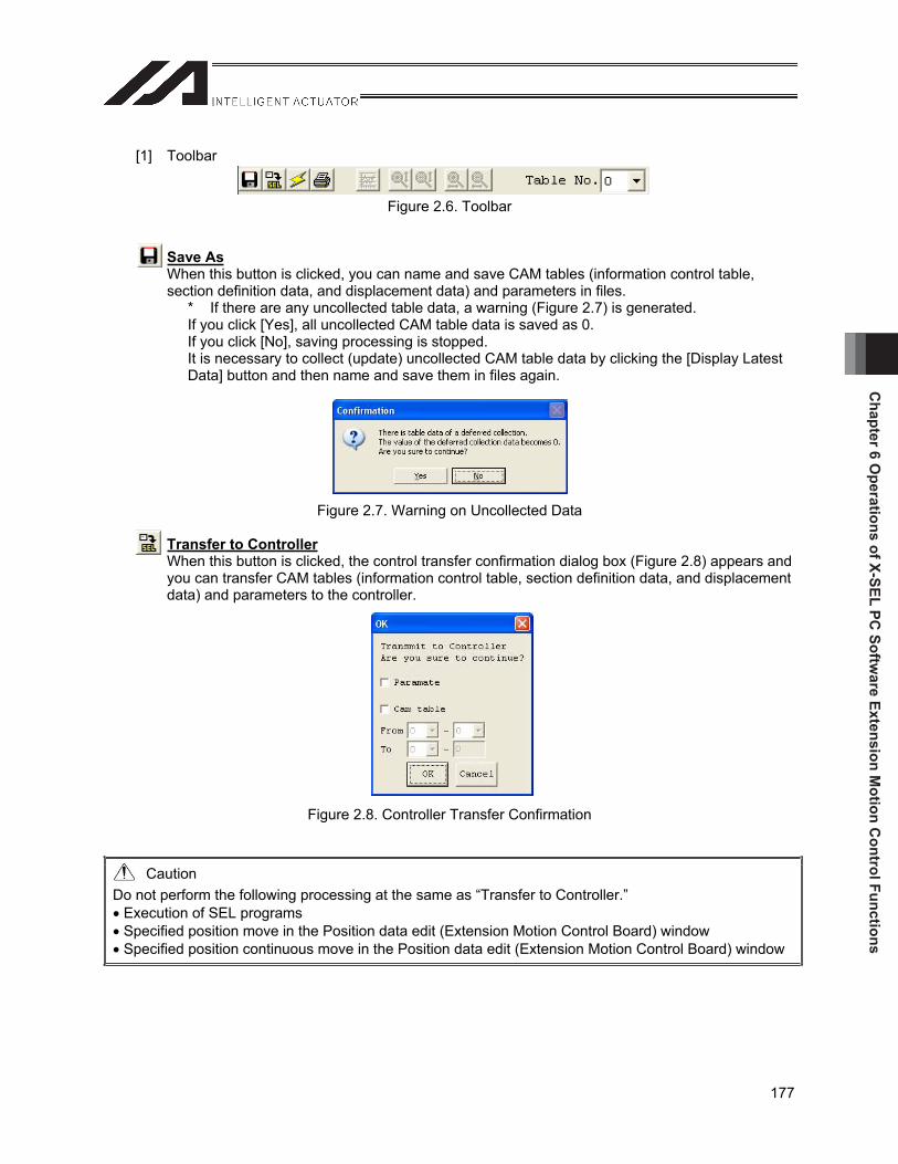
Chapter 6 O
perations of X-SEL PC Softw
are Extension Motion C
ontrol Functions
177
[1] Toolbar
Figure 2.6. Toolbar
Save AsWhen this button is clicked, you can name and save CAM tables (information control table, section definition data, and displacement data) and parameters in files.
* If there are any uncollected table data, a warning (Figure 2.7) is generated. If you click [Yes], all uncollected CAM table data is saved as 0. If you click [No], saving processing is stopped. It is necessary to collect (update) uncollected CAM table data by clicking the [Display Latest Data] button and then name and save them in files again.
Figure 2.7. Warning on Uncollected Data
Transfer to ControllerWhen this button is clicked, the control transfer confirmation dialog box (Figure 2.8) appears and you can transfer CAM tables (information control table, section definition data, and displacement data) and parameters to the controller.
Figure 2.8. Controller Transfer Confirmation
Caution Do not perform the following processing at the same as “Transfer to Controller.” Execution of SEL programs Specified position move in the Position data edit (Extension Motion Control Board) window Specified position continuous move in the Position data edit (Extension Motion Control Board) window
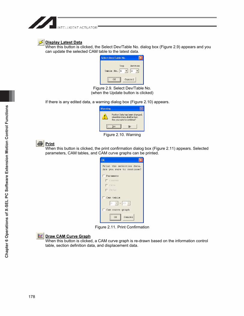
Cha
pter
6 O
pera
tions
of X
-SEL
PC
Sof
twar
e Ex
tens
ion
Mot
ion
Con
trol
Fun
ctio
ns
178
Display Latest DataWhen this button is clicked, the Select Dev/Table No. dialog box (Figure 2.9) appears and you can update the selected CAM table to the latest data.
Figure 2.9. Select Dev/Table No. (when the Update button is clicked)
If there is any edited data, a warning dialog box (Figure 2.10) appears.
Figure 2.10. Warning
PrintWhen this button is clicked, the print confirmation dialog box (Figure 2.11) appears. Selected parameters, CAM tables, and CAM curve graphs can be printed.
Figure 2.11. Print Confirmation
Draw CAM Curve GraphWhen this button is clicked, a CAM curve graph is re-drawn based on the information control table, section definition data, and displacement data.

Chapter 6 O
perations of X-SEL PC Softw
are Extension Motion C
ontrol Functions
179
Zoom in vertical axisWhen this button is clicked, the vertical axis of a CAM curve graph is zoomed in.
Zoom out vertical axisWhen this button is clicked, the vertical axis of a CAM curve graph is zoomed out.
Zoom in horizontal axisWhen this button is clicked, the horizontal axis of a CAM curve graph is zoomed in.
Zoom out horizontal axisWhen this button is clicked, the horizontal axis of a CAM curve graph is zoomed out.
Table No.CAM table No. to be displayed can be selected.
Electronic CAM table casting off setting (at offline only) When this button is clicked, the Electronic CAM table casting off setting dialog box (Figure 2.12) appears and you can change electronic CAM table assignment for offline data. In offline data mode, changes made to common parameter No. 2 (electronic CAM table
assignment) are not reflected to the number of CAM tables, number of partitions, etc. If you want to change the number of CAM tables, number of partitions, etc. in online data
mode, change common parameter No. 2 first, then transfer it to the controller, write to the flash ROM and then reset the software.
Figure 2.12. Electronic CAM Table Casting Off Setting

Cha
pter
6 O
pera
tions
of X
-SEL
PC
Sof
twar
e Ex
tens
ion
Mot
ion
Con
trol
Fun
ctio
ns
180
[2] Information control table
Figure 2.13. Information Control Table
Decimal position phaseThe number of decimals for the maximum phase, section definition data phase, displacement data phase, and CAM curve graph horizontal axis value can be set. If you select the phase, the Processing selection when the decimal position is changed dialog box (Figure 2.14) appears; you can select either to change the number of displayed digits only or to convert data according to the changed number of digits.
* If you change only the displayed number of digits, a conversion error (Figure 2.15) occurs if there are any data exceeding the maximum number of digits (8 digits). The corresponding data is displayed in the error message. It is necessary to correct the corresponding data and convert the values again.
Figure 2.14. Processing Selection when the Decimal Position is Changed
Figure 2.15. Conversion Error
DisplacementThe number of decimals for section definition data displacement train, displacement data displacement train, and CAM curve graph vertical axis value can be set. (See “Decimal position phase” above for the processing after making selection.)
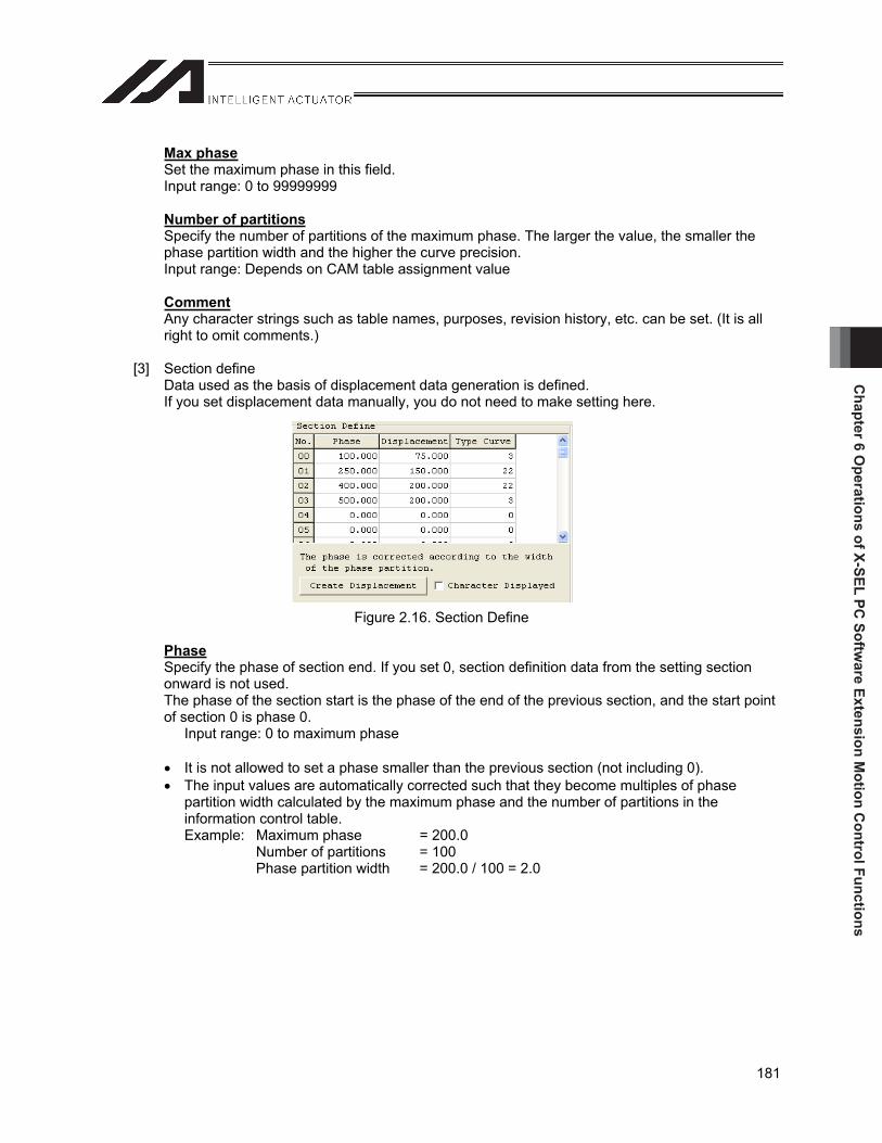
Chapter 6 O
perations of X-SEL PC Softw
are Extension Motion C
ontrol Functions
181
Max phaseSet the maximum phase in this field. Input range: 0 to 99999999
Number of partitionsSpecify the number of partitions of the maximum phase. The larger the value, the smaller the phase partition width and the higher the curve precision. Input range: Depends on CAM table assignment value
CommentAny character strings such as table names, purposes, revision history, etc. can be set. (It is all right to omit comments.)
[3] Section define Data used as the basis of displacement data generation is defined. If you set displacement data manually, you do not need to make setting here.
Figure 2.16. Section Define
PhaseSpecify the phase of section end. If you set 0, section definition data from the setting section onward is not used. The phase of the section start is the phase of the end of the previous section, and the start point of section 0 is phase 0.
Input range: 0 to maximum phase
It is not allowed to set a phase smaller than the previous section (not including 0). The input values are automatically corrected such that they become multiples of phase
partition width calculated by the maximum phase and the number of partitions in the information control table. Example: Maximum phase = 200.0
Number of partitions = 100 Phase partition width = 200.0 / 100 = 2.0
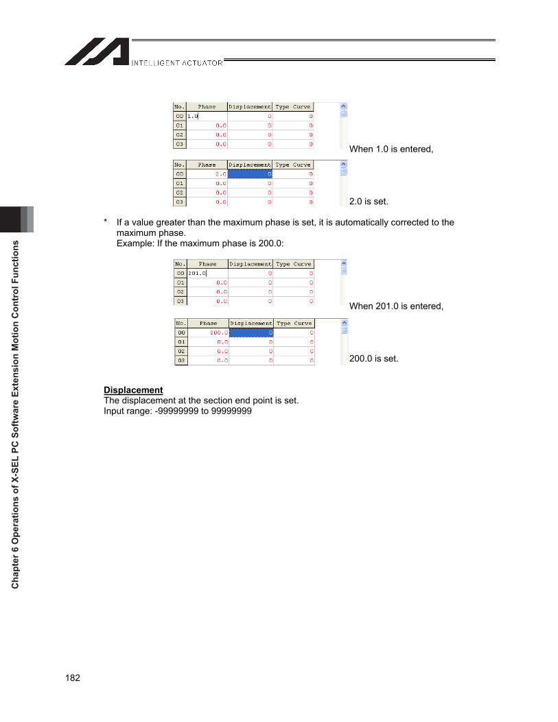
Cha
pter
6 O
pera
tions
of X
-SEL
PC
Sof
twar
e Ex
tens
ion
Mot
ion
Con
trol
Fun
ctio
ns
182
When 1.0 is entered,
2.0 is set.
* If a value greater than the maximum phase is set, it is automatically corrected to the maximum phase. Example: If the maximum phase is 200.0:
When 201.0 is entered,
200.0 is set.
DisplacementThe displacement at the section end point is set. Input range: -99999999 to 99999999
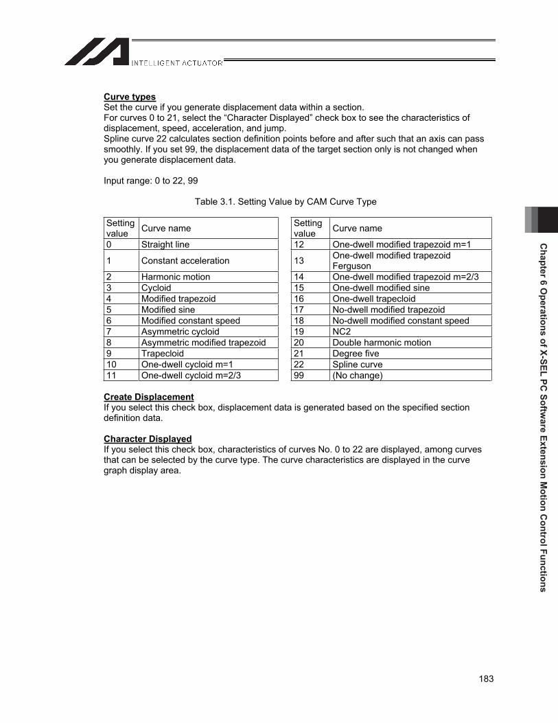
Chapter 6 O
perations of X-SEL PC Softw
are Extension Motion C
ontrol Functions
183
Curve typesSet the curve if you generate displacement data within a section. For curves 0 to 21, select the “Character Displayed” check box to see the characteristics of displacement, speed, acceleration, and jump. Spline curve 22 calculates section definition points before and after such that an axis can pass smoothly. If you set 99, the displacement data of the target section only is not changed when you generate displacement data.
Input range: 0 to 22, 99
Table 3.1. Setting Value by CAM Curve Type
Settingvalue Curve name Setting
value Curve name
0 Straight line 12 One-dwell modified trapezoid m=1
1 Constant acceleration 13 One-dwell modified trapezoid Ferguson
2 Harmonic motion 14 One-dwell modified trapezoid m=2/3 3 Cycloid 15 One-dwell modified sine 4 Modified trapezoid 16 One-dwell trapecloid 5 Modified sine 17 No-dwell modified trapezoid 6 Modified constant speed 18 No-dwell modified constant speed 7 Asymmetric cycloid 19 NC2 8 Asymmetric modified trapezoid 20 Double harmonic motion 9 Trapecloid 21 Degree five 10 One-dwell cycloid m=1 22 Spline curve 11 One-dwell cycloid m=2/3 99 (No change)
Create DisplacementIf you select this check box, displacement data is generated based on the specified section definition data.
Character DisplayedIf you select this check box, characteristics of curves No. 0 to 22 are displayed, among curves that can be selected by the curve type. The curve characteristics are displayed in the curve graph display area.
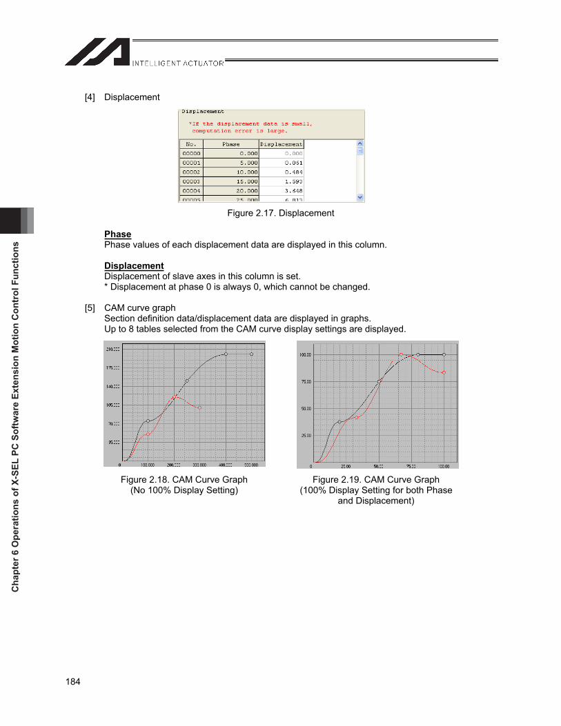
Cha
pter
6 O
pera
tions
of X
-SEL
PC
Sof
twar
e Ex
tens
ion
Mot
ion
Con
trol
Fun
ctio
ns
184
[4] Displacement
Figure 2.17. Displacement
PhasePhase values of each displacement data are displayed in this column.
DisplacementDisplacement of slave axes in this column is set. * Displacement at phase 0 is always 0, which cannot be changed.
[5] CAM curve graph Section definition data/displacement data are displayed in graphs. Up to 8 tables selected from the CAM curve display settings are displayed.
Figure 2.18. CAM Curve Graph (No 100% Display Setting)
Figure 2.19. CAM Curve Graph (100% Display Setting for both Phase
and Displacement)
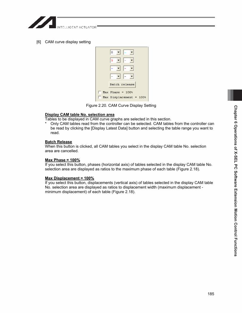
Chapter 6 O
perations of X-SEL PC Softw
are Extension Motion C
ontrol Functions
185
[6] CAM curve display setting
Figure 2.20. CAM Curve Display Setting
Display CAM table No. selection areaTables to be displayed in CAM curve graphs are selected in this section. * Only CAM tables read from the controller can be selected. CAM tables from the controller can
be read by clicking the [Display Latest Data] button and selecting the table range you want to read.
Batch ReleaseWhen this button is clicked, all CAM tables you select in the display CAM table No. selection area are cancelled.
Max Phase = 100%If you select this button, phases (horizontal axis) of tables selected in the display CAM table No. selection area are displayed as ratios to the maximum phase of each table (Figure 2.18).
Max Displacement = 100%If you select this button, displacements (vertical axis) of tables selected in the display CAM table No. selection area are displayed as ratios to displacement width (maximum displacement - minimum displacement) of each table (Figure 2.18).
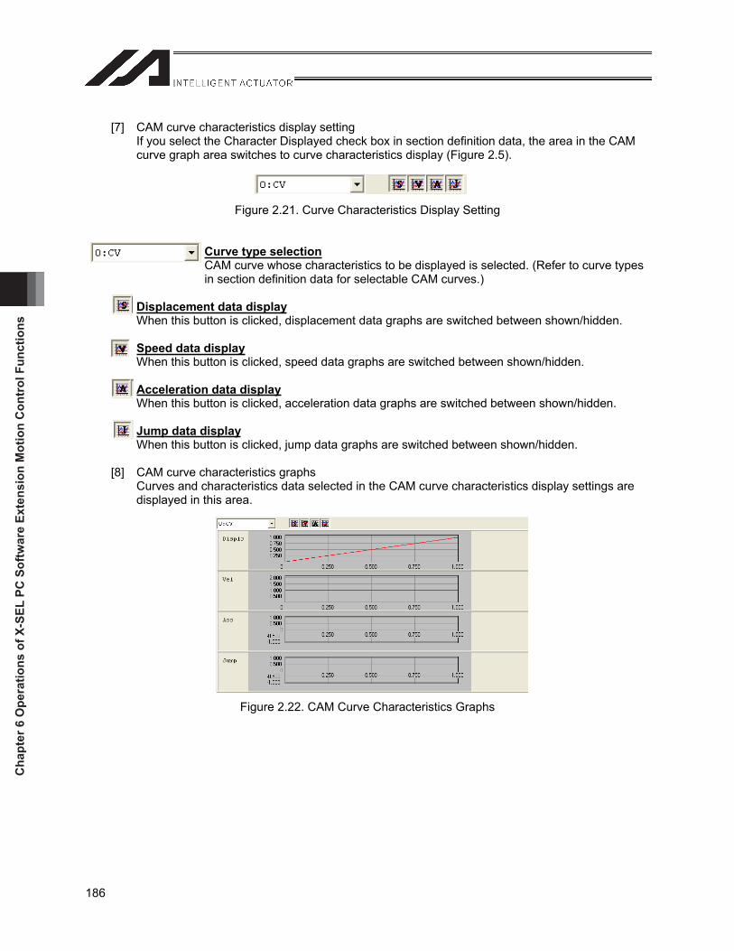
Cha
pter
6 O
pera
tions
of X
-SEL
PC
Sof
twar
e Ex
tens
ion
Mot
ion
Con
trol
Fun
ctio
ns
186
[7] CAM curve characteristics display setting If you select the Character Displayed check box in section definition data, the area in the CAM curve graph area switches to curve characteristics display (Figure 2.5).
Figure 2.21. Curve Characteristics Display Setting
Curve type selectionCAM curve whose characteristics to be displayed is selected. (Refer to curve types in section definition data for selectable CAM curves.)
Displacement data displayWhen this button is clicked, displacement data graphs are switched between shown/hidden.
Speed data displayWhen this button is clicked, speed data graphs are switched between shown/hidden.
Acceleration data displayWhen this button is clicked, acceleration data graphs are switched between shown/hidden.
Jump data displayWhen this button is clicked, jump data graphs are switched between shown/hidden.
[8] CAM curve characteristics graphs Curves and characteristics data selected in the CAM curve characteristics display settings are displayed in this area.
Figure 2.22. CAM Curve Characteristics Graphs
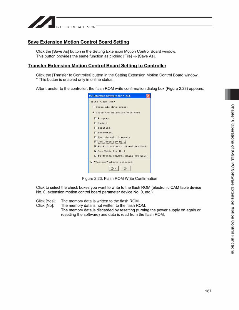
Chapter 6 O
perations of X-SEL PC Softw
are Extension Motion C
ontrol Functions
187
Save Extension Motion Control Board Setting
Click the [Save As] button in the Setting Extension Motion Control Board window. This button provides the same function as clicking [File] [Save As].
Transfer Extension Motion Control Board Setting to Controller
Click the [Transfer to Controller] button in the Setting Extension Motion Control Board window. * This button is enabled only in online status.
After transfer to the controller, the flash ROM write confirmation dialog box (Figure 2.23) appears.
Figure 2.23. Flash ROM Write Confirmation
Click to select the check boxes you want to write to the flash ROM (electronic CAM table device No. 0, extension motion control board parameter device No. 0, etc.).
Click [Yes]: The memory data is written to the flash ROM. Click [No]: The memory data is not written to the flash ROM.
The memory data is discarded by resetting (turning the power supply on again or resetting the software) and data is read from the flash ROM.
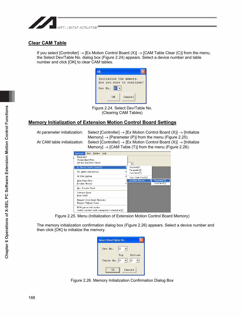
Cha
pter
6 O
pera
tions
of X
-SEL
PC
Sof
twar
e Ex
tens
ion
Mot
ion
Con
trol
Fun
ctio
ns
188
Clear CAM Table
If you select [Controller] [Ex Motion Control Board (X)] [CAM Table Clear (C)] from the menu, the Select Dev/Table No. dialog box (Figure 2.24) appears. Select a device number and table number and click [OK] to clear CAM tables.
Figure 2.24. Select Dev/Table No. (Clearing CAM Tables)
Memory Initialization of Extension Motion Control Board Settings
At parameter initialization: Select [Controller] [Ex Motion Control Board (X)] [Initialize Memory] [Parameter (P)] from the menu (Figure 2.25).
At CAM table initialization: Select [Controller] [Ex Motion Control Board (X)] [Initialize Memory] [CAM Table (T)] from the menu (Figure 2.26).
Figure 2.25. Menu (Initialization of Extension Motion Control Board Memory)
The memory initialization confirmation dialog box (Figure 2.26) appears. Select a device number and then click [OK] to initialize the memory.
Figure 2.26. Memory Initialization Confirmation Dialog Box
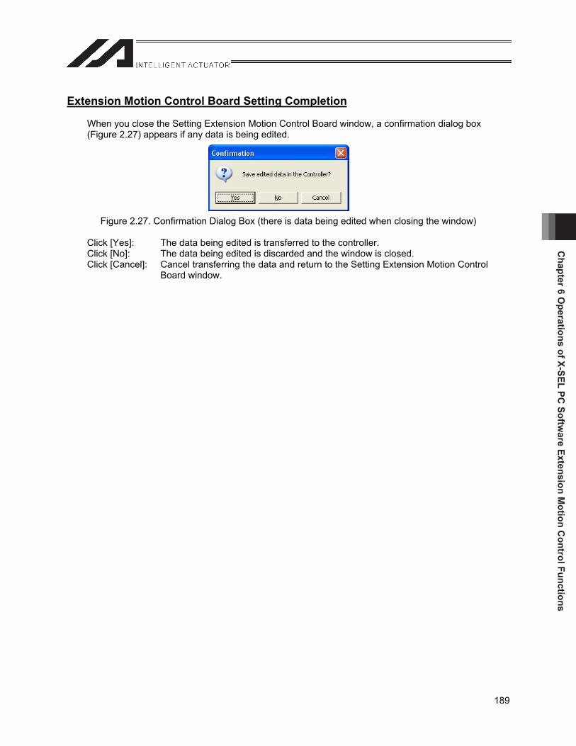
Chapter 6 O
perations of X-SEL PC Softw
are Extension Motion C
ontrol Functions
189
Extension Motion Control Board Setting Completion
When you close the Setting Extension Motion Control Board window, a confirmation dialog box (Figure 2.27) appears if any data is being edited.
Figure 2.27. Confirmation Dialog Box (there is data being edited when closing the window)
Click [Yes]: The data being edited is transferred to the controller. Click [No]: The data being edited is discarded and the window is closed. Click [Cancel]: Cancel transferring the data and return to the Setting Extension Motion Control
Board window.
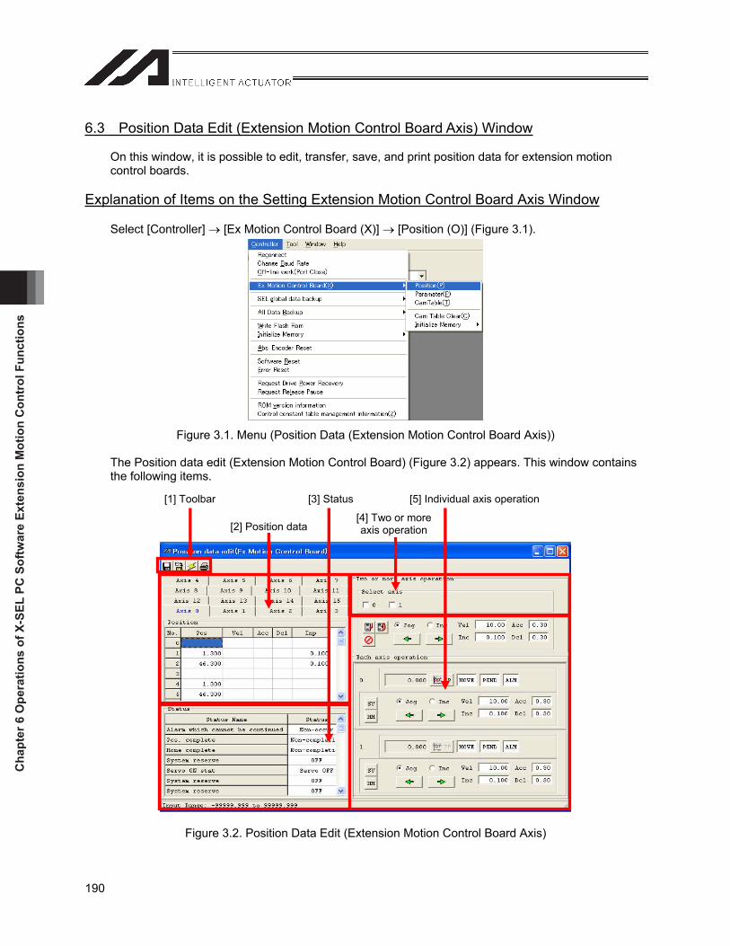
Cha
pter
6 O
pera
tions
of X
-SEL
PC
Sof
twar
e Ex
tens
ion
Mot
ion
Con
trol
Fun
ctio
ns
190
6.3 Position Data Edit (Extension Motion Control Board Axis) Window
On this window, it is possible to edit, transfer, save, and print position data for extension motion control boards.
Explanation of Items on the Setting Extension Motion Control Board Axis Window
Select [Controller] [Ex Motion Control Board (X)] [Position (O)] (Figure 3.1).
Figure 3.1. Menu (Position Data (Extension Motion Control Board Axis))
The Position data edit (Extension Motion Control Board) (Figure 3.2) appears. This window contains the following items.
Figure 3.2. Position Data Edit (Extension Motion Control Board Axis)
[1] Toolbar [3] Status [5] Individual axis operation
[2] Position data[4] Two or more axis operation
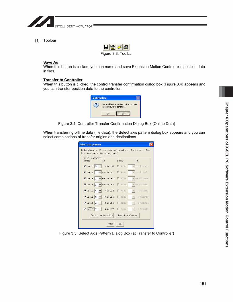
Chapter 6 O
perations of X-SEL PC Softw
are Extension Motion C
ontrol Functions
191
[1] Toolbar
Figure 3.3. Toolbar
Save AsWhen this button is clicked, you can name and save Extension Motion Control axis position data in files.
Transfer to ControllerWhen this button is clicked, the control transfer confirmation dialog box (Figure 3.4) appears and you can transfer position data to the controller.
Figure 3.4. Controller Transfer Confirmation Dialog Box (Online Data)
When transferring offline data (file data), the Select axis pattern dialog box appears and you can select combinations of transfer origins and destinations.
Figure 3.5. Select Axis Pattern Dialog Box (at Transfer to Controller)
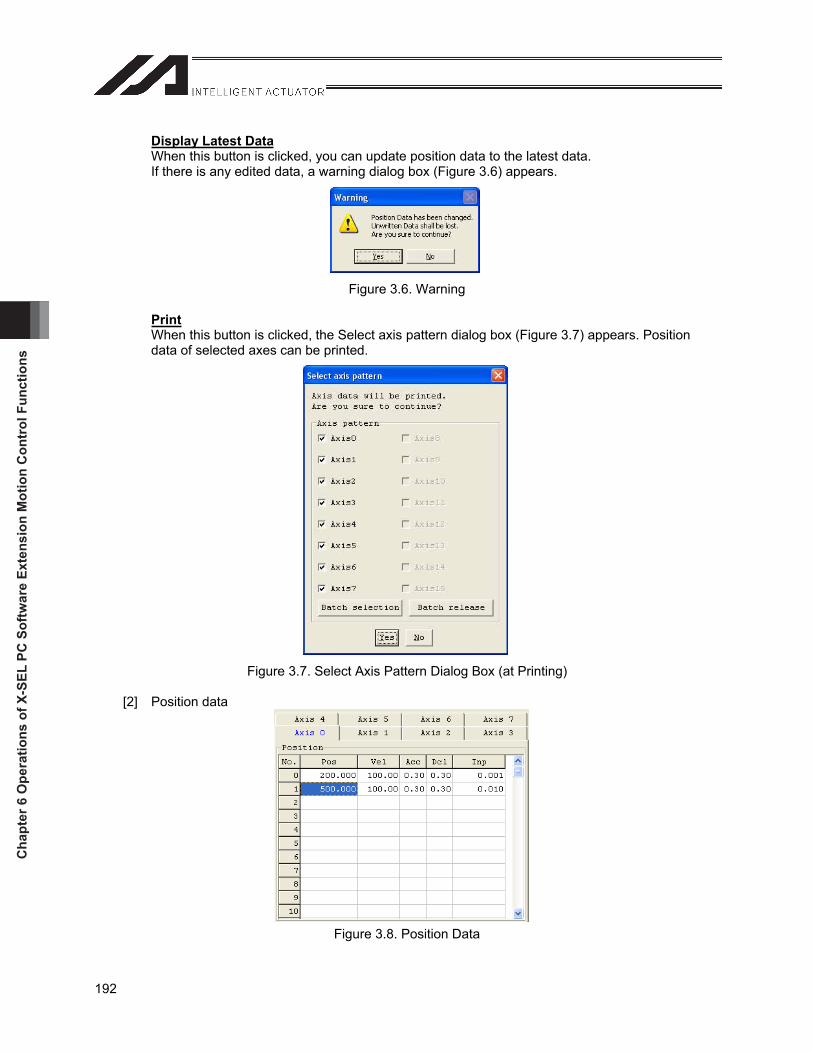
Cha
pter
6 O
pera
tions
of X
-SEL
PC
Sof
twar
e Ex
tens
ion
Mot
ion
Con
trol
Fun
ctio
ns
192
Display Latest DataWhen this button is clicked, you can update position data to the latest data. If there is any edited data, a warning dialog box (Figure 3.6) appears.
Figure 3.6. Warning
PrintWhen this button is clicked, the Select axis pattern dialog box (Figure 3.7) appears. Position data of selected axes can be printed.
Figure 3.7. Select Axis Pattern Dialog Box (at Printing)
[2] Position data
Figure 3.8. Position Data
Chapter 6 O
perations of X-SEL PC Softw
are Extension Motion C
ontrol Functions
193
Axis 0 to 15Axis numbers are displayed. If you click one of the tabs, the display switches to the position data of the selected tab.
No.This column displays position No.
PosTarget positions in this column are set (unit: [mm]). Input range: -99999.999 to 99999.999
VelSpeeds in this column are set (unit: [mm/sec]). Input range:
(When corresponding channels are used) 0.01 to output channel parameter No. 12 “maximum speed”
(When corresponding channels are not used) 0.01 to 9999.99
AccAcceleration in this column are selected (unit: [1G]). Input range:
(When corresponding channels are used) 0.01 to output channel parameter No. 13 “maximum acceleration”
(When corresponding channels are not used) 0.01 to 9.99
DclDeceleration in this column are selected (unit: [1G]). Input range:
(When corresponding channels are used) 0.01 to output channel parameter No. 14 “maximum deceleration”
(When corresponding channels are not used) 0.01 to 9.99
InpPositioning band in this column are selected (unit: [mm]). Input range: 0 to 99999.999
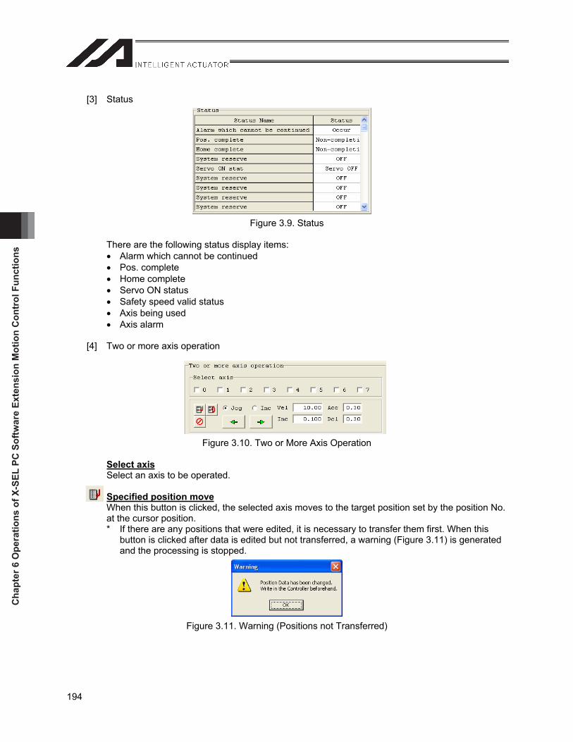
Cha
pter
6 O
pera
tions
of X
-SEL
PC
Sof
twar
e Ex
tens
ion
Mot
ion
Con
trol
Fun
ctio
ns
194
[3] Status
Figure 3.9. Status
There are the following status display items: Alarm which cannot be continued Pos. complete Home complete Servo ON status Safety speed valid status Axis being used Axis alarm
[4] Two or more axis operation
Figure 3.10. Two or More Axis Operation
Select axisSelect an axis to be operated.
Specified position moveWhen this button is clicked, the selected axis moves to the target position set by the position No. at the cursor position. * If there are any positions that were edited, it is necessary to transfer them first. When this
button is clicked after data is edited but not transferred, a warning (Figure 3.11) is generated and the processing is stopped.
Figure 3.11. Warning (Positions not Transferred)
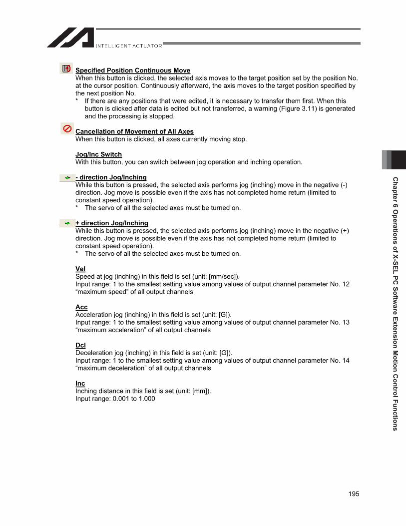
Chapter 6 O
perations of X-SEL PC Softw
are Extension Motion C
ontrol Functions
195
Specified Position Continuous MoveWhen this button is clicked, the selected axis moves to the target position set by the position No. at the cursor position. Continuously afterward, the axis moves to the target position specified by the next position No. * If there are any positions that were edited, it is necessary to transfer them first. When this
button is clicked after data is edited but not transferred, a warning (Figure 3.11) is generated and the processing is stopped.
Cancellation of Movement of All AxesWhen this button is clicked, all axes currently moving stop.
Jog/Inc SwitchWith this button, you can switch between jog operation and inching operation.
- direction Jog/InchingWhile this button is pressed, the selected axis performs jog (inching) move in the negative (-) direction. Jog move is possible even if the axis has not completed home return (limited to constant speed operation). * The servo of all the selected axes must be turned on.
+ direction Jog/InchingWhile this button is pressed, the selected axis performs jog (inching) move in the negative (+) direction. Jog move is possible even if the axis has not completed home return (limited to constant speed operation). * The servo of all the selected axes must be turned on.
VelSpeed at jog (inching) in this field is set (unit: [mm/sec]). Input range: 1 to the smallest setting value among values of output channel parameter No. 12 “maximum speed” of all output channels
AccAcceleration jog (inching) in this field is set (unit: [G]). Input range: 1 to the smallest setting value among values of output channel parameter No. 13 “maximum acceleration” of all output channels
DclDeceleration jog (inching) in this field is set (unit: [G]). Input range: 1 to the smallest setting value among values of output channel parameter No. 14 “maximum deceleration” of all output channels
IncInching distance in this field is set (unit: [mm]). Input range: 0.001 to 1.000
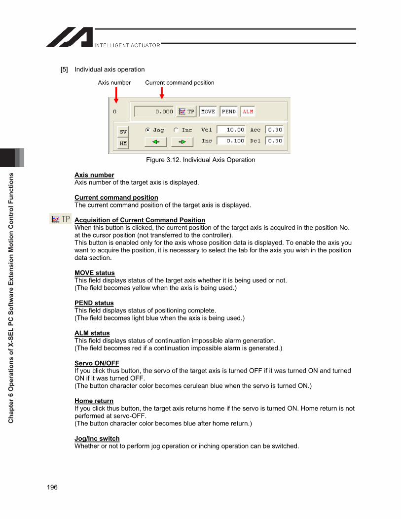
Cha
pter
6 O
pera
tions
of X
-SEL
PC
Sof
twar
e Ex
tens
ion
Mot
ion
Con
trol
Fun
ctio
ns
196
[5] Individual axis operation
Figure 3.12. Individual Axis Operation
Axis numberAxis number of the target axis is displayed.
Current command positionThe current command position of the target axis is displayed.
Acquisition of Current Command PositionWhen this button is clicked, the current position of the target axis is acquired in the position No. at the cursor position (not transferred to the controller). This button is enabled only for the axis whose position data is displayed. To enable the axis you want to acquire the position, it is necessary to select the tab for the axis you wish in the position data section.
MOVE statusThis field displays status of the target axis whether it is being used or not. (The field becomes yellow when the axis is being used.)
PEND statusThis field displays status of positioning complete. (The field becomes light blue when the axis is being used.)
ALM statusThis field displays status of continuation impossible alarm generation. (The field becomes red if a continuation impossible alarm is generated.)
Servo ON/OFFIf you click thus button, the servo of the target axis is turned OFF if it was turned ON and turned ON if it was turned OFF. (The button character color becomes cerulean blue when the servo is turned ON.)
Home returnIf you click thus button, the target axis returns home if the servo is turned ON. Home return is not performed at servo-OFF. (The button character color becomes blue after home return.)
Jog/Inc switchWhether or not to perform jog operation or inching operation can be switched.
Axis number Current command position
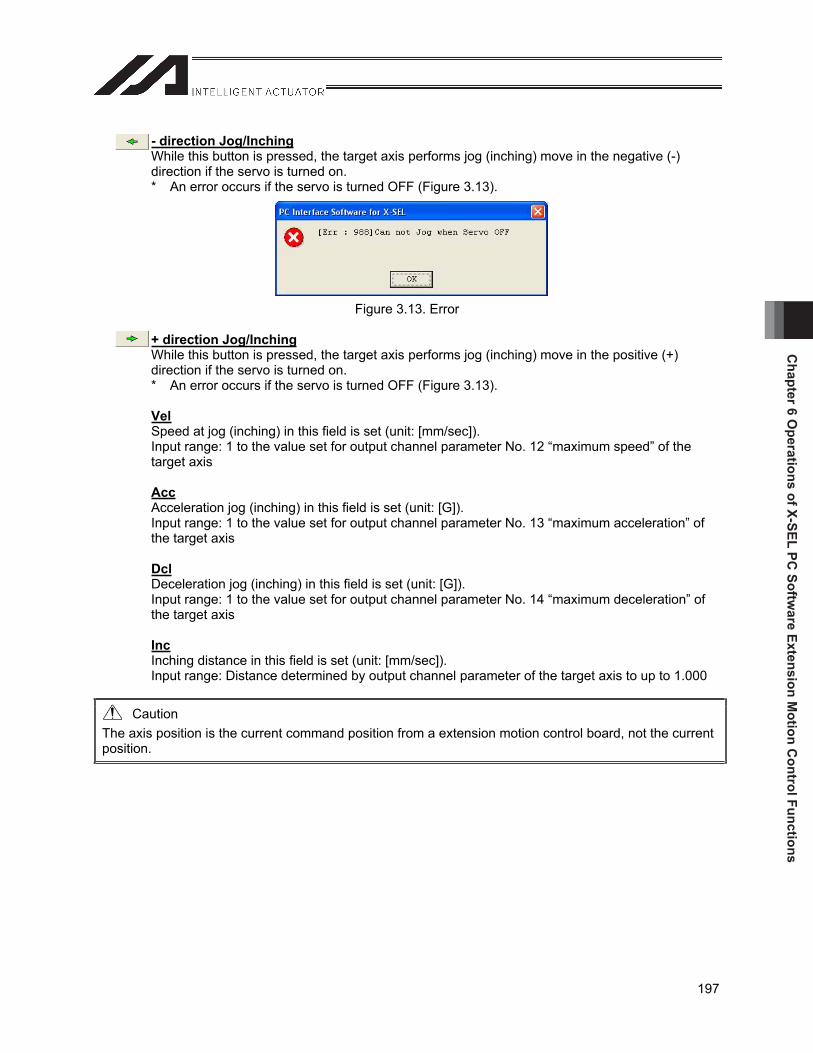
Chapter 6 O
perations of X-SEL PC Softw
are Extension Motion C
ontrol Functions
197
- direction Jog/InchingWhile this button is pressed, the target axis performs jog (inching) move in the negative (-) direction if the servo is turned on. * An error occurs if the servo is turned OFF (Figure 3.13).
Figure 3.13. Error
+ direction Jog/InchingWhile this button is pressed, the target axis performs jog (inching) move in the positive (+) direction if the servo is turned on. * An error occurs if the servo is turned OFF (Figure 3.13).
VelSpeed at jog (inching) in this field is set (unit: [mm/sec]). Input range: 1 to the value set for output channel parameter No. 12 “maximum speed” of the target axis
AccAcceleration jog (inching) in this field is set (unit: [G]). Input range: 1 to the value set for output channel parameter No. 13 “maximum acceleration” of the target axis
DclDeceleration jog (inching) in this field is set (unit: [G]). Input range: 1 to the value set for output channel parameter No. 14 “maximum deceleration” of the target axis
IncInching distance in this field is set (unit: [mm/sec]). Input range: Distance determined by output channel parameter of the target axis to up to 1.000
Caution The axis position is the current command position from a extension motion control board, not the current position.
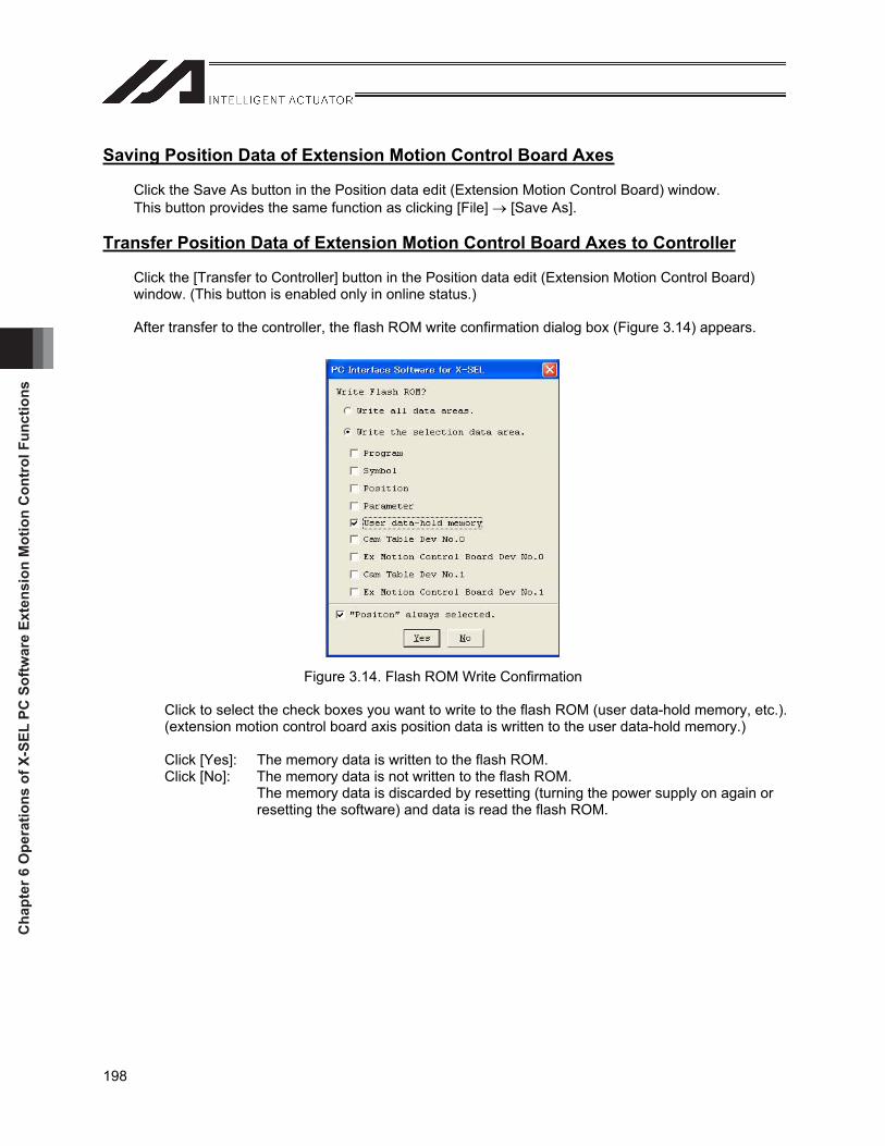
Cha
pter
6 O
pera
tions
of X
-SEL
PC
Sof
twar
e Ex
tens
ion
Mot
ion
Con
trol
Fun
ctio
ns
198
Saving Position Data of Extension Motion Control Board Axes
Click the Save As button in the Position data edit (Extension Motion Control Board) window. This button provides the same function as clicking [File] [Save As].
Transfer Position Data of Extension Motion Control Board Axes to Controller
Click the [Transfer to Controller] button in the Position data edit (Extension Motion Control Board) window. (This button is enabled only in online status.)
After transfer to the controller, the flash ROM write confirmation dialog box (Figure 3.14) appears.
Figure 3.14. Flash ROM Write Confirmation
Click to select the check boxes you want to write to the flash ROM (user data-hold memory, etc.). (extension motion control board axis position data is written to the user data-hold memory.)
Click [Yes]: The memory data is written to the flash ROM. Click [No]: The memory data is not written to the flash ROM.
The memory data is discarded by resetting (turning the power supply on again or resetting the software) and data is read the flash ROM.
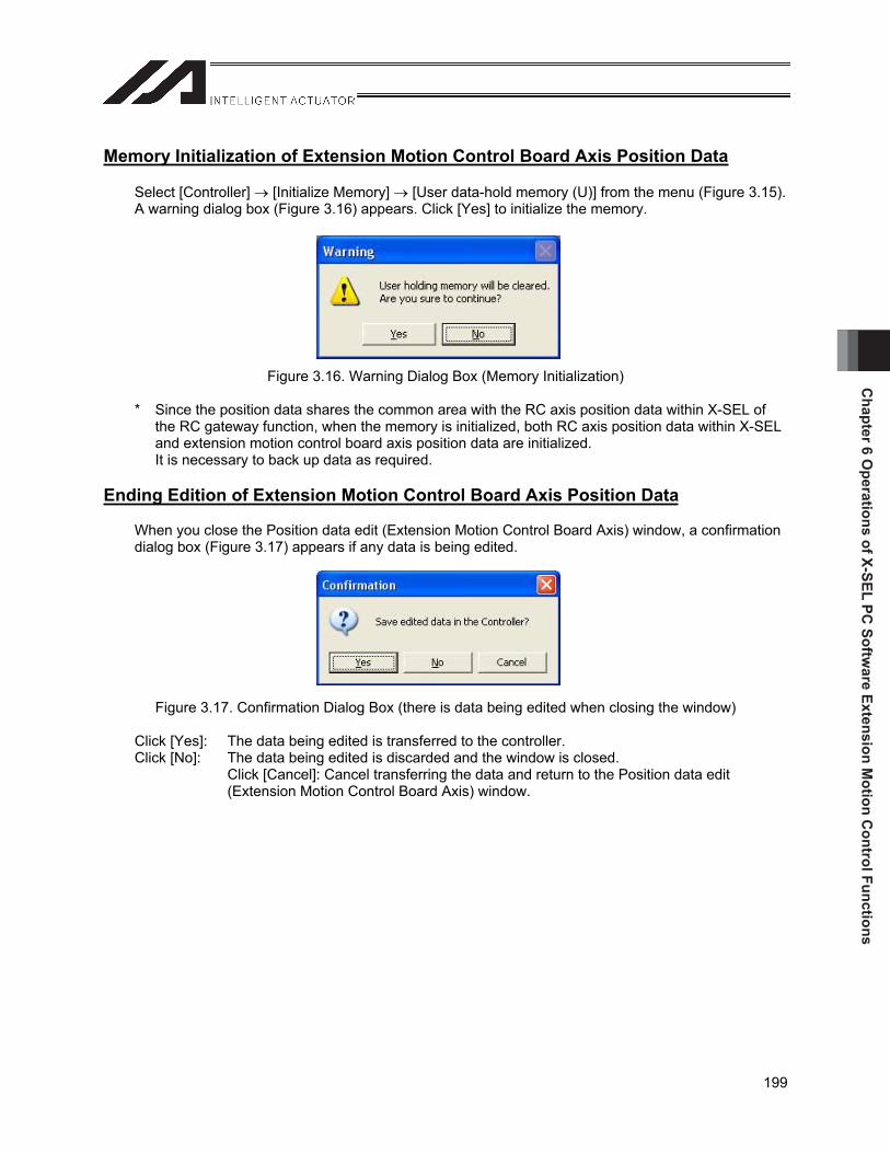
Chapter 6 O
perations of X-SEL PC Softw
are Extension Motion C
ontrol Functions
199
Memory Initialization of Extension Motion Control Board Axis Position Data
Select [Controller] [Initialize Memory] [User data-hold memory (U)] from the menu (Figure 3.15). A warning dialog box (Figure 3.16) appears. Click [Yes] to initialize the memory.
Figure 3.16. Warning Dialog Box (Memory Initialization)
* Since the position data shares the common area with the RC axis position data within X-SEL of the RC gateway function, when the memory is initialized, both RC axis position data within X-SEL and extension motion control board axis position data are initialized. It is necessary to back up data as required.
Ending Edition of Extension Motion Control Board Axis Position Data
When you close the Position data edit (Extension Motion Control Board Axis) window, a confirmation dialog box (Figure 3.17) appears if any data is being edited.
Figure 3.17. Confirmation Dialog Box (there is data being edited when closing the window)
Click [Yes]: The data being edited is transferred to the controller. Click [No]: The data being edited is discarded and the window is closed.
Click [Cancel]: Cancel transferring the data and return to the Position data edit (Extension Motion Control Board Axis) window.
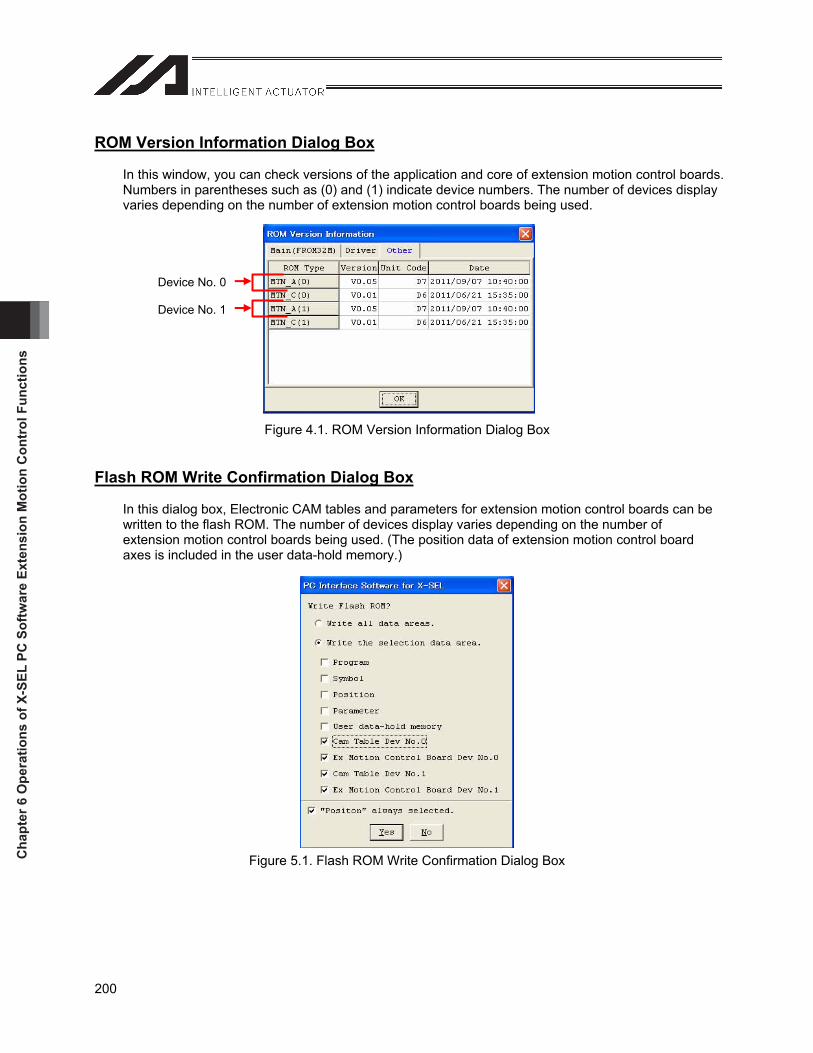
Cha
pter
6 O
pera
tions
of X
-SEL
PC
Sof
twar
e Ex
tens
ion
Mot
ion
Con
trol
Fun
ctio
ns
200
ROM Version Information Dialog Box
In this window, you can check versions of the application and core of extension motion control boards. Numbers in parentheses such as (0) and (1) indicate device numbers. The number of devices display varies depending on the number of extension motion control boards being used.
Figure 4.1. ROM Version Information Dialog Box
Flash ROM Write Confirmation Dialog Box
In this dialog box, Electronic CAM tables and parameters for extension motion control boards can be written to the flash ROM. The number of devices display varies depending on the number of extension motion control boards being used. (The position data of extension motion control board axes is included in the user data-hold memory.)
Figure 5.1. Flash ROM Write Confirmation Dialog Box
Device No. 0
Device No. 1
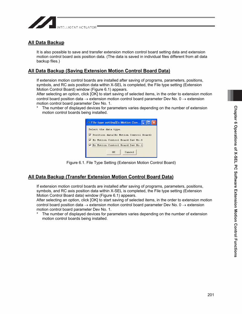
Chapter 6 O
perations of X-SEL PC Softw
are Extension Motion C
ontrol Functions
201
All Data Backup
It is also possible to save and transfer extension motion control board setting data and extension motion control board axis position data. (The data is saved in individual files different from all data backup files.)
All Data Backup (Saving Extension Motion Control Board Data)
If extension motion control boards are installed after saving of programs, parameters, positions, symbols, and RC axis position data within X-SEL is completed, the File type setting (Extension Motion Control Board) window (Figure 6.1) appears. After selecting an option, click [OK] to start saving of selected items, in the order to extension motion control board position data extension motion control board parameter Dev No. 0 extension motion control board parameter Dev No. 1. * The number of displayed devices for parameters varies depending on the number of extension
motion control boards being installed.
Figure 6.1. File Type Setting (Extension Motion Control Board)
All Data Backup (Transfer Extension Motion Control Board Data)
If extension motion control boards are installed after saving of programs, parameters, positions, symbols, and RC axis position data within X-SEL is completed, the File type setting (Extension Motion Control Board data) window (Figure 6.1) appears. After selecting an option, click [OK] to start saving of selected items, in the order to extension motion control board position data extension motion control board parameter Dev No. 0 extension motion control board parameter Dev No. 1. * The number of displayed devices for parameters varies depending on the number of extension
motion control boards being installed.
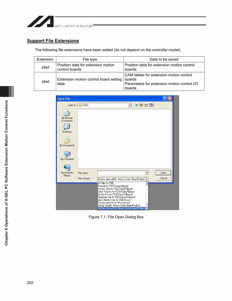
Cha
pter
6 O
pera
tions
of X
-SEL
PC
Sof
twar
e Ex
tens
ion
Mot
ion
Con
trol
Fun
ctio
ns
202
Support File Extensions
The following file extensions have been added (do not depend on the controller model).
Extension File type Data to be saved
.pbpt Position data for extension motion control boards
Position data for extension motion control boards
.pbst Extension motion control board setting data
CAM tables for extension motion control boardsParameters for extension motion control I/O boards
Figure 7.1. File Open Dialog Box


Manual No.: ME0246-5C (October 2014)
The information contained in this document is subject to change without notice for purposes of product improvement.Copyright © 2014. Oct. IAI Corporation. All rights reserved.
14.10.000
Head Office: 577-1 Obane Shimizu-KU Shizuoka City Shizuoka 424-0103, JapanTEL +81-54-364-5105 FAX +81-54-364-2589
website: www.iai-robot.co.jp/
Ober der Röth 4, D-65824 Schwalbach am Taunus, GermanyTEL 06196-88950 FAX 06196-889524
SHANGHAI JIAHUA BUSINESS CENTER A8-303, 808, Hongqiao Rd. Shanghai 200030, ChinaTEL 021-6448-4753 FAX 021-6448-3992
website: www.iai-robot.com
Technical Support available in USA, Europe and China
Head Office: 2690 W. 237th Street, Torrance, CA 90505TEL (310) 891-6015 FAX (310) 891-0815
Chicago Office: 110 East State Parkway, Schaumburg, IL 60173TEL (847) 908-1400 FAX (847) 908-1399
TEL (678) 354-9470 FAX (678) 354-9471website: www.intelligentactuator.com
Atlanta Office: 1220 Kennestone Circle, Suite 108, Marietta, GA 30066
Related Documents