SCON-CA/CAL/CGAL Instruction Manual Eighth Edition Controller IAI Corporation

Welcome message from author
This document is posted to help you gain knowledge. Please leave a comment to let me know what you think about it! Share it to your friends and learn new things together.
Transcript
SCON-CA/CAL/CGAL
Instruction Manual Eighth Edition
Controller
IAI Corporation

[Important] • This Instruction Manual is original. • The product cannot be operated in any way unless expressly specified in this Instruction Manual.
IAI shall assume no responsibility for the outcome of any operation not specified herein. • Information contained in this Instruction Manual is subject to change without notice for the
purpose of product improvement. • If you have any question or comment regarding the content of this manual, please contact the
IAI sales office near you. • Using or copying all or part of this Instruction Manual without permission is prohibited. • The company names, names of products and trademarks of each company shown in the
sentences are registered trademarks.
Please Read Before Use Thank you for purchasing our product. This Instruction Manual describes all necessary information items to operate this product safely such as the operation procedure, structure and maintenance procedure. Before the operation, read this manual carefully and fully understand it to operate this product safely. The enclosed DVD in this product package includes the Instruction Manual for this product. For the operation of this product, print out the necessary sections in the Instruction Manual or display them using the personal computer. After reading through this manual, keep this Instruction Manual at hand so that the operator of this product can read it whenever necessary.
ME0243-8J

ME0243-8J
Contents Safety Guide··································································································1 Difference between SCON-CA and SCON-CAL/CGAL············································8 Precautions in Operation ··················································································9 International Standards Compliances ································································13 Name for Each Parts and Their Functions ··························································14 Actuator Axes·······························································································19 Starting Procedures·······················································································21 Chapter 1 Specifications Check········································································23
1.1 Product Check······························································································ 23 1.1.1 Parts ···································································································· 23 1.1.2 Teaching Tool························································································· 23 1.1.3 Instruction Manuals Related to this Product, which are Contained in the
Instruction Manual (DVD).········································································· 24 1.1.4 How to Read the Model Plate ···································································· 24 1.1.5 How to Read the Model of the Controller······················································ 25
1.2 Basic Specifications······················································································· 26 1.2.1 Specifications························································································· 26 1.2.2 Power Capacity and Heat Generation·························································· 28 1.2.3 Selection of Circuit Interrupter···································································· 28 1.2.4 Selection of Leak Current Breaker ······························································ 29
1.3 Appearance ································································································· 30 1.3.1 SCONCA Less than 400W······································································ 30 1.3.2 SCON-CA 400W or More ······································································· 30 1.3.3 SCON-CAL/CGAL··················································································· 31
1.4 I/O Specifications ·························································································· 32 1.4.1 PIO Input and Output Interface ·································································· 32 1.4.2 Pulse Train Input Output Interface (Dedicated for SCON-CA) ··························· 33
1.5 Options ······································································································· 33 1.5.1 Pulse Converter : AK-04 (Dedicated for SCON-CA)········································ 33 1.5.2 Pulse Converter : JM-08 (Dedicated for SCON-CA)········································ 34 1.5.3 Regenerative Unit (Option) ······································································· 35 1.5.4 Brake Box: RCB-110-RA13-0 (Option)························································· 36 1.5.5 Loadcell (Dedicated for SCON-CA Option) ··············································· 37
1.6 Installation and Storage Environment································································· 38 1.7 Noise Elimination and Mounting Method····························································· 39
Chapter 2 Wiring···························································································43 2.1 Positioner Mode (PIO Control) ········································································· 43
2.1.1 Wiring Diagram (Connection of Construction Devices) ···································· 43 2.1.1.1 SCON-CA························································································ 43 2.1.1.2 SCON-CAL/CGAL ············································································· 45
2.1.2 PIO Pattern Selection and PIO Signal ························································· 46 2.1.3 Circuit Diagram ······················································································ 52
[1] Main Power Circuit ················································································· 52 [2] Brake Power Supply Circuit ······································································ 52 [3] Emergency Stop Circuit ··········································································· 53 [4] Motor • Encoder Circuit············································································ 55 [5] PIO Circuit ···························································································· 58 [6] Regenerative Units Circuit········································································ 66
ME0243-8J
2.2 Pulse Train Control Mode (SCON-CA Type) ························································ 67 2.2.1 Wiring Diagram (Connection of Construction Devices) ···································· 67 2.2.2 I/O Signals in Pulse Train Control Mode······················································· 69 2.2.3 Circuit Diagram ······················································································ 70
[1] Main Power Circuit ················································································· 70 [2] Brake Power Supply Circuit ······································································ 70 [3] Emergency Stop Circuit ··········································································· 71 [4] Motor • Encoder Circuit············································································ 72 [5] PIO Circuit ···························································································· 73 [6] Circuits for Pulse Train Control ·································································· 74 [7] Regenerative Units Circuit········································································ 75
2.3 Wiring Method ······························································································ 76 2.3.1 Wiring of Power Circuit············································································· 76 2.3.2 Wiring for Emergency Stop Circuit (System I/O)············································· 78 2.3.3 Connection to Actuator············································································· 79 2.3.4 Connection of PIO··················································································· 82 2.3.5 Connection of Pulse Train Signal (Dedicated for SCON-CA)····························· 83 2.3.6 Connectable Regenerative Units ································································ 86 2.3.7 SIO Connector Connection ······································································· 88
Chapter 3 Operation ······················································································89 3.1 Basic Operation ···························································································· 89
3.1.1 Basic Operation Methods ········································································· 89 3.1.2 Parameter Settings ················································································· 90
3.2 Operation in Positioner Mode··········································································· 91 [1] PIO Pattern Selection and Main Functions ·······················································92 [2] Overview of major Functions ·········································································93 [3] Operation modes of rotary actuator in multiple rotation mode and command
limitations ·································································································93 3.2.1 Set of Position Table (This section is not required in selection of pulse train
control mode.) ························································································ 94 3.2.2 Control of Input Signal ············································································100 3.2.3 Operation Ready and Auxiliary Signals = Common to Patterns 0 to 7 ················100
[1] Emergency stop status (EMGS)································································100 [2] Operation Mode (RMOD, RMDS)······························································101 [3] Servo ON (SON, SV, PEND)····································································102 [4] Home Return (HOME, HEND, PEND, MOVE) ·············································103 [5] Zone Signal and Position Zone Signal (ZONE1, PZONE)·······························106 [6] Alarm, Alarm Reset (*ALM, RES)······························································108 [7] Binary Output of Alarm Data Output (*ALM, PM1 to 8) ···································109 [8] Brake release (BKRL) ············································································ 111 [9] Battery Alarm (*BALM) ··········································································· 111
3.2.4 Operation with the Position No. Input = Operations of PIO Patterns 0 to 3 and 6 ···· 112 [1] Positioning [Basic] (PC1 to PC**, CSTR, PM1 to PM**, PEND, MOVE, LOAD,
TRQS) ································································································ 112 [2] Speed change during the movement ························································· 117 [3] Pitch Feeding (relative movement = incremental feed)··································· 118 [4] Pressing operation ················································································120 [5] Tension Operation ·················································································126 [6] Multi-step pressing ················································································128 [7] Teaching by PIO (MODE, MODES, PWRT, WEND, JISL, JOG+, JOG-)·············129 [8] Pause and Operation Interruption (*STP, RES, PEND, MOVE)························131
ME0243-8J
3.2.5 Direct Position Specification (Solenoid Valve Mode 1) = Operation of PIO Pattern 4 or 7 ··································································································133
[1] Positioning [Basic] (ST1 to ST6, PE1 to PE6, PEND) ····································133 [2] Pitch Feeding (relative movement = incremental feed)···································135 [3] Pressing operation ················································································137 [4] Tension Operation ·················································································142 [5] Multi-step pressing ················································································144 [6] Pause and Operation Interruption (ST*, *STP, RES, PE*, PEND)·····················145
3.2.6 Direct Position Specification (Solenoid Valve Mode 2) = Operation of PIO Pattern 5······························································································147
[1] Home return (ST0, HEND) ······································································147 [2] Features of LS signals (LS0 to 2)······························································150 [3] Positioning [Basic] (ST0 to ST2, LS0 to LS1)···············································151 [4] Speed change during the movement ·························································153 [5] Pause and Operation Interruption (ST*, *STP, RES, PE*, PEND)·····················155
3.2.7 Operation Ready for Pressing Operation Using Force Sensor (Calibration of Loadcell) (Dedicated for SCON-CA) ·······································156
[1] Initial Setting ························································································157 [2] Calibration of Loadcell (CLBR, CEND) ·······················································158
3.3 Operation in Pulse Train Control Mode (Dedicated for SCON-CA)···························160 3.3.1 I/O Signal Controls ·················································································161 3.3.2 Operation Ready and Auxiliary Signals ·······················································162
[1] System Ready (PWR) ············································································162 [2] Emergency stop status (*EMGS) ······························································162 [3] Operation Mode (RMOD, RMDS)······························································163 [4] Compulsory Stop (CSTP)········································································164 [5] Servo ON (SON, SV) ·············································································164 [6] Home Return (HOME, HEND)··································································165 [7] Zone (ZONE1, ZONE2) ··········································································168 [8] Alarm, Alarm Reset (*ALM, RES)······························································169 [9] Binary Output of Alarm Data Output (*ALM, ALM1 to 8) ·································169 [10] Brake Forcible Release (BKRL)································································171 [11] Overload Alarm/Light Error Alarm (*OVLW/*ALML) ·······································171
3.3.3 Pulse Train Input Operation······································································172 [1] Command Pulse Input (PP•/PP, NP•/NP)····················································172 [2] Position complete (INP) ··········································································173 [3] Torque Limit Select (TL, TLR) ··································································174 [4] Deviation Counter Clear (DCLR)·······························································174 [5] Feedback Pulse Output (AFB•/AFB, BFB•/BFB, ZFB•/ZFB) ····························175
3.3.4 Settings of Basic Parameters Required for Operation ····································176 [1] Electrical Gear Setting············································································176 [2] Format Settings of Command Pulse Train···················································178
3.3.5 Output Settings of Feedback Pulse····························································179 [1] Setting Feedback Pulse Output Effective ····················································179 [2] Format Settings for Feedback Pulse··························································180 [3] Electric Gear Settings for Feedback Pulse ··················································181
3.3.6 Parameter Settings Required for Advanced Operations ··································183 [1] Position command primary filter time constant ·············································183 [2] Torque Limit ·························································································183 [3] Clearing deviation during servo OFF or alarm stop ·······································183 [4] Error monitor during torque limiting ···························································184 [5] Deviation Counter Clear Input ··································································184 [6] Torque limit command input ·····································································184 [7] Pulse count direction··············································································184 [8] Compulsory Stop Input ···········································································184
ME0243-8J
Chapter 4 Field Network ··············································································· 185 Chapter 5 Vibration Suppress Control Function ················································· 187
5.1 Setting Procedure ························································································189 5.2 Settings of Parameters for Vibration Suppress Control ·········································190
[1] Damping Characteristic Coefficient 1,2 (Parameter No.97, 98, 101, 102, 105, and 106) Do Not Change.·················································································190
[2] Natural Frequency [1/1000Hz] (Parameter No.99, 103 and 107) ·························190 [3] Notch Filter Gain (Parameter No.100, 104 and 108) ·········································190 [4] Default Vibration Suppress No. (Parameter No.109)·········································191 [5] Stop method at Servo OFF (Parameter No.110) ··············································191
5.3 Setting of Position Data ·················································································191 Chapter 6 Power-saving Function (Auto Servo-motor OFF Function) ····················· 193 Chapter 7 Absolute Reset and Absolute Battery ················································ 195
7.1 Absolute Reset ····························································································195 [1] Absolute Reset Procedure from Teaching Tool ················································195 [2] Absolute Reset Using PIO ··········································································198
7.2 Absolute Battery ··························································································199 7.2.1 Absolute Encoder Backup Specifications······················································199 7.2.2 Replacement of Absolute Battery ·······························································201
Chapter 8 I/O Parameter ·············································································· 203 8.1 I/O Parameter List ························································································204 8.2 Detail Explanation of Parameters·····································································209 8.3 Servo Adjustment ·························································································244
Chapter 9 Troubleshooting············································································ 247 9.1 Action to Be Taken upon Occurrence of Problem·················································247
9.1.1 WRG LED (Specified only for SCON-CA/CGAL) ···········································248 9.2 Fault Diagnosis····························································································249
9.2.1 Impossible Operation of Controller·····························································249 9.2.2 Positioning and Speed of Poor Precision (Incorrect Operation) ························252 9.2.3 Generation of Noise and/or Vibration··························································254 9.2.4 Impossible Communication ······································································255
9.3 Alarm Level ································································································256 9.4 Alarm List ···································································································257
Chapter 10 Appendix··············································································· 271 10.1 Conformity to Safety Category ········································································271
[1] System Configuration ················································································271 [2] Wiring and Setting of Safety Circuit·······························································272 [3] Examples of Safety Circuits ········································································274 [4] TP Adapter and Related Components ···························································280
10.2 Way to Set Multiple Controllers with 1 Teaching Tool ············································283 10.2.1 Connecting Example ··············································································283 10.2.2 Detailed Connection Diagram of Communication Lines ··································284 10.2.3 Axis No. Setting·····················································································285
[1] SCON-CA····························································································285 [2] SCON-CAL/CGAL ·················································································285
10.2.4 Handling of e-CON Connector (How to Connect) ··········································286 10.2.5 SIO Converter ·······················································································287 10.2.6 Communications Cable ···········································································289 10.2.7 External Dimension ················································································289
10.3 Maintenance ·······························································································290 10.3.1 Consumed Parts····················································································290 10.3.2 Maintenance Information ·········································································290 10.3.3 Replacement of Fan Unit (Specified only for SCON-CAL/CGAL) ······················291
ME0243-8J
10.4 Example of Basic Positioning Sequence (PIO Pattern 0 to 3) ·································292 10.4.1 I/O Assignment······················································································292 10.4.2 Ladder Sequence ··················································································293 [1] Servo ON (Emergency Stop) Circuit······························································293 [2] Operation and Stop Circuit··········································································293 [3] Pause Circuit ···························································································294 [4] Reset Circuit····························································································295 [5] Home Return Circuit··················································································296 [6] Decode Circuit of Positioning Complete Position No. ········································297 [7] Actuator Start Circuit ·················································································297 [8] Position 1 Operation Circuit ········································································298 [9] Position 2 Operation Circuit ········································································299 [10] Position 3 Operation Circuit ········································································300 [11] Commanded Position No. Output Ready Circuit ··············································301 [12] Commanded Position No. Output Circuit························································302 [13] Start Signal Output Circuit ··········································································302 [14] Other Display Circuits (Zone 1, Position Zone, and Manual Mode) ······················303
10.5 List of Specifications of Connectable Actuators ···················································304 10.5.1 List of Specifications for Actuator Operation Conditions ··································304 10.5.2 Specifications and Limitations in Pressing Operation of RCS2-RA13R
(Dedicated for SCON-CA)········································································348 [1] Pressing Force and Current-Limiting Value ·················································348 [2] Limitation in Operation············································································349
Chapter 11 Warranty ··············································································· 355 11.1 Warranty Period···························································································355 11.2 Scope of the Warranty···················································································355 11.3 Honoring the Warranty ··················································································355 11.4 Limited Liability ····························································································355 11.5 Conditions of Conformance with Applicable Standards/Regulations, Etc., and
Applications ································································································356 11.6 Other Items Excluded from Warranty ································································356
Change History··························································································· 357
ME0243-8J

ME0243-8J
1
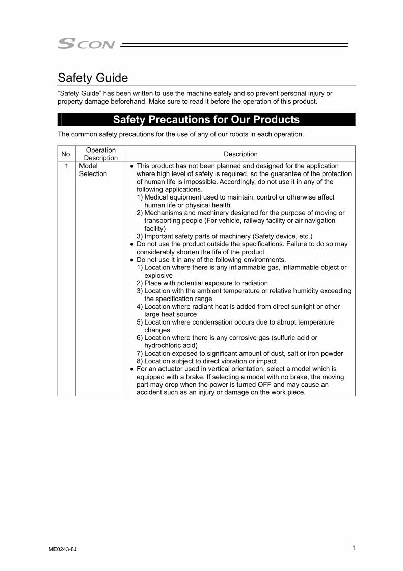
Safety Guide “Safety Guide” has been written to use the machine safely and so prevent personal injury or property damage beforehand. Make sure to read it before the operation of this product.
Safety Precautions for Our Products The common safety precautions for the use of any of our robots in each operation.
No. Operation Description Description
1 Model Selection
● This product has not been planned and designed for the application where high level of safety is required, so the guarantee of the protection of human life is impossible. Accordingly, do not use it in any of the following applications. 1) Medical equipment used to maintain, control or otherwise affect
human life or physical health. 2) Mechanisms and machinery designed for the purpose of moving or
transporting people (For vehicle, railway facility or air navigation facility)
3) Important safety parts of machinery (Safety device, etc.) ● Do not use the product outside the specifications. Failure to do so may
considerably shorten the life of the product. ● Do not use it in any of the following environments.
1) Location where there is any inflammable gas, inflammable object or explosive
2) Place with potential exposure to radiation 3) Location with the ambient temperature or relative humidity exceeding
the specification range 4) Location where radiant heat is added from direct sunlight or other
large heat source 5) Location where condensation occurs due to abrupt temperature
changes 6) Location where there is any corrosive gas (sulfuric acid or
hydrochloric acid) 7) Location exposed to significant amount of dust, salt or iron powder 8) Location subject to direct vibration or impact
● For an actuator used in vertical orientation, select a model which is equipped with a brake. If selecting a model with no brake, the moving part may drop when the power is turned OFF and may cause an accident such as an injury or damage on the work piece.
ME0243-8J
2
No. Operation Description Description
2 Transportation ● When carrying a heavy object, do the work with two or more persons or utilize equipment such as crane.
● When the work is carried out with 2 or more persons, make it clear who is to be the leader and who to be the follower(s) and communicate well with each other to ensure the safety of the workers.
● When in transportation, consider well about the positions to hold, weight and weight balance and pay special attention to the carried object so it would not get hit or dropped.
● Transport it using an appropriate transportation measure. The actuators available for transportation with a crane have eyebolts attached or there are tapped holes to attach bolts. Follow the instructions in the instruction manual for each model.
● Do not step or sit on the package. ● Do not put any heavy thing that can deform the package, on it. ● When using a crane capable of 1t or more of weight, have an operator
who has qualifications for crane operation and sling work. ● When using a crane or equivalent equipments, make sure not to hang a
load that weighs more than the equipment’s capability limit. ● Use a hook that is suitable for the load. Consider the safety factor of the
hook in such factors as shear strength. ● Do not get on the load that is hung on a crane. ● Do not leave a load hung up with a crane. ● Do not stand under the load that is hung up with a crane.
3 Storage and Preservation
● The storage and preservation environment conforms to the installation environment. However, especially give consideration to the prevention of condensation.
● Store the products with a consideration not to fall them over or drop due to an act of God such as earthquake.
4 Installation and Start
(1) Installation of Robot Main Body and Controller, etc. ● Make sure to securely hold and fix the product (including the work part).
A fall, drop or abnormal motion of the product may cause a damage or injury. Also, be equipped for a fall-over or drop due to an act of God such as earthquake.
● Do not get on or put anything on the product. Failure to do so may cause an accidental fall, injury or damage to the product due to a drop of anything, malfunction of the product, performance degradation, or shortening of its life.
● When using the product in any of the places specified below, provide a sufficient shield. 1) Location where electric noise is generated 2) Location where high electrical or magnetic field is present 3) Location with the mains or power lines passing nearby 4) Location where the product may come in contact with water, oil or
chemical droplets
ME0243-8J
3
No. Operation Description Description
(2) Cable Wiring ● Use our company’s genuine cables for connecting between the actuator
and controller, and for the teaching tool. ● Do not scratch on the cable. Do not bend it forcibly. Do not pull it. Do not
coil it around. Do not insert it. Do not put any heavy thing on it. Failure to do so may cause a fire, electric shock or malfunction due to leakage or continuity error.
● Perform the wiring for the product, after turning OFF the power to the unit, so that there is no wiring error.
● When the direct current power (+24V) is connected, take the great care of the directions of positive and negative poles. If the connection direction is not correct, it might cause a fire, product breakdown or malfunction.
● Connect the cable connector securely so that there is no disconnection or looseness. Failure to do so may cause a fire, electric shock or malfunction of the product.
● Never cut and/or reconnect the cables supplied with the product for the purpose of extending or shortening the cable length. Failure to do so may cause the product to malfunction or cause fire.
4 Installation and Start
(3) Grounding ● The grounding operation should be performed to prevent an electric
shock or electrostatic charge, enhance the noise-resistance ability and control the unnecessary electromagnetic radiation.
● For the ground terminal on the AC power cable of the controller and the grounding plate in the control panel, make sure to use a twisted pair cable with wire thickness 0.5mm2 (AWG20 or equivalent) or more for grounding work. For security grounding, it is necessary to select an appropriate wire thickness suitable for the load. Perform wiring that satisfies the specifications (electrical equipment technical standards).
● Perform Class D Grounding (former Class 3 Grounding with ground resistance 100Ω or below).
ME0243-8J
4
No. Operation Description Description
4 Installation and Start
(4) Safety Measures ● When the work is carried out with 2 or more persons, make it clear who
is to be the leader and who to be the follower(s) and communicate well with each other to ensure the safety of the workers.
● When the product is under operation or in the ready mode, take the safety measures (such as the installation of safety and protection fence) so that nobody can enter the area within the robot’s movable range. When the robot under operation is touched, it may result in death or serious injury.
● Make sure to install the emergency stop circuit so that the unit can be stopped immediately in an emergency during the unit operation.
● Take the safety measure not to start up the unit only with the power turning ON. Failure to do so may start up the machine suddenly and cause an injury or damage to the product.
● Take the safety measure not to start up the machine only with the emergency stop cancellation or recovery after the power failure. Failure to do so may result in an electric shock or injury due to unexpected power input.
● When the installation or adjustment operation is to be performed, give clear warnings such as “Under Operation; Do not turn ON the power!” etc. Sudden power input may cause an electric shock or injury.
● Take the measure so that the work part is not dropped in power failure or emergency stop.
● Wear protection gloves, goggle or safety shoes, as necessary, to secure safety.
● Do not insert a finger or object in the openings in the product. Failure to do so may cause an injury, electric shock, damage to the product or fire.
● When releasing the brake on a vertically oriented actuator, exercise precaution not to pinch your hand or damage the work parts with the actuator dropped by gravity.
5 Teaching ● When the work is carried out with 2 or more persons, make it clear who is to be the leader and who to be the follower(s) and communicate well with each other to ensure the safety of the workers.
● Perform the teaching operation from outside the safety protection fence, if possible. In the case that the operation is to be performed unavoidably inside the safety protection fence, prepare the “Stipulations for the Operation” and make sure that all the workers acknowledge and understand them well.
● When the operation is to be performed inside the safety protection fence, the worker should have an emergency stop switch at hand with him so that the unit can be stopped any time in an emergency.
● When the operation is to be performed inside the safety protection fence, in addition to the workers, arrange a watchman so that the machine can be stopped any time in an emergency. Also, keep watch on the operation so that any third person can not operate the switches carelessly.
● Place a sign “Under Operation” at the position easy to see. ● When releasing the brake on a vertically oriented actuator, exercise
precaution not to pinch your hand or damage the work parts with the actuator dropped by gravity.
* Safety protection Fence : In the case that there is no safety protection fence, the movable range should be indicated.
ME0243-8J
5
No. Operation Description Description
6 Trial Operation
● When the work is carried out with 2 or more persons, make it clear who is to be the leader and who to be the follower(s) and communicate well with each other to ensure the safety of the workers.
● After the teaching or programming operation, perform the check operation one step by one step and then shift to the automatic operation.
● When the check operation is to be performed inside the safety protection fence, perform the check operation using the previously specified work procedure like the teaching operation.
● Make sure to perform the programmed operation check at the safety speed. Failure to do so may result in an accident due to unexpected motion caused by a program error, etc.
● Do not touch the terminal block or any of the various setting switches in the power ON mode. Failure to do so may result in an electric shock or malfunction.
7 Automatic Operation
● Check before starting the automatic operation or rebooting after operation stop that there is nobody in the safety protection fence.
● Before starting automatic operation, make sure that all peripheral equipment is in an automatic-operation-ready state and there is no alarm indication.
● Make sure to operate automatic operation start from outside of the safety protection fence.
● In the case that there is any abnormal heating, smoke, offensive smell, or abnormal noise in the product, immediately stop the machine and turn OFF the power switch. Failure to do so may result in a fire or damage to the product.
● When a power failure occurs, turn OFF the power switch. Failure to do so may cause an injury or damage to the product, due to a sudden motion of the product in the recovery operation from the power failure.
ME0243-8J
6
No. Operation Description Description
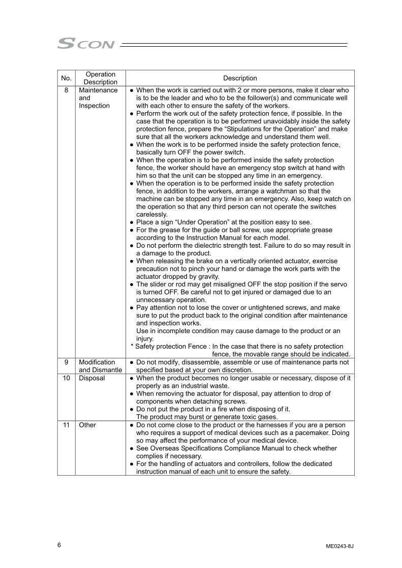
8 Maintenance and Inspection
● When the work is carried out with 2 or more persons, make it clear who is to be the leader and who to be the follower(s) and communicate well with each other to ensure the safety of the workers.
● Perform the work out of the safety protection fence, if possible. In the case that the operation is to be performed unavoidably inside the safety protection fence, prepare the “Stipulations for the Operation” and make sure that all the workers acknowledge and understand them well.
● When the work is to be performed inside the safety protection fence, basically turn OFF the power switch.
● When the operation is to be performed inside the safety protection fence, the worker should have an emergency stop switch at hand with him so that the unit can be stopped any time in an emergency.
● When the operation is to be performed inside the safety protection fence, in addition to the workers, arrange a watchman so that the machine can be stopped any time in an emergency. Also, keep watch on the operation so that any third person can not operate the switches carelessly.
● Place a sign “Under Operation” at the position easy to see. ● For the grease for the guide or ball screw, use appropriate grease
according to the Instruction Manual for each model. ● Do not perform the dielectric strength test. Failure to do so may result in
a damage to the product. ● When releasing the brake on a vertically oriented actuator, exercise
precaution not to pinch your hand or damage the work parts with the actuator dropped by gravity.
● The slider or rod may get misaligned OFF the stop position if the servo is turned OFF. Be careful not to get injured or damaged due to an unnecessary operation.
● Pay attention not to lose the cover or untightened screws, and make sure to put the product back to the original condition after maintenance and inspection works. Use in incomplete condition may cause damage to the product or an injury.
* Safety protection Fence : In the case that there is no safety protection fence, the movable range should be indicated.
9 Modification and Dismantle
● Do not modify, disassemble, assemble or use of maintenance parts not specified based at your own discretion.
10 Disposal ● When the product becomes no longer usable or necessary, dispose of it properly as an industrial waste.
● When removing the actuator for disposal, pay attention to drop of components when detaching screws.
● Do not put the product in a fire when disposing of it. The product may burst or generate toxic gases.
11 Other ● Do not come close to the product or the harnesses if you are a person who requires a support of medical devices such as a pacemaker. Doing so may affect the performance of your medical device.
● See Overseas Specifications Compliance Manual to check whether complies if necessary.
● For the handling of actuators and controllers, follow the dedicated instruction manual of each unit to ensure the safety.
ME0243-8J
7
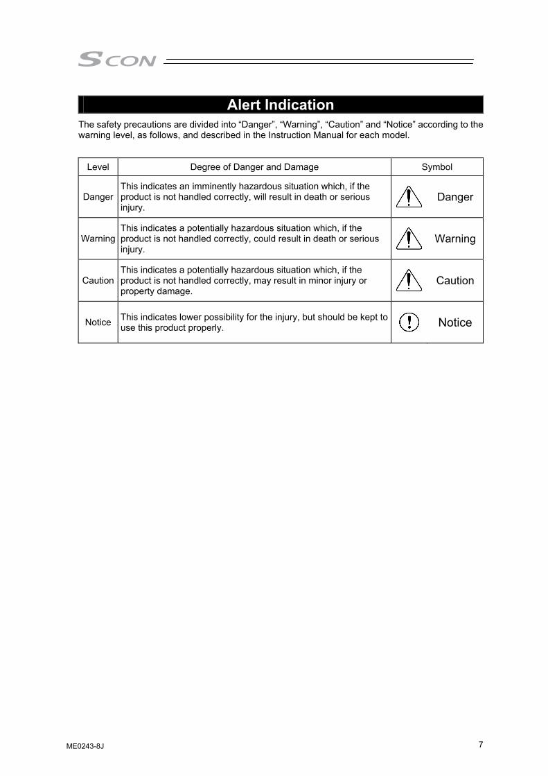
Alert Indication The safety precautions are divided into “Danger”, “Warning”, “Caution” and “Notice” according to the warning level, as follows, and described in the Instruction Manual for each model.
Level Degree of Danger and Damage Symbol
Danger This indicates an imminently hazardous situation which, if the product is not handled correctly, will result in death or serious injury.
Danger
Warning This indicates a potentially hazardous situation which, if the product is not handled correctly, could result in death or serious injury.
Warning
Caution This indicates a potentially hazardous situation which, if the product is not handled correctly, may result in minor injury or property damage.
Caution
Notice This indicates lower possibility for the injury, but should be kept to use this product properly. Notice
ME0243-8J
8
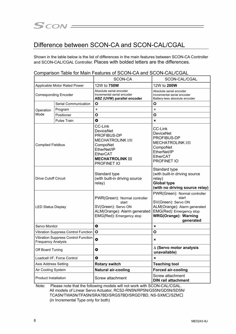
Difference between SCON-CA and SCON-CAL/CGAL Shown in the table below is the list of differences in the main features between SCON-CA Controller and SCON-CAL/CGAL Controller. Places with bolded letters are the differences. Comparison Table for Main Features of SCON-CA and SCON-CAL/CGAL SCON-CA SCON-CAL/CGAL Applicable Motor Rated Power 12W to 750W 12W to 200W
Corresponding Encoder Absolute serial encoderIncremental serial encoder ABZ (UVW) parallel encoder
Absolute serial encoder Incremental serial encoder Battery-less absolute encoder
Operation Mode
Serial Communication Program × ×Positioner Pulse Train ×
Complied Fieldbus
CC-Link DeviceNet PROFIBUS-DP MECHATROLINK Ι/ΙΙ CompoNet EtherNet/IP EtherCAT MECHATROLINK ΙΙΙΙΙΙ PROFINET IO
CC-Link DeviceNet PROFIBUS-DP MECHATROLINK Ι/ΙΙ CompoNet EtherNet/IP EtherCAT PROFINET IO
Drive Cutoff Circuit Standard type (with built-in driving source relay)
Standard type (with built-in driving source relay) Global type (with no driving source relay)
LED Status Display
PWR(Green): Normal controller start
SV(Green): Servo ON ALM(Orange): Alarm generatedEMG(Red): Emergency stop
PWR(Green): Normal controller start
SV(Green): Servo ON ALM(Orange): Alarm generated EMG(Red): Emergency stop WRG(Orange): Warning
generatedServo Monitor ×Vibration Suppress Control Function
Vibration Suppress Control Function Frequency Analysis ×
Off Board Tuning ΔΔ (Servo motor analysis unavailable)
Loadcell I/F, Force Control ×Axis Address Setting Rotary switch Teaching tool Air Cooling System Natural air-cooling Forced air-cooling
Product Installation Screw attachment Screw attachment DIN rail attachment
Note: Please note that the following models will not work with SCON-CAL/CGAL. All models of Linear Servo Actuator, RCS2-RN5N/RP5N/GS5N/GD5N/SD5N/ TCA5N/TWA5N/TFA5N/SRA7BD/SRGS7BD/SRGD7BD, NS-SXM□/SZM□ (in Incremental Type only for both)
ME0243-8J
9
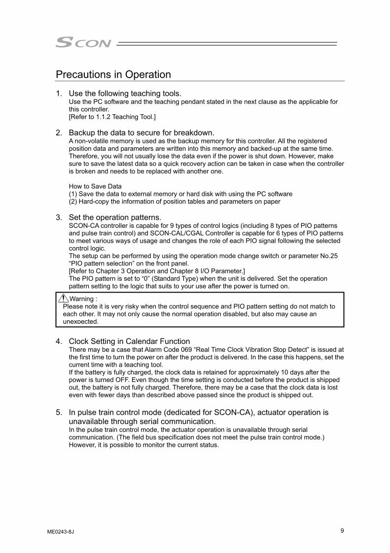
Precautions in Operation
1. Use the following teaching tools. Use the PC software and the teaching pendant stated in the next clause as the applicable for this controller. [Refer to 1.1.2 Teaching Tool.]
2. Backup the data to secure for breakdown. A non-volatile memory is used as the backup memory for this controller. All the registered position data and parameters are written into this memory and backed-up at the same time. Therefore, you will not usually lose the data even if the power is shut down. However, make sure to save the latest data so a quick recovery action can be taken in case when the controller is broken and needs to be replaced with another one. How to Save Data (1) Save the data to external memory or hard disk with using the PC software (2) Hard-copy the information of position tables and parameters on paper
3. Set the operation patterns. SCON-CA controller is capable for 9 types of control logics (including 8 types of PIO patterns and pulse train control) and SCON-CAL/CGAL Controller is capable for 6 types of PIO patterns to meet various ways of usage and changes the role of each PIO signal following the selected control logic. The setup can be performed by using the operation mode change switch or parameter No.25 “PIO pattern selection” on the front panel. [Refer to Chapter 3 Operation and Chapter 8 I/O Parameter.] The PIO pattern is set to “0” (Standard Type) when the unit is delivered. Set the operation pattern setting to the logic that suits to your use after the power is turned on.
4. Clock Setting in Calendar Function
There may be a case that Alarm Code 069 “Real Time Clock Vibration Stop Detect” is issued at the first time to turn the power on after the product is delivered. In the case this happens, set the current time with a teaching tool. If the battery is fully charged, the clock data is retained for approximately 10 days after the power is turned OFF. Even though the time setting is conducted before the product is shipped out, the battery is not fully charged. Therefore, there may be a case that the clock data is lost even with fewer days than described above passed since the product is shipped out.
5. In pulse train control mode (dedicated for SCON-CA), actuator operation is
unavailable through serial communication. In the pulse train control mode, the actuator operation is unavailable through serial communication. (The field bus specification does not meet the pulse train control mode.) However, it is possible to monitor the current status.
Warning : Please note it is very risky when the control sequence and PIO pattern setting do not match to each other. It may not only cause the normal operation disabled, but also may cause an unexpected.
ME0243-8J
10
6. Attempt not to exceed the actuator specifications in the pulse train control mode (dedicated for SCON-CA). In Pulse Train Control Mode, the operation is performed corresponding to the input pulse. • Input Pulse Value → Moving distance • Input pulse frequency → Velocity • Change in Input Pulse Frequency → Velocity change and acceleration/deceleration Do not use the actuator above the specifications (for stroke, maximum velocity, maximum acceleration/deceleration) for the commands of the movement amount, velocity and acceleration/deceleration from the host controller (PLC). Doing so may cause an error or malfunction. The pressing operation velocity should be set to the rated pressing velocity when it is to conduct the pressing operation. Pressing with velocity not at the rated pressing velocity could end up with pressing force different from that shown in “10.5.2 Specifications and Limitations in Pressing Operation of RCS2-RA13R”. Also, operation in velocity higher than the rated pressing velocity could cause an error or malfunction. Refer to “10.5.1 List of Specifications for Actuator Operation Conditions” or model code for the specifications and rated pressing velocity for each actuator.
7. Actuator would not operate without servo-on and pause signals.
(1) Servo ON Signal (SON)
Servo ON signal (SON) is selectable from “Enable” or “Disable” by using a parameter. It is settable by parameter No.21 “selection of servo-on signal disable”. [Refer to Chapter 8 I/O Parameter.] If it is set to “Enable”, the actuator would not operate unless turning this signal on. If parameter No.21 is set to “1”, SON is made disable. If it is set to “Disable”, the servo becomes on and the actuator operation becomes enabled as soon as the power supply to the controller is turned on and the emergency stop signal is cancelled. [Refer to 3.2.3 [3] or 3.3.2 [5] Emergency Stop Circuit.] This parameter is set to “0” (Enable) at delivery. Have the setting that suits to the desirable control logic.
(2) Pause Signal (*STP)
The input signal of the pause signal (*STP) is always on considering the safety. Therefore, in general, the actuator would not operate if this signal is not on. It is available to make this signal to “Disable”, if this signal is undesirable. It is settable by parameter No.15 “Pause input disable”. [Refer to Chapter 8 I/O Parameter.] If parameter No.15 is set to “1” (Disable), the actuator can operate even if this signal is not on. This parameter is set to “0” (Enable) at delivery.
8. Note that there are some frictions and/or torsions in through-hole of rotary actuator when it is used. When using rotary actuator with a through hole in the center of the revolution and using the hole to put cables through, have a treatment to prevent wear from rubbing or wire break due to the cables getting twisted.
9. For rotary actuator, note cable disconnections due to distortions. Take particular note on actuators of 360-degree specification because they can be rotated infinitely in a single direction.
ME0243-8J
11
10. Limitations on operation of rotary actuator in index mode Rotary actuators of 360-degree specification can select the normal mode for finite rotations or the index mode enabling multi-rotation control by using parameter No.79 “Rotary axis mode selection”. [Refer to Chapter 8 I/O Parameter.] The following limitations are applied to the index mode: 1) Controllers of absolute specification cannot select the index mode. If selected, alarm code
0A1 “parameter data error” is issued. 2) Index Mode cannot be selected in Pulse Train Control Mode. It will generate Alarm Code
0A1 “Parameter Error”. 3) The command range in the jog operation with PC software, teaching pendant or PIO signal
is 0 to 360.00. 4) Pressing is unavailable. The pressing torque can only be set to 0. 5) Do not issue positioning command around 0 repeatedly during movement near 0. Failure
to follow this may cause the actuator to rotate in the direction reverse to the specified rotation direction or operate indefinitely.
6) Software stroke limit is invalid in the index mode.
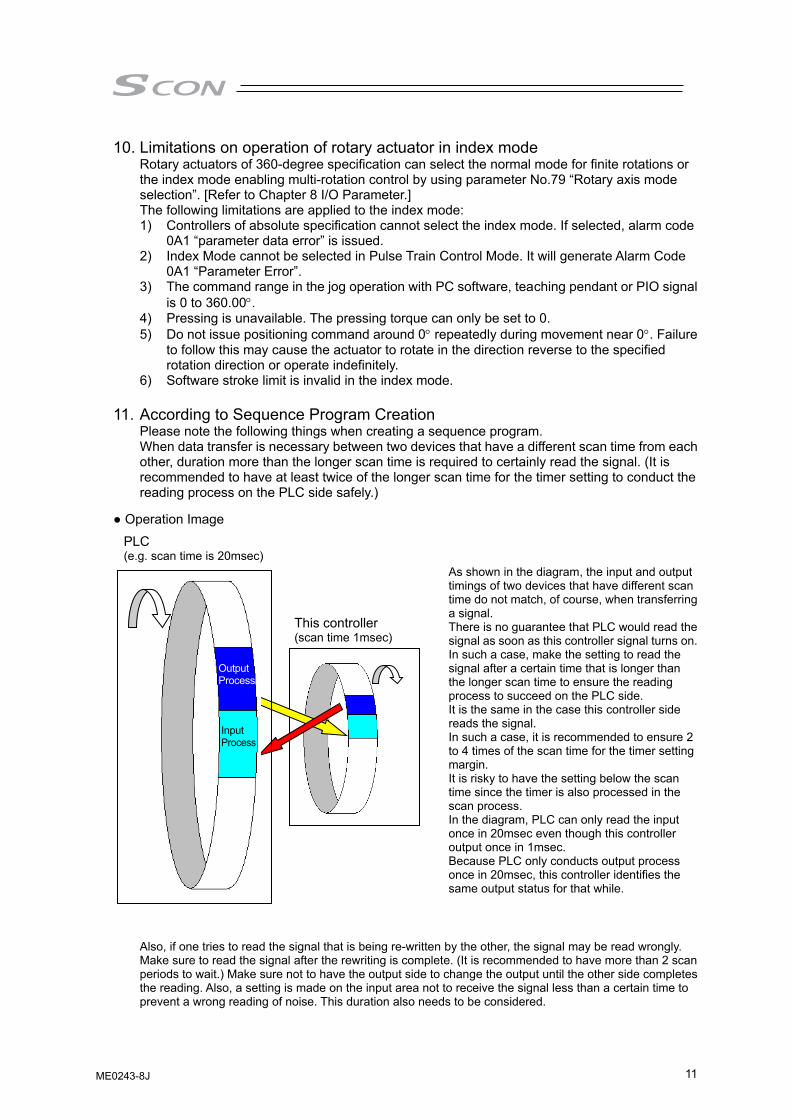
11. According to Sequence Program Creation Please note the following things when creating a sequence program. When data transfer is necessary between two devices that have a different scan time from each other, duration more than the longer scan time is required to certainly read the signal. (It is recommended to have at least twice of the longer scan time for the timer setting to conduct the reading process on the PLC side safely.)
● Operation Image
Also, if one tries to read the signal that is being re-written by the other, the signal may be read wrongly. Make sure to read the signal after the rewriting is complete. (It is recommended to have more than 2 scan periods to wait.) Make sure not to have the output side to change the output until the other side completes the reading. Also, a setting is made on the input area not to receive the signal less than a certain time to prevent a wrong reading of noise. This duration also needs to be considered.
This controller (scan time 1msec)
PLC (e.g. scan time is 20msec)
As shown in the diagram, the input and output timings of two devices that have different scan time do not match, of course, when transferring a signal. There is no guarantee that PLC would read the signal as soon as this controller signal turns on.In such a case, make the setting to read the signal after a certain time that is longer than the longer scan time to ensure the reading process to succeed on the PLC side. It is the same in the case this controller side reads the signal. In such a case, it is recommended to ensure 2 to 4 times of the scan time for the timer setting margin. It is risky to have the setting below the scan time since the timer is also processed in the scan process. In the diagram, PLC can only read the input once in 20msec even though this controller output once in 1msec. Because PLC only conducts output process once in 20msec, this controller identifies the same output status for that while.
Output Process
Input Process
ME0243-8J
12
12. PLC Timer Setting Do not have the PLC timer setting to be done with the minimum setting. Setting to “1” for 100msec timer turns ON at the timing from 0 to 100msec while 10msec timer from 0 to 10msec for some PLC. Therefore, the same process as when the timer is not set is held and may cause a failure such as the actuator cannot get positioned to the indicated position number in Positioner Mode. Set “2” as the minimum value for the setting of 10msec timer and when setting to 100msec, use 10msec timer and set to “10”.
13. Handling and Caution for Built-in Drive Cutoff Relay
The product equips a built-in drive cutoff relay, and it is necessary to be careful in handling. Use the product with narrow understanding to the following notes. • The drive cutoff relay built in our controllers is designed under assumption of limited frequency of use
such as a case to require emergency stop of a system, and frequent operation is not considered. Therefore, in a condition to require high frequency of use of the drive cutoff relay such as a case to turn ON/OFF the driving source in every setup change, the life of the relay may reach to the end in early stage.
• The relay itself may not meet a sufficient safety demand level when it is used in a system that prioritizes safety in the drive cutoff system. It is necessary to construct a system to meet the safety demand level in a circuit that a customer prepares.
• IAI products equip a built-in drive cutoff relay considering customer’s usage. However, as described above, whether it can be used or not relies on such facts as the safety demand level and frequency of drive cutoff. Please use it in limitation to the way to use as described below.
• Do not expect reliability of the drive cutoff relay (Anything can do as long as driving source can be cut off.)
• Take around 5 times a day as a reference to turn ON/OFF the drive cutoff relay • Thermistor type (which the resistance gets high and restrains in-rush current in low temperature, and
resistance gets low and reduce loss in high temperature) in-rush current limiter circuit is equipped. Therefore, to keep the thermistor temperature as low as possible when turning the power on is a key point to make degradation slower on such components as the drive cutoff relay. As a reference, it is preferred to have approximately 30 minutes for cooling after the driving source being cut off.
ME0243-8J
13
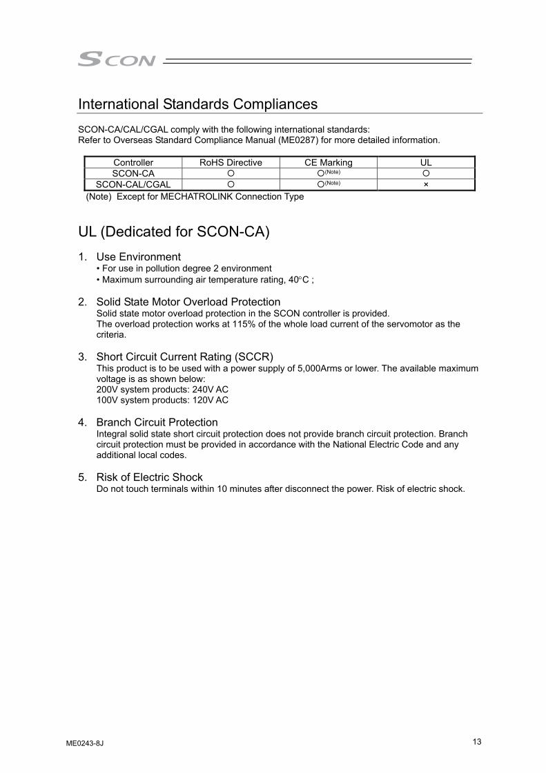
International Standards Compliances SCON-CA/CAL/CGAL comply with the following international standards: Refer to Overseas Standard Compliance Manual (ME0287) for more detailed information.
Controller RoHS Directive CE Marking UL SCON-CA (Note)
SCON-CAL/CGAL (Note) × (Note) Except for MECHATROLINK Connection Type
UL (Dedicated for SCON-CA) 1. Use Environment
• For use in pollution degree 2 environment • Maximum surrounding air temperature rating, 40°C ;
2. Solid State Motor Overload Protection Solid state motor overload protection in the SCON controller is provided. The overload protection works at 115% of the whole load current of the servomotor as the criteria.
3. Short Circuit Current Rating (SCCR) This product is to be used with a power supply of 5,000Arms or lower. The available maximum voltage is as shown below: 200V system products: 240V AC 100V system products: 120V AC
4. Branch Circuit Protection Integral solid state short circuit protection does not provide branch circuit protection. Branch circuit protection must be provided in accordance with the National Electric Code and any additional local codes.
5. Risk of Electric Shock Do not touch terminals within 10 minutes after disconnect the power. Risk of electric shock.
ME0243-8J
14
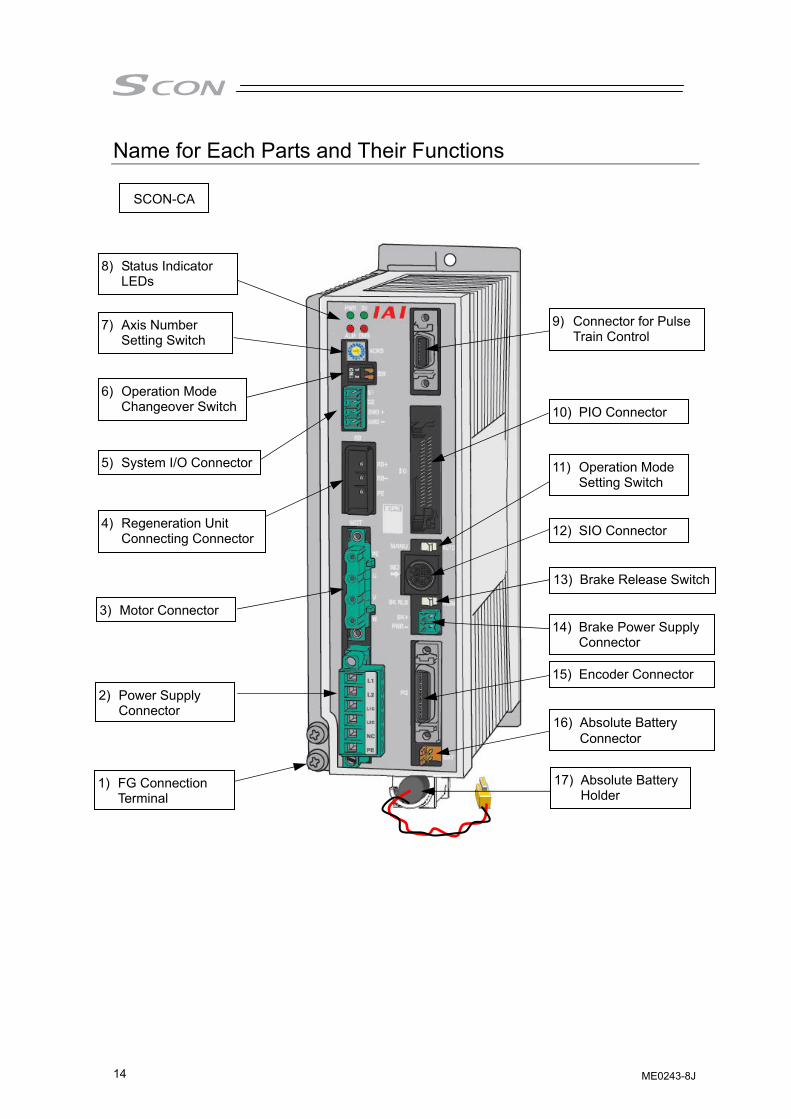
Name for Each Parts and Their Functions
SCON-CA
2) Power Supply Connector
4) Regeneration Unit Connecting Connector
3) Motor Connector
5) System I/O Connector
6) Operation Mode Changeover Switch
7) Axis Number Setting Switch
8) Status Indicator LEDs
1) FG Connection Terminal
10) PIO Connector
9) Connector for Pulse Train Control
12) SIO Connector
11) Operation Mode Setting Switch
13) Brake Release Switch
14) Brake Power Supply Connector
15) Encoder Connector
16) Absolute Battery Connector
17) Absolute Battery Holder
ME0243-8J
15
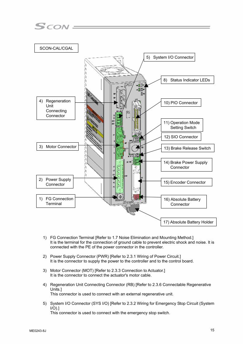
1) FG Connection Terminal [Refer to 1.7 Noise Elimination and Mounting Method.] It is the terminal for the connection of ground cable to prevent electric shock and noise. It is connected with the PE of the power connector in the controller.
2) Power Supply Connector (PWR) [Refer to 2.3.1 Wiring of Power Circuit.] It is the connector to supply the power to the controller and to the control board.
3) Motor Connector (MOT) [Refer to 2.3.3 Connection to Actuator.] It is the connector to connect the actuator's motor cable.
4) Regeneration Unit Connecting Connector (RB) [Refer to 2.3.6 Connectable Regenerative Units.] This connector is used to connect with an external regenerative unit.
5) System I/O Connector (SYS I/O) [Refer to 2.3.2 Wiring for Emergency Stop Circuit (System I/O).] This connector is used to connect with the emergency stop switch.
17) Absolute Battery Holder
16) Absolute Battery Connector
15) Encoder Connector
14) Brake Power Supply Connector
13) Brake Release Switch
12) SIO Connector
11) Operation Mode Setting Switch
10) PIO Connector
8) Status Indicator LEDs
1) FG Connection Terminal
2) Power Supply Connector
3) Motor Connector
4) Regeneration Unit Connecting Connector
5) System I/O Connector
SCON-CAL/CGAL
ME0243-8J
16
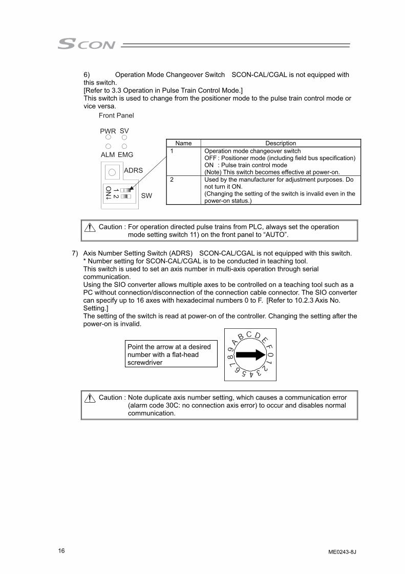
6) Operation Mode Changeover Switch SCON-CAL/CGAL is not equipped with this switch. [Refer to 3.3 Operation in Pulse Train Control Mode.] This switch is used to change from the positioner mode to the pulse train control mode or vice versa.
Caution : For operation directed pulse trains from PLC, always set the operation mode setting switch 11) on the front panel to “AUTO”.
7) Axis Number Setting Switch (ADRS) SCON-CAL/CGAL is not equipped with this switch.
* Number setting for SCON-CAL/CGAL is to be conducted in teaching tool. This switch is used to set an axis number in multi-axis operation through serial communication. Using the SIO converter allows multiple axes to be controlled on a teaching tool such as a PC without connection/disconnection of the connection cable connector. The SIO converter can specify up to 16 axes with hexadecimal numbers 0 to F. [Refer to 10.2.3 Axis No. Setting.] The setting of the switch is read at power-on of the controller. Changing the setting after the power-on is invalid.
Caution : Note duplicate axis number setting, which causes a communication error (alarm code 30C: no connection axis error) to occur and disables normal communication.
Name Description 1 Operation mode changeover switch
OFF : Positioner mode (including field bus specification)ON : Pulse train control mode (Note) This switch becomes effective at power-on.
2 Used by the manufacturer for adjustment purposes. Do not turn it ON. (Changing the setting of the switch is invalid even in the power-on status.)
Point the arrow at a desired number with a flat-head screwdriver
Front Panel
PWR
ALM EMG
ADRS
SW
12
ON
SV
ME0243-8J
17
8) Status Indicator LEDs (PWR, SV, ALM, EMG, WRG) SCON-CA is not equipped with WRG.
Following show the controller operation status: ○ : Illuminating × : OFF Δ : Illuminating or OFF
LED Operation status PWR (GN) SV (GN) ALM (OR) EMG (RD) WRG (OR)
× × × × × Control power OFF ○ × × × × Normal controller start ○ × Δ Δ Δ Servo OFF ○ ○(Note 1) × × Δ Servo ON ○ × ○ Δ Δ Alarm being generated ○ × Δ ○ Δ Emergency stop ○ Δ Δ Δ ○ (Note 2) Warning being generated
Note 1 Blinking in auto servo-off state Note 2 Flashes in 1Hz
9) Connector for Pulse Train Control (PULSE) [Refer to Chapter 3.3 Operation in Pulse Train
Control Mode.] This connector is not equipped in SCON-CAL/CGAL. The pulse train I/O connector is used in the pulse train control mode. Feedback Pulse is also effective in Positioner Mode
10) PIO Connector (PIO) [Refer to 2.3.4 Connection of PIO.] The PIO connector is used for control I/O signals.
11) Operation Mode Setting Switch (MANU/AUTO) This switch is used for interlock so that a moving command from PIO (PLC) and a command from the teaching tool such as a PC may not be issued at a time. AUTO ··· Allows auto operation by PIO signals. The teaching tool such as a PC can only
operate the monitor. MANU ··· Allows the teaching tool such as a PC to operate the controller.
12) SIO Connector (SIO) [Refer to 2.3.7 SIO Connector Connection.]
The SIO connector is used to connect the controller with a teaching tool such as PC software or a gateway unit through a proper communication cable.
13) Brake Release Switch (BK RLS/NOM) For the actuator equipped with a brake, the switch is used to release the brake forcibly.
Warning : Always set the switch to “NOM” in normal operation. The brake would not work even with the servo OFF condition if the switch is on the RLS side. In the vertical oriented mount, the work may drop and cause an injury or the work to be damaged.
14) Brake Power Supply Connector (BK PWR) [Refer to 2.3.1 Wiring of Power Circuit.]
For the actuator equipped with a brake, the connector supplies the power (24V DC) to release the brake.
15) Encoder Connector (PG) [Refer to 2.3.3 Connection to Actuator.]
This connector is used to connect the encoder cable of the actuator. 16) Absolute Battery Connector
In the absolute specification, the connector is connected with the absolute battery.
ME0243-8J

18
17) Absolute Battery Holder (for absolute type) This is the holder for the storage of the absolute battery.
Caution : If it is Pulse Train Control, it would not comply with absolute type.
ME0243-8J
19
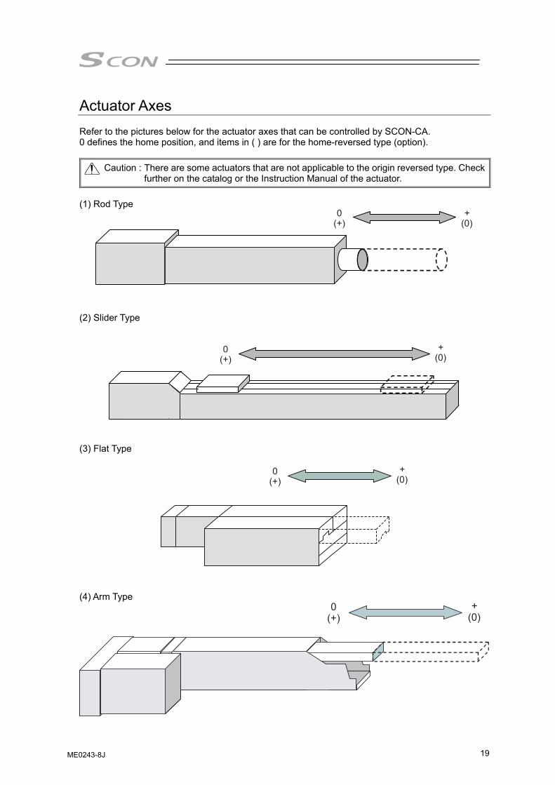
Actuator Axes Refer to the pictures below for the actuator axes that can be controlled by SCON-CA. 0 defines the home position, and items in ( ) are for the home-reversed type (option).
Caution : There are some actuators that are not applicable to the origin reversed type. Check further on the catalog or the Instruction Manual of the actuator.
(1) Rod Type
(2) Slider Type
(3) Flat Type
(4) Arm Type
ME0243-8J
20
300°0° - +
- +
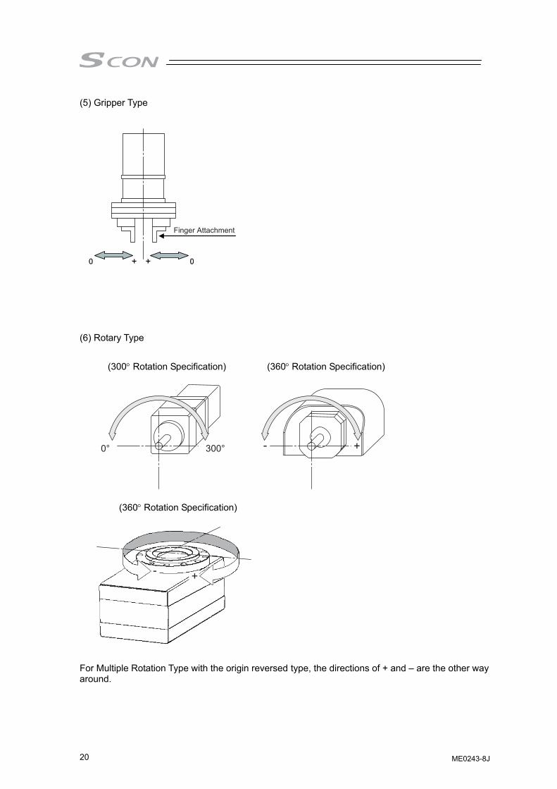
(5) Gripper Type
(6) Rotary Type
(300° Rotation Specification) (360° Rotation Specification)
(360° Rotation Specification)
For Multiple Rotation Type with the origin reversed type, the directions of + and – are the other way around.
Finger Attachment
ME0243-8J
21
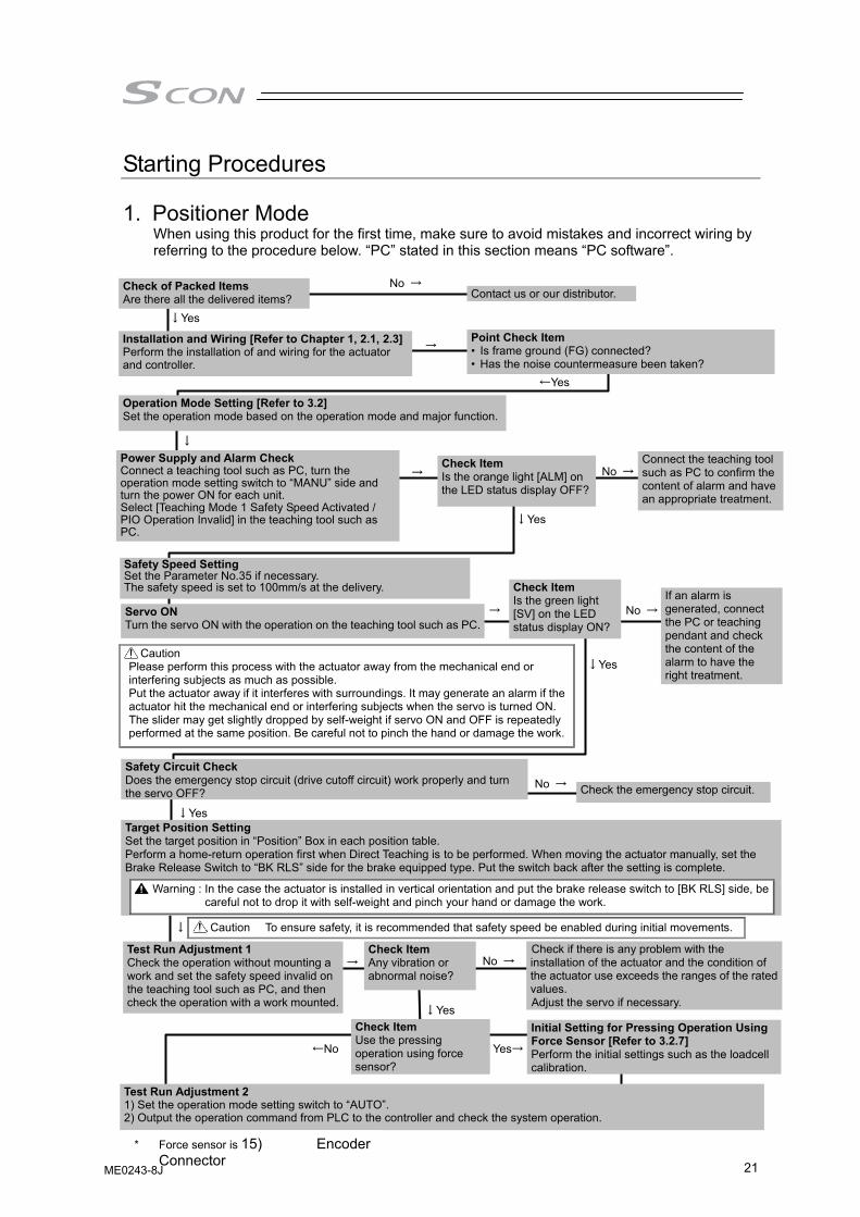
Starting Procedures
1. Positioner Mode
When using this product for the first time, make sure to avoid mistakes and incorrect wiring by referring to the procedure below. “PC” stated in this section means “PC software”.
↓Yes
↓Yes
→
No →
↓
→ No →
Contact us or our distributor.
↓Yes
No →
→
Check Item Is the orange light [ALM] on the LED status display OFF?
Connect the teaching tool such as PC to confirm the content of alarm and have an appropriate treatment.
Servo ON Turn the servo ON with the operation on the teaching tool such as PC.
Check Item Is the green light [SV] on the LED status display ON?
Safety Circuit Check Does the emergency stop circuit (drive cutoff circuit) work properly and turn the servo OFF? Check the emergency stop circuit.
Target Position Setting Set the target position in “Position” Box in each position table. Perform a home-return operation first when Direct Teaching is to be performed. When moving the actuator manually, set the Brake Release Switch to “BK RLS” side for the brake equipped type. Put the switch back after the setting is complete.
→
No →
↓Yes
Safety Speed Setting Set the Parameter No.35 if necessary. The safety speed is set to 100mm/s at the delivery.
↓
Test Run Adjustment 1 Check the operation without mounting a work and set the safety speed invalid on the teaching tool such as PC, and then check the operation with a work mounted.
Check if there is any problem with the installation of the actuator and the condition of the actuator use exceeds the ranges of the rated values. Adjust the servo if necessary.
Power Supply and Alarm Check Connect a teaching tool such as PC, turn the operation mode setting switch to “MANU” side and turn the power ON for each unit. Select [Teaching Mode 1 Safety Speed Activated / PIO Operation Invalid] in the teaching tool such as PC.
If an alarm is generated, connect the PC or teaching pendant and check the content of the alarm to have the right treatment.
↓Yes
←Yes
Operation Mode Setting [Refer to 3.2] Set the operation mode based on the operation mode and major function.
Test Run Adjustment 2 1) Set the operation mode setting switch to “AUTO”. 2) Output the operation command from PLC to the controller and check the system operation.
Check Item Any vibration or abnormal noise?
No →
Check of Packed Items Are there all the delivered items?
Caution To ensure safety, it is recommended that safety speed be enabled during initial movements.
Installation and Wiring [Refer to Chapter 1, 2.1, 2.3]Perform the installation of and wiring for the actuator and controller.
Point Check Item • Is frame ground (FG) connected? • Has the noise countermeasure been taken?
Check Item Use the pressing operation using force sensor?
Yes→
Initial Setting for Pressing Operation Using Force Sensor [Refer to 3.2.7] Perform the initial settings such as the loadcell calibration.
←No
Caution Please perform this process with the actuator away from the mechanical end or interfering subjects as much as possible. Put the actuator away if it interferes with surroundings. It may generate an alarm if the actuator hit the mechanical end or interfering subjects when the servo is turned ON. The slider may get slightly dropped by self-weight if servo ON and OFF is repeatedly performed at the same position. Be careful not to pinch the hand or damage the work.
Warning : In the case the actuator is installed in vertical orientation and put the brake release switch to [BK RLS] side, be careful not to drop it with self-weight and pinch your hand or damage the work.
* Force sensor is 15) Encoder Connector
ME0243-8J
22
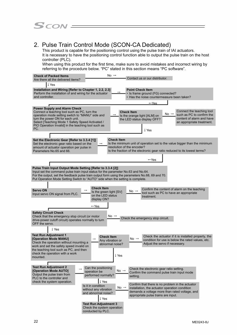
2. Pulse Train Control Mode (SCON-CA Dedicated) This product is capable for the positioning control using the pulse train of IAI actuators. It is necessary to have the positioning control function able to output the pulse train on the host controller (PLC). When using this product for the first time, make sure to avoid mistakes and incorrect wiring by referring to the procedure below. “PC” stated in this section means “PC software”.
Set the Electronic Gear [Refer to 3.3.4 [1]] Set the electronic gear ratio based on the amount of actuator operation per pulse in Parameters No.65 and 66.
→ Check Item Is the minimum unit of operation set to the value bigger than the minimum resolution of the encoder? Is the fraction of the electronic gear ratio reduced to its lowest terms?
←Yes
Pulse Train Input Output Mode Setting [Refer to 3.3.4 [2]] Input set the command pulse train input status for the parameter No.63 and No.64. For the output, set the feedback pulse train output form using the parameters No.68, 69 and 70.Put Operation Mode Setting Switch to “AUTO” side when the setting is complete.
Servo ON Input servo ON signal from PLC.
→ Check Item Is the green light [SV] on the LED status display ON?
No → Confirm the content of alarm on the teaching tool such as PC to have an appropriate treatment.
←Yes
Safety Circuit Check Check that the emergency stop circuit (or motor drive-power cutoff circuit) operates normally to turn OFF the servo.
No →Check the emergency stop circuit.
↓Yes
→ No →
Contact us or our distributor.
↓Yes
No →
→
Check Item Is the orange light [ALM] on the LED status display OFF?
Connect the teaching tool such as PC to confirm the content of alarm and have an appropriate treatment.
Test Run Adjustment 2 [Operation Mode AUTO] Output the pulse train from PLC to the controller and check the system operation.
→ Can the positioning operation be performed normally?
↓Yes
No →
No → Check the electronic gear ratio setting. Confirm the command pulse train input mode setting.
Confirm that there is no problem in the actuator installation, the actuator operation condition demands a voltage more than rated voltage, and appropriate pulse trains are input.
Power Supply and Alarm Check Connect a teaching tool such as PC, turn the operation mode setting switch to “MANU” side and turn the power ON for each unit. Select [Teaching Mode 1 Safety Speed Activated / PIO Operation Invalid] in the teaching tool such as PC. ↓Yes
←Yes
Check of Packed Items Are there all the delivered items?
Installation and Wiring [Refer to Chapter 1, 2.2, 2.3]Perform the installation of and wiring for the actuator and controller.
Point Check Item • Is frame ground (FG) connected? • Has the noise countermeasure been taken?
→
Test Run Adjustment 1 [Operation Mode MANU] Check the operation without mounting a work and set the safety speed invalid on the teaching tool such as PC, and then check the operation with a work mounted.
Check the actuator if it is installed properly, the condition for use is below the rated values, etc.Adjust the servo if necessary.
Check Item Any vibration or abnormal noise?
No →
↓Yes
Is it in condition without any vibration and abnormal noise?
Test Run Adjustment 3 Check the system operation conducted by PLC.
↓Yes
ME0243-8J
Chapter 1 Specifications C
heck
23
Chapter 1 Specifications Check 1.1 Product Check 1.1.1 Parts
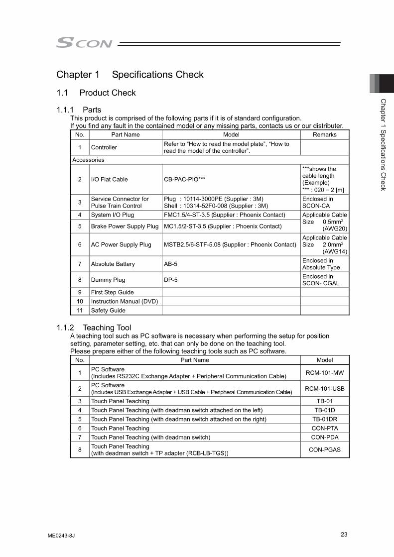
This product is comprised of the following parts if it is of standard configuration. If you find any fault in the contained model or any missing parts, contacts us or our distributer.
No. Part Name Model Remarks
1 Controller Refer to “How to read the model plate”, “How to read the model of the controller”.
Accessories
2 I/O Flat Cable CB-PAC-PIO***
***shows the cable length (Example) *** : 020 = 2 [m]
3 Service Connector for Pulse Train Control
Plug : 10114-3000PE (Supplier : 3M) Shell : 10314-52F0-008 (Supplier : 3M)
Enclosed in SCON-CA
4 System I/O Plug FMC1.5/4-ST-3.5 (Supplier : Phoenix Contact)
5 Brake Power Supply Plug MC1.5/2-ST-3.5 (Supplier : Phoenix Contact)
Applicable Cable Size 0.5mm2
(AWG20)
6 AC Power Supply Plug MSTB2.5/6-STF-5.08 (Supplier : Phoenix Contact) Applicable Cable Size 2.0mm2
(AWG14)
7 Absolute Battery AB-5 Enclosed in Absolute Type
8 Dummy Plug DP-5 Enclosed in SCON- CGAL
9 First Step Guide 10 Instruction Manual (DVD) 11 Safety Guide
1.1.2 Teaching Tool
A teaching tool such as PC software is necessary when performing the setup for position setting, parameter setting, etc. that can only be done on the teaching tool. Please prepare either of the following teaching tools such as PC software.
No. Part Name Model
1 PC Software (Includes RS232C Exchange Adapter + Peripheral Communication Cable) RCM-101-MW
2 PC Software (Includes USB Exchange Adapter + USB Cable + Peripheral Communication Cable) RCM-101-USB
3 Touch Panel Teaching TB-01 4 Touch Panel Teaching (with deadman switch attached on the left) TB-01D 5 Touch Panel Teaching (with deadman switch attached on the right) TB-01DR 6 Touch Panel Teaching CON-PTA 7 Touch Panel Teaching (with deadman switch) CON-PDA
8 Touch Panel Teaching (with deadman switch + TP adapter (RCB-LB-TGS)) CON-PGAS
ME0243-8J
Cha
pter
1 S
peci
ficat
ions
Che
ck
24
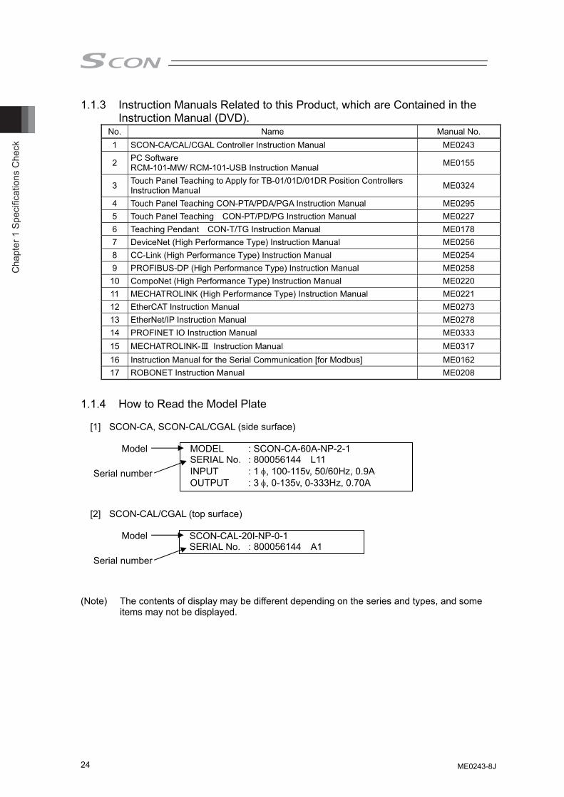
1.1.3 Instruction Manuals Related to this Product, which are Contained in the Instruction Manual (DVD).
No. Name Manual No. 1 SCON-CA/CAL/CGAL Controller Instruction Manual ME0243
2 PC Software RCM-101-MW/ RCM-101-USB Instruction Manual ME0155
3 Touch Panel Teaching to Apply for TB-01/01D/01DR Position Controllers Instruction Manual ME0324
4 Touch Panel Teaching CON-PTA/PDA/PGA Instruction Manual ME0295 5 Touch Panel Teaching CON-PT/PD/PG Instruction Manual ME0227 6 Teaching Pendant CON-T/TG Instruction Manual ME0178 7 DeviceNet (High Performance Type) Instruction Manual ME0256 8 CC-Link (High Performance Type) Instruction Manual ME0254 9 PROFIBUS-DP (High Performance Type) Instruction Manual ME0258 10 CompoNet (High Performance Type) Instruction Manual ME0220 11 MECHATROLINK (High Performance Type) Instruction Manual ME0221 12 EtherCAT Instruction Manual ME0273 13 EtherNet/IP Instruction Manual ME0278 14 PROFINET IO Instruction Manual ME0333 15 MECHATROLINK-Ⅲ Instruction Manual ME0317 16 Instruction Manual for the Serial Communication [for Modbus] ME0162 17 ROBONET Instruction Manual ME0208
1.1.4 How to Read the Model Plate
[1] SCON-CA, SCON-CAL/CGAL (side surface)
[2] SCON-CAL/CGAL (top surface)
(Note) The contents of display may be different depending on the series and types, and some
items may not be displayed.
MODEL : SCON-CA-60A-NP-2-1 SERIAL No. : 800056144 L11 INPUT : 1 φ, 100-115v, 50/60Hz, 0.9A OUTPUT : 3 φ, 0-135v, 0-333Hz, 0.70A
Model
Serial number
SCON-CAL-20I-NP-0-1 SERIAL No. : 800056144 A1
Model
Serial number
ME0243-8J
Chapter 1 Specifications C
heck
25
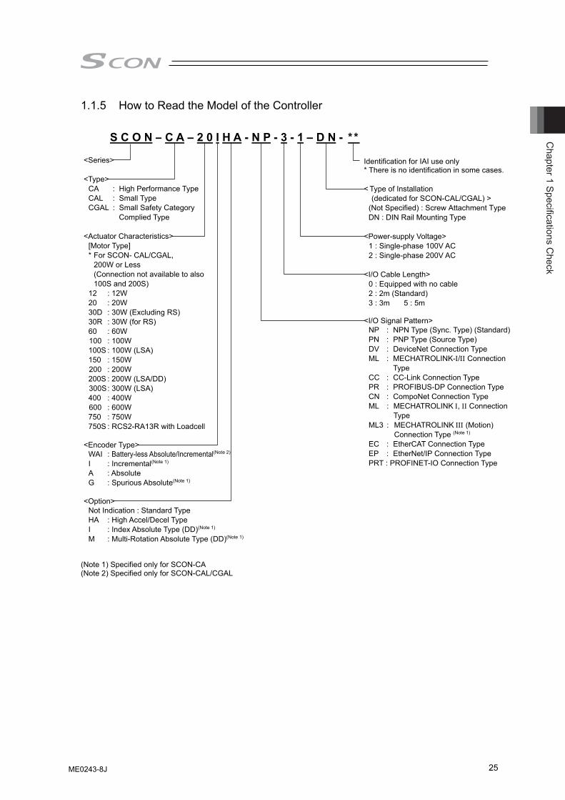
1.1.5 How to Read the Model of the Controller (Note 1) Specified only for SCON-CA (Note 2) Specified only for SCON-CAL/CGAL
S C O N – C A – 2 0 I H A - N P - 3 - 1 – D N - * *
<Series> <Type>
CA : High Performance Type CAL : Small Type CGAL : Small Safety Category
Complied Type
<Actuator Characteristics> [Motor Type]
* For SCON- CAL/CGAL, 200W or Less (Connection not available to also 100S and 200S)
12 : 12W 20 : 20W 30D : 30W (Excluding RS) 30R : 30W (for RS) 60 : 60W 100 : 100W 100S : 100W (LSA) 150 : 150W 200 : 200W 200S : 200W (LSA/DD) 300S : 300W (LSA) 400 : 400W 600 : 600W 750 : 750W 750S : RCS2-RA13R with Loadcell
<Encoder Type> WAI : Battery-less Absolute/Incremental(Note 2) I : Incremental(Note 1) A : Absolute G : Spurious Absolute(Note 1)
<Option> Not Indication : Standard Type HA : High Accel/Decel Type I : Index Absolute Type (DD)(Note 1) M : Multi-Rotation Absolute Type (DD)(Note 1)
Identification for IAI use only * There is no identification in some cases. < Type of Installation
(dedicated for SCON-CAL/CGAL) > (Not Specified) : Screw Attachment Type DN : DIN Rail Mounting Type
<Power-supply Voltage>
1 : Single-phase 100V AC 2 : Single-phase 200V AC
<I/O Cable Length>
0 : Equipped with no cable 2 : 2m (Standard) 3 : 3m 5 : 5m
<I/O Signal Pattern>
NP : NPN Type (Sync. Type) (Standard) PN : PNP Type (Source Type) DV : DeviceNet Connection Type ML : MECHATROLINK-Ι/ΙΙ Connection
Type
CC : CC-Link Connection Type PR : PROFIBUS-DP Connection Type CN : CompoNet Connection Type
ML : MECHATROLINK Ι, ΙΙ Connection Type
ML3 : MECHATROLINK ΙΙΙ (Motion) Connection Type (Note 1)
EC : EtherCAT Connection Type EP : EtherNet/IP Connection Type PRT : PROFINET-IO Connection Type
ME0243-8J
Cha
pter
1 S
peci
ficat
ions
Che
ck
26
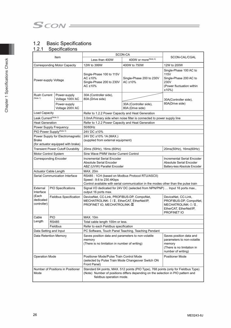
1.2 Basic Specifications 1.2.1 Specifications
Item SCON-CA
SCON-CAL/CGAL Less than 400W 400W or more(Note 4)
Corresponding Motor Capacity 12W to 399W 400W to 750W 12W to 200W
Power-supply Voltage
Single-Phase 100 to 115V AC ±10% Single-Phase 200 to 230V AC ±10%
Single-Phase 200 to 230V AC ±10%
Single-Phase 100 AC to 115V Single-Phase 200 AC to 230V (Power fluctuation within ±10%)
Rush Current (Note 1)
Power-supply Voltage 100V AC
30A (Controller side), 80A (Drive side)
30A(Controller side), 80A(Drive side) Power-supply
Voltage 200V AC 30A (Controller side), 80A (Drive side)
Load Capacity Refer to 1.2.2 Power Capacity and Heat Generation Leak Current(Note 2) 3.0mA Primary side when noise filter is connected to power supply line Heat Generation Refer to 1.2.2 Power Capacity and Heat Generation Power Supply Frequency 50/60Hz PIO Power Supply(Note 3) 24V DC ±10% Power Supply for Electromagnetic Brake (for actuator equipped with brake)
24V DC ±10% 1A (MAX.) (supplied from external equipment)
Transient Power Cutoff Durability 20ms (50Hz), 16ms (60Hz) 20ms(50Hz), 16ms(60Hz) Motor Control System Sine Wave PWM Vector Current Control Corresponding Encoder Incremental Serial Encoder
Absolute Serial Encoder ABZ (UVW) Parallel Encoder
Incremental Serial EncoderAbsolute Serial Encoder Battery-less Absolute Encoder
Actuator Cable Length MAX. 20m Serial Communication Interface RS485 : 1CH (based on Modbus Protocol RTU/ASCII)
Speed : 9.6 to 230.4Kbps Control available with serial communication in the modes other than the pulse train
External Interface (Each dedicated controller)
PIO Specifications Signal I/O dedicated for 24V DC (selected from NPN/PNP) … Input 16 ports max., output 16 ports max.
Fieldbus Specification DeviceNet, CC-Link, PROFIBUS-DP, CompoNet, MECHATROLINK-Ⅰ/Ⅱ, EtherCAT, EtherNet/IP, PROFINET IO, MECHATROLINK-Ⅲ
DeviceNet, CC-Link, PROFIBUS-DP, CompoNet, MECHATROLINK-Ⅰ/Ⅱ, EtherCAT, EtherNet/IP, PROFINET IO
Cable Length
PIO MAX. 10m RS485 Total cable length 100m or less. Fieldbus Refer to each Fieldbus specification
Data Setting and Input PC Software, Touch Panel Teaching, Teaching Pendant Data Retention Memory Saves position data and parameters to non-volatile
memory (There is no limitation in number of writing)
Saves position data and parameters to non-volatile memory (There is no limitation in number of writing)
Operation Mode Positioner Mode/Pulse Train Control Mode (selected by Pulse Train Mode Changeover Switch ON Front Panel)
Positioner Mode
Number of Positions in Positioner Mode
Standard 64 points, MAX. 512 points (PIO Type), 768 points (only for Fieldbus Type) (Note) Number of positions differs depending on the selection in PIO pattern and
fieldbus operation mode.
ME0243-8J
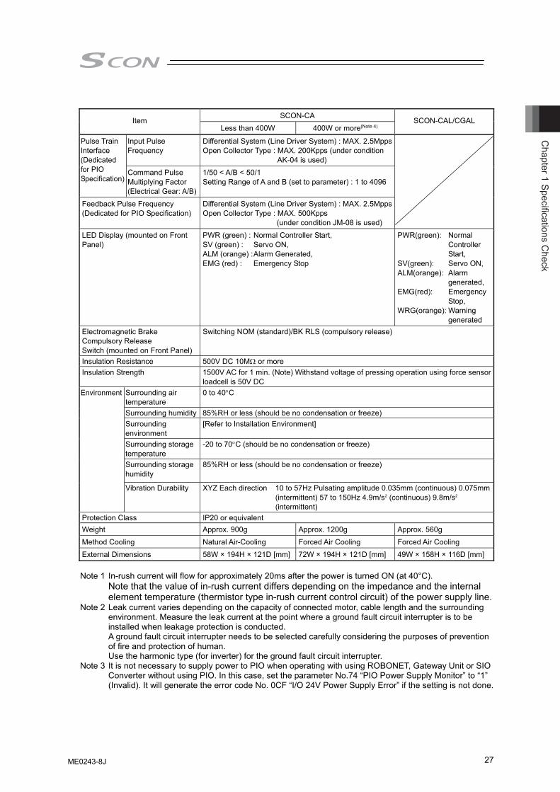
Chapter 1 Specifications C
heck
27
SCON-CA
Item Less than 400W 400W or more(Note 4)
SCON-CAL/CGAL
Input Pulse Frequency
Differential System (Line Driver System) : MAX. 2.5MppsOpen Collector Type : MAX. 200Kpps (under condition
AK-04 is used)
Pulse Train Interface (Dedicated for PIO Specification)
Command Pulse Multiplying Factor (Electrical Gear: A/B)
1/50 < A/B < 50/1 Setting Range of A and B (set to parameter) : 1 to 4096
Feedback Pulse Frequency (Dedicated for PIO Specification)
Differential System (Line Driver System) : MAX. 2.5MppsOpen Collector Type : MAX. 500Kpps
(under condition JM-08 is used)
LED Display (mounted on Front Panel)
PWR (green) : Normal Controller Start, SV (green) : Servo ON, ALM (orange) : Alarm Generated, EMG (red) : Emergency Stop
PWR(green): Normal Controller Start,
SV(green): Servo ON, ALM(orange): Alarm
generated, EMG(red): Emergency
Stop, WRG(orange): Warning
generated Electromagnetic Brake Compulsory Release Switch (mounted on Front Panel)
Switching NOM (standard)/BK RLS (compulsory release)
Insulation Resistance 500V DC 10MΩ or more Insulation Strength 1500V AC for 1 min. (Note) Withstand voltage of pressing operation using force sensor
loadcell is 50V DC Surrounding air temperature
0 to 40°C
Surrounding humidity 85%RH or less (should be no condensation or freeze) Surrounding environment
[Refer to Installation Environment]
Surrounding storage temperature
-20 to 70°C (should be no condensation or freeze)
Surrounding storage humidity
85%RH or less (should be no condensation or freeze)
Environment
Vibration Durability XYZ Each direction 10 to 57Hz Pulsating amplitude 0.035mm (continuous) 0.075mm (intermittent) 57 to 150Hz 4.9m/s2 (continuous) 9.8m/s2 (intermittent)
Protection Class IP20 or equivalent Weight Approx. 900g Approx. 1200g Approx. 560g
Method Cooling Natural Air-Cooling Forced Air Cooling Forced Air Cooling External Dimensions 58W × 194H × 121D [mm] 72W × 194H × 121D [mm] 49W × 158H × 116D [mm] Note 1 In-rush current will flow for approximately 20ms after the power is turned ON (at 40°C).
Note that the value of in-rush current differs depending on the impedance and the internal element temperature (thermistor type in-rush current control circuit) of the power supply line.
Note 2 Leak current varies depending on the capacity of connected motor, cable length and the surrounding environment. Measure the leak current at the point where a ground fault circuit interrupter is to be installed when leakage protection is conducted. A ground fault circuit interrupter needs to be selected carefully considering the purposes of prevention of fire and protection of human. Use the harmonic type (for inverter) for the ground fault circuit interrupter.
Note 3 It is not necessary to supply power to PIO when operating with using ROBONET, Gateway Unit or SIO Converter without using PIO. In this case, set the parameter No.74 “PIO Power Supply Monitor” to “1” (Invalid). It will generate the error code No. 0CF “I/O 24V Power Supply Error” if the setting is not done.
ME0243-8J
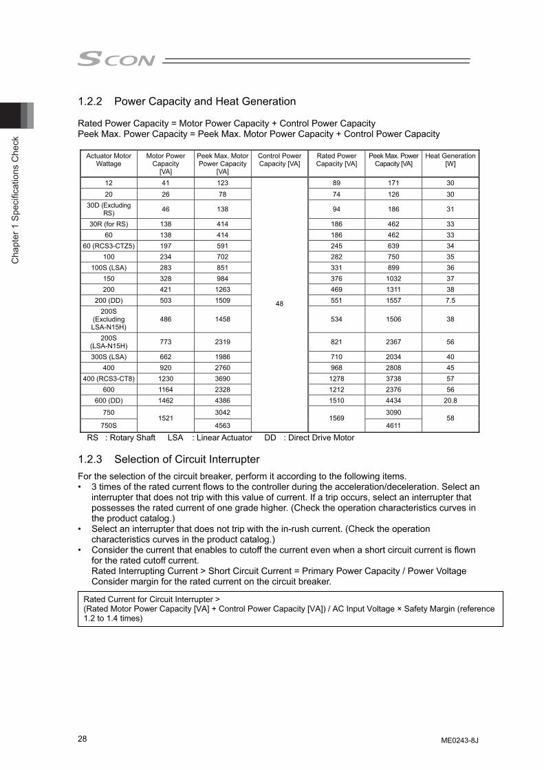
Cha
pter
1 S
peci
ficat
ions
Che
ck
28
1.2.2 Power Capacity and Heat Generation Rated Power Capacity = Motor Power Capacity + Control Power Capacity Peek Max. Power Capacity = Peek Max. Motor Power Capacity + Control Power Capacity
Actuator Motor Wattage
Motor Power Capacity
[VA]
Peek Max. Motor Power Capacity
[VA]
Control Power Capacity [VA]
Rated Power Capacity [VA]
Peek Max. Power Capacity [VA]
Heat Generation [W]
12 41 123 89 171 30
20 26 78 74 126 30 30D (Excluding
RS) 46 138 94 186 31
30R (for RS) 138 414 186 462 33 60 138 414 186 462 33
60 (RCS3-CTZ5) 197 591 245 639 34 100 234 702 282 750 35
100S (LSA) 283 851 331 899 36 150 328 984 376 1032 37 200 421 1263 469 1311 38
200 (DD) 503 1509 551 1557 7.5 200S
(Excluding LSA-N15H)
486 1458 534 1506 38
200S (LSA-N15H) 773 2319 821 2367 56
300S (LSA) 662 1986 710 2034 40 400 920 2760 968 2808 45
400 (RCS3-CT8) 1230 3690 1278 3738 57 600 1164 2328 1212 2376 56
600 (DD) 1462 4386 1510 4434 20.8
750 3042 3090
750S 1521
4563
48
1569 4611
58
RS : Rotary Shaft LSA : Linear Actuator DD : Direct Drive Motor 1.2.3 Selection of Circuit Interrupter For the selection of the circuit breaker, perform it according to the following items. • 3 times of the rated current flows to the controller during the acceleration/deceleration. Select an
interrupter that does not trip with this value of current. If a trip occurs, select an interrupter that possesses the rated current of one grade higher. (Check the operation characteristics curves in the product catalog.)
• Select an interrupter that does not trip with the in-rush current. (Check the operation characteristics curves in the product catalog.)
• Consider the current that enables to cutoff the current even when a short circuit current is flown for the rated cutoff current. Rated Interrupting Current > Short Circuit Current = Primary Power Capacity / Power Voltage Consider margin for the rated current on the circuit breaker.
Rated Current for Circuit Interrupter > (Rated Motor Power Capacity [VA] + Control Power Capacity [VA]) / AC Input Voltage × Safety Margin (reference 1.2 to 1.4 times)
ME0243-8J
Chapter 1 Specifications C
heck
29
1.2.4 Selection of Leak Current Breaker • A ground fault circuit interrupter needs to be selected carefully considering the purposes of
prevention of fire and protection of human. • Leak current varies depending on the capacity of connected motor, cable length and the
surrounding environment. Measure the leak current at the point where a ground fault circuit interrupter is to be installed when leakage protection is conducted.
• Use the harmonic type (for inverter) for the ground fault circuit interrupter.
ME0243-8J
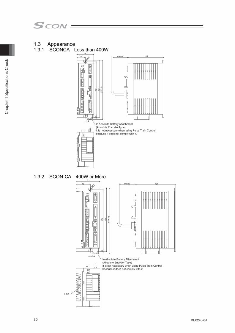
Cha
pter
1 S
peci
ficat
ions
Che
ck
30
1.3 Appearance 1.3.1 SCONCA Less than 400W
58 121
184
5 19
4
4.2
In Absolute Battery Attachment(Absolute Encoder Type)It is not necessary when using Pulse Train Control because it does not comply with it.
(200
.5)
φ4.2 29 min80
1.3.2 SCON-CA 400W or More
In Absolute Battery Attachment(Absolute Encoder Type)It is not necessary when using Pulse Train Control because it does not comply with it.
Fan
72 121 min80 43
184
5
194
(200
.5)
φ4.2
4.2
ME0243-8J
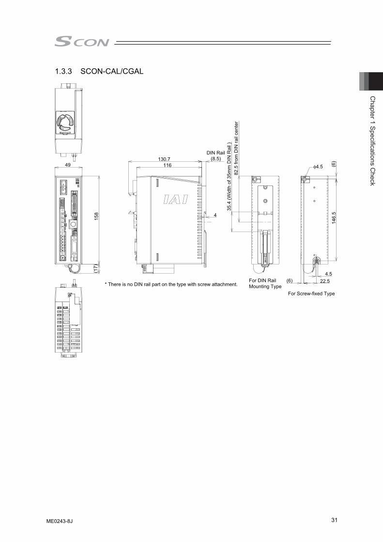
Chapter 1 Specifications C
heck
31
1.3.3 SCON-CAL/CGAL
DIN Rail(8.5)
35.4
(Wid
th o
f 35m
m D
IN R
ail )
* There is no DIN rail part on the type with screw attachment.For DIN Rail Mounting Type
82.5
from
DIN
rail
cent
er
130.7116
4
49
158
(17)
For Screw-fixed Type
(6)4.5
φ4.5
22.5
(6)
146.
5
ME0243-8J
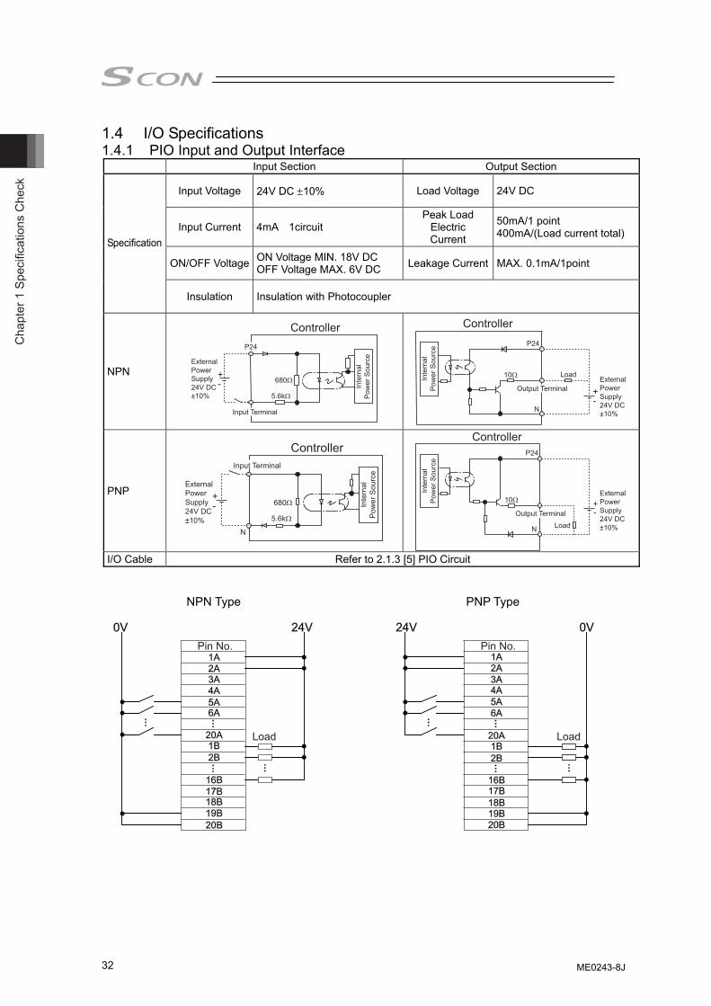
Cha
pter
1 S
peci
ficat
ions
Che
ck
32
1.4 I/O Specifications 1.4.1 PIO Input and Output Interface Input Section Output Section
Input Voltage 24V DC ±10% Load Voltage 24V DC
Input Current 4mA 1circuit Peak Load
Electric Current
50mA/1 point 400mA/(Load current total)
ON/OFF Voltage ON Voltage MIN. 18V DC OFF Voltage MAX. 6V DC Leakage Current MAX. 0.1mA/1point
Specification
Insulation Insulation with Photocoupler
NPN
P24
680Ω
5.6kΩ
Controller
Inte
rnal
Pow
er S
ourc
e
Input Terminal
ExternalPowerSupply24V DC±10%
10Ω
N
P24
Controller
Inte
rnal
Pow
er S
ourc
e
Output TerminalExternalPowerSupply24V DC±10%
Load
PNP 680Ω
5.6kΩ
N
Controller
Inte
rnal
Pow
er S
ourc
e
Input Terminal
ExternalPowerSupply24V DC±10%
ControllerP24
10Ω
N
Inte
rnal
Pow
er S
ourc
e
Output Terminal
ExternalPowerSupply24V DC±10%Load
I/O Cable Refer to 2.1.3 [5] PIO Circuit
NPN Type PNP Type
Load Load
Pin No. Pin No.
ME0243-8J
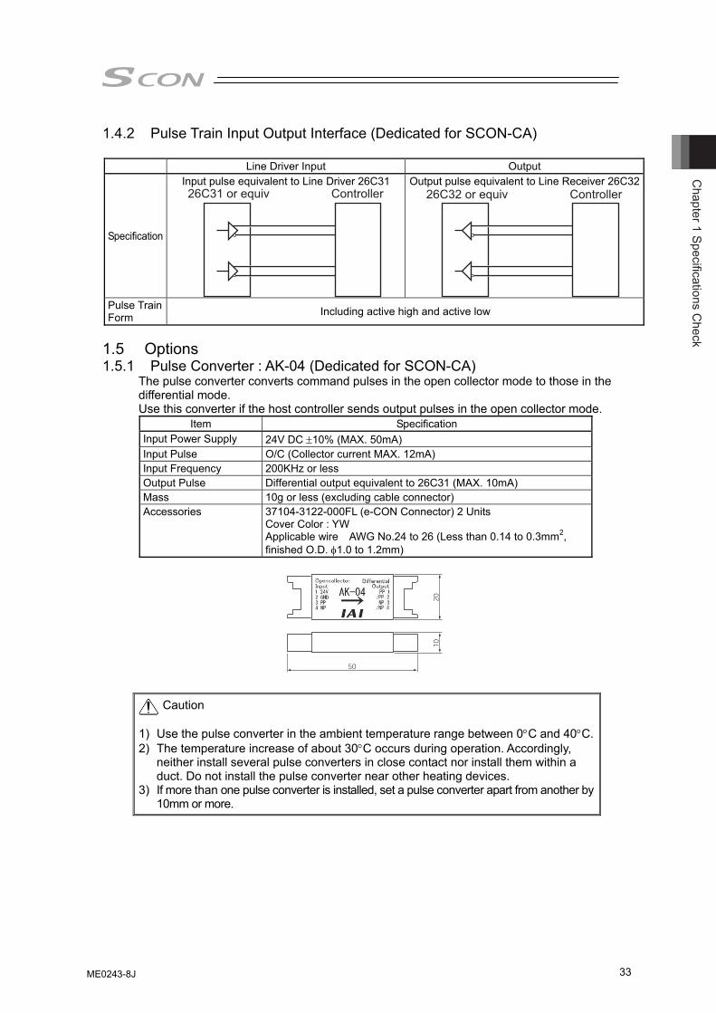
Chapter 1 Specifications C
heck
33
1.4.2 Pulse Train Input Output Interface (Dedicated for SCON-CA) Line Driver Input Output
Specification
Input pulse equivalent to Line Driver 26C31 26C31 or equiv Controller
Output pulse equivalent to Line Receiver 26C3226C32 or equiv Controller
Pulse Train Form Including active high and active low
1.5 Options 1.5.1 Pulse Converter : AK-04 (Dedicated for SCON-CA)
The pulse converter converts command pulses in the open collector mode to those in the differential mode. Use this converter if the host controller sends output pulses in the open collector mode.
Item Specification Input Power Supply 24V DC ±10% (MAX. 50mA) Input Pulse O/C (Collector current MAX. 12mA) Input Frequency 200KHz or less Output Pulse Differential output equivalent to 26C31 (MAX. 10mA) Mass 10g or less (excluding cable connector) Accessories 37104-3122-000FL (e-CON Connector) 2 Units
Cover Color : YW Applicable wire AWG No.24 to 26 (Less than 0.14 to 0.3mm2, finished O.D. φ1.0 to 1.2mm)
Caution 1) Use the pulse converter in the ambient temperature range between 0°C and 40°C.2) The temperature increase of about 30°C occurs during operation. Accordingly,
neither install several pulse converters in close contact nor install them within a duct. Do not install the pulse converter near other heating devices.
3) If more than one pulse converter is installed, set a pulse converter apart from another by 10mm or more.
ME0243-8J
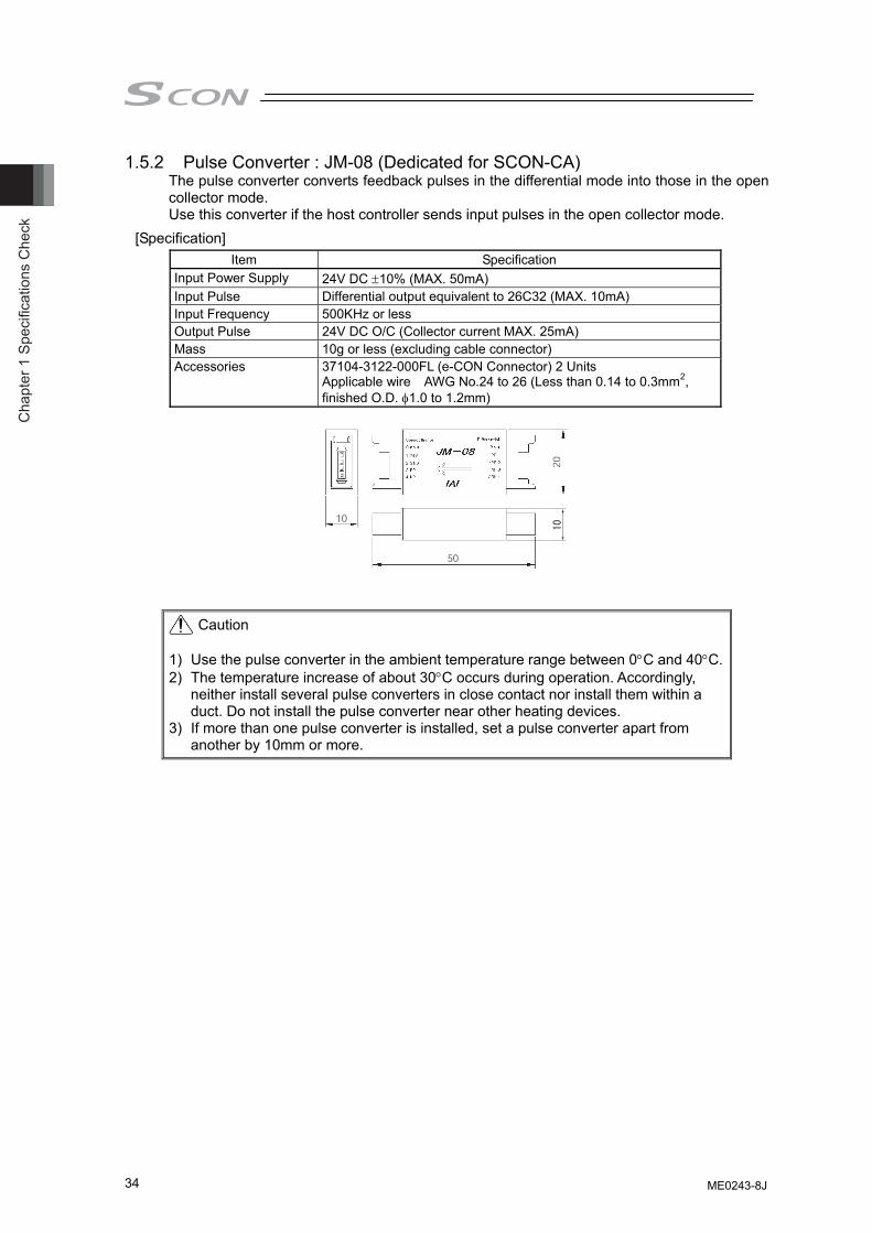
Cha
pter
1 S
peci
ficat
ions
Che
ck
34
1.5.2 Pulse Converter : JM-08 (Dedicated for SCON-CA) The pulse converter converts feedback pulses in the differential mode into those in the open collector mode. Use this converter if the host controller sends input pulses in the open collector mode.
[Specification] Item Specification
Input Power Supply 24V DC ±10% (MAX. 50mA) Input Pulse Differential output equivalent to 26C32 (MAX. 10mA) Input Frequency 500KHz or less Output Pulse 24V DC O/C (Collector current MAX. 25mA) Mass 10g or less (excluding cable connector) Accessories 37104-3122-000FL (e-CON Connector) 2 Units
Applicable wire AWG No.24 to 26 (Less than 0.14 to 0.3mm2, finished O.D. φ1.0 to 1.2mm)
Caution 1) Use the pulse converter in the ambient temperature range between 0°C and 40°C.2) The temperature increase of about 30°C occurs during operation. Accordingly,
neither install several pulse converters in close contact nor install them within a duct. Do not install the pulse converter near other heating devices.
3) If more than one pulse converter is installed, set a pulse converter apart from another by 10mm or more.
External Dimensions
ME0243-8J
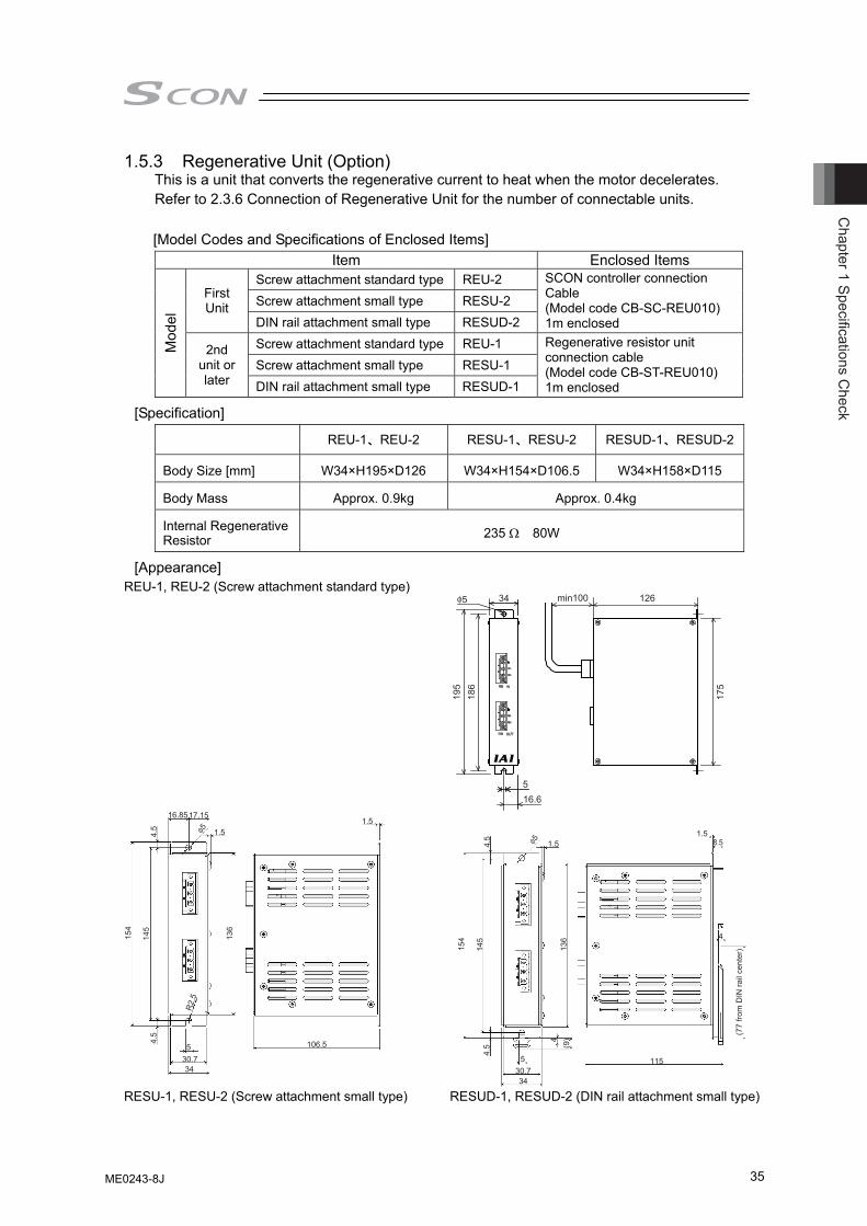
Chapter 1 Specifications C
heck
35
1.5.3 Regenerative Unit (Option) This is a unit that converts the regenerative current to heat when the motor decelerates. Refer to 2.3.6 Connection of Regenerative Unit for the number of connectable units. [Model Codes and Specifications of Enclosed Items]
Item Enclosed Items Screw attachment standard type REU-2 Screw attachment small type RESU-2 First
Unit DIN rail attachment small type RESUD-2
SCON controller connection Cable (Model code CB-SC-REU010) 1m enclosed
Screw attachment standard type REU-1 Screw attachment small type RESU-1
Mod
el
2nd unit or later DIN rail attachment small type RESUD-1
Regenerative resistor unit connection cable (Model code CB-ST-REU010) 1m enclosed
[Specification]
REU-1、REU-2 RESU-1、RESU-2 RESUD-1、RESUD-2
Body Size [mm] W34×H195×D126 W34×H154×D106.5 W34×H158×D115
Body Mass Approx. 0.9kg Approx. 0.4kg
Internal Regenerative Resistor 235 Ω 80W
[Appearance] REU-1, REU-2 (Screw attachment standard type)
16.8517.15
1.5φ54.5
145
154
136
R2.
5
4.5
106.5530.734
1.5
1.5φ54.5
145
154
136
4.5
115530.734
1.5
4
4
8.5
(77
from
DIN
rail
cent
er)
(9)
RESU-1, RESU-2 (Screw attachment small type) RESUD-1, RESUD-2 (DIN rail attachment small type)
ME0243-8J
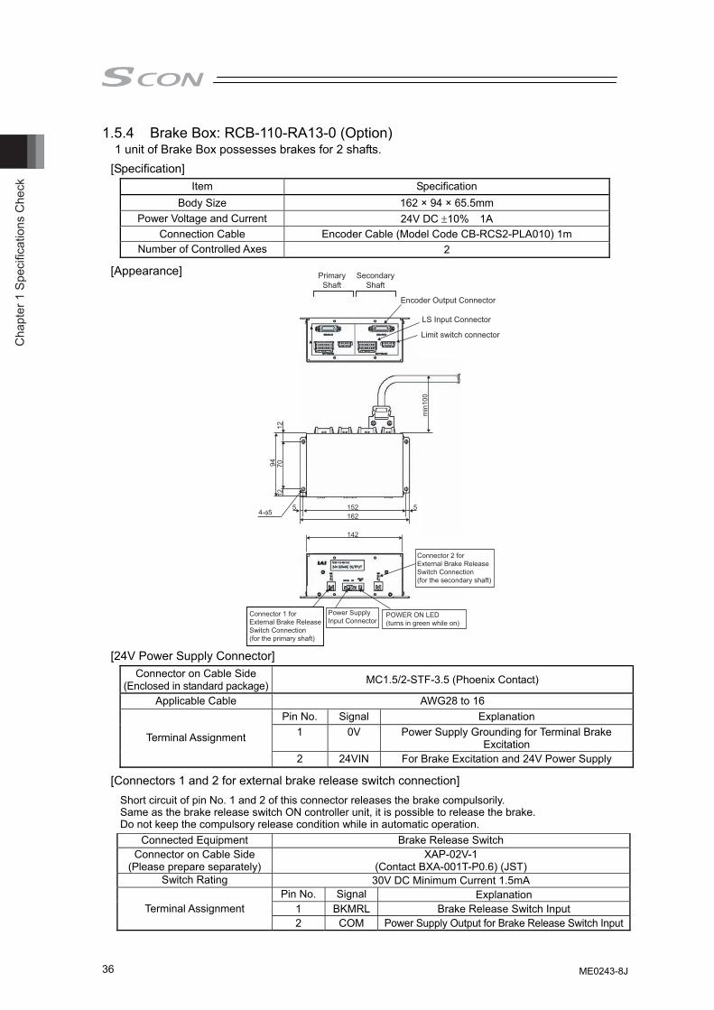
Cha
pter
1 S
peci
ficat
ions
Che
ck
36
1.5.4 Brake Box: RCB-110-RA13-0 (Option) 1 unit of Brake Box possesses brakes for 2 shafts.
[Specification] Item Specification
Body Size 162 × 94 × 65.5mm Power Voltage and Current 24V DC ±10% 1A
Connection Cable Encoder Cable (Model Code CB-RCS2-PLA010) 1m Number of Controlled Axes 2
[Appearance]
[24V Power Supply Connector] Connector on Cable Side
(Enclosed in standard package) MC1.5/2-STF-3.5 (Phoenix Contact)
Applicable Cable AWG28 to 16 Pin No. Signal Explanation
1 0V Power Supply Grounding for Terminal Brake Excitation Terminal Assignment
2 24VIN For Brake Excitation and 24V Power Supply
[Connectors 1 and 2 for external brake release switch connection] Short circuit of pin No. 1 and 2 of this connector releases the brake compulsorily. Same as the brake release switch ON controller unit, it is possible to release the brake. Do not keep the compulsory release condition while in automatic operation.
Connected Equipment Brake Release Switch Connector on Cable Side
(Please prepare separately) XAP-02V-1
(Contact BXA-001T-P0.6) (JST) Switch Rating 30V DC Minimum Current 1.5mA
Pin No. Signal Explanation 1 BKMRL Brake Release Switch Input Terminal Assignment 2 COM Power Supply Output for Brake Release Switch Input
min
100
94 7012
12
55 251261
241
-4 φ5
Encoder Output Connector
Limit switch connector
LS Input Connector
Connector 2 forExternal Brake ReleaseSwitch Connection(for the secondary shaft)
Connector 1 forExternal Brake ReleaseSwitch Connection(for the primary shaft)
Power SupplyInput Connector
POWER ON LED(turns in green while on)
PrimaryShaft
SecondaryShaft
ME0243-8J
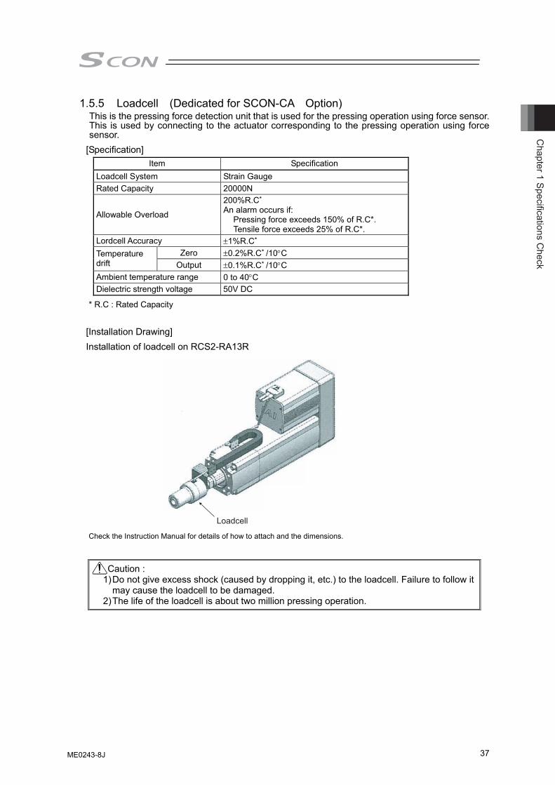
Chapter 1 Specifications C
heck
37
1.5.5 Loadcell (Dedicated for SCON-CA Option) This is the pressing force detection unit that is used for the pressing operation using force sensor. This is used by connecting to the actuator corresponding to the pressing operation using force sensor.
[Specification] Item Specification
Loadcell System Strain Gauge Rated Capacity 20000N
Allowable Overload
200%R.C*
An alarm occurs if: Pressing force exceeds 150% of R.C*. Tensile force exceeds 25% of R.C*.
Lordcell Accuracy ±1%R.C* Zero ±0.2%R.C* /10°C Temperature
drift Output ±0.1%R.C* /10°C Ambient temperature range 0 to 40°C Dielectric strength voltage 50V DC
* R.C : Rated Capacity
[Installation Drawing] Installation of loadcell on RCS2-RA13R
Check the Instruction Manual for details of how to attach and the dimensions.
Caution : 1) Do not give excess shock (caused by dropping it, etc.) to the loadcell. Failure to follow it
may cause the loadcell to be damaged. 2) The life of the loadcell is about two million pressing operation.
Loadcell
ME0243-8J
Cha
pter
1 S
peci
ficat
ions
Che
ck
38
1.6 Installation and Storage Environment
This product is capable for use in the environment of pollution degree 2*1 or equivalent. *1 Pollution Degree 2 : Environment that may cause non-conductive pollution or transient
conductive pollution by frost (IEC60664-1) [1] Installation Environment Do not use this product in the following environment. • Location where the surrounding air temperature exceeds the range of 0 to 40°C • Location where condensation occurs due to abrupt temperature changes • Location where relative humidity exceeds 85%RH • Location exposed to corrosive gases or combustible gases • Location exposed to significant amount of dust, salt or iron powder • Location subject to direct vibration or impact • Location exposed to direct sunlight • Location where the product may come in contact with water, oil or chemical droplets • Environment that blocks the air vent [Refer to 1.7 Noise Elimination and Mounting Method]
When using the product in any of the locations specified below, provide a sufficient shield. • Location subject to electrostatic noise • Location where high electrical or magnetic field is present • Location with the mains or power lines passing nearby
[2] Storage Environment • Storage environment follows the installation environment. Especially in a long-term storage,
consider to avoid condensation of surrounding air. Unless specially specified, moisture absorbency protection is not included in the package when the machine is delivered. In the case that the machine is to be stored in an environment where dew condensation is anticipated, take the condensation preventive measures from outside of the entire package, or directly after opening the package.
ME0243-8J
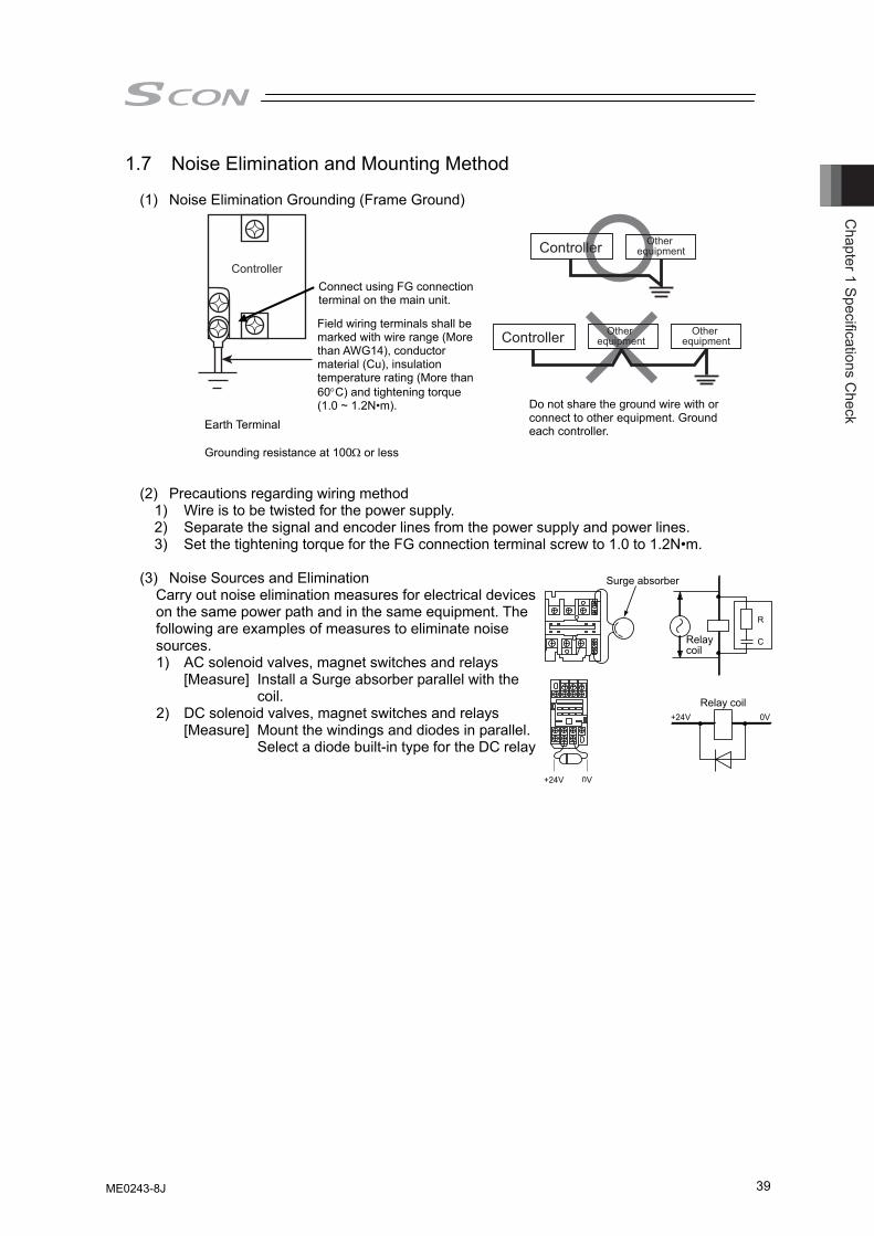
Chapter 1 Specifications C
heck
39
1.7 Noise Elimination and Mounting Method
(1) Noise Elimination Grounding (Frame Ground)
(2) Precautions regarding wiring method
1) Wire is to be twisted for the power supply. 2) Separate the signal and encoder lines from the power supply and power lines. 3) Set the tightening torque for the FG connection terminal screw to 1.0 to 1.2N•m.
(3) Noise Sources and Elimination Carry out noise elimination measures for electrical devices on the same power path and in the same equipment. The following are examples of measures to eliminate noise sources. 1) AC solenoid valves, magnet switches and relays
[Measure] Install a Surge absorber parallel with the coil.
2) DC solenoid valves, magnet switches and relays [Measure] Mount the windings and diodes in parallel.
Select a diode built-in type for the DC relay
Controller
Do not share the ground wire with or connect to other equipment. Ground each controller. Earth Terminal
Grounding resistance at 100Ω or less
Field wiring terminals shall be marked with wire range (More than AWG14), conductor material (Cu), insulation temperature rating (More than 60°C) and tightening torque (1.0 ~ 1.2N•m).
Connect using FG connectionterminal on the main unit.
Controller Other equipment
Controller Other equipment
Other equipment
0V
R
C
+24V
0V +24V
Relay coil
Relay coil
Surge absorber
ME0243-8J
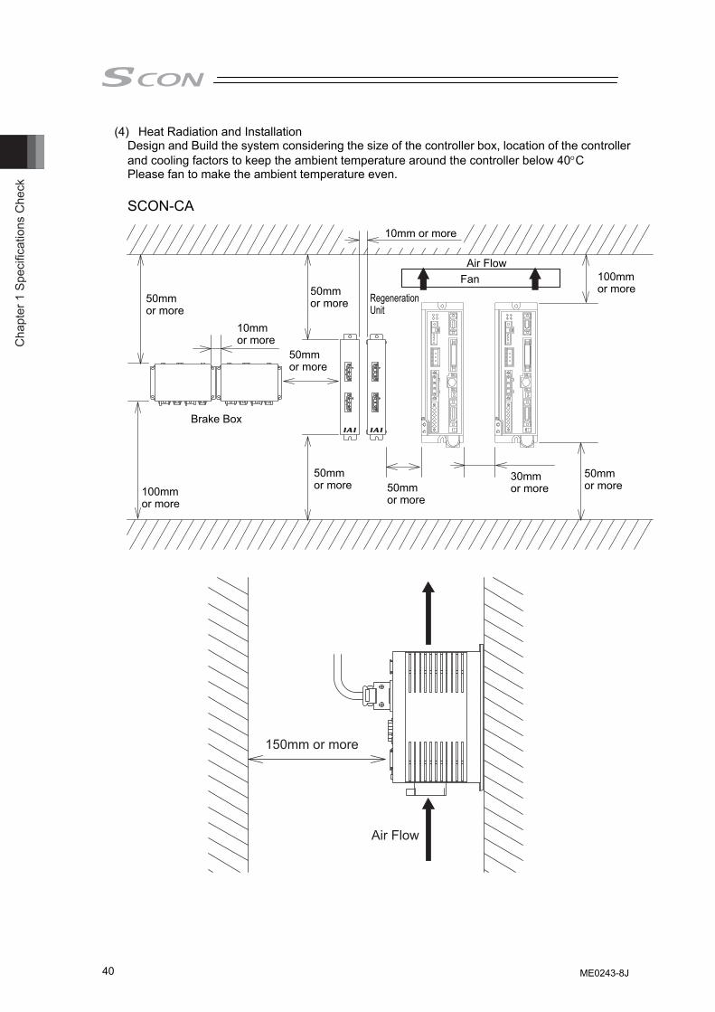
Cha
pter
1 S
peci
ficat
ions
Che
ck
40
(4) Heat Radiation and Installation Design and Build the system considering the size of the controller box, location of the controller and cooling factors to keep the ambient temperature around the controller below 40°C Please fan to make the ambient temperature even. SCON-CA
150mm or more
Air Flow
Brake Box
Regeneration Unit
Air FlowFan
10mmor more
100mmor more
50mmor more
50mmor more
100mmor more
30mmor more
50mmor more
50mmor more
50mmor more
50mmor more
10mm or more
ME0243-8J
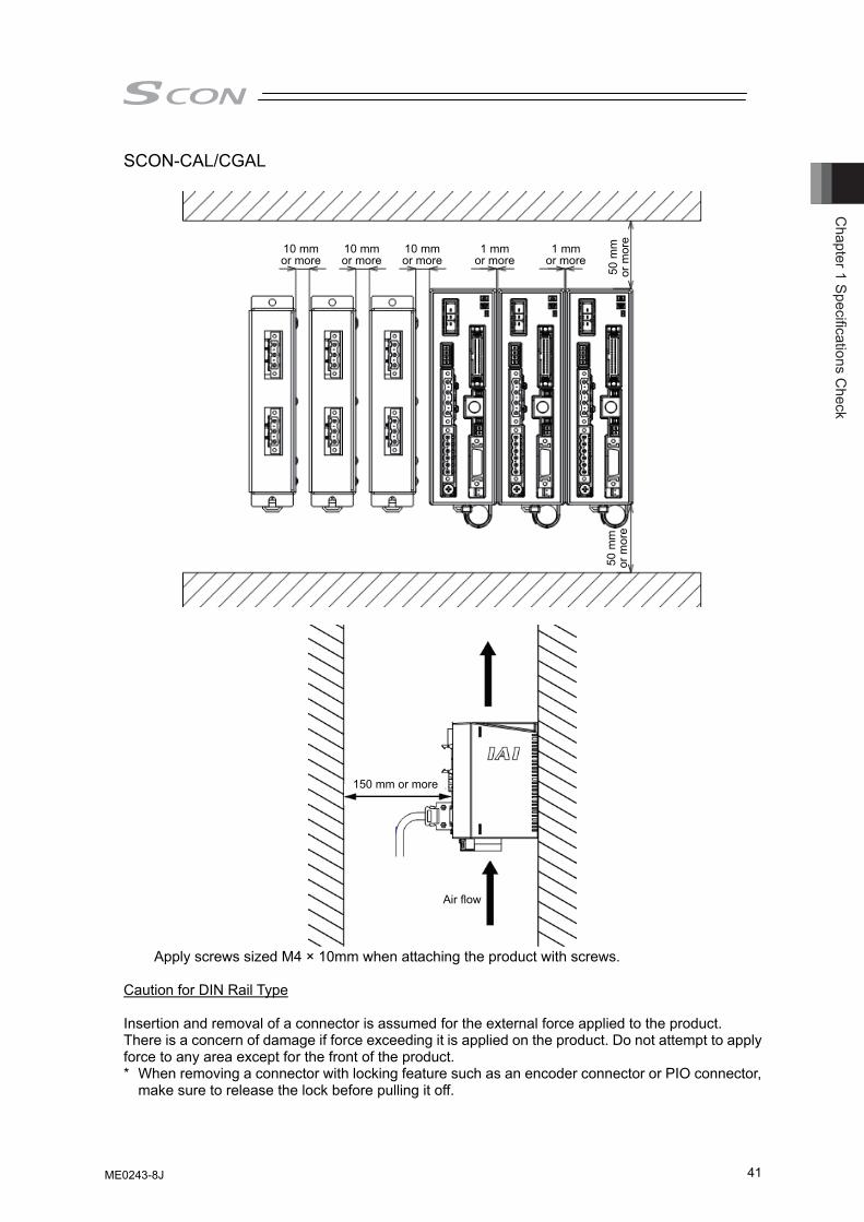
Chapter 1 Specifications C
heck
41
SCON-CAL/CGAL
10 mmor more
10 mmor more
10 mmor more
1 mmor more
1 mmor more
50 m
mor
mor
e50
mm
or m
ore
150 mm or more
Air flow
Apply screws sized M4 × 10mm when attaching the product with screws.
Caution for DIN Rail Type Insertion and removal of a connector is assumed for the external force applied to the product. There is a concern of damage if force exceeding it is applied on the product. Do not attempt to apply force to any area except for the front of the product. * When removing a connector with locking feature such as an encoder connector or PIO connector,
make sure to release the lock before pulling it off.
ME0243-8J

Cha
pter
1 S
peci
ficat
ions
Che
ck
42
ME0243-8J
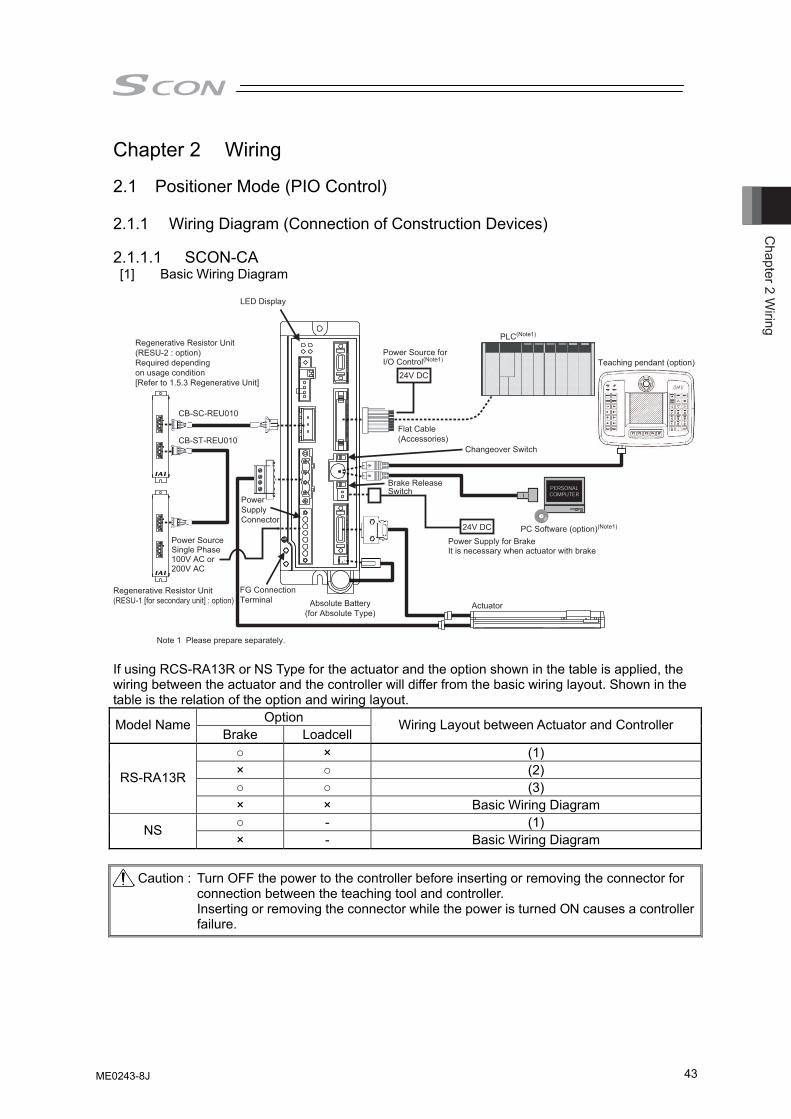
Chapter 2 W
iring
43
Chapter 2 Wiring 2.1 Positioner Mode (PIO Control) 2.1.1 Wiring Diagram (Connection of Construction Devices) 2.1.1.1 SCON-CA [1] Basic Wiring Diagram
Power Supply for BrakeIt is necessary when actuator with brake
Note 1 Please prepare separately.
Absolute Battery(for Absolute Type)
PC Software (option)(Note1)
Actuator
Teaching pendant (option)
PLC(Note1)
Regenerative Resistor Unit(RESU-1 [for secondary unit] : option)
Regenerative Resistor Unit(RESU-2 : option)Required dependingon usage condition[Refer to 1.5.3 Regenerative Unit]
Power SupplyConnector
Flat Cable(Accessories)
CB-SC-REU010
CB-ST-REU010
FG ConnectionTerminal
24V DC
24V DCPower Source Single Phase 100V AC or 200V AC
Power Source for I/O Control(Note1)
LED Display
Changeover Switch
Brake Release Switch
If using RCS-RA13R or NS Type for the actuator and the option shown in the table is applied, the wiring between the actuator and the controller will differ from the basic wiring layout. Shown in the table is the relation of the option and wiring layout.
Option Model Name Brake Loadcell
Wiring Layout between Actuator and Controller
○ × (1) × ○ (2) ○ ○ (3)
RS-RA13R
× × Basic Wiring Diagram ○ - (1) NS × - Basic Wiring Diagram
Caution : Turn OFF the power to the controller before inserting or removing the connector for
connection between the teaching tool and controller. Inserting or removing the connector while the power is turned ON causes a controller failure.
ME0243-8J
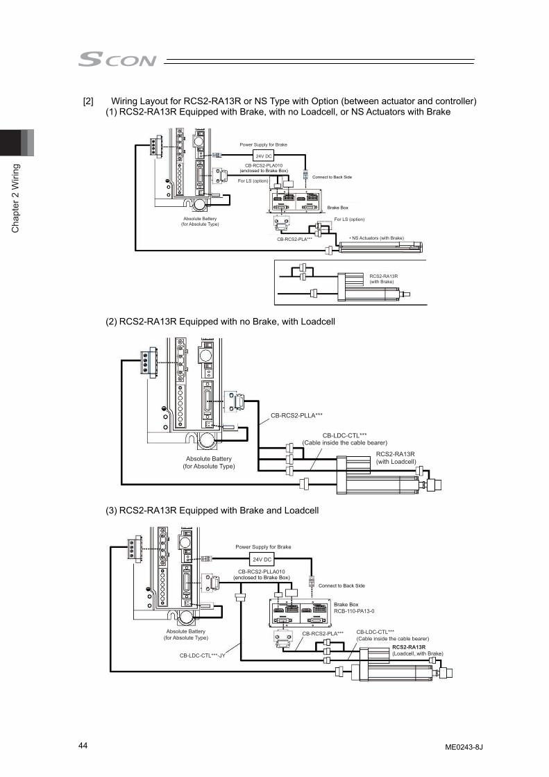
Cha
pter
2 W
iring
44
[2] Wiring Layout for RCS2-RA13R or NS Type with Option (between actuator and controller) (1) RCS2-RA13R Equipped with Brake, with no Loadcell, or NS Actuators with Brake
Power Supply for Brake
24V DC
For LS (option)
• NS Actuators (with Brake)
For LS (option)Absolute Battery(for Absolute Type)
(enclosed to Brake Box)
Brake Box
RCS2-RA13R(with Brake)
CB-RCS2-PLA***
CB-RCS2-PLA010
Connect to Back Side
(2) RCS2-RA13R Equipped with no Brake, with Loadcell
Absolute Battery(for Absolute Type)
CB-RCS2-PLLA***
CB-LDC-CTL***(Cable inside the cable bearer)
RCS2-RA13R(with Loadcell)
(3) RCS2-RA13R Equipped with Brake and Loadcell
Power Supply for Brake
Absolute Battery(for Absolute Type)
Brake Box
RCS2-RA13R(Loadcell, with Brake)
Connect to Back Side
24V DC
(enclosed to Brake Box)
CB-RCS2-PLA***
CB-LDC-CTL***-JY
CB-LDC-CTL***
RCB-110-PA13-0
CB-RCS2-PLLA010
(Cable inside the cable bearer)
ME0243-8J
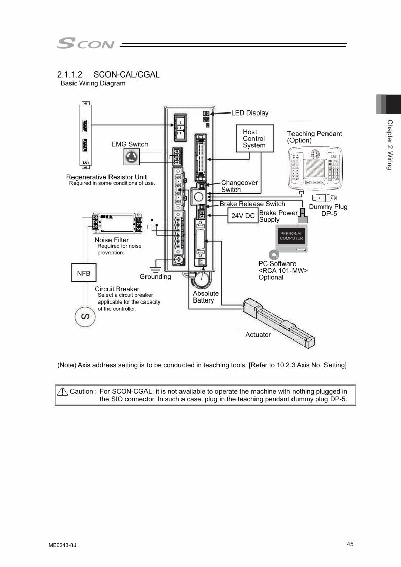
Chapter 2 W
iring
45
2.1.1.2 SCON-CAL/CGAL Basic Wiring Diagram
EMG Switch
Regenerative Resistor Unit Required in some conditions of use.
Noise Filter Required for noise prevention.
Host Control System
Circuit Breaker Select a circuit breaker applicable for the capacity of the controller.
Actuator
PC Software<RCA 101-MW>Optional
PC
24V DC
NFB Grounding
Absolute Battery
Brake Power Supply
Dummy Plug DP-5
Teaching Pendant (Option)
LED Display
Changeover Switch
Brake Release Switch
(Note) Axis address setting is to be conducted in teaching tools. [Refer to 10.2.3 Axis No. Setting] Caution : For SCON-CGAL, it is not available to operate the machine with nothing plugged in
the SIO connector. In such a case, plug in the teaching pendant dummy plug DP-5.
ME0243-8J
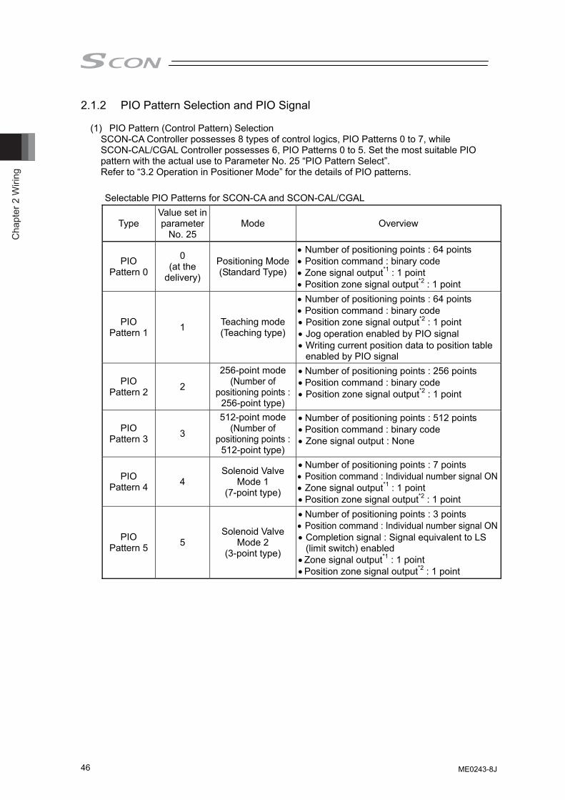
Cha
pter
2 W
iring
46
2.1.2 PIO Pattern Selection and PIO Signal (1) PIO Pattern (Control Pattern) Selection
SCON-CA Controller possesses 8 types of control logics, PIO Patterns 0 to 7, while SCON-CAL/CGAL Controller possesses 6, PIO Patterns 0 to 5. Set the most suitable PIO pattern with the actual use to Parameter No. 25 “PIO Pattern Select”. Refer to “3.2 Operation in Positioner Mode” for the details of PIO patterns. Selectable PIO Patterns for SCON-CA and SCON-CAL/CGAL
Type Value set in parameter
No. 25 Mode Overview
PIO Pattern 0
0 (at the
delivery)
Positioning Mode(Standard Type)
• Number of positioning points : 64 points • Position command : binary code • Zone signal output*1 : 1 point • Position zone signal output*2 : 1 point
PIO Pattern 1 1 Teaching mode
(Teaching type)
• Number of positioning points : 64 points • Position command : binary code • Position zone signal output*2 : 1 point • Jog operation enabled by PIO signal • Writing current position data to position table
enabled by PIO signal
PIO Pattern 2 2
256-point mode (Number of
positioning points :256-point type)
• Number of positioning points : 256 points • Position command : binary code • Position zone signal output*2 : 1 point
PIO Pattern 3 3
512-point mode (Number of
positioning points :512-point type)
• Number of positioning points : 512 points • Position command : binary code • Zone signal output : None
PIO Pattern 4 4
Solenoid Valve Mode 1
(7-point type)
• Number of positioning points : 7 points • Position command : Individual number signal ON• Zone signal output*1 : 1 point • Position zone signal output*2 : 1 point
PIO Pattern 5 5
Solenoid Valve Mode 2
(3-point type)
• Number of positioning points : 3 points • Position command : Individual number signal ON• Completion signal : Signal equivalent to LS
(limit switch) enabled • Zone signal output*1 : 1 point • Position zone signal output*2 : 1 point
ME0243-8J
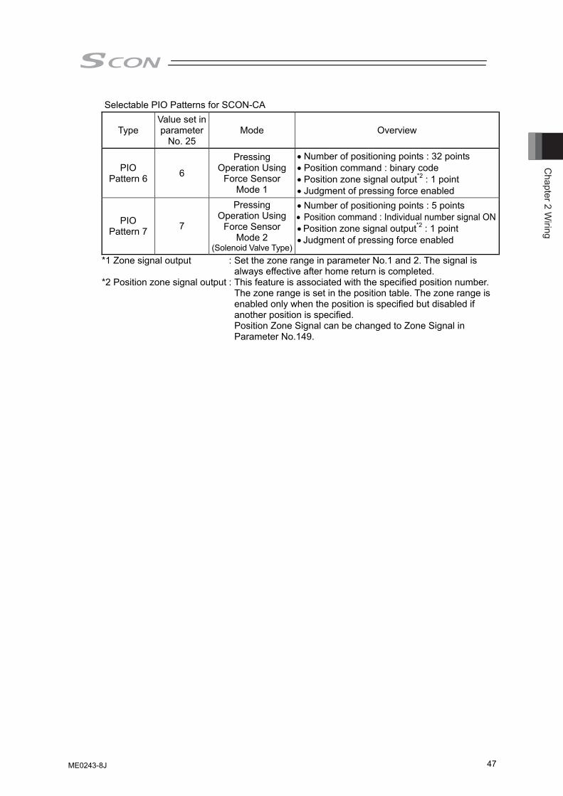
Chapter 2 W
iring
47
Selectable PIO Patterns for SCON-CA
Type Value set in parameter
No. 25 Mode Overview
PIO Pattern 6 6
Pressing Operation Using
Force Sensor Mode 1
• Number of positioning points : 32 points • Position command : binary code • Position zone signal output*2 : 1 point • Judgment of pressing force enabled
PIO Pattern 7 7
Pressing Operation Using
Force Sensor Mode 2
(Solenoid Valve Type)
• Number of positioning points : 5 points • Position command : Individual number signal ON• Position zone signal output*2 : 1 point • Judgment of pressing force enabled
*1 Zone signal output : Set the zone range in parameter No.1 and 2. The signal is always effective after home return is completed.
*2 Position zone signal output : This feature is associated with the specified position number. The zone range is set in the position table. The zone range is enabled only when the position is specified but disabled if another position is specified. Position Zone Signal can be changed to Zone Signal in Parameter No.149.
ME0243-8J
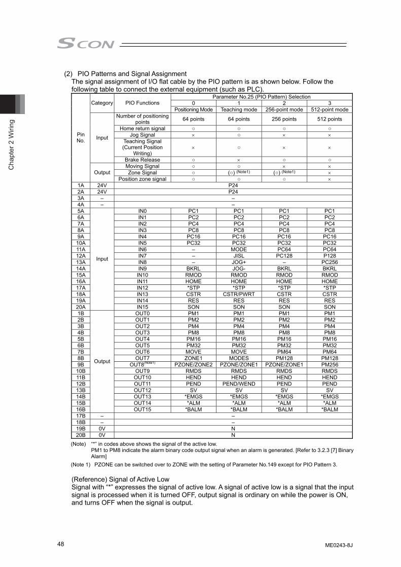
Cha
pter
2 W
iring
48
(2) PIO Patterns and Signal Assignment The signal assignment of I/O flat cable by the PIO pattern is as shown below. Follow the following table to connect the external equipment (such as PLC).
Parameter No.25 (PIO Pattern) Selection 0 1 2 3 Category PIO Functions
Positioning Mode Teaching mode 256-point mode 512-point modeNumber of positioning
points 64 points 64 points 256 points 512 points
Home return signal ○ ○ ○ ○ Jog Signal × ○ × ×
Teaching Signal (Current Position
Writing) × ○ × ×
Input
Brake Release ○ × ○ ○ Moving Signal ○ ○ × × Zone Signal ○ (○) (Note1) (○) (Note1) ×
Pin No.
Output Position zone signal ○ ○ ○ ×
1A 24V P24 2A 24V P24 3A – – 4A – – 5A IN0 PC1 PC1 PC1 PC1 6A IN1 PC2 PC2 PC2 PC2 7A IN2 PC4 PC4 PC4 PC4 8A IN3 PC8 PC8 PC8 PC8 9A IN4 PC16 PC16 PC16 PC16
10A IN5 PC32 PC32 PC32 PC32 11A IN6 – MODE PC64 PC64 12A IN7 – JISL PC128 P128 13A IN8 – JOG+ – PC256 14A IN9 BKRL JOG- BKRL BKRL 15A IN10 RMOD RMOD RMOD RMOD 16A IN11 HOME HOME HOME HOME 17A IN12 *STP *STP *STP *STP 18A IN13 CSTR CSTR/PWRT CSTR CSTR 19A IN14 RES RES RES RES 20A
Input
IN15 SON SON SON SON 1B OUT0 PM1 PM1 PM1 PM1 2B OUT1 PM2 PM2 PM2 PM2 3B OUT2 PM4 PM4 PM4 PM4 4B OUT3 PM8 PM8 PM8 PM8 5B OUT4 PM16 PM16 PM16 PM16 6B OUT5 PM32 PM32 PM32 PM32 7B OUT6 MOVE MOVE PM64 PM64 8B OUT7 ZONE1 MODES PM128 PM128 9B OUT8(Note1) PZONE/ZONE2 PZONE/ZONE1 PZONE/ZONE1 PM256
10B OUT9 RMDS RMDS RMDS RMDS 11B OUT10 HEND HEND HEND HEND 12B OUT11 PEND PEND/WEND PEND PEND 13B OUT12 SV SV SV SV 14B OUT13 *EMGS *EMGS *EMGS *EMGS 15B OUT14 *ALM *ALM *ALM *ALM 16B
Output
OUT15 *BALM *BALM *BALM *BALM 17B – – 18B – – 19B 0V N 20B 0V N
(Note) “*” in codes above shows the signal of the active low. PM1 to PM8 indicate the alarm binary code output signal when an alarm is generated. [Refer to 3.2.3 [7] Binary Alarm]
(Note 1) PZONE can be switched over to ZONE with the setting of Parameter No.149 except for PIO Pattern 3. (Reference) Signal of Active Low Signal with “*” expresses the signal of active low. A signal of active low is a signal that the input signal is processed when it is turned OFF, output signal is ordinary on while the power is ON, and turns OFF when the signal is output.
ME0243-8J
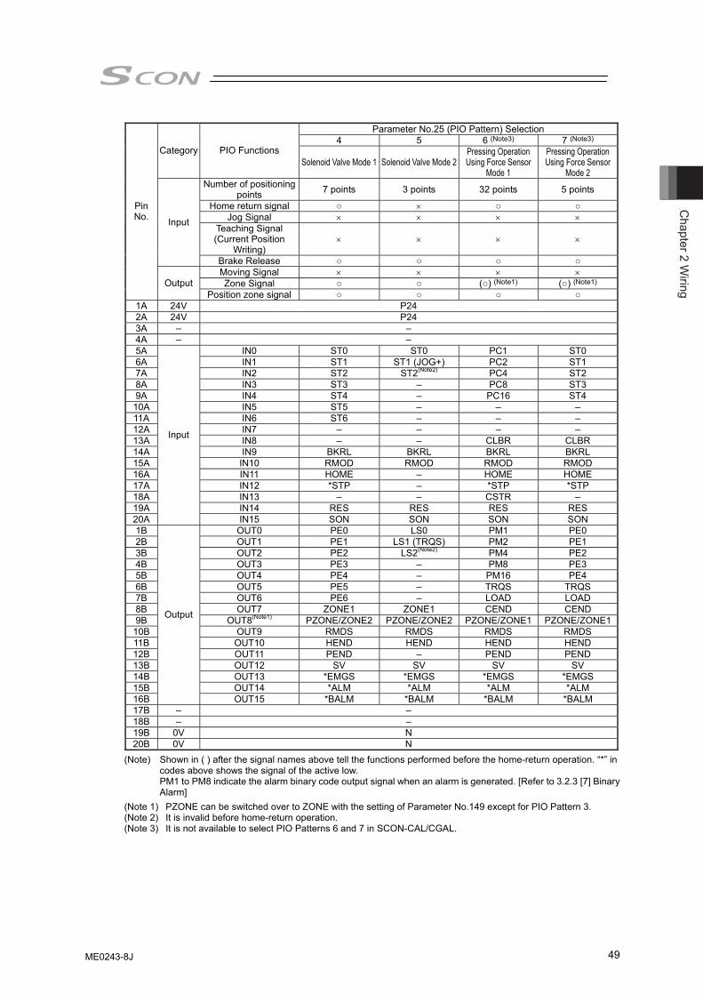
Chapter 2 W
iring
49
Parameter No.25 (PIO Pattern) Selection 4 5 6 (Note3) 7 (Note3)
Category PIO Functions Solenoid Valve Mode 1 Solenoid Valve Mode 2
Pressing Operation Using Force Sensor
Mode 1
Pressing Operation Using Force Sensor
Mode 2 Number of positioning
points 7 points 3 points 32 points 5 points
Home return signal ○ × ○ ○ Jog Signal × × × ×
Teaching Signal (Current Position
Writing) × × × ×
Input
Brake Release ○ ○ ○ ○ Moving Signal × × × × Zone Signal ○ ○ (○) (Note1) (○) (Note1)
Pin No.
Output Position zone signal ○ ○ ○ ○
1A 24V P24 2A 24V P24 3A – – 4A – – 5A IN0 ST0 ST0 PC1 ST0 6A IN1 ST1 ST1 (JOG+) PC2 ST1 7A IN2 ST2 ST2(Note2) PC4 ST2 8A IN3 ST3 – PC8 ST3 9A IN4 ST4 – PC16 ST4
10A IN5 ST5 – – – 11A IN6 ST6 – – – 12A IN7 – – – – 13A IN8 – – CLBR CLBR 14A IN9 BKRL BKRL BKRL BKRL 15A IN10 RMOD RMOD RMOD RMOD 16A IN11 HOME – HOME HOME 17A IN12 *STP – *STP *STP 18A IN13 – – CSTR – 19A IN14 RES RES RES RES 20A
Input
IN15 SON SON SON SON 1B OUT0 PE0 LS0 PM1 PE0 2B OUT1 PE1 LS1 (TRQS) PM2 PE1 3B OUT2 PE2 LS2(Note2) PM4 PE2 4B OUT3 PE3 – PM8 PE3 5B OUT4 PE4 – PM16 PE4 6B OUT5 PE5 – TRQS TRQS 7B OUT6 PE6 – LOAD LOAD 8B OUT7 ZONE1 ZONE1 CEND CEND 9B OUT8(Note1) PZONE/ZONE2 PZONE/ZONE2 PZONE/ZONE1 PZONE/ZONE1
10B OUT9 RMDS RMDS RMDS RMDS 11B OUT10 HEND HEND HEND HEND 12B OUT11 PEND – PEND PEND 13B OUT12 SV SV SV SV 14B OUT13 *EMGS *EMGS *EMGS *EMGS 15B OUT14 *ALM *ALM *ALM *ALM 16B
Output
OUT15 *BALM *BALM *BALM *BALM 17B – – 18B – – 19B 0V N 20B 0V N
(Note) Shown in ( ) after the signal names above tell the functions performed before the home-return operation. “*” in codes above shows the signal of the active low. PM1 to PM8 indicate the alarm binary code output signal when an alarm is generated. [Refer to 3.2.3 [7] Binary Alarm]
(Note 1) PZONE can be switched over to ZONE with the setting of Parameter No.149 except for PIO Pattern 3. (Note 2) It is invalid before home-return operation. (Note 3) It is not available to select PIO Patterns 6 and 7 in SCON-CAL/CGAL.
ME0243-8J
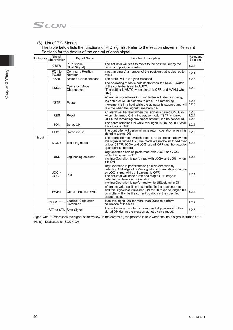
Cha
pter
2 W
iring
50
(3) List of PIO Signals The table below lists the functions of PIO signals. Refer to the section shown in Relevant Sections for the details of the control of each signal.
Category Signal Abbreviation Signal Name Function Description Relevant
Sections
CSTR PTP Strobe (Start Signal)
The actuator will start to move to the position set by the command position number. 3.2.4
PC1 to PC256
Command Position Number
Input (in binary) a number of the position that is desired to move. 3.2.4
BKRL Brake Forcible Release The brake will forcibly be released. 3.2.3
RMOD Operation Mode Changeover
The operating mode is selectable when the MODE switch of the controller is set to AUTO. (The setting is AUTO when signal is OFF, and MANU when ON.)
3.2.3
*STP Pause
When this signal turns OFF while the actuator is moving, the actuator will decelerate to stop. The remaining movement is in a hold while the actuator is stopped and will resume when the signal turns back ON.
3.2.4 3.2.5
RES Reset An alarm will be reset when this signal is turned ON. Also, when it is turned ON in the pause mode (*STP is turned OFF), the remaining movement amount can be cancelled.
3.2.3 3.2.4 3.2.5
SON Servo ON The servo remains ON while this signal is ON, or OFF while this signal is OFF. 3.2.3
HOME Home return The controller will perform home return operation when this signal is turned ON 3.2.3
MODE Teaching mode The operating mode will change to the teaching mode when this signal is turned ON. The mode will not be switched over unless CSTR, JOG+ and JOG- are all OFF and the actuator operation is stopped.
3.2.4
JISL Jog/inching selector Jog Operation can be performed with JOG+ and JOG- while this signal is OFF. Inching Operation is performed with JOG+ and JOG- when it is ON.
3.2.4
JOG + JOG - Jog
Jog Operation is performed to positive direction by detecting ON edge of JOG+ signal and to negative direction by JOG- signal while JISL signal is OFF. The actuator will decelerate and stop if OFF edge is detected while in each Operation. Inching Operation is performed while JISL signal is ON.
3.2.4
PWRT Current Position Write When the write position is specified in the teaching mode and this signal has remained ON for 20 msec or longer, the controller will write the current position in the specified position field.
3.2.4
CLBR (Note 1) Loadcell Calibration Command
Turn this signal ON for more than 20ms to perform calibration of loadcell. 3.2.7
Input
ST0 to ST6 Start Signal The actuator moves to the commanded position with this signal ON during the electromagnetic valve mode. 3.2.5
Signal with “*” expresses the signal of active low. In the controller, the process is held when the input signal is turned OFF. (Note) Dedicated for SCON-CA
ME0243-8J
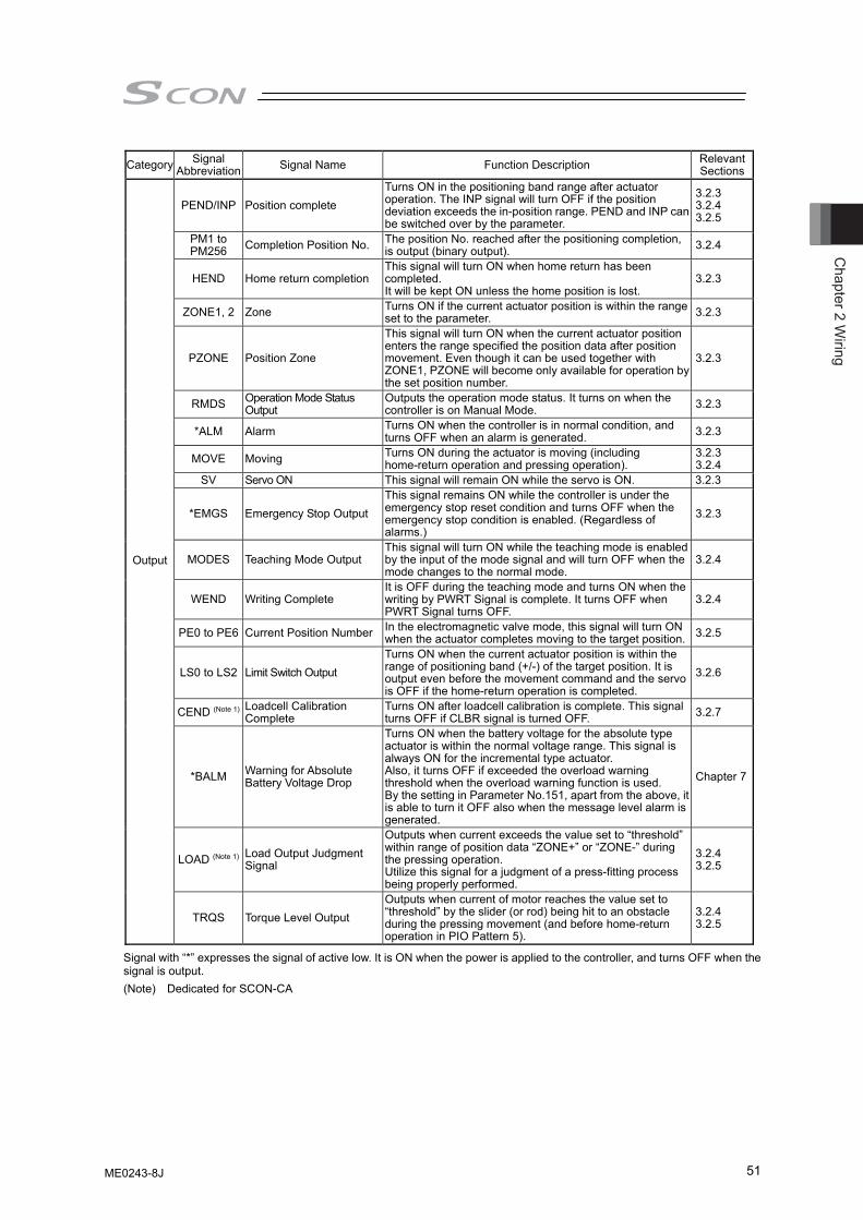
Chapter 2 W
iring
51
Category Signal Abbreviation Signal Name Function Description Relevant
Sections
PEND/INP Position complete Turns ON in the positioning band range after actuator operation. The INP signal will turn OFF if the position deviation exceeds the in-position range. PEND and INP can be switched over by the parameter.
3.2.3 3.2.4 3.2.5
PM1 to PM256 Completion Position No. The position No. reached after the positioning completion,
is output (binary output). 3.2.4
HEND Home return completion This signal will turn ON when home return has been completed. It will be kept ON unless the home position is lost.
3.2.3
ZONE1, 2 Zone Turns ON if the current actuator position is within the range set to the parameter. 3.2.3
PZONE Position Zone
This signal will turn ON when the current actuator position enters the range specified the position data after position movement. Even though it can be used together with ZONE1, PZONE will become only available for operation by the set position number.
3.2.3
RMDS Operation Mode Status Output
Outputs the operation mode status. It turns on when the controller is on Manual Mode. 3.2.3
*ALM Alarm Turns ON when the controller is in normal condition, and turns OFF when an alarm is generated. 3.2.3
MOVE Moving Turns ON during the actuator is moving (including home-return operation and pressing operation).
3.2.3 3.2.4
SV Servo ON This signal will remain ON while the servo is ON. 3.2.3
*EMGS Emergency Stop Output This signal remains ON while the controller is under the emergency stop reset condition and turns OFF when the emergency stop condition is enabled. (Regardless of alarms.)
3.2.3
MODES Teaching Mode Output This signal will turn ON while the teaching mode is enabled by the input of the mode signal and will turn OFF when the mode changes to the normal mode.
3.2.4
WEND Writing Complete It is OFF during the teaching mode and turns ON when the writing by PWRT Signal is complete. It turns OFF when PWRT Signal turns OFF.
3.2.4
PE0 to PE6 Current Position Number In the electromagnetic valve mode, this signal will turn ON when the actuator completes moving to the target position. 3.2.5
LS0 to LS2 Limit Switch Output Turns ON when the current actuator position is within the range of positioning band (+/-) of the target position. It is output even before the movement command and the servo is OFF if the home-return operation is completed.
3.2.6
CEND (Note 1) Loadcell Calibration Complete
Turns ON after loadcell calibration is complete. This signal turns OFF if CLBR signal is turned OFF. 3.2.7
*BALM Warning for Absolute Battery Voltage Drop
Turns ON when the battery voltage for the absolute type actuator is within the normal voltage range. This signal is always ON for the incremental type actuator. Also, it turns OFF if exceeded the overload warning threshold when the overload warning function is used. By the setting in Parameter No.151, apart from the above, it is able to turn it OFF also when the message level alarm is generated.
Chapter 7
LOAD (Note 1) Load Output Judgment Signal
Outputs when current exceeds the value set to “threshold” within range of position data “ZONE+” or “ZONE-” during the pressing operation. Utilize this signal for a judgment of a press-fitting process being properly performed.
3.2.4 3.2.5
Output
TRQS Torque Level Output Outputs when current of motor reaches the value set to “threshold” by the slider (or rod) being hit to an obstacle during the pressing movement (and before home-return operation in PIO Pattern 5).
3.2.4 3.2.5
Signal with “*” expresses the signal of active low. It is ON when the power is applied to the controller, and turns OFF when the signal is output. (Note) Dedicated for SCON-CA
ME0243-8J
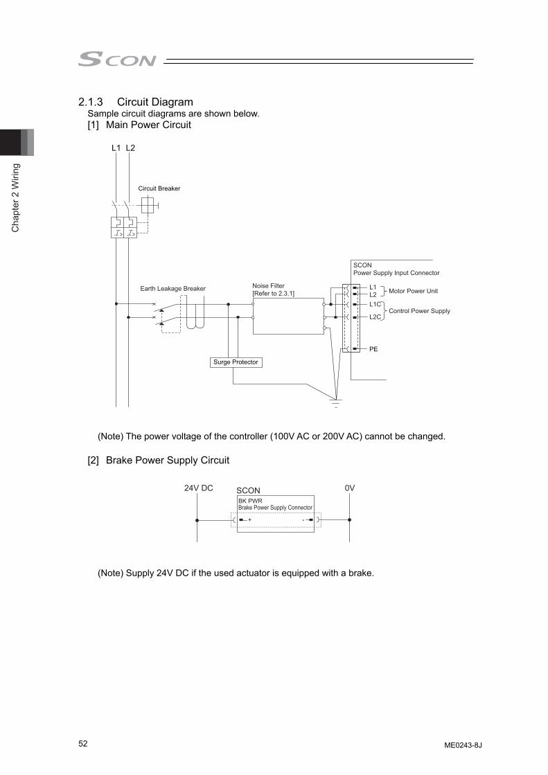
Cha
pter
2 W
iring
52
2.1.3 Circuit Diagram Sample circuit diagrams are shown below.
[1] Main Power Circuit
Surge Protector
Noise Filter[Refer to 2.3.1]
Earth Leakage Breaker
Circuit Breaker
PE
Motor Power Unit
Control Power Supply
L1 L2
L1L2L1C
L2C
SCONPower Supply Input Connector
(Note) The power voltage of the controller (100V AC or 200V AC) cannot be changed.
[2] Brake Power Supply Circuit
(Note) Supply 24V DC if the used actuator is equipped with a brake.
Brake Power Supply ConnectorBK PWR
+ -
24V DC 0VSCON
ME0243-8J
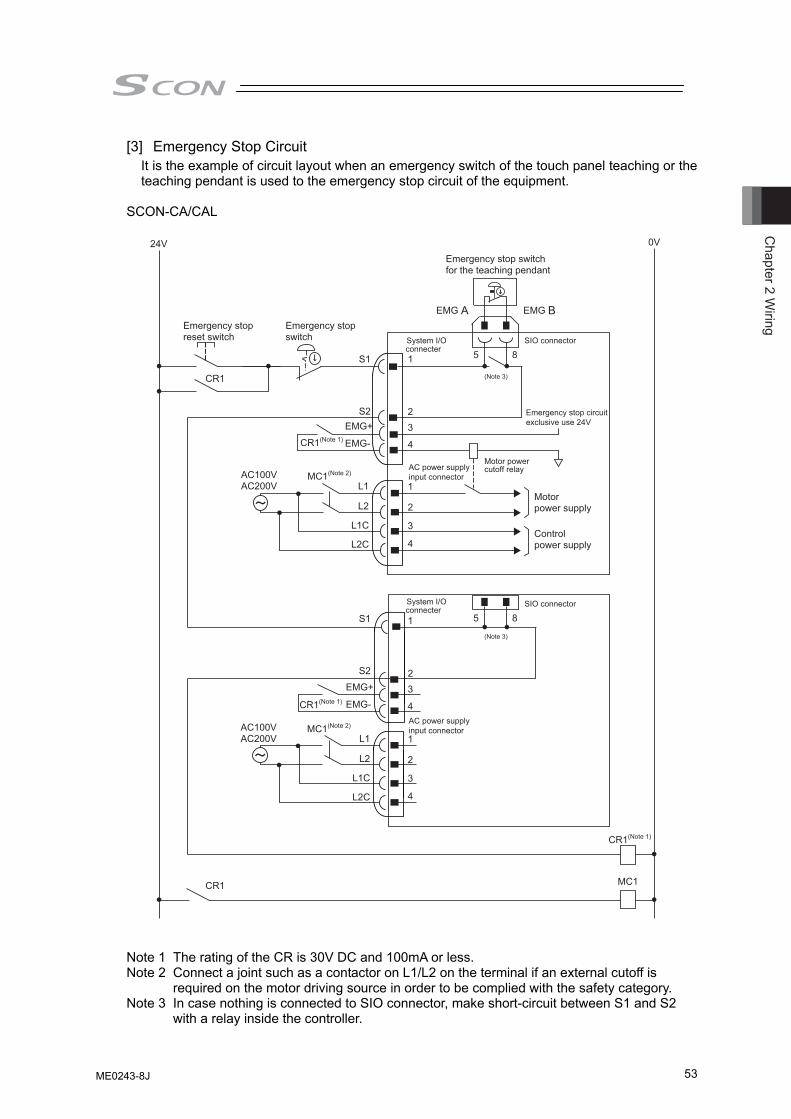
Chapter 2 W
iring
53
[3] Emergency Stop Circuit It is the example of circuit layout when an emergency switch of the touch panel teaching or the teaching pendant is used to the emergency stop circuit of the equipment.
SCON-CA/CAL
24V
Emergency stop reset switch
Emergency stop switch
Emergency stop switch for the teaching pendant
CR1(Note 1)
0V
MC1
CR1
CR1
S1
S2
S1
S2
1 5 8
5 8
23
4
1
23
4
1
2
3
4
1
2
3
4
EMG A EMG B
CR1(Note 1)
MC1(Note 2)AC100VAC200V
System I/O SIO connector
Emergency stop circuitexclusive use 24V
SIO connector
connecter
System I/Oconnecter
EMG+
EMG-
L1
L2
L1C
L2C
AC power supply Motor powercutoff relay
(Note 3)
(Note 3)
input connector
AC power supply input connector
Motor power supply
Control power supply
CR1(Note 1)
MC1(Note 2)AC100VAC200V
EMG+
EMG-
L1
L2
L1C
L2C
Note 1 The rating of the CR is 30V DC and 100mA or less. Note 2 Connect a joint such as a contactor on L1/L2 on the terminal if an external cutoff is
required on the motor driving source in order to be complied with the safety category. Note 3 In case nothing is connected to SIO connector, make short-circuit between S1 and S2
with a relay inside the controller.
ME0243-8J
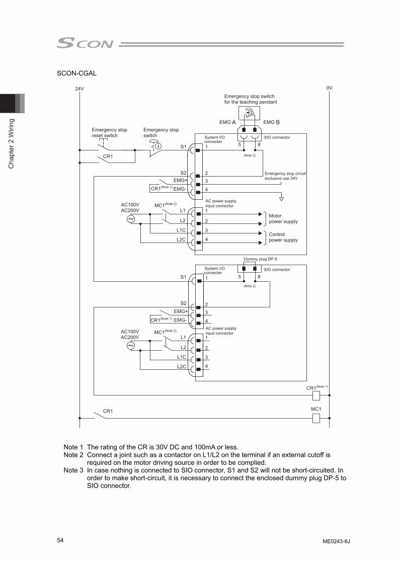
Cha
pter
2 W
iring
54
SCON-CGAL
24V
Emergency stop reset switch
Emergency stop switch
Emergency stop switch for the teaching pendant
CR1(Note 1)
0V
MC1
CR1
CR1
S1
S2
S1
S2
1 5 8
5 8
23
4
1
23
4
1
2
3
4
1
2
3
4
EMG A EMG B
CR1(Note 1)
MC1(Note 2)AC100VAC200V
System I/O SIO connector
Emergency stop circuitexclusive use 24V
SIO connector
Dummy plug DP-5
connecter
System I/Oconnecter
EMG+
EMG-
L1
L2
L1C
L2C
AC power supply
(Note 3)
(Note 3)
input connector
AC power supply input connector
Motor power supply
Control power supply
CR1(Note 1)
MC1(Note 2)AC100VAC200V
EMG+
EMG-
L1
L2
L1C
L2C
Note 1 The rating of the CR is 30V DC and 100mA or less. Note 2 Connect a joint such as a contactor on L1/L2 on the terminal if an external cutoff is
required on the motor driving source in order to be complied. Note 3 In case nothing is connected to SIO connector, S1 and S2 will not be short-circuited. In
order to make short-circuit, it is necessary to connect the enclosed dummy plug DP-5 to SIO connector.
ME0243-8J
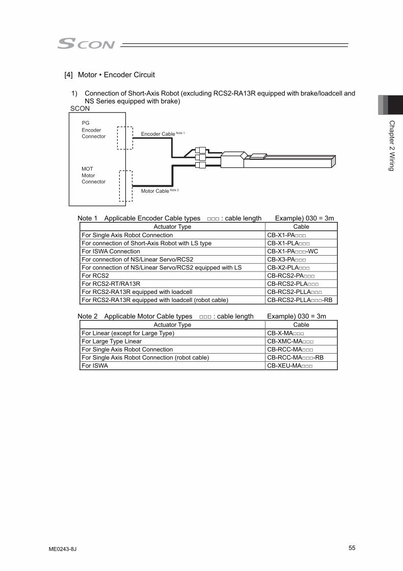
Chapter 2 W
iring
55
[4] Motor • Encoder Circuit
1) Connection of Short-Axis Robot (excluding RCS2-RA13R equipped with brake/loadcell and NS Series equipped with brake)
Note 1 Applicable Encoder Cable types □□□ : cable length Example) 030 = 3m
Actuator Type Cable For Single Axis Robot Connection CB-X1-PA□□□ For connection of Short-Axis Robot with LS type CB-X1-PLA□□□ For ISWA Connection CB-X1-PA□□□-WC For connection of NS/Linear Servo/RCS2 CB-X3-PA□□□ For connection of NS/Linear Servo/RCS2 equipped with LS CB-X2-PLA□□□ For RCS2 CB-RCS2-PA□□□ For RCS2-RT/RA13R CB-RCS2-PLA□□□ For RCS2-RA13R equipped with loadcell CB-RCS2-PLLA□□□ For RCS2-RA13R equipped with loadcell (robot cable) CB-RCS2-PLLA□□□-RB
Note 2 Applicable Motor Cable types □□□ : cable length Example) 030 = 3m
Actuator Type Cable For Linear (except for Large Type) CB-X-MA□□□ For Large Type Linear CB-XMC-MA□□□ For Single Axis Robot Connection CB-RCC-MA□□□ For Single Axis Robot Connection (robot cable) CB-RCC-MA□□□-RB For ISWA CB-XEU-MA□□□
SCON
PG
MOT
Encoder Cable Note 1
Motor Cable Note 2
Encoder Connector
Motor Connector
ME0243-8J
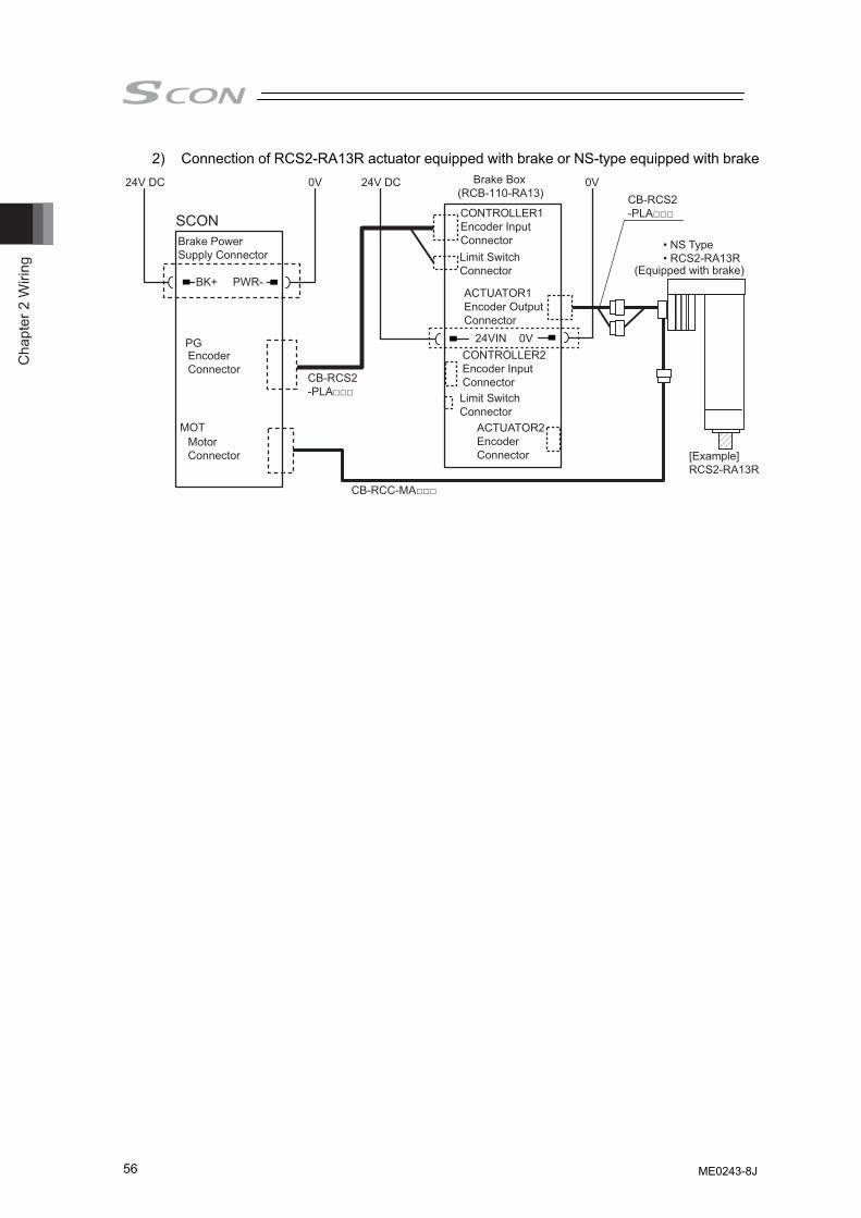
Cha
pter
2 W
iring
56
2) Connection of RCS2-RA13R actuator equipped with brake or NS-type equipped with brake
SCON
PG
MOT
Brake Box(RCB-110-RA13)
24VIN 0V
CB-RCS2-PLA□□□CONTROLLER1
Encoder Input ConnectorLimit SwitchConnector
Limit SwitchConnector
ACTUATOR1Encoder Output Connector
24V DC 0V
• NS Type• RCS2-RA13R
[Example]RCS2-RA13R
BK+
24V DC 0V
CB-RCC-MA□□□
CB-RCS2-PLA□□□
PWR-
Brake Power Supply Connector
CONTROLLER2Encoder Input Connector
ACTUATOR2EncoderConnector
Encoder Connector
MotorConnector
(Equipped with brake)
ME0243-8J
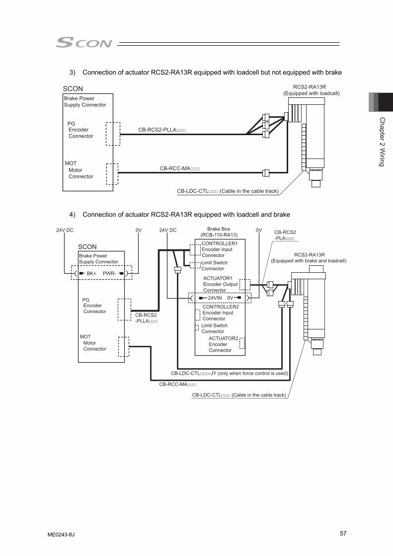
Chapter 2 W
iring
57
3) Connection of actuator RCS2-RA13R equipped with loadcell but not equipped with brake
SCON RCS2-RA13R(Equipped with loadcell)
MOTMotorConnector
Brake Power Supply Connector
PGEncoder Connector
CB-RCS2-PLLA□□□
CB-RCC-MA□□□
CB-LDC-CTL□□□ (Cable in the cable track)
4) Connection of actuator RCS2-RA13R equipped with loadcell and brake
SCON
Brake Box(RCB-110-RA13)
24VIN 0V
CONTROLLER1Encoder Input ConnectorLimit SwitchConnector
Limit SwitchConnector
ACTUATOR1Encoder Output Connector
24V DC 0V
RCS2-RA13R(Equipped with brake and loadcell)
BK+
24V DC 0V CB-RCS2-PLA□□□
PWR-
CONTROLLER2Encoder Input Connector
ACTUATOR2EncoderConnector
MOTMotorConnector
Brake Power Supply Connector
PGEncoderConnector
CB-RCC-MA□□□
CB-RCS2-PLLA□□□
CB-LDC-CTL□□□-JY (only when force control is used)
CB-LDC-CTL□□□ (Cable in the cable track)
ME0243-8J
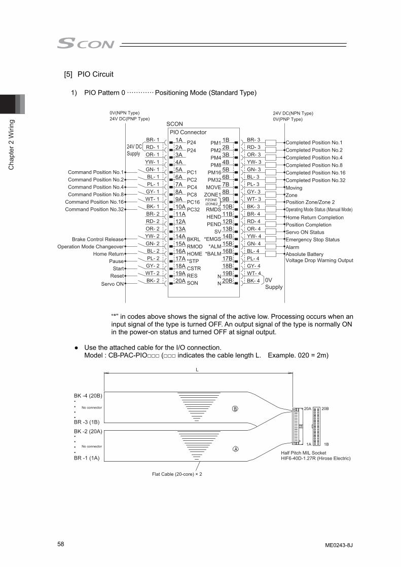
Cha
pter
2 W
iring
58
[5] PIO Circuit
1) PIO Pattern 0 ············ Positioning Mode (Standard Type)
0V(NPN Type)
24V DCSupply
BR- 1 1A P24 PM1 1B BR- 3
0VSupply
24V DC(NPN Type)24V DC(PNP Type)
RD- 1 2A P24 PM2 2B RD- 3
0V(PNP Type)
Command Position No.1
OR- 1 3A
PC1
PM4 3B OR- 3
Completed Position No.1
Command Position No.2
YW- 1 4A
PC2
PM8 4B YW- 3
Completed Position No.2
Command Position No.4
GN- 1 5A
PC4
PM16 5B GN- 3
Completed Position No.4
Command Position No.8
BL- 1 6A
PC8
PM32 6B BL- 3
Completed Position No.8
Command Position No.16
PL- 1 7A
PC16
MOVE 7B PL- 3
Completed Position No.16
Command Position No.32
GY- 1 8A
PC32
ZONE1 8B GY- 3
Completed Position No.32
Brake Control Release
WT- 1 9A
BKRL
9B WT- 3
Moving
Operation Mode Changeover
BK- 1 10A
RMOD
RMDS 10B BK- 3
Zone
Home Return
BR- 2 11A
HOME
HEND 11B BR- 4
Pause
RD- 2 12A
*STP
PEND 12B RD- 4
Operating Mode Status (Manual Mode)
Start
OR- 2 13A
CSTR
SV 13B OR- 4
Home Return Completion
Reset
YW- 2 14A
RES
*EMGS 14B YW- 4
Position Completion
Servo ON
GN- 2 15A
SON
*ALM*BALM
15B GN- 4
Servo ON Status
BL- 2 16A 16B BL- 4
Emergency Stop Status
PL- 2 17A
N
17B PL- 4
Alarm
GY- 2 18A
N
18B GY- 4
Absolute BatteryVoltage Drop Warning Output
WT- 2 19A 19B WT- 4BK- 2 20A 20B BK- 4
SCONPIO Connector
PZONE/ZONE2 Position Zone/Zone 2
“*” in codes above shows the signal of the active low. Processing occurs when an input signal of the type is turned OFF. An output signal of the type is normally ON in the power-on status and turned OFF at signal output.
● Use the attached cable for the I/O connection.
Model : CB-PAC-PIO□□□ (□□□ indicates the cable length L. Example. 020 = 2m)
Half Pitch MIL SocketHIF6-40D-1.27R (Hirose Electric)
Flat Cable (20-core) × 2
L
20A 20B
1A 1B
BK -4 (20B)
BK -2 (20A)
BR -3 (1B)
BR -1 (1A)
No connector
No connector
ME0243-8J
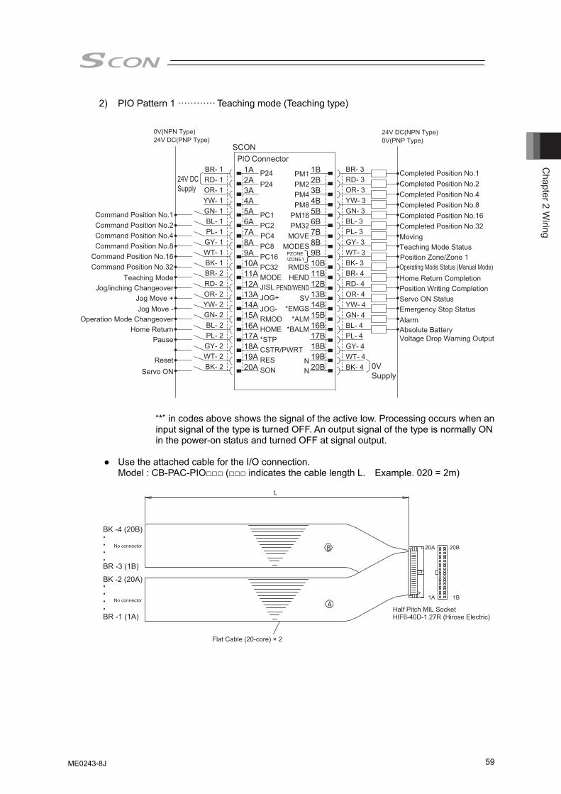
Chapter 2 W
iring
59
2) PIO Pattern 1 ············ Teaching mode (Teaching type)
Position Zone/Zone 1
0V(NPN Type)
24V DCSupply
1A P24 PM1 1B
0VSupply
24V DC(NPN Type)24V DC(PNP Type)
2A P24 PM2 2B
0V(PNP Type)
Command Position No.1
3A
PC1
PM4 3B
Completed Position No.1
Command Position No.2
4A
PC2
PM8 4B
Completed Position No.2
Command Position No.4
5A
PC4
PM16 5B
Completed Position No.4
Command Position No.8
6A
PC8
PM32 6B
Completed Position No.8
Command Position No.16
7A
PC16
MOVE 7B
Completed Position No.16
Command Position No.32
8A
PC32MODE
MODES 8B
Completed Position No.32
Jog Move -
9A
JOG-JOG+JISL
9B
Moving
Operation Mode Changeover
10A
RMOD
RMDS 10B
Teaching Mode Status
Home Return
Teaching ModeJog/inching Changeover
Jog Move +
11A
HOME
HEND 11B
Pause
12A
*STP
PEND/WEND 12B
Operating Mode Status (Manual Mode)
13A
CSTR/PWRT
SV 13B
Home Return Completion
Reset
14A
RES
*EMGS 14B
Position Writing Completion
Servo ON
15A
SON
*ALM*BALM
15B
Servo ON Status
16A 16B
Emergency Stop Status
17A
N
17B
Alarm
18A
N
18B
Absolute BatteryVoltage Drop Warning Output
19A 19B20A 20B
SCONPIO Connector
BR- 1RD- 1OR- 1YW- 1GN- 1BL- 1PL- 1GY- 1WT- 1BK- 1BR- 2RD- 2OR- 2YW- 2GN- 2BL- 2PL- 2GY- 2WT- 2BK- 2
BR- 3RD- 3OR- 3YW- 3GN- 3BL- 3PL- 3GY- 3WT- 3BK- 3BR- 4RD- 4OR- 4YW- 4GN- 4BL- 4PL- 4GY- 4WT- 4BK- 4
PZONE/ZONE1
“*” in codes above shows the signal of the active low. Processing occurs when an input signal of the type is turned OFF. An output signal of the type is normally ON in the power-on status and turned OFF at signal output.
● Use the attached cable for the I/O connection.
Model : CB-PAC-PIO□□□ (□□□ indicates the cable length L. Example. 020 = 2m)
Half Pitch MIL SocketHIF6-40D-1.27R (Hirose Electric)
Flat Cable (20-core) × 2
L
20A 20B
1A 1B
BK -4 (20B)
BK -2 (20A)
BR -3 (1B)
BR -1 (1A)
No connector
No connector
ME0243-8J
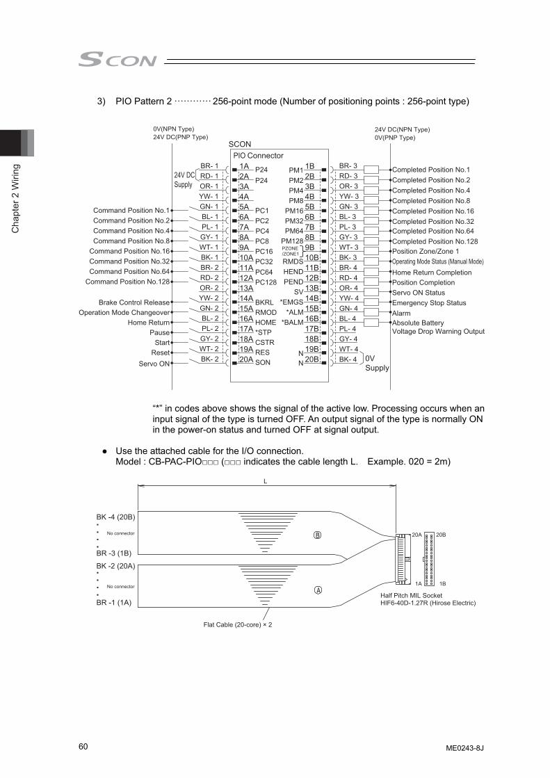
Cha
pter
2 W
iring
60
3) PIO Pattern 2 ············ 256-point mode (Number of positioning points : 256-point type)
0V(NPN Type)
24V DCSupply
1A P24 PM1 1B
0VSupply
24V DC(NPN Type)24V DC(PNP Type)
2A P24 PM2 2B
0V(PNP Type)
Command Position No.1
3A
PC1
PM4 3B
Completed Position No.1
Command Position No.2
4A
PC2
PM8 4B
Completed Position No.2
Command Position No.4
5A
PC4
PM16 5B
Completed Position No.4
Command Position No.8
6A
PC8
PM32PM64
PM128
6B
Completed Position No.8
Command Position No.16
7A
PC16
7B
Completed Position No.16
Command Position No.32Command Position No.64
Command Position No.128
8A
PC32PC64PC128
8B
Completed Position No.32Completed Position No.64Completed Position No.128
Brake Control Release
9A
BKRL
9B
Operation Mode Changeover
10A
RMOD
RMDS 10B
Home Return
11A
HOME
HEND 11B
Pause
12A
*STP
PEND 12B
Start
13A
CSTR
SV 13B
Reset
14A
RES
*EMGS 14B
Servo ON
15A
SON
*ALM*BALM
15B16A 16B17A
N
17B18A
N
18B19A 19B20A 20B
SCONPIO Connector
Operating Mode Status (Manual Mode)Home Return CompletionPosition CompletionServo ON StatusEmergency Stop StatusAlarmAbsolute BatteryVoltage Drop Warning Output
BR- 1RD- 1OR- 1YW- 1GN- 1BL- 1PL- 1GY- 1WT- 1BK- 1BR- 2RD- 2OR- 2YW- 2GN- 2BL- 2PL- 2GY- 2WT- 2BK- 2
BR- 3RD- 3OR- 3YW- 3GN- 3BL- 3PL- 3GY- 3WT- 3BK- 3BR- 4RD- 4OR- 4YW- 4GN- 4BL- 4PL- 4GY- 4WT- 4BK- 4
PZONE/ZONE1 Position Zone/Zone 1
“*” in codes above shows the signal of the active low. Processing occurs when an input signal of the type is turned OFF. An output signal of the type is normally ON in the power-on status and turned OFF at signal output.
● Use the attached cable for the I/O connection.
Model : CB-PAC-PIO□□□ (□□□ indicates the cable length L. Example. 020 = 2m)
Half Pitch MIL SocketHIF6-40D-1.27R (Hirose Electric)
Flat Cable (20-core) × 2
L
20A 20B
1A 1B
BK -4 (20B)
BK -2 (20A)
BR -3 (1B)
BR -1 (1A)
No connector
No connector
ME0243-8J
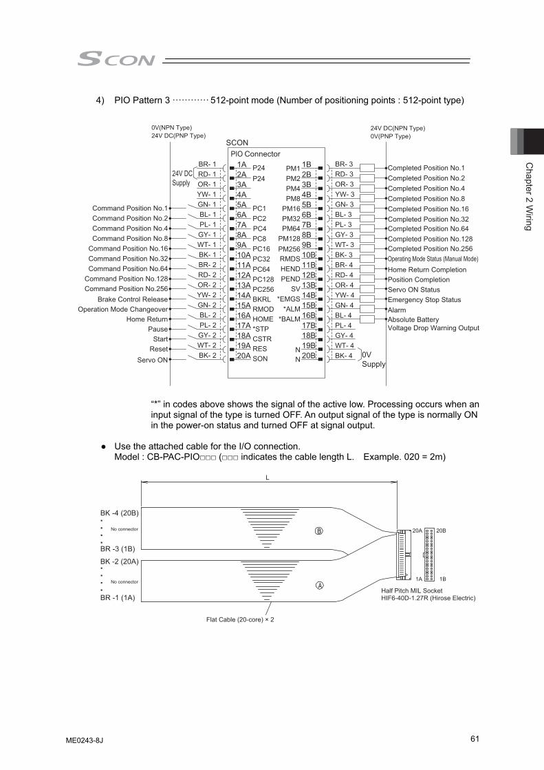
Chapter 2 W
iring
61
4) PIO Pattern 3 ············ 512-point mode (Number of positioning points : 512-point type)
0V(NPN Type)
24V DCSupply
1A P24 PM1 1B
0VSupply
24V DC(NPN Type)24V DC(PNP Type)
2A P24 PM2 2B
0V(PNP Type)
Command Position No.1
3A
PC1
PM4 3B
Completed Position No.1
Command Position No.2
4A
PC2
PM8 4B
Completed Position No.2
Command Position No.4
5A
PC4
PM16 5B
Completed Position No.4
Command Position No.8
6A
PC8
PM32PM64
PM128PM256
6B
Completed Position No.8
Command Position No.16
7A
PC16
7B
Completed Position No.16
Command Position No.32Command Position No.64
Command Position No.128Command Position No.256
8A
PC32PC64PC128PC256
8B
Completed Position No.32Completed Position No.64Completed Position No.128Completed Position No.2569A
BKRL
9B10A
RMOD
RMDS 10B11A
HOME
HEND 11B12A
*STP
PEND 12B13A
CSTR
SV 13B14A
RES
*EMGS 14B15A
SON
*ALM*BALM
15B16A 16B17A
N
17B18A
N
18B19A 19B20A 20B
SCONPIO Connector
Brake Control ReleaseOperation Mode Changeover
Home ReturnPause
StartReset
Servo ON
Operating Mode Status (Manual Mode)Home Return CompletionPosition CompletionServo ON StatusEmergency Stop StatusAlarmAbsolute BatteryVoltage Drop Warning Output
BR- 1RD- 1OR- 1YW- 1GN- 1BL- 1PL- 1GY- 1WT- 1BK- 1BR- 2RD- 2OR- 2YW- 2GN- 2BL- 2PL- 2GY- 2WT- 2BK- 2
BR- 3RD- 3OR- 3YW- 3GN- 3BL- 3PL- 3GY- 3WT- 3BK- 3BR- 4RD- 4OR- 4YW- 4GN- 4BL- 4PL- 4GY- 4WT- 4BK- 4
“*” in codes above shows the signal of the active low. Processing occurs when an input signal of the type is turned OFF. An output signal of the type is normally ON in the power-on status and turned OFF at signal output.
● Use the attached cable for the I/O connection.
Model : CB-PAC-PIO□□□ (□□□ indicates the cable length L. Example. 020 = 2m)
Half Pitch MIL SocketHIF6-40D-1.27R (Hirose Electric)
Flat Cable (20-core) × 2
L
20A 20B
1A 1B
BK -4 (20B)
BK -2 (20A)
BR -3 (1B)
BR -1 (1A)
No connector
No connector
ME0243-8J
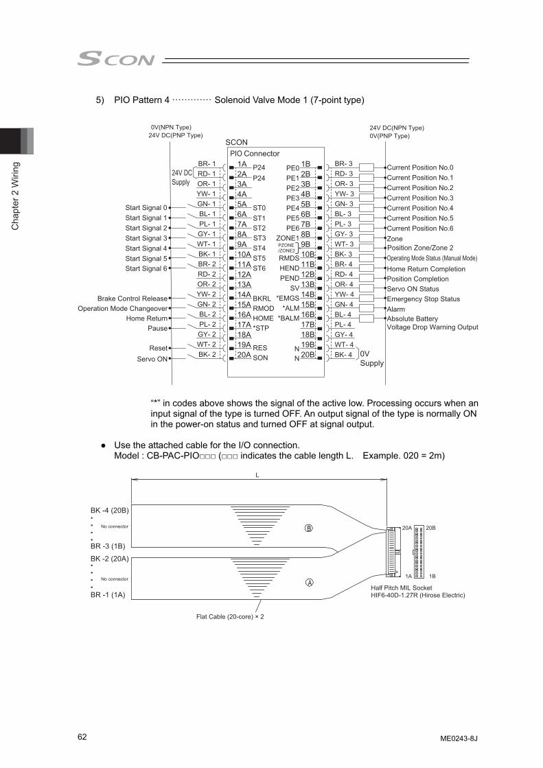
Cha
pter
2 W
iring
62
5) PIO Pattern 4 ············· Solenoid Valve Mode 1 (7-point type)
0V(NPN Type)
24V DCSupply
1A P24 PE0 1B
0VSupply
24V DC(NPN Type)24V DC(PNP Type)
2A P24 PE1 2B
0V(PNP Type)
Start Signal 0
Start Signal 5Start Signal 6
Start Signal 4Start Signal 3Start Signal 2Start Signal 1
3A
ST0
PE2 3B
Current Position No.0
Current Position No.2Current Position No.1
Current Position No.3Current Position No.4Current Position No.5Current Position No.6
4A
ST2ST1
PE3 4B5A
ST3
PE4 5B6A
ST4
PE5 6B7A
ST5
PE6 7B8A
ST6
ZONE1 8B9A
BKRL
9B10A
RMOD
RMDS 10B11A
HOME
HEND 11B12A
*STP
PEND 12B13A SV 13B14A
RES
*EMGS 14B15A
SON
*ALM*BALM
15B16A 16B17A
N
17B18A
N
18B19A 19B20A 20B
SCONPIO Connector
BR- 1RD- 1OR- 1YW- 1GN- 1BL- 1PL- 1GY- 1WT- 1BK- 1BR- 2RD- 2OR- 2YW- 2GN- 2BL- 2PL- 2GY- 2WT- 2BK- 2
BR- 3RD- 3OR- 3YW- 3GN- 3BL- 3PL- 3GY- 3WT- 3BK- 3BR- 4RD- 4OR- 4YW- 4GN- 4BL- 4PL- 4GY- 4WT- 4BK- 4
Brake Control ReleaseOperation Mode Changeover
Home ReturnPause
ResetServo ON
Zone
Operating Mode Status (Manual Mode)Home Return CompletionPosition CompletionServo ON StatusEmergency Stop StatusAlarmAbsolute BatteryVoltage Drop Warning Output
Position Zone/Zone 2PZONE/ZONE2
“*” in codes above shows the signal of the active low. Processing occurs when an input signal of the type is turned OFF. An output signal of the type is normally ON in the power-on status and turned OFF at signal output.
● Use the attached cable for the I/O connection.
Model : CB-PAC-PIO□□□ (□□□ indicates the cable length L. Example. 020 = 2m)
Half Pitch MIL SocketHIF6-40D-1.27R (Hirose Electric)
Flat Cable (20-core) × 2
L
20A 20B
1A 1B
BK -4 (20B)
BK -2 (20A)
BR -3 (1B)
BR -1 (1A)
No connector
No connector
ME0243-8J
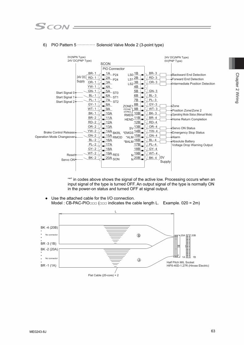
Chapter 2 W
iring
63
6) PIO Pattern 5 ············· Solenoid Valve Mode 2 (3-point type)
0V(NPN Type)
24V DCSupply
1A P24 1B
0VSupply
24V DC(NPN Type)24V DC(PNP Type)
2A P24 2B
0V(PNP Type)
Start Signal 0
Start Signal 2Start Signal 1
3A
ST0
LS0LS1LS2 3B
4A
ST1
4B5A
ST2
5B6A 6B7A 7B8A ZONE1 8B9A
BKRL
9B10A
RMOD
RMDS 10B
Backward End DetectionForward End DetectionIntermediate Position Detection
11A HEND 11B12A 12B13A SV 13B
Reset
14A
RES
*EMGS 14B
Servo ON
15A
SON
*ALM*BALM
15B16A 16B17A
N
17B18A
N
18B19A 19B20A 20B
SCONPIO Connector
Alarm
Servo ON StatusEmergency Stop Status
Absolute BatteryVoltage Drop Warning Output
Zone
Operating Mode Status (Manual Mode)Home Return Completion
Brake Control ReleaseOperation Mode Changeover
BR- 1RD- 1OR- 1YW- 1GN- 1BL- 1PL- 1GY- 1WT- 1BK- 1BR- 2RD- 2OR- 2YW- 2GN- 2BL- 2PL- 2GY- 2WT- 2BK- 2
BR- 3RD- 3OR- 3
GN- 3BL- 3PL- 3GY- 3WT- 3BK- 3BR- 4RD- 4OR- 4YW- 4GN- 4BL- 4PL- 4GY- 4WT- 4BK- 4
PZONE/ZONE2 Position Zone/Zone 2
“*” in codes above shows the signal of the active low. Processing occurs when an input signal of the type is turned OFF. An output signal of the type is normally ON in the power-on status and turned OFF at signal output.
● Use the attached cable for the I/O connection.
Model : CB-PAC-PIO□□□ (□□□ indicates the cable length L. Example. 020 = 2m)
Half Pitch MIL SocketHIF6-40D-1.27R (Hirose Electric)
Flat Cable (20-core) × 2
L
20A 20B
1A 1B
BK -4 (20B)
BK -2 (20A)
BR -3 (1B)
BR -1 (1A)
No connector
No connector
ME0243-8J
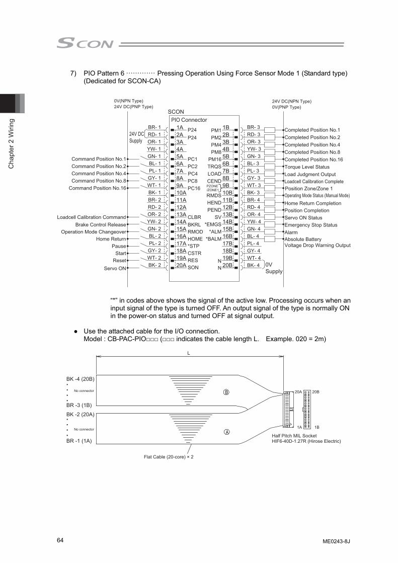
Cha
pter
2 W
iring
64
7) PIO Pattern 6 ············· Pressing Operation Using Force Sensor Mode 1 (Standard type) (Dedicated for SCON-CA)
0V(NPN Type)
24V DCSupply
1A P24 PM1 1B
0VSupply
24V DC(NPN Type)24V DC(PNP Type)
2A P24 PM2 2B
0V(PNP Type)
Command Position No.1
3A
PC1
PM4 3B
Completed Position No.1
Command Position No.2
4A
PC2
PM8 4B
Completed Position No.2
Command Position No.4
5A
PC4
PM16 5B
Completed Position No.4
Command Position No.8
6A
PC8
TRQS 6B
Completed Position No.8
Command Position No.16
7A
PC16
LOADCEND
7B
Completed Position No.16
8A 8B
Torque Level Status
Loadcell Calibration Command
9A
BKRLCLBR
9B
Load Judgment Output
10A
RMOD
RMDS 10B
Loadcell Calibration Complete
11A
HOME
HEND 11B12A
*STP
PEND 12B13A
CSTR
SV 13B14A
RES
*EMGS 14B15A
SON
*ALM*BALM
15B16A 16B17A
N
17B18A
N
18B19A 19B20A 20B
SCONPIO Connector
BR- 1RD- 1OR- 1YW- 1GN- 1BL- 1PL- 1GY- 1WT- 1BK- 1BR- 2RD- 2OR- 2YW- 2GN- 2BL- 2PL- 2GY- 2WT- 2BK- 2
BR- 3RD- 3OR- 3YW- 3GN- 3BL- 3PL- 3GY- 3WT- 3BK- 3BR- 4RD- 4OR- 4YW- 4GN- 4BL- 4PL- 4GY- 4WT- 4BK- 4
Brake Control ReleaseOperation Mode Changeover
Home ReturnPause
StartReset
Servo ON
Operating Mode Status (Manual Mode)Home Return CompletionPosition CompletionServo ON StatusEmergency Stop StatusAlarmAbsolute BatteryVoltage Drop Warning Output
Position Zone/Zone 1PZONE/ZONE1
“*” in codes above shows the signal of the active low. Processing occurs when an input signal of the type is turned OFF. An output signal of the type is normally ON in the power-on status and turned OFF at signal output.
● Use the attached cable for the I/O connection.
Model : CB-PAC-PIO□□□ (□□□ indicates the cable length L. Example. 020 = 2m)
Half Pitch MIL SocketHIF6-40D-1.27R (Hirose Electric)
Flat Cable (20-core) × 2
L
20A 20B
1A 1B
BK -4 (20B)
BK -2 (20A)
BR -3 (1B)
BR -1 (1A)
No connector
No connector
ME0243-8J
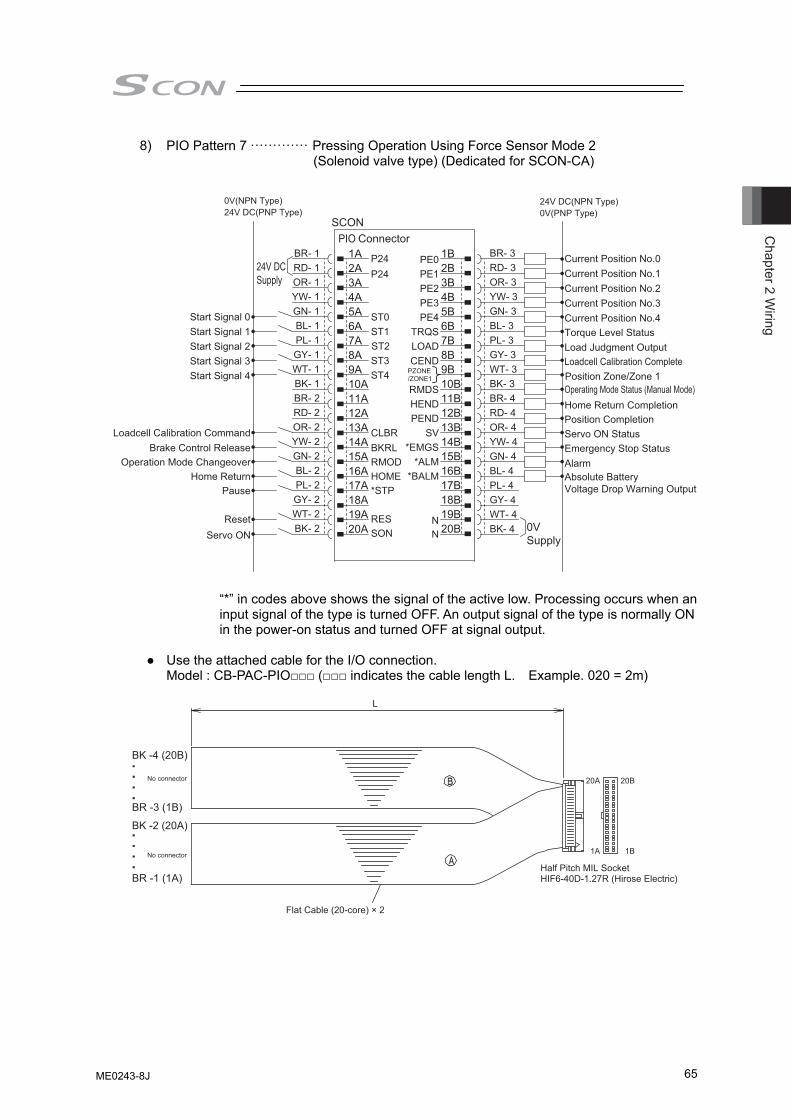
Chapter 2 W
iring
65
8) PIO Pattern 7 ············· Pressing Operation Using Force Sensor Mode 2 (Solenoid valve type) (Dedicated for SCON-CA)
0V(NPN Type)
24V DCSupply
1A P24 PE0 1B
0VSupply
24V DC(NPN Type)24V DC(PNP Type)
2A P24 PE1 2B
0V(PNP Type)
3A
ST0
PE2 3B
Current Position No.0Current Position No.1Current Position No.2Current Position No.3Current Position No.4
4A
ST1
PE3 4B5A
ST2
PE4 5B6A
ST3
TRQS 6B7A
ST4
LOADCEND
7B8A 8B9A
BKRLCLBR
9B10A
RMOD
RMDS 10B11A
HOME
HEND 11B12A
*STP
PEND 12B13A SV 13B14A
RES
*EMGS 14B15A
SON
*ALM*BALM
15B16A 16B17A
N
17B18A
N
18B19A 19B20A 20B
SCONPIO Connector
Start Signal 0
Start Signal 4Start Signal 3Start Signal 2Start Signal 1
Loadcell Calibration CommandBrake Control Release
Operation Mode ChangeoverHome Return
Pause
ResetServo ON
Torque Level StatusLoad Judgment OutputLoadcell Calibration Complete
Operating Mode Status (Manual Mode)Home Return CompletionPosition CompletionServo ON StatusEmergency Stop StatusAlarmAbsolute BatteryVoltage Drop Warning Output
BR- 1RD- 1OR- 1YW- 1GN- 1BL- 1PL- 1GY- 1WT- 1BK- 1BR- 2RD- 2OR- 2YW- 2GN- 2BL- 2PL- 2GY- 2WT- 2BK- 2
BR- 3RD- 3OR- 3YW- 3GN- 3BL- 3PL- 3GY- 3WT- 3BK- 3BR- 4RD- 4OR- 4YW- 4GN- 4BL- 4PL- 4GY- 4WT- 4BK- 4
PZONE/ZONE1 Position Zone/Zone 1
“*” in codes above shows the signal of the active low. Processing occurs when an input signal of the type is turned OFF. An output signal of the type is normally ON in the power-on status and turned OFF at signal output.
● Use the attached cable for the I/O connection.
Model : CB-PAC-PIO□□□ (□□□ indicates the cable length L. Example. 020 = 2m)
Half Pitch MIL SocketHIF6-40D-1.27R (Hirose Electric)
Flat Cable (20-core) × 2
L
20A 20B
1A 1B
BK -4 (20B)
BK -2 (20A)
BR -3 (1B)
BR -1 (1A)
No connector
No connector
ME0243-8J
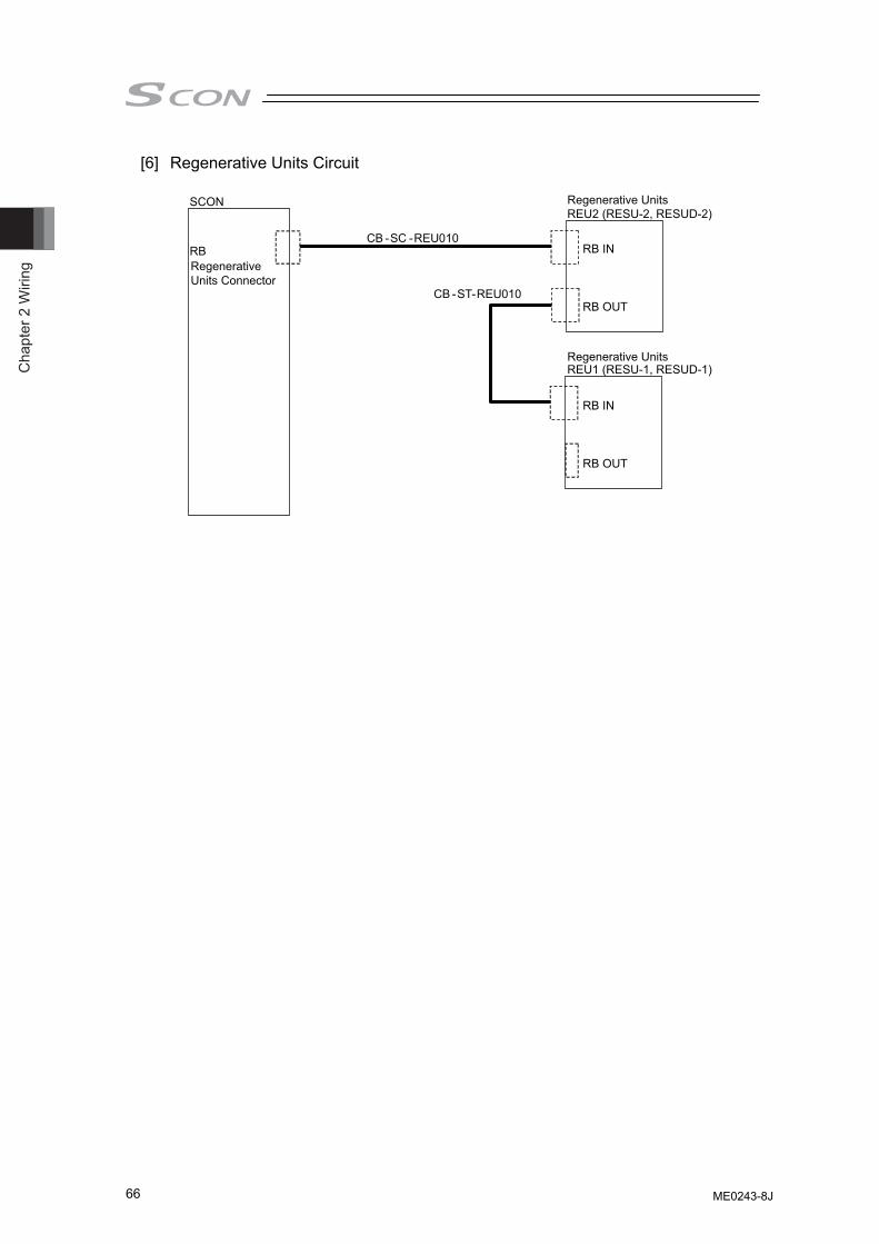
Cha
pter
2 W
iring
66
[6] Regenerative Units Circuit
SCON
RBRegenerative Units Connector
Regenerative UnitsREU2 (RESU-2, RESUD-2)
Regenerative Units REU1 (RESU-1, RESUD-1)
CB -SC -REU010
CB -ST
RB IN
RB OUT
RB IN
RB OUT
-REU010
ME0243-8J
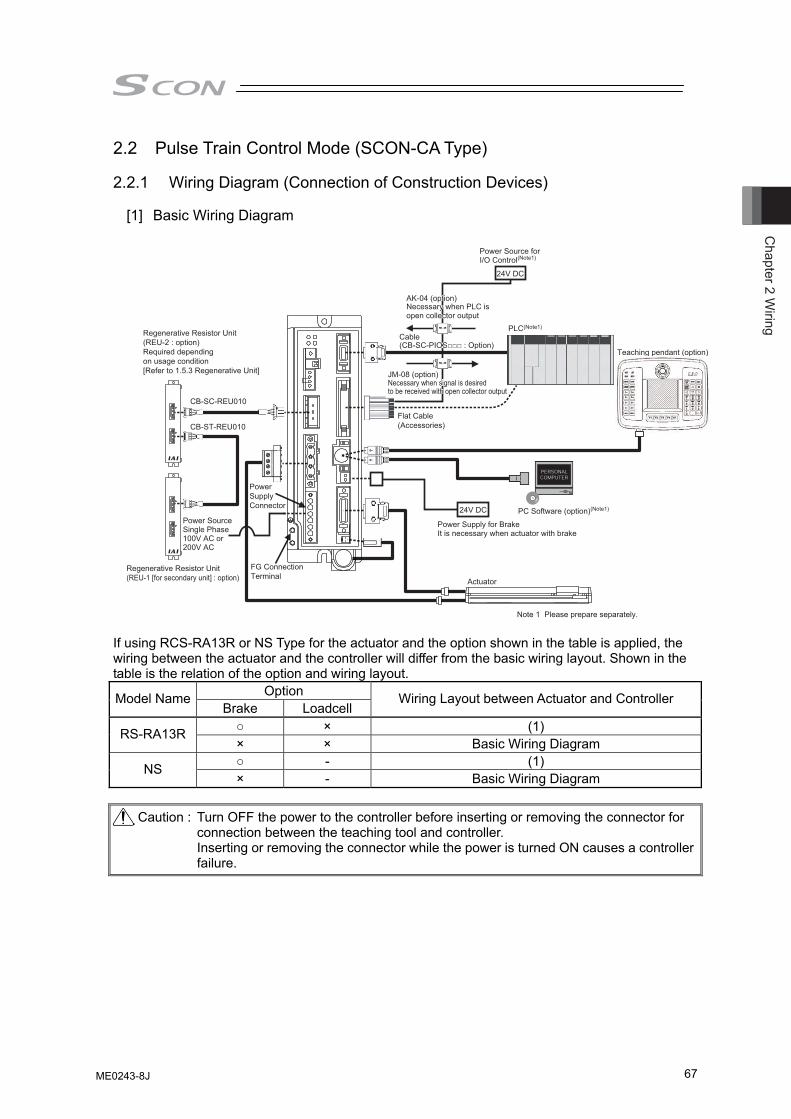
Chapter 2 W
iring
67
2.2 Pulse Train Control Mode (SCON-CA Type) 2.2.1 Wiring Diagram (Connection of Construction Devices)
[1] Basic Wiring Diagram
Actuator
Teaching pendant (option)
PLC(Note1)
Regenerative Resistor Unit(REU-1 [for secondary unit] : option)
Power SupplyConnector
Flat Cable(Accessories)
CB-SC-REU010
CB-ST-REU010
FG ConnectionTerminal
Regenerative Resistor Unit(REU-2 : option)Required dependingon usage condition[Refer to 1.5.3 Regenerative Unit]
Note 1 Please prepare separately.
JM-08 (option)Necessary when signal is desired to be received with open collector output
JM-08 (option)Necessary when signal is desired to be received with open collector output
AK-04 (option)Necessary when PLC is open collector output
AK-04 (option)Necessary when PLC is open collector output
24V DC
24V DC
Cable(CB-SC-PIOS□□□ : Option)Cable(CB-SC-PIOS□□□ : Option)
Power Supply for BrakeIt is necessary when actuator with brake
PC Software (option)(Note1)
Power Source Single Phase 100V AC or 200V AC
Power Source for I/O Control(Note1)
If using RCS-RA13R or NS Type for the actuator and the option shown in the table is applied, the wiring between the actuator and the controller will differ from the basic wiring layout. Shown in the table is the relation of the option and wiring layout.
Option Model Name Brake Loadcell
Wiring Layout between Actuator and Controller
○ × (1) RS-RA13R × × Basic Wiring Diagram ○ - (1) NS × - Basic Wiring Diagram
Caution : Turn OFF the power to the controller before inserting or removing the connector for
connection between the teaching tool and controller. Inserting or removing the connector while the power is turned ON causes a controller failure.
ME0243-8J
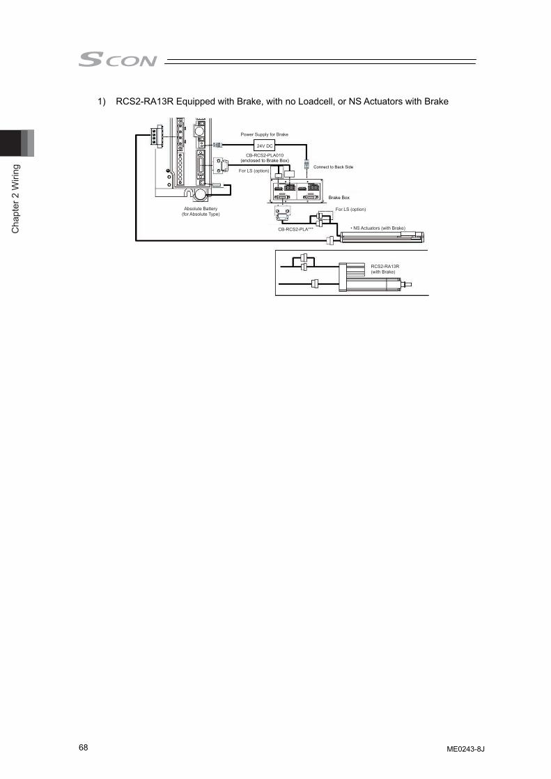
Cha
pter
2 W
iring
68
1) RCS2-RA13R Equipped with Brake, with no Loadcell, or NS Actuators with Brake
Power Supply for Brake
24V DC
For LS (option)
• NS Actuators (with Brake)
For LS (option)Absolute Battery(for Absolute Type)
(enclosed to Brake Box)
Brake Box
RCS2-RA13R(with Brake)
CB-RCS2-PLA***
CB-RCS2-PLA010
Connect to Back Side
ME0243-8J
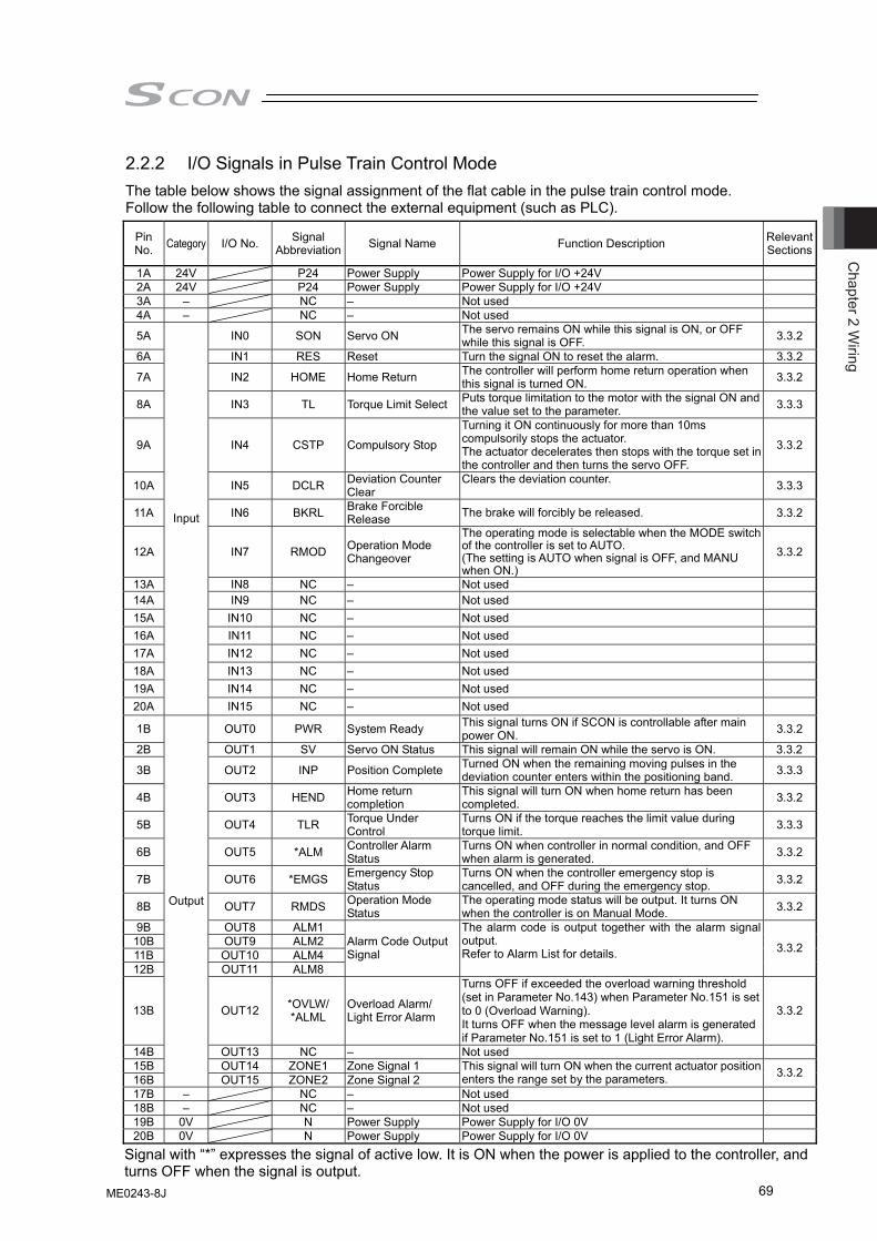
Chapter 2 W
iring
69
2.2.2 I/O Signals in Pulse Train Control Mode The table below shows the signal assignment of the flat cable in the pulse train control mode. Follow the following table to connect the external equipment (such as PLC).
Pin No. Category I/O No. Signal
Abbreviation Signal Name Function Description Relevant Sections
1A 24V P24 Power Supply Power Supply for I/O +24V 2A 24V P24 Power Supply Power Supply for I/O +24V 3A – NC – Not used 4A – NC – Not used
5A IN0 SON Servo ON The servo remains ON while this signal is ON, or OFF while this signal is OFF. 3.3.2
6A IN1 RES Reset Turn the signal ON to reset the alarm. 3.3.2
7A IN2 HOME Home Return The controller will perform home return operation when this signal is turned ON. 3.3.2
8A IN3 TL Torque Limit Select Puts torque limitation to the motor with the signal ON and the value set to the parameter. 3.3.3
9A IN4 CSTP Compulsory Stop
Turning it ON continuously for more than 10ms compulsorily stops the actuator. The actuator decelerates then stops with the torque set in the controller and then turns the servo OFF.
3.3.2
10A IN5 DCLR Deviation Counter Clear
Clears the deviation counter. 3.3.3
11A IN6 BKRL Brake Forcible Release The brake will forcibly be released. 3.3.2
12A IN7 RMOD Operation Mode Changeover
The operating mode is selectable when the MODE switch of the controller is set to AUTO. (The setting is AUTO when signal is OFF, and MANU when ON.)
3.3.2
13A IN8 NC – Not used 14A IN9 NC – Not used 15A IN10 NC – Not used 16A IN11 NC – Not used 17A IN12 NC – Not used 18A IN13 NC – Not used 19A IN14 NC – Not used 20A
Input
IN15 NC – Not used 1B OUT0 PWR System Ready This signal turns ON if SCON is controllable after main
power ON. 3.3.2
2B OUT1 SV Servo ON Status This signal will remain ON while the servo is ON. 3.3.2
3B OUT2 INP Position Complete Turned ON when the remaining moving pulses in the deviation counter enters within the positioning band. 3.3.3
4B OUT3 HEND Home return completion
This signal will turn ON when home return has been completed. 3.3.2
5B OUT4 TLR Torque Under Control
Turns ON if the torque reaches the limit value during torque limit. 3.3.3
6B OUT5 *ALM Controller Alarm Status
Turns ON when controller in normal condition, and OFF when alarm is generated. 3.3.2
7B OUT6 *EMGS Emergency Stop Status
Turns ON when the controller emergency stop is cancelled, and OFF during the emergency stop. 3.3.2
8B OUT7 RMDS Operation Mode Status
The operating mode status will be output. It turns ON when the controller is on Manual Mode. 3.3.2
9B OUT8 ALM1 10B OUT9 ALM2 11B OUT10 ALM4 12B OUT11 ALM8
Alarm Code Output Signal
The alarm code is output together with the alarm signal output. Refer to Alarm List for details. 3.3.2
13B OUT12 *OVLW/ *ALML
Overload Alarm/ Light Error Alarm
Turns OFF if exceeded the overload warning threshold (set in Parameter No.143) when Parameter No.151 is set to 0 (Overload Warning). It turns OFF when the message level alarm is generated if Parameter No.151 is set to 1 (Light Error Alarm).
3.3.2
14B OUT13 NC – Not used 15B OUT14 ZONE1 Zone Signal 1 16B
Output
OUT15 ZONE2 Zone Signal 2 This signal will turn ON when the current actuator position enters the range set by the parameters. 3.3.2
17B – NC – Not used 18B – NC – Not used 19B 0V N Power Supply Power Supply for I/O 0V 20B 0V N Power Supply Power Supply for I/O 0V
Signal with “*” expresses the signal of active low. It is ON when the power is applied to the controller, and turns OFF when the signal is output.
ME0243-8J
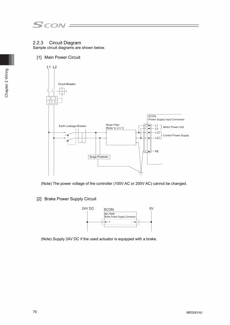
Cha
pter
2 W
iring
70
2.2.3 Circuit Diagram Sample circuit diagrams are shown below.
[1] Main Power Circuit
Surge Protector
Noise Filter[Refer to 2.3.1]
Earth Leakage Breaker
Circuit Breaker
PE
Motor Power Unit
Control Power Supply
L1 L2
L1L2L1C
L2C
SCONPower Supply Input Connector
(Note) The power voltage of the controller (100V AC or 200V AC) cannot be changed.
[2] Brake Power Supply Circuit
Brake Power Supply ConnectorBK PWR
+ -
24V DC 0VSCON
(Note) Supply 24V DC if the used actuator is equipped with a brake.
ME0243-8J
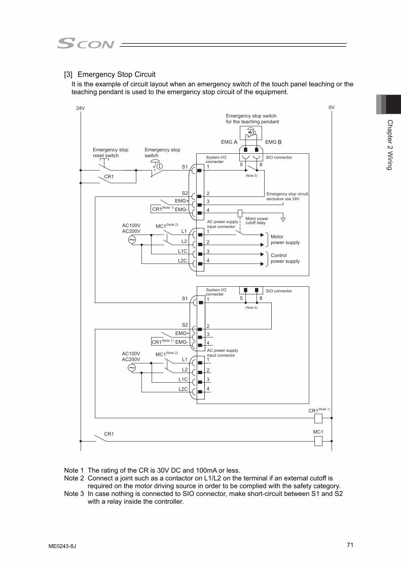
Chapter 2 W
iring
71
[3] Emergency Stop Circuit It is the example of circuit layout when an emergency switch of the touch panel teaching or the teaching pendant is used to the emergency stop circuit of the equipment.
24V
Emergency stop reset switch
Emergency stop switch
Emergency stop switch for the teaching pendant
CR1(Note 1)
0V
MC1
CR1
CR1
S1
S2
S1
S2
1 5 8
5 8
23
4
1
23
4
1
2
3
4
1
2
3
4
EMG A EMG B
CR1(Note 1)
MC1(Note 2)AC100VAC200V
System I/O SIO connector
Emergency stop circuitexclusive use 24V
SIO connector
connecter
System I/Oconnecter
EMG+
EMG-
L1
L2
L1C
L2C
AC power supply Motor powercutoff relay
(Note 3)
(Note 3)
input connector
AC power supply input connector
Motor power supply
Control power supply
CR1(Note 1)
MC1(Note 2)AC100VAC200V
EMG+
EMG-
L1
L2
L1C
L2C
Note 1 The rating of the CR is 30V DC and 100mA or less. Note 2 Connect a joint such as a contactor on L1/L2 on the terminal if an external cutoff is
required on the motor driving source in order to be complied with the safety category. Note 3 In case nothing is connected to SIO connector, make short-circuit between S1 and S2
with a relay inside the controller.
ME0243-8J
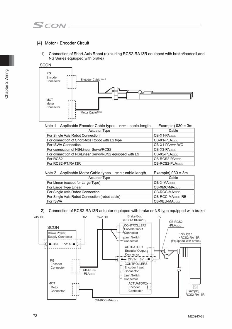
Cha
pter
2 W
iring
72
[4] Motor • Encoder Circuit
1) Connection of Short-Axis Robot (excluding RCS2-RA13R equipped with brake/loadcell and NS Series equipped with brake)
Note 1 Applicable Encoder Cable types □□□ : cable length Example) 030 = 3m
Actuator Type Cable For Single Axis Robot Connection CB-X1-PA□□□ For connection of Short-Axis Robot with LS type CB-X1-PLA□□□ For ISWA Connection CB-X1-PA□□□-WC For connection of NS/Linear Servo/RCS2 CB-X3-PA□□□ For connection of NS/Linear Servo/RCS2 equipped with LS CB-X2-PLA□□□ For RCS2 CB-RCS2-PA□□□ For RCS2-RT/RA13R CB-RCS2-PLA□□□
Note 2 Applicable Motor Cable types □□□ : cable length Example) 030 = 3m
Actuator Type Cable For Linear (except for Large Type) CB-X-MA□□□ For Large Type Linear CB-XMC-MA□□□ For Single Axis Robot Connection CB-RCC-MA□□□ For Single Axis Robot Connection (robot cable) CB-RCC-MA□□□-RB For ISWA CB-XEU-MA□□□
2) Connection of RCS2-RA13R actuator equipped with brake or NS-type equipped with brake
SCON
PG
MOT
Brake Box(RCB-110-RA13)
24VIN 0V
CB-RCS2-PLA□□□CONTROLLER1
Encoder Input ConnectorLimit SwitchConnector
Limit SwitchConnector
ACTUATOR1Encoder Output Connector
24V DC 0V
• NS Type• RCS2-RA13R
[Example]RCS2-RA13R
BK+
24V DC 0V
CB-RCC-MA□□□
CB-RCS2-PLA□□□
PWR-
Brake Power Supply Connector
CONTROLLER2Encoder Input Connector
ACTUATOR2EncoderConnector
Encoder Connector
MotorConnector
(Equipped with brake)
SCON
PG
MOT
Encoder Cable Note 1
Motor Cable Note 2
Encoder Connector
Motor Connector
ME0243-8J
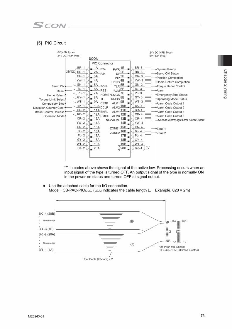
Chapter 2 W
iring
73
[5] PIO Circuit
0V(NPN Type)
24V DCBR- 1 1A P24 PWR 1B BR- 3
0V
24V DC(NPN Type)24V DC(PNP Type)
RD- 1 2A P24 SV 2B RD- 3
0V(PNP Type)
OR- 1 3A
SON
INP 3B OR- 3
System Ready
YW- 1 4A
RES
HEND 4B YW- 3
Servo ON Status
GN- 1 5A
HOME
TLR 5B GN- 3BL- 1 6A
TL
6B BL- 3PL- 1 7A
CSTP
7B PL- 3
Deviation Counter Clear
GY- 1 8A
DCLR
8B GY- 3
Brake Control Release
Compulsory StopTorque Limit Select
WT- 1 9A
BKRL
ZONE1ZONE2
9B WT- 3
Operation Mode
BK- 1 10A
RMOD
RMDS
10B BK- 3
Zone 2Zone 1
Home Return
BR- 2 11A
ALM1ALM2ALM4ALM8
11B BR- 4RD- 2 12A 12B RD- 4
Operating Mode StatusEmergency Stop Status
OR- 2 13A 13B OR- 4
Home Return CompletionTorque Under Control
Reset
YW- 2 14A
*EMGS
14B YW- 4
Position Completion
Servo ON
GN- 2 15A
*ALM
15B GN- 4BL- 2 16A 16B BL- 4PL- 2 17A
N
17B PL- 4
Alarm Code Output 1
Alarm
Alarm Code Output 2Alarm Code Output 4Alarm Code Output 8
GY- 2 18A
N
18B GY- 4WT- 2 19A 19B WT- 4BK- 2 20A 20B BK- 4
SCON PIO Connector
NC/*ALML Overload Alarm/Light Error Alarm Output
“*” in codes above shows the signal of the active low. Processing occurs when an input signal of the type is turned OFF. An output signal of the type is normally ON in the power-on status and turned OFF at signal output.
● Use the attached cable for the I/O connection.
Model : CB-PAC-PIO□□□ (□□□ indicates the cable length L. Example. 020 = 2m)
Half Pitch MIL SocketHIF6-40D-1.27R (Hirose Electric)
Flat Cable (20-core) × 2
L
20A 20B
1A 1B
BK -4 (20B)
BK -2 (20A)
BR -3 (1B)
BR -1 (1A)
No connector
No connector
ME0243-8J
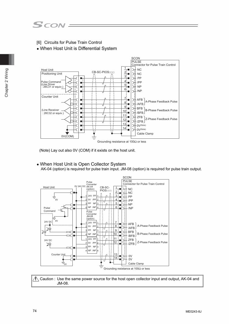
Cha
pter
2 W
iring
74
[6] Circuits for Pulse Train Control ● When Host Unit is Differential System
Host Unit
Pulse Command(Line Driver : 26C31 or equiv.)
(Line Receiver : 26C32 or equiv.)
Positioning Unit
Counter Unit
CB-SC-PIOS□□□123456
789
101112
SCONPULSEConnector for Pulse Train Control
NCNCPP/PPNP/NP
AFB/AFBBFB/BFBZFB/ZFB
A-Phase Feedback Pulse
Z-Phase Feedback Pulse
B-Phase Feedback Pulse
Cable Clamp
Grounding resistance at 100Ω or less
0V(Note)
0V(Note)
1314
0V(COM)
(Note) Lay out also 0V (COM) if it exists on the host unit. ● When Host Unit is Open Collector System
AK-04 (option) is required for pulse train input. JM-08 (option) is required for pulse train output.
123456
789
101112
1314
0V
Host Unit
SCON
NCNCPP/PPNP/NP
0V0VCable Clamp
0V 24V DC
Pulse Command
Pulse ConverterAK-04(option)
1
2
3
4
12
3
4
11
22
4
33
4
11
22
4
33
4
AFB/AFBBFB/BFBZFB/ZFB
PULSEConnector for Pulse Train Control
CB-SC-PIOS□□□
A-Phase Feedback Pulse
B-Phase Feedback Pulse
Z-Phase Feedback Pulse
0V
0V
24V DC
24V DC
PP
NP
/NP
/PP
24V
0V
PP
NP
24V0V
PP
NP
PP
NP
/NP
/PP
PP
NP
/NP
/PP
24V
0V
PP
NP
Counter Unit
Pulse ConverterJM-08(option)
Grounding resistance at 100Ω or less Caution : Use the same power source for the host open collector input and output, AK-04 and
JM-08.
ME0243-8J
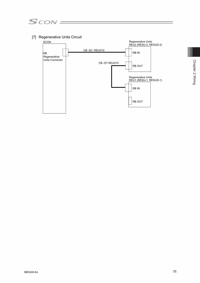
Chapter 2 W
iring
75
[7] Regenerative Units Circuit SCON
RBRegenerative Units Connector
Regenerative UnitsREU2 (RESU-2, RESUD-2)
Regenerative Units REU1 (RESU-1, RESUD-1)
CB -SC -REU010
CB -ST
RB IN
RB OUT
RB IN
RB OUT
-REU010
ME0243-8J
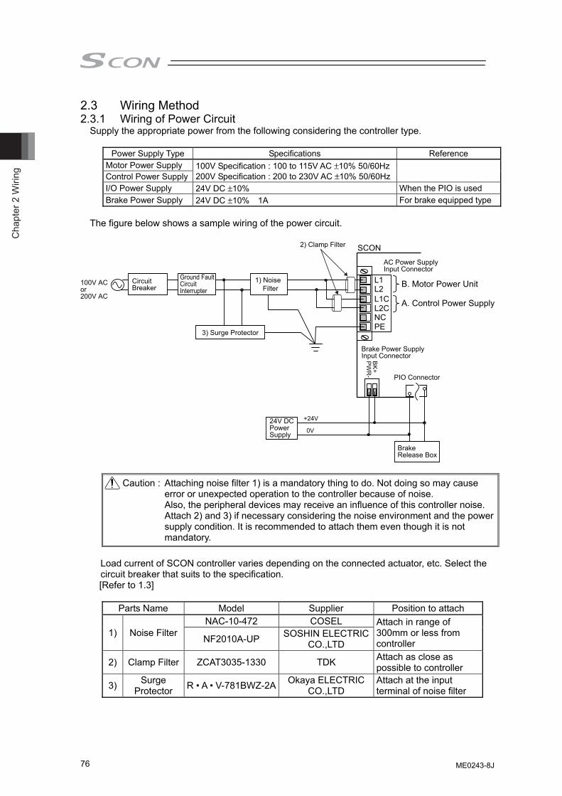
Cha
pter
2 W
iring
76
2.3 Wiring Method 2.3.1 Wiring of Power Circuit
Supply the appropriate power from the following considering the controller type.
Power Supply Type Specifications Reference Motor Power Supply 100V Specification : 100 to 115V AC ±10% 50/60Hz
200V Specification : 200 to 230V AC ±10% 50/60Hz Control Power Supply I/O Power Supply 24V DC ±10% When the PIO is used Brake Power Supply 24V DC ±10% 1A For brake equipped type
The figure below shows a sample wiring of the power circuit.
L1L2L1CL2CNCPE
CircuitBreaker
Ground FaultCircuitInterrupter
1) Noise Filter
2) Clamp Filter
3) Surge Protector
SCON
100V ACor200V AC
PW
R-
BK+
+24V
0V
Brake Power SupplyInput Connector
AC Power SupplyInput Connector
PIO Connector
A. Control Power Supply
B. Motor Power Unit
24V DCPowerSupply
BrakeRelease Box
Caution : Attaching noise filter 1) is a mandatory thing to do. Not doing so may cause error or unexpected operation to the controller because of noise. Also, the peripheral devices may receive an influence of this controller noise. Attach 2) and 3) if necessary considering the noise environment and the power supply condition. It is recommended to attach them even though it is not mandatory.
Load current of SCON controller varies depending on the connected actuator, etc. Select the circuit breaker that suits to the specification. [Refer to 1.3]
Parts Name Model Supplier Position to attach
1) Noise Filter NAC-10-472 COSEL Attach in range of
300mm or less from controller NF2010A-UP SOSHIN ELECTRIC
CO.,LTD
2) Clamp Filter ZCAT3035-1330 TDK Attach as close as possible to controller
3) Surge Protector R • A • V-781BWZ-2A Okaya ELECTRIC
CO.,LTD Attach at the input terminal of noise filter
ME0243-8J
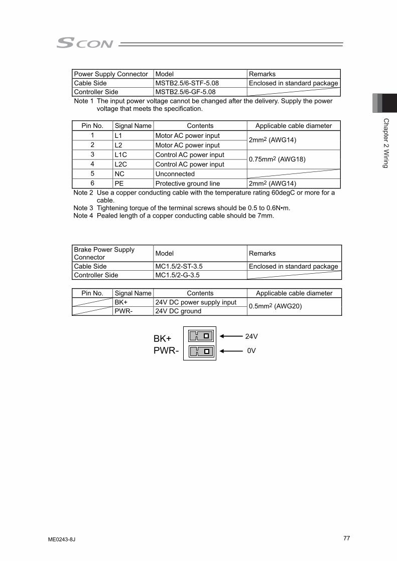
Chapter 2 W
iring
77
Power Supply Connector Model Remarks Cable Side MSTB2.5/6-STF-5.08 Enclosed in standard packageController Side MSTB2.5/6-GF-5.08 Note 1 The input power voltage cannot be changed after the delivery. Supply the power
voltage that meets the specification.
Pin No. Signal Name Contents Applicable cable diameter 1 L1 Motor AC power input 2 L2 Motor AC power input
2mm2 (AWG14)
3 L1C Control AC power input 4 L2C Control AC power input
0.75mm2 (AWG18)
5 NC Unconnected 6 PE Protective ground line 2mm2 (AWG14)
Note 2 Use a copper conducting cable with the temperature rating 60degC or more for a cable.
Note 3 Tightening torque of the terminal screws should be 0.5 to 0.6N•m. Note 4 Pealed length of a copper conducting cable should be 7mm.
Brake Power Supply Connector Model Remarks
Cable Side MC1.5/2-ST-3.5 Enclosed in standard packageController Side MC1.5/2-G-3.5
Pin No. Signal Name Contents Applicable cable diameter BK+ 24V DC power supply input PWR- 24V DC ground
0.5mm2 (AWG20)
BK+PWR-
24V
0V
ME0243-8J
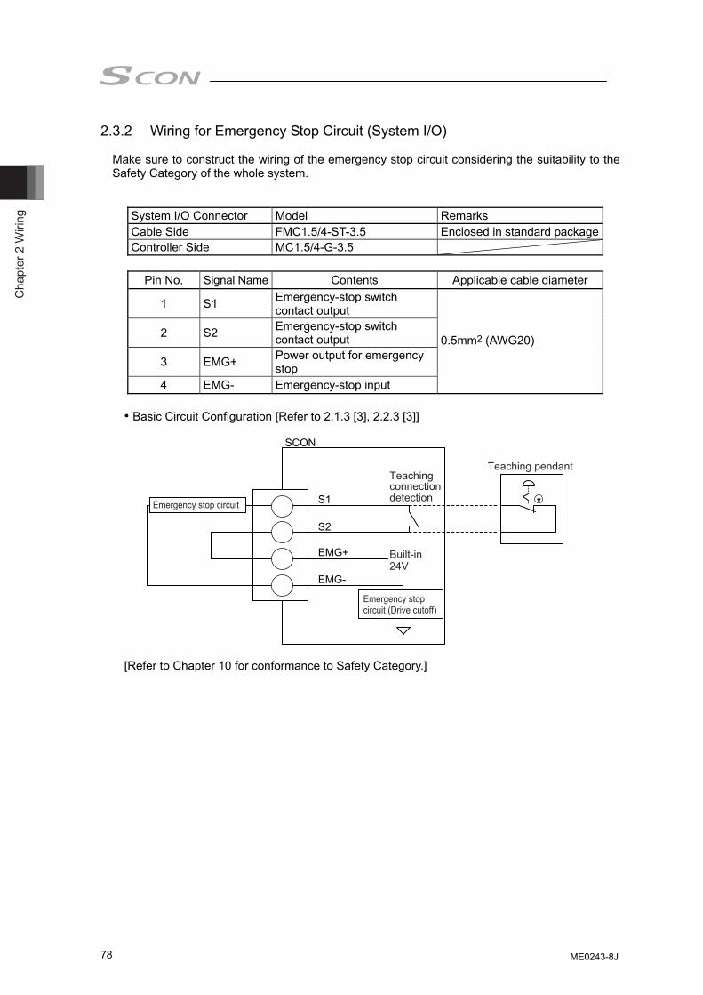
Cha
pter
2 W
iring
78
2.3.2 Wiring for Emergency Stop Circuit (System I/O)
Make sure to construct the wiring of the emergency stop circuit considering the suitability to the Safety Category of the whole system.
System I/O Connector Model Remarks Cable Side FMC1.5/4-ST-3.5 Enclosed in standard packageController Side MC1.5/4-G-3.5
Pin No. Signal Name Contents Applicable cable diameter
1 S1 Emergency-stop switch contact output
2 S2 Emergency-stop switch contact output
3 EMG+ Power output for emergency stop
4 EMG- Emergency-stop input
0.5mm2 (AWG20)
• Basic Circuit Configuration [Refer to 2.1.3 [3], 2.2.3 [3]]
SCON
S1
S2
EMG+
EMG-
Emergency stop circuit
Emergency stopcircuit (Drive cutoff)
Teaching pendantTeaching
Built-in24V
connectiondetection
[Refer to Chapter 10 for conformance to Safety Category.]
ME0243-8J
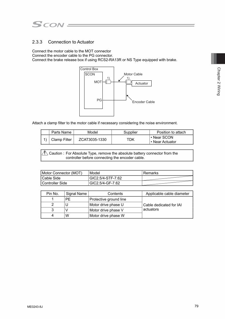
Chapter 2 W
iring
79
2.3.3 Connection to Actuator
Connect the motor cable to the MOT connector Connect the encoder cable to the PG connector. Connect the brake release box if using RCS2-RA13R or NS Type equipped with brake.
Control Box
SCON
MOT
PG
Motor Cable
Actuator
Encoder Cable
1) 1)
Attach a clamp filter to the motor cable if necessary considering the noise environment.
Parts Name Model Supplier Position to attach
1) Clamp Filter ZCAT3035-1330 TDK • Near SCON • Near Actuator
Caution : For Absolute Type, remove the absolute battery connector from the controller before connecting the encoder cable.
Motor Connector (MOT) Model Remarks Cable Side GIC2.5/4-STF-7.62 Controller Side GIC2.5/4-GF-7.62
Pin No. Signal Name Contents Applicable cable diameter 1 PE Protective ground line 2 U Motor drive phase U 3 V Motor drive phase V 4 W Motor drive phase W
Cable dedicated for IAI actuators
ME0243-8J
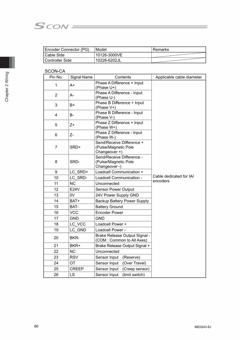
Cha
pter
2 W
iring
80
Encoder Connector (PG) Model Remarks Cable Side 10126-3000VE Controller Side 10226-6202JL SCON-CA
Pin No. Signal Name Contents Applicable cable diameter
1 A+ Phase A Difference + Input (Phase U+)
2 A- Phase A Difference - Input (Phase U-)
3 B+ Phase B Difference + Input (Phase V+)
4 B- Phase B Difference - Input (Phase V-)
5 Z+ Phase Z Difference + Input (Phase W+)
6 Z- Phase Z Difference - Input (Phase W-)
7 SRD+ Send/Receive Difference + (Pulse/Magnetic Pole Changeover +)
8 SRD- Send/Receive Difference - (Pulse/Magnetic Pole Changeover -)
9 LC_SRD+ Loadcell Communication + 10 LC_SRD- Loadcell Communication - 11 NC Unconnected 12 E24V Sensor Power Output 13 0V 24V Power Supply GND 14 BAT+ Backup Battery Power Supply15 BAT- Battery Ground 16 VCC Encoder Power 17 GND GND 18 LC_VCC Loadcell Power + 19 LC_GND Loadcell Power -
20 BKR- Brake Release Output Signal -(COM : Common to All Axes)
21 BKR+ Brake Release Output Signal +22 NC Unconnected 23 RSV Sensor Input (Reserve) 24 OT Sensor Input (Over Travel) 25 CREEP Sensor Input (Creep sensor)26 LS Sensor Input (limit switch)
Cable dedicated for IAI encoders
ME0243-8J
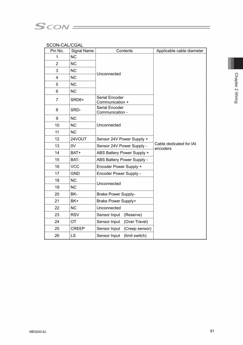
Chapter 2 W
iring
81
SCON-CAL/CGAL Pin No. Signal Name Contents Applicable cable diameter
1 NC
2 NC
3 NC
4 NC
5 NC
6 NC
Unconnected
7 SRD6+ Serial Encoder Communication +
8 SRD- Serial Encoder Communication -
9 NC
10 NC
11 NC
Unconnected
12 24VOUT Sensor 24V Power Supply +
13 0V Sensor 24V Power Supply -
14 BAT+ ABS Battery Power Supply +
15 BAT- ABS Battery Power Supply -
16 VCC Encoder Power Supply +
17 GND Encoder Power Supply -
18 NC
19 NC Unconnected
20 BK- Brake Power Supply-
21 BK+ Brake Power Supply+
22 NC Unconnected
23 RSV Sensor Input (Reserve)
24 OT Sensor Input (Over Travel)
25 CREEP Sensor Input (Creep sensor)
26 LS Sensor Input (limit switch)
Cable dedicated for IAI encoders
ME0243-8J
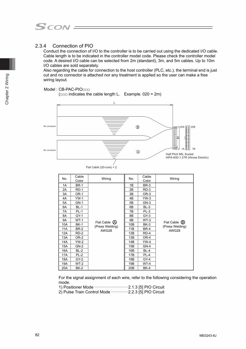
Cha
pter
2 W
iring
82
2.3.4 Connection of PIO Conduct the connection of I/O to the controller is to be carried out using the dedicated I/O cable. Cable length is to be indicated in the controller model code. Please check the controller model code. A desired I/O cable can be selected from 2m (standard), 3m, and 5m cables. Up to 10m I/O cables are sold separately. Also regarding the cable for connection to the host controller (PLC, etc.), the terminal end is just cut and no connector is attached nor any treatment is applied so the user can make a free wiring layout. Model : CB-PAC-PIO□□□
(□□□ indicates the cable length L. Example. 020 = 2m)
Half Pitch MIL SocketHIF6-40D-1.27R (Hirose Electric)
Flat Cable (20-core) × 2
L
20A 20B
1A 1B
No connector
No connector
No. Cable Color Wiring No. Cable
Color Wiring
1A BR-1 1B BR-3 2A RD-1 2B RD-3 3A OR-1 3B OR-3 4A YW-1 4B YW-3 5A GN-1 5B GN-3 6A BL-1 6B BL-3 7A PL-1 7B PL-3 8A GY-1 8B GY-3 9A WT-1 9B WT-3
10A BK-1 10B BK-3 11A BR-2 11B BR-4 12A RD-2 12B RD-4 13A OR-2 13B OR-4 14A YW-2 14B YW-4 15A GN-2 15B GN-4 16A BL-2 16B BL-4 17A PL-2 17B PL-4 18A GY-2 18B GY-4 19A WT-2 19B WT-4 20A BK-2
Flat Cable ○A (Press Welding)
AWG28
20B BK-4
Flat Cable ○B (Press Welding)
AWG28
For the signal assignment of each wire, refer to the following considering the operation mode. 1) Positioner Mode ························2.1.3 [5] PIO Circuit 2) Pulse Train Control Mode ············2.2.3 [5] PIO Circuit
ME0243-8J
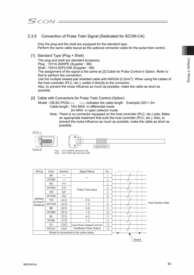
Chapter 2 W
iring
83
2.3.5 Connection of Pulse Train Signal (Dedicated for SCON-CA) Only the plug and the shell are equipped for the standard type. Perform the same cable layout as the optional connector cable for the pulse train control.
[1] Standard Type (Plug + Shell) The plug and shell are standard accessory. Plug : 10114-3000PE (Supplier : 3M) Shell : 10314-52F0-008 (Supplier : 3M) The assignment of the signal is the same as [2] Cable for Pulse Control in Option. Refer to that to perform the connection. Use the multiple twisted pair shielded cable with AWG24 (0.2mm2). When using the cables of the host controller (PLC, etc.), solder it directly to the connector. Also, to prevent the noise influence as much as possible, make the cable as short as possible.
[2] Cable with Connectors for Pulse Train Control (Option) Model : CB-SC-PIOS□□□ □□□ indicates the cable length Example) 020 = 2m
Cable length : 10m MAX. in differential mode 2m MAX. in open collector mode
Note : There is no connector equipped on the host controller (PLC, etc.) side. Make an appropriate treatment that suits the host controller (PLC, etc.). Also, to prevent the noise influence as much as possible, make the cable as short as possible.
Pin No. 1
Pin No. 8PlugShell
10114-3000PE (Sumitomo 3M)10314-52F0-008 (Sumitomo 3M)
::
CB-SC-PIOS***
Host System SideAWG24
(0.2mm2)Soldered
Wiring ColorBK
WT/BKRD
WT/RDGN
WT/GNYW
WT/YWBR
WT/BRBL
WT/BLGY
WT/GY
Symbol Signal Name
Pulse Train Input
Line Driver Output Line forFeedback Pulse Output
Shield is connected to the cable clamp
Shield
ME0243-8J
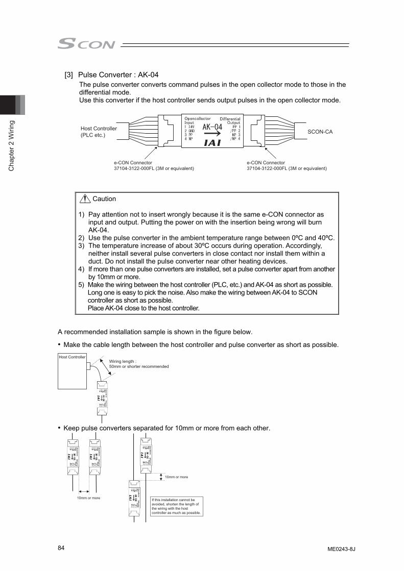
Cha
pter
2 W
iring
84
[3] Pulse Converter : AK-04 The pulse converter converts command pulses in the open collector mode to those in the differential mode. Use this converter if the host controller sends output pulses in the open collector mode.
Host Controller(PLC etc.) SCON-CA
e-CON Connector37104-3122-000FL (3M or equivalent)
e-CON Connector37104-3122-000FL (3M or equivalent)
Caution 1) Pay attention not to insert wrongly because it is the same e-CON connector as
input and output. Putting the power on with the insertion being wrong will burn AK-04.
2) Use the pulse converter in the ambient temperature range between 0ºC and 40ºC.3) The temperature increase of about 30ºC occurs during operation. Accordingly,
neither install several pulse converters in close contact nor install them within a duct. Do not install the pulse converter near other heating devices.
4) If more than one pulse converters are installed, set a pulse converter apart from another by 10mm or more.
5) Make the wiring between the host controller (PLC, etc.) and AK-04 as short as possible. Long one is easy to pick the noise. Also make the wiring between AK-04 to SCON controller as short as possible. Place AK-04 close to the host controller.
A recommended installation sample is shown in the figure below.
• Make the cable length between the host controller and pulse converter as short as possible.
Wiring length : 50mm or shorter recommended
Host Controller
• Keep pulse converters separated for 10mm or more from each other.
10mm or more
10mm or more
If this installation cannot be avoided, shorten the length of the wiring with the host controller as much as possible.
ME0243-8J
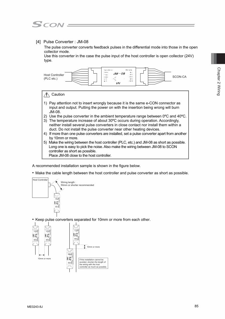
Chapter 2 W
iring
85
[4] Pulse Converter : JM-08 The pulse converter converts feedback pulses in the differential mode into those in the open collector mode. Use this converter in the case the pulse input of the host controller is open collector (24V) type.
Host Controller(PLC etc.) SCON-CA
Caution 1) Pay attention not to insert wrongly because it is the same e-CON connector as
input and output. Putting the power on with the insertion being wrong will burn JM-08.
2) Use the pulse converter in the ambient temperature range between 0ºC and 40ºC.3) The temperature increase of about 30ºC occurs during operation. Accordingly,
neither install several pulse converters in close contact nor install them within a duct. Do not install the pulse converter near other heating devices.
4) If more than one pulse converters are installed, set a pulse converter apart from another by 10mm or more.
5) Make the wiring between the host controller (PLC, etc.) and JM-08 as short as possible. Long one is easy to pick the noise. Also make the wiring between JM-08 to SCON controller as short as possible. Place JM-08 close to the host controller.
A recommended installation sample is shown in the figure below.
• Make the cable length between the host controller and pulse converter as short as possible.
Wiring length : 50mm or shorter recommended
Host Controller
• Keep pulse converters separated for 10mm or more from each other.
10mm or more
10mm or more
If this installation cannot be avoided, shorten the length of the wiring with the host controller as much as possible.
ME0243-8J
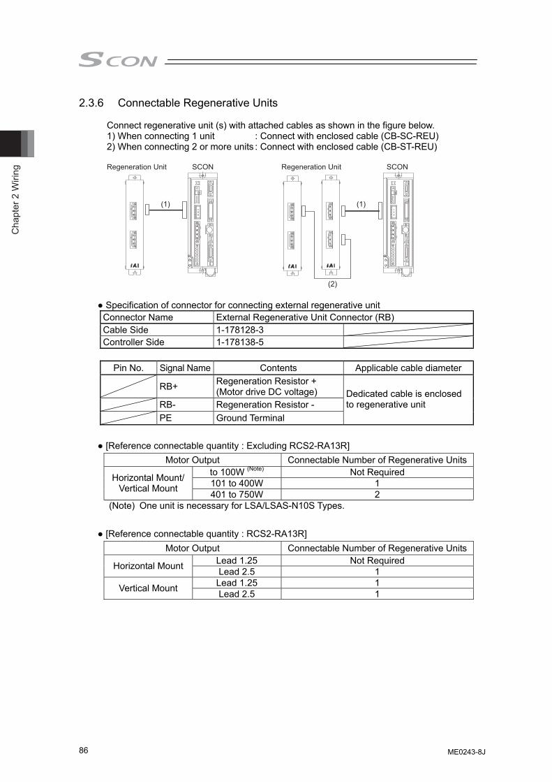
Cha
pter
2 W
iring
86
2.3.6 Connectable Regenerative Units
Connect regenerative unit (s) with attached cables as shown in the figure below. 1) When connecting 1 unit : Connect with enclosed cable (CB-SC-REU) 2) When connecting 2 or more units : Connect with enclosed cable (CB-ST-REU)
(1) (1)
(2)
SCON SCONRegeneration Unit Regeneration Unit
● Specification of connector for connecting external regenerative unit Connector Name External Regenerative Unit Connector (RB) Cable Side 1-178128-3 Controller Side 1-178138-5
Pin No. Signal Name Contents Applicable cable diameter RB+ Regeneration Resistor +
(Motor drive DC voltage) RB- Regeneration Resistor - PE Ground Terminal
Dedicated cable is enclosed to regenerative unit
● [Reference connectable quantity : Excluding RCS2-RA13R]
● [Reference connectable quantity : RCS2-RA13R]
Motor Output Connectable Number of Regenerative Unitsto 100W (Note) Not Required 101 to 400W 1 Horizontal Mount/
Vertical Mount 401 to 750W 2 (Note) One unit is necessary for LSA/LSAS-N10S Types.
Motor Output Connectable Number of Regenerative UnitsLead 1.25 Not Required Horizontal Mount Lead 2.5 1 Lead 1.25 1 Vertical Mount Lead 2.5 1
ME0243-8J
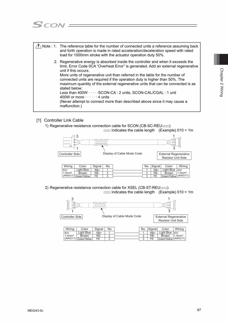
Chapter 2 W
iring
87
[1] Controller Link Cable
1) Regenerative resistance connection cable for SCON (CB-SC-REU□□□) □□□ indicates the cable length (Example) 010 = 1m
2) Regenerative resistance connection cable for XSEL (CB-ST-REU□□□)
□□□ indicates the cable length (Example) 010 = 1m
Note : 1. The reference table for the number of connected units a reference assuming back and forth operation is made in rated acceleration/deceleration speed with rated load for 1000mm stroke with the actuator operation duty 50%.
2. Regenerative energy is absorbed inside the controller and when it exceeds the limit, Error Code 0CA “Overheat Error” is generated. Add an external regenerative unit if this occurs. More units of regenerative unit than referred in the table for the number of connected units are required if the operation duty is higher than 50%. The maximum quantity of the external regenerative units that can be connected is as stated below: Less than 400W · · · · ·SCON-CA : 2 units, SCON-CAL/CGAL : 1 unit 400W or more · · · · · · 4 units (Never attempt to connect more than described above since it may cause a malfunction.)
3
1 3
1
123
RB-PE
RB+RB-PE
RB+KIV1.0mm2
(AWG17) 321
Controller Side
Wiring WiringColorLight Blue
BrownGreen/Yellow
ColorLight Blue
BrownGreen/Yellow
Signal SignalNo. No.
External RegenerativeResistor Unit Side
KIV1.0mm2
(AWG17)
Display of Cable Mode Code
KIV1.0mm2
(AWG17)
KIV1.0mm2
(AWG17)
3
1 3
1
123
RB-PE
RB+RB-PE
RB+
321
Controller Side
Wiring WiringColorLight Blue
BrownGreen/Yellow
ColorLight Blue
BrownGreen/Yellow
Signal SignalNo. No.
External RegenerativeResistor Unit Side
Display of Cable Mode Code
ME0243-8J
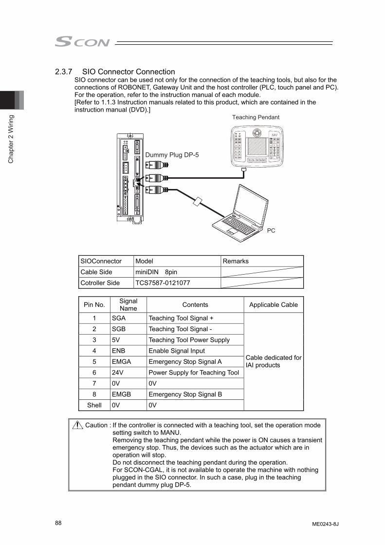
Cha
pter
2 W
iring
88
2.3.7 SIO Connector Connection SIO connector can be used not only for the connection of the teaching tools, but also for the connections of ROBONET, Gateway Unit and the host controller (PLC, touch panel and PC). For the operation, refer to the instruction manual of each module. [Refer to 1.1.3 Instruction manuals related to this product, which are contained in the instruction manual (DVD).]
Teaching Pendant
PC
Dummy Plug DP-5
SIOConnector Model Remarks
Cable Side miniDIN 8pin
Cotroller Side TCS7587-0121077
Pin No. Signal Name Contents Applicable Cable
1 SGA Teaching Tool Signal +
2 SGB Teaching Tool Signal -
3 5V Teaching Tool Power Supply
4 ENB Enable Signal Input
5 EMGA Emergency Stop Signal A
6 24V Power Supply for Teaching Tool
7 0V 0V
8 EMGB Emergency Stop Signal B
Shell 0V 0V
Cable dedicated for IAI products
Caution : If the controller is connected with a teaching tool, set the operation mode
setting switch to MANU. Removing the teaching pendant while the power is ON causes a transient
emergency stop. Thus, the devices such as the actuator which are in operation will stop. Do not disconnect the teaching pendant during the operation.
For SCON-CGAL, it is not available to operate the machine with nothing plugged in the SIO connector. In such a case, plug in the teaching pendant dummy plug DP-5.
ME0243-8J
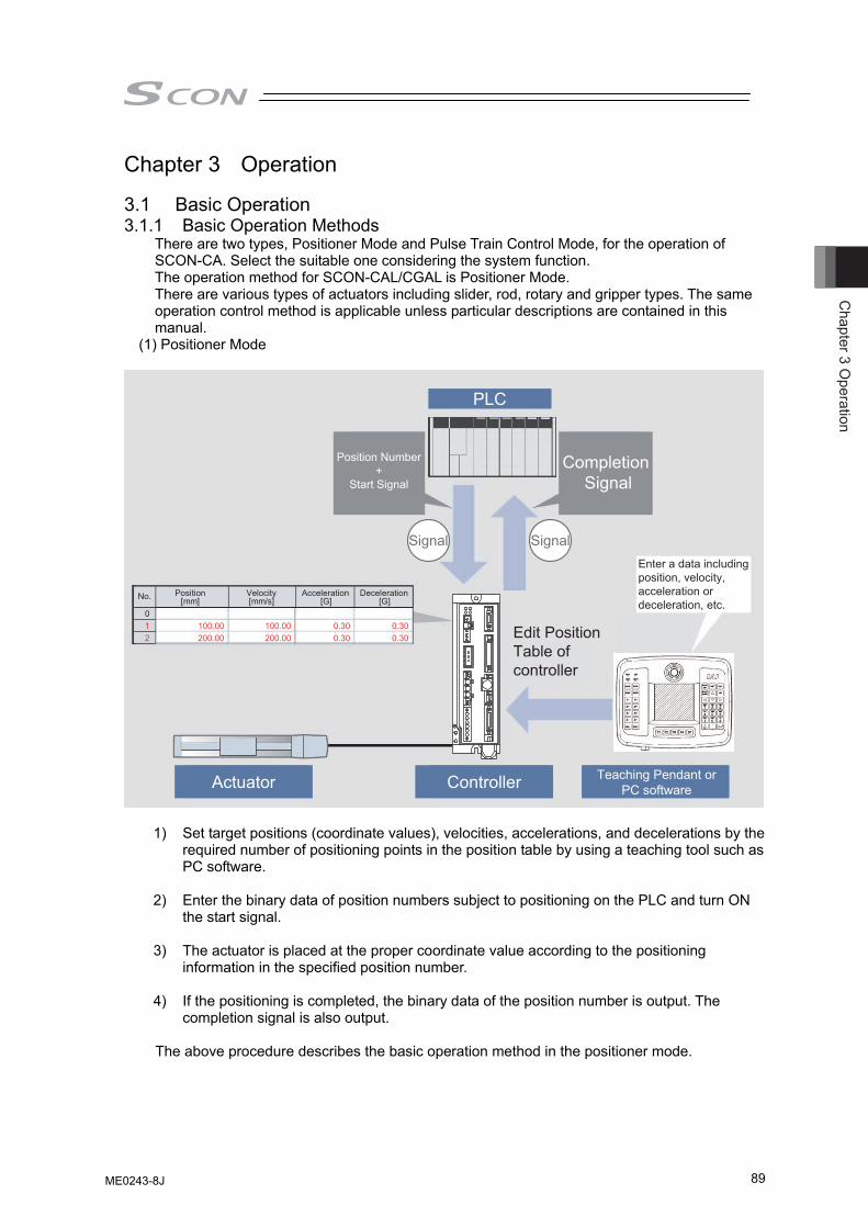
Chapter 3 O
peration
89
Chapter 3 Operation
3.1 Basic Operation 3.1.1 Basic Operation Methods
There are two types, Positioner Mode and Pulse Train Control Mode, for the operation of SCON-CA. Select the suitable one considering the system function. The operation method for SCON-CAL/CGAL is Positioner Mode. There are various types of actuators including slider, rod, rotary and gripper types. The same operation control method is applicable unless particular descriptions are contained in this manual.
(1) Positioner Mode
Completion Signal
Signal Signal
Edit Position Table of controller
Actuator Controller Teaching Pendant orPC software
Position Number +
Start Signal
PLC
Enter a data including position, velocity, acceleration or deceleration, etc.
No. [G] 0 1 100.00 0.30 0.30 2 200.00 0.30 0.30
100.00 200.00
Acceleration Deceleration Velocity [mm] [mm/s] [G]
Position
1) Set target positions (coordinate values), velocities, accelerations, and decelerations by the required number of positioning points in the position table by using a teaching tool such as PC software.
2) Enter the binary data of position numbers subject to positioning on the PLC and turn ON
the start signal. 3) The actuator is placed at the proper coordinate value according to the positioning
information in the specified position number. 4) If the positioning is completed, the binary data of the position number is output. The
completion signal is also output.
The above procedure describes the basic operation method in the positioner mode.
ME0243-8J
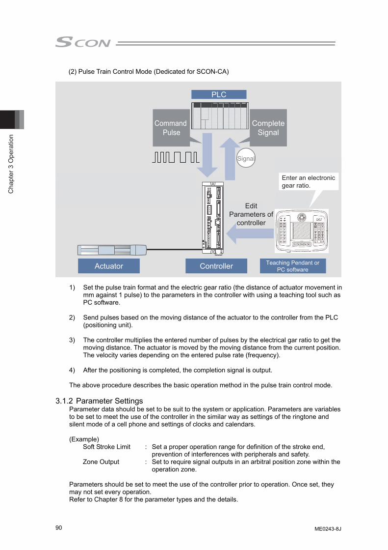
Cha
pter
3 O
pera
tion
90
(2) Pulse Train Control Mode (Dedicated for SCON-CA)
CompleteSignal
Signal
Edit Parameters of
controller
Actuator Controller Teaching Pendant or PC software
Command Pulse
PLC
Enter an electronic gear ratio.
1) Set the pulse train format and the electric gear ratio (the distance of actuator movement in
mm against 1 pulse) to the parameters in the controller with using a teaching tool such as PC software.
2) Send pulses based on the moving distance of the actuator to the controller from the PLC
(positioning unit). 3) The controller multiplies the entered number of pulses by the electrical gar ratio to get the
moving distance. The actuator is moved by the moving distance from the current position. The velocity varies depending on the entered pulse rate (frequency). 4) After the positioning is completed, the completion signal is output. The above procedure describes the basic operation method in the pulse train control mode.
3.1.2 Parameter Settings
Parameter data should be set to be suit to the system or application. Parameters are variables to be set to meet the use of the controller in the similar way as settings of the ringtone and silent mode of a cell phone and settings of clocks and calendars. (Example)
Soft Stroke Limit : Set a proper operation range for definition of the stroke end, prevention of interferences with peripherals and safety.
Zone Output : Set to require signal outputs in an arbitral position zone within the operation zone.
Parameters should be set to meet the use of the controller prior to operation. Once set, they may not set every operation. Refer to Chapter 8 for the parameter types and the details.
ME0243-8J
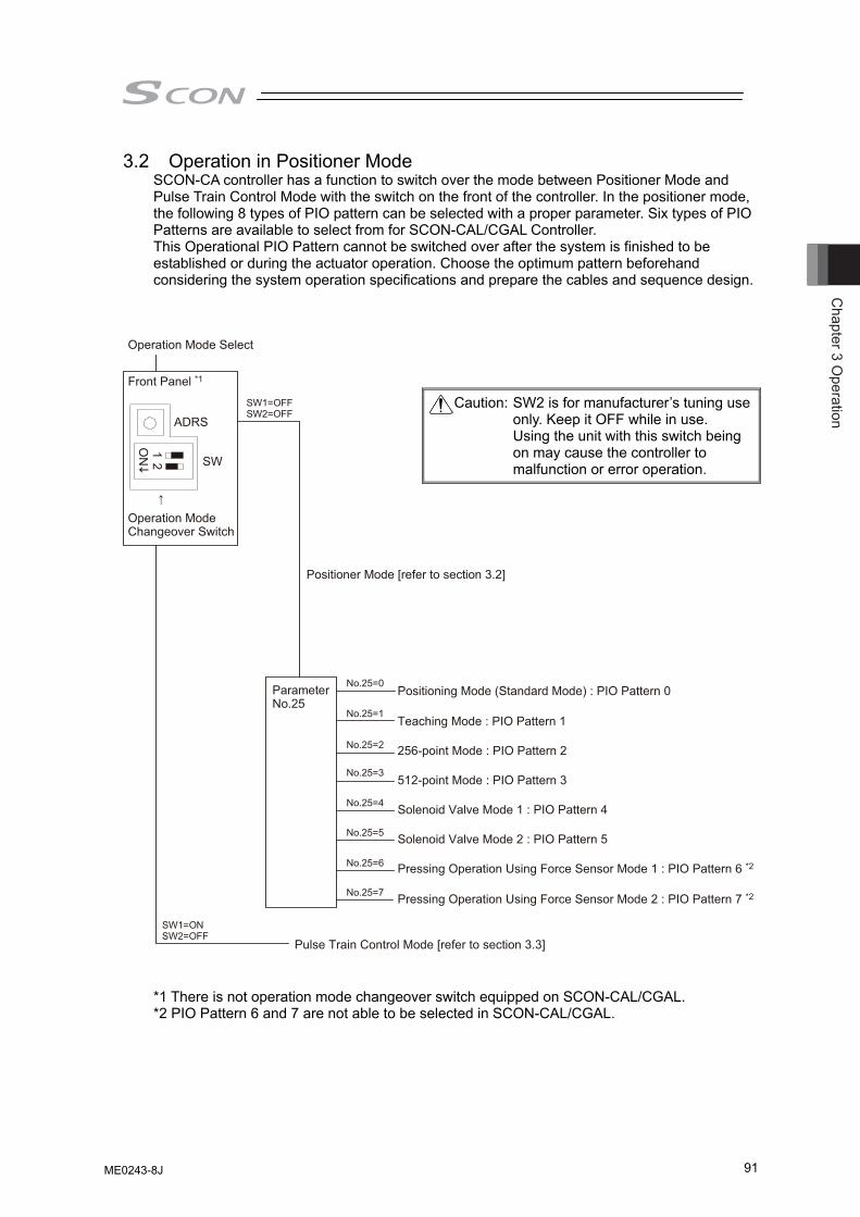
Chapter 3 O
peration
91
3.2 Operation in Positioner Mode SCON-CA controller has a function to switch over the mode between Positioner Mode and Pulse Train Control Mode with the switch on the front of the controller. In the positioner mode, the following 8 types of PIO pattern can be selected with a proper parameter. Six types of PIO Patterns are available to select from for SCON-CAL/CGAL Controller. This Operational PIO Pattern cannot be switched over after the system is finished to be established or during the actuator operation. Choose the optimum pattern beforehand considering the system operation specifications and prepare the cables and sequence design.
*1 There is not operation mode changeover switch equipped on SCON-CAL/CGAL. *2 PIO Pattern 6 and 7 are not able to be selected in SCON-CAL/CGAL.
Caution: SW2 is for manufacturer’s tuning use only. Keep it OFF while in use. Using the unit with this switch being on may cause the controller to malfunction or error operation.
SW1=OFFSW2=OFF
SW1=ONSW2=OFF
↑
No.25=0
No.25=7
No.25=6
No.25=5
No.25=4
No.25=3
No.25=2
No.25=1
ParameterNo.25
Positioner Mode [refer to section 3.2]
Positioning Mode (Standard Mode) : PIO Pattern 0
Teaching Mode : PIO Pattern 1
256-point Mode : PIO Pattern 2
512-point Mode : PIO Pattern 3
Solenoid Valve Mode 1 : PIO Pattern 4
Solenoid Valve Mode 2 : PIO Pattern 5
Pressing Operation Using Force Sensor Mode 1 : PIO Pattern 6 *2
Pressing Operation Using Force Sensor Mode 2 : PIO Pattern 7 *2
Front Panel *1
Operation Mode Select
ADRS
SW
12
ON
Pulse Train Control Mode [refer to section 3.3]
Operation Mode Changeover Switch
ME0243-8J
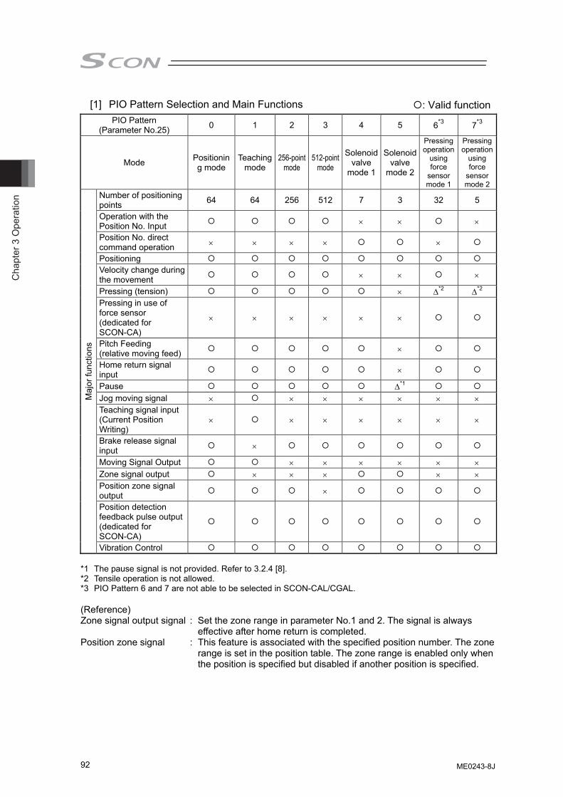
Cha
pter
3 O
pera
tion
92
[1] PIO Pattern Selection and Main Functions PIO Pattern
(Parameter No.25) 0 1 2 3 4 5 6*3 7*3
Mode Positioning mode
Teaching mode
256-point mode
512-point mode
Solenoid valve
mode 1
Solenoid valve
mode 2
Pressing operation
using force
sensor mode 1
Pressing operation
using force
sensor mode 2
Number of positioning points 64 64 256 512 7 3 32 5
Operation with the Position No. Input × × ×
Position No. direct command operation × × × × ×
Positioning Velocity change during the movement × × ×
Pressing (tension) × Δ*2 Δ*2 Pressing in use of force sensor (dedicated for SCON-CA)
× × × × × ×
Pitch Feeding (relative moving feed) ×
Home return signal input ×
Pause Δ*1 Jog moving signal × × × × × × × Teaching signal input (Current Position Writing)
× × × × × × ×
Brake release signal input ×
Moving Signal Output × × × × × × Zone signal output × × × × × Position zone signal output ×
Position detection feedback pulse output (dedicated for SCON-CA)
Maj
or fu
nctio
ns
Vibration Control *1 The pause signal is not provided. Refer to 3.2.4 [8]. *2 Tensile operation is not allowed. *3 PIO Pattern 6 and 7 are not able to be selected in SCON-CAL/CGAL. (Reference) Zone signal output signal : Set the zone range in parameter No.1 and 2. The signal is always
effective after home return is completed. Position zone signal : This feature is associated with the specified position number. The zone
range is set in the position table. The zone range is enabled only when the position is specified but disabled if another position is specified.
: Valid function
ME0243-8J
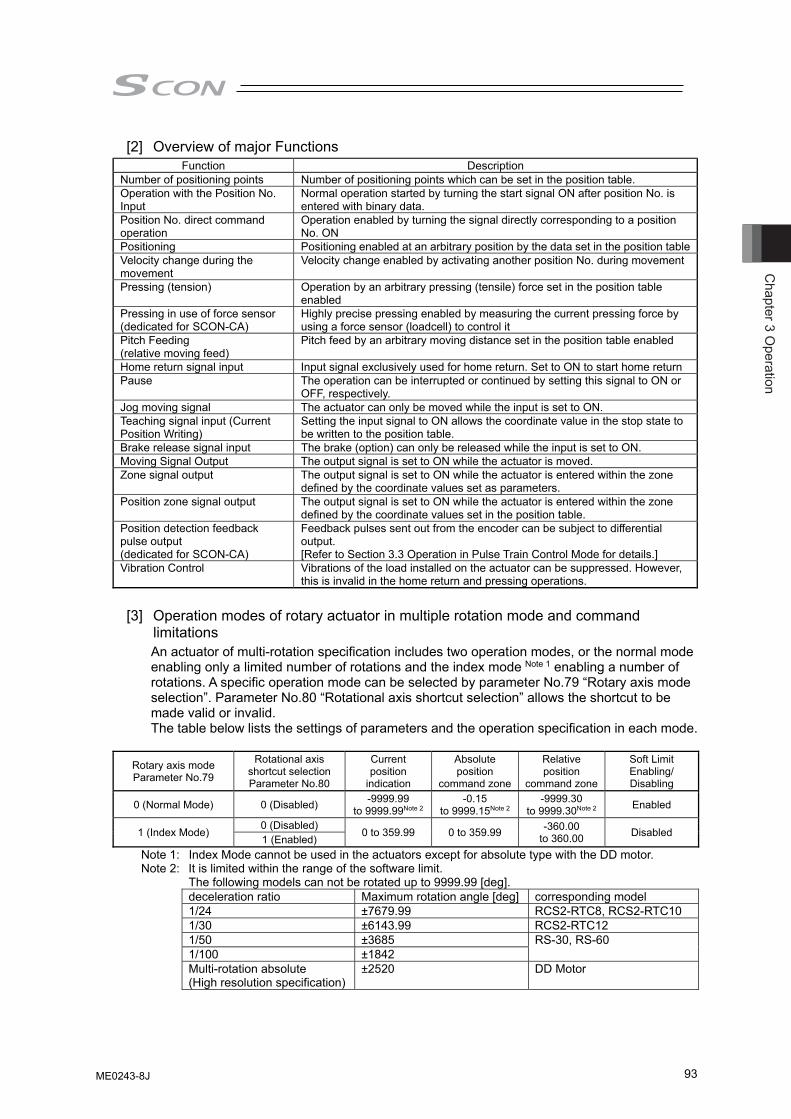
Chapter 3 O
peration
93
[2] Overview of major Functions Function Description
Number of positioning points Number of positioning points which can be set in the position table. Operation with the Position No. Input
Normal operation started by turning the start signal ON after position No. is entered with binary data.
Position No. direct command operation
Operation enabled by turning the signal directly corresponding to a position No. ON
Positioning Positioning enabled at an arbitrary position by the data set in the position tableVelocity change during the movement
Velocity change enabled by activating another position No. during movement
Pressing (tension) Operation by an arbitrary pressing (tensile) force set in the position table enabled
Pressing in use of force sensor (dedicated for SCON-CA)
Highly precise pressing enabled by measuring the current pressing force by using a force sensor (loadcell) to control it
Pitch Feeding (relative moving feed)
Pitch feed by an arbitrary moving distance set in the position table enabled
Home return signal input Input signal exclusively used for home return. Set to ON to start home returnPause The operation can be interrupted or continued by setting this signal to ON or
OFF, respectively.Jog moving signal The actuator can only be moved while the input is set to ON. Teaching signal input (Current Position Writing)
Setting the input signal to ON allows the coordinate value in the stop state to be written to the position table.
Brake release signal input The brake (option) can only be released while the input is set to ON. Moving Signal Output The output signal is set to ON while the actuator is moved. Zone signal output The output signal is set to ON while the actuator is entered within the zone
defined by the coordinate values set as parameters. Position zone signal output The output signal is set to ON while the actuator is entered within the zone
defined by the coordinate values set in the position table. Position detection feedback pulse output (dedicated for SCON-CA)
Feedback pulses sent out from the encoder can be subject to differential output. [Refer to Section 3.3 Operation in Pulse Train Control Mode for details.]
Vibration Control Vibrations of the load installed on the actuator can be suppressed. However, this is invalid in the home return and pressing operations.
[3] Operation modes of rotary actuator in multiple rotation mode and command
limitations An actuator of multi-rotation specification includes two operation modes, or the normal mode enabling only a limited number of rotations and the index mode Note 1 enabling a number of rotations. A specific operation mode can be selected by parameter No.79 “Rotary axis mode selection”. Parameter No.80 “Rotational axis shortcut selection” allows the shortcut to be made valid or invalid. The table below lists the settings of parameters and the operation specification in each mode.
Rotary axis mode Parameter No.79
Rotational axis shortcut selection Parameter No.80
Current position
indication
Absolute position
command zone
Relative position
command zone
Soft Limit Enabling/ Disabling
0 (Normal Mode) 0 (Disabled) -9999.99 to 9999.99Note 2
-0.15 to 9999.15Note 2
-9999.30 to 9999.30Note 2 Enabled
1 (Index Mode) 0 (Disabled) 0 to 359.99 0 to 359.99 -360.00 to 360.00 Disabled 1 (Enabled)
Note 1: Index Mode cannot be used in the actuators except for absolute type with the DD motor. Note 2: It is limited within the range of the software limit.
The following models can not be rotated up to 9999.99 [deg]. deceleration ratio Maximum rotation angle [deg] corresponding model 1/24 ±7679.99 RCS2-RTC8, RCS2-RTC10 1/30 ±6143.99 RCS2-RTC12 1/50 ±3685 RS-30, RS-60 1/100 ±1842Multi-rotation absolute (High resolution specification)
±2520 DD Motor
ME0243-8J
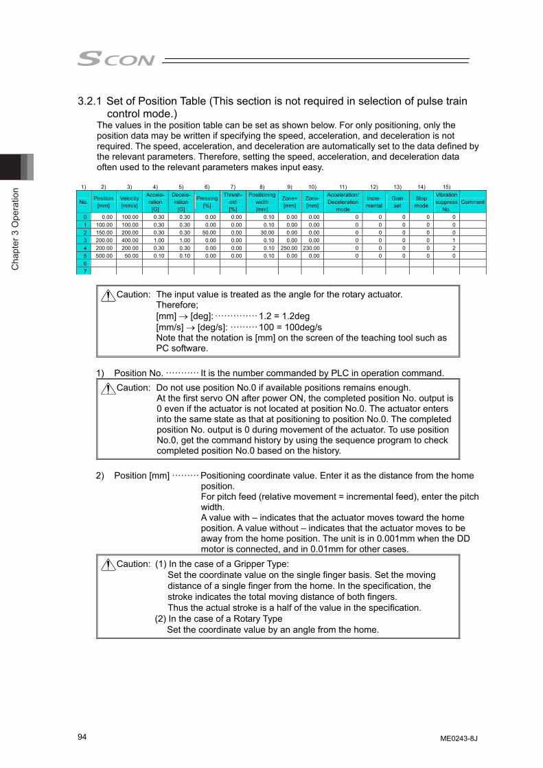
Cha
pter
3 O
pera
tion
94
3.2.1 Set of Position Table (This section is not required in selection of pulse train control mode.)
The values in the position table can be set as shown below. For only positioning, only the position data may be written if specifying the speed, acceleration, and deceleration is not required. The speed, acceleration, and deceleration are automatically set to the data defined by the relevant parameters. Therefore, setting the speed, acceleration, and deceleration data often used to the relevant parameters makes input easy.
1) 2) 3) 4) 5) 6) 7) 8) 9) 10) 11) 12) 13) 14) 15)
No. Position
[mm] Velocity [mm/s]
Accele-ration
[G]
Decele- ration
[G]
Pressing [%]
Thresh-old [%]
Positioning width [mm]
Zone+[mm]
Zone-[mm]
Acceleration/Deceleration
mode
Incre-mental
Gain set
Stop mode
Vibration suppress
No. Comment
0 0.00 100.00 0.30 0.30 0.00 0.00 0.10 0.00 0.00 0 0 0 0 01 100.00 100.00 0.30 0.30 0.00 0.00 0.10 0.00 0.00 0 0 0 0 02 150.00 200.00 0.30 0.30 50.00 0.00 30.00 0.00 0.00 0 0 0 0 03 200.00 400.00 1.00 1.00 0.00 0.00 0.10 0.00 0.00 0 0 0 0 14 200.00 200.00 0.30 0.30 0.00 0.00 0.10 250.00 230.00 0 0 0 0 25 500.00 50.00 0.10 0.10 0.00 0.00 0.10 0.00 0.00 0 0 0 0 06 7
Caution: The input value is treated as the angle for the rotary actuator.
Therefore; [mm] → [deg]: ··············1.2 = 1.2deg [mm/s] → [deg/s]: ·········100 = 100deg/s Note that the notation is [mm] on the screen of the teaching tool such as
PC software.
1) Position No. ··········· It is the number commanded by PLC in operation command. Caution: Do not use position No.0 if available positions remains enough. At the first servo ON after power ON, the completed position No. output is
0 even if the actuator is not located at position No.0. The actuator enters into the same state as that at positioning to position No.0. The completed position No. output is 0 during movement of the actuator. To use position No.0, get the command history by using the sequence program to check completed position No.0 based on the history.
2) Position [mm] ········· Positioning coordinate value. Enter it as the distance from the home
position. For pitch feed (relative movement = incremental feed), enter the pitch width. A value with – indicates that the actuator moves toward the home position. A value without – indicates that the actuator moves to be away from the home position. The unit is in 0.001mm when the DD motor is connected, and in 0.01mm for other cases.
Caution: (1) In the case of a Gripper Type: Set the coordinate value on the single finger basis. Set the moving distance of a single finger from the home. In the specification, the stroke indicates the total moving distance of both fingers. Thus the actual stroke is a half of the value in the specification.
(2) In the case of a Rotary Type Set the coordinate value by an angle from the home.
ME0243-8J
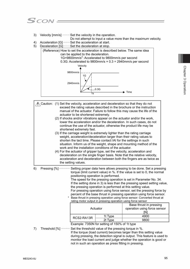
Chapter 3 O
peration
95
3) Velocity [mm/s] ······· Set the velocity in the operation. Do not attempt to input a value more than the maximum velocity.
4) Acceleration [G] ······ Set the acceleration at start. 5) Deceleration [G]······ Set the deceleration at stop.
(Reference) How to set the acceleration is described below. The same idea can be applied to the deceleration.
1G=9800mm/s2: Accelerated to 9800mm/s per second 0.3G: Accelerated to 9800mm/s × 0.3 = 2940mm/s per second
Caution: (1) Set the velocity, acceleration and deceleration so that they do not
exceed the rating values described in the brochure or the instruction manual of the actuator. Failure to follow this may cause the life of the actuator to be shortened extremely.
(2) If shocks and/or vibrations appear on the actuator and/or the work, lower the acceleration and/or the deceleration. In such cases, do not continue the use of the actuator, otherwise the product life may be shortened extremely fast.
(3) If the carriage weight is extremely lighter than the rating carriage weight, acceleration/deceleration larger than their rating values to shorten the tact time. Please contact IAI for the settings in such situation. Inform us of the weight, shape and mounting method of the work and the installation conditions of the actuator.
(4) For the actuator of gripper type, set the velocity, acceleration and deceleration on the single finger basis. Note that the relative velocity, acceleration and deceleration between both the fingers are as twice as the setting values.
6) Pressing [%] ·········· Setting proper data here allows pressing to be done. Set a pressing torque (limit current value) in %. If the value is set to 0, the normal positioning operation is performed. The speed for the pressing operation is set in Parameter No. 34. If the setting done in 3) is less than the pressing speed setting value, the pressing operation is performed at this setting value. For pressing operation using force sensor, set the pressing force by percent of the base thrust in pressing operation using force sensor.
* Base thrust in pressing operation using force sensor: Converted thrust at rating motor output in pressing operation using force sensor
Actuator Base thrust in pressing
operation using force sensor [N]
1t Type 4900 RCS2-RA13R 2t Type 9800 Example: 7350N for setting of 150% of 1t type 7) Threshold [%] ········ Set the threshold value of the pressing torque in %.
If the torque (load current) becomes larger than this setting value during pressing, the detection signal is output. This feature is used to monitor the load current and judge whether the operation is good or not in such an operation as press fitting in pressing.
Velocity
Time
9800mm/s
1s
1G
2940mm/s
0.3G
ME0243-8J
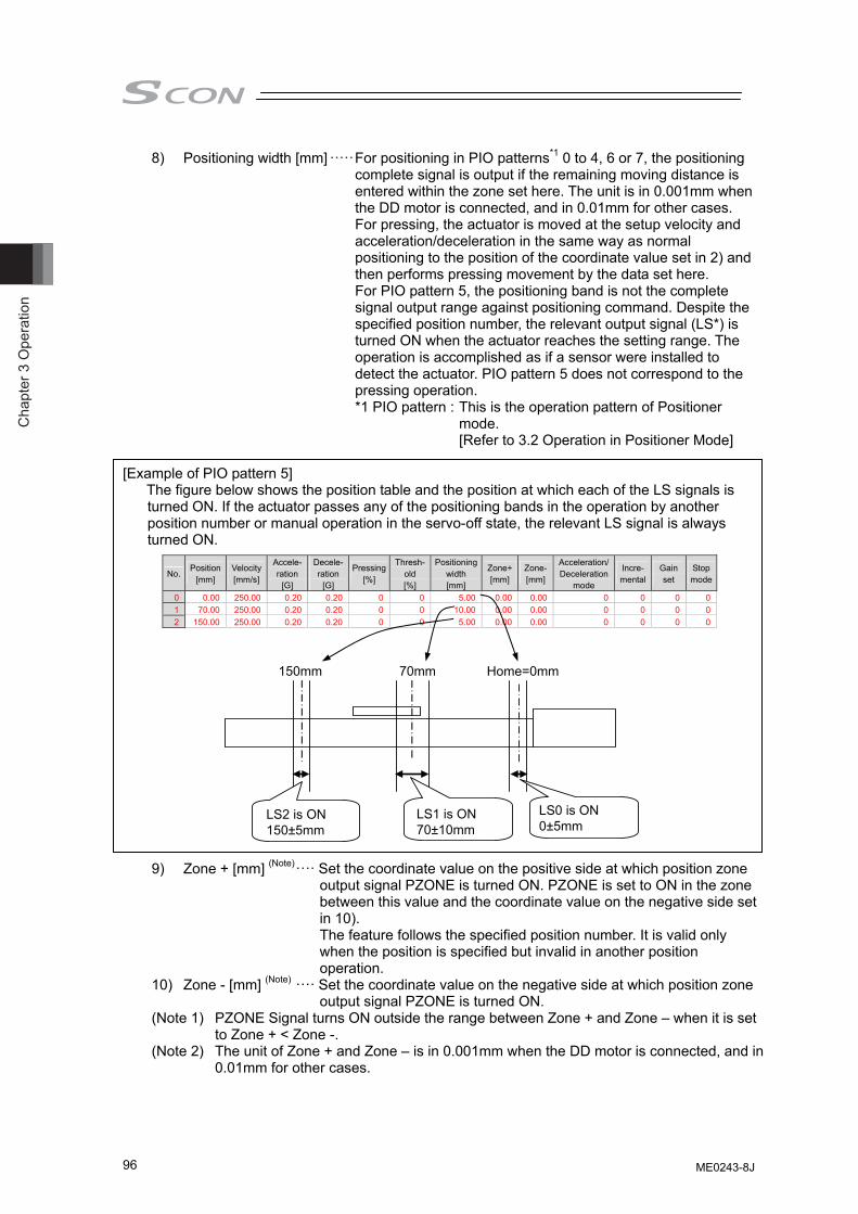
Cha
pter
3 O
pera
tion
96
8) Positioning width [mm] ·····For positioning in PIO patterns*1 0 to 4, 6 or 7, the positioning complete signal is output if the remaining moving distance is entered within the zone set here. The unit is in 0.001mm when the DD motor is connected, and in 0.01mm for other cases. For pressing, the actuator is moved at the setup velocity and acceleration/deceleration in the same way as normal positioning to the position of the coordinate value set in 2) and then performs pressing movement by the data set here. For PIO pattern 5, the positioning band is not the complete signal output range against positioning command. Despite the specified position number, the relevant output signal (LS*) is turned ON when the actuator reaches the setting range. The operation is accomplished as if a sensor were installed to detect the actuator. PIO pattern 5 does not correspond to the pressing operation. *1 PIO pattern : This is the operation pattern of Positioner
mode. [Refer to 3.2 Operation in Positioner Mode]
[Example of PIO pattern 5]
The figure below shows the position table and the position at which each of the LS signals is turned ON. If the actuator passes any of the positioning bands in the operation by another position number or manual operation in the servo-off state, the relevant LS signal is always turned ON.
No. Position
[mm] Velocity[mm/s]
Accele- ration
[G]
Decele- ration
[G]
Pressing[%]
Thresh-old [%]
Positioning width [mm]
Zone+[mm]
Zone-[mm]
Acceleration/ Deceleration
mode
Incre- mental
Gain set
Stop mode
0 0.00 250.00 0.20 0.20 0 0 5.00 0.00 0.00 0 0 0 01 70.00 250.00 0.20 0.20 0 0 10.00 0.00 0.00 0 0 0 02 150.00 250.00 0.20 0.20 0 0 5.00 0.00 0.00 0 0 0 0
9) Zone + [mm] (Note)···· Set the coordinate value on the positive side at which position zone
output signal PZONE is turned ON. PZONE is set to ON in the zone between this value and the coordinate value on the negative side set in 10). The feature follows the specified position number. It is valid only when the position is specified but invalid in another position operation.
10) Zone - [mm] (Note) ···· Set the coordinate value on the negative side at which position zone output signal PZONE is turned ON.
(Note 1) PZONE Signal turns ON outside the range between Zone + and Zone – when it is set to Zone + < Zone -.
(Note 2) The unit of Zone + and Zone – is in 0.001mm when the DD motor is connected, and in 0.01mm for other cases.
70mm
Home=0mm
LS2 is ON150±5mm
LS1 is ON70±10mm
LS0 is ON0±5mm
150mm
ME0243-8J
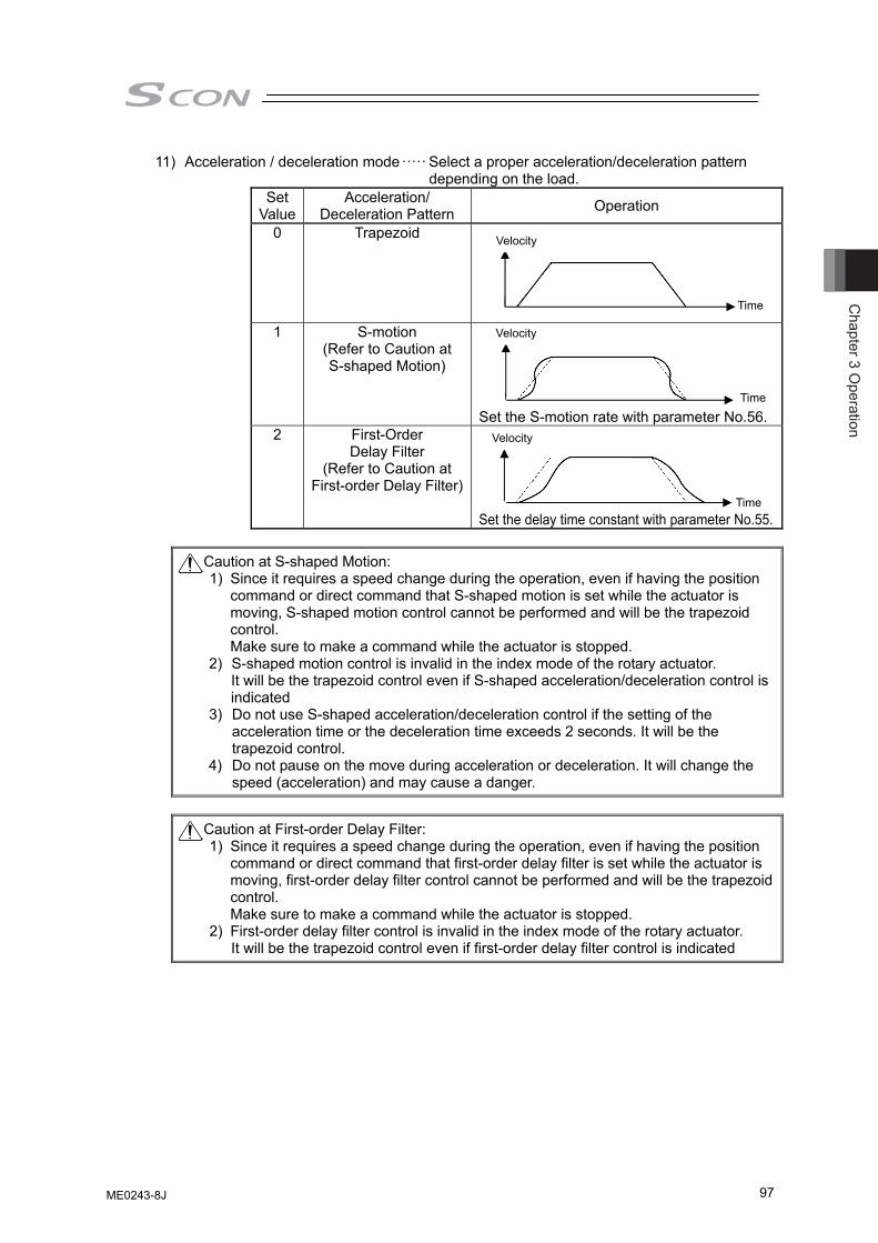
Chapter 3 O
peration
97
11) Acceleration / deceleration mode····· Select a proper acceleration/deceleration pattern depending on the load.
Set Value
Acceleration/ Deceleration Pattern Operation
0 Trapezoid
1 S-motion
(Refer to Caution at S-shaped Motion)
Set the S-motion rate with parameter No.56.
2 First-Order Delay Filter
(Refer to Caution at First-order Delay Filter)
Set the delay time constant with parameter No.55.
Caution at S-shaped Motion:
1) Since it requires a speed change during the operation, even if having the position command or direct command that S-shaped motion is set while the actuator is moving, S-shaped motion control cannot be performed and will be the trapezoid control. Make sure to make a command while the actuator is stopped.
2) S-shaped motion control is invalid in the index mode of the rotary actuator. It will be the trapezoid control even if S-shaped acceleration/deceleration control is indicated
3) Do not use S-shaped acceleration/deceleration control if the setting of the acceleration time or the deceleration time exceeds 2 seconds. It will be the trapezoid control.
4) Do not pause on the move during acceleration or deceleration. It will change the speed (acceleration) and may cause a danger.
Caution at First-order Delay Filter:
1) Since it requires a speed change during the operation, even if having the position command or direct command that first-order delay filter is set while the actuator is moving, first-order delay filter control cannot be performed and will be the trapezoid control. Make sure to make a command while the actuator is stopped.
2) First-order delay filter control is invalid in the index mode of the rotary actuator. It will be the trapezoid control even if first-order delay filter control is indicated
Time
Velocity
Time
Velocity
Time
Velocity
ME0243-8J
Cha
pter
3 O
pera
tion
98
12) Incremental ··········· Set to 1 for pitch feed (relative movement = incremental feed). The value set for the position in 1) indicates the pitch feed distance. With the value set to 0, positioning is defined to the position in 1) based on the absolute coordinate system.
Caution: In the pitch feed, do not perform a command with a pitch smaller than the minimum encoder resolution (lead/encoder pulse number) or that less than positioning accuracy repeatability. There would be no deviation to occur even with the command because it is an operation command to the same position as the positioning complete condition, but the positioning control cannot be performed properly. When solenoid valve mode 2 is selected, set this to 0. Setting this to 1 causes the position data error to occur.
13) Gain set················ Six parameters required for servo gain adjustment are collected to be
a single set. Up to four sets can be registered to change the servo gain in positioning. By utilizing Off Board Tuning Function (Note) in the PC software, the setting close to the optimum can be obtained. (Note) Refer to Section 10 Appendix Connectable Actuators for the
applicable models. It may require the setting of the gain set dedicated for the home-return operation in the case this function is used to have the high-speed setting or the setting to apply a transported weight more than the ratings. For how to set up and the caution items, refer to the instruction manual for RC PC Software.
[Parameters included in a set:] Servo gain number (Position Gain) Position feed forward gain Speed Loop Proportional Gain Speed Loop Integral Gain Torque Filter Time Constant Current control band number
It is able to establish the gain set that corresponds to the position number to be operated to the indicated gain set.
[Refer to “Servo Adjustment” in Section 8.3 for each gain parameter details.]
Setting Selected parameter set Parameter No. 0 Gain set 0 7, 71, 31 to 33, 541 Gain set 1 120 to 125 2 Gain set 2 126 to 131 3 Gain set 3 132 to 137
ME0243-8J
Chapter 3 O
peration
99
14) Stop mode ············ Automatic servo OFF is enabled after a certain period from the completion of positioning for power saving. A proper period can be selected from three parameters.
Setting Operation after completion of operation parameter No. 0 Servo ON not changed – 1 Automatic servo OFF after certain period 36 2 Automatic servo OFF after certain period 37 3 Automatic servo OFF after certain period 38
Caution: No retaining torque is provided in automatic servo OFF. Pay sufficient
attention to the setting because the actuator may be moved by external force applied to it.
Do not use the automatic servo OFF if the next moving command is relative distance specification (pitch feed). Failure to follow it may cause position shift to occur.
Do not use the automatic servo OFF in pressing. If used, the pressing force is lost.
Automatic Servo OFF would not function in the operation with teaching mode of PC software.
15) Vibration suppress No.·····Suppresses vibration (sympathetic vibration) of the load
installed on the actuator. The vibration suppress No. can accept three types of vibrations. Four parameters are defined for a single vibration to form a single set. In the position table, parameter sets are defined to correspond to position numbers for which vibrations must be suppressed. [Refer to Chapter 5 Vibration Suppress Control Function (Option) for details.]
Setting Vibration suppress frequency (Natural frequency) Parameter No.
0 Vibration suppress frequency (Natural frequency) –
1 Normal position control (no vibration suppress) 97 to 100
2 Vibration suppress control parameter set 1 101 to 104 3 Vibration suppress control parameter set 2 105 to 108
Caution: (1) The natural frequency range between 0.5Hz and 30Hz can be suppressed. (2) The target vibrations are those of the load induced by the actuator
connected to the controller. Any other vibrations cannot be suppressed.
(3) Vibrations to be suppressed should be in the same direction as that in which the actuator is moved. Vibrations in any other directions cannot be suppressed.
(4) The function is not applied to the home return and pressing operations. (5) The function is not available in the pulse train control mode. (6) One or more setting vibration frequencies are rather low, the tact time may
be long. With a vibration frequency being 6Hz or less, the positioning convergence time is 150ms or longer.
ME0243-8J
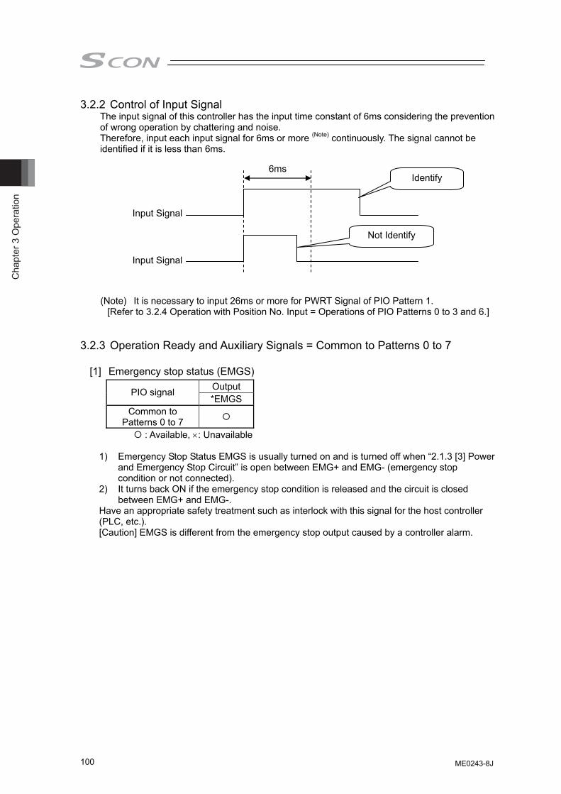
Cha
pter
3 O
pera
tion
100
3.2.2 Control of Input Signal The input signal of this controller has the input time constant of 6ms considering the prevention of wrong operation by chattering and noise. Therefore, input each input signal for 6ms or more (Note) continuously. The signal cannot be identified if it is less than 6ms.
(Note) It is necessary to input 26ms or more for PWRT Signal of PIO Pattern 1. [Refer to 3.2.4 Operation with Position No. Input = Operations of PIO Patterns 0 to 3 and 6.]
3.2.3 Operation Ready and Auxiliary Signals = Common to Patterns 0 to 7 [1] Emergency stop status (EMGS)
Output PIO signal *EMGS
Common to Patterns 0 to 7
: Available, ×: Unavailable
1) Emergency Stop Status EMGS is usually turned on and is turned off when “2.1.3 [3] Power and Emergency Stop Circuit” is open between EMG+ and EMG- (emergency stop condition or not connected).
2) It turns back ON if the emergency stop condition is released and the circuit is closed between EMG+ and EMG-.
Have an appropriate safety treatment such as interlock with this signal for the host controller (PLC, etc.). [Caution] EMGS is different from the emergency stop output caused by a controller alarm.
Input Signal
Input Signal
Identify
Not Identify
6ms
ME0243-8J
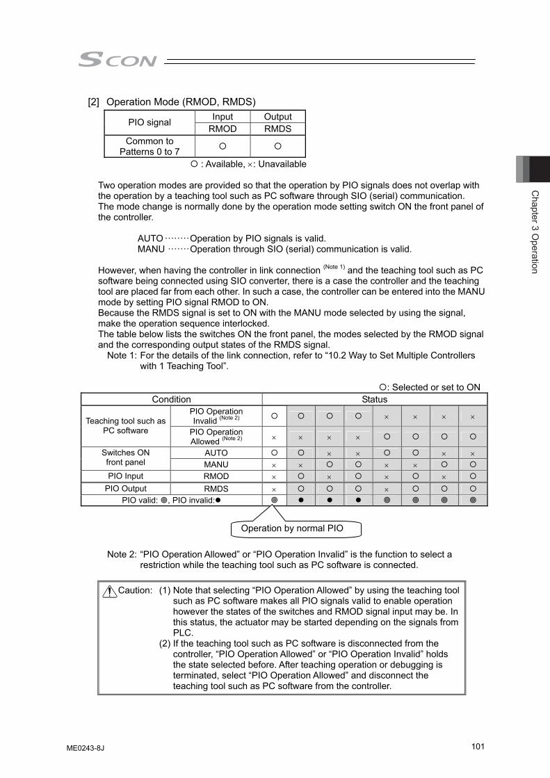
Chapter 3 O
peration
101
[2] Operation Mode (RMOD, RMDS) Input Output PIO signal
RMOD RMDS Common to
Patterns 0 to 7
: Available, ×: Unavailable Two operation modes are provided so that the operation by PIO signals does not overlap with the operation by a teaching tool such as PC software through SIO (serial) communication. The mode change is normally done by the operation mode setting switch ON the front panel of the controller.
AUTO ········Operation by PIO signals is valid. MANU ·······Operation through SIO (serial) communication is valid.
However, when having the controller in link connection (Note 1) and the teaching tool such as PC software being connected using SIO converter, there is a case the controller and the teaching tool are placed far from each other. In such a case, the controller can be entered into the MANU mode by setting PIO signal RMOD to ON. Because the RMDS signal is set to ON with the MANU mode selected by using the signal, make the operation sequence interlocked. The table below lists the switches ON the front panel, the modes selected by the RMOD signal and the corresponding output states of the RMDS signal.
Note 1: For the details of the link connection, refer to “10.2 Way to Set Multiple Controllers with 1 Teaching Tool”.
: Selected or set to ON
Condition Status PIO Operation Invalid (Note 2) × × × × Teaching tool such as
PC software PIO Operation Allowed (Note 2) × × × ×
AUTO × × × × Switches ON front panel MANU × × × × PIO Input RMOD × × × ×
PIO Output RMDS × × PIO valid: , PIO invalid:
Note 2: “PIO Operation Allowed” or “PIO Operation Invalid” is the function to select a restriction while the teaching tool such as PC software is connected.
Caution: (1) Note that selecting “PIO Operation Allowed” by using the teaching tool
such as PC software makes all PIO signals valid to enable operation however the states of the switches and RMOD signal input may be. In this status, the actuator may be started depending on the signals from PLC.
(2) If the teaching tool such as PC software is disconnected from the controller, “PIO Operation Allowed” or “PIO Operation Invalid” holds the state selected before. After teaching operation or debugging is terminated, select “PIO Operation Allowed” and disconnect the teaching tool such as PC software from the controller.
Operation by normal PIO
ME0243-8J
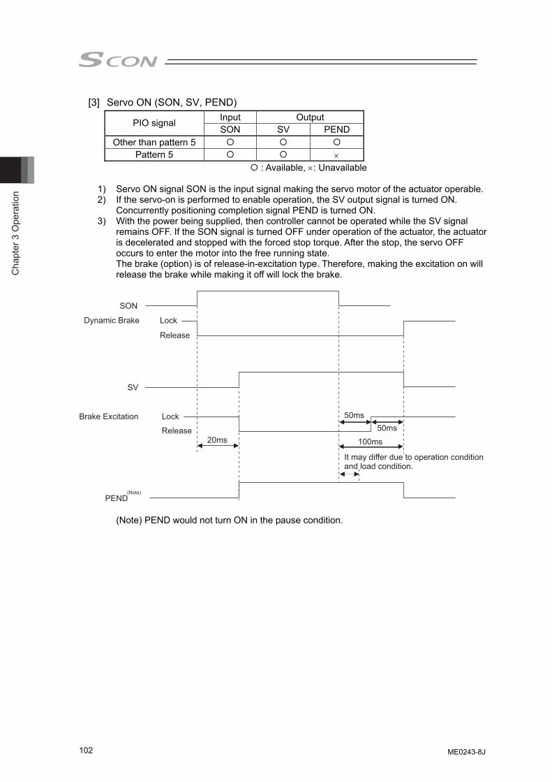
Cha
pter
3 O
pera
tion
102
[3] Servo ON (SON, SV, PEND) Input Output PIO signal SON SV PEND
Other than pattern 5 Pattern 5 ×
: Available, ×: Unavailable
1) Servo ON signal SON is the input signal making the servo motor of the actuator operable. 2) If the servo-on is performed to enable operation, the SV output signal is turned ON.
Concurrently positioning completion signal PEND is turned ON. 3) With the power being supplied, then controller cannot be operated while the SV signal
remains OFF. If the SON signal is turned OFF under operation of the actuator, the actuator is decelerated and stopped with the forced stop torque. After the stop, the servo OFF occurs to enter the motor into the free running state. The brake (option) is of release-in-excitation type. Therefore, making the excitation on will release the brake while making it off will lock the brake.
SON
SV
Dynamic Brake Lock
20ms
50ms50ms
100ms
Lock
Release
Release
Brake Excitation
It may differ due to operation condition and load condition.
PEND(Note)
(Note) PEND would not turn ON in the pause condition.
ME0243-8J
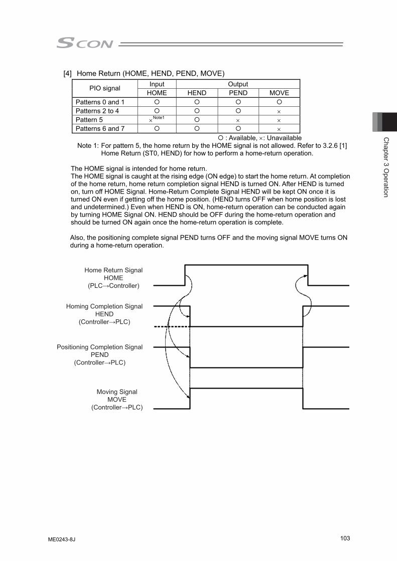
Chapter 3 O
peration
103
[4] Home Return (HOME, HEND, PEND, MOVE) Input Output PIO signal
HOME HEND PEND MOVE Patterns 0 and 1 Patterns 2 to 4 × Pattern 5 ×Note1 × × Patterns 6 and 7 ×
: Available, ×: Unavailable Note 1: For pattern 5, the home return by the HOME signal is not allowed. Refer to 3.2.6 [1]
Home Return (ST0, HEND) for how to perform a home-return operation.
The HOME signal is intended for home return. The HOME signal is caught at the rising edge (ON edge) to start the home return. At completion of the home return, home return completion signal HEND is turned ON. After HEND is turned on, turn off HOME Signal. Home-Return Complete Signal HEND will be kept ON once it is turned ON even if getting off the home position. (HEND turns OFF when home position is lost and undetermined.) Even when HEND is ON, home-return operation can be conducted again by turning HOME Signal ON. HEND should be OFF during the home-return operation and should be turned ON again once the home-return operation is complete. Also, the positioning complete signal PEND turns OFF and the moving signal MOVE turns ON during a home-return operation.
Homing Completion SignalHEND
(Controller→PLC)
Positioning Completion SignalPEND
(Controller→PLC)
Moving SignalMOVE
(Controller→PLC)
Home Return SignalHOME
(PLC→Controller)
ME0243-8J
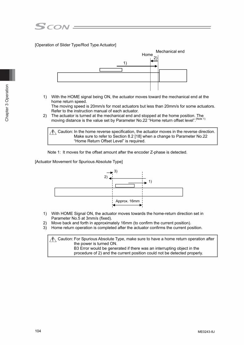
Cha
pter
3 O
pera
tion
104
[Operation of Slider Type/Rod Type Actuator]
1) With the HOME signal being ON, the actuator moves toward the mechanical end at the home return speed. The moving speed is 20mm/s for most actuators but less than 20mm/s for some actuators. Refer to the instruction manual of each actuator.
2) The actuator is turned at the mechanical end and stopped at the home position. The moving distance is the value set by Parameter No.22 “Home return offset level”.(Note 1)
Caution: In the home reverse specification, the actuator moves in the reverse direction.
Make sure to refer to Section 8.2 [18] when a change to Parameter No.22 “Home Return Offset Level” is required.
Note 1: It moves for the offset amount after the encoder Z-phase is detected.
[Actuator Movement for Spurious Absolute Type]
1) With HOME Signal ON, the actuator moves towards the home-return direction set in Parameter No.5 at 3mm/s (fixed).
2) Move back and forth in approximately 16mm (to confirm the current position). 3) Home return operation is completed after the actuator confirms the current position.
Caution: For Spurious Absolute Type, make sure to have a home return operation after the power is turned ON. B3 Error would be generated if there was an interrupting object in the procedure of 2) and the current position could not be detected properly.
Mechanical end Home
1) 2)
1) 2)
3)
Approx. 16mm
ME0243-8J
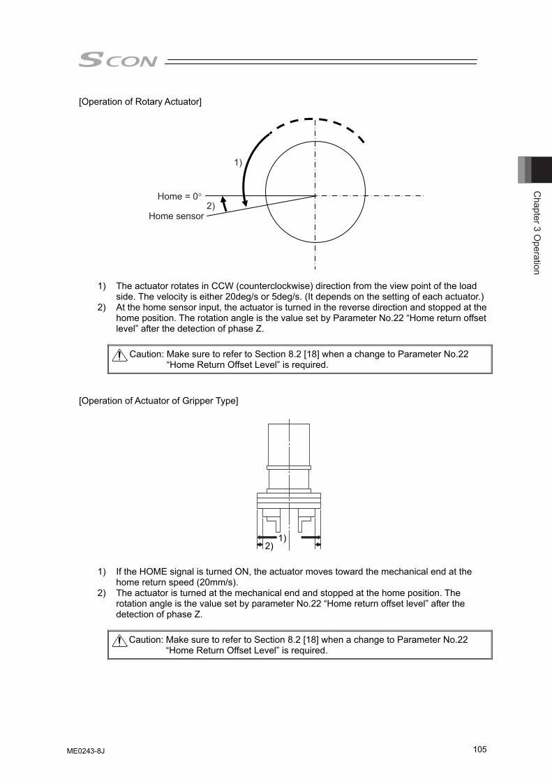
Chapter 3 O
peration
105
[Operation of Rotary Actuator]
1)
2)Home = 0°
Home sensor
1) The actuator rotates in CCW (counterclockwise) direction from the view point of the load side. The velocity is either 20deg/s or 5deg/s. (It depends on the setting of each actuator.)
2) At the home sensor input, the actuator is turned in the reverse direction and stopped at the home position. The rotation angle is the value set by Parameter No.22 “Home return offset level” after the detection of phase Z.
Caution: Make sure to refer to Section 8.2 [18] when a change to Parameter No.22
“Home Return Offset Level” is required.
[Operation of Actuator of Gripper Type] 1) If the HOME signal is turned ON, the actuator moves toward the mechanical end at the
home return speed (20mm/s). 2) The actuator is turned at the mechanical end and stopped at the home position. The
rotation angle is the value set by parameter No.22 “Home return offset level” after the detection of phase Z.
Caution: Make sure to refer to Section 8.2 [18] when a change to Parameter No.22
“Home Return Offset Level” is required.
1) 2)
ME0243-8J
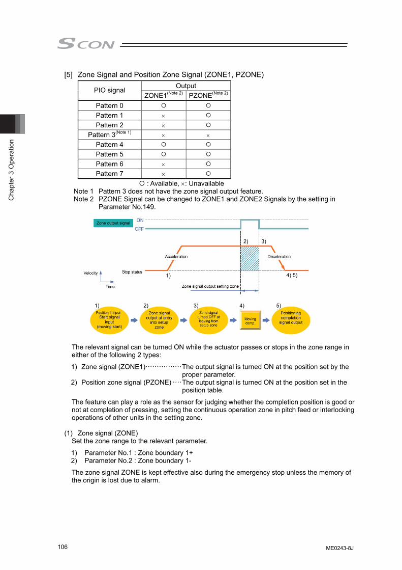
Cha
pter
3 O
pera
tion
106
[5] Zone Signal and Position Zone Signal (ZONE1, PZONE) Output PIO signal
ZONE1(Note 2) PZONE(Note 2)
Pattern 0 Pattern 1 × Pattern 2 ×
Pattern 3(Note 1) × × Pattern 4 Pattern 5 Pattern 6 × Pattern 7 ×
: Available, ×: Unavailable Note 1 Pattern 3 does not have the zone signal output feature. Note 2 PZONE Signal can be changed to ZONE1 and ZONE2 Signals by the setting in
Parameter No.149.
The relevant signal can be turned ON while the actuator passes or stops in the zone range in either of the following 2 types:
1) Zone signal (ZONE1)················The output signal is turned ON at the position set by the proper parameter.
2) Position zone signal (PZONE) ····The output signal is turned ON at the position set in the position table.
The feature can play a role as the sensor for judging whether the completion position is good or not at completion of pressing, setting the continuous operation zone in pitch feed or interlocking operations of other units in the setting zone.
(1) Zone signal (ZONE)
Set the zone range to the relevant parameter.
1) Parameter No.1 : Zone boundary 1+ 2) Parameter No.2 : Zone boundary 1-
The zone signal ZONE is kept effective also during the emergency stop unless the memory of the origin is lost due to alarm.
Time
Velocity
Zone output signal
1) 2) 3) 4) 5)
1)
2) 3)
4) 5)
ME0243-8J
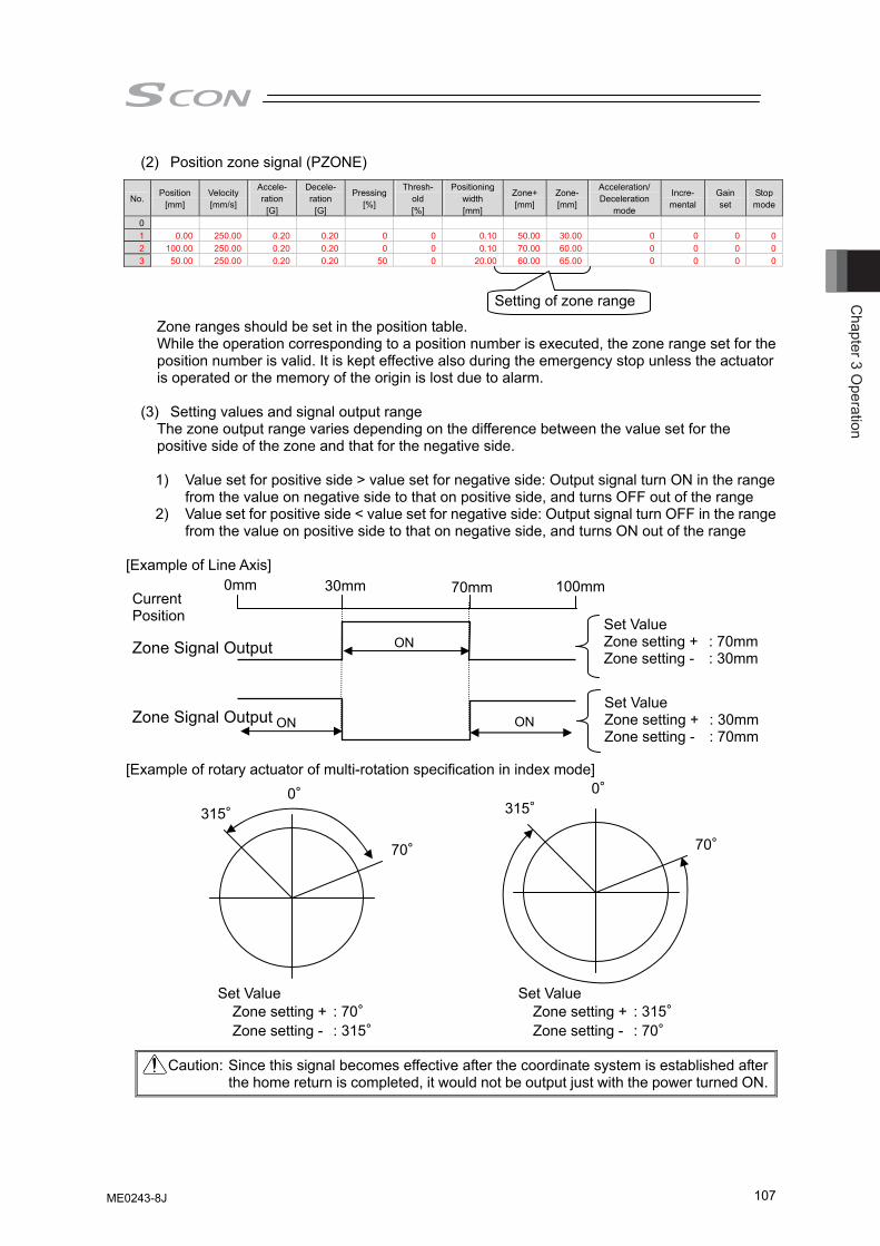
Chapter 3 O
peration
107
(2) Position zone signal (PZONE)
No. Position
[mm] Velocity [mm/s]
Accele- ration
[G]
Decele- ration
[G]
Pressing[%]
Thresh-old [%]
Positioning width [mm]
Zone+[mm]
Zone-[mm]
Acceleration/ Deceleration
mode
Incre- mental
Gain set
Stop mode
0 1 0.00 250.00 0.20 0.20 0 0 0.10 50.00 30.00 0 0 0 02 100.00 250.00 0.20 0.20 0 0 0.10 70.00 60.00 0 0 0 03 50.00 250.00 0.20 0.20 50 0 20.00 60.00 65.00 0 0 0 0
Zone ranges should be set in the position table. While the operation corresponding to a position number is executed, the zone range set for the position number is valid. It is kept effective also during the emergency stop unless the actuator is operated or the memory of the origin is lost due to alarm.
(3) Setting values and signal output range
The zone output range varies depending on the difference between the value set for the positive side of the zone and that for the negative side.
1) Value set for positive side > value set for negative side: Output signal turn ON in the range
from the value on negative side to that on positive side, and turns OFF out of the range 2) Value set for positive side < value set for negative side: Output signal turn OFF in the range
from the value on positive side to that on negative side, and turns ON out of the range [Example of Line Axis] [Example of rotary actuator of multi-rotation specification in index mode]
Caution: Since this signal becomes effective after the coordinate system is established after the home return is completed, it would not be output just with the power turned ON.
Current Position
Zone Signal Output
Zone Signal Output
0mm 30mm 70mm 100mm
ON
ON ON
Set Value Zone setting + : 70mm Zone setting - : 30mm
Set Value Zone setting + : 30mm Zone setting - : 70mm
315°
70°
0° 315°
70°
0°
Set Value Zone setting + : 70° Zone setting - : 315°
Set Value Zone setting + : 315° Zone setting - : 70°
Setting of zone range
ME0243-8J
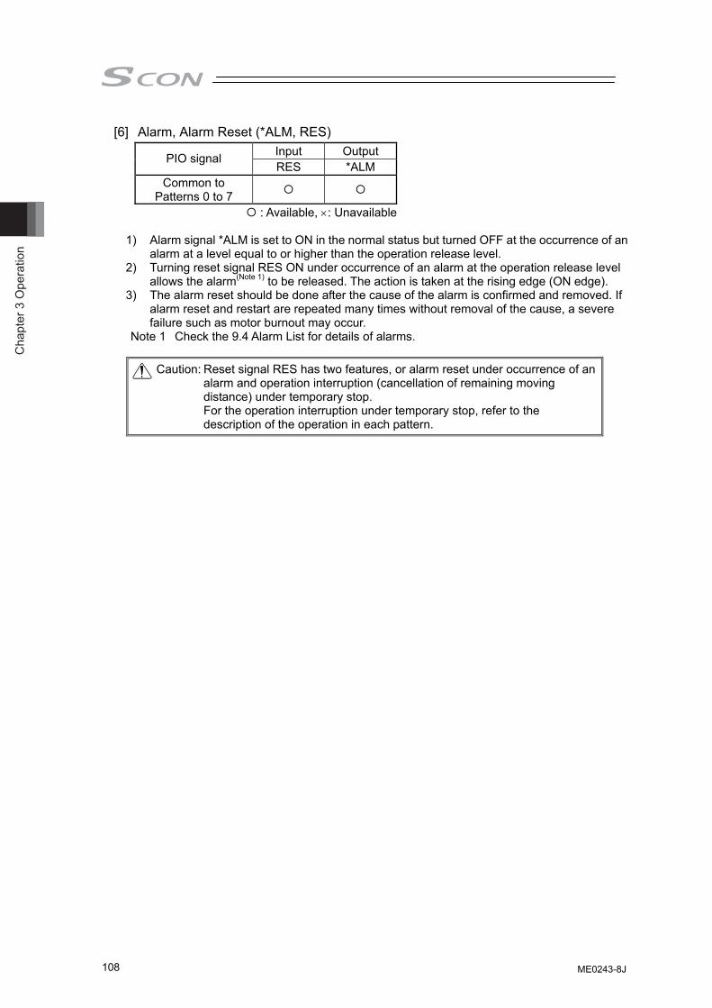
Cha
pter
3 O
pera
tion
108
[6] Alarm, Alarm Reset (*ALM, RES) Input Output PIO signal RES *ALM
Common to Patterns 0 to 7
: Available, ×: Unavailable 1) Alarm signal *ALM is set to ON in the normal status but turned OFF at the occurrence of an
alarm at a level equal to or higher than the operation release level. 2) Turning reset signal RES ON under occurrence of an alarm at the operation release level
allows the alarm(Note 1) to be released. The action is taken at the rising edge (ON edge). 3) The alarm reset should be done after the cause of the alarm is confirmed and removed. If
alarm reset and restart are repeated many times without removal of the cause, a severe failure such as motor burnout may occur.
Note 1 Check the 9.4 Alarm List for details of alarms.
Caution: Reset signal RES has two features, or alarm reset under occurrence of an alarm and operation interruption (cancellation of remaining moving distance) under temporary stop. For the operation interruption under temporary stop, refer to the description of the operation in each pattern.
ME0243-8J
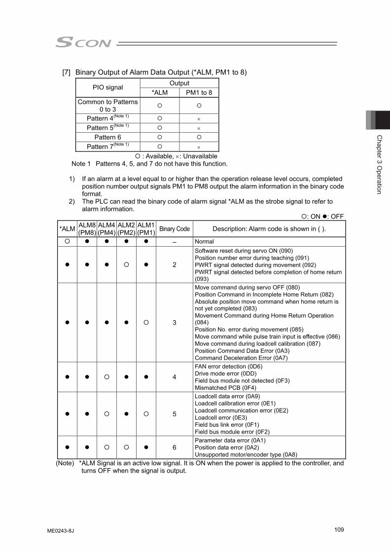
Chapter 3 O
peration
109
[7] Binary Output of Alarm Data Output (*ALM, PM1 to 8) Output PIO signal
*ALM PM1 to 8 Common to Patterns
0 to 3
Pattern 4(Note 1) × Pattern 5(Note 1) ×
Pattern 6 Pattern 7(Note 1) ×
: Available, ×: Unavailable Note 1 Patterns 4, 5, and 7 do not have this function.
1) If an alarm at a level equal to or higher than the operation release level occurs, completed
position number output signals PM1 to PM8 output the alarm information in the binary code format.
2) The PLC can read the binary code of alarm signal *ALM as the strobe signal to refer to alarm information.
: ON : OFF
*ALM ALM8 (PM8)
ALM4(PM4)
ALM2 (PM2)
ALM1 (PM1) Binary Code Description: Alarm code is shown in ( ).
– Normal
2
Software reset during servo ON (090) Position number error during teaching (091) PWRT signal detected during movement (092) PWRT signal detected before completion of home return (093)
3
Move command during servo OFF (080) Position Command in Incomplete Home Return (082) Absolute position move command when home return is not yet completed (083) Movement Command during Home Return Operation (084) Position No. error during movement (085) Move command while pulse train input is effective (086)Move command during loadcell calibration (087) Position Command Data Error (0A3) Command Deceleration Error (0A7)
4 FAN error detection (0D6) Drive mode error (0DD) Field bus module not detected (0F3) Mismatched PCB (0F4)
5
Loadcell data error (0A9) Loadcell calibration error (0E1) Loadcell communication error (0E2) Loadcell error (0E3) Field bus link error (0F1) Field bus module error (0F2)
6 Parameter data error (0A1) Position data error (0A2) Unsupported motor/encoder type (0A8)
(Note) *ALM Signal is an active low signal. It is ON when the power is applied to the controller, and turns OFF when the signal is output.
ME0243-8J
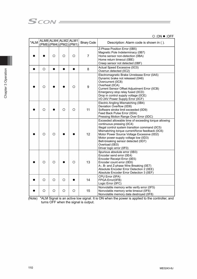
Cha
pter
3 O
pera
tion
110
:ON :OFF
*ALM ALM8 (PM8)
ALM4(PM4)
ALM2 (PM2)
ALM1 (PM1) Binary Code Description: Alarm code is shown in ( ).
7
Z-Phase Position Error (0B5) Magnetic Pole Indeterminacy (0B7) Home sensor non-detection (0BA) Home return timeout (0BE) Creep sensor not detected (0BF)
8 Actual Speed Excessive (0C0) Overrun detected (0C2)
9
Electromagnetic Brake Unrelease Error (0A5) Dynamic brake not released (0A6) Overcurrent (0C8) Overheat (0CA) Current Sensor Offset Adjustment Error (0CB) Emergency stop relay fused (0CD) Drop in control supply voltage (0CE) I/O 24V Power Supply Error (0CF)
11
Electric Angling Mismatching (0B4) Deviation Overflow (0D8) Software stroke limit exceeded (0D9) Feed Back Pulse Error (0DA) Pressing Motion Range Over Error (0DC)
12
Exceeded allowable time of exceeding torque allowing continuous pressing (0C4) Illegal control system transition command (0C5) Mismatching torque current/force feedback (0C6) Motor Power Source Voltage Excessive (0D2) Motor power-supply voltage low (0D3) Belt-breaking sensor detected (0D7) Overload (0E0) Driver logic error (0F0)
13
Spurious absolute error (0B3) Encoder send error (0E4) Encoder Receipt Error (0E5) Encoder count error (0E6) A-, B- and Z-phase Wire Breaking (0E7) Absolute Encoder Error Detection 2 (0EE) Absolute Encoder Error Detection 3 (0EF)
14 CPU Error (0FA) FPGA Error(0FB) Logic Error (0FC)
15 Nonvolatile memory write verify error (0F5) Nonvolatile memory write timeout (0F6) Nonvolatile memory data destroyed (0F8)
(Note) *ALM Signal is an active low signal. It is ON when the power is applied to the controller, and turns OFF when the signal is output.
ME0243-8J
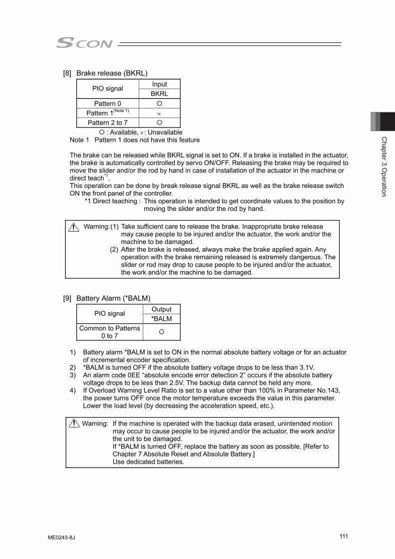
Chapter 3 O
peration
111
[8] Brake release (BKRL) Input PIO signal BKRL
Pattern 0 Pattern 1(Note 1) × Pattern 2 to 7
: Available, ×: Unavailable Note 1 Pattern 1 does not have this feature
The brake can be released while BKRL signal is set to ON. If a brake is installed in the actuator, the brake is automatically controlled by servo ON/OFF. Releasing the brake may be required to move the slider and/or the rod by hand in case of installation of the actuator in the machine or direct teach*1. This operation can be done by break release signal BKRL as well as the brake release switch ON the front panel of the controller.
*1 Direct teaching : This operation is intended to get coordinate values to the position by moving the slider and/or the rod by hand.
Warning: (1) Take sufficient care to release the brake. Inappropriate brake release
may cause people to be injured and/or the actuator, the work and/or the machine to be damaged.
(2) After the brake is released, always make the brake applied again. Any operation with the brake remaining released is extremely dangerous. The slider or rod may drop to cause people to be injured and/or the actuator, the work and/or the machine to be damaged.
[9] Battery Alarm (*BALM) Output PIO signal *BALM
Common to Patterns 0 to 7
1) Battery alarm *BALM is set to ON in the normal absolute battery voltage or for an actuator
of incremental encoder specification. 2) *BALM is turned OFF if the absolute battery voltage drops to be less than 3.1V. 3) An alarm code 0EE “absolute encode error detection 2” occurs if the absolute battery
voltage drops to be less than 2.5V. The backup data cannot be held any more. 4) If Overload Warning Level Ratio is set to a value other than 100% in Parameter No.143,
the power turns OFF once the motor temperature exceeds the value in this parameter. Lower the load level (by decreasing the acceleration speed, etc.).
Warning: If the machine is operated with the backup data erased, unintended motion
may occur to cause people to be injured and/or the actuator, the work and/or the unit to be damaged. If *BALM is turned OFF, replace the battery as soon as possible. [Refer to Chapter 7 Absolute Reset and Absolute Battery.] Use dedicated batteries.
ME0243-8J
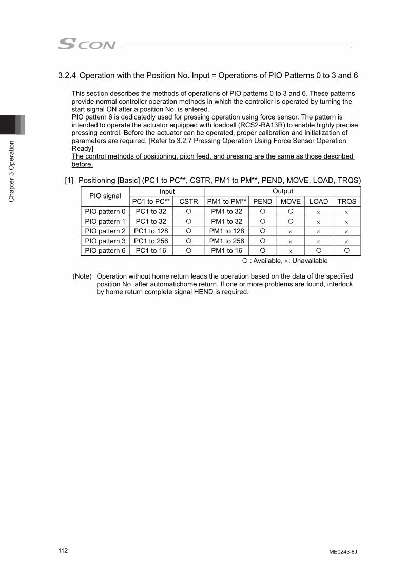
Cha
pter
3 O
pera
tion
112
3.2.4 Operation with the Position No. Input = Operations of PIO Patterns 0 to 3 and 6
This section describes the methods of operations of PIO patterns 0 to 3 and 6. These patterns provide normal controller operation methods in which the controller is operated by turning the start signal ON after a position No. is entered. PIO pattern 6 is dedicatedly used for pressing operation using force sensor. The pattern is intended to operate the actuator equipped with loadcell (RCS2-RA13R) to enable highly precise pressing control. Before the actuator can be operated, proper calibration and initialization of parameters are required. [Refer to 3.2.7 Pressing Operation Using Force Sensor Operation Ready] The control methods of positioning, pitch feed, and pressing are the same as those described before.
[1] Positioning [Basic] (PC1 to PC**, CSTR, PM1 to PM**, PEND, MOVE, LOAD, TRQS)
Input Output PIO signal
PC1 to PC** CSTR PM1 to PM** PEND MOVE LOAD TRQSPIO pattern 0 PC1 to 32 PM1 to 32 × × PIO pattern 1 PC1 to 32 PM1 to 32 × × PIO pattern 2 PC1 to 128 PM1 to 128 × × × PIO pattern 3 PC1 to 256 PM1 to 256 × × × PIO pattern 6 PC1 to 16 PM1 to 16 ×
: Available, ×: Unavailable
(Note) Operation without home return leads the operation based on the data of the specified position No. after automatichome return. If one or more problems are found, interlock by home return complete signal HEND is required.
ME0243-8J
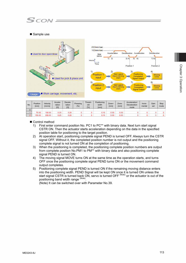
Chapter 3 O
peration
113
Sample use
No. Position
[mm] Velocity [mm/s]
Accele- ration
[G]
Decele- ration
[G]
Pressing[%]
Thresh-old [%]
Positioning width [mm]
Zone+[mm]
Zone-[mm]
Acceleration/ Deceleration
mode
Incre- mental
Gain set
Stop mode
0 1 70.00 100.00 0.20 0.20 0 0 0.10 0.00 0.00 0 0 0 02 150.00 200.00 0.20 0.20 0 0 0.10 0.00 0.00 0 0 0 0
Control method 1) First enter command position No. PC1 to PC** with binary data. Next turn start signal
CSTR ON. Then the actuator starts acceleration depending on the data in the specified position table for positioning to the target position.
2) At operation start, positioning complete signal PEND is turned OFF. Always turn the CSTR signal OFF. Without it, the completed position number is not output and the positioning complete signal is not turned ON at the completion of positioning.
3) When the positioning is completed, the positioning complete position numbers are output from complete position No.PM1 to PM** with binary data and also positioning complete signal PEND is turned ON.
4) The moving signal MOVE turns ON at the same time as the operation starts, and turns OFF once the positioning complete signal PEND turns ON or the movement command output completes.
5) Positioning complete signal PEND is turned ON if the remaining moving distance enters into the positioning width. PEND Signal will be kept ON once it is turned ON unless the start signal CSTR is turned back ON, servo is turned OFF (Note) or the actuator is out of the positioning band width range (Note). (Note) It can be switched over with Parameter No.39.
Positioning Completion
Signal Output
Velocity
Positioning Completion
Signal Output
1) 2) 3) 4)
5) 6) 7) 8)
1) 2) 5) 6) 3) 4) 7) 8)
ME0243-8J
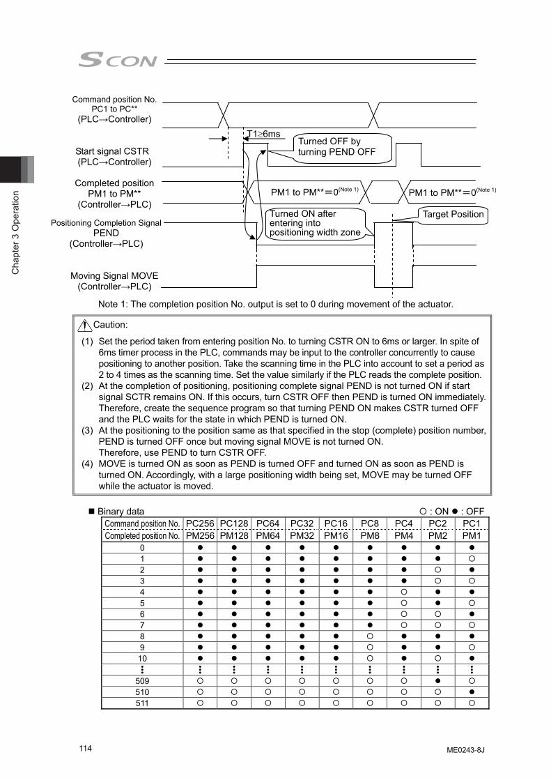
Cha
pter
3 O
pera
tion
114
Note 1: The completion position No. output is set to 0 during movement of the actuator.
Caution:
(1) Set the period taken from entering position No. to turning CSTR ON to 6ms or larger. In spite of 6ms timer process in the PLC, commands may be input to the controller concurrently to cause positioning to another position. Take the scanning time in the PLC into account to set a period as 2 to 4 times as the scanning time. Set the value similarly if the PLC reads the complete position.
(2) At the completion of positioning, positioning complete signal PEND is not turned ON if start signal SCTR remains ON. If this occurs, turn CSTR OFF then PEND is turned ON immediately.Therefore, create the sequence program so that turning PEND ON makes CSTR turned OFF and the PLC waits for the state in which PEND is turned ON.
(3) At the positioning to the position same as that specified in the stop (complete) position number, PEND is turned OFF once but moving signal MOVE is not turned ON. Therefore, use PEND to turn CSTR OFF.
(4) MOVE is turned ON as soon as PEND is turned OFF and turned ON as soon as PEND is turned ON. Accordingly, with a large positioning width being set, MOVE may be turned OFF while the actuator is moved.
Binary data : ON : OFF
Command position No. PC256 PC128 PC64 PC32 PC16 PC8 PC4 PC2 PC1Completed position No. PM256 PM128 PM64 PM32 PM16 PM8 PM4 PM2 PM1
0 1 2 3 4 5 6 7 8 9 10 •••
•••
•••
•••
•••
•••
•••
•••
•••
•••
509 510 511
Command position No. PC1 to PC**
(PLC→Controller)
Completed position PM1 to PM**
(Controller→PLC)
Start signal CSTR (PLC→Controller)
Positioning Completion Signal PEND
(Controller→PLC)
Moving Signal MOVE (Controller→PLC)
T1≥6ms
PM1 to PM**=0(Note 1) PM1 to PM**=0(Note 1)
Turned OFF by turning PEND OFF
Turned ON after entering into positioning width zone
Target Position
ME0243-8J
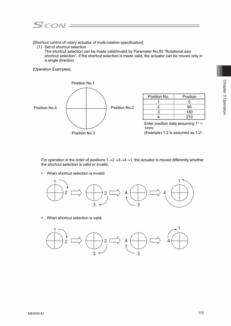
Chapter 3 O
peration
115
[Shortcut control of rotary actuator of multi-rotation specification] (1) Set of shortcut selection The shortcut selection can be made valid/invalid by Parameter No.80 “Rotational axis
shortcut selection”. If the shortcut selection is made valid, the actuator can be moved only in a single direction.
[Operation Examples]
Position No. Position1 0 2 903 1804 270
Enter position data assuming 1 = 1mm. (Example) 1.2 is assumed as 1.2.
For operation in the order of positions 12341, the actuator is moved differently whether the shortcut selection is valid or invalid. When shortcut selection is invalid:
When shortcut selection is valid:
Position No.1
Position No.2
Position No.3
Position No.4
ME0243-8J
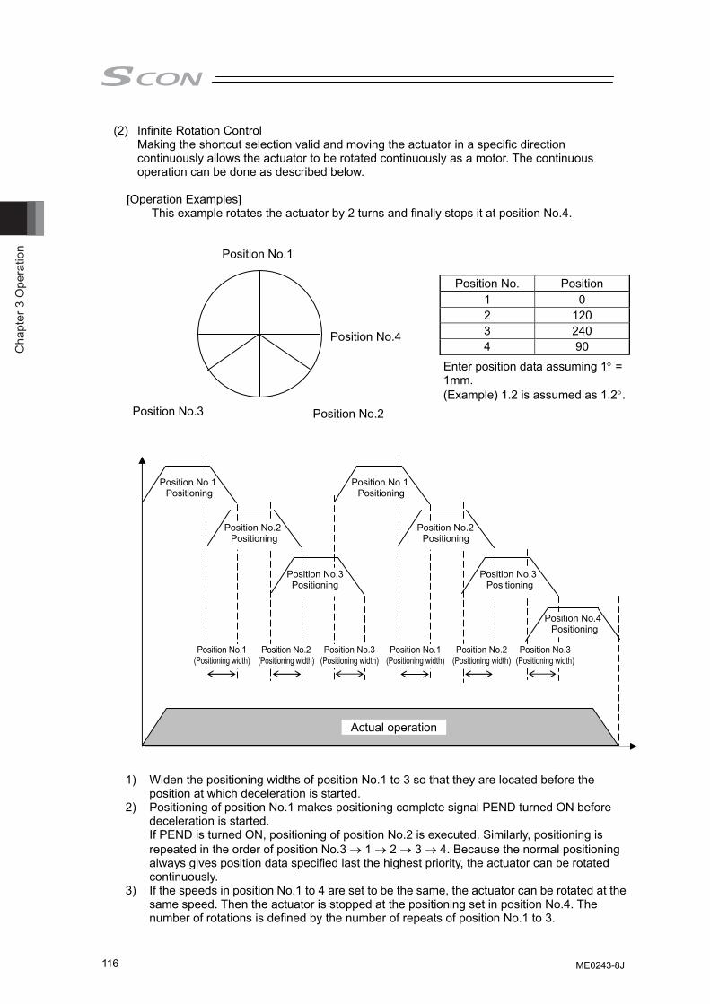
Cha
pter
3 O
pera
tion
116
(2) Infinite Rotation Control Making the shortcut selection valid and moving the actuator in a specific direction
continuously allows the actuator to be rotated continuously as a motor. The continuous operation can be done as described below.
[Operation Examples]
This example rotates the actuator by 2 turns and finally stops it at position No.4.
Position No. Position 1 0 2 120 3 240 4 90
Enter position data assuming 1° = 1mm. (Example) 1.2 is assumed as 1.2°.
1) Widen the positioning widths of position No.1 to 3 so that they are located before the position at which deceleration is started.
2) Positioning of position No.1 makes positioning complete signal PEND turned ON before deceleration is started. If PEND is turned ON, positioning of position No.2 is executed. Similarly, positioning is repeated in the order of position No.3 → 1 → 2 → 3 → 4. Because the normal positioning always gives position data specified last the highest priority, the actuator can be rotated continuously.
3) If the speeds in position No.1 to 4 are set to be the same, the actuator can be rotated at the same speed. Then the actuator is stopped at the positioning set in position No.4. The number of rotations is defined by the number of repeats of position No.1 to 3.
Position No.4
Position No.1
Position No.2 Position No.3
Position No.1 (Positioning width)
Position No.2(Positioning width)
Position No.3(Positioning width)
Position No.1(Positioning width)
Position No.2 (Positioning width)
Position No.3 (Positioning width)
Actual operation
Position No.1 Positioning
Position No.2 Positioning
Position No.3Positioning
Position No.1 Positioning
Position No.2 Positioning
Position No.3 Positioning
Position No.4 Positioning
ME0243-8J
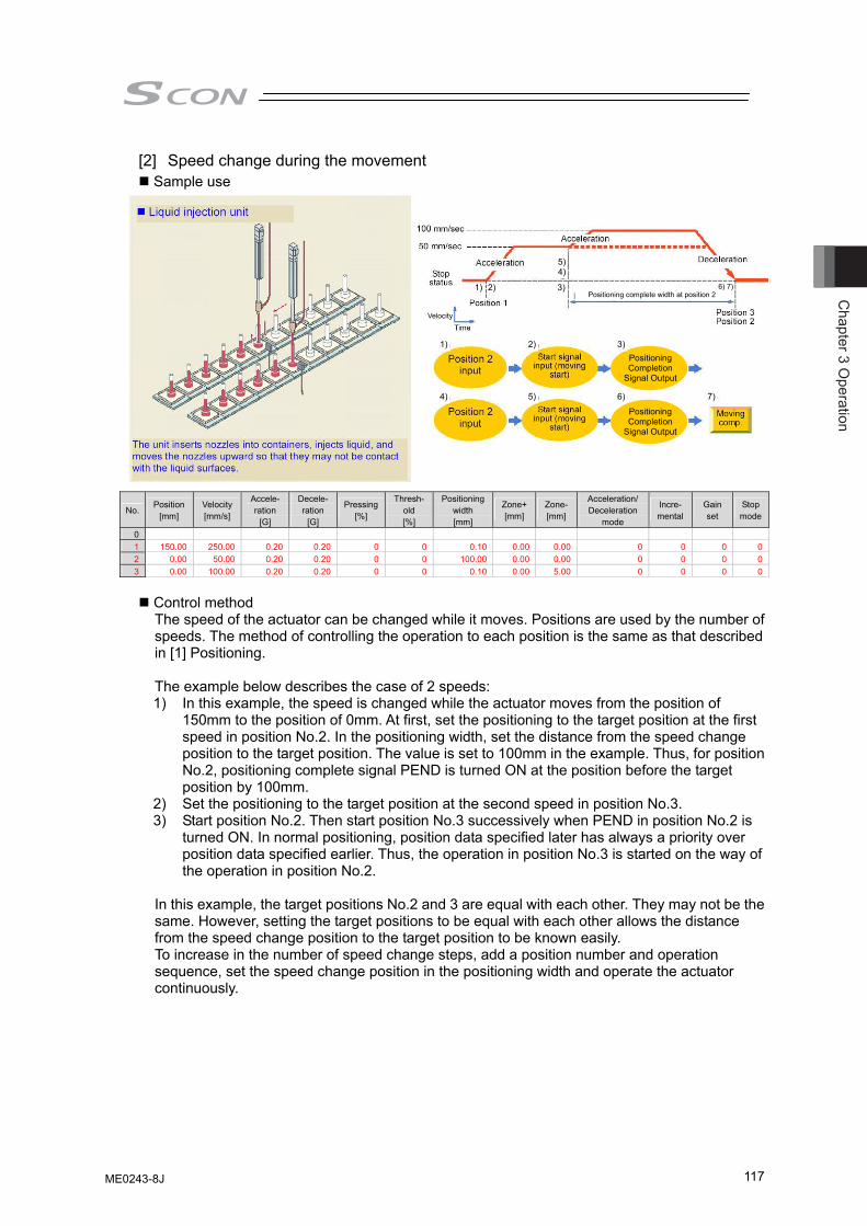
Chapter 3 O
peration
117
[2] Speed change during the movement Sample use
No. Position
[mm] Velocity [mm/s]
Accele- ration
[G]
Decele- ration
[G]
Pressing[%]
Thresh-old [%]
Positioning width [mm]
Zone+[mm]
Zone-[mm]
Acceleration/ Deceleration
mode
Incre- mental
Gain set
Stop mode
0 1 150.00 250.00 0.20 0.20 0 0 0.10 0.00 0.00 0 0 0 02 0.00 50.00 0.20 0.20 0 0 100.00 0.00 0.00 0 0 0 03 0.00 100.00 0.20 0.20 0 0 0.10 0.00 5.00 0 0 0 0
Control method The speed of the actuator can be changed while it moves. Positions are used by the number of speeds. The method of controlling the operation to each position is the same as that described in [1] Positioning.
The example below describes the case of 2 speeds: 1) In this example, the speed is changed while the actuator moves from the position of
150mm to the position of 0mm. At first, set the positioning to the target position at the first speed in position No.2. In the positioning width, set the distance from the speed change position to the target position. The value is set to 100mm in the example. Thus, for position No.2, positioning complete signal PEND is turned ON at the position before the target position by 100mm.
2) Set the positioning to the target position at the second speed in position No.3. 3) Start position No.2. Then start position No.3 successively when PEND in position No.2 is
turned ON. In normal positioning, position data specified later has always a priority over position data specified earlier. Thus, the operation in position No.3 is started on the way of the operation in position No.2.
In this example, the target positions No.2 and 3 are equal with each other. They may not be the same. However, setting the target positions to be equal with each other allows the distance from the speed change position to the target position to be known easily. To increase in the number of speed change steps, add a position number and operation sequence, set the speed change position in the positioning width and operate the actuator continuously.
Positioning Completion
Signal Output
Velocity
Positioning Completion
Signal Output
1) 2) 3)
4) 5) 6) 7)
1) 2) 3)
5)4)
6) 7)Positioning complete width at position 2
ME0243-8J
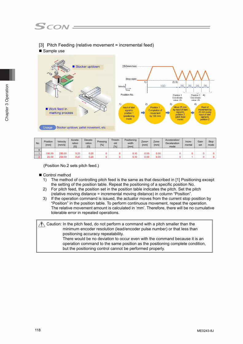
Cha
pter
3 O
pera
tion
118
[3] Pitch Feeding (relative movement = incremental feed) Sample use
No. Position
[mm] Velocity [mm/s]
Accele- ration
[G]
Decele- ration
[G]
Pressing[%]
Thresh-old [%]
Positioning width [mm]
Zone+[mm]
Zone-[mm]
Acceleration/ Deceleration
mode
Incre- mental
Gain set
Stop mode
0 1 100.00 250.00 0.20 0.20 0 0 0.10 0.00 0.00 0 0 0 02 25.00 250.00 0.20 0.20 0 0 0.10 0.00 0.00 0 1 0 0
(Position No.2 sets pitch feed.)
Control method 1) The method of controlling pitch feed is the same as that described in [1] Positioning except
the setting of the position table. Repeat the positioning of a specific position No. 2) For pitch feed, the position set in the position table indicates the pitch. Set the pitch
(relative moving distance = incremental moving distance) in column “Position”. 3) If the operation command is issued, the actuator moves from the current stop position by
“Position” in the position table. To perform continuous movement, repeat the operation. The relative movement amount is calculated in ‘mm’. Therefore, there will be no cumulative tolerable error in repeated operations.
Caution: In the pitch feed, do not perform a command with a pitch smaller than the
minimum encoder resolution (lead/encoder pulse number) or that less than positioning accuracy repeatability. There would be no deviation to occur even with the command because it is an operation command to the same position as the positioning complete condition, but the positioning control cannot be performed properly.
Velocity
1) 2) 3) 4)
4)
1) 2) 3)
ME0243-8J
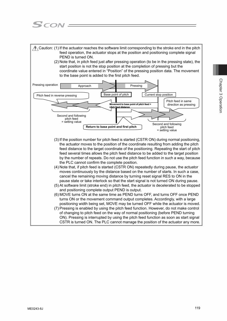
Chapter 3 O
peration
119
Caution: (1) If the actuator reaches the software limit corresponding to the stroke end in the pitch
feed operation, the actuator stops at the position and positioning complete signal PEND is turned ON.
(2) Note that, in pitch feed just after pressing operation (to be in the pressing state), the start position is not the stop position at the completion of pressing but the coordinate value entered in “Position” of the pressing position data. The movement to the base point is added to the first pitch feed.
(3) If the position number for pitch feed is started (CSTR ON) during normal positioning,
the actuator moves to the position of the coordinate resulting from adding the pitch feed distance to the target coordinate of the positioning. Repeating the start of pitch feed several times allows the pitch feed distance to be added to the target position by the number of repeats. Do not use the pitch feed function in such a way, because the PLC cannot confirm the complete position.
(4) Note that, if pitch feed is started (CSTR ON) repeatedly during pause, the actuator moves continuously by the distance based on the number of starts. In such a case, cancel the remaining moving distance by turning reset signal RES to ON in the pause state or take interlock so that the start signal is not turned ON during pause.
(5) At software limit (stroke end) in pitch feed, the actuator is decelerated to be stopped and positioning complete output PEND is output.
(6) MOVE turns ON at the same time as PEND turns OFF, and turns OFF once PEND turns ON or the movement command output completes. Accordingly, with a large positioning width being set, MOVE may be turned OFF while the actuator is moved.
(7) Pressing is enabled by using the pitch feed function. However, do not make control of changing to pitch feed on the way of normal positioning (before PEND turning ON). Pressing is interrupted by using the pitch feed function as soon as start signal CSTR is turned ON. The PLC cannot manage the position of the actuator any more.
Approach Pressing
Current stop position Base point of pitch
Movement to base point of pitch feed + pitch feed distance
Second and following pitch feed
= setting value Return to base point and first pitch
Pressing operation
Second and following pitch feed
= setting value
Pitch feed in reverse pressing
Pitch feed in same direction as pressing
ME0243-8J
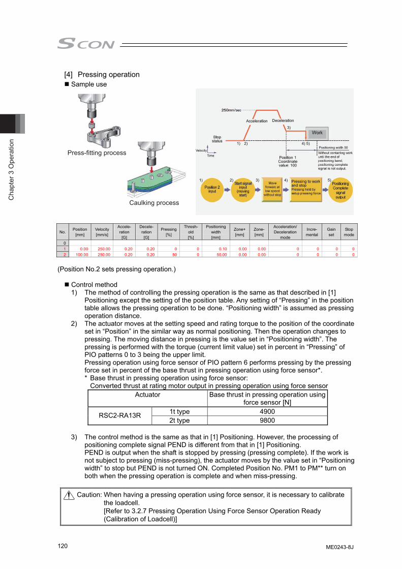
Cha
pter
3 O
pera
tion
120
[4] Pressing operation Sample use
Velocity
1) 2) 3) 4) 5)
1) 2)
3)
4) 5)Positioning width 50
Press-fitting process
Caulking process
No. Position
[mm] Velocity [mm/s]
Accele- ration
[G]
Decele- ration
[G]
Pressing[%]
Thresh-old [%]
Positioning width [mm]
Zone+[mm]
Zone-[mm]
Acceleration/ Deceleration
mode
Incre- mental
Gain set
Stop mode
0 1 0.00 250.00 0.20 0.20 0 0 0.10 0.00 0.00 0 0 0 02 100.00 250.00 0.20 0.20 50 0 50.00 0.00 0.00 0 0 0 0
(Position No.2 sets pressing operation.)
Control method 1) The method of controlling the pressing operation is the same as that described in [1]
Positioning except the setting of the position table. Any setting of “Pressing” in the position table allows the pressing operation to be done. “Positioning width” is assumed as pressing operation distance.
2) The actuator moves at the setting speed and rating torque to the position of the coordinate set in “Position” in the similar way as normal positioning. Then the operation changes to pressing. The moving distance in pressing is the value set in “Positioning width”. The pressing is performed with the torque (current limit value) set in percent in “Pressing” of PIO patterns 0 to 3 being the upper limit. Pressing operation using force sensor of PIO pattern 6 performs pressing by the pressing force set in percent of the base thrust in pressing operation using force sensor*. * Base thrust in pressing operation using force sensor: Converted thrust at rating motor output in pressing operation using force sensor
Actuator Base thrust in pressing operation using force sensor [N]
1t type 4900 RSC2-RA13R 2t type 9800
3) The control method is the same as that in [1] Positioning. However, the processing of
positioning complete signal PEND is different from that in [1] Positioning. PEND is output when the shaft is stopped by pressing (pressing complete). If the work is not subject to pressing (miss-pressing), the actuator moves by the value set in “Positioning width” to stop but PEND is not turned ON. Completed Position No. PM1 to PM** turn on both when the pressing operation is complete and when miss-pressing.
Caution: When having a pressing operation using force sensor, it is necessary to calibrate
the loadcell. [Refer to 3.2.7 Pressing Operation Using Force Sensor Operation Ready (Calibration of Loadcell)]
ME0243-8J
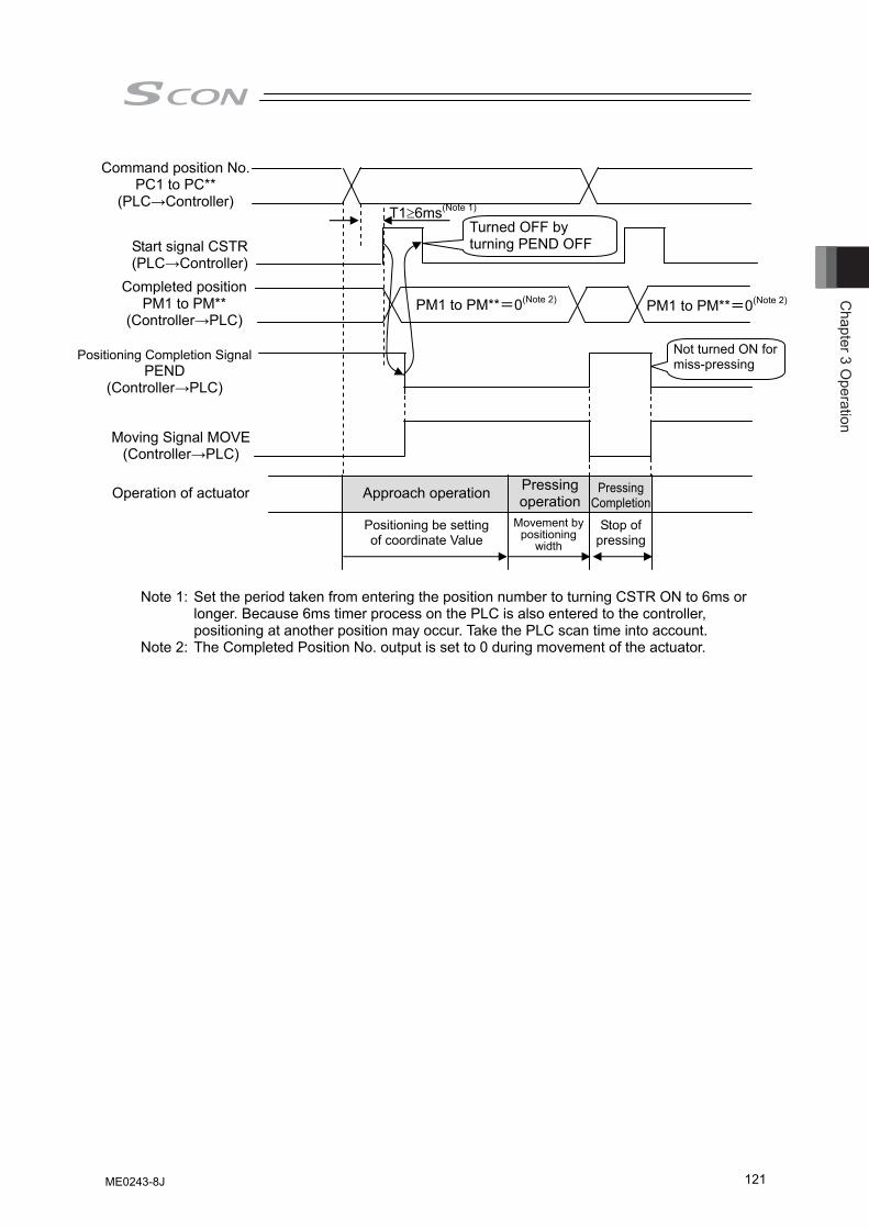
Chapter 3 O
peration
121
Note 1: Set the period taken from entering the position number to turning CSTR ON to 6ms or longer. Because 6ms timer process on the PLC is also entered to the controller, positioning at another position may occur. Take the PLC scan time into account.
Note 2: The Completed Position No. output is set to 0 during movement of the actuator.
T1≥6ms(Note 1)
PM1 to PM**=0(Note 2) PM1 to PM**=0(Note 2)
Operation of actuator
Not turned ON for miss-pressing
Approach operation Pressing operation
Pressing Completion
Positioning be setting of coordinate Value
Movement by positioning
width
Stop of pressing
Command position No. PC1 to PC**
(PLC→Controller)
Completed position PM1 to PM**
(Controller→PLC)
Start signal CSTR (PLC→Controller)
Positioning Completion Signal PEND
(Controller→PLC)
Turned OFF by turning PEND OFF
Moving Signal MOVE (Controller→PLC)
ME0243-8J
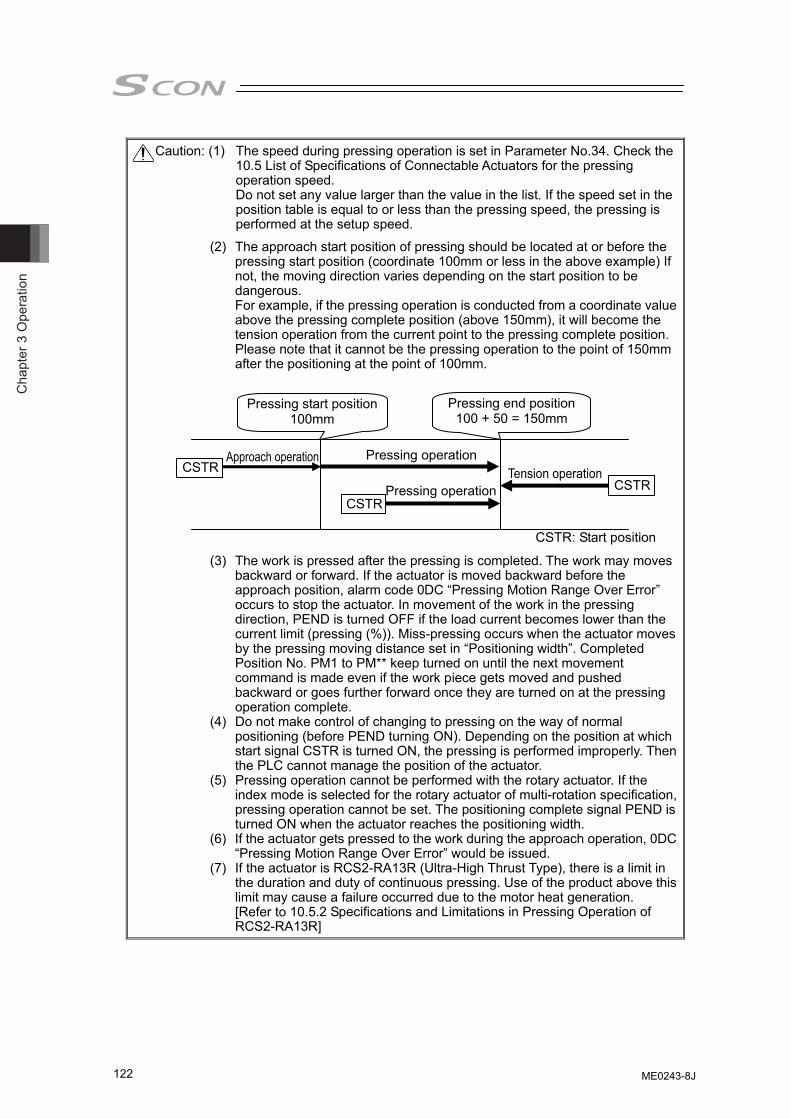
Cha
pter
3 O
pera
tion
122
Caution: (1) The speed during pressing operation is set in Parameter No.34. Check the 10.5 List of Specifications of Connectable Actuators for the pressing operation speed. Do not set any value larger than the value in the list. If the speed set in the position table is equal to or less than the pressing speed, the pressing is performed at the setup speed.
(2) The approach start position of pressing should be located at or before the pressing start position (coordinate 100mm or less in the above example) If not, the moving direction varies depending on the start position to be dangerous. For example, if the pressing operation is conducted from a coordinate value above the pressing complete position (above 150mm), it will become the tension operation from the current point to the pressing complete position. Please note that it cannot be the pressing operation to the point of 150mm after the positioning at the point of 100mm.
(3) The work is pressed after the pressing is completed. The work may moves backward or forward. If the actuator is moved backward before the approach position, alarm code 0DC “Pressing Motion Range Over Error” occurs to stop the actuator. In movement of the work in the pressing direction, PEND is turned OFF if the load current becomes lower than the current limit (pressing (%)). Miss-pressing occurs when the actuator moves by the pressing moving distance set in “Positioning width”. Completed Position No. PM1 to PM** keep turned on until the next movement command is made even if the work piece gets moved and pushed backward or goes further forward once they are turned on at the pressing operation complete.
(4) Do not make control of changing to pressing on the way of normal positioning (before PEND turning ON). Depending on the position at which start signal CSTR is turned ON, the pressing is performed improperly. Then the PLC cannot manage the position of the actuator.
(5) Pressing operation cannot be performed with the rotary actuator. If the index mode is selected for the rotary actuator of multi-rotation specification, pressing operation cannot be set. The positioning complete signal PEND is turned ON when the actuator reaches the positioning width.
(6) If the actuator gets pressed to the work during the approach operation, 0DC “Pressing Motion Range Over Error” would be issued.
(7) If the actuator is RCS2-RA13R (Ultra-High Thrust Type), there is a limit in the duration and duty of continuous pressing. Use of the product above this limit may cause a failure occurred due to the motor heat generation. [Refer to 10.5.2 Specifications and Limitations in Pressing Operation of RCS2-RA13R]
Pressing start position100mm
Pressing end position 100 + 50 = 150mm
CSTR
Pressing operation
CSTR
Approach operation
CSTR: Start position
CSTR
Pressing operationTension operation
ME0243-8J
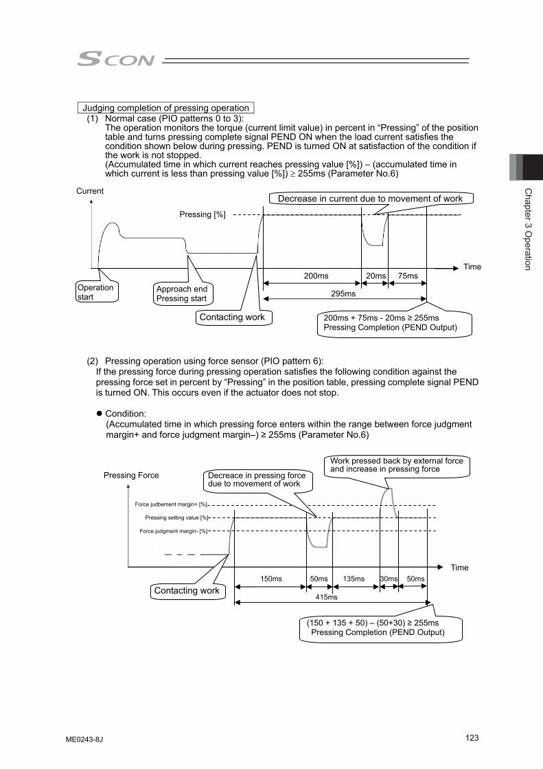
Chapter 3 O
peration
123
Judging completion of pressing operation
(1) Normal case (PIO patterns 0 to 3): The operation monitors the torque (current limit value) in percent in “Pressing” of the position
table and turns pressing complete signal PEND ON when the load current satisfies the condition shown below during pressing. PEND is turned ON at satisfaction of the condition if the work is not stopped. (Accumulated time in which current reaches pressing value [%]) – (accumulated time in which current is less than pressing value [%]) ≥ 255ms (Parameter No.6)
(2) Pressing operation using force sensor (PIO pattern 6):
If the pressing force during pressing operation satisfies the following condition against the pressing force set in percent by “Pressing” in the position table, pressing complete signal PEND is turned ON. This occurs even if the actuator does not stop.
Condition: (Accumulated time in which pressing force enters within the range between force judgment margin+ and force judgment margin–) ≥ 255ms (Parameter No.6)
Current
Time
Pressing [%]
Operation start
Approach end Pressing start
200ms 20ms 75ms
295ms
200ms + 75ms - 20ms ≥ 255ms Pressing Completion (PEND Output)
Contacting work
Decrease in current due to movement of work
Time
Pressing setting value [%]
150ms 50ms 135ms
415ms
(150 + 135 + 50) – (50+30) ≥ 255ms Pressing Completion (PEND Output)
Contacting work
Work pressed back by external force and increase in pressing force
Force judgment margin- [%]
Force judbement margin+ [%]
Pressing Force Decreace in pressing force due to movement of work
50ms 30ms
ME0243-8J

Cha
pter
3 O
pera
tion
124
Force judgment margins are described by percent of the base thrust in pressing operation using force sensor *1 provided by the actuator. They should be set in Parameter No.95 and 96. The pressing complete judging range is,
Pressing setting value [%] + Force judgment margin+ [%]
to Pressing setting value [%] – Force judgment margin [%]
*1 Base thrust in pressing operation using force sensor:
Converted thrust at rating motor output in pressing operation using force sensor
Actuator Base thrust in pressing operation using force sensor [N]
1t type 4900 RCS2-RA13R 2t type 9800
[Setting sample]
In case where the actuator is of 1-ton type and the pressing value, force judgment margin + side, and force judgment margin – side are set to 150%, 4%, and 4%, respectively: Setup pressing value: 4900 [N] × 150% = 7350 [N] and Force judgment margin + and –: 4900 [N] × 4% = 196 [N]. Hence, the pressing complete judging range is between 7154 to 7546 [N].
(3) Torque Level Detection during Pressing Operation (Valid in PIO pattern 6)
Image diagram
Operation start
Pressing Complete
Detect torque level while in pressing operation
Force judgment margin + side
Force judgment margin - side
Setup pressing force Pressing Completion (PEND Output)judging range
ME0243-8J

Chapter 3 O
peration
125
Control method This is a function to detect whether the specified load is applied to the actuator by checking the torque while in press-fitting operation when having a press-fitting process with the pressing operation. If there is no resistance in press-fitting, the specified load would not be applied, thus it is defined as the normal pressing is not conducted and an alarm can be issued from PLC. It monitors the pressing force set in % in “Threshold” in the position data, and turns the torque level status (TRQS) signal ON when the pressing force reaches the following condition. At the same time, load output judge (LOAD) signal also turns ON if it is in the position zone. This signal turns OFF either when a movement command to another position is issued or the servo is turned OFF. This signal is kept ON once it is turned ON until the next movement command.
Condition: (Total time of pressing force to reach above threshold) – (total time of pressing force to get below threshold) ≥ 255ms (Parameter No.6)
265ms
110ms + 5ms + 10ms - 5ms + 135ms ≥ 255msLoad output judgment (TRQS output)
TRQS
LOAD
Pressing Force
Push [%]
Threshold [%]
Time
msms ms5105
110ms 135ms
Position zone
Pressing force exceeding force judgment margin is occurred
Pressing force being dropped below threshold
Positive side of force judgment margin
Negative side of force judgment margin
Touched to work
ME0243-8J
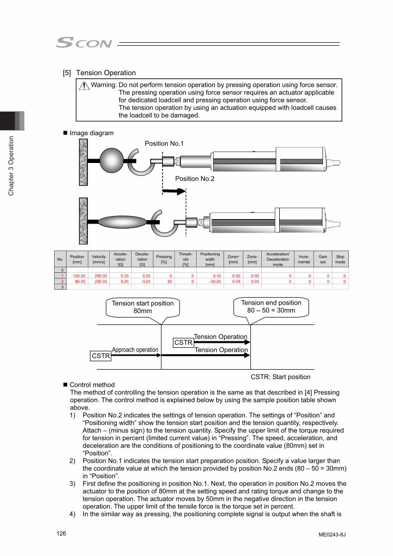
Cha
pter
3 O
pera
tion
126
[5] Tension Operation Warning: Do not perform tension operation by pressing operation using force sensor.
The pressing operation using force sensor requires an actuator applicable for dedicated loadcell and pressing operation using force sensor. The tension operation by using an actuation equipped with loadcell causes the loadcell to be damaged.
Image diagram
No. Position
[mm] Velocity [mm/s]
Accele- ration
[G]
Decele- ration
[G]
Pressing[%]
Thresh-old [%]
Positioning width [mm]
Zone+[mm]
Zone-[mm]
Acceleration/ Deceleration
mode
Incre- mental
Gain set
Stop mode
0 1 100.00 250.00 0.20 0.20 0 0 0.10 0.00 0.00 0 0 0 02 80.00 250.00 0.20 0.20 50 0 –50.00 0.00 0.00 0 0 0 03
Control method The method of controlling the tension operation is the same as that described in [4] Pressing operation. The control method is explained below by using the sample position table shown above. 1) Position No.2 indicates the settings of tension operation. The settings of “Position” and
“Positioning width” show the tension start position and the tension quantity, respectively. Attach – (minus sign) to the tension quantity. Specify the upper limit of the torque required for tension in percent (limited current value) in “Pressing”. The speed, acceleration, and deceleration are the conditions of positioning to the coordinate value (80mm) set in “Position”.
2) Position No.1 indicates the tension start preparation position. Specify a value larger than the coordinate value at which the tension provided by position No.2 ends (80 – 50 = 30mm) in “Position”.
3) First define the positioning in position No.1. Next, the operation in position No.2 moves the actuator to the position of 80mm at the setting speed and rating torque and change to the tension operation. The actuator moves by 50mm in the negative direction in the tension operation. The upper limit of the tensile force is the torque set in percent.
4) In the similar way as pressing, the positioning complete signal is output when the shaft is
CSTR
Tension Operation CSTR
Approach operation Tension Operation
CSTR: Start position
Tension start position80mm
Tension end position 80 – 50 = 30mm
Position No.1
Position No.2
ME0243-8J
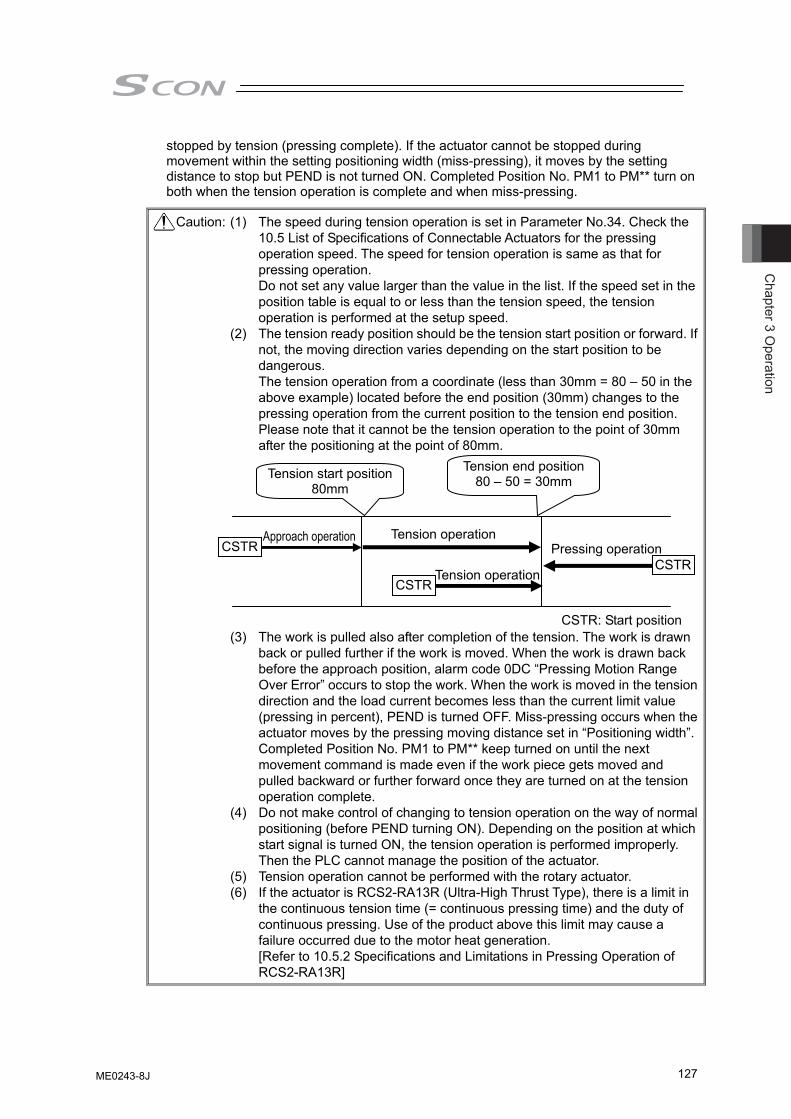
Chapter 3 O
peration
127
stopped by tension (pressing complete). If the actuator cannot be stopped during movement within the setting positioning width (miss-pressing), it moves by the setting distance to stop but PEND is not turned ON. Completed Position No. PM1 to PM** turn on both when the tension operation is complete and when miss-pressing.
Caution: (1) The speed during tension operation is set in Parameter No.34. Check the 10.5 List of Specifications of Connectable Actuators for the pressing operation speed. The speed for tension operation is same as that for pressing operation. Do not set any value larger than the value in the list. If the speed set in the position table is equal to or less than the tension speed, the tension operation is performed at the setup speed.
(2) The tension ready position should be the tension start position or forward. If not, the moving direction varies depending on the start position to be dangerous. The tension operation from a coordinate (less than 30mm = 80 – 50 in the above example) located before the end position (30mm) changes to the pressing operation from the current position to the tension end position. Please note that it cannot be the tension operation to the point of 30mm after the positioning at the point of 80mm.
(3) The work is pulled also after completion of the tension. The work is drawn
back or pulled further if the work is moved. When the work is drawn back before the approach position, alarm code 0DC “Pressing Motion Range Over Error” occurs to stop the work. When the work is moved in the tension direction and the load current becomes less than the current limit value (pressing in percent), PEND is turned OFF. Miss-pressing occurs when the actuator moves by the pressing moving distance set in “Positioning width”. Completed Position No. PM1 to PM** keep turned on until the next movement command is made even if the work piece gets moved and pulled backward or further forward once they are turned on at the tension operation complete.
(4) Do not make control of changing to tension operation on the way of normal positioning (before PEND turning ON). Depending on the position at which start signal is turned ON, the tension operation is performed improperly. Then the PLC cannot manage the position of the actuator.
(5) Tension operation cannot be performed with the rotary actuator. (6) If the actuator is RCS2-RA13R (Ultra-High Thrust Type), there is a limit in
the continuous tension time (= continuous pressing time) and the duty of continuous pressing. Use of the product above this limit may cause a failure occurred due to the motor heat generation. [Refer to 10.5.2 Specifications and Limitations in Pressing Operation of RCS2-RA13R]
Pressing operation
CSTR: Start position
CSTRCSTR
CSTR
Tension operation Approach operation
Tension operation
Tension start position80mm
Tension end position 80 – 50 = 30mm
ME0243-8J
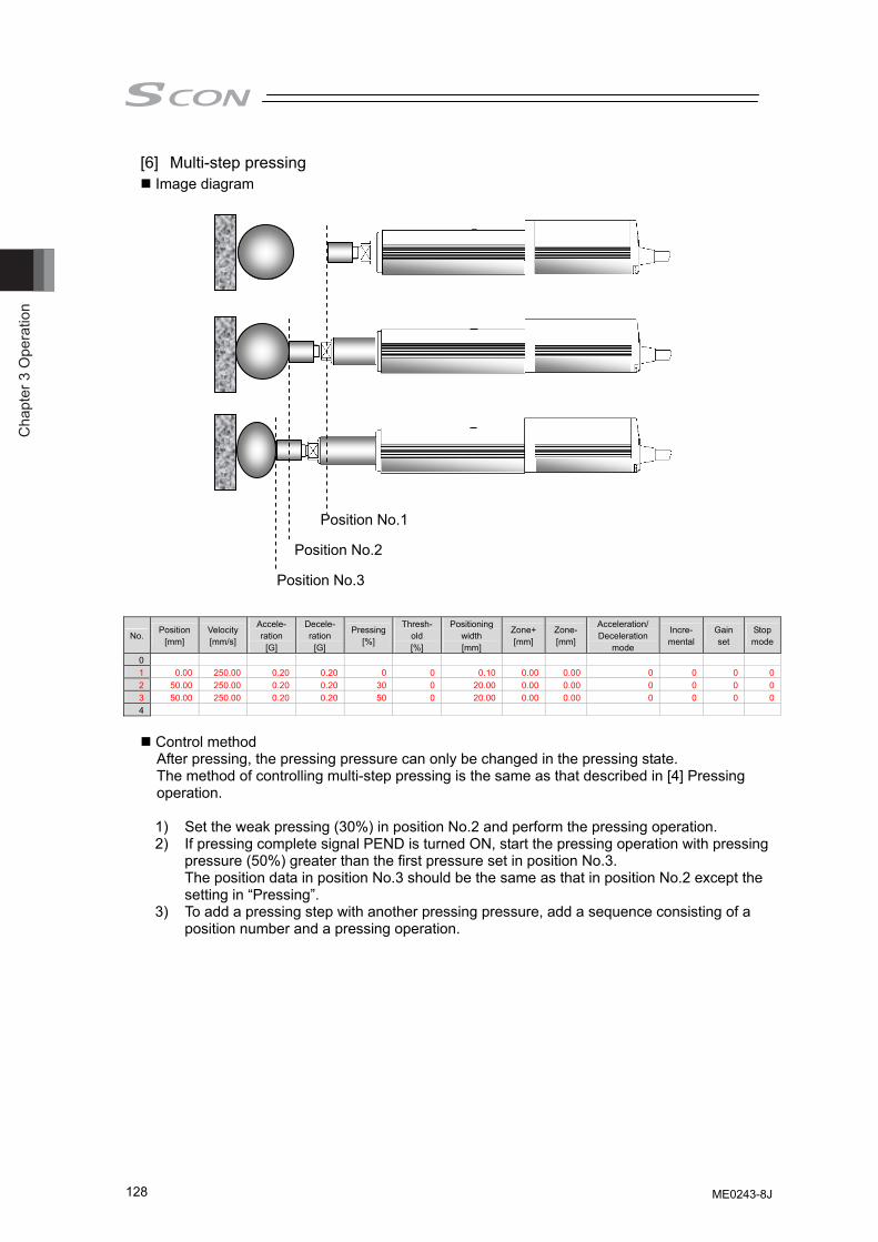
Cha
pter
3 O
pera
tion
128
[6] Multi-step pressing Image diagram
No. Position
[mm] Velocity [mm/s]
Accele- ration
[G]
Decele- ration
[G]
Pressing[%]
Thresh-old [%]
Positioning width [mm]
Zone+[mm]
Zone-[mm]
Acceleration/ Deceleration
mode
Incre- mental
Gain set
Stop mode
0 1 0.00 250.00 0.20 0.20 0 0 0.10 0.00 0.00 0 0 0 02 50.00 250.00 0.20 0.20 30 0 20.00 0.00 0.00 0 0 0 03 50.00 250.00 0.20 0.20 50 0 20.00 0.00 0.00 0 0 0 04
Control method After pressing, the pressing pressure can only be changed in the pressing state. The method of controlling multi-step pressing is the same as that described in [4] Pressing operation.
1) Set the weak pressing (30%) in position No.2 and perform the pressing operation. 2) If pressing complete signal PEND is turned ON, start the pressing operation with pressing
pressure (50%) greater than the first pressure set in position No.3. The position data in position No.3 should be the same as that in position No.2 except the setting in “Pressing”.
3) To add a pressing step with another pressing pressure, add a sequence consisting of a position number and a pressing operation.
Position No.1
Position No.2
Position No.3
ME0243-8J
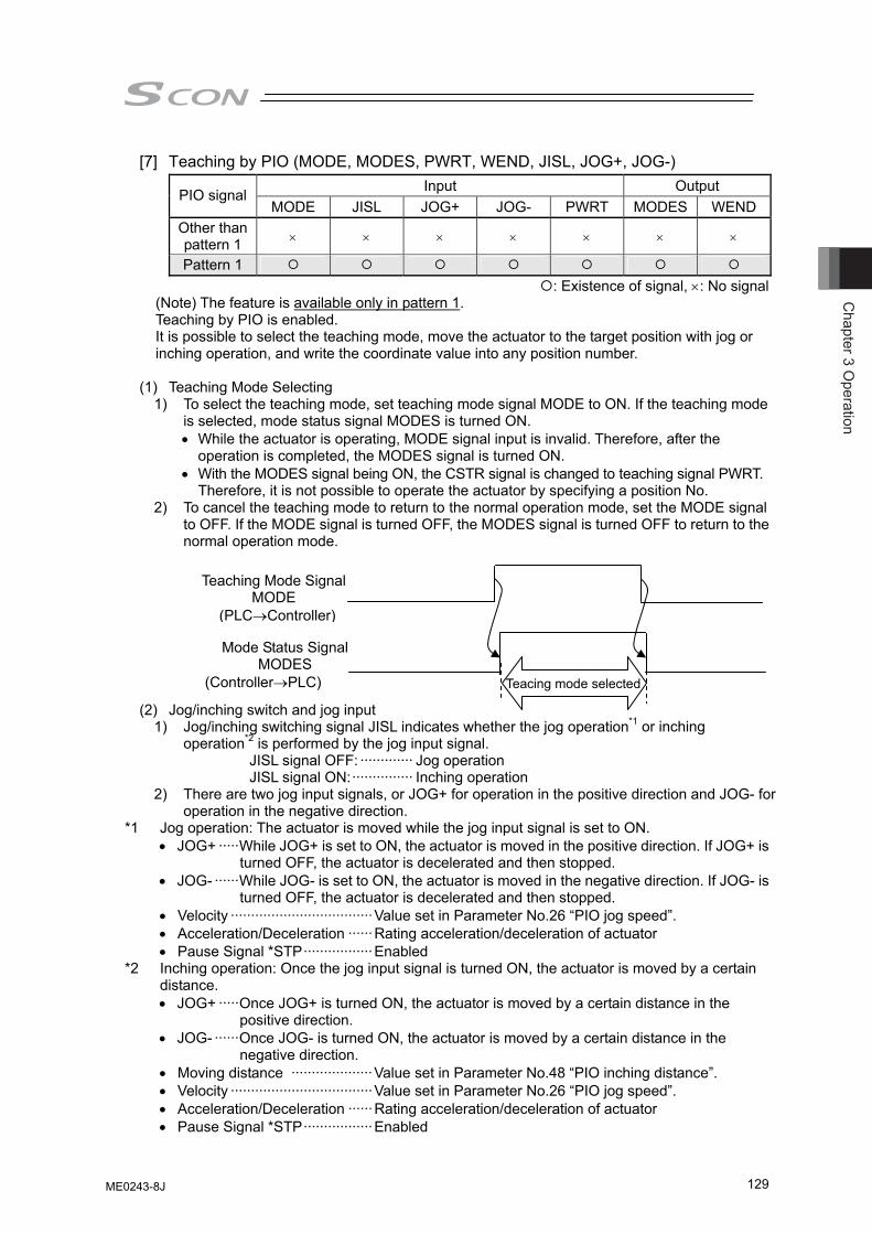
Chapter 3 O
peration
129
[7] Teaching by PIO (MODE, MODES, PWRT, WEND, JISL, JOG+, JOG-) Input Output PIO signal
MODE JISL JOG+ JOG- PWRT MODES WEND Other than pattern 1 × × × × × × ×
Pattern 1 : Existence of signal, ×: No signal
(Note) The feature is available only in pattern 1. Teaching by PIO is enabled. It is possible to select the teaching mode, move the actuator to the target position with jog or inching operation, and write the coordinate value into any position number.
(1) Teaching Mode Selecting
1) To select the teaching mode, set teaching mode signal MODE to ON. If the teaching mode is selected, mode status signal MODES is turned ON.
• While the actuator is operating, MODE signal input is invalid. Therefore, after the operation is completed, the MODES signal is turned ON.
• With the MODES signal being ON, the CSTR signal is changed to teaching signal PWRT. Therefore, it is not possible to operate the actuator by specifying a position No.
2) To cancel the teaching mode to return to the normal operation mode, set the MODE signal to OFF. If the MODE signal is turned OFF, the MODES signal is turned OFF to return to the normal operation mode.
(2) Jog/inching switch and jog input 1) Jog/inching switching signal JISL indicates whether the jog operation*1 or inching
operation*2 is performed by the jog input signal. JISL signal OFF: ············· Jog operation JISL signal ON:··············· Inching operation
2) There are two jog input signals, or JOG+ for operation in the positive direction and JOG- for operation in the negative direction.
*1 Jog operation: The actuator is moved while the jog input signal is set to ON. • JOG+ ·····While JOG+ is set to ON, the actuator is moved in the positive direction. If JOG+ is
turned OFF, the actuator is decelerated and then stopped. • JOG- ······While JOG- is set to ON, the actuator is moved in the negative direction. If JOG- is
turned OFF, the actuator is decelerated and then stopped. • Velocity ···································Value set in Parameter No.26 “PIO jog speed”. • Acceleration/Deceleration ······Rating acceleration/deceleration of actuator • Pause Signal *STP·················Enabled *2 Inching operation: Once the jog input signal is turned ON, the actuator is moved by a certain
distance. • JOG+ ·····Once JOG+ is turned ON, the actuator is moved by a certain distance in the
positive direction. • JOG- ······Once JOG- is turned ON, the actuator is moved by a certain distance in the
negative direction. • Moving distance ····················Value set in Parameter No.48 “PIO inching distance”. • Velocity ···································Value set in Parameter No.26 “PIO jog speed”. • Acceleration/Deceleration ······Rating acceleration/deceleration of actuator • Pause Signal *STP·················Enabled
Teaching Mode Signal MODE
(PLC→Controller)
Mode Status Signal MODES
(Controller→PLC) Teacing mode selected
ME0243-8J
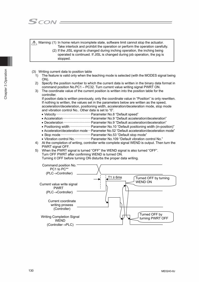
Cha
pter
3 O
pera
tion
130
Warning: (1) In home return incomplete state, software limit cannot stop the actuator. Take interlock and prohibit the operation or perform the operation carefully.
(2) If the JISL signal is changed during inching operation, the inching being operated is continued. If JISL is changed during job operation, the jog is stopped.
(3) Writing current data to position table 1) The feature is valid only when the teaching mode is selected (with the MODES signal being
ON). 2) Specify the position number to which the current data is written in the binary data format in
command position No.PC1 – PC32. Turn current value writing signal PWRT ON. 3) The coordinate value of the current position is written into the position table for the
controller. If position data is written previously, only the coordinate value in “Position” is only rewritten. If nothing is written, the values set in the parameters below are written as the speed, acceleration/deceleration, positioning width, acceleration/deceleration mode, stop mode and vibration control No.. Other data is set to “0”. • Velocity ····································· Parameter No.8 “Default speed” • Acceleration······························ Parameter No.9 “Default acceleration/deceleration” • Deceleration ····························· Parameter No.9 “Default acceleration/deceleration” • Positioning width ······················ Parameter No.10 “Default positioning width (in-position)” • Acceleration/deceleration mode··· Parameter No.52 “Default acceleration/deceleration mode” • Stop mode ································ Parameter No.53 “Default stop mode” • Vibration control No.················· Parameter No.109 “Default vibration control No.”
4) At the completion of writing, controller write complete signal WEND is output. Then turn the PWRT signal OFF.
5) When the PWRT signal is turned “OFF” the WEND signal is also turned “OFF”. Turn OFF PWRT after confirming WEND is turned ON. Turning it OFF before turning ON disturbs the proper data writing.
Current value write signal PWRT
(PLC→Controller)
Current coordinate writing prosess
(Controller)
Writing Completion Signal WEND
(Controller→PLC)
T1 ≥ 6ms Turned OFF by turning WEND ON
Turned OFF by turning PWRT OFF
Command position No. PC1 to PC**
(PLC→Controller)
ME0243-8J
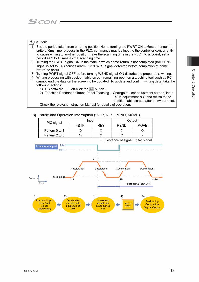
Chapter 3 O
peration
131
Caution: (1) Set the period taken from entering position No. to turning the PWRT ON to 6ms or longer. In
spite of 6ms timer process in the PLC, commands may be input to the controller concurrently to cause writing to another position. Take the scanning time in the PLC into account, set a period as 2 to 4 times as the scanning time.
(2) Turning the PWRT signal ON in the state in which home return is not completed (the HEND signal is set to ON) causes alarm 093 “PWRT signal detected before completion of home return” to occur.
(3) Turning PWRT signal OFF before turning WEND signal ON disturbs the proper data writing. (4) Writing processing with position table screen remaining open on a teaching tool such as PC
cannot lead the data on the screen to be updated. To update and confirm writing data, take the following actions:
1) PC software ······Left-click the button. 2) Teaching Pendant or Touch Panel Teaching ···Change to user adjustment screen, input
“4” in adjustment N O and return to the position table screen after software reset.
Check the relevant Instruction Manual for details of operation.
[8] Pause and Operation Interruption (*STP, RES, PEND, MOVE)
Input Output PIO signal *STP RES PEND MOVE
Pattern 0 to 1 Pattern 2 to 3 ×
: Existence of signal, ×: No signal
Velocity
Positioning Completion
Signal Output
1) 2) 3) 4) 5)
1)
2)
3) 4) 5)
ME0243-8J
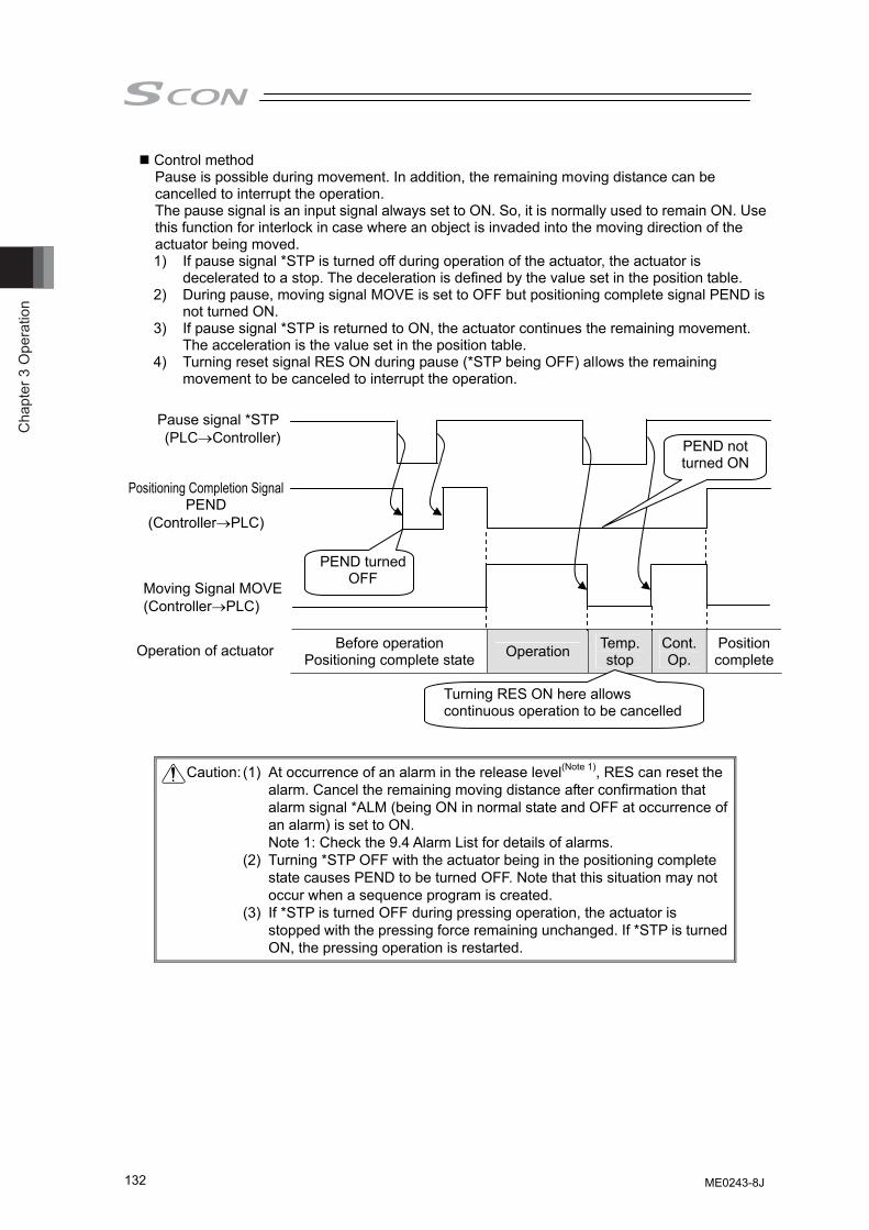
Cha
pter
3 O
pera
tion
132
Control method Pause is possible during movement. In addition, the remaining moving distance can be cancelled to interrupt the operation. The pause signal is an input signal always set to ON. So, it is normally used to remain ON. Use this function for interlock in case where an object is invaded into the moving direction of the actuator being moved. 1) If pause signal *STP is turned off during operation of the actuator, the actuator is
decelerated to a stop. The deceleration is defined by the value set in the position table. 2) During pause, moving signal MOVE is set to OFF but positioning complete signal PEND is
not turned ON. 3) If pause signal *STP is returned to ON, the actuator continues the remaining movement.
The acceleration is the value set in the position table. 4) Turning reset signal RES ON during pause (*STP being OFF) allows the remaining
movement to be canceled to interrupt the operation.
Caution: (1) At occurrence of an alarm in the release level(Note 1), RES can reset the alarm. Cancel the remaining moving distance after confirmation that alarm signal *ALM (being ON in normal state and OFF at occurrence of an alarm) is set to ON. Note 1: Check the 9.4 Alarm List for details of alarms.
(2) Turning *STP OFF with the actuator being in the positioning complete state causes PEND to be turned OFF. Note that this situation may not occur when a sequence program is created.
(3) If *STP is turned OFF during pressing operation, the actuator is stopped with the pressing force remaining unchanged. If *STP is turned ON, the pressing operation is restarted.
Before operation Positioning complete state Operation Temp.
stop Cont. Op.
Position complete
Pause signal *STP (PLC→Controller)
Positioning Completion Signal PEND
(Controller→PLC)
Moving Signal MOVE (Controller→PLC)
Turning RES ON here allows continuous operation to be cancelled
Operation of actuator
PEND turned OFF
PEND not turned ON
ME0243-8J
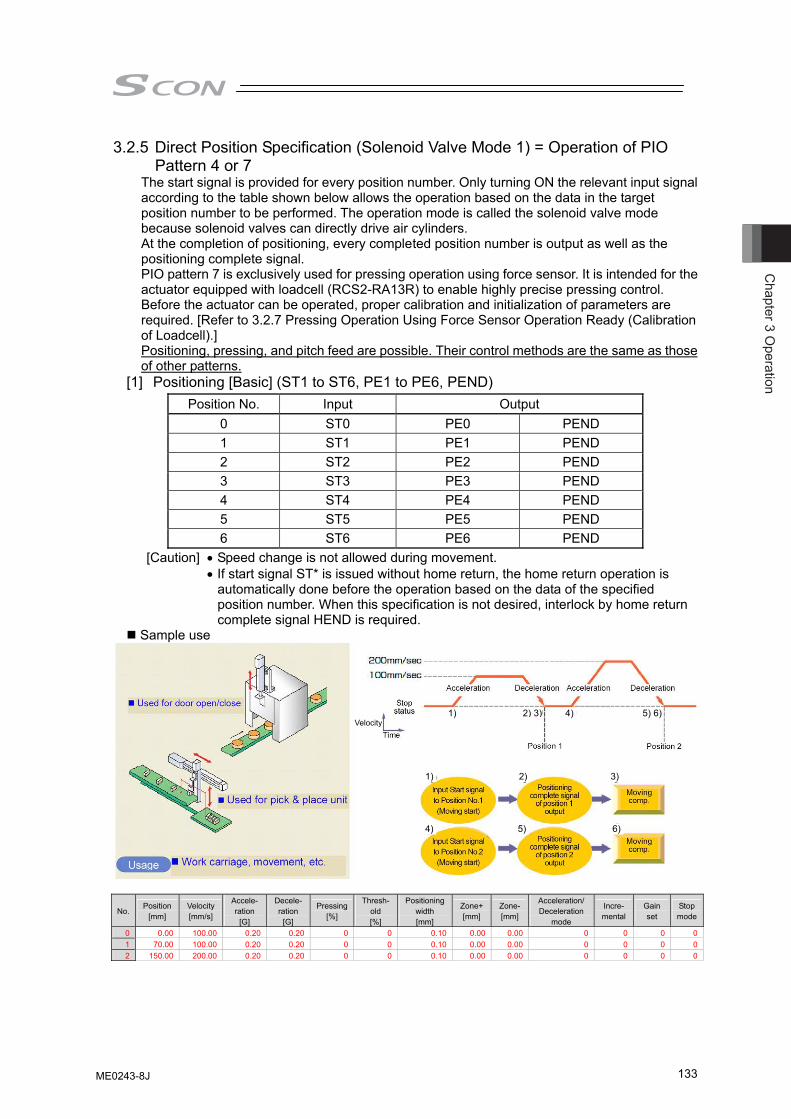
Chapter 3 O
peration
133
3.2.5 Direct Position Specification (Solenoid Valve Mode 1) = Operation of PIO Pattern 4 or 7
The start signal is provided for every position number. Only turning ON the relevant input signal according to the table shown below allows the operation based on the data in the target position number to be performed. The operation mode is called the solenoid valve mode because solenoid valves can directly drive air cylinders. At the completion of positioning, every completed position number is output as well as the positioning complete signal. PIO pattern 7 is exclusively used for pressing operation using force sensor. It is intended for the actuator equipped with loadcell (RCS2-RA13R) to enable highly precise pressing control. Before the actuator can be operated, proper calibration and initialization of parameters are required. [Refer to 3.2.7 Pressing Operation Using Force Sensor Operation Ready (Calibration of Loadcell).] Positioning, pressing, and pitch feed are possible. Their control methods are the same as those of other patterns.
[1] Positioning [Basic] (ST1 to ST6, PE1 to PE6, PEND) Position No. Input Output
0 ST0 PE0 PEND 1 ST1 PE1 PEND 2 ST2 PE2 PEND 3 ST3 PE3 PEND 4 ST4 PE4 PEND 5 ST5 PE5 PEND 6 ST6 PE6 PEND
[Caution] • Speed change is not allowed during movement. • If start signal ST* is issued without home return, the home return operation is
automatically done before the operation based on the data of the specified position number. When this specification is not desired, interlock by home return complete signal HEND is required.
Sample use No.
Position [mm]
Velocity [mm/s]
Accele- ration
[G]
Decele- ration
[G]
Pressing[%]
Thresh-old [%]
Positioning width [mm]
Zone+[mm]
Zone-[mm]
Acceleration/ Deceleration
mode
Incre- mental
Gain set
Stop mode
0 0.00 100.00 0.20 0.20 0 0 0.10 0.00 0.00 0 0 0 01 70.00 100.00 0.20 0.20 0 0 0.10 0.00 0.00 0 0 0 02 150.00 200.00 0.20 0.20 0 0 0.10 0.00 0.00 0 0 0 0
Velocity
1) 2) 3)
4) 5) 6)
1) 2) 3) 4) 5) 6)
ME0243-8J
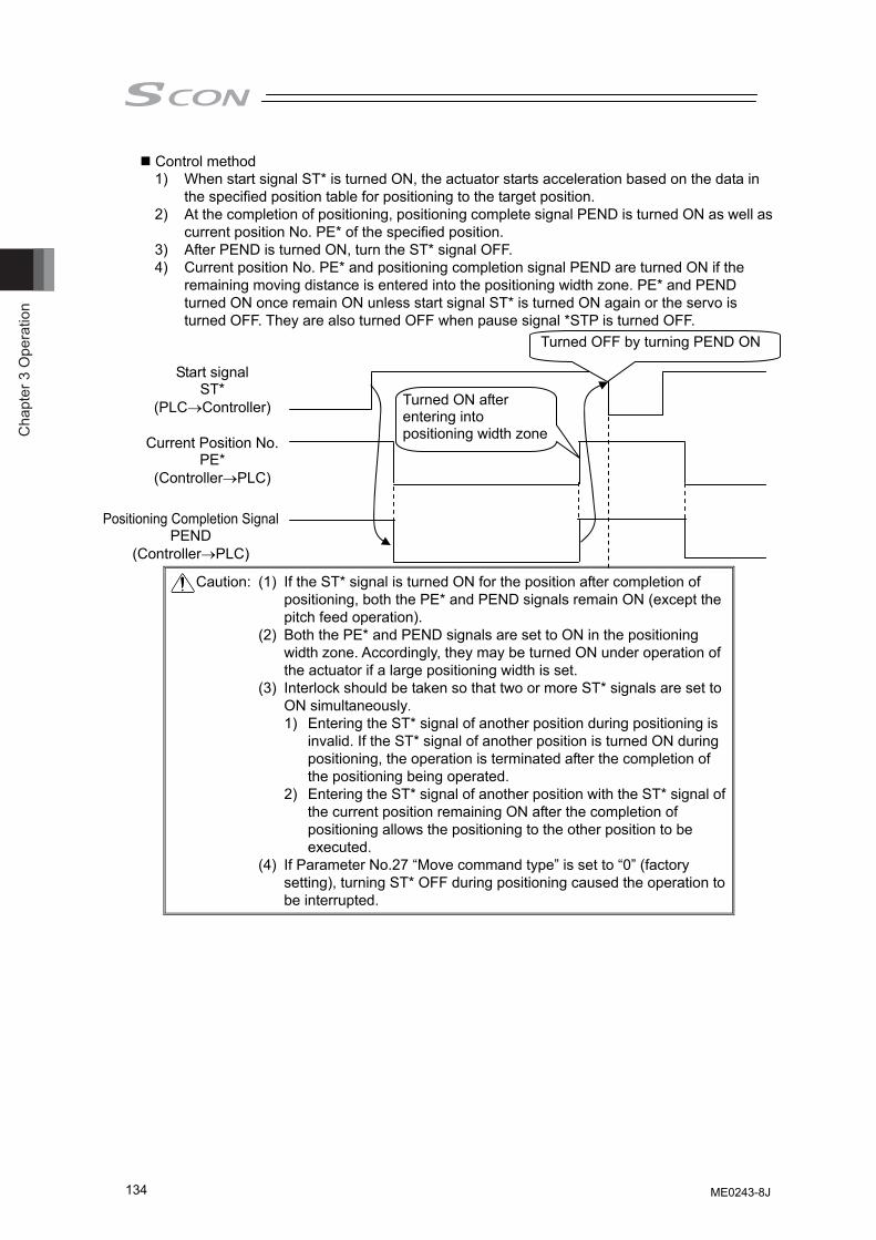
Cha
pter
3 O
pera
tion
134
Control method 1) When start signal ST* is turned ON, the actuator starts acceleration based on the data in
the specified position table for positioning to the target position. 2) At the completion of positioning, positioning complete signal PEND is turned ON as well as
current position No. PE* of the specified position. 3) After PEND is turned ON, turn the ST* signal OFF. 4) Current position No. PE* and positioning completion signal PEND are turned ON if the
remaining moving distance is entered into the positioning width zone. PE* and PEND turned ON once remain ON unless start signal ST* is turned ON again or the servo is turned OFF. They are also turned OFF when pause signal *STP is turned OFF.
Caution: (1) If the ST* signal is turned ON for the position after completion of positioning, both the PE* and PEND signals remain ON (except the pitch feed operation).
(2) Both the PE* and PEND signals are set to ON in the positioning width zone. Accordingly, they may be turned ON under operation of the actuator if a large positioning width is set.
(3) Interlock should be taken so that two or more ST* signals are set to ON simultaneously.
1) Entering the ST* signal of another position during positioning is invalid. If the ST* signal of another position is turned ON during positioning, the operation is terminated after the completion of the positioning being operated.
2) Entering the ST* signal of another position with the ST* signal of the current position remaining ON after the completion of positioning allows the positioning to the other position to be executed.
(4) If Parameter No.27 “Move command type” is set to “0” (factory setting), turning ST* OFF during positioning caused the operation to be interrupted.
Start signal ST*
(PLC→Controller)
Positioning Completion Signal PEND
(Controller→PLC)
Turned ON after entering into positioning width zoneCurrent Position No.
PE* (Controller→PLC)
Turned OFF by turning PEND ON
ME0243-8J
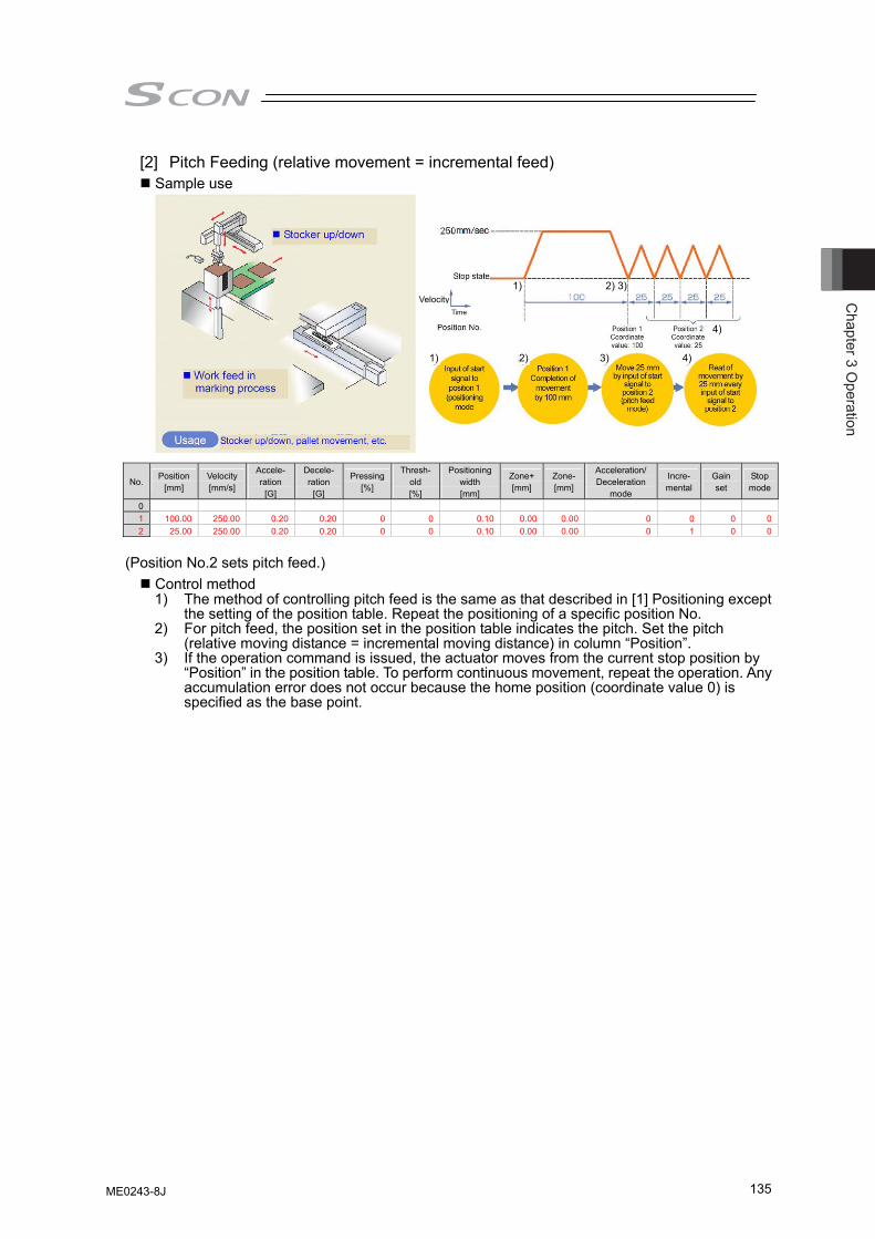
Chapter 3 O
peration
135
[2] Pitch Feeding (relative movement = incremental feed) Sample use
No. Position
[mm] Velocity [mm/s]
Accele- ration
[G]
Decele- ration
[G]
Pressing[%]
Thresh-old [%]
Positioning width [mm]
Zone+[mm]
Zone-[mm]
Acceleration/ Deceleration
mode
Incre- mental
Gain set
Stop mode
0 1 100.00 250.00 0.20 0.20 0 0 0.10 0.00 0.00 0 0 0 02 25.00 250.00 0.20 0.20 0 0 0.10 0.00 0.00 0 1 0 0
(Position No.2 sets pitch feed.)
Control method 1) The method of controlling pitch feed is the same as that described in [1] Positioning except
the setting of the position table. Repeat the positioning of a specific position No. 2) For pitch feed, the position set in the position table indicates the pitch. Set the pitch
(relative moving distance = incremental moving distance) in column “Position”. 3) If the operation command is issued, the actuator moves from the current stop position by
“Position” in the position table. To perform continuous movement, repeat the operation. Any accumulation error does not occur because the home position (coordinate value 0) is specified as the base point.
Velocity
1) 2) 3) 4)
1) 2) 3)
4)
ME0243-8J
Cha
pter
3 O
pera
tion
136
Caution:
(1) Because pitch feed is repeated, turning ON the ST* signal of the same position after completion of positioning causes both the PE* and PEND signals to be turned OFF at operation start and turned ON again at completion of positioning in the same way as [1] Positioning.
(2) If the actuator reaches the software limit (stroke end) in pitch feed, the actuator is decelerated to be stopped and current position No. PE* and positioning complete signal PEND are turned ON at the stop position.
(3) Both the PE* and PEND signals are set to ON in the positioning width zone. Accordingly, they may be turned ON under operation of the actuator if a large positioning width is set.
(4) Interlock should be taken so that two or more ST* signals are set to ON simultaneously.1) Entering the ST* signal of another position during positioning is invalid. If the ST*
signal of another position is turned ON during positioning, the operation is terminated after the completion of the positioning being operated.
2) Entering the ST* signal of another position with the ST* signal of the current position remaining ON after the completion of positioning allows the positioning to the other position to be executed.
(5) If Parameter No.27 “Move command type” is set to “0” (factory setting), turning ST* OFF during positioning caused the operation to be interrupted.
(6) Note that, when Parameter No.27 “Move command type” is set to “1”, starting (ST* ON) pitch feed repeatedly during pause causes the actuator to be moved successively by the number of starts. If this situation is supposed, cancel the remaining moving distance by turning reset signal RES ON in the pause state or take interlock so that start signals are not turned on during pause.
(7) The pressing operation is enabled by using the pitch feed function. (8) In the pitch feed, do not perform a command with a pitch smaller than the minimum
encoder resolution (lead/encoder pulse number) or that less than positioning accuracy repeatability. There would be no deviation to occur even with the command because it is an operation command to the same position as the positioning complete condition, but the positioning control cannot be performed properly.
ME0243-8J
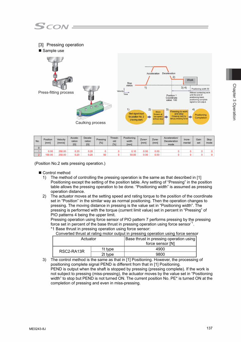
Chapter 3 O
peration
137
[3] Pressing operation Sample use
PositioningCompletion
1) 2) 3) 4)
1) 3) 4)
2)
Positioning width 50VelocityPress-fitting process
Caulking process
No. Position
[mm] Velocity [mm/s]
Accele- ration
[G]
Decele- ration
[G]
Pressing[%]
Thresh-old [%]
Positioning width [mm]
Zone+[mm]
Zone-[mm]
Acceleration/ Deceleration
mode
Incre- mental
Gain set
Stop mode
0 1 0.00 250.00 0.20 0.20 0 0 0.10 0.00 0.00 0 0 0 02 100.00 250.00 0.20 0.20 50 0 50.00 0.00 0.00 0 0 0 0
(Position No.2 sets pressing operation.)
Control method 1) The method of controlling the pressing operation is the same as that described in [1]
Positioning except the setting of the position table. Any setting of “Pressing” in the position table allows the pressing operation to be done. “Positioning width” is assumed as pressing operation distance.
2) The actuator moves at the setting speed and rating torque to the position of the coordinate set in “Position” in the similar way as normal positioning. Then the operation changes to pressing. The moving distance in pressing is the value set in “Positioning width”. The pressing is performed with the torque (current limit value) set in percent in “Pressing” of PIO patterns 4 being the upper limit. Pressing operation using force sensor of PIO pattern 7 performs pressing by the pressing force set in percent of the base thrust in pressing operation using force sensor*1. *1 Base thrust in pressing operation using force sensor: Converted thrust at rating motor output in pressing operation using force sensor
Actuator Base thrust in pressing operation using force sensor [N]
1t type 4900 RSC2-RA13R 2t type 9800
3) The control method is the same as that in [1] Positioning. However, the processing of positioning complete signal PEND is different from that in [1] Positioning. PEND is output when the shaft is stopped by pressing (pressing complete). If the work is not subject to pressing (miss-pressing), the actuator moves by the value set in “Positioning width” to stop but PEND is not turned ON. The current position No. PE* is turned ON at the completion of pressing and even in miss-pressing.
ME0243-8J
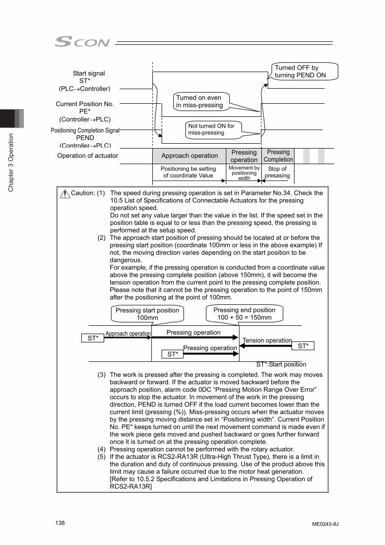
Cha
pter
3 O
pera
tion
138
Caution: (1) The speed during pressing operation is set in Parameter No.34. Check the 10.5 List of Specifications of Connectable Actuators for the pressing operation speed. Do not set any value larger than the value in the list. If the speed set in the position table is equal to or less than the pressing speed, the pressing is performed at the setup speed.
(2) The approach start position of pressing should be located at or before the pressing start position (coordinate 100mm or less in the above example) If not, the moving direction varies depending on the start position to be dangerous. For example, if the pressing operation is conducted from a coordinate value above the pressing complete position (above 150mm), it will become the tension operation from the current point to the pressing complete position. Please note that it cannot be the pressing operation to the point of 150mm after the positioning at the point of 100mm.
(3) The work is pressed after the pressing is completed. The work may moves
backward or forward. If the actuator is moved backward before the approach position, alarm code 0DC “Pressing Motion Range Over Error” occurs to stop the actuator. In movement of the work in the pressing direction, PEND is turned OFF if the load current becomes lower than the current limit (pressing (%)). Miss-pressing occurs when the actuator moves by the pressing moving distance set in “Positioning width”. Current Position No. PE* keeps turned on until the next movement command is made even if the work piece gets moved and pushed backward or goes further forward once it is turned on at the pressing operation complete.
(4) Pressing operation cannot be performed with the rotary actuator. (5) If the actuator is RCS2-RA13R (Ultra-High Thrust Type), there is a limit in
the duration and duty of continuous pressing. Use of the product above this limit may cause a failure occurred due to the motor heat generation. [Refer to 10.5.2 Specifications and Limitations in Pressing Operation of RCS2-RA13R]
Positioning Completion Signal PEND
(Controller→PLC)
Turned OFF by turning PEND ON
Turned on even in miss-pressing
Start signal ST*
(PLC→Controller)
Current Position No. PE*
(Controller→PLC) Not turned ON for miss-pressing
Pressing operation
Pressing Completion Operation of actuator Approach operation
Positioning be setting of coordinate Value
Movement by positioning
width
Stop of presasing
Pressing start position100mm
Pressing end position 100 + 50 = 150mm
ST*
Pressing operation
ST*
Approach operation
ST*:Start position
ST* Pressing operation
Tension operation
ME0243-8J
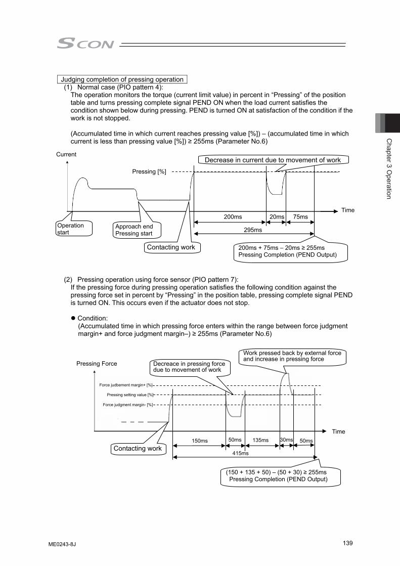
Chapter 3 O
peration
139
Judging completion of pressing operation
(1) Normal case (PIO pattern 4): The operation monitors the torque (current limit value) in percent in “Pressing” of the position
table and turns pressing complete signal PEND ON when the load current satisfies the condition shown below during pressing. PEND is turned ON at satisfaction of the condition if the work is not stopped.
(Accumulated time in which current reaches pressing value [%]) – (accumulated time in which current is less than pressing value [%]) ≥ 255ms (Parameter No.6)
(2) Pressing operation using force sensor (PIO pattern 7):
If the pressing force during pressing operation satisfies the following condition against the pressing force set in percent by “Pressing” in the position table, pressing complete signal PEND is turned ON. This occurs even if the actuator does not stop.
Condition: (Accumulated time in which pressing force enters within the range between force judgment margin+ and force judgment margin–) ≥ 255ms (Parameter No.6)
Current
Time
Pressing [%]
Operation start
Approach end Pressing start
200ms 20ms 75ms
295ms
200ms + 75ms – 20ms ≥ 255ms Pressing Completion (PEND Output)
Contacting work
Decrease in current due to movement of work
Time
Pressing setting value [%]
150ms 50ms 135ms
415ms
(150 + 135 + 50) – (50 + 30) ≥ 255ms Pressing Completion (PEND Output)
Contacting work
Work pressed back by external force and increase in pressing force
Force judgment margin- [%]
Force judbement margin+ [%]
Pressing Force Decreace in pressing force due to movement of work
50ms 30ms
ME0243-8J
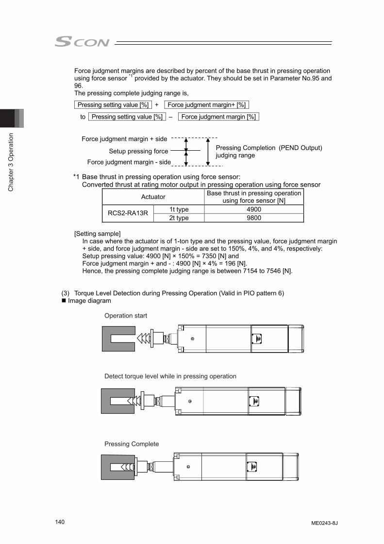
Cha
pter
3 O
pera
tion
140
Force judgment margins are described by percent of the base thrust in pressing operation using force sensor *1 provided by the actuator. They should be set in Parameter No.95 and 96. The pressing complete judging range is,
Pressing setting value [%] + Force judgment margin+ [%]
to Pressing setting value [%] – Force judgment margin [%]
*1 Base thrust in pressing operation using force sensor:
Converted thrust at rating motor output in pressing operation using force sensor
Actuator Base thrust in pressing operation using force sensor [N]
1t type 4900 RCS2-RA13R 2t type 9800
[Setting sample]
In case where the actuator is of 1-ton type and the pressing value, force judgment margin + side, and force judgment margin - side are set to 150%, 4%, and 4%, respectively: Setup pressing value: 4900 [N] × 150% = 7350 [N] and Force judgment margin + and - : 4900 [N] × 4% = 196 [N]. Hence, the pressing complete judging range is between 7154 to 7546 [N].
(3) Torque Level Detection during Pressing Operation (Valid in PIO pattern 6)
Image diagram
Operation start
Pressing Complete
Detect torque level while in pressing operation
Force judgment margin + side
Force judgment margin - side
Setup pressing force Pressing Completion (PEND Output)judging range
ME0243-8J
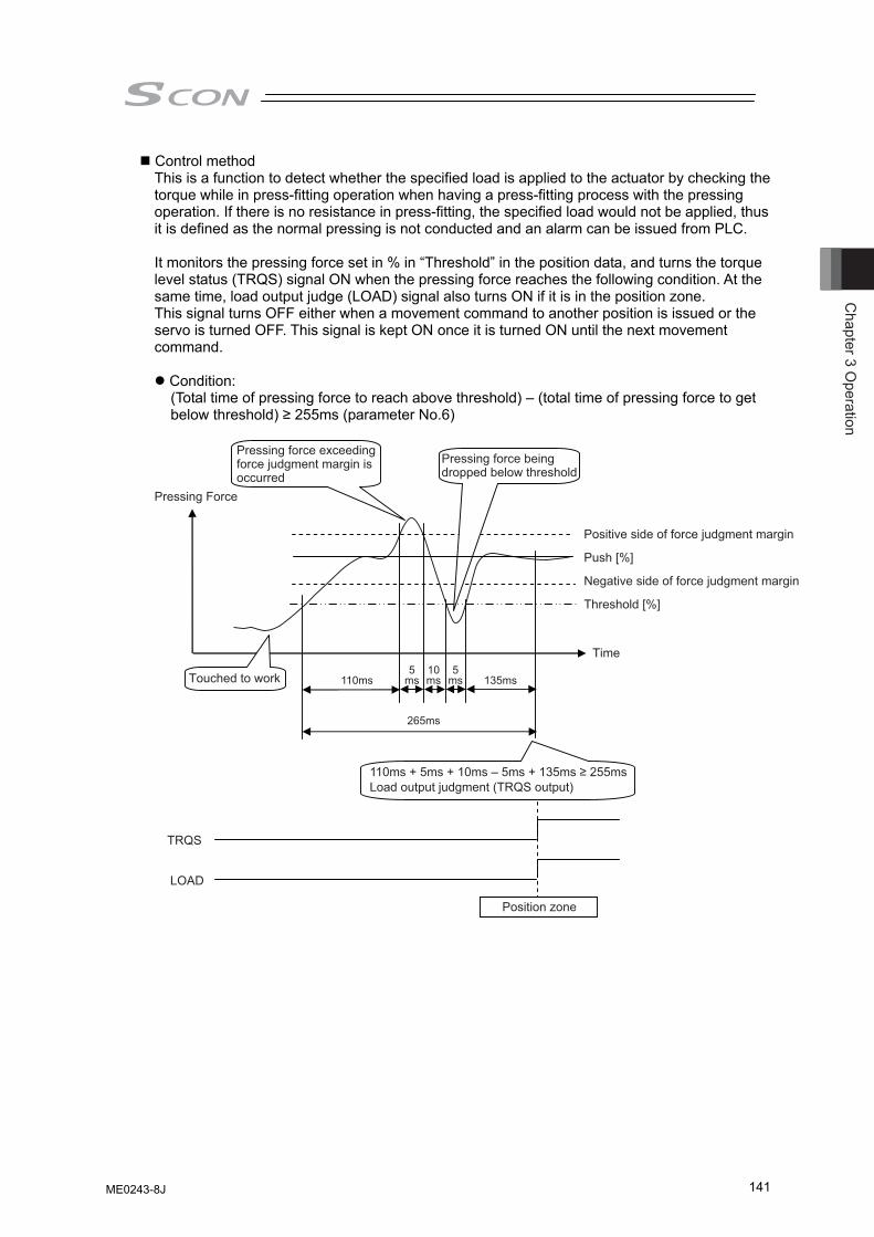
Chapter 3 O
peration
141
Control method This is a function to detect whether the specified load is applied to the actuator by checking the torque while in press-fitting operation when having a press-fitting process with the pressing operation. If there is no resistance in press-fitting, the specified load would not be applied, thus it is defined as the normal pressing is not conducted and an alarm can be issued from PLC. It monitors the pressing force set in % in “Threshold” in the position data, and turns the torque level status (TRQS) signal ON when the pressing force reaches the following condition. At the same time, load output judge (LOAD) signal also turns ON if it is in the position zone. This signal turns OFF either when a movement command to another position is issued or the servo is turned OFF. This signal is kept ON once it is turned ON until the next movement command.
Condition: (Total time of pressing force to reach above threshold) – (total time of pressing force to get below threshold) ≥ 255ms (parameter No.6)
265ms
110ms + 5ms + 10ms – 5ms + 135ms ≥ 255msLoad output judgment (TRQS output)
TRQS
LOAD
Pressing Force
Push [%]
Threshold [%]
Time
msms ms5105
110ms 135ms
Position zone
Pressing force exceeding force judgment margin is occurred
Pressing force being dropped below threshold
Positive side of force judgment margin
Negative side of force judgment margin
Touched to work
ME0243-8J
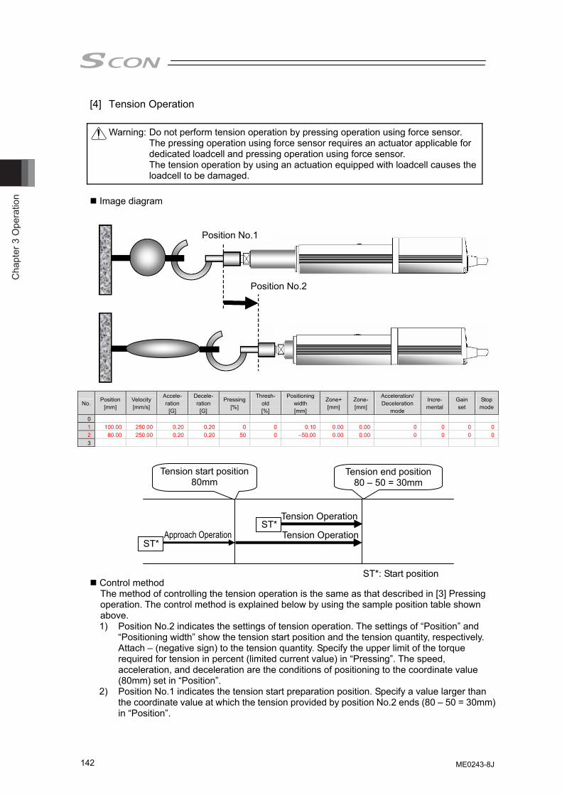
Cha
pter
3 O
pera
tion
142
[4] Tension Operation
Warning: Do not perform tension operation by pressing operation using force sensor. The pressing operation using force sensor requires an actuator applicable for dedicated loadcell and pressing operation using force sensor. The tension operation by using an actuation equipped with loadcell causes the loadcell to be damaged.
Image diagram
No. Position
[mm] Velocity [mm/s]
Accele- ration
[G]
Decele- ration
[G]
Pressing[%]
Thresh-old [%]
Positioning width [mm]
Zone+[mm]
Zone-[mm]
Acceleration/ Deceleration
mode
Incre- mental
Gain set
Stop mode
0 1 100.00 250.00 0.20 0.20 0 0 0.10 0.00 0.00 0 0 0 02 80.00 250.00 0.20 0.20 50 0 –50.00 0.00 0.00 0 0 0 03
Control method The method of controlling the tension operation is the same as that described in [3] Pressing operation. The control method is explained below by using the sample position table shown above. 1) Position No.2 indicates the settings of tension operation. The settings of “Position” and
“Positioning width” show the tension start position and the tension quantity, respectively. Attach – (negative sign) to the tension quantity. Specify the upper limit of the torque required for tension in percent (limited current value) in “Pressing”. The speed, acceleration, and deceleration are the conditions of positioning to the coordinate value (80mm) set in “Position”.
2) Position No.1 indicates the tension start preparation position. Specify a value larger than the coordinate value at which the tension provided by position No.2 ends (80 – 50 = 30mm) in “Position”.
ST*
ST*
ST*: Start position
Position No.1
Position No.2
Tension Operation
Approach Operation Tension Operation
Tension start position80mm
Tension end position 80 – 50 = 30mm
ME0243-8J
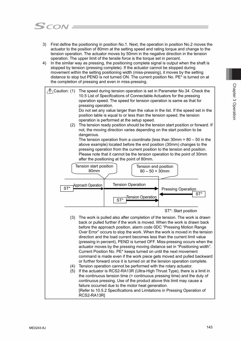
Chapter 3 O
peration
143
3) First define the positioning in position No.1. Next, the operation in position No.2 moves the actuator to the position of 80mm at the setting speed and rating torque and change to the tension operation. The actuator moves by 50mm in the negative direction in the tension operation. The upper limit of the tensile force is the torque set in percent.
4) In the similar way as pressing, the positioning complete signal is output when the shaft is stopped by tension (pressing complete). If the actuator cannot be stopped during movement within the setting positioning width (miss-pressing), it moves by the setting distance to stop but PEND is not turned ON. The current position No. PE* is turned on at the completion of pressing and even in miss-pressing.
Caution: (1) The speed during tension operation is set in Parameter No.34. Check the 10.5 List of Specifications of Connectable Actuators for the pressing operation speed. The speed for tension operation is same as that for pressing operation. Do not set any value larger than the value in the list. If the speed set in the position table is equal to or less than the tension speed, the tension operation is performed at the setup speed.
(2) The tension ready position should be the tension start position or forward. If not, the moving direction varies depending on the start position to be dangerous. The tension operation from a coordinate (less than 30mm = 80 – 50 in the above example) located before the end position (30mm) changes to the pressing operation from the current position to the tension end position. Please note that it cannot be the tension operation to the point of 30mm after the positioning at the point of 80mm.
(3) The work is pulled also after completion of the tension. The work is drawn
back or pulled further if the work is moved. When the work is drawn back before the approach position, alarm code 0DC “Pressing Motion Range Over Error” occurs to stop the work. When the work is moved in the tension direction and the load current becomes less than the current limit value (pressing in percent), PEND is turned OFF. Miss-pressing occurs when the actuator moves by the pressing moving distance set in “Positioning width”. Current Position No. PE* keeps turned on until the next movement command is made even if the work piece gets moved and pulled backward or further forward once it is turned on at the tension operation complete.
(4) Tension operation cannot be performed with the rotary actuator. (5) If the actuator is RCS2-RA13R (Ultra-High Thrust Type), there is a limit in
the continuous tension time (= continuous pressing time) and the duty of continuous pressing. Use of the product above this limit may cause a failure occurred due to the motor heat generation. [Refer to 10.5.2 Specifications and Limitations in Pressing Operation of RCS2-RA13R]
Pressing Operation
ST*: Start position
ST*ST*
ST*
Tension Operation Approach Operation
Tension Operation
Tension start position80mm
Tension end position 80 – 50 = 30mm
ME0243-8J
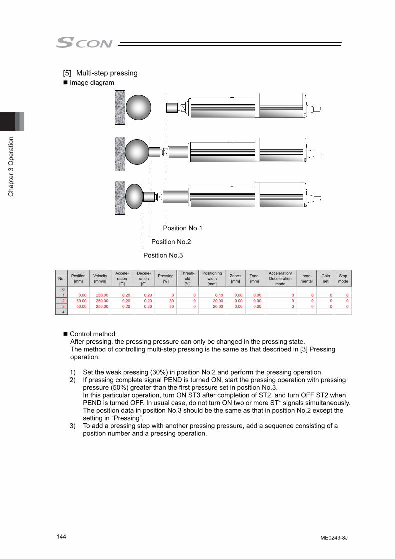
Cha
pter
3 O
pera
tion
144
[5] Multi-step pressing Image diagram
No. Position
[mm] Velocity [mm/s]
Accele- ration
[G]
Decele- ration
[G]
Pressing[%]
Thresh-old [%]
Positioning width [mm]
Zone+[mm]
Zone-[mm]
Acceleration/ Deceleration
mode
Incre- mental
Gain set
Stop mode
0 1 0.00 250.00 0.20 0.20 0 0 0.10 0.00 0.00 0 0 0 02 50.00 250.00 0.20 0.20 30 0 20.00 0.00 0.00 0 0 0 03 50.00 250.00 0.20 0.20 50 0 20.00 0.00 0.00 0 0 0 04
Control method After pressing, the pressing pressure can only be changed in the pressing state. The method of controlling multi-step pressing is the same as that described in [3] Pressing operation.
1) Set the weak pressing (30%) in position No.2 and perform the pressing operation. 2) If pressing complete signal PEND is turned ON, start the pressing operation with pressing
pressure (50%) greater than the first pressure set in position No.3. In this particular operation, turn ON ST3 after completion of ST2, and turn OFF ST2 when PEND is turned OFF. In usual case, do not turn ON two or more ST* signals simultaneously. The position data in position No.3 should be the same as that in position No.2 except the setting in “Pressing”.
3) To add a pressing step with another pressing pressure, add a sequence consisting of a position number and a pressing operation.
Position No.1
Position No.2
Position No.3
ME0243-8J
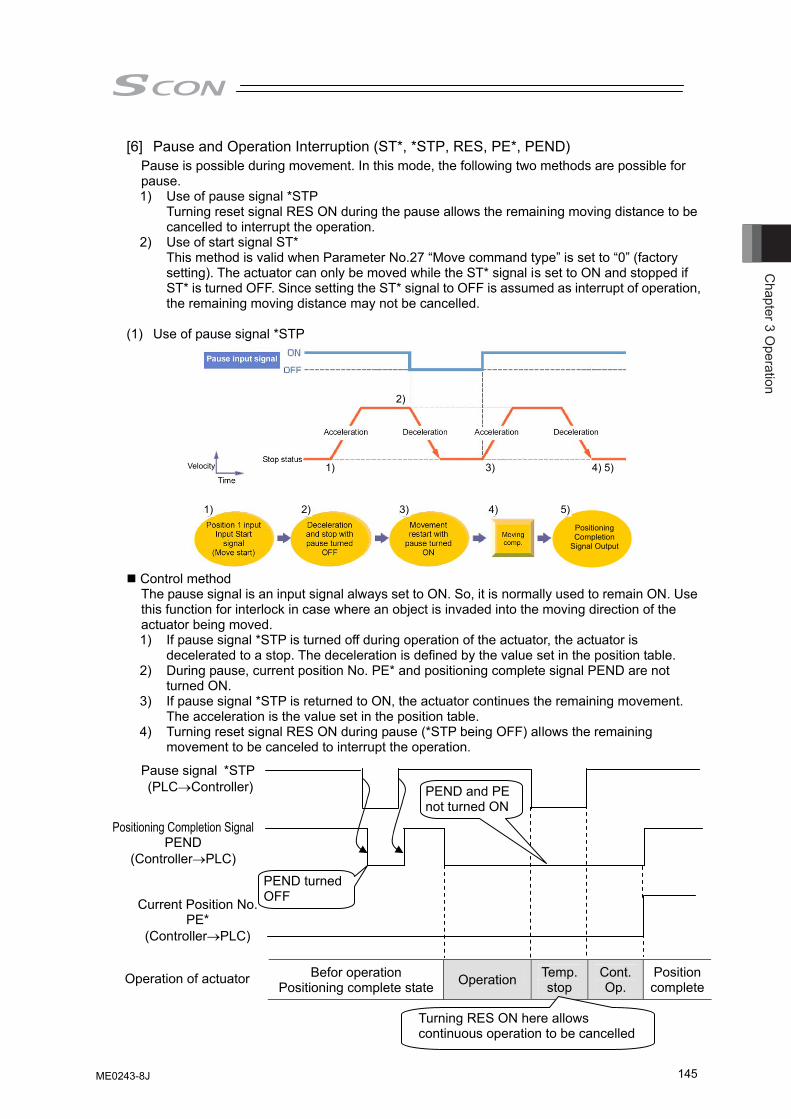
Chapter 3 O
peration
145
[6] Pause and Operation Interruption (ST*, *STP, RES, PE*, PEND) Pause is possible during movement. In this mode, the following two methods are possible for pause. 1) Use of pause signal *STP Turning reset signal RES ON during the pause allows the remaining moving distance to be
cancelled to interrupt the operation. 2) Use of start signal ST* This method is valid when Parameter No.27 “Move command type” is set to “0” (factory
setting). The actuator can only be moved while the ST* signal is set to ON and stopped if ST* is turned OFF. Since setting the ST* signal to OFF is assumed as interrupt of operation, the remaining moving distance may not be cancelled.
(1) Use of pause signal *STP
Control method The pause signal is an input signal always set to ON. So, it is normally used to remain ON. Use this function for interlock in case where an object is invaded into the moving direction of the actuator being moved. 1) If pause signal *STP is turned off during operation of the actuator, the actuator is
decelerated to a stop. The deceleration is defined by the value set in the position table. 2) During pause, current position No. PE* and positioning complete signal PEND are not
turned ON. 3) If pause signal *STP is returned to ON, the actuator continues the remaining movement.
The acceleration is the value set in the position table. 4) Turning reset signal RES ON during pause (*STP being OFF) allows the remaining
movement to be canceled to interrupt the operation.
Befor operation Positioning complete state Operation Temp.
stop Cont. Op.
Position complete
Turning RES ON here allows continuous operation to be cancelled
Pause signal *STP (PLC→Controller)
Positioning Completion Signal PEND
(Controller→PLC)
Operation of actuator
PEND turned OFF
PEND and PE not turned ON
Current Position No. PE*
(Controller→PLC)
Velocity
Positioning Completion
Signal Output
1) 2) 3) 4) 5)
1) 3) 4) 5)
2)
ME0243-8J
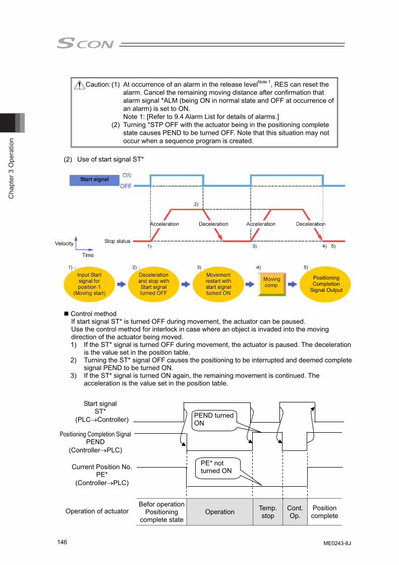
Cha
pter
3 O
pera
tion
146
Caution: (1) At occurrence of an alarm in the release levelNote 1, RES can reset the
alarm. Cancel the remaining moving distance after confirmation that alarm signal *ALM (being ON in normal state and OFF at occurrence of an alarm) is set to ON. Note 1: [Refer to 9.4 Alarm List for details of alarms.]
(2) Turning *STP OFF with the actuator being in the positioning complete state causes PEND to be turned OFF. Note that this situation may not occur when a sequence program is created.
(2) Use of start signal ST*
Control method If start signal ST* is turned OFF during movement, the actuator can be paused. Use the control method for interlock in case where an object is invaded into the moving direction of the actuator being moved. 1) If the ST* signal is turned OFF during movement, the actuator is paused. The deceleration
is the value set in the position table. 2) Turning the ST* signal OFF causes the positioning to be interrupted and deemed complete
signal PEND to be turned ON. 3) If the ST* signal is turned ON again, the remaining movement is continued. The
acceleration is the value set in the position table.
Befor operationPositioning
complete stateOperation Temp.
stop Cont. Op.
Position complete
Start signal ST*
(PLC→Controller)
Positioning Completion Signal PEND
(Controller→PLC)
Operation of actuator
PEND turned ON
PE* not turned ON Current Position No.
PE* (Controller→PLC)
Velocity
PositioningCompletion
Signal Output
1) 2) 3) 4) 5)
1) 3) 4) 5)
2)
ME0243-8J
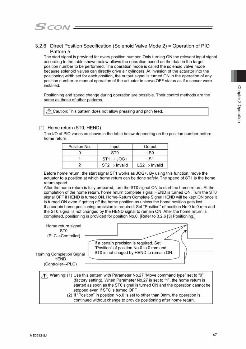
Chapter 3 O
peration
147
3.2.6 Direct Position Specification (Solenoid Valve Mode 2) = Operation of PIO Pattern 5
The start signal is provided for every position number. Only turning ON the relevant input signal according to the table shown below allows the operation based on the data in the target position number to be performed. The operation mode is called the solenoid valve mode because solenoid valves can directly drive air cylinders. At invasion of the actuator into the positioning width set for each position, the output signal is turned ON in the operation of any position number or manual operation of the actuator in servo OFF status as if a sensor were installed. Positioning and speed change during operation are possible. Their control methods are the same as those of other patterns.
Caution: This pattern does not allow pressing and pitch feed.
[1] Home return (ST0, HEND) The I/O of PIO varies as shown in the table below depending on the position number before home return.
Position No. Input Output 0 ST0 LS0 1 ST1 ⇒ JOG+ LS1 2 ST2 ⇒ Invalid LS2 ⇒ Invalid
Before home return, the start signal ST1 works as JOG+. By using this function, move the actuator to a position at which home return can be done safely. The speed of ST1 is the home return speed. After the home return is fully prepared, turn the ST0 signal ON to start the home return. At the completion of the home return, home return complete signal HEND is turned ON. Turn the ST0 signal OFF if HEND is turned ON. Home-Return Complete Signal HEND will be kept ON once it is turned ON even if getting off the home position as unless the home position gets lost. If a certain home positioning precision is required, Set “Position” of position No.0 to 0 mm and the ST0 signal is not changed by the HEND signal to remain ON. After the home return is completed, positioning is provided for position No.0. [Refer to 3.2.6 [3] Positioning.]
Warning: (1) Use this pattern with Parameter No.27 “Move command type” set to “0” (factory setting). When Parameter No.27 is set to “1”, the home return is started as soon as the ST0 signal is turned ON and the operation cannot be stopped even if ST0 is turned OFF.
(2) If “Position” in position No.0 is set to other than 0mm, the operation is continued without change to provide positioning after home return.
Home return signal ST0
(PLC→Controller)
If a certain precision is required. Set "Position" of position No.0 to 0 mm and ST0 is not chaged by HEND to remain ON.Homing Completion Signal
HEND (Controller→PLC)
ME0243-8J
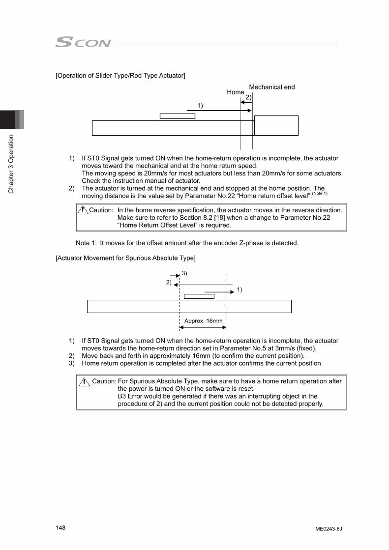
Cha
pter
3 O
pera
tion
148
[Operation of Slider Type/Rod Type Actuator]
1) If ST0 Signal gets turned ON when the home-return operation is incomplete, the actuator moves toward the mechanical end at the home return speed. The moving speed is 20mm/s for most actuators but less than 20mm/s for some actuators. Check the instruction manual of actuator.
2) The actuator is turned at the mechanical end and stopped at the home position. The moving distance is the value set by Parameter No.22 “Home return offset level”.(Note 1)
Caution: In the home reverse specification, the actuator moves in the reverse direction.Make sure to refer to Section 8.2 [18] when a change to Parameter No.22 “Home Return Offset Level” is required.
Note 1: It moves for the offset amount after the encoder Z-phase is detected.
[Actuator Movement for Spurious Absolute Type]
1) If ST0 Signal gets turned ON when the home-return operation is incomplete, the actuator moves towards the home-return direction set in Parameter No.5 at 3mm/s (fixed).
2) Move back and forth in approximately 16mm (to confirm the current position). 3) Home return operation is completed after the actuator confirms the current position.
Caution: For Spurious Absolute Type, make sure to have a home return operation after the power is turned ON or the software is reset. B3 Error would be generated if there was an interrupting object in the procedure of 2) and the current position could not be detected properly.
Mechanical end Home
1) 2)
1) 2)
3)
Approx. 16mm
ME0243-8J
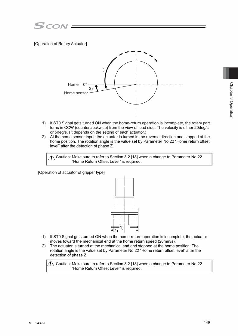
Chapter 3 O
peration
149
[Operation of Rotary Actuator]
1)
2)Home = 0°
Home sensor
1) If ST0 Signal gets turned ON when the home-return operation is incomplete, the rotary part turns in CCW (counterclockwise) from the view of load side. The velocity is either 20deg/s or 5deg/s. (It depends on the setting of each actuator.)
2) At the home sensor input, the actuator is turned in the reverse direction and stopped at the home position. The rotation angle is the value set by Parameter No.22 “Home return offset level” after the detection of phase Z.
Caution: Make sure to refer to Section 8.2 [18] when a change to Parameter No.22
“Home Return Offset Level” is required.
[Operation of actuator of gripper type] 1) If ST0 Signal gets turned ON when the home-return operation is incomplete, the actuator
moves toward the mechanical end at the home return speed (20mm/s). 2) The actuator is turned at the mechanical end and stopped at the home position. The
rotation angle is the value set by Parameter No.22 “Home return offset level” after the detection of phase Z.
Caution: Make sure to refer to Section 8.2 [18] when a change to Parameter No.22 “Home Return Offset Level” is required.
1) 2)
ME0243-8J
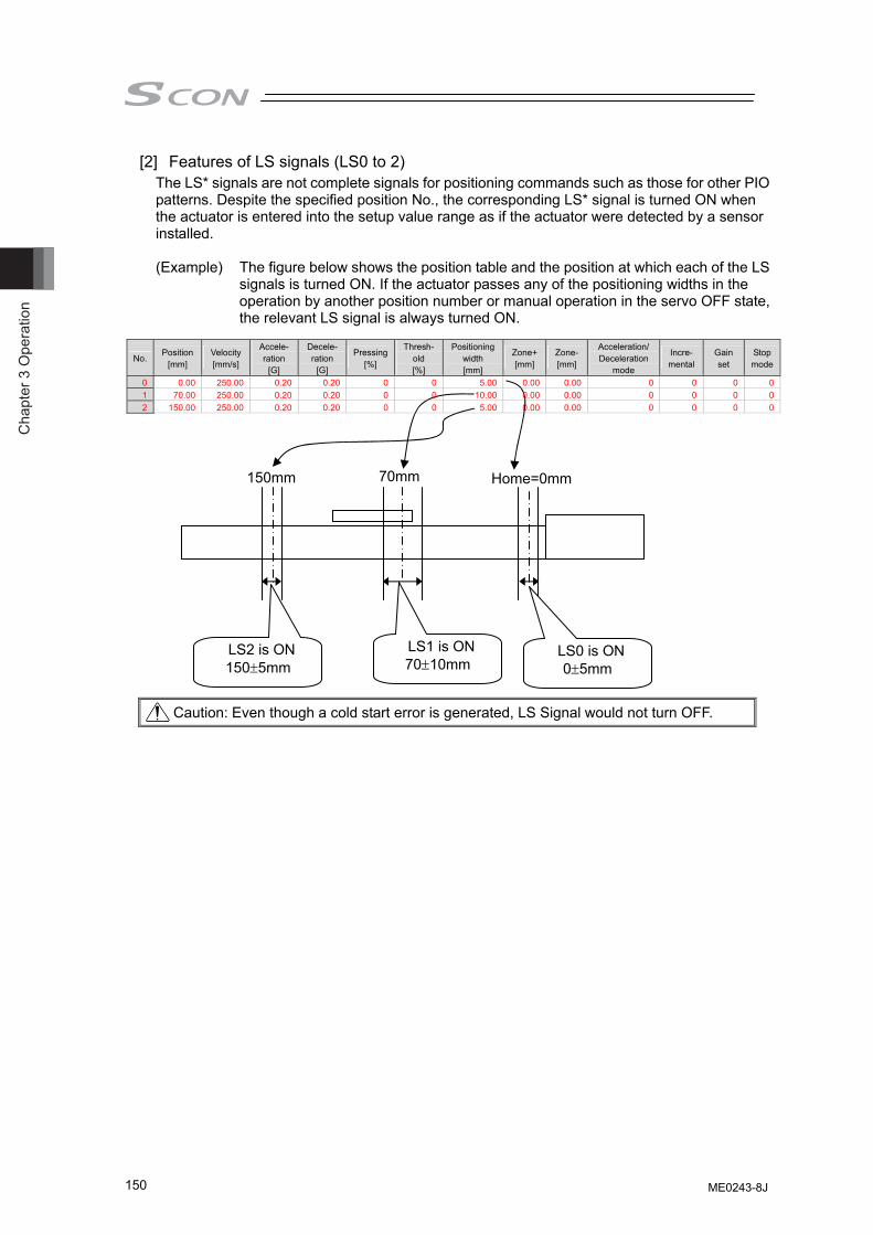
Cha
pter
3 O
pera
tion
150
[2] Features of LS signals (LS0 to 2) The LS* signals are not complete signals for positioning commands such as those for other PIO patterns. Despite the specified position No., the corresponding LS* signal is turned ON when the actuator is entered into the setup value range as if the actuator were detected by a sensor installed. (Example) The figure below shows the position table and the position at which each of the LS
signals is turned ON. If the actuator passes any of the positioning widths in the operation by another position number or manual operation in the servo OFF state, the relevant LS signal is always turned ON.
Caution: Even though a cold start error is generated, LS Signal would not turn OFF.
Home=0mm70mm 150mm
LS0 is ON 0±5mm
LS1 is ON 70±10mm
LS2 is ON 150±5mm
No. Position
[mm] Velocity [mm/s]
Accele- ration
[G]
Decele- ration
[G]
Pressing[%]
Thresh-old [%]
Positioning width [mm]
Zone+[mm]
Zone-[mm]
Acceleration/ Deceleration
mode
Incre- mental
Gain set
Stop mode
0 0.00 250.00 0.20 0.20 0 0 5.00 0.00 0.00 0 0 0 01 70.00 250.00 0.20 0.20 0 0 10.00 0.00 0.00 0 0 0 02 150.00 250.00 0.20 0.20 0 0 5.00 0.00 0.00 0 0 0 0
ME0243-8J
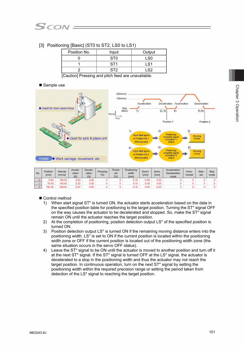
Chapter 3 O
peration
151
[3] Positioning [Basic] (ST0 to ST2, LS0 to LS1) Position No. Input Output
0 ST0 LS0 1 ST1 LS1 2 ST2 LS2
[Caution] Pressing and pitch feed are unavailable.
Sample use
No. Position
[mm] Velocity [mm/s]
Accele- ration
[G]
Decele- ration
[G]
Pressing[%]
Thresh-old [%]
Positioning width [mm]
Zone+[mm]
Zone-[mm]
Acceleration/ Deceleration
mode
Incre- mental
Gain set
Stop mode
0 0.00 100.00 0.20 0.20 0 0 0.10 0.00 0.00 0 0 0 01 70.00 100.00 0.20 0.20 0 0 0.10 0.00 0.00 0 0 0 02 150.00 200.00 0.20 0.20 0 0 0.10 0.00 0.00 0 0 0 0
Control method 1) When start signal ST* is turned ON, the actuator starts acceleration based on the data in
the specified position table for positioning to the target position. Turning the ST* signal OFF on the way causes the actuator to be decelerated and stopped. So, make the ST* signal remain ON until the actuator reaches the target position.
2) At the completion of positioning, position detection output LS* of the specified position is turned ON.
3) Position detection output LS* is turned ON if the remaining moving distance enters into the positioning width. LS* is set to ON if the current position is located within the positioning width zone or OFF if the current position is located out of the positioning width zone (the same situation occurs in the servo OFF status).
4) Leave the ST* signal to be ON until the actuator is moved to another position and turn off it at the next ST* signal. If the ST* signal is turned OFF at the LS* signal, the actuator is decelerated to a stop in the positioning width and thus the actuator may not reach the target position. In continuous operation, turn on the next ST* signal by setting the positioning width within the required precision range or setting the period taken from detection of the LS* signal to reaching the target position.
Velocity
1) 2) 3)
4) 5) 6)
1) 2) 3) 4) 5) 6)
100mm/s
200mm/s
ME0243-8J
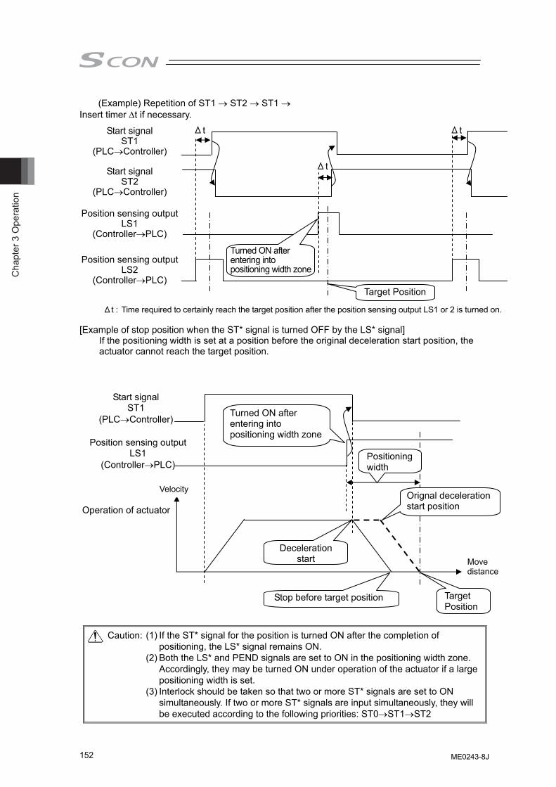
Cha
pter
3 O
pera
tion
152
(Example) Repetition of ST1 → ST2 → ST1 → Insert timer Δt if necessary. [Example of stop position when the ST* signal is turned OFF by the LS* signal]
If the positioning width is set at a position before the original deceleration start position, the actuator cannot reach the target position.
Caution: (1) If the ST* signal for the position is turned ON after the completion of positioning, the LS* signal remains ON.
(2) Both the LS* and PEND signals are set to ON in the positioning width zone. Accordingly, they may be turned ON under operation of the actuator if a large positioning width is set.
(3) Interlock should be taken so that two or more ST* signals are set to ON simultaneously. If two or more ST* signals are input simultaneously, they will be executed according to the following priorities: ST0→ST1→ST2
Start signal ST1
(PLC→Controller)
Turned ON after entering into positioning width zone
Target Position
Position sensing output LS1
(Controller→PLC)
Start signal ST2
(PLC→Controller)
Position sensing output LS2
(Controller→PLC)
Δt
Δt Δt
Δt : Time required to certainly reach the target position after the position sensing output LS1 or 2 is turned on.
Start signal ST1
(PLC→Controller) Turned ON after entering into positioning width zone
Target Position
Position sensing output LS1
(Controller→PLC)
Operation of actuator
Stop before target position
Orignal deceleration start position
Positioning width
Deceleration start
Velocity
Move distance
ME0243-8J
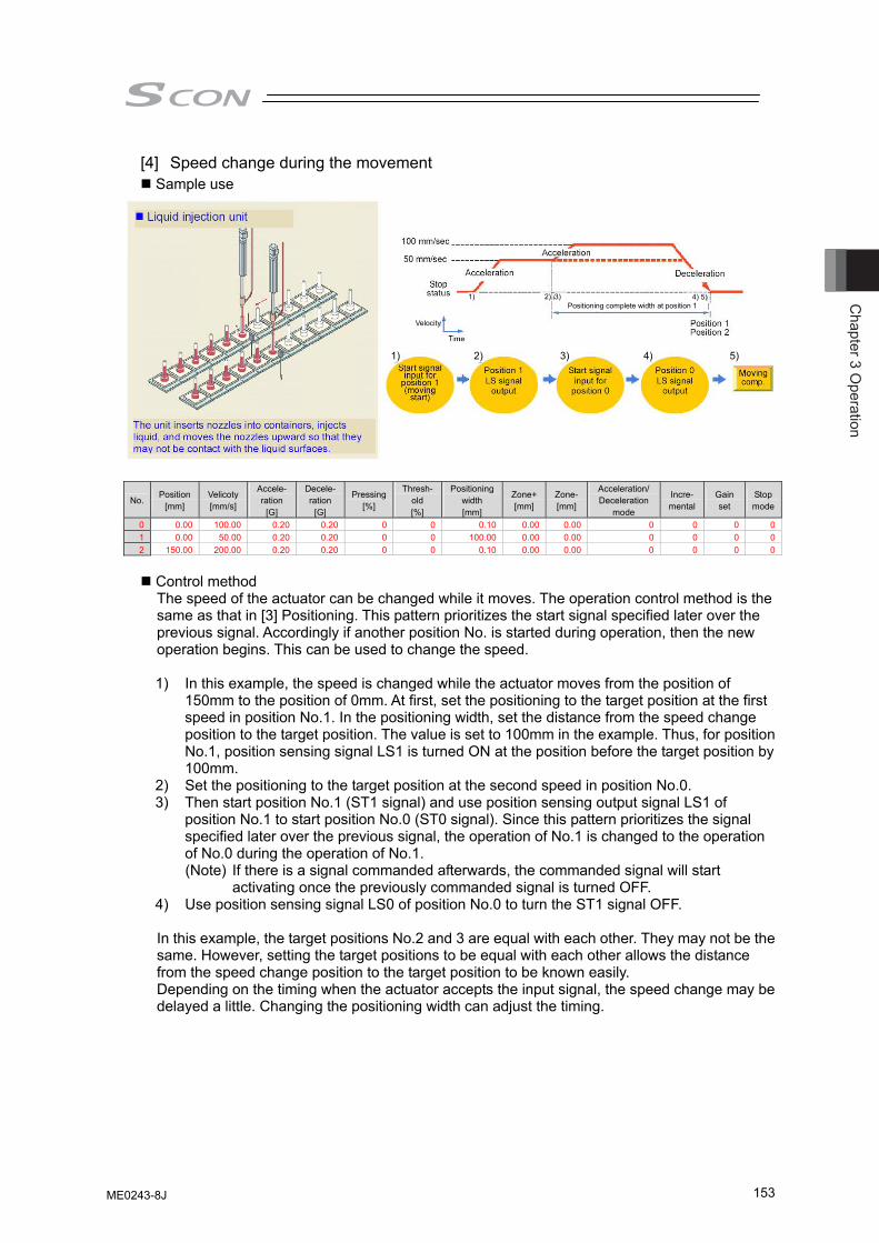
Chapter 3 O
peration
153
[4] Speed change during the movement Sample use
No. Position
[mm] Velicoty [mm/s]
Accele- ration
[G]
Decele- ration
[G]
Pressing[%]
Thresh-old [%]
Positioning width [mm]
Zone+[mm]
Zone-[mm]
Acceleration/ Deceleration
mode
Incre- mental
Gain set
Stop mode
0 0.00 100.00 0.20 0.20 0 0 0.10 0.00 0.00 0 0 0 01 0.00 50.00 0.20 0.20 0 0 100.00 0.00 0.00 0 0 0 02 150.00 200.00 0.20 0.20 0 0 0.10 0.00 0.00 0 0 0 0
Control method The speed of the actuator can be changed while it moves. The operation control method is the same as that in [3] Positioning. This pattern prioritizes the start signal specified later over the previous signal. Accordingly if another position No. is started during operation, then the new operation begins. This can be used to change the speed.
1) In this example, the speed is changed while the actuator moves from the position of
150mm to the position of 0mm. At first, set the positioning to the target position at the first speed in position No.1. In the positioning width, set the distance from the speed change position to the target position. The value is set to 100mm in the example. Thus, for position No.1, position sensing signal LS1 is turned ON at the position before the target position by 100mm.
2) Set the positioning to the target position at the second speed in position No.0. 3) Then start position No.1 (ST1 signal) and use position sensing output signal LS1 of
position No.1 to start position No.0 (ST0 signal). Since this pattern prioritizes the signal specified later over the previous signal, the operation of No.1 is changed to the operation of No.0 during the operation of No.1. (Note) If there is a signal commanded afterwards, the commanded signal will start
activating once the previously commanded signal is turned OFF. 4) Use position sensing signal LS0 of position No.0 to turn the ST1 signal OFF.
In this example, the target positions No.2 and 3 are equal with each other. They may not be the same. However, setting the target positions to be equal with each other allows the distance from the speed change position to the target position to be known easily. Depending on the timing when the actuator accepts the input signal, the speed change may be delayed a little. Changing the positioning width can adjust the timing.
Velocity
1) 2) 3) 4) 5)
1) 2) 3) 4) 5)Positioning complete width at position 1
ME0243-8J
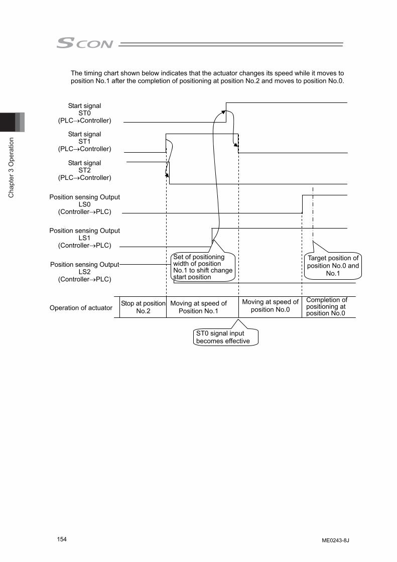
Cha
pter
3 O
pera
tion
154
The timing chart shown below indicates that the actuator changes its speed while it moves to position No.1 after the completion of positioning at position No.2 and moves to position No.0.
Start signal ST0
(PLC→Controller)
Position sensing OutputLS0
(Controller→PLC)
Start signal ST1
(PLC→Controller)
Position sensing OutputLS1
(Controller→PLC)
Position sensing OutputLS2
(Controller→PLC)
Target position of position No.0 and
No.1
Start signal ST2
(PLC→Controller)
Set of positioning width of position No.1 to shift change start position
Operation of actuator Stop at position
No.2 Moving at speed of
Position No.1 Moving at speed of
position No.0 Completion of positioning at position No.0
ST0 signal input becomes effective
ME0243-8J
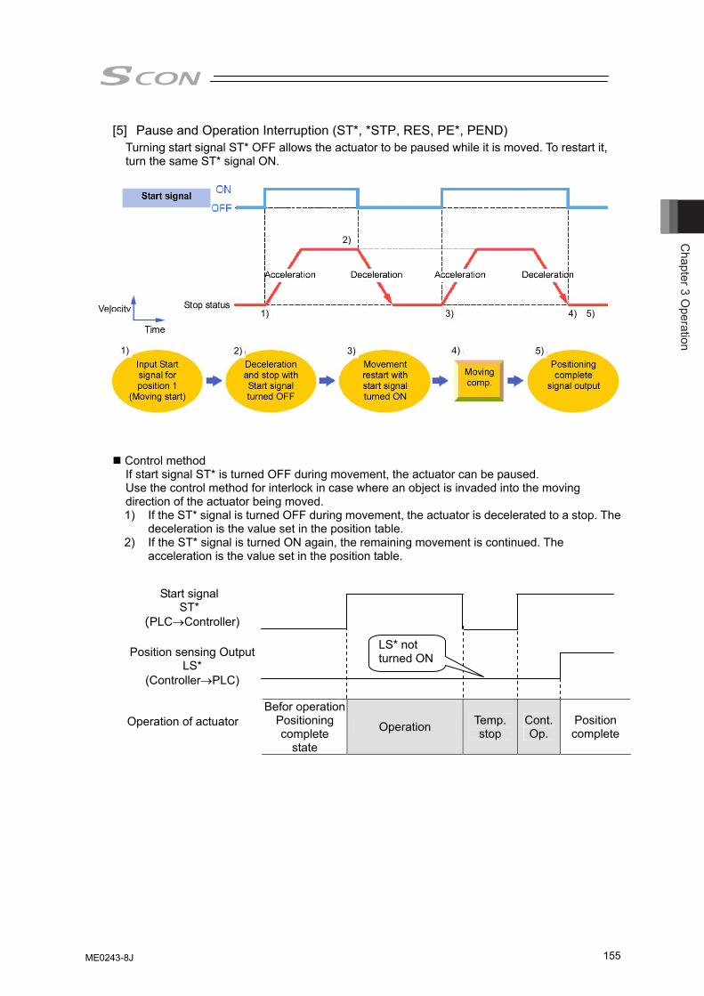
Chapter 3 O
peration
155
[5] Pause and Operation Interruption (ST*, *STP, RES, PE*, PEND) Turning start signal ST* OFF allows the actuator to be paused while it is moved. To restart it, turn the same ST* signal ON.
Control method If start signal ST* is turned OFF during movement, the actuator can be paused. Use the control method for interlock in case where an object is invaded into the moving direction of the actuator being moved. 1) If the ST* signal is turned OFF during movement, the actuator is decelerated to a stop. The
deceleration is the value set in the position table. 2) If the ST* signal is turned ON again, the remaining movement is continued. The
acceleration is the value set in the position table.
Befor operationPositioning complete
state
Operation Temp. stop
Cont. Op.
Position complete
Operation of actuator
Start signal ST*
(PLC→Controller)
LS* not turned ONPosition sensing Output
LS* (Controller→PLC)
Velocity
1) 2) 3) 4) 5)
1) 3) 4) 5)
2)
ME0243-8J
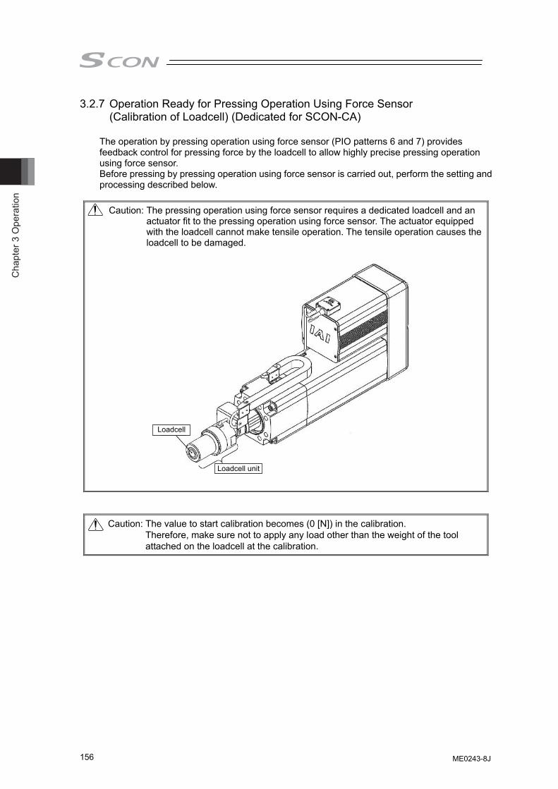
Cha
pter
3 O
pera
tion
156
3.2.7 Operation Ready for Pressing Operation Using Force Sensor (Calibration of Loadcell) (Dedicated for SCON-CA)
The operation by pressing operation using force sensor (PIO patterns 6 and 7) provides feedback control for pressing force by the loadcell to allow highly precise pressing operation using force sensor. Before pressing by pressing operation using force sensor is carried out, perform the setting and processing described below.
Caution: The pressing operation using force sensor requires a dedicated loadcell and an
actuator fit to the pressing operation using force sensor. The actuator equipped with the loadcell cannot make tensile operation. The tensile operation causes the loadcell to be damaged.
Caution: The value to start calibration becomes (0 [N]) in the calibration. Therefore, make sure not to apply any load other than the weight of the tool attached on the loadcell at the calibration.
Loadcell
Loadcell unit
ME0243-8J
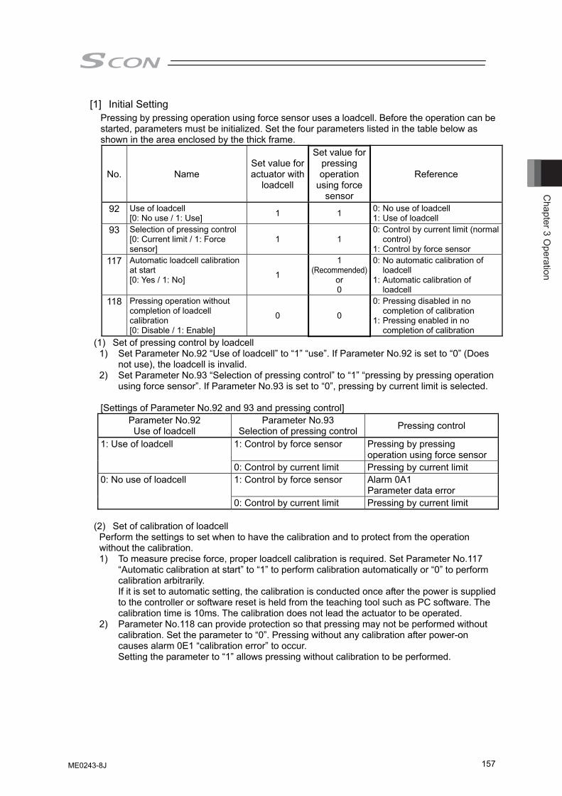
Chapter 3 O
peration
157
[1] Initial Setting Pressing by pressing operation using force sensor uses a loadcell. Before the operation can be started, parameters must be initialized. Set the four parameters listed in the table below as shown in the area enclosed by the thick frame.
No. Name Set value for actuator with
loadcell
Set value for pressing operation
using force sensor
Reference
92 Use of loadcell [0: No use / 1: Use] 1 1 0: No use of loadcell
1: Use of loadcell 93 Selection of pressing control
[0: Current limit / 1: Force sensor]
1 1 0: Control by current limit (normal
control) 1: Control by force sensor
117 Automatic loadcell calibration at start [0: Yes / 1: No] 1
1 (Recommended)
or 0
0: No automatic calibration of loadcell
1: Automatic calibration of loadcell
118 Pressing operation without completion of loadcell calibration [0: Disable / 1: Enable]
0 0
0: Pressing disabled in no completion of calibration
1: Pressing enabled in no completion of calibration
(1) Set of pressing control by loadcell 1) Set Parameter No.92 “Use of loadcell” to “1” “use”. If Parameter No.92 is set to “0” (Does
not use), the loadcell is invalid. 2) Set Parameter No.93 “Selection of pressing control” to “1” “pressing by pressing operation
using force sensor”. If Parameter No.93 is set to “0”, pressing by current limit is selected. [Settings of Parameter No.92 and 93 and pressing control]
Parameter No.92 Use of loadcell
Parameter No.93 Selection of pressing control Pressing control
1: Control by force sensor Pressing by pressing operation using force sensor
1: Use of loadcell
0: Control by current limit Pressing by current limit 1: Control by force sensor Alarm 0A1
Parameter data error 0: No use of loadcell
0: Control by current limit Pressing by current limit
(2) Set of calibration of loadcell Perform the settings to set when to have the calibration and to protect from the operation without the calibration. 1) To measure precise force, proper loadcell calibration is required. Set Parameter No.117
“Automatic calibration at start” to “1” to perform calibration automatically or “0” to perform calibration arbitrarily. If it is set to automatic setting, the calibration is conducted once after the power is supplied to the controller or software reset is held from the teaching tool such as PC software. The calibration time is 10ms. The calibration does not lead the actuator to be operated.
2) Parameter No.118 can provide protection so that pressing may not be performed without calibration. Set the parameter to “0”. Pressing without any calibration after power-on causes alarm 0E1 “calibration error” to occur. Setting the parameter to “1” allows pressing without calibration to be performed.
ME0243-8J
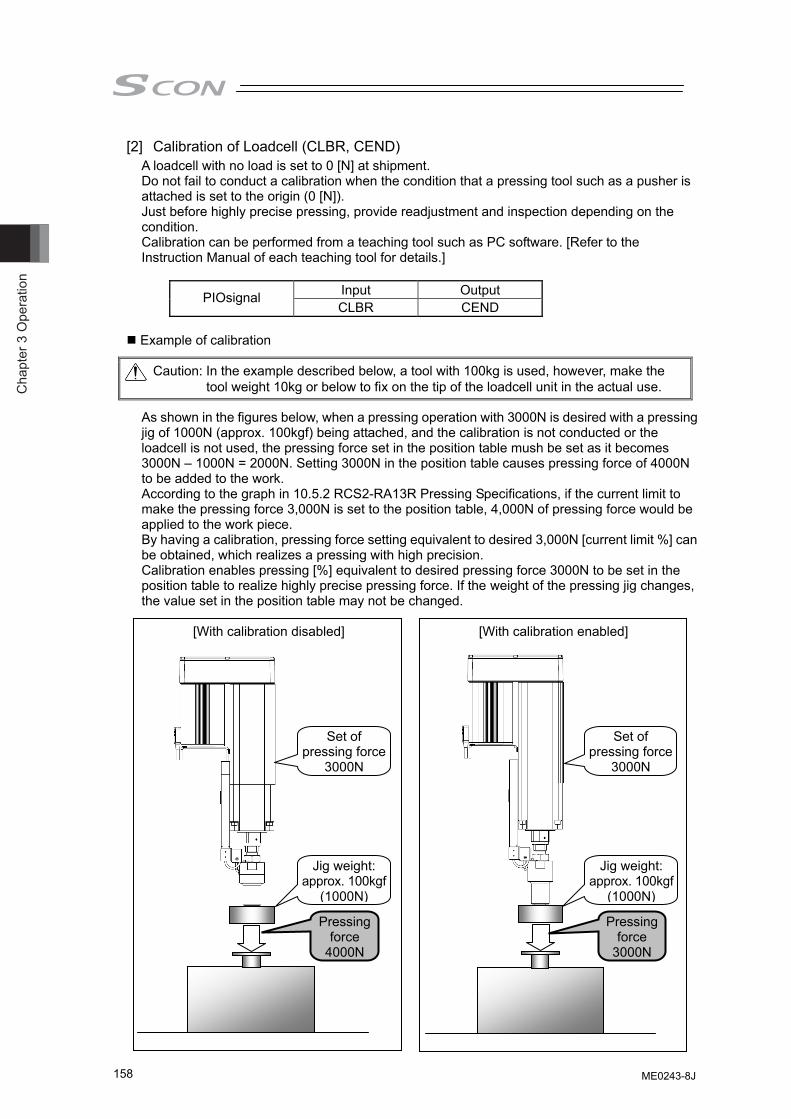
Cha
pter
3 O
pera
tion
158
[2] Calibration of Loadcell (CLBR, CEND) A loadcell with no load is set to 0 [N] at shipment. Do not fail to conduct a calibration when the condition that a pressing tool such as a pusher is attached is set to the origin (0 [N]). Just before highly precise pressing, provide readjustment and inspection depending on the condition. Calibration can be performed from a teaching tool such as PC software. [Refer to the Instruction Manual of each teaching tool for details.]
Input Output PIOsignal CLBR CEND
Example of calibration
Caution: In the example described below, a tool with 100kg is used, however, make the tool weight 10kg or below to fix on the tip of the loadcell unit in the actual use.
As shown in the figures below, when a pressing operation with 3000N is desired with a pressing jig of 1000N (approx. 100kgf) being attached, and the calibration is not conducted or the loadcell is not used, the pressing force set in the position table mush be set as it becomes 3000N – 1000N = 2000N. Setting 3000N in the position table causes pressing force of 4000N to be added to the work. According to the graph in 10.5.2 RCS2-RA13R Pressing Specifications, if the current limit to make the pressing force 3,000N is set to the position table, 4,000N of pressing force would be applied to the work piece. By having a calibration, pressing force setting equivalent to desired 3,000N [current limit %] can be obtained, which realizes a pressing with high precision. Calibration enables pressing [%] equivalent to desired pressing force 3000N to be set in the position table to realize highly precise pressing force. If the weight of the pressing jig changes, the value set in the position table may not be changed.
[With calibration disabled] [With calibration enabled]
Set of pressing force
3000N
Jig weight: approx. 100kgf
(1000N)
Pressing force
3000N
Set of pressing force
3000N
Jig weight: approx. 100kgf
(1000N)
Pressing force
4000N
ME0243-8J
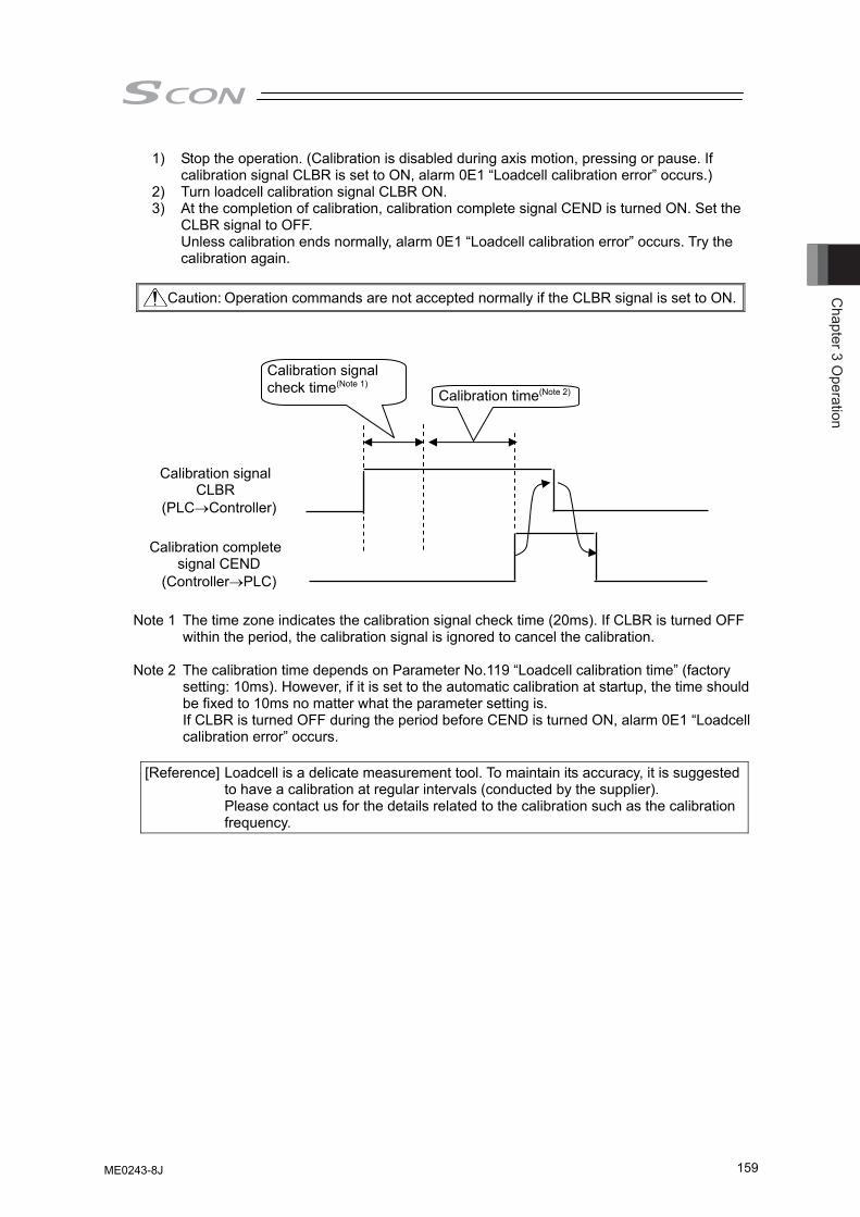
Chapter 3 O
peration
159
1) Stop the operation. (Calibration is disabled during axis motion, pressing or pause. If calibration signal CLBR is set to ON, alarm 0E1 “Loadcell calibration error” occurs.)
2) Turn loadcell calibration signal CLBR ON. 3) At the completion of calibration, calibration complete signal CEND is turned ON. Set the
CLBR signal to OFF. Unless calibration ends normally, alarm 0E1 “Loadcell calibration error” occurs. Try the calibration again.
Caution: Operation commands are not accepted normally if the CLBR signal is set to ON.
Note 1 The time zone indicates the calibration signal check time (20ms). If CLBR is turned OFF within the period, the calibration signal is ignored to cancel the calibration.
Note 2 The calibration time depends on Parameter No.119 “Loadcell calibration time” (factory
setting: 10ms). However, if it is set to the automatic calibration at startup, the time should be fixed to 10ms no matter what the parameter setting is. If CLBR is turned OFF during the period before CEND is turned ON, alarm 0E1 “Loadcell calibration error” occurs.
[Reference] Loadcell is a delicate measurement tool. To maintain its accuracy, it is suggested
to have a calibration at regular intervals (conducted by the supplier). Please contact us for the details related to the calibration such as the calibration frequency.
Calibration signal CLBR
(PLC→Controller)
Calibration complete signal CEND
(Controller→PLC)
Calibration time(Note 2)
Calibration signal check time(Note 1)
ME0243-8J
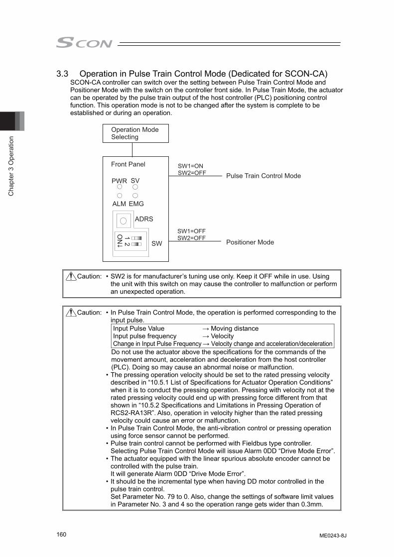
Cha
pter
3 O
pera
tion
160
3.3 Operation in Pulse Train Control Mode (Dedicated for SCON-CA) SCON-CA controller can switch over the setting between Pulse Train Control Mode and Positioner Mode with the switch on the controller front side. In Pulse Train Mode, the actuator can be operated by the pulse train output of the host controller (PLC) positioning control function. This operation mode is not to be changed after the system is complete to be established or during an operation.
PWR
ALM EMG
ADRS
SW
12
ON
SV
Front Panel SW1=ONSW2=OFF
SW1=OFFSW2=OFF
Operation Mode Selecting
Pulse Train Control Mode
Positioner Mode
Caution: • SW2 is for manufacturer’s tuning use only. Keep it OFF while in use. Using the unit with this switch on may cause the controller to malfunction or perform an unexpected operation.
Caution: • In Pulse Train Control Mode, the operation is performed corresponding to the
input pulse. Input Pulse Value → Moving distance Input pulse frequency → Velocity Change in Input Pulse Frequency → Velocity change and acceleration/deceleration
Do not use the actuator above the specifications for the commands of the movement amount, acceleration and deceleration from the host controller (PLC). Doing so may cause an abnormal noise or malfunction.
• The pressing operation velocity should be set to the rated pressing velocity described in “10.5.1 List of Specifications for Actuator Operation Conditions” when it is to conduct the pressing operation. Pressing with velocity not at the rated pressing velocity could end up with pressing force different from that shown in “10.5.2 Specifications and Limitations in Pressing Operation of RCS2-RA13R”. Also, operation in velocity higher than the rated pressing velocity could cause an error or malfunction.
• In Pulse Train Control Mode, the anti-vibration control or pressing operation using force sensor cannot be performed.
• Pulse train control cannot be performed with Fieldbus type controller. Selecting Pulse Train Control Mode will issue Alarm 0DD “Drive Mode Error”.
• The actuator equipped with the linear spurious absolute encoder cannot be controlled with the pulse train. It will generate Alarm 0DD “Drive Mode Error”.
• It should be the incremental type when having DD motor controlled in the pulse train control. Set Parameter No. 79 to 0. Also, change the settings of software limit values in Parameter No. 3 and 4 so the operation range gets wider than 0.3mm.
ME0243-8J
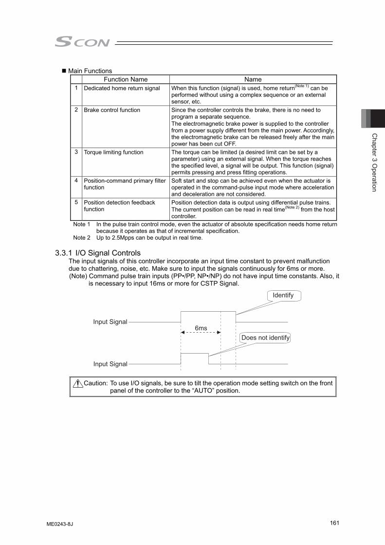
Chapter 3 O
peration
161
Main Functions Function Name Name 1 Dedicated home return signal When this function (signal) is used, home return(Note 1) can be
performed without using a complex sequence or an external sensor, etc.
2 Brake control function Since the controller controls the brake, there is no need to program a separate sequence. The electromagnetic brake power is supplied to the controller from a power supply different from the main power. Accordingly, the electromagnetic brake can be released freely after the main power has been cut OFF.
3 Torque limiting function The torque can be limited (a desired limit can be set by a parameter) using an external signal. When the torque reaches the specified level, a signal will be output. This function (signal) permits pressing and press fitting operations.
4 Position-command primary filter function
Soft start and stop can be achieved even when the actuator is operated in the command-pulse input mode where acceleration and deceleration are not considered.
5 Position detection feedback function
Position detection data is output using differential pulse trains.The current position can be read in real time(Note 2) from the host controller.
Note 1 In the pulse train control mode, even the actuator of absolute specification needs home return because it operates as that of incremental specification.
Note 2 Up to 2.5Mpps can be output in real time. 3.3.1 I/O Signal Controls
The input signals of this controller incorporate an input time constant to prevent malfunction due to chattering, noise, etc. Make sure to input the signals continuously for 6ms or more. (Note) Command pulse train inputs (PP•/PP, NP•/NP) do not have input time constants. Also, it
is necessary to input 16ms or more for CSTP Signal.
Caution: To use I/O signals, be sure to tilt the operation mode setting switch on the front panel of the controller to the “AUTO” position.
Identify
Does not identify
Input Signal
Input Signal
6ms
ME0243-8J
Cha
pter
3 O
pera
tion
162
3.3.2 Operation Ready and Auxiliary Signals [1] System Ready (PWR)
Output PIO signal PWR
The signal is turned ON if the controller can be controlled after main power-on. It is turned ON once the initialization terminates normally after main power-on and SCON can be controlled regardless of alarm and servo status. Even in the alarm condition, when the SCON can control the system, it is turned “ON”. The signal is synchronized with the illumination of the PWR LED (GN) on the front face of the controller.
[2] Emergency stop status (*EMGS) Output PIO signal *EMGS
1) Emergency Stop Status EMGS is usually turned on and is turned off when “2.2.3 [3] Power
and Emergency Stop Circuit” is open between EMG+ and EMG- (emergency stop condition or not connected).
2) It turns back on if the emergency stop condition is cancelled and the circuit is closed between EMG+ and EMG-. Have an appropriate safety treatment such as interlock with this signal for the host controller (PLC, etc.).
Caution: It is not an emergency stop output due to an alarm generation of the
controller.
ME0243-8J
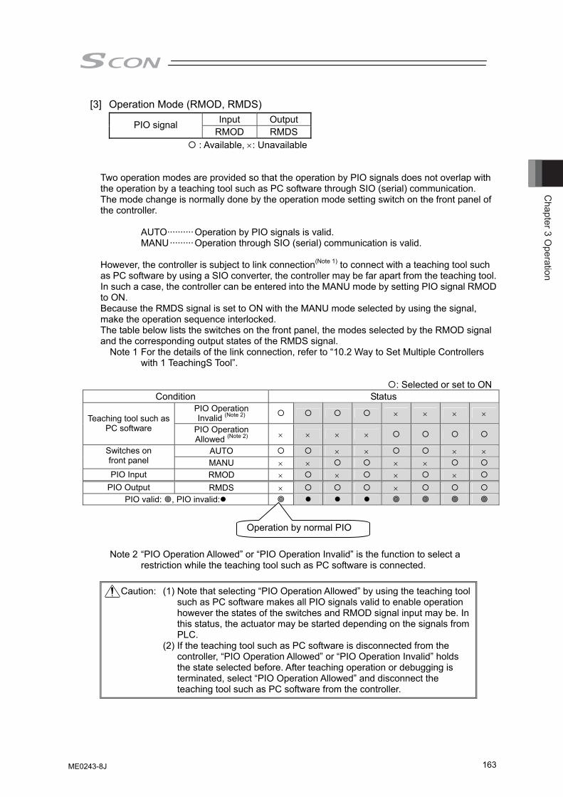
Chapter 3 O
peration
163
[3] Operation Mode (RMOD, RMDS) Input Output PIO signal
RMOD RMDS : Available, ×: Unavailable
Two operation modes are provided so that the operation by PIO signals does not overlap with the operation by a teaching tool such as PC software through SIO (serial) communication. The mode change is normally done by the operation mode setting switch on the front panel of the controller.
AUTO··········Operation by PIO signals is valid. MANU·········Operation through SIO (serial) communication is valid.
However, the controller is subject to link connection(Note 1) to connect with a teaching tool such as PC software by using a SIO converter, the controller may be far apart from the teaching tool. In such a case, the controller can be entered into the MANU mode by setting PIO signal RMOD to ON. Because the RMDS signal is set to ON with the MANU mode selected by using the signal, make the operation sequence interlocked. The table below lists the switches on the front panel, the modes selected by the RMOD signal and the corresponding output states of the RMDS signal. Note 1 For the details of the link connection, refer to “10.2 Way to Set Multiple Controllers
with 1 TeachingS Tool”.
: Selected or set to ON Condition Status
PIO Operation Invalid (Note 2) × × × × Teaching tool such as
PC software PIO Operation Allowed (Note 2) × × × ×
AUTO × × × × Switches on front panel MANU × × × × PIO Input RMOD × × × ×
PIO Output RMDS × × PIO valid: , PIO invalid:
Note 2 “PIO Operation Allowed” or “PIO Operation Invalid” is the function to select a restriction while the teaching tool such as PC software is connected.
Caution: (1) Note that selecting “PIO Operation Allowed” by using the teaching tool
such as PC software makes all PIO signals valid to enable operation however the states of the switches and RMOD signal input may be. In this status, the actuator may be started depending on the signals from PLC.
(2) If the teaching tool such as PC software is disconnected from the controller, “PIO Operation Allowed” or “PIO Operation Invalid” holds the state selected before. After teaching operation or debugging is terminated, select “PIO Operation Allowed” and disconnect the teaching tool such as PC software from the controller.
Operation by normal PIO
ME0243-8J
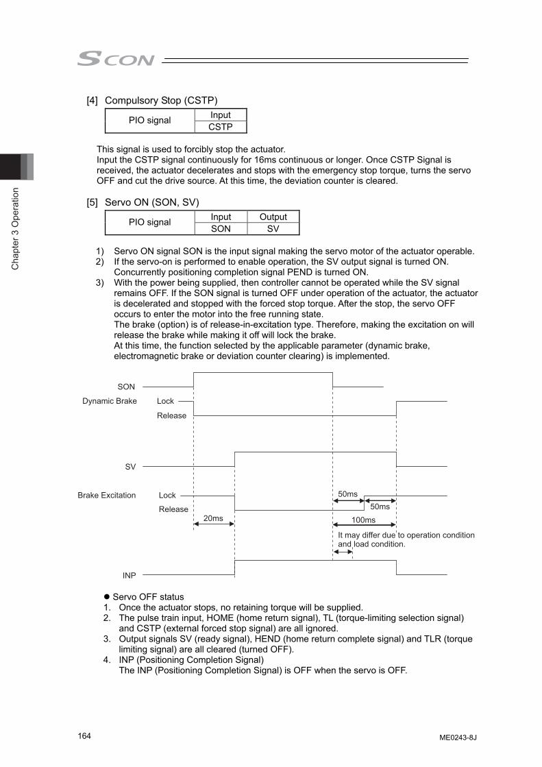
Cha
pter
3 O
pera
tion
164
[4] Compulsory Stop (CSTP) Input PIO signal CSTP
This signal is used to forcibly stop the actuator. Input the CSTP signal continuously for 16ms continuous or longer. Once CSTP Signal is received, the actuator decelerates and stops with the emergency stop torque, turns the servo OFF and cut the drive source. At this time, the deviation counter is cleared.
[5] Servo ON (SON, SV)
Input Output PIO signal SON SV
1) Servo ON signal SON is the input signal making the servo motor of the actuator operable. 2) If the servo-on is performed to enable operation, the SV output signal is turned ON.
Concurrently positioning completion signal PEND is turned ON. 3) With the power being supplied, then controller cannot be operated while the SV signal
remains OFF. If the SON signal is turned OFF under operation of the actuator, the actuator is decelerated and stopped with the forced stop torque. After the stop, the servo OFF occurs to enter the motor into the free running state. The brake (option) is of release-in-excitation type. Therefore, making the excitation on will release the brake while making it off will lock the brake. At this time, the function selected by the applicable parameter (dynamic brake, electromagnetic brake or deviation counter clearing) is implemented.
SON
SV
Dynamic Brake Lock
20ms
50ms50ms
100ms
Lock
Release
Release
INP
Brake Excitation
It may differ due to operation condition and load condition.
Servo OFF status 1. Once the actuator stops, no retaining torque will be supplied. 2. The pulse train input, HOME (home return signal), TL (torque-limiting selection signal)
and CSTP (external forced stop signal) are all ignored. 3. Output signals SV (ready signal), HEND (home return complete signal) and TLR (torque
limiting signal) are all cleared (turned OFF). 4. INP (Positioning Completion Signal)
The INP (Positioning Completion Signal) is OFF when the servo is OFF.
ME0243-8J
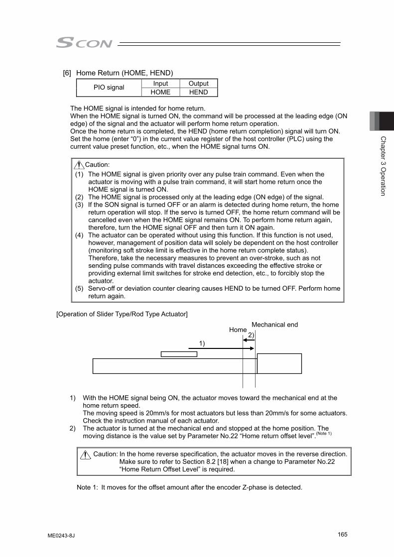
Chapter 3 O
peration
165
[6] Home Return (HOME, HEND) Input Output PIO signal
HOME HEND
The HOME signal is intended for home return. When the HOME signal is turned ON, the command will be processed at the leading edge (ON edge) of the signal and the actuator will perform home return operation. Once the home return is completed, the HEND (home return completion) signal will turn ON. Set the home (enter “0”) in the current value register of the host controller (PLC) using the current value preset function, etc., when the HOME signal turns ON.
Caution:
(1) The HOME signal is given priority over any pulse train command. Even when the actuator is moving with a pulse train command, it will start home return once the HOME signal is turned ON.
(2) The HOME signal is processed only at the leading edge (ON edge) of the signal. (3) If the SON signal is turned OFF or an alarm is detected during home return, the home
return operation will stop. If the servo is turned OFF, the home return command will be cancelled even when the HOME signal remains ON. To perform home return again, therefore, turn the HOME signal OFF and then turn it ON again.
(4) The actuator can be operated without using this function. If this function is not used, however, management of position data will solely be dependent on the host controller (monitoring soft stroke limit is effective in the home return complete status). Therefore, take the necessary measures to prevent an over-stroke, such as not sending pulse commands with travel distances exceeding the effective stroke or providing external limit switches for stroke end detection, etc., to forcibly stop the actuator.
(5) Servo-off or deviation counter clearing causes HEND to be turned OFF. Perform home return again.
[Operation of Slider Type/Rod Type Actuator]
1) With the HOME signal being ON, the actuator moves toward the mechanical end at the home return speed. The moving speed is 20mm/s for most actuators but less than 20mm/s for some actuators. Check the instruction manual of each actuator.
2) The actuator is turned at the mechanical end and stopped at the home position. The moving distance is the value set by Parameter No.22 “Home return offset level”.(Note 1)
Caution: In the home reverse specification, the actuator moves in the reverse direction.
Make sure to refer to Section 8.2 [18] when a change to Parameter No.22 “Home Return Offset Level” is required.
Note 1: It moves for the offset amount after the encoder Z-phase is detected.
Mechanical end Home
1) 2)
ME0243-8J
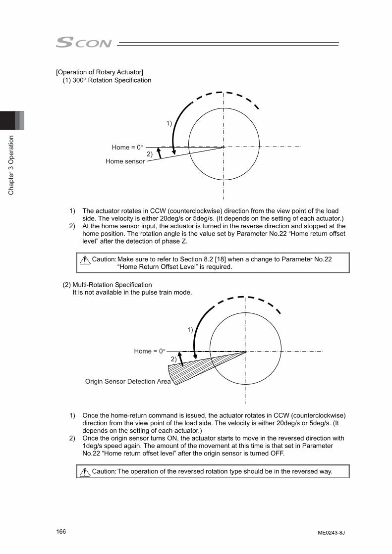
Cha
pter
3 O
pera
tion
166
[Operation of Rotary Actuator] (1) 300° Rotation Specification
1)
2)Home = 0°
Home sensor
1) The actuator rotates in CCW (counterclockwise) direction from the view point of the load side. The velocity is either 20deg/s or 5deg/s. (It depends on the setting of each actuator.)
2) At the home sensor input, the actuator is turned in the reverse direction and stopped at the home position. The rotation angle is the value set by Parameter No.22 “Home return offset level” after the detection of phase Z.
Caution: Make sure to refer to Section 8.2 [18] when a change to Parameter No.22
“Home Return Offset Level” is required.
(2) Multi-Rotation Specification It is not available in the pulse train mode.
1)
2)Home = 0°
Origin Sensor Detection Area
1) Once the home-return command is issued, the actuator rotates in CCW (counterclockwise) direction from the view point of the load side. The velocity is either 20deg/s or 5deg/s. (It depends on the setting of each actuator.)
2) Once the origin sensor turns ON, the actuator starts to move in the reversed direction with 1deg/s speed again. The amount of the movement at this time is that set in Parameter No.22 “Home return offset level” after the origin sensor is turned OFF.
Caution: The operation of the reversed rotation type should be in the reversed way.
ME0243-8J
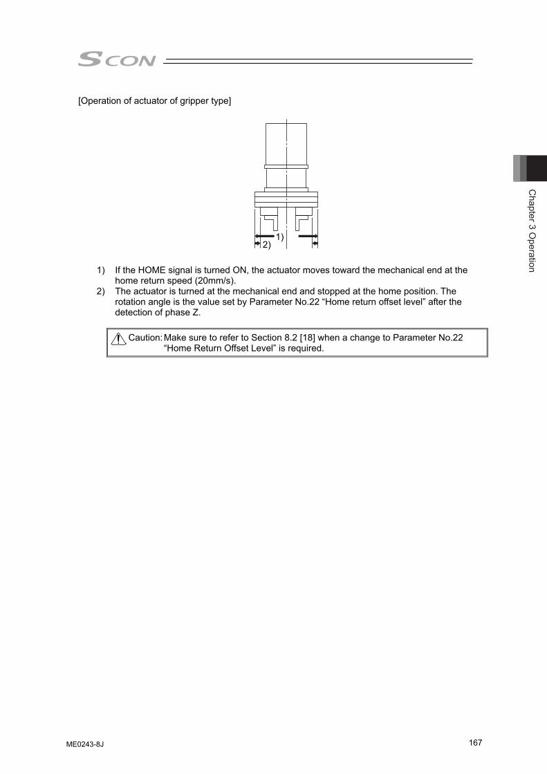
Chapter 3 O
peration
167
[Operation of actuator of gripper type] 1) If the HOME signal is turned ON, the actuator moves toward the mechanical end at the
home return speed (20mm/s). 2) The actuator is turned at the mechanical end and stopped at the home position. The
rotation angle is the value set by Parameter No.22 “Home return offset level” after the detection of phase Z.
Caution: Make sure to refer to Section 8.2 [18] when a change to Parameter No.22
“Home Return Offset Level” is required.
1) 2)
ME0243-8J
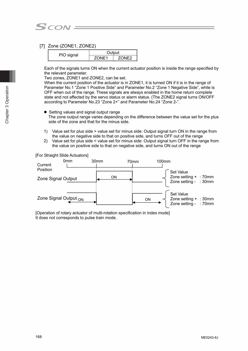
Cha
pter
3 O
pera
tion
168
[7] Zone (ZONE1, ZONE2) Output PIO signal
ZONE1 ZONE2
Each of the signals turns ON when the current actuator position is inside the range specified by the relevant parameter. Two zones, ZONE1 and ZONE2, can be set. When the current position of the actuator is in ZONE1, it is turned ON if it is in the range of Parameter No.1 “Zone 1 Positive Side” and Parameter No.2 “Zone 1 Negative Side”, while is OFF when out of the range. These signals are always enabled in the home return complete state and not affected by the servo status or alarm status. (The ZONE2 signal turns ON/OFF according to Parameter No.23 “Zone 2+” and Parameter No.24 “Zone 2-”.
Setting values and signal output range The zone output range varies depending on the difference between the value set for the plus side of the zone and that for the minus side.
1) Value set for plus side > value set for minus side: Output signal turn ON in the range from
the value on negative side to that on positive side, and turns OFF out of the range 2) Value set for plus side < value set for minus side: Output signal turn OFF in the range from
the value on positive side to that on negative side, and turns ON out of the range [For Straight Slide Actuators] [Operation of rotary actuator of multi-rotation specification in index mode] It does not corresponds to pulse train mode.
Current Position
Zone Signal Output
Zone Signal Output
0mm 30mm 70mm 100mm
ON
ON ON
Set Value Zone setting + : 70mm Zone setting - : 30mm
Set Value Zone setting + : 30mm Zone setting - : 70mm
ME0243-8J
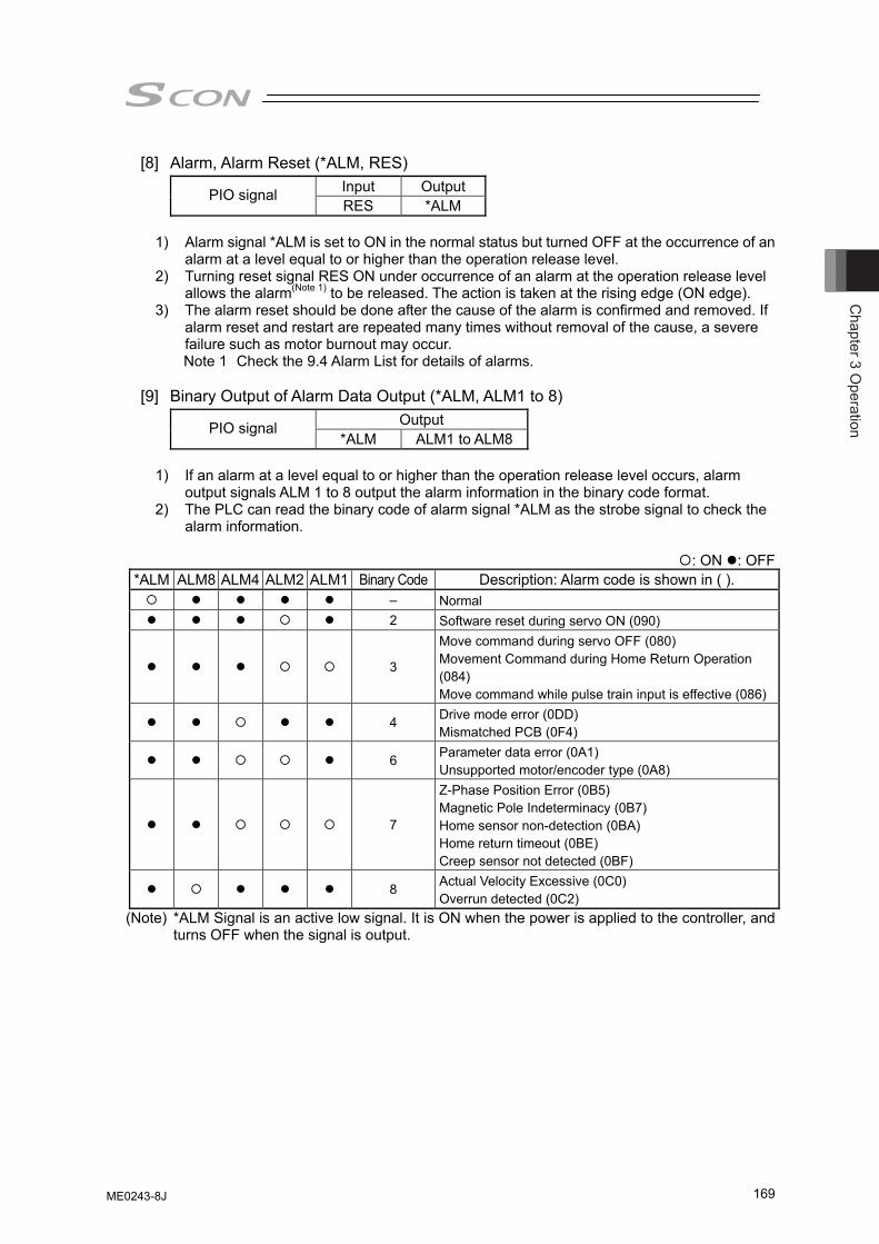
Chapter 3 O
peration
169
[8] Alarm, Alarm Reset (*ALM, RES) Input Output PIO signal RES *ALM
1) Alarm signal *ALM is set to ON in the normal status but turned OFF at the occurrence of an
alarm at a level equal to or higher than the operation release level. 2) Turning reset signal RES ON under occurrence of an alarm at the operation release level
allows the alarm(Note 1) to be released. The action is taken at the rising edge (ON edge). 3) The alarm reset should be done after the cause of the alarm is confirmed and removed. If
alarm reset and restart are repeated many times without removal of the cause, a severe failure such as motor burnout may occur. Note 1 Check the 9.4 Alarm List for details of alarms.
[9] Binary Output of Alarm Data Output (*ALM, ALM1 to 8)
Output PIO signal *ALM ALM1 to ALM8
1) If an alarm at a level equal to or higher than the operation release level occurs, alarm
output signals ALM 1 to 8 output the alarm information in the binary code format. 2) The PLC can read the binary code of alarm signal *ALM as the strobe signal to check the
alarm information.
: ON : OFF *ALM ALM8 ALM4 ALM2 ALM1 Binary Code Description: Alarm code is shown in ( ).
– Normal 2 Software reset during servo ON (090)
3
Move command during servo OFF (080) Movement Command during Home Return Operation (084) Move command while pulse train input is effective (086)
4 Drive mode error (0DD) Mismatched PCB (0F4)
6 Parameter data error (0A1) Unsupported motor/encoder type (0A8)
7
Z-Phase Position Error (0B5) Magnetic Pole Indeterminacy (0B7) Home sensor non-detection (0BA) Home return timeout (0BE) Creep sensor not detected (0BF)
8 Actual Velocity Excessive (0C0) Overrun detected (0C2)
(Note) *ALM Signal is an active low signal. It is ON when the power is applied to the controller, and turns OFF when the signal is output.
ME0243-8J
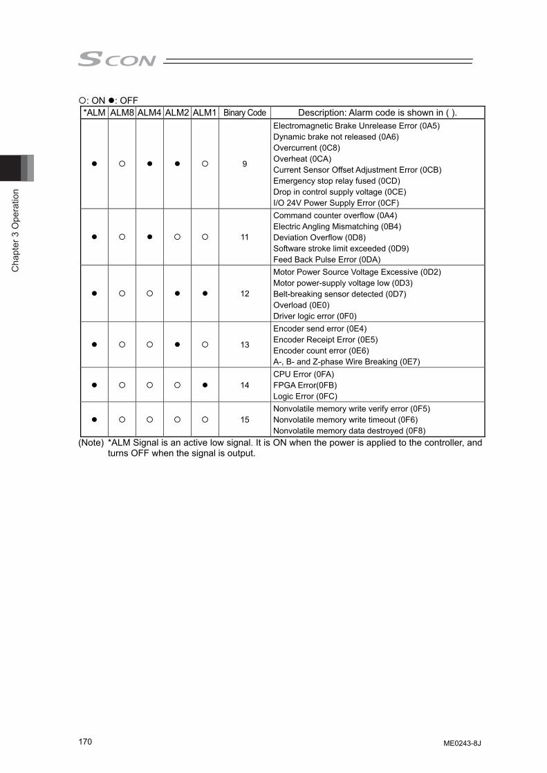
Cha
pter
3 O
pera
tion
170
: ON : OFF *ALM ALM8 ALM4 ALM2 ALM1 Binary Code Description: Alarm code is shown in ( ).
9
Electromagnetic Brake Unrelease Error (0A5) Dynamic brake not released (0A6) Overcurrent (0C8) Overheat (0CA) Current Sensor Offset Adjustment Error (0CB) Emergency stop relay fused (0CD) Drop in control supply voltage (0CE) I/O 24V Power Supply Error (0CF)
11
Command counter overflow (0A4) Electric Angling Mismatching (0B4) Deviation Overflow (0D8) Software stroke limit exceeded (0D9) Feed Back Pulse Error (0DA)
12
Motor Power Source Voltage Excessive (0D2) Motor power-supply voltage low (0D3) Belt-breaking sensor detected (0D7) Overload (0E0) Driver logic error (0F0)
13
Encoder send error (0E4) Encoder Receipt Error (0E5) Encoder count error (0E6) A-, B- and Z-phase Wire Breaking (0E7)
14 CPU Error (0FA) FPGA Error(0FB) Logic Error (0FC)
15 Nonvolatile memory write verify error (0F5) Nonvolatile memory write timeout (0F6) Nonvolatile memory data destroyed (0F8)
(Note) *ALM Signal is an active low signal. It is ON when the power is applied to the controller, and turns OFF when the signal is output.
ME0243-8J
Chapter 3 O
peration
171
[10] Brake Forcible Release (BKRL) Output PIO signal BKRL
The brake can be released while BKRL signal is turned ON. For the actuator equipped with a brake, the brake can be controlled by turning the servo ON/OFF, however, a release of the brake may be necessary in the case of installing the unit to a system so the slider or rod can be moved by hand. This operation can be performed not only by the brake release switch on the front panel of the controller, but also by the brake release signal BKRL.
Warning: (1) Take sufficient care to release the brake. Inappropriate brake release
may cause people to be injured and/or the actuator, the work and/or the machine to be damaged.
(2) After the brake is released, always make the brake applied again. Any operation with the brake remaining released is extremely dangerous. The slider or rod may drop to cause people to be injured and/or the actuator, the work and/or the machine to be damaged.
[11] Overload Alarm/Light Error Alarm (*OVLW/*ALML)
Output PIO signal *OVLW/*ALML
Use this with changing the setting in Parameter No.151. Setting Parameter No.151 to “0” changes to the overload warning output, and it turns OFF when the motor temperature exceeds the rate set in Parameter No.143 “Overload Level Ratio”. This signal will be ON as long as the motor temperature does not exceed the warning level. Setting Parameter No.151 to “1” changes to the light failure alarm output, and it turns OFF when a message level alarm is generated. This signal will be ON as long as the message level alarm is not issued.
ME0243-8J
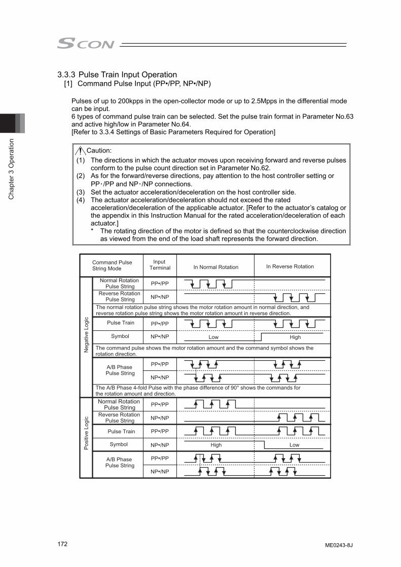
Cha
pter
3 O
pera
tion
172
3.3.3 Pulse Train Input Operation [1] Command Pulse Input (PP•/PP, NP•/NP)
Pulses of up to 200kpps in the open-collector mode or up to 2.5Mpps in the differential mode can be input. 6 types of command pulse train can be selected. Set the pulse train format in Parameter No.63 and active high/low in Parameter No.64. [Refer to 3.3.4 Settings of Basic Parameters Required for Operation]
Caution:
(1) The directions in which the actuator moves upon receiving forward and reverse pulses conform to the pulse count direction set in Parameter No.62.
(2) As for the forward/reverse directions, pay attention to the host controller setting or PP・/PP and NP・/NP connections.
(3) Set the actuator acceleration/deceleration on the host controller side. (4) The actuator acceleration/deceleration should not exceed the rated
acceleration/deceleration of the applicable actuator. [Refer to the actuator’s catalog or the appendix in this Instruction Manual for the rated acceleration/deceleration of each actuator.]
* The rotating direction of the motor is defined so that the counterclockwise direction as viewed from the end of the load shaft represents the forward direction.
PP•/PP
NP•/NP
PP•/PP
NP•/NP
PP•/PP
NP•/NP
PP•/PP
NP•/NP
PP•/PP
NP•/NP
PP•/PP
NP•/NP
High Low
High Low
Normal Rotation Pulse String
Normal Rotation Pulse String
Reverse Rotation Pulse String
Reverse Rotation Pulse String
The normal rotation pulse string shows the motor rotation amount in normal direction, and reverse rotation pulse string shows the motor rotation amount in reverse direction.
Pulse Train
Pulse Train
Symbol
Symbol
The command pulse shows the motor rotation amount and the command symbol shows the rotation direction.
A/B Phase Pulse String
A/B Phase Pulse String
The A/B Phase 4-fold Pulse with the phase difference of 90° shows the commands for the rotation amount and direction.
Command Pulse String Mode
Input Terminal In Normal Rotation In Reverse Rotation
Neg
ativ
e Lo
gic
Pos
itive
Log
ic
ME0243-8J
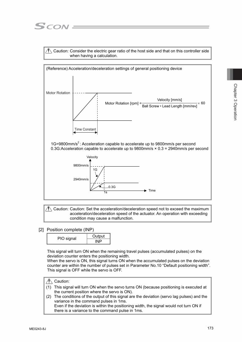
Chapter 3 O
peration
173
Time Constant
Motor Rotation
Caution: Consider the electric gear ratio of the host side and that on this controller side
when having a calculation.
(Reference) Acceleration/deceleration settings of general positioning device
1G=9800mm/s2 : Acceleration capable to accelerate up to 9800mm/s per second 0.3G:Acceleration capable to accelerate up to 9800mm/s × 0.3 = 2940mm/s per second
Caution: Caution: Set the acceleration/deceleration speed not to exceed the maximum
acceleration/deceleration speed of the actuator. An operation with exceeding condition may cause a malfunction.
[2] Position complete (INP)
Output PIO signal INP
This signal will turn ON when the remaining travel pulses (accumulated pulses) on the deviation counter enters the positioning width. When the servo is ON, this signal turns ON when the accumulated pulses on the deviation counter are within the number of pulses set in Parameter No.10 “Default positioning width”. This signal is OFF while the servo is OFF.
Caution: (1) This signal will turn ON when the servo turns ON (because positioning is executed at
the current position where the servo is ON). (2) The conditions of the output of this signal are the deviation (servo lag pulses) and the
variance in the command pulses in 1ms. Even if the deviation is within the positioning width, the signal would not turn ON if there is a variance to the command pulse in 1ms.
Motor Rotation [rpm] =Velocity [mm/s]
Ball Screw • Lead Length [mm/rev] × 60
Velocity
Time
9800mm/s
1s
1G
2940mm/s
0.3G
ME0243-8J
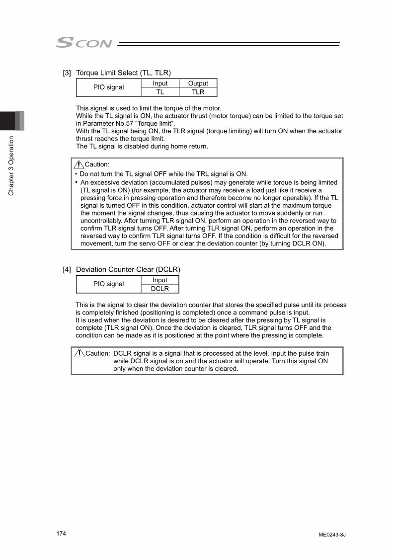
Cha
pter
3 O
pera
tion
174
[3] Torque Limit Select (TL, TLR) Input Output PIO signal TL TLR
This signal is used to limit the torque of the motor. While the TL signal is ON, the actuator thrust (motor torque) can be limited to the torque set in Parameter No.57 “Torque limit”. With the TL signal being ON, the TLR signal (torque limiting) will turn ON when the actuator thrust reaches the torque limit. The TL signal is disabled during home return.
Caution:
• Do not turn the TL signal OFF while the TRL signal is ON. • An excessive deviation (accumulated pulses) may generate while torque is being limited
(TL signal is ON) (for example, the actuator may receive a load just like it receive a pressing force in pressing operation and therefore become no longer operable). If the TL signal is turned OFF in this condition, actuator control will start at the maximum torque the moment the signal changes, thus causing the actuator to move suddenly or run uncontrollably. After turning TLR signal ON, perform an operation in the reversed way to confirm TLR signal turns OFF. After turning TLR signal ON, perform an operation in the reversed way to confirm TLR signal turns OFF. If the condition is difficult for the reversed movement, turn the servo OFF or clear the deviation counter (by turning DCLR ON).
[4] Deviation Counter Clear (DCLR) Input PIO signal DCLR
This is the signal to clear the deviation counter that stores the specified pulse until its process is completely finished (positioning is completed) once a command pulse is input. It is used when the deviation is desired to be cleared after the pressing by TL signal is complete (TLR signal ON). Once the deviation is cleared, TLR signal turns OFF and the condition can be made as it is positioned at the point where the pressing is complete.
Caution: DCLR signal is a signal that is processed at the level. Input the pulse train
while DCLR signal is on and the actuator will operate. Turn this signal ON only when the deviation counter is cleared.
ME0243-8J
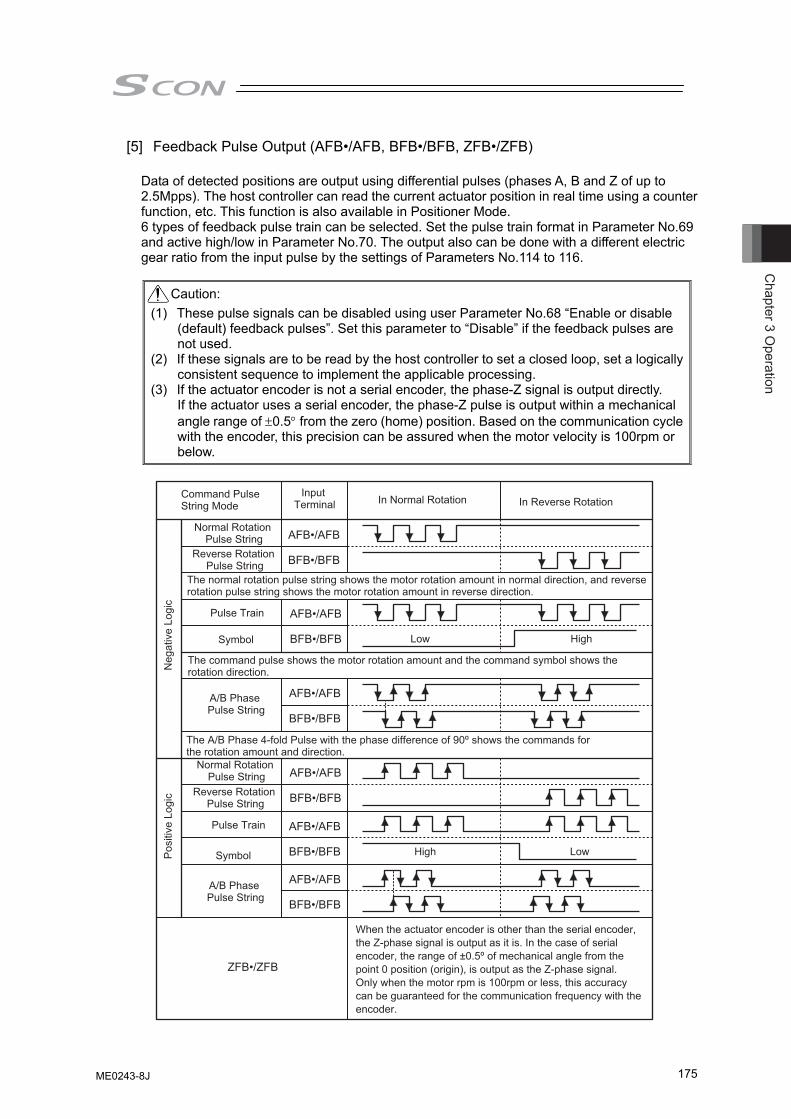
Chapter 3 O
peration
175
[5] Feedback Pulse Output (AFB•/AFB, BFB•/BFB, ZFB•/ZFB)
Data of detected positions are output using differential pulses (phases A, B and Z of up to 2.5Mpps). The host controller can read the current actuator position in real time using a counter function, etc. This function is also available in Positioner Mode. 6 types of feedback pulse train can be selected. Set the pulse train format in Parameter No.69 and active high/low in Parameter No.70. The output also can be done with a different electric gear ratio from the input pulse by the settings of Parameters No.114 to 116.
Caution:
(1) These pulse signals can be disabled using user Parameter No.68 “Enable or disable (default) feedback pulses”. Set this parameter to “Disable” if the feedback pulses are not used.
(2) If these signals are to be read by the host controller to set a closed loop, set a logically consistent sequence to implement the applicable processing.
(3) If the actuator encoder is not a serial encoder, the phase-Z signal is output directly. If the actuator uses a serial encoder, the phase-Z pulse is output within a mechanical angle range of ±0.5° from the zero (home) position. Based on the communication cycle with the encoder, this precision can be assured when the motor velocity is 100rpm or below.
AFB•/AFB
BFB•/BFB
AFB•/AFB
BFB•/BFB
AFB•/AFB
BFB•/BFB
AFB•/AFB
BFB•/BFB
AFB•/AFB
BFB•/BFB
AFB•/AFB
BFB•/BFB
ZFB•/ZFB
High Low
High Low
Normal Rotation Pulse String
Normal Rotation Pulse String
Reverse Rotation Pulse String
Reverse Rotation Pulse String
The normal rotation pulse string shows the motor rotation amount in normal direction, and reverse rotation pulse string shows the motor rotation amount in reverse direction.
Pulse Train
Pulse Train
Symbol
Symbol
The command pulse shows the motor rotation amount and the command symbol shows the rotation direction.
A/B Phase Pulse String
A/B Phase Pulse String
The A/B Phase 4-fold Pulse with the phase difference of 90º shows the commands for the rotation amount and direction.
Command Pulse String Mode
Input Terminal In Normal Rotation In Reverse Rotation
Neg
ativ
e Lo
gic
Pos
itive
Log
ic
When the actuator encoder is other than the serial encoder, the Z-phase signal is output as it is. In the case of serial encoder, the range of ±0.5º of mechanical angle from the point 0 position (origin), is output as the Z-phase signal.Only when the motor rpm is 100rpm or less, this accuracy can be guaranteed for the communication frequency with the encoder.
ME0243-8J
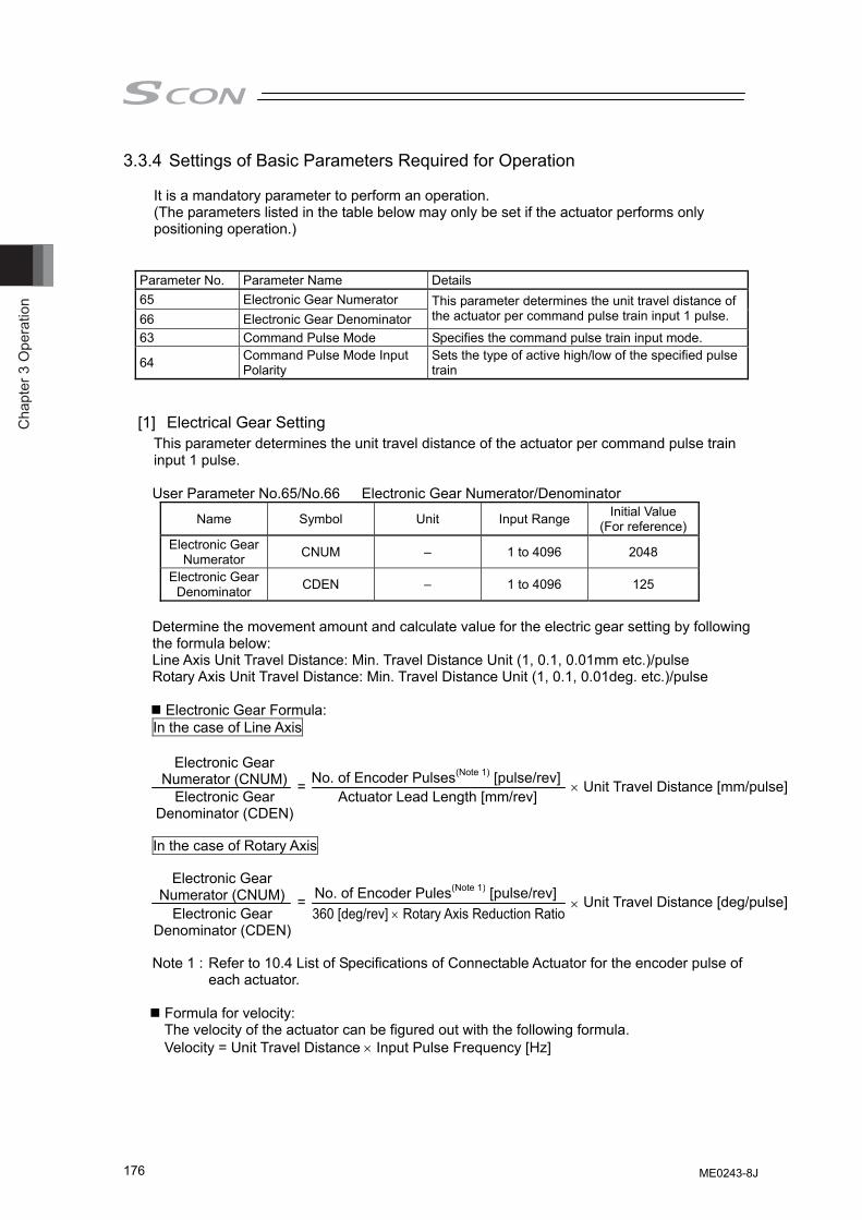
Cha
pter
3 O
pera
tion
176
3.3.4 Settings of Basic Parameters Required for Operation
It is a mandatory parameter to perform an operation. (The parameters listed in the table below may only be set if the actuator performs only positioning operation.)
Parameter No. Parameter Name Details 65 Electronic Gear Numerator 66 Electronic Gear Denominator
This parameter determines the unit travel distance of the actuator per command pulse train input 1 pulse.
63 Command Pulse Mode Specifies the command pulse train input mode.
64 Command Pulse Mode Input Polarity
Sets the type of active high/low of the specified pulse train
[1] Electrical Gear Setting This parameter determines the unit travel distance of the actuator per command pulse train input 1 pulse.
User Parameter No.65/No.66 Electronic Gear Numerator/Denominator
Name Symbol Unit Input Range Initial Value (For reference)
Electronic Gear Numerator CNUM – 1 to 4096 2048
Electronic Gear Denominator CDEN – 1 to 4096 125
Determine the movement amount and calculate value for the electric gear setting by following the formula below: Line Axis Unit Travel Distance: Min. Travel Distance Unit (1, 0.1, 0.01mm etc.)/pulse Rotary Axis Unit Travel Distance: Min. Travel Distance Unit (1, 0.1, 0.01deg. etc.)/pulse
Electronic Gear Formula: In the case of Line Axis In the case of Rotary Axis
Note 1 : Refer to 10.4 List of Specifications of Connectable Actuator for the encoder pulse of
each actuator.
Formula for velocity: The velocity of the actuator can be figured out with the following formula. Velocity = Unit Travel Distance × Input Pulse Frequency [Hz]
Electronic Gear Numerator (CNUM)
Electronic Gear Denominator (CDEN)
= No. of Encoder Pulses(Note 1) [pulse/rev]Actuator Lead Length [mm/rev]
× Unit Travel Distance [mm/pulse]
= No. of Encoder Pules(Note 1) [pulse/rev]360 [deg/rev] × Rotary Axis Reduction Ratio
× Unit Travel Distance [deg/pulse] Electronic Gear
Numerator (CNUM) Electronic Gear
Denominator (CDEN)
ME0243-8J
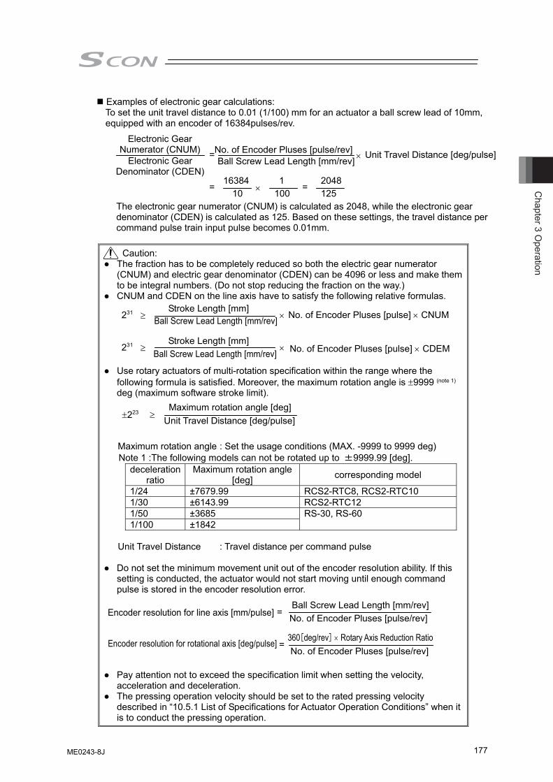
Chapter 3 O
peration
177
Examples of electronic gear calculations: To set the unit travel distance to 0.01 (1/100) mm for an actuator a ball screw lead of 10mm, equipped with an encoder of 16384pulses/rev.
The electronic gear numerator (CNUM) is calculated as 2048, while the electronic gear denominator (CDEN) is calculated as 125. Based on these settings, the travel distance per command pulse train input pulse becomes 0.01mm.
Caution:
● The fraction has to be completely reduced so both the electric gear numerator (CNUM) and electric gear denominator (CDEN) can be 4096 or less and make them to be integral numbers. (Do not stop reducing the fraction on the way.)
● CNUM and CDEN on the line axis have to satisfy the following relative formulas. ● Use rotary actuators of multi-rotation specification within the range where the
following formula is satisfied. Moreover, the maximum rotation angle is ±9999 (note 1) deg (maximum software stroke limit).
Maximum rotation angle : Set the usage conditions (MAX. -9999 to 9999 deg) Note 1 :The following models can not be rotated up to ±9999.99 [deg].
deceleration ratio
Maximum rotation angle [deg] corresponding model
1/24 ±7679.99 RCS2-RTC8, RCS2-RTC10 1/30 ±6143.99 RCS2-RTC12 1/50 ±3685 1/100 ±1842
RS-30, RS-60
Unit Travel Distance : Travel distance per command pulse
● Do not set the minimum movement unit out of the encoder resolution ability. If this
setting is conducted, the actuator would not start moving until enough command pulse is stored in the encoder resolution error.
● Pay attention not to exceed the specification limit when setting the velocity,
acceleration and deceleration. ● The pressing operation velocity should be set to the rated pressing velocity
described in “10.5.1 List of Specifications for Actuator Operation Conditions” when it is to conduct the pressing operation.
231 ≥ Stroke Length [mm]
Ball Screw Lead Length [mm/rev] × No. of Encoder Pluses [pulse] × CNUM
231 ≥ Stroke Length [mm]
Ball Screw Lead Length [mm/rev] × No. of Encoder Pluses [pulse] × CDEM
Encoder resolution for line axis [mm/pulse] =Ball Screw Lead Length [mm/rev] No. of Encoder Pluses [pulse/rev]
Encoder resolution for rotational axis [deg/pulse] =360[deg/rev] × Rotary Axis Reduction Ratio No. of Encoder Pluses [pulse/rev]
= No. of Encoder Pluses [pulse/rev]Ball Screw Lead Length [mm/rev] ×
Unit Travel Distance [deg/pulse]
= 16384
10 ×1
100=
2048125
Electronic Gear Numerator (CNUM)
Electronic Gear Denominator (CDEN)
±223 ≥ Maximum rotation angle [deg]
Unit Travel Distance [deg/pulse]
ME0243-8J
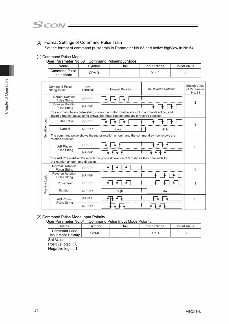
Cha
pter
3 O
pera
tion
178
[2] Format Settings of Command Pulse Train Set the format of command pulse train in Parameter No.63 and active high/low in No.64.
(1) Command Pulse Mode
User Parameter No.63 Command PulseInput Mode Name Symbol Unit Input Range Initial Value
Command Pulse Input Mode CPMD – 0 to 2 1
(2) Command Pulse Mode Input Polarity User Parameter No.64 Command Pulse Input Mode Polarity
Name Symbol Unit Input Range Initial Value Command Pulse
Input Mode Polarity CPMD – 0 to 1 0
Set Value Positive logic : 0 Negative logic : 1
PP•/PP
NP•/NP
PP•/PP
NP•/NP
PP•/PP
NP•/NP
PP•/PP
NP•/NP
PP•/PP
NP•/NP
PP•/PP
NP•/NP
High Low
HighLow
Normal Rotation Pulse String
Normal Rotation Pulse String
Reverse Rotation Pulse String
Reverse Rotation Pulse String
The normal rotation pulse string shows the motor rotation amount in normal direction, and reverse rotation pulse string shows the motor rotation amount in reverse direction.
Pulse Train
Pulse Train
Symbol
Symbol
The command pulse shows the motor rotation amount and the command symbol shows the rotation direction.
A/B Phase Pulse String
A/B Phase Pulse String
The A/B Phase 4-fold Pulse with the phase difference of 90° shows the commands for the rotation amount and direction.
Command Pulse String Mode
Input Terminal In Normal Rotation In Reverse Rotation
Neg
ativ
e Lo
gic
Pos
itive
Log
ic
Setting Value of Parameter
No. 63
2
1
0
2
1
0
ME0243-8J
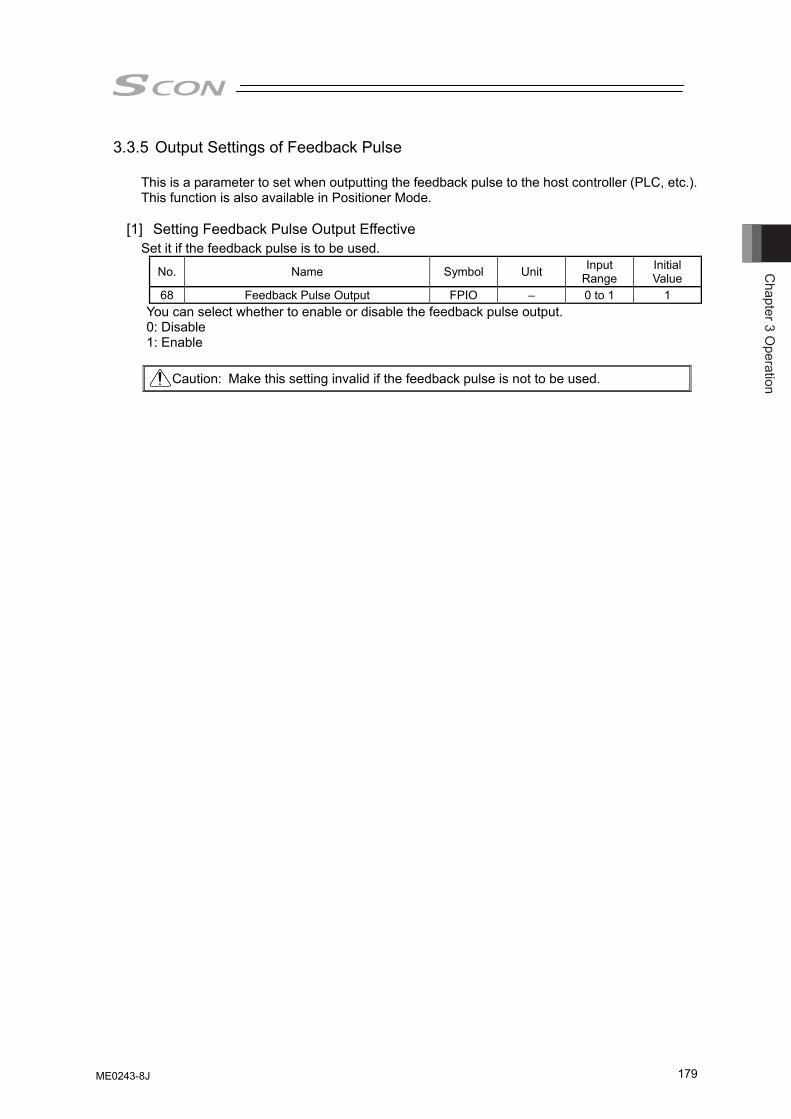
Chapter 3 O
peration
179
3.3.5 Output Settings of Feedback Pulse
This is a parameter to set when outputting the feedback pulse to the host controller (PLC, etc.). This function is also available in Positioner Mode.
[1] Setting Feedback Pulse Output Effective Set it if the feedback pulse is to be used.
No. Name Symbol Unit Input Range
Initial Value
68 Feedback Pulse Output FPIO – 0 to 1 1 You can select whether to enable or disable the feedback pulse output. 0: Disable 1: Enable
Caution: Make this setting invalid if the feedback pulse is not to be used.
ME0243-8J
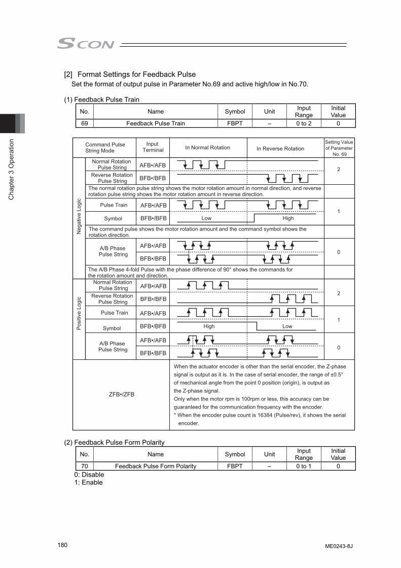
Cha
pter
3 O
pera
tion
180
[2] Format Settings for Feedback Pulse Set the format of output pulse in Parameter No.69 and active high/low in No.70.
(1) Feedback Pulse Train
No. Name Symbol Unit Input Range
Initial Value
69 Feedback Pulse Train FBPT – 0 to 2 0
(2) Feedback Pulse Form Polarity
No. Name Symbol Unit Input Range
Initial Value
70 Feedback Pulse Form Polarity FBPT – 0 to 1 0 0: Disable 1: Enable
AFB•/AFB
BFB•/BFB
AFB•/AFB
BFB•/BFB
AFB•/AFB
BFB•/BFB
AFB•/AFB
BFB•/BFB
AFB•/AFB
BFB•/BFB
AFB•/AFB
BFB•/BFB
ZFB•/ZFB
High Low
High Low
2
1
0
2
1
0
Normal Rotation Pulse String
Normal Rotation Pulse String
Reverse Rotation Pulse String
Reverse Rotation Pulse String
The normal rotation pulse string shows the motor rotation amount in normal direction, and reverse rotation pulse string shows the motor rotation amount in reverse direction.
Pulse Train
Pulse Train
Symbol
Symbol
The command pulse shows the motor rotation amount and the command symbol shows the rotation direction.
A/B Phase Pulse String
A/B Phase Pulse String
The A/B Phase 4-fold Pulse with the phase difference of 90° shows the commands for the rotation amount and direction.
Command Pulse String Mode
Input Terminal In Normal Rotation In Reverse Rotation
Setting Value of Parameter
No. 69
Neg
ativ
e Lo
gic
Pos
itive
Log
ic
When the actuator encoder is other than the serial encoder, the Z-phase signal is output as it is. In the case of serial encoder, the range of ±0.5° of mechanical angle from the point 0 position (origin), is output as the Z-phase signal.Only when the motor rpm is 100rpm or less, this accuracy can be guaranteed for the communication frequency with the encoder.* When the encoder pulse count is 16384 (Pulse/rev), it shows the serial encoder.
ME0243-8J
Chapter 3 O
peration
181
[3] Electric Gear Settings for Feedback Pulse This is the parameter to determine the output pulse corresponding to the actuator movement amount. Determine the movement amount per pulse to define how many millimeters you would like the actuator to move with the output of 1 pulse.
Movement in line axis per pulse = Minimum output unit (1, 0.1, 0.01mm etc.)/pulse Movement in rotary axis per pulse = Minimum output unit (1, 0.1, 0.01deg etc.)/pulse
(1) Selecting used feedback pulse gear ratio (Parameter No.114)
No. Name Symbol Unit Input Range
Initial Value
114 Selecting used feedback pulse gear ratio FPIO – 0 to 1 0 0: It outputs the pulse equivalent to the input pulse.
If the movement amount of input pulse is 0.01mm, 1 pulse is output when moved for 0.01mm. Thus, 1 pulse is output in response to 1 pulse of input. Output pulse is determined by the electric gear for input (Parameters No.65 and 66).
1: The relation of the output pulse and the actuator movement can be set freely. Set the electric gear in Parameters No.115 and 116.
(2) Electrical Gear (Feedback Pulse) (Parameter No.115, No.116)
Set these parameters when the relation of the output pulse and the actuator movement are to be set freely. These parameters are enabled when Parameter No.114 is set to 1.
User Parameter No.115/116 Electronic Gear (Feedback Pulse) Numerator/Denominator
Name Symbol Unit Input Range Initial Value (For reference)
Electronic Gear Numerator FNUM – 1 to 4096 125
Electronic Gear Denominator FDEN – 1 to 4096 2048
Electronic Gear Formula: In the case of Line Axis In the case of Rotary Axis
Note 1 : Refer to 10.4 List of Specifications of Connectable Actuator for the encoder pulse of
each actuator.
Formula for velocity: The velocity of the actuator is in proportion to the frequency of the output pulse. Velocity = Movement amount per pulse × Output Pulse Frequency [Hz]
Electronic Gear Numerator (FNUM)
Electronic Gear Denominator (FDEN)
= Ball Screw Lead Length [mm/rev] No. of Encoder Pulses [pulse/rev]
×Movement amount per pulse [mm]
= 360 [deg/rev] × Rotary Axis Reduction RatioNo. of Encoder Pules [pulse/rev] × Movement amount per pulse [mm]
Electronic Gear Numerator (FNUM)
Electronic Gear Denominator (FDEN)
1
1
ME0243-8J
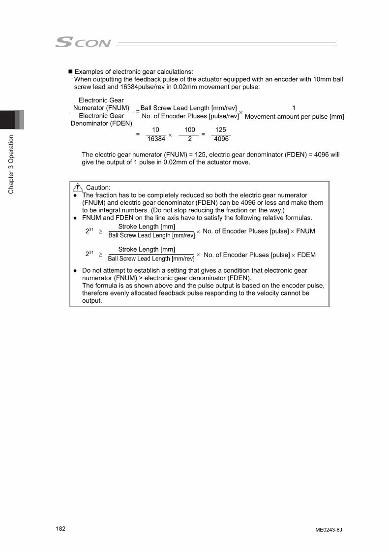
Cha
pter
3 O
pera
tion
182
Examples of electronic gear calculations: When outputting the feedback pulse of the actuator equipped with an encoder with 10mm ball screw lead and 16384pulse/rev in 0.02mm movement per pulse:
The electric gear numerator (FNUM) = 125, electric gear denominator (FDEN) = 4096 will give the output of 1 pulse in 0.02mm of the actuator move.
Caution: ● The fraction has to be completely reduced so both the electric gear numerator
(FNUM) and electric gear denominator (FDEN) can be 4096 or less and make them to be integral numbers. (Do not stop reducing the fraction on the way.)
● FNUM and FDEN on the line axis have to satisfy the following relative formulas. ● Do not attempt to establish a setting that gives a condition that electronic gear
numerator (FNUM) > electronic gear denominator (FDEN). The formula is as shown above and the pulse output is based on the encoder pulse,
therefore evenly allocated feedback pulse responding to the velocity cannot be output.
Electronic Gear Denominator (FDEN)
Electronic Gear Numerator (FNUM) = Ball Screw Lead Length [mm/rev]
No. of Encoder Pluses [pulse/rev]× Movement amount per pulse [mm]
= 10
16384 ×100
2 =
1254096
231 ≥ Stroke Length [mm]
Ball Screw Lead Length [mm/rev] × No. of Encoder Pluses [pulse] × FNUM
231 ≥ Stroke Length [mm]
Ball Screw Lead Length [mm/rev] × No. of Encoder Pluses [pulse] × FDEM
1
ME0243-8J
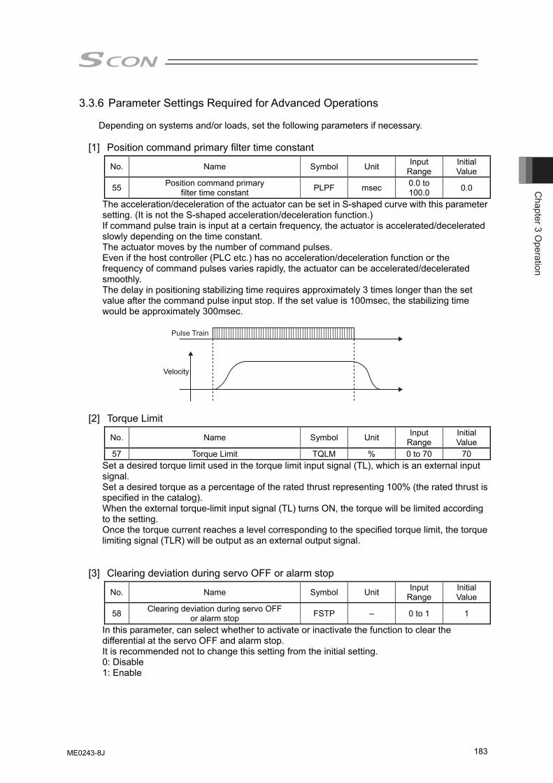
Chapter 3 O
peration
183
3.3.6 Parameter Settings Required for Advanced Operations
Depending on systems and/or loads, set the following parameters if necessary.
[1] Position command primary filter time constant
No. Name Symbol Unit Input Range
Initial Value
55 Position command primary filter time constant PLPF msec 0.0 to
100.0 0.0
The acceleration/deceleration of the actuator can be set in S-shaped curve with this parameter setting. (It is not the S-shaped acceleration/deceleration function.) If command pulse train is input at a certain frequency, the actuator is accelerated/decelerated slowly depending on the time constant. The actuator moves by the number of command pulses. Even if the host controller (PLC etc.) has no acceleration/deceleration function or the frequency of command pulses varies rapidly, the actuator can be accelerated/decelerated smoothly. The delay in positioning stabilizing time requires approximately 3 times longer than the set value after the command pulse input stop. If the set value is 100msec, the stabilizing time would be approximately 300msec.
Pulse Train
Velocity
[2] Torque Limit
No. Name Symbol Unit Input Range
Initial Value
57 Torque Limit TQLM % 0 to 70 70 Set a desired torque limit used in the torque limit input signal (TL), which is an external input signal. Set a desired torque as a percentage of the rated thrust representing 100% (the rated thrust is specified in the catalog). When the external torque-limit input signal (TL) turns ON, the torque will be limited according to the setting. Once the torque current reaches a level corresponding to the specified torque limit, the torque limiting signal (TLR) will be output as an external output signal.
[3] Clearing deviation during servo OFF or alarm stop
No. Name Symbol Unit Input Range
Initial Value
58 Clearing deviation during servo OFF or alarm stop FSTP – 0 to 1 1
In this parameter, can select whether to activate or inactivate the function to clear the differential at the servo OFF and alarm stop. It is recommended not to change this setting from the initial setting. 0: Disable 1: Enable
ME0243-8J
Cha
pter
3 O
pera
tion
184
[4] Error monitor during torque limiting
No. Name Symbol Unit Input Range
Initial Value
59 Error monitor during torque limiting FSTP – 0 to 1 0 You can select whether to enable or disable the function to monitor deviation while torque is being limited (the TL signal is ON). By enabling this function, you can have the controller output an error while torque is being limited, if a deviation equal to or exceeding the specified value 0: Enable 1: Disable
[5] Deviation Counter Clear Input
No. Name Symbol Unit Input Range
Initial Value
60 Deviation Counter Clear Input FPIO – 0 to 1 0 You can select whether to enable or disable the DCLR signal to clear the generated deviation while torque is being limited (the TL signal is ON). 0: Enable 1: Disable
[6] Torque limit command input
No. Name Symbol Unit Input Range
Initial Value
61 Torque limit command input FPIO – 0 to 1 0 Torque control of the motor with the value set in Parameter No.57 “Torque Control Value” can be performed with PIO (TL Signal ON) from the host system. In this parameter, a choice can be made from using (disable) TL Signal (Torque Limiting Signal) and not using (enable) the signal. 0: Enable 1: Disable
[7] Pulse count direction
No. Name Symbol Unit Input Range
Initial Value
62 Pulse count direction FPIO – 0 to 1 Set individually
You can set the direction in which the motor turns according to command pulses. Set the same value as that set in Parameter No.5 “Home-Return Direction” and the actuator moves in positive direction if the command pulse is input in positive direction. 0: Forward rotation 1: Reverse rotation
[8] Compulsory Stop Input
No. Name Symbol Unit Input Range
Initial Value
67 Compulsory Stop Input FPIO – 0 to 1 0 Compulsory stop of the actuator can be performed with PIO (CSTP Signal ON) from the host system. In this parameter, a choice can be made from using (disable) CSTP Signal (Compulsory Stop Input Signal) and not using (enable) the signal. 0: Enable 1: Disable
ME0243-8J
Chapter 4 Field N
etwork
185
Chapter 4 Field Network The controller is applicable for the following field networks. Except for RS485, it is the option which can be selected when purchasing. It cannot be changed after the product is delivered. Also, for the field networks other than RS485, PIO cannot be equipped. And Pulse Train Control Mode cannot be operated.
Type of Field Network Name of Field Network Description Detail DeviceNet Refer to ME0256 of separate
volume. (Note 1) CC-Link Refer to ME0254 of separate
volume. (Note 1) PROFIBUS-DP Refer to ME0258 of separate
volume. (Note 1) CompoNet Refer to ME0220 of separate
volume. (Note 1) MECHATROLINK-I/II Refer to ME0221 of separate
volume. (Note 1) EtherCAT Refer to ME0273 of separate
volume. (Note 1) EtherNet/IP Refer to ME0278 of separate
volume. (Note 1) PROFINET IO
Allows actuator to be controlled through I/O communication using control signals similar to PIO or numerical data communication.
Refer to ME0333 of separate volume. (Note 1)
MECHATROLINK-III (Dedicated for SCON-CA)
Refer to ME0317 of separate volume. (Note 1)
RS485 Controls actuator through general-purpose protocol “MODBUS”.
Refer to ME0162 of separate volume. (Note 1)
(Note 1) • SCON-CA/CAL/CGAL is handled as a slave unit. For details of each network, check the Instruction Manuals of the master unit provided by the manufacturer and that of the installed PLC.
• The Instruction Manuals describing how to use SCON-CA/CAL/CGAL field networks are provided separately. Read them together with this manual.
ME0243-8J

Cha
pter
4 F
ield
Net
wor
k
186
ME0243-8J
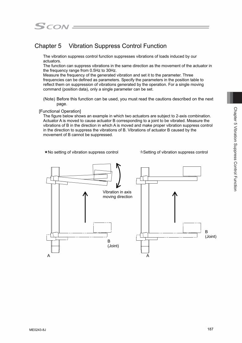
Chapter 5 Vibration Suppress C
ontrol Function
187
Chapter 5 Vibration Suppress Control Function
The vibration suppress control function suppresses vibrations of loads induced by our actuators. The function can suppress vibrations in the same direction as the movement of the actuator in the frequency range from 0.5Hz to 30Hz. Measure the frequency of the generated vibration and set it to the parameter. Three frequencies can be defined as parameters. Specify the parameters in the position table to reflect them on suppression of vibrations generated by the operation. For a single moving command (position data), only a single parameter can be set. (Note) Before this function can be used, you must read the cautions described on the next
page.
[Functional Operation] The figure below shows an example in which two actuators are subject to 2-axis combination. Actuator A is moved to cause actuator B corresponding to a joint to be vibrated. Measure the vibrations of B in the direction in which A is moved and make proper vibration suppress control in the direction to suppress the vibrations of B. Vibrations of actuator B caused by the movement of B cannot be suppressed.
A A
B (Joint)
B (Joint)
Vibration in axis moving direction
No setting of vibration suppress control Setting of vibration suppress control
ME0243-8J
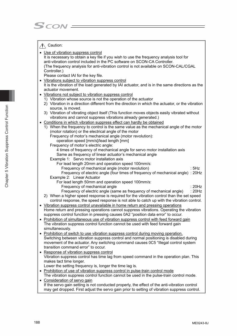
Cha
pter
5 V
ibra
tion
Supp
ress
Con
trol F
unct
ion
188
Caution:
• Use of vibration suppress control It is necessary to obtain a key file if you wish to use the frequency analysis tool for anti-vibration control included in the PC software on SCON-CA Controller. (The frequency analysis for anti-vibration control is not available on SCON-CAL/CGAL Controller.) Please contact IAI for the key file.
• Vibrations subject to vibration suppress control It is the vibration of the load generated by IAI actuator, and is in the same directions as the actuator movement.
• Vibrations not subject to vibration suppress control 1) Vibration whose source is not the operation of the actuator 2) Vibration in a direction different from the direction in which the actuator, or the vibration
source, is moved. 3) Vibration of vibrating object itself (This function moves objects easily vibrated without
vibrations and cannot suppress vibrations already generated.) • Conditions in which vibration suppress effect can hardly be obtained
1) When the frequency to control is the same value as the mechanical angle of the motor (motor rotation) or the electrical angle of the motor
Frequency of motor’s mechanical angle (motor revolution): operation speed [mm/s]/lead length [mm] Frequency of motor’s electric angle: 4 times of frequency of mechanical angle for servo motor installation axis Same as frequency of linear actuator’s mechanical angle Example 1: Servo motor installation axis For lead length 20mm and operation speed 100mm/s: Frequency of mechanical angle (motor revolution) : 5Hz Frequency of electric angle (four times of frequency of mechanical angle) : 20Hz Example 2: Linear Actuator For lead length 50mm and operation speed 100mm/s: Frequency of mechanical angle : 20Hz Frequency of electric angle (same as frequency of mechanical angle) : 20Hz2) When a higher speed response is required for the vibration control than the set speed
control response, the speed response is not able to catch up with the vibration control.• Vibration suppress control unavailable in home return and pressing operations
Home return and pressing operations cannot suppress vibrations. Operating the vibration suppress control function in pressing causes 0A2 “position data error” to occur.
• Prohibition of simultaneous use of vibration suppress control with feed forward gain The vibration suppress control function cannot be used with feed forward gain simultaneously.
• Prohibition of switch to use vibration suppress control during moving operation. Switching between vibration suppress control and normal positioning is disabled during movement of the actuator. Any switching command causes 0C5 “Illegal control system transition command error” to occur.
• Response of vibration suppress control Vibration suppress control has time lag from speed command in the operation plan. This makes tact time longer. Lower the setting frequency is, longer the time lag is.
• Prohibition of use of vibration suppress control in pulse-train control mode The vibration suppress control function cannot be used in the pulse-train control mode.
• Consideration of servo gain If the servo gain setting is not conducted properly, the effect of the anti-vibration control may get dropped. First adjust the servo gain prior to setting of vibration suppress control.
ME0243-8J
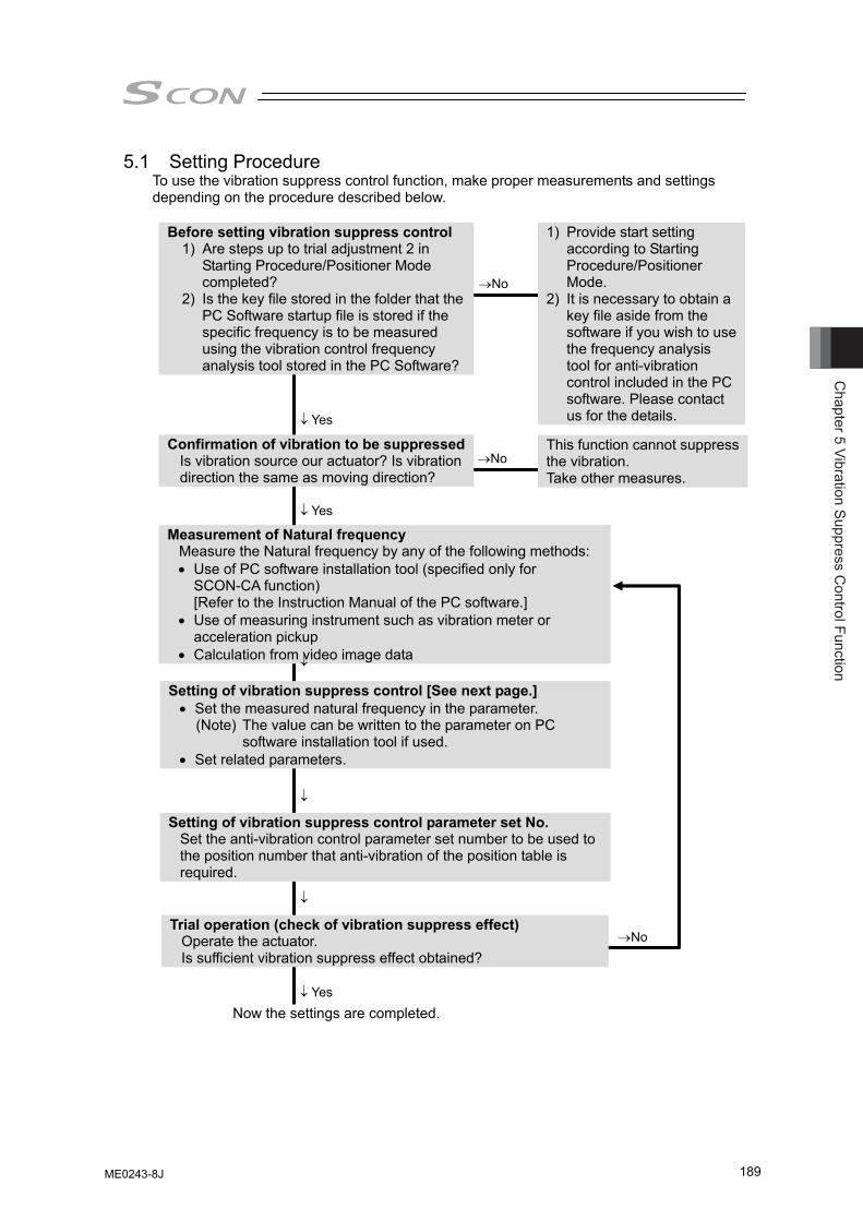
Chapter 5 Vibration Suppress C
ontrol Function
189
5.1 Setting Procedure To use the vibration suppress control function, make proper measurements and settings depending on the procedure described below.
1) Provide start setting according to Starting Procedure/Positioner Mode.
2) It is necessary to obtain a key file aside from the software if you wish to use the frequency analysis tool for anti-vibration control included in the PC software. Please contact us for the details.
→No
This function cannot suppress the vibration. Take other measures.
→No
Before setting vibration suppress control 1) Are steps up to trial adjustment 2 in
Starting Procedure/Positioner Mode completed?
2) Is the key file stored in the folder that the PC Software startup file is stored if the specific frequency is to be measured using the vibration control frequency analysis tool stored in the PC Software?
↓ Yes
Measurement of Natural frequency Measure the Natural frequency by any of the following methods: • Use of PC software installation tool (specified only for
SCON-CA function) [Refer to the Instruction Manual of the PC software.]
• Use of measuring instrument such as vibration meter or acceleration pickup
• Calculation from video image data
↓ Yes
Setting of vibration suppress control [See next page.] • Set the measured natural frequency in the parameter.
(Note) The value can be written to the parameter on PC software installation tool if used.
• Set related parameters.
Setting of vibration suppress control parameter set No. Set the anti-vibration control parameter set number to be used to the position number that anti-vibration of the position table is required.
Confirmation of vibration to be suppressedIs vibration source our actuator? Is vibration direction the same as moving direction?
↓
Now the settings are completed.
Trial operation (check of vibration suppress effect) Operate the actuator. Is sufficient vibration suppress effect obtained?
↓
↓
→No
↓ Yes
ME0243-8J
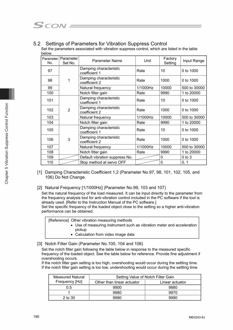
Cha
pter
5 V
ibra
tion
Supp
ress
Con
trol F
unct
ion
190
5.2 Settings of Parameters for Vibration Suppress Control Set the parameters associated with vibration suppress control, which are listed in the table below. Parameter
No. Parameter
Set No. Parameter Name Unit Factory Setting Input Range
97 Damping characteristic coefficient 1 Rate 10 0 to 1000
98 Damping characteristic coefficient 2 Rate 1000 0 to 1000
99 Natural frequency 1/1000Hz 10000 500 to 30000100
1
Notch filter gain Rate 9990 1 to 20000
101 Damping characteristic coefficient 1 Rate 10 0 to 1000
102 Damping characteristic coefficient 2 Rate 1000 0 to 1000
103 Natural frequency 1/1000Hz 10000 500 to 30000104
2
Notch filter gain Rate 9990 1 to 20000
105 Damping characteristic coefficient 1 Rate 10 0 to 1000
106 Damping characteristic coefficient 2 Rate 1000 0 to 1000
107 Natural frequency 1/1000Hz 10000 500 to 30000108
3
Notch filter gain Rate 9990 1 to 20000 109 Default vibration suppress No. 0 0 to 3 110 Stop method at servo OFF 0 0, 1
[1] Damping Characteristic Coefficient 1,2 (Parameter No.97, 98, 101, 102, 105, and
106) Do Not Change.
[2] Natural Frequency [1/1000Hz] (Parameter No.99, 103 and 107) Set the natural frequency of the load measured. It can be input directly to the parameter from the frequency analysis tool for anti-vibration control included in the PC software if the tool is already used. [Refer to the Instruction Manual of the PC software.] Set the specific frequency of the loaded object close to the setting so a higher anti-vibration performance can be obtained.
[Reference] Other vibration measuring methods
• Use of measuring instrument such as vibration meter and acceleration pickup
• Calculation from video image data
[3] Notch Filter Gain (Parameter No.100, 104 and 108) Set the notch filter gain following the table below in response to the measured specific frequency of the loaded object. See the table below for reference. Provide fine adjustment if overshooting occurs. If the notch filter gain setting is too high, overshooting would occur during the settling time. If the notch filter gain setting is too low, undershooting would occur during the settling time.
Setting Value of Notch Filter Gain Measured Natural
Frequency [Hz] Other than linear actuator Linear actuator 0.5 9900 9880 1 9980 9970
2 to 30 9990 9990
ME0243-8J
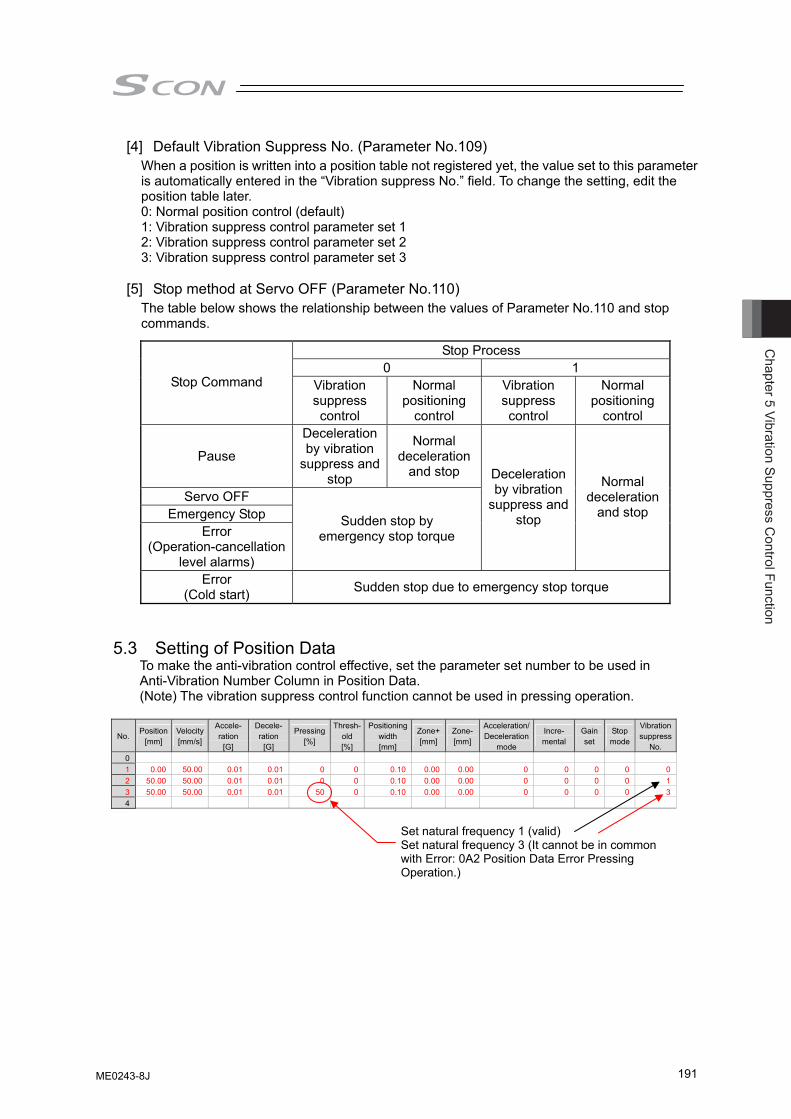
Chapter 5 Vibration Suppress C
ontrol Function
191
[4] Default Vibration Suppress No. (Parameter No.109) When a position is written into a position table not registered yet, the value set to this parameter is automatically entered in the “Vibration suppress No.” field. To change the setting, edit the position table later. 0: Normal position control (default) 1: Vibration suppress control parameter set 1 2: Vibration suppress control parameter set 2 3: Vibration suppress control parameter set 3
[5] Stop method at Servo OFF (Parameter No.110)
The table below shows the relationship between the values of Parameter No.110 and stop commands.
5.3 Setting of Position Data
To make the anti-vibration control effective, set the parameter set number to be used in Anti-Vibration Number Column in Position Data. (Note) The vibration suppress control function cannot be used in pressing operation.
No. Position
[mm] Velocity [mm/s]
Accele-ration
[G]
Decele- ration
[G]
Pressing [%]
Thresh-old [%]
Positioning width [mm]
Zone+[mm]
Zone-[mm]
Acceleration/Deceleration
mode
Incre- mental
Gain set
Stop mode
Vibration suppress
No. 0 1 0.00 50.00 0.01 0.01 0 0 0.10 0.00 0.00 0 0 0 0 02 50.00 50.00 0.01 0.01 0 0 0.10 0.00 0.00 0 0 0 0 13 50.00 50.00 0.01 0.01 50 0 0.10 0.00 0.00 0 0 0 0 34
Stop Process 0 1
Stop Command Vibration suppress control
Normal positioning
control
Vibration suppress control
Normal positioning
control
Pause
Deceleration by vibration
suppress and stop
Normal deceleration
and stop
Servo OFF Emergency Stop
Error (Operation-cancellation
level alarms)
Sudden stop by emergency stop torque
Deceleration by vibration
suppress and stop
Normal deceleration
and stop
Error (Cold start) Sudden stop due to emergency stop torque
Set natural frequency 1 (valid) Set natural frequency 3 (It cannot be in common with Error: 0A2 Position Data Error Pressing Operation.)
ME0243-8J

Cha
pter
5 V
ibra
tion
Supp
ress
Con
trol F
unct
ion
192
ME0243-8J
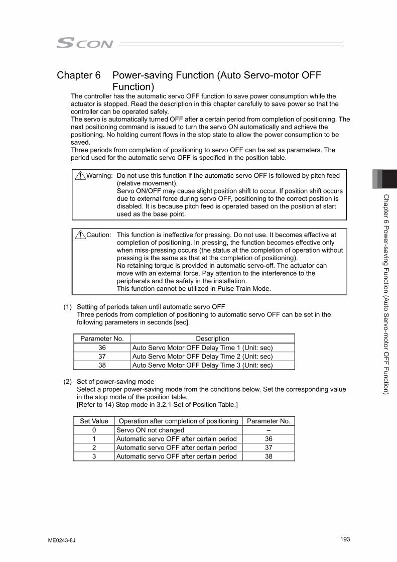
Chapter 6 Pow
er-saving Function (Auto Servo-motor O
FF Function)
193
Chapter 6 Power-saving Function (Auto Servo-motor OFF Function)
The controller has the automatic servo OFF function to save power consumption while the actuator is stopped. Read the description in this chapter carefully to save power so that the controller can be operated safely. The servo is automatically turned OFF after a certain period from completion of positioning. The next positioning command is issued to turn the servo ON automatically and achieve the positioning. No holding current flows in the stop state to allow the power consumption to be saved. Three periods from completion of positioning to servo OFF can be set as parameters. The period used for the automatic servo OFF is specified in the position table. Warning: Do not use this function if the automatic servo OFF is followed by pitch feed
(relative movement). Servo ON/OFF may cause slight position shift to occur. If position shift occurs due to external force during servo OFF, positioning to the correct position is disabled. It is because pitch feed is operated based on the position at start used as the base point.
Caution: This function is ineffective for pressing. Do not use. It becomes effective at
completion of positioning. In pressing, the function becomes effective only when miss-pressing occurs (the status at the completion of operation without pressing is the same as that at the completion of positioning). No retaining torque is provided in automatic servo-off. The actuator can move with an external force. Pay attention to the interference to the peripherals and the safety in the installation. This function cannot be utilized in Pulse Train Mode.
(1) Setting of periods taken until automatic servo OFF Three periods from completion of positioning to automatic servo OFF can be set in the
following parameters in seconds [sec].
Parameter No. Description 36 Auto Servo Motor OFF Delay Time 1 (Unit: sec) 37 Auto Servo Motor OFF Delay Time 2 (Unit: sec) 38 Auto Servo Motor OFF Delay Time 3 (Unit: sec)
(2) Set of power-saving mode Select a proper power-saving mode from the conditions below. Set the corresponding value
in the stop mode of the position table. [Refer to 14) Stop mode in 3.2.1 Set of Position Table.]
Set Value Operation after completion of positioning Parameter No.
0 Servo ON not changed – 1 Automatic servo OFF after certain period 36 2 Automatic servo OFF after certain period 37 3 Automatic servo OFF after certain period 38
ME0243-8J
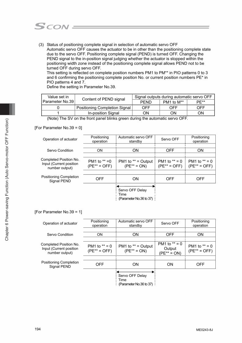
Cha
pter
6 P
ower
-sav
ing
Func
tion
(Aut
o Se
rvo-
mot
or O
FF F
unct
ion)
194
(3) Status of positioning complete signal in selection of automatic servo OFF Automatic servo OFF causes the actuator to be in other than the positioning complete state
due to the servo OFF. Positioning complete signal (PEND) is turned OFF. Changing the PEND signal to the in-position signal judging whether the actuator is stopped within the positioning width zone instead of the positioning complete signal allows PEND not to be turned OFF during servo OFF. This setting is reflected on complete position numbers PM1 to PM** in PIO patterns 0 to 3 and 6 confirming the positioning complete position No. or current position numbers PE* in PIO patterns 4 and 7. Define the setting in Parameter No.39.
Signal outputs during automatic servo OFFValue set in
Parameter No.39 Content of PEND signal PEND PM1 to M** PE**
0 Positioning Completion Signal OFF OFF OFF 1 In-position Signal ON ON ON
(Note) The SV on the front panel blinks green during the automatic servo OFF. [For Parameter No.39 = 0]
Operation of actuator Positioning operation
Automatic servo OFF standby Servo OFF Positioning
operation
Servo Condition ON ON OFF ON
Completed Position No. Input (Current position
number output)
PM1 to ** =0 (PE** = OFF)
PM1 to ** = Output(PE** = ON)
PM1 to ** = 0 (PE** = OFF)
PM1 to ** = 0(PE** = OFF)
Positioning Completion
Signal PEND OFF ON OFF OFF
Servo OFF Delay Time (Parameter No.36 to 37)
[For Parameter No.39 = 1]
Operation of actuator Positioning operation
Automatic servo OFF standby Servo OFF Positioning
operation
Servo Condition ON ON OFF ON
Completed Position No. Input (Current position
number output)
PM1 to ** = 0 (PE** = OFF)
PM1 to ** = Output(PE** = ON)
PM1 to ** = 0 Output
(PE** = ON)
PM1 to ** = 0(PE** = OFF)
Positioning Completion
Signal PEND OFF ON ON OFF
Servo OFF Delay Time (Parameter No.36 to 37)
ME0243-8J
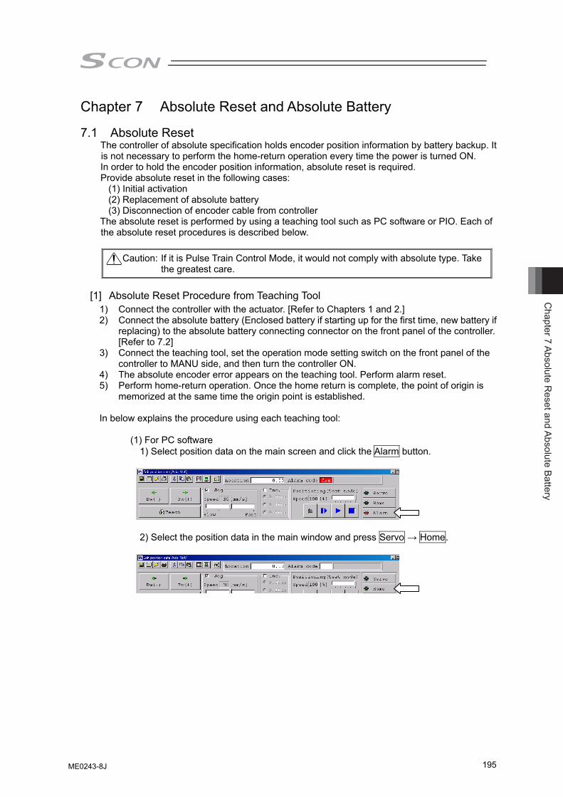
Chapter 7 Absolute R
eset and Absolute Battery
195
Chapter 7 Absolute Reset and Absolute Battery 7.1 Absolute Reset
The controller of absolute specification holds encoder position information by battery backup. It is not necessary to perform the home-return operation every time the power is turned ON. In order to hold the encoder position information, absolute reset is required. Provide absolute reset in the following cases:
(1) Initial activation (2) Replacement of absolute battery (3) Disconnection of encoder cable from controller
The absolute reset is performed by using a teaching tool such as PC software or PIO. Each of the absolute reset procedures is described below.
Caution: If it is Pulse Train Control Mode, it would not comply with absolute type. Take
the greatest care.
[1] Absolute Reset Procedure from Teaching Tool 1) Connect the controller with the actuator. [Refer to Chapters 1 and 2.] 2) Connect the absolute battery (Enclosed battery if starting up for the first time, new battery if
replacing) to the absolute battery connecting connector on the front panel of the controller. [Refer to 7.2]
3) Connect the teaching tool, set the operation mode setting switch on the front panel of the controller to MANU side, and then turn the controller ON.
4) The absolute encoder error appears on the teaching tool. Perform alarm reset. 5) Perform home-return operation. Once the home return is complete, the point of origin is
memorized at the same time the origin point is established. In below explains the procedure using each teaching tool:
(1) For PC software
1) Select position data on the main screen and click the Alarm button.
2) Select the position data in the main window and press Servo → Home.
ME0243-8J
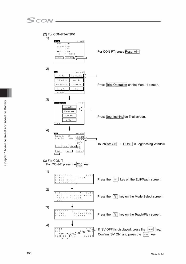
Cha
pter
7 A
bsol
ute
Res
et a
nd A
bsol
ute
Batte
ry
196
(2) For CON-PTA/TB01 1)
2)
3)
4)
(3) For CON-T
For CON-T, press the key.
1)
2)
3)
4)
Press Trial Operation on the Menu 1 screen.
Press Jog_Inching on Trial screen.
Touch SV ON → HOME in Jog/Inching Window.
For CON-PT, press Reset Alm.
Press the key on the Edit/Teach screen.
Press the key on the Mode Select screen.
Press the key on the Teach/Play screen.
If [SV OFF] is displayed, press the key. Confirm [SV ON] and press the key.
ME0243-8J
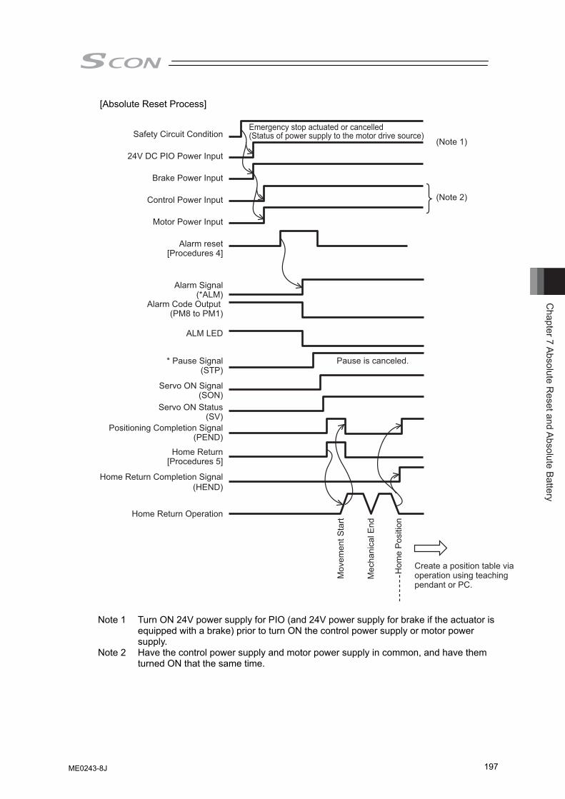
Chapter 7 Absolute R
eset and Absolute Battery
197
[Absolute Reset Process]
Safety Circuit Condition
24V DC PIO Power Input
Brake Power Input
Control Power Input
Motor Power Input
Alarm reset[Procedures 4]
Emergency stop actuated or cancelled (Status of power supply to the motor drive source)
(Note 1)
(Note 2)
Alarm Signal(*ALM)
Alarm Code Output (PM8 to PM1)
ALM LED
* Pause Signal(STP)
Servo ON Signal(SON)
Servo ON Status(SV)
Positioning Completion Signal(PEND)
Home Return[Procedures 5]
Home Return Completion Signal(HEND)
Home Return Operation
Pause is canceled.
Mov
emen
t Sta
rt
Mec
hani
cal E
nd
Hom
e P
ositi
on
Create a position table via operation using teaching pendant or PC.
Note 1 Turn ON 24V power supply for PIO (and 24V power supply for brake if the actuator is
equipped with a brake) prior to turn ON the control power supply or motor power supply.
Note 2 Have the control power supply and motor power supply in common, and have them turned ON that the same time.
ME0243-8J
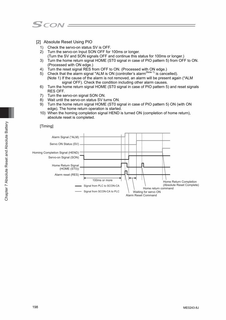
Cha
pter
7 A
bsol
ute
Res
et a
nd A
bsol
ute
Batte
ry
198
[2] Absolute Reset Using PIO 1) Check the servo-on status SV is OFF. 2) Turn the servo-on Input SON OFF for 100ms or longer.
(Turn the SV and SON signals OFF and continue this status for 100ms or longer.) 3) Turn the home return signal HOME (ST0 signal in case of PIO pattern 5) from OFF to ON.
(Processed with ON edge.) 4) Turn the reset signal RES from OFF to ON. (Processed with ON edge.) 5) Check that the alarm signal *ALM is ON (controller’s alarm(Note 1) is cancelled). (Note 1) If the cause of the alarm is not removed, an alarm will be present again (*ALM
signal OFF). Check the condition including other alarm causes. 6) Turn the home return signal HOME (ST0 signal in case of PIO pattern 5) and reset signals
RES OFF. 7) Turn the servo-on signal SON ON. 8) Wait until the servo-on status SV turns ON. 9) Turn the home return signal HOME (ST0 signal in case of PIO pattern 5) ON (with ON
edge). The home return operation is started. 10) When the homing completion signal HEND is turned ON (completion of home return),
absolute reset is completed. [Timing]
Alarm Signal (*ALM)
Servo ON Status (SV)
Homing Completion Signal (HEND)Servo-on Signal (SON)
Home Return Signal(HOME (ST0))
Alarm reset (RES)
100ms or more
Alarm Reset CommandWaiting for servo ON
Home return command
Home Return Completion(Absolute Reset Complete)Signal from PLC to SCON-CA
Signal from SCON-CA to PLC
ME0243-8J
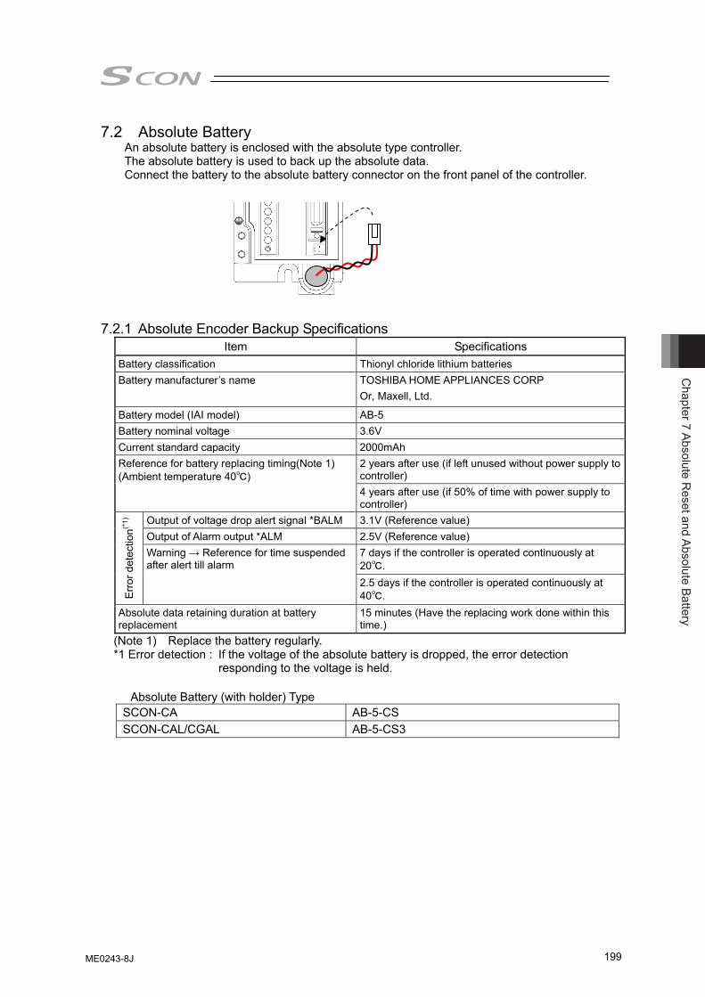
Chapter 7 Absolute R
eset and Absolute Battery
199
7.2 Absolute Battery An absolute battery is enclosed with the absolute type controller. The absolute battery is used to back up the absolute data. Connect the battery to the absolute battery connector on the front panel of the controller.
7.2.1 Absolute Encoder Backup Specifications
Item Specifications Battery classification Thionyl chloride lithium batteries Battery manufacturer’s name TOSHIBA HOME APPLIANCES CORP
Or, Maxell, Ltd.
Battery model (IAI model) AB-5 Battery nominal voltage 3.6V Current standard capacity 2000mAh
2 years after use (if left unused without power supply to controller)
Reference for battery replacing timing(Note 1) (Ambient temperature 40℃)
4 years after use (if 50% of time with power supply to controller)
Output of voltage drop alert signal *BALM 3.1V (Reference value) Output of Alarm output *ALM 2.5V (Reference value)
7 days if the controller is operated continuously at 20℃.
Erro
r det
ectio
n(*1)
Warning → Reference for time suspended after alert till alarm
2.5 days if the controller is operated continuously at 40℃.
Absolute data retaining duration at battery replacement
15 minutes (Have the replacing work done within this time.)
(Note 1) Replace the battery regularly. *1 Error detection : If the voltage of the absolute battery is dropped, the error detection
responding to the voltage is held. Absolute Battery (with holder) Type
SCON-CA AB-5-CS SCON-CAL/CGAL AB-5-CS3
ME0243-8J
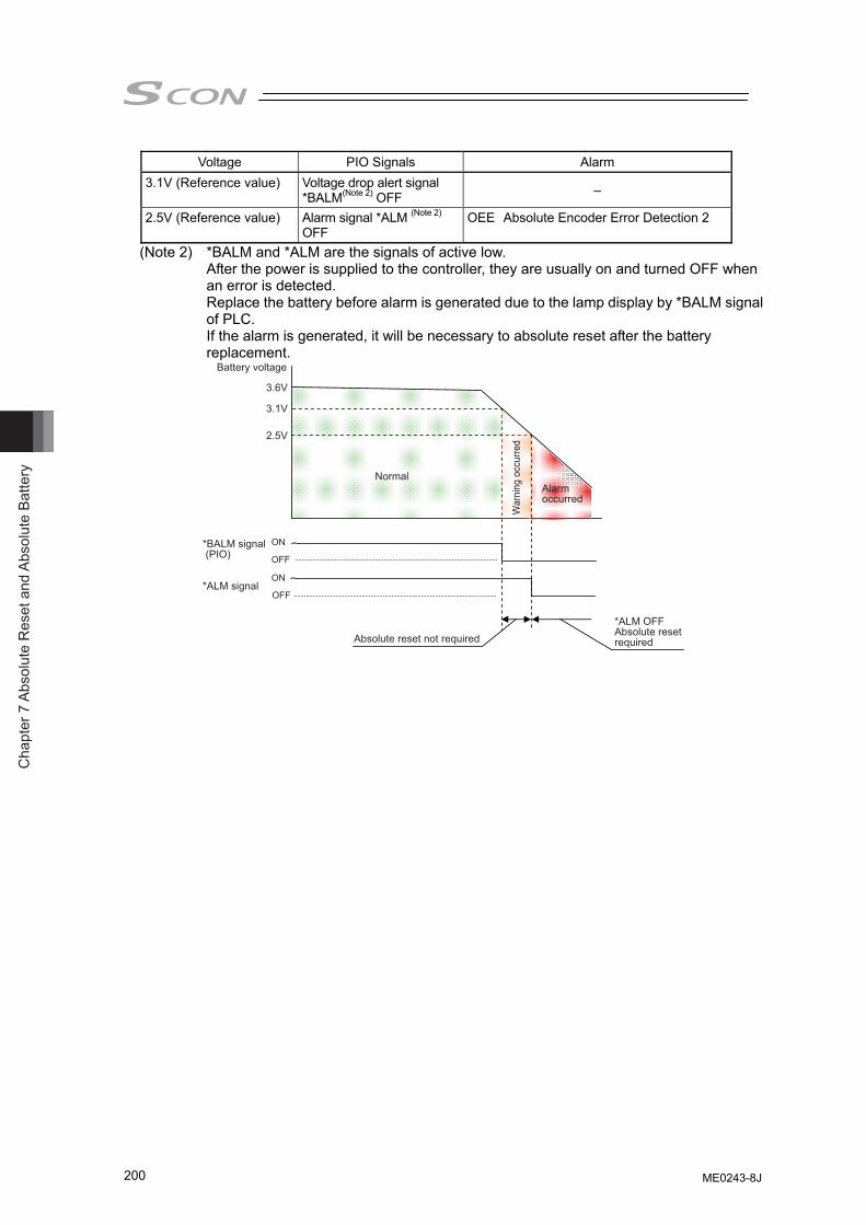
Cha
pter
7 A
bsol
ute
Res
et a
nd A
bsol
ute
Batte
ry
200
Voltage PIO Signals Alarm 3.1V (Reference value) Voltage drop alert signal
*BALM(Note 2) OFF –
2.5V (Reference value) Alarm signal *ALM (Note 2) OFF
OEE Absolute Encoder Error Detection 2
(Note 2) *BALM and *ALM are the signals of active low. After the power is supplied to the controller, they are usually on and turned OFF when an error is detected. Replace the battery before alarm is generated due to the lamp display by *BALM signal of PLC. If the alarm is generated, it will be necessary to absolute reset after the battery replacement.
3.6V
3.1V
2.5V
*ALM OFFAbsolute reset required
ON
OFF
ON
OFF
Battery voltage
*ALM signal
*BALM signal (PIO)
Absolute reset not required
Normal
War
ning
occ
urre
d
Alarm occurred
ME0243-8J
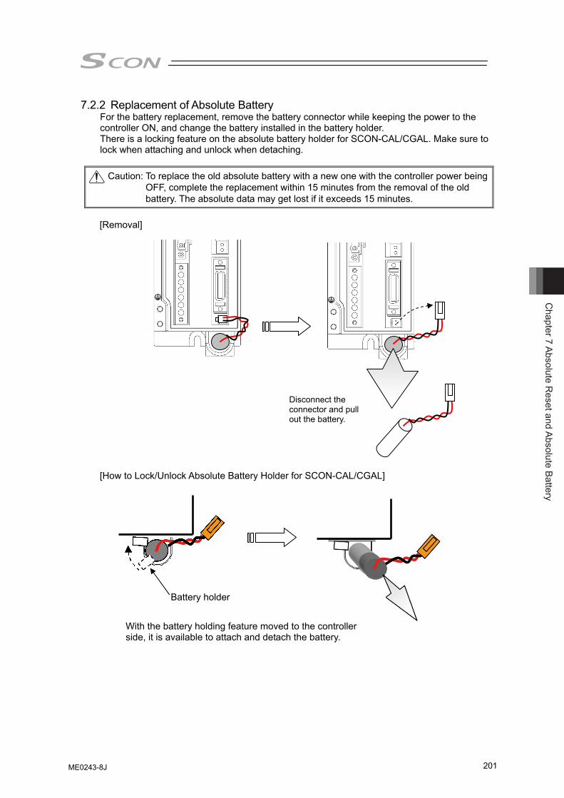
Chapter 7 Absolute R
eset and Absolute Battery
201
7.2.2 Replacement of Absolute Battery For the battery replacement, remove the battery connector while keeping the power to the controller ON, and change the battery installed in the battery holder. There is a locking feature on the absolute battery holder for SCON-CAL/CGAL. Make sure to lock when attaching and unlock when detaching.
Caution: To replace the old absolute battery with a new one with the controller power being
OFF, complete the replacement within 15 minutes from the removal of the old battery. The absolute data may get lost if it exceeds 15 minutes.
[Removal]
[How to Lock/Unlock Absolute Battery Holder for SCON-CAL/CGAL]
Battery holder
Disconnect the connector and pull out the battery.
With the battery holding feature moved to the controller side, it is available to attach and detach the battery.
ME0243-8J
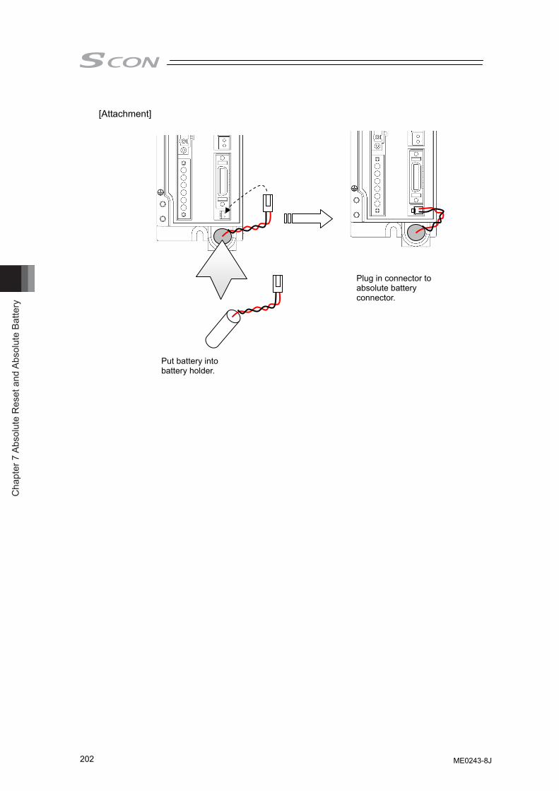
Cha
pter
7 A
bsol
ute
Res
et a
nd A
bsol
ute
Batte
ry
202
[Attachment]
Put battery into battery holder.
Plug in connector to absolute battery connector.
ME0243-8J
Chapter 8 I/O
Parameter
203
Chapter 8 I/O Parameter
Parameters are the data to set up considering the system and application. When a change is required to the parameters, make sure to back up the data before the change so the settings can be returned anytime. With using PC software, it is able to store the backup to the PC. Leave a memo if using the teaching pendant. Also, for the purpose of rapid recovery after the investigation of failure unit or replacing the controller, keep data backup or memo also after the parameter change. The change to the parameters will be activated after they are edited, written to the flash FeRAM, then either software reset or reboot of the power. It will not be active only with writing on the teaching tool. Warning: Parameter setting has great influences on operations of the controller.
Incorrect parameter setting may not only cause malfunction or failure of the controller to occur but also people and assets to be exposed to risk. The controller is configured to be applicable to normal operation at shipment. Before providing certain change or setting for the controller to be fit to your system, understand the control methods of the controller sufficiently. Please contact us if you have anything unclear.
Do not turn OFF the power to the controller during the parameter writing.
ME0243-8J
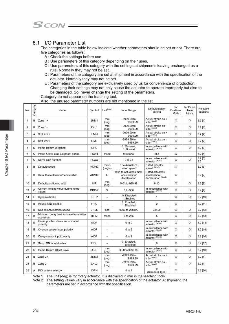
Cha
pter
8 I/
O P
aram
eter
204
8.1 I/O Parameter List The categories in the table below indicate whether parameters should be set or not. There are five categories as follows:
A : Check the settings before use. B : Use parameters of this category depending on their uses. C : Use parameters of this category with the settings at shipments leaving unchanged as a
rule. Normally they may not be set. D : Parameters of the category are set at shipment in accordance with the specification of the
actuator. Normally they may not be set. E : Parameters of the category are exclusively used by us for convenience of production.
Changing their settings may not only cause the actuator to operate improperly but also to be damaged. So, never change the setting of the parameters.
Category do not appear on the teaching tool. Also, the unused parameter numbers are not mentioned in the list.
No.
Cat
egor
y
Name Symbol Unit(Note1) Input Range Default factory setting
for Positioner
Mode
for Pulse Train Mode
Relevant sections
1 B Zone 1+ ZNM1 mm (deg)
-9999.99 to 9999.99
Actual stroke on + side (Note2) 8.2 [1]
2 B Zone 1- ZNL1 mm (deg)
-9999.99 to 9999.99
Actual stroke on - side (Note2) 8.2 [1]
3 A Soft limit+ LIMM mm (deg)
-9999.99 to 9999.99
Actual stroke on + side (Note2) 8.2 [2]
4 A Soft limit+ LIML mm (deg)
-9999.99 to 9999.99
Actual stroke on - side (Note2) 8.2 [2]
5 D Home Return Direction ORG – 0: Reverse, 1: Normal
In accordance with actuator (Note2) 8.2 [3]
6 C Press & hold stop judgment period PSWT msec 0 to 9999 255 8.2 [4]
7 C Servo gain number PLGO – 0 to 31 In accordance with actuator (Note2) 8.2 [5]
8.3
8 B Default speed VCMD mm/s(deg/s)
1 to Actuator’s max. speed
Rated actuator speed (Note2) 8.2 [6]
9 B Default acceleration/deceleration ACMD G 0.01 to actuator's max.
acceleration/ deceleration
Rated actuator's acceleration/ deceleration (Note2)
8.2 [7]
10 B Default positioning width INP mm (deg) 0.01 to 999.99 0.10 8.2 [8]
13 C Current-limiting value during home return ODPW % 1 to 300 In accordance with
actuator (Note2) 8.2 [9]
14 E Dynamic brake FSTP – 0: Disabled, 1: Enabled 1 8.2 [10]
15 B Pause input disable FPIO – 0: Enabled, 1: Disabled 0 8.2 [11]
16 B SIO communication speed BRSL bps 9600 to 230400 38400 8.2 [12]
17 B Minimum delay time for slave transmitter activation RTIM msec 0 to 255 5 8.2 [13]
18 E Home position check sensor input polarity AIOF – 0 to 2 In accordance with
actuator (Note2) 8.2 [14]
19 E Overrun sensor input polarity AIOF – 0 to 2 In accordance with actuator (Note2) 8.2 [15]
20 E Creep sensor input polarity AIOF – 0 to 2 In accordance with actuator (Note2) 8.2 [16]
21 B Servo ON input disable FPIO – 0: Enabled, 1: Disabled 0 8.2 [17]
22 C Home Return Offset Level OFST mm (deg) 0.00 to 9999.99 In accordance with
actuator (Note2) 8.2 [18]
23 B Zone 2+ ZNM2 mm (deg)
-9999.99 to 9999.99
Actual stroke on + side (Note2) 8.2 [1]
24 B Zone 2- ZNL2 mm (deg)
-9999.99 to 9999.99
Actual stroke on - side (Note2) 8.2 [1]
25 A PIO pattern selection IOPN – 0 to 7 0 (Standard Type) 8.2 [20]
Note 1 The unit (deg) is for rotary actuator. It is displayed in mm in the teaching tools. Note 2 The setting values vary in accordance with the specification of the actuator. At shipment, the
parameters are set in accordance with the specification.
ME0243-8J
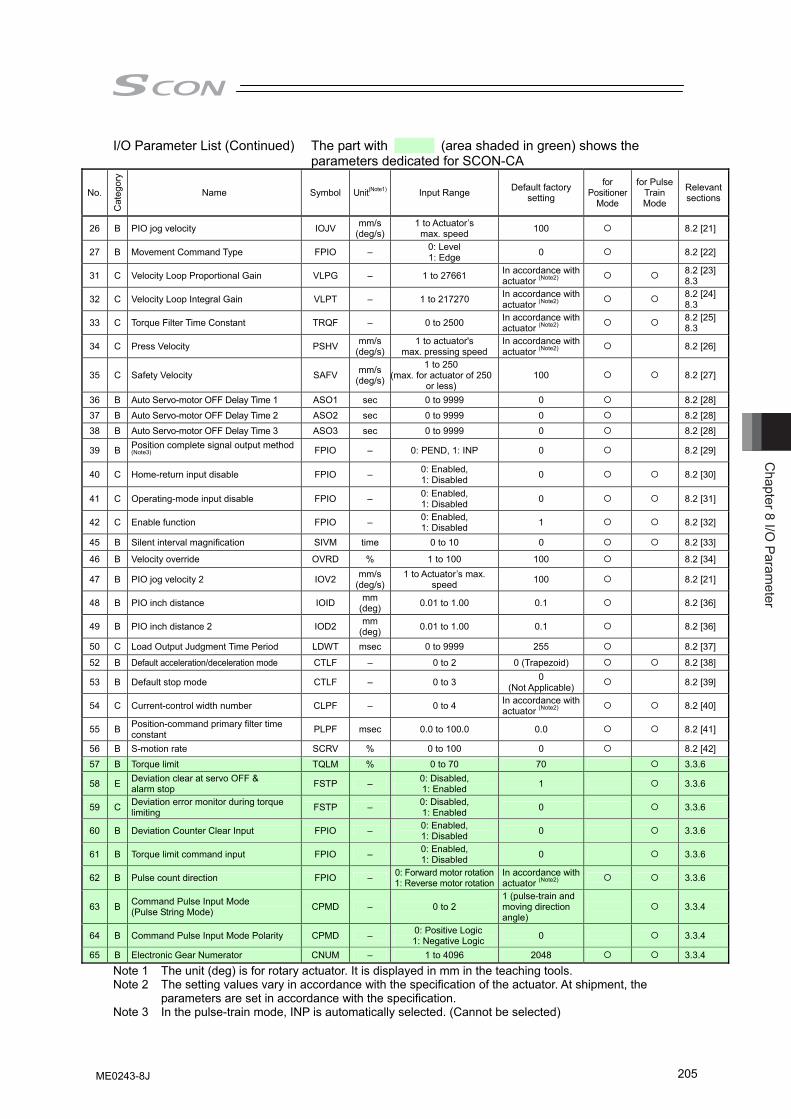
Chapter 8 I/O
Parameter
205
I/O Parameter List (Continued) The part with (area shaded in green) shows the parameters dedicated for SCON-CA
No.
Cat
egor
y
Name Symbol Unit(Note1) Input Range Default factory setting
for Positioner
Mode
for Pulse Train Mode
Relevant sections
26 B PIO jog velocity IOJV mm/s(deg/s)
1 to Actuator’s max. speed 100 8.2 [21]
27 B Movement Command Type FPIO – 0: Level 1: Edge 0 8.2 [22]
31 C Velocity Loop Proportional Gain VLPG – 1 to 27661 In accordance with actuator (Note2) 8.2 [23]
8.3
32 C Velocity Loop Integral Gain VLPT – 1 to 217270 In accordance with actuator (Note2) 8.2 [24]
8.3
33 C Torque Filter Time Constant TRQF – 0 to 2500 In accordance with actuator (Note2) 8.2 [25]
8.3
34 C Press Velocity PSHV mm/s(deg/s)
1 to actuator's max. pressing speed
In accordance with actuator (Note2) 8.2 [26]
35 C Safety Velocity SAFV mm/s(deg/s)
1 to 250 (max. for actuator of 250
or less) 100 8.2 [27]
36 B Auto Servo-motor OFF Delay Time 1 ASO1 sec 0 to 9999 0 8.2 [28] 37 B Auto Servo-motor OFF Delay Time 2 ASO2 sec 0 to 9999 0 8.2 [28] 38 B Auto Servo-motor OFF Delay Time 3 ASO3 sec 0 to 9999 0 8.2 [28]
39 B Position complete signal output method (Note3) FPIO – 0: PEND, 1: INP 0 8.2 [29]
40 C Home-return input disable FPIO – 0: Enabled, 1: Disabled 0 8.2 [30]
41 C Operating-mode input disable FPIO – 0: Enabled, 1: Disabled 0 8.2 [31]
42 C Enable function FPIO – 0: Enabled, 1: Disabled 1 8.2 [32]
45 B Silent interval magnification SIVM time 0 to 10 0 8.2 [33]
46 B Velocity override OVRD % 1 to 100 100 8.2 [34]
47 B PIO jog velocity 2 IOV2 mm/s(deg/s)
1 to Actuator’s max. speed 100 8.2 [21]
48 B PIO inch distance IOID mm (deg) 0.01 to 1.00 0.1 8.2 [36]
49 B PIO inch distance 2 IOD2 mm (deg) 0.01 to 1.00 0.1 8.2 [36]
50 C Load Output Judgment Time Period LDWT msec 0 to 9999 255 8.2 [37]
52 B Default acceleration/deceleration mode CTLF – 0 to 2 0 (Trapezoid) 8.2 [38]
53 B Default stop mode CTLF – 0 to 3 0 (Not Applicable) 8.2 [39]
54 C Current-control width number CLPF – 0 to 4 In accordance with actuator (Note2) 8.2 [40]
55 B Position-command primary filter time constant PLPF msec 0.0 to 100.0 0.0 8.2 [41]
56 B S-motion rate SCRV % 0 to 100 0 8.2 [42] 57 B Torque limit TQLM % 0 to 70 70 3.3.6
58 E Deviation clear at servo OFF & alarm stop FSTP – 0: Disabled,
1: Enabled 1 3.3.6
59 C Deviation error monitor during torque limiting FSTP – 0: Disabled,
1: Enabled 0 3.3.6
60 B Deviation Counter Clear Input FPIO – 0: Enabled, 1: Disabled 0 3.3.6
61 B Torque limit command input FPIO – 0: Enabled, 1: Disabled 0 3.3.6
62 B Pulse count direction FPIO – 0: Forward motor rotation1: Reverse motor rotation
In accordance with actuator (Note2) 3.3.6
63 B Command Pulse Input Mode (Pulse String Mode) CPMD – 0 to 2
1 (pulse-train and moving direction angle)
3.3.4
64 B Command Pulse Input Mode Polarity CPMD – 0: Positive Logic 1: Negative Logic 0 3.3.4
65 B Electronic Gear Numerator CNUM – 1 to 4096 2048 3.3.4
Note 1 The unit (deg) is for rotary actuator. It is displayed in mm in the teaching tools. Note 2 The setting values vary in accordance with the specification of the actuator. At shipment, the
parameters are set in accordance with the specification. Note 3 In the pulse-train mode, INP is automatically selected. (Cannot be selected)
ME0243-8J
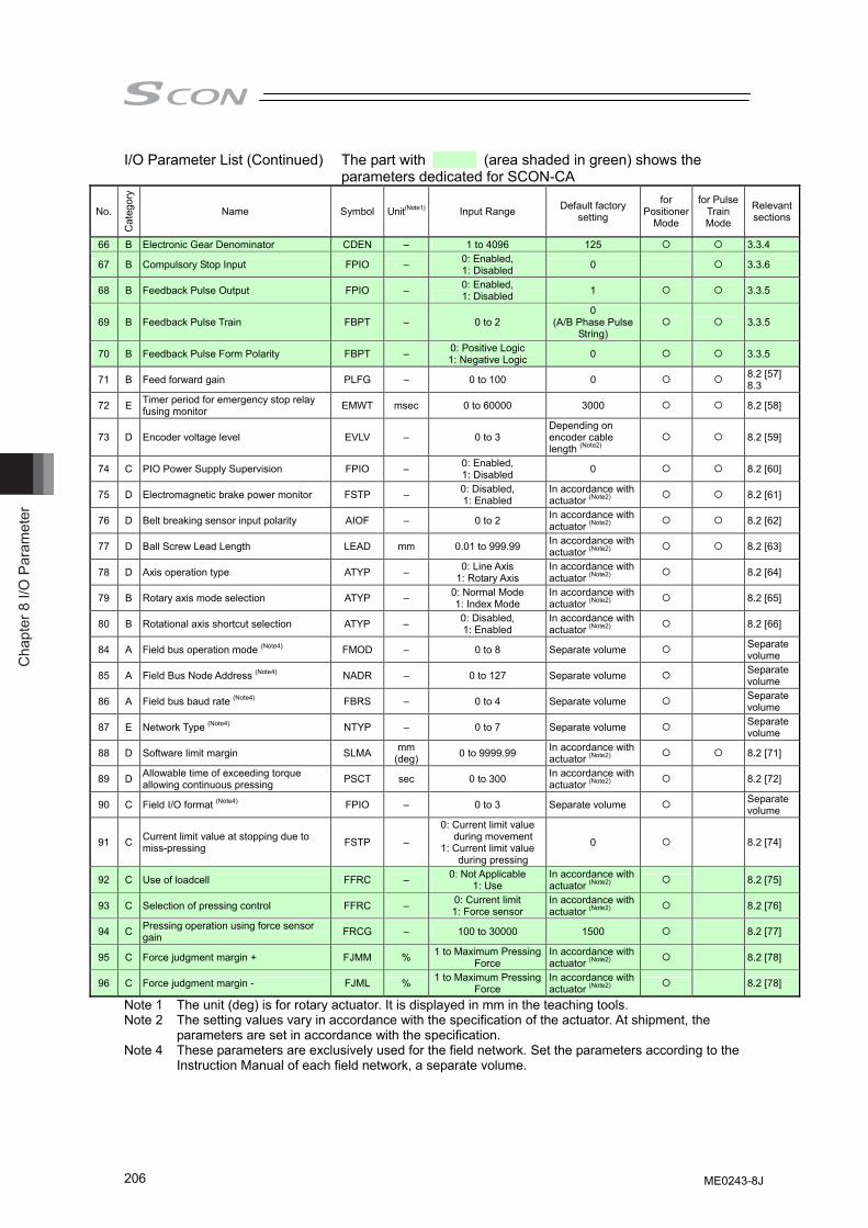
Cha
pter
8 I/
O P
aram
eter
206
I/O Parameter List (Continued) The part with (area shaded in green) shows the parameters dedicated for SCON-CA
No.
Cat
egor
y
Name Symbol Unit(Note1) Input Range Default factory setting
for Positioner
Mode
for Pulse Train Mode
Relevant sections
66 B Electronic Gear Denominator CDEN – 1 to 4096 125 3.3.4
67 B Compulsory Stop Input FPIO – 0: Enabled, 1: Disabled 0 3.3.6
68 B Feedback Pulse Output FPIO – 0: Enabled, 1: Disabled 1 3.3.5
69 B Feedback Pulse Train FBPT – 0 to 2 0
(A/B Phase Pulse String)
3.3.5
70 B Feedback Pulse Form Polarity FBPT – 0: Positive Logic 1: Negative Logic 0 3.3.5
71 B Feed forward gain PLFG – 0 to 100 0 8.2 [57] 8.3
72 E Timer period for emergency stop relay fusing monitor EMWT msec 0 to 60000 3000 8.2 [58]
73 D Encoder voltage level EVLV – 0 to 3 Depending on encoder cable length (Note2)
8.2 [59]
74 C PIO Power Supply Supervision FPIO – 0: Enabled, 1: Disabled 0 8.2 [60]
75 D Electromagnetic brake power monitor FSTP – 0: Disabled, 1: Enabled
In accordance with actuator (Note2) 8.2 [61]
76 D Belt breaking sensor input polarity AIOF – 0 to 2 In accordance with actuator (Note2) 8.2 [62]
77 D Ball Screw Lead Length LEAD mm 0.01 to 999.99 In accordance with actuator (Note2) 8.2 [63]
78 D Axis operation type ATYP – 0: Line Axis 1: Rotary Axis
In accordance with actuator (Note2) 8.2 [64]
79 B Rotary axis mode selection ATYP – 0: Normal Mode 1: Index Mode
In accordance with actuator (Note2) 8.2 [65]
80 B Rotational axis shortcut selection ATYP – 0: Disabled, 1: Enabled
In accordance with actuator (Note2) 8.2 [66]
84 A Field bus operation mode (Note4) FMOD – 0 to 8 Separate volume Separate volume
85 A Field Bus Node Address (Note4) NADR – 0 to 127 Separate volume Separate volume
86 A Field bus baud rate (Note4) FBRS – 0 to 4 Separate volume Separate volume
87 E Network Type (Note4) NTYP – 0 to 7 Separate volume Separate volume
88 D Software limit margin SLMA mm (deg) 0 to 9999.99 In accordance with
actuator (Note2) 8.2 [71]
89 D Allowable time of exceeding torque allowing continuous pressing PSCT sec 0 to 300 In accordance with
actuator (Note2) 8.2 [72]
90 C Field I/O format (Note4) FPIO – 0 to 3 Separate volume Separate volume
91 C Current limit value at stopping due to miss-pressing FSTP –
0: Current limit value during movement
1: Current limit value during pressing
0 8.2 [74]
92 C Use of loadcell FFRC – 0: Not Applicable 1: Use
In accordance with actuator (Note2) 8.2 [75]
93 C Selection of pressing control FFRC – 0: Current limit 1: Force sensor
In accordance with actuator (Note2) 8.2 [76]
94 C Pressing operation using force sensor gain FRCG – 100 to 30000 1500 8.2 [77]
95 C Force judgment margin + FJMM % 1 to Maximum Pressing Force
In accordance with actuator (Note2) 8.2 [78]
96 C Force judgment margin - FJML % 1 to Maximum Pressing Force
In accordance with actuator (Note2) 8.2 [78]
Note 1 The unit (deg) is for rotary actuator. It is displayed in mm in the teaching tools. Note 2 The setting values vary in accordance with the specification of the actuator. At shipment, the
parameters are set in accordance with the specification. Note 4 These parameters are exclusively used for the field network. Set the parameters according to the
Instruction Manual of each field network, a separate volume.
ME0243-8J
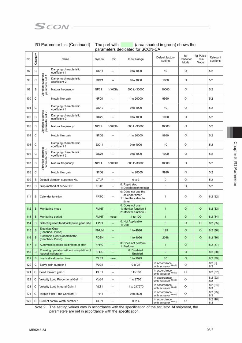
Chapter 8 I/O
Parameter
207
I/O Parameter List (Continued) The part with (area shaded in green) shows the parameters dedicated for SCON-CA
No.
Cat
egor
y
Name Symbol Unit Input Range Default factory setting
for Positioner
Mode
for Pulse Train Mode
Relevant sections
97 C Damping characteristic coefficient 1 DC11 – 0 to 1000 10
5.2
98 C Damping characteristic coefficient 2 DC21 – 0 to 1000 1000
5.2
99 B Natural frequency NP01 1/1000Hz 500 to 30000 10000
5.2
100 C
Vibr
atio
n su
ppre
ss
para
met
er s
et 1
Notch filter gain NFG1 – 1 to 20000 9990 5.2
101 C Damping characteristic coefficient 1 DC12 – 0 to 1000 10 5.2
102 C Damping characteristic coefficient 2 DC22 – 0 to 1000 1000 5.2
103 B Natural frequency NP02 1/1000Hz 500 to 30000 10000 5.2
104 C
Vibr
atio
n su
ppre
ss
para
met
er s
et 2
Notch filter gain NFG2 – 1 to 20000 9990 5.2
105 C Damping characteristic coefficient 1 DC11 – 0 to 1000 10 5.2
106 C Damping characteristic coefficient 2 DC21 – 0 to 1000 1000 5.2
107 B Natural frequency NP01 1/1000Hz 500 to 30000 10000 5.2
108 C
Vibr
atio
n su
ppre
ss
para
met
er s
et 3
Notch filter gain NFG2 – 1 to 20000 9990 5.2
109 B Default vibration suppress No. CTLF – 0 to 3 0 5.2
110 B Stop method at servo OFF FSTP – 0: Rapid stop 1: Deceleration to stop 0 5.2
111 B Calendar function FRTC –
0: Does not use the calendar timer
1: Use the calendar timer
1 8.2 [82]
112 B Monitoring mode FMNT – 0: Does not use 1: Monitor function 1 2: Monitor function 2
1 8.2 [83]
113 B Monitoring period FMNT msec 1 to 100 1 8.2 [84]
114 B Selecting used feedback pulse gear ratio FPIO – 0: Not Applicable 1: Use 0 8.2 [85]
115 B Electrical Gear (Feedback Pulse) FNUM – 1 to 4096 125 8.2 [86]
116 B Electronic Gear Denominator (Feedback Pulse) FDEN – 1 to 4096 2048 8.2 [86]
117 B Automatic loadcell calibration at start FFRC – 0: Does not perform 1: Perform 1 8.2 [87]
118 B Pressing operation without completion of loadcell calibration FFRC – 0: Disabled,
1: Enabled 0 8.2 [88]
119 B Loadcell calibration time CLBT msec 1 to 9999 10 8.2 [89]
120 C Servo gain number 1 PLG1 – 0 to 31 In accordance with actuator (Note2) 8.2 [5]
8.3
121 C Feed forward gain 1 PLF1 – 0 to 100 In accordance with actuator (Note2) 8.2 [57]
122 C Velocity Loop Proportional Gain 1 VLG1 – 1 to 27661 In accordance with actuator (Note2) 8.2 [23]
8.3
123 C Velocity Loop Integral Gain 1 VLT1 – 1 to 217270 In accordance with actuator (Note2) 8.2 [24]
8.3
124 C Torque Filter Time Constant 1 TRF1 – 0 to 2500 In accordance with actuator (Note2) 8.2 [25]
8.3
125 C Current control width number 1 CLP1 – 0 to 4 In accordance with actuator (Note2) 8.2 [40]
8.3 Note 2: The setting values vary in accordance with the specification of the actuator. At shipment, the
parameters are set in accordance with the specification.
ME0243-8J
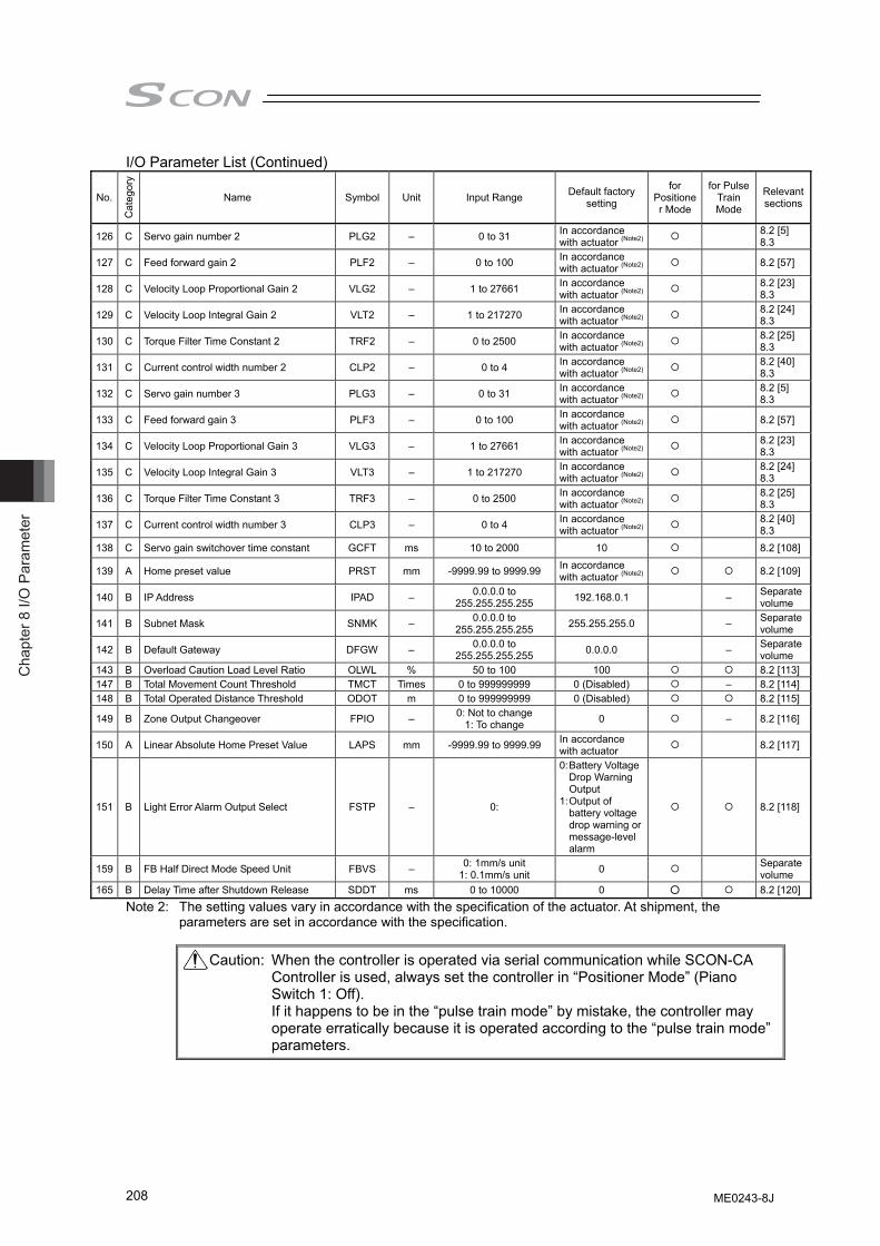
Cha
pter
8 I/
O P
aram
eter
208
I/O Parameter List (Continued)
No.
Cat
egor
y
Name Symbol Unit Input Range Default factory setting
for Positioner Mode
for Pulse Train Mode
Relevant sections
126 C Servo gain number 2 PLG2 – 0 to 31 In accordance with actuator (Note2) 8.2 [5]
8.3
127 C Feed forward gain 2 PLF2 – 0 to 100 In accordance with actuator (Note2) 8.2 [57]
128 C Velocity Loop Proportional Gain 2 VLG2 – 1 to 27661 In accordance with actuator (Note2) 8.2 [23]
8.3
129 C Velocity Loop Integral Gain 2 VLT2 – 1 to 217270 In accordance with actuator (Note2) 8.2 [24]
8.3
130 C Torque Filter Time Constant 2 TRF2 – 0 to 2500 In accordance with actuator (Note2) 8.2 [25]
8.3
131 C Current control width number 2 CLP2 – 0 to 4 In accordance with actuator (Note2) 8.2 [40]
8.3
132 C Servo gain number 3 PLG3 – 0 to 31 In accordance with actuator (Note2) 8.2 [5]
8.3
133 C Feed forward gain 3 PLF3 – 0 to 100 In accordance with actuator (Note2) 8.2 [57]
134 C Velocity Loop Proportional Gain 3 VLG3 – 1 to 27661 In accordance with actuator (Note2) 8.2 [23]
8.3
135 C Velocity Loop Integral Gain 3 VLT3 – 1 to 217270 In accordance with actuator (Note2) 8.2 [24]
8.3
136 C Torque Filter Time Constant 3 TRF3 – 0 to 2500 In accordance with actuator (Note2) 8.2 [25]
8.3
137 C Current control width number 3 CLP3 – 0 to 4 In accordance with actuator (Note2) 8.2 [40]
8.3 138 C Servo gain switchover time constant GCFT ms 10 to 2000 10 8.2 [108]
139 A Home preset value PRST mm -9999.99 to 9999.99 In accordance with actuator (Note2) 8.2 [109]
140 B IP Address IPAD – 0.0.0.0 to 255.255.255.255 192.168.0.1 – Separate
volume
141 B Subnet Mask SNMK – 0.0.0.0 to 255.255.255.255 255.255.255.0 – Separate
volume
142 B Default Gateway DFGW – 0.0.0.0 to 255.255.255.255 0.0.0.0 – Separate
volume 143 B Overload Caution Load Level Ratio OLWL % 50 to 100 100 8.2 [113]147 B Total Movement Count Threshold TMCT Times 0 to 999999999 0 (Disabled) – 8.2 [114]148 B Total Operated Distance Threshold ODOT m 0 to 999999999 0 (Disabled) 8.2 [115]
149 B Zone Output Changeover FPIO – 0: Not to change 1: To change 0 – 8.2 [116]
150 A Linear Absolute Home Preset Value LAPS mm -9999.99 to 9999.99 In accordance with actuator 8.2 [117]
151 B Light Error Alarm Output Select FSTP – 0:
0: Battery Voltage Drop Warning Output
1: Output of battery voltage drop warning or message-level alarm
8.2 [118]
159 B FB Half Direct Mode Speed Unit FBVS – 0: 1mm/s unit 1: 0.1mm/s unit 0 Separate
volume 165 B Delay Time after Shutdown Release SDDT ms 0 to 10000 0 ○ 8.2 [120]
Note 2: The setting values vary in accordance with the specification of the actuator. At shipment, the parameters are set in accordance with the specification.
Caution: When the controller is operated via serial communication while SCON-CA Controller is used, always set the controller in “Positioner Mode” (Piano Switch 1: Off). If it happens to be in the “pulse train mode” by mistake, the controller may operate erratically because it is operated according to the “pulse train mode” parameters.
ME0243-8J
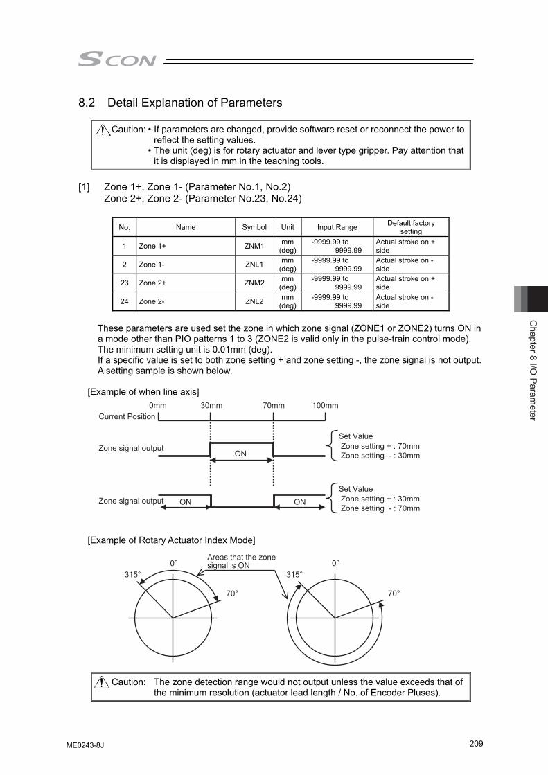
Chapter 8 I/O
Parameter
209
8.2 Detail Explanation of Parameters
Caution: • If parameters are changed, provide software reset or reconnect the power to reflect the setting values.
• The unit (deg) is for rotary actuator and lever type gripper. Pay attention that it is displayed in mm in the teaching tools.
[1] Zone 1+, Zone 1- (Parameter No.1, No.2)
Zone 2+, Zone 2- (Parameter No.23, No.24)
No. Name Symbol Unit Input Range Default factory setting
1 Zone 1+ ZNM1 mm(deg)
-9999.99 to 9999.99
Actual stroke on + side
2 Zone 1- ZNL1 mm(deg)
-9999.99 to 9999.99
Actual stroke on - side
23 Zone 2+ ZNM2 mm(deg)
-9999.99 to 9999.99
Actual stroke on + side
24 Zone 2- ZNL2 mm(deg)
-9999.99 to 9999.99
Actual stroke on - side
These parameters are used set the zone in which zone signal (ZONE1 or ZONE2) turns ON in a mode other than PIO patterns 1 to 3 (ZONE2 is valid only in the pulse-train control mode). The minimum setting unit is 0.01mm (deg). If a specific value is set to both zone setting + and zone setting -, the zone signal is not output. A setting sample is shown below.
[Example of when line axis] [Example of Rotary Actuator Index Mode]
Caution: The zone detection range would not output unless the value exceeds that of the minimum resolution (actuator lead length / No. of Encoder Pluses).
Areas that the zone signal is ON0°
315°
70°
0°315°
70°
0mm 30mm 70mm
ON
ON ON
100mmCurrent Position
Zone signal output
Zone signal output
Set ValueZone setting + : 70mmZone setting - : 30mm
Set ValueZone setting + : 30mmZone setting - : 70mm
ME0243-8J
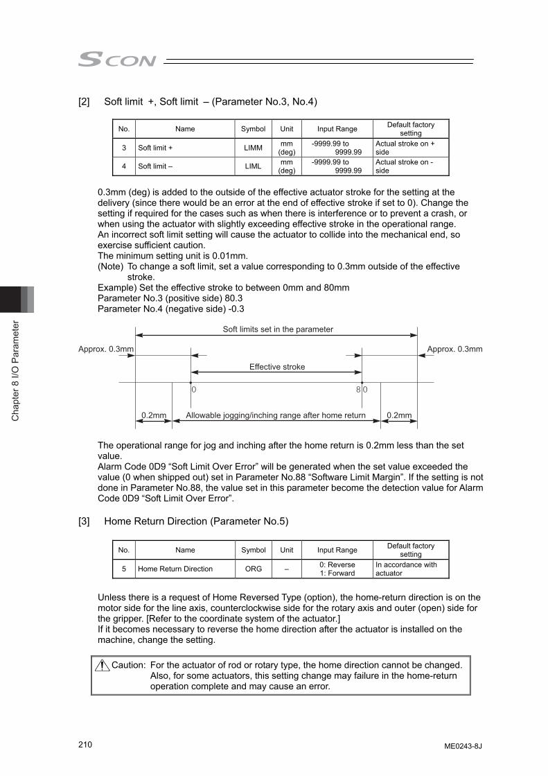
Cha
pter
8 I/
O P
aram
eter
210
[2] Soft limit +, Soft limit – (Parameter No.3, No.4)
No. Name Symbol Unit Input Range Default factory setting
3 Soft limit + LIMM mm (deg)
-9999.99 to 9999.99
Actual stroke on + side
4 Soft limit – LIML mm (deg)
-9999.99 to 9999.99
Actual stroke on - side
0.3mm (deg) is added to the outside of the effective actuator stroke for the setting at the delivery (since there would be an error at the end of effective stroke if set to 0). Change the setting if required for the cases such as when there is interference or to prevent a crash, or when using the actuator with slightly exceeding effective stroke in the operational range. An incorrect soft limit setting will cause the actuator to collide into the mechanical end, so exercise sufficient caution. The minimum setting unit is 0.01mm. (Note) To change a soft limit, set a value corresponding to 0.3mm outside of the effective
stroke. Example) Set the effective stroke to between 0mm and 80mm Parameter No.3 (positive side) 80.3 Parameter No.4 (negative side) -0.3
Approx. 0.3mm Approx. 0.3mm
Soft limits set in the parameter
Effective stroke
Allowable jogging/inching range after home return 0.2mm0.2mm
The operational range for jog and inching after the home return is 0.2mm less than the set value. Alarm Code 0D9 “Soft Limit Over Error” will be generated when the set value exceeded the value (0 when shipped out) set in Parameter No.88 “Software Limit Margin”. If the setting is not done in Parameter No.88, the value set in this parameter become the detection value for Alarm Code 0D9 “Soft Limit Over Error”.
[3] Home Return Direction (Parameter No.5)
No. Name Symbol Unit Input Range Default factory setting
5 Home Return Direction ORG – 0: Reverse 1: Forward
In accordance with actuator
Unless there is a request of Home Reversed Type (option), the home-return direction is on the motor side for the line axis, counterclockwise side for the rotary axis and outer (open) side for the gripper. [Refer to the coordinate system of the actuator.] If it becomes necessary to reverse the home direction after the actuator is installed on the machine, change the setting.
Caution: For the actuator of rod or rotary type, the home direction cannot be changed.Also, for some actuators, this setting change may failure in the home-return operation complete and may cause an error.
ME0243-8J
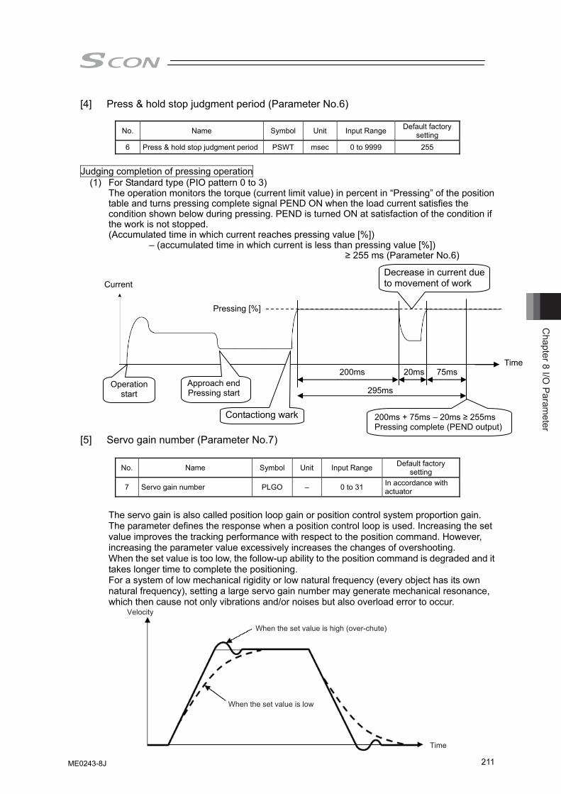
Chapter 8 I/O
Parameter
211
[4] Press & hold stop judgment period (Parameter No.6)
No. Name Symbol Unit Input Range Default factory setting
6 Press & hold stop judgment period PSWT msec 0 to 9999 255
Judging completion of pressing operation
(1) For Standard type (PIO pattern 0 to 3) The operation monitors the torque (current limit value) in percent in “Pressing” of the position
table and turns pressing complete signal PEND ON when the load current satisfies the condition shown below during pressing. PEND is turned ON at satisfaction of the condition if the work is not stopped.
(Accumulated time in which current reaches pressing value [%]) – (accumulated time in which current is less than pressing value [%])
≥ 255 ms (Parameter No.6)
[5] Servo gain number (Parameter No.7)
No. Name Symbol Unit Input Range Default factory setting
7 Servo gain number PLGO – 0 to 31 In accordance with actuator
The servo gain is also called position loop gain or position control system proportion gain. The parameter defines the response when a position control loop is used. Increasing the set value improves the tracking performance with respect to the position command. However, increasing the parameter value excessively increases the changes of overshooting. When the set value is too low, the follow-up ability to the position command is degraded and it takes longer time to complete the positioning. For a system of low mechanical rigidity or low natural frequency (every object has its own natural frequency), setting a large servo gain number may generate mechanical resonance, which then cause not only vibrations and/or noises but also overload error to occur.
Current
Time
Pressing [%]
Operation start
Approach endPressing start
200ms 20ms 75ms
295ms
200ms + 75ms – 20ms ≥ 255ms Pressing complete (PEND output)
Contactiong wark
Decrease in current due to movement of work
When the set value is high (over-chute)
When the set value is low
Velocity
Time
ME0243-8J
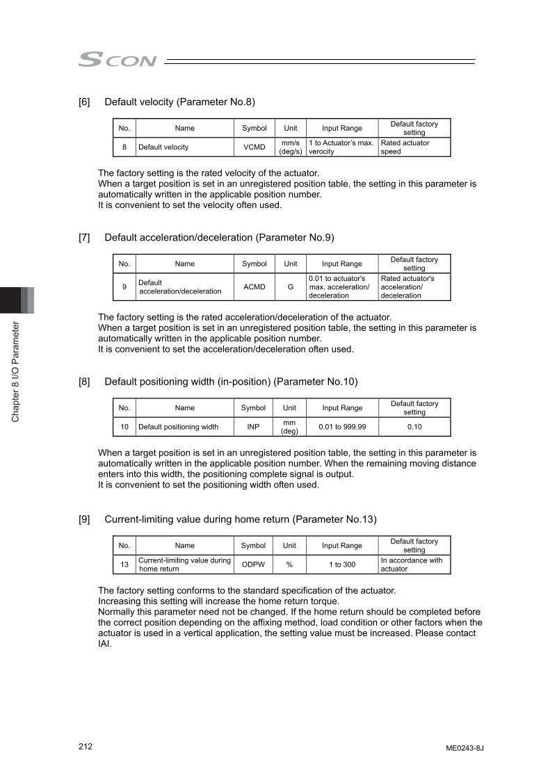
Cha
pter
8 I/
O P
aram
eter
212
[6] Default velocity (Parameter No.8)
No. Name Symbol Unit Input Range Default factory setting
8 Default velocity VCMD mm/s(deg/s)
1 to Actuator’s max. verocity
Rated actuator speed
The factory setting is the rated velocity of the actuator. When a target position is set in an unregistered position table, the setting in this parameter is automatically written in the applicable position number. It is convenient to set the velocity often used.
[7] Default acceleration/deceleration (Parameter No.9)
No. Name Symbol Unit Input Range Default factory
setting
9 Default acceleration/deceleration ACMD G
0.01 to actuator's max. acceleration/ deceleration
Rated actuator's acceleration/ deceleration
The factory setting is the rated acceleration/deceleration of the actuator. When a target position is set in an unregistered position table, the setting in this parameter is automatically written in the applicable position number. It is convenient to set the acceleration/deceleration often used.
[8] Default positioning width (in-position) (Parameter No.10)
No. Name Symbol Unit Input Range Default factory
setting
10 Default positioning width INP mm (deg) 0.01 to 999.99 0.10
When a target position is set in an unregistered position table, the setting in this parameter is automatically written in the applicable position number. When the remaining moving distance enters into this width, the positioning complete signal is output. It is convenient to set the positioning width often used.
[9] Current-limiting value during home return (Parameter No.13)
No. Name Symbol Unit Input Range Default factory
setting
13 Current-limiting value during home return ODPW % 1 to 300 In accordance with
actuator The factory setting conforms to the standard specification of the actuator. Increasing this setting will increase the home return torque. Normally this parameter need not be changed. If the home return should be completed before the correct position depending on the affixing method, load condition or other factors when the actuator is used in a vertical application, the setting value must be increased. Please contact IAI.
ME0243-8J
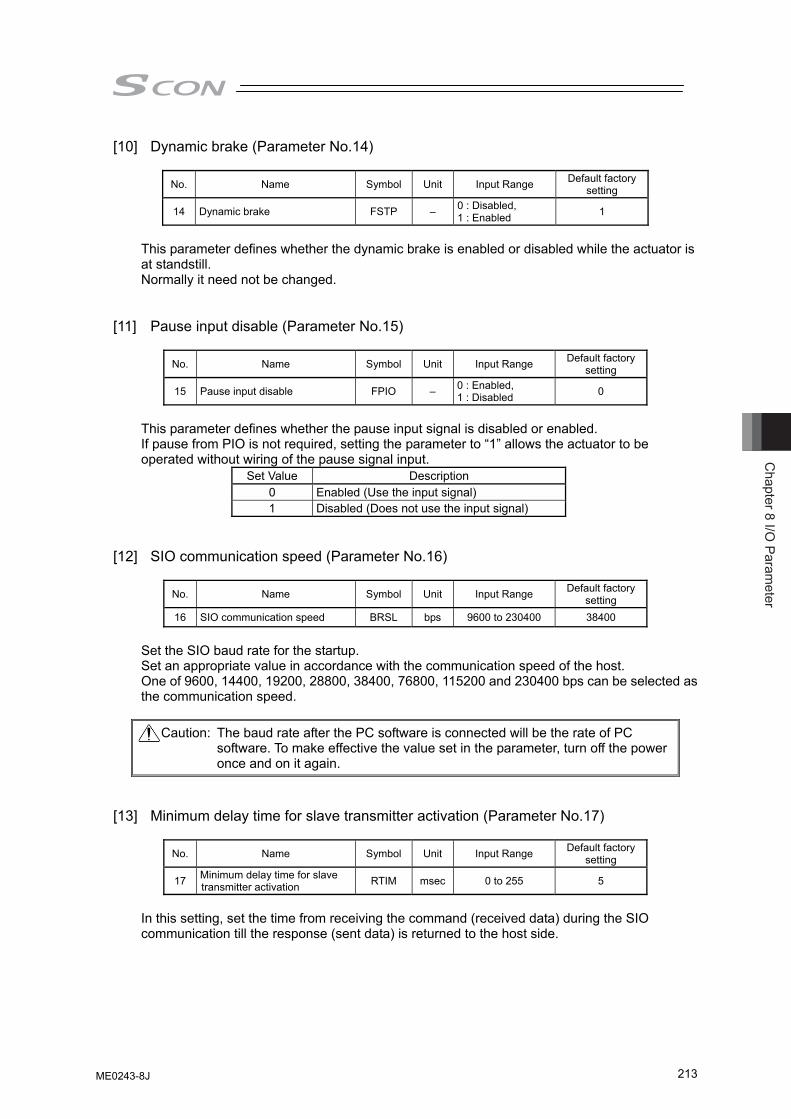
Chapter 8 I/O
Parameter
213
[10] Dynamic brake (Parameter No.14)
No. Name Symbol Unit Input Range Default factory setting
14 Dynamic brake FSTP – 0 : Disabled, 1 : Enabled 1
This parameter defines whether the dynamic brake is enabled or disabled while the actuator is at standstill. Normally it need not be changed.
[11] Pause input disable (Parameter No.15)
No. Name Symbol Unit Input Range Default factory setting
15 Pause input disable FPIO – 0 : Enabled, 1 : Disabled 0
This parameter defines whether the pause input signal is disabled or enabled. If pause from PIO is not required, setting the parameter to “1” allows the actuator to be operated without wiring of the pause signal input.
Set Value Description 0 Enabled (Use the input signal) 1 Disabled (Does not use the input signal)
[12] SIO communication speed (Parameter No.16)
No. Name Symbol Unit Input Range Default factory setting
16 SIO communication speed BRSL bps 9600 to 230400 38400
Set the SIO baud rate for the startup. Set an appropriate value in accordance with the communication speed of the host. One of 9600, 14400, 19200, 28800, 38400, 76800, 115200 and 230400 bps can be selected as the communication speed.
Caution: The baud rate after the PC software is connected will be the rate of PC software. To make effective the value set in the parameter, turn off the power once and on it again.
[13] Minimum delay time for slave transmitter activation (Parameter No.17)
No. Name Symbol Unit Input Range Default factory
setting
17 Minimum delay time for slave transmitter activation RTIM msec 0 to 255 5
In this setting, set the time from receiving the command (received data) during the SIO communication till the response (sent data) is returned to the host side.
ME0243-8J
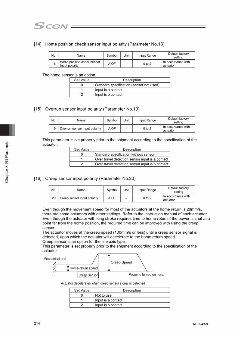
Cha
pter
8 I/
O P
aram
eter
214
[14] Home position check sensor input polarity (Parameter No.18)
No. Name Symbol Unit Input Range Default factory setting
18 Home position check sensor input polarity AIOF – 0 to 2 In accordance with
actuator The home sensor is an option.
Set Value Description 0 Standard specification (sensor not used) 1 Input is a contact 2 Input is b contact
[15] Overrun sensor input polarity (Parameter No.19)
No. Name Symbol Unit Input Range Default factory
setting
19 Overrun sensor input polarity AIOF – 0 to 2 In accordance with actuator
This parameter is set properly prior to the shipment according to the specification of the actuator.
Set Value Description 0 Standard specification without sensor 1 Over travel detection sensor input is a contact2 Over travel detection sensor input is b contact
[16] Creep sensor input polarity (Parameter No.20)
No. Name Symbol Unit Input Range Default factory
setting
20 Creep sensor input polarity AIOF – 0 to 2 In accordance with actuator
Even though the movement speed for most of the actuators at the home return is 20mm/s, there are some actuators with other settings. Refer to the instruction manual of each actuator. Even though the actuator with long stroke requires time to home-return if the power is shut at a point far from the home position, the required time can be improved with using the creep sensor. The actuator moves at the creep speed (100mm/s or less) until a creep sensor signal is detected, upon which the actuator will decelerate to the home return speed. Creep sensor is an option for the line axis type. This parameter is set properly prior to the shipment according to the specification of the actuator.
Set Value Description 0 Not to use 1 Input is a contact 2 Input is b contact
Home-return speed
Creep Sensor
Creep Speed
Power is turned on here.
Mechanical end
Actuator decelerates when creep sensor signal is detected
ME0243-8J
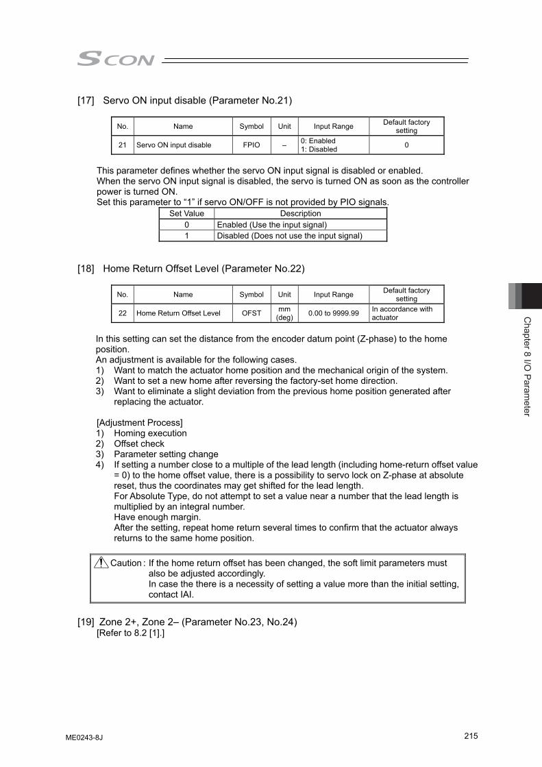
Chapter 8 I/O
Parameter
215
[17] Servo ON input disable (Parameter No.21)
No. Name Symbol Unit Input Range Default factory setting
21 Servo ON input disable FPIO – 0: Enabled 1: Disabled 0
This parameter defines whether the servo ON input signal is disabled or enabled. When the servo ON input signal is disabled, the servo is turned ON as soon as the controller power is turned ON. Set this parameter to “1” if servo ON/OFF is not provided by PIO signals.
Set Value Description 0 Enabled (Use the input signal) 1 Disabled (Does not use the input signal)
[18] Home Return Offset Level (Parameter No.22)
No. Name Symbol Unit Input Range Default factory
setting
22 Home Return Offset Level OFST mm(deg) 0.00 to 9999.99 In accordance with
actuator In this setting can set the distance from the encoder datum point (Z-phase) to the home position. An adjustment is available for the following cases. 1) Want to match the actuator home position and the mechanical origin of the system. 2) Want to set a new home after reversing the factory-set home direction. 3) Want to eliminate a slight deviation from the previous home position generated after
replacing the actuator. [Adjustment Process] 1) Homing execution 2) Offset check 3) Parameter setting change 4) If setting a number close to a multiple of the lead length (including home-return offset value
= 0) to the home offset value, there is a possibility to servo lock on Z-phase at absolute reset, thus the coordinates may get shifted for the lead length. For Absolute Type, do not attempt to set a value near a number that the lead length is multiplied by an integral number. Have enough margin. After the setting, repeat home return several times to confirm that the actuator always returns to the same home position.
Caution : If the home return offset has been changed, the soft limit parameters must
also be adjusted accordingly. In case the there is a necessity of setting a value more than the initial setting,
contact IAI.
[19] Zone 2+, Zone 2– (Parameter No.23, No.24)
[Refer to 8.2 [1].]
ME0243-8J
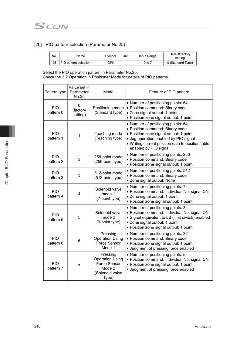
Cha
pter
8 I/
O P
aram
eter
216
[20] PIO pattern selection (Parameter No.25)
No. Name Symbol Unit Input Range Default factory setting
25 PIO pattern selection IOPN – 0 to 7 0 (Standard Type) Select the PIO operation pattern in Parameter No.25. Check the 3.2 Operation in Positioner Mode for details of PIO patterns.
Pattern type Value set in Parameter
No.25 Mode Feature of PIO pattern
PIO pattern 0
0 (factory setting)
Positioning mode (Standard type)
• Number of positioning points: 64 • Position command: Binary code • Zone signal output: 1 point • Position zone signal output: 1 point
PIO pattern 1 1 Teaching mode
(Teaching type)
• Number of positioning points: 64 • Position command: Binary code • Position zone signal output: 1 point • Jog operation enabled by PIO signal • Writing current position data to position table
enabled by PIO signal
PIO pattern 2 2 256-point mode
(256-point type)
• Number of positioning points: 256 • Position command: Binary code • Position zone signal output: 1 point
PIO pattern 3 3 512-point mode
(512-point type)
• Number of positioning points: 512 • Position command: Binary code • Zone signal output: None
PIO pattern 4 4
Solenoid valve mode 1
(7-point type)
• Number of positioning points: 7 • Position command: Individual No. signal ON • Zone signal output: 1 point • Position zone signal output: 1 point
PIO pattern 5 5
Solenoid valve mode 2
(3-point type)
• Number of positioning points: 3 • Position command: Individual No. signal ON • Signal equivalent to LS (limit switch) enabled• Zone signal output: 1 point • Position zone signal output: 1 point
PIO pattern 6 6
Pressing Operation Using
Force Sensor Mode 1
• Number of positioning points: 32 • Position command: Binary code • Position zone signal output: 1 point • Judgment of pressing force enabled
PIO pattern 7 7
Pressing Operation Using
Force Sensor Mode 2
(Solenoid valve Type)
• Number of positioning points: 5 • Position command: Individual No. signal ON • Position zone signal output: 1 point • Judgment of pressing force enabled
ME0243-8J
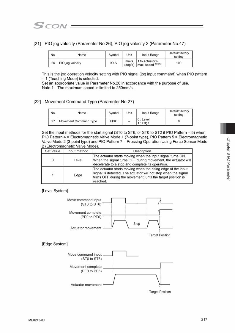
Chapter 8 I/O
Parameter
217
[21] PIO jog velocity (Parameter No.26), PIO jog velocity 2 (Parameter No.47)
No. Name Symbol Unit Input Range Default factory setting
26 PIO jog velocity IOJV mm/s(deg/s)
1 to Actuator’s max. speed (Note1) 100
This is the jog operation velocity setting with PIO signal (jog input command) when PIO pattern = 1 (Teaching Mode) is selected. Set an appropriate value in Parameter No.26 in accordance with the purpose of use. Note 1 The maximum speed is limited to 250mm/s.
[22] Movement Command Type (Parameter No.27)
No. Name Symbol Unit Input Range Default factory
setting
27 Movement Command Type FPIO – 0 : Level 1 : Edge 0
Set the input methods for the start signal (ST0 to ST6, or ST0 to ST2 if PIO Pattern = 5) when PIO Pattern 4 = Electromagnetic Valve Mode 1 (7-point type), PIO Pattern 5 = Electromagnetic Valve Mode 2 (3-point type) and PIO Pattern 7 = Pressing Operation Using Force Sensor Mode 2 (Electromagnetic Valve Mode).
Set Value Input method Description
0 Level The actuator starts moving when the input signal turns ON. When the signal turns OFF during movement, the actuator will decelerate to a stop and complete its operation.
1 Edge
The actuator starts moving when the rising edge of the input signal is detected. The actuator will not stop when the signal turns OFF during the movement, until the target position is reached.
[Level System]
Move command input
(ST0 to ST6)
Movement complete (PE0 to PE6)
Actuator movement Stop
Target Position
[Edge System]
Move command input(ST0 to ST6)
Movement complete(PE0 to PE6)
Actuator movement
Target Position
ME0243-8J
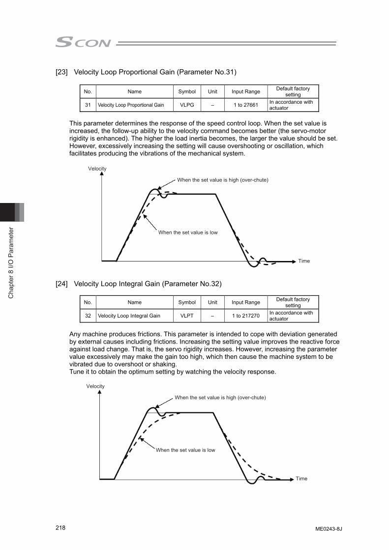
Cha
pter
8 I/
O P
aram
eter
218
[23] Velocity Loop Proportional Gain (Parameter No.31)
No. Name Symbol Unit Input Range Default factory setting
31 Velocity Loop Proportional Gain VLPG – 1 to 27661 In accordance with actuator
This parameter determines the response of the speed control loop. When the set value is increased, the follow-up ability to the velocity command becomes better (the servo-motor rigidity is enhanced). The higher the load inertia becomes, the larger the value should be set. However, excessively increasing the setting will cause overshooting or oscillation, which facilitates producing the vibrations of the mechanical system.
When the set value is high (over-chute)
When the set value is low
Velocity
Time
[24] Velocity Loop Integral Gain (Parameter No.32)
No. Name Symbol Unit Input Range Default factory setting
32 Velocity Loop Integral Gain VLPT – 1 to 217270 In accordance with actuator
Any machine produces frictions. This parameter is intended to cope with deviation generated by external causes including frictions. Increasing the setting value improves the reactive force against load change. That is, the servo rigidity increases. However, increasing the parameter value excessively may make the gain too high, which then cause the machine system to be vibrated due to overshoot or shaking. Tune it to obtain the optimum setting by watching the velocity response.
When the set value is high (over-chute)
When the set value is low
Velocity
Time
ME0243-8J
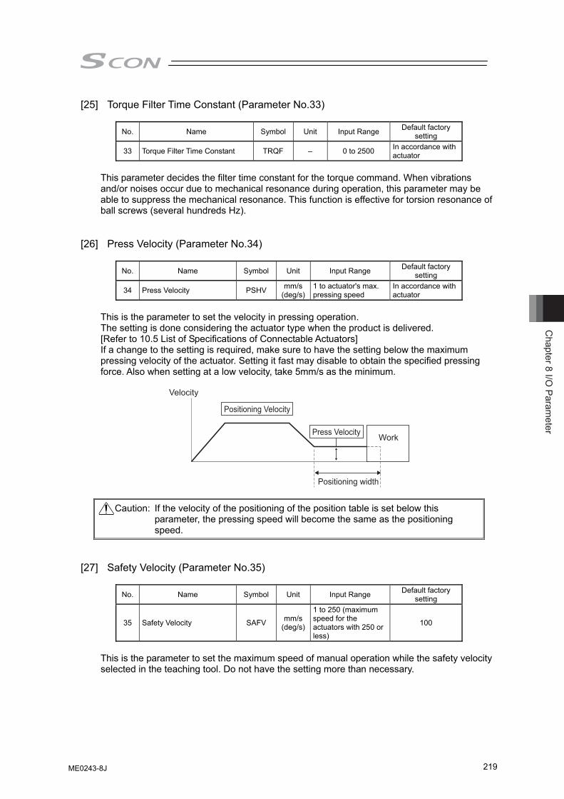
Chapter 8 I/O
Parameter
219
[25] Torque Filter Time Constant (Parameter No.33)
No. Name Symbol Unit Input Range Default factory setting
33 Torque Filter Time Constant TRQF – 0 to 2500 In accordance with actuator
This parameter decides the filter time constant for the torque command. When vibrations and/or noises occur due to mechanical resonance during operation, this parameter may be able to suppress the mechanical resonance. This function is effective for torsion resonance of ball screws (several hundreds Hz).
[26] Press Velocity (Parameter No.34)
No. Name Symbol Unit Input Range Default factory
setting
34 Press Velocity PSHV mm/s(deg/s)
1 to actuator's max. pressing speed
In accordance with actuator
This is the parameter to set the velocity in pressing operation. The setting is done considering the actuator type when the product is delivered. [Refer to 10.5 List of Specifications of Connectable Actuators] If a change to the setting is required, make sure to have the setting below the maximum pressing velocity of the actuator. Setting it fast may disable to obtain the specified pressing force. Also when setting at a low velocity, take 5mm/s as the minimum.
Velocity
Press Velocity
Positioning width
Work
Positioning Velocity
Caution: If the velocity of the positioning of the position table is set below this parameter, the pressing speed will become the same as the positioning speed.
[27] Safety Velocity (Parameter No.35)
No. Name Symbol Unit Input Range Default factory
setting
35 Safety Velocity SAFV mm/s(deg/s)
1 to 250 (maximum speed for the actuators with 250 or less)
100
This is the parameter to set the maximum speed of manual operation while the safety velocity selected in the teaching tool. Do not have the setting more than necessary.
ME0243-8J
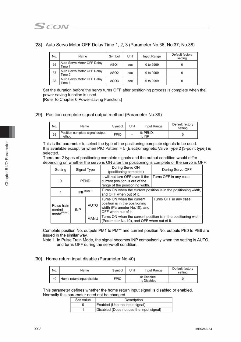
Cha
pter
8 I/
O P
aram
eter
220
[28] Auto Servo Motor OFF Delay Time 1, 2, 3 (Parameter No.36, No.37, No.38)
No. Name Symbol Unit Input Range Default factory setting
36 Auto Servo Motor OFF Delay Time 1 ASO1 sec 0 to 9999 0
37 Auto Servo Motor OFF Delay Time 2 ASO2 sec 0 to 9999 0
38 Auto Servo Motor OFF Delay Time 3 ASO3 sec 0 to 9999 0
Set the duration before the servo turns OFF after positioning process is complete when the power saving function is used. [Refer to Chapter 6 Power-saving Function.]
[29] Position complete signal output method (Parameter No.39)
No. Name Symbol Unit Input Range Default factory
setting
39 Position complete signal output method FPIO – 0: PEND,
1: INP 0
This is the parameter to select the type of the positioning complete signals to be used. It is available except for when PIO Pattern = 5 (Electromagnetic Valve Type 2 [3-point type]) is selected. There are 2 types of positioning complete signals and the output condition would differ depending on whether the servo is ON after the positioning is complete or the servo is OFF.
Setting Signal Type During Servo ON (positioning complete) During Servo OFF
0 PEND It will not turn OFF even if the current position is out of the range of the positioning width.
Turns OFF in any case
1 INP(Note1) Turns ON when the current position is in the positioning width, and OFF when out of it.
AUTO
Turns ON when the current position is in the positioning width (Parameter No.10), and OFF when out of it.
Turns OFF in any case
Pulse train control mode(Note1)
INP
MANU Turns ON when the current position is in the positioning width (Parameter No.10), and OFF when out of it.
Complete position No. outputs PM1 to PM** and current position No. outputs PE0 to PE6 are issued in the similar way. Note 1 In Pulse Train Mode, the signal becomes INP compulsorily when the setting is AUTO,
and turns OFF during the servo-off condition. [30] Home return input disable (Parameter No.40)
No. Name Symbol Unit Input Range Default factory
setting
40 Home return input disable FPIO – 0: Enabled 1: Disabled 0
This parameter defines whether the home return input signal is disabled or enabled. Normally this parameter need not be changed.
Set Value Description 0 Enabled (Use the input signal) 1 Disabled (Does not use the input signal)
ME0243-8J
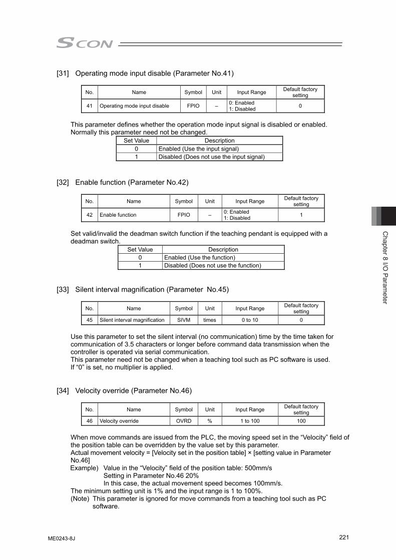
Chapter 8 I/O
Parameter
221
[31] Operating mode input disable (Parameter No.41)
No. Name Symbol Unit Input Range Default factory setting
41 Operating mode input disable FPIO – 0: Enabled 1: Disabled 0
This parameter defines whether the operation mode input signal is disabled or enabled. Normally this parameter need not be changed.
Set Value Description 0 Enabled (Use the input signal) 1 Disabled (Does not use the input signal)
[32] Enable function (Parameter No.42)
No. Name Symbol Unit Input Range Default factory
setting
42 Enable function FPIO – 0: Enabled 1: Disabled 1
Set valid/invalid the deadman switch function if the teaching pendant is equipped with a deadman switch.
Set Value Description 0 Enabled (Use the function) 1 Disabled (Does not use the function)
[33] Silent interval magnification (Parameter No.45)
No. Name Symbol Unit Input Range Default factory
setting 45 Silent interval magnification SIVM times 0 to 10 0
Use this parameter to set the silent interval (no communication) time by the time taken for communication of 3.5 characters or longer before command data transmission when the controller is operated via serial communication. This parameter need not be changed when a teaching tool such as PC software is used. If “0” is set, no multiplier is applied.
[34] Velocity override (Parameter No.46)
No. Name Symbol Unit Input Range Default factory
setting 46 Velocity override OVRD % 1 to 100 100
When move commands are issued from the PLC, the moving speed set in the “Velocity” field of the position table can be overridden by the value set by this parameter. Actual movement velocity = [Velocity set in the position table] × [setting value in Parameter No.46] Example) Value in the “Velocity” field of the position table: 500mm/s Setting in Parameter No.46 20% In this case, the actual movement speed becomes 100mm/s. The minimum setting unit is 1% and the input range is 1 to 100%. (Note) This parameter is ignored for move commands from a teaching tool such as PC
software.
ME0243-8J
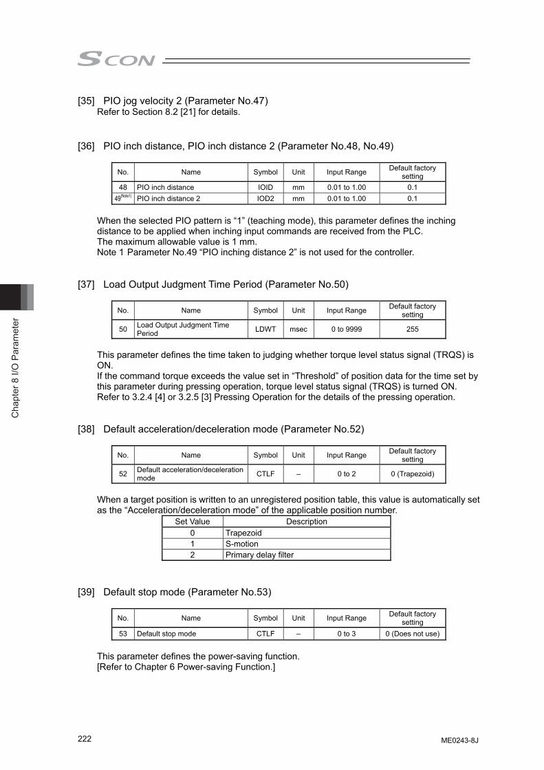
Cha
pter
8 I/
O P
aram
eter
222
[35] PIO jog velocity 2 (Parameter No.47) Refer to Section 8.2 [21] for details.
[36] PIO inch distance, PIO inch distance 2 (Parameter No.48, No.49)
No. Name Symbol Unit Input Range Default factory
setting 48 PIO inch distance IOID mm 0.01 to 1.00 0.1
49(Note1) PIO inch distance 2 IOD2 mm 0.01 to 1.00 0.1
When the selected PIO pattern is “1” (teaching mode), this parameter defines the inching distance to be applied when inching input commands are received from the PLC. The maximum allowable value is 1 mm. Note 1 Parameter No.49 “PIO inching distance 2” is not used for the controller.
[37] Load Output Judgment Time Period (Parameter No.50)
No. Name Symbol Unit Input Range Default factory
setting
50 Load Output Judgment Time Period LDWT msec 0 to 9999 255
This parameter defines the time taken to judging whether torque level status signal (TRQS) is ON. If the command torque exceeds the value set in “Threshold” of position data for the time set by this parameter during pressing operation, torque level status signal (TRQS) is turned ON. Refer to 3.2.4 [4] or 3.2.5 [3] Pressing Operation for the details of the pressing operation.
[38] Default acceleration/deceleration mode (Parameter No.52)
No. Name Symbol Unit Input Range Default factory
setting
52 Default acceleration/deceleration mode CTLF – 0 to 2 0 (Trapezoid)
When a target position is written to an unregistered position table, this value is automatically set as the “Acceleration/deceleration mode” of the applicable position number.
Set Value Description 0 Trapezoid 1 S-motion 2 Primary delay filter
[39] Default stop mode (Parameter No.53)
No. Name Symbol Unit Input Range Default factory
setting 53 Default stop mode CTLF – 0 to 3 0 (Does not use)
This parameter defines the power-saving function. [Refer to Chapter 6 Power-saving Function.]
ME0243-8J
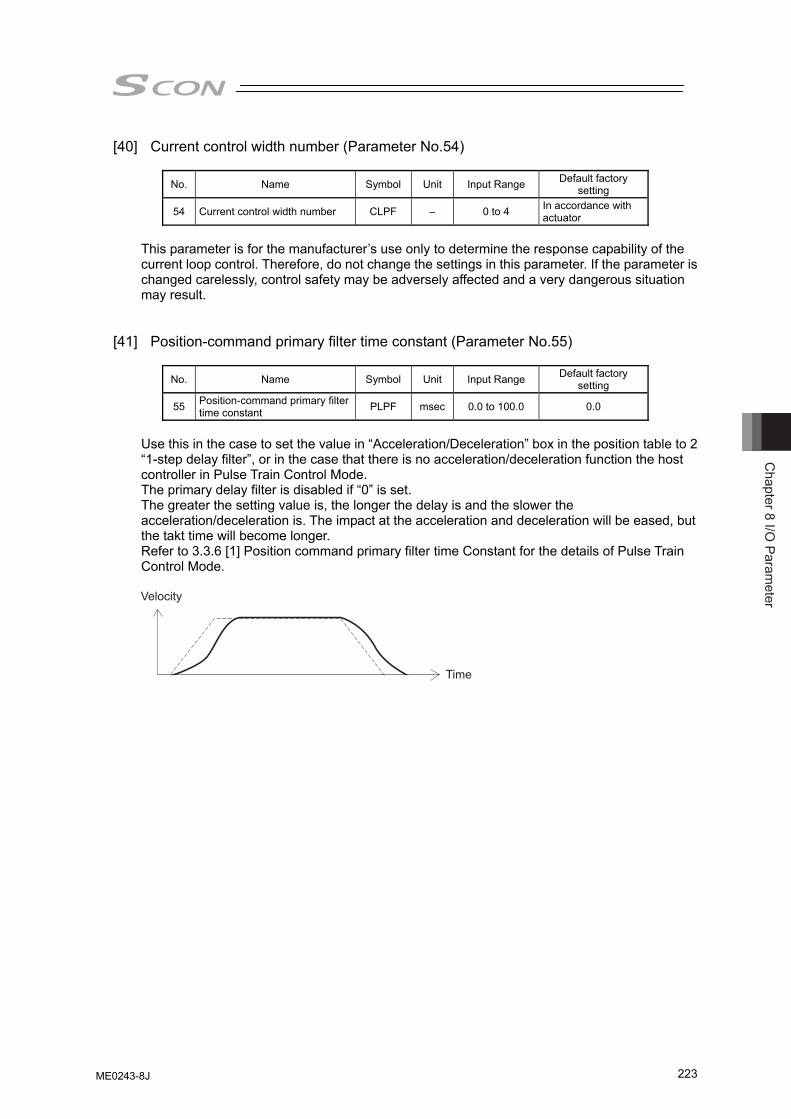
Chapter 8 I/O
Parameter
223
[40] Current control width number (Parameter No.54)
No. Name Symbol Unit Input Range Default factory setting
54 Current control width number CLPF – 0 to 4 In accordance with actuator
This parameter is for the manufacturer’s use only to determine the response capability of the current loop control. Therefore, do not change the settings in this parameter. If the parameter is changed carelessly, control safety may be adversely affected and a very dangerous situation may result.
[41] Position-command primary filter time constant (Parameter No.55)
No. Name Symbol Unit Input Range Default factory
setting
55 Position-command primary filter time constant PLPF msec 0.0 to 100.0 0.0
Use this in the case to set the value in “Acceleration/Deceleration” box in the position table to 2 “1-step delay filter”, or in the case that there is no acceleration/deceleration function the host controller in Pulse Train Control Mode. The primary delay filter is disabled if “0” is set. The greater the setting value is, the longer the delay is and the slower the acceleration/deceleration is. The impact at the acceleration and deceleration will be eased, but the takt time will become longer. Refer to 3.3.6 [1] Position command primary filter time Constant for the details of Pulse Train Control Mode.
Velocity
Time
ME0243-8J
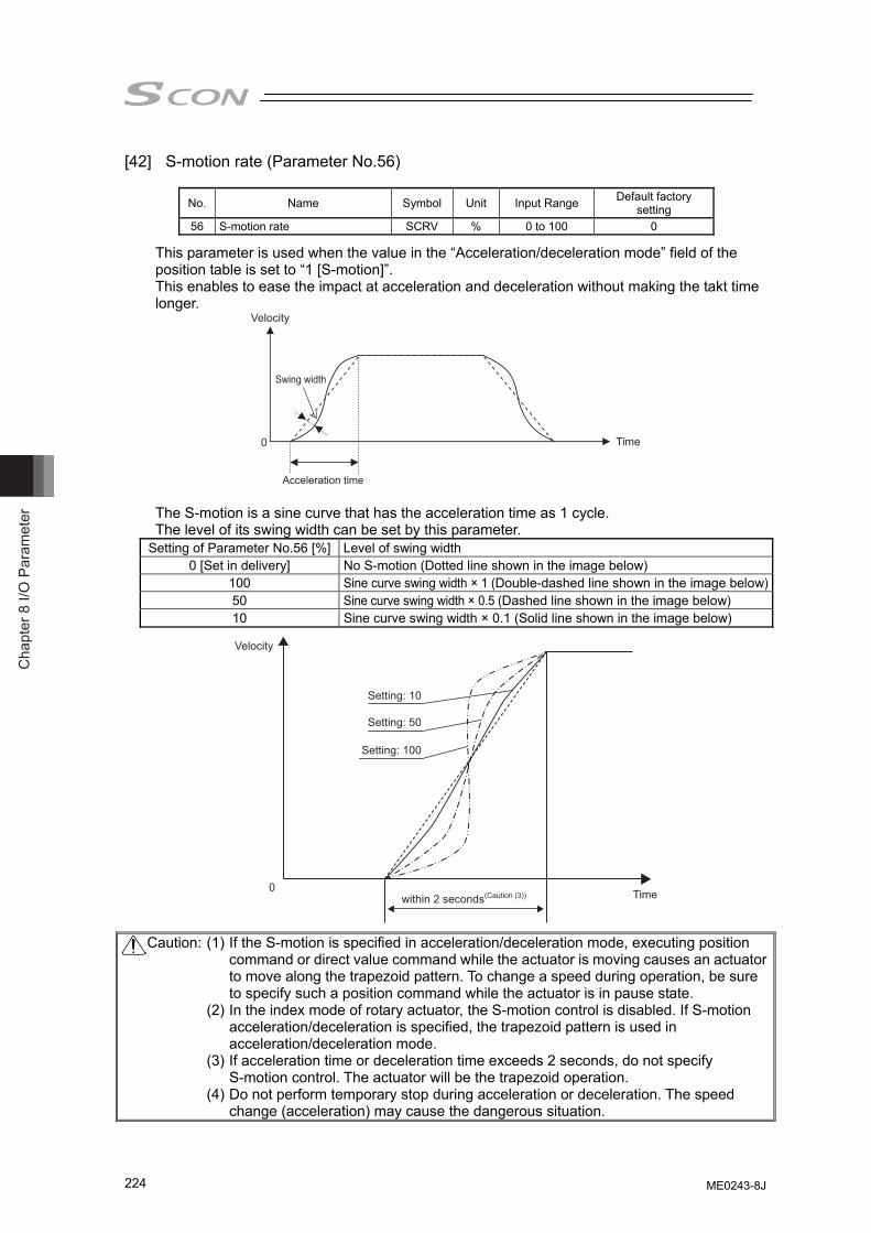
Cha
pter
8 I/
O P
aram
eter
224
[42] S-motion rate (Parameter No.56)
No. Name Symbol Unit Input Range Default factory setting
56 S-motion rate SCRV % 0 to 100 0
This parameter is used when the value in the “Acceleration/deceleration mode” field of the position table is set to “1 [S-motion]”. This enables to ease the impact at acceleration and deceleration without making the takt time longer.
Velocity
Time0
Swing width
Acceleration time
The S-motion is a sine curve that has the acceleration time as 1 cycle. The level of its swing width can be set by this parameter.
Setting of Parameter No.56 [%] Level of swing width 0 [Set in delivery] No S-motion (Dotted line shown in the image below)
100 Sine curve swing width × 1 (Double-dashed line shown in the image below)50 Sine curve swing width × 0.5 (Dashed line shown in the image below) 10 Sine curve swing width × 0.1 (Solid line shown in the image below)
Velocity
Time
Setting: 10
Setting: 50
Setting: 100
0within 2 seconds(Caution (3))
Caution: (1) If the S-motion is specified in acceleration/deceleration mode, executing position command or direct value command while the actuator is moving causes an actuator to move along the trapezoid pattern. To change a speed during operation, be sure to specify such a position command while the actuator is in pause state.
(2) In the index mode of rotary actuator, the S-motion control is disabled. If S-motion acceleration/deceleration is specified, the trapezoid pattern is used in acceleration/deceleration mode.
(3) If acceleration time or deceleration time exceeds 2 seconds, do not specify S-motion control. The actuator will be the trapezoid operation.
(4) Do not perform temporary stop during acceleration or deceleration. The speed change (acceleration) may cause the dangerous situation.
ME0243-8J
Chapter 8 I/O
Parameter
225
[43] Torque limit (Parameter No.57) dedicated for SCON-CA This parameter is exclusively used for the pulse-train control mode. [Refer to 3.3.6 Parameter Settings Required for Advanced Operations.]
[44] Deviation clear at servo OFF & alarm stop (Parameter No.58) dedicated for
SCON-CA This parameter is exclusively used for the pulse-train control mode. [Refer to 3.3.6 Parameter Settings Required for Advanced Operations.]
[45] Deviation error monitor during torque limiting (Parameter No.59) dedicated for
SCON-CA This parameter is exclusively used for the pulse-train control mode. [Refer to 3.3.6 Parameter Settings Required for Advanced Operations.]
[46] Deviation Counter Clear Input (Parameter No.60) dedicated for SCON-CA
This parameter is exclusively used for the pulse-train control mode. [Refer to 3.3.6 Parameter Settings Required for Advanced Operations.]
[47] Torque limit command input (Parameter No.61) dedicated for SCON-CA
This parameter is exclusively used for the pulse-train control mode. [Refer to 3.3.6 Parameter Settings Required for Advanced Operations.]
[48] Pulse count direction (Parameter No.62) dedicated for SCON-CA
This parameter is exclusively used for the pulse-train control mode. [Refer to 3.3.6 Parameter Settings Required for Advanced Operations.]
[49] Command Pulse Input Mode (Parameter No.63) dedicated for SCON-CA
This parameter is exclusively used for the pulse-train control mode. [Refer to 3.3.4 Settings of Basic Parameters Required for Operation.]
[50] Command Pulse Input Mode Polarity (Parameter No.64) dedicated for SCON-CA
This parameter is exclusively used for the pulse-train control mode. [Refer to 3.3.4 Settings of Basic Parameters Required for Operation.]
[51] Electronic Gear Numerator (Parameter No.65) dedicated for SCON-CA
This parameter is exclusively used for the pulse-train control mode. [Refer to 3.3.4 Settings of Basic Parameters Required for Operation.]
[52] Electronic Gear Denominator (Parameter No.66) dedicated for SCON-CA
This parameter is exclusively used for the pulse-train control mode. [Refer to 3.3.4 Settings of Basic Parameters Required for Operation.]
[53] Compulsory Stop Input (Parameter No.67) dedicated for SCON-CA
This parameter is exclusively used for the pulse-train control mode. [Refer to 3.3.6 Parameter Settings Required for Advanced Operations.]
[54] Feedback Pulse Output (Parameter No.68) dedicated for SCON-CA
ME0243-8J
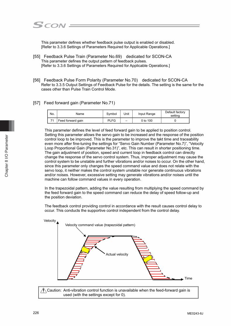
Cha
pter
8 I/
O P
aram
eter
226
This parameter defines whether feedback pulse output is enabled or disabled. [Refer to 3.3.6 Settings of Parameters Required for Applicable Operations.]
[55] Feedback Pulse Train (Parameter No.69) dedicated for SCON-CA
This parameter defines the output pattern of feedback pulses. [Refer to 3.3.6 Settings of Parameters Required for Applicable Operations.]
[56] Feedback Pulse Form Polarity (Parameter No.70) dedicated for SCON-CA
Refer to 3.3.5 Output Settings of Feedback Pulse for the details. The setting is the same for the cases other than Pulse Train Control Mode.
[57] Feed forward gain (Parameter No.71)
No. Name Symbol Unit Input Range Default factory
setting 71 Feed forward gain PLFG – 0 to 100 0
This parameter defines the level of feed forward gain to be applied to position control. Setting this parameter allows the servo gain to be increased and the response of the position control loop to be improved. This is the parameter to improve the takt time and traceability even more after fine-tuning the settings for “Servo Gain Number (Parameter No.7)”, “Velocity Loop Proportional Gain (Parameter No.31)”, etc. This can result in shorter positioning time. The gain adjustment of position, speed and current loop in feedback control can directly change the response of the servo control system. Thus, improper adjustment may cause the control system to be unstable and further vibrations and/or noises to occur. On the other hand, since this parameter only changes the speed command value and does not relate with the servo loop, it neither makes the control system unstable nor generate continuous vibrations and/or noises. However, excessive setting may generate vibrations and/or noises until the machine can follow command values in every operation.
In the trapezoidal pattern, adding the value resulting from multiplying the speed command by the feed forward gain to the speed command can reduce the delay of speed follow-up and the position deviation.
The feedback control providing control in accordance with the result causes control delay to occur. This conducts the supportive control independent from the control delay.
Caution: Anti-vibration control function is unavailable when the feed-forward gain is
used (with the settings except for 0).
Actual velocity
Velocity command value (trapezoidal pattern) Velocity
Time
ME0243-8J
Chapter 8 I/O
Parameter
227
[58] Timer period for emergency stop relay fusing monitor (Parameter No.72)
No. Name Symbol Unit Input Range Default factory setting
72 Timer period for emergency stop relay fusing monitor EMWT msec 0 to 60000 3000
This parameter defines the timer period in which fusing of the emergency stop relay for cutting off the motor drive power is detected. If the motor AC power is not cut off after elapse of the timer period set by this parameter following the cutoff of the driver power, the control will recognize that the relay has been fused and generate an alarm. Normally this parameter need not be changed. When a value between 0 and 9 is set, no fusing is detected.
[59] Encoder voltage level (Parameter No.73)
No. Name Symbol Unit Input Range Default factory
setting
73 Encoder voltage level EVLV – 0 to 3 Depending on encoder cable length
To stabilize encoder detection signals, this parameter defines the voltage supplied to the encoder circuit to one of four levels in accordance with the encoder type and the length of the encoder relay cable. Normally this parameter need not be changed. If you have changed the length of the encoder relay cable after the shipment, the value of the parameter may be changed. If you wish to change this parameter, always consult us in advance. If the setting is not optimum, it may cause an operation error of the actuator or malfunction of the encoder.
[60] PIO Power Supply Supervision (Parameter No.74)
No. Name Symbol Unit Input Range Default factory
setting
74 PIO Power Supply Supervision(Note1) FPIO – 0: Enabled 1: Disabled 0
A power monitor function is provided to prevent incorrect operations, burning of the I/O board and/or breakdown of parts caused by an abnormal voltage of the 24V DC for PIO power supply. This parameter can be disabled in certain situations such as when the controller is operated by a teaching tool without connection of PIO during trail operation for adjustments. Do not forget put it back to “0” (Valid) before starting the system operation after the test run for the adjustment is finished.
Set Value Description 0 Enabled 1 Disabled
Note 1 The power monitoring will not be conducted no matter the settings for the Fieldbus
types (CC-Link/DeviceNet, etc.).
ME0243-8J
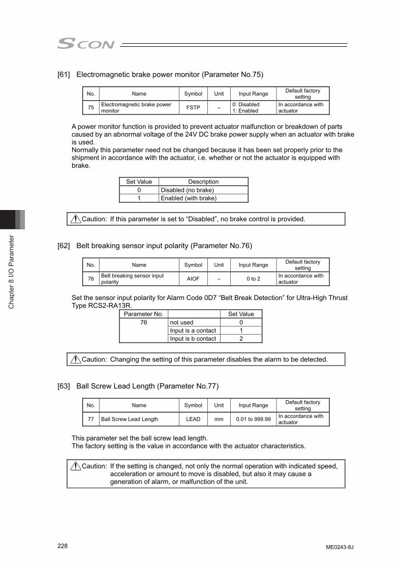
Cha
pter
8 I/
O P
aram
eter
228
[61] Electromagnetic brake power monitor (Parameter No.75)
No. Name Symbol Unit Input Range Default factory setting
75 Electromagnetic brake power monitor FSTP – 0: Disabled
1: Enabled In accordance with actuator
A power monitor function is provided to prevent actuator malfunction or breakdown of parts caused by an abnormal voltage of the 24V DC brake power supply when an actuator with brake is used. Normally this parameter need not be changed because it has been set properly prior to the shipment in accordance with the actuator, i.e. whether or not the actuator is equipped with brake.
Set Value Description 0 Disabled (no brake) 1 Enabled (with brake)
[62] Belt breaking sensor input polarity (Parameter No.76)
No. Name Symbol Unit Input Range Default factory setting
76 Belt breaking sensor input polarity AIOF – 0 to 2 In accordance with
actuator Set the sensor input polarity for Alarm Code 0D7 “Belt Break Detection” for Ultra-High Thrust Type RCS2-RA13R.
Parameter No. Set Value not used 0 Input is a contact 1
76
Input is b contact 2
[63] Ball Screw Lead Length (Parameter No.77)
No. Name Symbol Unit Input Range Default factory
setting
77 Ball Screw Lead Length LEAD mm 0.01 to 999.99 In accordance with actuator
This parameter set the ball screw lead length. The factory setting is the value in accordance with the actuator characteristics.
Caution: If this parameter is set to “Disabled”, no brake control is provided.
Caution: Changing the setting of this parameter disables the alarm to be detected.
Caution: If the setting is changed, not only the normal operation with indicated speed, acceleration or amount to move is disabled, but also it may cause a generation of alarm, or malfunction of the unit.
ME0243-8J
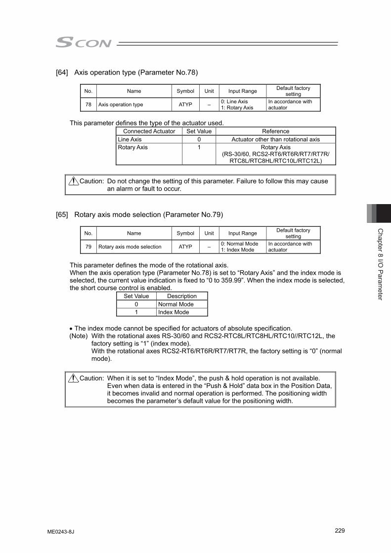
Chapter 8 I/O
Parameter
229
[64] Axis operation type (Parameter No.78)
No. Name Symbol Unit Input Range Default factory setting
78 Axis operation type ATYP – 0: Line Axis 1: Rotary Axis
In accordance with actuator
This parameter defines the type of the actuator used.
Connected Actuator Set Value Reference Line Axis 0 Actuator other than rotational axis Rotary Axis 1 Rotary Axis
(RS-30/60, RCS2-RT6/RT6R/RT7/RT7R/ RTC8L/RTC8HL/RTC10L/RTC12L)
[65] Rotary axis mode selection (Parameter No.79)
No. Name Symbol Unit Input Range Default factory
setting
79 Rotary axis mode selection ATYP – 0: Normal Mode 1: Index Mode
In accordance with actuator
This parameter defines the mode of the rotational axis. When the axis operation type (Parameter No.78) is set to “Rotary Axis” and the index mode is selected, the current value indication is fixed to “0 to 359.99”. When the index mode is selected, the short course control is enabled.
Set Value Description 0 Normal Mode 1 Index Mode
• The index mode cannot be specified for actuators of absolute specification. (Note) With the rotational axes RS-30/60 and RCS2-RTC8L/RTC8HL/RTC10//RTC12L, the
factory setting is “1” (index mode). With the rotational axes RCS2-RT6/RT6R/RT7/RT7R, the factory setting is “0” (normal mode).
Caution: Do not change the setting of this parameter. Failure to follow this may cause an alarm or fault to occur.
Caution: When it is set to “Index Mode”, the push & hold operation is not available. Even when data is entered in the “Push & Hold” data box in the Position Data, it becomes invalid and normal operation is performed. The positioning width becomes the parameter’s default value for the positioning width.
ME0243-8J
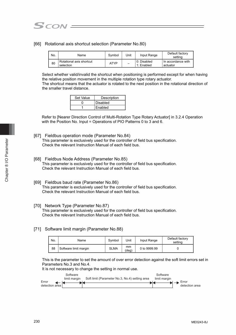
Cha
pter
8 I/
O P
aram
eter
230
[66] Rotational axis shortcut selection (Parameter No.80)
No. Name Symbol Unit Input Range Default factory setting
80 Rotational axis shortcut selection ATYP – 0: Disabled
1: Enabled In accordance with actuator
Select whether valid/invalid the shortcut when positioning is performed except for when having the relative position movement in the multiple rotation type rotary actuator. The shortcut means that the actuator is rotated to the next position in the rotational direction of the smaller travel distance.
Set Value Description 0 Disabled 1 Enabled
Refer to [Nearer Direction Control of Multi-Rotation Type Rotary Actuator] in 3.2.4 Operation with the Position No. Input = Operations of PIO Patterns 0 to 3 and 6.
[67] Fieldbus operation mode (Parameter No.84)
This parameter is exclusively used for the controller of field bus specification. Check the relevant Instruction Manual of each field bus.
[68] Fieldbus Node Address (Parameter No.85)
This parameter is exclusively used for the controller of field bus specification. Check the relevant Instruction Manual of each field bus.
[69] Fieldbus baud rate (Parameter No.86) This parameter is exclusively used for the controller of field bus specification. Check the relevant Instruction Manual of each field bus.
[70] Network Type (Parameter No.87)
This parameter is exclusively used for the controller of field bus specification. Check the relevant Instruction Manual of each field bus.
[71] Software limit margin (Parameter No.88)
No. Name Symbol Unit Input Range Default factory
setting
88 Software limit margin SLMA mm (deg) 0 to 9999.99 0
This is the parameter to set the amount of over error detection against the soft limit errors set in Parameters No.3 and No.4. It is not necessary to change the setting in normal use.
Software limit margin
Software limit margin
Error detection area
Error detection area
Soft limit (Parameter No.3, No.4) setting area
ME0243-8J
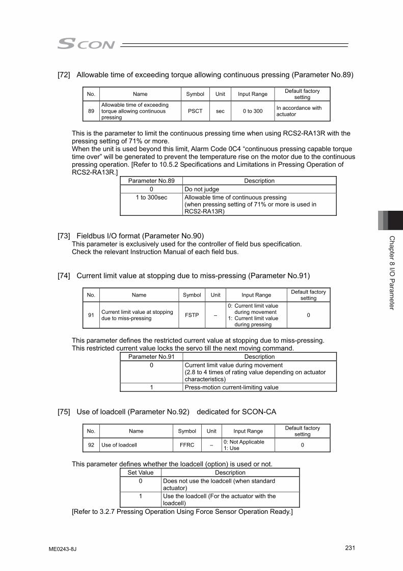
Chapter 8 I/O
Parameter
231
[72] Allowable time of exceeding torque allowing continuous pressing (Parameter No.89)
No. Name Symbol Unit Input Range Default factory setting
89 Allowable time of exceeding torque allowing continuous pressing
PSCT sec 0 to 300 In accordance with actuator
This is the parameter to limit the continuous pressing time when using RCS2-RA13R with the pressing setting of 71% or more. When the unit is used beyond this limit, Alarm Code 0C4 “continuous pressing capable torque time over” will be generated to prevent the temperature rise on the motor due to the continuous pressing operation. [Refer to 10.5.2 Specifications and Limitations in Pressing Operation of RCS2-RA13R.]
Parameter No.89 Description 0 Do not judge
1 to 300sec Allowable time of continuous pressing (when pressing setting of 71% or more is used in RCS2-RA13R)
[73] Fieldbus I/O format (Parameter No.90)
This parameter is exclusively used for the controller of field bus specification. Check the relevant Instruction Manual of each field bus.
[74] Current limit value at stopping due to miss-pressing (Parameter No.91)
No. Name Symbol Unit Input Range Default factory
setting
91 Current limit value at stopping due to miss-pressing FSTP –
0: Current limit value during movement
1: Current limit value during pressing
0
This parameter defines the restricted current value at stopping due to miss-pressing. This restricted current value locks the servo till the next moving command.
Parameter No.91 Description 0 Current limit value during movement
(2.8 to 4 times of rating value depending on actuator characteristics)
1 Press-motion current-limiting value [75] Use of loadcell (Parameter No.92) dedicated for SCON-CA
No. Name Symbol Unit Input Range Default factory
setting
92 Use of loadcell FFRC – 0: Not Applicable 1: Use 0
This parameter defines whether the loadcell (option) is used or not.
Set Value Description 0 Does not use the loadcell (when standard
actuator) 1 Use the loadcell (For the actuator with the
loadcell) [Refer to 3.2.7 Pressing Operation Using Force Sensor Operation Ready.]
ME0243-8J
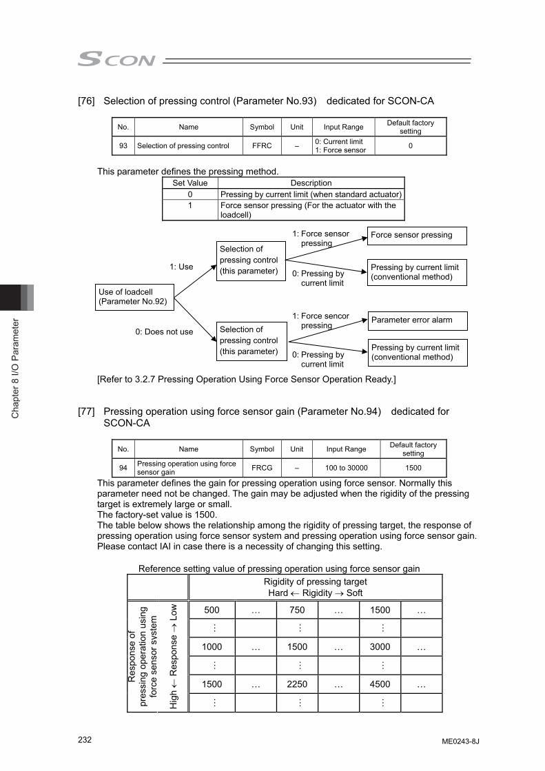
Cha
pter
8 I/
O P
aram
eter
232
[76] Selection of pressing control (Parameter No.93) dedicated for SCON-CA
No. Name Symbol Unit Input Range Default factory setting
93 Selection of pressing control FFRC – 0: Current limit 1: Force sensor 0
This parameter defines the pressing method.
Set Value Description 0 Pressing by current limit (when standard actuator) 1 Force sensor pressing (For the actuator with the
loadcell)
[Refer to 3.2.7 Pressing Operation Using Force Sensor Operation Ready.] [77] Pressing operation using force sensor gain (Parameter No.94) dedicated for
SCON-CA
No. Name Symbol Unit Input Range Default factory setting
94 Pressing operation using force sensor gain FRCG – 100 to 30000 1500
This parameter defines the gain for pressing operation using force sensor. Normally this parameter need not be changed. The gain may be adjusted when the rigidity of the pressing target is extremely large or small. The factory-set value is 1500. The table below shows the relationship among the rigidity of pressing target, the response of pressing operation using force sensor system and pressing operation using force sensor gain. Please contact IAI in case there is a necessity of changing this setting.
Reference setting value of pressing operation using force sensor gain
Rigidity of pressing target Hard ← Rigidity → Soft
500 … 750 … 1500 …
…
…
…
1000 … 1500 … 3000 …
…
…
…
1500 … 2250 … 4500 … Res
pons
e of
pr
essi
ng o
pera
tion
usin
g fo
rce
sens
or s
yste
m
Hig
h ←
Res
pons
e →
Low
…
…
…
Use of loadcell (Parameter No.92)
Selection of pressing control(this parameter)
Force sensor pressing
Pressing by current limit(conventional method)
0: Does not use
1: Use
1: Force sensor pressing
0: Pressing by current limit
Selection of pressing control (this parameter)
Parameter error alarm
Pressing by current limit(conventional method)
1: Force sencor pressing
0: Pressing by current limit
ME0243-8J
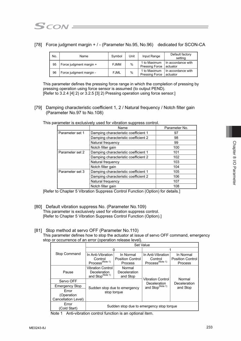
Chapter 8 I/O
Parameter
233
[78] Force judgment margin + / - (Parameter No.95, No.96) dedicated for SCON-CA
No. Name Symbol Unit Input Range Default factory setting
95 Force judgment margin + FJMM % 1 to Maximum Pressing Force
In accordance with actuator
96 Force judgment margin - FJML % 1 to Maximum Pressing Force
In accordance with actuator
This parameter defines the pressing force range in which the completion of pressing by pressing operation using force sensor is assumed (to output PEND). [Refer to 3.2.4 [4] 2) or 3.2.5 [3] 2) Pressing operation using force sensor.]
[79] Damping characteristic coefficient 1, 2 / Natural frequency / Notch filter gain
(Parameter No.97 to No.108) This parameter is exclusively used for vibration suppress control.
Name Parameter No. Damping characteristic coefficient 1 97 Damping characteristic coefficient 2 98 Natural frequency 99
Parameter set 1
Notch filter gain 100 Damping characteristic coefficient 1 101 Damping characteristic coefficient 2 102 Natural frequency 103
Parameter set 2
Notch filter gain 104 Damping characteristic coefficient 1 105 Damping characteristic coefficient 2 106 Natural frequency 107
Parameter set 3
Notch filter gain 108 [Refer to Chapter 5 Vibration Suppress Control Function (Option) for details.]
[80] Default vibration suppress No. (Parameter No.109) This parameter is exclusively used for vibration suppress control. [Refer to Chapter 5 Vibration Suppress Control Function (Option).]
[81] Stop method at servo OFF (Parameter No.110)
This parameter defines how to stop the actuator at issue of servo OFF command, emergency stop or occurrence of an error (operation release level).
Set Value 0 1
Stop Command In Anti-Vibration Control
Process(Note 1)
In Normal Position Control
Process
In Anti-Vibration Control
Process(Note 1)
In Normal Position Control
Process
Pause Vibration Control
Deceleration and Stop(Note 1)
Normal Deceleration
and Stop Servo OFF
Emergency Stop Error
(Operation Cancellation Level)
Sudden stop due to emergency stop torque
Vibration Control Deceleration
and Stop(Note 1)
Normal Deceleration
and Stop
Error (Cold Start) Sudden stop due to emergency stop torque
Note 1 Anti-vibration control function is an optional item.
ME0243-8J
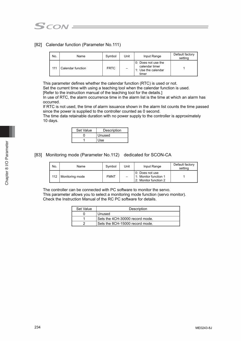
Cha
pter
8 I/
O P
aram
eter
234
[82] Calendar function (Parameter No.111)
No. Name Symbol Unit Input Range Default factory setting
111 Calendar function FRTC –
0: Does not use the calendar timer
1: Use the calendar timer
1
This parameter defines whether the calendar function (RTC) is used or not. Set the current time with using a teaching tool when the calendar function is used. [Refer to the instruction manual of the teaching tool for the details.] In use of RTC, the alarm occurrence time in the alarm list is the time at which an alarm has occurred. If RTC is not used, the time of alarm issuance shown in the alarm list counts the time passed since the power is supplied to the controller counted as 0 second. The time data retainable duration with no power supply to the controller is approximately 10 days.
Set Value Description 0 Unused 1 Use
[83] Monitoring mode (Parameter No.112) dedicated for SCON-CA
No. Name Symbol Unit Input Range Default factory setting
112 Monitoring mode FMNT – 0: Does not use 1: Monitor function 1 2: Monitor function 2
1
The controller can be connected with PC software to monitor the servo. This parameter allows you to select a monitoring mode function (servo monitor). Check the Instruction Manual of the RC PC software for details.
Set Value Description 0 Unused 1 Sets the 4CH-30000 record mode. 2 Sets the 8CH-15000 record mode.
ME0243-8J
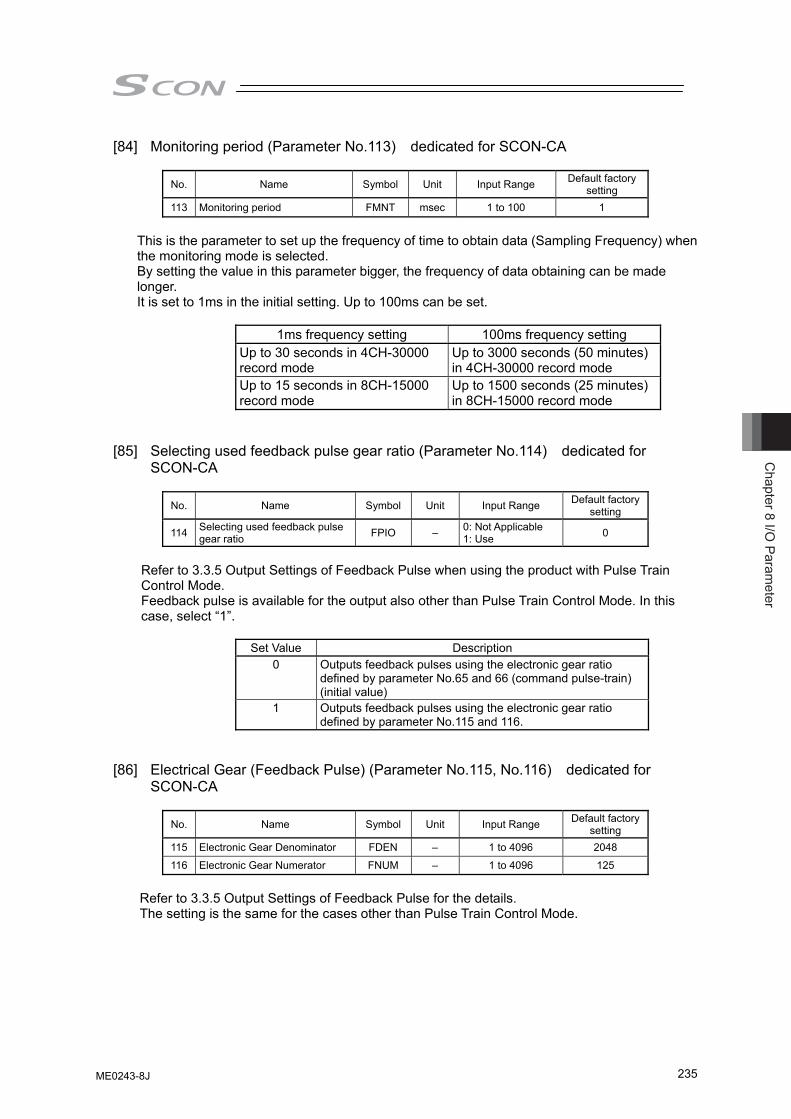
Chapter 8 I/O
Parameter
235
[84] Monitoring period (Parameter No.113) dedicated for SCON-CA
No. Name Symbol Unit Input Range Default factory setting
113 Monitoring period FMNT msec 1 to 100 1
This is the parameter to set up the frequency of time to obtain data (Sampling Frequency) when the monitoring mode is selected. By setting the value in this parameter bigger, the frequency of data obtaining can be made longer. It is set to 1ms in the initial setting. Up to 100ms can be set.
1ms frequency setting 100ms frequency setting Up to 30 seconds in 4CH-30000 record mode
Up to 3000 seconds (50 minutes) in 4CH-30000 record mode
Up to 15 seconds in 8CH-15000 record mode
Up to 1500 seconds (25 minutes) in 8CH-15000 record mode
[85] Selecting used feedback pulse gear ratio (Parameter No.114) dedicated for
SCON-CA
No. Name Symbol Unit Input Range Default factory setting
114 Selecting used feedback pulse gear ratio FPIO – 0: Not Applicable
1: Use 0
Refer to 3.3.5 Output Settings of Feedback Pulse when using the product with Pulse Train Control Mode. Feedback pulse is available for the output also other than Pulse Train Control Mode. In this case, select “1”.
Set Value Description 0 Outputs feedback pulses using the electronic gear ratio
defined by parameter No.65 and 66 (command pulse-train) (initial value)
1 Outputs feedback pulses using the electronic gear ratio defined by parameter No.115 and 116.
[86] Electrical Gear (Feedback Pulse) (Parameter No.115, No.116) dedicated for
SCON-CA
No. Name Symbol Unit Input Range Default factory setting
115 Electronic Gear Denominator FDEN – 1 to 4096 2048
116 Electronic Gear Numerator FNUM – 1 to 4096 125
Refer to 3.3.5 Output Settings of Feedback Pulse for the details. The setting is the same for the cases other than Pulse Train Control Mode.
ME0243-8J
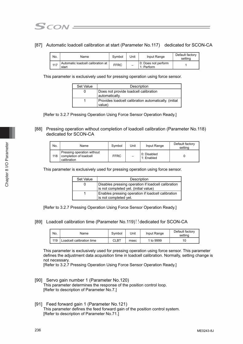
Cha
pter
8 I/
O P
aram
eter
236
[87] Automatic loadcell calibration at start (Parameter No.117) dedicated for SCON-CA
No. Name Symbol Unit Input Range Default factory setting
117 Automatic loadcell calibration at start FFRC – 0: Does not perform
1: Perform 1
This parameter is exclusively used for pressing operation using force sensor.
Set Value Description 0 Does not provide loadcell calibration
automatically. 1 Provides loadcell calibration automatically. (initial
value) [Refer to 3.2.7 Pressing Operation Using Force Sensor Operation Ready.]
[88] Pressing operation without completion of loadcell calibration (Parameter No.118) dedicated for SCON-CA
No. Name Symbol Unit Input Range Default factory
setting
118 Pressing operation without completion of loadcell calibration
FFRC – 0: Disabled 1: Enabled 0
This parameter is exclusively used for pressing operation using force sensor.
Set Value Description 0 Disables pressing operation if loadcell calibration
is not completed yet. (initial value) 1 Enables pressing operation if loadcell calibration
is not completed yet. [Refer to 3.2.7 Pressing Operation Using Force Sensor Operation Ready.]
[89] Loadcell calibration time (Parameter No.119)!!dedicated for SCON-CA
No. Name Symbol Unit Input Range Default factory
setting 119 Loadcell calibration time CLBT msec 1 to 9999 10
This parameter is exclusively used for pressing operation using force sensor. This parameter defines the adjustment data acquisition time in loadcell calibration. Normally, setting change is not necessary. [Refer to 3.2.7 Pressing Operation Using Force Sensor Operation Ready.]
[90] Servo gain number 1 (Parameter No.120)
This parameter determines the response of the position control loop. [Refer to description of Parameter No.7.]
[91] Feed forward gain 1 (Parameter No.121)
This parameter defines the feed forward gain of the position control system. [Refer to description of Parameter No.71.]
ME0243-8J
Chapter 8 I/O
Parameter
237
[92] Velocity Loop Proportional Gain 1 (Parameter No.122) This parameter determines the response of the speed control loop. [Refer to description of Parameter No.31.]
[93] Velosity Loop Integral Gain 1 (Parameter No.123)
This parameter determines the response of the speed control loop. [Refer to description of Parameter No.32.]
[94] Torque Filter Time Constant 1 (Parameter No.124)
This parameter decides the filter time constant for the torque command. [Refer to description of Parameter No.33.]
[95] Current control width number 1 (Parameter No.125)
This parameter defines the control width of the current control system. [Refer to description of Parameter No.54.]
[96] Servo gain number 2 (Parameter No.126)
This parameter determines the response of the position control loop. [Refer to description of Parameter No.7.]
[97] Feed forward gain 2 (Parameter No.127)
This parameter defines the feed forward gain of the position control system. [Refer to description of Parameter No.71.]
[98] Speed Loop Proportional Gain 2 (Parameter No.128)
This parameter determines the response of the speed control loop. [Refer to description of Parameter No.31.]
[99] Speed Loop Integral Gain 2 (Parameter No.129)
This parameter determines the response of the speed control loop. [Refer to description of Parameter No.32.]
[100] Torque Filter Time Constant 2 (Parameter No.130)
This parameter decides the filter time constant for the torque command. [Refer to description of Parameter No.33.]
[101] Current control width number 2 (Parameter No.131)
This parameter defines the control width of the current control system. [Refer to description of Parameter No.54.]
[102] Servo gain number 3 (Parameter No.132)
This parameter determines the response of the position control loop. [Refer to description of Parameter No.7.]
ME0243-8J
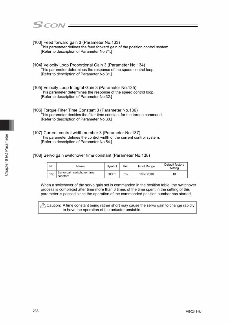
Cha
pter
8 I/
O P
aram
eter
238
[103] Feed forward gain 3 (Parameter No.133) This parameter defines the feed forward gain of the position control system. [Refer to description of Parameter No.71.]
[104] Velocity Loop Proportional Gain 3 (Parameter No.134)
This parameter determines the response of the speed control loop. [Refer to description of Parameter No.31.]
[105] Velocity Loop Integral Gain 3 (Parameter No.135)
This parameter determines the response of the speed control loop. [Refer to description of Parameter No.32.]
[106] Torque Filter Time Constant 3 (Parameter No.136)
This parameter decides the filter time constant for the torque command. [Refer to description of Parameter No.33.]
[107] Current control width number 3 (Parameter No.137)
This parameter defines the control width of the current control system. [Refer to description of Parameter No.54.]
[108] Servo gain switchover time constant (Parameter No.138)
No. Name Symbol Unit Input Range Default factory
setting
138 Servo gain switchover time constant GCFT ms 10 to 2000 10
When a switchover of the servo gain set is commanded in the position table, the switchover process is completed after time more than 3 times of the time spent in the setting of this parameter is passed since the operation of the commanded position number has started.
Caution: A time constant being rather short may cause the servo gain to change rapidly to have the operation of the actuator unstable.
ME0243-8J
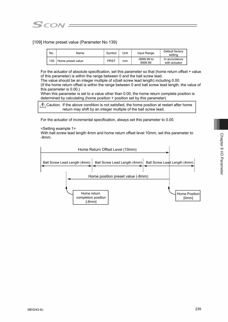
Chapter 8 I/O
Parameter
239
[109] Home preset value (Parameter No.139)
No. Name Symbol Unit Input Range Default factory setting
139 Home preset value PRST mm -9999.99 to 9999.99
In accordance with actuator
For the actuator of absolute specification, set this parameter so that (home return offset + value of this parameter) is within the range between 0 and the ball screw lead. The value should be an integer multiple of ±(ball screw lead length) including 0.00. (If the home return offset is within the range between 0 and ball screw lead length, the value of this parameter is 0.00.) When this parameter is set to a value other than 0.00, the home return complete position is determined by calculating (home position + position set by this parameter)
For the actuator of incremental specification, always set this parameter to 0.00. <Setting example 1> With ball screw lead length 4mm and home return offset level 10mm, set this parameter to -8mm.
Caution: If the above condition is not satisfied, the home position at restart after home return may shift by an integer multiple of the ball screw lead.
Home Return Offset Level (10mm)
Home position preset value (-8mm)
Home return completion position
[-8mm]
Ball Screw Lead Length (4mm) Ball Screw Lead Length (4mm) Ball Screw Lead Length (4mm)
Home Position[0mm]
ME0243-8J
Cha
pter
8 I/
O P
aram
eter
240
[110] IP Address (Parameter No.140) No. Name Symbol Unit Input Range Default factory
setting
140 IP Address IPAD – 0.0.0.0 to 255.255.255.255 192.168.0.1
It is the parameter dedicated for Fieldbus (EtherNet/IP). [For details, refer to Fieldbus Instruction Manual.]
[111] Subnet Mask (Parameter No.141)
No. Name Symbol Unit Input Range Default factory setting
141 Subnet Mask SNMK – 0.0.0.0 to 255.255.255.255 255.255.255.0
It is the parameter dedicated for Fieldbus (EtherNet/IP). [For details, refer to Fieldbus Instruction Manual.]
[112] Default Gateway (Parameter No.142)
No. Name Symbol Unit Input Range Default factory setting
142 Default Gateway DFGW – 0.0.0.0 to 255.255.255.255 0.0.0.0
It is the parameter dedicated for Fieldbus (EtherNet/IP). [For details, refer to Fieldbus Instruction Manual.]
[113] Overload Caution Load Level Ratio (Parameter No. 143)
No. Name Symbol Unit Input Range Default factory setting
143 overload caution load level ratio OLWL % 50 to 100 100
With the motor thrust increase temperature of when an overload caution warning gets generated being set as 100%, the overload warning (message level) is output when the motor temperature exceeds the rate set in this parameter. The judgment would not be made if the value is set to 100%.
[114] Total Movement Count Threshold!(Parameter No.147) No. Name Symbol Unit Input Range Default factory
setting
147 Total Movement Count Threshold TMCT Times 0 to 999999999 0(Disabled)
An alarm is generated when the total movement count exceeds the value set to this parameter. The judgment would not be made if the value is set to 0.
[115] Total Operated Distance Threshold (Parameter No.148) No. Name Symbol Unit Input Range Default factory
setting
148 Total Operated Distance Threshold ODOT m 0 to 999999999 0(Disabled)
An alarm is generated when the total operation distance exceeds the value set to this parameter. The judgment would not be made if the value is set to 0.
ME0243-8J
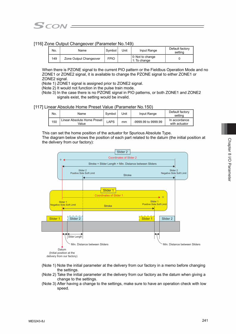
Chapter 8 I/O
Parameter
241
[116] Zone Output Changeover (Parameter No.149) No. Name Symbol Unit Input Range Default factory
setting
149 Zone Output Changeover FPIO 0: Not to change 1: To change 0
When there is PZONE signal to the current PIO pattern or the Fieldbus Operation Mode and no ZONE1 or ZONE2 signal, it is available to change the PZONE signal to either ZONE1 or ZONE2 signal. (Note 1) ZONE1 signal is assigned prior to ZONE2 signal. (Note 2) It would not function in the pulse train mode. (Note 3) In the case there is no PZONE signal in PIO patterns, or both ZONE1 and ZONE2
signals exist, the setting would be invalid. [117] Linear Absolute Home Preset Value (Parameter No.150)
No. Name Symbol Unit Input Range Default factory setting
150 Linear Absolute Home Preset Value LAPS mm -9999.99 to 9999.99 In accordance
with actuator This can set the home position of the actuator for Spurious Absolute Type. The diagram below shows the position of each part related to the datum (the initial position at the delivery from our factory): (Note 1) Note the initial parameter at the delivery from our factory in a memo before changing
the settings. (Note 2) Take the initial parameter at the delivery from our factory as the datum when giving a
change to the settings. (Note 3) After having a change to the settings, make sure to have an operation check with low
speed.
+
+
Slider 2
Slider 1
Slider 2 Slider 2Slider 1Slider 1
Stroke
Stroke
Stroke + Slider Length + Min. Distance between Sliders
Coordinates of Slider 2
Coordinates of Slider 1
Slider 2Positive Side Soft Limit
Slider 1Negative Side Soft Limit
Slider 1Positive Side Soft Limit
Slider 2Negative Side Soft Limit
Min. Distance between Sliders Min. Distance between Sliders
Datum (Initial position at the
delivery from our factory)
Slider Length
ME0243-8J
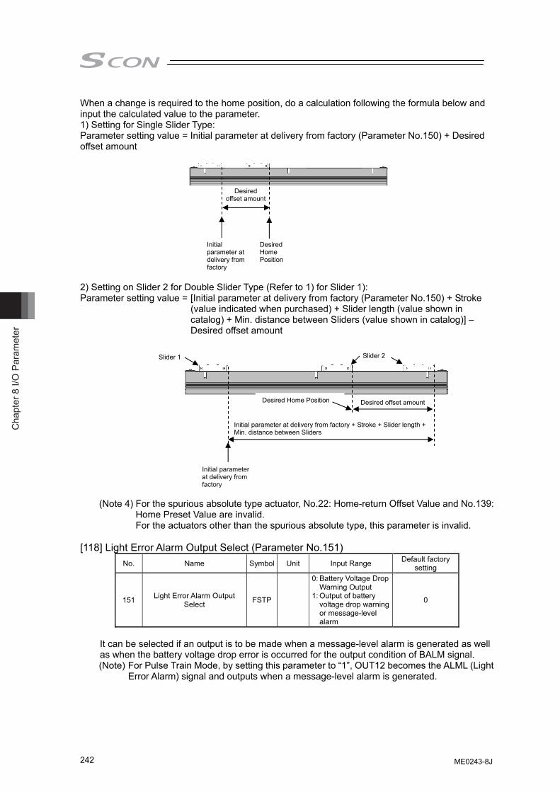
Cha
pter
8 I/
O P
aram
eter
242
When a change is required to the home position, do a calculation following the formula below and input the calculated value to the parameter. 1) Setting for Single Slider Type: Parameter setting value = Initial parameter at delivery from factory (Parameter No.150) + Desired offset amount 2) Setting on Slider 2 for Double Slider Type (Refer to 1) for Slider 1): Parameter setting value = [Initial parameter at delivery from factory (Parameter No.150) + Stroke
(value indicated when purchased) + Slider length (value shown in catalog) + Min. distance between Sliders (value shown in catalog)] – Desired offset amount
(Note 4) For the spurious absolute type actuator, No.22: Home-return Offset Value and No.139: Home Preset Value are invalid. For the actuators other than the spurious absolute type, this parameter is invalid.
[118] Light Error Alarm Output Select (Parameter No.151)
No. Name Symbol Unit Input Range Default factory setting
151 Light Error Alarm Output Select FSTP
0: Battery Voltage Drop Warning Output
1: Output of battery voltage drop warning or message-level alarm
0
It can be selected if an output is to be made when a message-level alarm is generated as well as when the battery voltage drop error is occurred for the output condition of BALM signal. (Note) For Pulse Train Mode, by setting this parameter to “1”, OUT12 becomes the ALML (Light
Error Alarm) signal and outputs when a message-level alarm is generated.
Desired offset amount
Initial parameter at delivery from factory
Desired Home Position
Desired offset amount
Initial parameter at delivery from factory
Desired Home Position
Initial parameter at delivery from factory + Stroke + Slider length + Min. distance between Sliders
Slider 2Slider 1
ME0243-8J
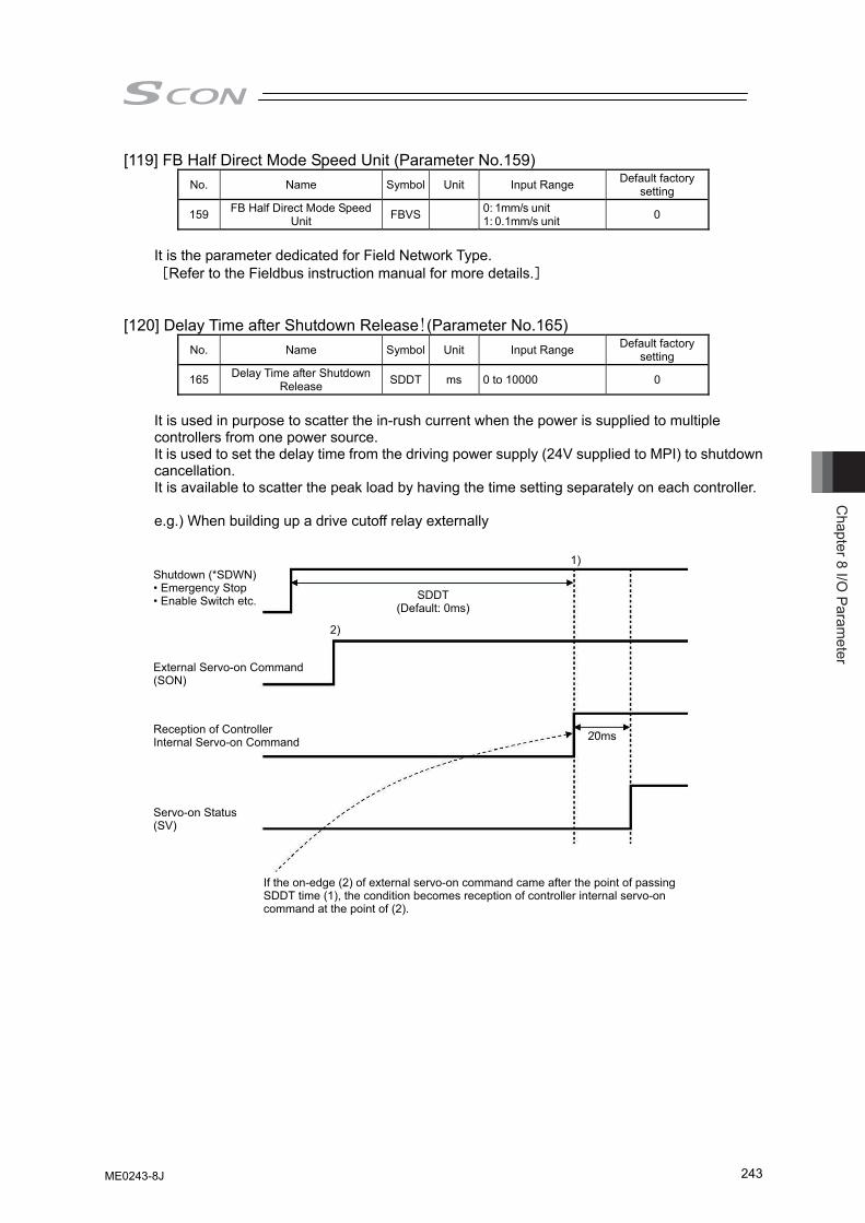
Chapter 8 I/O
Parameter
243
[119] FB Half Direct Mode Speed Unit (Parameter No.159) No. Name Symbol Unit Input Range Default factory
setting
159 FB Half Direct Mode Speed Unit FBVS 0: 1mm/s unit
1: 0.1mm/s unit 0
It is the parameter dedicated for Field Network Type. [Refer to the Fieldbus instruction manual for more details.]
[120] Delay Time after Shutdown Release!(Parameter No.165) No. Name Symbol Unit Input Range Default factory
setting
165 Delay Time after Shutdown Release SDDT ms 0 to 10000 0
It is used in purpose to scatter the in-rush current when the power is supplied to multiple controllers from one power source. It is used to set the delay time from the driving power supply (24V supplied to MPI) to shutdown cancellation. It is available to scatter the peak load by having the time setting separately on each controller. e.g.) When building up a drive cutoff relay externally
External Servo-on Command (SON)
Reception of Controller Internal Servo-on Command
Servo-on Status (SV)
If the on-edge (2) of external servo-on command came after the point of passing SDDT time (1), the condition becomes reception of controller internal servo-on command at the point of (2).
20ms
1)
2)
SDDT(Default: 0ms)
Shutdown (*SDWN)• Emergency Stop• Enable Switch etc.
ME0243-8J
Cha
pter
8 I/
O P
aram
eter
244
8.3 Servo Adjustment
The parameters are preset at the factory before shipment so that the actuator operates stably within the rated (maximum) transportable weight. However, the preset setting cannot always be the optimum load condition in the actual use. In such cases, servo adjustment may be required. This section describes the basic servo adjustment method.
Caution: Rapid and excessive settings are dangerous. They may devices including the actuator to be damaged and/or people to be injured. Take sufficient note on the setting.
Record settings during servo adjustment so that prior settings can always be recovered.
When a problem arises and the solution cannot be found, please contact IAI.
ME0243-8J
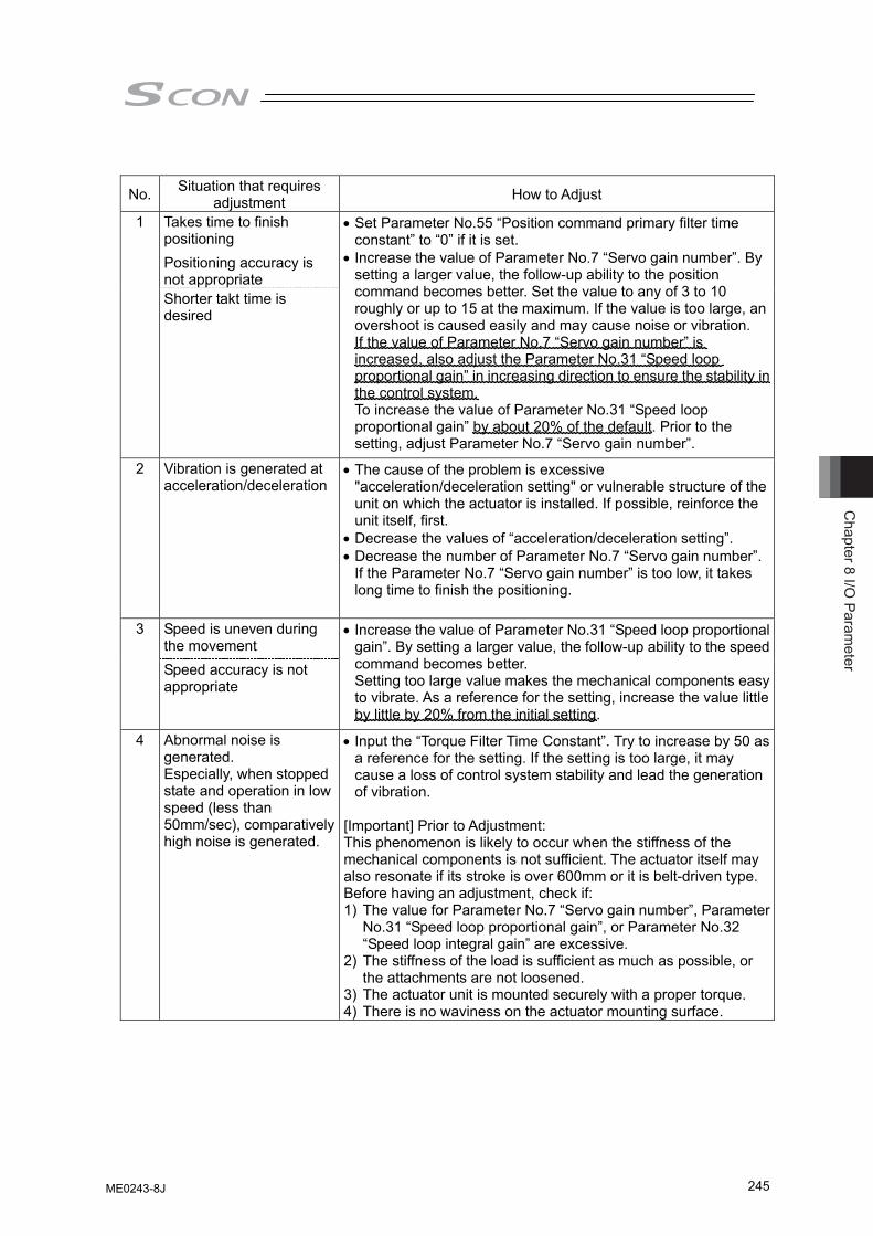
Chapter 8 I/O
Parameter
245
No. Situation that requires adjustment How to Adjust
Takes time to finish positioning Positioning accuracy is not appropriate
1
Shorter takt time is desired
• Set Parameter No.55 “Position command primary filter time constant” to “0” if it is set.
• Increase the value of Parameter No.7 “Servo gain number”. By setting a larger value, the follow-up ability to the position command becomes better. Set the value to any of 3 to 10 roughly or up to 15 at the maximum. If the value is too large, an overshoot is caused easily and may cause noise or vibration. If the value of Parameter No.7 “Servo gain number” is increased, also adjust the Parameter No.31 “Speed loop proportional gain” in increasing direction to ensure the stability in the control system. To increase the value of Parameter No.31 “Speed loop proportional gain” by about 20% of the default. Prior to the setting, adjust Parameter No.7 “Servo gain number”.
2 Vibration is generated at acceleration/deceleration
• The cause of the problem is excessive "acceleration/deceleration setting" or vulnerable structure of the unit on which the actuator is installed. If possible, reinforce the unit itself, first.
• Decrease the values of “acceleration/deceleration setting”. • Decrease the number of Parameter No.7 “Servo gain number”.
If the Parameter No.7 “Servo gain number” is too low, it takes long time to finish the positioning.
Speed is uneven during the movement
3
Speed accuracy is not appropriate
• Increase the value of Parameter No.31 “Speed loop proportional gain”. By setting a larger value, the follow-up ability to the speed command becomes better. Setting too large value makes the mechanical components easy to vibrate. As a reference for the setting, increase the value little by little by 20% from the initial setting.
4 Abnormal noise is generated. Especially, when stopped state and operation in low speed (less than 50mm/sec), comparatively high noise is generated.
• Input the “Torque Filter Time Constant”. Try to increase by 50 as a reference for the setting. If the setting is too large, it may cause a loss of control system stability and lead the generation of vibration.
[Important] Prior to Adjustment: This phenomenon is likely to occur when the stiffness of the mechanical components is not sufficient. The actuator itself may also resonate if its stroke is over 600mm or it is belt-driven type. Before having an adjustment, check if: 1) The value for Parameter No.7 “Servo gain number”, Parameter
No.31 “Speed loop proportional gain”, or Parameter No.32 “Speed loop integral gain” are excessive.
2) The stiffness of the load is sufficient as much as possible, or the attachments are not loosened.
3) The actuator unit is mounted securely with a proper torque. 4) There is no waviness on the actuator mounting surface.
ME0243-8J
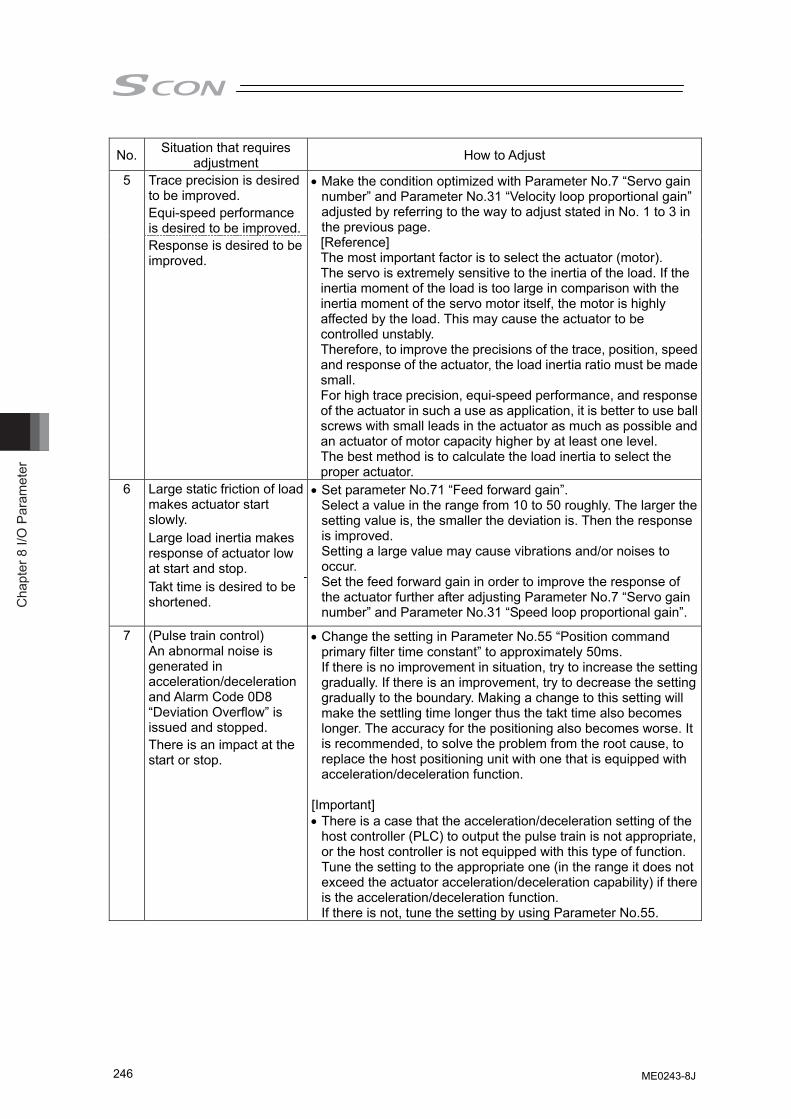
Cha
pter
8 I/
O P
aram
eter
246
No. Situation that requires adjustment How to Adjust
Trace precision is desired to be improved. Equi-speed performance is desired to be improved.
5
Response is desired to be improved.
• Make the condition optimized with Parameter No.7 “Servo gain number” and Parameter No.31 “Velocity loop proportional gain” adjusted by referring to the way to adjust stated in No. 1 to 3 in the previous page. [Reference] The most important factor is to select the actuator (motor). The servo is extremely sensitive to the inertia of the load. If the inertia moment of the load is too large in comparison with the inertia moment of the servo motor itself, the motor is highly affected by the load. This may cause the actuator to be controlled unstably. Therefore, to improve the precisions of the trace, position, speed and response of the actuator, the load inertia ratio must be made small. For high trace precision, equi-speed performance, and response of the actuator in such a use as application, it is better to use ball screws with small leads in the actuator as much as possible and an actuator of motor capacity higher by at least one level. The best method is to calculate the load inertia to select the proper actuator.
Large static friction of load makes actuator start slowly. Large load inertia makes response of actuator low at start and stop.
6
Takt time is desired to be shortened.
• Set parameter No.71 “Feed forward gain”. Select a value in the range from 10 to 50 roughly. The larger the setting value is, the smaller the deviation is. Then the response is improved. Setting a large value may cause vibrations and/or noises to occur. Set the feed forward gain in order to improve the response of the actuator further after adjusting Parameter No.7 “Servo gain number” and Parameter No.31 “Speed loop proportional gain”.
(Pulse train control) An abnormal noise is generated in acceleration/deceleration and Alarm Code 0D8 “Deviation Overflow” is issued and stopped.
7
There is an impact at the start or stop.
• Change the setting in Parameter No.55 “Position command primary filter time constant” to approximately 50ms. If there is no improvement in situation, try to increase the setting gradually. If there is an improvement, try to decrease the setting gradually to the boundary. Making a change to this setting will make the settling time longer thus the takt time also becomes longer. The accuracy for the positioning also becomes worse. It is recommended, to solve the problem from the root cause, to replace the host positioning unit with one that is equipped with acceleration/deceleration function.
[Important] • There is a case that the acceleration/deceleration setting of the
host controller (PLC) to output the pulse train is not appropriate, or the host controller is not equipped with this type of function. Tune the setting to the appropriate one (in the range it does not exceed the actuator acceleration/deceleration capability) if there is the acceleration/deceleration function. If there is not, tune the setting by using Parameter No.55.
ME0243-8J
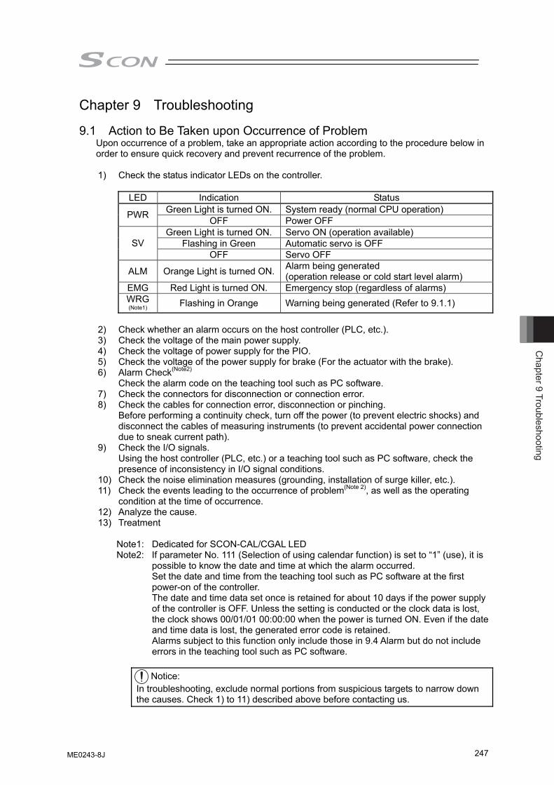
Chapter 9 Troubleshooting
247
Chapter 9 Troubleshooting 9.1 Action to Be Taken upon Occurrence of Problem
Upon occurrence of a problem, take an appropriate action according to the procedure below in order to ensure quick recovery and prevent recurrence of the problem.
1) Check the status indicator LEDs on the controller.
LED Indication Status Green Light is turned ON. System ready (normal CPU operation) PWR OFF Power OFF Green Light is turned ON. Servo ON (operation available)
Flashing in Green Automatic servo is OFF SV OFF Servo OFF
ALM Orange Light is turned ON. Alarm being generated (operation release or cold start level alarm)
EMG Red Light is turned ON. Emergency stop (regardless of alarms) WRG (Note1) Flashing in Orange Warning being generated (Refer to 9.1.1)
2) Check whether an alarm occurs on the host controller (PLC, etc.). 3) Check the voltage of the main power supply. 4) Check the voltage of power supply for the PIO. 5) Check the voltage of the power supply for brake (For the actuator with the brake). 6) Alarm Check(Note2)
Check the alarm code on the teaching tool such as PC software. 7) Check the connectors for disconnection or connection error. 8) Check the cables for connection error, disconnection or pinching.
Before performing a continuity check, turn off the power (to prevent electric shocks) and disconnect the cables of measuring instruments (to prevent accidental power connection due to sneak current path).
9) Check the I/O signals. Using the host controller (PLC, etc.) or a teaching tool such as PC software, check the presence of inconsistency in I/O signal conditions.
10) Check the noise elimination measures (grounding, installation of surge killer, etc.). 11) Check the events leading to the occurrence of problem(Note 2), as well as the operating
condition at the time of occurrence. 12) Analyze the cause. 13) Treatment
Note1: Dedicated for SCON-CAL/CGAL LED Note2: If parameter No. 111 (Selection of using calendar function) is set to “1” (use), it is
possible to know the date and time at which the alarm occurred. Set the date and time from the teaching tool such as PC software at the first power-on of the controller. The date and time data set once is retained for about 10 days if the power supply of the controller is OFF. Unless the setting is conducted or the clock data is lost, the clock shows 00/01/01 00:00:00 when the power is turned ON. Even if the date and time data is lost, the generated error code is retained. Alarms subject to this function only include those in 9.4 Alarm but do not include errors in the teaching tool such as PC software.
Notice:
In troubleshooting, exclude normal portions from suspicious targets to narrow down the causes. Check 1) to 11) described above before contacting us.
ME0243-8J

Cha
pter
9 T
roub
lesh
ootin
g
248
9.1.1 WRG LED (Specified only for SCON-CAL/CGAL)
WRG LED is a feature to prompt regular maintenance works for consumables such as absolute battery and fan unit. It flashes when following causes are occurred.
(1) When the battery voltage has dropped below the normal voltage in the absolute type
actuator (2) When the rotation speed of the fan attached on the top of the product has dropped below
the specified value (degradation) (3) When the load has exceeded the overload warning threshold (when the setting in Parameter
No. 151 is 0) (4) When a message level alarm has been generated (when the setting in Parameter No. 151 is
1)
ME0243-8J
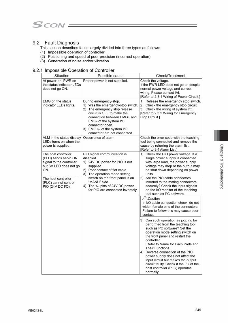
Chapter 9 Troubleshooting
249
9.2 Fault Diagnosis This section describes faults largely divided into three types as follows: (1) Impossible operation of controller (2) Positioning and speed of poor precision (incorrect operation) (3) Generation of noise and/or vibration
9.2.1 Impossible Operation of Controller
Situation Possible cause Check/Treatment At power-on, PWR on the status indicator LEDs does not go ON.
Proper power is not supplied. Check the voltage. If the PWR LED does not go on despite normal power voltage and correct wiring, Please contact IAI. [Refer to 2.3.1 Wiring of Power Circuit.]
EMG on the status indicator LEDs lights.
During emergency-stop. 1) Was the emergency-stop switch.2) The emergency stop release
circuit is OFF to make the connection between EMG+ and EMG- of the system I/O connector open.
3) EMG+/- of the system I/O connector are not connected.
1) Release the emergency stop switch.2) Check the emergency stop circuit. 3) Check the wiring of system I/O. [Refer to 2.3.2 Wiring for Emergency Stop Circuit.]
ALM in the status display LEDs turns on when the power is supplied.
Occurrence of alarm Check the error code with the teaching tool being connected and remove the cause by referring the alarm list. [Refer to 9.4 Alarm List.]
The host controller (PLC) sends servo ON signal to the controller, but SV LED does not go ON. The host controller (PLC) cannot control PIO (24V DC I/O).
PIO signal communication is disabled. 1) 24V DC power for PIO is not
supplied. 2) Poor contact of flat cable 3) The operation mode setting
switch on the front panel is on “MANU” side.
4) The +/- pins of 24V DC power for PIO are connected inversely.
1) Check the PIO power voltage. If a single power supply is connected with large load, the power supply voltage may drop or the output may be shut down depending on power units.
2) Are the PIO cable connectors inserted to the mating connectors securely? Check the input signals on the I/O monitor of the teaching tool such as PC software.
Caution In I/O cable conduction check, do not widen female pins of the connectors. Failure to follow this may cause poor contact.
3) Can such operation as jogging be performed from the teaching tool such as PC software? Set the operation mode setting switch on the front panel and restart the controller. [Refer to Name for Each Parts and Their Functions.]
4) Reverse connection of the PIO power supply does not affect the input circuit but makes the output circuit faulty. Check if the I/O of the host controller (PLC) operates normally.
ME0243-8J
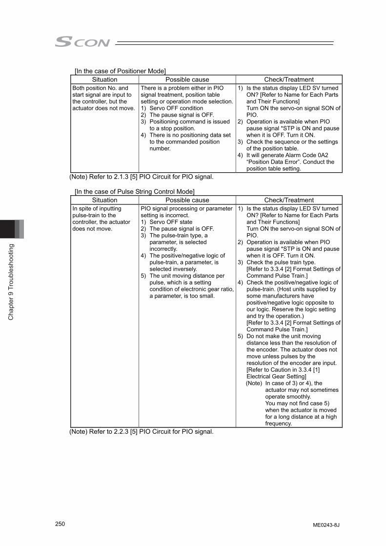
Cha
pter
9 T
roub
lesh
ootin
g
250
[In the case of Positioner Mode] Situation Possible cause Check/Treatment
Both position No. and start signal are input to the controller, but the actuator does not move.
There is a problem either in PIO signal treatment, position table setting or operation mode selection.1) Servo OFF condition 2) The pause signal is OFF. 3) Positioning command is issued
to a stop position. 4) There is no positioning data set
to the commanded position number.
1) Is the status display LED SV turned ON? [Refer to Name for Each Parts and Their Functions] Turn ON the servo-on signal SON of PIO.
2) Operation is available when PIO pause signal *STP is ON and pause when it is OFF. Turn it ON.
3) Check the sequence or the settings of the position table.
4) It will generate Alarm Code 0A2 “Position Data Error”. Conduct the position table setting.
(Note) Refer to 2.1.3 [5] PIO Circuit for PIO signal.
[In the case of Pulse String Control Mode] Situation Possible cause Check/Treatment
In spite of inputting pulse-train to the controller, the actuator does not move.
PIO signal processing or parameter setting is incorrect. 1) Servo OFF state 2) The pause signal is OFF. 3) The pulse-train type, a
parameter, is selected incorrectly.
4) The positive/negative logic of pulse-train, a parameter, is selected inversely.
5) The unit moving distance per pulse, which is a setting condition of electronic gear ratio, a parameter, is too small.
1) Is the status display LED SV turned ON? [Refer to Name for Each Parts and Their Functions] Turn ON the servo-on signal SON of PIO.
2) Operation is available when PIO pause signal *STP is ON and pause when it is OFF. Turn it ON.
3) Check the pulse train type. [Refer to 3.3.4 [2] Format Settings of Command Pulse Train.]
4) Check the positive/negative logic of pulse-train. (Host units supplied by some manufacturers have positive/negative logic opposite to our logic. Reserve the logic setting and try the operation.) [Refer to 3.3.4 [2] Format Settings of Command Pulse Train.]
5) Do not make the unit moving distance less than the resolution of the encoder. The actuator does not move unless pulses by the resolution of the encoder are input. [Refer to Caution in 3.3.4 [1] Electrical Gear Setting] (Note) In case of 3) or 4), the
actuator may not sometimes operate smoothly. You may not find case 5) when the actuator is moved for a long distance at a high frequency.
(Note) Refer to 2.2.3 [5] PIO Circuit for PIO signal.
ME0243-8J
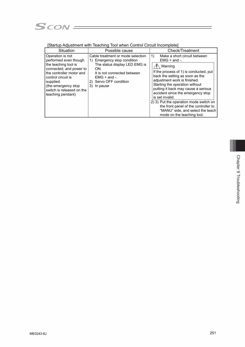
Chapter 9 Troubleshooting
251
[Startup Adjustment with Teaching Tool when Control Circuit Incomplete] Situation Possible cause Check/Treatment
Operation is not performed even though the teaching tool is connected, and power to the controller motor and control circuit is supplied. (the emergency stop switch is released on the teaching pendant)
Cable treatment or mode selection1) Emergency stop condition
The status display LED EMG is ON. It is not connected between EMG + and -.
2) Servo OFF condition 3) In pause
1) Make a short circuit between EMG + and -. Warning
If the process of 1) is conducted, put back the setting as soon as the adjustment work is finished. Starting the operation without putting it back may cause a serious accident since the emergency stop is set invalid.
2) 3) Put the operation mode switch on the front panel of the controller to “MANU” side, and select the teach mode on the teaching tool.
ME0243-8J
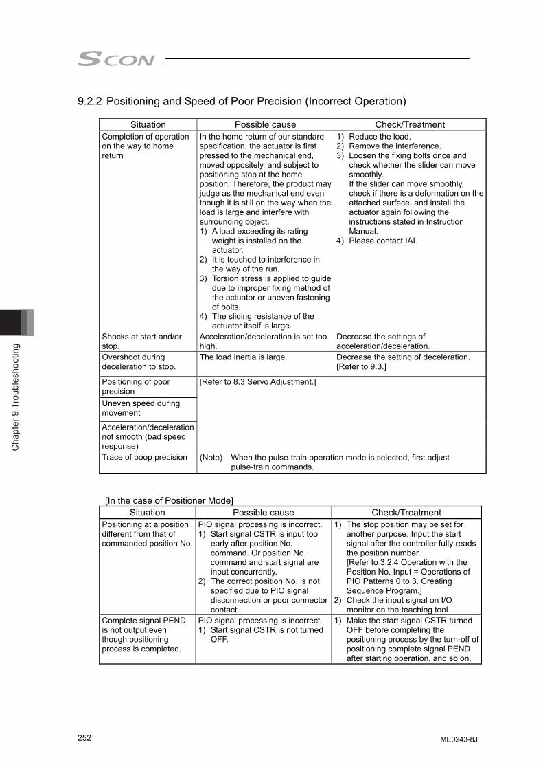
Cha
pter
9 T
roub
lesh
ootin
g
252
9.2.2 Positioning and Speed of Poor Precision (Incorrect Operation)
Situation Possible cause Check/Treatment Completion of operation on the way to home return
In the home return of our standard specification, the actuator is first pressed to the mechanical end, moved oppositely, and subject to positioning stop at the home position. Therefore, the product may judge as the mechanical end even though it is still on the way when the load is large and interfere with surrounding object. 1) A load exceeding its rating
weight is installed on the actuator.
2) It is touched to interference in the way of the run.
3) Torsion stress is applied to guide due to improper fixing method of the actuator or uneven fastening of bolts.
4) The sliding resistance of the actuator itself is large.
1) Reduce the load. 2) Remove the interference. 3) Loosen the fixing bolts once and
check whether the slider can move smoothly. If the slider can move smoothly, check if there is a deformation on the attached surface, and install the actuator again following the instructions stated in Instruction Manual.
4) Please contact IAI.
Shocks at start and/or stop.
Acceleration/deceleration is set too high.
Decrease the settings of acceleration/deceleration.
Overshoot during deceleration to stop.
The load inertia is large. Decrease the setting of deceleration. [Refer to 9.3.]
Positioning of poor precision Uneven speed during movement
Acceleration/deceleration not smooth (bad speed response) Trace of poop precision
[Refer to 8.3 Servo Adjustment.] (Note) When the pulse-train operation mode is selected, first adjust
pulse-train commands.
[In the case of Positioner Mode] Situation Possible cause Check/Treatment
Positioning at a position different from that of commanded position No.
PIO signal processing is incorrect. 1) Start signal CSTR is input too
early after position No. command. Or position No. command and start signal are input concurrently.
2) The correct position No. is not specified due to PIO signal disconnection or poor connector contact.
1) The stop position may be set for another purpose. Input the start signal after the controller fully reads the position number. [Refer to 3.2.4 Operation with the Position No. Input = Operations of PIO Patterns 0 to 3. Creating Sequence Program.]
2) Check the input signal on I/O monitor on the teaching tool.
Complete signal PEND is not output even though positioning process is completed.
PIO signal processing is incorrect. 1) Start signal CSTR is not turned
OFF.
1) Make the start signal CSTR turned OFF before completing the positioning process by the turn-off of positioning complete signal PEND after starting operation, and so on.
ME0243-8J
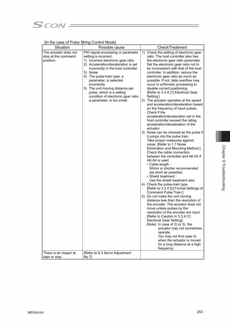
Chapter 9 Troubleshooting
253
[In the case of Pulse String Control Mode] Situation Possible cause Check/Treatment
The actuator does not stop at the command position.
PIO signal processing or parameter setting is incorrect. 1) Incorrect electronic gear ratio 2) Acceleration/deceleration is set
incorrectly in the host controller.3) Noise 4) The pulse-train type, a
parameter, is selected incorrectly.
5) The unit moving distance per pulse, which is a setting condition of electronic gear ratio, a parameter, is too small.
1) Check the setting of electronic gear ratio. The host controller also has the electronic gear ratio parameter. Set the electronic gear ratio not to be inconsistent with that of the host controller. In addition, reduce the electronic gear ratio as much as possible. If not, data overflow may occur in arithmetic processing to disable correct positioning. [Refer to 3.3.4 [1] Electrical Gear Setting.]
2) The actuator operates at the speed and acceleration/deceleration based on the frequency of input pulses. Check if the acceleration/deceleration set in the host controller exceed the rating acceleration/deceleration of the actuator.
3) Noise can be misread as the pulse if it jumps into the pulse train. Take proper measures against noise. [Refer to 1.7 Noise Elimination and Mounting Method.]Check the cable connection between the controller and AK-04 if AK-04 is used. • Cable length :
50mm or shorter recommended (as short as possible)
• Shield treatment : Use the shield treatment wire.
4) Check the pulse-train type. [Refer to 3.3.4 [2] Format Settings of Command Pulse Train.]
5) Do not make the unit moving distance less than the resolution of the encoder. The actuator does not move unless pulses by the resolution of the encoder are input. [Refer to Caution in 3.3.4 [1] Electrical Gear Setting] (Note) In case of 2) or 3), the
actuator may not sometimes operate. You may not find case 4) when the actuator is moved for a long distance at a high frequency.
There is an impact at start or stop
[Refer to 8.3 Servo Adjustment No.7]
ME0243-8J
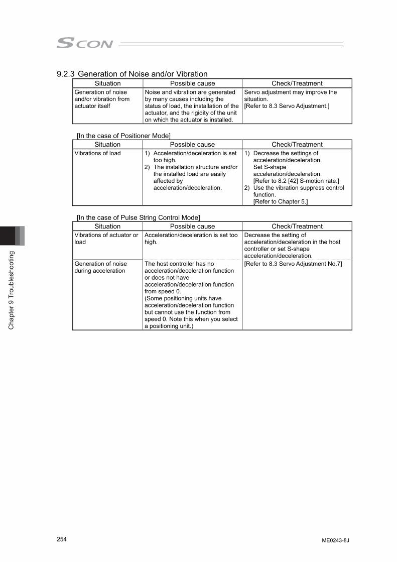
Cha
pter
9 T
roub
lesh
ootin
g
254
9.2.3 Generation of Noise and/or Vibration Situation Possible cause Check/Treatment
Generation of noise and/or vibration from actuator itself
Noise and vibration are generated by many causes including the status of load, the installation of the actuator, and the rigidity of the unit on which the actuator is installed.
Servo adjustment may improve the situation. [Refer to 8.3 Servo Adjustment.]
[In the case of Positioner Mode]
Situation Possible cause Check/Treatment Vibrations of load 1) Acceleration/deceleration is set
too high. 2) The installation structure and/or
the installed load are easily affected by acceleration/deceleration.
1) Decrease the settings of acceleration/deceleration. Set S-shape acceleration/deceleration. [Refer to 8.2 [42] S-motion rate.]
2) Use the vibration suppress control function. [Refer to Chapter 5.]
[In the case of Pulse String Control Mode]
Situation Possible cause Check/Treatment Vibrations of actuator or load
Acceleration/deceleration is set too high.
Decrease the setting of acceleration/deceleration in the host controller or set S-shape acceleration/deceleration.
Generation of noise during acceleration
The host controller has no acceleration/deceleration function or does not have acceleration/deceleration function from speed 0. (Some positioning units have acceleration/deceleration function but cannot use the function from speed 0. Note this when you select a positioning unit.)
[Refer to 8.3 Servo Adjustment No.7]
ME0243-8J
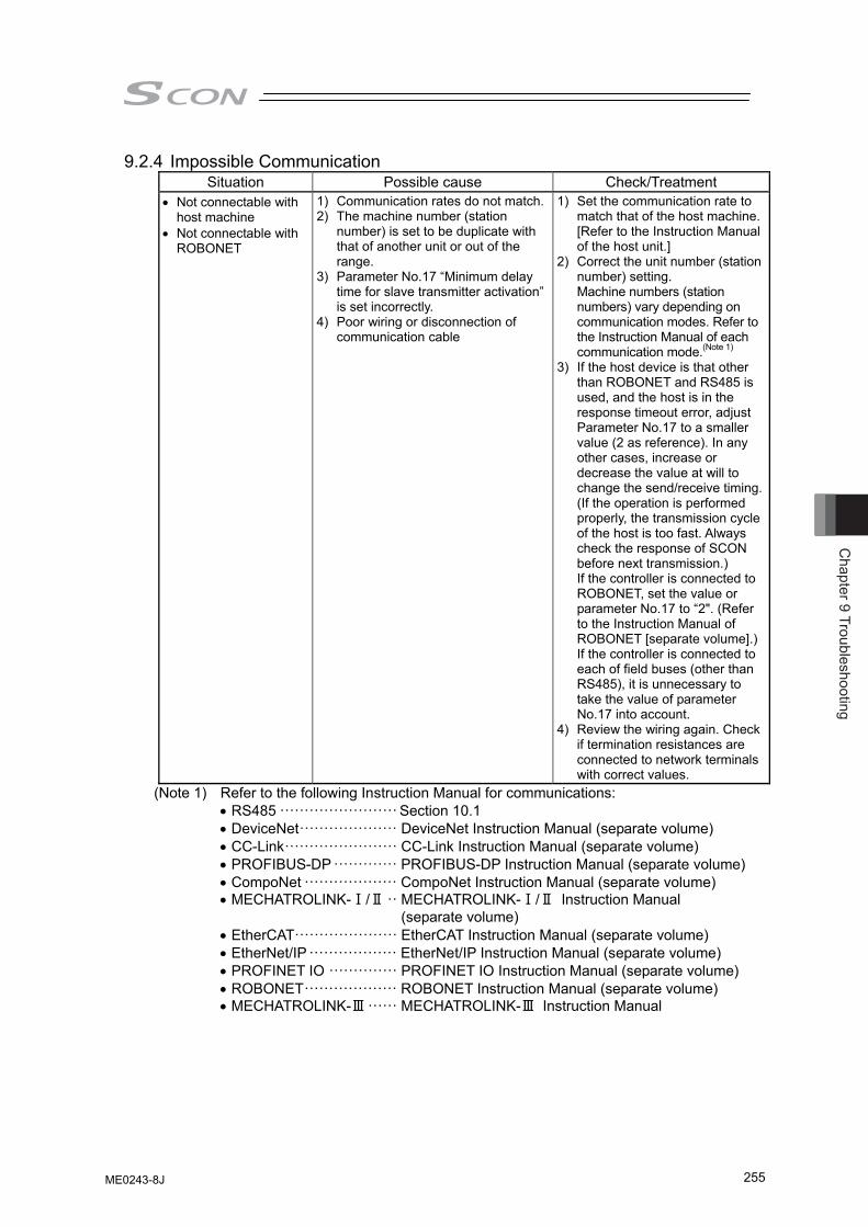
Chapter 9 Troubleshooting
255
9.2.4 Impossible Communication Situation Possible cause Check/Treatment
• Not connectable with host machine
• Not connectable with ROBONET
1) Communication rates do not match.2) The machine number (station
number) is set to be duplicate with that of another unit or out of the range.
3) Parameter No.17 “Minimum delay time for slave transmitter activation” is set incorrectly.
4) Poor wiring or disconnection of communication cable
1) Set the communication rate to match that of the host machine. [Refer to the Instruction Manual of the host unit.]
2) Correct the unit number (station number) setting. Machine numbers (station numbers) vary depending on communication modes. Refer to the Instruction Manual of each communication mode.(Note 1)
3) If the host device is that other than ROBONET and RS485 is used, and the host is in the response timeout error, adjust Parameter No.17 to a smaller value (2 as reference). In any other cases, increase or decrease the value at will to change the send/receive timing. (If the operation is performed properly, the transmission cycle of the host is too fast. Always check the response of SCON before next transmission.) If the controller is connected to ROBONET, set the value or parameter No.17 to “2". (Refer to the Instruction Manual of ROBONET [separate volume].)If the controller is connected to each of field buses (other than RS485), it is unnecessary to take the value of parameter No.17 into account.
4) Review the wiring again. Check if termination resistances are connected to network terminals with correct values.
(Note 1) Refer to the following Instruction Manual for communications: • RS485 ························ Section 10.1 • DeviceNet···················· DeviceNet Instruction Manual (separate volume) • CC-Link······················· CC-Link Instruction Manual (separate volume) • PROFIBUS-DP ············· PROFIBUS-DP Instruction Manual (separate volume) • CompoNet ··················· CompoNet Instruction Manual (separate volume) • MECHATROLINK-Ⅰ/Ⅱ ·· MECHATROLINK-Ⅰ/Ⅱ Instruction Manual
(separate volume) • EtherCAT····················· EtherCAT Instruction Manual (separate volume) • EtherNet/IP ·················· EtherNet/IP Instruction Manual (separate volume) • PROFINET IO ·············· PROFINET IO Instruction Manual (separate volume) • ROBONET··················· ROBONET Instruction Manual (separate volume) • MECHATROLINK-Ⅲ ······ MECHATROLINK-Ⅲ Instruction Manual
ME0243-8J
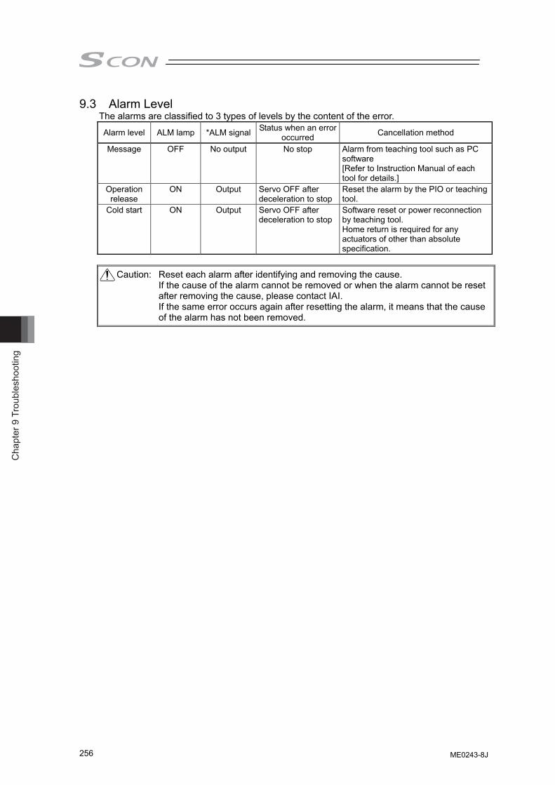
Cha
pter
9 T
roub
lesh
ootin
g
256
9.3 Alarm Level The alarms are classified to 3 types of levels by the content of the error.
Alarm level ALM lamp *ALM signal Status when an error occurred Cancellation method
Message OFF No output No stop Alarm from teaching tool such as PC software [Refer to Instruction Manual of each tool for details.]
Operation release
ON Output Servo OFF after deceleration to stop
Reset the alarm by the PIO or teaching tool.
Cold start ON Output Servo OFF after deceleration to stop
Software reset or power reconnection by teaching tool. Home return is required for any actuators of other than absolute specification.
Caution: Reset each alarm after identifying and removing the cause. If the cause of the alarm cannot be removed or when the alarm cannot be reset after removing the cause, please contact IAI. If the same error occurs again after resetting the alarm, it means that the cause of the alarm has not been removed.
ME0243-8J
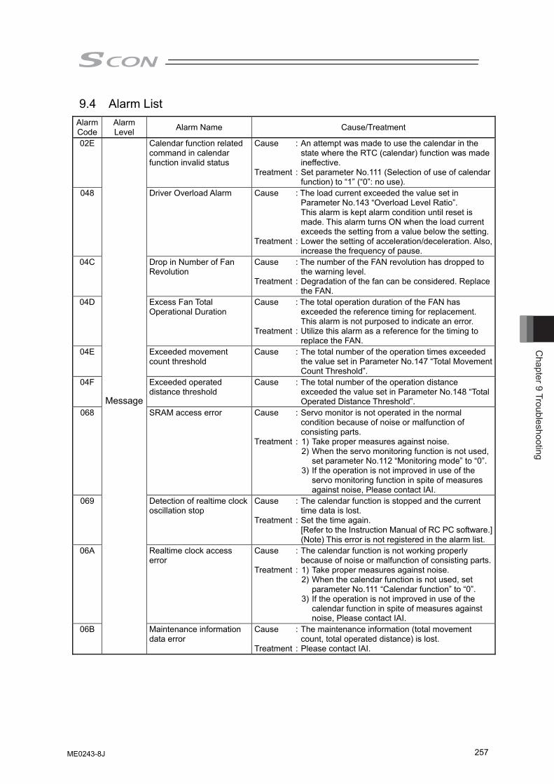
Chapter 9 Troubleshooting
257
9.4 Alarm List Alarm Code
Alarm Level Alarm Name Cause/Treatment
02E Calendar function related command in calendar function invalid status
Cause : An attempt was made to use the calendar in the state where the RTC (calendar) function was made ineffective.
Treatment : Set parameter No.111 (Selection of use of calendar function) to “1” (“0”: no use).
048 Driver Overload Alarm Cause : The load current exceeded the value set in Parameter No.143 “Overload Level Ratio”. This alarm is kept alarm condition until reset is made. This alarm turns ON when the load current exceeds the setting from a value below the setting.
Treatment : Lower the setting of acceleration/deceleration. Also, increase the frequency of pause.
04C Drop in Number of Fan Revolution
Cause : The number of the FAN revolution has dropped to the warning level.
Treatment : Degradation of the fan can be considered. Replace the FAN.
04D Excess Fan Total Operational Duration
Cause : The total operation duration of the FAN has exceeded the reference timing for replacement. This alarm is not purposed to indicate an error.
Treatment : Utilize this alarm as a reference for the timing to replace the FAN.
04E Exceeded movement count threshold
Cause : The total number of the operation times exceeded the value set in Parameter No.147 “Total Movement Count Threshold”.
04F Exceeded operated distance threshold
Cause : The total number of the operation distance exceeded the value set in Parameter No.148 “Total Operated Distance Threshold”.
068 SRAM access error Cause : Servo monitor is not operated in the normal condition because of noise or malfunction of consisting parts.
Treatment : 1) Take proper measures against noise. 2) When the servo monitoring function is not used,
set parameter No.112 “Monitoring mode” to “0”. 3) If the operation is not improved in use of the
servo monitoring function in spite of measures against noise, Please contact IAI.
069 Detection of realtime clock oscillation stop
Cause : The calendar function is stopped and the current time data is lost.
Treatment : Set the time again. [Refer to the Instruction Manual of RC PC software.](Note) This error is not registered in the alarm list.
06A Realtime clock access error
Cause : The calendar function is not working properly because of noise or malfunction of consisting parts.
Treatment : 1) Take proper measures against noise. 2) When the calendar function is not used, set
parameter No.111 “Calendar function” to “0”. 3) If the operation is not improved in use of the
calendar function in spite of measures against noise, Please contact IAI.
06B
Message
Maintenance information data error
Cause : The maintenance information (total movement count, total operated distance) is lost.
Treatment : Please contact IAI.
ME0243-8J
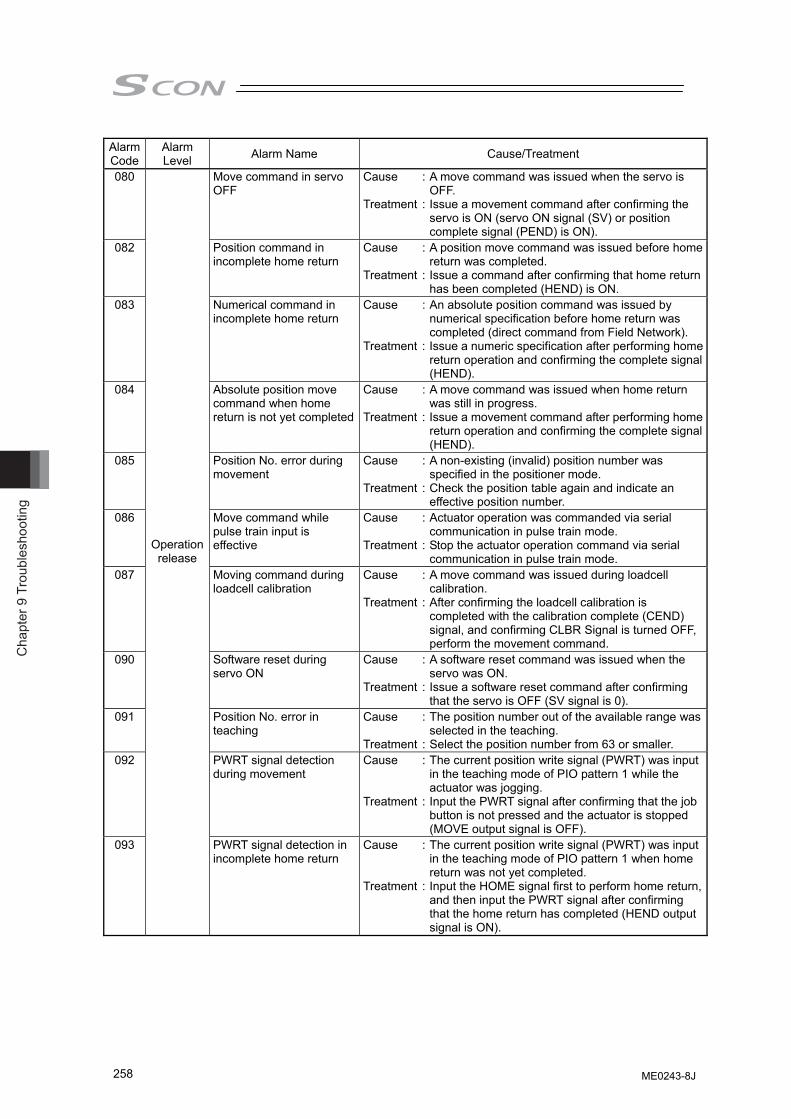
Cha
pter
9 T
roub
lesh
ootin
g
258
Alarm Code
Alarm Level Alarm Name Cause/Treatment
080 Move command in servo OFF
Cause : A move command was issued when the servo is OFF.
Treatment : Issue a movement command after confirming the servo is ON (servo ON signal (SV) or position complete signal (PEND) is ON).
082 Position command in incomplete home return
Cause : A position move command was issued before home return was completed.
Treatment : Issue a command after confirming that home return has been completed (HEND) is ON.
083 Numerical command in incomplete home return
Cause : An absolute position command was issued by numerical specification before home return was completed (direct command from Field Network).
Treatment : Issue a numeric specification after performing home return operation and confirming the complete signal (HEND).
084 Absolute position move command when home return is not yet completed
Cause : A move command was issued when home return was still in progress.
Treatment : Issue a movement command after performing home return operation and confirming the complete signal (HEND).
085 Position No. error during movement
Cause : A non-existing (invalid) position number was specified in the positioner mode.
Treatment : Check the position table again and indicate an effective position number.
086 Move command while pulse train input is effective
Cause : Actuator operation was commanded via serial communication in pulse train mode.
Treatment : Stop the actuator operation command via serial communication in pulse train mode.
087 Moving command during loadcell calibration
Cause : A move command was issued during loadcell calibration.
Treatment : After confirming the loadcell calibration is completed with the calibration complete (CEND) signal, and confirming CLBR Signal is turned OFF, perform the movement command.
090 Software reset during servo ON
Cause : A software reset command was issued when the servo was ON.
Treatment : Issue a software reset command after confirming that the servo is OFF (SV signal is 0).
091 Position No. error in teaching
Cause : The position number out of the available range was selected in the teaching.
Treatment : Select the position number from 63 or smaller. 092 PWRT signal detection
during movement Cause : The current position write signal (PWRT) was input
in the teaching mode of PIO pattern 1 while the actuator was jogging.
Treatment : Input the PWRT signal after confirming that the job button is not pressed and the actuator is stopped (MOVE output signal is OFF).
093
Operation release
PWRT signal detection in incomplete home return
Cause : The current position write signal (PWRT) was input in the teaching mode of PIO pattern 1 when home return was not yet completed.
Treatment : Input the HOME signal first to perform home return, and then input the PWRT signal after confirming that the home return has completed (HEND output signal is ON).
ME0243-8J
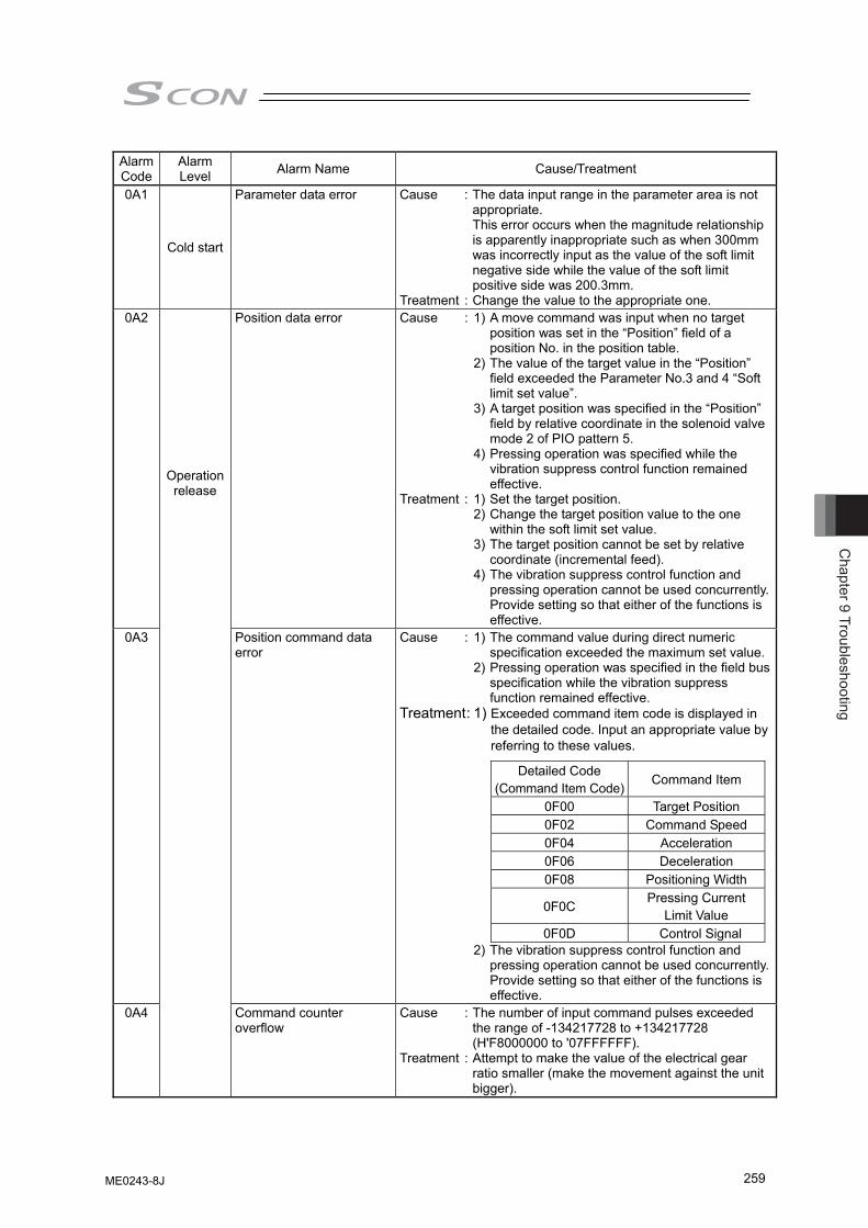
Chapter 9 Troubleshooting
259
Alarm Code
Alarm Level Alarm Name Cause/Treatment
0A1
Cold start
Parameter data error Cause : The data input range in the parameter area is not appropriate.
This error occurs when the magnitude relationship is apparently inappropriate such as when 300mm was incorrectly input as the value of the soft limit negative side while the value of the soft limit positive side was 200.3mm.
Treatment : Change the value to the appropriate one. 0A2 Position data error Cause : 1) A move command was input when no target
position was set in the “Position” field of a position No. in the position table.
2) The value of the target value in the “Position” field exceeded the Parameter No.3 and 4 “Soft limit set value”.
3) A target position was specified in the “Position” field by relative coordinate in the solenoid valve mode 2 of PIO pattern 5.
4) Pressing operation was specified while the vibration suppress control function remained effective.
Treatment : 1) Set the target position. 2) Change the target position value to the one
within the soft limit set value. 3) The target position cannot be set by relative
coordinate (incremental feed). 4) The vibration suppress control function and
pressing operation cannot be used concurrently. Provide setting so that either of the functions is effective.
0A3 Position command data error
Cause : 1) The command value during direct numeric specification exceeded the maximum set value.
2) Pressing operation was specified in the field bus specification while the vibration suppress function remained effective.
Treatment : 1) Exceeded command item code is displayed in the detailed code. Input an appropriate value by referring to these values.
Detailed Code
(Command Item Code) Command Item
0F00 Target Position 0F02 Command Speed 0F04 Acceleration 0F06 Deceleration 0F08 Positioning Width
0F0C Pressing Current Limit Value
0F0D Control Signal 2) The vibration suppress control function and
pressing operation cannot be used concurrently. Provide setting so that either of the functions is effective.
0A4
Operation release
Command counter overflow
Cause : The number of input command pulses exceeded the range of -134217728 to +134217728 (H'F8000000 to '07FFFFFF).
Treatment : Attempt to make the value of the electrical gear ratio smaller (make the movement against the unit bigger).
ME0243-8J
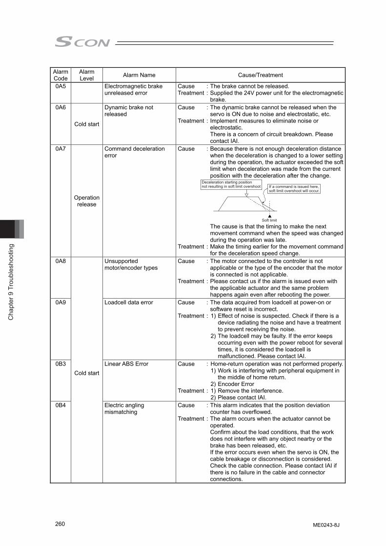
Cha
pter
9 T
roub
lesh
ootin
g
260
Alarm Code
Alarm Level Alarm Name Cause/Treatment
0A5 Electromagnetic brake unreleased error
Cause : The brake cannot be released. Treatment : Supplied the 24V power unit for the electromagnetic
brake. 0A6
Cold start
Dynamic brake not released
Cause : The dynamic brake cannot be released when the servo is ON due to noise and electrostatic, etc.
Treatment : Implement measures to eliminate noise or electrostatic. There is a concern of circuit breakdown. Please contact IAI.
0A7
Operation release
Command deceleration error
Cause : Because there is not enough deceleration distance when the deceleration is changed to a lower setting during the operation, the actuator exceeded the soft limit when deceleration was made from the current position with the deceleration after the change.
Soft limit
Deceleration starting position not resulting in soft limit overshoot If a command is issued here,
soft limit overshoot will occur.
The cause is that the timing to make the next
movement command when the speed was changed during the operation was late.
Treatment : Make the timing earlier for the movement command for the deceleration speed change.
0A8 Unsupported motor/encoder types
Cause : The motor connected to the controller is not applicable or the type of the encoder that the motor is connected is not applicable.
Treatment : Please contact us if the alarm is issued even with the applicable actuator and the same problem happens again even after rebooting the power.
0A9 Loadcell data error Cause : The data acquired from loadcell at power-on or software reset is incorrect.
Treatment : 1) Effect of noise is suspected. Check if there is a device radiating the noise and have a treatment to prevent receiving the noise.
2) The loadcell may be faulty. If the error keeps occurring even with the power reboot for several times, it is considered the loadcell is malfunctioned. Please contact IAI.
0B3 Linear ABS Error Cause : Home-return operation was not performed properly. 1) Work is interfering with peripheral equipment in
the middle of home return. 2) Encoder Error Treatment : 1) Remove the interference. 2) Please contact IAI.
0B4
Cold start
Electric angling mismatching
Cause : This alarm indicates that the position deviation counter has overflowed.
Treatment : The alarm occurs when the actuator cannot be operated. Confirm about the load conditions, that the work does not interfere with any object nearby or the brake has been released, etc. If the error occurs even when the servo is ON, the cable breakage or disconnection is considered. Check the cable connection. Please contact IAI if there is no failure in the cable and connector connections.
ME0243-8J
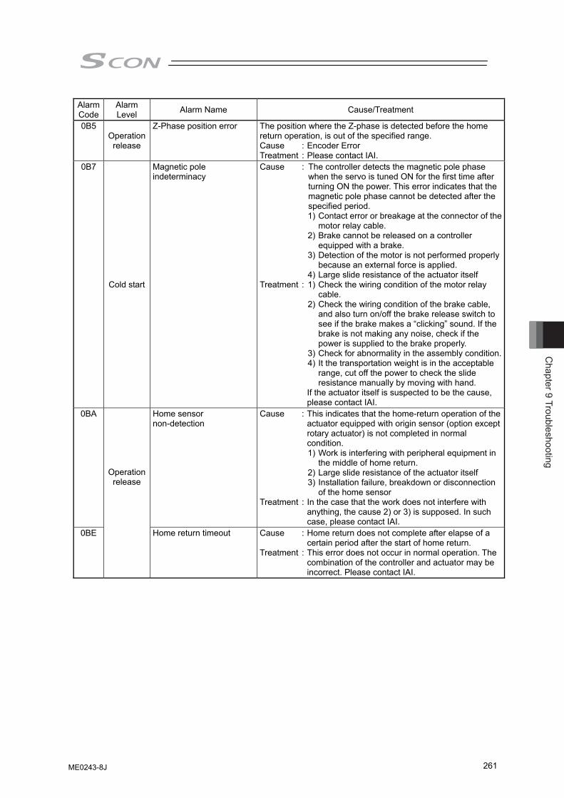
Chapter 9 Troubleshooting
261
Alarm Code
Alarm Level Alarm Name Cause/Treatment
0B5 Operation release
Z-Phase position error The position where the Z-phase is detected before the home return operation, is out of the specified range. Cause : Encoder Error Treatment : Please contact IAI.
0B7
Cold start
Magnetic pole indeterminacy
Cause : The controller detects the magnetic pole phase when the servo is tuned ON for the first time after turning ON the power. This error indicates that the magnetic pole phase cannot be detected after the specified period.
1) Contact error or breakage at the connector of the motor relay cable.
2) Brake cannot be released on a controller equipped with a brake.
3) Detection of the motor is not performed properly because an external force is applied.
4) Large slide resistance of the actuator itself Treatment : 1) Check the wiring condition of the motor relay
cable. 2) Check the wiring condition of the brake cable,
and also turn on/off the brake release switch to see if the brake makes a “clicking” sound. If the brake is not making any noise, check if the power is supplied to the brake properly.
3) Check for abnormality in the assembly condition. 4) It the transportation weight is in the acceptable
range, cut off the power to check the slide resistance manually by moving with hand.
If the actuator itself is suspected to be the cause, please contact IAI.
0BA Home sensor non-detection
Cause : This indicates that the home-return operation of the actuator equipped with origin sensor (option except rotary actuator) is not completed in normal condition.
1) Work is interfering with peripheral equipment in the middle of home return.
2) Large slide resistance of the actuator itself 3) Installation failure, breakdown or disconnection
of the home sensor Treatment : In the case that the work does not interfere with
anything, the cause 2) or 3) is supposed. In such case, please contact IAI.
0BE
Operation release
Home return timeout Cause : Home return does not complete after elapse of a certain period after the start of home return.
Treatment : This error does not occur in normal operation. The combination of the controller and actuator may be incorrect. Please contact IAI.
ME0243-8J
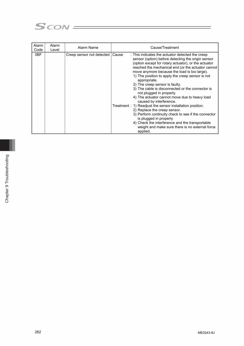
Cha
pter
9 T
roub
lesh
ootin
g
262
Alarm Code
Alarm Level Alarm Name Cause/Treatment
0BF Creep sensor not detected Cause : This indicates the actuator detected the creep sensor (option) before detecting the origin sensor (option except for rotary actuator), or the actuator reached the mechanical end (or the actuator cannot move anymore because the load is too large).
1) The position to apply the creep sensor is not appropriate.
2) The creep sensor is faulty. 3) The cable is disconnected or the connector is
not plugged in properly. 4) The actuator cannot move due to heavy load
caused by interference. Treatment : 1) Readjust the sensor installation position. 2) Replace the creep sensor. 3) Perform continuity check to see if the connector
is plugged in properly. 4) Check the interference and the transportable
weight and make sure there is no external force applied.
ME0243-8J
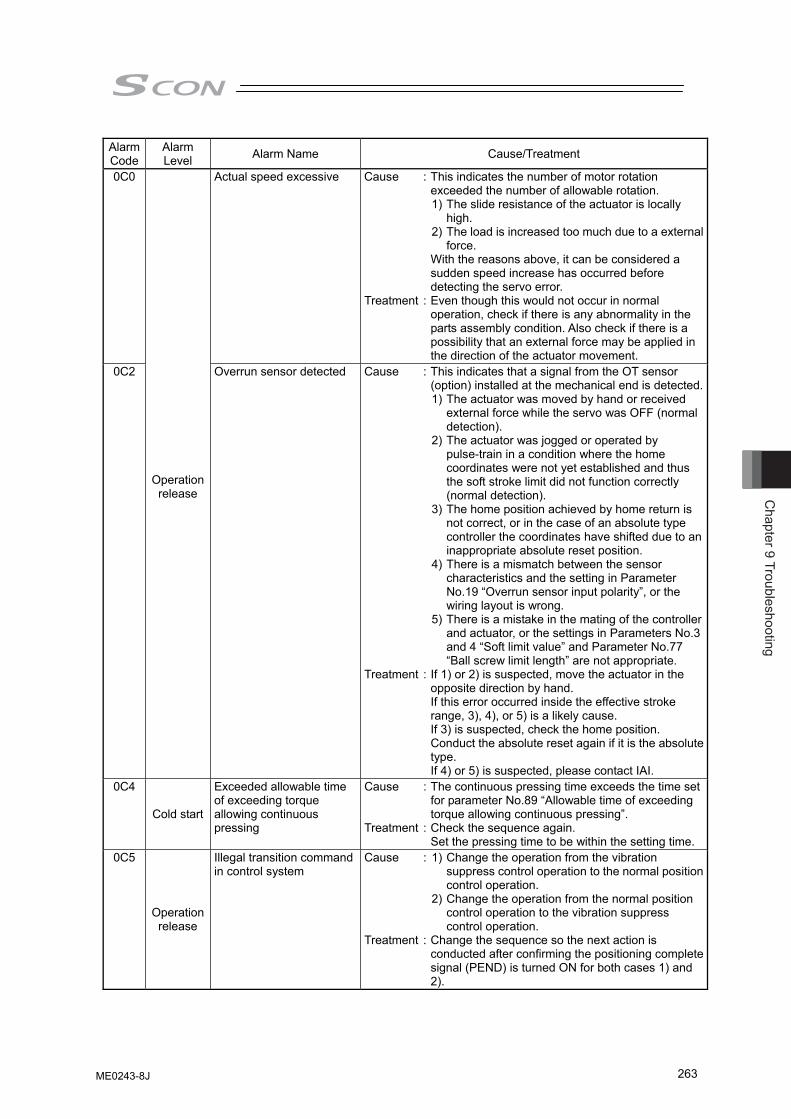
Chapter 9 Troubleshooting
263
Alarm Code
Alarm Level Alarm Name Cause/Treatment
0C0 Actual speed excessive Cause : This indicates the number of motor rotation exceeded the number of allowable rotation.
1) The slide resistance of the actuator is locally high.
2) The load is increased too much due to a external force.
With the reasons above, it can be considered a sudden speed increase has occurred before detecting the servo error.
Treatment : Even though this would not occur in normal operation, check if there is any abnormality in the parts assembly condition. Also check if there is a possibility that an external force may be applied in the direction of the actuator movement.
0C2
Operation release
Overrun sensor detected Cause : This indicates that a signal from the OT sensor (option) installed at the mechanical end is detected.
1) The actuator was moved by hand or received external force while the servo was OFF (normal detection).
2) The actuator was jogged or operated by pulse-train in a condition where the home coordinates were not yet established and thus the soft stroke limit did not function correctly (normal detection).
3) The home position achieved by home return is not correct, or in the case of an absolute type controller the coordinates have shifted due to an inappropriate absolute reset position.
4) There is a mismatch between the sensor characteristics and the setting in Parameter No.19 “Overrun sensor input polarity”, or the wiring layout is wrong.
5) There is a mistake in the mating of the controller and actuator, or the settings in Parameters No.3 and 4 “Soft limit value” and Parameter No.77 “Ball screw limit length” are not appropriate.
Treatment : If 1) or 2) is suspected, move the actuator in the opposite direction by hand. If this error occurred inside the effective stroke range, 3), 4), or 5) is a likely cause. If 3) is suspected, check the home position. Conduct the absolute reset again if it is the absolute type. If 4) or 5) is suspected, please contact IAI.
0C4
Cold start
Exceeded allowable time of exceeding torque allowing continuous pressing
Cause : The continuous pressing time exceeds the time set for parameter No.89 “Allowable time of exceeding torque allowing continuous pressing”.
Treatment : Check the sequence again. Set the pressing time to be within the setting time.
0C5
Operation release
Illegal transition command in control system
Cause : 1) Change the operation from the vibration suppress control operation to the normal position control operation.
2) Change the operation from the normal position control operation to the vibration suppress control operation.
Treatment : Change the sequence so the next action is conducted after confirming the positioning complete signal (PEND) is turned ON for both cases 1) and 2).
ME0243-8J
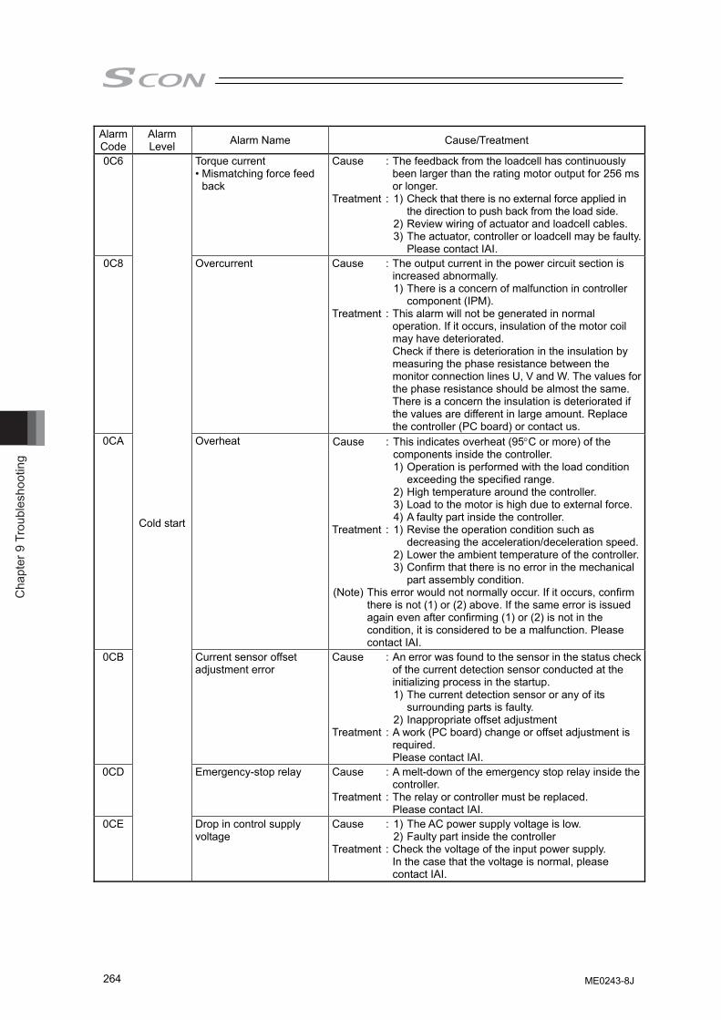
Cha
pter
9 T
roub
lesh
ootin
g
264
Alarm Code
Alarm Level Alarm Name Cause/Treatment
0C6 Torque current • Mismatching force feed
back
Cause : The feedback from the loadcell has continuously been larger than the rating motor output for 256 ms or longer.
Treatment : 1) Check that there is no external force applied in the direction to push back from the load side.
2) Review wiring of actuator and loadcell cables. 3) The actuator, controller or loadcell may be faulty.
Please contact IAI. 0C8 Overcurrent Cause : The output current in the power circuit section is
increased abnormally. 1) There is a concern of malfunction in controller
component (IPM). Treatment : This alarm will not be generated in normal
operation. If it occurs, insulation of the motor coil may have deteriorated. Check if there is deterioration in the insulation by measuring the phase resistance between the monitor connection lines U, V and W. The values for the phase resistance should be almost the same. There is a concern the insulation is deteriorated if the values are different in large amount. Replace the controller (PC board) or contact us.
0CA Overheat Cause : This indicates overheat (95°C or more) of the components inside the controller.
1) Operation is performed with the load condition exceeding the specified range.
2) High temperature around the controller. 3) Load to the motor is high due to external force. 4) A faulty part inside the controller. Treatment : 1) Revise the operation condition such as
decreasing the acceleration/deceleration speed. 2) Lower the ambient temperature of the controller. 3) Confirm that there is no error in the mechanical
part assembly condition. (Note) This error would not normally occur. If it occurs, confirm
there is not (1) or (2) above. If the same error is issued again even after confirming (1) or (2) is not in the condition, it is considered to be a malfunction. Please contact IAI.
0CB Current sensor offset adjustment error
Cause : An error was found to the sensor in the status check of the current detection sensor conducted at the initializing process in the startup.
1) The current detection sensor or any of its surrounding parts is faulty.
2) Inappropriate offset adjustment Treatment : A work (PC board) change or offset adjustment is
required. Please contact IAI.
0CD Emergency-stop relay Cause : A melt-down of the emergency stop relay inside the controller.
Treatment : The relay or controller must be replaced. Please contact IAI.
0CE
Cold start
Drop in control supply voltage
Cause : 1) The AC power supply voltage is low. 2) Faulty part inside the controller Treatment : Check the voltage of the input power supply.
In the case that the voltage is normal, please contact IAI.
ME0243-8J
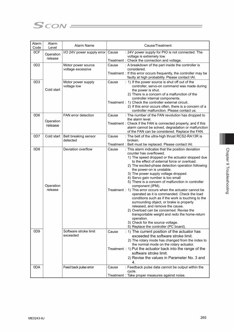
Chapter 9 Troubleshooting
265
Alarm Code
Alarm Level Alarm Name Cause/Treatment
0CF Operation release
I/O 24V power supply error Cause : 24V power supply for PIO is not connected. The voltage is extremely low.
Treatment : Check the connection and voltage. 0D2 Motor power source
voltage excessive Cause : A breakdown of the part inside the controller is
considered. Treatment : If this error occurs frequently, the controller may be
faulty at high probability. Please contact IAI. 0D3
Cold start
Motor power supply voltage low
Cause : 1) If the power source is shut off out of the controller, servo-on command was made during the power is shut.
2) There is a concern of a malfunction of the controller internal components.
Treatment : 1) Check the controller external circuit. 2) If this error occurs often, there is a concern of a
controller malfunction. Please contact us. 0D6
Operation release
FAN error detection Cause : The number of the FAN revolution has dropped to the alarm level.
Treatment : Check if the FAN is connected properly, and if this alarm cannot be solved, degradation or malfunction of the FAN can be considered. Replace the FAN.
0D7 Cold start Belt breaking sensor detected
Cause : The belt of the ultra-high thrust RCS2-RA13R is broken.
Treatment : Belt must be replaced. Please contact IAI. 0D8 Deviation overflow Cause : This alarm indicates that the position deviation
counter has overflowed. 1) The speed dropped or the actuator stopped due
to the effect of external force or overload. 2) The excited-phase detection operation following
the power-on is unstable. 3) The power supply voltage dropped. 4) Servo gain number is too small 5) There is a concern of malfunction in controller
component (IPM). Treatment : 1) This error occurs when the actuator cannot be
operated as it is commanded. Check the load conditions such as if the work is touching to the surrounding object, or brake is properly released, and remove the cause.
2) Overload can be concerned. Revise the transportable weight and redo the home-return operation.
3) Check for the source voltage. 5) Replace the controller (PC board).
0D9 Software stroke limit exceeded
Cause : 1) The current position of the actuator has exceeded the software stroke limit.
2) The rotary mode has changed from the index to the normal mode on the rotary actuator.
Treatment : 1) Put the actuator back into the range of the software stroke limit.
2) Revise the values in Parameter No. 3 and 4.
0DA
Operation release
Feed back pulse error Cause : Feedback pulse data cannot be output within the cycle.
Treatment : Take proper measures against noise.
ME0243-8J
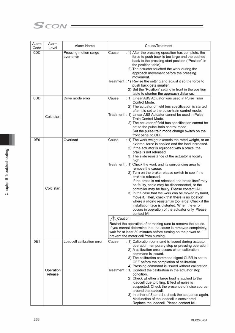
Cha
pter
9 T
roub
lesh
ootin
g
266
Alarm Code
Alarm Level Alarm Name Cause/Treatment
0DC Pressing motion range over error
Cause : 1) After the pressing operation has complete, the force to push back is too large and the pushed back to the pressing start position (“Position” in the position table).
2) The actuator touched the work during the approach movement before the pressing movement.
Treatment : 1) Revise the setting and adjust it so the force to push back gets smaller.
2) Set the “Position” setting in front in the position table to shorten the approach distance.
0DD
Cold start
Drive mode error Cause : 1) Linear ABS Actuator was used in Pulse Train Control Mode.
2) The actuator of field bus specification is started after it is set to the pulse-train control mode.
Treatment : 1) Linear ABS Actuator cannot be used in Pulse Train Control Mode.
2) The actuator of field bus specification cannot be set to the pulse-train control mode. Set the pulse-train mode change switch on the front panel to OFF.
0E0
Cold start
Overload Cause : 1) The work weight exceeds the rated weight, or an external force is applied and the load increased.
2) If the actuator is equipped with a brake, the brake is not released.
3) The slide resistance of the actuator is locally high.
Treatment : 1) Check the work and its surrounding area to remove the cause.
2) Turn on the brake release switch to see if the brake is released. If the brake is not released, the brake itself may be faulty, cable may be disconnected, or the controller may be faulty. Please contact IAI.
3) In the case that the work can be moved by hand, move it. Then, check that there is no location where a sliding resistant is too large. Check if the installation face is distorted. When the error occurs in operation of the actuator only, Please contact IAI.
Caution Restart the operation after making sure to remove the cause. If you cannot determine that the cause is removed completely, wait for at least 30 minutes before turning on the power to prevent the motor coil from burning.
0E1
Operation release
Loadcell calibration error Cause : 1) Calibration command is issued during actuator operation, temporary stop or pressing operation.
2) A calibration error occurs when calibration command is issued.
3) The calibration command signal CLBR is set to OFF before the completion of calibration.
4) Pressing command is issued without calibration.Treatment : 1) Conduct the calibration in the actuator stop
condition. 2) Check whether a large load is applied to the
loadcell due to biting. Effect of noise is suspected. Check the presence of noise source around the loadcell.
3) In either of 3) and 4), check the sequence again. Malfunction of the loadcell is considered. Replace the loadcell. Please contact IAI.
ME0243-8J
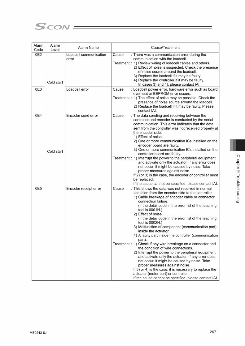
Chapter 9 Troubleshooting
267
Alarm Code
Alarm Level Alarm Name Cause/Treatment
0E2 Loadcell communication error
Cause : There was a communication error during the communication with the loadcell.
Treatment : 1) Review wiring of loadcell cables and others. 2) Effect of noise is suspected. Check the presence
of noise source around the loadcell. 3) Replace the loadcell if it may be faulty. 4) Replace the controller if it may be faulty.
In cases 3) and 4), please contact IAI. 0E3
Cold start
Loadcell error Cause : Loadcell power error, hardware error such as board overheat or EEPROM error occurs.
Treatment : 1) The effect of noise may be possible. Check the presence of noise source around the loadcell.
2) Replace the loadcell if it may be faulty. Please contact IAI.
0E4 Encoder send error Cause : The data sending and receiving between the controller and encoder is conducted by the serial communication. This error indicates that the data sent from the controller was not received properly at the encoder side.
1) Effect of noise 2) One or more communication ICs installed on the
encoder board are faulty. 3) One or more communication ICs installed on the
controller board are faulty. Treatment : 1) Interrupt the power to the peripheral equipment
and activate only the actuator. If any error does not occur, it might be caused by noise. Take proper measures against noise.
If 2) or 3) is the case, the encoder or controller must be replaced. If the cause cannot be specified, please contact IAI.
0E5
Cold start
Encoder receipt error Cause : This shows the data was not received in normal condition from the encoder side to the controller.
1) Cable breakage of encoder cable or connector connection failure. (If the detail code in the error list of the teaching tool is 0001H.)
2) Effect of noise. (If the detail code in the error list of the teaching tool is 0002H.)
3) Malfunction of component (communication part) inside the actuator.
4) A faulty part inside the controller (communication part).
Treatment : 1) Check if any wire breakage on a connector and the condition of wire connections.
2) Interrupt the power to the peripheral equipment and activate only the actuator. If any error does not occur, it might be caused by noise. Take proper measures against noise.
If 3) or 4) is the case, it is necessary to replace the actuator (motor part) or controller. If the cause cannot be specified, please contact IAI.
ME0243-8J
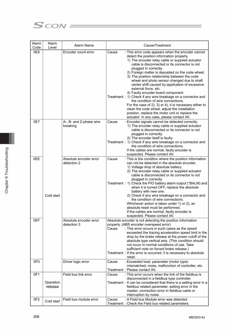
Cha
pter
9 T
roub
lesh
ootin
g
268
Alarm Code
Alarm Level Alarm Name Cause/Treatment
0E6 Encoder count error Cause : This error code appears when the encoder cannot detect the position information properly.
1) The encoder relay cable or supplied actuator cable is disconnected or its connector is not plugged in correctly.
2) Foreign matter is deposited on the code wheel. 3) The position relationship between the code
wheel and photo sensor changed due to shaft center shift caused by application of excessive external force, etc.
4) Faulty encoder board component Treatment : 1) Check if any wire breakage on a connector and
the condition of wire connections. For the case of 2), 3) or 4), it is necessary either to
clean the code wheel, adjust the installation position, replace the motor unit or replace the actuator. In any case, please contact IAI.
0E7 A-, B- and Z-phase wire breaking
Cause : Encoder signals cannot be detected correctly. 1) The encoder relay cable or supplied actuator
cable is disconnected or its connector is not plugged in correctly.
2) The encoder itself is faulty. Treatment : 1) Check if any wire breakage on a connector and
the condition of wire connections. If the cables are normal, faulty encoder is
suspected. Please contact IAI. 0EE Absolute encoder error
detection 2 Cause : This is the condition where the position information
can not be detected in the absolute encoder. 1) Voltage drop of absolute battery. 2) The encoder relay cable or supplied actuator
cable is disconnected or its connector is not plugged in correctly.
Treatment : 1) Check the PIO battery alarm output (*BALM) and when it is turned OFF, replace the absolute battery with new one.
2) Check if any wire breakage on a connector and the condition of wire connections.
Whichever action is taken under 1) or 2), an absolute reset must be performed. If the cables are normal, faulty encoder is suspected. Please contact IAI.
0EF Absolute encoder error detection 3
Absolute encoder is not detecting the position information properly. (ABS encoder overspeed error) Cause : This error occurs in such cases as the speed
exceeded the tracing acceleration speed limit in the drop by the brake release at the power cutoff of the absolute type vertical axis. (This condition should not occur in normal conditions of use. Take sufficient note on forced brake release.)
Treatment : If the error is occurred, it is necessary to absolute reset.
0F0
Cold start
Driver logic error Cause : Exceeded load, parameter (motor type) mismatched, noise, malfunction of controller, etc.
Treatment : Please contact IAI. 0F1
Operation release
Field bus link error Cause : This error occurs when the link of the fieldbus is disconnected in a fieldbus type controller.
Treatment : It can be considered that there is a setting error in a fieldbus related parameter, setting error in the master, connection error in fieldbus cable or interruption by noise.
0F2 Cold start Field bus module error Cause : A Field bus Module error was detected. Treatment : Check the Field bus related parameters.
ME0243-8J
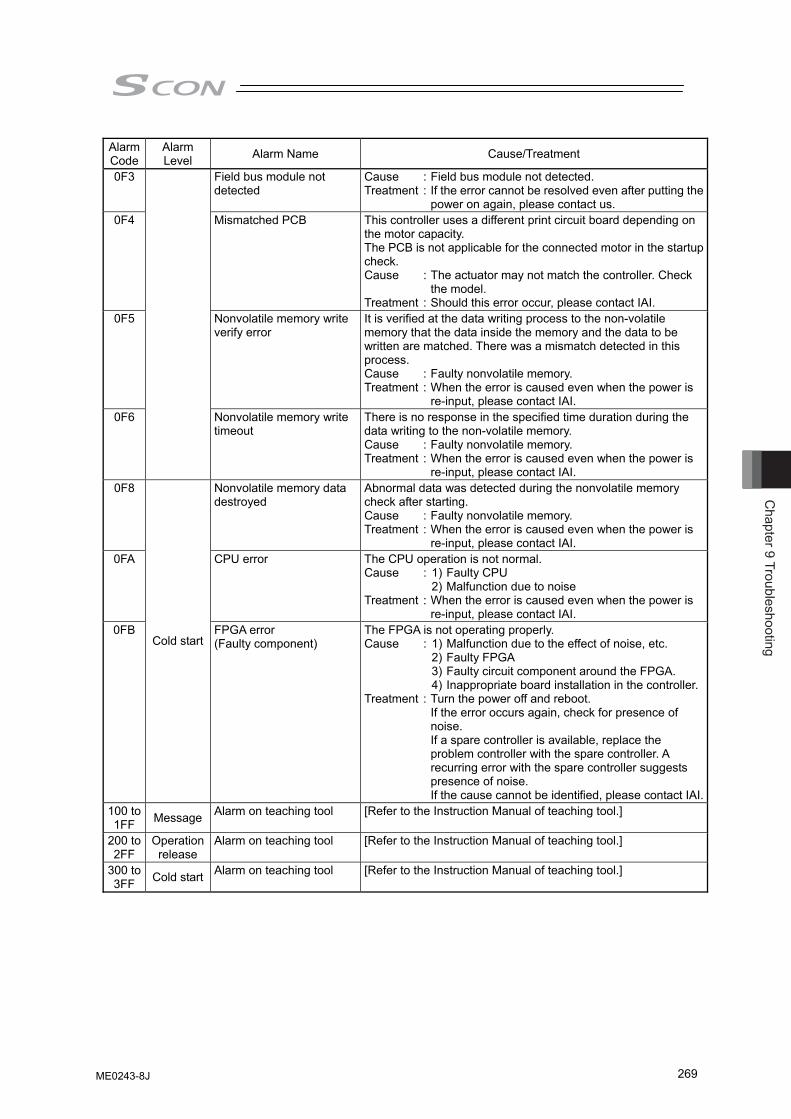
Chapter 9 Troubleshooting
269
Alarm Code
Alarm Level Alarm Name Cause/Treatment
0F3 Field bus module not detected
Cause : Field bus module not detected. Treatment : If the error cannot be resolved even after putting the
power on again, please contact us. 0F4 Mismatched PCB This controller uses a different print circuit board depending on
the motor capacity. The PCB is not applicable for the connected motor in the startup check. Cause : The actuator may not match the controller. Check
the model. Treatment : Should this error occur, please contact IAI.
0F5 Nonvolatile memory write verify error
It is verified at the data writing process to the non-volatile memory that the data inside the memory and the data to be written are matched. There was a mismatch detected in this process. Cause : Faulty nonvolatile memory. Treatment : When the error is caused even when the power is
re-input, please contact IAI. 0F6 Nonvolatile memory write
timeout There is no response in the specified time duration during the data writing to the non-volatile memory. Cause : Faulty nonvolatile memory. Treatment : When the error is caused even when the power is
re-input, please contact IAI. 0F8 Nonvolatile memory data
destroyed Abnormal data was detected during the nonvolatile memory check after starting. Cause : Faulty nonvolatile memory. Treatment : When the error is caused even when the power is
re-input, please contact IAI. 0FA CPU error The CPU operation is not normal.
Cause : 1) Faulty CPU 2) Malfunction due to noise Treatment : When the error is caused even when the power is
re-input, please contact IAI. 0FB
Cold start FPGA error (Faulty component)
The FPGA is not operating properly. Cause : 1) Malfunction due to the effect of noise, etc. 2) Faulty FPGA 3) Faulty circuit component around the FPGA. 4) Inappropriate board installation in the controller.Treatment : Turn the power off and reboot.
If the error occurs again, check for presence of noise. If a spare controller is available, replace the problem controller with the spare controller. A recurring error with the spare controller suggests presence of noise. If the cause cannot be identified, please contact IAI.
100 to 1FF Message Alarm on teaching tool [Refer to the Instruction Manual of teaching tool.]
200 to 2FF
Operation release
Alarm on teaching tool [Refer to the Instruction Manual of teaching tool.]
300 to 3FF Cold start Alarm on teaching tool [Refer to the Instruction Manual of teaching tool.]
ME0243-8J

Cha
pter
9 T
roub
lesh
ootin
g
270
ME0243-8J
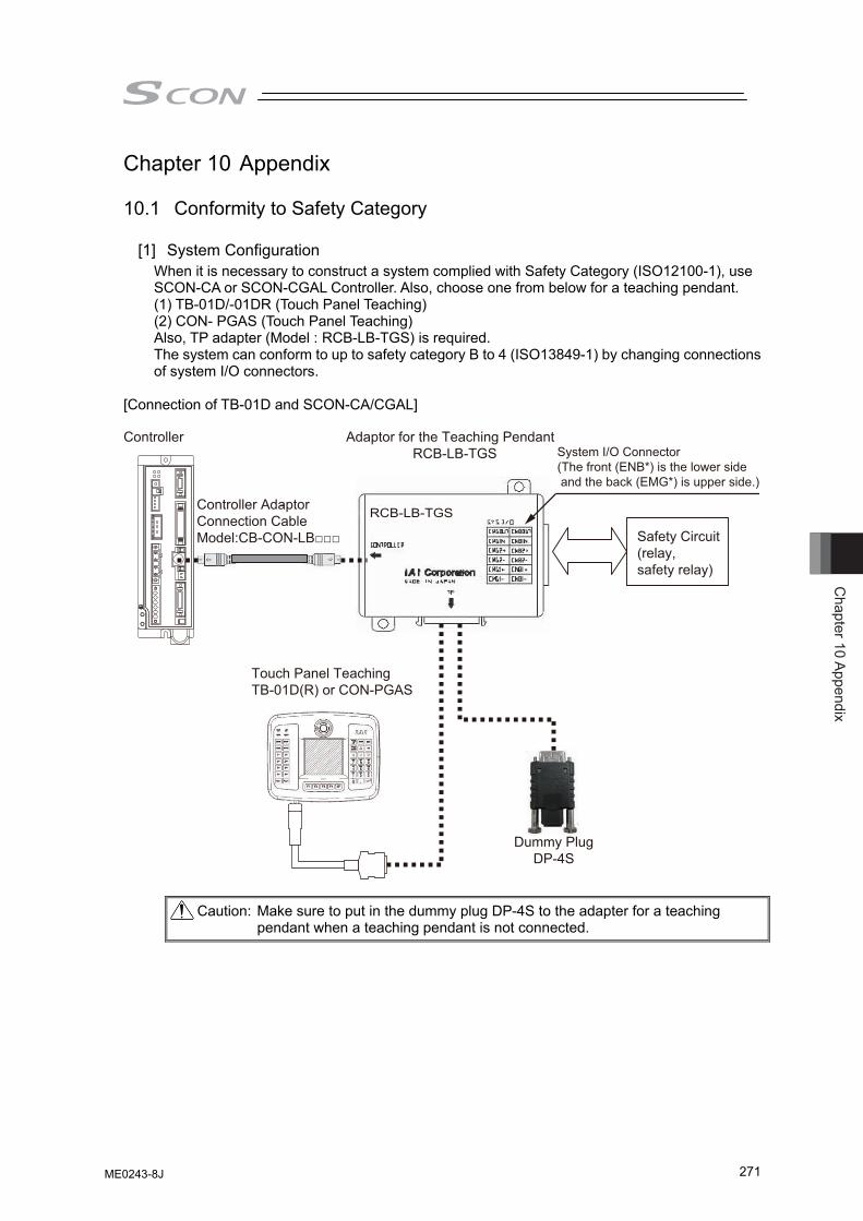
Chapter 10 Appendix
271
Chapter 10 Appendix 10.1 Conformity to Safety Category
[1] System Configuration
When it is necessary to construct a system complied with Safety Category (ISO12100-1), use SCON-CA or SCON-CGAL Controller. Also, choose one from below for a teaching pendant. (1) TB-01D/-01DR (Touch Panel Teaching) (2) CON- PGAS (Touch Panel Teaching) Also, TP adapter (Model : RCB-LB-TGS) is required. The system can conform to up to safety category B to 4 (ISO13849-1) by changing connections of system I/O connectors.
[Connection of TB-01D and SCON-CA/CGAL] Controller Adaptor for the Teaching Pendant
RCB-LB-TGS
Controller Adaptor-Connection CableModel:CB-CON-LB□□□
Touch Panel TeachingTB-01D(R) or CON-PGAS
Dummy PlugDP-4S
Safety Circuit(relay,safety relay)
RCB-LB-TGS
System I/O Connector(The front (ENB*) is the lower side and the back (EMG*) is upper side.)
Caution: Make sure to put in the dummy plug DP-4S to the adapter for a teaching pendant when a teaching pendant is not connected.
ME0243-8J
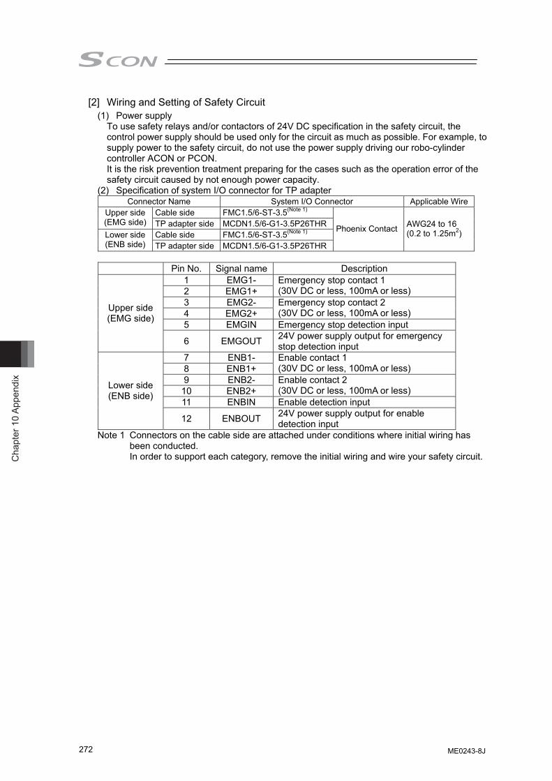
Cha
pter
10
Appe
ndix
272
[2] Wiring and Setting of Safety Circuit (1) Power supply
To use safety relays and/or contactors of 24V DC specification in the safety circuit, the control power supply should be used only for the circuit as much as possible. For example, to supply power to the safety circuit, do not use the power supply driving our robo-cylinder controller ACON or PCON. It is the risk prevention treatment preparing for the cases such as the operation error of the safety circuit caused by not enough power capacity.
(2) Specification of system I/O connector for TP adapter Connector Name System I/O Connector Applicable Wire
Cable side FMC1.5/6-ST-3.5(Note 1) Upper side (EMG side) TP adapter side MCDN1.5/6-G1-3.5P26THR
Cable side FMC1.5/6-ST-3.5(Note 1) Lower side (ENB side) TP adapter side MCDN1.5/6-G1-3.5P26THR
Phoenix Contact AWG24 to 16 (0.2 to 1.25m2)
Pin No. Signal name Description
1 EMG1- 2 EMG1+
Emergency stop contact 1 (30V DC or less, 100mA or less)
3 EMG2- 4 EMG2+
Emergency stop contact 2 (30V DC or less, 100mA or less)
5 EMGIN Emergency stop detection input
Upper side (EMG side)
6 EMGOUT 24V power supply output for emergency stop detection input
7 ENB1- 8 ENB1+
Enable contact 1 (30V DC or less, 100mA or less)
9 ENB2- 10 ENB2+
Enable contact 2 (30V DC or less, 100mA or less)
11 ENBIN Enable detection input
Lower side (ENB side)
12 ENBOUT 24V power supply output for enable detection input
Note 1 Connectors on the cable side are attached under conditions where initial wiring has been conducted. In order to support each category, remove the initial wiring and wire your safety circuit.
ME0243-8J
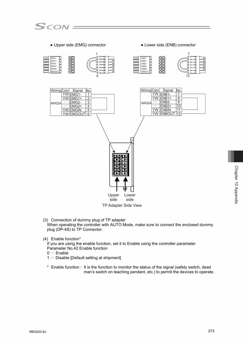
Chapter 10 Appendix
273
● Upper side (EMG) connector ● Lower side (ENB) connector
EMG1-EMG1+EMG2-EMG2+EMGINEMGOUT
ENB1-ENB1+ENB2-ENB2+ENBINENBOUT
EMG1-EMG1+EMG2-EMG2+EMGINEMGOUT
1
6
7
12
Wiring ColorYW 1
23456
YW
YWYW
Signal No.
AWG24
ENB1-ENB1+ENB2-ENB2+ENBINENBOUT
Wiring ColorYW 7
89101112
YW
YWYW
Signal No.
AWG24
Upperside
Lowerside
TP Adapter Side View
(3) Connection of dummy plug of TP adapter When operating the controller with AUTO Mode, make sure to connect the enclosed dummy plug (DP-4S) to TP Connector.
(4) Enable function*
If you are using the enable function, set it to Enable using the controller parameter. Parameter No.42 Enable function 0 ··· Enable 1 ··· Disable [Default setting at shipment]
* Enable function : It is the function to monitor the status of the signal (safety switch, dead
man’s switch on teaching pendant, etc.) to permit the devices to operate.
ME0243-8J
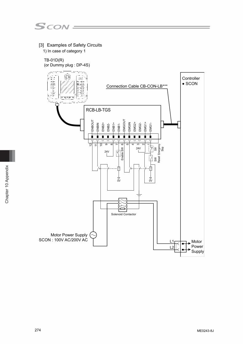
Cha
pter
10
Appe
ndix
274
[3] Examples of Safety Circuits 1) In case of category 1
TB-01D(R)(or Dummy plug : DP-4S)
Connection Cable CB-CON-LB***
Controller● SCON
Enab
le S
W
SW Rese
tSW
Emer
genc
ySt
op24V24V
0V 0V
RCB-LB-TGS
Solenoid Contactor
Motor Power SupplySCON : 100V AC/200V AC Motor
PowerSupply
ENBO
UT
ENBI
N
ENB2
+
ENB2
-
ENB1
+
ENB1
-
EMG
OU
T
EMG
IN
EMG
2+
EMG
2-
EMG
1+
EMG
1-
12 11 10 9 8 7 6 5 4 3 2 1
L1L2
ME0243-8J
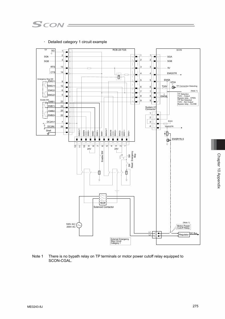
Chapter 10 Appendix
275
• Detailed category 1 circuit example
SG
SGA
SGB
RTS
CTS
EMG1-
EMG1+
EMG2-
EMG2+
EMB1-
EMB1+
EMB2-
EMB2+
DC24V+
DC24V-
EMBO
UT
EMBI
N
EMB2
+
EMB2
-
EMB1
+
EMB1
-
EMG
OU
T
EMG
IN
EMG
2+
EMG
2-
EMG
1+
EMG
1-
1
2
3
4
5
6
7
8
9
1
2
3
4
System I/OConnector
Enab
le S
W
SW Rese
tSW
Emer
genc
y S
top
24V24V
Solenoid Contactor
100V AC/200V AC
DC BusL1L2
E24V
*EMGSTR
EMGRYRLS
EMGSTR
VP24
SCON
TP Connection Detecting
TP DetectionT24V…OutputBypass relay…OPENTP Not DetectedT24V…Not OutputBypass relay…CLOSE
TP
Emergency Stop SW
Enable SW
Shell
1
2
3
13
14
9
12
6
5
23
24
25
22
7
26
12 11 10 9 8 7 6 5 4 3 2 1
External EmergencyStop CircuitCategory 1
Motor PowerCutoff Relay
Regulator
RCB-LB-TGS
SGA
SGB
EMGA
T24V
EMGB
1
2
3
4
5
6
7
8
9
5V
+
(Note 1)
(Note 1)
Note 1 There is no bypath relay on TP terminals or motor power cutoff relay equipped to SCON-CGAL.
ME0243-8J
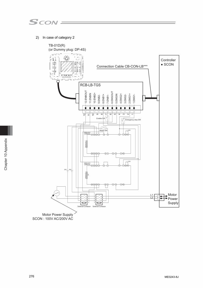
Cha
pter
10
Appe
ndix
276
2) In case of category 2
TB-01D(R)(or Dummy plug: DP-4S)
Connection Cable CB-CON-LB***
Controller● SCON
12.E
NB
OU
T
11.E
NB
IN
10.E
NB
2+
9.E
NB
2-
8.E
NB
1+
7.E
NB
1-
6.E
MG
OU
T
5.E
MG
IN
4.E
MG
2+
3.E
MG
2-
2.E
MG
1+
1.E
MG
1-
RCB-LB-TGS
Motor Power Supply
Motor Power SupplySCON : 100V AC/200V AC
L1L2
12 11 10 9 8 7 6 5 4 3 2 124VReset SW
Emergency stop SW
G9SA-301(OMRON)
24VG9SA-301(OMRON)
41 33 23 13 T32 T31 T12 T11 A2 A1
123456
42 34 24 14 T22 T23 T21 PEB A
41 33 23 13 T32 T31 T12 T11 A2 A1
123456
42 34 24 14 T22 T23 T21 PEB A
24V24V
Solenoid Contactor Solenoid Contactor
Enable SWEnable SW
ME0243-8J
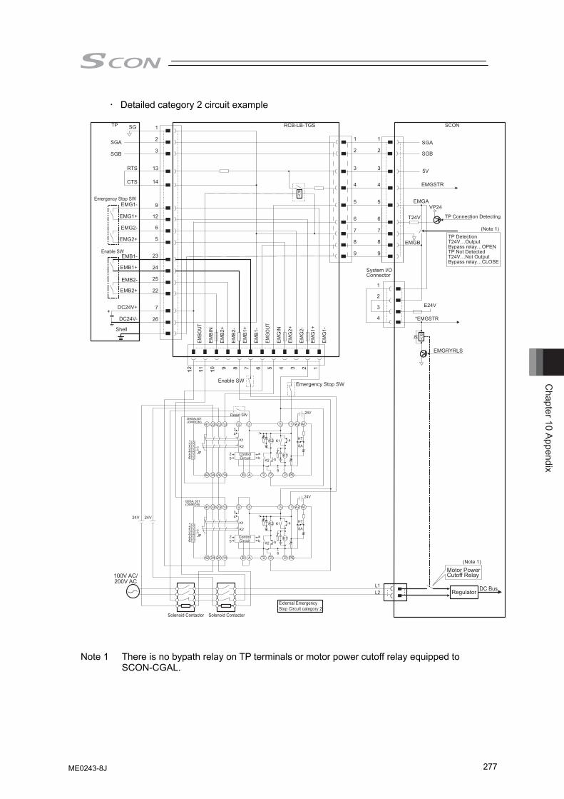
Chapter 10 Appendix
277
• Detailed category 2 circuit example
SG
SGA
SGB
RTS
CTS
EMG1-
EMG1+
EMG2-
EMG2+
EMB1-
EMB1+
EMB2-
EMB2+
DC24V+
DC24V-
EMBO
UT
EM
BIN
EM
B2+
EM
B2-
EM
B1+
EM
B1-
EMG
OUT
EM
GIN
EM
G2+
EM
G2-
EM
G1+
EM
G1-
1
2
3
4
5
6
7
8
9
1
2
3
4
System I/O Connector
DC BusL1L2
E24V
*EMGSTR
EMGRYRLS
EMGSTR
VP24
SCON
TP Connection Detecting
TP DetectionT24V…OutputBypass relay…OPENTP Not DetectedT24V…Not OutputBypass relay…CLOSE
TP
Emergency Stop SW
Enable SW
Shell
1
2
3
13
14
9
12
6
5
23
24
25
22
7
26
12 11 10 9 8 7 6 5 4 3 2 1
Motor Power Cutoff Relay
Regulator
RCB-LB-TGS
SGA
SGB
EMGA
T24V
EMGB
1
2
3
4
5
6
7
8
9
5V
+
Enable SWEnable SWEmergency Stop SW
Reset SW
ControlCircuit
ControlCircuit
100V AC/200V AC
Solenoid Contactor Solenoid Contactor
External EmergencyStop Circuit category 2
(Note 1)
(Note 1)
Note 1 There is no bypath relay on TP terminals or motor power cutoff relay equipped to SCON-CGAL.
ME0243-8J
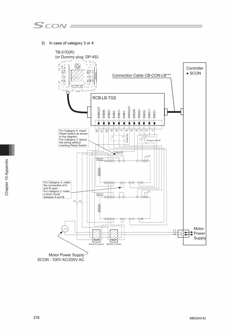
Cha
pter
10
Appe
ndix
278
3) In case of category 3 or 4
TB-01D(R)(or Dummy plug: DP-4S)
Connection Cable CB-CON-LB***
Controller● SCON
EN
BO
UT
EN
BIN
EN
B2+
EN
B2-
EN
B1+
EN
B1-
EM
GO
UT
EM
GIN
EM
G2+
EM
G2-
EM
G1+
EM
G1-
RCB-LB-TGS
Motor Power Supply
Motor Power SupplySCON : 100V AC/200V AC
12 11 10 9 8 7 6 5 4 3 2 1
Solenoid Contactor Solenoid Contactor
Enab
le S
W
Reset SW
Emergency Stop SWEmergency Stop SW
For Category 4, insert Reset Switch as shown in the diagram.For Category 3, layout the wiring without inserting Reset Switch.
For Category 4, make the connection of A and B open.For category 3, make a short circuit between A and B.
ME0243-8J
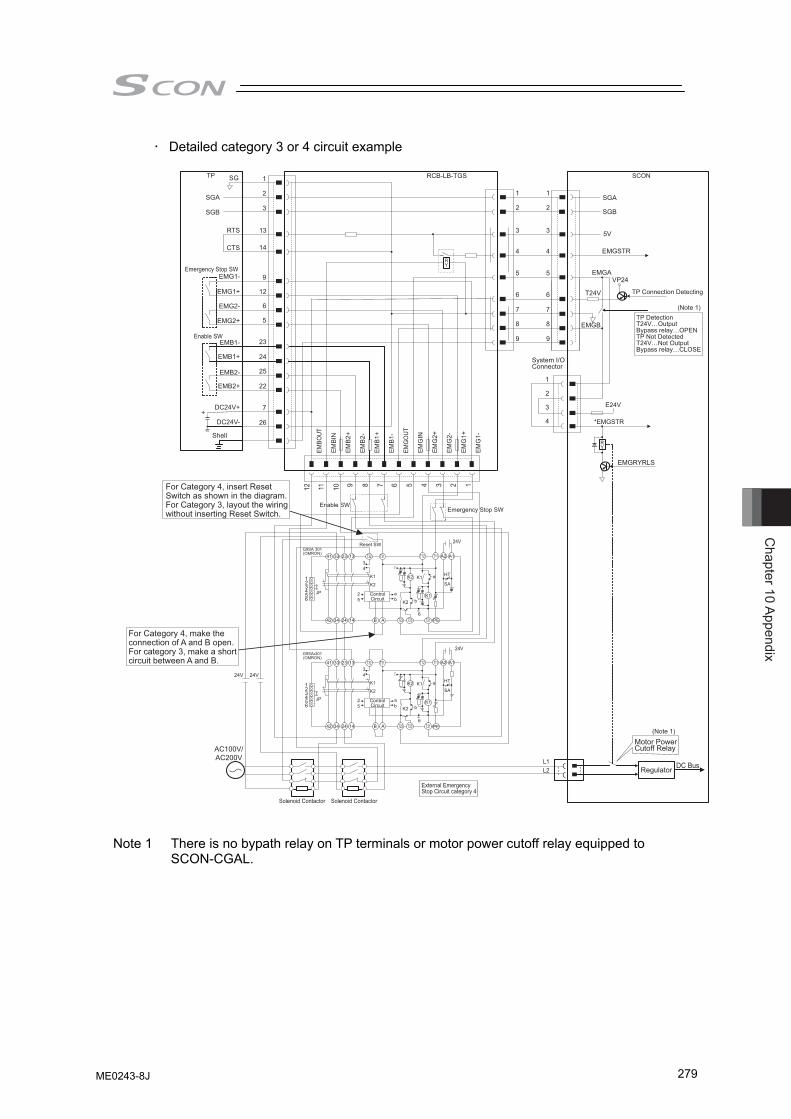
Chapter 10 Appendix
279
• Detailed category 3 or 4 circuit example
SG
SGA
SGB
RTS
CTS
EMG1-
EMG1+
EMG2-
EMG2+
EMB1-
EMB1+
EMB2-
EMB2+
DC24V+
DC24V-
EMBO
UT
EM
BIN
EM
B2+
EM
B2-
EM
B1+
EM
B1-
EMG
OUT
EM
GIN
EM
G2+
EM
G2-
EM
G1+
EM
G1-
1
2
3
4
5
6
7
8
9
1
2
3
4
System I/O Connector
DC BusL1L2
E24V
*EMGSTR
EMGRYRLS
EMGSTR
VP24
SCON
TP Connection Detecting
TP DetectionT24V…OutputBypass relay…OPENTP Not DetectedT24V…Not OutputBypass relay…CLOSE
TP
Emergency Stop SW
Enable SW
Shell
1
2
3
13
14
9
12
6
5
23
24
25
22
7
26
Motor Power Cutoff Relay
Regulator
RCB-LB-TGS
SGA
SGB
EMGA
T24V
EMGB
1
2
3
4
5
6
7
8
9
5V
+
Reset SWEnable SWEmergency Stop SWEmergency Stop SW
Reset SW
ControlCircuit
ControlCircuit
Solenoid Contactor Solenoid Contactor
External EmergencyStop Circuit category 4
For Category 4, insert Reset Switch as shown in the diagram.For Category 3, layout the wiring without inserting Reset Switch.
For Category 4, make the connection of A and B open.For category 3, make a short circuit between A and B.
(Note 1)
(Note 1)
Note 1 There is no bypath relay on TP terminals or motor power cutoff relay equipped to SCON-CGAL.
ME0243-8J
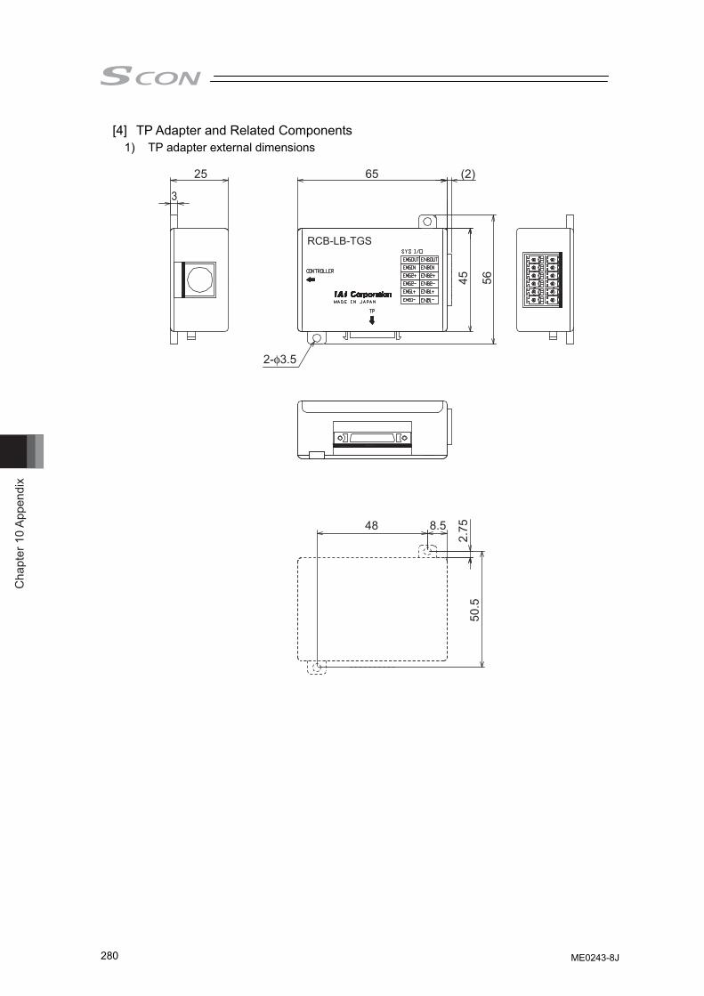
Cha
pter
10
Appe
ndix
280
[4] TP Adapter and Related Components 1) TP adapter external dimensions
25
3
65 (2)
2-φ3.5
45 56
48 8.5
2.75
50.5
RCB-LB-TGS
ME0243-8J
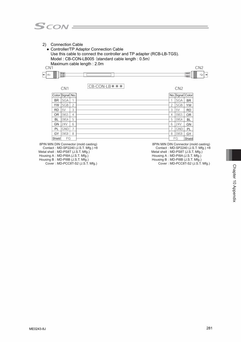
Chapter 10 Appendix
281
2) Connection Cable ● Controller/TP Adaptor Connection Cable
Use this cable to connect the controller and TP adapter (RCB-LB-TGS). Model : CB-CON-LB005 (standard cable length : 0.5m) Maximum cable length : 2.0m
Color Signal No. ColorSignalNo.BRYWRDORBLGNPLGY
Shield
BRYWRDORBLGNPLGY
Shield
8PIN MIN DIN Connector (mold casting)Contact
Metal shellHousing AHousing B
Cover
: MD-SP2240 (J.S.T. Mfg.) ×8: MD-PS8T (J.S.T. Mfg.): MD-PI8A (J.S.T. Mfg.): MD-PI8B (J.S.T. Mfg.): MD-PCC8T-S2 (J.S.T. Mfg.)
8PIN MIN DIN Connector (mold casting)Contact
Metal shellHousing AHousing B
Cover
: MD-SP2240 (J.S.T. Mfg.) ×8: MD-PS8T (J.S.T. Mfg.): MD-PI8A (J.S.T. Mfg.): MD-PI8B (J.S.T. Mfg.): MD-PCC8T-S2 (J.S.T. Mfg.)
ME0243-8J
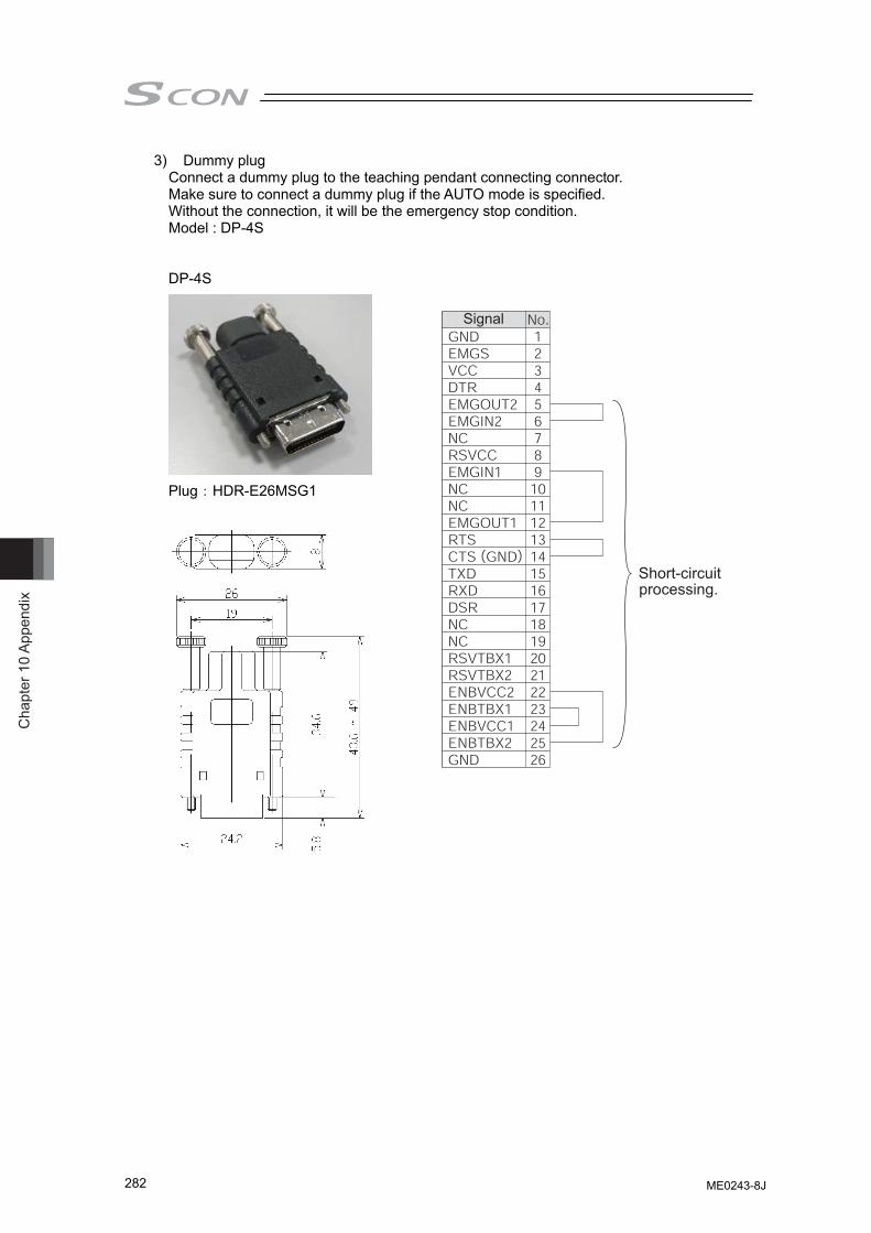
Cha
pter
10
Appe
ndix
282
3) Dummy plug Connect a dummy plug to the teaching pendant connecting connector. Make sure to connect a dummy plug if the AUTO mode is specified. Without the connection, it will be the emergency stop condition. Model : DP-4S
DP-4S
Plug:HDR-E26MSG1
ME0243-8J
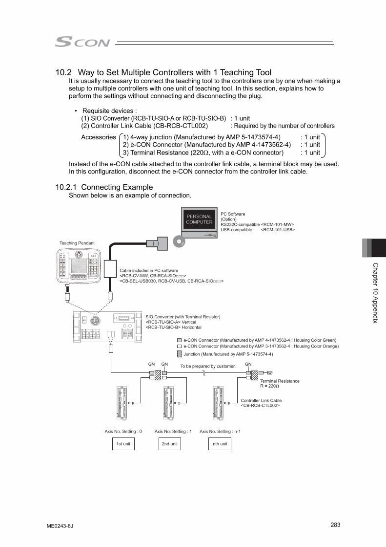
Chapter 10 Appendix
283
10.2 Way to Set Multiple Controllers with 1 Teaching Tool It is usually necessary to connect the teaching tool to the controllers one by one when making a setup to multiple controllers with one unit of teaching tool. In this section, explains how to perform the settings without connecting and disconnecting the plug.
• Requisite devices : (1) SIO Converter (RCB-TU-SIO-A or RCB-TU-SIO-B) : 1 unit (2) Controller Link Cable (CB-RCB-CTL002) : Required by the number of controllers
Accessories 1) 4-way junction (Manufactured by AMP 5-1473574-4) : 1 unit 2) e-CON Connector (Manufactured by AMP 4-1473562-4) : 1 unit 3) Terminal Resistance (220Ω, with a e-CON connector) : 1 unit
Instead of the e-CON cable attached to the controller link cable, a terminal block may be used. In this configuration, disconnect the e-CON connector from the controller link cable.
10.2.1 Connecting Example Shown below is an example of connection.
Teaching Pendant
To be prepared by customer.
Cable included in PC software <RCB-CV-MW, CB-RCA-SIO□□□> <CB-SEL-USB030, RCB-CV-USB, CB-RCA-SIO□□□>
PC Software (Option) RS232C-compatible <RCM-101-MW> USB-compatible <RCM-101-USB>
SIO Converter (with Terminal Resistor) <RCB-TU-SIO-A> Vertical <RCB-TU-SIO-B> Horizontal
e-CON Connector (Manufactured by AMP 4-1473562-4 : Housing Color Green) e-CON Connector (Manufactured by AMP 3-1473562-4 : Housing Color Orange)
Junction (Manufactured by AMP 5-1473574-4)
GN GN GN
Terminal Resistance R = 220Ω
Controller Link Cable <CB-RCB-CTL002>
Axis No. Setting : 0 Axis No. Setting : n-1 Axis No. Setting : 1
1st unit nth unit 2nd unit
ME0243-8J
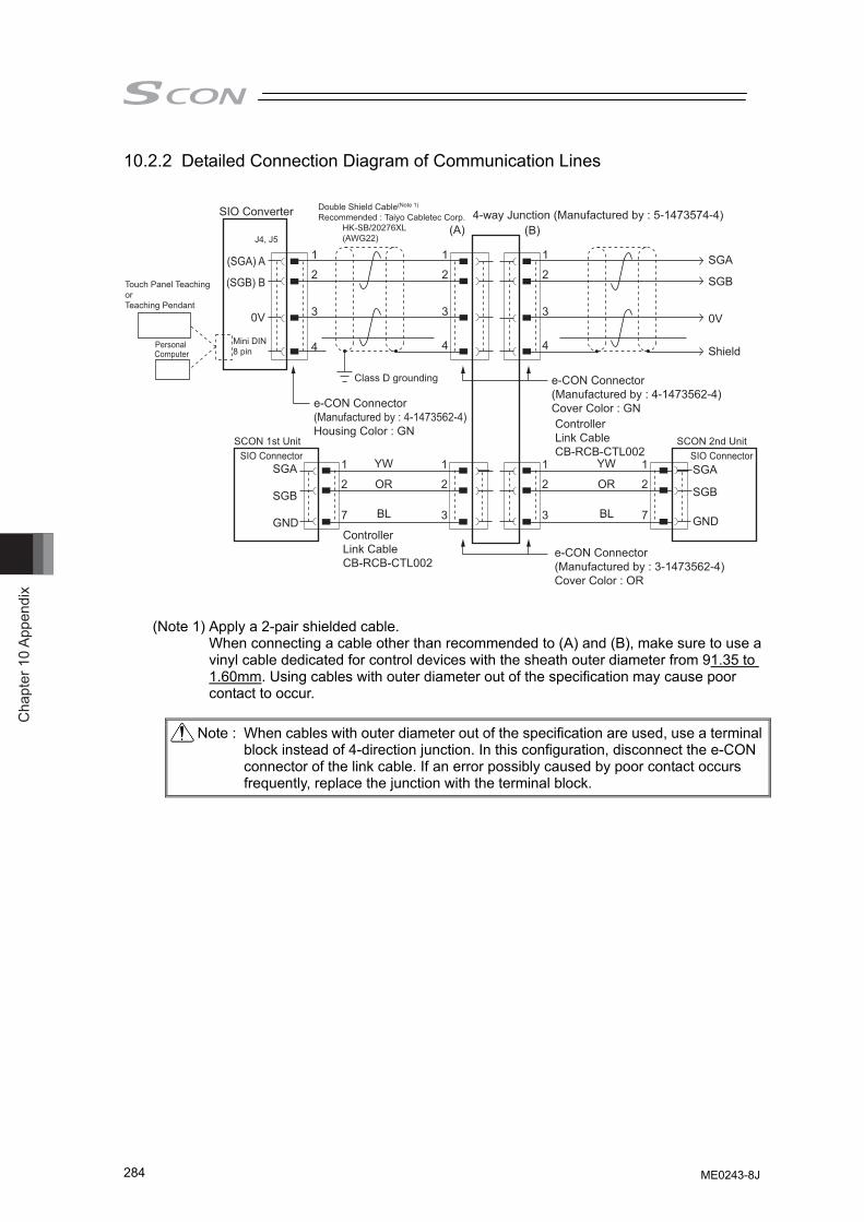
Cha
pter
10
Appe
ndix
284
10.2.2 Detailed Connection Diagram of Communication Lines
SIO Converter 4-way Junction (Manufactured by : 5-1473574-4)
(SGA) A
(SGB) B
0V
1
2
3
1
2
7
1
2
7
1
2
3
1
2
3
4
1
2
3
4
1
2
3
4Personal Computer
Touch Panel Teaching or Teaching Pendant
J4, J5
Mini DIN 8 pin
Double Shield Cable(Note 1)
Recommended : Taiyo Cabletec Corp. HK-SB/20276XL (AWG22)
e-CON Connector(Manufactured by : 4-1473562-4)Cover Color : GNController Link CableCB-RCB-CTL002
SCON 2nd Unit SIO Connector SIO Connector
Class D grounding
SCON 1st Unit
e-CON Connector(Manufactured by : 4-1473562-4)Housing Color : GN
e-CON Connector(Manufactured by : 3-1473562-4)Cover Color : OR
Controller Link CableCB-RCB-CTL002
YW
OR
BL
YW
OR
BL
SGA
SGB
GND
SGA
SGB
GND
(A) (B)
SGA
SGB
0V
Shield
(Note 1) Apply a 2-pair shielded cable. When connecting a cable other than recommended to (A) and (B), make sure to use a vinyl cable dedicated for control devices with the sheath outer diameter from 91.35 to 1.60mm. Using cables with outer diameter out of the specification may cause poor contact to occur.
Note : When cables with outer diameter out of the specification are used, use a terminal
block instead of 4-direction junction. In this configuration, disconnect the e-CON connector of the link cable. If an error possibly caused by poor contact occurs frequently, replace the junction with the terminal block.
ME0243-8J
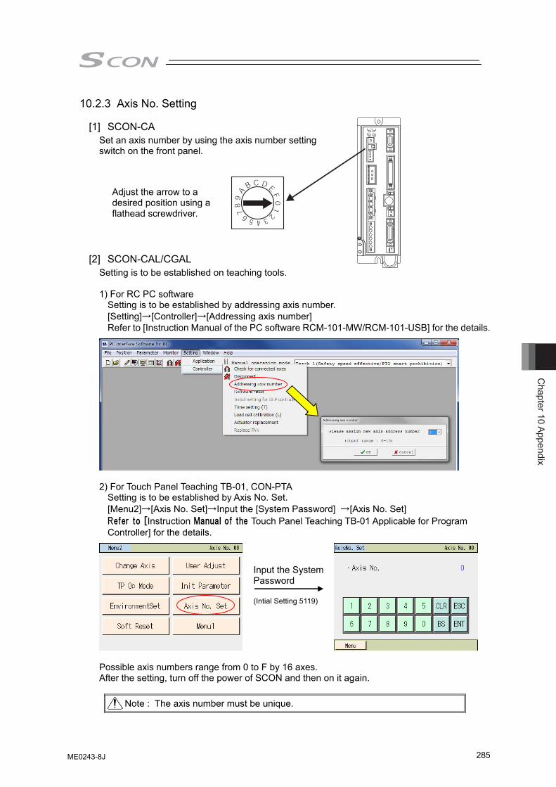
Chapter 10 Appendix
285
10.2.3 Axis No. Setting
[1] SCON-CA Set an axis number by using the axis number setting switch on the front panel.
[2] SCON-CAL/CGAL
Setting is to be established on teaching tools. 1) For RC PC software
Setting is to be established by addressing axis number. [Setting]→[Controller]→[Addressing axis number] Refer to [Instruction Manual of the PC software RCM-101-MW/RCM-101-USB] for the details.
2) For Touch Panel Teaching TB-01, CON-PTA
Setting is to be established by Axis No. Set. [Menu2]→[Axis No. Set]→Input the [System Password] →[Axis No. Set] Refer to [Instruction Manual of the Touch Panel Teaching TB-01 Applicable for Program Controller] for the details.
Possible axis numbers range from 0 to F by 16 axes. After the setting, turn off the power of SCON and then on it again.
Note : The axis number must be unique.
Adjust the arrow to a desired position using a flathead screwdriver.
Input the System Password (Intial Setting 5119)
ME0243-8J
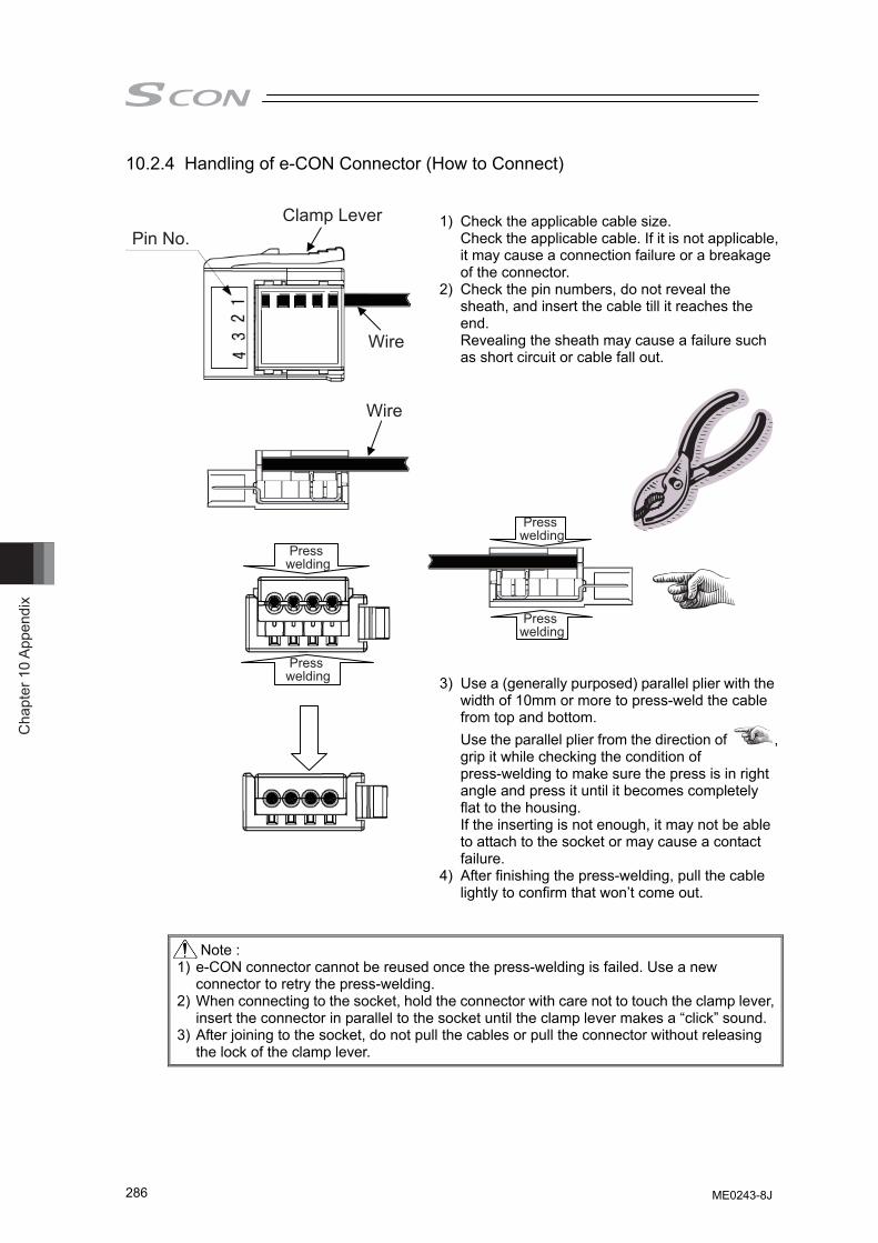
Cha
pter
10
Appe
ndix
286
Wire
Wire
Clamp LeverPin No.
Press welding
Press welding
Press welding
Press welding
10.2.4 Handling of e-CON Connector (How to Connect)
1) Check the applicable cable size.
Check the applicable cable. If it is not applicable, it may cause a connection failure or a breakage of the connector.
2) Check the pin numbers, do not reveal the sheath, and insert the cable till it reaches the end. Revealing the sheath may cause a failure such as short circuit or cable fall out.
3) Use a (generally purposed) parallel plier with the width of 10mm or more to press-weld the cable from top and bottom. Use the parallel plier from the direction of , grip it while checking the condition of press-welding to make sure the press is in right angle and press it until it becomes completely flat to the housing. If the inserting is not enough, it may not be able to attach to the socket or may cause a contact failure.
4) After finishing the press-welding, pull the cable lightly to confirm that won’t come out.
Note : 1) e-CON connector cannot be reused once the press-welding is failed. Use a new
connector to retry the press-welding. 2) When connecting to the socket, hold the connector with care not to touch the clamp lever,
insert the connector in parallel to the socket until the clamp lever makes a “click” sound. 3) After joining to the socket, do not pull the cables or pull the connector without releasing
the lock of the clamp lever.
ME0243-8J
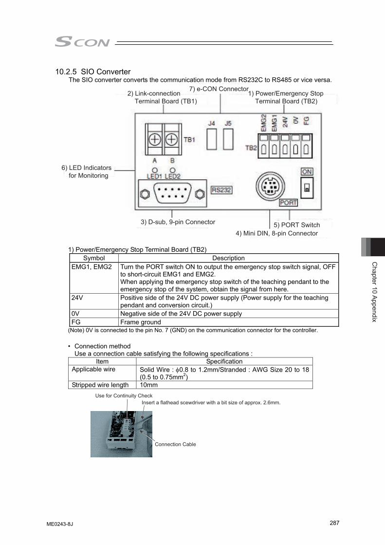
Chapter 10 Appendix
287
10.2.5 SIO Converter The SIO converter converts the communication mode from RS232C to RS485 or vice versa.
1) Power/Emergency Stop Terminal Board (TB2)
2) Link-connection Terminal Board (TB1)
3) D-sub, 9-pin Connector
6) LED Indicators for Monitoring
7) e-CON Connector
4) Mini DIN, 8-pin Connector 5) PORT Switch
1) Power/Emergency Stop Terminal Board (TB2) Symbol Description
EMG1, EMG2 Turn the PORT switch ON to output the emergency stop switch signal, OFF to short-circuit EMG1 and EMG2. When applying the emergency stop switch of the teaching pendant to the emergency stop of the system, obtain the signal from here.
24V Positive side of the 24V DC power supply (Power supply for the teaching pendant and conversion circuit.)
0V Negative side of the 24V DC power supply FG Frame ground
(Note) 0V is connected to the pin No. 7 (GND) on the communication connector for the controller.
• Connection method Use a connection cable satisfying the following specifications :
Item Specification Applicable wire Solid Wire : φ0.8 to 1.2mm/Stranded : AWG Size 20 to 18
(0.5 to 0.75mm2) Stripped wire length 10mm
Use for Continuity CheckInsert a flathead scewdriver with a bit size of approx. 2.6mm.
Connection Cable
ME0243-8J
Cha
pter
10
Appe
ndix
288
2) Link-connection Terminal Board (TB1) This is the connection port to obtain communication connection with the controller. Connect terminal “A” on the left side to communication line SGA of the controller. (Terminal A is connected to pin 1 of (7) internally.) Connect terminal “B” on the right side to communication line SGB of the controller. (Terminal B is connected to pin 2 of (7) internally.) Use a twisted pair shielded cable for the connection of SGA and SGB to TB1.
3) D-sub, 9-pin connector
A connection port with the PC. (RS232C) It is used when the operation is conducted with using SIO communication.
4) Mini DIN, 8-pin connector
This connector is connected to PC software, teaching pendant or touch panel teaching.
5) PORT Switch The PORT switch is used to exchange enable/disable of connector (4). Set the switch to ON if connector (4) is used or OFF if not used. The switchover of valid/invalid on the teaching pendant is held at the same time as the emergency stop button switch signal output (between EMG1 and 2).
6) LED Indicators for Monitoring
LED1 : Lights/blinks while the controller sends signals. LED2 : Lights/blinks while signals are sent from the RS232C connector.
7) e-CON Connector
It is used when connecting to the controller with e-CON connector without using 2).
ME0243-8J
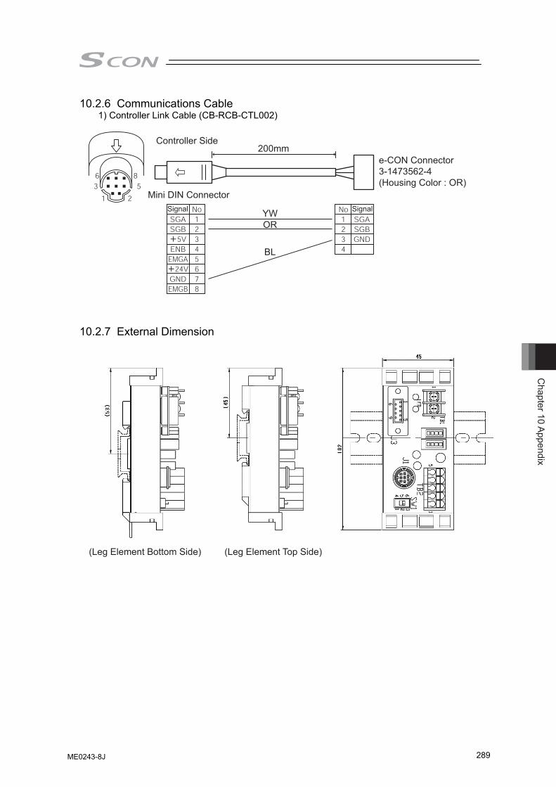
Chapter 10 Appendix
289
10.2.6 Communications Cable 1) Controller Link Cable (CB-RCB-CTL002)
10.2.7 External Dimension
(Leg Element Bottom Side) (Leg Element Top Side)
Controller Side
Mini DIN Connector
YWOR
BL
200mme-CON Connector3-1473562-4(Housing Color : OR)
Signal Signal
ME0243-8J
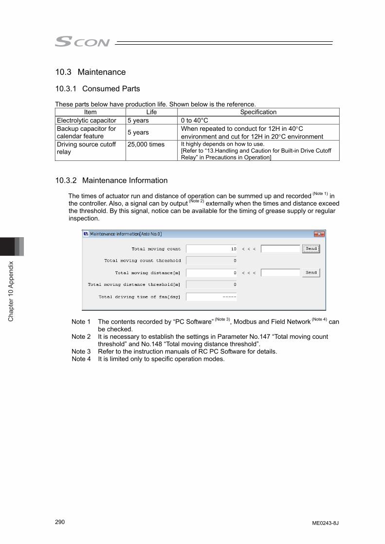
Cha
pter
10
Appe
ndix
290
10.3 Maintenance
10.3.1 Consumed Parts These parts below have production life. Shown below is the reference.
Item Life Specification Electrolytic capacitor 5 years 0 to 40°C Backup capacitor for calendar feature 5 years When repeated to conduct for 12H in 40°C
environment and cut for 12H in 20°C environment Driving source cutoff relay
25,000 times It highly depends on how to use. [Refer to “13.Handling and Caution for Built-in Drive Cutoff Relay” in Precautions in Operation]
10.3.2 Maintenance Information The times of actuator run and distance of operation can be summed up and recorded (Note 1) in the controller. Also, a signal can by output (Note 2) externally when the times and distance exceed the threshold. By this signal, notice can be available for the timing of grease supply or regular inspection.
Note 1 The contents recorded by “PC Software” (Note 3), Modbus and Field Network (Note 4) can
be checked. Note 2 It is necessary to establish the settings in Parameter No.147 “Total moving count
threshold” and No.148 “Total moving distance threshold”. Note 3 Refer to the instruction manuals of RC PC Software for details. Note 4 It is limited only to specific operation modes.
ME0243-8J
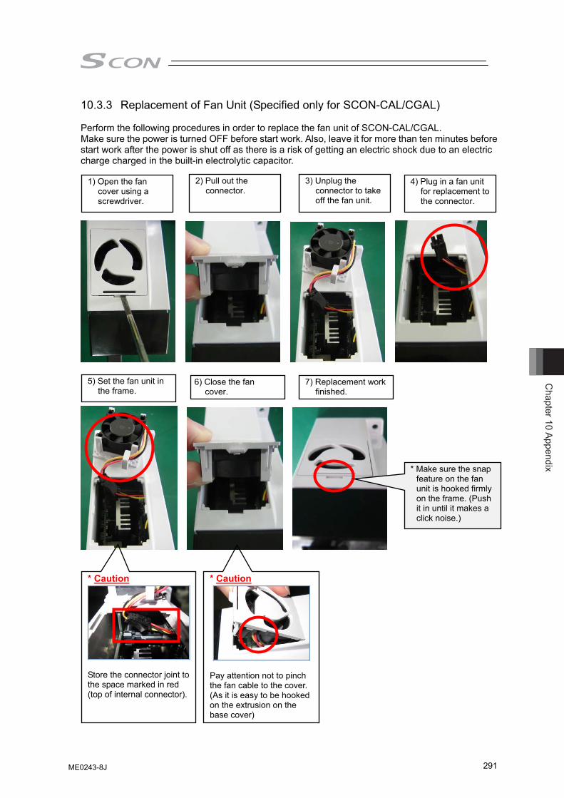
Chapter 10 Appendix
291
10.3.3 Replacement of Fan Unit (Specified only for SCON-CAL/CGAL) Perform the following procedures in order to replace the fan unit of SCON-CAL/CGAL. Make sure the power is turned OFF before start work. Also, leave it for more than ten minutes before start work after the power is shut off as there is a risk of getting an electric shock due to an electric charge charged in the built-in electrolytic capacitor.
1) Open the fan cover using a screwdriver.
2) Pull out the connector.
3) Unplug the connector to take off the fan unit.
4) Plug in a fan unit for replacement to the connector.
5) Set the fan unit in the frame.
6) Close the fan cover.
* Caution
Pay attention not to pinch the fan cable to the cover. (As it is easy to be hooked on the extrusion on the base cover)
* Caution
Store the connector joint to the space marked in red (top of internal connector).
* Make sure the snap feature on the fan unit is hooked firmly on the frame. (Push it in until it makes a click noise.)
7) Replacement work finished.
ME0243-8J
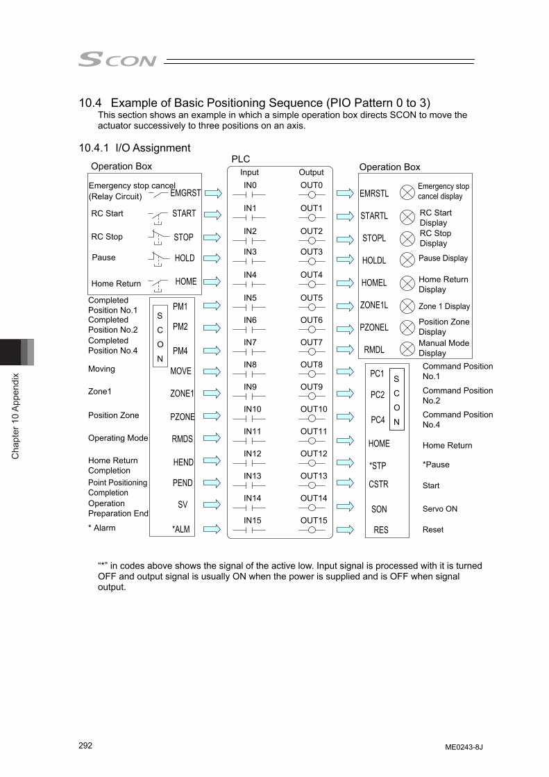
Cha
pter
10
Appe
ndix
292
10.4 Example of Basic Positioning Sequence (PIO Pattern 0 to 3) This section shows an example in which a simple operation box directs SCON to move the actuator successively to three positions on an axis.
10.4.1 I/O Assignment
Emergency stop cancel (Relay Circuit)
Command PositionNo.1
Command PositionNo.2 Command PositionNo.4
Home Return
RC Start
Output Input
RC Stop
Pause
Home Return
Completed Position No.1 Completed Position No.2 Completed Position No.4
Moving
Zone1
Home Return Completion
Operating Mode
Position Zone
Point Positioning Completion Operation Preparation End
* Alarm
Emergency stop cancel display
RC Start Display
Pause Display
RC Stop Display
Home Return Display
Zone 1 Display
Position Zone Display Manual Mode Display
*Pause
Start
Servo ON
Reset
PLC
S
IN0 OUT0
C
O
N
S
C
O
N
EMGRST
START
STOP
HOLD
HOME
PM1
PM2
PM4
MOVE
ZONE1
PZONE
RMDS
HEND
PEND
SV
*ALM
IN1 OUT1
IN2 OUT2
IN3 OUT3
IN4 OUT4
IN5 OUT5
IN6 OUT6
IN7 OUT7
IN8 OUT8
IN9 OUT9
IN10 OUT10
IN11 OUT11
IN12 OUT12
IN13 OUT13
IN14 OUT14
IN15 OUT15
EMRSTL
STARTL
STOPL
HOLDL
HOMEL
ZONE1L
PZONEL
RMDL
PC1
PC2
PC4
HOME
*STP
CSTR
SON
RES
Operation Box Operation Box
“*” in codes above shows the signal of the active low. Input signal is processed with it is turned OFF and output signal is usually ON when the power is supplied and is OFF when signal output.
ME0243-8J
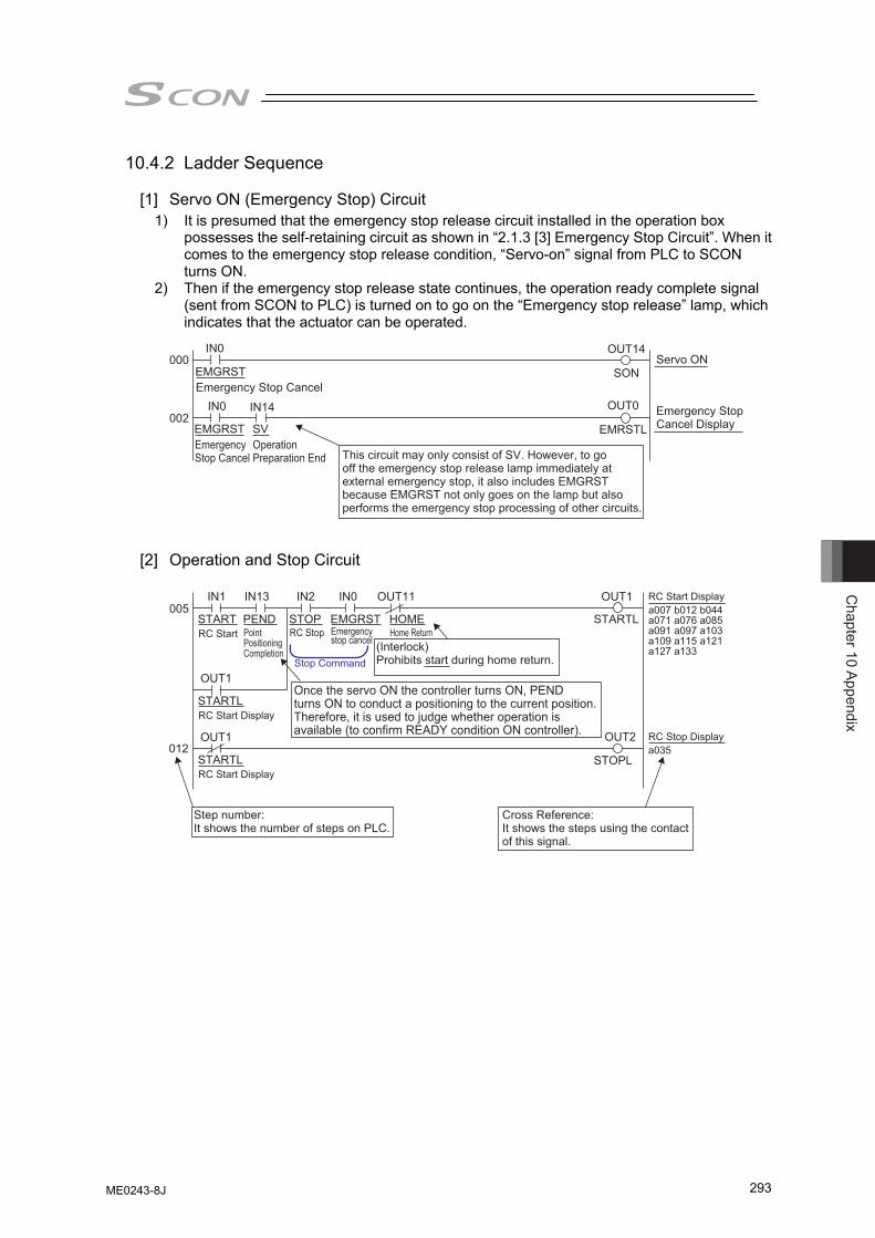
Chapter 10 Appendix
293
10.4.2 Ladder Sequence
[1] Servo ON (Emergency Stop) Circuit 1) It is presumed that the emergency stop release circuit installed in the operation box
possesses the self-retaining circuit as shown in “2.1.3 [3] Emergency Stop Circuit”. When it comes to the emergency stop release condition, “Servo-on” signal from PLC to SCON turns ON.
2) Then if the emergency stop release state continues, the operation ready complete signal (sent from SCON to PLC) is turned on to go on the “Emergency stop release” lamp, which indicates that the actuator can be operated.
[2] Operation and Stop Circuit
000
002
IN0
IN0
OUT14
OUT0IN14
EMGRSTEmergency Stop Cancel
Servo ON
Emergency Stop Cancel Display EMGRST
Emergency Stop Cancel
SV
SON
EMRSTLOperation Preparation End This circuit may only consist of SV. However, to go
off the emergency stop release lamp immediately at external emergency stop, it also includes EMGRST because EMGRST not only goes on the lamp but also performs the emergency stop processing of other circuits.
005
012
IN1
OUT1
OUT1
IN13 IN2 IN0 OUT11 OUT1
OUT2
START RC Start
RC Start Display
STARTL RC Start Display
STARTL RC Start Display
PEND Point Positioning Completion
STOP RC Stop
EMGRST Emergency stop cancel
Stop Command
HOME STARTL
STOPL
Home Return
Step number:It shows the number of steps on PLC.
(Interlock) Prohibits start during home return.
a007 b012 b044 a071 a076 a085 a091 a097 a103 a109 a115 a121 a127 a133
RC Stop Display a035
Once the servo ON the controller turns ON, PEND turns ON to conduct a positioning to the current position. Therefore, it is used to judge whether operation is available (to confirm READY condition ON controller).
Cross Reference:It shows the steps using the contact of this signal.
ME0243-8J
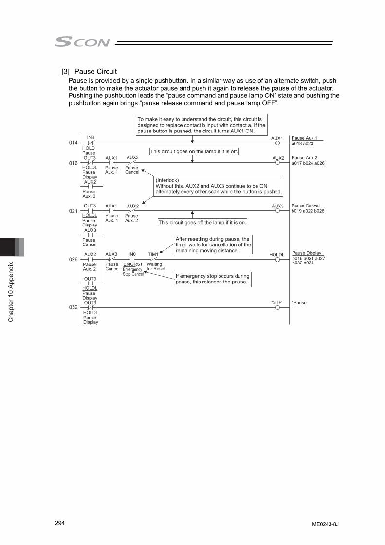
Cha
pter
10
Appe
ndix
294
[3] Pause Circuit Pause is provided by a single pushbutton. In a similar way as use of an alternate switch, push the button to make the actuator pause and push it again to release the pause of the actuator. Pushing the pushbutton leads the “pause command and pause lamp ON” state and pushing the pushbutton again brings “pause release command and pause lamp OFF”.
014
016
021
026
032
IN3
OUT3
OUT3
OUT3
OUT3
IN0 TIM1
HOLD
AUX1
AUX2
AUX3
HOLDL
*STP
Pause
HOLDL Pause Display
HOLDL Pause Display
HOLDL Pause Display
HOLDL Pause Display
AUX1
Pause Aux. 1
AUX1
Pause Aux. 1
AUX2
Pause Aux. 2
AUX2
Pause Aux. 2
AUX2
Pause Aux. 2
AUX3
Pause Cancel
Pause Aux.1 a018 a023
Pause Aux.2 a017 b024 a026
Pause Cancel b019 a022 b028
Pause Display
*Pause
b016 a021 a027 b032 a034
AUX3
Pause Cancel
AUX3
Pause Cancel
EMGRST Emergency Stop Cancel
Waiting for Reset
To make it easy to understand the circuit, this circuit is designed to replace contact b input with contact a. If the pause button is pushed, the circuit turns AUX1 ON.
This circuit goes on the lamp if it is off.
(Interlock) Without this, AUX2 and AUX3 continue to be ON alternately every other scan while the button is pushed.
This circuit goes off the lamp if it is on.
If emergency stop occurs during pause, this releases the pause.
After resetting during pause, the timer waits for cancellation of the remaining moving distance.
ME0243-8J
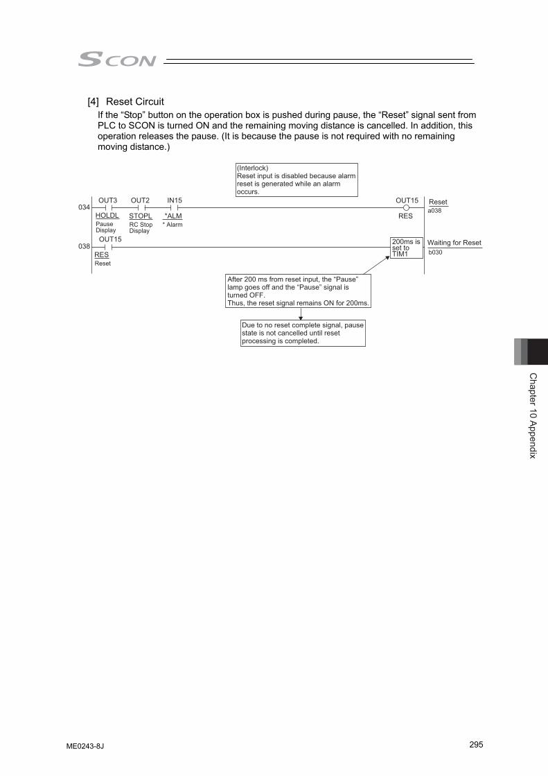
Chapter 10 Appendix
295
[4] Reset Circuit If the “Stop” button on the operation box is pushed during pause, the “Reset” signal sent from PLC to SCON is turned ON and the remaining moving distance is cancelled. In addition, this operation releases the pause. (It is because the pause is not required with no remaining moving distance.)
034
038
OUT3
OUT15
OUT2 IN15 OUT15
RES HOLDL Pause Display
RES Reset
STOPL RC Stop Display
*ALM* Alarm
Reset a038
Waiting for Reset b030
After 200 ms from reset input, the “Pause” lamp goes off and the “Pause” signal is turned OFF. Thus, the reset signal remains ON for 200ms.
Due to no reset complete signal, pause state is not cancelled until reset processing is completed.
(Interlock) Reset input is disabled because alarm reset is generated while an alarm occurs.
200ms is set to TIM1
ME0243-8J
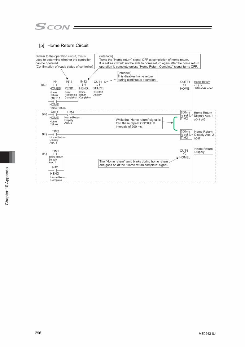
Cha
pter
10
Appe
ndix
296
[5] Home Return Circuit
040
046
049
051
IN4
OUT11
OUT11
IN12
IN13 IN12 OUT1 OUT11
HOMES HOME
OUT4
HOMEL
Home Return
HOME Home Return
HOME Home Return
Home Return Dispaly Aux. 2
Home Return Dispaly Aux. 1
Home Return Dispaly Aux. 1
HEND Home Return Complete
PEND Point Positioning Completion
HEND Home Return Completion
STARTL RC Start Display
Home Return <1.11> b010 a042 a046
Home Return Dispaly Aux. 1 a049 a051
Home Return Dispaly Aux. 2
Home Return Dispaly
b047
(Interlock) This disables home return during continuous operation.
While the “Home return” signal is ON, these repeat ON/OFF at intervals of 200 ms.
(Interlock)Turns the “Home return” signal OFF at completion of home return.It is set as it would not be able to home return again after the home return operation is complete unless “Home Return Complete” signal turns OFF.
Similar to the operation circuit, this is used to determine whether the controller can be operated. (Confirmation of ready status of controller)
The “Home return” lamp blinks during home return and goes on at the “Home return complete” signal.
TIM3
TIM2
TIM2
200ms is set toTIM2
200ms is set to TIM3
ME0243-8J
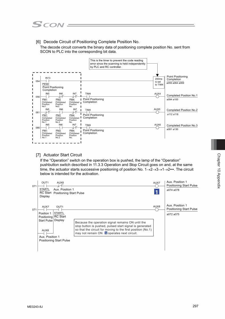
Chapter 10 Appendix
297
[6] Decode Circuit of Positioning Complete Position No. The decode circuit converts the binary data of positioning complete position No. sent from SCON to PLC into the corresponding bit data.
054
056
061
066
PEND Point Positioning Completion
Point Positioning Completion
PM1 Completed Position No1.
PM2 Completed Position No2.
PM4 Completed Position No.
IN13
IN5 IN6 IN7
Point Positioning Completion
PM1 Completed Position No.1
PM2 Completed Position No.2
PM4 Completed Position No.
IN5 IN6 IN7
Point Positioning Completion
PM1 Completed Position No.1
PM2 Completed Position No.2
PM4 Completed Position No.
IN5 IN6 IN7
AUX4
AUX5
AUX6
Point Positioning Completion
Completed Position No.1
Completed Position No.2
a059 a064 a069
a094 a100
a 1 12 a 1 18
Completed Position No.3 a081 a130
TIM4
TIM4
TIM4
200ms is set to TIM4
This is the timer to prevent the code reading error since the scanning is held independently by PLC and RC controller.
[7] Actuator Start Circuit If the “Operation” switch on the operation box is pushed, the lamp of the “Operation” pushbutton switch described in 11.3.3 Operation and Stop Circuit goes on and, at the same time, the actuator starts successive positioning of position No. 1→2→3→1→2•••. The circuit below is intended for the activation.
Because the operation signal remains ON until the stop button is pushed, pulsed start signal is generated so that the circuit for moving to the first position (No.1) may not remain ON. operates next circuit.
S T A R T L
AUX8
RC Start Display
Aux. Position 1 Positioning Start Pulse
AUX7
Position 1 Positioning Start Pulse
071
071
OUT1
OUT1
AUX7
AUX8
a074 a078
S T A R T L RC Start Display
Aux. Position 1 Positioning Start Pulse
a072 a075
Aux. Position 1 Positioning Start Pulse
AUX8
Aux. Position 1 Positioning Start Pulse
ME0243-8J
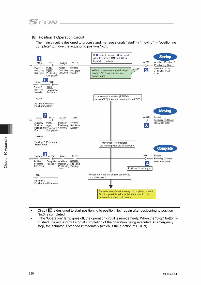
Cha
pter
10
Appe
ndix
298
[8] Position 1 Operation Circuit The main circuit is designed to process and manage signals “start” → “moving” → “positioning complete” to move the actuator to position No.1.
S T A R T L PEND RC Start Display
AUX7
Position 1 Positioning Start Pulse
AUX10
Position 1 Positioning Start Check
Point Positioning Completion
AUX17
Position 3 Positioning Complete
AUX6 Completed Position 3
078
OUT1
IN13 OUT1 AUX9
a083 a087 b132 a135 b144 b151 a162
Auxiliary Position 1 Positioning Start
AUX9
Auxiliary Position 1 Positioning Start
S T A R T L PEND RC Start Display
AUX9 AUX 1 1
Position 1 Positioning Complete
Point Positioning Completion
087
093
AUX10
AUX10
a084 a089 b093
Position 1 Positioning Start Check
Auxiliary Position 1 Positioning Start
Position 1 Positioning Start Check
S T A R T L RC Start Display
AUX10 AUX4 AUX12 AUX 1 1
AUX11
b 090 a095 b099
Position 1 Positioning Complete
Auxiliary Position 2 Positioning Start
Position 1 Positioning Complete
Position 1 Positioning Start Check
Completed Position 1
IN13 OUT1
OUT1
If 1 is not pulsed, 3 is reset with 4 turned ON and 2 is turned ON again.
Position 2 start signal
If movement is completed, the moving circuit is turned OFF.
Turned OFF at start of next positioning to position No.2.
Because any of start, moving or completion is set to ON, it is possible to know the state in which the actuator is stopped if it occurs.
If movement is started (PEND is turned OFF), the start circuit is turned OFF.
Without home return, positioning to position No.2 takes place after home return
Moving
Complete
Startup
• Circuit 10 is designed to start positioning to position No.1 again after positioning to position No.3 is completed.
• If the “Operation” lamp goes off, the operation circuit is reset entirely. When the “Stop” button is pushed, the actuator will stop at completion of the operation being executed. At emergency stop, the actuator is stopped immediately (which is the function of SCON).
ME0243-8J
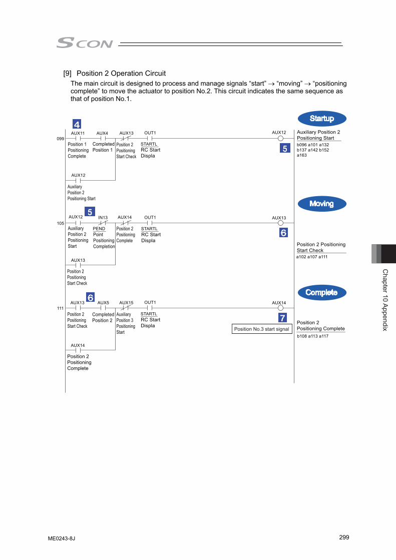
Chapter 10 Appendix
299
[9] Position 2 Operation Circuit The main circuit is designed to process and manage signals “start” → “moving” → “positioning complete” to move the actuator to position No.2. This circuit indicates the same sequence as that of position No.1.
S T A R T L RC Start Displa
AUX 1 1
Position 1 Positioning Complete
AUX4
Completed Position 1
099 OUT1 AUX12
105 IN13 OUT1 AUX13
1 1 1 OUT1 AUX14
b096 a101 a132 b137 a142 b152 a163
Auxiliary Position 2 Positioning Start
AUX12
Auxiliary Position 2 Positioning Start
Auxiliary Position 2 Positioning Start
S T A R T L RC Start Displa
AUX12 AUX14
Position 2 Positioning Complete
PEND Point Positioning Completion
a102 a107 a 1 1 1
Position 2 Positioning Start Check
AUX13
Position 2 Positioning Start Check
S T A R T L RC Start Displa
AUX13
AUX5 AUX15
b108 a 1 13 a 1 17
Position 2 Positioning Complete
AUX14
Auxiliary Position 3 Positioning Start
Position 2 Positioning Complete
Position 2 Positioning Start Check
AUX13
Position 2 Positioning Start Check
Completed Position 2
Moving
Complete
Startup
Position No.3 start signal
ME0243-8J
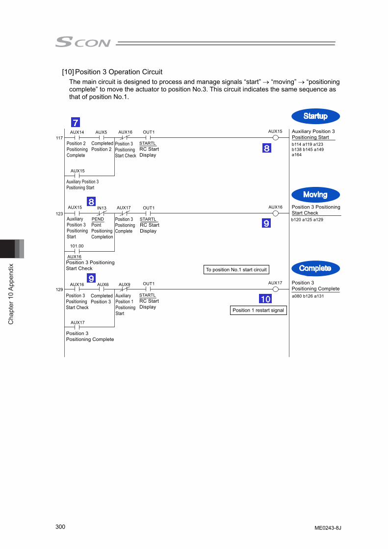
Cha
pter
10
Appe
ndix
300
[10] Position 3 Operation Circuit The main circuit is designed to process and manage signals “start” → “moving” → “positioning complete” to move the actuator to position No.3. This circuit indicates the same sequence as that of position No.1.
S T A R T L RC Start Display
AUX14
Position 2 Positioning Complete
AUX5
Completed Position 2
1 17 OUT1 AUX15
123 IN13 OUT1 AUX16
101.00
129 OUT1 AUX17
b 1 14 a 1 19 a123 b138 b145 a149
a164
Auxiliary Position 3 Positioning Start
AUX15
Auxiliary Position 3 Positioning Start
AUX15
Auxiliary Position 3 Positioning Start
S T A R T L RC Start Display
AUX17
Position 3 Positioning Complete
PEND Point Positioning Completion
b120 a125 a129
Position 3 Positioning Start Check
AUX16
Position 3 Positioning Start Check
S T A R T L RC Start Display
AUX16
AUX6 AUX9
a080 b126 a131
Position 3 Positioning Complete
AUX17
Auxiliary Position 1 Positioning Start
Position 3 Positioning Complete
Position 3 Positioning Start Check
AUX16
Position 3 Positioning Start Check
Completed Position 3
To position No.1 start circuit
Position 1 restart signal
Moving
Complete
Startup
ME0243-8J
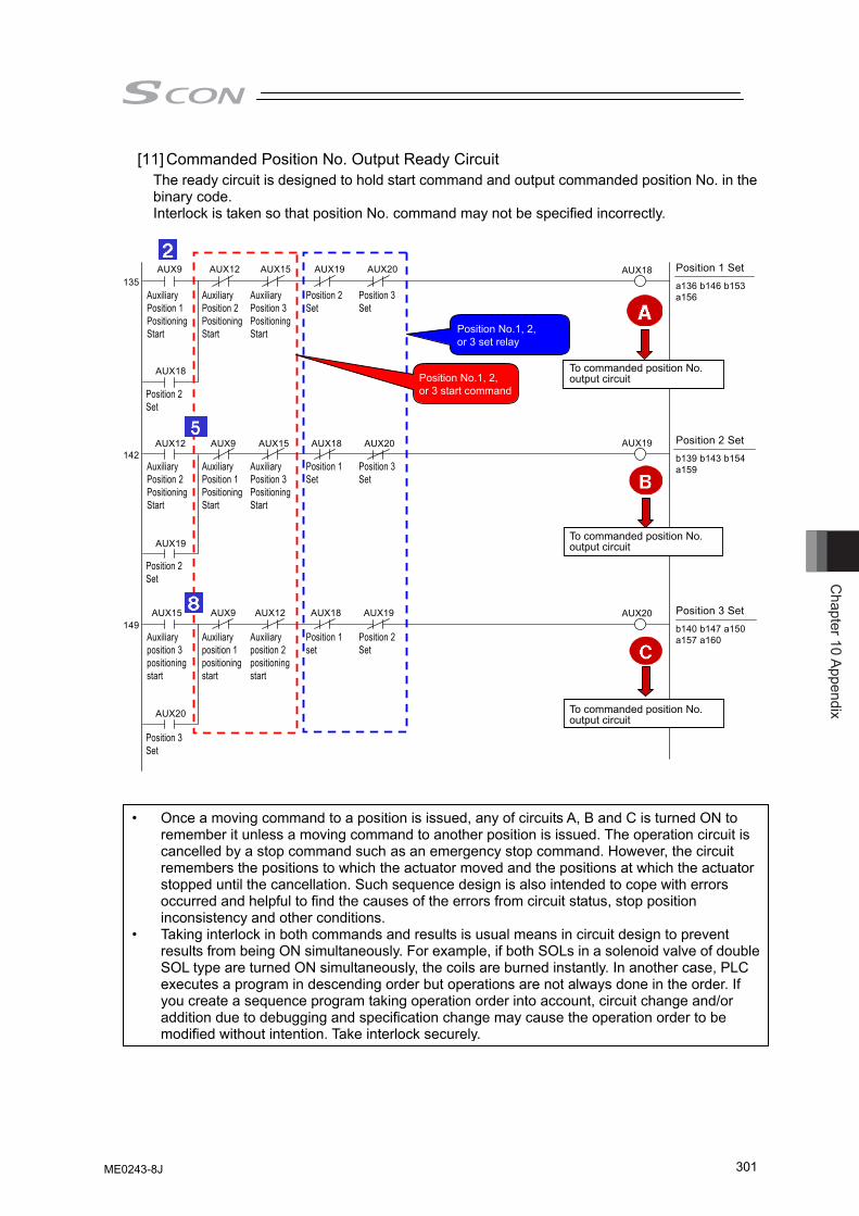
Chapter 10 Appendix
301
[11] Commanded Position No. Output Ready Circuit The ready circuit is designed to hold start command and output commanded position No. in the binary code. Interlock is taken so that position No. command may not be specified incorrectly.
135 AUX18
142 AUX19
149 AUX20
a136 b146 b153 a156
Position 1 Set
b139 b143 b154 a159
Position 2 Set
b140 b147 a150 a157 a160
Position 3 Set
AUX9
Auxiliary Position 1 Positioning Start
AUX12
Auxiliary Position 2 Positioning Start
AUX15
Auxiliary Position 3 Positioning Start
AUX19
Position 2 Set
AUX20
Position 3 Set
AUX18
Position 2 Set
AUX12
Auxiliary Position 2 Positioning Start
AUX9
Auxiliary Position 1 Positioning Start
AUX15
Auxiliary Position 3 Positioning Start
AUX18
Position 1 Set
AUX20
Position 3 Set
AUX19
Position 2 Set
AUX15
Auxiliary position 3 positioning start
AUX9
Auxiliary position 1 positioning start
AUX12
Auxiliary position 2 positioning start
AUX18
Position 1 set
AUX19
Position 2 Set
AUX20
Position 3 Set
Position No.1, 2, or 3 set relay
Position No.1, 2, or 3 start command
To commanded position No. output circuit
To commanded position No. output circuit
To commanded position No. output circuit
• Once a moving command to a position is issued, any of circuits A, B and C is turned ON to remember it unless a moving command to another position is issued. The operation circuit is cancelled by a stop command such as an emergency stop command. However, the circuit remembers the positions to which the actuator moved and the positions at which the actuator stopped until the cancellation. Such sequence design is also intended to cope with errors occurred and helpful to find the causes of the errors from circuit status, stop position inconsistency and other conditions.
• Taking interlock in both commands and results is usual means in circuit design to prevent results from being ON simultaneously. For example, if both SOLs in a solenoid valve of double SOL type are turned ON simultaneously, the coils are burned instantly. In another case, PLC executes a program in descending order but operations are not always done in the order. If you create a sequence program taking operation order into account, circuit change and/or addition due to debugging and specification change may cause the operation order to be modified without intention. Take interlock securely.
ME0243-8J
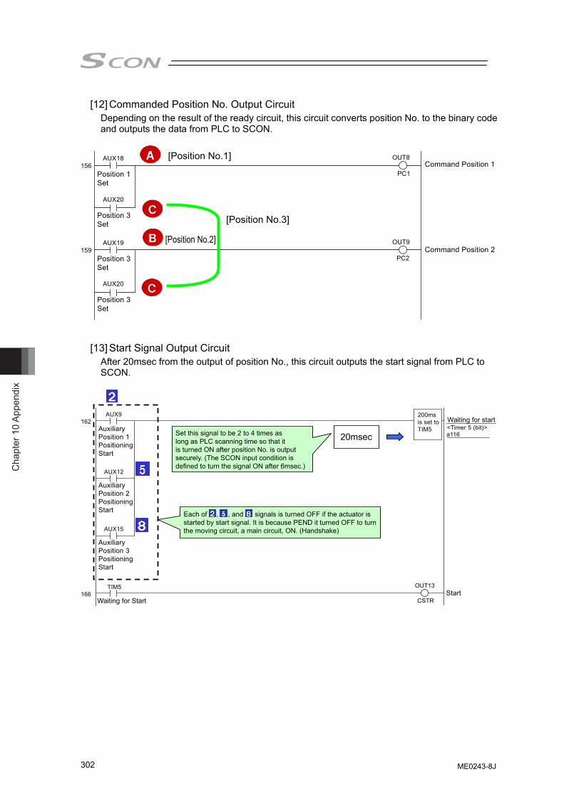
Cha
pter
10
Appe
ndix
302
[12] Commanded Position No. Output Circuit Depending on the result of the ready circuit, this circuit converts position No. to the binary code and outputs the data from PLC to SCON.
156 OUT8
PC1 Command Position 1
AUX18
Position 1 Set
AUX20
Position 3 Set
AUX20
Position 3 Set
159 OUT9
PC2 Command Position 2
AUX19
Position 3 Set
[Position No.1]
[Position No.2]
[Position No.3]
[13] Start Signal Output Circuit After 20msec from the output of position No., this circuit outputs the start signal from PLC to SCON.
162
166
AUX9
Auxiliary Position 1 Positioning Start
AUX12
Auxiliary Position 2 Positioning Start
AUX15
Auxiliary Position 3 Positioning Start
OUT13
CSTR
Waiting for start
Start
<Timer 5 (bit)> a 1 16
Waiting for Start
TIM5
200ms is set to TIM5
20msec
Set this signal to be 2 to 4 times as long as PLC scanning time so that it is turned ON after position No. is output securely. (The SCON input condition is defined to turn the signal ON after 6msec.)
Each of 2 , 5 , and 8 signals is turned OFF if the actuator is started by start signal. It is because PEND it turned OFF to turn the moving circuit, a main circuit, ON. (Handshake)
ME0243-8J
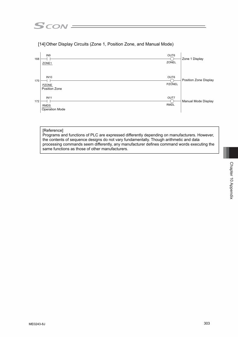
Chapter 10 Appendix
303
[14] Other Display Circuits (Zone 1, Position Zone, and Manual Mode)
[Reference] Programs and functions of PLC are expressed differently depending on manufacturers. However, the contents of sequence designs do not vary fundamentally. Though arithmetic and data processing commands seem differently, any manufacturer defines command words executing the same functions as those of other manufacturers.
172 RMDS Operation Mode
OUT7 IN 1 1
RMDLManual Mode Display
170 PZONE Position Zone
OUT6 IN10
PZONE L Position Zone Display
168 ZONE1
OUT6 IN9
ZONE L Zone 1 Display
ME0243-8J
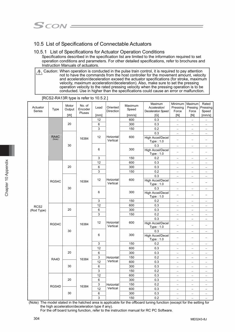
Cha
pter
10
Appe
ndix
304
10.5 List of Specifications of Connectable Actuators
10.5.1 List of Specifications for Actuator Operation Conditions Specifications described in the specification list are limited to the information required to set operation conditions and parameters. For other detailed specifications, refer to brochures and Instruction Manuals of actuators.
[RCS2-RA13R type is refer to 10.5.2.]
Motor Output Lead Maximum
Speed
Maximum Acceleration/
Deceleration Speed
Minimum Pressing
Force
Maximum Pressing
Force
Rated Pressing Speed
Actuator Series Type
[W]
No. of Encoder Pluses
[mm]
Oriented Direction
[mm/s] [G] [N] [N] [mm/s]12 600 0.3 − − − 6 300 0.3 − − − 20 3 150 0.2 − − −
0.3 − − − 12 600 High Accel/Decel
Type : 1.0 − − −
0.3 − − − 6 300 High Accel/Decel
Type : 1.0 − − −
RA4C (Note)
30
16384
3
Horizontal/Vertical
150 0.2 − − − 12 600 0.3 − − − 6 300 0.3 − − − 20 3 150 0.2 − − −
0.3 − − − 12 600 High Accel/Decel
Type : 1.0 − − −
0.3 − − − 6 300 High Accel/Decel
Type : 1.0 − − −
RGS4C
30
16384
3
Horizontal/Vertical
150 0.2 − − − 12 600 0.3 − − − 6 300 0.3 − − − 20 3 150 0.2 − − −
0.3 − − − 12 600 High Accel/Decel
Type : 1.0 − − −
0.3 − − − 6 300 High Accel/Decel
Type : 1.0 − − −
RGD4C
30
16384
3
Horizontal/Vertical
150 0.2 − − − 12 600 0.3 − − − 6 300 0.3 − − − 20 3 150 0.2 − − −
12 600 0.3 − − − 6 300 0.3 − − −
RA4D
30
16384
3
Horizontal/Vertical
150 0.2 − − − 12 600 0.3 − − − 6 300 0.3 − − − 20 3 150 0.2 − − −
12 600 0.3 − − − 6 300 0.3 − − −
RCS2 (Rod Type)
RGS4D
30
16384
3
Horizontal/Vertical
150 0.2 − − −
Caution: When operation is conducted in the pulse train control, it is required to pay attention not to have the commands from the host controller for the movement amount, velocity and acceleration/deceleration exceed the actuator specifications (for stroke, maximum velocity, maximum acceleration/deceleration). Also, make sure to set the pressing operation velocity to the rated pressing velocity when the pressing operation is to be conducted. Use in higher than the specifications could cause an error or malfunction.
(Note) The model stated in the hatched area is applicable for the offboard tuning function (except for the setting for the high acceleration/deceleration type if any). For the off board tuning function, refer to the instruction manual for RC PC Software.
ME0243-8J
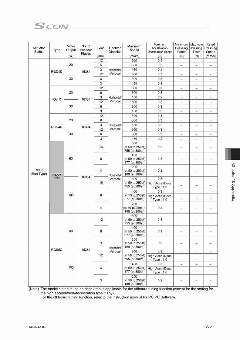
Chapter 10 Appendix
305
Motor Output Lead Maximum
Speed
Maximum Acceleration/
Deceleration Speed
Minimum Pressing
Force
Maximum Pressing
Force
Rated Pressing Speed
Actuator Series Type
[W]
No. of Encoder Pluses
[mm]
Oriented Direction
[mm/s] [G] [N] [N] [mm/s]12 600 0.3 − − − 6 300 0.3 − − − 20 3 150 0.2 − − −
12 600 0.3 − − − 6 300 0.3 − − −
RGD4D
30
16384
3
Horizontal/Vertical
150 0.2 − − − 12 600 0.3 − − − 6 300 0.3 − − − 20 3 150 0.2 − − −
12 600 0.3 − − − 6 300 0.3 − − −
RA4R
30
16384
3
Horizontal/Vertical
150 0.3 − − − 12 600 0.3 − − − 6 300 0.3 − − − 20 3 150 0.2 − − −
12 600 0.3 − − − 6 300 0.3 − − −
RGD4R
30
16384
3
Horizontal/Vertical
150 0.2 − − −
16 800
(at 50 to 250st)755 (at 300st)
0.3 − − −
8 400
(at 50 to 250st)377 (at 300st)
0.3 − − − 60
4 200
(at 50 to 250st)188 (at 300st)
0.2 − − −
0.3 − − − 16
800 (at 50 to 250st)755 (at 300st)
High Accel/Decel Type : 1.0 − − −
0.3 − − − 8
400 (at 50 to 250st)377 (at 300st)
High Accel/Decel Type : 1.0 − − −
RA5C (Note)
100
16384
4
Horizontal/Vertical
200 (at 50 to 250st)188 (at 300st)
0.2 − − −
12 800
(at 50 to 250st)755 (at 300st)
0.3 − − −
6 400
(at 50 to 250st)377 (at 300st)
0.3 − − − 60
3 200
(at 50 to 250st)188 (at 300st)
0.2 − − −
0.3 − − − 12
800 (at 50 to 250st)755 (at 300st)
High Accel/Decel Type : 1.0 − − −
0.3 − − − 6
400 (at 50 to 250st)377 (at 300st)
High Accel/Decel Type : 1.0 − − −
RCS2 (Rod Type)
RGS5C
100
16384
3
Horizontal/Vertical
200 (at 50 to 250st)188 (at 300st)
0.2 − − −
(Note) The model stated in the hatched area is applicable for the offboard tuning function (except for the setting for the high acceleration/deceleration type if any). For the off board tuning function, refer to the instruction manual for RC PC Software.
ME0243-8J
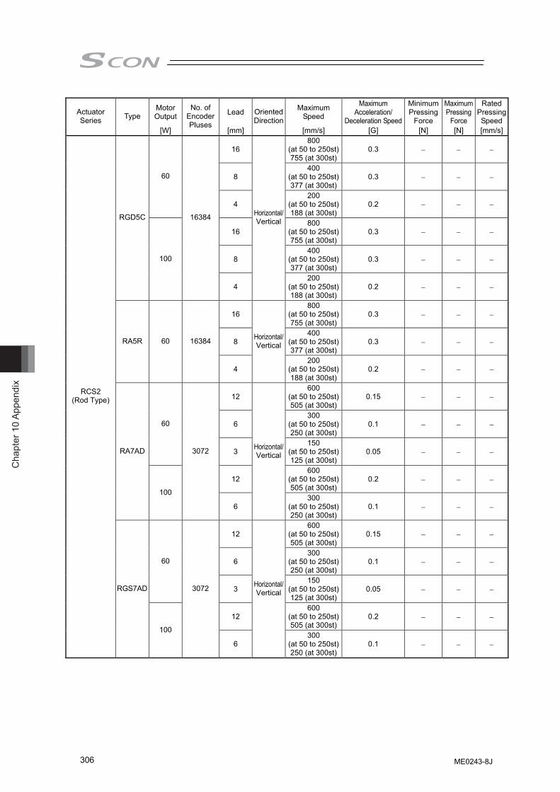
Cha
pter
10
Appe
ndix
306
Motor Output Lead Maximum
Speed
Maximum Acceleration/
Deceleration Speed
Minimum Pressing
Force
Maximum Pressing
Force
Rated Pressing Speed
Actuator Series Type
[W]
No. of Encoder Pluses
[mm]
Oriented Direction
[mm/s] [G] [N] [N] [mm/s]
16 800
(at 50 to 250st)755 (at 300st)
0.3 − − −
8 400
(at 50 to 250st)377 (at 300st)
0.3 − − − 60
4 200
(at 50 to 250st)188 (at 300st)
0.2 − − −
16 800
(at 50 to 250st)755 (at 300st)
0.3 − − −
8 400
(at 50 to 250st)377 (at 300st)
0.3 − − −
RGD5C
100
16384
4
Horizontal/Vertical
200 (at 50 to 250st)188 (at 300st)
0.2 − − −
16 800
(at 50 to 250st)755 (at 300st)
0.3 − − −
8 400
(at 50 to 250st)377 (at 300st)
0.3 − − − RA5R 60 16384
4
Horizontal/Vertical
200 (at 50 to 250st)188 (at 300st)
0.2 − − −
12 600
(at 50 to 250st)505 (at 300st)
0.15 − − −
6 300
(at 50 to 250st)250 (at 300st)
0.1 − − − 60
3 150
(at 50 to 250st)125 (at 300st)
0.05 − − −
12 600
(at 50 to 250st)505 (at 300st)
0.2 − − −
RA7AD
100
3072
6
Horizontal/Vertical
300 (at 50 to 250st)250 (at 300st)
0.1 − − −
12 600
(at 50 to 250st)505 (at 300st)
0.15 − − −
6 300
(at 50 to 250st)250 (at 300st)
0.1 − − − 60
3 150
(at 50 to 250st)125 (at 300st)
0.05 − − −
12 600
(at 50 to 250st)505 (at 300st)
0.2 − − −
RCS2 (Rod Type)
RGS7AD
100
3072
6
Horizontal/Vertical
300 (at 50 to 250st)250 (at 300st)
0.1 − − −
ME0243-8J
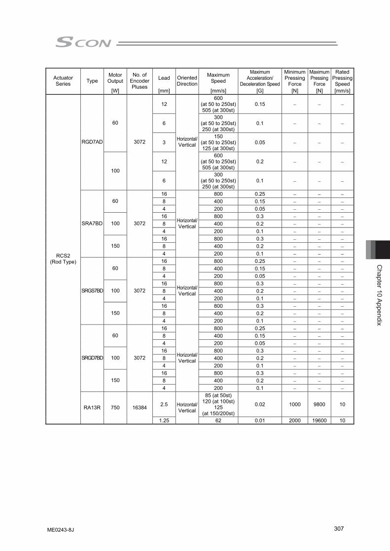
Chapter 10 Appendix
307
Motor Output Lead Maximum
Speed
Maximum Acceleration/
Deceleration Speed
Minimum Pressing
Force
Maximum Pressing
Force
Rated Pressing Speed
Actuator Series Type
[W]
No. of Encoder Pluses
[mm]
Oriented Direction
[mm/s] [G] [N] [N] [mm/s]
12 600
(at 50 to 250st)505 (at 300st)
0.15 − − −
6 300
(at 50 to 250st)250 (at 300st)
0.1 − − − 60
3 150
(at 50 to 250st)125 (at 300st)
0.05 − − −
12 600
(at 50 to 250st)505 (at 300st)
0.2 − − −
RGD7AD
100
3072
6
Horizontal/Vertical
300 (at 50 to 250st)250 (at 300st)
0.1 − − −
16 800 0.25 − − − 8 400 0.15 − − − 60 4 200 0.05 − − −
16 800 0.3 − − − 8 400 0.2 − − − 100 4 200 0.1 − − − 16 800 0.3 − − − 8 400 0.2 − − −
SRA7BD
150
3072
4
Horizontal/Vertical
200 0.1 − − − 16 800 0.25 − − − 8 400 0.15 − − − 60 4 200 0.05 − − −
16 800 0.3 − − − 8 400 0.2 − − − 100 4 200 0.1 − − − 16 800 0.3 − − − 8 400 0.2 − − −
SRGS7BD
150
3072
4
Horizontal/Vertical
200 0.1 − − − 16 800 0.25 − − − 8 400 0.15 − − − 60 4 200 0.05 − − −
16 800 0.3 − − − 8 400 0.2 − − − 100 4 200 0.1 − − − 16 800 0.3 − − − 8 400 0.2 − − −
SRGD7BD
150
3072
4
Horizontal/Vertical
200 0.1 − − −
2.5
85 (at 50st) 120 (at 100st)
125 (at 150/200st)
0.02 1000 9800 10
RCS2 (Rod Type)
RA13R 750 16384
1.25
Horizontal/Vertical
62 0.01 2000 19600 10
ME0243-8J
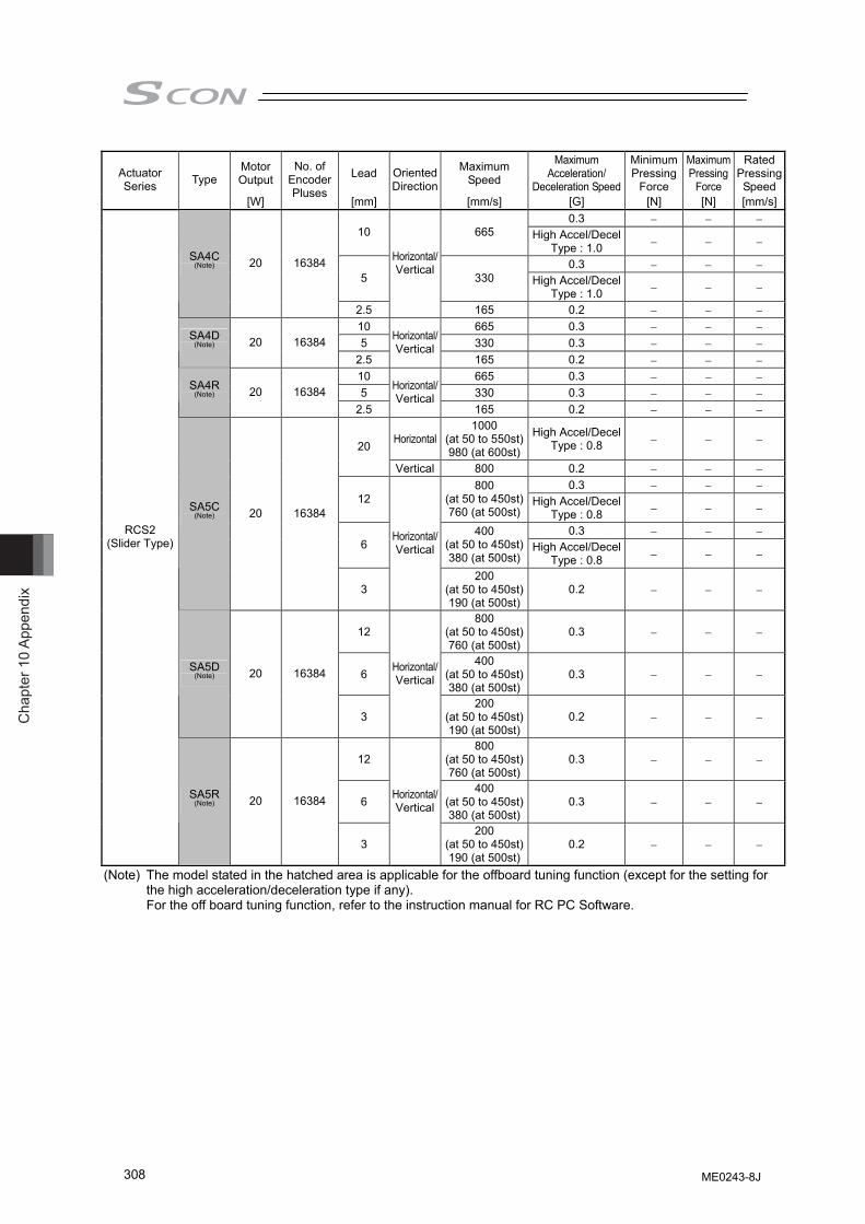
Cha
pter
10
Appe
ndix
308
Motor Output Lead Maximum
Speed
Maximum Acceleration/
Deceleration Speed
Minimum Pressing
Force
Maximum Pressing
Force
Rated Pressing Speed
Actuator Series Type
[W]
No. of Encoder Pluses
[mm]
Oriented Direction
[mm/s] [G] [N] [N] [mm/s]0.3 − − −
10 665 High Accel/Decel Type : 1.0 − − −
0.3 − − − 5 330 High Accel/Decel
Type : 1.0 − − −
SA4C (Note) 20 16384
2.5
Horizontal/Vertical
165 0.2 − − − 10 665 0.3 − − − 5 330 0.3 − − −
SA4D (Note) 20 16384
2.5
Horizontal/Vertical
165 0.2 − − − 10 665 0.3 − − − 5 330 0.3 − − −
SA4R (Note) 20 16384
2.5
Horizontal/Vertical
165 0.2 − − −
Horizontal1000
(at 50 to 550st)980 (at 600st)
High Accel/Decel Type : 0.8 − − − 20
Vertical 800 0.2 − − − 0.3 − − −
12 800
(at 50 to 450st)760 (at 500st)
High Accel/Decel Type : 0.8 − − −
0.3 − − − 6
400 (at 50 to 450st)380 (at 500st)
High Accel/Decel Type : 0.8 − − −
SA5C (Note) 20 16384
3
Horizontal/Vertical
200 (at 50 to 450st)190 (at 500st)
0.2 − − −
12 800
(at 50 to 450st)760 (at 500st)
0.3 − − −
6 400
(at 50 to 450st)380 (at 500st)
0.3 − − − SA5D
(Note) 20 16384
3
Horizontal/Vertical
200 (at 50 to 450st)190 (at 500st)
0.2 − − −
12 800
(at 50 to 450st)760 (at 500st)
0.3 − − −
6 400
(at 50 to 450st)380 (at 500st)
0.3 − − −
RCS2 (Slider Type)
SA5R (Note) 20 16384
3
Horizontal/Vertical
200 (at 50 to 450st)190 (at 500st)
0.2 − − −
(Note) The model stated in the hatched area is applicable for the offboard tuning function (except for the setting for the high acceleration/deceleration type if any). For the off board tuning function, refer to the instruction manual for RC PC Software.
ME0243-8J
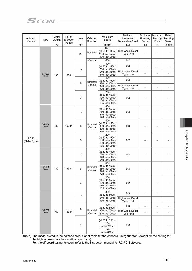
Chapter 10 Appendix
309
Motor Output Lead Maximum
Speed
Maximum Acceleration/
Deceleration Speed
Minimum Pressing
Force
Maximum Pressing
Force
Rated Pressing Speed
Actuator Series Type
[W]
No. of Encoder Pluses
[mm]
Oriented Direction
[mm/s] [G] [N] [N] [mm/s]
Horizontal1300
(at 50 to 500st)1160 (at 550st)990 (at 600st)
High Accel/Decel Type : 1.0 − − − 20
Vertical 800 0.2 − − −
0.3 − − − 12
800 (at 50 to 450st)760 (at 500st)640 (at 550st)540 (at 600st)
High Accel/Decel Type : 1.0 − − −
0.3 − − − 6
400 (at 50 to 450st)380 (at 500st)320 (at 550st)270 (at 600st)
High Accel/Decel Type : 1.0 − − −
SA6C (Note) 30 16384
3
Horizontal/Vertical
200 (at 50 to 450st)190 (at 500st)160 (at 550st)135 (at 600st)
0.2 − − −
12
800 (at 50 to 450st)760 (at 500st)640 (at 550st)540 (at 600st)
0.3 − − −
6
400 (at 50 to 450st)380 (at 500st)320 (at 550st)270 (at 600st)
0.3 − − − SA6D
(Note) 30 16384
3
Horizontal/Vertical
200 (at 50 to 450st)190 (at 500st)160 (at 550st)135 (at 600st)
0.2 − − −
12
800 (at 50 to 450st)760 (at 500st)640 (at 550st)540 (at 600st)
0.3 − − −
6
400 (at 50 to 450st)380 (at 500st)320 (at 550st)270 (at 600st)
0.3 − − − SA6R
(Note) 30 16384
3
Horizontal/Vertical
200 (at 50 to 450st)190 (at 500st)160 (at 550st)135 (at 600st)
0.2 − − −
0.3 − − − 16
800 (at 50 to 600st)640 (at 700st)480 (at 800st)
High Accel/Decel Type : 1.0 − − −
0.3 − − − 8
400 (at 50 to 650st)320 (at 700st)240 (at 800st)
High Accel/Decel Type : 0.8 − − −
RCS2 (Slider Type)
SA7C (Note) 60 16384
4
Horizontal/Vertical
200 (at 50 to 650st)
160 (at to 700st)
120 (at to 800st)
0.2 − − −
(Note) The model stated in the hatched area is applicable for the offboard tuning function (except for the setting for the high acceleration/deceleration type if any). For the off board tuning function, refer to the instruction manual for RC PC Software.
ME0243-8J
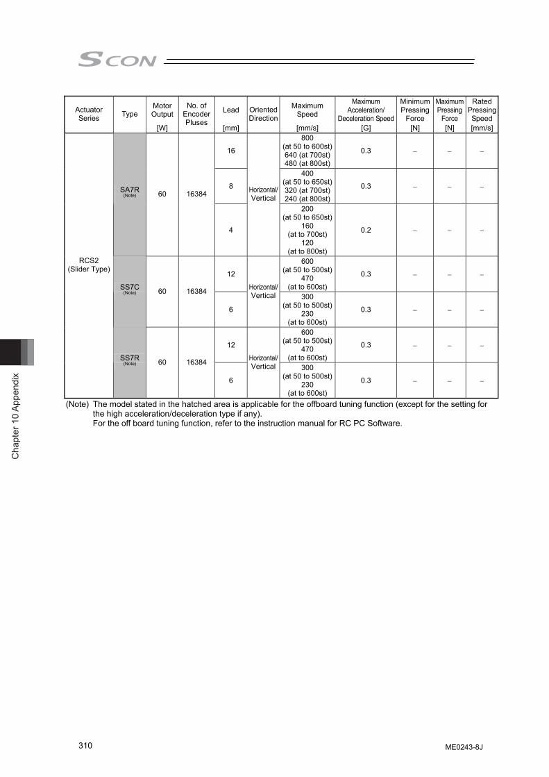
Cha
pter
10
Appe
ndix
310
Motor Output Lead Maximum
Speed
Maximum Acceleration/
Deceleration Speed
Minimum Pressing
Force
Maximum Pressing
Force
Rated Pressing Speed
Actuator Series Type
[W]
No. of Encoder Pluses
[mm]
Oriented Direction
[mm/s] [G] [N] [N] [mm/s]
16
800 (at 50 to 600st)640 (at 700st)480 (at 800st)
0.3 − − −
8
400 (at 50 to 650st)320 (at 700st)240 (at 800st)
0.3 − − − SA7R (Note) 60 16384
4
Horizontal/Vertical
200 (at 50 to 650st)
160 (at to 700st)
120 (at to 800st)
0.2 − − −
12
600 (at 50 to 500st)
470 (at to 600st)
0.3 − − −
SS7C (Note) 60 16384
6
Horizontal/Vertical 300
(at 50 to 500st)230
(at to 600st)
0.3 − − −
12
600 (at 50 to 500st)
470 (at to 600st)
0.3 − − −
RCS2 (Slider Type)
SS7R (Note) 60 16384
6
Horizontal/Vertical 300
(at 50 to 500st)230
(at to 600st)
0.3 − − −
(Note) The model stated in the hatched area is applicable for the offboard tuning function (except for the setting for the high acceleration/deceleration type if any). For the off board tuning function, refer to the instruction manual for RC PC Software.
ME0243-8J
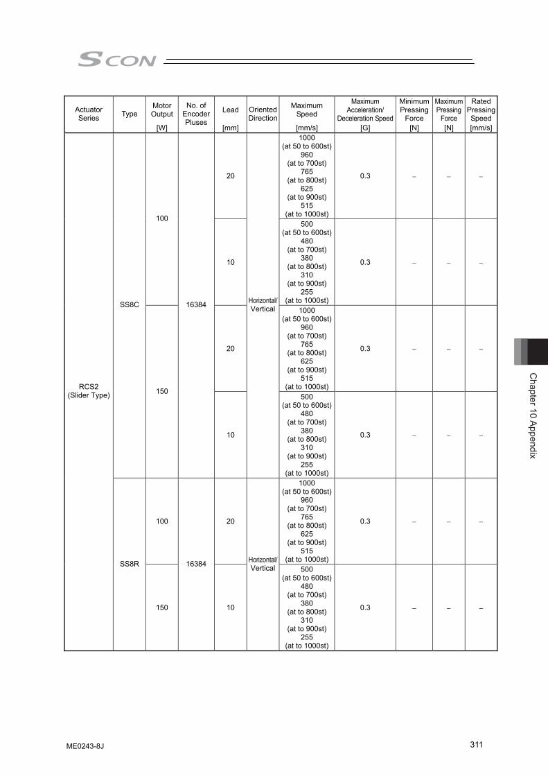
Chapter 10 Appendix
311
Motor Output Lead Maximum
Speed
Maximum Acceleration/
Deceleration Speed
Minimum Pressing
Force
Maximum Pressing
Force
Rated Pressing Speed
Actuator Series Type
[W]
No. of Encoder Pluses
[mm]
Oriented Direction
[mm/s] [G] [N] [N] [mm/s]
20
1000 (at 50 to 600st)
960 (at to 700st)
765 (at to 800st)
625 (at to 900st)
515 (at to 1000st)
0.3 − − −
100
10
500 (at 50 to 600st)
480 (at to 700st)
380 (at to 800st)
310 (at to 900st)
255 (at to 1000st)
0.3 − − −
20
1000 (at 50 to 600st)
960 (at to 700st)
765 (at to 800st)
625 (at to 900st)
515 (at to 1000st)
0.3 − − −
SS8C
150
16384
10
Horizontal/Vertical
500 (at 50 to 600st)
480 (at to 700st)
380 (at to 800st)
310 (at to 900st)
255 (at to 1000st)
0.3 − − −
100 20
1000 (at 50 to 600st)
960 (at to 700st)
765 (at to 800st)
625 (at to 900st)
515 (at to 1000st)
0.3 − − −
RCS2 (Slider Type)
SS8R
150
16384
10
Horizontal/Vertical 500
(at 50 to 600st)480
(at to 700st)380
(at to 800st)310
(at to 900st)255
(at to 1000st)
0.3 − − −
ME0243-8J

Cha
pter
10
Appe
ndix
312
Motor Output Lead Maximum
Speed
Maximum Acceleration/
Deceleration Speed
Minimum Pressing
Force
Maximum Pressing
Force
Rated Pressing Speed
Actuator Series Type
[W]
No. of Encoder Pluses
[mm]
Oriented Direction
[mm/s] [G] [N] [N] [mm/s]
5
300 (at 50 to 650st)
260 (at to 700st)
230 (at to 750st)
200 (at to 800st)
180 (at to 850st)
170 (at to 900st)
150 (at to 950st)
135 (at to 1000st)
120 (at to 1050st)
110 (at to 1100st)
0.3 − − −
10
Horizontal/Vertical 600
(at 50 to 650st)530
(at to 700st)470
(at to 750st)410
(at to 800st)370
(at to 850st)340
(at to 900st)310
(at to 950st)270
(at to 1000st)250
(at to 1050st)230
(at to 1100st)
0.5 − − − RCS3
(Slider Type) SA8 (Note) 100 16384
20 Horizontal/Vertical
1200 (at 50 to 650st)
1070 (at to 700st)
940 (at to 750st)
840 (at to 800st)
750 (at to 850st)
670 (at to 900st)
610 (at to 950st)
550 (at to 1000st)
500 (at to 1050st)
460 (at to 1100st)
0.7 − − −
(Note) The model stated in the hatched area is applicable for the offboard tuning function (except for the setting for the high acceleration/deceleration type if any). For the off board tuning function, refer to the instruction manual for RC PC Software.
ME0243-8J
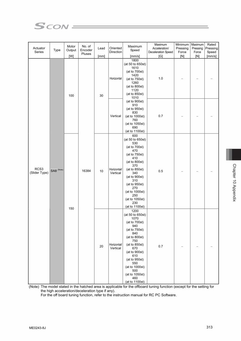
Chapter 10 Appendix
313
Motor Output Lead Maximum
Speed
Maximum Acceleration/
Deceleration Speed
Minimum Pressing
Force
Maximum Pressing
Force
Rated Pressing Speed
Actuator Series Type
[W]
No. of Encoder Pluses
[mm]
Oriented Direction
[mm/s] [G] [N] [N] [mm/s]
Horizontal 1.0 − − −
100 30
Vertical
1800 (at 50 to 650st)
1610 (at to 700st)
1420 (at to 750st)
1260 (at to 800st)
1120 (at to 850st)
1010 (at to 900st)
910 (at to 950st)
830 (at to 1000st)
760 (at to 1050st)
690 (at to 1100st)
0.7 − − −
10 Horizontal/Vertical
600 (at 50 to 650st)
530 (at to 700st)
470 (at to 750st)
410 (at to 800st)
370 (at to 850st)
340 (at to 900st)
310 (at to 950st)
270 (at to 1000st)
250 (at to 1050st)
230 (at to 1100st)
0.5 − − − RCS3
(Slider Type) SA8 (Note)
150
16384
20 Horizontal/Vertical
1200 (at 50 to 650st)
1070 (at to 700st)
940 (at to 750st)
840 (at to 800st)
750 (at to 850st)
670 (at to 900st)
610 (at to 950st)
550 (at to 1000st)
500 (at to 1050st)
460 (at to 1100st)
0.7 − − −
(Note) The model stated in the hatched area is applicable for the offboard tuning function (except for the setting for the high acceleration/deceleration type if any). For the off board tuning function, refer to the instruction manual for RC PC Software.
ME0243-8J
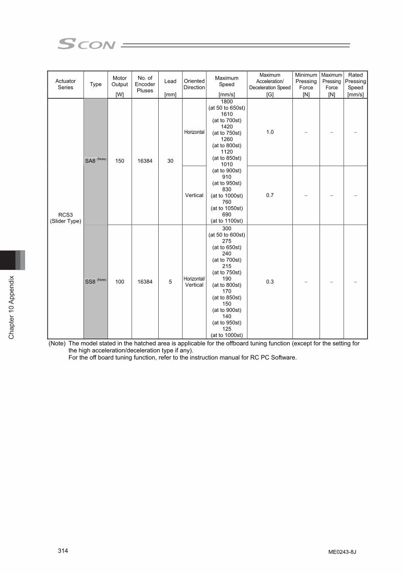
Cha
pter
10
Appe
ndix
314
Motor Output Lead Maximum
Speed
Maximum Acceleration/
Deceleration Speed
Minimum Pressing
Force
Maximum Pressing
Force
Rated Pressing Speed
Actuator Series Type
[W]
No. of Encoder Pluses
[mm]
Oriented Direction
[mm/s] [G] [N] [N] [mm/s]
Horizontal 1.0 − − −
SA8 (Note) 150 16384 30
Vertical
1800 (at 50 to 650st)
1610 (at to 700st)
1420 (at to 750st)
1260 (at to 800st)
1120 (at to 850st)
1010 (at to 900st)
910 (at to 950st)
830 (at to 1000st)
760 (at to 1050st)
690 (at to 1100st)
0.7 − − −
RCS3 (Slider Type)
SS8 (Note) 100 16384 5 Horizontal/Vertical
300 (at 50 to 600st)
275 (at to 650st)
240 (at to 700st)
215 (at to 750st)
190 (at to 800st)
170 (at to 850st)
150 (at to 900st)
140 (at to 950st)
125 (at to 1000st)
0.3 − − −
(Note) The model stated in the hatched area is applicable for the offboard tuning function (except for the setting for the high acceleration/deceleration type if any). For the off board tuning function, refer to the instruction manual for RC PC Software.
ME0243-8J
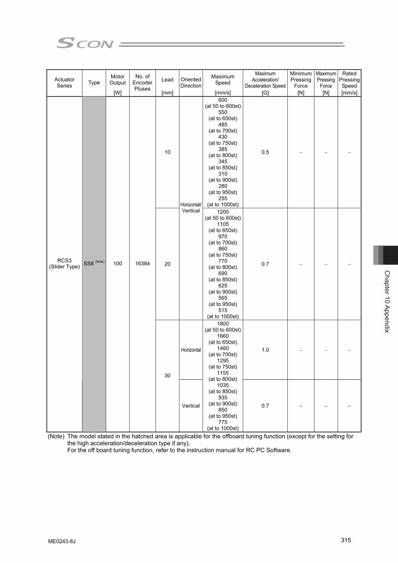
Chapter 10 Appendix
315
Motor Output Lead Maximum
Speed
Maximum Acceleration/
Deceleration Speed
Minimum Pressing
Force
Maximum Pressing
Force
Rated Pressing Speed
Actuator Series Type
[W]
No. of Encoder Pluses
[mm]
Oriented Direction
[mm/s] [G] [N] [N] [mm/s]
10
600 (at 50 to 600st)
550 (at to 650st)
485 (at to 700st)
430 (at to 750st)
385 (at to 800st)
345 (at to 850st)
310 (at to 900st)
280 (at to 950st)
255 (at to 1000st)
0.5 − − −
20
Horizontal/Vertical 1200
(at 50 to 600st)1105
(at to 650st)970
(at to 700st)860
(at to 750st)770
(at to 800st)690
(at to 850st)625
(at to 900st)565
(at to 950st)515
(at to 1000st)
0.7 − − −
Horizontal 1.0 − − −
RCS3 (Slider Type) SS8 (Note) 100 16384
30
Vertical
1800 (at 50 to 600st)
1660 (at to 650st)
1460 (at to 700st)
1295 (at to 750st)
1155 (at to 800st)
1035 (at to 850st)
935 (at to 900st)
850 (at to 950st)
775 (at to 1000st)
0.7 − − −
(Note) The model stated in the hatched area is applicable for the offboard tuning function (except for the setting for the high acceleration/deceleration type if any). For the off board tuning function, refer to the instruction manual for RC PC Software.
ME0243-8J
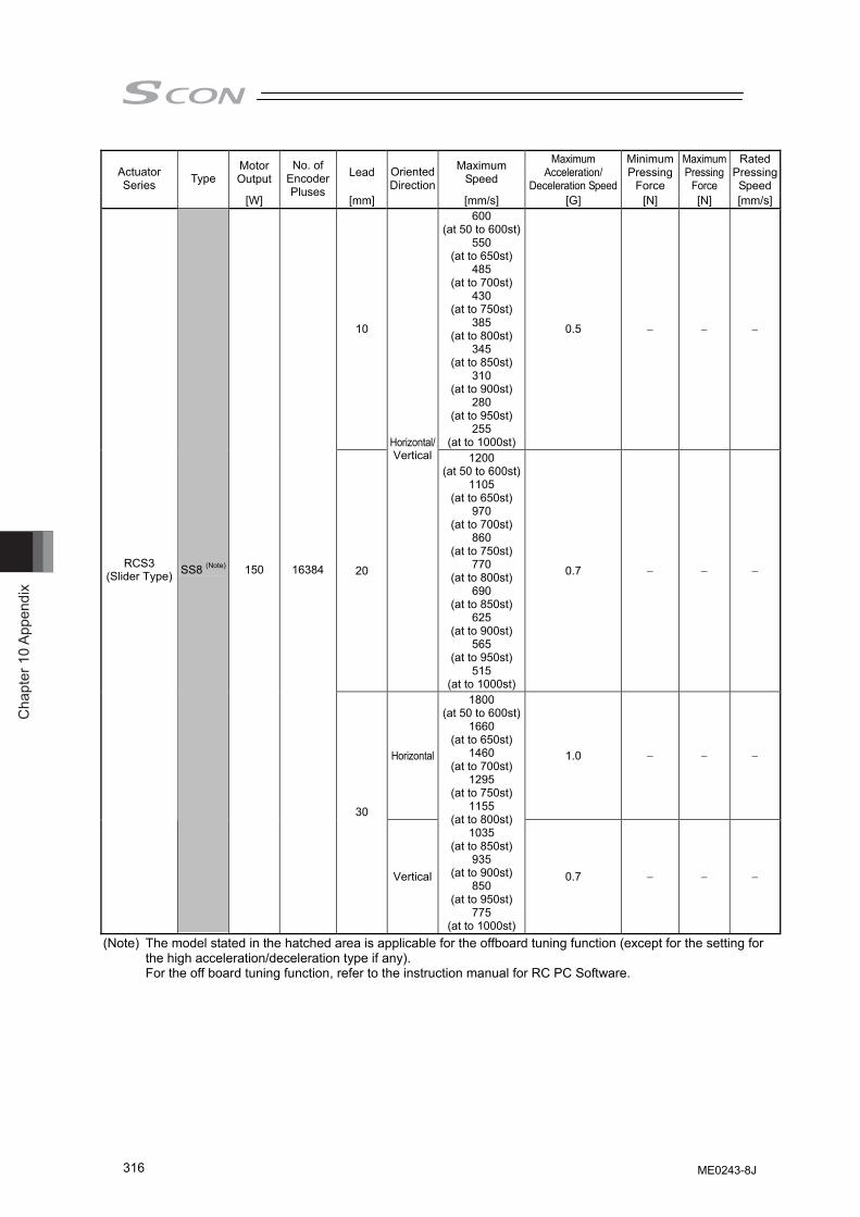
Cha
pter
10
Appe
ndix
316
Motor Output Lead Maximum
Speed
Maximum Acceleration/
Deceleration Speed
Minimum Pressing
Force
Maximum Pressing
Force
Rated Pressing Speed
Actuator Series Type
[W]
No. of Encoder Pluses
[mm]
Oriented Direction
[mm/s] [G] [N] [N] [mm/s]
10
600 (at 50 to 600st)
550 (at to 650st)
485 (at to 700st)
430 (at to 750st)
385 (at to 800st)
345 (at to 850st)
310 (at to 900st)
280 (at to 950st)
255 (at to 1000st)
0.5 − − −
20
Horizontal/Vertical 1200
(at 50 to 600st)1105
(at to 650st)970
(at to 700st)860
(at to 750st)770
(at to 800st)690
(at to 850st)625
(at to 900st)565
(at to 950st)515
(at to 1000st)
0.7 − − −
Horizontal 1.0 − − −
RCS3 (Slider Type) SS8 (Note) 150 16384
30
Vertical
1800 (at 50 to 600st)
1660 (at to 650st)
1460 (at to 700st)
1295 (at to 750st)
1155 (at to 800st)
1035 (at to 850st)
935 (at to 900st)
850 (at to 950st)
775 (at to 1000st)
0.7 − − −
(Note) The model stated in the hatched area is applicable for the offboard tuning function (except for the setting for the high acceleration/deceleration type if any). For the off board tuning function, refer to the instruction manual for RC PC Software.
ME0243-8J

Chapter 10 Appendix
317
Motor Output Lead Maximum
Speed
Maximum Acceleration/
Deceleration Speed
Minimum Pressing
Force
Maximum Pressing
Force
Rated Pressing Speed
Actuator Series Type
[W]
No. of Encoder Pluses
[mm]
Oriented Direction
[mm/s] [G] [N] [N] [mm/s]
5
300 (at 50 to 650st)
250 (at to 700st)
220 (at to 750st)
190 (at to 800st)
170 (at to 850st)
160 (at to 900st)
140 (at to 950st)
130 (at to 1000st)
120 (at to 1050st)
110 (at to 1100st)
0.3 − − −
10
600 (at 50 to 650st)
500 (at to 700st)
440 (at to 750st)
390 (at to 800st)
350 (at to 850st)
320 (at to 900st)
290 (at to 950st)
260 (at to 1000st)
240 (at to 1050st)
220 (at to 1100st)
0.5 − − − RCS3CR
(Slider Type) SA8 (Note) 100 16384
20
Horizontal/Vertical
1200 (at 50 to 650st)
1010 (at to 700st)
890 (at to 750st)
790 (at to 800st)
710 (at to 850st)
640 (at to 900st)
580 (at to 950st)
530 (at to 1000st)
480 (at to 1050st)
440 (at to 1100st)
0.7 − − −
(Note) The model stated in the hatched area is applicable for the offboard tuning function (except for the setting for the high acceleration/deceleration type if any). For the off board tuning function, refer to the instruction manual for RC PC Software.
ME0243-8J
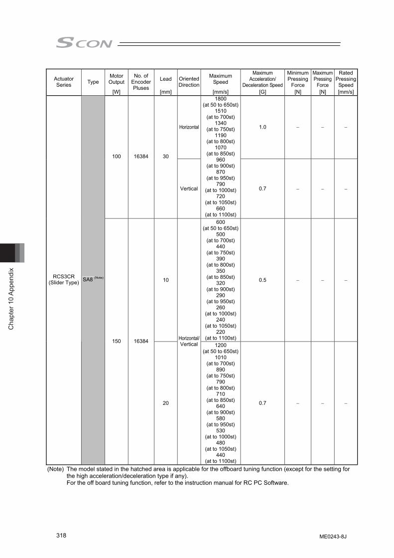
Cha
pter
10
Appe
ndix
318
Motor Output Lead Maximum
Speed
Maximum Acceleration/
Deceleration Speed
Minimum Pressing
Force
Maximum Pressing
Force
Rated Pressing Speed
Actuator Series Type
[W]
No. of Encoder Pluses
[mm]
Oriented Direction
[mm/s] [G] [N] [N] [mm/s]
Horizontal 1.0 − − −
100 16384 30
Vertical
1800 (at 50 to 650st)
1510 (at to 700st)
1340 (at to 750st)
1190 (at to 800st)
1070 (at to 850st)
960 (at to 900st)
870 (at to 950st)
790 (at to 1000st)
720 (at to 1050st)
660 (at to 1100st)
0.7 − − −
10
600 (at 50 to 650st)
500 (at to 700st)
440 (at to 750st)
390 (at to 800st)
350 (at to 850st)
320 (at to 900st)
290 (at to 950st)
260 (at to 1000st)
240 (at to 1050st)
220 (at to 1100st)
0.5 − − − RCS3CR
(Slider Type) SA8 (Note)
150 16384
20
Horizontal/Vertical 1200
(at 50 to 650st)1010
(at to 700st)890
(at to 750st)790
(at to 800st)710
(at to 850st)640
(at to 900st)580
(at to 950st)530
(at to 1000st)480
(at to 1050st)440
(at to 1100st)
0.7 − − −
(Note) The model stated in the hatched area is applicable for the offboard tuning function (except for the setting for the high acceleration/deceleration type if any). For the off board tuning function, refer to the instruction manual for RC PC Software.
ME0243-8J
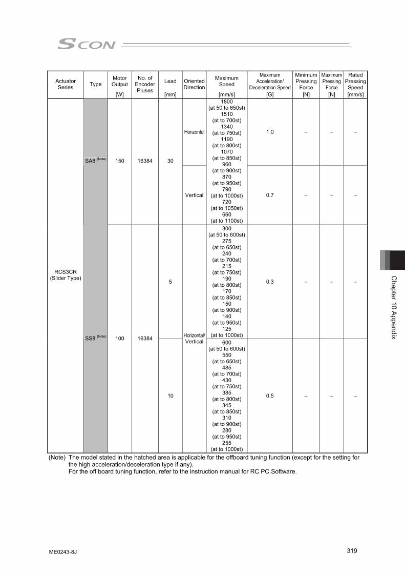
Chapter 10 Appendix
319
Motor Output Lead Maximum
Speed
Maximum Acceleration/
Deceleration Speed
Minimum Pressing
Force
Maximum Pressing
Force
Rated Pressing Speed
Actuator Series Type
[W]
No. of Encoder Pluses
[mm]
Oriented Direction
[mm/s] [G] [N] [N] [mm/s]
Horizontal 1.0 − − −
SA8 (Note) 150 16384 30
Vertical
1800 (at 50 to 650st)
1510 (at to 700st)
1340 (at to 750st)
1190 (at to 800st)
1070 (at to 850st)
960 (at to 900st)
870 (at to 950st)
790 (at to 1000st)
720 (at to 1050st)
660 (at to 1100st)
0.7 − − −
5
300 (at 50 to 600st)
275 (at to 650st)
240 (at to 700st)
215 (at to 750st)
190 (at to 800st)
170 (at to 850st)
150 (at to 900st)
140 (at to 950st)
125 (at to 1000st)
0.3 − − −
RCS3CR (Slider Type)
SS8 (Note) 100 16384
10
Horizontal/Vertical 600
(at 50 to 600st)550
(at to 650st)485
(at to 700st)430
(at to 750st)385
(at to 800st)345
(at to 850st)310
(at to 900st)280
(at to 950st)255
(at to 1000st)
0.5 − − −
(Note) The model stated in the hatched area is applicable for the offboard tuning function (except for the setting for the high acceleration/deceleration type if any). For the off board tuning function, refer to the instruction manual for RC PC Software.
ME0243-8J
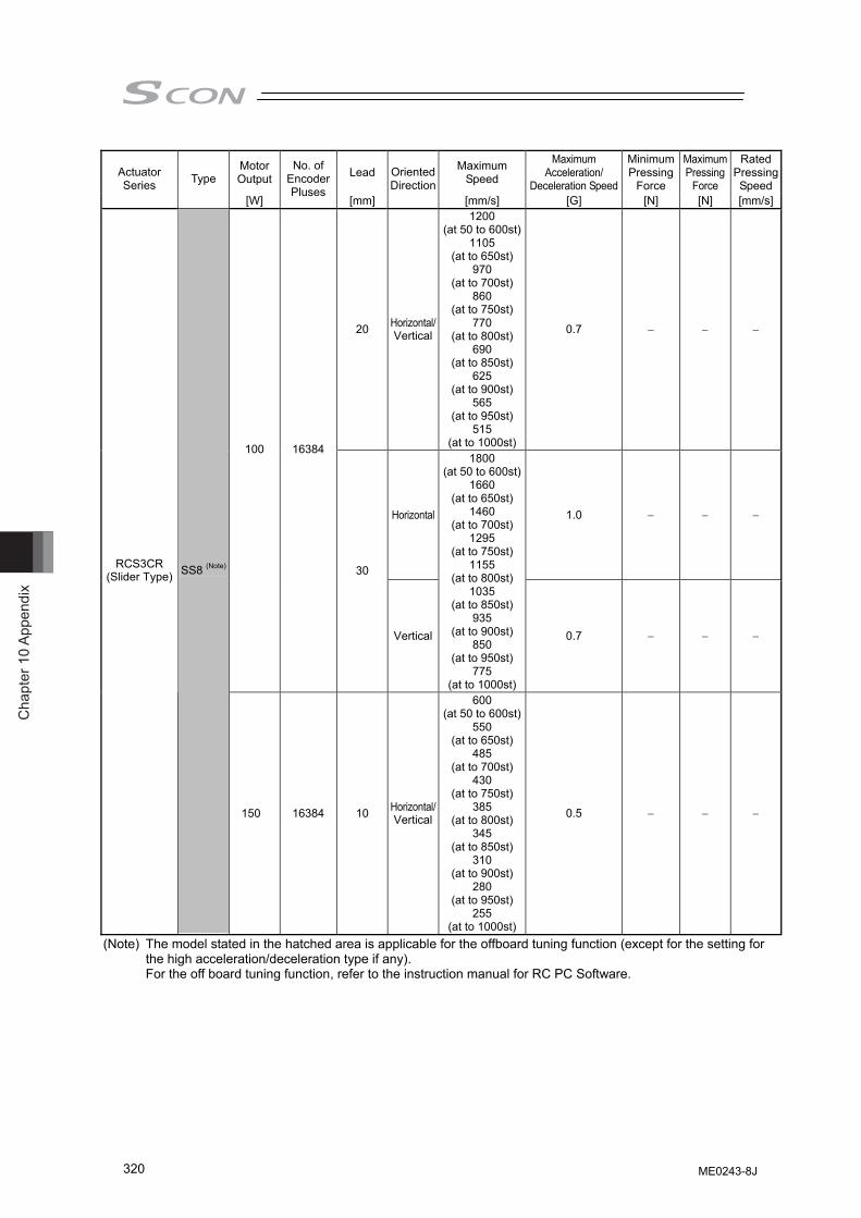
Cha
pter
10
Appe
ndix
320
Motor Output Lead Maximum
Speed
Maximum Acceleration/
Deceleration Speed
Minimum Pressing
Force
Maximum Pressing
Force
Rated Pressing Speed
Actuator Series Type
[W]
No. of Encoder Pluses
[mm]
Oriented Direction
[mm/s] [G] [N] [N] [mm/s]
20 Horizontal/Vertical
1200 (at 50 to 600st)
1105 (at to 650st)
970 (at to 700st)
860 (at to 750st)
770 (at to 800st)
690 (at to 850st)
625 (at to 900st)
565 (at to 950st)
515 (at to 1000st)
0.7 − − −
Horizontal 1.0 − − −
100 16384
30
Vertical
1800 (at 50 to 600st)
1660 (at to 650st)
1460 (at to 700st)
1295 (at to 750st)
1155 (at to 800st)
1035 (at to 850st)
935 (at to 900st)
850 (at to 950st)
775 (at to 1000st)
0.7 − − −
RCS3CR (Slider Type) SS8 (Note)
150 16384 10 Horizontal/Vertical
600 (at 50 to 600st)
550 (at to 650st)
485 (at to 700st)
430 (at to 750st)
385 (at to 800st)
345 (at to 850st)
310 (at to 900st)
280 (at to 950st)
255 (at to 1000st)
0.5 − − −
(Note) The model stated in the hatched area is applicable for the offboard tuning function (except for the setting for the high acceleration/deceleration type if any). For the off board tuning function, refer to the instruction manual for RC PC Software.
ME0243-8J
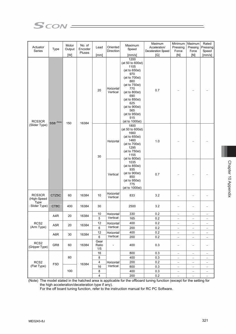
Chapter 10 Appendix
321
Motor Output Lead Maximum
Speed
Maximum Acceleration/
Deceleration Speed
Minimum Pressing
Force
Maximum Pressing
Force
Rated Pressing Speed
Actuator Series Type
[W]
No. of Encoder Pluses
[mm]
Oriented Direction
[mm/s] [G] [N] [N] [mm/s]
20 Horizontal/Vertical
1200 (at 50 to 600st)
1105 (at to 650st)
970 (at to 700st)
860 (at to 750st)
770 (at to 800st)
690 (at to 850st)
625 (at to 900st)
565 (at to 950st)
515 (at to 1000st)
0.7 − − −
Horizontal 1.0 − − −
RCS3CR (Slider Type) SS8 (Note) 150 16384
30
Vertical
1800 (at 50 to 600st)
1660 (at to 650st)
1460 (at to 700st)
1295 (at to 750st)
1155 (at to 800st)
1035 (at to 850st)
935 (at to 900st)
850 (at to 950st)
775 (at to 1000st)
0.7 − − −
CTZ5C 60 16384 10 Horizontal/Vertical 833 3.2 − − − RCS3CR
(High-Speed Type
: Slider Type) CT8C 400 16384 30 2500 3.2 − − −
10 330 0.2 − − − A4R 20 16384 5
Horizontal/Vertical 165 0.2 − − −
12 400 0.2 − − − A5R 20 16384 6
Horizontal/Vertical 200 0.2 − − −
12 400 0.2 − − −
RCS2 (Arm Type)
A6R 30 16384 6
Horizontal/Vertical 200 0.2 − − −
RCS2 (Gripper Type) GR8 60 16384
Gear Ratio1/5
- 400 0.3 − − −
16 800 0.3 − − − 8 400 0.3 − − − 60 4 200 0.2 − − −
16 800 0.3 − − − 8 400 0.3 − − −
RCS2 (Flat Type) F5D
100
16384
4
Horizontal/Vertical
200 0.2 − − − (Note) The model stated in the hatched area is applicable for the offboard tuning function (except for the setting for
the high acceleration/deceleration type if any). For the off board tuning function, refer to the instruction manual for RC PC Software.
ME0243-8J
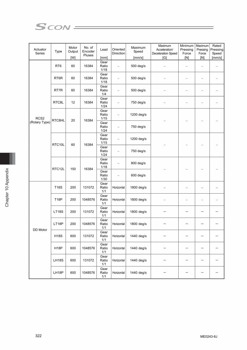
Cha
pter
10
Appe
ndix
322
Motor Output Lead Maximum
Speed
Maximum Acceleration/
Deceleration Speed
Minimum Pressing
Force
Maximum Pressing
Force
Rated Pressing Speed
Actuator Series Type
[W]
No. of Encoder Pluses
[mm]
Oriented Direction
[mm/s] [G] [N] [N] [mm/s]
RT6 60 16384 Gear Ratio1/18
− 500 deg/s − − − −
RT6R 60 16384 Gear Ratio1/18
− 500 deg/s − − − −
RT7R 60 16384 Gear Ratio1/4
− 500 deg/s − − − −
RTC8L 12 16384 Gear Ratio1/24
− 750 deg/s − − − −
Gear Ratio1/15
− 1200 deg/s
RTC8HL 20 16384 Gear Ratio1/24
− 750 deg/s
− − − −
Gear Ratio1/15
− 1200 deg/s
RTC10L 60 16384 Gear Ratio1/24
− 750 deg/s
− − − −
Gear Ratio1/18
− 800 deg/s
RCS2 (Rotary Type)
RTC12L 150 16384 Gear Ratio1/30
− 600 deg/s
− − − −
T18S 200 131072 Gear Ratio1/1
Horizontal 1800 deg/s − − − −
T18P 200 1048576 Gear Ratio1/1
Horizontal 1800 deg/s − − − −
LT18S 200 131072 GearRatio1/1
Horizontal 1800 deg/s - - - -
LT18P 200 1048576 GearRatio1/1
Horizontal 1800 deg/s - - - -
H18S 600 131072 GearRatio1/1
Horizontal 1440 deg/s - - - -
H18P 600 1048576 GearRatio1/1
Horizontal 1440 deg/s - - - -
LH18S 600 131072 GearRatio1/1
Horizontal 1440 deg/s - - - -
DD Motor
LH18P 600 1048576 GearRatio1/1
Horizontal 1440 deg/s - - - -
ME0243-8J
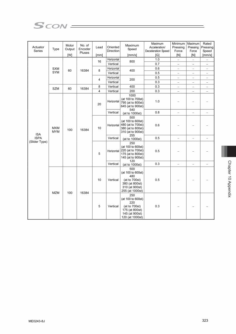
Chapter 10 Appendix
323
Motor Output Lead Maximum
Speed
Maximum Acceleration/
Deceleration Speed
Minimum Pressing
Force
Maximum Pressing
Force
Rated Pressing Speed
Actuator Series Type
[W]
No. of Encoder Pluses
[mm]
Oriented Direction
[mm/s] [G] [N] [N] [mm/s]Horizontal 1.0 − − − 16 Vertical
800 0.7 − − −
Horizontal 0.6 − − − 8 Vertical
400 0.5 − − −
Horizontal 0.5 − − −
SXM SYM 60 16384
4 Vertical
200 0.3 − − −
8 Vertical 400 0.3 − − − SZM 60 16384 4 Vertical 200 0.3 − − −
Horizontal 1.0 − − − 20
Vertical
1000 (at 100 to 700st)795 (at to 800st)645 (at to 900st)
540 (at to 1000st) 0.8 − − −
Horizontal 0.6 − − − 10
Vertical
500 (at 100 to 600st)480 (at to 700st)380 (at to 800st)310 (at to 900st)
255 (at to 1000st) 0.5 − − −
Horizontal 0.5 − − −
MXM MYM 100 16384
5
Vertical
250 (at 100 to 600st)220 (at to 700st)175 (at to 800st)145 (at to 900st)
120 (at to 1000st) 0.3 − − −
10 Vertical
500 (at 100 to 600st)
480 (at to 700st)
380 (at 800st)310 (at 900st)
255 (at 1000st)
0.5 − − −
ISA ISPA
(Slider Type)
MZM 100 16384
5 Vertical
250 (at 100 to 600st)
220 (at to 700st)
175 (at 800st)145 (at 900st)
120 (at 1000st)
0.3 − − −
ME0243-8J
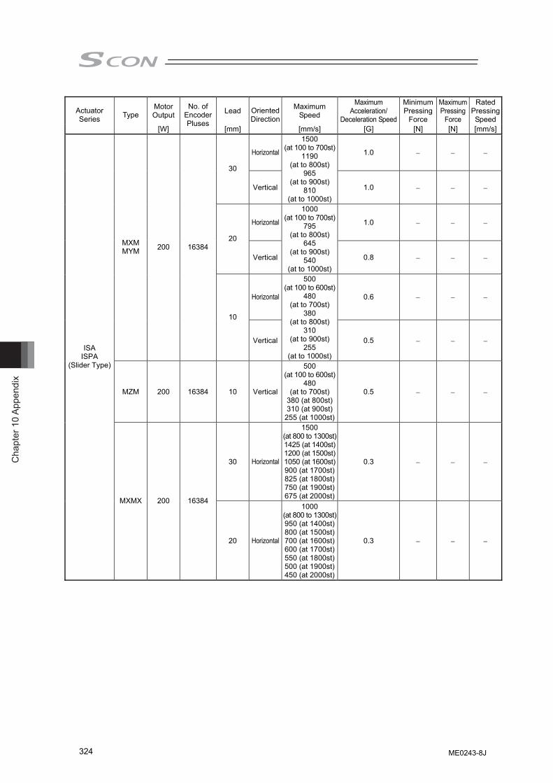
Cha
pter
10
Appe
ndix
324
Motor Output Lead Maximum
Speed
Maximum Acceleration/
Deceleration Speed
Minimum Pressing
Force
Maximum Pressing
Force
Rated Pressing Speed
Actuator Series Type
[W]
No. of Encoder Pluses
[mm]
Oriented Direction
[mm/s] [G] [N] [N] [mm/s]
Horizontal 1.0 − − −
30
Vertical
1500 (at 100 to 700st)
1190 (at to 800st)
965 (at to 900st)
810 (at to 1000st)
1.0 − − −
Horizontal 1.0 − − −
20
Vertical
1000 (at 100 to 700st)
795 (at to 800st)
645 (at to 900st)
540 (at to 1000st)
0.8 − − −
Horizontal 0.6 − − −
MXM MYM 200 16384
10
Vertical
500 (at 100 to 600st)
480 (at to 700st)
380 (at to 800st)
310 (at to 900st)
255 (at to 1000st)
0.5 − − −
MZM 200 16384 10 Vertical
500 (at 100 to 600st)
480 (at to 700st)
380 (at 800st)310 (at 900st)
255 (at 1000st)
0.5 − − −
30 Horizontal
1500 (at 800 to 1300st)1425 (at 1400st)1200 (at 1500st)1050 (at 1600st)900 (at 1700st)825 (at 1800st)750 (at 1900st)675 (at 2000st)
0.3 − − −
ISA ISPA
(Slider Type)
MXMX 200 16384
20 Horizontal
1000 (at 800 to 1300st)950 (at 1400st)800 (at 1500st)700 (at 1600st)600 (at 1700st)550 (at 1800st)500 (at 1900st)450 (at 2000st)
0.3 − − −
ME0243-8J

Chapter 10 Appendix
325
Motor Output Lead Maximum
Speed
Maximum Acceleration/
Deceleration Speed
Minimum Pressing
Force
Maximum Pressing
Force
Rated Pressing Speed
Actuator Series Type
[W]
No. of Encoder Pluses
[mm]
Oriented Direction
[mm/s] [G] [N] [N] [mm/s]
Horizontal 1.0 − − −
20
Vertical
1000 (at 100 to 800st)
830 (at to 900st)
690 (at to 1000st)
585 (at to 1100st)
500 (at to 1200st)
0.8 − − −
Horizontal 0.6 − − −
LXM LYM 200 16384
10
Vertical
500 (at 100 to 700st)
470 (at to 800st)
385 (at to 900st)
320 (at to 1000st)
270 (at to 1100st)
235 (at to 1200st)
0.5 − − −
LZM 200 16384 10 Vertical
500 (at 100 to 700st)
470 (at to 800st)
385 (at to 900st)
320 (at to 1000st)
270 (at to 1100st)
235 (at to 1200st)
0.5 − − −
Horizontal 1.0 − − −
40
Vertical
2000 (at 100 to 800st)
1660 (at to 900st)
1380 (at to 1000st)
1170 (at to 1100st)
1000 (at to 1200st)
1.0 − − −
Horizontal 1.0 − − −
LXM LYM 400 16384
20
Vertical
1000 (at 100 to 800st)
830 (at to 900st)
690 (at to 1000st)
585 (at to 1100st)
500 (at to 1200st)
0.8 − − −
ISA ISPA
(Slide Type)
LZM 400 16384 10 Vertical
500 (at 100 to 700st)
470 (at to 800st)
385 (at to 900st)
320 (at to 1000st)
270 (at to 1100st)
235 (at to 1200st)
0.5 − − −
ME0243-8J
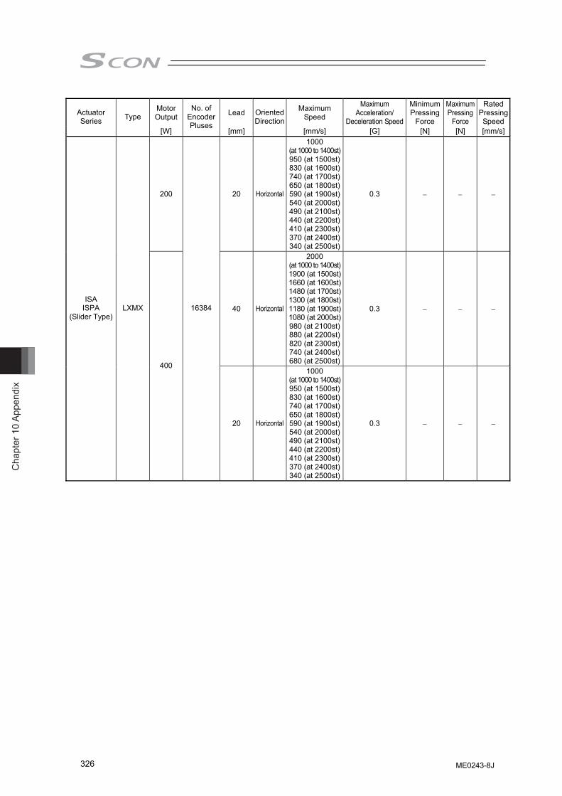
Cha
pter
10
Appe
ndix
326
Motor Output Lead Maximum
Speed
Maximum Acceleration/
Deceleration Speed
Minimum Pressing
Force
Maximum Pressing
Force
Rated Pressing Speed
Actuator Series Type
[W]
No. of Encoder Pluses
[mm]
Oriented Direction
[mm/s] [G] [N] [N] [mm/s]
200 20 Horizontal
1000 (at 1000 to 1400st)950 (at 1500st)830 (at 1600st)740 (at 1700st)650 (at 1800st)590 (at 1900st)540 (at 2000st)490 (at 2100st)440 (at 2200st)410 (at 2300st)370 (at 2400st)340 (at 2500st)
0.3 − − −
40 Horizontal
2000 (at 1000 to 1400st)1900 (at 1500st)1660 (at 1600st)1480 (at 1700st)1300 (at 1800st)1180 (at 1900st)1080 (at 2000st)980 (at 2100st)880 (at 2200st)820 (at 2300st)740 (at 2400st)680 (at 2500st)
0.3 − − − ISA
ISPA (Slider Type)
LXMX
400
16384
20 Horizontal
1000 (at 1000 to 1400st)950 (at 1500st)830 (at 1600st)740 (at 1700st)650 (at 1800st)590 (at 1900st)540 (at 2000st)490 (at 2100st)440 (at 2200st)410 (at 2300st)370 (at 2400st)340 (at 2500st)
0.3 − − −
ME0243-8J
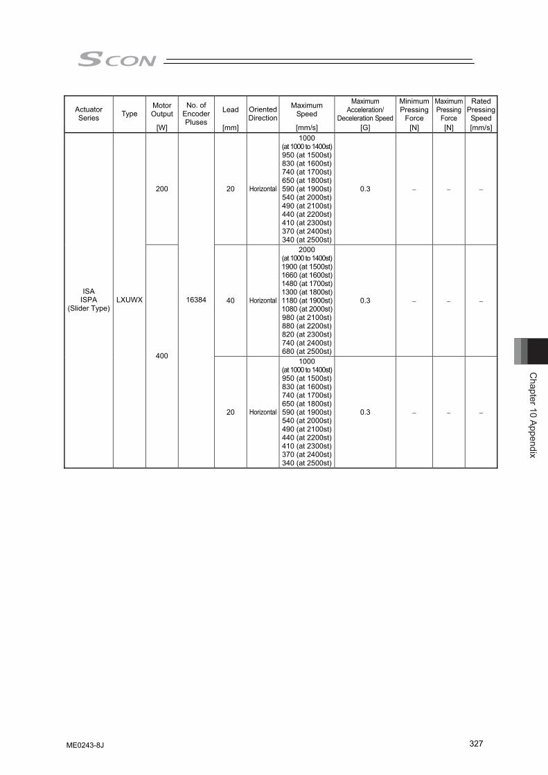
Chapter 10 Appendix
327
Motor Output Lead Maximum
Speed
Maximum Acceleration/
Deceleration Speed
Minimum Pressing
Force
Maximum Pressing
Force
Rated Pressing Speed
Actuator Series Type
[W]
No. of Encoder Pluses
[mm]
Oriented Direction
[mm/s] [G] [N] [N] [mm/s]
200 20 Horizontal
1000 (at 1000 to 1400st)950 (at 1500st)830 (at 1600st)740 (at 1700st)650 (at 1800st)590 (at 1900st)540 (at 2000st)490 (at 2100st)440 (at 2200st)410 (at 2300st)370 (at 2400st)340 (at 2500st)
0.3 − − −
40 Horizontal
2000 (at 1000 to 1400st)1900 (at 1500st)1660 (at 1600st)1480 (at 1700st)1300 (at 1800st)1180 (at 1900st)1080 (at 2000st)980 (at 2100st)880 (at 2200st)820 (at 2300st)740 (at 2400st)680 (at 2500st)
0.3 − − − ISA
ISPA (Slider Type)
LXUWX
400
16384
20 Horizontal
1000 (at 1000 to 1400st)950 (at 1500st)830 (at 1600st)740 (at 1700st)650 (at 1800st)590 (at 1900st)540 (at 2000st)490 (at 2100st)440 (at 2200st)410 (at 2300st)370 (at 2400st)340 (at 2500st)
0.3 − − −
ME0243-8J
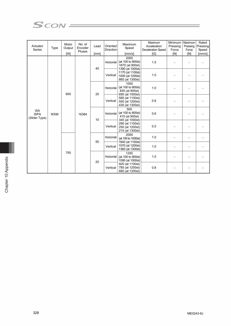
Cha
pter
10
Appe
ndix
328
Motor Output Lead Maximum
Speed
Maximum Acceleration/
Deceleration Speed
Minimum Pressing
Force
Maximum Pressing
Force
Rated Pressing Speed
Actuator Series Type
[W]
No. of Encoder Pluses
[mm]
Oriented Direction
[mm/s] [G] [N] [N] [mm/s]
Horizontal 1.0 − − −
40
Vertical
2000 (at 100 to 800st)1670 (at 900st)1390 (at 1000st)1170 (at 1100st)1000 (at 1200st)865 (at 1300st)
1.0 − − −
Horizontal 1.0 − − −
20
Vertical
1000 (at 100 to 800st)835 (at 900st)
695 (at 1000st)585 (at 1100st)500 (at 1200st)430 (at 1300st)
0.8 − − −
Horizontal 0.6 − − −
600
10
Vertical
500 (at 100 to 800st)415 (at 900st)
345 (at 1000st)290 (at 1100st)250 (at 1200st)215 (at 1300st)
0.5 − − −
Horizontal 1.0 − − − 50
Vertical
2000 (at 100 to 1000st)1840 (at 1100st)1570 (at 1200st)1360 (at 1300st)
1.0 − − −
Horizontal 1.0 − − −
ISA ISPA
(Slider Type) WXM
750
16384
25
Vertical
1250 (at 100 to 900st)1090 (at 1000st)920 (at 1100st)785 (at 1200st)680 (at 1300st)
0.8 − − −
ME0243-8J
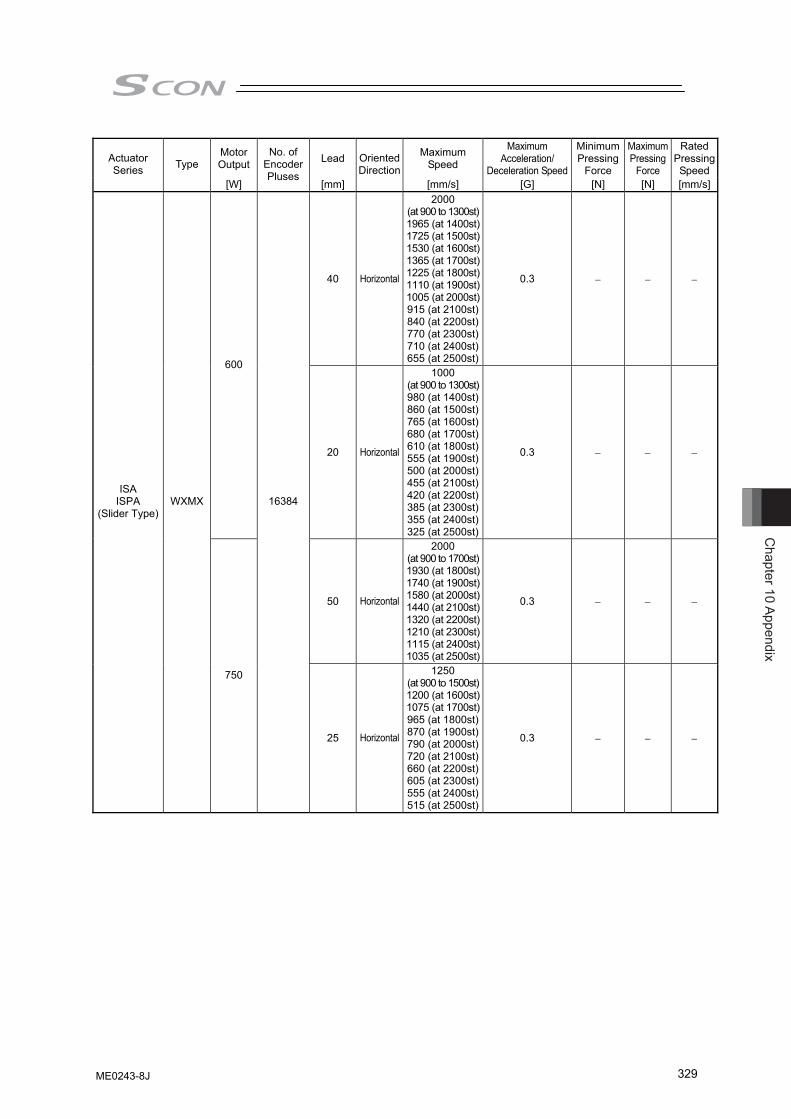
Chapter 10 Appendix
329
Motor Output Lead Maximum
Speed
Maximum Acceleration/
Deceleration Speed
Minimum Pressing
Force
Maximum Pressing
Force
Rated Pressing Speed
Actuator Series Type
[W]
No. of Encoder Pluses
[mm]
Oriented Direction
[mm/s] [G] [N] [N] [mm/s]
40 Horizontal
2000 (at 900 to 1300st)1965 (at 1400st)1725 (at 1500st)1530 (at 1600st)1365 (at 1700st)1225 (at 1800st)1110 (at 1900st)1005 (at 2000st)915 (at 2100st)840 (at 2200st)770 (at 2300st)710 (at 2400st)655 (at 2500st)
0.3 − − −
600
20 Horizontal
1000 (at 900 to 1300st)980 (at 1400st)860 (at 1500st)765 (at 1600st)680 (at 1700st)610 (at 1800st)555 (at 1900st)500 (at 2000st)455 (at 2100st)420 (at 2200st)385 (at 2300st)355 (at 2400st)325 (at 2500st)
0.3 − − −
50 Horizontal
2000 (at 900 to 1700st)1930 (at 1800st)1740 (at 1900st)1580 (at 2000st)1440 (at 2100st)1320 (at 2200st)1210 (at 2300st)1115 (at 2400st)1035 (at 2500st)
0.3 − − −
ISA ISPA
(Slider Type) WXMX
750
16384
25 Horizontal
1250 (at 900 to 1500st)1200 (at 1600st)1075 (at 1700st)965 (at 1800st)870 (at 1900st)790 (at 2000st)720 (at 2100st)660 (at 2200st)605 (at 2300st)555 (at 2400st)515 (at 2500st)
0.3 − − −
ME0243-8J
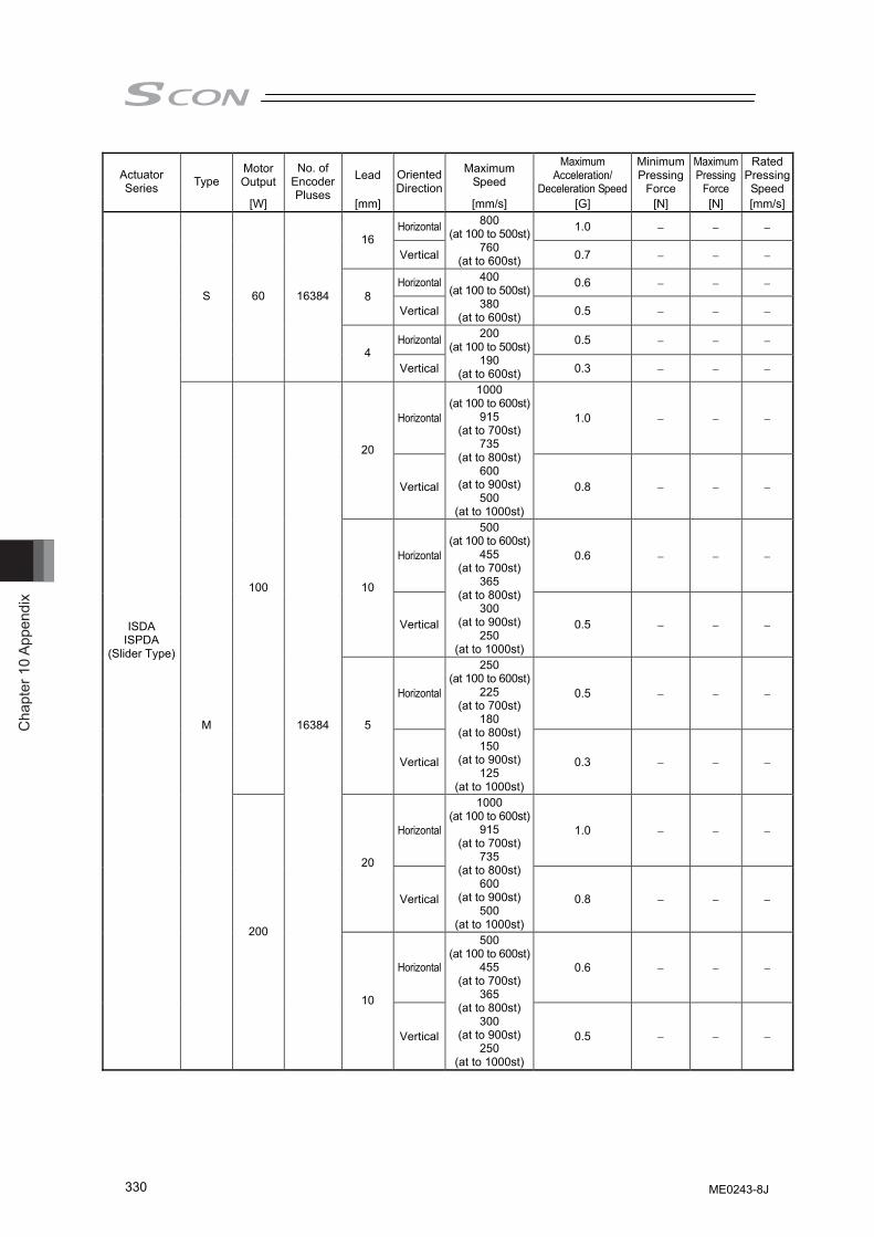
Cha
pter
10
Appe
ndix
330
Motor Output Lead Maximum
Speed
Maximum Acceleration/
Deceleration Speed
Minimum Pressing
Force
Maximum Pressing
Force
Rated Pressing Speed
Actuator Series Type
[W]
No. of Encoder Pluses
[mm]
Oriented Direction
[mm/s] [G] [N] [N] [mm/s]
Horizontal 1.0 − − − 16
Vertical
800 (at 100 to 500st)
760 (at to 600st) 0.7 − − −
Horizontal 0.6 − − − 8
Vertical
400 (at 100 to 500st)
380 (at to 600st) 0.5 − − −
Horizontal 0.5 − − −
S 60 16384
4 Vertical
200 (at 100 to 500st)
190 (at to 600st) 0.3 − − −
Horizontal 1.0 − − −
20
Vertical
1000 (at 100 to 600st)
915 (at to 700st)
735 (at to 800st)
600 (at to 900st)
500 (at to 1000st)
0.8 − − −
Horizontal 0.6 − − −
10
Vertical
500 (at 100 to 600st)
455 (at to 700st)
365 (at to 800st)
300 (at to 900st)
250 (at to 1000st)
0.5 − − −
Horizontal 0.5 − − −
100
5
Vertical
250 (at 100 to 600st)
225 (at to 700st)
180 (at to 800st)
150 (at to 900st)
125 (at to 1000st)
0.3 − − −
Horizontal 1.0 − − −
20
Vertical
1000 (at 100 to 600st)
915 (at to 700st)
735 (at to 800st)
600 (at to 900st)
500 (at to 1000st)
0.8 − − −
Horizontal 0.6 − − −
ISDA ISPDA
(Slider Type)
M
200
16384
10
Vertical
500 (at 100 to 600st)
455 (at to 700st)
365 (at to 800st)
300 (at to 900st)
250 (at to 1000st)
0.5 − − −
ME0243-8J
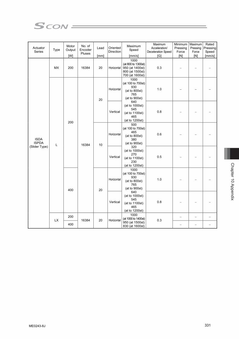
Chapter 10 Appendix
331
Motor Output Lead Maximum
Speed
Maximum Acceleration/
Deceleration Speed
Minimum Pressing
Force
Maximum Pressing
Force
Rated Pressing Speed
Actuator Series Type
[W]
No. of Encoder Pluses
[mm]
Oriented Direction
[mm/s] [G] [N] [N] [mm/s]
MX 200 16384 20 Horizontal
1000 (at 800 to 1300st)950 (at 1400st)800 (at 1500st)700 (at 1600st)
0.3 − − −
Horizontal 1.0 − − −
20
Vertical
1000 (at 100 to 700st)
930 (at to 800st)
765 (at to 900st)
640 (at to 1000st)
545 (at to 1100st)
465 (at to 1200st)
0.8 − − −
Horizontal 0.6 − − −
200
10
Vertical
500 (at 100 to 700st)
465 (at to 800st)
380 (at to 900st)
320 (at to 1000st)
270 (at to 1100st)
230 (at to 1200st)
0.5 − − −
Horizontal 1.0 − − −
L
400
16384
20
Vertical
1000 (at 100 to 700st)
930 (at to 800st)
765 (at to 900st)
640 (at to 1000st)
545 (at to 1100st)
465 (at to 1200st)
0.8 − − −
200 − − −
ISDA ISPDA
(Slider Type)
LX 400
16384 20 Horizontal1000
(at 1000 to 1400st)950 (at 1500st)830 (at 1600st)
0.3 − − −
ME0243-8J
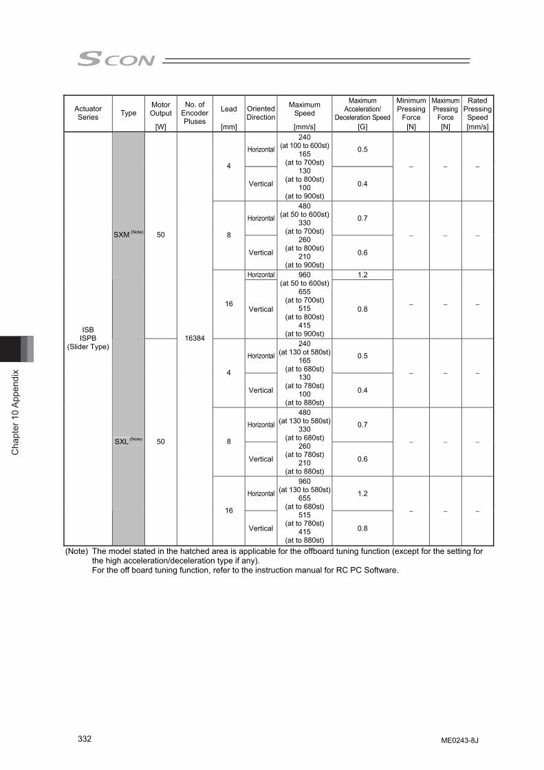
Cha
pter
10
Appe
ndix
332
Motor Output Lead Maximum
Speed
Maximum Acceleration/
Deceleration Speed
Minimum Pressing
Force
Maximum Pressing
Force
Rated Pressing Speed
Actuator Series Type
[W]
No. of Encoder Pluses
[mm]
Oriented Direction
[mm/s] [G] [N] [N] [mm/s]
Horizontal 0.5
4
Vertical
240 (at 100 to 600st)
165 (at to 700st)
130 (at to 800st)
100 (at to 900st)
0.4
− − −
Horizontal 0.7
8
Vertical
480 (at 50 to 600st)
330 (at to 700st)
260 (at to 800st)
210 (at to 900st)
0.6
− − −
Horizontal 1.2
SXM (Note) 50
16 Vertical
960 (at 50 to 600st)
655 (at to 700st)
515 (at to 800st)
415 (at to 900st)
0.8 − − −
Horizontal 0.5
4
Vertical
240 (at 130 ot 580st)
165 (at to 680st)
130 (at to 780st)
100 (at to 880st)
0.4
− − −
Horizontal 0.7
8
Vertical
480 (at 130 to 580st)
330 (at to 680st)
260 (at to 780st)
210 (at to 880st)
0.6
− − −
Horizontal 1.2
ISB ISPB
(Slider Type)
SXL (Note) 50
16384
16
Vertical
960 (at 130 to 580st)
655 (at to 680st)
515 (at to 780st)
415 (at to 880st)
0.8
− − −
(Note) The model stated in the hatched area is applicable for the offboard tuning function (except for the setting for the high acceleration/deceleration type if any). For the off board tuning function, refer to the instruction manual for RC PC Software.
ME0243-8J
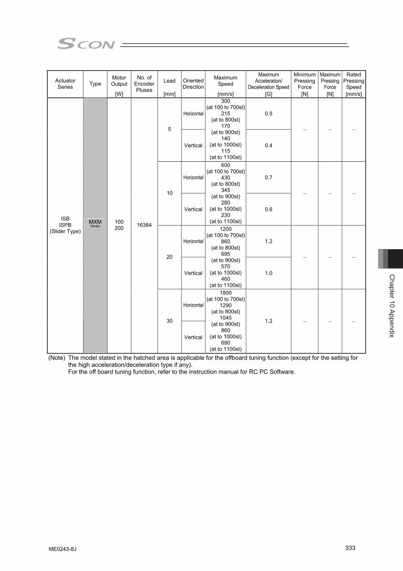
Chapter 10 Appendix
333
Motor Output Lead Maximum
Speed
Maximum Acceleration/
Deceleration Speed
Minimum Pressing
Force
Maximum Pressing
Force
Rated Pressing Speed
Actuator Series Type
[W]
No. of Encoder Pluses
[mm]
Oriented Direction
[mm/s] [G] [N] [N] [mm/s]
Horizontal 0.5
5
Vertical
300 (at 100 to 700st)
215 (at to 800st)
170 (at to 900st)
140 (at to 1000st)
115 (at to 1100st)
0.4
− − −
Horizontal 0.7
10
Vertical
600 (at 100 to 700st)
430 (at to 800st)
345 (at to 900st)
280 (at to 1000st)
230 (at to 1100st)
0.6
− − −
Horizontal 1.2
20
Vertical
1200 (at 100 to 700st)
860 (at to 800st)
695 (at to 900st)
570 (at to 1000st)
460 (at to 1100st)
1.0
− − −
Horizontal
ISB ISPB
(Slider Type)
MXM
(Note) 100 200 16384
30
Vertical
1800 (at 100 to 700st)
1290 (at to 800st)
1045 (at to 900st)
860 (at to 1000st)
690 (at to 1100st)
1.2 − − −
(Note) The model stated in the hatched area is applicable for the offboard tuning function (except for the setting for the high acceleration/deceleration type if any). For the off board tuning function, refer to the instruction manual for RC PC Software.
ME0243-8J
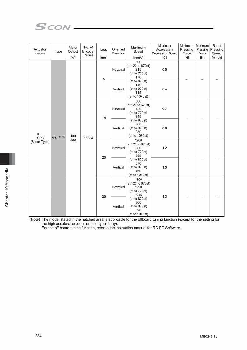
Cha
pter
10
Appe
ndix
334
Motor Output Lead Maximum
Speed
Maximum Acceleration/
Deceleration Speed
Minimum Pressing
Force
Maximum Pressing
Force
Rated Pressing Speed
Actuator Series Type
[W]
No. of Encoder Pluses
[mm]
Oriented Direction
[mm/s] [G] [N] [N] [mm/s]
Horizontal 0.5
5
Vertical
300 (at 120 to 670st)
215 (at to 770st)
170 (at to 870st)
140 (at to 970st)
115 (at to 1070st)
0.4
− − −
Horizontal 0.7
10
Vertical
600 (at 120 to 670st)
430 (at to 770st)
345 (at to 870st)
280 (at to 970st)
230 (at to 1070st)
0.6
− − −
Horizontal 1.2
20
Vertical
1200 (at 120 to 670st)
860 (at to 770st)
695 (at to 870st)
570 (at to 970st)
460 (at to 1070st)
1.0
− − −
Horizontal
ISB ISPB
(Slider Type) MXL (Note) 100
200 16384
30
Vertical
1800 (at 120 to 670st)
1290 (at to 770st)
1045 (at to 870st)
860 (at to 970st)
690 (at to 1070st)
1.2 − − −
(Note) The model stated in the hatched area is applicable for the offboard tuning function (except for the setting for the high acceleration/deceleration type if any). For the off board tuning function, refer to the instruction manual for RC PC Software.
ME0243-8J
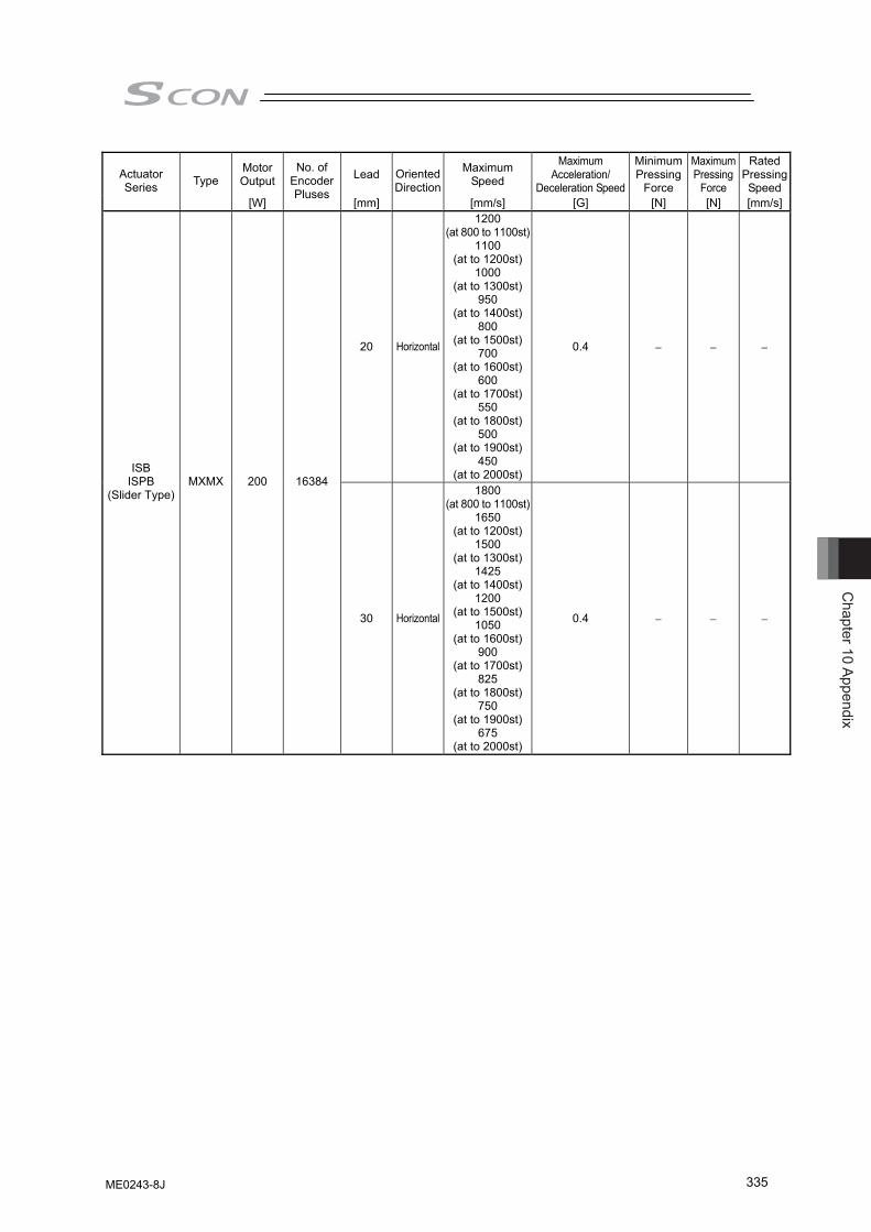
Chapter 10 Appendix
335
Motor Output Lead Maximum
Speed
Maximum Acceleration/
Deceleration Speed
Minimum Pressing
Force
Maximum Pressing
Force
Rated Pressing Speed
Actuator Series Type
[W]
No. of Encoder Pluses
[mm]
Oriented Direction
[mm/s] [G] [N] [N] [mm/s]
20 Horizontal
1200 (at 800 to 1100st)
1100 (at to 1200st)
1000 (at to 1300st)
950 (at to 1400st)
800 (at to 1500st)
700 (at to 1600st)
600 (at to 1700st)
550 (at to 1800st)
500 (at to 1900st)
450 (at to 2000st)
0.4 − − −
ISB ISPB
(Slider Type) MXMX 200 16384
30 Horizontal
1800 (at 800 to 1100st)
1650 (at to 1200st)
1500 (at to 1300st)
1425 (at to 1400st)
1200 (at to 1500st)
1050 (at to 1600st)
900 (at to 1700st)
825 (at to 1800st)
750 (at to 1900st)
675 (at to 2000st)
0.4 − − −
ME0243-8J
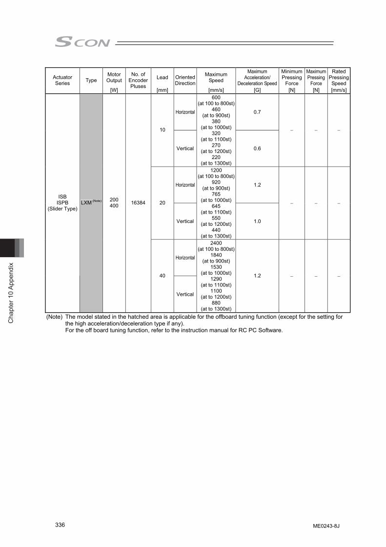
Cha
pter
10
Appe
ndix
336
Motor Output Lead Maximum
Speed
Maximum Acceleration/
Deceleration Speed
Minimum Pressing
Force
Maximum Pressing
Force
Rated Pressing Speed
Actuator Series Type
[W]
No. of Encoder Pluses
[mm]
Oriented Direction
[mm/s] [G] [N] [N] [mm/s]
Horizontal 0.7
10
Vertical
600 (at 100 to 800st)
460 (at to 900st)
380 (at to 1000st)
320 (at to 1100st)
270 (at to 1200st)
220 (at to 1300st)
0.6
− − −
Horizontal 1.2
20
Vertical
1200 (at 100 to 800st)
920 (at to 900st)
765 (at to 1000st)
645 (at to 1100st)
550 (at to 1200st)
440 (at to 1300st)
1.0
− − −
Horizontal
ISB ISPB
(Slider Type) LXM (Note) 200
400 16384
40
Vertical
2400 (at 100 to 800st)
1840 (at to 900st)
1530 (at to 1000st)
1290 (at to 1100st)
1100 (at to 1200st)
880 (at to 1300st)
1.2 − − −
(Note) The model stated in the hatched area is applicable for the offboard tuning function (except for the setting for the high acceleration/deceleration type if any). For the off board tuning function, refer to the instruction manual for RC PC Software.
ME0243-8J
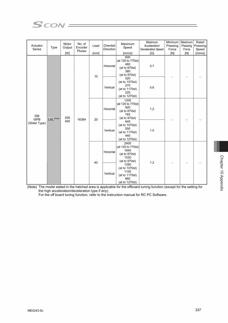
Chapter 10 Appendix
337
Motor Output Lead Maximum
Speed
Maximum Acceleration/
Deceleration Speed
Minimum Pressing
Force
Maximum Pressing
Force
Rated Pressing Speed
Actuator Series Type
[W]
No. of Encoder Pluses
[mm]
Oriented Direction
[mm/s] [G] [N] [N] [mm/s]
Horizontal 0.7
10
Vertical
600 (at 120 to 770st)
460 (at to 870st)
380 (at to 970st)
320 (at to 1070st)
270 (at to 1170st)
220 (at to 1270st)
0.6
− − −
Horizontal 1.2
20
Vertical
1200 (at 120 to 770st)
920 (at to 870st)
765 (at to 970st)
645 (at to 1070st)
550 (at to 1170st)
440 (at to 1270st)
1.0
− − −
Horizontal
ISB ISPB
(Slider Type) LXL (Note) 200
400 16384
40
Vertical
2400 (at 120 to 770st)
1840 (at to 870st)
1530 (at to 970st)
1290 (at to 1070st)
1100 (at to 1170st)
880 (at to 1270st)
1.2 − − −
(Note) The model stated in the hatched area is applicable for the offboard tuning function (except for the setting for the high acceleration/deceleration type if any). For the off board tuning function, refer to the instruction manual for RC PC Software.
ME0243-8J
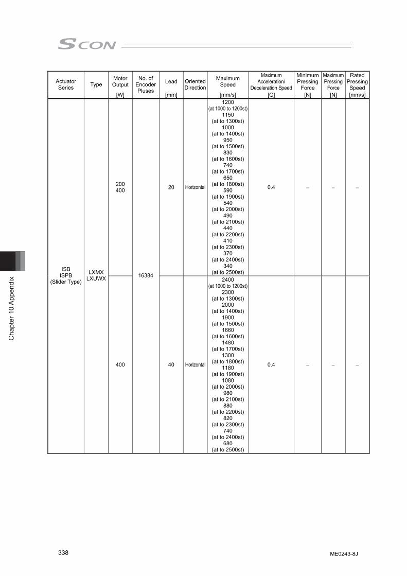
Cha
pter
10
Appe
ndix
338
Motor Output Lead Maximum
Speed
Maximum Acceleration/
Deceleration Speed
Minimum Pressing
Force
Maximum Pressing
Force
Rated Pressing Speed
Actuator Series Type
[W]
No. of Encoder Pluses
[mm]
Oriented Direction
[mm/s] [G] [N] [N] [mm/s]
200 400 20 Horizontal
1200 (at 1000 to 1200st)
1150 (at to 1300st)
1000 (at to 1400st)
950 (at to 1500st)
830 (at to 1600st)
740 (at to 1700st)
650 (at to 1800st)
590 (at to 1900st)
540 (at to 2000st)
490 (at to 2100st)
440 (at to 2200st)
410 (at to 2300st)
370 (at to 2400st)
340 (at to 2500st)
0.4 − − −
ISB ISPB
(Slider Type)
LXMX LXUWX
400
16384
40 Horizontal
2400 (at 1000 to 1200st)
2300 (at to 1300st)
2000 (at to 1400st)
1900 (at to 1500st)
1660 (at to 1600st)
1480 (at to 1700st)
1300 (at to 1800st)
1180 (at to 1900st)
1080 (at to 2000st)
980 (at to 2100st)
880 (at to 2200st)
820 (at to 2300st)
740 (at to 2400st)
680 (at to 2500st)
0.4 − − −
ME0243-8J
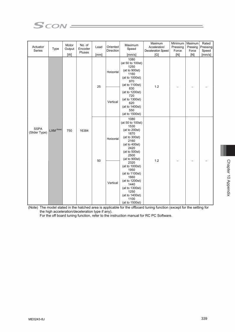
Chapter 10 Appendix
339
Motor Output Lead Maximum
Speed
Maximum Acceleration/
Deceleration Speed
Minimum Pressing
Force
Maximum Pressing
Force
Rated Pressing Speed
Actuator Series Type
[W]
No. of Encoder Pluses
[mm]
Oriented Direction
[mm/s] [G] [N] [N] [mm/s]
Horizontal
25
Vertical
1080 (at 50 to 100st)
1250 (at to 900st)
1160 (at to 1000st)
970 (at to 1100st)
830 (at to 1200st)
720 (at to 1300st)
620 (at to 1400st)
550 (at to 1500st)
1.2 − − −
Horizontal
SSPA (Slider Type) LXM (Note) 750 16384
50
Vertical
1080 (at 50 to 100st)
1530 (at to 200st)
1870 (at to 300st)
2160 (at to 400st)
2420 (at to 500st)
2500 (at to 900st)
2320 (at to 1000st)
1950 (at to 1100st)
1660 (at to 1200st)
1440 (at to 1300st)
1250 (at to 1400st)
1100 (at to 1500st)
1.2 − − −
(Note) The model stated in the hatched area is applicable for the offboard tuning function (except for the setting for the high acceleration/deceleration type if any). For the off board tuning function, refer to the instruction manual for RC PC Software.
ME0243-8J
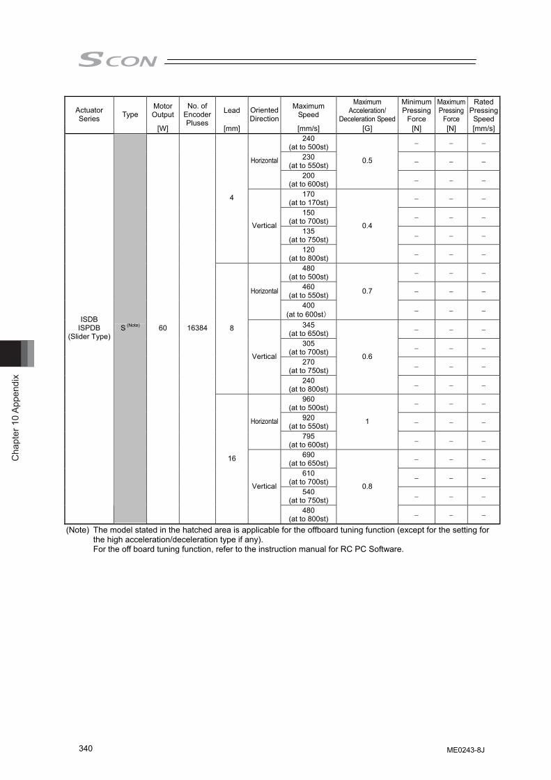
Cha
pter
10
Appe
ndix
340
Motor Output Lead Maximum
Speed
Maximum Acceleration/
Deceleration Speed
Minimum Pressing
Force
Maximum Pressing
Force
Rated Pressing Speed
Actuator Series Type
[W]
No. of Encoder Pluses
[mm]
Oriented Direction
[mm/s] [G] [N] [N] [mm/s]240
(at to 500st) − − −
230 (at to 550st) − − − Horizontal
200 (at to 600st)
0.5
− − −
170 (at to 170st) − − −
150 (at to 700st) − − −
135 (at to 750st) − − −
4
Vertical
120 (at to 800st)
0.4
− − −
480 (at to 500st) − − −
460 (at to 550st) − − − Horizontal
400 (at to 600st)
0.7
− − −
345 (at to 650st) − − −
305 (at to 700st) − − −
270 (at to 750st) − − −
8
Vertical
240 (at to 800st)
0.6
− − −
960 (at to 500st) − − −
920 (at to 550st) − − − Horizontal
795 (at to 600st)
1
− − −
690 (at to 650st) − − −
610 (at to 700st) − − −
540 (at to 750st) − − −
ISDB ISPDB
(Slider Type) S (Note) 60 16384
16
Vertical
480 (at to 800st)
0.8
− − −
(Note) The model stated in the hatched area is applicable for the offboard tuning function (except for the setting for the high acceleration/deceleration type if any). For the off board tuning function, refer to the instruction manual for RC PC Software.
ME0243-8J
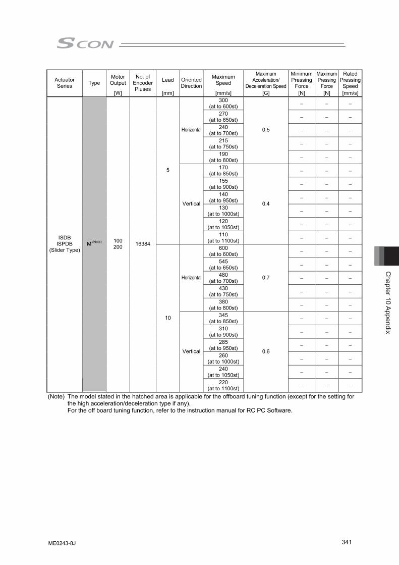
Chapter 10 Appendix
341
Motor Output Lead Maximum
Speed
Maximum Acceleration/
Deceleration Speed
Minimum Pressing
Force
Maximum Pressing
Force
Rated Pressing Speed
Actuator Series Type
[W]
No. of Encoder Pluses
[mm]
Oriented Direction
[mm/s] [G] [N] [N] [mm/s]300
(at to 600st) − − −
270 (at to 650st) − − −
240 (at to 700st) − − −
215 (at to 750st) − − −
Horizontal
190 (at to 800st)
0.5
− − −
170 (at to 850st) − − −
155 (at to 900st) − − −
140 (at to 950st) − − −
130 (at to 1000st) − − −
120 (at to 1050st) − − −
5
Vertical
110 (at to 1100st)
0.4
− − −
600 (at to 600st) − − −
545 (at to 650st) − − −
480 (at to 700st) − − −
430 (at to 750st) − − −
Horizontal
380 (at to 800st)
0.7
− − −
345 (at to 850st) − − −
310 (at to 900st) − − −
285 (at to 950st) − − −
260 (at to 1000st) − − −
240 (at to 1050st) − − −
ISDB ISPDB
(Slider Type) M (Note) 100
200 16384
10
Vertical
220 (at to 1100st)
0.6
− − −
(Note) The model stated in the hatched area is applicable for the offboard tuning function (except for the setting for the high acceleration/deceleration type if any). For the off board tuning function, refer to the instruction manual for RC PC Software.
ME0243-8J
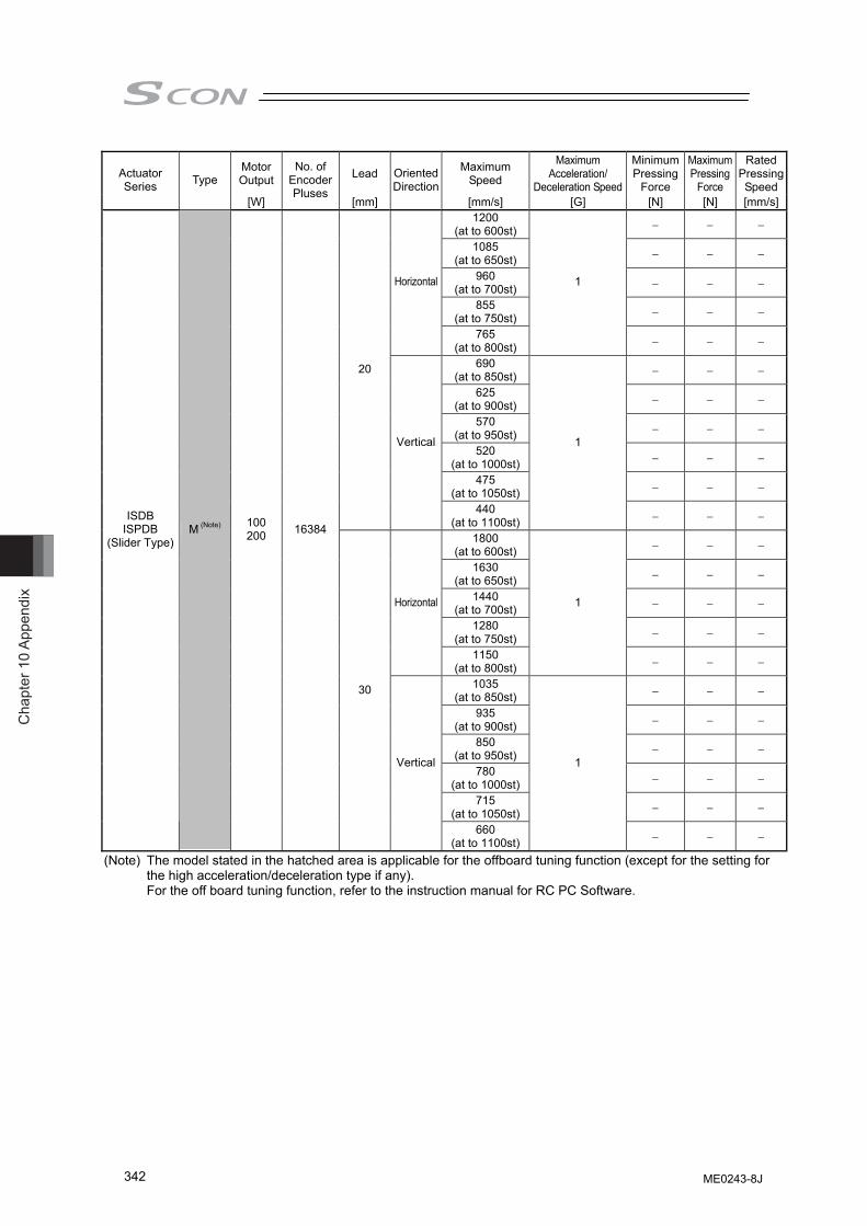
Cha
pter
10
Appe
ndix
342
Motor Output Lead Maximum
Speed
Maximum Acceleration/
Deceleration Speed
Minimum Pressing
Force
Maximum Pressing
Force
Rated Pressing Speed
Actuator Series Type
[W]
No. of Encoder Pluses
[mm]
Oriented Direction
[mm/s] [G] [N] [N] [mm/s]1200
(at to 600st) − − −
1085 (at to 650st) − − −
960 (at to 700st) − − −
855 (at to 750st) − − −
Horizontal
765 (at to 800st)
1
− − −
690 (at to 850st) − − −
625 (at to 900st) − − −
570 (at to 950st) − − −
520 (at to 1000st) − − −
475 (at to 1050st) − − −
20
Vertical
440 (at to 1100st)
1
− − −
1800 (at to 600st) − − −
1630 (at to 650st) − − −
1440 (at to 700st) − − −
1280 (at to 750st) − − −
Horizontal
1150 (at to 800st)
1
− − −
1035 (at to 850st) − − −
935 (at to 900st) − − −
850 (at to 950st) − − −
780 (at to 1000st) − − −
715 (at to 1050st) − − −
ISDB ISPDB
(Slider Type) M (Note) 100
200 16384
30
Vertical
660 (at to 1100st)
1
− − −
(Note) The model stated in the hatched area is applicable for the offboard tuning function (except for the setting for the high acceleration/deceleration type if any). For the off board tuning function, refer to the instruction manual for RC PC Software.
ME0243-8J
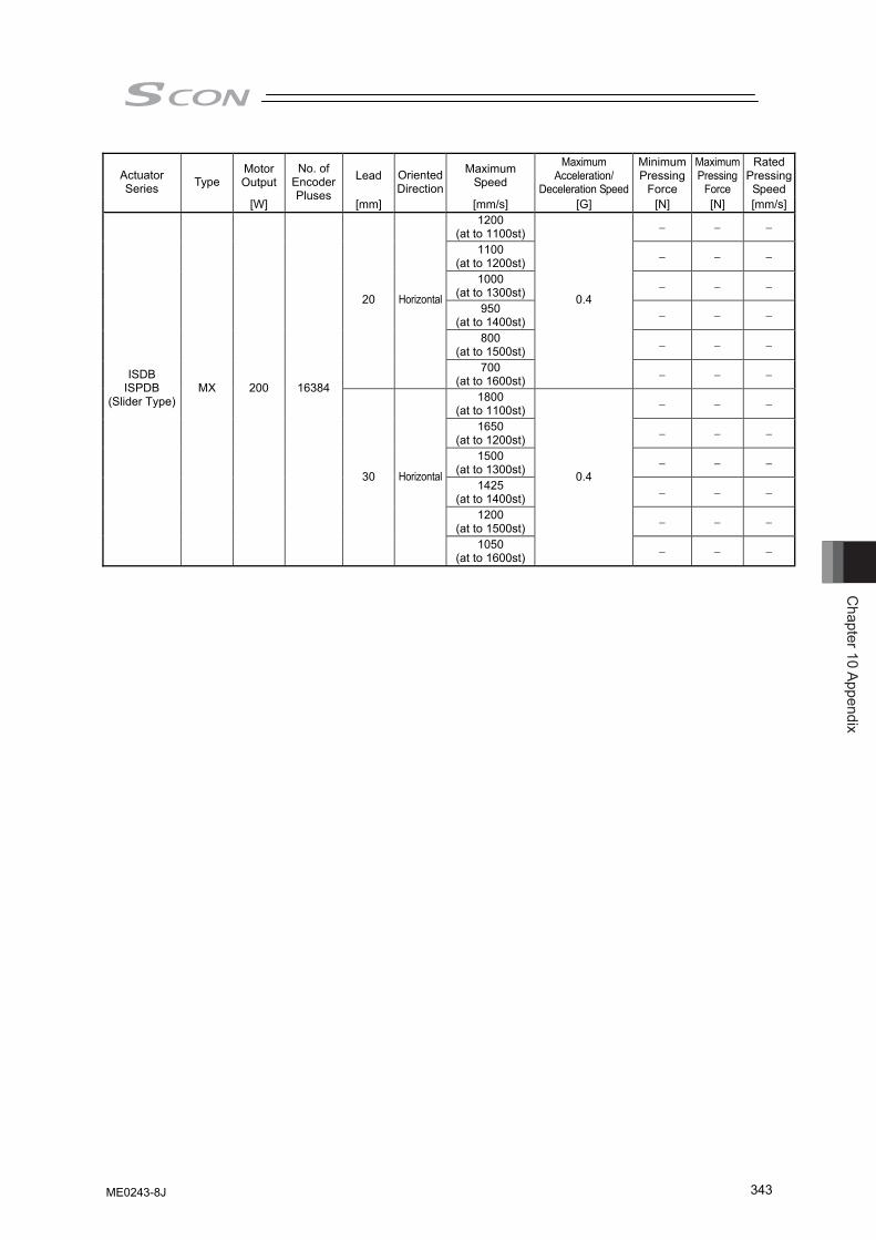
Chapter 10 Appendix
343
Motor Output Lead Maximum
Speed
Maximum Acceleration/
Deceleration Speed
Minimum Pressing
Force
Maximum Pressing
Force
Rated Pressing Speed
Actuator Series Type
[W]
No. of Encoder Pluses
[mm]
Oriented Direction
[mm/s] [G] [N] [N] [mm/s]1200
(at to 1100st) − − −
1100 (at to 1200st) − − −
1000 (at to 1300st) − − −
950 (at to 1400st) − − −
800 (at to 1500st) − − −
20 Horizontal
700 (at to 1600st)
0.4
− − −
1800 (at to 1100st) − − −
1650 (at to 1200st) − − −
1500 (at to 1300st) − − −
1425 (at to 1400st) − − −
1200 (at to 1500st) − − −
ISDB ISPDB
(Slider Type) MX 200 16384
30 Horizontal
1050 (at to 1600st)
0.4
− − −
ME0243-8J
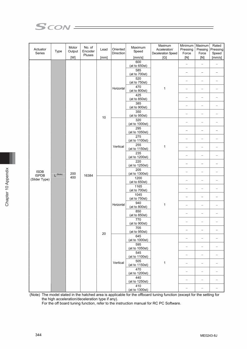
Cha
pter
10
Appe
ndix
344
Motor Output Lead Maximum
Speed
Maximum Acceleration/
Deceleration Speed
Minimum Pressing
Force
Maximum Pressing
Force
Rated Pressing Speed
Actuator Series Type
[W]
No. of Encoder Pluses
[mm]
Oriented Direction
[mm/s] [G] [N] [N] [mm/s]600
(at to 650st) − − −
585 (at to 700st) − − −
520 (at to 750st) − − −
470 (at to 800st) − − −
425 (at to 850st) − − −
385 (at to 900st) − − −
Horizontal
350 (at to 950st)
1
− − −
320 (at to 1000st) − − −
295 (at to 1050st) − − −
275 (at to 1100st) − − −
255 (at to 1150st) − − −
235 (at to 1200st) − − −
220 (at to 1250st) − − −
10
Vertical
205 (at to 1300st)
1
− − −
1200 (at to 650st) − − −
1165 (at to 700st) − − −
1045 (at to 750st) − − −
940 (at to 800st) − − −
850 (at to 850st) − − −
770 (at to 900st) − − −
Horizontal
705 (at to 950st)
1
− − −
645 (at to 1000st) − − −
595 (at to 1050st) − − −
545 (at to 1100st) − − −
505 (at to 1150st) − − −
470 (at to 1200st) − − −
440 (at to 1250st) − − −
ISDB ISPDB
(Slider Type) L (Note) 200
400 16384
20
Vertical
410 (at to 1300st)
1
− − −
(Note) The model stated in the hatched area is applicable for the offboard tuning function (except for the setting for the high acceleration/deceleration type if any). For the off board tuning function, refer to the instruction manual for RC PC Software.
ME0243-8J
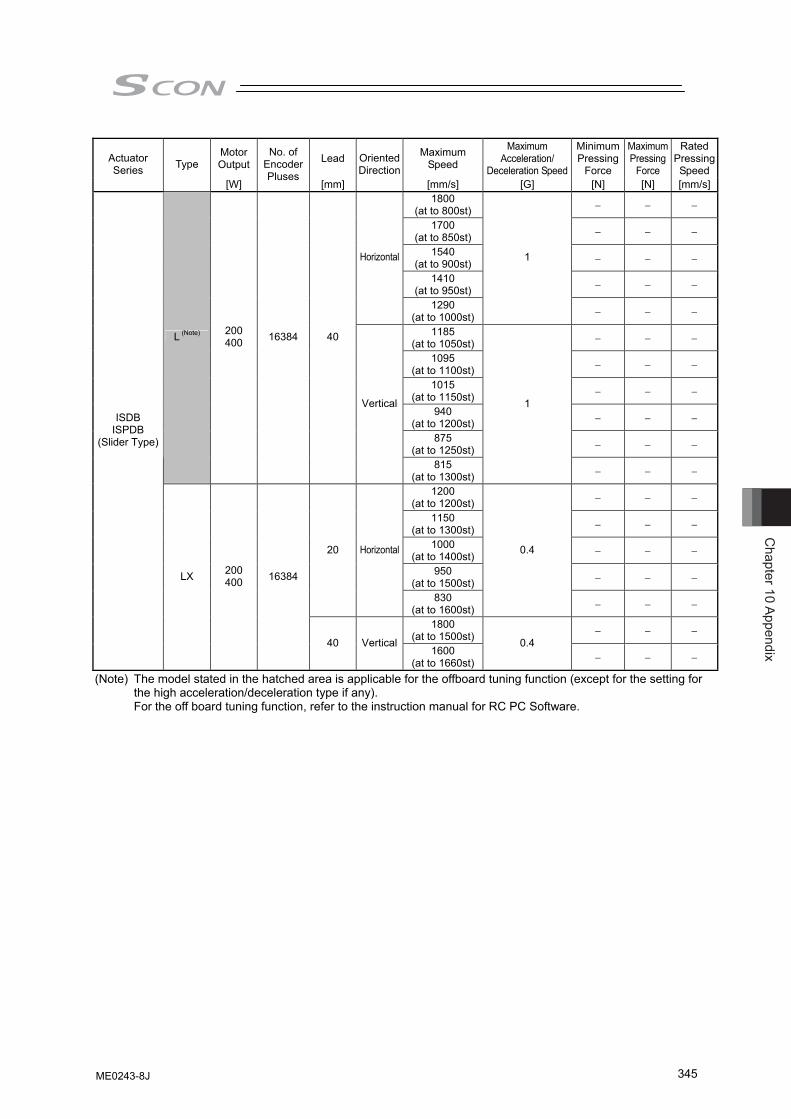
Chapter 10 Appendix
345
Motor Output Lead Maximum
Speed
Maximum Acceleration/
Deceleration Speed
Minimum Pressing
Force
Maximum Pressing
Force
Rated Pressing Speed
Actuator Series Type
[W]
No. of Encoder Pluses
[mm]
Oriented Direction
[mm/s] [G] [N] [N] [mm/s]1800
(at to 800st) − − −
1700 (at to 850st) − − −
1540 (at to 900st) − − −
1410 (at to 950st) − − −
Horizontal
1290 (at to 1000st)
1
− − −
1185 (at to 1050st) − − −
1095 (at to 1100st) − − −
1015 (at to 1150st) − − −
940 (at to 1200st) − − −
875 (at to 1250st) − − −
L (Note) 200 400 16384 40
Vertical
815 (at to 1300st)
1
− − −
1200 (at to 1200st) − − −
1150 (at to 1300st) − − −
1000 (at to 1400st) − − −
950 (at to 1500st) − − −
20 Horizontal
830 (at to 1600st)
0.4
− − −
1800 (at to 1500st) − − −
ISDB ISPDB
(Slider Type)
LX 200 400 16384
40 Vertical1600
(at to 1660st)
0.4 − − −
(Note) The model stated in the hatched area is applicable for the offboard tuning function (except for the setting for the high acceleration/deceleration type if any). For the off board tuning function, refer to the instruction manual for RC PC Software.
ME0243-8J
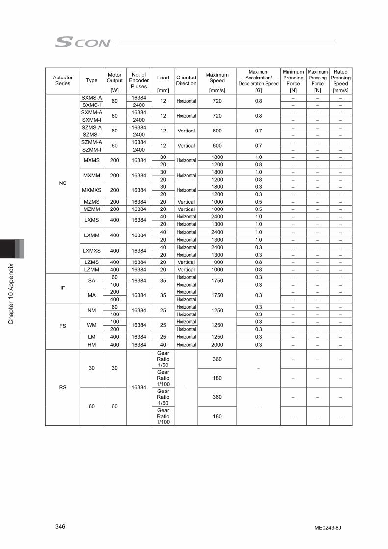
Cha
pter
10
Appe
ndix
346
Motor Output Lead Maximum
Speed
Maximum Acceleration/
Deceleration Speed
Minimum Pressing
Force
Maximum Pressing
Force
Rated Pressing Speed
Actuator Series Type
[W]
No. of Encoder Pluses
[mm]
Oriented Direction
[mm/s] [G] [N] [N] [mm/s]SXMS-A 16384 − − − SXMS-I
60 2400
12 Horizontal 720 0.8 − − −
SXMM-A 16384 − − − SXMM-I
60 2400
12 Horizontal 720 0.8 − − −
SZMS-A 16384 − − − SZMS-I
60 2400
12 Vertical 600 0.7 − − −
SZMM-A 16384 − − − SZMM-I
60 2400
12 Vertical 600 0.7 − − −
30 1800 1.0 − − − MXMS 200 16384 20
Horizontal1200 0.8 − − −
30 1800 1.0 − − − MXMM 200 16384 20
Horizontal1200 0.8 − − −
30 1800 0.3 − − − MXMXS 200 16384 20
Horizontal1200 0.3 − − −
MZMS 200 16384 20 Vertical 1000 0.5 − − − MZMM 200 16384 20 Vertical 1000 0.5 − − −
40 Horizontal 2400 1.0 − − − LXMS 400 16384 20 Horizontal 1300 1.0 − − − 40 Horizontal 2400 1.0 − − − LXMM 400 16384 20 Horizontal 1300 1.0 − − − 40 Horizontal 2400 0.3 − − − LXMXS 400 16384 20 Horizontal 1300 0.3 − − −
LZMS 400 16384 20 Vertical 1000 0.8 − − −
NS
LZMM 400 16384 20 Vertical 1000 0.8 − − − 60 Horizontal 0.3 − − − SA
100 16384 35
Horizontal1750
0.3 − − − 200 Horizontal − − −
IF MA
400 16384 35
Horizontal1750 0.3
− − − 60 Horizontal 0.3 − − − NM
100 16384 25
Horizontal1250
0.3 − − − 100 Horizontal 0.3 − − − WM 200
16384 25 Horizontal
1250 0.3 − − −
LM 400 16384 25 Horizontal 1250 0.3 − − −
FS
HM 400 16384 40 Horizontal 2000 0.3 − − − Gear Ratio1/50
360 − − −
30 30 Gear Ratio1/100
180
−
− − −
Gear Ratio1/50
360 − − −
RS
60 60
16384
Gear Ratio1/100
−
180
−
− − −
ME0243-8J
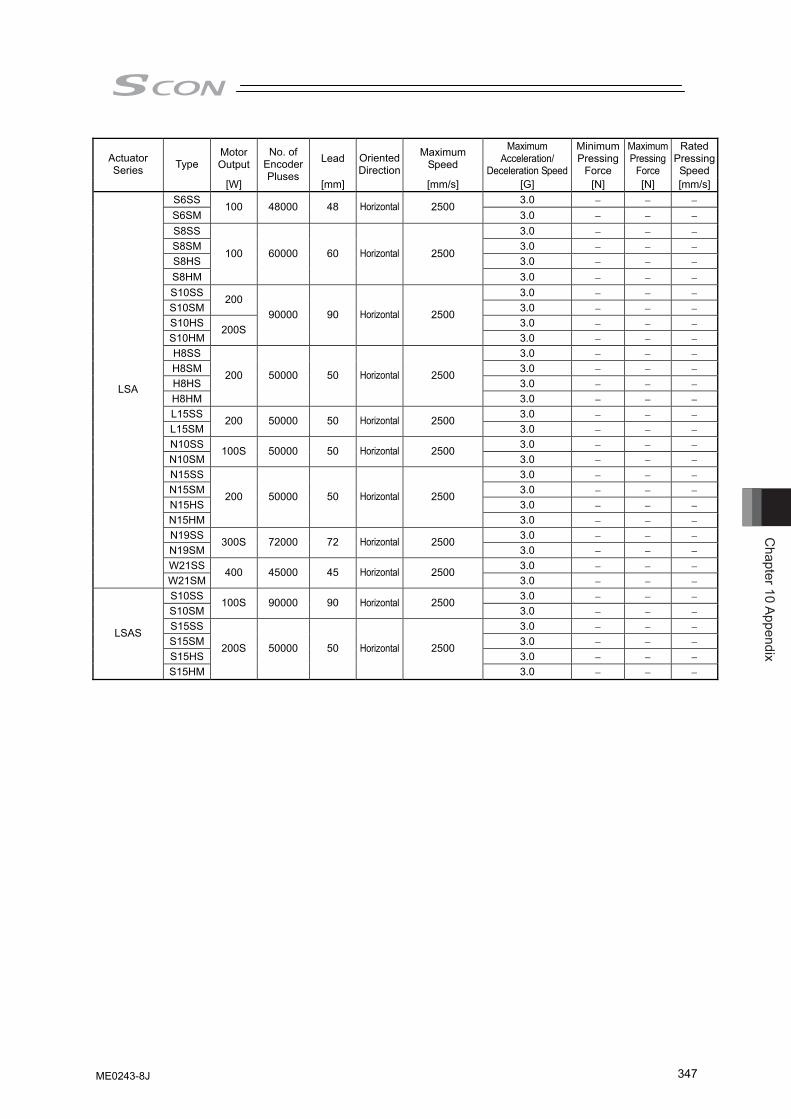
Chapter 10 Appendix
347
Motor Output Lead Maximum
Speed
Maximum Acceleration/
Deceleration Speed
Minimum Pressing
Force
Maximum Pressing
Force
Rated Pressing Speed
Actuator Series Type
[W]
No. of Encoder Pluses
[mm]
Oriented Direction
[mm/s] [G] [N] [N] [mm/s]S6SS 3.0 − − − S6SM
100 48000 48 Horizontal 2500 3.0 − − −
S8SS 3.0 − − − S8SM 3.0 − − − S8HS 3.0 − − − S8HM
100 60000 60 Horizontal 2500
3.0 − − − S10SS 3.0 − − − S10SM
200 3.0 − − −
S10HS 3.0 − − − S10HM
200S 90000 90 Horizontal 2500
3.0 − − − H8SS 3.0 − − − H8SM 3.0 − − − H8HS 3.0 − − − H8HM
200 50000 50 Horizontal 2500
3.0 − − − L15SS 3.0 − − − L15SM
200 50000 50 Horizontal 2500 3.0 − − −
N10SS 3.0 − − − N10SM
100S 50000 50 Horizontal 2500 3.0 − − −
N15SS 3.0 − − − N15SM 3.0 − − − N15HS 3.0 − − − N15HM
200 50000 50 Horizontal 2500
3.0 − − − N19SS 3.0 − − − N19SM
300S 72000 72 Horizontal 2500 3.0 − − −
W21SS 3.0 − − −
LSA
W21SM 400 45000 45 Horizontal 2500
3.0 − − − S10SS 3.0 − − − S10SM
100S 90000 90 Horizontal 2500 3.0 − − −
S15SS 3.0 − − − S15SM 3.0 − − − S15HS 3.0 − − −
LSAS
S15HM
200S 50000 50 Horizontal 2500
3.0 − − −
ME0243-8J
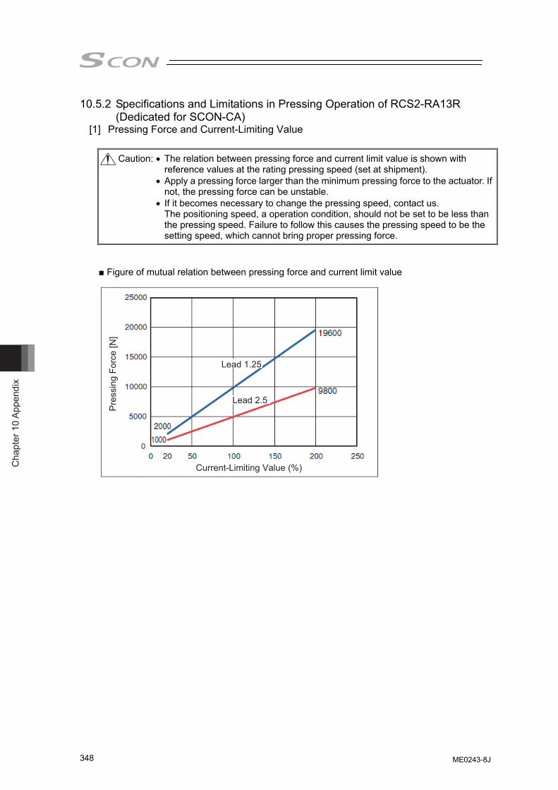
Cha
pter
10
Appe
ndix
348
10.5.2 Specifications and Limitations in Pressing Operation of RCS2-RA13R (Dedicated for SCON-CA)
[1] Pressing Force and Current-Limiting Value
■ Figure of mutual relation between pressing force and current limit value
Caution: • The relation between pressing force and current limit value is shown with reference values at the rating pressing speed (set at shipment).
• Apply a pressing force larger than the minimum pressing force to the actuator. If not, the pressing force can be unstable.
• If it becomes necessary to change the pressing speed, contact us. The positioning speed, a operation condition, should not be set to be less than the pressing speed. Failure to follow this causes the pressing speed to be the setting speed, which cannot bring proper pressing force.
Pre
ssin
g Fo
rce
[N]
Lead 1.25
Lead 2.5
Current-Limiting Value (%)
ME0243-8J
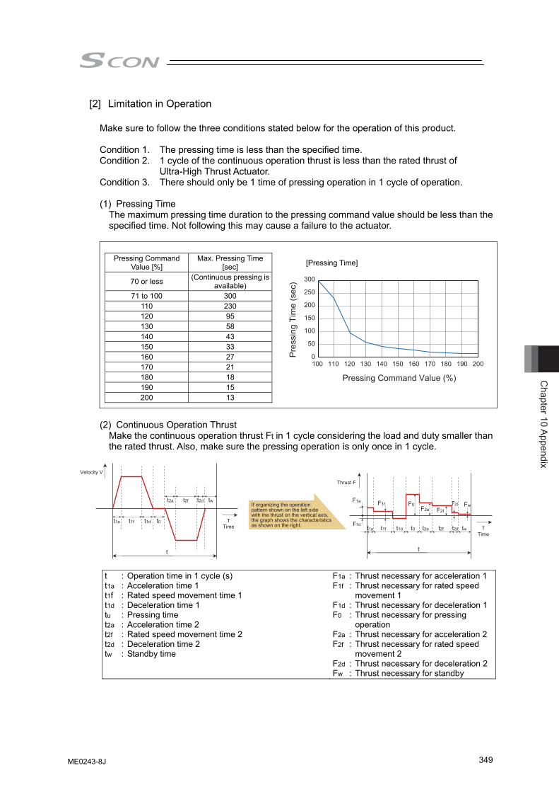
Chapter 10 Appendix
349
[2] Limitation in Operation Make sure to follow the three conditions stated below for the operation of this product. Condition 1. The pressing time is less than the specified time. Condition 2. 1 cycle of the continuous operation thrust is less than the rated thrust of
Ultra-High Thrust Actuator. Condition 3. There should only be 1 time of pressing operation in 1 cycle of operation. (1) Pressing Time
The maximum pressing time duration to the pressing command value should be less than the specified time. Not following this may cause a failure to the actuator.
Pressing Command
Value [%] Max. Pressing Time
[sec]
70 or less (Continuous pressing is available)
71 to 100 300 110 230 120 95 130 58 140 43 150 33 160 27 170 21 180 18 190 15 200 13
(2) Continuous Operation Thrust
Make the continuous operation thrust Ft in 1 cycle considering the load and duty smaller than the rated thrust. Also, make sure the pressing operation is only once in 1 cycle.
Velocity V
TTime
t1a t1f t1d t0
t2a t2f t2d tw
t
t1a t1f t1d t0 t2a t2f t2d tw
F1f F0F2a F2f
F1a F2d Fw
TTime
t
Thrust F
If organizing the operation pattern shown on the left side with the thrust on the vertical axis, the graph shows the characteristics as shown on the right.
t : Operation time in 1 cycle (s) t1a : Acceleration time 1 t1f : Rated speed movement time 1 t1d : Deceleration time 1 tu : Pressing time t2a : Acceleration time 2 t2f : Rated speed movement time 2 t2d : Deceleration time 2 tw : Standby time
F1a : Thrust necessary for acceleration 1F1f : Thrust necessary for rated speed
movement 1 F1d : Thrust necessary for deceleration 1F0 : Thrust necessary for pressing
operation F2a : Thrust necessary for acceleration 2F2f : Thrust necessary for rated speed
movement 2 F2d : Thrust necessary for deceleration 2Fw : Thrust necessary for standby
[Pressing Time]
300
250
200
150
100
50
0100 110 120 130 140 150 160 170 180 190 200
Pre
ssin
g Ti
me
(sec
)
Pressing Command Value (%)
ME0243-8J
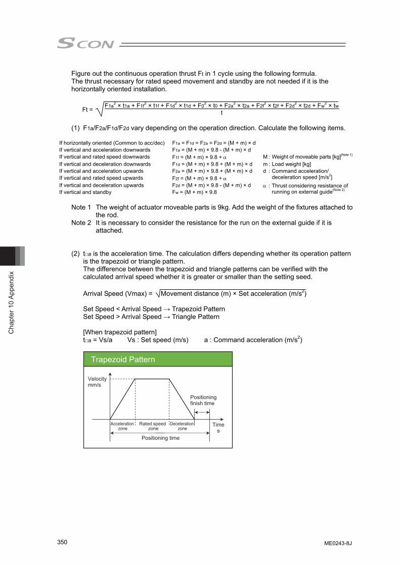
Cha
pter
10
Appe
ndix
350
Figure out the continuous operation thrust Ft in 1 cycle using the following formula. The thrust necessary for rated speed movement and standby are not needed if it is the horizontally oriented installation.
Ft = F1a2 × t1a + F1f2 × t1f + F1d2 × t1d + F02 × t0 + F2a2 × t2a + F2f2 × t2f + F2d2 × t2d + Fw2 × twt
(1) F1a/F2a/F1d/F2d vary depending on the operation direction. Calculate the following items.
If horizontally oriented (Common to acc/dec) F1a = F1d = F2a = F2d = (M + m) × d If vertical and acceleration downwards F1a = (M + m) × 9.8 - (M + m) × d If vertical and rated speed downwards F1f = (M + m) × 9.8 + α M : Weight of moveable parts [kg](Note 1)
If vertical and deceleration downwards F1d = (M + m) × 9.8 + (M + m) × d m : Load weight [kg] If vertical and acceleration upwards F2a = (M + m) × 9.8 + (M + m) × d If vertical and rated speed upwards F2f = (M + m) × 9.8 + α
d : Command acceleration/ deceleration speed [m/s2]
If vertical and deceleration upwards F2d = (M + m) × 9.8 - (M + m) × d If vertical and standby Fw = (M + m) × 9.8
α : Thrust considering resistance of running on external guide(Note 2)
Note 1 The weight of actuator moveable parts is 9kg. Add the weight of the fixtures attached to
the rod. Note 2 It is necessary to consider the resistance for the run on the external guide if it is
attached. (2) t□a is the acceleration time. The calculation differs depending whether its operation pattern
is the trapezoid or triangle pattern. The difference between the trapezoid and triangle patterns can be verified with the calculated arrival speed whether it is greater or smaller than the setting seed.
Arrival Speed (Vmax) = Movement distance (m) × Set acceleration (m/s2)
Set Speed < Arrival Speed → Trapezoid Pattern Set Speed > Arrival Speed → Triangle Pattern [When trapezoid pattern] t□a = Vs/a Vs : Set speed (m/s) a : Command acceleration (m/s2)
Trapezoid Pattern
Velocitymm/s
Times
Positioning finish time
Acceleration zone
Rated speed zone
Deceleration zone
Positioning time
ME0243-8J
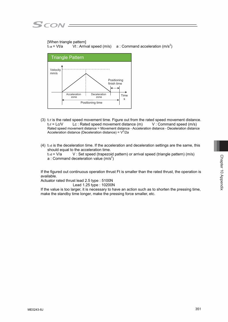
Chapter 10 Appendix
351
[When triangle pattern] t□a = Vt/a Vt : Arrival speed (m/s) a : Command acceleration (m/s2)
Velocitymm/s
Times
Positioning finish time
Acceleration zone
Deceleration zone
Positioning time
Triangle Pattern
(3) t□f is the rated speed movement time. Figure out from the rated speed movement distance. t□f = Lc/V Lc : Rated speed movement distance (m) V : Command speed (m/s) Rated speed movement distance = Movement distance - Acceleration distance - Deceleration distance Acceleration distance (Deceleration distance) = V2/2a
(4) t□d is the deceleration time. If the acceleration and deceleration settings are the same, this
should equal to the acceleration time. t□d = V/a V : Set speed (trapezoid pattern) or arrival speed (triangle pattern) (m/s) a : Command deceleration value (m/s2)
If the figured out continuous operation thrust Ft is smaller than the rated thrust, the operation is available. Actuator rated thrust lead 2.5 type : 5100N Lead 1.25 type : 10200N If the value is too larger, it is necessary to have an action such as to shorten the pressing time, make the standby time longer, make the pressing force smaller, etc.
ME0243-8J
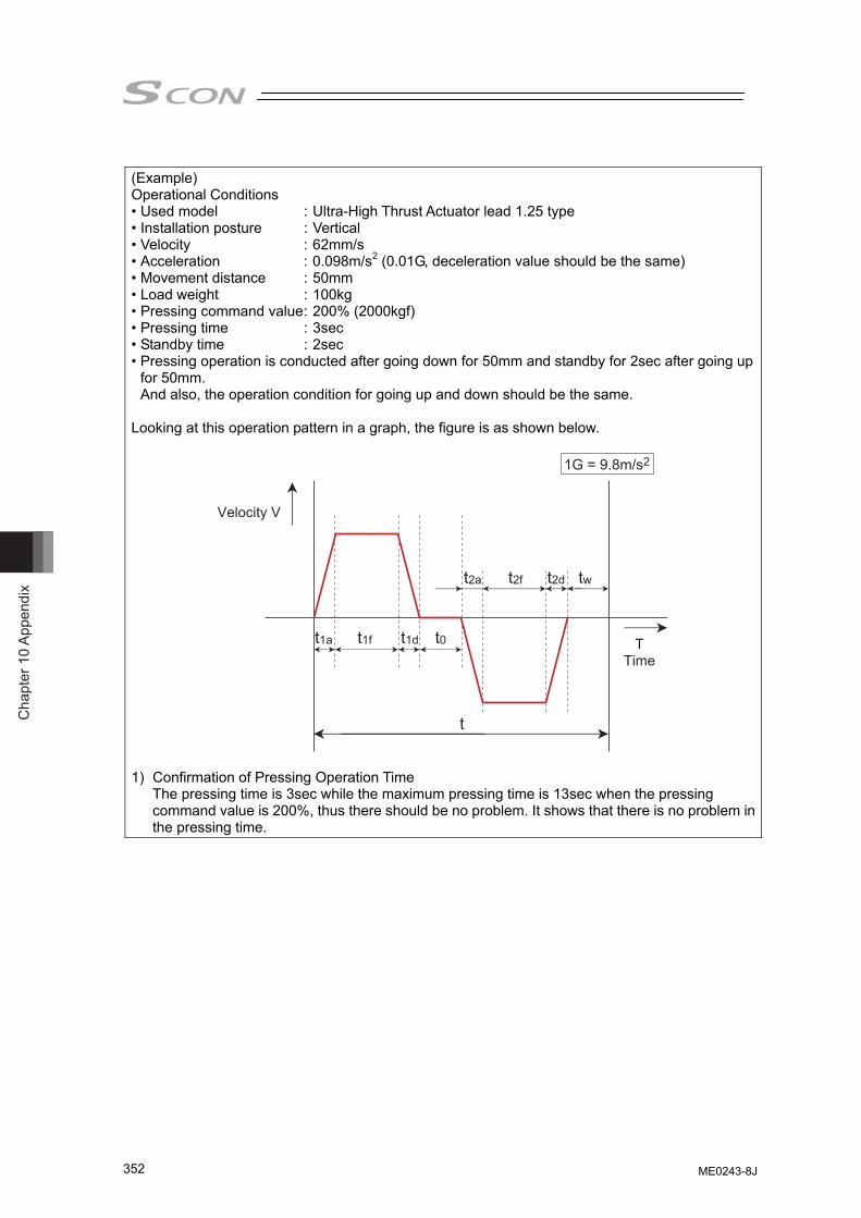
Cha
pter
10
Appe
ndix
352
(Example) Operational Conditions • Used model : Ultra-High Thrust Actuator lead 1.25 type • Installation posture : Vertical • Velocity : 62mm/s • Acceleration : 0.098m/s2 (0.01G, deceleration value should be the same) • Movement distance : 50mm • Load weight : 100kg • Pressing command value : 200% (2000kgf) • Pressing time : 3sec • Standby time : 2sec • Pressing operation is conducted after going down for 50mm and standby for 2sec after going up
for 50mm. And also, the operation condition for going up and down should be the same.
Looking at this operation pattern in a graph, the figure is as shown below.
Velocity V
TTime
t1a t1f t1d t0
t2a t2f t2d tw
t
1G = 9.8m/s2
1) Confirmation of Pressing Operation Time The pressing time is 3sec while the maximum pressing time is 13sec when the pressing command value is 200%, thus there should be no problem. It shows that there is no problem in the pressing time.
ME0243-8J
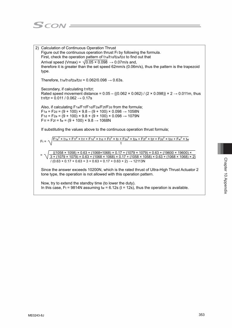
Chapter 10 Appendix
353
2) Calculation of Continuous Operation Thrust
Figure out the continuous operation thrust Ft by following the formula. First, check the operation pattern of t1a/t1d/t2a/t2d to find out that Arrival speed (Vmax) = 0.05 × 0.098 → 0.07m/s and, therefore it is greater than the set speed 62mm/s (0.06m/s), thus the pattern is the trapezoid type. Therefore, t1a/t1d/t2a/t2d = 0.062/0.098 → 0.63s. Secondary, if calculating t1f/t2f; Rated speed movement distance = 0.05 – {(0.062 × 0.062) / (2 × 0.098)} × 2 → 0.011m, thus t1f/t2f = 0.011 / 0.062 → 0.17s Also, if calculating F1a/F1f/F1d/F2a/F2f/F2d from the formula; F1a = F2d = (9 + 100) × 9.8 – (9 + 100) × 0.098 → 1058N F1d = F2a = (9 + 100) × 9.8 + (9 + 100) × 0.098 → 1079N F1f = F2f = fw = (9 + 100) × 9.8 → 1068N If substituting the values above to the continuous operation thrust formula;
Ft = F1a2 × t1a + F1f2 × t1f + F1d2 × t1d + F02 × t0 + F2a2 × t2a + F2f2 × t2f + F2d2 × t2d + Fw2 × twt
= {(1058 × 1058) × 0.63 + (1068×1068) × 0.17 + (1079 × 1079) × 0.63 + (19600 × 19600) × 3 + (1079 × 1079) × 0.63 + (1068 × 1068) × 0.17 + (1058 × 1058) × 0.63 + (1068 × 1068) × 2}
/ (0.63 + 0.17 + 0.63 + 3 + 0.63 + 0.17 + 0.63 + 2) → 12113N Since the answer exceeds 10200N, which is the rated thrust of Ultra-High Thrust Actuator 2
tone type, the operation is not allowed with this operation pattern. Now, try to extend the standby time (to lower the duty). In this case, Ft = 9814N assuming tw = 6.12s (t = 12s), thus the operation is available.
ME0243-8J

Cha
pter
10
Appe
ndix
354
ME0243-8J
Chapter 11 W
arranty
355
Chapter 11 Warranty
11.1 Warranty Period One of the following periods, whichever is shorter: • 18 months after shipment from our factory • 12 months after delivery to a specified location
11.2 Scope of the Warranty Our products are covered by warranty when all of the following conditions are met. Faulty products covered by warranty will be replaced or repaired free of charge:
(1) The breakdown or problem in question pertains to our product as delivered by us or our authorized dealer.
(2) The breakdown or problem in question occurred during the warranty period. (3) The breakdown or problem in question occurred while the product was in use for an
appropriate purpose under the conditions and environment of use specified in the instruction manual and catalog.
(4) The breakdown or problem in question was caused by a specification defect or problem, or by the poor quality of our product.
Note that breakdowns due to any of the following reasons are excluded from the scope of warranty:
[1] Anything other than our product [2] Modification or repair performed by a party other than us (unless we have approved
such modification or repair) [3] Anything that could not be easily predicted with the level of science and technology
available at the time of shipment from our company [4] A natural disaster, man-made disaster, incident or accident for which we are not liable [5] Natural fading of paint or other symptoms of aging [6] Wear, depletion or other expected result of use [7] Operation noise, vibration or other subjective sensation not affecting function or
maintenance Note that the warranty only covers our product as delivered and that any secondary loss arising from a breakdown of our product is excluded from the scope of warranty.
11.3 Honoring the Warranty As a rule, the product must be brought to us for repair under warranty.
11.4 Limited Liability (1) We shall assume no liability for any special damage, consequential loss or passive loss
such as a loss of expected profit arising from or in connection with our product. (2) We shall not be liable for any program or control method created by the customer to operate
our product or for the result of such program or control method.
ME0243-8J
Cha
pter
11
War
rant
y
356
11.5 Conditions of Conformance with Applicable Standards/Regulations, Etc., and Applications
(1) If our product is combined with another product or any system, device, etc., used by the
customer, the customer must first check the applicable standards, regulations and/or rules. The customer is also responsible for confirming that such combination with our product conforms to the applicable standards, etc. In such a case we will not be liable for the conformance of our product with the applicable standards, etc.
(2) Our product is for general industrial use. It is not intended or designed for the applications specified below, which require a high level of safety. Accordingly, as a rule our product cannot be used in these applications. Contact us if you must use our product for any of these applications:
[1] Medical equipment pertaining to maintenance or management of human life or health [2] A mechanism or mechanical equipment intended to move or transport people (such
as a vehicle, railway facility or aviation facility) [3] Important safety parts of mechanical equipment (such as safety devices) [4] Equipment used to handle cultural assets, art or other irreplaceable items
(3) Contact us at the earliest opportunity if our product is to be used in any condition or environment that differs from what is specified in the catalog or instruction manual.
11.6 Other Items Excluded from Warranty
The price of the product delivered to you does not include expenses associated with programming, the dispatch of engineers, etc. Accordingly, a separate fee will be charged in the following cases even during the warranty period:
[1] Guidance for installation/adjustment and witnessing of test operation [2] Maintenance and inspection [3] Technical guidance and education on operating/wiring methods, etc. [4] Technical guidance and education on programming and other items related to programs
357
Change History
Revision Date Revision Description 2011.11
2012.05
2012.08
2012.12
2013.01
2013.09
2013.11
2014.03
2014.08
2014.12
2015.02
First Edition Second Edition • Contents changed and added in Safety Guide • Number of regenerative resistance revised • Correction made to calculation of electronic gear ratio for feedback pulse Third Edition • Note added for high accel/decal type is not applicable for offboard turning function Fourth Edition • Parameter No.159 added and EMG circuit revised. Fifth Edition • Add UL Standard compliance conditions. • CE Marking support for EtherCAT and EtherNet/IP • Reviewed the movable angle of rotary actuator • Notes revised for Pressing Operation and Tension Operation Sixth Edition Applicable to DD motor connection Seventh Edition Caution added to caution in handling for when turning ON/OFF the power and inputting emergency stop 7B Edition Pg. 22 Refer to "How to Read the Model Number." Pg. 46,63 Change made to ISWA cable Pg. 255 Change made to detail codes in 1) and 2) in 0E5 Encoder Reception
Error Eighth Edition • Applicable to SCON-CAL/CGAL • Revising made due to model change of teaching pendants • Applicable to PROFINAT IO 8B Edition • Colophon Change made in address of Chicago Office 8C Edition • Pg. 199 Correction made to model cord of absolute battery with holder for
SCON-CA • Pg. 269 SCON-CA added in Safety Category Application
ME0243-8J
Change H
istory
357
Change History
Revision Date Revision Description 2011.11
2012.05
2012.08
2012.12
2013.01
2013.09
2013.11
2014.03
2014.08
2014.12
2015.02
First Edition Second Edition • Contents changed and added in Safety Guide • Number of regenerative resistance revised • Correction made to calculation of electronic gear ratio for feedback pulse Third Edition • Note added for high accel/decal type is not applicable for offboard turning function Fourth Edition • Parameter No.159 added and EMG circuit revised. Fifth Edition • Add UL Standard compliance conditions. • CE Marking support for EtherCAT and EtherNet/IP • Reviewed the movable angle of rotary actuator • Notes revised for Pressing Operation and Tension Operation Sixth Edition Applicable to DD motor connection Seventh Edition Caution added to caution in handling for when turning ON/OFF the power and inputting emergency stop 7B Edition Pg. 22 Refer to "How to Read the Model Number." Pg. 46,63 Change made to ISWA cable Pg. 255 Change made to detail codes in 1) and 2) in 0E5 Encoder Reception
Error Eighth Edition • Applicable to SCON-CAL/CGAL • Revising made due to model change of teaching pendants • Applicable to PROFINAT IO 8B Edition • Colophon Change made in address of Chicago Office 8C Edition • Pg. 199 Correction made to model cord of absolute battery with holder for
SCON-CA • Pg. 269 SCON-CA added in Safety Category Application
Cha
nge
His
tory
358
Revision Date Revision Description
2015.06
2015.07
2015.11
2016.12
2019.08
2019.10
2020.06
8D Edition • 1.1.2 Correction made to applicable teaching pendants • 1.1.3, Chapter 4 Description added regarding MECHATROLINK-III • 1.1.5 Information deleted regarding models not applicable from how to read
model code • 1.2.1 Information deleted regarding models not applicable from and
correction made in in-rush current value in specifications list • 1.2.2 Description of DD motor added to current amperage and heat
radiation • 1.4.1 Correction made to max. load current value of PIO input and output
interface • 2.3.6 Correction made to number of regenerative units at less than 400W • 2.3.7, 3.2.3 Correction made in notes • 3.2.3 Fan Error Detection added in binary output in [7] Alarm Details • 8.1 Correction made in contents of Parameter List No. 143 and 165 • 8.2 Correction made in contents of Parameter Details [21], [113] and [120] 8E Edition • Pg. 160 Caution note added for when using DD motor 8F Edition • Pg. 281 Correction made to e-CON model code 8G Edition • Contents revised in international standards and UL description • 2.1.3 Description revised in emergency stop circuit in schematic diagram • 9.4 Detail address added in alarm code 0A3 in alarm list • 10.1 Description revised for TP adapter, dummy plug and system I/O
connector • 10.1 Note added in detail circuit example regarding safety category
compliance • 10.2.3 Correction made to description for axis number setting for
SCON-CAL/CGAL • 10.3 Descriptions added for maintenance (consumables, maintenance
feature, fan unit replacement) • Correction made 8H Edition • 2.3.1 End-of-production noise filter deleted from Wiring of Power Circuit • 7.2 Correction made to description in Absolute Battery Specifications and
Alarm • 8.2 Correction made to description in Detail Explanation of Parameters
[18] Home Return Offset Level (Parameter No. 22) • 10.1 Correction made to description in Conformity to Safety Category [4] 2)
and 3) • Note added and changed in cause for Pulse Train Control Mode • Note added for velocity setting at pressing operation in pulse train control • Correction made 8I Edition • 10.1 Correction made to description in Conformity to Safety Category [3] 1) 8J Edition • Applicable for SCON-CAL/CGAL battery-less absolute encoder


Manual No.: ME0243-8J (June 2020)
The information contained in this document is subject to change without notice for purposes ofproduct improvement.Copyright © 2020. Jun. IAI Corporation. All rights reserved.
20.06.000
Head Office: 577-1 Obane Shimizu-KU Shizuoka City Shizuoka 424-0103, JapanTEL +81-54-364-5105 FAX +81-54-364-2589
website: www.iai-robot.co.jp/
Ober der Röth 4, D-65824 Schwalbach am Taunus, GermanyTEL 06196-88950 FAX 06196-889524
SHANGHAI JIAHUA BUSINESS CENTER A8-303, 808, Hongqiao Rd. Shanghai 200030, ChinaTEL 021-6448-4753 FAX 021-6448-3992
website: www.iai-robot.com
Technical Support available in USA, Europe and China
Head Office: 2690 W. 237th Street, Torrance, CA 90505TEL (310) 891-6015 FAX (310) 891-0815
Chicago Office: 110 East State Parkway, Schaumburg, IL 60173TEL(847) 908-1400 FAX (847) 908-1399
TEL (678) 354-9470 FAX (678) 354-9471website: www.intelligentactuator.com
Atlanta Office: 1220 Kennestone Circle, Suite 108, Marietta, GA 30066
825, PhairojKijja Tower 7th Floor, Debaratana RD., Bangna-Nuea, Bangna, Bangkok 10260, ThailandTEL +66-2-361-4458 FAX +66-2-361-4456
website: www.iai-gmbh.de
website: www.iai-robot.co.th
Related Documents