I-Q Transmission Lecture 17 I Q t ii • I-Q transmission • Sending Digital Data – Binary Phase Shift Keying (BPSK): sending binary data Binary Phase Shift Keying (BPSK): sending binary data over a single frequency band – Quadrature Phase Shift Keying (QPSK): sending twice the amount of binary data amount of binary data – Constellation Diagrams and Eye Diagrams • Summary ELEC1200 1

Welcome message from author
This document is posted to help you gain knowledge. Please leave a comment to let me know what you think about it! Share it to your friends and learn new things together.
Transcript

I-Q TransmissionLecture 17
I Q t i i• I-Q transmission• Sending Digital Data
– Binary Phase Shift Keying (BPSK): sending binary data Binary Phase Shift Keying (BPSK): sending binary data over a single frequency band
– Quadrature Phase Shift Keying (QPSK): sending twice the amount of binary dataamount of binary data
– Constellation Diagrams and Eye Diagrams• Summary
ELEC1200 1
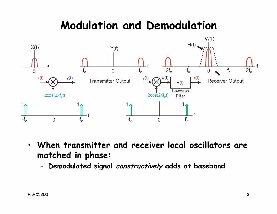
Modulation and Demodulation
• When transmitter and receiver local oscillators are When transmitter and receiver local oscillators are matched in phase:– Demodulated signal constructively adds at baseband
ELEC1200 2
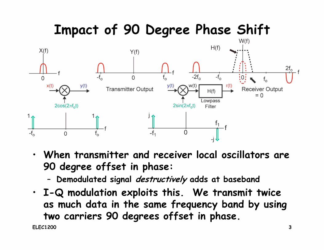
Impact of 90 Degree Phase Shift
• When transmitter and receiver local oscillators are 90 degree offset in phase:g p– Demodulated signal destructively adds at baseband
• I-Q modulation exploits this. We transmit twice as much data in the same frequency band by using as much data in the same frequency band by using two carriers 90 degrees offset in phase.
ELEC1200 3

I/Q ModulationI stands forI stands for
in-phasecomponent
Q stands forQ fquadraturecomponent
• Consider modulating with both a cosine and sine wave and then adding the results
Thi i k I/Q d l ti– This is known as I/Q modulation• The I/Q signals occupy the same frequency band, but one is
real and one is imaginary– We will see that we can recover both of these signals– We will see that we can recover both of these signals
ELEC1200 4

I/Q Demodulation
• Here we take advantage of the property that 90 degree shift between the two local oscillators will destructively
l h b b d lcancel out the baseband signal• I/Q modulation allows twice the amount of information to
be sent over the same frequency band
What can go wrong here?ELEC1200 5

Modulated Signal requires 2x the Bandwidth
Original Signal Modulated Signalwidth = 2W(We consider only
width = W
(We consider onlypositive frequencies.)
I-Q modulation sendstwo signals in the samepart of the frequency
spectrumspectrum.
ELEC1200 6

Impact of 90 Degree Phase Shift
• I and Q channels get swapped at receiver– Key observation: no information is lost!y
• For intermediate phase shifts, the signals are I and Q signals are mixed.
ELEC1200 7

Summary of Analog I/Q ModulationF d i i• Frequency domain view
Time domain view• Time domain view
ELEC1200 8

Digital I&Q ModulationAll i ti t t b t t d f • Allows communication systems to be constructed from “computers”, like micro processors– Sophisticated processing becomes possible
I i t b ild– Inexpensive to build• Allows information to be “packetized”
– Efficiently send information as packets through network– Analog signal requires “circuit-switched” connections
• Allows error correction to be achieved– Less sensitivity to radio channel imperfections
• Enables compression of information– More efficient use of channel
• Supports a wide variety of information contentpp y– Voice, text and email messages, video can all be represented as
digital bit streams
ELEC1200 9

Sending Binary Data with a Carrier+A
z(t)x(t)
+A
-A1 bit time
1 bit time
y(t) = 2cos(2πfot) T
• Motivation: leverage analog communication channel to send • Motivation: leverage analog communication channel to send digital bits
• We represent each binary zero or one as a sampled data waveform x(t) held at A or +A for 1 bit timewaveform x(t) held at -A or +A for 1 bit time.
• This sampled data waveform modulates a carrier with normalized frequency f0 Hz. Typically, the period T = 1/f0 is much smaller than 1 bit timemuch smaller than 1 bit time.
ELEC1200 10

Binary Phase Shift Keying (BPSK)+A
z(t)x(t)
+A
-A
y(t) = 2cos(2πfot)
ELEC1200 11

At the receiver side• In order to receive the digital data transmitted in
this way, we demodulate the received signals and sample the data waveform at the appropriate point sample the data waveform at the appropriate point at the output
1 0 1 1 0 1
Sample andCompare withThreshold
bits
samplepoints
Threshold
ELEC1200 12

Digital I/Q ModulationBaseband Input Receiver Output
0 50 100-1
0
1
0 50 100-1
0
1
Baseband Input Receiver Output
0 50 100 0 50 100
1
0
1
-1
0
1
• Using the same principle of I/Q transmission to transmit two
0 50 100-1 0 50 100
1
• Using the same principle of I/Q transmission to transmit two baseband signals
• At receiver, demodulate and sample the I/Q waveforms every bit time (e.g. at blue dots)y ( g )– Determine whether the transmitted bit on each channel was a 0
or 1 by comparing the sampled value with a threshold (e.g. 0).
ELEC1200 13

Constellation Diagrams and Quadrature Phase Shift Keying (QPSK)
Baseband Input Receiver Output
-1
0
1
-1
0
1
Baseband Input Receiver Output
0 50 1001
0 50 1001
1
0
1
1
0
1
• Plot I/Q sampled values on I-Q (x-y) axis– Example: sampled I/Q value of {1 -1}
0 50 100-1 0 50 100
-1
QExample: sampled I/Q value of {1, 1} forms a dot at I=1, Q=-1
– As more samples are plotted, constellation diagram eventually displays all possible symbol values I
1
y• Constellation diagram provides a sense of
how easy it is to distinguish between different symbols
• For the simple case of BPSK the
I1-1
-1• For the simple case of BPSK, the
constellation diagram is
ELEC1200 141-1 I
Q

The Impact of Noise
0 50 100-1
0
1
0 50 100-1
0
1
0 50 100-1
0
1
0 50 100-1
0
1
• Noise perturbs sampled I/Q
0 50 100 0 50 100
Q• Noise perturbs sampled I/Q
values– Constellation points no longer
consist of single dots for each I
1
consist of single dots for each symbol
• If noise is big enough, this can cause bit errors!
I-1 1
-1cause bit errors!
ELEC1200 15

To save transmission bandwidth1
0 50 100-1
0
1
0 50 100-1
0
1
spectrum
• Want transmitted spectrum with minimal bandwidth, since p ,wireless communication channels are a shared resource– However, sharply changing I/Q waveforms lead to a wide
bandwidth spectrum• Thus, we add a low pass filter before modulation.
ELEC1200 16

Impact of Transmit Filter
0 50 100-101
0 50 100-101
0 50 100-101
0 50 100-101
0 50 100
• Transmit filter enables reduced bandwidth for transmitted spectrum
0
spectrum• Issue: can lead to intersymbol interference (ISI)
– By removing the high frequency components, the rise time and the fall time of the signal increasetime of the signal increase
– Constellation diagram displays vulnerability to making bit errors
ELEC1200 17

Impact of High Bandwidth Filter1 1
0 50 100-101
1
0 50 100-101
1
I Ph
0 50 100-101
0 50 100-101
sufficient bandwidth
1
1.5
0
2In Phase
-0.5
0
0.50 5 10 15
-2
2Quadraturesample
points
-1.5 -1 -0.5 0 0.5 1 1.5-1.5
-1
0 5 10 15-2
0
• Open eye diagrams lead to tight symbol groupings in constellationELEC1200 18

Impact of Low Bandwidth Filter1 1
0 50 100-101
0 50 100-101
1
1 5
0 50 100-101
0 50 100-101
insufficient bandwidth
0.5
1
1.5
0
2In Phase
-0.5
00 5 10 15-2
2Quadraturesample
points
-1.5 -1 -0.5 0 0.5 1 1.5-1.5
-1
0 5 10 15-2
0
• Eye diagrams intuitively show increased ISI and
ELEC1200 19
• Eye diagrams intuitively show increased ISI and sensitivity to sample time placement.

Summary
• I/Q modulation allows twice the amount of information to be sent in the same frequency bandq y
• To leverage the analog communication channel for sending digital bits, we multiply the digital bits with a carriera carrier
• Using the same principle of I/Q transmission, we can transmit two separate digital data over the p gsame frequency band
• There is a tradeoff between saving transmission b d idth d i i i i i t b l i t f bandwidth and minimizing intersymbol interference (ISI)
ELEC1200 20
Related Documents