I I I. I I I I I I I I I I I I I • ' • • • EVELEIGH RAILWAY LOCOMOTIVE SHOPS THE NEW LOCOMOTIVE WORKSHOP Overhead Travelling Cranes - Conservation Plan and Recording • Report Prepared for: The Australian Technology Park May 1995 • • • • • • • • • • • • • • • • • • •• • -- .... , .. ·.: . ,.

Welcome message from author
This document is posted to help you gain knowledge. Please leave a comment to let me know what you think about it! Share it to your friends and learn new things together.
Transcript
I I I. I I
I I
I I I I I I I
I I
•
'
•
• •
EVELEIGH RAILWAY LOCOMOTIVE SHOPS THE NEW LOCOMOTIVE WORKSHOP
Overhead Travelling Cranes - Conservation Plan and Recording
•
Report Prepared for: The Australian Technology Park
May 1995
•
• •
•
•
•
•
• •
• •
• •
• • • • • •• •
-- .... , .. ·.: . ,.

-----~-------------~----~----~------------------------------
I I I.
•
CONTENTS PAGE NO.
1.0 INTRODUCTION 1 1.1 Preamble 1 •
I 1.2 Background 1 1.3 Site Identification 1 1.4 Author Identification 2 1.5 Methodology 2
I 1.6 Documentary Research 2 1.7 Fieldwork 2 1.8 Limitations 2
I 1.9 Acknowledgments 2 1.10 Report Format 3
-. ~..;"' .. •
I 2.0 HISTORICAL CONTEXT 4
2.1 Brief History Of Eveleigh Railway Workshops 4 2.1.1 History and Development 4
I 2.2 The New Loco Shop And Its Operations 20
3.0 THE CRANES IN THE NEW LOCO SHOP 22 3.1 Introduction 22
I 3.2 Brief Description 22 3.3 Physical Condition 24 \
'
I 4.0 SIGNIFICANCE 25 4.1 Discussion Of Significance 25 4.2 Statement Of Cultural Significance 25
I 4.2.1 Historical Signficance 25 4.2.2 Aesthetic Significance 25 4.2.3 Technological Significance 25
I 4.2.4 Social Significance 26
5.0 CONSTRAINTS 27 5.1 Constraints Arising From
I The Statement Of Cultural Significance 27 5.2 Legislative Constraints 27 5.3 Constraints Arising From The Physical Condition 27
I 5.4 Client Requirements 27
6.0 CONSERVATION POLICY 28
I 6.1 Introduction 28 6.2 The 35 Ton Crane 28 6.3 The 20 Ton Crane 28
I 7.0 NEW LOCOMOTIVE WORKSHOP -OVERHEAD TRAVELLING CRANE 30 -7.1 Description 30
'I 7.1.1 Introduction • 30 7.1.2 General 30 7.1.3 The Main Crane Beams 30 7.1.4 The Crane Trolley 31 7.1.5 The Crane Cabin 33
7.2 Photographic Catalogue 38
•
I

I I I. I I I I I I I I I I I I I I I I I I
- ------------~------ ---- ------------ ------ ----~--~----~ ---- -------
1.0
1.1
INTRODUCTION
•
PREAMBLE
GODDEN MACKAY
From the tjme o( construction until their closure in 1988 Eveleigh Railway Workshops were the most important single workshops complex in the rail system. When constructed they were the largest and certainly the most advanced workshops in Australia. They were an indication of the importance of the NSW rail system and the esteem in which the people of the Victorian era held their railways.
At the time of their closure in 1988 the workshops contained the finest examples of large late Victorian industrial buildings in NSW. The workshops, principally Bays 1-15, also contained the most complete set of late nineteenth and early twentieth century light and medium engineering workshop technology in Australia. This collection of equipment was of international heritage significance and there were no known collections of such importance in the United Kingdom, Europe or the United States of America.
This report concerns the two electric overhead travelling cranes which were erected in the new locomotive workshops. The building is also known as the new loco shop and the new engine shop. Both cranes were manufactured by Craven Brothers of Manchester in 1907, one being a twenty ton, (20 tonne), and one being a thirty five ton, (35 tonne), crane. These items were the only machines which were left in the loco shop after the closure of the workshops in 1988.
1.2 BACKGROUND
The new loco shop is now under the control of the Australian Technology Park Pty Ltd. It is to be refurbished to become the National Engineering Innovation Centre. A conservation plan for the building has been prepared and it is proposed that a further two floors will be* introduced to the building to double the floor space. An atrium will be provided almost immediately inside the main entry, which is in the centre of the building on the west facade.
The conservation plan and its implementation section were endorsed by the Heritage Council of NSW as well as the South Sydney Council. The conservation plan shows the removal of one of the cranes and the conservation of the other.
1.3 SITE IDENTIFICATION
The new locomotive shop is located close to the site boundary with Cornwallis St. Its north elevation is some 20 metres from the administrative office and its west elevation some 60 metres from the eastern wall of Bay 1 of the main workshops building.
•
1 •
• •
•

I I ·I I I I I I I I I I I I I I I I I I I
' '
•
•
1.4 AUTHOR IDENTIFICATION
GODDEN MACKAY
•
This report was compiled and written by Don Godden of Godden Mackay Pty Ltd. Historic photographs and plans were provided by the archive section of the State Rail Authority and all photographs were taken by Don Godden and Tony Brassil.
•
1.5 METHODOLOGY
This report follows the methodology outlined in J.S.Kerr's The Conservation Plan, The National Trust of Australia, (NSW), 3rd edition 1990, and complies with the principles of the Australian ICOMOS Charter for the conservation of places of cultural significance, The Burra Charter and Guidelines. The terminology used in this report, and particularly the words place, cultural significance, conservation, maintenance, preservation, restoration, reconstruction, adaptation and compatible use, follows the definitions provided by the Burra Charter.
1.6 DOCUMENTARY RESEARCH
Documentary research was primarily carried out by Don Godden who made limited use of SRA archives and other material relating to Eveleigh Railway Workshop held by Godden Mackay. There are very few photographs, plans or other records relating to the locomotive workshop and its operations in general and to the cranes in particular.
1.7 FIELDWORK
The equivalent of twelve and a half person hours were spent at the Eveleigh site in measuring the crane and interviewing informants. ·
'
1.8 LIMITATIONS
Documentary research revealed very little significant information. The loco shop was constructed in a period of reduced publicity prior to the First World War. A thorough search of all repositories was not carried out due to time constraints. However it is believed that sufficient information was gathered to allow the implementation and the recommendations of this report to be made.
•
1.9 ACKNOWLEDGMENTS
Assistance for the search for documentary material was once again provided efficiently and cheerfully by Victor Pojanski of the State Rail Archives, Sydney. Assistance was also given by Guido Gouvernor of Wrought Artworks, occupants of workshop Bays 1 and 2.
2
I I I.
I I I I I
I I I I I I
I I I I
. .
1.10 REPORT FORMAT
GODDEN MACKAY
•
•
This report is in parts which should be considered together. The first part is a Conservation Policy, Sections 1-6, while the second part contains a recording of the 20 tonne crane, Section 7. In the original copy of this report the photographic recording has been presented as a second volume because of the physical size of the negative envelopes. In all other copies both parts are bound together.
Section 2 contains a historical outline of the workshops.
Section 3 is a brief description of the cranes while Section 4 deals witli their significance .. •
Section 5 deals with the constraints which apply to the cranes and the Conservation Poiicy is enunciated in Section 6.
The description of the crane is contained in Section 7.1 and the photographic recording in Section 7.2.
•
•
•
3 •
-
. . . ·:: ....
~~ ., . ., •
• •
•
• •
•

I I I.
I I I I I I I I I I I I I I I I I I
•
2.0 IDSTORICAL CONTEXT
GODDEN MACKAY
•
2.1 BRIEF HISTORY OF EVELEIGH RAILWAY WORI(SHOPS
2.1.1 History and Development
1870-1887- The Establishment of the Workshops Planning for the provision of a large modern railway workshops complex at Redfern began with the proposed expansion of the existing Repair Shops in 1871. The original workshops, which were known as the Locomotive and Carriage and Wagon Repair Shops, were located towards the Redfern end of the Sydney Railway Yard in an area known as "Cleveland Paddock". [Gilder, (1905, quoted in Inst. of Eng., Syd. Div., 1922, p.20.] Some improvements and additions were made to the old repair workshops at this time, however, it was apparent that a new location would soon be required to allow sufficient room for expansion, see Figure 2.1
By 1875, the site at Eveleigh was selected and plans and estimates prepared for a workshops complex adequate for the foreseeable future. Clearing of the land commenced early in 1882 and construction of the Running Shed was begun while foundations for the workshops were being prepared. Owing to the sandy nature of the soil in the vicinity and the need for absolute stability of the workshop walls (for the overhead crane supports) a great deal of work went into the design and construction of the foundations for the workshops. ·
The construction of the workshops was scheduled in stages, with Bays 1-4 proceeding ahead of the rest of the workshops. By 1885, the construction was in progress and the purchase of machinery had commenced. During this year, an office building for the Locomotive Operations Manager was constructed near the southern coal stage and adjacent to the Running Shed with entrance gates and a watchman's office built nearby. A small brick building was erected on the southern side of the Running Shed and a self-contained steam-driven electric light plant installed. By the end of 1885, the Running Shed was completed and put into operation. The construction of the workshops continued throughout 1886. During this time the Carriage and Wagen Shops were also being built.
•
Early in 1887, workshops 1-4 were offici~lly opened. [N.S. W.R. Papers 87/57.] The four shops were each 300ft (90m) long and 60ft (18m) wide, built as adjoining bays with no internal walls. Internally, the bays were separated by a double row of cast-iron columns running the length of the bays. Workshops were numbered from the eastern end of the building, Bay 1 being the Steam Hammer Shop, Bay 2 the Blacksmith's Shop, Bay 3 the Boiler Shop and Bay 4 the Foundry. Annexes were built off the southern and western sides. -Later in 1887 the workshops 5-15 were also completed and opened. [N.S. W.R. Papers, 87/57.] The building was structurally very similar to the first four workshops. The intended function of each workshop bay was part of the design of the building, with the relevant features necessary for the function included in the arrangements of the building.
• 4

I
I. •
I I I
~~---
I I I I I I
• ••
' • •
•
' .
Figure 2.1 The original railway workshops were housed in a collection of sheds around a two storey store Turning and Pattern Shop, shown in this photograph. The Mortuary Station and Sydney University are apparent in the background.
•
5
•
• - .. -
•
•

-
•
. , ... ·-
... ~~ ,,. .. ' • •
. •
• •• '"~-~
r:., • • . . .-. • •
• .. ... •
•
•
• • • •
• ... "" • • • .... ~. . •
•
-
•
-
•
•• • • •
. l . ~ .~. ·''" ....... ,,~
' . . •· . .
•
•
-
• ... . •
'"""'- "' .... ., _,. ... •
• •
• •• ~ ..
•
•
•
•
-~ ......... _,...,_
• • •
• • • ••
• • •
••
•
• •
•
•
•
••
.
., • • "
•
• •
-----: I"A"T PLAH tND WA1LI
...........~.-~. .... ··-e-
" •
" •
•
. • •
• • •
•
•
~-------~-~
•
.. ·; . ··--···----
n~TIOH or rttRI
•
•
. •
• •
•
•
•
\ . • • . . ' . ,;-, f. . ~
•
' . '~ ~ .... .. ••
•
•
• • •
• • •
'•
.:__~lltc:TION Lt. • • I
•-- CI\OSI stCTIOH ,_.M
•
• ·-•
•
• t • ;
•
Figure 2.2 Plan, New Workshops Eveleigh. Details of foundations and pits, shops 16 to 25 .
•
•
•
• •
•
'· .. •
•
•
•
6
•
• i
•
'
.~ ~ ., '
• • -~. ., ~
...;, ··~ •..
•
•
•
•
•
•
.,
• .. •
•
•
'
• •
•
;.. . .. . ... - ..
~: ;:"jb.:. ~ ~>:._:..:, . ._,._._,___ -'"--··--=------~"· ..... -~.
•
• • •
•
. ,, .
• '
' L
I I •
• •
' •
1--·o,·=~ _.,. ___ =.::.._-
- ~---
•
•
.....- .$- .. 1, .I;,,._,_, - " --~.;...-
• "'""'~..,_.,_.,
•
•
•
•
•
;}
••
• • . . .
•
. •
•
\
• •
•
• '• •
• •• •
•
• •
• • . .
•
.•

I I I. I I I I I
I I I
~-1- ....... •
I •
~~
I I I I I
• •
.·
••
•
• •
•
GODDEN MACKAY
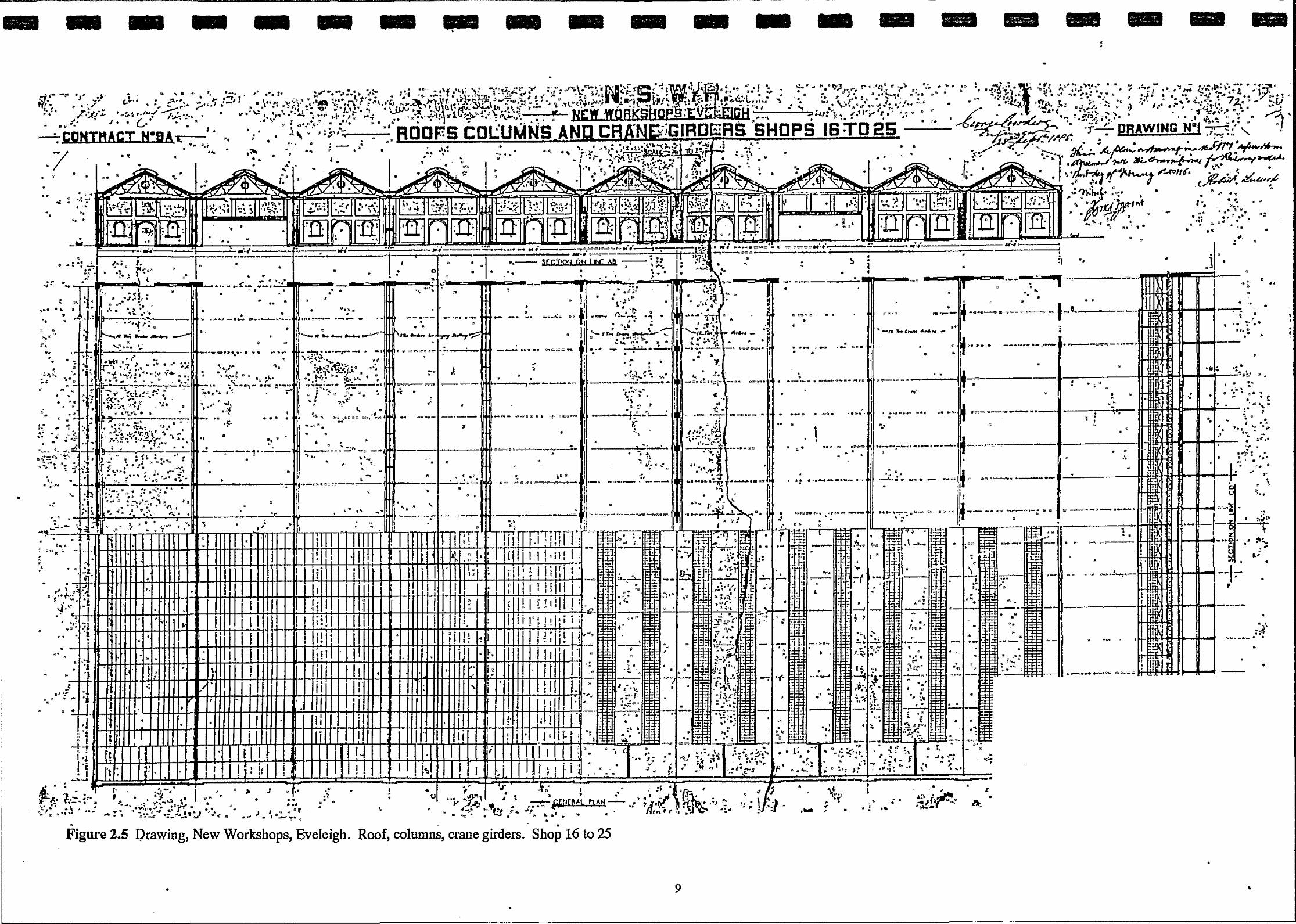
On the northern half of the site, the Carriage and Wagon Workshops also opened late in 1887. Built of the same materials and to an almost identical design as the Locomotive Workshops, the building comprised ten bays, again 300ft (90m) long and 60ft (18m) wide, numbered 16-25. These shops performed much the same general function as the Locomotive Workshops but acted exclusively on Carriages and Wagons and from the outset, new carriages and wagons were constructed at these workshops (see Figure2.2).
·,.. . •
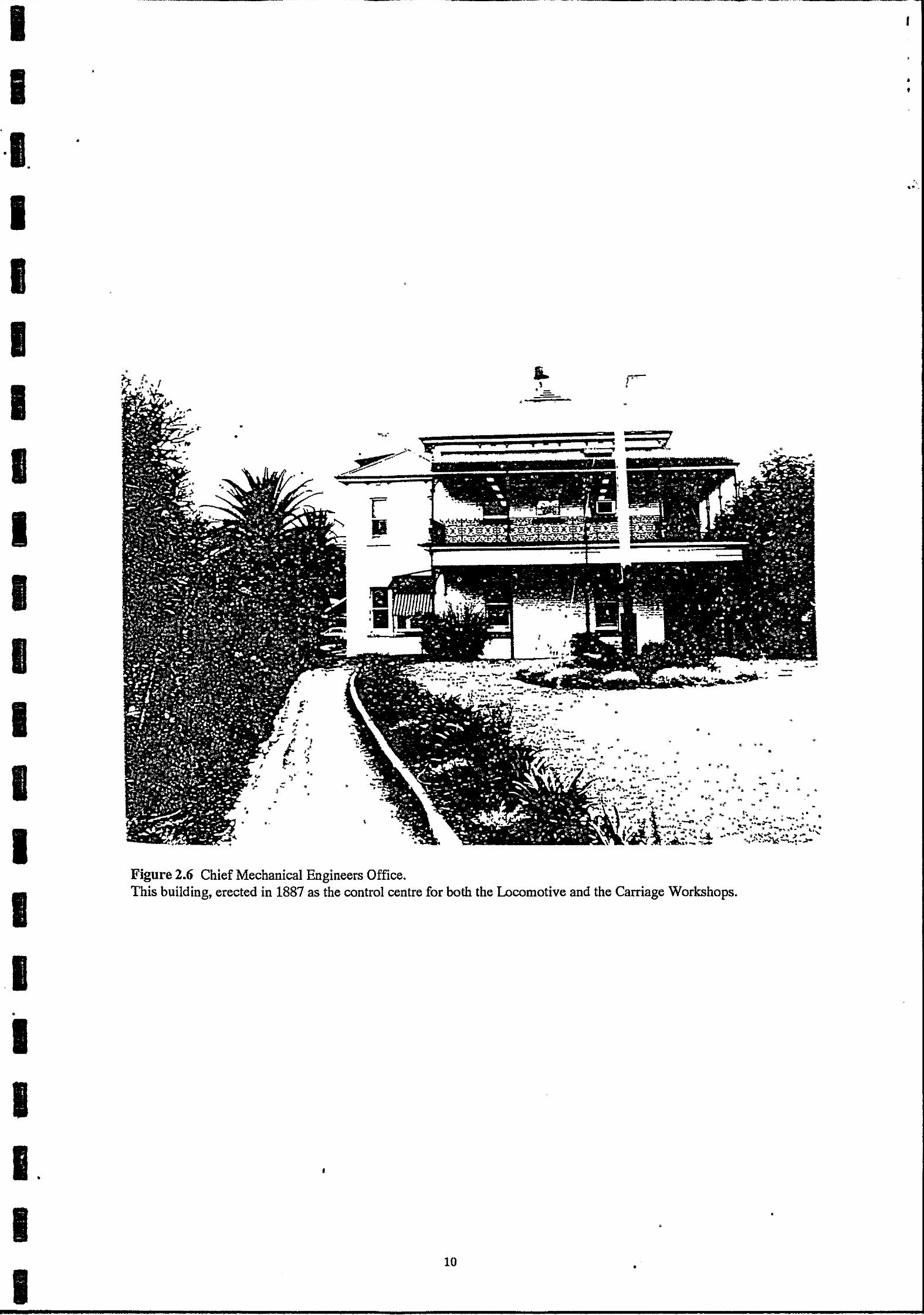
On the eastern side of the Carriage Workshops was built a large Paint Shop for the painting of carriages. On the ridge above the workshops adjacent to Wilson Street, a large two storey brick building was erected to house the offices of the Chief Mechanical Engineer, under whose supervision the whole workshops operated.
All the workshops began operations almost as soon as they were completed, such was the backlog of work created by the inadequacy of the old workshops and the demand created by the constantly expanding rail system. [Illus. Syd. New, 18/7!91 p.ll.] Approximately 1500 men were employed in the Workshops, under the Chief Mechanical Engineer, Mr W. Thow. Works Manager of the Locomotive side was Mr H.B. Howe and of the Carriage Side was MrElson.
1888-1910- Consolidation and Growth Following the opening of the Workshops in 1887, the N.S.W. rail system underwent a period of sustained growth both in the construction of new lines and the amount of traffic handled. Although other workshops were established in other locations, Eveleigh was the central repair facility for the N.S.W. system throughout this period.
A few major additions appear to have been made to the workshops following its opening. In 1890, a carriage shed was constructed in the south-western comer of the site, adjacent to the Macdonald town Station. In September of 1890 the erection of a timber drying shed was commenced on the Carriage Side of the Workshops for the storage and seasoning of timber • used in Carriage construction and repair. In 1891, a new coal stage was constructed using materials salvaged from the demolition of other earlier coal stages on the site. [N.S. W.R. Shop Order 1590!252.] A special workshop was established in that year for the manufacture, maintenance and repair of Signals and Telegraphs in the northern part of the
. site. [N.S. W.R. Shop Order 2265/252.] In the western comer of the site, construction of a gas-producing plant was commenced in November to replace a small plant established during the construction of the Workshops, [N.S. W.R. Shop Order 2720!253.]
Construction also commenced on a steam-powered laundry to be housed in a corrugatediron shed on the southern side of the workshops. [N.S. W.R. Shop Order 2357/252.] It washed the waste and sponge cloths used for cleaning all over the N.S.W. rail system.
•
. [N.S. W.R. Budget, 21/7!00, p.239-240.]
7
• • • •
I I I. I
I
I I I I I I I I I I
····-------------------------
'
•
.... --
I
• .. ~ ---
·•·
-. -'
'
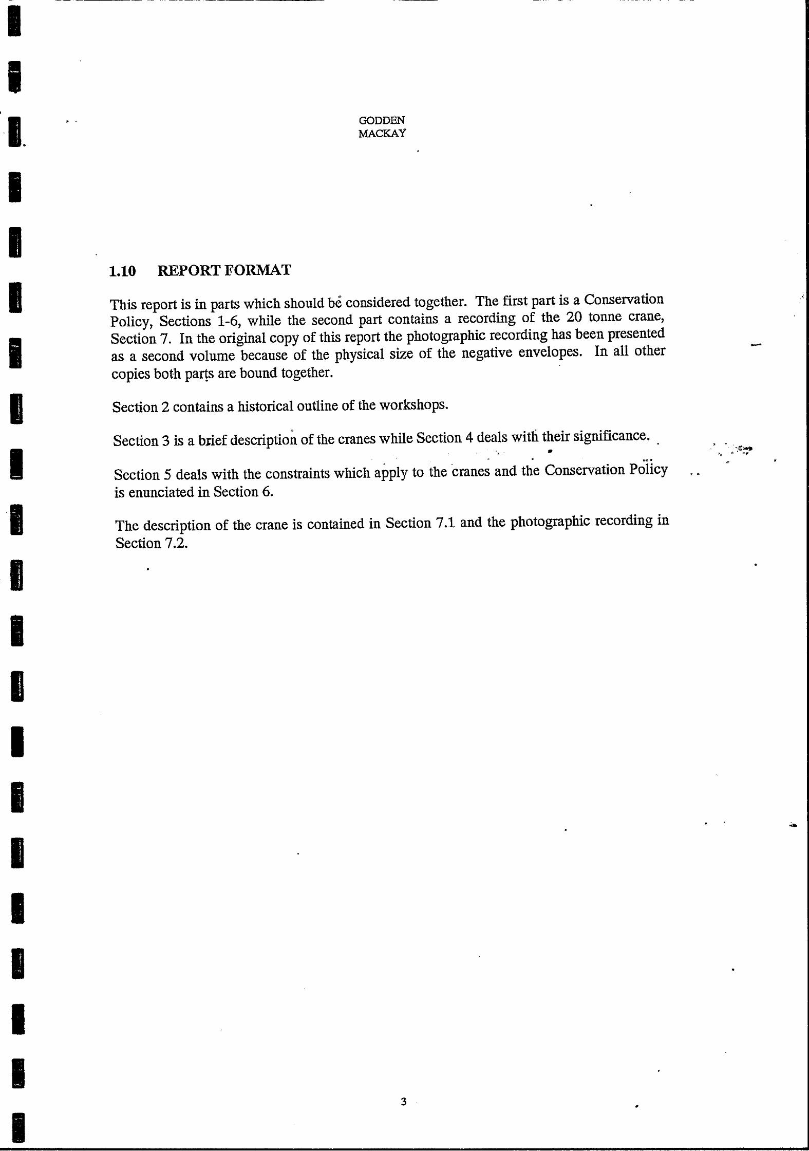
Figure 2.3 Railway Workshops in the early 1890's.
Figure 2.4 Carriage and Wagon Workshops, Bay 16-25
8 •
I '
• •
I ·,~
f'!fl' • .,.,,,, I Ll,f I I
• '
I "
.. " •
' ...... Tl I -, . ~ - ---·•·
- - - - - - - - - - -
•
• ' . --=;J;DNTMACT N"BA a;
. / .. ·•· • ••
•• ~-
<
• •
• "
•
.. -~ .. .. " •
• •
••
~-, j_
.::~""' :::~~ .. -. ~-
• • • " !-·~
. , • • • • . . ----•
>· • •• .. •
' •
•
•
.. • ••
•
•
• • • •
• •
• •'
•
• •
•
••
•
•
I • •• •
• • •
,:-.
•
• •
• • •
.• •
., "'" .. •
• • •
~ . .. " .............. . . ••
. .. • •
• -•
• •
.. • ____ ... ,., . .
•
•
•
•
•
.. . • •
• •
•
• ••
•
• •
•
•
' ·' I '
•
• • •
•
.......
• • •
~-- ...
• •
•
• -
•
• • I
.,
•
•
•
'
,, • • • •
•
•
•
>
•
•
... -- stcT:o« QN bu: AD • • • •
•
• •
-,
•
•
,. '
•
... •
•
• ,. -:: "'
.,_.._.._.~..:._..,~ ... ~ ·r:
:: •.
•
•
· · •4-t-f~~+H+''-++H+~~~H+~++H+~~~+H4-HH+H4-~4+H+~4+4+~~+4~~~H-~---
• • Figure 2.5 I)rawing, New Workshops, Eveleigh. Roof, columns, crane girders. Shop 16 to 25
•
•
-
•
9
- -
•
• •
•
•
•
---• •
.. -~ ... ~"
• •
"' .... ·-•
• ,,
• • ........ "
...................... -...... ~ ....... ,..~~
.. ..... . •
1 •
. ... ,.. ..
- -
•
... ;oj< ..
.._, ..... ,_ .......... -•
•••
. • • •, • •
•
• I
-
••
• •
'
• •
• •. .. ........ ~~~~:f ........ _., .. ,, ... , .............. . •• •
• '
• • 'r -~~ ·-·· .... .a~ ...
""~""-•7"';.w"- ._. • • •
•
.... -
•
•• .;..:_, e
"' ... :1--:IEJE!~I-··.·:._.:..f!:FFII----11 .. __.. • ., ... ~~·~ ...
•
•
• • .. .
-
• •
•
•
-
• .. •
••
• •
·' •
•
•
• •• •
•
HHI-~ .. +-•
•
•
•
•
•
•
•
•
•
• •
• . .
..
... ~ .~·
••• • \
• •
•
•
•
• • I
I I
··I. •
I I I I I I I I I I I I I •
I I I. I I
---------------·-----------------------·------
• • .... ...
r II -
.,. •• -- • • ' •
•
'. '
Figure 2.6 Chief Mechanical Engineers Office.
J,.. r-' ' ~-=--
• •
•
•
•
• •
•
• -.. .,~····'"' ......... ..-···.~ ... -~"' .... ·~
~ IIJ "' .... :., ••. .. :
This building, erected in 1887 as the control centre for both the Locomotive and the Carriage Workshops.
•
• •
10 •
I
• •
...
• •

•
I I ·I. I I I I I I I I I I I I I I I I I I
• GODDEN MACKAY
A contemporary description from 18th July, 1891 edition of the Illustrated Sydney News describes the works in detail and claims that in size, scope and in the technology employed , Eveleigh Workshops at this time had no equal either in Australia or the southern
hemisphere.
In 1892, union negotiations led to the workshops being closed on Saturdays- this. was part of the social change underway at this time that eventually created the two-day weekend that remains a feature of Australian working conditions. [McLachlan, N.S. W.R. Sec. Office 19!3!92.]
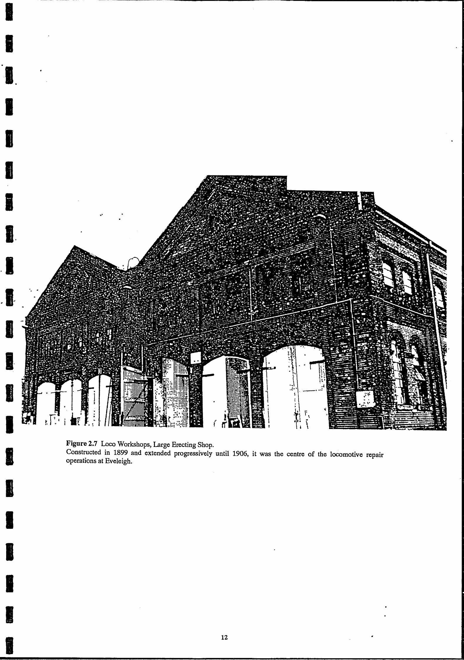
In 1898, the first major expansion of workshop facilities occurred with the construction of the new Erecting Shop (See Figure 2.7). Built to increase the accommodation for the repair of locomotives, it soon became known as the Large Erecting Shop to differentiate it from the Erecting Shop occupying Bays 6-8 in the main workshop building. The Large Erecting Shop was situated on the western side of Bay 15 and was completed in June, 1899. [N.S. W.R. Shop Order 28!6!99.]
Concurrently, a new Foundry building was being erected adjacent to the Large Erecting Shop site. [N.S. W.R. Shop Order 2/3!99.] It was established to allow the Boiler Shop to expand in Bay 4 of the main workshops.
Following the establishment of the Large Erecting Shop enabling many of the engine repair functions to be removed from the main building, the Paint Shop became immediately redundant and work commenced on converting Bays 12 and 13 for an Interlocking Shop. [N.S. W.R. Budget 21!7/00, p.239-240.]
•
In 1900, owing to the large amount of locomotive repair work in hand and the expected growth in the area, an extension to the Large Erecting Shop was commenced. [N.S. W. Railway and Tramway Magazine, 12!17, p.37.] This extension was of 200ft on the western end. It appears that this extension proceeded gradually as the work was not completed till
1906.
In a separate development, a compressed-air plant was installed in an annexe to the Boiler Shop (Bays 3 and 4) and air-mains were installed around the workshops~ [Fewtell, F., Works Manager, 14/5/55.] The year 1900 also provided an excellent and comprehensive description of both the Locomotive Workshops and the Carriage and Wagon Workshops in the monthly journal known as the N.S.W. Railway Budget. The Locomotive Workshops were detailed in the July 21 issue and the Carriage and Wagon Shops in the following issue
of August 21.
11
I ' •
----- ------
I I
•
1. •
I I I I I.
.I-•
•• •
I I
. I
I I I I I I I
• •
., I !
Figure 2.7 Loco Workshops, Large Erecting Shop.
i I I
\ ... . .! •
!.
' • • •
• •
···-· ~-
I' I -
I \
Constructed in 1899 and extended progressively until 1906, it was the centre of the locomotive repair operations at Eveleigh.
12 •
•
•
•

I I ·I. I I I I I I I I I I I I I I I I I I
• GODDEN MACKAY
Two new structures were commenced at the end of 1902. [N.S. W.R. Shop Order 1/12!02.] A new Copper and Tinsmiths Shop was established in a shed on the southern side of Bays 5-9, the former shop in the laneway between Bays 4 and 5 being demolished shortly afterward. [N.S. W.R. Shop Order 1!12!02.] A large building of corrugated-iron was erected on the eastern end of the workshops (outside Bay 1) which contained in its northern half a Spring Shop and in its southern half a Steam Hammer Shop. The reason for these two constructio·ns was the need to expand the operations of both the Blacksmiths Shop (Bay 2) and the Boiler Shop (Bays 3 and 4).
Although the exact date is unclear, it appears that the Wheel Press Shop was also established at this time adjacent to the new Tinsmiths Shop. Housed in a corrugatediron/clad, steel framed shed to the south of Bays 10-12, this shop contained hydraulic presses for removing axle centers, a tyre-heating plant, hydraulic cranes and a chain-testing machine. [Inst. of Eng. Syd. Div. 11!10!22.]
The year 1907 was distinguished by the decision of the Commission~rs for Railways to begin the manufacture of new locomotives at Eveleigh and a new build.lJtg was designed for this purpose. Clearing of ground on the eastern end of the workshops complex commenced in September and construction began shortly afterwards of the New Loco Shop. [Fewtell, F., Works Manager, 14/5/55]. Also during 1907, a new compressor house was established on the south side of the New Loco Shop site. • • •
• • ~ ..... . .. .. The following two years saw the refqrbishment o_r repla~e:rilerrt of mariy.:t>f'the operating boilers around the workshops. [N.S. W.RShop Order, 28i5!0S.] ·
Most overhead cranes in the workshops were all converted to electric drives by 1902. A significant development in 1910 was the construction of indoor toilet facilities throughout the workshops - the result of labour negotiations for improved conditions .
• • •
In contrast to the almost constant development·in the Locomotive Workshops during the two decades 1890-1910, operations in the Carriage an"a Wagon Workshops appear to have proceeded with few major changes or alteration'S to either the buildings or equipment. [N.S. W.R Shop Order, 31/1!01 and Shop Order, 7!11!01.] In 1907, a new building was erected on the northern side of the workshops to house the Wagon and Carriage Blacksmiths Shop. [N.S. W.R Shop Order, 29!10/07.] Apart from minor changes, work on the maintenance and repair of the Railways rolling stock was carried on uninterrupted and new carriages were being constructed at the rate of about ten per week.
•
• 13
. . ,
I I ·I. I I I I I I I I I I I I
' " r
I I I I I I
•
•
.. ,
•
• •
• ., -
GODDEN MACKAY
1910-1935 - War, Peace and Recession The years 1911 to 1913 were quiet years for the Workshops. A Grinding and File Making Shop was established in the old Cleaning Annexe behind Bay 9 during 1911; it provided a central facility in the Workshops for tool maintenance and repair. [Fewtell, F., Works Manager, 14/5/55.] In 1912 a Signal and Telegraph Branch Workshop was constructed in the north-eastern corner of the workshops site, adjacent to the Redfern Station No. 1 Platform. [N.S. W.R. Shop Order 228!256.]
The Carriage and Wagon Paint Shop was extended around this time and the area on the western side of the Carriage Repair Shed, known as the Carriage Shop Paddock, was roofed over for additional car repair space. [N.S. W.R Shop Order 228!256.] The Paint Shop extension was built on the northern side of the existing shed. [N.S. W.R. Shop Order 24/8!12 and Shop Order 19!9!13] In 1913 a footbridge was built across the southern end of the yard for the workmen to cross the tracks more safely. [ N.S. W.R. Shop Order 256/187.]
The beginning of 1914 and presumably the outbreak of war in Europe gave impetus to a significant upgrading of facilities and rearrangement of workshops. The New Loco Shop, constructed in 1907, was extended on its southern end by 100ft (30m) to a total of 300ft (80m), making it equivalent in length to the Main Workshops. [N.S. W.R. Shop Order 11/5/14.]
Electrification of machinery in the workshops was another major undertaking, with No. 14 Bay (Pattern Shop) electrified by the 8th of January, and No. 8 Bay (Erecting Shop) and No.9 Bay (Machine Shop) completed by the beginning of August.
In order to allow an expansion of the Machine Shop, the Laundry was removed from the building adjacent to the Large Erecting Shop and re-established in a new building at Clyde where it still remains, known as the Clyde Laundry. The Millwrights Section and the Water Supply Section then moved from No. 11 Bay to the former Laundry building and the No . 11 Bay become part of the Machine Shop. [Fewtell, F., Works Manager, 14/5/55.] This was a temporary arrangement while the Machine Shop was reorganised .
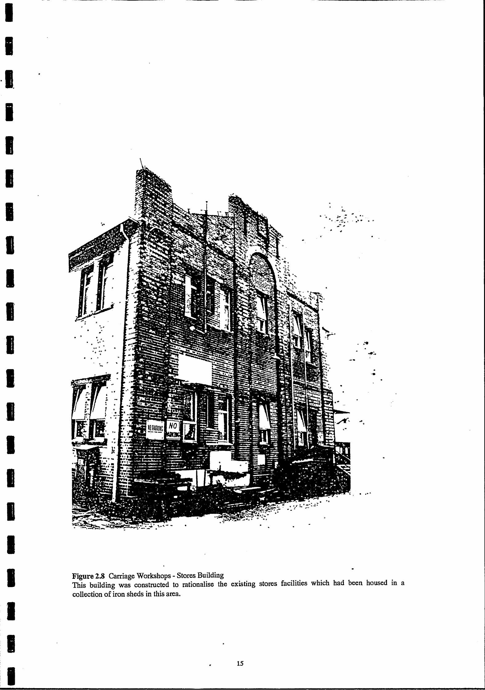
On the Carriage side of the Workshops, a large two-storey stores building was constructed west of the timber shed in the Stores Branch complex. [N.S. W.R. Shop Order 257/38.] The other stores buildings were less substantial timber and corrugated-iron buildings, built at various times since the establishment of the Workshops, all administered by the Railways Stores Branch. The new building rationalised much of the Stores Branch's activities under one roofin the centre of this area (see Figure 2.8).
Following the rearrangement of the Machine Shop, the MilJwrights moved into a section of No. 9 Bay. The Water Supply section, concerned with the supply of all taps, pipes, connections, tanks and other material concerned with the provision and use of water in the railways, also moved out of the former Laundry to a new workshop at Erskineville and the laundry building was subsequently demolished.
14
•
•
I I ·I. •
I I I I I I I I I I I I I I I I I I
• ,.
' •
• • •• • • •
• • • • • • ·.,~ ~ . •
~ .... • • .... .. ., • •
• • • • . • • -
• • •
----------------------
•
• ·~·~-~:.:.:
;·-:.~ .......
•
•
•
• •
-• • .
•
•
•·
. "--~ .. ~ • "'· . . .
~---· . . .. '"' .. "' .,.,""' ... •
•
•
• . ,.. •
• •
•
•
•
L • #.., ..
•
Figure 2.8 Carriage Workshops - Stores Building This building was constructed to rationalise the existing stores facilities which had been housed in a collection of iron sheds in this area.
•
• 15

-- ··--·-·---------- --------- ···---··-----
1 I ·I. I I I I I I I I I I I I I I I I I I
•
•
•
•
GODDEN MACKAY
•
During 1916 as part of the war effort at this time, a trial production run of 5,000 18lb fieldgun shells was made in the workshops using machines modified for the purpose. [Fewtell, F., Works Manager, 14/5/55.] This was discontinued because the machines were inappropriate and the whole arrangement judged to be unsatisfactory for both the Army and the Railways.
In 1917, a'new Foundry building and a new Pattern Shop building were constructed on the southern side of the workshops. This required a resumption of two acres of land on the south-western end of the site to allow a rail siding to be built to connect to these two new structures. [N.S. W.R. Shop Orders 258/272, 40!254 and 2160/259.]
Sometime prior to 1917, a Potash Washing Plant was established in a small corrugated-iron shed between Bay 15 and the site of the new Foundry. Containing large Potash tanks served by a hand-operated overhead crane, it was used to wash the grease and dirt from detail parts
·· of locomotives. [N.S. W.Railway and Tramway Magazine, 12!17, p.37.] With the completion of the new buildings and the transfer of operations from the workshop building, the remaining shops were rearranged and rationalised.
The Steel Foundry section of the new foundry was opened in 1919 using an oil-fired Stock Steel Converter as its main furnace. [Inst. of Eng. Syd. Div. 11!10!22.] By 1922, it was deemed necessary to have an electric furnace for this section and a major extension of the Steel Foundry was undertaken for this purpose. Added on to the western end of the Foundry building, the extension and furnace installation was completed by November, 1923. [N.S. W.R. Shop Order 437!260.]
In 1923, a major portion of the boiler repair work was shifted to a new facility established at Chullora. In 1925, the No. 1 Blacksmiths Shop in Bay 1 was completely rearranged and a 1500 ton steam-driven 11Davy11 press was installed in the northern side. [Fewtell, F., Works
Manager, 14/5/55.]
The quadruplication of the Illawarra Line in 1925 brought, as an initial step, the demolition of the northern bay of the Running Shed to provide more room in the yard for these lines. [Wylie, 1963, inA.R.H.S. Bulletin 291-314, p.945.] Also in 1925, construction commenced on an elevated timber coal stage on the northern side of the workshops, a 40,000 gallon water tank was erected on high ground near Cornwallis Street and plans were approved and construction commenced on a subway under the main yard. The subway was completed in July 1927. [E. W.C.S.C., 1968 in Eveleigh News No. 377.]
•
As these works were underway, elsewhere in the works the mounting pressure on Locomotive repair facilities led to, in 1925, the decision to cease the manufacture of new locomotives at Eveleigh. [Fewtel~ F., Works Manager, 14/5/55.] The New Loco Shop was from this time used largely for locomotive repair work. Up to this time, one hundred and fifty-three locomotives had been constructed at Eveleigh.
16
J . '

•
I ·I.
I I I I I I I I I I I I I I
I
• GODDEN MACKAY
By the end of the year, a new Tinsmiths and Plumbers Shop had been built on the bank above the Pattern Shop. The former Tinsmiths Shop adjacent to the Wheel-Press House was subsequently converted to a Welding Shop, welders having previously been housed in several different areas.
In February of 1928, two new Traversers were installed in the Large Erecting .Shop. This appears to· be tlie last new building or purchase of new equipment that occurred in the workshops until 1935, the period of the Great Depression. Apart from this lack of growth, the Workshops appear to have managed through the difficult times without major setbacks.
The equivalent period 1910-1935 brought far less activity and development in the Carriage and Wagon Workshops than for the Locomotive Workshops. 1913 saw extensions to the Paint Shop and the Carriage Repair Yards, with the construction of the large Stores building in 1914. The Traverser between the Paint Shop and the Wagon Shop was extended in 1915 and two 25 ton T.Goodall and Co. electric overhead cranes were installed in 1920. [N.S. W.R. Shop Order 21!6!15.] A number of buildings came into existence in the Carriage Workshops area that were erected between 1914 and 1924. They were a Materials Testing Laboratory, two stores and general workshops, a brick residence near the stores buildings and an oil storage shed.
1935-1970 From Excellence to Obsolescence By 1935, the Eveleigh Workshops had grown into a solid and mature operation, with its role within the Railway's system established and complete. Eveleigh was the central Locomotive and Carriage and Wagon Repair facility as well as handling most of the heavy forging and parts casting for the system. Technology brought in with the twentieth century, electricity and steel for example, had been embraced and adopted where appropriate and the interrelationships between various departments and shops .were well established. The improvements made during the early 1920's were obviously sufficient to carry the works
~ ,.-
through the Depression without mishaps or problems. . . . . . . . . .. : ...... :...-. ' "' . ~~ . .. ... ~.... .. . ~ ~·
~ ·= .. '";,;"'-~.~
The lack of development at Eveleigh duR.ng the 1930's was related to the development of . other Workshops in the system - with Eveleigh established· and· running smoothly, new· .•. ~·. . constructions and developments in other departments could be undertaken at the other · · · · Workshops. In 1937, the opening of a new large locomotive repair depot at the Chullora Workshops enabled much of the repair work to be removed from Eveleigh and the Old Erecting Shop located in Bays 5 and 6 was vacated later in the year. [Fewtell, F., Works' Manager, 14/5/55.]
With the outbreak of war in Europe, negotiations between the Department of Defence and the Railways Department were initiated again as all heavy ~ngineering shops throughout the country were pressed to assist in the manufacture of military equipment. The lessons of the First World War experiment had been learned and in early 1940, Bays 5 and 6 were cleared of machinery and plans drawn up for the installation of equipment supplied by the Department of Defence for the manufacture of 25lb field-gun shells. [Fewtell, F., Works' Manager,14/5/55.] Another contribution to the war effort was the manufacture of the
•
•
17 •
. -.
...
• • ·>~.

- --- --- ----- ----------~-----~ ----- ------------
'
I ·I.
•
I I I I I I I I I I I I
I I I I I.
•
•
GODDEN MACKAY
special tools required in the manufacture of Bren Guns. Although the guns were manufactured in Defence Department factories, the whole of the machinery required was m~nufactured in the Machine Shop' at Eveleigh. These arrangements were in general a temporary solution while the Defence Department organised its own factories. - .
On the Carriage .Workshops side, the war saw the building of several temporary·barrackstype accdmmodation buildings and the conversion of the large brick Stores building to a hostel for the accommodation of transient railway employees and Defence Department workers. A canteen building and kitchen were constructed adjacent to the hostel. The stores residence was used during this period as the Hostel and Canteen Supervisor's Residence.
About 1942/43, concrete air-raid shelters were erected in various locations around the Workshops, generally against embankments or in sheltered corners of the site.
. During 1944, plans were drawn up and construction commenced on a major extension of the Works Managers'Offi~, transforming it into a much larger building. [Plans: N.S. W.R. o/aYS and Warks Branch No's. 1~2/144 to 102/146, 23/3!44.] At the same time a larger -. . addition was:erected O!l the southern side of the Foundry to house new staff amenities for
·-the fountlry staff. [Plan: N.S. W.R. Ways and Works Branch No. 975/34.215, 8!12!43.] . - - . . .
With the end of the war i..nJ~945, lti~ production of 25lb field gun shells in Bay 5 ceased and the machinery, owned by )lie Defence Departme~t, was removed soon afterwards. The Workshops settled back into their normal routines with only few alterations and additions over the next few years.
1945 also saw the reintroduction of the construction of new locomotives at Eveleigh. Between 1945 and 1952, fourteen C38 Class locomotives and thirteen D58 Class locos were built. No further new locomotives were constructed at Eveleigh after this time. All of these locomotives were built in the Large Erecting Shop.
The national coal strike of 1949 brought a host of difficulties for the railways with their dependence on coal as a fuel supply. Although the crisis was endured without serious setback, much of the Gasworks machinery was severely damaged by the low grade brown coal it was forced to use during this period.· As a consequence, about 1958 the gas manufacturing plant was. demolished and the Workshops began drawing gas from the city supply, using the aid gasworks as a storage and distribution centre.
The 1950's and 1960's brought a new era to the railways and the introduction and reequipment with large diesel locomotives. By the middle of the 1960's, steam locomotion had been completely abandoned. Due to Eveleigh's historical place as a steam locomotive workshop and the lack of available space on the site· for additional facilities, diesel construction, maintenance and repair facilities were erected at other workshops, with Eveleigh continuing to service steam locomotives until the change over was complete. Coincidental with this was the development and re-equipment of the electric train and carriage fleet with the now familiar air-conditioned cars.
18
I
I I I
• ' i I I
I I
•
·I. I I I
•
I I I I
I I I I I I I I I I
•
• • •
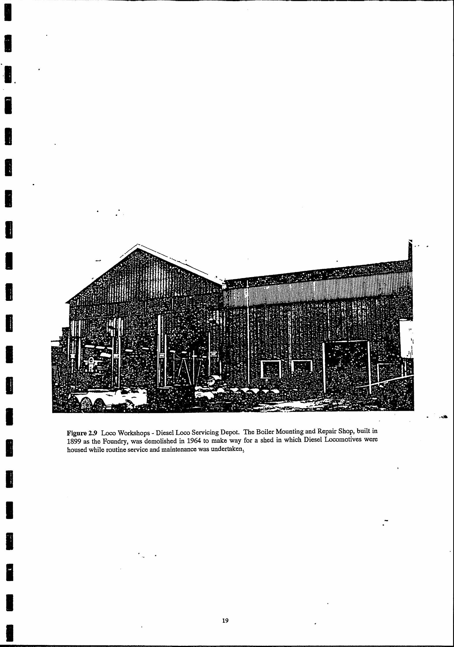
Figure 2.9 Loco Workshops - Diesel Loco Servicing Depot. The Boiler Mounting and Repair Shop, built in 1899 as the Foundry, was demolished in 1964 to make way for a shed in which Diesel Locomotives were housed while routine service and maintenance was undertaken . •
• •
19 •
' . .
'
-•

•
I I I. I I I I I I I I I I I I I I I I I I
~~~~---~--------------------------------------------...
•
•
GODDEN MACKAY
The last passenger service in N.S.W. to be hauled by a steam locomotive ran during 1963. Where appropriate, the steam locomotives were then used to pull goods trains and for shunting and yard services, otherwise they were disposed of. In 1964, the Boiler Repair Shop located in the former foundry on the north side of the Large Erecting Shop was dismantled and the building was remodelled as a Diesel Locomotive Service Depot (see Figure 2.9). • ~
• •
1970-1988 By the early 1970's the change in the Eveleigh Workshops from a central and fully equipped railway workshops, capable of all aspects of constructions, maintenance and repair of steam locomotives, to an old complex of engineering shops filled with ageing and obsolete equipment, ill-suited to the requirements of the new railway technology, was apparent and various re-arrangements and re-equipment were made to update the works.
The main responsibilities of the Workshops in the final years were for Classes 44,45,80 and 86 locomotive bogie overhauls, raiC car engine overhauls, component manufacturing and repair to support branch programmes; foundry, machine shop, blacksmith and boilermaker activities and the overhaul of the 73 class shunting locomotives. [Lyons, Fisher, 1985.]
With the rationalisation of the New South Wales rail system in the 1980's, Eveleigh Workshops was closed down as a workshop in 1988. Paddy's Markets were relocated there temporarily from their home in Darling Harbour and took up residence for the period 1989-1993. .
2.2 THE NEW LOCO SHOP AND ITS OPERATIONS
In 1907 the Commissioner for Railways decided to commence the manufacture of the new locomotives at Eveleigh rather than continue with the maintenance and repair programme. A new building was designed for this purpose to be erected adjacent to the spring shop which was at the eastern end of the main workshops complex. The new building which was known as the New Loco Shop was two bays wide and eight bays long, each bay being 53 feet wide, (16 metres), and 200 feet long, (60 metres). The walls were of polychrome loadbearing brick laid in English bond with double semi-circular arched windows at ground level and segmented arch windows above giving the building the appearance of having twostoreys. The building was in the same style as the earlier workshops and resembled the erecting shop, although not quite as grand. The windows and door arches were in contrasting dark brick, and white mortar was used throughout. Windows were cast iron framed, multi-paned with sandstone sills. Internally, the exceedingly light steel trusses supported a corrugated iron roof fitted with skylights. The double gabled roof and the overhead travelling electric crane was supported on cast irori columns manufactured by the
Globe Foundry of Glebe. The internal arrangement was similar to that in both the earlier workshops and the erecting workshop.
•
• 20
' •

-==-------------------~------· ·--··
I -----------------------------------~
I ··I
•
I I I I I I I I I I I •
I I I I I I I
•
•
GODDEN MACKAY
Possibly because of the outbreak of war in Europe, in 1914 there was a significant upgrading of the workshops.· The new loco shop, which consisted of nine bays, was extended on its southern end by 100 feet to be 300 feet in length. This was equivalent in length to the main workshop. It is not known if the original south wall of the locg shop was constructed in a timber frame sheathed in corrugated iron to allow for an extension in this direction l;mt it. would appear most likely that this was the case. The brickwork was continued' in the same style with twin windows on ground floor with twin windows above, however, the walls terminated in a sawtooth pattern, giving them a distinct appearance when compared to the parapets of the gable-ended 1907 building.
The south lights of the 1914 extension made that section of the building one of the most pleasant of the workshops in which to work. The notes on the visit of inspection by the Institution of Engineers of Australia on the 11th of October 1922 provides one of the only references to the New Loco Shop. The west bay, it is noted, is equipped with heavy machinery for slotting, milling and drilling of locomotive frames, ferrous castings and heavy forgings etc. It is possible that much of the material to be milled or finished in the New Loco Shop was initially formed in the Steam Hammer Shop which was on the south end of the Spring Shop. Very little is known of this building except that it was open sided, and was probably constructed as an emergency measure around 1910.
•
•
21
' •
•
•

I I
·I. I I I I I I I I I I I I I I I I I I
• GODDEN MACKAY
3.0 THE CRANES IN THE NEW LOCO SHOP
3.1 INTRODUCTION
The two electric overhead travelling cranes were ordered from and manufactured by Craven Brothers of Manchester in 1907. Unlike some of the earlier cranes which had been installed in the workshops to be powered by rope drives, these cranes were driven by three direct current electric motors. When constructed they were state of the art. The smaller crane located in the west bay had a capacity of 20 tonnes whilst that in the east bay or the erecting
•
bay had a capacity of 35 tonnes. Both exhibit the detail typical of turn of the century machinery, with riveted plates and heavy castings. Unlike the earlier cranes, which were operated by crane drivers located on the crane deck, these cranes were operated from a cabin slung beneath the crane.
• • ' . - ~
Electric travelling cranes come in several varieties. Sometiru~.s a single motor is used for hoisting, traversing of the trolley and longitudinal travel. ~·The design of these early cranes was derived from cranes which were driven by continuous rope drives powered by steam engines mounted at the end of. buildings. Generally however, modern cranes have an individual motor for each of the three motions. In some cases, for cranes of heavy capacity, (which is now regarded as being in excess of_1~""ifnnes), two hoisting motors may be provided. This is to allow an economic operation of-tlie crane when small loads (between one tenth and one third of the normal maximum load),.~re being raised. At Eveleigh, all of the cranes introduced were originally powered by cont)n~ous rope until 1902, when the supply of electricity could reliably be obtained from ~he Ultimo Power House, recently established by the Railways and Tramways Department. -In 1902, alternators introduced to the Power House allowed alternating current electricitr to be sent over longer distances than
• the previously generated direct current. The AG.though, once it had reached Eveleigh, had to be rectified to DC as the workshops were operated by 500 or 550 Volt DC electric power. The continuous rope cranes were mostly converted to electric power from 1902 to 1910. The two cranes in the New Loco Shop would have been amongst the first of the electrically operated cranes to be installed in the workshops.
3.2 BRIEF DESCRIPTION
The cranes both span 16.2 metres from centre line to centre line of the crane rails. The crane rails are direct mounted to riveted section crane rail girders which run the full length of each bay. All four crane rails have turned up ends to prevent over-run of the tracks.
•
The cranes are very similar in design, construction and function. Both have riveted section twin box girders to support the crab, trolley or traveller, with curved bottom cords. The end cradles, which run at right angles to the main beams or girders and which carry the wheels, are themselves box section girders about 3 metres in length with an effective wheel base of
• 22
'
,--~-~~----~-------- ----------~--- ----------------------------~----~-_....,--~~..........,.----------~-- --------~"----
•
1 I I. I I I I I I I I I I I I I I I I I· I
•
-
GODDEN MACKAY
2.130 metres. The wheels are carried in cast iron blocks fitted with bronze bearings. The end cradles supplied strength to the main beams to resist the twisting of the frame and this explains their stout construction.
The trolleys on both cranes are similar in design with all members being of universal or C section steel, riveted or bolted together. It was standard practice of the time to use rolled steel sections ~or the trolleys on cranes above ten tonne capacity and for lighter cranes, many components were made of cast iron. Standard practice also indicated that trolleys should be of rolled steel components rather than built up box sections as these cannot be adequately inspected for rust, wear or fatigue cracks.
The trolley rails, on which the cradle completed it transverse motion, had a gauge of 1.670 metres and were direct fastened to the upper cord of the main beams. In the case of both cranes the rails were of the rolled Barlow type. This type of rail spread the load more evenly than the standard track which was then used throughout the rail system. The Barlow rail also had a lower profile which meant that the trolley did not project so far above the crane rail beams.
• Each crane carried three electric motors. One was located on the leading face of the main beam for longitudinal travel, and two on the carriage, one of which was for transverse travel
__ and one for hoisting. Some electric overhead travelling cranes, especially those of this ; capacity produced after World War I, were equipped with four motors. The fourth one was
· ~ . .,.}' · dedicated to a rapid, low load cable drum. The crane carriages in the new loco shop at Eveleigh carried two drums which were driven by the one motor through gear boxes dedicated to each drum. The change from one drum to the other was done manually from the platform through a dog clutch mounted on the auxilliary drum shaft.
The cranes typify early twentieth century electro/mechanical design with fail safe electrolp.agnetic brakes which incorporate air buffers and mechanical hoist over-ride safety gear, which consisted of a circuit breaker activated by a bar driven through a worm gear. Once activated, the circuit breaker had to be closed by hand. ·
The cranes were operated from a small open cabin located beneath, and to one side, of the crane beams. Each cabin held a seat, a bank of fuses and had, attached to is external cowling, two banks of iron resistors. Further sets of iron resistors were located on the crane platform.
The cranes were equipped with three motor controllers, each of five speeds in forward and reverse. Each was marked with a removable tag to indicate the direction of travel.
· Lci ... werin~- of the loads was through a reversing motor and the use of a brake. Both cable drums had doubled cables which were looped around the sheath of a swivel block. The hooks were supplied with the cranes and are believed to be the original. The lifting barrels, or cable drums, were made of cast iron with grooves turned in a spiral to suit the size of cable. The cable had to be so spaced on the drum that at least five millimetres clearance was allowed between the cables when sitting in the drum grooves. This allowance meant
23
..
·I.
I
I I I I I I I I I I I I I I
•
•
GODDEN MACKAY
allowance meant that even when the rope cables had slightly flattened out under load, there was sufficient side clearance. With insufficient site clearance, the cables ground against each other eventually wearing through the outer strands.
On the larger of the two cranes, the primary cable drum was 550 millimetres in diameter while the smaller one was 290 millimetres in diameter. The motors on both cranes were all made by <;raven Brothers Limited and came in a variety of sizes. The 20 ton crane was equipped with a motor for longitudinal travel of 6.5 brake horse power.-while the transverse motor and hoisting motor were both 20 brake horse power. The 35 ton crane was equipped with 20 brake horse power motors for both the longitudinal and transverse movement and a 30 brake horse power motor for hoisting.
3.3 PHYSICAL CONDITION
At the time of writing, both cranes appeared to be in excellent condition. Both had been operating certainly unti11990 and may have been used sporadically since this date up until 1994. Both exhibit signs of superficial rust around the cabin and around some of the brackets. However, there was practically no rust on any of the main components apart from that which could be expected on the upper surfaces.
Some time recently the cranes, including many timber components .. as well as steel components, had been painted a bright yellow. It is believeq .that the cranes-were originally painted a mid grey. ~ · ·• ·
•
•
•
•
24 •

I I ·I. I I I I I I I I I I I I I I I I I I
•
•
•
4.0 SIGNIFICANCE
GODDEN MACKAY
4.1 DISCUSSION OF SIGNIFICANCE
The type of overhead travelling crane found in the New Loco Shop is similar to cranes of • •
the same vintage found throughout Eveleigh and other railway workshops and manufacturing units throughout New South Wales. Similar cranes dating from 1910, again with three motors, and of 7, 10 and 15 tonnes capacity, were located at the Tramway Workshops in Randwick. The oldest overhead crane in the Eveleigh Locomotive Workshop is also a Craven Brothers Crane and the insignia on that indicates that it was made in 1888.
~ The cranes installed in the workshops up until1902 were driven by rope and those installed after 1902 were electrically driven. The overhead cranes were amongst the most important
..... items in the workshop, allowing the tradespeople to install machines, move partly finished work from one machine to another and, in the case of the eastern bay, allow the erection of a variety of small and large items. The overhead cranes were used extensively in the bedding of machines and in their basic erecting or assembly.
4.2 STATEMENT OF CULTURAL SIGNIFICANCE
4._7.1:- Historical Signficance ~
' •
The cranes are the oldest operating pieces of equipment in the New Loco Shop. They were designed specifically for this location and their existence is an indication of the work which was carried out within the shop.
4.2.2 Aesthetic Significance
The cranes with their massive riveted main beams and heavily constructed trolleys are extremely attractive pieces of early nineteenth century engineering equipment.
4.2.3 Technological Significance
The cranes are amongst the earliest electric powered cranes to be introduced to the workshop and indicate the link between the workshops and the Ultimo Power House. The cranes with their open construction carriages and accessible gear trains and levers are easily understood industrial relics.
The cranes are superb examples of late nineteenth century fabrication methods, still following the traditional engineering design methods developed with wrought iron sections.
25
•
•

·I. I I I I I I I
.
I I I I I I I
•
•
4.2.4 Social Significance
GODDEN MACKAY
Like many of the larger industrial items throughout the workshops, the cranes were held in high esteem by former workers .
' • •
•
• •
•
•
-• ·---
•
•
•
•
•
.
• •
• .. '" _ .. .,
-·· •
- ....... •
•
•
26 •
•

I I 1. I I I I I I I I I I I I I I I I I
•
•
5.0 CONSTRAINTS
GODDEN MACKAY
5.1 CONSTRAINTS ARISING FROM THE STATEMENT OF CULTURAL SIGNIFICANCE
The cranes are of some cultural significance and they should be retained and conserved. The existing fabric of the cranes should be preserved and maintained.
The exterior appearance of the cranes and their internal configuration, including all motors and mechanical parts, should be preserved. The track and the six cable electric power feed should be conserved and the cranes should be regularly maintained.
5.2 LEGISLATIVE CONSTRAINTS
The cranes are not subject to any order placed pursuant to the Heritage Act of 1977.
5.3 CONSTRAINTS ARISING FROM THE PHYSICAL CONDITION
• The physical condition of the cranes is good to excellent and they are housed in a building which has had, until very recently, a very sound roof covering .
• •
5.4 CLIENT REQUIREMENTS
The client is adapting the New Loco Shop to the Engineering Innovation Centre. To this effect, two new floors are being added to the building which will increase the floor space to a point where the adaptation can be economically pursued. In the Development Application, which was submitted to the South Sydney Council, the diagrams indicated that it was possible only to keep one crane. The crane in the east bay would interfere with operation of at least one transfer bay and would prevent the adequate introduction of services. If the crane in the east bay were to be kept, it would not be visible and would certainly be boxed in. The client has expressed quite strong reservations about the ability to keep a crane in the east bay.
•
•
27
•
•
•
I I ·I I I I I I I I .I I I I I I I I I I I
•
6.0 CONSERVATION POLICY
6.1 INTRODUCTION
GODDEN MACKAY
Having regard to the significance of the two cranes and their condition and similarity and taking note of the client requirements which indicate that it is possible to ke.ep only one crane, it is recommended that the crane in the east bay be transferred to the west bay and that the crane in the west bay be removed and items from it salvaged before the crane frame itself is scrapped. The crane in the west bay was manufactured specifically for use in the west bay and it is not envisaged that it will be erected in any of the other bays. Most of the Workshop bays 1-15 have their original cranes still intact. However, some bays have new cranes such as the De-Mag, which is now located in bay 11 and was introduced in 1981.
6.2 . THE 35 TON CRANE
The 35 tonne crane should be conserved according to the principles of the Burra Charter. There should be no interference with its fabric and, if possible, it should be connected to the wires mounted on insulators adjacent to which it originally operated.
No fabric should be removed from the crane and no material should be added to it unless this is done for the safety of workers who are maintaining the crane. The crane should be painted in its original colours. To this end, colour samples should be taken from the motors, from the trolley, and from three places on the crane body and beams itself. Painting should take place with great care and items which were not formally painted should be stripped of paint and returned to the bare metal. This applies particularly to the cast iron components, such as the balusters and the cast iron bearings. All bare metal components should be, coated with Shell ENSIS SDC. The crane should be inspected annually for corrosion of the metal components or insect or fungal attack of timber
components.
6.3 THE 20 TON CRANE
Unless the crane is required for display purposes, it may be scrapped. However, before scrapping the following items are to be removed from the crane and stored within the Eveleigh Workshop precinct for later use:
• The three motors;
• the two hooks;
•
28 •
•
. • •
• • • •

-;;,;;;~~-------~------~-~--------·
I . I. I I I I I I I I I I I I I I I -I I I
•
• the balusters;
• the four main wheels;
• the three motor controllers.
GODDEN MACKAY
As well, other iJems may be specified for retention when the needs of the workshops are more accurately known. No items are to be removed from the crane until its fate has been
decided.
An industrial archaeologist is to be present when the crane is being dismantled and each item is to be catalogued. Copies of the catalogue are to be kept in the workshop, in the Australian Technology Park offices and at the Powerhouse Museum.
The items removed from the crane are to be conserved by having external surfaces coated with Shell ENSIS SDC. No fluid is to come in contact with the electric motor brushes or windings.
•
-• -• • . .. ~ . or -..... •• ' •
• • • • • •
• - . •
-
•
• 29 j
l '

I I I. I I I I I I I I I I I I I I I I I I
•
7.0
7.1
7.1.1
·---------~----------------~--------------
GODDEN MACKAY
NEW LOCOMOTIVE WORKSHOP OVERHEAD TRA YELLING CRANE - 20 TONNE -ARCHIVAL RECORDING
DESCRIPTION
' . Introduction
The 1907 Craven Brothers 20 tonne crane was removed from the New Loco Shop in April 1995. It was determined by the Conservation Policy that no attempt would be made to relocate the crane within the workshops. However, there is no impediment to using the crane as a static display anywhere throughout the precinct. It must be noted, though, that the reuse of the crane in any other location for any other purpose cannot be seen as conservation. This description is complete and it is accompanied by a set of archivally developed negatives and a series of photographs which help define the crane.
7 .1.2 General
The 20 tonne overhead travelling crane consists of two beams which span the workshops, two end cradles rigidly attached to these· beams which carry the wheels which allow the longitudinal motion of the crane and a carriage trolley or crab mounted on rails which are in turn supported by the beams of the crane, which holds and supports the hoisting gear. Longitudinal motion from one end of the workshop to the other was powered by a small 6.5 bhp. motor by Craven Brothers attached to the face of the leading beam. The other two motors, the traverse motor, which propelled the Trolley across the beams and the hoisting motor, were both of 20 bhp and were also be Craven Brothers.
7 .1.3 The Main Crane Beams
The beams are riveted plate box girders, 16.580 metres long, 360 metres wide and 620 millimetres high where they join to the cradles end and 1170 millimetres high at the centre. The gracefully curved bottom cord of the girder gives a most pleasing appearance to the crane. Each beam is divided into ten sections. Each section is a vertical plate joined to the adjoining ones by riveted tee section vertical members. The top and bottom cords are attached to the plate members by riveted angle sections. The tee sections, both top and bottom, are gently curved to ride over the horizontal angle sections. The tee sections are 160 millimetres wide with an 85 millimetre high web. The angle sections are 85 by 85 millimetres. There appears to be no further strengthening of the bottom cord by the addition of a separate plate to its lower face.
The end cradles are fabricated by attaching riveted angles internally. Each end cradle is strengthened internally by a gusset plate which is located immediately below the centre line and is again, riveted in place. This gusset is identifiable only by the appearance of the rivets on the external face of the end cradle.
30 •

•
I I ·I.
I I I I I I I I I I I I I I I I I I
•
•
GODDEN MACKAY
Each end cradle is attached to the beams by rivets. The end box protrudes towards the fore end of the crane by 600 millimetres. The end cradles support the wheel bearings on their lower gusset plates. The driven wheels are attached to the drive shaft via a single cog. The drive shaft itself is driven via the longitudinal drive motor and a gear train.
A maintenance platform runs almost the length of the main beam on the longitucl.inal motor side. The 'platfo'rm is 700 millimetres wide and has toe rails both front and back. The platform is supported on twin angle brackets which are bolted to the web of the vertical tee section members of the beam. There is a hand rail which runs the full length of the platform on its outer edge which is supported on cast iron balusters. There is a break of 3.150 metres in the centre of the platform which allows clear access to the motor and gearing. Directly below the motor and gearing is a separate small platform, 820 millimetres below th,e main platform, which allowed maintenance of the motor .
•
The longitudinal drive motor is directly bolted to the face of the beam; close to the centre. Mounted just in front and slightly above centre line of the motor is the driving shaft. The
- ·- ~ _, . ., driving shaft is connected to the motor via an qpen gear train. ;r'he driving shaft, which is in three sections joined by rigid couplings, is supported on a br~cket close to the driven gear wheel and at brackets at each end of the beam plus two intermediate brackets. All five brackets are directly bolted to the face of the main beam. One wheel at each end of the crane is driven via a cog on the main drive shaft. The main shaft is not attached to the driving wheels. Close to one end of the shaft a brake Qjum is fitted. The braJ:ce drum shoe and mechanism is missing from the cranes but it appears to .of been of the strap type and would almost certainly have been manually operated:
7 .1.4 The Crane Trolley
The crane carriage or trolley holds two motors, one for transverse movement and the other for the hoisting cable. Most of the items on the carriage are direct mounted to its main frame.
The frame of the carriage is basically rectangular with a small outrigger at the rear end which carries the main shaft extension and the auto-magnetic brake drum. The frame consists of two universal beam sections to which two angles of C section steel have been riveted to form the front and rear cross members. The Universal section beams carry most of the bearings and plumber blocks for the system .
Parallel to the C section beams are a further two universal section beams. One of these protrudes past the main frame of the carriage, as does the rear beam, to provide a small outrigger.
Basically there are two independent systems mounted on the carriage. The first is the traversing motor assembly, gear train and axle for the transverse movement of the trolley. The second consists of the motor and four shafts and gear train which comprise the hoisting gear.
• 31
I I
•

I I ·I. I I I I I I I I
I I I I I I I I
•
. ··----.. -·---------------
GODDEN MACKAY
The carriage or trolley runs on rails directly attached to the top cord of the main beams. Transverse movement is through an electric motor which is permanently engaged to a gear train, the fourth cog of which is keyed to the axle of a front pair of driving wheels. The motor is supported on two short lengths of C section steel directly attached to the main transverse C section of the frame and a universal beam slung beneath the main two longitudinal beams.
.... . The motor shaft has a driving cog on its end which, unsupported by a bearing (Figure 1), is permanently engaged with a large gear wheel attached to a lay shaft. The lay shaft is supported by two plumber blocks. Also on the lay shaft is a small cog permanently meshed with a large cog known as the fourth cog which is keyed to the front axle of the trolley. The speed of the trolley is controlled by the motor controller in the cabin. The front or driving axle is 80 millimetres in diameter, machined at the end to 75 millimetres to receive the driving wheels.
The cog on the motor shaft contains 23 teeth, the large gear on the lay shaft on which it is engaged has 104 teeth, the smaller cog on the lay shaft has 28 teeth and the drive wheel on the axle has 68 teeth.
The hoisting system on this crane, as on most cranes, was relatively complex. The motor is mounted on a pair of brackets at the rear of the trolley frame. The drive shaft, as it emerged from the motor, was flexibly coupled to a second length of shaft which was supported by two plumber blocks mounted on raised brackets. One of these brackets was attached to the main longitudinal beam and the second one was attached further out on the beam of the outrigger. Between the plumber blocks, a brake drum for the electro-mechanical braking system was mounted. In the centre of the drive shaft, a small gear cog was mounted. This was meshed with a cog mounted on a short lay shaft (Figure 2). The lay shaft was supported by plumber blocks mounted on the main universal section member and the motor beam. A second small cog on the lay shaft was permanently meshed with the large cog of the third shaft which passed through the auxiliary hoist drum. This shaft was equipped with a dog clutch. The large cog of the lay shaft could be disengaged by pushing it with a lever in contact with its inside face (Figure 2). When pushed to the full extent, which was about 20 millimetres, the cog was then free to rotate on the shaft, thus effectively disengaging the motor drive. This would have allowed minor repairs to be conducted on the motor in situ.
At the opposite end to the driving cog of the third shaft, or auxiliary hoist shaft, a small flanged cog was permanently keyed. This cog was in permanent mesh with the large driving cog of the large hoisting drum.
Between the end of the auxiliary drum and the flanged cog was a dog clutch. When the dog clutch was engaged with the auxiliary drum, the main drum was disengaged (Figure 3). The dog clutch, when moved in the other direction, engaged the flanged cog, disengaged the auxiliary drum and the main drum hoist was then operated. The movement of this dog clutch was achieved by a lever, the end of which protruded below the main frame and was operated from the platform of the crane beam. Both the main drum shaft and the auxiliary
32
•
•
---~·~------~--
•
I I ·I.
I I I I I I I I I I I I I I I I I I
•
•
-- ---------- ---------~-·------ ---~- -----------~~------~---- -- ------ ------~-"~' ---~~--
GODDEN MACKAY
drum shaft were fitted with small strap brake drums which were manually operated. When one hoist drum was selected, the other was then mechanically braked by dropping a counter-weighted lever (Figure 4) .
Both cable drum sets were equipped with their own hook systems. A pair of guide pulleys or sheaths directly below the cable drum supported the cable as it was unwound from the drum. The cable was always used doubled and passed around the twin or quadruple
• sheaves of the hook assembly. In all cases the hook was trunioned and free to rotate in the main hook bar. It is believed that the hooks presently on the crane are the original.
The automatic safety override system was simplicity in itself. For the auxiliary cable drum there was a small toothed ring gear attached to the third shaft or auxiliary cable shaft. This was permanently meshed with a second ring gear about the same size, mounted on special brackets almost directly above. On its furthest end the ·shaft was threaded. This thread passed through the collar of a lever which was pivoted around its centre. As the load was raised above the safety point where tlie hook was in danger of tangling with the base of the crane beams, the lever forced open a cir~1;1jt break~ll(figure 5). The circuit breaker then had to be held in position manually· to allow the load to be fractionally lowered and the crane to resume its full operation. The safety override system for the main cable drum was direct driven from an extension to the main cable drum shaft itself.
The automatic safety brake was in the permanently on position until the·current was turned on, when the brake drum was released and the crane free to operate. When the current ceased, the brake was automatically activated. •
7 .1.5 The Crane Cabin
The crane cabin measures about 1.2 metres by 1.2 metres and is about 2.2 metres high. Its basic frame was made from 50 mm angle steel and the whole frame was slung between the main beams of the crane. Internally it was fitted with a small seat: three motor controllers, two of which were by Craven Brothers Ltd of Manchester while the third is by the Lancashire Dynamo Motor Company of Manchester. It is not known if the latter controller was a replacement but considering the age of the crane, this would not be surprising. It was general practice in the railways to cannibalise old machinery, setting aside those parts which may be reused at a later date. The two Craven Brothers controllers are Stellite Patent Controllers and a serial number appears after the word Stellite which is cast into the top panel. However, heavy paint and the wear pattern has actually obliterated most of the insignia and almost all of the serial numbers. There is no insignia on the Lancashire Dynamo and Motor Company controller. On the left hand motor controller by Craven Brothers are two screwed-on cast signs, one saying "Lifting" and the other on the opposite side of the controller saying "Lowering". On the adjacent motor controller there are similar signs saying "Length~ays", one with an arrow pointing to the left and the other to the right. On the third motor controller, which appears to control the longitudinal travel of tlie-trane, there is no such signage. Each of the motor controllers is five speed which allows a gradual build up of power to prevent blowing the circuits. · · ·
•
- 33 •
••

•
I. I I I I I I I I ..
I I I I I I I I I
•
•
•
GODDEN MACKAY
The cabin itself is open and not enclosed in any way. This affords the driver an excellent view but also subjects him to the noise of the factory. Power entered the cabin and the motor controllers through two rolling contact points at the end of insulated spars and was then transmitted by heavy cable by the three controllers. The motors all appear to be in operating condition and all are series-wound DC motors with brushes contained in cast iron hinged panels.
• • •
•
•
•
34
•
•

------------
I I
•
·I. •
I I I I
I I I I I I I I I I I I
-----------------
•
Figure 7.1 The front or driving end of the crane trolley. The motor drives the axle to which two wheels are press fitted via the Iayshaft in the centre of the photograph.
Figure 7.2 The gear train of the hoisting system viewed from the rear end of the frame. The driving teeth of the dog clutch are fixed to the lay shaft. The large cog on the layshaft which has integrated dog clutch teeth is disengaged by being pushed away (to the right) from the driving teeth.
•
35 •
j •
• '. " ' ')
'J •• ,,
~- ... ·.;.~
··-
•

I I •
I I I I I I I I I
,.,
I •
I.·:·~. •
I I I I
•
Figure 7.3 The hoist system from the front end of the frame. The large hoist is behind the smaller. On the right is the transverse motion motor.
Figure 7.4 The hoist system with the auxiliary hoist engaged. The brake is incorrectly shown in the "on" position on the auxiliary hoist shaft. ·
• •
• •
36
•
. ' , . •
•
•
•
•
•

I I I. •
I I I I I I I I I •
I I I I I I I
•
I I
•
Figure 7.5 The electro magnetic brake is on the left side. The mechanically operated circuit breaker system is on the right with the driver ring gear shown above the right hand bracket of the brake drum.
•
•
37 •

-~---~~~-~---~---------------------,
I I ·1. .
I I I I I I
.
I I I I I I I I I I I
GODDEN MACKAY
7.2 PHOTOGRAPHIC CATALOGUE
•
38
•

I •
I ·I. I I I I I I I I I I I I I I I I
I
• Job Title Ph t
EVELEIGH- 20 TON EOHT CRANE Date April,1995 h" C I o ograpt IC ata o ue
Photographer: T Brassil Sketch (or use reverse)
Film Type: ILFORD XPCB/W •
Roll No:94-044-1 Frame Orientation Description 0 NW Main Crane span - south-east corner. ..
. . ... 1 w Main Crane span - south end of east side. -2 w Main Crane span - centre of east side. 3 w Main Crane span - north-end of east side. 4 sw Main Crane span- north-east corner. 5 w Lifting Crab - east side. 6 w Lifting Crab - east side. 7 sw Lifting Crab- north west corner. 8 w Control Cabin - east side. 9 s Control Cabin - north side. 10 E Control Cabin - west side. 11 SE Lifting Crab - north west corner. 12 SE Lifting Crab - north west corner. 13 s Main Crane Span - west side from north end. 14 N Main Crane Span - west side from south end. 15 NW Main Crane Span - south end 16 NW Main Crane Span - detail of south west corner wheel. 17 sw Main Crane Span - detail of drive to wheel. 18 NW Main Crane Span - detail of drive shaft. 19 NW Main Crane Span - detail of drive motor and gear. 20 w Main Crane Span- detail of drive motor and gear. 21 w Main Crane Span - detail of motor platform and mounting. 22 NW Main Crane S)Jan -aetail of drive to north west corner wheel. 23 sw Main Crane Span - detail of north-west corner wheel. 24 s Main Crane Span - view south between main girders. 25 SE Main Crane Span - view into south west corner interior. 26 N Main· Crane Span - view north between main girders. 27 SE Lifting Crab - north-east corner. 28 SE Lifting Crab - centre section from north-west. 29 NE Lifting Crab - view from south-west. 30 w Lifting Crab - view from east. 31 NE Lifting Crab - south side brake mechanism. 32 NE Lifting Crab - south side view of name plate. 33 w Lifting Crab - main hook with cabin leaning over it. 34 N Control Cabin - view of controller boxes.
.
35 w Control Cabin - controller resistor bank on side. 36 s Control Cabin - controller resistor bank-detached.
GODDEN MACKAY PTY LTD 78 GEORGE ST. REDFERN PHONE (02) 319 4811
• •
•
•
'
•
.
•
• •

I •
--~--------
•
• • • ' . ..
• •• ' • •
• •
•
• • •
•
• • • • ,. • •
• • • •
•
• • •
l
•
• •• ·- .. • • • -· '_." • . ·•. • •• . ' . • .. ' ' . ' -. -"'"" •

•
I •
• . .
I I I I I I I I I
•
·I I I I I I I I I
10 • 10" E
• •
•
•
•
> •
'\ .
J
Related Documents