• Three-phase Input 200V Class • Three-phase Input 400V Class UL Version Models CE Version Models Manual No. NB6041XE • December 2003 Hitachi Industrial Equipment Systems Co., Ltd. HITACHI L300P Series Inverter Quick Reference Guide

Welcome message from author
This document is posted to help you gain knowledge. Please leave a comment to let me know what you think about it! Share it to your friends and learn new things together.
Transcript
• Three-phase Input 200V Class
• Three-phase Input 400V Class
UL Version Models CE Version Models
Manual No. NB6041XE • December 2003
Hitachi Industrial Equipment Systems Co., Ltd.
HITACHIL300P Series InverterQuick Reference Guide

1
Caution: Be sure to read the L300P Inverter Manual and follow its Cautions and Warnings for the initial product installation. This Quick Reference Guide is intended for reference use by experienced users in servicing existing installations.
Power Circuit Terminals
(L1)R
(L2)S
(L3)T
(+1)PD
(T2)V
(T3)W
(G)(G)
(R0)R0
(T0)T0
(L1)R
(L2)S
(L3)T
(+1)PD
(+)P
(T2)V
(T3)W
(G)
(R0)R0
(T0)T0
(L1)R
(L2)S
(L3)T
(+1)PD
(+)P
(T2)V
(T3)W
(G) (G)
(R0)R0
(T0)T0
(–)N
(T1)U
(+)P
(–)N
(T1)U
(–)N
(T1)U
(RB)RB
–075LFU2–075HFU2, HFE2–110LFU2–110HFU2, HFE2–150LFU2–150HFU2, HFE2
–185LFU2–185 to –370HFU2, HFE2–370LFU2,–450 to –750HFU2, HFE2
–220LFU2, –300LFU2,–450 to –750LFU2,–900 to –1320HFU2, HFE2
Jumper
Jumper
Jumper
(G)
(L1)R
(L2)S
(L3)T
(+1)PD
(+)P
(T2)V
(T3)W
(G) (G)(R0)R0
(T0)T0
(–)N
(T1)U
(RB)RB
–015 to –055LFU2–015 to –055HFU2, HFE2
Jumper
2
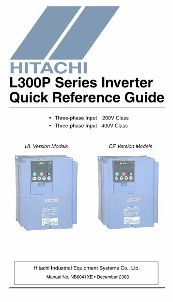
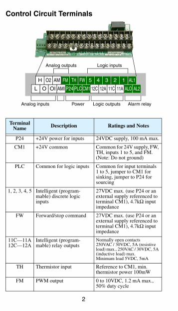
Control Circuit Terminals
Terminal Name Description Ratings and Notes
P24 +24V power for inputs 24VDC supply, 100 mA max.
CM1 +24V common Common for 24V supply, FW, TH, inputs 1 to 5, and FM. (Note: Do not ground)
PLC Common for logic inputs Common for input terminals 1 to 5, jumper to CM1 for sinking, jumper to P24 for sourcing
1, 2, 3, 4, 5 Intelligent (program-mable) discrete logic inputs
27VDC max. (use P24 or an external supply referenced to terminal CM1), 4.7kΩ input impedance
FW Forward/stop command 27VDC max. (use P24 or an external supply referenced to terminal CM1), 4.7kΩ input impedance
11C—11A12C—12A
Intelligent (program-mable) relay outputs
Normally open contacts250VAC / 30VDC, 5A (resistiveload) max., 250VAC / 30VDC, 5A (inductive load) max.Minimum load 5VDC, 5mA
TH Thermistor input Reference to CM1, min. thermistor power 100mW
FM PWM output 0 to 10VDC, 1.2 mA max., 50% duty cycle
L O OI P24 PLC CM1
4 2
ALO AL2
AL15 3 1FWFMAM
AMI
O2H TH
Analog inputs
Analog outputs
Power Alarm relay
Logic inputs
Logic outputs
12A 11C 11A12C
3
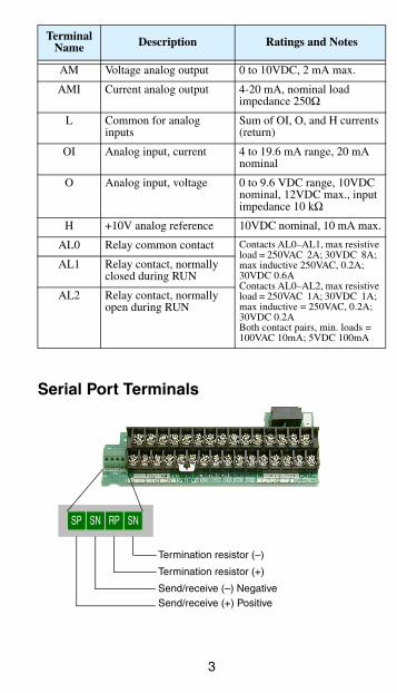
Serial Port Terminals
AM Voltage analog output 0 to 10VDC, 2 mA max.
AMI Current analog output 4-20 mA, nominal load impedance 250Ω
L Common for analog inputs
Sum of OI, O, and H currents (return)
OI Analog input, current 4 to 19.6 mA range, 20 mA nominal
O Analog input, voltage 0 to 9.6 VDC range, 10VDC nominal, 12VDC max., input impedance 10 kΩ
H +10V analog reference 10VDC nominal, 10 mA max.
AL0 Relay common contact Contacts AL0–AL1, max resistive load = 250VAC 2A; 30VDC 8A; max inductive 250VAC, 0.2A; 30VDC 0.6AContacts AL0–AL2, max resistive load = 250VAC 1A; 30VDC 1A; max inductive = 250VAC, 0.2A; 30VDC 0.2ABoth contact pairs, min. loads = 100VAC 10mA; 5VDC 100mA
AL1 Relay contact, normally closed during RUN
AL2 Relay contact, normally open during RUN
Terminal Name Description Ratings and Notes
RPSP SN
Termination resistor (–)
SN
Termination resistor (+)
Send/receive (–) NegativeSend/receive (+) Positive
4
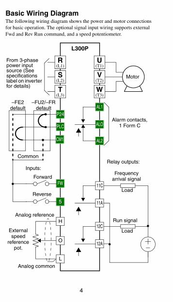
Basic Wiring DiagramThe following wiring diagram shows the power and motor connections for basic operation. The optional signal input wiring supports external Fwd and Rev Run command, and a speed potentiometer.
(L1)R
(L2)S
(L3)T
(T2)V
(T3)W
(T1)U
Motor
Forward
L
O
P24
PLC
CM1
ALO
AL2
AL1
5
FW
H
Reverse
Alarm contacts, 1 Form C
Run signal
Frequency arrival signal
Relay outputs:
External speed
reference pot.
L300P
From 3-phase power input source (See specifications label on inverter for details)
Load
Load
Analog common
Analog reference
11A
11C
12A
12C
–FU2/–FR default
–FE2 default
Common
Inputs:
5
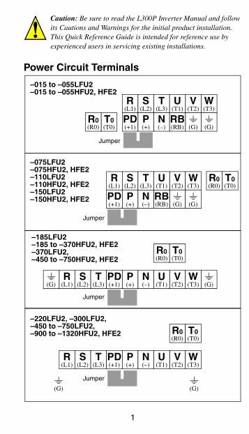
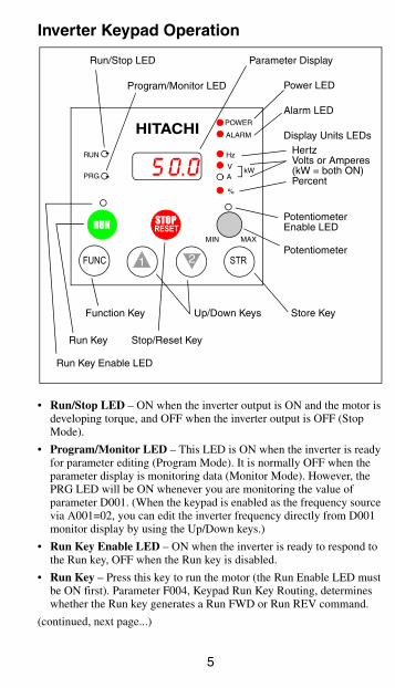
Inverter Keypad Operation
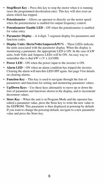
• Run/Stop LED – ON when the inverter output is ON and the motor is developing torque, and OFF when the inverter output is OFF (Stop Mode).
• Program/Monitor LED – This LED is ON when the inverter is ready for parameter editing (Program Mode). It is normally OFF when the parameter display is monitoring data (Monitor Mode). However, the PRG LED will be ON whenever you are monitoring the value of parameter D001. (When the keypad is enabled as the frequency source via A001=02, you can edit the inverter frequency directly from D001 monitor display by using the Up/Down keys.)
• Run Key Enable LED – ON when the inverter is ready to respond to the Run key, OFF when the Run key is disabled.
• Run Key – Press this key to run the motor (the Run Enable LED must be ON first). Parameter F004, Keypad Run Key Routing, determines whether the Run key generates a Run FWD or Run REV command.
(continued, next page...)
Hz
POWER
A
RUN
PRG
RUN STOPRESET
MIN MAX
HITACHI
FUNC 1 2
%
ALARM
STR
V kW
Parameter Display
5 0.0
Run/Stop LED
Program/Monitor LED
Run Key Enable LED
Run Key
Power LED
Alarm LED
Display Units LEDsHertzVolts or Amperes(kW = both ON)Percent
PotentiometerEnable LED
Potentiometer
Stop/Reset Key
Function Key Up/Down Keys Store Key
6
• Stop/Reset Key – Press this key to stop the motor when it is running (uses the programmed deceleration rate). This key will also reset an alarm which has tripped.
• Potentiometer – Allows an operator to directly set the motor speed when the potentiometer is enabled for output frequency control.
• Potentiometer Enable LED – ON when the potentiometer is enabled for value entry.
• Parameter Display – A 4-digit, 7-segment display for parameters and function codes.
• Display Units: Hertz/Volts/Amperes/kW/% – These LEDs indicate the units associated with the parameter display. When the display is monitoring a parameter, the appropriate LED is ON. In the case of kW units, both Volts and Amperes LEDs will be ON. An easy way to remember this is that kW = (V x A)/1000.
• Power LED – ON when the power input to the inverter is ON.
• Alarm LED – ON when an alarm condition has tripped the inverter. Clearing the alarm will turn this LED OFF again. See page 9 for details on clearing alarms.
• Function Key – This key is used to navigate through the lists of parameters and functions for setting and monitoring parameter values.
• Up/Down Keys – Use these keys alternately to move up or down the lists of parameter and functions shown in the display, and to increment/decrement values.
• Store Key – When the unit is in Program Mode and the operator has edited a parameter value, press the Store key to write the new value to the EEPROM. This parameter is then displayed at powerup by default. If you want to change the powerup default, navigate to a new parameter value and press the Store key.
7
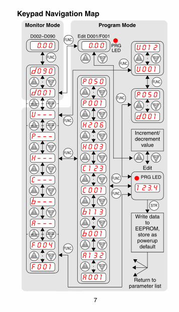
Keypad Navigation Map
U o 1 2
U o 0 1
1 2
P o 5 0
P o 0 1
1 2
h 2 0 6
h o 0 3
1 2
c 1 2 3
c o 0 1
1 2
b 1 1 3
b o 0 1
1 2
A 1 3 2
A o 0 1
1 2
U – – – 1 2
1 2
1 2
1 2
P – – –1 2
H – – –1 2
C – – –1 2
b – – –1 2
A – – –
F 0 0 4
F o 0 1
1 2
d o 9 0
d o 0 1
1 2
o.0 0
1 2 3.4
Edit
1 2
Increment/decrement
value
Write data to
EEPROM, store as powerup default
Monitor Mode Program Mode
1 2
FUNC.
STR
FUNC.
FUNC.
1 2
P o 5 0
d o 0 1
1 2
FUNC.
FUNC.
1 2FUNC.
FUNC.
Return to parameter list
FUNC.
FUNC.
D002–D090FUNC.
Edit D001/F001
o.0 0
1 2
PRG LED
PRG LED
8
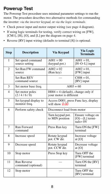
Powerup TestThe Powerup Test procedure uses minimal parameter settings to run the motor. The procedure describes two alternative methods for commanding the inverter: via the inverter keypad, or via the logic terminals.
• Check power input and motor output wiring (see page 4 diagram).
• If using logic terminals for testing, verify correct wiring on [FW], [CM1], [H], [O], and [L] per the diagram on page 4.
• Reverse [RV] input wiring (defaults to terminal [8]) is optional.
Step Description Via Keypad Via Logic Terminals
1 Set speed command source setting
A001 = 00 (keypad pot.)
A001 = 01,[H–O–L] input
2 Set Run FW command source
A002 = 02(Run key)
A002 = 01,[FW] input
Set Run REV command source
— C008 = 01,[RV] input
3 Set motor base freq. A003 = 60
4 Set motor poles(2 / 4 / 6 / 8)
H004 = 4 (default), change only if your motor is different
5 Set keypad display to monitor freq.
Access D001, press Func key, display will show 0.00
6 Perform safety check Disconnect load from motor
Turn keypad pot. to MIN position
Ensure voltage on [O]—[L] termi-nals= 0V
7 Run Forward command
Press Run key Turn ON the [FW] terminal
8 Increase speed Rotate keypad pot. CW dir.
Increase voltage at [O]
9 Decrease speed Rotate keypad pot. CCW dir.
Decrease voltage at [O]
10 Stop motor Press Stop key Turn OFF the [FW] terminal
11 Run Reverse command (optional)
— Turn ON the [RV] terminal
12 Stop motor — Turn OFF the [RV] terminal
9
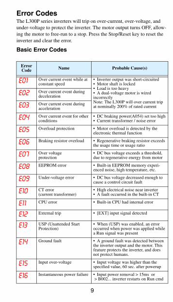
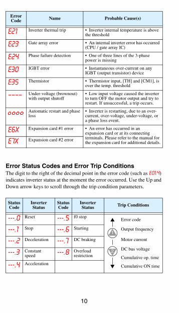
Error CodesThe L300P series inverters will trip on over-current, over-voltage, and under-voltage to protect the inverter. The motor output turns OFF, allow-ing the motor to free-run to a stop. Press the Stop/Reset key to reset the inverter and clear the error.
Basic Error Codes
Error Code Name Probable Cause(s)
E01 Over current event while at constant speed
• Inverter output was short-circuited• Motor shaft is locked• Load is too heavy• A dual-voltage motor is wiredincorrectlyNote: The L300P will over current trip at nominally 200% of rated current
E02 Over current event during deceleration
E03 Over current event during acceleration
E04 Over current event for other conditions
• DC braking power(A054) set too high• Current transformer / noise error
E05 Overload protection • Motor overload is detected by the electronic thermal function
E06 Braking resistor overload • Regenerative braking resistor exceeds the usage time or usage ratio
E07 Over voltageprotection
• DC bus voltage exceeds a threshold, due to regenerative energy from motor
E08 EEPROM error • Built-in EEPROM memory experi-enced noise, high temperature, etc.
E09 Under-voltage error • DC bus voltage decreased enough to cause a control circuit fault
E10 CT error(current transformer)
• High electrical noise near inverter• A fault occurred in the built-in CT
E11 CPU error • Built-in CPU had internal error
E12 External trip • [EXT] input signal detected
E13 USP (Unattended Start Protection)
• When (USP) was enabled, an error occurred when power was applied while a Run signal was present
E14 Ground fault • A ground fault was detected between the inverter output and the motor. This feature protects the inverter, and does not protect humans.
E15 Input over-voltage • Input voltage was higher than the specified value, 60 sec. after powerup
E16 Instantaneous power failure • Input power removal > 15ms or > B002... inverter restarts on Run cmd
10
Error Status Codes and Error Trip ConditionsThe digit to the right of the decimal point in the error code (such as E01.4) indicates inverter status at the moment the error occurred. Use the Up and Down arrow keys to scroll through the trip condition parameters.
E21 Inverter thermal trip • Inverter internal temperature is above the threshold
E23 Gate array error • An internal inverter error has occurred (CPU / gate array IC)
E24 Phase failure detection • One of three lines of the 3-phase power is missing
E30 IGBT error • Instantaneous over-current on any IGBT (output transistor) device
E35 Thermistor • Thermistor input, [TH] and [CM1], is over the temp. threshold
–––– Under-voltage (brownout) with output shutoff
• Low input voltage caused the inverter to turn OFF the motor output and try to restart. If unsuccessful, a trip occurs.
Automatic restart and phase loss
• Inverter is restarting, due to an over-current, over-voltage, under-voltage, or a phase loss event.
E6x Expansion card #1 error • An error has occurred in anexpansion card or at its connecting terminals. Please refer to the manual for the expansion card for additional details.E7x Expansion card #2 error
Status Code
Inverter Status
Status Code
Inverter Status Trip Conditions
---.0 Reset ---.5 f0 stop
---.1 Stop ---.6 Starting
---.2 Deceleration ---.7 DC braking
---.3 Constant speed ---.8 Overload
restriction
---.4 Acceleration
Error Code Name Probable Cause(s)
Output frequency
Motor current
DC bus voltage
Cumulative op. time
Cumulative ON time
Error code
1
2
11
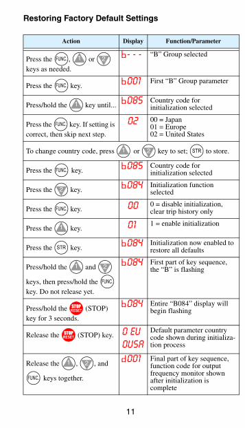
Restoring Factory Default Settings
Action Display Function/Parameter
Press the , or keys as needed.
b- - - “B” Group selected
Press the key. b001 First “B” Group parameter
Press/hold the key until... b085 Country code forinitialization selected
Press the key. If setting is correct, then skip next step.
02 00 = Japan01 = Europe02 = United States
To change country code, press or key to set; to store.
Press the key. b085 Country code forinitialization selected
Press the key. b084 Initialization function selected
Press the key. 00 0 = disable initialization, clear trip history only
Press the key. 01 1 = enable initialization
Press the key. b084 Initialization now enabled to restore all defaults
Press/hold the and
keys, then press/hold the key. Do not release yet.
b084 First part of key sequence, the “B” is flashing
Press/hold the (STOP) key for 3 seconds.
b084 Entire “B084” display will begin flashing
Release the (STOP) key. 0 EU0USA
Default parameter country code shown during initializa-tion process
Release the , , and
keys together.
d001 Final part of key sequence, function code for output frequency monitor shown after initialization is complete
FUNC. 1 2
FUNC.
1
FUNC.
1 2 STR
FUNC.
2
FUNC.
1
STR
1 2
FUNC.
STOPRESET
STOPRESET
1 2
FUNC.
12
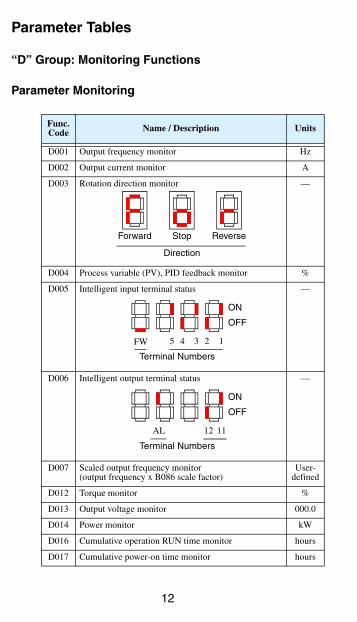
Parameter Tables
“D” Group: Monitoring Functions
Parameter Monitoring
Func. Code Name / Description Units
D001 Output frequency monitor Hz
D002 Output current monitor A
D003 Rotation direction monitor —
D004 Process variable (PV), PID feedback monitor %
D005 Intelligent input terminal status —
D006 Intelligent output terminal status —
D007 Scaled output frequency monitor(output frequency x B086 scale factor)
User-defined
D012 Torque monitor %
D013 Output voltage monitor 000.0
D014 Power monitor kW
D016 Cumulative operation RUN time monitor hours
D017 Cumulative power-on time monitor hours
Direction
Forward Stop Reverse
2 14 35
Terminal Numbers
ON
OFF
FW
12 11AL
Terminal Numbers
ON
OFF
13
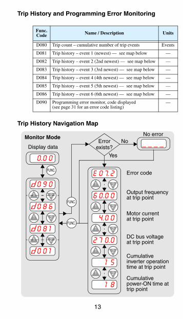
Trip History and Programming Error Monitoring
Trip History Navigation Map
Func. Code Name / Description Units
D080 Trip count – cumulative number of trip events Events
D081 Trip history – event 1 (newest) — see map below —
D082 Trip history – event 2 (2nd newest) — see map below —
D083 Trip history – event 3 (3rd newest) — see map below —
D084 Trip history – event 4 (4th newest) — see map below —
D085 Trip history – event 5 (5th newest) — see map below —
D086 Trip history – event 6 (6th newest) — see map below —
D090 Programming error monitor, code displayed(see page 31 for an error code listing)
—
E o 7.2
6 o.0 0
1 2
4.0 0
2 7 0.0
1 2
1 5
1 8
1 2
1 2
1 2
d o 9 0
d o 8 6
1 2
o.0 0
Display data
Monitor Mode
1 2
FUNC.
1 2
FUNC.
d o 0 1
d o 8 1
Error exists? _ _ _ _No
Error code
Output frequency at trip point
Motor current at trip point
DC bus voltage at trip point
Cumulative inverter operation time at trip point
Cumulative power-ON time at trip point
FUNC.
Yes
No error
14
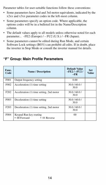
Parameter tables for user-settable functions follow these conventions:
• Some parameters have 2nd and 3rd motor equivalents, indicated by the x2xx and x3xx parameter codes in the left-most column.
• Some parameters specify an option code. Where applicable, the options codes will be in a bulleted list in the Name/Description column.
• The default values apply to all models unless otherwise noted for each parameter... –FE2 (Europe) / – FU2 (U.S.) / –FR (Japan).
• Some parameters cannot be edited during Run Mode, and certain Software Lock settings (B031) can prohibit all edits. If in doubt, place the inverter in Stop Mode or consult the inverter manual for details.
“F” Group: Main Profile Parameters
Func. Code Name / Description
Default Value–FE2 / –FU2 /
–FR
Set Value
F001 Output frequency setting 0.00
F002 Acceleration (1) time setting 30.0 / 60.0 / 30.0
F202 Acceleration (1) time setting, 2nd motor 30.0 / 60.0 / 30.0
F003 Deceleration (1) time setting 30.0 / 60.0 / 30.0
F203 Deceleration (1) time setting, 2nd motor 30.0 / 60.0 / 30.0
F004 Keypad Run key routing• 00 Forward • 01 Reverse
00
15
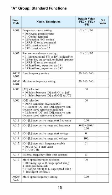
“A” Group: Standard Functions
Func. Code Name / Description
Default Value–FE2 / –FU2 /
–FR
Set Value
A001 Frequency source setting• 00 Keypad potentiometer• 01 Control terminal• 02 Function F001 setting• 03 RS485 serial command• 04 Expansion board 1• 05 Expansion board 2
01 / 01 / 00
A002 Run command source setting• 01 Input terminal FW or RV (assignable)• 02 Run key on keypad, or digital operator• 03 RS485 serial command• 04 Start/Stop, expansion card #1• 05 Start/Stop, expansion card #2
01 / 01 / 02
A003/A203
Base frequency setting 50. / 60. / 60.
A004/A204
Maximum frequency setting 50. / 60. / 60.
A005 [AT] selection• 00 Select between [O] and [OI] at [AT]• 01 Select between [O] and [O2] at [AT]
00
A006 [O2] selection• 00 No summing, [O2] and [OI]• 01 Sum of [O2] and [OI], negative sum (reverse speed reference) inhibited• 02 Sum of [O2] and [OI], negative sum (reverse speed reference) allowed
00
A011 [O]–[L] input active range start frequency 0.00
A012 [O]–[L] input active range end frequency 0.00 / 60.0 / 0.00
A013 [O]–[L] input active range start voltage 0.
A014 [O]–[L] input active range end voltage 100.
A015 [O]–[L] input start frequency enable• 00 Use A011 start value• 01 Use 0 Hz
01
A016 External frequency filter time constant 8.
A019 Multi-speed operation selection• 00 Binary; up to 16-stage speed using4 intelligent terminals• 01 Single-bit; up to 8-stage speed using7 intelligent terminals
00
A020/A220
Multi-speed frequency setting 0.00
16
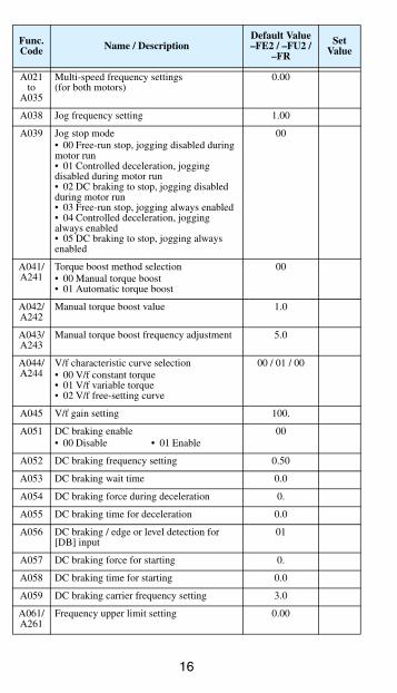
A021to
A035
Multi-speed frequency settings(for both motors)
0.00
A038 Jog frequency setting 1.00
A039 Jog stop mode• 00 Free-run stop, jogging disabled during motor run• 01 Controlled deceleration, jogging disabled during motor run• 02 DC braking to stop, jogging disabled during motor run• 03 Free-run stop, jogging always enabled• 04 Controlled deceleration, jogging always enabled• 05 DC braking to stop, jogging always enabled
00
A041/A241
Torque boost method selection• 00 Manual torque boost• 01 Automatic torque boost
00
A042/A242
Manual torque boost value 1.0
A043/A243
Manual torque boost frequency adjustment 5.0
A044/A244
V/f characteristic curve selection• 00 V/f constant torque• 01 V/f variable torque• 02 V/f free-setting curve
00 / 01 / 00
A045 V/f gain setting 100.
A051 DC braking enable• 00 Disable • 01 Enable
00
A052 DC braking frequency setting 0.50
A053 DC braking wait time 0.0
A054 DC braking force during deceleration 0.
A055 DC braking time for deceleration 0.0
A056 DC braking / edge or level detection for [DB] input
01
A057 DC braking force for starting 0.
A058 DC braking time for starting 0.0
A059 DC braking carrier frequency setting 3.0
A061/A261
Frequency upper limit setting 0.00
Func. Code Name / Description
Default Value–FE2 / –FU2 /
–FR
Set Value
17
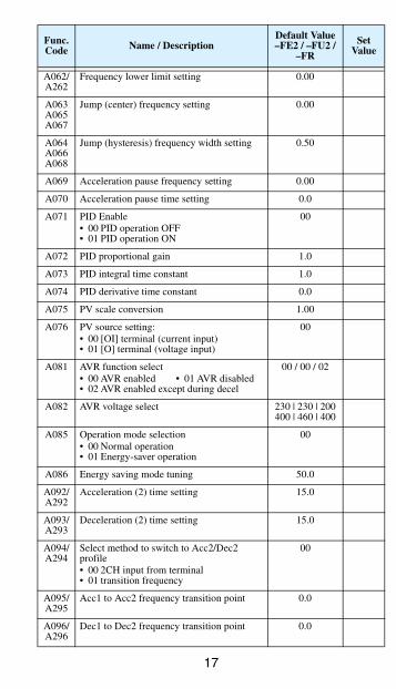
A062/A262
Frequency lower limit setting 0.00
A063A065A067
Jump (center) frequency setting 0.00
A064A066A068
Jump (hysteresis) frequency width setting 0.50
A069 Acceleration pause frequency setting 0.00
A070 Acceleration pause time setting 0.0
A071 PID Enable• 00 PID operation OFF• 01 PID operation ON
00
A072 PID proportional gain 1.0
A073 PID integral time constant 1.0
A074 PID derivative time constant 0.0
A075 PV scale conversion 1.00
A076 PV source setting:• 00 [OI] terminal (current input)• 01 [O] terminal (voltage input)
00
A081 AVR function select• 00 AVR enabled • 01 AVR disabled• 02 AVR enabled except during decel
00 / 00 / 02
A082 AVR voltage select 230 | 230 | 200400 | 460 | 400
A085 Operation mode selection• 00 Normal operation• 01 Energy-saver operation
00
A086 Energy saving mode tuning 50.0
A092/A292
Acceleration (2) time setting 15.0
A093/A293
Deceleration (2) time setting 15.0
A094/A294
Select method to switch to Acc2/Dec2 profile• 00 2CH input from terminal• 01 transition frequency
00
A095/A295
Acc1 to Acc2 frequency transition point 0.0
A096/A296
Dec1 to Dec2 frequency transition point 0.0
Func. Code Name / Description
Default Value–FE2 / –FU2 /
–FR
Set Value
18
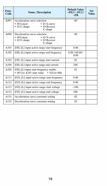
A097 Acceleration curve selection• 00 Linear • 01 S-curve• 02 U-shape • 03 Reverse U-shape
00
A098 Deceleration curve selection• 00 Linear • 01 S-curve• 02 U-shape • 03 Reverse
U-shape
00
A101 [OI]–[L] input active range start frequency 0.00
A102 [OI]–[L] input active range end frequency 0.00 / 60.00 / 0.00
A103 [OI]–[L] input active range start current 20.
A104 [OI]–[L] input active range end current 100.
A105 [OI]–[L] input start frequency enable• 00 Use A101 start value • 01Use 0Hz
01
A111 [O2]–[L] input active range start frequency 0.00
A112 [O2]–[L] input active range end frequency 0.00
A113 [O2]–[L] input active range start voltage –100.
A114 [O2]–[L] input active range end voltage 100.
A131 Acceleration curve constants setting 02
A132 Deceleration curve constants setting 02
Func. Code Name / Description
Default Value–FE2 / –FU2 /
–FR
Set Value
19
“B” Group: Fine-tuning Functions
Func. Code Name / Description
Default Value–FE2 / –FU2 /
–FR
Set Value
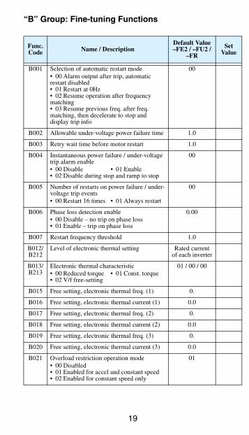
B001 Selection of automatic restart mode• 00 Alarm output after trip, automatic restart disabled• 01 Restart at 0Hz• 02 Resume operation after frequency matching• 03 Resume previous freq. after freq. matching, then decelerate to stop and display trip info
00
B002 Allowable under-voltage power failure time 1.0
B003 Retry wait time before motor restart 1.0
B004 Instantaneous power failure / under-voltage trip alarm enable• 00 Disable • 01 Enable• 02 Disable during stop and ramp to stop
00
B005 Number of restarts on power failure / under-voltage trip events• 00 Restart 16 times • 01 Always restart
00
B006 Phase loss detection enable• 00 Disable – no trip on phase loss• 01 Enable – trip on phase loss
0.00
B007 Restart frequency threshold 1.0
B012/B212
Level of electronic thermal setting Rated current of each inverter
B013/B213
Electronic thermal characteristic• 00 Reduced torque • 01 Const. torque• 02 V/f free-setting
01 / 00 / 00
B015 Free setting, electronic thermal freq. (1) 0.
B016 Free setting, electronic thermal current (1) 0.0
B017 Free setting, electronic thermal freq. (2) 0.
B018 Free setting, electronic thermal current (2) 0.0
B019 Free setting, electronic thermal freq. (3) 0.
B020 Free setting, electronic thermal current (3) 0.0
B021 Overload restriction operation mode• 00 Disabled• 01 Enabled for accel and constant speed• 02 Enabled for constant speed only
01
20
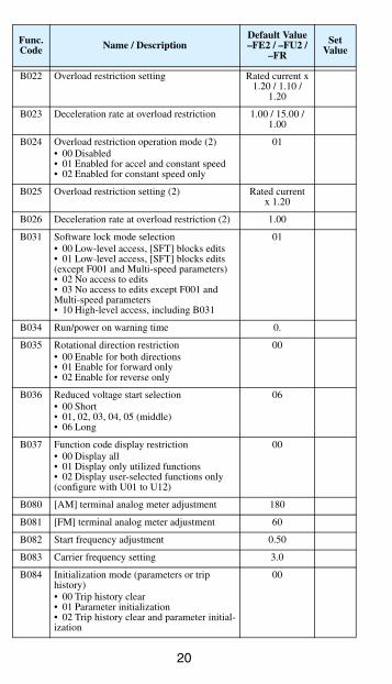
B022 Overload restriction setting Rated current x1.20 / 1.10 /
1.20
B023 Deceleration rate at overload restriction 1.00 / 15.00 / 1.00
B024 Overload restriction operation mode (2)• 00 Disabled• 01 Enabled for accel and constant speed• 02 Enabled for constant speed only
01
B025 Overload restriction setting (2) Rated currentx 1.20
B026 Deceleration rate at overload restriction (2) 1.00
B031 Software lock mode selection• 00 Low-level access, [SFT] blocks edits• 01 Low-level access, [SFT] blocks edits (except F001 and Multi-speed parameters)• 02 No access to edits• 03 No access to edits except F001 and Multi-speed parameters• 10 High-level access, including B031
01
B034 Run/power on warning time 0.
B035 Rotational direction restriction• 00 Enable for both directions• 01 Enable for forward only• 02 Enable for reverse only
00
B036 Reduced voltage start selection• 00 Short• 01, 02, 03, 04, 05 (middle)• 06 Long
06
B037 Function code display restriction• 00 Display all• 01 Display only utilized functions• 02 Display user-selected functions only (configure with U01 to U12)
00
B080 [AM] terminal analog meter adjustment 180
B081 [FM] terminal analog meter adjustment 60
B082 Start frequency adjustment 0.50
B083 Carrier frequency setting 3.0
B084 Initialization mode (parameters or trip history)• 00 Trip history clear• 01 Parameter initialization• 02 Trip history clear and parameter initial-ization
00
Func. Code Name / Description
Default Value–FE2 / –FU2 /
–FR
Set Value
21
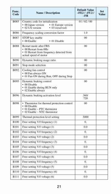
B085 Country code for initialization• 00 Japan version • 01 Europe version• 02 US version • 03 (reserved)
01 / 02 / 00
B086 Frequency scaling conversion factor 1.0
B087 STOP key enable• 00 Enable • 01 Disable
00
B088 Restart mode after FRS• 00 Restart from 0Hz• 01 Restart from frequency detected from actual speed of motor
00
B090 Dynamic braking usage ratio 00
B091 Stop mode selection 00
B092 Cooling fan control• 00 Fan always ON• 01 Fan ON during Run, OFF during Stop
00
B095 Dynamic braking control• 00 Disable• 01 Enable during RUN only• 02 Enable always
00
B096 Dynamic braking activation level 360/720
B098 • Thermistor for thermal protection control• 00 Disable• 01 Enable – PTC thermistor• 02 Enable – NTC thermistor
00
B099 Thermal protection level setting 3000
B100 Free-setting V/f frequency (1) 0.
B101 Free-setting V/f voltage (1) 0.0
B102 Free-setting V/f frequency (2) 0.
B103 Free-setting V/f voltage (2) 0.0
B104 Free-setting V/f frequency (3) 0.
B105 Free-setting V/f voltage (3) 0.0
B106 Free-setting V/f frequency (4) 0.
B107 Free-setting V/f voltage (4) 0.0
B108 Free-setting V/f frequency (5) 0.
B109 Free-setting V/f voltage (5) 0.0
B110 Free-setting V/f frequency (6) 0.
B111 Free-setting V/f voltage (6) 0.0
Func. Code Name / Description
Default Value–FE2 / –FU2 /
–FR
Set Value
22
“C” Group: Intelligent Terminal Functions
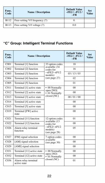
B112 Free-setting V/f frequency (7) 0.
B113 Free-setting V/f voltage (7) 0.0
Func. Code Name / Description
Default Value–FE2 / –FU2 /
–FR
Set Value
C001 Terminal [1] function 33 option codes available (34 codes for–xFE2/–xFU2 models)(see page 27)
18
C002 Terminal [2] function 16
C003 Terminal [3] function 03 / 13 / 03
C004 Terminal [4] function 02
C005 Terminal [5] function 01
C011 Terminal [1] active state • 00 Normally open [NO]• 01 Normally closed [NC]
00
C012 Terminal [2] active state 00
C013 Terminal [3] active state 00 / 01 / 00
C014 Terminal [4] active state 00
C015 Terminal [5] active state 00
C019 Terminal [FW] active state
00
C021 Terminal [11] function 12 option codes available (13 codes for–xFE2/–xFU2 models)(see page 28)
01
C022 Terminal [12] function 00
C026 Alarm relay terminal function
05
C027 [FM] signal selection 7 option codes available(see page 30)
00
C028 [AM] signal selection 00
C029 [AMI] signal selection 00
C031 Terminal [11] active state • 00 Normally open (NO)• 01 Normally closed (NC)
00
C032 Terminal [12] active state 00
C036 Alarm relay terminal active state
01
Func. Code Name / Description
Default Value–FE2 / –FU2 /
–FR
Set Value
23
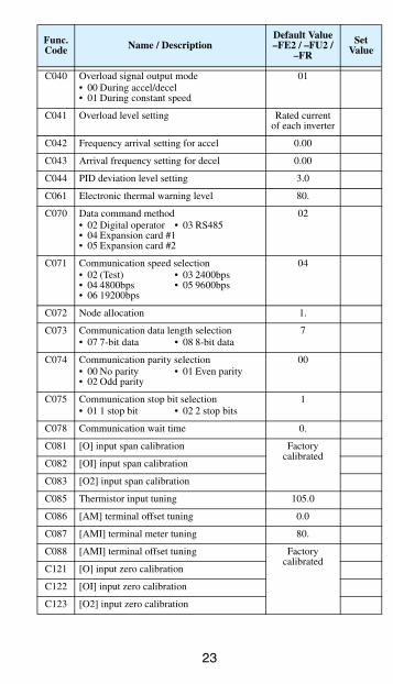
C040 Overload signal output mode• 00 During accel/decel• 01 During constant speed
01
C041 Overload level setting Rated current of each inverter
C042 Frequency arrival setting for accel 0.00
C043 Arrival frequency setting for decel 0.00
C044 PID deviation level setting 3.0
C061 Electronic thermal warning level 80.
C070 Data command method• 02 Digital operator • 03 RS485• 04 Expansion card #1• 05 Expansion card #2
02
C071 Communication speed selection• 02 (Test) • 03 2400bps• 04 4800bps • 05 9600bps• 06 19200bps
04
C072 Node allocation 1.
C073 Communication data length selection• 07 7-bit data • 08 8-bit data
7
C074 Communication parity selection• 00 No parity • 01 Even parity• 02 Odd parity
00
C075 Communication stop bit selection• 01 1 stop bit • 02 2 stop bits
1
C078 Communication wait time 0.
C081 [O] input span calibration Factory calibrated
C082 [OI] input span calibration
C083 [O2] input span calibration
C085 Thermistor input tuning 105.0
C086 [AM] terminal offset tuning 0.0
C087 [AMI] terminal meter tuning 80.
C088 [AMI] terminal offset tuning Factory calibrated
C121 [O] input zero calibration
C122 [OI] input zero calibration
C123 [O2] input zero calibration
Func. Code Name / Description
Default Value–FE2 / –FU2 /
–FR
Set Value
24
“H” Group: Motor Constants Functions
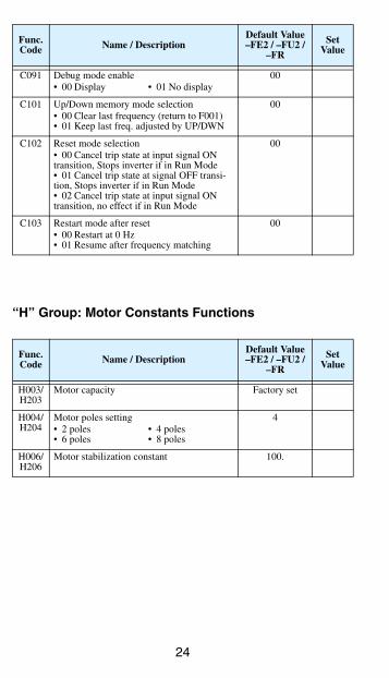
C091 Debug mode enable• 00 Display • 01 No display
00
C101 Up/Down memory mode selection• 00 Clear last frequency (return to F001)• 01 Keep last freq. adjusted by UP/DWN
00
C102 Reset mode selection• 00 Cancel trip state at input signal ON transition, Stops inverter if in Run Mode• 01 Cancel trip state at signal OFF transi-tion, Stops inverter if in Run Mode• 02 Cancel trip state at input signal ON transition, no effect if in Run Mode
00
C103 Restart mode after reset• 00 Restart at 0 Hz• 01 Resume after frequency matching
00
Func. Code Name / Description
Default Value–FE2 / –FU2 /
–FR
Set Value
H003/H203
Motor capacity Factory set
H004/H204
Motor poles setting• 2 poles • 4 poles• 6 poles • 8 poles
4
H006/H206
Motor stabilization constant 100.
Func. Code Name / Description
Default Value–FE2 / –FU2 /
–FR
Set Value
25
“P” Group: Expansion Card Functions
Func. Code Name / Description
Default Value–FE2 / –FU2 /
–FR
Set Value
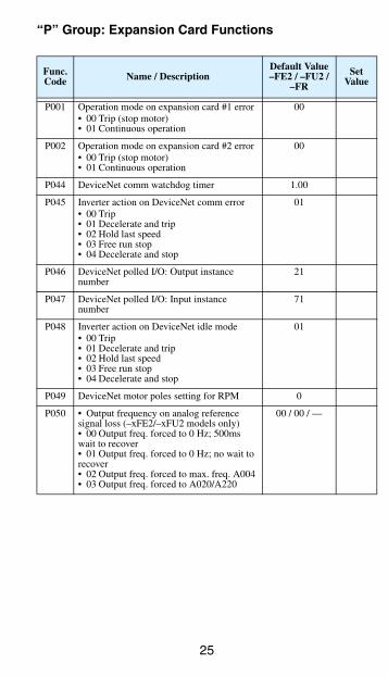
P001 Operation mode on expansion card #1 error• 00 Trip (stop motor)• 01 Continuous operation
00
P002 Operation mode on expansion card #2 error• 00 Trip (stop motor)• 01 Continuous operation
00
P044 DeviceNet comm watchdog timer 1.00
P045 Inverter action on DeviceNet comm error• 00 Trip• 01 Decelerate and trip• 02 Hold last speed• 03 Free run stop• 04 Decelerate and stop
01
P046 DeviceNet polled I/O: Output instance number
21
P047 DeviceNet polled I/O: Input instance number
71
P048 Inverter action on DeviceNet idle mode• 00 Trip• 01 Decelerate and trip• 02 Hold last speed• 03 Free run stop• 04 Decelerate and stop
01
P049 DeviceNet motor poles setting for RPM 0
P050 • Output frequency on analog reference signal loss (–xFE2/–xFU2 models only)• 00 Output freq. forced to 0 Hz; 500ms wait to recover• 01 Output freq. forced to 0 Hz; no wait to recover• 02 Output freq. forced to max. freq. A004• 03 Output freq. forced to A020/A220
00 / 00 / —
26
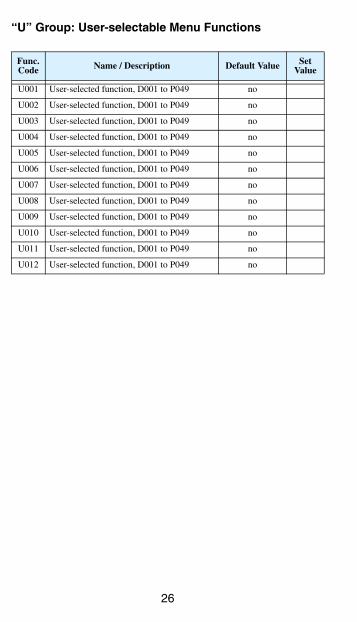
“U” Group: User-selectable Menu Functions
Func. Code Name / Description Default Value Set
Value
U001 User-selected function, D001 to P049 no
U002 User-selected function, D001 to P049 no
U003 User-selected function, D001 to P049 no
U004 User-selected function, D001 to P049 no
U005 User-selected function, D001 to P049 no
U006 User-selected function, D001 to P049 no
U007 User-selected function, D001 to P049 no
U008 User-selected function, D001 to P049 no
U009 User-selected function, D001 to P049 no
U010 User-selected function, D001 to P049 no
U011 User-selected function, D001 to P049 no
U012 User-selected function, D001 to P049 no
27
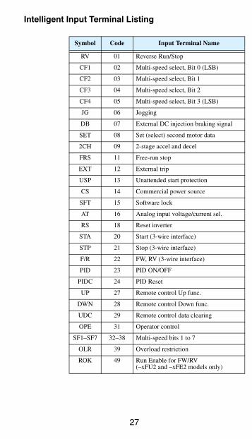
Intelligent Input Terminal Listing
Symbol Code Input Terminal Name
RV 01 Reverse Run/Stop
CF1 02 Multi-speed select, Bit 0 (LSB)
CF2 03 Multi-speed select, Bit 1
CF3 04 Multi-speed select, Bit 2
CF4 05 Multi-speed select, Bit 3 (LSB)
JG 06 Jogging
DB 07 External DC injection braking signal
SET 08 Set (select) second motor data
2CH 09 2-stage accel and decel
FRS 11 Free-run stop
EXT 12 External trip
USP 13 Unattended start protection
CS 14 Commercial power source
SFT 15 Software lock
AT 16 Analog input voltage/current sel.
RS 18 Reset inverter
STA 20 Start (3-wire interface)
STP 21 Stop (3-wire interface)
F/R 22 FW, RV (3-wire interface)
PID 23 PID ON/OFF
PIDC 24 PID Reset
UP 27 Remote control Up func.
DWN 28 Remote control Down func.
UDC 29 Remote control data clearing
OPE 31 Operator control
SF1–SF7 32–38 Multi-speed bits 1 to 7
OLR 39 Overload restriction
ROK 49 Run Enable for FW/RV(–xFU2 and –xFE2 models only)
28
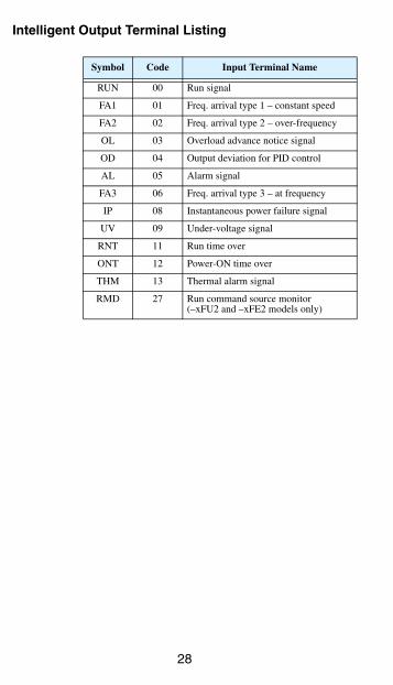
Intelligent Output Terminal Listing
Symbol Code Input Terminal Name
RUN 00 Run signal
FA1 01 Freq. arrival type 1 – constant speed
FA2 02 Freq. arrival type 2 – over-frequency
OL 03 Overload advance notice signal
OD 04 Output deviation for PID control
AL 05 Alarm signal
FA3 06 Freq. arrival type 3 – at frequency
IP 08 Instantaneous power failure signal
UV 09 Under-voltage signal
RNT 11 Run time over
ONT 12 Power-ON time over
THM 13 Thermal alarm signal
RMD 27 Run command source monitor(–xFU2 and –xFE2 models only)
29
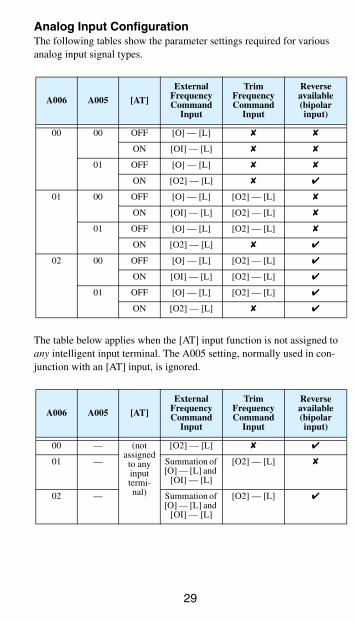
Analog Input ConfigurationThe following tables show the parameter settings required for various analog input signal types.
The table below applies when the [AT] input function is not assigned to any intelligent input terminal. The A005 setting, normally used in con-junction with an [AT] input, is ignored.
A006 A005 [AT]
External Frequency Command
Input
Trim Frequency Command
Input
Reverse available (bipolar input)
00 00 OFF [O] — [L]
ON [OI] — [L]
01 OFF [O] — [L]
ON [O2] — [L]
01 00 OFF [O] — [L] [O2] — [L]
ON [OI] — [L] [O2] — [L]
01 OFF [O] — [L] [O2] — [L]
ON [O2] — [L]
02 00 OFF [O] — [L] [O2] — [L]
ON [OI] — [L] [O2] — [L]
01 OFF [O] — [L] [O2] — [L]
ON [O2] — [L]
A006 A005 [AT]
External Frequency Command
Input
Trim Frequency Command
Input
Reverse available (bipolar input)
00 — (not assigned
to any input termi-nal)
[O2] — [L]
01 — Summation of [O] — [L] and
[OI] — [L]
[O2] — [L]
02 — Summation of [O] — [L] and
[OI] — [L]
[O2] — [L]
30
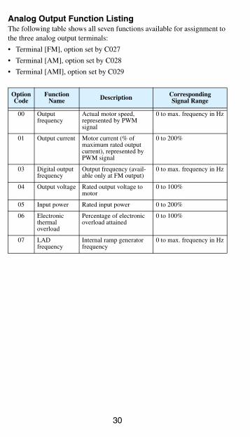
Analog Output Function ListingThe following table shows all seven functions available for assignment to the three analog output terminals:
• Terminal [FM], option set by C027
• Terminal [AM], option set by C028
• Terminal [AMI], option set by C029
Option Code
Function Name Description Corresponding
Signal Range
00 Output frequency
Actual motor speed, represented by PWM signal
0 to max. frequency in Hz
01 Output current Motor current (% of maximum rated output current), represented by PWM signal
0 to 200%
03 Digital output frequency
Output frequency (avail-able only at FM output)
0 to max. frequency in Hz
04 Output voltage Rated output voltage to motor
0 to 100%
05 Input power Rated input power 0 to 200%
06 Electronic thermal overload
Percentage of electronic overload attained
0 to 100%
07 LAD frequency
Internal ramp generator frequency
0 to max. frequency in Hz
31
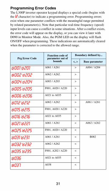
Programming Error CodesThe L300P inverter operator keypad displays a special code (begins with the character) to indicate a programming error. Programming errors exist when one parameter conflicts with the meaningful range permitted by related parameter(s). Note that particular real-time frequency (speed) input levels can cause a conflict in some situations. After a conflict exists, the error code will appear on the display, or you can view it later with D090 in Monitor Mode. Also, the PGM LED on the display will flash ON/OFF when programming. These indications are automatically cleared when the parameter is corrected to the allowed range.
Prg Error CodeFunction code of parameter out of
bounds
Boundary defined by...
<, > Base parameter
001 201 A061 / A261 > A004 / A204
002 202 A062 / A262 >
004 204 A003 / A203 >
005 205 F001, A020 / A220 >
006 206 A021 to A035 >
012 212 A062 / A262 > A061 / A261
015 215 F001, A020 / A220 >
016 216 A021 to A035 >
021 221 A061 / A261 < A062 / A262
025 225 F001, A020 / A220 <
031 231 A061 / A261 < B082
032 232 A062 / A262 <
035 235 F001, A202 / A220 <
036 A021 to A035 <
037 A038 <
32
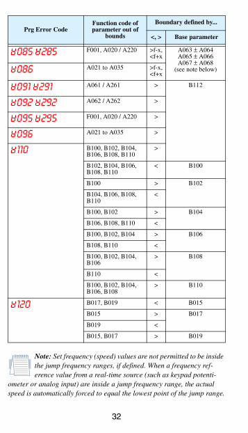
Note: Set frequency (speed) values are not permitted to be inside the jump frequency ranges, if defined. When a frequency ref-erence value from a real-time source (such as keypad potenti-
ometer or analog input) are inside a jump frequency range, the actual speed is automatically forced to equal the lowest point of the jump range.
085 285 F001, A020 / A220 >f-x,<f+x
A063 ± A064A065 ± A066A067 ± A068
(see note below)086 A021 to A035 >f-x,<f+x
091 291 A061 / A261 > B112
092 292 A062 / A262 >
095 295 F001, A020 / A220 >
096 A021 to A035 >
110 B100, B102, B104, B106, B108, B110
>
B102, B104, B106, B108, B110
< B100
B100 > B102
B104, B106, B108, B110
<
B100, B102 > B104
B106, B108, B110 <
B100, B102, B104 > B106
B108, B110 <
B100, B102, B104, B106
> B108
B110 <
B100, B102, B104, B106, B108
> B110
120 B017, B019 < B015
B015 > B017
B019 <
B015, B017 > B019
Prg Error CodeFunction code of parameter out of
bounds
Boundary defined by...
<, > Base parameter

33
Related Documents