Highly precise micropositioning task using a direct visual servoing scheme. Brahim Tamadazte, Guillaume Duceux, Nadine Le Fort-Piat, Eric Marchand To cite this version: Brahim Tamadazte, Guillaume Duceux, Nadine Le Fort-Piat, Eric Marchand. Highly precise micropositioning task using a direct visual servoing scheme.. IEEE internatioanal Conference on Robotics and Automation, ICRA’11., May 2011, Shangai, China. sur CD ROM, pp.5689-5694. <hal-00554841> HAL Id: hal-00554841 https://hal.archives-ouvertes.fr/hal-00554841 Submitted on 11 Jan 2011 HAL is a multi-disciplinary open access archive for the deposit and dissemination of sci- entific research documents, whether they are pub- lished or not. The documents may come from teaching and research institutions in France or abroad, or from public or private research centers. L’archive ouverte pluridisciplinaire HAL, est destin´ ee au d´ epˆ ot et ` a la diffusion de documents scientifiques de niveau recherche, publi´ es ou non, ´ emanant des ´ etablissements d’enseignement et de recherche fran¸cais ou ´ etrangers, des laboratoires publics ou priv´ es.

Welcome message from author
This document is posted to help you gain knowledge. Please leave a comment to let me know what you think about it! Share it to your friends and learn new things together.
Transcript
Highly precise micropositioning task using a direct
visual servoing scheme.
Brahim Tamadazte, Guillaume Duceux, Nadine Le Fort-Piat, Eric Marchand
To cite this version:
Brahim Tamadazte, Guillaume Duceux, Nadine Le Fort-Piat, Eric Marchand. Highly precisemicropositioning task using a direct visual servoing scheme.. IEEE internatioanal Conference onRobotics and Automation, ICRA’11., May 2011, Shangai, China. sur CD ROM, pp.5689-5694.<hal-00554841>
HAL Id: hal-00554841
https://hal.archives-ouvertes.fr/hal-00554841
Submitted on 11 Jan 2011
HAL is a multi-disciplinary open accessarchive for the deposit and dissemination of sci-entific research documents, whether they are pub-lished or not. The documents may come fromteaching and research institutions in France orabroad, or from public or private research centers.
L’archive ouverte pluridisciplinaire HAL, estdestinee au depot et a la diffusion de documentsscientifiques de niveau recherche, publies ou non,emanant des etablissements d’enseignement et derecherche francais ou etrangers, des laboratoirespublics ou prives.
Highly Precise Micropositioning Task
using a Direct Visual Servoing Scheme
B. Tamadazte, G. Duceux, N. Le-Fort Piat, and E. Marchand,
Abstract— This paper demonstrates a precise microposition-ing scheme based on a direct visual servoing process. This tech-nique uses only the pure image signal (photometric information)to design the control law. With respect to traditional visualservoing approaches that use geometric visual features (points,lines, ...), the visual features used in the control law is nothingbut the pixel luminance. The proposed approach was testedin term of precision and robustness in several experimentalconditions. The obtained results have demonstrated a goodbehavior of the control law and very good positioning precision.The obtained precisions are 89 nanometers, 14 nanometers, and0.001 degrees in the x, y and θ axes of positioning platform,respectively.
I. OVERVIEW
The heterogeneous integration of high-performance elec-
tronic devices, microelectromechanical structures (MEMS),
and optoelectronic devices onto the same substrate is im-
portant for the development of low-cost, high performance,
and high-compact microsystems [9]. To set up intelligent and
miniature systems, handle and assemble the various elements
that constitute these microsystems, it is necessary to be able
to manipulate the different individual micro-elements which
compose the final MEMS. These operations (i.e. handle and
assemble) must be done with high precision. In the last
decade considerable researches have been performed on the
development of robotic microassembly station, gripping sys-
tems, precise actuators, micromanipulation and microassem-
bly strategies. Furthermore, a lot of works has been done con-
cerning the development of control approaches to automatize
the different micromanipulation and microassembly tasks
such positioning, orientation, picking, placing and insertion
of the different micro-objects [10], [8]. Most of these works
consider the use of the vision sensor to control the behavior
of the robotic structure of the microassembly station during
the assembly process. Thus, the guidance of robots through
real-time and continuous visual feedback is generally known
as visual servoing [4], and the continuous observation of the
objects of interest is referred to visual tracking [10], [11].
Visual tracking of an object involves the detection of some
known object features in the acquired images and, using these
features, the estimation of the object position and orientation.
This work is partially conducted with financial support from the project”Hybrid Ultra Precision Manufacturing Process Based on Positional andSelf assembly for Complex Micro-Products (HYDROMEL NMP2-CT-2006-026622)” funded by the European Commission.
B. Tamadazte, G. Duceux, and N. Le-Fort Piat are with the FEMTO-ST Institute, UMR CNRS 6174-UFC/ENSMM/UTBM. Automatic Controland Micro-Mechatronic Systems Department (AS2M). 24 rue Alain Savary,25000 Besancon, France. [email protected]
E. Marchand is with Universite de Rennes 1, IRISA, INRIA Rennes-Bretagne Atlantique, Lagadic research group, Rennes 35042, France.
A feature can be a distinctive part of the object and can exist
naturally as a part of the geometry (i.e. a corner, an edge),
or as a deliberately fabricated marking on the surface (i.e.
markers). This tracking process is one of the bottleneck of
the development of visual servoing techniques. Recently, it
has been shown that these tracking and matching processes
can be totally removed and that no other information than the
image intensity [7] [2], the image entropy [3], and the image
Laplacian can be considered to control a manipulator. In this
paper, we will consider such a direct approach to control the
microrobot motion with a precision. Only the image (as a
whole) are used to design the control law. However, despite
the fact that no complex image processing algorithms are
consider, we will show that these new techniques are:
• robust to global light variations
• robust to partial occlusions
• robust to different perturbations such as the addition of
others micro-objects during the manipulation process
Furthermore, as all the pixels of the image are considered, the
proposed scheme is highly precise thanks to the redundant
information.
In this paper, we use this photometric visual servo-
ing scheme in an eye-to-hand configuration. The camera
mounted on an optical microscope is motionless and observes
a moving positioning platform. The developed methods are
validated using a five degrees of freedom (dof) microassem-
bly workcell. This development has been also validated
using a multiple scale visual servoing which means the
integration of the dynamic control of the optical microscope
magnification in the control law.
Section II describes the experimental setup used to validate
the proposed approach. Section III presents some definition
about the principles of the eye-to-hand visual servoing. Sec-
tion IV describes the new visual servoing approach without
image processing using only the pixels intensity of the
image as visual features, and the design of the new control
law. Section V discusses the experimental results using the
developed method in terms of the obtained precision quality
during the different positioning and orientation tasks.
II. EXPERIMENTAL SETUP
The integration of the developed concept is done on the
microassembly workcell illustrated in Fig. 1. This MEMS
microassembly station had been developed in our laboratory.
It includes a robotic system with five high accuracy dof (3-
dof positioning platform: two linear stages i.e. xy and one
rotating stage θ, and 2-dof micromanipulator: one vertical
linear stage z and one rotating stage mounted at 45 degrees
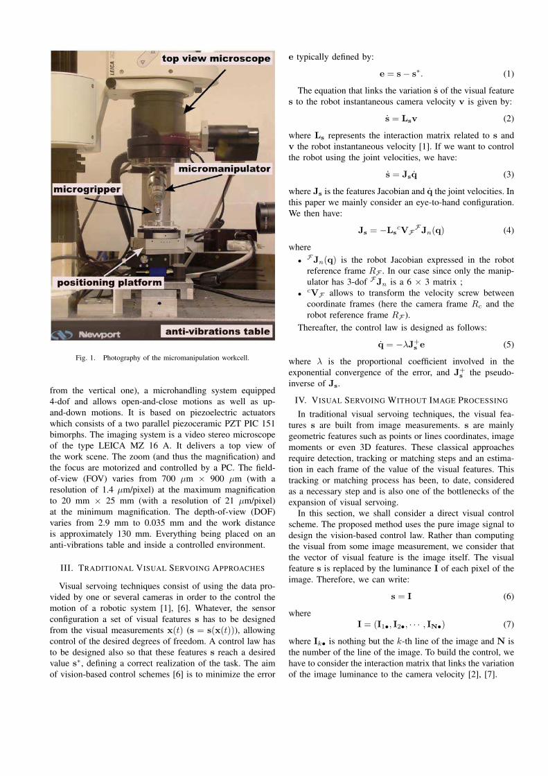
Fig. 1. Photography of the micromanipulation workcell.
from the vertical one), a microhandling system equipped
4-dof and allows open-and-close motions as well as up-
and-down motions. It is based on piezoelectric actuators
which consists of a two parallel piezoceramic PZT PIC 151
bimorphs. The imaging system is a video stereo microscope
of the type LEICA MZ 16 A. It delivers a top view of
the work scene. The zoom (and thus the magnification) and
the focus are motorized and controlled by a PC. The field-
of-view (FOV) varies from 700 µm × 900 µm (with a
resolution of 1.4 µm/pixel) at the maximum magnification
to 20 mm × 25 mm (with a resolution of 21 µm/pixel)
at the minimum magnification. The depth-of-view (DOF)
varies from 2.9 mm to 0.035 mm and the work distance
is approximately 130 mm. Everything being placed on an
anti-vibrations table and inside a controlled environment.
III. TRADITIONAL VISUAL SERVOING APPROACHES
Visual servoing techniques consist of using the data pro-
vided by one or several cameras in order to the control the
motion of a robotic system [1], [6]. Whatever, the sensor
configuration a set of visual features s has to be designed
from the visual measurements x(t) (s = s(x(t))), allowing
control of the desired degrees of freedom. A control law has
to be designed also so that these features s reach a desired
value s∗, defining a correct realization of the task. The aim
of vision-based control schemes [6] is to minimize the error
e typically defined by:
e = s − s∗. (1)
The equation that links the variation s of the visual feature
s to the robot instantaneous camera velocity v is given by:
s = Lsv (2)
where Ls represents the interaction matrix related to s and
v the robot instantaneous velocity [1]. If we want to control
the robot using the joint velocities, we have:
s = Jsq (3)
where Js is the features Jacobian and q the joint velocities. In
this paper we mainly consider an eye-to-hand configuration.
We then have:
Js = −LscVF
FJn(q) (4)
where
•FJn(q) is the robot Jacobian expressed in the robot
reference frame RF . In our case since only the manip-
ulator has 3-dof FJn is a 6 × 3 matrix ;
•cVF allows to transform the velocity screw between
coordinate frames (here the camera frame Rc and the
robot reference frame RF ).
Thereafter, the control law is designed as follows:
q = −λJ+se (5)
where λ is the proportional coefficient involved in the
exponential convergence of the error, and J+s
the pseudo-
inverse of Js.
IV. VISUAL SERVOING WITHOUT IMAGE PROCESSING
In traditional visual servoing techniques, the visual fea-
tures s are built from image measurements. s are mainly
geometric features such as points or lines coordinates, image
moments or even 3D features. These classical approaches
require detection, tracking or matching steps and an estima-
tion in each frame of the value of the visual features. This
tracking or matching process has been, to date, considered
as a necessary step and is also one of the bottlenecks of the
expansion of visual servoing.
In this section, we shall consider a direct visual control
scheme. The proposed method uses the pure image signal to
design the vision-based control law. Rather than computing
the visual from some image measurement, we consider that
the vector of visual feature is the image itself. The visual
feature s is replaced by the luminance I of each pixel of the
image. Therefore, we can write:
s = I (6)
where
I = (I1•, I2•, · · · , IN•) (7)
where Ik• is nothing but the k-th line of the image and N is
the number of the line of the image. To build the control, we
have to consider the interaction matrix that links the variation
of the image luminance to the camera velocity [2], [7].
Considering the optical flow constraint equation (OFCE)
hypothesis [5], we can compute the interaction matrix that
links the variation of a pixel intensity to camera motion.
The OFCE states that the intensity I(x, t) of each projected
physical point in the image remains the same during a short
time interval dt. We have:
I(x, t) = I(x + dx, t + dt) (8)
.
A first order Taylor expansion of the equation (8) gives:
∂I
∂xdx +
∂I
∂ydy +
∂I
∂tdt = 0 (9)
which can be written as follows:
I = −∇Ixx −∇Iy y (10)
with
∇Ix =∂I
∂x(11)
and
∇Iy =∂I
∂y(12)
Now, the temporal variations of the image must be linked
to the camera displacements. For this, we introduce the
interaction matrix of a point of the image which links the
point velocity in the image to the camera velocity [1]. It is
given by:
x = Lxv (13)
and
y = Lyv (14)
where Lx and Ly are the interaction related to the point:
Lx =(
−1/Z 0 x/Z xy −(1 + x) y)
Ly =(
0 −1/Z y/Z 1 + y xy −x)
Hence, introducing equations (13) and (14) in the equation
(10), we obtain:
I = −(∇IxLx + ∇IyLy) v (15)
or
I = LI v (16)
Knowing the interaction matrix LI, it is possible to design
a control law. As in [2], we use a control law inspired
from the Levenberg-Maquardt optimization algorithm. This
provides an efficient numerical solution to the problem
of minimizing the error function I − I∗ which is highly
non-linear. It is the interpolation of the Gauss-Newton and
gradient descent method. More stable than a simple gradient
descent, it converges faster that the Gauss-Newton scheme
corresponding to equation (5). Therefore, the platform ve-
locity q is given by:
q = −λ(
H + µ.diag(H))−1
J⊤
I
(
I − I∗)
(17)
where JI represents the Jacobian matrix computed from
interaction matrix (16) and (4) computed at the desired
position. The parameters λ and µ are positive gains and
diag(H) is the matrix of diagonal terms of the combination
matrix H which is given by:
H = J⊤
IJI (18)
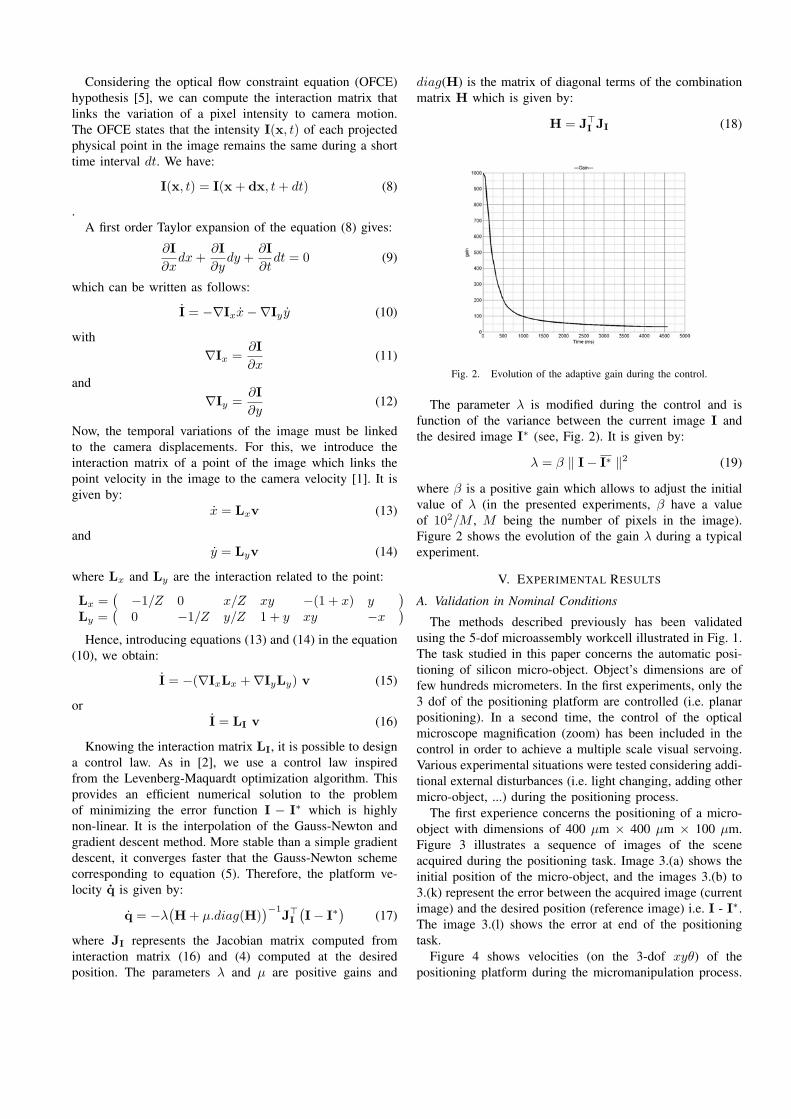
Fig. 2. Evolution of the adaptive gain during the control.
The parameter λ is modified during the control and is
function of the variance between the current image I and
the desired image I∗ (see, Fig. 2). It is given by:
λ = β ‖ I − I∗ ‖2 (19)
where β is a positive gain which allows to adjust the initial
value of λ (in the presented experiments, β have a value
of 102/M , M being the number of pixels in the image).
Figure 2 shows the evolution of the gain λ during a typical
experiment.
V. EXPERIMENTAL RESULTS
A. Validation in Nominal Conditions
The methods described previously has been validated
using the 5-dof microassembly workcell illustrated in Fig. 1.
The task studied in this paper concerns the automatic posi-
tioning of silicon micro-object. Object’s dimensions are of
few hundreds micrometers. In the first experiments, only the
3 dof of the positioning platform are controlled (i.e. planar
positioning). In a second time, the control of the optical
microscope magnification (zoom) has been included in the
control in order to achieve a multiple scale visual servoing.
Various experimental situations were tested considering addi-
tional external disturbances (i.e. light changing, adding other
micro-object, ...) during the positioning process.
The first experience concerns the positioning of a micro-
object with dimensions of 400 µm × 400 µm × 100 µm.
Figure 3 illustrates a sequence of images of the scene
acquired during the positioning task. Image 3.(a) shows the
initial position of the micro-object, and the images 3.(b) to
3.(k) represent the error between the acquired image (current
image) and the desired position (reference image) i.e. I - I∗.
The image 3.(l) shows the error at end of the positioning
task.
Figure 4 shows velocities (on the 3-dof xyθ) of the
positioning platform during the micromanipulation process.
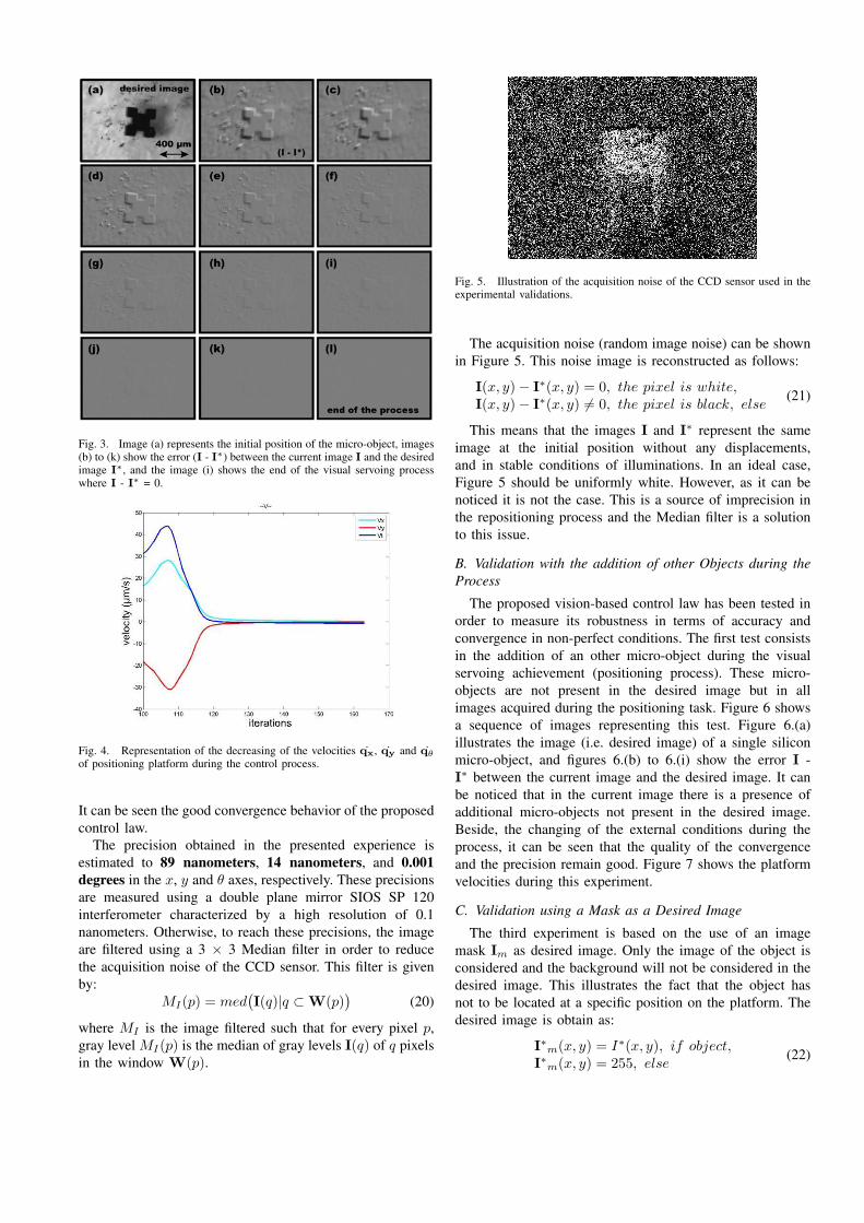
Fig. 3. Image (a) represents the initial position of the micro-object, images(b) to (k) show the error (I - I∗) between the current image I and the desiredimage I∗, and the image (i) shows the end of the visual servoing processwhere I - I∗ = 0.
Fig. 4. Representation of the decreasing of the velocities qx, qy and qθ
of positioning platform during the control process.
It can be seen the good convergence behavior of the proposed
control law.
The precision obtained in the presented experience is
estimated to 89 nanometers, 14 nanometers, and 0.001
degrees in the x, y and θ axes, respectively. These precisions
are measured using a double plane mirror SIOS SP 120
interferometer characterized by a high resolution of 0.1
nanometers. Otherwise, to reach these precisions, the image
are filtered using a 3 × 3 Median filter in order to reduce
the acquisition noise of the CCD sensor. This filter is given
by:
MI(p) = med(
I(q)|q ⊂ W(p))
(20)
where MI is the image filtered such that for every pixel p,
gray level MI(p) is the median of gray levels I(q) of q pixels
in the window W(p).
Fig. 5. Illustration of the acquisition noise of the CCD sensor used in theexperimental validations.
The acquisition noise (random image noise) can be shown
in Figure 5. This noise image is reconstructed as follows:
I(x, y) − I∗(x, y) = 0, the pixel is white,I(x, y) − I∗(x, y) 6= 0, the pixel is black, else
(21)
This means that the images I and I∗ represent the same
image at the initial position without any displacements,
and in stable conditions of illuminations. In an ideal case,
Figure 5 should be uniformly white. However, as it can be
noticed it is not the case. This is a source of imprecision in
the repositioning process and the Median filter is a solution
to this issue.
B. Validation with the addition of other Objects during the
Process
The proposed vision-based control law has been tested in
order to measure its robustness in terms of accuracy and
convergence in non-perfect conditions. The first test consists
in the addition of an other micro-object during the visual
servoing achievement (positioning process). These micro-
objects are not present in the desired image but in all
images acquired during the positioning task. Figure 6 shows
a sequence of images representing this test. Figure 6.(a)
illustrates the image (i.e. desired image) of a single silicon
micro-object, and figures 6.(b) to 6.(i) show the error I -
I∗ between the current image and the desired image. It can
be noticed that in the current image there is a presence of
additional micro-objects not present in the desired image.
Beside, the changing of the external conditions during the
process, it can be seen that the quality of the convergence
and the precision remain good. Figure 7 shows the platform
velocities during this experiment.
C. Validation using a Mask as a Desired Image
The third experiment is based on the use of an image
mask Im as desired image. Only the image of the object is
considered and the background will not be considered in the
desired image. This illustrates the fact that the object has
not to be located at a specific position on the platform. The
desired image is obtain as:
I∗m(x, y) = I∗(x, y), if object,I∗m(x, y) = 255, else
(22)
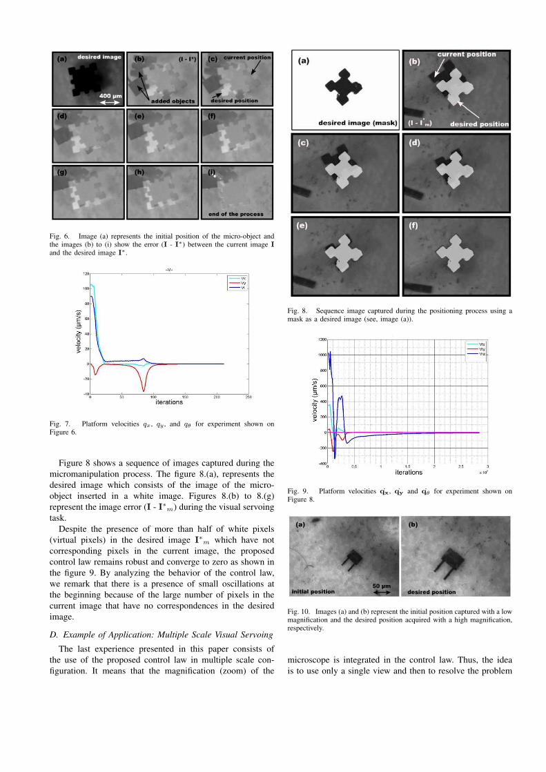
Fig. 6. Image (a) represents the initial position of the micro-object andthe images (b) to (i) show the error (I - I∗) between the current image I
and the desired image I∗.
Fig. 7. Platform velocities qx, qy , and qθ for experiment shown onFigure 6.
Figure 8 shows a sequence of images captured during the
micromanipulation process. The figure 8.(a), represents the
desired image which consists of the image of the micro-
object inserted in a white image. Figures 8.(b) to 8.(g)
represent the image error (I - I∗m) during the visual servoing
task.
Despite the presence of more than half of white pixels
(virtual pixels) in the desired image I∗m which have not
corresponding pixels in the current image, the proposed
control law remains robust and converge to zero as shown in
the figure 9. By analyzing the behavior of the control law,
we remark that there is a presence of small oscillations at
the beginning because of the large number of pixels in the
current image that have no correspondences in the desired
image.
D. Example of Application: Multiple Scale Visual Servoing
The last experience presented in this paper consists of
the use of the proposed control law in multiple scale con-
figuration. It means that the magnification (zoom) of the
Fig. 8. Sequence image captured during the positioning process using amask as a desired image (see, image (a)).
Fig. 9. Platform velocities qx, qy and qθ for experiment shown onFigure 8.
Fig. 10. Images (a) and (b) represent the initial position captured with a lowmagnification and the desired position acquired with a high magnification,respectively.
microscope is integrated in the control law. Thus, the idea
is to use only a single view and then to resolve the problem
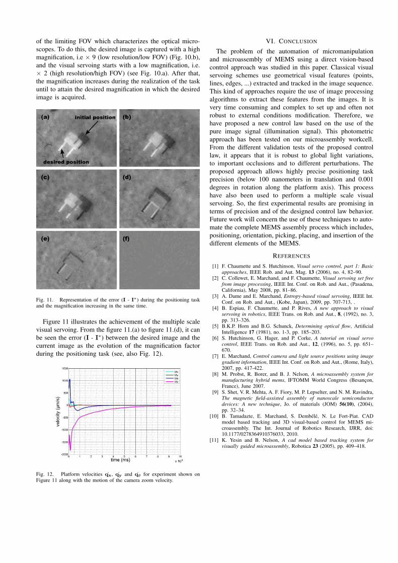
of the limiting FOV which characterizes the optical micro-
scopes. To do this, the desired image is captured with a high
magnification, i.e × 9 (low resolution/low FOV) (Fig. 10.b),
and the visual servoing starts with a low magnification, i.e.
× 2 (high resolution/high FOV) (see Fig. 10.a). After that,
the magnification increases during the realization of the task
until to attain the desired magnification in which the desired
image is acquired.
Fig. 11. Representation of the error (I - I∗) during the positioning taskand the magnification increasing in the same time.
Figure 11 illustrates the achievement of the multiple scale
visual servoing. From the figure 11.(a) to figure 11.(d), it can
be seen the error (I - I∗) between the desired image and the
current image as the evolution of the magnification factor
during the positioning task (see, also Fig. 12).
Fig. 12. Platform velocities qx, qy and qθ for experiment shown onFigure 11 along with the motion of the camera zoom velocity.
VI. CONCLUSION
The problem of the automation of micromanipulation
and microassembly of MEMS using a direct vision-based
control approach was studied in this paper. Classical visual
servoing schemes use geometrical visual features (points,
lines, edges, ...) extracted and tracked in the image sequence.
This kind of approaches require the use of image processing
algorithms to extract these features from the images. It is
very time consuming and complex to set up and often not
robust to external conditions modification. Therefore, we
have proposed a new control law based on the use of the
pure image signal (illumination signal). This photometric
approach has been tested on our microassembly workcell.
From the different validation tests of the proposed control
law, it appears that it is robust to global light variations,
to important occlusions and to different perturbations. The
proposed approach allows highly precise positioning task
precision (below 100 nanometers in translation and 0.001
degrees in rotation along the platform axis). This process
have also been used to perform a multiple scale visual
servoing. So, the first experimental results are promising in
terms of precision and of the designed control law behavior.
Future work will concern the use of these techniques to auto-
mate the complete MEMS assembly process which includes,
positioning, orientation, picking, placing, and insertion of the
different elements of the MEMS.
REFERENCES
[1] F. Chaumette and S. Hutchinson, Visual servo control, part 1: Basic
approaches, IEEE Rob. and Aut. Mag. 13 (2006), no. 4, 82–90.[2] C. Collewet, E. Marchand, and F. Chaumette, Visual servoing set free
from image processing, IEEE Int. Conf. on Rob. and Aut., (Pasadena,California), May 2008, pp. 81–86.
[3] A. Dame and E. Marchand, Entropy-based visual servoing, IEEE Int.Conf. on Rob. and Aut., (Kobe, Japan), 2009, pp. 707-713, .
[4] B. Espiau, F. Chaumette, and P. Rives, A new approach to visual
servoing in robotics, IEEE Trans. on Rob. and Aut., 8, (1992), no. 3,pp. 313–326.
[5] B.K.P. Horn and B.G. Schunck, Determining optical flow, ArtificialIntelligence 17 (1981), no. 1-3, pp. 185–203.
[6] S. Hutchinson, G. Hager, and P. Corke, A tutorial on visual servo
control, IEEE Trans. on Rob. and Aut., 12, (1996), no. 5, pp. 651–670.
[7] E. Marchand, Control camera and light source positions using image
gradient information, IEEE Int. Conf. on Rob. and Aut., (Rome, Italy),2007, pp. 417-422.
[8] M. Probst, R. Borer, and B. J. Nelson, A microassembly system for
manufacturing hybrid mems, IFTOMM World Congress (Besancon,France), June 2007.
[9] S. Shet, V. R. Mehta, A. F. Fiory, M. P. Lepselter, and N. M. Ravindra,The magnetic field-assisted assembly of nanoscale semiconductor
devices: A new technique, Jo. of materials (JOM) 56(10), (2004),pp. 32–34.
[10] B. Tamadazte, E. Marchand, S. Dembele, N. Le Fort-Piat. CADmodel based tracking and 3D visual-based control for MEMS mi-croassembly. The Int. Journal of Robotics Research, IJRR, doi:10.1177/0278364910376033, 2010.
[11] K. Yesin and B. Nelson, A cad model based tracking system for
visually guided microassembly, Robotica 23 (2005), pp. 409–418.
Related Documents