HIGH RESOLUTION RADAR BACKSCATTER FROM SEA ICE & RANGE-GATED STEP-FREQUENCY RADAR USING FM-CW CONCEPT Master’s Thesis Defense by Pannirselvam Kanagaratnam

Welcome message from author
This document is posted to help you gain knowledge. Please leave a comment to let me know what you think about it! Share it to your friends and learn new things together.
Transcript
HIGH RESOLUTION RADAR BACKSCATTER FROM SEA ICE
&RANGE-GATED STEP-FREQUENCY RADAR USING FM-CW CONCEPT
Master’s Thesis Defenseby
Pannirselvam Kanagaratnam

Overview - Sea Ice
• Introduction• Objectives• Approach• Experiments• Data Processing• Results• Conclusion

Overview - Radar
• Objective• FM-CW concepts• Principles of operation• Simulation• System Description• Results• Conclusion

Introduction to sea ice remote sensing
• Sea ice plays a major role in the global climate system- Surface radiation balance
- sea ice reflects 90% of solar energy- open water absorbs 85-90% of solar energy- reduction in sea ice --> global warming
- Heat flux- Ice sheet serves as insulation between cold
polar air & the warm ocean• Operations
- Navigation and offshore exploration

Objectives
• To determine sources of scattering from saline ice
• To determine relative contributions of coherent and incoherent terms at nadir
Approach
• Determine experimentally by performing high resolution measurements
• Developed an ultra wideband radar using the concept of compact antenna range to generate plane wave

Why Plane Wave Illumination ?
• Radar systems used to generate ground truth data are operated in the near zone region
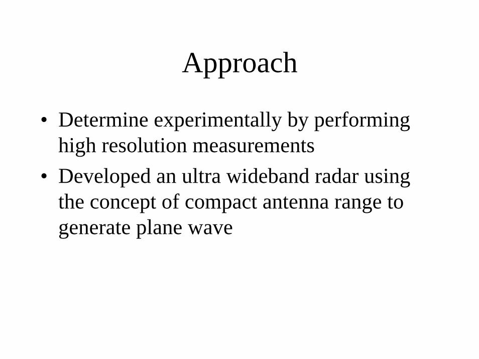
• Illumination of distributed targets using conventional antennas contain a wide range of incidence angle
• This problem can be overcome by using a parabolic reflector with an offset feed which propagates a plane wave of uniform phase
Comparison between Conventional Antenna and Plane Wave Antenna
θ βα
Surface of
interest
α = θ = βα = θ = β
Focal
Point
Surface of
interest
α θ β

Geometry of Parabolic Reflector
Diffracted
Rays
interest
Surface of
Reflection
Boundary (RB)
Focal
Point
18''
42''

Generation of Plane Wave• Rays emanating from a spherical source at the
focal point of a parabolic reflector are reflected in the form of parallel rays
• Surface normal to these parallel rays will have a constant incidence angle
• In the vicinity of the reflection boundary diffracted rays are planar and they do not decay as a function of range
• Diffracted rays are spherical and their amplitude decays as 1/r far from the antenna
• Diffracted rays can be minimized by edge shaping or the use of absorbing material

Generation of Plane Wave
• Plane wave has uniform phase over an area equal to the area of the reflector
• The range of propagation is about 0.5*D2/λ• Ideally the diameter of the reflector should be 10
wavelengths at the lowest frequency to be effective in the compact range
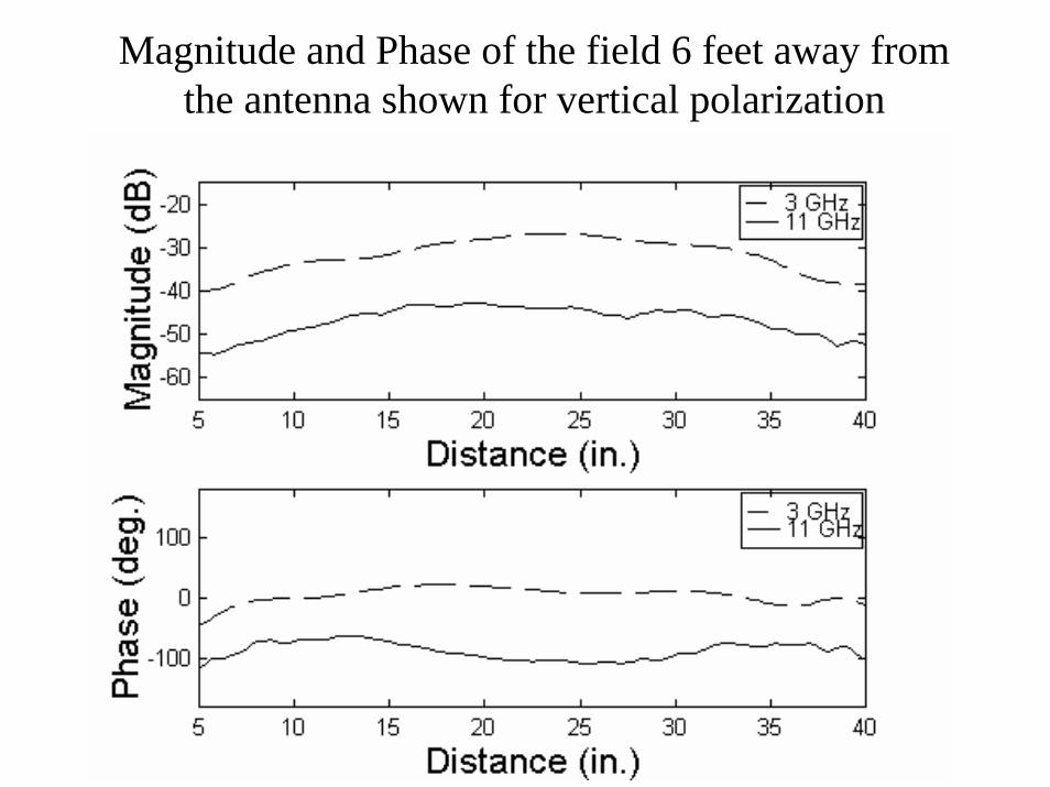
Magnitude and Phase of the field 6 feet away from the antenna shown for vertical polarization

Step-frequency radar principles• Transmitted signal
• Received signal
where β=2π/λd is the distance to the target
• When frequency is stepped uniformly N times we have
n=0:N-1fo is the start frequency∆f is the frequency step size
V f Et o( ) =
V f E j dr o( ) exp( )= Γ 2β
V f E jf n f d
cr n o
o( ) exp( )
=+⎛
⎝⎜⎞⎠⎟
Γ∆4π
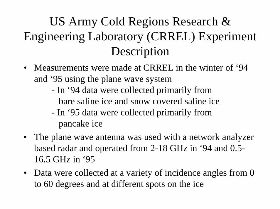
US Army Cold Regions Research & Engineering Laboratory (CRREL) Experiment
Description• Measurements were made at CRREL in the winter of ‘94
and ‘95 using the plane wave system- In ‘94 data were collected primarily from
bare saline ice and snow covered saline ice- In ‘95 data were collected primarily from
pancake ice• The plane wave antenna was used with a network analyzer
based radar and operated from 2-18 GHz in ‘94 and 0.5-16.5 GHz in ‘95
• Data were collected at a variety of incidence angles from 0 to 60 degrees and at different spots on the ice
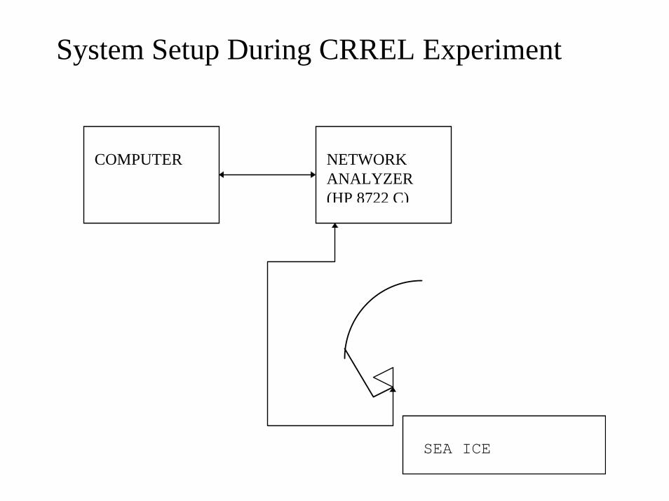
System Setup During CRREL Experiment
COMPUTER NETWORKANALYZER(HP 8722 C)
SEA ICE

Data Processing• Important parameter of interest is the
backscattering coefficient (σo)
Pr is the power returned from icePcal is the return power from a target of
known radar cross section, σcal andAill is the area illuminated by the antenna
σσo r cal
cal ill
PP A
=

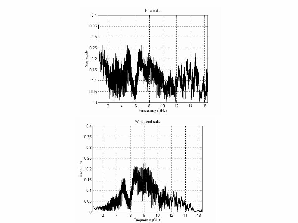
Frequency Response Computation of Pr(f)
RAW DATA
WINDOW
IFFT
CNR
FILTER
Pr(f)
FFT
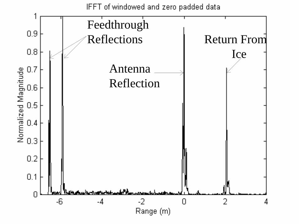
FeedthroughReflections
AntennaReflection
Return From Ice

V CNR VN
Vii
N
1 11
1= − ∑
=

IceReturn
GaussianFilter
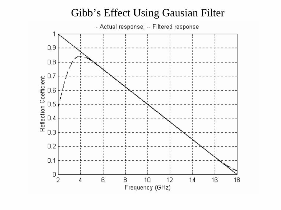
Gibb’s Effect Using Gausian Filter
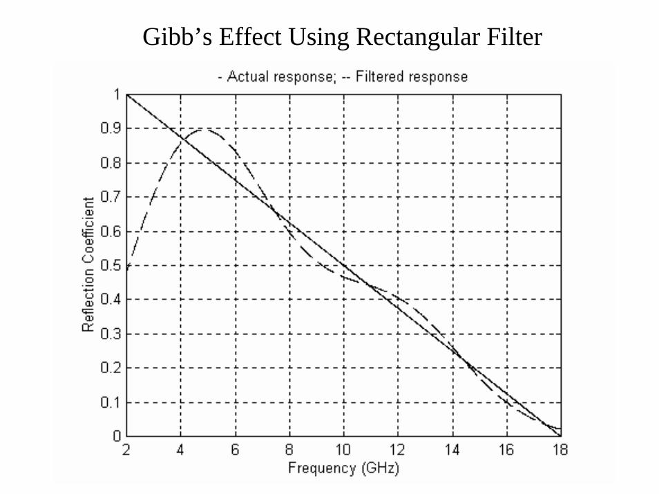
Gibb’s Effect Using Rectangular Filter
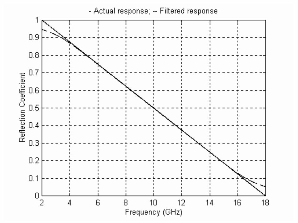
Reducing the Gibb’s effect
• To reduce the Gibb’s effect, -Simulate the step-frequency data with a reflection coefficient of one at the same range as the target-Use the same window on the simulated data, zero pad and take the IFFT-Use the same filter that is used on the ice return for the simulated data. -FFT of this filtered signal is the correction factor which is divided by the frequency response of the target.
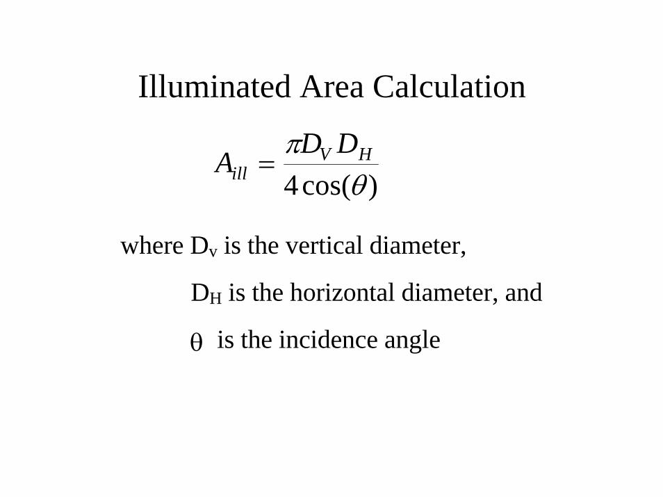
Illuminated Area Calculation
AD D
illV H=
πθ4cos( )
where Dv is the vertical diameter,
DH is the horizontal diameter, and
θ is the incidence angle

Measured
Fit

Scattering Theory
Coherentcomponent
IncidentWave
Incoherentcomponents
Surface
Surface Scattering

Scattering Theory- con’t
IncidentBeam
Air bubbles &brine pocketsin sea ice
Surface
Volume Scattering
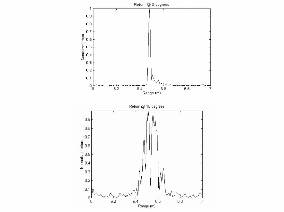

Results - Impulse Response I

Results - Impulse Response II
ICE
SNOW

Results - Angular Scattering Response I

COMPARISON BETWEEN FIELD AND LAB MEASUREMENT OF PANCAKE ICE

ANGULAR RESPONSE OF BARE, SNOW COVER AND PANCAKE ICE

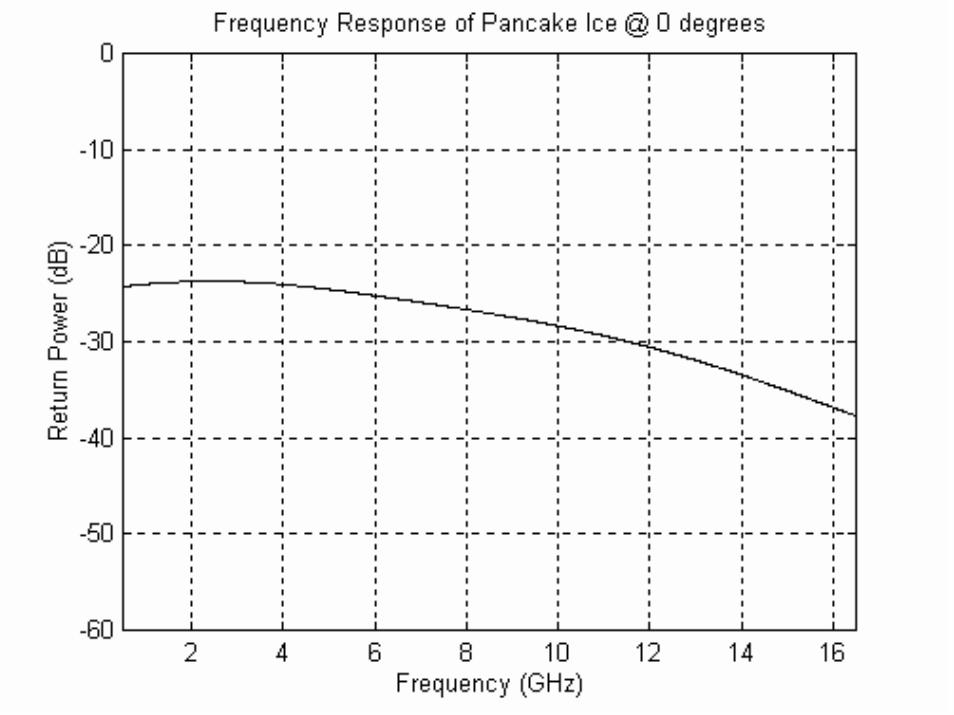
FREQUENCY RESPONSE OF BARE, SNOW COVER AND
PANCAKE ICE
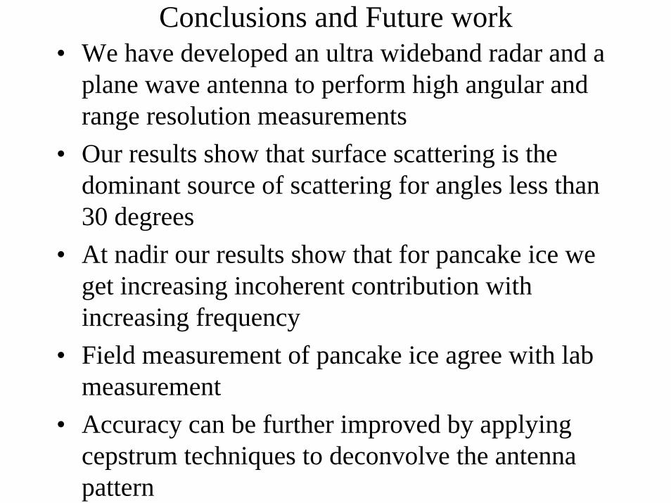
Conclusions and Future work• We have developed an ultra wideband radar and a
plane wave antenna to perform high angular and range resolution measurements
• Our results show that surface scattering is the dominant source of scattering for angles less than 30 degrees
• At nadir our results show that for pancake ice we get increasing incoherent contribution with increasing frequency
• Field measurement of pancake ice agree with lab measurement
• Accuracy can be further improved by applyingcepstrum techniques to deconvolve the antenna pattern

Design of a Range-Gated Step-Frequency Radar using FMCW
Concept
Objective
• To design a range-gated step-frequency radar/probe using FMCW concept

FM-CW Concepts
Transmittedsignal
Receivedsignal
1/fm
B τ fb
τ =2Rc
f RBfcb
m=2
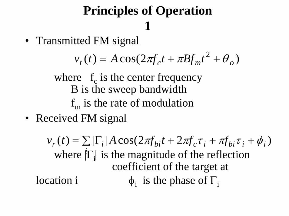
Principles of Operation1
• Transmitted FM signal
where fc is the center frequencyB is the sweep bandwidthfm is the rate of modulation
• Received FM signal
where |Γi| is the magnitude of the reflection coefficient of the target at
location i φi is the phase of Γi
v t A f t Bf tt c m o( ) cos( )= + +2 2π π θ
v t A f t f fr i bi c i bi i ii
( ) | | cos( )= + + +∑ Γ 2 2π π τ π τ φ

Principles of Operation 2
• FFT of the received signal gives the magnitude and phase of the target at each beat frequency.
where ψfb= 2πfcτfb + φfb
• Apply a bandpass filter centered at the beat frequency corresponding to the target to obtain the complex Γ of the target
V f jfft b fb fb( ) | |exp( )= Γ ψ

Principles of Operation 3
• Store the magnitude and phase of target for each center frequency (fc)
• We now have
where fi = fo + i∆f fo is the start frequency
∆f is the frequency step size• FFT of H(i) with respect to i gives us the high
resolution spectrum of the target.
H i j ftar i tar tar( ) | |exp{ ( )}= +Γ 2π τ φ

Summary of operation
Highresolution
range-gatedspectrum
FFT
Save Magnitude& Phase of target
FFT
Range-gatingFilter
Receive FMSignal
Transmit FMSignal
Increment fc

SIMULATION - I
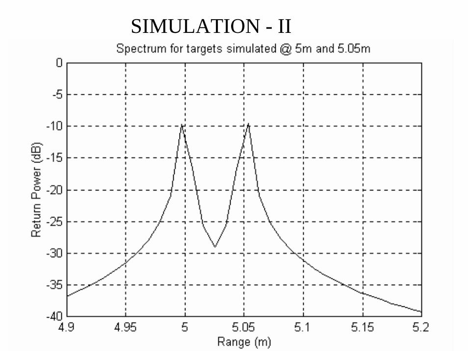
SIMULATION - II
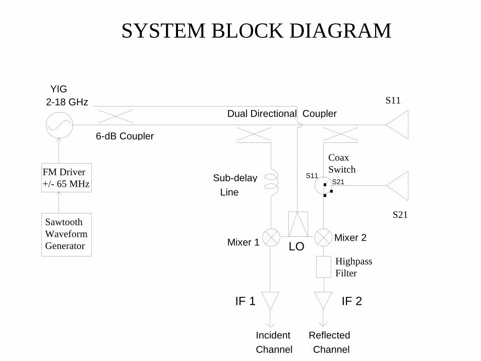
Dual Directional Coupler
...
IF 1
IncidentChannel
ReflectedChannel
IF 2
S11S21
LOMixer 2Mixer 1
6-dB Coupler
LineSub-delay
2-18 GHzYIG
FM Driver+/- 65 MHz
Sawtooth Waveform Generator
S11
S21
CoaxSwitch
HighpassFilter
SYSTEM BLOCK DIAGRAM

STEP-FREQUENCY RADAR PARAMETERS
Parameter ValueCenter Frequency 2.37 - 17.65 GHzCenter Frequency step size 11.7 MHzNumber of Frequency steps 1300Range resolution 0.98 cmMax. Unambiguous Range 29 m

LINEARITY OF OSCILLATOR’S SWEEP
• The performance of the radar is dependent on the linearity of the oscillator’s sweep
• To test the linearity of the oscillator’s sweep, we measured all 4096 of the oscillator’s frequency using a spectrum analyzer

LINEARITY OF OSCILLATOR’S SWEEP - I

LINEARITY OF OSCILLATOR’S SWEEP -II

SIMULATION WITH OSCILLATOR’S MEASURED FREQUENCY
SYSTEM TESTS
• To test the system’s ability to measure thepermitivity of materials we developed a cylindrical monopole antenna
• To use the existing models to obtain the relative permittivity of materials, the antenna has to resonate
• To resonate, the ratio of the length to diameter must be greater than 10

SYSTEM TESTS - II• The length of the antenna for a given resonant
frequency is
h cf
d= −
0 242
.
d=0.51mm
h=5 mmGround Plane
Dielectric
Connector
MonopoleAntenna
D=7.54 cm

REAL PART OF INPUT IMPEDANCE
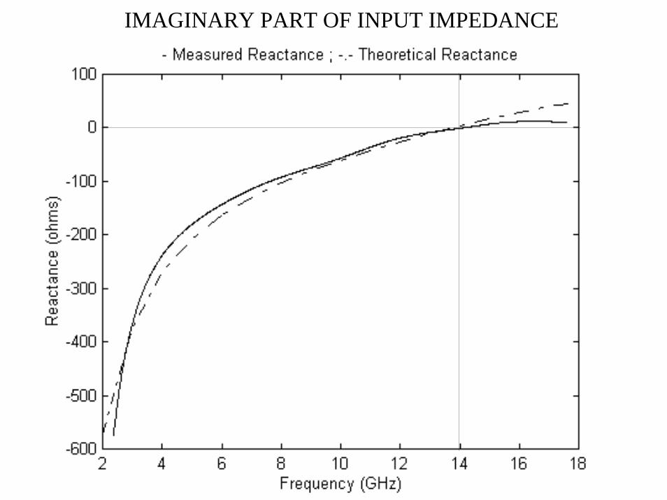
IMAGINARY PART OF INPUT IMPEDANCE

MODELLING THE INPUT IMPEDANCE
Z Zo( , ) ( , )( , )
ω ε ω εω ε
=+−
11
ΓΓ
ε ω ε ε ω εr r r rZ Z1 1 1 1 2 2 2 2( , ) ( , )=Deschamp’s Theorem
Z kh Z khk h
Zn r ro
r( ) ( , ) ( , )= =ε ω ε ω ε
( )Zn
kh j Kkh
jb kh b kh
jb kh a kh≈
+ +
+ +
⎡
⎣
⎢⎢⎢
⎤
⎦
⎥⎥⎥
11 2
2
11 2
2
( ) ( )
( ) ( ) εrkh
koh=
⎛
⎝⎜⎜
⎞
⎠⎟⎟
2
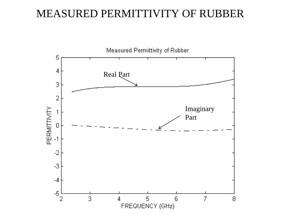
MEASURED PERMITTIVITY OF RUBBER
Real Part
ImaginaryPart

NOTE ON CALIBRATION
• Reflection from the medium did not appear at the plane of calibration
• Applied phase correction term to the reflection coefficient to correct for this lag
Z Z eeo
l j l
l j l( , ) ( , )( , )
ω ε ω εω ε
α β
α β=+−
− −
− −11
2 2
2 2ΓΓ

DELAY LINE TEST

Radar Comparison• FMCW Radar
- Long range - Poor resolution
• Step-frequency radar - High resolution- Very short range - Need to use network analyzer for ultra wideband operation - Need very fast switches to implement range gate
• Our Radar- FMCW radar’s range - Ultra wideband operation-Range gate can be implemented with filters - Range-gated spectrum with the resolution of step-frequency radar -Can be operated with a single antenna
CONCLUSION & FUTURE WORK• Shown that the step-frequency radar can be
operated and range-gated using the FM-CW concept
• Permittivity measurement using this system agrees with theoretical results
• Radar can be used for high-resolution probing of geophysical surfaces and also for ground-pentration applications
• Performance can be improved using Direct Digital Synthesizer (DDS)
Related Documents