11.2 High Pressure Equipment Air Operated Hydraulic Pumping Systems to 50,000 psi System includes hydraulic oil reservoir, oil filter, air operated hydraulic pump, pressure gauge, panel mounted high pressure valves, safety head assembly, panel mounted air regulator and gauge and air line filter and lubricator. All components are enclosed in a steel console with only the back exposed. Dimensions of standard systems are 26" wide, 24" deep and 40" high. High Pressure air operated hydraulic pumping systems are complete, self- contained units and ready to operate. Just hook up standard shop air supply (maximum 100 psi) to connection supplied on the side of the console. Discharge capacities range to 64 in 3 /min. ● Model PS-10: 10,000 psi ● Model PS-20: 20,000 psi ● Model PS-30: 30,000 psi ● Model PS-40: 40,000 psi ● Model PS-50: 50,000 psi ● Model PS-90: 90,000 psi Standard Features R4 2/02

Welcome message from author
This document is posted to help you gain knowledge. Please leave a comment to let me know what you think about it! Share it to your friends and learn new things together.
Transcript

11.2
High Pressure Equipment
Air Operated HydraulicPumping Systems to 50,000 psi
System includes hydraulic oil reservoir,oil filter, air operated hydraulic pump,pressure gauge, panel mounted highpressure valves, safety head assembly,panel mounted air regulator and gaugeand air line filter and lubricator.
All components are enclosed in a steelconsole with only the back exposed.
Dimensions of standard systems are26" wide, 24" deep and 40" high.
High Pressure air operated hydraulicpumping systems are complete, self-contained units and ready to operate.Just hook up standard shop air supply(maximum 100 psi) to connection supplied on the side of the console.Discharge capacities range to 64 in3/min.
● Model PS-10: 10,000 psi● Model PS-20: 20,000 psi● Model PS-30: 30,000 psi● Model PS-40: 40,000 psi● Model PS-50: 50,000 psi● Model PS-90: 90,000 psi
Standard Features
R4 2/02

R4 2/02
100 psi MAXAIR INLETSUPPLIED WITHREGULATOR FILTERAND LUBRICATOR
RESERVOIR AIR OPERATEDHYDRAULIC PUMP
HIGH PRESSUREOUTLET
PRESSUREGAUGE
11.3High Pressure Equipment Company2955 W. 17th Street • Erie, PA 16505 U.S.A. • Phone: (814) 838-2028 • 1-800-289-7447 • Fax: (814) 838-6075 • Website: www.HighPressure.com
System CapabilitiesThe output pressure is predetermined by adjustment to the air regulator setting.
Output pressure is maintained constantlyand pump compensates for pressure drops or losses.
Hydraulic input is gravity fed, however, if pump is used alone, the feed can be pressurized to the limit of the pump.
Within the pump the large diameter air piston drives a smaller piston to provide fluid flow at high pressure.
Air consumption will be approximately 56 CFM of free air at 100 psi input.
Reservoir = 4 gallon capacity, do not pressurize.
Standard Pumping System SpecificationsApproximate Air to Hydraulic Pressure Ratio — Static Conditions
Approximate Rate of Discharge — CIPM
Model Air psiNo. 10 20 30 40 50 60 70 80 90 100 110
PS-10 1,500 3,200 5,200 7,100 9,000 10,800 12,500 14,500 16,300 18,000 19,800
PS-20 3,000 6,000 9,500 12,600 16,000 19,100 22,300 25,600 29,000 32,300 35,600
PS-30 4,000 8,800 13,700 18,000 22,500 27,000 31,500 36,500 41,400 45,800 50,300
PS-40 6,000 13,000 21,000 27,000 34,000 40,500 46,000 52,000 59,000 65,000 70,000
PS-50 6,000 13,000 21,000 27,000 34,000 40,500 46,000 52,000 59,000 65,000 70,000
PS-90 Uses Dual Pump N/A N/A N/A N/A N/A N/A N/A N/A
HydraulicPressure
psi
Model
Air psi
Pressure
60 80 100 60 80 100 60 80 100 60 80 100 60 80 100
10,000 psi 27 52 64 31 40 44 28 33 35 19 23 24 19 23 24
30,000 psi 0 0 0 0 0 14 0 16 21 12 15 17 12 15 17
40,000 psi 0 0 0 0 0 0 0 0 14 2 12 15 2 12 15
50,000 psi 0 0 0 0 0 0 0 0 0 0 6 11 0 6 11
PS-10 PS-20 PS-30 PS-40 PS-50

100 psi MAXAIR INLETSUPPLIED WITHREGULATOR FILTERAND LUBRICATOR
INTENSIFIERA
RET
UR
N L
INE
C B
CHECKVALVE PRESSURE
GAUGE
AIR OPERATEDHYDRAULIC PUMP
RESERVOIR
The Model PS-150 Pumping System is designed for generatinghydraulic pressure up to 150,000 psi by means of an air operatedhydraulic pump and an intensifier. The 10 to 1 ratio intensifier is fullyillustrated on facing page 11.5. This system is complete and ready to operate requiring only the connection of an air supply of approximately 80 psi.
The steel console is 26" wide, 24" deep, 40" high and includesmanual valves, air regulator, filter and lubricator, air gauge, high pressuregauge, reservoir, oil filter, pump (0-16,000 psi), related high pressuretubing and fittings.
The 0-20,000 psi pressure gauge is connected to the low pressureside of the intensifier which has a ratio of 10 to 1. Pressure on the highpressure side of the intensifier is thus determined by multiplying thegauge reading by 10. A small variation must be allowed for frictionfrom the intensifier packing.
The air operated hydraulic pump pressurizes the system to16,000 psi with valves “A” and “B” closed and the intensifier pistonis automatically positioned to the low pressure end of its stroke. Withvalves “A” and “C” closed, valve “B” is opened to allow the pump topressurize the low pressure end of the intensifier. The fluid in the highpressure end of the intensifier is thus pressurized with a 10 to 1 ratio.If the intensifier reaches the end of its stroke before the desiredpressure is achieved, the intensifier may be recycled. The intensifieroutput is approximately 1.2 cubic inches per stroke.
150,000 psiPumpingSystemModel PS-150
11.4
High Pressure Equipment
R1 12/97

6"
19"
The 150,000 psi Hydraulic Intensifier is designed with aratio of areas on the two pistons of 10 to 1. Consequently,pressures up to 150,000 psi can be achieved by using acommercially available lower pressure (15,000 psi) pump.
Operation of this intensifier is illustrated in the typicalinstallation shown in the schematic on facing page 11.4.
Material of construction for the pressure containingparts is 4340 alloy steel (or equivalent) properly heat treatedfor use at elevated pressures. Only non-corrosive typefluids should be used. The high pressure packing ishoused in a separate removable stuffing box. This designpermits improved concentricity and facilitates closetolerance machining of the packing area.
Capacity per stroke at the high pressure end is 1.2 cubicinches. Capacity at the low pressure end is 12.6 cubic inchesper stroke. Piston travel is 4 inches. Weight is approximately150 pounds.
Standard connections are for 1/4" O.D. tubing (HF4) on thelow pressure end and 3/8" O.D. x 1/16" I.D. tubing (XF6) on thehigh pressure end.
150,000 psiHydraulic Intensifiers
11.5High Pressure Equipment Company2955 W. 17th Street • Erie, PA 16505 U.S.A. • Phone: (814) 838-2028 • 1-800-289-7447 • Fax: (814) 838-6075 • Website: www.HighPressure.com

RETURN LINE
OIL
AIR OPERATEDHYDRAULIC PUMP
RESERVOIR
(Schematic shows60,000 psi Booster)
AIRINLET
AIRREGULATOR
GASINLET
GASBOOSTERCYLINDERINTENSIFIERTYPE
VENT
COMPRESSEDGAS
OUTLET
PRESSUREGAUGE
Gas BoostersMODEL GBS - 30
30,000 psi Gas Booster System(One-to-one ratio — 112 cubic inch per stroke displacement)(17-4PH stainless steel construction)
MODEL GBS - 6060,000 psi Gas Booster System(Thirty-to-one ratio — 4.7 cubic inch per stroke displacement)(4340 alloy steel construction)
11.6
High Pressure Equipment
The Model GBS-30 and GBS-60 Gas Booster Systems are complete and ready to operate. All that is required is an air supply for the pump (approximately 70 psi) and a commerciallyavailable container of compressed gas.
The steel console is 26" wide, 24" deep, 40" high and includesmanual valves, air regulator, filter and lubricator, air gauge, highpressure gauge, reservoir, oil filter, pump, gas booster and relatedhigh pressure tubing and fittings.
Operation is by means of an air operated hydraulic pump whichpressurizes one end of the gas booster which then compressesthe gas in the opposite end of the booster. To accomplish this, the gas inlet valve is opened to permit gas to fill the gas end of the booster. Check valves are provided to permit gas flow in onedirection only. With the gas outlet valve open, the hydraulic pumpis operated in order to pressurize the hydraulic end of the booster.Thus, the gas is compressed in the booster. If required pressure is not reached by the end of the stroke, the gas booster can easily be recycled for additional strokes.
Note the gauge on these systems is connected to thehydraulic side of the booster. On the Model GBS-30 which has a 1 to 1 ratio, there is a direct reading of the pressure in the gasend of the booster. The Model GBS-60 has a 30 to 1 ratio and thegauge will accordingly indicate a reading of one-thirtieth (1/30) ofthe actual pressure in the gas end of the booster. An additionalgauge can be furnished for connection to the gas end of thebooster to provide direct pressure readings of the gas pressure.
Details of the gas boosters are shown on facing page 11.7.These systems should not be used with hydrogen or oxygen.

HIGHPRESSURE
END
33"
LOWPRESSURE
END
30"
11.7
Model GB-30 30,000 psi
The Model GB-30 Gas Booster is rated for use up to 30,000 psiand has a one-to-one ratio. Displacement per stroke is 112 cubicinches (1835 ml).
Material of construction is 17-4PH stainless steel for the bodyand covers. The piston is supplied in brass with other materialsavailable as an option. Standard O-ring material for the coversand piston is BUNA-N (nitrile).
Standard connections supplied are for 1/4" O.D. High Pressuretubing (HF4 connection) at each end.
The Model GB-30 can be supplied as a separate unit or withthe complete system (Model GBS-30) shown on page 11.6.
The Model GB-30 should not be used with hydrogen or oxygen.
Model GB-60
Special Gas Boosters and Intensifiers
60,000 psi
The Model GB-60 Gas Booster is rated for use up to 60,000 psi and has a thirty-to-one (30-1) ratio. Thus, 60,000 psi can be obtainedat the high pressure end using only 2,000 psi inlet pressure.Displacement per stroke is 4.7 cubic inches (77 ml).
Material of construction is Type 4340 alloy steel (or equivalent)properly heat treated for use at high pressure. Other internal materials include 17-4PH stainless steel and aluminum bronze.Seals include BUNA-N (nitrile) O-rings and a Parker Poly Pak®.
Standard connections supplied are for 1/4" O.D. High Pressuretubing (HF4 on the high pressure end and AF4 on the low pressure end).
The Model GB-60 can be supplied as a separate unit or with the complete system (Model GBS-60) shown on page 11.6.
The Model GB-60 should not be used with hydrogen or oxygen.
High Pressure Equipment Company has designed and suppliednumerous gas boosters and intensifiers to meet the customer'sspecial requirements. A price quotation can be made by advisingus of the requirements including: media (gas or liquid) to be pressurized, maximum outlet pressure required, available inletpressure and required displacement per stroke.
Gas Boosters
R4 2/02High Pressure Equipment Company2955 W. 17th Street • Erie, PA 16505 U.S.A. • Phone: (814) 838-2028 • 1-800-289-7447 • Fax: (814) 838-6075 • Website: www.HighPressure.com
Piston travel - 6"

High Pressure GeneratorsThe HiP High Pressure Generator is a manually operated piston screw pump. It is designed for any applicationwhere a liquid* is to be compressed within a small volume to develop pressure.
Pressure Ranges:0-5,000 psi ● 0-10,000 psi ● 0-15,000 psi ● 0-30,000 psi ● 0-60,000 psi ● 0-75,000 psi ● 0-100,000 psi
All wetted parts are of 316 stainless steel and 17-4PH stainless steel. Parker Poly Pak® is standard.
The High Pressure Generator is easily mounted to a work bench and maximum pressures may be obtained with a minimum amount of effort by the operator. The standard connection is a High Pressure coned-and-threaded(HF4) opening for 1/4" O.D. tubing up to 60,000 psi and XF4 connections for pressures above 60,000 psi. Adapters are available with optional Teflon packing at no additional cost for other type connections including pipe.
Typical Applications:● Testing of instruments, gauges, component parts● Pressure measurement studies● Injection of liquid catalysts● Pressurizing chemicals● A convenient source of high
pressure in the laboratory
11.8
High Pressure Equipment
ExtraCapacityModel
Vernier Indicators as shown in the photo at left are available as an accessory on all of the Standard LaboratoryModels. These indicators provide controlled measurement of column displacement with an accuracy of ± 0.003" movement of stroke.
* If required for GAS application, please consult factory.
StandardLaboratoryModel
18.75" to 24"
R A B C
1 4
1"1"
8"5
18" 23
1"1"
6 7 8
1"
1"1"
1"8"
875469224"
10
30"
1
11 3
High Pressure Generators
11.9High Pressure Equipment Company2955 W. 17th Street • Erie, PA 16505 U.S.A. • Phone: (814) 838-2028 • 1-800-289-7447 • Fax: (814) 838-6075 • Website: www.HighPressure.com
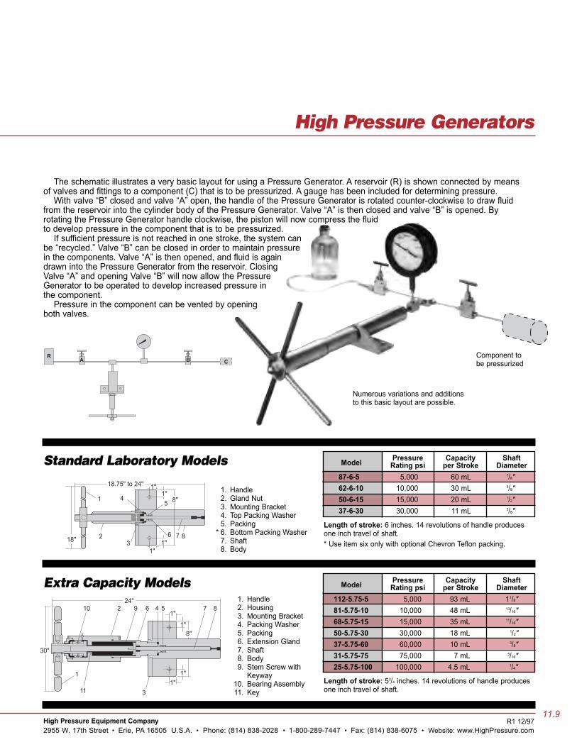
Model Pressure Capacity ShaftRating psi per Stroke Diameter
87-6-5 5,000 60 mL 7/8"62-6-10 10,000 30 mL 5/8"50-6-15 15,000 20 mL 1/2"37-6-30 30,000 11 mL 3/8"
Length of stroke: 6 inches. 14 revolutions of handle producesone inch travel of shaft.* Use item six only with optional Chevron Teflon packing.
Model Pressure Capacity ShaftRating psi per Stroke Diameter
112-5.75-5 5,000 93 mL 11/8"81-5.75-10 10,000 48 mL 13/16"68-5.75-15 15,000 35 mL 11/16"50-5.75-30 30,000 18 mL 1/2"37-5.75-60 60,000 10 mL 3/8"31-5.75-75 75,000 7 mL 5/16"25-5.75-100 100,000 4.5 mL 1/4"
Length of stroke: 53/4 inches. 14 revolutions of handle producesone inch travel of shaft.
1. Handle2. Gland Nut3. Mounting Bracket4. Top Packing Washer5. Packing
* 6. Bottom Packing Washer7. Shaft8. Body
1. Handle2. Housing3. Mounting Bracket4. Packing Washer5. Packing6. Extension Gland7. Shaft8. Body9. Stem Screw with
Keyway10. Bearing Assembly11. Key
The schematic illustrates a very basic layout for using a Pressure Generator. A reservoir (R) is shown connected by meansof valves and fittings to a component (C) that is to be pressurized. A gauge has been included for determining pressure.
With valve “B” closed and valve “A” open, the handle of the Pressure Generator is rotated counter-clockwise to draw fluidfrom the reservoir into the cylinder body of the Pressure Generator. Valve “A” is then closed and valve “B” is opened. Byrotating the Pressure Generator handle clockwise, the piston will now compress the fluidto develop pressure in the component that is to be pressurized.
If sufficient pressure is not reached in one stroke, the system canbe “recycled.” Valve “B” can be closed in order to maintain pressurein the components. Valve “A” is then opened, and fluid is againdrawn into the Pressure Generator from the reservoir. ClosingValve “A” and opening Valve “B” will now allow the PressureGenerator to be operated to develop increased pressure inthe component.
Pressure in the component can be vented by openingboth valves.
Component tobe pressurized
Numerous variations and additionsto this basic layout are possible.
Standard Laboratory Models
Extra Capacity Models
R1 12/97
Related Documents