T E C H N I C A L C A T A L O G PRESSURE CONTROL VALVES HYDRAULIC COMPONENTS

Welcome message from author
This document is posted to help you gain knowledge. Please leave a comment to let me know what you think about it! Share it to your friends and learn new things together.
Transcript

T E C H N I C A L C A T A L O G
PRESSURE CONTROL VALVESHYDRAULIC COMPONENTS

25/03/13 3
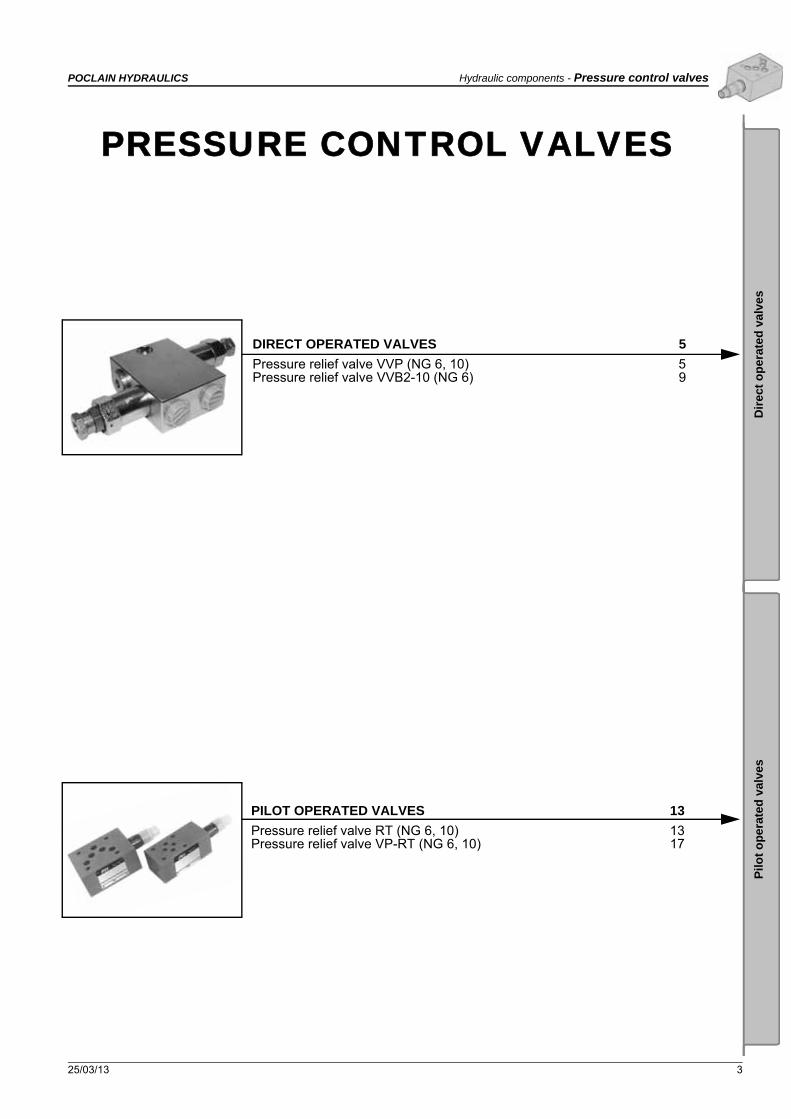
POCLAIN HYDRAULICS Hydraulic components - Pressure control valves
CONTENT
Dir
ect
op
erat
ed
val
ves
Pilo
t o
pe
rate
d v
alve
s
PILOT OPERATED VALVES 13
Pressure relief valve RT (NG 6, 10) 13Pressure relief valve VP-RT (NG 6, 10) 17
DIRECT OPERATED VALVES 5
Pressure relief valve VVP (NG 6, 10) 5Pressure relief valve VVB2-10 (NG 6) 9
PRESSURE CONTROL VALVES

4 25/03/13
Pressure control valves - Hydraulic components POCLAIN HYDRAULICS

25/03/13 5
POCLAIN HYDRAULICS Hydraulic components - Pressure control valves
Dir
ect
op
erat
ed
val
ves
Pilo
t o
pe
rate
d v
alve
s
PRESSURE RELIEF VALVE VVP (NG 6, 10)
• NG 6, 10• Up to 400 bar [3,045 PSI]• Up to 60 L/min [31.7 GPM]
• For fitting into a block.• For independent mounting.• Two pressure setting elements (set screw, rotary knob).
VVP-6, VVP-10
Operation Hydraulic symbol
These valves consist of a housing (1), a hardened seat (2), a poppet (3), with a damping spool (4), a spring (5), and a pressure setting element (6).The P-line of this pressure relief valve is connected with the hydraulic system. The pressure of the hydraulic fluid acts on the front side of the pilot poppet (3), and the force of the spring (5) set by the pressure setting element (6) is applied to the poppet from the opposite side. When the system pressure exceeds the valve of the spring set by the pressure setting element (6) the pilot poppet moves off the seat (2), and frees the flow of the hydraulic fluid in the direction from P towards T.The damping spol (4) prevents vibrations of the pilot poppet when opening or closing the flow way of the hydraulic flow. Loosening of the pressure setting element is prevented by a counternut (8).
Direct operated pressure relief valves type VVP are used to maintain and limit the pressure in a hydraulic system.
Features
Size 6 10
Flow rate L/min [GPM] 50 [13.2] 120 [31.7]
Pressure setting range bar [PSI] 400 [5 801]
Oil temperature range °C [°F] -30 to +70 [-22 to + 158]
Viscosity range mm2/s [SUS] 2,8 to 380 [12.9 to 1760]
Filtration NAS 1638 8
MassExecution A
kg [lbs]0,4 [0.88] 0,5 [1.10]
Execution BExecution B 0,5 [1.10] 0,6 [1.32]
DIRECT OPERATED VALVES

6 25/03/13
Hydraulic components - Pressure control valves POCLAIN HYDRAULICS
Dimensions
Connecting dimensions / connection P-VVP-6, P-VVP-10
9. Pressure setting by screw and protective cap.10. Pressure setting by rotary knob.12. O-ring, nominal size 6, 19,2 x 3.
O-ring, nominal size 10, 26 x 3.13. Usit ring, nominal size 6, 17,4 x 24 x 1,5.
Usit ring, nominal size 10, 24,7 x 31 x 2.
Tightening torque for fixing:Nominal size 6 Md=80 Nm [708 in.lbf].Nominal size 10 Md=140 Nm [1 239 in.lbf].
Customer specified setting can be secured by means of a stamp and a wire.
Type a b Øc e Øf Øg Øh i j k l m n o Øp Ør s s1 s2
VVP-672
[2.83]94
[3.70]34
[1.34]M28x1,5 60
[2.36]
24,9 [0.98]
15 [0.59]
65 [2.56]
56,5 [2.22]
45 [1.77]
30 [1.18]
19 [0.75]
15 [0.59]
35 [1.38]
6 [0.24]
25H932
[1.26] 6 [0.24]
19 [0.75]
VVP-1068
[2.67]90
[3.54]38
[1.50]M35x1,5
31,9 [1.25]
18,5 [0.73]
80 [3.15]
67,5 [2.66]
52 [2.05]
35 [1.38]
23 [0.90]
18 [0.71]
41 [1.61]
10 [0.39]
32H936
[1.42]
1. Oil discharge when fitted independently.2. Oil supply when fitted independently.3. Oil supply when fitted on a tank cover.4. Oil discharge when fitted on a tank cover.
When fitting, the excess ports for oil supply and discharge must be closed by means of suitable screw.
Size Øa Øb c d Masse kg [lb]
659 d9[2.32]
24 [0.94]
M18x1,560
[2.36]2,5
[5.51]
1069 d9[2.72]
28[1.10]
M22x1,570
[2.76]2,9
[6.39]
1. Port ’’P’’.2. Return line ’’T’’.3. Locking screws - P line.4. Locking screws - T line.

25/03/13 7
POCLAIN HYDRAULICS Hydraulic components - Pressure control valves
Dir
ect
op
erat
ed
val
ves
Pilo
t o
pe
rate
d v
alve
s
P-Q Performance curves
Model code
Size 6 Size 10
Flow
Diff
. pre
ssur
e
Diff
. pre
ssur
e
Measured at 50°C [122°F] and viscosity of 32 mm2/s [148 SUS].
Flow
PV
Pressure setting range[PSI]
To 50 [725] 50
To 100 [1,450] 100
To 200 [2,900] 200
To 315 [4,568] 315
To 400 [5,801] 400
Size
Size 6 6Size 10 10
- -
Seal type
NBR seals for mineral oil HL,HLP to DIN 51524
No designation
FPM seals for HETG, HEES, HEPG to VDMA 24568 and ISO 15380 E
Special requirements to be briefly specified
- - *V -
Pressure setting element
Set screw with protective cap A
Rotary knob B

8 25/03/13
Hydraulic components - Pressure control valves POCLAIN HYDRAULICS

25/03/2013 9
POCLAIN HYDRAULICS Hydraulic components - Pressure control valves
Dir
ect
op
erat
ed
val
ves
Pilo
t o
pe
rate
d v
alve
s
PRESSURE RELIEF VALVE VVB2-10 (NG 6)
• NG 6• Up to 210 bar [3,045 PSI]• Up to 60 L/min [15,8 GPM]
• Direct in-line mounting.• hreaded connections to ISO 9974 (Metric), ISO 1179 (BSPP/Gas).• Five different pressure setting elements.
VVB2-10-...
Features Hydraulic symbol
Size 6
Operating pressure Bar [PSI] 210 [3 045]
Flow rate L/min [GPM] 60 [15.8]
Pressure setting range bar [PSI] 120 [1 740]; 160[2 320]; 200 [2 900]
Oil temperature range °C [°F] -10 to +70 [14 to + +158]
Viscosity range mm2/s [SUS] 15 to 380 [69.5 to + 1,760]
Filtration ISO 4406-1999 19/17/14
Mass kg [lbs] 1.85 [4.08]
Seal type NBR seals for mineral oil HL, HLP, to DIN 51524
P-Q Performance curves
Flow
Diff
. pr
essu
re
Measured at 50°C [122°F] and viscosity of 32 mm2/s [148 SUS].
A = 120 bar [1740 PSI]B = 160 bar [2320 PSI]C = 200 bar [2900 PSI]

10 25/03/2013
Hydraulic components - Pressure control valves POCLAIN HYDRAULICS
Dimensions
Inner hexagonal key
Inner hexagonal key and
protective cap
Knob Fixed setting Exterior key

25/03/2013 11
POCLAIN HYDRAULICS Hydraulic components - Pressure control valves
Dir
ect
op
erat
ed
val
ves
Pilo
t o
pe
rate
d v
alve
s
Model code
BV 0
Pressure setting range [PSI]
120 [1740] 120
160 [2 320] 160
200 Bar [2 900 PSI] 200
- -
Threaded connections
M18 x 1,5 No designation
G 3/8 3/8
Special requirements to be briefly specified
- - *V -
Pressure setting element
Inner hexagonal key A
Inner hexagonal key and protective cap B
Knob G
Fixed setting K
Exterior key S
2 1

12 25/03/2013
Hydraulic components - Pressure control valves POCLAIN HYDRAULICS

25/03/13 13
POCLAIN HYDRAULICS Hydraulic components - Pressure control valves
Dir
ect
op
erat
ed
val
ves
Pilo
t o
pe
rate
d v
alve
s
PRESSURE RELIEF VALVE RT (NG 6, 10)
• NG 4, 6, 10• Up to 350 bar [3,045 PSI]• Up to 60 L/min [26.4 GPM]
• For independent fitting into a block.• Two pressure setting ranges.
RT-4, RT-6, RT-10
Operation Hydraulic symbol
Pilot operated pressure relief valves type RT are used for maintaining and limiting the pressure in a hydraulic system.These valves consist of a housing of cartridge design (1), main spool insert (2) with a spring (3), pilot poppet (4), spring (5) and pressure setting element (6).The P-line of this pressure relief valve is connected with the hydraulic system. The hydraulic medium pressure acts on the front side of the main spool insert. The bores (7,8) permit the introduction of pilot oil into the pressure chamber (9) and the application of pressure to the opposite side of the main spool insert and the front side of the pilot poppet. The pressure balance in the system and pressure chamber holds this pressure relief valve in closed position till the pressure in system exceeds this value the pilot poppet moves off the valve seat, freeing the pilot oil discharge through the bore (10). A pressure drop in the pressure chamber rises the main spool insert, thus clearing the hydraulic medium flow way in the direction from P towards port T.Loosening of the pressure setting element (6) is prevented by a counternut (11).
Features
Size 4 6 10
Flow rate L/min [GPM] 4 [1.1] 60 [15.8] 100 [26.4]
Pressure setting range bar [PSI] 315 [4 568]
Oil temperature range °C [°F] -20 to +70 [-4 to + 158]
Viscosity range mm2/s [SUS] 15 to 380 [69.5 to + 1,760]
Filtration NAS 1638 8
Mass kg [lbs] 0,15 [0.33] 0,18 [0.40]
T
T
P
2 3 10 4 5 1 6 11
7 9 8 RT-6
P
RT-4
T
Direct operated valves
Pilot operated valves
RT-4 RT-6, RT-10
PILOT OPERATED VALVES

14 25/03/13
Hydraulic components - Pressure control valves POCLAIN HYDRAULICS
Dimensions
P-Q Performance curves
1. Housing.12. O-ring 13x1.13. O-ring, size 4,6 16.3x2,4.
size 10 20x2,5.14. Pressure setting element.15. Counternut.17. PE cover.Tightening torque for fixing Md=30 Nm.
The value set on the pressure setting element is protected by means of a lead stamp Ø11 and a wire Ø1,1 mm.
Size a b c d D L1 L2 L3 L4 L5 L6 M
4, 696
[3.78]64
[2.52]53
[2.09]6
[0.24]20,5
[0.81]36
[1.42]32
[1.26]30
[1.18]26
[1.02]14
[0.55]4,8
[0.19]M20x1
1097
[3.82]61
[2.40]50
[1.97]10,5
[0.41]24,5
[0.96]40
[1.57]36
[1.42]34
[1.34]29,7
[1.17]15
[0.59]5,2
[0.20]M24x1
Note: Ports P and T can be located optionally at any place on the circumference.
Flow
Diff
. pre
ssur
e
Measured at 50°C [122°F] and viscosity of 32 mm2/s [148 SUS].
Ope
ratio
n pr
essu
reLowest settable pressure
Flow
Out of range
Size 4

25/03/13 15
POCLAIN HYDRAULICS Hydraulic components - Pressure control valves
Dir
ect
op
erat
ed
val
ves
Pilo
t o
pe
rate
d v
alve
s
P-Q Performance curves
Model code
Size 6
Diff
. pre
ssu
re
Measured at 50°C [122°F] and viscosity of 32 mm2/s [148 SUS].
Ope
ratio
n pr
essu
re
Flow Flow
Flow Flow
Lowest settable pressure
Out of range
Size 6D
iff. p
ress
ure
Lowest settable pressure
Out of range
Size 10
Size 10O
pera
tion
pres
sure
T
Pressure setting range[PSI]
To 100 [1 450] 100
To 315 [4 568] 315
Size
Size 4 4Size 6 6Size 10 10
- -
Seal type
NBR seals for mineral oil HL,HLP to DIN 51524
No designation
FPM seals for HETG, HEES, HEPG to VDMA 24568 and ISO 15380 E
Special requirements to be briefly specified
- *R -

16 25/03/13
Hydraulic components - Pressure control valves POCLAIN HYDRAULICS

25/03/13 17
POCLAIN HYDRAULICS Hydraulic components - Pressure control valves
Dir
ect
op
erat
ed
val
ves
Pilo
t o
pe
rate
d v
alve
s
PRESSURE RELIEF VALVE VP-RT (NG 6, 10)
• NG 6, 10• Up to 350 Bar [3,045 PSI]• Up to 100 l/min [26.4 GPM]
• Connecting dimensions to ISO 4401.• For vertical stacking - sandwich plate design.• Two pressure setting ranges.
VP-RT-10, VP-RT-6
Operation Hydraulic symbol
These valves consist of a stack plate (1), pressure relief valve housing (2), main spool insert (3) with a spring (4), pilot poppet (5), spring (6) and pressure setting element (7). The P-line of this pressure relief valve is connected with the hydraulic system. The hydraulic medium pressure acts on the front side of the main spool insert (3). The bores (8,9) permit the introduction of pilot oil into the pressure chamber (10) and the application of pressure to the opposite side of the main spool insert.This pressure relief valve remains in closed position till the system pressure exceeds the valve set at the spring (6). A pressure rise in the system above the value set by the pressure setting element (7), provokes the movement of the pilot poppet (5) of the seat, freeing the pilot oil discharge through the bores (9) and (11). A pressure drop in the pressure chamber (10) rises the main spool insert (3), thus clearing the hydraulic medium flow in the direction from port P towards port T.Loosening of the pressure setting element is prevented by a counternut (12).
Pilot operated pressure relief valves type VP-RT of sandwich plate design, for vertical stacking, are used for maintaining and limiting the maximum pressure in a hydraulic system.
Features
Size 6 10
Flow rate l/min [GPM] 50 [13.2] 100 [26.4]
Pressure setting range Bar [PSI] 315 [4 568]
Oil temperature range °C [°F] -20 to +70 [-4 to + +158]
Viscosity range mm2/s [SUS] 15 to 380 [69.5 to + 1,760]
Filtration NAS 1638 8
Mass kg [lbs] 1,2 [2,64] - 1,7 [3,75] (D) 2,6 [5.73]

18 25/03/13
Hydraulic components - Pressure control valves POCLAIN HYDRAULICS
Dimensions
The value set on the pressure setting element is protected by means of a lead stamp Ø11 [0.43 dia.] and a wire Ø1,1 [0.04 dia.].
Size L1 L2 L3 L4 L5
VP-RT-6-EA - 154 [6.06] -
90 [3.54]
9 [0.35]
VP-RT-6-EB - -154 [6.06] 40,5 [1.59]
VP-RT-6-EP - -
VP-RT-6-D 249 [9.80] - - 121 [4.76] 40 [1.57]
VP-RT-6-DAB 245 [9.64] - - 116,5 [4.59] 38 [1.50]
VP-RT-10-EP 156 [6.14] - 95,5 [3.76]28,5 [1.12]
-
VP-RT-10-EA 161 [6.34] -100,5 [3.96]
-
VP-RT-10-EB - 161 [6.34] 18 [0.71] -
Required quality of the mating surface
13. O-ring, Size 6: 9,25x1,78Size 10: 12x2.
14. Nameplate
VP-RT-6
VP-RT-10

25/03/13 19
POCLAIN HYDRAULICS Hydraulic components - Pressure control valves
Dir
ect
op
erat
ed
val
ves
Pilo
t o
pe
rate
d v
alve
s
P-Q Performance curves
Model code
Size 6 Size 10
Flow
Diff
. pre
ssur
e
Diff
. pre
ssur
e
Measured at 50°C [122°F] and viscosity of 32 mm2/s [148 SUS].
Flow
Flow Flow
Ope
ratio
n p
ress
ure
Ope
ratio
n pr
essu
re
Lowest settable pressure
Lowest settable pressureLowest settable pressure
Out of range
Size 6 Size 10
Lowest settable pressure
Out of range
T
Pressure setting range[PSI]
100 [1 450] 100
315 [4 568] 315
Size
Size 6 6Size 10 10
- -
Seal type
NBR seals for mineral oil HL,HLP to DIN 51524
No designation
FPM seals for HETG, HEES, HEPG to VDMA 24568 and ISO 15380 E
Special requirements to be briefly specified
- *R -P -V -
Relief function from → toA → T EA
B →T EB
P → T EP
A → T and B →T (only for size 6) D
A → B and B →A (only for size 6) DBA

25/03/13
More information on
Poclain Hydraulics reserves the right to make any modifications it deems necessary to the products described in this document without prior notification.The information contained in this document must be confirmed by Poclain Hydraulics before any order is submitted.Illustrations are not binding.The Poclain Hydraulics brand is the property of Poclain Hydraulics S.A.
Thirteen subsidiaries and a worldwide network of more than 150 distributors and partners …
A35760U
A35773J
Related Documents