FDHD-18R-V FDHD-24R-V FDHD-30R-V FDHD-36R-V FDHD-48-V FDHD-60B-V FDHD-75-V FDHD-100-V HIGH PRESSURE DUCT FDHD Serie FDHD-V/P - AC MOTOR Edition R00 Models INSTALLATION AND MAINTENANCE MANUAL FDHD-18R-P FDHD-24R-P FDHD-30R-P FDHD-36R-P FDHD-48-P FDHD-60B-P FDHD-75-P FDHD-100-P

Welcome message from author
This document is posted to help you gain knowledge. Please leave a comment to let me know what you think about it! Share it to your friends and learn new things together.
Transcript

FDHD-18R-VFDHD-24R-VFDHD-30R-VFDHD-36R-VFDHD-48-VFDHD-60B-VFDHD-75-VFDHD-100-V
HIGH PRESSURE DUCTFDHD
SerieFDHD-V/P - AC MOTOR
EditionR00
Models
INSTALLATION AND MAINTENANCE MANUAL
FDHD-18R-PFDHD-24R-PFDHD-30R-PFDHD-36R-PFDHD-48-PFDHD-60B-PFDHD-75-PFDHD-100-P
Page 1 of 48
SK2019 EU FDHD-V/P-AC-001
INVESTING IN QUALITY, RELIABILITY & PERFORMANCE
ISO 9001 QUALITY World Leading Design and Technology
Every product is manufactured to meet the stringent requirements of the internationally recognized ISO 9001 standard for quality assurance in design, development and production.
Equipped with the latest air-conditioning test rooms and manufacturing technology, we produce over 50,000 fan coil units each year, all conforming to the highest international standards of quality and safety.
CE SAFETY STANDARDS The Highest Standards of Manufacturing
All products conform to the Certificate Europe directives (Machinery Safety, Electromagnetic Compatibility and Low Voltage), as required throughout the European Community, to guarantee correct standards of safety.
In order to guarantee the very highest standards and performance, we manage every stage in the manufacturing of our products. Throughout the production process we maintain strict control, starting with our extensive resources in research and development through to the design and manufacture of almost every individual component, from molded plastics to the assembly of units and controllers.
EUROVENT CERTIFICATION Quality Controlled from Start to Finish
Our highly trained staff and strict quality control methods enable us to produce products with an exceptional reputation for reliability and efficiency, maintained over many years. As well as CE certification and ISO 9001, several products ranges have UL / ETL safety approval in the USA and Canada, Eurovent performance and sound certification as well as ROHS compliance for Europe, giving you the confidence of knowing our company is the right choice when selecting fan coil units.
WEEE MARK All products conform to the “WEEE” directive to guarantee correct standards of environmental solutions.
ALWAYS MAKE SURE THIS MANUAL REMAINS WITH THE UNIT. READ THIS MANUAL BEFORE PERFORMING ANY OPERATION ON THE UNIT.
Page 2 of 48
SK2019 EU FDHD-V/P-AC-001
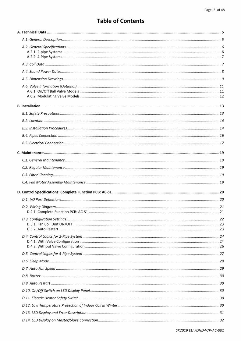
Table of Contents
A. Technical Data ................................................................................................................................................................... 5
A.1. General Description ............................................................................................................................................................ 5
A.2. General Specifications ........................................................................................................................................................ 6 A.2.1. 2-pipe Systems ........................................................................................................................................................... 6 A.2.2. 4-Pipe Systems............................................................................................................................................................ 7
A.3. Coil Data ............................................................................................................................................................................. 7
A.4. Sound Power Data .............................................................................................................................................................. 8
A.5. Dimension Drawings ........................................................................................................................................................... 9
A.6. Valve Information (Optional)............................................................................................................................................ 11 A.6.1. On/Off Ball Valve Models ......................................................................................................................................... 11 A.6.2. Modulating Valve Models ......................................................................................................................................... 12
B. Installation ....................................................................................................................................................................... 13
B.1. Safety Precautions ............................................................................................................................................................ 13
B.2. Location ............................................................................................................................................................................ 14
B.3. Installation Procedures ..................................................................................................................................................... 14
B.4. Pipes Connection .............................................................................................................................................................. 16
B.5. Electrical Connection ........................................................................................................................................................ 17
C. Maintenance .................................................................................................................................................................... 19
C.1. General Maintenance ....................................................................................................................................................... 19
C.2. Regular Maintenance ....................................................................................................................................................... 19
C.3. Filter Cleaning ................................................................................................................................................................... 19
C.4. Fan Motor Assembly Maintenance ................................................................................................................................... 19
D. Control Specifications: Complete Function PCB: AC-S1 .................................................................................................... 20
D.1. I/O Port Definitions........................................................................................................................................................... 20
D.2. Wiring Diagram ................................................................................................................................................................ 21 D.2.1. Complete Function PCB: AC-S1 ................................................................................................................................ 21
D.3. Configuration Settings ...................................................................................................................................................... 22 D.3.1. Fan Coil Unit ON/OFF ............................................................................................................................................... 23 D.3.2. Auto Restart ............................................................................................................................................................. 23
D.4. Control Logics for 2-Pipe System ...................................................................................................................................... 24 D.4.1. With Valve Configuration ......................................................................................................................................... 24 D.4.2. Without Valve Configuration .................................................................................................................................... 26
D.5. Control Logics for 4-Pipe System ...................................................................................................................................... 27
D.6. Sleep Mode ....................................................................................................................................................................... 29
D.7. Auto Fan Speed ................................................................................................................................................................ 29
D.8. Buzzer ............................................................................................................................................................................... 30
D.9. Auto Restart ..................................................................................................................................................................... 30
D.10. On/Off Switch on LED Display Panel............................................................................................................................... 30
D.11. Electric Heater Safety Switch .......................................................................................................................................... 30
D.12. Low Temperature Protection of Indoor Coil in Winter ................................................................................................... 30
D.13. LED Display and Error Description .................................................................................................................................. 31
D.14. LED Display on Master/Slave Connection....................................................................................................................... 32

Page 3 of 48
SK2019 EU FDHD-V/P-AC-001
D.15. Master-Slave Network .................................................................................................................................................... 33 D.15.1. Master Unit Control Settings .................................................................................................................................. 33 D.15.2. Master Slave Network Setup .................................................................................................................................. 34 D.15.3. Master Slave Communication Method .................................................................................................................. 36
D.16. Open Modbus Protocol ................................................................................................................................................... 37
E. User Interface .................................................................................................................................................................. 40
E.1. Remote Handset ............................................................................................................................................................... 40
E.2. Wired Wall Pad Controller ................................................................................................................................................ 41
F. Sensor Resistance R-T Conversion Table ........................................................................................................................... 45
G. Troubleshooting .............................................................................................................................................................. 46
H. Accessories ...................................................................................................................................................................... 47
Page 4 of 48
SK2019 EU FDHD-V/P-AC-001
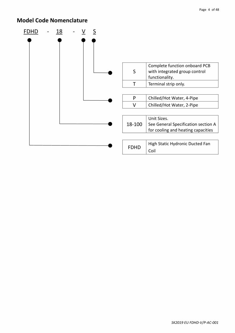
Model Code Nomenclature
FDHD - 18 - V S
S Complete function onboard PCB with integrated group control functionality.
T Terminal strip only.
P Chilled/Hot Water, 4-Pipe
V Chilled/Hot Water, 2-Pipe
18-100
Unit Sizes. See General Specification section A for cooling and heating capacities
FDHD High Static Hydronic Ducted Fan
Coil

Page 5 of 48
SK2019 EU FDHD-V/P-AC-001
Technical Data
General Description The Duct Fan Coil is designed to meet and exceed the demanding requirements for efficiency and quiet operation. STRUCTURE Structure is made from electrostatic coating steel panels completed with couplings for the connection of ducting and gravity drain condensate pan with insulation. Fire resistant insulation is fitted internally to provide both thermal and acoustic insulation. Insulation is fitted on the top of coil. COILS Constructed with seamless copper tubes and headers. The tubes are mechanically expanded into corrugated aluminum fin material for a permanent primary to secondary surface bond. Coils are tested at 25 bars and recommended for maximum operating at 16 bars. Coils include manual air vent and water purge valves. FAN The forward-curved centrifugal fan is statically and dynamically balanced for quiet operation. Fan impellers are made from metal. AC MOTOR Standard motors are PSC, permanently lubricated type with internal thermal overload protection. The unit is using 3-speed AC motor. AIR FILTER The filter is easily removable and washable and is made from self-extinguishing acrylic with a class EU2 (G2) (Merv 2-4) efficiency rating. G4 or F8 (Merv 8, 14) efficiency filter is optional. DRAIN PAN The drain pan fits a drain pipe of Ø 21mm (on both left and right side of drain pan) and is with fire resistant insulation. Complete Function Control (AC-S1 type) The PCB (printed circuit board) Modbus microprocessor controls functionality of the indoor fan motor, water valves (ON/OFF) and electric heater (optional), to maintain room conditions at a user-defined set point. Temperature settings, fan speeds and other control functions can be changed by either infrared handset or wired wall pad controller. Terminal Strip (T1 type) A 230Vac relays board is used to drive 3-speed AC motor. 40VA (24Vac) transformer is optional which supplies power to thermostat and modulating valve. Terminal Strip (T2 type) A 24Vac relays board is used to drive 3-speed AC motor. 40VA (24Vac) transformer is optional which supplies power to thermostat and modulating valve.
Casing with insulation internal
Coil with insulation on the top
Filter
Fan deck
Control box
Page 6 of 48
SK2019 EU FDHD-V/P-AC-001
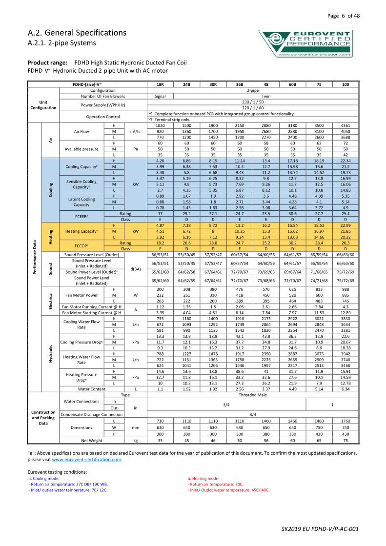
General Specifications A.2.1. 2-pipe Systems
Product range: FDHD High Static Hydronic Ducted Fan Coil FDHD-V~ Hydronic Ducted 2-pipe Unit with AC motor
FDHD-[Size]-V~ 18R 24B 30R 36B 48 60B 75 100
Unit Configuration
Configuration 2-pipe
Number Of Fan Blowers Signal Twin
Power Supply (V/Ph/Hz) 230 / 1 / 50
220 / 1 / 60
Operation Control ~S: Complete function onboard PCB with integrated group control functionality.
~T: Terminal strip only.
Pe
rfo
rman
ce D
ata
Air
Air Flow
H
m3/hr
1020 1500 1900 2150 2880 3180 3500 4361
M 920 1360 1700 1950 2680 2880 3100 4050
L 770 1200 1450 1700 2270 2400 2600 3688
Available pressure
H
Pa
60 60 60 60 58 60 62 72
M 50 50 50 50 50 50 50 50
L 35 35 35 35 35 35 35 42
Co
olin
g
Cooling Capacitye
H
kW
4.26 6.86 8.15 11.24 13.4 17.18 18.19 22.34
M 3.99 6.38 7.53 10.4 12.7 15.98 16.6 21.2
L 3.48 5.8 6.68 9.43 11.2 13.74 14.52 19.73
Sensible Cooling Capacitye
H 3.37 5.19 6.25 8.32 9.8 12.7 13.8 16.99
M 3.11 4.8 5.73 7.69 9.26 11.7 12.5 16.06
L 2.7 4.35 5.05 6.87 8.12 10.1 10.8 14.83
Latent Cooling Capacity
H 0.89 1.67 1.9 2.92 3.6 4.48 4.39 5.35
M 0.88 1.58 1.8 2.71 3.44 4.28 4.1 5.14
L 0.78 1.45 1.63 2.56 3.08 3.64 3.72 4.9
FCEERe Rating 17 25.2 27.1 24.7 23.5 30.6 27.7 25.4
Class E D D E E D D D
Hea
tin
g Heating Capacitye
H
kW
4.87 7.28 8.72 11.2 16.2 16.84 18.53 22.99
M 4.51 6.72 8 10.25 15.3 15.62 16.97 21.85
L 3.92 6.16 7.12 9.24 13.4 13.63 14.66 20.22
FCCOPe Rating 18.2 26.6 28.8 24.7 25.2 30.2 28.4 26.3
Class E D D E D D D D
Sou
nd
Sound Pressure Level (Outlet)
d(BA)
56/53/51 53/50/45 57/53/47 60/57/54 64/60/56 64/61/57 65/59/54 66/63/60
Sound Pressure Level (Inlet + Radiated)
56/53/51 53/50/45 57/53/47 60/57/54 64/60/56 64/61/57 65/59/54 66/63/60
Sound Power Level (Outlet)e 65/62/60 64/62/58 67/64/61 72/70/67 73/69/63 69/67/64 71/68/65 75/72/69
Sound Power Level (Inlet + Radiated)
65/62/60 64/62/59 67/64/61 72/70/67 73/68/66 72/70/67 74/71/68 75/72/69
Ele
ctri
cal
Fan Motor Power
H
W
300 308 380 476 570 625 813 988
M 232 261 310 418 450 520 600 885
L 203 222 260 389 395 464 483 745
Fan Motor Running Current @ H A
1.12 1.35 1.5 2.05 2.61 2.66 3.84 4.3
Fan Motor Starting Current @ H 3.35 4.04 4.51 6.14 7.84 7.97 11.53 12.89
Hyd
rau
lic
Cooling Water Flow Rate
H
L/h
735 1160 1400 1910 2175 2922 3022 3830
M 672 1093 1292 1749 2064 2694 2848 3634
L 581 990 1135 1542 1820 2354 2470 3381
Cooling Pressure Drope
H
kPa
13.3 13.8 18.9 43.1 43.8 36.3 12.9 22.6
M 11.7 12.1 16.3 37.7 34.8 31.7 10.9 20.67
L 9.3 10.3 13.2 31.2 27.9 24.6 8.6 18.28
Heating Water Flow Rate
H
L/h
788 1227 1478 1917 2350 2887 3075 3942
M 722 1151 1365 1758 2225 2659 2909 3746
L 624 1041 1206 1546 1957 2317 2513 3466
Heating Pressure Drope
H
kPa
14.6 13.6 18.8 38.6 41 31.7 11.9 15.91
M 12.7 11.8 16.1 33.2 32.6 27.6 10.1 14.59
L 10 10.2 13.1 27.3 26.2 21.9 7.9 12.78
Water Content L 1.1 1.92 1.92 2.56 3.37 4.49 5.14 6.34
Construction and Packing
Data
Water Connections
Type Threaded Male
In
in 3/4 1
Out
Condensate Drainage Connection 3/4
Dimensions
L
mm
710 1110 1110 1110 1460 1460 1460 1760
W 630 630 630 630 650 650 750 750
H 300 300 300 300 380 380 430 430
Net Weight kg 33 45 46 50 56 60 65 75
"e": Above specifications are based on declared Eurovent test data for the year of publication of this document. To confirm the most updated specifications, please visit www.eurovent-certification.com.
Eurovent testing conditions: a. Cooling mode: b. Heating mode:
- Return air temperature: 27C DB/ 19C WB. - Return air temperature: 20C.
- Inlet/ outlet water temperature: 7C/ 12C. - Inlet/ Outlet water temperature: 45C/ 40C.
Page 7 of 48
SK2019 EU FDHD-V/P-AC-001
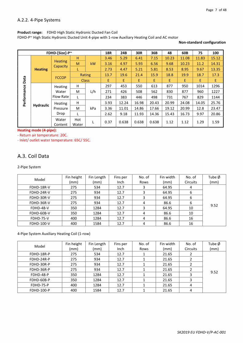
A.2.2. 4-Pipe Systems
Product range: FDHD High Static Hydronic Ducted Fan Coil FDHD-P~ High Static Hydronic Ducted Unit 4-pipe with 1-row Auxiliary Heating Coil and AC motor
Non-standard configuration
FDHD-[Size]-P~ 18R 24B 30R 36B 48 60B 75 100
Pe
rfo
rman
ce D
ata
Heating
Heating Capacity
H
kW
3.46 5.29 6.41 7.15 10.23 11.08 11.83 15.12
M 3.16 4.97 5.93 6.56 9.68 10.23 11.2 14.31
L 2.73 4.47 5.21 5.81 8.53 8.95 9.67 13.35
FCCOP Rating 13.7 19.6 21.4 15.9 18.8 19.9 18.7 17.3
Class E E E E E E E E
Hydraulic
Heating Water
Flow Rate
H
L/h
297 453 550 613 877 950 1014 1296
M 271 426 508 562 830 877 960 1227
L 234 383 446 498 731 767 829 1144
Heating Pressure
Drop
H
kPa
3.93 12.24 16.98 20.43 20.99 24.08 14.05 25.76
M 3.36 11.01 14.86 17.66 19.12 20.99 12.8 23.47
L 2.62 9.18 11.93 14.36 15.43 16.73 9.97 20.86
Water Content
Hot Water
L 0.37 0.638 0.638 0.638 1.12 1.12 1.29 1.59
Heating mode (4-pipe): - Return air temperature: 20C.- Inlet/ outlet water temperature: 65C/ 55C.
Coil Data
2-Pipe System
Model Fin height
(mm) Fin Length
(mm) Fins per
Inch No. of Rows
Fin width (mm)
No. of Circuits
Tube Ø (mm)
FDHD-18R-V 275 534 12.7 3 64.95 4
9.52
FDHD-24R-V 275 934 12.7 3 64.95 6
FDHD-30R-V 275 934 12.7 3 64.95 6
FDHD-36R-V 275 934 12.7 4 86.6 6
FDHD-48-V 350 1284 12.7 3 64.95 10
FDHD-60B-V 350 1284 12.7 4 86.6 10
FDHD-75-V 400 1284 12.7 4 86.6 16
FDHD-100-V 400 1584 12.7 4 86.6 16
4-Pipe System Auxiliary Heating Coil (1-row)
Model Fin height
(mm) Fin Length
(mm) Fins per
Inch No. of Rows
Fin width (mm)
No. of Circuits
Tube Ø (mm)
FDHD-18R-P 275 534 12.7 1 21.65 2
9.52
FDHD-24R-P 275 934 12.7 1 21.65 2
FDHD-30R-P 275 934 12.7 1 21.65 2
FDHD-36R-P 275 934 12.7 1 21.65 2
FDHD-48-P 350 1284 12.7 1 21.65 3
FDHD-60B-P 350 1284 12.7 1 21.65 3
FDHD-75-P 400 1284 12.7 1 21.65 4
FDHD-100-P 400 1584 12.7 1 21.65 4
Page 8 of 48
SK2019 EU FDHD-V/P-AC-001
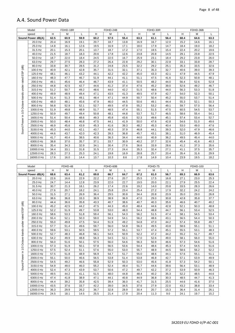
Sound Power Data
Model FDHD-18R FDHD-24B FDHD-30R FDHD-36B
speed H M L H M L H M L H M L
Sound Power dB(A) 62.5 60.9 59.9 60.2 57.5 55.4 63.3 61.1 56.4 68.4 64.6 63.3
Soun
d P
ow
er
in 1
/3 O
cta
ve
-band
s u
nd
er
rate
d E
SP
(dB
)
20.0 Hz 20.4 16.9 19.1 20.7 18.7 13.8 16.9 16.7 12.0 15.2 14.6 16.1
25.0 Hz 14.8 16.1 12.6 19.5 16.9 17.1 18.0 17.9 14.7 18.4 19.0 18.2
31.5 Hz 20.1 15.3 20.1 13.7 18.7 17.2 17.0 19.5 15.4 22.4 20.2 19.6
40.0 Hz 21.5 18.7 18.3 20.6 17.8 12.6 23.8 20.8 14.5 29.1 23.8 22.5
50.0 Hz 18.7 22.0 18.4 24.5 22.5 16.7 25.9 23.1 18.4 29.2 23.8 26.0
63.0 Hz 29.7 27.5 28.3 27.2 26.4 22.8 29.2 30.1 22.8 33.1 33.8 28.7
80.0 Hz 33.8 30.7 28.5 31.2 24.8 23.5 32.2 29.2 25.1 35.3 33.5 32.6
100.0 Hz 40.9 42.1 42.8 35.7 31.5 32.1 37.1 35.3 32.7 40.6 39.0 39.3
125.0 Hz 48.1 46.1 43.2 44.1 42.2 42.2 45.0 43.3 42.1 47.9 44.5 47.9
160.0 Hz 48.3 47.7 46.7 51.9 44.1 41.1 51.1 47.5 41.6 52.3 50.8 48.1
200.0 Hz 49.1 45.6 46.4 46.7 43.9 41.1 50.5 48.2 44.0 56.4 52.6 52.8
250.0 Hz 44.8 42.5 42.7 44.6 41.2 37.4 47.6 45.2 39.0 52.6 49.2 46.7
315.0 Hz 51.2 50.7 49.2 48.6 44.0 42.2 51.5 48.6 44.0 56.3 53.3 51.8
400.0 Hz 49.9 48.9 49.4 47.1 43.5 41.3 49.5 47.9 42.7 54.0 52.3 50.1
500.0 Hz 51.4 51.3 49.1 48.4 47.1 44.9 50.7 50.4 45.2 55.0 53.7 51.4
630.0 Hz 48.0 48.1 45.6 47.9 46.0 44.5 50.6 49.1 44.4 55.3 52.1 50.3
800.0 Hz 56.8 52.9 52.1 52.7 49.5 47.8 55.2 53.2 49.1 59.7 57.0 56.4
1000.0 Hz 51.9 49.8 48.9 51.7 48.5 47.4 55.1 51.5 47.5 60.5 54.5 53.7
1250.0 Hz 50.9 49.7 49.4 50.8 48.1 44.8 53.7 51.7 46.5 58.6 55.4 54.1
1600.0 Hz 51.4 50.4 48.6 49.3 45.8 43.6 52.3 49.6 45.1 57.4 53.4 52.7
2000.0 Hz 50.0 48.4 46.8 47.5 44.1 41.9 50.0 47.6 42.8 54.6 51.0 49.6
2500.0 Hz 46.9 45.6 43.9 45.3 41.6 39.3 48.2 45.3 40.4 53.0 49.0 47.6
3150.0 Hz 45.3 44.0 42.1 43.7 40.3 37.9 46.8 44.1 39.3 52.0 47.9 46.6
4000.0 Hz 44.6 43.7 42.0 42.3 39.3 36.8 45.7 43.1 38.1 51.0 46.9 45.4
5000.0 Hz 41.7 40.4 38.5 40.6 36.3 34.4 44.0 40.9 36.2 49.5 45.4 44.0
6300.0 Hz 38.8 37.0 35.7 37.1 33.7 30.9 40.2 37.7 32.6 45.4 41.6 40.3
8000.0 Hz 35.4 34.3 32.9 34.1 30.4 27.6 36.6 33.9 28.6 41.2 37.3 35.6
10000.0 Hz 34.4 33.1 31.8 31.5 27.3 24.4 35.3 32.4 27.1 41.1 37.5 35.7
12500.0 Hz 28.3 27.3 25.3 24.1 19.8 16.9 28.8 25.7 20.4 35.4 31.6 29.9
16000.0 Hz 17.6 16.0 14.4 13.7 10.3 8.6 17.8 14.9 10.4 23.9 19.5 18.2
Model FDHD-48 FDHD-60B FDHD-75 FDHD-100
speed H M L H M L H M L H M L
Sound Power dB(A) 68.6 63.4 61.2 69.8 66.7 64.7 67.2 61.0 56.7 69.3 66.9 63.6
Soun
d P
ow
er
in 1
/3 O
cta
ve
-band
s u
nd
er
rate
d E
SP
(dB
)
20.0 Hz 22.6 16.6 22.9 22.2 27.6 20.7 25.5 17.5 16.8 27.1 23.0 25.3
25.0 Hz 24.7 14.4 12.8 23.9 22.0 22.7 19.5 20.0 22.1 27.9 25.5 22.4
31.5 Hz 30.7 21.3 18.1 26.2 17.4 22.6 19.2 14.0 20.8 33.5 28.3 26.6
40.0 Hz 27.6 20.7 18.2 24.1 25.8 23.4 25.4 27.2 17.9 32.2 24.2 24.2
50.0 Hz 31.5 27.1 26.9 36.4 29.5 30.8 34.4 20.8 20.9 35.0 29.0 26.8
63.0 Hz 38.6 36.8 33.3 38.9 38.9 36.9 47.0 29.0 30.8 42.8 35.8 37.7
80.0 Hz 44.4 36.6 35.8 43.3 40.7 38.6 40.7 40.3 35.6 46.6 40.7 40.2
100.0 Hz 45.2 42.5 44.2 47.5 44.3 45.0 48.4 44.6 42.8 52.1 50.3 48.8
125.0 Hz 52.2 51.9 49.7 53.8 53.0 48.0 54.4 48.8 44.7 56.1 53.4 52.5
160.0 Hz 58.6 53.3 51.8 59.4 56.1 54.3 56.2 51.5 47.4 58.1 54.5 53.4
200.0 Hz 55.4 52.1 50.3 59.0 54.9 54.1 56.2 48.6 43.1 56.5 54.4 50.3
250.0 Hz 55.0 49.8 47.5 54.4 51.9 49.2 54.8 47.0 44.2 57.4 55.8 49.7
315.0 Hz 57.7 51.4 49.6 59.7 56.0 54.8 56.3 49.5 43.8 58.6 55.1 51.1
400.0 Hz 59.6 53.1 50.5 59.5 57.2 55.1 53.7 47.4 45.1 55.5 53.1 48.3
500.0 Hz 52.7 48.3 46.8 56.1 54.5 50.9 52.2 47.2 44.2 55.2 51.7 49.7
630.0 Hz 54.2 49.9 48.8 56.3 54.5 52.1 57.0 52.6 49.0 58.1 56.0 55.0
800.0 Hz 56.0 51.6 50.1 57.5 56.0 54.6 56.3 50.9 46.6 57.3 54.6 51.6
1000.0 Hz 57.3 51.9 50.1 57.8 56.5 53.6 54.4 48.6 45.3 57.4 54.5 51.6
1250.0 Hz 57.5 52.4 51.1 57.6 55.0 53.0 55.7 48.9 44.5 58.6 56.2 52.2
1600.0 Hz 57.5 51.8 48.9 56.9 54.7 51.7 55.0 48.6 44.1 57.6 55.1 51.1
2000.0 Hz 55.1 50.0 46.6 56.5 53.8 51.4 53.8 46.8 42.7 57.1 53.9 49.9
2500.0 Hz 54.5 49.2 46.6 55.8 52.9 50.3 53.0 45.6 41.8 57.3 54.2 50.1
3150.0 Hz 54.9 49.0 46.0 55.2 52.4 49.4 51.7 44.6 39.6 56.4 53.1 48.9
4000.0 Hz 52.4 47.3 43.9 53.7 50.6 47.2 49.7 42.2 37.2 53.9 50.9 46.3
5000.0 Hz 49.5 44.2 41.1 51.5 48.0 44.8 48.4 40.2 35.3 52.2 48.5 44.6
6300.0 Hz 47.4 41.8 38.9 47.1 44.1 40.8 44.9 36.8 30.3 48.5 44.7 41.3
8000.0 Hz 44.4 39.2 35.8 42.5 39.4 36.0 41.7 31.5 25.5 44.6 41.6 37.0
10000.0 Hz 43.5 37.6 33.7 42.2 39.0 34.5 37.6 27.9 22.0 43.2 38.8 33.4
12500.0 Hz 36.3 29.9 26.2 36.7 32.8 28.9 30.4 20.7 15.3 36.4 31.4 26.1
16000.0 Hz 24.5 18.1 14.5 25.5 21.4 17.9 20.4 11.3 9.0 24.1 19.7 15.2
Page 9 of 48
SK2019 EU FDHD-V/P-AC-001
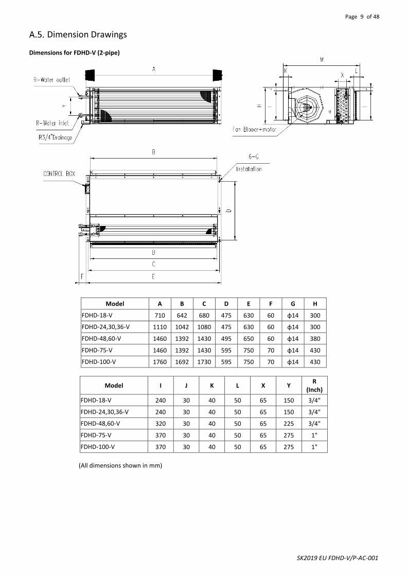
Dimension Drawings Dimensions for FDHD-V (2-pipe)
Model A B C D E F G H
FDHD-18-V 710 642 680 475 630 60 φ14 300
FDHD-24,30,36-V 1110 1042 1080 475 630 60 φ14 300
FDHD-48,60-V 1460 1392 1430 495 650 60 φ14 380
FDHD-75-V 1460 1392 1430 595 750 70 φ14 430
FDHD-100-V 1760 1692 1730 595 750 70 φ14 430
Model I J K L X Y R
(Inch)
FDHD-18-V 240 30 40 50 65 150 3/4"
FDHD-24,30,36-V 240 30 40 50 65 150 3/4"
FDHD-48,60-V 320 30 40 50 65 225 3/4"
FDHD-75-V 370 30 40 50 65 275 1"
FDHD-100-V 370 30 40 50 65 275 1"
(All dimensions shown in mm)

Page 10 of 48
SK2019 EU FDHD-V/P-AC-001
Dimensions for FDHD-P (4-pipe)
Model A B C D E F G H I
FDHD-18-P 710 642 680 475 630 60 φ14 300 240
FDHD-24,30,36-P 1110 1042 1080 475 630 60 φ14 300 240
FDHD-48,60-P 1460 1392 1430 495 650 60 φ14 380 320
FDHD-75-P 1460 1392 30 595 750 70 φ14 430 370
FDHD-100-P 1760 1692 1730 595 750 70 φ14 430 370
Model J K L X Y V W P R
(Inch)
FDHD-18-P 30 40 50 65 150 22 80 22 3/4"
FDHD-24,30,36-P 30 40 50 65 150 22 80 22 3/4"
FDHD-48,60-P 30 40 50 65 225 22 150 22 3/4"
FDHD-75-P 30 40 50 65 275 22 200 22 1"
FDHD-100-P 30 40 50 65 275 22 200 22 1"
(All dimensions shown in mm)

Page 11 of 48
SK2019 EU FDHD-V/P-AC-001
Valve Information (Optional) A.6.1. On/Off Ball Valve Models
Model Definitions 1. 3-way ball valve with 3/4” connectors and on/ off motorized actuator 2. 2-way ball valve with 3/4” connectors and on/ off motorized actuator 3. 3-way ball valve with 1” connectors and on/ off motorized actuator 4. 2-way ball valve with 1” connectors and on/ off motorized actuator
Specifications
Medium: Cool/Hot water or 60% glycol Structure: Two way or Three way Operating Mode: On/Off Power Supply: AC220V Power Consumption: 6W (during valve position change) Running Times: 15 sec. Pressure Rating: 2MPa Media Temp. Range: 34°F to 203°F (1°C to 95°C) Max. Differential Pressure: 1MPa Body: Forged brass, nickel plated Ball: Chrome plated brass Stem: Brass Seats: Fiberglass reinforced Teflon PTFE Seal: 2 EPDM O-rings, lubricated Protection Grade: IP65
Dimensions
Caliber Inch (mm)
Kv Value L L1 H
3/4" (DN20) 7.50 66 33 36 1" (DN25) 13.02 88 44 40
(All dimensions shown in mm)

Page 12 of 48
SK2019 EU FDHD-V/P-AC-001
A.6.2. Modulating Valve Models
Model Definitions 1. 3/4" inch 2-way modulating valve and 24VAC actuator with 0-10VDC input 2. 3/4" inch 3-way modulating valve and 24VAC actuator with 0-10VDC input 3. 1" inch 2-way modulating valve and 24VAC actuator with 0-10VDC input 4. 1" inch 3-way modulating valve and 24VAC actuator with 0-10VDC input which is used with unit~S2/W2
Specifications 24VAC power supply 0~10VDC control signal Bi-directional modulating proportional control Working media: cool/hot water or with 60% glycol Media Temp. Range: 34°F to 203°F (1°C to 95°C) Rating pressure: 2.0MPa Max. Differential Pressure: 0.3MPa Opening or closing time: 50 sec.(50Hz), 40 sec.(60Hz) Connection: NPT internal thread
Dimensions
Size Type Kv Value Dimension
C D E F G
3/4” (DN20) 2-way 4.6 115 73 67 89 90
3/4” (DN20) 3-way 6.8 127 73 67 89 90
1” (DN20) 2-way 4.6 117 73 67 93 90
1” (DN20) 3-way 5.7 139 73 67 93 90
(All dimensions shown in mm)
Page 13 of 48
SK2019 EU FDHD-V/P-AC-001
Installation
Safety Precautions
• When installing, performing maintenance or servicing Polar Air fan coil units observe the precautions stated in this manual as well as those stated on the labels attached to the unit.
• Ensure all local and national safety codes, laws, regulations, as well as general electrical and mechanical safety guidelines are followed for installation, maintenance and service.
• The appliance is for indoor use only.
• Ensure the correct power supply is provided.
• If the power supply cord is damaged, it must be replaced by qualified personnel.
• Installing and servicing fan coil unit should be performed by qualified service personnel only.
• This appliance is not intended for use by persons (including children) with reduced physical, sensory or mental capabilities, or persons lacking in experience and knowledge of the appliance, unless they have been given supervision or instruction concerning it.
• User of this appliance is responsible for his/her own safety.
• Warranty shall be voided if installation instructions and safety precaution stated in this manual are not observed.
• The unit should only be switched off by using the ON-OFF button on the control interface.
CAUTIONS
Before any service or maintenance operations turn off the mains electrical supply. DO NOT turn OFF the main power supply when the unit is operating. Turn off the unit BEFORE turning off the main power

Page 14 of 48
SK2019 EU FDHD-V/P-AC-001
Location Before installing and running the unit, please check the following: 1. There must be enough space for unit installation and maintenance. Please refer to below figure for the unit's outlines
and dimensions and for the minimum distance between the unit and the obstacle/ any obstructions/ its surroundings. 2. Please ensure there is enough space for piping connections and electrical wiring. 3. Check whether the hanging rods can support the weight of the unit (see specification table for weight of the unit). 4. The unit must be installed horizontally to ensure proper operation and condensate draining. 5. The external static pressure of the ducting must be within the unit’s static pressure range. 6. Confirm that the unit has been switched OFF before installing or servicing the unit.
B>200mm-
>600mm_
CEILLING
DRAIN PIPE
Installation Procedures 1. The unit is designed to be installed in a concealed ceiling. Installation and maintenance should be performed by
qualified personnel who are familiar with local codes and regulations, and are experienced with this type of appliance.
2. Please refer to the pictures below for installation procedures.
Counternut
Washer
NUT
Rod
Nut
5 0

Page 15 of 48
SK2019 EU FDHD-V/P-AC-001
B
CEILLING
DRAIN PIPE
>200mm->600mm_
H2
H1H1>12*ESPmax/9.81
H2>ESPmax/9.81
L>300mm-
N
M
DISCHARGE AIRRETURN AIR
CEILLING ACCESS PANELWITH AIR RETRUN
CAUTION
Make sure the top of the unit is level after installation. The drain pan is designed with a slight gradient to facilitate drainage.
CAUTIONS
Dimension M and N are determined by air duct design. Air duct should be fire-proof. Please refer to concerned country national and local regulation. Circulatory air pressure drop should be approximately equal to the External Static Pressure.
Page 16 of 48
SK2019 EU FDHD-V/P-AC-001
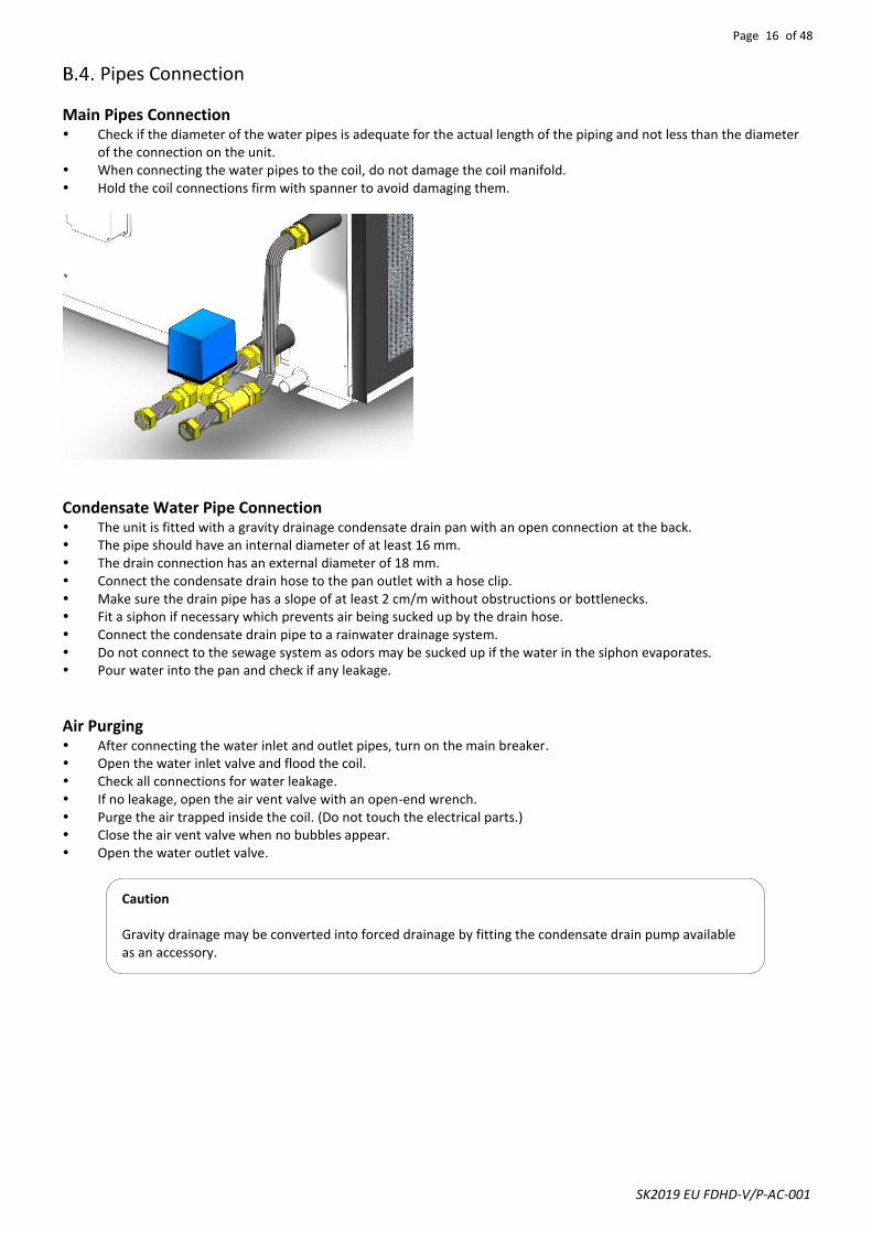
Pipes Connection
Main Pipes Connection Check if the diameter of the water pipes is adequate for the actual length of the piping and not less than the diameter
of the connection on the unit. When connecting the water pipes to the coil, do not damage the coil manifold. Hold the coil connections firm with spanner to avoid damaging them.
Condensate Water Pipe Connection The unit is fitted with a gravity drainage condensate drain pan with an open connection at the back. The pipe should have an internal diameter of at least 16 mm. The drain connection has an external diameter of 18 mm. Connect the condensate drain hose to the pan outlet with a hose clip. Make sure the drain pipe has a slope of at least 2 cm/m without obstructions or bottlenecks. Fit a siphon if necessary which prevents air being sucked up by the drain hose. Connect the condensate drain pipe to a rainwater drainage system. Do not connect to the sewage system as odors may be sucked up if the water in the siphon evaporates. Pour water into the pan and check if any leakage.
Air Purging After connecting the water inlet and outlet pipes, turn on the main breaker. Open the water inlet valve and flood the coil. Check all connections for water leakage. If no leakage, open the air vent valve with an open-end wrench. Purge the air trapped inside the coil. (Do not touch the electrical parts.) Close the air vent valve when no bubbles appear. Open the water outlet valve.
Caution Gravity drainage may be converted into forced drainage by fitting the condensate drain pump available as an accessory.

Page 17 of 48
SK2019 EU FDHD-V/P-AC-001
Electrical Connection 1. Wiring connection must be done according to the wiring diagram on the unit.
2. The unit must be GROUNDED well.
3. An appropriate strain relief device must be used to attach the power wires to the terminal box.
4. Field wiring must be complied with the national security regulations.
5. A main switch or other means for disconnection, having a contact separation in all poles, must be incorporated in the
fixed wiring in accordance with the relevant local and national legislation.
*S Control Wiring Diagram: Please refer to section D.
T1 Wiring Diagram for 230VAC Input Signal:
LOW
HIGHMEDM
N
RELAY
RELAY
RELAY
Fan control
FUSE
FuseEH element
Protection switch
L N
H
i M
Lo
V1
V2
N
Neutral
Heating signal (230V)
Cooling valve signal(230V)
L-speed signal (230V)
M-speed signal (230V)
H-speed signal (230V)
1Ph-230V-50Hz Power input
Earth
Yellow (H)
Brown (M)
Orange (L)
Neutral
TR kit is optional.
LiveP
rotection switch
FuseEH element
Protection switch
FuseEH element
Protection switch
CO
NTR
OL
LOAD
LOAD
LOAD
L1 L
2 L
3 N
380~400V3Ph50/60Hz
3-speed unit with 3 Ph EH Wiring scheme
24Vac12VacCOM
IPA18-DL-T-R230V-003

Page 18 of 48
SK2019 EU FDHD-V/P-AC-001
T2 Wiring Diagram for 24VAC Input Signal:
Remark: 40VA (24Vac) transformer is optional.
L N
H
i M
Lo
V1
V2
C
R1
R
Heating signal (24Vac)
Cooling valve signal(24Vac)
L-speed signal (24Vac)
M-speed signal (24Vac)
H-speed signal (24Vac)
Earth
Yellow (H)Brown (M)Orange (L)
3-speed unit w ith EH W iring scheme
LOW
HIGHMEDM
N
RELAY
RELAY
RELAY
Fan control
FUSE
COM
FuseEH element
Protection switch
Protection switch
FuseEH element
Protection switch
FuseEH element
Protection switch
CO
NTR
OL
LOAD
LOAD
LOAD
L1 L
2 L
3 N
380~400V3Ph50/60Hz
Neutral
Live
TR kit is optional.
IPA18-DL-T24V-002 24Vac for thermostat12Vac for thermostat

Page 19 of 48
SK2019 EU FDHD-V/P-AC-001
Maintenance
General Maintenance 1. Installation and maintenance should be performed by qualified personnel who are familiar with local codes and
regulations, and are also experienced with this type of appliance.
2. Confirm that the unit has been switched OFF before installing or servicing the unit.
3. A good general maintenance plan will prevent damage to and unexpected shutting down of the equipment.
4. Dirty filters reduce air flow as well as unit performance. Therefore, changing or cleaning the filters is very important. Check
the cleanliness of the filter and replace or clean as required monthly.
5. Coils should be cleaned with compressed air or water to remove dust, dirt or lint. They can be brushed with a soft brush
or vacuumed with a vacuum cleaner.
6. If the water coil is not being used during the winter season it should be drained, or an anti-freezing solution should be
added to the water circuit to avoid freezing.
Regular Maintenance 1. Inspect and clean the condensate drain pan to avoid any clogging of the drain by dirt, dust, etc. Inspect drainage piping to
ensure the proper condensate flow.
2. Check and clean the coil. Clean the coils with low-pressure water jets or low-pressure air.
3. Clean and tighten all the wiring connections.
4. Drain out the water system and check for buildup of mineral deposits.
Filter Cleaning 1. Remove the filter from bottom or side. 2. Clean the filter with a brush, or with water. 3. Reinstall the filter by sliding it back into the groove.
Fan Motor Assembly Maintenance 1. Remove the screws from the bottom panel.
2. Remove the 4 screws on both side.
3. Pull out the fan motor assembly. 4. Reinstall it to the casing after maintenance

Page 20 of 48
SK2019 EU FDHD-V/P-AC-001
Control Specifications: Complete Function PCB: AC-S1
Abbreviations Ts = Setting temperature AUX1 = Hot water free contact Tr = Room air temperature AUX2 = Chilled water free contact Ti1 = Chilled water coil temperature MTV1 = Chilled water valve Ti2 = Hot water coil temperature MTV2 = Hot water valve
I/O Port Definitions
I/O Code 2-Pipe 4-Pipe
Analogue Input
Return air Sensor AI1 Return air temperature (Tr)
Chilled water Sensor AI2 Chilled / hot water coil circuit (Ti1)
Chilled water coil circuit (Ti1)
Hot water Sensor AI3 N/A Hot water coil circuit (Ti2)
Input IR receiver X-DIS 1 Digital communication port to LED display/IR receiver board.
Wired wall pad TTL1 Digital communication port to wired wall-pad board.
Digital input
Occupancy contact PR1/PR2
This contact can be connected to occupancy sensor or BMS system. DIP-SWITCH IS ON. (Window contact) The contact is normally open. If the contact has been closed for 10 minutes, the unit will be shut down. When the contact is open again, the unit restarts. DIP-SWITCH IS OFF. (Economy contact) Cooling operation will only be activated when Tr - Ts ≥ 4ºC. If Tr<Ts, cool operation will be terminated. Heating operation will only be activated when Tr-Ts≤ -4ºC. If Tr>Ts, heating operation will be terminated.
Float switch Float Voltage-free (NC). The contact is closed before the float switch is turned on.
Electrical heater safety switch
EH Voltage-free (NC). The contact is closed before the EH is turned on.
Power input
Phase L Power supply to the PCB and all the loads connected to the voltage outputs.
Neutral N Power supply to the PCB and all the loads connected to the voltage outputs.
Earth G Power supply to the PCB and all the loads connected to the voltage outputs.
Voltage output
High fan speed HF Voltage output (L)
Medium fan speed MF Voltage output (L)
Low fan speed LF Voltage output (L)
Valve1 MTV1 Water valve Voltage output (L)
Chilled water valve Voltage output (L)
Valve2 MTV2 Reserved Hot water valve Voltage output (L)
Water pump WP Voltage output (L), Power supply to condensate pump.
Voltage of electrical heater (Live)
L-EH Voltage output (L), maximum 30A.
Output
Stepping motor CN1, CN2 Power supply to louver stepping motors.
Cold water free contact. AUX2 Voltage free contact. Maximum load 5A.
Hot water free contact. AUX1 Voltage free contact. Maximum load 5A.
In Modbus signal AB Terminals for local network serial connection
Out Modbus signal AB

Page 21 of 48
SK2019 EU FDHD-V/P-AC-001
Wiring Diagram D.2.1. Complete Function PCB: AC-S1
CN1
X-DISI
AI1
AI2
AI3
TTL1wired wall-pad
4-pipe coil circuit sensor
2-pipe sensor (Ti1):
return air sensor (Tr)
LED display / IR receiver
chilled/hot water
(Ti2):hot water
louver stepping moterconnections
CN2
A B A B
S1S2 FLOAT EH2 EH1 PR2 PR1
AUX2 AUX1 HF MF LF VALVE1VALVE2 WP
GY
BK BL
PUMP
L1N
PRO
PRO
A2A2
A1A1
GTERMINAL
WH
L
N N
NNRY7
BK
BL
YL/GR
WH
WH
RD
RD
GR
GR485
FUSE
float
con
trol s
witc
h fo
r pum
p
RD
RD
AC-S1 Control Box Wiring scheme
L\N :Power supply VALVE1: 230V On/Off valve output.
(2-pipe: Cooling / Heating); (4-pipe: Cooling) VALVE2: 230V On/Off valve output. (4-pipe: heating) WP: 230V condensate pump output. RYL: 230 V Electrical heater output. HF: 230 V Fan motor high speed output. MF: 230 V Fan motor medial speed output. LF: 230 V Fan motor low speed outpu AUX1: Voltage free contact;ON=unit in Heating mode. AUX2:Voltage free contact;ON=unit in Cooling mode. PRO:Occupancy contact. FLOAT: Float swith for pump. EH: protectionl swith for elecctrical heater CN1~2: Stepping motor output. TTL: Wired wall-pad. AI3: Indoor coil temperature sensor 2 (Ti2). AI2: Indoor coil temperature sensor 1 (Ti1). AI1: Return air temperature sensor (Tr). X-DIS1: LED recevier output. RS485: Serial BUS contacts.
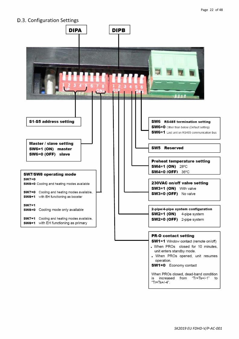
Legend:DIPA-S1SW1-5: set the unit addressSW6: set unit type: master or slaveMode Configuration:
DIPB-S2SW1: Occupancy contact settingSW2: Unit configuration setting:0=2-pipe system
1=4-pipe systemSW3: On/off vavle configuration setting:
0=no vavle; 1=with vavle;
SW4: Pheheat setting: 0=36 C; 1=28 C.SW5:Reserved.SW6:1 = last unit on RS485 communication bus;
0 = other than above.
SW7=0;SW8=0;unit operates in cooling/heating.SW7=0;SW8=1;unit operates in cooling/heating withbooster EH.SW7=1;SW8=0;unit operates in colling only.SW7=1;SW8=1;unit operates in cooling with primary EH
OR
BRYL
EH
BKBL
YL/GR
IPA19-DL-FDHD-AC-S
Page 22 of 48
SK2019 EU FDHD-V/P-AC-001
Configuration Settings
Page 23 of 48
SK2019 EU FDHD-V/P-AC-001
D.3.1. Fan Coil Unit ON/OFF
There are 3 ways to turn the system on or off:
a) By the ON/OFF button on the remote handset or wired wall pad;
b) By the programmable timer on the handset or wired wall pad.
c) By the manual control button on fan coil unit.
D.3.2. Auto Restart
The system uses a non-volatile memory to save the present operation parameters when the system is turned off or in case of system failure or cessation of power supply.
The restored parameter data-set depends on the type of user interface.
a) Handset only user interface:
When the power ON signal is received by the fan coil unit and no wired wall-pad is installed, the Mode, Fan Speed, Set temperature will be the same as the handset setting before the last power OFF.
b) Wall-pad only OR wall-pad and handset user interface:
When the power ON signal is received by the fan coil unit and a wired wall-pad is installed, the Mode, Fan Speed, Set temperature and Timer ON/OFF weekly program will be the same as the wall pad setting before the last power OFF.

Page 24 of 48
SK2019 EU FDHD-V/P-AC-001
Control Logics for 2-Pipe System D.4.1. With Valve Configuration COOL MODE a) MTV2, AUX1 and electric heater are always off. b) If Tr ≥ Ts + 1ºC (or + 4ºC if economy contact is activated), then cool operation is activated and MTV1 and AUX2 are
turned on. Indoor fan runs at set speed. c) If Tr < Ts, then cool operation is terminated and MTV1 and AUX2 are turned off. Indoor fan runs at set speed. d) The range of Ts is 16 - 30ºC e) Indoor fan speed can be adjusted to low, medium, high and auto. f) When turned on, MTV1 requires 30 seconds before it is fully open. g) When turned off, MTV1 requires 120 seconds before it is fully closed. h) When the unit is turned off, the indoor fan will shut down after 5 seconds. LOW TEMPERATURE PROTECTION OF INDOOR COIL a) If Ti1 ≤ 2 ºC for 2 minutes, then MTV1 and AUX2 are turned off. If indoor fan is set for low speed, then it will run at
medium speed. If it is set at medium or high speed, then it will keep running at the same speed. b) If Ti1 ≥ 5ºC for 2 minutes, then MTV1 and AUX2 are turned on. Indoor fan runs at set speed. FAN MODE a) Indoor fan runs at the set speed while heater, MTV1, MTV2, AUX1 and AUX2 are turned off. b) Indoor fan speed can be adjusted to low, medium and high. HEAT MODE Heat mode without electrical heater a) MTV2, AUX2 and electric heater are always off. b) If Tr ≤ Ts - 1 ºC (or - 4ºC if economy contact is activated), then heat operation is activated and MTV1 and AUX1 are
turned on. Indoor fan runs at the set speed. c) If Tr > Ts, then heat operation is terminated and MTV1 and AUX1 are turned off. Indoor fan repeatedly runs at low fan
speed for 30 seconds and then stops for 3 minutes. d) The range of Ts is 16 - 30ºC. e) Indoor fan speed can be adjusted to low, medium, high and auto. f) When turned on, MTV1 requires 30 seconds before it is fully open. g) When turned off, MTV1 requires 120 seconds before it is fully closed. Heat mode with electrical heater as booster a) MTV2 and AUX2 are always off. b) If Tr ≤ Ts - 1ºC (or - 4ºC if economy contact is activated), then heat operation is activated and MTV1 and AUX1 are turned
on. Indoor fan runs at the set speed. c) If Tr > Ts, then heat operation is terminated and MTV1 and AUX1 are turned off. Indoor fan repeatedly runs at low fan
speed for 30 seconds and then stops for 3 minutes. d) If Ti1 < 40ºC, then the electrical heater is turned on. If 40ºC ≤ Ti1 < 45ºC, then the electrical heater maintains its original
state. If Ti1 ≥ 45ºC, then the electrical heater is turned off. e) The range of Ts is 16 - 30ºC f) Indoor fan speed can be adjusted to low, medium, high and auto. g) When turned on, MTV1 requires 30 seconds before it is fully open. h) When turned off, MTV1 requires 120 seconds before it is fully closed. Heat mode with electrical heater as primary heat source a) MTV1, MTV2, and AUX2 are always off b) If Ti2 ≤ 30ºC (or Ti2 is damaged or disconnected), AND if Tr ≤ Ts-1ºC (or -4ºC if economy contact is activated), heat
operation is activated, electrical heater and AUX1 are turned on. Indoor fan runs at set speed. c) If Tr > Ts, then heat operation is terminated and the electrical heater and AUX1 are turned off. Indoor fan repeatedly
runs at low fan speed for 30 seconds and then stops for 3 minutes. d) The range of Ts is 16-30 ºC e) Indoor fan speed can be adjusted to low, medium, high and auto.

Page 25 of 48
SK2019 EU FDHD-V/P-AC-001
PRE-HEAT Pre-heat without electrical heater a) If Ti1 < 36ºC [or < 28ºC is selected by DIPB-S2 position SW4], then MTV1 and AUX1 are turned on, indoor fan remains off. b) If Ti1 ≥ 38ºC [or ≥ 30ºC is selected by DIPB-S2 position SW4], then MTV1 and AUX1 are turned on, indoor fan runs at set
speed. c) If the indoor coil temperature sensor is damaged, then pre-heat time is set for 2 minutes. Indoor fan runs at set speed. Pre-heat with electrical heater a) Indoor fan will turn on after the electrical heater has been turned on for 10 seconds. POST-HEAT Post-heat without electrical heater a) If Ti1 ≥ 38ºC, then MTV1 and AUX 1 are off, then indoor fan continues to run at set speed. b) If 36ºC ≤ Ti1 ≤ 38ºC, then MTV1 and AUX1 are turned off. Then indoor fan maintains its original state. c) If Ti1 < 36ºC, then MTV1 and AUX1 are turned off. Then indoor fan repeatedly runs for 30 seconds and then stops for 3
minutes. d) If the indoor coil temperature sensor is damaged, then post-heat time is set for 3 minutes. Indoor fan runs at set speed.
Post-heat with electrical heater a) Indoor fan will shut down after the unit has been turned off for 20 seconds. OVER-HEAT PROTECTION OF INDOOR COIL a) If Ti1 ≥ 75ºC, then MTV1 and AUX1 are turned off. Indoor fan remains on and runs at high speed. b) If Ti1 < 70ºC, then MTV1 and AUX1 are turned on. Indoor fan remains on and runs at set speed. c) If the indoor coil temperature sensor is damaged, then the protection mode will be overridden and the unit will work
according to the pre-heat and post-heat program. DEHUMIDIFICATION MODE a) MTV2, AUX1 and heater are always off. b) If Tr ≥ 25ºC, then MTV1 and AUX2 will be ON for 3 minutes, and then OFF for 4 minutes. c) If 16ºC ≤ Tr < 25ºC, then MTV1 and AUX2 will be ON for 3 minutes, and then OFF for 6 minutes. d) If Tr < 16ºC, then MTV1 and AUX2 will be turned off for 4 minutes. e) At the end of the above dehumidification cycle, the system will decide the next dehumidification control option. Indoor
fan will run at low speed throughout the dehumidification process. AUTOMODE Auto cool/heat/heat with electric heater as booster Every time the unit is turned on, MTV1 is on, AUX1, AUX2 and fan are off. MTV2 and heater are always off. After 120secs, the subsequent operation mode is decided according to the following programs:
a) If the coil temperature sensor (Ti1) ≥ 36ºC, then MTV1, AUX1 and fan turn on or off according to HEAT mode. b) If Ti1 < 36ºC, then MTV1, then AUX2 and fan turn on or off according to COOL mode.
Unit remains in AUTO COOL or AUTO HEAT mode throughout the operating cycle until the user changes the mode manually or restarts the unit. Should the Ti1 sensor be damaged, auto mode will not function. Auto heat with electric heater as primary heat source / all configuration auto changeover If current running mode is auto cool mode, then the control Logics will change over to auto heat mode when all the following conditions are met: a) Ts-Tr ≥ 1.0°C (or 4 ºC if economy contact is activated) b) MTV1 has stop ≥ 10 min.
If current running mode is auto heat mode, then the control Logics will change over to auto cool mode when all the following conditions are met: a) Tr-Ts ≥ 1.0°C (or 4 ºC if economy contact is activated) b) MTV1 has stop ≥ 10 min.
Note: Auto cool or auto heat operation are the same as cool or heat mode respectively.

Page 26 of 48
SK2019 EU FDHD-V/P-AC-001
D.4.2. Without Valve Configuration
COOL MODE a) Electric heater, AUX1, MTV1 and MTV2 are always off. b) If Tr ≥ Ts + 1ºC (or + 4ºC if economy contact is activated), then cool operation is activated and AUX2 is turned on. Indoor
fan runs at set speed. c) If Tr < Ts, then cool operation is terminated and AUX2 is turned off. Indoor fan is turned off. d) The range of Ts is 16 - 30ºC e) Indoor fan speed can be adjusted to low, medium, high and auto.
Note: When the unit is turned off, the indoor fan shut down after 5 seconds. LOW TEMPERATURE PROTECTION OF INDOOR COIL a) If Ti1 ≤ 2ºC for 2 minutes, then AUX2 is turned off. If low speed is selected via user interface, then indoor fan runs at
medium speed. If medium or high speed is selected via user interface, then indoor fan runs at set speed. b) If Ti1 ≥ 5ºC for 2 minutes, then AUX2 is turned on. Indoor fan runs at set speed. FAN MODE a) Indoor fan runs at the set speed while heater, MTV1, MTV2, AUX1 and AUX2 are turned off. b) Indoor fan speed can be adjusted to low, medium and high. HEAT MODE Heat mode without electrical heater a) MTV1, MTV2, AUX2 and heater are always off. b) If Tr ≤ Ts - 1ºC (or - 4ºC if economy contact is activated), then heat operation is activated and AUX1 is turned on. Indoor
fan runs at the set speed. c) If Tr > Ts, then heat operation is terminated and AUX1 is turned off. Indoor fan repeatedly runs at low fan speed for 30
seconds and then stops for 3 minutes. d) The range of Ts is 16 - 30ºC. e) Indoor fan speed can be adjusted to low, medium, high and auto. PRE-HEAT Pre-heat without electrical heater a) MTV1, MTV2 and AUX2 are off. b) If Ti1 < 36 ºC [or 28 ºC depending on DIP setting], AUX1 is on while indoor fan remains off. c) If Ti1 ≥ 38 ºC [or 30 ºC depending on DIP setting], AUX1 is on while indoor fan runs at set speed. d) If indoor coil temperature sensor is damaged, pre-heat time is set for 2 minutes and indoor fan runs at set speed. OVERHEAT PROTECTION OF INDOOR COIL a) If Ti1 ≥ 75ºC, then AUX1 is turned off, indoor fan remains on and runs at high speed. b) If Ti1 < 70ºC, then AUX1 is turned on, indoor fan remains on and runs at set speed. c) If the indoor coil temperature sensor is damaged, then the protection mode will be overridden and the unit will work
according to the pre-heat and post-heat program. DEHUMIDIFICATION MODE a) MTV1, MTV2, AUX1 and heater are always off. b) If Tr ≥ 25ºC, then indoor fan and AUX2 will be ON for 3 minutes, and then OFF for 4 minutes. c) If 16ºC ≤ Tr < 25ºC, then indoor fan and AUX2 will be ON for 3 minutes, and then OFF for 6 minutes. d) If Tr < 16ºC, then indoor fan and AUX2 will be turned off. e) At the end of the above dehumidification cycle, the system will decide the next dehumidification control option. Indoor
fan will run at low speed throughout the dehumidification process. AUTOMODE Not available.
Page 27 of 48
SK2019 EU FDHD-V/P-AC-001
Control Logics for 4-Pipe System
Note: 4-pipe system must always be equipped with 2 valves.
COOL MODE a) MTV2, AUX1 and Electrical Heater are always off. b) If Tr ≥ Ts + 1ºC (or + 4ºC if economy contact is activated), then cool operation is activated, MTV1 and AUX2 are turned
on. Indoor fan runs at set speed. c) If Tr < Ts, then cool operation is terminated, MTV1 and AUX2 are turned off. Indoor fan runs at set speed. d) The range of Ts is 16 - 30ºC e) Indoor fan speed can be adjusted to low, medium, high and auto. f) When turned on, MTV1 requires 30 seconds before it is fully open. g) When turned off, MTV1 requires 120 seconds before it is fully closed. h) When the unit is turned off, the indoor fan will shut down after 5 seconds. LOW TEMPERATURE PROTECTION OF INDOOR COIL a) If Ti1 ≤ 2ºC for 2 minutes, then MTV1 and AUX2 are turned off. If indoor fan is set for low speed, then it will run at
medium speed. If it is set at medium or high speed, then it will keep running at the same speed. b) If Ti1 ≥ 5ºC for 2 minutes, then MTV1 and AUX2 are turned on. Indoor fan runs at set speed. FAN MODE a) Indoor fan runs at the set speed while heater, MTV1, MTV2, AUX1 and AUX2 are turned off. b) Indoor fan speed can be adjusted to low, medium and high. HEAT MODE Without Electrical Heater a) MTV1, AUX2 and are heater always off. b) If Tr ≤ Ts - 1ºC (or - 4ºC if economy contact is activated), then heat operation is activated, MTV2 and AUX1 are turned on.
Indoor fan runs at the set speed. c) If Tr > Ts, then heat operation is terminated, MTV2 and AUX1 are turned off. Indoor fan repeatedly runs at low fan speed
for 30 seconds and then stops for 3 minutes. d) The range of Ts is 16 - 30ºC. e) Indoor fan speed can be adjusted to low, medium, high and auto. f) When turned on, MTV2 requires 30 seconds before it is fully open. g) When turned off, MTV2 requires 120 seconds before it is fully closed. With Electrical Heater as Booster a) MTV1 and AUX2 are always off. b) If Tr ≤ Ts - 1ºC (or - 4ºC if economy contact is activated), then heat operation is activated, MTV2 and AUX1 are turned on.
Indoor fan runs at the set speed. c) If Tr > Ts, then heat operation is terminated, MTV2 and AUX1 are turned off. Indoor fan repeatedly runs at low fan speed
for 30 seconds and then stops for 3 minutes. d) If Ti2 < 40ºC, then the electrical heater is turned on. If 40ºC ≤ Ti2 < 45ºC, then the electrical heater maintains its original
state. If Ti2 ≥ 45ºC, then the electrical heater is turned off. e) The range of Ts is 16 - 30ºC f) Indoor fan speed can be adjusted to low, medium, high and auto. g) When turned on, MTV2 requires 30 seconds before it is fully open. h) When turned off, MTV2 requires 120 seconds before it is full closed.

Page 28 of 48
SK2019 EU FDHD-V/P-AC-001
PRE-HEAT Without Electrical Heater a) If Ti2 < 36ºC [or 28ºC depends on DIP setting], then MTV2 and AUX1 are on, then indoor fan remains off. b) If Ti2 ≥ 38ºC [or 30ºC depends on DIP setting], then MTV2 and AUX1 are on, then indoor fan runs at set speed. c) If indoor coil temperature sensor is damaged, then pre-heat time is set for 2 minutes and indoor fan runs at set speed. With Electrical Heater a) MTV2 and AUX1 turn on. b) Indoor fan will turn on after the electrical heater is turned on for 10 seconds. POST HEAT Without Electrical Heater a) If Ti2 ≥ 38ºC, then MTV2 and AUX 1 are turned off. Indoor fan continues to run at set speed. b) If 36ºC ≤ Ti2 ≤ 38ºC, then MTV2and AUX1 are turned off. Indoor fan maintains its original state. c) If Ti2 < 36ºC, then MTV2 and AUX1 are turned off. Indoor fan repeatedly runs for 30 seconds and then stops for 3
minutes. d) If the indoor coil temperature coil is damaged, then post-heat time is set for 3 minutes. Indoor fan runs at set speed.
With Electrical Heater a) Indoor fan will shut down after the unit has been turned off for 20 seconds. OVER HEAT PROTECTION OF INDOOR COIL a) If Ti2 ≥ 75ºC, then MTV2 and AUX1 are turned off, indoor fan remains on and runs at high speed. b) If Ti2 < 70ºC, then MTV2 and AUX1 are turned on, indoor fan remains on and runs at set speed. c) If the indoor coil temperature sensor is damaged, then the protection mode will be overridden and the unit will work
according to the pre-heat and post heat set times. DEHUMIDIFICATION MODE a) MTV2, AUX1 and heater are always off. b) If Tr ≥ 25ºC, then MTV1 and AUX2 will be ON for 3 minutes, and then OFF for 4 minutes. c) If 16ºC ≤ Tr < 25ºC, then MTV1 and AUX2 will be ON for 3 minutes, and then OFF for 6 minutes. d) If Tr < 16ºC, then MTV1 and AUX2 will be turned off for 4 minutes. e) At the end of the above dehumidification cycle, the system will decide the next dehumidification control option. Indoor
fan will run at low speed throughout the dehumidification process. AUTOMODE a) If the current running mode is AUTO COOL mode, it will change over to AUTO HEAT mode when all the following
conditions are met:
i. Ts – Tr ≥ 1ºC (or - 4ºC if economy contact is activated) ii. MTV1 has closed ≥ 10 min.
b) If the current running mode is AUTO HEAT mode, it will change over to AUTO COOL mode when all the following conditions are met:
i. Tr – Ts ≥ 1ºC (or + 4ºC if economy contact is activated)
ii. MTV2 has closed ≥ 10 min. Note: AUTO COOL or AUTO HEAT operations are the same as COOL or HEAT mode respectively.

Page 29 of 48
SK2019 EU FDHD-V/P-AC-001
Sleep Mode a) The sleep mode can only be set when the unit is in cool mode or heat mode. b) If the sleep mode is activated when the unit is in cool mode, then the indoor fan will run at low speed and Ts will increase
by 2ºC over 2 hours. c) If the sleep mode is activated when the unit is in heat mode, then the indoor fan will run at set speed and Ts will decrease
by 2ºC over 2 hours. d) Changing the mode of operation will cancel the sleep mode.
The cool mode sleep profile is: The heat mode sleep profile is:
Auto Fan Speed
COOL MODE HEAT MODE
Fan speed cannot change until it has run for more than 30 seconds.
Fan speed is regulated according to the profile below.
Fan speed cannot change until it has run for more than 30 seconds.
Fan speed is regulated according to the profile below.
Hour
Sleep on
0.5 1.0 2.0
Sleep off
Set temperature
Ts
Ts+0.5
Ts+1.0
Ts+2.0 Hour
Sleep on
0.5 1.0 2.0
Sleep off
Set temperature
Ts
Ts-2.0
Ts-1.0
Ts-0.5
High
Tr
Medium
Low
Low
Ts+3C
Ts+2C
Ts+1C
Ts
High
Medium
Low
High
Tr
Low
Low
Medium
Ts
Ts-1C
Ts-2C
Ts-3C
Low
Medium
High
Page 30 of 48
SK2019 EU FDHD-V/P-AC-001
Buzzer If a command is received by the fan coil unit, the master unit will respond with 2 beeps for each setting, while the slave unit will respond with 1 beep.
Auto Restart The system uses non-volatile memory to save the present operation parameters when system is turned off or in case of system failure or cessation of power supply. Operation parameters are mode, set temperature and fan speed. When power supply resumes or the system is switched on again, the same operations as previously set will function.
On/Off Switch on LED Display Panel
a) This is a tact switch to select Cool→Heat→Off operation mode.
b) In COOL mode, the set temperature of the system is 24ºC with auto fan speed. There are no timer and sleep modes.
c) In HEAT mode, the set temperature of the system is 24ºC with auto fan speed. There are no timer and sleep modes.
d) Master unit that does not use a wall pad will globally broadcast.
Electric Heater Safety Switch
• Before the electrical heater is turned on, the EH safety switch must be closed and the fan must be working.
• If this contact is opened for ≥ 1 second or the fan is not working, the heater will be turned off immediately and report an error and fan speed will change to high speed.
• Once the contact is returned to the closed position ≥ 60 seconds, reset the error and the heater will start again.
• When the EH safety switch is opened ≥ 3 times within 60 minutes the heater is not allowed to start anymore.
• Turn off the unit to reset the fault, provided that the switch has returned to the closed position.
Low Temperature Protection of Indoor Coil in Winter This is frost protection when the unit is off to prevent water from freezing in the coil.
If Unit with SW2=0 (2-pipe system), it is in Standby Mode
If Tr ≦ 2 ºC for 2 minutes, MTV1 is turned on. AUX1 is on. If Ti1 < 5ºC for 2 minutes, EH (if present) is switched on. Indoor fan is turned on at low speed. If Tr ≧ 5ºC for 2 minutes, MTV1 is turned off. AUX1 is off. Electric Heater is turned off. Indoor fan is switched off.
If Unit with SW2=1 (4-pipe system), it is in Standby Mode
If Tr ≦ 2 ºC for 2 minutes, MTV2 is turned on. AUX1 is on. If Ti2 < 5ºC for 2 minutes EH (if present) is switched on. Indoor fan is turned on at low speed. If Tr ≧ 5ºC for 2 minutes, MTV2 is turned off. AUX1 is off. Electric Heater is turned off. Indoor fan is switched off.
NOTE
When button pressing is effective, the master unit buzzer will beep twice and the slave unit will beep once.
Page 31 of 48
SK2019 EU FDHD-V/P-AC-001
LED Display and Error Description
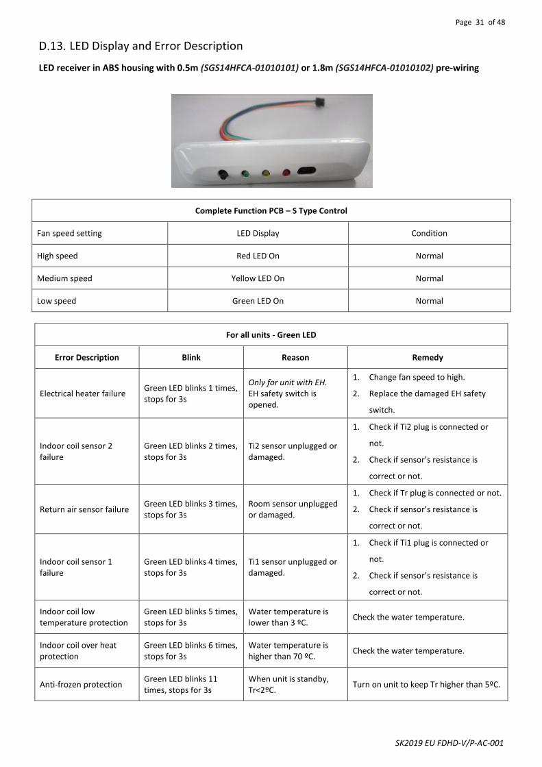
LED receiver in ABS housing with 0.5m (SGS14HFCA-01010101) or 1.8m (SGS14HFCA-01010102) pre-wiring
Complete Function PCB – S Type Control
Fan speed setting LED Display Condition
High speed Red LED On Normal
Medium speed Yellow LED On Normal
Low speed Green LED On Normal
For all units - Green LED
Error Description Blink Reason Remedy
Electrical heater failure Green LED blinks 1 times, stops for 3s
Only for unit with EH. EH safety switch is opened.
1. Change fan speed to high.
2. Replace the damaged EH safety
switch.
Indoor coil sensor 2 failure
Green LED blinks 2 times, stops for 3s
Ti2 sensor unplugged or damaged.
1. Check if Ti2 plug is connected or
not.
2. Check if sensor’s resistance is
correct or not.
Return air sensor failure Green LED blinks 3 times, stops for 3s
Room sensor unplugged or damaged.
1. Check if Tr plug is connected or not.
2. Check if sensor’s resistance is
correct or not.
Indoor coil sensor 1 failure
Green LED blinks 4 times, stops for 3s
Ti1 sensor unplugged or damaged.
1. Check if Ti1 plug is connected or
not.
2. Check if sensor’s resistance is
correct or not.
Indoor coil low temperature protection
Green LED blinks 5 times, stops for 3s
Water temperature is lower than 3 ºC.
Check the water temperature.
Indoor coil over heat protection
Green LED blinks 6 times, stops for 3s
Water temperature is higher than 70 ºC.
Check the water temperature.
Anti-frozen protection Green LED blinks 11 times, stops for 3s
When unit is standby, Tr<2ºC.
Turn on unit to keep Tr higher than 5ºC.

Page 32 of 48
SK2019 EU FDHD-V/P-AC-001
LED Display on Master/Slave Connection The error message indicating the defect status of all slave units will be shown in LED lights on the master unit.
Master unit LED Unit No. Blink Remedy
Unit 2 failure RED LED blinks 2 times, stops for 3s Check unit 2 communication plug and fix it
Unit 3 failure RED LED blinks 3 times, stops for 3s Check unit 3 communication plug and fix it
Unit 4 failure RED LED blinks 4 times, stops for 3s Check unit 4 communication plug and fix it
Unit 5 failure RED LED blinks 5 times, stops for 3s Check unit 5 communication plug and fix it
Unit 6 failure RED LED blinks 6 times, stops for 3s Check unit 6 communication plug and fix it
Unit 7 failure RED LED blinks 7 times, stops for 3s Check unit 7 communication plug and fix it
Unit 8 failure RED LED blinks 8 times, stops for 3s Check unit 8 communication plug and fix it
Unit 9 failure RED LED blinks 9 times, stops for 3s Check unit 9 communication plug and fix it
Unit 10 failure RED LED blinks 10 times, stops for 3s Check unit 10 communication plug and fix it
Unit 11 failure RED LED blinks 11 times, stops for 3s Check unit 11 communication plug and fix it
Unit 12 failure RED LED blinks 12 times, stops for 3s Check unit 12 communication plug and fix it
Unit 13 failure RED LED blinks 13 times, stops for 3s Check unit 13 communication plug and fix it
Unit 14 failure RED LED blinks 14 times, stops for 3s Check unit 14 communication plug and fix it
Unit 15 failure RED LED blinks 15 times, stops for 3s Check unit 15 communication plug and fix it
Unit 16 failure RED LED blinks 16 times, stops for 3s Check unit 16 communication plug and fix it
Unit 17 failure RED LED blinks 17 times, stops for 3s Check unit 17 communication plug and fix it
Unit 18 failure RED LED blinks 18 times, stops for 3s Check unit 18 communication plug and fix it
Unit 19 failure RED LED blinks 19 times, stops for 3s Check unit 19 communication plug and fix it
Unit 20 failure RED LED blinks 20 times, stops for 3s Check unit 20 communication plug and fix it
Unit 21 failure RED LED blinks 21 times, stops for 3s Check unit 21 communication plug and fix it
Unit 22 failure RED LED blinks 22 times, stops for 3s Check unit 22 communication plug and fix it
Unit 23 failure RED LED blinks 23 times, stops for 3s Check unit 23 communication plug and fix it
Unit 24 failure RED LED blinks 24 times, stops for 3s Check unit 24 communication plug and fix it
Unit 25 failure RED LED blinks 25 times, stops for 3s Check unit 25 communication plug and fix it
Unit 26 failure RED LED blinks 26 times, stops for 3s Check unit 26 communication plug and fix it
Unit 27 failure RED LED blinks 27 times, stops for 3s Check unit 27 communication plug and fix it
Unit 28 failure RED LED blinks 28 times, stops for 3s Check unit 28 communication plug and fix it
Unit 29 failure RED LED blinks 29 times, stops for 3s Check unit 29 communication plug and fix it
Unit 30 failure RED LED blinks 30 times, stops for 3s Check unit 30 communication plug and fix it
Unit 31 failure RED LED blinks 31 times, stops for 3s Check unit 31 communication plug and fix it
Unit 32 failure RED LED blinks 32 times, stops for 3s Check unit 32 communication plug and fix it

Page 33 of 48
SK2019 EU FDHD-V/P-AC-001
Master-Slave Network
The control PCB can be set either as a master unit or slave unit.
Mater Unit Function a) The master unit sends data regarding its setting to the slave unit. b) The master unit settings are unit ON/OFF, Mode, Fan Speed, Timer, Clock, Set Temperature and Sleep Function for
handset operation. c) The master unit settings are unit ON/OFF, Mode, Fan Speed, Timer, Clock, Set Temperature and Sleep Function for wall
pad operation. Slave Unit Function a) The slave unit receives data regarding its settings from the master unit. b) The slave unit is allowed to change to a locally desired setting by local controller as long as there are no subsequent
changes to the settings of the master unit. c) The slave units can be set individually for timer ON/OFF function by handset or wall pad. The handset cannot override
the wall pad timer and clock setting.
D.15.1. Master Unit Control Settings
The control PCB can receive data from both wireless Infrared handset and wired wall pad.
Using Remote Control Handset to Set Master Control Unit:
1. Connect all the units’ PCBs according to the wire color and type of connector. 2. Select the master unit by setting DIPA-S1 SW6 to ON (=1) in the PCB. 3. Ensure the DIPA-S1 SW6 is set to OFF (=0) in the PCB on each slave unit. 4. Switch on the units by connecting the main power supply. 5. Using the handset, set the operation parameters for the master unit which will automatically send the settings to the
slave unit. 6. Master unit will beep twice confirming receipt of commands while the slave unit will beep once. Using Wall pad to Set Master Control Unit:
1. Connect all the units’ PCBs according to the wire color and type of connector. 2. Select the master unit by setting DIPA-S1 SW6 to ON (=1) in the PCB. 3. Ensure the DIPA-S1 SW6 is set to OFF (=0) in the PCB on each slave unit. 4. Provide each slave unit with an addressable code by configuring SW1 – SW5 of DIPA-S1 according to the DIP switch
setting table. 5. Switch on the units by connecting the main power supply. 6. Using the wall pad set the operation parameters for the master unit which will send the setting to the slave units by
Global-control communication or Addressable communication methods. 7. Master unit will beep twice confirming receipt of commands while the slave unit will beep once.
Page 34 of 48
SK2019 EU FDHD-V/P-AC-001
D.15.2. Master Slave Network Setup
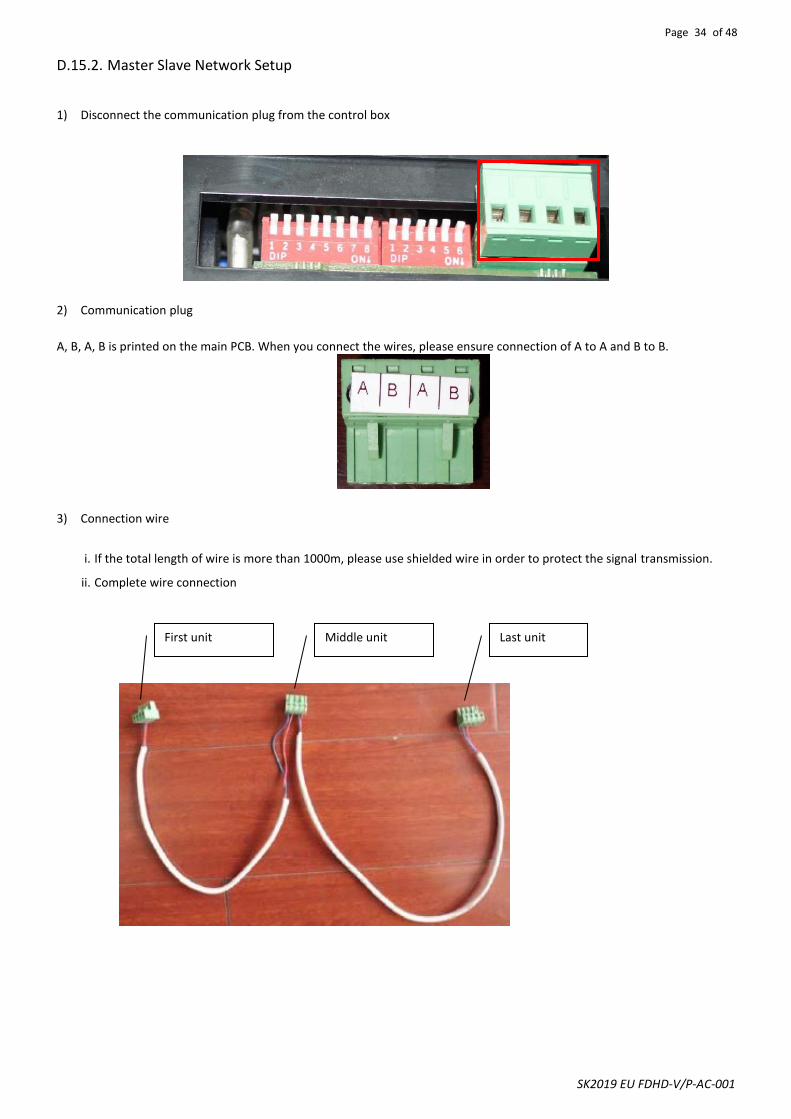
1) Disconnect the communication plug from the control box
2) Communication plug
A, B, A, B is printed on the main PCB. When you connect the wires, please ensure connection of A to A and B to B.
3) Connection wire
i. If the total length of wire is more than 1000m, please use shielded wire in order to protect the signal transmission.
ii. Complete wire connection
First unit Middle unit Last unit
Page 35 of 48
SK2019 EU FDHD-V/P-AC-001
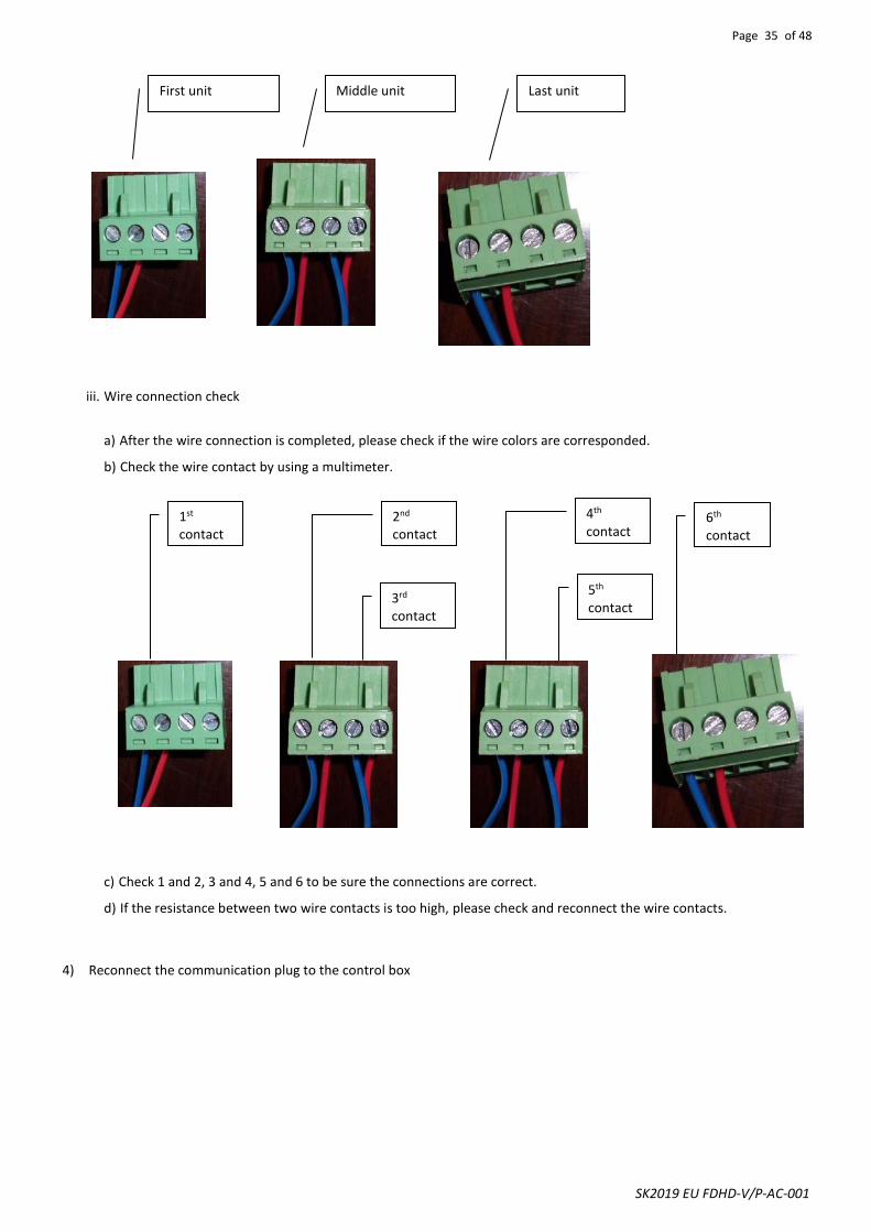
iii. Wire connection check
a) After the wire connection is completed, please check if the wire colors are corresponded.
b) Check the wire contact by using a multimeter.
c) Check 1 and 2, 3 and 4, 5 and 6 to be sure the connections are correct.
d) If the resistance between two wire contacts is too high, please check and reconnect the wire contacts.
4) Reconnect the communication plug to the control box
First unit Middle unit Last unit
1st contact
2nd contact
3rd contact
4th contact
5th contact
6th contact

Page 36 of 48
SK2019 EU FDHD-V/P-AC-001
D.15.3. Master Slave Communication Method There are two modes for the master-slave structure.
Global Control communication The master unit will broadcast the settings to all slave units. During normal operation, slave units can receive commands from its wireless handset and wall pad control panel. Upon receiving the master global commands, all slave unit settings will be replaced by the master settings.
DIPA-S1 address setting: ON=1, OFF=0.
DIPA-S1 SW6
DIPA-S1 SW5
DIPA-S1 SW4
DIPA-S1 SW3
DIPA-S1 SW2
DIPA-S1 SW1
Unit No. Remark
1 0 0 0 0 0 01 Master
0 0 0 0 0 1 02 Slave
0 0 0 0 1 0 03 Slave
0 0 0 0 1 1 04 Slave
0 0 0 1 0 0 05 Slave
0 0 0 1 0 1 06 Slave
0 0 0 1 1 0 07 Slave
0 0 0 1 1 1 08 Slave
0 0 1 0 0 0 09 Slave
0 0 1 0 0 1 10 Slave
0 0 1 0 1 0 11 Slave
0 0 1 0 1 1 12 Slave
0 0 1 1 0 0 13 Slave
0 0 1 1 0 1 14 Slave
0 0 1 1 1 0 15 Slave
0 0 1 1 1 1 16 Slave
0 1 0 0 0 0 17 Slave
0 1 0 0 0 1 18 Slave
0 1 0 0 1 0 19 Slave
0 1 0 0 1 1 20 Slave
0 1 0 1 0 0 21 Slave
0 1 0 1 0 1 22 Slave
0 1 0 1 1 0 23 Slave
0 1 0 1 1 1 24 Slave
0 1 1 0 0 0 25 Slave
0 1 1 0 0 1 26 Slave
0 1 1 0 1 0 27 Slave
0 1 1 0 1 1 28 Slave
0 1 1 1 0 0 29 Slave
0 1 1 1 0 1 30 Slave
0 1 1 1 1 0 31 Slave
0 1 1 1 1 1 32 Slave
If the master unit is equipped with a wireless handset only, it can only use the Global-Control communication method. If it is equipped with a wall pad, it can use both communication methods.
Page 37 of 48
SK2019 EU FDHD-V/P-AC-001
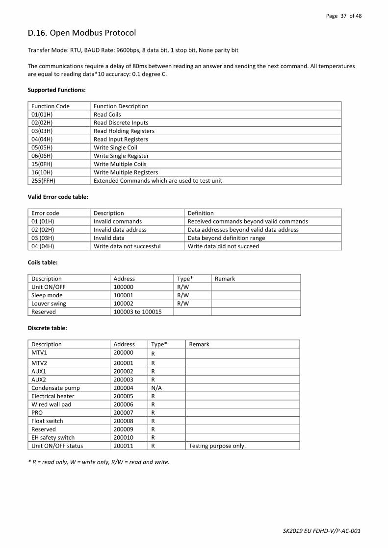
Open Modbus Protocol Transfer Mode: RTU, BAUD Rate: 9600bps, 8 data bit, 1 stop bit, None parity bit The communications require a delay of 80ms between reading an answer and sending the next command. All temperatures are equal to reading data*10 accuracy: 0.1 degree C.
Supported Functions:
Function Code Function Description
01(01H) Read Coils
02(02H) Read Discrete Inputs
03(03H) Read Holding Registers
04(04H) Read Input Registers
05(05H) Write Single Coil
06(06H) Write Single Register
15(0FH) Write Multiple Coils
16(10H) Write Multiple Registers
255(FFH) Extended Commands which are used to test unit
Valid Error code table:
Error code Description Definition
01 (01H) Invalid commands Received commands beyond valid commands
02 (02H) Invalid data address Data addresses beyond valid data address
03 (03H) Invalid data Data beyond definition range
04 (04H) Write data not successful Write data did not succeed
Coils table:
Description Address Type* Remark
Unit ON/OFF 100000 R/W
Sleep mode 100001 R/W
Louver swing 100002 R/W
Reserved 100003 to 100015
Discrete table:
Description Address Type* Remark
MTV1 200000 R
MTV2 200001 R
AUX1 200002 R
AUX2 200003 R
Condensate pump 200004 N/A
Electrical heater 200005 R
Wired wall pad 200006 R
PRO 200007 R
Float switch 200008 R
Reserved 200009 R
EH safety switch 200010 R
Unit ON/OFF status 200011 R Testing purpose only.
* R = read only, W = write only, R/W = read and write.
Page 38 of 48
SK2019 EU FDHD-V/P-AC-001
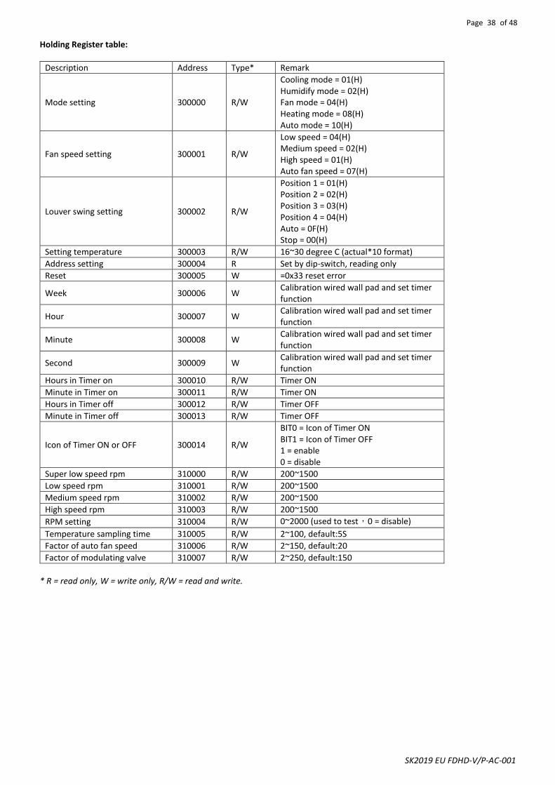
Holding Register table:
Description Address Type* Remark
Mode setting 300000 R/W
Cooling mode = 01(H) Humidify mode = 02(H) Fan mode = 04(H) Heating mode = 08(H) Auto mode = 10(H)
Fan speed setting 300001 R/W
Low speed = 04(H) Medium speed = 02(H) High speed = 01(H) Auto fan speed = 07(H)
Louver swing setting 300002 R/W
Position 1 = 01(H) Position 2 = 02(H) Position 3 = 03(H) Position 4 = 04(H) Auto = 0F(H) Stop = 00(H)
Setting temperature 300003 R/W 16~30 degree C (actual*10 format)
Address setting 300004 R Set by dip-switch, reading only
Reset 300005 W =0x33 reset error
Week 300006 W Calibration wired wall pad and set timer function
Hour 300007 W Calibration wired wall pad and set timer function
Minute 300008 W Calibration wired wall pad and set timer function
Second 300009 W Calibration wired wall pad and set timer function
Hours in Timer on 300010 R/W Timer ON
Minute in Timer on 300011 R/W Timer ON
Hours in Timer off 300012 R/W Timer OFF
Minute in Timer off 300013 R/W Timer OFF
Icon of Timer ON or OFF 300014 R/W
BIT0 = Icon of Timer ON BIT1 = Icon of Timer OFF 1 = enable 0 = disable
Super low speed rpm 310000 R/W 200~1500
Low speed rpm 310001 R/W 200~1500
Medium speed rpm 310002 R/W 200~1500
High speed rpm 310003 R/W 200~1500
RPM setting 310004 R/W 0~2000 (used to test,0 = disable)
Temperature sampling time 310005 R/W 2~100, default:5S
Factor of auto fan speed 310006 R/W 2~150, default:20
Factor of modulating valve 310007 R/W 2~250, default:150
* R = read only, W = write only, R/W = read and write.

Page 39 of 48
SK2019 EU FDHD-V/P-AC-001
Input Register table:
Description Address Type* Remark
Dip switch 1 status 400000 R
Dip switch 2 status 400001 R
Room temperature sensor 400002 R
Ti1 temperature sensor 400003 R
Ti2 temperature sensor 400004 R
Error code 400005 R
Bit0 = Room temperature sensor error Bit1 = Ti1 temperature sensor error Bit2 = Ti2 temperature sensor error Bit3 = Float switch error Bit4 = Indoor coil low temperature protection Bit5 = Indoor coil over heat protection Bit6 = Reserved Bit7 = Electrical heater failure Bit8 = Motor1 Error Bit9 = Motor2 Error Bit10 = System parameters error Bit11 = Anti-frozen protection Bit12 = Reserved Bit13 = Reserved Bit14 = Reserved Bit15 = Reserved
Fan speed status 400006 R Low = 04(H) Medium = 02(H) High = 01(H)
Mode status 400007 R
Cooling mode = 01(H) Dehumidify mode = 02(H) Fan mode = 04(H) Heating = 08(H)
Setting temperature status 400008 R Testing only
Room temperature in wall pad status
400009 R
Room temperature in main PCB status
400010 R
Unit type 400011 R 4-pipe = 03, 2-pipe = 02 This setting is configured by dip switch
EC motor 1# RPM 400012 R
EC motor 2# RPM 400013 R
* R = read only, W = write only, R/W = read and write.
Remark: The above protocol address is in Base 0.

Page 40 of 48
SK2019 EU FDHD-V/P-AC-001
User Interface
Remote Handset
Attention
When unit with handset is the master unit, its settings are automatically sent to the slave units; Auto Cool-Heat operation will be applicable in 4-pipe system only. “Swing” and “Louver” functions are not applicable. European version only uses degree C setting.
Swing It is not available
Interchange oF and oC on Display Press up and down buttons for 3 seconds, then release.
Louver It is not available

Page 41 of 48
SK2019 EU FDHD-V/P-AC-001
Wired Wall Pad Controller
Day display
Mode display
Temperature display
Fan speed display
Timer display
Real Time display
Master-Slave Button display Network Sleep icon Key lock

Page 42 of 48
SK2019 EU FDHD-V/P-AC-001
1. Buttons function
Button
Name ONOFF MODE FAN SET DOWN UP
Function Switch on or off the unit
Switch between modes
Change Fan Speed
Switch interfaces
Modify parameters
Modify parameters
Press to change function setting: (CNT stands for pressing times) (1) CNT=0:No function
(2) CNT=1:Real time setting
(3) CNT=2:Timer On/Off setting
(4) CNT=3:Sleep or swing settings
(5) CNT=4:Network control (Single control) mode setting
(6) CNT=5:Global control
(7) CNT=6:Parameters checking
2. Real time setting
“:” blinks for every second when real time is shown. Press once to enter Real Time setting interface. When “:” is on,
then press or to adjust the current time. Press to adjust date. Press to adjust hour or minute.
Press to confirm settings and exit. If no operation within 6 seconds, it will automatically exit and the setting will not be saved. 3. Time On/Off setting If the master unit is in global control mode and the ON/OFF timer setting is selected, the master unit will command the whole network to be ON or OFF. Otherwise, the ON/OFF timer affects the local unit only. The system supports ON/OFF timer settings for each day of the week.
Press twice to enter Timer setting interface and timer icon is on. When “ON” blinks, press to set timer date
(from Monday to Sunday). Press to set hour and minute of timer-on or timer-off alternately. “ON” blinks when timer is
set to on and “OFF” blinks when timer is set to off. Press or to set timer on/off time.
Press to confirm settings and exit. If no operation within 6 seconds, it will automatically exit and the setting will not be saved. Timer on/off icon is on when timer on/off is set on that day. 4. Swing or Sleep setting
Press three times to enter Swing or Sleep setting interface and key lock icon blinks. Press to turn the sleep function on or off. Sleep icon is on or off when sleep function is turned on or off.
Press to turn on or off the swing function. is on when swing function is on.
Press to select room sensor in the wall pad or in the unit. If “∩” is shown in the area of fan speed display, the
senor in the wall pad is selected. If “F” is shown in the area of fan speed display, the senor in the unit is selected.
Press to confirm settings and exit. If no operation within 6 seconds, it will automatically exit and the setting will not be saved.
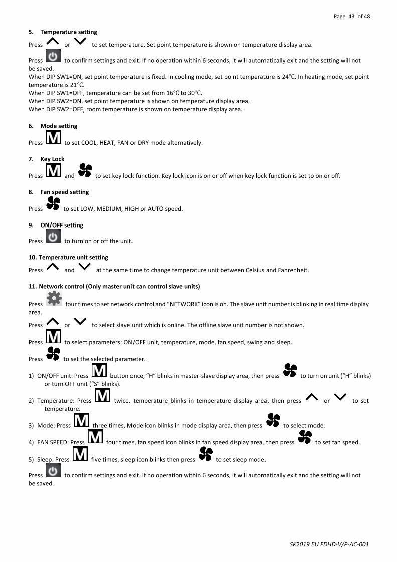
Page 43 of 48
SK2019 EU FDHD-V/P-AC-001
5. Temperature setting
Press or to set temperature. Set point temperature is shown on temperature display area.
Press to confirm settings and exit. If no operation within 6 seconds, it will automatically exit and the setting will not be saved. When DIP SW1=ON, set point temperature is fixed. In cooling mode, set point temperature is 24℃. In heating mode, set point temperature is 21℃. When DIP SW1=OFF, temperature can be set from 16℃ to 30℃. When DIP SW2=ON, set point temperature is shown on temperature display area. When DIP SW2=OFF, room temperature is shown on temperature display area. 6. Mode setting
Press to set COOL, HEAT, FAN or DRY mode alternatively. 7. Key Lock
Press and to set key lock function. Key lock icon is on or off when key lock function is set to on or off. 8. Fan speed setting
Press to set LOW, MEDIUM, HIGH or AUTO speed. 9. ON/OFF setting
Press to turn on or off the unit. 10. Temperature unit setting
Press and at the same time to change temperature unit between Celsius and Fahrenheit. 11. Network control (Only master unit can control slave units)
Press four times to set network control and “NETWORK” icon is on. The slave unit number is blinking in real time display area.
Press or to select slave unit which is online. The offline slave unit number is not shown.
Press to select parameters: ON/OFF unit, temperature, mode, fan speed, swing and sleep.
Press to set the selected parameter.
1) ON/OFF unit: Press button once, “H” blinks in master-slave display area, then press to turn on unit (“H” blinks) or turn OFF unit (“S” blinks).
2) Temperature: Press twice, temperature blinks in temperature display area, then press or to set temperature.
3) Mode: Press three times, Mode icon blinks in mode display area, then press to select mode.
4) FAN SPEED: Press four times, fan speed icon blinks in fan speed display area, then press to set fan speed.
5) Sleep: Press five times, sleep icon blinks then press to set sleep mode.
Press to confirm settings and exit. If no operation within 6 seconds, it will automatically exit and the setting will not be saved.

Page 44 of 48
SK2019 EU FDHD-V/P-AC-001
12. Global control setting
Press five times to set global control and “NETWORK” icon blinks.
1) Press , timer on/off icon blinks and all slave units’ timer on/off function setting are cancelled.
2) Press , all slave units time are set to the same as master units.
Press , master unit sends commands to all online slave units. “NETWORK” icon is off. If timer on/off function is set on mater unit, “NETWORK” icon blinks until Timer on/off disappears. 13. Parameter checking
Press six times to enter parameter checking interface. Local unit parameter is shown in temperature display area. Unit number is shown in real time hour area and parameter number is shown in real time minute area. For example, 2:03 stands
for No.2 unit and No.3 parameter. Press and to select the specific parameter. Press and to select
unit number. Press to exit parameter checking interface. Parameters shown below:
Temp. area Time area
C0 Return air temperature
C1 Indoor coil 1 temperature
C2 DIP switch setting
C3 Indoor coil 2 temperature
14. Error codes When unit error is detected, unit number blinks on real time hour area and Error code blinks on real time minute area. The Error codes display alternately if more than one error is detected. If there is no slave unit online, only error code is shown in real time minute area. Error code table:
Error reason Error code
Indoor coil sensor 2 faulty E2
Return air sensor faulty E3
Indoor coil sensor 1 faulty E4
Indoor coil low temperature protection E5
Indoor coil over heat protection E6
Water pump faulty E7
Local communication error EC0
15. EC motor RPM setting (Not available in AC motor unit) DIP SW3 is used to set EC motor RPM. When DIP SW3=ON, wired wall pad enters setting interface. D1/D2/D3 is shown in temperature display area and EC motor RPM is shown in real time display area.
Press and to select motor speed (D1, D2 or D3). Press or to set EC motor RPM. After 3 seconds, the setting is valid. When DIP SW3=OFF, wired wall pad resumes normal operation.
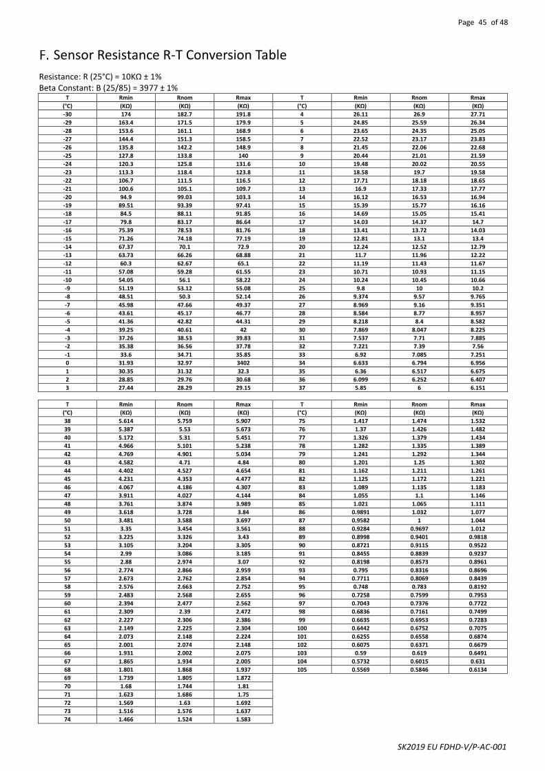
Page 45 of 48
SK2019 EU FDHD-V/P-AC-001
Sensor Resistance R-T Conversion Table
Resistance: R (25°C) = 10KΩ ± 1% Beta Constant: B (25/85) = 3977 ± 1%
T Rmin Rnom Rmax T Rmin Rnom Rmax
(°C) (KΩ) (KΩ) (KΩ) (°C) (KΩ) (KΩ) (KΩ)
-30 174 182.7 191.8 4 26.11 26.9 27.71
-29 163.4 171.5 179.9 5 24.85 25.59 26.34
-28 153.6 161.1 168.9 6 23.65 24.35 25.05
-27 144.4 151.3 158.5 7 22.52 23.17 23.83
-26 135.8 142.2 148.9 8 21.45 22.06 22.68
-25 127.8 133.8 140 9 20.44 21.01 21.59
-24 120.3 125.8 131.6 10 19.48 20.02 20.55
-23 113.3 118.4 123.8 11 18.58 19.7 19.58
-22 106.7 111.5 116.5 12 17.71 18.18 18.65
-21 100.6 105.1 109.7 13 16.9 17.33 17.77
-20 94.9 99.03 103.3 14 16.12 16.53 16.94
-19 89.51 93.39 97.41 15 15.39 15.77 16.16
-18 84.5 88.11 91.85 16 14.69 15.05 15.41
-17 79.8 83.17 86.64 17 14.03 14.37 14.7
-16 75.39 78.53 81.76 18 13.41 13.72 14.03
-15 71.26 74.18 77.19 19 12.81 13.1 13.4
-14 67.37 70.1 72.9 20 12.24 12.52 12.79
-13 63.73 66.26 68.88 21 11.7 11.96 12.22
-12 60.3 62.67 65.1 22 11.19 11.43 11.67
-11 57.08 59.28 61.55 23 10.71 10.93 11.15
-10 54.05 56.1 58.22 24 10.24 10.45 10.66
-9 51.19 53.12 55.08 25 9.8 10 10.2
-8 48.51 50.3 52.14 26 9.374 9.57 9.765
-7 45.98 47.66 49.37 27 8.969 9.16 9.351
-6 43.61 45.17 46.77 28 8.584 8.77 8.957
-5 41.36 42.82 44.31 29 8.218 8.4 8.582
-4 39.25 40.61 42 30 7.869 8.047 8.225
-3 37.26 38.53 39.83 31 7.537 7.71 7.885
-2 35.38 36.56 37.78 32 7.221 7.39 7.56
-1 33.6 34.71 35.85 33 6.92 7.085 7.251
0 31.93 32.97 3402 34 6.633 6.794 6.956
1 30.35 31.32 32.3 35 6.36 6.517 6.675
2 28.85 29.76 30.68 36 6.099 6.252 6.407
3 27.44 28.29 29.15 37 5.85 6 6.151
T Rmin Rnom Rmax T Rmin Rnom Rmax
(°C) (KΩ) (KΩ) (KΩ) (°C) (KΩ) (KΩ) (KΩ)
38 5.614 5.759 5.907 75 1.417 1.474 1.532
39 5.387 5.53 5.673 76 1.37 1.426 1.482
40 5.172 5.31 5.451 77 1.326 1.379 1.434
41 4.966 5.101 5.238 78 1.282 1.335 1.389
42 4.769 4.901 5.034 79 1.241 1.292 1.344
43 4.582 4.71 4.84 80 1.201 1.25 1.302
44 4.402 4.527 4.654 81 1.162 1.211 1.261
45 4.231 4.353 4.477 82 1.125 1.172 1.221
46 4.067 4.186 4.307 83 1.089 1.135 1.183
47 3.911 4.027 4.144 84 1.055 1.1 1.146
48 3.761 3.874 3.989 85 1.021 1.065 1.111
49 3.618 3.728 3.84 86 0.9891 1.032 1.077
50 3.481 3.588 3.697 87 0.9582 1 1.044
51 3.35 3.454 3.561 88 0.9284 0.9697 1.012
52 3.225 3.326 3.43 89 0.8998 0.9401 0.9818
53 3.105 3.204 3.305 90 0.8721 0.9115 0.9522
54 2.99 3.086 3.185 91 0.8455 0.8839 0.9237
55 2.88 2.974 3.07 92 0.8198 0.8573 0.8961
56 2.774 2.866 2.959 93 0.795 0.8316 0.8696
57 2.673 2.762 2.854 94 0.7711 0.8069 0.8439
58 2.576 2.663 2.752 95 0.748 0.783 0.8192
59 2.483 2.568 2.655 96 0.7258 0.7599 0.7953
60 2.394 2.477 2.562 97 0.7043 0.7376 0.7722
61 2.309 2.39 2.472 98 0.6836 0.7161 0.7499
62 2.227 2.306 2.386 99 0.6635 0.6953 0.7283
63 2.149 2.225 2.304 100 0.6442 0.6752 0.7075
64 2.073 2.148 2.224 101 0.6255 0.6558 0.6874
65 2.001 2.074 2.148 102 0.6075 0.6371 0.6679
66 1.931 2.002 2.075 103 0.59 0.619 0.6491
67 1.865 1.934 2.005 104 0.5732 0.6015 0.631
68 1.801 1.868 1.937 105 0.5569 0.5846 0.6134
69 1.739 1.805 1.872
70 1.68 1.744 1.81
71 1.623 1.686 1.75
72 1.569 1.63 1.692
73 1.516 1.576 1.637
74 1.466 1.524 1.583

Page 46 of 48
SK2019 EU FDHD-V/P-AC-001
Troubleshooting
Symptoms Cause Remedy
The fan coil does not start up
No voltage
Mains switch in the “OFF position
Faulty room control
Faulty fan
- Check for presence of voltage
- Check fuse on board
- Place in the “ON” position
- Check the room control
- Check fan motor
Filter clogged
Air flow obstructed
Room control regulation
Incorrect water temperature
Air present
Insufficient output
- Clean the filter
- Remove obstacles
- Check the room air sensor
- Check the water source
- Check the air vent
Contact between metal parts
Loose screws
Noise and vibrations
- Check for loosening parts
- Tighten screws

Page 47 of 48
SK2019 EU FDHD-V/P-AC-001
Accessories
TWO-WAY INTAKE PLENUM WITH DAMPER The two-way intake plenum with damper enables the room air intake duct and the external air intake duct to be connected when required. The cross section of the external air intake duct is accounted for 25% of the total cross section.

Page 48 of 48
SK2019 EU FDHD-V/P-AC-001
DISCHARGE (AND INTAKE) PLENUM The discharge and intake plenum are supplied when the incoming or outgoing airflow must be directed to or from the bottom of the unit. It has a flange for connection to the basic unit or other accessories and blanked panels for optimum and flexible use.
DISCHARGE PLENUM FOR ROUND DUCTING The discharge plenum for round ducting enables the air to be distributed through flexible ducts. Distribution takes place through two 190mm diameter ducts in sizes FDHD-18, three 190 mm diameter ducts in sizes FDHD-24/30/36, four 250 mm diameter ducts in sizes FDHD-40/48, three 300 mm diameter ducts in sizes FDHD-75; four 300 mm diameter ducts in size FDHD-100. The number of ducts is calculated so as to obtain an air speed of 5.0 m/s in the ducts with rated airflow and the ducts fully open.
AUXILIARY 1 ROW or 2 ROWS HEATING COIL MODULE FOR 4-PIPE SYSTEM Install the auxiliary 1 row or 2 rows heating coil module to the unit with 8 screws as shown above. ELECTRICAL HEATER MODULE The electric heater module is supplied for winter heating as an alternative to the auxiliary hot water coil. The maximum outputs available with 380V~50 are 3.0 KW for sizes FDHD-18; 4.5 kW for sizes FDHD-24/30/36; 6.0 kW for sizes FDHD-48/60; 7.5 kW for sizes FDHD-75 and 9.0 kW for sizes FDHD-100. The module must be installed downstream of the basic unit directly in the outflow of air. The stainless-steel spiral heaters are mounted on a removable frame independent from the module. The heaters feature ON-OFF operation. Install the electrical heater module to the unit with 8 screws as same as the auxiliary coil module for 4 pipe systems. Note: For correct operation of the heaters, make sure airflow is not less than the values for minimum speed.

Eurofred S.A.Marqués de Sentmenat 9708029 Barcelonawww.eurofred.es
Related Documents