WSRC-TR-94-0442, Rev. 1 High-Level Waste System Process Interface Description by P. D. d’Entremont Westinghouse Savannah River Company Savannah River Site Aiken, South Carolina 29808 DOE Contract No. DE-AC09-89SR18035 This paper was prepared in connection with work done under the above contract number with the U.S. Department of Energy. By acceptance of this paper, the publisher and/or recipient acknowledges the U.S. Government’s right to retain a nonexclusive, royalty-free license in and to any copyright covering this paper, along with the right to reproduce and to authorize others to reproduce all or part of the copyrighted paper.

Welcome message from author
This document is posted to help you gain knowledge. Please leave a comment to let me know what you think about it! Share it to your friends and learn new things together.
Transcript
WSRC-TR-94-0442, Rev. 1
High-Level Waste System Process Interface Description
by
P. D. d’Entremont
Westinghouse Savannah River Company
Savannah River SiteAiken, South Carolina 29808
DOE Contract No. DE-AC09-89SR18035
This paper was prepared in connection with work done under the above contract number with the U.S.Department of Energy. By acceptance of this paper, the publisher and/or recipient acknowledges the U.S.Government’s right to retain a nonexclusive, royalty-free license in and to any copyright covering this paper,along with the right to reproduce and to authorize others to reproduce all or part of the copyrighted paper.
DISCLAIMER
IMS IWJOrt was mePared N an accomt of work sponsoti by an agency of the United StatesGoverrikent. Niiti%r tie Unitd SWM Govq@t nor any ageniy thereof, nor any of theiremployees, makes any W-MY, express or nplled, or assumes any legal liability orresponsibility for the ax-y, completeness: or usefulness of any information, apparatus,prdum or process dkclose& or represents that ItS use would not infringe privately owned rights.Reference herein to any specific commercial produc~ process, or service by trade name,trademark, manufacturer, or otherwise does not necessarily constitute or imply its endorsemen~recommendation, or favoring by the United States Governmentor any agency thereof. Theviews and opinions of authors expressed herein do not necessarily state or reflect those of theUnited States Government or any agency thereof.
This report has been reproduced directly fmm the best available copy.
Available to DOE and DOE contractors horn the Office of Scientific and Technical Information,P.O. Box 62, Oak Ridge, TN 37831; prices available horn (615) 576-8401.
Available to the public from the National Technical Information Service, U.S. Department ofCommerce? 5285 Port Royal Road, Springfield, VA 22161.
DISCLAIMER
Portions of this document may be illegiblein electronic image products. Images areproduced from the best available originaldocument.

s..
A.
WSRC-TR-94-0442
Rev. 1
March 1995
sF-ii=
HIGH-LEVEL WASTE SYSTEM!3=.-- =s&
PROCESS INTERFACE DESCRIPTION ==?<—g-tr~8~
Functions and Requirements of the High-Level Waste Process (U) ~
P. D. d’EntremontR. A. Jacobs, SRTCJ. R. FowlerD. F. BrownD. J. McCabe, SRTCD. D. Walker, SRTCJ. M. Gillam
●?o t’mll:~p+
Westinghouse Savannah River Company● ● se
*A ~—~ — p%
High-Level Waste Management Division $ -~~-a: ~-4
Aiken, SC 29808&z ~-- A *
SAVANNAH RIVER SITE
PREPAREDFOR THE U.S. DEPARTMENTOF ENERGYUNDERCONTRACTNO. DE-AC0943$SR18035

. . *
HIGH-LEVEL WASTE ENG~G
HIGH-LEVEL WASTE
WSRC!-TR-944M42REVISION 1
KEYWORDS:Tank Farm, Chemicals, DWPF, ITP,ETF, ESP, Functional Description,Requirements, Intmfaces
RETENTION PERMANHWCLASSIFICATION U
SYSTEMPROCESS INTERFACE DESCRIPTION
Functions and Requirements of the High-Level Waste Process (U’)
P. D. d’EntremontR. A. Jacobs, SRTC
J. R. FowlerD. F. Brown
D. J. McCabe, SRTCD. D. Walker, SRTC
J. M. Gillam
Isstled: 31 March 1995
T. M. Monalmn, Manager, HLWE
.
WM Engineering Dept.i
I
. . ,
&
High-Levelw8s&yatanPreeea8Tntufke Description
Table of ContentsPage No.
1. SUMMARY ... . ....... ................. ... .. . ... ... ... ... ... ... ... ... ... .. .. ... ... . ... ... .... ... .. .. .. . ... . ... ... .. . .. 1
2. INTRODUCTIONAND APPLICATION... .... ... .. ... ... .. ... ... ..... ... .. . .. . ....... . ... .. ... .. .. . ... . ... ... . 12.1. Background..... ... ... . ..... ....... ... ... .... .. ... ... ........ .. ... ... ......... . ... . ... . .. .... .. ..... ... .... ... 12.2,. Description and Purpose of the ProcessInterfhceDescription... .. ....... . .... ... . ... . .... ..... .... .. 32.3. Changes to ProeesaInterfaeeDescription.. ... ... ... . ... ... ... .... ....... .. .. .. .. . ... .... . ... ... .. ... .. . . 4
3. HIGH-LEVELWASTE SYSTEMFUNCTIONSAND HOWTHEY ARE ACCOMPLISHED.... ....53.1. Mission . ... ... ... .. ... .. ... ... ....... ... ... ... ....... ... ... ... ....... .. . ... ... . .... ... . .. . ... .. .... .. .. . . .. .. .. 53.2. Fuction De~ti- .. ..... ... ... .. ... .. ...... .. ...... ... .. .... .. .. ... .... ... ... .. .. .... ... .... .. .. ... .... ...53.3. Allocation of HLW SystemFunctions to HLW Pmxsaea . ... .. ... ..... .. ... .... . ... . .. .. .. ... . .. .. . 163.4. Defining the HLW Pmcesam and Interfaces.... ... .......... ... ... .. .. ... .... ... .... .... ... .... ... .. .. . 17
3.4.1. Relationshipof the Process InterfaceDescriptionand HLW Process TechniealBaadinea. ... .. .. ... ... . .. . ... ... ... ... .... ... .. .. ... . ... . ... . ... . .. . .. . .. . 183.4.2. Definition of an bterface . ... . ... ... .... ... ... .... ... ... ... . ... .. ... ... .. ... . .... .... ... ... ... .. .. 193.4.3. Applicationof the InterfkceConcept. . .. . ... . ... ... ....... ... . .. .... .. .. ... .. .. .... .... ... .... ..20
4. SRS HIGH-LEVELWASTEPROCESSESAND INTERFACES.. ... . ... . ... . .. .... .. .. ...... . ... .... . ....214.1. Overall High-LevelWaste Process Description. ... ..... ... .... ... ... . ... . . .. . ... .... ... .. .. .. . .... . ...2l
4.1.1. Routine Wastes.. ... .......... ..... .. ... ... .. ... ... .. .. .. ... .... .. . ..... ... ... . ... .... ... ...... . . ...214.1.1,1. High-LevelWasteTreatment. ... ........ .. .. ... .. ... ... . ... . .... .. .. ... . ... .. ... ... .. . ..2l4.1.1.2. Low-LevelAqueousWasteTreatmeat . . . . . . ..". . . . . . . . . . . . . . . . . . . . . . . . . . . . . . . . . . . . . . ...24
4.1.2, ContaminationControl Waste+?..... ....... ... .... ... . ... .... ... ... .. .. ... . .... .. . . ... . ... . ... ....254.1.3. Non-RoutineMinor Wastca. . .. . ... . .. . ...... . ... .... .. ..... . ... . .. ..... . .... .. ... ... . .... . ... ...254.1.4. Untired Utique WmW ......... ....... ....... .. . .. . . .. . .... . ... ... .. .. .. . ..... ... .. .. . ... ...26
4.2. DWPF Feed Acceptance... .. .. ... .. .. ... ....... .. ... .... ... ....... ... .. .. .... . ... ... . ... . .... ...... . ......264.2.1. HLW Material Evaluation Board.... ... .... ... .. ... .. ... .. .. .... ... . ... . ... .. .. . ... .... .... .. ...27
4.3. HLW P~ .. .... ... . ... . ... . .. . ... ... . ... . .. . ... ... .... ... ....... .. .. .. ... .. .... .... . .. . .. ... . .... .. . ...28
5. HIGH-LEVEL WASTE STORAGEAND EVAPORATION... ... . ... . ... ... . ... .... . .... . .. .... .... ... . ...295.1. Function .... .. ... .. .... ....... ... ....m.. . ... ... . .. . ... . ... .... ... .... .. .. ... . ... .. .. .. .. ... . .... .. .. .. .. ... ...295.2. Descri@ionof the Storage and Evqm’ation process . . . . . . . . . . . . . . . . . . . . . . . . . . . . . . . . . . . . . . . . . . . . . . . . . .29
5.2.1. Receipt, Storage, and Aging of Waste.... ....... ... .... .... .... . ... ... .. .. . ... . .... . .. .. . .... ..325.2.2. Evaporation... .. .. ... .. .. ... .... ... ... ..... ... ..... ...... . .. . ... . ... . .. .. . ... ... ... . . ... . ... .. .... ..325.2.3. Waste Remowd... .. ... .. .. .. .. .. ... .. .. ... . ..... ... .. .. .. .. ... .. ... . .. .. . .. ..... . ... . ....... . ... ...335.2.4. kti=itig mdClmm .... .. ... .. .. ... .. .. .. .. .. ... .... ... . . .... ... .. .. . ... . . .. .. .. . .....34
5.3. Influent Streamsand Key Process Variables. ....... .... .. ... .... .. .. .. ... . . .. . . ... . . .. .. ..... . ... .. . ...345.3.1. soum .. ...... .. ... . ... . ... .. ..... . ... . ... . ... ... .... .. ... .. .. .. .. .. .. .. . ... . ... . .. .. ... ... . . ... ....345.3.2. ~H@lWIHttS . . . . . . . . . . . . . . . . . . . . . . . . . . . . . . . . . . . . . . . . . . . . . . . . . . . . . . . . . . . . . . . . . . . . . . . . . . . . . . . . . . . . . .35
S.3.2.1. R.m@for Comsion Pmvmtion .. ... . ... ... .... .. . .... . .. ... . ... .. .. .. . .. .. ...365.3.2.2. Requirementsfor Preventionof Accurnulationof Flammabie and Explosivecomponents . ... .... ... . .... ... . ... . ... ... . ... . ... ... . ... . .... .... .. .. .. .. .. . .... . . .. .. . .. . .. .. ... . ....375.3.2.3. CS-137Concentrationin WaateTransferred to Type IV Tanks. . .. .... . . ... .. .. ...3?5.3.2.4. R~tim-W for Re@la@~Co~ii~w .... .... . .. ... .... . ... .. .. ... . .... . ... . .. ....385.3.2.5. Requirementsfor Criticality Safety ... .. .... .... .... ... . .... . . ... .. .. . ... . ... . . ... .. ...385.3.2.6. Requirementsfor SAR SourceTerm Comparison .... . .. ... .. .. .... .... . .... .. . .....385.3.2.7. Requirementsto Satisfy ETF Feed Bases .. .. .. .. ... . .... ... . .... . . ... . .. .. ... . .. .....395.3.2.8. Requimnettts to Satisfy SaltStoneWaste AcceptanceCriteria ., . ... .. . .. ... . ......395.3.2.9. Requirementsto Satisfy DWPF Glass Feed Design Basis . .. . ... . .... ... ... . . ......395.3.2.10. Requirementsto Satisfy ITP SAR addendum Basis . ... . .. .. ... . . .. ... ... . . ... . ...39
5.4. Effluent Streams and Key Process Controls . . . . . . . . . . . . . . . . . . . . . . . . . . . . . . . . . . . . . . . . . . . . . . . . . . . . . . . . . . . .40
.
WSRC-TR-94-0442, Rev. 1 i
High-LevelWaatr’syselnProc@?arntedke Dmcription
Table of ContentsPage No.
5.4.1. sludge to EsP-rIlterface stream2 ...... .. ... .... ... . .. . ... ... . ........0. . ..... . .... ... . .... .. ..405.4.2. Sait solution to ~-htterface St= 5. ... ........ .... ... ... . ...... . ... .. .... . .. .. .. .. .... .. ..405.4.3. Evaponttor OVSfhCdS-hited’itfX&rcam 13.... . .. . ... .... .... ... ... .... .. .. ... ... .. ... .. .. ... .415.4.4. Storm Water Runoff (Clan and Diverte+hterfkce St- 17..... ... .. ... ... .. . ... . . ...41
6. SALT PROCESSING(IN-TJWJKPRECIPITATION).... ..... ... .... ... .. ... .... ... .. .. . ... . ... .... .. .. ... . ..426.1. Function .. . ....... ... . .. . ... ... . ... ... .... ... ... ... ... . .. .... . .. ....... ... . ... .. ... .. ... . . .. . .... . ... . ... .. ...426,2. D-ption ofh-Tti *lpi@on ... . ...... ... .... ... .... ... . .. . . .. . ... ... .. .... .. .... ... . .... . ... ....42
6.2.1. Decontamimtion and ConcentrationProcess . .... ........ ... ... . ... ... . ... ... . .... . ... . ...... .446.2.2. P=ipim W*g_ .... . .. . ... ... . ... ... . ... ... . ... .... .... ... . ... ... . .. ... .. . .... ... ....456.2.3. Benzzte RemovalProcess .... ... .......... ... .... ....... ... . .. . ..... .. . ... . . .. .. .. . .. . . ... ... ....45
6.3. Influent Streams and Key Process Variables..... .... ... ....... ...... . ... . .... . ... .... ... .. .. . .. .. .. .. ..456.3.1.6.3.2.6.3.3.6.3.4.6.3.5.6.3.6.6.3.7.6.3.8.6.3.9.
sources... . ... ... ....... ... .... ... ....... ... ........ .. .. .. .. ... .. .. .. .. . ... . .... . ... .. .. ... . .... ... ...45Requirements .. .... ... . .. . ... ... . ... ... .... ... .... ... ... ... . ... .. .. .. .. .. . . .. . .... . ... .. . . ... . .... . .45Requirementsfor Corrosion Prevention.. . ... . .. . ... . ... ... .... .. .. ... .... .... . ... . .. .... . .. . ..46Tank 4SH Influent CompositionSaf~ Requirements... . ... . ... . ... .. . .. .. . . ... .. ... .. .. . ..46Tank 22H Feed Requirements-Interface Stream8 ... . .... .... .. .. .. ... .. . .. . .. ... . .... ..... .46Tanks 48H and 49H Criticality SafetyRequirements. . ... . .. .. . .. . .. ... .. ... . ... .. ... .. ... ..46Requirementsto Satisfy SaltstoneFeed Rcquirementa+nterfkce Streams 5 and 15.....46Requirementsto Satisfy DWPF Feed Basea-Interf&ceStream 7 ..... . ... . .. ... .. .... ......48Raw Materiala... .... ... . ... . .. . ... . .. . ... . ... ... . .. . ... .... ... .. .. ... .. .. . .... . ... .. .. .. .. ... . .. . . .48
6.4. Effluent Streamsaud Key Process Controls .. . .. . ... . .. . ... . ... ..... .. .. .. . ... .. .. . . ... . .... . ... .. .... .496.4.1. D.ntiti Su. to Sdhtin+L& Sti6 . .. .. .. .. ... . ... .. .. .. ... .. .. ....496.4.2. Precipitate to Late Wash-Interface Stream7 ... .. .. .... .... . .. . ... .. .. . ... .. ... . .. ... .. .. .. ...496.4.3. DivextedStorm Water to ETF-Interface Stream 17... .... .... . ... .. .. ... .. .. . . .... ... . .... ..49
7. EXTENDED SLUDGE PROCESSING(ESP).... .... .. .. ... .... .. .. .. ... .... ... . .. .. . ... ... .. .. .. .. . ... .. . .. . .507.1. Function .. ... . ... . ... . ... . ... . ... ... . ... .... .... ... ... .... ... .. .. .... .. .. .. .. ... ... . . .... . ... .. .. ... . ... .. ... .507.2. i)e5cri@ioli of ESP .... .... .... .... .... ....0. . ... . ... ... .... ..... .. .. .. . ... .. .. .... . .. . .... .. . .. ... . .... . ...50
7,2.1. Aluminum Dissolution .. . ... . .. ..... .... ... . ... .... . ... .... ... . ... .... .. .. . ... . .... . ... . ... .. . . . ..517.2.2. Soluble Salt Washing.. .. . .. . . ... .... ... . ... . ... .... .... ... . . ... ... . ... . .. .... . . .... . ... .. .. ... . . ..53
7.3. Effluent Streams and Key Process Controls .. ... . ... . ... . .. . . ... .... . ... .. .. . .. ... .. .. ... .. .. .. .. ... . ..537.3.1. Washed sludge-rnterface stream 4 ..... .... .. ... ... . ... . ... . .... . ... .. .. ... .... ... ... .... .. ...537.3.2. DecantedSupmate-Interface Stream 3 .. .. .. ...... .... .... . .... . . ... .. .. .. .. ... . . .... . ... ....54
7.3.2.1. Di~itim A&~tiv& .. .. .. .... ..... .. .. .. .. .. ... ..... .. . . . ... . . ... .. .. ... . . .... . .. ....547.3.2.2. corrosion Inhibitor Content.. .. .. ... .... ..... ... ..... . .. .. .. ... . . .. .. . ... .. .. ... . ... ....557.3.2.3. Additional Limits for Type IV Tanka.. . ... . .. ..... . ... . .. .. ... . .... . . .. . .. .. ... . . ... . .55
7.3.3. Storm Water Runoff (Cleanand Diverted)-Inter&e Stream 18 ... . .. ... .. .. .. .. . .. .. ....557.4. Influcnt Stream and Key Process Variables.. ... . .... .... .... .... . ... . ... .. . .. ... . . ... . .. .. .. . .. ... . . ..55
7.4.1. unmatedSludge-hwerfimstream2 .... . ... . ... . ... .. ..... .. . ... .. . .. .. . .. ... . . ... .. .. . ... ...557.4.2. WtiWti .. .. .. .. .. .... . ... .... .. .. .... . ... .... .... .... ... .... . ... . .... . . ... . .. .. ... . . .... . .. .. .. ...567.4.3. Raw Materials ... .. . .. ... . .. .. .... .. .. .. ... .... . .. ... .. . .... .... ... . .... . . ... .. . .. ... . . .... . .. .. ....56
8. DEFENSE WASTE PROCESSINGFACILITY (DWPF) Inchtdes Late Wash Facility (LWF) .. .. ... .578.1. Fmction . . .... . ... . . ... . ... . ... . .... ... . .. ..... .. .. .... . ... . ... . .... .. .. .. . .. ... . .. .. . . ... . ... . .... ... .. . .. ...578.2. D-tiption . .. . .. .. .... .... . ... . . .. . . ... . ... . ... . .. .. ... . ... . ... .... .. . ... . .. .. .. . .. ... .. .. . ... . .. .. .. .. . . . ...57
8.2.1. Late Wash Facility .. ... . . .... ... ..... .... . . .. . ... . .. .. . ... . .. ... ... ... . . ... . . . ... . ... . ... . . ... . . ...578.2.2. salt Process ceil (SPC) . ... . . ... . ... . .... .... .... .... ... .. . ... . ... .. . .. . ... . . ... . . ... .. . .. . .. . . ...59
8.2.2.1. SPC Chemistry +.... .. ... . ... . .. .. . ... . ... . ... . .... ... .. . ... . . .. . . ....m... . . .... .... . .. . ...598.2.2.2. SPCD~ri@m ... .. .. .... .... .... ... ..... . ... . ... . ... . . .... . .. .. . . ... . ... . .... . .. .. . .. ...59
8.2.3. Chemical Process Cell (CPC) .. ... .. .. .. ..... . .. .. .. .. . .... .. .. . .. .. . . ... .. . . .. ... ... .. . . .. .. . ...6O8.2.3.1. CPCD~ription .. . . .. .. . ... . .. . . ..... .. . ... .... .. . .. .. . .. .... . .... . . .. .. .. .. .... . .. . .. ...60
WSRC-TR-94-0442, Rev. 1 ii

.,
A.
High-LevelWaate;ystem Prolma Irtte&X Description
Table of ContentsPage No.
8.2.3.2. Product ConqmsitionControl ... ... .... .... .. ...... ... .. . ... . ... .... . ....... .. ... .... ...618.2.4. Melt UU ... . ... ... ... ......... .. .... ... ... ... ... ... ... .... .... .. ... ... ... ... . .... ... . .... . .. .. ... . ..6l8.2.5. CanisterClosure and Decontamination.. . ... ... ... ... ... ... ....... ... ... ... ... . .... ... ... .. . ...628.2.6. Process Air Emissions. ... ... .. .. .. ... .... ......... ....... ...... ... ... ... .. .. .. ..... ... .... . .. .. ...62
8.3. Eftluent Streamsand Key Proeesacontrols ............ ... . .. . ... ... ....... ... . ... ..... ..... ..... .. ....63S.3. 1. The CanisteredWasteForm-Interface Stream9.. .... ...... .. . ... .... . ... . .. .... ... ... .. ... . .63
8.3.1.1. ~Rqtimm@ ... ... ............. ... ... ... .. ... .. ... ... . .. . .... ... . .. . ... ..... ....638.3.1.2. ti~rk@@&/~4h- . ... . ... ... ... ... .... .. .... ... .... .. . . .. . .... ... ... .. .. ....ti8.3.1,3. ~~-ili* Glw .............. ... .. ........ ... ... . ... ... .. ... .. ..... .. .... .. . .. .....64
8.3.2. D~F AqueoushCyCk St-ma .. . ... ... . .. ... . ... ... ....... ... . ... . ...... ... .... ... . ... . .. ...648.3.2.1. LWF SpentWash Water-Interface St-8 . ... ... .... ... . ... . .... .. .. ... .. .... ... ,.648.3,2.2. DWPF kyck--hN.erf’ Stream 10 .... .......... .. .... ... . .... . .. . ... .. .. ... ... .. ...64
8.3.3. Recovered&@lliC-hkfiUX stream 11... ..... .. ... ... .. .. ... ...... . ... .... ... . . .. .. .. ... ....658.3.4. h30VerSd Mereury-Interfaee Stream 12 ... . .. . ... ... ... .... ... .. .... . ... .... . ... . .. .... ... . ..65
8.4. Influent Streamsand Key Process Variables. . . . . . . . . . . . . . . . . . . . . . . . . . . . . . . . . . . . . . . . . . . . . . . . . . . . . . . . . . . . 658.4.1. High-LevelWasteFeed Streams......... ... ...... ... . ... ... .... . .. . ... ... .. .... ..... ... .... . ....65
8.4.1.1. PrecipitateFeed to the LWF--InterfaceStream7 ... . .... ... . ..... ..... .. ..... .. . ....658.4.1.2. !NudgeFeed-Interface Stream4 .... . ...... ..... ... .. ...... . ... . ... . ... . ... ... .. ..... ...658.4.1.3. Requirementsfor High-bwel Waste Feed Streama.... ... .... ... .. .. ..... .. . .. .. ....66
8.4.2. Raw Materials ... .... ... .. ..... .. .... ...... . ... ... ... ... . ... ....... . .. . ... .. .. . .. . ... ... . .. . .... ... .67
9. WASTEWATERTREATMENT-THE EFFLUENT TREATMENTFACILXTY.. .. .. .... .... .. ... . ..699.1. Function . .... .. .... ....... .... ... ... . .. . ... ... . ... ... .... ... .. . ... .... ... .. ...... .. . ... .... . ... ....... ... .... .699.2. Description of the ETF Process.. ... ... .... ... ... .... ... .... ... . ... .... .. .. ... .. .. .. . ... .... .... ... ... . ...69
9.2.1. Process Sewerand TreatxneatPlant .. ... .... .. . ... ... . ....... . ... ... .. .. ... ... . .... .... ... ......699.2.2. Diveti W*r B*ti . . ... .. ... .. ... .. ..... ........ ..... . .. . ... . ... . ... .... ... .... ... . .... ... . ....7l
9.3. hfluent St~d Key P~Vtiabl= .. . ... .. ... ... .. ... .. .. ... ... . ... . .. .. ... .. .. ... . ... . ... . ...7i9.3.1. Evaporator Overheds and Other Low Levei Streams-InterfaceStream 13.............719.3.2. Dive& Cooling Waterand Diverted Storm Water-Interface Streams 17 and 18......739.3.3. WwM*rids dWRagen@ ..... . ... ... ....... .... ... . ... ..... .. ... . .... .. .. ... .. .. .... ....739.3.4. Unusual and Unique Wastes.. .. ..... .. . ... ... . ... .. .. ... . ... .... . ... ..... .. ... . .... . .. . .. . . ......73
9.4. EfflutmtStreamsand Key Process Controls ... .... ... ... ... . ... ... . .... . ... .. ... .. ... . .... ... . .... .. ...749.4.1. Treated Emuent-Interfacestream 14.. ... .... ... .... .... .. . ... . . .. . ... .. .. .... ... . .... . ... ....749.4.2. ETF Concentrate-Interface Stream 15 .. ... .... ... .. .. ... ... .... . .... ... . . .... .. .. .. .... . . .....749.4.3. Clean BasinWater .. ... . ... . ... . .. . ... ... . ... ... . .. . ... . ... ... .... .. .. ... . .. .. .... . ... ... ... . . .....749.4.4. HighIy ContaminatedBssin Water--interfaceStream 19.. .. .. ... .. .. ... . .... . ... .. .. .. .. ....749.4.5. Highiy contaminated EvaporatorBottoms--InterfaceStream20 .. . .. ... .. .. . ... .. .. ... . ...75
10. SOLIDIFICATION AND DISPOSAL(DWPF SALTSTONE).. ... .. .. .... ... . .... . ... . ... ... . .... . ... ....7510.1. Function. .. .. .. .... ....... . ... .. .. . ... . ... ... . ... .. ..... .. ..... ... .. .... .. .. .. .... ... . .... . .. .... . . ... . . .. ...7510.2. Dmri@mof bMkbm Pdution mdDi~d P~ .. .. ... .. .. ... . . .... . ... ... ..- . . . ....75
10.2.1. !Mtstone Production Faciiity” .. . ... . ... .. ... .. . .. .. ... .... . ... ... .. ... .. . . ... . . ... .. .. ... . ....7510.2.1. L Equipment .... .... ..... .. ..... ... ... .... .... .. . ... . ... .. ... . ... .... .. .. ... . . ... . ... ... . ...7510.2.1.2. Waste Receipt . .. .. ... .. .. .. .. .. .. ... .. .. .... ... .... ... . .... .... . ... . ... ... . .... . ... . ... . .7710.2.1,3. Process .. . .... ... . ... ... . ... .... ... . ... .... .. .. ... .. .. .... ... . .... . ... . .. .. ... .... . .. .. ....77
10.2.2. SaltStoneDisposai Facility ‘. ... ... . ... .... ... . ... . ... . .. .... . ... . .. . . .. .. . ... . . .. .. . .... . .... . ..7710.2.2.1. Disposal Opemtions Prior to Closure .. .... . ... . ... . ... ... . ... . .... . . .. . .. .. .. .. .....7710.2.2.2. Site Closure.. .. .... .. .. ... .... ...... .... .... . ... . ... .. ... . ... .... ... . . . .. . .... . ... .... .. ..78
10.3. Influent Stream and Key Process Variables-Interface Stream6 .. . .... . ... .. . .. .... ... . .... . . .. . ..7810.4. Effluent Stream and Key Process Controls--InterfaceStream 16 ... .. .. . .... ...- . ... . ... . .... . ....8010.5. Raw Materials.. .... .... .... .... .... .. .. . ... . ... .. .. ... . .... .. .. ... ... . .... .. .. .. . . .... . . .... . .. .... .. .. ....8o
WSRC-TR-94-0442. Rev. 1 111

High-Levd wasteSystemPluceoaheffaceDcaccipti4m
Table ContentsPage No.
11. CONTROL OF HLW PROCESSINTERFACES....... ... .... .. ... . ... ... . ... .... ... . ... ..... .. ... ... . .... ..81
12. DEFINITIONS AND ACRONYMS..... .. ... ..... ... ... ... .. ..... ... .. .. ..... ... ... .. .. .... . .. .... .. ..... ... ..95
13. REFERENCES ... ... . ... .... ... ... ... ... . ... ... .... .. . ... ....... ... .. .... ... ... . ... ... .... ... . ... .... .. .. .. .. .. . . ..98
.
.
WSRC-TR-944M42. Rev, 1 iv

i High-Luvd waste&ternProcess hlterfaw Description
1. SUMMARY
The High-LeveIWaste Systemis a * of six differentprocessesinterconnectedby pipelines. Theseprocesses function as one large tmatmmt plant that receives, stores, and treats high-level wastes fromvarious generatorsat SRS and convextsthem into forms suitable for thal disposal. The three majorforms are borosilicate gtass, which wiUbe eventuallydisposedof in a Federal Repository, Sakstone to beburied on site, and treatedwater effluent that is releasedto the environment.
Processingof these wasteain a safe, effective, and environmentallysound manner is critical toaccomplishingthe HLW System’smission. Niie of the waste tanks have leaked in the past. Twenty-four of the tanks do not meet current regulatory standwds. And all of the high-level wastes areprohibited from continued storageunder EPA regulations.
The High-Level Waste (HLW) SystemProcess TnterfhceDescription(PID) was created to promoteeffective integration of the six HLW Pmmsaes. The PID
● Describes the entire HLW System in terms of its overall mission and is a usetiI referenceforunderstanding the operation of the system.
s Identifies the functionsof the HLW system and how these functionsare allocated to the six HLWprocesses
. Identifies a system of interfacecontrol documentsthat, taken together, control the interactionsof allof the HLW Proceasea.
● Enhancescommunicationamong people managingthe various HLW Processes. This will ensure thatdecisions about changes to HLW ~ that could have an effect on downstreamprwesses areproperiy idattif%d, communicated,and reviewed.
Thus, the PID is a key tool for ensuring that the HLW Systemaccomplishesits mission in a safe,efficient, and environmenttalIy sound manner.
2. INTROI)UCTION ANO APPLICATION
2.1. Background
The High-Level Waste System is a set of six different procesm intercomected by pipelines:
1) High-Levei Waste Storageand Evaporation (F- and H-areaTauk Farms)
2) salt Pmceasm‘ g @-Tank Precipitation)
3) Extended Sludge Pmcawing
4) Vitrification (DWPF Late Wash, DWPF Pretreatment, and Vitrification)
5) WastewaterTreatment (Effluent Treatment Facility)
6) Solidification {DWPF Saltstone)
WSRC-TR-94-0442, Rev. 1 1

Higweved WaetiystemProceaaMerface Deecriptioe
Figure 2-1: The WlgMevelWm@Sys@m
saltProecssing
(ITP)
I I
-1 -J_
IExtended Sludge
Processing(ESP)
To a large extent, these pmceaaeaiitnction independently, and each accomplishesseveral of the functionsof the HLW system. But taken together these six HLW Procesws functionas one large treatment plantthat storea and treats high-level wasted(primarily from the F- and H-area Separations Procesaea)andconverts them into formasuitable for tlnal disposal, specificallyglass, Saltatone, and decontaminatedeffluent from ETF.
Characterizingand c&troiling the composition of these wastes as they pass among the HLW Processes isessential to safe, eff-tive, and environmentallysound operation of HLW Pmceaaes. HLW is a complexmixture of tilonuclidee, soluble salts, and insoluble sludges. Many of these canponents are hamdousto human health (e.g. plutonium) or can cause serious hamrds if not properly managed. Manycomponents can cause proceaaingproblems if present in inappro@ate concentrations (e.g. high-levels ofaluminum in the washed sludge could impact operation of the DWPF glass melter, greatly increasing thecost and time to proceeathe waste). And the composition uf each of the effluent streams-glass,Saltstone, and decontaminatedwater-is regulated by outside regulatory agenciea. TIM, goodcoordination among the managementof the HLW Processes is essential to ensure that the HLW Systemaccomplishes its mission in a cost+ffixtive manner.
However, good communicationand coordiition are difficuit becauseof the size and organizationalstmcture of the HLW System. Also, the facilities in the HLW system have been constructed over a 40-
year period, and many are performing timctions that are different from their originally intended finction.For example, tank 48 was originally intended as a storage tank but is now king used as a reaction vessel.Another example is that the ITP process was originally intended to compietely wash precipitate in
WSRC-TR-94-0442, Rev. I 2
&
High-LuveSWaste’SystemRoeeaa InterfaeeDeaeription.
preparation for vitrification in DWFF, but will now only perform the first phase of the wash (becausethewashing will be completedin the Late wash Facility). Thus, a clear wtdedg of the functions andrequirementsof eaeh process is neededto ensure that changeah one HLW Proeeaadon’t causeunrecognizedsafetyor pwessing problems in anotherHLW Roeess.
The PIDwaacreated asareaukofthis eoncen!. l%e PUJ sems as a functionsand requirementsdoemnent in that it identificathe fimetionsof HLW systemsand the requirementsfor how eaeh of th~functions is accomplishedwithin the existing HLW pmxssea. However, since the facilitiesare alreadyexisting, the PID doeanot &tine the uirements, as would happen in a traditionalP===~d-systernaengineeringapproach (In a traditionalapproach, the functionsand requirementswould bedefied first, and then the pmmaaeswould be developedfrom those). Instead, the PID identifies thealready existing pmceasesand de- the ftmetionaartdrequirementsof eaeh, providing an overalltechrtiealbasis for the HLW system. This provides ● teehniealbaaiafor deeiaionmaking in the HLWSystem and for recognizingwhen proeeaachangesin one HLW Roeeaa might afibct other pmeesaea.
2.2, Description and Purpose of the Process Interface Description
lhe PID deaeribes
● The mission of the HLW System,
● The functions of the HLW system
● The six EILWPmceeaeathat eompriaethe HLW System, and
● The technied basis for the major interface among the HLW Pmceaaea,includiig the interfaeecontrol doeurmmtaat each interfaee. TMe interfaeeeontrd documentsare included in the technicalbaaedinefor each HLW Roeeaa.
Beforea change is made to a HLW Process, the change is reviewedto assess its impacton the PID-related interface for that Proeesa. Thus, the PID is a key tool for assuring that changeato HLWProeeaaeaam consistent with the overall mission.
The objectives of the PID are ae followx
Provides the basis for identifying and controlling HLW Proms changeathat could impact otherproeessea.
Identifies 1) the internal interheea where WSSteaand other materialsare being exchangedbetweenHLW Proceaaesand 2) external interfaeeaIeadiig into or out of the HLW System.
Identifies the basis for controlling eaeh interfaeeand how this control is documented.
Complemrata eaeh HLW Froeeas’stechnic-albaselineand avoids unneceaaag duplication of HLWproc@aa’stechniealbaselines.
Promotes decision making at the appropriate organhtional level. Decisions that aff=? only oneHLW Proeeas are outsi&-the sco&-of ‘tie PID &dean thereforebe made at the HLW Pro&s level;decisions with broader impact across the HLW Systemare inside the PID scope and must be made atan appropriately higher level.
WSRC-TR-94-M42, Rev. 1 3

High-Leve4WulteSyetemPlxxem Merf8ce Desc@on
2.3. Changes to Process fntefface Description
As with any living document, changesto the pID are expectedas changesare needed in the HLWsystem. Changeswill be wntrolled accading to the SystemIn%pation Managernatt Plan (SIMP), aHLWM division-level guidancedocument.n
To ensure that change8in the HLW Systemare adquatdy reviewed, the SIMP incorporates thefollowing provisions:
●
●
●
●
●
●
The Engheering Maageumt of each HI-WPrm=s is maponsiblefm emmringthet changes withinits HLWProcess arepmperiymviewed to &ermine their potential fw impact on the PID interfacecontrol doculmmts. If the reviewdetemdnes thet au interfka control document or the PID itself mayneedtobechanged, thenthe E-g M=ct for*=== =W ~ isresponsible for initiating review of the chaegeat the division level.
Changes to the PID will be reviewedand approvedat the division level and will require review andapproval by the managementof all the HLW Procsaes.
Additions of new process chemicalsto a HLW Process, not anticipatedby the PID, or significantchanges in the plannedqttentitieeof existing processchemicalswill be considered changes to thePID. Therefore, such changesmust be reviewedat the division level and will require review andapproval by the mmmgemmtof eil the HLw Pmceases. LabOmtorywaaW and incidental quantitiesof chemicals are exchtdui from this provision.
Laboratory wastes and incidentalchemicalswill be evaluetedbased on a minimal risk evaluation.
Chsngea to external interfacecontrol documents(i.e. when one of the pmcesacs at the interface 1soutside the HLW System)will require review and approval by the managemcatof that HLW Processand review at the division level. Managementof the HLW process is responsible for determining Ifthe chauge could have an impact on other inter&es, and, if there is the pote@ai for impact, thoseinterface documentsmuet be reviewedand revised, as mmasary.
Changes to internal interfkcecontrol documents (i.e. whea both promsses are I-ILWPmccss@ mustbe reviewed and approved by the managementof both affectedprocemeaand aho at the divisionlevel.
WSRC-TR-94-0442, Rev. 1 4

a..
L
, High-Levd wastesystemProeaJaIutedke Description
3. HIGH-LEVEL WASTE SYSTEM FUNCTIONS AND HOW THEY ARE~
3.1. Mission
The mission of the HL.WSystem is to receiveand store SRS high-levelwastes in a safe andenvironmentallysound manner, and to convert thesewastes into formasuitable for tinai disposal. Theplanned formaare 1) borosilicateglass to be sent to a FederaIRepository, 2) Sahstone to be disposed ofon site, and 3) treatedwaatewaterto be releasedto the environment. Jn addition, various eftluents andother miscellaneouswaateaam generatedthat must be managed. Also, the stomge tanks and facilitiesused to process the high-levelwaste must be left in a state such that they can be decommissionedandclosed in a cost-effkctivemanner and in aecdartce with appropriateregulationsand regulatoryagreements.
Removal of the waste from the high-kvel waste tanks is n=kd to resolve several safbtyand regulatoryconcerns. Nine @mat SRS have leakedobaemlde qutmtitieaof waste from primary to secondarycontainment, and one of these tanka, Tank 16H, leakeda few teas of gallons of waste to the environmentin 1960.i Two other tanks, .Ttmk19Hand 20H, have known penetmtionsabove the liquid level,although no waste has been observed to 14 through these penetrations. Tanks 1 though 24 do not meetEPA secondary containmentstandards for storageof hazardouswaste, which were effective.kumary12,1987.Z
As a result of these concerns, removalof the wastes tim tanks 1 through 24 is required by the FederalFacility Agreement for SRS among DOE, EPA, and SCDHEC.3ASpart of the FFA process, DOE hascommitted to a schedule for removing the wastes from the tanks.
Furthermore, all of the high-level wastes in stomge at SRS are &d Disposal Restricted wastes, whichare prohibited km storage. Since the plannedprocessingof these wasteswill require considerable timeand therefore continued storageof the waste, DOE has entered into a complianceagreementwith theEPA.4 This complianceagreementrequirespmcesaingof all the high-levelwaste at SRS accordiig to aschedulenegotiated behveenDOE and EPA.
3.2. Function Definitions
The functions of the SRS HLW Systemhave recentlybeen analymd using a systems engineeringmethodology. For new projects, the systemsengineeringprocess, as defined by DOE Order 4700.1 is asequenceof activities that transformsatt identified mission need into a description of system performanceand a preferred system configuration.
However, since most of the componats of the SRS HLW system are in the tirtal stageaof design,constmction, or testing, it is notpossible to perform a traditional systemsenginexxirtgknctionai .analysis. Consequently, a “reverse “ systems engineering methodologywas used to break down thecomponentsand processesof the SRS HLWsystem. In the “reverse” systems engineering analysis anexisting system (designed, constructed, or opemted) is descfibed in terms of the functions that must beperformed by the collection of parts, components, or facilities that makeup that system rather than bytraditional organization structures and bourtdarie-s.s
For the HLW system, this tictional analysis begins with the mission of the system as described in theprevious section. From this top-level statement, all essential functions that the system must perform are
.WCD P.TDJ)AM7 Dew t
5

L
L
High-LeveIWaetesystemPmceeaInteda Description.
WCQP.TR.c3dJMA9 QW 1 6
derived. These fimctionaam aimpie atatmenta of puqnxwand definewhat the systent xnuatdo.Function statcmmta are by deilnition composedof an action verb and a noun, and are usually singular inna-, that is, they describeone activity or procee8.
The fimctiond breakdownto the fourth levei for tie SRS HLW apern is schematically ilbtrated in theTable beIow. A brief dosmiptionof each functim is provided. For consistency, the numbering system isidentical to that used in the High-LevelWasteManagementTechnologyProgram Plea.s
Function Description
1.0 me H@-kai W*The mission of the HLW Systemis to receiveand store SRS high-level wastes in a safeand environtnentally sound mauner, and to convert these wastea into formaauitabie forfinal disposal. The major wastefoxmaare 1)bomsilicate glass to be sent to a FederalRepository, 2) Sahtone to be dkpoeed of on site, and 3) treated wastewater to be
t. In tiltion, variouaefflueuts and other mi.weilaaeouareleaaedto the environmentwasteaare genemted that must be managed. Also, the storage tanks and facilitiesusedto prowwathe high-levelwaste must be left in a state such that they can bedecommissionedand closed in a cost-effectivemanner and in accordancewithappropriate regdationa and regulatoryagreements.
1.1 Receive WasteReceiveneutralized liquid waste (pH> 12)and dilute effluents from wastegeneratingorganizationsto support production missions and facilitydecontaminationand dcccmunissioning.
1.1.1 ReceiveRoutineLow-Heat WaateReceiveneutralizedliquid waste from normal processing operations associatedwith the F- and H-area ~oaa p~ (with the exception of waste fromthe first cycle of solvent extraction), the Savannah River Technology Center,tie actoraDivision, the ReceivingBasin for Offai& Fuel (RBOF), the ResinRt .eration Facility (RRF), and recyclestreams associated with the treatmentand processingof existing waste storage in the HLW tanks (e.g., recycle fromthe Defa WasteProcessing Fscility).
1.1.1.1 Ensure Weate AcceptanceBnaurethat any waste that is inteoded for transfm meets the wastewxqtmxe criteria for routine low-heatwaste.
1.1.1.2
1.1.1s
1.1.1.4
Deeiite Receipt TankDecide which tank in each Tank Farm wili receive the routine low-heatwaste.
Perf6nn TnmsferPUMPthe waste from the SeparationsPrmess to the Tank Farm usingapproved procedures.
(he Material BahmceEnsure that amount sent from the Separations Process matches thatreceived in the Tank Farms and none is 10SSin transit.

., .
L
Higlt-LcveiWaatskyst$m ktceas krfhce Deacriptimt
1.1.2
1.1.2.1
1.1.2.2
1.1.23
1.1.2.4
1.1.3
1.1.3.1
1.1.3.2
1.1.3.3
1.1.3.4
L1.3*S
1.1.4
●
Receive High-Heat WasteReceiveneutrdhd waste fkomthe normal first cycle opemtions of the F- andH-ares SepamtionsCattyonsolvent extractionprocesses.
Ensure Waste AcceptanceEnsure that any waste that is intended for transfer meets the wasteXcqmnce criteria for high-heatwaste.
Dssiite Receipt TankDecidewhich tank in eachTank Fatm will receive the high-heat waste.
Worm TransfsrPump the waateftom the SepamtionaProcess to the Tank Farm usingapprovedprocedures.
close MAes’ialBalanceEnsure thatamount sent fromthe SepamtionsProc=amatchesthatreceivedin the Tank Farms and none is loss in transit.
ReceiveSpecial WastesReceivewaste generati as part of non-rou~ activities associatedwith aproductionprocess (e.g., water flush of prmsaing vessels), special activitie9associatedwith routine proceaa(e.g., use of special cleaning solutions), orone-timeactivities (e.g., facilitydecutnmissioningand closure). Typically thewaatecomponentschange from batch to batch.
Ensure Waste AcceptanceEnsure that any specialwaste intended for tranafm meets the wasteacceptancecriteria. For specialwastes, this will usually involve speaalreviewand approvalby HLW management.
_te Receipt TankDeci& which tank in each Tank Farm will receive the routine specialwaste.
m ReceiptTankIf neceawy, prepare the receipt tank for the transfer. Special receipts willsometimesbe receivedinto tanks that do not normally receivewastesdirectly from generators. Occasionallyspecial monitoring will berequired. The type and amount of preparation will vary with differentwaste types, and some special wasteawill need no preparation at ail.
k’fOllll TramferPump the waste tlom the waste generator to the Tank Faint usingapproved procedures
closeM8t$$+dBalanceEnsure that amount sent from the waste generator matches that received inthe Tank Farms and none is 10SSin transit.
Receive Nuclear Facility Liquid EMuentsReceivedihte liquid effluents such as evaporator overheads and contaminatedcoding water for treatmentand discharge to a permitted outfall.

High?LevelWmttesyatexnProeeuhtedhoemeeription
L1.4.1 Ibure Waste AcceptanceEnsure that dilute liquid effluentsmeet the acceptancecriteria for
1.1.4.2
1.1.4.3
I&form Tram&Transf6rthe dilute liquid eftlueata fi’omthe generator to the treatmeatfikeility.
ChaeMatdal B8bnceEnsure that all dilute liquid effluentsare receivedat treatmmt facility (i.e.minimal losses).
1.1.5 Etiuate New Mission WastePerform evakationa of potentialnew waste streams thxt future SRS missionsmay ~erste. Wasteacceptanceeriteris thxt control HLW System interfacesare the bases fbr these evaluations.
1.1.5.1 Ensure Waate AceepiamEnsurs that new mission waste will meet waste acceptancecriteria in thereceiving facility. This involves evaluatingany prqesed waste againstexisting criteria and, if the proposedwaste is outside existing critefi,evaluating 1) if the criteria ean ha changedsud 2) what changes in thefaeilityare needed toaeeept thewaste.
L1.5.2 W* Receipt E’~li~Decidewhere new mission waste should be received and processed.
1.1*5.3 ~ R-x Faali&Prepare the reeeipt facility for receiving the waste by accomplishingwhateverphysical or procedural changesare needed.
1.1.5.4 I&orm TransferTrausfer the new missionwaste from the generator to the receipt fscility.
1.1.5.5 Cbe Material BalanceEnsure thxt all new mission w8ateis received with no loasei3.
1.2 _ Tank WasteManageexisting inventory of high-levelwaste and future waste receipts in 43 typeI, II, and III tanks (double-shelled)and 8 type IV tanks (single-shelled).
1.2.1 store wadeStore SRS high-level waste in a safe and environmentally sound manner,
1.2.1.1 Maintain Tank ChemistryMonitor the chemicalcomposition of the waste tanks and make whateveradjustments in chemicalcomposition are needed to ensure that waste tanksstay within appropriate limits.
WSRC-TR.94M2. Rev. 1 8

High-LevelWasts’systemProceseMer6ce Descriptim
1.2.1.2 Pesform hspectionsInspect the waste tanks and associatedequipmenton a periodic basis to&term& if any deteriorationof the tanks is occurring.
L2.1.3 Pufomn SudMnce and Ow!mightPerform frequentsuweys of the waste tanks and ssockkd equipment,monitdng waste levels, teqeratum, &ta loggers, control systems, andkey equipmtmtpmmetem to ensure that the waste tanks and equipmentare opemting properly. Recordand archive this data as appropriate, forexamplein roundsheetsand electronicdata records.
WSIM!-TR.94-0442. Rev. 1 9
1.2.1.4 Monitor 140as TreadsExaminethe data obtained from performance of surveillanceand oversightto idemtifyundesirabletreads in performanceof the waste tanks orequipment.
1.2.1.5 ~Oslll EquipmentMaintenance I
Perform neededmaintenanceon the waste tanks and ssacciatedequipment.
1.2.1.6 Perform Upgmdi!slhblcementsUpgradeequipmsnt in the Tank Farm to enhance safety and efficiency, orto reduceWsts.
1.2.2 characterizewasteDdmnb waste chemistryby a combinationof process knowledgeaudperiodic sampling. Provide physical, chemicai, and radiologicalcharacterizationinformationin support of process and corrosion control, safeissue resolution, production planning, and other needs. Waste characterimtionactivities include sampleacquisitionand shipment to laboratories, laboratoryanalysisof sanqdea, and reviewof historical data and lab results as necessaryto completecharacterization.
1.2.2.1 Predict compositionUsing records of waste generatorsand past sampling, predict thecomposition of waste in Tank Farm tanh Ike of prediction rather thansampliig is desirablebecause 1) it avoids sample representativenessconcernsand 2) it avoids the high coat of sampling and analyzing samplesthat are high in radiation.
1.2.2.2 Selnpie wasteSelectivelysamplewaste to verify predictions that have been made, or to
obtain data on componentsthat cannot be confidently predcted.
L2.2.3 l%ckage and Transport SampkaPackagesamplesand transport them to an appropriate laboratory.
1.2.2.4 Analyze &llllpk8AnaIym samples to determine their composition.
1.2.2.5 Ewduate ResultsComparesample results to predictions and to appropriate limits.

&
High-b?d Waate’syaauProeala Intedae D-iptkm
1.2J.6 ~~m~~
Maintain adatab=eofwaste _tiap=diA- =d=Wl-ti -be acoesad by people who need this information for production planning,Safq amdyses,engineeringatudiee,etc.
1.2.3 Tramfi!t WasteTrsnsfbr write for evaporationand tOpro=tdll g facilities for pretreatmenttandimmobilization. Also, _ ~cy ~fem ~m ~fig ~mge ~if the need ariaea. This fimctionincluck all n~ equipmrmt(transferPUMPS,j*j *.) to accomplishthe waste transfer operation.
1.2.3.1
1.2.3.2
1.2.3.3
1.2.4.1
1.2.4.2
1.2.4.3
L2.4.4
Defiha Trader Rou@For a particular trandbr, define the_ of pipelines, diversion boxes,andpumppita thatwillbe~to makethetransfer.
Confii Waste Compatibility~fimtitiaa tie~mtia-ble tititiew~mk-tdtittis iskkg~ttiti p~-tion.
Verify Transfkr tine/System IntegrityVeri& that the Wanafmlines d other componentsused to transfer thewaste are free of leaks and ready for use.
1.2.3.4 Perform TraderPerform the intendedW8stetransfer
1.2.3.S clo6e Mat’erialBahuK!eEnsure that all waste reacheaits destinationwith no losses.
1.2.4 concentrate wasteRemove excesswater km liquid waste to reduce volume of waste feed forprekatmmt and to fkeestorage capacity in existing tanks. This includes thepmwlsea of settling Skdge and evaporating mpemte.
Settle SludgeAllow sludge to settle in the bottom of a waste receipt tank and monitor itspro- via sludge soundingsor other indicators.
Dec8nt SupsrtutteRemove the claw supemate overlyiog sludge that has settled. Transferthis supemate to other tanka.
Evaporate SupernateEvaporate the supemate by boiling, which drivea off water. Collect the
ova and condense. Return the evaporatedconcentrate to a wastetank.
Pke-Treat overhed and RBOF W@eIf necestmy, pre-treat overheadsand RBOF waste to remove Cs-i37. Thewaste can then be sent for fiwthertmatmeat.
1,3 Pretreat wasteSeparate tank waste into a high-level and low-level fractions suitable forimmobilization, a fraction suitable for reuse in waste removal, and a fraction
.
WSRC-TR-94-0442, Rev. 1 10

,
High-LevelWeste SystemFrocess Inter&e Deeccipticat
suitable for rekase as liquid e~uent. htrdment inchdearemwing wastefromexistirtgstorage tanks, -g the conatituen* suitable for irmnobihtion asIow-leveiwaste %katone, reuse, or diapoaslas liquid effluent, and converting thereag t%actioninto f- for the high-levelwaste immobili~on facility (i.e.,the DWFF).
1.3.1
1.3*L1
1.3.1.2
1.3.1.3
1.3.1.4
1.3.1.5
1.3.1.6
1.3.2
1.3.2.1
1.3.2.2
Remove WasteRemovewaste (salt and sludge) from the existing underground storage tanksfor transfer to pretreatment facilities. Waste to be removed include liquids,sak cake, and sludges. AkJO,otk rn8Wiak my be ~moved as ~pKIPIi@(e.g., failedequipment, zeolite, send, etc.).
Remove Failed or Wneeded EquipmentWhenawsste tankisready forthewaate to beremoved, remove fromthetank equipmentthat has failed or is no longer needed.
Diaselre SaltAdd water or other slurry mediumto waste tanks containing salt andagitate to dissolve the salt. The waste is then ready for transfer (fiction1.2.3)
slurry sludgeAdd water or other slurry trtedkm to waste tanks containing sludge andagitate to suspend the shdge. The waste is then ready for transfer(flUICtiOllL2.3)
Remove Reaiduea (Zedita, de=}Removeresidues (such as zeolite) that are not readily removed using theslurry techniquesplanned for sah and sludge.
Wash TankSpray the tank with water to remove small amounts of waste clinging tothe walls, roof, cooling coils, etc.
Frs#are Tardc for Future (l~tions andhw ~poaitionY the tank for its fiture mission. For some tanks, this will meanpreparing the tank for waste receipts. For tanks that don’t have a fitureproceeamission, this may mean ibther cleaning that will prepare it forcbaure as ● waste site, or it may involve other preparations. The scope ofthis function is not well defined at this time and must be closely integratedinto plans for closure of the tanks as waste sites.
- salt
Process dissolved salt solution to removemdionuclideaand fissile materials toproduce tiactions suitable for immobilizationas low-level waste (Sahstone)and re-use, and fked the concentratedradionuclides to immobilization (inDWFF).
Emmre Waste AceeptaneeEnsure that waste received for salt processing meets the waste acceptancecriteria.
Decontaminate !MtRemove hamrdous radionuclidesfrom the salt by precipitation.
WCRP.TRA2AJkiA7 Rw 1 11

a.&
,,#
High-Levelw8eteSyetemProceesInterf- De=ri@ion
1.3.2.3
1.3.2.4
1.3.2.5
1.3.2.6
1.3.3
1.3.3.1
1.3.3.2
1.3.3.3
Concdrate SIucqCunceLItretethe precipitateby filtration.
Wesll PrecipitateWeahthe precipitatewith water to reduce the concentrationof solubleSelte.
Remove BenzemeRemove tbe benmne tim the decontambted salt solution that is- during fikretiom
Late Wa?lbPN)CiPitateJust before tmnefer to glaeemehg, wash the precipitate to expropriatelevels for incorporationinto gleae.
Plwctss sludgeWeabwaste sludge to removeexceaedissolved salts and eluminum to providesuitable feed for immobilizationin glees.
Emiure Waste AcceptanceEnam that sludge receivedinto sludge pmceaakg meets wxateacceptanceCriterie.
Dissolve AluminumConvert the insoluble aluminumcompounds in the siudge iato solublecompounds.
Wesb SludgeRemovesoluble salts from the sludge by washing it with water.
1.4. Imrnobilb wastePrmsa high-level weste sludge and demntembted seltsolution into immobilizedforms suitebie for long-term storage and dispoaat.
1.4.1 Wrify W*Vi&i& high-level waste that has km stored in the SRS tank farms. Vhrifypretreated high-levelwaste (i.e., precipitatedseh solution and washed sludge),ad the vitrified waste into primmy stainless steel canisters, decOntamka&dthe outer surfkes of the canister, teat canister integrity, and store prior toshipmemtto the fedend repository.
1.4.1.1 Emure Waste AcceptanceEnsure that eny waste accepted into the vitrification plant meets wasteaxqtanm criteria.
1.4.1.2 Hydrolyze PrecipitateHydrolyze the precipitate to remove the orgmic constituents, which wouldinterfere with glass production in the melter.
1.4.1.3 Prepare Melter FeedPrepare the sludge feedand mix with the precipitate and glass formers toproduce a slurry suitable for glass melting.
WSRC-TR-94-0442, Rev. 1 12
,
L
L
High-Levelwast8 systemProcess rnterfacaDescription
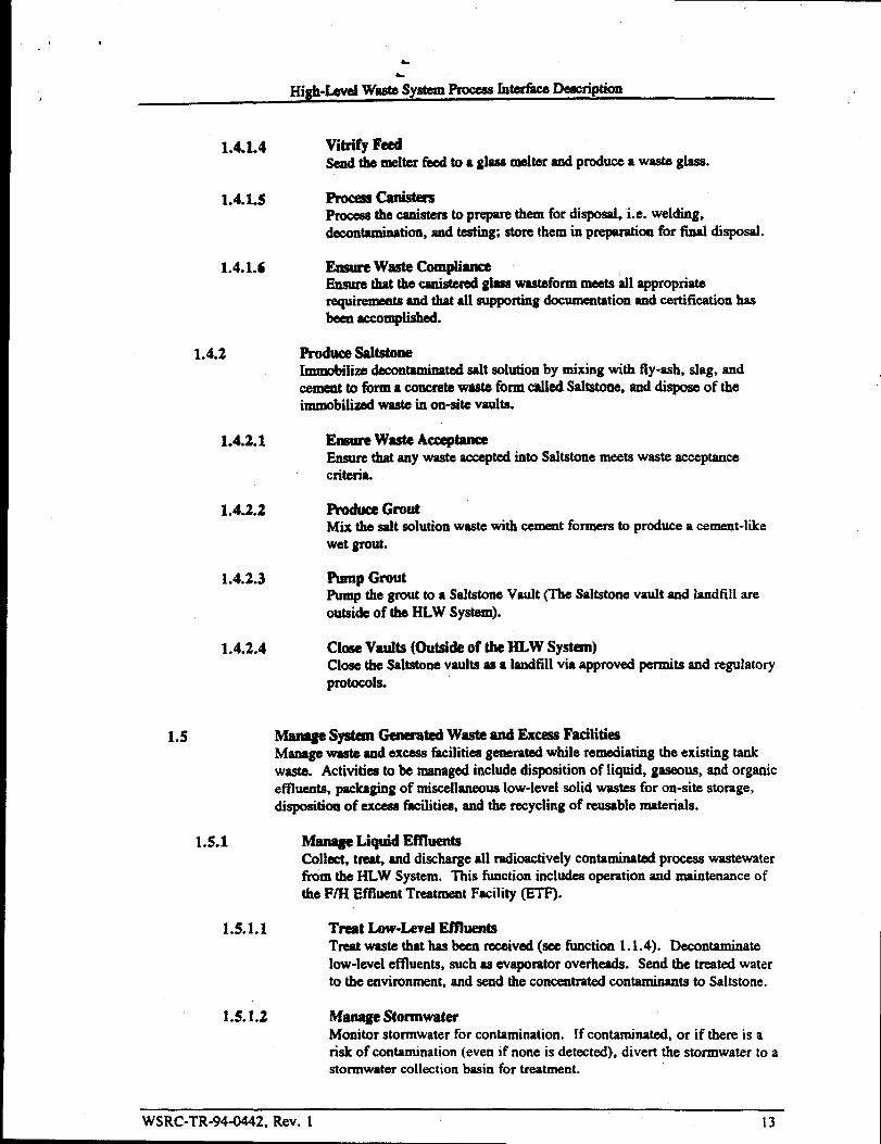
1.4.1.4
1.4.1.s
1.4.1.6
1.4.2
1.4.2.1
1.4.2.2
1.4.2.3
1.4.2.4
1.5
Vitrify FeedSad the melter feed to a glass melterand produce a waste glass.
-Cards@%Procesethecankrs to prepare them for disposal, i.e. welding,decontamination,and testing; store them in prepamtion for final disposal.
Elxnlre waste CompliiEnsure thatthewdetemd glass Wasteformmeets all appropriaterequirementsand that all supportingdocumentationand certificationhasbaea accomplished.
Produce saltstoneImmobilim decontaminatedsalt solution by mixing with fly-ash, slag, andcemeat to form a concrete waste form called Saltstone, and dispose of theimmoblliti waste in on-site vaults.
Emure Waste AcceptanceEnsure that any waste acceptedinto Saltstonemeets waste acceptancecriteria.
Produce GroutMix the salt solution waste with cement formers to produce a cement-likewet grout.
Pump GroutPump the grout to a Sahstone Vault (lb Saltstone vault and landfill areoutside of the HLW System).
Cloee Vaults (Outside of the HLW System)Close the Saltstonevaults as a landfill Via approved permits and regulatoryprotocols.
-es- Genemted Waste and Excess Faciliti~Managewaste and excess facilitiesgemratcd while rerndating the existing tankwaste. Activities to be managedinclude disposition of liquid, gaseous, and organiceffluents, packagingof miscellaneouslow-level solid wastes for on-site storage,disposition of excess&ilitiea, and the recycling of reusable materials.
1.5.1 Manage Lh@d EffluentsCollect, treat, and dischargeall radioactivelycontaminatedprocess wastewaterfrom the HLW System. This fimctionincludes operation and maintenanceofthe F/H Effluent Treatment Facility (ETF).
1.5*LI Treat bw-kwl EffluentsTreat waste that has been received(see timction 1.1.4). Decontaminatelow-leveletlluents, such as evaporator overheads. Send the treated waterto the environment, and send the concentratedcontaminants to SaltStone.
1.5.1.2 Menage StormwaterMonitor stormwater for contamination. If contaminated, or if there is arisk of contamination (even if none is detected), divert the stormwater to astormwater collection basin for treatment.
WSRC-TR-94-0442, Rev. 1 13
J
L
L
High-LevelWaste SyatemProcaJarnterhce Deecnph“ “on
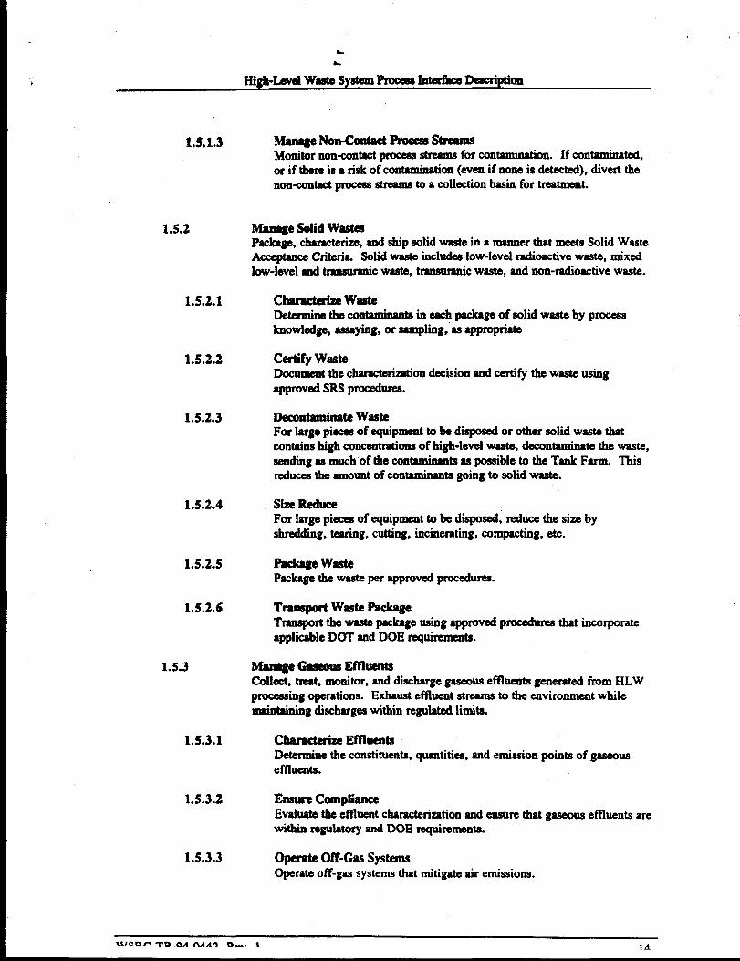
1.s.1.3
1.5.2
1.5.2.1
1.5.2.2
1.5.2.3
1.5.2.4
1.5.2.5
1.5.2.6
1.5.3
1.s.3.1
1.5.3.2
1.5.3.3
Mantt#e Non-contact FrocewsStmllnsMonitor non+mtact proceaastrwunafor contamkmtion. If contaminated,or if there is a risk of contamination(evemif none is detected), divert thenon-contactprocess streamsto a collectionbasin for tmatmemt.
Mme8e SOWWastesPackage, ckacten “ze,and ship solid waste in a manner that meets Solid WasteAcce@mceCriteria. Solid waste includes low-levelradioactivewaste, mixedlow-leveland tmnsumnicwaste, tmnaumnicwaste, and non-radioactivewaste.
Cbmctemn“ wasteDetemimthe contaminamineachpackageof solid waste by pmcesaknowledge, assaying, or Sarnpiing,as appropriate
Celtify wasteDocumentthe characterizationdecision and certi~ the waste usingred SRS -U=l,
llecon~inate WasteFor large pieces of equipment to be disposed or other solid waste thatcontainshigh concentration of high-level waste, decontaminate the waste,aeadingas much of the contaminaata as possible to the Tank Farm. Thisreducesthe amount of contaminantagoing to solid waste.
Si ReduceFor large pieces of equipment to be disposed, reduce the size byshredding, teaMg, cutting, incinerating, compacting, etc.
Mckttge WastePackagethe waste per approvedprocedures.
Tmaaport Waste PackageTmnaport the waste packageusing approvedprmedures that incmporateapplicableDOT and DOE requirements.
M-& -new EmuentsColkt, treat, monitor, and dischargegaseouseffluents generated !km HLWPmceaaingopemtions. Exhaust effluent streams to the ewironment whilemaintaining dischargeswithin reguiated Iimita.
CharU&in EmuentsDe@rmhwthe constituents, quantities, and emission points of gaseousdthds.
Emsure thnpbceEvaluate the effbmt characterizationand ensure that gaseous effi~~ arewithin regulatory and DOE nqirementa.
opemte (M-Gas systemsOperate off-gas systems that mitigate air emissions,
* ,
L
High-LevelWX’S ystem ProceesInte&ce Description
1.s.3.4
L5.4
1.5.4.1
1.5.4.2
1.5.4.3
1.5.5
1.5.5.1
L5.5.2
L5.6
1.5.6.1
1.5.6.2
MonitorOpedorM “Monitor gaaeouarxttissionaas appropriatetoensttre that systems are
P@l Pm~Y* em’issio~- wi~ limits$~d ~1 =-vrequirementsfor monitoringm satisfied.
-e Organic EffluentsCollectorganic effluents, treat as required to meetdisposal facility criteria,
mcesaing/disposal. This function includes storage and transferand store fbr pof matwials to the ConsolidatedIncineratorFacility (CIF).
Chamdmze“ EmuentsDetermme“ the compositionof the organiceffluentby process knowledgeand Sampling.
Store Recovered ~tiC MateridaStore recoveredorganic materialsin a safe and environmmMy soundmanner.
Transf@r(h’@liC EftluentsTrtutsferorganiceffluents to incineration.
Disposition Excess Faciii-Empty, decontaminated,and deactivateexcess faciiitiee,prepare excessf=ilities for disposition by the Environmenttal Restoration Division. Identifyandhr removechemical inventories, ~ or stabilize work areas,shut down non+=mtisl support systems, and isolate tanks. Excess facilitiesare time structurcaused in the storage, treatment, or processing of high-levelwaste that have no future identifiableor planned programmaticuse. Examplesof excess facilities include waste tanks, transfer ii-, waste evaporators, andpretreatment fmilitiea. SCDHEC, EPA, and DOE have agreed that CERCLAis the appropriate regulatoryvehicle for closure of the high-level waste tanksand associatedfacilities.3
Chanmalm“ Ikidual ContaminationDeterminethe residualamount of contamination in excess facilities byproceesknowledge, sampling, or other means.
Define D&D OperationDeb the proper means to disposition each excess facility.
Disposition Reusable MaterialsCollect, treat, store, package, and transfer tnsterials thatareeconomicallysuitable for reuse. Major types of reusable materials include scrap metal, scrapiron, and process equipmentthat can be decontaminatedto levels sufficient fortransportation and use in non-radioactiveenvironments.
Characterize MaterialsChamterim materialsthat are to be reused.
TreatIf appropriate, treat reusablematerials so that they are suitable for theirintendeduse,
,
WSRC-TR-94-0442. Rev. 1 15
,.
L
High-Levd waetekyetemPmeeurntdace Deihptiort
1.5.603 stofeReusabkMat=iahStore reusablematerialsins safe and envimnmentally sound manner.
1.!5.6.4 D&iii cK3tOmer/vseIMrte who will use the materialsand how they will be used.
1.S.6S Tmnaport MaterialsTranapmtthe reusablemateridst otheintendeduaer.
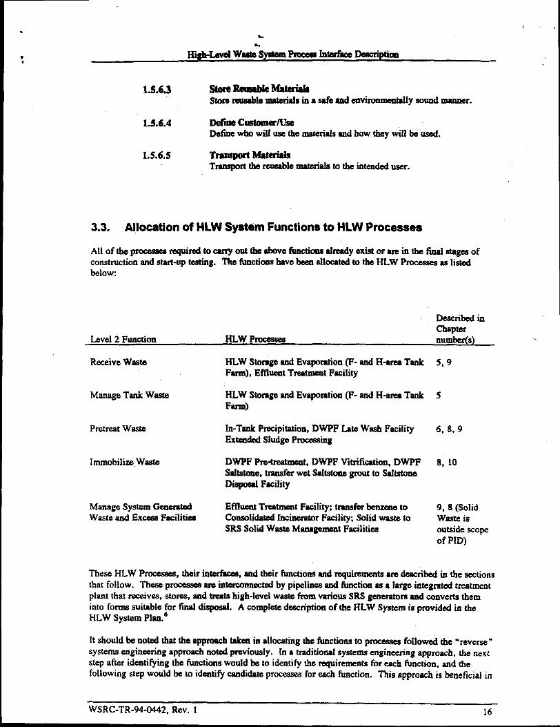
3.3. Allocation of HLW System Functions to HLW Processe*
All of the pmceaaea~tim~mti~e timd-yexi~o rmti~~fig~ofconstruction and start-up testing. ‘Ihe fimctionahave been allocatedto the HLW Pmeeaaesbelow:
as listed
Described inchapter
Level 2 Function HLw Pmcesaea number(s) .
ReceiveWaste HLW Storage and Evaporation (F- and H-area TankFarm), EffluentTreatment Facility
ManageTank Waste HLW Storageand Evaporation (F- and H-area TankFarm)
Pretreat Waste In-Tank Precipitation, DWPF Late Wash FacilityExtended Sludge Processing
hnmobilixe,Waate DWPF pm-treatment, DWPF Vkrific.ation,DWFFSaltstone, tranafti wet Sahatonegrout to SaltatoneDisposal Facility
Manage System Generated Efflueat Treatment Facili~, transfbrbermne toWaste and Excess Facilities ConscdidatedIncinerator Facili~, Solid waste to
SIN Solid Waste Managermnt Facilities
5,9
5
6, 8,9
8, 10
9, 8 (SolidWaste isoutside scopeof MD) -
These HLW Pmcesaes, their interfkes, and their functions and requirementsare described in the sectionsthat follow. These pmceaaeaare interconnectedby pipelh and litrtctionas a large integrated treatment
plant that receives, stores, and treats high-level waste from various SRS generators and converts theminto forms suitable for final disposal. A completedescription of the HLW System is provided in theHLW System Plan.d
[t should be noted that the approach taken in allocating the functions to pmcessea followed the” reverse”systems engineering approach noted previously. [n a traditional systems engineering approach, the nextstep after identifying the functionswould be to identify the requirements for each function, and thefoliowing step would be to identifi candidate processes for each function. This approach is beneficial in
WSRC-TR-94-0442, Rev. 1 16

&
H@t-LeveiWm!te%yatemProceul rttterk Description
ensuring that all promising esndi~ ~ arc id=tified in b early ~ges of defining the systemconfiguration.
However, atSRS, candidateprow$sMfor mmplishing HLW bctions have been studkd over the lastIS years, and the systemconfitiou hss k dcM ss a -t of eonaiderablestudies on akemativeprocesses to accomplishthe required functions, for example, ion exchangefor salt processing,centrifigation for sludge procedn g, tailoredceramicsand cementwaste forms for immotilimion,alternatives to ETF pmcessea, stainless steel tanks for processingwas% etc. As a retmltof this work,the ti.mctionalrequirementsand pref+ systemconfiguration are akeady known, and there is minimalbenefit to rigorously &fining requirementsfor each level 1, level 2, level 3, and level 4 functionidentified in the previous section. A more useful approachis to define requirements for each of the HI..Wproemses because this is directly applicableto systemplanning and integration.
Therefore, the remainderof this documentconeeattrateaon theactualHLW %eeases, their functions,interfaces, and requirements.
3.4. Defining the HLW Processes and Interfaces
The PID detinea 20 interfacesbetweeaHLW Processes(see next chapter] and provides the technicalbases for control of these interfaces. For the PID to ef%ctivelyperform its fimetion, the HLW Processesand the interfaeeabetween them must be euetldIy defined. Although some of the divisions are relativelystraightfotward, some facilitieseau logicallybe consideredto be in more than one pmcessea. Forexample, the DWPF Late Wash ficility could be logicallyconsidered 1) part of ITF, since it uses thesame process as ITF and finishes the fimctionof pmeeasingash @XtCtiOIl1.3.2) that~ S-,2) partof DWPF, since it is close-coupledto DWPF and begins thejob of processing the precipitate, or 3) acompletely separateprocess.
In carving up the HLW system into HLW Pmcesseaand interfaces, the PID team chose tmundaries thatwould be most effwtive at meeting the objeetiv= of 1) providing enough control to ensure that changesare properly reviewed, while 2) avoiding unnecessaryinterkenee in the operation of each process.
For example, in the case of the Late Wash facility, if Late Wash were consideredpart of ITP or aseparateprocess, this would result in an division-levelintafaee betweenMe Wash and DWPFVitrification. This would require division-leveIreviewof any changeato this interfaee. Xnthe opinionof the PID team, treating Late Wash and Vitrificationas part of one proeesais better because the twofacilitiesare close-coupled, the compositionchange ink Wash is minimal (washing of soluble salts)with little impact on the rest of the HLW System, and both f=ilities are controlled by the DWPForganization. Thus, the team defied Late Wash as being part of the DWPF Vitrification Process.
Another example is that air emissions from DWPF (and other pmcessa) are not included because thesecan be controlled within the DWPF’Stschnical baseline. Air emissions limits will have an impact oninterface within the scope of the PID, specificallycomposition requirementson the wsshed siudge andprecipitate. These requirementsare refleetedin the DWFF Feed Design Ikses documeat thus areindirectly under the control of the PID.
The folIowing three sections provide more explanationof how the interfkceeomcpt helps the PIDperform its function.
.
WSRC-TR-94-0442, Rev. 1 17

m
, ,
High-Levelwastesyste4nProceasmerfaceDescription
3.4.1. Relationship of the P~cess Intefface Description and HLWProcess Technical Baselines
Since the PID is n division-leveldocument, considemblereview and approval will be required throughoutthe division to makechaagea. lherefm, to promote cost+ffective and efficient decision-msking in theHLW System, it is desirable to judiciously restrict the scopeof the document to those items that trulyhave an impact throughout the division. ‘l’heideai structurewould causedecisions to be made asfollow!x
1. Decisions affectingonly one HLW Process should be made within that HLW Process. No otherEILWProcess would be iQVOkd.
2. Decisions that affect only the in* between two HLW P~ should be made by the tWO
respective organizations, although some division-level reviewwould be required.
3. Decisions with thr reaching impact (such as the use of a new chemical, or the constmction of a majornew poce.sa, such as Late Wash), should be elevated to the division level and reviewed by themanagementof all HI-WProcesm.
To accomplish this ideal control structure, the PID concmtrates primarily on the interfacesbetweenHLw Processes. This structure is illustrated schematicallyin Pigure 3-1.

L
L
Hi@-Level Wats System ProcessInterfaceDescription
Figure 3-1
.=r-.~ ●
ProcessInterface
I-ILW System Process
I
●
Interface Description
Summary level foreach facility
Identifies therequired interfacecontrol documents
Controlled atDivision Level
Facility
P
;;::
Technical i ‘iBaselines Storage
Includes theinterface controldocuments andmany other basisdocuments
Controlled atfacility Ievel
BasisDocuments
;OSR ~;OSR ~;OSR~ Drawings ~ Drawings j Drawings
Etc Etc Etc
● (htr.lled atfacility level
●Intake CmlfolDaculnd
3.4.2. Definition of an Interface
A HLW Interface is defied as a boundary in the HLw Systemthrough which wastes are beingexchangedbetween HLW Processesor betweena HLW Process and an external process. A few suchinterfaces are shown in Figure 3-1 (for a complete list, see Figures 4-1 and 4-2; and Table i 1-8). Eachinterface has associatedinterfacecontrol documents. GenerslIy, each interfacehas at least twodocuments 1) a document tlom the receivingorganizationdefining the important parameters (chemicaland radionuclide concentrations, flows, temperatures, etc.) for that stream, and 2) a document written bythe sending organization deaeribmghow it will control the stream. The interfacedocuments for eachinterface repmaentart agreementbetween the two organi=tions on how the interface will be managed. Inthe future, plans are to consolidatesome of these interfacedocuments to reduce the number of dc-cumentsrequired to regulate each interfiwe.
These interface control documentsare part of both the PID and the technical baselines for the HLWProcesses to which they apply. Since these documentsare past of the HLW Process’s technical baseline,when a HLW Process technicalbaseline is changed, the interfacecontrol documents must be reviewed forpotential impact. Similarly, when an interfacecontrol document is revised, the HLW Process’s technicalbaseline must be reviewed.

,
wsrlr.TR.Q4J14d’2 Rev. 1 20
High-Luvd Wsate syatemProeeaaInwfhce Ded@ion,
3.4.3. Application of the Interface Concept
By coneemtmtingmainly on the iddaeea betweenHLW Pmcessea, the Pm will tend to promotedecision making at the appm@a@ levels, as a few exampleswill illustrate:
1.
2.
3.
h the HLW Storagead Evapmation Process, hydrogemis producedby the mdiolysis of water. TIMgeneration of hydrogen is a criticai safetyconcernand &minates the Tank Farm saf~ analysea.
However, this safety concernhaa very little impactoutside of Storage and Evaporation and does notWp=f in any intdiee doeumeut. Therefm, this Safktymncern is handled entirely within thetschnicai baseline for Storageand Evapomtionand is not addressedin the ProeeasJnterfaceDescription.
Nttrites aad nitrates in the sludge feed to DWPF will causeNOXemissions from the DWPF.Therefore, this concern is addmsed in the DWPF Feed Design Bases, the document that describesimportaat pammetm in streamscatering the DWPF. The concentmtionaof these species iscontrolled in Extended Sludge Processingand will be addmwed in the Inter&e Control lhc~tfor washed sludge. However, there is minimal impactoutside of these two HLW Pmmsses, sodecisions about these eonceatrationswili be restrictedprimarily to personnel at Extended SludgeProeesaingand the DWPF, although some division-level review is required.
The addition ofs new chemieai in a processcould potedally have impactaon aIl &wnstreamPmeeasea. Thus, it would receivewide reviewthroughout the HLWM division.
k
High-Level waste&tem FroceanMerface Description
4. SRS HIGH-LEVEL WAST_OCESSES AND INTERFACES
4.1. Overall High-Level Waste Process Description
This chapter is organizedby broad categofieaof wastes that are receivedinto the HLW System,specifically:
1.
2.
3.
4.
Routine Wastes-wastes normally receiwd and pmcesaedthrough the HI-W System. Most of thewasteareceived into the HLW Systemwill fall into this category.
ContamhmtionControl Waatea-wiatea resulting fromprocess incidentsor upsets, in whichpotentially large quantities of aqueouswastesare producedthat must be pmcemed.
Non-routine minor waateu-waste that are mceked dondfy, h cm be anticipated in advance,and whose volumes and chemicalcontent are small relative to the normal streams.
Unique and unusual wastes-non-routine wastes that am handled on a case-by- basis. Someofthese wastes, though unique, may be similar to wastesusually prvcewed. Others maybe completelyunlike any waste normally pmcewed.
The procmsea for eachof these broad categoriesis discussed in the four subsections that follow.
4.1.1. Routine Wastes
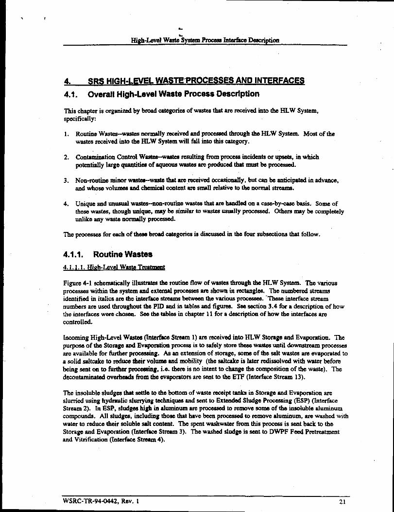
4.1. L1. Hhzh-LeveiWasteTreatme@
Figure 4-1 schematicallyillustmtes the routine flow of wastes through the HI-w System. The variousprocesseswithin the system and extemd processesare shown in rectangles. The numbered streamsidentified in italics are the interfacestreamsbetweenthe various pmceases. ‘These interface streamnumbers are used throughout the PID and in tables and tigures. See section 3.4 for a description of howthe interfaces were chosen. See the tables in chapter 11 for a descriptionof how the interface arecontrolled.
Incoming High-Level Wastes (Interfke Stream 1)are receivedinto HLW Storage and Evaporation. Thepurpose of the Storage and Evaporationprocess is to safely store these wastes until downstnaun processesare available for further processing. As au extensionof strmtge, some of the salt wastes are evaporated toa solid sakcake to reduce their vohtme and mobility (the sahcake is later redissolved with water beforebeing sent onto fiuther procdng, i.e. there is no intent to change the composition of the waste). Thedecontaminatedoverheads front the evapomtorsare sent to the ETF (interface Stream 13).
The insoluble shdgea that settle to the bottom of waste receipt tanks in Stomge and Evaporation areslurried using hydmulic slurrying techniquesand sent to Extended Sludge Pmeeas@ (IMP) (TnterfiMxStream 2). In ESP, sludges high in aluminum are pmcesaed to remove some of the insoluble aluminumcompounds. All sludges, including those that have been processed to remove aluminum, are washed withwater to reduce their soluble salt content. The spent washwater from this process is sent back to theStorage and Evaporation (InterfaceStream 3). The washedsludge is sent to DWPF Feed Pretreatmentand Vitrification @erfkce Stream4).
WSRC-TR-94-0442, Rev. 1 21

High-l-awl WasteSystemProcess InterfaceDescription
Figure 4-1: HLW System Maior Interfaces._Generation
.
WaateGenerators
w~
i3. Etwpomtoroverheads& other low-be!stream
15. ETFconcentrate
WastewaterTreatment 1-
Ffm I
+-l” ‘1’w$
~
6’~e~+ 7.Pm2ipitale4. WmhedSludge
~$
Solidification $ Vitrification0.DWPFReqde
:>(mvm 3 (Me wash — nGrgMic
Destmotion(cIF)
..
WSRC-TR-94-0442, Rev. 122 ,,
.>,,

High-lad Waste SystemProcess InterfaceDescription“
Figure 4-2: HLW Contamination Control StreamswasteGeneration
I waste I18, Diverted Cooling Water
I Generatom I
Low-LevelAaUeousm Treatment
19.Highly Contiuninated Water
r
k ContaminatedE7F con-centrate
17. DivertedSbrntwater
J
oTanksol-lWmL 1 1 I
DestinationsI
outfallI I LandMi I
uHLw Stmge&Evaporation(TankFarms)
I l\
L--salt
Processing(ITP) II
ShtdgeProcessing
(ESP)1 I
uVitdkation(L* wash
& DWPFGlass)
........t...........v+...Y.+fi..Y.<.ts<*\+i#.+.+**.<f..:t?<<.:+w<.>..........:;:.::.X<.:<.W+Z’..’..................................+.sfi...mw<.b.k.....>.,..,*A..,,Tt...t+.d%i%,............../.,................................:.:*......................................., “’“““V*%’4W%?E
Izzzlm
rr
IorganicDestmction
(cm)
t3Mu 95
I
WSRC-TR-94-0442,Rev. 1&.J

I@lt-bvei WasJSystem Process Merke Description
Saltcakeis redissolvedusing hyddic sl~ing techniquessimilar to Slwlgeshmying. Ile saltaohtions from this operatimt, and O* ~~ SOIUtionSfim stow and Ihpmation, are seat to In-Tankprecipitation(lTP)(fntafb Stream5). IXIlTP, the salt solution is pmcesaedto remove mdionuclides,which are concentratedinto an organic precipitate. The decontaminatedSUpemateis sent to Tank 50H,which is sdminiatmtivelywntrded ss part of ITP. A concentrated organicprecipitate,containingmoatof the radionuelidee, is producedby the process. This pfecipiu is-bed with water to remove solublesalts and sent to Vitrification (Inti Stream7), specificallythe hte W* F=ility. However, somesoluble currosion inhibitors (which interferewith IWPF processing)met be left in the precipitate afterwashing because the precipitate is stored in c=bon steel tanks, which are susceptibleto mrrosive attackby uninhibited precipitatewastes.
7%ewashed precipitate from Late Wash is then sent to the DWPF VItrifiea$iOXIbuilding (221-S). In thevitrification building, the precipitate is cataiytkdy decomposedand sepmted into two streams: a mildlycontaminatedorganic stream, which is seat to storageand eventualorganic destination ii theConsolidatedIncineration Facility (?ntertkceStream 11), and an aqueousstream containing virtually allof the radionuclides. The aqueousstream is combhd with the washed sludge from ESP, which hasundergone further processing (see next paragraph), and the mixture is seat to glass melting.
WS~C-TR-944442, Rev. 1 24
The washed sludge from ESP (lnterfaeeStceun 4) is chemicallyadjusted in the DWPF to prepare thesludge for feed to the glass meiter.As partof this process, a significant amount of mercury is strippedout, which is purified and sent to mercury receivers(TnterfkceStream 12). The aqueous product fromorganic decomposition is added to the chemicallydjuated sludge. The mixture is then mixed with glassfit and send to glass melting. The glass meiter drives off the water and melts the wastes into aborosilicate glass matrix, which is poured into a canister. Ilte eanisteredglass wastefortu (InterfaceStream 9) is sent to on site interim storage, and will eventuallybe disposed of in a Federal Repository.
The water vapor driven off from the melter along with other aqueousstreams geaerated throughout theDWPF Vitrification budding are recycledto Storageand Evaporation for evaporation, storage, andeventual fiuther prowsaing @lterke stream lo).
4.1.1.2. Low-Level Aoueous WasteTrea~
overheads from the Storage and Evaporation evaporatorsare emnbinedwith overheads from evaporatorsin the F- and H-area Sepamtionspmwsaes and other low-Ievelstreams from various waste generators.This mixture of low-level wastm is sent to the EffluentTreatment Facility (ETF). (Interface Stream 13)
In the ETF, b low-level wastes are decontaminatedby a series of ckaning procaess. Thedecontambted water efflueat is sent to the H-areaoutfill and eventutdly flows to on site creeks and theSavannahRiver (InterfkMStrom 14). The contaminants removed from the water are concentrated andsent to Tank 50H (XnterfaceStrewn 15).
IISTank 50H (administratively controlled as part of ITP), the concentrate from the ETF is combined withthe decontaminatedsupemate from ITP. This mixture of wastes is then sent to SaMstone(InterfaceStream 6). In Saltstone, the liquid waste is combinedwith cemeat formers and pumped aa a wet grout(Intedkce Stream 16) to a vault. In the vault, the cement formers hydrate and cure, forming a Saltstonemonolith that will eventually be closed as a landfill.

High4Avel wastesyatem ProceaeIntet’fke Descriptiosl
4.1.2. Contamination Control Wastes
Contamination Control wastes are wastes resulting km pmcesaupsets or accideuts that contaminatelarge amounts of water. Exampieuof such accidentsincludea HLW evaporatortube bundle kak, a 14in Acanyon vessel cooling water cd or stream cd, or a fkkater line leak (Ts& 13H accident). Anyof these accidentshave the potential to contamhate large quantities of storm water, cooling water, orsteam cxmdenaste. The flow of such wastes is achemkWy iktrated in Figure 4-2.
Diverted Stormwater (Mm&e Stream 17) is any large volumeof mntaminated or potentiallycontaminatedwater from the Tank Farms. Sinceany of these streamswould be seat to the atormwatercollection system, they are grouped togetheras “DivertedStormwater.” Stormwater is collected fromspecific monitored zmes in the Tank Farms (IncludingStorageand Evaporation, ITP, and ESP) and ismonitored for radioactivity in the storm sewers. If the water is contminatd ,thewateria diwrtedtoastorrmvaterbasin. AISO,during_ operationsin the Tank Farms that have the potentiai to relewcontamination, such as transfers, stormwateris procedurallydiverted to the storm sewers to increase theassurancethat any contambatd water is captured. There are also other reasons for these precautionarydiversions, such as when monitoring equipmentis inoperable. Such precautionarydiversions usuallycontain a negligible amount of radioactivitybut representa significant fraction of the volume of thisstream.
Other aourcuJof contaminatedwater that might contribute to this stream are cuntminatd steamcondensate (for example, fioxna failedevaporatortube bundle) and contaminatedcooling water.
Diverted Cooling Water (InterfaceStream 18) is contaminatedwater from the F- or H-area Separationsproms. Water and steam are used fbr cooling and heating, respectively, in Separationstardrs. If theheating or cooling coils Ieaks, the water becomescontdnated. Therefo#, this water is monitored afterleaving the canyon. If it is contaminated, the water is diverted to a mding water basin.
If the water from a diversion of stormwateror cooling water isfbund to be very highly contaminated, itcannot be safely pmcesaed through the ETF. Therefore, the very highiy contaminatedwater would besent directly to a waste tank in the Storageand Evaporationprocessvia the HDB-8 diversion tmx(InterfaceStream 19). However, all divemions to date have resulted in low levels of contamination thatcan bepmcessed through thenormal ETFpmcesaes and handled as normal waste (see previous section).There is also the possibility that waste would be contaminatedto some intermediate level such that itcould be safely pmcesaed through ●ll or part of the ETF promm but the reauhing concentratewould betoo contamkted toaendto Tank SOH. Inthatcase, the ETFconeentrate wouldbe senttoawsatetankin the Storage and Evaporation process via the HDB-8 diversion box (TnterfiweStream 20).
4.1.3. Non-Routine Minor Wastes
These are wastes whose volume and chemicalantent are smaii relative to normaSstreams, i.e. they areeasily handled by stmdard practicesaad procedures The PID does not attempt to establish the tdnicalbasis for each of these streams. These streams should be controlled in the InterfaceControl Documentsfor HLW Processesand are reguhted under the SIMP.
An example of a stream of this type would be water from ITP dikes. The water is collected andanalyizd. If the water is clean, it is dischargedas stormwater. However, if it were to be contaminatedwith benzene, it would be sent to ETF.
.- r--a - A. A. Aa n.. . ● *C

High-LevelWasw system Process htterfaceDescription
4.1.4. Unusual and Unique Wastes
As the words imply, mmsud ad unique WS@SSaro those WSS@Stht are one-of-a-kind, Orwastes that aresimilar to normal wastes but with some unususi aspect. .ADexampleof such waste is the tritiated waterfrom the reaotorareas that was receivedinto Tank 17F in January 1992.
Nom@tibhti ~t@Xctd-li* ti@tiAtisti dl*~ible-athat might be received in the HLW System. Suchwastes must be controlled on a caae-byuue bssii.~OWUV~,a few &swrai @pb S@y to COQtroiof such waste#:
●
●
●
●
l%e canposition of each waste stnam must be characterizedand documented.
Al! such wastes must be approvedon ● case-by-casebasis by the managementof the receivingHLWProce#.
The review should consider the effkcton downstreaminterfkea. If the review shows that the receiptinvolves new chemicalsor has the poteutiai to impactdownstreaminterhces, then Inanagenmt ofthe receiving HLW Process is responsible for requiring further review, as qqxiate.
Any review of an unusual stream must be documented.
4.2. DWPF Feed Acceptance
A critical mission-level need in the HLW system is that the DWFF pmeaauP—Vitrification and Saitstone--must operate efficiently and safely and must produce acc+table product. Aithough the DWPF pmcesaesare designed to accept the range of compositionsexpectedk the tank fkrms, there is the poteatiai thatsmaii batches of waste may exist that could impact operation of the DWPF if they are not anticipated.AIao, much of this waste has b depositedover 40 years of operation, and the information oncomposition of the waste is limited
To alleviate this concern, it would be desirabie to biend the salt and sludge wastsa before sending them tothe DWPF. Biendiig would ted to dampen the swings of compositions and reduce the potential forunintended disruptions of the process. SonMbiendiig is already pkmed as a natural result of the wasteremoval scheduie. For example, the amount of siudge in most tanks is small, and several tanks must becombined to form one batch of W fbr DWPF. Also, in ITF a number of bstchea of precipitate w1l becombined in Tank 49H, the feed tank for DWPF, so that the precipitate sent to DWPF wiii alwayscowainwastestiommor ethanonessit tank.
However, the amount of blending that is pianned is iimited. For smrmthoperation of HLW Fmaxwes, ttwould be desirable to detemme“ the composition of each tank and purpoady bkmd tanks that are high mone constitumt with tanks that are low in the same constituent. This wouid limit the variations in thecomposition of wasteasent to Vitrifiwtion and Saitstone, making it simpier to ensure that these procewesproduu acceptableproduct.
The abiiity of the HLW Storage and Evaporation to blend wastes to achieve more uniform feedcomposition is limited fora number of reasons:
● The Tank Farms currently do not have enough space to perform blending among a iarge uumlxrof tanics. Oniy a fiv+vtanks at a time can be blended, greatiy limiting the blending options.Plans are to process the first seversi salt tanks one at a time.

High-LevelWasteSystem~ Intake Ikmription
● Opeming fbctoMintknce the order of waste removal, especiallythe &t that to continueoperation of the Evspo*r sys@I% wastesmustk RXKWVAfrom specific receipt tanks so thatsufficient space is available.
● Removing the waste from ● tank requirw a long lead time for dedgn, Wl@tll&On, and SktUp
of waste fCIUOVidf@ditit!S.Thus, SChdtdiIIgof * ill tk mXt = y- is ~ byexisting projects, budgets, and availabletank space. The waste must be removed from the taukathat are already scheduledor there will be consideraldepenalties in time and budget.
b Knowledgeof the waste cmnpoaitionsin individual tanks is limited, which will limit confilen=in predictions about the waateproducedby a gives bleading schmxm
4.2.1, HLW Material Evacuation Board
To address the concerns about the compositionof sludge and salt solution sent to processing, a DWFFFeed AcceptanceProcess is being establishedto evaluatethe schedulingof wastes for waste removal.The feed acceptanceprocess is described in the SIMP.=
A key part of this process is that the HLWM Division Chief Engineer till appoint a HLW MateriaiEvacuationBoard to review the schedulingof wastes for disposal h develop stmtegies for workingaround any problems that are found. This board may be a new board or may bean added responsibilityto an existing group, at the discretionof the HLWM Division Chief Engineer. What’s important is thatthe fktction of the board is accomplished.
The HLW Materiai Evaluation Boardhas the followingresponsibilities:
● Prepare batch-by-batchestimatesof the compositionof sludge, precipitate, and sdt solution sentto DWFF Vitrification and Saltstone.
● Review changes to the High-LevelWaste System Plan that impact the order or blending volumesof batches being sent to the DWFF and Saltstone.
● If batcheaare planned that are out of the DWPF Feed Design Basin, the Material EvaluationBoard will determme“ the impactof pmccsaing these batchca.
● i%commendcorrectiveactions to managementwhen plannedbatches are discovered that are outof specifications, or when the information is insuflkienttoconfidently predict the compositions.Such corrective actiottamight inchule revisionof the blending scheme, cbangea to the process(such as revising the DWPF batch recipe), or iiuther dettmninationof waste compositionthrough process knowledgeor sampling.
The Material Evakatioa Bead will report to the High-LevelWaste TechnicalOversight Steering Team(TOST), a board chaired by the HLWM Division Chief Engineer and composed of level 3 managersresponsible for the various HLW Pmcesseaand representationfrom DOE HLW Managerneat. TheTOST will be responsible for reviewing the recommendationsmade by the HLW Material EvaluationBoardand approving changes to the High-LevelWsste System Phm.
WSR(?-TR.94-CM42.Rev. 1 27

&
High-Levelwatt’s ystem PmcenerIlte&e rkucription
4.3. HLW pra)cesse$
The following six chspters discuss the six ~ HLw hcesses. The pwpose of thlYechaptersis to describe the key cbmctemh“ “caofcacb HLWProcess, sadtodescribe thekeyprocess controlssndvarisbles thst me impmtant for each KLW Processto fimctionproperly in the hig&-Ievelwsste system.The suc=eding chspter (Cbspter 11, ‘Control of HI-WPmceusIMerfac=”) deacribc8the sctusl controlsand the interhce control docurncds fm each interfsce.
The chspters sfe as follows
5. High-Level W* Storage snd Evsporstioa (Tsak Fsrms)6. Sdt Pmceahg (Im-TsakPrccipitstion)7. Exteded Sludge Pmcas@I8. Vitrit%xttioa@VPF Lste W* Pmtmatment, and Vitrification)9. Wss@u@erTmstmcnt @fluent TreatmentFscility)10. Solidification (DWPF SSItstone)
For each HLW Process, the following topics sre discussed:
● Function of the HLW Proceu8
. Description of the HLw Process
● Mhaent Stfesmsd Key Process Vsfisbles
. EffluemtStreamssad Key Process Controls
WCRP-TR.QAAM9 Raw 1 28

&.
L
High-LevelWasteSystemProceaaT@er6ceDescription
5. HIGH-LEVEL WASTE STORAGE AND EVAPORATION
5.1. Function
The HLW Storage and EvaporationProce8sstores high-levelwaste in a safe and environmentallysoundmanneruntil dow@mamproce=s are availabIeto process the waste into formasuitable for finaldisposal.
oncedownstream pmceaseamwtildle~p atiofm, tiexis-vdfimtitiand sent for further procedng.
5.2. Description of the Storage and Evaporation Process
Distributed between F and H areasare 51 tanks designedto store high-levelwaste. These tanks andassociatedequipment are known as the F md H-areaTank Farms.
The HLW Storage and Evapomtion Proccss meansthose tanks, evaporators, and associatedequipmentdedcated primarily to storage of the waste, Whichincludesevaporation. Specifically, this includes thefollowing tanks and associatedtranst%rlines, diversion boxes, pump pits, and evaporatonx Tanka 1-21,23-39,41,4347.
The following tanks are located in H-areaTank Farm but are reamed for other purposes and areassociatedwith other HLw Pmceaaeeaa foltow
● Tanka 22H, 48H, 49H-In-Tank Precipitation (Sumeillanceof Taok 22H is administrativelycontrolled by Stomge and Evaporation,but tmnafm into and out of the tank are controlled byITP, i.e., for @=s purpoaeeit is att ITP tank). Discussed in Chapter 6.
● Tanks 40H, 42H, and 51H-Extended Sludge Pmcesdng. Discussed in Chapter 7.
● Tank 50H-Sahatone Feed (Administrativelycontrolledas part of In-Tank Precipitation).Discussed in Cha@era6 and 10.
A diagram of the Storage and Evaporation Procesw is shown in Figure 5-1.
The 51 high-level waste tanks at SRS are of four types, as follows’
Type I Tanks Theee are tanks 1-12, the original tweive tanks bui!t at SRS. The primaxytanks areconstructed of carbon steel with a design capacityof 750,000 gallons. Each tank has a carbonsteel annulus pan, five f=t in height, which is underneath the primary tank to catch leaked waste(sometimes referred to as cup-and-saucerconstruction). The primary tank and anmdus pan areenclosed in a concrete vault. Five of these tanks (Tanks 1,9,10,11, and 12) have leakedobsemble quantities of waste from primary containment into the annulua pans. Also, none ofthe tanks meet current DOE or regulatory criteria for secondarycontainrneat. Thus, emptyingand retiring these tanks is a high priority in the HLW System.

High-LevelWaste System ProcessInterfaceDweription
Figure 5-1
HLW Storage and Evaporationlneoming Wastes Spent Washwater From DWPF Reeycle
(Interfaee Stnxun 1)Exbnded Sludge hsb (H- Stream 10)
* (Interfhee Stream 3) #
I 1
I II
ReceiptTanks
,...,- ,-------...~..
‘Ev@iiiid iFeed Tank~ b (Optionsl)
;.. .... .. .................s..
(Optional) ~,,+
Y
‘“...’.””*” Me~~‘............ ..........
.$i reeycle to
separations(low-volume
Sdt.wTanks
Sludge Removaland Decommissioning* and
ISalt RemovalDecommissioning*
EvaporatorOvezheadsto ETF(Interfaee stream 13)
t T * Sludge and Salt Removal andSludge to Extended Salt Solution toSludge Processing
decommissioning may also producein-Tsnk Prwipitation
(lnlcrface Stream 2)wastes that are sent to evaporation
(Interfaee Stream 5) ITP, and EI’F..
‘an———WSRC-TR-94~2, Rev. 1
d“ ,
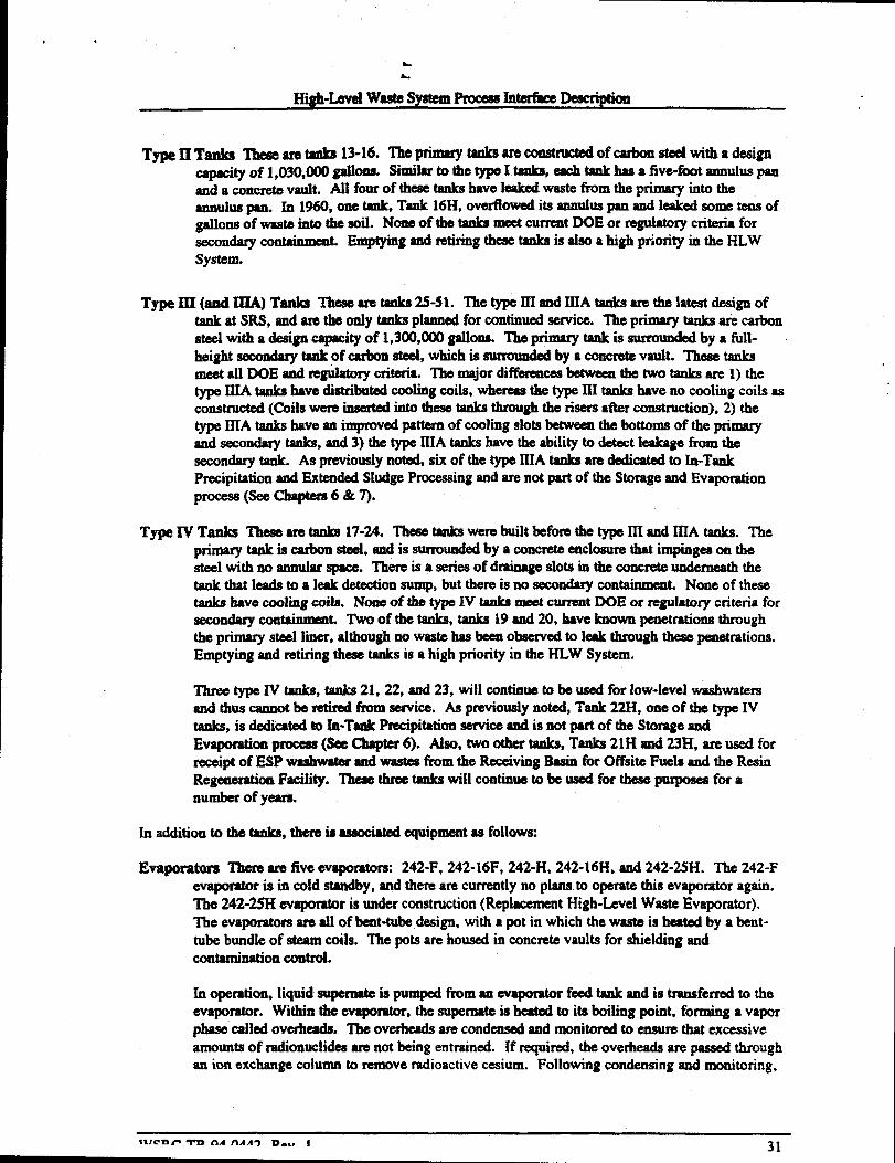
High-hvd wastesystemProcess InterfaeeMcripth
Type II Tanks Theaeare* 1s-16. ‘fhepri=y ti~mutiofcarbo n-wit hadesigncapacityof 1,030,000 gallons. Simk to the type I tank% each tank has a five-f- annulus panand a concretevault. All fo~ of th= ti have 1~~ waateflom the primary into theSMUIUSpan. xo M60, one ~. T* 16H, OV@Owedi~ ammlusP= ~ l=k~ SO= teUSofgallonaof waste into the soil. None of the tanks meetcurrent DOE or regulatory criteria forsecondarycontakmmt. Emptying and WMng these tanks is also a high priority in the HLWSystem.
Type IIX(and IIIA)Tanks lkaearetanka25-51. Thetype IIIand IIIAtanksare thelatsatdeaignoftank at SRS, and are the only tanks planned for continued-ice. me primary tanks are carbonsteel with a design capacityof 1,300,000 gallons. Tlw @nary tank is surrounded by a full-height secondarytank of carbon steel, which is surroundd by a concrete vault. These tankameet all DOE and reguktq critia. The major diffbrenceabetween the two tanks are 1) thetype IUA tanks have distributed coding coils, whereasthe type III tanks have no cooling coils asconstructed (Coils were imsertd iQti tie= tanks through the risera after construction), 2] thetype IIIA tanks have an improvedpattern of cooling slots betweenthe bottoms of the primaryand secondary tanks, and 3) the type IIIA tanks have the ability to detect leakage from thesecondaty tank. As previously noted, six of the type 111Ataokaare dedicated to in-TankPrecipitation and ExtendedSludge Processingand ws not part of the Storageand Evaporationproceaa(See Chaptem6&7).
Type XVTanks Theeeare tanks 17-24. The= tanks wem built before the type IIi and IIIA tacks. Theprimary tank is carbon steel, and is surroundedby a concreteenclosure that impinges OQthesteel with no annular space. There is a series of drainageslots in the concrete undemeatb thetank that leads to a leak detectionsump, but there is no secondarycontainmentt. None of thesetanks have cooling coils. None of the typ IV tanks mee4current DOE or reguiatmy Criteria for
tainment. Two of the tanks, tanks 19and 20, have known penetrations throughsecondq conthe primary steel liner, although no waste has been observed to leak through these peaetrationa.Emptying and retiring these tanks is a high priority in the HLW System.
Three type IV tanks, tanks 21, 22, and 23, will continue to be used for few-level washwatersand thus cannot be retired t%omservice. Aapnwioualy noted, Tank 22H, one of the type IVtanks, is dedicated to In-Tank Precipitation serviceand is not part of the Storage andEvaporation process (See Chepter 6). Also, OWOother tank%Tanks 21H and 23H, are used forreceipt of ESP washwaterend wasteafrom the ReceivingEasin for Off%iteFuels and the ResinRegenerationFaciIity. These three taokawill continue to be used for these purpmwafor anumber of yearn.
Inaddition tothetanb,t hereiaasmiatd equipmentas follows:
Evaporator There are five evaporatmx 242-F, 242-16F, 242-H, 242-16H, and 242-2S?I. The 242-Fevapomtor is in cold standby, and there me cumentlyno plans to operate this evaporator again.The 242-25H evaporator is under construction (ReplacementHigh-LevelWaate Evaporator).The evaporator are all of bent-tubedesign, with a pot in which the waste is heated by a bent-tube bundle of steam *iIs. The pots are housed in concretevaults for shielding andcontaminationcontrol.
Ih operation, liquid mpemate is pumped from an evaporator f- tank and is transferred to theevaporator. Within the evaporator, the supemate is heated to ita boding point, forming a vaporphase called overheads. The overheadsare condensedand monitored to ensure that excessiveamounts of radionuclideaare not being entrained. If required, the overheads are paaaedthroughan ion exchangecolumn to removeradioactivecesium. Following condensing and monitoring,
.
&.
High-Levd WeetesystemProcess Merfece DaMiption
thsowhsadsaretraastkrdm them for—~ -rheemlcentrete dmpemateiltthempomtorpotie tmnakedtoan evaponwrecaipt tank.
hfain~ Facility (299-E) This is ● fkility for mpaidng faifedcquipmeat fkomthe tank farm.Equipmeat eutering the theilitycan be dumntaminatui by various means, including soaking indeconmmimtl“onsolutions. Beeeuseof ita extemsivedeeonteminadoneapabilitks, the fedityallows deeontaminab“onof equipment to lower levels then is possible in the field. Mmdecontsminadon the equipmentcan be repairedby pemmmelin protectiveciothing (i.e. contsetmaintenancerather thanthe remotemaintenancetbatisnormaUy required for HLW.u@ammaM items). This facility is usually umaiderd part of the Tank Farm, and the spentdeeontaminadoneohttionefhn the fkeilityam sent to the Tank I%rms. However, since themaintenancefacility intmbes deeeateminedonchemieah into the waste stream, it is cmnaideredawaategenemtor forthepurpmee of the PID.
Transfsr Systems This ineludeatranafwpipelines (including the ioteraree trensfbr line fbm F to Harea), diversion boxes, and pump pits.
5.2.1. Receipt Storage, and Aging of Waste
The Tank Farms receivewasm fbm a number of sources, priti~y in F and H areas. The wastes areproduced as the result of the aepamtionof uaet%lproducts from spent aluminunduf nuclear fuel andtargets. In the Sepamtionepmeemea, the waste is diedvsd in nitric scid. To preve@eomosionof thecarbon steel waa@tanks, the waste is thea neutralizedwith sodium hydroxide in the Sepamtionaprocessbefote it is -t to HLW Storsge aud Evaporation.
Neutmlizing the waste prothxm ● dark btowtt mixture of insoluble sludges wpended in a salt solution.The primmy insoluble speciesare Iron, Manganese,Aluminum, and Uranium hydroxides. The primqsalt constituents are the sodium salts of N%, N02- and OW.
Incoming Wastes eateri.ngthe Tank Farm @erfaee Stream 1) am received into a reeeipt tank. .’ fivinsoluble sludges in the weete tie to the bottom of the tank, forming a layer of sludge at the b ‘m,with a clear layer of mpemate (salt solution) above it. The tanks am designed to safely store tlw Aate,incorporating a number of fbetura to preveat migration of the waste and to prevetit process aeeidenta(For example, the potedal f-s hydrogea explosion is eignifieantlygreater if mdiolyticaily generatedhydrogea were allowed to uxmdate in ● tank). Safe storage of wsete is eoatrolled by the Storage andEvapomtkm baseline and is outai& of the scope of this documeatexcept where it influcneeatherequirements for influent streams (See “Influentstreams and key proeesavariables=below).
During storage, the waste else ages, allowing mdionuelidesto key. For some mdionuditi (forexample, Ru-106) radioactivesging is the proce-saplanned for removing these nuclidea from high-levelwaste.
5.2.2. Evaporation
Once the sludge in the waste bee settled to the bottom of the tank, a region of char supemate remainsabove the sludge. To reduce the coat of storage and improve the safety of storage, the supernate isevapomted to reduee ita volurm aad mobility. Much of the supemate is redueed to solid aeitcake(withsome interstitial liquid). Converting the waste into saltcakeeonaidemblyredueeathe number of tanksneeded for storage and redueeathe nxhility of the waste, which mhances safety for two reascmw 1) thewaste is 1sssMcelyto leak, and 2) having the waste in solid form reduces the probability and/orconsequencesof many accidentsanalyzed in the Safety Analysis Report.
U? CllF-TQ.0AAA9 Va. f 32

High-LeveIWaste SystemProcess Merface Description
Tomq~w@~ti ~ka~=i@tiis -tid=ttimw~mr.The supemab maybe seat directly from the waste =eipt tank tom evapmtor [i.e., the waste recx3ipttank doubles as au evapomtor feed tank) of may be sent b a designatedevaporator feed tank.
The overheads fmm the evaporatorare condensed,creatinga mildly contaminatedwastewaterstream.After cmdendort, the overheadsam sent to a mercurycollection tank. overheads from HLW withhigh nwcury concentrationsare supemtumted in mercury(bwauae mercury is volatile), so smallquantities (liters per weekor less) of memuzycolkct in the bottom of the tank. Any memury that iscollected (many wastes produce no mercwy) is recyckd to the Sepamtionspmcesae8. This ia a low-volume, intermittent stream that is managedas part of the Storageand Evaporationtechnicalbaseline.
After passing through the mercurycollection tank, the overheadsMSybe treated by @aaingthem througha cesium removal column (an ion exchangecolumn) to removereaiduaiCa-137. This Watmeat step isomitted for overheadsthat have been sufficiedy decontminatd by the evaporator.
Onceall treatmeatstepsin the evapomtorsystemare completed, the overheadsare sent to ETP (ha-f&eStream 13) for further decontamimkon and eventual releaseto the environment.
The concentmtedevaporatorbottoms are sent to an evapomtorreceipt tank. In the receipt tank, theconcentratedwaste cools, and solid salt crystallizesand deposits on the floor, cooling coils, and wall ofthe receipt tank. The conccatratedsalt solution left in the receipt tank is then tranafti back to theevaporator feed tank fbr fiwtherevaporation.
The goal of this process is to concentratemost of the salt solution into solid sahcske, which minimizesthe volume and enhanceathe aafbtyof storing the salt waste.
5.2.3. Waste Removal
oncethe&wnstmamp mcescs-Extended Sludge Processingand In-Tank Precipitation-are ready toreceivewaste from a particular tank, the waste is removed from the tank using hydraulic shuryingtechniques.
Waste removal from a tank includes the fokwing pmcesaca:
● Waste removal (sludge or salt) using long-shaftedsiurry pumps to agitate the liquid contents ofthe tank and suspend the sludge or dissolve the salt. Waste is pumped out of the tank using apump or jet.
● Spray washing of the tank using rotary sprayjets with hot water. The contents of the tank arethen @ated with shy_ and Ptl@ out of the tank.
● Annulus ckning of tanks that have leakedusing steamand hot water.
oncethese prOUSS$xhave bees completed on a tank, waste removal from the tank is complete. If thereare no plans for future operation of the tank, then the tank must then be decommissionedand closed.
Although various optionsfa closing of W8stetanks have - pmpo=J6 a this tim them is no acceptedmethod ofclosings waatetank ~el-gdh~ti hismfill titititiclm~mprevent subsidence, then close the tank und immediatelysummdingland asalmdfill. sRsiscurreatIystudying this method of ciosum for Tank 16H, an older waste tank from which waste removal has beencompieted. Tank 16H is the su$jectof a RCRA Facility Inveatigition, and so is being actively discussedsmong DOE, EPA, SCDHEC, and WSRC.
,
A.
L
High-Levelw8stesystemProcess huerhce Description
5.2.4. Decommissioning and C!osure
OnceWasteRemovalhas been completedin a tank, the tank lemmsthe HI-W Systerm and responsibilityfor the tsnk changcato SRS organizationsmsponaiblefor ~ssioning and cbure These activitiesare outside the scope of the PID.
Closure of waste tanks might require further cleaningthan possible with the waste removal processes.For example, during waste removal from Tank 16H, the tank was spray washed with hot oxalic acid,which resulted in better ckaning than spiny washingwith hot wUer. _ing on the results of theTank 16H RCRA Facility Investigationand other studis%the dechion maybe made to use oxalic acidcleaning or other aggressiveckaning methodsm part of cbsure of the tanks. However, none of thesecidg~mtititie~oftiP~h-H@a Theproblemwithmostchemicalcleaning methods is that they introduce large quantities of water or chemicals (either newchemicalsor larger quantities of existing chemicals)that must then be managed throughout the high-levelwaste system.
5.3. Influent Streams and Key Process Variables
5.3.1. Sourms
HLW Storage and Evaporation receives IncomingWastes from a number of sources, i.ncludiig but notlimited to the following:
1 Interface Stream 1: Incoming Wastes lkomi
● F-&yon (Sepamticms,including outsi& facilities)
● H-Canyon (Separations, inc[udingoutside f=iiities)
● The -Ving Easin for Offsite Fuels (RBOF) and the Resin Regeneration Facility (RRF)(These two facilities are bated in the same Wlldmg, md the waste from them is otk mixedbefore transfer to Storage and Evaporation)
● Reactor Arus
● SavannahRiver Technology (%mer (SRTC)
● Analytical Laboratory facilities
● Other site facilities

High-Levelwaste system Proeeasrntedke Deecriptiort
● Wastegamatedfmmdeco missioning of tanks or other tkcilitiea
The HLW Stmage snd Evaporationproccasreceiveshe fbllowingrecyclestreams fkoxnwithin the HLWSystem
tnterface Stream 1: Spent decontaminationsolutions from the Tank Farm MaintenanceFacility (299-H)InterfaceStream 3: Spent Washwaterilom SludgeProceAngInh Stream 10 Recycle from the Def- Wastehceasing Facility (DWPF)Interfacestream 19: Highly contdnated Cooling Wateror Storm WaterMerface stream m I@bly Contamided ETF concentrate
k addition to these streams, StOr$@aDdEvaporation$ktO~v~ M$nyinternally generated $~.However, these strum are controlledby the Storageand EvaporaticMbaselineand are not described in “detail in this docummt.
5.3.2. Requirements
This section ckcribes the requirementsfor acceptanceof waste into tbe Storage and Evapotntion. AUoftbe streams mentioned in tbe previous section are receivedinto waste tanks for storage and are subject tothe same requirementsexceptwhere specifiedbelow.
The pammeters of concern in receivingwaste into Storageand Evaporationare shown in table 4-1. TheHLW Waste AcceptanceCriteria (WAC)* gives more informationon what characterizationmust beperformed on any particular waste.

L
High-LevelWaate’SystemProaYlaInterbm Deacriptioll
Table 4-1Storage and Evaporation Influent Parameter List
N03-N02-Free OHcl-F-C03 =S04=P04-3Alo2-C204=cN-NH4+HgAgNa+K+FeAlMncrAsBsecdPbCuTlBan-Butanol
Ru-106 Total Insoluble SolidsCS-137 SpecificGravityTotal ~pk Total OrganicCarbonTotal beta-gamnM Totai Dissolved Solidssr-89/90 pHTc-99 Ibown volatiiea >20 ppmsb-125 Knownchelating agentsCC-144PIU-147Total UU isotopicsTotal PuPu IsotopicsH-3
CS-134Eu-1S4Total AmAm Isotopic-sTotal CmCm IsotopicsC-14Ni-59Ni43Nb-94Sn-1261-129Np-237
Phenol/phenoxide/nitmpheaol
5.3.2.1. Reoui_ for Carrq@n Pmventi~
The HLW storage tanks and cooling coils within the tanks are composedof carbon steedand aresusceptible to gemeralcorroaioa, nitrate induced stress corrosion cracking, and pitting corrosion.
Waste solutions to lMtransferred into Storage and Evapomtion must be alkaline and must be inhibited toprevent corrosion of carbon steel. Also, Concentrationsand volumes of incoming wastea must becontrolled so that when two or more incomingwasteaare combined in a waste tank the resultant mixtureis also within limits. Corrosion limits are specified in the Tank Farm Waste AcceptanceCriteria.’
The High-Level Waste En@neeringSupport Group meetswith all routine generators orI a quarterly bsaisand sets specific limits for individual generators, as appropriate, to ensure that controls am adequatelymaintained. These limits are dwumented in meeting minutes for these meetings. in the fhre, eachgenerator will be required to develop a Waste Comphance Plan describing the waste compositioncontrols.
.
W!iRfZTR -04-0442. Rev. 1 36
..
1
High-Levelw8Sisntem Process InterfhceDescription
Special streamsarc reviewedcase-by- by the Kigh%evelwaste EnginemingSupport Group.
. .$32.2. wO~~El e d hu“ 1 losive ComuonenQ
Ammonia: In the pmaenceof freehydroxideammom‘Umnitrate formaammoniumhydroxide, evolvingammoniagas, which is flammableat greater than 14.5 VO1%in dry air. To ensure that the ammoniaconcentmtiondoes not exceedflammablelimits, the Tank Farm Waste AcceptanceCriteria: limits theconcentrationof ammoniumni~ in wastes receivedin the Tank Farm to 2.5 W%, with a maximumrate of receipt of 1000kg per 12 houm. Receiptsthat are high in ammoniaam unusual transfkrs thatmust be reviewedcsse-by+ase or in quartdy meetingswith routine genemtors. In the future,compliancewith this requirementwill be documentedin genemtorwaste compliance Plan(s).
Organic Compoundw Organicsentming the Tank Farm have the ~tential to float m the surfhccof theaqueouswaste and presmt a fire or explosionhazard. To control this hamrd, the concentrationof allorgsnics entering the Tank Farm is limited to 0.5 vol% insolubleorganics (determked by freonextraction).s In addition, highly volatile organics (e.g., benzene)are controlled to lower limits toprevent the formation of flammablevapors. Currently, this Iimit is controlkd by discussions in quarterlymeetings or case-by-caseevaluationsof specialwaste streams. In the future, compliancewith thisrequirementwill be documentedin generatorWaste CompliancePlan(s).
Shock Seasitive Compounds: In 1970,popping noises were heanl whea dried waste deposits in the tank21 feedjet enclosure and the 242-H evaporatorcell were disturbed by ~i and/or equipment.Investigationof the incident revealedthat silver was present in the waste fdtng the evaporator andprobably formed silver nitride, a shock sensitivecompound. The silver was praent due to flushesof thesilver coated Bed saddleaused in the canyons to remove1-129. To control this hazard, the Tank FarmWaste AcceptanceCritia specifk that no waste maybe receivedinto the Tank Farms that containssilver, except for silver present as a fission productand small quantities from Idwatory snd/or analyticalmethods.s This requirementwas instituted in 1970g and has successfid]yprevented thrther incidents.Currently, this limit is controlled by discussionsin quarterly meetingsor case-byaae evaluations ofspecial waste streams. In the future, compliancewith this requirementwill be documented in generatorwaste Colnfdiimceplan(s).
5.3.2.3. CS-137Conceatratton. .
mWsste Transerredtof Tvoe W Ten@
The Tank Farm Waste Acc@anee Criteria limits the concentrationof waste Wad&red into type IVtanks to 0.6 Curies per gtdbtt of CS-137.SThe purpose of this limit is to reduce the risk of leakage. Thetype W tanks have no wxmdary containment, so the probability that leakage froms type IV tank willreach the environment is higher than tir a leaking primary on the other types of tanks. The purpose ofthe control is to limit the txmaequenceof leakage, so that the total risk (probability times consequence)isacceptable.
Under emergemcyconditions, there is the potential that one generator, the ReceivingBasin for OffsiteFuels (RBOF), may need to -d waste that exceedsthis limit to type IV tanks. Waste from RBOF isnormally received into Tanks 21H WI 23H, which are type IV tanks. The waste is normally low-level,but there are potential accidents that add cause the radioactivity in the reactor fitels stored in the basinto be released into the basin water, creating a large quantity of contamimted water. Under suchemergencyconditions, the waste would be acceptedinto Tanks 21H and 23H but would be transferredout as soon as possible to reduca the risk of leakage from the tanks.
This limit is controlled by discussions in quiuterly meetingswith routine generators and case-byaseevaluations for special streams. In the fiture, compliancewith this requirementwill be documented ingenerator Wsste Compliance Phut(s).
37

L
High-LevelwastesystemProcess hterfke Description
No RCRA listed hazardom wastes (i.e., ~ liti in the subpart D lists of 40 CFR 261) may bereceived into the Tank Fsnn.$ Chamctm“Sticallyhazdoua wastea(Subpart C wastes)are accqxable forthe characteristics listed in Tank Farm permits d m@@Y w- (such as the Federal FacilityComplianceAg~ t).’
The prohibition on aweptmm of RCRA listed hazdoua waateisimposed toenaurethst anywastereceived into Stem@ and Evaporationcan be p~ throu@ dwmtmam pmmsaes. Reviews ofm~ytimkve- tinliti-~tie -tidlyk-m~titi.Although small quantities of Momtory chemicalson the kardous waste lists have best received in theTank Farms, in all cases the disposal of thosechemicalswas coveredby various RCRA exemptions anddid not genemtd a listed kardous waste.*0’l!’12
Although the Tank Farm permits allow receivinglisted hazdous wastes, the permits for DWPF Glassand fdtatone, Which will p~ aii the Wastesfkomthe Tank Farms, do not tallowprocessing of ktd
hazardous wastes. This is because DWPF, %dtstone,and ETF are permitted to produce only non-hazardousproducts (glass, Saltstone, ad treated water, respectively). EPA and SCDHEC regulationsspecifi that any products derived tiom a listed waste am SISOconsideredkardous waste.
It would be possible to receivea listed hazardouswaste in the Tank Farm, but ordy if the glass,Sahstone, and treated water effluents from DWPF Glass, Sakatone, and ETF were formally delistedfollowing approved EPA protocols. Such a delisting is a kngthy regdatory procures.
This limit is controlled by discussions in quarterly meetingswith routine generators and case-by-caseevaluations for special stmrns. In the future, compliancewith this requirementwill be documented ingenerator Waste CompliancePlan(s).
5.3.2.5. ~ for ~. . .
waste received in the Storage and Evaporationmust be sufficiently low in fiasilematerial cacentrationor sufficiently high in neutron poisona to prevent a criticality. The concentrations in any incoming wastemust be sufficient to prevent a criticality in infinite gwmetry, and under all tiltiona to which thewaste wili be subjected during Mher processing in evaporation, In-Tank Precipitation, and ExtendedSludge Procedng (Washing and AluminumDksolutioa). The limits on receipt into Storage andEvaporation are the primary oriticslity control for these pmceasea. Note that this limit specifically doesnot address DWPF, because the DWPF Pmesse8have tbepotentialto concentrate fiasile material.Therefore, criticality asfkty in the DWPF is addressedseparately.
This criticality aaf’ requirement is administeredby the High-LevelWaste Engineetig Support Group.
‘IMs group has the twponsibility of 1)preparing nuclear criticality safety analyses for all wastearoutinely mcepted into the Storage and Evaporation, and 2) reviewingand approving the receipt of anywaste not routinely accepted. Administrativecontrols require a nuclearcriticality safety analysis for anynew waste not bounded by an existing nuclear criticality aafktyanalysis.
5.3.2.6. Reuuirementafor SAR SourceTerm Comnarisoq
The Tank Farm SAR contains tables of source terms--assumedconcentrationsof radionuclides in Storageand Ihpmation waatss. These source terms are used in SAR accident analysis and are part of theauthorktion basis for Storage and Evapomtion. The Tank Farm Wsste AcceptanceCritia8 requires
WSRC-TR-94-0442, Rev. 1 38
.
High-unfd waEtesysttmlProcess rntahce De3cIiption
that incomingwastea mustbe withinb -mttrationa s@fid in the Tank Rum SAR source terms, orthe discrepancymust be addresd via 1111Utiewed SafetyQuestionWkmni@ion.
l%is limit is controlled by discussionsk q-ly m with mub m-m and case-by-caseevaluations for special streams. In the fiture, compliancewith this requirementwiil be documented ingenerator Waste CompliancePlan(s).
5.3.2.7. Requirementsto SatisfvETF Fd Base!+
The concentrationof vohttile speeiesin wastesacceptedinto StOrXgeand Evaporation must be withinappropriate limits so that the evaporatoroverheadsean be producedthat will meet ETF acceptancecriteria.
~s limit is controlled by discussionsin -Y meetingswith routine generators and case-by-caseevaluations for special streams. In the future, compliancewith this requirementwill be documentedingeneratorWaste Compiiice Plan(s).
5.3.2.8. Rea ts to Satisfv Saltatone cuJtmm Cntewuiremen Waste Ac. .
The concentrationof wastes acceptedinto StOmgeand Evqordon must be within appropriate limits sothat decontaminatedaupernatecan be produced that will meet SaItstoneWaste AcceptanceCriteria.13 [t isacceptableto receivelimited quantitiesof waste outside these limits, as long as the quantities arecontrolled such that this waste can be blendedwith other wastes that are inakle the limits. Acceptanceofcontrolled qusntitiea of waste outside the Saltatonelimits must be reviewedand approved on a case-by-case basis.
TMSlimit is controlled by discussions in quarterIymeetingswith routine generatorsand case-by-caseevaluations for special strcmns. In the Mum, compliancewith this requiremtmtwill be documentedingenerator Wsste CompliancePlan(s).
5.3.2.9. Requirementsto Satisfi DWPF G ass FI eed Desian 13asi$
The concentration of wastes acceptedinto Storageand EvsPomtion must be within appropriate limits sothat washed sludge from ESP and precipitate from In-Tank Precipitationam produced that will meet theDWPF Feed Design lksm.i’
l%is limit is controlled by discussions in quarterly meetingswith routine generators and case-by-caseevaluations for apeciai streanM. In the fhture, compliancewith this requirementwill be documented ingeneratorWaste CompliancePlan(s).
5.3.2.10. Requirements to Satisti ITP SAR addendum Baaiq
The concentrationof wastes am@ed into Storage and Evspomtioa must be within appropriate limits sothat salt solution can be produced that will meet the ITP SAR addedum Iimits.”
This iirnit is controlled by discussions in quarterly meetingswith routine generators and case-by-caseevaluations for special streams. In the future, compliancewith this requirementwill be documented ingenerator Wsste Compliance Plan(s).

.
8..
High-Iavel WsstsLSystemFrocess Intdhee Description
5.4. Effluent Stream and Key Proces8 ControlS
5.4.1. Sludge to ESP--lnterface Stream 2
In the Tank Farms, sludge is wmpoaed of the insoluble umpmmds - settle to the bottom of wsstereceipt tanks. To remove the sludge tim the h, -or dilute WSSteis sdded to the tank and thesludge is suspendedusing Iong-ahafbd slurry PUMPS.After slurrying, the slurrying is pumped to one ofthe tsnks dedk.sted to sludge pmceasing(Tanks40H, 42H, and SIH).
Moat of the sludge that will be _ through the High-LevelWsste Systemalready exists in theTank Farms, having been deposited in over 40 yearsof SRS operstion. Variations in the wmpoaition ofthe sludge hsve the potentisl to impset DWPF operation.
~eD=is&Zmb it-~sltige tiktititi-& oftin_P-X~HM pmceaaesthxt have been historically used in the SRS cartyons,16 so there is minirnsi Coneemwithprocessing most of the wastea. However, high-kt wast6scontsin high concentrationsof radionuclides,which have the potential to impsct DWPF operation. Also, srd quantities of unusual wastes exist instorage that are significantlydifferwit in compositionfrom those normally produced by these processw,mostly from special eampsigns. This waste hss the potentisl to negatively impsct DWPF operation if notsufficiently mixed with other wsates. Inforrnstionabout this time spsciai Camp8ignwastes is limited.
To ensure sece@abIeoperation of the entire HI-WSY~ the composition of each bstch of sludge isforecastedin advanceof procedng, using sampledata and process knowledge. Once each bstch isassembled in the precessing tmb, it is themsampledand amlyzad to confirm th8t the composition isacceptable. During eachstep (forecaahg or samplingand Snslysis in the procedlg tanks) the potentialexists that pockets of waste maybe identified that are unacceptable. In such ~, it may be desirable toblend the waste fium tanks that am high in a particular componentwith wastes from tanks that are low inthat amponent. Or it msy be aeeesmy to sdjust pmessing conditions in HLW ProcesMI. ?nany case,anticipating the composition of the waste is neded to avoid unintended disruptions to opsation of HLWprocesses. The High-Levelwaste System Plan documentsthe plsnned batches in which the waste is to& removed from tanks and seat to Extended Sludge Processing.
The process for rnodi~g the High-LevelWaste System Plan is described in more detail in the sectionon *DWPF Feed Acc@snce. ”
5.4.2. Salt Solution to lTP--lnterface Stream 5
The saltsolution seat to In-TmikPrecipitation comes from two sourcee: l)sdtcakethst imsbeendissolved using water or dilute w8ste snd Iong-shafbd slurry PUMPS,and 2) aupernate in Storage andEvaporation that has not bees converted into saltcake.
Similar to sludge, nmst of the sslt wxstealready exists, and its composition can no longer be adjusted.Variationain the CQmpoaitionof salt have the potential to irnpsct lTP, DWPF Sahtone, or DWPFVitrification. Thus, the compositionof each bstch of salt solution is fomcaatedin sdvsnce of processingusing samples and pmcesseeknowledge, as is done for sludge. Once each batch is assembled in theprocessing tanks, it is then asmpled xnd analy- to ensure thst the composition is xceptable. The High-Level Waste System Plsns documents this batch scheme by describing the order in which the waste is tobe removed fiwmtanks and sent to in-Tsnk Precipitation.
The process for modifiing the High-LevelWaste System Plan is described in more detail in the sectionon “DWPF Feed Acceptance.”
.
8*----- -A AA A- -... ● 40
.

,
L
Higll-Levd wasteSystemProcua Interke Deacriptioa
5.4.3. Evaporator overheads--interface Stream 13
lh owheads km the evaporator m SUOFWAyzed, d bn tranafemd tothe ETF if withinlimits. The key parameterthat ia controlled is the concentrationof CS-137.
There is also ● ~t-~ov~~~ wmr&nce withthe limitain the ETFpermit.However, given the compositionof the existingwastes in Storageand Evaporation, expmbco has shownthat the current limits on Ca-137fm evapomtoroverbeadaare Sufficient.*’
If new constituentsam added to the Storageand Evaporation, most notably volatile constituents thatcould go overhead in significant concentration%considerationmust be given to establishing additionalcontrols.
5.4.4. Storm Water Runoff [Clean and Diverted)--Interface Stream 17
Storm wa@r nmofffmm the Storageand Evapation taaka is scat directly to ● NPDES outfkll after theonline monitor &temiml that it is not radioactivelycontaminated. If the moniti detects contamination,or for any of several administmtivelprecautionaryreasona, thestmmwaW can bedivertedtotba ETFbssins, as described in “9.2.2. DivertedWater Basins.”

,
a.
High-LevelWeste?5ystemProcess I@erthmDescription
a SALT PROCESSING [1N-TANK PREC!PITATiON~
6.4. Function
The Jn-TankPrecipitation (lTP) process treats the saltsolution from HI-W Storage and Evaporation toremove radionuclidesso that the salt solution can be disposedof in Saltstone. The removedradionuclidesare ~titimor@c p=ipi-tik- d=thti DWFk WtiFacility.
6.2. Deacfiption of in-Tank Precipitation
In the Ill? process, soluble radk=tive metal ions-ceaium, mtium, wmium, and plutonium-amprecipitated with sodium tetraphenylborateor adsorbedon M_ium titanate to firm insdutde solids.l%e resulting precipitate, which COQtainamoatof the diem.=lidea, is filtered to concuttrate the solids.The precipitate is senttotheDWPF for vitrifkion in ghtss. The deconhmhated ask soiution, orfiltrate, containing primarily sodium salts of hydroxide, titrate, d nitrite, is transf~ to Saltstone fordisposal. ITP is sized to process the contits of approxirnatdy one tank @rout I,000,WO gallons ofssltcake) of HLW saItcakeP year.
The concentratedprecipitate is washedwith inhibited water (well water with corrosion inhibitorchemicals) to reduce the soluble salt content. As a result, the maSSof constituents that must beincorpomted io the DWPF glass is significantlydecreasedby the ITF process, reducing the volume ofgisss produced and the disposal costs.
The low-activity, decontaminatedfiltrate from the concentrationproceaais procemed through a strippsrcolumn to remove benzenegeneratedfrom radiolytic decompositionof tetraphenylborate. Benzeneremoval from salt solution is required becauseof flammabilitycxmcemsin Tank 50H and kachabdity ofbenzene from the Saltstoae. The ben=te-stfipped saltsolution is transferred to Tank 50H and disposedof in Z-area Saltatone.
The filtrate genemted by washing the high-activity precipitate is passed through ● shipper column and is
temporarily stored in Tank 22H fm recycle into subsequentcycles. This wash water can have aradioactivity levei higher than decontaminatedsalt solution due to the dissolution of CSTPBduringwashing and may not be pmceeaedin Sakstone. Benxeneis stripped from this filtrate to meet the limitsfor Tank 22H fkmmability.
WSRC-TR-94-0442, Rev. 1 42

.High-Lw4 WasteSystem Process[nterfwe Description
Figure 6-1: In-Tank Precipitation
saltsolution Ihm Chemicals from Late washTank Farms (Stream 5) Cold Feeds Area Spent Washwater
(Stream 8) ITP Process Boun aryd
.....!:,,::;~f:; Partially washed;%* Pmeipitate
[ Tank(stream 7)
g 49Hg~.:./:.:j!::..:.;.x~;,:,..;,,:,,;:.,,:,’..,.,,:{
1Tank48H 4
Recycled
r-J-+=w Spent W-d Wtttm
w ‘i’”’’”Filtrate
&
Hold Tank
ETF concen~atc (Stream 15) I
1
1--1Vitrifkation(DWPF
Late wash)
cSolidification(DWPF
Saltstone)
WSRC-TR-944M42, ikW. 1 43 .
T*

.=*--- -- m. n.. - m... ,
, *
-. ●
b
High-bvel Was&SyatemProcess Me&4 Description
In-Tank ~
In-Tank Precipitation (Pigure 6-1) includesand interi%ceewith the following equipment
Tank 48H - This Type IIIA tank is the locationof the precipitationand absorption reaetions.nitrogen-inerted tank is equippedWithfilter feedpumps and slurry pumps for agitation.
This
Tank 49H - This nitrogen-inertedType IIIA tank stores washedprecipitateand serves as the feed tank forthe Late wash.
Tank50H-This TypelIrAtank storeadecon “Wmnatedsalt solution and ETF Concentrateprior todisposal in Saltstone. ‘II& tank fimctionsass feed tank for Saltstonebut is administratively controlled aspart of the IT’P.
Tti22H-~T~ Wtiis@~-~t _*timhti~d-W*. Thistank is administrativelypart of the Stomgeand Evapomtionprocess but fimctionsas part of the ITPprocess.
Filter/Stripper Building - This thcility houses the two crossflowfilters used for concentrationof theprecipitate, as well as the two stripping columnsused to remove~. The filters are sinteredstainless-steel tube bundea with a submicronpore size. The strippers are pmckedcolumns in whichnitrogen is used to stip bmsene from the filtrate. The FWrNtripper BuiMingalso contains tanks,piping, valves, and instrumentationto support the process, as well as ● process control laboratory.
ITP Control Building - l%ia building houses the InstrumentControl Room and the EMrical ControlRoom.
Cold Feeds Area - This area contains tanka, pumps, piping, and “~~ti~ ~ to ~ive$store, and add nonradioactivereagents to the process.
Diversion Boxes 2,5, and 7- Three boxes are used to tranafmsolutions and Slurneabetween tanks.
6.2.1. Decontamination and Concentration Process
Salt solution is pumped into Tank 48H from Storageand Evaporation. The salt solution isdecon -tammatd inabatchproceas whereit istixdtiti~titiwmor=ycld-~ fromTank 22H, sodium tetqdwmylborate (NaTPB), NaB(C6H5)4,and mmwsodium titanate (MST),NaTi205H. The purpose of the inhibited water or recycledwash water is to reduce the total sodiumcontent to within the range necesmy to optimim the precipitation reaction. The most abundantradionuclide preseat in salt solution is CS-137. Sodium tetrapbenylborateis added to precipitate thecesium as a telraphenylborate sah. The non-radioactivepotassium, ceaium, and ammonium ions are alsoprecipitated in this process. The potassium ion concentration is normally 100 times that of the totalcesium concentration, ahhough this mtio can vary widely.
M+ + B(C6H5)4- s MB(C6H5)4 (M = Cs, K, or NH~
Mercury also reacts with tetraphenylborateto form insoluble diphenyhnercury which is retained in theprecipitate during filtration. An excessof NaTPB is added to enhance the decontamination of ce.sium.

, .
L
*
High-LevelwastesystemProces8htt5rke Dulcription
Monosodium titatute is added to-~ ~l~bJe tirontium, Piu@um, and umnium ions if prwcmtinquantitiesexceeding the bit in SaMtone.
The concentrationof the slurry, Contig b M= and precipitatedWmphenylbomteadids, is a
nominal 1wt % insohxblesolids afler precipitation. The slurry is concentratedby croasflowfiltration toa nominal 10 wt 56and is returned to Tank 48H. This seriesof steps {wastetransfer, inhibited water andchemical addition, and filtmtion) is _ as ne+xsmryto_ an acceptableamount of concentratedslurry for the washing stage.
6.2.2. Precipitate Washing Process
The combined slumy fium one or more batchsais then washed to renmveeolubIesodium salts by addinginhibited water to Tank 48H and renwving spent wash water by filtration. The spat wash water istmnsfti to Tad 22H fm recycling ia aubaequmt& as ddllth *. Excess sodiumtetraphenylborateis also removed in this promdum, and is similarly recycled in subsequentbatches. Thehigh-activity washedprecipitate is tmmfermd to an interim storage tank, Tank 49H, prior to tmnsfm tothe DWPF hte Wash.
When necesmry, the filters are chemicallycleanedto remove fwlanta tiom the surhce during either thewashing or concentrationprocerm. l%e cleaningchemicalsare oxalic acid solution and sodiumhydroxide solution. The waste solutions generatedby this cleaningare sent to Tank 48X.
6.2.3. Benzene Removal Process
The filtrate solutions are pmcemed through the benzeneatrippingcolumns bated in the ~Filter/Stripper building. “fhetwo columns are designedfor diffkmmtflow rates with the larger columnfor the decontamkted salt solution and the smaller column for spent wash water. Using sepamtecolumns for the prmxsma impxwea contaminationcontrol by segregatingthe higher activity spat washwater fbm decontdnated sak dxtion. Eenxeaeis preseat in the sodium tetmpbnyibomte and is alsoproduced from radiolysis of the precipitate in the tank. The counter~ tnitrogengml phaaeinbothcolumns passes through ● High EfficiencyParticulate Air (HEPA) filter system prior to venting to theatmosphere. The liquid exiting the columns is collected in filtrate hold tanks, sampled, and analyzedprior to release to Tank 50H (~ sdt SOhltiOIl)OrTank 22H (Spent WXShWiBtM).
6.3. Inffuent Streams
6.3.1. Sources
and Key Process Variables
The influent to the ITT process is salt mlution from Storageand Evaporation (interface Stream 5), spentwash water fkomLate Wash (interface Stream 8), and ETF ccmcentrateinto Tank 50H (Interface Stream15). The origiu of the waste contained in the salt solution is discussed in Section 4.3.1. The saltremoval proceaais discussed in Section -5,4.2. salt Solution to lTP-Interfhce Stream S.”
6.3.2. Requirements
The composition of the saltsolutions transferred to ITP must be within certain limits to ensure bothsafety and efficiency of the operation. The ITT OSRslCand ProceaaRequirernemtsi9establish specificlimits for key species. The composition of the spent wash water from Late Wash must also meet thecriteria listed in the Process Requirements.

.
L
Higit-hd %%J&ystem k Interke Description
6.3.3. Requirements for (%rrosion Prevention
ITP Tank 48H, which receivesincomingwasteato ITP, is conatmctedof carbon Steel. Thus, anyincoming waateumust be inhibitul wih ~ia-inhibiting chembls. Inhibi@rlimits are ‘controlledbythe ITP-OSR
6.3.4. Tank 48H Influent Composition Safety Requirements
The canpoaitionof the salt solution transferredinto Tank 48H must be known. Radionucli&composition must be ~*htititi-~ -dtihti ~S~Abdm~swd TtiFarm SAR.a Anydkmpancymustbe addresd via au [email protected] flammabilityand several accidentaceaarioainvolving solids fires and natural diaaatm areevtkited inthe ITP SAR AddedunL 1sRadionucli& compositionof the waste in ITP is bounded by thelevels evaluated in these scenarios.
The time for the vapor spacegases to reach the Lower Flammability Limit (LFL), coupled with the needfor apare tank capacity, dictate the tank fill limits in both Tti 48H and Taak 49H (TIT 0SR13. Vaporflammabilityconcernsarise due to the decompositionof tetmpbnylborate and radiolyaisof water whichgeneratesbmmne and hydrogen, respectively. VentilationMd nitrogen purging of the tanks decreaseathe flammability risk. However, a 3day allowanceto restore ventilation following ● loaa-of-wmtilatiouevent requires that a specifiedvolume of apacebe available for vapor accumulation. The fill limit for thetank is defined such that the calculatedtime to LFL is more than the 3day criterion, including the sparetank capacityallotment.
6.3.S. Tank 22H Feed Requhments-interface Stream 8
The Tank Farm TechnicalWandar&21and the ITT Process Requirernents19dictate that Type IV tanksreceiveonly solutions containing less than 0.6 Ci/gal of CS-137activity. solutions gaerated during theLate Wash and ITP wash cycl= must meet this requirements FlammsMlitycontrols on Tank 22Hinflwmt, as described in the ITP SatktyAnalysis Report,ts apply to spent wash water from Late Wash.
6.3.6. Tanks 48H and 49H Criticality Safety Requirements
Administrative criticality saf~ ~@for~~-@l~~in~~~R.l* meinfluent waste stream from Storage and Evaporation is sampled and andyzsd to enaum compliance withthedminkmm “vewntml ru@mmeW
6.3.7. Requirements to Satisfy Saltstone Feed Requirements-InterfaceStreams 5 and 15
SaltatorwFeed Requirementsam listed in the ITP Process Requirements.19 After cmakking dilution,blending, precipitation, and adsorption which occur in ITP, influeat to ITP must permit decontaminatedsaltsolution to meet concentration requirements for Saltatoneafler the stream is mixed with ETFconcentrate in Tank 50H. The Sahstone influent speciescurrently controlled by the ITP ProcessRequirements are listed in Table 6-1. The waste contauwother species not listed, which is expected, but
the addition of species not listed in Table 6-1 requires rw iew and approval (see “2.3. Changes to%oce@l Interface Description”).
WSRC-TR-94-0442, Rev. 1 46

, ,
&&
High-LevelwastesystemProeesshttdhcu Description
Table 6-1ITP Infiuent Parameter List
Non da e.. “v
AsBacdCrPb*HgMose&N02-N-
%S04 -OH-
9Al-C03 -cI-F-%lxdate (C20427pod3-%&opanol%ethlmol%trsphenylborate ion
;=
x~~uble ~lidg59Ni60ti
‘@pH
63Ni~e~
79%*89Sr*90SC!kl~
*Cl%U12s~126sn129:*134&*137C8154EU237NPlb241~=rOtal alpha~otal betafgamma
* coMtitiw of these speciesare Iwdified within ITP
Variability in the salt soiution influeat will be controlkd by bleding salt solutions to the extent possible(see “4.2. DWPF Feed Acceptance”). The reasons for establishingwaste imeptmm criteria for theseeonatitueataare described in Section” 10.3. Influent Streamand Key process Variables--InterfaceStream6.=
Methanol and isopropanol am preamt in small quantities in the monosodiumtitanate slurry as a result ofrnanufhctwingprocess. The kmme and phenol are present as radiolytic and chemical degradationprodueta of tetmphtylborate. Beaxeneis removed in the stripper column. Tetraphenylborateconcentmtion is controlled by the inherent low sdubility of the ion in sdt solution.
The pH and specific gravity are partially catrolled by the degree of dilution to reach the appropriatesodium ion concentration. The temperatureis manipulatedby pump operation cycling and cooling coils.The insoluble solids are virtually all removedby the crosaflowfilters.
Mercury ions react with tetqhenylborate ion to form dipheayhnercury. The dipheriylmemuryisinsoluble and is retained in the slurry phase sent to Tank 49H. Oxalate ion is added to Tank 48H duringthe iTP processing as a result of fiker cleaning. oxalate ion is also present in the recyckxl spent washwater received from Tank 22H due to filter cleaning in Me Wash and radiolytic degradation of TP13.Both mercury and oxalate ion are controlled by the lTP Process Requirements*gand limited by theirinherently low volubility in salt solution.
WSRC-TR-94-0442, Rev. 1 47
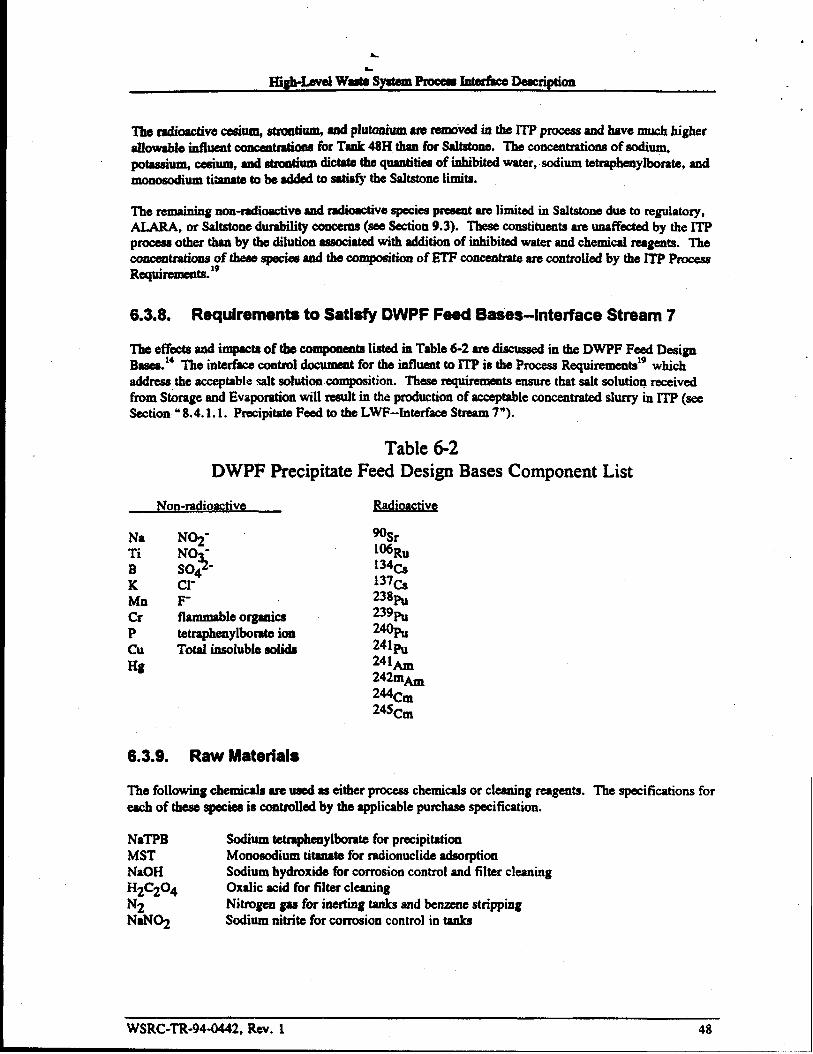
.
H&Level wa&y8tem Pmce#s Itltdke Deac@ion
.
The radioactivecesiw stmntiurm d pfu@dum mu -vd in the lTP pmxwandhave much higherallowable influeat ~ fbr Tank 48H than for Sahtone. The conwatrations of sodium,potassium, cesium, and strontium di~ ~ qutitiea of inh.ibiti -r, sodium tetmphenylborate, andmonosodium thuate to be added to Satisfj’the Saltstonelimits.
The remainingnon-radioactiveand radioactivespeciespresent are limited in Saltstone due to regulatory,AUIU, or Sahatonedurability concerns(see section 9.3). Theseconstituents am unaffectedby the ITPprocess other than by the diIution associatedwith addition of inhibki water and chemicalmagenta. The~_ofti_d k~itimof~ww_ mwntioU&[email protected]
6.3.8. Requirements to Satisfy DWPF Feed Bases-4nterface Stream 7
The et%ctaand impacts of the cornponds listed in Table 6-2 are discussed in the DWPF Feed DesignBasea.14The interfhcecontroi dwurmat for the inthent to ITP is the Process Requirementsigwhichaddress the acwptable dt solution composition. These requirementsensure that salt solution receivedfrom Storage and Evaporationwill result in the production of acceptableconcentratedshiny in ~ (seeSection u8.4.1.1. Precipitate Feed to the LWF-Interface Stream7“).
Table 6-2DWPF Precipitate Feed Design Bases Component List
Non-radioactive
lvaTiBKMnCrP(xlHg
N02-NO “
%S04cl-F-ftammableorgankxtetrapheaylbomte ion~Otd insolubIe sdida
Wimc tiv~
%rlMRU134c~137(-*238~239~z%241~241h242mAm244cm245cm
6.3.9. Raw Materials
The following chemicals we used as either processchemicalsor cleaning reagents. The specification foreach of these specieuis controlled by the applicablepurchasespecification.
NaTPB Sodium tetmpheuylbomte for precipitationMST Monosodium titanate for mdionuclideadsorptionNaOH Sodium hydroxi& for corrosion control and fiker cleaningH2C204 Oxalic acid for filter cleaningN2 Nitmgea gas for inerting tanks and benzenestrippingNaN02 Sochm nitrite for corrosion control in tanks
WSRC-TR-9441442, Rev. 1 48

Higlt-Lwel Waste system Pmcesshtterke Desuiptioa
6.4. Effluent Streame and Key Process Controls
6.4.1. Decontaminated Supernate to Saltetone--lnterface Stream 6
Composition of ITP efflusat to Saltstane is controlledby the ITT Process Requirementst$and the High-I&vel waste system Plsn.6 The m process rsduces the c.omxatrationof several speciss in the saltsoiution to levels accepdde within %hstone. Those spocicswhich we not dlbctsd by the ITP processare controlled by the High-LevelWesteSystemPlsn. The voium of decoatdnated salt solutiontransferred into Tank SOHis controlledby the ITT ProcessRe@remmts, which includesa tsnkageallowance for ETF operations.
6.4.2. Precipitate to La*e Wash-Interface Stream 7
Wsshed precipitate is producedwithin lTP snd is trsnsfsrred to Tank 49H where it remainsuntil it isprocessed in Late Wssh and DWPF. ThrIinfheattoITP mustb of a wxnpositionwhich allows ITT toprecipitate, filter, end wash the slurry such thst the sceumulstedmsterhd in Tsnk 49H is acceptabletoDWPF whea received. Tsnk 49H will shvays contain meterid from more tbau one cycle of ITP, sosonmcxeditan be tskea for tho blending tbst will omur. The interfbcecontrol dommeat is the lTPProcess Requimmeatslg which will permit production of slurry to meet the requirementsof the DWPFFeed Design Bases.14
The insolubie solids [cvei in the precipitatemust be sufficiedy wncemtratedto permit chemicalprocessing in DWPF, and the compoundswhich sre incompatiblewith glass must be removsd. Theprecipitate is washed in lTP until tho canccntmtiooof soluble speciesare at mxeptable levels for MeWssh. Comosiortinhibitors are sdded to the precipitateduxingthe washing phase and in Tauk 49H.Multiple batcheaof washed precipitateare stored in Tank 49H and are blended with sluny pumps priorto trsnsfer to Late wash.
6.4.3. Diverted Storm Water to ETF-interface Stream 17
storm wsterrunoff km the ITP tauksis sent directly to a NPDES outfall after the online monitordetermines that it is ‘clean’. If the nmnitor detectscQntamirWioa,or for aoy of severalsdministrativelprecautkmq reasons, thesmrmwtw can bedivertedtothe ETFbasins, asdescribcdin“9.2.2. Diverted Water Basins.”
WSRC-TR-944442, Rev. 1 49

. .
a.
High-LevelWastekyatemPmceeabterfke Deacnption
7. EXTENDED SLUDGE PROCESSING (ESP~
7.7. Function
Extended Sludge Fmceasm“ g tnodifieathe sludgecomposition to prepare the sludge fir M to DWPFVitrification. ‘The~ of prowwing is to reduce the voium of glass thst is produd (i.e. allowsmuch higher waste loading of sludge in glass). ESP modifies the sludge composition in two ways: 1)insoluble ahnninum compoda am mumved from those sludges that contain high Conceatratiollaofinsoluble sIuminunk snd 2) ail sIudgeis wsahad to renmvesoluble salts.
7.2. Description of ESP
ESP P-
h deecribedin Chapter 5, an insolublesidge is formedwhm Sepamtionaadds sodium hydroxi& to thefreshwaste being sent to the Tank Farms. Exti SludgeProcessing (ESP) converts insolublealuminum compounds into soluble compoundsby contacting the sludge with high Conccatlmtionsofsodium hydroxide at near-boiling tempeWu-. After the aluminumhas been solubilixed, ESP wadesthe soluble salts (e.g., sodium nitrate) from this sludge by washing it with water. Both of theseoperationa reduce the quantity of ghss producedwhen the sludge is vitrified into waste glass.
ESP O~_ on 1- batchea of dUdW, m the attire curreat Storageand Evaporation h%ltoq wili betreated in about 6 batches. Each batch wi]]be dy2!d and then will SllppiyDWPF for a 2-6 y-period. ~s time period maybe altered by the achievableopemting attahmm ta, or it may be limited bythe waste removai schedule (i.e., - the nextbatch of sludge will be available). While ESP pmceaseaa batch of sludge (in Timk 42H, and either Tank 51H or 40H), the previous batch WN be fd to DWPFfrom the other tank (i.e., either 40H or 51H).
Extended ShliilggP~
Extended Shdge Processing (Figure 7-1) includeeand m-with the following equipmen~
Tank 42H - This Type IHA tank is used for the aluminumdissolution reaction and for sludge washing.This tank is equipped with steam spargers for heating and slurry pumps for agitation.
Tanks 40H and 51H- Each of these Type 111Atanks is used for sludge washing and for feeding washedsludge to the DWPF.
Tank 21H - This Type IV tank is used to store spent wash water from ESP. This tank is administrativelypart of the Storage and Evaporation process and has functionsother than ESP, but it functions as part ofthe ESP p~.
ITF Control Building - This building houses the Instmmatt Control Room and the Electrical ControlRoom for the ESP equipnmt (in addition to performing the same functions for lTP; = chapter 6).
ITP Cold Feeds h - This area contains tanks, pumps, piping, and instrwnsntation neceaamytoreceive, store, and add nonradioactive reagents to the ESP process (in addition to performing the samefunctions for lTF; see chapter 6).
WSRC-TR-94-0442, Rev. 1 50

. .
&
High-LevelwastesystemPfocess Inte&e Dedption
7.2.1. Aluminum Dissolution
Part of the sludge inventory cmtains large Sfmunts of alumilnmLwhich can & partially removed(dissolved)by heating the sludge ins high causticconwmtration. If the aluminumwere not removed,themDWPP would have to - the tiO of frit-to-wsste(to coatrd the viscosity and Iiquiduaof themolten glass), inmeas@the Immbe?ofglasscmistersproducd
Mfim-l-ish kTti42wtig ti@*~mtid~, @tiweatihydroxide-to-AluminumtiO and ● certaia excesshydroxideconcentration. The sludge aoii& are~byagdwmf~ti-=,dti @mpem@eis raised by injecting steam throughspa@ng dmmwmem. Maintaining this condition m =ed dSyS_Wrta the ~203.(3)H20 @hsite)to a ao]ub]eform (e.g., AI(OH)3, or AIMV. Afler the SIWIIPSOli&SIBallowed to de, the ~containing distdved Aluminum is then dscnntedfmm the tsnk
One concern with the process is that uranium becomsamom soluble under the high hydroxide conditionsthst exist during Aluminum Dissolution. Therefore, fisde isotopesof uranium (mainly U-235)dissolved during Aluminum Dissolution could poteotisily causea criticality whca the decantedsupemteis evaporatedand sub$equatly redissolved. Criticality is not a concernchuingAluminum Dissolution ord~gw~timof~-ti ~-eti--~h-ti~~salt. However, whea the SSItcakeis redissolved, some uranium may remain insoluble, and there is thepbtidtitis ti-wodd-~ti tibmofti~ti katitid~. smdieawe Curnmtiyumkmvay to &ermine if this mechaaismis cmdiie sad if any controls are needed toprevent C1’itidlty.=
The selectioo of specific sludges to uadergo AluminumDissolution is dsacribsd in section “7.3. 1.Wsshed Sludge-Merfkce Stream 4.s The disposition of decantedsupmate km Aluminum
Dissolution is dsacribed in section ‘7.3.2. DecantedSupnate-Merfhca Stream 3.”

High-LevelWasteSystemProcess InterfaceDescription
Figure 7.1 Extended Sludge ProcessingInhibitedwater and Sludge, from Storage and Evaporation
bulk inhibitors, (ltlterface Stream 2)for washing
1“ FinaJdecan$
I Sodittmhydroxideand steam,
fix Al dissolution 1
toevaporator,
t
temporarystorage,*JInnStn3tm 3)
----- /
Tank40H or 51H
\
,,.,,::,,....>..,.,.,,,.,.,.,.,.,.,,,.,,.,.,..,...........v.,...,...,,,.,,..,,.A.,.,.A,,,,,..,.,,.....................................................................................v....”.v../. .V.w.->.+j .**.. ,-..’.--..., .%+s~,.,.
Wastewater for washing/~-- i
x
washedsludge,to DWPF
(lnterk stream 4)
Note: the washingprocesscan also be operated in the oppositedirection:
u
TankDivertedStormwatdetc,
● Washwateradded to Tank 51H or 40Htombasina
2111 or other● Deeantfrom 51H or 40H to 42H
(Interfaeestream 17)
c Final decant from 42H to evaporator,Tank 21H,wttshwater storage
or other destination Tank
‘r
.
WSRC-TR-944M42,Rev. 152
.

h.
High-Lwd WalmesyatemProeeaarnterkerkcfiptiea
7.2.2. Soluble Salt Washing
Mthough the sludge baa aettiedand ~mpscti in the VUiOUSwaste* for 5 to 30 yura, tkt settledVOhllI& d COntaius a large fhdiotl of Iiquid. This htitid ~ CoII- a h- ~ Ofdissolved salt @reac@as NaOH, NaN03, NaNOZ NaA102, Na2C03, Na2S04, etc). If tbia salt werenot removed, then DWPF would have to imreasa tbe ratio of frit-to-waste(to control the rhaology of themoite.ngiaaa). This would greatly incraasethe number of glass canistersproduced. Other reasons forremoving the soluble salts include reducingDWPF’SatmoapbericNOXemiaaioas,smdto meetrequiremcats for gksa inaolubl= and corrosivespecies.
The soluble salts are removedkm the intemtitialqemate by repted dilution. First, waakwater(withalowdt-e) istitib tidtisld~mti~ -~wkgdqm fixagitation. ktisld& mli&-_b tiedti-~ishMkmtitank. This cycle is mpeatsd until the ash contcatof the interstitial supemte is sufficiently low. Tocontrol nitmte induced corrosion, inhibitor salts (i.e., NaOH aad NaN02) must be added along with thewashwater. Themakeup washwatermay be fiesb Waterorit-haome other waste sohatioavvithasufficiently low salt contest.
~edteg~tie~ ~tiepb~=~ytititi~ troika(i.e., Tauk 42H,andeither Tank51Hor40H) where the ‘used’ washw-decaatdhn tbefirsttankisthen ‘nxaed’inthe second tank. This process, oh CaIled●cowaahing,”_ the total volume of afxmtwaehwaterproduced (thus mhimking the load on tbe 2H evapomtor)but it requiraJ adMOnal washing cycies.Many other factors impact the number of wash cyclesand the total decant volume, e.g., the amount ofwashwaterused in each cycle, tbe time the sludge is allowed to Settls and tbe amount of supmate leftcovering the sludge whsa the decantingends. These tradeoffsalso impact the total duration of thewashing process and will have to be re+@imixedwhen umditiona and conatmm“ ta Chatlge.
The disposition of decantedmpemate from sludge washing is described in “7.3.2. DecantedSupernate-Interfke Stream 3.”
7.3.
7.3.1.
Effluent Streame and Key Process Controls
Washed Sludge--Interface Stream 4
ESP detemka the conceatratimtaof shuninum, aoIubIeask and inadub[e solids in the sludge fd toDWPF for vitxificatiom
● The Ahminum contestispartidy determinedby tha dissolution process, which has ● relativelyhigh effici~ for that part of the total aluminumwhich is msceptible to dissolution. Otherformaof dumilmm are not affectd by the aluminumdissolution opmntiq conditions, asdescribed in “7.4.L Un- sludge-interfacestream2.” Tlma the OvsrallAiuminumremoval efficiencyand the Aluminumcontest of ES’% product is partialiy detmnkd by thebknding provided by tbe waste removal schedule.s T%eallowable aluminum contest is limitedby the DWFF feed design baacs” to ensure the molten glass has a satisfactory rheology. If thealuminum is outside of these limits, this will increasethe numbsr of canisters at DWPF andincrease the cost of processing. The DWPF limit applies to tbe tlnal mixture composition afterTank 42H is combinedwith Tank 51H or 40H.
● The soluble salt content is controlled by the ash washing process. The allowable salt content islimited by the DWPF f~ design bases*4becauseof several factors. These ensure the moltmglass has a aatiafactoryrkdogy (i.e., Na+) and meets the Iimitaon glass inaolubks and
.
..,-=” _ AAfiAA~ S3 -.. 9
53
. .
High-bvel Weste syetem Proceeerrtterb Deecripticm
comoeiveepeciea(e.g., ~ ~ S04=). ~s ~so emauresthat DWPF reeks the air emissionspesmit for N(3x(i.e., N02-, N03-, OW). The allowablesalt contentscan be affectedby someinsoluble apecicapmseat in the sludge (e.g., patt of the sodium).
● The insoluble solids content is cofttrdkd by h exted that the sludge is ailowed to settle for thefinal decant operation. If the W% solids is too high, themthe slurry’s rheology could be stiffenough to mskeit difficult to pump iium Tank51Hor40H to DWPF. As thewt% soli&decmaaa, then DWPF requires additionaltime to process the same anxnmt of solids (i.e., moreboiling is required in the Slurry Receipt Adjuetmmt Tanir). Mm, the water content of thesludge slurry eerhto DWPF is ail r@rned * to the Storageand Evaporation in the DWPFrecycleetmam (InterfkceStream 10). The slurry and transferpumps wiii leak some of theirbearing water into the fked tartk, gfSddy diluting th Wt%insoluble. This dihitkm myrequire thatedditior d~bebted~odi~y. Eachdecant wouidrequire sprocess_mdmm~_titi slti&~~e, ~wuldc~tidt --toftiesludge (i.e., the ratio of inaoluble:aolublesolids).
The DWPF Feed Design Eaase*4sise documentsthe impactsof numerous other speciee, but thoseconcentrationsare determined by the waste removal schedulein the HLW System Plan.G The scheduleprovik for limited blending, baaedeither on proceaaknowledgeof W@Sorigins and transfera, or onwaste tank sampling. Becauseof the small amount of sludge in moat tanks compared to ESP batch si=,some blendii win MtUdiy occur.
The unwashed sludge & into ESPmust haveenappm@te composition SUGhthat the DWPFrequiremmtsi’ for ESP*Sprcmssed sludgewill be met. Othewise, DW’PF’Strim chemicalsor fritcomposition may heve to be @steal. The HLW MaterialEvaluation Board and TOST are responsiblefor resolving the notwomplianwh including the impactsor operationalcost. See” 8.4.1. High-LevelWaste Feed Stmuns” fm a discussion of specieswhose composition is important to DWPF.
7.3.2. Decanted Supernate--lnterface Stream 3
7.3.2.1. Disnos@ Al~ “v
Recycling the decants from ESP for beneficialuse (rather thao evaporating them) will require meshingthe various transf~ schedule requirwneda. Initially, teak 21H will be used fw temporary storage.Later, other tanks could be used as more spare tank speccbecomesavailable (i.e., as the waste removalprogram proceds). options for bertetlcid use have been reviewed.=
The supemate decantedafter Aiuminumdissolution can be seat to various destinations depending on thecomposition and various production planning neak
● It uu be fkd to the HLW evaporators, but the high hydroxide contemtwiii limit the evaporator’svolum reduction thctor (the Aluminumdissolution supemate will not crystallize weii).
● The high hydroxide mntentwould actuaiiy be desirable for dissolving salt to feed ITT.
● Depending on its salt and radionucli& content, the mpemate can be fed directly to ITP, e.g., ifRu-106 meets the Z-area waste acceptanceCfitC1’ia.i3
Decanted spent waahwatercan also be sent to various destinations, depending on the composition andvarious production planning nedx
● R can be fd to the HLW evaporators.
WSRC-TR-944M42, Rev. 1 54
syatemProceu8rntdhcekcription
● Eachaubqumt decantwillconta inadecremm“ gamountofsalt, andla@rdeeanta can beusedtodissolve salt to fA m.
● Dilute decaatscan beheld forreuseasmakeup wdwater in the initial washes of the nextsludge batch.
7.3.2.2. Corro810n-tor CoateQ. . .
Meeting the Technieai Wndad@ (soon to ~ ~ by the mp Process Requirements)in the ESPtanks will aaturally remdtin decmt solutions that am iabibked for * nitrate contents. However, thereceivingwaste taak’s inhibitor awl nitrate contests maybe such* inhibitors have to be added (to thereceiving tank) fm the mixture to comply with the TechnicalStaDdardS.21
7.3.2.3+ A~ for TVIMIV T-
The TechnicalStadarda,a which Iimitetbe (2s-137~on of liquids added to the Type-IV taaksmild restrict oppmtmdtiea to hold decant solution in Tank 21H. After the initial wash cycles on a batchofslud~,tih*~db-maT~Wti
7.3.3. Storm Water Runoff (Ciean and Diverted)-4nte~ace Stream 18
Storm water runofffkom theESP tanlwis -t dirdy to ● NPDES outfall after the online nmaitordeterrnineathat it is ‘claa’. If themordtordetectsm-m, or for any of severai. .Anm@mtive/pma&mry reaaoaa, the storunmter call bedivelted tothe ETFbasina, asdescribedin“9.2.2. DiVeftGdWater =.”
7.4. Influent Streams and Key Process Variables
7.4.1. Untreated Sludge--interface Stream 2
The DWPF Feed Design Baaae14doeummts the impactsof numerous species, see” 8.4.1. High-IselWaste Feed S-” several of which are ecmtrdled by ESP. The other mmcemrationaare determinedby the waste removal achechde,ewhich provides a blended sludge based on process knowledge of wasteorigins, transf-, and on limited tauk sampling. Since the originai blending plan was developed, thewaste removal project budget baa ahifledseveral tanks to Iaterbatebea. The new expectedbatchcompositioeahave bees estimated. The unwashedsludge transfd into ESP will either have an
‘4 for ESP’Spmcesscd sludge will be met, orappropriate composition such that the DWPFrequirementsthe HLW Material Evaluation Boardwill resolve the matter (See section 4.2. i. HLW Materiai EvaluationBoard).
WSRC-TR-94-0442, Rev. 1 5s
HigMevelwaatesyatemPmceearnterfhD-iptim
The Tank Farm sludge inveatory is ~ M ~ the ~ of the Shdge. which geaedy.
de&mmea the composition (e.g., ~ -~ ~> ~ high ~ --- low =)” ~ d-$ highheat HM sludge contaiaa Iarg6amountsof aiuminum. The waste removal schedtdeaselects eestain tankstoundergothe Ahmimlm dis801utioIlprocess. some aluminumis present as A1203.(l)H20 (beohmite)and as aluminum-silicacompounds,which are not solubleat ESP’Sdissdution tqmatum.
The radionuclide content of the sludge is limited by the DWPF Feed Design Basis and also by the time-to-LFL in ESP tanks (see “7.4.2. Waahwa@r”).
The maximumamount of sludge in eachESP processbatch is limited by the slurry pump’s capability tosuspend theaolidaand bythemximum~ volume allowable.
7.4.2. Washwater
Fresh water c.anbeusedaauukeq ~ after adding a small amount of hydroxide and nitriteinhibitora to comply with the Tank F- Tech!lid StandardS,21which will be mpemded by the ESPProcess Re@relm ta. Altemativ4y, vaziousdilute wastewatersolutions could be used as washwaterwhen their salt content ia aufficientIyhnv to effkctiveiydilute the interstitial supernate in the shdge. Forexample, the DWPF recyclestream cdd be used as waahwater,or some ESP decants could be re-used inthe next ESP batch, see -7.3.2.1. Disposition Ahernativea.” Using dilute waatmmta could reduce thetotal amount of feed that the evaporatorsmust eventuallyprocess, although requiring more washingCyc[esin ESP.
The total volume of washwaterused for each ESP batch is minimimd by performing more wash cycles,each one using a small volmm of water. Alternatively, the total pmeessing time caa be rahiced by doingfewer washes, each one using a larpr volumeof water (and increasingthe total waahwatervolume). Themaximumvolume of washwater is limited by the ESP OSRIS require-t fix ● minimum time-to-LFL(i.e., upon 10SSof ventilation), becausehigher volumesof washwaterdecrease the availablevapor space,which demaaes thetimeto LFL
7.4.3. Raw Materials
Caustic and sodium nitrite are used as eorroaion inhibitors, both for bulk additiona to the ESP processingtanks and for minor additions to the makeupwaahwaterstream.
Caustic and steam are din the aluminumdissolution phase of ESP.
WSRC-TR-94-0442, Rev. 1 56
High-LenidWdesystemProa!usInteacs Description
8. DEFENSE WASTE PROCESSING FACILIIY (DWPF} Includes LateWash FacilNv (L~
8.1. Function
tip~titimofb DWFis@~tigh l~4_(h&fmof_~pi*dwashed sludge) into s borosilicateglass, Caaisteredwaste fbrm which Uleetsthe quimmlmts of theFcdersl Repository.
The DWPF will also produce recyclestreams (spat wash from the LWF and DWPF mcycie)which meetthe Stomge and Evaporation’sac@@nce criteria, andproduce anorgsnic waste ~whichmcets the
-- ~ of the ConsolidatedIncineratorFacility (q.
8.2. Description
Figure 8-1X
1.
2.
3.
4.
5.
Me WashFacility (LWF), which washsawater soluble components from thetetrapbylhate (TPB) pmcipiM shy which hss beesi stored in Tank 49H
Salt Process Ceil (WC), which hydrolyzesthe TPB precipitate sl~,
chemical Frocesscell, which prqmresmslter fed bychemically trutingthewashedsludge and mmbinkg it with hydrolynd pmipitate and glass fric
M4t~fl, -titifimti f&-kti=, ~&etitigtitistailda?sStselcanisters, sad =rubs the melter Offgawd
Canis@rClosumalld~.
“on,which seals the canister sad cleans its extesior fortransf= to the Glass Waste Storage Building (GWSB)and eventually to a FederaiRepositmy.
8.2.1. Late Wash Facility
k ITF, the~ is_ toreducelevelsof soluble species (prewmtingexcessive glassproduction) d i8 iahibited with NaN@ to preveat corrosion. However, the conccatmtion of Na?qrequired to inhibit corrosion is too high for the precipitatehydrolysis ~. Also, while theprecipitate is stool in Tank49H, water soluble organic speciesare produced by radiolysis of the ‘II%.‘Ilese organic species also impact precipitatehydrolysis operability by reducing the copper atalystactivity.
WSRC-TR-944142, Rev. 1 57
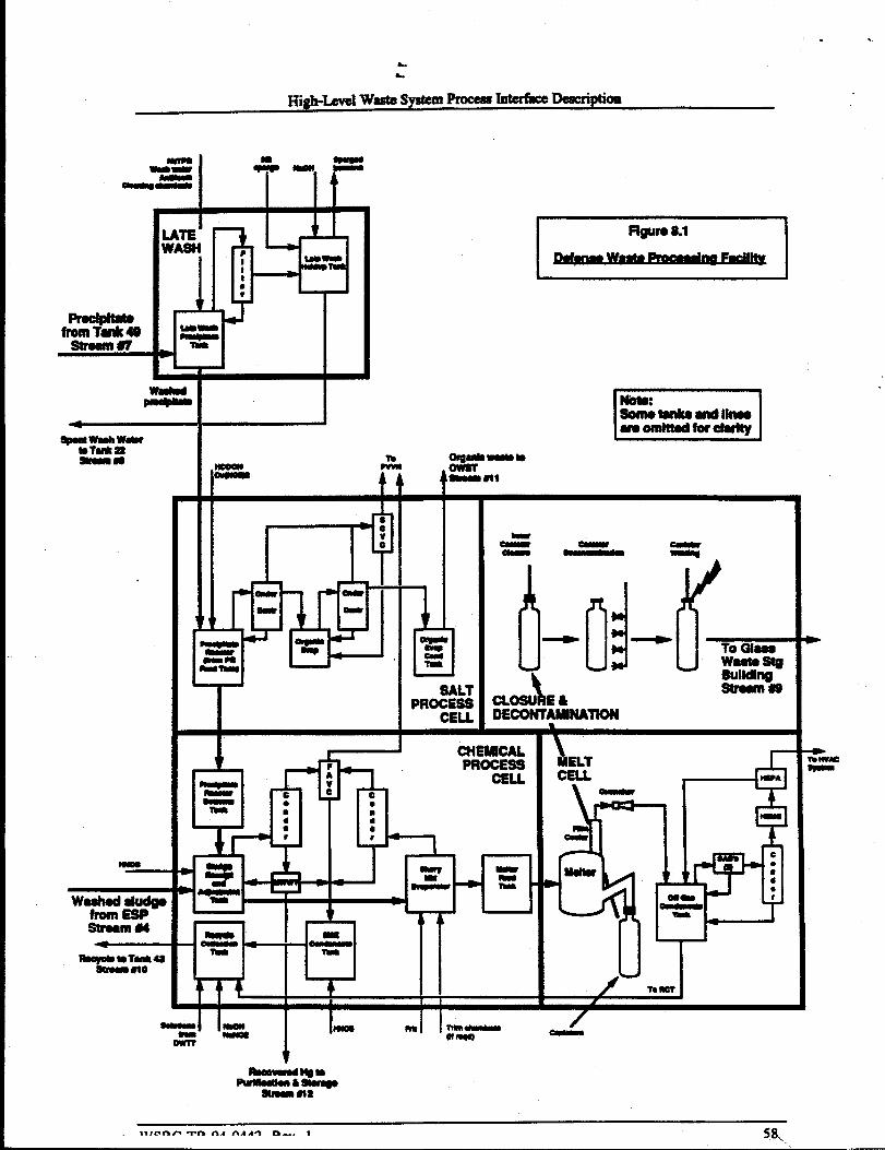
. .
High-LeveIwastesystemPmceal lnterhc8 De4uxiptiaa
-==1 T’-Ir1
I , m
I i 1 I
L==1
I1=
m
4
F@r8 al
b
,
High-Level waste%ystemPmcesskterhce Deaicriptioe
The precipitateslurry @terhce S- 7) is pumped into the M Wash PrecipitateTank (LWPT) wheresoluble Caand K (fkomradiolysi=sof CS,KTPB)are reprecipitatedwith NaTPB. The slurry is thaIconcentratedto the desiredpercrmtsolids using a ainterd mdal -flow filter. It is thea washed with adilute NaTPB solution (to prewmtdissolution of CSTPB)until the nitrite and soluble organicsconcentrationsare reduced to levelscompatiblewith precipitatehydrolysis.~ ‘Ihe washedslurry maybe!iuther CaKxmtrated ptior to tnmsfsr to the DWPF.
Fihrste from the washingand concentrationsteps flows to the Me Wash Hoh3upTank from which itwill betmns&mdto Tank22H @terhe Stream8). TomeetlTP requimmcntsfbrbensene, pHandinhibitors, the filtrate is spargedwith N2 to removethe di=lved bmzemeand NaOH is added. LWFvessels contwmn“ “ g~dh_&&*olytis, m~@ti&ti_@-titi~below the minimum oxygen fir combustion(MO(2).
Additional chemicalswill be used in the LWF. The fiker Wii require periodic cleaning with oxalic acidand CSustic. Foaming in the Late Wash Precipitateand the Late wash Hold Tanks will be cuntrcdledbythe additicmof an antifowtb su~i~ 420.
8.2.2. Salt Process Cell (SPC)
8.2.2.1. SPC Chemt@y.
The washed and concentratedCS,KTPBprecipitatdNaTi20J-1 shmry is acid hydrolyrd snd steamstripped in the salt Process CelL The purpose is to remove the aromstic organics from the Cs-containingsqueous stream which is ultimtely fbd to the melterbecauw high concentrationsof organic interfere withmetter operation. The desired reactioa is
&+2
Cs,KB(@15)4 + HCOOH + 3 H20 = CS,KCOOH+ 4 Q% + B(O~
resulting in soluble Cs fonnate and bcmzeae. However, - b *OXUl involve the radicals and ionicspecies such as nitrite, bypducta are fbrnd such as phenol, biphraiyl, aniline, diphenylamine,terphenyl, etc. Becsuseof the prearma of the volatile, flammablebenzene, all the pmc=sswads in theSPC are purged with C02 (or N2) to ‘mamtain the 02 ~tration below the Minimum Oxidant forcombustion.
AZIotherreadion of interestis thereductionof diphenyl mercury (precipitatedby TPB duxingX.n-TsnkPrecipitation) to elemental mercury. l%e reaction pmceedaby f-c acid cleavageto the phyimercuric ion fiilowed by reduction to elemtmtalmercury. ‘l%iareaction must occur sufficieattlyto meetthe CIF limit on merctny since the biphcayl mercusyeasily steam strips to the recoveredorganic phsse.
2. SPCDax@JQQ. .. .
The washed slumy is tmuaferred to the Precipitate Rsactor Feed Tank (PRFT) in the Salt Process Cdl forfeeding to the Precipitate Reactor (PR). I%or to feeding, formicacid and copper catalyst (either copperformateorcopper nitmte) amaddedtothe reactor heel. Theatheshuryis fedandthere actorisheatedto boiling. Benzeswis evolved as it is formed (the hydrolysis reactions begin as soon as the feed entersthe PR) and the stepwise reactionscontinue through the aqueousboiling step. Ocheraromatic organics
WSkC-TR-944M42, Rev. 1 59

.&
k
High-LevelwastesystemPmcesaInt=fia Dcacription
Ati~timxis ~- b~b-vdec-istidmtiydecontemina@ fbr transferoutaideof the DWPF canYon(InterfiweStream i 1) to the Orgmic WasteStorageTank(OWST) and fromtheretothe CXF. Water isddadtothe OEandtheboiling, ateamstripping, andensm“ g, decantingcycle is rqeated. The twice-distilledorganic is collected in the OECondatsate Tank (OE(T) and anaiymd for activity and for mercury.
After steam stripping and coding in the PR, the remaining ~ @WSSis known as PHA (precipitatehydrolysis aqueous). The PHA is b tram&md to the Precipitate l@@or EottomaTank (FRET)where it held until fhd to the Sludge Recuiptand AdjuetnM@Tank (SRAT). The NaTL20sH,and thersdionuclideewhich were a&orbed on the titaaate, remainwith the aqueousphase and are ukimatdy fedto the melter.
t L
AUveasclsin the WC am collectivelymaintainedunder a slight vacuum and vented through the chilledSalt Ceil V- Condenser (SCVC) into the PrumM Vessel Vent Header (PVVH). The primary purposeof the SCVC is to limit benzeneemissionsand to preventa flammablebenzenemixture io the PWH.The PVVH exhausts to the atmospherethrough the ad filter after combining with the Zone 1ventilation system.
8.2.3. Chemical Process Cell [CpC) .
8.2.3.1. CPC Dew-. .
The purposes of the Chemical Process Cd (@C) are to completaprepamtion of the reeker feed and tocollect and adjust the aqueous recyclestream. In fact, the CPC is also known as Meher FeedPrepamtion.
Sludge (Interthce Stream 4) which has beemprepared in Exteded Sludge Processing (aiuminum dissolvedand washed) is transferred into the Sludge Receiptand AdjustmentTaok (SRAT). Sufficient nitric acid isadded to react componeatesuch as nitrite and mbonate, to obtain an acidic pH (required for control ofslurry rheology), and to provide the required reduction-oxidationbalancebetwwmformate and nitrate.PHA is then added to the SRAT and excesswater is boiled off, condewd, and collected in the SMECondensateTank (SME~; if an antifoam is needed in the SRAT or SME, Dow Corning 544 will beused. Excess formic acid in the PHA also contributes to desired pH as well as reducing HgO toelemental mercury and Mn+4 to Mn+2 (reduces foaming in the melter). Elemenhd mercury is swunstripped during the conceatmtkm step and is collected in the Mercury Water Wash Tank (MlVWT). Themercury is paiodidly pumpd to ● shieldedceil where it is acid washed, water washed, and vacuumdistilled in preparation for eventualdisposition (InterfhceStream 12).
The acidified and concentratedsludge and PHA are then transferred to the Slurry Mix Evapcmator(SME)where glass frit slurry is added and exccsewater is again boiied off, condensed, and collected in theSMECI’. If any composition adjuatmmta are required, the trim chemicalsare added in the SME prior totransferring the combined sludge, PHA, frit SIUITYto the Melter Feed Tank (MfW). The melter is fedcontinually from the MFt’.
All the vessels in the CPC!are maintained at a slight vacuum and collectively vented through the chilledFormic Acid Vent Condenser (FAVC) into the PVVH, and ultimately to the atmosphere. The primarypurpose of the FAVC is to limit mercuryemissions. In addition to air leakage from the vacuum, air isadded to CPC wads to dilute potentially flammableconcentratiorteof hydrogen (produced both by
.

k
k
High-Level w8stesyatemProcess InterfaceDescription
noble metal catalyzeddeconpdtimof tic =i~ d W *l@S), d benzeaefromthePHA.Aho,thec Pcvesaelvents yti~ti ammonia scrubbers(directly &wu@mamof theSRAT and SME cmbaera and on the RCI’vent) 10mitigatedcpoaitionof ammonianitrate inventilation system piping. (Ammoniais pmt in the precipitatesky as NWTPB and is generated bychemical reaction in the SRAT, NOXis ga~ fromnitite and ni~te reactions in the SRAT.)SME(X’condensateis used for ammoniascmbbiug and nitric acid will be added to the SMECT as neededto maintain the proper pH fbr scrubbing.
The RCT collects condeswatefimn the SIUT and the SME - from the melter Off Gas CondensateTank@G~ fm recycle to Storage and Evapomtion(M&ace Stream 10). Prior to transfer, NaOH andNaN~ are added to meet Storageand Evaporationinhibitor rcquiremmts. l%e RCT also periodically~ solutions fkomthe Decontdnated WasteTieatment Tank (DWTT). These are neutralizedsolutions from equipmeat decontamktion and aolutionslslurriesfrom dissolution of HEMEs (HighEfficiencyMist Eliminator) and HEPAs (H@ EfficiencyParticulateAir-filter).
8.2.3.2. Product Comw Itmn Con rol. .s t
The melter f~ canposition, and thus the glms compositionand its properties, are controlled by theGlass ProductControl Program (GPCP). The GPcP uses 1) samplemalyaea and tank inventiea hornthree process locations (the SRAT, the PRBT, and the Sh4E)2) fit composition and frit slurry makeupvolumes, and 3) statistical methodologyto control the glass product.
A computer program, the Process CompositionControl System(PCCS), has bees developed to performthese fimctions. Taking into acmmt the uncertaintiesin property correlations, physical measurements,sampling, and analytical results, the P(XS determinesthe appropriate mix of sludge, PHA, and frit to
meet six objective functiomx 1) glass durability, 2) melt viscosity, 3) melt Iiquidua(the temperatureatwhich the first portion of the glass starts to solidifjf),4) minimum fit (that is, maximum waste loading),S) limits for glass insolubka, and 6) glass predictability (meaningthe degree to which the glasscomposition is within the range of compositionsthat baabeen studkd. A high predictability means theglass composition is well within the studied mnge, and the glass’s propertie8can be predicted withconfidence).
If necewary, trim chemicals (’NsOH,KNQ, F13B03WC acid), andlor fit) can be added to the SME.A confirming sample is takes from the MIT and occasionalglass sampleswill be takea from the melterpour stream to confirm glass duratdity.
8.2.4. Melt Cell
The combined sludge, PHA, and fit are fed continuously to the melter where the mixture is vitrified andpoured into atainleassteel canisters. The melter is heatedprimarily by joule besting (resistanceheating)from DC curreat passing through the molten glass. The secondarysource is radiant heating fkomresistanceheating of metal rods in the melter plenum.
The sky tim the MFT is fed onto the molten glass pool in the meher. Water tim the Amy feed isvaporimd and volati~eorganicaare burned in the plenum space or at the cold cap. (The cold cap is an‘ishmd=of f~ material flosting on the molten glass where much of the vaporizing and burning takesplace. The cold cap diaappars when the melter is not being fed.) Also several combustion andoxidationheduetion reactions occur generatingoff-gasesof CO, C%, and NOX. The sources of oxygenare air, nitrate, and reduction of F~~ to FeO. The primary reducing agent is the formate ion.
The melter offgas, which includes gases (CO, C%, hydrogen and NOJ, entrained glass, vaporimd ds(sulfates, chlorides, borate@,semi-volatile forms of Cs and Ru, and various forms of mercury, flows into
WSRC-TR-94-0442, Rev. 1 61

. ..
a“
High-Levelw- sptemProcunlIntedace Deacliptioa
theMel&oEGas(MOG) eystCIWmM@q@-**the =J*@eradi@t=uumandsufficiently cleanathe of@asstrsauI b evati vdtig to the abwaphe. The Mm system cmaistsof
1. A film cooler and qwmcher, which W ~ =i *, zvely, to mi, ~, andpartially scmb the offgaawhile minimizingplugging hn da and ghsa.
2. An off Gas~ Tank which collects the amhsate Sndremove heat,
3. Steam Atomized Scrubbers(SASS)which use steamand off@s condensateto scrub semi-volatile Csand Rufromthenon—comhsA Ie gaMJ,
4. A Chihd ~ conhaer which primarily limits elenmtal mercuryemisaioxw,and
5. A HEME and a HEPA to removeaerosolsand partkulates.
The melter &d composition is controlkd such that a borosiiicateglass with the required durability (leachrate) is produced. The radioactivecomponmts preseat in High Level Wasteare immobilti either bybecomingpart of the glass matrix (for example, ~ and Pu) or by being encapaula@dwithin the glassmatrix (for exanqde, Ca and Sr). The molten glass is vacuumpoured into ● stainless steel canister whereit is allowml to cod and solidi~.
8.25. Canister Closure and Decontamination
ARer filling, the canistermustbe cleanedand smlsd prior to Uanaf*g to the Glass Waste StorageBuilding (GWSB)where the misters WNbe tempoMly stored until the Federal Repositwy is ready(Interfacestream9).
The firststepis the insertion of a temporaryplug called the Inner Mater Closure. The puqmse of theInner Canister CIosum is to excludewater during the subsequentcleaning step.
During filling, the heat from the moltea glass causes formationof an oxide coating on the canister. Thiscoating is contamhatd with radioactivitywhich could easily spread unicusthe canister is cleaned.Decontaminationis accmnplishedin either of two Caaister
.DamWmWion Chamka (CDCS)by
blasting the cauister with a diIute slurry of glass frit followedby rinsing with clean water. SnmU testingisperfwmedtoasaurethecai atem am sufficientlycleaa to move on to the weId teat cell.
The !inal closure is made by fbrcing the Inner Canister Closure md the canister nozzle into the canisterneck and thea welding the final weld plug using an upset resistancewelding process. The canister issmear tested ome nx)re befm transfer to the GWSB.
8.2.6. Process Air Emissions
The DWPF will be operating under an air permit fbm South CaroIina SCDHEC.S The petit limitsemissions of mercury, bamne, NOX,aad CO, of which mercuxy,he and NO=are monitored. Thesourwa for these compounds are the LWF (beamne), the SCVC (bemmueand mercury), the FAVC(mercury, NO,, and bermme), the OGCTC (mercury, NOX,and CO), and the OWST (benze@. Inaddition, radionuclide emissions fi’omthe DWPF ventilation system am permitted by the EPA.
WSRC-TR-94-0442. Rev. 1 6~
L
High-LevelWaetihtemProceaaInterfaceDeacripticm
Emissioosfrom thevariou8~m~ andlor controlledas follows:
●
●
●
●
●
●
●
Eeazerwemissions fmm the LWF are primarily detembd by the dissolved benzenein theprecipitateas receivedfrom Tank 49H,
SCVC benzeneand mercmyemissiousare a tition of the air inloakage, the inert purgerequirementsand theopemting temperatm of the Scvc.
NOXemissions (both from the FAVC and the OGCTC)are detemdned by the nitrite andnitrate in the feeds (precipitateaad sludge)and by tbe amount of nitric acid added in theDWIW(whichdependson the hydroxide, mercury, and mmnganesein the sludge f~).
The ~ from the FAVC is determinedby tbe amountof benzeiteand btxwneP~ in the Pm.
Mercury tim both the FAVC and OGCTCis detem&d by the non-umdensable flow andthe FAVC opemting temperature.
Carbon monoxide from the OGCI’Cis a functionof the carbon fed to the melter and thewmpleteness of wmbustion.
The OWSTbernme emissionsare limited by the floating roof in the tank.
DWPF administrativecontrols require monitoring and projectingDWPF emissions on a routinefi’equtmcy.
8.3.
8.3.1.
Effluent Streams and Key Process Controls
The Canistered Waste Form--Interface Stream 9
The caniateredwaste form (the glass + the canister) is the principle product of the DWPF. The DOEhas specified the requiremeatafbr the unisted waste form in the Waste AcceptatteeProductSpecifications(WAPS).m The specificationsapply to the canister itself, to the integrity/cleanliness ofthe canister, and to b giaae. The DWPF Waste Form CompliancePlan (WCP)lSdetails the strategiesfor meeting the speciticationaand tbe multi-volumeWasteForm QualificationReport (WQR)m containsthe objective evideace mpportbg our ability to meet the WCP. The GlaaaProduct Control Program(GPCP), which is a put of the WQR, details the strategiesused to ensure that glass propertyrequirements are met through contful of the nxAer fd composition. hns and activities important tothe DWPF’Sability to compIy with the WAPS arc identifiedand maintained in the DWPF WasteAcceptanceRef~ Manual.= Modification to these items and activities must go through DWPFchange control and be reviewedfor impact on DWPF’Sability to meet the WAPS.
Changes to the WAFS affbctingthe canister itself or the canister integrityicleanlineaaare unlikely to haveany impacts on the rest of the HLW System. However, any changeadealing with the borosilicate glass(for examp~e,product durability, chemicalcomposition, or radionuclide inventrq) could potentiallyaff6ct feed requirements km ITT and ESP.
8.3.1.1. Canister ReuuiremenM
Requirements for the canister itself are controlled during canister fabricationand verified by inspections.The requirements specify materialsof constmction (austeniticstainless steel), labeling (number of labels,
.
WSRC-TR-94-0442, Rev. 1 63

‘
a.h.
HigMevdwastesyatemFrocesahterhceDeacr@a
font type and size, required ~=, l=ti~> *.), di~, 1=*, pqemdicuimity, and neck andflangeconcentricity.
312 Car&ter II@@v. . . . “ /ci-
Sevend of the complianm Strategic fm the WAPS req@reme@adeal with the integrity and cleanliness,both inaideand out, of the canister. T%merequiremmts are Inner CauMer CIoaureladr-tightneaa(topXSV- water intrusion during canister decontamimtion), fmai piug weld pammtem (force, current, andtime to assure a leak-tight ad), exchaicmof fbreign materMa (to preveMpotentially incompatiblematmhda* altering the canister), ammmbiebetdgamma (to PMV- apmadof contaminadon), andcontrol of frit blasting pametem (to prevent breachingof the canister).
Boroahate Glaaq. .
. . .
Finally, there are WAFS requirentmta that apply to the giaaaitself attd are a fintctionof the process.These requirementsare glass dtitiity (leachability),minimumcanhter fill limits, and requiredreporting of estimated radionuciidehwentory and heat genemtionrateabaaedon cmnposition.
8.3.2. DWPF Aqueous Recycle Streams
‘i%ereare two aqueous recycleatrsamab the DwpF~w’F to the Stomge and Evapomtioriprocess.Fiti, ~t_Xkmti LWfl-~Tti22H, istibti~~, mdwatiygoes to Saitatone (Z Area)as partof the decon-ti salt solution. The second is DWPF recyclewhich flows to Tank 43H and is concemtrateiiin the 2H Evaporator.
8.3.2.1. LWF Suent wash Water-rnterfkce Stream8
The spent wash water (filtrate) h the LWFwill contain soluble salts (NaN~, IWtlQ, NaOH, etc),soluble Ca, soluble and sparingly soluble organkx (for example, phsaol and me) from the precipitateShlrryas wd as NaTFB, OXdiCacid, and NaGH which am added in the LWF. The Tank Farm OSRs.speci@limits on C!S-137,~, and inhibitors. The Tauk Farm Waste Acc@nce Criterias specifiesthe limits on CS-137,beanme, NaOH, and comaion inhibitora. The controls for meeting limits on Ca-137, benxene, NaOH, and pH wiUbe implementedaccording to the required compliance plan.
8.3.2.2. DWFF Recvc1-_ Stream lQ
The aqueousrecyclefromtheDWFFis normdy comprisedof condenmteafrom the Chemical ProceaaCell (from the SMECT) and *m the Melt CeU(from the OGCil. Occasionally, there wiii beneutralizedacid fmm equiprmmtdecontaminationand cauaticifiberg!aassolutionshdurriea fromdissolution of HEMEa andHEPAa.
l%ere are small quantiticeof drained sludge, soluble and sparingly soluble organica (including nitratedaromatics), HN~, NH@~, memury compounds, and antifoarnin the SMECT condensate. The OGCTcondensatecontains small amountaof glass particlee, dissolved Ce@um,nitric acid, and mercurycompounds. In addition, DWFF analytical chemicalswili be disposed of via the RCI’and will,therefore, be present in small concentrations. The High Levei Liquid Waste WAC* specifies thefollowing items which apply to the DWFF recycie: compositionalcharacterization;pH inhibitor(hydroxide and nitrite); limits on nitmtea, haiidcs, ammonium, organica, sulfates, and silver; andcharacteristicallyhazardous wastes allowed (mercuryand benzene). These requirements are implementedin the DWPF by adminhtmtive controis aa specified in the DWPF Recycle Waste Compliance Phm.m
WSRC-TR-94-0442, Rev. 1 64

b
Irlgh-bv’elw8s&3yetemPmee4n!hlterke Deaeription
8.3.3. Recoversd Organic--lntefface Stream 11
The vast mqjorityof the TPB precipi~ aromaticcontent is recoveredin the SPC!as organic waste,primarily beazenewith numerousO* O- including phd, bipheayl, aniline, diphenylamine, andterpheny~s. w recoveredorganic must meet radioactivityknits for transfer to an outside storagefidity (the Organic WasteStorageTank - OWST)and also the ConsolidatedIncineratorFacility’smercury limits. Administrativecontrols implementthese requirementsin the DWFF.
8.3.4. Recovered Mercury-Interface Stream 12
After suft%ientwashing and decontamination,the recoveredrnmwy is tmnsfmed as a Low-IAvelMixed Waste to Solid Wastefor interimstorageuntileventualdisposd, which is to be detemined.Administrativecontrols in the DWPF wiii be used to eaaure the mquiremeotsfor interim storage andeveatwd diqnwal am met.
8.4. Influent Streams and Key Process Variables
There are two main types of “influents”into the DWPF: the high level waste feed streams and rawmaterials. These infhwnta, along with how the proeeasis operated, determine the composition of theeffIuentstreams.
8.4.1. High-Level Waste Feed Streams
The composition of the precipitateand sludge slurries have impactson both process operations and on theeffluent streams. Aa documentedin the DWPF Feed Design Basea,i4the impactsare on NOXemissions,canister beat genemtion, DWPF shielding, SAR bases, glass insoluble, proeeascorrosion, meltvkwosityand Iiquidus, glass durability, and procea operability/attainment. These impacts are dkussedindividually below.
It is widely recognizedthat it may be necesary at times to f~ material to the DW’PFwhich is outsidethe DWPF Feed Design Baseaand which may have significant impact in the DWPF such as operability,attainment, and waste loadiig in the glass. The HLW Material Evaluation Board,w composed of HLW,i)WPF, and SRTC personnel, will guide and oversee reviewof projected feed compositions, evaluationof impacts and alternatives, and selection of Sltematives.
8.4.1.1. Precipitate Feed to the LWF-Interface Stream7
Key variables h the precipitate f+ to the LWF are total and soluble Cesium concentration, solids andnitrite concentratiooa,dissolved hen-, and batch-to-batchhomogcmeity. The total Cesiumconcentration ●ffects shielding requirements, and the soluble Cesium, determines the quantity of sodiumtetraphenyhorate required for precipitation. Solids and nitrite concentrations impact LWF attainmentsince batch operatioo eao, if necesary, be modified to compensatefor low so[ids andlor high nitrite.The dissolved benzeneaffectsboth the flammabilitycontroi rrquirementaand the bexmne emissions.Batch-to-batchnon-homogeneityhas high impacton cycle times since considembly more p~processinganalyses are required.
Similar to precipitate feed, dilute sludge primarily impacts DWPF attainment since batch operation wouIdhave to be altered to compensate; an additional feed and concentrationstep might be required. Ako,
WSRC-TR-94-0442, Rev. 1 65

.
High-LevelWssts!ystemPmeees Intedke Deeeriptiolt
betch-tdeteh idmno&=“tywould effect Wtsinmat (more dyS@ end IUSyinfhmcc hydrogen
g-=fiea * (Veriatim in noble Inetde Contest).
8.4.1.3. R~ Level. WseteFeed S-
Nitrates and nittites,primarily from the sludge, result in NOXemissionsduring SRAT pmcessing andfrom the melter. Hydroxides and cdmatee in tho sludge affkctNOXemissionsby requiring addkion of
mitric scid in the SRAT. Essentiallyell these enionaam wster soluble and are directly wntroikd by theamount ofweahing performed in ESP. ITP, and LWF.
Radioactivedecay of the radionuclidedin the glsse will malt in heating of the gless, the canisters, andthe storage bcility. The primary Conc8rnis the GWSBdesign heat handing capecity and the potentialdeleterious etkts of heat on the cmcrete streogth. Cmister beet generation _ are evaluated based thefollowing radionucliti.
Precipita@ 137(-3
The eatimsted heating mtes must not excesd the GWSBdesign besis.
DWF sMl#.tnu.Eksum. . .
The shielding fbr the DWPFwas designedbasedon 5 yeer out-of-reactorblemdedsludge and 15 yearout~f-reactor ssltcake. If the feed stream contsin any of the following radionuclideein concentrationswhich excxd the shielding design MIS, then en evaluationof impsct on shielding and pereonne1exposure must be performer
Precipitak 137@ 238~, 244c~
Consistence with the SW
The Safety Anelysis Report evelusteathe comequmces of certain mxideat Seeneriosbased on estimatedprecipitate end sludge feed eompneitions. Concentrationsof the following rdonuciidcxs must becompemd to the quentitisa used in the SAR:
Preeipitetw ma, 137&
sludge l~Ru, l-, 147Pm
130tlx ‘Sr, ‘SW (earichrnent), ‘8Pu, ‘9Pu, 2%, 241Pu,241Am, 242mA~ 2“Cm, 24sCm
A UnreviewedSafety Question Detmmkt ion is required if sny of these exceedpreviously evaluatedlevels.
WSRC-TR-944M42, Rev. 1 66
k
High-LevelW*’System ProcessInterfb De8eription
There are 8 number of speeieswhich kve limited volubilityin the glma. If any one of these exceeds thevolubility Iimits, eeeomky glasl - mtlyb8 formedin tb !nCIm thus adverselyaffecting meiteroperations and life. The glass insolublespeciesof concernare Ti (primariIyadded ss NttT@5H in ITT,S04=, Cr, P, F-, cl-, and cu.
Corrosive Sueei~
Extensiveeorroaionevaluationshave beenperformedon HLW Materials of construction. Mercury,sulfhtes, chloride, and fluoride have bees evaluatedat maximumanticipatedlevels. However, if anythese concentrationsam expectedto be exeeeded,then tier corrosion testing will be required.
~. .
.The DWPF was designed to produce glass with certainpmpertiea (melt viscosity, liquidus, and glassdurability). Th- properties are &4emind by the compositionof the melter feed. The primarycomponentswhich afkt theseproperties are iron, aluminum, alkali, and fit. The DWPF frit has beenfonmdated based on projectedcompositionsof treated sludge (ahuninumdkaohmd and washed).
Iron and aluminum in the sludge affect the melt viscosity and Iiquiduatemperature. Excessiveamountsof either would either lead to reducedwaste loading in the glass (which redueesDWPF’Scapacity toprocesswaste and m8y result in increasedproduction of canisters)or may require reformulationof thefrit.
AlkaIi in P#x ioitate and S1ud~
Excessivealkali (Ns and K) in the glass affect melt viscosity and glass product durability. The impact issimilar to excessiveIron and Aluminumin that DWPF capacityto processwastewouldbereduced(possibly requiring production of extra canisters). while the quantity of K in the precipitate cannot becontrolled, the amounts of Na in the sludge and precipitateare controllableby washing in ESP andITP/LWF, respectively.
(NOTB: Frit reformulation for high incomingalkali is not a realistic possibility since the DWPF fritalready has essentially all the alkali removedthat can be and still have a procesaable fit.)
M~
Other materh& for which there are no current design basedlimits but which can affect DWPF operablhtyand glass production are 2E01ite,silkx, ad carbon.
8.4.2. Raw Matetials
Therearen~ chemieaIswhich are added either as processchemicalsor as cleaning chemicals.requirements for thew raw materialsare controlled by the DWPF Easeatial Materials Speeitications.Presented below are the DWPF raw materiakx
E
NaTPB Sodium tetraphenylboratefor repreeipitationNaOH Caustic for filter cleaning and pH adjustment of the spent wash reeycle
‘I+zC204 Oxalic acid for filter cleaningSUdjmOi@ 420 Prevents foamingof both precipitateand filtrate
The
——WSRC-TR-94-0442, Rev. 1 67

L
High-LevelWaate; ystem PfoceashWrfaceDeacriptioll
SEG
HCOOH
CU(N03)2
Surfynola 104
FntNaOHKN03H3B03Dow-coming 544NaOHNaNo2
Formic acid for acidhydrolysis, neutraiimtioe, dipiMxIylmercury reaction,midex= acid to provide reduciugagent in the SRAT .-C llitrx@ (hl+2 iStk hydrolysis -y~ CU@C hllltlh caa aiao be
May be added to simulatedprecipitateduring coid chemical runs to controlfbamioginthe LPPPand/orthe PRFr
Nitic acid foTneutrdimtioe and other reactionssuch as nitrite andCsrbmWq aiao for redox balanceof fbrmateBorosihte giasa tit; can be used as a trim chemical, if neededCaustic aaatrimchemicai, if neededPotassiumaitrata as a trim chemical, if neededBoricacid as ● trim chemical, if seededFor Silld@f-gCorrosion inhibitor added to the DWPF RecycieStreamCorrosion inhibitoraddedto theDWPFRecycleStrum
.
HNq IWric acidH2CZ04 Oxalic acid
WSRC.TR-944442, Rev. i 68

&
L
High-LevelwastesystemProcessIn- Descriptio33
9. WASTEWATER TREATMENT--THE EFFLUENT TREATMENTFACILITY
9.1. Function
The Effluent TreatrnemtFacility (E’IT)collects, treata, sad disebargesall radioactivelycontaminatedprocess wastewater from the High Level WasteDivision.
9.2. Description of the ETF Process
Adiagram of the ETFprocess isahown in Figure 9-1.
9.2.1. Process Sewer and Treatment Plant
various geaeratlm dischargedilute ~ streams into the procuMsewers, which drain by gravity to~sF&H_lifi *tia, d- b= W~@ti~T~ t Plant. The wastewaterconsistsprimarily of evaporatoroverheadafrom the Storageand Evaporationand the Separationafacilities(Interfkcestream13).
The ETF treamentplant decontaminatesthe infhlent UmtewaW through ● Seriesof steps consisting ofpH adjustment, sub-micron fihation, heavy metal and organic adsorption, reverse osmosis, and ionexchange. Ah the treatme!atsteps removespecificspecies, the treatedeffluent is aotdyxedanddischarged to the environmentt through a NPDES permittedoutfkll (H-016).E The treatrmnt S-concentratethe contaminants into a smsller volume of aecondaiywaste, which is thea fhrtherconcentratedby evaporation. Variouschemicalsare used ~ restore the proce-saefficiency (e.g., filtercleaning, ion exchange regenembon“ ) and the spent solutions ah seat to the evaporator. The ETFevapomtor bottoms are then pumped to Tank 50H for eveatualdispoaaIin Saltatone.
Esclsstepinthe ETF tmatnmtt process has c@ain Capabllitieaand certain vulnerabilities:
●
●
●
●
l’lte wastm@er infkent is pH adjusted to maximixesolids removal in the filter system. Thisadjustment is done continuouslyand also on a batch basis.
The sub-micron filtration p~ nxnoves suspended solids, but it - be overloaded by anexcessivequantity of solids and con be fouled by certain types of suspendedsolids (e.g., bacteria).The fikers are cleanedwith oxalic acid, caustic, and chlorine (bleach). The feed can be treatedwith afumimminitrate andhr fkrricnitrate to reduce filter fouling.
The main used fix heavy metal removal (e.g., mercury, Iead)would be impactedby oxidizingagents (e.g., chlorine), and its effk@ivenesscan depend on the speciesoxidatioa state (e.g.,removes Cr+3, but not Cr+6). Excessivebacteria growths are removed by soaking the resin incaustic. Ailer it becomm mtumted, it is replaced. The speat resin is not a hsmrdoua wastebecause it passes the EPA TCLP test.
The activated carbon usui for organic removalhas a high capacity for some species (e.g., theTEP/NPH mlveat used by Separations)and a [owercapacity for othm (e.g., phenol). If theinfluent wastewatercontains an excessivequantity of some species (e.g., benzene) then the spentcarbon dkpoaal costs increasedrastically (as a mixedwaste).
WSRC-TR-94-0442, Rev. 1 69

.
Figure 9.1 Effluent Treatment FacilityEvaporatorOWdldS & welted coding water
h: 10W-1CVCI-S & Wmnwater&terfaceStream13)
~“$-
(lntuface Stmama17and 18) s.,. .... ...’ .. . . .... . “ .. ..... ... *.< . ....... . ... .***,:. ... . . ,
(4)DivcltCdwater
basinsinF&Hareas
Contaminatedwater................. .. ., .+.,’...-..........’...’-..’.”--~J-,.’~.-..-----.-.-”.’---- +:+’,.. . .,-~............. ...’...’.’,....-.~.,,..~....................... ......*"`"""`".""""`~`"`"""-`"""""`"""~""""`"""""`"``"``=.""".""i..............................................................
L-I $.,Wastewater~~~i~~W ..*& ................w.. ....v.......................m..w..........*..*..w-t .aTreatedW-A....*.W ........N..W....-N....... .... ...... ....................... ..,W................... ..
OffSpecpmduetrecycle+ ...........AW.*VM.
pH adjustmenyaistanka
!?Solidsremoval Mercuiy Melwury Cs ploval
aubmicron mmovdfiltration
removalionexchange
* ionexehange& $
k-
I-v..-...%...>.=. ........** . ...........v>..%-..\..m
.
Evaporator it
............ ......................... .... ............................/. . . . .............. .:. .. ? .,,,.,,,.,.;.,.A,,,..... .....\\y\.ti.ti,.....+..,,.:.:*>,,.,...,.+iy,<:::i)f<:4..::j:<<:::;*A*+...,................... :.>.:.:..’..... .....'...'..sx.::.:*.:::~.::~~.~:+v'.'.',"``"`'`'.--...’..... .-.........G*X*.%.X........ ....................*VW.*WV..*WN d.~x::w.weu%i,>.vp~.:...w%w%..–1
... *W..~if%+ww~ ‘.K’wxwww.
t
.tjl:?$;
MT concentrate,.:?
f Treatedefikmt, v‘fto Z-area viaTankW}{ Iiighlycontaminate concentrate&bash wakr, Cleanbaainwater, to NPDESdischarge
(Inkrfaix Stream15) to TankFarmvia HDB-8(Interf= Wxms 19and20) to NPDESdischarge (M&x Stream14)
?r
.
WSRC-TR-94-0442, Rev. 1 70 ,,

,-4
High-LevelWaste Systema InterfkceDescription
● TIM reverseosmosisstep m ~ OV~ded W e dissoIveddts which it is removing, and itsremovalefficiencydependson the specificSpecies(e.g., it is better on nitrate than on ammonia).l%e R(3memhnea are cleanedwith oxalic acid audlor caustic.
● The ion exchangereeinused in the tinai treatmentstep is only efkctiveon Ca-137. It isregeneratedwith a sodium nitrate solution at a thquency determinedby the inffueat sodiumcontent.
● In the ETF evaporator, most of the contaminantt speciesgo to the concentratebottoms (toTank 50H and then to Z-sree), but a fewspecieeare volatile (e.g., metallic mercury, and ammoniaif the pH isn’t low enough).
‘rheprocea saewerandtreatmmt plant are operated in amdance with several SCDHEC IhduatrialWastewaterFacility permits.”
9.2.2. Diverted Water Basins
The SeparationsDqartment normally discharge its non-ntact cooling water directly to theenvironment, after monitoring to ensure thst it is not mdioactively contaminated. Likewise, the Storageand Evaporation proceaa,ESP, and ITT each monitor and discharge their uncontaminatedstorm water(which also includes small flows or noncontactsteamcondensateand cooling water). If any stream iscontamkatd it is then diverted to one of E’IT’s four large lined basins which segregate the W* basedon its source ‘mddegreeof contminatI“on. There are also several administrativeor precautionary reasonsfor the generators to divert the atmmnsto the basins. In this report, the four basins are describedgenerically; but specifically they are the F- and H-area “coolingwater mrenrionbasins” and the “stownwater & eme.rscoding wuzer retention basins” (although the italicirsd words am usually omitted).
The depositionof water which has been divemd to the basins is described in “9.3.2. Diverted CoolingWater and Diverted Storm Water-Interface Stremna17 and 18.”
9.3. Influent Streams and Key Process Variables
9.3.1. Evaporator Overheads and Other Low Level Strearns--lnterfaceStream 13
AS described in “9.2. 1. ProceaaSewerand Treatment Plant,” each tmatxwnt step in the ETF process hasa different removal efficiency for each contaminantspeciesand the operation of some steps can beimpaired by various speeiee. This results in several methodologiesthat can determine the maximuminfluent mwentmdon of eech speci-
● The maximum influent composition maybe set by the dischargelimitations (e.g., the NPDESpermit, or DOE ordcm) in cmjunction with the overall removal efficiencies. For many species,the overall process efficiency (typically >95 %) determinesthe ETF inftuent Iimit. The notableexception is tritium, which is not removedat all (discounting the small fraction that goes toSaItstone).
● The allowable influent composition may be limited by the Z-areawaste accepmncecriteria,t3e.g., for chromium and gross betdgamms. Most contaminantsthat are removed from the ETFinfluent are concentrated into the evaporatorbottoms stream andgoto Sahstone after temporary
WSRC-TR-94-0442, Rev. 1 71
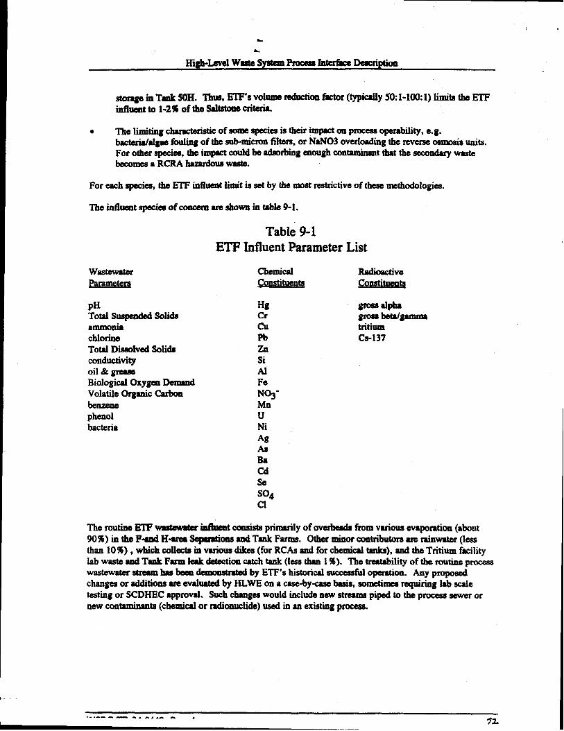
.
Highmwd wa8teSyetemProceaeInterke DeacriptioQ
● ‘me limiting Chamten“sticof some speciesia their impact on proceaeoperability, e.g.bacwridaigee finding of the SU&miLWMfli~, ox NW03 overkdng the rcvemeosmosis units.For other species, the impactcould be adsorbingenough contaminanttthatthesecondary wastebecomesa RCRA hawdous mate.
For each species, fhe ETF influent limit is set by the most restrictiveof these methockhgiea.
The influeat specku of c0nc8m are shown in table 9-L
Table 9-1ETF Mluent Parameter List
wastewaterParameter
pHTotal Suapmded SolidsammoniachlorineTotal DISSOhfd solidsconductivityoil & greaseBiological oxy~ DemandVolatile Organic Carbon
phenolbacteria
chemical RadioactiveConstituen~ Conatttuentq
.
Hg gross alpheCr gmaebetdgmunaCu tritiumPb CS-137ZnSiAlFeN03-MnuNiAgAaBacdSeS04c1
Theroutine ETFwasteWW iaftuakt consists primady of overheadetiom varioue evaporation(about90%) inthe Fund Ha Se@retioneand Tenk Farms. Other minor contributoraare “Mmwater(leesthan 10%) , which collects in various dikes (for RCASand for chemical tanka), and the Tritium fmilitylab waste and Tank Farm leak detection catch tank (leas than 1%). The treutability of the routine processWaatewateretreemheabeen Ammkmtd by ETF’s historical successfidoperation. Any pmpoaedchangeaor additions are evaluatedby HLWE on a case-by-casebsek, smmtimea requiring lab scaletesting or SCDHEC approval. Such chengeawotdd include new stream piped to the process eewer ornew contaminan?a@emical or radiomwlide)used in an existing procees.
. . ---- —.4 J.. .-m. 7%

.
WSRC-TR-94-0442, Rev. 1 73
High-LevelWasteSystem~ Interfke Desm@tion
9.3.2. Diverted Cooling Water and ~~verted Sbm Water--InterfaceStreams 17 and 18
AS described in “9.2.2. DivertedWaterBasins,” coolingW- and storm water am be diverted to theETF basins. Subsequentsample rcaukafrequentlyshow that the diverted water actually meets thedischarge limits and then it is dischrged to a NPDES outfall (se@“9.4.3. Clean Basii Water”).
RS&oactively contaminatedcoding water or storm waterwhich has been diverted to the baaiDEcan beSentto them treatmentplant. Historically, such diversionsoccur infkqwmtly, and the actual isotopesand ~ ‘onsdepend oethesourceofccm~ “on. This variety requires that HLWE evaluateeachdiversiononacase-by-casebashinordertodekndneproperhandling.
Mstorically, the bacteriahlgae in basin water has severely ftied the ETF filtration process. If the basinwater were chemicallyContdnated , thea SCDHEC requireuthat they approve specificpkns fortmabwnt.
With two additions, the methodologiesdescribedin “9.3.1. Evaporator Overheadsand Other LowLevel Streams-Interihce Stream 13” also apply when evaluating the ttillity of kin water. First,the treatment plant influent compositionis limited by the alhwabie radiation dose rab, since the processequipment is essentially unshielded. Second, if the evapomtor botkmw resulting from treatmeat of aparticular basin water is too contaminatedfor Saltstone, thea that concentratecan be sent to StorageandEvaporationvia HDB-8 (see section “9.4.4. Highly Con otammamdBasin Water-rnterfsce stream 19”).
If the basin water is too highly contambatd for the treatmnt plant, thea itwill be sent to Storage andEvaporation via HDB-8 (see section “9.4.4. HigMyCorItdnated Basin Water-TnterfaceStream i9”).
9.3.3. Raw Materials and Lab Reagents
Aluminum nitrate andlor ferric nitrate are used to impmve fikration performancewhen needed,especially for high bacteria influenta(e.g., baaii water). Nitric acid is used for pH adjustment and tomake sodium nitrate regenersnt for the ion exchangestep. Sodiumhydroxi& (caustic) is used for pHadjustment, to cla,process equipment, to inhibit the ETF concentratestream to meet Tank 50Hcorrosion requirements, and to make sodium nitrate regenemntfor the ion exchangestep. Both oxalicacid and b[each(di[ute NaOCl)are used to ckan process equipmeut. After use, vshms ETF iab reagentsareadded into the ETFw@ewatw iufiuent stream.
9.3.4. Unusual and unique Wastes
HLWE will perform a case-by-caseevaluationof each proposed waste stream using the samemethodologies and criteria described in sections9.3.1 and 9.3.2. Such evaluations will be reviewedandapproved before waste is accepted. bboratory testing and SCDHEC approval are likely to be required.Depending on the contaminant species, the waste can either be processed through the entire treatmentsequenceor it can be routed dimctiy to the ETF evaporator.
&
High-Levd WaateSystemPrece4arntedke Dmcnption.
9.4. Effluent Streams and Key Process Controls -
9.4.1. Treated Effluent--lnterface Stream 14
Atlerthe ETFinffuent isproeesad tbroughthe~ of tmatmmt !?@adescribed abOVe,the treatedeffluent strewn is analymd and diachrged through NPDES outfall H4116to Upper Three Runs Creek.The efthwnt’s chemiul content is controlledby the ETF WaatewaterPermitn and the dischargemdiomdide Iimitaam aa4by DOE order 5403.5~ and WSRC’SALARAprogram for efflud b.
9.4.2. ETF Concentrate--Interface Stream 15,
Ihe amtaminantavvhich ETFremovettffomtheinfluemt atreamamConcentratedinto 1-2% of theoriginal volume. This eqmator bottoms concentrateis then pumped to Tank 50H for eventual disposalin Saftstone, see Chapter 10. Su!Ticieatcorrosion inhibitor (NaOH) is added to meet the ITT requirement(administratively, ITP opemtes Tank SOH). Other aapectaof the streamcomposition are mntroiled byITP’s Pmc.essRequiremeata. Aa discussedin “9.3.1. Evaporator Overheadaand Other Low LevelStreama-Interfhce Stream 13,” theeeSaltstonecriteriaare mst by limiting ~ ETF influentComposition.
Short term conqmsition s@keswill be bkded into the t- vOiuXWmaintained in Tank 50H (S0-1230Kgal), relative to the small flow fkm ETF (-5-20 Kgalhnonth fix the past 5 years). Two slurry pumpshave been inatalhd in Tank 50H to eaaurecompletemixing. The minimum level in Tank 50H iscontrded by the lTP ProceaaRequiremeata,both to dampmtout composition swings and to allowadequatecoding fw ~% high tenqteratureconcentrate.
If the radioactive amtmination level is too high for Sakatone, then the concentratewill be simt toStorage and Evaporation via HD3-8 (not yet in service), see section *9.4.4. WlghlyContaminatedBasin Water-Tnte&ce Stream 19.” If the chemicalcontent is unsuitable for Saltstone, then SCDHECapproval is needed fbr any alternatediapoaition.
9.4.3. Clean Basin Water
As described “9.3.2. Diverted Cooling Water and Divetted Storm Water-Interface Streams 17 and
18,” cmlingwateror storm water whichhaa bees diverted to the ETF basins is analyxed. Frequentlythe basin water is suitable for&charge through a NPDES outfhil (F-012, F-013, H-017, or H-0i8depending oa the particular baain) to Four Mile Creek, in accordmce with the ETF Wastewater Permit.mThe discharge radioQucli& iimita are set by DOE Order 5400.5” and the WSRC ALARA program foreffluent doaeu.
9.4.4. Highly Contaminated Basin Water--Interface Stream 19
If the radioactivecontent of the basin water is too high for the ETF treatment plant, then it @l be sent toStorage and Evaporation via HDB-8 (not yet in service). Due to the variety of compositions possible,such routing will be evaluatedby HLWE on a case-byase basis. A suitable amount of corrosioninhibitor (NaOH andhr NaN~ would have to be added at some point in the transfer. A large volumeof contaminatedwater would probably be involved in any diversion and could consume a large fractionof the Tank Faxm’aspare volume available.
WQRO-TR .QAJIAA9 DMD 17+

&
&
High-LevelWasta systemProfxaaInterfkxDesixiption
If the cbemicsicontestof the baaiD* is ~i~io fti Em, ~ SCDHECapprmwi is needed forany alternate disposition.
9.4.5. Highly Contaminated Evaporator Bottoms--Interface Stream 20
If the radioactiveconteutof the ETF evapors@rbottoms is too high for Saitstone, thtmit wili bs -t toStorage and Evaporationvia HDB-8 (not yet in service). Due to the variety of compositionspossible,such routing wiii be evaiuatadby HLWEon a caae-bya basis. The normai amount of corrosioninhibitor @aOH) added to the concentratewouid suffice(see “5.3.2.1. Requiremeattsfm CorrosionFreverltion.”).
If the chemicaicontsmtof the ETF evapomtorbottoms is unsuitable for Saitstone, thea SCDHECapprovai is nesded for any alternatedisposition.
10. SOLIDIFICATION AND DISPOSAL (DWPF SALTSTONE\
10.1. Function
The Saitstone Production Faciiity (SPF) snd the SaitstoneD- Facility (SDF) are both located in Z-AnMat the SRS. These Z-b fkcditiesare used tcx 1)process aqueoussalt aoiution waste in the SPF
taily sound matmerinaaabandenvironmm to generatea Low-hwei Waste grout-like wastefoxmknownas SaitstomZand 2) dispose of Saitatoaein a safe and environmentallysound msrmorby piacing thesaitatone in concrete vauits that are located in the SDF. Controls are imposed oa waste sat to Z-Area tolifittitiof_g Z-- b~~ti-Mtiiswn-~.
10.2. Description of the Saltstone Production and Disposal Process
In the Saltstone Production Facility, aqueoussait mlution is received fktm Tank 50H and is thcacombined with a biend of cement,flyashand biaat-furnacesiag to generatenonhaswdw LLW Saitstone(Fig. 10-1). The Sakatonegrout is pumped through a pipeline from the SaitstoneProduction Facility toa coved ceil of an above-grade, concretevault iocated in the Saltstone DiaposaiFaciiity. The groutsoiidifiea into a monoiitbic, nmhardoua solid waste ailed Saitatone. No aqueous waste streams are
t or sent to other facilities from Z-Area.reieaseddirectly to the environment
10.2.1. SaltStone Production Facility ‘=s’”
10.2.1.1. ~
Major @pmeatcompom?atsof the SaMone Production ?%ciiityinclude: (1) buik storage siios for dryfeedq (2) dry fd bkding and trader equipmentthat inciudes the ibnix Feed Bim (3) the SaitSoiution Hold Tank(SSHT)thatmmiveaaqueoussaltsolutiontobe procc=xk(4) the Fiush WaterReceipt Tank (FWRT) that receivesequipmnt flushesand liquids collected in sumpa iocated in Z-Area;(5) a Mixer that bkrtda waste SOMOO(and flush water, when neceamry)with dry feedato producenonhaawdoua Saitatonegroufi (6) ● SahatoneHoid Tank (WIT) that provideaa reaetvoir of grout toprevent cavitation of the grout putnpIK(7) grout pu~, and (8) pipeiii that are used to traosfer saltsoiutions, flush water and Saitatoneput within the production faciiity and grout to the disposal vauits.
WSRC-TR-94-0442. Rev. 1 75

i
sll&dl&n
n
Mixer
Tak
v R8ikamuckUnbadmg
Vedto*A
t

A.
High-LevelWasi%yatemPmCeSaIntake Description
10212.. . . wasteRecem
As presently permitted, all* waste Sentto Z-Afea * - generatorsmust first be transferredto Tank SOH,a 1.3-million gallon tank 1- in the H-AreaTank Farm. Tank 50H thus forms thephysical intertkcebetweea Z-Areaand waste pnemtom. Salt SQlutionsfmm other HLW treatmentoperations in the Effluent TreatmeatFacility (ETF) and the In-TankPrecipitationProcess are transferredto Tank 50H. Salt so[ution is then tmuaf+ from Tank SOHto Z-Areathrough the H-to-Z lntemreaTransfer Line, an undergroundpipeline that is designedto maintaindouble umtainmeut of any wastetransferred through the line.
The Saitstonepmdqction pmcesaissimple. Dry f~ materMs are blendedautomatically in the desiredratio andtransferred pneurnaticailytothe Premix Feed Bii. Premix iatheafdat apmsetmtetotheMixer. Salt solution is also f~ to the Mixer where it is mixedwith the premix to produce SaMtonegrout. The grout is then pumped to the disposalvaults. Except for specialdesi~ considerationsandoperating procedura becauseof the presenceof low levels of radknmclides, the process is identical to aGOIICrStebatch phmt.
Since the Salt Solution Hold Tank and the Flush Water ReceiptTank can contain potentially hazardouscontaminantsand radioactivecontaminants,both tanb are isolated tim the immdiate environment bysecondarycontainment (concretedikes). B-w Z-Area f~ilities are tkigned to ailow contactmaintenance, radbactive contamimmts in waste sent to Z-Areamust be sufficiently low to preveatexcessive radiation exposure to workers in Z-Area.
10.2.2. Saltstone Disposa[ Facility 37*W
BecauseSaitatoneis nmbamkm, the SaItstoneDisposal Facility is designed aas “cxmtroiledrekasewhndfill disposal site. The only hmg-termpoteatial risk to the environment and to the general pubiic isthrough possible de@ation of surfhcewater or gmndWer quality due to a releaseof chemicalorradioactivepollutants from the SDF into surfacestreamsor into the underlying gmundwater. Suchreleaaeeare mitigated by the surrounding concretevaults aud the Sahstone waste form, itself. Final siteclosure will fbrther mitigate the potential long-term risk to the ewi ronment. Monitoring wells areinstalled in accord with permit requirementsto @odicdly monitor the groundwater for cuntaminantathat could be released from the SDF.
10.2.2.1. Dimosal @eratmM Prior to Closurq.
The low concentrationof gamma-emittingisotopes specified for Sahstone allows a delay of backfillingoperations at the SaitatoneDkposal Facility. Minhnal backfilling around the vaults prior to final closureoperation is planned, principally to control surfacewater nmoff and erosion. Thus the SaRstoneDisposal Facility will consist of above-gradevaults during active disposal operations.
Aqueous waste from sampling and laboratory testing in Z-Areaare sent to the FWRT and subsequentlyprocwaed as a part of normal Sahstone production. Solid sampieafmm laboratory testing and f~edequipment from the SaltstoneProduction Facility are simply placed in a disposal vault and covered withSakatone from continuing production operations, eliminating the need to transfer a significant quantity ofsolid waste to another dhqmal site. Job control waste from maintenanceand production operation inradiologically controlled areas (shoe covers, gloves, plastic sheeting, etc.) is the only solid wastegenerated in Z-Area that must be Se& toanother facility for treatmentand disposal.
WSRC-TR-944442, Rev. 1 77
,
High-bvel WesteS*Proceushltedke Dcacriptioa
lo.2J& Site CiossJ@.
Fired closure operations et the Z-Areesito wiil W begin until most (or ail) of the vauits have been fiiiedwith saitstone ad cappsd with ● Ieyerof clean grout. As presmtiy conceived, the OVerailsilo closureconcept is designed to minimizewater infiltration through the vaults that could transport potentiaicontaminantts from the vmdts into underlying gromdwater.
Key elemmts of the cbsure concept iachtde bscktllling with native soil, PIacenwatof a clay cap over thesite to minimim infiltration to tbe vauits, ad placinga graveliayerabovetheciay cap. The gravel iayerwill reduc8tits hydmstatk hod and provide 8 capillarybreak above the clay cap to minimize infiltrationthrough tbe cap. A geotextiiehbric will be placed over the gnvel layer to minimim infiitmtion of fino-paxticlesoil iato the gravei layer fmm additionalnative aoii &et will be piacui over the gravel layer.Shallow-rootedbamkm, a Wminai vegetationremmmendedby the U. S. Soil Conservation Semite, willbephlataioatheaiteto mhdmizeencrdumt by&pootedpiantssucbaspin etreeawhoaerootacould penetrate tbe C]ay cap and thUSiuc!=M idibtbn tiKou@ the waste.
10.3. Influent Stream and Key Process Variables--Interface Stream 6
ASnoted ia Section 10.1, Tank 50H is the physicaiinterfacebetweenZ-Areaandthe restof the HLWSystem. Accordingly, additions to and the contentsof Taak 50H must be monitored to assure thataqueouswaste sent to Z-Ares is within waste acceptancecriterie fix Z-Area.g”’ Pres@iy, aqueouswaste istransf*to Tank50H timthe EflhtentTreat=at Facility (InterfaceStream 15) and the In-Tank Precipitation Fmcess @erface Stream5). Both operations (and Taok 50H) are geographicallybated in H-Area. Administratively, Z-Areaassumesresponsibility for the aqueous waste wbea it entersthe SSHT.WS
Saitsolution sent to Z-Area (IaterfkceStream6) cancontainlow levels of bmudoua substance.However, wmentmb “onaof these conteminantamust be sufficiemtiylow to assure that non-hamdouaSaI_ as defined by mguiatq agenciea,ca bs produced. Controislg are imposed on additions toTank50Htoassum tbattheaqueoua waatewillmeetwaste ~ criteria for regdatory and !.ng-
- Cbaogeato theeecontrols requhe review and approvai by the &tom performancerequirements.Area Facility Manager.
Because of limited radietioa shielding in the SPF, additional matrictionsare imposed on gsneratom tominimize the concentration of radioactivecontaminantsthat emit high-energy gatnmmradiation. I%esentwaste acceptium criteria specify limits for Co-60, Ru-106, S&125, Cs-137 and Eu-154, since thesespecieshave been identified u poteutiai contaminantsin aqueouswaste from the ETF and ITT.Significant cmcdmtiona of other gsmma-etnittingcontaminantsh equeouawaste must be reviewed forpoasibie impec&on radiological saf6tyin Z-h before the weetecan be sent to Z-kca for treatmentand disposal.
Limits imposed by Saitstone require thet the pH of the waste be greater than 10 and the temperature ofthe soiution be ieas then 40 degrees C. Contaminantsthat are monitored by generators in wastetransferred to Z Area are iisted below:
.
WSRC-TR-94-0442, Rev. 1 78—

* ,. >
k
H@-LevdwastesystemProcess Iilte&e D6ecription
Table 104Saltstone Influent Parameter List
MAJOR MINOR CHEMICALS~~ METAL IONS
H-3C-14Ni-59Ni-63
Sr-89/90TC-99Ru-106W-1251-129CS-137Eu-154Pu-241Total Bete/GammaTotal Alpha
HydroxideNitrateNitrite
sulfateFluorideChloride
TetmphenylbaateAhuninat8
PhenolIsopropanolMethanolArseuicBariumCadmiumChromium
MercurySeleniumSilver
The limits inthe Test Authorizationand WAC am set at levels that asaunx 1)prmits for 2--operations will not be violated and 2) ad” ofZ-k operationsandlong-termperfommncewillnotbecompromised.Waategenemtm must provideevidenceofcomplianceWithlimitsbeforead solution canbe tmmfbed to z-h for processing.
Any significant waste componentsnot specificallycovered in cumed waste acceptancecriterie must betested for regulatory complianceprior to introducing Suchcompments into salt solution sed to Tank 50Hand ukimately to Z-Area The significanceof a new waste cmponent is establishedby: 1)potentialprocess hard (CbeMid or mdiolo~) to Tank 50H or Z-AreaopemtiomG 2) regulatory ~ froman environmental rela, 3) inability to producenon—baardowSaltstone,asdefinedby EPA and stateregulations (Saktone samplesmust be prepred and tested, using a range of concentrationsof a newcontaminan~ to establish limits for the wntaminantk or 4) a chemicalspecificallyadded by a wastegenemtor as a result of ● new or changing process in sufficientconcentmtion to impact the properties ofSaltstone.
Any *gee to the waste emqmnce criteria for salt solution transfd to Z-Aree requires technicalreview by HLW “Engner@ end approval of the HLW Level 2 Manager. Becausefacilities in Z-Areaare permitted by the 9teteof South Cerdne, salt solution containingany significant waste componentsnot previously idattified in permit applicationssubmitted to SCDHECcannot be sent to Z-Area fortreatment and disposal without prior approvalby SCDHEC.
WSRC-TR-94-0442, Rev. 1 79
.“. IL
a.
High-bvd wastesyatemPmce+Yskttedke Deatcripticm
I
10.4. Effluent Stream and Key Process Contmls--lnterface Stream 16
Saltstone must be formulatd to meetpermit and long-term@brmance requirements. As noted inSection 10.3, abroad range of dry materialcompoaitionahave bees demonstratedto yieki an acceptableSaltstone product. However, * restrictionsare imposedon the SPF process to assure Sakstone withthe required pmpertiea is producd
1. suffitimt* ~eb*mti~-* *eptionof MwMbSssurethat thepresesweoftkeeliqui& in8vaultdomaotex* t VO1%of themslwastavolum at the tb of vaultclosure.
2. Hamdms waste, as defined by SCDHEC (snd the EPA), cannot IMplaced in the SDF fordiapoaai.
3. The temperatureof the Saltstoneduring curing in the vault cannot exceed90 degreesCUItigmdeto assure long-term inte@y of tbe Saltstone.
4. Radioactivecontaminantsin the waste must be ‘as low as reasonablyachievable”(ALARA) andin no case should the concentrationof individual radhactive contaminsntaexceedthe limitsspecifiedby the Nuclear Regulatorycommission (NRC) fw CtaaaC LLW. WSRC has imposeda goal to assure that the overall averageconcentrationof individual radioactivecontaminants inti_pHkti SDFtil-ex* tiliti&Piti wti~Ctiti A-@.
Testing, procdma, and limits imposedon waste genemtomand in the SPF for the production anddisposal of Saltstone must assure these conditions are met. To confirm these conditions are being met,periodic sampling of Sahstone grout and aubwqwmttesting of curd Saltstoneproduced from the samplesof grout is rsquimd.
Baaedon maulta from tests on various ratios of waste componeataand dry mateMs, the aboverestrictions will always be md with salt solution that meets the Waste Acce@nce Criteria , providing thetempmture of grout -t to ● disposal vaultis acceptable.
10.5. Raw Materials .
Materida used intheproduction of Saltstoneare obtained from off-site vendom. To prod= Saltatonefrom aqueous waste requires tba addition of a blend of cemedtious dry msteriaia. If necemry, a setretardant cau also be added to kilitate production in the SPF and aubaequeatpowing of SaItatonegroutinto a vault cell in the SDF.
A blead of dry ma@als is prepared in the SPF by combininga lime source, Class F fly ash, and blast-thnace slag. Either calcium hydroxide or Class 11Portimd cementcan be used as the lime source in theSaltStoneformulation.
.
WSRC-TR-94-0442, Rev. 1 80
L
A.
,, ●
High-LevelwastesyatemProcess InterhceDacription
11. CONTROL OF HLW PROCESS INTERFACE~
This chapter describes HLW Psuceaaiotedhceain the HLW System. The PID identifies20 intedkesthat wc the basis f~ control of the HLW System(- Figurss 4-1 and 4-2). Theseiatedkceahaveshady bees describedin theprevioussix chaptersdiscussingeachHLWProcess. However, theinformation abou~a specific interfkceis usually in two pkw (e.g.,theExtendedSludge Processingchapter describeshow washedsludge is prqared, whereasthe informationon why the composition ofthis washed sludge must be controlledis in the Vitrificationchapter). This chapter ia orgmized byin~, and identifies the required iatdace control documamfor eachinterface.
The eight tables that follow dsacribe all the significant in-in the high-kwelwaste system. Table11-1describesgatdc interhws that apply to all HI-W~. TabIsa 11-2 through 11-7describe theinterface specificto each of the HLW ~. til~” mterhca are listed, i.e. stream thatcontact the proce8s. streams that don’t contact the process, such aa instrument air, cooling water, etc.,are not listed. If the interfaceis controlledwithin h HI-w System, then the table describss the basis forthat control. If the interfiweis one that is within the scopeof the PID, tha the “Basis for Control=column says, “TntertkceStraun NN (Table 11-8),”where NN is the interfacestream number. Look inTable 11-8 for more information.
Al the identified in- streamsare described in order in Table 11-8. The required in@rfkcccontroldocuments for each stream are listed. TIISdocummts listed are the primxry documents that regulate theinterfkce(i.e. there will ahvays be procedurcaand other docunxmtsthat support the primary documents,but the PID concentratsaon the primary agreementsbetween the two affectedpmcessea).
. --------- .,. ..-s.81

High-LevelWasteSystemProcess InterfaceDescription
Table 11-1: Generic Interfaces That Armlv To All HLWPmcesse~. K J— .-. . ——— ---------
Wltbin Sc4)peStream From To Of PID? Basis for Control
Raw Materials vendors Any HLW OnlyFor New EssentialMaterialSpecificationsor other controls in HLWprocesstecluticdbasditw.(including chemicals MostCbW@S to these will be handed at the HLWProceaalevel. However,Uly awvLaboratory _c~@~*~~yHLW*mmitia-~tiReageuts) Pmc.esaInterfaceDmcriptionandmustberevimld *that levd. Ldwmoryreagents
arerevimed forlevel of risk.Water Power Any HLW No Controlled By Power Dcprtmmt Proce&m
Untwal and Any geaemtor Any fwility Yea Nluddtiqww* -bddbytid*mwh. Ifuniquewastes b-~llktivd kamdtip~, bbk-mtifir
interfaceapplies. If thew8stew be receivedin anUnusioalplace, b rmmgemmtof thatHLWProcessis nxponsible for revimhg tbewastevelaua tlminterhmcontroldocurtwattsand the PID.
Sohd waste AnyHLW Solid Waste No Controlledby Solid WasteDisposalWasteAcce@anmCriteria and HLWProeeaaProcess Disposal HLW waste compliance Plans
ProcessAlr Emtsaioas Any HLW Atmospbcm No Controlledby permits
Processunmonitored .%~yHLW outfall No Controlledby permits or unumtrollcd .Stormwater ProcemAnd codingWater(NotMomtored ForRadioactivityBeforeRelease)
WSRC-TR-94+42, Rev. 1 82. .

High-LevelWsste.System Process InterfaceDescription
●
✌✎
I
Stream From
SamplesTo Any HLWAnalytical ProcessLaboratoriesGroundwater Any HLWEgressFrom ProcessHLWPmceas
●
Within ScopeTo Of PID? Bssis for Control
laboratories No C!a@rolledBy Site Manualsand AnalyticalPmcehrea
Grotmdwater No May be controlled by Permitsand may impactinterfacedocumentsthat am within thescopeof tie PID (e.g. Saltstone),
WSRC-TR-94-0442,Rev. 183
.,

High-LevelWasteSystemProcess InterfaceDescription
Table 11-2: Storaizeand Evaporation Interfaces*-Within Scope I
Stream From To Of PID? Basis for Control1
Generic Any geaerator SeeTable 11-1Streams(SeeTable 11-1)Incoming waste storage Utd Yea lnterfiaceStream 1 (See Table 11-8)wastes Generators Evaporation
(IncludingWMMaintenanceFacility,299-H)
spent Sludge Storage and Yes InterfaceStream3 (SeeTable 11-8)Washwater Processing EvaporationFrom SludgeProcessingDWPF Vitrification Storage and Yes InterfaceStream 10 (SeeTable 11-8)Recycle EvaporationHighly ETF Basins Storage and Yes Interfke Stream 19 (SeeTable 11-8)contaminated EvaporationStormwaterOrCoolingWaterHighly ETF Storage and Yes InterfaceStream20 (See Table 11-8)
contaminated Tr@ment Evaporation
ETF Plantconcentrate
WSRC-TR-94-0442,Rev. 184
.
:
●
t

High-Level WasteSystemProcess InterfaceDescription
Within ScopeStream From To Of PID? Basis fir Control
Sludge Storageand sludge Y= Inter!kceStream2 (SeeTable 11-8)Evaporation Processing
Salt Solution storage awl In-Tank Yes InterfaceStream5 (SeeTable 11-8)Evapomtion Precipitation
Evaporator storage and ETF Yes InterfaceStream 13 (SeeTable 11-8)Overheads EvaporationDiverted Stolage and ETP Basins Yes InterfaceStream 17 (SMTable 11-8]Stormwater EvaporationFromMonitoredzonesMonitored Storage md outfall No Storageand EvaporationProceduresStormwater EvaporationThat 1sCleanWastewater Storage aud sludge No Coatmlled by Sludge Pmcessiig Baseline. Any streamis aweptableas loag asUsed For Evaporation Processing ExtendedSludge Pmussing baselineand &mma@aminterfiscorequiremmtacan beWashing (originally m.
comes fromRBOF, DWPFRecycle,
)MercuryFrom Mercury separations No Controlledby StorageandEvaporationBaseline. Streamis very low volumeEvaporators Collection C.anyona (maximumof a few literspermonthsfromall evaporatorscombined),e.g.
Tanksand comparableto Laboratorysteams,whichamcontrolledoutsideof scopeof PID.HLWEvaporators
WSRC-TR-94-M42, Rev. 1 85

High-Level WasteSystemProcess InterfaceDescription
Stream
Genericstreams(seeTable 11-1)Salt Solution
spentWashwaterETFCoflcentnlte
Table 11-3” In-Tank Pr
From
Any generator
Storage andEvaporationVitrificationIbte wash)
T~tPlant
SaltstoneFed
PartiallyWtiPrecipitateDivertedStormWaterFromMonitoredZones In ITP(Part of TankFarm system)MonitoredStormwaterThat 1sclean
ITP (Tank50!4)In-TankPrecipitation
Runoff FromIn-TankPrecipitationTanks
Runoff FromIn-TankPrecipitationTanks
cipitation (I
To
In-TankPrwipitationIn-TrekprecipitationITP (Tank50H)
SaltStone
Vitrification(LateWashing)ETF killS
outfall
‘P)InterfaceWithin ScopeOf PID?
Yes
Yea
Yes
Yes
Yes
No
,
Basis for Control
SeeTable 11-1
InterfacaStream5 (SeeTable 11-8)
interfaceStream8 (SeeTable 11-8)
ItIterke Stream 15 (SeeTable 11-8)
InterfacaStream6 (SeeTable 11-8)
InterfaceStream7 (SeeTtile 11-8)
Interfaeostream 17 (SeeTable 11-8)
Tank Farm and ITP Proeadums
WSRC-TR-94@142, Rev. 1 86
a
I
?

High-LevelWasteSystem ProcessInterfaceIkwxiption
Table 11-4
Stream
Genericstreams (seeTable 1l-l)Shldge
WastewaterUsedForWashing
spentWashwaterWddSludgeDivertedStormwaterFromMonitoredzones 10SludgePmcessiig(Part Of TankFarm System)MonitoredStormwaterThat ISclean
Extended $
From
StorageandEvaporationStorageadEvaporatkm(originallyCoumJFromRBOF,DWPFRecycle,others)
sludgeProcessingsludgeProcessingSludgeProcessingTanks
Runoff FromSludgeProceedingTanks
udge Proce
To
Pro&ssingShdge
StorageandEvaporationDWPF Glass
ETF Basins
outfall
!@2z!L!Within ScopeOf PID?
Yea
Yea
Yes
Yes
No
terfaces
Basisfor Control
SeeTable 11-1
InterfaceStream2 (SeeTable 11-8)
Controlledby SludgePmceaaing Baseline. Any streamis acceptableas long asExtendedsludge ProceAng basdine and &wn#mem interfacerequirementscan bellW
InterfaceStream3 (SeeTable 11-8)
Intedke Streun 4 (SeeTable 11-8)
InterfaceStream 17 (SeeTable 11-8)
TankFarm and ESP Procdures
r
.
●✎
☛
r
WSRC-TR-94-0442,Rev. 1
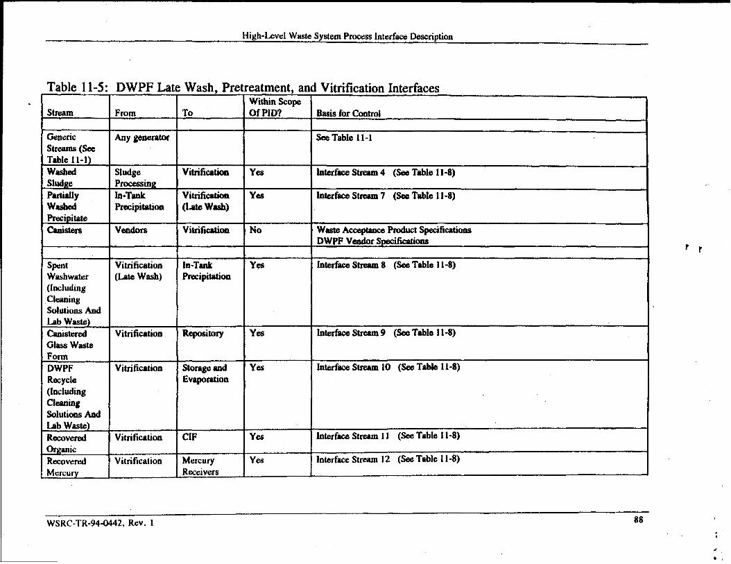
High-Level WasteSystemProcessInterfaceDescription
Table 11-5: DWPF La(.
Wash, Pre eatment, a]Within Scope
IVitrification Interfaces
Stream From To Of PID? Basisfor Control
Any generator See Table 11-1Genericstreams (seeTable 1l-l)washed VitrificationSludge Yes InterfaceStream4 (See Table 11-8)Sludge Processing
In-Tank InterfaceStream7 (See Table 11-8)pallidlywashed
Vitrification(LateWA}
YesPrecipitation
PrecipitateCanisters WasteA_ce Product Specifications
DWPF VendorSpecificationsVitrification Novedors
rr
InterfaceStream8 (See Table 11-8)SpncWashwater(kludmgCleaningsolutions AndLab Waste)CanisteredGlass Waste
Vitrification(Latewash)
In-TankPrecipitation
Vitrification Repository Yea InterfaceStream9 (See Table 11-8)
FormDWPF InterfaceStream 10 (SeeTable 11-8)YesVitrification storageand
EvaporationRecycle(IncludingcleatingSolutions AndLab Waste)RecoveredOrganicRecover&Mercury
InterfaceSt~m 11 (SeeTable 11-8)Vitrification CIF Yes
InterfaceStream 12 (SeeTable 11-8)Vitrification YesMercuryReceivers
WSRC-TR-944M42, Rev. 188
..

High-LevelWaste SystemProcessInterfaceDescriptiont
:rfacesTable 11-6: Effluent Treatment Facility (ETF) InWithinScopeOf PID?Stream From To Basis for Control.
Sea Table 11-1Genericstreams(seeTable 11-1)EvaporatorOverheadaAnd OtherLow-Levelstreams
DivertedStormwater
DivertedCoding Water
TreatedWaterEffluentETFConcentrateCleaoDischargesFrom Basina
Highlycontaminatedcooling waterOr StormWaterHighlyContaminatedETFContentrate
Any generator
StorageandEvaporation,F&HCaayona, AndOtherFacilitiesStomgeandEvaporation,lTP, ESPF&HCanyons
Yea IntertkceStream13 (SeeTable 11-8)ETF
ETF Basins
ETF Basins
Y@? Interfke Stream 17 (SeeTable 11-8)
?rYes InterfhceStream 18 (SeeTable 11-8)
ETF ETF Outfall InterfaceStream 14 (SeeTable 11-8)No
ETF Tank 50H interfaceStream 1S (SeeTable 11-8)Yea
NoETFBaaioa ETF Outfall ETF InternalProceduresETF WaatewaterPermits#14218 And 14219Chemicalconatitwmtacontrolledby NPDES Permit SCOMM175Radioactivecomponentscontrolledby DOE5400.5InterftaeeStresm19 (SeeTable 11-8)ETF Bash Yesstorageand
Evaporation
InterfaceStream20 (SeeTabie 11-8)Yea‘ETFTreatmentPlant
StorageandEvaporation
.-WSRC-TR-94-0442,Rev. 1
BY
. .

High-LevelWaste SystemProcess InterfaceDescription
Table 11-7: DWPF Sal
Stream I From
stone Interfaces
~
+
m
LalxUlll No
Bash for Control I
SeeTable 11-1
InterfaceStream6 (SeeTable 11-8)
IntorhceStream16 (SeeTable 11-8)
r r
WSRC-TR-94-M42, Rev. 190
.,
I
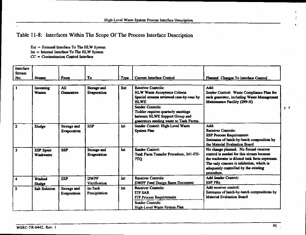
High-Level Waste System ProcessInterfaceDescription
Table 11-8: Interfaces Within The Scope Of The Process Interface Description
Ext = External InterfaceTo The HLW SystemInt = Internal InterfaceTo The HLW SystemCC = ContaminationControl Interfsee
E-1- 1... IT. l,- I-*.ti=titi, I,**[email protected].,.*ti,mInterface
1 Incoming An storageand Ext ReceiverControls: Addwastes Gmfxdora Evaporation HLWWasteAcce@nm Criteria SenderContmk WasteCompliancePlan*
Specialstreamsreviewedcase-by-caseby eachgenerator,includingWasteMsqpmmntHLWE Main@anm Facility(299-H)senderControllxTickler requirss quarterlymee$ingsbetweenHLWESupportGroup andgeneratorssendingwaste to Tank Farms.
2 Sludge Storageand ESP Int Sader Control: High-hel Waste Ad&Evaporation SyatmnPlan ReceiverControls:
ESP ProcewtRequirermattsEstimnteaof batch-by-batchcompositionbythe MaterialEvaluationBoard
3 ESP sped E.SP storage ad Int sender Control: No ChM@_ No fornud -V=Washwater Evaporation TankFarmTransferProcedure,241-FH- eontmlis nsededfor this streambecause
7TQ thewashwateris dilutedtankfarmsupemate.TheOnlyconcernis inhibition,whichis/td@@dy contded by theexi~procedure.
4 Waahed ESP DWPF Int Receiverfhrttrols Add sealderCQntrok
sludge Vitrification DWPF Feed DesignBasesDocun.wmt ESP PRS
5 salt solution Storageand Ln-Tank Int Receivercontrols: Add receivermntrol:
Evaporation Precipitation ITP SAR Estimatesof batch-by-batchCOMpOSitiOIIS byITP ProcessRequirorr@s MaterialEvaluationEoardSenderControlsHigh-LevelWasteSystemPlan
WSRC-TR4442, Rev. 1 91. ,
rr
‘s

High-LevelWaste SystemProcessInterfaceDescriptionInterface 1
StreamNo. Stream From To Type Current Interfac8Control Pianned changes To InterfaeeControl
6 SaMone lTP Saltatone Int ReceiverContrdx Add S&tone wasteAcceptanceCrkrhFeed (Tank 50H) SaitatoneWasteACceptaneecriteria
Seder Controls:ITPProcessRequirements
7 Partially In-Tank Vitrification (Late Int ReceiverControlswashed Precipitation Wash& DWPF) DWPF Feed Des&I BasesDocumentPrwipitate SenderControl:
ITP ProcessRequirements8 Late wash DWPF In-Tank Int ReceiverContrrk sendercontrol:
spent Vitrification Preeipitation HLWWAC Developa LateWashWasteCompiianeePlanWashwater (Late wash) SenderControk
None9 Canistered DWPF Repository Ext ReceiverControls: No Change
Glass Waste Vitrification DOE Waste AcceptanceProductForm Specifications
SenderControls:Waatcformcompliance PlanWaste Aceqtanca llef~ Maoual
10 DWPF DWPF storage and Int ReceiverControl: HLWWaste SenderControl: DWPF Waste ComplianceRecycle Vitrification Evaporation AcceptanceCriteria Plaq
SenderControls:None (PRs are existingbut plans am toreplacethorn)
11 Recovered DWPF Consolidated Ext No receivercriteriaarecurrently ReceiverControl:Organic Vitrification Incimyation available. CIF WasteAcceptanceCriteria
Facility (CIF) SenderControl:DWPF WasteCompliancePlan
12 Recovered DWPF Mercury Ext No approvedcontrolsat this timeMercury Vitrification Receivers
WSRC-TR-94-M42, Rev. 192
rr

,. .
.
7>4
.~
p d-Wfk
*. Go

High-LevelWasteSystemI%oceaainterfaceDescriptionInterfaceStream
. No. stream From To Type current Interfacecontrol Planned @angea To InterfiweControl
19
20
HighlyContaminatedCoolingWater OrStorm WaterHighly
ETF
ETF Baains
ETFTreatmmtPlant
storageandEvaporation(Via HDB-8)
storageandEvaporation(via HDB-8)
cc
ReceiverControl:HLWWaateAcc@mce CriteriaSenderand R-iver Control:Reviewedcaae-by-caaeby HLWE
Rew3iverControl:HLWWaste Acceptance CriteriaSeder aud ReceiverCXMItrol:Reviewedeaae-by-csseby HLWE
No Change
No Change
\
r
QA
WSRC-TR-94-0442, Rev. 1,.

A.
&.
High-Level wastesystemFfoce#ahterhce macnptl- “00
12 DEFINITIONS AND ACROM~
CIF-Conaoiidated Incinadon FaciIity h kcimmtw fhcilitynow undercmstrudonin Harea. Theti_rtill ti-md~of~* oXctimti D_ iuaddition tomanyothefincinerablestreams at SRS.
DOE-(The United States)Dqutme@ of Eneqy
DWPF-Def” Waste Rmeshqf Ftt@i@ w HLWpfoceaain which~ly washedprecipitateand WSShMisludge am converted irlto a hdicata glaasinacmiated gIaaa waatef~ % Chapter 8.
ESP-Extended Sludge Rocemhg llw HI-w PIOC=Sk tid tie tilale shdgea am washed and in whichSom Sludga are treatad to remove aluminum mmpouda. k _ 7.
ETF--Effluent TreatmentFaciKty The HLWprocessthatdacoamminataknv-hweiws&lmemso thatthey canberekaaedto themhnmsal t. seechaptsr9.
F- olM30ftkp mcesaiogareaa atthe SRS. The F-araa Taok Parm, which isonepartofthe !korageandEvaporate Procesa, iain Fs See Cha@er5.
FederalRepoaitoFYA g~lo@ raimaim *g *4* by * F* gov~t foratonge of highlyAioactive Waatea,primarilyb DOEhigh-levelWaateeandepelltnuclearfilel fknn cotmmxcialpowerreactors. OncetheFederalRepositoryis cmWmctdalld etaItedup,plsnaamtosemd the Caaie@dGlass Wasteformto therepositoryfbrfinaldispoasl.
FFA-Fedcd Facility Agreem@ A compksive documemtsigned by EPA, SCDHEC,midDOE describing
Irma
how CERCLAwaate sites at SRSwiUbemsoagcd ‘l%eFFAhsaasection mtthe Tank Farmathatdescribeahow the Tank Farnmwillbe regulated, eetSfbfth=onduycm~ criteria fbr high-levelmti, dtitia~-ticlmof ti-~-=~.
oneofthe Pm@saiM araa at SRS. Tbe H- Tank Farm-which includes ITT, ESP, and the H-srcapartoftheStomge ~Evapomtion Mceaa--is locatadin Hama. See Cha@era5,6, aMi7.
High-Level WasteRoceeaOneof eix pmeaaea thatmmpriee the high-level waste system. The six HLWMcessaeam
1) High-Level Waste Storsge and Evaporation (F- and H-era Tank Farms)2) SaltMceedng (Is-Tank precipitation)3) Exteadsd SIudgeFmceaabg4] Vitrification (DWPF Late Wash, P@mabmmt, and Vitrification)5’)W~Treutmmt (EffiuaatTmatmeutFacifity)6) solidification (DWPF Saltstone)
High-LevelWaste SystmI The satof six HLW ~, intemmnectul by pipdiaes, thattreathigh-levelwaateareceivedin F and H - at the SRS. Together, these six HLW ProceuM fimction aa one largetreatment plantthattrata high-levelwastesandconvertsthemioto fmns suitabiefor tlnd disposal.
95

.- ●
✍✍✍✍✍
Hi@t-LevelWaisystemPmeeilsM4’face Description
~h-hvd wastesy9tLSU~ A dOCW13d&It (kSdeS theOVd @tt for rernov@ thewastesfrom
Storage and Evaporationand pmceu$ingtis waste though the HLW System.
HLW-High-Level Waste The highlyradioactivewastematerialthatrssultsfromthe repmcessingofspentnuckarM, inciudiig liquidwasteproduceddirectlyin reprocessingandanydid wastederivedfromthe liquid, that containsa combinationof transuranicwaste and fission products in concentrations
rmanent isolation.” (DOEorder S820.2A) Most of the wastes receivedinto the Tank Farmsrequiring peare High-Level W-.
HLWM-High-Level Waste Management DivisioII The WSRC Division chargedwith operating the HLWSystem.
HLW MaterialEvaluation Board Aboard establishedby theHLWMdivision ChiefEngineerto estimatethecanpositionofbatcheaofwasmtobe seitttotheDWPF. ,
HLW Storage and Evaporation Process (F-& H-area) Thosepmceasingareasin theF-andH-AreaTankFarms dedicated to safe aod enviromnentally sound storageof High-LevelWaste. Within the H--Tank Farm are tanks dedhted to other purposes, SpecificallyIn-’MkPrecipitation and Extended SludgePmce$sing. see Section5.1.2.
IcD(IcDs)-rllterfalx!controlDoctmwnt(s)A document(s)describingthemethodof controllingthe interfacebetweentwo HLwProcessesor betweensHLWProcess andattextemal process.
Interface A boundaryintheHLW system through which wastesare exchangedbetween HLW Processes or
betweenaHLWProcew anda3texternalprocesa.
XTP--In-TankPrecipitation TheHLWProcessin which aupmate is decontaminated. See Chapter 6.
LWF-La@ WttShFacility One of the DWPF ~, in wkich the @iaily washed precipitate from ITP is
fully washedMom beiig senttotheDWPF Vitrificationbuilding. See Chapter 8.
PID--(High-LevelWaste System) Recess InterfaceDescription Adocument describingthe cmtireHLWSystemin termsof its missiott. The doeunmt treatstheentireHLWSystemas one largeprocess,andidentifies&eWti4tifam_g@ktiW~tiHLW~m insure thatchange3withbroadimpactareadquately communicated,reviewed,andcontrolled+
RCRA-Resource Conservationand RecoveryAet An Act thatregulatestheoperationof ~us wastefacilities and other aspects of high-levelwastemanagement.The otdy facility in the HLW System that isregulated by this law is Tank 16H, which is the subject of ● RCRA f=ility investigation.
Sarea Theprocedxg -at SRSthatcontainsthe DWPFVitrification building (221-S).
Salt (Sakcal@ The solubtesake io high-levelwaste. Salt plus water comprises supemate. When the supemateis concentratedin an evaporator and sent to a waste tank, the salts precipitate because of their highconcentration and form ● light-coloredcrystalline sahcake.
SCDHEC-South Carolina Departmentof Health and EnviromnemtalControl The regulatoryagency that hasprimaryenvironmentalauthority over the HLWSystem.
SIIMP-System ktegmtion Management Ilan A HLWM division guidance that describes how the PID, theHigh-Levei Waste System Plan, and the High-LevelWaste Integrated Fknvsheet Model are used andmodMed, and how these documentswork together to control the HLW system.
I46
HigMavel Waatt’&tentPtucau IuWf&2eDaac@km
SRs-sa- Rha’ site
Supernate In a waste receipt X the clear salt solution mmainiagin thetopoftha tankafterth einsdublesludgaeorsalts bavesettled tothebottcnm Alsousedto reWtoanyclear liquid inawaste~incl*aak rcceipttmka aadwapo@orfaedtanh
Stotage and Evapomtion See “HLWShxageandEvaporations
Tank Farma(F-and H-are@ Thoaepmesaiq areasat SRSthatcantaiuthehigh-leveiwastetanka. ~eF-areaTank Farmumtains partofthe StoragedEvapomtion Proceu. The H-ameTank Farmcontaina ITP,ESP, andthercst of the S~aad Evapomtioe Proccaa.
TechnicalBa@ina Fora particularHI-WProcass,theTecbnial Eaaelinais all documents,includingall dittydocumrmtatioa,usedto iddi$, justifjf,anddmmmatethephyaical, bctioml, oroperationalrequkelm!mtsof stmcmre, systems,andcomponaats(WSRCE7, Procedure1.02). The InterihceControlD-~h=&titi tiP~-@ofti ~-tifi@=W~.
T~--(FfLW) Tachniul OvernightStearbg Taam Ateamchairedby tbs HLWMDiviaionCbiefEagimexdm~ofti~WW_ghe13~d~E~WM~ ‘rhetcalnismsponaible for ovemaeingall of the technicalactivities m the HLWM division, which include chaagea tothe PID, the High-Lev4 Waste SystemPlan, die SIMP, the TechnologyProgram Plan, and the High-Level Waste In@rated FIowshe&Model.
Usfy)-unmvkvndSafety@aafiUUMadnatkAprocessibrckrmumg“ “ ifa UnreviewedSa&tyQueatioQexists tbr● particularityactivityor conditioa,andwha&arDOEapprovalis requiredforimple~ting thechaage.
WAC WaateAccepmceCrltah An ICDwrittembythere&vimgmgmimtkdemcribing thepwmwem(e.g. imposition, flow, tqmture)that mustreconsideredirIrcceiviagthewasteaad rMnirlgcriteriaforaco@mceofthe waate*
WAPS (DWPF)WasteAcceptmMProductSpecificatima--ADOE ~t describingthe requiremrmtsfor theCabtemd GlaaaWastefmntobeaccc@ad intothaFexkralRepository
WCP-Waste CampliancaPlam An ICDwrittcmbytheamdingmy@zation describiIIghowthesendingOqpbtion will mama thatit ia in complii with the WACof the raceivingoaoa.
wsRc-wdil@mleS8vultmh Rim companyThe primly am~ fiwOpatioa of SRS.

.
k
f3. REFEREiUCE~
1.
2.
3.
4.
5.
6.
7.
8.
9.
10.
11.
12.
13.
14,
15.
16.
17.
!.8.
19.
’20.
21.
22,
W. L. Poe, ‘Leakage from WasteTaok 16; Amount, Fate, and Impact,” X)P-1358,November 1974
code of Federal Reguiatioas, Title 40, Part 264, “TSDFacility S~,” Subpart J, “TankSystems,’264.193, “Containmentt and detectionof releases”
EPA, SCDHEC, and DOE, ●Federal Facility Agramant under section 120of CERCLA and 3008(h) and6001 of RCRA,” EPA AdministrativeDocket Number 894M-FF, EffkctiveAugust 16, 1993
EPA and DOE, “FederalFacility COmPli=e AgreemaK,* EPA AdministrativeDOCWN*r 914 M-FFR,EPA ID Number SCI 890008989, Effective3/13/91
H. D. Harmon, ‘High-Lewd Waste ManagementTechnologyProgram Plan, ” HLW-TEC-94MJ20,Rev. O,31 October 1994
High-Level Waste System plan, Rev. 4, HLW-OVP-94-0415,30 November W94
‘As-Buik construction Permit Applicationfor an IndustrialWasteTreatment Facility for the F- and H-areaHig&Level RadbmctiveWaste Tank FaraM.”Rev. 0, April 1991
“WasteAcceptanceCriteria for High-LevelLiquid waste Transfbrsto the 241-F/H Tank Farms,= X-SC-G-00001, Rev. 1, March 1995
A. S. Barab, “DiscontinuingTransfw of Silver compounds to 242 waste Tanks,” (Unnumbereddocument)30 September 1970
P. D. d’Entremont, ‘High-Level waste characterization in SUPPMof Low Level Waste certification:Qter VT-PhysicalK2hemicalCharacterizationof Solid WasteGenem@din High Level Waste Facilities,-WSRC-TR-!W0393, Revision 1, 19 August 1994
M. Hawkins, ‘Listed Waste in HL Tanks BackgroundInformation,” ESH-FSG-90007, 7 February 1990
J. S. R-, “Listed WasteFrom Laboratories-Tiger T=n Finding WIWBMP+5.“ ESH-FSG-900315, 29May 1990
“AcceptanceCriteria for Aqueous$Wste sent to the SaltStOCISproduction Facility in Z-area,” DR4FTprocedm 3.14 in 1SManual
N. D. HutSonand R. A. Jacobs, ‘DWPF Feed~ign Basea,”WSRC-TR-934133,Rev. O, March 9, 1993
“SafetyAnalysis Repoxt, Savaaaah River Site, Liquid RadioactiveWaste Handling Facilities, Addendum 1,Additional Analysis for DWPF Feed Preparationby In-Tank Pmcessiig,’ WSRC-SA-15, Rev 6, December1994
“DWPF Was@Form Compbce Plan,” WSRC-IM-91-11641,Rev. 2, June 1993
J. P. Ryan and R. E. Stimaon, “TechnicalData Summary, F/H Eftluent Facility,” DPSTD-84-I 14,December1984
jwnal Saf~ Requirements, 241-82H Control Room,* WSRC-RP-94-303, Revision 2, 15 December
“ProcessRequirements, 241-82H Control Room,● WSRC-IM-91-63,Revision 3, November 1994
‘Safety AnaIysis-200 Area, Liquid RadioactiveWaste Handling Facilities, ” DPSTSA-2MP1O,Sup-18,August 1988
‘Technical Standarda, Waste Tank Farma,- DPSTS-241-3.01, May 15, 1988
M. C. Chandler, “HLW Criticality Safety Program Plan,” Rev. O, HLW-HLE-9443385,February 22, 1994
‘91
High-bvd wMteSystemProces6rntedkeDescription
23.
24.
25.
26.
27.
28.
29.
30.
31.
32.
33.
34.
35.
36.
37.
38.
39.
40.
WSRC-RP-94-1 12, “ESPWaahw@wDisposal Options,- L. 0. ~anyn, JanwuY25, 1994
“13WPFLate Wash Facility,” WSRC-RP-92-793,Rev. 3, Febraury M94
DWPF Air Emission PenniL 00W-0066-CA,South CarolinaDep@ment of Hedtb and Environmmtalcontrol
DOE Offb of Enviromneatal Restorationand WaateMansgma@ “WasteAcceptanceProductSpecificatioaafa Vitrified High-LeveiWsateFmma,” Rev. O,Feb 1993
“WaateForm QualificationRepmt,” WSRC-fM-92-21&X(X = W~Uttf4!nund@
Waste Acc@ance RefenmceMan@ , WSRC.4M-9345
DWPF RecycleW8stcCompliancePlan, to be developed
HLW-OVP-95-0010,Revision O, “High-LevelWaateManagementSystem Integration ManagementPIan,=
SCDHEC Wastmder Permits 14624, 13105, 12870, aad 14020.
SCDHEC Wsatewa& Permit sCt3000i75
DOE Order 5400.5, “Radiition Protection of the Public and the Environment”
*Safety Analyais Z-- Savannah RiverSiteSaltatonCFacility,” WSRC-SA-3, DOE Review Draft,September 1992.
J. R. Fowler, “Juatific.ationfor ContinuedOperationof the SRS SaltatoneFacility (Z--),” WSRC-RP-92-444, March 31, 1992.
Test Authorization, “Transf- of Salt Solution from Tank 50H to Saltatone,”WSRC-OX-89-15-001(Rev. 5)
C.A. Langton and D.G. ThO_, ‘ConceptualZ-Area Cap and SecondGeneration Vauit Design (u),’WSRC-RP-90-992,We@inghouaeSavannahRiver Compmny,SavannahRiver bbmatory, Aiken, SC(October 12, 1990).
J. R. Fowler et al., ‘RadiologicalPerformanceAsaesamentfor the Z-Area Sal@toneDiapoaalFacility,”WSRC-RP-92-1360(Rev. O),December 18, 1992.
ETF Hazard Aseaammt Documeat, WSRC-TR-934)31, Rev. 1
ETF saf~ AaaesamentDocument, DPST-SAD-200-5
49
Related Documents