,, - - - -- - * ,.,[f|, t . .s i . f \ w t < * .;. - * ' . .- , 3 ., ~ , : * ' * .:, Procedure No. W-SP-16 '9'. J ,' - . ?, ADDENDUM 1. REVIS10N3 * . rT s . . - : .),,g, . - '' . .e I n..- 7' J. A. JONES CONSTRllCTION COMPANY ..p- : *- * r .2. .cn - SPECIAL PROCESS. PROCEDURE . * * .. . !f* * 'g;;, - FOR .. . ' .t . ~ ,t . 076t REPAIR, INSPECTION, DOCUMENTATION, AND VERIFICATION ' ' h3,5* 5, . . in. OF ' gQif- , .p ['C.n;..f[5 PLACEMENT 499503-19 ,' , ., h , , , - x '.- ?g ' ADDENDUM I * . ~. ,4 . , g ;. . s . fik WATERFORD SES UNIT NO. 3 - S, yg CONTRACT NO. W3-NY,-4 _ . . |: , . .. bhh If ". ENGINEERING CONSTRUCTION QUAI.lTY ASSURANCE . REV. DATE REVIEWED BY DATE REVIEWED BY DATE APPROVED BY DATE O 3-17-77 hh M Yl? ?E B/#w s.n- n 2GL s /,, ' 3-18-77 h k||W77 , T -/840 fha = ' ? , k-13-77 /J W _ 8b d 7/ i Y-M-f) & / 77 9'/ 'P - 9-/V-7) | _ _j |26%f' ~ ' ' ' ' ' [[ > w.m ;% .- * .. { 2 . * '{ PZ7IITED ' } '' * ' * , , ' '$ W/ CollEITS .,3 j * $.,,*.u. .'$ fi W/0 C01riE'TS M "i J 3 . . ' * . '*g'i.:- ~[ . PZ:ECTED * . h .f' < . . y. : a r paw >.w . . %% - FREEDOM OF INFORMATK)N ' * : ',44 ACT REQUEST " ' . i- ' - . gq.qrj * ~' ,q, . ;c[$f.;3.' '' T. 8 *- 8506220110 850222 . - PDR FDIA 3,y ' - . 9 . CARDE84-455 PDR - %d * 1; . . . . . . - . . . . . . - - . ... . . . . >

Welcome message from author
This document is posted to help you gain knowledge. Please leave a comment to let me know what you think about it! Share it to your friends and learn new things together.
Transcript

,, -- - -- -
*
,.,[f|, t . .si . f \ w t <*
.;.- *
' ..- ,
3 .,~
,:
* '*
.:,
Procedure No. W-SP-16'9'. J ,'
-.
?,ADDENDUM 1. REVIS10N3
*
. rT s . . - :.),,g, .- ''
. .e I
n..-7' J. A. JONES CONSTRllCTION COMPANY
..p-: *-*r.2..cn -
SPECIAL PROCESS. PROCEDURE.*
*..
.
!f* *'g;;, - FOR..
.
'
.t.
~ ,t .
076t REPAIR, INSPECTION, DOCUMENTATION, AND VERIFICATION'
'
h3,5* 5,.
.
in. OF '
gQif- , .p
['C.n;..f[5 PLACEMENT 499503-19 ,' , ., h , ,,
-x '.-?g ' ADDENDUM I
* . ~.
,4 .
, g ;. . s .
fik WATERFORD SES UNIT NO. 3 -
S, yg CONTRACT NO. W3-NY,-4_
..
|: ,...
bhh If ".ENGINEERING CONSTRUCTION QUAI.lTY ASSURANCE
.
REV. DATE REVIEWED BY DATE REVIEWED BY DATE APPROVED BY DATE
O 3-17-77 hh M Yl? ?E B/#w s.n- n 2GL s /,,'
3-18-77 h k||W77 , T -/840 fha = '? ,
k-13-77 /J W _ 8b d 7/i Y-M-f) & / 77 9'/ 'P - 9-/V-7) |_ _j
|26%f'~ ' ' ' ' ' [[ >
w.m
;%.-*
..{ 2 .
* '{ PZ7IITED ' } ''* '*
,,
'
'$ W/ CollEITS .,3 j*
$.,,*.u. .'$fi W/0 C01riE'TS M "iJ3. .'*
. '*g'i.:- ~[ .PZ:ECTED*
.
.
h .f'< .
.
y. : a r paw >.w. .
%% - FREEDOM OF INFORMATK)N'*
:
',44 ACT REQUEST" ' . i-
' -.gq.qrj*~',q, .
;c[$f.;3.'''
T. 8 *- 8506220110 850222.- PDR FDIA 3,y
'
- .
9 . CARDE84-455 PDR -
%d *1; .
. . . . . - . . . . . . - - . ..._ . . . . >
__ _._ _ ._ _ . __ ._ _ __ _ _ _ _ . . _ . . _ _ . _
, .. .. . . . _ . . _ . _ . . . . ..- - - . - - - - - - - - - - -
:-. . , ..., ..~q
, , ,
. . ...) ,
/ 9- -
|**
._
^
'. J.A. JONES CONSTRUCTION COMPANY PAGE 1 0F 2
G PROCEDURE NO. i-
j|* SPECIAL PROCESS PROCEDURE W-SP-16i
ADDENDUM I
.3, TITLE OF PROCEDURE: Issue Date: 3-|7-77 ,
'
j f,, REPAlR, INSPECTION, DOCUMENTATION, AND VERIFICATION'
Rev. No. & Date:"'PROJECT TITLE: * *
..
:.h. ' W4TERFORD SES UNli N0. 3 ",' S 4-13/77.
.| *
f[. ,.( l.0 PURPOSE
-.
,
i -
1 . p.
Nd The purpose of this addendum is to establish guidelines for verificationi
1
, ,j~(.. ', of the grouting repair of placement 499503-19..
1 2.0 REFERENCE .
3r..*g 2.1 J. A. Jones Special Process Procedure, W-SP-16, Revision 1.
-
.w.j. 30 RESPONSIBillTY* '
9.j :.
.',: : .
j?j,j.3.1 Ebasco Services, Inc. shall be responsible for verification revieww
;
and repair acceptance.,
, . . . ,'
2[" 32 J. A. Jones Construction Company shall be responsible for the necessaryj/Y- coring, transportation of samples to the testing laboratory and pre-)jf sentation of the resultant test data.,
-p
' */s{:,. 4.0 VERIFICATION?. .''
- .C'. 4.1 Eight (8) four (4) Inch diameter cores shall be drilled in the vicinI-*.,'('
,
ties listed below and to the depths listed below.-.
f SAMPLE . LOCATION * g,
. <. - i 48 4.FT.,' h - 2. B7 to 86 4 FT.*
3 810 to A10 4 FT.QD[!~
'.' i
-
:| 4 C5 to C6 4.5 FT.<f 5- G7 6 FT., .
.'n 6 F8 to F9 6 FT.
. K.J,p--
7 111 7 FT. .,
. ,8,.{| ,8 13 to H3 7 FT.' -
" %;' I ', .
,Q * Locations are specified by grout hole numbers. See Attachment A.,
.c:'$ 4.2 Cores shall' be numbered, logged, and cut In 7t' segments for compression
. J.),. testing. -
r.. ,f
.
h?,]),. 4.3 Cores shafi be capped and compression tested and the data transmitted%'. to the Eng.1neer.p,. ,
jf 4.4. The Engineer shall review the data and upon acceptance notlfy J. A..
.Jones in writing that further repairs, as specified in Section 12 off.;v. - -
if.f y| W-SP-16, Revision I, may conenence.h ..:.% . **
., ,
qf.r,.- -i
.s. a u o n22.o u.e u: - .,
i. ..._.........n -- - ~ ~ ~ ~ . - . - - . . ~ - - - . . .
->w..-., ,-- . . . , . ,y, ,,-_,,.m., y..,,.7mm_.,_.,,,, . -,, . , , _, . _ . .m , , , _ _ , _ _ _ . , , , , . _ _ , . , _ , , ._

- _. _ -. - _. -
, . , . . . _ _ _ _ _ . . _ _ _ . . _ _ _ _ _ _ _ . - _ . - - - - - - - - - - - - - - -
.
.-* ',y .
.
.
*J.A. JONES CONSTRUCTION COMPANY
PROCEDURE NO.SPECIAL PROCESS PROCEDURE W-SP-16,
annrunnu 1-.
TITLE OF PROCED'URE: Issue Date: 3-17-77*
.
! REPA IR, INSPECTION, DOCUMENTATION, AND VERIFICATION, . ,'' *PROJECT TITLE: Rev. No. & Date:-
. .
WATERFORD SES UNIT No. 3 3 4/13/77.
.
. IR'- l : 4.5. cores shall be photographed and placed in core boxes imediately after .'s.I .:t coring. Core logs shall be maintained and shall contain as a minimum: '
.-
..~'k (l) core number I
~ ,
f ''' (2) piece marks such that proper orientation of the entire core will 2
.:'; '? be maintained |.
.T' (3) definition of all questionable zones ~,
;.,s '? (4) exact core location as drilled1 .
5RU 4.6 Verification core holes shalf be r.apped imediately after cores are com- !
'
..;; |- plated to insure that the holes are kept clean until the holes are."2 '' g routed.M ,iM2" 4.7 The nine (9) additional two (2) Inch diameter verification cores drilled. ~.f, ' '? to extend the northern limits of the core grid shall be grouted in' '-/. ;- accordance with W-SP-16.. Revision 1..
% ''. ,
R': 2,. 4.8 The verification cores drilled in accordance with Paragraph 4.1 shall beM ', grouted after the nine (9) two (2) Inch diameter cores.
U. .' .
R$2.e ' 4.9 After the grouting operation all data shall be evaluated by thei Enginee r.4,y .
"7,n..-
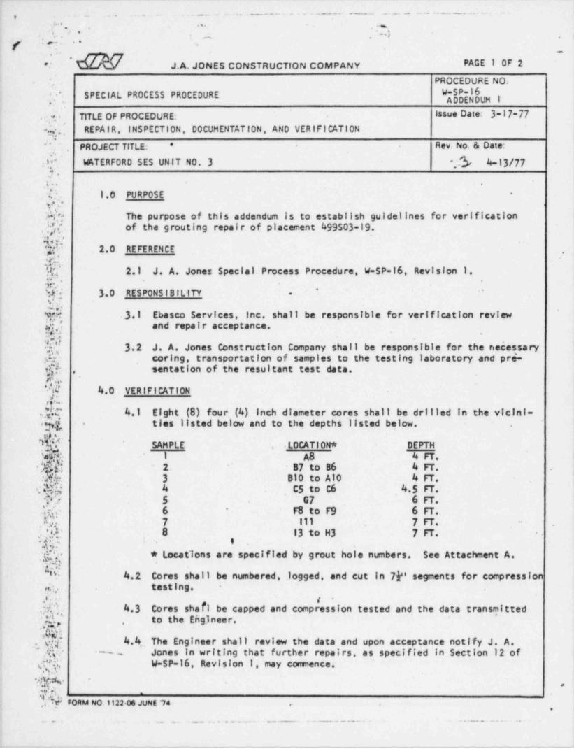
' h' V. '5.0 ATTACHMENTS
G.,.,p f R-3 5.1 Grout Hole Grids (2)
s.p .. .
,
. y. .^~
}.v.'.
.[ , . -
'];*;'
,S.* -
. .i? *'
|. .
,
.:.
| . ~ . ''*,
; ,a a. g< . . , -
.''',a.*,, .. . . ..
P'
'I,;f ?'. '
'i|
...
..
.; . ] * ;..
I
l'
! :.',:*:J g *
*'
< . . .' ' '
FORM NO 1122 06 JUPeE '74*. . . . . . . . . - - - - ~ ~ ~ ~ ~ ~ ~ ~ - ~ - - ~ ~ ~ ~ ' ' ^ - - -
,,
- . _ _ - . _ - , _ _ _ _ , _ _ _ _ _ _ . _ _ _ _ _ _ . . . _ _ . . , _ _ . , . . _ _ _ _ - _ . . . . _ . _ _ _ . _ . _ _ - _ , _ _ _ _ _ _ _ _ _ _ . _ _ _ . , , . _ , , , . , _ _ - - . - - . . _ . , _ _ . . -

11
. . . . . . . , , . . . . . - -- - - -- - - - - - - w,e. ,. 6 %..t-
- I|||r '' i i d i 1:i-- .l ltLT i - [. i
_ , - . rf r ---- -
l i l .i. . .' '4.
..i'..
-
!; | ,II,I|..:: l'IN,3,i':''- '
..,; i
, . ... tu s . .4
-
' .
i 1 --___ _ .-
- - . - %- >l' .
f.:in ! .9 .1 ! |Ll- l- -- .--- - -i , -
l ,. *g . 'p.: . l tor
!.ce'
2 to'::' ' .b'.x: .--
- - to-
.g y | if to. 4 4 :m . ..c n .,
i.e . . i. a-
}.| | o z),, .
.. . i c i. .
I' tP 3 * 3 '*4-* - l'[ t .~- I/:|. 8 : - *'I ** '
. ,T,,T_,...
._7_f__~ i .
._..j.,
..
.;. i , .. v; . , . m. ,,. ., i . , .,. i
. . - .,8: :: ... r t. 1: , ., , ,
,
.n], ,;_i.., 3.,. ,.r .. r
- * .w. -.. -- +
. , .,.4. .n ,
I, ,
j.s _ ,. i.: ..; 0 : ., .O.; :Oi .O.:-
( l.,
p,..'; i,.; ; .; . s . ..L . ; ..,4 g ' 1n. . ' u..
a. .
I
...,_ .,.
t*g . s , ~_. A,4,
. .. i i.4 , , .. . . . . ,,,, s.i. .... ..,, .... -t.r,r. . ,.,., i .. .. .
.. - t.i .4,, . -
. ,. ...
rFJTi[ ] [.I 1T4 1. O C :.O ! [ 10bj. ;O,ri i;p g|.j |jj! tpj.1.,
. ;.i H.;. J v.4.g. 2,
I! ,, ., ....,i.;is F .>.,..
i. .
. . ...
r 3 I ! I,! ,! i lf ItT I i ' ' -4'- % . O. | i .I !!:: ,0! i . , | | f"--r- ' -
-l} t< . O, i o' M' ~ '', ,
3 + --, '. .i,
i .: .- ..i.i . li . 3|: ;.i
i+s jII " ,1J- 1
,
;i f.i i;, .i : > > -, .
. ,- r- . 4
p | 1
i | x| |Cg '08 |O' . ,0j ,- p. ;; ! j i (3 | 1| ,0, [ s i - -
? 71-" ';. - . - --
-> ii- i i. ,.-
T 'r -ii , '. |$n ;. i. ,IL p, 61.4 , 'g.4_ %....., .
l. :I.
iF i! .| 1
y!.1. [. ,;.,j ! . 'l
.; --. .
j q, ..
|O', 6|y ') j ;O ,.i i :H i , . e. .
S'w @- a l- : .' d,h; ' ;O _. XM iO foj| -
f-- .. - .y t,;i
-r-. .. j. i ,, ,. . i . .. ! ,,
. t.. : .s __..
s,.
.i
_, .,..
,
.,,. .
.
r. . | : _ . _,,. . . . . . ..
4,,
_ .__, .o -. .
.[ g. . gj., . . O _y _q_.. ,,
__. . . ; ...g.
!7_._ .. 4,,,,','.t. , . . . i j. 3 ,_ _ _ . .q
_.ti
~
.. .; .,i: : i .. .gIi t.,
-
lji.' ..'.6'. N. , , . -f-.. . .-
.O. l a,. . y~ -
'O'r- %w, : , i i
F ... . . "- - %L p+ .o. n .
.
____u4 [O ' t- . l ~l t H-
~~~ ~ ''~ ':
:n W,. 2i .o, e , .i. , i 4, i ,, , ,,._- . . .. . . -' . .. g~ " h,u
-'- -
,..
~'~ ~ iI' < j. I...h f|C .h| ||h .Nd I. |O j ]-
-- . . ,
h| 10 Oi![.O1. tb .} [.2 4
.l' t-E- .x.h i-
~_1 . .! * |j 0:| iOr' xi. O!t Og! O [ [- x| 'ji'eT__i.- . . . .-s ~
I I,.l. --
Q','
__ . , ]r'. . <. 'O ie4 .O , . ; . Oj ;O,i ! .O . oi: , ,- . .'_.i.I
' i ' .. .i--" . .,' i,,
__--
,
_ . . ,.. i . ,. i. ,,e ! . i .: -i ||, O., - ,it
.
, , ,, i. . . , - . . .
! ' ..
' , ,,
e ., ..,e r.. i. ..-... .
"'__~__ _ , _ ,
.,
ilt" f H ~l 4 ,| .I |___ 3. . j, .q. .j799 tg 7,7p ;;g. [ 7.l T Q_ g.
%|j.{.L.h .ifi[Sn.T(z.
- -4; r. {c :.i bQ;_ P H.E P.t_; Wir ,0L f;.; ;O 5 '; Fe '
x:YrF ut F:tt9 j.',- 5C. | i
1| : Igi :! !| !ii1i
. r|! II
- 1I~ .|!I6
' W | j|,.| | ,! N''-- It! | 'O 'Oh dI fi |[ ,!.C-~l,g'd I ! E
,,
. . ., .._i|.i .[, ... ,'__
| ..: i. ; . ,! [ .)8
,i .I | li-|,i t- - ,i_--. , o
x " .| .O : ..I ]' | | j''- [ 'i, ;g .i[ }.T ;_.., g |
J i,
:.- C x$x. , - O
i.i i, . ;-
, =. , ,'
,_. .
.-- s 4. H q ,. ~< !, . , , . .. . - -._ - ,- -;
2. ti i |I 6,,e. ,0 .! i O' ;if. ! l ! I'| 8||j !i! :I 1; ! N.6 ipet..h! 9. . 3'
4. i . 0,s. .| Og |-
,
.O g , . , _ , . 4 y. .] . , .i . . . , . . . . p . .. _ '; u'
:n,
. j |. [. j ..
jj h,.. . he;'- -. . . 4.n , r.
-. ., .. .
-
. c,. ..
c !i it O Oi O! ep.. j... I.. .i !. i
t..14..b4.We .
m |.,, . i- 4.... i .
.. .a ' H-8- s'Q. . . *4 ' -**;.
M .17 r' tT. o4., .t ~
Q' '- O cq:i,. .i -
,
_
,_.. -. ; . . ]'..
. t- .f e G, . .
. 'j. , i., , .. ..
|'l ''l ji j ia', i t l I- 1 - d |---.j '' |i S! . hj i' c, i 9 F; dj j j' j[ OB . g
I- - 0-P'j i'
g, Ib . u, i i! j thi i '. t'
;l illl|f!. i L.,
l i :,1! Jl,i,- ' ' '
-L D2 e. tg; -.. ,
_ L. l...
. . e.rl_.._ . .i i i . '. M | ! r,
,,
s . ,i 4,i r !.es u m =..i
. ., , . s .
i u , _ . . - e ,__ , .
, .j, ,r. |.. .t. ' }.,f.*iij.-l..+Fj- Y4
_4_. .., -._ _-i .I f - .rRi tt ; , .,|.
, -
. l.7 s.; .,.. I g... . ,
.
7 .g tie i,_ _
, . , . .
<) 7i. . 3gr- ,,
. ii''.! l' i;i , | | | i ; @,l r ||.ji.[.;l-
'. ._:L.Q .. .'
-9 3 tJk ! ) !, , i
~ __.,,I.
i i..- li'. . ., ,, i i . .. . _ .. :-
|..iiI,ei.,jl,ii.,'..i 6 '.ie!;,,; I..! ..
J. i *- --c .- .
; .i.,. i j, ! !- l + l + L9- 4
. i. ,8
1 ig ,i 6 .|i
. .
-t-r ! lt. :.
, ... .. . I. . - -. . . .-
. . >; ...1-. ...
U:%.c.'
.. . . . ... - - -. - _ . - - -- --- - '- -~
. - . __ - - - - - - - -- - - - - - - - - - - - -

. . . . ._ -~. . _ - - . _ ._. _._____..
,.
. . . - .
_ _ . , _
m''
. . . . , .,~ , , '., 'g, g,-
J 7 R-2
6,,q d_g ?. 7o3 h.'
.
1c4Ps$ $ .M O.o H-
cc 0 .*3 ?
'-
sL m-I*smaa asop .
5, .a. .c , . ,s .
- ._.
;4. .. .
b F- 4 O Vi 'O 1' 'T o.,.. .
.e \ F*' 'C' FC, - -
'. | A.
ge .-
-| o o o o I s1 / 4-'
i
o; 6 /i utv *i
h a g ', .!- 'oe o 0 0 | 0 Not v --.
,,c>,f. | ' '
g O oE8 o o o (o M L g,gl' t t T;oh Og o o o 2S g O f g
.: 2 3 = v o uSfd o
.
8 Oj. D d' . }p' o o o og 3 ~'
.
t " 8 C,
e O o o o Og oh o o o e '. @ -
y e z- .
gh 3 gj o ,Db O O |o 0 0 g g 2o c 9 g
Ob o e O$ I''* o o o 8 o **-
e a. ..
. gu'F 4 |w i t | O- T { j e
h3 oy.8 ' 1 ;o o O o o' 01 '8 W y 2,glul u a
h{ O V. IIG O o 0 0 e o
g of.e,,
** *. =b
,
0 'e o o o e eb 5 T $)uo8 '
.<. 243 <S 16y, of G .t. G .t t *to
| 3yC F4 e$ n- a6 o eg o,
"e o) o |o o Oh o 5- 68
u .'a of a0 -=3= .
t' o is i %---
o o h @n: $ y3 g gp9 y3 H U9 3<gJ-4 O o o o oja Oj -.- goc . . . ..
, . .r., O h. m o 0 0 4 % k*
g g,M *>&*y*2 2 F.
a bh wdb (.
.% . [N9:VI. ..,
.0 ',5 2 |*E *
G o e, o O eto haZe ' '
g -3
. -. . . . . . . . . . . . . . . . . . . . . . . . . .,
m,.
k .'~ ~
-.. . . - ..
-. , .4
- - - - - - - - - - - ~ ~ - - - ~ - - - ~ ' ~ ~ ^ - ~ ~_ _ .. _ . . _ . . _ - - . --
. , - _ -- _ . _ _ _ . . - - . , _ _ _ _ _ _ _ _ - - _ . - - __
Related Documents