274 Int. J. Vehicle Design, Vol. 62, Nos. 2/3/4, 2013 Heavy duty vehicle tyre forces estimation using variable gain sliding mode observer O. Khemoudj* and H. Imine Universit´ e Paris-Est, LEPSIS, IFSTTAR 58, Boulevard Lefèbvre, 75015 Paris, France E-mail: [email protected] E-mail: [email protected] *Corresponding author M. Djema ¨ ı Univ Lille Nord de France, F-59000 Lille, France UVHC, LAMIH, F-59313 Valenciennes, France CNRS, UMR 8530, F-59313 Valenciennes, France E-mail: [email protected] Abstract: In this paper an original method for estimating heavy duty vehicle tyre forces is presented. The method is based on a variable gain sliding mode observer. The main on-board sensors are available through the CAN-bus of the vehicle to which low-cost sensors are added. The approach is validated by comparing the estimated forces to those provided by the software vehicle dynamics simulator PROSPER. Keywords: heavy duty vehicles; sliding mode observer; variable gain; exact differentiator; on-board sensors. Reference to this paper should be made as follows: Khemoudj, O., Imine, H. and Djema ¨ ı M. (2013) ‘Heavy duty vehicle tyre forces estimation using variable gain sliding mode observer’, Int. J. Vehicle Design, Vol. 62, Nos. 2/3/4, pp.274–288. Biographical notes: Omar Khemoudj is Control Engineer from Ecole Nationale Polytechnique d’Alger. He received in 2010 his PhD Degree in control theory from Universit´ e de Valenciennes et du Hainaut Cambr´ esis while holding a position of research assistant at Laboratoire Central des Ponts et Chaussées (LCPC), France. His research interests are in vehicle dynamics and advanced driver assistance systems, particularly in relation to commercial vehicles safety and the issue of measuring dynamic tyre forces by means of optimised sensor configuration and using mathematical tools provided by control theory. Hocine Imine received his Master’s Degree and his PhD in Robotics and Automation from the Versailles University, France, respectively in 2000 and 2003. From 2003 to 2004 he was a Researcher at the Robotic Laboratory of Versailles and Assistant Professor at the Versailles University. In 2005, he joined IFSTTAR where he is currently a Copyright © 2013 Inderscience Enterprises Ltd.

Welcome message from author
This document is posted to help you gain knowledge. Please leave a comment to let me know what you think about it! Share it to your friends and learn new things together.
Transcript

274 Int. J. Vehicle Design, Vol. 62, Nos. 2/3/4, 2013
Heavy duty vehicle tyre forces estimation using
variable gain sliding mode observer
O. Khemoudj* and H. Imine
Universite Paris-Est, LEPSIS, IFSTTAR58, Boulevard Lefèbvre, 75015 Paris, FranceE-mail: [email protected]: [email protected]*Corresponding author
M. DjemaıUniv Lille Nord de France, F-59000 Lille, FranceUVHC, LAMIH, F-59313 Valenciennes, FranceCNRS, UMR 8530, F-59313 Valenciennes, FranceE-mail: [email protected]
Abstract: In this paper an original method for estimating heavy dutyvehicle tyre forces is presented. The method is based on a variablegain sliding mode observer. The main on-board sensors are availablethrough the CAN-bus of the vehicle to which low-cost sensors are added.The approach is validated by comparing the estimated forces to thoseprovided by the software vehicle dynamics simulator PROSPER.
Keywords: heavy duty vehicles; sliding mode observer; variable gain; exactdifferentiator; on-board sensors.
Reference to this paper should be made as follows: Khemoudj, O.,Imine, H. and Djemaı M. (2013) ‘Heavy duty vehicle tyre forcesestimation using variable gain sliding mode observer’, Int. J. VehicleDesign, Vol. 62, Nos. 2/3/4, pp.274–288.
Biographical notes: Omar Khemoudj is Control Engineer from EcoleNationale Polytechnique d’Alger. He received in 2010 his PhD Degree incontrol theory from Universite de Valenciennes et du Hainaut Cambresiswhile holding a position of research assistant at Laboratoire Central desPonts et Chaussées (LCPC), France. His research interests are in vehicledynamics and advanced driver assistance systems, particularly in relationto commercial vehicles safety and the issue of measuring dynamictyre forces by means of optimised sensor configuration and usingmathematical tools provided by control theory.
Hocine Imine received his Master’s Degree and his PhD in Roboticsand Automation from the Versailles University, France, respectivelyin 2000 and 2003. From 2003 to 2004 he was a Researcher at theRobotic Laboratory of Versailles and Assistant Professor at the VersaillesUniversity. In 2005, he joined IFSTTAR where he is currently a
Copyright © 2013 Inderscience Enterprises Ltd.

Heavy duty vehicle tyre forces estimation using variable gain 275
researcher. He is involved in different projects like vehicule Interactifdu Futur (VIF) and Heavyroute (Intelligent Route Guidance for HeavyTraffic). He is also responsible of the research project PLInfra onheavy vehicle safety, assessment of their impacts on pavement andbridges. He is Member of IFAC Technical Committee on Transportationsystems (TC 7.4) and member of Working group on Automatic andAutomobile. His research interests include Intelligent TransportationSystems, heavy vehicle modelling and stability, diagnosis, non linearobservation, non linear control. He currently serves as a Guest Editorfor Int. J. of Vehicle Design, special Issue on: ‘Variable Structure Systemsin Automotive Applications’. He has published over 60 technical papers,and several industrial technical reports. Many of them were on light andheavy vehicle dynamics, estimation, control and prediction of the risks.He published two books. One was published in 2010 related to roadprofile estimation and impact on vehicle dynamics and a second one in2011, called Sliding Mode Based Analysis and Identification of VehicleDynamics.
Mohamed Djemaı received the PhD Degree in Automatic Control in 1995from the University Paris Sud -Orsay- (France) in 2000–2008. he hasa teaching position in automatic control in Ecole Nationale Superieurede l’Electronique et de Ses Applications (ENSEA-Cergy, France) andsince 2008 he is in Valenciennes University (Full Professor). He isnow with LAMIH (http://www.univ-valenciennes.fr/LAMIH/) (UMR-CNRS). His research interests are in analysis, observation and control ofnonlinear and hybrid systems with priority to robust ways (high ordersliding mode).
1 Introduction
The problem of the estimation of the contact forces for heavy duty vehicles isessential for obtaining the necessary information on the interaction between thevehicle and the pavement. This information is particularly useful in order to avoidroad and vehicle damage (tyre, suspension, fragile payload) and to enhance securityby preventing rollover of trucks. The issue of estimating vehicle contact forces isconsidered in many previous works. In Ray (1995) an Extended Kalman Filter(EKF) to estimate the longitudinal and lateral forces in a vehicle bicycle modelis applied, the forces are considered as additional states and their dynamics aremodelled by the use of a shaping filter driven by white noise. In the paper Siegrist(2003) a similar estimation algorithm to an off-highway mining truck is applied.The main restriction of this approach is that it is supposed that the forces arechanging in low frequency when tuning the shaping filter, this requires the exactknowledge of the nature of the forces and the way they vary. In Bouteldja (2005),Imine and Dolcemascolo (2008) and Imine et al. (2011), sliding mode observersare used to estimate contact forces in heavy duty vehicles. First, the height of thewheel hub is estimated, then by measuring the road profile, the tyre deflection iscalculated assuming the linear stiffness of the tyre and the estimation of the verticalforce is obtained by multiplying the tyre deflection with its stiffness, the longitudinal

276 O. Khemoudj et al.
and lateral forces are also derived using the Pacejka tyre model. This methodinvolves accurate knowledge of the vehicle parameters and the pneumatic andalso to measure the road profile. Another way to estimate the forces is to usestrain gauges in the wheel hub; the solution provides precise measurement butis expensive. Axle bar can else be instrumented by shear strain gauges, this lastmethod is limited to straight constant speed manoeuvre and does not suit turningcorners manoeuvres with large lateral forces. Furthermore, strain gauges in vehiclesare complex to install and to calibrate. In Blanksby et al. (2008), a laser sensor inplaced on the wheel to measure the tyre deflection and to deduce the dynamic loads,this method is practical but some errors appear due to the unstable measurementof the laser and the inteference due to noise and road irregular profile. Tuononen(2009) tested some optical sensors to measure carcass deflections of the tyre anddeduce tyre forces, the method is quite complex to install.
In this paper we propose a method using sliding mode observer to evaluate theforces where we consider these forces as unknown inputs. On this basis we usesliding mode observers (Khemoudj et al., 2009a, 2009b) and the main embeddedsensors in the vehicle and finally we estimate the vertical forces. The advantageof this approach is to avoid the use of many parameters of the vehicle (usuallyunknown), to optimise the sensors configuration (low-cost sensors) and to present agood alternative to the use of strain gauges especially while turning corners (simpleinstallation and calibration).
This paper is divided into three main sections. In the first section, the model isdescribed. In the second section the estimation method is presented. The simulationresults are presented in the third section. We finally conclude with some perspectivesin the last section.
2 Model description
To be able to develop observers and to validate our approach, we use an observablenon linear yaw plane model as described in Figure 1.
The behaviour of the articulated vehicle is related to the forces applied bypavement on the tyres. In the model, we consider the two axles of the tractor andthe axle-group in the trailer which we represent by a unique equivalent axle. Inorder to describe the dynamics of the articulated vehicle, we represent separatelythe tractor and the trailer. The hitch force which is an internal force appears as anexternal force for both the tractor and the trailer. Moreover, we represent the hitchforce by two components: one longitudinal component noted Xh and one lateralcomponent noted Yh.
Let us note Ffx and Ffy the tractor front longitudinal and lateral tyre forces,Frx and Fry the tractor rear longitudinal and lateral tyre forces and Ftx and Fty
the total forces applied on trailer-axle. x and y are respectively the longitudinal andlateral tractor acceleration. lf and lr the distances between the centre of gravityof the tractor and respectively the front and the rear axles. Moreover lft andlrt correspond to the distance between the centre of gravity of the trailer andrespectively the hitch and rear axle. δ is the steering angle and θ is relative yaw

Heavy duty vehicle tyre forces estimation using variable gain 277
Figure 1 Extended semi-trailer yaw plane bicycle model (see online version for colours)
angle between the tractor and trailer. The equations of motion of the tractor in theyaw plane are given in the longitudinal axis:
Ffy sin(δ) + Ffx cos(δ) + Frx − Xh = M1x (1)
for the lateral direction
Ffy cos(δ) − Ffx sin(δ) + Fry − Yh = M1y. (2)
The yaw moment of the tractor at the hitch point
(lf + lh)(Ffy cos(δ) − Ffx sin(δ)) − Fry(lr − lh) = Iz1α1. (3)
Remark 2.1: Iz1 is the moment of inertia of the tractor around a vertical axiscrossing the hitch. It is obtained by the use of Huyghens theorem:
Iz1 = I1cog + M1l2h (4)
where I1cog is the inertia moment according to the vertical axle crossing the centreof gravity of the tractor. M1 is the total mass of the tractor. lh the distance betweenthe CoG of the tractor and the hitch.

278 O. Khemoudj et al.
The trailer dynamics is governed by the following equations. In the longitudinaldirection:
Xh + Ftx cos(θ) − Fty sin(θ) = M2xt cos(θ) − M2yt sin(θ). (5)
For lateral direction
Yh + Ftx sin(θ) + Fty cos(θ) = M2xt sin(θ) + M2yt cos(θ). (6)
and the yaw dynamics
Yh cos(θ)lft − Xh sin(θ)lft − Ftylrt = Iz2α2 (7)
where M2 and Iz2 are the mass and the moment of inertia of the trailer. xt and yt
are the longitudinal and lateral accelerations of the trailer. The state space vectorconsists of measured velocities. It is composed of the tractor yaw rate α1, the frontand rear tractor wheel rotational velocities noted respectively ωfw and ωrw, thetrailer yaw rate α2 and the trailer wheel rotational velocity noted ωtw. It is given by:
Xv =
α1
ωfw
ωrw
α2
ωtw
. (8)
The output vector is
Y =
α1
ωfw
ωrw
α2
ωtw
1M1
(Frx + Ffx cos(δ) + Ffy sin(δ) − Xh)
1M1
(Fry − Ffx sin(δ) + Ffy cos(δ) − Yh)
1M2
(Ftx cos(θ) − Fty sin(θ) + Xh)
1M2
(Ftx sin(θ) − Fty cos(θ) + Yh)
. (9)
The state-space model can be written in this form:
Xv = Bu + W1(u)uF
Y =
[Xv
W2(u)uF
](10)

Heavy duty vehicle tyre forces estimation using variable gain 279
where u is the known input vector composed of the tractor front and rear wheeltorques respectively Tfw and Trw, the trailer wheel torque Ttw, the steering angleand the relative yaw angle.
u =[Tfw Trw Ttw δ θ
]T. (11)
Remark 2.2: In practice, steering angle, yaw rate, wheel rotational velocity, thelateral acceleration and the driving torques are signals available on the CAN-busof the vehicle. The braking torque can be deduced from the brakes pressure whichis also available at the CAN-bus. In our application, we do not consider brakingsituations. The relative yaw angle θ between the tractor and the trailer can beobtained by integrating the difference between the measured tractor yaw rate α1and the measured trailer yaw rate α2.
The unknown input forces are
uF =[Ffx Frx Ftx Ffy Fry Fty Xh Yh
]T. (12)
Suppose that lfh = lf + lh and lrh = lr − lh. The matrix W1 ∈ R5×8 is given by:
W1(u) =
lfh
Iz1sin(δ) 0 0
lfh
Iz1cos(δ) − lrh
Iz10 0 0
rw
Ifw0 0 0 0 0 0 0
0rw
Irw0 0 0 0 0 0
0 0 0 0 0 − lrt
Iz2
−lft
Iz2sin(θ)
lft
I2cos(θ)
0 0rw
Itw0 0 0 0 0
(13)
and W2 ∈ R4×8 is given by:
W2(u) =
cos(δ)M1
1M1
0sin(δ)M1
0 0 − 1M1
0
− sin δ
M10 0
cos(δ)M1
1M1
0 0−1M1
0 0cos(θ)M2
0 0− sin(θ)
M2
1M2
0
0 0sin(θ)M2
0 0cos(θ)M2
01
M2
(14)
with Mfw, Mrw, Mtw, Ifw, Irw and Itw are respectively the masses and rotationalinertias of the front and rear tractor wheels and trailer wheels. rw is the wheelsradius supposed self-same for all wheels.

280 O. Khemoudj et al.
The matrix B ∈ R5×5 is given by:
B =
0 0 0 0 0
1Ifw
0 0 0 0
01
Irw0 0 0
0 0 0 0 0
0 01
Itw0 0
. (15)
To evaluate the vertical forces, we introduce an axle model. We represent the forcesapplied to the axle (Figure 2). We can set the equations of movement of the freebody in the vertical plane:
Fz,l + Fz,r = Fs,l + Fs,r + Ma.g + Ma.a (16)
and
Fz,l.� + Fs,r.�s = Fz,r.� + Fs,l.�s + Fy.r + Ia.aϕ (17)
with gravity acceleration g = 9.81m/s2. Fz,l and Fz,r the vertical wheel forces at theleft and at the right of the axle. Fs,l and Fs,r the suspension forces at the left andthe right of the axle. Fy the resultant lateral force i.e., the sum of the left and rightlateral tyre-force applied to the axle. Me the mass of the axle. Ia the moment ofinertia of the axle around its roll axle. a the axle-hop acceleration. aϕ the axle-rollacceleration. � the distance between the point of application of the tyre force andthe centre of gravity of the axle. �s the distance between the point of application ofthe suspension force and the centre of gravity of the axle and finally r the distancebetween the ground and the centre of gravity of the axle. In order to simplify theproblem, we have taken some assumptions:
Assumption 1: The roll centre and the centre of gravity of the axle are the same.In order to simplify the roll moments equation.
Assumption 2: The axle is perfectly symmetric.
Assumption 3: The distance r is constant and is equal to wheel radius. The tyredeflection is neglected compared to tyre radius.
Remark 2.3: the suspension forces can be measured either by the use of a pressuretransducer connected to the suspension air-bags or by the use of an LVDT sensormeasuring the suspension deflection. We assume that the relation pressure/forceremain in the linear portion of the characteristic.
Model validation: The evaluation of both yaw plane chassis model and verticalaxle model are processed by the use of the simulator software PROSPER (Delanneet al., 2003).

Heavy duty vehicle tyre forces estimation using variable gain 281
PROSPER is a software dedicated to dynamic simulation of the non linearbehaviour of vehicles and describing the complete vehicle dynamics in differentdriving scenarios. PROSPER allows to simulate the behaviour of vehiclescontaining from 2–10 axles, with or without trailer. The suspensions can beselected from a set of different types. Diffrent grounds (road profile) are alsomodelled with the possibility to use a real road profile acquisition. Diffrent drivingscenarions can also be simulated (straight line, cornering, double lane change).PROSPER models are based on a modular conception so that every part of thevehicle is modelled and interacts with the other parts of the global model. Forthe simuation, we select in our case a tractor-trailer vehicle configuration, with atridem in the trailor. We simulate double bend manoeuvre to excite lateral andvertical dynamics of the vehicle. We present the results of the model validationin Khemoudj et al. (2009b).
3 Estimation of tyre forces
3.1 Augmented state-space model
We will consider the model as a control system with the forces as unknown inputs.We will use an explicit inverse model to evaluate these forces. However, this inducescalculating the pseudo inverse of an 8 × 9 matrix which can be ill-conditioned andconsequently result in errors. The idea is to use variable gain sliding mode observerswhich make use of an implicit inverse model. To do that, we modify the statespace model. We maintain the velocities Xv as states and we consider moreoverthe unknown forces uf as an additional state which derivative is monitored by theunknown input vector µ.
X1 = Xv
uF = X2
uF = µ
. (18)
Figure 2 Forces applied on the truck-axle

282 O. Khemoudj et al.
The new state-space model is given by:{X1 = Bu + W1(u)X2
X2 = µ. (19)
The outputs of the model can be written in this form:{Y1 = X1
Y2 = W2(u)X2. (20)
It is supposed that the unknown input µ is bounded. No additional informationabout µ is known.
3.2 Observer synthesis
In order to reconstruct the tyre force, we begin by evaluating the lateral forces oneach axle and then we calculate the vertical forces.
The challenge is to estimate the tyre forces contained in the state variableX2. To do so, one proceeds in two steps. First, the quantity W1X2 is estimated,once the estimation achieved, it is injected in the second observer equationfor estimating X2.
Step 1: In order to estimate the quantity W1X2, one can use a first order slidingmode, the inconvenient is that a large chattering is induced and a low-pass filtermust be introduced. To get a better estimation, a robust differentiator (Davila et al.,2006) is introduced to evaluate X1 from the measured velocities X1 and then afterconvergence, W1X2 can be calculated. The robust exact differentiator is given bythis set of equations:
ˆX1 = Z + λ∣∣∣X1
∣∣∣ 12
sign(X1)
Z = αsign(X1)(21)
with X1 the estimation error : X1 = X1 − X1, X1 the estimate of X1. α and λ arethe observer matrix gains with
λ = diag{λ1, λ2, . . . , λ5}
α = diag{α1, α2, . . . , α5}∣∣∣X1
∣∣∣ 12
= diag{∣∣∣X11
∣∣∣ 12
,∣∣∣X12
∣∣∣ 12
, . . . ,∣∣∣X15
∣∣∣ 12 }
sign(X1) = [sign(X11), sign(X12), . . . , sign(X15)]T .
. (22)
Considering the known velocities to be locally bounded, there exists α and λ
such that the observer error ei = ˆX1i − X1i tends to 0 in finite time t1 fori = 1, . . . , 5. The complete proof of this theorem can be found in Saadaoui et al.(2006). Sufficient conditions for convergence of the differentiator are given on gain

Heavy duty vehicle tyre forces estimation using variable gain 283
diagonal matrices α and λ. These gains are tuned such that for all i = 1, . . . , 5we have:
αi > σi (23)
and
λi > (σi + αi)√
2αi − σi
(24)
σi is the an upper bound for the second derivative of X1i : σi = max{X1i}. These
gains are tuned by simulation.
Step 2: Now that the X1 is exactly estimated, we have W1(u)X2 = ˙X1 − Bu.
To evaluate X2, use the observer given by :
˙X2 = µ + K1sign(W (u)X2) (25)
with, X2 is the estimate of X2, X2 = X2 − X2 is the estimation error of X2.
K1 = diag{K11 , K12 , . . . , K18}
sign(W (u)X2) = [sign([W (u)X2]1), sign([W (u)X2]2), . . . ,
sign([W (u)X2]8)]T
(26)
and for j = 1, . . . , 8
W (u)1,j = W1(u)2,j
W (u)2,j = W2(u)1,j
W (u)3,j = W1(u)4,j
W (u)4,j = W1(u)1,j
W (u)5,j = W2(u)2,j
W (u)6,j = W1(u)5,j
W (u)7,j = W2(u)3,j
W (u)8,j = W2(u)4,j
. (27)
This disposition of the matrix ensures that the diagonal elements are differentfrom zero. It will be useful for the choice of the observer gain. One can noticethat W1(u)X2 is estimated in the first step. Moreover, W2(u)X2 = W2(u)X2 −W2(u)X2, and given the measurement Y2 = W2(u)X2, we can write W2(u)X2= Y2 − W2(u)X2. The matrices W1(u), W2(u) and W (u) arecompletely known.

284 O. Khemoudj et al.
3.3 Convergence study
The observer convergence error is given by:
˙X2 = µ − K1sign(W (u)X2). (28)
Let us consider the Lyapunov function V of the observation error X2 given by:
V =12XT
2 X2. (29)
The time derivative of V is:
V = XT2
˙X2. (30)
Then,
V = XT2 (µ − K1sign(W (u)X2)). (31)
To ensure the convergence of the observer we have to select the gain K1 so thatV < 0. We propose the variable diagonal gain matrix K1 (it varies according to theinputs vector u) given by:
K1 = WT (u)K2 (32)
with K2 = diag{K21 , K22 , . . . , K28} a constant diagonal gain matrix and WT (u) isthe transpose matrix of W (u). Therefore:
V = XT2 (µ − WT (u)K2sign(W (u)X2)). (33)
The gain K2 is tuned so that k2i >> max abs{µi/WT (u)i,i
}with i = 1, . . . , 8.
In this case V can be written:
V = XT2 (−WT (u)K2sign(W (u)X2)) (34)
therefore,
V = −XT2 WT (u)K2sign(W (u)X2). (35)
Knowing that XT2 WT (u) is equal to (W (u)X2)T , we obtain then:
V = −(W (u)X2)T K2sign(W (u)X2)). (36)
Given that k2i > 0 for i = 1, . . . , 8, we have V < 0 and therefore X2 converges toX2 in finite time t2 > t1.

Heavy duty vehicle tyre forces estimation using variable gain 285
The unknown input µ can be calculated using the equation (28). Afterconvergence of X2 to X2, we have:
µ = K1sign(W (u)X2)). (37)
Given that the vector µ = µ − µ, we obtain:
µ = µ + K1sign(W (u)X2)). (38)
In the next section, we present the simulation results and a comparison toPROSPER outputs.
4 Simulation results
As mentioned before, in order to test the efficiency of the proposed method, weuse signals from the software simulator PROSPER. We simulate a double lanemanoeuvre with a constant speed. The double lane manoeuvre is simulated to exciteboth the lateral dynamics and the load transfer in the vehicle. The input signalsare obtained from simulator PROSPER and introduced into the model. The modeland the estimation forces are compared. In Figure 3, we show respectively acomparison between the yaw accelerations respectively of the tractor and the trailergiven by the simulator and their estimation from the differentiator. We noticethat the differentiator converges in finite time approximately equal to 50 ms.The chattering is reduced by using a right choice of the gains. In Figure 4the estimation of lateral forces respectively in front, rear, equivalent trailer axlesand at the hitch are shown (solid line). The forces are compared to the onesgiven by PROSPER (dashed line). The observer convergence time appears atthe beginning. We notice that the forces are reconstructed with the presence ofsome error. This error is due to the modelling errors. As it is shown in themodelling section, we considered an equivalent trailer axle for the complete tridemin the trailer, it is also considered that the equivalent axle is situated at themid-axle of the trailer, these modelling considerations introduce some errors whileestimating the forces. The estimated lateral forces are then used to evaluate thevertical forces.
Figure 3 Estimation of yaw accelerations (see online version for colours)

286 O. Khemoudj et al.
Figure 4 Estimation of lateral forces (see online version for colours)
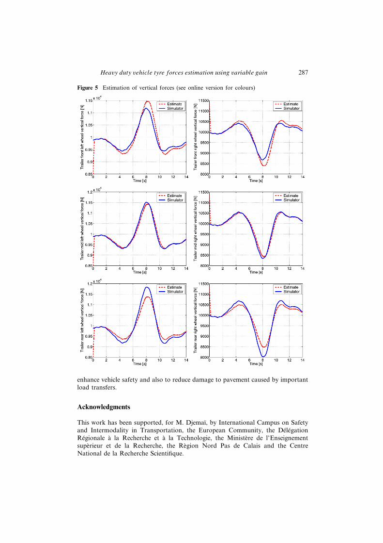
As shown in Figure 5. The lateral load transfer due to lane change simulationcan clearly be viewed. As we considered in the modelling step an equivalent axlefor trailer, we assume that the estimated lateral force in the trailer is uniformlydistributed on the three axles of the tridem. In reality, the lateral force is moreimportant at the rear axle of the trailer than at the front or mid one. Therefore,we overestimate the vertical force at the front axle and underestimate at the reartrailer axle. However, considering the trailer axle group, the maximum relative gapsbetween the estimated and simulated vertical forces are around 3% for the frontaxle, 1.9% for the middle axle and 6.5% for the rear axle. Tests on real vehicle willprovide a more robust evaluation of the estimation method.
5 Conclusion
In this paper a method to estimate the vertical forces applied on axles of atractor-trailer vehicle is presented. This on-board estimation is developed by theuse of low-cost sensors and the introduction of sliding mode observers and exactdifferentiations. An original variable gain observer is introduced so that the explicitmodel inversion is avoided. The estimated forces are then compared to simulatordata in order to provide a validation of the method. As a perspective, the methodis to be tested on a real instrumented truck and the estimated vertical forces areto be used in developing active steering and suspension systems with the focus to
Heavy duty vehicle tyre forces estimation using variable gain 287
Figure 5 Estimation of vertical forces (see online version for colours)
enhance vehicle safety and also to reduce damage to pavement caused by importantload transfers.
Acknowledgments
This work has been supported, for M. Djemaï, by International Campus on Safetyand Intermodality in Transportation, the European Community, the DélégationRégionale à la Recherche et à la Technologie, the Ministère de l’Enseignementsupèrieur et de la Recherche, the Règion Nord Pas de Calais and the CentreNational de la Recherche Scientifique.

288 O. Khemoudj et al.
References
Blanksby, C., George, R., Peters, B., Ritzinger, A. and Bruzsa L. (2008) ‘Measuring dynamicwheel loads on tri and quad axle groups’, 5th International Conference on Weigh-In-Motion ICWIM, International 10th Symposium on Heavy Vehicle Transport TechnologyHVTT, Paris, France.
Bouteldja, M. (2005) Modélisation des Interactions Dynamiques PoidsLourd/Infrastructures pour la Sécurité et les Alertes, PhD Thesis, University ofVersailles Saint-Quentin-en-Yvelines, France.
Davila, J., Fridman, L. and Poznyak, A. (2006), ‘Observation and identification ofmechanical systems via second order sliding modes’, International Journal of Control,Vol. 79, pp.1251–1262.
Delanne, Y., Schmitt, V. and Dolcemascolo, V. (2003) ‘Heavy truck rollover simulation’,18th International Conference on the Enhanced Safety of Vehicles, Nagoya, Japan.
Imine, H. and Dolcemascolo, V. (2008) ‘Sliding mode observers to heavy vehicle verticalforces estimation’, International Journal of Heavy Vehicle Systems, Vol. 15, pp.53–64.
Imine, H., Fridman, L., Shraim, H. and Djemaï, M. (2011) Sliding Mode Based Analysis,Observer and Identification of Vehicle Dynamics, Lecture Notes in Control andInformation Sciences, 1st ed., Vol. 414, Springer, Berlin, Germany.
Khemoudj, O., Imine, H. and Djemal, M. (2009a) ‘Unknown input observation via slidingmodes: application to vehicle contact forces’, IEEE Multi-conference on Systems andControl, Saint Petersburg, Russia, pp.541–546.
Khemoudj, O., Imine, H. and Djemal, M. (2009b) ‘Robust observation of tractor-trailervertical forces using inverse model and exact differentiator’, SAE International Journalof Materials and Manufacturing, Vol. 3, No. 1, pp.278–289.
Ray, L.R. (1995) ‘Non linear state and tire force estimation for advanced vehicle control’,IEEE Transaction on Control Systems Technology, Vol. 3, pp.117–124.
Saadaoui, H., Manamanni, N., Djemaı, M., Barbot, J.P. and Floquet, T. (2006) ‘Exactdifferentiation and sliding mode observers for switched Lagrangian systems’, NonlinearAnalysis: Theory, Methods & Applications, Special Issue: Hybrid Systems andApplications, Elsivier Editions, Vol. 65, No. 5, pp.1050–1069.
Siegrist, P.M. (2003) A Methodology for Monitoring Tyre-forces on Off-highway MiningTrucks, PhD Thesis, University of Queensland, Australia.
Tuononen, A. (2009) ‘On-board estimation of dynamic tyre forces from optically measuredtyre carcass deflections’, International Journal of Heavy Vehicle Systems, Vol. 16,No. 3, pp.362–378.
Related Documents


![SpeedestimationandParametersIdentificationsimultaneously … · 2017. 5. 2. · sliding mode observer, MRAS, Kalman filter, and othersensorlessschemearealsodeveloped[4].These methods](https://static.cupdf.com/doc/110x72/612e92aa1ecc51586942e639/speedestimationandparametersidentificationsimultaneously-2017-5-2-sliding-mode.jpg)