TALLINN UNIVERSITY OF TECHNOLOGY SCHOOL OF ENGINEERING Department of Power Engineering and Mechatronics HEAVY COMPONENTS LIFTING RASKETE KOMPONENTIDE TÕSTMINE MASTER THESIS Tallinn 2020 Supervisor: Co-Supervisors: Leo Teder ,Professor Vjatseslav Koop Eduard Tiganik Students: Nitin Gupta 177186MAHM

Welcome message from author
This document is posted to help you gain knowledge. Please leave a comment to let me know what you think about it! Share it to your friends and learn new things together.
Transcript

TALLINN UNIVERSITY OF TECHNOLOGY
SCHOOL OF ENGINEERING
Department of Power Engineering and Mechatronics
HEAVY COMPONENTS LIFTING
RASKETE KOMPONENTIDE TÕSTMINE
MASTER THESIS
Tallinn 2020
Supervisor:
Co-Supervisors:
Leo Teder ,Professor
Vjatseslav Koop
Eduard Tiganik
Students: Nitin Gupta
177186MAHM

AUTHOR’S DECLARATION
Hereby I declare, that I have written this thesis independently.
No academic degree has been applied for based on this material. All works, major
viewpoints and data of the other authors used in this thesis have been referenced.
“.......” .................... 2020
Author: ..............................
/signature /
Thesis is in accordance with terms and requirements
“.......” .................... 2020
Supervisor: ….........................
/signature/
Accepted for defence
“.......”....................2020 .
Chairman of theses defence commission: .................................................
/name and signature/

Non-exclusive Licence for Publication and Reproduction of
GraduationTthesis¹
I, Nitin Gupta (date of birth: 04,September,2019 ) hereby
1. grant Tallinn University of Technology (TalTech) a non-exclusive license for my
thesis
___________________________________________________________________
___________________________________________________________________
___________________________________________________________________
________________________________,
(Heavy Components Lifting)
supervised by
____________________________________________________________,
(Leo Teder)
1.1 reproduced for the purposes of preservation and electronic publication, incl. to
be entered in the digital collection of TalTech library until expiry of the term of
copyright;
1.2 published via the web of TalTech, incl. to be entered in the digital collection of
TalTech library until expiry of the term of copyright.
1.3 I am aware that the author also retains the rights specified in clause 1 of this
license.
2. I confirm that granting the non-exclusive license does not infringe third persons'
intellectual property rights, the rights arising from the Personal Data Protection
Act or rights arising from other legislation.
¹ Non-exclusive Licence for Publication and Reproduction of Graduation Thesis is not valid
during the validity period of restriction on access, except the university`s right to reproduce
the thesis only for preservation purposes.
______________ (signature)
______________ (date)
Department of Power Engineering and Mechatronics`s
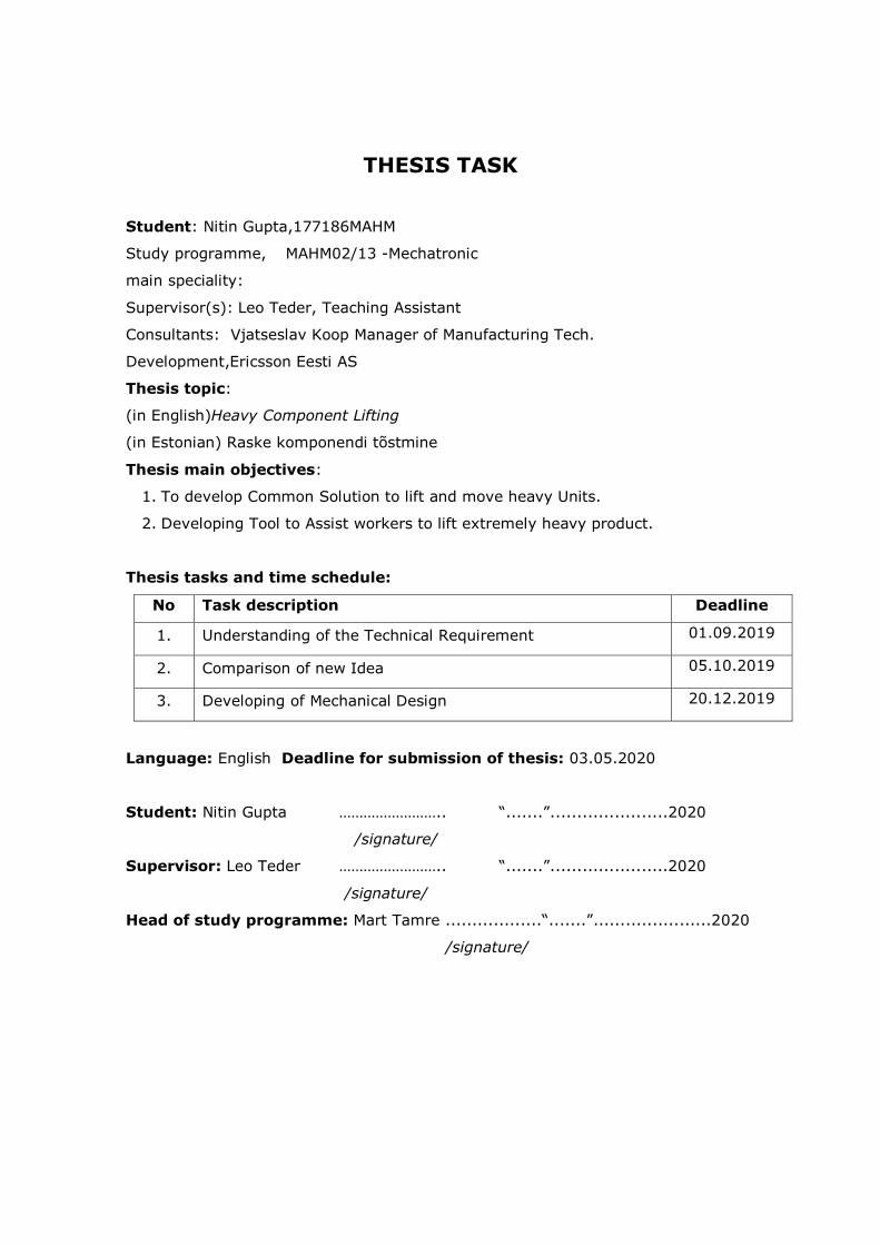
THESIS TASK
Student: Nitin Gupta,177186MAHM
Study programme, MAHM02/13 -Mechatronic
main speciality:
Supervisor(s): Leo Teder, Teaching Assistant
Consultants: Vjatseslav Koop Manager of Manufacturing Tech.
Development,Ericsson Eesti AS
Thesis topic:
(in English)Heavy Component Lifting
(in Estonian) Raske komponendi tõstmine
Thesis main objectives:
1. To develop Common Solution to lift and move heavy Units.
2. Developing Tool to Assist workers to lift extremely heavy product.
Thesis tasks and time schedule:
No Task description Deadline
1. Understanding of the Technical Requirement 01.09.2019
2. Comparison of new Idea 05.10.2019
3. Developing of Mechanical Design 20.12.2019
Language: English Deadline for submission of thesis: 03.05.2020
Student: Nitin Gupta …………………….. “.......”......................2020
/signature/
Supervisor: Leo Teder …………………….. “.......”......................2020
/signature/
Head of study programme: Mart Tamre ..................“.......”......................2020
/signature/

5
Table of Contents
List of abbreviations and symbols ................................................................................................ 7
List of Figures ............................................................................................................................... 8
List of Tables ................................................................................................................................ 9
1 Introduction ........................................................................................................................ 10
1.1 Overview...................................................................................................................... 10
1.2 Motivation ................................................................................................................... 11
1.3 Scope ........................................................................................................................... 11
1.4 Background Research .................................................................................................. 12
1.5 Problem ....................................................................................................................... 12
1.6 Requirements .............................................................................................................. 13
2 Process Analysis .................................................................................................................. 14
2.1 Introduction ................................................................................................................. 14
2.2 Existing Solution .......................................................................................................... 14
2.3 Layout .......................................................................................................................... 16
2.4 Assembly Process ........................................................................................................ 16
3 Task Formation ................................................................................................................... 19
3.1 Introduction ................................................................................................................. 19
3.2 Dimensions measurement ........................................................................................... 19
3.3 Mechanical child parts and whole assembly 3-D Models individual ............................ 19
3.4 Improvements in Designs ............................................................................................ 20
4. Idea Generation ................................................................................................................. 21
4.1 Introduction ................................................................................................................. 21
4.2 Design 1 (Trolley Lift) ................................................................................................... 21
4.3 Design 2 (Prong lift) ..................................................................................................... 22
4.4 Design 3 (3rd Fulcrum Lift)........................................................................................... 23
4.5 Design 4 (Ball Screw) ................................................................................................... 24
4.6 Comparison Matrix ...................................................................................................... 25
4.7 Conclusion ................................................................................................................... 25
5 Mechanical Design .............................................................................................................. 27
5.1 Calculations and Analysis of Child Parts and Assembly ................................................ 27
6 Updated Mechanical Design ............................................................................................... 43
7 Safety .................................................................................................................................. 44
7.1 ESD Safety .................................................................................................................... 44

6
7.2 Locking in the Actuators .............................................................................................. 44
7.3 Safety in Mechanical design ........................................................................................ 45
8 Conclusion ........................................................................................................................... 46
Summary .................................................................................................................................... 47
References ................................................................................................................................. 48
Appendix 1 ................................................................................................................................. 52
Appendix 2 ................................................................................................................................. 53
Appendix 3 ................................................................................................................................. 54
Appendix 4 ................................................................................................................................. 55
Appendix 5 ................................................................................................................................. 56
Appendix 6 ................................................................................................................................. 57
Appendix 7 ................................................................................................................................. 58
Appendix 8 (Updated Mechanical Design) ................................................................................. 59
7
List of abbreviations and symbols
ESD Electrostatic discharge
CE European Community
FIB Forwarding information base
HMI Human machine interface
PIM Passive Intermodulation
3-D 3-Dimensional
NEMA National Electrical Manufacturers Association
UL Underwriters Laboratories
° Degree
SPDT Single Pole-Double throw
8
List of Figures
Figure 1 Example of Heavy Radio Units of Manufacturing site [1] ............................................. 10
Figure 2 LionGrip Lift [3] ............................................................................................................. 15
Figure 3 LionGrip Gripper with Nylon strap ................................................................................ 15
Figure 4 Assembly Layout ........................................................................................................... 16
Figure 5 Small Radio Unit Gripper .............................................................................................. 17
Figure 6 PIM Table ..................................................................................................................... 18
Figure 7 Design 1 (Trolley Lift) .................................................................................................... 22
Figure 8 Design 2 (Prong Lift) w/ Antenna Integrated Radio [4] ................................................. 23
Figure 9 Design 3 (3rd Fulcrum Lift) ........................................................................................... 24
Figure 10 Design 4 (Ball Screw) [4] ............................................................................................. 24
Figure 11 Visual Representation of the Unit in Nylon Gripper ................................................... 27
Figure 12 Visual Representation of the Unit on Nylon Gripper in Rotating Frame ..................... 28
Figure 13 Moments directions and Loads .................................................................................. 29
Figure 14 Stress distribution ...................................................................................................... 29
Figure 15 Image of Beam attached to the gripper...................................................................... 30
Figure 16 Solidworks Simulation results of Beam [7] ................................................................. 31
Figure 17 Image of Beam attachment to Cover .......................................................................... 33
Figure 18 Solidworks simulation results ..................................................................................... 34
Figure 19 Implementation of the Telescopic Guide rails on the Cover and the base ................. 35
Figure 20 Solidworks Simulation results of Base ........................................................................ 36
Figure 21 Implementation of the Frame and Sliding rail in Design ............................................. 37
Figure 22 Solidworks Simulation results of Base for the Sliding mechanism .............................. 38
Figure 23 Solidworks simulation result on Frame ...................................................................... 39
Figure 24 Motorised Wheel from Tente [16].............................................................................. 41
Figure 25 Locking system on the Frame for Unit ........................................................................ 41
Figure 26 Updated Mechanical design ....................................................................................... 43

9
List of Tables
Table 1 Design Comparison ............................................................................................. 26
10
1 Introduction
1.1 Overview
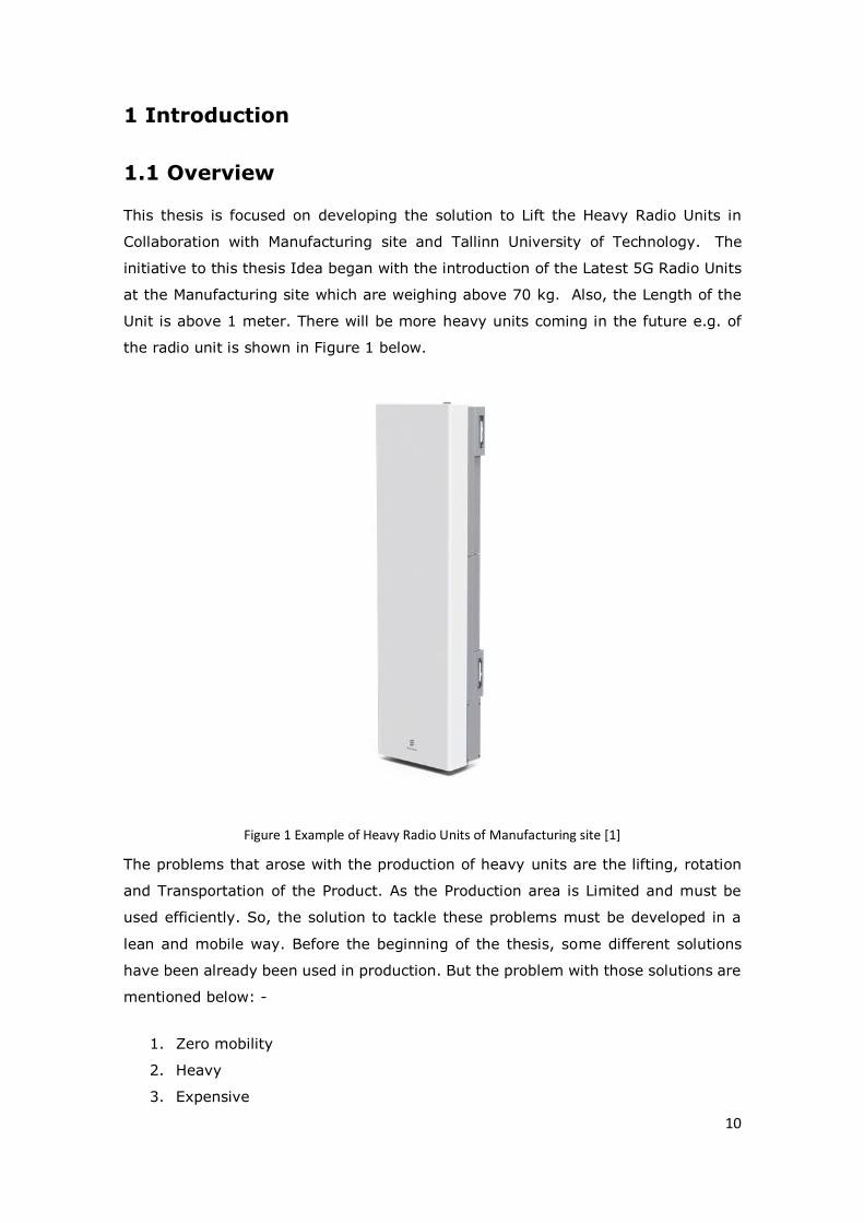
This thesis is focused on developing the solution to Lift the Heavy Radio Units in
Collaboration with Manufacturing site and Tallinn University of Technology. The
initiative to this thesis Idea began with the introduction of the Latest 5G Radio Units
at the Manufacturing site which are weighing above 70 kg. Also, the Length of the
Unit is above 1 meter. There will be more heavy units coming in the future e.g. of
the radio unit is shown in Figure 1 below.
Figure 1 Example of Heavy Radio Units of Manufacturing site [1]
The problems that arose with the production of heavy units are the lifting, rotation
and Transportation of the Product. As the Production area is Limited and must be
used efficiently. So, the solution to tackle these problems must be developed in a
lean and mobile way. Before the beginning of the thesis, some different solutions
have been already been used in production. But the problem with those solutions are
mentioned below: -
1. Zero mobility
2. Heavy
3. Expensive
11
4. Needed different machine for different process
The new design development must be done keeping the above drawbacks into
consideration. The initial approach to solve this problem was to make the team of the
students which will provide different Idea to tackle the problems. All these Ideas will
be compared to each other and to the current production solutions. After the
comparison of all the ideas and solutions, one solution will be finalized, and the
realization of this idea will start by developing the realistic 3-D model of the idea
which will require the development of the child Parts and assemblies. During the
development, the selection of standard parts has to be done. These standard parts
must be selected on the base of market research which will include a comparison of
the different standard parts from a different company. In the realization phase, all
the Technical parameters of each part must be calculated to check the reliability of
the product.
This solution is going to be the first prototype. The basis on the results of this
prototype the future placement of the solution in real production will be decided.
1.2 Motivation
The reason to choose this topic was the board approach to the tasks. As, from the
problem discussion it was clear that this thesis requires a lot of research and the
development in the field mechanical design, electronics and control. Because this is
going to be the new solution build from scratch which allows us to practice all the
aspects of our Master’s in Mechatronics. Mechatronics is a simple way is defined as
the combination of mechanical, electrical and software. In thesis, the author is going
to develop a solution based on this combination as previously mentioned. Besides,
this the thesis topic is time and budget bounded. This project is also going to make
us work into the field of logistic because some parts must be ordered which require
a price and lead time research. For this, the author must contact different companies
to extract information and analysis of the information has to be done to select the
best.
1.3 Scope
As the author had already discussed the this is a prototype which it itself clarifies that
to reach the final fully developed product a lot of research and improvement has to

12
be made. In this project, a detailed study of the production process must be done.
This project also requires the work in the three big fields of engineering which are: -
1. Mechanical Design Engineering
2. Electrical/Electronic Engineering
3. Software Engineering
There will different tools which author are going to use in this thesis. For e.g. CAD
software for 3D model and analysis. As this is a team project good understanding
and management is required. In management the following details must be clarified
for the smooth cooperation: -
1. Task distribution
2. Follow-ups on the status of the task
3. Defined roles in Project
4. Understanding of problems
1.4 Background Research
As the main approach of this thesis topic is to Develop solution in a certain timeframe
which requires us to understand the current production process in-depth and to
develop a new solution for it. For which similar kind of literature study must be done.
To understand the previously developed similar solution. This research should also
include the Technical data analysis of the machine which is in the current production
process of heavy radio units. This analysis will give us the in-depth details about
limitation in the current production process, which the author has to overcome in our
new solution.
1.5 Problem
As mentioned earlier. Manufacturing site is coming up with new and highly advanced
antenna integrated radio products. Some of those new products are quite heavy up
to 90 kg. This product weighs 90 kg and it’s quite heavy for a human to lift and move
around which is required for the production, testing and sometimes troubleshooting.
Currently, Manufacturing site is using a fixed crane which does provide all the solution
but in a confined area and because of which the layout of production is optimized to
keep everything within the reach of the crane and the similar crane is installed in a
warehouse. In the cases where the product needs to be picked and placed in other
production hall or the area out the reach of the crane working area. It would be

13
impossible to do such tasks because the fixed crane and in future more products are
coming with similar characteristics. So, it’s not an optimal or mobile solution which
can be used in different production hall or situations.
1.6 Requirements
For any solution that was proposed, it was important for that proposal to check
whether it can perform the said function and to meet the following requirements. [2]
• The proposed solution should be ESD safe.
• The proposed solution should comply with CE standards.
• The proposed solution should be easy and safe to use.
• The proposed solution shouldn’t require maintenance more than once.
• The proposed solution should be future proof meaning it should not only
provide a solution to one product but will be able to work with future products
right away or with small modifications.
• The proposed solution should not take too much time to start-up.
These requirements are were explained initially in the proposal of the project.
14
2 Process Analysis
2.1 Introduction
This chapter contains a detailed description of the process required for the
manufacturing of the Antenna Integrated Radio. The process analysis was done to
provide the best solution possible because the process includes some
complicated/unique manoeuvres which are required during the manufacturing of the
product which also includes the testing of the Radio. Also, this process analysis will
help us to gather information about technologies used in the current solution and
what can be done better. To produce an efficient solution.
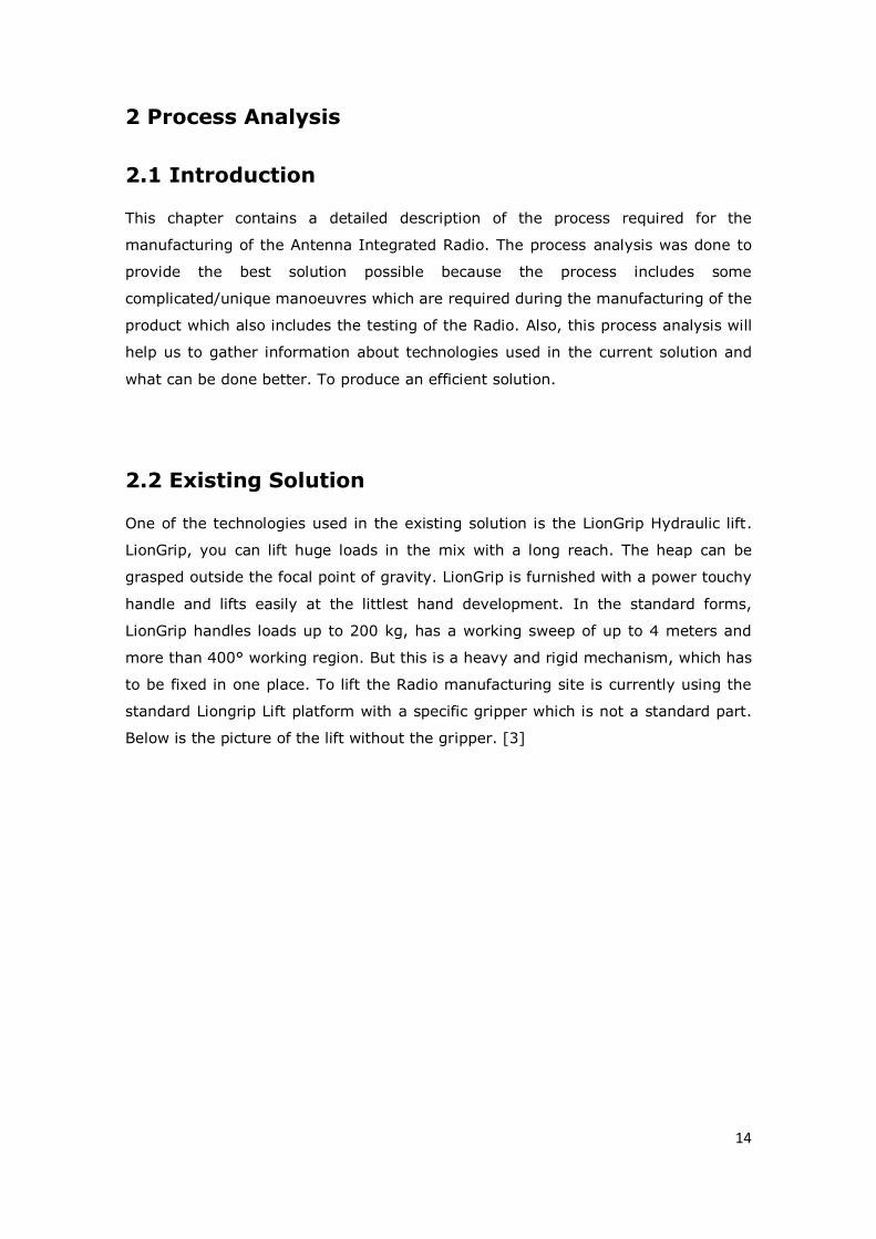
2.2 Existing Solution
One of the technologies used in the existing solution is the LionGrip Hydraulic lift.
LionGrip, you can lift huge loads in the mix with a long reach. The heap can be
grasped outside the focal point of gravity. LionGrip is furnished with a power touchy
handle and lifts easily at the littlest hand development. In the standard forms,
LionGrip handles loads up to 200 kg, has a working sweep of up to 4 meters and
more than 400° working region. But this is a heavy and rigid mechanism, which has
to be fixed in one place. To lift the Radio manufacturing site is currently using the
standard Liongrip Lift platform with a specific gripper which is not a standard part.
Below is the picture of the lift without the gripper. [3]

15
Figure 2 LionGrip Lift [3]
2.2.1 Pulley gripper
So to lift and rotate the radio manufacturing site is using the two pulleys type gripper. In which
the radio is hanged on the pulleys using nylon straps. The pulleys provide easy rotation of the
unit on the gripper. Below is the picture of the gripper.
Figure 3 LionGrip Gripper with Nylon strap
16
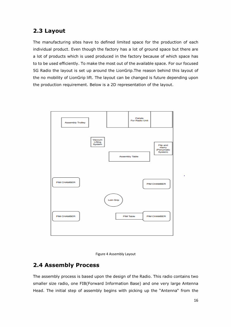
2.3 Layout
The manufacturing sites have to defined limited space for the production of each
individual product. Even though the factory has a lot of ground space but there are
a lot of products which is used produced in the factory because of which space has
to to be used efficiently. To make the most out of the available space. For our focused
5G Radio the layout is set up around the LionGrip.The reason behind this layout of
the no mobility of LionGrip lift. The layout can be changed is future depending upon
the production requirement. Below is a 2D representation of the layout.
Figure 4 Assembly Layout
2.4 Assembly Process
The assembly process is based upon the design of the Radio. This radio contains two
smaller size radio, one FIB(Forward Information Base) and one very large Antenna
Head. The initial step of assembly begins with picking up the “Antenna“ from the

17
pallets and then placing it on the Semi-Automated Assembly System. The Radio and
antenna connection is made on the Semi-Automated system in Controlled and precise
way. After the assembly Complete Unit(Contains Radio, FIB and Antenna) is taken to
the PIM(Passive Intermodulation)Chambers to test the Radio Unit for verification and
validation. For testing in PIM Chamber unit has to be picked up from the Semi-
Automated System and rotated 1800 degrees to put on the PIM table. Later this table
is slide into the PIM chamber to begin the test. In the last step, after the Unit passes
the test in the PIM chamber, the unit is lifted out from the PIM table and rotated
again to put it into the package placed on the pallets. The Further detailed description
and visual representation of assembly is explained below.
2.4.1 Flip and Marry
The small radio units and FIB have to be picked up from the pallets and rotated 1800
degrees. Before placing it on the Semi-Automated System for assembly. To do this
current solution is Flip and marry machine base on Pneumatic mechanism. The Flip
and marry gripper is designed specifically according to the radio design specification
to lack and rotate the Radios and FIB. Below is the Picture of the flip and marry
system.
Figure 5 Small Radio Unit Gripper

18
2.4.2 Semi-Automated System
The Connection between radios and Antenna is done through RF Coaxial connector.
As these connectors are small and delicate the placement of the radio units has to to
be done in the controlled and precise way. For this current solution is semi Automated
assembly system. The Process Involved in the Semi-Automated Assembly system:-
• The placement of the approx 1 meter Long Antenna head Upside on the base
of the system.
• Placement of individual Radios and FIB on the System.
• The alignment and placing of the Radios and FIB on the Antenna base.
2.4.3 PIM Table
The UNIT after getting assembled on the Semi-automated System is lifted with
LionGrip Lift and taken to PIM chamber test. The unit is lifted and rotated 1800
degrees before placing it on the PIM table. The PIM chamber is test reflected signal
signals because of which table can’t be made of metal. This table is made of wood.
The Table is slide inside and out at initialising and at the end of the test. Below is the
picture of the PIM table.
Figure 6 PIM Table
After Passing the test, Unit is lifted from the PIM table with hydraulic lift with nylon
straps and rotated 1800 degrees and place in the package with styrofoam coating to
protect the unit from any possible damages during transportation and storing.

19
3 Task Formation
3.1 Introduction
After a clear understanding of the process, author-defined certain tasks in the initial
stage. To distribute the work responsibilities. These responsibilities were divided into
Tasks which are defined below: [2]
• Dimensions measurement
• Mechanical child parts and whole assembly 3-D Models individual
• Improvements in Designs
3.2 Dimensions measurement
For the prototype to work in a similar way as a current solution author must keep the
dimension of the manoeuvres the same as the current solution. To achieve that
precise recording of the dimension was needed. These dimensioning includes the
following parts:
1. Distances of each process from the ground: The ground is as the reference
value of zero which is common for all the dimension.
2. Individual production machine dimensions: To merge the design with current
machines (Assembly machine, Test chamber, Palette and Trolleys) our design
must reach and fit in all the required positions and sizes.
3. In-depth product dimension analysis for new Idea generation: The product
each point dimension must be clear to create a solution which will accumulate
the design perfectly according to the size of the Product.
3.3 Mechanical child parts and whole assembly 3-D
Models individual
In the 2nd part of the task formation CAD models of the idea must be made to
understand and explain the concepts of the solutions. With these 3D models, the
initial analysis of the ideas would be easier and visually understandable. The Basic
3D models of the Initial Ideas was done individually then the analysis and the
improvement was done by the team.

20
3.4 Improvements in Designs
During Idea generation, all the designs were appearing flawless, but the author
started facing a lot of problems when the author started analyzing all the Designs in
depth. As the author found out all the design Required the improvement based on
the following points:
• Based on the Complexity of the mechanism and manufacturing
• Availability of the Standard parts
• Safety of the mechanism
3.4.1 Based on Complexity of the mechanism and manufacturing
The design must be amended according to a practical limitation of the manufacturing.
Also, the mechanism must simple in function to reduce the chances of failures.
Because something which might be easy to conceptualize in the 3D model, but
realization might not be possible or difficult.
3.4.2 Availability of the Standard parts
To prepare the solution in the least possible time frame design must include as many
standard (market) parts available as possible. It will give benefit in reducing the
timeframe of the prototype building. Also, most of the standard parts come with CE
and UL safety certification which will increase the overall confidence of the design
reliability.
3.4.3 Safety of the mechanism
As this is industry-oriented Solution, so it must be made according to the safety
norms CE and UL. The solution is going to be operated by a human. So, it should
consist of all the required safety Locks in case of mechanical failure.

21
4. Idea Generation
4.1 Introduction
After understanding of the problems and the process, several different ideas were
presented and compared based upon there merits and demerits. Different ideas were
developed by all team members. The importance of this part was to come with an
innovative and efficient solution which will not be limited by a single person thinking
ability. This comparison helped to select the best design and efficient design. By
comparing it on below-mentioned attributes: -
1. Flexibility
2. Space
3. Time
4. Cost
5. Design
6. Lead Time
7. Safety
8. Ergonomics
9. Mobility
10. One Man Operation
11. Future Proof
12. Product Independent
13. Customizable
4.2 Design 1 (Trolley Lift)
Initial Idea was focused on providing the solution to all the processes with the author
required in the production. The Lifting solution in this idea was to provide by using
the same gripper with nylon slings which are used in the current solution. This gave
us the advantage to use this design in production without any mechanical
modification of the process and parts. The Idea generation of the Rotation mechanism
was similar to the current small radio units rotation solution which is 180 degrees
rotating (Clockwise and anticlockwise) gripper which goes inside the grooves of the
unit. This Idea was enclosed in the frame of 2x2 m to provide isolation from any
human accident (due to the interface). The Idea was providing us with all the solution
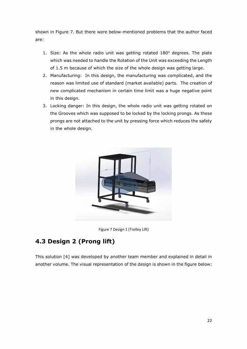
22
shown in Figure 7. But there were below-mentioned problems that the author faced
are:
1. Size: As the whole radio unit was getting rotated 180o degrees. The plate
which was needed to handle the Rotation of the Unit was exceeding the Length
of 1.5 m because of which the size of the whole design was getting large.
2. Manufacturing: In this design, the manufacturing was complicated, and the
reason was limited use of standard (market available) parts. The creation of
new complicated mechanism in certain time limit was a huge negative point
in this design.
3. Locking danger: In this design, the whole radio unit was getting rotated on
the Grooves which was supposed to be locked by the locking prongs. As these
prongs are not attached to the unit by pressing force which reduces the safety
in the whole design.
Figure 7 Design 1 (Trolley Lift)
4.3 Design 2 (Prong lift)
This solution [4] was developed by another team member and explained in detail in
another volume. The visual representation of the design is shown in the figure below:

23
Figure 8 Design 2 (Prong Lift) w/ Antenna Integrated Radio [4]
4.4 Design 3 (3rd Fulcrum Lift)
This Design was proposed after the analysis of the first two designs and comparing
overall efficiency with the current solution. In this design, the author had omitted the
solution to lift small radio units which give us more room of improvement in the lifting
and rotation of the whole radio unit. In this solution, the lifting solution is again the
same as the current solution with nylon slings gripper which will be attached to
movable cranes which will lift the whole Radio unit by cylindrical actuators. These
actuators will provide us with an increase and decrease in height and length. To rotate
the whole unit, the author introduced the idea of the rotating box which will cover
unit partially from one end and provide the rotation force instead of manual human
rotational force which is used in the current solution.

24
Figure 9 Design 3 (3rd Fulcrum Lift)
4.5 Design 4 (Ball Screw)
This solution was [4]developed by another team member and explained in detail in
another volume. The visual representation of the design is shown in the figure below:
Figure 10 Design 4 (Ball Screw) [4]

25
4.6 Comparison Matrix
Comparison matrix is prepared to compare and analysis in easily understandable.
The points on which the designs are compared is based on Production, Design,
Feasibility and Practicality.
All the design are given +1 point for merit,-1 for demerit and neutral is zero. Merit is
denoted by green colour, demerit by red colour and neutral by yellow colour.
4.7 Conclusion
Table 1 shows the comparison between the different design based on the below-
mentioned attributes.
Attributes Design 1 Design 2 Design 3 Design 4 Existing Sol.
Flexibility Assembly
Table
Adjustment
Equipment
Adjustment
Required
No Change
Req.
No
Change
Req.
No Change
Req.
Space 2 X 2 X 2 m 2 X 2 X 2 m 2 X 2 X 2
m
2 X 2 X
2m
Fixed
Time Approx. +4
mins
Approx. +4
mins
+0 +0 +0
Cost Most of the
parts need
manufacturin
g
Parts not
available
In Budget In
Budget
N/A
Design Complete
solution but
slower
Complete
solution but
slower
Can
perform all
task of
with more
safety than
the
existing
solution
Complet
e
solution
Complete
solution
Lead Time N/A N/A 7 Weeks 9 Weeks N/A

26
Safety Improper use
may result in
injury or
product
damage
Improper use
may result in
injury or
product
damage
Safe Safe The long
boom can be
dangerous
Ergonomics Bulky, not
easy to steer
Bulky, not
easy to steer
Lean,
Easier to
steer.
Light,
But big
Fixed,
Mobility Yes Yes Yes Yes No
One Man Op. No Yes, but not
recommende
d
Yes Yes, but
not
recomme
nded
Yes, but not
recommende
d
Future Proof No Yes Yes Yes N/A
Product
Independent
No Yes Yes Yes Yes
Customizabl
e
Difficult Yes Yes Yes Yes
Points 2 5 11 10 6.5
Table 1 Design Comparison
From the comparison shown above, Design 3 is the best way of moving forward. This
table is based on the knowledge the author had about the designs. It also shows how
our designs improved with each new proposal. There is still development needed
which author will do in the next steps and will discuss in detail later in this thesis.
Not Applicable (0) Demerit (Point: 0) Neutral (Point: 0.5) Merit (Point: 1)

27
5 Mechanical Design
Mechanical design Development was done on the design selected after the
comparison of all the first Ideas for the project. The designs were presented as a very
raw concept. Further development was needed to prove the design feasibility and
make it producible. As this design is going to be the semi-automatic system. The
work is divided into two parts:
• Mechanical
• Electronics and control
In this volume, only mechanical design development is discussed.
5.1 Calculations and Analysis of Child Parts and
Assembly
To proof the concept of various calculations and analysis done for verification and
components selections. As design need constant improvement. In this thesis, the
author will describe the development which has been done in this project. The
solution that the author came up with is a lifting crane which is the combination of
all ideas in a more lean and efficient way. In figure 17 & 18 below is the complete
picture of the solution lifting the desired radio unit.
Figure 11 Visual Representation of the Unit in Nylon Gripper

28
Figure 12 Visual Representation of the Unit on Nylon Gripper in Rotating Frame
As seen from the above Figure 11 &12 this solution contains a lot of different child
parts attached in a final assembly. In this chapter, the author will describe how the
author selected the component (Material and design and how the author had
improved it over time. As the design initially was just a concept describing the
functionality which got improved over the period.
5.1.1 Realisation of the design
From concept stage to realization the design has been changed drastically. The
reason behind the change is the practical feasibility of the concept. As designed
concept priority was to provide the solution to the problems in production. When the
concept was ready the next step was to introduce as many standard parts as possible
to reduce the manufacturing complexity and the time. The selection of standard part
was based on the analysis described in the initial part of the chapter.
Even though the author found out a lot of standard parts which are suitable for are
design but still, there were some parts which must be manufactured. Before the
manufacturing of these parts, all the FEA (Finite element analysis) [5] must be made
in order to secure the safety and reliability of the design.
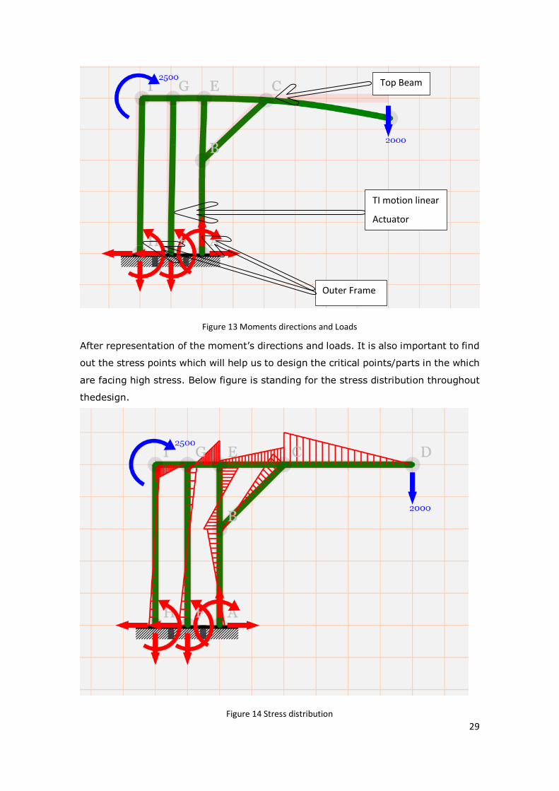
To understand the failure point of the design all the bending moments and loads has
to be analysed. This moment will give us an understanding of the most stressed point
in the design. All the moments and loads are shown in the line in the figure below.
29
Figure 13 Moments directions and Loads
After representation of the moment’s directions and loads. It is also important to find
out the stress points which will help us to design the critical points/parts in the which
are facing high stress. Below figure is standing for the stress distribution throughout
thedesign.
Figure 14 Stress distribution
TI motion linear
Actuator
Outer Frame
Top Beam

30
5.1.2 Description of Individual parts and assembly
Below author is going to discuss each individual child part and assembly which
contains 8 main parts.
5.1.2.1 Beam
As described above the Nylon gripper [referred to 5.2.5] to is used in the design
which is attached on the hollow steel beam with below dimension.
Length: - 1800 mm, Height: - 80 mm, Width: - 80 mm, Thickness: - 10 mm
Figure 15 Image of Beam attached to the gripper
The material used is steel [6] . The reason for using steel is the easy availability and
desired result which the author got after the FEA [7]analysis. As shown in figure 20
below:

31
Figure 16 Solidworks Simulation results of Beam [7]
As the load is calculated by the sum of weights of all the parts and the units. Weight
of unit is the 90 kg and weight of nylon sling is 10 kg including nylon straps and
screw. So are total force will be:
Total Force = Weight of Gripper +Weight of Radio Unit = (100+900) N = 1000
Newton
But for analysis, the author had used 1500 N force to increase the safety factor. But
even after 1500 N it can be seen from the Figure, the results of this analysis are
positive [8]. The shape of the Figure is stable and no major bending is detected that
can affect the overall performance or shape. The most critical part in the
displacement analysis is shown in red and the highest value is 1.862 mm. This value
defines the actual displacement of this area from its original shape

32
into 1.862 mm. This value is too small to affect the device and it can be that Beam
is durable enough to withstand the load. [9]
The lower part of Figure shows the stress analysis that determines the maximum
pressure the part can withstand and the pressure it is experiencing along the whole
area.
In this case, the maximum pressure it can withstand, AKA yield strength is 2.827𝒆8
N/m2.
The most critical area of the beam has a brighter red colour and by the red area
according to the results is experiencing a pressure of 4.339𝒆𝟕 N/m2. This value is
smaller than the maximum value, and it means that the structure is strong enough
to handle the force or 1500 N or 150 kg.
5.1.2.2 Upper Frame (Cover)
In our design author are a Linear column (referred to 5.2.1) showed in figure 21
below. Maximum Bending moment it can withstand is 1000 Nm at the stroke of 200-
300 mm and the maximum required Stroke is 1200 mm. The bending moment
withstands capacity reduced to 200 Nm which is way less than our required bending
moment calculated below:
Maximum Bending Moment = Force on the end of the beam x length of the beam
from Upper frame
= 1500 N x 1.5 m
=2250 Nm

33
Figure 17 Image of Beam attachment to Cover
To improve the Bending moment capacity additional cover to Linear column was
designed to introduce the additional moment of resistance for the linear column. To
check this, the author made a simulation in the Solidworks. The author gave a remote
load on the Cover and to the area where the strut is attached to the cover to check
the Yield strength and maximum displacement [10]. The remote load was applied on
the coordinates where are radio unit is going to hand which is 1500 mm in Z axis and
Y [9]axis 400 and force of 1500 N or 150 kg are applied towards the ground as shown
in figure 22 below:

34
Figure 18 Solidworks simulation results
As from figure 23 and values, the author can analysis that the design is without any
hotspot. The figure shows the design stable and no major bending are detected that
can affect the overall performance or shape. The most critical part in the
displacement analysis is shown in red and the highest value is 3.152𝑒−3 mm. This
value defines the actual displacement of this area from its original shape into
0.003152 mm. This value is too small to affect the device. This is almost negligible,
and the author can state that Cover is durable enough to withstand the load. Besides
this, in the Upper picture, the maximum stress that the author had encountered is
2.311𝒆6 N/m2.

35
Maximum yield strength which the design can bear before going to the plastic region
[11] which might cause the breaking or fracture is 1.3719𝒆8 N/m2 which is less then
are maximum stress and give huge factor of safety of 60.
This was the most critical part of the mechanical design and it has been improved
after FEA before it was bar design which reducing the weight but yield strength was
reduced and was lower than the maximum strength. The material of steel was
selected instead of aluminium because of high Young’ modulus which provides us
with more resistance to moment (Mr). The high moment of resistance was required
to the opposite bending moment which was caused due to a radio unit hanging on
the beam.
5.1.2.3 Telescopic Guide rails.
The cover which is used in the design is four-sided and to provide desired smooth
and linear upward moment by the push of linear column author used four telescopic
guide rail of 930 mm length with the stroke of the of 960 mm which required the lift
the radio unit to a maximum length of 1700 mm. These guide rails are attached to
the upper cover and bottom frame which was introduced to reduce the bending
moment on the linear column as shown in figure 23 below:
Figure 19 Implementation of the Telescopic Guide rails on the Cover and the base
As this is the standard part from company “IBC” (referred to 5.2.4). These guiding
rails calculation is provided in the datasheet [12]. From the datasheet, the author
knows that if you install two rails parallel to each other the permissible load capacity

36
would double. So, for a single rail the permissible radial load is 2581 N and for two
at parallel then it’ll be 5162 N. Similarly, the allowed axial load is 905 and for two
the combined load would be 1010 N. So, after confirmation from the company author
found out that the permissible load = permissible moment. Hence, the permissible
radial moment is 5162 N and permissible axial loads are 905 N. [12]
5.1.2.4 Base Design
The base is the part of the design which must support all the load. Keeping this thing
in mind, the base is designed with steel. The heavyweight of the base will provide us
with more stability and it must strong enough to support all the forces. In figure 24
below:
Figure 20 Solidworks Simulation results of Base
37
The weight of 250 kg or 2500 N on the base to make the analysis. The 250 kg of
weight is the addition of the all the parts above from the analysis author had got the
maximus stress of 5.349e7 N/m2 which is lower than are yield strength of the 1.724e8
N/m2. Also, in the image below the maximum Displacement is of 3.173e-01 mm. Which
supply us the value of maximum displacement of 0.317 mm. This value is too small
to make and any harmful effect on the design [13]. Thus, by this analysis, the author
found out that the design is stable and durable. But as this is whole steel plate and
weight around 80 kg. To reduce the weight some change will be made. Currently, the
solution which the author will implement is chassis frame similar automobiles in the
base.
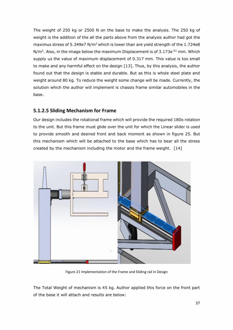
5.1.2.5 Sliding Mechanism for Frame
Our design includes the rotational frame which will provide the required 180o rotation
to the unit. But this frame must glide over the unit for which the Linear slider is used
to provide smooth and desired front and back moment as shown in figure 25. But
this mechanism which will be attached to the base which has to bear all the stress
created by the mechanism including the motor and the frame weight. [14]
Figure 21 Implementation of the Frame and Sliding rail in Design
The Total Weight of mechanism is 45 kg. Author applied this force on the front part
of the base it will attach and results are below:

38
Figure 22 Solidworks Simulation results of Base for the Sliding mechanism
After the simulation results that author got are:
Maximum stress = 2.323e7 N/m2
Yield strength =1.724e8 N/m2
Maximum Displacement = 9.066e-1 mm
These values are desired because our maximum stress is less than yield strength.
Also, the maximum displacement is 0.9066 mm which is really small to make any
harmful change in the system [13].
39
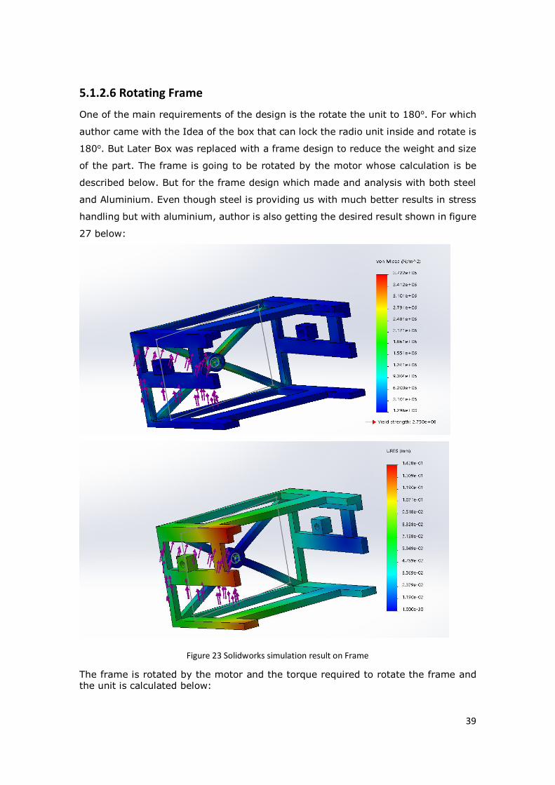
5.1.2.6 Rotating Frame
One of the main requirements of the design is the rotate the unit to 180o. For which
author came with the Idea of the box that can lock the radio unit inside and rotate is
180o. But Later Box was replaced with a frame design to reduce the weight and size
of the part. The frame is going to be rotated by the motor whose calculation is be
described below. But for the frame design which made and analysis with both steel
and Aluminium. Even though steel is providing us with much better results in stress
handling but with aluminium, author is also getting the desired result shown in figure
27 below:
Figure 23 Solidworks simulation result on Frame
The frame is rotated by the motor and the torque required to rotate the frame and the unit is calculated below:

40
Motor Sizing [15]
Known Parameters
Mass = m = 100 kg (product + box)
Length = A = 420 mm (product + box)
Width = B = 300 mm (product + box)
System Efficiency = η = 95%
Operation Speed = 10 rpm
Load Inertia JL = (1/12) m × ((A × 10-3) 2 + (B × 10-3)2 + 12 × (r × 10-3)2)
= (1/12) × (420 × 10-3) 2 + (300 × 10-3)2 + 12 × (5 × 10-3)2)
= 2.222 [kg·m2]
Needed Torque
Acceleration Torque = Ta = JL (Vm / (9.55 × t1)) = 2.222 × (10 / (9.55 × t1)) =
0.7757 Nm
Load Torque = TL = ((m × r × 10-3)) ×g × (1 / (η × 0.01))
= ((100 × 5 ×10-3)) ×9.8 × (1 / (95 × 0.01))
= 5.158 Nm
Hence,
Needed Torque T = (Ta + TL) (Safety Factor)
= (0.7757 + 5.158) × 2
= 11.87 Nm
The calculated torque was applied on the frame to check the stress value and the
maximum displacement and values the author got are:
Maximum stress = 3.722e6 N/m2
Yield strength =2.750e8 N/m2
Maximum Displacement = 1.428e-1 mm
41
Our maximum stress is less than the yield strength which justifies that the system
stable. the maximum displacement is 0.1428 mm which is very low to make any kind
of harmful effect on the system.
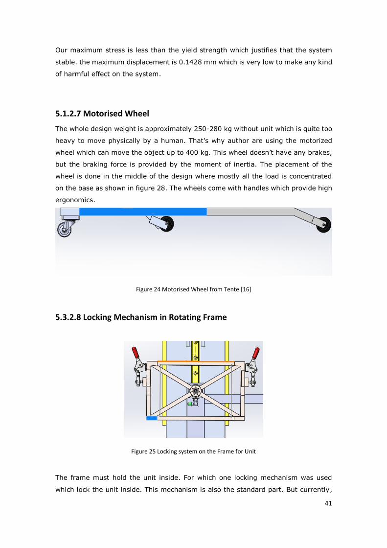
5.1.2.7 Motorised Wheel
The whole design weight is approximately 250-280 kg without unit which is quite too
heavy to move physically by a human. That’s why author are using the motorized
wheel which can move the object up to 400 kg. This wheel doesn’t have any brakes,
but the braking force is provided by the moment of inertia. The placement of the
wheel is done in the middle of the design where mostly all the load is concentrated
on the base as shown in figure 28. The wheels come with handles which provide high
ergonomics.
Figure 24 Motorised Wheel from Tente [16]
5.3.2.8 Locking Mechanism in Rotating Frame
Figure 25 Locking system on the Frame for Unit
The frame must hold the unit inside. For which one locking mechanism was used
which lock the unit inside. This mechanism is also the standard part. But currently,

42
author is using the manual locking system what this will be changed to automatic in
future if it is required.
43
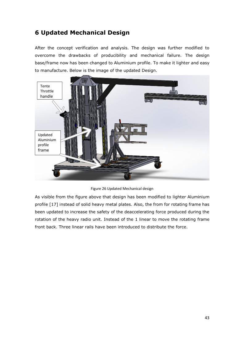
6 Updated Mechanical Design
After the concept verification and analysis. The design was further modified to
overcome the drawbacks of producibility and mechanical failure. The design
base/frame now has been changed to Aluminium profile. To make it lighter and easy
to manufacture. Below is the image of the updated Design.
Figure 26 Updated Mechanical design
As visible from the figure above that design has been modified to lighter Aluminium
profile [17] instead of solid heavy metal plates. Also, the from for rotating frame has
been updated to increase the safety of the deaccelerating force produced during the
rotation of the heavy radio unit. Instead of the 1 linear to move the rotating frame
front back. Three linear rails have been introduced to distribute the force.
Updated Aluminium profile frame
Tente Throttle handle
44
7 Safety
As this solution is going to be used in the production by the human also in the area
where the humans are going to work along. Safety has to be the utmost important
factor. The design is being developed to follow the CE and UL standards. But besides
this as this going to be used in electronics production. This solution has to ESD free.
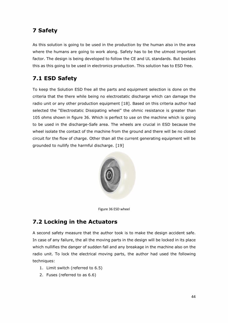
7.1 ESD Safety
To keep the Solution ESD free all the parts and equipment selection is done on the
criteria that the there while being no electrostatic discharge which can damage the
radio unit or any other production equipment [18]. Based on this criteria author had
selected the “Electrostatic Dissipating wheel” the ohmic resistance is greater than
105 ohms shown in figure 36. Which is perfect to use on the machine which is going
to be used in the discharge-Safe area. The wheels are crucial in ESD because the
wheel isolate the contact of the machine from the ground and there will be no closed
circuit for the flow of charge. Other than all the current generating equipment will be
grounded to nullify the harmful discharge. [19]
Figure 36 ESD wheel
7.2 Locking in the Actuators
A second safety measure that the author took is to make the design accident safe.
In case of any failure, the all the moving parts in the design will be locked in its place
which nullifies the danger of sudden fall and any breakage in the machine also on the
radio unit. To lock the electrical moving parts, the author had used the following
techniques:
1. Limit switch (referred to 6.5)
2. Fuses (referred to as 6.6)

45
7.3 Safety in Mechanical design
The mechanical design has been made in an ergonomic way to reduce any kind
prevent injuries which can arise due to uncomfortable design. Beside this for the
safety of the unit locks (referred to 5.3.2.8) has been used mounted on the rotating
frame which holds the unit in the desired position. All the human interaction has been
reduced in this new design compare to current solution use in production which the
largest contributing factor in any accidents.

46
8 Conclusion
The expected outcome of this thesis was to give an operational, safe and ergonomic
solution. For which initial prototype has to be designed and build. This thesis involves
almost all the step of product development which includes conceptualizing various
solutions and combining them in one efficient design. The proposed design in this is
a result of deep production process analysis, economic profitability and development
of design from scratch. Development of the solution has shown in the clear way how
knowledge of Mechatronics studies proved helpful in each step of the development.
Starting from an understanding of the production process, which includes
measurement, mechanism and technology involved in the production process. Later
during the development of the semi-automatic product combination of the electronics
with the mechanical possibility in a controlled system. This product development has
also proved how the engineering creativity has to meet reality, which was realized
mostly during the search and selection of standard parts which includes actuators,
motors and mechanical parts etc. One of the biggest problems realised during this
selection is mostly related to logistics, which showed how geographical place of the
product development influence the development by influencing the cost, availability
and time of transportation.
Besides this human competence and involvement plays a vital role in product
development. The competence decreases the development time but still working in
a team helps to find an efficient solution. All the projects in the world are developed
by a group of people, which clarifies that working in a team is equally important to
the along gaining technical skills. Because for better understanding clear
communication within team and stakeholders is essential to come up with the product
which will be profitable in the end.
Future of this product has a huge scope. As seen from mechanical design
development with every update design can get lighter and stronger because of which
more the development will be done better the outcome will be. Besides this as this
thesis is only conceptual based, a lot of work and challenges has to solve during the
prototype build. This prototype can’t be achieved because of limitation in time and
resources.
Learning aspects of this thesis are huge, the reason for that was the expected
outcome. The solution/product is developed with a lot of constraints which includes
practical feasibility, manufacturing feasibility and profitability. These constraints just
didn’t make the development harder, it also made it important to develop the product
inefficient way.

47
Summary
The manufacturing site is one of the leading 5G radio manufactures. They’re coming
up with a lot of new radios. Many of them are going to be heavy up to 90 kg or more.
This thesis is focused on these heavy radios, as these products quite weight for a
human to lift and move around as required for the production, testing and now and
again investigating. Presently, Manufacturing site is a fixed crane which provides all
the arrangement yet in a restricted territory and in light of this the format of
generation is improved to keep everything inside the compass of the crane and the
comparable crane is introduced in the stockroom. In the event that the item should
be picked and place in other creation corridor or far from the fixed crane it is absurd
and in future, more items are accompanying comparative attributes. Thus, it is
anything but an ideal or versatile arrangement which can be utilized in various
creation lobby or circumstances.
The thesis is developing a conceptual solution to overcome the problem fulfilling all
the requirements. To take care of the issue creator needed to think of various
arrangements from the scratch, at that point creator ran a required examination on
the answers for check the plausibility and the later creator contrasted those
arrangements and one another. After examination, the creator showed those
outcomes to our director and assembling/generation builds after which the creator
chose one to move one with one arrangement and to additionally create it. For the
improvement and refinement, the creator did advance the mechanical investigation
and inquired about business sectors for answers for our plan issues and if necessary,
the creator reached organizations to get the missing information. On the other, the
creator was likewise dealing with the control arrangement of the lift and attempting
to make it as straightforward as could be expected under the circumstances, which
made the framework conservative, modest and simple to the commission. In the
proposal, creator contacted all the part of "Item Improvement" which incorporates
specialized and the executive’s perspectives.

48
References
[1] Ericsson, “Network Products,” [Online]. Available:
https://www.ericsson.com/en/newsroom/photo-library/network-products. [Accessed
05 May 2019].
[2] N. Cross, Nigel Cross - Engineering Design Methods - Strategies for Product Design (3rd
Ed.), 2000.
[3] LionGrip, [Online]. Available: https://www.liongrip.de/. [Accessed 21 12 2019].
[4] U. I. Khan, “Heavy Component Lifting(Electricala and Control Volume),” Tallinn, 2020.
[5] S. S. J. Nudehi, Analysis of Machine Elements Using SOLIDWORKS Simulation 2016,
Mission, KS: SDC Publications, 2016.
[6] B2B Metal, “SQUARE STRUCTURAL HOLLOW SECTIONS - HSS OF EN 10210, PROPERTIES
HOT FORMED SQUARE HOLLOW SECTIONS,” [Online]. Available:
http://www.b2bmetal.eu/square-structural-hollow-sections---hss-of-en-10210-
properties-hot-formed-square-hollow-sections. [Accessed 14 May 2019].
[7] Dassault Systems, “Workflow for Performing 2D Simplification,” [Online]. Available:
https://help.solidworks.com/2016/English/SolidWorks/cworks/HelpViewerDS.aspx?ve
rsion=2016&prod=SolidWorks&lang=English&path=cworks%2fc_Workflow.htm&id=97
e9c61aaa3b4db9bfe349e15a67a359. [Accessed 22 12 2019].
[8] A. E. Ismail, A. K. Ariffin, S. . Abdullah, M. J. Ghazali and R. . Daud, “J-integral analysis of
surface cracks in round bars under bending moments,” Applied Mechanics and
Materials, vol. , no. , pp. 43-48, 2011.
[9] Dassault systems, “Loads and Restraints,” [Online]. Available:
https://help.solidworks.com/2016/English/SolidWorks/cworks/c_Loads_and_Restraint
s.htm?id=767f5c9bfa3744e9886ea61e692d77c9#Pg0. [Accessed 22 12 2019].
[10] W. . Wittke, “Finite Element Method (FEM),” , 2014. [Online]. Available:
https://onlinelibrary.wiley.com/doi/10.1002/9783433604281.ch10. [Accessed 16 5
2019].
[11] A. . Aktaş, “Elastic–Plastic Stress Analysis and Plastic Region Expansion of Clamped
Aluminum Metal–Matrix Laminated Plates with an Elliptical Hole,” Journal of Reinforced
Plastics and Composites, vol. 23, no. 18, pp. 1997-2009, 2004.

49
[12] Aluflex System AS Energivegen, “Heavy Telescopic Rail,” [Online]. Available:
https://www.aluflex.no/Kategori_4_no.html. [Accessed 30 April 2019].
[13] A. . Ohta, Y. . Maeda and N. . Suzuki, “EFFECT OF YIELD STRENGTH ON THE BASIC
FATIGUE STRENGTH OF WELDED JOINTS,” Fatigue & Fracture of Engineering Materials
& Structures, vol. 16, no. 5, pp. 473-479, 1993.
[14] Rexroth A Boch Company, “Linear Profiled Rail Systems Selector,” [Online]. Available:
https://selector.boschrexroth.com/en/us/rail/#/. [Accessed 21 12 2019].
[15] Orientalmotor, “Motor sizing tools,” [Online]. Available:
https://www.orientalmotor.com/motor-sizing/. [Accessed 9 May 2019].
[16] Tente, “E-Drive (Motorized Wheel),” [Online]. Available: https://www.tente.com/en-
gb/product-families/castors/e-drive. [Accessed 21 12 2019].
[17] P. T. SHEPPARD, EXTRUSION OF ALUMINIUM ALLOYS, Kluwer Academic Publisher, 1999.
[18] P. . Besse, J. . Casters, J. P. Laine and A. . Salles, “Electrostatic discharge protection circuit
arrangement, electronic circuit and ESD protection method,” , 2012. [Online]. Available:
http://freepatentsonline.com/y2015/0049406.html. [Accessed 16 5 2019].
[19] Blickle, “Electrically conductive and antistatic wheels and castors from Blickle,” [Online].
Available: https://www.blickle.com/productgroups/electrically-conductive-and-
antistatic-wheels-castors. [Accessed 21 12 2019].
[20] L. S. Sterling, The Art of Agent-Oriented Modeling, London: The MIT Press, 2009.
[21] Hofpartner AB, “A smart lifting device,” [Online]. Available:
https://www.hofpartner.com/en/lifting-equipment/lifting-device-liongrip/. [Accessed
02 May 2019].
[22] LINTECH, “400 series Rotary Positioning Stage,” [Online]. Available:
https://www.lintechmotion.com/products2.cfm?ModelNo=400&t=Group1. [Accessed
April 30 2019].
[23] TSUBAKI GROUP, “Power Transmission products,” [Online]. Available:
https://tsubakimoto.com/power-transmission/linear-actuator/electrical-lifter/lift-
master/lmeb/. [Accessed 30 April 2019].
[24] Rexroth, “Strut Profiles,” [Online]. Available:
https://www.boschrexroth.com/ics/cat/content/assets/Online/do/Strut_profiles_MGE
_EN_20170918_154042.pdf. [Accessed 30 April 2019].

50
[25] TiMotion Technology, “TL3 Series Lifting Columns,” [Online]. Available:
https://www.timotion.com/en/product/detail/lifting-columns/tl3-
series?upcls=1481269382&guid=1488520856. [Accessed 30 April 2019].
[26] TiMotion Technology, “TA16 Series Liner Actuators,” [Online]. Available:
https://www.timotion.com/en/product/detail/linear-actuators/ta16-
series?upcls=1481269298&guid=1494568945. [Accessed 30 April 2019].
[27] Planetroll GmbH & Co. KG, “Planetary gearheads planetdrive,” [Online]. Available:
http://www.planetroll.com/en/antriebstechnik/planetdrive_pd_planetengetriebe/ind
ex.php. [Accessed 11 May 2019].
[28] M. S. a. N. A. R. a. C. T. a. M. A. M. a. S. R. S. Raihan, “Optimal sizing and energy scheduling
of isolated microgrid considering the battery lifetime degradation,” PLOS ONE, 2019.
[29] A. Tang, “Aging Mechanisms of Anode Materials in Lithium-ion Batteries for Electric
Vehicles,” DESTech Transactions on Engineering and Technology Research, 2017.
[30] A. . Mishra, S. . Panda and S. . B, “Control of Voltage Source Inverters using
PWM/SVPWM for Adjustable Speed Drive Applications,” , 2009. [Online]. Available:
http://ethesis.nitrkl.ac.in/1133. [Accessed 16 5 2019].
[31] E. . Januarto and S. . Supratno, “PLCMIKRO SEBAGAI SOLUSI OTOMATISASI INDUSTRI,” ,
2013. [Online]. Available: http://ejournal-
unisma.net/ojs/index.php/resultan/article/view/705/630. [Accessed 16 5 2019].
[32] T. R. Kuphaldt, “Chapter 6 LADDER LOGIC,” , . [Online]. Available:
http://www.ibiblio.org/kuphaldt/electricCircuits/Digital/DIGI_6.html. [Accessed 16 5
2019].
[33] “Electronic Circuit Symbols,” , . [Online]. Available:
http://www.circuitstoday.com/electronic-circuit-symbols. [Accessed 16 5 2019].
[34] S. . Ioannou, K. . Dalamagkidis, E. K. Stefanakos, K. P. Valavanis and P. H. Wiley, “Runtime,
capacity and discharge current relationship for lead acid and lithium batteries,” , 2016.
[Online]. Available: https://ieeexplore.ieee.org/document/7535940. [Accessed 16 5
2019].
[35] T. S. James Moran, “Variations in Dry Sliding Friction Coefficients with Velocity,”
Department of mechanical engineering, Faculty of Engineering. Chiang Mai University,
2010.

51
[36] S. Kumaran, “Motor Torque Calculation,” [Online]. Available:
https://www.academia.edu/5125232/Motor_Torque_Calculation_Motor_Torque_Calc
ulation. [Accessed 23 12 2019].
[37] J. a. F. E. a. H. G. Bucaille, “Mechanical analysis of the scratch test on elastic perfectly
plastic materials with the three-dimensional finite element modeling,” Wear, vol. 249,
2001.
52
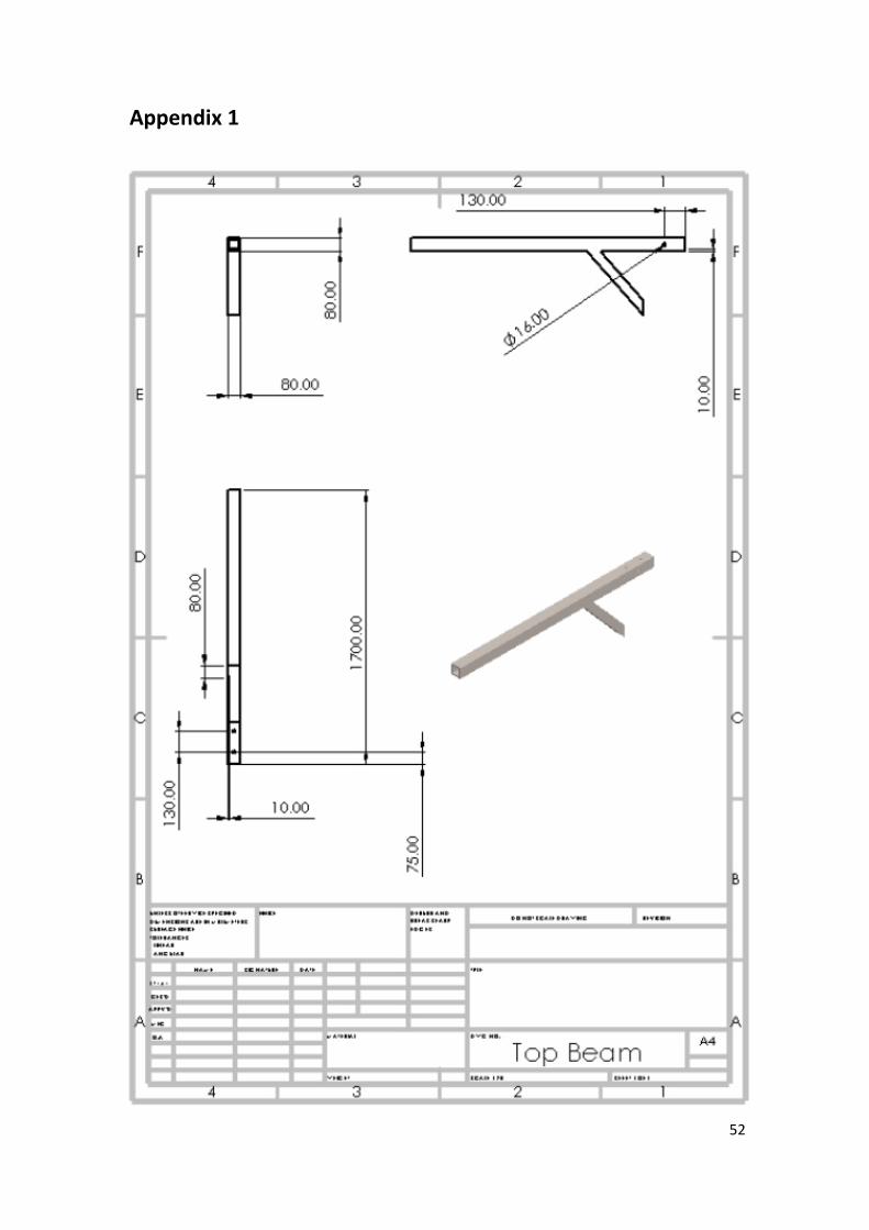
Appendix 1
53
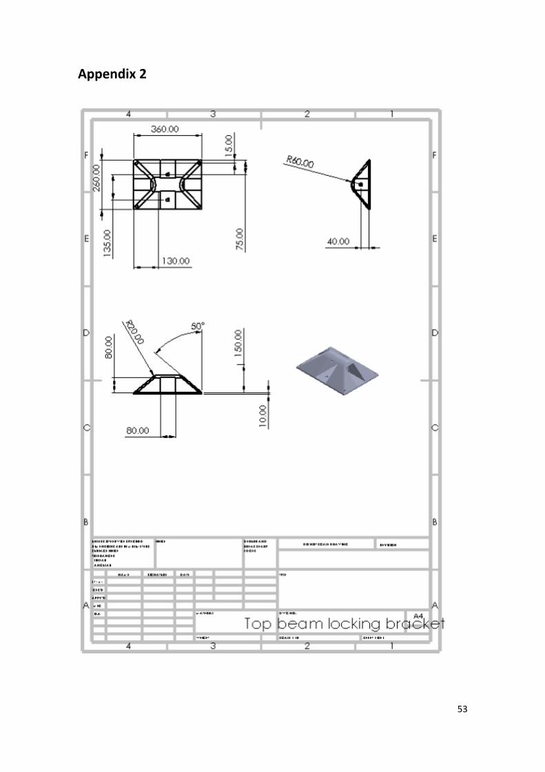
Appendix 2

54
Appendix 3

55
Appendix 4

56
Appendix 5

57
Appendix 6

58
Appendix 7

59
Appendix 8 (Updated Mechanical Design)
Related Documents