Journal of National Fisheries University 64 (4) 283 - 291(2016) 研究会記録 Heat Transeer Performance of Falling Film Type Plate-Fin Evaporator Junichi Ohara Abstract:The characteristics of heat transfer and flow patterns are investigated experimentally for the vertical falling film evaporation of pure refrigerant HCFC123 in a rectangular minichannels consisting of offset strip fins. The refrigerant liquid is uniformly supplied to the channel through a distributor. The liquid flowing down vertically is heated electrically from the rear wall of the channel and evaporated. To observe the flow patterns during the evaporation process directly, a transparent vinyl chloride resin plate is placed as the front wall. The experimental parameters are as follows: the mass velocity G = 28~70 kg/(m 2 s), the heat flux q = 20~50 kW/m 2 and the pressure P 100 kPa. It is clarified that the heat transfer coefficient a depends on G and q in the region of vapor quality x 0.3 while there is little influence of G and q in the region x 0.3 . From the direct observation using a high speed video camera and a digital still camera, flow patterns are classified into five types. Then the empirical correlation equations for evaporation heat transfer coefficient on a vertical falling film plate fin evaporator with minichannels are proposed. From the physical model to evaluate the heat transfer coefficient of the minichannel surface with fins, the characteristics of fin efficiency is clarified that the average value of fin efficiency is about 0.6 and the distributive characteristics of fin efficiency is roughly inverse of heat transfer coefficient characteristics. Key words:Minichannels, Heat transfer, Plate Fin Evaporator, Falling film Department of Ocean Mechanical Engineering, National Fisheries University, Shimonoseki, Yamaguchi, Japan Introduction Recently, nonazeotropic refrigerant mixtures (NARMs), which are composed of environmentally acceptable alternatives, have become of special interest in the use as working fluid in vapor compression heat pump/refrigeration cycles. Previous studies on evaporation and condensation of NARMs, however, reported that the heat transfer coefficients of NARMs are lower than those of pure refrigerant. To compensate for this defect, it is necessary to improve the performance of heat exchangers. From this point of view, special interests have been taken in plate fin heat exchangers. Focusing on evaporators, falling liquid type plate fin evaporators that have standout features of high heat transfer rate at small temperature difference even in the case of small mass velocity of refrigerants are considered as one of the promising evaporators to improve the performance of heat pump/ refrigeration cycles using NARMs as working fluids. Robertson and Lovegrove 1) conducted flow boiling experiments with CFC 11 vertically up through the electrically heated offset strip fin test section. Thome 2) introduced plate fin heat exchanger as an important alternative to enhanced boiling tubes for augmenting boiling heat transfer and summarized previous studies on boiling in plate fin heat exchanger. Kandlikar 3) proposed the additive model of the convective and nucleate boiling components for flow boiling heat transfer in offset strip fin evaporator using the data obtained by Rovertson and Loveglove 1) . Feldman et al. 4) obtained local heat transfer characteristics of CFC114 experimentally in a plate fin evaporator with offset strip and perforated fin surface and proposed a correlation equation taking into account the

Welcome message from author
This document is posted to help you gain knowledge. Please leave a comment to let me know what you think about it! Share it to your friends and learn new things together.
Transcript
Journal of National Fisheries University 64 (4) 283 - 291(2016)研究会記録
Heat Transeer Performance of Falling Film Type Plate-Fin Evaporator
Junichi Ohara
Abstract:The characteristics of heat transfer and flow patterns are investigated experimentally
for the vertical falling film evaporation of pure refrigerant HCFC123 in a rectangular minichannels
consisting of offset strip fins. The refrigerant liquid is uniformly supplied to the channel through a
distributor. The liquid flowing down vertically is heated electrically from the rear wall of the channel
and evaporated. To observe the flow patterns during the evaporation process directly, a transparent
vinyl chloride resin plate is placed as the front wall. The experimental parameters are as follows: the
mass velocity G = 28~70 kg/(m2s), the heat flux q = 20~50 kW/m
2 and the pressure P 100 kPa.
It is clarified that the heat transfer coefficient a depends on G and q in the region of vapor quality x
0.3 while there is little influence of G and q in the region x 0.3 . From the direct observation using a
high speed video camera and a digital still camera, flow patterns are classified into five types. Then the
empirical correlation equations for evaporation heat transfer coefficient on a vertical falling film plate
fin evaporator with minichannels are proposed. From the physical model to evaluate the heat transfer
coefficient of the minichannel surface with fins, the characteristics of fin efficiency is clarified that
the average value of fin efficiency is about 0.6 and the distributive characteristics of fin efficiency is
roughly inverse of heat transfer coefficient characteristics.
Key words:Minichannels, Heat transfer, Plate Fin Evaporator, Falling film
Department of Ocean Mechanical Engineering, National Fisheries University,
Shimonoseki, Yamaguchi, Japan
Introduction
Recently, nonazeotropic refrigerant mixtures (NARMs), which
are composed of environmentally acceptable alternatives, have
become of special interest in the use as working fluid in vapor
compression heat pump/refrigeration cycles. Previous studies on
evaporation and condensation of NARMs, however, reported
that the heat transfer coefficients of NARMs are lower than those
of pure refrigerant. To compensate for this defect, it is necessary
to improve the performance of heat exchangers. From this point
of view, special interests have been taken in plate fin heat
exchangers. Focusing on evaporators, falling liquid type plate fin
evaporators that have standout features of high heat transfer rate
at small temperature difference even in the case of small mass
velocity of refrigerants are considered as one of the promising
evaporators to improve the performance of heat pump/
refrigeration cycles using NARMs as working fluids.
Robertson and Lovegrove1) conducted flow boiling experiments
with CFC 11 vertically up through the electrically heated offset
strip fin test section. Thome2) introduced plate fin heat exchanger
as an important alternative to enhanced boiling tubes for
augmenting boiling heat transfer and summarized previous
studies on boiling in plate fin heat exchanger. Kandlikar3)
proposed the additive model of the convective and nucleate
boiling components for flow boiling heat transfer in offset strip
fin evaporator using the data obtained by Rovertson and
Loveglove 1). Feldman et al.4) obtained local heat transfer
characteristics of CFC114 experimentally in a plate fin
evaporator with offset strip and perforated fin surface and
proposed a correlation equation taking into account the

284
dominance of nucleate boiling and convective boiling. Watel 5)
had compiled the review for heat transfer characteristics of flow
boiling in compact heat exchangers that have small passages of
straight, perforated and offset strip fin. The typical trends of
local heat transfer coefficient show that it is easy to distinguish
between the two dominant mechanisms of boiling. Kim and
Sohn6) reported that an experimental study on saturated flow
boiling heat transfer of R113 in a vertical rectangular channel
with offset strip fins. The predictions of local flow boiling heat
transfer coefficients were found to be in good agreement with
experimental data. An experimental study on saturated flow
boiling heat transfer of HFE-7100 in vertical rectangular
channels with offset strip fins is presented by Pulvirenti et al.7).
The local boiling heat transfer coefficient has been obtained
from experiments and analyzed by means of Chen superposition
method. Some correlations for convective and nucleate boiling
heat transfer coefficients have been found that agree well with
the obtained data.
Most of them reviewed above have been carried out on the
condition that test fluid flows up vertically, but few studies on
the downflow condition. At the same time, a number of studies
are conducted and reported about flow boiling heat transfer
characteristics of falling liquid film that flows down on the plane
walls, the inside and the outside wall of the tubes and horizontal
tube banks other than offset strip fin surface in plate fin heat
exchanger.
Ribatski and Jacobi8) reviewed studies for falling film
evaporation on horizontal tubes. It covers flow-pattern studies,
and the experimental parameters that affect the heat transfer
performance on plain single tubes, enhanced surfaces and tube
bundles. An experimental study of falling film heat transfer
outside horizontal tubes was carried out by Yang and Shen9) in
order to show how the heat transfer coefficient is affected by
different parameters such as evaporation temperatures,
temperature difference between wall and saturation water and so
on. The results show that the heat transfer coefficient increases
with the increase in liquid feeding, evaporation boiling
temperature and heat flux. An experimental study of heat and
mass transfer in free and forced convection in a vertical channel
with parallel metal plates is presented by Cherif et al.10). The
results obtained are exploited to study the influence of the
operating parameters such as the heat flux.
As shown above, there are very few literatures about falling
film evaporation in a plate fin heat exchanger. In the present
study, to clarify the heat transfer and flow pattern characteristics
in a plate fin evaporator on the downflow condition, the vertical
falling film evaporation of pure refrigerant HCFC123 in a
rectangular minichannel consisting of offset strip fins was
investigated experimentally.
NOMENCLATURE
A : area of heat transfer [m2]Cp : isobaric specific heat [J/(kg K)]dh : hydraulic diameter [m]G : refrigerant mass velocity [kg/(m2s)]h : specific enthalpy [kJ/kg]Nu : Nusselt number [ - ]
= adh/λl
P : pressure [Pa]Pr1 : Prandtl Number [ - ]
= μlCpl/λl
Q : heat transfer rate [W]q : heat flux [W/m2]Re1 : liquid Reynolds number [ - ]
= G(1-x)dh/μl
Relv : vapor Reynolds number [ - ]= Gxdh/μv
: two phase Reynolds number [ - ]= Gxdh/ρvvl
S : cross sectional area [m2]T : temperature [K]W : mass flow rate [kg/s]x : vapor quality [ - ]a : heat transfer coefficient [W/(m2K)]λ : thermal conductivity [W/(m K)]μ : dynamic viscosity [Pas]ρ : density [kg/m3]Xu : Lockhart-Martinelli parameter [ - ]
=(1-x/x)0.9(ρv / ρl)0.5(μl /μv)
0.1
SubscriptB : base lo : liquid onlyb : bulk r : refrigerantf : fin sat : saturation statei : section number v : vaporl : liquid w : wall
EXPERIMANTAL APPARATUS AND MEASUREMENT
METHOD
Experimental Apparatus
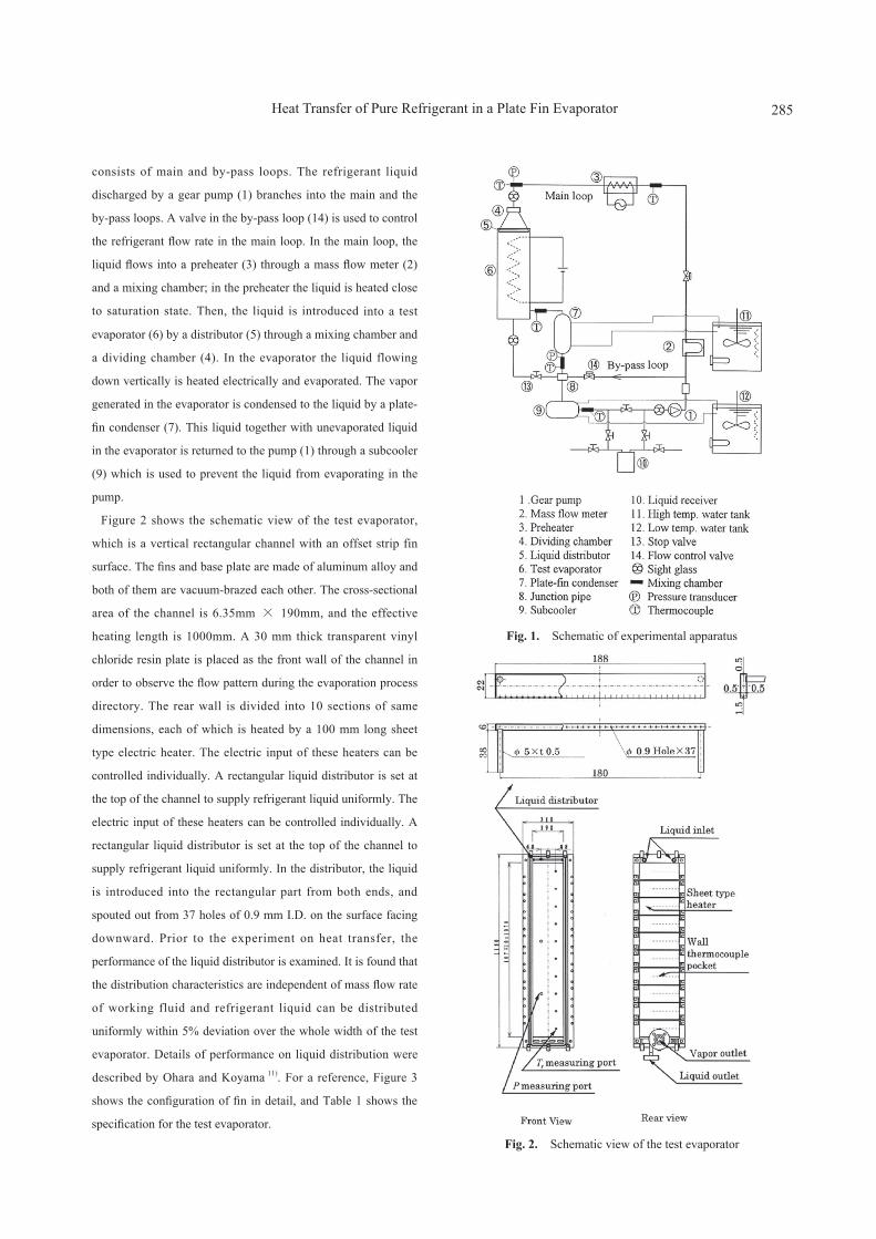
Figure 1 shows schematic view of the present experimental
apparatus. The refrigerant loop is a forced circulation one which
Junji Kawasaki
285
consists of main and by-pass loops. The refrigerant liquid
discharged by a gear pump (1) branches into the main and the
by-pass loops. A valve in the by-pass loop (14) is used to control
the refrigerant flow rate in the main loop. In the main loop, the
liquid flows into a preheater (3) through a mass flow meter (2)
and a mixing chamber; in the preheater the liquid is heated close
to saturation state. Then, the liquid is introduced into a test
evaporator (6) by a distributor (5) through a mixing chamber and
a dividing chamber (4). In the evaporator the liquid flowing
down vertically is heated electrically and evaporated. The vapor
generated in the evaporator is condensed to the liquid by a plate-
fin condenser (7). This liquid together with unevaporated liquid
in the evaporator is returned to the pump (1) through a subcooler
(9) which is used to prevent the liquid from evaporating in the
pump.
Figure 2 shows the schematic view of the test evaporator,
which is a vertical rectangular channel with an offset strip fin
surface. The fins and base plate are made of aluminum alloy and
both of them are vacuum-brazed each other. The cross-sectional
area of the channel is 6.35mm × 190mm, and the effective
heating length is 1000mm. A 30 mm thick transparent vinyl
chloride resin plate is placed as the front wall of the channel in
order to observe the flow pattern during the evaporation process
directory. The rear wall is divided into 10 sections of same
dimensions, each of which is heated by a 100 mm long sheet
type electric heater. The electric input of these heaters can be
controlled individually. A rectangular liquid distributor is set at
the top of the channel to supply refrigerant liquid uniformly. The
electric input of these heaters can be controlled individually. A
rectangular liquid distributor is set at the top of the channel to
supply refrigerant liquid uniformly. In the distributor, the liquid
is introduced into the rectangular part from both ends, and
spouted out from 37 holes of 0.9 mm I.D. on the surface facing
downward. Prior to the experiment on heat transfer, the
performance of the liquid distributor is examined. It is found that
the distribution characteristics are independent of mass flow rate
of working fluid and refrigerant liquid can be distributed
uniformly within 5% deviation over the whole width of the test
evaporator. Details of performance on liquid distribution were
described by Ohara and Koyama 11). For a reference, Figure 3
shows the configuration of fin in detail, and Table 1 shows the
specification for the test evaporator.
Fig. 1. Schematic of experimental apparatus
Fig. 2. Schematic view of the test evaporator
Heat Transfer of Pure Refrigerant in a Plate Fin Evaporator

286
Measurement Method
The heat loss is evaluated ignorable for the following reasons. 1)
In the case of refrigerant mass velocity G = 28 kg/(m2s) and
heat flux q = 50 kW/m2, rear surface temperature reaches its
maximum about 170 degree Celsius, and total of estimated free
convective heat transfer rate and heat transfer rate by radiation
from rear surface without insulation is 891W/m2. The heat loss
becomes only 1.8% of total. 2) The rear surface of the test
evaporator was covered by 80mm thick rockwool for heat
insulation. 3) The temperature of the room where experiments
was carried out was kept about 28 degrees C near the saturation
temperature of test refrigerant. Because of the negligible heat
loss from the evaporator to the ambient, the heat transfer rate to
the refrigerant in each section is supposed to be equal to the
electric power of a heater, which is evaluated from the voltage
drop through it and the electric current flowing through a
standard resistance connected in series. Refrigerant mass flow
rate is measured by a micro-motion mass flow meter. The
refrigerant temperature is measured at each section of the test
evaporator with a φ 1.6 mm K-type thermocouple inserted in the
refrigerant channel through the transparent plate. The wall
temperature at the center of each section is measured with a φ
0.5 mm K-type thermocouple inserted through a capillary tube
(0.9 mm I.D.) laid in the wall. This thermocouple is traveled in
the capillary tube in order to evaluate the average wall
temperature. The refrigerant pressure is measured at upper part
of the test evaporator, centers of 5th and 8th sections and outlet
of evaporator with absolute pressure transducers set at the ports
on the transparent plate. The calibration errors of sensors are
summarized in Table 2. And the evaluation of the accuracy in
the determination of the local heat transfer coefficient gives
average relative error of 14% by use of each experimental data.
From definition of heat transfer coefficient, the relative error
consists of heat flux term and term of temperature difference
between the wall and the saturated fluid, and the term of
temperature difference relatively increased when the temperature
difference becomes smaller (about 2K) in the high heat transfer
region.
Table 2: The calibration errors of sensorsMeasurement Type of Sensor Accuracy
R e f r i g e r a n t Temperature(Test Section)
K-Type Thermocouple
± 0.01degrees C
Wall Temperature(Test Section)
K-Type Thermocouple
±0.01degrees C
Pressure Pressure Transducer ±0.01 kPaRefr igerant f low Rate
Micro-motion Mass Flow Meter ±0.3 R.D.
Power Input Standard Resistance ±0.01 mΩ
The experiments are carried out with the following range: the
refrigerant saturation pressure Psat 100kPa, uniform heat flux
from 2nd to 10th sections q = 20, 30, 40 and 50 kW/m2, and to
clarify the heat transfer characteristics in small range of mass
velocity, the value of refrigerant mass velocities are chosen as G
= 28, 40, 55 and 70 kg/(m2s).
DATA REDUCTION
The specific enthalpy of subcool liquid flowing into the
evaporator is evaluated from the refrigerant pressure and
temperature, both of which are measured at the mixing chamber
set just before the evaporator.
hb0 = hl (P,Tr) (1)
The bulk enthalpy at the outlet of the i th section hbi is
Fig. 3. Schematic view of the test evaporator
Table 1. Specification of test evaporator
Fin Type Offset strip
Fin Spacing a [mm] 1.478
Fin Height b [mm] 6.35
Fin Thickness δf [mm] 0.203
Hydraulic Diameter dh [mm] 2.11
Width of refrigerant channel . [mm] 190
Effective Heat Transfer Length . [mm] 1000
Number of Section 10
Cross-sectional Area [m2] 1.02×10⁻³
Base Surface Area [m2] 0.202
Real Surface Area [m2] 2.056
Increased Ratio of Surface Area 10.18
Junichi Ohara

287
calculated as
hbi = hb(i-1) + (i=1,2…,10) (2)
where Qi is the heat transfer rate of the i th section, and W is
the refrigerant mass flow rate. Then the quality at the outlet of
the i th section xi is calculated as
xi = (3)
where hvsat and hlsat denote the enthalpy of vapor and liquid at
saturation state, which is evaluated by the measured pressure.
The quality at the center of the i th section is calculated as
arithmetic average one between inlet and outlet of the i th
section. The local heat transfer coefficient is defined as
ai = (4)
where AB , q and Twi are the base heat transfer area, the local
heat flux and the wall temperature of the i th section,
respectively, and Tsai is the saturation temperature at the center
of the i th section, which is estimated from the pressure
distribution. The mass velocity G is defined as
G = (5)
where, S is the cross-sectional area excluding the sum of fin
cross-sectional area. The thermodynamic and transport property
of HCFC123 are estimated by use of REFPROP ver.7.
RESULTS AND DISCUSSIONS
Distribution of Temperature, Pressure and Quality
Figure 4 shows an example of the distribution of temperature,
pressure and quality in the refrigerant flow direction on the
condition of heat flux q= 50 kW/m2 and refrigerant mass
velocity G= 55 kg/(m2s). Symbols of solid circle, solid triangle,
solid inverted triangle and triangle denote refrigerant temperature
Tr, wall temperature Tw, pressure P, and heat flux q, respectively;
all data of Tr and Tw are measured values. The pressure
measurement ports of the test evaporator are set at the inlet, the
5th section, the 8th section and the outlet, so pressure data of
other sections are interpolated data. Symbols of solid square and
circle denote saturation state temperature Tsat and quality x ;
these are calculated values. Integer and MIX on the abscissa
represent the section number and the mixing chamber just before
the test evaporator. In this case, the 1st section is heated at 15
kW/m2for preheating, and the others are heated uniformly at 50
kW/m2. The value of Tr increases gradually toward the
downstream from the inlet, and approaches Tsat after the 3rd
section. The value of Tw increases sharply between the 1st and
the 2nd sections, and remains constant from the 2nd to the 5th
sections. After the 5th section, it decreases gradually in the flow
direction. The value of x increases linearly in the flow direction
because of the uniform heat flux from the 2nd to the 10th
sections. Through all the experiments, the subcooling of the
refrigerant liquid at the inlet of the test evaporator is ranged from
0.5 to 7.0 K. The average pressure drop between inlet and outlet
of the test evaporator are 1.4 kPa. Saturated temperature rising
caused by this pressure difference is estimated as small as 0.37
K.
The maximum and average temperature difference between wall
and saturated refrigerant are 7.6 K and 3.9 K respectively except
in the region of dry patch and dry out. From the results of heat
transfer experiments and the flow observation, it is inferred that
the convective evaporation is dominant and the nucleate boiling
is fully suppressed.
Flow Pattern
Figure 5 shows the result of the flow observation with a high-
speed camera and a digital still camera through a 30 mm thick
transparent vinyl chloride resin plate placed as the front wall of
the channel in order to observe the flow pattern during the
evaporation process directory. Figures. (a)(stereogram), (b)
(projected plane), (c)(projected plane) are the flow patterns of
liquid film accompanied with dry patch, dripping and mist,
Heat Transfer of Pure Refrigerant in a Plate Fin Evaporator
Fig. 4. Distribution of temperature, heat flux and quality

288
respectively, where the shaded part in Figure(a) denotes dry part
of the heat transfer area, the hatched part in Figure(b) denotes
liquid drop or liquid film thicker than other parts and a dot in
Figure(c) denotes a mist particle.
In the case of small G, despite the magnitude of q, the dry patch
appears on the middle part of fin surface, as shown in Figure(a).
The reason of dry patch is that the liquid gathers at larger
curvature parts (top and root) of the fin and its flow rate is not
sufficient for wetting the whole fin surface. The area of dry
patch enlarges in the downstream region. Therefore, heat transfer
coefficient α decreases with increase of quality x. This
phenomenon is observed more clearly when q increases. In the
case of large G, the dry patch does not appear in the whole
region from upstream to downstream. In the upstream region
liquid flows down mainly on the root and the top parts of fins
and is not entrained to the gas phase. In the middle- stream
region, drip from the trailing edge of a fin to the leading edge of
a fin after next, as shown in Figure(b). a starts to increase with
increase in x. The reason of the dripping is that the shear stress
acting on liquid-vapor interface becomes larger due to the
increase of the vapor velocity. In the downstream region, as
shown in Figure(c), the liquid dripping turns into spraying, and
the mist generation is much enhanced as the vapor velocity
increases. The value of α rise much more with increasing of x.
Most of the generated mist collide with the leading edge of the
fin after next and make a thin liquid film on the fin surface
again. This flow pattern is the mist flow type with the thin liquid
film on the fin surface.
It is confirmed that the disturbance of liquid film is small in the
whole region from upstream to downstream in the case of small
G, while in the case of large G, that becomes violently with
increase of q. It is also noted that nucleate boiling is not
observed through the present experiments. In addition, flow
pattern map was indicated in Ohara, J. and Koyama, S., (2012)
Characteristics of Heat Transfer
Figure 6(a), (b), (c) and (d) show the relation between heat
transfer coefficient α and quality x in the case of q= 20, 30, 40
and 50 kW/m2, respectively, where symbols of triangle, square,
inverted triangle and circle represent the data of G= 28, 40, 55
and 70 kg/(m2s), respectively. In each figure, in the case of G=
55, 70 kW/(m2s), the value of α firstly decreases and then
increases with increase of x. The main reason for the increase of
α is considered that the flow pattern becomes dripping (Figure
5(b)) in the middle-stream region, and turns into mist flow with
thin liquid film on the fin surface in the downstream region
(Figure 5(c)). On the other hand, in the case of G= 28 kg/(m2s),
the value of α decreases in some degree with increase of x. This
fact is seen from figures (a), (b), (c) and (d) that the value of α in
the range x 0.3 is almost independent of the magnitude of q
and G, being almost constant about 9.5 kW/(m2K). When the
liquid film is laminar, the value of α is supposed to decreases
with the increase of G (in other words, increase of film
thickness). In these results, however, α does not decrease with
the increase of G. It can be inferred from this fact that the
disturbance of liquid film is promoted with the increase of G.
Comparing α at constant values of G and x in these figures, it is
seen that α decrease with the increase of q.
Figure 7(a), (b), (c) and (d) show the relation between α/αlo and
1/Xtt in the case of G= 28, 40, 55, and 70 kg/(m2s), respectively,
where Xtt is the Lockhart-Maltinelli’s parameter defined as
Xtt = 0.9 0.5 0.1
(6)
and αlo is the heat transfer coefficient supposed that the liquid
component only flows in the passage of heat exchanger, defined
Fig. 6. The relation between α and x
Junichi Ohara
Fig. 5. Flow patterns(a) Liquid film accompanied with dry patch
(b) Liquid film accompanied with dripping
(c) Liquid film accompanied with mist

289
as
αlo = 0.023 Rel0.8 Prl
0.4 (7)
where dh is a hydraulic diameter and the Reynolds number Rel is
defined as
Rel=G(1-x)dh/μl (8)
symbols of triangle, square, inverted triangle and circle represent
the case of q= 20, 30, 40 and 50kW/m2, respectively. The solid
line is the heat transfer correlation equation for downflow forced
convective evaporation in a vertical tube proposed by Wright12).
=2.72 0.85
(9)
In each figure, in the region of small 1/Xtt the value of α/αlo
keeps constant, while in the other range it increases with the
increase of 1/Xtt. It is also found from these figures that there is
little effect of q and G on the relation between α/αlo and 1/Xtt.
The data in the region of large 1/Xtt is ten times the value given
by Wright’s correlation equation.
Heat Transfer Correlation Equations
Figure 8 shows the relation between Nusselt number Nu and
two phase Reynolds number Relv, where Nu and Relv are
defined as
Nu = (10)
Relv = (11)
In the figure, symbol colors of blue, green, orange and red
represent the data of G= 28, 40, 55 and 70 kg/(m2s),
respectively. And shapes of symbols; inverted triangle, square,
triangle and circle represent the data of q= 20, 30, 40 and 50
kW/m2, respectively. The value of Nu is almost constant
independently of q and G when Relv 8000. In the region of
Relv 8000, Nu increases with increasing of Relv. Based on the
above results, empirical correlation equations for heat transfer
coefficient in a vertical falling film plate-fin evaporator are
proposed as equations
Nu ={ 250 (12)
32Xtt-0.65Nulo
where, Nulo is Nusselt number of single phase turbulent flow
based on the equation of Dittus-Bӧelter, and is defined as
following equation.
Nulo=0.023Rel0.8Prl
0.4 (13)
Using equations (12), a greater value of Nusselt number should
be chosen.
Figure 9 shows a relation between Nu/Nulo and 1/Xtt. Symbols
and lines represent the experimental data and the calculated
result using equation (12) respectively. The data
excepted for dry out region are well correlated within error of ±
30%. In this research, a boundary between equations (12) is that
the value of two phase Reynolds number Relv =~ 8000 ~ 15000.
Fin Efficiency
Figure10 shows a physical model to evaluate the heat transfer
Fig. 7. The relation between α/αlo and 1/Xtt
Heat Transfer of Pure Refrigerant in a Plate Fin Evaporator
Fig. 8. Relation between Nu and Relv

290
coefficient of the minichannel surface with fins. In this model,
the following assumptions are employed: (1) the heat conduction
in a fin is one dimensional along the fin surface, and (2) the heat
transfer coefficient is constant in both of the fin and base
surfaces. Based on this model, the local heat transfer coefficient
αfi is defined as
αfi Qi (14)
{Ai-Afi(1-ηi)}(Twi-Tsati)
where, Ai and Afi are total heat transfer area of a section and fins
respectively, Twi and Tsati are the wall temperature and
refrigerant saturation temperature of the i th section,
respectively, and ηi is the efficiency of the i th section. The
function of ηi is calculated as
ηi= ・tanh (15)
where, s is the circumferential length of the fin, F is the cross-
sectional area of a fin and λf is the thermal conductivity of fins.
Figure 11 shows the relation between heat transfer coefficient
taking into fin efficiency account αfi and quality x. In the figure,
colors of symbols and shapes of symbols represent the values of
mass velocity G and heat flux q respectively. Distributive
characteristic of heat transfer coefficient αfi is as same as the
case of heat transfer coefficient α evaluated from base heat
transfer area qualitatively (see Figure 6). The distribution range
of value of heat transfer coefficient αfi is from 7.5 to 3.2 kW/
m2K.
Figure 12 shows the value of fin efficiency η along the quality
x. The average value of η is about 0.6. In the region of x 0.3,
η is almost independent of the magnitude of q and G, being
almost constant. While in the region of x 0.3, data disperse
widely from 0.42 to 0.76. Data of fin efficiency seems having
inverse distributive characteristic of heat transfer coefficient in
the Figure 11. It could be understand from equations (14) and
(15).
CONCLUSIONS
Heat transfer characteristics and flow patterns are investigated
experimentally for vertical falling film evaporation of pure
refrigerant HCFC123 in rectangular minichannels consisting of
offset strip fins. The following major conclusions are derived
from this study:
(1) From the direct observation, the flow pattern is classified
into five typical types: plane liquid film, wavy liquid film, liquid
film accompanied with dry patch, liquid film accompanied with
dripping and liquid film accompanied with mist.
(2) In the case of small mass velocity G= 28 kg/(m2s) and heat
flux q= 20~50 kW/m2, dry patch appears on the middle part of
each fin surface in the upstream region (low quality region). As
evaporation proceeds further, the area of each dry patch becomes
Fig. 10. Physical model of fin
Fig. 9. Relation between Nu/Nulv and 1/Xtt
Fig. 11. The relation between α and x
Fig. 12. The value of Fin efficiency
Junichi Ohara

291
larger, and the heat transfer coefficient α decreases gradually,
and ranging from 5 to 9 kW/(m2K) in this case.
(3) As G increases, dry patch is not observed, but the
disturbance of liquid film is observed in the upstream region. In
the middle-stream region, the liquid starts to drip, and the value
of α starts to increase in the flow direction. In the downstream
region, the liquid dripping turns into spraying, and the mist
generation occurs. The flow pattern is the mist flow type with
thin liquid film on fin surface. In this region, the value of α
increases with increase of x, and ranges from 10 to 16 kW/
(m2K).
(4) The experimental data of heat transfer coefficient are
compared with Wright’s equation for forced convective
evaporation. The data agree with about ten times of Wright’s
equation in the region of large 1/Xtt. In the region of small 1/Xtt
the value of α/αlo keeps constant.
(5) Heat transfer correlation equation for vertical falling film
plate fin evaporator is proposed as
Nu ={ 25032Xtt
-0.65Nulo
This equation agrees with the experimental data within 30%
deviation.
(6) From the results of fin efficiency analysis, distributive
characteristic of heat transfer coefficient taking into account fin
efficiency αfi is as same as the case of heat transfer coefficient α
evaluated from base heat transfer area qualitatively. The value
takes from 7.5 to 3.2 kW/m2K, and the average value of fin
efficiency becomes about 0.6. The data of fin efficiency seems
having inverse distributive characteristic of heat transfer
coefficient.
REFERENCES
1) Rovertson, J. M., and Lovegrove, P. C.: Boiling heat transfer
with freon 11 brazed-aluminum plate fin heat exchanger.
Trans. ASME J of Heat Transfer, 105, 605-610 (1983)
2) Thome, J. R.: Enhanced boiling heat transfer. New York
Hemisphere Publishing Corporation, 323-351 (1990)
3) Kanlikar, S. G.: A model correlating flow boiling heat transfer
in augmented tubes and compact evaporators”, Trans.
ASME, 113, 966-972 (1991)
4) Feldmana A., Marvilletb C., Lebouche M.: Nucleate and
convective boiling in plate-fin heat exchangers, Int Jo of Heat
and Mass Transfer, 43, 3433-3442. (2000)
5) Watel B.: Review of saturated flow boiling in small passages
of compact heat-exchangers. Int Jo of Thermal Sciences, 42,
107-140 (2003)
6) Kim B., and Sohn B.: An experimental study of flow boiling
in a rectangular channel with offset strip fins. Int J of Heat and
Fluid Flow, 27, 514-521 (2006)
7) Pulvirenti B., Matalone A. and Barucca U.: Boiling heat
transfer in narrow channels with offset strip fins: Application
to electronic chipsets cooling, Applied Thermal Engineering
30, 2138-2145 (2010)
8) Ribatski G. and Jacobi A.M.: Falling-film evaporation on
horizontal tubes-a critical review. Int J of Refrigeration, 28,
635-653 (2005)
9) Yang L. and Shen S.: Experimental study of falling film
evaporat ion heat t ransfer outside horizontal tubes.
Desalination ,220, 654-660 (2008)
10) Cherif A.S. et al.: Intensification of the liquid film
evaporation in a vertical channel. Desalination, 250, 433-437
(2010)
11) Ohara, J. and Koyama, S.: Falling film evaporation of pure
refrigerant HCFC123 in a plate-fin heat exchanger. J of
Enhanced Heat Transfer, 19, 301-311 (2012)
12) Wright, R. M.: Downflow forced convection boiling in
uniformly heated tubes. USAEC Rep. UCRL, (1961).
Heat Transfer of Pure Refrigerant in a Plate Fin Evaporator
Related Documents