HEAT RECOVERY VENTILATORS INSTALLATION AND OWNERS OPERATING MANUAL MODEL SHRV2500DD DO NOT ATTEMPT INSTALLING UNIT WITHOUT FIRST READING THIS ENTIRE MANUAL APPLICATION WARNING !! CAUTION Before installation, consideration must be given to how this system will operate if connected to any other piece of mechanical equipment, i.e. a forced air furnace or air handler, operating at a higher static. After installation, the compatibility of the two pieces of equipment must be confirmed by measuring the airflow’s of the Heat Recovery Ventilator (HRV) using the balancing procedure found in this manual. It is always important to assess how the operation of any Heat Recovery Ventilator may interact with vented combus- tion equipment. NEVER install a Heat Recovery Ventilator in a situation where its’ normal operation (including defrost function), lack of operation or partial failure may result in the back drafting or improper functioning of vented combustion equipment! Summeraire Mfg., Peterborough, Ontario, Canada, K9J 6X6

Welcome message from author
This document is posted to help you gain knowledge. Please leave a comment to let me know what you think about it! Share it to your friends and learn new things together.
Transcript

1
HEAT RECOVERY VENTILATORS
INSTALLATION AND OWNERS OPERATING MANUAL
MODEL SHRV2500DD
DO NOT ATTEMPT INSTALLING UNITWITHOUT FIRST READING THIS ENTIRE MANUAL
APPLICATION WARNING !!CAUTIONBefore installation, consideration must be given to how this system will operate if connected to any other piece of mechanical equipment, i.e. a forced air furnace or air handler, operating at a higher static. After installation, the compatibility of the two pieces of equipment must be confirmed by measuring the airflow’s of the Heat Recovery Ventilator (HRV) using the balancing procedure found in this manual.
It is always important to assess how the operation of any Heat Recovery Ventilator may interact with vented combus-tion equipment.NEVER install a Heat Recovery Ventilator in a situation where its’ normal operation (including defrost function), lack of operation or partial failure may result in the back drafting or improper functioning of vented combustion equipment!
Summeraire Mfg.,Peterborough, Ontario,
Canada, K9J 6X6

2
TABLE OF CONTENTS
PRODUCT SPECIFICATIONS ...........................................................................3
INTRODUCTION ...............................................................................................7
HRV SIZING CHART .........................................................................................8
INSTALLATION INSTRUCTIONS ...................................................................9
INSTALLATION METHODS ................................................................. 12 & 13
PITOT TUBE AIR FLOW BALANCING ........................................................15
GENERAL OPERATING ..................................................................................18
GENERAL MAINTENANCE ...........................................................................20
WIRING DIAGRAM .........................................................................................21
PARTS LIST ............................................................................................ 22 & 23
TROUBLE SHOOTING GUIDE ......................................................................24
WARRANTY .....................................................................................................25
3
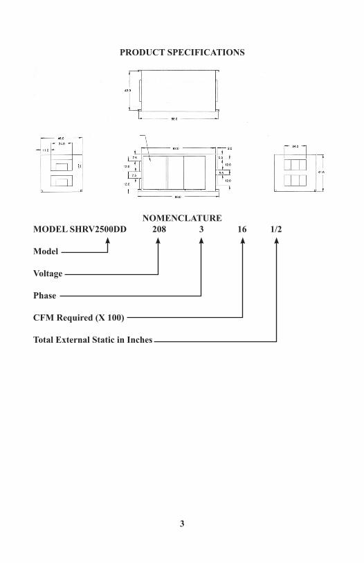
PRODUCT SPECIFICATIONS
NOMENCLATUREMODEL SHRV2500DD 208 3 16 1/2 Model
Voltage
Phase
CFM Required (X 100)
Total External Static in Inches

4
MODELS AVAILABLE: 230/1/60 single speed 1 H.P. 208/230/460/575 3 phase single speed 1 H.P. and 2 H.P. Refer to Model selection table for capacities available.
MOTORS: Type ODP motors with sleeve bearings or fan cooled with ball bearings depending on application. Available in 1hp or 2hp in various voltages and phases including 208/230/460/575 3 phase and 230/1 phase..
CABINET: Cabinet is white powder coated 18ga. Galvanized with 2” foil faced reinforced insulation. Includes six (6) Access Doors to service air filters, drain pans, heat recovery cores and fan and motor assemblies.
HEAT RECOVERY CORE: Three (3) polypropylene cores located for easy removal for cleaning.
BLOWERS: Belt Drive, double inlet, forward curved centrifugal blowers.Painted housing and galvanized wheels.
FILTERS: Four (4) - 16 “ X 20 “ X 4 “ Pleated Disposable Air Filters
DEFROST: Damper defrost system is actuated when supply air temperature entering HRV falls below preset temperature. This causes cold supply air to be dampened off thereby passing ambient indoor air from the building over the core for a 5-7 minute cycle until the core defrosts.
CONTROLS: Power On/Off is field supplied as a fused disconnect. Control keypad on the unit gives several options including; Hi420 20 minutes of run time on high speed, Intermittent ventilation repeating cycle of 20 minutes of fan on followed by 40 minutes of fan off, Auto Off to put the unit into standby off mode until activated to high speed ventilation by a remote device or a Remote Push Button or Crank Timer. Standby mode, power to the main control remains on but the Remote Devices are inactive, cold supply damper closes.
OPTIONAL REMOTE CONTROLS: Remote On/Off toggle switch, Crank timers, Remote 20 minute Push Buttons (Maximum 6) and Dehumidistats.
CONDENSATION: Unit supplied with Drain Spigots and a Tee fitting. Drain hose (5/8 inside diameter) to be field supplied.
MOUNTING: Indoor application only, fasten at four corners of unit using field supplied threaded rod for ceiling suspension
SHIPPING WEIGHT: 750 pounds
NOTE: ALL WIRING MUST BE IN COMPLIANCE WITH ALL NATIONAL – STATE – PROVINCIAL AND LOCAL CODES

5

6
7
INTRODUCTION
The SHRV2500 series of Heat Recovery Ventilators (HRV’s) are designed for commercial and industrial applications to provide fresh air to a building and exhaust an equal amount of stale air. During the winter months, the incoming cold fresh air is warmed by utilizing the heat recovered from the stale air before it is exhausted to the outdoors. During the summer months, when the indoor air space is air conditioned, the HRV will help in cooling the incoming fresh air with the stale air that is being exhausted. Fresh air is distributed throughout the building by way of the existing duct system or a dedicated duct system.
SELECT THE CORRECT SIZE HRV
Commercial and Institutional Requirements
ASHRAE has produced the Ventilation Standard 62-1989 that is used to deter-mine acceptable ventilation rates. This standard is referenced directly or used as Good Engineering Practice in most Code documents or design criteria.

8
Small Restaurants, Donut Shops & Fast Food StoresSeats 40Employees 5Total 45ASHRAE Requirements 20 cfm ( 10 L/s) per personVentilation Required 45 X 20 = 900 cfm ( 450 L/s) BankCustomers 25Staff 9Total 34ASHRAE Requirements 20 cfm ( 10 L/s) per personVentilation Required 34 X 20 = 680 cfm ( 320 L/s )
Bar or TavernSeats 50Employees 7Total 57ASHRAE Requirements 30 cfm ( 15 L/s ) per personVentilation Required 57 X30 = 1710 cfm ( 855 L/s )
Bingo HallCustomers 180Staff 20Total 200ASHRAE Requirements 30 cfm ( 15 L/s ) per personVentilation Required 200 X30 = 6000 cfm ( 3000 L/s )
Classrooms and School PortablesSeats 29Teacher 1ASHRAE Requirements 15 cfm ( 7.5 L/s ) per personVentilation Required 18 X 25 = 450 cfm ( 255 L/s ) Print ShopSquare Footage of Shop 2000 sq. ft.ASHRAE Requirements 0.5 cfm / sq. ft. ( 2.5 L/s – m 2 )Ventilation Required 2000 X 0.5 = 1000 cfm ( 500 L/s )
Beauty SalonCustomers 12Employees 6Total 18ASRAE Requirements 25 cfm ( 12.5 L/s ) per personVentilation Required 18 X 25 = 450 cfm (255 L/s )
Swimming Pools1 cfm per sq. ft. of the water surface area or.5 cfm per sq. ft. of the water surface + deck area
Hot Tubs7 – 10 cfm per sq. ft. of the water surface area

9
NOTE: ALWAYS REFER TO THE MOST RECENT VERSION OF ASHRAE VENTILATION STANDARD TO DETERMINE CFM REQUIREMENTS.
INSTALLATION INSTRUCTIONSLOCATION
The HRV should be suspended from a supported ceiling ideally in a mechanical room proximate to an outside wall to establish outside venting and weather-hoods. This unit can only be mounted indoors and consideration should be give to the location of available power and water drainage for the unit’s condensation. When installing the unit, ensure that it is level and that adequate space is allowed around the unit for easy accessibility into the access doors for service and main-tenance.
DUCT SYSTEM
The Duct System must be well designed to allow the HRV to operate at its’ maximum efficiency. It is very important the Duct System must be adequately sized and includes no sharp radius bends or tees which will significantly increase the pressure drop in the Duct System and reduce air flows.Galvanized ducts must be sized for 1200 f.p.m. (6.09 m/s) maximum velocity; this is recommended to avoid excessive pressure drop and noise. Ducting should be as short as possible and use the minimum number of elbows and tees. Connecting duct sections and shorter runs may be flexible ducting one size larger than the metal duct. The use of flexible duct connectors at the HRV will considerably reduce noise transmission. All duct joints must be secured with screws, rivets or duct sealant and sealed with aluminum tape.
MAKE – UP HEAT REQUIREMENTS @ 1200 CFM ( 566 L/s ) Outdoor Temp Nominal Nominal Nominal °C °F kw req. for kw req. for kw req. for 20°C ( 68°F ) 25°C ( 77°F ) 30°C( 86°F) Air Delivery Air Delivery Air Delivery
0 32 7 10 14 - 10 14 10 14 17 - 20 - 4 12 15 19 - 30 - 22 15 19 22 - 40 - 40 17 21 24

10
DUCTING OUTSIDE OUTSIDE WEATHERHOODS
The Outside Weatherhoods required for operation of the SHRV2500 HRV are to be provided by the installing contractor. Weatherhoods must have built in bird screens to prevent birds and rodents from entering the premise through the ductwork. When designing and locating the fresh air intake, consideration should be given to the best place where the hoods will gather the freshest air, free from restriction.
We recommend:• No less than 10 ft. (3 m) apart from each other.• At least 18 in. (46 cm) above ground level or potential snow accumulation.• Away from sources of contaminates, such as automobile exhaust fumes, gas
meters, garbage containers, cooling towers, etc.• Not exposed to prevailing winds, wherever reasonably possible.
The outside perimeter of the weatherhoods must be caulked to prevent leakage into the building. Roof vents must have adequate curb height for water protection and to be sealed to the ducting.
The design and size of the weatherhoods or louvers chosen by the installer, must allow for adequate free area. Water and snow penetration of the system is minimized when the airflow does not exceed 750 fpm (3.81 m/s) free area velocity.
WEATHERHOOD DUCTING
Galvanized metal ducting with sufficient cross section and with an integral single piece vapor barrier should be used to connect to the HRV to the weatherhoods. All ducting must meet ULC Class 1 Fire Rating and the minimum R-value of the insulation should be equal to 4 (RSI 0.75), or as stated in local codes.
All ducting must be well sealed to prevent air leaks and a sufficient bead of high quality caulking (preferably acoustical sealant) and taping with a high quality aluminum foil tape is recommended to seal the duct to both the HRV and the weatherhoods.

11
DUCTING WITHIN THE BUILDING
To reduce airflow restriction in the duct system, galvanized ducting should be used from the HRV to different areas within the building whenever possible. Also, to minimize airflow losses in the duct work system, all ducts should be as short as possible and incorporate as few elbows as possible. The use of 45° elbows is preferred to 90 o elbows and Y tees instead of 90 o tees is also recommended.
All duct joints must be fastened securely and wrapped with a quality duct tape, such as aluminum foil tape, to prevent leakage.
NOTE: See Installation Warning under the “Integrated HVAC System” section.
STALE AIR (RETURN) DUCT SYSTEM
The Stale Air (Return) Duct System is used to draw stale air from the points of the building where the worst air quality problems occur. Balancing damp-ers and, or, adjustable grilles are recommended on all return air lines which are used (during installation) to help balance the “draw” from different areas of the building. Note that the installation schematics show balancing dampers and, or, adjustable grilles on all return air lines coming back to the HRV. Please refer to figs. 1-3 to view the various installation system options.
A balancing damper is required prior to the HRV to balance the stale air exhausted with the fresh air supply entering the building.
Return air extraction points should be located at the opposite side of the room to the fresh air inlet. The inlets may be located in the ceiling or high on the walls and fitted with inlet grilles.
Many commercial activities produce air contaminates in the form of dusts, fumes, vapors and gases. Contaminates should be controlled at the source so that they are not dispersed through the building nor allowed to increase to toxic concentration levels. The HRV allows for economical operation of the HVAC system, while effectively removing contaminates from the space. In designing the exhaust portion of the system, the exhaust grilles are placed so as to remove the contaminates while not allowing them to enter the breathing zone of the occupants.
For contaminates that are lighter than air, grilles should be located high on the wall. If contaminates are heavier than air a lower placement of the grilles will
12
be required. Information on contaminates specific gravity and toxicity should be available from the chemical data sheets.
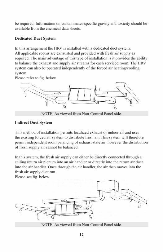
Dedicated Duct System
In this arrangement the HRV is installed with a dedicated duct system. All applicable rooms are exhausted and provided with fresh air supply as required. The main advantage of this type of installation is it provides the ability to balance the exhaust and supply air streams for each serviced room. The HRV system can also be operated independently of the forced air heating/cooling system.Please refer to fig. below.
Indirect Duct System
This method of installation permits localized exhaust of indoor air and uses the existing forced air system to distribute fresh air. This system will therefore permit independent room balancing of exhaust stale air, however the distribution of fresh supply air cannot be balanced.
In this system, the fresh air supply can either be directly connected through a ceiling return air plenum into an air handler or directly into the return air duct into the air handler. Once through the air handler, the air then moves into the fresh air supply duct run.Please see fig. below.
NOTE: As viewed from Non-Control Panel side.
NOTE: As viewed from Non-Control Panel side.

13
Simplified Duct System
This system is primarily used when it is impractical to install dedicated duct runs from the HRV to various room of the building. In this installation the warm air exhaust from the building to the HRV and fresh air supply from the HRV to the building are connected to the existing force air duct system. This installation has the exhaust stale air may drawn directly from the return air duct.
When this system is used, the air handlers’ blower will need to operate constantly when ventilation is required. The exhaust take-off connection must be at least 1 meter (3.28 ft) away from a directly connected HRV supply duct if both are connected to the same run.Please see fig. below.
SUPPLY AIR DUCT SYSTEM
The fresh air supply ductwork from the HRV may be directly connected to the return air duct of the forced air system. When directly connected, it is recommended that the air handler blower be in constant operation to move the fresh air about the building (see warning under “The Integrated HVAC System”). Also, it is advisable to include a short length fabric flex duct or other non – metallic connector in this hard duct line in order to keep the HRV acoustically isolated and separately grounded (electrically) from the air handler. This will avoid a possible shock hazard to service people if a short to ground develops in one of the devices. It may be necessary to install a separate fresh air supply ductwork system if the heating is other than forced air.
When installing an HRV, the designer and installer should be aware of local codes that may require smoke detectors and / or firestops in the HVAC or HRV ductwork. Because an HRV is designed to bring fresh air into the building, structures may require a supply voltage interrupt when fire or smoke or flame
NOTE: As viewed from Non-Control Panel side.

14
sensors are triggered or central fire system is activated.
Supply air grilles may be ceiling or high wall mounted. Avoid incoming fresh air grilles that could cause a direct draft on the occupants as the incoming air may be below room temperature. A reheat duct heater can be installed to improve occupant comfort. Information on electric or hydronic duct heaters is commercially available.
INSTALLATION TIPS
1. Whichever method is chosen to operate the SHRV2500, keep in mind that Air – to – Air exchangers are not “booster fans”, and are not normally sized to ventilate at a steady rate. To achieve optimum performance from the SHRV2500, the desired ventilation rate (speed of the system) should be reached before the contaminant has reached its’ maximum.
2. It is recommended that backdraft dampers be installed in the supply and exhaust ductwork to the outside, to prevent air from entering in through the HRV when the HRV is OFF. Failure to install backdraft dampers may result in damage to HVAC equipment and / or other building components.
INTEGRATED HVAC SYSTEM
Increasingly, the HRV has become an integral component of the commercial HVAC system. HRV’s are very versatile, being able to provide fresh air directly to the return air plenum of a rooftop heat / cool unit or into a ceiling return air plenum or directly into the ceiling space near the air handlers intake. Special care and attention should be given if connecting this unit to any air handler or other unit that may draw more than the SHRV25500 is designed to accommodate.
Installations where it is satisfactory to provide general exhaust from the space, the air to be exhausted may be taken directly from the return air plenum to the HRV as it is drawn back to the air handler. Fresh air supplied by the HRV is then introduced directly into the return air plenum but at a location closer to the air handler. The air handler would have a constant running blower to effectively distribute the fresh air and remove the stale air. Balancing dampers would be located in both the HRV supply and exhaust ducts between the return air plenum and the HRV.

15
ELECTRICAL
The electrical characteristics available for the SHRV2500 are application specific. Refer to product specifications and nomenclature on page # 3.
An external disconnect must be installed prior to the HRV. This disconnect shall be turned off and locked out before servicing the unit. All electrical connections shall be made by a qualified, and where required by law, a licensed electrician.
PITOT TUBE AIR FLOW BALANCING
It is necessary to have balanced air flows in any HRV. The volume of air brought in from outside must be equal to the volume of air exhausted by the HRV. If the air flows are not properly balanced :
• The HRV may not operate at its’ maximum efficiency.• A negative or positive air pressure may occur in the building.• The HRV may not defrost properly.• Failure to balance the HRV may void warranty
Excessive positive pressure may drive moist indoor air into external walls of the building where it may condense ( in cold weather ) and degrade structural components. It may also cause key holes to freeze up.Excessive negative pressure may have several undesirable effects. In some geographic locations, soil gases, such as methane and Radon gas may be drawn into the building through basement / ground contact areas. Excessive negative pressure may also cause back drafting of atmospherically vented combustion appliances.

16
Read the Application WARNING on the Front Page of This Manual.Prior to balancing, insure that :
1. All sealing of the ductwork system has been completed.2. All of the HRV’s components are in place and function properly.3. Balancing dampers are open.4. HRV is on High Speed.5. Air flows in branch lines to specific areas of the building should be adjusted
first, prior to balancing the HRV. A smoke pencil used at the grilles is a good indicator of each branch line’s relative air flow.
6. After taking readings of both the stale air to the HRV duct and fresh air to the building duct, the lower CFM ( L/s ) velocity reading should be left alone, while the duct with the higher reading should be dampered to match the lower reading.
7. Return HRV to appropriate fan speed for normal operation.
BALANCING PROCEDURE
The following is a method of field balancing an HRV using a Pitot Tube, advantageous in situations when air flow stations are not installed in the duct-work. This procedure should be performed with the HRV on High Speed. The first step is to identify the supply duct to the building and the return duct from the building. Choose the straightest section of duct between the HRV and any branches or take-offs.This will be for both the supply and return ducts.Drill a small hole in the duct ( approx. 3/16” ) 3 feet downstream of any elbows or bends, and 1 foot upstream of any elbows or bends. These are recommended distances, but the actual installation may limit the amount of straight duct.
The Pitot Tube should be connected to a Magnahelic gauge or other manometer capable of reading from 0.0 – 1.0 in. ( 0-500 Pa ) of water, preferably to 3 digits of resolution. The Tube coming out of the top of the Pitot is connected to the High Pressure side of the gauge. The Tube coming out of the side of the Pitot is connected to the Low Pressure or reference side of the gauge.
Insert the Pitot Tube into the duct, pointing the tip into the airflow.
More precise readings can be made by taking a number of readings through a cross section of the duct. The readings should be taken at the centers of equal areas in the duct.

17
This procedure is outlined in the instructions accompanying the Pitot Tube. This method is also described in the ASRAE Handbook of Fundamentals, chapter on measurements and instruments.
Determine which duct has the highest airflow ( highest reading on the gauge ). Then damper that airflow back to match the lower reading from the other duct. The airflows should now be balanced.
Actual airflow can be determined from the gauge reading. The value read on the gauge is called the velocity pressure. The Pitot Tube comes with a chart that will give the airflow velocity based on the velocity pressure indicated by the gauge. This velocity will be in either feet per minute or meters per second.
To determine the actual airflow, the velocity is multiplied by the cross sectional area of the duct being measured.
Example:• This is an example for determining the airflow in a 6 “ duct• The Pitot Tube reading was 0.025 “ W.C.• From this chart, this is 640 f.p.m.• The 6 “ duct has a cross sectional area = ( 3.14X { 6”/12 } 2 ) /4 = 0.2 square ft.• The airflow is then 640 ft / min. X 0.2 square ft. = 128 cfm

18
GENERAL OPERATING INSTRUCTIONSSUMMERAIRE SHRV2500 SERIES - HEAT RECOVERY VENTILATOR
ON / OFF SWITCHThe SHRV2500 series HRV’s are NOT supplied with an ON / OFF switch. The HRV’ s in this series are direct connected to their power source through a field supplied disconnect switch.
OPTIONAL REMOTE CONTROLSRemote Dehumidistats, Timers, or switches can be easily installed to automatically turn fan onto high speed.
AUTOMATIC DAMPER STYLE DEFROST The automatic damper defrost is factory pre – set and normally does not require adjustments. A temperature sensor, located in the fresh air supply stream, acti-vates and electronic timer when the outdoor temperature drops to – 3°C (25°F). This timer controls the timing cycles of the defrost system. During the defrost cycle, the fresh air supply is shut off by the motorized multi blade damper as-sembly for approximately 5 – 7 minutes, ambient air from the building is designed to flow through the core assembly, melting any frost accumulations.
CORE AND FILTER CLEANINGThe core assembly and filters are removed via the hinged access doors located on both sides of the HRV. By unscrewing the hex head screws that secure the access doors these cabinet doors can be opened, allowing the core assemblies and air filters to be removed from either or both sides of the HRV. Always use care when handling the core assemblies. At re assembly, ensure that cores are oriented properly, refer to THIS WAY UP and FILTERS THIS SIDE labels.
CLEANINGA visible inspection of the HRV should be made every 3 – 6 months. The core assembly can be easily removed and cleaned by immersing in soapy water and rinsing. The “ pleated “ type air filters can be removed and “ tapped” to remove excess dirt and dust and should be replaced annually, or as required. These steps must be carried out to prevent any build – up of dust dirt etc. Vacuuming the in-terior of the HRV may also be necessary annually. Also, check the outside fresh air intake hood and the stale air exhaust hood, and remove debris every 2 months. Do not let snow cover the outdoor weatherhoods.
CONDENSATE DRAINAGEPeriodically, inspect and clean the drip pan(s) and condensate hose. Check for any blockage which may disrupt normal drainage.
19
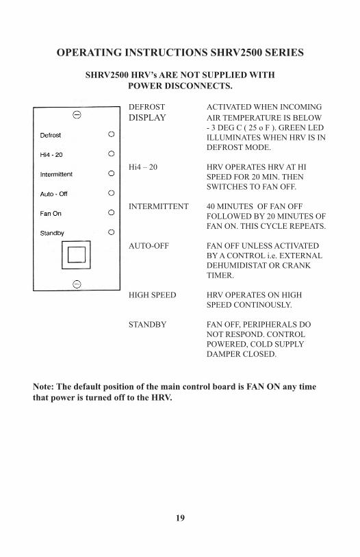
OPERATING INSTRUCTIONS SHRV2500 SERIES
SHRV2500 HRV’s ARE NOT SUPPLIED WITHPOWER DISCONNECTS.
DEFROST ACTIVATED WHEN INCOMINGDISPLAY AIR TEMPERATURE IS BELOW - 3 DEG C ( 25 o F ). GREEN LED ILLUMINATES WHEN HRV IS IN DEFROST MODE.
Hi4 – 20 HRV OPERATES HRV AT HI SPEED FOR 20 MIN. THEN SWITCHES TO FAN OFF.
INTERMITTENT 40 MINUTES OF FAN OFF FOLLOWED BY 20 MINUTES OF FAN ON. THIS CYCLE REPEATS.
AUTO-OFF FAN OFF UNLESS ACTIVATED BY A CONTROL i.e. EXTERNAL DEHUMIDISTAT OR CRANK TIMER.
HIGH SPEED HRV OPERATES ON HIGH SPEED CONTINOUSLY.
STANDBY FAN OFF, PERIPHERALS DO NOT RESPOND. CONTROL POWERED, COLD SUPPLY DAMPER CLOSED.
Note: The default position of the main control board is FAN ON any time that power is turned off to the HRV.

20
MAINTENANCE
As with any mechanical system, a dedicated maintenance program will prolong the life of the equipment, and maintain its’ optimum performance. We recommend at least two (2) full inspections and cleanings per year under normal operating conditions, and more, if circumstances warrant it.
Service Should Include:• Cleaning of screens protecting the outside hoods• Cleaning the core – core assembly is made up of 3 cores. To access the core,
remove service panels and slide core half way out. Wash core(s) protruding from the cabinet with water and / or a mild cleaning solution. Push core through to the other side of the cabinet and repeat the procedure to clean the other side of the core. In many cases, only a vacuuming of the core surface is required.
• Always ensure that cores are installed correctly. Refer to labels referring to “Core This Way Up” and “Air Filters This Side”.
• Inspect filters and replace as necessary.• Wipe down drain pans and inside of the cabinet using a mild disinfectant.• Ensure condensate drain has free flow of moisture.• Inspect blowers and electrical disconnect panel.• Confirm operation.
MOTORSApply 4 – 5 drops of oil to the ports at each end of the motor every 12 months is required. We strongly recommend that the motor ( s ) should be oiled once every year in order to extend its’ life. USE S.A.E. 20W NON – DETERGENT OIL. Do not “over oil”, as this may damage the motor. Depending on the HRV specifications, the motors may have sealed bearings that do not require oiling. An inspection of the motors will identify if oiling is required.

21
WIRING DIAGRAMSHRV2500

22
SHRV2500 SERVICEABLE PARTS
23
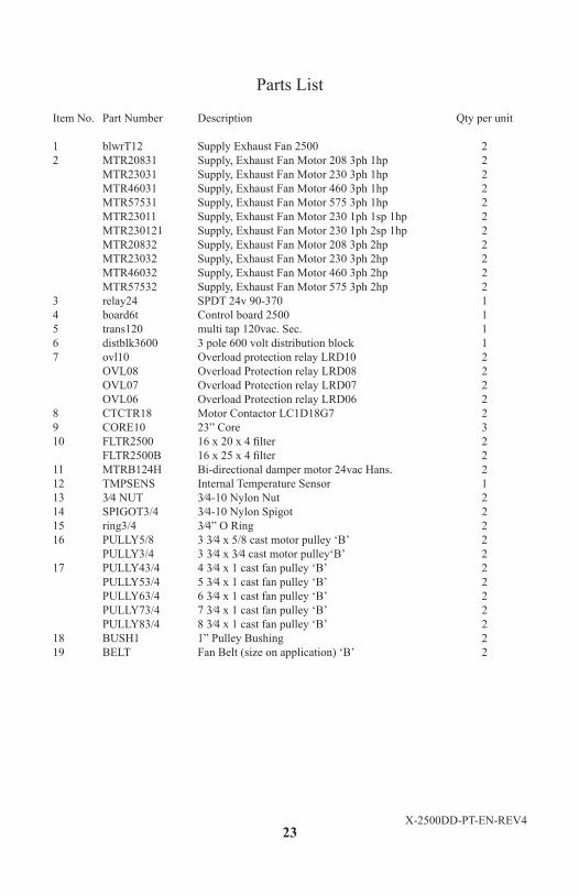
Parts List
Item No. Part Number Description Qty per unit
1 blwrT12 Supply Exhaust Fan 2500 22 MTR20831 Supply, Exhaust Fan Motor 208 3ph 1hp 2 MTR23031 Supply, Exhaust Fan Motor 230 3ph 1hp 2 MTR46031 Supply, Exhaust Fan Motor 460 3ph 1hp 2 MTR57531 Supply, Exhaust Fan Motor 575 3ph 1hp 2 MTR23011 Supply, Exhaust Fan Motor 230 1ph 1sp 1hp 2 MTR230121 Supply, Exhaust Fan Motor 230 1ph 2sp 1hp 2 MTR20832 Supply, Exhaust Fan Motor 208 3ph 2hp 2 MTR23032 Supply, Exhaust Fan Motor 230 3ph 2hp 2 MTR46032 Supply, Exhaust Fan Motor 460 3ph 2hp 2 MTR57532 Supply, Exhaust Fan Motor 575 3ph 2hp 23 relay24 SPDT 24v 90-370 14 board6t Control board 2500 15 trans120 multi tap 120vac. Sec. 16 distblk3600 3 pole 600 volt distribution block 17 ovl10 Overload protection relay LRD10 2 OVL08 Overload Protection relay LRD08 2 OVL07 Overload Protection relay LRD07 2 OVL06 Overload Protection relay LRD06 28 CTCTR18 Motor Contactor LC1D18G7 29 CORE10 23” Core 310 FLTR2500 16 x 20 x 4 filter 2 FLTR2500B 16 x 25 x 4 filter 211 MTRB124H Bi-directional damper motor 24vac Hans. 212 TMPSENS Internal Temperature Sensor 113 3⁄4 NUT 3⁄4-10 Nylon Nut 214 SPIGOT3/4 3⁄4-10 Nylon Spigot 215 ring3/4 3⁄4” O Ring 216 PULLY5/8 3 3⁄4 x 5/8 cast motor pulley ‘B’ 2 PULLY3/4 3 3⁄4 x 3⁄4 cast motor pulley‘B’ 217 PULLY43/4 4 3⁄4 x 1 cast fan pulley ‘B’ 2 PULLY53/4 5 3⁄4 x 1 cast fan pulley ‘B’ 2 PULLY63/4 6 3⁄4 x 1 cast fan pulley ‘B’ 2 PULLY73/4 7 3⁄4 x 1 cast fan pulley ‘B’ 2 PULLY83/4 8 3⁄4 x 1 cast fan pulley ‘B’ 218 BUSH1 1” Pulley Bushing 219 BELT Fan Belt (size on application) ‘B’ 2
X-2500DD-PT-EN-REV4
24
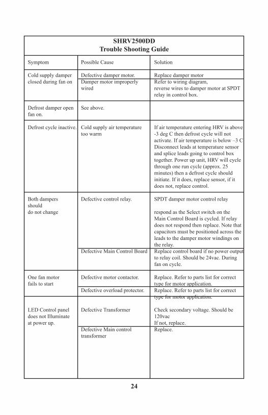
SHRV2500DDTrouble Shooting Guide
Symptom Possible Cause Solution
Cold supply damper Defective damper motor. Replace damper motorclosed during fan on Damper motor improperly Refer to wiring diagram, wired reverse wires to damper motor at SPDT relay in control box.
Defrost damper open See above.fan on.
Defrost cycle inactive. Cold supply air temperature If air temperature entering HRV is above too warm -3 deg C then defrost cycle will not activate. If air temperature is below –3 C Disconnect leads at temperature sensor and splice leads going to control box together. Power up unit, HRV will cycle through one run cycle (approx. 25 minutes) then a defrost cycle should initiate. If it does, replace sensor, if it does not, replace control.
Both dampers Defective control relay. SPDT damper motor control relay shoulddo not change respond as the Select switch on the Main Control Board is cycled. If relay does not respond then replace. Note that capacitors must be positioned across the leads to the damper motor windings on the relay. Defective Main Control Board Replace control board if no power output to relay coil. Should be 24vac. During fan on cycle.
One fan motor Defective motor contactor. Replace. Refer to parts list for correctfails to start type for motor application. Defective overload protector. Replace. Refer to parts list for correct type for motor application.
LED Control panel Defective Transformer Check secondary voltage. Should bedoes not Illuminate 120vac at power up. If not, replace. Defective Main control Replace. transformer

25
SUMMERAIRECommercial Heat Recovery Ventilator Limited Warranty
Summeraire Mfg. warrants this product to the original owner, should it prove to be defective by reason of faulty manufacturing material or workmanship within two (2) years of the purchase date. Extended warranty is offered for the “Core” as outlined below.
Core(s)
Summeraire Mfg. warrants the “Core” of the commercial Heat Recovery Ventilator to the original purchaser for a period of fifteen (15) years if the “Core” has become defective by reason of defective manufacturing material and or/faulty workmanship.
The General Provisions outlined below form an integral part of this warranty.
General Provisions
This warranty covers normal use and does not cover defects caused by: modification, improper installation or misapplication, abuse to, or operation of the product in a manner contrary to the instructions included with the unit at the time of shipment, or failure to perform maintenance as detailed in the aforementioned instructions.
Summeraire Mfg. will provide a replacement HRV unit or component as pre-scribed in the foregoing section, F.O.B Peterborough, Ontario, Canada. This warranty does not include freight, labor, including diagnostic labor, or sales tax that might be incurred by the purchaser if parts require replacement. Replacement units and/or components are warranted for the remainder of the originalwarranty period.
Summeraire Mfg. is not responsible for providing an authorized service center near the purchaser or in the general area.
Under no circumstances shall Summeraire Mfg. be liable to the purchaser or any other person(s) for any consequential damages, whether arising out of breach or warranty, breach of contract, negligence or otherwise in the use of the ventila-tion system.
This warranty expressly supercedes all other warranties and obligations of Sum-meraire Mfg. whether expressed or implied. No person has authority to alter or

26
modify the terms of this warranty in any manner
Keep your warranty at work for you. Please complete and mail your Warranty Registration Card to Summeraire Mfg., 2040 Fisher Drive, Peterborough, Ontario, Canada, K9J 6X6 to register this warranty.
Notes:

X-2500DD-INSUSMAN-EN-REV5
SUMMERAIRE MFG.PETERBOROUGH, ONTARIO
CANADAK9J 7B1
Related Documents