HB0379 CoreFIFO v2.6 Handbook 02 2017

Welcome message from author
This document is posted to help you gain knowledge. Please leave a comment to let me know what you think about it! Share it to your friends and learn new things together.
Transcript
HB0379
CoreFIFO v2.6 Handbook 02 2017

HB0379: CoreFIFO v2.6 Handbook
Microsemi makes no warranty, representation, or guarantee regarding the information contained herein or the suitability of its products and services for any particular purpose, nor does Microsemi assume any liability whatsoever arising out of the application or use of any product or circuit. The products sold hereunder and any other products sold by Microsemi have been subject to limited testing and should not be used in conjunction with mission-critical equipment or applications. Any performance specifications are believed to be reliable but are not verified, and Buyer must conduct and complete all performance and other testing of the products, alone and together with, or installed in, any end-products. Buyer shall not rely on any data and performance specifications or parameters provided by Microsemi. It is the Buyer’s responsibility to independently determine suitability of any products and to test and verify the same. The information provided by Microsemi hereunder is provided “as is, where is” and with all faults, and the entire risk associated with such information is entirely with the Buyer. Microsemi does not grant, explicitly or implicitly, to any party any patent rights, licenses, or any other IP rights, whether with regard to such information itself or anything described by such information. Information provided in this document is proprietary to Microsemi, and Microsemi reserves the right to make any changes to the information in this document or to any products and services at any time without notice. About Microsemi Microsemi Corporation (Nasdaq: MSCC) offers a comprehensive portfolio of semiconductor and system solutions for aerospace & defense, communications, data center and industrial markets. Products include high-performance and radiation-hardened analog mixed-signal integrated circuits, FPGAs, SoCs and ASICs; power management products; timing and synchronization devices and precise time solutions, setting the world's standard for time; voice processing devices; RF solutions; discrete components; enterprise storage and communication solutions; security technologies and scalable anti-tamper products; Ethernet solutions; Power-over-Ethernet ICs and midspans; as well as custom design capabilities and services. Microsemi is headquartered in Aliso Viejo, Calif., and has approximately 4,800 employees globally. Learn more at www.microsemi.com. ©2017 Microsemi Corporation. All rights reserved. Microsemi and the Microsemi logo are registered trademarks of Microsemi Corporation. All other trademarks and service marks are the property of their respective owners.
Microsemi Corporate Headquarters One Enterprise, Aliso Viejo, CA 92656 USA Within the USA: +1 (800) 713-4113 Outside the USA: +1 (949) 380-6100 Sales: +1 (949) 380-6136 Fax: +1 (949) 215-4996 E-mail: [email protected] www.microsemi.com
50200379-7.02/17 Revision 7 2
HB0379: CoreFIFO v2.6 Handbook
1 Revision History
The revision history describes the changes that were implemented in the document. The changes are listed by revision, starting with the most current publication.
1.1 Revision 7.0 Updated changes related to CoreFIFO v2.6.
1.2 Revision 6.0 Updated changes related to CoreFIFO v2.5.
1.3 Revision 5.0 Updated changes related to CoreFIFO v2.4.
1.4 Revision 4.0 Updated changes related to CoreFIFO v2.3.
1.5 Revision 3.0 Updated changes related to CoreFIFO v2.2.
1.6 Revision 2.0 Updated changes related to CoreFIFO v2.1.
1.7 Revision 1.0 Revision 1.0 was the first publication of this document. Created for CoreFIFO v2.0.
50200379-7.02/17 Revision 7 3
HB0379: CoreFIFO v2.6 Handbook
Contents
1 Revision History ........................................................................................................................ 3 1.1 Revision 7.0 ................................................................................................................................................ 3 1.2 Revision 6.0 ................................................................................................................................................ 3 1.3 Revision 5.0 ................................................................................................................................................ 3 1.4 Revision 4.0 ................................................................................................................................................ 3 1.5 Revision 3.0 ................................................................................................................................................ 3 1.6 Revision 2.0 ................................................................................................................................................ 3 1.7 Revision 1.0 ................................................................................................................................................ 3
2 Preface ..................................................................................................................................... 8 2.1 About this Document ................................................................................................................................. 8 2.2 Intended Audience ..................................................................................................................................... 8
3 Introduction ............................................................................................................................. 9 3.1 Overview .................................................................................................................................................... 9 3.2 Features ..................................................................................................................................................... 9 3.3 Core Version ............................................................................................................................................... 9 3.4 Supported Families .................................................................................................................................... 9 3.5 Device Utilization and Performance ........................................................................................................ 10
4 Functional Description ........................................................................................................... 13 4.1 Independent Clocks ................................................................................................................................. 14 4.2 Async FIFO Controller Logic ..................................................................................................................... 14 4.3 Sync FIFO Controller Logic ....................................................................................................................... 14 4.4 Flag Control Logic ..................................................................................................................................... 14
4.4.1 FULL/EMPTY Status.................................................................................................................... 15 4.4.2 Almost FULL/Almost EMPTY Status ........................................................................................... 15 4.4.3 Error Status ................................................................................................................................ 15 4.4.4 EMPTY/FULL Stop ...................................................................................................................... 15 4.4.5 Data Handshaking ...................................................................................................................... 16 4.4.6 Count Status .............................................................................................................................. 16
4.5 Variable Aspect Ratio ............................................................................................................................... 16 4.5.1 Variable Aspect Ratio Special Considerations ............................................................................ 16
4.6 Binary Counter ......................................................................................................................................... 17 4.7 Gray-to-Binary and Binary-to-Gray Converter ......................................................................................... 17 4.8 Synchronizer ............................................................................................................................................ 17 4.9 FWFT Logic ............................................................................................................................................... 18 4.10 PREFETCH Logic ........................................................................................................................................ 18 4.11 Controller Only Logic ............................................................................................................................... 19 4.12 ECC ........................................................................................................................................................... 20
50200379-7.02/17 Revision 7 4
HB0379: CoreFIFO v2.6 Handbook
5 Interface ................................................................................................................................. 21
5.1 I/O Signals ................................................................................................................................................ 21 5.2 Core Parameters ...................................................................................................................................... 23
5.2.1 CoreFIFO Configurable Options ................................................................................................. 23
6 Timing Diagrams .................................................................................................................... 26 6.1 Asynchronous FIFO .................................................................................................................................. 26 6.2 Synchronous FIFO .................................................................................................................................... 29 6.3 Asynchronous FIFO with FWFT/PREFETCH ............................................................................................... 31 6.4 Synchronous FIFO with FWFT/PREFETCH ................................................................................................. 33 6.5 Synchronous FIFO with Variable Aspect Ratio ......................................................................................... 35 6.6 Asynchronous FIFO with ECC ................................................................................................................... 36 6.7 Performance ............................................................................................................................................ 38
7 Tool Flow ................................................................................................................................ 39 7.1 License ..................................................................................................................................................... 39 7.2 RTL ........................................................................................................................................................... 39 7.3 SmartDesign ............................................................................................................................................. 39 7.4 Configuring CoreFIFO in SmartDesign ...................................................................................................... 40 7.5 Simulation Flows ...................................................................................................................................... 40 7.6 Synthesis in Libero ................................................................................................................................... 41 7.7 Place-and-Route in Libero ........................................................................................................................ 41
8 Testbench ............................................................................................................................... 42 8.1 User Test-bench ....................................................................................................................................... 42
9 Register Map and Descriptions .............................................................................................. 43
10 Ordering Information ............................................................................................................. 44 10.1 Ordering Codes ........................................................................................................................................ 44
50200379-7.02/17 Revision 7 5
HB0379: CoreFIFO v2.6 Handbook
List of Figures
Figure 1 CoreFIFO Block Diagram ................................................................................................................................ 13 Figure 2 FWFT/ PREFETCH Logic for Async FIFO .......................................................................................................... 18 Figure 3 External Memory Interfacing when CTRL_TYPE=1, PREFETCH = 0 ................................................................ 19 Figure 4 FIFO Write Operation and Flags ..................................................................................................................... 26 Figure 5 Asynchronous FIFO Read Operation with Pipe1 ............................................................................................ 27 Figure 6 FIFO Read Operation and Flags ...................................................................................................................... 28 Figure 7 Asynchronous FIFO with EMPTY De-assertion and FULL Assertion Operation .............................................. 28 Figure 8 Asynchronous FIFO with FULL De-assertion and EMPTY Assertion Operation .............................................. 29 Figure 9 Synchronous FIFO with EMPTY De-assertion and FULL Assertion Operation ................................................ 30 Figure 10 Synchronous FIFO with FULL De-assertion and EMPTY Assertion Operation .............................................. 30 Figure 11 FIFO Read Operation with Pipe1_ PREFETCH 1 ........................................................................................... 31 Figure 12 Asynchronous FIFO with FWFT=1 ................................................................................................................ 32 Figure 13 Asynchronous FIFO with PREFETCH=1 ......................................................................................................... 32 Figure 14 Synchronous FIFO with FWFT=1 .................................................................................................................. 33 Figure 15 Synchronous FIFO with PREFETCH=1 ........................................................................................................... 34 Figure 16 Synchronous FIFO with Variable Aspect Ratio (Write Width > Read Width) ............................................... 35 Figure 17 Synchronous FIFO with Variable Aspect Ratio (Write Width < Read Width) ............................................... 36 Figure 18 Asynchronous FIFO Read operation with ECC=1 PIPE=1 ............................................................................. 36 Figure 19 Asynchronous FIFO Read operation with ECC=1 PIPE=2 ............................................................................. 37 Figure 20 Asynchronous FIFO Read operation with ECC=2 PIPE=0 ............................................................................. 38 Figure 21 SmartDesign CoreFIFO Instance View .......................................................................................................... 39 Figure 22 Configuring CoreFIFO in SmartDesign.......................................................................................................... 40 Figure 23 CoreFIFO User Test-bench ........................................................................................................................... 42
50200379-7.02/17 Revision 7 6
HB0379: CoreFIFO v2.6 Handbook
List of Tables
Table 1 CoreFIFO Device Utilization and Performance ................................................................................................ 10 Table 2 CoreFIFO Device Utilization and Performance ................................................................................................ 11 Table 3 CoreFIFO Device Utilization and Performance ................................................................................................ 12 Table 4 CoreFIFO I/O Signals ....................................................................................................................................... 21 Table 5 CoreFIFO Configuration Options ..................................................................................................................... 23 Table 6·Ordering Codes ............................................................................................................................................... 44
50200379-7.02/17 Revision 7 7
HB0379: CoreFIFO v2.6 Handbook
2 Preface
2.1 About this Document This handbook provides details about the CoreFIFO DirectCore module, and how to use it.
2.2 Intended Audience FPGA designers using Libero® System-on-Chip (SoC).
50200379-7.02/17 Revision 7 8
HB0379: CoreFIFO v2.6 Handbook
3 Introduction
3.1 Overview CoreFIFO is a fully configurable Soft FIFO controller. It is designed to support SmartFusion®2 system-on-chip (SoC) field programmable gate array (FPGA), IGLOO®2, RTG4, and PolarFire family devices. You can select various configuration parameters or generics that are applicable to CoreFIFO.
3.2 Features • Dual and single clock operation • Clock edge - positive/negative
• FULL/EMPTY flag generation • Almost FULL and almost empty flag generation • EMPTY/FULL stop generation • Write and read count • Variable aspect ratio (depth/width) • Error status generation with overflow and underflow
• Write acknowledge and read data valid generation • Supports large RAM and micro RAM or controller only option • Almost FULL and almost empty single threshold value for assertion • Pipelining in the memory read data paths (controller with memory option) • Pre-fetch mode option to provide read data in the same clock cycle • First-Word Fall-Through (FWFT)
• ECC capability for RTG4 device family
3.3 Core Version This handbook is for CoreFIFO version 2.6.
3.4 Supported Families • PolarFire • RTG4™
• SmartFusion®2 • IGLOO®2
50200379-7.02/17 Revision 7 9
HB0379: CoreFIFO v2.6 Handbook
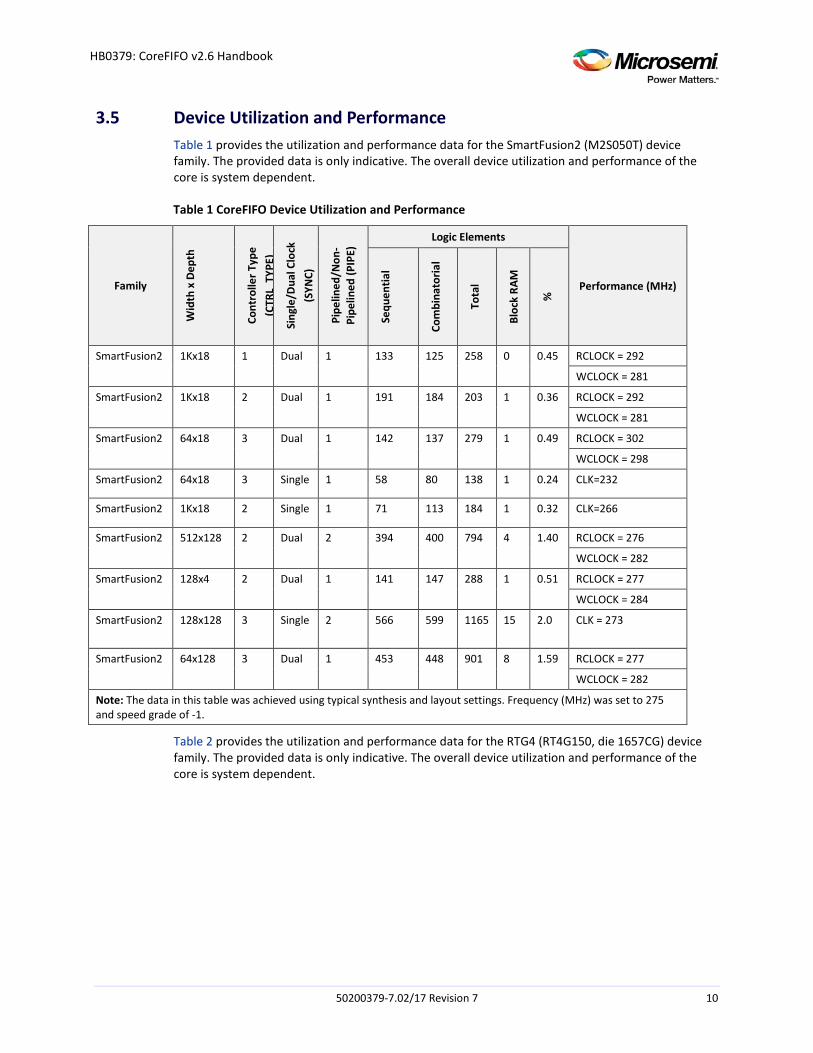
3.5 Device Utilization and Performance Table 1 provides the utilization and performance data for the SmartFusion2 (M2S050T) device family. The provided data is only indicative. The overall device utilization and performance of the core is system dependent.
Table 1 CoreFIFO Device Utilization and Performance
Family
Wid
th x
Dep
th
Cont
rolle
r Typ
e (C
TRL
TYPE
)
Sing
le/D
ual C
lock
(S
YNC)
Pipe
lined
/Non
-Pi
pelin
ed (P
IPE)
Logic Elements
Performance (MHz)
Sequ
entia
l
Com
bina
toria
l
Tota
l
Bloc
k RA
M
%
SmartFusion2 1Kx18 1 Dual 1 133 125 258 0 0.45 RCLOCK = 292
WCLOCK = 281
SmartFusion2 1Kx18 2 Dual 1 191 184 203 1 0.36 RCLOCK = 292
WCLOCK = 281
SmartFusion2 64x18 3 Dual 1 142 137 279 1 0.49 RCLOCK = 302
WCLOCK = 298
SmartFusion2 64x18 3 Single 1 58 80 138 1 0.24 CLK=232
SmartFusion2 1Kx18 2 Single 1 71 113 184 1 0.32 CLK=266
SmartFusion2 512x128 2 Dual 2 394 400 794 4 1.40 RCLOCK = 276
WCLOCK = 282
SmartFusion2 128x4 2 Dual 1 141 147 288 1 0.51 RCLOCK = 277
WCLOCK = 284
SmartFusion2 128x128 3 Single 2 566 599 1165 15 2.0 CLK = 273
SmartFusion2 64x128 3 Dual 1 453 448 901 8 1.59 RCLOCK = 277
WCLOCK = 282
Note: The data in this table was achieved using typical synthesis and layout settings. Frequency (MHz) was set to 275 and speed grade of -1.
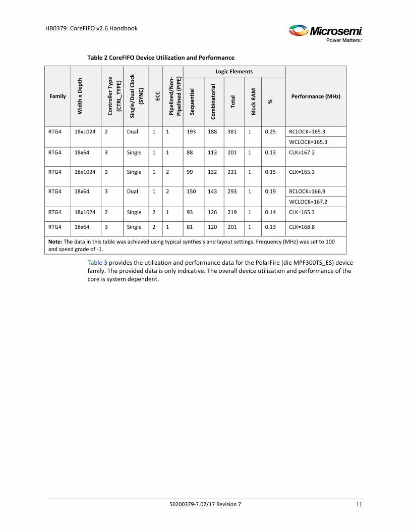
Table 2 provides the utilization and performance data for the RTG4 (RT4G150, die 1657CG) device family. The provided data is only indicative. The overall device utilization and performance of the core is system dependent.
50200379-7.02/17 Revision 7 10
HB0379: CoreFIFO v2.6 Handbook
Table 2 CoreFIFO Device Utilization and Performance
Family
Wid
th x
Dep
th
Cont
rolle
r Typ
e (C
TRL_
TYPE
)
Sing
le/D
ual C
lock
(S
YNC)
ECC
Pipe
lined
/Non
-Pi
pelin
ed (P
IPE)
Logic Elements
Performance (MHz)
Sequ
entia
l
Com
bina
toria
l
Tota
l
Bloc
k RA
M
%
RTG4 18x1024 2 Dual 1 1 193 188 381 1 0.25 RCLOCK=165.3
WCLOCK=165.3
RTG4 18x64 3 Single 1 1 88 113 201 1 0.13 CLK=167.2
RTG4 18x1024 2 Single 1 2 99 132 231 1 0.15 CLK=165.3
RTG4 18x64 3 Dual 1 2 150 143 293 1 0.19 RCLOCK=166.9
WCLOCK=167.2
RTG4 18x1024 2 Single 2 1 93 126 219 1 0.14 CLK=165.3
RTG4 18x64 3 Single 2 1 81 120 201 1 0.13 CLK=168.8
Note: The data in this table was achieved using typical synthesis and layout settings. Frequency (MHz) was set to 100 and speed grade of -1.
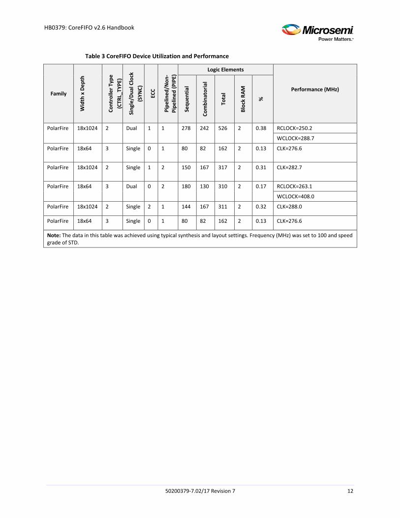
Table 3 provides the utilization and performance data for the PolarFire (die MPF300TS_ES) device family. The provided data is only indicative. The overall device utilization and performance of the core is system dependent.
50200379-7.02/17 Revision 7 11
HB0379: CoreFIFO v2.6 Handbook
Table 3 CoreFIFO Device Utilization and Performance
Family
Wid
th x
Dep
th
Cont
rolle
r Typ
e (C
TRL_
TYPE
)
Sing
le/D
ual C
lock
(S
YNC)
ECC
Pipe
lined
/Non
-Pi
pelin
ed (P
IPE)
Logic Elements
Performance (MHz)
Sequ
entia
l
Com
bina
toria
l
Tota
l
Bloc
k RA
M
%
PolarFire 18x1024 2 Dual 1 1 278 242 526 2 0.38 RCLOCK=250.2
WCLOCK=288.7
PolarFire 18x64 3 Single 0 1 80 82 162 2 0.13 CLK=276.6
PolarFire 18x1024 2 Single 1 2 150 167 317 2 0.31 CLK=282.7
PolarFire 18x64 3 Dual 0 2 180 130 310 2 0.17 RCLOCK=263.1
WCLOCK=408.0
PolarFire 18x1024 2 Single 2 1 144 167 311 2 0.32 CLK=288.0
PolarFire 18x64 3 Single 0 1 80 82 162 2 0.13 CLK=276.6
Note: The data in this table was achieved using typical synthesis and layout settings. Frequency (MHz) was set to 100 and speed grade of STD.
50200379-7.02/17 Revision 7 12
HB0379: CoreFIFO v2.6 Handbook
4 Functional Description
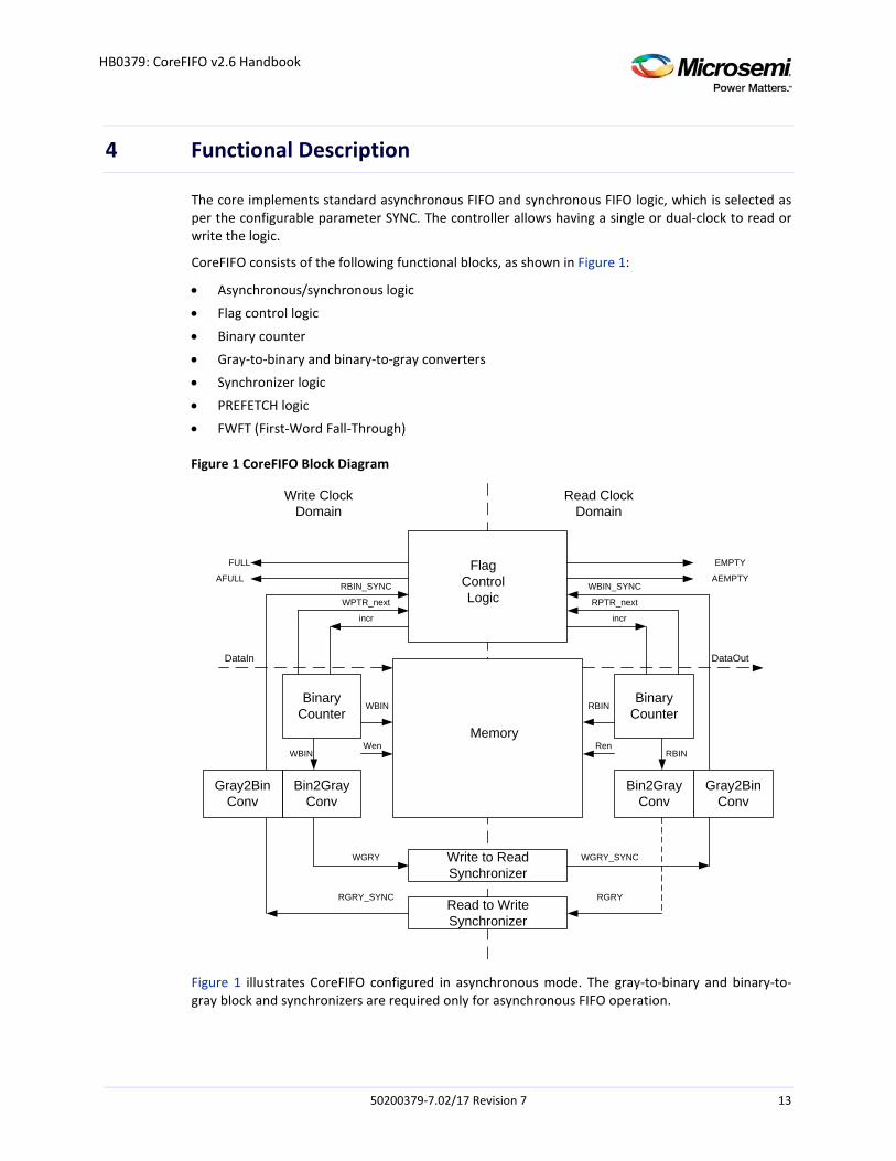
The core implements standard asynchronous FIFO and synchronous FIFO logic, which is selected as per the configurable parameter SYNC. The controller allows having a single or dual-clock to read or write the logic.
CoreFIFO consists of the following functional blocks, as shown in Figure 1:
• Asynchronous/synchronous logic • Flag control logic
• Binary counter • Gray-to-binary and binary-to-gray converters • Synchronizer logic • PREFETCH logic • FWFT (First-Word Fall-Through)
Figure 1 CoreFIFO Block Diagram
DataIn
Memory
Flag Control Logic
Write Clock Domain
Read Clock Domain
Write to Read Synchronizer
Read to Write Synchronizer
Binary Counter
Binary Counter
WBIN RBIN
RGRY
WGRY WGRY_SYNC
RGRY_SYNC
RBIN_SYNC WBIN_SYNC
Gray2Bin Conv
Bin2Gray Conv
RBIN
Bin2Gray Conv
Gray2Bin Conv
WBIN
EMPTY
AEMPTY
WPTR_next RPTR_next
incrincr
DataOut
RenWen
AFULL
FULL
Figure 1 illustrates CoreFIFO configured in asynchronous mode. The gray-to-binary and binary-to-gray block and synchronizers are required only for asynchronous FIFO operation.
50200379-7.02/17 Revision 7 13
HB0379: CoreFIFO v2.6 Handbook
4.1 Independent Clocks The Soft FIFO controller gives an option of having independent or common read and write clocks. The core handles all the synchronization logic for independent clock configurations. Operations in the read domain are synchronous to the read clock and operations in the write domain are synchronous to the write clock.
By having the independent clock domains, the de-assertion of EMPTY/AEMPTY signals in relation to a write is not completely deterministic due to synchronization logic. The same holds true for the de-assertion of the FULL/AFULL signals to a read operation. However, the assertion of EMPTY/AEMPTY will be accurate and deterministic to the read domain, and the assertion of the FULL/AFULL will be accurate and deterministic to the write domain.
Using the common clock configuration results in smaller design.
4.2 Async FIFO Controller Logic For asynchronous clocking, the write logic works on the write clock and the read logic works on the read clock.
On reset, both the write and read pointers are reset to zero. Both the pointers are synchronized with the destination clock domain.
The write pointer always points to the next word to be written. On a FIFO-write operation, the memory location that is pointed to by the write pointer is written, and then the write pointer is incremented to point to the next location.
Similarly, the read pointer always points to the current FIFO word to be read. The FIFO is empty. As soon as the first data word is written to the FIFO, the write pointer increments, the empty flag is cleared, and the read pointer that is still addressing the contents of the first FIFO memory word, immediately drives that first valid word onto the FIFO data output port.
The FIFO is empty when the read and write pointers are both equal including the MSB bit. This condition happens when both the pointers are reset to zero during the reset operation or when the read pointer catches up to the write pointer, having read the last word from the FIFO.
A FIFO is full when the pointers are again equal except the MSB bit, that is, when the write pointer is wrapped around and caught up to the read pointer.
4.3 Sync FIFO Controller Logic For synchronous or single clock domain, the write and read logic works on the same clock.
For synchronous FIFO design, the FIFO is full when the FIFO counter reaches a predetermined full value and the FIFO is empty when the FIFO counter is zero. In this case, synchronization, gray-to-binary, and binary-to-gray conversion logic is not required.
4.4 Flag Control Logic The flag control logic generates the status flags such as FULL, EMPTY, Almost FULL, and Almost EMPTY. These flags are the registered outputs of this module. For asynchronous clocking, the FULL/Almost FULL flag is synchronous to the WCLOCK. Similarly, the Empty/Almost Empty flag is synchronous to the RCLOCK. The threshold values for Almost FULL/Almost EMPTY flags are set statically through user parameter configurations as AEVAL/AFVAL, respectively.
50200379-7.02/17 Revision 7 14
HB0379: CoreFIFO v2.6 Handbook
4.4.1 FULL/EMPTY Status
The FULL flag is asserted on the same clock that the data that fills the FIFO is written. The EMPTY flag is asserted on the same clock that the last data is read out of the FIFO.
All the flag signals are registered outputs.
4.4.2 Almost FULL/Almost EMPTY Status The Almost FULL (AFULL) flag is asserted on the same clock that the threshold is reached. The Almost Empty (AEMPTY) flag is asserted on the same clock that the threshold is reached.
These signals are optional. All the flag signals are the registered outputs.
4.4.3 Error Status The error status of the FIFO controller is given by UNDERFLOW and OVERFLOW flags. If write occurs when the FIFO is full, then OVERFLOW flag is asserted. If read occurs when the FIFO is empty, then UNDERFLOW flag is asserted.
In case ESTOP/FSTOP is equal to 0 then the OVERFLOW and UNDERFLOW signals are invalid. These signals are optional. All the flag signals are the registered outputs.
4.4.4 EMPTY/FULL Stop This option allows to specify whether or not to stop the read or write pointer when the EMPTY or FULL flags are asserted.
• If ESTOP = 1, disable incrementing when EMPTY is asserted (default). • If FSTOP = 1, disable incrementing when FULL is asserted (default). • If ESTOP = 0, enable incrementing when EMPTY is asserted (non-default). • If FSTOP = 0, enable incrementing when FULL is asserted (non-default). Note: By using the non-default settings on these flags, the EMPTY/FULL flags behave differently. The
EMPTY/FULL status flag, if asserted already, will de-assert when the rollback occurs. For example, continuously reading the FIFO after the EMPTY flag is asserted will cause the pointers to roll around, thus indicating that it is no longer empty. So the EMPTY flag will be de-asserted. The same holds true for the FULL flag. These behaviors must be kept in mind if these control signals are to be used.
Note: When wrap around reading is enabled, the FIFO will continue to allow reads to occur past the typical EMPTY state. Thus, the FIFO can be viewed as a circular buffer and continually read regardless of the count. The EMPTY/almost EMPTY status flags and read count port in this case are invalid and is recommended not to be used for any type of logic.
This feature may be useful if the FIFO is pre-loaded with a certain data set which the user design requires to cycle through continuously.
When wrap around writing occurs, the FIFO will continue to allow writes to occur past the typical full state. The FULL/Almost FULL status flags and write count port in this case are invalid and is recommended not to be used for any type of logic.
If ESTOP = 0, then use of the UNDERFLOW status flag will be illegal.
If FSTOP = 0, then use of the OVERFLOW status flag will be illegal.
Refer to the timing diagrams below (Figure 4 through Figure 20).
50200379-7.02/17 Revision 7 15
HB0379: CoreFIFO v2.6 Handbook
4.4.5 Data Handshaking
The data handshaking signals are provided by WACK and DVLD signals indicating that the data written is accepted or the data read is valid, respectively. WACK flag has one clock latency with respect to the write enable. It asserts a clock after the write enable is asserted. DVLD is asserted along with the output read data.
These signals are optional and dependent on the WRITE_ACK and READ_DVALID parameters, respectively.
All the flag signals are registered outputs.
Note:
1. For Pipe = 0, DVLD is asserted along with read enable.
2. For Pipe = 1, DVLD is asserted one clock cycle after the read enable is asserted.
3. For Pipe = 2, DVLD is asserted two clock cycles after the read enable is asserted.
4. For PREFETCH = 1 and PIPE = 1, DVLD is asserted along with the read enable.
5. For FWFT = 1 and PIPE = 1, the DVLD is asserted as soon as the EMPTY is de-asserted for the first read data. For the subsequent read data words, it is asserted along with the read enable.
4.4.6 Count Status The read count port is the remaining number of elements in the FIFO from the READ domain. The write count port is the remaining number of elements in the FIFO from the WRITE domain. This is essentially the difference between the read and write pointers. In addition, it is synchronized to the respective clock domain.
These signals are optional. All the flag signals are the registered outputs.
4.5 Variable Aspect Ratio A FIFO operation with variable aspect ratio will have a different width x depth configuration on the write and read side.
The variable aspect logic is handled by shifting the required bits of the read/write pointer so that they are of the same width. This is done during the instantiation so there is no actual logic required to perform data width matching.
The basic restriction is that Write Depth * Write Width = Read Depth * Read Width.
The width of the counters will be adjusted to match the counter with the smaller width for the FULL/EMPTY flag comparison. The FULL/EMPTY flags are generated only when the complete word can be written or read.
For example, if the write port is 512x32 and the read port is 2Kx8, the write count status is 1, while the read count status is 4.
4.5.1 Variable Aspect Ratio Special Considerations A FIFO with variable aspect width has a different depth and width configurations for the write and read side. For more information, refer to Figure 16 and Figure 17. Following needs to be considered while using this FIFO:
50200379-7.02/17 Revision 7 16
HB0379: CoreFIFO v2.6 Handbook
• Data order – Write side has a smaller width than Read side. The FIFO writes to the least
significant portion of the memory up.
• Data order – Write side has a larger width than Read side. The FIFO reads from the least significant portion of the memory. If the first word into the write side is 0xABCD, the words read out of the FIFO will be 0xCD followed by 0xAB.
• FULL flag generation – The FULL flag will be asserted when a full word from the write perspective cannot be written. The FULL will be de-asserted only if there is enough space in the FIFO to write a full word from the write aspect ratio.
• EMPTY flag generation – The EMPTY flag will be de-asserted only when a full word from the read aspect ratio can be read out. The EMPTY flag will be asserted if the FIFO does not contain a full word from the read aspect ratio.
The implication of the status flag generation is that it is possible to have a partial word in the FIFO which may not be immediately visible on the read side. For example, a write side has a smaller width than the read side. The write side writes 1 word and finishes.
In this case, the application using the FIFO must consider what a partial data word represents. If the partial data word cannot be processed downstream then it is not required to take the FIFO out until it has reached a full-word. However, if the partial word is considered valid and can be processed downstream in its incomplete state, then some other of mechanism needs to be designed to handle this condition.
4.6 Binary Counter The binary counter is used to generate the write/read pointers, as shown in Figure 1. It also serves as address to the memory.
4.7 Gray-to-Binary and Binary-to-Gray Converter As shown in Figure 1, the write and read pointers are used for generating the FULL and EMPTY flags.
The write and read pointers are converted into gray code before they are synchronized to the write and read clock domain, respectively. This ensures only single bit change between the states, thereby reducing any synchronization related issues.
After synchronization, the write and read pointers are again converted back into binary using binary-to-gray converter for easy arithmetic calculation in the flag generation.
4.8 Synchronizer A standard two stage synchronizer is used to pass the write and read pointers across clock domains.
A single-clock domain implementation does not require binary-to-gray, gray-to-binary converters and synchronizers. The flag, control and binary counter will remain the same.
50200379-7.02/17 Revision 7 17
HB0379: CoreFIFO v2.6 Handbook
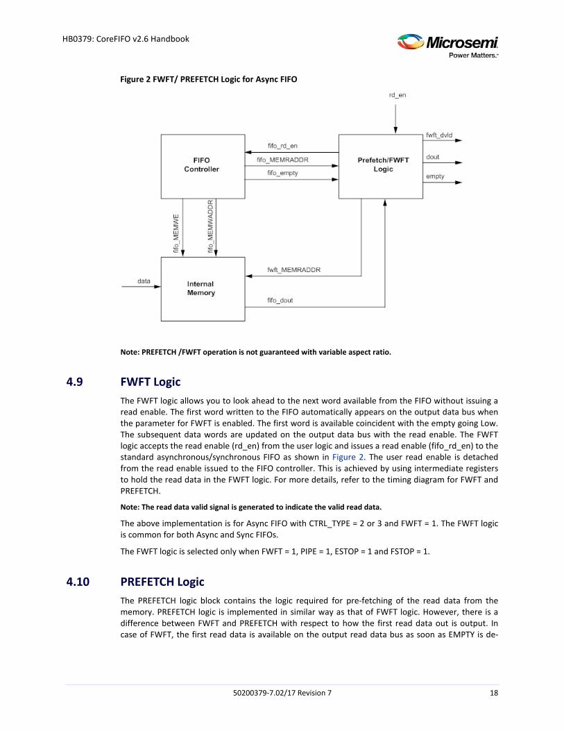
Figure 2 FWFT/ PREFETCH Logic for Async FIFO
Note: PREFETCH /FWFT operation is not guaranteed with variable aspect ratio.
4.9 FWFT Logic The FWFT logic allows you to look ahead to the next word available from the FIFO without issuing a read enable. The first word written to the FIFO automatically appears on the output data bus when the parameter for FWFT is enabled. The first word is available coincident with the empty going Low. The subsequent data words are updated on the output data bus with the read enable. The FWFT logic accepts the read enable (rd_en) from the user logic and issues a read enable (fifo_rd_en) to the standard asynchronous/synchronous FIFO as shown in Figure 2. The user read enable is detached from the read enable issued to the FIFO controller. This is achieved by using intermediate registers to hold the read data in the FWFT logic. For more details, refer to the timing diagram for FWFT and PREFETCH.
Note: The read data valid signal is generated to indicate the valid read data.
The above implementation is for Async FIFO with CTRL_TYPE = 2 or 3 and FWFT = 1. The FWFT logic is common for both Async and Sync FIFOs.
The FWFT logic is selected only when FWFT = 1, PIPE = 1, ESTOP = 1 and FSTOP = 1.
4.10 PREFETCH Logic The PREFETCH logic block contains the logic required for pre-fetching of the read data from the memory. PREFETCH logic is implemented in similar way as that of FWFT logic. However, there is a difference between FWFT and PREFETCH with respect to how the first read data out is output. In case of FWFT, the first read data is available on the output read data bus as soon as EMPTY is de-
50200379-7.02/17 Revision 7 18
HB0379: CoreFIFO v2.6 Handbook
asserted. In case of PREFETCH, the first data is available only when read enable is issued. Refer to Figure 2.
The PREFETCH logic is selected only when PREFETCH = 1, PIPE = 1, ESTOP = 1 and FSTOP = 1.
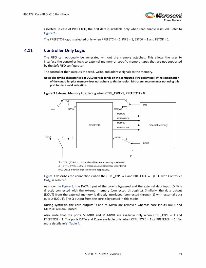
4.11 Controller Only Logic The FIFO can optionally be generated without the memory attached. This allows the user to interface the controller logic to external memory or specific memory types that are not supported by the Soft FIFO configurator.
The controller then outputs the read, write, and address signals to the memory.
Note: The timing characteristic of DVLD port depends on the configured PIPE parameter. If the combination of the controller plus memory does not adhere to this behavior, Microsemi recommends not using this port for data valid indication.
Figure 3 External Memory Interfacing when CTRL_TYPE=1, PREFETCH = 0
CoreFIFO External Memory
MEMWE
MEMWADDR
MEMRE
MEMRADDR
MEMWD
1
1
1
1
2
2
2
2DIN
DOUT
DATA
Q
DOUT
DIN
MEMRD
1 - CTRL_TYPE = 1. Controller with external memory is selected2 - CTRL_TYPE = either 2 or 3 is selected. Controller with internal RAM1Kx18 or RAM64x18 is selected, respectively.
Figure 3 describes the connections when the CTRL_TYPE = 1 and PREFETCH = 0 (FIFO with Controller Only) is selected.
As shown in Figure 3, the DATA input of the core is bypassed and the external data input (DIN) is directly connected with the external memory (connected through 1). Similarly, the data output (DOUT) from the external memory is directly interfaced (connected through 1) with external data output (DOUT). The Q output from the core is bypassed in this mode.
During synthesis, the core outputs Q and MEMWD are removed whereas core inputs DATA and MEMRD remain unused.
Also, note that the ports MEMRD and MEMWD are available only when CTRL_TYPE = 1 and PREFETCH = 1. The ports DATA and Q are available only when CTRL_TYPE = 1 or PREFETCH = 1. For more details refer Table 4.
50200379-7.02/17 Revision 7 19

HB0379: CoreFIFO v2.6 Handbook
4.12 ECC CoreFIFO provides ECC capability for RTG4 device family as explained in the Timing Diagram section.
ECC has three modes:
• Disabled • Pipelined • Non-Pipelined Note: The ECC flags are reset to zero, but are valid only on the same cycle as the corresponding data out. An
additional clock cycle is required if the data out pipeline is also selected. ECC flags (SB_CORRECT and DB_DETECT) will only be valid the same clock cycle as the data out.
50200379-7.02/17 Revision 7 20
HB0379: CoreFIFO v2.6 Handbook
5 Interface
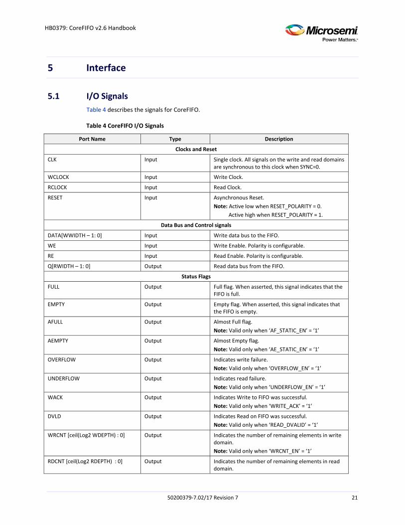
5.1 I/O Signals Table 4 describes the signals for CoreFIFO.
Table 4 CoreFIFO I/O Signals
Port Name Type Description
Clocks and Reset
CLK Input Single clock. All signals on the write and read domains are synchronous to this clock when SYNC=0.
WCLOCK Input Write Clock.
RCLOCK Input Read Clock.
RESET Input Asynchronous Reset. Note: Active low when RESET_POLARITY = 0. Active high when RESET_POLARITY = 1.
Data Bus and Control signals
DATA[WWIDTH – 1: 0] Input Write data bus to the FIFO.
WE Input Write Enable. Polarity is configurable.
RE Input Read Enable. Polarity is configurable.
Q[RWIDTH – 1: 0] Output Read data bus from the FIFO.
Status Flags
FULL Output Full flag. When asserted, this signal indicates that the FIFO is full.
EMPTY Output Empty flag. When asserted, this signal indicates that the FIFO is empty.
AFULL Output Almost Full flag. Note: Valid only when ‘AF_STATIC_EN’ = ‘1’
AEMPTY Output Almost Empty flag. Note: Valid only when ‘AE_STATIC_EN’ = ‘1’
OVERFLOW Output Indicates write failure. Note: Valid only when ‘OVERFLOW_EN’ = ‘1’
UNDERFLOW Output Indicates read failure. Note: Valid only when ‘UNDERFLOW_EN’ = ‘1’
WACK Output Indicates Write to FIFO was successful. Note: Valid only when ‘WRITE_ACK’ = ‘1’
DVLD Output Indicates Read on FIFO was successful. Note: Valid only when ‘READ_DVALID’ = ‘1’
WRCNT [ceil(Log2 WDEPTH) : 0] Output Indicates the number of remaining elements in write domain. Note: Valid only when ‘WRCNT_EN’ = ‘1’
RDCNT [ceil(Log2 RDEPTH) : 0] Output Indicates the number of remaining elements in read domain.
50200379-7.02/17 Revision 7 21
HB0379: CoreFIFO v2.6 Handbook
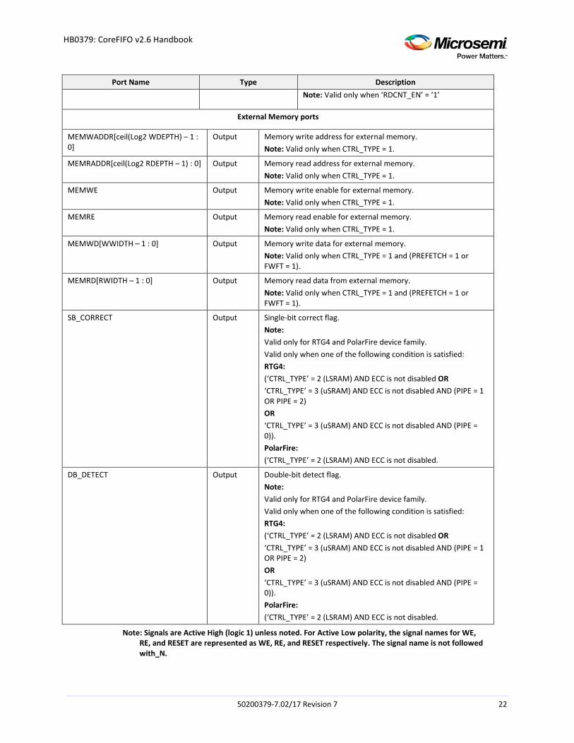
Port Name Type Description
Note: Valid only when ‘RDCNT_EN’ = ‘1’
External Memory ports
MEMWADDR[ceil(Log2 WDEPTH) – 1 : 0]
Output Memory write address for external memory. Note: Valid only when CTRL_TYPE = 1.
MEMRADDR[ceil(Log2 RDEPTH – 1) : 0] Output Memory read address for external memory. Note: Valid only when CTRL_TYPE = 1.
MEMWE Output Memory write enable for external memory. Note: Valid only when CTRL_TYPE = 1.
MEMRE Output Memory read enable for external memory. Note: Valid only when CTRL_TYPE = 1.
MEMWD[WWIDTH – 1 : 0] Output Memory write data for external memory. Note: Valid only when CTRL_TYPE = 1 and (PREFETCH = 1 or FWFT = 1).
MEMRD[RWIDTH – 1 : 0] Output Memory read data from external memory. Note: Valid only when CTRL_TYPE = 1 and (PREFETCH = 1 or FWFT = 1).
SB_CORRECT Output Single-bit correct flag. Note: Valid only for RTG4 and PolarFire device family. Valid only when one of the following condition is satisfied: RTG4: (‘CTRL_TYPE’ = 2 (LSRAM) AND ECC is not disabled OR ‘CTRL_TYPE’ = 3 (uSRAM) AND ECC is not disabled AND (PIPE = 1 OR PIPE = 2) OR ‘CTRL_TYPE’ = 3 (uSRAM) AND ECC is not disabled AND (PIPE = 0)). PolarFire: (‘CTRL_TYPE’ = 2 (LSRAM) AND ECC is not disabled.
DB_DETECT Output Double-bit detect flag. Note: Valid only for RTG4 and PolarFire device family. Valid only when one of the following condition is satisfied: RTG4: (‘CTRL_TYPE’ = 2 (LSRAM) AND ECC is not disabled OR ‘CTRL_TYPE’ = 3 (uSRAM) AND ECC is not disabled AND (PIPE = 1 OR PIPE = 2) OR ‘CTRL_TYPE’ = 3 (uSRAM) AND ECC is not disabled AND (PIPE = 0)). PolarFire: (‘CTRL_TYPE’ = 2 (LSRAM) AND ECC is not disabled.
Note: Signals are Active High (logic 1) unless noted. For Active Low polarity, the signal names for WE, RE, and RESET are represented as WE, RE, and RESET respectively. The signal name is not followed with_N.
50200379-7.02/17 Revision 7 22
HB0379: CoreFIFO v2.6 Handbook
5.2 Core Parameters
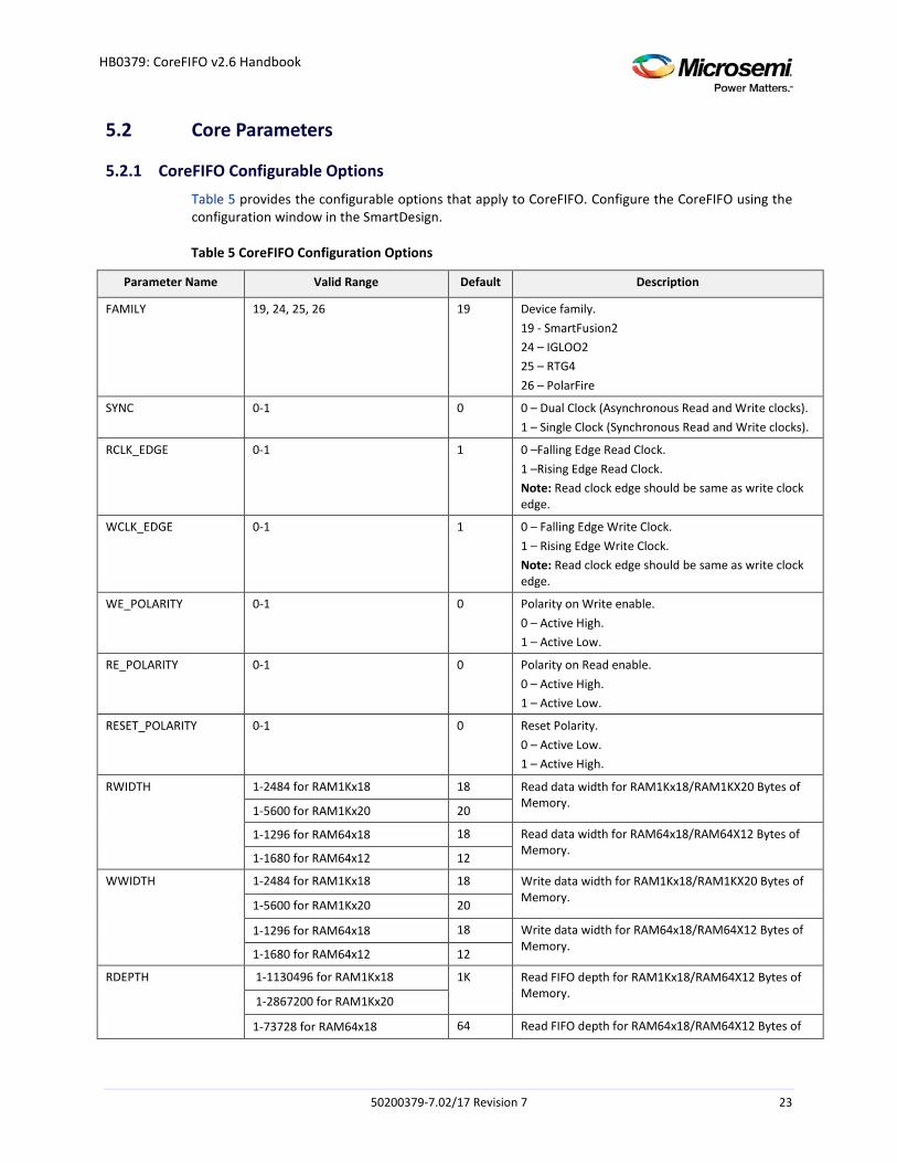
5.2.1 CoreFIFO Configurable Options Table 5 provides the configurable options that apply to CoreFIFO. Configure the CoreFIFO using the configuration window in the SmartDesign.
Table 5 CoreFIFO Configuration Options
Parameter Name Valid Range Default Description
FAMILY 19, 24, 25, 26 19 Device family. 19 - SmartFusion2 24 – IGLOO2 25 – RTG4 26 – PolarFire
SYNC 0-1 0 0 – Dual Clock (Asynchronous Read and Write clocks). 1 – Single Clock (Synchronous Read and Write clocks).
RCLK_EDGE 0-1 1 0 –Falling Edge Read Clock. 1 –Rising Edge Read Clock. Note: Read clock edge should be same as write clock edge.
WCLK_EDGE 0-1 1 0 – Falling Edge Write Clock. 1 – Rising Edge Write Clock. Note: Read clock edge should be same as write clock edge.
WE_POLARITY 0-1 0 Polarity on Write enable. 0 – Active High. 1 – Active Low.
RE_POLARITY 0-1 0 Polarity on Read enable. 0 – Active High. 1 – Active Low.
RESET_POLARITY 0-1 0 Reset Polarity. 0 – Active Low. 1 – Active High.
RWIDTH 1-2484 for RAM1Kx18 18 Read data width for RAM1Kx18/RAM1KX20 Bytes of Memory. 1-5600 for RAM1Kx20 20
1-1296 for RAM64x18 18 Read data width for RAM64x18/RAM64X12 Bytes of Memory. 1-1680 for RAM64x12 12
WWIDTH 1-2484 for RAM1Kx18 18 Write data width for RAM1Kx18/RAM1KX20 Bytes of Memory. 1-5600 for RAM1Kx20 20
1-1296 for RAM64x18 18 Write data width for RAM64x18/RAM64X12 Bytes of Memory. 1-1680 for RAM64x12 12
RDEPTH 1-1130496 for RAM1Kx18 1K Read FIFO depth for RAM1Kx18/RAM64X12 Bytes of Memory. 1-2867200 for RAM1Kx20
1-73728 for RAM64x18 64 Read FIFO depth for RAM64x18/RAM64X12 Bytes of
50200379-7.02/17 Revision 7 23

HB0379: CoreFIFO v2.6 Handbook
Parameter Name Valid Range Default Description
1-8960 for RAM64X12 Memory.
WDEPTH 1-1130496 for RAM1Kx18 1K Write FIFO depth for RAM1Kx18/RAM64X12 Bytes of Memory. 1-2867200 for RAM1Kx20
1-73728 for RAM64x18 64 Write FIFO depth for RAM64x18/RAM64X12 Bytes of Memory. 1-8960 for RAM64X12
WRITE_ACK 0,1 0 Write Acknowledgement indicates whether data has been written. 0 - Disable Write Acknowledgement generation. 1 - Enable Write Acknowledgement generation.
READ_DVALID 0,1 0 Read Data Valid indicates whether Read data is valid or not. 0 – Disable Read Data Valid generation. 1 – Enable Read Data Valid generation.
CTRL_TYPE 1,2,3 1 1 - Controller Only. This allows the user to instantiate the FIFO controller without the memory. 2 - Controller with RAM1Kx18 memory. 3 - Controller with RAM64x18 memory.
ESTOP 0,1 1 1 – Disable Reads when EMPTY. 0 – Enable Reads when EMPTY.
FSTOP 0,1 1 1 – Disable Writes when FULL. 0 – Enable Writes when FULL.
AE_STATIC_EN 0,1 0 Enable/Disable Static threshold values. 0 - Disables use of Static values. 1 - Enables use of Static values given by parameter AEVAL.
AF_STATIC_EN 0,1 0 0 - Disables use of Static values. 1 - Enables use of Static values given by parameter AFVAL.
AEVAL 2-1130495 for RAM1Kx18 4 Programmable Empty Threshold Assert: This parameter is used to set the lower threshold value for the programmable empty flag, which defines when the AEMPTY signal is asserted. Note: Valid only when ‘AE_STATIC_EN’ = ‘1’.
2-2867199 for RAM1Kx20
2-73727 for RAM64X18 4
2-8959 for RAM64X12
AFVAL 2-1130495 for RAM1Kx18 1020 Programmable Full Threshold Assert: This parameter is used to set the upper threshold value for the programmable full flag, which defines when the AFULL signal is asserted. Note: Valid only when ‘AF_STATIC_EN’ = ‘1’.
2-2867199 for RAM1Kx20
2-73727 for RAM64x18 60
2-8959 for RAM64X12
UNDERFLOW_EN 0,1 0 Underflow Error flag generation. 0 – Disable. 1 – Enable.
OVERFLOW_EN 0,1 0 Overflow Error flag generation. 0 – Disable. 1 – Enable.
50200379-7.02/17 Revision 7 24
HB0379: CoreFIFO v2.6 Handbook
Parameter Name Valid Range Default Description
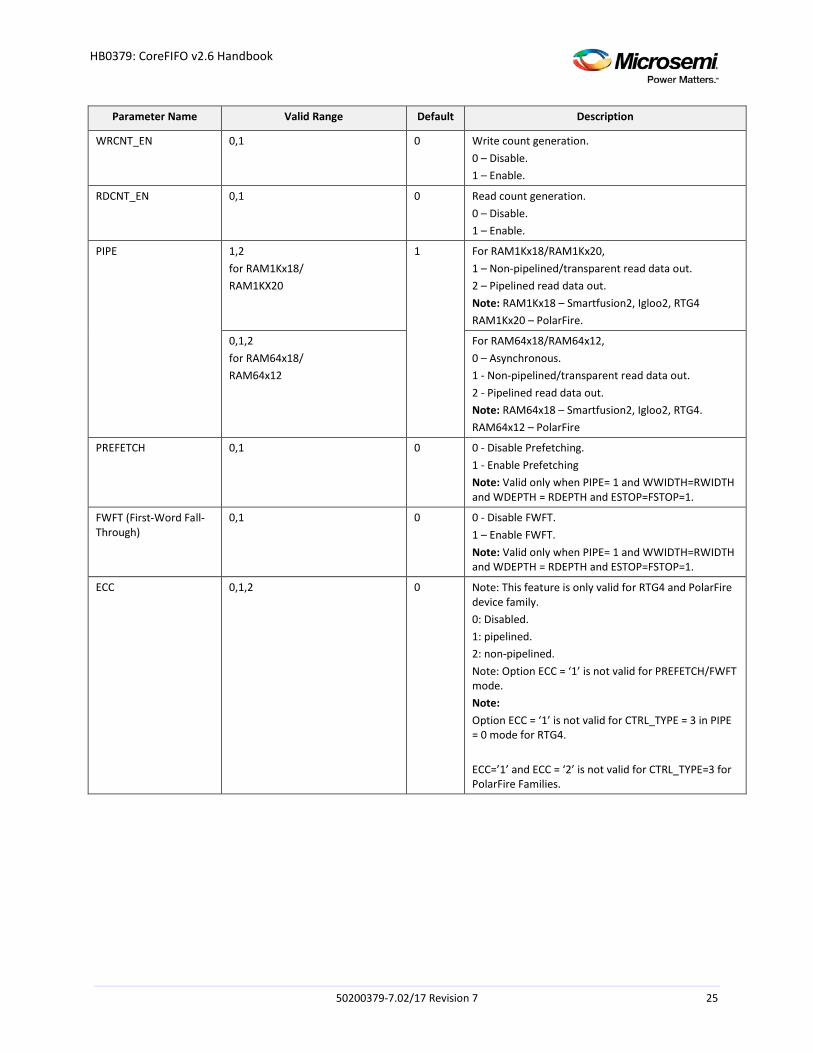
WRCNT_EN 0,1 0 Write count generation. 0 – Disable. 1 – Enable.
RDCNT_EN 0,1 0 Read count generation. 0 – Disable. 1 – Enable.
PIPE 1,2 for RAM1Kx18/ RAM1KX20
1 For RAM1Kx18/RAM1Kx20, 1 – Non-pipelined/transparent read data out. 2 – Pipelined read data out. Note: RAM1Kx18 – Smartfusion2, Igloo2, RTG4 RAM1Kx20 – PolarFire.
0,1,2 for RAM64x18/ RAM64x12
For RAM64x18/RAM64x12, 0 – Asynchronous. 1 - Non-pipelined/transparent read data out. 2 - Pipelined read data out. Note: RAM64x18 – Smartfusion2, Igloo2, RTG4. RAM64x12 – PolarFire
PREFETCH 0,1 0 0 - Disable Prefetching. 1 - Enable Prefetching Note: Valid only when PIPE= 1 and WWIDTH=RWIDTH and WDEPTH = RDEPTH and ESTOP=FSTOP=1.
FWFT (First-Word Fall-Through)
0,1 0 0 - Disable FWFT. 1 – Enable FWFT. Note: Valid only when PIPE= 1 and WWIDTH=RWIDTH and WDEPTH = RDEPTH and ESTOP=FSTOP=1.
ECC 0,1,2 0 Note: This feature is only valid for RTG4 and PolarFire device family. 0: Disabled. 1: pipelined. 2: non-pipelined. Note: Option ECC = ‘1’ is not valid for PREFETCH/FWFT mode. Note: Option ECC = ‘1’ is not valid for CTRL_TYPE = 3 in PIPE = 0 mode for RTG4. ECC=’1’ and ECC = ‘2’ is not valid for CTRL_TYPE=3 for PolarFire Families.
50200379-7.02/17 Revision 7 25
HB0379: CoreFIFO v2.6 Handbook
6 Timing Diagrams
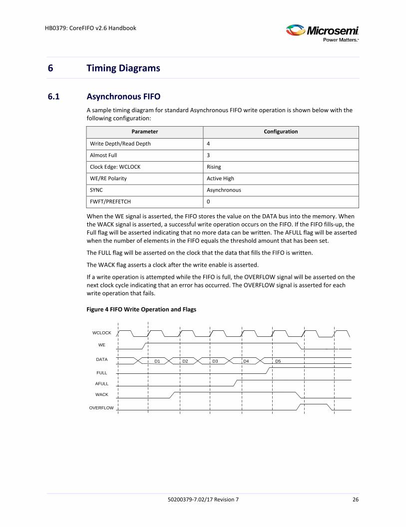
6.1 Asynchronous FIFO A sample timing diagram for standard Asynchronous FIFO write operation is shown below with the following configuration:
Parameter Configuration
Write Depth/Read Depth 4
Almost Full 3
Clock Edge: WCLOCK Rising
WE/RE Polarity Active High
SYNC Asynchronous
FWFT/PREFETCH 0
When the WE signal is asserted, the FIFO stores the value on the DATA bus into the memory. When the WACK signal is asserted, a successful write operation occurs on the FIFO. If the FIFO fills-up, the Full flag will be asserted indicating that no more data can be written. The AFULL flag will be asserted when the number of elements in the FIFO equals the threshold amount that has been set.
The FULL flag will be asserted on the clock that the data that fills the FIFO is written.
The WACK flag asserts a clock after the write enable is asserted.
If a write operation is attempted while the FIFO is full, the OVERFLOW signal will be asserted on the next clock cycle indicating that an error has occurred. The OVERFLOW signal is asserted for each write operation that fails.
Figure 4 FIFO Write Operation and Flags
D1 D2 D3 D4 D5
WCLOCK
DATA
WE
FULL
AFULL
WACK
OVERFLOW
50200379-7.02/17 Revision 7 26
HB0379: CoreFIFO v2.6 Handbook
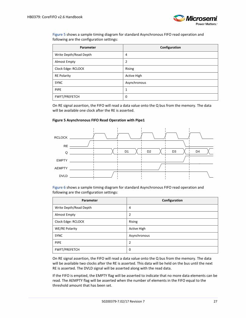
Figure 5 shows a sample timing diagram for standard Asynchronous FIFO read operation and following are the configuration settings:
Parameter Configuration
Write Depth/Read Depth 4
Almost Empty 2
Clock Edge: RCLOCK Rising
RE Polarity Active High
SYNC Asynchronous
PIPE 1
FWFT/PREFETCH 0
On RE signal assertion, the FIFO will read a data value onto the Q bus from the memory. The data will be available one clock after the RE is asserted.
Figure 5 Asynchronous FIFO Read Operation with Pipe1
RCLOCK
RE
Q
EMPTY
AEMPTY
DVLD
D1 D2 D3 D4
Figure 6 shows a sample timing diagram for standard Asynchronous FIFO read operation and following are the configuration settings:
Parameter Configuration
Write Depth/Read Depth 4
Almost Empty 2
Clock Edge: RCLOCK Rising
WE/RE Polarity Active High
SYNC Asynchronous
PIPE 2
FWFT/PREFETCH 0
On RE signal assertion, the FIFO will read a data value onto the Q bus from the memory. The data will be available two clocks after the RE is asserted. This data will be held on the bus until the next RE is asserted. The DVLD signal will be asserted along with the read data.
If the FIFO is emptied, the EMPTY flag will be asserted to indicate that no more data elements can be read. The AEMPTY flag will be asserted when the number of elements in the FIFO equal to the threshold amount that has been set.
50200379-7.02/17 Revision 7 27
HB0379: CoreFIFO v2.6 Handbook
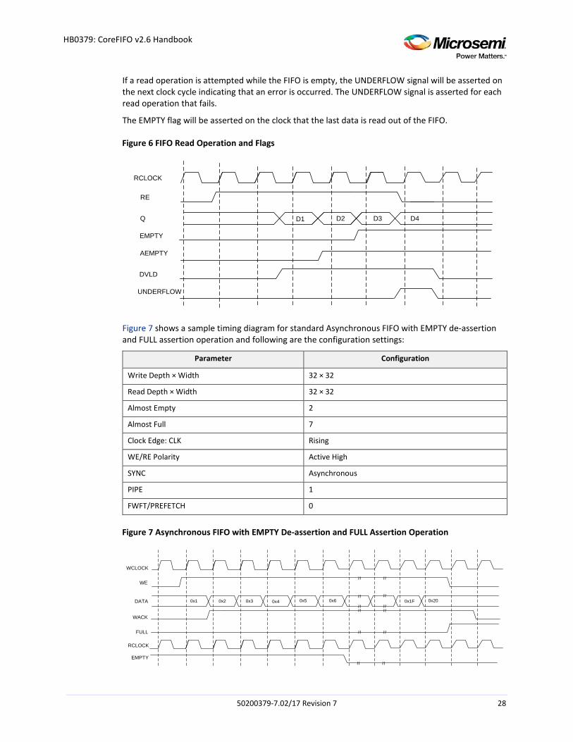
If a read operation is attempted while the FIFO is empty, the UNDERFLOW signal will be asserted on the next clock cycle indicating that an error is occurred. The UNDERFLOW signal is asserted for each read operation that fails.
The EMPTY flag will be asserted on the clock that the last data is read out of the FIFO.
Figure 6 FIFO Read Operation and Flags
RCLOCK
Q
RE
EMPTY
AEMPTY
DVLD
UNDERFLOW
D2 D3 D4D1
Figure 7 shows a sample timing diagram for standard Asynchronous FIFO with EMPTY de-assertion and FULL assertion operation and following are the configuration settings:
Parameter Configuration
Write Depth × Width 32 × 32
Read Depth × Width 32 × 32
Almost Empty 2
Almost Full 7
Clock Edge: CLK Rising
WE/RE Polarity Active High
SYNC Asynchronous
PIPE 1
FWFT/PREFETCH 0
Figure 7 Asynchronous FIFO with EMPTY De-assertion and FULL Assertion Operation
WCLOCK
DATA
WE
WACK
EMPTY
FULL
~ ~~ ~
~ ~~ ~
RCLOCK
~ ~ ~ ~
~ ~ ~ ~
~ ~ ~ ~
~ ~ ~ ~
0x1 0x2 0x3 0x1F0x4 0x200x5 0x6
50200379-7.02/17 Revision 7 28
HB0379: CoreFIFO v2.6 Handbook
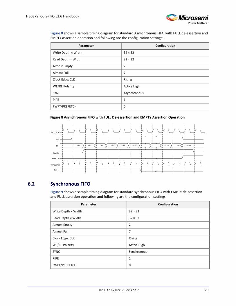
Figure 8 shows a sample timing diagram for standard Asynchronous FIFO with FULL de-assertion and EMPTY assertion operation and following are the configuration settings:
Parameter Configuration
Write Depth × Width 32 × 32
Read Depth × Width 32 × 32
Almost Empty 2
Almost Full 7
Clock Edge: CLK Rising
WE/RE Polarity Active High
SYNC Asynchronous
PIPE 1
FWFT/PREFETCH 0
Figure 8 Asynchronous FIFO with FULL De-assertion and EMPTY Assertion Operation
Q
RE
DVLD
FULL
EMPTY
~ ~~ ~
~ ~~ ~
~ ~ ~ ~
~ ~ ~ ~
~ ~ ~ ~
~ ~ ~ ~
RCLOCK
WCLOCK
0x1 0x2 0x3 0x1F0x4 0x200x50x0 0x1E
6.2 Synchronous FIFO Figure 9 shows a sample timing diagram for standard synchronous FIFO with EMPTY de-assertion and FULL assertion operation and following are the configuration settings:
Parameter Configuration
Write Depth × Width 32 × 32
Read Depth × Width 32 × 32
Almost Empty 2
Almost Full 7
Clock Edge: CLK Rising
WE/RE Polarity Active High
SYNC Synchronous
PIPE 1
FWFT/PREFETCH 0
50200379-7.02/17 Revision 7 29
HB0379: CoreFIFO v2.6 Handbook
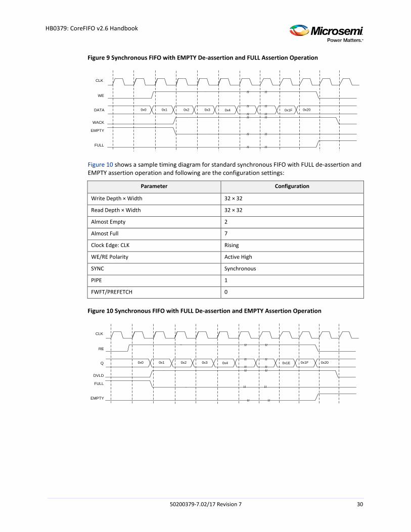
Figure 9 Synchronous FIFO with EMPTY De-assertion and FULL Assertion Operation
CLK
DATA
WE
WACK
EMPTY
FULL
~ ~~ ~
~ ~~ ~
~ ~~ ~
~ ~~ ~
~ ~ ~ ~
~ ~ ~ ~
0x0 0x1 0x2 0x3 0x1F0x4 0x20
Figure 10 shows a sample timing diagram for standard synchronous FIFO with FULL de-assertion and EMPTY assertion operation and following are the configuration settings:
Parameter Configuration
Write Depth × Width 32 × 32
Read Depth × Width 32 × 32
Almost Empty 2
Almost Full 7
Clock Edge: CLK Rising
WE/RE Polarity Active High
SYNC Synchronous
PIPE 1
FWFT/PREFETCH 0
Figure 10 Synchronous FIFO with FULL De-assertion and EMPTY Assertion Operation
CLK
Q
RE
DVLD
FULL
EMPTY
~ ~~ ~
~ ~~ ~
~ ~ ~ ~
~ ~ ~ ~
~ ~ ~ ~
~ ~ ~ ~
0x0 0x1 0x2 0x3 0x1E0x4 0x1F 0x20
50200379-7.02/17 Revision 7 30
HB0379: CoreFIFO v2.6 Handbook
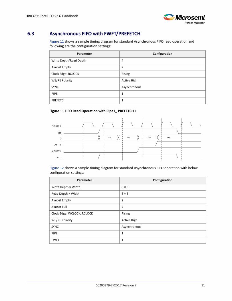
6.3 Asynchronous FIFO with FWFT/PREFETCH Figure 11 shows a sample timing diagram for standard Asynchronous FIFO read operation and following are the configuration settings:
Parameter Configuration
Write Depth/Read Depth 4
Almost Empty 2
Clock Edge: RCLOCK Rising
WE/RE Polarity Active High
SYNC Asynchronous
PIPE 1
PREFETCH 1
Figure 11 FIFO Read Operation with Pipe1_ PREFETCH 1
RCLOCK
RE
Q
EMPTY
AEMPTY
DVLD
D1 D2 D3 D4
Figure 12 shows a sample timing diagram for standard Asynchronous FIFO operation with below configuration settings:
Parameter Configuration
Write Depth × Width 8 × 8
Read Depth × Width 8 × 8
Almost Empty 2
Almost Full 7
Clock Edge: WCLOCK, RCLOCK Rising
WE/RE Polarity Active High
SYNC Asynchronous
PIPE 1
FWFT 1
50200379-7.02/17 Revision 7 31
HB0379: CoreFIFO v2.6 Handbook
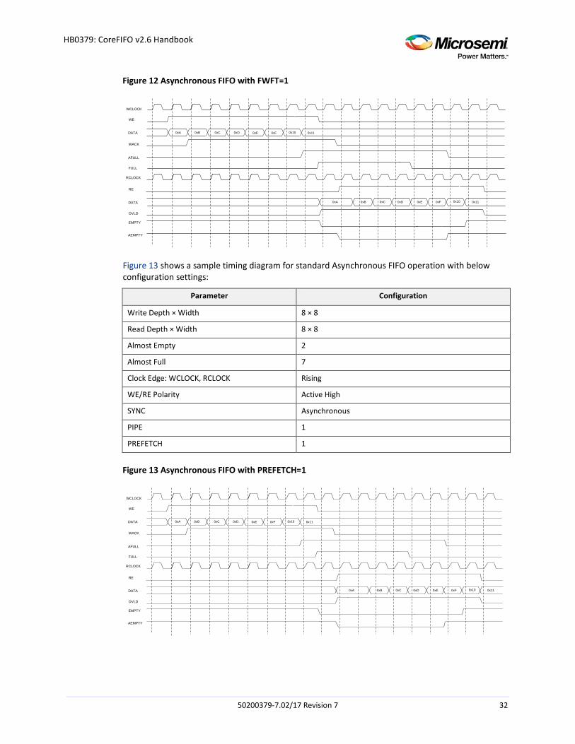
Figure 12 Asynchronous FIFO with FWFT=1
WCLOCK
DATA
WE
WACK
EMPTY
FULL
RCLOCK
DATA
RE
DVLD
0xA 0xB 0xC 0xD 0x110x100xF0xE
0xA 0xB 0xC 0xD 0x110x100xF0xE
AEMPTY
AFULL
Figure 13 shows a sample timing diagram for standard Asynchronous FIFO operation with below configuration settings:
Parameter Configuration
Write Depth × Width 8 × 8
Read Depth × Width 8 × 8
Almost Empty 2
Almost Full 7
Clock Edge: WCLOCK, RCLOCK Rising
WE/RE Polarity Active High
SYNC Asynchronous
PIPE 1
PREFETCH 1
Figure 13 Asynchronous FIFO with PREFETCH=1
WCLOCK
DATA
WE
WACK
EMPTY
FULL
RCLOCK
DATA
RE
DVLD
0xA 0xB 0xC 0xD 0x110x100xF0xE
0xA 0xB 0xC 0xD 0x110x100xF0xE
AEMPTY
AFULL
50200379-7.02/17 Revision 7 32
HB0379: CoreFIFO v2.6 Handbook
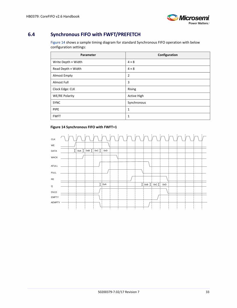
6.4 Synchronous FIFO with FWFT/PREFETCH Figure 14 shows a sample timing diagram for standard Synchronous FIFO operation with below configuration settings:
Parameter Configuration
Write Depth × Width 4 × 8
Read Depth × Width 4 × 8
Almost Empty 2
Almost Full 3
Clock Edge: CLK Rising
WE/RE Polarity Active High
SYNC Synchronous
PIPE 1
FWFT 1
Figure 14 Synchronous FIFO with FWFT=1
CLK
WE
DATA
WACK
RE
Q
DVLD
EMPTY
FULL
0xA 0xB 0xC 0xD
0xA 0xB 0xC 0xD
AEMPTY
AFULL
50200379-7.02/17 Revision 7 33
HB0379: CoreFIFO v2.6 Handbook
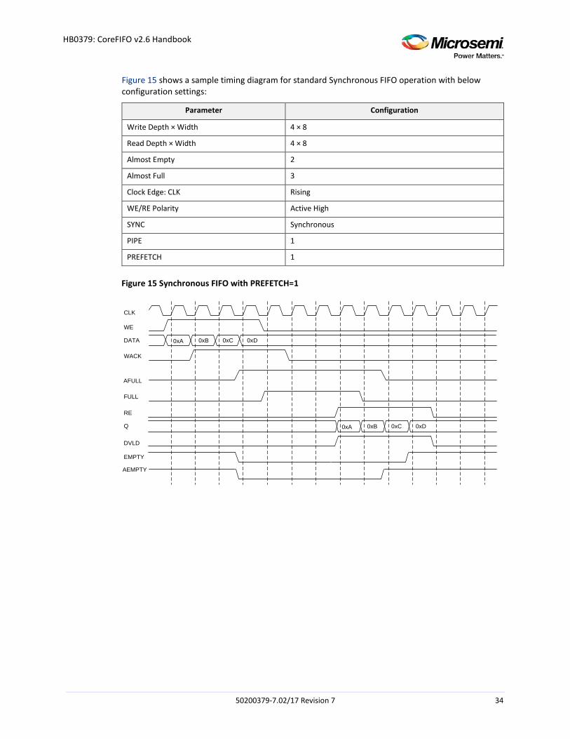
Figure 15 shows a sample timing diagram for standard Synchronous FIFO operation with below configuration settings:
Parameter Configuration
Write Depth × Width 4 × 8
Read Depth × Width 4 × 8
Almost Empty 2
Almost Full 3
Clock Edge: CLK Rising
WE/RE Polarity Active High
SYNC Synchronous
PIPE 1
PREFETCH 1
Figure 15 Synchronous FIFO with PREFETCH=1
CLK
WE
DATA
WACK
RE
Q
DVLD
0xA
EMPTY
FULL
0xB 0xC 0xD
0xA 0xB 0xC 0xD
AFULL
AEMPTY
50200379-7.02/17 Revision 7 34
HB0379: CoreFIFO v2.6 Handbook
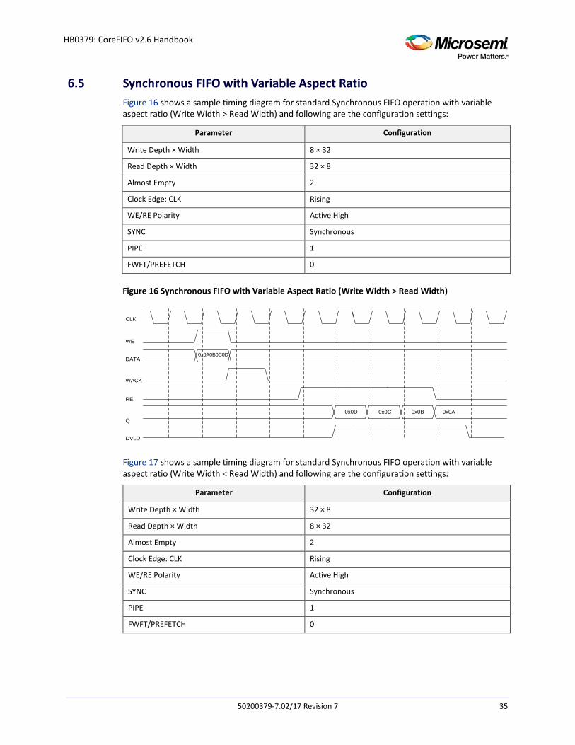
6.5 Synchronous FIFO with Variable Aspect Ratio Figure 16 shows a sample timing diagram for standard Synchronous FIFO operation with variable aspect ratio (Write Width > Read Width) and following are the configuration settings:
Parameter Configuration
Write Depth × Width 8 × 32
Read Depth × Width 32 × 8
Almost Empty 2
Clock Edge: CLK Rising
WE/RE Polarity Active High
SYNC Synchronous
PIPE 1
FWFT/PREFETCH 0
Figure 16 Synchronous FIFO with Variable Aspect Ratio (Write Width > Read Width)
0x0A0B0C0D
0x0D
CLK
WE
DATA
WACK
RE
Q
DVLD
0x0C 0x0B 0x0A
Figure 17 shows a sample timing diagram for standard Synchronous FIFO operation with variable aspect ratio (Write Width < Read Width) and following are the configuration settings:
Parameter Configuration
Write Depth × Width 32 × 8
Read Depth × Width 8 × 32
Almost Empty 2
Clock Edge: CLK Rising
WE/RE Polarity Active High
SYNC Synchronous
PIPE 1
FWFT/PREFETCH 0
50200379-7.02/17 Revision 7 35
HB0379: CoreFIFO v2.6 Handbook
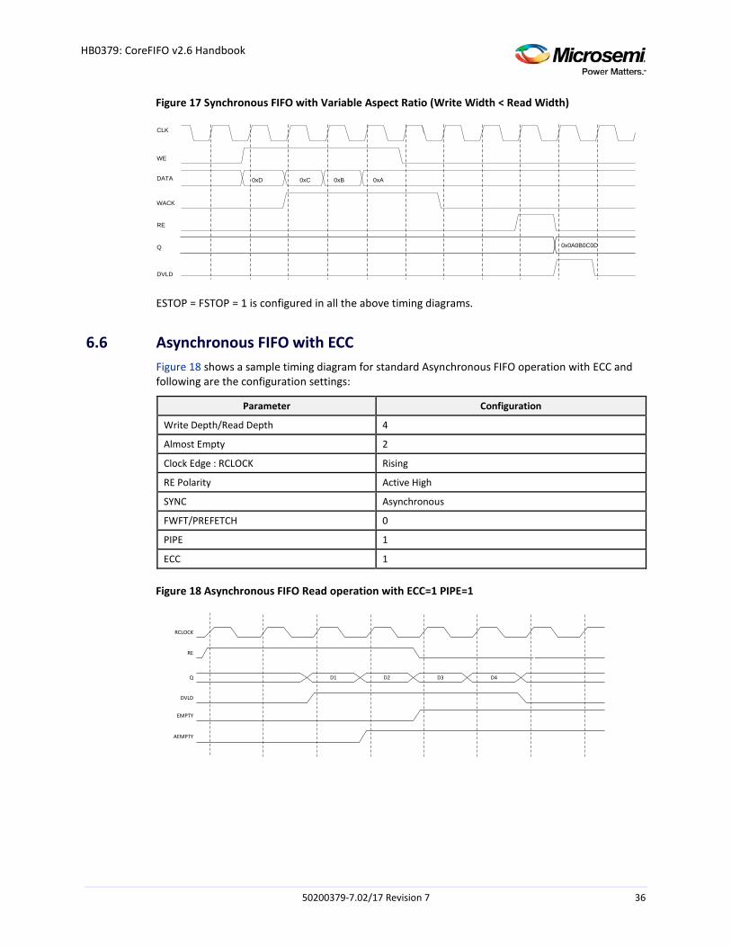
Figure 17 Synchronous FIFO with Variable Aspect Ratio (Write Width < Read Width)
CLK
WE
DATA
WACK
RE
Q
DVLD
0xD 0xC 0xB 0xA
0x0A0B0C0D
ESTOP = FSTOP = 1 is configured in all the above timing diagrams.
6.6 Asynchronous FIFO with ECC Figure 18 shows a sample timing diagram for standard Asynchronous FIFO operation with ECC and following are the configuration settings:
Parameter Configuration
Write Depth/Read Depth 4
Almost Empty 2
Clock Edge : RCLOCK Rising
RE Polarity Active High
SYNC Asynchronous
FWFT/PREFETCH 0
PIPE 1
ECC 1
Figure 18 Asynchronous FIFO Read operation with ECC=1 PIPE=1
RCLOCK
Q
RE
DVLD
EMPTY
AEMPTY
D1 D2 D3 D4
50200379-7.02/17 Revision 7 36
HB0379: CoreFIFO v2.6 Handbook
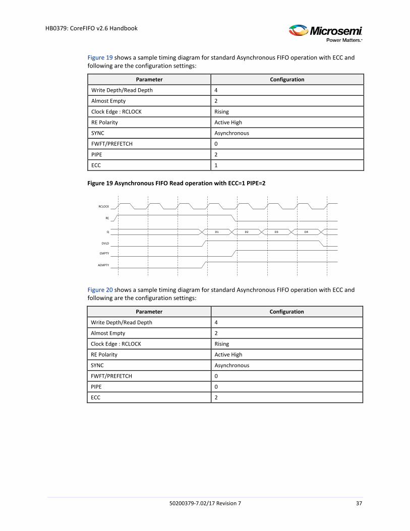
Figure 19 shows a sample timing diagram for standard Asynchronous FIFO operation with ECC and following are the configuration settings:
Parameter Configuration
Write Depth/Read Depth 4
Almost Empty 2
Clock Edge : RCLOCK Rising
RE Polarity Active High
SYNC Asynchronous
FWFT/PREFETCH 0
PIPE 2
ECC 1
Figure 19 Asynchronous FIFO Read operation with ECC=1 PIPE=2
RCLOCK
Q
RE
DVLD
EMPTY
AEMPTY
D1 D2 D3 D4
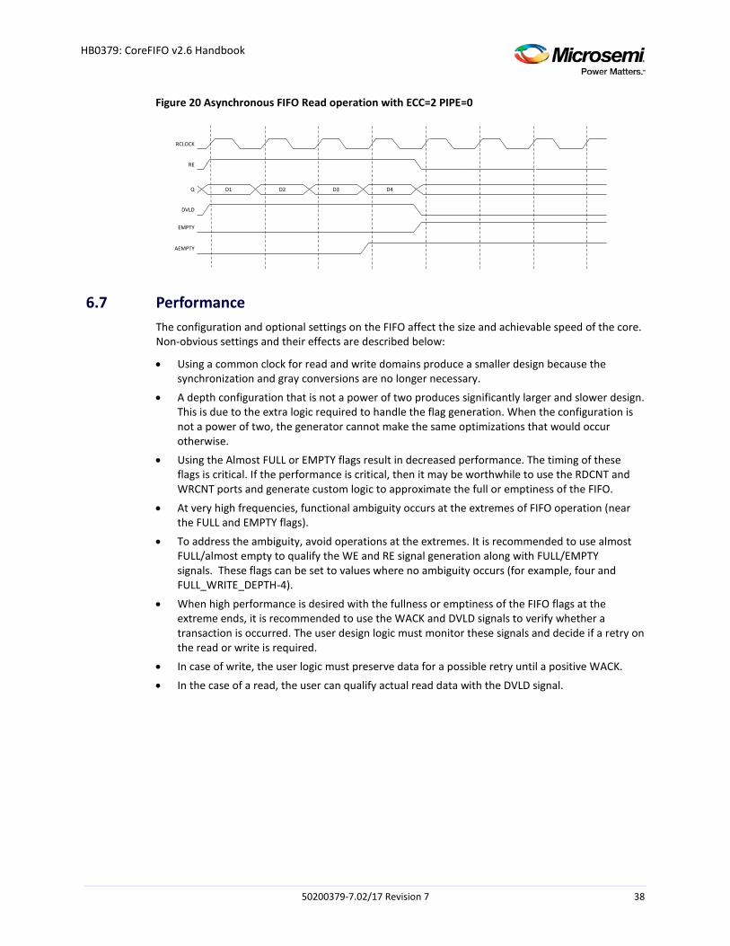
Figure 20 shows a sample timing diagram for standard Asynchronous FIFO operation with ECC and following are the configuration settings:
Parameter Configuration
Write Depth/Read Depth 4
Almost Empty 2
Clock Edge : RCLOCK Rising
RE Polarity Active High
SYNC Asynchronous
FWFT/PREFETCH 0
PIPE 0
ECC 2
50200379-7.02/17 Revision 7 37
HB0379: CoreFIFO v2.6 Handbook
Figure 20 Asynchronous FIFO Read operation with ECC=2 PIPE=0
RCLOCK
RE
DVLD
EMPTY
AEMPTY
D1 D2 D3 D4Q
6.7 Performance The configuration and optional settings on the FIFO affect the size and achievable speed of the core. Non-obvious settings and their effects are described below:
• Using a common clock for read and write domains produce a smaller design because the synchronization and gray conversions are no longer necessary.
• A depth configuration that is not a power of two produces significantly larger and slower design. This is due to the extra logic required to handle the flag generation. When the configuration is not a power of two, the generator cannot make the same optimizations that would occur otherwise.
• Using the Almost FULL or EMPTY flags result in decreased performance. The timing of these flags is critical. If the performance is critical, then it may be worthwhile to use the RDCNT and WRCNT ports and generate custom logic to approximate the full or emptiness of the FIFO.
• At very high frequencies, functional ambiguity occurs at the extremes of FIFO operation (near the FULL and EMPTY flags).
• To address the ambiguity, avoid operations at the extremes. It is recommended to use almost FULL/almost empty to qualify the WE and RE signal generation along with FULL/EMPTY signals. These flags can be set to values where no ambiguity occurs (for example, four and FULL_WRITE_DEPTH-4).
• When high performance is desired with the fullness or emptiness of the FIFO flags at the extreme ends, it is recommended to use the WACK and DVLD signals to verify whether a transaction is occurred. The user design logic must monitor these signals and decide if a retry on the read or write is required.
• In case of write, the user logic must preserve data for a possible retry until a positive WACK.
• In the case of a read, the user can qualify actual read data with the DVLD signal.
50200379-7.02/17 Revision 7 38
HB0379: CoreFIFO v2.6 Handbook
7 Tool Flow
7.1 License CoreFIFO does not require a license.
7.2 RTL Complete RTL source code is provided for the core and testbenches.
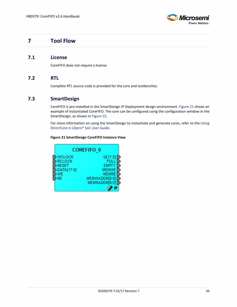
7.3 SmartDesign CoreFIFO is pre-installed in the SmartDesign IP Deployment design environment. Figure 21 shows an example of instantiated CoreFIFO. The core can be configured using the configuration window in the SmartDesign, as shown in Figure 22.
For more information on using the SmartDesign to instantiate and generate cores, refer to the Using DirectCore in Libero® SoC User Guide.
Figure 21 SmartDesign CoreFIFO Instance View
50200379-7.02/17 Revision 7 39
HB0379: CoreFIFO v2.6 Handbook
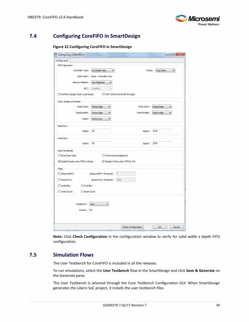
7.4 Configuring CoreFIFO in SmartDesign
Figure 22 Configuring CoreFIFO in SmartDesign
Note: Click Check Configuration in the configuration window to verify for valid width x depth FIFO configuration.
7.5 Simulation Flows The User Testbench for CoreFIFO is included in all the releases.
To run simulations, select the User Testbench flow in the SmartDesign and click Save & Generate on the Generate pane.
The User Testbench is selected through the Core Testbench Configuration GUI. When SmartDesign generates the Libero SoC project, it installs the user testbench files.
50200379-7.02/17 Revision 7 40
HB0379: CoreFIFO v2.6 Handbook
To run the user testbench, set the design root to the CoreFIFO instantiation in the Libero SoC design hierarchy pane and click Simulation in the Libero SoC Design Flow window. This invokes ModelSim® and automatically run the simulation.
7.6 Synthesis in Libero Click Synthesis in the Libero software. The Synthesis window displays the Synplify® project. Set Synplify to use the Verilog 2001 standard, if Verilog is being used. To run the synthesis, click Run.
7.7 Place-and-Route in Libero Click Layout in the Libero software to invoke the Designer. CoreFIFO does not require any special place-and-route settings.
50200379-7.02/17 Revision 7 41
HB0379: CoreFIFO v2.6 Handbook
8 Testbench
A unified test-bench is used to verify and test CoreFIFO called as user test-bench.
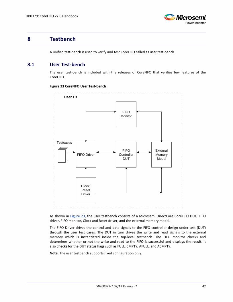
8.1 User Test-bench The user test-bench is included with the releases of CoreFIFO that verifies few features of the CoreFIFO.
Figure 23 CoreFIFO User Test-bench
FIFO DriverFIFO
Controller DUT
FIFO Monitor
Clock/Reset Driver
External MemoryModel
Testcases
User TB
As shown in Figure 23, the user testbench consists of a Microsemi DirectCore CoreFIFO DUT, FIFO driver, FIFO monitor, Clock and Reset driver, and the external memory model.
The FIFO Driver drives the control and data signals to the FIFO controller design-under-test (DUT) through the user test cases. The DUT in turn drives the write and read signals to the external memory which is instantiated inside the top-level testbench. The FIFO monitor checks and determines whether or not the write and read to the FIFO is successful and displays the result. It also checks for the DUT status flags such as FULL, EMPTY, AFULL, and AEMPTY.
Note: The user testbench supports fixed configuration only.
50200379-7.02/17 Revision 7 42

HB0379: CoreFIFO v2.6 Handbook
9 Register Map and Descriptions
CoreFIFO does not contain any registers.
50200379-7.02/17 Revision 7 43
HB0379: CoreFIFO v2.6 Handbook
10 Ordering Information
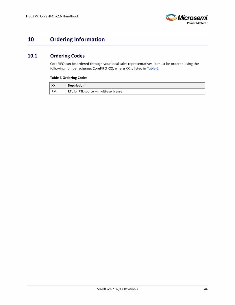
10.1 Ordering Codes CoreFIFO can be ordered through your local sales representatives. It must be ordered using the following number scheme: CoreFIFO -XX, where XX is listed in Table 6.
Table 6·Ordering Codes
XX Description
RM RTL for RTL source — multi-use license
50200379-7.02/17 Revision 7 44
Related Documents