HardiePipe ™ Concrete Pipes Installation Guide MAY 2011

Welcome message from author
This document is posted to help you gain knowledge. Please leave a comment to let me know what you think about it! Share it to your friends and learn new things together.
Transcript
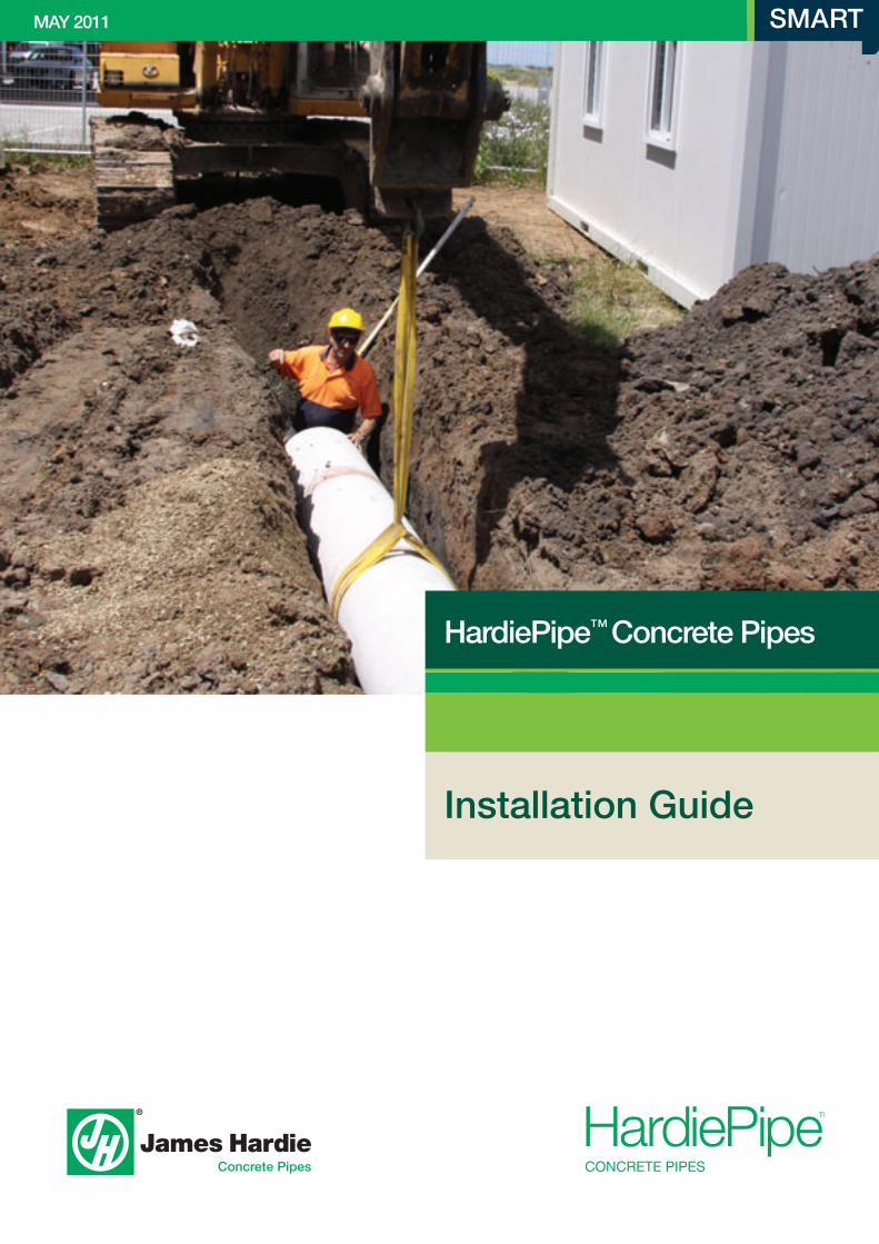
HardiePipe™ Concrete Pipes
Installation Guide
MAY 2011
Contents
1 IntroduCtIon 31.1 overview 31.2 scope 31.3 More Information 3
2 WHy HArdIePIPe™? 32.1 longer lengths 32.2 smart 32.3 safe 32.4 Durable 32.5 lightweight Composition 32.6 strong 3
3 ProduCt InformAtIon 43.1 standards 43.2 Composition 43.3 HardiePipe™ Rubber Ring Joint 4 3.4 sizes 43.5 HardiePipe™ Fittings 4
4 sAfe WorkIng PrACtICes 54.1 Health & safety Information 54.2 Cutting HardiePipe™ Concrete Pipes 5
5 storAge And HAndLIng 65.1 Avoiding Product Damage 65.2 Pipe stack Configuration & Mass 65.3 unloading Requirements 85.4 storing on-site 95.5 General Handling 9 5.6 lifting 11
6 LoAds on BurIed PIPes 126.1 types of loads 126.2 Force from Backfill weight 126.3 Construction loads 136.4 traffic loads 14
7 suPPortIng tHe PIPe 157.1 overview 157.2 type u 167.3 type H 167.4 type Hs 177.5 Compaction 187.6 Bedding Factor 18
8 trenCH 198.1 trench size 198.2 Preparing of the trench 198.3 width of the trench 198.4 trench stability 208.5 trench Depth 208.6 Groundwater 20
9 suItABLe PIPe suPPort mAterIAL 219.1 overview 219.2 Bedding and Haunch 219.3 side Zone 219.4 overlay 219.5 Backfill 21
10 InstALLAtIon 2210.1 overview 2210.2 Preparation 2210.3 Grade 2210.4 Pipe laying sequence 2210.5 Joints 2210.6 Installing Rubber V Ring 2310.7 Applying lube 2310.8 HardieJoin™ lubricant 2310.9 Joining lubricated Pipes 2410.10 Joint Gap tolerances 2510.11 splayed Joint Deflection 2510.12 Haunch, side and overlay Installation 2610.13 Compaction using Flooding Methods 2710.14 optimum Moisture Content for Compaction 2710.15 Backfill 27
11 CuttIng And fIttIngs 2811.1 Cutting 2811.2 HardiePipe™ Fittings 2811.3 Joining a Cut Pipe 2811.4 Making Holes 2911.5 saddles 2911.6 Equal slope Junctions 2911.7 Bends 3011.8 Connecting to Pits 30
12 dAmAge And rePAIrs 3112.1 Pipe Cracking 3112.2 Repairing Pipe sections 3112.3 Repairing Punctures 3112.4 Damaged Ends 32
13 WArrAnty 33
Note: we value your feedback. For ideas and suggestions please contact us on 1800 650 859 or [email protected].
2 mAy 2011 HArdIePIPe™ INSTALLATION GUIde
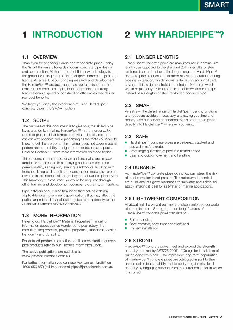
1.1 OVerVIeWthank you for choosing HardiePipe™ concrete pipes. today the smart thinking is towards modern concrete pipe design and construction. At the forefront of this new technology is the groundbreaking range of HardiePipe™ concrete pipes and fittings. As a result of our ongoing research and development the HardiePipe™ product range has revolutionised modern construction practices. light, long, adaptable and strong features enable speed of construction efficiencies that deliver real cost benefits.
we hope you enjoy the experience of using HardiePipe™ concrete pipes, the sMARt option.
1.2 SCOPethe purpose of this document is to give you, the skilled pipe layer, a guide to installing HardiePipe™ into the ground. our aim is to present this information to you in the clearest and easiest way possible, while presenting all the facts you need to know to get the job done. this manual does not cover material performance, durability, design and other technical aspects. Refer to section 1.3 from more information on these topics.
this document is intended for an audience who are already familiar or experienced in pipe laying and hence topics on general safety, setting out, levelling, earthworks, working with trenches, lifting and handling of construction materials - are not covered in this manual although they are relevant to pipe-laying. this knowledge is assumed, or would be acquired through other training and development courses, programs, or literature.
Pipe installers should also familiarise themselves with any applicable local government specifications that may affect the particular project. this installation guide refers primarily to the Australian standard As/NZs3725:2007
1.3 MOre INfOrMATIONRefer to our HardiePipe™ Material Properties manual for information about James Hardie, our pipes history, the manufacturing process, physical properties, standards, design life, quality and durability.
For detailed product information on all James Hardie concrete pipe products refer to our Product Information Book.
the above publications are available at www.jameshardiepipes.com.au
For further information you can also Ask James Hardie® on 1800 659 850 (toll free) or email [email protected]
1 IntroduCtIon 2 WHy HArdIePIPe™?
2.1 LONGer LeNGTHSHardiePipe™ concrete pipes are manufactured in nominal 4m lengths, as opposed to the standard 2.44m lengths of steel reinforced concrete pipes. the longer length of HardiePipe™ concrete pipes reduces the number of laying operations during pipeline installation, which allows faster laying and significant savings. this is demonstrated in a straight 100m run which would require only 25 lengths of HardiePipe™ concrete pipe instead of 40 lengths of steel reinforced concrete pipe.
2.2 SMArTVersatile – the smart range of HardiePipe™ bends, junctions and reducers avoids unnecessary pits saving you time and money. use our saddle connectors to join smaller pvc pipes directly into HardiePipe™ wherever you want.
2.3 SAfe HardiePipe™ concrete pipes are delivered, stacked and
packed in safety crates store large quantities of pipe in a limited space Easy and quick movement and handling
2.4 dUrAbLeAs HardiePipe™ concrete pipes do not contain steel, the risk of steel corrosion is not present. the autoclaved chemical structure ensures good resistance to saltwater and acidic soil attack, making it ideal for saltwater or marine applications.
2.5 LIGHTWeIGHT COMPOSITIONAt about half the weight per metre of steel reinforced concrete pipe, the inherent ‘strong, light and long’ features of HardiePipe™ concrete pipes translate to:
Easier handling; Cost effective, easy transportation; and Efficient installation
2.6 STrONGHardiePipe™ concrete pipes meet and exceed the strength capacity required by As3725:2007 – “Design for installation of buried concrete pipes”. the impressive long-term capabilities of HardiePipe™ concrete pipes are attributed in part to their unique deflection capability and its ability to gain extra load capacity by engaging support from the surrounding soil in which it is buried.
HArdIePIPe™ INSTALLATION GUIde mAy 2011 3

3 ProduCt InformAtIon
3.1 STANdArdSthe following standards are applicable to HardiePipe™ concrete pipes:
Design & Installation: As/NZs3725:2007 Manufacture: As4139:2003 Quality: Iso9001:2008
For more information relating to fibre reinforced concrete pipe standards refer to HardiePipe™ Material Properties manual.
3.2 COMPOSITIONsand (silica), cement, cellulose reinforcement & proprietary additives. Refer to the HardiePipe™ Material Properties manual for more details relating to our manufacturing process.
3.3 HArdIePIPe™ rUbber rING JOINTHardiePipe™ concrete pipes are manufactured with a unique rubber ‘V’ ring joint to seal against moisture ingres or egress, see Figure 1. the standard rubber ring joint enables:
Easy pipe assembly - low insertion forces mean less effort for equipment and less strain to join pipelines. Flush pipe exterior - the flush exterior through each joint
ultimately increases the ease of laying.
3.4 SIzeSHardiePipe™ concrete pipes are available in the following range of size and class:
225mm in Class 2 & 4 300-750mm in Class 2, 3 & 4
length = 4m nominal
Nominal diameters relate to the sizes listed in As4139. A nominal diameter is a convenient round number reference related to the internal diameter, in millimetres where DN = Nominal size (mm).
fIGUre 1 rUbber rING JOINT
TAbLe 1 HArdIePIPe™ dIMeNSIONS ANd MASS
Nominal Pipe Size dN (mm)
Strength Class (AS3725)
Pipe I.d. (mm)
Pipe O.d. (mm)
Pipe Wall Thickness(mm)
Pipe Length dN (m)
Approx dry Mass(kg)
Approx dry mass(kg/m)
225 24
230 270273
2022
44
96104
2426
300 234
303 346348354
222326
444
140148168
353742
375 234
377 427431439
252731
444
196212248
495362
450 234
457 512519529
283135
444
272308360
687790
525 234
534 594606618
303642
444
344416488
86104122
600 234
610 678691705
344148
444
444532628
111133157
675 234
675 752770787
394856
444
556692824
139173206
750 234
720 803822839
425160
444
628780920
157195230
3.5 HArdIePIPe™ fITTINGSthere are a variety of fittings and accessories available for use with the HardiePipe™ concrete pipes, making it one of the most versatile concrete pipes on the market. More information about our products can be found in our Product Information Book and on our website at www.jameshardiepipes.com.au
4 mAy 2011 HArdIePIPe™ INSTALLATION GUIde
HardiePipe™ spigot HardiePipe™ socket
V ring

HArdIePIPe™ INSTALLATION GUIde mAy 2011 5
4 sAfe WorkIng PrACtICes
4.1 HeALTH & SAfeTY INfOrMATIONwARNING - Do Not BREAtHE Dust AND Cut oNly IN wEll VENtIlAtED AREA.
James Hardie products contain sand, a source of respirable crystalline silica which is considered by some international authorities to be a cause of cancer from some occupational sources. Breathing excessive amounts of respirable silica dust can also cause a disabling and potentially fatal lung disease called silicosis, and has been linked with other diseases. some studies suggest smoking may increase these risks.
During installation or handling:
1. work in outdoor areas with ample ventilation; 2. Minimise dust when cutting by only using suitable cutting equipment capable of adequately suppressing dust; 3. warn others in the immediate area to avoid breathing dust; 4. wear a properly fitted, approved dust mask or respirator (e.g. P1 or P2) in accordance with applicable government regulations and manufacturer instructions to further limit respirable silica exposures. During clean-up, use HEPA vacuums or wet clean-up methods - never dry sweep.
For further information such as Material safety Data sheets, please Ask James Hardie™ on 1800 659 850.
FAIluRE to ADHERE to ouR wARNINGs, MAtERIAl sAFEty DAtA sHEEts, AND INstAllAtIoN INstRuCtIoNs MAy lEAD to sERIous PERsoNAl INJuRy oR DEAtH.
4.2 CUTTING HArdIePIPe™ CONCreTe PIPeSFrom time to time it will be necessary to cut pipes and install fittings. only use suitable cutting equipment capable of adequately suppressing dust. All power cutting operations should be carried out in an open-air situation or in well ventilated spaces.
As there is no steel reinforcement to corrode, no corrosion protection is required to be applied to the cut end.
use appropriate safety precautions when operating saw/blade in accordance with manufacturers recommended practices.
Cutting guide: 1. Mark a cut line on the outside of the pipe. 2. Make sure pipe is stable before cutting. 3. Cut length of pipe to the cut line marked. 4. when cutting a length of pipe, it will be necessary to roll the pipe to get access to the entire circumference. After rolling make sure pipe is stable before resuming cutting. It is recommended pipe be chocked to prevent the pipe rolling during cutting. 5. Proper safety gear must be worn to protect operator in accordance with applicable safety standards and manufacturers recommendations.
Note: Refer to section 11 for further cutting recommendations.
5 HAndLIng And storAge
5.1 AVOIdING PrOdUCT dAMAGeHardiePipe™ concrete pipes are supplied in timber crates to facilitate safe and economical transport and to reduce the likelihood of damage during transit. Before attempting to unload HardiePipe™ concrete pipes, personnel should be aware of the weight to be lifted. the mass of pipes is given in table 2.
Careless handling can damage pipes and couplings. they should not be dropped or thrown to the ground and severe impact with other pipes or objects should be avoided.
Pipes should be unloaded using a crane and a suitable spreader and lifting bars or a forklift with slippers supporting the full width of the crate.
wire slings must be kept clear of pipes. the timber crating is solely for packing purposes and should never be used for lifting.
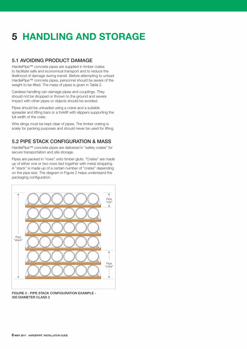
5.2 PIPe STACk CONfIGUrATION & MASSHardiePipe™ concrete pipes are delivered in “safety crates” for secure transportation and site storage.
Pipes are packed in “rows” onto timber gluts. “Crates” are made up of either one or two rows tied together with metal strapping. A “stack” is made up of a certain number of “crates” depending on the pipe size. the diagram in Figure 2 helps understand the packaging configuration.
Pipe“crate”
Pipe“stack”
Pipe“row”
fIGUre 2 - PIPe STACk CONfIGUrATION exAMPLe - 300 dIAMeTer CLASS 2
6 mAy 2011 HArdIePIPe™ INSTALLATION GUIde
HArdIePIPe™ INSTALLATION GUIde mAy 2011 7
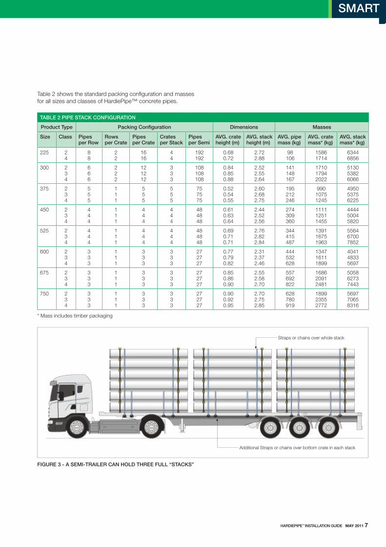
TAbLe 2 PIPe STACk CONfIGUrATION
Product Type Packing Configuration dimensions Masses
Size Class Pipes per row
rows per Crate
Pipes per Crate
Crates per Stack
Pipes per Semi
AVG. crate height (m)
AVG. stack height (m)
AVG. pipe mass (kg)
AVG. crate mass* (kg)
AVG. stack mass* (kg)
225 24
88
22
1616
44
192192
0.680.72
2.722.88
98106
15861714
63446856
300 234
666
222
121212
333
108108108
0.840.850.88
2.522.552.64
141148167
171017942022
513053826066
375 234
555
111
555
555
757575
0.520.540.55
2.602.682.75
195212246
99010751245
495053756225
450 234
444
111
444
444
484848
0.610.630.64
2.442.522.56
274309360
111112511455
444450045820
525 234
444
111
444
444
484848
0.690.710.71
2.762.822.84
344415487
139116751963
556467007852
600 234
333
111
333
333
272727
0.770.790.82
2.312.372.46
444532628
134716111899
404148335697
675 234
333
111
333
333
272727
0.850.860.90
2.552.582.70
557692822
168620912481
505862737443
750 234
333
111
333
333
272727
0.900.920.95
2.702.752.85
628780919
189923552772
569770658316
* Mass includes timber packaging
table 2 shows the standard packing configuration and masses for all sizes and classes of HardiePipe™ concrete pipes.
Straps or chains over whole stack
Additional Straps or chains over bottom crate in each stack
fIGUre 3 - A SeMI-TrAILer CAN HOLd THree fULL “STACkS”
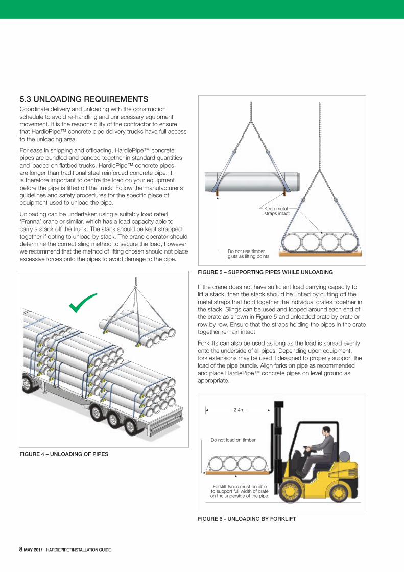
5.3 UNLOAdING reqUIreMeNTSCoordinate delivery and unloading with the construction schedule to avoid re-handling and unnecessary equipment movement. It is the responsibility of the contractor to ensure that HardiePipe™ concrete pipe delivery trucks have full access to the unloading area.
For ease in shipping and offloading, HardiePipe™ concrete pipes are bundled and banded together in standard quantities and loaded on flatbed trucks. HardiePipe™ concrete pipes are longer than traditional steel reinforced concrete pipe. It is therefore important to centre the load on your equipment before the pipe is lifted off the truck. Follow the manufacturer’s guidelines and safety procedures for the specific piece of equipment used to unload the pipe.
unloading can be undertaken using a suitably load rated ‘Franna’ crane or similar, which has a load capacity able to carry a stack off the truck. the stack should be kept strapped together if opting to unload by stack. the crane operator should determine the correct sling method to secure the load, however we recommend that the method of lifting chosen should not place excessive forces onto the pipes to avoid damage to the pipe.
fIGUre 4 – UNLOAdING Of PIPeS
Do not use timbergluts as lifting points
Keep metalstraps intact
fIGUre 5 – SUPPOrTING PIPeS WHILe UNLOAdING
If the crane does not have sufficient load carrying capacity to lift a stack, then the stack should be untied by cutting off the metal straps that hold together the individual crates together in the stack. slings can be used and looped around each end of the crate as shown in Figure 5 and unloaded crate by crate or row by row. Ensure that the straps holding the pipes in the crate together remain intact.
Forklifts can also be used as long as the load is spread evenly onto the underside of all pipes. Depending upon equipment, fork extensions may be used if designed to properly support the load of the pipe bundle. Align forks on pipe as recommended and place HardiePipe™ concrete pipes on level ground as appropriate.
2.4m
Forklift tynes must be ableto support full width of crateon the underside of the pipe.
Do not load on timber
fIGUre 6 - UNLOAdING bY fOrkLIfT
8 mAy 2011 HArdIePIPe™ INSTALLATION GUIde
HArdIePIPe™ INSTALLATION GUIde mAy 2011 9
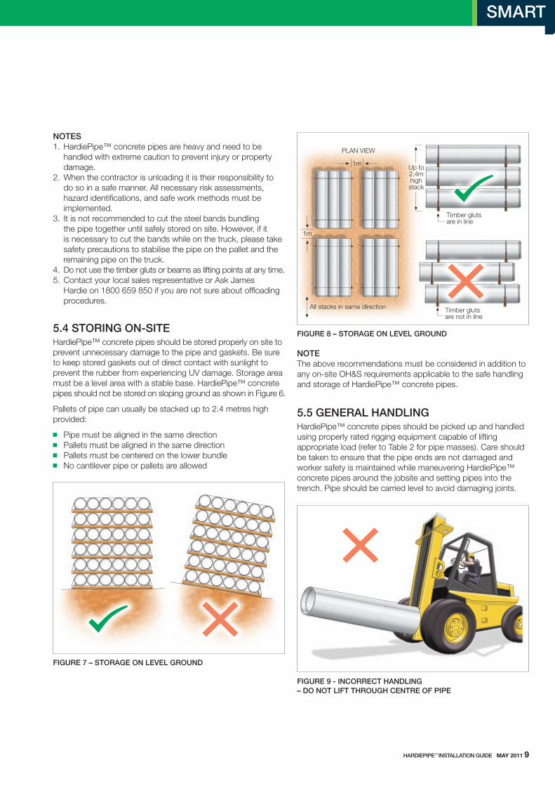
NOTeS 1. HardiePipe™ concrete pipes are heavy and need to be handled with extreme caution to prevent injury or property damage. 2. when the contractor is unloading it is their responsibility to do so in a safe manner. All necessary risk assessments, hazard identifications, and safe work methods must be implemented. 3. It is not recommended to cut the steel bands bundling the pipe together until safely stored on site. However, if it is necessary to cut the bands while on the truck, please take safety precautions to stabilise the pipe on the pallet and the remaining pipe on the truck. 4. Do not use the timber gluts or beams as lifting points at any time. 5. Contact your local sales representative or Ask James Hardie on 1800 659 850 if you are not sure about offloading procedures.
5.4 STOrING ON-SITeHardiePipe™ concrete pipes should be stored properly on site to prevent unnecessary damage to the pipe and gaskets. Be sure to keep stored gaskets out of direct contact with sunlight to prevent the rubber from experiencing uV damage. storage area must be a level area with a stable base. HardiePipe™ concrete pipes should not be stored on sloping ground as shown in Figure 6.
Pallets of pipe can usually be stacked up to 2.4 metres high provided:
Pipe must be aligned in the same direction Pallets must be aligned in the same direction Pallets must be centered on the lower bundle No cantilever pipe or pallets are allowed
fIGUre 7 – STOrAGe ON LeVeL GrOUNd
Timber glutsare in line
Up to2.4mhighstack
Timber glutsare not in line
1m
1m
All stacks in same direction
PLAN VIEW
fIGUre 8 – STOrAGe ON LeVeL GrOUNd
NOTe the above recommendations must be considered in addition to any on-site oH&s requirements applicable to the safe handling and storage of HardiePipe™ concrete pipes.
5.5 GeNerAL HANdLINGHardiePipe™ concrete pipes should be picked up and handled using properly rated rigging equipment capable of lifting appropriate load (refer to table 2 for pipe masses). Care should be taken to ensure that the pipe ends are not damaged and worker safety is maintained while maneuvering HardiePipe™ concrete pipes around the jobsite and setting pipes into the trench. Pipe should be carried level to avoid damaging joints.
fIGUre 9 - INCOrreCT HANdLING – dO NOT LIfT THrOUGH CeNTre Of PIPe
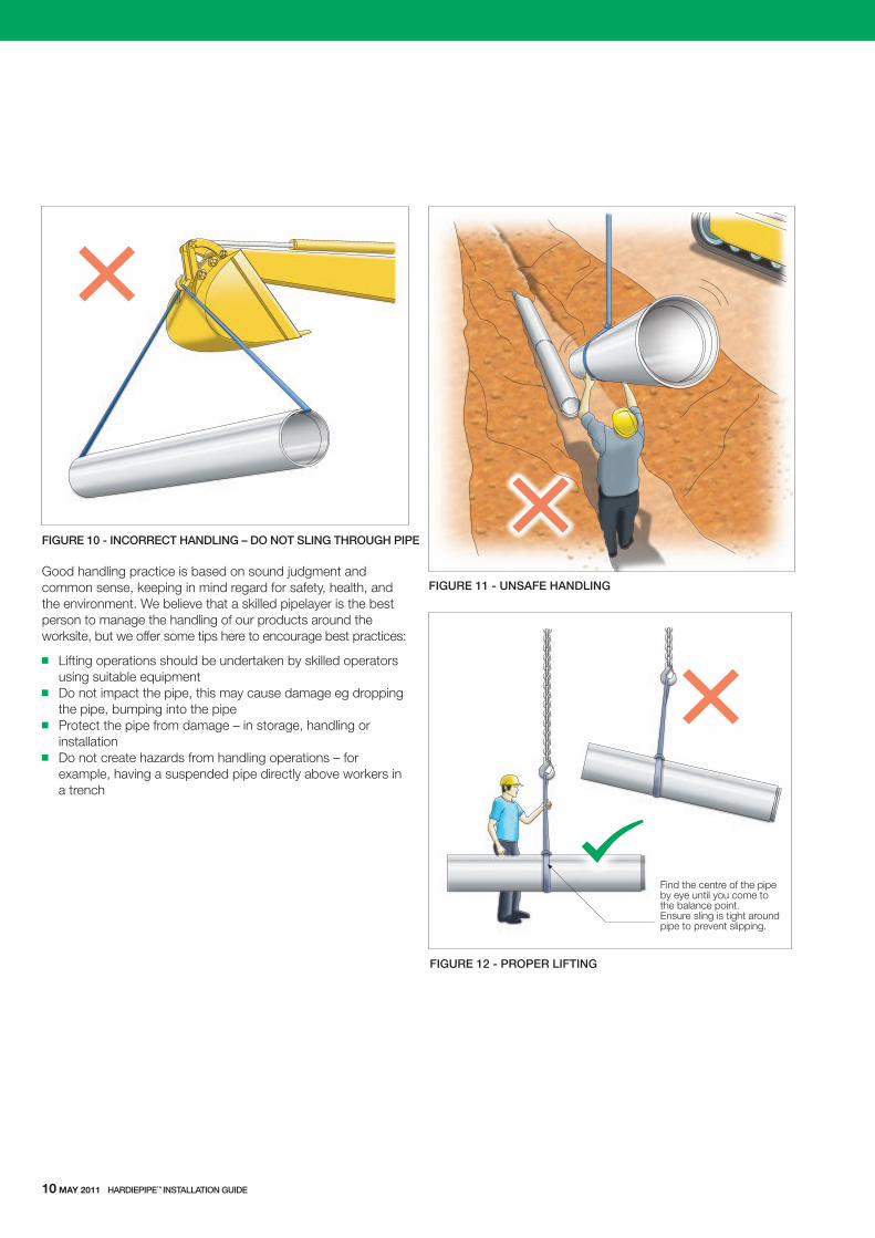
fIGUre 10 - INCOrreCT HANdLING – dO NOT SLING THrOUGH PIPe
Good handling practice is based on sound judgment and common sense, keeping in mind regard for safety, health, and the environment. we believe that a skilled pipelayer is the best person to manage the handling of our products around the worksite, but we offer some tips here to encourage best practices:
lifting operations should be undertaken by skilled operators using suitable equipment Do not impact the pipe, this may cause damage eg dropping
the pipe, bumping into the pipe Protect the pipe from damage – in storage, handling or
installation Do not create hazards from handling operations – for
example, having a suspended pipe directly above workers in a trench
fIGUre 11 - UNSAfe HANdLING
Find the centre of the pipeby eye until you come tothe balance point.Ensure sling is tight aroundpipe to prevent slipping.
fIGUre 12 - PrOPer LIfTING
10 mAy 2011 HArdIePIPe™ INSTALLATION GUIde

5.6 LIfTINGlocate the true centre of the pipe for lifting and to handle loads safely. Align rigging along centre to ensure stability of pipe during lift. use appropriate job safety precautions such as a dogman and keep people clear. use nylon straps for lifting.
fIGUre 13 – rIGGING Of NYLON STrAPS
HArdIePIPe™ INSTALLATION GUIde mAy 2011 11
fIGUre 14 - PIPe LIfTING
6 LoAds on BurIed PIPes
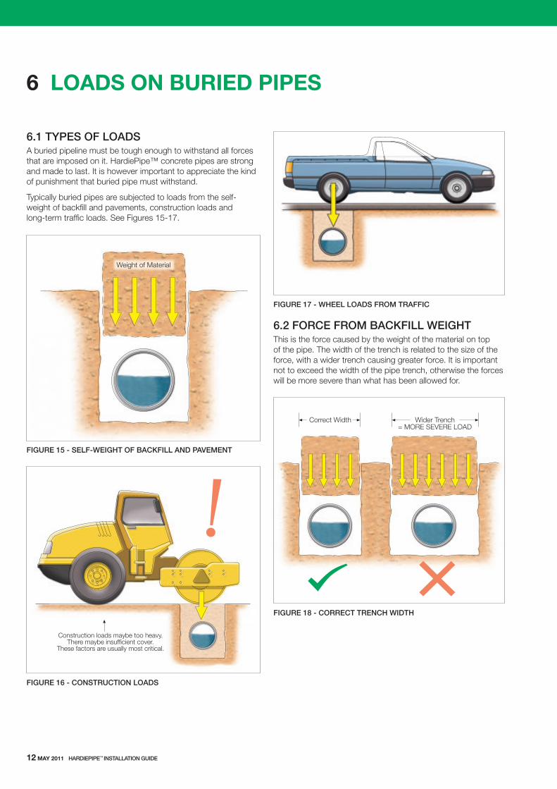
6.1 TYPeS Of LOAdSA buried pipeline must be tough enough to withstand all forces that are imposed on it. HardiePipe™ concrete pipes are strong and made to last. It is however important to appreciate the kind of punishment that buried pipe must withstand.
typically buried pipes are subjected to loads from the self-weight of backfill and pavements, construction loads and long-term traffic loads. see Figures 15-17.
fIGUre 15 - SeLf-WeIGHT Of bACkfILL ANd PAVeMeNT
fIGUre 16 - CONSTrUCTION LOAdS
fIGUre 17 - WHeeL LOAdS frOM TrAffIC
6.2 fOrCe frOM bACkfILL WeIGHTthis is the force caused by the weight of the material on top of the pipe. the width of the trench is related to the size of the force, with a wider trench causing greater force. It is important not to exceed the width of the pipe trench, otherwise the forces will be more severe than what has been allowed for.
fIGUre 18 - COrreCT TreNCH WIdTH
Weight of Material
Construction loads maybe too heavy.There maybe insufficient cover.
These factors are usually most critical.
Correct Width Wider Trench= MORE SEVERE LOAD
12 mAy 2011 HArdIePIPe™ INSTALLATION GUIde

HArdIePIPe™ INSTALLATION GUIde mAy 2011 13
6.3 CONSTrUCTION LOAdSIn many cases loads imposed on pipes during construction can exceed those the pipe will experience once in service. this will depend on the type of compaction/construction equipment used on-site, the ground/trench condition, the given depth and cover, etc.
when a designer specifies the pipe strength class he/she may not be aware of the type of construction equipment and temporary cover being used by the contractor. It is not uncommon that the actual cover over the pipe during construction will be less than what the final cover once the finished surface levels have been established, see Figure 19. this combined with heavy construction equipment can cause pipe cracking if the construction cover and loads have not been allowed for.
fIGUre 19 - deSIGN VS CONSTrUCTION COVer
the effect of heavy machine wheel loads and shallow cover may induce an extremely severe load onto the pipe and lead to failure. the contractor must take care that they do not run heavy machines over buried pipelines unless they have provided adequate cover over the pipe. the pipeline should be protected by either mounding up soil temporarily over haul roads, or to redirect heavy construction plant to alternative locations, see Figure 20.
Constructioncover
Finalcover
TIP In some cases it may be necessary to use a stronger pipe (eg Class 3 instead of Class 2) to meet construction load requirements.
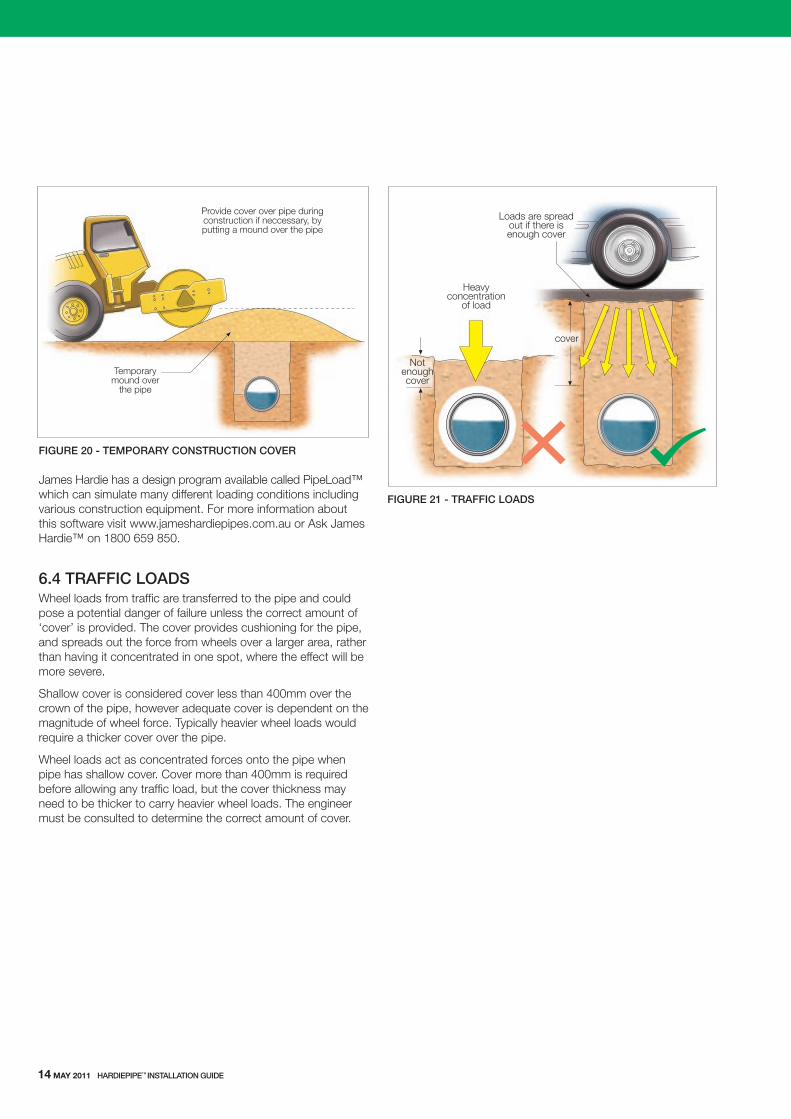
fIGUre 20 - TeMPOrArY CONSTrUCTION COVer
James Hardie has a design program available called Pipeload™ which can simulate many different loading conditions including various construction equipment. For more information about this software visit www.jameshardiepipes.com.au or Ask James Hardie™ on 1800 659 850.
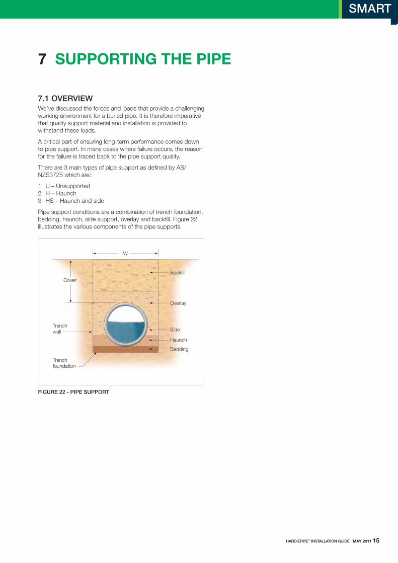
6.4 TrAffIC LOAdSwheel loads from traffic are transferred to the pipe and could pose a potential danger of failure unless the correct amount of ‘cover’ is provided. the cover provides cushioning for the pipe, and spreads out the force from wheels over a larger area, rather than having it concentrated in one spot, where the effect will be more severe.
shallow cover is considered cover less than 400mm over the crown of the pipe, however adequate cover is dependent on the magnitude of wheel force. typically heavier wheel loads would require a thicker cover over the pipe.
wheel loads act as concentrated forces onto the pipe when pipe has shallow cover. Cover more than 400mm is required before allowing any traffic load, but the cover thickness may need to be thicker to carry heavier wheel loads. the engineer must be consulted to determine the correct amount of cover.
fIGUre 21 - TrAffIC LOAdS
Temporarymound over
the pipe
Provide cover over pipe duringconstruction if neccessary, byputting a mound over the pipe
Notenoughcover
cover
Heavyconcentration
of load
Loads are spreadout if there isenough cover
14 mAy 2011 HArdIePIPe™ INSTALLATION GUIde
HArdIePIPe™ INSTALLATION GUIde mAy 2011 15
7 suPPortIng tHe PIPe
7.1 OVerVIeWwe’ve discussed the forces and loads that provide a challenging working environment for a buried pipe. It is therefore imperative that quality support material and installation is provided to withstand these loads.
A critical part of ensuring long-term performance comes down to pipe support. In many cases where failure occurs, the reason for the failure is traced back to the pipe support quality.
there are 3 main types of pipe support as defined by As/NZs3725 which are:
1 u – unsupported 2 H – Haunch 3 Hs – Haunch and side
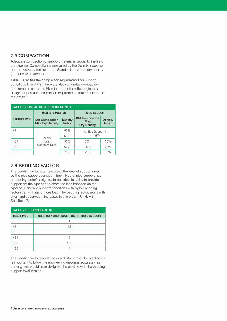
Pipe support conditions are a combination of trench foundation, bedding, haunch, side support, overlay and backfill. Figure 22 illustrates the various components of the pipe supports.
fIGUre 22 - PIPe SUPPOrT

TAbLe 3 TYPe U SUPPOrT
Size (mm) Class Width of Trench ‘W’ (mm)
depth of embedment
‘d’ (mm)
225 24
570573
520523
300234
646648654
596598604
375234
727731739
677681689
450234
812819829
762769779
525234
894906918
844856868
600234
9789911005
928941955
675234
105210701087
100210201037
750234
110311221139
105310721089
7.3 TYPe Htype H support (H - ‘haunch’) provides support to the pipeline by placing a bedding layer on top of the excavated foundation, and also providing support to the pipe’s haunch. type H support is further broken into H1 and H2, where H2 has a slightly deeper haunch support zone and a slightly higher compaction requirement. type H supports are the most common forms of pipe support specified by the engineer. Refer to table 4 for type H support requirements and Clause 7.5 for compaction requirements.
TAbLe 4 TYPe H SUPPOrT
Size (mm) ClassWidth of
Trench ‘W’ (mm)
depth of embedment
‘d’ (mm)
Haunch thickness ‘H’ (mm)
H1 H2
225 24
570573
520523
2727
8182
300234
646648654
596598604
353535
104104106
375234
727731739
677681689
434344
128129132
450234
812819829
762769779
515253
154156159
525234
894906918
844856868
596162
178182185
600234
9789911005
928941955
686971
203207212
675234
105210701087
100210201037
757779
226231236
750234
110311221139
105310721089
808284
241247252
7.2 TYPe U type u support (u - ‘unsupported’) is essentially pipe that is directly placed on top of an excavated foundation floor without any bedding. this could be either soil or rock foundation. type u supports do not feature any bedding, haunch or side supports, but are filled with ordinary fill all around the pipe. type u support provides the least amount of support to the pipeline, and generally would only be used in temporary installations or other non-essential uses. Compaction requirements are typically specified by the design engineer. It is typically the cheapest support condition to install and the quickest. Refer to table 3 for type u support requirements.

7.4 TYPe HStype Hs support (Hs - ‘haunch and side’) is a higher level of support given to the pipe, by adding a side support zone in addition to the support in type H. type Hs support is further broken into Hs1, Hs2 and Hs3 with specific compaction requirements for each type. type Hs supports is generally used where cover over pipe is quite high – in a deep trench, or a high fill embankment. type Hs installations require a high level of quality control on site, and hence, is generally used where there is tight supervision available to ensure that the exacting requirements of the Engineer are met in the quality of workmanship. Refer to table 5 for type Hs support requirements and Clause 7.5 for compaction requirements.
TAbLe 5 TYPe HS SUPPOrT
Size (mm) Class
Width of Trench ‘W’ (mm)
depth of embedment
‘d’ (mm)
Haunch thickness ‘H’ (mm)
Side zone Layer ‘S’
(mm)
HS1 HS2 & HS3 HS1 HS2 &
HS3
225 24
570573
520523
2727
8182
108109
5455
300234
646648654
596598604
353535
104104106
138139142
697071
375234
727731739
677681689
434344
128129132
171172176
858688
450234
812819829
762769779
515253
154156159
205208212
102104106
525234
894906918
844856868
596162
178182185
238242247
119121124
600234
9789911005
928941955
686971
203207212
271276282
136138141
675234
105210701087
100210201037
757779
226231236
301308315
150154157
750234
110311221139
105310721089
808284
241247252
321329336
161164168
HArdIePIPe™ INSTALLATION GUIde mAy 2011 17
7.5 COMPACTIONAdequate compaction of support material is crucial to the life of the pipeline. Compaction is measured by the Density Index (for non-cohesive materials), or the standard maximum dry density (for cohesive materials).
table 6 specifies the compaction requirements for support conditions H and Hs. there are also no overlay compaction requirements under the standard, but check the engineer’s design for possible compaction requirements that are unique to the project.
TAbLe 6 COMPACTION reqUIreMeNTS
Support Type
bed and Haunch Side Support
Std Compaction Max dry density
density Index
Std Compaction Max
dry density
density Index
H1
Do Not use
Cohesive soils
50% No side support in H typeH2 60%
Hs1 50% 85% 50%
Hs2 60% 90% 60%
Hs3 70% 95% 70%
7.6 beddING fACTOrthe bedding factor is a measure of the level of support given by the pipe support condition. Each type of pipe support has a ‘bedding factor’ assigned, to describe its ability to provide support for the pipe and to share the load imposed on the pipeline. Generally, support conditions with higher bedding factors can withstand more load. the bedding factor, along with effort and supervision, increases in this order – u, H, Hs, see table 7.
TAbLe 7 beddING fACTOr
Install Type bedding factor (larger figure - more support)
u 1
H1 1.5
H2 2
Hs1 2
Hs2 2.5
Hs3 4
the bedding factor affects the overall strength of the pipeline – it is important to follow the engineering drawings accurately as the engineer would have designed the pipeline with the bedding support level in mind.
18 mAy 2011 HArdIePIPe™ INSTALLATION GUIde
HArdIePIPe™ INSTALLATION GUIde mAy 2011 19
8 trenCH
8.1 TreNCH SIzeCare should be taken to ensure that excavation of the trench conforms to any specifications, As/NZs3725, local regulations or other statutory requirements, particularly in regard to benching or shoring.
the width and depth of trenches to be excavated will depend on many factors including:
Pipe size type of soil and substrate Application and load (local road, highway, inter-allotment, etc) Pipe invert depth Pipeline direction (whether straight or deflecting around a curve)
Refer to section 7 for trench size requirements for various pipe diameters and support conditions.
trenches should be excavated in accordance with drainage plans and specifications. the pipe designer has specified the pipe strength class based on a maximum trench width at the level of the top of the pipe and the trench depth and/or pipe invert level. the width and depth of the trench nominated must not be exceeded without consulting the designer.
fIGUre 23 - TreNCH exCAVATION
8.2 PrePArING THe TreNCHthe trench bottom provides the foundation for the pipeline and therefore should be stable and uniform along the pipeline.
Prior to placement of bedding material, in good working conditions, the trench bottom should be made sufficiently even with stones and rocks removed to provide even distribution of the bedding material layer and provide continuous support for the pipes.
Depressions left in the trench bottom below the pipe can result in damage to the pipe. when the trench bottom is flat, localised
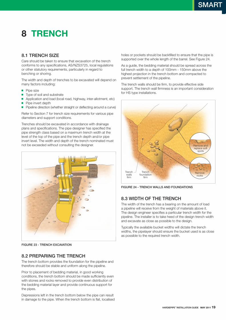
holes or pockets should be backfilled to ensure that the pipe is supported over the whole length of the barrel. see Figure 24.
As a guide, the bedding material should be spread across the full trench width to a depth of 100mm - 150mm above the highest projection in the trench bottom and compacted to prevent settlement of the pipeline.
the trench walls should be firm, to provide effective side support. the trench wall firmness is an important consideration for Hs type installations.
fIGUre 24 - TreNCH WALLS ANd fOUNdATIONS
8.3 WIdTH Of THe TreNCHthe width of the trench has a bearing on the amount of load a pipeline will receive from the weight of materials above it. the design engineer specifies a particular trench width for the pipeline. the installer is to take heed of the design trench width and excavate as close as possible to the design.
typically the available bucket widths will dictate the trench widths, the pipelayer should ensure the bucket used is as close as possible to the required trench width.
Trenchfoundation
firm
Trenchwallsfirm
Removerocks
Remove andreplace soft
spots
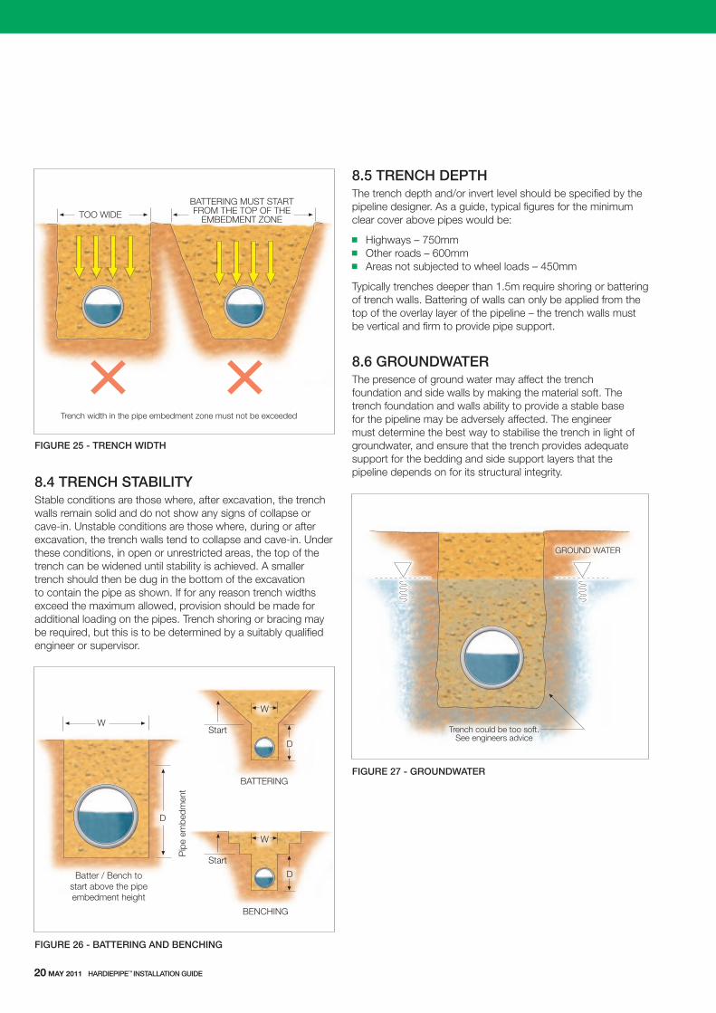
fIGUre 25 - TreNCH WIdTH
8.4 TreNCH STAbILITYstable conditions are those where, after excavation, the trench walls remain solid and do not show any signs of collapse or cave-in. unstable conditions are those where, during or after excavation, the trench walls tend to collapse and cave-in. under these conditions, in open or unrestricted areas, the top of the trench can be widened until stability is achieved. A smaller trench should then be dug in the bottom of the excavation to contain the pipe as shown. If for any reason trench widths exceed the maximum allowed, provision should be made for additional loading on the pipes. trench shoring or bracing may be required, but this is to be determined by a suitably qualified engineer or supervisor.
fIGUre 26 - bATTerING ANd beNCHING
8.5 TreNCH dePTHthe trench depth and/or invert level should be specified by the pipeline designer. As a guide, typical figures for the minimum clear cover above pipes would be:
Highways – 750mm other roads – 600mm Areas not subjected to wheel loads – 450mm
typically trenches deeper than 1.5m require shoring or battering of trench walls. Battering of walls can only be applied from the top of the overlay layer of the pipeline – the trench walls must be vertical and firm to provide pipe support.
8.6 GrOUNdWATerthe presence of ground water may affect the trench foundation and side walls by making the material soft. the trench foundation and walls ability to provide a stable base for the pipeline may be adversely affected. the engineer must determine the best way to stabilise the trench in light of groundwater, and ensure that the trench provides adequate support for the bedding and side support layers that the pipeline depends on for its structural integrity.
fIGUre 27 - GrOUNdWATer
Trench width in the pipe embedment zone must not be exceeded
TOO WIDEBATTERING MUST STARTFROM THE TOP OF THE
EMBEDMENT ZONE
W
D
BATTERING
Start
W
D
BENCHING
Start
Batter / Bench tostart above the pipeembedment height
W
D
Pip
e em
bedm
ent
Trench could be too soft.See engineers advice
GROUND WATER
20 mAy 2011 HArdIePIPe™ INSTALLATION GUIde
HArdIePIPe™ INSTALLATION GUIde mAy 2011 21
9 suItABLe PIPe suPPort mAterIAL
9.1 OVerVIeWthere are many types of materials available on the market place that could be used for pipe support. the most common materials are sand, crusher dust and gravel amongst others. Australian standard As/NZs3725 provides guidance on assessing whether the material you intend to use is suitable for supporting the pipe.
Check with the relevant local government authority for applicable specifications in a specific area.
Pipe support components consist of: Bedding Haunch side support overlay Backfill
9.2 beddING ANd HAUNCHBedding and haunch layers of the pipe support have identical requirements on material properties. the material must be a non-cohesive soil. the particles of the material must not be made of a material that would break down, such as shale. the grading of the material is such that it is a free draining material. the material must pass the particle size distribution shown in table 8 (from As/NZs3725).
TAbLe 8 beddING MATerIAL
Sieve Size mm % Weight Passing through Sieve
19.0 100
2.36 100 - 50
0.6 90 - 20
0.3 60 - 10
0.15 25 - 0
0.075 10 - 0
9.3 SIde zONeside zone material must be a non-cohesive soil. the particles of the material must not be made of a material that would break down, such as shale. the material must pass the particle size distribution shown in table 9 (from As/NZs3725).
TAbLe 9 beddING MATerIAL
Sieve Size mm % Weight Passing through Sieve
75.0 100
9.5 100 - 50
2.36 100 - 30
0.6 50 - 15
0.075 25 - 0
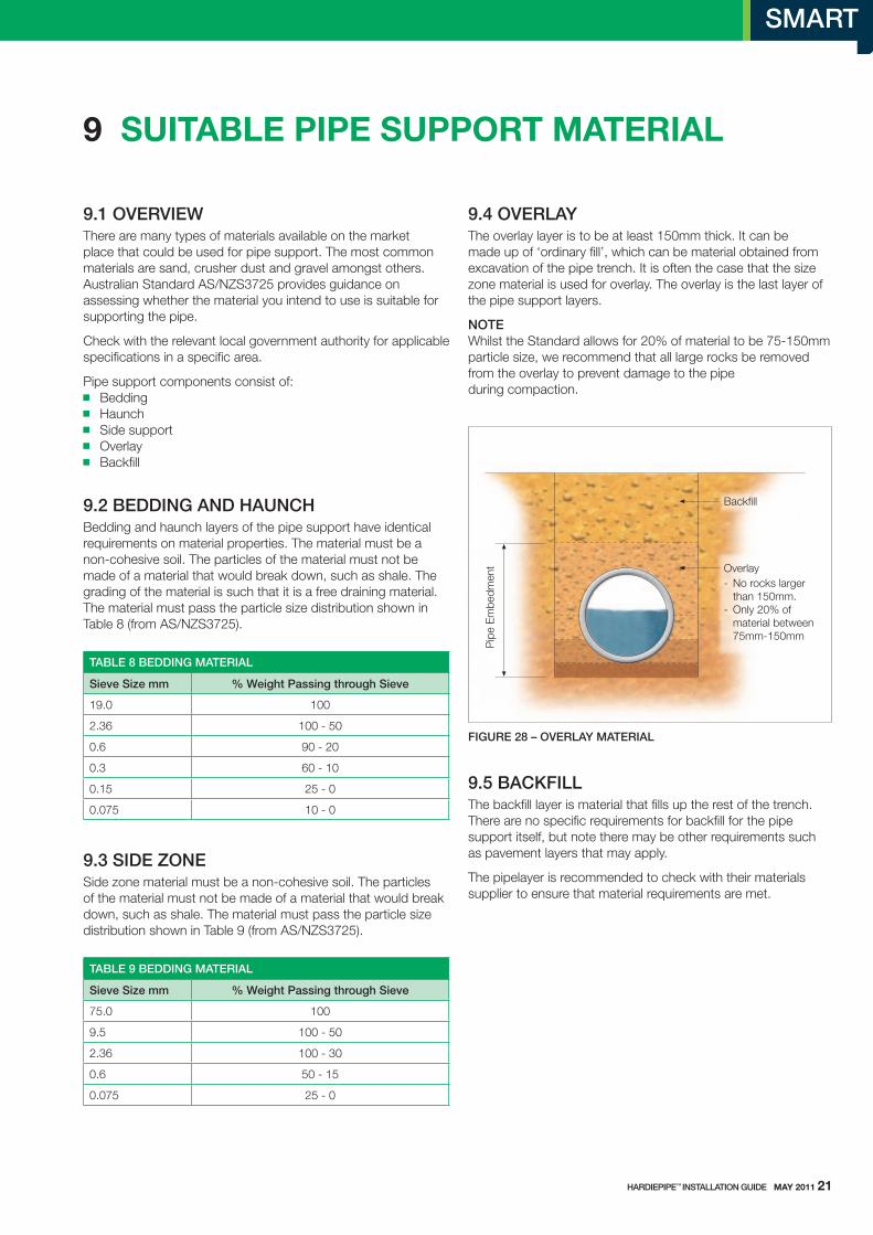
9.4 OVerLAYthe overlay layer is to be at least 150mm thick. It can be made up of ‘ordinary fill’, which can be material obtained from excavation of the pipe trench. It is often the case that the size zone material is used for overlay. the overlay is the last layer of the pipe support layers.
NOTe whilst the standard allows for 20% of material to be 75-150mm particle size, we recommend that all large rocks be removed from the overlay to prevent damage to the pipe during compaction.
fIGUre 28 – OVerLAY MATerIAL
9.5 bACkfILLthe backfill layer is material that fills up the rest of the trench. there are no specific requirements for backfill for the pipe support itself, but note there may be other requirements such as pavement layers that may apply.
the pipelayer is recommended to check with their materials supplier to ensure that material requirements are met.
Overlay
Backfill
- No rocks largerthan 150mm.
- Only 20% ofmaterial between75mm-150mm
Pip
e E
mbe
dmen
t

10 InstALLAtIon
10.1 OVerVIeWAlthough laying conditions vary from site to site, the following information is intended as a guide and covers some issues encountered during normal installation of HardiePipe™ concrete pipes. All construction must comply with the project specific engineering specifications and any relevant regulations and standards.
10.2 PrePArATIONPipes are laid after the preparation of the trench and the bedding. the pipelayer should make sure that the pipe is going to be sitting on firm support, meaning there are no soft areas in the trench foundation, and no sharp protruding material anywhere in the bedding, see section 7 for more information relating to the trench.
Bedding must be flat, with appropriate level and grade to achieve fall for the pipeline. Bedding is compacted around the outer thirds of the bedding width, leaving the middle third lightly compacted or not compacted at all. the pipe sits on top of the middle third, and will induce compaction through its own self weight and the weight of other loads.
10.3 GrAdeCheck for proper line and grade. Ensure minimum specified bedding thickness is maintained. If pipe grade needs to be raised, remove the pipe from the trench and regrade full length of bedding. lifting up pipe and shovelling dirt/bedding material under the pipe will leave voids and is Not acceptable. Do not use excavation equipment to bring pipe into line with grade, see Figure 29.
fIGUre 29 - IMPrOPer GrAde ALIGNMeNT
If pipe grade needs to be lowered, remove pipe from the trench and correct the grade. Do not make adjustment in grade by lifting and dropping the pipe, by pushing down on pipe with excavating equipment or by lifting the pipe and packing bedding material beneath the pipe. Any pipe not installed at correct grade should be completely removed, the grade corrected and the pipe re-laid.
10.4 PIPe LAYING SeqUeNCethe pipe laying sequence is normally conducted facing upstream, with the spigot (male) end facing down-stream. the spigot (male) ends are pushed into the socket (female) end.
fIGUre 30 - PIPe LAYING SeqUeNCe
10.5 JOINTSHardiePipe™ joints have an in-wall rebated spigot and socket which is designed to resist water ingress/egress using rubber ‘v’ rings, see Figure 31. the joint allows a smooth flush surface on the outside of the joint, which enables you to lay the pipe on a continuous bed, without having to dig recesses in your bedding. the joint also allows for some degree of movement to allow the pipeline some flexibility to withstand some ground movement.
Push home
FALL
Male end facesdirection of fall
Progress
22 mAy 2011 HArdIePIPe™ INSTALLATION GUIde
HArdIePIPe™ INSTALLATION GUIde mAy 2011 23
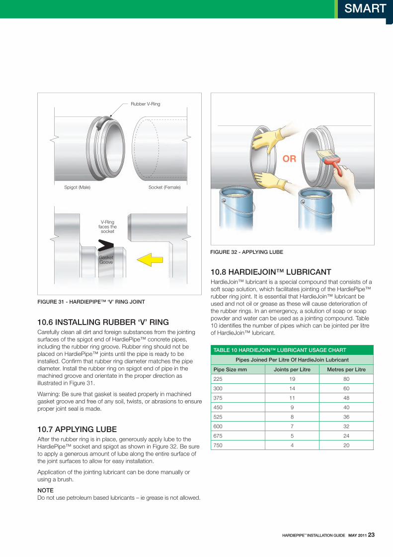
fIGUre 31 - HArdIePIPe™ ‘V’ rING JOINT
10.6 INSTALLING rUbber ‘V’ rINGCarefully clean all dirt and foreign substances from the jointing surfaces of the spigot end of HardiePipe™ concrete pipes, including the rubber ring groove. Rubber ring should not be placed on HardiePipe™ joints until the pipe is ready to be installed. Confirm that rubber ring diameter matches the pipe diameter. Install the rubber ring on spigot end of pipe in the machined groove and orientate in the proper direction as illustrated in Figure 31.
warning: Be sure that gasket is seated properly in machined gasket groove and free of any soil, twists, or abrasions to ensure proper joint seal is made.
10.7 APPLYING LUbeAfter the rubber ring is in place, generously apply lube to the HardiePipe™ socket and spigot as shown in Figure 32. Be sure to apply a generous amount of lube along the entire surface of the joint surfaces to allow for easy installation.
Application of the jointing lubricant can be done manually or using a brush.
NOTe Do not use petroleum based lubricants – ie grease is not allowed.
fIGUre 32 - APPLYING LUbe
10.8 HArdIeJOIN™ LUbrICANTHardieJoin™ lubricant is a special compound that consists of a soft soap solution, which facilitates jointing of the HardiePipe™ rubber ring joint. It is essential that HardieJoin™ lubricant be used and not oil or grease as these will cause deterioration of the rubber rings. In an emergency, a solution of soap or soap powder and water can be used as a jointing compound. table 10 identifies the number of pipes which can be jointed per litre of HardieJoin™ lubricant.
TAbLe 10 HArdIeJOIN™ LUbrICANT USAGe CHArT
Pipes Joined Per Litre Of HardieJoin Lubricant
Pipe Size mm Joints per Litre Metres per Litre
225 19 80
300 14 60
375 11 48
450 9 40
525 8 36
600 7 32
675 5 24
750 4 20
V-Ringfaces thesocket
GasketGoove
Rubber V-Ring
Spigot (Male) Socket (Female)
OR
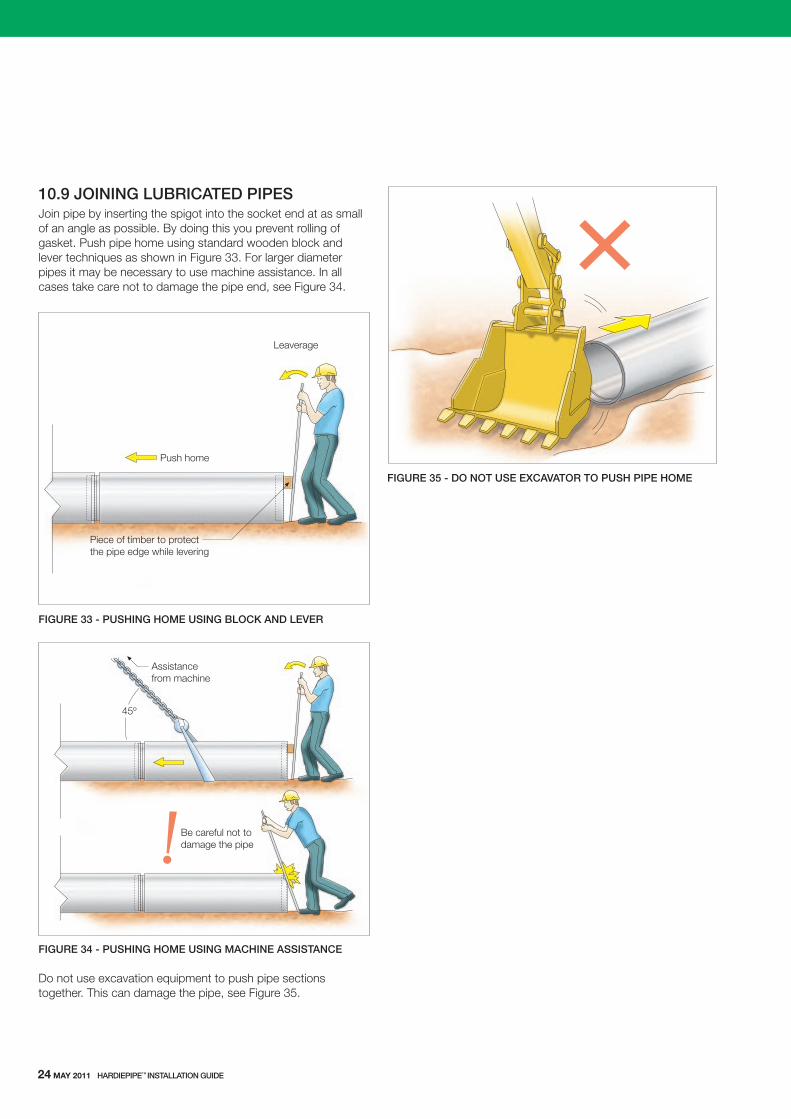
fIGUre 33 - PUSHING HOMe USING bLOCk ANd LeVer
fIGUre 34 - PUSHING HOMe USING MACHINe ASSISTANCe
Do not use excavation equipment to push pipe sections together. this can damage the pipe, see Figure 35.
fIGUre 35 - dO NOT USe exCAVATOr TO PUSH PIPe HOMe
Leaverage
Piece of timber to protectthe pipe edge while levering
Push home
45º
Assistancefrom machine
Be careful not todamage the pipe
24 mAy 2011 HArdIePIPe™ INSTALLATION GUIde
10.9 JOINING LUbrICATed PIPeSJoin pipe by inserting the spigot into the socket end at as small of an angle as possible. By doing this you prevent rolling of gasket. Push pipe home using standard wooden block and lever techniques as shown in Figure 33. For larger diameter pipes it may be necessary to use machine assistance. In all cases take care not to damage the pipe end, see Figure 34.
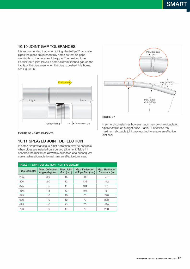
10.10 JOINT GAP TOLerANCeSIt is recommended that when joining HardiePipe™ concrete pipes the pipes are pushed fully home so that no gaps are visible on the outside of the pipe. the design of the HardiePipe™ joint leaves a nominal 3mm finished gap on the inside of the pipe even when the pipe is pushed fully home, see Figure 36.
fIGUre 36 - GAPS IN JOINTS
Rubber V-Ring
Positive seal
3mm nom. gap
SocketSpigot
HArdIePIPe™ INSTALLATION GUIde mAy 2011 25
10.11 SPLAYed JOINT defLeCTIONIn some circumstances, a slight deflection may be desirable when pipes are installed on a curved alignment. table 11 specifies the maximum allowable deflection and subsequent curve radius allowable to maintain an effective joint seal.
TAbLe 11 JOINT defLeCTION - 4M PIPe LeNGTH
Pipe diameter Max. deflection Angle (degrees)
Max. Joint Gap (mm)
Max. deflection at Pipe end (mm)
Max. radius of Curvature (m)
225 3.0 15 206 76
300 2.0 12 138 112
375 1.5 11 104 151
450 1.5 13 104 151
525 1.0 10 70 228
600 1.0 12 70 228
675 1.0 13 70 228
750 1.0 14 70 228
fIGUre 37
In some circumstances however gaps may be unavoidable eg pipes installed on a slight curve. table 11 specifies the maximum allowable joint gap required to ensure an effective joint seal.
max. radiusof curvature
max. deflectionat pipe end
max. joint gap
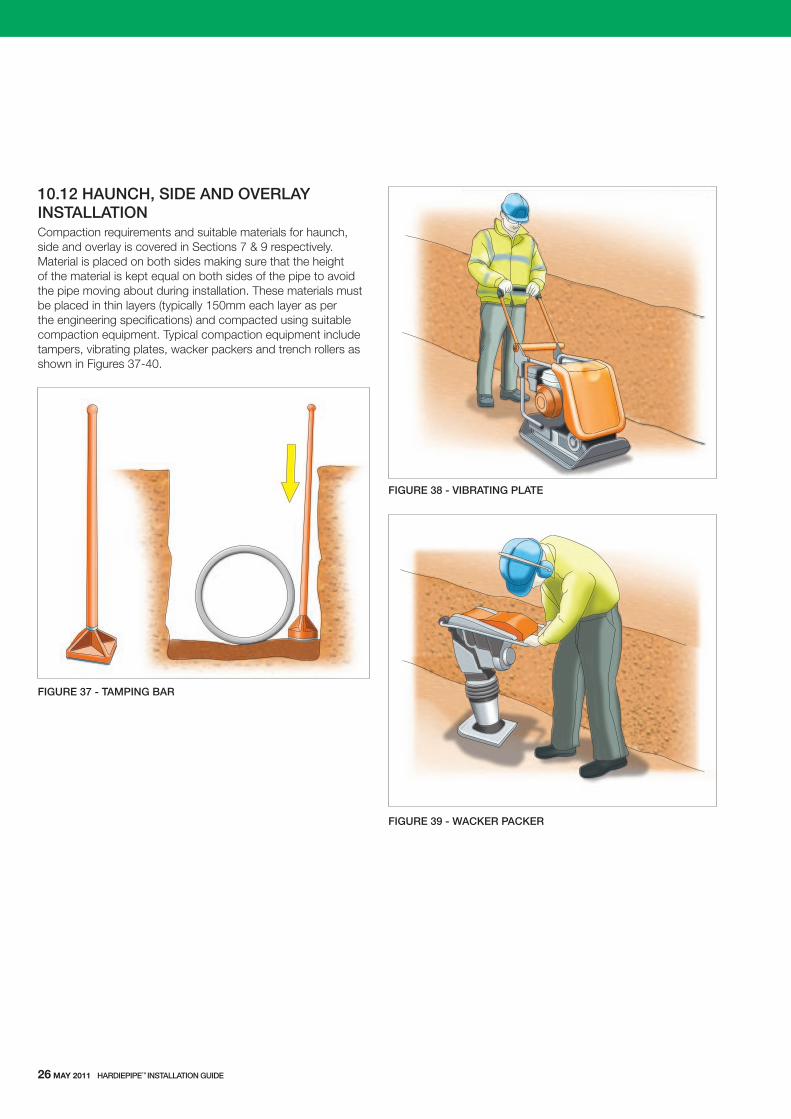
10.12 HAUNCH, SIde ANd OVerLAY INSTALLATIONCompaction requirements and suitable materials for haunch, side and overlay is covered in sections 7 & 9 respectively. Material is placed on both sides making sure that the height of the material is kept equal on both sides of the pipe to avoid the pipe moving about during installation. these materials must be placed in thin layers (typically 150mm each layer as per the engineering specifications) and compacted using suitable compaction equipment. typical compaction equipment include tampers, vibrating plates, wacker packers and trench rollers as shown in Figures 37-40.
fIGUre 37 - TAMPING bAr
fIGUre 38 - VIbrATING PLATe
fIGUre 39 - WACker PACker
26 mAy 2011 HArdIePIPe™ INSTALLATION GUIde
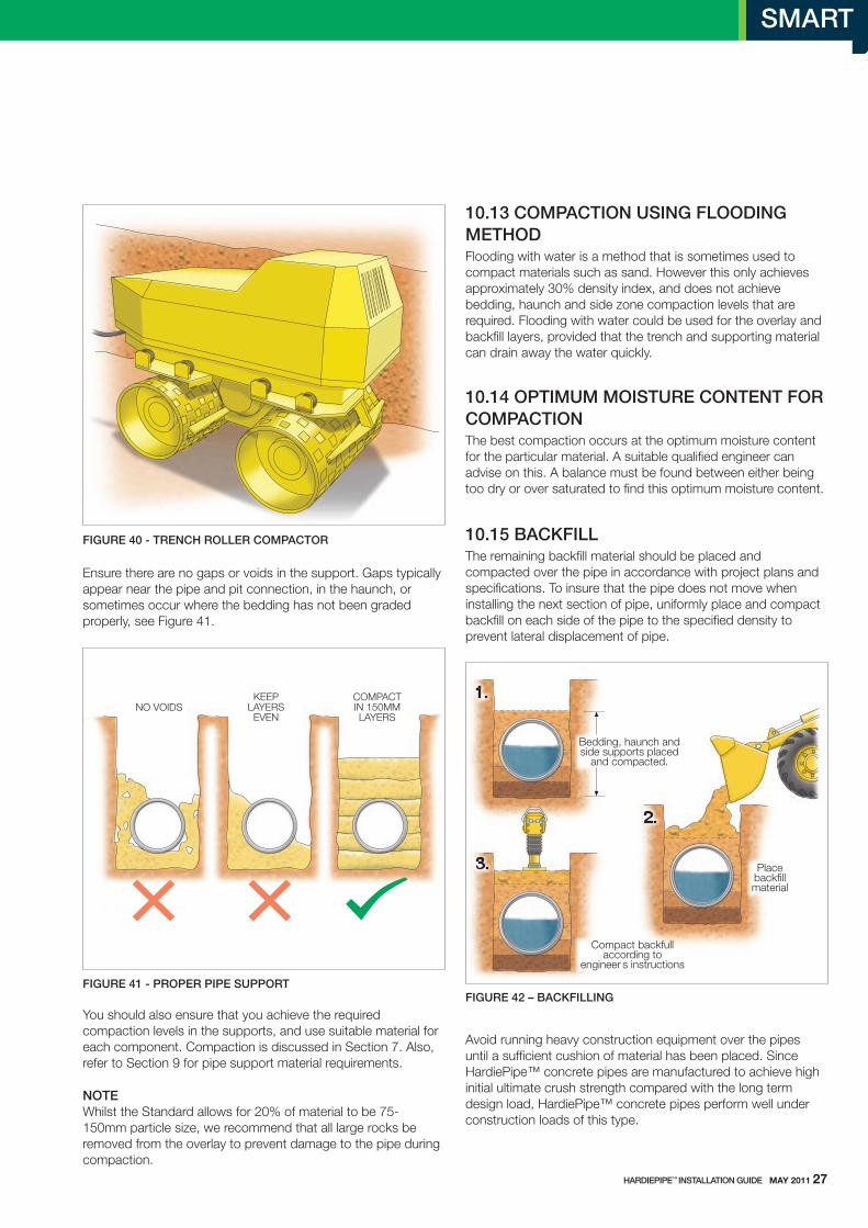
fIGUre 40 - TreNCH rOLLer COMPACTOr
Ensure there are no gaps or voids in the support. Gaps typically appear near the pipe and pit connection, in the haunch, or sometimes occur where the bedding has not been graded properly, see Figure 41.
fIGUre 41 - PrOPer PIPe SUPPOrT
you should also ensure that you achieve the required compaction levels in the supports, and use suitable material for each component. Compaction is discussed in section 7. Also, refer to section 9 for pipe support material requirements.
NOTe whilst the standard allows for 20% of material to be 75-150mm particle size, we recommend that all large rocks be removed from the overlay to prevent damage to the pipe during compaction.
10.13 COMPACTION USING fLOOdING MeTHOdFlooding with water is a method that is sometimes used to compact materials such as sand. However this only achieves approximately 30% density index, and does not achieve bedding, haunch and side zone compaction levels that are required. Flooding with water could be used for the overlay and backfill layers, provided that the trench and supporting material can drain away the water quickly.
10.14 OPTIMUM MOISTUre CONTeNT fOr COMPACTION the best compaction occurs at the optimum moisture content for the particular material. A suitable qualified engineer can advise on this. A balance must be found between either being too dry or over saturated to find this optimum moisture content.
10.15 bACkfILLthe remaining backfill material should be placed and compacted over the pipe in accordance with project plans and specifications. to insure that the pipe does not move when installing the next section of pipe, uniformly place and compact backfill on each side of the pipe to the specified density to prevent lateral displacement of pipe.
Avoid running heavy construction equipment over the pipes until a sufficient cushion of material has been placed. since HardiePipe™ concrete pipes are manufactured to achieve high initial ultimate crush strength compared with the long term design load, HardiePipe™ concrete pipes perform well under construction loads of this type.
fIGUre 42 – bACkfILLING
NO VOIDSKEEP
LAYERSEVEN
COMPACTIN 150MMLAYERS
Bedding, haunch andside supports placed
and compacted.
Placebackfillmaterial
Compact backfullaccording to
engineer s instructions
HArdIePIPe™ INSTALLATION GUIde mAy 2011 27

11 CuttIng And fIttIngs
11.1 CUTTINGFrom time to time it will be necessary to cut pipes and install fittings. Refer to section 4 for safe working methods. use appropriate safety precautions when operating saw/blade in accordance with manufacturers recommended practices.
Cutting guide:
1. Mark a cut line on the outside of the pipe. 2. Make sure pipe is stable before cutting. 3. Cut length of pipe to the cut line marked. 4. when cutting a length of pipe, it will be necessary to roll the pipe to get access to the entire circumference. After rolling make sure pipe is stable before resuming cutting. It is recommended pipe be chocked to prevent the pipe rolling during cutting. 5. Proper safety gear must be worn to protect operator in accordance with applicable safety standards and manufacturers recommendations.
As there is no steel reinforcement to corrode, no corrosion protection is required to be applied to the cut end.
11.2 HArdIePIPe™ fITTINGSHardiePipe™ concrete pipes have the unique benefit of being able to connect branches to the pipeline. this allows installers to custom align PVC connections, or align other drainage branches by making a hole in HardiePipe™ and using the assortment of saddles, tees and junctions available from James Hardie. Bends and reducers are also available. For detailed product information about HardiePipe™ fittings refer to the Product Information Book available at www.jameshardiepipes.com.au.
11.3 JOINING A CUT PIPeunturned Couplings are used with HardiePipe™ concrete pipes in underground applications to enable two cut pipe ends to be joined.
unturned HardiePipe™
unturned HardiePipe™
o ringo ring unturned Coupling
fIGUre 43 - UNTUrNed COUPLINGS
when joining using unturned coupling follow these steps:
1. cut mating ends square. 2. roll on o ring onto the outside of the pipe, roll up and down a couple of times to get all kinks out of the ring. 3. align the ring close to the end of the pipe. 4. Push the coupling on to the pipe, ensuring the ring rolls on.
NOTe Do Not APPly luBRICANt when joining with the unturned coupling.
fIGUre 44 - JOINING WITH UNTUrNed COUPLINGS
1. Cut end square
2. Roll onO-Ring
3. Push on U.C.
Do not useHardieJoinfor U.C.
28 mAy 2011 HArdIePIPe™ INSTALLATION GUIde
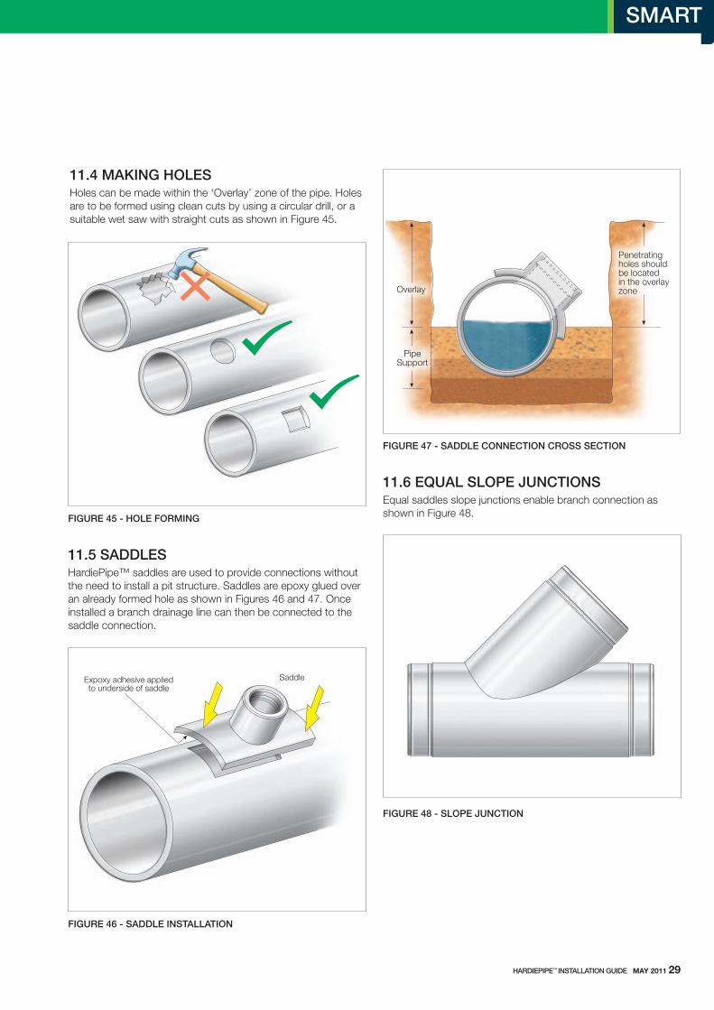
11.4 MAkING HOLeSHoles can be made within the ‘overlay’ zone of the pipe. Holes are to be formed using clean cuts by using a circular drill, or a suitable wet saw with straight cuts as shown in Figure 45.
fIGUre 45 - HOLe fOrMING
11.5 SAddLeSHardiePipe™ saddles are used to provide connections without the need to install a pit structure. saddles are epoxy glued over an already formed hole as shown in Figures 46 and 47. once installed a branch drainage line can then be connected to the saddle connection.
fIGUre 46 - SAddLe INSTALLATION
fIGUre 47 - SAddLe CONNeCTION CrOSS SeCTION
11.6 eqUAL SLOPe JUNCTIONSEqual saddles slope junctions enable branch connection as shown in Figure 48.
fIGUre 48 - SLOPe JUNCTION
Expoxy adhesive appliedto underside of saddle
Saddle
Penetratingholes shouldbe locatedin the overlayzoneOverlay
PipeSupport
HArdIePIPe™ INSTALLATION GUIde mAy 2011 29

11.7 beNdSHardiePipe™ bends enable change of direction with the need to install a pit structure. Bends are available in 450 & 880 angles, see Figure 49.
fIGUre 49 beNdS
11.8 CONNeCTING TO PITSPipes connected to pits should be designed to accommodate differential movement between pipes and pits. It is recommended that a short pipe or ‘rocker pipe’ is used in this situation. the end of the pipe joining to the pit should be cut square and aligned with the inside wall of the pit. Figure 50 shows the typical configuration.
Generally the short pipe length nominated is the maximum length, there is a degree of customisation allowable to ensure that your pipeline fits between the pit distances. It is common to find cracks in pipe near the pit and pipe joint due to differential settlement and voids in bedding between the pit and pipe. the installer can custom cut short lengths of HardiePipe™ and connect to adjacent pipe lengths using the unturned coupling. see Clause 11.3 for information about joining a cut pipe.
fIGUre 50 fLexIbLe PIT JUNCTION
the outside diameters of HardiePipe™ concrete pipes are generally smaller than the same size and class steel reinforced concrete pipe. Refer to table 1 of this manual for pipe oD dimensions. Ensure that you take this into account when ordering pits.
suitable grout composition to fill gaps, can be a sand:cement mortar, or a flexible adhesive mastic. A closed cell foam of 10mm thick is placed on the outside of the pipe and then the gap filled with mortar or mastic.
Pit
Normallengths
Closed cell foameg. ABLEFLEX
UC Coupling
Grout orflexible mastic
Short length ofpipe a.k.a stubor rocker pipe
30 mAy 2011 HArdIePIPe™ INSTALLATION GUIde
12 dAmAge And rePAIrs
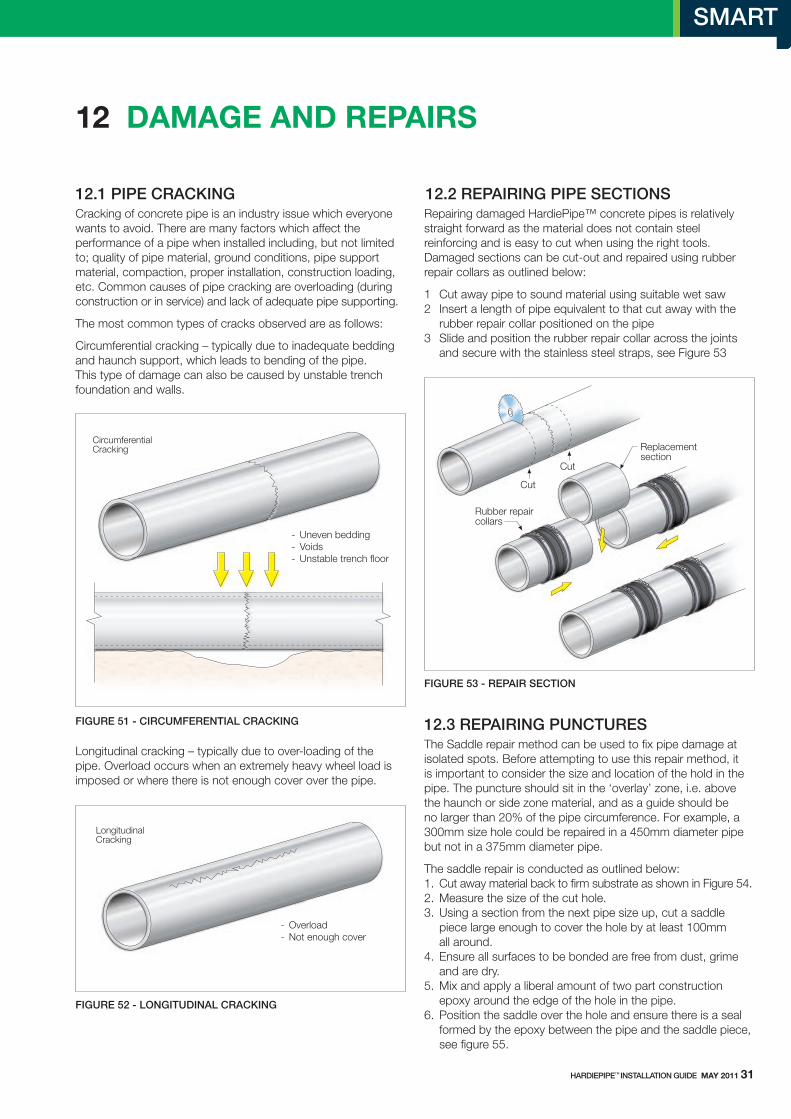
12.1 PIPe CrACkINGCracking of concrete pipe is an industry issue which everyone wants to avoid. there are many factors which affect the performance of a pipe when installed including, but not limited to; quality of pipe material, ground conditions, pipe support material, compaction, proper installation, construction loading, etc. Common causes of pipe cracking are overloading (during construction or in service) and lack of adequate pipe supporting.
the most common types of cracks observed are as follows:
Circumferential cracking – typically due to inadequate bedding and haunch support, which leads to bending of the pipe. this type of damage can also be caused by unstable trench foundation and walls.
fIGUre 51 - CIrCUMfereNTIAL CrACkING
longitudinal cracking – typically due to over-loading of the pipe. overload occurs when an extremely heavy wheel load is imposed or where there is not enough cover over the pipe.
fIGUre 52 - LONGITUdINAL CrACkING
12.2 rePAIrING PIPe SeCTIONSRepairing damaged HardiePipe™ concrete pipes is relatively straight forward as the material does not contain steel reinforcing and is easy to cut when using the right tools. Damaged sections can be cut-out and repaired using rubber repair collars as outlined below:
1 Cut away pipe to sound material using suitable wet saw 2 Insert a length of pipe equivalent to that cut away with the rubber repair collar positioned on the pipe 3 slide and position the rubber repair collar across the joints and secure with the stainless steel straps, see Figure 53
fIGUre 53 - rePAIr SeCTION
12.3 rePAIrING PUNCTUreS the saddle repair method can be used to fix pipe damage at isolated spots. Before attempting to use this repair method, it is important to consider the size and location of the hold in the pipe. the puncture should sit in the ‘overlay’ zone, i.e. above the haunch or side zone material, and as a guide should be no larger than 20% of the pipe circumference. For example, a 300mm size hole could be repaired in a 450mm diameter pipe but not in a 375mm diameter pipe.
the saddle repair is conducted as outlined below: 1. Cut away material back to firm substrate as shown in Figure 54. 2. Measure the size of the cut hole. 3. using a section from the next pipe size up, cut a saddle piece large enough to cover the hole by at least 100mm all around. 4. Ensure all surfaces to be bonded are free from dust, grime and are dry. 5. Mix and apply a liberal amount of two part construction epoxy around the edge of the hole in the pipe. 6. Position the saddle over the hole and ensure there is a seal formed by the epoxy between the pipe and the saddle piece, see figure 55.
CircumferentialCracking
- Uneven bedding- Voids- Unstable trench floor
LongitudinalCracking
- Overload- Not enough cover
HArdIePIPe™ INSTALLATION GUIde mAy 2011 31
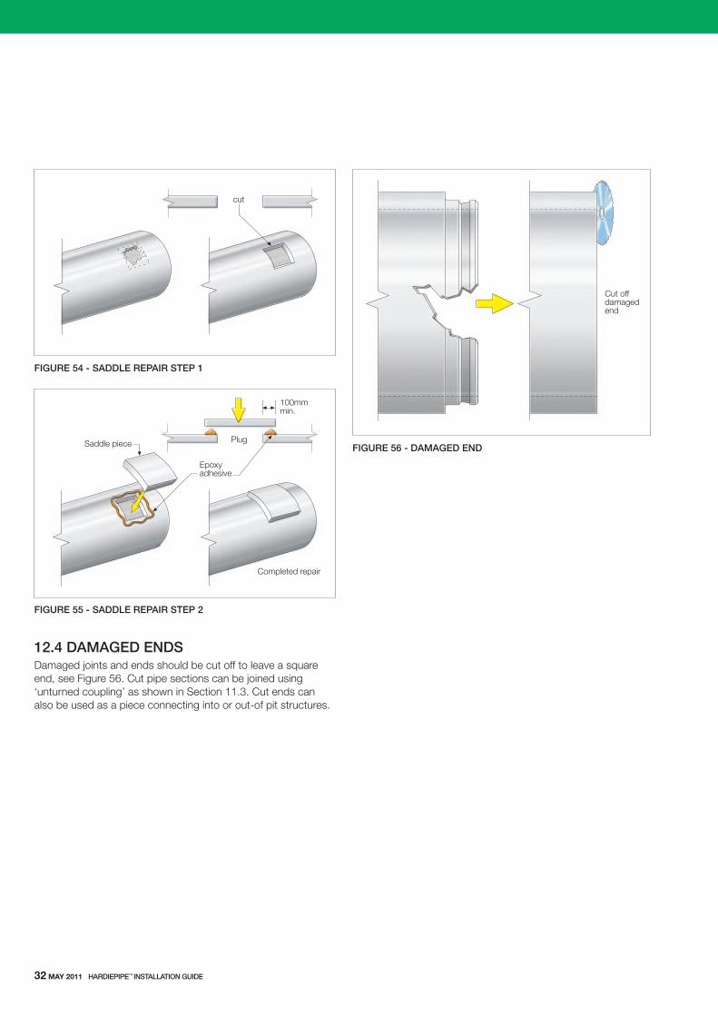
fIGUre 54 - SAddLe rePAIr STeP 1
fIGUre 55 - SAddLe rePAIr STeP 2
12.4 dAMAGed eNdSDamaged joints and ends should be cut off to leave a square end, see Figure 56. Cut pipe sections can be joined using ‘unturned coupling’ as shown in section 11.3. Cut ends can also be used as a piece connecting into or out-of pit structures.
fIGUre 56 - dAMAGed eNd
cut
Plug
Epoxyadhesive
Saddle piece
Completed repair
100mmmin.
Cut offdamagedend
32 mAy 2011 HArdIePIPe™ INSTALLATION GUIde
James Hardie Australia Pty limited (“James Hardie”) warrants to the first purchaser of the product and the last purchaser prior to installation of the product for a period of 10 years from the date of purchase that the HardiePipe™ concrete pipe (the “Product”), will be free from defects due to defective factory workmanship or materials and, subject to compliance with the conditions below, will be resistant to cracking, rotting, fire and damage from termite attacks to the extent set out in James Hardie’s relevant published literature current at the time of installation. James Hardie warrants for a period of 12 months from the date of purchase that the accessories supplied by James Hardie will be free from defects due to defective factory workmanship or materials.
Nothing in this document shall exclude or modify any legal rights a customer may have under the trade Practices Act or otherwise which cannot be excluded or modified at law.
CONdITIONS Of WArrANTYthe warranty is strictly subject to the following conditions:
a) James Hardie will not be liable for breach of warranty unless the claimant provides proof of purchase and makes a written claim either within 30 days after the defect would have become reasonably apparent or, if the defect was reasonably apparent prior to installation, then the claim must be made prior to installation;
b) this warranty is not transferable;
c) the Product must be installed and maintained strictly in accordance with the relevant James Hardie literature current at the time of installation and must be installed in conjunction with the components or products specified in the literature. to obtain copies of such literature contact Ask James Hardie on 1800 659 850. Further, all other products, are to be used in conjunction with the Product must be applied or installed and maintained strictly in accordance with the relevant manufacturer’s instructions and good trade practice;
d) the project must be designed and constructed in strict compliance with all relevant provisions of the current As/ NZs3725 and all other relevant regulations and standards;
e) the claimant’s sole remedy for breach of warranty is (at James Hardie’s option) that James Hardie will either supply replacement product, rectify the affected product or pay for the cost of the replacement or rectification of the affected product;
f) James Hardie will not be liable for any losses or damages (whether direct or indirect) including property damage or personal injury, consequential loss, economic loss or loss of profits, arising in contract or negligence or howsoever arising. without limiting the foregoing James Hardie will not be liable for any claims, damages or defects arising from or in any way attributable to poor workmanship, poor design or detailing, settlement or structural movement and/or movement of materials to which the Product is attached, incorrect design of the structure, acts of God including but not limited to earthquakes, cyclones, floods or other severe weather conditions or unusual climatic conditions,
13 WArrAnty
efflorescence or performance of paint/coatings applied to the Product, normal wear and tear, growth of mould, mildew, fungi, bacteria, or any organism on any Product surface or Product (whether on the exposed or unexposed surfaces);
g) all warranties, conditions, liabilities and obligations other than those specified in this warranty are excluded to the fullest extent allowed by law;
dISCLAIMerthe recommendations in James Hardie’s literature are based on good building practice, but are not an exhaustive statement of all relevant information and are subject to conditions (c), (d), (f) and (g) above. Further, as the successful performance of the relevant system depends on numerous factors outside the control of James Hardie (eg quality of workmanship and design) James Hardie shall not be liable for the recommendations in that literature and the performance of the relevant system, including its suitability for any purpose or ability to satisfy the relevant provisions of As/NZs3725 or other relevant regulations and standards.
HArdIePIPe™ INSTALLATION GUIde mAy 2011 33

James Hardie Australia Pty Ltd ABN 12 084 635 558
CoPyRIGHt MAy 2011 © JAMEs HARDIE AustRAlIA Pty ltD ABN 12 084 635 558 ™ AND ® DENotEs A tRADEMARk oR REGIstERED MARk owNED By JAMEs HARDIE tECHNoloGy lIMItED.
Related Documents