NARENDRA MAHABOOB NAGAR CHITTOOR VEMAGIRI GVK VTS STAGE IV GAZUWAKA GHANAPUR RAICHUR GOOTY SALEM UDUMALP ET TRICHUR MADURAI TRICHY SRIPERUMBUDUR NEYVELI GUTTUR KAIGA RSTPP BHADRAVATI MUNIRABAD P P P P P KOLAR TALCHER JEYPO RE HOSUR SSLM M MMDP TRIVANDRUM NELLORE KALPAKKA SIMHADRI HIRIYUR TALGUPPA KADAPA NEYVELI TPS–2 (EXP) MAPS HOODY KURNOOL KHAMMAM N’SAGAR ALMATHY MYSORE NELAMANGA LA SOMANAHALLI GAUTHAMI KONASEEMA GMR KALAVINDAPATTU TIRUNELVELI DITCHIPALLY PUGALUR GAJWEL BTPS VIJAYAWADA WARANGAL B P PPALLY MALKARAM KARAIKUDY NEYVELI TPS–1 (EXP) JINDAL SPECIAL ENERGY METERS IN SOUTHERN REGION (HAND BOOK) POWER SYSTEM OPERATION CORPORATION LTD. SOUTHERN REGIONAL LOAD DESPATCH CENTRE BANGALORE. November 2010

Welcome message from author
This document is posted to help you gain knowledge. Please leave a comment to let me know what you think about it! Share it to your friends and learn new things together.
Transcript
NARENDRA
MAHABOOB
NAGAR
CHITTOOR
VEMAGIRI
GVK
VTS STAGE IV
GAZUWAKA
GHANAPUR
RAICHUR
GOOTY
SALEM
UDUMALP
ET
TRICHUR
MADURAI
TRICHY
SRIPERUMBUDUR
NEYVELI
GUTTUR
KAIGA
RSTPP
BHADRAVATI
MUNIRABAD
P
P
P
P
P
KOLAR
TALCHER
JEYPO
RE
HOSUR
SSLM
M
MMDP
TRIVANDRUM
NELLORE
KALPAKKA
SIMHADRI
HIRIYUR
TALGUPPA
KADAPA
NEYVELI TPS–2 (EXP)
MAPS
HOODY
KURNOOL
KHAMMAM
N’SAGAR
ALMATHY
MYSORE
NELAMANGA
LA
SOMANAHALLI
GAUTHAMI
KONASEEMA
GMR
KALAVINDAPATTU
TIRUNELVELI
DITCHIPALLY
PUGALUR
GAJWEL
BTPS
VIJAYAWADA
WARANGAL
B P PPALLY
MALKARAM
KARAIKUDY
NEYVELI TPS–1 (EXP)
JINDAL
SPECIAL ENERGY METERS IN
SOUTHERN REGION
(HAND BOOK)
POWER SYSTEM OPERATION CORPORATION LTD.
SOUTHERN REGIONAL LOAD DESPATCH CENTRE
BANGALORE.
November 2010
I N D E X Sl. No. Description Page No: 1. SPECIAL ENERGY METERS
TECHNICAL DETAILS & OPERATING INSTRUCTIONS 01-20
1.1 Technical Specification for SEMs 01-08 1.2 Salient features of SEMs 09-13 1.3 Operating Instructions for SEMs and DCDs 14-16 1.4 Software installation procedure 17-18 1.5 SEM Data Format 19 1.6 Typical Metering Diagram 20
2. SPECIAL ENERGY METERS IN SOUTHERN REGION 21-47
2.1 Summary of SEMs in Southern Region 21 2.2 Constituent-wise summary of SEMs 22-27 2.3 List of Special Energy Meters installed in Southern Region 28-46 2.4 Master Frequency SEMs 47
3. SPECIAL ENERGY METERS LOCATION DIAGRAMS 48-67
3.1 General 3.1(a) Location diagram of SEMs in SR – 400 KV System 48 3.1(b) Location diagram of SEMs in State owned Inter-State lines 49 3.1(c) Location diagram of SEMs in ISTS network 50 3.1(d) Location diagram of SEMs in 400kV substations 51-55
3.2 Location diagram of SEMs at ISGSs 3.2(a) Ramagundam STPS 56 3.2(b) Talcher STPP-II 57 3.2(c) Neyveli Lignite Corporation 58 3.2(d) Madras Atomic Power Station 59 3.2(e) Kaiga Generating Station 60
3.3 Location diagram of SEMs at Drawee utilities 3.3(a) APTRANSCO system 61
3.3(b) KPTCL system 62 3.3(c) KSEB system 63 3.3(d) TNEB system 64 3.3(e) Pondicherry system 65 3.3(f) Goa system 66 3.3(g) PG-HVDC system 67
4. COMPUTATION OF INJECTION AND DRAWAL 68-85
4.1 Accounting Methodology 68-71
4.2 Computation of injection by ISGSs 72-77
4.2(a) Ramagundam STPS 72 4.2(b) Talcher STPP-II 73 4.2(c) Neyveli Lignite Corporation (TS2 Stage-1, TS2 Stage-2) 74 4.2(d) Neyveli Lignite Corporation TPS-1 Expansion 75 4.2(e) Madras Atomic Power Station 76 4.2(f) Kaiga Generating Station 76 4.2(g) Western Region 77 4.2(h) Eastern Region 77
4.3 Computation of drawal by Drawee Utilities
4.3(a) APTRANSCO system 78-79 4.3(b) KPTCL system 80-81 4.3(c) KSEB system 82 4.3(d) TNEB system 83-84 4.3(e) Pondicherry system 85 4.3(f) Goa system 85 4.3(g) PG-HVDC system 85
5. FUTURE REQUIREMENT OF SEMs IN SR 1.1 FUTURE REQUIREMENTS IN SR-II 86-89 1.2 FUTURE REQUIREMENTS IN SR-I 90
SECTION - 1
SPECIAL ENERGY METERS
TECHNICAL DETAILS
&
OPERATING INSTRUCTIONS
SPECIAL ENERGY METERS TECHNICAL
DETAILS
&
OPERATING INSTRUCTIONS
1.1 Technical Specification for SEMs
1.2 Salient features of SEMs
1.3 Operating Instructions for SEMs and DCDs
1.4 Software installation procedure
1.5 SEM Data Format
1.6 Typical Metering Diagram
SRLDC SEMs IN SOUTHERN REGION 1
1.1 TECHNICAL SPECIFICATION FOR SEMs
Technical Specification*
1.0 The energy metering system specified herein shall be used for tariff metering for
bulk, inter-utility power flows, in different Regions of India. One static type
composite meter shall be installed for each EHV circuit, as a self-contained device
for measurement of active energy (MWh) transmittals in each successive 15 minute
block and certain other functions, as described in the following paragraphs.
2.0 The meters shall be suitable for being connected directly to voltage transformers
(VTs) having a rated secondary line-to-line voltage of 110V, and to current
transformers (CTs) having a rated secondary current of 1 A (model-A) or 5A
(model-B). Any further transformers/transactions/transducers required for their
functioning shall be in-built in the meters. Necessary isolation and/or suppression
shall also be built-in, for protecting the meters from surges and voltage spikes that
occur in the VT and CT circuits of extra high voltage switchyards. The reference
frequency shall be 50Hz.
3.0 The active energy (Wh) measurement shall be carried out on 3-phase, 4-wire
principle, with an accuracy as per class 0.2 S of IEC-687-1992-06 (2nd
edition)/
IEC-62053-22:2003. In model-A (for CT secondary rating 1A), the energy shall be
computed directly in CT and VT secondary quantities, and indicated in watt-hours.
The meter shall compute the net active energy (Wh) sent out from the substation
bus bars during each successive 15-minutes block, and store it in its memory along
with plus/minus sign. It shall also display on demand the net Wh sent out during
the previous 15-minute block, with a minus sign if there is net Wh export.
4.0 Further, the meter shall continuously integrate and display on demand the net
cumulative active energy sent out from the substation bus bars upto that time. The
cumulative Wh reading at each midnight shall be stored in the meter’s memory.
The register shall move backwards when active power flows back to substation bus
bars.
5.0 The meter shall count the number of cycles in VT output during each successive
15-minutes block, and divide the same by 900 to arrive at the average frequency.
This shall be stored in the meter’s memory as a 2-digit code which shall be arrived
at by subtracting 49 from the average frequency, multiplying by 50 and neglecting
all decimals. For example, 49.89 Hz shall be recorded as 44. In case the average
frequency is less than 49.0 Hz, it shall be recorded as 00. In case it is 51.0 Hz or
higher, it shall be recorded as 99. The average frequency of the previous 15-
minutes block shall also be displayed, on demand in hertz.
* Note: This specification is applicable to the meters procured by POWERGRID in general ,while the
underlined items are the modifications carried out in the specification in respect of SEMs
procured after 2005 .
SRLDC SEMs IN SOUTHERN REGION 2
6.0 The meter shall continuously compute the average of the RMS values of the three
line-to-neutral VT secondary voltages as a percentage of 63.51 V, and display the
same on demand. The accuracy of the voltage measurement/computation shall be
atleast 0.5%, a better accuracy such as 0.2% in the 95-105% range being desirable.
7.0 The meter shall also compute the reactive power (VAR) on 3-phase, 4-wire
principle, with an accuracy as specified in clause 11.0, and integrate the reactive
energy (VARh) algebraically into two separate registers, one for the period for
which the average RMS voltage is 103.0% or higher, and the other for the period
for which the average RMS voltage is below 97.0%. The current reactive power
(VAR), with a minus sign if negative, and cumulative reactive energy (VARh)
readings of the two registers shall be displayed on demand. The readings of the
two registers at each midnight shall also be stored in the meter’s memory. In
model-A (for CT secondary rating of 1 A), the reactive power and reactive energy
transmittals shall be computed in VAR/VARh directly calculated in CT and VT
secondary quantities. When lagging reactive power is being sent out from
substation bus bars, VAR display shall have a plus sign or no sign and VARh
registers shall move forward. When reactive power flow is in the reverse direction,
VAR display shall have negative sign and VARh registers shall move backwards.
8.0 In the model-B (for CT secondary rating of 5A), all computations, displays and
memory storage shall be similar except that all figures shall be one fifth of the
actual Wh, VAR and VARh worked out from CT and VT secondary quantities.
9.0 The meters shall fully comply with all stipulations in IEC standards 687-1992-06
(2nd
edition)/62052-11:2003 and 62053-22:2003, except those specifically modified
by this specification. The reference ambient temperature shall be 30° C.
10.0 Errors shall be reasonable for all power factor angles from 0° to 360°.
11.0 For reactive power (VAR) and reactive energy (VARh) measurements, IEC/145 /
IEC 62053-23:2003 shall be complied with. The accuracy of measurement of
reactive energy shall be as per class 2.
12.0 Each meter shall have a test output device (visual) for checking the accuracy of
active energy (Wh) measurement. The preferred pulsing rate is twenty(20) per Wh
for Model-A and four(4) per Wh for model –B. It shall be possible to couple this
device to suitable testing equipment also.
13.0 No rounding off to the next higher last decimal shall be done for voltage and
frequency displays. All 15 minute Wh figures shall however be rounded off to the
nearest last decimal.
14.0 The three line-to-neutral voltage shall be continuously monitored and in case any of
these falls below about 70%, a normally flashing lamp provided on meter’s front
shall become steady. It shall go off it all three voltages fall below 70%. The time
blocks in which such a voltage failure occurs/persists shall also be recorded in the
meter’s memory. The lamp shall automatically resume flashing when all VT
SRLDC SEMs IN SOUTHERN REGION 3
secondary voltages are healthy again. The two VARh registers specified in clause
7.0 shall remain stay-put while VT supply is unhealthy.
15.0 The meters shall normally operate with the power drawn from the VT secondary
circuits. The total burden imposed by a meter for measurement and operation shall
not exceed 10 VA on any of the phases. An automatic backup for continued
operation of the meter’s calendar-clock, and for retaining all data stored in its
memory, shall be provided through a long-life battery, which shall be capable of
supplying the required power for at least 2 years. The meters shall be supplied duly
fitted with the batteries, which shall not require to be changed for atleast 10 years,
as long as total VT supply interruption does not exceed two years. The battery
mounting shall be designed to facilitate easy battery replacement without affecting
PCB of the meter. The meters shall not require any separate auxiliary supply for
their operation. All displays may disappear on loss of VT supply.
16.0 Each meter shall have a built-in calendar and clock, having an accuracy of 30
seconds per month or better. The calendar and clock shall be correctly set at the
manufacturer’s works. The date (year-month-day) and time (hour-min.-sec.) shall
be displayed on the meter front (when VT supply has been connected), on demand.
Only limited clock adjustment shall be possible at site, using the DCD. When an
advance or retard command is given, six subsequent time blocks shall be contracted
or elongated by ten seconds each. The meter shall not accept another clock
correction command for seven days. All clock corrections shall be registered in the
meter’s memory and suitably shown on print out of collected data.
17.0 Each meter shall have a unique identification code, which shall be marked
permanently on its front, as well as in its memory. All meters supplied to
POWERGRID as per this specification shall have their identification code starting
with “NP”, which shall not be used for any other supplies. “NP” shall be followed
by a dash and a four digit running serial number, further followed by a dash and
“A” for Model-A, and “B”, for the use with CT secondary of 1 A and 5 A
respectively.
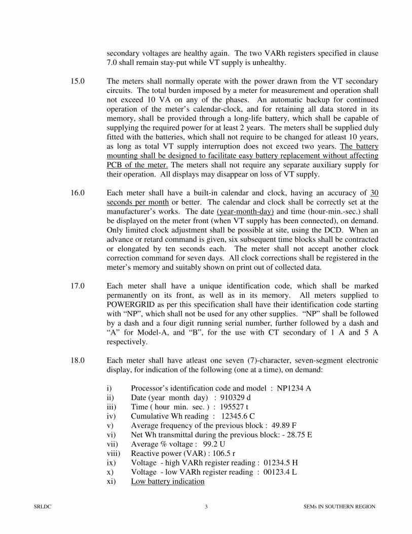
18.0 Each meter shall have atleast one seven (7)-character, seven-segment electronic
display, for indication of the following (one at a time), on demand:
i) Processor’s identification code and model : NP1234 A
ii) Date (year month day) : 910329 d
iii) Time ( hour min. sec. ) : 195527 t
iv) Cumulative Wh reading : 12345.6 C
v) Average frequency of the previous block : 49.89 F
vi) Net Wh transmittal during the previous block: - 28.75 E
vii) Average % voltage : 99.2 U
viii) Reactive power (VAR) : 106.5 r
ix) Voltage - high VARh register reading : 01234.5 H
x) Voltage - low VARh register reading : 00123.4 L
xi) Low battery indication
SRLDC SEMs IN SOUTHERN REGION 4
19.0 A gold plated touch key or push button shall be provided on the meter front for
switching on the display and for changing from one indication to the next. (The
display shall switch off automatically about one minute after the last operation of
touch key/push button). When the display is switched on, the parameter last
displayed shall be displayed again, duly updated.
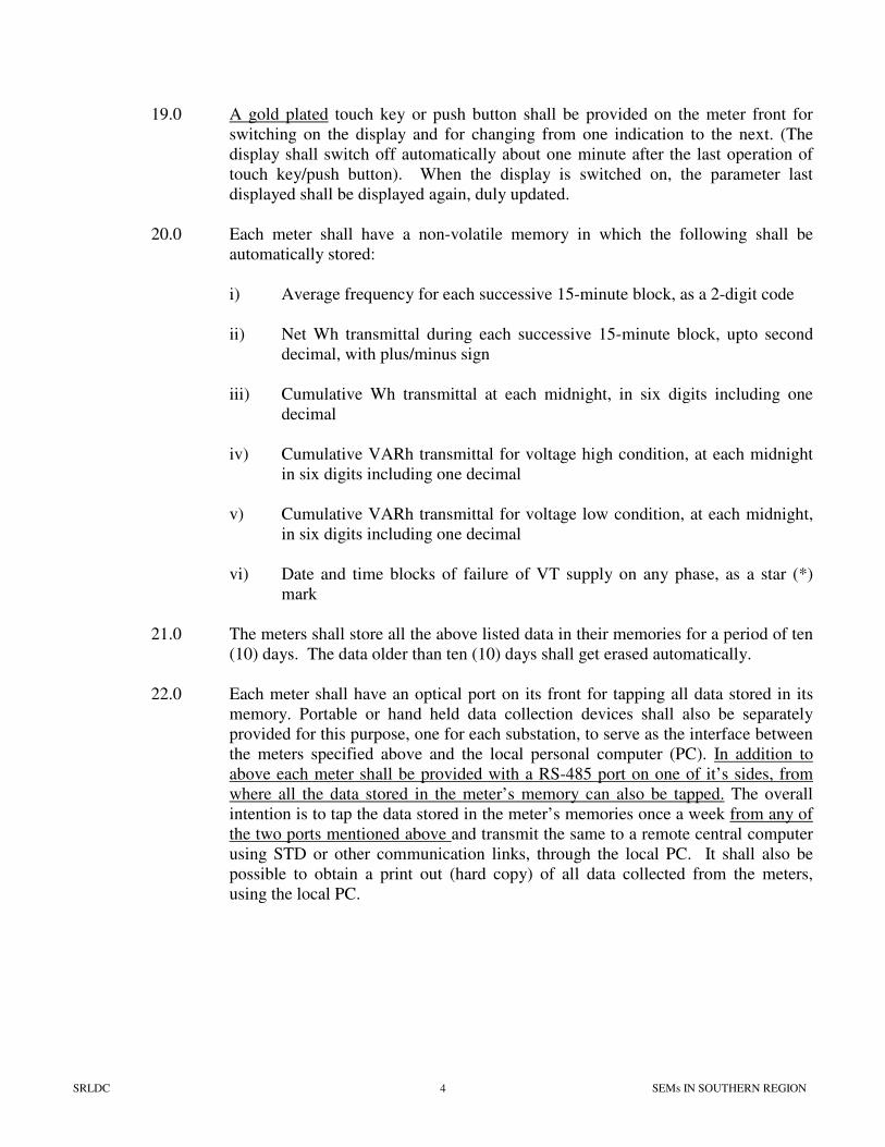
20.0 Each meter shall have a non-volatile memory in which the following shall be
automatically stored:
i) Average frequency for each successive 15-minute block, as a 2-digit code
ii) Net Wh transmittal during each successive 15-minute block, upto second
decimal, with plus/minus sign
iii) Cumulative Wh transmittal at each midnight, in six digits including one
decimal
iv) Cumulative VARh transmittal for voltage high condition, at each midnight
in six digits including one decimal
v) Cumulative VARh transmittal for voltage low condition, at each midnight,
in six digits including one decimal
vi) Date and time blocks of failure of VT supply on any phase, as a star (*)
mark
21.0 The meters shall store all the above listed data in their memories for a period of ten
(10) days. The data older than ten (10) days shall get erased automatically.
22.0 Each meter shall have an optical port on its front for tapping all data stored in its
memory. Portable or hand held data collection devices shall also be separately
provided for this purpose, one for each substation, to serve as the interface between
the meters specified above and the local personal computer (PC). In addition to
above each meter shall be provided with a RS-485 port on one of it’s sides, from
where all the data stored in the meter’s memory can also be tapped. The overall
intention is to tap the data stored in the meter’s memories once a week from any of
the two ports mentioned above and transmit the same to a remote central computer
using STD or other communication links, through the local PC. It shall also be
possible to obtain a print out (hard copy) of all data collected from the meters,
using the local PC.
SRLDC SEMs IN SOUTHERN REGION 5
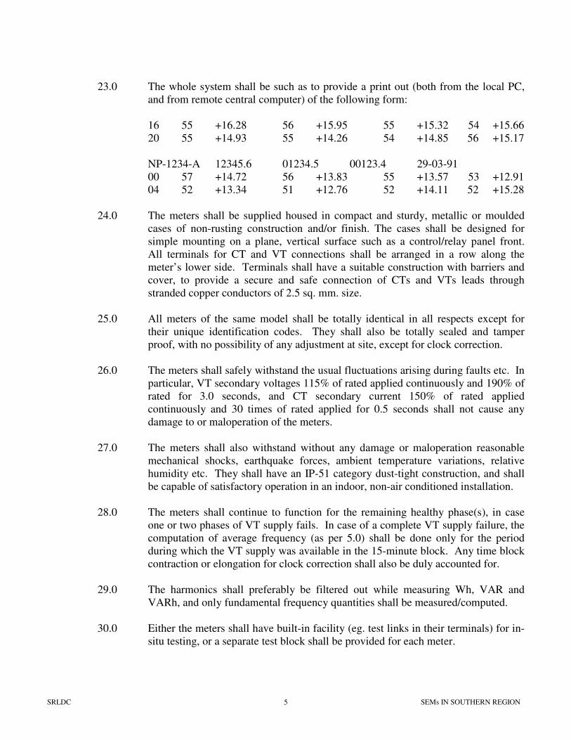
23.0 The whole system shall be such as to provide a print out (both from the local PC,
and from remote central computer) of the following form:
16 55 +16.28 56 +15.95 55 +15.32 54 +15.66
20 55 +14.93 55 +14.26 54 +14.85 56 +15.17
NP-1234-A 12345.6 01234.5 00123.4 29-03-91
00 57 +14.72 56 +13.83 55 +13.57 53 +12.91
04 52 +13.34 51 +12.76 52 +14.11 52 +15.28
24.0 The meters shall be supplied housed in compact and sturdy, metallic or moulded
cases of non-rusting construction and/or finish. The cases shall be designed for
simple mounting on a plane, vertical surface such as a control/relay panel front.
All terminals for CT and VT connections shall be arranged in a row along the
meter’s lower side. Terminals shall have a suitable construction with barriers and
cover, to provide a secure and safe connection of CTs and VTs leads through
stranded copper conductors of 2.5 sq. mm. size.
25.0 All meters of the same model shall be totally identical in all respects except for
their unique identification codes. They shall also be totally sealed and tamper
proof, with no possibility of any adjustment at site, except for clock correction.
26.0 The meters shall safely withstand the usual fluctuations arising during faults etc. In
particular, VT secondary voltages 115% of rated applied continuously and 190% of
rated for 3.0 seconds, and CT secondary current 150% of rated applied
continuously and 30 times of rated applied for 0.5 seconds shall not cause any
damage to or maloperation of the meters.
27.0 The meters shall also withstand without any damage or maloperation reasonable
mechanical shocks, earthquake forces, ambient temperature variations, relative
humidity etc. They shall have an IP-51 category dust-tight construction, and shall
be capable of satisfactory operation in an indoor, non-air conditioned installation.
28.0 The meters shall continue to function for the remaining healthy phase(s), in case
one or two phases of VT supply fails. In case of a complete VT supply failure, the
computation of average frequency (as per 5.0) shall be done only for the period
during which the VT supply was available in the 15-minute block. Any time block
contraction or elongation for clock correction shall also be duly accounted for.
29.0 The harmonics shall preferably be filtered out while measuring Wh, VAR and
VARh, and only fundamental frequency quantities shall be measured/computed.
30.0 Either the meters shall have built-in facility (eg. test links in their terminals) for in-
situ testing, or a separate test block shall be provided for each meter.
SRLDC SEMs IN SOUTHERN REGION 6
31.0 Portable/hand-held Data Collection Devices (DCD) :
These shall be tailor-made for tapping all data stored in a meter’s memory, and
faithfully transferring it to the local PC. Each device shall be supplied complete
with
i) a lead with optical head for coupling it to the meter,
ii) a lead for plugging it to a personal computer;
iii) an internal battery for powering the devices;
iv) a case for safely carrying it about
v) a battery charger
The total arrangement shall be such that one (1) operation can carry out the whole
operation himself, in about five (5) minutes per meter.
32.0 The DCD shall have a key for starting the data tapping from the coupled meter’s
memory, a key to start data transfer to the PC, and a lamp, which would light up on
completion of data collection, remain ‘on’ while the data is held in the device and
would go ‘off’ when all data has been transferred to the PC. Data tapping
operation shall not erase the data from the meter’s memory, or effect the meter
operation in any way. The memory of the DCD shall get automatically cleared
when the data has been transferred to the PC only then the DCD shall accept data
from another meter. DCDs shall also have necessary provision for meter clock
correction. DCDs shall be compatible with earlier supplied meters of L&T/SML
make in regard to data downloading etc.
33.0 The Contractor shall provide the necessary software which would enable a local
IBM-Compatible PC to (i) accept the data from the DCD and/or from a interface
device connected to the optical port/RS-485 port and store it in it’s memory in
binary read only format, (ii) Polling feature along with a task scheduler to run the
data downloading software at a pre-designated date and time repeatedly or by
manually selecting a meter. A detailed activity log shall also be available for each
downloading operation, (iii) display the collected data on PC’s screen in text
format, with forward/backward rolling, (iv) print out in text format the data
collected from one or more meters, starting from a certain date and time, as per
operator’s instructions, (v) transmit the collected data, in binary format, through an
appropriate communication link to the central computer, starting from a certain date
and time, as per operator’s instructions, and (vi) store the collected data ,in binary
format, on a floppy disc/CD/Pen Device.
34.0 The above software shall further ensure that absolutely no tampering (except total
erasures) of the collected metering data is possible during its handling by the PC.
The software shall be suitable for the commonly available PCs, and shall be
supplied to Owner in a compatible form to enable its easy loading into the PCs
available (or to be installed by the Owner/others) at the various substations.
SRLDC SEMs IN SOUTHERN REGION 7
35.0 Quality Assurance
The quality control procedure to be adopted during manufacture of the specified
equipment shall be mutually discussed and finalized in due course, generally based
on the established and proven practices of the manufacturer.
36.0 Testing
All equipment, after final assembly and before dispatch from manufacturer’s
works, shall be duly tested to verify that is suitable for supply to the Owner. In
particular, each and every meter shall be subjected to the following acceptance
tests:
i) Verification of compliance with Table 9 of IEC-687-1992-06 (2nd
edition) /
clause 8.1 of IEC-62053-22:2003, in both directions of power flow, for
class 0.2S.
ii) Test of the register ratio and the impulse value of the transmitting device,
for both directions.
iii) Verification that VARh measurement errors are within values permitted for
class 2 in Table-1 of IEC-145 / Table 6 of IEC 62053-23 for both directions
of power flow.
iv) Effect of +10% variation in measuring circuit voltage, on accuracy of Wh
and VARh measurement
v) Power loss.
vi) Dielectric properties.
vii) Starting and running with no-load for Wh and VARh, in both directions.
viii) Functional checks for display and memory.
ix) Accuracy of the calendar and clock.
x) Accuracy of voltage and frequency measurement.
37.0 Any meter which fails to fully comply with the specification requirements shall be
liable to be rejected by the Owner. However, the Owner may purchase such meters
at a reduced price in case of marginal non-compliance, at his sole discretion.
SRLDC SEMs IN SOUTHERN REGION 8
38.0 Acceptance Tests for DCD and PC Software
All DCDs, after final assembly and before despatch from
Contractor’s/Manufacturer’s works shall be duly tested to verify that they are
suitable for supply to the Purchaser. In particular, each and every DCD shall be
subjected to the following acceptance test:
i) Functional checks
ii) Downloading Meter Data from the Meter(s)
iii) Compatibility with PC Software
iv) Downloading the meter data on PC
v) Functioning of advance and retard time commands
vi) Per meter downloading time verification
vii) Capacity of DCD for data storage
39.0 Type Tests
One (1) out of every hundred (100) meters shall be subjected to the complete range
of type tests as per IEC-687-1992-06 (2nd
edition) / IEC-62053-22:2003, IEC-
62053-23:2003 and IEC 62052-11:2003, after final assembly. In case of any
failure to pass all specified tests, the contractor shall arrange to carry out the
requisite modifications/replacements in the entire lot of meters at his own cost.
After any such modifications and final assembly, two (2) meters selected out of the
lot by the Owner’s representative shall be subjected to the full range of type tests.
The lot shall be accepted by the Owner only after successful type testing.
40.0 Installation and Commissioning
The static energy meters specified above shall be installed at various EHV
substations owned by the Owner, SEBs and other agencies, throughout India. The
exact location and time-table for installation shall be finalized by the Owner in due
course, and advised to the contractor, such that contractor’s responsibility in this
respect ends within six (6) months of completion of all supplies.
41.0 The Contractor shall be responsible for total installation and commissioning of the
meters (along with test blocks, if supplied separately) as per Owner’s advice,
including unpacking and inspection on receipt at site, mounting the meters on
existing control and relay panels at an appropriate viewing height, connection of
CT and VT circuits including any required rewiring, functional testing,
commissioning and handing over. The Contractor’s personnel shall procure/carry
the necessary tools, equipment, materials and consumables (including insulated
wires, lugs, ferrules, hardware etc.)
42.0 As a part of commissioning of DCDs the Contractor shall load the software
specified in clause 33 and 34 into the PCs at the respective substations, and fully
commission the total meter reading scheme. He shall also impart the necessary
instructions to substation engineers.
SRLDC SEMs IN SOUTHERN REGION 9
1.2 SALIENT FEATURES OF SEMs
Special Energy Meters
The meters are of 0.2S accuracy class and are specially designed for Frequency Linked Tariff
Metering scheme for Inter Utility Exchanges at Grid level.
Salient features :
• Static type – Totally Electronic
• Compliant with IEC 687 / IEC-62053-22:2003 standard
• Better accuracy (0.2S class)
• Composite meter capable of measuring Active and Reactive Energy in all 4 quadrants
• 3 phase-4 wire measurement
• Direct measurement as per CT/PT secondary quantities
• Filters harmonics and measure energy at fundamental frequencies.
• Operates on self power from connected PT supply (110V Ph to Ph/ 63.51 V Ph-N)
• Different Current ratings suiting to CT secondary [ex. 1 Amp (A-type meter) or 5 Amp
(B type Meter)]
• VA burden not more than 10 on any of the phases
• Works on Real Time Clock (RTC) hence data is time stamped.
• Time adjustment facility ( in steps of 1 min in a week )
• No calibration required due to absence of moving parts.
• Calibration possible only at Manufacturers’ works
• High security of data storage
Criteria for location of SEMs
Main Meters: Those SEMs primarily used for Energy Accounting / Billing
Check Meters: Those SEMs connected to the same CT/PT as the Main meter. They are used
for Energy Accounting / Billing in case of Discrepancy in reading of Main Meter.
SRLDC SEMs IN SOUTHERN REGION 10
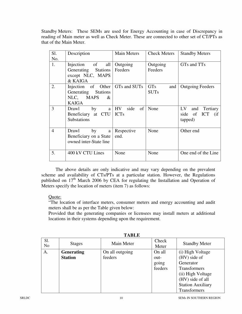
Standby Meters: These SEMs are used for Energy Accounting in case of Discrepancy in
reading of Main meter as well as Check Meter. These are connected to other set of CT/PTs as
that of the Main Meter.
Sl.
No.
Description Main Meters Check Meters Standby Meters
1. Injection of all
Generating Stations
except NLC, MAPS
& KAIGA
Outgoing
Feeders
Outgoing
Feeders
GTs and TTs
2. Injection of Other
Generating Stations
NLC, MAPS &
KAIGA
GTs and SUTs GTs and
SUTs
Outgoing Feeders
3 Drawl by a
Beneficiary at CTU
Substations
HV side of
ICTs
None LV and Tertiary
side of ICT (if
tapped)
4 Drawl by a
Beneficiary on a State
owned inter-State line
Respective
end.
None Other end
5. 400 kV CTU Lines None None One end of the Line
The above details are only indicative and may vary depending on the prevalent
scheme and availability of CTs/PTs at a particular station. However, the Regulations
published on 17th
March 2006 by CEA for regulating the Installation and Operation of
Meters specify the location of meters (item 7) as follows:
Quote:
“The location of interface meters, consumer meters and energy accounting and audit
meters shall be as per the Table given below:
Provided that the generating companies or licensees may install meters at additional
locations in their systems depending upon the requirement.
TABLE Sl.
No Stages Main Meter Check
Meter Standby Meter
A. Generating
Station
On all outgoing
feeders
On all
out-
going
feeders
(i) High Voltage
(HV) side of
Generator
Transformers
(ii) High Voltage
(HV) side of all
Station Auxiliary
Transformers
SRLDC SEMs IN SOUTHERN REGION 11
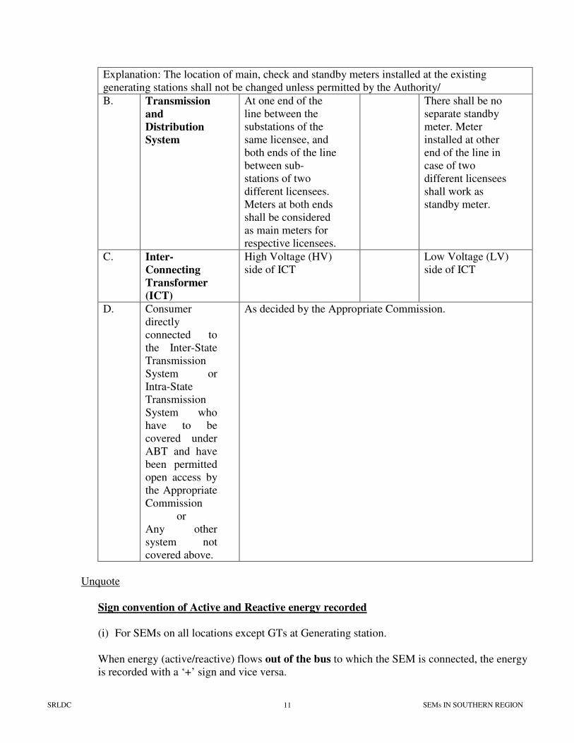
Explanation: The location of main, check and standby meters installed at the existing
generating stations shall not be changed unless permitted by the Authority/
B. Transmission
and
Distribution
System
At one end of the
line between the
substations of the
same licensee, and
both ends of the line
between sub-
stations of two
different licensees.
Meters at both ends
shall be considered
as main meters for
respective licensees.
There shall be no
separate standby
meter. Meter
installed at other
end of the line in
case of two
different licensees
shall work as
standby meter.
C. Inter-
Connecting
Transformer
(ICT)
High Voltage (HV)
side of ICT
Low Voltage (LV)
side of ICT
D. Consumer
directly
connected to
the Inter-State
Transmission
System or
Intra-State
Transmission
System who
have to be
covered under
ABT and have
been permitted
open access by
the Appropriate
Commission
or
Any other
system not
covered above.
As decided by the Appropriate Commission.
Unquote
Sign convention of Active and Reactive energy recorded
(i) For SEMs on all locations except GTs at Generating station.
When energy (active/reactive) flows out of the bus to which the SEM is connected, the energy
is recorded with a ‘+’ sign and vice versa.
SRLDC SEMs IN SOUTHERN REGION 12
(ii) For SEMs on GTs at Generating Stations
When energy (active/reactive) flows into the bus to which the SEM is connected, the energy
is recorded with a ‘+’ sign and vice versa.
Accordingly the values in the cumulative registers for active energy and reactive energy keep
incrementing when the net energy for a particular time period recorded is ‘+ve’ and
decrementing when it is ‘-ve’. For example if the initial value of these registers is 00000.0
(say) and the net energy in a block is 25.0 (say), the cumulative value of the register
increments to 00025.0. Once the value reaches 99999.9, the same will get reset to 00000.0
Details of Data recorded :
• No multiplication Factor is incorporated in the Meter. Hence data in Secondary side (Wh)
is recorded.
• Meter can be interchanged from one location to another irrespective of their CT/PT ratios
• To get data on Primary side in MWh, the secondary side data in Wh is to be multiplied by
the connected CT/PT ratio.
• Stores the following data for previous 9 days and the current day period (in case of
SMLOLD meters) and previous 10 days and current day period (in case of SMLNEW and
L&T meters).
Data recorded in every Block :
• Net Active Energy in 15 min. Time blocks (Wh)
• Average frequency in 15 min. Time block
(records frequency in the band of 49Hz<f<51.00Hz in steps of 0.02Hz
in a coded form as integer from 00 to 99)
FC = (f-49)*50
where FC means Frequency Code
f means Frequency
• Voltage failure flag. ( a * mark is recorded if Avg. Voltage in the three phases falls below
70%)
• Time Correction flag ( ‘aa’ if time is advanced and ‘rr’ if time is retarded).
Data recorded once in a day at 00:00 hrs :
(1) Sl. No. Of meter
(2) Cumulative active energy register – C
(3) High voltage reactive energy register – H
(4) Low voltage reactive energy register – L
(5) Date
SRLDC SEMs IN SOUTHERN REGION 13
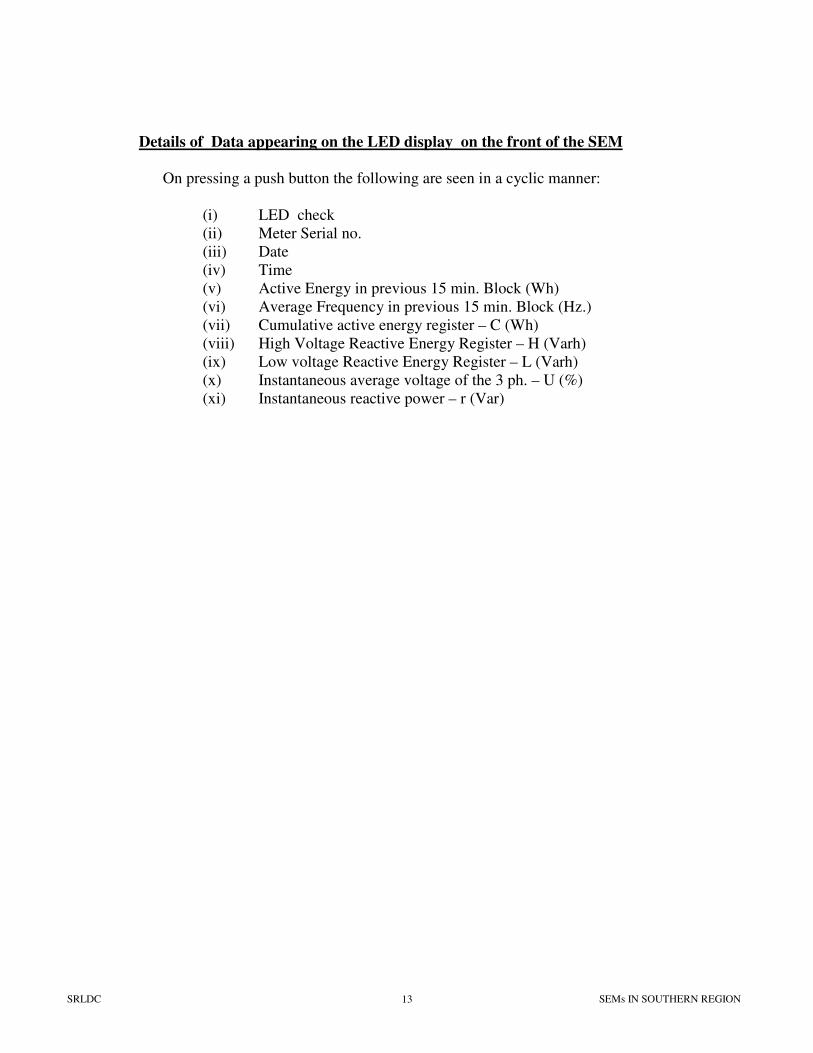
Details of Data appearing on the LED display on the front of the SEM
On pressing a push button the following are seen in a cyclic manner:
(i) LED check
(ii) Meter Serial no.
(iii) Date
(iv) Time
(v) Active Energy in previous 15 min. Block (Wh)
(vi) Average Frequency in previous 15 min. Block (Hz.)
(vii) Cumulative active energy register – C (Wh)
(viii) High Voltage Reactive Energy Register – H (Varh)
(ix) Low voltage Reactive Energy Register – L (Varh)
(x) Instantaneous average voltage of the 3 ph. – U (%)
(xi) Instantaneous reactive power – r (Var)
SRLDC SEMs IN SOUTHERN REGION 14
1.3 OPERATING INSTRUCTIONS FOR
SEMs AND DCDs
1) SEMs Data Collection
Every Monday morning data is to be collected using a Data Collecting Device (DCD), a small
hand held unit though an Optical Coupler Cable
The same is used to dump the SEM data into a PC using a Serial Port Communication Cable
with the help of a manufacturer supplied software.
The text form of the data is to be created through this software and is to be checked for proper
format and syntactic correctness.
Voltage failure flags (*) are to be correlated with PT supply failures due to feeder shutdowns /
Blown fuse, Switching operations etc.
Time Correction flags (aa/rr) are to be correlated with the Time Advance/Retard commands
given through DCD.
After all the above checks, the binary coded file (*.MRI in case of SML meters or *.DCD and
*.DAT in case of L&T meters as the case may be) is to be transmitted to SRLDC through e-
The reasons for Voltage Failure flags shall be intimated to SRLDC for incorporating necessary
adjustments for under recording. Time correction flags shall also be intimated so that the same
can be analysed further.
The data along with above information and site observations shall be e-mailed to
[email protected]., [email protected] , [email protected] , and [email protected]
2) Data collection in case of feeder outage
In case the feeder is in ‘out of service’ condition the meter will not communicate with
DCD as the power supply to the meter will not be available. In such cases for enabling data
collection a single phase supply of 63.5V may be extended between any of the phase and
neutral points of the voltage terminal of the meter through a means like ‘Variac’ or any such
transformer which gives the required output. While doing this, permission may be obtained
from local operational staff and due care may be taken to effect necessary isolations like
removal of PT fuse or corresponding PT input wiring to the meter etc.
SRLDC SEMs IN SOUTHERN REGION 15
In case of L&T meters a battery back up button is provided for data collection during
the feeder outage conditions. The same may be kept pressed and data shall be collected. This
button is to be sparingly used to conserve the battery back-up and is to be kept pressed while
data collection is going on
3) Periodical Checks :
SEMs
• Special energy meter may be periodically checked for any low voltage LED indication. If the
LED becomes steady, it indicates the average voltage falling below 70%. PT inputs may be
checked for any blown fuse etc.
• The push button display on the front panel may be made use of, for periodical checking of
various parameters measured by the meter
• Time Drift checking
Since the data recorded by SEM is time stamped (15 min. block data), it is very important to
maintain the time of the meter, as it is prone to drift due to inherent variation of parameters
like temperature, humidity etc. The time of the meter (Real Time Clock) as shown on the
display panel of the SEM may be periodically checked for its correctness with respect to
GPS/AIR time. When the time drift is more than 1 minute, necessary correction through the
DCD may be carried out. It may be noted that time correction through DCD can be done by
only 1 minute in a week and if the drift is more than 2 minutes, correction may be carried out
in successive weeks. Due care may be taken regarding the type of correction i.e. ADVANCE
or RETARD depending on whether the meter is SLOW or FAST. All the sites have to send
monthly reports on the time drift of the SEMs as on the 1st Monday of the month and also the
Time corrections carried out during the month.
DCDs
• Manual for DCD shall be thoroughly studied to ensure proper operation of DCD.
• DCD may be carefully handled and preserved in a suitable cover, when not in use.
• Healthiness of Data Collecting Device (DCD) and associated cables, accessories like charger,
battery etc. shall be maintained to avoid last minute emergencies.
• It is preferred to use a fully charged battery with the DCD before data collection.
• In case of Analogic DCDs, the DCD may be kept in charged condition for at least 24 hours
before data collection.
SRLDC SEMs IN SOUTHERN REGION 16
4) Special precautions
SEMs
i) Never keep the SEM in De-energised condition for long durations, to avoid drain on the
internal battery. In case of spare meters, the SEM may be kept in charged condition by
extending the supply to the voltage terminals.
ii) Never leave the optical window uncovered. Otherwise entry of dust particles on the
window glass may result in problems in data collection because of improper
communication of DCD with the meter.
iii) Never remove the optical cable from the meter while data collection is in progress. Doing
so may result in hanging of the internal processor because the same would be in
handshaking mode with the DCD till the data collection process is completed.
iv) Never subject the meter to extreme climatic conditions. It may be suitably guarded in a
safe panel free from dust and water ingression.
DCDs
i) Never use a non-chargeable/disposable Battery cell in the DCD as it is prone to improper
drain characteristics.
ii) Never fold the optical cable used for data collection or data dumping cable as this may
result in cutting of the internal strands or opening of the soldered joints.
iii) Never leave the Analogic DCDs (supplied with L&T and SML new meters) in uncharged
condition for a long time as it may result in corruption of the internal software.
SRLDC SEMs IN SOUTHERN REGION 17
1.4 SOFTWARE INSTALLATION PROCEDURE
A software provided by the meter manufacturer is required to be installed in the PC
where SEM data is to be dumped. In case of SEMs supplied by SML, the name of the software
is SMARTGRID in Windows version and FBM_SYS in DOS version. In case of SEMs
supplied by L&T the software is called VINCOM in Windows version and LUCID in DOS
version. The DOS version of these programs can be installed by simply copying the concerned
folders. The programs may be run by double clicking on the respective files viz.
FBM_SYS.EXE or LUCID.EXE or executing tem from DOS prompt.
For installation of the Windows version of the software the following procedure may
be followed:
SMARTGRID INSTALLATION
1. Insert ‘CD’ and go to folder ‘S_Grid\Disc1’.
2. Run ‘Setup’ file with PC symbol by double clicking the same. Installation sequence will ask
you to enter the drive/folder where Smartgrid is to be installed. Select the same as per your
choice.
3. The software is copyright protected and hence a protection floppy is provided along with the
CD to copy the copyright permission into the PC. The floppy can be utilized for installation in
two PCs.
4. For installing the copyright permission files, insert the protection floppy.
Copy Smartini & Keys.dat files from floppy and paste them in C:\Smartgrid directory.
Go to DOS prompt and then to A: drive and type ‘install A:C: or the drive where you installed
the files as in step 2.
The following messages will appear on screen in sequence:
Installing Protection system………
Installing………….
Complete.
Copying all pertinent files
1 file(s) copied
1 file(s) copied
A:\>
Now the program is ready for use. It can be executed by clicking on the “Smartgrid” icon in
the ‘Programs’ Menu or in the corresponding folder.
After opening the program the following details are to be entered
User Name: Supervisor
Password: superpower
SRLDC SEMs IN SOUTHERN REGION 18
The menu in the program appears and the same is self explanatory. For further guidelines,
Help menu may be referred.
5. If the software from this PC is to be removed, first the copyright permission shall be
transferred from the PC to protection floppy to utilize the same in another location. Then
uninstall the program files from PC.
i) For transferring the copyright permission from PC to floppy:
Insert the Protection floppy and type the following command:
A:\>Remove C: or D: or E: or F: A:
where C/D/E/F is the drive name where software was installed.
The following messages will appear in sequence:
A:\>SCPBAT R C: A:GRIDSVR /E/V/D
Removing………….
Complete.
A:\>
Now the copyright file is restored from PC to floppy, so that the same can be used for another
installation.
ii) For uninstalling the program files from the PC:
Uninstall the ‘Smartgrid’ software through ‘Add/Remove programmes’ menu in ‘Control
Panel’ in “My Computer”.
VINCOM INSTALLATION
Insert the CD containing VINCOM software and unzip the files contained in VINCOM
0203f.zip to a Folder of your choice.
Open that folder and double click on the ‘set up‘ file (with computer icon) and follow the
procedure displayed. The program would ask details such as consumer name, invoice No.,
consumer code etc. Ignore the same. At this stage, press Alt + Tab keys together and follow
the steps given thereof. After completion of installation, the computer would prompt for
restarting of the computer. After restarting of the computer go the Programs Menu and click
on the VINCOM icon The opening screen appears requiring to enter the following details:
User ID : Administrator
Password : admin
After entering the above details, the program is ready for use and the menu displayed is
self explanatory. Further guidance can be obtained from the ‘Help’ Menu.
SRLDC SEMs IN SOUTHERN REGION 19
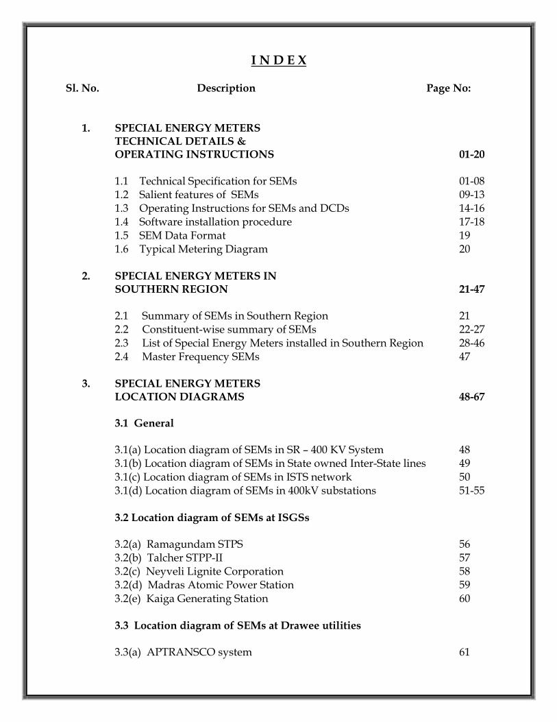
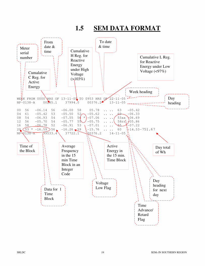
1.5 SEM DATA FORMAT
WEEK FROM 0000 HRS OF 13-11-05 TO 0953 HRS OF 22-11-05
NP-0138-A 00285.1 37994.0 00376.2 13-11-05
00 56 -06.14 56 -06.00 58 05.78 .. .. 63 -05.42
04 61 -05.42 53 -05.50 52 -05.62 .. .. 60 -06.33
08 54 -06.93 54 -07.55 56 * -07.06 .. .. 53aa -06.69
12 56 -05.70 54 -05.77 55 -05.75 .. .. 58rr -05.86
16 58 -06.78 52 -06.91 53 -07.01 .. .. 55 -07.22
20 53 * -16.59 56 -16.26 59 -15.76 .. .. 60 -14.53-751.67
NP-0138-A 99533.4 37722.1 00376.2 14-11-05
Time
Advance/
Retard
Flag
Week heading
To date
& time Meter
serial
number
Cumalative
C Reg. for
Active
Energy
From
date &
time Cumalative
H Reg. for
Reactive
Energy
under High
Voltage
(>103%)
Cumalative L Reg.
for Reactive
Energy under Low
Voltage (<97%)
Day
heading
Time of
the Block
Average
Frequency
in the 15
min Time
Block in an
Integer
Code
Active
Energy in
the 15 min.
Time Block
Day
heading
for next
day
Data for 1
Time
Block
Voltage
Low Flag
Day total
of Wh
SRLDC SEMs IN SOUTHERN REGION 20
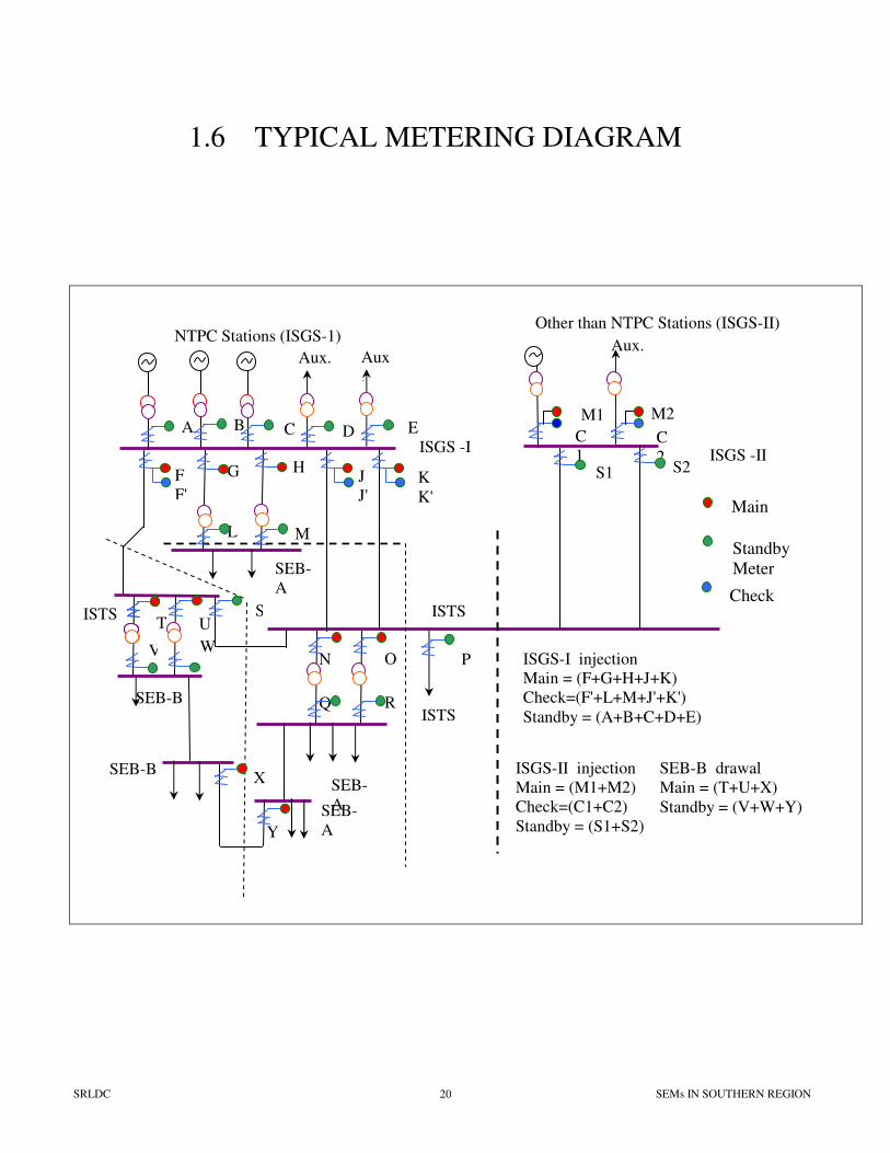
ISTS
NTPC Stations (ISGS-1) Other than NTPC Stations (ISGS-II)
ISGS -I ISGS -II
Aux. Aux
.
ISTS
ISTS
SEB-
A SEB-
A
SEB-B
A B D E C
F
F'
G H J
J' K
K'
L M
SEB-
A
ST U
V W
X
Y
SEB-B
N O P
Q R
C
1 C
2
M1 M2
S1 S2
ISGS-I injection
Main = (F+G+H+J+K)
Check=(F'+L+M+J'+K')
Standby = (A+B+C+D+E)
ISGS-II injection
Main = (M1+M2)
Check=(C1+C2)
Standby = (S1+S2)
Aux.
Main
Standby
Meter
Check
SEB-B drawal
Main = (T+U+X)
Standby = (V+W+Y)
1.6 TYPICAL METERING DIAGRAM
SECTION – 2
SPECIAL ENERGY METERS IN
SOUTHERN REGION
SPECIAL ENERGY METERS
IN SOUTHERN REGION
2.1 Summary of SEMs in Southern Region
2.2 Constituent-wise summary of SEMs
2.3 List of Special Energy Meters installed in
Southern Region
2.4 Master Frequency SEMs
2000
series
4000
series
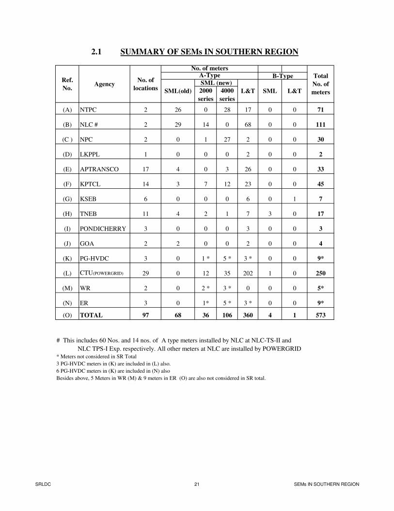
(A) NTPC 2 26 0 28 17 0 0 71
(B) NLC # 2 29 14 0 68 0 0 111
(C ) NPC 2 0 1 27 2 0 0 30
(D) LKPPL 1 0 0 0 2 0 0 2
(E) APTRANSCO 17 4 0 3 26 0 0 33
(F) KPTCL 14 3 7 12 23 0 0 45
(G) KSEB 6 0 0 0 6 0 1 7
(H) TNEB 11 4 2 1 7 3 0 17
(I) PONDICHERRY 3 0 0 0 3 0 0 3
(J) GOA 2 2 0 0 2 0 0 4
(K) PG-HVDC 3 0 1 * 5 * 3 * 0 0 9*
(L) CTU(POWERGRID) 29 0 12 35 202 1 0 250
(M) WR 2 0 2 * 3 * 0 0 0 5*
(N) ER 3 0 1* 5 * 3 * 0 0 9*
(O) TOTAL 97 68 36 106 360 4 1 573
# This includes 60 Nos. and 14 nos. of A type meters installed by NLC at NLC-TS-II and
NLC TPS-I Exp. respectively. All other meters at NLC are installed by POWERGRID
* Meters not considered in SR Total
3 PG-HVDC meters in (K) are included in (L) also.
6 PG-HVDC meters in (K) are included in (N) also
Besides above, 5 Meters in WR (M) & 9 meters in ER (O) are also not considered in SR total.
2.1 SUMMARY OF SEMs IN SOUTHERN REGION
A-Type
SML (new)
SML(old)
Total
No. of
metersL&T
Ref.
No.Agency
No. of meters
No. of
locations
B-Type
SML L&T
SRLDC 21 SEMs IN SOUTHERN REGION
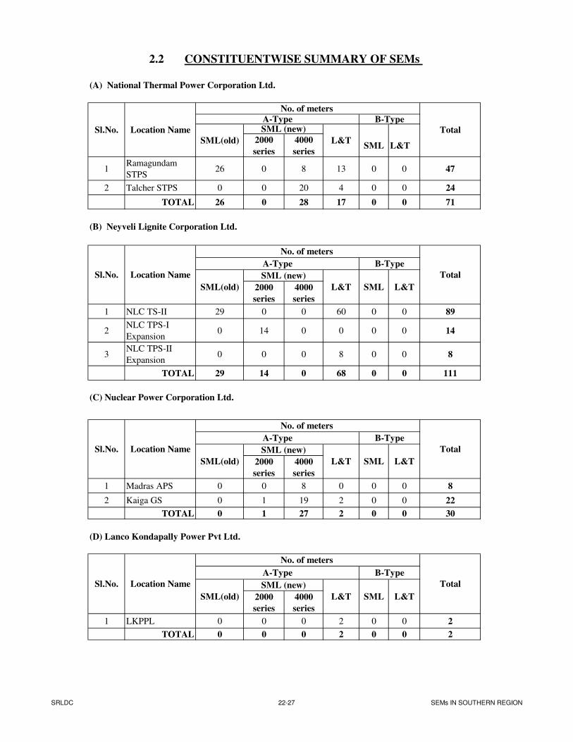
(A) National Thermal Power Corporation Ltd.
2000
series
4000
seriesSML L&T
1Ramagundam
STPS26 0 8 13 0 0 47
2 Talcher STPS 0 0 20 4 0 0 24
TOTAL 26 0 28 17 0 0 71
(B) Neyveli Lignite Corporation Ltd.
2000
series
4000
series
1 NLC TS-II 29 0 0 60 0 0 89
2NLC TPS-I
Expansion0 14 0 0 0 0 14
3NLC TPS-II
Expansion0 0 0 8 0 0 8
TOTAL 29 14 0 68 0 0 111
(C) Nuclear Power Corporation Ltd.
2000
series
4000
series
1 Madras APS 0 0 8 0 0 0 8
2 Kaiga GS 0 1 19 2 0 0 22
TOTAL 0 1 27 2 0 0 30
(D) Lanco Kondapally Power Pvt Ltd.
2000
series
4000
series
1 LKPPL 0 0 0 2 0 0 2
TOTAL 0 0 0 2 0 0 2
Sl.No. Location Name
No. of meters
Total
A-Type B-Type
SML(old)
SML (new)
L&T SML L&T
Total
Total
A-Type
L&T SML
B-Type
L&T
2.2 CONSTITUENTWISE SUMMARY OF SEMs
A-TypeSML (new)Sl.No. Location Name
SML(old) L&T
No. of meters
Total
B-Type
Sl.No. Location Name
No. of meters
Sl.No. Location Name
No. of meters
A-Type
SML(old)
SML (new)
L&TSML(old)
SML (new)
B-Type
SML L&T
SRLDC 22-27 SEMs IN SOUTHERN REGION
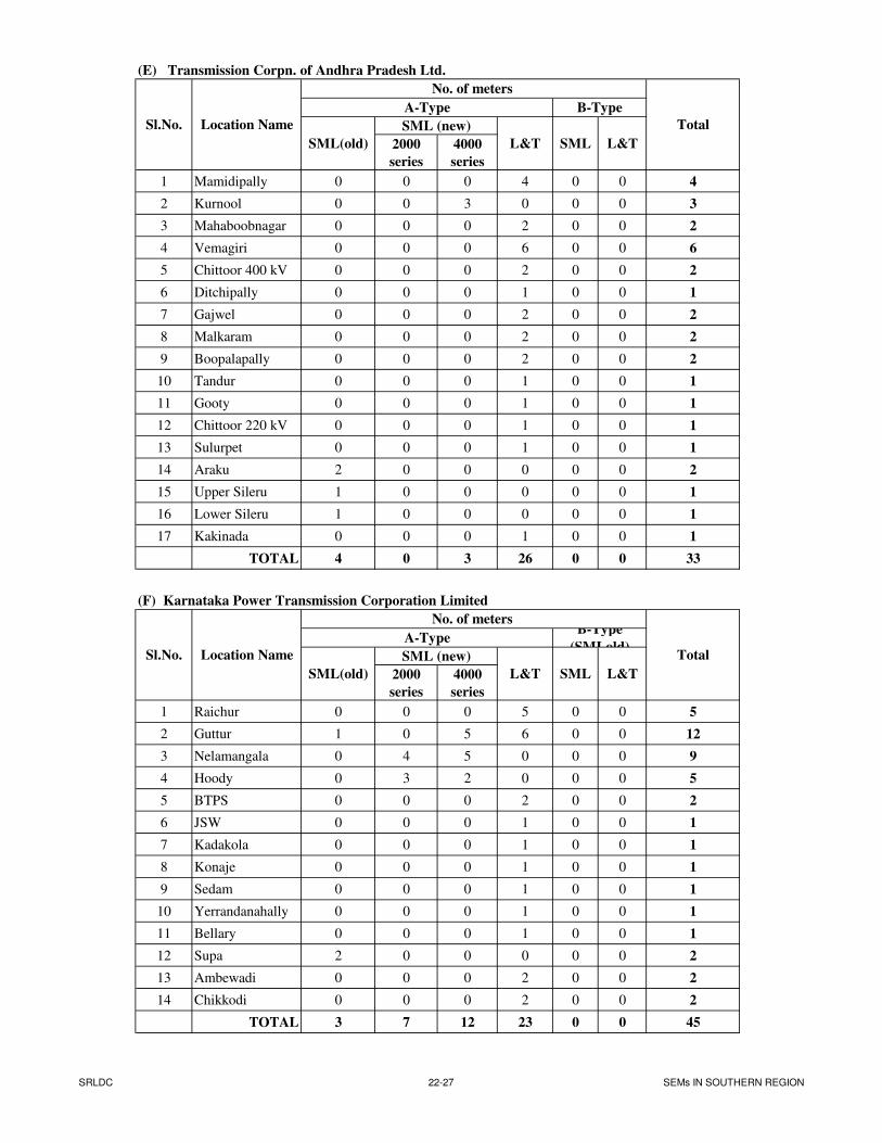
(E) Transmission Corpn. of Andhra Pradesh Ltd.
2000
series
4000
series
1 Mamidipally 0 0 0 4 0 0 4
2 Kurnool 0 0 3 0 0 0 3
3 Mahaboobnagar 0 0 0 2 0 0 2
4 Vemagiri 0 0 0 6 0 0 6
5 Chittoor 400 kV 0 0 0 2 0 0 2
6 Ditchipally 0 0 0 1 0 0 1
7 Gajwel 0 0 0 2 0 0 2
8 Malkaram 0 0 0 2 0 0 2
9 Boopalapally 0 0 0 2 0 0 2
10 Tandur 0 0 0 1 0 0 1
11 Gooty 0 0 0 1 0 0 1
12 Chittoor 220 kV 0 0 0 1 0 0 1
13 Sulurpet 0 0 0 1 0 0 1
14 Araku 2 0 0 0 0 0 2
15 Upper Sileru 1 0 0 0 0 0 1
16 Lower Sileru 1 0 0 0 0 0 1
17 Kakinada 0 0 0 1 0 0 1
TOTAL 4 0 3 26 0 0 33
(F) Karnataka Power Transmission Corporation Limited
2000
series
4000
series
1 Raichur 0 0 0 5 0 0 5
2 Guttur 1 0 5 6 0 0 12
3 Nelamangala 0 4 5 0 0 0 9
4 Hoody 0 3 2 0 0 0 5
5 BTPS 0 0 0 2 0 0 2
6 JSW 0 0 0 1 0 0 1
7 Kadakola 0 0 0 1 0 0 1
8 Konaje 0 0 0 1 0 0 1
9 Sedam 0 0 0 1 0 0 1
10 Yerrandanahally 0 0 0 1 0 0 1
11 Bellary 0 0 0 1 0 0 1
12 Supa 2 0 0 0 0 0 2
13 Ambewadi 0 0 0 2 0 0 2
14 Chikkodi 0 0 0 2 0 0 2
TOTAL 3 7 12 23 0 0 45
Sl.No.
SML (new)Sl.No. Location Name
No. of meters
Total
A-Type
SML(old) L&T L&T
Total
No. of meters
L&T
Location Name
SML
A-Type
SML(old)
SML (new)
L&T
B-Type
B-Type
(SMLold)
SML
SRLDC 22-27 SEMs IN SOUTHERN REGION
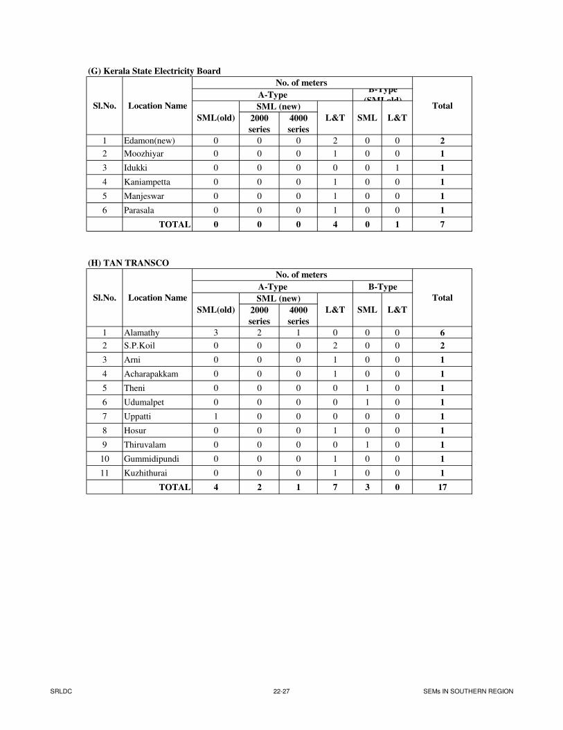
(G) Kerala State Electricity Board
2000
series
4000
series
1 Edamon(new) 0 0 0 2 0 0 2
2 Moozhiyar 0 0 0 1 0 0 1
3 Idukki 0 0 0 0 0 1 1
4 Kaniampetta 0 0 0 1 0 0 1
5 Manjeswar 0 0 0 1 0 0 1
6 Parasala 0 0 0 1 0 0 1
TOTAL 0 0 0 4 0 1 7
(H) TAN TRANSCO
2000
series
4000
series
1 Alamathy 3 2 1 0 0 0 6
2 S.P.Koil 0 0 0 2 0 0 2
3 Arni 0 0 0 1 0 0 1
4 Acharapakkam 0 0 0 1 0 0 1
5 Theni 0 0 0 0 1 0 1
6 Udumalpet 0 0 0 0 1 0 1
7 Uppatti 1 0 0 0 0 0 1
8 Hosur 0 0 0 1 0 0 1
9 Thiruvalam 0 0 0 0 1 0 1
10 Gummidipundi 0 0 0 1 0 0 1
11 Kuzhithurai 0 0 0 1 0 0 1
TOTAL 4 2 1 7 3 0 17
Sl.No. Location Name
Sl.No. Location Name
No. of meters
Total
A-Type
SML(old)
SML (new)
L&T SML L&T
B-Type
Total
A-Type
SML(old)
SML (new)
L&T SML
B-Type
(SMLold)
No. of meters
L&T
SRLDC 22-27 SEMs IN SOUTHERN REGION
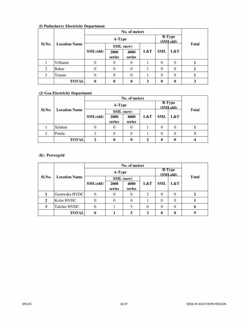
(I) Puducherry Electricity Department
2000
series
4000
series
1 Villianur 0 0 0 1 0 0 1
2 Bahur 0 0 0 1 0 0 1
3 Yanam 0 0 0 1 0 0 1
TOTAL 0 0 0 3 0 0 3
(J) Goa Electricity Department
2000
series
4000
series
1 Xeldem 0 0 0 1 0 0 1
2 Ponda 2 0 0 1 0 0 3
TOTAL 2 0 0 2 0 0 4
(K) Powergrid
2000
series
4000
series
1 Gazuwaka HVDC 0 0 0 2 0 0 2
2 Kolar HVDC 0 0 0 1 0 0 1
3 Talcher HVDC 0 1 5 0 0 0 6
TOTAL 0 1 5 3 0 0 9
Sl.No. Location Name
No. of meters
Total
A-Type
SML(old)
SML (new)
L&T
B-Type
(SMLold)
SML
Total
A-Type
SML(old)
SML (new)
L&T
B-Type
(SMLold)
SML L&T
Sl.No. Location Name
No. of meters
Sl.No. Location Name
No. of meters
SML L&T
Total
A-Type
SML(old)
SML (new)
L&T
B-Type
(SMLold)
L&T
SRLDC 22-27 SEMs IN SOUTHERN REGION
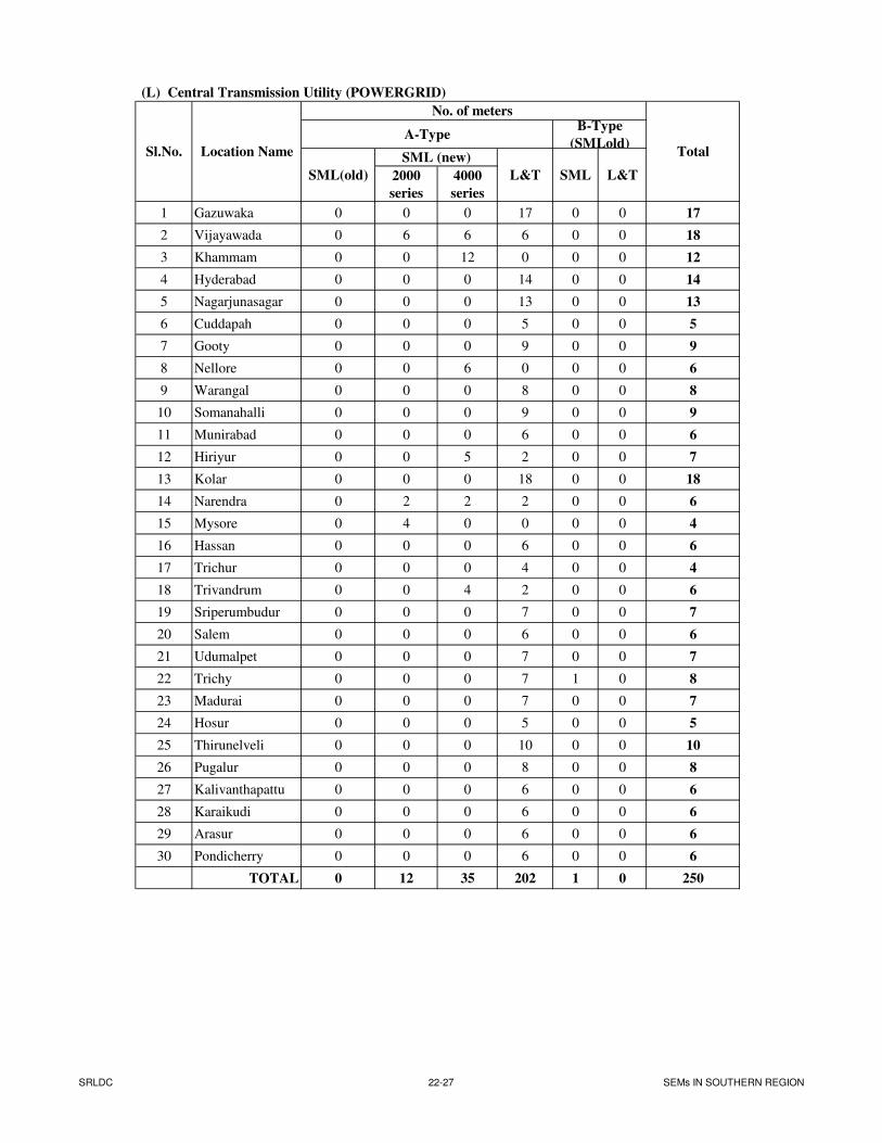
(L) Central Transmission Utility (POWERGRID)
2000
series
4000
series
1 Gazuwaka 0 0 0 17 0 0 17
2 Vijayawada 0 6 6 6 0 0 18
3 Khammam 0 0 12 0 0 0 12
4 Hyderabad 0 0 0 14 0 0 14
5 Nagarjunasagar 0 0 0 13 0 0 13
6 Cuddapah 0 0 0 5 0 0 5
7 Gooty 0 0 0 9 0 0 9
8 Nellore 0 0 6 0 0 0 6
9 Warangal 0 0 0 8 0 0 8
10 Somanahalli 0 0 0 9 0 0 9
11 Munirabad 0 0 0 6 0 0 6
12 Hiriyur 0 0 5 2 0 0 7
13 Kolar 0 0 0 18 0 0 18
14 Narendra 0 2 2 2 0 0 6
15 Mysore 0 4 0 0 0 0 4
16 Hassan 0 0 0 6 0 0 6
17 Trichur 0 0 0 4 0 0 4
18 Trivandrum 0 0 4 2 0 0 6
19 Sriperumbudur 0 0 0 7 0 0 7
20 Salem 0 0 0 6 0 0 6
21 Udumalpet 0 0 0 7 0 0 7
22 Trichy 0 0 0 7 1 0 8
23 Madurai 0 0 0 7 0 0 7
24 Hosur 0 0 0 5 0 0 5
25 Thirunelveli 0 0 0 10 0 0 10
26 Pugalur 0 0 0 8 0 0 8
27 Kalivanthapattu 0 0 0 6 0 0 6
28 Karaikudi 0 0 0 6 0 0 6
29 Arasur 0 0 0 6 0 0 6
30 Pondicherry 0 0 0 6 0 0 6
TOTAL 0 12 35 202 1 0 250
Sl.No. Location Name
No. of meters
Total
A-Type
SML(old)
SML (new)
L&T
B-Type
(SMLold)
SML L&T
SRLDC 22-27 SEMs IN SOUTHERN REGION
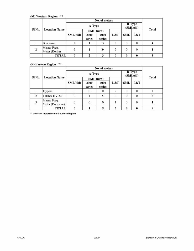
(M) Western Region **
2000
series
4000
series
1 Bhadravati 0 1 3 0 0 0 4
2Master Freq.
Meter (Korba)0 1 0 0 0 0 1
TOTAL 0 2 3 0 0 0 5
(N) Eastern Region **
2000
series
4000
series
1 Jeypore 0 0 0 2 0 0 2
2 Talcher HVDC 0 1 5 0 0 0 6
3Master Freq.
Meter (Durgapur)0 0 0 1 0 0 1
TOTAL 0 1 5 3 0 0 9
** Meters of importance to Southern Region
SML (new)
L&T
Sl.No.
Sl.No. Location Name
No. of meters B-Type
(SMLold)
Location Name
No. of meters B-Type
(SMLold)
SML L&T
SML L&T
A-Type
Total
SML(old)
Total
A-Type
SML(old)
SML (new)
L&T
SRLDC 22-27 SEMs IN SOUTHERN REGION
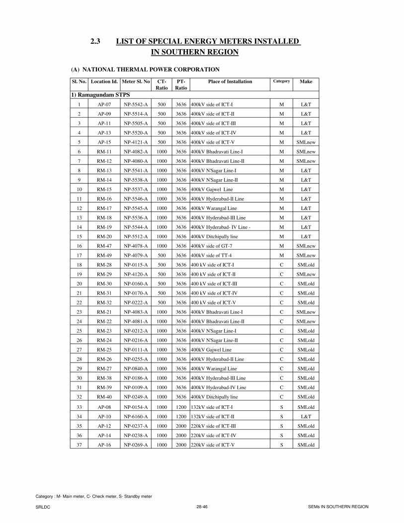
2.3 LIST OF SPECIAL ENERGY METERS INSTALLED
IN SOUTHERN REGION
(A) NATIONAL THERMAL POWER CORPORATION
Sl. No. Location Id. Meter Sl. No CT-
Ratio
PT-
Ratio
Place of Installation Category Make
1) Ramagundam STPS
1 AP-07 NP-5542-A 500 3636 400kV side of ICT-I M L&T
2 AP-09 NP-5514-A 500 3636 400kV side of ICT-II M L&T
3 AP-11 NP-5505-A 500 3636 400kV side of ICT-III M L&T
4 AP-13 NP-5520-A 500 3636 400kV side of ICT-IV M L&T
5 AP-15 NP-4121-A 500 3636 400kV side of ICT-V M SMLnew
6 RM-11 NP-4082-A 1000 3636 400kV Bhadravati Line-I M SMLnew
7 RM-12 NP-4080-A 1000 3636 400kV Bhadravati Line-II M SMLnew
8 RM-13 NP-5541-A 1000 3636 400kV N'Sagar Line-I M L&T
9 RM-14 NP-5538-A 1000 3636 400kV N'Sagar Line-II M L&T
10 RM-15 NP-5537-A 1000 3636 400kV Gajwel Line M L&T
11 RM-16 NP-5546-A 1000 3636 400kV Hyderabad-II Line M L&T
12 RM-17 NP-5545-A 1000 3636 400kV Warangal Line M L&T
13 RM-18 NP-5536-A 1000 3636 400kV Hyderabad-III Line M L&T
14 RM-19 NP-5544-A 1000 3636 400kV Hyderabad- IV Line - M L&T
15 RM-20 NP-5512-A 1000 3636 400kV Ditchipally line M L&T
16 RM-47 NP-4078-A 1000 3636 400kV side of GT-7 M SMLnew
17 RM-49 NP-4079-A 500 3636 400kV side of TT-4 M SMLnew
18 RM-28 NP-0115-A 500 3636 400 kV side of ICT-I C SMLold
19 RM-29 NP-4120-A 500 3636 400 kV side of ICT-II C SMLnew
20 RM-30 NP-0160-A 500 3636 400 kV side of ICT-III C SMLold
21 RM-31 NP-0170-A 500 3636 400 kV side of ICT-IV C SMLold
22 RM-32 NP-0222-A 500 3636 400 kV side of ICT-V C SMLold
23 RM-21 NP-4083-A 1000 3636 400kV Bhadravati Line-I C SMLnew
24 RM-22 NP-4081-A 1000 3636 400kV Bhadravati Line-II C SMLnew
25 RM-23 NP-0212-A 1000 3636 400kV N'Sagar Line-I C SMLold
26 RM-24 NP-0216-A 1000 3636 400kV N'Sagar Line-II C SMLold
27 RM-25 NP-0111-A 1000 3636 400kV Gajwel Line C SMLold
28 RM-26 NP-0255-A 1000 3636 400kV Hyderabad-II Line C SMLold
29 RM-27 NP-0840-A 1000 3636 400kV Warangal Line C SMLold
30 RM-38 NP-0186-A 1000 3636 400kV Hyderabad-III Line C SMLold
31 RM-39 NP-0109-A 1000 3636 400kV Hyderabad-IV Line C SMLold
32 RM-40 NP-0249-A 1000 3636 400kV Ditchipally line C SMLold
33 AP-08 NP-0154-A 1000 1200 132kV side of ICT-I S SMLold
34 AP-10 NP-6160-A 1000 1200 132kV side of ICT-II S L&T
35 AP-12 NP-0237-A 1000 2000 220kV side of ICT-III S SMLold
36 AP-14 NP-0238-A 1000 2000 220kV side of ICT-IV S SMLold
37 AP-16 NP-0269-A 1000 2000 220kV side of ICT-V S SMLold
Category : M- Main meter, C- Check meter, S- Standby meter
SRLDC 28-46 SEMs IN SOUTHERN REGION
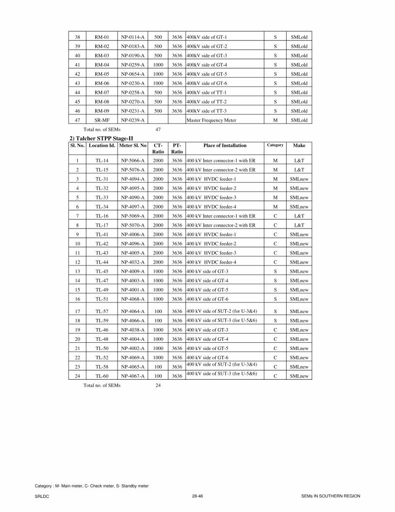
38 RM-01 NP-0114-A 500 3636 400kV side of GT-1 S SMLold
39 RM-02 NP-0183-A 500 3636 400kV side of GT-2 S SMLold
40 RM-03 NP-0190-A 500 3636 400kV side of GT-3 S SMLold
41 RM-04 NP-0259-A 1000 3636 400kV side of GT-4 S SMLold
42 RM-05 NP-0654-A 1000 3636 400kV side of GT-5 S SMLold
43 RM-06 NP-0230-A 1000 3636 400kV side of GT-6 S SMLold
44 RM-07 NP-0258-A 500 3636 400kV side of TT-1 S SMLold
45 RM-08 NP-0270-A 500 3636 400kV side of TT-2 S SMLold
46 RM-09 NP-0231-A 500 3636 400kV side of TT-3 S SMLold
47 SR-MF NP-0239-A Master Frequency Meter M SMLold
Total no. of SEMs 47
2) Talcher STPP Stage-II
Sl. No. Location Id. Meter Sl. No CT-
Ratio
PT-
Ratio
Place of Installation Category Make
1 TL-14 NP-5066-A 2000 3636 400 kV Inter connector-1 with ER M L&T
2 TL-15 NP-5076-A 2000 3636 400 kV Inter connector-2 with ER M L&T
3 TL-31 NP-4094-A 2000 3636 400 kV HVDC feeder-1 M SMLnew
4 TL-32 NP-4095-A 2000 3636 400 kV HVDC feeder-2 M SMLnew
5 TL-33 NP-4090-A 2000 3636 400 kV HVDC feeder-3 M SMLnew
6 TL-34 NP-4097-A 2000 3636 400 kV HVDC feeder-4 M SMLnew
7 TL-16 NP-5069-A 2000 3636 400 kV Inter connector-1 with ER C L&T
8 TL-17 NP-5070-A 2000 3636 400 kV Inter connector-2 with ER C L&T
9 TL-41 NP-4006-A 2000 3636 400 kV HVDC feeder-1 C SMLnew
10 TL-42 NP-4096-A 2000 3636 400 kV HVDC feeder-2 C SMLnew
11 TL-43 NP-4005-A 2000 3636 400 kV HVDC feeder-3 C SMLnew
12 TL-44 NP-4032-A 2000 3636 400 kV HVDC feeder-4 C SMLnew
13 TL-45 NP-4009-A 1000 3636 400 kV side of GT-3 S SMLnew
14 TL-47 NP-4003-A 1000 3636 400 kV side of GT-4 S SMLnew
15 TL-49 NP-4001-A 1000 3636 400 kV side of GT-5 S SMLnew
16 TL-51 NP-4068-A 1000 3636 400 kV side of GT-6 S SMLnew
17 TL-57 NP-4064-A 100 3636 400 kV side of SUT-2 (for U-3&4) S SMLnew
18 TL-59 NP-4066-A 100 3636 400 kV side of SUT-3 (for U-5&6) S SMLnew
19 TL-46 NP-4038-A 1000 3636 400 kV side of GT-3 C SMLnew
20 TL-48 NP-4004-A 1000 3636 400 kV side of GT-4 C SMLnew
21 TL-50 NP-4002-A 1000 3636 400 kV side of GT-5 C SMLnew
22 TL-52 NP-4069-A 1000 3636 400 kV side of GT-6 C SMLnew
23 TL-58 NP-4065-A 100 3636400 kV side of SUT-2 (for U-3&4)
C SMLnew
24 TL-60 NP-4067-A 100 3636400 kV side of SUT-3 (for U-5&6)
C SMLnew
Total no. of SEMs 24
Category : M- Main meter, C- Check meter, S- Standby meter
SRLDC 28-46 SEMs IN SOUTHERN REGION
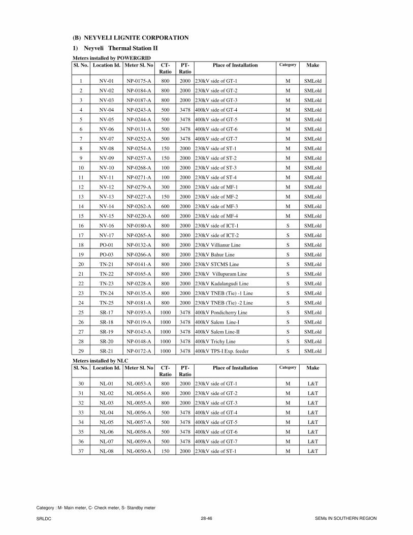
(B) NEYVELI LIGNITE CORPORATION
1) Neyveli Thermal Station II
Meters installed by POWERGRID
Sl. No. Location Id. Meter Sl. No CT-
Ratio
PT-
Ratio
Place of Installation Category Make
1 NV-01 NP-0175-A 800 2000 230kV side of GT-1 M SMLold
2 NV-02 NP-0184-A 800 2000 230kV side of GT-2 M SMLold
3 NV-03 NP-0187-A 800 2000 230kV side of GT-3 M SMLold
4 NV-04 NP-0243-A 500 3478 400kV side of GT-4 M SMLold
5 NV-05 NP-0244-A 500 3478 400kV side of GT-5 M SMLold
6 NV-06 NP-0131-A 500 3478 400kV side of GT-6 M SMLold
7 NV-07 NP-0252-A 500 3478 400kV side of GT-7 M SMLold
8 NV-08 NP-0254-A 150 2000 230kV side of ST-1 M SMLold
9 NV-09 NP-0257-A 150 2000 230kV side of ST-2 M SMLold
10 NV-10 NP-0268-A 100 2000 230kV side of ST-3 M SMLold
11 NV-11 NP-0271-A 100 2000 230kV side of ST-4 M SMLold
12 NV-12 NP-0279-A 300 2000 230kV side of MF-1 M SMLold
13 NV-13 NP-0227-A 150 2000 230kV side of MF-2 M SMLold
14 NV-14 NP-0262-A 600 2000 230kV side of MF-3 M SMLold
15 NV-15 NP-0220-A 600 2000 230kV side of MF-4 M SMLold
16 NV-16 NP-0180-A 800 2000 230kV side of ICT-1 S SMLold
17 NV-17 NP-0265-A 800 2000 230kV side of ICT-2 S SMLold
18 PO-01 NP-0132-A 800 2000 230kV Villianur Line S SMLold
19 PO-03 NP-0266-A 800 2000 230kV Bahur Line S SMLold
20 TN-21 NP-0141-A 800 2000 230kV STCMS Line S SMLold
21 TN-22 NP-0165-A 800 2000 230kV Villupuram Line S SMLold
22 TN-23 NP-0228-A 800 2000 230kV Kadalangudi Line S SMLold
23 TN-24 NP-0135-A 800 2000 230kV TNEB (Tie) -1 Line S SMLold
24 TN-25 NP-0181-A 800 2000 230kV TNEB (Tie) -2 Line S SMLold
25 SR-17 NP-0193-A 1000 3478 400kV Pondicherry Line S SMLold
26 SR-18 NP-0119-A 1000 3478 400kV Salem Line-I S SMLold
27 SR-19 NP-0143-A 1000 3478 400kV Salem Line-II S SMLold
28 SR-20 NP-0148-A 1000 3478 400kV Trichy Line S SMLold
29 SR-21 NP-0172-A 1000 3478 400kV TPS-I Exp. feeder S SMLold
Meters installed by NLC
Sl. No. Location Id. Meter Sl. No CT-
Ratio
PT-
Ratio
Place of Installation Category Make
30 NL-01 NL-0053-A 800 2000 230kV side of GT-1 M L&T
31 NL-02 NL-0054-A 800 2000 230kV side of GT-2 M L&T
32 NL-03 NL-0055-A 800 2000 230kV side of GT-3 M L&T
33 NL-04 NL-0056-A 500 3478 400kV side of GT-4 M L&T
34 NL-05 NL-0057-A 500 3478 400kV side of GT-5 M L&T
35 NL-06 NL-0058-A 500 3478 400kV side of GT-6 M L&T
36 NL-07 NL-0059-A 500 3478 400kV side of GT-7 M L&T
37 NL-08 NL-0050-A 150 2000 230kV side of ST-1 M L&T
Category : M- Main meter, C- Check meter, S- Standby meter
SRLDC 28-46 SEMs IN SOUTHERN REGION
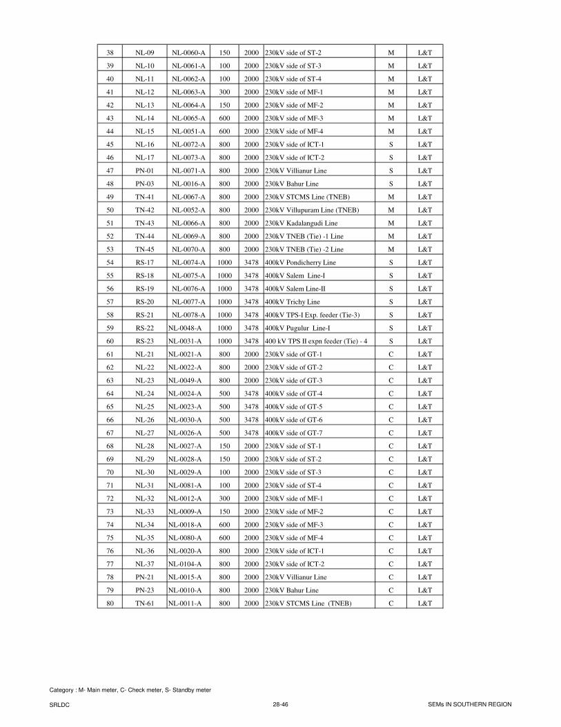
38 NL-09 NL-0060-A 150 2000 230kV side of ST-2 M L&T
39 NL-10 NL-0061-A 100 2000 230kV side of ST-3 M L&T
40 NL-11 NL-0062-A 100 2000 230kV side of ST-4 M L&T
41 NL-12 NL-0063-A 300 2000 230kV side of MF-1 M L&T
42 NL-13 NL-0064-A 150 2000 230kV side of MF-2 M L&T
43 NL-14 NL-0065-A 600 2000 230kV side of MF-3 M L&T
44 NL-15 NL-0051-A 600 2000 230kV side of MF-4 M L&T
45 NL-16 NL-0072-A 800 2000 230kV side of ICT-1 S L&T
46 NL-17 NL-0073-A 800 2000 230kV side of ICT-2 S L&T
47 PN-01 NL-0071-A 800 2000 230kV Villianur Line S L&T
48 PN-03 NL-0016-A 800 2000 230kV Bahur Line S L&T
49 TN-41 NL-0067-A 800 2000 230kV STCMS Line (TNEB) M L&T
50 TN-42 NL-0052-A 800 2000 230kV Villupuram Line (TNEB) M L&T
51 TN-43 NL-0066-A 800 2000 230kV Kadalangudi Line M L&T
52 TN-44 NL-0069-A 800 2000 230kV TNEB (Tie) -1 Line M L&T
53 TN-45 NL-0070-A 800 2000 230kV TNEB (Tie) -2 Line M L&T
54 RS-17 NL-0074-A 1000 3478 400kV Pondicherry Line S L&T
55 RS-18 NL-0075-A 1000 3478 400kV Salem Line-I S L&T
56 RS-19 NL-0076-A 1000 3478 400kV Salem Line-II S L&T
57 RS-20 NL-0077-A 1000 3478 400kV Trichy Line S L&T
58 RS-21 NL-0078-A 1000 3478 400kV TPS-I Exp. feeder (Tie-3) S L&T
59 RS-22 NL-0048-A 1000 3478 400kV Pugulur Line-I S L&T
60 RS-23 NL-0031-A 1000 3478 400 kV TPS II expn feeder (Tie) - 4 S L&T
61 NL-21 NL-0021-A 800 2000 230kV side of GT-1 C L&T
62 NL-22 NL-0022-A 800 2000 230kV side of GT-2 C L&T
63 NL-23 NL-0049-A 800 2000 230kV side of GT-3 C L&T
64 NL-24 NL-0024-A 500 3478 400kV side of GT-4 C L&T
65 NL-25 NL-0023-A 500 3478 400kV side of GT-5 C L&T
66 NL-26 NL-0030-A 500 3478 400kV side of GT-6 C L&T
67 NL-27 NL-0026-A 500 3478 400kV side of GT-7 C L&T
68 NL-28 NL-0027-A 150 2000 230kV side of ST-1 C L&T
69 NL-29 NL-0028-A 150 2000 230kV side of ST-2 C L&T
70 NL-30 NL-0029-A 100 2000 230kV side of ST-3 C L&T
71 NL-31 NL-0081-A 100 2000 230kV side of ST-4 C L&T
72 NL-32 NL-0012-A 300 2000 230kV side of MF-1 C L&T
73 NL-33 NL-0009-A 150 2000 230kV side of MF-2 C L&T
74 NL-34 NL-0018-A 600 2000 230kV side of MF-3 C L&T
75 NL-35 NL-0080-A 600 2000 230kV side of MF-4 C L&T
76 NL-36 NL-0020-A 800 2000 230kV side of ICT-1 C L&T
77 NL-37 NL-0104-A 800 2000 230kV side of ICT-2 C L&T
78 PN-21 NL-0015-A 800 2000 230kV Villianur Line C L&T
79 PN-23 NL-0010-A 800 2000 230kV Bahur Line C L&T
80 TN-61 NL-0011-A 800 2000 230kV STCMS Line (TNEB) C L&T
Category : M- Main meter, C- Check meter, S- Standby meter
SRLDC 28-46 SEMs IN SOUTHERN REGION
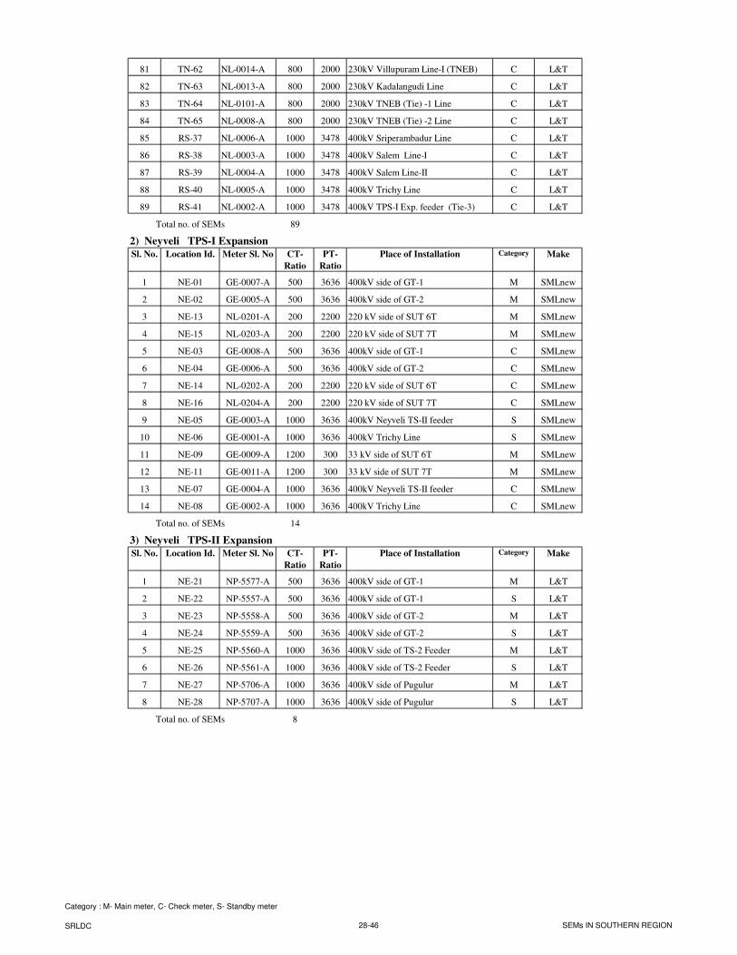
81 TN-62 NL-0014-A 800 2000 230kV Villupuram Line-I (TNEB) C L&T
82 TN-63 NL-0013-A 800 2000 230kV Kadalangudi Line C L&T
83 TN-64 NL-0101-A 800 2000 230kV TNEB (Tie) -1 Line C L&T
84 TN-65 NL-0008-A 800 2000 230kV TNEB (Tie) -2 Line C L&T
85 RS-37 NL-0006-A 1000 3478 400kV Sriperambadur Line C L&T
86 RS-38 NL-0003-A 1000 3478 400kV Salem Line-I C L&T
87 RS-39 NL-0004-A 1000 3478 400kV Salem Line-II C L&T
88 RS-40 NL-0005-A 1000 3478 400kV Trichy Line C L&T
89 RS-41 NL-0002-A 1000 3478 400kV TPS-I Exp. feeder (Tie-3) C L&T
Total no. of SEMs 89
2) Neyveli TPS-I Expansion
Sl. No. Location Id. Meter Sl. No CT-
Ratio
PT-
Ratio
Place of Installation Category Make
1 NE-01 GE-0007-A 500 3636 400kV side of GT-1 M SMLnew
2 NE-02 GE-0005-A 500 3636 400kV side of GT-2 M SMLnew
3 NE-13 NL-0201-A 200 2200 220 kV side of SUT 6T M SMLnew
4 NE-15 NL-0203-A 200 2200 220 kV side of SUT 7T M SMLnew
5 NE-03 GE-0008-A 500 3636 400kV side of GT-1 C SMLnew
6 NE-04 GE-0006-A 500 3636 400kV side of GT-2 C SMLnew
7 NE-14 NL-0202-A 200 2200 220 kV side of SUT 6T C SMLnew
8 NE-16 NL-0204-A 200 2200 220 kV side of SUT 7T C SMLnew
9 NE-05 GE-0003-A 1000 3636 400kV Neyveli TS-II feeder S SMLnew
10 NE-06 GE-0001-A 1000 3636 400kV Trichy Line S SMLnew
11 NE-09 GE-0009-A 1200 300 33 kV side of SUT 6T M SMLnew
12 NE-11 GE-0011-A 1200 300 33 kV side of SUT 7T M SMLnew
13 NE-07 GE-0004-A 1000 3636 400kV Neyveli TS-II feeder C SMLnew
14 NE-08 GE-0002-A 1000 3636 400kV Trichy Line C SMLnew
Total no. of SEMs 14
3) Neyveli TPS-II Expansion
Sl. No. Location Id. Meter Sl. No CT-
Ratio
PT-
Ratio
Place of Installation Category Make
1 NE-21 NP-5577-A 500 3636 400kV side of GT-1 M L&T
2 NE-22 NP-5557-A 500 3636 400kV side of GT-1 S L&T
3 NE-23 NP-5558-A 500 3636 400kV side of GT-2 M L&T
4 NE-24 NP-5559-A 500 3636 400kV side of GT-2 S L&T
5 NE-25 NP-5560-A 1000 3636 400kV side of TS-2 Feeder M L&T
6 NE-26 NP-5561-A 1000 3636 400kV side of TS-2 Feeder S L&T
7 NE-27 NP-5706-A 1000 3636 400kV side of Pugulur M L&T
8 NE-28 NP-5707-A 1000 3636 400kV side of Pugulur S L&T
Total no. of SEMs 8
Category : M- Main meter, C- Check meter, S- Standby meter
SRLDC 28-46 SEMs IN SOUTHERN REGION
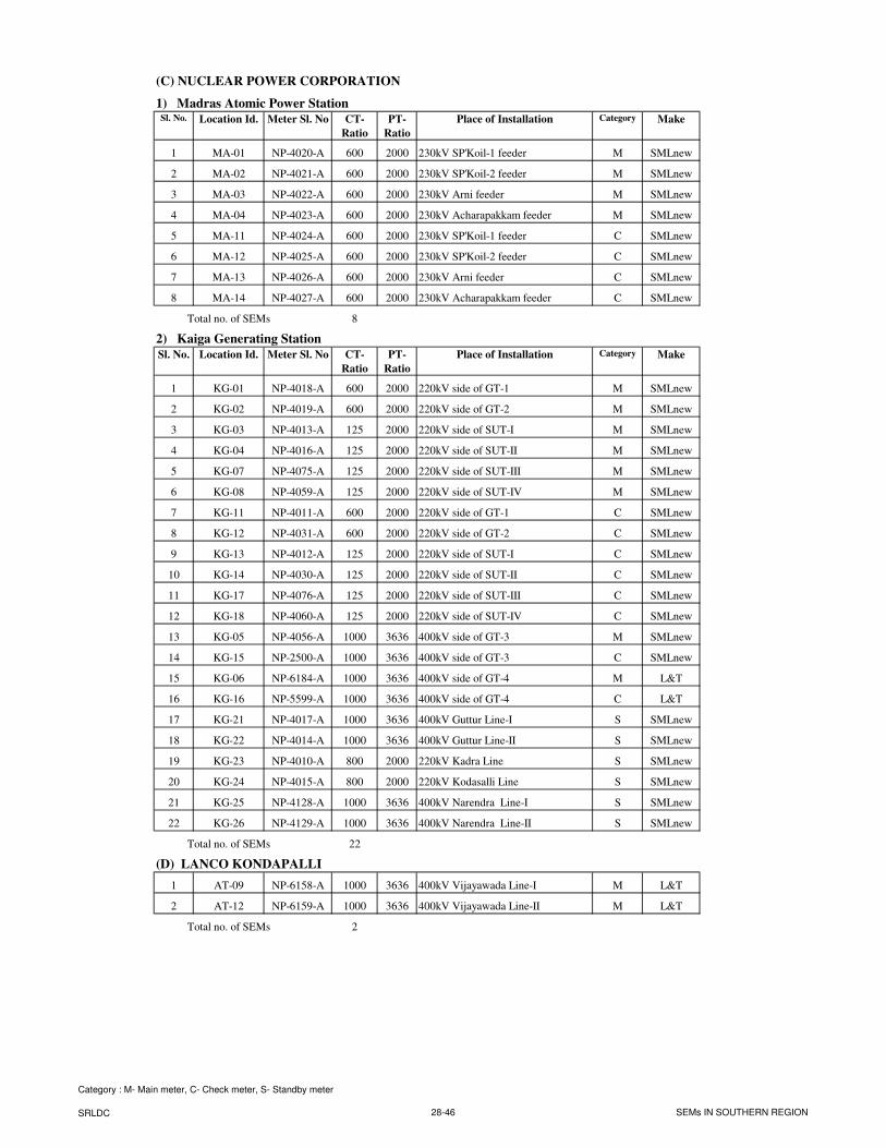
(C) NUCLEAR POWER CORPORATION
1) Madras Atomic Power StationSl. No. Location Id. Meter Sl. No CT-
Ratio
PT-
Ratio
Place of Installation Category Make
1 MA-01 NP-4020-A 600 2000 230kV SP'Koil-1 feeder M SMLnew
2 MA-02 NP-4021-A 600 2000 230kV SP'Koil-2 feeder M SMLnew
3 MA-03 NP-4022-A 600 2000 230kV Arni feeder M SMLnew
4 MA-04 NP-4023-A 600 2000 230kV Acharapakkam feeder M SMLnew
5 MA-11 NP-4024-A 600 2000 230kV SP'Koil-1 feeder C SMLnew
6 MA-12 NP-4025-A 600 2000 230kV SP'Koil-2 feeder C SMLnew
7 MA-13 NP-4026-A 600 2000 230kV Arni feeder C SMLnew
8 MA-14 NP-4027-A 600 2000 230kV Acharapakkam feeder C SMLnew
Total no. of SEMs 8
2) Kaiga Generating Station
Sl. No. Location Id. Meter Sl. No CT-
Ratio
PT-
Ratio
Place of Installation Category Make
1 KG-01 NP-4018-A 600 2000 220kV side of GT-1 M SMLnew
2 KG-02 NP-4019-A 600 2000 220kV side of GT-2 M SMLnew
3 KG-03 NP-4013-A 125 2000 220kV side of SUT-I M SMLnew
4 KG-04 NP-4016-A 125 2000 220kV side of SUT-II M SMLnew
5 KG-07 NP-4075-A 125 2000 220kV side of SUT-III M SMLnew
6 KG-08 NP-4059-A 125 2000 220kV side of SUT-IV M SMLnew
7 KG-11 NP-4011-A 600 2000 220kV side of GT-1 C SMLnew
8 KG-12 NP-4031-A 600 2000 220kV side of GT-2 C SMLnew
9 KG-13 NP-4012-A 125 2000 220kV side of SUT-I C SMLnew
10 KG-14 NP-4030-A 125 2000 220kV side of SUT-II C SMLnew
11 KG-17 NP-4076-A 125 2000 220kV side of SUT-III C SMLnew
12 KG-18 NP-4060-A 125 2000 220kV side of SUT-IV C SMLnew
13 KG-05 NP-4056-A 1000 3636 400kV side of GT-3 M SMLnew
14 KG-15 NP-2500-A 1000 3636 400kV side of GT-3 C SMLnew
15 KG-06 NP-6184-A 1000 3636 400kV side of GT-4 M L&T
16 KG-16 NP-5599-A 1000 3636 400kV side of GT-4 C L&T
17 KG-21 NP-4017-A 1000 3636 400kV Guttur Line-I S SMLnew
18 KG-22 NP-4014-A 1000 3636 400kV Guttur Line-II S SMLnew
19 KG-23 NP-4010-A 800 2000 220kV Kadra Line S SMLnew
20 KG-24 NP-4015-A 800 2000 220kV Kodasalli Line S SMLnew
21 KG-25 NP-4128-A 1000 3636 400kV Narendra Line-I S SMLnew
22 KG-26 NP-4129-A 1000 3636 400kV Narendra Line-II S SMLnew
Total no. of SEMs 22
(D) LANCO KONDAPALLI
1 AT-09 NP-6158-A 1000 3636 400kV Vijayawada Line-I M L&T
2 AT-12 NP-6159-A 1000 3636 400kV Vijayawada Line-II M L&T
Total no. of SEMs 2
Category : M- Main meter, C- Check meter, S- Standby meter
SRLDC 28-46 SEMs IN SOUTHERN REGION
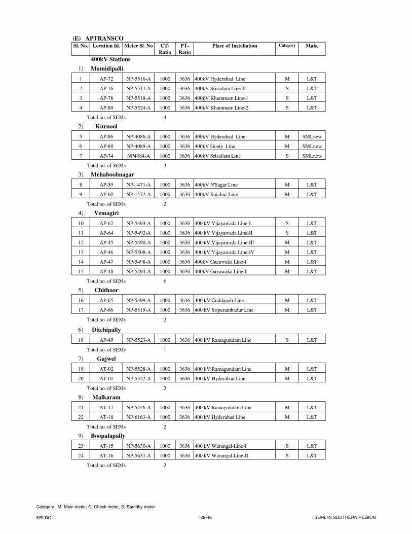
(E) APTRANSCO
Sl. No. Location Id. Meter Sl. No CT-
Ratio
PT-
Ratio
Place of Installation Category Make
400kV Stations
1) Mamidipalli
1 AP-72 NP-5516-A 1000 3636 400kV Hyderabad Line M L&T
2 AP-76 NP-5517-A 1000 3636 400kV Srisailam Line-II S L&T
3 AP-78 NP-5518-A 1000 3636 400kV Khammam Line-1 S L&T
4 AP-80 NP-5524-A 1000 3636 400kV Khammam Line-2 S L&T
Total no. of SEMs 4
2) Kurnool
5 AP-86 NP-4086-A 1000 3636 400kV Hyderabad Line M SMLnew
6 AP-88 NP-4089-A 1000 3636 400kV Gooty Line M SMLnew
7 AP-74 NP4084-A 1000 3636 400kV Srisailam Line S SMLnew
Total no. of SEMs 3
3) Mehaboobnagar
8 AP-59 NP-1471-A 1000 3636 400kV N'Sagar Line M L&T
9 AP-60 NP-1472-A 1000 3636 400kV Raichur Line M L&T
Total no. of SEMs 2
4) Vemagiri
10 AP-62 NP-5493-A 1000 3636 400 kV Vijayawada Line-I S L&T
11 AP-64 NP-5492-A 1000 3636 400 kV Vijayawada Line-II S L&T
12 AP-45 NP-5490-A 1000 3636 400 kV Vijayawada Line-III M L&T
13 AP-46 NP-5508-A 1000 3636 400 kV Vijayawada Line-IV M L&T
14 AP-47 NP-5498-A 1000 3636 400kV Gazuwaka Line-I M L&T
15 AP-48 NP-5494-A 1000 3636 400kV Gazuwaka Line-I M L&T
Total no. of SEMs 6
5) Chithoor
16 AP-65 NP-5499-A 1000 3636 400 kV Cuddapah Line M L&T
17 AP-66 NP-5515-A 1000 3636 400 kV Sriperambadur Line M L&T
Total no. of SEMs 2
6) Ditchipally
18 AP-49 NP-5523-A 1000 3636 400 kV Ramagundam Line S L&T
Total no. of SEMs 1
7) Gajwel
19 AT-02 NP-5528-A 1000 3636 400 kV Ramagundam Line M L&T
20 AT-01 NP-5522-A 1000 3636 400 kV Hyderabad Line M L&T
Total no. of SEMs 2
8) Malkaram
21 AT-17 NP-5526-A 1000 3636 400 kV Ramagundam Line M L&T
22 AT-18 NP-6163-A 1000 3636 400 kV Hyderabad Line M L&T
Total no. of SEMs 2
9) Boopalapally
23 AT-15 NP-5630-A 1000 3636 400 kV Warangal-Line-I S L&T
24 AT-16 NP-5631-A 1000 3636 400 kV Warangal-Line-II S L&T
Total no. of SEMs 2
Category : M- Main meter, C- Check meter, S- Standby meter
SRLDC 28-46 SEMs IN SOUTHERN REGION
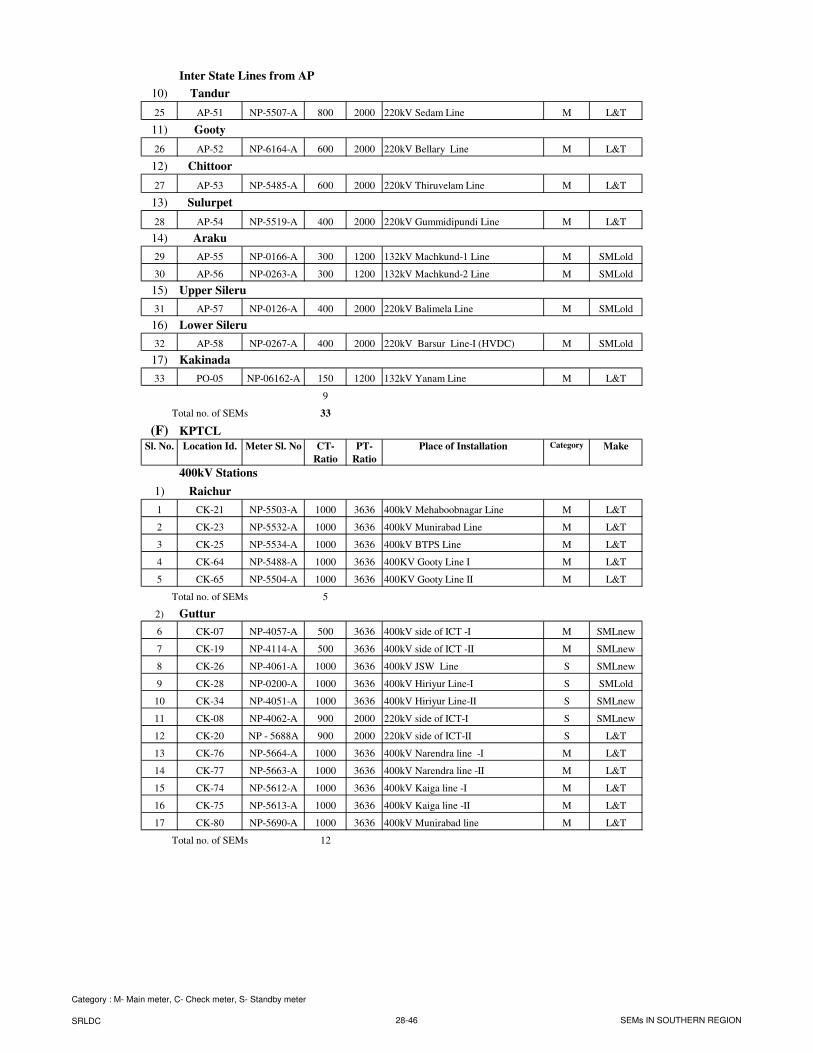
Inter State Lines from AP
10) Tandur
25 AP-51 NP-5507-A 800 2000 220kV Sedam Line M L&T
11) Gooty
26 AP-52 NP-6164-A 600 2000 220kV Bellary Line M L&T
12) Chittoor
27 AP-53 NP-5485-A 600 2000 220kV Thiruvelam Line M L&T
13) Sulurpet
28 AP-54 NP-5519-A 400 2000 220kV Gummidipundi Line M L&T
14) Araku
29 AP-55 NP-0166-A 300 1200 132kV Machkund-1 Line M SMLold
30 AP-56 NP-0263-A 300 1200 132kV Machkund-2 Line M SMLold
15) Upper Sileru
31 AP-57 NP-0126-A 400 2000 220kV Balimela Line M SMLold
16) Lower Sileru
32 AP-58 NP-0267-A 400 2000 220kV Barsur Line-I (HVDC) M SMLold
17) Kakinada
33 PO-05 NP-06162-A 150 1200 132kV Yanam Line M L&T
9
Total no. of SEMs 33
(F) KPTCL
Sl. No. Location Id. Meter Sl. No CT-
Ratio
PT-
Ratio
Place of Installation Category Make
400kV Stations
1) Raichur
1 CK-21 NP-5503-A 1000 3636 400kV Mehaboobnagar Line M L&T
2 CK-23 NP-5532-A 1000 3636 400kV Munirabad Line M L&T
3 CK-25 NP-5534-A 1000 3636 400kV BTPS Line M L&T
4 CK-64 NP-5488-A 1000 3636 400KV Gooty Line I M L&T
5 CK-65 NP-5504-A 1000 3636 400KV Gooty Line II M L&T
Total no. of SEMs 5
2) Guttur
6 CK-07 NP-4057-A 500 3636 400kV side of ICT -I M SMLnew
7 CK-19 NP-4114-A 500 3636 400kV side of ICT -II M SMLnew
8 CK-26 NP-4061-A 1000 3636 400kV JSW Line S SMLnew
9 CK-28 NP-0200-A 1000 3636 400kV Hiriyur Line-I S SMLold
10 CK-34 NP-4051-A 1000 3636 400kV Hiriyur Line-II S SMLnew
11 CK-08 NP-4062-A 900 2000 220kV side of ICT-I S SMLnew
12 CK-20 NP - 5688A 900 2000 220kV side of ICT-II S L&T
13 CK-76 NP-5664-A 1000 3636 400kV Narendra line -I M L&T
14 CK-77 NP-5663-A 1000 3636 400kV Narendra line -II M L&T
15 CK-74 NP-5612-A 1000 3636 400kV Kaiga line -I M L&T
16 CK-75 NP-5613-A 1000 3636 400kV Kaiga line -II M L&T
17 CK-80 NP-5690-A 1000 3636 400kV Munirabad line M L&T
Total no. of SEMs 12
Category : M- Main meter, C- Check meter, S- Standby meter
SRLDC 28-46 SEMs IN SOUTHERN REGION
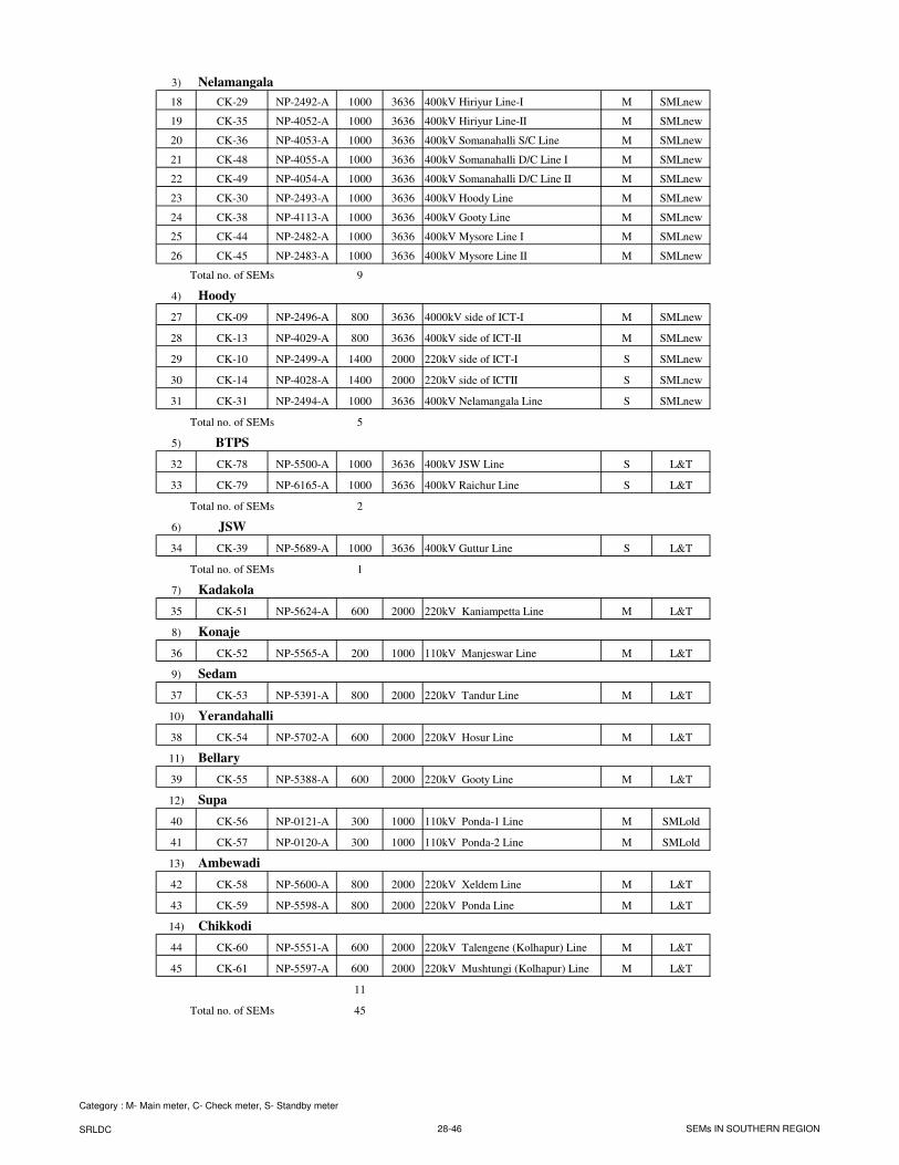
3) Nelamangala
18 CK-29 NP-2492-A 1000 3636 400kV Hiriyur Line-I M SMLnew
19 CK-35 NP-4052-A 1000 3636 400kV Hiriyur Line-II M SMLnew
20 CK-36 NP-4053-A 1000 3636 400kV Somanahalli S/C Line M SMLnew
21 CK-48 NP-4055-A 1000 3636 400kV Somanahalli D/C Line I M SMLnew
22 CK-49 NP-4054-A 1000 3636 400kV Somanahalli D/C Line II M SMLnew
23 CK-30 NP-2493-A 1000 3636 400kV Hoody Line M SMLnew
24 CK-38 NP-4113-A 1000 3636 400kV Gooty Line M SMLnew
25 CK-44 NP-2482-A 1000 3636 400kV Mysore Line I M SMLnew
26 CK-45 NP-2483-A 1000 3636 400kV Mysore Line II M SMLnew
Total no. of SEMs 9
4) Hoody
27 CK-09 NP-2496-A 800 3636 4000kV side of ICT-I M SMLnew
28 CK-13 NP-4029-A 800 3636 400kV side of ICT-II M SMLnew
29 CK-10 NP-2499-A 1400 2000 220kV side of ICT-I S SMLnew
30 CK-14 NP-4028-A 1400 2000 220kV side of ICTII S SMLnew
31 CK-31 NP-2494-A 1000 3636 400kV Nelamangala Line S SMLnew
Total no. of SEMs 5
5) BTPS
32 CK-78 NP-5500-A 1000 3636 400kV JSW Line S L&T
33 CK-79 NP-6165-A 1000 3636 400kV Raichur Line S L&T
Total no. of SEMs 2
6) JSW
34 CK-39 NP-5689-A 1000 3636 400kV Guttur Line S L&T
Total no. of SEMs 1
7) Kadakola
35 CK-51 NP-5624-A 600 2000 220kV Kaniampetta Line M L&T
8) Konaje
36 CK-52 NP-5565-A 200 1000 110kV Manjeswar Line M L&T
9) Sedam
37 CK-53 NP-5391-A 800 2000 220kV Tandur Line M L&T
10) Yerandahalli
38 CK-54 NP-5702-A 600 2000 220kV Hosur Line M L&T
11) Bellary
39 CK-55 NP-5388-A 600 2000 220kV Gooty Line M L&T
12) Supa
40 CK-56 NP-0121-A 300 1000 110kV Ponda-1 Line M SMLold
41 CK-57 NP-0120-A 300 1000 110kV Ponda-2 Line M SMLold
13) Ambewadi
42 CK-58 NP-5600-A 800 2000 220kV Xeldem Line M L&T
43 CK-59 NP-5598-A 800 2000 220kV Ponda Line M L&T
14) Chikkodi
44 CK-60 NP-5551-A 600 2000 220kV Talengene (Kolhapur) Line M L&T
45 CK-61 NP-5597-A 600 2000 220kV Mushtungi (Kolhapur) Line M L&T
11
Total no. of SEMs 45
Category : M- Main meter, C- Check meter, S- Standby meter
SRLDC 28-46 SEMs IN SOUTHERN REGION
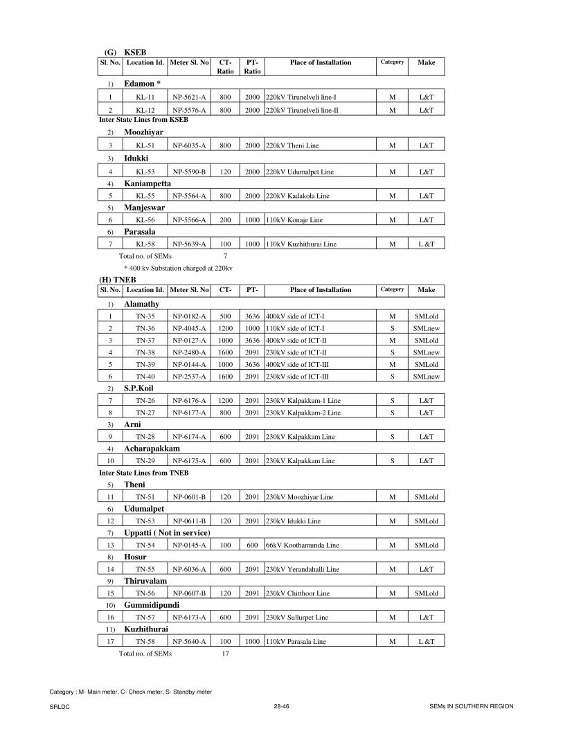
(G) KSEB
Sl. No. Location Id. Meter Sl. No CT-
Ratio
PT-
Ratio
Place of Installation Category Make
1) Edamon *
1 KL-11 NP-5621-A 800 2000 220kV Tirunelveli line-I M L&T
2 KL-12 NP-5576-A 800 2000 220kV Tirunelveli line-II M L&T
Inter State Lines from KSEB
2) Moozhiyar
3 KL-51 NP-6035-A 800 2000 220kV Theni Line M L&T
3) Idukki
4 KL-53 NP-5590-B 120 2000 220kV Udumalpet Line M L&T
4) Kaniampetta
5 KL-55 NP-5564-A 800 2000 220kV Kadakola Line M L&T
5) Manjeswar
6 KL-56 NP-5566-A 200 1000 110kV Konaje Line M L&T
6) Parasala
7 KL-58 NP-5639-A 100 1000 110kV Kuzhithurai Line M L &T
Total no. of SEMs 7
(H) TNEB
Sl. No. Location Id. Meter Sl. No CT-
Ratio
PT-
Ratio
Place of Installation Category Make
1) Alamathy
1 TN-35 NP-0182-A 500 3636 400kV side of ICT-I M SMLold
2 TN-36 NP-4045-A 1200 1000 110kV side of ICT-I S SMLnew
3 TN-37 NP-0127-A 1000 3636 400kV side of ICT-II M SMLold
4 TN-38 NP-2480-A 1600 2091 230kV side of ICT-II S SMLnew
5 TN-39 NP-0144-A 1000 3636 400kV side of ICT-III M SMLold
6 TN-40 NP-2537-A 1600 2091 230kV side of ICT-III S SMLnew
2) S.P.Koil
7 TN-26 NP-6176-A 1200 2091 230kV Kalpakkam-1 Line S L&T
8 TN-27 NP-6177-A 800 2091 230kV Kalpakkam-2 Line S L&T
3) Arni
9 TN-28 NP-6174-A 600 2091 230kV Kalpakkam Line S L&T
4) Acharapakkam
10 TN-29 NP-6175-A 600 2091 230kV Kalpakkam Line S L&T
Inter State Lines from TNEB
5) Theni
11 TN-51 NP-0601-B 120 2091 230kV Moozhiyar Line M SMLold
6) Udumalpet
12 TN-53 NP-0611-B 120 2091 230kV Idukki Line M SMLold
7) Uppatti ( Not in service)
13 TN-54 NP-0145-A 100 600 66kV Koothamunda Line M SMLold
8) Hosur
14 TN-55 NP-6036-A 600 2091 230kV Yerandahalli Line M L&T
9) Thiruvalam
15 TN-56 NP-0607-B 120 2091 230kV Chitthoor Line M SMLold
10) Gummidipundi
16 TN-57 NP-6173-A 600 2091 230kV Sullurpet Line M L&T
11) Kuzhithurai
17 TN-58 NP-5640-A 100 1000 110kV Parasala Line M L &T
Total no. of SEMs 17
* 400 kv Substation charged at 220kv
Category : M- Main meter, C- Check meter, S- Standby meter
SRLDC 28-46 SEMs IN SOUTHERN REGION
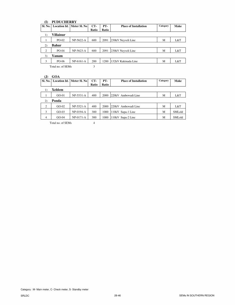
(I) PUDUCHERRY
Sl. No. Location Id. Meter Sl. No CT-
Ratio
PT-
Ratio
Place of Installation Category Make
1) Villainur
1 PO-02 NP-5622-A 600 2091 230kV Neyveli Line M L&T
2) Bahur
2 PO-04 NP-5623-A 600 2091 230kV Neyveli Line M L&T
3) Yanam
3 PO-06 NP-6161-A 200 1200 132kV Kakinada Line M L&T
Total no. of SEMs 3
(J) GOA
Sl. No. Location Id. Meter Sl. No CT-
Ratio
PT-
Ratio
Place of Installation Category Make
1) Xeldem
1 GO-01 NP-5531-A 400 2000 220kV Ambewadi Line M L&T
2) Ponda
2 GO-02 NP-5521-A 400 2000 220kV Ambewadi Line M L&T
3 GO-03 NP-0194-A 300 1000 110kV Supa-1 Line M SMLold
4 GO-04 NP-0171-A 300 1000 110kV Supa-2 Line M SMLold
Total no. of SEMs 4
Category : M- Main meter, C- Check meter, S- Standby meter
SRLDC 28-46 SEMs IN SOUTHERN REGION
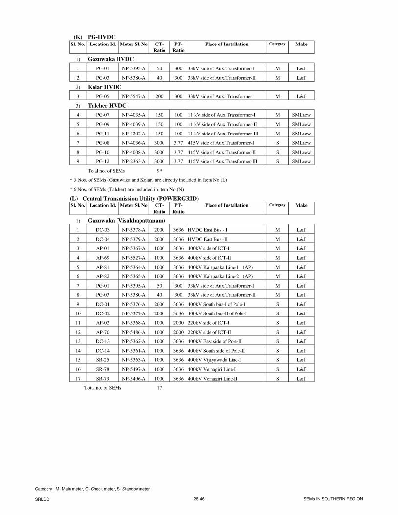
(K) PG-HVDC
Sl. No. Location Id. Meter Sl. No CT-
Ratio
PT-
Ratio
Place of Installation Category Make
1) Gazuwaka HVDC
1 PG-01 NP-5395-A 50 300 33kV side of Aux.Transformer-I M L&T
2 PG-03 NP-5380-A 40 300 33kV side of Aux.Transformer-II M L&T
2) Kolar HVDC
3 PG-05 NP-5547-A 200 300 33kV side of Aux. Transformer M L&T
3) Talcher HVDC
4 PG-07 NP-4035-A 150 100 11 kV side of Aux.Transformer-I M SMLnew
5 PG-09 NP-4039-A 150 100 11 kV side of Aux.Transformer-II M SMLnew
6 PG-11 NP-4202-A 150 100 11 kV side of Aux.Transformer-III M SMLnew
7 PG-08 NP-4036-A 3000 3.77 415V side of Aux.Transformer-I S SMLnew
8 PG-10 NP-4008-A 3000 3.77 415V side of Aux.Transformer-II S SMLnew
9 PG-12 NP-2363-A 3000 3.77 415V side of Aux.Transformer-III S SMLnew
Total no. of SEMs 9*
* 3 Nos. of SEMs (Gazuwaka and Kolar) are directly included in Item No.(L)
* 6 Nos. of SEMs (Talcher) are included in item No.(N)
(L) Central Transmission Utility (POWERGRID)
Sl. No. Location Id. Meter Sl. No CT-
Ratio
PT-
Ratio
Place of Installation Category Make
1) Gazuwaka (Visakhapattanam)
1 DC-03 NP-5378-A 2000 3636 HVDC East Bus - I M L&T
2 DC-04 NP-5379-A 2000 3636 HVDC East Bus -II M L&T
3 AP-01 NP-5367-A 1000 3636 400kV side of ICT-I M L&T
4 AP-69 NP-5527-A 1000 3636 400kV side of ICT-II M L&T
5 AP-81 NP-5364-A 1000 3636 400kV Kalapaaka Line-1 (AP) M L&T
6 AP-82 NP-5365-A 1000 3636 400kV Kalapaaka Line-2 (AP) M L&T
7 PG-01 NP-5395-A 50 300 33kV side of Aux.Transformer-I M L&T
8 PG-03 NP-5380-A 40 300 33kV side of Aux.Transformer-II M L&T
9 DC-01 NP-5376-A 2000 3636 400kV South bus-I of Pole-I S L&T
10 DC-02 NP-5377-A 2000 3636 400kV South bus-II of Pole-I S L&T
11 AP-02 NP-5368-A 1000 2000 220kV side of ICT-I S L&T
12 AP-70 NP-5486-A 1000 2000 220kV side of ICT-II S L&T
13 DC-13 NP-5362-A 1000 3636 400kV East side of Pole-II S L&T
14 DC-14 NP-5361-A 1000 3636 400kV South side of Pole-II S L&T
15 SR-25 NP-5363-A 1000 3636 400kV Vijayawada Line-I S L&T
16 SR-78 NP-5497-A 1000 3636 400kV Vemagiri Line-I S L&T
17 SR-79 NP-5496-A 1000 3636 400kV Vemagiri Line-II S L&T
Total no. of SEMs 17
Category : M- Main meter, C- Check meter, S- Standby meter
SRLDC 28-46 SEMs IN SOUTHERN REGION
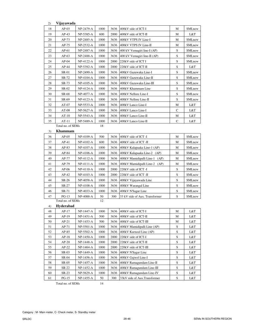
2) Vijayawada
18 AP-03 NP-2479-A 1000 3636 400kV side of ICT-I M SMLnew
19 AP-43 NP-5385-A 600 2000 400kV side of ICT-II M L&T
20 AP-73 NP-2485-A 1000 3636 400kV VTPS IV Line-I M SMLnew
21 AP-75 NP-2532-A 1000 3636 400kV VTPS IV Line-II M SMLnew
22 AP-61 NP-2487-A 1000 3636 400 kV Vemagiri line-I (AP) S SMLnew
23 AP-63 NP-2488-A 1000 3636 400 kV Vemagiri line-II (AP) S SMLnew
24 AP-04 NP-4122-A 1000 2000 220kV side of ICT I S SMLnew
25 AP-44 NP-5392-A 1000 2000 220kV side of ICT-II S L&T
26 SR-01 NP-2490-A 1000 3636 400kV Gazuwaka Line-I S SMLnew
27 SR-72 NP-4104-A 1000 3636 400kV Gazuwaka Line-II S SMLnew
28 SR-73 NP-4105-A 1000 3636 400kV Gazuwaka Line-III S SMLnew
29 SR-02 NP-4124-A 1000 3636 400kV Khammam Line S SMLnew
30 SR-68 NP-4077-A 1000 3636 400kV Nellore Line-I S SMLnew
31 SR-69 NP-4123-A 1000 3636 400kV Nellore Line-II S SMLnew
32 AT-07 NP-5533-A 1000 3636 400kV Lanco Line-I M L&T
33 AT-08 NP-5627-A 1000 3636 400kV Lanco Line-I C L&T
34 AT-10 NP-5543-A 1000 3636 400kV Lanco Line-II M L&T
35 AT-11 NP-5489-A 1000 3636 400kV Lanco Line-II C L&T
Total no. of SEMs 18
3) Khammam
36 AP-05 NP-4109-A 500 3636 400kV side of ICT -I M SMLnew
37 AP-41 NP-4102-A 600 3636 400kV side of ICT -II M SMLnew
38 AP-83 NP-4107-A 1000 3636 400kV Kalapaaka Line-1 (AP) M SMLnew
39 AP-84 NP-4106-A 1000 3636 400kV Kalapaaka Line-2 (AP) M SMLnew
40 AP-77 NP-4112-A 1000 3636 400kV Mamidipalli Line-1 (AP) M SMLnew
41 AP-79 NP-4111-A 1000 3636 400kV Mamidipalli Line-2 (AP) M SMLnew
42 AP-06 NP-4110-A 1000 2000 220kV side of ICT -I S SMLnew
43 AP-42 NP-4103-A 1000 2000 220kV side of ICT -II S SMLnew
44 SR-26 NP-4058-A 1000 3636 400kV Vijayawada Line S SMLnew
45 SR-27 NP-4108-A 1000 3636 400kV Warangal Line S SMLnew
46 SR-71 NP-4033-A 1000 3636 400kV N'Sagar Line S SMLnew
47 PG-13 NP-4088-A 50 300 33 kV side of Aux. Transformer S SMLnew
Total no. of SEMs 12
4) Hyderabad
48 AP-17 NP-1447-A 1000 3636 400kV side of ICT-I M L&T
49 AP-19 NP-1451-A 500 3636 400kV side of ICT-II M L&T
50 AP-21 NP-1453-A 500 3636 400kV side of ICT-III M L&T
51 AP-71 NP-5501-A 1000 3636 400kV Mamidipalli Line (AP) S L&T
52 AP-85 NP-5502-A 1000 3636 400kV Kurnool Line (AP) S L&T
53 AP-18 NP-1450-A 1000 2000 220kV side of ICT-I S L&T
54 AP-20 NP-1448-A 1000 2000 220kV side of ICT-II S L&T
55 AP-22 NP-1464-A 1000 2000 220kV side of ICT-III S L&T
56 SR-03 NP-1449-A 1000 3636 400kV N'Sagar Line S L&T
57 SR-04 NP-1456-A 1000 3636 400kV Gajwel Line-I S L&T
58 SR-05 NP-1457-A 1000 3636 400kV Ramagundam Line-II S L&T
59 SR-22 NP-1452-A 1000 3636 400kV Ramagundam Line-III S L&T
60 SR-23 NP-5629-A 1000 3636 400kV Ramagundam Line-IV S L&T
61 PG-15 NP-1455-A 50 300 33kV side of Aux.Transformer S L&T
Total no. of SEMs 14
Category : M- Main meter, C- Check meter, S- Standby meter
SRLDC 28-46 SEMs IN SOUTHERN REGION
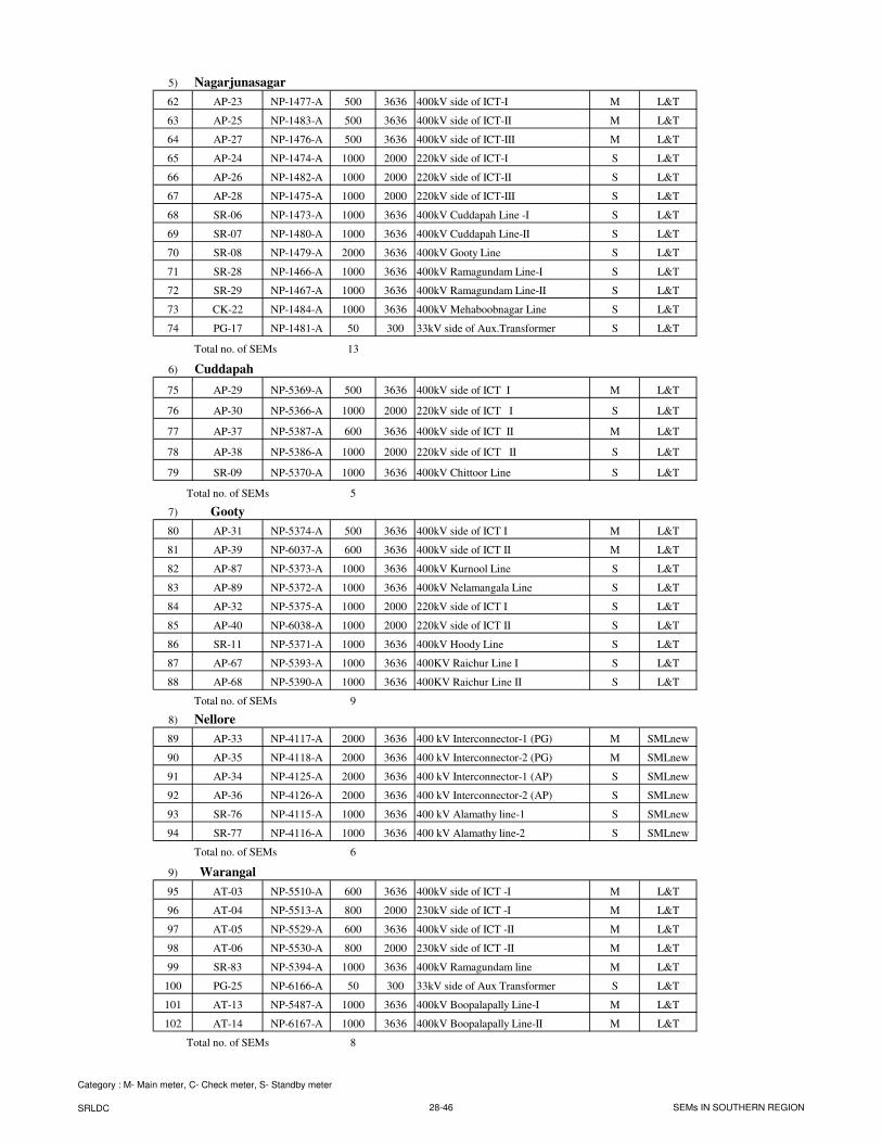
5) Nagarjunasagar
62 AP-23 NP-1477-A 500 3636 400kV side of ICT-I M L&T
63 AP-25 NP-1483-A 500 3636 400kV side of ICT-II M L&T
64 AP-27 NP-1476-A 500 3636 400kV side of ICT-III M L&T
65 AP-24 NP-1474-A 1000 2000 220kV side of ICT-I S L&T
66 AP-26 NP-1482-A 1000 2000 220kV side of ICT-II S L&T
67 AP-28 NP-1475-A 1000 2000 220kV side of ICT-III S L&T
68 SR-06 NP-1473-A 1000 3636 400kV Cuddapah Line -I S L&T
69 SR-07 NP-1480-A 1000 3636 400kV Cuddapah Line-II S L&T
70 SR-08 NP-1479-A 2000 3636 400kV Gooty Line S L&T
71 SR-28 NP-1466-A 1000 3636 400kV Ramagundam Line-I S L&T
72 SR-29 NP-1467-A 1000 3636 400kV Ramagundam Line-II S L&T
73 CK-22 NP-1484-A 1000 3636 400kV Mehaboobnagar Line S L&T
74 PG-17 NP-1481-A 50 300 33kV side of Aux.Transformer S L&T
Total no. of SEMs 13
6) Cuddapah
75 AP-29 NP-5369-A 500 3636 400kV side of ICT I M L&T
76 AP-30 NP-5366-A 1000 2000 220kV side of ICT I S L&T
77 AP-37 NP-5387-A 600 3636 400kV side of ICT II M L&T
78 AP-38 NP-5386-A 1000 2000 220kV side of ICT II S L&T
79 SR-09 NP-5370-A 1000 3636 400kV Chittoor Line S L&T
Total no. of SEMs 5
7) Gooty
80 AP-31 NP-5374-A 500 3636 400kV side of ICT I M L&T
81 AP-39 NP-6037-A 600 3636 400kV side of ICT II M L&T
82 AP-87 NP-5373-A 1000 3636 400kV Kurnool Line S L&T
83 AP-89 NP-5372-A 1000 3636 400kV Nelamangala Line S L&T
84 AP-32 NP-5375-A 1000 2000 220kV side of ICT I S L&T
85 AP-40 NP-6038-A 1000 2000 220kV side of ICT II S L&T
86 SR-11 NP-5371-A 1000 3636 400kV Hoody Line S L&T
87 AP-67 NP-5393-A 1000 3636 400KV Raichur Line I S L&T
88 AP-68 NP-5390-A 1000 3636 400KV Raichur Line II S L&T
Total no. of SEMs 9
8) Nellore
89 AP-33 NP-4117-A 2000 3636 400 kV Interconnector-1 (PG) M SMLnew
90 AP-35 NP-4118-A 2000 3636 400 kV Interconnector-2 (PG) M SMLnew
91 AP-34 NP-4125-A 2000 3636 400 kV Interconnector-1 (AP) S SMLnew
92 AP-36 NP-4126-A 2000 3636 400 kV Interconnector-2 (AP) S SMLnew
93 SR-76 NP-4115-A 1000 3636 400 kV Alamathy line-1 S SMLnew
94 SR-77 NP-4116-A 1000 3636 400 kV Alamathy line-2 S SMLnew
Total no. of SEMs 6
9) Warangal
95 AT-03 NP-5510-A 600 3636 400kV side of ICT -I M L&T
96 AT-04 NP-5513-A 800 2000 230kV side of ICT -I M L&T
97 AT-05 NP-5529-A 600 3636 400kV side of ICT -II M L&T
98 AT-06 NP-5530-A 800 2000 230kV side of ICT -II M L&T
99 SR-83 NP-5394-A 1000 3636 400kV Ramagundam line M L&T
100 PG-25 NP-6166-A 50 300 33kV side of Aux Transformer S L&T
101 AT-13 NP-5487-A 1000 3636 400kV Boopalapally Line-I M L&T
102 AT-14 NP-6167-A 1000 3636 400kV Boopalapally Line-II M L&T
Total no. of SEMs 8
Category : M- Main meter, C- Check meter, S- Standby meter
SRLDC 28-46 SEMs IN SOUTHERN REGION
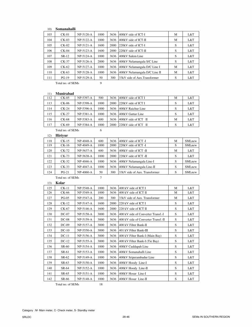
10) Somanahalli
103 CK-01 NP-5120-A 1000 3636 400kV side of ICT-I M L&T
104 CK-03 NP-5122-A 1000 3636 400kV side of ICT-II M L&T
105 CK-02 NP-5121-A 1600 2000 220kV side of ICT-I S L&T
106 CK-04 NP-5123-A 1600 2000 220kV side of ICT-II S L&T
107 SR-12 NP-5124-A 1000 3636 400kV Salem Line S L&T
108 CK-37 NP-5126-A 2000 3636 400kV Nelamangala S/C Line S L&T
109 CK-62 NP-5127-A 1000 3636 400kV Nelamangala D/C Line I M L&T
110 CK-63 NP-5128-A 1000 3636 400kV Nelamangala D/C Line II M L&T
111 PG-19 NP-5129-A 50 300 33kV side of Aux.Transformer S L&T
Total no. of SEMs 9
11) Munirabad112 CK-05 NP-5397-A 500 3636 400kV side of ICT I M L&T
113 CK-06 NP-5398-A 1000 2000 220kV side of ICT I S L&T
114 CK-24 NP-5396-A 1000 3636 400kV Raichur Line S L&T
115 CK-27 NP-5381-A 1000 3636 400kV Guttur Line S L&T
116 CK-68 NP-5383-A 600 3636 400kV side of ICT II M L&T
117 CK-69 NP-5384-A 1000 2000 220kV side of ICT II S L&T
Total no. of SEMs 6
12) Hiriyur
118 CK-15 NP-4048-A 600 3636 400kV side of ICT -I M SMLnew
119 CK-16 NP-4049-A 1000 2000 220kV side of ICT -I S SMLnew
120 CK-72 NP-5637-A 600 3636 400kV side of ICT -II M L&T
121 CK-73 NP-5638-A 1000 2000 220kV side of ICT -II S L&T
122 CK-32 NP-4046-A 1000 3636 400kV Nelamangala Line-I S SMLnew
123 CK-33 NP-4047-A 1000 3636 400kV Nelamangala Line-II S SMLnew
124 PG-21 NP-4060-A 50 300 33kV side of Aux. Transformer S SMLnew
Total no. of SEMs 7
13) Kolar
125 CK-11 NP-5548-A 1000 3636 400 kV side of ICT I M L&T
126 CK-66 NP-5549-A 1000 3636 400 kV side of ICT II M L&T
127 PG-05 NP-5547-A 200 300 33kV side of Aux. Transformer M L&T
128 CK-12 NP-5147-A 1600 2000 220 kV side of ICT I S L&T
129 CK-67 NP-5146-A 1600 2000 220 kV side of ICT II S L&T
130 DC-07 NP-5158-A 3000 3636 400 kV side of Converter Transf.-I S L&T
131 DC-08 NP-5159-A 3000 3636 400 kV side of Converter Transf.-II S L&T
132 DC-09 NP-5157-A 3000 3636 400 kV Filter Bank-II S L&T
133 DC-10 NP-5550-A 3000 3636 401 kV Filter Bank-III S L&T
134 DC-11 NP-5156-A 3000 3636 400 kV Filter Bank-I (Main Bay) S L&T
135 DC-12 NP-5155-A 3000 3636 400 kV Filter Bank-I (Tie Bay) S L&T
136 SR-60 NP-5154-A 1000 3636 400kV Cuddapah Line S L&T
137 SR-61 NP-5153-A 1000 3636 400kV Somanahalli Line S L&T
138 SR-62 NP-5149-A 1000 3636 400kV Sriperambadur Line S L&T
139 SR-63 NP-5150-A 1000 3636 400kV Hoody Line-I S L&T
140 SR-64 NP-5152-A 1000 3636 400kV Hoody Line-II S L&T
141 SR-65 NP-5151-A 1000 3636 400kV Hosur Line-I S L&T
142 SR-66 NP-5148-A 1000 3636 400kV Hosur Line-II S L&T
Total no. of SEMs 18
Category : M- Main meter, C- Check meter, S- Standby meter
SRLDC 28-46 SEMs IN SOUTHERN REGION
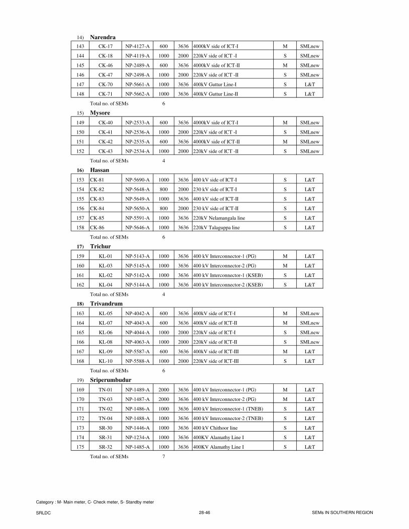
14) Narendra
143 CK-17 NP-4127-A 600 3636 4000kV side of ICT-I M SMLnew
144 CK-18 NP-4119-A 1000 2000 220kV side of ICT -I S SMLnew
145 CK-46 NP-2489-A 600 3636 4000kV side of ICT-II M SMLnew
146 CK-47 NP-2498-A 1000 2000 220kV side of ICT -II S SMLnew
147 CK-70 NP-5661-A 1000 3636 400kV Guttur Line-I S L&T
148 CK-71 NP-5662-A 1000 3636 400kV Guttur Line-II S L&T
Total no. of SEMs 6
15) Mysore
149 CK-40 NP-2533-A 600 3636 4000kV side of ICT-I M SMLnew
150 CK-41 NP-2536-A 1000 2000 220kV side of ICT -I S SMLnew
151 CK-42 NP-2535-A 600 3636 4000kV side of ICT-II M SMLnew
152 CK-43 NP-2534-A 1000 2000 220kV side of ICT -II S SMLnew
Total no. of SEMs 4
16) Hassan
153 CK-81 NP-5690-A 1000 3636 400 kV side of ICT-I S L&T
154 CK-82 NP-5648-A 800 2000 230 kV side of ICT-I S L&T
155 CK-83 NP-5649-A 1000 3636 400 kV side of ICT-II S L&T
156 CK-84 NP-5650-A 800 2000 230 kV side of ICT-II S L&T
157 CK-85 NP-5591-A 1000 3636 220kV Nelamangala line S L&T
158 CK-86 NP-5646-A 1000 3636 220kV Talaguppa line S L&T
Total no. of SEMs 6
17) Trichur
159 KL-01 NP-5143-A 1000 3636 400 kV Interconnector-1 (PG) M L&T
160 KL-03 NP-5145-A 1000 3636 400 kV Interconnector-2 (PG) M L&T
161 KL-02 NP-5142-A 1000 3636 400 kV Interconnector-1 (KSEB) S L&T
162 KL-04 NP-5144-A 1000 3636 400 kV Interconnector-2 (KSEB) S L&T
Total no. of SEMs 4
18) Trivandrum
163 KL-05 NP-4042-A 600 3636 400kV side of ICT-I M SMLnew
164 KL-07 NP-4043-A 600 3636 400kV side of ICT-II M SMLnew
165 KL-06 NP-4044-A 1000 2000 220kV side of ICT-I S SMLnew
166 KL-08 NP-4063-A 1000 2000 220kV side of ICT-II S SMLnew
167 KL-09 NP-5587-A 600 3636 400kV side of ICT-III M L&T
168 KL-10 NP-5588-A 1000 2000 220kV side of ICT-III S L&T
Total no. of SEMs 6
19) Sriperumbudur
169 TN-01 NP-1489-A 2000 3636 400 kV Interconnector-1 (PG) M L&T
170 TN-03 NP-1487-A 2000 3636 400 kV Interconnector-2 (PG) M L&T
171 TN-02 NP-1486-A 1000 3636 400 kV Interconnector-1 (TNEB) S L&T
172 TN-04 NP-1488-A 1000 3636 400 kV Interconnector-2 (TNEB) S L&T
173 SR-30 NP-1446-A 1000 3636 400 kV Chithoor line S L&T
174 SR-31 NP-1234-A 1000 3636 400KV Alamathy Line I S L&T
175 SR-32 NP-1485-A 1000 3636 400KV Alamathy Line I S L&T
Total no. of SEMs 7
Category : M- Main meter, C- Check meter, S- Standby meter
SRLDC 28-46 SEMs IN SOUTHERN REGION
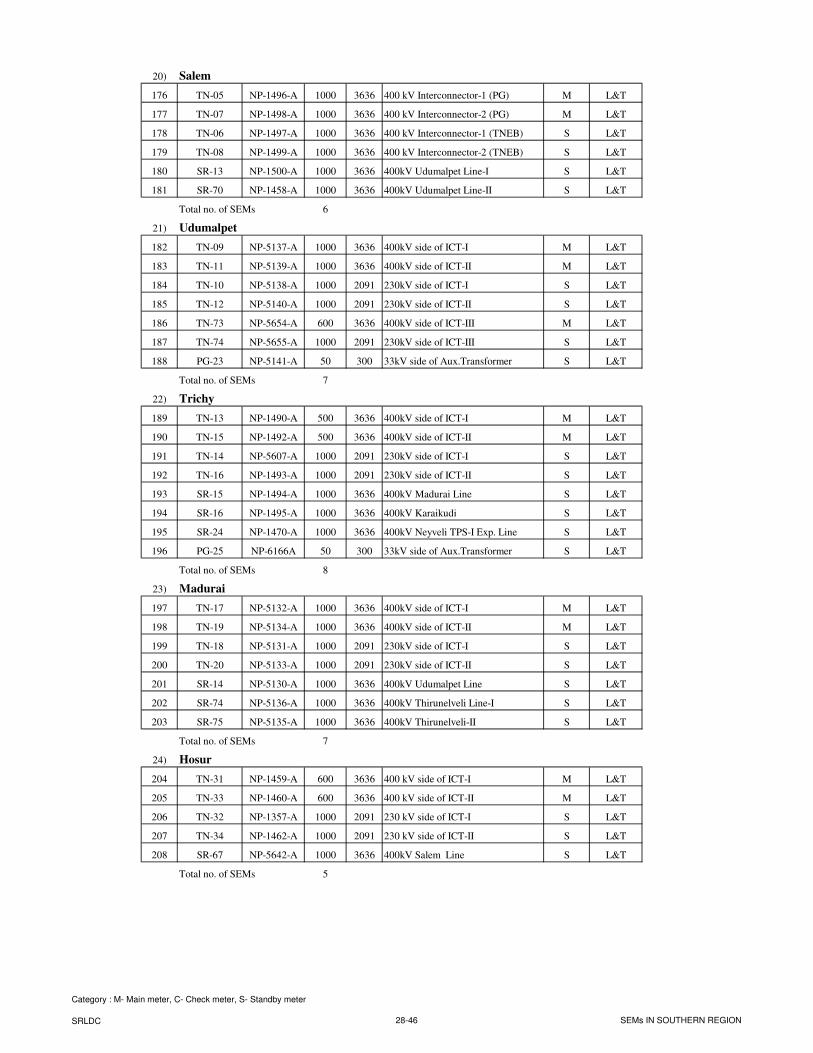
20) Salem
176 TN-05 NP-1496-A 1000 3636 400 kV Interconnector-1 (PG) M L&T
177 TN-07 NP-1498-A 1000 3636 400 kV Interconnector-2 (PG) M L&T
178 TN-06 NP-1497-A 1000 3636 400 kV Interconnector-1 (TNEB) S L&T
179 TN-08 NP-1499-A 1000 3636 400 kV Interconnector-2 (TNEB) S L&T
180 SR-13 NP-1500-A 1000 3636 400kV Udumalpet Line-I S L&T
181 SR-70 NP-1458-A 1000 3636 400kV Udumalpet Line-II S L&T
Total no. of SEMs 6
21) Udumalpet
182 TN-09 NP-5137-A 1000 3636 400kV side of ICT-I M L&T
183 TN-11 NP-5139-A 1000 3636 400kV side of ICT-II M L&T
184 TN-10 NP-5138-A 1000 2091 230kV side of ICT-I S L&T
185 TN-12 NP-5140-A 1000 2091 230kV side of ICT-II S L&T
186 TN-73 NP-5654-A 600 3636 400kV side of ICT-III M L&T
187 TN-74 NP-5655-A 1000 2091 230kV side of ICT-III S L&T
188 PG-23 NP-5141-A 50 300 33kV side of Aux.Transformer S L&T
Total no. of SEMs 7
22) Trichy
189 TN-13 NP-1490-A 500 3636 400kV side of ICT-I M L&T
190 TN-15 NP-1492-A 500 3636 400kV side of ICT-II M L&T
191 TN-14 NP-5607-A 1000 2091 230kV side of ICT-I S L&T
192 TN-16 NP-1493-A 1000 2091 230kV side of ICT-II S L&T
193 SR-15 NP-1494-A 1000 3636 400kV Madurai Line S L&T
194 SR-16 NP-1495-A 1000 3636 400kV Karaikudi S L&T
195 SR-24 NP-1470-A 1000 3636 400kV Neyveli TPS-I Exp. Line S L&T
196 PG-25 NP-6166A 50 300 33kV side of Aux.Transformer S L&T
Total no. of SEMs 8
23) Madurai
197 TN-17 NP-5132-A 1000 3636 400kV side of ICT-I M L&T
198 TN-19 NP-5134-A 1000 3636 400kV side of ICT-II M L&T
199 TN-18 NP-5131-A 1000 2091 230kV side of ICT-I S L&T
200 TN-20 NP-5133-A 1000 2091 230kV side of ICT-II S L&T
201 SR-14 NP-5130-A 1000 3636 400kV Udumalpet Line S L&T
202 SR-74 NP-5136-A 1000 3636 400kV Thirunelveli Line-I S L&T
203 SR-75 NP-5135-A 1000 3636 400kV Thirunelveli-II S L&T
Total no. of SEMs 7
24) Hosur
204 TN-31 NP-1459-A 600 3636 400 kV side of ICT-I M L&T
205 TN-33 NP-1460-A 600 3636 400 kV side of ICT-II M L&T
206 TN-32 NP-1357-A 1000 2091 230 kV side of ICT-I S L&T
207 TN-34 NP-1462-A 1000 2091 230 kV side of ICT-II S L&T
208 SR-67 NP-5642-A 1000 3636 400kV Salem Line S L&T
Total no. of SEMs 5
Category : M- Main meter, C- Check meter, S- Standby meter
SRLDC 28-46 SEMs IN SOUTHERN REGION
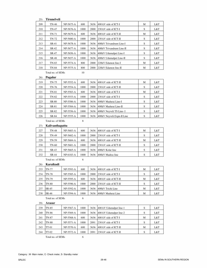
25) Tirunelveli
209 TN-46 NP-5675-A 600 3636 400 kV side of ICT-I M L&T
210 TN-47 NP-5676-A 1000 2000 230 kV side of ICT-I S L&T
211 TN-71 NP-5679-A 600 3636 400 kV side of ICT-II M L&T
212 TN-72 NP-5680-A 1000 2000 230 kV side of ICT-II S L&T
213 SR-41 NP-5678-A 1000 3636 400kV Trivandrum Line-I S L&T
214 SR-42 NP-5677-A 1000 3636 400kV Trivandrum Line-II S L&T
215 SR-47 NP-5656-A 1000 3636 400kV Udumalpet Line-I S L&T
216 SR-48 NP-5657-A 1000 3636 400kV Udumalpet Line-II S L&T
217 TN-83 NP-5574-A 800 2000 220kV Edamon line-I M L&T
218 TN-84 NP-5575-A 800 2000 220kV Edamon line-II M L&T
Total no. of SEMs 10
26) Pugalur
219 TN-75 NP-5552-A 600 3636 400 kV side of ICT-II M L&T
220 TN-76 NP-5554-A 1000 2000 230 kV side of ICT-II S L&T
221 TN-81 NP-5583-A 600 3636 400 kV side of ICT-I M L&T
222 TN-82 NP-5553-A 1000 2000 230 kV side of ICT-I S L&T
223 SR-80 NP-5586-A 1000 3636 400kV Madurai Line-I S L&T
224 SR-81 NP-5584-A 1000 3636 400kV Madurai Line-II S L&T
225 SR-82 NP-5556-A 1000 3636 400kV Neyveli TS Line- I S L&T
226 SR-84 NP-5555-A 1000 3636 400kV Neyveli Expn-II Line S L&T
Total no. of SEMs 8
27) Kalivanthapattu
227 TN-48 NP-5683-A 600 3636 400 kV side of ICT-I M L&T
228 TN-49 NP-5682-A 1000 2000 230 kV side of ICT-I S L&T
229 TN-59 NP-5684-A 600 3636 400 kV side of ICT-II M L&T
230 TN-60 NP-5681-A 1000 2000 230 kV side of ICT-II S L&T
231 SR-43 NP-5665-A 1000 3636 400kV Kolar line S L&T
232 SR-44 NP-6183-A 1000 3636 400kV Madras line S L&T
Total no. of SEMs 6
28) Karaikudi
233 TN-77 NP-5593-A 600 3636 400 kV side of ICT-I M L&T
234 TN-78 NP-5585-A 1000 2000 230 kV side of ICT-I S L&T
235 TN-79 NP-5595-A 600 3636 400 kV side of ICT-II M L&T
236 TN-80 NP-5596-A 1000 2000 230 kV side of ICT-II S L&T
237 SR-45 NP-5592-A 1000 3636 400kV Trichi Line M L&T
238 SR-46 NP-5594-A 1000 3636 400kV Madurai Line M L&T
Total no. of SEMs 6
29) Arasur
239 TN-85 NP-5567-A 1000 3636 400 kV Udumalpet line-1 S L&T
240 TN-86 NP-5569-A 1000 3636 400 kV Udumalpet line-2 S L&T
241 TN-87 NP-5568-A 600 3636 400 kV side of ICT-I M L&T
242 TN-88 NP-5571-A 1000 2091 230 kV side of ICT-I S L&T
243 TT-01 NP-5570-A 600 3636 400 kV side of ICT-II M L&T
244 TT-02 NP-5572-A 1000 2091 230 kV side of ICT-II S L&T
Total no. of SEMs 6
Category : M- Main meter, C- Check meter, S- Standby meter
SRLDC 28-46 SEMs IN SOUTHERN REGION
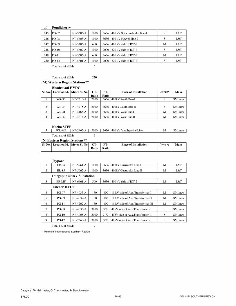
30) Pondicherry
245 PO-07 NP-5606-A 1000 3636 400 kV Sriperumbudur line-1 S L&T
246 PO-08 NP-5603-A 1000 3636 400 kV Neyveli line-2 S L&T
247 PO-09 NP-5705-A 600 3636 400 kV side of ICT-I M L&T
248 PO-10 NP-5602-A 1000 2000 220 kV side of ICT-I S L&T
249 PO-11 NP-5605-A 600 3636 400 kV side of ICT-II M L&T
250 PO-12 NP-5601-A 1000 2000 220 kV side of ICT-II S L&T
Total no. of SEMs 6
Total no. of SEMs 250
(M) Western Region Stations**
Bhadravati HVDC
Sl. No. Location Id. Meter Sl. No CT-
Ratio
PT-
Ratio
Place of Installation Category Make
1 WR-33 NP-2310-A 2000 3636 400kV South Bus-I S SMLnew
2 WR-34 NP-4215-A 2000 3636 400kV South Bus-II S SMLnew
3 WR-31 NP-4165-A 2000 3636 400kV West Bus-I M SMLnew
4 WR-32 NP-4214-A 2000 3636 400kV West Bus-II M SMLnew
Korba STPP5 WR-MF NP-2465-A 2000 3636 400 kV Vindhyachal Line M SMLnew
Total no. of SEMs 5
(N) Eastern Region Stations**
Sl. No. Location Id. Meter Sl. No CT-
Ratio
PT-
Ratio
Place of Installation Category Make
Jeypore1 ER-84 NP-5961-A 1000 3636 400kV Gazuwaka Line-I M L&T
2 ER-85 NP-5962-A 1000 3636 400kV Gazuwaka Line-II M L&T
Durgapur 400kV Substation
3 ER-MF NP-6461-A 500 3636 400 kV side of ICT-2 M L&T
Talcher HVDC
4 PG-07 NP-4035-A 150 100 11 kV side of Aux.Transformer-I M SMLnew
5 PG-09 NP-4039-A 150 100 11 kV side of Aux.Transformer-II M SMLnew
6 PG-11 NP-4202-A 150 100 11 kV side of Aux.Transformer-III M SMLnew
7 PG-08 NP-4036-A 3000 3.77 415V side of Aux.Transformer-I S SMLnew
8 PG-10 NP-4008-A 3000 3.77 415V side of Aux.Transformer-II S SMLnew
9 PG-12 NP-2363-A 3000 3.77 415V side of Aux.Transformer-III S SMLnew
Total no. of SEMs 9
** Meters of importance to Southern Region
Category : M- Main meter, C- Check meter, S- Standby meter
SRLDC 28-46 SEMs IN SOUTHERN REGION
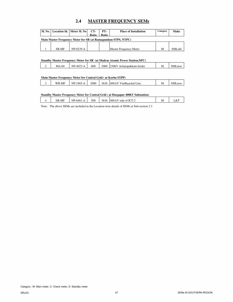
2.4 MASTER FREQUENCY SEMs
Sl. No. Location Id. Meter Sl. No CT-
Ratio
PT-
Ratio
Place of Installation Category Make
Main Master Frequency Meter for SR (at Ramagundam STPS, NTPC)
1 SR-MF NP-0239-A Master Frequency Meter M SMLold
Standby Master Frequency Meter for SR (at Madras Atomic Power Station,NPC)
2 MA-04 NP-4023-A 600 2000 230kV Acharapakkam feeder M SMLnew
Main Master Frequency Meter for Central Grid ( at Korba STPP)
3 WR-MF NP-2465-A 2000 3636 400 kV Vindhyachal Line M SMLnew
Standby Master Frequency Meter for Central Grid ( at Durgapur 400kV Substation)
4 ER-MF NP-6461-A 500 3636 400 kV side of ICT-2 M L&T
Note: The above SEMs are included in the Location-wise details of SEMs at Sub-section 2.3
Category : M- Main meter, C- Check meter, S- Standby meter
SRLDC 47 SEMs IN SOUTHERN REGION
SECTION – 3
SPECIAL ENERGY METERS
LOCATION DIAGRAMS
SPECIAL ENERGY METERS
LOCATION DIAGRAMS
3.1 General
3.1(a) Location diagram of SEMs in SR – 400 KV System
3.1(b) Location diagram of SEMs in State owned Inter-State lines
3.1(c) Location diagram of SEMs in CTU network
3.1(d) Location diagram of SEMs in 400kV substations
3.2 Location diagram of SEMs at ISGSs
3.2(a) Ramagundam STPS
3.2(b) Talcher STPP-II
3.2(c) Neyveli Lignite Corporation
3.2(d) Madras Atomic Power Station
3.2(e) Kaiga Generating Station
3.3 Location diagram of SEMs at Drawee utilities
3.3(a) APTRANSCO system
3.3(b) KPTCL system
3.3(c) KSEB system
3.3(d) TNEB system
3.3(e) Pondicherry system
3.3(f) Goa system
3.3(g) POWERGRID-HVDC system
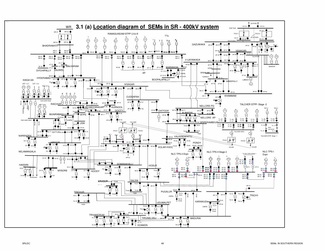
3.1 (a) Location diagram of SEMs in SR - 400kV system```
RM-21
RM-11
HYDERABAD
RM-01RM-02
RM-03RM-04 RM-05 RM-06
RM-15
RM-25RM-16
RM-26
RM-17
RM-27
AP-15
RM-32
AP-16
AP-13
RM-31
AP-14
AP-11
RM-30
AP-12
AP-07
RM-28
AP-08
AP-09
RM-29
AP-10
RM-14
RM-24
RM-13
RM-23
N'SAGAR
TTs
AP-17
AP-18
PG-15
AP-21
AP-22
AP-19
AP-20
AP-71
SR-04 SR-05
SR-28 SR-29
AP-25
AP-26
AP-27
AP-28
AP-23
AP-24
PG-17
AP
SR-06 SR-07
AP-29
AP-30
AP-31
AP-32
SR-08
SR-11
GOOTY
SOMANAHALLI
SR-60
CK-01
CK-02
CK-03
CK-04
CK-22
CUDDAPAH
HOODY
CK-11
CK-12
PG-05
KPTCL
KOLAR HVDC
POLE1 POLE2
SR-63 SR-64 SR-61
SR-62
TN-03 TN-01
TN-02
TNEB
SRIPERAMBDUR
SR-65 SR-66
HOSURSR-12
SR-67
SALEMARASURTN -85 TN-86
TN-05
TN-06
TNEB
TN-07
TN-08
NLC-TPS-I
Expn
TRICHY
SR-21
RS-21
RS-41
45 6 7
TN-15
TN-16
PG-25
TN-13
TN-14
TN-19
TN-20
TN-17
TN-18
MADURAI
RS-22
SR-15
TN-09
TN-10
TN-11
TN-12
UDUMALPET
SR-13 SR-70
TN-04
KL01
KL-02
KL-03
KL-04
TRICHUR
KSEB
AF-1 AF-2 AF-3
TN-31
TN-32
CK-37
1
RM-07
2
RM-08
3
RM-09
12 3 4
6 75
KURNOOL
4
RM-49RM-47
KL-05TN-19TN-17
KL-06
KL-07
KL-08
SR-74SR-75
TRIVANDRUM
TN-33
TN-34
SR-22 SR-23
RM-18
RM-38
RM-19
RM-39
MEHABOOBNAGAR
AP-60
PG-21
CK-21
RAICHUR
4 5 6 7
MUNIRABAD
CK-23
CK-05/68
CK-06/69
CK-24
CK-27
GUTTUR
CK-25
CK-26
NELAMANGALA
CK-28
CK-09
CK-10
CK-30
CK-31
CK-07
CK-08
CK-15
CK-16
HIRIYUR
CK-29
CK-32 CK-33
CK-13
CK-14
CK-35
CK
-36
CK-34
Talaguppa
AP-89
AP-59
KG
-25
KG
-26
CK-17
CK-18
NARENDRA
KAIGA GS
KG
-22
GAZUWAKA
JEYPORE
DC-03 DC-04
V IJAYAWADA
MAMIDIPALLY
AP-73
AP
-02
KALAPAKA
VTPS
AP
-01
DC-01DC-02
SR-02
AP-81AP-82
AP-75
AP-76
AP-77 AP-79
AP-78 AP-80
AP-83 AP-84
KHAMMAM
NELLORE-PG
PG
-03
KURNOOL
AP-03
AP-04
SR-71
SR-27
SIMHADRI
1 2
DC-14
POLE-1 POLE-2
DC-13
SR-72SR-01 SR-73
SR-76 SR-77 AP-33 AP-35
AP-34 AP-36
NELLORE -AP
SR-68 SR-69
AC BYPASS
EAST BUS
SOUTH BUS
PG-01
VEMAGIRI
AP-62 AP-64
AP-61 AP-63
WR-33 WR-34
WR
To NLC TPS-II Sage 1
ICT-2ICT-1
NLC-TPS-II Stage 2
NE-05
NE-07
BHADRAWATI
RAMAGUNDAM STPP I,II & III
RM-22
RM-12
WR-31 WR-32
POLE1 POLE2
TL-31
TL-41TL-32
TL-42
TL-33
TL-43
TL-34
TL-44
3
TL-46
TL-45
4
TL-48
TL-47
5
TL-50
TL-49
6
TL-52
TL-51
3
RM-09
TL-58
TL-57
TL-60
TL-59
SUT-2 SUT-3
TL-16 TL-17
X X
TL-14 TL-15
TALCHER STPP- Stage -2
TALCHER STPP- Stage -1
Inter -
connector
KOLAR KOLAR
TALCHER TALCHER
NV-04
NL-04
NL-24
NV-04
NL-04
NL-24
NV-05
NL-05
NL-25
NV-06
NL-06
NL-26
NV-07
NL-07
NL-27
NV-16
NL-16
NL-36
NV-17
NL-17
NL-37
SR-17
RS-17
RS-37
SR-18
RS-18
RS-38
SR-19
RS-19
RS-39
SR-20
RS-20
RS-40
1 2
NE-01
NE-03
NE-02
NE-04
NE-06
NE-08
SR-24
4
RM-49
AP-72
AP-86
AP-88
AP-87
AP-74
SRISAILAM
CK-38
SR-25
AP-05
AP-06
SR-26
PG-13
AP-85 SR-03
SR-09
PG-19
DC-07 DC-08
DC-12
DC-11 DC-09 DC-10
PG-23
SR-14
TALCHER HVDC
ALAMATHYTN-35
TN-36
TN-37
TN-38
CK-19
CK-20
CK-40
CK-41
CK-42
CK-43
MYSORE
CK-46
CK-47
SR-31 SR-32
TN-40
TN-39
KG
-21
SUT-1 & 2UNIT 1 & 2
SUT-3 & 4
UNIT 3 & 4
KO
DA
SA
LL
Y
KA
DR
A
KG
-01 K
G-1
1
KG
-02
KG
-12
KG
-03 K
G-1
3
KG
-04 KG
-14
KG
-05
KG
-06
KG
-07
KG
-08
KG
-15
KG
-16
KG
-17
KG
-18
KGS 220KV BUS
KGS 400KV BUS
CK
-48
CK
-49
CK-62 CK-63
AP-65
SR-30
AP-66
CHITTOOR
CK-44 CK-45
AP-67 AP-68CK-64
CK-65
AP-39
AP-40
AP-37
AP-38
TL-33
TL-43
AP-46AP-45
AP-47AP-48
SR-79 SR-78
AP-43
AP-44
RM-20
RM-40
DITCHIPALLY
CK-70 CK-71
TN-46
TN-
47
TIRUNELVELI
SR-81 SR-80
CK-72
CK-73
CK-66
CK-67
GAJWEL
BTPS
KALAVINDAPATTU
SR-43
SR-44
TN-48
TN-49
TN-59
TN-60 PO-07 PO-08
KG
-23
KG
-24
AP-49
TN-71
TN-72
TN-83 TN-84
KL11 KL-12
AT-02
AT-01
CK-78
CK-79
CK-76 CK-77
KL-09
KL-10
TN-73
TN-74SR-47
SR-48
AT-17
AT-18 MALKARAM
AT-03/05
AT-04/06
2 ICT'S
SR-83
PG-25
AT-13/14
AT-15/16
BOOPALAPALLY
AP
-69
AP
-70
SRISAILAM
CK
-74
CK
-75
CK-80
JSWCK-39
2 ICT'S
WARANGAL
LANCO
AT-07
AT-08
AT-09
AT-10
AT-11
AT-12
NLC-TPS-2 Expn
TN-77
TN-79
TN-78
TN-80
2 ICT's
KARAIKUDI
TN-75
TN-81
TN-76
TN-82
2 ICT's
PUGALUR
SR
-80
SR
-81
SR-82SR-84
RS-23
SR-16
SR-45
SR-46
EDAMON
TN-
87
TN-88
HASSAN
CK-83
CK-84
CK-81
CK-82
TT-01
TT-02
1 2
NE-21
NE-22
NE-23
NE-24
NE-25
NE-26
NE-27
NE-28
PO-11
PO-12
PO-09
PO-10
PONDY
SRLDC 48 SEMs IN SOUTHERN REGION
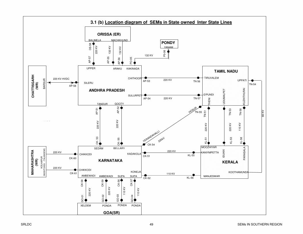
HOSUR
YERANDAHALLI
220kV
MANJESWAR
UPPATI
KADAKOLAKANIYMPETTA
KONEJA
ARAKU
BALIMELA
ORISSA (ER)
ANDHRA PRADESH
TAMIL NADU
KERALAKARNATAKA
GOA(SR)
LOWER
SILERU
KO
LH
AP
UR
KU
ZH
ITH
UR
AI
UD
UM
AL
PE
T TH
EN
I
BELLARY
TANDUR GOOTY
SEDAM
CHIKKODI
MOOZHIYAR
IDU
KK
I
PA
RA
SA
LA
MA
HA
RA
SH
TR
A
(WR
)C
HA
TT
ISG
AR
H
(W
R)
22
0 K
V2
20
KV
22
0 K
V
11
0 K
V
22
0 K
V
13
2 K
V
66
KV
11
0 K
V
220 KV
110 KV
AP
-57
OS
-58
P0
-06
TN 56
AP-54 TN-57
TN-54
TN-55
CK-54
CK-51
CK-52
KL-55
KL-56
CK
-56
CK
-59
CK
-58
GO
-03
CK
-57
CK-60
CK-61
CK
- 5
5
CK
- 5
3
PONDY YANAM
13
2 K
V
XELDEM
GO
-04
UPPER
PONDA PONDA
AMBEWADI SUPA
MACHKHUNDBALIMELA
AP-53CHITHOOR TIRUVALEM
SULURPET G'PUNDI
KOOTHAMUNDA
220 KV
HVDC
AP-58
220 KV HVDC 220 KV
220 KV
132 KV
22
0 K
V
11
0 K
V
3.1 (b) Location diagram of SEMs in State owned Inter State Lines
AP
-55
AP
-56
AP
-51
AP
-52
(TA
LA
NG
EN
E)
(M
US
HT
UN
GI)
B
AR
SU
R
KAKINADA
PO
-05
KL
-53
TN
-53
TN
-58
KL
-58
KL
-51
TN
-51
HVDC
GO
-01
GO
-02
AMBEWADI
22
0 K
V
22
0 K
V
SUPA
PONDA
CHIKKODI220 KV
SRLDC 49 SEMs IN SOUTHERN REGION
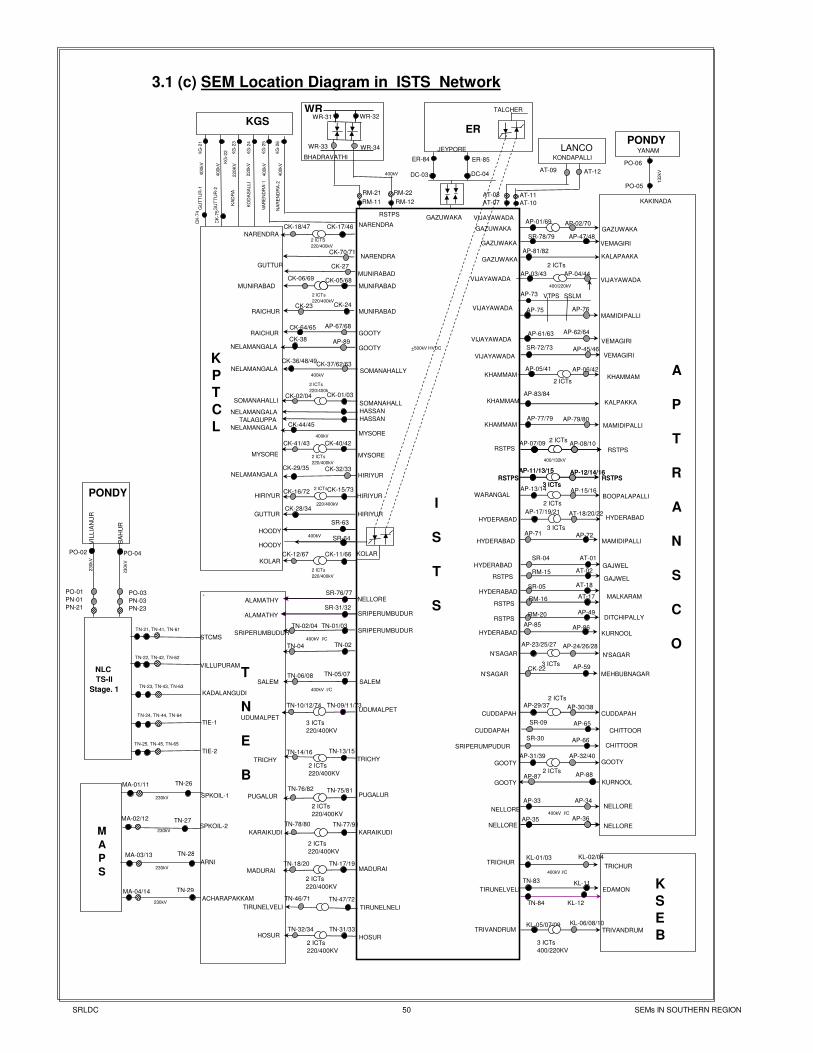
ARNI
ACHARA-
PAKKAM
KG
-21
GU
TT
UR
-1
RM-21
RM-11
RM-22
RM-12
ER-84 ER-85
WR-33 WR-34
WR-32
BHADRAVATHI
400kV
+500kV HVDC
CK
-75G
UT
TU
R-2
400kV
KG
-23
KA
DR
A 2
20K
V
KG
-24
KO
DA
SA
LLI
220kV
KG
-25
NA
RE
ND
RA
-1
400kV
KG
-26
400kV
NA
RE
ND
RA
-2
3.1 (c) SEM Location Diagram in ISTS Network
`
T
N
E
B
TN-25, TN-45, TN-65
TRICHUR
I
S
T
S
TN-05/07
TN-01/03
TN-09/11/73TN-10/12/74
TN-06/08
TN-04
SRIPERUMBUDUR
TIRUNELNELI
TN-47/72TN-46/71
TIRUNELVELI
PONDY YANAM
PO-05
PO-06
132kV
KAKINADA
K
P
T
C
L
2 ICTs
220/400kV
CK-16/72 CK-15/73HIRIYUR HIRIYUR
KOLAR
KOLAR
CK-11/66CK-12/67
2 ICTs
220/400kV
CK-18/47 CK-17/46 NARENDRA
NARENDRA
SR-63
HOODY
400kVHOODY
CK-01/03CK-02/04
2 ICTs
220/400k
SOMANAHALLI SOMANAHALL
HASSAN
HASSAN
CK-06/69 CK-05/68MUNIRABAD MUNIRABAD
400kV
RSTPS
DC-03 DC-04
ER
JEYPORE
TALCHER
2 ICTS
220/400kV
SRIPERUMBUDUR
BA
HU
R
VIL
LIA
NU
R
PO-01
PN-01
PN-21
230kV
PO-03
PN-03
PN-23
PONDY
230kV
PO-02 PO-04
NLC
TS-II
Stage. 1
TIE-2
TIE-1
TN-24, TN-44, TN-64
KADALANGUDI
TN-23, TN-43, TN-63
VILLUPURAM
TN-22, TN-42, TN-62
TN-21, TN-41, TN-61
STCMS
KL-05/07/09 KL-06/08/10
TRIVANDRUMTRIVANDRUM
TN-83 KL-11TIRUNELVELI EDAMON
SR-72/73 AP-45/46
VIJAYAWADA VEMAGIRI
400kV I/C
KL-01/03 KL-02/04TRICHUR
TRICHUR
MA-01/11 TN-26
SPKOIL-1230kV
MA-02/12 TN-27
230kVSPKOIL-2
TN-28MA-03/13
230kVARNI
TN-29MA-04/14
230kVACHARAPAKKAM
TN-13/15TN-14/16
TRICHYTRICHY
UDUMALPET
UDUMALPET
SALEMSALEM
AP-02/70AP-01/69
GAZUWAKA GAZUWAKA
AP-04/44AP-03/43VIJAYAWADA VIJAYAWADA
AP-81/82
AP-47/48
GAZUWAKA
KALAPAAKA
AP-76AP-75VIJAYAWADA
AP-73
MAMIDIPALLI
AP-33 AP-34
NELLORENELLORE
AP-35 AP-36NELLORE NELLORE
AP-61/63 AP-62/64
VIJAYAWADA VEMAGIRI
AP-06/42AP-05/41KHAMMAM KHAMMAM
400/132kV
WARANGAL
2 ICTsAP-07/09 AP-08/10
RSTPS
3 ICTs
AP-11/13/15
RSTPSAP-12/14/16
RSTPS
3 ICTs
HYDERABAD
AP-17/19/21 AT-18/20/22HYDERABAD
AP-23/25/27
N'SAGAR
AP-24/26/28
N'SAGAR
AP-30/38AP-29/37
CUDDAPAH CUDDAPAH
AP-31/39 AP-32/40
GOOTY GOOTY
AP-71 AP-72HYDERABAD MAMIDIPALLI
AP-77/79 AP-79/80KHAMMAM MAMIDIPALLI
KHAMMAM KALPAKKA
AP-83/84
AP-59CK-22N'SAGAR MEHBUBNAGAR
AP-85AP-86
HYDERABAD KURNOOL
SR-09 AP-65
CUDDAPAH CHITTOOR
SR-30 AP-66SRIPERUMPUDUR CHITTOOR
AP-87 AP-88
GOOTY KURNOOL
K
S
E
B
400kV I/C
400kV I/C
CK-40/42CK-41/43
2 ICTs
220/400kV
MYSORE MYSORE
CK-44/45
NELAMANGALA
TALAGUPPA
NELAMANGALAMYSORE
SR-76/77NELLOREALAMATHY
SR-31/32
GOOTY
NELAMANGALAAP-89CK-38
KGS
NARENDRA
NELAMANGALACK-32/33
CK-28/34GUTTUR
HIRIYUR
HIRIYUR
220/400kV
GUTTUR
MUNIRABAD
CK-27
CK-24MUNIRABADRAICHUR
CK-23
GOOTY
RAICHUR
AP-67/68CK-64/65
CK-37/62/63CK-36/48/49
NELAMANGALA SOMANAHALLY
SRIPERUMBUDURALAMATHY
WR
CK-29/35
3 ICTs
2 ICTs
2 ICTs
3 ICTs
400/220KV
2 ICTs
220/400KV
TN-17/19TN-18/20MADURAIMADURAI
2 ICTs
220/400KV
2 ICTs
220/400KV
3 ICTs
220/400KV
SR-64
400kV
400kV
M
A
P
S
A
P
T
R
A
N
S
C
O
WR-31
2 ICTs
VEMAGIRI
2 ICTs
400/220kV
2 ICTs
HOSUR
TN-31/33TN-32/34HOSUR
CK-70/71
CK
-74
KG
-22
VTPS SSLM
SR-04 AT-01
HYDERABAD GAJWEL
RSTPS GAJWELRM-15 AT-02
MALKARAM
RSTPS
HYDERABADAT-17
AT-18SR-05
RM-16
DITCHIPALLYRSTPSAP-49RM-20
TN-02/04
TN-02400kV I/C
2 ICTs
220/400KV
2 ICTs
220/400KV
TN-76/82 TN-75/81PUGALURPUGALUR
KARAIKUDIKARAIKUDI
TN-78/80 TN-77/91
GAZUWAKA
GAZUWAKASR-78/79
AT-08
AT-07
AT-11
AT-10
VIJAYAWADA
LANCO KONDAPALLI
AT-09 AT-12
TN-84 KL-12
3 ICTs
AP-11/13/15
RSTPSAP-12/14/16
RSTPS
2 ICTs
AP-13/14 AP-15/16BOOPALAPALLI
RSTPS
SRLDC 50 SEMs IN SOUTHERN REGION
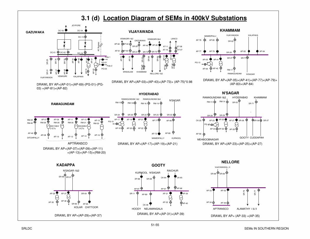
East Bus
T
AP
70
AP
-02
JEYPORE
AP
69
AP
-01
DC-03
DC-01
DC-04
AP
-81
AP
-82
KALAPAKA
AP
-73
KHAMMAM
AP-77 AP-79 AP-83 AP-84
MAMIDIPALLI KALAPAKAVIJAYAWADA
RAMAGUNDAM
N'SAGAR
AP-25
AP-26
AP-27
AP-28
AP-23
AP-24
PG-17
SR-06 SR-07SR-08CK-22
CUDDAPAHMEHBOOBNAGAR
RAMAGUNDAM-1&2
AP-29
AP-30
N'SAGAR-1&2
KADAPPA
GOOTY
HYDERABAD
KOLAR CHITTOOR
AP-31
AP-32
SR-11
GOOTY
N'SAGAR
HOODY
DRAWL BY AP=(AP-03)+(AP-43)+(AP-73)+ (AP-75)*0.98 DRAWL BY AP=(AP-05)+(AP-41)+(AP-77)+(AP-79)+
(AP-83)+(AP-84)
AP-05
AP-06
PG-13
HYDERABAD
AP-17
AP-18
AP-21
AP-22
AP-19
AP-20
AP-71
MAMIDIPALLY
SR-04 SR-05
DRAWL BY AP=(AP-17)+(AP-19)+(AP-21) DRAWL BY AP=(AP-23)+(AP-25)+(AP-27)
DRAWL BY AP=(AP-29)+(AP-37)DRAWL BY AP=(AP-31)+(AP-39)
AP-15
AP-16
AP-13
AP-14
AP-11
AP-12
AP-07
AP-08
AP-09
AP-10
APTRANSCO
DRAWL BY AP=(AP-07)+(AP-09)+(AP-11)
+(AP-13)+(AP-15)+(RM-20)
DRAWL BY AP=(AP-01)+(AP-69)-(PG-01)-(PG-
03) +(AP-81)+(AP-82)
SR-09
GAZUWAKA
RAMAGUNDAM-3&4N'SAGAR
VIJAYAWADA
VIJAYAWADA
AP
-03
SRISAILAM
AP
-04
AP
-75
SR-73
NELLORE-1&2KHAMMAM
GAZUWAKA
3.1 (d) Location Diagram of SEMs in 400kV Substations
DC-02
DC-13
AC
Bypass
PG-01
SR
-25
PG-03
Pole-2
DC-14
Pole-1
SR
-68
SR
-69
SR-72SR-01
SR
-02
SR-26
SR-27 SR-71
N'SAGAR
RAMAGUNDAM
SR-22 SR-23
RAMAGUNDAM-1&2
AP-85
KURNOOL
SR-03 SR-28 SR-29
AP-89
NELAMANGALA
AP-87
KURNOOL
AP-72
RM-28 RM-29 RM-30 RM-31 RM-32
AP-61 AP-63
VEMAGIRI-1&2
SR
-76
SR
-77
VIJAYAWADA-I, II
NELLORE
ALAMATHY -I & II
AP-33
AP-34
AP-35
AP-36
APTRANSCO
DRAWL BY AP= (AP-33) +(AP-35)
400/132kV
2 ICTs
400/220kV
3 ICTs
PG-15
KHAMMAM
AP-67 AP-68
RAICHUR
AP-39
AP-40
AP-37
AP-38
SR
-01
SR
-78
SR
-79
AP-62 AP-64
SR-25
SR
-26
AP-78 AP-80SR-02
RM-17
AP-59
SR-03SR-71
RM-13 RM-14
AP-86
RM-15 RM-16 RM-18 RM-19
SR-06 SR-07
AP-65SR-60
SR-08AP-88CK-64 CK-65
CK-38
SR-68 SR-69
VEMAGIRI
AP
-47
AP
-48
VEMAGIRI-3&4
AP-45 AP-46
AP
-43
AP
-44
AP-41
AP-42
RM-20
AP-49
RM-40
DITCHIPALLY
LANCO
AT-10 AT-07
AT-11 AT-08
SRLDC51-55
SEMs IN SOUTHERN REGION
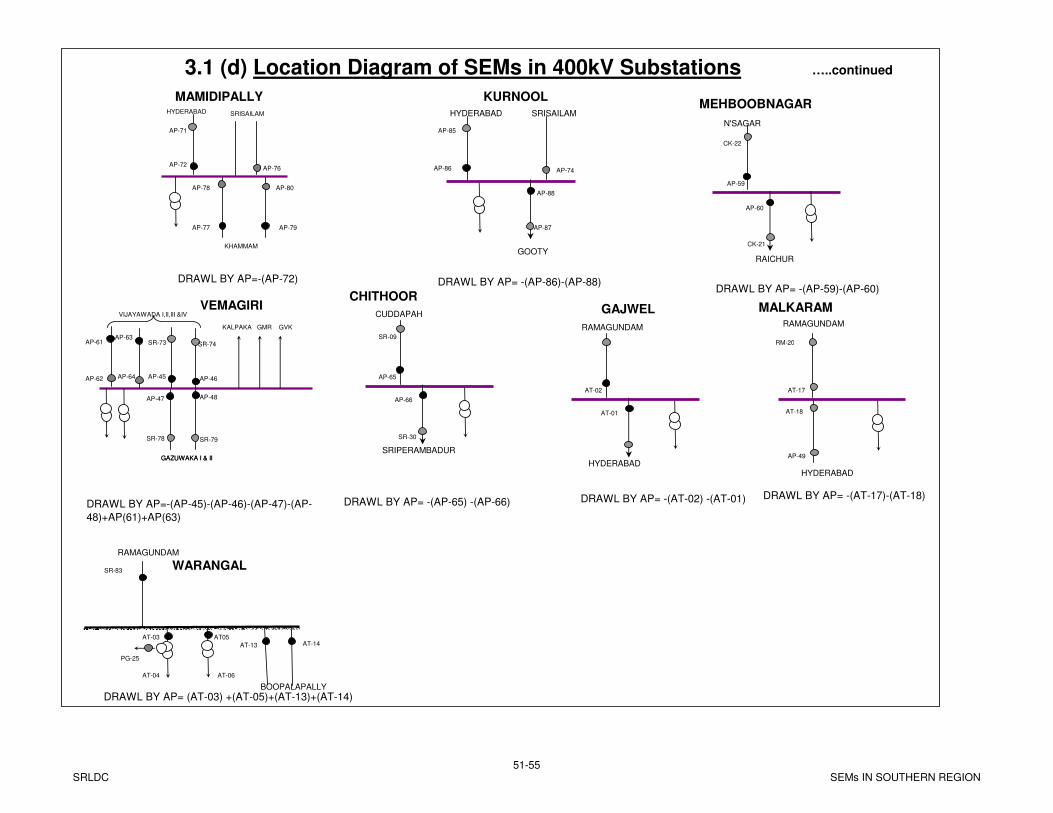
MAMIDIPALLYSRISAILAM
AP-76
AP-77 AP-79
AP-78 AP-80
KHAMMAM
DRAWL BY AP=-(AP-72)
AP-72
HYDERABAD
3.1 (d) Location Diagram of SEMs in 400kV Substations …..continued
KURNOOLHYDERABAD
AP-86
AP-88
GOOTY
AP-74
SRISAILAM
AP-65
AP-66
SRIPERAMBADUR
CHITHOOR
CUDDAPAH
DRAWL BY AP= -(AP-65) -(AP-66)
DRAWL BY AP= -(AP-86)-(AP-88)
AP-59
N'SAGAR
AP-60
RAICHUR
MEHBOOBNAGAR
DRAWL BY AP= -(AP-59)-(AP-60)
AP-71
AP-87
AP-85
CK-21
CK-22
SR-09
SR-30
VEMAGIRI
SR-78 SR-79
AP-47 AP-48
GAZUWAKA I & II
DRAWL BY AP=-(AP-45)-(AP-46)-(AP-47)-(AP-
48)+AP(61)+AP(63)
AP-45
VIJAYAWADA I,II,III &IV
SR-73
AP-46
SR-74
AP-64AP-62
AP-61AP-63
KALPAKA GMR GVK
AT-02
AT-01
HYDERABAD
GAJWEL
RAMAGUNDAM
DRAWL BY AP= -(AT-02) -(AT-01)
AT-17
MALKARAM
HYDERABAD
DRAWL BY AP= -(AT-17)-(AT-18)
RM-20
WARANGALRAMAGUNDAM
AT-04 AT-06
GAZUWAKA I & II
AT-03 AT05
SR-83
PG-25
DRAWL BY AP= (AT-03) +(AT-05)+(AT-13)+(AT-14)
AP-49
AT-18
RAMAGUNDAM
AT-13 AT-14
BOOPALAPALLY
SRLDC51-55
SEMs IN SOUTHERN REGION
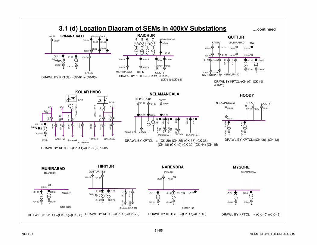
CK-05
CK-06
MUNIRABAD
CK-24
CK-27
RAICHUR
SOMANAHALLI
CK-01
CK-02
CK-03
CK-04
PG-19SR-12
SALEM
KOLAR NELAMANGALA
MEHBUBNAGAR
CK-21
RAICHUR4 5 6 7
CK-23 CK-25
MIUNIRABAD BTPS
NELAMANGALA
CK-29
CK
-30
HOODY
CK
-09
CK
-10
HOODY
NELAMANGALA KOLAR
DRAWL BY KPTCL=(CK-05)+(CK-68)
DRAWL BY KPTCL = -(CK-29)-(CK-35)-(CK-38)-(CK-36)
-(CK-48)-(CK-49)-(CK-30)-(CK-44)-(CK-45)
DRAWAL BY KPTCL= -(CK-21)-(CK-23)-
(CK-64)-(CK-65)
CK-07
CK-08
GUTTUR
CK-26
CK
-28
HIRIYUR-1&2
JSW
DRAWL BY KPTCL=(CK-07)+(CK-19)+
(CK-26)
DRAWL BY KPTCL= (CK-01)+(CK-03)
DRAWL BY KPTCL=(CK-09)+(CK-13)
AP-60 KAIGA
CK
-34
HIRIYUR-1&2
CK-35
TALAGUPPA HASSAN
CK
-36
CK-38
GOOTY
CK
-13
CK
-14
CK-11/66
CK-12/67
PG-05
SR
-64
SR
-63
SR
-61
SR
-60
SR
-62
KPTCL
KOLAR HVDC
POLE1POLE2
AF-3AF-2AF-1
DC-12
DC
-11
DC
-09
DC
-07
DC
-08
DC
-10C
ON
V. T
RF
-1
CO
NV
. T
RF
-2
SR
-65
SR
-66
HOSUR-1&2Somnahalli
CUDDAPAH
SP'DURHOODY-1&2
DRAWL BY KPTCL =(CK-11)+(CK-66)-(PG-05
3.1 (d) Location Diagram of SEMs in 400kV Substations …..continued
NELAMANGALA-1&2
CK
-33
GUTTUR-1&2
CK
-32
HIRIYUR
CK-15
CK-16
PG-21
CK
-44
MYSORE-1&2
CK
-45
MIUNIRABAD
GUTTUR
KAIGA-1&2
CK-17
CK-18
NARENDRA
GUTTUR-1&2
DRAWL BY KPTCL=(CK-15)+(CK-72)
CK-37
SOMANAHALLI
CK-19
CK-20
GOOTY
CK-46
CK-47
NELAMANGALA
CK-40
CK-41
MYSORE
CK-42
CK-43
DRAWL BY KPTCL =(CK-17)+(CK-46) DRAWL BY KPTCL = (CK-40)+(CK-42)
KG-22
CK-75
CK-27
CK-80
CK-62 CK-63
CK
-48
CK
-49
SR-61
CK-79CK-24
GOOTY
CK-64 CK-65
AP-67 AP-68
CK-36CK-48 CK-49
CK-39
CK-32CK-33 AP-89
CK
-31
CK
-37
CK
-62
CK
-63
CK-31
CK-30 SR-11SR-63 SR-64
CK
-29
CK
-35
CK-28 CK-34KG-25 KG-26
KG-21
CK-74
CK-76
CK-70
CK-77
CK-71
NARENDRA-1&2
CK-70 CK-71CK-68
CK-69
CK-72
CK-73
SRLDC51-55
SEMs IN SOUTHERN REGION
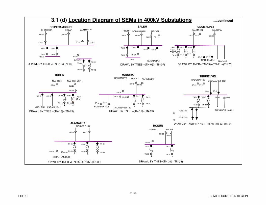
TN-03TN-01
TN-02
TNEB
SRIPERAMBDUR
TN-04
CHITHOOR KOLAR
PONDY
ALAMATHY
SALEM
TN-05
TN-06
TNEB
TN-07
TN-08
SR-13 SR-70
SOMANAHALLI NEYVELI
UDUMALPET
TN-09
TN-10
TN-11
TN-12
UDUMALPETSALEM-1&2 MADURAI
TRICHUR
PG-23
TRICHY
TN-15
TN-16
PG-25TN-13
TN-14
SR-15 SR-16
MADURAI
NLC TS-II NLC TS-I EXP.
TN-19
TN-20
TN-17
TN-18
MADURAIUDUMALPET TRICHY
DRAWL BY TNEB =(TN-01)+(TN-03) DRAWL BY TNEB =(TN-05)+(TN-07) DRAWL BY TNEB=(TN-09)+(TN-11)+(TN-73)
DRAWL BY TNEB =(TN-13)+(TN-15) DRAWL BY TNEB =(TN-17)+(TN-19)
SR-74SR-75
TIRUNELVELI-1&2
TN-33
TN-34
TN-31
TN-32
HOSUR
SALEM KOLAR
DRAWL BY TNEB=(TN-31)+(TN-33)
SR-30
HOSUR
SR-24SR-14
SR-67
SR-31 SR-32
TN-35
NELLORE 1&2
ALAMATHY
TN-36
TN-37
TN-38
TN-39
TN-40
SRIPERUMBUDUR
DRAWL BY TNEB =(TN-35)+(TN-37+(TN-39)
SR-31SR-32
SR-76 SR-77
AP-66 SR-62
RS-17
SR-67 SR-12RS-18 RS-19
SR-13 SR-70 SR-14
SR-65SR-66
SR-15SR-16RS-20
RS-21RS-21
TN-46
MADURAI-1&2
DRAWL BY TNEB=(TN-46)+ (TN-71)-(TN-83)-(TN-84)
TIRUNELVELI
TN-47
SR-41
SR-74 SR-75
TRIVANDRUM-1&2
SR-42
TN-73
TN-74
TN-71
TN-72
KARAIKUDY
KARAIKUDY
SR-47 SR-48
TIRUNELVELI
SR-47 SR-48
UDUMALPET-1&2
SR-80 SR-81
PUGALUR-1&2
TN-83 / TN-
84
KL-11 / KL-
12
PO-09
PO-10
PO-11
PO-12
3.1 (d) Location Diagram of SEMs in 400kV Substations …..continued
SRLDC51-55
SEMs IN SOUTHERN REGION
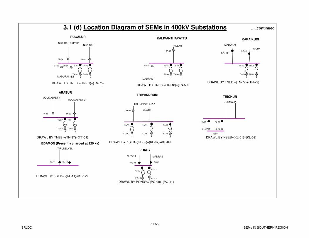
TRICHY
SR-46
KL01
KL-02
KL-03
KL-04
TRICHUR
KSEB
UDUMALPET
DRAWL BY KSEB=(KL-01)+(KL-03)
KL-05
TIRUNELVELI-1&2
DRAWL BY KSEB=(KL-05)+(KL-07)+(KL-09)
TRIVANDRUM
KL-06
KL-07
KL-08
SR-80 SR-81
KL-09
KL-10
TN-75
TN-76
TN-81
TN-82
PUGALUR
NLC TS-II
DRAWL BY TNEB =(TN-81)+(TN-75)
SR-80 SR-81
MADURAI-1&2
SR-84 SR-82
TN-59
TN-60
TN-48
TN-49
KALIVANTHAPATTU
KOLAR
DRAWL BY TNEB =(TN-77)+(TN-79)
SR-44
MADRAS
SR-43
TN-79
TN-80
TN-77
TN-78
MADURAI
SR-45
KARAIKUDINLC TS-II EXPN 2
DRAWL BY TNEB =(TN-48)+(TN-59)
TT-01
TT-02
TN-87
TN-88
ARASUR
UDUMALPET-2
DRAWL BY TNEB =(TN-87)+(TT-01)
TN-85 TN-86
UDUMALPET-1
KL-11 KL-12
EDAMON (Presently charged at 220 kv)
TIRUNELVELI
DRAWL BY KSEB= -(KL-11)-(KL-12)
PONDY
PO-08
PO-09
PO-10
PO-11
PO-12
PO-07
NEYVELI MADRAS
DRAWL BY PONDY= (PO-09)+(PO-11)
3.1 (d) Location Diagram of SEMs in 400kV Substations …..continued
SRLDC51-55
SEMs IN SOUTHERN REGION
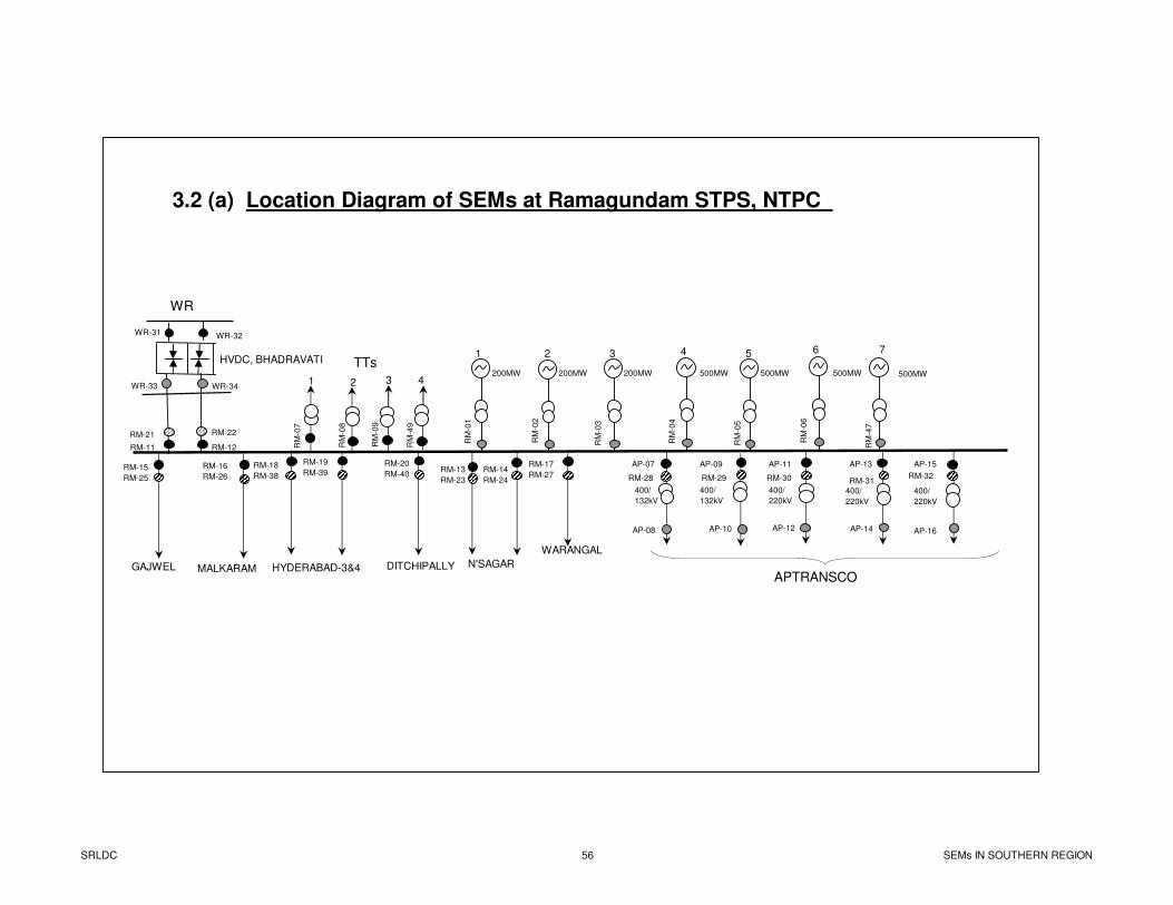
WR-31 WR-32
RM-21 RM-22
RM-11 RM-12
WR-33 WR-34
GAJWEL
RM
-01
RM
-02
RM
-03
RM
-04
RM
-05
RM
-06
RM-15
RM-25
RM-16
RM-26
RM
-07
RM
-08
RM
-09
AP-15
AP-16
AP-13
AP-14
AP-11
AP-12
AP-07
AP-08
AP-09
AP-10
RM-14
RM-24
RM-13
RM-23
N'SAGAR
TTs
42 3
RM-28 RM-29 RM-30 RM-31RM-32
HVDC, BHADRAVATI
WR
APTRANSCO
400/
132kV
400/
220kV
400/
220kV
400/
220kV
400/
132kV
1 2 3 4 5 6
200MW 500MW200MW 200MW 500MW 500MW
RM
-47
7
500MW
RM
-49
HYDERABAD-3&4
1
3.2 (a) Location Diagram of SEMs at Ramagundam STPS, NTPC
RM-18
RM-38
RM-19
RM-39
WARANGAL
RM-17
RM-27
RM-20
RM-40
DITCHIPALLYMALKARAM
SRLDC 56 SEMs IN SOUTHERN REGION
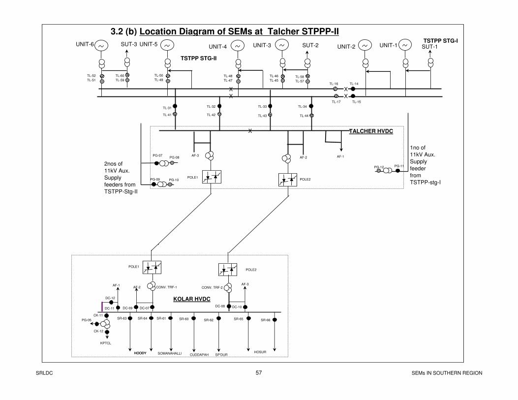
CK-11
CK-12
PG-05SR-64SR-63 SR-65 SR-66
SR-61 SR-60 SR-62
KPTCL
HOODY SOMANAHALLI CUDDAPAH SP'DURHOSUR
KOLAR HVDC
HOODY
POLE1POLE2
UNIT-6 UNIT-5 UNIT-4 UNIT-3TSTPP STG-I
TSTPP STG-II
POLE1POLE2
AF-3AF-2 AF-1
AF-3AF-2
AF-1
TALCHER HVDC
X
X
X
DC-12
DC-11 DC-09 DC-07DC-08 DC-10
CONV. TRF-1 CONV. TRF-2
TL-14TL-16
TL-17
TL-31 TL-32 TL-33 TL-34
TL-41 TL-42 TL-43
XXTL-15
TL-44
SUT-3 SUT-2 UNIT-2 UNIT-1 SUT-1
1no of
11kV Aux.
Supply
feeder
from
TSTPP-stg-I
2nos of
11kV Aux.
Supply
feeders from
TSTPP-Stg-II
3.2 (b) Location Diagram of SEMs at Talcher STPPP-II
PG-07PG-08
PG-09 PG-10
PG-11PG-12
TL-46
TL-45TL-58
TL-57
TL-48
TL-47
TL-50
TL-49
TL-52
TL-51
TL-60
TL-59
SRLDC 57 SEMs IN SOUTHERN REGION
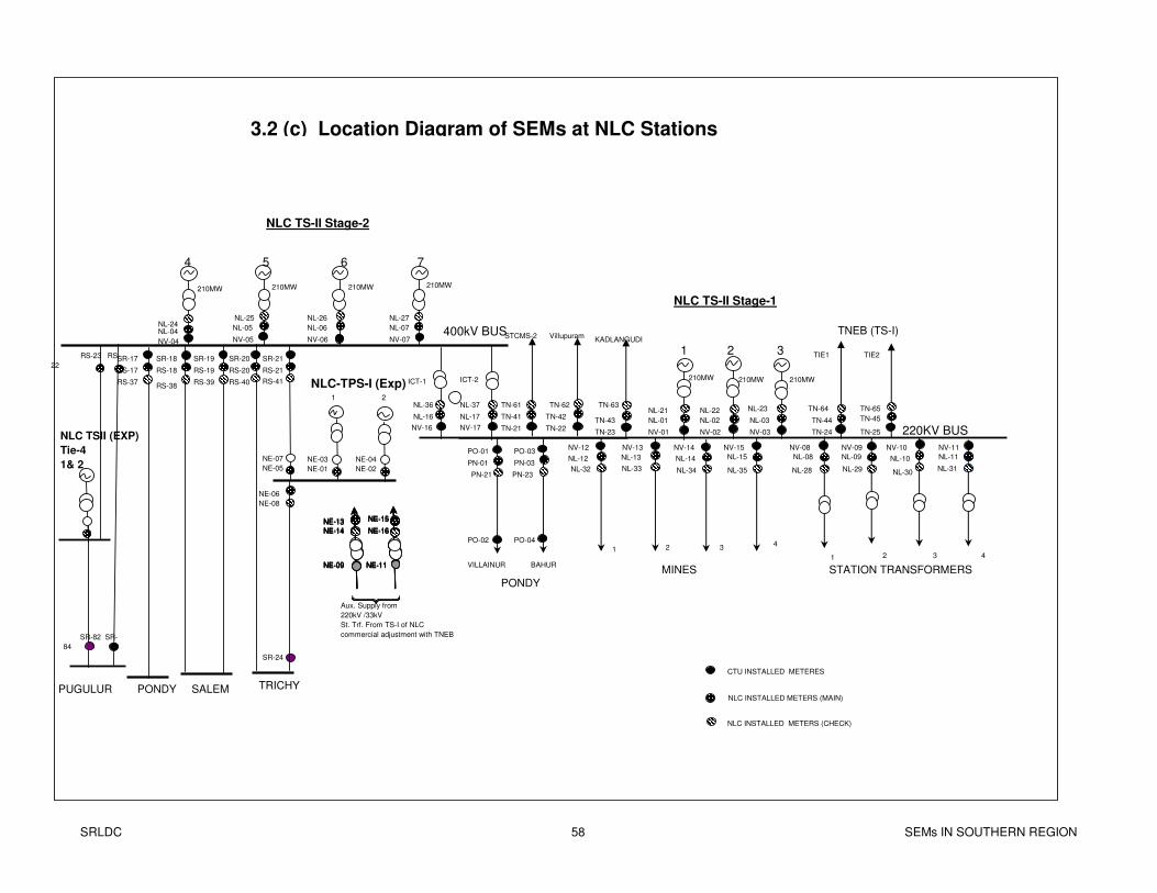
220KV BUS
MINES STATION TRANSFORMERS
NV-09 NV-10 NV-11NV-08NV-15NV-14NV-13NV-12
1 2 34
1 2 3 4
TNEB (TS-I)
TIE1 TIE2
TN-24 TN-25NV-03NV-17NV-16
STCMS-2 VillupuramKADLANGUDI
PO-03
PO-04
PO-01
PO-02
VILLAINUR BAHUR
TN-22TN-21TN-23
ICT-1 ICT-2NLC-TPS-I (Exp)
SALEM TRICHYPUGULUR PONDY
SR-17 SR-18 SR-19 SR-21SR-20
NV-02NV-01
NV-04 NV-05 NV-06 NV-07
4 5 6 7
400kV BUS
321
PONDY
NLC TS-II Stage-2
NLC TS-II Stage-1
210MW 210MW 210MW
210MW 210MW 210MW 210MW
NL-04NL-05 NL-06 NL-07
RS-17 RS-18 RS-19 RS-21RS-20
PN-03PN-01NL-09 NL-10 NL-11NL-08NL-15NL-14NL-13NL-12
TN-44 TN-45NL-03NL-17NL-16 TN-42TN-41
TN-43 NL-02NL-01
SR-24
NLC INSTALLED METERS (MAIN)
NLC INSTALLED METERS (CHECK)
CTU INSTALLED METERES
Aux. Supply from
220kV /33kV
St. Trf. From TS-I of NLC
commercial adjustment with TNEB
3.2 (c) Location Diagram of SEMs at NLC Stations
NL-33NL-32 NL-34 NL-35 NL-28 NL-29 NL-30NL-31
NL-36 NL-37
PN-21 PN-23
TN-61 TN-62 TN-63TN-64 TN-65NL-21 NL-22 NL-23
NL-24NL-25 NL-26 NL-27
RS-37RS-38
RS-39 RS-40
1 2
NE-03
NE-01
NE-04
NE-02
NE-06
NE-08
NE-07
NE-05
NE-15
NE-16
NE-13
NE-14
NE-09 NE-11
RS-41
NE-15
NE-16
NE-13
NE-14
NE-09 NE-11
NE-15
NE-16
NE-13
NE-14
NE-09 NE-11
NE-15
NE-16
NE-13
NE-14
NE-09 NE-11
NLC TSII (EXP)
Tie-4
1& 2
RS-23 RS-
22
SR-82 SR-
84
SRLDC 58 SEMs IN SOUTHERN REGION
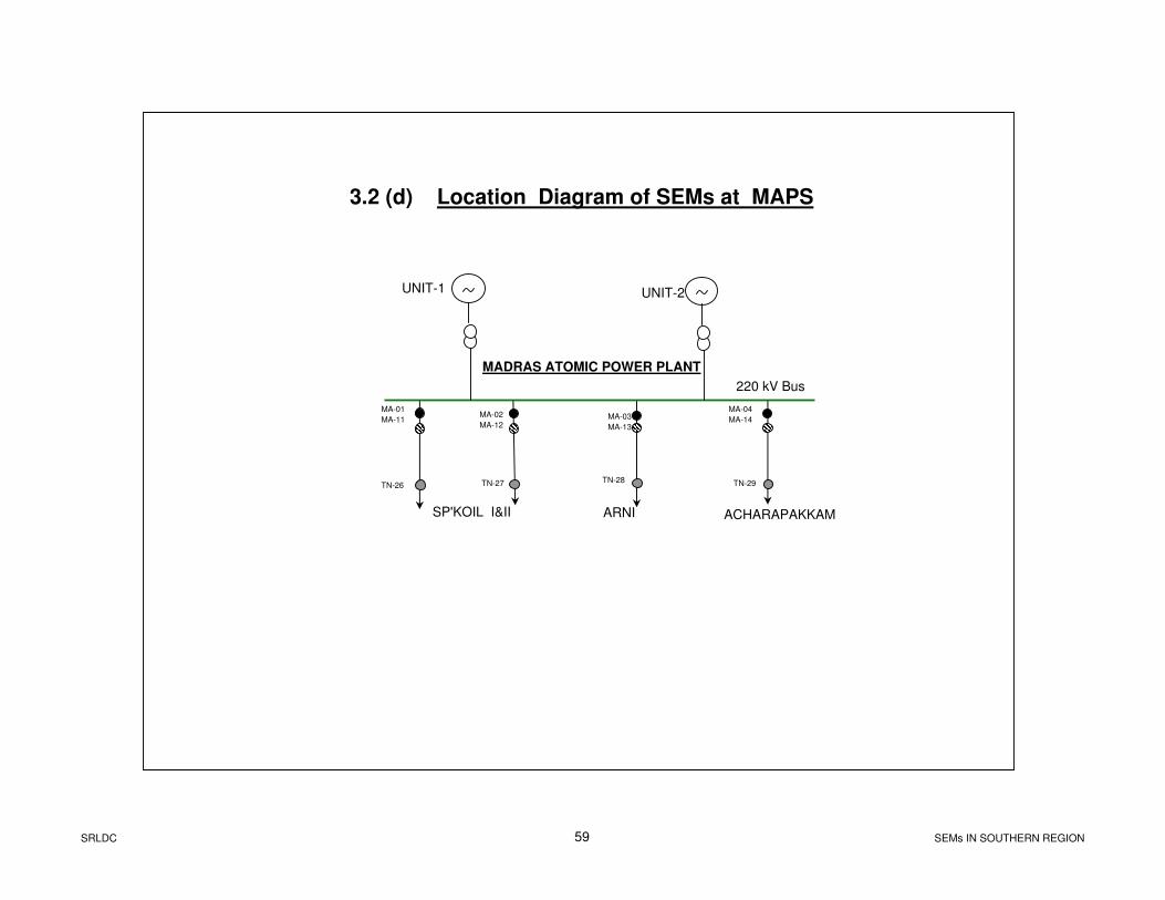
SP'KOIL I&II ACHARAPAKKAM
MA-01
MA-11MA-02
MA-12
ARNI
MA-03
MA-13
MA-04
MA-14
UNIT-1 UNIT-2
TN-26 TN-27TN-28
TN-29
MADRAS ATOMIC POWER PLANT
220 kV Bus
3.2 (d) Location Diagram of SEMs at MAPS
SRLDC 59 SEMs IN SOUTHERN REGION
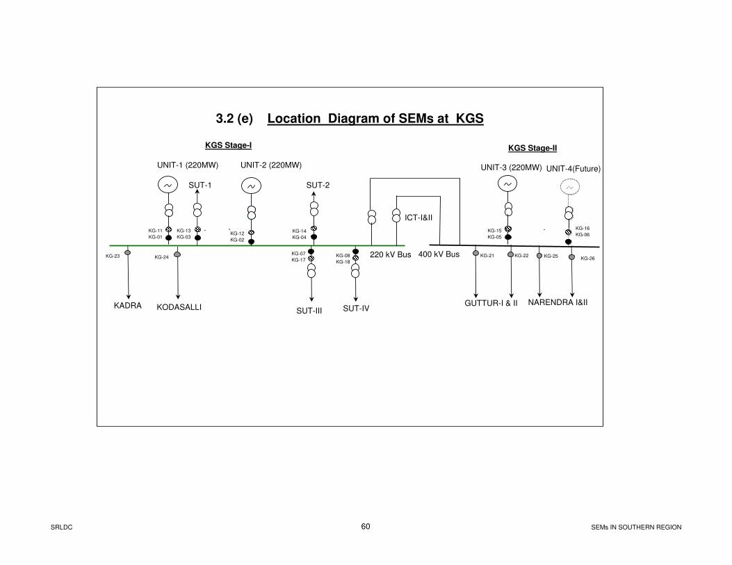
GUTTUR-I & II
KG-21
KODASALLIKADRA
KG-23 KG-24
KG-11
KG-01
UNIT-1 (220MW)
400 kV Bus 220 kV Bus
UNIT-4(Future)
ICT-I&II
SUT-III
KG-07
KG-17
SUT-IV
KG-08
KG-18
NARENDRA I&II
KG-25KG-26
3.2 (e) Location Diagram of SEMs at KGS
KG-12
KG-02
UNIT-2 (220MW)
KG-13
KG-03
SUT-1
KG-14
KG-04
SUT-2
KG-22
KG-15
KG-05
UNIT-3 (220MW)
KGS Stage-I KGS Stage-II
KG-16
KG-06
SRLDC 60 SEMs IN SOUTHERN REGION
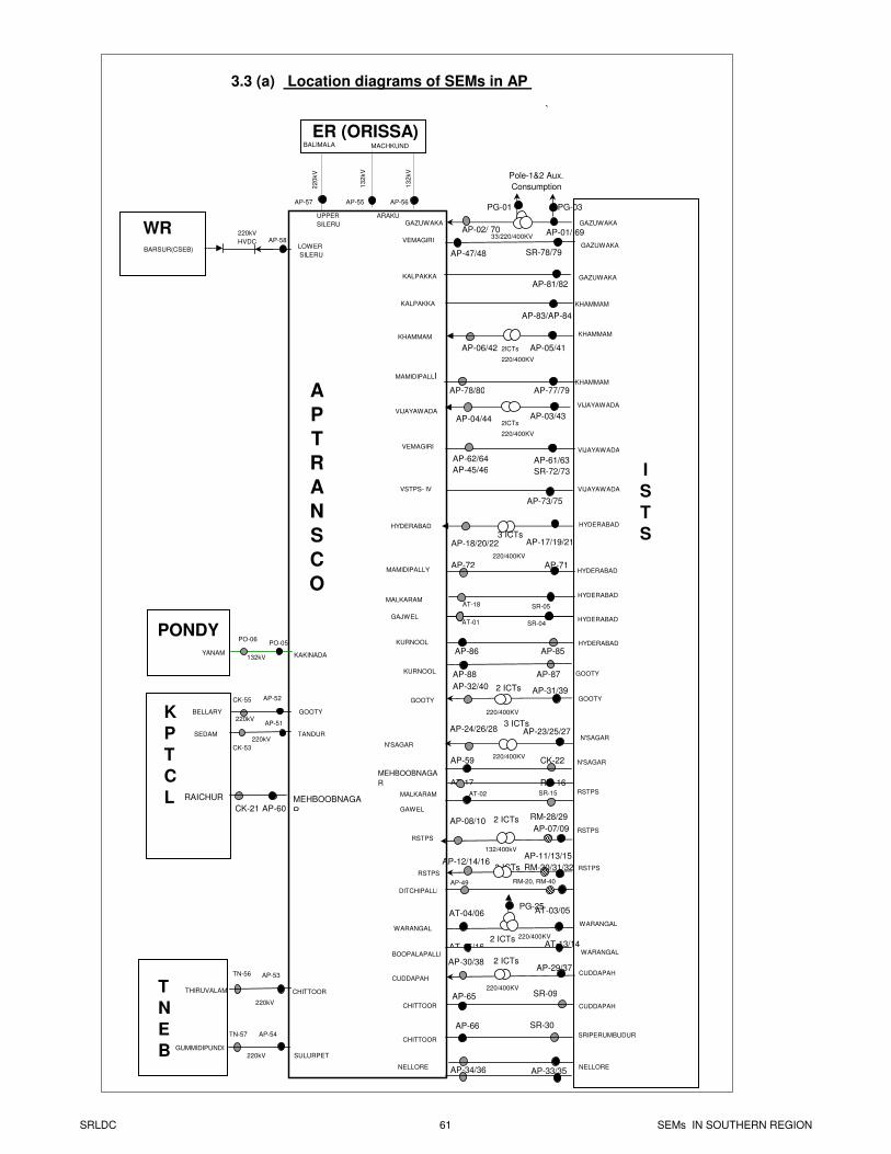
`
BARSUR(CSEB)LOWER
SILERU
UPPER
SILERU
ARAKU
AP-57 AP-56AP-55
BALIMALA MACHKUND
WR
ER (ORISSA)
220kV
HVDC
22
0kV
T
N
E
B
PONDYPO-05
PO-06
KAKINADA
AP-54TN-57
SEDAM TANDUR
GOOTYK
P
T
C
L
AP-53TN-56
THIRUVALAM CHITTOOR
BELLARY
SULURPETGUMMIDIPUNDI
220kV
132kV
220kV
13
2kV
3.3 (a) Location diagrams of SEMs in AP
13
2kV
AP-01/ 69AP-02/ 70GAZUWAKA
AP-03/43AP-04/44VIJAYAWADA
GAZUWAKA
KALPAKKA
VSTPS- IV
NELLORE
AP-62/64
AP-45/46AP-61/63
SR-72/73
VEMAGIRI
AP-05/41AP-06/42
KHAMMAM
132/400kV
RSTPS
2 ICTsAP-08/10AP-07/09
3 ICTsAP-12/14/16
RSTPS
AP-11/13/15
220/400KV
AP-18/20/22 AP-17/19/21
HYDERABAD
AP-24/26/28
N'SAGAR
AP-23/25/27N'SAGAR
AP-30/38AP-29/37
CUDDAPAH
AP-32/40AP-31/39
AP-71
AP-78/80 AP-77/79
MAMIDIPALLI
KHAMMAM
CK-22
RM-16
AP-59
AT-17MEHBOOBNAGA
R
MALKARAM RAICHUR
AP-86 AP-85KURNOOL
SR-09AP-65CHITTOOR
SR-30AP-66
PG-01 PG-03
Pole-1&2 Aux.
Consumption
AP-87AP-88
A
P
T
R
A
N
S
C
O
AP-58
YANAM
3 ICTs
AP-83/AP-84
3 ICTs
220/400KV
220/400KV
2 ICTs
220/400KV
AP-81/82
2ICTs
220/400KV
33/220/400KV
CK-53
AP-51
CK-55 AP-52
CK-21 AP-60
I
S
T
S
220kV
220kV
2 ICTs
220/400KV
RM-28/29
RM-30/31/32
SR-78/79
PG-25
WARANGAL
BOOPALAPALLI
DITCHIPALLI
GAWEL
AP-73/75
VEMAGIRI
AP-47/48
RM-20, RM-40AP-49
AP-72MAMIDIPALLY
AT-02 SR-15
AT-01 SR-04
AT-03/05
AT-13/14
AT-04/06
AT-15/16
KALPAKKA
GAJWEL
KURNOOL GOOTY
GAZUWAKA
GAZUWAKA
KHAMMAM
KHAMMAM
VIJAYAWADA
VIJAYAWADA
VIJAYAWADA
HYDERABAD
HYDERABAD
GOOTY
AP-34/36 AP-33/35
CHITTOOR
2 ICTs
2ICTs
220/400KV
MALKARAMAT-18 SR-05
MEHBOOBNAGA
R
HYDERABAD
HYDERABAD
HYDERABAD
GOOTY
N'SAGAR
RSTPS
RSTPS
RSTPS
WARANGAL
WARANGAL
CUDDAPAH
CUDDAPAH
SRIPERUMBUDUR
NELLORE
SRLDC 61 SEMs IN SOUTHERN REGION

`
````
AP-51CK-53
TANDUR
GOOTY
A P
AP-52CK-55BELLARY
SEDAM
HOSURYERANDAHALLI
TNEB
BANGALORE
N'SAGAR
MBD
IS
T
S
CK-51KL-55
KL-56 CK-52
KONAJE
KADAKOLA
MANJESWAR
KANIAMPETTA
KSEB
KG-24
KG-23
KG-21
KODASALLI
KADRA
GUTTUR-1
K
G
S
CK-60
CK-61
CHIKKODI
TALANGENE (Kolhapur)
MSEB(WR)
220kV
110kV
TN-55CK-54220kV
220kV
220kV
220kV
220kV
220kV
220kV
220kV
GO-03
GO-04
GO-01
GO-02
AMBEWADI
XELDEMXELDEM
PONDA
PONDA
PONDA
SUPA
G
O
A(SR)
CK-58
CK-59
CK-56
CK-57
220kV
220kV
110kV
110kV
HOODY
SR-63
SR-64
KOLAR400kV
KG-25
NARENDRA400kV
KG-26
NARENDRA400kV
HOODY
CK-11CK-12
KOLARKOLAR
220/400kV
PG-05
Pole-1&2 Aux.
3.3(b) Location Diagram of SEMs in KPTCL System
MUSHTUNGI (Kolhapur)
KPTCL
CK-17CK-18
NARENDRA NARENDRA
CK-01CK-02SOMANAHALLI SOMANAHALLI
CK-03CK-04 220/400kV
SOMANAHALLI SOMANAHALLI
CK-21MEHBOOBNAGAR
AP-60
RAICHUR400kV
220/400kVCK-15CK-16
HIRIYURHIRIYUR
400kVCK-38GOOTY
AP-89NELAMANGALA
NELAMANGALA
CK-37400kV
CK-36
SOMANAHALLI
CK-05CK-06220/400kV
MUNIRABAD MUNIRABAD
CK-21RAICHUR
4 5 6 7
CK-23
CK-05
CK-06
CK-24
CK-27
CK-26 GUTTUR
CK-25
BTPS
JSW
NELAMANGALA
CK-28
CK-09
CK-10
CK-30
CK-31
CK-07
CK-08
CK-15
CK-16
HIRIYUR
CK-29
CK-32 CK-33
CK-35
CK-48
CK-34
Talaguppa
MEHBBOBNAGAR
MUNIRABAD
SOMANAHALLI
GOOTY
KOLAR
CK-38
Raichur-Hoody section
CK-13
CK-14
GOOTY
KAIGA-1&2
CK-46CK-47NARENDRA NARENDRA
220/400kV
MYSOREMYSORE
220/400KV
MYSOREMYSORE
CK-41 CK-40
CK-42CK-43
CK-21RAICHUR
4 5 6 7
CK-23
CK-05
CK-06
CK-24
CK-27
CK-26 GUTTUR
NELAMANGALA
CK-28
CK-07
CK-08
CK-15
CK-16
HIRIYUR
CK-29
CK-32 CK-33
CK-35
CK-36
CK-34
Talaguppa
MEHBBOBNAGAR
MUNIRABAD
SOMANAHALLI
GOOTY
KOLAR
CK-38
Raichur-Hoody section
GOOTY
CK-19
CK-20
KG-224000kV
GUTTUR-2
CK-24CK-23400kV
CK-27MUNIRABAD
MUNIRABADRAICHUR
GUTTUR
CK-34
CK-28
GUTTUR HIRIYUR
CK-33
CK-35
NELAMANGALA HIRIYUR
NELAMANGALA
CK-62400kV
CK-49
SOMANAHALLI
NELAMANGALA
CK-63400kV
CK-48
SOMANAHALLI
NELAMANGALA MYSORE
CK-44
CK-45
400kV
400kV
400kV
Mysore
CK-45CK-44CK-49
AP-65RAICHUR 400kV
AP-64CK-64
CK-65 GOOTY
GOOTYCK-64 CK-65
400kV
CK-19
CK-08 CK-07
CK-20
CK-13 CK-09
SRLDC 62 SEMs IN SOUTHERN REGION
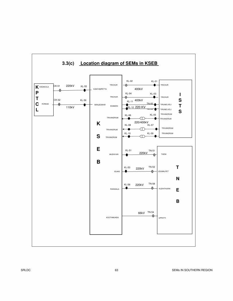
KL-01KL-02
KL-03KL-04 I
S
T
S
KL-56
MANJESWARKONAJE
K
P
T
C
L
TN-51
TN-83
TN-84
TN-53
TN-58
KL-51
KL-11
KL-12
KL-53
KL-58
THENI
UDUMALPET
KUZHITHURAI
MUZHIYAR
IDUKKI
PARASALA
K
S
E
B
CK-52
KL-55
KANIYAMPETTA
KADAKOLACK-51 220kV
110kV
T
N
E
B
TN-54
UPPATTIKOOTHMUNDA
220kV
220kV
220kV
66kV
400kV
400kV
KL-05KL-06
220/400kV
3.3(c) Location diagram of SEMs in KSEB
TRIVANDRUM
TRICHUR
TRIVANDRUM
TRIVANDRUM
TRIVANDRUM
TRIVANDRUM
TRIVANDRUM
KL-08 KL-07
KL-10 KL-09
220 KV
TRICHUR
EDAMON
TRICHUR
TRICHUR
TRIVANDRUM
TIRUNELVELI
TIRUNELVELI
SRLDC 63 SEMs IN SOUTHERN REGION
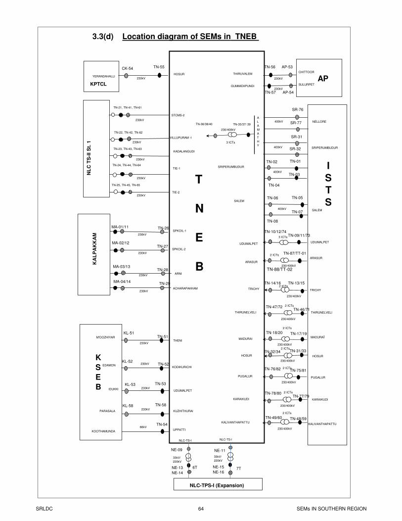
AP-53TN-56
TN-57 AP-54
CHITTOOR
SULURPET
APTHIRUVALEM
GUMMIDIIPUNDI
I
S
T
S
TN-55
HOSURYERANDAHALLI
KPTCL
K
S
E
B
T
N
E
B
CK-54
TN-51KL-51
THENIM'OOZHIYAR
TN-58KL-58
KUZHITHURAIPARASALA
TN-53KL-53
UDUMALPETIDUKKI
230kV 230kV
230kV
230kV
TN-52KL-52
KODIKURICHIEDAMON
230kV
230kV
230kV
TN-54
UPPATTIKOOTHAMUNDA
66kV
400kV
SALEM400kV
SRIPERUMBUDUR
TN-01TN-02
TN-03
TN-04
NE-13
NE-14
NLC-TPS-I (Expansion)
NLC-TS-I NLC-TS-I
3.3(d) Location diagram of SEMs in TNEB
NE-15
NE-16
6T 7T
NE-09 NE-11
UDUMALPET
TN-09/11/73TN-10/12/74
230/400kV
UDUMALPET
TRICHY TRICHY
33kV/
220kV
33kV/
220kV
NL
C T
S-I
I S
t. 1
TIE-2
TIE-1TN-24, TN-44, TN-64
KADALANGUDITN-23, TN-43, TN-63
VILLUPURAM -I
TN-22, TN-42, TN-62
TN-21, TN-41, TN-61
STCMS-2
TN-25, TN-45, TN-65
MA-01/11 TN-26SPKOIL-1
230kV
MA-02/12TN-27
230kV
SPKOIL-2
TN-28MA-03/13
230kVARNI
TN-29MA-04/14
230kVACHARAPAKKAM
NELLORE
A
L
A
M
A
T
H
Y
400kV
SR-76
SR-77
400kV
SR-31
SR-32
230kV
230kV
230kV
230kV
230kV
KA
LP
AK
KA
M
TN-35/37/ 39TN-36/38/40
230/400kV
3 ICTs
TN-05TN-06
TN-07
TN-08
TN-13/15TN-14/16
230/400kV
SALEM
TN-17/19TN-18/20
230/400kV
MADURAIMADURAI
3 ICTs
2 ICTs
2 ICTs
TN-31/33TN-32/34HOSURHOSUR
230/400kV
2 ICTs
TN-75/81TN-76/82
PUGALURPUGALUR
230/400kV
2 ICTs
TN-48/59TN-49/60
KALIVANTHAPATTUKALIVANTHAPATTU
230/400kV
2 ICTs
TN-46/71TN-47/72
THIRUNELVELITHIRUNELVELI
230/400kV
2 ICTs
TN-77/79TN-78/80
KARAIKUDIKARAIKUDI
230/400kV
2 ICTs
2 ICTsTN-87/TT-01
TN-88/TT-02
ARASUR
ARASUR
SRIPERUMBUDUR
SRLDC 64 SEMs IN SOUTHERN REGION
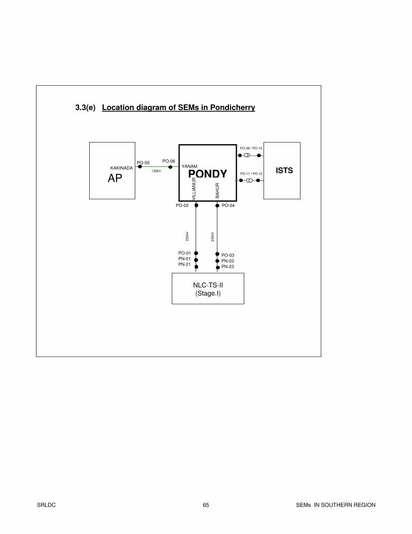
NLC-TS-II
(Stage.I)
PONDY
PO-06
PO-01
PN-01
PN-21
23
0kV
23
0kV
AP
PO-05
132kVKAKINADA
VIL
LIA
NU
R
PO-04
BA
HU
R
PO-03
PN-03
PN-23
PO-02
YANAM
3.3(e) Location diagram of SEMs in Pondicherry
ISTS
PO-09 / PO-10
PO-11 / PO-12
SRLDC 65 SEMs IN SOUTHERN REGION
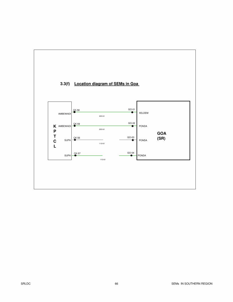
GO-01CK-58
220 kV
3.3(f) Location diagram of SEMs in Goa
K
P
T
C
L
GOA
(SR)
AMBEWADI XELDEM
PONDA
GO-02CK-59
220 kV
AMBEWADI
SUPA
CK-56
110 kV
CK-57
110 kV
SUPA
PONDA
GO-03
GO-04
PONDA
SRLDC 66 SEMs IN SOUTHERN REGION
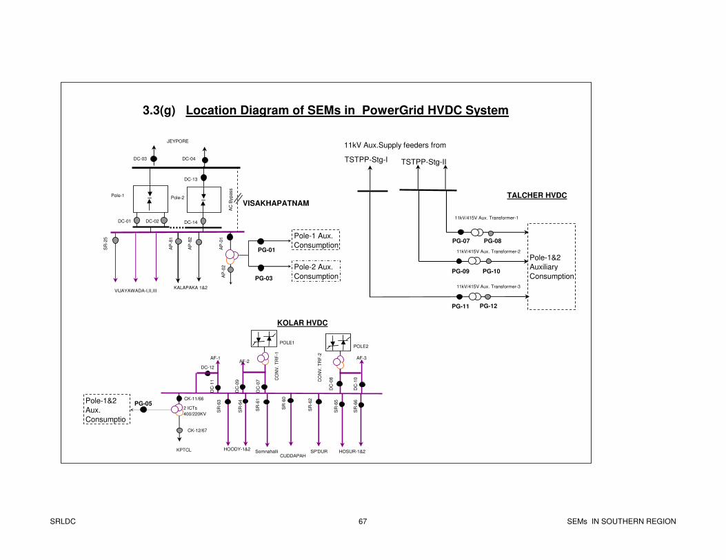
East Bus
3.3(g) Location Diagram of SEMs in PowerGrid HVDC System
AP
-02
JEYPORE
AP
-01
DC-03
DC-01
AC
Bypass
DC-04
AP
-81
AP
-82
KALAPAKA 1&2
VISAKHAPATNAM
VIJAYAWADA-I,II,III
DC-02
DC-13
PG-01SR
-25
PG-03
Pole-2 Aux.
Consumption
DC-14
Pole-1 Pole-2
Pole-1 Aux.
Consumption
CK-11/66
CK-12/67
PG-05
SR
-64
SR
-63
SR
-61
SR
-60
SR
-62
KPTCL
KOLAR HVDC
POLE1POLE2
AF-3AF-2
AF-1
DC-12
DC
-11
DC
-09
DC
-07
DC
-08
DC
-10CO
NV
. T
RF
-1
CO
NV
. T
RF
-2
SR
-65
SR
-66
HOSUR-1&2SomnahalliCUDDAPAH
SP'DURHOODY-1&2
Pole-1&2
Aux.
Consumptio
11kV Aux.Supply feeders from
Pole-1&2
Auxiliary
Consumption
TALCHER HVDC
11kV/415V Aux. Transformer-1
11kV/415V Aux. Transformer-3
11kV/415V Aux. Transformer-2
PG-07 PG-08
PG-10PG-09
PG-11 PG-12
TSTPP-Stg-IITSTPP-Stg-I
2 ICTs
400/220KV
SRLDC 67 SEMs IN SOUTHERN REGION
SECTION – 4
COMPUTATION OF INJECTION & DRAWAL
COMPUTATION OF INJECTION & DRAWAL
4.1 Accounting Methodology
4.2 Computation of injection by ISGSs / other Regions
4.2(a) Ramagundam STPS
4.2(b) Talcher STPP-II
4.2(c) NLC TS-2 Stage-1, TS-2 Stage-2
4.2(d) NLC TPS-1 Expansion
4.2(e) Madras Atomic Power Station
4.2(f) Kaiga Generating Station
4.2(g) Western Region
4.2(h) Eastern Region
4.3 Computation of drawal by Drawee Utilities
4.3(a) APTRANSCO system
4.3(b) KPTCL system
4.3(c) KSEB system
4.3(d) TNEB system
4.3(e) Pondicherry system
4.3(f) Goa system
4.3(g) PG-HVDC system
SRLDC 68-71 SEMs IN SOUTHERN
REGION
4.1 ACCOUNTING METHODOLOGY
1. Definitions
(a) Main Meters: Meters which would primarily be used for energy
accounting and billing. For example meters connected on 400 kV side of an ICT
shall be called as main meters.
(b) Check Meters: Meters connected to the same core of CT/PT to which main
meter is connected. They shall be used for energy accounting and billing in case
of failure of main meter.
(c) Standby meters: Meters connected to CTs and VTs other than those used for
main and check meters. They shall be used or energy accounting and billing in
case of failure of both main and check meters. For example meters connected on
220 kV side of an ICT shall be called as standby meters.
2. General:
(a) In accordance with the sign convention described in Section No.1.2, Main
and Check meters record data with same sign whereas the corresponding
Standby meter records data with opposite sign.
(b) While carrying out Energy Accounting, SEMs on feeders not carrying
ISGS power are not considered.
(c) To facilitate computations and check their correctness, various ‘Ficticious’
meters are defined using sum of a few meters. For example,
SRLDC 68-71 SEMs IN SOUTHERN
REGION
i) For a Generating Station, for computing the total injection by
the ISGS, a ficticious meter is defined using the sum of all
meters on GTs/TTs. Similarly one more ficticious meter is
defined, using sum of meters on outgoing feeders. Various
combinations are worked out using Main meters, Check
meters and Standby Meters.
ii) For a drawee utility, for computing its total drawal fromGrid,
a ficticious meter is defined using sum of all the meters at its
touch points.
3. Criteria for Energy Accounting
(a) Injection by NTPC stations
Data of SEMs connected on outgoing feeders is used.
(b) Injection by stations other than NTPC.
Data of SEMs connected on GT side feeders is used.
(c) Drawal by utilities
At Generating Stations/CTU substations : Data of SEMs connected on HV
side of ICTs is used. For State owned 400 kV lines connecting to CTU
network, data of SEM on the line at CTU end is used.
At State owned substations connecting 220 kV/132 kV/110 kV inter-State
lines: Data of SEMs connected at respective end is used.
SRLDC 68-71 SEMs IN SOUTHERN
REGION
4. Data Validation and pair checks:
For ensuring correctness of readings and detecting under recording by meters,
block-wise data of Main Meters, Check Meters and Standby Meters on a
particular feeder are compared using suitable tolerances. Such pair check is
carried out for some Ficticious meters also wherever one-one to one
correspondence exists. Further, energy loss at a particular station is also
computed using Kirchoff’s law, to detect any under recording by a meter.
5. Computations in case of Under-recording of Main SEMS :
(a) Whenever a Main meter is under recording (in comparison with the
corresponding Standby/Check meter) due to reasons such as fuse failure
etc., an adjustment is made using the difference in the reading with respect
to that of standby/check meter so that the under recording is compensated.
While doing so, suitable Loss factors applied in general are as given
below:
In case of ICTs, no loss factor is applied.
In case of 400 kV Line, a loss factor of 1% is applied.
In case of 220 kV/132 kV Lines, a loss factor of 2% is applied.
(b) Wherever Standby meters are not available, if both Main and Check
meters are under recording, then Algebraic Sum of the meters connected
to the Bus will be considered for arriving at the adjustment to be done for
such under recording.
SRLDC 68-71 SEMs IN SOUTHERN
REGION
6. Sharing of losses in State owned 400 kV lines on regional basis
(a) Losses on KPTCL owned 400 kV lines in Raichur-Guttur-Hiriyur-
Nelamangala-Hoody section are being shared by all constituents. For
details please refer to Sub-Section 4.3(b) ‘Computation of drawal by
KPTCL from Grid’.
(b) Losses on 400 kV Hyderabad-Mamidipally S/C line are being shared by
all constituents. Accordingly for computing APTRANSCO’s drawal from
Hyderabad S/S, SEM installed at Mamidipally end on 400 kV Hyderabad-
Mamidipally is used.
(c) Losses on 400 kV Vijayawada-Srisailam-Mamidipally line-II are being
shared by all constituents. A loss factor of 2% is applied on SEM installed
on 400 kV Srisailam line-II at Vijayawada (considering 1% for
Vijayawada-Srisailam Line-II and 1% for Srisailam-Mamdipally line-II).
7. Computations of Reactive Energy
(a) Reactive power exchange by a beneficiary at an ISGS shall not be
considered for computing the reactive energy drawal by that beneficiary
(as per item No.6.6.1 of IEGC).
(b) Generally for computation of Reactive energy, SEMs at same points as the
active energy are considered. However, at touch points between CTU and
State owned 400 kV lines (except) in case of KPTCL) data of SEM at
CTU end shall be considered for determining the reactive energy
injection/drawal by the beneficiary.
(c) No adjustment is made in the computation of reactive energy in case of
under recording of SEM due to reasons such as fuse failure etc.
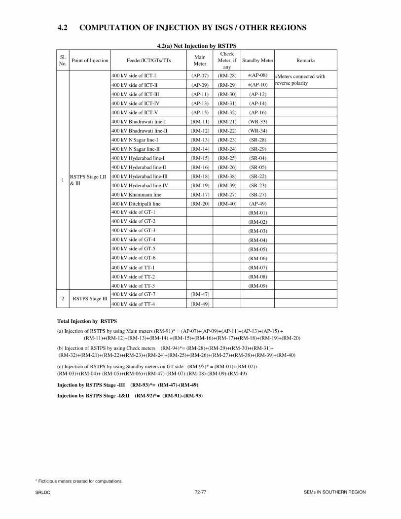
4.2 COMPUTATION OF INJECTION BY ISGS / OTHER REGIONS
4.2(a) Net Injection by RSTPS
Sl.
No.Point of Injection Feeder/ICT/GTs/TTs
Main
Meter
Check
Meter, if
any
Standby Meter Remarks
400 kV side of ICT-I (AP-07) (RM-28) #(AP-08)
400 kV side of ICT-II (AP-09) (RM-29) #(AP-10)
400 kV side of ICT-III (AP-11) (RM-30) (AP-12)
400 kV side of ICT-IV (AP-13) (RM-31) (AP-14)
400 kV side of ICT-V (AP-15) (RM-32) (AP-16)
400 kV Bhadrawati line-I (RM-11) (RM-21) (WR-33)
400 kV Bhadrawati line-II (RM-12) (RM-22) (WR-34)
400 kV N'Sagar line-I (RM-13) (RM-23) (SR-28)
400 kV N'Sagar line-II (RM-14) (RM-24) (SR-29)
400 kV Hyderabad line-I (RM-15) (RM-25) (SR-04)
400 kV Hyderabad line-II (RM-16) (RM-26) (SR-05)
400 kV Hyderabad line-III (RM-18) (RM-38) (SR-22)
400 kV Hyderabad line-IV (RM-19) (RM-39) (SR-23)
400 kV Khammam line (RM-17) (RM-27) (SR-27)
400 kV Ditchipalli line (RM-20) (RM-40) (AP-49)
400 kV side of GT-1 (RM-01)
400 kV side of GT-2 (RM-02)
400 kV side of GT-3 (RM-03)
400 kV side of GT-4 (RM-04)
400 kV side of GT-5 (RM-05)
400 kV side of GT-6 (RM-06)
400 kV side of TT-1 (RM-07)
400 kV side of TT-2 (RM-08)
400 kV side of TT-3 (RM-09)
400 kV side of GT-7 (RM-47)
400 kV side of TT-4 (RM-49)
Total Injection by RSTPS
(a) Injection of RSTPS by using Main meters (RM-91)* = (AP-07)+(AP-09)+(AP-11)+(AP-13)+(AP-15) +
(RM-11)+(RM-12)+(RM-13)+(RM-14) +(RM-15)+(RM-16)+(RM-17)+(RM-18)+(RM-19)+(RM-20)
(b) Injection of RSTPS by using Check meters (RM-94)*= (RM-28)+(RM-29)+(RM-30)+(RM-31)+
(RM-32)+(RM-21)+(RM-22)+(RM-23)+(RM-24)+(RM-25)+(RM-26)+(RM-27)+(RM-38)+(RM-39)+(RM-40)
(c) Injection of RSTPS by using Standby meters on GT side (RM-95)* = (RM-01)+(RM-02)+
(RM-03)+(RM-04)+ (RM-05)+(RM-06)+(RM-47)-(RM-07)-(RM-08)-(RM-09)-(RM-49)
Injection by RSTPS Stage -III (RM-93)*= (RM-47)-(RM-49)
Injection by RSTPS Stage -I&II (RM-92)*= (RM-91)-(RM-93)
#Meters connected with
reverse polarity
1RSTPS Stage I,II
& III
RSTPS Stage III2
* Ficticious meters created for computations.
SRLDC 72-77 SEMs IN SOUTHERN REGION
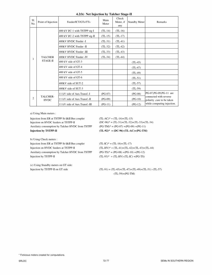
4.2(b) Net Injection by Talcher Stage-II
Sl.
No.Point of Injection Feeder/ICT/GTs/TTs
Main
Meter
Check
Meter, if
any
Standby Meter Remarks
400 kV I/C-1 with TSTPP stg-I (TL-14) (TL-16)
400 kV I/C-2 with TSTPP stg-II (TL-15) (TL-17)
400kV HVDC Feeder -I (TL-31) (TL-41)
400kV HVDC Feeder -II (TL-32) (TL-42)
400kV HVDC Feeder -III (TL-33) (TL-43)
400kV HVDC Feeder -IV (TL-34) (TL-44)
400 kV side of GT-3 (TL-45)
400 kV side of GT-4 (TL-47)
400 kV side of GT-5 (TL-49)
400 kV side of GT-6 (TL-51)
400kV side of SUT-2 (TL-57)
400kV side of SUT-3 (TL-59)
11 kV side of Aux.Transf.-I (PG-07) (PG-08)
11 kV side of Aux.Transf.-II (PG-09) (PG-10)
11 kV side of Aux.Transf.-III (PG-11) (PG-12)
a) Using Main meters :
Injection from ER at TSTPP St-I&II Bus coupler (TL-AC)* = (TL-14)+(TL-15)
Injection on HVDC feeders at TSTPP-II (DC-96)* = (TL-31)+(TL-32)+(TL-33)+(TL-34)
Auxilairy consumption by Talcher HVDC from TSTPP (PG-TM)* = (PG-07) +(PG-09) +(PG-11)
Injection by TSTPP-II (TL-92)* = (DC-96)-(TL-AC)+(PG-TM)
b) Using Check meters :
Injection from ER at TSTPP St-I&II Bus coupler (TL-IC)* = (TL-16)+(TL-17)
Injection on HVDC feeders at TSTPP-II (TL-HV)* = (TL-41)+(TL-42)+(TL-43)+(TL-44)
Auxilairy consumption by Talcher HVDC from TSTPP (PG-TS)* = (PG-08) +(PG-10) +(PG-12)
Injection by TSTPP-II (TL-93)* = (TL-HV)-(TL-IC) +(PG-TS)
(c) Using Standby meters on GT side:
Injection by TSTPP-II on GT side (TL-91) = (TL-45)+(TL-47)+(TL-49)+(TL-51) -(TL-57)
-(TL-59)+(PG-TM)
1
2
PG-07,PG-09,PG-11 are
connected with reverse
polarity ,care to be taken
while computing injection.
TALCHER-
HVDC
TALCHER
STAGE-II
* Ficticious meters created for computations.
SRLDC 72-77 SEMs IN SOUTHERN REGION
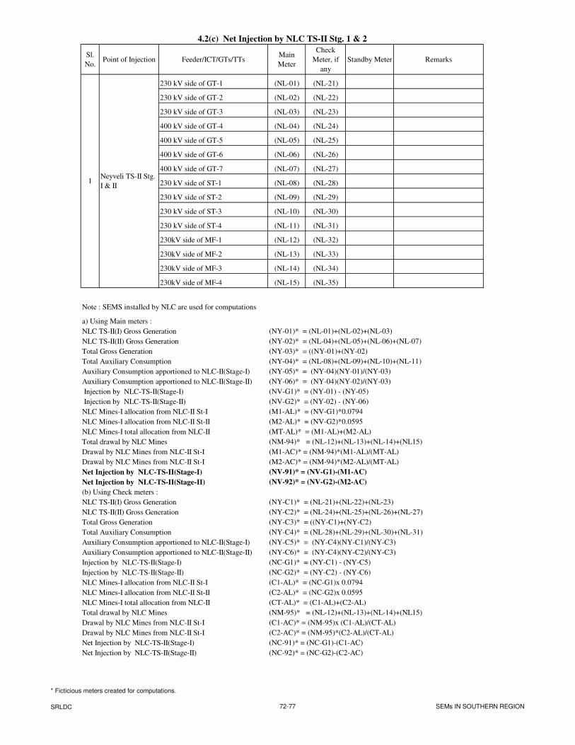
4.2(c) Net Injection by NLC TS-II Stg. 1 & 2
Sl.
No.Point of Injection Feeder/ICT/GTs/TTs
Main
Meter
Check
Meter, if
any
Standby Meter Remarks
230 kV side of GT-1 (NL-01) (NL-21)
230 kV side of GT-2 (NL-02) (NL-22)
230 kV side of GT-3 (NL-03) (NL-23)
400 kV side of GT-4 (NL-04) (NL-24)
400 kV side of GT-5 (NL-05) (NL-25)
400 kV side of GT-6 (NL-06) (NL-26)
400 kV side of GT-7 (NL-07) (NL-27)
230 kV side of ST-1 (NL-08) (NL-28)
230 kV side of ST-2 (NL-09) (NL-29)
230 kV side of ST-3 (NL-10) (NL-30)
230 kV side of ST-4 (NL-11) (NL-31)
230kV side of MF-1 (NL-12) (NL-32)
230kV side of MF-2 (NL-13) (NL-33)
230kV side of MF-3 (NL-14) (NL-34)
230kV side of MF-4 (NL-15) (NL-35)
Note : SEMS installed by NLC are used for computations
a) Using Main meters :
NLC TS-II(I) Gross Generation (NY-01)* = (NL-01)+(NL-02)+(NL-03)
NLC TS-II(II) Gross Generation (NY-02)* = (NL-04)+(NL-05)+(NL-06)+(NL-07)
Total Gross Generation (NY-03)* = ((NY-01)+(NY-02)
Total Auxiliary Consumption (NY-04)* = (NL-08)+(NL-09)+(NL-10)+(NL-11)
Auxiliary Consumption apportioned to NLC-II(Stage-I) (NY-05)* = (NY-04)(NY-01)/(NY-03)
Auxiliary Consumption apportioned to NLC-II(Stage-II) (NY-06)* = (NY-04)(NY-02)/(NY-03)
Injection by NLC-TS-II(Stage-I) (NV-G1)* = (NY-01) - (NY-05)
Injection by NLC-TS-II(Stage-II) (NV-G2)* = (NY-02) - (NY-06)
NLC Mines-I allocation from NLC-II St-I (M1-AL)* = (NV-G1)*0.0794
NLC Mines-I allocation from NLC-II St-II (M2-AL)* = (NV-G2)*0.0595
NLC Mines-I total allocation from NLC-II (MT-AL)* = (M1-AL)+(M2-AL)
Total drawal by NLC Mines (NM-94)* = (NL-12)+(NL-13)+(NL-14)+(NL15)
Drawal by NLC Mines from NLC-II St-I (M1-AC)* = (NM-94)*(M1-AL)/(MT-AL)
Drawal by NLC Mines from NLC-II St-I (M2-AC)* = (NM-94)*(M2-AL)/(MT-AL)
Net Injection by NLC-TS-II(Stage-I) (NV-91)* = (NV-G1)-(M1-AC)
Net Injection by NLC-TS-II(Stage-II) (NV-92)* = (NV-G2)-(M2-AC)
(b) Using Check meters :
NLC TS-II(I) Gross Generation (NY-C1)* = (NL-21)+(NL-22)+(NL-23)
NLC TS-II(II) Gross Generation (NY-C2)* = (NL-24)+(NL-25)+(NL-26)+(NL-27)
Total Gross Generation (NY-C3)* = ((NY-C1)+(NY-C2)
Total Auxiliary Consumption (NY-C4)* = (NL-28)+(NL-29)+(NL-30)+(NL-31)
Auxiliary Consumption apportioned to NLC-II(Stage-I) (NY-C5)* = (NY-C4)(NY-C1)/(NY-C3)
Auxiliary Consumption apportioned to NLC-II(Stage-II) (NY-C6)* = (NY-C4)(NY-C2)/(NY-C3)
Injection by NLC-TS-II(Stage-I) (NC-G1)* = (NY-C1) - (NY-C5)
Injection by NLC-TS-II(Stage-II) (NC-G2)* = (NY-C2) - (NY-C6)
NLC Mines-I allocation from NLC-II St-I (C1-AL)* = (NC-G1)x 0.0794
NLC Mines-I allocation from NLC-II St-II (C2-AL)* = (NC-G2)x 0.0595
NLC Mines-I total allocation from NLC-II (CT-AL)* = (C1-AL)+(C2-AL)
Total drawal by NLC Mines (NM-95)* = (NL-12)+(NL-13)+(NL-14)+(NL15)
Drawal by NLC Mines from NLC-II St-I (C1-AC)* = (NM-95)x (C1-AL)/(CT-AL)
Drawal by NLC Mines from NLC-II St-I (C2-AC)* = (NM-95)*(C2-AL)/(CT-AL)
Net Injection by NLC-TS-II(Stage-I) (NC-91)* = (NC-G1)-(C1-AC)
Net Injection by NLC-TS-II(Stage-II) (NC-92)* = (NC-G2)-(C2-AC)
1Neyveli TS-II Stg.
I & II
* Ficticious meters created for computations.
SRLDC 72-77 SEMs IN SOUTHERN REGION
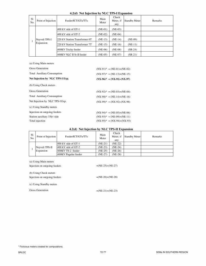
4.2(d) Net Injection by NLC TPS-I Expansion
Sl.
No.Point of Injection Feeder/ICT/GTs/TTs
Main
Meter
Check
Meter, if
any
Standby Meter Remarks
400 kV side of GT-1 (NE-01) (NE-03)
400 kV side of GT-2 (NE-02) (NE-04)
220 kV Station Transformer 6T (NE-13) (NE-14) (NE-09)
220 kV Station Transformer 7T (NE-15) (NE-16) (NE-11)
400KV Trichy feeder (NE-06) (NE-08) (SR-24)
400KV NLC II St-II feeder (NE-05) (NE-07) (SR-21)
(a) Using Main meters
Gross Generation (NX-91)* = (NE-01)+(NE-02)
Total Auxiliary Consumption (NX-97)* = (NE-13)+(NE-15)
Net Injection by NLC TPS-I Exp. (NX-96)* = (NX-91)-(NX-97)
(b) Using Check meters
Gross Generation (NX-92)* = (NE-03)+(NE-04)
Total Auxiliary Consumption (NX-98)* = (NE-14)+(NE-16)
Net Injection by NLC TPS-I Exp. (NX-99)* = (NX-92)-(NX-98)
(c) Using Standby meters
Injection on outgoing feeders (NX-94)* = (NE-05)+(NE-06)
Station auxiliary 33kv side (NX-93)* = (NE-09)+(NE-11)
Total injection (NX-95)* = (NX-94)+(NX-93)
4.2(d) Net Injection by NLC TPS-II Expansion
Sl.
No.Point of Injection Feeder/ICT/GTs/TTs
Main
Meter
Check
Meter, if
any
Standby Meter Remarks
400 kV side of GT-1 (NE-21) (NE-22)
400 kV side of GT-2 (NE-23) (NE-24)
400KV TS-2 feeder (NE-25) (NE-26)
400KV Pugulur feeder (NE-27) (NE-28)
(a) Using Main meters
Injection on outgoing feeders =(NE-25)+(NE-27)
(b) Using Check meters
Injection on outgoing feeders =(NE-26)+(NE-28)
(c) Using Standby meters
Gross Generation =(NE-21)+(NE-23)
1Neyveli TPS-I
Expansion
1Neyveli TPS-II
Expansion
* Ficticious meters created for computations.
SRLDC 72-77 SEMs IN SOUTHERN REGION
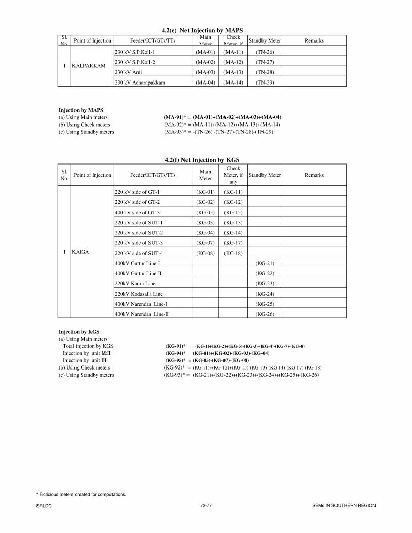
4.2(e) Net Injection by MAPSSl.
No.Point of Injection Feeder/ICT/GTs/TTs
Main
Meter
Check
Meter, if Standby Meter Remarks
230 kV S.P.Koil-1 (MA-01) (MA-11) (TN-26)
230 kV S.P.Koil-2 (MA-02) (MA-12) (TN-27)
230 kV Arni (MA-03) (MA-13) (TN-28)
230 kV Acharapakkam (MA-04) (MA-14) (TN-29)
Injection by MAPS
(a) Using Main meters (MA-91)* = (MA-01)+(MA-02)+(MA-03)+(MA-04)
(b) Using Check meters (MA-92)* = (MA-11)+(MA-12)+(MA-13)+(MA-14)
(c) Using Standby meters (MA-93)* = -(TN-26) -(TN-27)-(TN-28)-(TN-29)
4.2(f) Net Injection by KGS
Sl.
No.Point of Injection Feeder/ICT/GTs/TTs
Main
Meter
Check
Meter, if
any
Standby Meter Remarks
220 kV side of GT-1 (KG-01) (KG-11)
220 kV side of GT-2 (KG-02) (KG-12)
400 kV side of GT-3 (KG-05) (KG-15)
220 kV side of SUT-1 (KG-03) (KG-13)
220 kV side of SUT-2 (KG-04) (KG-14)
220 kV side of SUT-3 (KG-07) (KG-17)
220 kV side of SUT-4 (KG-08) (KG-18)
400kV Guttur Line-I (KG-21)
400kV Guttur Line-II (KG-22)
220kV Kadra Line (KG-23)
220kV Kodasalli Line (KG-24)
400kV Narendra Line-I (KG-25)
400kV Narendra Line-II (KG-26)
Injection by KGS
Total injection by KGS (KG-91)* = =(KG-1)+(KG-2)+(KG-5)-(KG-3)-(KG-4)-(KG-7)-(KG-8)
Injection by unit I&II (KG-94)* = (KG-01)+(KG-02)-(KG-03)-(KG-04)
Injection by unit III (KG-95)* = (KG-05)-(KG-07)-(KG-08)
(b) Using Check meters (KG-92)* = (KG-11)+(KG-12)+(KG-15)-(KG-13)-(KG-14)-(KG-17)-(KG-18)
(c) Using Standby meters on feeders (KG-93)* = (KG-21)+(KG-22)+(KG-23)+(KG-24)+(KG-25)+(KG-26)
KAIGA
(a) Using Main meters
1
1 KALPAKKAM
* Ficticious meters created for computations.
SRLDC 72-77 SEMs IN SOUTHERN REGION
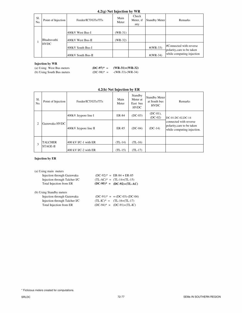
4.2(g) Net Injection by WR
Sl.
No.Point of Injection Feeder/ICT/GTs/TTs
Main
Meter
Check
Meter, if
any
Standby Meter Remarks
400kV West Bus-I (WR-31)
400kV West Bus-II (WR-32)
400kV South Bus-I #(WR-33)
400kV South Bus-II #(WR-34)
Injection by WR
(a) Using West Bus meters (DC-97)* = (WR-31)+(WR-32)
(b) Using South Bus meters (DC-98)* = -(WR-33)-(WR-34)
4.2(h) Net Injection by ER
Sl.
No.Point of Injection Feeder/ICT/GTs/TTs
Main
Meter
Standby
Meter at
East bus
HVDC
Standby Meter
at South bus
HVDC
Remarks
400kV Jeypore line I ER-84 (DC-03)(DC-01),
(DC-02)
400kV Jeypore line II ER-85 (DC-04) (DC-14)
400 kV I/C-1 with ER (TL-14) (TL-16)
400 kV I/C-2 with ER (TL-15) (TL-17)
Injection by ER
(a) Using main meters
Injection through Gazuwaka (DC-92)* = ER-84 + ER-85
Injection through Talcher I/C (TL-AC)* = (TL-14+(TL-15)
Total Injection from ER (DC-95)* = (DC-92)+(TL-AC)
(b) Using Standby meters
Injection through Gazuwaka (DC-91)* = =-(DC-03)-(DC-04)
Injection through Talcher I/C (TL-IC)* = (TL-16+(TL-17)
Total Injection from ER (DC-94)* = (DC-91)+(TL-IC)
#Connected with reverse
polarity,care to be taken
while computing injection
TALCHER
STAGE-II
Bhadravathi
HVDC
2
3
Gazuwaka HVDC
1
DC-01.DC-02,DC-14
connected with reverse
polarity,care to be taken
while computing injection.
* Ficticious meters created for computations.
SRLDC 72-77 SEMs IN SOUTHERN REGION
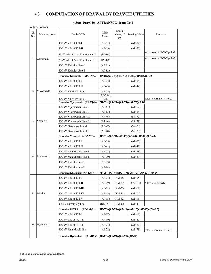
4.3 COMPUTATION OF DRAWAL BY DRAWEE UTILITIES
4.3(a) Drawl by APTRANSCO from Grid
At ISTS network
Sl.
No.Metering point Feeder/ICTs
Main
Meter
Check
Meter, if
any
Standby Meter Remarks
400 kV side of ICT-I (AP-01) (AP-02)
400 kV side of ICT-II (AP-69) (AP-70)
33kV side of Aux. Transformer-I (PG 01)Aux. cons.of HVDC pole-1
33kV side of Aux. Transformer-II (PG 03)Aux. cons.of HVDC pole-2
400 kV Kalpaka Line-I (AP 81)
400 kV Kalpaka Line-2 (AP 82)
Drawal at Gazuwaka (AP-GZ)*=
400 kV side of ICT I (AP-03) (AP-04)
400 kV side of ICT II (AP-43) (AP-44)
400 kV VTPS IV Line-I (AP-73)
400 kV VTPS IV Line-II
(AP-75) x
0.98 refer to para no. 4.1.6(c)
Drawal at Vijayawada (AP-VJ)*=
400 kV Vijayawada Line-I (AP-61) (AP-62)
400 kV Vijayawada Line-II (AP-63) (AP-64)
400 kV Vijayawada Line-III (AP-45) (SR-72)
400 kV Vijayawada Line-IV (AP-46) (SR-73)
400 kV Gazuwaka Line-I (AP-47) (SR-78)
400 kV Gazuwaka Line-II (AP-48) (SR-79)
Drawal at Vemagiri (AP-VM)*=
400 kV side of ICT I (AP-05) (AP-06)
400 kV side of ICT II (AP-41) (AP-42)
400 kV Mamidipally line-I (AP-77) (AP-78)
400 kV Mamidipally line-II (AP-79) (AP-80)
400 kV Kalpaka line-I (AP-83)
400 kV Kalpaka line-II (AP-84)
Drawal at Khammam (AP-KM)*=
400 kV side of ICT-1 (AP-07) (RM-28) (AP-08)
400 kV side of ICT-II (AP-09) (RM-29) #(AP-10) # Reverse polarity
400 kV side of ICT-III (AP-11) (RM-30) (AP-12)
400 kV side of ICT-IV (AP-13) (RM-31) (AP-14)
400 kV side of ICT-V (AP-15) (RM-32) (AP-16)
400kV Ditchipally line (RM-20) (RM-40) (AP-49)
Drawal at RSTPS (AP-RM)*=
400 kV side of ICT-1 (AP-17) (AP-18)
400 kV side of ICT-II (AP-19) (AP-20)
400 kV side of ICT-III (AP-21) (AP-22)
400 kV Mamidipalli line (AP-72) (AP-71) refer to para no. 4.1.6(b)
Drawal at Hyderabad (AP-HY)*= (AP-17)+(AP-19)+(AP-21)-(AP-72)
Gazuwaka
Vijayawada
6
Khammam
RSTPS
Vemagiri
Hyderabad
1
2
4
5
3
(AP-07)+(AP-09)+(AP-11)+(AP-13)+(AP-15)+(RM-20)
(AP-61)+(AP-63)-(AP-45)-(AP-46)-(AP-47)-(AP-48)
(AP-01)+(AP-69)-(PG-01)-(PG-03)+(AP-81)+(AP-82)
(AP-03)+(AP-43)+(AP-73)+(AP-75)x 0.98
(AP-05)+(AP-41)+(AP-77)+(AP-79)+(AP-83)+(AP-84)
* Ficticious meters created for computations.
SRLDC 78-85 SEMs IN SOUTHERN REGION
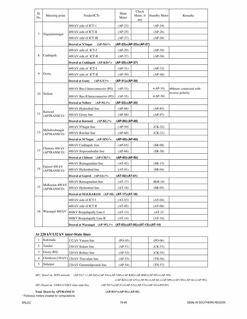
Sl.
No.Metering point Feeder/ICTs
Main
Meter
Check
Meter, if
any
Standby Meter Remarks
400 kV side of ICT-1 (AP-23) (AP-24)
400 kV side of ICT-II (AP-25) (AP-26)
400 kV side of ICT-III (AP-27) (AP-28)
Drawal at N'Sagar (AP-NS)*=
400 kV side of ICT-I (AP-29) (AP-30)
400 kV side of ICT-II (AP-37) (AP-38)
Drawal at Cuddapah (AP-KD)*=
400 kV side of ICT-I (AP-31) (AP-32)
400 kV side of ICT-II (AP-39) (AP-40)
Drawal at Gooty (AP-GY)*=
400 kV Bus-I Interconnector (PG) (AP-33) #(AP-34)
400 kV Bus-II Interconnector (PG) (AP-35) #(AP-36)
Drawal at Nellore (AP-NL)*=
400 kV Hyderabad line (AP-86) (AP-85)
400 kV Gooty line (AP-88) (AP-87)
Drawal at Kurnool (AP-KL)*=
400 kV N'Sagar line (AP-59) (CK-22)
400 kV Raichur line (AP-60) (CK-21)
Drawal at M'Nagar (AP-MN)*=
400 kV Cuddapah line (AP-65) (SR-09)
400 kV Sriperambadur line (AP-66) (SR-30)
Drawal at Chittoor (AP-CH)*=
400 kV Ramagundam line (AT-02) (SR-15)
400 kV Hyderabad line (AT-01) (SR-04)
Drawal at Gajwel (AP-GL)*=
400 kV Ramagundam line (AT-17) (RM-16)
400 kV Hyderabad line (AT-18) (SR-05)
Drawal at MALKARAM (AP-ML)*=
400 kV side of ICT I (AT-03) (AT-04)
400 kV side of ICT II (AT-05) (AT-06)
400kV Boopalapally Line-I (AT-13) (AT-15
400kV Boopalapally Line-II (AT-14) (AT-16)
Drawal at Warangal (AP-WL)*=
At 220 kV/132 kV inter-State lines
1 Kakinada 132 kV Yanam line (PO-05) (PO-06)
2 Tandur 230 kV Sedam line (AP-51) (CK-53)
3 Gooty (RS) 220 kV Bellary line (AP-52) (CK-55)
4 Chitthoor(220 kV) 220 kV Tiruvalam line (AP-53) (TN-56)
5 Sulurpet 220 kV Gummidipoondi line (AP-54) (TN-57)
AP's Drawl on ISTS network (AP-91)* = (AP-GZ)+(AP-VJ)+(AP-VM)+(AP-KM)+(AP-RM)+(AP-HY)+(AP-NS)
AP's Drawl on 220kV/132KV inter-state lies (AP-92)*=(AP-51)+(AP-52)+(AP-53)+(AP-54)+(PO-05)
Total Drawl by APTRANSCO (AP-93)*=(AP-91)-(AP-92)
Gooty
#Meters connected with
reverse polarity
Mehaboobnagar
(APTRANSCO)
Nagarjunasagar
8
9
7
14Gajwel 400 kV
(APTRANSCO)
Warangal 400 kV
15Malkaram 400 kV
(APTRANSCO)
16
(AP-23)+(AP-25)+(AP-27)
-(AT-02)-(AT-01)
Nellore
(AT-03)+(AT-05)+(AT-13)+(AT-14)
+(AP-KD)+(AP-GY)+(AP-NL)+(AP-KL)+(AP-MN)+(AP-CH)+(AP-GL)+(AP-WL)
-(AP-59)-(AP-60)
-(AT-17)-(AT-18)
(AP-29)+(AP-37)
-(AP-65)-(AP-66)
13Chittoor 400 kV
(APTRANSCO)
(AP-31)+(AP-39)
Cuddapah
(AP-33)+(AP-35)
-(AP-86)-(AP-88)
12
10
11Kurnool
(APTRANSCO)
* Ficticious meters created for computations.
SRLDC 78-85 SEMs IN SOUTHERN REGION
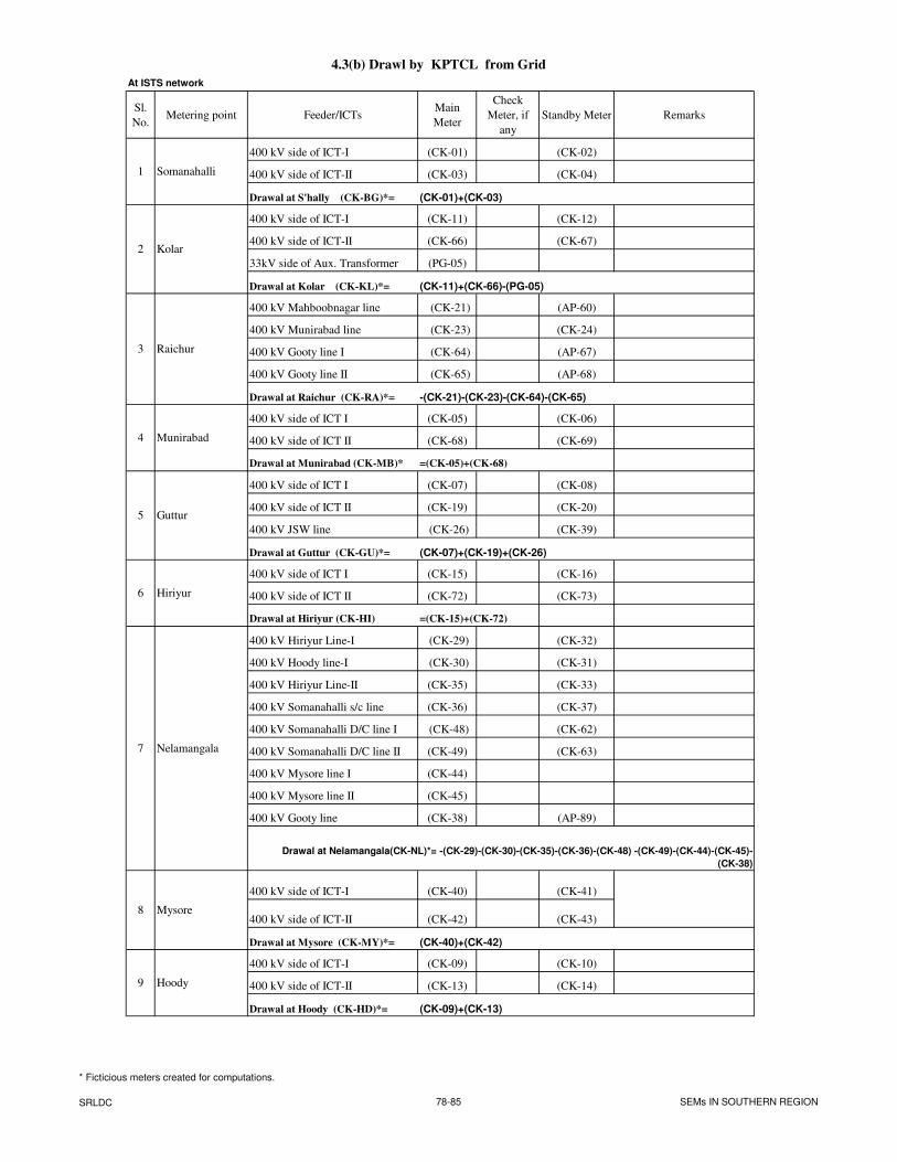
4.3(b) Drawl by KPTCL from Grid
At ISTS network
Sl.
No.Metering point Feeder/ICTs
Main
Meter
Check
Meter, if
any
Standby Meter Remarks
400 kV side of ICT-I (CK-01) (CK-02)
400 kV side of ICT-II (CK-03) (CK-04)
Drawal at S'hally (CK-BG)*=
400 kV side of ICT-I (CK-11) (CK-12)
400 kV side of ICT-II (CK-66) (CK-67)
33kV side of Aux. Transformer (PG-05)
Drawal at Kolar (CK-KL)*=
400 kV Mahboobnagar line (CK-21) (AP-60)
400 kV Munirabad line (CK-23) (CK-24)
400 kV Gooty line I (CK-64) (AP-67)
400 kV Gooty line II (CK-65) (AP-68)
Drawal at Raichur (CK-RA)*=
400 kV side of ICT I (CK-05) (CK-06)
400 kV side of ICT II (CK-68) (CK-69)
Drawal at Munirabad (CK-MB)*
400 kV side of ICT I (CK-07) (CK-08)
400 kV side of ICT II (CK-19) (CK-20)
400 kV JSW line (CK-26) (CK-39)
Drawal at Guttur (CK-GU)*=
400 kV side of ICT I (CK-15) (CK-16)
400 kV side of ICT II (CK-72) (CK-73)
Drawal at Hiriyur (CK-HI)
400 kV Hiriyur Line-I (CK-29) (CK-32)
400 kV Hoody line-I (CK-30) (CK-31)
400 kV Hiriyur Line-II (CK-35) (CK-33)
400 kV Somanahalli s/c line (CK-36) (CK-37)
400 kV Somanahalli D/C line I (CK-48) (CK-62)
400 kV Somanahalli D/C line II (CK-49) (CK-63)
400 kV Mysore line I (CK-44)
400 kV Mysore line II (CK-45)
400 kV Gooty line (CK-38) (AP-89)
400 kV side of ICT-I (CK-40) (CK-41)
400 kV side of ICT-II (CK-42) (CK-43)
Drawal at Mysore (CK-MY)*=
400 kV side of ICT-I (CK-09) (CK-10)
400 kV side of ICT-II (CK-13) (CK-14)
Drawal at Hoody (CK-HD)*=
Somanahalli
=(CK-05)+(CK-68)
(CK-07)+(CK-19)+(CK-26)
=(CK-15)+(CK-72)
Hiriyur
Kolar
Raichur
Munirabad
Nelamangala
Guttur
Mysore
Drawal at Nelamangala(CK-NL)*= -(CK-29)-(CK-30)-(CK-35)-(CK-36)-(CK-48) -(CK-49)-(CK-44)-(CK-45)-
(CK-38)
(CK-40)+(CK-42)
2
-(CK-21)-(CK-23)-(CK-64)-(CK-65)
(CK-11)+(CK-66)-(PG-05)
Hoody
8
9
4
7
3
5
6
1
(CK-01)+(CK-03)
(CK-09)+(CK-13)
* Ficticious meters created for computations.
SRLDC 78-85 SEMs IN SOUTHERN REGION
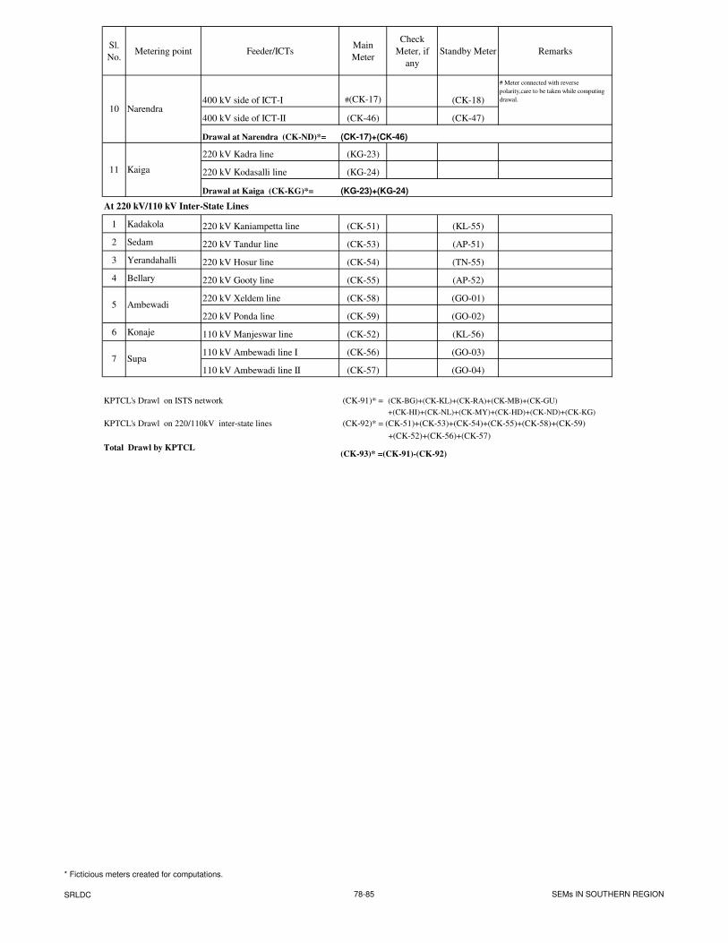
Sl.
No.Metering point Feeder/ICTs
Main
Meter
Check
Meter, if
any
Standby Meter Remarks
400 kV side of ICT-I #(CK-17) (CK-18)
# Meter connected with reverse
polarity,care to be taken while computing
drawal.
400 kV side of ICT-II (CK-46) (CK-47)
Drawal at Narendra (CK-ND)*=
220 kV Kadra line (KG-23)
220 kV Kodasalli line (KG-24)
Drawal at Kaiga (CK-KG)*=
At 220 kV/110 kV Inter-State Lines
1 Kadakola 220 kV Kaniampetta line (CK-51) (KL-55)
2 Sedam 220 kV Tandur line (CK-53) (AP-51)
3 Yerandahalli 220 kV Hosur line (CK-54) (TN-55)
4 Bellary 220 kV Gooty line (CK-55) (AP-52)
220 kV Xeldem line (CK-58) (GO-01)
220 kV Ponda line (CK-59) (GO-02)
6 Konaje 110 kV Manjeswar line (CK-52) (KL-56)
110 kV Ambewadi line I (CK-56) (GO-03)
110 kV Ambewadi line II (CK-57) (GO-04)
KPTCL's Drawl on ISTS network (CK-91)* = (CK-BG)+(CK-KL)+(CK-RA)+(CK-MB)+(CK-GU)
+(CK-HI)+(CK-NL)+(CK-MY)+(CK-HD)+(CK-ND)+(CK-KG)
KPTCL's Drawl on 220/110kV inter-state lines (CK-92)* = (CK-51)+(CK-53)+(CK-54)+(CK-55)+(CK-58)+(CK-59)
+(CK-52)+(CK-56)+(CK-57)
Total Drawl by KPTCL (CK-93)* =(CK-91)-(CK-92)
Supa
11 Kaiga
Narendra
Ambewadi5
7
10
(CK-17)+(CK-46)
(KG-23)+(KG-24)
* Ficticious meters created for computations.
SRLDC 78-85 SEMs IN SOUTHERN REGION
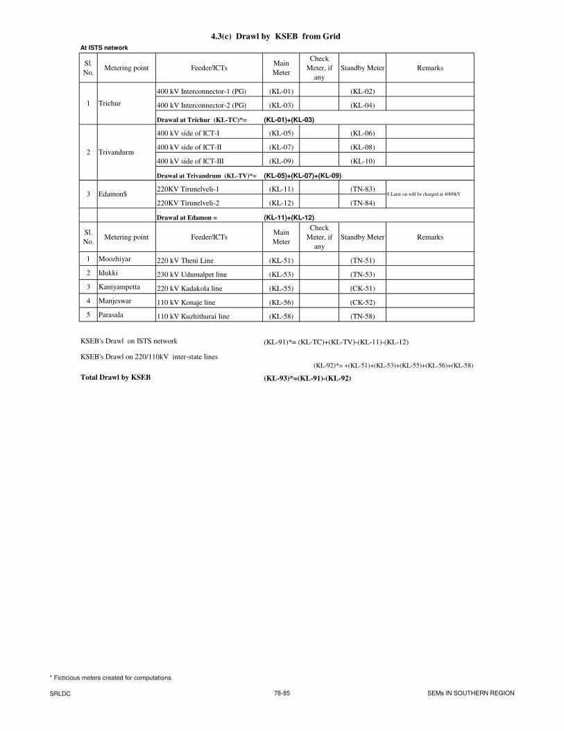
4.3(c) Drawl by KSEB from Grid
At ISTS network
Sl.
No.Metering point Feeder/ICTs
Main
Meter
Check
Meter, if
any
Standby Meter Remarks
400 kV Interconnector-1 (PG) (KL-01) (KL-02)
400 kV Interconnector-2 (PG) (KL-03) (KL-04)
Drawal at Trichur (KL-TC)*=
400 kV side of ICT-I (KL-05) (KL-06)
400 kV side of ICT-II (KL-07) (KL-08)
400 kV side of ICT-III (KL-09) (KL-10)
Drawal at Trivandrum (KL-TV)*=
220KV Tirunelveli-1 (KL-11) (TN-83)
220KV Tirunelveli-2 (KL-12) (TN-84)
Drawal at Edamon =
Sl.
No.Metering point Feeder/ICTs
Main
Meter
Check
Meter, if
any
Standby Meter Remarks
1 Moozhiyar 220 kV Theni Line (KL-51) (TN-51)
2 Idukki 230 kV Udumalpet line (KL-53) (TN-53)
3 Kaniyampetta 220 kV Kadakola line (KL-55) (CK-51)
4 Manjeswar 110 kV Konaje line (KL-56) (CK-52)
5 Parasala 110 kV Kuzhithurai line (KL-58) (TN-58)
KSEB's Drawl on ISTS network (KL-91)*= (KL-TC)+(KL-TV)-(KL-11)-(KL-12)
KSEB's Drawl on 220/110kV inter-state lines
Total Drawl by KSEB (KL-93)*=(KL-91)-(KL-92)
Trichur1
Trivandurm
3 Edamon$
(KL-92)*= +(KL-51)+(KL-53)+(KL-55)+(KL-56)+(KL-58)
(KL-01)+(KL-03)
(KL-05)+(KL-07)+(KL-09)
$ Later on will be charged at 4000kV
(KL-11)+(KL-12)
2
* Ficticious meters created for computations.
SRLDC 78-85 SEMs IN SOUTHERN REGION
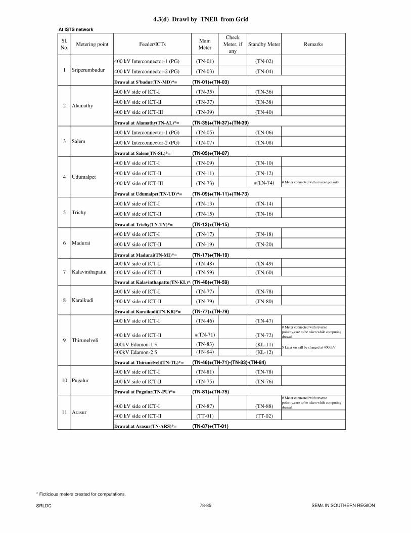
4.3(d) Drawl by TNEB from Grid
At ISTS network
Sl.
No.Metering point Feeder/ICTs
Main
Meter
Check
Meter, if
any
Standby Meter Remarks
400 kV Interconnector-1 (PG) (TN-01) (TN-02)
400 kV Interconnector-2 (PG) (TN-03) (TN-04)
Drawal at S'budur(TN-MD)*=
400 kV side of ICT-I (TN-35) (TN-36)
400 kV side of ICT-II (TN-37) (TN-38)
400 kV side of ICT-III (TN-39) (TN-40)
Drawal at Alamathy(TN-AL)*=
400 kV Interconnector-1 (PG) (TN-05) (TN-06)
400 kV Interconnector-2 (PG) (TN-07) (TN-08)
Drawal at Salem(TN-SL)*=
400 kV side of ICT-I (TN-09) (TN-10)
400 kV side of ICT-II (TN-11) (TN-12)
400 kV side of ICT-III (TN-73) #(TN-74) # Meter connected with reverse polarity
Drawal at Udumalpet(TN-UD)*=
400 kV side of ICT-I (TN-13) (TN-14)
400 kV side of ICT-II (TN-15) (TN-16)
Drawal at Trichy(TN-TY)*=
400 kV side of ICT-I (TN-17) (TN-18)
400 kV side of ICT-II (TN-19) (TN-20)
Drawal at Madurai(TN-MI)*=
400 kV side of ICT-I (TN-48) (TN-49)
400 kV side of ICT-II (TN-59) (TN-60)
Drawal at Kalavinthapattu(TN-KL)*=
400 kV side of ICT-I (TN-77) (TN-78)
400 kV side of ICT-II (TN-79) (TN-80)
Drawal at Karaikudi(TN-KR)*=
400 kV side of ICT-I (TN-46) (TN-47)
400 kV side of ICT-II #(TN-71) (TN-72)
# Meter connected with reverse
polarity,care to be taken while computing
drawal.
400kV Edamon-1 $ (TN-83) (KL-11)
400kV Edamon-2 $ (TN-84) (KL-12)
Drawal at Thirunelveli(TN-TL)*=
400 kV side of ICT-I (TN-81) (TN-78)
400 kV side of ICT-II (TN-75) (TN-76)
Drawal at Pugalur(TN-PU)*=
400 kV side of ICT-I (TN-87) (TN-88)
# Meter connected with reverse
polarity,care to be taken while computing
drawal.
400 kV side of ICT-II (TT-01) (TT-02)
Drawal at Arasur(TN-ARS)*=
7
(TN-77)+(TN-79)
(TN-09)+(TN-11)+(TN-73)
(TN-13)+(TN-15)
(TN-17)+(TN-19)
6 Madurai
4
Alamathy
(TN-35)+(TN-37)+(TN-39)
(TN-05)+(TN-07)
(TN-87)+(TT-01)
Kalavinthapattu
(TN-48)+(TN-59)
(TN-46)+(TN-71)-(TN-83)-(TN-84)
(TN-81)+(TN-75)
Udumalpet
Karaikudi
$ Later on will be charged at 4000kV
(TN-01)+(TN-03)
1 Sriperumbudur
Trichy
3 Salem
Pugalur
9 Thirunelveli
10
2
5
8
11 Arasur
* Ficticious meters created for computations.
SRLDC 78-85 SEMs IN SOUTHERN REGION
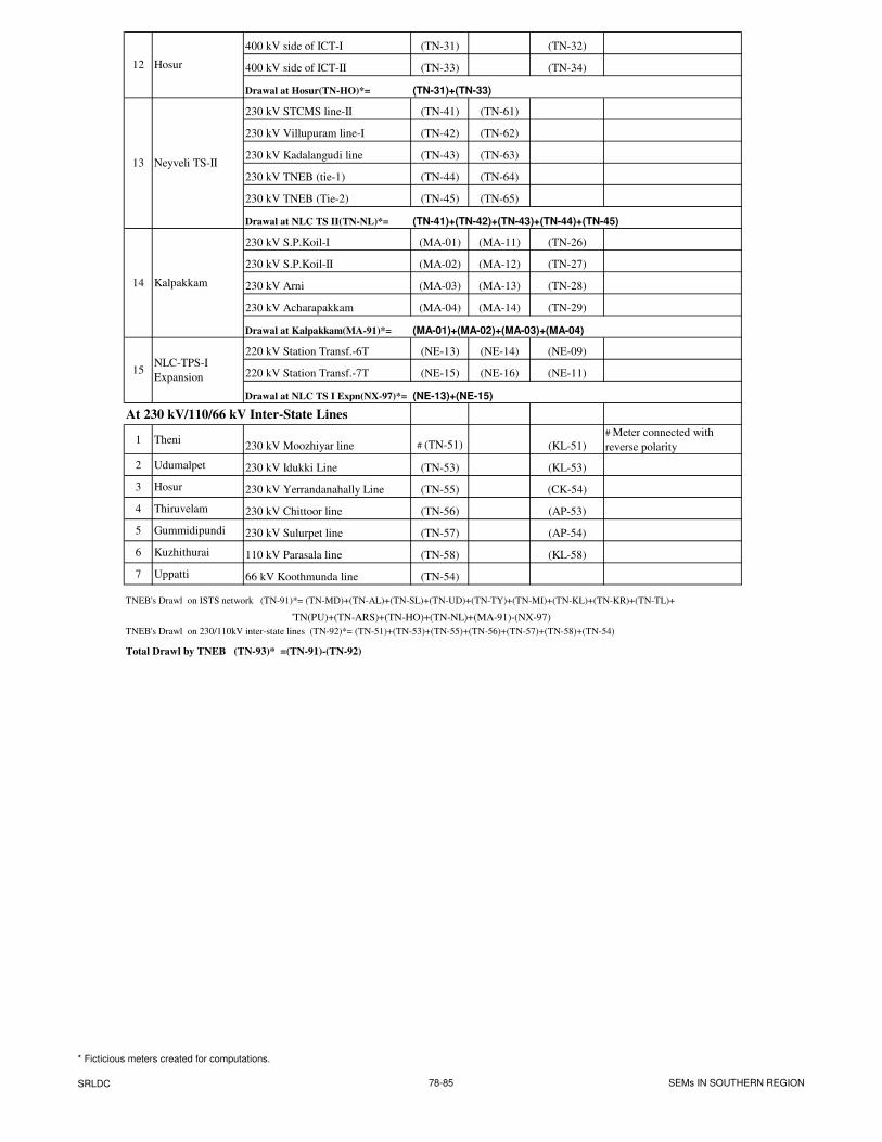
400 kV side of ICT-I (TN-31) (TN-32)
400 kV side of ICT-II (TN-33) (TN-34)
Drawal at Hosur(TN-HO)*=
230 kV STCMS line-II (TN-41) (TN-61)
230 kV Villupuram line-I (TN-42) (TN-62)
230 kV Kadalangudi line (TN-43) (TN-63)
230 kV TNEB (tie-1) (TN-44) (TN-64)
230 kV TNEB (Tie-2) (TN-45) (TN-65)
Drawal at NLC TS II(TN-NL)*=
230 kV S.P.Koil-I (MA-01) (MA-11) (TN-26)
230 kV S.P.Koil-II (MA-02) (MA-12) (TN-27)
230 kV Arni (MA-03) (MA-13) (TN-28)
230 kV Acharapakkam (MA-04) (MA-14) (TN-29)
Drawal at Kalpakkam(MA-91)*=
220 kV Station Transf.-6T (NE-13) (NE-14) (NE-09)
220 kV Station Transf.-7T (NE-15) (NE-16) (NE-11)
Drawal at NLC TS I Expn(NX-97)*=
At 230 kV/110/66 kV Inter-State Lines
1 Theni230 kV Moozhiyar line # (TN-51) (KL-51)
# Meter connected with
reverse polarity
2 Udumalpet 230 kV Idukki Line (TN-53) (KL-53)
3 Hosur 230 kV Yerrandanahally Line (TN-55) (CK-54)
4 Thiruvelam 230 kV Chittoor line (TN-56) (AP-53)
5 Gummidipundi 230 kV Sulurpet line (TN-57) (AP-54)
6 Kuzhithurai 110 kV Parasala line (TN-58) (KL-58)
7 Uppatti 66 kV Koothmunda line (TN-54)
TNEB's Drawl on ISTS network (TN-91)*= (TN-MD)+(TN-AL)+(TN-SL)+(TN-UD)+(TN-TY)+(TN-MI)+(TN-KL)+(TN-KR)+(TN-TL)+
'TN(PU)+(TN-ARS)+(TN-HO)+(TN-NL)+(MA-91)-(NX-97)
TNEB's Drawl on 230/110kV inter-state lines (TN-92)*= (TN-51)+(TN-53)+(TN-55)+(TN-56)+(TN-57)+(TN-58)+(TN-54)
Total Drawl by TNEB (TN-93)* =(TN-91)-(TN-92)
(TN-31)+(TN-33)
(TN-41)+(TN-42)+(TN-43)+(TN-44)+(TN-45)
(MA-01)+(MA-02)+(MA-03)+(MA-04)
(NE-13)+(NE-15)
13 Neyveli TS-II
14 Kalpakkam
15NLC-TPS-I
Expansion
12 Hosur
* Ficticious meters created for computations.
SRLDC 78-85 SEMs IN SOUTHERN REGION
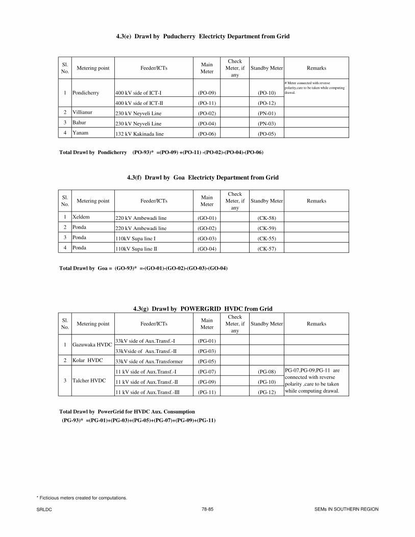
4.3(e) Drawl by Puducherry Electricty Department from Grid
Sl.
No.Metering point Feeder/ICTs
Main
Meter
Check
Meter, if
any
Standby Meter Remarks
400 kV side of ICT-I (PO-09) (PO-10)
# Meter connected with reverse
polarity,care to be taken while computing
drawal.
400 kV side of ICT-II (PO-11) (PO-12)
2 Villianur 230 kV Neyveli Line (PO-02) (PN-01)
3 Bahur 230 kV Neyveli Line (PO-04) (PN-03)
4 Yanam 132 kV Kakinada line (PO-06) (PO-05)
Total Drawl by Pondicherry (PO-93)* =(PO-09) +(PO-11) -(PO-02)-(PO-04)-(PO-06)
4.3(f) Drawl by Goa Electricty Department from Grid
Sl.
No.Metering point Feeder/ICTs
Main
Meter
Check
Meter, if
any
Standby Meter Remarks
1 Xeldem 220 kV Ambewadi line (GO-01) (CK-58)
2 Ponda 220 kV Ambewadi line (GO-02) (CK-59)
3 Ponda 110kV Supa line I (GO-03) (CK-55)
4 Ponda 110kV Supa line II (GO-04) (CK-57)
Total Drawl by Goa = (GO-93)* =-(GO-01)-(GO-02)-(GO-03)-(GO-04)
4.3(g) Drawl by POWERGRID HVDC from Grid
Sl.
No.Metering point Feeder/ICTs
Main
Meter
Check
Meter, if
any
Standby Meter Remarks
33kV side of Aux.Transf.-I (PG-01)
33kVside of Aux.Transf.-II (PG-03)
2 Kolar HVDC 33kV side of Aux.Transformer (PG-05)
11 kV side of Aux.Transf.-I (PG-07) (PG-08)
11 kV side of Aux.Transf.-II (PG-09) (PG-10)
11 kV side of Aux.Transf.-III (PG-11) (PG-12)
Total Drawl by PowerGrid for HVDC Aux. Consumption
(PG-93)* =(PG-01)+(PG-03)+(PG-05)+(PG-07)+(PG-09)+(PG-11)
PG-07,PG-09,PG-11 are
connected with reverse
polarity ,care to be taken
while computing drawal.
3 Talcher HVDC
1 Gazuwaka HVDC
1 Pondicherry
* Ficticious meters created for computations.
SRLDC 78-85 SEMs IN SOUTHERN REGION
�
��������0�+�
�
�
�
,��������A����������,��
������ �������������������
���������������
,��������A����������,��
������ �������������������
������������������
��
�
�
�
+� ,��������A������������������
+�$ ,��������A�����������������
�
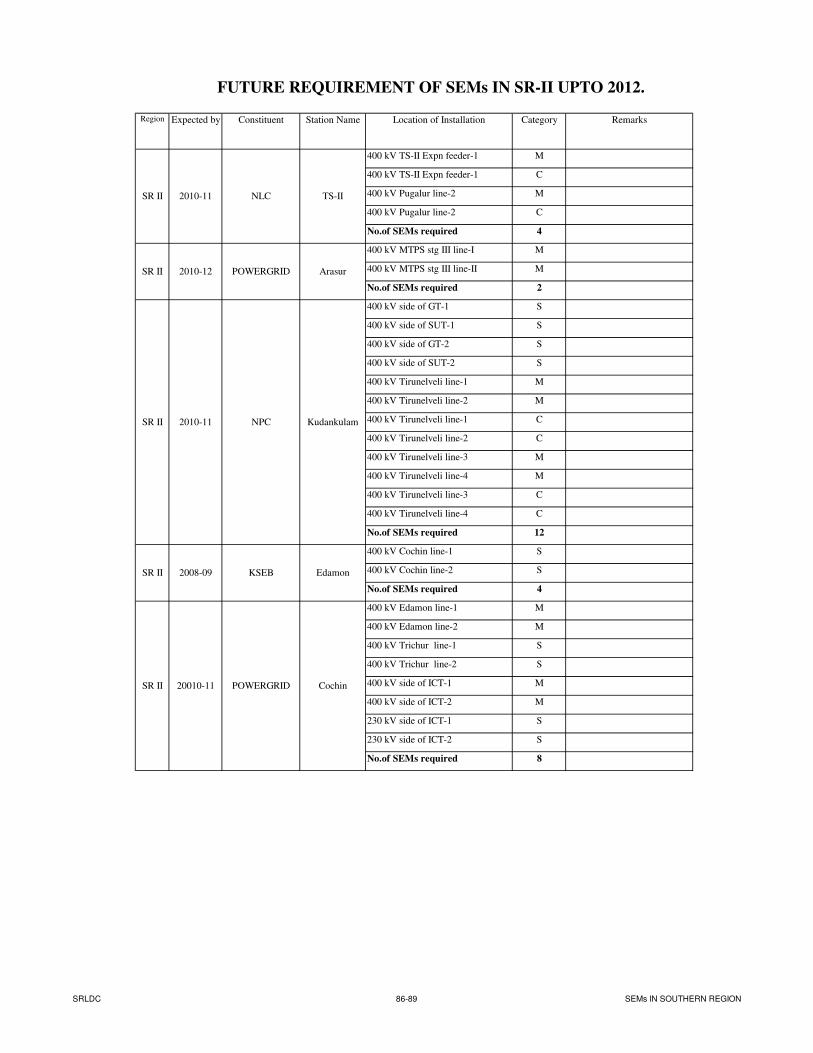
FUTURE REQUIREMENT OF SEMs IN SR-II UPTO 2012.
Region Expected by Constituent Station Name Location of Installation Category Remarks
400 kV TS-II Expn feeder-1 M
400 kV TS-II Expn feeder-1 C
400 kV Pugalur line-2 M
400 kV Pugalur line-2 C
No.of SEMs required 4
400 kV MTPS stg III line-I M
400 kV MTPS stg III line-II M
No.of SEMs required 2
400 kV side of GT-1 S
400 kV side of SUT-1 S
400 kV side of GT-2 S
400 kV side of SUT-2 S
400 kV Tirunelveli line-1 M
400 kV Tirunelveli line-2 M
400 kV Tirunelveli line-1 C
400 kV Tirunelveli line-2 C
400 kV Tirunelveli line-3 M
400 kV Tirunelveli line-4 M
400 kV Tirunelveli line-3 C
400 kV Tirunelveli line-4 C
No.of SEMs required 12
400 kV Cochin line-1 S
400 kV Cochin line-2 S
No.of SEMs required 4
400 kV Edamon line-1 M
400 kV Edamon line-2 M
400 kV Trichur line-1 S
400 kV Trichur line-2 S
400 kV side of ICT-1 M
400 kV side of ICT-2 M
230 kV side of ICT-1 S
230 kV side of ICT-2 S
No.of SEMs required 8
2010-11
2010-12
SR II
2010-11
SR II 2008-09
20010-11
SR II
SR II
SR II
TS-IINLC
POWERGRID Arasur
Kudankulam
POWERGRID Cochin
KSEB Edamon
NPC
SRLDC 86-89 SEMs IN SOUTHERN REGION
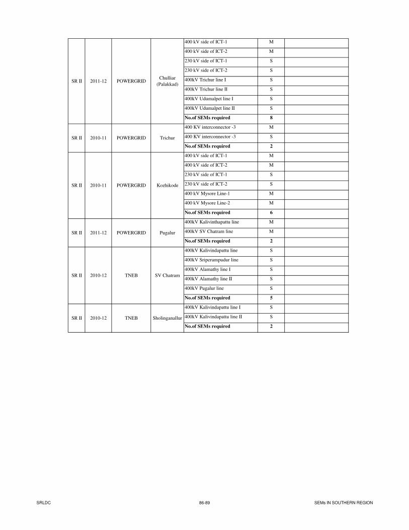
400 kV side of ICT-1 M
400 kV side of ICT-2 M
230 kV side of ICT-1 S
230 kV side of ICT-2 S
400kV Trichur line I S
400kV Trichur line II S
400kV Udumalpet line I S
400kV Udumalpet line II S
No.of SEMs required 8
400 KV interconnector -3 M
400 KV interconnector -3 S
No.of SEMs required 2
400 kV side of ICT-1 M
400 kV side of ICT-2 M
230 kV side of ICT-1 S
230 kV side of ICT-2 S
400 kV Mysore Line-1 M
400 kV Mysore Line-2 M
No.of SEMs required 6
400kV Kalivinthapattu line M
400kV SV Chatram line M
No.of SEMs required 2
400kV Kalivindapattu line S
400kV Sriperumpudur line S
400kV Alamathy line I S
400kV Alamathy line II S
400kV Pugalur line S
No.of SEMs required 5
400kV Kalivindapattu line I S
400kV Kalivindapattu line II S
No.of SEMs required 2
SR II
SR II
SR II
SR II
SR II
SR II
POWERGRID Trichur
POWERGRIDChulliar
(Palakkad)2011-12
2010-12
2010-11
2010-12
TNEB
2010-11
2011-12 POWERGRID
TNEB
Pugalur
SV Chatram
Sholinganallur
KozhikodePOWERGRID
SRLDC 86-89 SEMs IN SOUTHERN REGION
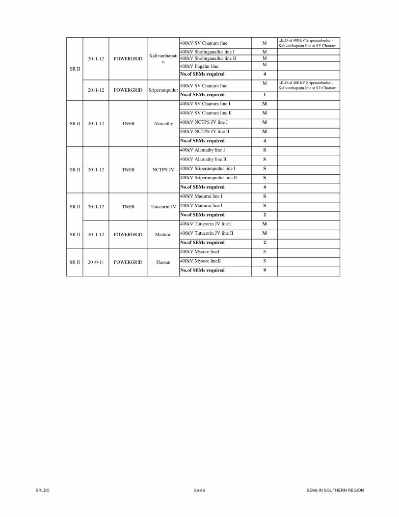
400kV SV Chatram line MLILO of 400 kV Sriperumbudur -
Kalivanthapattu line at SV Chatram
400kV Sholinganallur line I M
400kV Sholinganallur line II M
400kV Pugalur line M
No.of SEMs required 4
400kV SV Chatram lineM LILO of 400 kV Sriperumbudur -
Kalivanthapattu line at SV Chatram
No.of SEMs required 1
400kV SV Chatram line I M
400kV SV Chatram line II M
400kV NCTPS JV line I M
400kV NCTPS JV line II M
No.of SEMs required 4
400kV Alamathy line I S
400kV Alamathy line II S
400kV Sriperumpudur line I S
400kV Sriperumpudur line II S
No.of SEMs required 4
400kV Madurai line I S
400kV Madurai line I S
No.of SEMs required 2
400kV Tutucorin JV line I M
400kV Tutucorin JV line II M
No.of SEMs required 2
400kV Mysore lineI S
400kV Mysore lineII S
No.of SEMs required 9
2011-12 POWERGRID
2011-12 TNEB
TNEB
2011-12
2011-12
POWERGRID
SR II
TNEB Tutucorin JVSR II
2011-12
2011-12
POWERGRID
SR II 2010-11
SR II
SR II
SR II
POWERGRID
Kalivanthapatt
u
Sriperumpudur
Madurai
Alamathy
Hassan
NCTPS JV
SRLDC 86-89 SEMs IN SOUTHERN REGION
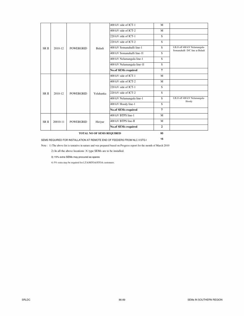
400 kV side of ICT-1 M
400 kV side of ICT-2 M
220 kV side of ICT-1 S
220 kV side of ICT-2 S
400 kV Somanahalli line-1 S
400 kV Somanahalli line-1I S
400 kV Nelamangala line-1 S
400 kV Nelamangala line-1I S
No.of SEMs required 7
400 kV side of ICT-1 M
400 kV side of ICT-2 M
220 kV side of ICT-1 S
220 kV side of ICT-2 S
400 kV Nelamangala line-1 S
400 kV Hoody line-1 S
No.of SEMs required 7
400 kV BTPS line-1 M
400 kV BTPS line-II M
No.of SEMs required 2
TOTAL NO OF SEMS REQUIRED 93
SEMS REQUIRED FOR INSTALLATION AT REMOTE END OF FEEDERS FROM NLC II STG I 15
Note : 1) The above list is tentative in nature and was prepared based on Progress report for the month of March 2010
2) In all the above locations 'A' type SEMs are to be installed.
3) 15% extra SEMs may procured as spares
4) 5% extra may be required for LTA/MTOA/STOA customers.
2010-12 POWERGRID LILO off 400 kV Nelamangala-
Somanahalli D/C line at BidadiSR II
2010-12 POWERGRID Yelahanka
LILO off 400 kV Nelamangala-
Hoody
20010-11SR II
SR II
Bidadi
HiriyurPOWERGRID
SRLDC 86-89 SEMs IN SOUTHERN REGION
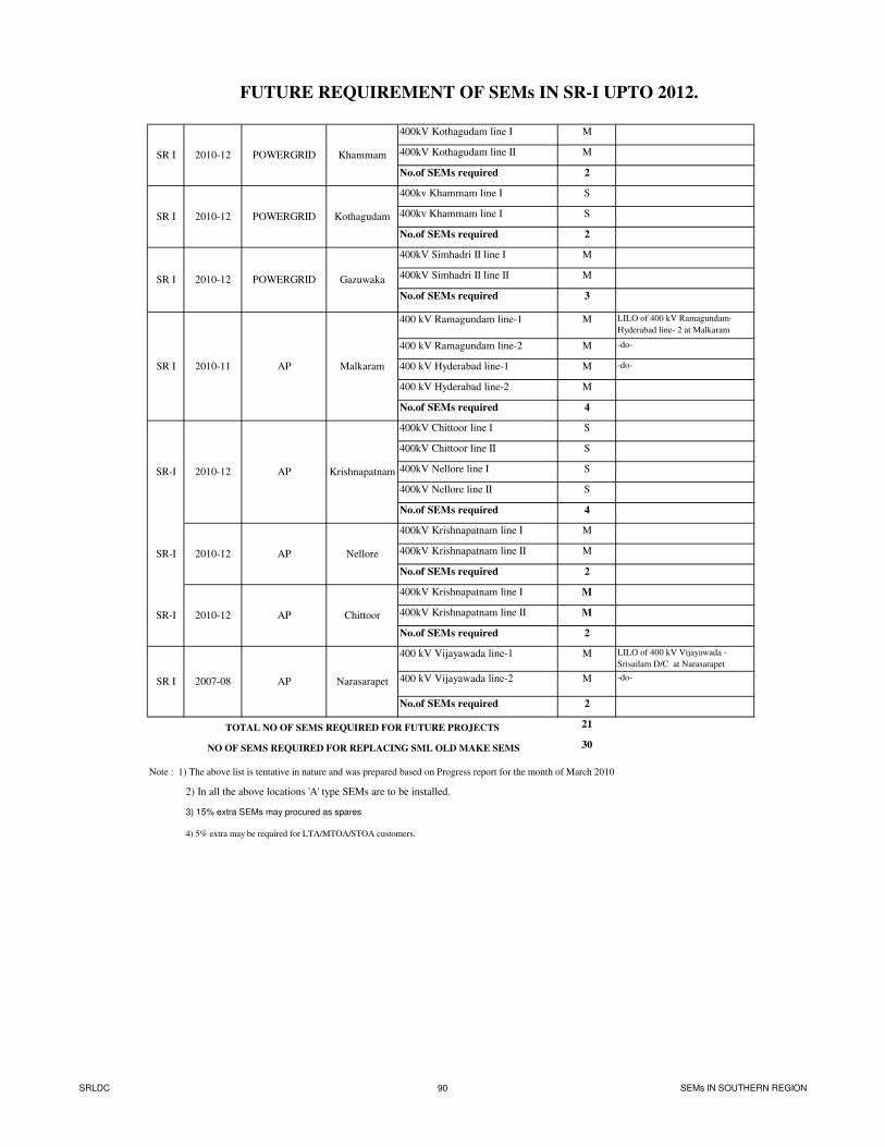
FUTURE REQUIREMENT OF SEMs IN SR-I UPTO 2012.
400kV Kothagudam line I M
400kV Kothagudam line II M
No.of SEMs required 2
400kv Khammam line I S
400kv Khammam line I S
No.of SEMs required 2
400kV Simhadri II line I M
400kV Simhadri II line II M
No.of SEMs required 3
400 kV Ramagundam line-1 M LILO of 400 kV Ramagundam-
Hyderabad line- 2 at Malkaram
400 kV Ramagundam line-2 M -do-
400 kV Hyderabad line-1 M -do-
400 kV Hyderabad line-2 M
No.of SEMs required 4
400kV Chittoor line I S
400kV Chittoor line II S
400kV Nellore line I S
400kV Nellore line II S
No.of SEMs required 4
400kV Krishnapatnam line I M
400kV Krishnapatnam line II M
No.of SEMs required 2
400kV Krishnapatnam line I M
400kV Krishnapatnam line II M
No.of SEMs required 2
400 kV Vijayawada line-1 M LILO of 400 kV Vijayawada -
Srisailam D/C at Narasarapet
400 kV Vijayawada line-2 M -do-
No.of SEMs required 2
TOTAL NO OF SEMS REQUIRED FOR FUTURE PROJECTS 21
NO OF SEMS REQUIRED FOR REPLACING SML OLD MAKE SEMS 30
Note : 1) The above list is tentative in nature and was prepared based on Progress report for the month of March 2010
2) In all the above locations 'A' type SEMs are to be installed.
3) 15% extra SEMs may procured as spares
4) 5% extra may be required for LTA/MTOA/STOA customers.
AP2010-12
SR-I 2010-12 AP
POWERGRID
SR I
SR I
SR I
SR-I
SR-I
2010-12
2010-12
2010-12
SR I
SR I
2007-08
POWERGRID Gazuwaka
2010-11 Malkaram
Krishnapatnam
Nellore
AP
AP2010-12 Chittoor
Khammam
AP Narasarapet
POWERGRID
Kothagudam
SRLDC 90 SEMs IN SOUTHERN REGION
Related Documents